MATIONAL WATER SUPPLY AMD DRAINAGE BOARD ...
97
FOR OC'fA} < ¡i :• ; V RANiiTATifSó! ¡¡PD W/ï: LR SUP^L'Ï AN'fj JV!I _OF LOCAL GOVERNM!=f<iï. HOUSING AND CONSTRUCTION MATIONAL WATER SUPPLY AMD DRAINAGE BOARD SRI LA ¡NiKA 3 4 1 . 0 8 9 w A DESIGN MANUAL D7 WASTEWATER TREATMENT DRAFT 1 JANUARY, 1989 WATER SUPPLY AND SANITATION SECTOR PROJECT (USAID SRI LANKA PROJECT 383-0088)
-
Upload
khangminh22 -
Category
Documents
-
view
2 -
download
0
Transcript of MATIONAL WATER SUPPLY AMD DRAINAGE BOARD ...
FOR OC'fA} < ¡i :• ; VRANiiTATifSó! ¡¡PD
W/ï : LR S U P ^ L ' Ï AN'fj
JV! I _OF LOCAL GOVERNM!=f<iï. HOUSING AND CONSTRUCTION
MATIONAL WATER SUPPLY AMD DRAINAGE BOARD
SRI LA ¡NiKA
3 4 1 . 0
8 9 w A
DESIGN MANUAL D7
WASTEWATER TREATMENT
DRAFT 1
JANUARY, 1989
WATER SUPPLY AND SANITATION SECTOR PROJECT(USAID SRI LANKA PROJECT 383-0088)

1IIIIIIIIIIIIII111I11
UF-HA^Y. -.NT--.!"
P. . :, ...:-.0'.; AD "Sív:íí. vO/u) d ; .O i i ext 14Ij 142
•: /5/?-- ^ 3 ^ 3
. oL 0 :
DESIGN-MANUAL D7
WASTEWATER TREATMENT
DRAFT I
January

•
I
TABLE or CONTESTS
1IIII• SECTION 1 INTRODUCTION \W SCOPE
I SECTION 2 WASTFWATER DíSCHARGE <;OSTROL RE'QL'iREMEÍÍTS
• 2 .1 Publ ic Health ïfjpacls
2 .2 Discharge Staridarris
I-1st OÍ Tables
Abbr^-v ¡ at ions
SF:CTIOS' :? WASTEWATER CHARACTERISTICS 7
I 3.1 Existing Wastewater Character i st.ics 7
3.2 Projected Wastépater Characteristics 9
SECTION 4 GRAVITY SEWERS 11
I 4,1 Hydraulic Criteria 11
4.2- Peak Factors and Infiltration 12
| 4.3 Sulphide Problem 14
4.4 Property Connect ions 15
4.5 Structural Considerations 15
I 4.6 Materials 16
4.7 Sewer Construct ior¡ Tcchn tques 10
I ¿,7.1. Open Trench O nstrijction 20
— ¿.7.2 Tunnel. Cons» r< ,ct i :-n 20
SECTION' 5 PUMP STATION'S AND PRESSURE MA IKS 23
III

I• SECTIOS 6 WASTCWATCR TREATMENT SV5ÏLMS ' 30
6.1. Prel ininary Treatment 30
J 6.2 Fixed tirovcth Sy stens 30
_ 6.2.1 Biological Filters 30
• 6.2.2 Rotating Biological Contactors 31
B 6.3 Suspendei Growth Systems 31
6.3.1 Activated Sludge Systeras 34
I 6.3.2 Lagoon Systems 39
6,4 Tertiary Treatment 50
• 6.5 Proprietary Treatment Systems 50
• 6,6 Sludge Disposal 51
6.7 Miscellaneous Design Criteria 52
I 6.7.1 • Odour Control 52
6.7.2 Buffer Zones 55
SECTION 7 INDUSTRIAL WASTES 56
I 7.1 Discharge to the Sewerage System 56
_ 7.2 Complete Treatment and Discharge to Watercourses 61
• 7.3 Control of Industrial Wastes Discharged to the 61
Sewerage System
| 7,A Estimating Industrial Waste Pollution Loads 64
I SECTION1 8 OCEAN OUTFALLS 65
8.1 Discharge Standards 65
• 8.2 Outfall Design Procedure 67
• 8.2.1 Initial Dilution 67
6.2.2 Coastal Dilution 72
I 8.3 • Construction 74
0.4 Pretreatment 74
III

II SECTION 9 SEPTIC TASK SYSTEMS 76
9,1. Applicability of Septic Tank Systera* 76
| 9.2 Septic Tank 77
_ 9.3 Soak.iv.ay 79
APPENDIX A REFERENCES
APPENDIX B SRI LANKAN STANDARDS FOR WASTEWATER DISCHARGES
9.4 Sept.age Disposal 60
IIIIIIIIIIIIII
(iii)
II
IIIIIIIIIIIIIIIIIIIII
5.1 Typical Punp .Station Plans 25
5.2 Typical Pump Station Section 26
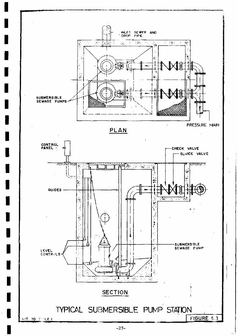
5.3 Typical Submersible Pump Station 27
5.4 Typical Screw Pump Station 28
6.1 Flow Diagram for Biological Filter Treatment Systems 33
6.2 Flow Diagram Activated Sludge Treatment Systems 37
6.3 Flow Diagrara Deep Shaft Treatment System 38
6.4 Flow Diagram Oxidation Ditch Treatment System 40
6.5 Comparison of Design Equations for BOD Reraov.nl in 4.3Primary Facultative Ponds
6.6 Recommended Maximum BOD Loads to Primary Ponds 45as a Function of Temperature
6.7 Typical Sludge Treatment Systems 54
7.1 Grease Trap on Waste Drain Lines for Small Factories 59and Catering Establishments
7.2 Derivation of Maximum Allowable Concentration 63
6.1 Definition Sketch for Rising Jet of Wastewater 68Discharged Horizontally into Ocean
8.2 Calculation of Initial Dilution of a Horizontal 69Discharge of Wastewater into Still Marine Waters
8.3 Calculation of Initial Dilution of Wastewater into 71Marine Waters Taking into account Ocean Current
8.4 Design Model for Calculating Outfall Length 73
0,5 Typical Cross. Section Detail'for a Buried Diffuser 75
9.1 Recommended Septic Tank Dimensions 70
(iv)

2.1 Effect of Various Treatment Systems on Pathogens
IIIIII
2.2 Relative Efficiencies of Sludge Treatment Processes in 5jm Reducing Pathogen Levels
3.1 Typical Metered Water Use Data 6
4.1 Recommended Gravity Sewer Design Criteria 13
| 4.2 Recommended Sewer Pipe Materials (Technical Aspects) 19
• 5.1 Recommended Design Criteria for Pressure Mains and 24" Pump Stations
I 6.1 Design Criteria for Fixed Growth Systems .32
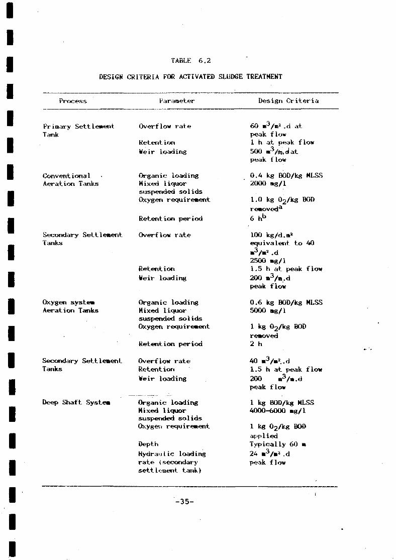
• 6.2 Design Criteria for Activated Sludge Treatment 35
6.3 Design Criteria for Aerated Lagoons 41
• 6.4 Design Criteria for Stabilisation Ponds 46
6,5 Design Criteria for Sludge Treatment 53
IIII•II

IIIIIIIIIIIIIIIIIIIII
ABBREVIATIONS
BOD0
CEACODeracudF8hhakg1MJ
MLSSMPKm
•gminnimmP
PP»revSSssqTSSucWy
Biocheraioai oxygen demand (5 «J at 20 °C)CentigradeCentral Environmental AuthorityChemical oxygen demandcentimetrecubicdayFahrenheitgramhourhectarekilogramlitreMega JouleMixed liquor suspended solidsMost probable numbermetremilligramminutemillilitremillimetrepersonpart per millionrevolutionSuspended so1idssecondsquareTotal suspended solidsmicrocurieWattyear
SECTION 1
INTRODUCTION AND SCOPE
This Wastewater Treatment Design Manual is intended to provideHWSDB Engineers with sufficient background knowledge and process designcriteria to enable preliminary designs to be prepared for urban wast.ewat.erinfrastructure projects. it should provide enough information to enablealternative wastewater management strategies to be formulated andevaluated and for the infrastructure to be sized, and therefore costed atleast for preliminary estimating purposes. The manual does not deal withaspects of detail engineering design, construction or Q&M.
Although the NWSDB has the responsibility for providing urbansewerage systems in Sri Lanka, .such systems are limited at present and arelikely to remain so because of economic constraints. Until such time asthe demand for sophisticated waterbome sewerage systems increases, theKWSDB should retain only a small cadre of personnel who have sufficientknowledge in the field to enable them to prepare feasibility studies andtentative cost estimates. Recourse should be made to consulting firms fordetail design assistance until such time as the work load justifies thecreation of a comprehensive design tea» within the NWSDB. Responsibilityfor the O&M of major urban wastewater collection, treatment and disposalfacilities should remain vested in the local authorities.
The manual deals specifically with wastewater from urban areaswhere properties are provided with piped water supply connections andcistern-flush toilets. It does not deal with low cost on-sitetechnologies suitable for peri-urban, squatter upgrading or rural areaprojects.
The main topics covered are:
o Discharge standards
o Wastewater characteristics
o Gravity sewers and sewage pumping
o Treatment systems
o Ocean outfalls
o Septic tanks
o Industrial wastes
The current Sri Lankan standards relating to wastewater dischargesand water quality are included in Appendix B.
The manual stresses the need for local field surveys to be carriedout wherever possible because of the dearth of information available onwastewater characteristics in Sri Lanka,
This manual was prepared under the USAID «ater Supply andSart i tat ion Sector Project. :
-1-
IIIIIIIIIIIIIIII
IIII
SECTION 2
WASTEWATER DISCHARGE CONTROL REQUIREMENTS
The discharge of untreated wastewater to the environment canresult in unacceptable pollution levels which render the environnentunsuitable for designated uses. This is recognised in Sri Lanka and theCEA has been established specifically to control environmental quality(Ref.Government of Sri Lanka (1980)), In the context of urban wastewaterdischarges the two main concerns are adverse public health impacts andenvironmental degredation generally either of water bodies or land.
2.1 Public Health Impacts
It is recognised that inadequate water supplies and defectiveexcreta disposal systems are, among other f,actors, responsible for a widerange of diseases. In the. urban environment where households are providedwith piped water connections and cistern flush toilets, the level of wateruse in the house ,is generally well in excess of the tentative thresholdlevel of 50 l/d.p below which water-related diseases become manifest. Theincidence of water—related disease in such areas is likely to be relatedto poor hygiene practices, food contamination, and improper use of waterand excreta disposal systems, rather than with the levels of provision ofwater supply and sanitation facilities.
nevertheless, the discharge of raw domestic wastewater to waterbodies or to land does constitute a public health risk. The types andnumbers of pathogens in the wastewater are related to the state of healthof the contributing community, hence the logical concern to ensure thathospital wastes are adequately treated before discharge. The risk to aperson coming in contact with sewage contaminated water, or with sludge onland for example, depends on such factors as the number of pathogenspresent, the dose required to cause infection, and the person's generalhealth status and level of immunity.
It is not possible to generalise on public health risks because ofthe multiplicity of factors involved. As a result, general guidelines areused in an attempt to reduce the perceived risks, and in the case ofpathogens the coliform bacteria level is usually adopted as a surrogateindicator for pathogens.
Recommended colifor» levels for marine waters are discussed inSection 6. The Sri Lankan standards incorporate a coliform level of 5000/100 ml (95 percent i le) for an inland water source to be used for watersupply purposes (see Table Bl) regardless of the type of water treatmentprocess to be used. Recent studies in the USA have suggested that faecalcoliforo levels in treated wastewater discharged to parks should notexcceed 500/100 ml, regardless of the recreation activity taking place.Schwebach and others (1966). This is a considerable relaxation on earlierstandards and perhaps reflects the fact that necessary infective doselevels of most pathogens are far higher than the levels a person incontact with treated wastewater or sludge would normally encounter.
-2-
IIIIIII
I
IIIIIIIIIIIII
2.1.2 R ^ ^ t i ^ o f Paj^g^sdurj.ng_Wastewater_Treat»erit
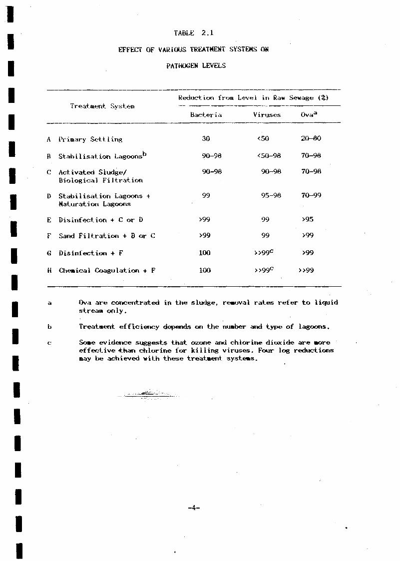
Typical reductions in pathogens afforded by various wastewatertreatment processes are shown in Table 2.1. The reductions should beviewed as general guidelines, considerable variations may exist inspecific circumstances. A significant proportion of the pathogens presentin the sewage are concentrated in the sludge. Traditional sludgetreatment processes such as digestion and drying will result inconsiderable reductions but will not necessarily eliminate pathogenscompletely. High temperature processes to 60°C such as composting or heattreatment are probably more effective. Relative efficiencies of sludgetreatment processes are shown in Table 2,2.
2• 2 Discharge Standards
In order to control environmental quality it is necessary tocontrol wastewater discharges through the use of standards. The logicalconcept is to base treatment levels on the desired quality of theenvironmental sector receiving the wastewater (inland waters, marinewaters, land). This concept implies that designated environmental qualitycriteria should be specified for different environmental uses. It is notthe purpose of this Design Manual to discuss the wide range of environ-mental quality criteria, but reference must be made to the existing SriLankan standards, and these are given in Appendix B.
The concept of relating wastewater discharges to environmental useis embodied in the Sri Lankan standards, with tolerance limits alreadyestablished for public water supply sources (Table Bl), and for dischargeof water to public sewers and for irrigation (Tables B4 and B5),Tolerance limits for wastewater discharges to inland waters and marinewaters are also laid down (Tables B2 and B3), although the limits fordischarge to inland waters relate only to industrial wastes and the limitsare not strictly related to receiving water use. However, pollutioncontrol is still " in its infancy in Sri Lanka and there is littlejustification for legislating compre- hensive standards for all possibleenvironmental use alternatives when monitoring and corrective actionresources are minimal.
There are as yet no standards for domestic sewage discharges toinland waters. Until such time as domestic sewage standards arepromulgated it would seem logical to base treatment levels for such wasteson the BOD and SS levels of 30 and 50 mg/1 respectively stipulated inTable B2 for discharge of industrial wastes to inland Waters. — ~ -
The standards in Table B2 are specified as maximum (not to beexceeded) values. Studies on variations in domestic sewage effluentquality elsewhere have shown that for 95 percentile limits (not to beexceeded in more than 5% of samples), the associated mean values aretypically as follows:
95 percentile
Mean
BOD
30
16
-3-
SS
50
30
IIIIIIIIIIIIIIIIIIIII
TABLE 2.1
EFFECT OF VARIOUS TREATMENT SYSTEMS ON
PATHOGEN LEVELS
Reduction f ron Level in Raw Sewage (Z)
A
B
C
i reatraeriT- ¿>ysT_em
Primary Sett 1 ing
Stab i 1 i sat ion Lagoons"
Activated Sludge/B iolog ica1 Filtrat ion
Bacteria
30
90-96
90-98
Viruses
<50
<50-98
90-98
0vaa
20-60
70-96
70-98
D Stabilisation Lagoons +Maturation Lagoons
E Disinfection + C or D
F Sand Filtration + B or C
G Disinfection + F
H Chemical Coagulation + F
99
>99
>99
100
100
95-98 70-99
99
99
>>99C
>>99C
>95
>99
>99
>>99
Ova are concentrated in the sludge, renoval rates refer to liquidstream only.
Treatment efficiency depends on the number arid type of lagoons.
Some evidence suggests that ozone and chlorine dioxide are moreeffective-than chlorine for killing viruses. Four log reductionsmay be achieved with these treatment systems.
-4-

IIIIIIIIIIIIIIIIIIIII
TABLE 2,2
• RELATIVE EFFICIENCIES OF SLUDGE TREATMENT PROCESSES
IN REDUCING PATHOGEN LEVELS
Treatment Process
Raw sludge storage
Digestion
Compost ing
Line treatment
Heat treatment
Irradiation
Ref. Carrington
Relative reduction
Poof
Ascaris
Taenia
Ascaris
Taenia
ova
ova
ova
ova
Moderate
Viruses
Bacteria
Hookworm ova
Good
Viruses
Bacteria
Entamoebacrysts
VirusesBacteriaFungiHelminth
Ascaris ova
Ascaris ova
-5-
ova
Bacteria
VirusesBacteriaHelminthova
BacteriaViruses
I• Larger variations would probably occur for stabilization lagoon™ systens, particularly for SS. It is recommended, therefore, that the Sri
Lankan standards in Table B2 be interpreted as 95 percenti les and theI sewage treatment processes described in Section 6 be designed to produceI an effluent quality of BOD 20 rag/1 and SS 30 rag/1,
IIIIIIIIIIIIIIIIII
-6-
IIIIIIIIIIIIIIIIIIIII
SECTION 3
WASTEWATER CHARACTERISTICS
In order to design any wastewater collection and treatment systeait is necessary to define present and projected future wastewatercharacteristics. Survey data for Sri Lankan wastewaters are virtuallynon-existent, with the exception of some specific industrial wastesurveys. For urban areas where monitoring data are not available it isreconiaended that field surveys be carried out in selected areas todeter»ine current loads. The surveys should be carried out over 24-hourperiods in order to reflect diurnal variations in waste flows and toidentify infiltration rates in the sewerage system. The survey areasshould be selected on the basis of representative housing types, coveringthe predominant socio-economic levels, including if possible examples ofhousing developments likely to be typical in the future.
The main components of the wastewater for the purpose of treatmentsystem design and discharge to the environment are flow, BOD, SS, nitrogencompounds, pasphorous and pathogens. In the absence of specific andcomprehensive Sri Lankan field survey data on wastewater characteristics,it would be inadvisable to speculate on the full spectrum of wastewatercomponents. However, estimates of domestic sewage flow and BOD loads arepresented since these two parameters constitute the fundamental designinputs for virtually all categories of treatment process.
3.1 Existing Wastewater Characteristics
In the absence of comprehensive survey data estimates of sewageflows can be made from water use records. The proportion of the wateruse which is returned as sewage varies primarily in accordance with thesocio-economic characteristics of the household. In affluent areas in theUSA, for example, the return ratio may be tas low as 50% because a.substantial proportion of the water is used for garden irrigation. InAsia, return ratios typically fall within the range 70 to 90?. An averagereturn ratio of 6O5£ is probably realistic for urban areas in Sri Lankaunless field survey data indicate otherwise.
The data in Table 3,1 give typical water use characteristics formetered connections in Greater Colombo and the regions. The data excludestandposts since the major water use of standposts is in situ for bathingand laundry with the wastewater being discharged to the stor» drainages y s t e m . ' "• '"
On the basis of an average urban area house occupancy of 6.0 and areturn ratio of 60?, domestic sewage flows can be estimated at about140 1/d. p in Greater Colombo. In regional urban areas the use of areturn ratio of 60? may not give a realistic picture since the mainreasons for lower regional water use compared to Colombo are that socio-economic levels tend to be lower in the regions and alternative watersources such as wells are readily available. As a result the regionalsewage flow is likely to be much closer to the metered water use than inColombo. For regional urban areas, therefore, a domestic sewage flow ofsay 100 1/d. p would probably be more realistic pending field surveyverification. '
-7-

1111111111
Category
Domest ic
Commercial
Industrial
Government
Tourist Hotel
Inst itut iona1
School
Re 1 ig ious
Port
TABLE 3.1
TYPICAL METERED WATER USE DATA
Water Use - m^/month
Greater Colombo
30.6
106
579
606
1157
210
-
-
2705
connection
Kandy Region
19.5
25.2
] -
~
17
-
A3.A
A3.A
-
NOTES, a) Colombo data for June-August 1968
I b) Kandy data for July 1966 for 22 schemes.
II
IIIIII
-8-
IIIIIIIIIIIIIIIIIII
The data in Table 3.1 also give an indication of water use in non-domestic categories. The overall metered water use in Greater Colonbo is48 is /month connection, but 91% of the water use is accounted for by thedomestic, commercial and Government categories. For designing specificdrainage area sewers allowances should be made for such non-domestic uses.Typical allowances are as follows but they should be verified by fieldchecks.
LandUse
SchooIs 0.1 persons/pupi 1Hospitals 3 persons/bedOffice 3 persons/100 n2
Comercial 3 persons/100 ma
Hotels 4.4 persons/room
In order to determine BOD loads, field surveys are .mandatory. InSri Lanka the per capita BOD load is likely to be in the region of 35 to50 g/d depending on the socio-economic level of the area. Faecal matterwill account for 25 to 30 g of BOD/d.p, with vegetarians tending to havehigher BOD levels than meat eaters on account of the higher weight andmoisture content of vegetarian faeces. The proportion of the BOD loadabove the faecal matter base of 25 to 30 g is accounted for entirely bysullage loads.
3.2
Projections of future per capita domestic sewage loads need totake into account a number of factors such as increased availability ofwater supply and increased affluence resulting in a more widespread use ofsuch appliances as washing machines. Based on the existing field surveydata for a range of specific socio-economic levels covering thepredominant housing categories, the likely future housing categoryprojections can then form the basis for estimating future waste loads. Inthis way there is more likelihood that future load projections willreflect planned development rather than relying on a general average loadfactor for the whole urban area. -.-,
There is often a tendency to assume that per capita loads in lessdeveloped countries will eventually attain the same levels as thoseexperienced in the USA and some European countries. This may notnecessarily be the case. It is important to realise that the future BODand flow increase wtTt=lãê^«ÉtríB«table to sul lage and not to excreta. Itis highly probable that per capita excreta BOD loads in Sri Lanka are infact higher than those in the USA and other more developed countriesbecause of the relatively low meat consumption in Sri Lanka and theconsequent higher proportion of vegetarians and neo-vegetariaris in thecontributing population.
It is, of course, a matter of conjecture, as to whether or not theper capita BOD loads will ever attain the 60 to 80 g/d range recorded inEurope and the USA. If garbage grinders are prohibited, as they are in«any urban areas in Europe, the BOD load should never exceed 60 g/d.p.Even in the more affluent higher socio-economic levels of Southeast Asia,such as Singapore, domestic sewage characteristics are today only, around160 1/d.p and 51 g BOD/d.p.
IIIIIIIIIIIIIIIIIIIII
Previous projections of sewage flows for the Colombo area werebased on a^n average annual increase of about 0.9? over the period 197Ô to2000 (Engineering Science, 1981). This is not unrealistic, it would implya year 2000 domestic sewage flow of about 160 1/d.p assuming an occupancyof 6.0, or about 175 1/d.p if average occupancy rates fell to 5.5. Sewageflow increase rates of 2 to 3? per year were connon in the more developedcountries during the 1960s and 1970s as a direct result of increasingaffluence and the more widespread provision of water using appliances.Evert in Singapore, the domestic sewage flow and BOD loads increased atannual rates of 2.0 and 1.3? respectively over the ten-year period to1963.
It is considered that unless field survey data indicate otherwise,an annual sewage flow increase of 1? be adopted for major urban areas inSri Lanka where water supply restrictions are not a constraining factor.A target BOD load of 50 g/d.should be adequate at least up to the year2000.
-10-
IIIIIIIIIIIIIIIIIIIII
SECTION
GRAVITY SEWERS
4.1
Wherever technically .arid economically possible gravity sewersshould be designed to maintain minimun scouring velocities at averagedaily flows anticipated in the design year in order to preventaccumulation of settleable materials and to retard and, if possible,prevent corrosion resulting fro» the formation of hydrogen sulphide. Inorder to ensure that slimes and deposits are removed from the pipe wallsand invert at least once during the day, peak flow velocities (in thedesign year) should be no less than 0.6 m/s since slime growth occursrapidly at velocities below 0.76 m/s. Where both sewage temperatures andBOD are high, a higher velocity should be aimed for. Under suchcircumstances a velocity of 1.0 m/s would probably safeguard the systemfrom sulphide- generated corrosion.
Ideally, flow velocities under present peak flow conditions shouldbe at least 0.7 m/s. In practice, the range of flows, from present day tothe design year «ay be too large to accommodate these velocity criteria,particularly where both BOD and temperature are high. In such casesflushing and additional maintenance of the sewers may be required duringthe initial years of operation and in some cases it will inevitably benecessary to use pipe materials which are able to withstand acid attack.
With respect to erosion of pipe materials, velocities of 6 m/s orhigher may be satisfactory but it is recommended that as a generalguideline a maximum velocity of A m/s be adopted.
The major factor affecting the roughness coefficient in sewers,apart from the pipe material and method of jointing, is the slime whichbuilds up as the pipe as exposed to sewage. The velocity is related tothe roughness coefficient by the Manning formula:
V = (1/n) R0.67gp.50
Where V = velocity <m/s)R = hydraulic radius <m>S - hydraulic gradient (m/m)n - Manning'saKQUghness coefficient
The following Manning 'n' roughness values are recommended forsewer pipes flowing full for a velocity of about 0.75 »/s:
Spun concrete
Asbestos cement
Clay
uPVC
Vertically cast
n
concrete
-11-
= 0.01A
0.01A
0,013
0.013
0.01A
IIIIIIIIIIIIIIIIIIIII
Flow velocities in part-full pipes .are generally lower than thosepredicted using the* sarae roughness value for the. pipe flowing full. Forexample, the n value for a sewer flowing half full is about 1.22 timesgreater than the n value for the sewer flowing full. The largestdifference typically occurs at a flow depth of about 0.25 diameters, whenthe rt value increases to about 1.3 times the pipe full value. The effectof a higher roughness value in early years of operation caused by slimeaccumulations would be to reduce the effective carrying capacity of thesewer. For example, if the n value was 0,015 rather than 0.014, the pipefull capacity would typically be reduced by about 8 percent. Since higherroughness values are more likely to arise in early years when flows arelow, a slight error in the rt value adopted for design should not besignificant.
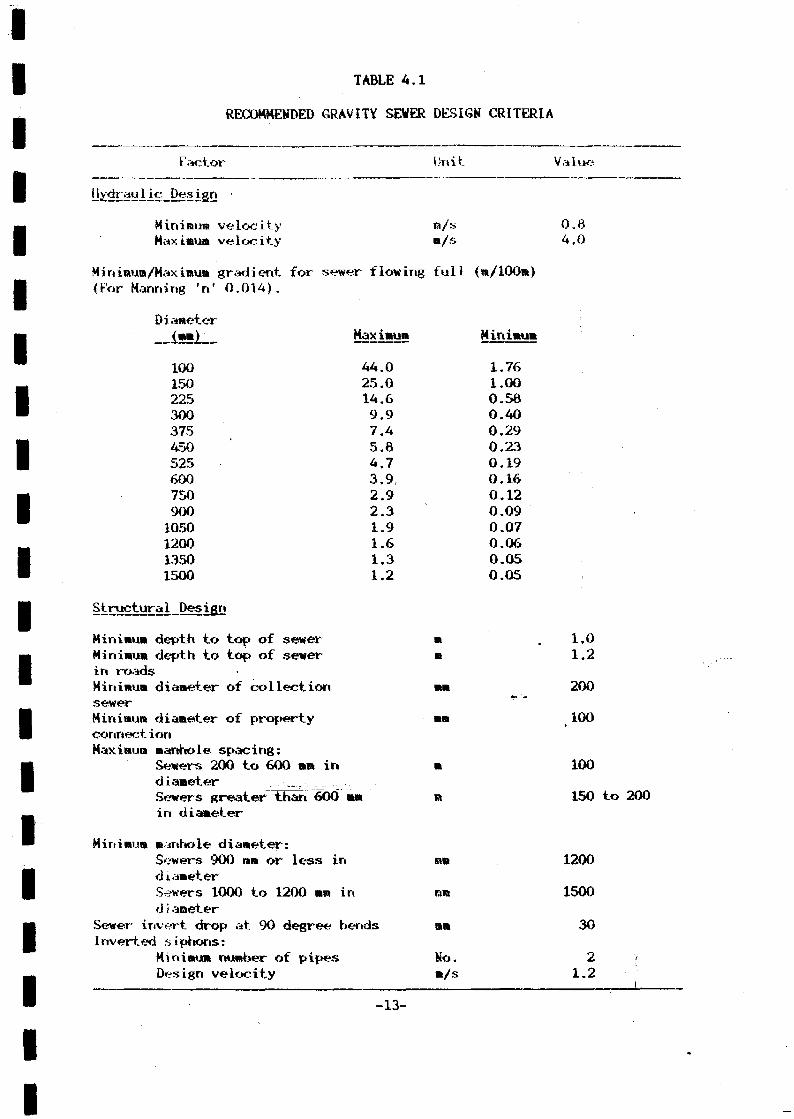
The data in Table 4.1 indicate desired minimum and maximumgradients calculated on the basis of peak flow velocities being in therange of 0.6 to 4.0 m/s for a pipe roughness (Manning n) of 0.014. Incertain circumstances factors such as rates of development, topography,ground conditions, economics and the need to prevent hydrogen sulphideemission may necessitate different velocities being adopted. In flatareas, the control of sulphides by providing adequate velocities mayresult in excessive excavation costs. An economic comparison should bemade between the cost of additional excavation, possible additionalpumping costs and the use of traditional less expensive pipe materials andthe cost of more expensive pipe materials which are inert to sulphideattack.
4.2 Peak Factors and Infiltration
In order to determine the required capacity of interceptor sewersit is necessary to determine the peak to average flow ratio. Peak factorstraditionally exclude infiltration and are calculated as follows:
(average domestic flow x peaking factor) +(average industrial flow x peaking factor) + -
, infiltration.
Typical peak factors for domestic flow^ excluding infiltrationrange from about 2.5 for a population of 100 000 through 3.3 for 10 000people to greater than 4.0 for a population smaller than 2000.
In the Greater Colombo area measured peak factors in the oldsewerage network are heavily influenced by the high infiltration ratescaused by the use^ot^cement mortar joints. It is recommended that thepeak factor used for domestic sewage flows be as given below. Thisrelationship has been well-proven elsewhere and is similar to the formulaeused in other urban areas in Asia.
Peak Factor = 4.7 P~ °-11
Where P = Population (in thousands)
v
-12-
IIIIIIIIIIIIIIIIIIIII
TABLE A.I
RECOMMENDED GRAVITY SEWER DESIGN CRITERIA
Factor
Hydraulic Design •
Minimum velocityMaximum velocity
Unit
ra/sm/S
Value
0.04.0
Miniraura/Maxintum g r a d i e n t for sewer flowing f u l l (m/100m)<For Manning 'n' 0 . 0 1 4 ) .
DiameterXmnl _ ííâ?íiSu5 Minimum
100 44.0 1.76150 25.0 1.00225 14.6 0.5Ô300 9.9 0.40375 7.4 0.29450 5.6 0.23525 4.7 0.19600 3.9, 0.16750 2.9 0.12900 2.3 0.091050 1.9 0.071200 1.6 0.061350 1.3 0.051500 1.2 0.05
Minimum depth to top of sewer m . 1 . 0Minimun depth to top of sewer m 1.2in roadsMinimum diameter of collection mm 200sewerMinimum diameter of property mm 100connectionMaximum manhole spacing;
Sewers 200 to 600 mn in m 100diameterSewers greater~thãn 600 mm m 150 to 200in diameter
Minimum m mhole diameter:Sewers 900 mm or less in mn 1200diameterSewers 1000 to 1200 mm in mm 1500di araeter
Sewer invert drop at 90 degree bends mm 30Inverted siphons:
Minimum number of pipes No. 2 '•Design velocity m/s 1.2
, i
- 1 3 -
IIIIIIIIIIIIIIIIIIIII
The formula gives the fol lowing results:
t Contr it>y
1000 4.71000 to 10 000 4.7 to 3.610 000 to 50 000 3.6 to 3.150 000 to 100 000 3,1 to 2.6
Peak factors for industrial flows should be limited to 2.0 tinesaverage flow as discussed in Section 7.
Infiltration rates are often expressed as a proportion of dryweather sewage flow. However, since infiltration is a function of thequality of construction of the sewerage system, it is recommended thatinfiltration be based on a sewered area or pipe length basis.
For new housing developments comprising medium/high—cost housingit should be possible to liait infiltration to 6 n^/d^ha. This willnecessitate a high standard of sewer and manhole construction. Inparticular, strict .pipe testing before backfill will be necessary andcareful supervision of pipe bedding, trench backfilling and theconstruction of property connections must be carried out. In addition, nobrick manholes should be used, all pipes must be with flexible joints andmanhole covers should be locked to prevent them fro» being stolen.
For connecting existing sewered developments to trunk sewers, aninfiltaration allowance of 16 m*Vd,ha should be used to reflect thegeneral poor quality of sewer, particularly lateral and manholeconstruction, and the use of right—joint pipes.
4.3 Sulphide Problem
Sulphides occur in sewage in both soluble and insoluble form. Eachperson normally discharges 1 to 1.5 g S/d, of which about 703; arises fromsulphate in urine. Sulphates are present in most water supplies and may beas high as 00 g S/l in some areas. Industrial wastes from tanneries,textiles, and chemical operations often contain sulphides in highconcentrât ion.
In the absence of oxygen, sulphate reducing bacteria in the slimelayer on the sewer walI^reduce sulphates to sulphides. The outer layer ofslime is usually aerobic but between the outer layer and the sewer wall ananaerobic zone exists which may be up to 3 mm thick and it is in this zonethat sulphate reduction occurs. The sulphides diffuse out of theanaerobic zone and are either oxidised to thiosulphates in the aerobiczorie or pass into the sewage stream as dissolved sulphides. Dependingupon the pH and other factors the sulphide escapes to the sewer atmosphereas hydrogen sulphide gas (H2S). When H2S gas escapes from solutionit may be oxidised on the pipe wall above the sewage flow by the bacteria,Thiobaç_UJijs, to produce sulphuric acid which causes corrosion.
-14-
IIIIIIIIIIIIIIIIIIIII
There appears to be evidence of sulphide corrosion problems in theexisting Colombo sewerage- network, despite the dilution afforded byinfiltrât ion/inflow. Most of the sewage arriving at the pump stations issept ic.
It is recommended that at the preliminary design stage sulphidegeneration calculations be performed for all sewer sections in order tocheck the likelihood of sulphide production. PVC liners can be used forconcrete pipes, particularly those of 900 mm diameter and above in thedownstream sections of the main trunk sewers. In addition, imported VCpipes or imported PVC lined collar-jointed pipes may have to be used forsome of the smaller diameter sewers in critical areas with sacificialconcrete being specified for intermediate diameters.
4. A Property Connections
Property connections should be of an adequate diameter to reducethe problem of blockage. Because service connections receive only inter-mittent flow they invariably experience intermittent formations ofstoppages during normal operations and these are removed by wave actionrather than by the maintenance of a minimum flow velocity- A typicalconstruction gradient would be 1.67 m/100 m. A high quality ofworkmanship to eliminate backfalls and protruding joints is essential.
A.5 Structural Considerations
A summary of recommended structural criteria regarding the designof gravity sewers is included in Table A. The major items for gravitysewers are as follows;
o Manholes are required wherever the sewer diameter or gradientchanges, at junctions, and at regular intervals for straightrun sewer lines.
o Drop manholes should generally not be considered because ofhydrogen sulphide release. If the change in invert elevationis high and a drop manhole is necessary", 'corrosion can beprevented by the use of glass reinforced plastic linings andepoxy mortar benchings. The drop manhole should be providedwith a means to clean out materials which lodge in the droppipe.
o A terminal manhole should be provided at the upstream end ofeach sewer.
o Service connections to sewers should discharge at an angle ofapproximately 45° to the sewer in the direction of flow. Onlarge trunk sewers in developed areas, consideration should begiven to construction of small diameter, parallel sewers towhich service connections are. made. The small diameter sewersshould discharge to the trunk sewer at manholes.
-15-
1o ciei. i.cu lat ion .sewers al. head raanholes should be sufficiently
deep so as to make future extensions and connections possible.A rairtitaura depth of 1,5 n would be reasonable.
o Maxiraura depth to invert in urban areas and for open cutconstruction should preferably be less titan 6 in to minimiseconstruction probleias in poor ground conditions and to reducesurface disrupt i or» and costs,
o Inverted siphons should be avoided if possible but if feasiblealternatives are not available then they should be of dual pipeand encased with reinforced concrete to prevent damage andflotation. Adequate provision should be made for cleaning thesiphon and sharp bends should be avoided with the rising leg ofthe siphon being limited to approximately 15 % slope.
o Pipe bedding should be granular or concrete depending uponavailability of materials and cost. For flexible jointed pipesa concrete bed must be broken at each pipe joint. By using asuitable bedding the strertgh of a pipe relative to appliedloads can be increased by a "bedding" factor. However, it isabsolutely essential that the pipe laying specification befollowed since bedding, jointing and backfill are integralcomponents of the pipe structure. This is particularlycritical for flexible wall pipes.
o Minimum diameters of reticulation sewers should not be lessthan 200 D B . Pip« to pipe connections should not be made fordiameters exceeding 200 nn.
o As far as is possible, routes of sewers and force mains shouldbe selected so as to cause minimum disruption of traffic.Tunnels (auger boring, pipe jacking) should be considered forsensitive sewer routes if feasible alternatives are notavailable.
4,6 Materials
The following factors are among the more significant that shouldbe evaluated before selection of materials for sewerage facilities:
o Life expectancy
o Previous local experience
o Resistance to internal and external corrosion
o Resistance to abrasion
o Roughness coefficient and its effect on flow characteristics
o Ease of handling and installation
-16-
IIIIIIIIIIIIIIIIIII
o Structural strength both in place and during handling
o Cast of supply, transport and iristal latían
o Loca1 avai Iab i 1 ity
The following materials are normally used for sewers:
o Vitrified Clay <VC>
o Asbestos Cement (AC)
o Reinforced Concrete (RC)
o Steel
o Cast Iron
o High density polyethelene (HDPE)
o Unplastieised polyvinylchloride (PVC)
o G lass reinforced plastic (GRP)
Vitrified clay pipe with flexible rubber joints offers superiorresistance to corrosion and no lining is required. It does requirecareful handling during transport and laying as it is easily damaged.Clay pipes manufactured in Sri Lanka are unglazed, have a low strength anddo not have a flexible watertight joint.
Asbestos cement pipe can be used for both gravity sewer andpressure pipe applications. Pressure pipe is manufactured in variousclasses suitable for certain working pressure ranges, whereas gravitysewer pipe is manufactured to suit various loading conditions and requiredcrushing strengths. Only autoclaved asbestos cement pipes should beconsidered for sewers. Pipe joints consist of a collar with two rubberrings. A bitumen, lining can be applied to the pipe. Although the lightweight of AC pipe is an advantage in construction of sewers and pressuremains the pipe requires careful handling and offers poor resistance tosulphide corrosion even when lined, and should only be used if there is nolikelihood of corrosion.
Reinforced concrete pipe is manufactured with various degrees ofcorrosion protect ion ; °f-r Severa 1 wall linings are available including highalumina cement mortar, polyvinlychloride' sheets, and increased wallthickness as sacrificial concrete. PVC linings can be applied to pipes of750 mm diameter and above. Several types of pipe joints are available,including the spigot and socket type with rubber rings. Reinforcedconcrete pipe is manufactured in classifications related to pipe strengthand the maximus allowable load to which the pipe can be subjected. SriLankan manufactured concrete pipes do not incorporate watertight flexiblejoints.
-17-
IIIIIIIIIIIIIIIIIIIII
Steel pipe is manufactured with linings of bitunen or sulphateresistant cement mortar. Spigot arid socket joints, flanges, or Mechanicaljoints are commonly used on" SQ.II 1 diaaeter pipelines of up to 750 an andwelded joints are used on larger diameter lines. The best use of steelpipes is for inverted siphons, pump stations, and in large diameterpressure mains.
Cast iron pipe is manufactured with either flanged or spigot andsocket joints. Because of its relatively high cost and weight, theapplication of cast iron pipe is usually United to internal piping atpump stations and above-grade pressure mains.
High density polyethylene and unp last ici sed polyvinychloride pipesare becoming more popular particularly for the smaller diameter sewers.Since both pipes are flexible the design of the pipe/trench system is muchmore critical than for rigid pipe materials. Glass reinforced plastic(GRP) is an alternative, but also flexible, pipe material which issuitable for sewers.
Flexible pipes rely on the side support of the earth backfillaround the pipe for stability more than do non—flexible pipes.Consequently, in an urban environment, where the side supports can beremoved during construction of underground services in the future, pipefailures could be more frequent. Also, flexible wall pipes may not besuitable in poor ground conditions.
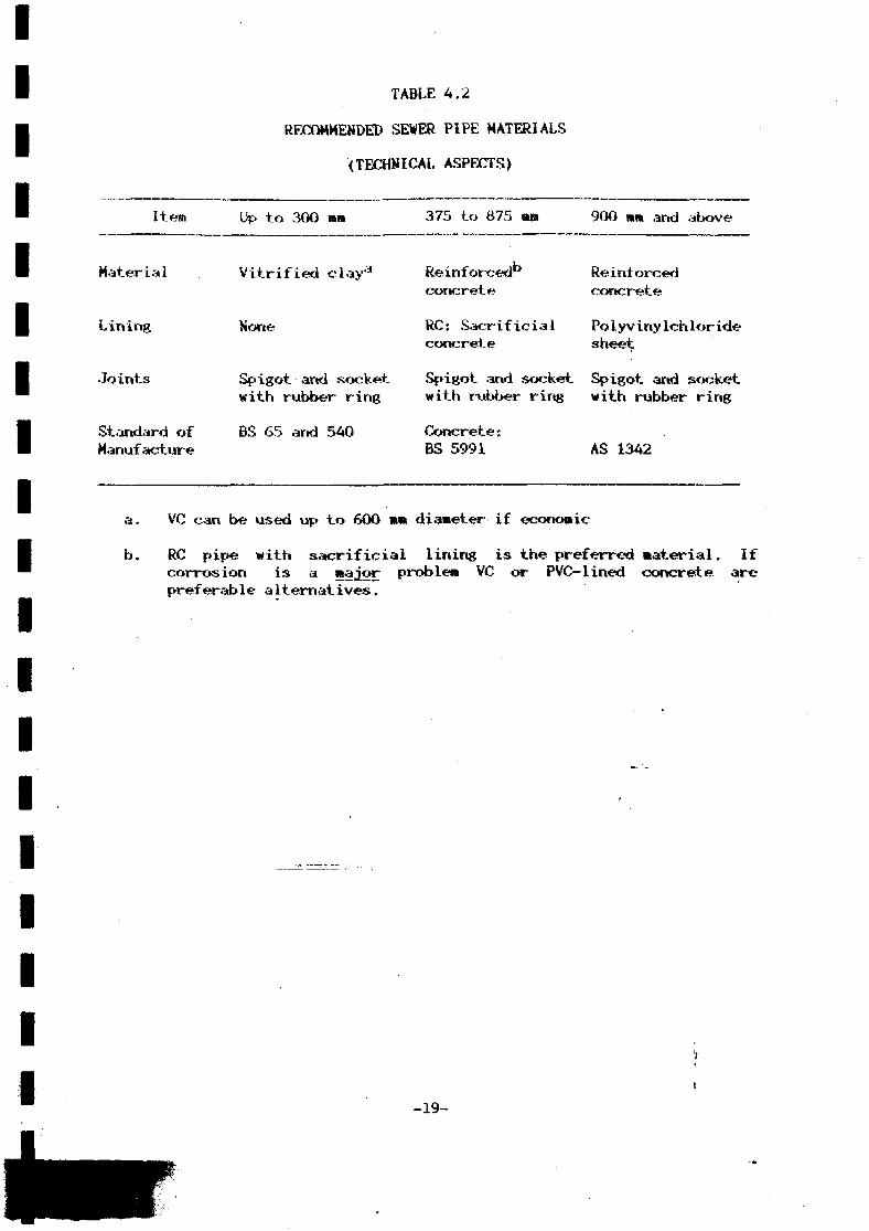
Since at the present time the number of experienced seweragecontractors in Sri Lanka is limited and since there is virtually no localexperience with large diameter flexible pipes it is recommended that onlyimported vitrified clay and reinforced concrete pipes ..be used for allsewers which are the direct responsibility of local authorities. Thiswill also ensure homogenej^ity of lateral connections and futureextensions. Flexible pipes could be used for property connections withinthe property boundary. All pipes, regardless of material, should haveflexible joints. Recommended sewer pipe materials are summarised in Table4.2.
Hanholes should be constructed generally of precast sections witha concrete surround. Manholes in locations where sulphide corrosion isexpected can be protected with epoxy mortar benching and the walls can beeither PVC lined or coated with epoxy. If the latter protection is usedit will require cheeking and repairing during routine maintenance. Brickmanholes should not be used because of the risk of high infiltrationrates. It is also recommended that step irons are not used and that sewermaintenance gangs bê^|s#Öv4ded with aluminium ladders for access. Allmanhole covers should be locked to prevent them being stolen.
4.7 Sewer Construction Techniques
There are two basic sewer construction techniques. These are opentrench construction and tunnelling which is considered to be anyconstruction method which results in the placement or construction of anunderground conduit without continuous disturbance of the ground surface.
-18-
IIIIIIIIIIIIIIIIIII
TABLE 4.2
RECOMMENDED SEWER PIPE MATERIALS
(TECHNICAL ASPECTS)
Item
Material
Lining
Joints
Standard ofManufacture
Up to 300 an
Vitrified clay'3
None
Spigot-and socketwith rubber ring
BS 65 and 540
375 to 675 n»
Reinforcedconcrete
RC: Sacrificialconcrete
Spigot and socketwith rubber ring
Concrete:BS 5991
900 mm and above
Reinforcedconcrete
Polyvinylchloridesheet
Spigot and socketwith rubber ring
AS 1342
a. VC can be. used up to 600 mm diameter if economic
b. RC pipe with sacrificial lining is the preferred material. Ifcorrosion is a major problem VC or PVC-lined concrete arepreferable alternatives.
-19-
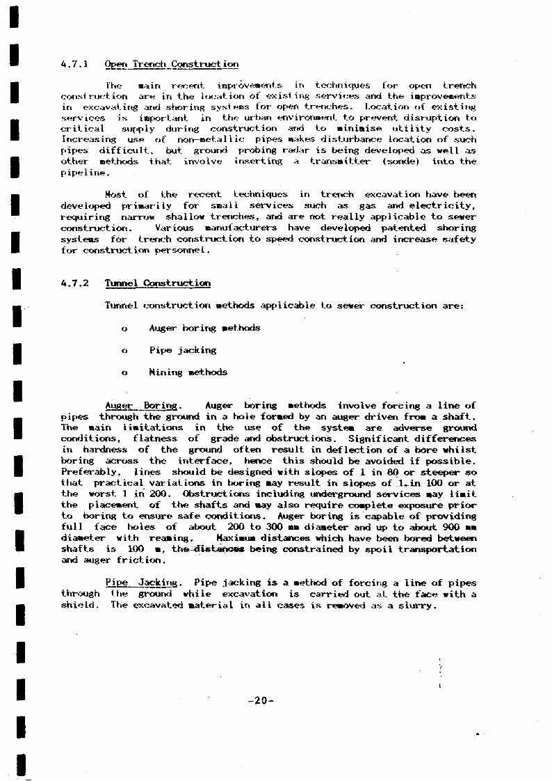
A. 7.1
The main recent improvements iri techniques for open trenchconstruction are in the location of existing .services and the improvementsin excavating and shoring systems for open trenches. Location of existingservices is important in the urban environment to prevent disruption tocritical supply during construction and to minimise utility costs,increasing use of non-metallic pipes makes disturbance location of suchpipes difficult, but ground probing radar is being developed as well asother methods that involve inserting a transmitter (sonde) into thepipeline.
Most of the recent techniques in trench excavation have beendeveloped primarily for .small services such as gas and electricity,requiring narrow shallow trenches, and are not really applicable to sewerconstruction. Various manufacturers have developed patented shoringsystems for trench construction to speed construction and increase safetyfor construct ion personne1.
4.7.2 Tunnel Construction
Tunnel construction methods applicable to sewer construction are:
o Auger boring methods
o Pipe jacking
o Mining methods
áuger Boring. Auger boring methods involve forcing a line ofpipes through the ground in a hole formed by an auger driven from a shaft.The main limitations in the use of the system are adverse groundconditions, flatness of grade and obstructions. Significant differencesin hardness of the ground often result in deflection of a bore whilstboring across the interface, hence this should be avoided if possible.Preferably, lines should be designed with slopes of 1 in 80 or steeper sothat practical variations in boring may result in slopes of 1-in 100 or atthe worst 1 in 200. Obstructions including underground services may limitthe placement of the shafts and may also require complete exposure priorto boring to ensure safe conditions. Auger boring is capable of providingfull face holes of about 200 to 300 mm diameter and up to about 900 mmdiameter with reaming. Maximum distances which have been bored betweenshafts is 100 m, the distances being constrained by spoil transportationand auger friction.
p.ÍE!e._¿2£k_ÍDS• Pipe jacking is a method of forcing a line of pipesthrough the ground while excavation is carried out at the face with ashield. The excavated material in all cases is removed as a slurry.
-20-

IIIIIIIIIIIIIIIIIIIII
the raethod oí excavation for conventional pipe jacking is by handbut sotae pipe jacking has been carried out using partial or full facemachines. Pipe jacking systems have been used with all types of shieldsarid machines, and jacking is now an alternative lining system for atunnel. Pipe jacks have been used in conjunction with most forms ofground stabilisation including compressed air, chemical consolidation anddewatering. Excavated material is removed by skip, conveyors or pneumatictransmission except in the case of slurry machines where the excavatedraaterial is removed in the slurry.
Shafts for pipe jacking can be of any shape or size necessary toaccommodate the permanent works and temporary jacking set-up. Theconventional form of pipe jacking can be carried out within shafts of upto 3 m diameter or sections 3 m by 2 m. A base heading may be necessaryat the bottom of the shaft to accommodate the jacking equipment.
In the UK tolerances on pipe jacks are generally specified as plusor minus 75 ma in line and 50 mm in level, although much closer tolerancesare normally achieved. As the limiting minimum diameter for conventionalpipe jacking is about 900 mm, the effective diameter of the fini-shedsystem can be reduced if required by either installing a smaller pipe orby reshaping the invert. A relatively recent development in pipe jackingis the fulIface remote control machine. These are manufactured by anumber of companies. In Japan such machines are in use for a range ofdiameters of 450 mm and larger but recent developments in Germany haveresulted in a machine capable of laying pipes 150 to 750 mm diameter.This latter machine jacks a large diameter (about 650 mm) pipe- and asmaller sleeve pipe is inserted enabling one machine to lay a variety ofpipe diameters. This is an advantage over conventional fullface machineswhich are generally used for a specific diameter.
The use of pipe jacking in urban areas is constrained by the needfor long jacking pits. These range from 7 to 9 « in length forconventional fulIface machines to 5 m for the German remote controlmachine, although German manufacturers are now attempting to limit the pitto A ra long by 3 m wide.
In Germany, tolerances for fulIface machine pipe jacking aregenerally limited to less than 30 mm in height and 100 mm in width fromthe specified axis. Machines are designed generally to drive -lengths of100 m of pipe.
All pipe jacking systems involve the purchase of expensivespecialised equipment, .and it is unlikely that any single local contractorvfill purchase the equipment without a specific contract on which it can beused. '- '•---• '~v- ? — '
Mitring Methods. Mining methods are generally applied to conduitswith finished diameters of 1.8 m or larger which are constructed usingshields, ful iface boring machines or by open face mining or heading.
With a shield it is necessary to install a primary lining ofsufficient strength to support the surrounding earth and to provide abackstop for the jacks which advance the shield. Boring machinesgenerally have cutters mounted on a rotating head which advances into theheading. Machines may be braced against the walls of the excavation orthe primary lining.
t
-21-
Upen î .•ju'., o nlríLrig is laatiual or la&chine assisted excavation withtinber or steel. supports for the excavation.
In all tunnelling systems a secondary lining is generallyinstalled for swers and is forned f ron precast or concrete gun i ting orpipes with the- outer voids, being grouted. Shafts are required forconstruction arid their number and location depend upon the need forcompressed air, the size of tunnel and depth below ground. Shafts do notneed to be located directly over the tunnel, they can be located in anadjacent area with access to the works through a short connecting tunnel.
-22-

IIIIIIIIIIIIIIIIIII
SECTION
PUMP STATIONS AND PRESSURE MAINS
Pump stations are required wherever the topography is too flat topermit gravity sewer construction and whenever it is necessary totransport flows against the natural grade for delivery of wastewater to atreatment plant or adjacent drainage area. Pump stations include bothlow-lift stations for puraping into a gravity system and pump stationsdelivering into pressure wains. Table 5.1 summarises the reconmendeddesign criteria for pump stations and pressure mains. Typical designs fordifferent types of pump stations ar& shown in Figures 5.1 to 5.4. Othersignificant principles for the design of wastewater pumping facilities aredescribed below:
o Purap stations should be either of the screw or centrifugal pumptype. Maximum lifts for single-stage screw pump stationsshould be up to 10 m but the maximum lift depends on screwdiameter, Where centrifugal pumps are necessary, submersibleunits can be used for a total station capacity (at peak flow)up to about 200 1/s. For larger stations wet-well/dry-wellsystems should be used.
o Pump station structures should be designed for the anticipateddesign year flow and initial pumping capacity should providefor flows expected no less than 10 years in the future.
o All fittings should be flanged and pipework should be offlanged ductile iron.
o To avoid potential flooding problems, pumps in dry well/wetwell configurations should either be driven by. vertical driveshafts with the motors located above flood levels or be sub-mersible motor, close-coupled pumps.
o The number of pumps should be such that the wet well volumedoes not became excessively large and the number of pump .startsdoes not exceed the manufacturers' recommended maximum.Variable speed pumps should generally be avoided although amore detailed analysis for individual pump stations should becarried out at detail design stage.
o Pump ofieration 'should be automatically controlled using a wet-well level sensing system which sequences pump operation withthe risa arid fall of the water surface.
o Maximum water level in the wet well should, when possible, beset no higher than the sewer invert.
o Pump stations should have sufficient capacity to deliver theexpected peak flow when one of the largest pump units is out ofoperation.
-23-
IIIIIIIIIIIIIIIIIIIII
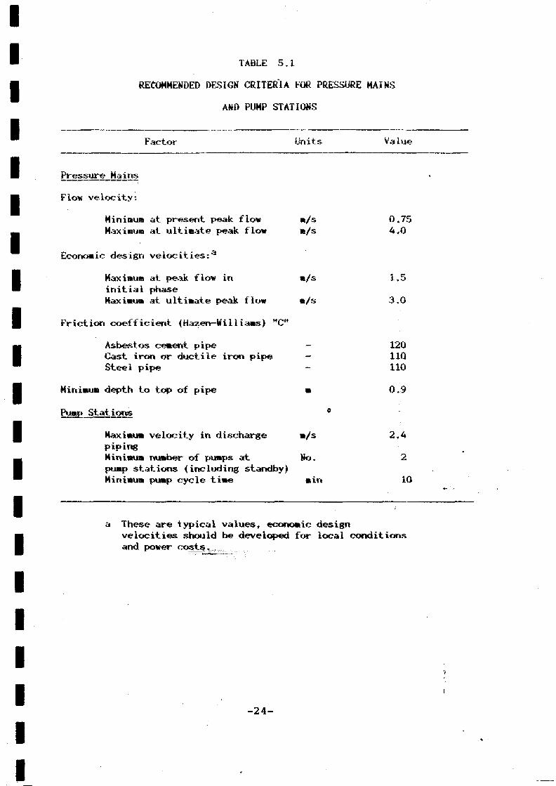
TABLE 5.1
RECOMMENDED DESIGN CRITERIA FOR PRESSURE MAINS
AND PUMP STATIONS
Factor
Pressure_Ma_ins
Flow velocity:
Minimum at present peak flowMaximum at ultimate peak flow
Economic design velocities:a
Maximum at peak flow ininitial phaseMaximum at ultimate peak flow
Friction coefficient (Hazen-Williams) "C"
Asbestos cement pipeCast iron or ductile iron pipeSteel pipe
Minimum depth to top of pipe
Pump Stations
Maximum velocity in dischargepipingMinimum number of pumps atpump stations (including standby)Minimum pump cycle time
Units
m/sm/s
m/s
m/s
-
m
9
m/s
No.
min
Value
0.754,0
1.5
3,0
12011Q110
0.9
2.4
2
10
a These are typical values, economic designvelocities should be developed for local conditionsand power costs, ,
-24-
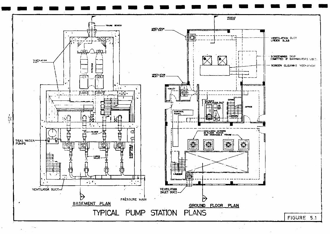
ItoenI
SEALPUMPS
VENTILATOR DUCT-
BASEMENT PLAN GROUND FLOOR PLAN
TYPICAL PUMP STATION PLANS
DUCTUflCCR SLAB
SCRECNMQS SKIP(OMITTED IF BARMINUTOR5 VJSF.D
SCREEN CLEANING MECHANiSM
FIGURE 5.1

EXT Bac TOR FANS
•—MECHAMLALLYCLEANED SCREOR SARMINUTOR
VEMTIL J~>ONINLET Sue:
.GROUND LEVEL
G.R.PVENTILATION«L£T DUCT
SECTION A - A
TYPICAL PUMP STATION SECTION
{NOT TO SCALE ) FIGURE 5.2
SUBMERSIBLESEWAGE PUMPS-
INLET SEWER ANO* DROP PIPE
'• £ * . ' .
-rti-
Li : 2
PLANPRESSURE MAIN
CONTROLPANEL - •+
GUIDES
LEVELCONTROLS-
CHECK VALVESLUICE VALVE
-SUBMERSIBLESEWAGE PUMP
SECTION
TYPICAL SUBMERSIBLE PUMP STATIONNOT TO C \LE ) j FIGURE 5.3 |
-27-

;NLET
to00
Q _
f//ft
rr
SECTION A - A
IT
I f) 1
STORAGEAND WORKSHOP
MOTORS ANDPftNELS
~1POWER
SUB STATION 'I
1
PLAN
TYPICAL SCREW PUMP STATION
1 NOT TO SCALE) FIGURE 5.4
IIIIIIIIIIIIIIIIIIIII
o Centrifugal pumps should have a speed no higher than 970rev/lain and should be suitably designed to avoid plugging orjamming by coarse solids arid pumps should be proceeded by trashracks to eliminate large solid materials. Size of trash rackopenings will depend on pump size but will generally be between50 to 150 mm.
o Wet well hoppers should be built with slopes no flatter than 2horizontal to 1 vertical and preferably steeper.
o Wet well areas should be adequately ventilated for safety ofoperation and odour control. Dry well areas should haveventilation to provide a safe and appropriate workingenvironment.
o Major pump stations should be provided with electricity fromtwo independent, sources (looped supply) and be given priorityrestoration by the power authority when outages do occur. Whensecurity of electrical power supply cannot be assured, the useof standby generators or engine drives as well as in—systemstorage and by-pass should be considered. By-passed dischargesunder emergency conditions should be directed to a suitablepoint of disposal.
o Staged construction of pressure mains and installation of pumpstation equipment should be considered in situations where theultimate flows greatly exceed present flows. Where recommendeddesign velocities cannot be achieved with a single pipeline,staged construction should be evaluated.
o Surge relief should be provided as required at each pumpstation.
o Ideally, pressure mains should be built with a risinggradient. Air release valves should be provided at high pointsand washouts at low points.
Submersible pumps should be fixed speed and a standby unit shouldbe provided. The pumps should be able to allow 100 mm objects to passwithout clogging. Pump speeds should be no higher than 1500 rev/min andpreferably lower than 970 rev/min.
-29-

IIIIIIIIIIIIIIIIII
SECTION
WASTE!WATER TREATMENT SYSTEMS
The bases for selection and comparison of alternative wastewatertreatment systems include cost, ease of operation and Maintenance,adaptability, land requirement and ease of expansion or modification.
Treatment systems for organic wastes such as sewage can becategorised as fixed or suspended growth systems. The followingdiscussion covers the range of available processes but emphasis is givento stabilisation pond processes which are highly appropriate for climaticconditions in most of Sri Lanka and are the least onerous in terms ofoperation and maintenance and sludge disposal.
6• * Preliminary Treatment
All treatment systems are preceeded by screening and flowmeasurement. In addition activated sludge and biological filtrationsystems will be preceeded by grit removal facilities. Typical designcriteria for screening and grit removal are as follows:
Screens Limiting velocity 1 m/sOpening 20 mm
Aerated > Retention at peak flow 3 minGrit )Chamber ) Depth: width ratio 1: 2
6.2 Fixed Growth Systems
There are basically two .types of fixed-growth systems: thebiological (trickling) filter and the rotating biological contactor (RBC)v
In the former, the sewage is distributed such that a thin film of liquidpasses over a fixed medium. Air, passing through voids in the medium,diffuses through the liquid to the biomass film. The RBC rotates thinplastic discs to which the microorganisms are attached, through a tankcontaining the sewage.
6.2.1 Biologica1_FiIters
Th*.* biological filter consists of a bed of medium such as rock,slag or plastic through which settled sewage trickles. Sewage is appliedto the m«^iiim through ;t travelling distributor. Biological growths becomeattached to, and fOri» a slime layer over, the tiedium.
^" ««iKierdrairi system collects the treated wastewater and anydetached M«»logical s o u d s and the effluent is then further treated. Theundordrairi *tyste» is also important as a porous structure through which,ilr cm Ciri-M\tf_e to keep the bed aerobic.
-30-

IIIIIIIIIIIIIIIIIIIII
The systems considered require preliminary treatment, primary andsecondary settlement and sludge treatment, Recommended design criteria.ate set out in Table 6-1 and a typical flow diagram is shown in Figure6.1. Filters incorporating a plastic medium are generally up to 8 m deepwhile filters incorporating a rainerai medium are generally about 2 mdeep. The specific surface areas of different media vary from about 69ra2 /ET* for crushed gravel to about 240 m*/» for plastics. Becauseplastic medium has a higher cost per unit volume compared to mineralmédium, plastic medium filters are often used for treatment of highstrength industrial wastes or for partial treatment of strong domesticsewage where advantage can be taken of their properties of high voidageand specific surface area. However, they are also widely used fortreating normal strength domestic sewage where land is not available formineral medium filters.
6.2.2 Rotating Biological Contactors
The rotating biological contactor takes the form of a series ofclosely spaced circular discs mounted on a shaft. The assembly issubmerged, almost to shaft level, in a trough through which wastewaterpasses. The shaft is rotated slowly in the direction of the wastewaterflow.
Biological growths become attached to the surfaces of the discsand eventually form a slime layer (biomass) over the disc. The rotationeffects oxygen transfer, keeps the biomass in an aerobic condition andalso causes excess biomass to slough from the discs into the mixed liquorand out of the process basin. This sloughing maintains a uniformly thickbiomass and prevents clogging of the discs. Some RBC manufacturers addair to the trough to cause rotation of the discs and to increase thedissolved oxygen content of the mixed liquor.
The systems considered require preliminary treatment, primary andsecondary settlement and sludge treatment. Recommended design criteriaare set out in Table 6.1 and a typical flow diagram is.shown in Figure6.1.
Plant sizes, in population equivalents, exist from 300 and smallerto 400 000 with the most common applications in the 5000 to 20 000 range.For packaged plants a balancing tank is generally required where the peakto average flow is more than 2.5 to 1.
6-3 Suspended firowttrSystems
In high-rate growth systems, oxygen for the biological processmust be supplied by mechanical means. This is the primary differencebetween high-rate suspended growth systems and comparable fixed growthsystems. In low-rate suspended growth systems (stabilisation ponds),oxygen is supplied by natural surface re-aeration from wind and byphotosynthesis of algae.
-31-

IIIIIIIIIIIIIIIIIIII
TABLE 6.1
DESIGN CRITERIA FOR FIXED GROWTH SYSTEMS
Process
Primary Settlement
Rotating BiologicalContactor
Biological Filter(mineral medium)
Biological Filter(plastic medium)
Secondary Settlement Tank
Parameter
Overflow rate atpeak flowRetention at peakflowWeir loading atpeak flow
BOD specific loadingTank volumeMaximum disc dia.Maximum peripheralvelocity
Organic loadingHydraulic loading
Organic loading
Hydraulic loading
Overflow rate atpeak flowRetention at peakflowWeir loading
Design Criteria
60 «3/«*.^
1 h
500 m3/m.d
15 to 20 g/d. »a
5 l/d. »a
3600 mm0.3 m/s
0.1 kg BOD/d. m3
1 m3/ma.d
1 to 5 m3
36 to 72 m3/ma.d
32 m3/ma .d
1.5 h
200 m3/m.d
Filter depths typically 1.6 m for mineral medium and 6 to 6 m forplastic medium.
For nitrification using RBCs the hydraulic loading rate on thenitrifying d«cs should 'be limited to about 0.05 m3/ma.dmedium surface.
For nitrification with mineral and plastic medium filters providea second filter with a maximum hydraulic load of 0.75 wr/m? .dand 30 ra3/m3.d respectively.
-32-

RAW SEWAGE.fNLET
, «RÎTRtMOVAL, FLOWMEASUREMENT
I RETURN1 LIQUOR
I
L.
GRAVITY SLUDGETHICKENER
J
PRIMARY SETTLEMENTTANK
ALTERNATIVE
SURPLUS SLUOGETO TREATMENT
Fri nPUMP
STATION1
ROTATINGBIOLOGICALCONTACTOR
BK31O6KALFILTER
RETURN SLUDGEPUMP STATION
1 L_
FLOWDISTRIBUTION
SECONDARYSETTLEMENTTANK
EF-LUEir
FLOW DIAGRAM FOR BIOLOGICAL FILTER TREATMENT SYSTEMS
FIGURE 6.1

IIIIIIIIIIIIIIIIIIIII
6.3.1 Activated_Sludge_Sy_stems
Conventional Activated §,iydg_e. Prior to aeration preliminarytreatment is effected by screens and grit removal after which the sewageis settled in primary settlement tanks to remove gross solids. The sludgeremoved is then further treated before ultimate disposal. Effluent fromthe primary settlement tanks then passes to the aeration tanks.
Retention in the aeration tanks is between 6 and 6 hours and thesludge age is normally between 4 and 6 days. Recommended design criteriaare set out in Table 6.2 and a typical flow diagram is shown in Figure6.2.
Oxygen. Enriched_-Activated Sludge. This process is similar to theconventional activated sludge process but the aeration tanks are usuallycovered, and high purity oxygen is fed into the tanks. Mixing isgenerally by mechanical aerators, although an alternative system uses finebubble diffusers to inject oxygen into the mixed liquor in open tanks.The mixed liquor suspended solids are higher than in conventionalactivated sludge and the retention time in the tank is shorter.
Oxygen is generated using either cryogenic or PSA (molecularsieve) techniques depending upon oxygen output requirements.
The system requires primary and secondary settlement and sludgetreatment. Recommended design criteria are set out in Table 6.2 and atypical flow diagram is shown in Figure 6.2.
There atre more than 100 oxygen enriched plants in operation aroundthe world, but they are sophisticated and require experienced operationspersonnel and are not recommended for domestic sewage treatment in SriLanka at the present time.
Deep Shaft Process. This process is a high intensity oxygentransfer system which exploits the high hydrostatic pressure, long gas-liquid contact time, small bubble size and high but uniform turbulencewithin a deep shaft typically 60 m deep. The system is a proprietarysystem.
Sewage is circulated through a downcomer to the bottom of theshaft and returns through a concentric outer or adjacent riser shaft. Airis introduced part way down the downcomer. Mixed liquor overflowing fromthe shaft contains micro-bubbles and must be passed through a bubblerstripper before settlement. New process designs by the manufacturers nowreduce the volume of-the shaft and replace the bubble stripper by anaeration tank followed by conventional settlement tanks. Some systems useflotation thickeners for separation of the suspended biomass. Returnactivated sludge is recirculated to the shaft.
The process requires primary and secondary settlememt and sludgetreatment- Recomiaended design criteria are set out in Table 6,2 and atypical flow diagram is shown in Figure 6.3.
-34-
IIIIIIIIIIIIIIIIIIIII
TABLE 6.2
DESIGN CRITERIA FOR ACTIVATED SLUDGE TREATMENT
Process
Primary SettlementTank
ConventionalAeration Tanks
Secondary SettlementTanks
Oxygen systemAeration Tanks
Secondary SettlementTanks
Deep Shaft System
Parameter
Overflow rate
Retent ion
Weir loading
Organic loadingMixed liquorsuspended solidsOxygen requirement
Retention period
Overflow rate
Retention
Weir loading
Organic loadingMixed liquorsuspended solidsOxygen requirement
Retention period
Overflow rateRetent ion
Weir loading
Organic loadingMixed liquorsuspended solidsOxygen requirement
Depth
Hydraulic loadingrate < secondarysettlement tank)
Design Criteria
60 m3/aa .d atpeak flow1 h at peak flow
500 m3/m,ol-atpeak flow
0.4 kg BOD/kg MLSS2000 mg/1
1.0 kg 02/kg BOD
removed3
6 h b
100 kg/d.ma
equivalent to 40
2500 mg/11.5 h at peak flow
200 m3/a.dpeak flow
0.6 kg BOD/kg MLSS5000 mg/1
1 kg O2/kg BOD
removed2 h
40 irVm^.d1.5 h at peak flow
200 m3/m.dpeak flow
1 kg BOD/kg MLSS4000-6000 mg/1
1 kg 02/kg BOD
appliedTypically 60 m
24 a3/m*.dpeak flow
v
-35-

IIIIIIIIIIIIIIIIIIIII
TABLE 6.2
DESIGN CRITERIA FOR ACTIVATED SLUDGE TREATMENT(continued)
Process
Ox idation Ditch
Parameter
Minimum Retention PeriodLiquid DepthOrganic LoadingRateMixed Liquorsuspended solidsAeration Requirement
Sludge Age
Hydraulic LoadingRate (secondarysettlement tank)
Design Criteria
1 dUp to A n0.15 kg BOD/d. kgMLSSS3000 to 6000 mg/1
2 kg 02/kg BOD
applied20 - AO d
22 m3/»2,dat pe^k flow
a. For nitrification additional oxygen requirement of A.25 kg/kgammonia nitrogen.
b. 8 h for nitrification.
-36-

ALTERNATIVE
OXYGEN(FOR OXYGEN ENRICHEDACTIWTED SLUDGE OPTION!
RAWSEW&GEI H E f
SCREENS, GRITREMOVAL, FLOWME A SORE.V c NT
PRIMARY SETTLEMENTTANK
AERATIONTANKS Jn n nvn
I rFLOWDISTRIBLmON/-
SECONDARYSETTLEMENTTANK
LRETURNLIQUORS
GRAVITYSLUDGETHICKENER
MECHANICALSLUDGETHICKENER
RETURN SLUDGE
RETURN SLUDGEPUMP STATION
CHEMICALFLOCCULANTS
SURPLUS SLUDGETO TRFATMENT
FLOW DIAGRAM ACTIVATED SLUDGE TREATMENT SYSTEMS
EF-LJEV"
FIGURE 6.2

R/VA' 5CWAGEINLET
SCREEN, GRITREMOVAL, FLOWMEASUREMENT DEEP SHAFT 8UBBLE
STRIPPERFINAL SETTLEMENT
TANK
SURPLUS SLUDGETO TREATMENT
CHEMICALFLOCCULANTS
EFFLUENT
MECHANICALSLUDGETHICKENER RETURN SLUDGE
PUMP STATION
FLOW DIAGRAM DEEP SHAFT TREATMENT SYSTEM
FiGURE 6.3
IIIIIIIIIIIIIIIIIIIII
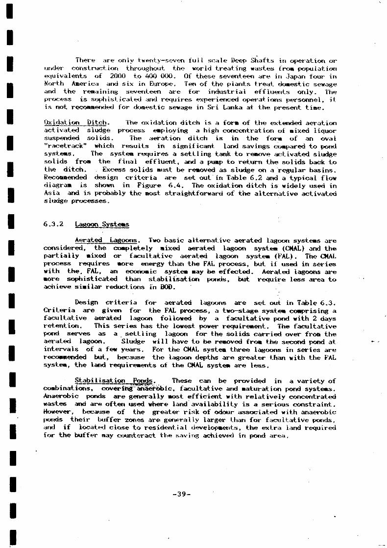
There are only twenty-seven full scale Deep Shafts in operation orunder construction throughout the world treating wastes fro» populationequivalents of 2000 to 400 000, Of these seventeen are in Japan four inNorth America and six in Europe. Ten of the plants treat domestic sewageand the remaining seventeen are for industrial effluents only. Theprocess is sophisticated arid requires experienced operations personnel, itis not recommended for domestic sewage in Sri Lanka at the present time.
Oxj.datj.on Ditch. The oxidation ditch is a form of the extended aerationactivated sludge process employing a high concentration of mixed liquorsuspended solids. The aeration ditch is in the form of an oval"racetrack" which results in significant land savings compared to pondsystems. The system requires a settling tank to remove activated sludgesolids from the final effluent, and a pump to return the solids back tothe ditch. Excess solids must be removed as sludge on a regular basins.Recommended design criteria are set out in Table 6.2 and a typical flowdiagram is shown in Figure 6.4. The oxidation ditch is widely used inAsia and is probably the most straightforward of the alternative activated.sludge processes.
6.3.2 Lagoon Systems
Aerated L-JS00™5- Two basic alternative aerated lagoon systems areconsidered, the completely mixed aerated lagoon system (CMAL) and thepartially mixed or facultative aerated lagoon system (FAL). The CMALprocess requires «ore energy than the FAL process, but if used in serieswith the. FAL, an economic system may be effected. Aerated lagoons aremore sophisticated than stabilisation ponds, but require less area toachieve similar reductions in BOD.
Design criteria for aerated lagoons are set out in Table 6.3.Criteria are given for the FAL process, a two-stage system comprising afacultative aerated lagoon followed by a facultative pond with 2 daysretention. This series has the lowest power requirement. The facultativepond serves as a settling lagoon for the solids carried over fro» theaerated lagoon. Sludge will have to be removed from the second pond atintervals of a few years. For the CMAL system three lagoons in series arerecommended but, because the lagoon depths are greater than with the FALsystem, the land requirements of the CMAL system are less.
Stabilisation Ponds. These can be provided in a variety ofcombinations, covering anaerobic, facultative and maturation pond systems.Anaerobic ponds are generally most efficient with relatively concentratedwastes and are often used where land availability is a serious constraint.However, because of the greater risk of odour associated with anaerobicponds their buffer zones are generally larger than for facultative ponds,and if located close to residential developments, the extra land requiredfor the buffer may counteract the saving achieved in pond area.
-39-
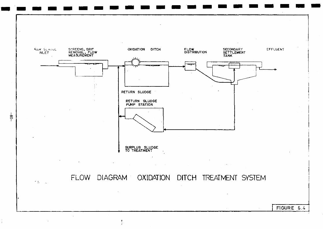
INLET
O
SCREENS, GRITREMOVAL, FLOWMEASUREMENT
OXIDATION OITCH FLOWDISTRIBUTION
SECONDARYSETTLEMENTTANK
EFFLUENT
RETURN SLUDGE
RETURN SLUDGEPUMP STATION
SURPLUS SLUDGETO TREATMENT
FLOW DIAGRAM OXIDATION DITCH TREATMENT SYSTEM
FIGURE 6.

1111111'11111111111111
TABLE 6
DESIGN CRITERIA FOR
Parameter
Facultative Aerated Lagoon System FAL^
Aerated Lagoon:
Minimum detention periodMaximum liquid depth
Minimum mixing powerOxygen requirement
Approximate BOD removalDissolved oxygen concentrationEmbankment protective lining(inner slopes)
Minimum freeboard
Facultative Lagoon (solids collection):
Minimum detention periodLiquid depth
Complete Mix Aerated Lagoon System (CMAL
Aerated Lagoon:
Minimum detention periodMaximum liquid depth
Power requirement
Primary Aerated Facultative Lagoon:
Minimum detention periodMaximum liquid depth
Power requirement
Secondary Aerated Facultative Lagoon(solids collection):
Minimum detention periodMaximum liquid depth
Power requirement
Overall BOD removal
-41-
.3
AERATED LAGOONS
Design Criteria
2.5 d4 m
5 W/ m3 lagoon volume0.8 to 1.2 kgconsumed/kg BOD removed60? to 70?2 mg/1Cemented rip-rap, 0.3 mthick extending from topto bottom of embankmentslope1.0 m
2.0 d2.0 m
)
1.4 d5 m6 W/m3 lagoon volume
1.8 d4 m
2 W/m3 lagoon volume
1.0 d4 m
0.8 iV/w*lagoon volume
6O-7ÛSS
IIIIIIIIIIIIIIIIIIIII
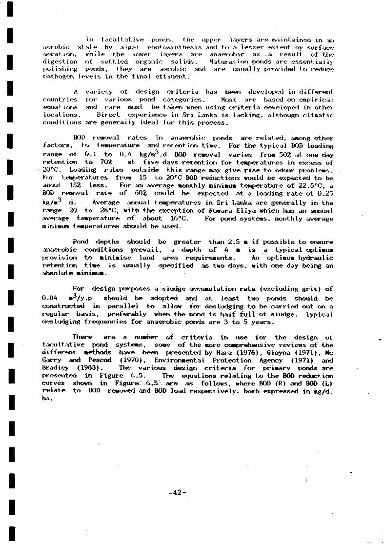
In facultative ponds, the upper layers are maintained in anaerobic state by algal photosynthesis and to a lesser extent by surfaceaeration, while the lower layers are anaerobic as -a result of thedigestion of settled organic solids. Maturation ponds are essentiallypolishing ponds, they are aerobic and are usually provided to reducepathogen levels in the final effluent.
A variety of design criteria has been developed in differentcountries for various pond categories. Most are based on empiricalequations arid care must be taken when using criteria developed in otherlocations. Direct experience in Sri Lanka is lacking, although climaticconditions are generally ideal for this process.
BOD renoval rates in anaerobic ponds are related, anong otherfactors, to temperature and retention time. For the typical BOD loadingrange of 0.1 to 0.A kg/®3.d BOD removal varies from 50$ at one dayretention to 70% at five days retention for temperatures in excess of20°C, Loading rates outside this range may give rise to odour problems.For temperatures from 15 to 20°C BOD reductions would be expected to beabout 15% less. For an average monthly minimum temperature of 22.5°C, aBOD renoval rate of 60% could be expected at a loading rate of 0,25kg/»'3 d. Average annual temperatures in Sri Lanka are generally in therange 20 to 28°C, with the exception of Kuwara Eliya which has an annualaverage temperature of about 16°C. For pond systems, monthly averageminimum temperatures should be used.
Pond depths should be greater than 2.5 m if possible to ensureanaerobic conditions prevail, a depth of 4 m is a typical optimumprovision to minimise land area requirements. An optimum hydraulic-retention time is usually specified as two days, with one day being anabsolute minimum.
For design purposes a sludge accumulation rate (excluding grit) of0.04 m^/y.p should be adopted and at least two ponds should beconstructed in parallel to allow for desludging to be carried out on aregular basis, preferably when the pond is half full of sludge. Typicaldesludging frequencies for anaerobic ponds are 3 to 5 years.
There are a number of criteria in use for the design offacultative pond systems, some of the more comprehensive reviews of thedifferent methods have been presented by Mara (1976), Gloyrta (1971), MeGarry and Pescod (1970), Environmental Protection Agency (1971) andBradley (1963). The various design criteria for primary ponds arepresented in Figure 6.5. The equations relating to the BOD reductioncurves shown in Figure- 6«5 are as follows, where BOD (R) and BOD (L)relate to BOD removed and BOD load respectively, both expressed in kg/d,ha.
-42-

lOO
200 300 400 500 600
BOD LOAD - kg /d . ha.
700 800
COMPARISON OF DESIGN EQUATIONSFOR BOD REMOVAL IN
PRIMARY FACULTATIVE PONDS
9 0 0 1000
FIGURE 6.5
IIIIIIIIIIIIIIIIIIIII
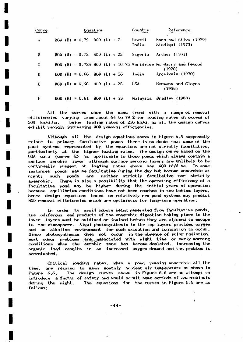
Curve Equation GiÜitltEy. BSÎSLËO^^
A BOD (R) = 0.79 BOD <L) + 2 Brazil Mara and Silva (1979)India Siddiqui (1973)
B BOD (R) = 0.73 BOD (L) + 25 Vigeria Arthur (1981)
C BOD (R) =0.725 BOD <L> + 10.75 Worldwide Me Garry and Pescod
(1970)D BOD (R) = 0.68 BOD (L) + 26 India Arceivala (1970)
E BOD (R) = 0.60 BOD (L) + 25 USA Hermann and'Gloyrta(1956)
F BOD <R> = 0.61 BOD <L> + 13 Malaysia Bradley (1983)
Ail the curves show the same trend with a range of removalefficiencies varying fro» about 64 to 79 % for loading rates in excess of500 kg/d.ha. Below loading rates of 250 kg/d. ha all the design curvesexhibit rapidly increasing BOD removal efficiencies.
Although all the design equations shown in Figure 6.5 supposedlyrelate to primary facultative ponds there is no doubt that some of thepond systems represented by the equations are not strictly facultative,particularly at the higher loading rates. The design curve based on theUSA data (curve E) is applicable to those ponds which always contain asurface aerobic layer although surface aerobic layers are unlikely to becontinually present at loading rates above say 400 kd/d.ha. In someinstances ponds may be facultative during the day but become anaerobic atnight; such ponds are neither strictly facultative nor strictlyanaerobic. There is also a possibility that the operating efficiency of afacultative pond may be higher during the initial years of operationbecause equilibrium conditions have not been reached in the bottom layers,hence design equations based on relatively new pond systems may predictBOD removal efficiencies which are optimistic for long-term operation.
In order to avoid odours being generated from facultative ponds,the odiferous end products of the anaerobic digestion taking place in thelower layers must be oxidised or ionised before they are allowed to escapeto the atmosphere. Algal photosynthesis in the top layers provides oxygenand an alkaline environment for such oxidation and ionisation to occur.Since photosynthesis does not occur in the absence of solar radiation,most odour problems -arsu™associated with night time or early morningconditions when the aerobic zone has become depleted. Increasing theorganic load results in an increased oxygen demand and the problem isaccentuated.
Critical loading rates, when a pond remains anaerobic all thetime, are related to mean monthly anbient air temperature as shown inFigure 6.6. The design curves shown in Figure 6.6 are an attempt tointroduce a factor of safety and would permit some periods of anaerobiosisduring the night. The equations for the curves in Figure 6.6 are asfollows:
-44-

I 00 2 0 0 3OO 4OO 5 0 0 6 0 0 7 0 0 8 0 0 9O0 lOOO
BOO LOADING (Li) - k g / d . ho.
RECOMMENDED MAXIMUM BOD LOADS TO PRIMARYPONDS AS A FUNCTION OF TEMPERATURE
FIGURE 6.6

Curve
Critical. A
Design B
Critical C
Design D
Des ign E
ion
BOD (I) - 25.6T + 75
BOD (L) = 22T + 65
Arthur (1961)
Arthur (1961)
BOD (L) = 11.2 <1.05A>T Mc Garry -and Peseod(1970)
BOD (L) = 7.5 (1.054)T Mara (1976)
BOD <L> = 20T - 120 Mara (1976)
Temperature in °F for equations C and DT in °C for others
It is apparent fro» Figure 6.6 that for a mean minimum temperatureof 25°C (Colombo area), recommended design loads would be from about 375to 625 kg/d. ha, allowing for some hours of anaerobios is, with a criticalmaximum loading being in the range 650 to 720 kg/d.ha. For locations inthe Nuwara Eliya area design and critical loadings would be of the orderof 125 and 200 kg/d,ha.
For single facultative ponds or primary facultative ponds in aseries of ponds it is recommended that if odour problems are to beminimised the pond should be designed on the basis of the mean minimummonthly temperature with the average organic loading not exceeding say 250kg/d.ha in the Colombo area. If occasional odours can be tolerated, thesewill usually occur just before dawn, the average loading can be increaedto say 500 kg/d. ha. Odours could be expected to occur f or about a 4-hourperiod every day at this loading, during the coldest, most cloudy months.
It is recommended that for both loading rates, an average BODremoval of 752: be assumed. This is similar to that suggested by Arthur(1983) in the most recent World Bank guidelines for pond design in warmclimates, where a "safe" design load of 390 kg/d. ha is proposed for atemperature of 22.5°C. Safe in this context refers to complete failure,some period of odour release would still be expected.
Primary pond volumes should be based on a depth -of 1.5 m with aminimum hydraulic retention time of 5 days. The water depths should notbe less than 1.0 m to prevent vegetation growth on the pond bottom. Thefirst part of the pond should be deepened (say over one quarter of thelength) to allow iorjsludge accumulation. An additional depth of up to2.5 n could be provided. Floating material in the feed sewage can best betrapped by a baffled entrance.
Sludge accumulation should be based on 0.04 «rVy.p. For largeponds, sludge removal can be achieved by pumping from a pontoon, for smallponds draining and allowing to dry by evaporation is probably morepracticable. Deslodging frequencies are typically once every 15 to 20years for primary facultative ponds based on sludge being removed when itoccupies up to one half of the f»ond volune. Secondary facultative pondsshould not need deslodging. In order to permit sewage to be treatedduring desludging two primary tonds should be provided in parallel and
i
-46-

IIIIIIIIIIIIIIIIIIIII
sized so that if one pond is decommissioned for desludging the other pondwill not be. loaded to such an extent that the. critical loading rate isreached. In order to minimise costs only one train of ponds need beprovided if they are temporary or to be expanded within say ten years.
Kone of the design equations are suitable for secondaryfacultative ponds in a series because BOD removal rate constants insecondary ponds are considerably less than those in primary ponds. On thebasis of an average recommended design removal rate in primary ponds of752, it is suggested that the secondary pond renoval rate be taken as 40£to give an overall BOD removal in a two-series system of about 85?;.Recommended loading rates for secondary ponds in climatic conditionssimilar to Colombo should be taken as 175 kg/d, ha for low-load systemsand 250 kg/d. ha for high-rate systems.
Design depths of secondary ponds can be taken as 1.5 m, surfacedimensions may be the same as for the primary ponds but if BOD removal isto be optimised then the secondary pond should have a smaller area thanthe primary pond, subject to the recommended loading rates not beingexceeded and the hydraulic retention time not being less than 3 to 5 daysin order to allow for reasonable bacterial removal.
Maturation ponds are provided to reduce pathogen levels, the bulkof the BOD renoval having been achieved in the preceeding ponds. As aresult, maturation ponds should not be taken into account in calculatingoverall BOD reduction.
The faecal coliform removal in a series of ponds is expressed bythe following;
FC(1 + kb tt> (1 -I- Kb t¿>
where PC(E) = faecal coli. in the effluentFC(I) = faecal coli. in the sewage feedKb = bacterial removal rate constantt^,t2 = hydraulic retention time in pond 1,
pond 2
The bacterial removal rate constant is related to temperature asfollows:
Kb(T> = 2.6 (1.19)T-20
where T = design temperature ("C>
Depths of maturation ponds are typically 1.0 to 1.5 m with anabsolute minimum detention time of 3 days, preferably 5 days. Designcriteria for stabilisation pond systems are summarised in Table 6.4.
-47-

111111111111111111111
TABLE
DESIGN CRITERIA FOR !
Parameter
Anaerobic
Loading rateHydraulic retentionWater depth
Sludge accumulationBOD removal
Preferred surface loading rate
Maximum surface loading ratea
MiniBUR detention periodMaximum liquid depthMinimum freeboardEmbankment protective lining(inner slope)
Embankment protective lining(outer slope)
Liquid seal liningSewage inlet and outlet structuresExpected BOD removal
Sludge accumulation rate
Second Stage Facultative
Preferred surface loading rateMaximum surface loading rateMinimum detention periodExpected BOD removal -- -^Other physical parameters
-48-
<
6.4
STABILISATION PONDS
Design Criteria
•
0.25 kg BOD/d. m3
2 d (absolute min. I d )2.5 - 4.0 m
0.04 m3/y. p60?> (at 22.5°C)
250 kg BOD/d. ha
500 kg BOD/d. ha5 d1.5 m0.5 mCemented rip-rap, 0.3 mthick extending from top ofembankment to minimum of 0.5 mbelow liquid surfaceTurfing and/or rip—rapif subjected to external waterwave action
Clay or polyethylene sheetsMultiple75?>0,04 B3/y.p
175 kg BOD/d. ha250 kg BOD/d. ha5 d
m%As for first stage
i
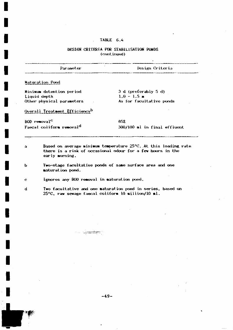
IIIIIIIIIIIIIIIIIII
TABLE 6.4
DESIGN CRITERIA FOR STABILISATION PONDS(continued)
Parameter Design Criteria
Maturation Pond
Minimi» detention periodLiquid depthOther physical parameters
BOD removaIe
Faecal colifor* removal
3 d (preferably 5 d)1.0 - 1.5 aAs for facultative ponds
85?,
300/100 ml in final effluent
Based on average minimum temperature 25 °C. At this loading ratethere is a risk of occasional odour for a few hours in theearly morning.
Two-stage facultative ponds of same surface area and onematuration pond.
c
d
Ignores any BOD removal in maturation pond.
Two facultative and one maturation pond in series, based on25 °C, raw sewage faecal coliform 10 «ii lion/10 ml.
-49-
IIIIIIIIIIIIIIIIIIIII
6.4
If it is necessary to achieve an effluent BOD lower than 20 ntg/1 atertiary treatment process should be employed. The most effective unit isa rapid gravity sand filter comprising sand of 0.8 to 1.7 mm nominaldiameter at a depth of up to 1,5 m. Design maximum flow .should be limitedto 165 nrVm2 -d and an operating head of 3 to 4 n is necessary.Backwashing using sand filter effluent should be carried out daily at arate of 10 1/s. a2, the cleaning efficiency can be improved if air scouris added, a typical air flow rate being 20 l/s,ma. BOD and SS reductionsof 70 and 8O5S respectively can be attained but there is usually areduction in DO of about 4 mg/1 as a result of biological activity in thesand bed.
6,5 Proprietary Treatment Syst
A package sewage treatment plant is usually defined as a sewagetreatment plant which is fabricated at the factory and is taken to thesite as a complete unit ready for use. Many proprietary systems areavailable in package plant form for lower flows and as an equipmentpackage for irte lus ion in concrete tanks for larger f loves. Many systemsare variations of well-established processes such as extended aeration andRBCs, while some rely on specific patented items or process. Some of theprocesses mentioned in the previous sections are proprietary systems i.e.Deep Shaft and the various oxygen-enriched activated sludge systems e.g.Unox, Oasis, Megox. The two most common proprietary systems are based onthe extended aeration and RBC process. Extended aeration systems areavailable from a number of manufacturers in package treatment plantshandling wastes from populations up to about 4000,
The system is similar to the oxidation ditch system whichnecessitates a relatively low organic loading and long aeration time.Sewage after screening is fed into the aeration tank which is followed bya settlement tank fro» where sludge is returned to the aeration tank.Surplus sludge is diverted for further treatment. Various manufacturersprovide different configurations e.g., separate aeration and settlementtanks (Simon Hartley) and concentric aeration and settlement tanks (Inka).Numerous plants are in operation around the world. The contactstabilisation process is a variation of the extended aeration process andhas been proven to be an effective treatment system in nany countries.Proprietary contact stabilisation plants are available to treat wastesfrom populations up teFMFÖÖÖ^or more.
The system concepts for package RBC units are the same asdescribed in Section 6.3.1 but various manufacturers have developedpackage plants with different settling compartment and sludge handlingconfigurations. Systems are available up to aroud 1100 m' /d capacity aspackage plants. Sludge requires further treatment. The systems arerelatively simple to maintain with the only moving parts being the shaftand in some systems, an integral sludge scraper.
-50-

IIIIIIIIIIIIIIIIIIII
- 6
A H treatment systems produce sludge which raust be disposed of ina nariner which does not give rise to nuisance or public health probleos.The quantity of sludge depends on the treatment systera; typical valuesrange from about A w^/d for 1000 persons for an oxidation ditch processto less than 0,1 ra^/d for 1000 persons with oxidation ponds.Screenings, in addition, would amount to about 0.01 m'Vd P e r 1000persons and grit quantities to about 0.05 «rVd per 1000 persons.
Typical sludge production rates would be as follows for treatpentsysteras designed to produce a final effluent BOD of 20 »g/l (30 »g/l foroxidation ponds). The sludge quantities include primary and excessbiological sludge:
Process
Pri»ary Settlement 0,04
Activates Sludge:
Conventional 0.06
Oxygen-enr iched 0.06
Deep Shaft 0.07
Oxidation Ditch 0.02
Bi lological Filters, RBCs 0.05
Oxidation Pond 0.005
For disposal of sludge the following factors for* the basis of alldesigns:
o There should be no hazard to the health of the public andworkers at the site of disposal,
o The deposited sludge should not cause nuisance fro» insects orrodents, neither should there be nuisance fro» odours,
o The deposited sludge should not cause ground or surface waterpollution.
o After tipping the deposited sludge must remain fir» andcompact.
o „ The sludge can be disposed of either in a liquid for» or forlandfill in dewatered for».
Digestion will destroy the readily putrescible organic »atter inthe primary sludge together with a large number, but not all, of thepathogenic micro-organisms. As a result, digested sludge should not causenuisance from insects, rodents or odours and it will constitute a greatlyreduced health hazard. Sludge fro» lagoon systems is essentially digestedwhen it is removed.
-51-

IIIIIIIIIIIIIIIIIIIII
The basic methods available for processing the sludge prior tolandfilling are air drying with or without prior mechanical dewatering,mechanical dewatering alone, or incineration. For a given sludge, thetexture and dryness of the dewatered sludge are dependent, upon theparticular dewatering process used and the type of conditioning, if any,adopted, i.e. each of the mechanical methods of dewatering sludges do notproduce sludge cakes of the sane dryness, and certain types ofconditioning are not suitable to some dewatering processes. In addition,some conditioners, e.g. lime, will destroy a large number of the micro-organisms in the sludge, so reducting further the public health hazard.The use of polymers in dewatering requires that the sludge be previouslydigested to reduce the problems of odours and decomposition at theultimate disposal site. If disposal of liquid sludge to land is feasible,digestion would not be necessary from aerated lagoons or from activatedsludge processes with long sludge rige», i.e. oxidation ditches.
Recommended design criteria are set out in Table 6,5 and typicalflow diagrams are shown in Figure 6.7.
Digestion of sludge can be in unheated tanks which underconditions similar to the Colombo area should ensure mesophilic digestion.Gas production should be adequate for power generation of about 0.12kWh/m^ of sewage treated based on a gas production of 1.0 »** for eachkilogram of volatile matter destroyed, and an energy value of 22 MJ/m°of gas.
6.7 Miscellaneous Design Criteria
6.7.1. Odour Control
Preliminary facilities should be grouped together in a compactarrangement to facilitate covering and removal and treatment of foul gasesif shown to be necessary. Mechanically vented air should be treated inscrubbing towers using sodium hypochlorite or similar chemicals or passedthrough odour absorption media such as activated carbon.
The remaining sewage treatments units should not be covered normechanically ventilated with the exception of sludge draw-off chambers atprimary settlement tanks.
For odour removal using activated carbon filters a typical h^Sdesign input would be 15 MR/1 for inlet works and raw sewage pump stationsand 50 mg/l for raw..sludge-sumps. Three carbon regenerations can usuallybe tolerated, at intervals of about four months, before needing to replacewith new carbon.
Sludge treatment facilities should have mechanical ventilationwhere raw sludge is the medium being handled but other-wise ventilationshould only be provided as required to provide an appropriate workingenvironment inside buildings.
-52-

IIIIIIIIIIIIIIIIIIIII
TABLE 6.5
DESIGN CRITERIA FOR SLUDGE TREATMENT
Parameters Design Criteria
Gravity Thicknening (Primary and Fixed Growth Sludges)
Input concentrationOutput concentrât ionRetent ion 24 h
Flotation Thickening (Secondary Suspended Growth Sludges)
Input concentrationOutput concentrationSolids loading
Digestion
RetentionTemperature
Plate Pressing
ChemicalPlate sizeCake solidsSolids loading
Belt_Pressirjg
ChemicalsBelt widthCake solidsSolids loading
Loading
Sludge depthFeed sludge solids (digested)Sludge cake solidsDrying time3
5000 mg/1
10 kg/h, m*
30 dAmbient
2% polymers1200 x 1200 x 25 mm35%4000 kg/m3
2% polymers0.5 to 1.5 m25%200 kg/h, m
30 kg/h.m1 hearth area
300 mm
4—6 weeks
a Depends on season. Advisable to allow grass to grow on sludge toaid evapo-transpiration of rainfall.
-53-

SURPLUS SLUDGE
RETURN LIQUORS
DIGESTERS
5JRPLLS SLUDGE
r—LIME AND CHEMICAL!- COAGULANTS
RETURN LIQUOB5
DEWATER1NGEQUIPMENT
SLLCGE j ^
I
' MECHANICALj SLUDGE
RETURN LIQUORS 2 ENTERING• — ' rCJlPVEN
CHfMICALCOAGULANTS
GASHOLDER
GAS
UTILISATION
r—
:: ^ tSLUDGESTORAGE
AINCINERATOR
• CHEMICALCOAGULANTS
rMECHANICALSLUDGEDEWATERINGEQUIPMENT
CAKE DISPOSALTO DUMP
= >
ASH DISPOSALTO DUMP
TYPICAL SLUDGE TREATMENT SYSTEMS
K CAKE DISPOSALS TO DtJMP
ALTERNATIVE
ALTERNATIVE 2
ALTERNATIVE 3
FIGURE 6.7 !
IIIIIIIIIIIIIIIIIIIII
6.7.2 Buffer_Zones
The provision of butter zones round treatment, systems in order toprovide visual screening and an area for dilution of obnoxious odours isstandard practice in raany countries. This concept is already establishedin Sri Lanka for different classifications of industry (CEA, 1988). Theguidelines for buffer sones in other countries vary over a wide rangedepending on the type of sewage treatment process arid the sensitivity ofthe population residing nearby. Recommended buffer zones should be basedon art evaluation of land values arid iraputed aesthetic and other benefitsfor specific locations. However, as a general guideline it is recommendedthat wherever possible regional treatment systems should be located inindustrial areas which have compatible land use. If this is not possiblea ramittug buffer zone should be provided which would include a beauti-fication zone and would be, say, 30 m in residential areas for regionalactivated sludge or fixed-growth systems which generally exhibit lowerodour risks than pond systems. For pond systems the buffer zone should begreater because of increased odour risk. Factors influencing buffer zoneselection are discussed in Bradley and others (1987).
-55-

IIIIIIIIIIIIIIIIIIIII
SECTION 7
INDUSTRIAL. WASTES
Industrial waste in urban areas can be dealt with either bytreatment on site or, for wastes which are compatible with the domesticsewage treatment processes, by treatment in admixture with donestic sewagein a regional plant after pretreatment, if necessary, at the factory. Thechoice between regional or on—site treatment for compatible (treatable)substances such as BOD and organic SS is invariably a matter of economics.
7•1 Discharge to the Sewerage System
The advantages of discharging compatible wastes to a regionalsewerage system can be summarised as follows:
o Variations in individual industrial pollution loads are oftenmuch greater than in large regional treatment works with theresult that considerable expertise would be required atindustrial waste treatment plants to maintain purificationefficiency.
o Some industrial wastes may be difficult to treat in isolationwithout, for example, buffering or nutrient addition. Mixingwith large volumes of sewage provides such additions at noextra cost.
o There is a shortage, of skilled personnel to operate a largenumber of individual industrial waste treatment plants.
o Sludge removal can be carried out more efficiently from aregional sewage treatment works than from a large number ofindustrial waste treatment plants.
o The risk of water pollution through plant malfunction orinadequate effluent monitoring increases with the number oftreatment plants.
o Few of the factories which were established before thenecessity to control pollution discharges have sufficient landon which to construct a treatment facility.
o Treatment in a regional facility is usually more cost—effectiveand the industrialist will not be involved in short ter», largecapital expenditures.
The degree of pretreatment depends on the type of regional sewagetreatment facility to which the industrial wastes are being discharged,the nature of the sewerage system and the characteristics of theindustrial waste. There are certain basic criteria which are common toall waste regulations, these are the prohibition of discharges ofexplosive or inflammable substances such as solvents or petrol, theavoidance of shock hydraulic or organic loads, maintaining teraf>eraturebelow 40°C, maintaining the pH between 5 and 9 and careful control towithin stipulated limits of discharges of oil and grease, unsettleablesolids, corrosion-indueing substances, and other incompatible substances
-56-
IIIIIIIIIIIIIIIIIII
fitI
such as metals and toxic chemicals. It is not difficult to comply withthese restrictions. The pH range nay be relaxed if the volume of effluentis sraall in relation to the volume of waste in the receiving sewer so thatimmediate neutralisation occurs within the sewer. Industrial wastedischarges of BOD and organic SS to the regional systea are perfectlyacceptable provided that adequate treatment capacity is available in thereg ioria 1 pi ant.
Sri Lankan tolerance limits for industial discharges to thesewerage system are set out in Table B.4. These are interim standards andinclude additional parameters for cases where the regional sewagetreatment plant effluent is used for irrigation. The standards stipulatea maximum temperature of 45 °C, this nust be considered as an absolutemaximum, a temperature of 40 °C would ensure less risk of adverse effectsor» sewerage structure or treatment process organisms. The standard limitof BOD 200 »g/l could be relaxed if adequate treatment plant capacity isavailable.
There is usually little justification for forcing industries topretreat their wastes for BOD and SS provided that the maximum BOD and SSconcentrations are. of the order of 500 mg/l and that the suspended mattercan be shown not to give rise to problems of sludge in the seweragesystem. If factories are. eventually to be charged for pollution loads,higher concentrations of BOD and SS may be acceptable. The importantaspect is to ensure that the organic load represented by the industrialBOD and SS has been .accounted for in the design of the treatment system.
Ec®tE£5t5£t!Í: • There are a wide variety of unit processesavailable for pretreatment; the selection of the appropriate processshould be made on a case-by-case basis after first studying thepossibilities of water conservation and waste reduction by adoptingimproved housekeeping practices.
For compatible pollutants such as BOD and SS the following unitprocesses are typical:
1. Coarse solids separation2. Grit removal3. Equalisation4. Neutralisation5. Dissolved air flotation6. Sed imentation7. Biological treatment
- activated sludge4iSgQoR systems
- biological filtration
6. Physical
- chemical treatment- chemical coagulation- filtration- activated carbon adsorption
-57-
Most. pretreatment systems utilise unit processes 1,2 and 3 as aminimum requirement. Equalisation is important in order to reduce
the fluctuations in flow arid pollution load in the sewerage system" and atthe treatment works. In terms of flow the aira is often to restrict thenaxinum daily to average daily waste flow ratio to less than 1.5, or 2,0if the industrial waste flows are small in comparison to domestic sewageflows. Flow balancing can be achieved by constructing holding lagoons andallowing the waste to discharge to the sewers at a controlled rate. Anoften more convenient and less costly solution is to stagger the times ofindividual waste discharges. It may be necessary to keep the holdinglagoons aerated or continually stirred to prevent the onset of anaerobicconditions arid the settling out of solid matter. It is suggested that amaximum to average flow ratio of 2.0 be adopted as a general guideline.Thesuch as metals and toxic chemicals. It is not difficult to comply withthese restrictions. The pH range may be relaxed if the volume of effluentis small in relation to the volume of waste in the receiving sewer so thatimmediate neutralisation occurs within the sewer. Industrial wastedischarges of BOD and organic SS to the regional system are perfectlyacceptable provided that adequate treatment capacity is available in therail waste discharges with a factory sewer exceeding this dimension.Pretreatment for removal of solids can be achieved by more sophisticatedscreens for the large factories, including mechanically raked bar screensor drum screens. Settling tanks may be required in some instances,particularly for flour mills where very high concentrations of suspendedsolids can be present in the waste.
The discharge of oil, grease, fats, waxes and similar substancescan give rise to serious problems of blockage in the sewers, blinding ofscreens and pumps and reduction in oxygen transfer efficiency inbiological treatment processes. Oils and greases can also cause seriousfoaming problems in aeration systems.'
It is recommended that a general guideline be adopted that thereshould be no visible oil or grease in any waste discharge and that themaximum concentration should not exceed 100 mg/l as ether extractablematerial. This concentration is higher than the interim limit of 30 mg/lstipulated in the Sri Lankan standard (see Table &4),
The installation of oil and grease traps on ail waste lines fromindustrial establishments using these substances should b« mandatory. Itis essential that the traps be located in an easily accessible positionand regularly cleaned. Dimensions of a trap suitable for small industriessuch as car repair shops, canteens, etc. are shown in Figure.7.1.
For larger industries with significant discharges of oil andgrease such as edible oil factories, slaughterhouses, petroleum storagedepots, etc., it is necessary to provide more sophisticated pretreatmentsystems. Typical examples are gravity separators with oil skimmers,dissolved air flotation units, with or without the addition of proteinprécipitants, and oil filters using proprietary filter medium. In somecases chemical treatment by acid cracking may be necessary to break oilemulsions. In many of these large scale cases the recovered oil andgrease can be reused or processed to make lower grafie products therebyrecovering the cost of the pretreatment unit.
-58-

r
MANHOLE COVER
PLAN
: ON CAVE GRATING,
\L1000
<M
SECTION
ALL DIMENSIONS IN mmSIZE FO1? 5 TO 10 MINUTES RETENTIONNOT TO MALE
GREASE TRAP ON WtôTE DRAIN LINESFROM SMALL FACTORIES AND CATERING ESTABLISHMENTS
FIGURE 7.1- 5 9 -
IIIIIIIIIIIIIIIIIIIII
Dissolved air flotation systems are caramon in the food industry,particularly when valuable by-products can be reclaimed. Althoughbiological treatment systems raay be capable of achieving completetreatment rather than pretreatment, in sorae cases they are used forpretreatment in order to reduce BOD loading to a combined treatmentfacility. Plastic medium roughing biological filters, high rate activatedsludge systems (low sludge age), anaerobic arid aerated lagoons are typicalexamples of biological unit processes used for pretreatment. Dependingupon space and economics, physical-chemical processes may be used insteadof biological systems.
For incompatible pollutants such as metals and toxic chemicals thefollowing unit processes are typical:
1. Coarse solid separation2. Grit removal ;3. Equalisation4. Neutralisation5. Dissolved air flotation6. Sed imentation7. Filtration8. Chemical coagulation/precipitation9. Activated carbon adsorption10, Chemical conversion
Substances which interfere with, or inhibit, the efficiency ofoperation of the biological treatment systems, and contaminate the sludgeand final effluent so as to endanger the environment are referred to asincompatible substances. Typical examples are heavy metals, organics,cyanides and asbestos. Where the final disposal of the waste is to landfor agricultural purposes the risk of accumulation of such substances inthe soil should be recognised.
Sri Lankan standard for certain incompatible substances are givenin Table B4, It is suggested that cadmium also be included, with amaximum limit of 1.0 mg/1, and a further stipulation that the total heavymetal content in each discharge does not exceed 10 mg/l unless theindustrial waste volume represents a very small porportion of the totalflow in the sewer.
The selection of the unit process depends on the type ofincompatible pollutant and the required discharge standard. Processes1 to 4 are as important for incompatible substances as they are forcompatible substances, since shock loads must be avoided. Inorganicdissolved metals are. commonly; removed by chemical precipation. Chemicalconversion is often necessary to convert the incompatible pollutant to aless harmful form. Typical examples are the reduction of hexavalentchromium to the trivalent form and oxidation of cyanide to nitrogen gas.Dissolved organic substances may be renoved by activated carbonadsorption.
In all industries detailed surveys should be carried out beforeinstalling pretreatment facilities in order to investigate thepossibilities of improved housekeeping to reduce pollution loads aridassociated costs. It is an established fact that in most countries
-60-
IIIIIIIIIIIIIIIIIIIII
industries usually have little concern for waste control where watersupplies and raw materials are readily available, and where there is nohistory of environmental pollution control in the immediate area. 'Whendischarge limitations .are imposed on industry there is an incentive forthe industrialist to study ways of reducing water consumption and therebyreducing waste flows. Segregation of more contaminated waste streams,installation of cooling towers, use of countei—current washing systems,and recycling of less contaminated wastes for proces;* use are typicalmethods whereby pollution loads can be reduced.
Very often \t is impossible to recover potentially valuablematerials from the waste, typical examples are grease arid oil, blood fromslaughterhouses, and grains from flour mills. Good housekeeping withinthe factory can be improved by reducing and collecting spillages,regulating water use by suitable valves, etc.
In the larger industries it is usually worthwhile commissioning awater use survey by persons experienced in this field. The cost of thesurvey can often be recovered many times over by the savings resultingfrom reduced water consunption and reduced waste discharges.
7.2 Comp 1 «tfLÎrggfcg^fc.gP^Digchargg _ to Watercourses
There may be certain instances where it is preferable to treat theindustrial wastes on site and discharge direct to a watercourse. Thisprocedure is normally appropriate where the wastes are incompatible fortreatment with domestic sewage, where separate treatment is demonstrai» 1ycheaper or where the cost of conveying the industrial waste to regionalsewerage systems or works is excessive,
Sri Lankan standards for discharge of industrial wastes to inlandwaters and marine waters are given in Tables B2 and B3 respectively.Tolerance limits for industrial wastes discharged on land for irrigationpurposes are given in Table B5.
7.3 Control of Industrial Wastes Discharged to the Seweragg_Systg»
It is essential that strict control be exercised over thedischarge of industrial wastes to a regional sewerage system. Licencesfor consent to discharge must be issued to each industrial discharger.
The concept of applying overall standards to cover all industriesin an urban area as-embödiecHn the Sri Lankan legislation appears to beadministratively easy to achieve but in practice it is not the mostlogical or equitable means of regulating industrial discharges. The idealsystem is to apply standards to each factory in accordance with thegeneral guidelines of protecting the sewers and treatment and disposalsystems. In practice the use of individual factory standards is oneroussince it requires a large amount of effort on behalf of the regulatingagency. A compromise solution is recommended where general guidelines areset down, such as those for incompatible substances in Table B4, and thenthe more important industries are assessed individually to verify if thegeneral guidelines are realistic.
-61-

IIIIIIIIIIIIIIIIIIIII
The logical. way ot establishing discharge standards is tocalculate the ta.ixirauia allowable concentration for a particular substancetaking into account the dilution in the sewer and the reduction occurringduring sewage treatment. The procedure for calculating maximum acceptableconcentrations is set out in a schematic form in Figure 7.2, The methodshould be introduced gradually as experience is gained in the operation ofthe regional system.
In order to recover the cost of conveying and treating industrialwates a charging formula should be applied. A logical formula wouldtypically be as follows:
Ci = Vo Vi + b o Bi + s o Si
where C^ = charge to industrial users (Rs/y) •
VQ - average unit cost of transport and treatment
chargeable to volume (Rs/ra )
b o = average unit cost of treatment chargeable to
BOD <Rs/kg>
s o = average unit cost of treatment (includingsludge disposal) chargeable to suspendedsolids (Rs/kg)
vj = volume of wastewater from industrial users
<«3>
B¿ = weight of BOD from industrial users (kg/y)
S¿ = weight of suspended solids from industrial
users (kg/y)
Two formulae should preferably be used, one to recover capitalcosts and a second to recover annual operation and maintenance costs. Thecapital cost formula should be based on maximum industrial waste flow andload which should be taken into account in designing the sewerage andtreatment system.
The application^***" ¿this type of formula requires an existing database on capital and annual treatment costs and in the early years it wouldprobably be more realistic for the charging formula to be based on flowfor sewer costs and on BOD for treatment costs.
-62-
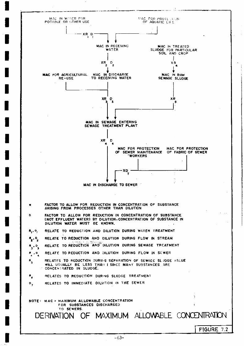
MAC IN W.-i ER FORPOTABLE OR OTHER USE
XR D-i I
N-AC FOR PROTET'. 1 ¡ONOF AQUATIC L l r E
MAC IN RECEIVINGWATER
XR D2 2
MAC IN TREATEDSLUDGE FOR PARTICULAR
SOIL AND CROP
XR
MAC FOR AGRICULTURAL MAC IN DISCHARGERE-USE TO RECEIVING WATER
XR 03 3
MAC IN SEWAGE ENTERINGSEWAGE TREATMENT PLANT
XR D4 4
MAC IN RAWSEWAGE SLUDGE
XR.9
MAC FOR PROTECTION MAC FOR PROTECTIONOF SEWER MAINTENANCE OF FABRIC OF SEWER
'WORKERS
rXD
MAC IN DISCHARGE TO SEWER
Vo.n , o
3 9R , D4 4
FACTOR TO ALLOW FOR REDUCTION IN CONCENTRATION OF SUBSTANCEARISING FROM PROCESSES OTHER THAN DILUTION
FACTOR TO ALLOW FOR REDUCTION IN CONCENTRATION OF SUBSTANCE(NOT EFFLUENT WATER) BY DILUTION. CONCENTRATION OF SUBSTANCE INDILUTION WATER MUST BE KNOWN.
RELATE TO REDUCTION AND DILUTION DURING WATER TREATMENT
RELATE TO REDUCTION ANO DILUTION DURING FLOW IN STREAM
RELATE TO REDUCTION ANO DILUTION DURING SEWAGE TREATMENT
RELATE TO REDUCTION AND DILUTION DURING FLOW IN S L W E R
RELATES TO REDUCTION DURlfG SEPARATION OF SEWAGE SLUDGE VALUEWILL USUALLY BE LESS THAN I SINCE M A N Ï SUBSTANCES ARECONCENTRATED IN SLUDGE.
RELATES TO REDUCTION DURING SLUDGE TREATMENT
RELATES TO IMMEDIATE DILUTION IN THE SEWER
NOTE! M A C : MAXIMUM ALLOWABLE CONCENTRATIONFOR SUBSTANCES DISCHARGED tTO SEWERS.
DERIVATION OF MAXIMUM ALLOWABLE CONŒNTRATDN
1 FIGURE 7.2
- 6 3 -
IIIIIIIIIIIIIIIIIIIII
7.4
Major potential waste generating industries in Sri Lanka tend tobe located either in industrial estates outside or on the periphery of thenain urban areas, or in rural areas. Most industries within residentialand commercial development areas are generally small—scale such as vehiclerepair and assembly, printing, and metal plating industries. Suchindustries do not produce significant waste quanities, but they do resultin a general environmental degradation which can be controlled byimproving internal housekeeping, installing oil traps, etc. A suitabletrap design for small—scale industries is shown in Figure 7,1.
There is no substitute for carrying out .field surveys to determineindustrial waste pollution loads. Few such surveys have been carried outin Sri Lanka although the CEA is gradually accumulating an industrialwaste data bank (Ref. CEA Reports and Publications), Data are availablefrom overseas locations but care should be taken in interpreting data fromelsewhere because industrial waste loads are heavily dependent on theproduction process, the avail- ability and cost of water, type of rawmaterial and general attention to housekeeping. For industrial estates,average estate wastes would typically be in the range of 20 to 50 n3/d*and 8 to 15 kg BOD/d. ha. These ranges have been determined fromindustrial estate surveys in Asia generally but the data do not allow formajor polluters such as breweries, and poultry processing factories. Forhigh technology electronics manufac- turing estates the waste loads wouldbe at the lower end of the range. Peak flows should be taken as twice theaverage values indicated above.
-64-

IIIIIIIIIIIIIIIIIIIII
SECTION 8
O C E A N O U T F A L L S
The discharge of wastewater to the ocean is an accepted means ofdisposal provided that the assimilative capacity of the ocean at thedischarge location is not exceeded and provided that the discharge doesnot give rise to unacceptable pollution levels in recreation areas or inshellfish harvesting areas.
6.I Discharge Standards
Tolerance linits for domestic and industrial effluents dischargedto Sri Lankan marine coastal waters are laid down in Sri Lanka StandardSLS 721: 1965 and are summarised in Table B3. The standard defines narinecoastal waters as the sea, ocean, creeks, and tidal waters extending outto 5 k« from the mean high water mark and up to the low tide level inestuaries. It should foe noted that these tolerance limits should beconsidered more as guidelines, since SLS 721; 1965 includes'the provisionthat they may be varied in consultation with the CEA.
The objective of a discharge standard is to safeguard the qualityof the receiving water for designated uses. In the coastal marineenvironment such uses are essentially recreation and fishing. It isnecessary, therefore, to base discharge standards on receiving waterquality criteria.
Recreational activities associated with marine waters encompasswater-contact activities (swimming, diving, wading, water skiing, windsurfing, net fishing) and non water-contact activities (boating, aestheticenjoyment). In Sri Lanka, of course, water-contact fishing such as netfishing is a comercial rather than a recreational activity. Althoughwater-contact activities demand a more stringent discharge standard thannon water-contact activities, there, are certain quality requirements whichform a baseline b&low which the water quality can be considered unsuitablefor any recreational activity. Basically the marine coasta,l waters shouldnot contain substances attributable to discharges of wastewater that:
o give rise to visible floating or suspended matter, oil, grease orf o a m ; . __.=_:,...._ .-•••
o produce sludge banks or slime infestation;
o give rise to heavy growths of attached plants or animals or bloomsof plankton;
o give rise to discolouration or turbidity or the evolution of gasesand odour;
o contain substances which are injurious or toxic to the naturalecology of the disposal area or which can be concentrated in foodchains.
-65-
IIIIIIIIIIIIIIIIIIIII
Most water quality criteria for marine waters where water-contactrecreational activities take place include specific limits for pH andpathogens. The maintenance of the receiving water pH within a range of6.5 to 6.3 (extreme units 5.0 to 9,0} is recommended in order to reduceeye irritation. This range is easily achieved by the natural bufferingcapacity of the sea unless highly alkaline or acidic industrial wastes <^r^present.
Although it is accepted that the presence of pathogens in thereceiving water constitutes a health risk, the practical difficulty ofisolating and aonitoring pathogens results in colifor» organisms beingused as surrogate indicators for pathogens. There is as yet no provenepideniological evidence which can be used to stipulate threshold coliformlevels in narine waters above which adverse health impacts will arise.Recommended criteria in other countries vary, for exanple maximum faecalcoliform levels of 2000/ 100 nl are stipulated by the EEC, in the USA theEnvironmental Protection Agency (1976) standard is based on a faecalcolifom level of 400/100 nl not being exceeded in 90% of samples.
Coliforn levels recorded in the ocean at Colombo, Negombo andGalle in 1979 showed a nean of 11 total coiifoms/lOQ ml. Fecal colifornlevels were zero. The samples were collected at a distance of 1000 to2000B from the shore. However, shoreline samples in Colombo taken at adepth of 0,6 m showed a total colifarm range of 14 to 6.12 x lG^/lOO ml,with a mean of 16000/100 ml (Engineering-Science, 1961). More recent datafor the period October 1967 to January 1966 show a mean total colifor»level of 4700/100 ml (range 210 to 110 600/100 ml). At the recreationbeach south of Dehiwela Canal to the Hount Lavinia Hotel, the mean totalcoliform level from the recent data is 1800/100 ml, compared to 4700/100ml in 1979. The commissioning of the marine outfall at Dehiwela isundoubtedly a contributory factor to this improvement.
There are no coliform criteria for marine waters in the Sri Lankanstandards. It is recommended that a guideline faecal coliform value of1000/100 ml not being exceeded in 60% of samples be adopted. This iscomparable to the World Health Organization (1975) criterion foracceptable bathing waters. This standard can be compared to the qualityof the recent shoreline samples in the recreation beach previouslyreferred to. The mean total coliform level was 1600/100 ml, with about80% of the samples being equal to or less than 2400/100 ml. Although anexact relationship between total and faecal colifor» organisms cannot bedefined, total coliform levels typically exceed faecal coliform levels byat least a factor of"two;" A tentative conclusion, therefore, is that theshoreline quality at the recreation beach is acceptable for water-contactrecreation.
Because of the ability of shellfish to concentrate both pathogensand toxic substances, it is essential that the quality of the water incommercial shell fishing areas be of a high quality. Studies carried outelsewhere on the bacterial pollution of shellfish suggest that the marinewater should not contain more, than 40 faecal coliforms/100 ml in more than10? of samples and the shellfish should be regularly monitored for thepresence of indicator organisms.
-66-

IIIIIIIIIIIIIIIIIIIII
8.2
The objective, in outfall design is to select a discharge locationsuch that the receiving water quality criteria are not exceeded. Usuallythis will entail ensuring that the outfall is of such a length that thecoliform levels at the shore are within acceptable limit.*? under the mostadverse conditions of on-shore currents and winds.
The outfall pipe should end in a diffuser section fitted with anuraber of horizontally-discharging ports. Typical diffuser designcriteria are:
o Total port area must not exceed the nain outfall pipe area,
o Port diameter > 0.15 ra to avoid blockage.
o Nozzle densimetric Froude number »ust be greater than unity toavoid ingress of sea water.
o Port velocity > 2 m/s.
o Main outfall pipe velocity > 1.5 «/s to avoid settlement ofparticulate matter.
o Flow per unit length of diffuser 0.005 to 0.02 m3/s.m
8.2.1 Initial Dilution
When sewage is discharged in the sea it tends to rise to thesurface because it is less dense than sea water. As the sewage mixes withthe sea water the density of the mixture approaches the density of thereceiving water and the sewage loses its monentua and ceases to rise. Insome cases density stratification occurs in the receiving water and thesewage remains submerged below the surface of the sea. The dilution ofthe sewage which occurs as the sewage rises is referred to as the initialdilution and is a function of jet volocity, depth of water, densitydifference and movement of the receiving water,
A range of design procedures are available for calculating theinitial dilution. Some procedures are based on calculating the initialdilution for still water and then modifying for sea water movement, otherprocedures incorporate factors to take into account the movement of thereceiving water. Hone of the procedures are exact, careful interpretationis necessary for each specific location based on field surveys of actualconditions. The following discussion summarises the most commonprocedures currently in use.
The initial dilution on the axis of a rising plume (defined as Soin Figure 6.1) can be derived for still water conditions from Figure Ô.2in accordance with the procedure of Fan and Brooks (1966). The Froudenumber (F) is defined as:
-67-
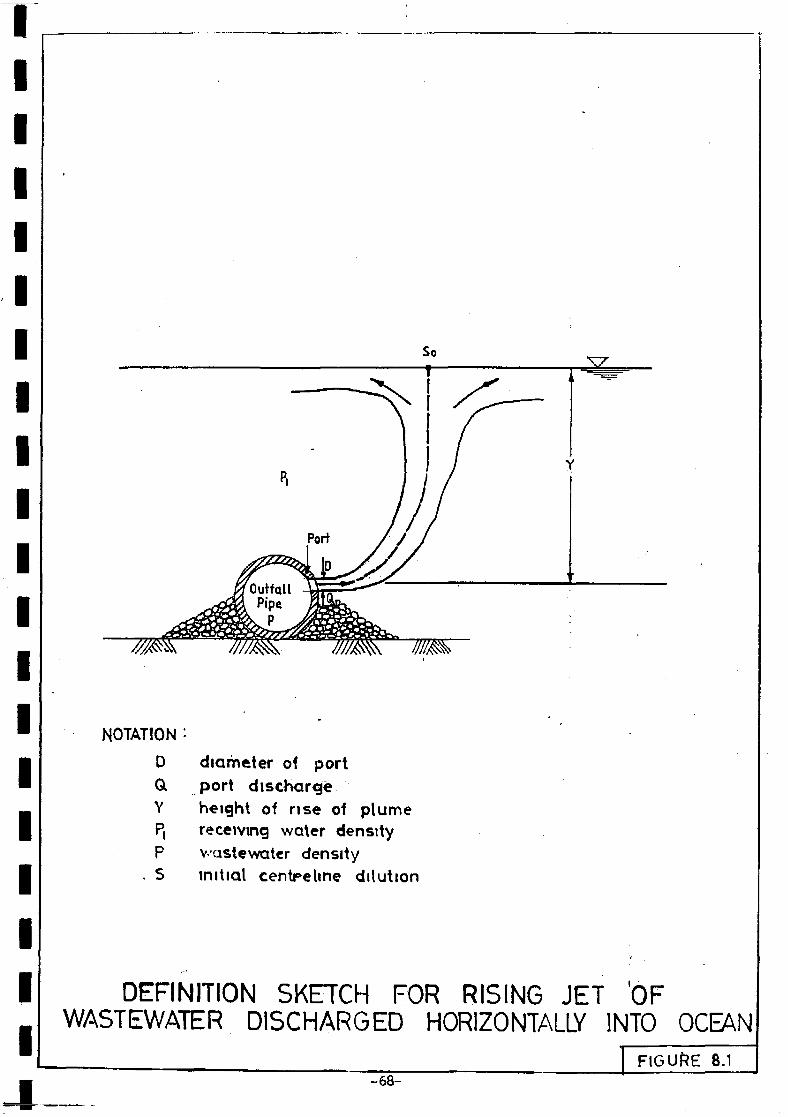
NOTATION :
DaY
P.P
. S
diameter of portport dischargeheight of rise of plumereceiving water densityv-astewater densityinitial centreline dilution
DEFINITION SKETCH FOR RISING JET 'OFWASTEWATER DISCHARGED HORIZONTALLY INTO OCEAN
-68-FIGURE 8.1
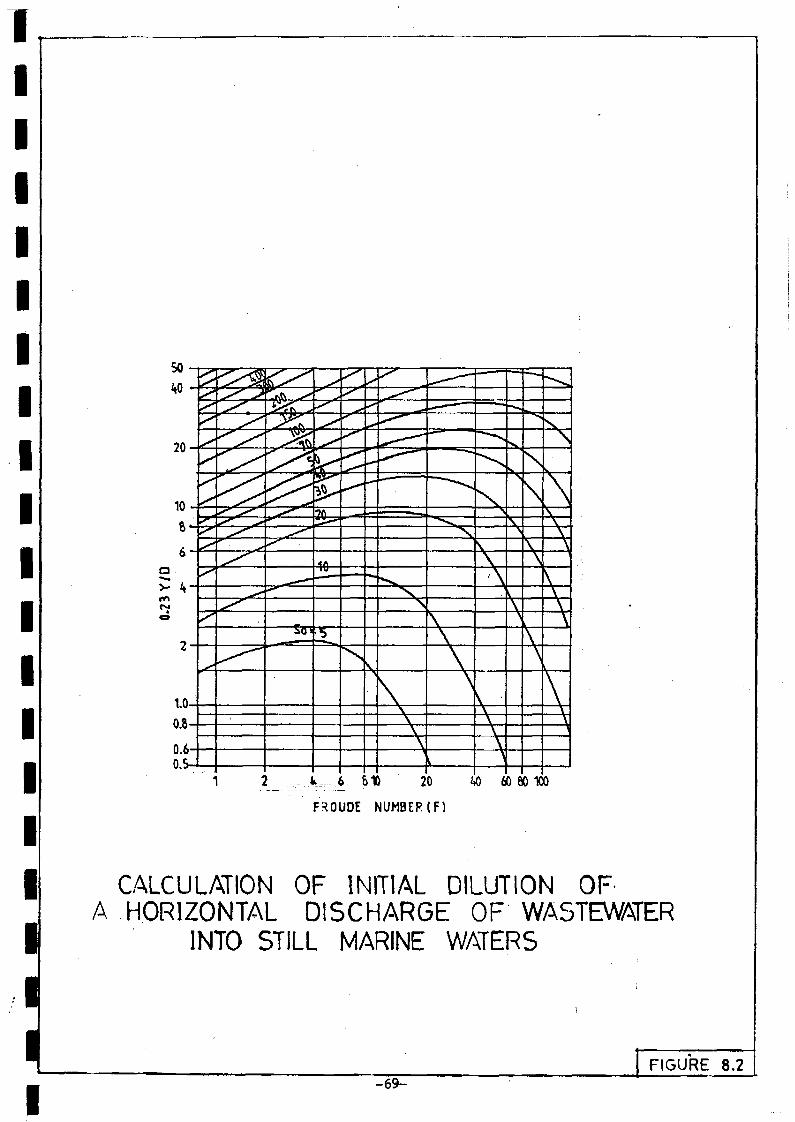
t__. 6 &t> 20
F30UDE NUMBER(F)
40 60 80 100
CALCULATION OF INITIAL DILUTION OFA HORIZONTAL DISCHARGE OF WASTEWATER
INTO STILL MARINE WATERS
I- 6 9 -
FIGURE 8.2

IIIIIIIIIIIIIIIIIIIII
F = Vj [sOiPi - P) Pl - 1 ] "
where Vj - jet'velocity <n/s)
g = acceleration due to gravity
A range of procedures can be used to correct the initial dilutionfor the movement of the receiving water. Typical correction factorsproposed by Agg and Wakeford (1972) and the Hydraulics Research Station(1977) respectively are as follows:
Log (correction factor) = 0,938 log
Correction factor
«here V.
= 1 + 6Y
D
Va
Vj
Va
Vj
1.107
1.5
= ambient velocity
Field tests have shown that the Agg and Wakefield (1972) equationtends to underestimate the measured initial dilution, whereas theHydraulics Research Station (1977) equation tends to overestimate themeasured d i lut ion.
An alternative procedure to calculate initial dilution whichincorporates a correction factor for ambient velocity is that of Roberts(1977) which is summarised in Figure 8.3 (adapted from Ludwig, 1978), Thenotation in Figure 8.3 is as follows:
Sia
Y
Q
L
Va
q
81
= centreline dilution taking into account ambientvelocity
- height of ri.se of plume (m)
= total wastewater discharge ( ff)3/s) '
- diffuser length (m)
— ö C è ^ h current velocity (m/s)
= wastewater flow per unit length of diffuser (Q/L)
= apparent acceleration due to gravity
-1= g ÏPi - P] PX
=. modified Froude nunber
( <»>
e = orientation of diffuser line to prédominent oceancurrent
-70-
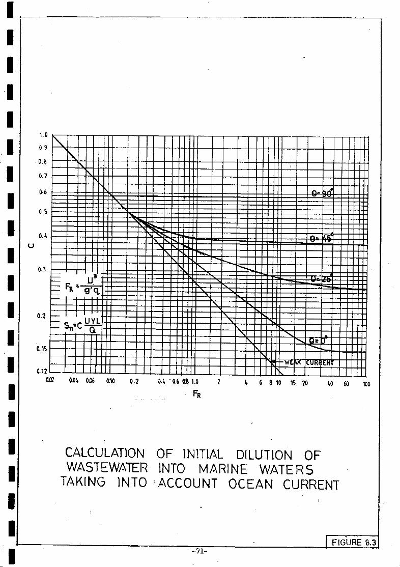
(J
1.0
0 9
• 0 . 8
0-7
0-6
0-5
<U
0.3
0.2
ais
0.12
\
e
\
FR—|
\S
s
u'
c a
- -v
\ ==^ *"\ s- \
- -r -V
s
>
i
< - -
<¡ -WÉ K
- ', .. JJI
'Uf7l
> e
'•H
0W 0.10 0.2 M 0.6 6 8 10 1S 20 M> 60 150
CALCULATION OF INITIAL DILUTION OFWASTEWATER INTO MARINE WATERS
TAKING INTO ACCOUNT OCEAN CURRENT
- 7 1 -FIGURE 8.3

IIIIIIIIIIIIIIIIIIIII
The procedure in Figure 8.3 is applicable, for the followingr.unges ;
L 3.65 to 30.0V
YN > 5.0L
where If = number of discharge ports
The curve narked "weak current" in Figure 6.3 is for still waterconditions, for 0 = 90° the diffuser is oriented perpendicular to thecurrent, for 0 = 0° the diffuser is oriented parallel to the current.Since the values of Sm are minimum centre-line dilutions, actual fielddilutions will be greater because of the spreading effect of the plume. Anapproximate estimate of the field dilution for a line source plumeaccording to Rawn and others (1960) is given by:
Sa = Sm.2 °-5
where Sa = field dilution
6.2.2 Coastal Dilution
The dilution which occurs along the coast is more difficult todetermine than initial dilution since it depends on coatal currents andturbulent diffusion, both of which are difficult to measure and predict.Various theroretical and experimental studies have been made in an attemptto define turbulent diffusion in the sea, but in coastal areas where thecoobined influence of tides, wind and currents predominates, no generalprocedures are wholly adequate. One approach based on field observationsof British coastal conditions was developed by Agg (1976) and issuenaarised in Figure 6.A. The procedure relates initial dilution to thedistance of the wastewater discharge from the shore for various amenityvalues of the receiving water. It is not suggested that the modeldepicted in Figure 8.A be applied directly to Sri Lanka, but the sameapproach can be followed by developing a data base from oceangraphicsurveys. _.•_= . . . -
In addition to initial dilution and dispersion, pathogen levelsare also reduced by natural die-off in accordance with the followingrelationship:
t /Tc>0S D = 10
where Sjj - dilution due to natural die—off
t = tine of travel from plume +_o amenity area (h)
T90= tirae required for 902 die-off (h)
-72-

I
TO3IV
s
2
102
¡ s° 2rf 1| 1 O 1
2
C
V
\ ^ ^ ^ ^ H I 6 H AMENITY
LOW ^ N .
AMENITY ^ ^ * ^ ^ ^
i i i i i
S00 1000 1S00 2000 2S00 3000
DISTANCE OFFSHORE (m)
DESIGN MÖ6ÈL FOR CALCULATINGOUTFALL LENGTH
FIGURE 8.4
- 7 3 -
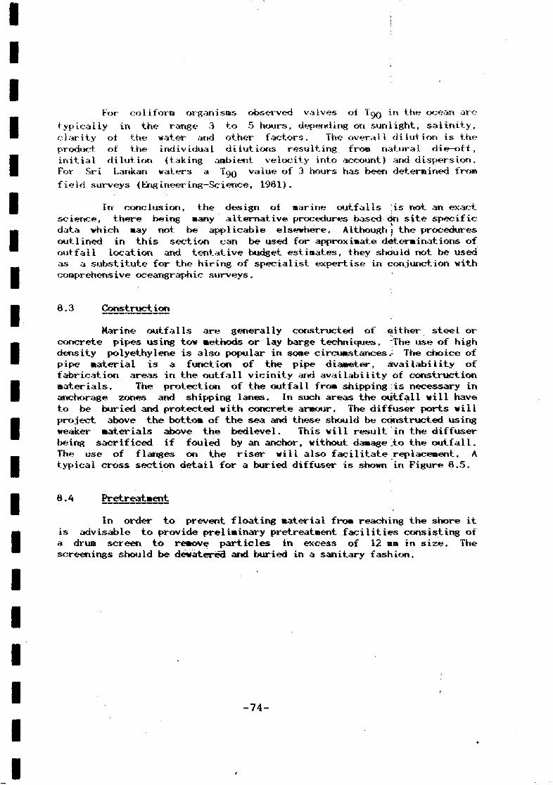
IIIIIIIIIIIIIIIIIIIII
For eoliforia organisms observed valves of TgQ in the ocean aretypically in the range 3 to 5 hours, depending on sunlight, salinity,clarity of the water and other factors. The overall dilution is theproduct of the individual dilutions resulting from natural die-off,initial dilution (taking ambient velocity into account) and dispersion.For Sri Lankan waters a T<JQ value of 3 hours has been determined fromfield surveys (Engineering—Science, 1981).
In conclusion, the design of marine outfalls is riot an exactscience, there being many alternative procedures based on site specificdata which may not be applicable elsewhere. Althoughj the proceduresoutlined in this section can be used for approximate determinations ofoutfall location and tentative budget estimates, they should not be usedas a substitute for the hiring of specialist expertise in conjunction withcomprehensive oceartgraphic surveys.
8.3 Construction
Marine outfalls are generally constructed of either steel orconcrete pipes using tow methods or lay barge techniques. The use of highdensity polyethylene is also popular in some circumstances.- The choice ofpipe material is a function of the pipe diameter, availability offabrication areas in the outfall vicinity and availability of constructionmaterials. The protection of the outfall from shipping is necessary inanchorage zones and shipping lanes. In such areas the outfall will haveto be buried and protected with concrete armour. The diffuser ports willproject above the bottom of the sea and these should be constructed usingweaker materials above the bedlevel. This will result in the diffuserbeing sacrificed if fouled by an anchor, without damage to the outfall.The use of flanges on the riser will also facilitate replacement. Atypical cross section detail for a buried diffuser is shown in Figure 8.5.
8.4 Pretreatment
In order to prevent floating material from reaching the shore itis advisable to provide preliminary pretreatment facilities consisting ofa drum screen to remove particles in excess of 12 mm in size. Thescreenings should be dewatered and buried in a sanitary fashion.
-74-
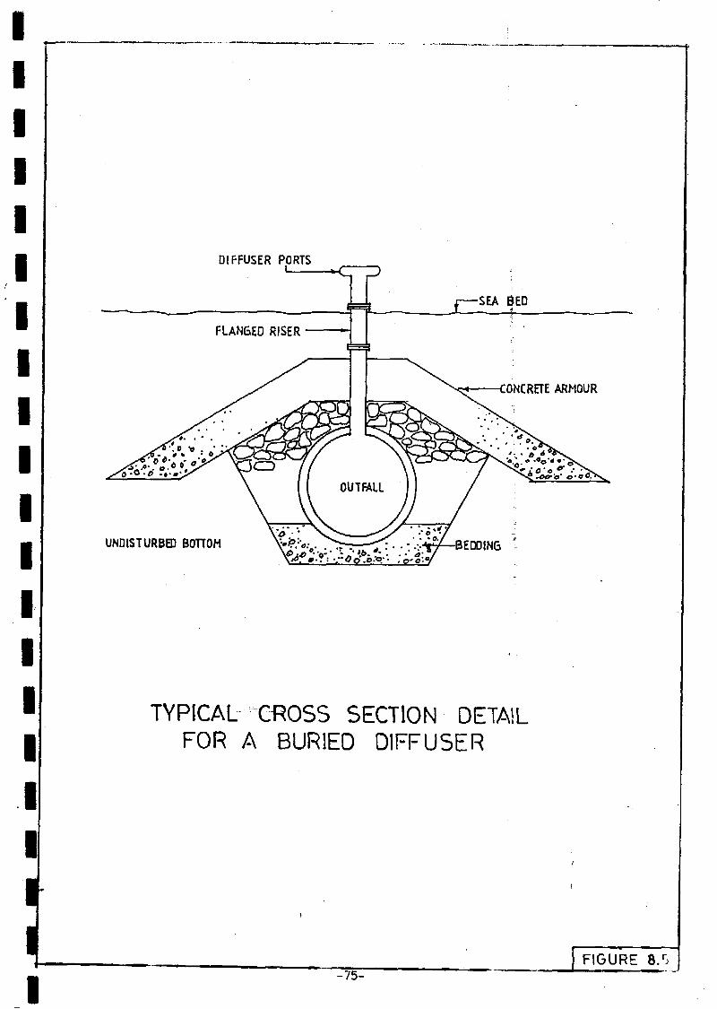
IIIIIIIIIIIIIII
DIFFUSER PORTS
FLANGED RISER£Z SEA SED
? CONCRETE ARMOUR
UNDISTURBED BOHOH
TYPICAL GROSS SECTION DETAILFOR A BURIED DIFFUSER
IFIGURE
- 7 5 -
IIIIIIIIIIIIIIIIIIIII
SECTION
S E P T I C TANK S Y S T E M S
Where cistern flush-toilets are provided, as opposed 'to pour-flushlatrines or pit privies, and where a local or regional sewerage system isriot immediately accessible, septic tank systems are an acceptable means ofsewage disposal. A comprehensive Sri Lankan code of practice is availablefor the design and construction of septic tank systems (Sri LankaStandards Institution, 1966), the purpose of this section is to summarisethe wore important aspects of this method of sewage disposal,
9.1 Applicability of Septic Tank.Systems I
The Sri Lankan code of practice recommends that communal septictanks not be used for populations exceeding 300. The Colombo MetropolitanRegion Urban Development Plan (UNDP, 1976) recommends that ón-site systemsshould only be considered when the population density is less than 140p/ha, with such systems being almost inevitably more economic thanwaterborne sewerage where the density is less than 100 p/ha; In practice,the key factors are the quantity of wastewater discharged and the methodadopted for disposal of the septic tank effluent.
The ideal effluent disposal system is to land, preferably by meansof a trench soakaway system. However, land requirements can beconsiderable if the absorptive capacity of the land is limited. Forexample, for a septic tank receiving the total household waste of say 1501/d.p from a family of five with a typical infiltration raie on reclaimedland of 10 1/d, m2 the total land area required for the soakaway would be112 m2 . For a population density of 100 p/ha on such land, the soakwayswould represent almost 25!? of the total development area.
If the septic tank was to receive only toilet waste, the land arearequired for the soakaway would be much less, say about 25? of thatrequired for the total household waste. In this case .sullage wastes (fromlaundry, bathing, kitchen) would be discharged to a roadside drain, acommon practice in many urban areas of Southeast Asia.
The health risks arising from roadside drains containing sullagedepend upon the pathogen content of the drain and the possibility ofeither direct contactbetween persons, particularly children, and thedrain, or contamination of water supplies by ingress of polluted drainwater, particularly for shallow well supplies and leaking distributionnetworks where interrupted supplies are frequent. If it is assumed thatpathogens may be. present in household wastes in similar proportions tofaecal coliforms, the health risks can be assessed from colifor» levels,although it is admitted that this is a somewhat tenuous assumption.Studies in varies countries have shown that faecal colifor» levels in'su 1-1 age are significantly lower than in excreta, often by a factor ofabout five orders of magnitude. For example, if it is assumed that aroadside drain containing raw sewage has a health risk of 100 (on anarbitrary scale) then a drain containing only sul lage wouId'have aminimum health risk of 0.001. This comparison gives a general idea of theoverall magnitude of potential ri.sk.
-76-

if"
If the drains are well designed and maintained 'and are alwaysfree-flowing, the likelihood of stagnant, anaerobic, conditions developingwill be «initial. In practice, of course, this is rarely the case and thedrains are frequently blocked with refuse and overgrown. The presence ofsu11age is unlikely to have a significant effect on the mosquitopopulation, with perhaps the exception of the filariasis vector whichtends to breed in polluted rather than clean water.
The Sri Lankan code of practice stipulates that septic tankeffluent should not be discharged to art open drain without priorchlorination. It is suggested that in the present context of the SriLankan urban environnent, this stipulation is inappropriate. Chlorinationof an effluent with a high organic content is not likely to be efficient.Since septic tanks in Sri Lanka are rarely desiudged, unless the householdis faced with blockage and severe odour problems, the tank effluent isalso likely to contain suspended natter which may encapsulate pathogensand render chlorination virtually ineffective. :
It is suggested that the following strategy be adopted for septictank use in Sri Lankan urban areas until such ti»e as financial resourcesare available to construct regional sewerage systems. The strategy is setout in order of preferred priority.
o Discharge all household wastes to the septic tank and trenchsoakaway.
o Discharge toilet wastes only to the septic tank and soakaway,discharge sullage wastes to the drain.
o Discharge all household wastes to the septic tank and then tothe drain (this should not be a widespread practice).
Septic tank desludging frequencies should be Maintained inaccordance with the design guidelines. The following design criteriarefer to tanks serving individual houses with in-house piped watersupplies and cistern-flush toilets. Criteria for systems serving pour-flush latrines are presented in the Design Manual "Guidelines for LatrineSelection and Construction."
9.2 Septic Tank
Recommended tank dimensions are shown in Figure 9.1 for a totalhousehold waste flow of 150 l/d. p and an occupancy of 5 persons. Thedesign is based on a total hydraulic retention time of 24 hours plussludge storage based on an accumulation rate of 0.04 m3/y.p, a typicalsludge build up rate where anal cleaning is with water or soft paper. Adesludging frequency of three years should be adopted for calculating thesludge storage capacity. The dimensions can be varied depending upon theoccupancy and flow, but the volume of the first chamber should be doublethe volume of the second chamber. The length to width ratio shown inFigure 9.1 is not mandatory, the tanks may be circular if cheaper. Thedesign shown in Figure 9.1 differs slightly from the standard tank designscurrently used in Sri Lanka. The simple wooden inlet baffle as shown inFigure 9.1 removes the risk of blockage of the more conventional inlet teepiece.
-77-

10002 0 0
IINCOMING SEWER
\1 \
2X
SLOTS 125100 HIGH
WIOE
\
WOODEN BAFFLE
PLAN VIEW
SOO
G. LEVEL
-INSPECTION COVERS
u INCOMING SEWER
'S • • • • « .
.1 OO
8
.1
TWL
i
oo
TO SOAK
- 1 0 0 «5
C.I. TEE
SECTION A - A
RECOMMENDED SEPTIC TANK DIMENSIONS
I-78-
1 FIGUR'E 9,1

Vent pipes leading iron the tank to the. atmosphere are notnecessary if the. house plumb ing is provided with a vent stack. Whendesludging, the tank should rtot be emptied completely since it isdesirable to leave a snail amount of sludge (typically 100 rara depth) as aseed to encourage digestion when the tank refills.
As an interim improvement measure to reduce odour problems whicharise fro» discharging tank effluents direct to surface drains rather thanto a soakaway, the second chamber can be filled with stones of nominalsize 50 ran and the entrance from the first chamber placed at about twothirds of the chamber depth. The outlet T-piece can be removed. Thestones act as art upflow anaerobic filter and malodorous compounds arebroken down thereby resulting in a tank effluent which can be dischargedto a storm drainage system without giving rise to odour problems. Thestone filter has no effect on BOD or pathogen removal,
A two-compartment septic tank which is regularly desludged willgenerally reduce BOD and SS levels in the incoming sewage by about 45 and60? respectively. Faecal coliform levels in tank effluents are often inthe range 1 to 10 mi 11ion/100 ml.
9.3 goakaway
For septic tank systems receiving the total household waste fromdwellings with a relatively high water use, a trench soakaway system isthe preferred method since the tank effluent is spread over a relativelylarge land area. Alternative soakaway systems for pour-flush latrines aredescribed in the Design Manual "Guidelines for Latrine Selection andConstruct ion."
A typical trench soakaway would have a trench width of 0,4 m, adepth of gravel of 0.75 m below the feed pipe in the trench and 0.2 mcover over the pipe. The soakaway should not be covered by an impermeablecover since thg£ eliminates evapotranspiration. The required trenchlength can be calculated from:
L = PQ2DÍ
where P = populationQ = flow (1/d.p)D = e.fftc#èvë-depth of trench walls (0.75 m>i * infiltration rate (l/d. ma )
Trench spacing should be not less than 2.0 m,
The infiltration rate must be determin^-d from a permeability testconducted on the site, Soakaways are not generally recommended if thepercolation time exceeds 4 min/am, equivalent to a minimum infiltrationrate of 10 l/d, ma. Maximum infiltration rates to be used in determiningtrench lengths should not exceed 50 l/d. m1 , regardless of the percolationtime. The percolation test is described in the Sri Lankan £ode ofpractice, '.
i
-79-
IIIIIIIIIIIIIIIIIIIII
The land area (rai} required for the soakaway can be calculatedirons the percolation rat*i arï follows:
A = 1,5 PJji
and i = 1 2 7
Õ7
where r = percolation rate (min/cm)
The factor of 1.5 allows for trench spacing.
9.4 Septate Disposal
The septic tanks should be desludged regularly in accordance withtheir design frequency and the septage discharged to a regional sewagetreatment works. If regional sewage treatment works are not available,the septage can be discharged either to evaporation/percolation lagoons orto land. Typical design criteria for land disposal are a hydraulicloading rate of 2 to 14 mm/d for areas of moderate permeability whereremoval of the liquid fraction is by evapotranspiration and percolationwithout surface run off. The actual rate should be. determined frompercolation tests and an estimate of the evapotranspiration rate ofvegetation growing on the disposal area. In order to avoid ponding thearea should be dosed intermittently, say for 6 h followed by 18 hresting. Overall maximum hydraulic loading rates would foe about. 50 mr/d. ha. Typical BOD loading rates for land disposal are generally in therange 0.2 to 5.6 kg/d. ha.
Basic guidelines to be followed in selecting a land disposal areafor septage are the avoidance of contamination of groundwater supplies,surface run off and ponding, and maintaining discharge rates such that thevegetation is not hydraulically swamped or killed due to an accumulationof trace metals or boron (fro» detergents) in the plant tissues. Odourprobleos can be minimised by siting the disposal area away fromresidential developments and by adding a bag of lime to thé tanks prior tocommencing the journey to the disposal area. The addition of lime has theeffect of stabilizing the organic matter and thereby reducing the sewageodour.
-80-
IIIIIII
APPENDIX A
R E F E R E N C E S
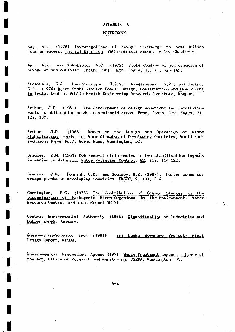
I
I
IIII
APPENDIX A
REFERENCES
Agg, A.R, (1978) Investigations of sewage discharge to some British•j coastal waters, Itiitj.aJ._Di j.utj.on, WRC Technical Report TR 99, Chapter 6,
IAgg, A.R. and Wakefield, AX. (1972) Field studies of jet dilution ofsewage at sea outfalls, Instn^J^b^jmiu Engrs^J^, 71, 126-149,
I Arceivala, S.J., Lakshiraarayan, J.S.S., Alagarasamy, S.R., and Sastry,C.A. (1970> Water_S abj.n zaj_i.onJPond Mtesi_gj2i
í ÑÍD_ÍDííÍa' Central Public Health Engineering Research Institute, Ñagpur.
Arthur, J,P. (19Ô1) The development of design equations for facultative
Iwaste stabilisation ponds in semi-arid areas, Proc. Instn. Civ. Engrs. 71,(2), 197.
Arthur, J.P. (19Ô3) M _ ^ _ _ j 2 _ _ _ _ _§£2Í2ÍIÍE^Íon.__E2"ds. îïi W«w»__CÍ ilâtgs pf jjffvgÍQB JM <^"?^lCÍgg » Wor ldBañkTechnical Paper Ko.7, World Bank, Washington, DC.
BisseeiDatieD 2Í E3tbo£emç__ÍUçroi£r^n_U«sI_ÍD theEnvTrõnaênt. Water
l
Bradley, R.M. (1963) BOD renoval efficiencies in two stabilisation lagoonsin series in Malaysia, Water Pollution Control, 62, (1), 114-122.
Bradley, R.M., Ponniah, CD., and Soulsby, M.R. (19Ô7). Buffer zones form sewage plants in developing countries. ENSIÇ, 9, (3>, 2-4.
Carrington, E.G. (1978) The Contribution of Sewage__SJ.udses_to__the
BisseeiDatieD 2Í E 3 t b o £ e m ç _ _ Í U ç r o i £ r ^ I T õ n êResearch Centre, Technical Report TR 71.
| Central Environmental Authority (I960) i f l £ ã t i _ _ _Buffer Zones, January.
Engineering-Science, Incv (1961) Srim_Lanka Sewerage Project^ Fi.nal._ Design Report, KWSDB.
Environmental Protection Agency (1971> Waste_Treatment_La^oon^ -_State_of• t^-Art. Office of Research and Monitoring,"OsEPA, Washington, DOT ™
A-2

I
Pan, K.L., and Brooks, U,H. (1966) Turbulent mixing phenomena of oceanoutfalls, Pro£j._Aner_L_Sac^_Cj.v^_Ensrsi 92, SAI, 296-300.
Irriviroriaental Protection Agency (1976)'. Qu^J-j-tvCriteri^_for_Water, USEPA,Washington DC.
Gloyna, E.F. (1971) Wa^te^Stabiiization^orids^ WHO, Geneva.
m Hermann, E.R., and Gloyna, E.F. (1956) Waste stabilization ponds 111.Fornulation of design equations, Sewage_¿nd^_Wastes, 30, (11), 646.
Hydraulics Research Station (1977) Horizo^tal,_0utfaj.i_s_ÍT5_FÍowi.ng_Water,. Report EX 763, HRS, Wallingford. - -
Ludvig, R.G. (1978) KovosEmissários Submarinos, PresenEaissarios de Esgotos Sanitarios," FEEMA, Rio de Janeiro, Brazil.I Emissários Submarinos, Presented to Course on "Projeto de Interceptores e
I Mara, D,D. (1976) Sewage_Treatraerit_i,n_Hot_ÇJL,i»ates, Wiley, London.
I Mara, D., and Silva, S.A. (1979) Sewage treatment in waste stabilization• f tonds: recent research in Northeast Brazil, Pro£^ Jtfat^Techno1., 11, (2),
340.
McGarry, M.G., and Pescod, M,B. (1970) Stabilization Pond Design Criteria
I for Tropical Asia. Er^Ê^iQSs^Sf-tbS-SsS^Ila-iDtSÏIDiîtiSOSJl-SïBË^lîiS-0!!Waste IrjatlSJi: L^S22!22' Kansas City, Fed. Wat. Quality Admin.,
WashinghtorTD.C.
• Rawn, A.M., Bowerman, F.R., and Brooks, M.H. (1960) Diffusers for disposalof-sewage in sea water, Prgc. Amer._Soc. Ciy_. Engrs, 66, SA2, 65-105,
IRoberts, P.J. (1977) DÍSE£E2Íí?D £î£ Buoyant. Wastewater DisçhgjrggdOutfall Diffusers of FinTte_Leñgth~~ Caï?7 Inst. Tech."Report"KÍÍ-R-35.
Schwebach, G.H., Cafaro, D., Egan, J., Grimes, M., and Michael, G. (1966)Overhauling(A), 473-79.
A-3
•Overhauling health effects perspectives, J. Wat. Pollut. Control Fed^, 60
IIIII

ISiéJiqui, R.H. < 1.973)_ir_i lrj<Ji&, 10th Aniversary Commémorât ion Volume, Indian Association ofWater Pollution Control, Kagpur, January.
ISri Lanka Standards Institution (1965) IoJLerançe_Limits_for_industrj.aj._and
II
Sri Lankan Standards Institution (1986) Code of Practice for Design and
I UHDP (1978) Colombo Metro^j,itan_Re£ion_yrban_Pjeveio£ment_PJLan, Ministryof Local Government, Housing & Construction, February.
I World Health Organization (1975) Guides and Criri* * -* 1 ¿ i- tl ^ f D^-u-tl^A*!- - r-. 2 / *-* riff -> 1 y ^4- **"*> D A I V I V » ! P» ***«-* ^ 1Quality of_Beaçheg_and_Çoastaj._WatersT Report Euro 31251 1, Geneva.
I Government of Sri Lanka, National
I1
1. Basic Guidelines For Environment Assessment of DevelopmentProjects.
2, Coastal Environmental Management Plan for the West Coast of SriLanka, UN EcoBangkok <1965>.
I Lanka, UN Economic and Social Commission for Asia and Pacific,
I 3. Industrial Pollution in Ratmalana and Moratuwa Areas - APreliminary Study, (1986),
14. >roceddings of UMDP/UKESCO/CEA National Seminar or» Environmental
Protection and Management, 11-13 Mar 1985, (August 1986).
5. - - BKH Consulting Engineers, Water Pollution Survey with an Ultralight• Aircraft, Colombo, Phase II, Final Report for CEA, (June 1967).
6. Clarification of Industries and Buffer Zones, (January 1988).
IIIIIII
A-4
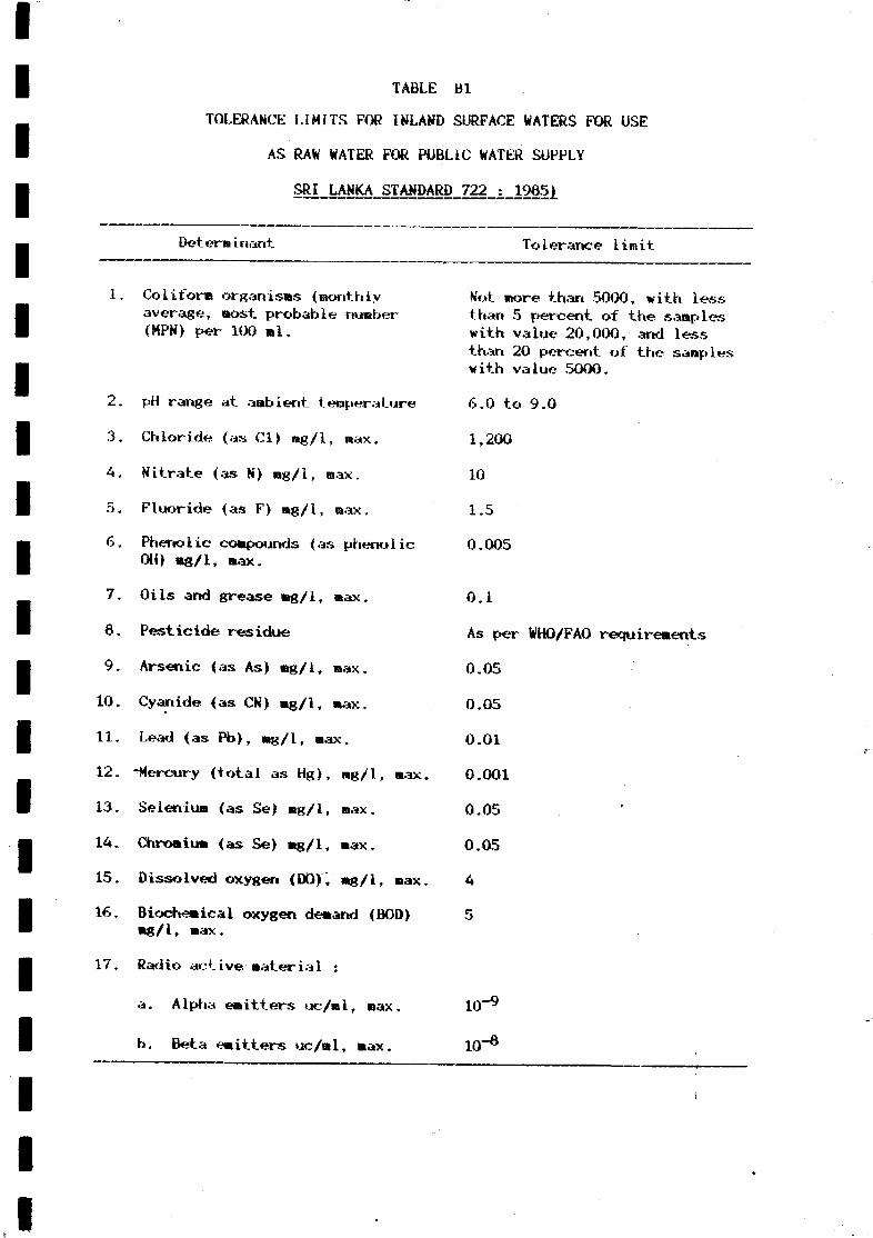
TABLE Bl
TOLERANCE LIMITS FOR INLAND SURFACE WATERS FOR USE
AS RAW WATER FOR PUBLIC WATER SUPPLY
SRI LANKA STANDARD 722 : 1965)
Det ero i nan t. ToIeranee lirait
1. Coliform organisas (monthlyaverage, most probable number(MPN) per 100 ml.
2. pH range at ambient temperature
3. Chloride (as Cl) ng/l, max.
4. Nitrate (as N) rag/1, max.
5. Fluoride (as F) wg/1, max,
6. Phenolic compounds (as phenolicOH) «g/1, max.
7. Oils and grease «g/1, max.
6. Pesticide residue
9. Arsenic (as As) mg/1, max.
10. Cyanide (as CN) «g/1, «ax.
11. Lead (as Pb), «g/1, max.
12. -Mercury (total as H g ) , ng/1, max.
13. Selenium (as Se) «g/1, max.
14. Chromium (as Se> «g/1, max.
15. Dissolved oxygen (DO), «g/1, max.
16. Biochemical oxygen demand (BOD)«g/1, max.
17. Radio active'«aterial :
a. Alpha emitters uc/ml, «ax,
b. Beta emitters uc/nl, max.
Not more than 5000, with lessthan 5 percent of the sampleswith value 20,000, and lessthan 20 percent of the sampleswith value 5000.
6.0 to 9.0
1,200
10
1.5
0.005
0.1
As per WHO/FAO requirements
0.05
0.05
0.01
0.001
0.05
0.05
4
5
10" 6
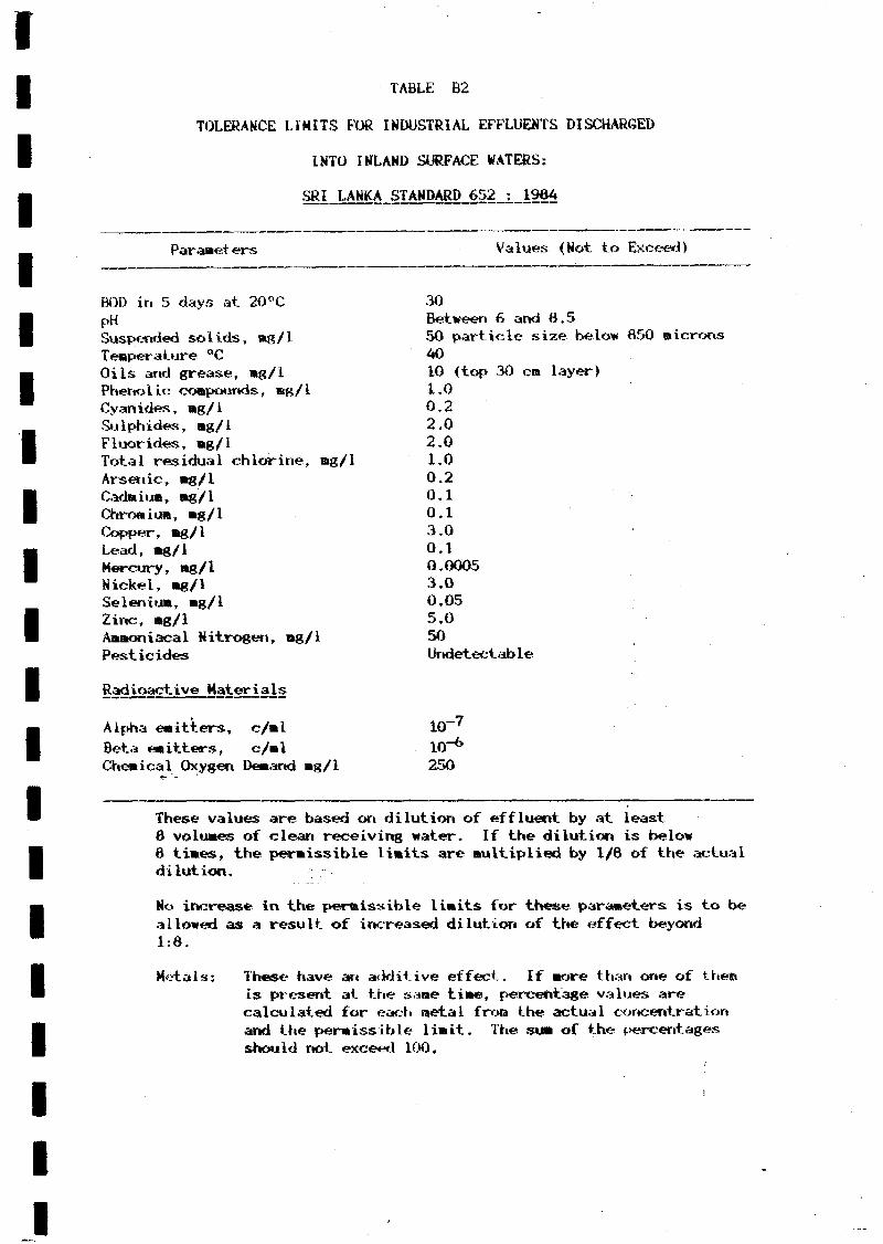
IIIIIIIIIIIIIIIIIIIII
TABLE B2
TOLERANCE LIMITS FOR INDUSTRIAL EFFLUENTS DISCHARGED
INTO INLAND SURFACE WATERS;
SRI LANKA STANDARD 652 : 19ÔA
Parameters Values (Not to Exceed)
BOD in 5 days at 20°C
PSuspended solids, rag/1Temperature °COils arid grease, mg/1Phenolic compounds, mg/1Cyanides, mg/1Sulphides, mg/1Fluorides, mg/1Total residual chlorine, mg/lArsenic, mg/1Cadmium, mg/1Chromium, mg/1Copper, mg/1Lead, mg/1Mercury, mg/1Nickel, mg/1Selenium, mg/1Zinc, mg/1Ammoniacal Nitrogen, mg/1Pesticides
Radioactive Materials
30Between 6 and 8.550 particle size below 850 microns4010 (top» 30 cm layer)
Alpha emitters, c/mlBeta emitters, c/mlChemical Oxygen Demand •8/1
1.00.22.02.01.00.20.10.13.00.10.00053.00.055.050Undetectable
10-710-6
250
These values are based on dilution of effluent by at least8 volumes of clean receiving water. If the dilution is below6 times, the permissible limits are multiplied by 1/8 of the actualdilution.
No increase in the permissible limits for these parameters is to beallowed as a result of increased dilution of the effect beyond1:8.
Metals: These have an a<lditive effect. If more than one of therais present at the same time, percentage values arecalculated for each metal fro» the actual concentrationand the permissible limit. The sum of the percentagesshould not exceed 100.

111111111111111111111
TABLE B3
SRI LANKA TOLERANCE LIMITS FOR
•
INDUSTRIAL ANDDOMESTIC EFFLUENTS
DISCHARGED INTO MARINE COASTAL AREAS
SRI LANKA STANDARD 721:
Parameter
Dosestic and Industrial;
TenperatureBODTSS (process waste)TSS (cooling water)
Particle size of:
Floatable solidsSettleable solidspHOils arid greaseCODResidual chlorineABBOT* i acal Nitrogen (N)
industrial only í«g/ü
PhenolsCyanides (CN)Sulphurides (S)Fluorides (F)Arsenic (As)CadsiuB (Cd)ChrowiuM (Cr)Copper (Cu)Lead <Pb>Mercury (Hg)Nickel (Ni)Seleniu» (Se)Zinc (Zn)Organo-phosphorous eotapourtds (P)Chlorinated hydrocarbons <Cl)Radio-active Material
Alpha eointersBeta emitters
-
: 1965
Tolerance Limit
45 °C100 Bg/1150 Bg/1influent cooling waterTSS plus 10?>
3»m650 B
6.0 - 6,520 Bg/1250 Bg/l1.0 Bg/l50 «g/1
5.00.25.015.00.22.01.03.01.00.015.00.055.01.00.02
ta
10 nicro curies »/l)10~7 " "
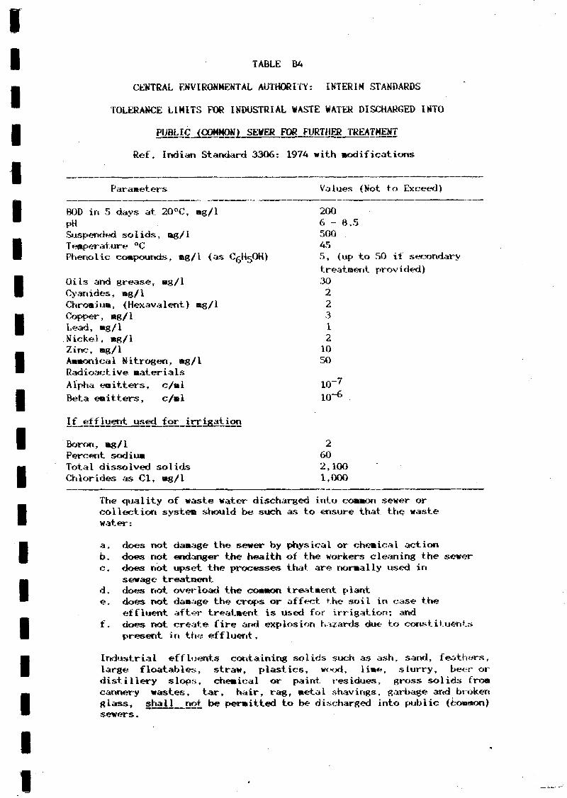
riiiiiiiiiiiiiiiiiiii
TABLE BA
CENTRAL ENVIRONMENTAL AUTHORITY: INTERIM STANDARDS
TOLERANCE LIMITS FOR INDUSTRIAL WASTE WATER DISCHARGED INTO
PUBLIC (COMMON} SEWER FOR FURTHER TREATMENT
Ref. Indian Standard 3306: 197A with modifications
Parameters Values (Not to Exceed)
BOD in 5 days at 2 0 ^ , mg/1pHSuspended so1 ids, mg/1Temperature °CPhenolic compounds, mg/1 (as
Oils and grease, »g/lCyanides, mg/1Chromium, (Hexavalent) mg/1Copper, »g/lLead, mg/1Nickel, mg/1Zinc, »g/lAmmonical Nitrogen, mg/1Radioactive materials
Alpha emitters, c/ml
Beta emitters, c/ml
If effluent used for irrigation
Boron, mg/1Percent .sodiumTotal dissolved solidsChlorides as Cl, mg/1
2006 - 8.5.500455, (up to 50 if secondary
treatment provided)30223121050
-710
10"
2602,1001,000
The quality of waste water discharged into common sewer orcollection system should be such as to ensure that the wastewater:
a. does not damage the sewer by physical or chemical actionb. does not endanger the health of the workers cleaning the sewer
c. does not upset the processes that are normally used insewage treatment
d. does not overload the common treatment plante. does not, damage the crops or affect the soil in case the
effluent after treatment is used for irrigation; andf. does not create fire arid explosion hazards due to constituents
present in the effluent.
Industrial effluents containing solids such as ash, sand, feathers,large floatables, straw, plastics, wood, lime, slurry, beer ordistillery slops, chemical or paint residues, gross solids fromcannery wastes, tar, hair, rag, metal shavings, garbage and brokenglass, shall not be permitted to be discharged into public (common)sewers.

IIIIIIIIIIIIIJ
TABLE B5
CENTRAL ENVIRONMENTAL AUTHORITY: INTERIM STANDARDS
TOLERANCE LIMITS FOR INDUSTRIAL
EFFLUENTS DISCHARGED ON LAND FOR IRRIGATION PURPOSES
Indian Standard 3307: 1977 with modifications
Parameters Values (Not to Exceed)
1. pH value2. Total dissolved solids, ng/1 maximum3. Sulphate (as S04) mg/l maximumA. Chloride (as Cl) rag/1 maximum5. Percent sodiun, maxinum6. Boron (as B) ng/1 maximum7. Oils and grease, ng/1 maximum8. Biochemical Oxygen Demand mg/1*
9. Alpha emitters microcuries permi H i litre
10. Beta emitters, microcuries per «1.«axiaura
11. Odour12. Floatables
6 to 0.52,1001,00060060210
250IO"9
No obnoxious odourNo visible large sizedsolids
*Can be relaxed or tightened depending on soil conditions andapplications rate.
Please Note:
1.
2.
3,
It is necessary to limit certain constituents in effluents,especially those considered toxic, so that the effluent may complywith normally accepted irrigation water quality.
The Authorities should give dwi consideration to the localconditions, and in special cases may relax or tighten the limits ifneed be.
Soils on which the effluents are applied are studied periodicallyfrom the viewpoint of physico-chemical characteristics to ensurethat they are not damaged and the ground waters are not polluted.Similarly, crop yields also need to be .studied.
HVDRAULIC LOADING APPLICABLE FOR DIFFERENT SOILS
Recomraermded Dosage of SettledIndustrial Effluents
Soil Texture Cj.ass
1. Sandy2. Sandy loam3. LoamA. Clay loam5. Clayey
225 to 2B0170 to 2Z5110 to 17055 to 10035 to 55
These hydraulic loading rates are only guidelines. In actualpractice the loading rates are fixed taking into account the natureof crop, the consumptive use, climate and frequency of application.