TAMIL NADU WATER SUPPLY AND DRAINAGE BOARD ...
814
TAMIL NADU WATER SUPPLY AND DRAINAGE BOARD CHENNAI. INTERNATIONAL COMPETITIVE BIDDING BID DOCUMENT FOR DESIGN, BUILD 60 MLD CAPACITY DESALINATION PLANT BASED ON SEA WATER REVERSE OSMOSIS AT KOONIMEDU IN VILLUPURAM DISTRICT, TAMIL NADU AND OPERATION AND MAINTENANE FOR 20 YEARS IFB No:15/DSP-VPM Pkg I/DO/CE/VLR/2021/Dt.07-01-2021 VOLUME - II SECTION VI – EMPLOYER’S REQUIREMENT PART– I A.PROCESS DESCRIPTION & DESIGN BASIS The Chief Engineer, Tamilnadu Water supply and Drainage Board, 8, 1 st East Main Road, Gandhinagar Vellore - 632006 Phone No: 0416 2243743 Email ID: [email protected] Website: https://www.twadboard/tn.gov.in/tenders.html
-
Upload
khangminh22 -
Category
Documents
-
view
0 -
download
0
Transcript of TAMIL NADU WATER SUPPLY AND DRAINAGE BOARD ...

TAMIL NADU WATER SUPPLY AND DRAINAGE BOARD CHENNAI.
INTERNATIONAL COMPETITIVE BIDDING
BID DOCUMENT
FOR
DESIGN, BUILD 60 MLD CAPACITY DESALINATION PLANT
BASED ON SEA WATER REVERSE OSMOSIS AT
KOONIMEDU IN VILLUPURAM DISTRICT, TAMIL NADU
AND OPERATION AND MAINTENANE FOR 20 YEARS
IFB No:15/DSP-VPM Pkg I/DO/CE/VLR/2021/Dt.07-01-2021
VOLUME - II
SECTION VI – EMPLOYER’S REQUIREMENT
PART– I
A. PROCESS DESCRIPTION & DESIGN BASIS
The Chief Engineer, Tamilnadu Water supply and Drainage Board,
8, 1st East Main Road,
Gandhinagar
Vellore - 632006
Phone No: 0416 2243743
Email ID: [email protected]
Website: https://www.twadboard/tn.gov.in/tenders.html

60 MLD Reverse Osmosis based Sea Water Desalination Plant near Koonimedu, Villupuram Tamil Nadu
1
Volume – II Part I A Process Description & Design basis
CONTENT VOLUME – II PART I: PROCESS DESCRIPTION & DESIGN BASIS
KOONIMEDU LIST OF SECTION
Section no.
Title Page No
1 Introduction 2
2 Design Services 10
3 Water Quality 14
4 SWRO Desalination Plant Layout
20
5 Design Criteria 23
6 Sea Water Intake 25
7 Pre-treatment System 35
8 Reverse Osmosis Plant 40
9 Post Treatment 47
10 Chemical System 50
11 Water Storage 55
12 Sludge Management 56
13 Sea Water Outfall 57
14 Power & Control System (Deleted and Incorporated in E & I)
59
15 Civil, Building and Structural Works
59
16 SWRO project – Mechanical Completion, Function Tests, Reliability & Performance Test
62
17 Environmental and Social Plan 64
18 Quality Assurance and Management Plan
70
19 Operation and Maintenance Services
75
20 Hand Back Requirements 94
Preferable Vendors list 98

60 MLD Reverse Osmosis based Sea Water Desalination Plant near Koonimedu, Villupuram Tamil Nadu
2
Volume – II Part I A Process Description & Design basis
SECTION 1: INTRODUCTION
1.1 Introduction
The Employers Requirement for Design, Build and Operate (“DBO”) services comprising
engineering, procurement and construction (“EPC”) services and Operation Service for the
proposed 60 MLD Desalination Project at Koonimedu, Villupuram district, Tamilnadu, India.
Terms used in this Employer’s Requirements shall have the meanings given in the DBO
Contract unless specifically defined otherwise in this document. The entity submitting binding
offer is further referenced as “Bidder” or “Contractor” throughout this document.
1.2 Project Background
Tamil Nadu Water Supply and Drainage Board (TWAD Board) was formed under Tamil Nadu
Act-4, 1971 on 14.04.1971 as an autonomous organization with an objective to provide
Water Supply and Drainage facilities to Rural and Urban areas except Chennai Metropolitan
area in Tamil Nadu.
TWAD Board is functioning under the Chairmanship of the Additional Chief Secretary to
Government, Municipal Administration and Water Supply (MAWS) Department. TWAD Board
Head Office is at Chennai and Managed by the Managing Director.
TWAD Board formulates and implements Projects with In-House capabilities without
outsourcing any of the activities. TWAD Board is also maintaining the Combined Water
Supply Schemes (CWSS) covering more than one Local Body. TWAD Board is having well
equipped Laboratories for Water Testing (ISO and Accredited Lab), Material Testing and
GIS.
TWAD Board formulates Water Supply Schemes with ground water and surface water
sources. Water is unequally distributed and increasingly scarce as a result of urbanization
and climate change and the Demand for water for various sectors exceeds the availability of
water. Erratic Rainfall and severe Drought conditions leads to depletion of water sources.
Hence TWAD Board is moving to alternate Water Sources wherever possible and feasible.
Villupuram District is one of the water scarce area with no perennial rivers and erratic
Rainfall. Since Villupuram District is located adjacent to Sea, TWAD Board has decided to
formulate a Combined Water Supply Scheme with Sea water as source by installing SWRO
Desalination Plant.

60 MLD Reverse Osmosis based Sea Water Desalination Plant near Koonimedu, Villupuram Tamil Nadu
3
Volume – II Part I A Process Description & Design basis
TWAD Board is pioneer in implementation of Desalination Plants (Both SWRO and BWRO)
in the year 1990 itself.
Currently TWAD Board is intended to develop 60 MLD Desalination plant at Koonimedu for
supplying water to Villupuram and Tindivanam Municipalities, Marakkanam and Vicravandi
Town Panchayats and Rural Habitations in Marakkanam, Vanur, Vikkiravandi, Mailam and
Kanai Unions in Villupuram District and also SIPCOT, Tindivanam and Government Medical
College, Mundiyampakkam.
1.3 Project Description:
The proposed SWRO Desalination Plant shall have a production capacity of 60 MLD (60000
cum/day) of product water with all the Civil works including Plant buildings such as
substation & control room, chemical house and Clo2 dosing generator room, Clear water
sump, Intake and Outfall systems etc sized for 72 MLD capacity. It is intended to increase
production capacity once the demand increases or on completion of the intermediate period
whichever is earlier.
The Plant production capacity availability factor of the SWRO Desalination plant shall be no
less than 95% i.e. the plant shall produce potable water of at least 60 MLD for at least 347
days per year on a running annual average basis till the intermediate period and shall be
68.4 MLD when the demand increases to 72 MLD. The Plant should be designed and
operated such that the scheduled plant shutdown for the complete plant is minimised and all
shutdown activities for individual or group of trains is completed within a maximum of 15 non-
sequential days per year. The Contractor shall demonstrate this very important requirement
throughout the 20 year Operation and Maintenance contract period. The contractor shall
ensure that the product water storage tank with working capacity of 19 ML is considered
and the design of the RO train cleaning system i.e. there shall not be any net reduction in the
SWRO Plants” capacity to export the product water, even when one RO train is being
cleaned.
1.4 Koonimedu – Location Details
Koonimedu is a village in Villupuram district and is located about 20 km north from
Marakkanam town. Survey no of the proposed site is SF.No.94/2 in koonimedu revenue
village of Marakkanam Taluk in Villupuram District. This is situated on the shoreline
bordering Bay of Bengal. The proposed site is at latitude 12°5'43.75"N and longitude 79°
54'8.09"E. The map showing the location of proposed plant site is given below.

60 MLD Reverse Osmosis based Sea Water Desalination Plant near Koonimedu, Villupuram Tamil Nadu
4
Volume – II Part I A Process Description & Design basis
Map showing location of Koonimedu
Based on the field study, the following facts has been ascertained and observed. The inland
region of the project area is a barren land with Casuarina and Palmira trees. The coastline
comprises long and nearly straight with moderately sloping beaches.
4.5 km

60 MLD Reverse Osmosis based Sea Water Desalination Plant near Koonimedu, Villupuram Tamil Nadu
5
Volume – II Part I A Process Description & Design basis
The oceanography of this region is controlled by three different seasons viz., i) Southwest
monsoon (June to September), ii) Northeast monsoon (October to January) and fair weather
period (February to May). However, the sea remains rough during southwest and northeast
monsoon.
Land and Sea View of Koonimedu area

60 MLD Reverse Osmosis based Sea Water Desalination Plant near Koonimedu, Villupuram Tamil Nadu
6
Volume – II Part I A Process Description & Design basis
Table 1: Advantages of the chosen Koonimedu site for proposed SWRO Plant Description Observation
Availability of land close to Sea & access to Land / Site identified:
Land available and no encroachment are found in that area.
Suitability for intake
The depth of sea bed found to be suitable to draw water
Outfall & Brine Discharge (Hydrodynamic forces): Waves, Currents & tides
Hydrodynamic forces found favourable in this area and suitable for Brine Discharge
Water quality / seabed sediment quality:
The quality of water found to be less turbid.
Access to Electrical Power Supply
TANGEDCO supply is available
Suitability for Plant Construction – Soil & Flooding
The site is not in the flooding area and suitable for construction
Acceptability from an environmental point of view and CRZ Ecologically non- sensitivity region (Marine Fauna & fisheries)
Construction of desalination activity can be done as per CRZ Notification 2011
Acceptability from an social point of view Disturbance to human settlement & Fishing
On social point of view there shall not be disturbance to human settlement & fishing, since there are no habitation nearby
Overall findings Land is available, the depth of sea bed is favourable for intake arrangements, no flooding, there is no disturbance to human settlement and fishing. Hence this site is found suitable and selected.
1.5 Scope of Works:
Design, Construction and Commissioning of 60 MLD SWRO Desalination Plant Expandable
to 72 MLD shall be completed in accordance with prudent engineering practices using design
and construction methods, technologies and criteria, which shall comply with all applicable
codes and regulatory requirements as well as best industry practices. All activities
associated with project implementation including plant design, site preparation, mobilisation,
construction, start up and commissioning shall be overseen by the Employer’s
Representatives.
The scope of works covers the following:
The Bidder shall be responsible for the Design, engineering, manufacturing, shop fabrication,
assembly, testing and inspection at supplier’s works, packing, dispatch, shipping, delivery
at Indian port/unloading at Indian port/delivery from Indian port to site in case of
imported equipment and delivery/unloading at site for indigenous equipment, unloading

60 MLD Reverse Osmosis based Sea Water Desalination Plant near Koonimedu, Villupuram Tamil Nadu
7
Volume – II Part I A Process Description & Design basis
and storing at site, insurance up to time of take -over/hand over by Employer at the
need of O&M period, handling at site, complete erection, start-up, commissioning,
successful performance testing and handing over of the full Package, warranty, and
defect liability period on Design Build Operate (DBO) basis.
The performance test shall be monitored and certified by Employer/Employer’s
Representative.
Upon completion of the Performance Test, Bidder is responsible for Twenty (20)
years of the operation and maintenance of the Plant in complete;
The Bidder shall include in its scope all the equipment, works and services necessary
for complete, safe and reliable operation and maintenance of the RO Plant in
accordance with the terms of the DBO Contract, even if certain works are not
expressly stated in any part of the Tender Documents.
Throughout the Tender Documents, the terms “Bid" and "Tender" and their
derivatives ("Bidder/Tenderer", "Bidding/Tendering", etc.) are synonymous, and Day
means calendar day of twenty-four (24) hours. Singular also means plural. "Bidder" or
"Applicant" and "Bid" or "Application" for the purpose of interpretation of Instructions
to Bidders shall mean the same. Any other term not defined herein should be
interpreted in a manner as defined in General Condition of Contract.
The Scope of work shall include but not be limited to following:
Construction of Internal Roads, including connecting road to site from existing Road
to have a separate and independent entry to plant/site.
Storm water Drainage within battery limits and extension up to nearest drain/point of
disposal, drinking water & sanitation water system for operating & maintenance
personnel, yard lighting, fencing, etc.
Construction of permanent boundary walls and/or fence and internal fencing, entry
gates and lighting including any temporary fencing required during construction.
Solar Street lighting.
Air Conditioning and Ventilation system for all buildings and units, Fire Fighting
System, Tools & Tackles for handling of equipment during maintenance.
Commissioning spares including chemicals etc.
Laboratory in complete for efficient operations of the plant.

60 MLD Reverse Osmosis based Sea Water Desalination Plant near Koonimedu, Villupuram Tamil Nadu
8
Volume – II Part I A Process Description & Design basis
Site services as required for the construction and commissioning of the RO Plant
including start-up and handover.
Lay-down areas, warehouses, workshops for site construction and pre-fabrication
purposes, vehicles, mobile equipment etc.
The Plant shall be constructed with minimal leakages. Leakage if any shall be
disposed via the plant outfall only. Leakages have to be monitored, counted in m³/d
and be part of the reporting. Maximum % of leakages has to be stated by EPC and to
be part of the O & M contract. Storm water has to be collected on the plant site and to
be used for rain water harvesting
A minimum of 5 TWAD Engineers / personnel shall be trained every year on site for
at least two months in every function of the regular O&M personnel. Necessary staff
of TWAD shall be deployed to the site of the plant for supervision / participation
during construction and operation
The plant shall be connected to the national Tsunami warning system directly. In case
of a Tsunami warning, an alert shall be issued. The operator shall introduce a
programme so that the Instrumentation and Control System (INC) of the plant shall
set the plant into a safe mode (including back flushing/cleaning of membranes with
desalinated water, closing all interconnected valves to the membranes and shutting
down all electrical devices) with a view of minimizing the damage to the plant. The
evacuation of the staff shall be planned and executed according to an occupational
health and safety system. A yearly mock drill shall be conducted in the presence of
TWAD officials to secure the operation of the Tsunami Response System. The result
of this mock drill shall be reported to TWAD. The SCADA system shall give the
possibility for remote control of the plant from TWAD Head Office, Chennai.
The Contractor shall comply with requirements specified under Environment
(Protection) Act, 1986, and Water (Prevention and Control of Pollution) Act, 1974, Air
(Prevention and Control of Pollution) Act, 1981 and Noise Pollution (Regulation and
Control) Rules, 2000 and Hazardous Material (Management, Handling and
Transboundary Movement) Rules, 2008 as applicable to the project and also with all
other applicable current legislation, regulations and specifications, with respect to all
measures, operations and administrative steps required for the full protection and
safeguarding of the environment.

60 MLD Reverse Osmosis based Sea Water Desalination Plant near Koonimedu, Villupuram Tamil Nadu
9
Volume – II Part I A Process Description & Design basis
1.6 Key Personnel
The Bidder should make available the following key personnel meeting the requirements
specified as below.
Table 2: Key Personnel
Key Personnel
Minimum Educational
Qualification
Length of Professional Experience
Experience on Eligible Assignments
Desalination Expert - cum - Team Leader (the “Team Leader”)
Post Graduate in Civil/Mechanical/ Environmental/ Chemical / Electrical Engineering
10 years Should have an experience of leading a multi-disciplinary team of design, supply, construction and commissioning at least one desalination plant of minimum 30 MLD
Civil Engineer Expert
Graduate in civil/Structural Engineering
7 years Should have experience of design, supply, construction and commissioning in Water/Waste Water Sector
Mechanical Engineer Expert
Graduate in Mechanical Engineering
7 Years Should have experience of design, supply, construction and commissioning in Water/Waste Water Sector
Electrical Engineer Expert
Graduate in Electrical Engineering
7 years Should have experience of design, supply, construction and commissioning in Water/Waste Water Sector
Geotechnical Engineer Expert
M.Sc., Geology or Graduate in Civil (with specialized subject Geotech.)
7 years Should have experience of design, supply, construction and commissioning in Water/Waste Water Sector
Environmental Engineer Expert
Post Graduate in Environmental Engineering
7 years after Graduation
Should have experience of design, supply, construction and commissioning in Water/Waste Water Sector
Marine Expert Graduate in Marine Science/Engineering
7 years Should have experience of design, supply, construction and commissioning in intake and outfall / marine study.
Chemical Engineer Expert
Graduate in Chemical Engineering
7 years Should have experience of design, supply, construction and commissioning in Water Sector
Instrument & control expert
Graduate in Instrument & Control Engineering
7 years Should have experience of design, supply, construction and commissioning in Water/Waste Water Sector
Safety Expert Graduate in Industrial safety Engineering
7 years Should have experience in maintaining safety measures in construction field of Water/Waste Water Sector
The list indicated above is only the minimum requirement as proposed by the Employer,
however the contractor should furnish the Exhaustive list of Key personnel along with the Bid
and any failure to engage key personnel shall attract penalty under Sub-Clause 6.9 of GCC
as provided in Contract Data.

60 MLD Reverse Osmosis based Sea Water Desalination Plant near Koonimedu, Villupuram Tamil Nadu
10
Volume – II Part I A Process Description & Design basis
SECTION 2: DESIGN SERVICES
2.1 General
The design of seawater desalination system shall be based on the best available, proven
Reverse Osmosis technology reflecting the latest innovation in the design, prudent
construction practices, and best industrial practices in operation and maintenance methods
and shall also be conceived with the contribution of multidisciplinary experience acquired in
seawater desalination.
The proposed SWRO Desalination Plant shall consist minimum of the following components
i.e. Seawater Intake, Pre-treatment System, Ultrafiltration system Reverse Osmosis Plant,
Post Treatment, Chemical System, Water Storage & Transfer, and Sea Water Outfall etc.
The SWRO Desalination Plant shall be constructed for 60 MLD capacity expandable to 72
MLD at Koonimedu with the following key systems and facilities.
TWAD intended to produce product water for the intermediate requirement of 60 MLD and
space shall be reserved adjacent to the units for ultimate requirement of 72 MLD product
water.
The Contractor shall design the layout and all the Civil works including Plant buildings such
as substation & control room, chemical house and Clo2 dosing generator room, Clear water
sump, Intake and Outfall systems, all the Civil works etc shall be sized for 72 MLD capacity
and all the RO units, mechanical, Electrical and Instrumentation shall be provided to produce
60 MLD of desalination water as per the Employer’s Requirements.
The General Arrangement Drawing (GAD) supported by hydraulic sizing calculation for
ultimate demand of 72 MLD shall be provided. However, all civil works for future
expansion/modifications i.e additional construction works for 12 MLD capacity modules over
and above the design capacity of 60 MLD capacity shall be provided now itself.
The following components need to be designed to produce product water for the
intermediate requirement of 60 MLD.
Flash Mixer
Flocculator

60 MLD Reverse Osmosis based Sea Water Desalination Plant near Koonimedu, Villupuram Tamil Nadu
11
Volume – II Part I A Process Description & Design basis
Lamella Clarifier
Dual Media Gravity Filter (DMGF)
Ultrafiltration (UF) Modules
Reverse Osmosis (RO) Modules
All Electro mechanical components
The following components need to be designed to produce product water for the Ultimate
requirement of 72 MLD.
Intake Chamber with Velocity Cap
Intake Pipeline
Intake Well
Receiving Chamber
Filtrate Collection Tank for DMGF
UF Permeate Tank
RO Permeate Tank
Product Water Tank
Reject Disposal Tank
Outfall Pipeline
UF and RO building
Chemical storage building
Back wash waste collection tank
Sludge holding tank
Sludge thickener
Dyke walls for bulk chemical storage
DCS/PLC and SCADA
2.2 Intake Facility
The intake source seawater system shall be designed & constructed by the Contractor based
on overall seawater recovery of 38.5% and ultimate plant Potable Water capacity of 72 MLD.
The recovery rate from the RO shall be minimum 45%. If the Bidder provides a Plant

60 MLD Reverse Osmosis based Sea Water Desalination Plant near Koonimedu, Villupuram Tamil Nadu
12
Volume – II Part I A Process Description & Design basis
recovery that is higher, this shall leave some buffer capacity. If the offered plant recovery is
lower than 45%, the Bidder shall explain reasons for the lower recovery (without
compromising on energy efficiency) and shall design the intake system to cater appropriately
on approval of the Employer/Employer’s Representative.
2.3 Pre-treatment Processes
Total suspended solids including marine algae and jelly fish are expected to enter the plant
through the intake system regularly as well as seasonally. The pre-treatment plant shall be
designed efficiently to minimise the entry of marine life to have good quality feed water to the
desalination plant, leading to uninterrupted performance of the plant.
To exclude the entry of jelly fish, at the intake offshore a vertical screen with maximum of
100 mm c/c shall be proposed and with approach velocity not exceeding 0.15 m/s. A fish net
is also proposed outside the vertical mesh screens to reduce the intake of bigger organisms.
Travelling Band Fine screens with 3 mm openings along with the debris collecting
conveyer and chute shall be provided before the sea water pumps to capture the jelly fish
and other small organisms to minimise crushing and chopping of them which ultimately
results in increase of fine suspended particles which are very difficult to settle and remove
from the feed water.
The TSS content on maximum is expected to be around 350 mg/l and requires chemical
coagulation, flocculation and settling. Flash mixers, flocculators, lamella clarifiers with
inorganic coagulant and polymeric flocculants dosing have been suggested. The clarified
water from lamella shall be passed through Dual Media Gravity Filter for particle removal.
However, Bidders shall have to confirm before bidding.
The filtered shall be passed through Ultrafiltration system (UF) for reducing the turbidity and
SDI. The gross flux of the UF membrane should be < 60 lm2h.
2.4 RO Plant
2.4.1 RO Membrane and Permeate Recovery
The RO plant shall be designed as single stage system with minimum recovery of 45%
permeate. SWRO membrane elements shall be of 8-inch diameter. Each pressure vessel
shall house seven membrane elements. The designed treated water TDS for the 3rd year
RO plant shall have to be no greater than 350 mg/l at 32° C. An average membrane flux
of 15 l/m2/hour (LMH) shall have to be provided for the RO plant.

60 MLD Reverse Osmosis based Sea Water Desalination Plant near Koonimedu, Villupuram Tamil Nadu
13
Volume – II Part I A Process Description & Design basis
2.4.2 RO Feed Water Pumping and Pressure Management
The membrane pressure shall preferably be in the range of 62 bar to 65 bar, depending
on feed water quality, temperature, membrane conditions and on the type of membrane
selected. Varying feed pressure to the RO system based on the design temperature and
salinity ranges mentioned in the report, a combination of VFD driven booster pumps with
Energy Recovery units and VFD driven RO HP pumps shall be provided for operational
flexibility and to minimise electrical energy costs. Energy recovery units shall be pressure
exchanger type.
2.5 Potabalisation
The Alkalinity required to meet the Langelier Saturation Index (LSI) to prevent corrosion of
the product water pipelines. The maximum alkalinity level recommended shall be as per IS
10500-2012 standard is 200 mg/l.
2.6 Reject and other waste Discharge arrangements
Reject disposal tank capacity of minimum 3970 m3 or larger than this shall be provided.
Sludge produced from the lamella clarifier should be collected in a sludge holding tank and
dewatering has to be carried out by dewatering equipment. Dewatered sludge has to be
disposed off safely into the landfill. Filtrate needed to be taken to the RO reject tank. Reject,
backwash from the ultrafiltration unit also to be sent into the reject disposal tank.
From the reject disposal collection tank waste is disposed off through outfall. Before
disposal, various environmental parameters such as pH, TDS, COD, BOD, conductivity,
residual chlorine and other necessary parameters needed to be monitored.
Solid waste such as used anthracite, filters, membranes and other waste should be disposed
off in compliance with pollution control board norms.
2.7 General site service facilities
Site service facilities compliance to the environmental, safety and industrial standards has to
be met as per the governed laws of Government of India and Government of Tamil Nadu.

60 MLD Reverse Osmosis based Sea Water Desalination Plant near Koonimedu, Villupuram Tamil Nadu
14
Volume – II Part I A Process Description & Design basis
SECTION 3: WATER QUALITY
3.1 Seawater Quality
Water quality parameters are important for pre-treatment selection and design of a SWRO
desalination plant include, for example, the range in turbidity, total suspended solids, oil and
grease, organics (TOC and DOC) and silt density index (not often available), nutrients,
particle size etc. In addition, it is critical to have an understanding of what factors impact on
seawater quality e.g. marine hydrodynamics, point and diffuse pollution sources, revering
inputs during monsoon seasons, marine activities such as shipping, dredging and the
occurrence of algal blooms that may impact on water quality in the vicinity of the sites.
The site, located on the Bay of Bengal. The Villupuram district receives rainfall from
southwest monsoon (June – September), northeast Monsoon (October – December) and
non-monsoon periods (January – May). The rainfall is generally heavy during low-pressure
depressions and cyclones during the northeast Monsoon period. During and following the
monsoon periods, a significant volume of fresh water is flushed into the Bay of Bengal which
may impact on salinity and temperature of seawater at site.
Jelly fish bloom is anticipated and their ingress can be controlled by preventing their inflow,
or by letting them pass freely. To prevent jelly fish from flowing in with water current, fish
netting shall be proposed.
For guidance of the Bidder, the sea Water quality data that was collected by the Employer,
offshore of Koonimedu in September 2019 with nine water samples at 3 points (surface,
middle and bottom) and based on the water samples collected and analysed, the average
results for the various analyses are tabulated below in Table 3. However the successful EPC
Contractor has to carry out water analysis as per relevant IS during execution to validate the
values specified in the tender.
However, upon commencement of the DBO Contract and no later than 30-days thereafter
the Contractor shall prepare influent water quality testing procedure and commence the
water quality analysis by taking regular daily samples of the seawater from the area adjacent
to the proposed seawater intake. This shall continue up to completion of design phase and
weekly water quality analysis and shall continue up to successful commissioning of the plant.

60 MLD Reverse Osmosis based Sea Water Desalination Plant near Koonimedu, Villupuram Tamil Nadu
15
Volume – II Part I A Process Description & Design basis
This is to ensure that the Contractor has sufficient and more reliable baseline data on the
raw seawater variability and can utilize this information to further optimize and refine the
SWRO Desalination Plant design, procurement, construction and commissioning and ensure
the plant equipment is resilient and can cater to the variations in seawater quality.
Influent water quality testing and analysis shall be completed using mutually acceptable
methodology and protocol sampling and analytical methods approved by the
Employer/Employer’s Representative.
The contractor is required to satisfy itself that it fully understands and allows for the water
intake quality and the variations in this water intake quality, and to take all necessary steps to
gain this understanding.
Table 3: Seawater Quality – Average
Sl. No. Parameter Unit Average
1 Temperature °C 24.5
2 Colour Hazen Units 5.0
3 Odour Agreeable
4 Turbidity NTU 23.6
5 Oil & Grease mg/l <0.2
6 pH 7.9
7 Total Suspended Solid mg/l 36.0
8 Total Dissolved Solids mg/l 38712
9 DO mg/l 5.9
10 BOD mg/l 1.1
11 COD mg/l 24.6
12 Sodium as Na mg/l 10734
13 Calcium as Ca mg/l 427
14 Magnesium as Mg mg/l 1239
15 Potassium as K mg/l 505
16 Total Alkalinity as CaCO3 mg/l 111
17 Total Hardness as CaCO3 mg/l 6162
18 Chloride as Cl mg/l 19429
19 Free Residual Chlorine mg/l BDL
20 Sulphate as SO4 mg/l 1588
21 Sulphide as S mg/l BDL
22 Nitrate as NO3 mg/l 4.9
23 Nitrite as NO2 mg/l 0.01
24 Ammoniacal Nitrogen mg/l 4.56
25 Total phosphorus mg/l 2.0

60 MLD Reverse Osmosis based Sea Water Desalination Plant near Koonimedu, Villupuram Tamil Nadu
16
Volume – II Part I A Process Description & Design basis
Sl. No. Parameter Unit Average
26 Silica as SiO2 mg/l 1.2
27 Fluoride as F mg/l 1.5
28 Barium as Ba mg/l 0.012
29 Boron as B mg/l 3.62
30 Cadmium as Cd mg/l BDL*
31 Iron as Fe mg/l BDL*
32 Lead as Pb mg/l BDL*
33 Manganese as Mn mg/l BDL*
34 Total Arsenic as As mg/l 0.01
35 Zinc as Zn mg/l 0.02
36 Mercury as Hg mg/l BDL*
37 Strontium as Sr mg/l 5.5
38 Chromium as Cr mg/l BDL*
39 Phenolic compounds as C6H5OH
mg/l BDL*
Note *BDL indicates below the detection limit.
The Pre-treatment system must be suitably designed considering these vital parameters.
3.2 Sea Water Quality - Design Criteria
The quality of sea water to be considered for design purposes is tabulated in the following
Tables 4.0 and 5.0. In the Table the ‘Normal’ values are based on the average data
gathered from the field.
The ‘Minimal’ and ‘Maximum’ adopted values draw upon data gathered from the area, as set
out above, and upon the experience of the designers.
Table 4.0: Seawater Quality
S.No Criterion Unit Normal - based
on field measurements
Minimum Maximum
1 Water Temperature °C 24.5 25 27
2 Turbidity NTU 23.6 17.7 28.9
3 Total suspended Solid mg/l 36 27.20 44.40
4 pH 7.9 7.9 8.05
5 Total Dissolved solids mg/l 38712 37870 39600

60 MLD Reverse Osmosis based Sea Water Desalination Plant near Koonimedu, Villupuram Tamil Nadu
17
Volume – II Part I A Process Description & Design basis
Table 5.0: Seawater Quality – Dissolved Solids
S.No Criterion Unit Maximum content for Design
consideration
1 Temperature °C 32
2 Total Dissolved Solid mg/l 41000.00
3 Total Suspended Solid mg/l 350.00
4 Carbonate (HCO3-) mg/l 0.5
5 Bicarbonate (CO3-) mg/l 280.00
6 Magnesium as (Mg ++) mg/l 1688.00
7 Calcium as (Ca++) mg/l 450.00
8 Chloride as (Cl-) mg/l 23275.00
9 Potassium as (K+) mg/l 512.00
10 Sulphate as (SO4-) mg/l 3063.00
11 Fluoride as (F) mg/l 1.80
12 Barium as (Ba) mg/l 0.05
13 Boron as (B) mg/l 4.64
14 Sodium (Na++) mg/l 12758
15 Nitrate (NO3-) mg/l 6.13
16 Nitrites (NO2-) 0.15
17 Ammonium (NH4) mg/l 0.01
18 Total phosphorus (PO4) mg/l 1.37
19 Iron (Fe) mg/l <1.0
20 Aluminium (Al) mg/l 0.01
21 Strontium mg/l 8.0
3.3 Water quality Targets
TWAD has specified that the water quality targets shall be as per IS 10500: 2012. The
quality parameters as per IS 10500 – 2012 are indicated in the following Table 6.0. It is to be
noted that the water quality requirements fall into two groups, ‘Essential Characteristics’ and
‘Desirable Characteristics’.

60 MLD Reverse Osmosis based Sea Water Desalination Plant near Koonimedu, Villupuram Tamil Nadu
18
Volume – II Part I A Process Description & Design basis
Table 6.0: Drinking Water Quality Requirements as per IS 10500 – 2012
Sl. No Substance or characteristic Requirement
Essential Characteristics
i. Colour, Hazen units, Max. 5.0
ii. Odour Unobjectionable
iii. Taste Agreeable
iv. Turbidity, NTU, Max. 5.0
v. pH value 6.5 to 8.5
vi. Total Hardness (as CaCO3) mg/l, Max. 300.0
vii. Iron (as Fe) mg/l, Max. 0.3
viii. Chlorides (as Cl) mg/l, Max. 250.0
ix. Residual, free chlorine ,mg/l, min. 0.2
x. Fluoride (as F) mg/l, max. 1.5
Desirable Characteristics
xi. Dissolved solids mg/l, Max. 500.0
Xii Calcium (as Ca) mg/l, Max. 75.0
xiii. Magnesium (as Mg) mg/l, Max. 30.0
xiv. Copper (as Cu) mg/l, Max. 0.05
xv. Manganese (as Mn) mg/l, Max. 0.1
xvi. Sulphate (as SO4) mg/l, Max 200.0
xvii. Nitrate (as NO2) mg/l, Max. 45.0
xviii. Phenolic compounds (as C6H5OH) mg/l, Max
0.001
xix. Mercury (as Hg) mg/l, Max 0.001
xx. Cadmium (as Cd) mg/l, Max 0.003
xxi. Selenium (as Se) mg/l, Max 0.01
xxii. Arsenic (as As) mg/l, Max 0.01
xxiii. Cyanide (as CN) mg/l, Max 0.05
xxiv. Lead (as Pb) mg/l, Max 0.01
xxv. Zinc (as Zn) mg/l, Max 5.0
xxvi. Anionic detergents (as MBAS) mg/l, max 0.2
xxvii. Polynuclear aromatic hydrocarbons (as PAH) mg/l, Max
0.0001

60 MLD Reverse Osmosis based Sea Water Desalination Plant near Koonimedu, Villupuram Tamil Nadu
19
Volume – II Part I A Process Description & Design basis
Sl. No Substance or characteristic Requirement
xxviii. Chromium (as Cr6+) mg/l, Max 0.05
xxix. Mineral oil mg/l, Max 0.5
xxx. Pesticides mg/l, Max Absent
Xxxi Radioactive materials *
a) Alpha emitters Bq/l, Max 0.1*
b) Beta emitters pci/l, Max 1 *
xxxi. Alkalinity mg/l, Max 200.0
xxxii. Aluminium (as Al) mg/l, Max 0.03
xxxiii. Boron mg/l, Max .0.5
xxxiv Langelier Saturation Index Positive
Note:* Permissible limit in the absence of alternative source
3.4 Dissolved Solids
IS 10500-2012 states that one of the desirable characteristics of drinking water is that the
maximum dissolved solids be limited, and not greater than 500 mg/l. For the purposes of this
Contract, the design the plant shall be set <350 mg/l for RO permeate at 25-32° C, such that
the dissolved solids in drinking water, after potabilisation, shall not exceed 500 mg/l.

60 MLD Reverse Osmosis based Sea Water Desalination Plant near Koonimedu, Villupuram Tamil Nadu
20
Volume – II Part I A Process Description & Design basis
SECTION 4: SWRO DESALINATION PLANT LAYOUT
SWRO Desalination Plant site location is depicted in Volume III Drawings. Bidder shall
develop site layout for the intermediate requirement of 60 MLD plant and space shall be
reserved adjacent to the units for ultimate requirement of 72 MLD in accordance with the
information provided in this section and shall submit this layout with their Proposal. For the
preparation of their biding offer, Bidder shall assume that the shape of the Greenfield plant
site is flexible and shall develop the most economically viable SWRO Desalination Plant
layout which the Bidder can fit in a site of total built up area not to exceed 26000 sq.m
including space for future expansion. In preparation of their bid, the contractor shall assume
that the new site has no existing surface or subsurface facilities, structures, buildings and
piping which shall need to be removed or relocated. A plan and general arrangement
(including sectional views) for staging/lay down area for the SWRO Desalination Plant shall
also be provided and kept up-to date by the Contractor. Planned lines for Topographic
survey of proposed SWRO Desalination Plant site are provided in Volume III Drawings.
Subsurface hydro geological conditions (i.e., groundwater level and soil type; soil load
bearing capacity; and stratification) of the plant site shall be confirmed by the Bidder during
the design phase of the project.
Tentative Site Plan (and general arrangements + sectional views) for the 60 MLD capacity
expandable to 72 MLD SWRO Desalination Plant shall depict, as a minimum, the following
information:
a) The boundaries of the plant site;
b) All key permanent on-site structures including but not limited to:
i. Intake Pump Station;
ii. Source Seawater Pre-treatment Facilities;
iii. DMGF;
iv. Ultrafiltration system;
v. Reverse Osmosis system;
vi. Reverse Osmosis Building;
vii. Post-treatment System;

60 MLD Reverse Osmosis based Sea Water Desalination Plant near Koonimedu, Villupuram Tamil Nadu
21
Volume – II Part I A Process Description & Design basis
viii. Chemical Storage Facilities, and Chemical Unloading Areas;
ix. Membrane Flush Tank;
x. Neutralization Tank for Membrane Cleaning Chemicals;
xi. Potable water Pump Station and Storage Tank;
xii. Electrical Substation and Out Door Switch Yard;
xiii. DCS / PLC and SCADA
xiv. Plant Maintenance Workshop, Equipment and Materials Storage Area and Spares storage facility;
xv. Plant Control Area (incorporating Central or Main Plant Control Equipment);
xvi. All Piping with diameter equal to or larger than 100 mm;
xvii. All flow and/or pressure meters and valves outside of the buildings;
xviii. Provision for expansion of the plant to 72 MLD;
xix. Administration Building, Training Centre;
xx. Roadways and Traffic Circulation;
xxi. Staging/Laydown Area;
xxii. Architectural features and arrangements;
xxiii. Sound proof room for Generator and its control;
xxiv. External lighting;
xxv. External security cameras;
xxvi. Site entry and exit points;
xxvii. Site emergency exit point;

60 MLD Reverse Osmosis based Sea Water Desalination Plant near Koonimedu, Villupuram Tamil Nadu
22
Volume – II Part I A Process Description & Design basis
4.1 INDICATIVE PROCESS FLOW CHART

60 MLD Reverse Osmosis based Sea Water Desalination Plant near Koonimedu, Villupuram Tamil Nadu
23
Volume – II Part I A Process Description & Design basis
SECTION 5: DESIGN CRITERIA
5.1 Design Period
The DBO contractor shall ensure that the infrastructures shall be designed for a life
expectancy in excess of:
➢ Electrical cables – 15 years
Mechanical – rotating machinery and complex equipment – 15 years
High Tension electrical transformers – 15 years
Low Tension electrical transformers and switch gears – 15 years
Instrumentation IT system – 10 years
DCS / PLC and SCADA system – 10 years
UF membranes life - 7 years
seawater reverse osmosis (SWRO) membrane life - 5 years
5.2 Operations and Availability
In order to specify design parameters for individual processes, the proposed operation and
availability of the RO plant is of foremost importance. Therefore all the design parameters
are based on minimum of 95% plant availability throughout the year. The standards specified
below are indicative and minimum requirement. The bidders / contractor have the
responsibility to design to meet the requirement as per the contract and functional guarantee
as stipulated in appendix VII- Functional guarantee.
5.3 SWRO Train Configuration
The RO configuration is of major concern and it has prominent impact on electrical power
consumption, permeate recovery, permeate and water quality piping. For optimal
performance and energy savings the RO system shall have the following configuration:
Table 7.0: RO Trains (60 MLD Product)
Design Parameter Details
RO Configuration Single pass, single stage
Number of Duty Trains 5

60 MLD Reverse Osmosis based Sea Water Desalination Plant near Koonimedu, Villupuram Tamil Nadu
24
Volume – II Part I A Process Description & Design basis
Number of Membranes per PV 7
The RO building shall be designed to house six trains, in a single row. There shall be
provision for one train for ultimate capacity.
5.4 Primary Flows
Based on the proposed operation and availability of the plant as described above, primary
flows have been calculated and are tabulated below in the Table 8.0. It is to be noted that
these flows are not the final design flows and can be expected to vary slightly as the designs
are developed by the Bidder.
Table 8.0 Primary Flows – 60 MLD Plant Production
Section details
Intake flow 186.7 MLD
Sludge from Lamella clarifier 5.1 MLD
Feed to DMGF 150.6 MLD
DMGF Losses 4.9 MLD
Feed to UF system 145.7 MLD
UF Filtrate 134.00 MLD
UF Losses 11.7 MLD
Feed to RO 134.00 MLD
RO permeate 60.30 MLD
RO permeate per train 12.06 MLD
Total Brine Reject Outfall Rate 108.0 MLD
Note: The above values are indicative only except for the Plant capacity.

60 MLD Reverse Osmosis based Sea Water Desalination Plant near Koonimedu, Villupuram Tamil Nadu
25
Volume – II Part I A Process Description & Design basis
SECTION 6: SEAWATER INTAKE
6.1 Primary Flows
The seawater intake works shall consist of intake tower, single intake pipeline connecting the
intake tower to the SWRO Desalination Plant intake wet well, which shall be located at the
plant site; intake pump station; intake pipeline delivering the source seawater to the pre-
treatment system, and associated service facilities (electrical substation and instrumentation
and control equipment).The conventional intake tower shall have coarse screen and the
onshore intake pump station must include intake screens of 3 to 4 mm openings
The intake system (Intake well & Intake pumping station) for ultimate capacity of 72 MLD
SWRO plant shall be designed for capacity of 186.7 MLD. The intake conduits shall be sized
with 10% additional capacity to take care for bio-growth which shall result in reduction of
carrying capacity. Hence, the inlet pipe shall be sized for a flow of 205.3 MLD. The intake
conduit shall be of minimum 1600 mm (OD) diameter and shall be of HDPE (SDR 13.6 PN10
PE100) as per ISO: 4427:2007, at a preferred location at a distance of 800m. The HDPE
pipeline shall be laid under the sea bed having minimum top cover of 960 mm. However, the
DBO contractor shall have to carry out necessary survey for locating Intake point with the
approval of the Employer/Employer’s Representative.
6.2 Intake structure with Screen offshore
A suitable sized screen preferably in GRP construction shall be provided at the intake to
exclude larger marine life. The screens shall be preferably with minimum of 5.0 m diameter,
2.0 m high, from the sea bottom in 5.0 metre depth of water. The approach velocity shall
have to be maintained as <0.15 m/s to minimise the entrapment of marine species. Any
material removed by the screens shall be disposed as described in the Environmental
Management Plan (EMP).
A fish net with shall be provided to minimise the ingress of jelly fish to the intake. The fish
net shall be required to be inspected and replaced from time to time, as the same is likely to
be damaged by marine lives. The head loss through the intake system shall also have to be
monitored, and in any increase in system losses indicating fouling at the intake, or the growth
of biomass within the intake conduit, the same shall be cleaned immediately.

60 MLD Reverse Osmosis based Sea Water Desalination Plant near Koonimedu, Villupuram Tamil Nadu
26
Volume – II Part I A Process Description & Design basis
6.3 Intake piping
Source water collected by an intake structure shall be conveyed to an intake pump station
located at the SWRO Desalination Plant site via a single intake pipeline or tunnel. The intake
pipeline material which can be used for this project is high-density polyethylene (HDPE).
Suitable provisions shall be made for pigging, Air bursting arrangement and Chlorine dosing
system in the intake pipe and the onshore intake well.
The intake piping must be designed and constructed such that it is completely buried in the
ocean bottom not less than one meter cover from the top of the pipe and also the surface of
the bottom after construction must closely resemble this surface before the installation of the
pipelines.
The DBO Contractor shall conduct detailed bore logging test and other required Geological
surveys to ensure the strata during the design phase itself and design accordingly.
The offshore intake pipes shall be laid with best Engineering practices with the following
precautionary measures.
While laying the offshore pipeline following mitigation measures needed to be taken as there
may be some coral pockets located along the pipe routing and without disturbing the coral
pockets pipeline has to be laid.
Table 9: Mitigation Measures
Parameter Activity Impact Mitigation measures
Construction Phase
Noise & Vibration Site preparation and laying of pipeline.
Marginal increase in noise level.
Personal protective equipment's like ear muffs or ear plugs shall be provided. Regular servicing and maintenance of construction machineries.
Land/soil Site preparation. Erosion and soil loss.
Excavated earth shall be stored in stockpiles and covered with tarpaulin sheets. Waste resulting from construction activity shall be collected, stored and transferred to neighbouring landfill.

60 MLD Reverse Osmosis based Sea Water Desalination Plant near Koonimedu, Villupuram Tamil Nadu
27
Volume – II Part I A Process Description & Design basis
Parameter Activity Impact Mitigation measures
Socio economic Construction. Positive impact. Preference shall be given to local labours while selecting labours during construction phase.
Occupational health and safety
Construction. Generation of dust and Noise during construction activities.
Workers shall be strictly enforced to wear Personal protective equipment's like dust mask, earmuffs etc.
Plankton Provision of intake channel and laying of outfall pipeline.
Disturbance to community.
Pipeline laying operation shall be done in shortest duration. Trenching must be carried out in controlled manner confined to pipeline corridor. Monitoring on turbidity and sediment concentration in water column shall be carried out to limit the TSS concentration.
Benthos Site preparation/construction of intake channel and outfall pipeline.
Fishes Site preparation/ construction of intake and outfall pipeline.
Corals Construction and laying of intake and outfall pipeline.
Deterioration of coral may takes place.
Pipeline should be laid in a such a way that there won't be any disturbance to the corals.
Benthos Construction and laying of intake and outfall pipeline. Discharge of brine reject.
Discharge of brine reject in seawater may disturb the benthos near the discharge location.
Marginal displacement of benthic organisms shall takes place. Number of diffuser ports elevated above the sea would make the plume travel minimum distance.
Coral reef Discharge of brine reject
Discharge of brine reject shall deteriorate the corals
Brine reject should be dispersed within minimum distance from the diffuser. There would not be any impact to the coral’s communities.
Seagrass and seaweeds
Construction and laying of intake and outfall pipeline.
No impact is anticipated
Proposed pipeline route does not have no seagrass and seaweeds.
Coastal vegetation
Construction and laying of intake and outfall pipeline.
No impact is anticipated.
No coastal vegetation is reported near project site. Hence no impact.
Turtles Not Applicable. No impact is anticipated.
No turtle nesting near the project site, hence no impact.

60 MLD Reverse Osmosis based Sea Water Desalination Plant near Koonimedu, Villupuram Tamil Nadu
28
Volume – II Part I A Process Description & Design basis
Parameter Activity Impact Mitigation measures
Fishermen and Fisheries
Not Applicable. Disturbance to fishing boat. Entrainment of fishes.
Outfall location shall be marked with the marker buoy with lighted beacon to avoid impact on fishing.
Design efficient mixing by providing optimum number of diffuser ports elevated well above the seafloor shall reduce the mixing zone and this shall help in reducing the impact on fishes. Provide adequate screen in the intake channel to avoid entrapment of fishes.
The pipe laying by the DBO Contractor shall follow the sequence indicated below.
1 Design
Detailed design of the seawater intake and outfall system complete with modelling,
hydraulic and mechanical analysis, on bottom stability for the pipeline, hydrodynamic
and structural analysis for the velocity cap intake and diffuser section.
2 Enabling Works
a. Pipe Launch Way
i. Pipe launch way to be prepared for stringing and launching the pipe with
blocks. Roller system to be used for facilitating pipe welding/doubling works.
Specifically designed rollers to be deployed for sliding the pipe up till HTL into
the sea from the shore.
3 Construction Works
a. Anti-Buoyancy Blocks Casting
i. Blocks to be casted based on design and spacing requirements, the shape and
weight of the blocks to meet the on-bottom stability requirements for the
pipeline.
ii. Anti-buoyancy/anchor blocks to be pre-casted and installed on the pipe at
defined interval to meet the requirements for on-bottom stability. Blocks to be
lined by EPDM strip offer higher grip on the pipe to avoid sliding of the blocks
as also to prevent abrasion of the pipe surface with the concrete.

60 MLD Reverse Osmosis based Sea Water Desalination Plant near Koonimedu, Villupuram Tamil Nadu
29
Volume – II Part I A Process Description & Design basis
iii. All bolts, washers and fasteners to be used for the anti-buoyancy blocks to be
suitable for sea water application. All steel in direct contact with seawater shall
be super duplex (PREN ≥ 40)
iv. Thrust/reaction blocks for diffuser to counter the reaction of the discharge
velocity and pressure from the diffuser ports, for outfall and intake elbow.
Detailed designs for the anti-buoyancy shall be prepared and evaluated during
the engineering stage and the most suitable system/design that suits the site
and construction conditions shall be adopted.
4 Pipe Jointing
For HDPE pipe jointing butt fusion type welding to be carried out using heat fusion
welding method as per the design requirements of the HDPE manufacturer. The
welding machine must be capable to generate QC report print out with data logging for
each joint.
5 Marine Pipeline Works
a. Offshore Trenching
i. Based on survey it is evident that layer of rock shall be encountered along the
entire intake and outfall pipe alignments, so trenching spread to be mobilized to
suit rock cutting/excavation/dredging. The trenching spread should comprise
the following at a minimum:
1. 2 x Trenching Barges suitable for soil and rock dredging, removal and disposal
2. Precision Positioning System
3. Spud System to ensure that no anchoring is carried out in the surrounding
Coral zone
4. Drill & Blasting System, barge mounted, if required
5. Tugs – as required
6. Support Crafts, Barges
7. Trenching monitoring spread (survey)
ii. Spud excavator barges to work parallel in both the intake and outfall
alignments. The barges to be positioned using a GPS system connected to the
plant grid and coordinate geometry to enable alignment of the trench as per the
overall marine layout. Excavated material to be side casted at a 10 meters from

60 MLD Reverse Osmosis based Sea Water Desalination Plant near Koonimedu, Villupuram Tamil Nadu
30
Volume – II Part I A Process Description & Design basis
the trench to prevent re-silting as also enabling availability of the natural soil for
subsequent backfill.
iii. Regular cross section surveys for monitoring trench slopes across and along
the alignment to be carried out using the survey system deployed at site. The
trench to be maintained and dredged for any siltation prior to installation of the
pipelines.
iv. Suitable arrangements, implements and procedures for meeting all mitigation
measures for marine environmental
b. Offshore Pipe laying
i. A launch way to be prepared to launch the pipeline offshore. The pipeline
segments to be floated out and sunk using controlled sinking. All floating and
sinking operations to be controlled by specifically designed pull heads, air and
water valves for achieving required rate of flooding, linear tension as per design
code and S-bend characteristics required for successful installation.
ii. Flooding of the pipeline to be carried out such that no deleterious material
enters the pipeline and all air is evacuated from the pipeline. Prior to launching
installation survey and dive checks to be performed to establish that the pipeline
is correctly positioned.
iii. The installation spread in general/tentatively to comprise the following:4 point
mooring Installation Crane barge with
1. 150T Crane spreader truss bar for pipe handling
2. Installation ramp
3. Deck clamps for pipe diameters
4. Precision positioning systems
5. Tugs – as required
6. Barge – transportation & logistics
7. Monitoring spread (survey)
8. Diving spread
9. HP/LP Compressors

60 MLD Reverse Osmosis based Sea Water Desalination Plant near Koonimedu, Villupuram Tamil Nadu
31
Volume – II Part I A Process Description & Design basis
10. Demand Valves
11. KMB Underwater communication system
12. Umbilical
13. Dive suits and gear
c. Offshore Pipe Aligning & Sinking
i. The pipe tow out from its bay into the sea to be controlled both from land and
from sea using tug boats, barges and positioning boats, the land end of the pipe
to be anchored to bollards and slowly loosened to ensure accurate positioning
and sinking on the land side. For the sea side positioning boats to be used with
positioning systems (Telemetry system) for ensuring that the pipe is aligned
and sunk exactly on top of the trench section, offshore divers would also
confirm the correctness of the sinking of the pipe in the trench section
progressively during pipe sinking.
d. Offshore Pipe Jointing
i. Considering the long length of the pipes and limited pipeline segment lengths,
there shall be number of mechanical joints to complete the 800 m outfall
pipeline. A clear methodology for offshore pipe jointing shall be provided along
with the offer. This should enumerate methodology for refloating of pipeline
segment, pipe jointing offshore, installation of bend arrestors and ensure
precision jointing on the barge along with tug boats and positioning boats for
final positioning. The joints shall be offered for inspection prior to sinking.
e. Offshore Trench Backfilling
i. Backfilling to be carried out after completion of the pipeline installation process.
ii. On completion of backfilling the pipeline trench, it should be checked by
surveys that the trench and general marine site have been re-instated
satisfactorily.

60 MLD Reverse Osmosis based Sea Water Desalination Plant near Koonimedu, Villupuram Tamil Nadu
32
Volume – II Part I A Process Description & Design basis
f. Intake velocity cap structure
i. Intake velocity cap structure with screen at the top to suit the required approach
velocity at screen 0.15m/s and catering to the required flow to be designed in
accordance with the site specific hydrodynamic loads. The structure to be
designed and check for its static & hydrodynamic stability and required
foundation elements to be constructed in-situ. The intake structure to be made
of concrete and the screen elements using material suitable for sea water
application. All steel in direct contact with seawater shall be super duplex
(PREN ≥ 40)
ii. The required marine spread to control these precision operations to be a 4 point
mooring barge with heavy lift crane and subsea diving intervention facilities.
g. Marker Buoys
i. The Permanent Non-metallic, solar powered marker buoys of suitable type as
per IALA recommendations O-139 (AISM Standards) to be installed at offshore
intake and Outfall location.
ii. Marker buoys at intake velocity cap structures and diffusers to be provided as
per convention to demarcate the underwater structure installation and shall be
installed with suitable anchoring.
6 Interface & Battery Limits
a. Intake pipeline shall be connected to the pump house puddle flange.
b. Chlorination and Air Bursting Line shall be connected to matching flange at pump house.
c. Outfall pipeline shall be connected to brine line matching flange at LFP.
6.4 Mitigation of Bio fouling
The intake pipelines must be equipped with a system that should focus on Low and
sustainable energy consumption alongwith mitigation of Biofouling. In addition to the
conventional methods of pretreatment and RO train design the system should include
following design featues
The system should be designed such that membrnes operate at best efficieny point to
deliver low energy consumption for the sea water desalination process including pre

60 MLD Reverse Osmosis based Sea Water Desalination Plant near Koonimedu, Villupuram Tamil Nadu
33
Volume – II Part I A Process Description & Design basis
and post treatment & produce desired product water quality on a continuous basis.
Frequency of Chemical Cleaning shall be restricted to a minimum possible extent for
longer membrane life and lower replacement rate. In addition Chemical free, online
membrane cleaning techniques shall be incorporated in the design.
The Bidder shall describe the system that is proposed for pipeline cleaning and how the
system operates.
6.5 Active Screens before the Sea Water Pumps
Travelling Band Screens shall be provided before the Pumps on shore and shall be the first
level of defence to the plant against all foreign matter like floating, sea shells, diatoms etc.
The mesh sizes shall vary from 2 mm to 10 mm, and, in view of the marine biomass
problems, a mesh size of 3 mm has been preferred.
6.6 Sea water Pumping Station
Vertical shaft pumps shall be provided in a wet well that are particularly suitable for sites with
a low tidal range.
6.7 Pump Configuration
There shall be 3 W + 1 S pumps sets with VFD in wet well delivering as cited below:
Three working pumps are delivering to a common manifold with a pump as standby. Isolation
valves along with flow meters shall be installed in main and branch manifolds. These pumps
are Vertical Turbine pumps with large clear passages and shall be as per the design
parameters as set out below:
Generic type of pump: vertical shaft mounted in pump well.
Material: super duplex stainless steel, PREN No ≥ 40.
Equipment per pump unit: Isolation valves, non-return valve and magnetic flow meter.
Pump motors: Electric variable speed.
Pump station control: by plant PLC based upon target flow rate.
Pump/equipment removal: by EOT.

60 MLD Reverse Osmosis based Sea Water Desalination Plant near Koonimedu, Villupuram Tamil Nadu
34
Volume – II Part I A Process Description & Design basis
6.8 Chlorination system
Chlorination shall be provided to minimise marine growth in the inlet pump station and
pressure main. Location for the chlorine dosing shall be Intake head, Intake well and in
product water .Type of the Chlorination shall be Sodium Hypo Chlorite with 12%
concentration. For chlorine dosing at Intake head, HDPE pipelines shall also be laid along
with intake pipeline. The pipeline is proposed to be laid below the sea bed on the sea bed
profile in such a way that there shall be minimal obstruction to navigation and the pipeline do
not experience any buoyancy or unsupported spans leading to stress in the pipeline.

60 MLD Reverse Osmosis based Sea Water Desalination Plant near Koonimedu, Villupuram Tamil Nadu
35
Volume – II Part I A Process Description & Design basis
SECTION 7: PRE-TREATMENT SYSTEM
7.1 Pre-treatment Process
Bidder shall provide process calculation for the pre-treatment equipment to guarantee long-
term performance and durability. The key water quality parameters relevant to the selection
of pre-treatment processes include Total Suspended Solids, Turbidity, and Marine Biomass,
Jelly fish, larvae and algae. The sea water quality is tabulated already in Table of Section 3.
The average of the turbidity measurement was 23.6 NTU and shall be reduced to less than
0.5 NTU during the pre-treatment to protect the RO membranes. The Total Suspended
Solids (TSS) content of the water is 36 mg/l and the content are comparatively high with
reference to other sea waters. However, upon commencement of the DBO Contract and no
later than 30-days thereafter the Contractor shall prepare influent water quality testing
procedure and commence the water quality analysis by taking regular daily samples of the
seawater from the area adjacent to the proposed seawater intake. This shall continue up to
completion of design phase and weekly water quality analysis and shall continue up to
successful commissioning of the plant. Organic pollutants contamination is indicated by
BOD, COD, NO2, NO3, and NH3 measurements. The Pre-Treatment Processes as indicated
already.
7.2 pH Correction
The seawater shall be dosed with 98 % Sulphuric acid to achieve the optimum pH for
coagulation. The pH shall be maintained as 8 preferably. Minimum of 2 dosing pumps one
working and one standby shall be provided.
7.3 Coagulation
Seawater turbidity is found to be high and ranges between 17.7 and 28.9 NTU. Turbidity
normally indicates the presence of mineral particles which can cause colloidal-particle fouling
of RO membranes, thus reducing the flux rate of the membranes. The DBO contractor shall
reduce the turbidity to an acceptable level, i.e. to less than 0.5 NTU, perhaps as low as 0.1
NTU during the pre-treatment i.e. in the UF Filtrate Tank.
A widely used test is the Silt Density Index (SDI). In UF product, the SDI should be less than
3.0 for 95%tile and less than 3.5 for 100%tile of the time, under all operating conditions, to
produce 60 MLD of RO permeate.

60 MLD Reverse Osmosis based Sea Water Desalination Plant near Koonimedu, Villupuram Tamil Nadu
36
Volume – II Part I A Process Description & Design basis
Mineral particles can be destabilized by the addition of coagulant, The Bidder shall design
the process in such a way that the pH is adjusted first, then the coagulant shall added and
flash mixed with the water.
Coagulation shall be followed by flocculation; a flocculant is added at this stage. Thereafter
the flocs are removed by settling and filtration. Coagulant shall be dosed at the flash mixer.
The coagulation and rapid mixing design parameters are summarised in Table 10.0 below.
Table 10.0: Coagulation and Rapid Mixing
Parameter Units Value
Flow inlet to flash mixer MLD 155.69
Coagulant Ferric chloride
Mixer type Flash mixer
Velocity Gradient (G) S-1 300 Minimum
Detention Time s 60
MOC of mixer SS316 L,
Shaft SMO 254
7.4 Flocculation
Flocculation shall be made preferably with minimum of four flocculation tanks. Flocculent
(flocculation aid) shall be dosed at the inlet of each flocculation tank.
Due to the warm temperature, min 15.0 minutes of flocculation shall be proposed. The
flocculation and flocculent design parameters are summarised in Table 11.0 below:
Table 11.0: Flocculation and Flocculation Aid
Parameter Units Value
Flow inlet to Flocculation MLD 155.69
Type of flocculation aid or alternate on approval from Employer/Employer’s Representative
Polyelectrolyte
Dose rate – average (Min) mg/l 0.2
Dose rate – maximum mg/l 1.0
Number of flocculation tanks No. 2
Detention time (minimum) min 30.0

60 MLD Reverse Osmosis based Sea Water Desalination Plant near Koonimedu, Villupuram Tamil Nadu
37
Volume – II Part I A Process Description & Design basis
Parameter Units Value
Type of mixers Turbine impellers
Mixing energy (G) S-1 65 -70
MOC for Flocculation Tank RCC
MOC for Mixer SS 316 L / SMO254
7.5 Lamella Settlers
Lamella settlers shall consist of a series of inclined parallel plates or tubes through which the
water passes. The footprint of a Lamella settler shall be relatively small. As the turbidity of
the water exiting a Lamella settler may be higher than for plain sedimentation suitable filters
shall be provided following the Lamella plate settlers. Coagulation and flocculation are
provided prior to the Lamella settlers.
Table 12.0: Lamella Settlers
Parameter Units Value
Flow inlet to Lamella MLD 155.6
No. of settlers No. 4
Lamella Type and Material Plates/Tubes made from GRP/ UPVC
with 55 - 60° inclination with horizontal
Lamella Surface loading rate (vertically projected surface area)
m/hr <15
Settling rate m/hr < 1.2
Lamella Supports Concrete
Bottom Sludge Removal Material of construction to be suitable
for seawater
Clarified water collection FRP troughs with triangular FRP weir
plates
7.6 Dual Media Gravity Filter
In order to protect the RO system against high suspended solids, Gravity Filtration system
shall work to remove suspended solids. The clarified water from the lamella clarifier shall be
passed through the DGMF and filtered water shall be collected in the filtrate collection tank.
The design of Dual Media Gravity Filter is given Table 13.0.

60 MLD Reverse Osmosis based Sea Water Desalination Plant near Koonimedu, Villupuram Tamil Nadu
38
Volume – II Part I A Process Description & Design basis
Table 13.0 Design of Dual Media Gravity Filter
Flow Unit Quantity
Flow inlet to DGMF MLD 150.5
DGMF Recovery Rate % 96.7%
Filtration rate m3/m2/hr 10.2
Total number of filter in service (Min) No. 10
Spare bed (Min) No. 2
Total No. 12
Feed flow to UF MLD 145.7
DMGF BACKWASH PUMP:
Item description Specification
No. of Backwash pumps 3 (2 W + 1S)
Capacity of each Backwash pump 1100 m3/h
Head 25 mwc (g)
Material of Construction Super Duplex
Type Horizontal Centrifugal
DMGF AIR SCOURING BLOWER:
Item description Specification
No. of Air scour Blowers 3 (2 W + 1S)
Capacity of each Blower 1700 Nm3/h
Head 6 mwc (g)
Material of Construction Cast Iron
Type Twin Lobe
7.7 Ultra-filtration (UF)
Pressure driven filters i.e. UF shall be proposed for removing solids above 0.10 micron. Feed
water is pumped through self-cleaning filters (Maximum 100 microns) to the UF membranes
and UF is vertical in configuration. Pressure systems are typically supplied as modular skid
mounted systems with skids varying in size depending on the duty requirement.
Table 14.0 Ultra Filtration System
Flow Unit Quantity
Flow inlet to UF MLD 145.70
UF Recovery Rate % 92%
Gross Filtration Flux LMH < 60
Molecular wt. cut-off Dalton 1,00,000 – 1,50,000

60 MLD Reverse Osmosis based Sea Water Desalination Plant near Koonimedu, Villupuram Tamil Nadu
39
Volume – II Part I A Process Description & Design basis
Total number of Skids ( Design n +2)
No. 14
Duty skid (Min) No. 12
Standby skid (Min) No. 2
Flow direction Inside / Out
Mode of filtration Dead End Filtration
Feed flow to RO MLD 134.00
Initial TMP Bar 0.20
Membrane material & type PES/ PVD, & Hollow
Fibre
7.8 Ultrafiltration Filtrate Storage
Filtered water i.e. UF permeate storage shall preferably be located immediately downstream
of the UF unit. This shall serve as feed tank to Reverse Osmosis. The tank has been sized to
provide about one hour storage. The backwash water for UF shall also be withdrawn from
the same tank. The design parameters for the Filtered Seawater Storage Tanks are
summarised in Table below.
Table 15.0: UF Filtered Seawater Storage
Parameter Units Value
UF filtrate flow MLD 134
No. of tanks No. 1
Capacity m3 7596
In their offer, the Bidder shall provide Equipment Specification Data Sheets / material of
construction and the followings;
a. For each component of the pre-treatment system, including but not limited to the type/model, number, size and configuration of individual units/modules.
b. Type, number of units and size of equipment and systems servicing the pre-treatment facilities (i.e., blowers, pumps, chemical cleaning system, etc.).
c. For all pumps, please provide information of the level of detail along with Technical proposal.

60 MLD Reverse Osmosis based Sea Water Desalination Plant near Koonimedu, Villupuram Tamil Nadu
40
Volume – II Part I A Process Description & Design basis
SECTION 8: REVERSE OSMOSIS PLANT
8.1 Overview of RO Plant
The RO plant shall be a single stage/single pass design with a recovery of not less than 45%
and overall plant recovery of 38.5%. The plant shall be configured as five numbers of
individual trains. Each of the RO trains consist of one RO rack each, with dedicated pumping
system and Energy Recover Devices (ERDs).
The plant is to be designed such that full production can be achieved through five trains of
individual production capacity of 12 MLD total installed water production capacity of 60 MLD.
The RO trains shall be designed in such a manner that the 60 MLD plant can be operated as
five (5) individual (independent) 12 MLD trains if required to meet lower capacity. The trains
shall be configured to allow for each individual train to be isolated for cleaning, maintenance,
or membrane replacement. Each pressure vessel shall house seven membrane elements.
The design treated water TDS for the RO plant shall be less than 350 mg/l. In sizing the RO
plant an average membrane flux of not more than 15 l/m2/hour (LMH) has to be selected. For
plant internal consumption bidder need to be considered for 0.5% in the production.
8.2 Pumping System Design and Pressure Control
Varying Feed pressure to the RO system based on the design temperature and salinity
ranges mentioned in the report, a combination of VFD driven booster pumps with Energy
Recovery units and VFD driven RO HP pumps shall be selected for operational flexibility and
to minimise electrical energy cost.
8.3 Cartridge Filtration
To protect the RO membranes, cartridge filtration shall be provided for each RO train
downstream of the filtered water transfer pumps. The cartridge filters shall be of 5 microns
spun wound type made of Polypropylene.
Table 16.0 SWRO Feed System
Parameter Unit Values
Cartridge Filter Feed Pumps:
Feed flow to SWRO MLD 134.0
Feed flow to SWRO m3/hr 5583

60 MLD Reverse Osmosis based Sea Water Desalination Plant near Koonimedu, Villupuram Tamil Nadu
41
Volume – II Part I A Process Description & Design basis
Parameter Unit Values
No. of Pumps No. 6 [5W +1S]
Capacity of each pump m3/hr 1150
Pump delivery head m 30
MOC Super Duplex, PREN No ≥ 40
Cartridge Filters:
Number of units per RO train No. 1
Total number of filters No. 6 (5W + 1S)
Maximum flow capacity / filter m3/hr 1150
Cartridge type Spun
Micron rating micron 5.0
MOC of Shell CSRL / FRP lined
8.4 Oxidant Control
The provision of sodium metabisulphite (SMBS) dosing is included in the design to neutralize
residual oxidants present in the feed water due to intake shock dosing. This shall be
controlled by measurement of oxidation reduction potential of the SWRO feed water. The
details of the bisulphite dosing system are given in approaching sections.
8.5 Scale Control
Provision for scale control by means of antiscalant dosing is included in the design. The
sulphuric acid addition as part of the pre-treatment system shall also assist with prevention of
scaling.
8.6 Reverse Osmosis Pumping and Energy Recovery System
The energy recovery devices shall be an isobaric design. Either the Energy Recovery
International (ERI) or Calder DWEER technology could be used. The design is based on the
Energy Recovery International technology but consideration of both makes are acceptable.
Details of the booster pumps are shown in Table 17.0.

60 MLD Reverse Osmosis based Sea Water Desalination Plant near Koonimedu, Villupuram Tamil Nadu
42
Volume – II Part I A Process Description & Design basis
Table 17.0: ERD and ERD Feed Booster Pumps
Parameter Unit Energy recovery device
Booster Pump
No. of units per RO train No. Bidder Shall Provide 1
Total No. of units for 60 MLD No. Bidder Shall Provide 5
Max Flow capacity MLD Bidder Shall Provide 14.73
Delivery Pressure (are dependent on final membrane and ERD selection and performance)
bar Bidder Shall Provide 63.9
Type of drive Isobaric PX-Q300 Variable Speed
Materials (PREN ≥ 40 for contact with seawater or brine):
Casing Stainless Steel (Super Duplex,
PREN No ≥ 40)
Pump impeller Stainless Steel (Super duplex,
PREN No ≥ 40)
Shaft Stainless Steel
High Pressure RO pump with VFD is considered to meet pressure requirements due to
change in temperature and TDS. Design parameters for the high-pressure RO pumps are
shown in Table 18.0 below
Table 18.0 High Pressure Pumps
Parameter Unit Values
Number of units per RO train No. 1
Total number of pumps No. 5
Type of drive Electric motor
Materials (PREN ≥ 40 for contact with seawater or brine):
Casing Stainless Steel (Super duplex
PREN ≥ 40)
Pump impeller Stainless Steel (Super duplex,
PREN ≥ 40)
Shaft Stainless Steel (Super duplex)
The design parameters of the proposed ERD system and ERD Booster pumps are shown in
Table 19.0 and 20.0 respectively.

60 MLD Reverse Osmosis based Sea Water Desalination Plant near Koonimedu, Villupuram Tamil Nadu
43
Volume – II Part I A Process Description & Design basis
Table 19.0 Energy Recovery System
Parameter Unit Value
Number of ERD skid per RO train No. 1
Total number of ERD Skid No. 5
Total number of ERD units standby % 10
Type of system - Isobaric System
Materials (PREN ≥ 40 for contact with seawater or brine):
Casing FRP
Rotor Ceramic
Table 20.0: ERD Booster Pumps
Parameter Unit Value
Number of pump per RO train
No. 1
Total number of pumps No. 5
Maximum flow capacity m3/hr 620
Type of drive Variable speed
Materials (PREN ≥ 40 for contact with seawater or brine):
Casing - Stainless Steel (Super duplex, PREN
≥ 40)
Pump impeller - Stainless Steel (Super duplex, PREN
≥ 40)
Shaft - Stainless Steel
8.7 RO Train Design
The RO system design shall be based on the use of spiral-wound, polyamide composite type
membrane elements. Suitable RO membrane products of standard 8-inch diameter by 40-
inch length from the following manufacturers are acceptable to be used for this project:
Hydranautics / Toray / DOW. The design parameters of the preferred membranes are
summarised in Table 21.0 below:
Table 21.0: SWRO Membrane
Parameter Unit Value
Number of RO trains -Total No. 5
RO Plant Recovery % 45.0

60 MLD Reverse Osmosis based Sea Water Desalination Plant near Koonimedu, Villupuram Tamil Nadu
44
Volume – II Part I A Process Description & Design basis
Parameter Unit Value
Material of membranes Polyamide
Type of membrane 8 inch spiral wound
Membrane manufacturer Hydranautics, Dow, Toray
Active area per membrane element ft2 (400 / 440 )
RO membrane flux rate Normal LMH < 15
Salt Rejection Nominal % > 99.8
Boron Retention Nominal % > 92.0
Salt Passage Increase %/a 10
Flux Decline %/a 7
Average Membrane Life Time years 5.0
No. of membranes per vessel No. 7
Feed Water SDI requirements <3.0
Pressure tube connection. Limited to Multi-port pressure
tubes
To allow trial and testing of individual elements to determine performance, a single one-
element vessel shall be installed and operated in parallel to one of the RO racks. Projections
for the selected membrane for different ages and temperatures in the range to be provided
along with proposal.
The DBO Contractor shall provide the type/model, number, size and configuration of
individual units/modules for the RO and provide information of the level of detail presented
along with their Technical Proposal.
8.8 RO Clean in Place (CIP) System
A RO clean in place (CIP) system shall be that includes a chemical cleaning preparation
tank, chemical cleaning buffering tank, pumps, cartridge filters, cleaning chemical storage
tanks, cleaning network and cleaning recirculation loop piping and a neutralisation system.
Provision shall be made in the design for storage and dosing of the following cleaning and
preservation chemicals: Caustic soda, Sodium metabisulphite, Hydrochloric acid, Phosphoric
acid, Citric acid, Detergents (surfactant).
Cleaning occurs intermittently and all of these chemicals would not be used at the same
time. The amount and type of cleaning chemical required would vary depending upon the
degree of membrane fouling and the nature of the fouling. Depending on the membrane
selected, the system may be designed to enable cleaning of the RO system from both

60 MLD Reverse Osmosis based Sea Water Desalination Plant near Koonimedu, Villupuram Tamil Nadu
45
Volume – II Part I A Process Description & Design basis
directions, i.e. from the front to the back and from the back to the front. This would allow
employing specific cleaning procedures for a particular type of fouling / scaling. The CIP
system shall be sized to clean each individual RO rack separately. The system, including the
chemicals for the CIP shall be located in a dedicated building located next to the main RO
building. The design parameters of the chemical cleaning preparation tank are shown in
Table 22.0.
Table 22.0: Chemical Cleaning Preparation Tank
Parameter Unit Value
Number of tanks (Min) No. 1
Net volume of tank (Min) m3 System Volume + 20% (min)
Material:
Body / ends GRP
Pipes / valves GRP/PP/SS316
Form of construction Circular
The design parameters for the chemical cleaning pumps are shown in Table 23.0
Table 23.0: Chemical Cleaning Pumps
Parameter Unit Value
Number of pumps No. 1W + 1S
Flow capacity of each pump m3/hr 1100
Pumping head bar 6.0
Number of stages No. 1
MOC SS 316L
8.9 RO Piping System:
The material for the low pressure piping carrying sea water in the SWRO section shall be
GRP. The high pressure line shall be either Super Duplex 2507 or high grade austenitic SS
254 SMO. On the permeate side material of piping shall be SS316 L. Connection between
the membrane pressure vessels and the piping be through Victaulic coupling. The design
parameters of piping material for the RO system is shall be as shown in Table 24.0.
Table 24.0: Piping materials
Piping Material
High pressure feed piping Super duplex 2507, PREN ≥ 40 or 254 SMO
High pressure feed and concentrate piping and headers
Super duplex 2507 , PREN ≥ 40 or 254 SMO

60 MLD Reverse Osmosis based Sea Water Desalination Plant near Koonimedu, Villupuram Tamil Nadu
46
Volume – II Part I A Process Description & Design basis
Piping Material
Connecting pipework feed/concentrate headers to pressure vessels
Super duplex 2507, PREN ≥ 40 or 254 SMO with Victaulic coupling
Product headers Stainless steel 316 L/GRP
Product piping Stainless steel 316 L/GRP
Piping for cleaning HDPE /GRP
Piping for shut-down flushing HDPE /GRP
MOC of Victaulic Coupling SDSS
8.10 Permeate Storage tank :
One permeate storage tank shall be located. The tank has to be sized for at least 1 hour net
storage for a minimum permeate flow of 72 MLD.

60 MLD Reverse Osmosis based Sea Water Desalination Plant near Koonimedu, Villupuram Tamil Nadu
47
Volume – II Part I A Process Description & Design basis
SECTION 9: POST TREATMENT
Post treatment of permeate is required to meet the statutory product water quality
requirements. Post treatment shall consist of remineralisation/stabilisation and disinfection of
the water.
9.1 Re-mineralization/Stabilization
9.1.1 Requirement for Stabilisation
Water produced by a reverse osmosis process has very low residual hardness and alkalinity,
which renders it very aggressive to most materials including steel and concrete thus causing
corrosion and premature aging of assets. Post-treatment works have two key components in
order to protect public health and to safeguard integrity of the water distribution system.
1. Remineralization/Stabilisation:
2. Disinfection.
The Design Parameters of re-mineralization/Stabilization are indicated in Table 25.0.
Table 25.0: Stabilisation
Item Requirement
Stabilization Process Limestone water/Carbon Dioxide Dosing
Target pH range 7.5 to 8.5
Target Calcium < 75 mg/l
Target Alkalinity < 200 mg/l
Target Langelier Index +0.1 to +0.3
Maximum Total Dissolved Solids Less than 500 mg/l
9.1.2 Limestone & Carbon Dioxide
Water shall be stabilised by dissolving carbon dioxide and limestone (calcium carbonate).
Calcium dosed as limestone is of 93% purity in the limestone filter.
Equipment typically required for dosing of lime would consist of main loading Hopper, Filling
Hopper, Screw feeder, two way diverter gates, Limestone ejector, Limestone recharging
booster pumps and manually operated electric hoist. Carbon dioxide would be stored and
dosed using a proprietary package plant consisting of storage vessels, evaporators and
dosing ventures. Sufficient quantity of limestone and Carbon dioxide used for

60 MLD Reverse Osmosis based Sea Water Desalination Plant near Koonimedu, Villupuram Tamil Nadu
48
Volume – II Part I A Process Description & Design basis
remineralisation shall be delivered and stored at the desalination plant site during Operation
Services.
Table 26.0: Carbon Dioxide
Component/Parameter Specifications/Design Criteria
Carbon dioxide dosage (as 100% pure Product) For Calcite / CO2 system
Storage time (Days) 10
Structure material type Carbon steel
The Bidder may also recommend a post-treatment system of their preference and provide a
brief analysis of the cost and operational advantages of the post-treatment stabilization
system they propose vs the post-treatment method indicated above along with their technical
proposal.
9.2 Disinfection
Requirement for Disinfection
Chlorine based disinfection (i.e. chlorination) is suggested for said project. This is because
this process is by far the most common form of disinfection in the country and has a shell life
as compared to other disinfection process which usually doesn’t have the required shell life
in distribution system. Chlorine is the most widely used water disinfection method. Chlorine
kills the micro-organisms by immobilising their metabolism rendering them harmless.
Chlorine is a slow stable reaction thus its main advantage of chlorine is the formation of
residuals which remain in the water for longer periods of time protecting the system from
bacterial contamination.
Necessity for Disinfection of RO Process Water
The need for continuous disinfection of the process water has been questioned, since
reverse osmosis permeate shall have a relatively low/nil level of microbiological
contamination. The reverse osmosis treatment process shall remove the majority of organic
matter present. This results in a limited amount of short chain carbon compounds available
as a food source for micro-organism growth. However, to have a residual chlorine in the
distribution network chlorination is envisaged for the treated water out of the proposed plant.
Chlorine Dosing Rates
The recommended chlorine dosing rates for Potable water are;

60 MLD Reverse Osmosis based Sea Water Desalination Plant near Koonimedu, Villupuram Tamil Nadu
49
Volume – II Part I A Process Description & Design basis
Continuous disinfection of potable water using chlorine at a concentration ranging between
0.75 – 1.0 mg/l, to achieve a residual chlorine of 0.2 mg/l as per IS:10500.Disinfection of the
produced water shall be carried out using sodium hypochlorite solution of 10 to 12%
concentration.
The Bidder may also recommend a disinfection system of their preference and provide a
brief analysis of the cost and operational advantages of the disinfection system they propose
vs the disinfection system indicated above along with their technical proposal.

60 MLD Reverse Osmosis based Sea Water Desalination Plant near Koonimedu, Villupuram Tamil Nadu
50
Volume – II Part I A Process Description & Design basis
SECTION 10: CHEMICAL SYSTEMS
10.1 Chemicals
The following chemicals are suggested for as part of the pre-treatment process.
Table 26.0: Chemicals List
Chemical Name Chemical Use
Sulphuric acid Inlet sea water pH correction
Sodium hypochlorite For Intake system to prevent entry of marine organisms
Ferric chloride Coagulant
Polyelectrolyte Flocculation aid
Sulphuric acid UF CEB
Sodium hydroxide UF CEB
Sodium hypochlorite UF CEB
Sodium metabisulphite Anti-oxidant
Antiscalant RO membrane scale prevention
Carbon Dioxide Post treatment for mineralization and stabilisation
Limestone (calcite) Post treatment for mineralization and stabilisation
Sodium hypochlorite Post treatment for disinfection
Citric / Hydrochloric acid RO CIP
Sodium hydroxide RO CIP
Surfactants RO CIP
Biocides RO CIP
Details of the chemical systems are summarised in the following sections
10.2 Antiscalant
Antiscalant is required to be dosed into the reverse osmosis system to minimise the
formation of mineral scale on the surface of the membranes. Stock to be maintained for a
minimum of 15 days and 2 nos dosing tank with service capacity of 12 hours each ( one tank
shall be in service and another tank for reparation) to be provided. Design parameters of the
antiscalant system are shown in Table 27.0 below.

60 MLD Reverse Osmosis based Sea Water Desalination Plant near Koonimedu, Villupuram Tamil Nadu
51
Volume – II Part I A Process Description & Design basis
Table 27.0: Antiscalant System
Parameter Unit Value
Design RO system feed flow
rate MLD 134
Antiscalant concentration % 100
Dose rate mg/l 1.0
Dosing point RO Cartridge Filter feed pump
suction main
Antiscalant consumption kg/day 1340.0
Dosing flow rate of
antiscalant Lph 50
No. of dosing pumps No. 1 (Duty)
No. 1 (Standby)
Mode of Operation Auto
Dosing pump capacity Lph 75
No. of antiscalant
preparation tanks No. 2
10.3 Carbon Dioxide
Carbon Dioxide is required to be dosed in association with Limestone for pH control and
stabilisation of the permeate water. Bulk storage tank with minimum of 7 days
capacity to be provided. The chemical dosing design parameters are summarised in
Table 28.0.
Table 28.0`: Carbon Dioxide Dosing
Parameter Level Units Value
Carbon Dioxide Vessels Number No. 2.0
Mode of Operation Auto
Period days 7.0
10.4 Sodium hypochlorite
Sodium hypochlorite solution of 12% concentration shall be stored in tanks required for
disinfection of the product water and for shock chlorination of sea water. Bulk storage tank
with minimum of 10 days capacity and 2 nos day tank with service capacity of 12 hours
each (One tank shall be in service and another tank for preparation) to be provided.

60 MLD Reverse Osmosis based Sea Water Desalination Plant near Koonimedu, Villupuram Tamil Nadu
52
Volume – II Part I A Process Description & Design basis
10.5 Ferric Chloride
Ferric Chloride is to be dosed to coagulate particles in the flash mixer. Bulk storage tank with
minimum of 15 days capacity and 2 nos day tank with service capacity of 12 hours each
(One tank shall be in service and another tank for preparation) to be provided.
10.6 Limestone
Limestone shall be supplied to site as calcite (CaCO3) and it is dissolved with carbonated
water to maintain alkalinity and hardness. The commercial limestone available should have a
purity of minimum 93%. Stock to be maintained for a minimum of 15 days and 2 nos
dosing tank with service capacity of 12 hours each ( one tank shall be in service
and another tank for preparation) to be provided.
10.7 Flocculation Aid Polyelectrolyte
Polyelectrolyte is required to be dosed to assist with the formation of settleable flocs in the
lamella clarifier. The polymer shall be dosed in the flocculation tank. The specific polymer to
be used shall be determined during a later design stage. Stock to be maintained for minimum
of 15 days and 2 nos dosing tank with service capacity of 12 hours each (One tank shall be
in service and another tank for preparation) to be provided.
10.8 Sodium Hydroxide
Sodium hydroxide shall be used to correct the pH of the RO permeate, UF membranes
cleaning and RO membranes. Bulk storage tank with minimum 15 days capacity and 2 nos
dosing tank with service capacity of 12 hours each (One tank shall be in service and another
tank for preparation) to be provided.
10.9 Sodium (meta) bisulphite
Sodium bisulphite (SBS) (NaHSO3) shall be prepared by dissolving sodium metabisulphite
(SMBS) (Na2S2O5) in water. Dosing of bisulphite shall be applied to remove residual chlorine
from the system resulting from intake shock dosing as well as to neutralise oxidants used for
cleaning of the UF membranes. Bulk storage tank with minimum 15 days capacity and 2 nos
dosing tank with service capacity of 12 hours each (One tank shall be in service and another
tank for preparation) to be provided.

60 MLD Reverse Osmosis based Sea Water Desalination Plant near Koonimedu, Villupuram Tamil Nadu
53
Volume – II Part I A Process Description & Design basis
The redox potential (ORP) shall be measured downstream of the dosing point to ensure that
the dosing is effective. Ventilation shall be provided to manage any fumes that may be
evolved in the chemical area.
10.10 Sulphuric Acid
The sulphuric acid shall be used to provide pH correction for optimum seawater coagulation.
Bulk storage tank with minimum 15 days capacity and 2 nos dosing tank with service
capacity of 12 hours each (One tank shall be in service and another tank for preparation) to
be provided.
10.11 Ultra-Filtration Chemicals
Table 28.0`: Ultra Filtration Chemicals
Parameters Units Value
Maintenance cleaning as per UF manufacturer
Recovery cleaning as per UF manufacturer
Number of tanks No. One
Volume m3 as per UF manufacturer
Proposed Acid HCl
Proposed Alkali NaOH
Proposed Oxidant NaOCl
CIP pump capacity m3/hr as per UF manufacturer
10.12 Miscellaneous Chemicals
This section covers miscellaneous chemicals used only for the purpose of cleaning the RO
membranes (i.e. RO CIP). Examples of these chemicals include (but may not be limited to):
Biocide;
Detergent;
Caustic solution; and Acids (such as Hydrochloric, Phosphoric, etc)

60 MLD Reverse Osmosis based Sea Water Desalination Plant near Koonimedu, Villupuram Tamil Nadu
54
Volume – II Part I A Process Description & Design basis
10.13 Cleaning-in-place (CIP)
To manage membrane fouling and scaling, periodical cleaning is required. Depending on the
performance of the pre-treatment system and on the actual operational envelope, it is
anticipated that four cleanings per year per train are necessary. Typical cleaning solutions
include low pH, and high pH solutions and special detergents. Preservation solution would
also be prepared within the CIP system.
To facilitate membrane cleaning a CIP system is required with the following features:
CIP tank: Chemical storage and dosing facilities for the preparation of various cleaning solutions (typically includes caustic soda, citric acid, sodium dodecyl sulphate, sodium bisulphite);
Recycling pumps:
Cartridge filter (typically 5 micron);
Pipework allowing each RO train to be cleaned individually; and
If required, holding tank to neutralise spent cleaning solution and enable discharge to environment.
10.14 Flushing
After chemical cleaning and prior shutdown of membrane trains the brine and spent cleaning
solution should be flushed out of the RO and ERD racks using RO permeate. Flushing prior
train shutdown shall reduce potential for scale build up and corrosion. The flushing system
would consist of flushing pumps and pipework allowing each RO train to be flushed
individually.
The Bidder may also recommend chemical system of their preference and provide a brief
analysis of the cost and operational advantages of the chemical system they propose vs the
chemical system indicated above along with their technical proposal.

60 MLD Reverse Osmosis based Sea Water Desalination Plant near Koonimedu, Villupuram Tamil Nadu
55
Volume – II Part I A Process Description & Design basis
SECTION 11: WATER STORAGE
11.1 Potable water storage
Treated potable water shall be stored on site prior to being transferred to the consumers for
consumption. The criteria for the storage tank are summarised below;
Total net usable storage volume shall be minimum 19 ML with 6 hours storage of capacity 72
MLD. Material of construction: RCC epoxy coating. Tank geometry: to suit site hydraulics
and cost optimisation and covered.

60 MLD Reverse Osmosis based Sea Water Desalination Plant near Koonimedu, Villupuram Tamil Nadu
56
Volume – II Part I A Process Description & Design basis
SECTION 12: SLUDGE MANAGEMNT
12.1 Sludge Management
It is usual practice to discharge the sludge from the pre-treatment units to the sea along with
the brine i.e. reject from the Reverse Osmosis process and can potentially have damaging
effect on the ecosystems. Considering the above sludge dewatering system considered.
The design of dewatering system is given table 29.0 below
Table 29.0 Design details of Sludge Management
Parameters Units Value
Inlet TSS mg/l 350

60 MLD Reverse Osmosis based Sea Water Desalination Plant near Koonimedu, Villupuram Tamil Nadu
57
Volume – II Part I A Process Description & Design basis
SECTION 13: SEAWATER OUTFALL
13.1 Outfall Pipeline
The desalination plant shall discharge rejected seawater concentrate and other waste
streams such as UF Backwash, neutralized effluents etc into the ocean via an outlet pipeline.
The outfall conduit shall be of minimum 1200 mm (OD) diameter and shall be of HDPE (SDR
13.6 PN10 PE100) as per ISO: 4427:2007, at a preferred location at a distance of 800m.
The outfall conduits shall be sized with 10% additional capacity to take care for bio-growth
which shall result in reduction of carrying capacity. Hence, the outlet pipe shall be sized for a
minimum flow of 126.5 MLD.
13.2 Diffusers
The outlet pipeline shall discharge seawater concentrate and other waste flows into the
ocean via a system of diffusers. These comprise a large number of small diameter nozzles
discharging jets of seawater concentrate from the seabed into the water body to entrain
dilution flows. Wider dispersion of the saline plume shall be achieved through the action of
wind, waves and currents. Both the seawater concentrate jets and the dispersion shall be
modelled using appropriate computer models. The design criteria for the diffuser design shall
be as follows;
Flow range @ peak: 115 MLD,
Discharge temperature range: 00 C > 30 C above ambient,
Target dilution: 5% above ambient salinity,
Jet, Diffuser material: rubber / EPDM,
Backflow prevention: In line rubber check valve at diffuser.
Diffuser of suitable number of ports made of HDPE material and length to
be designed, fabricated and installed at the required location for the given
discharge quantity. The ports and risers to be of parent material.
Non return valve arrangement to be used to prevent ingress of sediments,
marine life into the diffuser ports. The outlet diffuser riser ports are designed
to open at required exit velocity. Reaction blocks of defined weights to be

60 MLD Reverse Osmosis based Sea Water Desalination Plant near Koonimedu, Villupuram Tamil Nadu
58
Volume – II Part I A Process Description & Design basis
provided at required intervals to provide stability to the diffuser.
The required marine spread to control precision operations, a 4 point
mooring barge with heavy lift crane and subsea diving intervention facilities.
Material shall be suitable for sea water application. All steel in direct contact
with seawater shall be super duplex (PREN ≥ 40).
60 MLD Reverse Osmosis based Sea Water Desalination Plant near Koonimedu, Villupuram Tamil Nadu
59
Volume – II Part I A Process Description & Design basis
SECTION 14: POWER AND CONTROL SYSTEM (DELETED AND
INCORPORATED IN E&I)
SECTION 15: CIVIL, BUILDING AND STRUCTURAL WORKS
15.1 Plant Buildings
15.1.1 General
The desalination plant shall include the following:
Buildings: Intake Pump house, DMF building, UF Building including UF feed Pumps, RO
Plant Building (inclusive of Cartridge Filters pressure vessels, booster and HP pumps and
energy recovery), Administration and Control Building, Chemical Dosing Buildings, Electrical
Switchgear Buildings / Substation.
Buildings shall generally be of concrete foundation slabs, sheet metal clad, insulated and
suitable for cyclonic conditions with a design life of 30 years. Buildings shall comply with the
relevant Indian Building Code.
Buildings shall be provided with internal power, communications, lights, air conditioning,
ventilation, water, air and sewerage disposal facilities as well as equipment and furnishings
to provide fully functional facilities.
The Finished Floor Level (FFL) shall be a minimum of 500 mm above the external finished
ground level. External parking, laydown and walkway areas shall be landscaped and
illuminated.
Equipment buildings shall be provided with appropriate doors to suit the operation of the
plant including removal and replacement of all equipment. Some buildings shall be provided
with precast concrete walls to reduce noise levels and provide heat insulation.
15.1.2 Platforms, Access Ways and Stairways
Platforms, access ways and stairways shall be included in the design to allow sufficient
access for operations and maintenance. Ladders shall be avoided wherever possible.

60 MLD Reverse Osmosis based Sea Water Desalination Plant near Koonimedu, Villupuram Tamil Nadu
60
Volume – II Part I A Process Description & Design basis
15.1.3 Lifting Devices
Lifting devices shall be included in the design where necessary. These shall include
electrically operated Cranes (EOT’s) for removal of pumps and air blowers etc. Gantry
cranes shall be provided RO buildings and the Chlorine building. Mobile cranes shall be
required to move pumping and other equipment to a suitable truck loading area.
15.2 Road works
The desalination plant area shall be designed as a large, evenly graded area with provision
for adequate access to the plant such that vehicles need not cross open drains. Grading
around the plant shall be arranged to ensure drainage away from the plant at an appropriate
grade to minimise the potential for ponding or flooding.
Working areas around the desalination plant shall be surfaced in a road base or appropriate
capping layer to provide all-weather hard standing areas for maintenance traffic. Areas of
significant traffic, such as around workshops and offices and roads between facilities plus
roads surrounding and internal to the process plant shall be bitumen sealed. Any areas that
are sensitive to vehicle impact, in particular building edges, workshop door openings etc,
exposed items such as fire hydrants and other vulnerable infrastructure, shall be protected
by 150 mm diameter steel bollards painted or marked (in reflective material) and, filled with
concrete or by roadside type guardrail.
All underground electrical cable in ducts /conduit shall have concrete cable pits at changes of
direction. These pits shall be provided with removable concrete covers at plate level capable
of taking the load from the outrigger of a 50 t rough terrain crane. The covers shall be
levelled to the fished road level.
All Internal roads shall have a minimum carriage width of 6.0 m. Roads shall be wider in
areas adjacent to chemical storage facilities to allow a chemical truck to be unloading without
restricting through traffic. Road widening shall also be required at bends to provide sufficient
room for turning of a trailer. Road cross fall shall generally be designed at 2% for sealed
pavements and 5% for unsealed with vertical and horizontal alignment to be designed in
accordance with MORTH publications.

60 MLD Reverse Osmosis based Sea Water Desalination Plant near Koonimedu, Villupuram Tamil Nadu
61
Volume – II Part I A Process Description & Design basis
15.3 Site Services
Existing site level varies from 1.0 to 1.75 m above MSL and the nearby road is at 2.5 m above MSL.
All electrical and communication services shall be located in suitable underground.
Site pipework shall be buried where feasible.
15.4 Storm water Drainage
Local drainage design around buildings shall be based on a 1 in 5 year average recurrence
interval. Collector drains shall be based on a 1 in 20 year return period and over-all site
drains shall be designed for 1 in 100 year rainfall intensity. Drainage flows shall generally be
handled by drains mostly covered. The drainage design shall be checked for a 1 in 100 year
average recurrence interval rainfall event to ensure that no facilities (including electrical
equipment) suffer any permanent damage from such a storm.
Storm water drainage from all facilities shall be contained and directed into run-off channels.
Drainage from process overflows shall be returned back to the process.
15.5 Fire Systems
In order to mitigate the damage caused by occurrence of accidental fire hazard, fire alarm
and protection system has been proposed based on NFPA standard.

60 MLD Reverse Osmosis based Sea Water Desalination Plant near Koonimedu, Villupuram Tamil Nadu
62
Volume – II Part I A Process Description & Design basis
SECTION 16: SWRO PROJECT – ELECTRO- MECHANICAL COMPLETION, FUNCTION
TESTS, RELIABILITY AND PERFORMANCE TEST:
16.1 Mechanical Completion Inspections
After completion of erection activities, contractor shall send request to the client /PMC to
carryout Mechanical Completion Inspection of all the plant installations. Necessary
inspection format with check list of inspection points shall be submitted by the contractor to
Client /PMC for approval.
Contractor should include the following activities during this inspection
16.1.1 Electrical
IR checking of all cables, bus bars & motors
Testing of all protection devices.
Testing of earthing system
Panel interlock testing.
Battery discharge /charge testing.
Calibration of all panel meters, CT/PT
Bus bar contact resistance testing.
Transformer testing without power.
16.1.2 Instruments
Bench calibration of all Pressure measurement instruments and switches.
Loop checking up to DCS / PLC and SCADA.
Instrument and control cable IR check and continuity check up to DCS / PLC and SCADA
marshalling panels.
16.1.3 Piping and tanks
Hydro static testing of all pipes and tanks (if this test is not done at factory). Contractor
should include all supporting documents along with the Mechanical completion inspection
sheet such as welding radiography test report, painting thickness measurement record ,GRP
lamination hardness check reports etc.,
After successful inspection Client /PMC should sign the inspection sheets and issue
Mechanical Completion Certificate to the contractor to start the function tests.

60 MLD Reverse Osmosis based Sea Water Desalination Plant near Koonimedu, Villupuram Tamil Nadu
63
Volume – II Part I A Process Description & Design basis
16.2 Function Test
Function test involves energisation of all the equipment once the power supply is received at
site.
These tests involves the following:
No load running of all the motors.
Site acceptance testing of DCS / PLC and SCADA .
Interlock and sequence logic testing.
Running all the pumps at its duty point and check the parameters.
Running of individual filters and check back wash auto sequence.
Plug testing of RO units.
16.3 Reliability and Performance Testing
After successful function testing of all equipment, sub systems and systems, contractor
should send notification to client to seek permission for carrying out Reliability and
Performance testing of the whole plant.
The duration of the Reliability and Performance Testing shall be 30 days. Plant guarantee
parameters are to be measured during the last 7 days.
Plant trip is allowed only if the power supply fails due to reason beyond the contractor’s
control. In such a case contractor has to restart the plant and complete the remaining period
of tests.
If the plant trips due to unreliable condition of any system then the test shall be declared a
failure and the contractor has to repair the system and repeat the 30 day tests.
16.4 Preliminary Acceptance of the Plant
After successful completion of the Reliability and Performance Tests, contractor should
submit all the tests documents for Client/PMC review and approval and issue of PAC
(Preliminary Acceptance Certificate).
16.5 Final Acceptance Certificate
One year period after issue of PAC is defect liability period. During this period contractor
should clear all the punch list points, submit as built drawings/doc, final O&M manuals and
train the Employer’s engineers and issue of Final Acceptance Certificate (FAC).

60 MLD Reverse Osmosis based Sea Water Desalination Plant near Koonimedu, Villupuram Tamil Nadu
64
Volume – II Part I A Process Description & Design basis
SECTION 17: ENVIRONMENTAL AND SOCIAL PLAN
17.1 Environmental Plan
The monitoring shall be to assess the environmental impact caused by the project.
Monitoring of the project shall be in Construction Phase
17.1.1 Training Needs for Environmental Monitoring
General environmental monitoring during construction period is to be taken care of by the
construction supervision agency. The agency has to employ staff with adequate training in
the field.
Training shall however be required for the supervising staff into the sewerage scheme O&M
to monitor general environmental aspects.
17.1.2 Environmental Management Plan (EMP)
17.1.2.1 Construction Phase
During the construction phase, the negative environmental impact shall be in three
problem areas i.e. dust, noise and inconvenience to vehicular and pedestrian traffic.
A plan for the management of the environmental issues during construction and
Operation has been identified and developed into an EMP. All moderate to major issues
are fully addressed to ensure that any residual impacts would be minor and confined to a
short period. The Contractor is responsible for compliance of all the applicable laws
under environmental enforcement during construction phase and operation phase
The project process activity such as construction and operation of desalination of sea
water through pre-treatment, Ultra Filtration, Membrane separation, Product Water
storage, Chemical preparation falls under CRZ IA area and the off shore activity such as
sea water intake pipe line laying falls under (CRZ IA,III (NDZ) IB, IV A) at a distance of
800m at a depth of 4m, Outfall pipe line (CRZ IA,III, (NDZ) IB, IV A) laying with diffuser
arrangement at a depth of 9.6 meter at a distance of 800m
1. The contractor has the responsibility to obtain statutory compliances of the following
legal permits such as consent to establish and to operate and necessary
Authorizations under the

60 MLD Reverse Osmosis based Sea Water Desalination Plant near Koonimedu, Villupuram Tamil Nadu
65
Volume – II Part I A Process Description & Design basis
I. Water Prevention and Control of Pollution) Act,1974 as amended
II. Air (Prevention and Control of Pollution Act, 1981 as amended
III. Environment (Protection) Act,1986 as amended and applicable rules
framed under this Act.
1. Coastal Regulation Zone Management Notification, 2011 and 2019.
2. Solid Waste Management Rules,2016
3. Plastic Waste Management Rules,2016
4. Construction and demolition waste management rules,2016
5. E-waste Management rules,2016
6. Hazardous waste management rules,2016
2. The Employer is processing for CRZ clearance from the Authorities for the indicated
locations of Intake and Outfall point. The contractor is responsible for the planning,
review and implementation of the Environmental management plan committed by the
client with regard to Coastal Regulation Zone clearance. The selected Contractor has
to adhere the specific and General conditions laid down in the clearance letter
3. The contractor should comply the conditions imposed if any while obtaining CRZ
clearance/ Environmental clearance from MoEF&CC.
4. The contractor shall comply to obtain CTE from SPCB and follow the compliance
SOP in all stages of project implementation and submit the implementation and
compliances of EC, CTE and facilitate to produce the CTO with strict compliance of
conditions imposed.
5. The contractor shall submit the Environmental Monitoring report during dredging,
laying of intake and outfall pipe lines and establishment of the main Desalination
Plant as per MoEF&CC. guidelines.
6. The contractor shall furnish the report of the coordination activities to support the
Turtle Nesting Centres within the project area if 10 Km radius and shall furnish the
report of Turtle Conservation Plan to PMC and PIU.
7. The contractor shall identify the supporting activities for monitoring the Ecologically
Sensitive Areas within 20 Km radius of the project site.
8. The contractor shall take all initiatives to adhere the process of rehabilitation of native
vegetation and scientific disposal of waste generated during the site clearance.

60 MLD Reverse Osmosis based Sea Water Desalination Plant near Koonimedu, Villupuram Tamil Nadu
66
Volume – II Part I A Process Description & Design basis
9. The contractor shall identify quality and estimate the soil and silt for suitable disposal
during the civil excavation process during the construction and laying of pipelines
from the desalination processing main plant falling under CRZ IA.
10. The Contractor shall submit action plan with time-frames schedule to address the
Environmental safe guards and social safe guards as per World Bank Standards
applicable to the project location.
11. The Contractor shall submit the Social Mapping with Social Restoration Plan needed
from situation analysis from the Environmental due diligence report done by the
Project Funding International Agency.
12. The Contractor shall adhere strictly to the compliance of conditions imposed in the
CRZ Clearance and other permits issued for the onshore construction activity for
establishment of processing section such as raw sea water Pre-treatment, Ultra-
filtration, Membrane Desalination.
13. Product Water storage in respect of workers health and safety, community health and
safety, biodiversity, resource efficiency and pollution control, gender, grievance
redresses, sanitation and clean water as prescribed in the Environmental Social
Management Plan (ESMP).
14. The contractor shall submit an ESMP implementation plan with timeline schedule to
address the requirements of control measures, monitoring plan, reporting system,
grievance redressed. The monitoring program shall strictly adhere to the MOEFCC
guidelines for the frequency of monitoring, the core parameters committed for
monitoring the sea water quality, air quality, soil quality, surface water quality, marine
sediments quality, sea bed analysis and tracking of sensitive sea marine organisms
such as coral beds, sea grass and micro level monitoring to ensure the guidelines
and conditions imposed in the CRZ Clearance notification.
15. The Contractor shall submit a monitoring plan all around the marine disposal point of
near mix zone and far mix zone as predicted in the Cormix modelling and Mike 21
Modelling and submit report periodically .

60 MLD Reverse Osmosis based Sea Water Desalination Plant near Koonimedu, Villupuram Tamil Nadu
67
Volume – II Part I A Process Description & Design basis
16. The contractor shall submit all the Management Plan requirements before signing the
contractor agreement and shall appraise the Environmental and Social Experts of
Project Management Consultancy of this 60 MLD desalination project.
17. The Contractor shall establish an Environmental Monitoring Cell with a qualified
environmental professional, social expert who are educationally qualified in the field
and have eligibility and suitability to carry out the ESMP monitoring, compliance,
reporting, validation with PMC and comply all the legal requirements and social
requirements, Biodiversity, Worker and Safety, Community health and safety,
resource efficiency, gender equality and participation and relevant stake holders
consultation program and so on.
18. The contactor shall have extensive appraisal about Bio Diversity monitoring, reporting
about the intertidal zone marine habitat biodiversity conducted through a reputed
agency and furnish the quarterly report on the status of biodiversity in and around
project area.
19. The contractor shall implement the requirements to address the risk mitigation
program as per the risk assessment conducted and monitor the marine eco system,
desalination plant operation, inventory control and sound chemical waste
management. The chemical spill management, marine disposal monitoring shall be
recorded and reviewed by the PMC
20. The contractor shall strictly adhere to the Disaster Management Plan as submitted
for Coastal Regulation Zone Clearance .The contractor shall submit the monitoring
plan and management plan in case of chemical disaster in the plant area.
21. The contractor shall establish the plant and off shore marine structure in accordance
with structural stability, chemical inventory control, hazard identification, mitigation
and management program to meet out the chemical, natural disaster management
and shall establish the record keeping, emergency response, mutual aid program and
conducting mock drill program .
22. The contractor shall establish the social mapping of the villages within the proximity of
the proposed desalination plant and the relevant community development program
may be encouraged as part of the social commitment.

60 MLD Reverse Osmosis based Sea Water Desalination Plant near Koonimedu, Villupuram Tamil Nadu
68
Volume – II Part I A Process Description & Design basis
23. The contractor shall incorporate the gender equality in the employment opportunity
during construction phase and operational
24. The contractor is responsible for controlled dredging process with in vessel
dewatering process so as to scientifically dispose the dewatered sludge from the
dredging activity for intake and outfall pipeline laying activity.
25. The contractor shall ensure that the turbidity is in control through suction cutter
dredging with in vessel dewatering method to avoid the increasing trend of turbidity.
26. The Contractor shall install sea water turbidity real time monitors with online recording
with proper communication to the dredging operator and accordingly the dredging is
done with controlled activity.
27. The contractor shall have taken all measures to control noise and vibrations as the
marine habitats are sensitive to noise and vibration.
28. The contractor shall have the dedicated engineering control and administrative
control for EHS program to be adopted for addressing workers hygiene and safety
with proper onsite sanitation, safe drinking water, Personal Protective Equipment,
Heat Stress relief and so on.
29. The Contractor shall process all the compliance of conditions imposed and obtain the
statutory permits from the State Pollution Control Board such as Consent to
Establish, Consent to operate under the Water (Prevention and Control of Pollution)
Act,1974 as amended, the Air (Prevention and Control of Pollution) Act,1981 as
amended and necessary authorization under the Hazardous Waste Management
Rules,2016.
30. The contractor is responsible for traffic routing with proper signage for the community
safety and health.
31. The Contractor is responsible for providing wind shields, dust barriers at the site to
control dust during construction and make necessary arrangement for scientific
disposal of the wastes from the construction and demolition waste.
32. The Contractor shall adhere to the emission standards applicable for generator sets
proposed for temporary emergency purpose, as per Generator set emission

60 MLD Reverse Osmosis based Sea Water Desalination Plant near Koonimedu, Villupuram Tamil Nadu
69
Volume – II Part I A Process Description & Design basis
standards prescribed by the Genset emission standards prescribed by CPCB and
Notified as MOEFCC, GOI.
33. The contractor is responsible for scientific disposal of packaging material, debris to
ensure that the marine Habitats are not disturbed due to disposal on the beaches.
34. The contractor shall prepare and submit an action plan to scientifically dispose the
dewatered dredging sludge to non-sensitive area to ensure the marine habitats are
safe in inter tidal area.
35. Labour camps shall be appropriately planned and adequate measures shall be
undertaken to ensure adequate water supply to Labour staff, sanitation & drainage in
conformity with the Indian Labour Laws. The labour camps shall be provided with
temporary toilets, fire safety and first aid facilities.
36. Construction materials such as soil, stone/gravel, for backfill/resurfacing shall be
procured from notified and specified sites/quarries in the region and with prior
permission from relevant authorities
17.1.2.2 Operation and Maintenance Phase
1. Plantation, as provided by Construction Contractors, at operation areas surrounding the
Desalination Plant (within the premises of the plants) should be maintained. Reject and
other liquid waste disposal from both Desal and Sewage treatment plants should be
conveyed to the approved disposal site. Solid waste produced should be disposed off as
per the PCB Norms.
2. Adequate precautions to be taken during the operations to avoid contamination of
surface and ground waters due to spillage/ leakage of oils, fuel or chemicals.
3. Other relevant measures indicated for the Construction phase.
17.2 SOCIAL IMPACT
The sites for desalination plant have already been reserved for the proposed project.
Therefore, there shall be no acquisition of homesteads involved in the project and no
adverse impact is anticipated. However, the Bidder is encouraged to inspect the site and
ascertain any social impact is envisaged and detail the required mitigations measures along
with their Bid.

60 MLD Reverse Osmosis based Sea Water Desalination Plant near Koonimedu, Villupuram Tamil Nadu
70
Volume – II Part I A Process Description & Design basis
SECTION 18: QUALITY ASSURANCE AND MANAGEMENT PLAN
Inspection and test requirements shall be decided with due consideration of factors like
safety, duty cycle, operating conditions, equipment life, environmental conditions, place of
installation and statutory regulations, as applicable, for a particular equipment.
Detailed QAP shall be prepared by Contractor in consultation with Sub-contractors /
Manufacturers to avoid any complication later.
QAP shall clearly indicate the following:
a) Range of inspection & tests to be done by Manufacturers and cross checked by
Contractor during manufacture of equipment from raw materials to finishing stage.
b) Suggestive check/ hold points for Employer's Inspection and witnessing of tests
during the manufacturing and final product inspection.
c) Inspection documents to be furnished by Contractor/ Manufacturers to Employer for
reference during inspection.
18.1 INTERNAL INSPECTION BY CONTRACTOR / MANUFACTURER
Inspection and tests shall be carried out by Contractor/ Manufacturer in accordance with
approved drawings, Tender Specification, Purchase Order, and approved QAP. Contractor/
Manufacturer shall maintain record of each inspection and test carried out and signed
documents shall be submitted to Employer for verification.
Contractor shall carry out their internal inspection & obtain clearance from statutory bodies
e.g. IBR, CCE, TAC, Weights & Measures, safety, IE rules etc. prior to offering any
equipment for Employers inspection in accordance with approved QAP.
All the measuring & test instruments shall be calibrated by manufacturers and record of the
same shall be maintained for Employer's scrutiny. Contractor shall ensure use of appropriate
calibrated measuring &test instruments during their internal inspection, as well as, make
available the same for Employer's inspection and tests. Calibration standard shall be national
standard, if existing. Otherwise, manufacturers' own standard & calibration procedure shall
be accepted. Valid calibration certificates traceable to national/ international standards shall
be submitted to Employer during / prior to inspection.

60 MLD Reverse Osmosis based Sea Water Desalination Plant near Koonimedu, Villupuram Tamil Nadu
71
Volume – II Part I A Process Description & Design basis
Contractor / Manufacturers shall identify all the inspected equipment/component/raw
materials & shall maintain the record of status of inspection viz. inspected & found
acceptable, require rectification/rework, rejected etc.
The Contractor shall establish and maintain procedures to ensure that product that does not
conform to specified requirements, is prevented from inadvertent use or installation. The
description of non-conformity that has been accepted subsequently by Designer / Employer
by concession and/or of repairs, shall be recorded and forms part of the subsequent
drawings / schedules relevant to the products. Repaired and reworked product shall be
offered for reinspection to Employer along with records of corrective action taken.
Contractor / Manufacturer shall not despatch any equipment till receipt of despatch clearance
from Employer.
18.2 METHOD OF UNDERTAKING INSPECTION & TESTING BY EMPLOYER
18.2.1 Agency Responsible Inspection of /Waiver of Inspection of equipment shall be
undertaken by Employer.
18.2.2 Method of Issuing Inspection Call to Employer
Inspection call shall be given only on readiness of the equipment/ assembly/ sub-assembly
and approval of all relevant drawings and QAP. In case, equipment/ assembly/ sub-assembly
offered for inspection are found not ready, all the cost of visit of Employer's engineer shall
have to be borne by the Contractor.
18.2.3 Obligations of Contractor
Contractor shall provide all facilities and ensure full and free access of the Inspection
Engineer of Employer to the Contractor's or their Sub-Contractor's premises at any time
during contract period, to facilitate him to carry out inspection &testing of the product during
or after manufacture of the same.
The Contractor shall delegate a Representative / Co- Ordinator to deal with Employer on all
inspection matters. Also, Contractor's Representative shall be present during all inspection at
Sub - Contractor's works.
The Contractor shall comply with instructions of the Inspection Engineer fully and promptly.

60 MLD Reverse Osmosis based Sea Water Desalination Plant near Koonimedu, Villupuram Tamil Nadu
72
Volume – II Part I A Process Description & Design basis
The Contractor / Sub - Contractor shall provide all instruments, tools, necessary testing &
other inspection facilities to Inspection Engineer free of cost for carrying out inspection.
The cost of testing welds by ultrasonic, radiographic and dye penetration tests etc. in the
fabrication workshop shall be borne by the Contractor.
The Contractor shall ensure that the equipment / assembly /component of the plant and
equipment required to be inspected, are not dismantled or despatched before inspection.
The Contractor shall not offer equipment for inspection in painted condition unless
otherwise agreed in writing by Employer.
Employer or his representative reserves the right to inspect all equipment at any stage of
manufacture. Successful bidder shall submit a detailed Quality Assurance Plan for review
and approval by the Employer.
The Contractor shall ensure that the equipment and materials once rejected by the
Inspection Engineer are not re-used in the manufacture of the plant and equipment.
Where parts rejected by the Inspection Engineer have been rectified as per agreed
procedures laid down in advance, such parts shall be segregated for separate inspection
and approval, before being used in the work.
Employer or his representative reserves the right to inspect all equipment at any stage of
manufacture. Successful bidder shall submit a detailed Quality Assurance Plan for review
and approval by the Employer.
18.3 STAMPING AND ISSUE OF INSPECTION DOCUMENTS
18.3.1 Inspection memo
For stage inspection and for rejected items/items which do not conform to Technical
specification in one or more quality characteristics requiring rectification/rework,
Inspection memo shall be issued in standard form indicating therein the details of
observation and remarks. All the non-conformities with respect to specification of the
product shall be indicated in the inspection memo for further control by manufacturer.

60 MLD Reverse Osmosis based Sea Water Desalination Plant near Koonimedu, Villupuram Tamil Nadu
73
Volume – II Part I A Process Description & Design basis
18.3.2 Inspection Certificate
On satisfactory completion of final inspection and testing, all accepted plant and
equipment shall be stamped suitably and inspection Certificate in standard form shall be
issued by the Inspection engineer for the accepted items.
18.4 INSPECTION
18.4.1 Inspection by Employer’s Personnel
The Employer may require that various Goods to be supplied under this contract conform
to the requirements given in Employer’s Requirements. As directed by the Employer the
Contractor shall obtain the Certificates of Inspection from any agency or Personnel
nominated by the Employer.
18.4.2 Material Inspection by Employer’s Personnel at Manufacturer’s site
The following Materials may be inspected by the Employer at the factory as a bare
minimum:
i. SWRO membranes
ii. Ultra-Filtration Membrane (if required)
iii. RO pressure vessels (if required)
iv. RO high pressure feed pumps/ERD Booster Pumps/Intake Pumps
v. HV/LV electrical cabinets, generator sets and all motors
vi. DCS / PLC and SCADA
vii. SDSS/SS 316L/DI / HDPE pipes, fittings, specials and accessories and valves
viii. Any other relevant goods on request of Employer’s Personnel giving adequate notice
Each shipment should be inspected by Employer’s Personnel before dispatching at
Manufacturer’s factory. The Contractor shall provide the Employer’s representative the
test program and test process before at least one month of scheduled testing and get his
approval. Contractor shall organise the inspection and make all arrangements such as
stay, accommodation and food etc. The inspection programme shall be agreed with the
Employer’s representative.
The inspection at the specific manufacturer shall include;

60 MLD Reverse Osmosis based Sea Water Desalination Plant near Koonimedu, Villupuram Tamil Nadu
74
Volume – II Part I A Process Description & Design basis
i. Introduction to design standards and procedures adopted.
ii. Introduction to relevant procedures and quality control standards.
iii. Manufacturing process, and Quality Assurance procedure.
iv. Testing procedures, mill certificates, product conformity certificate, Quality
Management System Certificate and any other relevant Certificates etc.
regarding the products.
v. Packing & dispatching procedure
The Contractor shall arrange for up to two of the Employer’s Personnel for each pre-
shipment inspection visit to the country of manufacture. The duration of inspection for
each officer shall not be less than five (5) days excluding travelling to the Manufacturer’s
country and back. All visas, insurance and permits, air fares, taxes, transfer fees
accommodation on full board basis and per diem allowance, traveling expenses within the
manufacture’s country, other minor expenses to perform the inspection during pre-
shipment inspection visit at manufacture’s country shall be arranged and paid by the
Contractor.
Contractor shall assist and bear all costs associated for obtaining visa for the inspection
from the relevant Embassy/ High commission for Employer’s Personnel for such
inspection. The Employer’s Personnel shall be guided by an experienced engineer and
quality controllers of the Contractor/Manufacturer who shall be competent in English
language. The Employer’s Personnel shall be provided with printed catalogues, manuals,
illustrative videos etc., relevant to the manufacturing process and provide extra
information as requested by them as appropriate, and the Contractor shall arrange to
dispatch these documents to the Employer’s Personnel. The Contractor shall submit to
the Employer’s representative the reports of all the factory tests to format acceptable to
the Employer’s representative including all the conditions of testing, methods, measuring,
results and graphs. The Contractor shall also submit manufacture’s test certificates.
Nominated inspection agency should be present during pre-shipment inspection by the
Employer’s Personnel and should assist them for the testing and inspection. Any
inspections carried out by Inspection Agencies or Employer’s Personnel shall not relieve
the Contractor of his obligations under the Contract. Contractor/Manufacturer shall not
deliver / dispatch materials from the Factory or Stores without approval of the Employer’s
representative.

60 MLD Reverse Osmosis based Sea Water Desalination Plant near Koonimedu, Villupuram Tamil Nadu
75
Volume – II Part I A Process Description & Design basis
SECTION 19: OPERATION AND MAINTENANCE SERVICES
19.1 OPERATION AND MAINTENANCE
The contractor undertaking O&M responsibility of the 60 MLD SWRO project shall fulfil
following contractual obligations.
19.2 SCOPE OF WORK
19.2.1 The contract contemplates operation and maintenance of entire Desalination
Plant including complete intake, outfall systems and product water conveying
system upto potable water storage sump for a period of 20 Years (240 Months)
after successful completion of trial run, commissioning and demonstration of
performance guarantee and Reliability test. The O&M shall also cover the
product water pipeline from the desalination plant up to the potable water storage
sump.
Additional information is given in the following sections to facilitate the
monitoring works. Contractor shall note that preparation of Operation and
Maintenance Manual for the Desalination Plant & product water pipeline and set
up by them is included in Scope of Work.
This manual shall be duly got approved from Employer Representative prior to
commissioning of the facility. The Bidder shall provide a comprehensive O&M
concept comprising measures, strategies and guidelines for Plant protection
against Seawater pollution regard to in the O&M manual:
Facilities in the offshore including intake & outfall systems.
Facilities in the Pre-treatment units which make it possible within defined limits to adapt the operation of the Plant to fluctuations in water quality;
Facilities in the RO Plant structure, which make it possible within defined limits to adapt the operation of the RO Plant to fluctuations in water quality;
Facilities in the post treatment units which make it possible within defined limits to adapt the operation of the Plant to fluctuations in water quality
Facilities, which protect the RO Plant in case the normal range of fluctuations in water quality exceeds the reference point operating conditions;

60 MLD Reverse Osmosis based Sea Water Desalination Plant near Koonimedu, Villupuram Tamil Nadu
76
Volume – II Part I A Process Description & Design basis
Organizational measures which, in the event of a major reduction in water quality or in the event of an extreme mishap, lay down the procedure, measures and responsibilities for the operation and maintenance of the Plant.
Payments and all general conditions for O&M shall be as detailed in respective
clauses of Volume-1, however the commercial operations shall only start after
the issue of commissioning certificate.
The Operation and Maintenance Service shall not commence until the Design-
Build of the Works or any Section is completed. The Contractor shall thereafter
provide the Operation and Maintenance Service in compliance with the
requirements of the Operation, Maintenance and Safety Manuals. The
Contractor shall operate and maintain all units and equipment of the
desalination plant as per the requirement of the process to meet continuously
and consistently desire quality of permeate water as described in the Contract.
TWAD shall station representative in the plant on continuous basis. The O&M
shall normally report to the station-in-charge for day-to-day activities.
19.2.2 Plant shall be operated 24 hours/day throughout the year or as required by
TWAD with at least 95% annual availability. Contractor shall be responsible for
providing all consumables, spares, chemicals, membranes, labour,
transportation, storage, sludge handling (removal and disposal) and other
charges, taxes and duties including all cess as applicable from time to time by
the statutory bodies for efficient operations of the facility except Power, which
shall be provided by the Employer. Employer may at any time choose to operate
the plant at part capacity or may choose to keep the plant under shutdown.
Lubricants shall be supplied in accordance with the recommendations of the
various equipment and Plant manufacturers. The Contractor shall limit the
various types of lubricants by consolidating these, with the manufacturer's
approval, into the least number.
Contractor shall Operate and maintain the Desalination plant, all instruments
and mechanical, electrical equipment’s in accordance with the aim and purpose
of treatment. The plant & equipment covered under the above contract shall be

60 MLD Reverse Osmosis based Sea Water Desalination Plant near Koonimedu, Villupuram Tamil Nadu
77
Volume – II Part I A Process Description & Design basis
totally attended to, by the contractor including any “Troubleshooting” to ensure
smooth and trouble free operation.
Contractor shall incur all the costs, taxes & duties, cess or another tax or cess
levied for Operations of the said facility, transportation, labours repairing &
replacing making good any part or all part of equipment, consumable, motors,
pumps, gear unit, Capacitor, HT/LT Switchgear, Control Panel, Ultra filtration,
valves chemical and laboratory equipment’s, Pressure vessel, Membrane or
any other part in the RO System, pipes, EB power supply units including
transformer at plant site and EB distribution etc.
The maintenance service provided by the Contractor for the period specified in
the Contract shall ensure the continuous operation of the Plant and that the
breakdown or deterioration in performance, under normal operating conditions,
of any items of Plant and equipment and component parts thereof is kept to a
minimum. The Contractor shall carry out the maintenance of the plant
installations in accordance with the requirements of the O & M Manual and also
to the approved maintenance plan as mutually agreed.
The Contractor shall provide the facilities and equipment required for a proper
functioning of the Operation Service, before starting with the Operation Service
and immediately after commissioning.
The contractor should have necessary Tools & Plants including lifting devices
etc for emergency repair and maintenance of the Plant including Product water
pipeline.
Mobilization of all personnel, tools etc required for O&M shall be done
immediately on completion of commissioning.
During the Operation Service period, the Contractor shall make use of the new
facilities and equipment provided during the Design-Build part. The Contractor
shall hand over the facilities and equipment complete and in good condition at
the end of the Operation and Maintenance Service period.
During the Operation Service, the Contractor shall acquire and make use of the
vehicles and trucks necessary under the Contract to operate and maintain the

60 MLD Reverse Osmosis based Sea Water Desalination Plant near Koonimedu, Villupuram Tamil Nadu
78
Volume – II Part I A Process Description & Design basis
Works. Such vehicles and trucks are the property of the Contractor and shall
not be handed over to the Owner.
19.2.3 The Contractor shall submit with his tender to the Owner the methodology for the
operation and maintenance of desalination plant with the Schedule of ‘Manpower’
and ‘Organization Chart showing the structure of the organization for his
administration and operation of the Contract. The contractor shall depute a
project manager for execution and operation and maintenance contract of
desalination plant.
19.2.4 The Contractor shall at least one month prior to commissioning, appoint an
individual as RO Plant Manager for Operations who shall be authorized and
empowered to act as the agent for and on behalf of the Contractor on all matters
concerning this contract. The Contractor shall be bound by the communications,
directions, requests and decisions issued by the RO Plant Manager. The RO
Plant Manager shall have the requisite level of skill and experience to manage
the RO Project. The RO Plant Manager holds a Key Position. Any agreement,
contract, notice or other document that is expressly permitted under this Contract
or expressly envisaged to be executed by the Contractor shall be executed by
the RO Plant Manager or, subject to prior written notice to the Owner, such other
representative of the Contractor who is authorized and empowered by the
Contractor to execute such documents.
Only highly skilled and trained personnel shall be assigned to perform
inspections, repairs and preventive maintenance tasks. Specific skills are
required for the maintenance of mechanical, electrical and instrumentation
machinery and equipment. All the electrical equipment shall be handled and
operated by a trained and qualified person only. All the equipment shall be
checked for its proper earthing and loose connections prior to start of
equipment. Naked wire, loose connections and faulty connections shall be
repaired immediately prior to start for operation.
Contractor shall employ appropriate and skilled manpower, provide all tools,
tackles, equipment, laboratory instruments, glassware and chemicals, reagents
etc. required for effective implementation of the Services detailed above. The

60 MLD Reverse Osmosis based Sea Water Desalination Plant near Koonimedu, Villupuram Tamil Nadu
79
Volume – II Part I A Process Description & Design basis
contractor shall have to issue identity cards with photographs to all the staff
employed for Operation and Maintenance.
The Contractor shall submit a Health and Safety Plan as required by
International standards and confirming to Indian Legislation.
The Contractor shall provide a safety specialist being responsible for the
preparation, implementation and maintenance of a comprehensive safety
programme, which shall be approved by the Owner, and which shall be
evaluated whenever appropriate and at least at the conclusion of the Operation
Service. The specialist shall develop the safety and health policies, standards
and procedures. The responsibility of the safety specialist includes performing
safety training and conducting safety inspections, sessions and practice. He
shall also be responsible for the investigation of accidents. A safety committee
shall be formed and regular safety meetings shall be organized. All safety
equipment and tools shall be provided and maintained by the Contractor at this
own cost and the price shall be deemed included in his price bid. The safety
specialist shall prepare, implement and maintain a comprehensive fire
protection and prevention programme, which shall be approved by the Owner’s
Representative. The safety specialist shall also be responsible for the
inspection and maintenance of the fixed and portable fire protection equipment
and for the investigation of fire incidents. During Operation Service, the safety
specialist shall develop and implement a project emergency action plan and fire
hazard inspection procedure.
In order to protect property, materials and facilities against unauthorized entry
and trespass, pilferage and theft, destruction, damage, sabotage,
embezzlement, fraud and other dishonest, illegal or criminal acts during the
Operation Service, a security programme shall be prepared, implemented and
maintained. The Owner’s representative shall approve the security programme.

60 MLD Reverse Osmosis based Sea Water Desalination Plant near Koonimedu, Villupuram Tamil Nadu
80
Volume – II Part I A Process Description & Design basis
19.2.5 The Contractor shall develop and maintain a chemical treatment programme to
minimize corrosion, extend system life and maintain efficiency of the desalination
facility. The project systems shall be reviewed and recommended in relation to
the chemical treatment programme. Required improvements of the systems shall
be carried out, after approval by the Owner’s Representative. The Contractor
shall provide the staff necessary for implementation of the chemical treatment
programme.
19.2.6 Contractor has to keep the entire capacitor panel in working condition to maintain
the power factor more than 0.90. In any condition the power factor should not be
less than 0.90. Any spares required to keep capacitor panel in working condition
is in the scope of the contractor. Any Penalty levied due to the low power factor
then it shall be recovered from the contractor.
19.2.7 Maintenance
Maintenance covers all the techniques and systems which by means of regular
monitoring of equipment and scheduled maintenance procedures, prevent
failures and, in the event of problems, enable repairs to be carried out with the
minimum disruption of the process.
Maintenance is therefore a combination of technical, administrative, and
management activities. Maintenance consists of preventive and corrective
procedures.
Administrative maintenance policies shall be prepared and implemented by the
Contractor, based on the developed maintenance programme. The policies
shall be approved by the Owner’s representative and shall include, but not be
limited to:
Preventive maintenance,
Overhauls and half-overhauls plan,
Failures and unexpected repair works plan.
A basic maintenance management system shall be implemented after
approval by the Owners Representative. It shall include, but not be limited
to:

60 MLD Reverse Osmosis based Sea Water Desalination Plant near Koonimedu, Villupuram Tamil Nadu
81
Volume – II Part I A Process Description & Design basis
Planning and Scheduling,
Maintenance Personnel,
Maintenance Instructions,
Inventory Control of Items,
Equipment Records,
Forms for Costs and Budgets.
The Contractor shall periodically carry out maintenance. It shall include, but not
be limited to the provision of all required spare parts, material and personnel.
All items of equipment shall be inspected and maintained in accordance with
the manufacturer's specifications and to the local conditions. Replacements,
repairs and painting shall be carried out immediately and when necessary.
Maintenance records showing all maintenance work carried out on each item of
equipment shall be updated daily and shall be made available at any time for
examination by the Engineer. The installed equipment shall be checked and
serviced daily during working days.
The operating conditions of any instrument shall be maintained by function
checks and services. Calibration shall be checked and corrected whenever
necessary. After submission of the calibration data for approval, the instruments
shall be calibrated as required and directed by the Engineer. The buildings,
HVAC, electrical and sanitary installations shall be kept clean and continuously
maintained in a proper and orderly manner. All interior and exterior structures,
structural elements, equipment, installations, infrastructural elements and
others shall be maintained, repaired, painted and replaced if necessary and/or
as directed by the Owner’s Representative.
The maintenance of site works shall include, but not be limited to the repair,
painting and the replacement of defective items for traffic areas, pipes and
fittings (including protection), cables, channels, roads, drains, gardening areas,
lighting poles and fences and shall also include the maintenance of lawn areas,
plants, shrubs, bushes and trees.
The Contractor shall at his own cost provide and maintain at the Site of Works
standard first aid boxes at minimum six locations as directed and approved by

60 MLD Reverse Osmosis based Sea Water Desalination Plant near Koonimedu, Villupuram Tamil Nadu
82
Volume – II Part I A Process Description & Design basis
the Owner for the use of his own as well as the Owner's staff on Site as
stipulated by local regulations. Contractor shall arrange to train all their staff in
first aid treatment once in 6 months.
19.2.8 The Management of Maintenance shall include, but not be limited to:
Implementation and Operation of a Separate Maintenance Budget System
Comparing the Budget with the General Budget of Operation and
Maintenance,
Planning and Controlling the Work of Subcontractors, If Applicable.
Establishing of Requirements for Equipment Manuals, for Each Item of Equipment,
Setting Out Procedures for Installation and Commissioning, Instructions for
Operation and
Maintenance and Listings of Component Parts.
19.2.9 Planning and Schedule
The performance of maintenance shall be administered using a maintenance work
package system in which the job priorities, the work assignment and the available
personnel are listed. The required daily work shall be scheduled in charts by the hour or
more detailed. The maintenance work package system shall consider the manufacturers'
maintenance manuals and also conditions like topography, climate and operation of the
plant. The maintenance work package system shall include a chart for periodic
maintenance of any equipment and Plant on Site. The chart of every equipment and
plant shall indicate any necessary step of preventive maintenance. The maintenance
work package system shall be submitted to the Owner’s Representative for approval.
19.2.10 Inventory Control of items
A central storeroom for spare parts, equipment and supplies shall be maintained. All parts
shall be assigned with item identification codes, each of them possibly being an extension
of the design and construction documents. The Contractor in the operation and
maintenance manuals, shall furnish a complete schedule of recommended oils and other
lubricants.

60 MLD Reverse Osmosis based Sea Water Desalination Plant near Koonimedu, Villupuram Tamil Nadu
83
Volume – II Part I A Process Description & Design basis
A computerized system shall be implemented using the item identification code to record
all necessary information of any item, to place the items in the storeroom and to re-order
the items in case of requirement. This system shall keep a record of the quantity of each
item remaining in stock, shall allow a direct comparison with the recommended stock
level, as well as indicating the replacement lead-time.
The performance and the future requirements of maintenance shall be recorded daily and
updated in the equipment records. All maintenance of equipment, identification of
occurred problems and action taken to avoid failure shall be recorded. The records shall
be made available at any time for examination by the Engineer.
19.2.11 Work Control and Failure Management Planning
Work control shall be established by preparing and implementing procedures of
Corrective and protective maintenance, of tool control and of spare parts issues. Failures
of maintenance shall be bridged or repaired as soon as possible so as to minimise
negative effects on the environment. Therefore, the Contractor shall use a standard
procedure such as the critical plan method (CPM), or equivalent, to sufficiently schedule
for maintenance failures. Resource planning shall be carried out in order to find out the
requirements for special materials, special tools and/or special equipment for bridging or
repairing any failure as soon as possible.
19.2.12 Disposal of sludge and residuals
The Contractor shall arrange for the disposal of any screenings, grit, sand, other wastes,
debris and residuals (Except Sludge, wherein Sludge shall be as defined as sludge outlet
from Lamella) removed from the seawater or generated at the treatment plant to an
identified disposal landfill. Disposal shall be arranged through TNPCB authorized
agencies only. Toxic wastes shall be disposed off at a site to be agreed with the
concerned local body. Unless a public sanitary landfill site can be used for the disposal of
non-toxic residuals, the disposal site has to be approved by the local bodies responsible
for public health.
The disposal costs as such outside the boundaries of the facility shall be borne by the
Contractor. The brine shall be disposed off through the outfall chamber.

60 MLD Reverse Osmosis based Sea Water Desalination Plant near Koonimedu, Villupuram Tamil Nadu
84
Volume – II Part I A Process Description & Design basis
19.2.13 Reporting
The contractor shall monitor the performance of the SWRO Plant, conduct the analysis of
various parameters as indicated Technical Specifications for the inlet sea water, filtered
Water and permeate water. Contractor shall initiate and take adequate actions to ensure
smooth and satisfactory performance/ running of the plants on a 24 hours/ round the clock
basis.
The Contractor shall submit monthly reports including any important details concerning
technical performance, staffing, training and Operation and Maintenance of the Works by
the 10th day of the successive month. After approval by the Owner’s Representative, the
reports shall be used as a guide for regulation, adjustment and modification of the plant
facilities. The reports shall continuously record and demonstrate the performance of
staffing, training and operation and maintenance. The number of copies of each monthly
report shall be one hard copy and e-mail to notified personnel, the number of the final
report at the end of the Operation and Service period shall be one hard copy and e-mail to
notified personnel. The layout of the reports and other general requirements shall be
discussed with the Engineer and arranged to his satisfaction. The shift leaders in charge
of operation shall prepare a daily machine journal. The journal shall be a record of all the
readings of flow rates, counter readings, pressure values, temperatures, odours, etc. for
all facilities and equipment of the treatment plant. A file shall be maintained on site for
storage of hardcopies from supervisory control panel printouts showing the listed
parameters. In addition, all characteristic operation data of any major item of the
treatment plant and all remarks and comments of the shift leaders concerning abnormal
readings, overloads, stoppage, failures and other operation events shall be recorded.
Sampling, analysis and reporting of intake, permeate, discharge etc as required by
statutory guidelines etc shall be carried out.

60 MLD Reverse Osmosis based Sea Water Desalination Plant near Koonimedu, Villupuram Tamil Nadu
85
Volume – II Part I A Process Description & Design basis
Monthly laboratory reports shall be prepared presenting the results of the records of
laboratory tests and continuous quality control measurements. The monthly reports on
daily sample and measurement shall be prepared including, but not being limited to:
Results of seawater quality analysis.
Results of filtered water analysis.
Results of analysis of effluent from pre-treatment plant, including effluent pH records.
Pre-treatment plant specific energy consumption profile.
Pre-treatment specific chemical consumption for each chemical.
Pre-treatment plants run times between backwash and cleaning operations.
Pressure and flow profile through pre-treatment plant, showing success or otherwise of
Backwash / cleaning events.
Turbidity profile of pre-treatment plant permeates.
Pressure and flow profile through SWRO plant.
SWRO plant specific energy consumption profile.
SWRO specific chemical consumption for each chemical.
Results of Normalisation software projection for the SWRO plant (each train)
including, calculated pump net pressure profile, Salt rejection profile, element flow
profile, differential pressure profile, pH profile, temperature profile.
Conductivity results over SWRO plant.
Data on any CIP cleans carried out on the SWRO plant (each train) along with justification for performing such cleans.
RO system overall performance summary
Proactive maintenance / cleaning program for the following month along with justifications for any cleaning activities.
Summary of performance of membrane treatment process.
Summary of plant disinfection performance including free chlorine residual profiles for each free chlorine analyser.

60 MLD Reverse Osmosis based Sea Water Desalination Plant near Koonimedu, Villupuram Tamil Nadu
86
Volume – II Part I A Process Description & Design basis
Any other analysis that may be required for statutory reporting.
19.2.14 The contractor shall prepare and implement an effective plant maintenance
programme in consultation with the Owner. It is an absolutely contractor’s
responsibility to look after all sorts of maintenance whether preventive, Minor,
Major, or break-down. The Contractor shall be responsible to carry out day to day
as well as periodic maintenance necessary to ensure smooth and efficient
performance/running of all equipment. Contractor shall attend all the breakdown
of civil, mechanical, electrical, piping and instrumentation works and maintain the
plant and equipment throughout the Contract Period.
19.2.15 Quality Control
A quality control management system shall be developed and maintained, based on the
prepared quality control manual. All employed staff shall be trained in the application of
the quality control management system. All programmes and systems prepared for
Operation and Maintenance as well as for Staff Training shall be integrated in the quality
control management system. The quality control management system shall be approved
by the Owner’s representative.
19.2.16 Emergency Conditions
The Contractor shall establish requirements for dealing with potentially hazardous
conditions. All possible situations of emergency shall be scheduled within an emergency
plan. Herein, the required services, additional required structures, equipment, staff and
other resources shall be planned and recorded for the possible situations of emergency.
The emergency action plan shall be submitted for approval to the Engineer. Every effort
shall be made to ensure that any emergency situation at the treatment shall be limited to
the shortest possible period to minimize any negative effects on the environment. Any
necessary shutdown of the plant for operational adjustments shall be restricted to the
possibly shortest period with minimum flow at the inlet works and shall be approved by
the Owner’s Representative.

60 MLD Reverse Osmosis based Sea Water Desalination Plant near Koonimedu, Villupuram Tamil Nadu
87
Volume – II Part I A Process Description & Design basis
19.2.17 The Contractor shall follow the manufacturers’ recommendations with respect to
equipment maintenance, consumables, the types and grades of lubricants to be
used, frequency of lubrication, adjustments to be made regularly and
recommended spares to be held in store.
19.2.18 The contractor should plan & procure all spares, chemical and all consumables
including chemicals, grease, lubricating oil, cleaning agents, laboratory reagents
etc. Further the contractor shall plan about the requirement well in advance and
procure the material from the market and have minimum storage for all chemicals
including but not limited to coagulant, lime, chlorine, hypo, polymer, CO2 etc.
19.2.19 The contractor shall prepare and submit daily, fortnightly and monthly reports of
plant performance and shall assist the Owner in preparing the necessary
documents for their purpose and records and for submission to statutory
authorities, in their prescribed format.
19.2.20 Carry out regular and frequent sampling, analysis and result recording of raw and
permeate water as per the procedures laid out by the Owner and in conformity
with standard methods.
19.2.21 Contractor shall be responsible for maintaining the lighting and other equipment.
Daily on/off operation and routine cleaning of all type of electric fixtures.
Replacement of lamps / Tubes / Fans in case of failure shall be at contractor’s
cost.
19.2.22 Contractor shall be responsible for the maintenance of garden, lawn, green belt
etc. work shall include the watering, grass cutting, removal of shrubs, weed
cutting of branches of tree/plant, growth of garden, plantation etc. Contractor
shall be responsible for the maintenance of all buildings in the plant. Work all
buildings, bathroom, and toilet to be kept, swept, cleaned and washed daily.
Consumable requirement for cleaning such as acid, cleaning agents, phenyl, air
freshener, washing powder, brooms, wire brushes, duster, bamboos, toilet shop,
lotion waste shall be provided and used as required. All windows, doors shall be
cleaned and keep in good aesthetic condition.

60 MLD Reverse Osmosis based Sea Water Desalination Plant near Koonimedu, Villupuram Tamil Nadu
88
Volume – II Part I A Process Description & Design basis
19.2.23 Contractor shall be responsible to keep watch on overflowing of sump. If such
overflow takes place the contractor shall have to bear the damages caused to
surrounding properties.
19.2.24 On the expiry date of his contract operation and maintenance, the contractor
shall hand over the plant back to Owner in fully working condition satisfying the
requirement of permeate water as per the process guarantees specified in
technical specification. All the electrical, mechanical and instrumentation
including standby shall be in perfect working condition.
19.2.25 The Contractor shall provide a Notice Boards/Display Boards at appropriate
locations detailing precautions to be taken by operation and maintenance
personnel in work in conformity with Industries and Labour Regulations and
Department of Explosives.
19.2.26 Except where otherwise expressly provided herein, neither Party shall be liable to
the other Party for any loss of profit, loss of use, loss of contract or for any
indirect or consequential damage whatsoever which may be suffered by the other
Party.
19.2.27 The contractor shall grant the Owner a royalty free, non-exclusive, license to use
and reproduce its IP rights contained in its O&M documents furnished to the
Owner in accordance with the provisions of the Contract, for the sole purposes of
the operation and maintenance of the Plant. There shall be no transfer of legal
title to any IP rights, which shall remain vested with the Contractor. The Owner
shall grant the Contractor a royalty free license to use and reproduce all IP rights
held by the Owner, which are necessary to enable the contractor to lawfully
perform its obligations under the O&M Contract.
19.2.28 The Contractor shall comply with all safety rules and regulations and all inter-
disciplinary measures as followed by the Owner. The Owner shall not be
responsible for any accident/injury to the staff or any person of the Contractor or
loss or damage to any property. Further, the Owner shall not provide any
insurance or free medical facility to the staff of Contractor. Providing necessary
security arrangement for safety of the plant and contractor’s personnel shall be
the responsibility of contractor.

60 MLD Reverse Osmosis based Sea Water Desalination Plant near Koonimedu, Villupuram Tamil Nadu
89
Volume – II Part I A Process Description & Design basis
19.2.29 All Central / State Government/Semi-Government/Local Body’s rules, ESI,
Minimum wages and regulation pertaining to this contract, all legal formalities
pertaining to provident fund, factory act, and all legal formalities shall be followed
and observed by the Contractor without any extra cost to the Owner. The failure
in complying so, all liabilities arising as per laws shall be to the Contractor’s
account. The proof of compliance shall be the pre-request to monthly payment
under the contract.
19.3.1 Plant Operational Functions:
Plant Operation Manager shall ensure the following operational norms.
1. 95 % plant availability for supplying 60 MLD at the specified water quality at guarantied specific power consumption.
2. Proper operator logs for all the shifts.
3. Accountability for all actions related to process change and records such changes.
4. Upkeep of all the working areas.
5. Safety of operating personnel.
6. Coordinate with the Manager O&M and Planning Engineer for scheduling shut down activities and make contingency plan for alternate water supply.
7. Keep record of chemical consumption every day and monitor the actual consumption Vs. Design consumptions.
8. Safe disposal of waste as per Environmental norms.
9. Continuity of plant operation even during public holidays and provide substitute operation staff during leave period of any other staff.
10. Conduct regular review meeting with the Employer to highlight plant operational performance and inform in advance any major replacements.
11. Take advance action to procure membrane for replacement in a staggered manner for each RO train or UF train.
12. Prepare and distribute report on plant operational performance and its cost per cu.m with split up cost for all the operational components to the Employer.

60 MLD Reverse Osmosis based Sea Water Desalination Plant near Koonimedu, Villupuram Tamil Nadu
90
Volume – II Part I A Process Description & Design basis
19.3.2 Plant Maintenance Functions:
Plant Maintenance Manager shall ensure the following maintenance norms:
1. Coordinate with the Planning Engineer to schedule the weekly, monthly, annual routine preventive maintenance and shut down maintenance programs and inform the same to the Operation Manager and the Plant Manager.
2. Inform the scheduled shut down maintenance and its effect on loss of Plant Production to the Employer.
3. Coordination with the Planning Engineer to prepare a Standard Job Instruction for all the maintenance works for all the equipment based on manufacturer’s O&M manuals.
4. Ensure timely issue of Job cards with Permit to work to the concerned maintenance section to do their maintenance works as scheduled.
5. Keep a record of maintenance works carried out for each asset in the plant with details on time spent, materials used and their cost and report the monthly cost of maintenance to the Plant manager.
6. Prepare a spares inventory list and consumables quantity as per supplier’s recommendation and take purchase action to ensure their availability in time for maintenance.
7. Prepare a MTBF (Mean Time between Failures) report for each equipment.
8. Prepare a roster for on call duty of maintenance team for any unforeseen breakdowns.
9. Implement a software application for professional asset management.
10. Arrange periodic training of maintenance staff to upgrade their knowledge and skills.
11. Ensure periodic safety training for the maintenance staff.
12. Keep a physical and soft copy of all maintenance records.
13. Keep the plant manager and operation manager informed well in advance regarding replacement of any plant equipment nearing their life time.
14. Ensure proper upkeep of all the O&M manuals, as built drawings both in hard copy and soft copy and make them available to the technicians.
15. Establish works shops with necessary instruments, tools and shackles for Mechanical, electrical and C&I maintenance with air conditioner wherever required.

60 MLD Reverse Osmosis based Sea Water Desalination Plant near Koonimedu, Villupuram Tamil Nadu
91
Volume – II Part I A Process Description & Design basis
16. Establish stores for Mechanical, Electrical and C & I maintenance spares with store keepers and ensure timely reordering of spares base on re ordering levels in a computerized maintenance SAP system.
19.3.3 Plant Overall Management System:
The Plant Manager shall perform following functions:
1. Monitoring the functioning of the O&M team through review of reports from the Manager Operation and Maintenance.
2. Conduct regular meeting with the Employer to keep them informed about O&M activities and submit plant performance appraisal report with tables, charts, graphs and photographs etc.,
3. Ensure availability of required staff for O&M taking into account the attrition rate.
4. Keep the overall cost minimum by optimizing plant O&M functions and reduce unwanted inventories.
5. Implement an efficient watch and ward plan.
6. Coordinate with external regulatory agencies to meet all the Govt regulations related to plant O&M.
7. Ensure safety of O&M team.
8. Keep a good accounting system and arrange to pay duties and taxes and submit report to the client.
9. Arrange proper handling over of the Plant assets back to the client
10. Ensuring residual life as per O&M contract after the end of O&M period and contractually handover the plant.

60 MLD Reverse Osmosis based Sea Water Desalination Plant near Koonimedu, Villupuram Tamil Nadu
92
Volume – II Part I A Process Description & Design basis
SECTION 20: ASSET MANAGEMENT AND REPLACEMENT PLAN
The Asset Management Plan is a management plan that describes the functional
requirements, processes and activities relating to the management and Replacement of
assets during the performance of the Operation Services as per the Contract.
The Tenderer must describe the management systems, processes and activities intended to
ensure that operation and maintenance of the Plant is performed in accordance with the
requirements of the Contract.
The Asset Management Plan should be consistent with the Employer’s service objectives,
and be developed in conjunction with the forecast demand and service level requirements.
The Asset Management Plan is required to address and/or ensure that:
the condition and performance of the Plant (at handover and any time thereafter is
known;
1) the required levels of service are defined;
2) the future demand, corresponding levels of service and potential impacts/risks are outlined;
3) the possible modes of failure and impacts of failure are covered in the corresponding program of preventive maintenance;
4) maintenance plans including details of preventive maintenance requirements are in
place and reviewed as necessary to ensure the ongoing efficiency of the Plant;
5) new works, major upgrades and rehabilitation and/or replacement can be undertaken to ensure the ongoing efficiency of the Plant such that this
Information can be priority in terms of performance and risk;
6) maintenance, replacement work and new works can be prioritized to decrease the risk of failures and risk to the Employer and the Contractor; and
7) the costs and impacts of delivering different levels of service and replacement versus rehabilitation can be estimated.
The Asset Management and Replacement Plan and Schedule shall include the following:
(i) the definition of the adopted asset management framework;
(ii) a statement of Asset Management Strategy including Asset Replacement Schedule;
(iii) reference to the detailed asset register, to be completed in the Contractor’s proposed format;
(iv) definition of asset performance measures and targets, as agreed with the Company;

60 MLD Reverse Osmosis based Sea Water Desalination Plant near Koonimedu, Villupuram Tamil Nadu
93
Volume – II Part I A Process Description & Design basis
(v) an overview of present and future demands on the Plant;
(vi) reference to key business risks and mitigation plans, both current and future risks;
(vii) an overview of the Capital Investment Strategy, and predicted maintenance costs, Asset Replacement fund etc. in line with the Contract;
(viii) the financial commitments (both capital and operational) necessary to maintain the Plant and services that it provides;
(ix) definition of required maintenance resources;
(x) details of the Maintenance Strategy and reference to detailed maintenance plans, including both preventative and corrective maintenance;
(xi) an asset disposal strategy; and
(xii) a process for monitoring, review and improvement of the Asset Management Plan.
The Asset Management Plan must be developed in accordance with the requirements and specifications as stated in the relevant Asset Management Information provided by the Supplier.

60 MLD Reverse Osmosis based Sea Water Desalination Plant near Koonimedu, Villupuram Tamil Nadu
94
Volume – II Part I A Process Description & Design basis
SECTION 20: HANDBACK REQUIREMENTS
20.1 Introduction
This section describes the criteria to be used for Hand back, or transfer of the operations and
maintenance of the Desalination Plant from the Contractor to the Employer. The terms of this
section are applicable at the termination of the Agreement as set forth in Sub-Clause 8.7 of
the General Conditions of the contract.
The Contractor shall guarantee that the Project shall be handed back to the Employer in a
good and operable condition. The equipment, materials and structures the Desalination Plant
are within the Operation services Limits and shall comply with the Hand back
Requirements and in the desired maintenance condition. The quoted sums from the Asset
Replacement fund shall be added to the monthly payments upon replacement of equipment,
membranes, systems, assets, etc., that are to be replaced, overhauled, refurbished, or
rehabilitated in accordance with the Schedule of Replacement and all other works not in the
Asset Replacement Schedule but needs replacement shall be carried out at the Contractor’s
cost. The Contractor shall ensure that the equipment, systems, assets, etc. remain safe,
modern, and efficient to operate and maintain, and retain their asset value. The Contractor
shall rehabilitate any asset that has reached the end of its design life, cannot be maintained
to perform within the specified performance requirements, exhibits a measurably higher
failure rate, or ceases to be economical to maintain due to excessive deterioration or
obsolescence.
The approach at Hand back is for the Contractor and the Employer to work jointly to agree
on the Asset Replacement plan that shall have to be done 2 years before the Contract
completion date. For this purpose, it is proposed to provide as-built drawings and to carry
out specific inspections during the last 3 years prior to the Hand back to guarantee that the
initial functionalities are working at the desired level.
The Contractor shall Hand back all software special tools, spares and equipment that were
purchased to support the Operation services. The Contractor shall provide maintenance
training as per the Contract Conditions to Employer personnel upon the completion of the
Contract so the Employer’s personnel have a complete understanding of the maintenance
program, plans, reports and activities related to the operation and maintenance of the
Desalination Plant.

60 MLD Reverse Osmosis based Sea Water Desalination Plant near Koonimedu, Villupuram Tamil Nadu
95
Volume – II Part I A Process Description & Design basis
The software spares and assemblies shall be verified through demonstration testing
conducted by the Contractor and witnessed by the Employer’s Representative. The
detailed requirements of the demonstration testing are included herein.
20.2 Hand back Evaluation Plan
The Contractor, in coordination with the Employer, shall prepare a Hand back Evaluation
Plan that shall be used to determine the condition, performance and residual life of the Plant
assets. The Hand back Evaluation Plan shall be submitted to the Employer at minimum of 36
months (3 years) prior to the expected end of the Term. The Hand back Evaluation Plan shall
identify the testing, evaluation, and calculation methods that are to be utilized during the
condition assessment and the calculation of residual life of all Desalination plant assets. The
Hand back Evaluation Plan shall include all of the pertinent tests, inspections, processes and
evaluations required to verify and demonstrate to the Employer that all equipment and
systems function as intended and meet the applicable codes and standards set forth in Sub-
clause of Conditions of Contract and meets the life remaining requirements shall be 60% at
the time of hand back.
The Hand back Evaluation Plan submittal shall include the scope, test procedures, inspection
procedures, processes, schedule of inspections and tests, and shall be reviewed and
approved by the Employer prior to commencement of any work by the Employer’s
Representative. The Employer shall provide a minimum of thirty (30) days advance notice to
the Contractor prior to the commencement of any Hand back related tests or inspections
conducted by the Employer’s Representative.
The Hand back Evaluation Plan shall include an evaluation of the Plant assets during each
year remaining in the Operating Period, notwithstanding the Hand back joint inspections
described in this section. After the preparation of the first Hand back Evaluation Plan and
prior to the commencement of each year remaining in the Operating Period, the Contractor
upon consultation with the Employer shall update the Hand back Evaluation Plan as needed
to reflect changes in conditions of the Plant assets or evaluation methodology determined
following an inspection of the Project assets by the Employer’s Representative.

60 MLD Reverse Osmosis based Sea Water Desalination Plant near Koonimedu, Villupuram Tamil Nadu
96
Volume – II Part I A Process Description & Design basis
20.3 Testing & Inspection Criteria
The Contractor shall prepare the necessary testing and inspection procedures to assess the
condition and performance of plant and all assets in accordance with Clause 11 of GCC and
shall notify the Employer’s Representative in writing of the proposed date of
commencement of Hand back Test at least thirty (30) days prior. The Contractor’s detailed
testing and inspection procedures shall be submitted to the Employer’s Representative for
review and approval at least three years (36 months) prior to the Contract completion date,
and on each anniversary thereof. The test and inspection procedures shall indicate any
particular reference standards, or other information used to support the testing, inspection
and asset evaluation process.
The Contractor shall prepare residual life calculation methods for each asset and shall utilize
applicable industry standards, manufacturer’s life expectancy, equipment mean time
between failures, equipment/asset histories, and other connected criteria to determine the
condition, performance and the residual life for each asset.
However the actual identification of the assets to be evaluated is dependent upon the
Contractor’s final design configuration and assets in place at the time of the evaluation. The
Contractor shall develop a table based upon the Contractor’s design configuration and
assets in place at that time of the plan preparation.
20.4 Hand back Renewal Work Plan
Three years (36 months) prior to the Contract Completion period, the Contractor shall
carryout 3 year renewal work for repairing, replacing, or renovating the assets in response to
the results of the Testing and Inspection Criteria such that the assets comply with the
specified life remaining at the end of the Contract Period.
The Hand back Renewal Work Plan shall include the summary of results of the initial
inspection and include the estimated cost of the Hand back Renewal Work. The Hand
back Renewal Work Plan shall include the Contractor’s 3 year schedule for Hand back
Renewal Work. The Contractor’s Renewal Work Plan shall be financed under Asset
Replacement Fund, provided that the renewal/replacement of assets indicated in the Asset
Replacement Schedule and when it requires replacement of any assets not included in the
Asset Replacement Schedule, the same shall be replaced at the Contractor’s cost. The
Contractor shall coordinate all aspects of the Hand back Renewal Work Plan with the
Employer. Following each of the inspections of the Plant assets by the Employer as

60 MLD Reverse Osmosis based Sea Water Desalination Plant near Koonimedu, Villupuram Tamil Nadu
97
Volume – II Part I A Process Description & Design basis
described in this Section, and in any case on a yearly basis following the evaluation to be
done by the Contractor accordingly to the Hand back Evaluation Plan, the Contractor shall
update the Hand back Renewal Work Plan and submit it to the Employer until the plan is
completed at the agreed upon termination.
The Contractor shall retain all remediation responsibility (and liability) until such time that the
Contractor has received, and submitted to the Employer/Employer’s Representative,
acceptable documentation indicating that the Contractor has complied with all directives and
fulfilled and completed their remediation obligations.

60 MLD Reverse Osmosis based Sea Water Desalination Plant near Koonimedu, Villupuram Tamil Nadu
98
Volume – II Part I A Process Description & Design basis
Preferable Vendors list
The preferable vendor list is given below. However, the successful bidder may consider equivalent make also, for which prior vendor approval shall be obtained from the Employer / Employers’ representative with evidence of proven track record for working with high salinity and seawater desalination applications.
S. No Equipment Vendors
1. Cartridge Filters Parker Hannifin Corporation/Pall Corporation/Gopani/Geo Fluid
2. High Pressure Pumps Flowserve Corporation/ KSB/WILO/Sulzer/Andritz/ Ruhrpumpen/Torishima
3. Energy Recovery Device Energy Recovery Inc/Flowserve Corporation/KSB
4. RO Pressure Vessel Codeline/Advanced Composite/Geofluid RO PV
5. RO Membranes Hydranautics/ DOW Du Pont / Troy
6. Sea Water Supply Pumps (Vertical)
Flowserve Corporation/ KSB/WILO/Sulzer/ Andritz/ Ruhrpumpen/Torishima
7. Cleaning and Flushing Pumps
Flowserve Corporation/ KSB/WILO/Sulzer/Andritz/ Ruhrpumpen/Torishima/Weir/Grundfos/Xylem
8. Air Blowers Everest Blowers/Ingersoll Rand/Kaeser Compressors/Swam Pneumatics/Roots System
9. Product Water Transfer Pumps
Flowserve Corporation/ KSB/WILO/Sulzer/Andritz/ Ruhrpumpen/Torishima/Weir/Grundfos/Xylem/Kirloskar
10. Centrifugal Submersible Pumps for Product Water and other pits
Kirloskar/Flowserve Corporation/ KSB/WILO/Sulzer/ Andritz/Ruhrpumpen/Torishima/Weir/Grundfos/Xylem/Kirloskar/ABS
11. Special Duplex Material for Piping
Outokumpu/Sandvik/ThyssenKrup/Butting/Tubacex/Sumitamo
12. Plug Valve MTS Victaulic/KSB/Xomox
13. Butterfly Valve Talis Belgicast/GEMU/VAG/Audco/KSB/ Tyco/ Singer/Bayer/Wouter Witzel Valve Techologies/Intervalve/Crane
14. Expansion Joints KSB/Idrosapiens/Angst+Pfister/Cori Engineers
15. HP/LP Check Valve Talis Belgicast/GEMU/VAG/Audco/KSB/Tyco/ Singer/Bayer/Goodwin
16. Dual Plate Check Valve Talis Belgicast/GEMU/VAG/Audco/KSB/Tyco/Goodwin
17. Valves for Product Water Main (For Treated Water Main)
Talis Belgicast/GEMU/VAG/Audco/KSB/Tyco/DVPL
18. Self-Cleaning Filters Amiad/Azud/STF/Filtro/Taprogge
19. Ultrafiltration Hydranautics/DOW Du Pont / Inge/ Norit/ Hyflux /
20. Air Valves VAG/Tyco/Equivalent
21. Gate Valves Talis Belgicast /VAG /Audco /KSB/Tyco/Bayer/Goodwin
22. Travelling Band Screen Bilfinger / Ovivo /Johnson / Sismat /Shiv Pad Engineers / Apollo
23. Chemical Dosing Pumps Milton Roy/Prominent/Xeed/Swelore
24. Filter Press Andtriz / Sachin / Fluid Control Equipments / Filox- Adhithana Engineering
25. CO2 Generation Plant Asco / Universal Industries Gases / Trinity Containers/Bosco India

60 MLD Reverse Osmosis based Sea Water Desalination Plant near Koonimedu, Villupuram Tamil Nadu
99
Volume – II Part I A Process Description & Design basis
S. No Equipment Vendors
26. Gas Chlorination Perfect Chloro/Industrial Devices India Pvt Ltd/Capital Control/Penwalt/Metito/Wallace & Tiernan
27. Air Compressors Elgi Equipments / Kirloskar Pneumatics/Ingersoll Rand/Atlas Capco
28. Crane & Hoist MH Cranes & Engineers/K2 Cranes/Sun Cranes & Hoists/Hercules/Electromech/Eddy Cranes/Consolidated Hoist/WH Brady
29. Electric Actuators Rotork/Auma/Keystone
30. Reinforcement Steel SAIL/VIZAG Steel/Tata/Jindal
31. Cement Ultratech/Chettinad/Coromandel/ACC/Zurai
32. Structural Steel SAIL/VIZAG Steel/Tata/Jindal
33. Ductile Iron Pipes Electrosteel /Kobota – Tata/Jindal/Shrikalahasti Pipes
34. Mild Steel Pipes SAIL/Tata/Jindal/Welspun
35. GRP piping EPP/CPP/Protesa/Amiantit/Cumi/ Sunrise Industries India Ltd
36. HDPE pipes & Fittings Jain Irrigation Systems Ltd/Duraline/Timeplast/pipelife Norge/Dutron
37. H.V.A.C Blue Star/Voltas
38. Exhaust Ventilation Almonard/Bajaj/Khaitan/GEC
39. Cooling Tower Paharpur/Voltas/Crompton/Blue Chip
40. FRP Tanks CUMI/EPP/Sunrise Industries India Ltd /Enzotech/Geo Green
41. Glassed Fused Steel Tanks
Permastore/Omerastore/Schumann
42. Lamella Clarifier MOWS/EIMCO- KCP/K Pack/Suez/Veolia/Shiv Pad
Control & Instrumentation
1. Air Filter Regulator Placka/Schrader-Schovill/Shavo-Norgren
2. Annunciation System IIC/Instrumentation Ltd/Lectrotek/Minilec
3. Auxiliary Relay OEN/Siemens
4. Barrier MTL/OBO Betermann/P&F
5. Battery (Ni-Cd / Lead Acid - sealed maintenance free)
Amara Raja/Amco/Exide/Tata Green
6. Battery Charges & DCDB Amara Raja/Amco/Exide/Universal/Automatic Electric/Caldyne/Chhabi/Sab Nife
7. Cable Glands Sunil & Company/Comet/Dowell's Elektro Werke/Gland Mech Industries
8. Cables (Control & Instrumentation)
Delton/Finolex/Polycab/HavellsNicco/TCL/RPG
9. Cables (Data – CAT – VI) Simon/Systimax/Avaya/Amp
` Cables (Telephone) Delton/Finolex/Skytone
10. CCTV Pelco/Sonly/Honeywell/Panasonic
11. CCTV System Controller Pelco/Sonly/Honeywell/Panasonic
12. CCTV Monitor/Large Screens
LG/Sony/Samsung
13. Chlorine Measurement ABB/Chemtrac/E&H/Forbes Marshall
14. Computer HP/Dell/IBM
15. Control Desk, I/O Panels& PLC Panels / Consoles
Chemin/Instrumentation Limited/Lotus/Pyrotech Control India /Rittal/Siemens
16. DC Power Supply Unit Aplab/Elnova/Phoenix/Schneider/Siemens
17. PLC Display Unit LG/Samsung/Sony/Philips

60 MLD Reverse Osmosis based Sea Water Desalination Plant near Koonimedu, Villupuram Tamil Nadu
100
Volume – II Part I A Process Description & Design basis
S. No Equipment Vendors
18. Digital Indicator Chino/Laxsons/Lectrotek/Master Electronics Pyrotech Instruments/Micro Systems
19. DP type Flow / Level Transmitters
ABB/Chemtrols/Emerson/Siemens/Honeywell/Yokogawa/ Forbes Marshall
20. Earthing (Chemical Earthing system - Maintenance Free)
Remedies Earthing System/Sara Earthing India/Altec/CapeElectric/Kasa – Erico
21. Electrical Actuators Bosch Rexroth/Auma/Auma/Beacon Rotork/IL (Vaas Bernard)/ Keystone/Limitorque/Marsh
22. Electro- Pneumatic Positioner
Dresser Industries/Samson Controls/Siemens
23. Electro-Hydraulic Actuator Askania/Reineke
24. Electromagnetic Flow Meter
ABB/Emerson/Forbes Marshall/Endress & Hauser/Siemens/Yokogawa
25. Ethernet Switch & Terminal Server
Cisco/Extreme/IBM/Nortel Network
26. Fiber Optic Cables Amp/Krone/Molex
27. Fire Detection & Alarm System
Honeywell/GE/Monely/Notifier
28. Flow Switch Forbes/Nivelco/Siemens/Levcon/Switzer
29. Fuses with Fuse Base (HRC Link type)
ABB/Alstom/CGL/GE/Siemens/Schneider
30. Glands (Brass - Single & Double Compression)
Comet/Dowel/Electromac/HMI/Lotus
31. Hand Held Calibrator Emerson/Honeywell/YIL/REX
32. Input Converters ABB/Fisher – Xomax/Forbes Marshall/MIL controls/Shreyas-Barton
33. Impulse Pipe & Fittings Parker/Swagelok
34. Instrument Panels Instrumentation Ltd/Pyrotech/Rittal
35. Instrument Transformer Automatic Electric Ltd/Indcoil Manufacturing Company/National Engineering Corporation
36. Instrument Tubing Apex Tubes Pvt Ltd/Choksy Tube Co Ltd/Maharashtra Seamless Ltd/Ratnamani Metal & Tubes Ltd/Saw Pipes Ltd/Swagelock
37. Junction Boxes, Transmitter Protection Boxes
Baliga/Flame Proof Equipment Pvt. Ltd/Flamepack/Sudhir Switch Gears Pvt Ltd/Hensel
38. Large Video Screen Display
Barco/Sharp/Viewsonic
39. Level (Ultrasonic Type) Transmitter
ABB/Chemtrols/Emerson/Endress & Hauser/Honeywell/Khrone Marshall/Siemens/Yokogawa
40. Level Gauge (Magnetic & Reflex Type)
Levcon Instruments/Chemtrols/Level-Tech/Nivo Controls/Pratolina Instruments/SBEM/Sigma/Switzer Instruments/Techtrol/Waaree Instruments
41. Level Switch (Capacitance / RF /Conductance Type)
Chemtrols/Endress & Hauser/Level-Tech/Nivo Controls/SBEM/Switzer Instruments
42. Level Switch (Float Type) Nivelco/Forbes Marshall/D K Instruments/Levcon Instruments/Techtrol/Trac/Emerson
43. Limit Switch Electromag/Bhartia Cutler Hammer/Electronic & Power Control Company/Honeywell Automation(I) Ltd/Jayashree

60 MLD Reverse Osmosis based Sea Water Desalination Plant near Koonimedu, Villupuram Tamil Nadu
101
Volume – II Part I A Process Description & Design basis
S. No Equipment Vendors
Electronics/Kaycee/Schenider/Telemechanique/Siemens
44. Lugs Comet/Dowell/Forward/HMI/Jainson/Lotus
45. Master Station Limitorque/Rotork
46. MCBs, ELCB's, RCCB's & MCB DBs
ABB/Alstom/GE/Legrand/Schenider/Siemens
47. Microprocessor based Controller (One Loop / Two Loop)
Chemtrols/Eurotherm/Honeywell/Siemens/Yokogawa
48. Network Rack APW/Netrack/Schneider Electric President
49. Orifice Plate & Flanges Assembly / Venturi, Flow Nozzle
Hydro-pneumatics/Instrumentation Ltd/Engineering Specialities/Chemtrols/Micro Precision
50. ORP / pH / Conductivity Measurement
Emerson/ABB/Forbes Marshall/Foxbro/Hertman & Brown/Honeywell/Ion Exchange/Prominent/Endress Hauser/Servomax/Yokogawa/Siemens/Ametek
51. Panels/ Auxiliary Panels/ Control Desk
BCH/Hoffman/Pyrotech/Rittal/Siemens
52. PLC Honeywell/Siemens/Schneider/Rockwell Automation
53. Plug & Socket Simon/Anchor/Systimax/Legrand
54. Pneumatic Actuator Forbes Marshal/Dresser Industries/Instrumentation Ltd. (Palghat)/ MIL Controls/Samson Controls/ABB
55. Pneumatic Positioner Forbes Marshal/Dresser Industries/Instrumentation Ltd. (Palghat)/ MIL Controls/Samson Controls/ABB
56. Pressure / Differential Pressure Gauge
General Instruments/ AN Instruments/ Manometer India/ KSB/ Siemens/ Waaree instruments/ Walchandnagar/Wika
57. Pressure / Differential Pressure Switches
Indfoss/Switzer/Danfoss/ Yokogawa
58. Pressure / Differential Pressure Transmitter
ABB/Chemtrols/Emerson/Honeywell/KSB/SiemensYokogawa/Danfoss
59. Pressure Relief Valve Tyco Sanmar/ KSB/Instrumentation Ltd/Keystone Valves/Sebim Valves
60. Printer TVS/Wipro/Canon/HP/Brother
61. Public Address System & Associated Equipments
Philips/Bosch/Neumann
62. Relays & Controls JVS Electricals/ ABB/Omron/Siemens
63. Rotometers Eureka instruments/Chemtrols/ Instrumentation Engineers/ Krohne-Marshall/Trac
64. Rotary / Toggle Switches ABB/Alstom/Kaycee/Schenider/Switron/Siemens
65. SCRs and Diodes Schneider/Usha Rectifier/ABB/BHEL/Hind Rectifiers
66. Selector Switches (Rotary Type)
Kaycee/Salzer/Siemens/Schenider/
67. Self-Regulating Pressure Control Valve
Forbes Marshall/Instrumentation Limited/Nirmal Industries/Samson Controls
68. Signal Isolators MTL, Stahl/Chino/Forbes Marshall/ Pepperl+Fuchs/Yokogawa
69. Sockets (230 Volt, 20 Amps & 24 Volt, 10 Amps)
Hensel/Legrand/MDS/Pustron
70. Soft Starters Schneider/ABB/Siemens/CGL
71. Solenoid Valve Asco/Avcon/Herion/Jucomatic/ Schrader-Schovill
72. Speakers, Audio System Bosch/Philips/JBL

60 MLD Reverse Osmosis based Sea Water Desalination Plant near Koonimedu, Villupuram Tamil Nadu
102
Volume – II Part I A Process Description & Design basis
S. No Equipment Vendors
73. Surge Protection Device MTL/ OBO Betermann
74. Telephone Tag Blocks Krone/Poyuts
75. Temperature Gauges AN Instruments/Manometer India/ General instruments/ ODIN/Waaree Instruments/Baumer/Wika
76. Temperature Switch AN Instruments/Danfoss/Manometer India/Switzer/vasutech/Wika
77. Temperature Transmitter ABB/Chemtrols/Emerson/Honeywell/Siemens/Yokogawa
78. Terminal Block (Screw less Type)
Phoenix/Wago
79. Terminal Block Connectwell/Elmex/Essen/Phoneix/S&S/Wago
80. Terminals Elmex/Phoenix/Wago
81. Thermocouple & RTD / Thermo well
General Instruments/Industrial/ Nagman Instruments/ Pyroelectric Instruments/ Tempsens/ Toshniwal Industries
82. Thermocouple Compensating Cable
General Instruments/ Paramount/ Thermcables/Toshniwal Cables/ Udey Pyrocables
83. Turbidity Measurement ABB/ E&H/ GE Instrumentation/ YIL/Hach/Emerson
84. UPS Amara Raja/APC/Exide/DB Power Electronics/GE/Hirel/ PCI/Siemens
85. Vibration Monitoring System
Bentley Nevada/ Schenk Avery Corporation/ SPM Instruments
86. Wireless Data Communication System
Radwin/Motorola
Electrical
1. Air Circuit Breakers ABB/Siemens/Schneider
2. Alternators AVK / SEGC/Leyroy Sommers/Stamford
3. Annunciator (Facia Type) Digicont/Schenider/Procon
4. Anti-Vibration Spring Mounts / Pads
E&B Rubber Metal (EGAMA)/ Resistoflex
5. Automatic Voltage Regulating Relay (AVR)
ABB/Alstom/Emco
6. Balancing Valves Advance/Zoloto/BDK
7. Battery (Ni-Cd / Lead Acid - sealed maintenance free)
Amara Raja/AMCO/Exide/HBL Nife/Sab Nife/Tata Green
8. Battery Charger & DCDB Amara Raja/Automatic Electric/Caldyne/Chhabi/Exide/ HBL Nife/Sab Nife/Masstech/Universal
9. Bimetallic Overload Relay ABB/Schenider/Siemens
10. Buchholz Relay Prayog / Equivalent
11. Bus Ducts / Bus trunking Ducati/Elpro/ Globe Electricals/ Legrand/ Schneider/ Stardrive/ United Electric/ Castle
12. Cable Jointing Kit Raychem / Equivalent
13. Cable Termination Kits (HT - Heat Shrunk)
Densons/ Mahindra (MECP)/ Raychem
14. Cable Trays - FRP / GRP Densons/ Ercon/Indiana/ Premier/ Sumip
15. Cables (1.1kV Grade XLPE / PVC / FRLS IS 1554)
CCI/ Finolex/ Gemscab/ Lapp/Nicco/ Polycab/RPG/ RR Kable/ Satna/Thermo Cables/ Universal
16. Cables (1C Unsheathed Cu - 1.1kV Grade PVC/FRLS)
Finolex/ Polycab/ RR Kable/Skytone/Thermo Cables
17. Cables (Control & Delton/Lapp/Nicco/Polycab/RPG/Santa/Thermo

60 MLD Reverse Osmosis based Sea Water Desalination Plant near Koonimedu, Villupuram Tamil Nadu
103
Volume – II Part I A Process Description & Design basis
S. No Equipment Vendors
Instrumentation) Cables/Universal
18. Cables (Power - 11kV UE, XLPE)
CCI/Havels/ ICL/INCAB/Nicco/Polycab/RPG/Santa/Universal
19. Capacitor Bank (11 kV) ABB/Asian/CGL/Epcos/Khatau/Powercap/Meher/Unistar/ Universal
20. Capacitor Bank (415V) ABB/Asian/CGL/Epcos/Khatau/Powercap/Meher/Unistar/ Universal
21. Ceiling Fan Bajaj/Havels/Crompton Greaves/Usha/Orient/RR/Polycab
22. Change Over Switches Kirloskar/HPL/Control & Switch Gear
23. Circuit Breaker (110kV / 132kV)
ABB/Alstom/BHEL/Crompton/Siemens
24. Connector Upto 32 Amps Screw less type
Legrand/Phoenix/Wago/Schenider/Siemens
25. Contactors / Auxiliary Contactors
ABB/ Schneider/Siemens/ Telemecanique
26. Control & Relay Panel (110kV / 132kV)
ABB/ Alstom / Areva/Easun Reyrolle/Enpro/Siemens
27. Control Transformers AE/ Kappa/ Pragathi/Precise/ Salzer
28. CT & PT (11 / 6.6 / 3.3 kV) ABB/ Alstom/Automatic/CGL/Kappa/Telk/Pragato
29. CT & PT (110kV / 132kV) ABB/ Alstom/Automatic/CGL/Kappa/Telk/Pragato
30. CTs & PTs ABB/AE/ Crompton/Kappa/Meco/Pragati/Precise/Siemens
31. Diesel Generator Caterpilar/Cummins/Kirloskar/Ashok Leyland/Sterling Wilson
32. Distribution Boards (Lighting & Power)
Adlec/ Advance Panel & Swgr/ Asiatic Switchgears/ Hensel/ Pustron/ Unilec/ United Electic/
33. Power Control Centre/ Motor control center (PCCs / MCCs)
ABB/Schneider Electric/ Siemens
34. Distribution Transformer ABB/ Alstom / Areva/ Bharat Bijlee/ CGL/Wilson
35. Earthing (Chemical Earthing system -Maintenance Free)
Altec/Cape Electric/Kasa – Erico
36. Electronic Timer Siemens/Schneider/ABB/Legrand
37. Emergency Exit Lights Agni Suraksha/MK/Havells/Philips/RR/CGL
38. Energy Meter (Digital) ABB/AE/ Alstom/GE/Siemens
39. Energy Saving Lighting Transformer
Indian Transformers Ltd/ Rakesh Transformer/ Transformers & Electrical/Transformers &Rectifiers
40. Engineering Plastics / GRP DB's & Panel Enclosures
Hensel/ Sumip/Cumi
41. Exhaust Fans Bajaj/Crompton Greaves/Havells
42. Fuses Siemens/Ferraz/GE/Schneider
43. Feeder Pillar (Non-Magnetic Stainless Steel)
ABB/ Amptech Electric
44. Fuses with Fuse Base (HRC Link type)
ABB/Alstom/CGL/Cooper Busmann/GE/Schneider/Siemens
45. Fusible Switches ABB/ Alstom/ Bussman/GE/ Siemens/Schneider
46. Glands (Brass - Single & Double Compression)
Comet/Dowell/Electromac/HMI/Lotus/ Leader/Sant/Zoloto
47. Indicating Lamps ABB/AE/Alstom/ Bhartia Cutler Hammer/Binay/

60 MLD Reverse Osmosis based Sea Water Desalination Plant near Koonimedu, Villupuram Tamil Nadu
104
Volume – II Part I A Process Description & Design basis
S. No Equipment Vendors
SiemensSchenider/Teknik/Vaishno
48. Indicating Lamps (LED Type)
ABB/Binay/Raas Controls/Siemens/Schenider/Raas Controls
49. Indicating Meters (Analogue / Digital / Taut Band)
Automatic Electric/ Enercon/IMP/Meco/ Rishabh/Siemens
50. Insulators (110kV / 132kV) AMEI/BHEL/ Jayshree/Modern/MPL/SIL/WS Industries
51. Intellengent Modules / MCCs
ABB/Schenider/Rockwell/Siemens
52. Isolator (110kV / 132 kV) ABB/Elpro/GR Power/S&S/Siemens/SMC
53. KW Transducer ABB /Alstom/ Canopus/Rishabh/Siemens
54. Lamps Oshram/Bajaj/Philips/CGL/Havells
55. Lightning Arrestors (98kV/110kV)
ABB/Alstom/Altec/Cape Electric/CGL/Elpro/ Jayashree/ Lamco/Oblum
56. Liquid Resistance Starters (LRS), Grid Rotor Resistance (GRR)
BCH/Enterprising/Poineer/Resitech
57. Load Break Switch ABB/Alstom/H.H.E (Elecon)/Siemens
58. Lugs (Copper) Comet/Dowell/Forward/HMI/Lotus
59. Luminaires Bajaj/Crompton/GE/Philips/Wipro/Havells
60. Magnetic Oil Level Indicator
Sukrut/Equivalent
61. MCBs, ELCB's, RCCB's & MCB DBs
ABB/Alstom/GE/Legrand/Schneider/Siemens
62. Meters / Multi Function Meter (Digital / Microprocessor Based)
ABB/Automatic Electric/Conserve/Enercon/IMP/ MECO/Neptune/Rishabh/Secure/Siemens/Socomac
63. Motors (LT 415 V, 690V & HT 11 / 6.6 / 3.3 kV)
ABB/BBL/BHEL/CGL/KEC/Siemens
64. Moulded Case Circuit Breaker (MCCB)
ABB/Alstom/Legrand/Schneider/Siemens
65. Neutral Grounding Resistance
Cutler Hammer/National/Ohmark/Pioneer Electricals/Resitech/ RSI/SR Narkhede
66. Oil / Winding Temperature Indicators
Perfect Controls/Scientific Controls
67. OLTC Mechanism Crompton/CTR/Easun MR
68. Plug & Socket Units (20/32A Metal Clad / Moulded)
Legrand/Anchor/ Clipsal/Hensel/Pustron
69. Plug & Sockets (Computer)
AMP/Avaya/Simon/Systimax
70. Poles (MS / FRP / GRP) Bajaj/Sumip
71. Power Transformers (Oil & Dry Type)
ABB/Alstom / Areva/Bharat Bijlee (BBL)/ CGL/EMCO
72. Protection Relays (Conventional / Electromechanical)
ABB/Alstom/Areva/BCH/Easun Reyrolle/GEC/Minilec/Omron/ Schneider/Siemens
73. Protection Relays ABB/Alstom / Areva/BCH/Easun Reyrolle

60 MLD Reverse Osmosis based Sea Water Desalination Plant near Koonimedu, Villupuram Tamil Nadu
105
Volume – II Part I A Process Description & Design basis
S. No Equipment Vendors
(Numerical / Microprocessor based)
/GEC/Minilec/Omron/ Schneider/Siemens
74. Protection Relays (P.F. Correction)
ABB/Alstom/DUCATI/SIGMA
75. Push Button Stations Asiatic/Controls & Switchgear/Powergear/Pustron/United Electric
76. Push Buttons ABB/Siemens/Teknic/Vaishno
77. Rotary / Toggle Switches ABB/Alstom/Kaycee/ Siemens/Switron
78. SCRs and Diodes ABB/BHEL/Hind Rectifier/Schneider/Siemens/Usha Rectifier
79. Selector Switches (Rotary Type)
Kaycee/Salzer/Siemens
80. Selector Switches (Voltmeter / Ammeter)
ABB/Kaycee/Salzer/Siemens
81. Series Reactor (11 kV) ABB/Mehar/PS Electricals/Sagaon Power/Shrihans/Universal
82. SFU, Load Break Switches, Fuses
ABB/GEPC/ Schneider/Siemens
83. Single Phasing Preventer ABB/ Siemens
84. Sockets (230 Volt, 20 Amps & 24 Volt, 10 Amps)
Hensel/Legrand/MDS/Pustron/Anchor
85. Switchboards (11kV / 6.6 kV / 3.3kV - VCB Panels)
ABB/Alstom / Areva/Siemens/Schneider
86. Switches, Fan Regulators & Sockets
Clipsal/Legrand/MK/Siemens
87. Tacho Generators Allen Bradley/EFKTOR-IFM/Stroter/Telemechanique
88. Telephone Tag Blocks Krone/ Poyuts
89. Terminal Block (Screw less type)
Phoenix/Wago
90. Terminal Blocks Connectwell/Elmex/Essen/Phoenix/S & S/Wago
91. Timer (Pneumatic / Electronic)
ABB/Bhartia Cutler Hammer/Siemens
92. Tri-vector Meter (Digital) ABB/Alstom/Enercon/GE/Siemens
93. Vacuum Circuit Breaker (Indoor & Outdoor)
ABB/Alstom / Areva/Siemens
94. Vacuum Contactors ABB/Alstom / Areva/BHEL/CGL/Siemens
95. Variable Frequency (Speed) Drives
ABB/Siemens/CGL/Danfoss/Schneider Electric
96. Welding Socket, 63 Amps With Interlocking Switch
ABB/ Hensel / Pustron / Siemens

TAMIL NADU WATER SUPPLY AND DRAINAGE BOARD CHENNAI.
INTERNATIONAL COMPETITIVE BIDDING
BID DOCUMENT
FOR
DESIGN, BUILD 60 MLD CAPACITY DESALINATION PLANT
BASED ON SEA WATER REVERSE OSMOSIS AT KOONIMEDU
IN VILLUPURAM DISTRICT, TAMIL NADU AND OPERATION &
MAINTENANCE FOR 20 YEARS
IFB No:15/DSP-VPM Pkg I/DO/CE/VLR/2021/Dt.07-01-2021
VOLUME - II
SECTION VI – EMPLOYER’S REQUIREMENT
PART– II STANDARDS AND SPECIFICATIONS
A. CIVIL WORKS AND GENERAL SPECIFICATIONS
The Chief Engineer, Tamilnadu Water supply and Drainage Board,
8, 1st East Main Road, Gandhinagar
Vellore - 632006 Phone No: 0416 2243743
Email ID: [email protected] Website: https://www.twadboard/tn.gov.in/tenders.html

Table of Contents Ch. No. Description Page No.
1 Scope of Work & Supply 3
2 Specific Civil/Structural Work Requirement 7
3 General Requirement 21
4 Sampling Testing and Quality Control 31
5 Site Clearance and Levelling 34
6 Earth Work Excavation 35
7 Anti – Termite Treatment 51
8 Concrete and Allied Works 52
9 Piling Works 110
10 Building Works 120
11 Supply, Fabrication & Erection of Structural Steel 175
12 Roadways 199
13 Storm Water Drainage 222
14 Slab Culvert 222
15 Pipe Drains 223
16 Compound Wall with Gate, Security Building at Entrance 226
17 Landscaping and Tree Sapling Plantation 227
18 Plant Pipes 229
19 Product Water Conveyance Main ( Deleted, not used in the
present Contract)
241
20 Submittals 241
21 Appurtenances 243
22 Installation of Pipelines 243
23 Site Preparations 247
24 Dismantling 249
25 Earth Work and related works for Transmission main (Deleted,
not used in the present Contract)
250
26 List of Preferred Makes/ Manufacturers for Civil and Structural
Works
250
Annexure to Civil Works Specifications- Standard Specification for Shop
and Field Painting
256
Soil Investigation Report 302

60 MLD Reverse Osmosis based Sea Water Desalination Plant near Koonimedu, Villupuram Tamil Nadu
Volume-II-Part II Civil – Specifications Page 3 of 302
General Civil Specifications for the works to be carried out form an integral part of these
specifications and contractor shall conform to these specifications.
1.0 SCOPE OF WORK & SUPPLY
The scope of work includes Levelling the site, Survey , Designing, Engineering, Procuring,
Manufacturing, shop testing, Inspection, supply and erection of all items including all temporary
and permanent works, materials and equipment, mandatory spares, commissioning spares,
consumables, chemicals, special tools and tackles, all required labour, safe transportation from
factory to site, receipt, safe storage and handling at site, installation, painting, pre
commissioning and commissioning, trial runs and performance guarantee test run of general
civil facilities, of complete RO based Desalination Treatment Plant. The scope shall also
include preparation of all drawings and documents covering design calculations, general
arrangement and detail drawings including Fabrication Drawings & Bar Bending Schedule &
obtaining approval from the Engineer.
The Contractor shall obtain all necessary approvals from statutory authorities such as Local
Municipal or Development Authorities, Town & Country Planning Organisation, Factory
Inspectorate etc. for the design and construction, by preparing all drawings, documents as
required for obtaining such approvals. Any changes/ modifications etc. in design and
construction required for obtaining such approvals shall also be done by him without any time
and cost implication to the Employer.
The design and construction specification included are intended to cover the general design
and construction quality requirements. It is not intended to cover the minutest detail. The
Standard Technical Specifications for construction cover the quality and workmanship
requirements for the various materials and types of work. In case the same is not specified, the
Contractor shall indicate in his offer, the material and specification he proposes to adopt for
such materials / works and get the same approved. In case construction requirements for any
item specified in Design Specifications are not covered in the Construction Specifications, the
manufacturer’s specification / recommendations, other International standards, or good
engineering practice, as approved by the Engineer, shall be followed.
Any reference to unit rates, Schedule of Item, Bill of Quantities etc. if found, in the Technical
Specifications shall not be considered as applicable, as this is a Lump Sum Turnkey Tender.

60 MLD Reverse Osmosis based Sea Water Desalination Plant near Koonimedu, Villupuram Tamil Nadu
Volume-II-Part II Civil – Specifications Page 4 of 302
The General Civil and Structural Works for this package shall include but not limited to the
following: (Any other Items which have not been specifically mentioned in specifications
but are necessary for construction of the Plant as per good engineering practice, safety
norms and successful operation and guaranteed performance of the entire Plant shall be
deemed to be included within Scope of Work and shall be provided by the Contractor
without any extra cost to the Employer).
i. Carrying out topographic survey, Geotechnical Survey including Subsoil Investigation
and evaluation of foundation parameters like safe allowable bearing capacity, water table
and dewatering requirements, permeability, liquefaction, slope stability etc., preparation
and submission of design basis with criteria and scheme of construction for all offshore
and onshore structures including the pipeline supports for approval, for the completion of
the Project.
ii. Design and analysis of structures, buildings, equipment supporting structures, equipment
foundations, buried pipelines, cable trenches etc, submission of design report with
calculations for approval with all necessary documents, catalogues etc.
iii. Preparation and submission of all construction drawings (Layout, Architectural and
Structural) required for the complete execution of civil works, material selection and
material take off.
iv. Furnishing of quantities of all civil items involved like excavation, Plain Cement Concrete
(PCC), Reinforced Cement Concrete (RCC), formwork, reinforcement etc. based on
approved drawings.
v. Submission of Quality Assurance Programme for civil works.
vi. Handing over of all the documents in editable format in portable Universal Serial Bus
(USB) flash memory device or compact disc along with a set of hard copies.
vii. Carrying out site grading including micro grading of the entire area, Cutting of unwanted
Tress, Plants, Bushes and Shrubs etc. and removing the same from Site, Demolishing
any Structures (if required), removing the debris and unserviceable material and
disposing off the same away from the Plant complex to suitable areas identified and
maintained by the Contractor. Arranging excess earth if required to make up to finished
formation level from Borrow areas to be identified, arranged, and maintained by him
including payment of royalty charges.

60 MLD Reverse Osmosis based Sea Water Desalination Plant near Koonimedu, Villupuram Tamil Nadu
Volume-II-Part II Civil – Specifications Page 5 of 302
viii. Shifting of Pipe Lines, Cables and Poles etc. if required, Providing Site Office with
required Furniture, Air-conditioners, Personal Computers and Printers, Telecom facility
etc.
ix. Arranging Construction Power & Water.
x. Providing temporary Labour Shelters nearby Site.
xi. Providing all internal roads, approach road from main road to the Plant, RCC pavement
in operation and maintenance area including all construction approaches, footpath,
culverts.
xii. Providing RCC Pipe / Box culverts for storm drains on approach roads and also
providing Landscaping drawing and work execution.
xiii. Providing Instrument Road Crossing (IRC)/ Street Cable Road Crossing (SCRC)/
Electrical Road Crossing (ERC) for cable crossing.
xiv. Providing potable water supply to the various units of the Plant, Plumbing, Building
drainage including joining the sanitary sewer line from buildings to Plant sanitary sewer
system, Safety shower and eye wash units, wherever required including all connected
works.
xv. Cutting of existing road & other facilities, if required, restoring the same.
xvi. Providing Acid/Alkali proof floor tiles / lining as per requirement for the Caustic Handling /
treatment/ Wash areas/ other chemical handling areas over RCC pavement and on
associated equipment foundation with RCC kerb wall on both the sides.
xvii. False ceiling and false flooring.
xviii. Providing wherever required above ground Carbon Steel (CS) piping with required
painting and underground CS piping with tape coating.
xix. Providing Internal Fire protection system for the Plant area including first aid fire
protection equipment like portable fire extinguishers.
xx. Preparation of fabrication drawings for all structural steel works and bar bending
schedules for all RCC works.
xxi. Providing foundation, substructure, and super structure for all Buildings/Equipment/
Structure as applicable and required.
xxii. Providing all Liquid Retaining structures.

60 MLD Reverse Osmosis based Sea Water Desalination Plant near Koonimedu, Villupuram Tamil Nadu
Volume-II-Part II Civil – Specifications Page 6 of 302
xxiii. Providing Anti-corrosive layer under tanks, wherever required.
xxiv. Providing Walkways, cross-overs, Pipe supports, cable supports, operating and
maintenance platforms, embedment (sleeves / bolts / inserts), Hand Operated Travelling
(HOT) crane / Monorails / Electrically Operated Travelling (EOT) crane (as and where
applicable), stairs, ladders, trenches, pits, channels etc.
xxv. Providing water proofing and damp proofing wherever specified / directed by the
Engineer.
xxvi. Providing protective lining / coatings on RCC surfaces wherever required / specified /
directed by the Engineer.
xxvii. Providing sliding plates (One side machined), embedded in grout over sliding support,
under horizontal equipment.
xxviii. Providing anti-termite treatment for buildings, wherever required / specified / directed by
the Engineer.
xxix. Internal & External finishes for floors, walls, ceiling to all buildings and structures.
xxx. Anchor block and thrust blocks for buried pipes.
xxxi. Miscellaneous structures / facilities such as markers, buoys, and fenders.
xxxii. Dewatering and shoring support systems such as sheet piling, if required, etc.
xxxiii. Arranging and carrying out testing (for materials, concrete, degree of soil compaction,
leak testing of tanks, reservoirs, pipelines etc) as per specifications including providing
all tools, instruments, reports for the Engineer to inspect study, and approve the same.
xxxiv. Providing samples with test certificates, manufacturer’s literature for all bought out items
to be incorporated in the works as directed by the Engineer.

60 MLD Reverse Osmosis based Sea Water Desalination Plant near Koonimedu, Villupuram Tamil Nadu
Volume-II-Part II Civil – Specifications Page 7 of 302
2.0 SPECIFIC CIVIL / STRUCTURAL WORK REQUIREMENT
2.1 Design Submissions
Complete detailed design / hydraulic calculations & drawings of foundations and superstructure
together with general arrangement drawings and explanatory sketches shall be submitted to the
Employer. Separate calculations for foundations or superstructures submitted independent of
each other shall be deemed to be incomplete and will not be accepted. The design
considerations described herewith establish the minimum basic requirements of plain and
reinforcement concrete structures, masonry structures and structural steel works. However, any
particular structure shall be designed for the satisfactory performance of the functions for which
the same is being constructed. The Contractor shall also take care to check the stability of
partly completed structures.
The finished level shall be 300 mm above exisitng ground level.
Free board of minimum 500 mm should be provided for all Water retaining Structures.
The minimum Finished Floor Level should be maintained above the finished ground level at
500 mm for all buildings and structures.
2.2 Design Standards
All designs shall be based on the latest Indian Standard (IS) Specifications or Codes of
Practice. If such an Indian Standard is not available for a particular item of work then
International Standard can be adopted. The design standards adopted shall follow the best
modern engineering practice in the field based on any other international standard or specialist
literature subject to such standard reference or extract of such literature in the English language
being supplied to and approved by the Employer or Employer’s Representative i.e. the
Engineer. In case of any variation or contradiction between the provision of the IS Standards or
Code and the specifications described in these Bid documents, the provision in these Bid
documents shall be followed.

60 MLD Reverse Osmosis based Sea Water Desalination Plant near Koonimedu, Villupuram Tamil Nadu
Volume-II-Part II Civil – Specifications Page 8 of 302
2.3 Design Loadings
All buildings and structures / underground structures shall be designed to resist the worst
combination of the following loads/stresses under test and working conditions these include
dead load, live load, wind load, seismic load, stresses due to temperature changes, shrinkage
and creep in materials, dynamic loads, and uplift pressure.
i. Dead Load: This shall comprise all permanent construction including walls, floors, roofs,
partitions, stairways, fixed service equipment and other items of machinery. In estimating
the loads of process equipment all fixtures and attached piping shall be included, but
excluding contents shall be considered.
The following minimum loads shall be considered in design of structures:
Sl. No Parameter Load
1 Weight of water 10.0 KN /m3
2
Weight of soil (irrespective of strata available at site and type of soil used for filling etc.) However, for checking stability against uplift, actual weight of soil as determined by field test shall be considered.
20.0 KN/m3
3 Weight of plain concrete 24.0 KN/m3
4 Weight of reinforced concrete 25.0 KN/m3
5 Weight of brickwork (exclusive of plaster) 22.0 KN/m3
6 Weight of plaster to masonry surface 18.0 KN/m3
7 Weight of granolithic terrazzo finish or rendering screed, etc. 24.0 KN/m3
8 Weight of sand (filter media) 25.0 KN/m3
ii. Live Load: Live loads shall be in general as per the latest Indian Standard (IS) 875
“Code of Practice for Design Loads (Other Than Earthquake) For Buildings And
Structures”. However, the following minimum loads shall be considered in the design of
structures.

60 MLD Reverse Osmosis based Sea Water Desalination Plant near Koonimedu, Villupuram Tamil Nadu
Volume-II-Part II Civil – Specifications Page 9 of 302
Sl. No Location Live Load
1 Floor supporting Pumping Machinery 1000 kg/sq.m
2 Storage, Maintenance Bay, Air Blower 750 kg/sq.m
3 Platform, Staircase, Corridors, Walkways 500 kg/sq.m
4 Toilet 200 kg/sq.m
5 Roof Slab 150 kg/sq.m
In the absence of any suitable provisions for live loads in IS Codes or as given above for
any particular type of floor or structure, assumptions made must receive the approval of
the Engineer prior to starting the design work. Apart from the specified live loads or any
other loads due to material stored any other equipment load or possible overloading
during maintenance or erection/construction shall be considered and shall be partial or
full whichever causes the most critical condition.
iii. Wind Load: Wind loads shall be as per the latest Indian Standard (IS): 875 Part 3
“Design Loads (Other than Earthquake) for Buildings and Structures - Code of Practice
Part 3 Wind Loads”.
iv. Dynamic Load: Dynamic loads due to working of plant items such as pumps, blowers,
compressors, switchgears, traveling cranes, etc. shall be considered in the design of
structures.
v. Other Loads: In addition to earth pressure and water pressure etc., the surcharge of
2000 kg /sq.m shall be taken into account in the design for channels, tanks, pit etc. for
entire depth of structures.
vi. Earthquake Load: This shall be computed as per the latest Indian Standard (IS): 1893
“Criteria for Earthquake Resistant Design of Structures - Part 1 : General Provisions and
Buildings & Part 2 Liquid Retaining Tanks”.
2.4 Joints
Movement joints such as expansion joints, complete contraction joints, partial contraction joints
and sliding joints shall be designed to suit the structure as per relevant IS code provisions.
Expansion joints of suitable gap at intervals not more than 30 m shall be provided in walls,
floors and roof slabs of water retaining structures.

60 MLD Reverse Osmosis based Sea Water Desalination Plant near Koonimedu, Villupuram Tamil Nadu
Volume-II-Part II Civil – Specifications Page 10 of 302
Construction joints shall be provided at right angles to the general direction of the member. The
locations of construction joints shall be decided on convenience of construction. To avoid
segregation of concrete in walls, horizontal construction joints are normally to be provided with
suitable water stops of suitable type shall be used for walls and base slabs.
2.5 Water Retaining Structures
Liquid retaining/conveying structures including the members covering the same (such as roof of
a chamber, channel etc.) shall be designed by uncracked method of design as per the latest
Indian Standard (IS): 3370 “Concrete structures for the storage of liquids - Code of practice” .
All underground or partly underground liquid containing structures shall be designed for the
following conditions:
i. Liquid depth up to full height of wall including free board: no relief due to soil pressure
from outside to be considered.
ii. Structure empty (i.e. empty of liquid, any material, etc.) full earth pressure including
saturated condition and surcharge pressure wherever applicable to be considered.
iii. Partition wall between dry sump and wet sump : to be designed for full liquid depth up to
full height of wall including free board.
iv. Partition wall between two compartments: to be designed as one compartment empty
and other full including free board.
v. Structures shall be designed for uplift in empty conditions and ground water table up to
Finished Ground Level (FGL). No reduction factor for the uplift force shall be considered.
vi. The dead weight of the empty structures should provide a safety factor of not less than
1.2 against uplift pressures during construction and in service.
vii. Wall shall be designed under operating conditions to resist earthquake forces dynamic
water pressure (convective and impulsive pressure) and earth pressure.
viii. Underground or partially underground structures shall be checked against stresses
developed due to any combination of full and empty compartments with appropriate
ground/uplift pressures from below to base slab. The design shall be such that the
minimum gravity weight (empty conditions) exceeds the uplift pressure at least by 20%.

60 MLD Reverse Osmosis based Sea Water Desalination Plant near Koonimedu, Villupuram Tamil Nadu
Volume-II-Part II Civil – Specifications Page 11 of 302
ix. Pressure Release Valve: Use of pressure release valves to reduce uplift pressure due
to ground water table shall not be allowed.
x. The water retaining structures shall be designed as per latest IS 3370 codes.
2.6 Foundation
The minimum depth of foundations for all structures, equipment’s buildings and frame
foundations and load bearing walls shall be as per the latest Indian Standard (IS): 1904 “Code
of practice for design and construction of foundations in soils: General requirements”.
The major structures foundation founding level should be minimum 1.5 m from Natural Ground
Level (NGL).
The earth fill above virgin ground level till formation level shall be taken as a surcharge load and
shall be added in the loads coming on foundations appropriately.
Care shall be taken to avoid the foundations of adjacent buildings or structure foundations,
either existing or not within the scope of this Contract. Suitable adjustments in depth, location
and sizes may have to be made depending on site conditions. No extra claims for such
adjustments shall be accepted by the Employer.
Special attention is drawn to danger of uplift being caused by the ground water table.
Plinth level of all structures/top of tanks shall be at least (500) mm above formation level.
Where there is level difference between the natural ground level and the foundations of
structure or floor slab, this difference shall be filled up in the following ways:-
a) In case of non-liquid retaining structures, the natural top soil shall be removed till a firm
strata is reached (minimum depth of soil removed shall be 500 mm) and the level difference
shall be made up by compacted back fill as per specifications. However the maximum
thickness of each layer shall not exceed 150 mm and achieved 97% proctor compaction dry
density. The area of backfilling for floor slabs shall be confined to prevent soil from slipping
out during compaction.
b) In case of liquid retaining structures, the natural top soil shall be removed as described
above and the level difference shall be made up with Plain Cement Concrete of M-10 grade.

60 MLD Reverse Osmosis based Sea Water Desalination Plant near Koonimedu, Villupuram Tamil Nadu
Volume-II-Part II Civil – Specifications Page 12 of 302
Wherever the plinth level is above the ground level, a curtain wall shall have to be provided
from plinth level up to 300 mm below ground level, but not less than 1000 mm in total height.
If pile foundations are used, the contractor shall conduct the initial routine test as per the latest
Indian Standard (IS) 2911 “Design and construction of pile foundations - Code of practice : Part
4 Load test on piles” at his own cost, to determine the safe load bearing capacity of piles. To
verify the load carrying capacity of the piles a minimum of two initial load tests shall be
conducted and routine load tests as required as per the relevant BIS code shall also be
conducted. Under reamed piles shall not be allowed.
Pump foundations, foundation of the equipment liable to generate vibrations shall be isolated
from the main building. Foundations/structures are not to transmit vibrations to the adjacent
areas. Where common raft foundations for building and column and pump foundations are
used, isolation joint shall be provided around the pedestal of such equipment at finished floor
level.
2.7 Minimum Thickness of Civil Members
The following minimum thickness shall be used for different reinforced concrete members
irrespective of design thickness.
Sl. No Civil Member Thickness (mm)
1 Walls for liquid retaining structures (except S.no 5) 200
2 Base Slab of liquid retaining structures 300
3 Wall foundation (At Junction of Base Slab & Wall) of liquid retaining structures
400
4 Roof Slab of liquid retaining structures 150
5 Walls of Launders, Channels 150
6 Base slab of Launders, Channels 150
7 Floor slabs including roof slabs, walkways slabs 125
8 Walls of cables/pipe trenches, underground pits, etc. 125
9 Footing – Edge Thickness 300
10 Footing – At the Face of Column 300
11 Column 230 (width) 300 (depth)
12 Parapets, Sunshade 100

60 MLD Reverse Osmosis based Sea Water Desalination Plant near Koonimedu, Villupuram Tamil Nadu
Volume-II-Part II Civil – Specifications Page 13 of 302
Sl. No Civil Member Thickness (mm)
13 Precast trench cover 100
14 Beam 230 (width) 300 (depth)
15 Pile cap 500
Note:- 1) From fire resistance point of view minimum thickness of reinforced concrete
members will be as per Figure 1 of IS: 456 “Minimum Dimensions of Reinforced Concrete Members for fire resistance”. Minimum fire rating of 2 hours will be considered where fire hazard is expected.
2) The double layer of rebars required wherever concrete section thickness more than 100 mm
2.8 Minimum Cover to Main Reinforcement
The following minimum cover to reinforcement shall be used:-
Sl. No. Member Details Cover (mm)
1 Slab Free Face 40
Face in contact with earth 50
2 Beam Top /Bottom 40
Side 50
Face in contact with earth 50
3 Column and pedestal Super Structure 50
Face in contact with earth 50
4 Retaining wall, Basement and Pit wall Free side 50
Face in contact with earth 50
5 Liquid Retaining Structure wall Face in contact with Water 50
Face in contact with earth 50
Free face 50
6 Liquid Retaining Structure Base slab Face in contact with Water 50

60 MLD Reverse Osmosis based Sea Water Desalination Plant near Koonimedu, Villupuram Tamil Nadu
Volume-II-Part II Civil – Specifications Page 14 of 302
Sl. No. Member Details Cover (mm)
Face in contact with earth 60
7 Foundation Bottom 60
Top 60
Note- The above indicated covers should be followed outer most rebars for all water retaining structures.
2.9 Minimum Bar Diameter
The following minimum reinforcement bar diameter shall be used:-
Sl. No Member Diameter
(mm)
1 Major Foundation 10
2 Block Foundation – Main Bars 8
3 Block Foundation – Tie Bars 8
4 Minor Foundation (Local Foundation etc.) 8
5 Column, Pedestal – Main Bars 12
6 Column, Pedestal – Ties 8
7 Beam – Main Bars 12
8 Beam – Anchor Bars 10
9 Beam – Stirrups 8
10 Slab – Main Bars 8
11 Slab – Distribution Bars 8
12 Wall – Main Bars 10
13 Wall – Distribution Bars 8
14 Minor elements such as chajjas, Garland drains etc. 8

60 MLD Reverse Osmosis based Sea Water Desalination Plant near Koonimedu, Villupuram Tamil Nadu
Volume-II-Part II Civil – Specifications Page 15 of 302
2.10 Bar Spacing
The reinforcement bar spacing shall be done as per IS codes.
2.11 Site Related Information
The salient information like access, location and the general information of the Project site is
mentioned elsewhere in this Bid document. However, the Contractor shall fully apprise himself
of the prevailing conditions at the proposed Project site, oceanographic conditions, local
conditions, meteorological conditions like rainfall, relative humidity, climate, wind, storm and
cyclones, visibility, site specific parameters etc including those which may not have been
specifically brought out in this specification.
2.12 Site Investigations
The Contractor shall carry out additional site investigations and shall submit the detailed work
procedures and program for all site investigation work prior to undertaking the work. If any Sub-
contractor is employed by the Contractor for such site investigation work the same shall be to
submitted to employer representative.
2.13 Topographical Survey
The Contractor shall carry out any and all topographical survey that is required to have
complete and clear information regarding the topography of the site (where applicable),pipe line
cross over and pipeline corridor to establish the buildings, pipeline cross over and corridor to
proper lines and levels.
2.14 Geotechnical Investigations
A detailed geotechnical investigation shall be performed at the Site area as required before
starting works by the Contractor.
The Contractor is required to verify the sub-soil strata including the Safe Bearing Capacity
(SBC) value by performing its own site investigation prior to developing the designs.
The geotechnical parameters necessary for the detailed foundation designs would depend on
the findings of site specific ground investigation.
Soil Report
The soil report shall include but not limited to the following:-

60 MLD Reverse Osmosis based Sea Water Desalination Plant near Koonimedu, Villupuram Tamil Nadu
Volume-II-Part II Civil – Specifications Page 16 of 302
a. Detailed write up on the procedures adopted in all phases of the work.
b. Plan of borehole and field test locations.
c. Individual bore logs indicating various soil strata encountered, their thicknesses and
classifications, sampling locations, ground level, laboratory test results, Standard
Penetration Test (SPT) blow counts, ground water level and pertinent data.
d. Cross section of soil profile in two perpendicular and diagonal directions and all load
test curves & consolidation curves.
e. Detailed test results, laboratory observations both in tabular and graphical form and
necessary extracts from technical literature used in calculation, evaluation, &
recommendations.
f. Recommendation for type, depth, ultimate, and safe bearing pressure, and settlement of
foundations for various structures.
g. A summary of all design parameters.
The Contractor's recommendations shall include specific and definitive information on the
following, supported by detailed calculations.
a. Founding depths for various foundations and corresponding safe soil bearing
capacities evaluated from both strength and settlement considerations. Values
obtained from field tests and laboratory tests shall be compared and suitable
interpretation shall be furnished.
b. Consolidation and settlement characteristics.
c. Coefficient of subgrade reaction along with sample calculation.
d. Dynamic properties of soil including site spectrum values.
e. Type and capacity (vertical and lateral) of piles and data/ information on related
aspects.
f. Anticipated problems during foundation construction and recommended solutions.
g. Harmful chemical contents in soil and ground water, if any, and recommendations to
protect underground structures from their harmful effects.
h. Specification for soil to be used for backfilling with the suitability of available soil at site.
i. Swelling characteristic of soil clearly indicating all swelling pressure etc.

60 MLD Reverse Osmosis based Sea Water Desalination Plant near Koonimedu, Villupuram Tamil Nadu
Volume-II-Part II Civil – Specifications Page 17 of 302
j. Grade preparation for roads
k. Coefficient of earth pressure to be adopted for design of retaining structure.
l. Relative density of sand
m. California Bearing Ratio (CBR) value for roads in soaked and unsoaked conditions as
per IS:2720 Part-XVI
n. Slope stability for embankments with sample calculation.
o. Susceptibility of sub soil strata to liquefaction in the event of an earthquake. If so,
recommendation for remedial measures.
p. Electrical resistivity of subsoil based on tests including electrode spacing vs
cumulative resistivity curve (if applicable)
q. Suitability of soil for providing stone columns, spacing ,load carrying capacity and other
related aspects.
2.15 Construction Phase Requirement & Field Laboratories
The Contractor shall declare all temporary offices, laboratories, sanitary conveniences, store,
workshop, compounds, parking areas, etc. necessary for the completion of the works. The
setting and layout of these shall be in such a manner as to not interfere with the operation of the
plant when completed and to the general approval of the Engineer. The buildings shall be
handed over to the Employer at the end of the Contract or otherwise disposed of as directed by
the Engineer.
All temporary buildings shall be maintained in a clean condition and operated efficiently. All
buildings must at all times be open to the inspection of the Employer / government authorities
and the Contractor shall comply with any instruction given to him for the proper cleaning,
disinfection, and general maintenance in a sanitary and hygienic condition of the buildings. In
order to enable the Employer for providing the space for the Contractor’s site offices, canteen,
locker rooms and any other facilities required by Contractor’s personnel, the Contractor shall
give a layout and the area requirement and any other information which may facilitate the
Employer in providing space for these temporary site facilities. Temporary offices for Employer /
Engineer shall be provided for approval.
During the construction phase of the Contract, the following minimum temporary requirements
are to be provided by the Contractor for Engineer or his representative’s use:-

60 MLD Reverse Osmosis based Sea Water Desalination Plant near Koonimedu, Villupuram Tamil Nadu
Volume-II-Part II Civil – Specifications Page 18 of 302
a. Offices for site personnel of the Employer / Engineer. The office shall be equipped with
office furniture, power, communication facilities, toilet facilities, notice / display boards
including telephone, office helper / attendant, Temporary canteen/pantry inside
temporary office for Owner’s personnel with provision for making/storing beverages and
water for drinking and washing
b. Desk with 3 drawers with locks of size 1500 mm x 900 mm – 4 No.
c. Chairs – 4 No.
d. Oscillating desk top or wall mounted fan 400 mm dia – 2 No.
e. Split Air conditioner of suitable capacity – 1 No.
f. Personal computer of suitable capacity with an Inkjet printer – 1 No.
g. Pocket steel tape of 5 m length – 3 No. and
h. During execution period of the work that is from award of contract to the start of the
Operations and Maintenance (O&M) Contract, the contractor shall provide to Engineer a
brand-new Air Conditioned (A/C) vehicle with driver and required fuel (diesel/ petrol) for
day-to-day supervision of the project. The expense towards the fuel, maintenance,
driver’s salary, taxes, insurance etc. shall be borne by the contractor and shall be
included in the price and will not be reimbursed separately by the Employer. In case,
contractor fails to provide the above facility, the Employer shall hire/arrange a suitable
vehicle for the said work and deduct the expenses from the running bills of the
contractor or a minimum sum of Rs. 30,000 (Rupees Thirty Thousand only) per month
from the running bills of contractor. In case of any dispute regarding the above, decision
of the Engineer shall be final.
The Contractor will be required to establish a field laboratory as approved by the
Engineer, suitably equipped to carry out tests as required under the Contract, including all
specialized equipment which will be required for testing the material and equipment being
supplied under the Contract. Suitable trained laboratory staff must be posted with full facility of
computerized record keeping. The minimum equipment to be provided in the laboratory shall be
as listed below in the Table. Additional equipment as may be deemed necessary may be added
to the same in due course on requirement of the Engineer. The Contractor shall provide a
laboratory as approved by the Engineer for the testing of materials.

60 MLD Reverse Osmosis based Sea Water Desalination Plant near Koonimedu, Villupuram Tamil Nadu
Volume-II-Part II Civil – Specifications Page 19 of 302
In addition to the equipment in the laboratory, the Contractor will also provide field testing
equipment as directed by the Engineer on sites where work is in progress. If required, the
contractor shall put a concrete batching plant of required capacity within the site area for
efficient working.
The laboratory shall have the following facilities required for sampling and testing materials and
concrete in the field. All such facilities shall be provided by the Contractor at no extra cost to the
Employer. The following equipment with operators shall be made available at the Plant location
(all must be in serviceable condition).
Table: List of Equipment to be provided for Laboratory by the Contractor
S.No Description Requirement
1. Concrete cube testing machine suitable for 150 mm x 150 mm x 150 mm cubes
1 No.
2. Cast Iron Cube moulds 150 mm size 20 Nos. (Minimum)
3. Slump cone complete with tamping rod (as required to suit concrete Plan)
5 sets
4. Laboratory balance to weigh up to 5 Kg. with sensitivity of 10 gram
1 No.
5. I S. Sieves for coarse and fine aggregates 1 Set
6. Set of measures from 5 litres to 0.1 litre 1 Set
7. Electric oven with thermostat up to 120oC 1 No.
8. Flakiness gauge 1 No.
9. Schmidt Hammer 2 Nos.
10. Elongation index gauge 1 No.
11. Sedimentation pipette 1 No.
12. Pycnometer 1 No.
13. Calibrated glass jar (1-litre capacity) 2 Nos.
14. Glass flasks and metal containers As required
15. Chemical reagents like sodium hydroxide, tannic acid, litmus papers, etc.
As required
16. Total Station 1 No.

60 MLD Reverse Osmosis based Sea Water Desalination Plant near Koonimedu, Villupuram Tamil Nadu
Volume-II-Part II Civil – Specifications Page 20 of 302
The Contractor can make arrangement to have the cubes tested in an approved laboratory in
lieu of a testing machine at site at his expense, with the prior consent of the Engineer.
The outside authorised laboratory shall also be used for routine testing of cement,
reinforcement, coarse and fine aggregate, and other items.
17 Staff and associates equipment’s for total station 2 Nos.
18. Stainless Steel Standard Measuring Tape 5 Nos.

60 MLD Reverse Osmosis based Sea Water Desalination Plant near Koonimedu, Villupuram Tamil Nadu
Volume-II-Part II Civil – Specifications Page 21 of 302
3.0 GENERAL REQUIREMENT:
3.1 General Requirement:
a. Design of all reinforced concrete structures shall be as per the latest Indian Standard
(IS):456 “Plain and Reinforced Concrete - Code of Practice”, and for Pre-stressed
concrete structures as per the latest Indian Standard (IS):1343 “Code of Practice for
Prestressed Concrete”. The structural safety of all foundations on soil shall, in general be
based on the latest Indian Standard (IS): 1904 “Code of practice for design and
construction of foundations in soils: General requirements”.
b. Unless otherwise specified, the following grades of concrete shall be used.
Sl. No Description Concrete
grade
1
Substructure {up to Top Of Concrete (TOC) of Plinth}, Underground Structures in contact with seawater / water, conveying seawater / water and exposed to seawater vapour including offshore Thrust Block and Foundations
M 35
2 All Buildings superstructure, Non-Liquid Retaining Structures and Base plate encasement.
M 30
3 Block area paving, screed concrete, etc. M 20
4 Pavement around buildings including plinth protection work, damp proof course below brickwork etc.
M 15
5 Blinding layer below foundations, trenches, and underground structures.
M 10
c. From durability consideration, the minimum cement content, maximum water cement
ratio shall be for Very Severe Environmental exposure condition as given in IS 456.
d. All foundations and concrete structures shall be designed to resist full operating dead
and live loads, with appropriate combination of wind and seismic forces and with due
allowance for impact, inertia loading, vibration, unbalanced dynamic loads, etc. as
secondary effect of live loads, erection loads, temperature variation etc. While designing
structures and foundations either the effect of seismic forces or wind loads, whichever
produces the worst effect, shall be considered along with usual load conditions. Apart
from the installation and operating loads indicated by the equipment manufacturers, the
design of buildings an structures shall be based on dead and imposed loads calculated
according to the latest Indian Standard (IS): 875 “Design Loads (Other than
Earthquake) for Buildings and Structures - Code of Practice”. All structures shall be
designed for seismic load as per the latest Indian Standard (IS): 1893 “Criteria for

60 MLD Reverse Osmosis based Sea Water Desalination Plant near Koonimedu, Villupuram Tamil Nadu
Volume-II-Part II Civil – Specifications Page 22 of 302
Earthquake Resistant Design of Structures - Part 1 : General Provisions and Buildings &
Part 2 Liquid Retaining Tanks”.
e. Concentrated and uniformly distributed live load on floors and platforms shall be
considered depending upon the usage and in accordance with maximum expected
process requirements, to be indicated by the equipment manufactures. When the loads
are movable, they shall be so placed as to get worst effect in moment & shear, axial
load etc. for which the elements shall be designed.
f. The effect of concentrated load shall not be reduced. Due allowance shall be made,
wherever necessary, for installation and operation of any equipment as per equipment
manufacturer’s data and recommendations. The design shall be based on the
maximum loading due to uniform live load and/or equipment loading including impact,
vibration, unbalanced operating forces, etc.
g. Foundations for structures and equipment shall be proportioned to resist the worst
combination of loading and shall generally be designed as per the provision of the latest
Indian Standard (IS): 1904 “Code of practice for design and construction of foundations
in soils: General requirements” for open foundations on soil and as per the latest Indian
Standard (IS) 2911 “Design and construction of pile foundations - Code of practice” for
foundations on piles.
h. Monorail and Section pulley block (Manually operated) for all pump houses (both
underground and above ground) of adequate capacity (minimum 1.5 times the weight of
heaviest equipment) with Drop-out platform (minimum 1500 mm wide, unless otherwise
stated) shall be provided. To facilitate loading / unloading equipment directly on vehicle,
monorail shall be extended outside the Pumphouse. Ramp approach shall be given if
required.
i. Platform for operation of valves (minimum 900 mm wide, unless otherwise stated) shall
be provided with galvanized grating / chequered plate.
j. The Plant piping shall be through pipe racks, pipe sleepers, and trenches / underground
lines. Underground piping shall have a minimum cushion of 1.2 m below FGL. Wherever
such cushion is not feasible, pipe shall be encased in RCC pipe.
k. All pump pits shall have arrangement for collection of leakage and connection to the
nearest drain.

60 MLD Reverse Osmosis based Sea Water Desalination Plant near Koonimedu, Villupuram Tamil Nadu
Volume-II-Part II Civil – Specifications Page 23 of 302
l. For process units having Membrane / chemical / resin / media, etc vehicular approaches
shall be provided.
m. For access to pressure vessels, tanks, covered sumps, underground sewer etc RCC
Manholes shall be provided.
n. All units shall have proper approaches for maintenance, monitoring and control.
Platform access shall be of suitable ladders or staircase based on the operating
personnel’s attention frequency requirement. Approach and platform shall be provided
wherever adjustable measuring scale, weir, instruments, etc. are kept.
o. Adjoining units shall be connected with operating platform (with Handrailing).
p. The clear distance between adjacent pump/blower pedestals shall be minimum 900
mm. Minimum clearance shall be provided around pumps / blowers / equipment
pedestal for paving, etc. as per Chief Electrical Inspector to Government (CEIG) norms.
Minimum height of pedestal for Pumps and Blowers shall be 150 mm above floor/
pavement level.
q. Safety measures for hazardous chemical handling shall be strictly followed as per
industry norms and manufacturers recommendation.
r. Drains of all chemicals storage tanks shall be provided with spectacle blind in addition
to valves.
s. Sufficient tanker parking space shall be provided near all chemical unloading pumps
and entrance to chemical storage area in Chemical House.
t. All dry slop oil, acid, alkali, and all hazardous chemical pumps shall be located inside a
kerbed area, suitably lined (floor, inside kerb wall and all structures inside the kerb area)
with acid / alkali proof tiling. The pumps shall be located on elevated platform, with
platform elevation higher than kerb height (minimum 150 mm). Proper floor slope shall
be provided for area drainage. Internal drainage of the kerb area should be routed to the
disposal sump for chemical handling areas and to wet slop oil sump for slop oil handling
areas.
u. All chemical solution preparation and dosing tanks shall be provided with removable
lids, dissolving baskets, dosing funnel, mixer (as required), dilution water connections,
level instruments, overflow, drain, sampling connection, etc. as required.

60 MLD Reverse Osmosis based Sea Water Desalination Plant near Koonimedu, Villupuram Tamil Nadu
Volume-II-Part II Civil – Specifications Page 24 of 302
v. Safety Shower and eyewash facility, service water and plant air hose connection shall
be provided near chemical handling areas.
w. Corrosion Inhibitor shall be added to concreting for water retaining structures in contact
with sea water as well for use of concrete to embed the structural steel.
x. All instrument indication facility shall be readable from grade. Open and Close indication
of all on-off valves, running and stop indication for pumps, blowers, mixers etc shall be
provided on the Control System.
y. All below grade valves shall be provided with a valve pit and shall be operable from
grade by providing extended spindle and hand wheel arrangement.
z. Effective volume of the sump / tank shall be between low water level and high water
level (excluding free board & dead volume depth).
aa. Minimum width of RCC. stairs shall be 1200 mm unless otherwise stated. Minimum
width of Steel stairs shall be 750 mm unless otherwise stated.
bb. All walkways, overhanging floors, platforms, stairways, sump pits, and ponds more than
1.0 m deep below GL shall be provided with guard railing of minimum height of 1.0 m.
Access to get down by means of steps/rungs should also be provided.
cc. Minimum vertical clearance for roads crossing pipe racks shall be 6.0 m. Minimum
clearance between units shall be 3.5 m or the distance required for clearing foundation
whichever is greater.
dd. For Pumps/Blowers/Vessels located above grade level shall be paved to an extent 1.0
m minimum beyond the pedestal. Low pavement level of the same shall be minimum
150 mm above FGL.
ee. All such units, which are located above ground and are resting on elevated MS/RCC
supports, shall have a minimum of 1.0 m clearance beneath and pavement shall be
provided under such units.
ff. All chemical pipes shall be colour banded as per International Organization for
Standardization (ISO) Standards and suitably labelled so that individual lines can be
identified throughout their run. The chemical pipework shall be functional and neat in
appearance. Generally, where pipework is installed in ducts, it shall be supported with
not less than 200 mm clearance from the floor.

60 MLD Reverse Osmosis based Sea Water Desalination Plant near Koonimedu, Villupuram Tamil Nadu
Volume-II-Part II Civil – Specifications Page 25 of 302
gg. When selecting materials for pipework, consideration to the deteriorating effect of some
of the synthetic materials due to ultra-violet light action shall be taken into account.
Where such materials are used at the site, they shall be shielded from direct sunlight.
hh. Being located near the sea coast, all material used shall be non-corrosive and cathodic
protection shall be done where ever necessary to prevent corrosion.
ii. Components of the Plant which are subject to abrasion or potential high rates of wear
including heat transfer surfaces shall be selected from proven grades of high
corrosion/erosion resistant materials.
jj. Cathodic protection system as required and applicable shall be provided to mitigate the
corrosion that may occur due to combination of different materials.
3.2 Safety Requirement for Construction Works:
3.2.1. General
The following specification covers the requirement of safety and protection to be observed in
the Civil Construction. The Contractor shall also follow all related statutory
requirements/obligation including Government of India and State Government’s construction
work codes, byelaws, ordinance. For work like Excavation in loose soil and below water
table, Deep excavation, Complex formwork etc., the Contractor has to prepare a detailed
Work Plan before execution and the works can be executed only after approval from the
Engineer.
3.2.2. Indian Standard - Construction Management (including safety)
Standard No Publication Year
Reaffirmed Year
Title
3696 – (P-I & II)
1987 to 1991 Scaffolds and Ladders
3764 1992 2012 Code of safety for excavation work
4014 (P II ) 1967 Scaffolding, Steel Tubular
4130 1991 Demolition of Buildings
4138 1977 Working in Compressed Air
7293 1974 Working with Construction Machinery
7969 1975 2012 Safety code for handling and storage of building materials
8989 1978 2010 Safety code for erection of concrete framed structures
SP 70 2001 Handbook on Construction Safety Practices

60 MLD Reverse Osmosis based Sea Water Desalination Plant near Koonimedu, Villupuram Tamil Nadu
Volume-II-Part II Civil – Specifications Page 26 of 302
3.2.3. Excavations
Excavation / Earthwork below the foundation level of an adjoining building shall be taken up
only after taking up adequate steps to prevent possible damage to the existing structure or
fall of any part. Every accessible part of an open excavation below ground level shall be
suitably protected and fenced with a barrier up to a height of one metre so as to prevent any
accident to anyone. All materials required for the Project shall be so stacked / placed so as
not to cause danger or inconvenience to any person or public or any other agency at work.
Material or load shall not be placed / stacked near the edge of the excavation or opening in
the ground. The excavated material shall be placed / stacked from the trench atleast half of
the depth of the trench or 1.5 m whichever is more. Cutting shall be done from top to bottom.
No undercutting of sides of excavation shall be allowed. Materials shall be dumped away
from the existing walls or partition to a height so as not to endanger the stability of the walls.
While withdrawing piled materials like sand, loose earth, crushed stone etc. from the stock
piles, care shall be taken to avoid over hanging to be formed in the existing dump.
3.2.4. Safety Appliance
Protective goggles shall be provided for those engaged in white washing and mixing or
stacking of cement bags or any materials which is injurious to the eyes.
Unless otherwise stated, the contractor shall not employ men or women below the age of 18,
on the work of painting with products containing lead in any form. Whenever men / women
above the age of 18 are employed on the work of lead painting adequate precautions shall
be taken.
Sign boards of minimum size 1000 mm x 1500 mm shall be erected at the access to these
areas, with wordings like, “CONSTRUCTION AREA, HELMET COMPULSORY BEYOND
THIS POINT”.
All necessary personnel safety equipment such as leather gloves for welders, safety
helmets, safety boots, safety belts, clear glass safety goggles etc., as required have to be
compulsorily used by the workers.
Arrangement for First aid to the injured persons shall be maintained under the guidance of a
medical officer. The availability of an Ambulance at a very short notice, at a telephone call

60 MLD Reverse Osmosis based Sea Water Desalination Plant near Koonimedu, Villupuram Tamil Nadu
Volume-II-Part II Civil – Specifications Page 27 of 302
away shall be ensured. First-aid arrangements commensurate with the degree of hazard and
with the number of workers employed shall be maintained in a readily accessible place
throughout the working hours. At least one experienced first-aid attendant shall be available
on each shift to take care of any injured persons. Arrangements shall be made for calling the
medical officer immediately wherever need arises. Foreman / assistant foreman / supervisor
/ permanent workmen who are normally present at each working place in each shift are
given adequate training on first-aid methods so that they can act in place of a separate first
aid attendant.
3.2.5. Scaffolding, Ladders & Shuttering
All scaffolding shall be securely suspended / supported / properly braced to ensure stability.
Safely constructed scaffoldings of required strength shall be used as a safe means of access
to places of work for all works that are beyond reach from the ground level or from other
available means of support or from part of any permanent structure. All working stages /
platform from which workers are liable to fall shall be of adequate width depending on the
type of work done and closely boarded and planked. Every ladder shall be adequately and
securely fixed at bottom and top. A ladder more than 5 m long shall always be provided with
a prop. Portable single ladder length shall always be less than 8 m. Unfinished scaffolding
which is under erection shall be prominently marked as dangerous / unsafe and no access
points shall be provided till its completion in all respects.
For shuttering the points already given for scaffolding will also be applicable. Shuttering,
particularly for slabs, should be treated as a scaffold. Unfinished shuttering which is under
erection shall be prominently marked as dangerous / unsafe and no access points shall be
provided till its completion in all respects. The finished form work should be adequately
supported in order to avoid trap door effects.
3.2.6. Miscellaneous
To ensure effective enforcement of the rules and regulations relating to safety precautions,
the arrangements made by the Contractor shall be subject to the approval and inspection of
the Engineer. The contractor shall provide required fencing and lights to protect the public
from accident. Suitable warning and ‘NO SMOKING’ sign boards shall be provided in all
places, where flammable liquids are stored, handled, and processed. Containers containing
flammable liquids shall be tightly capped and stacked in such a way as to permit free
passage of air between them. All sources of ignition shall be prohibited in areas where

60 MLD Reverse Osmosis based Sea Water Desalination Plant near Koonimedu, Villupuram Tamil Nadu
Volume-II-Part II Civil – Specifications Page 28 of 302
flammable liquids are stored, handled, and processed. All combustible materials shall be
continuously removed from such areas where flammable liquids are stored, handled, and
processed. All spills of flammable liquids shall be cleared up immediately so as to avoid any
accidents.
3.2.7. Accident Reporting
All accidents, minor / major shall be reported immediately and brought to the notice of the
Engineer. The contractor shall provide first aid to the injured person immediately. The injured
person shall be brought to the first aid station along with the ‘INJURED ON WORK’ form (
format to be prepared by the Contractor after award of work and approved by the Engineer )
duly filled in with required copies and submit to the First Aid Station’s Medical Officer. In case
of serious injury, the First Aid shall be given immediately at the Site’s First Aid Station. The
injured person shall be rushed to the Hospital along with the “INJURED ON WORK” form
duly filled in. All accidents shall be reported to the Engineer and in case of Fatal accidents to
the Local Police department also.
3.3 Specific Requirement for Sump and Pumphouse:
3.3.1 Design Guide Lines for Sump & Pumphouse
a. All pump suctions shall have bell mouth and strainer.
b. For dry sump, 1 no. fixed dewatering pump shall be provided.
c. Where pipe passes through wall, puddle flange shall be provided.
d. All joints within Pumphouse shall be flanged.
e. The clear distance between pump pedestals shall not be less than 900 mm and the clear
distance from pedestal to internal face of side walls shall not be less than 1000 mm.
f. The clear distance from pedestal to internal face of walls on motor side of the pumps
shall not be less than 2000 mm.
g. While preparing the layout of the pumping House, the position of hand wheels to be
installed shall be located at convenient level for ease in operation. Sufficient space shall
also be made available for unhindered operation.
h. In case of horizontal centrifugal pumps, the flange of suction sluice valve shall be
minimum 150 mm from the side of the wall.

60 MLD Reverse Osmosis based Sea Water Desalination Plant near Koonimedu, Villupuram Tamil Nadu
Volume-II-Part II Civil – Specifications Page 29 of 302
i. For maintenance and operation of the valves, adequate access and working platform, if
necessary, shall be provided. Working platform unless otherwise specified shall be of
structural steel and galvanized chequered plates of thickness not less than 6 mm or
gratings.
j. All valves of size greater than 300 mm shall be gear operated.
k. Adequate ventilation is to be provided throughout in the pump house. In case of dry
sump being deeper than 4.0 m in depth below FGL, positive ventilation equipment shall
be provided consisting of Air blower, Exhaust fans, ducting, etc.
l. Reflux valves of size more than 350 mm and above on long rising mains shall be
provided with damper.
3.3.2 Sump & Pump House for Horizontal Pumps below Grade Level.
The wet sump shall be constructed in RCC and projected up to a minimum of 500 mm above
FGL and shall be provided with a 1.0 m high hand railing. The sump floor shall have
adequate slope towards the suction channel. Wherever still wells for level transmitters are
used, the floor shall be depressed suitably to accommodate the still well.
The dry sump adjacent to the wet sump is provided to house the pumps, dewatering pumps,
lifting mechanism for the pumps, motors etc; The dry sump up to FGL shall be of RCC
construction and the superstructure shall be of RCC columns and beams with brick masonry
walls and RCC Roof. The dry sump floor shall have adequate slope and proper drainage. A
dewatering pit with an electrically driven pump shall be provided. The delivery line from the
dewatering pump shall be taken to the wet sump.
3.3.3 Sump & Pump Houses for Vertical / Horizontal Centrifugal Pumps at Grade Level
Adequately sized pit should be provided to the wet sump to accommodate the vertical pump
casing etc. to allow flooded suction condition and submergence of the pump when the
contents of sump are pumped out up to floor level in the sump. The pump motor and other
accessories shall be supported on adequately sized platform or structural supports.
The pumphouse superstructure may be of RCC./steel structural construction. The wet sump
shall be constructed in RCC and extended up to minimum 500 mm above the FGL.
Encapsulated PVC two legged foot rests of size 35 mm X 35 mm of 350 mm long at suitable
intervals shall be provided in the wet sump. The floor shall be provided with proper slope

60 MLD Reverse Osmosis based Sea Water Desalination Plant near Koonimedu, Villupuram Tamil Nadu
Volume-II-Part II Civil – Specifications Page 30 of 302
towards the pump casing pit. Wherever still wells for level transmitters are used, the floor
shall be depressed suitably to accommodate the still well.
3.3.4 Pump house Piping
a. Reflux / check valves shall be installed on horizontal portion of the mains.
b. Pressure gauges etc. shall not be installed on fittings. They shall be mounted on straight
lengths of pipes.
c. Strainers shall invariably be provided on suction side of the pumps.
d. Wherever butterfly valve is used, a spool piece of adequate length has to be introduced
to accommodate the flap.
e. Valves shall be provided both on suction & delivery side of each pumping unit to allow
proper maintenance of the tank.
f. Each pumping unit shall have a separate suction line from the wet sump.
g. Monorail and Section-pulley block (manually operated) shall be provided in dry well of
Pumphouse of adequate capacity.

60 MLD Reverse Osmosis based Sea Water Desalination Plant near Koonimedu, Villupuram Tamil Nadu
Volume-II-Part II Civil – Specifications Page 31 of 302
4.0 AMPLING TESTING AND QUALITY CONTROL
4.1 General
The contractor shall carry out all sampling and testing in accordance with the relevant Indian
Standards and/or International Standards and shall conduct such tests as are called for by the
Engineer. Where no specific testing procedure is mentioned, the tests shall be carried out as
per the prevalent accepted Engineering practice to the directions of the Engineer. Tests shall be
done in the field and at a laboratory approved by the Engineer and the contractor shall submit to
the Engineer, the test results in triplicate within three days after completion of a test. The
Engineer may, at his discretion, waive off some of the stipulations given below, for small and
unimportant operations.
Material/work found unsuitable for acceptance, shall be removed, and replaced by the
contractor. The works shall be redone as per specification requirements and to the satisfaction
of the Engineer.
4.2 Quality Assurance Programme
The contractor shall submit and finalise a detailed Field Quality Assurance Programme within
15 days from the date of award of the contract according to the requirements of the
specification. This shall include but not limited to the following:-
a. Setting up of a testing laboratory (as already specified elsewhere in the
document),
b. Arrangement of required testing equipment/ apparatus,
c. Deployment of required manpower as per Bid conditions,
d. Preparation of format for Field Quality Plan etc.
Only on finalisation field quality Plan, the work shall proceed with the written approval of the
Engineer.
Frequency of sampling and testing including the methods for conducting the tests are given in
Table below. The testing shall be done at site. The testing frequencies set forth are the
desirable minimum and the Engineer shall have the full authority to carry out or call for tests as
frequently as he may deem necessary to satisfy himself that the materials and works comply
with the appropriate specifications. Some of the type tests and performance tests which are not
included in the table shall be carried out at the manufacturers premises or at an independent
Government approved laboratory.

60 MLD Reverse Osmosis based Sea Water Desalination Plant near Koonimedu, Villupuram Tamil Nadu
Volume-II-Part II Civil – Specifications Page 32 of 302
4.3 Frequency of Sampling and Testing
Sl. No.
Type of Material Work
Nature of Test/ Characteristics
Method of Test
No. of Samples & Frequency of Test
Remarks
1 Water
Harmful sub Stances. pH Value
IS:3025 (Part 11) Once a month for each source
Separate testing is not required in case water is tested for concrete mix
Initial setting time IS:4031 (Part 5) Same as above
Same as above
Compressive Strength
IS:516 Same as above
Same as above
2 Cement
Setting time IS:4031 (Part 5)
One set of sample for each lot of material received
Separate testing is not required in case cement is tested for preparation of concrete mix.
Compressive Strength
IS:4031 (Part 7) Same as above
Same as above
3 Sand
General quality Visual
One set of samples from each source of material per 100 cu.m. or part thereof
As specified
Deleterious material IS:2386 (Part- II) Same as above
Clause 3.3 of IS:2116
Grading Sieve analysis As per IS:2386 (Part-I)
Same as above
Table-1 of IS:2116
4 Burnt Bricks & Fly Ash Lime Bricks
Dimensions Relevant clause of IS:1077 for burnt Clay bricks.
A set of 20 bricks (min) for each lot of 50,000 or part thereof for all three tests
Max. 8% deviation for non-modular bricks. For modular bricks as per clause no.5.2 of IS:1077. For face bricks as per IS:2691.
Compressive strength IS:3495 (Part-I) Same as above
As specified
Water absorption IS:3495 (Part-II) Same as above
Max.20%. However for face bricks 15% only.

60 MLD Reverse Osmosis based Sea Water Desalination Plant near Koonimedu, Villupuram Tamil Nadu
Volume-II-Part II Civil – Specifications Page 33 of 302
Sl. No.
Type of Material Work
Nature of Test/ Characteristics
Method of Test
No. of Samples & Frequency of Test
Remarks
5 Mortar
Compressive Strength
Appendix-A of IS:2250
One sample (consisting of min.3 Specimens)
Table-1 of IS:2250
Consistency Appendix-B of IS:2250
One sample for Each type of mix
Clause 7.2 of IS:2250
Water Retentivity Appendix-C of IS:2250
Same as above
Clause 7.3 of IS:2250
6 Masonry Construction
Workmanship Visual & Physical Measurement
All Work Clause 11.0 of IS:2212 for brickwork.
Verticality and Alignment
Physical measurement
All work
The details of IS codes shown in the above Table are:-
Standard No Publication
Year Reaffirmed
Year Title
516 1959 2013 Method of Tests for Strength of Concrete
1077 1992 2011 Common Burnt Clay Building Bricks
2116 1980 2007 Sand for masonry mortars
2212 1991 2009 Code of practice for brickworks
2250 1981 2010 Code of Practice for Preparation and Use of Masonry Mortars
2386 Part 1 1963 2016 Methods of Test for Aggregates for Concrete - Part I : Particle Size and Shape
2386 Part 2 1963 2016 Methods of test for aggregates for concrete Part 2 Estimation of deleterious materials and organic impurities
2691 2017 Burnt Clay Facing Bricks - Specification (Third Revision)
3025 All
parts 1983 2017
Methods of sampling and test (physical and chemical) for water and wastewater
3495 Parts 1
to 4 1992 2011
Methods of tests of burnt clay building bricks: Part 1 Determination of compressive strength Part 2 Determination of water absorption Part 3 Determination of efflorescence Part 4 Determination of warpage
4031 Part 5 1988 2014 Methods of physical tests for hydraulic cement: Part 5 Determination of initial and final setting times
4031 Part 7 1988 2014 Methods of physical tests for hydraulic cement: Part 7 Determination of compressive strength of masonry cement

60 MLD Reverse Osmosis based Sea Water Desalination Plant near Koonimedu, Villupuram Tamil Nadu
Volume-II-Part II Civil – Specifications Page 34 of 302
5.0 SITE CLEARANCE & LEVELLING
The contractor shall inspect the site to determine the extent of all items to be cleared and the
cost of this work shall be included in the Contract price.
No trees or bushes are to be cut without the prior approval of the Engineer before starting this
work. All trees and bushes cut, all boulders removed, shall have to be stacked in an orderly
manner by the contractor and disposed suitably as directed by the Engineer. All combustible
matter shall be disposed of as directed by the Engineer.
The site shall be brought to a fairly good level for grid marking pillars to be established. The
formation level of the site shall be as specified elsewhere in the Bid document. The site
development includes levelling and filling, providing approaches, construction of compound
walls, drains, and culverts at required locations etc complete as directed by the Engineer.

60 MLD Reverse Osmosis based Sea Water Desalination Plant near Koonimedu, Villupuram Tamil Nadu
Volume-II-Part II Civil – Specifications Page 35 of 302
6.0 EARTH WORK EXCAVATION
6.1 Definitions
The works under this head shall comprise of the following and shall have the meanings hereby
assigned to them:
a. "Excavation" means excavation in open cut (excluding trench excavation outside buildings
/ structures) down to levels required as per approved drawings or otherwise as being the
general levels after completion of excavation.
b. “Trench excavation" means excavation (outside buildings / structures) of trenches into
which pipes (of all types and sizes) and cables are to be laid to levels and limits as
required as per approved drawings or otherwise. This shall also include miscellaneous
isolated lengths of trenches beneath or adjacent to other structures.
The term "excavation" is deemed to include for disposing excavated material within 500 m in
any of the following ways :
Back-filling to excavations and completed structures within the site using suitable excavated
material and including placing in temporary spoil tips and any double handling required all as
specified hereafter.
Or
Transporting and placing approved excavated material in permanent spoil tips, including the
shaping and drainage of such tips all as specified hereafter.
Or
Transporting selected excavated material to locations within the site where embankments are to
be constructed or where filling around structures is specified to be constructed as embankment
including tipping ready for spreading and compacting.
6.2 Excavation
The ground shall be excavated by such methods and to such dimensions and depths as shall
allow for the proper construction of the works and safety of personnel and equipment used on
excavation. Slopes required for stable formation of sides shall be provided. The excavation shall
include excavation in earth and murrum shall be carried out to the correct levels required and
specified and no clearance, plus or minus (i.e. no overcuts), shall be permitted. However, if any

60 MLD Reverse Osmosis based Sea Water Desalination Plant near Koonimedu, Villupuram Tamil Nadu
Volume-II-Part II Civil – Specifications Page 36 of 302
overcuts / depressions are formed due to fault of contractor, they shall be made good by filling
with M 10 concrete up to the bottom layer of the footing/raft without any extra cost implication.
When excavation has reached within 300 mm of the required formation level, further excavation
shall be carried out carefully to avoid any overcuts / depressions.
6.3 Excess excavation (excluding overcuts / depressions as mentioned in the above clause) to be made good
In case of excess excavation by the Contractor (beyond that specified in drawings, approved by
the Engineer), the contractor shall, at his own expense, if directed, remove from the pits all
material resulting from excess excavation and shall make good the same with such kind of fill
material or in such class of concrete as may be reasonably required by the Engineer having
regard to the circumstances.
The Contractor shall backfill such excess excavation with concrete, rubble, stone, or rock fill as
directed by the Engineer. Filling other than concrete shall be placed in layers not exceeding
300 mm in thickness, shall be thoroughly compacted and have adequate fines content to fill the
voids.
6.4 Supporting Excavations
The Contractor shall well and effectually support the sides and ends of all excavations to
prevent fall or run from any portion of the ground outside the excavation and to prevent
settlement or damage to structures adjacent to the excavation. Any excavation necessary to
provide space for such support or other working space shall be carried out. If, for any reason,
any portion of the bottoms, sides or ends of any excavations shall give way, the Contractor shall
at his own expense take all necessary remedial measures including the excavation and removal
of all the ground thereby distributed. Where the Contractor elects and is permitted by the
Engineer to perform excavations with sloping faces (other than sloping excavations shown on
the drawings or required as permanent features of the works) and without shoring, the
excavated faces shall be to stable slopes and heights.
6.5 Timber Shoring
Close timbering shall be done by completely covering the sides of the trenches and pits
generally with short, upright members called 'rolling boards'. The boards shall generally be
placed in position vertically side by side without any gap on each side of the excavation and
shall be secured by horizontal wailings of strong wood at maximum 1200 mm spacing and

60 MLD Reverse Osmosis based Sea Water Desalination Plant near Koonimedu, Villupuram Tamil Nadu
Volume-II-Part II Civil – Specifications Page 37 of 302
suitably strutted. If the soil is very soft and loose, the boards shall be placed horizontally against
each side of the excavation and supported by vertical wailings, which in turn shall be suitably
strutted. The lowest boards supporting the sides shall be taken into the ground and no portion
of the vertical side of the trench or pit shall remain exposed, so as to render the earth liable to
slip out.
The shoring material shall not be of sizes less than those specified below unless steel sheet
piling is used or unless otherwise approved by the Engineer in writing:
a. Planks - 50 mm x 250 mm
b. Waling pieces - 100 mm x 200 mm
c. Struts – 150 mm x 200 mm
Timber shoring shall be based on the nature of soil and the depth of pit or trench and can be
either “open” or “close” type. The type of timbering shall be as approved by the Engineer. It
shall be the responsibility of the Contractor to take all necessary steps to prevent the sides of
excavations, trenches, pits, etc., from collapsing.
Timber shoring may be required to keep the sides of excavations vertical to ensure safety of
adjoining structures or to limit the slope of excavations, or due to space restrictions or for other
reasons. Such shoring shall be carried out, except in an emergency, only under instructions
from the Engineer.
The withdrawal of the timber shall be done very carefully to prevent the collapse of the pit or
trench. It shall be started at one end and proceeded systematically to the other end. Concrete
or masonry shall not be damaged during the removal of the timber. No claim shall be
entertained for any timber which cannot be retrieved.
In case of open timbering, the entire surface of the side of trench or pit is not required to be
covered. The vertical boards of minimum 250 mm x 40 mm sections shall be spaced sufficiently
apart to leave unsupported strips of maximum 500 mm average width. The detailed
arrangement, sizes of the timber and the spacing shall be subject to the approval of the
Engineer. In all other respect, the specification for close timbering shall apply to open timbering.
In case of large pits and open excavations, where shoring is required for securing safety of
adjoining structures or for any other reasons and where the planking across sides of
60 MLD Reverse Osmosis based Sea Water Desalination Plant near Koonimedu, Villupuram Tamil Nadu
Volume-II-Part II Civil – Specifications Page 38 of 302
excavation/ pits cannot be strutted against, suitable inclined struts supported on the excavated
bed shall be provided. Load from such struts shall be suitably distributed on the bed to ensure
no yielding of the strut.
6.6 Trimming Excavations
When excavating to specified or required levels for the foundation of any structure or to
specified or required limits for the face of any structure required to abut undisturbed ground, the
Contractor shall not excavate the last 150 mm until immediately before commencing the
constructional work, except where the Engineer shall permit otherwise. Should the Contractor
have excavated to within 150 mm above these specified levels or to within 150 mm of these
specified limits before he is ready or able to commence the constructional work he shall, where
required by the Engineer, excavate further so as to remove not less than 150 mm of material
immediately before commencing the constructional work. Before commencement of any
constructional work all shattered and loose material shall be removed from the excavations by
hand so as to ensure that the work rest on a solid and perfectly clean foundation or abuts
against solid ground.
6.7 Pipe Trenches
Trench excavation (as previously defined) means excavation of trenches in to which pipes and
cables are to be laid and the term pipes shall mean pipes of all kinds and for whatever purpose.
The line and level of trenches shall be as shown on the Contractor’s drawings approved and
directed by the Engineer. Before commencing trench excavation, the route of the trench shall
be pegged out accurately and the natural ground levels shall be agreed with the Engineer.
Strong sight rails shall then be fixed and maintained at each change of gradient and at as many
intermediate points as may be necessary. On these rails shall be marked the centre line and the
level to which the excavation is to be carried out, such rails being not more than thirty meters
apart.
6.8 Trench Excavation
Trench excavation shall be carried out by such methods and to such lines, dimensions arid
depths as shall allow for the proper construction of the works, always provided that, unless the
Engineer permits otherwise, no trench excavation shall be less than 500 mm in width.

60 MLD Reverse Osmosis based Sea Water Desalination Plant near Koonimedu, Villupuram Tamil Nadu
Volume-II-Part II Civil – Specifications Page 39 of 302
Any hard rock in trench excavation shall be so excavated that the clearance between the pipe
when laid and the hard rock side and bottom of the trench is kept to the minimum limits
necessary to provide for working space and specified thickness of bedding haunching and
surround to the pipe.
The sides of trench excavation shall be vertical unless the Engineer permits otherwise. Any
widening or deepening of trench excavations necessary to accommodate curves, joints or
bends in the pipe as required or when ordered by the Engineer shall be provided.
No length of trench excavation shall be started until the pipes to be laid in that length are
available on the site.
6.9 Trench excavation in roads and footpaths
All trench excavation and other work carried out within the limits of any road shall be completed
as rapidly as possible and not more than half of the width of the carriage way shall be
obstructed at one time. Road drains and kerbs shall be kept free from obstruction.
In any event the Contractor’s shall take special precautions, which shall include the continuous
support of the sides of the excavation is begun until the refilling of the trench is placed to ensure
that there is no disturbance of the adjacent road or road foundation.
Where excavated material has temporarily been deposited on a grass margin or road
pavement, the margin or road pavement shall on completion of refilling be entirely restored to its
original condition and left free from loose stones.
6.10 Trench excavation in fields, etc.
The term "fields" includes fields, moor lands, grass verges and the like and all private lands,
and no length of trench excavation located in fields shall be commenced until suitable
temporary fencing has been erected around that length unless the Engineer permits otherwise.
Temporary fencing shall not be removed without the Engineer's permission, which will not
normally be given until the trench excavation had been refilled and reinstated to the original
ground condition or as directed by the Engineer.
6.11 Supporting trench excavations
The Contractor shall well and effectually support the sides of trench excavations to prevent any
fall or run from any portion of the ground outside the excavation and to prevent settlement of or

60 MLD Reverse Osmosis based Sea Water Desalination Plant near Koonimedu, Villupuram Tamil Nadu
Volume-II-Part II Civil – Specifications Page 40 of 302
damage to structures adjacent to the excavation. The Contractor shall be deemed to have
made his own allowance for any extra excavation necessary to provide space for such support
and for any other working space. If for any reason any portion of trench excavation shall give
way, the Contractor shall at his own expense take all necessary remedial measures including
the excavation and removal of all the ground thereby disturbed and making good the same.
Where the Contractor elects and is permitted by the Engineer to execute trench excavations
with battered sides instead of providing support as a foresaid they shall be excavated to stable
slopes and heights.
6.12 Trimming trench excavations
When excavating to required levels for trench excavations or to required limits from the face of
any structure therein required to abut undisturbed ground, the Contractor shall not excavate the
last 150 mm until immediately before commencing constructional work except where the
Engineer permits otherwise. Should the Contractor have excavated to within 150 mm above
these required levels or to within 150 mm of these required limits before he is ready or able to
commence the constructional work he shall, where required by the Engineer, excavate further
so as to remove not less than 150 mm of material immediately before commencing the
constructional work.
Where no bedding material is required to be laid beneath the pipe, the bottom of trench
excavations shall be carefully boned in and trimmed true to grade with the aid of a straight edge
at least 6 m long so as to ensure a continuous support for the pipes.
The trench bottom shall then be pricked over with a fork and any stones or flints either likely to
cause the pipe to bed unevenly or to damage the pipe and its coating or greater than 20 mm in
size shall be picked out of the pipe bed and any holes so formed shall be filled in with soft
material and trimmed to the correct level.
Where no bedding material is required, all shattered and loose material shall be removed from
the bottom of the trench excavation so that the bedding material rest on a solid and clean
foundation.
6.13 Trenches not to be left open (wherever applicable)
Trench excavation shall be carried out expeditiously and, subject to any specific requirements
of the Contract, the refilling and surface reinstatement of trench excavations shall be

60 MLD Reverse Osmosis based Sea Water Desalination Plant near Koonimedu, Villupuram Tamil Nadu
Volume-II-Part II Civil – Specifications Page 41 of 302
commenced and completed as soon as reasonably practicable after the pipes have been laid
and jointed.
Pipe laying shall follow closely upon the progress of trench excavation, and the Contractor shall
not permit unreasonably excessive lengths of trench excavation to remain open while awaiting
testing of the pipeline. The Contractor shall take precautions to prevent flotation of pipes in
locations where open trench excavations may become flooded, and these precautions may
include the partial refilling of the trench leaving pipe joints exposed while awaiting tests of the
joints.
If the Engineer considers that the Contractor is not complying with any of the foregoing
requirements he may prohibit further trench excavation until he is satisfied with the progress of
laying and testing of pipes and refilling of trench excavation.
6.14 Refilling of trench excavations (wherever applicable)
Trench excavations shall be refilled using suitable materials selected from excavations carried
out at site or borrow areas as directed by the Engineer.
Soft material (free from stones greater than 75 mm in size for pipes without bitumen sheathing
and 20 mm in size for pipes with bitumen sheathing) shall be deposited in 150 mm layers and
thoroughly rammed under and around the pipe with suitably shaped rammers working
alternately on either side of the pipe (particular care being taken to avoid damage to the pipe
and any sheathing) until the trench has been refilled up to the swell of the pipe, thereafter until
the soft filling has been carried up at least 300 mm above the top of the pipe.
The remainder of the refilling may consist of coarse material (including broken rock from
excavation in hard rock) free from boulders and clods of earth larger than 150 mm in size
provided that the compacted backfill is, in the opinion of the Engineer sufficiently dense to
prevent material from the superimposed layers being washed into the voids in such backfill.
This coarse material shall be spread in layers of not greater depth than 150 mm and be
thoroughly rammed by an approved mechanical rammer. The coarse filling is to be carried up to
the level at which (in roads and footpaths) surface reinstatement is to commence or (elsewhere)
to such level as with the surface reinstatement of the whole of the topsoil will leave the finished
work sufficient material to allow for future settlement to the original ground level.

60 MLD Reverse Osmosis based Sea Water Desalination Plant near Koonimedu, Villupuram Tamil Nadu
Volume-II-Part II Civil – Specifications Page 42 of 302
Hard material such as broken rock and original road metalling shall normally be used only for
the surface reinstatement of roads as specified but where it is suitable and available in sufficient
quantity it may be used in place of or as well as the aforesaid coarse material.
Where necessary the Contractor shall adjust the moisture content of the refill material either by
drying out or by adding water to assist the compaction of the material.
Should the material being placed as refilling, while acceptable at the time when approved,
become unacceptable to the Engineer due to exposure to weather conditions or due to flooding
or have become puddle, soft or segregated during the progress of the works, the Contractor
shall at his own expense remove such damaged, softened or segregated material and replace it
with fresh approved material. Where directed by the Engineer trench excavations shall be
refilled with concrete.
6.15 Surface reinstatement in fields etc.
After refilling of trench excavation in fields and grass verges in the manner and to the level
specified, the Contractor shall replace all top soil previously removed and it shall be evenly
distributed and levelled over the full extent of the stripped area. Such of the working areas
occupied by the Contractor as were originally down to grass shall be sown with grass seed of
equivalent quality and maintained until the new grass is properly established.
Other areas not originally down to grass shall be dressed in suitable fertilizers so as to restore
the original level of fertility.
6.16 Surface reinstatement in roads and footpaths
Surface reinstatement of refilled trench excavations in roads and footpaths shall consist of
approved backfill material which has been well compacted and brought up to the sub grade
level of the adjacent road surface. The balance portion shall be made good with similar material
as that of adjacent road, and shall be so maintained (including topping up when necessary) until
the end of the Defects Liability Period or until taken over for permanent reinstatement by the
appropriate authority, whichever is sooner.
6.17 Other structures in the pipeline
The Contractor shall carry out farther excavation as may be necessary to accommodate
structures such as thrust blocks and valve chambers. Such excavation shall include for disposal
of surplus material and, where appropriate, for backfilling around the structures.

60 MLD Reverse Osmosis based Sea Water Desalination Plant near Koonimedu, Villupuram Tamil Nadu
Volume-II-Part II Civil – Specifications Page 43 of 302
6.18 Care of existing service
Where trench excavation is carried out close to or across the line of sewers, pipes, cables and
other services, the Contractor shall, where necessary, provide temporary supports or slings and
where such sewer, pipe, cable, or other service is temporarily disturbed it shall be replaced.
Where, in the opinion of the Engineer, construction of the pipeline cannot reasonably be carried
out unless the sewer, pipe, cable, or other service is permanently severed or permanently
diverted or permanently supported by concrete the Engineer shall order the Contractor to
undertake such work.
Notwithstanding any relevant information furnished by the Engineer, the Contractor shall be
responsible for ascertaining from his own inspection of the site and from the respective supply
authorities and other public bodies the position of all mains, pipes, and cables whether
underground or overhead, within or near the site.
6.19 Crossing of barriers like hedges, fences and walls
Where the trench excavation crosses barriers such as hedges, fences and walls, the
Contractor, as a temporary measure during construction of the pipeline, shall provide temporary
fencing for any parts of such barriers as have had to be removed.
After trench excavation has been reinstated, the Contractor shall carry out such work as the
Engineer may order for permanent restoration of such barriers.
6.20 Crossing watercourses etc.
Where the pipeline crosses rivers, culverts and other water-courses, the Contractor shall be
deemed to have allowed for all the additional measures necessary for the proper construction of
the pipeline at these crossings including maintaining the full flow of water across the trench.
6.21 Works inspection requirement
When the specified levels or limits of excavation are reached, the Engineer will inspect the
ground exposed, and if he considers that any part of the ground is by its nature unsuitable the
Engineer may direct the Contractor to excavate further. Such further excavation shall be refilled
to the specified levels or limits with concrete, selected excavated material or selected imported
material as directed by the Engineer.

60 MLD Reverse Osmosis based Sea Water Desalination Plant near Koonimedu, Villupuram Tamil Nadu
Volume-II-Part II Civil – Specifications Page 44 of 302
Should the material forming the bottom of any excavation, while acceptable to the Engineer at
the time of his inspection, subsequently become unacceptable to him due to exposure to
weather conditions or due to flooding or have become puddle, soft, or loose during the progress
of the works, the Contractor shall remove such damaged, softened or loosened material and
excavate further by hand.
Where ever works inspection is involved either Engineer / other officers shall do the same and
shall be recorded and any procedural changes required for fulfilment of the system shall be
done by the contractor at no extra cost.
6.22 Embankments
6.22.1 Earthwork in embankment - Stripping
The entire area to be occupied by the embankment shall be stripped to a sufficient depth, as
determined by the Engineer to remove all materials unsuitable and objectionable for
incorporation in embankment.
All excavations below the ground level arising out of the removal of trees, stumps, etc., shall
be filled with suitable material and compacted thoroughly all as specified for the
embankment fill material, so as to make the surface at these points conform to the
surrounding area.
6.22.2 Setting out
After the site has been cleared the limit of embankments shall be set out true to lines as
shown on the Contractor’s drawings to be approved by the Engineer.
6.22.3 Embankment construction
The material used in embankment shall be earth, obtained as indicated in relevant Clause
and approved by the Engineer. The size of the coarse material in the earth shall not exceed
50 mm. Such material shall be free of logs, stumps, roots rubbish, organic matter, humus, or
any other unsuitable material likely to deteriorate or affect the stability of the embankment.
The limits of embankments shall be marked by, fixing batten pegs at regular intervals as
guides before, commencing the earthwork. It is desirable to fix the pegs about 500 mm back
from the actual limits of the fill and to paint them in a distinctive colour.

60 MLD Reverse Osmosis based Sea Water Desalination Plant near Koonimedu, Villupuram Tamil Nadu
Volume-II-Part II Civil – Specifications Page 45 of 302
In all cases, the original ground under the embankments shall be prepared by scarifying, by
ploughing, or by harrows or rakes or by any suitable method, all clods broken and, then
moistening in the, range of +1% to -2 % of optimum moisture content and rolling, as directed
by the Engineer.
The embankment material shall be spread uniformly over the entire width of the
embankment in horizontal layers not exceeding 230 mm and 150 mm in loose thickness,
when sheep foot rollers and smooth wheeled rollers respectively are used for compaction.
Successive layers of embankment shall not be placed until the layer under construction has
been thoroughly compacted to the requirements set down hereunder:
i. Moisture content of the material shall be checked at the source of supply and if found
less than that specified for compaction, the same shall be made good either at the
source or after spreading the soil in loose thickness for compaction, in the latter case,
water shall be sprinkled directly from a hose line or from a truck-mounted water tank,
and flooding shall not be permitted under any circumstances. Moisture content shall be
distributed uniformly throughout each layer of the material.
ii. If the material is too wet, it shall be dried, by aeration and exposure to the Sun, till the
moisture content is acceptable for compaction.
iii. Moisture content of each layer of soil shall be so adjusted (making due allowance for
evaporation losses) that at the time of compaction it is in the range of +1% to -2 % of
the optimum moisture content determined in accordance with as per the latest Indian
Standard (IS) 2720 (Part 7) “Methods of test for soils: Part 7 Determination of water
content-dry density relation using light compaction”.
iv. After adding the required amount of the water, the soil shall be processed by means of
harrows, or as otherwise approved by the Engineer until the layer is uniformly wet.
Clods or hard lumps of earth shall be broken to have maximum size of 50 mm when being
placed in the lower layers of the embankment and a maximum size of 25 mm when being
placed in the top 500 mm portion of the embankment.
Only compaction equipment approved by the Engineer shall be employed. If directed by the
Engineer the Contractor shall demonstrate the efficacy of the plant he intends to use by
carrying out compaction trials.

60 MLD Reverse Osmosis based Sea Water Desalination Plant near Koonimedu, Villupuram Tamil Nadu
Volume-II-Part II Civil – Specifications Page 46 of 302
Each layer of the material shall be thoroughly compacted to field dry density of not less than
97% of maximum laboratory dry density as per the latest Indian Standard (IS) 2720 (Part 7)
“Methods of test for soils: Part 7 Determination of water content-dry density relation using
light compaction”. Frequent laboratory tests to determine optimum moisture content and
maximum laboratory dry density for different soil samples being used for embankment
construction shall be made. Subsequent layers shall be placed only after the finished layer
has been tested, as specified herein after, and accepted by the Engineer. If in the opinion of
the Engineer the surface of the prepared foundation or the compacted surface of any layer
of earth fill is too dry or smooth to bond properly with the layer of material to be placed
thereon, it shall be moistened properly with the layer of material to be placed thereon, it shall
be moistened and/or worked with harrow, scarifies, or other suitable equipment, "in an
approved manner to a sufficient depth to provide a satisfactory bonding surface before the
next succeeding layer of earth fill material is placed. If in the opinion of the Engineer the
compacted surface of any layer of the earth fill in place is too wet for proper compaction of
the layer of earth fill material to be placed thereon, it "shall be removed; allowed to dry or be
worked with harrow, scarifies or other suitable equipment to reduce the moisture content to
the required amount and then it shall be re-compacted before the next succeeding layer of
earth fill material is placed.
When field density measurements reveal any soft areas in the embankment, further
compaction shall be carried out as directed by the Engineer. If in spite of that, the specified
compaction is not achieved, the material in the soft areas shall be removed and replaced by
approved material compacted to the density requirements.
6.22.4 Drainage
The surface of the embankment at all times during construction shall be maintained at such
a cross-fall as will shed water and prevent flooding. All rainwater shall be drained away from
the toe of the embankment.
6.22.5 Plying of construction traffic
Construction traffic shall not use the prepared surface of the embankment without the prior
permission of the Engineer. Any damage arising cut of such use shall, however, be made
good by the Contractor at his own expense.

60 MLD Reverse Osmosis based Sea Water Desalination Plant near Koonimedu, Villupuram Tamil Nadu
Volume-II-Part II Civil – Specifications Page 47 of 302
6.23 Disposal of excavated material (in excess of 500 m)
All excavated material shall remain the property of the Employer. The disposal of excavated
material within the Plant premises up to a distance of 500 m shall, unless the Engineer ordered
otherwise, be at the Contractor's discretion but shall be so arranged as to suit the overall
requirements for the construction of the works.
The Contractor shall ensure that no excavated material which is suitable for and is required for
re-use in the works is transported unless so ordered by the Engineer.
Excavated materials which are not required for or are unsuitable for reuse in the work shall be
disposed to any tipping location identified by the Contractor and the same approved by the
Engineer, at a distance from the place of excavation by the most direct practicable route.
Material so deposited shall be shaped up or spread and levelled as directed by the Engineer.
Any necessary work to provide access to the Engineer tips or other preliminary work in
connection there with shall be carried out by the Contractor to the Approval of the Engineer.
6.24 Back filling, general site grading & sand filling
i. Fill Material
All fill material whether such material in brought from outside borrow areas or excavation
within the site, will be subject to Engineer's approval. Notwithstanding any approval given to
the fill material or borrow areas from which fill materials is proposed to be brought, the
Engineer reserves the right to reject such material which in his opinion either does not meet
the specification requirements or is unsuitable for the purpose for which it is intended.
It shall be the Contractor's responsibility to locate suitable borrow areas for borrowing fill
material. Such areas will be inspected by Engineer and approved before Contractor makes
arrangements to borrow the fill material. The top soil which may contain vegetation, rubbish,
slush etc. shall not be used. If requested by the Engineer, the Contractor shall arrange to
have trial pits of specified dimensions and numbers dug at locations specified, for the
Engineer to examine and nature and type of material likely to be obtained from the borrow
areas.
The borrowed soil shall be generally granular, and non-cohesive. It shall consist of sand, silty
and murrum, ordinary soil, gravel, and shingle. Dredged material, free from clayey deposit,
may be accepted. Fill material shall also be free from sulphate, salts, organic, foreign, and

60 MLD Reverse Osmosis based Sea Water Desalination Plant near Koonimedu, Villupuram Tamil Nadu
Volume-II-Part II Civil – Specifications Page 48 of 302
other harmful or objectionable materials. Any material rejected by the Engineer shall be
removed from the site immediately.
Roads, of a temporary nature, required to be constructed for access and for movement of
men, materials, equipment, transport vehicles, vehicles carrying fill material, etc. to or over
borrow areas and/or to or over areas on which fill has to be deposited shall be constructed by
the Contractor. Such access roads shall be maintained in good condition during all seasons to
ensure completion of the work according to the time schedule.
ii. Backfilling
Excavated material used as backfilling to excavations or completed structures shall be free
from rubbish, vegetation, clods, and lumps and shall be approved by the Engineer. The
approved materials shall be placed in layers, not exceeding 150 mm in depth before
compaction and shall be compacted to a dry density not less than 97% of the maximum dry
density obtained by the test in the latest Indian Standard (IS) 2720 (Part 7) “Methods of test
for soils: Part 7 Determination of water content-dry density relation using light compaction” or
to such higher density as it specified hereinafter. During compaction, the backfill shall have a
uniform moisture content equal to or a little above the optimum moisture content recorded in
the LS Compaction Test. Where necessary, the Contractor shall adjust the moisture content of
the backfill either by drying out or by adding water. After such drying out or adding of water the
backfill shall be thoroughly mixed until the moisture content is uniform.
Should the material being placed as backfilling, while acceptable at the time of selection,
become unacceptable to the Engineer due to exposure to weather conditions or due to
flooding or have become puddled, soft or segregated during the progress of the works, the
Contractor shall remove such damaged, softened or segregated material and replace it with
fresh approved material.
The Contractor shall when placing the backfilling make due allowance for any settlement that
may occur before the end of the Defects liability period as defined in the contract. Where
necessary, the Contractor shall, during the Defects liability period and at or before the end of
the Defects liability period, remove any excess material or make up any deficiency by
backfilling to the specified levels. As a rule material to be backfilled shall be stacked
temporarily within the basic lead of 500 m unless otherwise directed by the Engineer.

60 MLD Reverse Osmosis based Sea Water Desalination Plant near Koonimedu, Villupuram Tamil Nadu
Volume-II-Part II Civil – Specifications Page 49 of 302
Compaction shall be carried out to achieve at least 97% of standard Proctor Dry Density at an
optimum moisture content determined in accordance with the relevant I.S. specification. It
shall be ensured however that the minimum compacted dry density is not less than 16
KN/cum. As the work progress field density tests shall be conducted on each layer at the rate
of one test for every 1000 square metres to check whether desired compaction has actually
been achieved.
iii. General Site Grading
Site grading shall be carried out as directed by the Engineer. Excavation shall be carried out
as specified in the specification. Filling and compaction shall, be carried out as already
specified, unless otherwise indicated below :
The approved material shall be placed in layers not exceeding 150 mm in depth before
compaction and shall be compacted to a dry density not less than 97% of the maximum dry
density obtained by the test in the latest Indian Standard (IS) 2720 (Part 7) “Methods of test
for soils: Part 7 Determination of water content-dry density relation using light compaction”.
To ensure that the fill has been compacted as specified, field and laboratory tests shall be
carried out by the Contractor. Field compaction test shall be carried out at different stages of
filling and also after the fill to the entire height has been completed. This shall hold good for
embankments as well.
The Contractor shall protect the earth fill from being washed away by rain or damaged in any
other way. Should any slip occur, the Contractor shall remove the affected materials and make
good the slip. The fill shall be carried out to such dimensions and levels as directed by the
Engineer, after the stipulated compaction. The fill will be considered as incomplete if the
desired compaction has not been obtained.
If specifically permitted by Engineer, compaction can be obtained by allowing loaded trucks
conveying fill or other material to ply over the fill area. Even if such a method is permitted, it
will be for the Contractor to demonstrate that the desired/specified compaction has been
achieved. In order that the fill may be reasonably uniform layers. Traffic over the fill shall then
be so routed to compact the area uniformly throughout.
If so specified, the rock as obtained from the excavation may be used for filling and levelling to
the indicated grades without further breaking. In such event, filling shall be done in layers not

60 MLD Reverse Osmosis based Sea Water Desalination Plant near Koonimedu, Villupuram Tamil Nadu
Volume-II-Part II Civil – Specifications Page 50 of 302
exceeding 500 mm approximately. After rock filling to the approximate level indicated above
has been carried out, the void in the rockfill shall be filled with finer materials such as earth,
broken stone etc. and the area flooded so that the finer fill material does not get washed out.
Over the layer, so filled, a 100 mm thick mixed layer of broken material and earth shall be laid
and consolidation carried out by a 12 tonnes roller. Not less than twelve passes of the roller
shall be accepted before subsequent similar operations are taken up.
iv. Sand filling below Plinth and Other Places
Backfilling shall be carried out with sand at places as directed by the Engineer. The sand
used shall be clean, medium grained and free from impurities. The filled-in sand shall be kept
flooded with water for 24 hours to ensure maximum consolidation. Any temporary work
required to contain sand under flooded condition shall be to the Contractor's account. The
surface of the consolidated sand shall be dressed to the required level or slope. Construction
of floors or other structures on sand fill shall not be started until the Engineer has inspected
and approved the fill.

60 MLD Reverse Osmosis based Sea Water Desalination Plant near Koonimedu, Villupuram Tamil Nadu
Volume-II-Part II Civil – Specifications Page 51 of 302
7.0 ANTI -TERMITE TREATMENT
Pre-constructional anti–termite treatment to all buildings so as to have a chemical barrier
against the sub-terrain termites shall be provided. The chemical (CHLROPYROPHOS) in water
emulsion, after approval from the Engineer, shall be used uniformly over the area to be treated.
Anti-termite treatment being a specialized job, should be got executed through specialized
agencies preferably a member of the Indian Pest Control Association. It should include the soil
treatment with approved chemicals in water emulsion in a) foundation trenches for pile caps,
service trenches, columns, plinth beams, brick walls, steps, ramps, lift pits and others b) at
junction of walls and floor, c) top surfaces of plinth filling, d) expansion joints etc., in stages as
per requirement and as directed by the Engineer.
The anti-termite treatment will be carried out as per the latest Indian Standard (IS) 6313 (Part-II)
“Code of Practice for Anti-Termite Measures in Buildings - Part 2 : Pre-constructional Chemical
Treatment Measures”.

60 MLD Reverse Osmosis based Sea Water Desalination Plant near Koonimedu, Villupuram Tamil Nadu
Volume-II-Part II Civil – Specifications Page 52 of 302
8.0 CONCRETE AND ALLIED WORKS
8.1 General
The quality of materials and method and control of manufacture and transportation of all
concrete work irrespective of mix, whether reinforced or otherwise, shall conform to the
applicable portions of this specification.
The Engineer shall have the right to inspect the source/s of material/s, the layout and operation
of procurement and storage of materials, the concrete batching and mixing equipment and the
quality control system. Such an inspection shall be arranged and Engineer’s approval obtained,
prior to starting of concrete work.
8.2 Materials for standard concrete
The ingredients to be used in the manufacture of concrete shall consist solely of Portland
cement, clean sand, natural coarse aggregate, clean water, and admixtures, if specifically
called for on drawings or specifications, or to the approval of the Engineer if conditions at site
warrant its use.
a) Cement
Generally the use of one of the following type of cements shall be considered:
i. 43 Grade Ordinary Portland Cement (OPC) conforming to the latest Indian Standard
(IS): 8112 “Ordinary Portland Cement, 43 Grade”.
ii. Portland Slag Cement confirming (PSC) to the latest Indian Standard (IS): 455
“Portland Slag Cement – Specification” for all works submerged under sea water.
iii. Sulphate Resisting Portland Cement (SRC) confirming to the latest Indian Standard
(IS): 12330 “Specification for sulphate resisting Portland cement” shall be used only for
Sulphur Pit and Sulphur Yard of Sulphur Unit.
The use of bulk cement will be permitted only with the approval of the Engineer. Changing of
brands or type of cement within the same structure should be avoided as far as possible.
Sample shall be tested at approved Laboratory at Contractor's cost from each lot of cement
delivered at site.

60 MLD Reverse Osmosis based Sea Water Desalination Plant near Koonimedu, Villupuram Tamil Nadu
Volume-II-Part II Civil – Specifications Page 53 of 302
The Contractor will have to make his own arrangements for the supply and storage of an
adequate quantity of cement. Employer will not supply cement. It will be the responsibility of
the Contractor to ensure adequate and proper storage and complete protection from
dampness, contamination and minimize caking and false set. Cement bags shall be stored in
a dry enclosed shed (storage under tarpaulins will not be permitted), well away from the outer
walls, and insulated from the floor to avoid contact with moisture from the ground and so
arranged as to provide ready access. Damaged or reclaimed or partly set cement will not be
permitted to be used and shall be removed from the site. The storage arrangement shall be
such that there is no dead storage. Not more than 12 bags shall be stacked in any tier. The
Engineer shall approve the storage arrangement. Consignments cement shall be stored as
received and shall be consumed in the order of their delivery.
Cement held in storage for a period of ninety (90) days or longer shall be tested. Should at
any time the Engineer have reasons to consider that any cement is defective, then
irrespective of it origin, date of manufacture and/or manufacture's test certificate, such cement
shall be tested immediately at the Contractor's cost at the approved laboratory and until the
results of such tests are found satisfactory, it shall not be used in any work. The Contractor
shall not be entitled to any claim of any nature on this account.
b) Aggregates
i. General
“Aggregate" in general designates both fine and coarse inert materials is used in the
manufacture of concrete.
"Fine Aggregate" is aggregate most of which passes through 4.75 mm IS sieve.
“Coarse Aggregate" is aggregate most of which is retained on 4.75 mm IS sieve.
All fine and coarse aggregates proposed for use in the Works shall be subject to the
Engineer's approval and after specific materials have been accepted, the source of supply of
such materials shall not be changed without prior approval of the Engineer.
Aggregates shall, except as noted above, consist of natural sands, crushed stone and gravel
from a source known to produce satisfactory aggregate for concrete and shall be chemically
inert, strong, hard, durable against weathering, of limited porosity and free from deleterious
materials that may cause corrosion of the reinforcement or may impair the strength shall

60 MLD Reverse Osmosis based Sea Water Desalination Plant near Koonimedu, Villupuram Tamil Nadu
Volume-II-Part II Civil – Specifications Page 54 of 302
such as to produce a dense concrete of specified strength and consistency that will work
readily into position without segregation and shall be based on the "mix design" and
preliminary tests on concrete specified later.
ii. Sampling and Testing
Samples of the aggregates for mix design and determination of suitability shall be taken
under the supervision of Engineer and delivered to the laboratory, well in advance of the
scheduled placing of concrete. Records of tests which have been made on proposed
aggregates and on concrete made from this source of aggregates shall be furnished to
Engineer in advance of the work for use in determining aggregate suitability. The costs of all
such tests, sampling, etc., shall be borne by the Contractor.
iii. Storage of Aggregates
All coarse and fine aggregates shall be stacked separately in stock piles in the material yard
near the work site in bins properly constructed to avoid inter mixing of different aggregates.
Contamination with foreign material and earth during storage and while heaping the
materials shall be avoided. The aggregate must be of specified quality not only at the time of
receiving at site but more so at the time of loading into mixer. Rakers shall be used for lifting
the coarse aggregates from bins or stockpiles. Coarse aggregate shall be piled in layers not
exceeding 1200 mm in height to prevent coning or segregation. Each layers shall cover the
entire area of the stock pile before succeeding layers are started. Aggregates that have
become segregated shall be rejected. Rejected material after remixing may be accepted if
subsequent tests demonstrate conformance with required gradation.
iv. Specific Gravity
Aggregates having a specific gravity below 2.6 (saturated surface dry basis) shall not be
used and may be allowed in exceptional cases with the special permission of the Engineer.
8.3 Fine aggregate
Fine aggregate shall be used as per the latest Indian Standard (IS) 383 “Coarse and Fine
Aggregate for Concrete – Specification”. The sand shall be clean, sharp, hard strong and
durable and shall be free from dust, vegetable substances, adherent coating, clay, alkali,
organic matter, mica, salt, or other deleterious substances, which can be injurious to the setting
qualities/strength/durability of concrete.

60 MLD Reverse Osmosis based Sea Water Desalination Plant near Koonimedu, Villupuram Tamil Nadu
Volume-II-Part II Civil – Specifications Page 55 of 302
a) Machine-made Sand
Machine-made sand will be acceptable, provided the constituent rock gravel composition shall
be sound, hard, dense, non-organic, uncoated, and durable against weathering.
b) Screening and Washing
Sand shall be prepared for use by such screening or washing, or both, as necessary, to
remove all objectionable foreign matter while separating the sand grains to the required size
tractions.
c) Foreign Material Limitations
The percentage of deleterious substance in sand delivered to the mixer shall not exceed the
following:
Sl. No. Description Percent by weight
Uncrushed Crushed
i) Material finer than 75 micron I.S sieve 3.00 15.00
ii) Shale 1.00 ---
iii) Coal and lignite 1.00 1.00
iv) Clay lumps 1.00 1.00
v) Total of all above substances including items (i) to (iv) for uncrushed sand and items (iii) and (iv) for Crushed sand
5.00 2.00
d) Gradation
Unless otherwise directed or approved by the Engineer, the grading of sand shall be within
the limits indicated hereunder:-
I.S. Sieve
Designation
Percentage Passing for
Grading Zone I Grading Zone II Grading Zone III Grading Zone IV
10 mm 100 100 100 100
4.75 mm 90-100 90-100 90-100 95-100
2.36 mm 60-95 75-100 85-100 95-100
1.18 mm 30-70 55-90 75-100 90-100

60 MLD Reverse Osmosis based Sea Water Desalination Plant near Koonimedu, Villupuram Tamil Nadu
Volume-II-Part II Civil – Specifications Page 56 of 302
I.S. Sieve
Designation
Percentage Passing for
Grading Zone I Grading Zone II Grading Zone III Grading Zone IV
600 micron 15-34 35-59 60-79 80-100
300 micron 5-20 8-30 12-40 15-50
150 micron 0-10 0-10 0-10 0-15
Where the grading falls outside the limits of any particular grading zone of sieves, other than
600 micron I.S. sieve, by total amount not exceeding 5%, it shall be regarded as falling within
that grading zone. This tolerance shall not be applied to percentage passing the 600 micron
IS. sieve or to percentage passing any other sieve size on the coarser limit of Grading Zone I
or the finer limit of Grading Zone IV. Fine aggregates conforming to Grading Zone IV shall be
used unless mix designs and preliminary tests shall show its suitability for producing concrete
of specified strength and workability.
e) Fineness Modulus
The sand shall have a fineness modulus of not less than 2.2 nor more than 3.2. The fineness
modulus is determined by adding the cumulative percentages retained on the following I.S.
sieve sizes (4.75 mm, 2.36 mm, 1.18 mm, 600 micron, 300 micron and 150 micron) and
dividing the sum by 100.
8.4 Coarse aggregate
Coarse aggregate for concrete, except as noted above, shall conform to the latest Indian
Standard (IS) 383 “Coarse and Fine Aggregate for Concrete – Specification”. This shall consist
of natural or crushed stone and gravel, and shall be clean, and free from elongated, flaky, or
laminated pieces, adhering coatings, clay lumps, coal residue, clinkers, slag, alkali, mica,
organic matter, or other deleterious matter.
a) Screening and Washing
Natural gravel and crushed rock shall be screened and/or washed for the removal of dirt or
dust coating, if so directed by the Engineer.
b) Grading
Coarse aggregate shall be either in single size or graded, in both cases the grading shall be
within the following limits:

60 MLD Reverse Osmosis based Sea Water Desalination Plant near Koonimedu, Villupuram Tamil Nadu
Volume-II-Part II Civil – Specifications Page 57 of 302
I.S Sieve Designation
Percentage passing for single sized aggregate of nominal size
Percentage passing for Graded aggregate of nominal size
40 mm 20
mm 16
mm 12.5 mm
10 mm
40 mm
20 mm 16
mm 12.5 mm
63 mm 100 -- -- -- -- 100 -- -- --
40 mm 85-100 100 -- -- -- 95-100
100 -- --
20 mm 0-20 85-100
100 -- -- 30-70 95-100
100 --
16 mm -- -- 85-100
100 -- -- -- 90- 100
--
12.5 mm -- -- -- 85-100 100 -- -- -- 90-100
10 mm 0-5 0-20 0-30 0-45 85-100
10-35 25-55 30-70 40-85
4.75 mm -- 0-5 0-5 0-10 0-20 0-5 0-10 0-10 0-10
2.36 mm -- -- -- -- 0-5 -- -- -- --
The pieces shall be angular in shape and shall have granular or crystalline surfaces. Friable,
flaky, and laminated pieces, mica, and shale, if present, shall be only in such quantities that
will not, in the opinion of the Engineer, affect adversely the strength and/or durability of
concrete. The maximum size of coarse shall be the maximum size specified above, but in no
case greater than 1/4 the minimum thickness of the member, provided that the concrete can
be placed without difficulty so as to surround all reinforcement thoroughly and fill the corners
of the form. Plums above 160 mm and up to any reasonable size can be used in plain mass
concrete work of large dimensions up to a maximum limit of 20% by volume of concrete when
specifically approved by Engineer. For heavily reinforced concrete members, the nominal
maximum size of the aggregate shall be 5 mm less than the minimum clear distance between
the reinforcing main bars or 5 mm less than the minimum cover to the reinforcement
whichever is smaller. The amount of fine particles occurring in the free state or as loose
adherent shall not exceed 1% when determined by laboratory sedimentation tests as per to
the latest Indian Standard (IS) 2386 “Methods of Test for Aggregates for Concrete”. After 24
hours immersion in water, a previously dried sample shall not have gained more than 10% of
its oven dry weight in air, as determined by the latest Indian Standard (IS) 2386 “Methods of
Test for Aggregates for Concrete”.

60 MLD Reverse Osmosis based Sea Water Desalination Plant near Koonimedu, Villupuram Tamil Nadu
Volume-II-Part II Civil – Specifications Page 58 of 302
c) Foreign Material Limitations
The percentage of deleterious substances in the aggregate delivered to the mixer shall not
exceed the following:
Sl. No. Foreign Material Percent by weight
Uncrushed Crushed
i) Material finer than 75 micron I.S Sieve
3.00 3.00
ii) Coal and lignite 1.00 1.00
iii) Clay lumps 1.00 1.00
iv) Soft fragments 3.00 ----
v) Total of all the above substances
5.00 5.00
8.5 Water
Water used for both mixing and curing, shall be free from injurious amounts of deleterious
materials. Potable water is generally satisfactory for mixing and curing concrete.
In case of doubt, the suitability of water for making concrete shall be ascertained by the
compressive strength and initial setting time test specified in the latest Indian Standard (IS) 456
“Plain and Reinforced Concrete - Code of Practice”. The sample of water for testing shall be
typical of the water proposed to be used for concreting, due account being paid to seasonal
variation. The sample shall not receive any treatment before testing other than that envisaged in
the regular supply of water proposed for use in concrete. The sample shall be stored in a clean
container previously rinsed out with similar water.
Average 28-day compressive strength of at least three 150 mm concrete cubes prepared with
water proposed to be used shall not be less than 90% of the average strength of three similar
concrete cubes prepared with distilled water. The cubes shall be prepared, cured, and tested in
accordance with the requirements of the latest Indian Standard (IS) 516 “Method of Tests for
Strength of Concrete”.
The initial setting time of test block made with the appropriate test cement and the water
proposed to be used shall not be less than 30 minutes and shall not differ by more than ±30
minutes from the initial setting time of control test block prepared with the appropriate test
cement and distilled water. The test blocks shall be prepared and tested in accordance with the

60 MLD Reverse Osmosis based Sea Water Desalination Plant near Koonimedu, Villupuram Tamil Nadu
Volume-II-Part II Civil – Specifications Page 59 of 302
requirements of the latest Indian Standard (IS) 4031 “Methods of physical tests for hydraulic
cement”.
Where water can be shown to contain an excess of acid, alkali, sugar or salt, Engineer may
refuse to permit its use. As a guide, the following concentrations represent the maximum
permissible values:
a. To neutralize 200 ml, sample of water, using Phenolphthalein as indicator, it should not
require more than 2 ml. of 0.1 Normal NaOH. The details of test shall be as given in the
latest Indian Standard (IS): 3025 “Methods of sampling and test (physical and chemical)
for water and wastewater”.
b. To neutralize 200-ml. sample of water, using methyl orange, as an indicator should not
require more than 10 ml. of 0.1 Normal HCL. The details of test shall be as given in the
latest Indian Standard (IS): 3025 “Methods of sampling and test (physical and chemical)
for water and wastewater”.
c. Percentage of solids, when tested in accordance with the method indicated below, shall
not exceed the following:
Solids Percent Method of Test
(Ref. to Clause No. In IS :3025)
Organic 0.02 10 and 11 (organic solids = total solids
minus ignited residue)
Inorganic 0.30 11 (ignited residue)
Sulphates (as SO4) 0.05 20
Alkali Chloride (As Cl) 0.20 24
Suspended matter 0.20 12
8.6 Steel members encased in concrete
Structural steel columns, beams, girders, and bracings to be encased in concrete shall be
unpainted. The encasing shall be done in concrete with 10 mm maximum size aggregate and
works cube strength not less than 30 N/mm2 at 28 days unless otherwise specified. The steel
member shall be wrapped with galvanised wire mesh of adequate size.
All steel members in the floor level in tanks contact with sea water shall be embedded in
concrete for minimum 450 mm above the finished floor level.

60 MLD Reverse Osmosis based Sea Water Desalination Plant near Koonimedu, Villupuram Tamil Nadu
Volume-II-Part II Civil – Specifications Page 60 of 302
The galvanised wire mesh shall be at 20 mm from the edge or surface of the steel member and
shall be held in position securely. The steel, member will have a minimum cover of 50 mm
unless otherwise indicated on the Contractor’s drawings, approved by the Engineer. Where the
clear cover to steel is more than 75 mm, mild steel bar and concrete with 20 mm coarse
aggregate can be used with the prior approval of the Engineer.
8.7 Controlled concrete
All concrete in the works shall be "controlled concrete" as defined in the latest Indian Standard
(IS) 456 “Plain and Reinforced Concrete - Code of Practice”, except for M10 for which nominal
mix concrete shall be used. Whether reinforced or otherwise, all concrete works to be carried
out under this specification shall be divided into the following classification:
Minimum compressive strength of 150 mm cubes at 7 and 28 days after mixing
conducted in accordance with the latest Indian Standard (is) 516 “Method of Tests for
Strength of Concrete”
Class Preliminary test
N/mm2 Works test N/mm2
Maximum size of
aggregate Locations for use
At 7 days At 28 days At 7 days At 28 days
M 35 30.0 44.0 23.5 35.0 20 As indicated in the specifications or as
required.
M 30 25.0 38.0 20.0 30.0 20 -do-
M 25 22.0 32.0 17.0 25.0 20 -do-
M 20 17.5 26.0 13.5 20.0 20 -do-
Notes: It shall be very clearly understood that whenever the concrete such as M 35, etc. is specified it shall be Contractor's responsibility to ensure that minimum crushing strength stipulated for the respective grade of concrete is obtained at works.
8.8 Mix design
a) General
This is to investigate the grading of aggregates, water cement ratio, workability and the
quantity of cement required to give preliminary and works cubes of the minimum strengths
specified. The proportions of the mix shall be determined by weight. Adjustment of aggregate
proportions due to moisture present in the aggregate shall be made.

60 MLD Reverse Osmosis based Sea Water Desalination Plant near Koonimedu, Villupuram Tamil Nadu
Volume-II-Part II Civil – Specifications Page 61 of 302
Determination of mix proportions shall be carried out according to the latest Indian Standard
(IS) 10262 “Guidelines for concrete mix design proportioning”
Whenever there is change either in required strength of concrete, or water-cement ratio or
workability or the source of aggregates and/or cement, preliminary tests shall be repeated to
determine the revised proportions of the mix to suit the altered conditions. While designing mix
proportions, over-wet mixes shall always be avoided.
While fixing the value for water/cement ratio for preliminary mixes, assistance maybe derived
from the latest Indian Standard (IS) 456 “Plain and Reinforced Concrete - Code of Practice”.
b) Preliminary Tests
Test specimens shall be prepared with at least two different water/cement ratios for each class
of concrete, consistent with workability required for the nature of the work.
The materials and proportions used in making preliminary tests shall be similar in all respects
to those to be actually employed in the works as the object of these tests is to determine the
proportions of cement, aggregates and water necessary to produce concrete of required
consistency and to give the specified strength. It will be Contractor's sole responsibility to carry
out these tests and he shall therefore furnish to the Engineer a statement of proportions
proposed to be used for the various concrete mixes. For preliminary tests, the following
procedure shall be followed :
Materials shall be brought to the room temperature and all materials shall be in a dry
condition. The quantities of water, cement and aggregates for each batch shall be determined
by weight to an accuracy of 1 part in 1000 parts.
i. Mixing Concrete
It shall be done by hand or in a small batch mixer as per the latest Indian Standard (IS) 516
“Method of Tests for Strength of Concrete” in such a manner as to avoid loss of water. The
cement and fine aggregate shall first be mixed dry until the mixture is uniform in colour. The
coarse aggregate shall then be added, mixed and water added and the whole batch mixed
thoroughly for a period of not less than two minute until the resulting concrete is uniform in
appearance. Each batch of, concrete shall be of such a size as to leave about 10% excess
concrete, after moulding the desired number of test specimens.

60 MLD Reverse Osmosis based Sea Water Desalination Plant near Koonimedu, Villupuram Tamil Nadu
Volume-II-Part II Civil – Specifications Page 62 of 302
ii. Consistency
The consistency of each batch of concrete shall be measured immediately after mixing, by
the slump test in accordance with the latest Indian Standard (IS) 1199 “Method of sampling
and analysis of concrete”. If in the slump test, care is taken to ensure that no water or other
material is lost, the material used for the slump test may be remixed with the remainder of
the concrete for making the specimen test cubes. The period of re-mixing shall be as short
as possible yet sufficient to produce a homogeneous mass.
iii. Size of Test Cubes
Compression tests of concrete cubes shall be made as per the latest Indian Standard (IS)
516 “Method of Tests for Strength of Concrete” on 150 mm. cubes. Each mould shall be
provided with a metal base plate having a plain surface so as to support the mould during
filling without leakage.
The base plate shall be preferably attached to the mould when assembled shall be positively
and rigidly held together. Before placing concrete, the mould and base plate shall be cleaned
and oiled. The dimensions and internal faces of the mould shall be accurate within the
following limits:
Height and distance between the opposite faces of the mould shall be of specified size +0.2
mm. The angle between the adjacent internal faces and between internal faces and top and
bottom faces of mould shall be 90° ± 0.5°. The interior faces of the mould shall be plain
surface with a permissible variation of 0.03 mm.
iv. Compacting
Concrete test cubes shall be moulded by placing fresh concrete in the mould and compacted
as specified in the latest Indian Standard (IS) 516 “Method of Tests for Strength of
Concrete”.
v. Curing
Curing shall be as specified in the latest Indian Standard (IS) 516 “Method of Tests for
Strength of Concrete”. The cubes shall be kept in moist air of at least 90% relative humidity
at a temperature of 27° ± 2° C for 24 hours ±1/2 hour from the time of adding water to the dry
ingredients. Thereafter they shall be removed from the moulds and kept immersed in clean,
fresh water and kept at 27° ± 2° C temperature until tested. Curing water shall be renewed

60 MLD Reverse Osmosis based Sea Water Desalination Plant near Koonimedu, Villupuram Tamil Nadu
Volume-II-Part II Civil – Specifications Page 63 of 302
every seven days. A record of maximum temperatures at the place of storage of the cubes
shall be maintained during the period they remain in storage.
vi. Testing of Specimens
The strength shall be determined based on not less than that of five cube test
specimens for each age and each water cement ratio. All these laboratory test
results shall be tabulated and furnished to the Engineer. The test results shall be
accepted by the Engineer if the average compressive strength of the specimens
tested is not less than the compressive strength specified for the age at which
specimens are tested subject to the condition that only one out of the five
consecutive tests may give a value less than the specified strength for that age. The
Engineer may direct the Contractor to repeat the tests if the results are not
satisfactory and also make such changes as he considers necessary to meet the
requirement specified. All these preliminary tests shall be conducted by the Contractor
at his own cost in approved laboratory.
8.9 Proportioning, consistency, batching and mixing of concrete
a) Proportioning
i. Aggregate
The proportions which shall be decided by conducting preliminary tests shall be by weight.
These proportions of cement, fine and coarse aggregates shall be maintained during
subsequent concrete batching by means of weigh batchers conforming to the latest Indian
Standard (IS) 2722 “Portable swing weigh batchers for concrete (single and double bucket
type)” capable of controlling the weights within one percent of the desired value. Except
where it can be shown to the satisfaction of the Engineer that supply of properly graded
aggregate of uniform quality can be maintained over the period of work, the grading of
aggregate shall be controlled by obtaining the coarse aggregate in different sizes and
blending them in the right proportions.
The different sizes shall be stocked in separate stock piles. The grading of coarse and fine
aggregate shall be checked as frequently as possible, as determined by the Engineer, to
ensure maintaining of grading in accordance with the samples used in preliminary mix
design. The material shall be stock piled well in advance of use.

60 MLD Reverse Osmosis based Sea Water Desalination Plant near Koonimedu, Villupuram Tamil Nadu
Volume-II-Part II Civil – Specifications Page 64 of 302
ii. Cement
Cement shall be measured by weight.
iii. Water
Only such quantity of water shall be added to the cement and aggregates in the concrete mix
as to ensure dense concrete, specified surface finish, satisfactory workability, consistent with
the strength stipulated for each class of concrete. The water added to the mix shall be such
as not to cause aggregation of materials or the collection of excessive free water on the
surface of the concrete.
iv. Definition of Water/ Cement Ratio
The water cement (W/C) ratio is defined as the weight of water in the mix (including the
surface moisture of the aggregates) divided by the weight of cement in the mix.
v. Water/ Cement Ratio
The actual water cement ratio to be adopted shall be determined in each instance by the
Contractor and approved by the Engineer.
vi. Proportioning by Water/ Cement Ratio
The W/C ratio specified for use by the Engineer shall be maintained. The Contractor shall
determine the water content of the aggregates as frequently as directed by the Engineer as
the work progresses and as specified in I.S. 2386 (Part ID) and the amount of mixing water
added at the mixer shall be adjusted as directed by the Engineer so as to maintain the
specified W/C ratio. To allow for the variation in weight of aggregates due to variation in their
moisture content, suitable adjustments in the weights of aggregates shall also be made.
b) Consistency and Slump
Concrete shall be of consistency and workability suitable for the conditions of the job. After the
amount of water required is determined, the consistency of the mix shall be maintained
throughout the progress of the corresponding parts of the work and approved tests e.g. slump
tests, compacting factor tests, in accordance with the latest Indian Standard (IS) 1199
“Method of sampling and analysis of concrete”, shall be conducted from time to time to ensure
the maintenance of such consistency.

60 MLD Reverse Osmosis based Sea Water Desalination Plant near Koonimedu, Villupuram Tamil Nadu
Volume-II-Part II Civil – Specifications Page 65 of 302
The following tabulation gives a range of slumps which shall generally be used for various
types of construction unless otherwise instructed by the Engineer:
SLUMPS FOR VARIOUS TYPES OF CONSTRUCTION
Works Details Slump in mm
Maximum Minimum
Reinforced foundation walls and footings 75 25
Plain footings and substructure walls 75 25
Slabs, Beams and reinforced walls 100 25
Pumps & Miscellaneous Equipment foundations 75 25
Building Columns 100 25
Pavements 50 25
Heavy Mass Construction 50 25
c) Batching and Mixing of Concrete
The materials and proportions of concrete materials as established by the preliminary tests for
the mix designs shall be rigidly followed for all concrete on the Works and shall not be
changed except when specifically permitted by the Engineer.
Concrete shall be produced only by weigh batching the ingredients. The mixer and weigh
batchers shall be maintained in clean, serviceable condition. The accuracy of weigh batchers
shall be periodically checked. They shall be set up level on a firm base and the hopper is
empty. Fine and coarse aggregates shall be weighed separately. Volume batching will not be
permitted. However, the Engineer may permit volume batching by subsequent conversion of
the weights of the aggregate into their equivalent volumes knowing their bulk densities, only in
the case of small and less important pours involving weigh batching are not likely to be taken
up. Concrete shall be of strength stipulated in the respective items. All concrete shall be mixed
in mechanically operated batch mixers complying with to the latest Indian Standard (IS) 1791
“General Requirements for Batch Type Concrete Mixers” and of the approved make with
suitable provision for correctly controlling the water delivered to the drum. The quantity of
water actually entering the drum shall be checked with the reading of the gauge or valve
setting, when starting a job. The test should be made while the mixer is running. The volume
of the mixed material shall not exceed the manufacturer's rated mixer capacity. The batch
shall be charged into the mixer so that some water will enter the drum in advance of cement

60 MLD Reverse Osmosis based Sea Water Desalination Plant near Koonimedu, Villupuram Tamil Nadu
Volume-II-Part II Civil – Specifications Page 66 of 302
and aggregates. All water shall be in the drum by the end of the first 15 seconds of the
specified mixing time.
Each batch shall be mixed until the concrete is uniform in colour, for a minimum period of two
minutes after all the materials and water are in the drum. The entire contents of the drum shall
be discharged in one operation before the raw materials for the succeeding batches are fed
into the drum. Each time the work stops, the mixer shall be cleaned out and when next
commencing the mixing, the first batch shall have 10% additional cement to allow for sticking
in the drum.
8.10 Mix design reinforced concrete
The works under this head covers all activities including raw materials, transportation to site,
Reinforced Cement Concrete grades shall be mix design as specified in General Specifications.
In case WPC is required to be added (if specified), same shall conform with general
specifications in all respects. Admixtures, as specified in General Specifications, shall be
added, if directed by Engineer depending on grade of concrete and construction requirements
(whose costs shall be included in the Contract price).
Contractor shall comply with all testing requirements as specified in General Specifications for
raw materials and concrete (for all grades of concrete).
8.11 Nominal mix concrete – M 10
Nominal mix concrete, used in plain concrete works, shall be of grade M 10, unless otherwise
stated. The Nominal mix concrete shall conform to the requirements of General specifications in
all respects.
8.12 Admixtures
a) General
Admixtures may be used in concrete where required, only with the approval of the Engineer
based upon evidence that, with the passage of time, neither the compressive strength nor its
durability are reduced.
Calcium chloride shall not be used for accelerating set of the cement for concrete containing
reinforcement, or embedded steel parts. When calcium chloride is permitted to be used, such
as in mass concrete works, it shall be dissolved in water and added to the mixing water in an

60 MLD Reverse Osmosis based Sea Water Desalination Plant near Koonimedu, Villupuram Tamil Nadu
Volume-II-Part II Civil – Specifications Page 67 of 302
amount not to exceed 1.5 % of the weight of the cement in each batch of concrete. When
admixtures are used, the designed concrete mix shall be corrected accordingly. Admixtures
shall be used as per manufacturer's instructions and in the manner and with the control
specified by the Engineer.
b) Air Entraining Agents
Neutralized vinsol resin or any other approved air entraining agent may be used to produce
the specified amount of air in the concrete mix and these agents shall conform to the
requirements of ASTM standard 6-20 “Air entraining admixtures for concrete”. The
recommended total air content of the concrete is 4% ± 1%. The method of measuring air
content shall be as per the latest Indian Standard (IS) 1199 “Method of sampling and analysis
of concrete”.
c) Water Reducing Admixtures
Water reducing lignosulfonate admixture may be added in quantities approved by the
Engineer. The admixtures shall be added in the form of a solution.
d) Retarding Admixtures
Retarding agents may be added to the concrete mix in quantities approved by the Engineer.
e) Water-Proofing Compound
i. As directed by the Engineer, the Contractor shall use approved waterproofing
compound made by reputed manufacturers approved by the Engineer, in the reinforced
concrete works. The quantity to be used shall be 2% by weight of cement or shall be in
accordance with the manufacturer's instructions subject however to the approval of the
Engineer. The compound shall not contain calcium chloride and shall conform to the
latest Indian Standard (IS): 2645 “Integral Waterproofing Compounds for Cement Mortar
and Concrete”.
ii. The water proofing compound should be mixed thoroughly with the cement by hand
before the cement is mixed with aggregate. Thorough mixing is essential. The two
materials should be heaped on a mixing board thoroughly turned over several times
with a shovel and finally passed through a fine sieve. If labour is unsatisfactory the
sieving should be done twice to ensure maximum dispersal of the compound throughout
the cement.

60 MLD Reverse Osmosis based Sea Water Desalination Plant near Koonimedu, Villupuram Tamil Nadu
Volume-II-Part II Civil – Specifications Page 68 of 302
iii. Mixing the concrete: The mixture of water proofing compound and cement should then
be added to the aggregate, the dry materials turned over twice and the correct amount
of water then added through a rose spray. A further thorough mixing by spade should
immediately follow. Only the minimum quantity of water necessary to give workability
should be used such that it will make the concrete just sufficiently plastic for purposes of
placing and thorough consolidation without affecting its strength.
f) Corrosion Inhibitor
As directed by the Engineer, the Contractor shall use approved Corrosion Inhibitor made by
reputed manufacturers approved by the Engineer to concreting for water retaining structures
in contact with sea water as well for use of concrete to embed the structural steel.
8.13 Concrete in alkali soils and alkaline water
Where concrete is vulnerable to attack from alkali salts or alkaline water, special cements
containing low amount of tricalcium aluminate shall be used, if so specified or directed by the
Engineer. Such concrete shall have a minimum 28 days compressive strength of 30 N/mm2 and
shall contain not less than 3.7 KN of cement per cubic metre of concrete in place. If specified,
additional protection shall be obtained by the use of chemically resistant stone facing or a layer
of Plaster of Paris covered with suitable fabric, such as jute thoroughly impregnated with tar.
8.14 Preparation prior to concrete placement. final inspection and approval
Before the concrete is actually placed in position, the insides of the formwork shall be inspected
to see that they have been cleaned and oiled. Temporary openings shall be provided to
facilitate inspection, especially of bottoms of columns and wall forms, to permit removal of saw
dust wood shavings, binding wire, rubbish, dirt, etc. Openings shall be placed or holes drilled so
that these materials and water can be removed. Such openings/holes shall be later suitably
plugged. Ample time shall be given to install drainage and plumbing lines, floor and trench
drains, conduits, hangers, anchors, inserts, sleeves, bolts, frames, and other miscellaneous
utilities required to be embedded in the concrete as specified or required or as is necessary for
the proper execution of the work.
All embedded parts, inserts, etc., supplied by the Contractor shall be correctly positioned and
securely held in the forms, to prevent displacement during depositing and vibrating of the
concrete.

60 MLD Reverse Osmosis based Sea Water Desalination Plant near Koonimedu, Villupuram Tamil Nadu
Volume-II-Part II Civil – Specifications Page 69 of 302
All anchor bolts shall be positioned and kept in place with the help of properly manufactured
templates unless specifically waived in writing by the Engineer.
Slots, openings, holes, pockets, etc., shall be provided in concrete work in the positions
specified or required or as directed by the Engineer.
Reinforcement and other items to be cast in concrete shall have clean surfaces that will not
impair bond.
Prior to concrete placement all work shall be inspected and approved by the Engineer and if
found unsatisfactory, concrete shall not be poured until all defects have been corrected.
Approval by the Engineer of any and all materials and work as stated herein shall not relieve
the Contractor from his obligation to produce finished concrete in accordance with the
requirements of the specification.
a) Rain or Wash Water
No concrete shall be placed in wet weather or on a water covered surface. Any concrete that
has been washed by heavy rains shall entirely be removed, if there is any sign of cement and
sand having been washed away from the concrete mixture. To guard against damage which
may be caused by rains, the works shall be covered with tarpaulins immediately after the
concrete has been placed and compacted before leaving the work ended. Any water
accumulating on the surface of the newly placed concrete shall be removed by approved
means and no further concrete shall be placed thereon until such work is carried out. To avoid
flow of water over/around freshly placed concrete, suitable drains and sumps shall be
provided.
b) Bonding Mortar
Immediately before concrete placement begins, prepared surfaces except formwork, which will
come in contact with the concrete to be placed, shall be covered with a bonding mortar as
specified.
c) Transportation
i. General
All buckets, containers or conveyors used for transporting concrete shall be mortar-tight.
Irrespective of the method of transportation adopted, concrete shall be delivered with the

60 MLD Reverse Osmosis based Sea Water Desalination Plant near Koonimedu, Villupuram Tamil Nadu
Volume-II-Part II Civil – Specifications Page 70 of 302
required consistency and plasticity without segregation or loss of slump. However, chutes
shall not be used for transport of concrete without the written permission of the Engineer
and concrete shall not be re-handled before placing.
ii. Re tempered or Contaminated Concrete
Concrete must be placed in its final position before it becomes too stiff to work. On no
account, water shall be added after the initial mixing. Concrete which has become stiff or
has been contaminated with foreign materials shall be rejected and disposed off as directed
by the Engineer.
iii. Cleaning of Equipment
All equipment used for mixing, transporting, and placing of concrete shall be maintained in
clean condition. All pans, buckets, hoppers, chutes, pipelines, and other equipment shall be
thoroughly cleaned after each period of placement.
8.15 Procedure for placing of concrete
a) Engineer's Approval for Equipment & Methods
Before any concrete is placed, the entire placing programme, consisting of equipment, layout,
proposed procedures, and methods shall be submitted to the Engineer for approval if so
demanded by the Engineer and no concrete shall be placed until the approval of the
Engineer has been received. Equipment for conveying concrete shall be of such size and
design as to ensure a practically continuous flow of concrete during depositing without
segregation of materials, considering the size of the job and placement location.
b) Time Interval between Mixing and Placing
Concrete shall be placed in its final position before the cement reaches its initial set and
concrete shall normally be compacted in its final position within Ninety minutes of leaving the
mixer, and once compacted it shall not be disturbed.
c) Avoiding Segregation
Concrete shall in all cases, be deposited as nearly as practicable directly in its final position,
and shall not be re-handled or caused to flow in a manner which will cause segregation, loss
of materials, displacement of reinforcement, shuttering or embedded inserts, or impair its
strength. For locations where direct placement is not possible, and in narrow forms, the

60 MLD Reverse Osmosis based Sea Water Desalination Plant near Koonimedu, Villupuram Tamil Nadu
Volume-II-Part II Civil – Specifications Page 71 of 302
Contractor shall provide suitable drop and "Elephant Trunks" to confine the movement of
concrete. Special care shall be taken when concrete is dropped from a height, especially if
reinforcement is in the way, particularly in columns and thin walls.
d) Placing of Manual Labour
Except when otherwise approved by the Engineer, concrete shall be placed in the shuttering
by shovels or other approved implements, and shall not be dropped from a height more than
1000 mm or handled in a manner which will cause segregation.
e) Placing by Mechanical Equipment
The following specification shall apply when placing of concrete by use of mechanical
equipment is warranted considering the nature of work involved.
The control of placing shall begin at the mixer discharge. Concrete shall be discharged by a
vertical drop into the middle of the bucket or hopper and the principle of a vertical discharge of
concrete shall be adhered to throughout all stages of delivery until the concrete comes to rest
in its final position.
i. Type of Buckets
Central-bottom-dump buckets of a type that provides for positive regulation of the amount
and rate of deposition of concrete in all dumping positions, shall be employed.
ii. Operation of Bucket
In placing concrete in large open areas, the bucket shall be positioned directly over the
position designated and then lowered for dumping. The open bucket shall clear the concrete
already in place and the height of drop shall not exceed 1000 mm the bucket shall be
opened slowly to avoid high vertical bounce. Dumping of buckets on the swing or in any
manner which results in separation of ingredients or disturbance of previously placed
concrete will not be permitted.
f) Placement in Restricted Forms
Concrete placed in restricted forms by barrows, buggies, cars, short chutes, or hand
shovelling shall be subject to the requirement for vertical delivery of limited height to avoid
segregation and shall be deposited as nearly as practicable in its final position.

60 MLD Reverse Osmosis based Sea Water Desalination Plant near Koonimedu, Villupuram Tamil Nadu
Volume-II-Part II Civil – Specifications Page 72 of 302
g) Chuting
Where it is necessary to use transfer chutes, specific approval of the Engineer must be
obtained to type, length, slopes, baffles, vertical terminals, and timing of operations. These
shall be so arranged that an almost continuous flow of concrete is obtained at the discharge
end without segregation. To allow for the loss of mortar against the sides of the chutes, the
first mixes shall have less coarse aggregate. During cleaning of chutes, the waste water shall
be kept clear of the forms. Concrete shall not be permitted to fall from the end of the chutes by
more than 1000 mm chutes, when approved for use, shall have slopes not flatter than 1
vertical : 3 horizontal and not steeper than 1 vertical : 2 horizontal. Chutes shall be of metal or
metal lined and of rounded cross section. The slopes of all chute sections shall be
approximately the same. The discharge end of the chutes shall be maintained above the
surface of the concrete in the forms.
h) Placing by Pumping / Pneumatic Placers
Concrete may be conveyed and placed by mechanically operated equipment e.g. pumps or
pneumatic placers only with the written permission of the Engineer. The slump shall be held
to the minimum necessary for conveying concrete by this method.
When pumping is adopted, before pumping of concrete is started, the pipeline shall be
lubricated with one or two batches of mortar composed of one part cement and two parts
sand. The concrete mix shall be specially designed to suit pumping. Care shall be taken to
avoid stoppages in work once pumping has started.
When a pneumatic placer is used, the manufacturer's advice on layout of the pipeline shall be
followed to avoid blockages and excessive wear. Restraint shall be provided at the discharge
box to cater for the reaction at this end.
Manufacturer's recommendations shall be followed regarding concrete quality and all other
related matters when pumping/ pneumatic placing equipment is used.
i) Concrete In Layers
Concreting, once started, shall be continuous until the pour is completed. Concrete shall be
placed in successive horizontal layers of uniform thickness ranging from 150 mm to 900 mm
as directed by the Engineer. These shall be placed as rapidly practicable to prevent the
formation of cold joints or places of weakness between each succeeding layer within the pour.

60 MLD Reverse Osmosis based Sea Water Desalination Plant near Koonimedu, Villupuram Tamil Nadu
Volume-II-Part II Civil – Specifications Page 73 of 302
The thickness of each layer shall be such that it can be deposited before the previous layer
has stiffened. The bucket loads or other units of deposit, shall be spotted progressively along
the face of the layer with such overlap as will facilitate spreading the layer to uniform depth
and texture with a minimum of shovelling. Any tendency to segregation shall be corrected by
shovelling stones into mortar rather than mortar on to stones. Such a 'condition' shall be
corrected by redesign of mix or other means, as directed by the Engineer.
j) Bedding of Layers
The top surface of each pour and bedding planes shall be approximately horizontal unless
otherwise instructed.
k) Compaction
Concrete shall be compacted during placing, with approved vibrating equipment until the
concrete has been consolidated to the maximum practical density, is free of pockets of coarse
aggregate fits tightly against all form surfaces, reinforcement, and embedded fixtures.
Particular care shall be taken to ensure that all concrete placed against the form faces and
into comers of forms or against hardened concrete at joints is free from voids or cavities. The
use of vibrators shall be consistent with the concrete mix and caution exercised not to over
vibrate the concrete to the point that segregation results.
i. Type of Vibrators
Vibrators shall conform to IS specifications. Type of vibrator to be used shall depend on the
structure where concrete is to be placed. Shutter vibrators to be effective, shall be firmly
secured to the formwork which must be sufficiently rigid to transmit the vibration and strong
enough not to be damaged by it. Immersion vibrators shall have "no load" frequency,
amplitude, and acceleration as per to the latest Indian Standard (IS) 2505 “Concrete
vibrators - Immersion type - General requirements” depending on the size of the vibrator.
Immersion vibrators in sufficient numbers and each of adequate size shall be used to
properly consolidate all concrete. Tapping or external vibrating of forms by hand tools or
immersion vibrators will not be permitted.
ii. Use of Vibrators
The exact manner of application and the most suitable machines for the purpose must be
carefully considered and operated by experienced men. Immersion vibrators shall be
inserted vertically at points not more than 450 mm apart and withdrawn when air bubbles

60 MLD Reverse Osmosis based Sea Water Desalination Plant near Koonimedu, Villupuram Tamil Nadu
Volume-II-Part II Civil – Specifications Page 74 of 302
cease to come to the surface. Immersion vibrators shall be withdrawn very slowly. In no case
shall immersion vibrators be used to transport concrete inside the forms. Particular attention
shall be paid to vibration at the top of a lift e.g. in a column or wall.
iii. Melding successive Batches
When placing concrete in layers, which are advancing horizontally as the work progresses,
great care shall be exercised to ensure adequate vibration, blending, and melding of the
concrete between the succeeding layers.
iv. Penetration of Vibrator
The immersion vibrator shall penetrate the layer being placed and also penetrate the layer
below while the under layer is still plastic to ensure good bond and homogeneity between the
two layers and prevent the formation of cold joints.
v. Vibrating against Reinforcement
Care shall be taken to prevent contact of immersion vibrators against reinforcement steel.
Immersion vibrators shall not be allowed to come in contact with reinforcement steel after
start of initial set. They shall also not be allowed to come in contact with forms or finished
surfaces.
vi. Use of Form Attached Vibrators
Form attached vibrator shall be used only with specific authorization of the Engineer.
vii. Use of Surface Vibrators
The use of surface vibrators will not be permitted under normal conditions. However, for thin
slabs, surface vibration by specially designed vibrators, may be permitted, upon approval of
the Engineer.
viii. Stone Pockets and Mortar Pondages
The formation of stone pockets or mortar pondages in corners and against faces of forms
shall not be permitted. Should these occur, they shall be dug out, reformed, and refilled to
sufficient depth and shape for thorough bonding, as directed by the Engineer.

60 MLD Reverse Osmosis based Sea Water Desalination Plant near Koonimedu, Villupuram Tamil Nadu
Volume-II-Part II Civil – Specifications Page 75 of 302
l) Placement Interval
Except when placing with slip forms, each placement of concrete in multiple lift work, shall be
allowed to set for at least 24 hours after the final set of concrete and before the start of a
subsequent placement.
m) Special Provision in Placing
When placing concrete in walls with openings, in floor of integral slab and beam construction
and other similar conditions, the placing shall stop when the concrete reaches the top of the
opening in walls or bottom horizontal surface of the slab, as the case may be. Placing shall be
resumed before the concrete in place takes initial set, but not until it has had time to settle as
determined by the Engineer.
n) Placing Concrete through Reinforcing Steel
When placing concrete through reinforcing steel, care shall be taken to prevent segregation of
the coarse aggregate. Where the congestion of steel makes placing difficult, it may be
necessary to temporarily move the top steel aside to get proper placement and restore
reinforcing steel to design position and the Engineer's approval shall be obtained prior to
adopting this method.
o) Bleeding
Bleeding or free water on top of concrete being deposited into the forms, shall be a cause to
stop the concrete pour and the conditions causing this defect corrected before any further
concreting is resumed.
8.16 Bonding of new and old concrete
a) General
Epoxy resins may be used to bond fresh concrete to concrete that is fully cured, to give a
monolithic bond capable of transmitting high stresses when traditional bonding agents such as
cement slurry cannot always be relied upon to provide good adhesion which is particularly the
case when large areas are involved.
The formulation shall be applied to a suitably prepared concrete substrata and the fresh
concrete poured as soon as possible, but always during the 'open time' of the adhesive.

60 MLD Reverse Osmosis based Sea Water Desalination Plant near Koonimedu, Villupuram Tamil Nadu
Volume-II-Part II Civil – Specifications Page 76 of 302
Material used shall be of best quality and approved by the Engineer. Manufacturer's
instruction shall be followed in all cases. Preferably an Acrylic emulsion cement modifier shall
be used.
b) Application
i. Preparation of the Substrata
To obtain good adhesion it is necessary to have a clean and sound substrata. Preparation
can be carried out using a variety of techniques including chemical treatment and
mechanical methods such as grinding, milling, abrading, planning and sand blasting. Dust
and loose particles resulting from the pre-treatment should be removed by vacuum cleaning
or oil-free air blast.
ii. Mixing
The resin and hardener should be thoroughly mixed before mixing in the dry filler. The
mixed, ready to use adhesive should not contain lumps of unwetted filler and should be of a
uniform colour. For a total weight of 1 kilogram or less, hand mixing should be sufficient. For
quantities in excess of 1 kilogram, the use of a mechanical mixer is recommended.
iii. Pot life and ‘Open Time’
The pot life is the period during which the ready to use Araldite based formulation must be
applied. After this period, the mix can no longer be worked and will have begun to set in its
container. The table below indicates the pot life at different temperatures :
Max. temperature 0C Pot life in minutes
25 90
30 60
35 45
The ‘open time’ is the maximum period of time allowable between application of the
ARALDITE adhesive (or equivalent) and pouring the fresh concrete. Exceeding the ‘open
time’ would result in considerably reduced adhesion.
The adhesive should be applied to the pre-treated substrata as soon as the components
have been mixed and fresh concrete poured immediately afterwards.
Accurate knowledge of the ‘open time’ is essential in case the work in interrupted.

60 MLD Reverse Osmosis based Sea Water Desalination Plant near Koonimedu, Villupuram Tamil Nadu
Volume-II-Part II Civil – Specifications Page 77 of 302
Substrate temperature 0C Open Time in minutes
35 30
30 60
25 105
23 180
The above Table gives the ‘open time’ of ARALDITE (or equivalent) base formulations as a
function of substrata temperature. In all cases the adhesives shall be applied immediately
after mixing. Any delay between mixing and application will reduce the ‘open time’. Fresh
concrete must be poured before the adhesive begins to gel. New to old concrete bonding is
not recommended at temperatures below 5°C as adequate curing cannot be assured under
these circumstances.
iv. Methods of Application
The shape and size of the concrete structure will determine the method of application used.
The ARALDITE (or equivalent) based adhesive may be applied by hand using brushes,
brooms, or any other suitable applicator.
v. Suitability of the Fresh Concrete
Best results are obtained when the water/cement ratio of the new concrete is as low as is
practicable.
vi. Coverage
One kilogram of the mixed ARALDITE (or equivalent) adhesive including hardeners and
thinner covers an area of 2.3 sq. metres when applied with a stiff nylon bristle brush.
However, the coverage is very much dependent on the finish in the concrete.
c) Handling Precautions
Epoxy resins can cause irritation of the skin of the persons if incorrectly handled. Certain
safety precautions must therefore be observed and those handling the resins and hardeners
should be given suitable instructions. Those working with epoxy resins should, above all, be
instructed that personal cleanliness at the place of work is essential. The resin and hardener
should not be allowed to come into direct contact with the skin. The most effective protection
is achieved by wearing rubber or polythene gloves, the later having the advantage that they
can be replaced when dirty. They are most pleasant to wear if cotton gloves are worn

60 MLD Reverse Osmosis based Sea Water Desalination Plant near Koonimedu, Villupuram Tamil Nadu
Volume-II-Part II Civil – Specifications Page 78 of 302
underneath. Parts of the skin which have come into contact with the resin or hardener should
be washed with lukewarm water and a mild soap. Special cleaning creams have also proved
to be highly suitable.
8.17 Construction joints
A construction joint is defined as a joint in the concrete introduced for convenience in
construction at which special measures are taken to achieve subsequent continuity without
provision for further relative movement.
All the drawings submitted for the Engineer’s approval shall indicate position of all construction
joints and lifts. No concreting shall be started until the Engineer has approved the method of
placing, the positions and form of the construction joints and lifts. The construction joints shall
be so located as not to impair the strength of the structure. Rebates, keys, or notches shall be
formed and water stops inserted as the Engineer may require. The position of construction
joints and the size of the formwork panels shall be so coordinate that where possible the line of
any construction joints coincides with the line of a formwork joint and that in any case all
construction joint lines and formwork joint lines appear as a regular and uniform series. For all
exposed horizontal joints and purposely inclined joints, a uniform joint shall be formed with a
batten of approved dimensions to give a straight and neat joint line.
Concrete placed to form the face of a construction joint shall have all laitance removed and the
aggregate exposed prior to the placing of fresh concrete. The laitance shall wherever
practicable be removed by spraying the concrete surface with water under pressure and
brushing while the concrete is still green. Where the laitance cannot be removed while the
concrete is still green the whole of the concrete surface forming part of the joint shall be hacked
to expose the aggregate. Where aggregate is damaged during hacking it shall be removed from
the concrete face by further hacking. All loose matter shall be removed and the exposed
surface thoroughly cleaned by wire brushing, air blasting or washing, leaving the surface clean
and damp. Immediately before fresh concrete is placed a 12 mm thick layer of sand/ cement
mortar mixed in the same proportions as in the concrete shall be spread in the horizontal face of
the construction joint. A drier mix shall be used for the top lift of horizontal pours to avoid
laitance. The new concrete shall be well worked against the prepared face before the mortar
sets. Special care shall be taken to obtain thorough compaction and to avoid segregation of the
concrete along the joint plain.

60 MLD Reverse Osmosis based Sea Water Desalination Plant near Koonimedu, Villupuram Tamil Nadu
Volume-II-Part II Civil – Specifications Page 79 of 302
8.18 Movement joints
Movement joints are defined as all joints intended to accommodate relative movement between
adjoining parts of a structure, special provision being made where necessary for maintaining the
water tightness of the joint. The Contractor shall comply with the instructions of manufacturers
of proprietary jointing materials and shall, if required by the Engineer, demonstrate that the
jointing materials can be applied satisfactorily.
The Contractor shall show locations of all movement joints and details thereof on drawings
submitted for the Engineer’s approval.
The surface of set concrete in a movement joint shall, as shown on the Drawings, be painted
with two coats of bituminous paint and new concrete shall be placed against it only when the
paint is dry. Expansion joints shall be formed by a separating strip of approved performed joint
filler. Caulking grooves shall be provided. At all joints where a caulking groove is formed,
immediately prior to caulking, the groove shall be wire brushed and loose material removed and
blown out by compressed air. After the groove has dried, it shall be primed and caulked with
approved sealing compound applied in accordance with the manufacturer’s instructions. At all
caulked joints, the face of the caulking strip and a 50 mm width of concrete on either side shall
be painted with two coats of paint having the same base as the sealing compound.
8.19 Water stops and joint fillers
At all vertical construction joints in walls of water retaining structures and all expansion joints in
the water retaining structures and wherever specified or directed by the Engineer, water stops
shall be provided. The water stops shall be of synthetic grade rubber and shall be as follows:
i) Tensile strength not less than 20 N per sq.mm
ii) Elongation at break not less than 500%
iii) Modulus at 300% elongation 5.1 N per sq.mm
iv) Specific gravity 1.12
v) Compression set / constant deflection percent of original deflection at 700C for 22 hrs.
24% max.
vi) Change in weight water immersion (2 days at 700C) 1.6% max.
vii) Tensile strength and elongation at break as % of original, after oxygen pressure test 48 hours, 700C, 0.0211 N per sq.mm before ageing

60 MLD Reverse Osmosis based Sea Water Desalination Plant near Koonimedu, Villupuram Tamil Nadu
Volume-II-Part II Civil – Specifications Page 80 of 302
viii) Tensile strength 85% min.
ix) Elongation at break 83% min.
Water stops shall not be exposed to direct sunlight for long periods. Before being concreted,
water stops shall be cleaned of all foreign materials. Wherever provided, water stops shall be
placed in such a manner that they are embedded in the adjacent sections of the panels for
equal width.
The storage, fixing in position, splicing of water stops shall be as per manufacturer’s
instructions.
Water stops shall be fully supported in the form work, free of nails and clear of reinforcement
and other fixtures. Damaged water stops shall be replaced and during concreting care shall be
taken to place concrete so that water stops do not bend or distort. The different type of water
stops to be used in liquid retaining structures shall be as follows:
Sl. No. Type of Joint Type of Water Stops
1. Partial / complete contraction joint in walls and slabs
225 mm wide, ribbed with hollow centre bulb and 5 mm minimum thickness
2. Expansion joints in walls and slabs 225 mm wide, ribbed with hollow centre bulb and 9 mm minimum thickness
3. Construction joint in raft 225 mm wide, ribbed with hollow centre bulb and 5 mm minimum thickness
4. Construction joint in wall 150 mm wide, ribbed with hollow centre bulb and 5 mm minimum thickness
5. Partial/ complete contraction joint in raft
225 mm wide, ribbed with hollow centre bulb and 5 mm minimum thickness
6. Expansion joint in raft 225 mm wide, ribbed with hollow centre bulb and 5 mm minimum thickness
8.20 Joint fillers
Joint fillers shall be of durable, compressible, and non-extruding material. The joint filler shall be
thermocole TF quality of thickness 25 mm. The side face of reinforced concrete member shall
be thoroughly cleaned with wire brush and 85/25 industrial grade hot bitumen, conforming to the
latest Indian Standard (IS) 702 “Industrial bitumen” shall be applied uniformly over the surface
at the rate of 1.5 kg/sq.m.
Thermocole boards (TF quality) of 25 mm thickness shall be stuck means of the same grade of
hot bitumen. The joints of the boards shall be sealed with bitumen. Holes in joint filler to

60 MLD Reverse Osmosis based Sea Water Desalination Plant near Koonimedu, Villupuram Tamil Nadu
Volume-II-Part II Civil – Specifications Page 81 of 302
accommodate the dowel bars shall be accurately done to produce a sliding fit on the dowel
bars.
8.21 Bitumen paint
The material shall be of the best quality unpigmented bituminous base paint of such a
composition as to satisfy the requirements of IS: 9862 where total volatile matter contained in
the paint shall not exceed 55% by weight.
At least 95% of the solid materials shall be soluble, in carbon di-sulphide or in benzene, and the
closed flash point as determined in Abel’s apparatus shall not be less than (86°F)30°C. The
paint shall remain liquid and retain its consistency at the ordinary atmospheric temperature
when packed in suitable containers. The drying time shall not be less than 2 hours and not
more than 8 hours and after drying, the paint shall not show any surface cracks, tendency to
powder or discoloration due to weathering action or expansion and contraction. It shall also be
able to resist the action of acids and alkalis. It shall soften under the action of mineral
turpentine.
The film resulting from brushing the material on a strip of tinned iron, 30 standard wire gauge
after being allowed to dry at room temperature not below (65°F) 18.3°C for 48 hours shall not
when bent over a 6 mm dia rod, shown any signs of flaking or cracking. The time occupied for
the actual bending shall not exceed one second. When the paint has dried hard, a 4 H pencil
should not be capable of scratching it. The weight of the paint shall be from 0.83 to 1.25 kg per
litre, the component of the paint shall be such as not to react the water chlorinated or otherwise
and develop poisonous or harmful elements thereto.
The paint shall be of reputed make and quality to be approved by the Engineer.
8.22 Bitumen Kraft paper
The Bitumen Kraft paper shall comprise of two plies of Kraft paper laminated with bitumen. It
shall conform to type 1 of IS: 1398. It shall be free of cracks. The adhesion between the plies
shall be such that they cannot be separated by pulling apart with hands after conditioning as per
Clause 2.1 of IS: 1060 Part I without damaging the paper. Its minimum bursting strength should
be 2.3 kg / sq cm. Its tensile strength shall be as per IS: 1398.
8.23 Sealing compound
The sealing compound shall satisfy the following requirements.
a. To seal the joints against passage of water.

60 MLD Reverse Osmosis based Sea Water Desalination Plant near Koonimedu, Villupuram Tamil Nadu
Volume-II-Part II Civil – Specifications Page 82 of 302
b. To prevent ingress of grit or other foreign matters and
c. To provide protection to the joint filler where necessary.
The various characteristic properties of the sealing compound those require consideration are
adhesion, good extensibility, resistance to flow, resistance to ingress of foreign matter,
resistance to weathering and resistance to oil, fuel, and fat.
For application of the sealing compounds the concrete shall be in dry condition. The
subsequent climatic conditions after construction shall also be considered in selection of proper
sealing compounds and its application so that the sealing compound is able to withstand the
stress and maintain its adhesive bond with the concrete. After allowing the concrete to dry, the
sealing cavity shall be cleaned and exposed to atmosphere for some time till it is dry.
While applying compounds, the manufacturer’s advice may be followed with regard to
application of primer, if necessary. The application of primer shall be such as to cover the
sealing cavity to the full depth. No excess primer shall be applied. Sufficient time shall be
allowed after the application of primer so that it dries completely before the application of
sealing compound.
8.24 Tolerances in concrete surfaces
Concrete surfaces for the various classes of unformed and formed finished specified in various
Clauses shall comply with the tolerances shown in Table hereunder, except where different
tolerances are expressly required by the specification.
In the Table ‘line and level’ and ‘dimension’ shall mean the lines, levels and cross sectional
dimensions as specified and required.
Surface irregularities shall be classified as ‘abrupt’ or ‘gradual’. Abrupt irregularities include but
shall not be limited to, offsets and fins caused by displaced or misplaced formwork, loose knots,
and other defects in formwork materials, and shall be tested by direct measurement. Gradual
irregularities shall be tested by means of a straight template for plain surfaces or its suitable
equivalent for curved surfaces, the template being 3 m long for unformed surfaces and 1.5 m
long for formed surfaces.

60 MLD Reverse Osmosis based Sea Water Desalination Plant near Koonimedu, Villupuram Tamil Nadu
Volume-II-Part II Civil – Specifications Page 83 of 302
Class of Finish
Maximum tolerances (mm) in :
Line and Level
Abrupt irregularity
Gradual irregularity
Dimension
U1 +12 6 +6 ---
U2 +6 3 +3 ---
U3 +6 3 +3 ---
F1 +12 6 +6 +12 – 6
F2 +6 6 +6 +12 – 6
F3 +3 3 +6 +6
8.25 Unformed surfaces – class of finish
Finishes to unformed surfaces of concrete shall be classified as U1, U2, U3, ‘spaded” or
‘bonded concrete’. Where the class of finish is not specified the concrete shall be finished to
Class U1.
Where a bonded concrete surface is specified, the laitance shall be removed from the Class U1
finished surface and the aggregate exposed while the concrete is still green.
A spaded finish shall be a surface free from voids and brought to reasonably uniform
appearance by the use of shovels as it is placed in the works.
Class U2 finish shall be a wood float finish. Floating shall be done after the initial set of the
concrete has taken place and the surface had hardened sufficiently. The concrete shall be
worked no more than is necessary to produce a uniform surface free from screed marks.
Class U3 finish shall be a hard smooth steel-trowelled finish. Trowelling shall not commence
until the moisture film has disappeared and the concrete has hardened sufficiently to prevent
excess laitance from being worked into the surface. The surfaces shall be trowelled under firm
pressure and left free from trowel marks.
The addition of dry cement, mortar or water shall not be permitted during any of the above
operations.

60 MLD Reverse Osmosis based Sea Water Desalination Plant near Koonimedu, Villupuram Tamil Nadu
Volume-II-Part II Civil – Specifications Page 84 of 302
8.26 Curing, protecting. Repairing & finishing
a) Curing
All concrete shall be cured by keeping it continuously damp for a period of time required for
complete hydration and hardening to take place. Preference shall be given to the use of
continuous sprays, or ponded water, continuously saturated coverings of sacking, canvas,
hessian, or other absorbent materials, or approved effective curing compounds applied with
spraying equipment capable of producing a smooth, even textured coat. Extra precautions
shall be exercised in curing concrete during cold and hot weather as outlined hereinafter. The
quality of curing water shall be the same as that used for mixing concrete.
Certain types of finish or preparation for overlaying concrete must be done at certain stages of
the curing process and special treatment may be required for specific concrete surface finish.
Curing of concretes made of high alumina cement and super sulphated cement (if used in the
Project) shall be carried out as directed by the Engineer.
i. Curing with Water
Fresh concrete shall be kept continuously wet for a minimum period of 10 days from the date
of placing of concrete, following a lapse 12 to 14 hours after laying concrete. The curing of
horizontal surfaces exposed to the drying winds shall however begin as soon as the concrete
has hardened. Water shall be applied to formed surfaces immediately upon removal of
forms. Quantity of water applied shall be controlled so as to prevent erosion of freshly placed
concrete.
ii. Continuous Spraying
Curing shall be assured by use of an ample water supply under pressure in pipes, with all
necessary appliances of hose, sprinklers, and spraying devices. Continuous fine mist
spraying or sprinkling shall be used, unless otherwise specified or approved by the
Engineer.
iii. Alternate Curing Methods
Whenever in the opinion of the Engineer, it is necessary to omit the continuous spray
method, a covering of clean sand or other proven means such as wet gunny bags which will
prevent loss of moisture from the concrete may be used. No type of covering will be
60 MLD Reverse Osmosis based Sea Water Desalination Plant near Koonimedu, Villupuram Tamil Nadu
Volume-II-Part II Civil – Specifications Page 85 of 302
approved which would stain or damage the concrete during or after the curing period.
Covering shall be kept continuously wet during the curing period.
For curing of concrete in pavements, sidewalks, floor, flat roofs or other level surfaces, the
ponding method of curing is preferred. The method of containing the ponded water shall be
approved by the Engineer. Special attention shall be given to edges and comers of the slabs
to ensure proper protection to these areas. The ponded areas shall be kept continuously
filled with water during the curing period.
iv. Curing Compounds
Surface coating type curing compounds shall be used only by special permission of
Engineer. Curing compounds shall be liquid type white pigmented, conforming to U.S.
Bureau of Reclamation specification. No curing compound shall be used on surfaces where
future blending with concrete, water or acid proof membrane, or painting is specified.
v. Curing Equipment
All equipment and materials required for curing shall be at site and ready for use before
concrete is placed.
b) Protecting Fresh Concrete
Fresh concrete shall be protected from defacements and damage due to construction
operations by leaving forms in place for an ample period as specified later in these
specifications. Newly placed concrete shall be protected by approved means such as
tarpaulins from rain, Sun, and winds. Steps as approved by the Engineer shall also be taken
to protect immature concrete from damage by debris, excessive loading, vibration, abrasion or
contact with other materials etc., that may impair the strength and/or durability of the concrete.
Workmen shall be warned against and prevented from disturbing green concrete during its
setting period. If it is necessary that workmen enter the area of freshly placed concrete, the
Engineer may require that bridges be placed over the area.
c) Repair and Replacement of Unsatisfactory Concrete
Immediately after the shuttering is removed, the surface of concrete shall be very carefully
gone over and all defectives areas called for the attention of the Engineer who may permit
patching of the defective areas or also reject the concrete unit either partially or its entirely.
Rejected concrete shall be removed and replaced by the Contractor. Holes left by form bolts

60 MLD Reverse Osmosis based Sea Water Desalination Plant near Koonimedu, Villupuram Tamil Nadu
Volume-II-Part II Civil – Specifications Page 86 of 302
etc., shall be filled up and made good with mortar composed of one part of cement to one and
half parts of sand passing 2.36 mm I.S. sieve shall be struck off flash at the face of the
concrete. Concrete surfaces shall be finished as described in specifications or as directed by
the Engineer.
Superficial honeycombed surfaces and rough patches shall be similarly made good
immediately after removal of shuttering, in the presence of the Engineer and superficial water
and air holes shall be filled in. The mortar shall be well worked into the surface with a wooden
float. Excess water shall be avoided. Unless instructed otherwise by the Engineer, the surface
of the exposed concrete placed against shuttering shall be rubbed down immediately on
removal of shuttering to remove fine or other irregularities, care being taken to avoid
damaging the surfaces. Surface irregularities shall be removed from grinding.
If reinforcement is exposed or the honeycombing occurs at vulnerable positions e.g. ends of
beams or columns it may be necessary to cut out the member completely or in part and
reconstruct. The decision of the Engineer shall be final in this regard. If only patching is
necessary, the defective concrete shall be cut out until solid concrete is reached or to a
minimum depth of 25 mm whichever is greater, the edges being cut perpendicular to the
affected surface or with a small undercut if possible. Anchors, tees, or dovetail slots shall be
provided whenever necessary to attach the new concrete securely in place. An area extending
several centimetres beyond the edges and the surfaces of the prepared voids shall be
saturated with water for 24 hours immediately before the patching material is placed.
i. Use of Epoxy
The use of epoxy for bonding fresh concrete used for repairs will be permitted upon written
approval of the Engineer. Epoxies shall be applied in strict accordance with the instructions
of the manufacturer.
ii. Method of Repair
Small sized holes having surface dimensions about equal to the depth of the hole, holes left
after removal of from bolts, grout insert holes and slots cut for repair of cracks shall be
repaired as follows. The hole to be patched shall be roughened and thoroughly soaked with
clean water till absorption stops.

60 MLD Reverse Osmosis based Sea Water Desalination Plant near Koonimedu, Villupuram Tamil Nadu
Volume-II-Part II Civil – Specifications Page 87 of 302
A 5 mm thick layer of grout of equal parts of cement and sand shall be well brushed into the
surface to be patched, followed immediately by the patching concrete which shall be well
consolidated with a wooden float and left slightly protrude of the surrounding surface. The
concrete patch shall be built up in 10 mm thick layers. After an hour or more, depending
upon weather conditions, it shall be worked off flush with a wooden float and a smooth finish
obtained by wiping with Hessian. A steel trowel shall be used for this purpose. The mix for
patching shall be of the same materials and in the same proportion as that used in the
concrete being repaired, although some reduction in the maximum size of the coarse
aggregates may be necessary and the mix shall be kept as dry as possible.
Mortar filling by air pressure (guniting) shall be used for repair of areas too large and/or too
shallow for patching with mortar. Patched surfaces shall be given a final treatment to match
the colour and texture of the surrounding concrete. White cement shall be substituted for
ordinary cement, if so directed by the Engineer, to match the shade of the patch with the
original concrete.
iii. Curing of Patched Work
The patched area shall be covered immediately with an approved non-staining, water
saturated material such as gunny bags which shall be kept continuously wet and protected
against Sun and wind for a period 24 hours. Thereafter, the patched area shall be kept wet
continuously by a fine spray, or sprinkling for not less than 10 days. All fillings shall be lightly
bonded to the concrete and shall be sound, free form shrinkage cracks after the fillings have
been cured, and dried.
iv. Approval by the Engineer
All materials, procedures and operations used in the repair of concrete and also the finished
repair work shall be subject to the approval of the Engineer.
d) Finishing
The type of finish for formed concrete surfaces shall be as follows, unless varied by the
Engineer.
When the structure is in service all the surfaces shall receive no special finish, except repair of
damaged or defective concrete, removal of fins and abrupt irregularities, filling of holes left by
form ties and rods and clean-up of loose or adhering debris.

60 MLD Reverse Osmosis based Sea Water Desalination Plant near Koonimedu, Villupuram Tamil Nadu
Volume-II-Part II Civil – Specifications Page 88 of 302
Surfaces which will be exposed to the weather and which would normally be level, shall be
sloped for drainage. Unless a horizontal surface or the slope required is specified, the tops of
narrow surfaces such as stair treads, wall curbs and parapets shall be sloped across the width
approximately 1 in 30. Broader surfaces such as walkways, roads parking areas and platforms
shall be sloped about 1 in 50.
Surfaces that will be covered by backfill of concrete, sub-floors to be covered with concrete
topping, such as outside decks, floors of galleries and sumps, parapets, gutters, side-walks,
floors, and slabs, shall be consolidated, screeded and floated. Excess water and laitance shall
be removed before final finishing. Floating may be done with hand or power tools and started
as soon as the screeded surface has attained a stiffness to permit finishing operations and
these shall be minimum required to produce a surface uniform in texture and free from screed
marks or other imperfections. Joints and edges shall be tooled as specified or as directed by
the Engineer.
e) Finishes
Finishes to concrete liquid retaining structures are as follows:-
i. External surfaces, buried
The main requirement is that of dense, well compacted concrete. No treatment is required
except repair of defective areas, filling all form tie holes, and cleaning up of loose or adhering
debris. For surfaces below grade which will receive waterproofing treatment the concrete
shall be free of surface irregularities which would interfere with proper and effective
application of waterproofing material specified for use.
ii. Internal surface
The appearance shall be that of a smooth dense, well compacted concrete showing the
slight marks of well fitted shuttering joints. The Contractor shall make good any blemishes.
iii. External surfaces exposed and up to 300 mm below the existing ground level
The appearance shall be that of a smooth dense, well compacted concrete with no shutter
marks, stain free and with no discoloration, blemishes, air holes etc. Only lined or coated
plywood with very tight joints shall be used to achieve this finish. The panel size shall be
uniform and as large as practicable. Any minor blemishes that might occur shall be made
good by the Contractor.

60 MLD Reverse Osmosis based Sea Water Desalination Plant near Koonimedu, Villupuram Tamil Nadu
Volume-II-Part II Civil – Specifications Page 89 of 302
f) Protection
The Contractor shall protect all concrete against damage until final acceptance by the
Engineer.
8.27 8.27. Preparation of earth strata for foundation
a) General
All earth surfaces upon which or against which concrete is to be placed, shall be well
compacted and free from standing water, mud, or debris. Soft, yielding soil shall be removed
and replaced with suitable earth well compacted or lean concrete as directed by the Engineer.
Where specified, lean concrete shall be provided on the earth stratum for receiving concrete.
The surface of absorptive soils against which concrete is to be placed shall be moistened
thoroughly so that no moisture will be drawn from the freshly placed concrete and later shall
help to cure the concrete.
b) Preparation of Concrete Surface
The preparation of concrete surfaces upon which additional concrete is to be placed later,
shall preferably be done by scarifying and cleaning while the concrete is between its initial and
final set. This method shall be used wherever practicable and shall consist of cutting the
surface with picks and stiff brooms and by use of an approved combination of air and water jet
as directed by the Engineer. Great care shall be taken in performing this work to avoid
removal of too much mortar thereby weakening of the surface by loosening of aggregate.
When it is not practicable to follow the above method, it will be necessary to employ air tools
to remove laitance and roughen the surface.
The final required result shall be a pitted surface from which all dirt, unsound concrete,
laitance and glazed mortar have been removed.
c) Bonding Treatment (Mortar)
After rock or concrete surfaces upon which new concrete is to be placed have been scarified,
cleaned, and wetted as specified herein, they shall receive a bonding treatment, immediately
before placement of the concrete.
The bonding medium shall be a coat of cement-sand mortar shall have the same cements and
proportions as the concrete which shall be placed on it. The water-cement ratio shall be
determined by site specific placing conditions and as approved by the Engineer.

60 MLD Reverse Osmosis based Sea Water Desalination Plant near Koonimedu, Villupuram Tamil Nadu
Volume-II-Part II Civil – Specifications Page 90 of 302
Bonding mortar shall be placed in sufficient quantity to completely cover the surface, about 10
mm thick for rock surface and about 5 mm thick for concrete surfaces. It shall be brushed or
broomed over the surface and worked thoroughly in to all cracks, crevices, and depressions.
Accumulations or puddles or mortar shall not be allowed to settle on depressions and shall be
brushed out to a satisfactory degree, as determined by the Engineer.
Mortar shall be placed at such rate that it can be brushed over the surface just in advance of
the placement of concrete. Only as much area shall be covered with mortar as can be covered
with concrete before initial set in the mortar takes place. The amount of mortar that will be
permitted to be place at any one time, or the area which it is to cover, shall be in accordance
with the Engineer’s directions.
d) Cleaning and Bonding Formed Construction Joints
Vertical construction joints shall be cleaned as specified above or by other methods approved
by the Engineer. When placing concrete against formed construction joints, the surfaces of
the joints, where accessible, shall be coated thoroughly with the specified bed-joint bonding
mortar immediately before they are covered with concrete or by scrubbing with wire brooms
dipped into the fresh concrete. Where it is impracticable to apply such a mortar coating,
special precautions shall be taken to ensure that the new concrete is brought into intimate
contact with the surface of the joint by careful puddling and spading with the aid of vibrators
and suitable tools.
e) Expansion and Contraction Joints
Provision shall be made for expansion and contraction in concrete by use of special type joints
located wherever necessary and as shown on Contractor’s drawings approved and as
directed by the Engineer.
8.28 Hot weather requirements
All concrete work performed in hot weather shall be in accordance with the latest Indian
Standard (IS) 456 “Plain and Reinforced Concrete – Code of Practice”, except as herein
modified.
Admixtures may be used only when approved by the Engineer.
Adequate provisions shall be made to lower concrete temperatures by cool ingredients,
eliminating excessive mixing, preventing exposure of mixers and conveyors to direct Sunlight

60 MLD Reverse Osmosis based Sea Water Desalination Plant near Koonimedu, Villupuram Tamil Nadu
Volume-II-Part II Civil – Specifications Page 91 of 302
and the use of effective paint on mixers, etc. The temperature of the freshly placed concrete
shall not be permitted to exceed 38°C.
Consideration shall be given to shading aggregate stockpiles from direct rays of the Sun and
spraying stockpiles with water, use of cold water when available, and burying, insulating,
shading, and/ or painting white the pipelines and water storage tanks and conveyances.
In order to reduce loss of mixing water, the aggregates, wooden forms, subgrade adjacent
concrete and other moisture absorbing surfaces shall be well wetted prior to concreting.
Placement and finishing shall be done as quickly as possible.
Extra precautions shall be taken for the protection and curing of concrete. Consideration shall
be given to continuous water curing and protection against high temperatures and drying hot
winds for a period of at least 7 days immediately after concrete has set and after which normal
curing procedures may be resumed.
8.29 Placing concrete underwater
Under all ordinary conditions all foundations shall be completely dewatered and concrete placed
in the dry. However, when concrete placement underwater is necessary, all work shall conform
to the latest Indian Standard (IS) 456 “Plain and Reinforced Concrete – Code of Practice” and
the procedure shall be as follows:
i. Method of Placement
Concrete shall be deposited underwater by means of tremies, or drop bottom buckets of
approved type.
ii. Discretion, Inspection and Approval
All work requiring placement of concrete underwater shall be designed, directed, and
inspected with due regard to local circumstances and purposes. All underwater concrete shall
be placed according to the plans or specifications approved by the Engineer.

60 MLD Reverse Osmosis based Sea Water Desalination Plant near Koonimedu, Villupuram Tamil Nadu
Volume-II-Part II Civil – Specifications Page 92 of 302
8.30 Precast concrete
a) General
Precast concrete units, whether manufactured on or off site, shall comply in every way with
the provisions of the Contract for in situ concrete. Pre-cast units shall be hydraulically pressed
or cast on vibrating table.
When ready for incorporation in the works, precast units shall be laid, bedded, jointed, and
fixed to the lines and levels as specified or required. Mortar for bedding and jointing shall
consist of one part by volume of Portland cement and two parts by volume of natural sand or
equivalent crusher fines.
All precast units shall be cast on a suitable bed or platform with firm foundation and free from
wind. The Contractor shall be responsible for the accuracy of the level or shape of the bed or
platform. A suitable serial number and the date of casting shall be impressed or painted on
each unit.
b) Striking Form
Side shutters shall not be struck in less than 24 hours after depositing concrete and no
precast unit shall be lifted until the concrete reaches strength of at least twice the stress to
which the concrete may be subjected to at the time of lifting.
c) Precast Units
The lifting and removal of precast units shall be undertaken without causing shock, vibration,
or undue bending stresses to or in the units. Before lifting and removal takes place, Contractor
shall satisfy the Engineer that the methods he proposes to adopt for these operations will not
over-stress or otherwise effect seriously the strength of the precast units. The reinforced side
of the units shall be distinctly marked.
d) Curing
All precast work shall be protected from the direct rays of the Sun for at least 7 days after
casting during that period each unit shall be kept constantly watered or preferably be
completely immersed in water if the size of the unit so permits.

60 MLD Reverse Osmosis based Sea Water Desalination Plant near Koonimedu, Villupuram Tamil Nadu
Volume-II-Part II Civil – Specifications Page 93 of 302
8.31 Precast concrete porous pipes
Concrete porous pipes shall be made in accordance with IS: 4350. The pipes shall be of
uniform cross section and bore and not more than 1 meter in length with minimum wall
thickness of 50 mm with 1:3 cement to coarse aggregate proportion. The pipes shall have ogee
or rebated joints, the axial length of which shall not be less than (D/36 + 12) mm, where D is the
nominal internal diameter of the pipe in millimetres.
The wall thickness shall be such that the pipe shall bear a load of 20 KN/m applied radially.
8.32 Slots, openings, etc.
Slots, openings or holes, pockets, etc., shall be provided in the concrete work in the approved
positions or as directed by the Engineer. Any deviation from the approved drawings shall be
made good by the Contractor at his own expense, without damaging and other work. Sleeves,
bolts, inserts, etc., shall also be provided in concrete work where so required.
8.33 Grouting
a) Standard Grout
Grout shall be provided as specified herein below.
The proportions of grout shall be such as to produce a flowable mixture consistent with
minimum water content and shrinkage. The grout proportions shall be limited as follows:
Use Grout thickness Mix Proportions W/C ratio (max.)
i) Fluid mix Under 25 mm One part Portland cement to one part sand
0.44
ii) General 25 mm and over but less than 50 mm
One part Portland cement to two parts of sand
0.53
iii) Stiff mix 50 mm and over One part Portland cement to three parts of sand
0.53
I i) Sand shall be such as to produce a flowable grout without any tendency to segregate.
ii) Sand, for general grouting purposes, shall be graded within the following limits.
Passing IS 2.36 mm sieve 95 to 100%

60 MLD Reverse Osmosis based Sea Water Desalination Plant near Koonimedu, Villupuram Tamil Nadu
Volume-II-Part II Civil – Specifications Page 94 of 302
Passing IS 1.18 mm sieve 65 to 95%
Passing IS 300-micron sieve 10 to 30%
Passing IS 150-micron sieve 3 to 10%
iii) Sand for fluid grouts, shall have the fine material passing the 300 and 150 micron sieves
at the upper limits specified above.
iv) Sand, for stiff grouts, shall meet the usual grading specifications for concrete.
II. i) Surfaces to be grouted shall be thoroughly roughened and cleaned of all foreign matter
and laitance.
ii) Anchor bolts, anchor bolt holes and the bottoms of equipment and column base plates
shall be cleaned of all oil, grease, dirt, and loose material. The use of hot, strong caustic
solution for this purpose will be permitted.
III. i) Prior to grouting, the hardened concrete surfaces to be grouted shall be saturated with
water.
ii) Water in anchor bolt holes shall be removed before grouting is started. Forms around
base plates shall be reasonably tight to prevent leakage of the grout.
Adequate clearance shall be provided between forms and base plate to permit grout to be
worked properly into place.
Grouting, once started, shall be done quickly and continuously to prevent segregation,
bleeding, and breakdown of initial set. Grout shall be worked from one side of one end to
the other to prevent entrapment of air. To distribute the grout and to ensure more
complete contact between base plate and foundation and to help release trapped air, link
chains can be used to work the grout into place.
Grout through holes in base plates shall be by pressure grouting.
Variations in grout mixes and procedures shall be permitted if approved by the Engineer.

60 MLD Reverse Osmosis based Sea Water Desalination Plant near Koonimedu, Villupuram Tamil Nadu
Volume-II-Part II Civil – Specifications Page 95 of 302
b) Non-Shrinking Grout for Equipment Foundation
Non-shrinking grout shall be used for grouting of machine base plates, anchor bolts, other
anchoring devices and at locations where ordinary grouts are ineffective due to shrinkage. It
shall be composed a type of expansive hydraulic setting binder and select-graded aggregates.
It shall have properties as mentioned below :
1. Maximum grain size - 6
2. Water % (for 80% flow) - 15.17
3. Density of hardened - 2.27-2.30
Grout gm/ml
4. Compressive strength N/mm2
Min. 3 days - 23
7 days - 34
28 days - 45
5. Expansion, %
Free - 0.15-0.2
Restrained - 0.08-0.12
Mixing, batching, cleaning, preparation of surface and curing of non-shrinking grout shall be
done as per Manufacturer’s instructions.
8.34 Inspection
All materials, workmanship and finished construction shall be subject to continuous inspection
and approval of the Engineer.
All materials supplied by the Contractor and all work or construction performed by the
Contractor which is rejected as not being in conformity with the specifications and
requirements, shall be immediately replaced.
Approvals of any preliminary materials or phase of work shall in no way relieve the Contractor
from the responsibility of supplying concrete and/or producing finished concrete in accordance
with specifications and requirements.
All finished concrete shall be protected against damage until final acceptance by the
Engineer.

60 MLD Reverse Osmosis based Sea Water Desalination Plant near Koonimedu, Villupuram Tamil Nadu
Volume-II-Part II Civil – Specifications Page 96 of 302
8.35 Clean-Up
Upon completion of the concrete work, all forms, equipment, construction tools, protective
coverings and any debris resulting from the work shall be removed from the premises.
All debris, i.e. containers, scrap wood, etc., shall be removed to “dump” daily, or as directed by
the Engineer.
The finished concrete surfaces shall be left in a clean condition satisfactory to the Engineer.
8.36 Records of concreting
An accurate and up to date record showing times, dates, weather, and temperature conditions
when various positions of all the concrete structures forming the works were concreted will be
kept by the Contractor and shall be countersigned by the Engineer, if required.
8.37 Foundation bedding, bonding and jointing
All surfaces upon or against which concrete will be placed, shall be suitably prepared by
thoroughly cleaning, washing, and dewatering, as specified or as the Engineer may direct, to
meet the various situations encountered in the work.
Soft or spongy areas shall be cleaned out and backfilled with either a soil-cement mixture,
lean concrete or clean sand fill compacted to minimum density of 97% Modified Proctor.
Prior to construction of formwork for any item where soil act as bottom form, approval shall be
obtained from the Engineer as to the suitability of the soil.
8.38 Dewatering
Dewatering is a process of removal of water from a foundation pit when it is situated below the
ground water table or when it is surrounded by a cofferdam. The purpose of dewatering is to
keep the excavation dry so that concreting can be done. Dewatering is temporary if it is done
at the time of construction. It is followed by restoration to its original water table after the
structure has been be completed. Dewatering may be done by sump and pump, but for deep
excavations such as in case of intake pump house, treated water sumps etc. Well-point
systems are advised. Well points are either with braces or stainless steel screens and are
made with either closed ends or self-jetting types and spacing of the well points depends on
the permeability of the soil and on the availability of the time to affect the drawdown. Further
specially in case of intake pump house, being quite deep the well points must be installed in

60 MLD Reverse Osmosis based Sea Water Desalination Plant near Koonimedu, Villupuram Tamil Nadu
Volume-II-Part II Civil – Specifications Page 97 of 302
two or more stages and on the other hand, it is possible to avoid multi-well point stages by
excavating done to water level before installing the pump and header or deep well drainage
shall be used for dewatering.
8.39 Preparation of rock strata for foundations (if required)
To provide tight bond with rock foundations, the rock surface shall be prepared and the
following general requirements shall be observed.
Concrete shall not be deposited on large sloping rock surfaces. Where required by the
Engineer, the rock shall he cut to form rough steps or benches to provide roughness or a more
suitable bearing surface.
Rock foundation stratum shall be prepared by picking, barring, wedging and similar methods
which will leave the rock in an entirely sound and unsheltered condition.
Shortly before concrete is placed, the rock surface shall be cleaned with high pressure water
and air jet even though it may have been previously cleaned in that manner.
Prior to placing concrete, the rock surface shall be kept wet for a period of 2 to 4 hours unless
otherwise directed by the Engineer.
Before placing concrete on rock surfaces all water shall be removed from depressions to
permit thorough inspection and proper bonding of the concrete to the rock.
8.40 Formwork
8.40.1 Formwork – fixing and general
All formwork shall be constructed of timber, sheet metal or other approved material. It shall
be firmly supported adequately strutted, braced, and tied to withstand the placing and
vibrating of concrete and the effects of weather. The tolerance on line and level shall not
exceed 3 mm and the soffit of beams other than pre-stressed beams shall be in the absence
of any specified camber, be erected with an upward camber of 6 mm for each 3 metres of
span.
The Contractor shall be responsible for the calculations and design for the formwork, and if
required, shall submit them to the Engineer for approval before construction. On formwork to
external faces, which will be permanently exposed, all horizontal and vertical formwork joints

60 MLD Reverse Osmosis based Sea Water Desalination Plant near Koonimedu, Villupuram Tamil Nadu
Volume-II-Part II Civil – Specifications Page 98 of 302
shall be so arranged that Joint lines will form a uniform pattern on the face of the concrete.
Where the Contractor proposes to make up the formwork from standard sized manufactured
formwork panels, the Engineer shall approve the size of such panels before they are used in
the construction of the works. The finished appearance of the entire elevation of the structure
and adjoining structures shall be considered when planning the pattern of joint lines caused
by formwork and by construction joint to ensure continuity of horizontal and vertical lines.
Faces of formwork in contact with concrete shall be free from adhering foreign matter,
projecting nails and the like, splits or other defects, and all formwork shall be clean and free
from standing water, dirt, shavings, chipping, or other foreign matter. Joints shall be
sufficiently watertight to prevent the escape of mortar or the formation of fine and other
blemishes on the face of the concrete.
Formwork shall be provided for the top surfaces of sloping work where the slope exceeds
fifteen degrees from the horizontal (except where such top surface is specified as spaded
finish) and shall be anchored to enable the concrete to be properly compacted and to
prevent floatation, care being taken to prevent air being trapped.
Openings for inspection of the inside of the formwork and for the removal of water used for
washing down shall be provided and so formed to be easily closed before placing concrete.
Before placing concrete, all bolts, pipes or conduits or other fixtures which are to be built in
shall be fixed in their correct positions, and cores and other devices for forming holes shall
be held fast by fixing to the formwork or otherwise. Holes shall not cut in any concrete
without approval of the Engineer. All exterior angles on the finished concrete of 90° or less
shall be given 20 mm x 20 mm chamfers unless otherwise ordered by the Engineer.
No ties or bolts or other device shall be built into the concrete for the purpose of supporting
formwork without the prior approval of the Engineer. The whole part of any such supports
shall be capable of removal so that no part remaining embedded in the concrete shall be
nearer than 50 mm from the surface in the case of reinforced concrete and 150 mm in the
case of un-reinforced concrete. Holes left after removal of such supports shall be neatly filled
with well-rammed dry-pack mortar as per the relevant Clause.
Formwork in contact with the concrete shall be treated with a suitable non-staining mould oil
to prevent adherence of the concrete except where the surface is subsequently to be
rendered. Care shall be taken to prevent the oil from coming in contact with reinforcement or

60 MLD Reverse Osmosis based Sea Water Desalination Plant near Koonimedu, Villupuram Tamil Nadu
Volume-II-Part II Civil – Specifications Page 99 of 302
with concrete at construction joints. Surface retarding agents shall be used only where
ordered by the Engineer.
8.40.2 Removal of formwork
Formwork shall be so designed as to permit any removal without resorting to hammering or
levering against the surface of the concrete. The periods of time elapsing between the
placing of the concrete and the striking of the formwork shall be as approved by the
Engineer after consideration of the loads likely to be imposed on the concrete and shall in
any case be not less than the periods shown in Table below. Where soffit formwork is
constructed in a manner during and after such removal of a sufficient number of adequate
supporting props in an undisturbed condition, the Contractor may with the agreement of the
Engineer, remove the formwork at the earlier times listed below provided that the props are
left in position.
Notwithstanding the foregoing, the Contractor shall be held responsible for any damage
arising from removal of formwork before the structure is capable of carrying its own weight
and any incidental loading.
Striking shall be done slowly with utmost care to avoid damage to arises and projections and
without shock or vibration, by gently easing the wedges. If after removing the formwork it is
found that timber has been embedded in the concrete, it shall be removed and made good
as specified earlier.
Position of Formwork Days for Striking
Walls 1
Side of beams and columns 2
Slabs (Props left under) 3
Props to slabs (span not exceeding 4.5 m) 7
Props to slabs (span exceeding 4.5 m) 14
Beams soffit (props left under) 7
Props to beams (span not exceeding 6 m) 14
Props to beams (span exceeding 6 m) 21
Reinforced temporary openings shall be provided, as directed by the Engineer, to facilitate
removal of formwork which otherwise may be inaccessible.
Tie rods, clamps, form bolts etc. which must be entirely removed from walls or similar
structures shall be loosened not sooner than 24 hours nor later than 40 hours after the

60 MLD Reverse Osmosis based Sea Water Desalination Plant near Koonimedu, Villupuram Tamil Nadu
Volume-II-Part II Civil – Specifications Page 100 of 302
concrete has been deposited. Ties, except those required to hold forms in place, may be
removed at the same time. Ties, withdrawn from walls and grade beams shall be pulled
toward the inside face. Cutting ties back from the faces of the walls and grade beams will not
be permitted.
For liquid retaining structures no sleeves for through bolts shall be used nor shall through
bolts be removed as indicated above. The bolts, in this case, shall be cut at 25 mm depth or
more from the surface and then the hole shall be made good by cement sand mortar of the
same proportions as the concrete just after striking the formwork.
8.40.3 Formed surfaces – classes of finish
Finishes to form surfaces of concrete shall be classified as Fl, F2 or F3 or such other special
finish as may be particularly specified. Where the class of finish is not specified the concrete
shall be finished to Class Fl.
Formwork for Class F3 finish shall be lined with as large panels as possible of non-staining
material with a smooth unblemished surface such as sanded plywood or hard compressed
fibre board, arranged in uniform approved pattern and fixed to back formwork by oval nails.
Un-faced wrought boarding or standard steel panels shall not be permitted.
Formwork for Class F2 finish shall be faced with wrought tongued and grooved boards or
plywood or metal panels arranged in a uniform approved pattern free from defects likely to
detract from the appearance of the surface.
Formwork for Class Fl finish shall be constructed in timber, sheet metal or any suitable
materials, which will prevent loss of grout when the concrete is vibrated. Surfaces
subsequently to be rendered, plastered, and tiled shall be adequately scabbed or hacked as
soon as the formwork is removed to reduce the irregularities to not more than half the
thickness of such rendering, plastering, or bedding for tiles and to provide a satisfactory key.
8.40.4 Defects in formed surfaces
Workmanship in formwork and concreting shall be such that concrete shall normally require
no making good, surface being properly compacted and smooth.

60 MLD Reverse Osmosis based Sea Water Desalination Plant near Koonimedu, Villupuram Tamil Nadu
Volume-II-Part II Civil – Specifications Page 101 of 302
If any blemishes are revealed after removal of formwork, the Engineer’s decisions
concerning remedial measures shall be obtained immediately. These measures may include,
but shall not be limited to the following:
Fins, pinhole bubbles, surface discolouration and minor defects may be rubbed down with
sacking immediately after the formwork is removed.
Abrupt and gradual irregularities may be rubbed down with carborundum stone and water
after the concrete has been fully cured. These and any other defects shall be remedied by
methods approved by the Engineer which may include using a suitable epoxy resin or,
where necessary, cutting out to a regular dovetailed shape at least 75 mm deep and refilling
with concrete over steel mesh reinforcement sprung into the dovetail.
8.40.5 Holes to be filled
Holes formed in concrete surfaces by formwork supports or the like shall be filled with dry-
pack mortar made from one part by weight of ordinary Portland cement and three parts fine
aggregate passing IS sieve 1.18 mm. The mortar shall be mixed with only sufficient water to
make the materials stick together when being moulded in the hands.
The Contractor shall thoroughly clean any hole that is to be filled with dry-pack mortar and
where the surface has been damaged the Contractor shall break out any loose, broken or
cracked concrete or aggregate. The concrete surrounding the hole shall then be thoroughly
soaked after which the surface shall be dried so as to leave a small amount of free water on
the surface. The surface shall then be dusted lightly with ordinary Portland cement by means
of a small dry brush until the whole surface that will come into contact with the dry-pack
mortar has been covered and darkened by absorption of the free water by the cement Any
dry cement in the hole shall be removed.
The dry-pack material shall then be placed and packed in layers having a compacted
thickness not greater than 15 mm. The compaction shall be carried out by use of a hardwood
stick and a hammer and shall extend over the full area of the layer; particular care being
taken to compact the dry-pack against the sides of the hole. After compaction, the surface of
each layer shall be scratched before further loose material is added. The hole shall be
finished by laying a hardwood block against the dry-pack fill and striking the block several
times. Steel finishing tools shall not be used and water shall not be added to facilitate
finishing.

60 MLD Reverse Osmosis based Sea Water Desalination Plant near Koonimedu, Villupuram Tamil Nadu
Volume-II-Part II Civil – Specifications Page 102 of 302
8.41 Tolerances
Tolerances is a specified permissible variation from lines, grade or dimensions given in
Contractor’s drawings, approved by the Engineer. No tolerance specified for horizontal or
vertical building lines or footings shall be constructed to permit encroachment beyond the legal
boundaries. Unless otherwise specified, the following tolerances will be permitted:
8.41.1 Tolerances for R.C. Building
i. Variation from the plumb
a. In the lines and surfaces of columns, piers, walls and in arises 5 mm per 2.5 m or 25
mm, whichever is less.
b. For exposed comer columns and other conspicuous lines
In any bay or 5 m maximum - 5 mm
In 10 m or more - 10 mm
ii. Variation from the level or from the grades indicated on the Contractor’s drawings,
approved by the Engineer.
a. In slab soffit, ceilings, beam soffit, and in sharp edges
In 2.5 m - 5 mm
In any bay or 5 m maximum - 10 mm
In 10 m or more - 15 mm
b. For exposed lintels, sills, parapets, horizontal grooves, and other conspicuous lines
In any bay or 5 m maximum - 5 mm
In 10 m or more - 10 mm
iii. Variation of the linear building lines from established position in plan and related
position of columns, wall, and partitions
In any bay or 5 m maximum - 10 mm
In 10 m or more - 20 mm
iv. Variation in the sizes and locations of sleeves, openings in walls and floors 5 mm
except in the case of and for anchor bolts.

60 MLD Reverse Osmosis based Sea Water Desalination Plant near Koonimedu, Villupuram Tamil Nadu
Volume-II-Part II Civil – Specifications Page 103 of 302
v. Variation in cross-sectional dimensions of columns and beams and in the thickness of
slabs and walls
Minus - 5 mm
Plus - 10 mm
vi. Footings
a. Variation in dimension in plan
Minus – 5 mm
Plus – 50 mm
b. Misplacement or eccentricity
2% of footing width in the direction of misplacement but not more than 50 mm
c. Reduction in thickness
Minus - 5% of specified thickness subject to a maximum of 50 mm
vii. Variation in steps
a. In a flight of stairs
Rise - 3 mm
Tread - 5 mm
b. In consecutive steps
Rise - 1.5 mm
Tread - 3 mm
8.41.2 Tolerances in other concrete structures
i. All structures
a. Variation of the constructed linear outline from established position in plan
ln 5 m - 10 mm
In 10 m or more - 15 mm
b. Variation of dimensions to individual structural features from established positions

60 MLD Reverse Osmosis based Sea Water Desalination Plant near Koonimedu, Villupuram Tamil Nadu
Volume-II-Part II Civil – Specifications Page 104 of 302
In 20 m or more - 25 mm
In buried construction - 50 mm
c. Variation from plumb, from specified batter or from curved surfaces of all structures
In 2.5 m - 10 mm
In 5 m - 15 mm
In 10 m or more - 25 mm
In buried construction - Twice the above amounts
d. Variation from level or grade indicated on Contractor’s drawings, approved by the
Engineer in slab, beams, soffit, horizontal grooves and visible arises
In 2.5 m - 5 mm
In 7.5 m or more - 10 mm
In buried construction - Twice the above amounts
e. Variation in cross-sectional dimensions of columns, beams, buttresses, piers, and similar
members
Minus - 5 mm
Plus - 10 mm
f. Variation in the thickness of slabs, walls, and similar members
Minus - 5 mm
Plus - 10 mm
ii. Footings for columns, piers, walls, buttresses, and similar members
a. Variation of dimensions in plan
Minus - 10 mm
Plus - 50 mm
b. Misplacement or electricity
2% of footing width in the direction of misplacement but not more than 50 mm
c. Reduction in thickness

60 MLD Reverse Osmosis based Sea Water Desalination Plant near Koonimedu, Villupuram Tamil Nadu
Volume-II-Part II Civil – Specifications Page 105 of 302
5% of specified thickness subject to a maximum of 50 mm
iii. Tolerances in other types of structures shall generally conform to those given in Clause
2.4 of “Recommended Practice for Concrete Formwork (American Concrete Institute -
Ad 347)”
iv. Tolerances in fixing anchor bolts shall be as follows:
a. Anchor bolts without sleeves: ±5 mm
b. Anchor bolts with sleeves: ± 3.0 mm for bolts up to 32 mm dia and ± 5.0 mm for bolts
above 32 mm dia
c. Embedded parts: ± 5 mm in all direction.
8.42 Bracings, struts and drops
Formwork shall be braced, strutted, propped, and so supported that it shall not deform
underweight and pressure of the concrete and also due to top movement of men and other
materials. Bamboos shall not be used as proper cross bearers.
The formwork for beams and slabs shall be so erected that the formwork on the sides of the
beams and under the soffit of slabs can be removed without disturbing the beam bottoms. Re-
propping of beams shall not be done except when props have to be reinstated to take care of
construction loads anticipated to be in excess of the design load. Vertical props shall be
supported on wedges or other measures shall be taken whereby the props can be gently
lowered vertically while striking the formwork.
If the formwork for a column is erected for the full height of the column, one side shall be left
open and built up in sections as placing of the concrete proceeds, or windows may be left for
pouring concrete from the sides to limit the drop of concrete to 1.0 m or as directed by the
Engineer.
8.43 8.43 Reinforcement
8.43.1 General
The Reinforcement shall be CRSD / TMT-HCR / HSCRM Grade Fe 500 confirming to IS:
1786. It shall be only procured from reputed manufacturers, after approval of the Engineer
Wire mesh or fabric shall be in accordance with IS: 1566 “Hard-drawn steel wire fabric for
concrete reinforcement”. No re-rolled material/secondary steel will be accepted or allowed for

60 MLD Reverse Osmosis based Sea Water Desalination Plant near Koonimedu, Villupuram Tamil Nadu
Volume-II-Part II Civil – Specifications Page 106 of 302
any structural steel. Every lot shall be accompanied by the Manufactures certificate certifying
the quality, grade and material and shall be tested in an independent laboratory to certify all
properties as per IS 1786.
8.43.2 Storage
The reinforcement shall not be kept in direct contact with the ground but stacked on top of an
arrangement of timber sleepers or the like.
If the reinforcing rods have to be stored for a long duration, they shall be coated with cement
wash before stacking and/ or be kept under cover or stored as directed by the Engineer.
Fabricated reinforcement shall be carefully stored lo prevent damage, distortion, corrosion,
and deterioration.
8.43.3 Quality
All steel shall be of Grade I quality unless specifically permitted by the Engineer. No re-
rolled material will be accepted. If requested by the Engineer, the Contractor shall submit
the manufacturer’s test certificate for the steel.
Random tests on steel supplied by the Contractor may be performed by the Engineer as per
relevant Indian Standards. All costs incidental to such test shall be at the Contractor’s
expense. Steel not conforming to specifications shall be rejected.
All reinforcements shall be clean, free from grease, oil, paint, dirt, loose rust, dust,
bituminous material, or any other substances that will destroy or reduce the bond. All rods
shall be thoroughly cleaned before being fabricated. Pitted and defective rods shall not be
used. No welding of rods to obtain continuity shall be allowed unless approved by the
Engineer. If welding is approved, the work shall be carried out as per IS: 2751 according to
the best modem practices and as directed by the Engineer, in all cases of important
connections, test shall be made to prove that the joints are of full strength of bars welded.
Special precautions, as specified by the Engineer, shall be taken in the welding of cold
worked reinforcing bars and bars other than mild steel.
8.43.4 Laps
Laps and splices for reinforcement shall be 50 time the diameter of such reinforcement.
Splices in adjacent bars shall be staggered and the locations of all splices, except those

60 MLD Reverse Osmosis based Sea Water Desalination Plant near Koonimedu, Villupuram Tamil Nadu
Volume-II-Part II Civil – Specifications Page 107 of 302
specified on the approved drawings, shall be approved by the Engineer. The bars shall not
be lapped unless the length required exceeds the maximum available lengths of bars at site.
8.43.5 Bending
Reinforcing bars supplied bent or in coils, shall be straightened before they are cut to size.
Straightening of bars shall be done cold and without damaging the bars.
All bars shall be accurately bent according to the sizes and shapes shown on the approved
details working drawings/bar bending schedules. They shall be bent gradually by machine or
other approved means. Reinforcing bars shall not be straightened and re-bent in a manner
that will injure the material, bars containing cracks or splits shall be rejected. They shall be
bent cold, except bars of over 25 mm in diameter which may be bent hot if specifically
approved by the Engineer. Bars which depend for their strength on cold working, shall not
be bent hot. Bars bent hot shall not be treated beyond cherry red colour (nor exceeding 845
°C) and after bending shall not be allowed to cool slowly without quenching. Bars incorrectly
bent shall be used only if the means used for straightening and re-bending be such as shall
not, in the opinion of the Engineer, injure the material. No reinforcement shall be bent when
in position the work without approval, whether or not it is partially embedded in hardened
concrete. Bars having kinks or bends other than those require by design shall not be used.
8.43.6 Fixing
Reinforcement shall be accurately fixed by any approved means and maintained in the
correct position shown in the approved drawings by the use of blocks, spacers, and chairs,
as per IS: 2502, to prevent displacement during placing and compaction of concrete. Bars
intended to be in contact at crossing points shall be securely bound together at all such
points with number 16 gauge annealed soft iron wire. The vertical distances required
between successive layers of bars in beams or similar members shall be maintained by the
provision of mild steel spacer bars at such intervals that the main bars do not perceptibly sag
between adjacent spacer bars.
8.43.7 Cover
Proposed concrete Structure is exposed to sea environment. Hence as per the latest Indian
Standard (IS) 456 “Plain and Reinforced Concrete – Code of Practice” – Table 3,
Environmental Exposure conditions – category – Severe exposure can be considered, with
cover not less than that mentioned elsewhere in this Bid document (Clause 2.8). Nominal

60 MLD Reverse Osmosis based Sea Water Desalination Plant near Koonimedu, Villupuram Tamil Nadu
Volume-II-Part II Civil – Specifications Page 108 of 302
cover shall be as per the latest Indian Standard (IS) 456 “Plain and Reinforced Concrete –
Code of Practice” – Table 16.
Increased cover thickness shall be provided for surfaces exposed to the action of harmful
chemicals or exposed to earth contaminated by such chemicals, acid, alkalis, saline
atmosphere, sulphurous smoke etc. and such increase of cover may be between 15 mm and
50 mm beyond the figures mentioned here as may be specified by the Engineer.
The correct cover shall be maintained by cement mortar cubes or other approved means.
Reinforcement for footings, grade beams and slabs on sub-grade shall be supported on
precast concrete blocks as approved by the Engineer. The use of pebbles or stones shall not
be permitted.
The 28 days crushing strength of cement mortar cubes/ precast concrete cover blocks shall
be at least equal to the specified strength of concrete in which these cubes/ blocks are
embedded.
The minimum clear distance between reinforcing bars shall be 50 mm.
8.43.8 Inspection
Erection and secured reinforcement shall be inspected and approved by the Engineer prior
to placement of concrete.
8.43.9 Welding of reinforcement
Reinforcement which is specified to be welded shall be welded by an process which
conforms with the Requirements of IS: 2751 and which the Contractor can demonstrate by
bend and tensile tests will ensure that the strength of the parent metal is not reduced and
that the weld possesses a strength not less than that of the parent metal. The welding
procedure established by successful test welds shall be maintained and no departure from
this procedure shall be permitted.
Weld in positions other than those shown on the approved drawings shall not be permitted.
Tack welding lightly secure reinforcement in place will be permitted subject to approval of the
Engineer.

60 MLD Reverse Osmosis based Sea Water Desalination Plant near Koonimedu, Villupuram Tamil Nadu
Volume-II-Part II Civil – Specifications Page 109 of 302
8.43.10 Supply of reinforcing bars
Steel reinforcement required for the works shall be procured by Contractor. The Contractor
shall arrange for transport, loading, unloading and storage at the work sites. The Contractor
should plan the procurement of steel in such a way that at least required quantity of steel of
specified sizes is available at site for 3 months period.
Steel brought on site shall be stored in a proper manner as approved by the Engineer so as
to avoid distortion, deterioration, and corrosion. The Contractor shall maintain proper
registers for the steel account, showing the steel received at site, steel used, and the
balance stock on site, to the entire satisfaction of the Engineer.

60 MLD Reverse Osmosis based Sea Water Desalination Plant near Koonimedu, Villupuram Tamil Nadu
Volume-II-Part II Civil – Specifications Page 110 of 302
9.0 PILING WORKS
9.1 Codes and Standards
IS:456 Code of practice for plain and reinforced concrete.
IS:2911 Code of practice for design and construction of pile foundations.
9.2 Materials
Cement shall conform to IS:269 or IS:455 or IS:6909. Steel shall conform to IS:432 (Part I), IS:1139,
IS:1786 or IS:226. Bentonite shall conform to Appendix-A of IS:2911 (Part I/Section-2).
9.3 Workmanship
Piles shall be cast-in-situ reinforced concrete bored piles capable of being tested for bearing
capacity after 28 days of casting. Workmanship shall generally conform to IS:2911 (Part
I/Section-2) and the tests shall be conducted in accordance with part- IV of IS:2911.
9.3.1 Boring
For bored cast-in-situ piles the casing shall be as required. A minimum of 2 m length of top of
bore shall invariably be provided with casing to ensure against loose soil falling into the bore.
The casing /liner shall be driven open ended with a pile driving hammer capable of achieving
penetration of the liner to the length shown on the drawing or as approved by the Engineer.
Materials inside the casing shall be removed progressively by airlift, grab or percussion
equipment or other approved means. Where bored cast-in-situ piles are used in soils liable
to flow, the bottom of the casing shall be kept enough in advance of the boring tool to
prevent the entry of soil into the casing, thus preventing the formation of cavities and
settlements in the adjoining ground. The water level in the casing should generally be
maintained at the natural ground water level for the same reasons. The joints of the casing
shall be made as tight as possible to minimize inflow of water or leakage of slurry during
concreting.
Boring shall be carried out using rotary or percussion type equipment. Unless otherwise
approved by the Engineer, the diameter of the boreholes shall not be more than the inside
diameter of the liner. Prior to the lowering of the reinforcement cage into the pile shaft, the
shaft shall be cleaned of all loose materials. Suitable spacers shall maintain cover to the
reinforcing steel.

60 MLD Reverse Osmosis based Sea Water Desalination Plant near Koonimedu, Villupuram Tamil Nadu
Volume-II-Part II Civil – Specifications Page 111 of 302
The diameter of the finished pile shall not be less than that specified and a continuous record
shall be kept for the Engineer’s inspection as to the volume of concrete placed in relation to
the pile length cast. Before concreting under water, the bottom of the hole shall be cleaned
of drilling mud and all soft or loose materials very carefully. In case a hole is bored with use
of drilling mud, concreting should not be taken up when the specific gravity of bottom slurry
is greater than 1.2. The drilling mud should be maintained at 1.5 m above the ground water
level.
The minimum embedment of cast-in-situ concrete piles into pile cap shall be 150 mm. Any
defective concrete at the head of the pile complete shall be cut away and made good with
new concrete. The reinforcement in the piles shall be exposed for full anchorage length to
permit it to be adequately bonded into the pile cap. Defective piles shall be removed or left in
place as judged convenient without affecting he performance of adjacent piles or pile cap.
Additional piles shall be provided to replace the defective piles.
The following general requirements and precaution for concreting under water should be
followed:
i. The concreting of a pile must be completed in one continuous operation. Also, for
bored holes, the finishing of the bore, cleaning of the bore, lowering of reinforcement
cage and concreting of pile for full height must be accomplished in one continuous
operation without any stoppage.
ii. The concrete should be coherent, rich in cement with high slump and restricted water
cement ratio.
iii. The tremie pipe shall have to be large enough with due regard to the size of
aggregate. For 20 mm aggregate the tremie pipe should be of diameter not less than
150 mm and for larger aggregate, larger diameter tremie pipes may be necessary.
iv. The first charge of concrete should be placed with a sliding plug pushed down the
type ahead of it to prevent mixing of water and concrete.
v. The tremie pipe should always penetrate well into the concrete with an adequate
margin of safety against accidental withdrawal if the pipe is surged to discharge the
concrete.

60 MLD Reverse Osmosis based Sea Water Desalination Plant near Koonimedu, Villupuram Tamil Nadu
Volume-II-Part II Civil – Specifications Page 112 of 302
vi. The pile should be concreted wholly by tremie and the method of deposition should
not be changed part way up the pile to prevent the laitance from being entrapped
within the pile.
vii. All tremie tubes should be scrupulously cleaned after use.
The drilling mud such as bentonite suspension shall be maintained at a level sufficiently
above the surrounding ground water level to ensure the stability of the strata, which is being
penetrated throughout the boring process until the pile has been concreted. Where bentonite
suspension is used to maintain the stability of the borehole, it is essential that the properties
of the material be carefully controlled at stages of mixing supply to the borehole and
immediately before concrete is placed. The following limitation shall usually apply unless
otherwise approved by the Engineer:
i. The density of bentonite suspension to 1.05 g/cc
ii. The marsh cone viscosity between 30 and 40
iii. The pH value between 9.5 and 12
iv. The silt content less than 1%
v. The liquid limit of bentonite not less than 400%.
These aspects shall act as controlling factors for preventing contamination of bentonite slurry
for clay and silt. The bores shall be washed by bentonite flushing to ensure clean bottom at
two stages viz. after completion of boring and prior to concreting after placing of
reinforcement cage. Flushing of bentonite shall be done continuously with fresh bentonite
slurry till the consistency of inflowing and out-flowing slurry is similar.
Tremie of 150 mm to 200 mm diameter shall be used for concreting. The tremie should have
uniform and smooth cross-section inside, and shall be withdrawn slowly ensuring adequate
height of concrete outside the tremie pipe at all stages of withdrawal. Other
recommendations for tremie concreting are:
i. The sides of the borehole have to be stable throughout.
ii. The tremie shall be watertight throughout its length and have a hopper attached at its
head by a watertight connection.

60 MLD Reverse Osmosis based Sea Water Desalination Plant near Koonimedu, Villupuram Tamil Nadu
Volume-II-Part II Civil – Specifications Page 113 of 302
iii. The tremie pipe shall be large enough in relation to the size of aggregates. For 20 mm
aggregate the tremie pipe shall be of diameter not less than 150 mm and for larger
size aggregate tremie pipe of larger diameter is required.
iv. The tremie pipe shall be lowered to the bottom of the borehole allowing water or
drilling mud to rise inside it before pouring concrete.
v. The tremie pipe shall always be kept full of concrete and shall penetrate well into the
concrete in the borehole with adequate margin of safety against accidental withdrawal
if the pipe is surged to discharge the concrete.
For very long or large diameter piles, use of retarding plasticiser in concrete is desirable. For
large diameter piles, it may be essential to conduct non-destructive pile integrity tests to
evaluate integrity of the pile. Where possible, it may be desirable to grout the base of pile
with cement slurry under suitable pressure after concrete in the pile attains the desired
strength. For this purpose, conduit pipes with easily removable plugs at the bottom end
should be placed in the bore along with reinforcement cage before concreting.
9.3.2 Driving
Cast-in-situ concrete driven piles shall be installed by driving a metal casing with a shoe at
the tip and displacing the material laterally. The metal casing shall be of sufficient thickness
and strength to hold its original form and show no harmful distortion after it and adjacent
casing have been driven with the driving core. The cast- in-situ concrete driven piles shall be
installed using a properly designed detachable shoe at the bottom of the casing. During
installation of the piles the final set of penetration of the pile per blow of hammer shall be
checked taking the average of last 10 blows. The concrete in piles shall be cast up to a
minimum height of 600 mm above the designed top level, which shall be stripped off at the
time of construction of pile cap.
9.3.3 Concreting
Materials and methods of manufacture of cement concrete shall in general be in accordance
with the method of concreting under the conditions of pile installation. Consistency shall be
suitably adjusted to the mode of placement, the slump of concrete being between 100 and
180 mm in water free bores having widely spaced reinforcement and between 150 and 180
mm for placing in drilling mud by tremie.

60 MLD Reverse Osmosis based Sea Water Desalination Plant near Koonimedu, Villupuram Tamil Nadu
Volume-II-Part II Civil – Specifications Page 114 of 302
Precautions in concreting: At all stages of work care shall be taken to prevent voids in
concrete. Reinforcement shall not be allowed to distort or displace. Volume of concrete shall
be checked at frequent intervals to maintain a sufficient head of concrete above the bottom
of the withdrawing casing tube. When concreting under water or drilling mud, an efficient
tremie technique for placement of concrete shall be employed.
9.3.4 Withdrawal of casings
Extraction of casing shall be done in such a way that no necking or shearing of the concrete
in the shaft takes place.
9.3.5 Sequence of piling
Sequence of piling shall be such that there is no damage caused to the concrete recently
laid in the adjacent piles. Sequence of piling shall be as approved by the Engineer.
9.3.6 Finishing of pile heads
The top level of concrete in the piles shall be brought up sufficiently above the required
finished level or cut-off level to allow for slumping or withdrawal above the cut-off level for
removal of laitance and weak or unconsolidated concrete. Any defective concrete and the
head of the completed pile shall be cut out, made good with new concrete and well bonded
to the old concrete at no extra cost to the Owner. The top shall be finished smooth and level.
9.3.7 Record of piling
Complete records of boring and concreting process for each pile shall be maintained by the
Contractor and the counter sign of the Engineer obtained. The record shall indicate the
following:
i. The sequence of installation of piles.
ii. Dimensions and mark of the pile and its reinforcement details.
iii. Depth bored with details of bore long holes as shown in Appendix-D of IS:2911 (Part-
I/ Section-2).
iv. Commencement and completion of concreting.
v. Ground water level, cut-off level and working level.

60 MLD Reverse Osmosis based Sea Water Desalination Plant near Koonimedu, Villupuram Tamil Nadu
Volume-II-Part II Civil – Specifications Page 115 of 302
vi. When drilling mud is used, the specific gravity of the fresh supply and contaminated
mud in the hole before concreting is commenced.
vii. Cube strength results of samples taken from each pile; pile test start and completion
dates; any other important observations.
9.4 Tolerance In Workmanship
Tolerance limits for the completed piles at the cut-off level shall be as given below:
Displacement : Shall not exceed 75 mm in any direction from its true position shown in the
drawings (both vertical & batter piles)
Verticality : Shall not deviate more than 2 in 100 (vertical piles)
Batter : Shall not deviate more than 2% (about 1 degree) beyond the batter prescribed for raker
piles
Any pile deviating beyond these limits and/or in a manner that the resulting eccentricity cannot
be taken care of by redesign of the pile cap, then such piles shall either be replaced or
supplemented by one or more additional piles as required. The extra cost of redesigned pile
caps or the supplementary piles shall be borne by the Contractor.
9.5 Testing of Concrete
Concrete shall be tested to ascertain its cube strength at 7 days and 28 days. The number of
piles for which test cubes are to be taken would be as follows:
Pile group No. of piles
2 to 4 1
5 to 8 2
Above 8 Every 4th pile
Six cubes shall be taken in accordance with IS:1199 for testing a set of three cubes after 7 days
and the second set of three cubes after 28 days. The method of testing concrete cubes shall be
as defined in IS:516 and the strength requirements and acceptance criteria of concrete shall be
as specified in IS:456.

60 MLD Reverse Osmosis based Sea Water Desalination Plant near Koonimedu, Villupuram Tamil Nadu
Volume-II-Part II Civil – Specifications Page 116 of 302
9.6 Load Test on Piles
1) The bearing capacity of a single pile shall be determined form test loading a pile. The load
test on concrete pile shall not be carried out earlier than 28 days from the time of casting
of the pile.
2) There shall be two categories of tests on piles, namely initial tests, and routine tests.
Initial tests should be carried out on test piles for vertical, lateral, and uplift loads, which
are not to be incorporated in the work. Routine tests shall be carried out as a check on
working piles for vertical and lateral loads. The routine tests on piles shall be conducted
up to test load of one and a half times the allowable pile capacity by direct loading
method. Piles for routine load test shall be approved by the Engineer. The number of
initial and routine tests on piles shall be determined by the Engineer depending upon the
number of foundations, type of superstructure and uncertainties of founding strata. In any
case the initial load tests shall not be less than 2 in number, while the routine load tests
shall not be less 2 % of the total number of piles in the structure nor less than 2 in
number. Both initial and routine tests may be suitably increased for important structures or
cases with large variation in the sub surface strata in accordance with the Engineer.
These stipulations hold good for both vertical as well as lateral load tests on piles.
3) The methodology of carrying out load tests and of arriving at safe load on piles shall
conform to IS:2911 (Part IV). In case of any doubt of workmanship or load carrying
capacity of working piles not subjected to routine tests, or when ordered by the Engineer,
load tests on working piles may be supplemented by non-destructive testing. Such tests
may include “Integrity Testing” of concrete in the installed pile and utilization of “Pile
Driving Analyzer” which gives an indication of pile capacity in end bearing and side
friction. The Contractor shall submit the scheme for testing pile concrete integrity for
Engineer’s approval and test at least 25% of piles.
4) The pile / pile group shall be tested for cyclic plate load test.
5) A report on the pile load tests shall be submitted for the Engineer’s approval. In case
routine pile load test shows that the pile has not achieved the desired capacity or pile(s)
have been rejected due to any other reason, then the Contractor shall install additional
pile(s) as required and accordingly, pile cap design shall be reviewed and modified, if
required, at no extra cost to the Employer.
6) Wherever pile foundations are adopted, a minimum of two pile group shall be provided.

60 MLD Reverse Osmosis based Sea Water Desalination Plant near Koonimedu, Villupuram Tamil Nadu
Volume-II-Part II Civil – Specifications Page 117 of 302
7) The loading shall be done by kentledge of adequate capacity for the full test load. Test pit
shall be excavated by open excavation through all types of soils and disintegrated rock to
required depth. The base of the pit shall be minimum 3000 mm x 3000 mm size with
adequate side slopes and provisions for shoring, dewatering etc. The excavated material
shall be dumped sufficiently away from the edge of the excavation so as not to endanger
the stability of pit.
8) The hydraulic jack for transferring the load to the pile shall be of capacity 25% in excess
of the test load and shall be provided with calibrated pressure gauge. The Contractor shall
furnish to the Engineer necessary test certificates from approved authorities to certify that
the pressure gauges are calibrated before putting into operation.
9) The deflection dial gauges to measure the settlement of pile shall have 0.02 mm
sensitivity and the reading shall be taken to an accuracy 0.01 mm. There shall preferably
be three dial gauges. The Contractor shall furnish to the Engineer necessary test
certificates for each dial from approved authorities before putting the dial gauges into
operation.
10) Before any load test is performed the Contractor shall obtain approval of the set-up and
the load from the Engineer. Care shall be taken to ensure that the centre of gravity of
kentledge is on the axis of pile and load applied by the jack is co-axial with the pile. The
test loads shall be applied in increments of 20% of the assumed safe load.
11) The pile cap for the selected pile group to be tested shall be cast of a mix capable of
sustaining the test load or preferably of same mix as prescribed for the pile and shall be
preferably level. The pile cap shall be provided such that the required conditions of actual
use are fulfilled. In case of single piles, one M.S. plate 50 mm thick shall be set on the pile
head such that its surface is perfectly horizontal. The hydraulic jack shall be inserted
between the M.S. plate and the kentledge frame. The jack shall be so placed that the load
is transferred centrally to the pile. The dial gauges shall rest at equal distance around
pile/pile cap and shall be fixed to a datum bar whose ends shall rest on immovable
supports. The supports for the datum bar with reference to which the settlement of the pile
shall be measured shall be at least 5 times the diameter of the pile, away clear from the
piles, subject to a minimum of 1.5 m.
12) Each of loading shall be maintained till the rate of movement of the pile top is not more
than 0.1 mm per hour in sandy soils and 0.02 mm per hour in case of clayey soils or a
maximum of 2 hours whichever is greater. For this purpose, the type of soil met at pile tip

60 MLD Reverse Osmosis based Sea Water Desalination Plant near Koonimedu, Villupuram Tamil Nadu
Volume-II-Part II Civil – Specifications Page 118 of 302
shall be considered. The estimated safe load shall be maintained for 24 hours and
settlements should be observed every hour during this period.
13) For each increment, application of load shall be smooth as far as possible. Time and
settlement observations shall be made at the commencement and completion of each
increment load is kept constant at about 15 minute intervals.
14) The load on the pile shall be removed in one stage by releasing the jack steadily after
completion of the test and rebound observations made for 2 hours.
15) The load settlement curve shall be drawn for the pile load test conducted. The safe load
on single pile shall be two-thirds of the final load at which the settlement attains the value
of 12 mm, unless it is specified that a total settlement different from 12 mm is permissible
in a given case on the basis of nature and type of structure. In the latter case the safe
load shall correspond to actual total settlement permissible.
16) The safe load on group piles shall be two thirds of the final load at which the total
settlement attains a value of 40 mm.
17) Recording of Data
The Contractor shall keep the following records of all the tests performed and shall obtain
counter signature of the Engineer or his representative.
i. Details of Piles
a. Pile designation/location etc.
b. Date of casting of pile
c. Concrete cube strength in the pile
d. Pile length from cut-off level
e. Description of strata at which the pile was found
f. Pile test commenced on
g. Pile test completed on

60 MLD Reverse Osmosis based Sea Water Desalination Plant near Koonimedu, Villupuram Tamil Nadu
Volume-II-Part II Civil – Specifications Page 119 of 302
ii. Details of Instruments used
a. Make and specification of jack, pressure gauge and dial gauge
b. Capacity of jack
c. Calibration of pressure and dial gauges
d. Design load of pile, description of location and identification marks of pile
e. Readings for settlement and rebound are to be entered in the following format:
Settlement / Time
Load Dial-1 Settlement / Rebound
Dial-2 Settlement / Rebound
Dial-3 Settlement / Rebound
Remarks
1 2 3 4 5 6 7 8 9

60 MLD Reverse Osmosis based Sea Water Desalination Plant near Koonimedu, Villupuram Tamil Nadu
Volume-II-Part II Civil – Specifications Page 120 of 302
10.0 BUILDING WORKS
10.1 General
All buildings/ sheds design and engineering under the package shall fully comply with
applicable codes and standards such as National Building Code of India, State Govt. Factory
Acts, Local Municipality or any other Authority’s Bye-laws as applicable.
For guidance, the building works shall generally comply with the following specifications unless
otherwise required:-
1. All building works shall be in reinforced concrete framework. It shall be RCC frame
structure with brick masonry wall and RCC roof.
2. All lean concrete for building work shall be in cement concrete with 40 mm nominal size
aggregate. Thickness of lean concrete shall not be less than 100 mm unless otherwise
specified.
3. Damp Proof Course (DPC): All masonry walls of buildings/Pumps Houses/Control Room
etc. shall be provided with a 40 mm thick Damp Proof Course (DPC) in concrete with 10
mm downgraded stone metal with proportionate quantity of water proof compound and to
be coated with 3 mm thick bitumen emulsion. The damp proof course shall run without a
break throughout the length of the wall, even under the door or other openings.
4. Plinth protection: All buildings and sheds shall be provided at the finished formation level
with 750 mm wide, 75 mm thick all-round plinth protection in concrete supported on well
compacted strata consisting of 200 mm thick stone soling using 40 mm nominal size
rammed consolidated & grouted with fine sand. Necessary slopes (minimum out ward
slope of 1 in 50) shall be given in the plinth protection so as to drain away the rain water
from the building.
5. Brick Masonry: All external walls shall be In 230 mm thick brick masonry built in cement
mortar in 1:4. All internal partition walls shall be in 230 mm /115 mm thick brick masonry in
cement mortar 1:4 ( depending on the overall length and height of the wall). 115 mm thick
brick partition walls (with nominal steel requirement as per structure design) shall be
provided with 230 mm thick brick pillars for stability. Wherever conduits or pipes are
required to be concealed within partition wall, the wall thickness shall be increased
suitably. Wherever, bricks are not commonly available, suitable alternative material shall

60 MLD Reverse Osmosis based Sea Water Desalination Plant near Koonimedu, Villupuram Tamil Nadu
Volume-II-Part II Civil – Specifications Page 121 of 302
be used after obtaining Engineer’s approval. Concrete wall (Blast resistant) as per
Structure design basis shall be provided wherever required.
6. Parapet: Parapets shall be of RCC for all buildings with 1000 mm high for approachable
roof.
7. Plastering Plain Cement plaster shall be provided in following thickness: a) 20 mm thick
in 1:4 cement mortar for all plumb of the internal masonry b) The external plastering shall
be with waterproof compound (cement mortar mixed with approved acrylic waterproof
compound @ 1 Kg. per 50 Kg. of cement) 20 mm thick cement plaster in 1:5 cement
mortar for all external surfaces as indicated. d) 6 mm thick in 1:4 cement mortar for all
RCC ceiling, column, beam etc. However if the undulation in ceiling is beyond 6 mm thick
plaster, extra thickness of plaster shall be applied to give a smooth and fair surface to the
satisfaction of the Engineer. e) Sand faced cement plaster, where required as per
architectural treatment shall be applied in two coats. The first coat of 14 mm thick in 1:3
cement mortar and the second coat of 6 mm thick in 1:3 cement mortar.
8. External finishes: 1) Chemical House building: Plain Cement Plaster with Textured
coating or equivalent finish. 2) All other buildings: Plain Cement Plaster with exterior
acrylic emulsion paint. 3) All reinforced concrete roofs shall be made waterproof by
providing with 4 mm thick APP (Atactic polypropylene) membrane waterproofing system
(laid over Cement concrete screed, and finished on top with cement concrete protective
layer, all complete as per specifications).
9. Internal Finishes:
Activity Areas Floor Finish Wall finishes Ceiling finishes
RO Building 50 thick Heavy Duty Cement Concrete Flooring
Cement Plaster & Oil Bound distemper
------
Switch Gear room 50 thick Heavy Duty Cement Concrete Flooring
Cement Plaster & Oil Bound distemper
Ceiling finish same as the wall finish of the respective room/ area
Maintenance Room, Cable Cellar
40 thick Cement Concrete Granolithic Flooring
Cement Plaster & Oil Bound distemper
Ceiling finish same as the wall finish of the respective room/ area
Battery Room
Acid Resistant epoxy resin coating over levelling epoxy screed (over I.P.S. Granolithic Flooring) & Acid
Acid Resistant Tile Dado up to 2100 mm, cement plaster with Oil Bound
Cement Plaster & Oil Bound Distemper

60 MLD Reverse Osmosis based Sea Water Desalination Plant near Koonimedu, Villupuram Tamil Nadu
Volume-II-Part II Civil – Specifications Page 122 of 302
Activity Areas Floor Finish Wall finishes Ceiling finishes
Resistant epoxy Dado up to 2100 mm
Distemper above.
Control Room/ VFD Room
High pressure Anti-static laminate over false Flooring.
Cement Plaster, Plaster of Paris (POP) Punning, Plastic Emulsion Paint.
False Ceiling (Aluminium Tray Type) with underdeck insulation
Loading/Unloading Platform, Stairs
Kota Stone Flooring Cement Plaster & Oil Bound distemper
Ceiling finish same as the wall finish of the respective room/ area
Chemical Storage Rooms/ Areas
Cement Concrete heavy duty flooring with Acid/Alkali proof lining within and around Treatment/Handling/ Wash Areas/ Other Chemical handling areas
Cement Plaster & Oil Bound Distemper
Water bound distemper
Operators Room/ Lab./Spare Room, Entrance Lobby, and circulation areas
Vitrified Tiles Flooring & Skirting in Matt finish as per requirement
Cement Plaster, Plaster of Paris (POP) Punning, Plastic Emulsion Paint.
Gypsum Board False Ceiling with underdeck insulation
Toilets and Drinking Water areas
Non slip vitrified Tiles Flooring laid over 25 mm thick cement concrete flooring.
Ceramic tiles Tile Dado up to 2100 mm height, Cement Plaster with Oil Bound Distemper above. Granite stone cladding in front of urinals
Oil Bound Distemper over cement plaster
Under deck insulation & false ceiling shall be provided in all AC areas. False ceiling shall also be provided in all habitable rooms, etc. whenever clear height of roof is more than 4000 mm. False flooring shall be provided wherever required for under floor cable/conduit connectivity irrespective of provisions in above table.
10. Bathroom/ W.C. floor slabs shall be sunk and filled with brickbat coba (broken bricks set in
lime) and provided with waterproofing as per the specifications of an approved specialist
waterproofing company. The finished floor level in Bathroom/ W.C. areas shall be 25 mm
below the finished floor level on the outer side.
11. Wherever specified, Ramps / staircases of minimum 1200 mm width shall be provided and
shall be finished with 25 mm thick Kota Stone treads and 12 mm thick Kota Stone skirting.
The rise of stairs shall not exceed 170 mm and minimum width of the tread shall not be
less than 275 mm. All steps shall have 20 mm nosing. RCC. stairways shall be provided to
permit access between different levels within buildings. For ramps slope shall not be

60 MLD Reverse Osmosis based Sea Water Desalination Plant near Koonimedu, Villupuram Tamil Nadu
Volume-II-Part II Civil – Specifications Page 123 of 302
steeper than 1 in 6. All roof tops and tops of overhead tanks shall be made accessible with
ladder provision. Vertical cage ladders fitted with landing point extensions will be permitted
where considered appropriate by the Engineer to access areas not frequently visited. The
intermediate landing shall be proposed when the vertical cage ladders more than 7 m
height.
12. Railings Unless specified otherwise one metre high (above floor level) railing shall be
provided in stairs, walkways or at other specified places and in all unprotected openings in
slabs as a safety device, with SS304 vertical posts of 40 mm dia (2 mm thick sheet) 1 m
high placed at C/C distance not exceeding 1.2 m with 40 mm dia (2 mm thick sheet)
SS304 pipes in two horizontal rows to the approval of the Engineer. Railings in loading/
unloading bay of shall be of removable type.
13. All floor cut-outs and cable ducts, etc. shall be covered with pre-cast concrete covers in
outdoor areas and GRP chequered plates of adequate thickness in indoor areas. All
uncovered openings shall be protected with SS-304 hand railing fixed with two rails.
14. Roof Gutter: For all buildings, Gutter with rain water pipes or RCC shafts shall be provided
for roof water drainage. Sizing of the gutter shall be based on area to be drained and
number of outlets. Gutters shall be of RCC.
15. For roofing drainage, PVC rainwater downtake with suitable bell mouth and grating at top
shall be provided. All the rainwater down take pipes shall suitably connected to rain water
harvesting structures.
16. Doors: Doors shall be provided for access, security, and safety at all entry & exits of
rooms, functional areas & the buildings. Air tight door shall be provided in pressurized area
and in gaseous protection area. Fire check doors shall be with minimum two hours rating
as per statuary requirement. Sizes of the doors shall be determined on the basis of the
following schedule: a) Equipment, Panel area:- Size of max. Equipment including packing
(not applicable in case of the fire-check doors where the maximum certified size of fire
door shall be provided) b) Other areas:- Volume of movement through door. C) Minimum
Entrance door size 1500 mm x 2100 mm (wall opening size) d) W.C., Bath Cubicle Door
800 mm x 2100 mm (wall opening size) e) Minimum size of other doors 1000 mm x 2100
mm (wall opening) Notes: i) Normally entrance doors shall be provided covering full width
of the Entrance lobby. In that case the door shall be of composite type consisting of
openable shutters & fixed portions. ii) Rolling shutters shall be provided for equipment
entry for Switchgear Room/Electrical Room, A.C. Plant Room etc. and wherever area

60 MLD Reverse Osmosis based Sea Water Desalination Plant near Koonimedu, Villupuram Tamil Nadu
Volume-II-Part II Civil – Specifications Page 124 of 302
requirement of openable shutters exceed 2500 mm x 2500 mm. iii) Motor operated Rolling
Shutters shall be provided in the main equipment entry door and for opening sizes
exceeding 9 sq.m.
17. Doors: All doors of office area, all circulation area doors including Entrance/ Exit doors (If
not subjected to any statutory norms etc.) shall be Fully Glazed Aluminium Doors. All
doors of Equipment areas shall be pressed steel doors with pressed steel frames, enamel
painted. Toilet doors: Laminated wooden flush Doors with pressed steel door frame. WC
cubicle door shall be Laminated wooden flush Doors with wooden frame.
18. Windows/ventilators: Windows/ventilators shall be provided in all areas for natural
lighting, ventilation, and visibility at working level. For the purposes of ventilation, total
openable area of the windows/ ventilators shall be as per Factory Act subjected to a
minimum of 15% of the floor area to be ventilated. However, for Control Room and in office
areas etc. where visibility from inside is of prime importance, increased window area shall
be provided. Areas accommodating panels/ equipment shall be normally provided with
ventilators at high level for unobstructed distributed lighting.
19. Door frames shall be of Aluminium with approved quality. The doors of control rooms and
pump houses shall be one third glazed and two third panelled with NUWUD 40 mm thick.
Glass shall be 5.5 mm thick
20. Shading Devices: Shading devices shall be provided over all windows, openable
ventilators for rain & Sun protection. These devices shall be in the form of horizontal
projections, vertical projected fins, or combination of both as per building facade treatment.
Minimum projection shall be 600 mm or half the width of opening whichever is higher.
Windows in closed condition should not allow any rain water inside.
21. Top surface of sunshades and canopies shall be made waterproof by providing a screed
layer of adequate slope or application of an approved roof membrane and sloped to drain
the rain water.
22. All windows and ventilators shall have 25 mm thick Kota stone sills bedded in cement
mortar 1:3.
23. Building plinth shall be unless otherwise stated minimum 500 mm above average finished
formation level.

60 MLD Reverse Osmosis based Sea Water Desalination Plant near Koonimedu, Villupuram Tamil Nadu
Volume-II-Part II Civil – Specifications Page 125 of 302
24. All concrete channels and ducts used for conveying liquid shall have smooth finish from
inside. The width of concrete channels shall not less than 500 mm. All open channels shall
be provided with SS-304 hand railings.
25. Kerbs to be provided below the hand railing on the catwalks/pathways should be as per
relevant sections of the Factory Act.
26. All rooms in the Plant building shall be provided with appropriate signboards indicating the
function of the rooms involved.
27. Wherever equipment and machinery is required to be moved for inspection servicing,
replacement etc, suitable movable gantry of required capacity shall be provided.
28. Various spaces of buildings shall be integrated together by means of proper circulation
spaces considering functional requirement, inter-relationship between various spaces,
Equipment lay-outs, operation, maintenance, and Safety requirements as reviewed/
approved by the Engineer. The design of building shall reflect the climatic conditions
existing on site.
29. Day Lighting and Natural Ventilation: Day lighting and natural ventilation shall be
provided in buildings in accordance with the applicable codes and standards. Required
level of illumination shall be maintained for all parts of the buildings by means of windows,
sky lights, roof monitors, eco-ventilators etc. Day lighting shall be supplemented by electric
lighting to obtain required illumination. Natural ventilation shall also be supplemented by
mechanical means of ventilation to obtain required ventilation.
30. Safety Requirement: Safety from fire and like emergencies shall be taken into account in
building design and the same shall be provided in accordance with the applicable codes
and standards. Every building shall be provided with exits sufficient to permit safe escape
of occupants in case of emergency. The exits shall be in terms of doorway, corridors, and
passage ways to internal/ external staircase or to areas having access to the outside.
31. Building Services: It shall include: (a) Electrical Services: Electrical services for buildings
shall consist of electrical power supply and distributions, Electrical lighting installations,
fans, exhaust fans, lightning protection system etc. including all accessories, cabling etc.
(b) Plumbing/ Sanitary Services: This shall consist of sanitary disposal/ supply services,
plumbing fittings and fixtures etc. (c) Air conditioning system .
32. Acoustics and Sound Insulation: Specified acceptable noise level and reverberation
time shall be maintained inside a building/shed. The references to be followed for the

60 MLD Reverse Osmosis based Sea Water Desalination Plant near Koonimedu, Villupuram Tamil Nadu
Volume-II-Part II Civil – Specifications Page 126 of 302
purpose are National Building Code of India and State Factory Act. Required noise level in
any space shall be maintained by means of segregating noise sources by buffer zones,
dampening of noise levels by damping devices and providing Acoustic treatment with
acoustic material (on walls, ceilings, floors, as required).
33. Aesthetics: Apart from the fulfilment of functional, maintenance & Safety requirement,
aesthetic requirement of the building shall be taken care of in the design. Preliminary
drawings indicating Architectural treatment shall be submitted for Engineer’s approval.
Elements like Canopies, overhangs & shading devices, gutters, door; Window/ Ventilator
composition, Colour Scheme etc. shall be considered as contributory elements to
aesthetics and their design etc. shall be subjected to the Engineer’s approval.
34. Partitions: Partitions shall be provided for flexible space arrangement in Office spaces if
specified, Control Room etc. The partitions shall be of removable type. Glazed panels shall
be provided for visibility in the partitions as per requirement.
35. Entrance Lobby: Suitable Entrance lobby shall be provided as a common entrance for
substation cum Control Room Building accommodating separate or similar functional
spaces integrated together. Individual entries to such functional spaces shall be from this
lobby by means of passages/corridors. Apart from common entry lobby area, separate
independent entries to these functional spaces shall also be provided if functionally
required. Size of the entrance lobby shall be decided on the basis of volume of the
movement subjected to the minimum requirement of 9 sq.m.
36. Passages/Corridors: Passages/corridors shall be provided to integrate various spaces.
Width of the passages/ corridors shall be a) Singly loaded passage/corridor Minimum 1200
mm. b) Doubly loaded passage/corridor Minimum 1800 mm. But whenever passages/
corridors are to be used for equipment/ machinery/ panels etc. the width shall be
determined on the basis of equipment/ machinery /panel sizes.
37. Service Entry: Separate service entry shall be provided for service areas such as
Airconditioned / Pressurization plant, Electrical Rooms etc. A common service entry may
be provided depending on spatial arrangement.
38. Air Lock Lobby: This shall be provided for all entries with centrally air-conditioned
spaces.
39. Emergency Exits: Emergency exits shall be provided for the building as per State Factory
Rules, National Building Code-Part IV and for individual functional spaces such as

60 MLD Reverse Osmosis based Sea Water Desalination Plant near Koonimedu, Villupuram Tamil Nadu
Volume-II-Part II Civil – Specifications Page 127 of 302
Console area, Electrical room etc. Emergency exits shall be located in such a manner that
escape route is direct, unobstructed & without passing through any other functional areas
to safe area. Corridors/staircases shall be provided as escape route to the emergency
exits.
40. Staircases: Staircases shall be provided for vertical circulation & emergency exits.
Number of staircases shall be based on building sizes, more than 500 sq.m ground
covered area shall have two stairs (National Building Code -Part IV). Emergency exit
requirements shall be as per safety distance requirement. At least one no. staircase/ladder
shall be provided for access to the flat roof top for maintenance.
41. False Ceiling: False ceilings shall be provided in the all air-conditioned areas for the
purpose of reducing room volume and to hide air conditioned ducting etc. and also to
maintain acoustic level inside any space.
42. False/Cavity flooring: False/ cavity flooring shall be provided to accommodate under floor
cabling in Instrumentation areas like Rack Room, UPS Room etc. Extent of false/ cavity
flooring shall be as per Instrumentation requirements.
43. Roofing/ Cladding (For Sheds): Roofing and cladding shall be of Precoated, profiled
colour coated galvalume/ zincalume steel sheet roofing/ cladding with 0.5 mm thickness.
44. Sanitary Fittings & Fixtures: Following specifications of sanitary fittings and fixtures shall
be followed: a) Water Closet (English): Pedestal type (White) European type WC b) Water
closet (Indian): Orissa Pan c) Wash basins: Wall hung Wash basin (White Colour) d)
Plumbing fixtures: CP brass bib cock, stop cock, etc. (sensor type fixtures for Washbasins
and Urinals in Main Control room) and e) Fittings and accessories like Towel Rail, Coat/
Hat Hook, Mirror, liquid soap container, glass shelf, paper holder etc.
45. Underdeck Insulation: Underdeck Insulation shall be of Polyisocyanurate Foam (PIR)
slab type in all Air-conditioned spaces
46. Drinking water shall be supplied from an overhead tank to be constructed suitably on a
building like Chemical House / Administration Building. All plumbing work shall be carried
out in GI pipes of Class C or Polypropylene pipes.
47. Anti-Termite Coating:- All woodwork frames, panels etc. including hidden/ embedded
portions of wooden members shall be provided with anti- termite coatings of approved
quality aldrinechlornated phenol compound conforming to IS: 401. Three or more coats as

60 MLD Reverse Osmosis based Sea Water Desalination Plant near Koonimedu, Villupuram Tamil Nadu
Volume-II-Part II Civil – Specifications Page 128 of 302
required @ 3 Sq.m per coat per Kg. covering capacity shall be applied before applying the
finishing (painting, polishing, lamination etc. as specified) coats.
48. Cinder Filling:- All the sunk RCC slabs shall be provided with cinder filling comprising of:-
(a) Plastering the RCC. slab top, sides etc. with 18 mm thick cement plaster 1:6 (1 cement:
6 sand by volume) mixed with approved waterproof compound @3% of cement by weight
and finishing with a floating coat of neat cement slurry @ 2.75 kg. per sq. m, finishing,
curing etc. The work includes preparation of base surface as described in Plastering item.
(b) Filling with Cinder concrete 1:10 (1 cement : 10 cinder of 12 mm and down grade)
including consolidating, finishing, curing etc. complete.
49. G.I. Spout:- 50 mm dia GI pipe spouts shall be fixed to slope for drainage of canopy,
sunshade etc., including puncturing the masonry/ RCC and grouting with M-20 grade
concrete, finishing etc. all complete.
10.2 Cement/ Lime Mortar
Mortar for brickwork and stonework shall be prepared, in accordance with IS: 2250. Cement
mortar shall consist of Portland cement and sand in proportions specified elsewhere.
Portland cement for mortar shall comply with IS: 269.
Sand for mortar shall comply with IS: 2116 and shall be of the following grading:
I.S. Sieve Percentage passing by Weight
4.75 mm 98 – 100
2.36 mm 80- 100
1.18 mm 60 – 80
600 microns 40 – 65
300 microns 10 – 40
150 microns 0 – 10
Sand for mortar shall be from an approved source and shall consist of hard, coarse siliceous
grains free from deleterious matter. It shall be stored separately from other sand or fine
aggregate and shall be kept covered. The Contractor shall submit samples of sand for mortar
for the Engineer’s approval if ordered. Water for mortar shall comply with relevant Clause.

60 MLD Reverse Osmosis based Sea Water Desalination Plant near Koonimedu, Villupuram Tamil Nadu
Volume-II-Part II Civil – Specifications Page 129 of 302
Cement and sand shall be thoroughly mixed dry in a mechanical mixer and water shall then be
added to obtain a mortar of the consistency of a stiff paste, care being taken to add just
sufficient water for the purpose. Water shall be clean and free from injurious amount of
deleterious matter such as oil, acid, alkali, salt, and vegetable growth. Hand mixing may be
allowed by the Engineer on clean approved platform in special cases only. Mortar shall be used
as early as possible after mixing before it begins to set and preferably within 30 minutes after
water is added to the dry mixture. Mortar unused for more than 30 minutes shall generally be
rejected and removed from site of work. However, the Engineer may allow the use of mortar up
to 2 hours. Surplus mortar droppings while laying masonry, if received on a surface free from
dirt, may be mixed with fresh mortar if permitted by the Engineer, who may direct for addition of
extra cement and this shall be implemented.
10.3 Bricks
Bricks for common brickwork shall be whole, sound, well burnt clay bricks free from cracks and
shall comply with the requirements of IS: 1077. Samples of bricks to be supplied shall be
submitted to the Engineer for his approval. Heavy duty burnt clay building bricks shall comply
with the requirements of IS: 2180.
Common burnt clay building bricks conforming to the requirements of IS 1077/1992-2011 and of
quality not less than class 50 with moisture absorption rate not exceeding 15% as defined in IS :
1077 shall be used. The bricks shall be chamber burnt and shall not be damaged in any
manner and sizes shall conform to the works sizes specified with tolerance as given in 6.2 of
IS:1077.
Burnt clay fly ash building bricks conforming to IS 13757/1993-2011 can also be used.
Bricks shall not be tipped on the site but shall be carefully stacked by hand in separate stacks.
Broken or damaged bricks shall not be used in brickwork.
10.4 Brickwork
Brickwork shall be built in accordance with the requirements of IS: 2212 / 1991-2009 “Code of
practice for brickworks”.
Bricks shall be laid in English bond, unless otherwise specified, with frogs upward over a full
bed of evenly laid mortar, and slightly pressed and tapped into final position to the lines levels
and shape as shown in the drawing (approved by the Engineer) fully embedded in mortar. All

60 MLD Reverse Osmosis based Sea Water Desalination Plant near Koonimedu, Villupuram Tamil Nadu
Volume-II-Part II Civil – Specifications Page 130 of 302
joints including inside faces shall be flushed and packed. Not more than 8 courses shall
generally be laid in a day. The first course itself shall be made horizontal by providing enough
mortar in the bed joint to fill up any undulations. The horizontality of courses and the verticality
of wall shall be checked very often with spirit level and plumb bob, respectively. Damaged or
broken brick or brick bats shall not be used in brick work. Cut bricks may be used to complete
bond or as closers or around irregular openings.
Every brick shall be wetted and laid on a full and close joint of mortar on its bed side and end in
one operation, joints being fully flushed up as the work proceeds. Previous course shall be
wetted if it has dried and the walls shall be brought up evenly with no portion racked up (and not
toothed) more than one metre higher than another. All brickwork shall be properly bonded
together. Joints shall not exceed 10 mm in thickness and shall be raked out a depth of 7.5 mm
as a key for rendering or plastering. All courses shall be truly horizontal and all perpendiculars
shall be strictly plumb and square.
In the cavity walls the two leaves of brickwork shall be bonded with galvanized wall ties 150 mm
to 250 mm long as required. The ties shall be built into the horizontal joints as the work
proceeds and the space between successive ties shall not exceed 750 mm horizontally nor 250
mm vertically. Ties shall be staggered and shall be laid sloping down towards the outer leaf of
the cavity. Cavities shall be kepi free from mortar droppings by the use of suspended battens
and temporary openings at the bottom of the wall. Every fourth vertical joint in the external face
in the course immediately above the horizontal damp proof courses shall be raked out and left
open to form a weep hole. Completed brickwork shall be kept wet for a minimum period of 14
days.
Brick-on-edge coping, brick paving and cut brick corner: The top course of all plinths,
parapets, steps, and tops of walls below RCC. slabs, beams and paving etc. shall be laid with
brick-on-edge, unless specified otherwise. Care shall be taken that bricks forming the top
corners and ends of walls shall be properly radiated and keyed into position as specified in
IS:2212 / Year 1991 – 2014 “Code of practice for brickworks”.
10.5 Concrete Blocks
Concrete blocks whether made on or off site shall be manufactured to the shapes, sizes and
finishes as specified or directed by the Engineer and shall comply with the requirements of IS:
2185. The Contractor shall submit full details of his proposed manufacturing arrangements to

60 MLD Reverse Osmosis based Sea Water Desalination Plant near Koonimedu, Villupuram Tamil Nadu
Volume-II-Part II Civil – Specifications Page 131 of 302
the Engineer for his approval before making any blocks for use in the works and shall submit
such samples as may be needed to demonstrate the quality of the finished product. Production
of blocks shall be of equal standard to the approved sample blocks.
Concrete for blocks shall be made generally with the combined aggregate shall have a fineness
modulus lying between 3.6 and 4 and shall conform with the following grading:
I.S. Sieve Percentage passing by Weight
12.5 mm 100
10 mm >85
4.75 microns >60
300 microns >10
Concrete for blocks shall be minimum Class M-30. Hand mixing shall not be permitted. When
ordered by the Engineer, sample block from any batch shall be tested as specified in IS: 2185.
Finished block shall be neatly stacked for storage on firm dry support and shall be covered to
protect them from dirt, Sun, and rain. Damaged blocks shall not be used in the works.
10.6 Concrete Block Work
Concrete blockwork shall be laid generally as specified for brickwork above except where
specified otherwise or as directed by the Engineer. The construction of hollow block masonry
shall be generally in accordance with IS: 2572. Block work for partition walls shall be laid in
stretcher bond. Fair face block work which is not to be plastered shall be neatly pointed as
specified.
10.7 Uncoursed Stone Masonry
Uncoursed stone masonry shall be built in layers not exceeding 450 mm in height. No stone
shall be less in breadth than 14 times its height and less in length than twice in height. Every
stone whether large or small shall be laid in its natural bed and set flush in mortar, and the small
stones used for wedging or filling being carefully selected to fit the interstices between the large
stones. Care shall be taken to see that no dry work or hollow space is left in the masonry. The
stones shall be so arranged as to break joints and long vertical joints of joints shall be avoided.
The joints at the face shall be finished off neatly, being struck and smoothed with a trowel, while
the mortar is fresh. The upper surface of the work shall be brought to a uniform level at the
height of each course. The faces of masonry walls shall be kept in perfect plumb and where

60 MLD Reverse Osmosis based Sea Water Desalination Plant near Koonimedu, Villupuram Tamil Nadu
Volume-II-Part II Civil – Specifications Page 132 of 302
batter has to be given it shall be uniform. The stones at all comers and junctions of wall shall be
of large sizes and hammer dressed to the correct angle.
Each stone shall be thoroughly wetted before being used in the work. The masonry shall be
kept thoroughly wet during the progress of the work, (care being taken to water it even on
Sundays and Holidays, special labour being employed if so required for this purpose) until it
becomes hard. As far as practicable, the whole of the masonry shall be raised in one uniform
level and no part of the masonry shall be allowed to rise more than 1 metre above the rest to
avoid unequal settlement. If raising one part of wall before the other becomes unavoidable the
end of the raised portion shall be racked back in steps to prevent cracks developing at the
junction of the old and new work. Care shall be taken to see that the sides of the wall are not
built separately from the hearting, the faces and internal filling being done simultaneously. The
stones shall overlap and cross each other as much as possible. No course shall be laid unless
the previous close is perfectly set.
At least one header or through stone per square metre of wall face shall be built into the work.
The headers or through stones shall be at least 0.05 m2 in area at face and shall have at least
0.025 m2 area at the back face. Where the thickness of the wall is more than 600 mm a series
of through stones shall be laid through the work so as to form front to back, breaking joints or
overlapping each other for at least 150 mm. No stone whose length is less than 600 mm shall
be used in such work as a header.
All the through stones shall be marked inside and outside and the marks shall be retained until
ordered by the Engineer to be removed. Sufficient number of headers shall be collected on site
before commencing any masonry work. Where adequately sized through stones are not
available in required quantities, the use of pre-cast plain concrete headers in M-30 mix may be
permitted at the discretion of the Engineer. No extra payment will be made for the provision of
substitute headers in concrete.
Quoins shall be 150 mm high and formed of header stones at least 300 mm long. They shall be
laid lengthwise alternately along each face and square on their beds, which shall be dressed to
a depth of at least 80 mm.
Weep holes 80 mm wide and 150 mm in height shall be provided in retaining walls at the rate of
one square metre as specified or directed. They shall be pointed with 1 : 2 cement sand mortar
after raking the joints to a minimum depth of 25 mm.

60 MLD Reverse Osmosis based Sea Water Desalination Plant near Koonimedu, Villupuram Tamil Nadu
Volume-II-Part II Civil – Specifications Page 133 of 302
Completed masonry shall be kept wet for a minimum period of 14 days, and newly laid masonry
shall be protected from the effects of heavy rainfall by tarpaulins or other approved material.
10.8 Pointing of Uncoursed Masonry
Joints in exposed masonry faces shall be formed while the mortar is still green and shall be
finished as flush joints, weathered joints, round-recessed joints, or square-recessed joints as
directed by the Engineer. Masonry which is to be rendered or plastered shall have the joints
raked out to a depth of 1.5 mm to form a key.
10.9 Stone Pitching
Stone pitching to slopes shall be carried out where specified or as directed by the Engineer.
Stone for pitching shall be obtained from an approved source and shall be hard, sound, durable,
clean, and generally as specified. The minimum dimension of any stone shall be at least equal
to the specified thickness of the pitching.
After excavation and trimming, slopes to be pitched shall be spread with as 75 mm thick layer of
crusher run rock or graded coarse aggregate ranging from 75 mm particle size to fines. The
slope shall then be hand packed with hard broken rock to a total thickness of 150 mm, each
stone being individually placed and rammed home, with smaller stones edged into the cracks.
50 mm dia weep-holes shall be provided where specified at intervals not exceeding two metres
in both directions. Joints in stone pitching shall be flushed up with sand/cement mortar on
completion.
10.10 Rubble Stone Packing
Rubble used for packing under floors, foundations, etc., shall be hard and durable rock, free
from veins, flaws, and other defects. The quality and size of the rubble shall be subject to the
approval of the Engineer.
The rubble stone shall be of best variety of black trap / granite / basalt or other approved
variety of stone available locally. The stone shall be hard, durable, free from defects and of
required size and shall be approved by the Engineer before incorporation in the work. The bed
on which rubble soling is to be laid shall be cleared of all loose materials, levelled, watered, and
compacted and got approved by the Engineer.
Small interstices shall be filled with hard clean sand and well-watered and rammed. Cable or
pipe trenches shall be got done before the soling is started. Over th prepared surface, the

60 MLD Reverse Osmosis based Sea Water Desalination Plant near Koonimedu, Villupuram Tamil Nadu
Volume-II-Part II Civil – Specifications Page 134 of 302
stone shall be set as closely as possible and well packed and firmly set. The stones shall be of
full height and shall be laid so as to have their bases of the largest area resting on the subgrade
Soling shall be laid in one layer of 230 mm or 150 mm or other specified thickness and no
stones shall be less than 230 mm or 150 mm depth or specified thickness of soling with a
tolerance of 25 mm. After packing the stones properly in position, the interstices between them
shall be carefully filled with quarry spoils of stone chips of larger size possible to obtain a hard,
compact surface. Spreading of loose spoils or stone chips is prohibited.
All interstices shall be filled with approved murrum. Excess murrum if any over the surfaces
shall be removed. The surfaces shall then be watered and consolidated with mechanical or
sufficiently heavy wooden tampers and log-rammers as approved by the Engineer to give
the required slope or level and dense sub-base. After compaction, the surface shall present
clean look. Adequate care shall be taken by the Contractor while laying and compacting the
rubble soling to see that concrete surfaces in contact with soling are not damaged.
Rubble Soling
Rubble soling for road work including foot paths, culverts, side drains etc. shall be carried out
shall follow the additional specifications stated below in addition to the specifications already
stated.
Subgrade for soling shall be prepared by cleaning of all foreign substances including rank
vegetation, if any. Any ruts or soft yielding places that appear due to improper drainage
conditions, traffic, hauling or from any other cause shall be corrected by filling/cutting up to 150
mm and compacted and the Subgrade dressed off parallel to the finished profile and the same
shall be approved by the Engineer, before laying of soling. Soling shall be laid in regular lines
and staggered joints. The stones shall be laid as closely as possible and packed well. The
stones shall be so laid as to have their bases and the target area resting on the Subgrade and
in contact with each other.
Soling shall be laid to proper gradient and camber, which shall be checked frequently to ensure
accuracy. Rolling shall then be carried out by a 8 to 10 t power roller and soling consolidated
properly shall be lightly sprinkled during rolling, if ordered by the Engineer. The surface thus
prepared shall first be passed by the Engineer, after which 40 mm to 50 mm thick layer of
selected hard murrum available from excavation shall be spread over the soling as directed by
the Engineer, and rolled again such that the hard murrum gets into the interstices, It shall,

60 MLD Reverse Osmosis based Sea Water Desalination Plant near Koonimedu, Villupuram Tamil Nadu
Volume-II-Part II Civil – Specifications Page 135 of 302
however, be ensured that a thin layer of murrum/grit shall remain on the finished surface of
soling.
10.11 Damp Proof Course (DPC)
Damp proof course shall be 40 mm thick (unless specified otherwise) of cement concrete with
admixture of a water proofing compound as approved by the Engineer. The percentage of
admixture shall be as per manufacturer’s specification.
The surface of the brick work/ stone masonry work shall be prepared before laying the cement -
concrete. Edges of DPC shall be straight and even. The side shuttering shall consist of steel /
wooden forms and shall be strongly and properly fixed so that it does not get disturbed during
compaction and mortar does not leak through.
The concrete mix shall be of workable consistency and dense. When the side shuttering is
removed the surface should come smooth without any honey combing. The top surface shall be
double chequered and cured by ponding for at least 7 days. Cement concrete shall be allowed
to dry for 24 hours after curing and hot bitumen of grade 85/25 Conforming to the latest Indian
Standard (IS) 702 “Industrial bitumen” at the rate of 1.7 kg/sqm shall be applied over the dried
surface of cement concrete properly cleaned with brushes and finally with a cloth soaked in
kerosene oil. The bitumen shall be applied uniformly so that no blank spaces are left anywhere.
10.12 Plinth Protection
Unless otherwise stated all buildings and sheds shall be provided at the finished formation level
with 750 mm wide, 75 mm thick all-round plinth protection in concrete supported on well
compacted strata consisting of 200 mm thick stone soling using 40 mm nominal size rammed
consolidated & grouted with fine sand. Necessary slopes (minimum out ward slope of 1 in 50)
shall be given in the plinth protection so as to drain away the rain water from the building.
For the purpose of stone filling, the ground shall be dressed consolidated by ramming or by light
rolling and a 12 mm thick cushion of sand be laid. Over this 75 mm thick layer of stone
aggregate, with stone size not more than 40 mm, shall be spread uniformly. This shall be then
compacted by light roller (by 1/2 ton roller & 4 to 5 passes) or any other means as approved by
the Engineer. After compacting, sand shall be uniformly spread & water shall be sprayed over it
to ensure that the voids are filled with sand. Water shall be spread in such a manner that
bulking in sand does not take place.

60 MLD Reverse Osmosis based Sea Water Desalination Plant near Koonimedu, Villupuram Tamil Nadu
Volume-II-Part II Civil – Specifications Page 136 of 302
This process shall be repeated till the filling reaches the desired level of 200 mm thick. When it
reaches the finished level, surface shall be flooded with water for 24 hours, allowed to dry &
then rammed & consolidated to avoid any settlement at a later stage.
75 mm thick PCC M 15 grade shall be laid over and above this stone soling.
Plinth protection shall be laid with a minimum outward slope of 1:50.
10.13 Plastering
10.13.1 Plain Cement Plaster
Plain Cement Plaster shall be provided in following thickness:
a) 20 mm thick in 1:4 cement mortar for all plumb of the internal masonry walls
b) 20 mm thick in 1:4 cement mortar for rough side of internal masonry walls .
c) The external plastering shall be with waterproof compound (cement mortar mixed with
approved acrylic waterproof compound @ 1 Kg. per 50 Kg. of cement) 20 mm thick
cement plaster in 1:5 cement mortar for all external surfaces as indicated.
d) 6 mm thick in 1:4 cement mortar for all RCC ceiling, column, beam etc. However if the
undulation in ceiling is beyond 6 mm thick plaster, extra thickness of plaster shall be
applied to give a smooth and fair surface to the satisfaction of the Engineer.
Cement and sand shall conform to the required specifications.
The plastering work shall include preparation of background surface which shall consist of
cleaning of all dust, loose mortar droppings, traces of algae, efflorescence, or any other
foreign matter by water or by brushing, roughening up of smooth surfaces by wire brushing
or hacking, trimming of projections whenever necessary. The surface shall be washed off
and well wetted before applying the plaster.
For external plaster, the plastering shall be started from top floor and carried downwards.
Internal plastering shall start with ceiling. Plastering shall be applied evenly in specified
thickness. The entire surface shall be finished smooth by means of trowel or wooden float.
All the joints between brick/stone masonry and RCC shall be provided with 20 gauge chicken
wire mesh stretched tight and fixed with G.I. type nails before plastering.

60 MLD Reverse Osmosis based Sea Water Desalination Plant near Koonimedu, Villupuram Tamil Nadu
Volume-II-Part II Civil – Specifications Page 137 of 302
20 mm x 10 mm grooves (horizontal and vertical) shall be provided in perfect straight line &
plumb in plastering as per requirement and instructions of the Engineer.
Curing shall be started 24 hours after finishing the plaster. The plaster shall be kept wet for a
period of 7 days. During this period, the plaster shall be suitably protected from all damages
at the contractor’s expense by such means as approved by the Engineer. The date of
execution of plastering shall be marked on the plastering to ensure the proper duration of
curing.
The plastering shall include all scaffolding, damage rectification etc. complete.
10.13.2 Sand faced cement plaster
Sand faced cement plaster, wherever required as per architectural treatment shall be applied
in two coats. All stone or brick masonry surface to be plastered shall be thoroughly wetted
for at least 6 hours and the joints raked to a depth of at least 12 mm and walls washed
before any plastering is done. The first coat of cement plaster in 1:3 cement sand mortar
shall be applied uniformly all over the surface to be plastered to a thickness of 14 mm with a
trowel and in exact plumb. This coat shall be allowed to set for not less than half an hour.
Indentation shall then be made in the form of waves by raking a wire broom over the surface
to form a key for the second coat. Water proofing compound of reputed make approved by
the Engineer shall be added in the 1st coat of cement plaster at the rate of 1 kg per 50 kg of
cement or at the rate specified by the manufacturer for its effective results. The plastered
surface shall be allowed to cure for at least four days. The second coat shall be applied in
1:3 cement sand mortar using clean sand screened through a mesh of not less than 1.50
mm and not more than 3.00 mm size to a uniform thickness of 6 mm by trowel and flat board
in exact plumb. The surface shall then be tapped with a cork, piece to give a desirable
uniform granular appearance. Care shall be taken for keeping the whole surface thoroughly
wetted for at least 7 days.
10.14 Floor Finishing
Reference shall be made to the following Indian Standards of the latest editions for any further
information etc. not covered in the specification. In case of any conflict/contradiction, provision
of specification shall override.
IS: 4971 “Recommendations for selection of Industrial floor finishes”.
60 MLD Reverse Osmosis based Sea Water Desalination Plant near Koonimedu, Villupuram Tamil Nadu
Volume-II-Part II Civil – Specifications Page 138 of 302
IS: 2571 “Code of practice for laying in situ cement concrete flooring”.
IS: 4631 “Code of practice for laying of epoxy resin floor toppings”.
IS: 5491 “Code of practice for laying in situ granolithic concrete floor topping”.
IS: 4441 “Code of practice for use of silicate type Chemical resistant mortars”.
IS: 4443 “Code of practice for use of resin type chemical resistant mortars”.
10.14.1 Cement Concrete Flooring
Cement concrete flooring shall be laid in average 25 mm thickness over sub base and shall
generally conform to the latest Indian Standard (IS): 2571 “Code of practice for laying in situ
cement concrete flooring”. The flooring shall be laid in panels and shall consist of:
25 mm thick base course of M-20 grade cement concrete (with 6 mm and down size stone
aggregate) laid on the sub-base in panels (each panel not exceeding 1 Sq. m in area) in
desired shape and pattern. The panels shall be bound by 3x20 mm PVC strips panel
dividers; fixed in position with their top at proper level maintaining the required levels, slopes,
linearity etc. as required. Base course shall be laid in alternate panels. Before laying the
base course, neat cement slurry @ 2.75 Kg. of cement per Sq. m of area shall be applied
(brushed) over the prepared sub base surface. Cement concrete shall be placed in position
and beaten with trowel, including tamping, and finishing smooth. Finishing of the surface
shall follow immediately after completion of laying of base. The bed for flooring shall be
prepared either level or sloped as per requirement and as instructed by the Engineer.
Neat cement @ 2.75 Kg. per Sq. m mixed with water to form a thick slurry applied over the
base course (when the concrete is green), spread over the surface, pressed twice by means
of iron floats; once when the slurry is applied and second time when the cement starts
setting. The junction of floor with wall plaster, cladding, skirting shall be rounded off uniformly
up to a radius of 25 mm unless otherwise mentioned.
Each finished portion of floor, on completion shall be kept wet with ponding for a minimum
period of 7 days.
10.14.2 Cement Concrete Granolithic Flooring
Cement concrete granolithic flooring shall be laid in overall 40 mm thickness over sub base
(as per requirement) and shall generally conforming to the latest Indian Standard (IS): 5491
“Code of practice for laying in situ granolithic concrete floor topping” in workmanship.

60 MLD Reverse Osmosis based Sea Water Desalination Plant near Koonimedu, Villupuram Tamil Nadu
Volume-II-Part II Civil – Specifications Page 139 of 302
The flooring shall be laid in panels and shall consist of:-
25 mm base Course (Under layer) of M-20 grade Concrete laid over sub base in panels
(each panel not exceeding 1 square metre in area) in desired shape and pattern. The panels
shall be bound by 3x30 PVC strips panel dividers; fixed in position with their top at proper
level maintaining the required levels, slopes, linearity etc. as required. Base course shall be
laid in alternate panels. Before laying the base course, neat cement slurry @ 2.75 Kg. of
cement per Sq.m of area shall be applied (brushed) over the prepared sub base surface.
The borders of the panels shall have mitred joints at the corners of the room and
intermediate joints shall be in straight line with panel joints. Cement concrete shall be placed
in position and beaten with trowel and finished smooth. Beating shall cease as soon as
surface is found covered with cream of mortar. Necessary slope shall be provided.
15 mm thick Wearing top layer of cement mortar 1:3 (1 cement: 3 coarse sand by volume)
which shall be laid within 15 minutes of laying the first layer. The cement and aggregates for
the top layer shall be mixed dry. After mixing, sufficient quantity of washed sand and water
shall be added to make the mix plastic but not flowing. The top and bottom layer shall firmly
grip together. The base course shall be free of excessive moisture before starting the floor
finishing. Use of dry cement, cement sand mixture sprinkled on the surface to stiffen the
concrete or absorb excessive moisture shall not be permitted.
While the concrete is still green, cement @ 2.75 kg per Sq.m of floor area shall be mixed
with water to form a thick slurry and spread over the surface. It shall be pressed twice by
means of iron floats, once when the slurry is applied and second time when the cement
starts setting. The junction of floor with wall plaster, cladding, skirting shall be rounded off
uniformly up to a radius of 25 mm unless otherwise mentioned.
Each finished portion of floor, on completion shall be kept wet with ponding for a minimum
period of 7 days.
10.14.3 Heavy Duty Cement Concrete Flooring
Heavy duty Cement concrete flooring shall be laid in overall 50 mm thickness over sub base
(as per requirement); shall generally conform to the latest Indian Standard (IS): 5491 “Code
of practice for laying in situ granolithic concrete floor topping” in workmanship.
The flooring shall be laid in panels and shall consist of:-

60 MLD Reverse Osmosis based Sea Water Desalination Plant near Koonimedu, Villupuram Tamil Nadu
Volume-II-Part II Civil – Specifications Page 140 of 302
Base Course (Under layer) 35 mm thick of cement concrete (1 cement: 1.5 coarse sand: 3.5
stone aggregates of 10 mm to 6 mm size by volume) laid over sub base in panels (each
panel not exceeding 1 Sq. m. in area) in desired shape and pattern. The panels shall be
bound by 3x40 mm PVC strips panel dividers; fixed in position with their top at proper level
maintaining the required levels, slopes, linearity etc. as required. Base course shall be laid in
alternate panels. Before laying the base course, neat cement slurry @ 2.75 Kg. of cement
per Sq. m of area shall be applied (brushed) over the prepared sub base surface. The
borders of the panels shall have mitred joints at the corners of the room and intermediate
joints shall be in straight line with panel joints. Cement concrete shall be placed in position
and beaten with trowel and finished smooth. Beating shall cease as soon as surface is found
covered with cream of mortar. Necessary slope shall be provided.
Wearing Top layer/ Finishing layer shall be of cement, hardener and stone aggregate mix of
15 mm thickness laid over the base course. Unless otherwise mentioned, one part of
approved quality hardener and four parts of cement by weight shall be mixed dry. This dry
mixture shall be mixed with stone grit of 6 mm and down size in the ratio of 1 hardener and
cement mixture : 2 stone grit by volume. Just enough water shall then be added to the mix.
The mixture so obtained shall then be laid on the base course within 2 to 4 hours of latter’s
laying. It shall be firmly pressed into bottom concrete so as to have a good bond with it. After
the starting of initial setting, the surface shall be finished smooth and true with steel floats.
Each finished portion of floor, on completion shall be kept wet with ponding for a minimum
period of 7 days.
10.14.4 Cement Plaster Skirting
Cement plaster skirting shall be laid with cement mortar (1 cement :3 coarse sand by
volume) shall be of 18 mm thickness. The surface on which the skirting is to be applied shall
be prepared and skirting shall be laid. The junction between flooring and wall shall be
rounded off to a radius of 25 mm if not otherwise mentioned.
While the mortar is still green, cement @ 2.75 Kg per square metre shall be mixed with water
to form a thick slurry and applied over the mortar. It shall be pressed twice by means of iron
floats, once when the slurry is applied and second time when the cement starts setting. The
flooring shall be cured for 7 days.

60 MLD Reverse Osmosis based Sea Water Desalination Plant near Koonimedu, Villupuram Tamil Nadu
Volume-II-Part II Civil – Specifications Page 141 of 302
10.14.5 Tile Work (Glazed/ Ceramic/Vitrified Porcelain/ Acid Resistant)
Glazed ceramic tiles for flooring shall be matt finished and non-slippery type. All tiles shall be
decorative type of approved shade, pattern, texture, and design and of reputed
manufacturer, approved by the Engineer before construction. The sizes of the ceramic tiles
shall generally be 300 x 300 x 8 mm for flooring and 300 x 200 x 6 mm or bigger for walls
(dado).
The sizes of Vitrified Porcelain tiles shall be of reputed manufacturer, approved by the
Engineer before construction. Pigments to be admixed with mortar for grouting the joints
shall conform to Table -1 of the latest Indian Standard (IS): 2114 “Code of practice for laying
in-situ terrazzo floor finish”. The tiles shall be laid over a coating of approved neoprene
based adhesive (as per manufacturers specification) laid on base floor/ wall plaster. The
joints of the tiles shall be flush pointed with cement paste (white cement and pigment
conforming to Table -1 of the latest Indian Standard (IS): 2114 “Code of practice for laying in-
situ terrazzo floor finish”) matching the shade of colours. The tile work shall be suitably
cured. The acid resistant tiles 12 mm thick, shall be laid over resin type chemical resistant
mortar conforming to the latest Indian Standard (IS):4443 “Code of practice for use of resin
type chemical resistant mortars” including raking of joints and flush pointing of joints with
same mortar.
10.14.6 Kota Stone Flooring / skirting / dado
Kota Stone Flooring shall be laid in minimum 40 mm overall thickness over sub base (as per
requirement). The Kota Stone slabs shall be of selected quality and shade, hard, sound,
dense, homogenous in texture, free from cracks, decay, weathering, and flakes. These shall
be machine cut to the requisite size and thickness and chisel dressed. For flooring and
skirting/ dado/ riser the thickness of the stone slabs shall be 25 mm and 18 mm, respectively.
Skirting shall normally be 125 mm high unless specified otherwise.
The slabs shall have smooth top (exposed) face before being laid. Before starting the work,
the contractor shall get the samples of slabs approved by the Engineer. Each slab shall be
machine cut to the required size and shape and fine chisel dressed at all edges to full depth
and machine rubbed to a smooth surface finish. All angles and edges of the slabs shall be
true square and free from chippings giving a plane and smooth surface.

60 MLD Reverse Osmosis based Sea Water Desalination Plant near Koonimedu, Villupuram Tamil Nadu
Volume-II-Part II Civil – Specifications Page 142 of 302
For steps, joints in Kota stone shall be permitted only when width/ length is more than 0.6/ 2
metre. For flooring minimum size of Kota stone slab shall be 450 mm x 450 mm and shall be
of uniform size.
Preparation of base shall include making it rough, cleaning thoroughly and applying neat
cement slurry @ 2.75 kg of cement per Sq.M. of area to receive the mortar. Cement mortar
shall be 15 mm thick 1:6 (1 cement: 6 Coarse sand by volume) for flooring and 12 mm thick
1:3 (1 cement: 3 Coarse sand by volume) for skirting. The mortar shall be laid for fixing one
slab at a time. The slab shall be washed clean before laying. It shall be laid over cement
mortar bedding on top, pressed, tapped gently to bring it in level. It shall be then lifted and
laid aside. Top surface of the mortar then shall be corrected by adding fresh mortar at
hollows and depressions. The mortar then shall be allowed to harden and cement slurry of
honey like consistency @ 4.4 kg of cement per Sq. M shall be spread over the mortar. The
edges of the slabs shall be buttered with white cement (with necessary pigment) grout to
match the shade of the slabs. The slabs shall then be gently placed in position and tapped
with wooden mallets till it is properly bedded in level. The joints shall be as fine as possible.
Surplus cement on the surface of the slab shall be removed. The slabs in flooring shall
continue for not less than 10 mm under the plaster/skirting. The finished surface shall be true
to levels and slopes as instructed by the Engineer. Cut size may be used along periphery as
required. Curing, as required shall be done.
Grinding shall be commenced when the joints are properly set. Unevenness at the meeting
edges of slabs shall be removed by fine chiselling. Grinding shall be done by machines
except for skirting and small areas. First grinding shall be done with Carborundum stones of
48 to 60 grade grit fitted in the machine. Water shall be properly used during grinding. When
the floor has been uniformly rubbed, it shall be cleaned with water exposing all pin holes. It
shall then be covered with a thin coat of cement mixed with pigments to match with colour of
the Kota stone. This grout shall be kept moist for a week. Thereafter the second grinding
shall be started with Carborundum stone of 120 grit. Grinding and curing shall follow again.
Final grinding shall be with Carborundum of grade 220 to 350 grit using water in abundance.
The floor shall be washed clean with water, oxalic acid powder shall then be dusted at 35 gm
/ sq. m. on the surface rubbed with machine fitted hessian bobs or rubbed hard with woollen
rags. The floor shall then be washed clean and dried with a soft cloth or linen. If any stone

60 MLD Reverse Osmosis based Sea Water Desalination Plant near Koonimedu, Villupuram Tamil Nadu
Volume-II-Part II Civil – Specifications Page 143 of 302
slab is disturbed or damaged, it shall be refitted or replaced and properly jointed and
polished.
10.14.7 Epoxy Coating
Epoxy floor coating shall be pigmented (approved shade) made of a solvent based, two pack
system with epoxy resins and amine curing agents, chosen to withstand high degrees of
chemical and abrasive action as per approved manufacturer’s specification and shall consist
of:-
Screed:
The screed shall be provided in flooring and shall consist of a solvent free combination of
epoxy resin, modified amine hardeners filled with specially graded and selected chemically
inert aggregates of high strength. The system shall include an epoxy resin primer and screed
which are both supplied in pre-weighed units ready for on-site mixing and application. The
thickness of screed shall be minimum 3 mm thick. The primer shall be applied by brush and
shall be allowed to become tacky. The screed shall be prepared as per manufacturers
specification and laid evenly over the base floor by trowel. In case of flooring, the finished,
cured screed shall have a slightly granular texture.
Finishing Coat:
An epoxy resin sealing coat in two coats @ 125 gm / sq.m. (minimum) per coat shall form
the topping coat over the screed in case of flooring and over plastering in case of vertical
surfaces. The epoxy resin topping shall be applied at least 24 hours after the laying of the
screed. This topping shall be applied by brush or sprayed to a specified thickness in two
coats with 3-5 hours interval between them. Care shall be taken to finish the topping
perfectly smooth and devoid of any bubbles and unevenness. The newly laid floor shall be
protected from dust or moisture and allowed to be used only after a minimum lapse of 48
hours.
The surface on which the epoxy coating is to be done shall be sound, clean, and dry in order
to achieve maximum adhesion with the primer coating of epoxy resin as per approved
manufacturer’s specification.

60 MLD Reverse Osmosis based Sea Water Desalination Plant near Koonimedu, Villupuram Tamil Nadu
Volume-II-Part II Civil – Specifications Page 144 of 302
10.15 Roofing
The roof slope shall be as specified and in general not pitched flatter than 1:5. The normal pitch
if not specified shall be 1:2. Materials shall be supplied by approved manufacturer. The items
supplied shall be free from cracks, chipped edges or corners or other damages. Storage and
safety precautions shall be taken to avoid damage to the accessories.
10.15.1 Precoated Galvanised Steel Sheet Roofing/ Cladding
The base metal of the roofing shall be Cold rolled in high tensile Galvalume Steel of 550
MPA yield stress conforming to the latest Indian Standard (IS):513 “Cold reduced low carbon
steel sheets and strips”, the latest Indian Standard (IS):14246 “Continuously Pre-Painted
Galvanized Steel Sheets and Coils” and ASTM A446 Grade E. The substrate shall have hot
dip metallic coating of aluminium- zinc alloy (150 grams per square metre Total on both
sides, coating class AZ150 as per ASTM A792). The bottom unexposed surface shall then
be coated with alkyd backer of minimum 7 microns. Top exposed surface shall have SMP
(Silicon Modified Polyester) paint system Minimum 20 microns top coat applied over 5
microns primer with additional coating of Fluropolymer (PVF2) paint system (for the present
Project being in the coastal area) over and above the top coating. The top coat shall be in
specified colour.
The precoated galvalume steel sheets shall meet the following performance standards
Pencil Hardness : F minimum
Formability : 2-3 t
Specular Glass (60 deg) : 20- 35%
(ASTM D523)
Impact Resistance : Greater than 10J
Salt spray test : 750 hours
QUV-Wealterometer Test : 1000 light hours
Humidity Test : 1000 hours
Temperature Resistance : 100 deg C
Fire performance : Class I

60 MLD Reverse Osmosis based Sea Water Desalination Plant near Koonimedu, Villupuram Tamil Nadu
Volume-II-Part II Civil – Specifications Page 145 of 302
The SMP coated steel sheet in standard colour under normal well washed conditions of
exposure shall not show any cracking, flaking, or peeling of paint film for at least 10 years.
Colour change during service, determined according to ASTM D2244 should not exceed 5E
hunter lab units on light colours.
The profiles shall have a depth of not less than 28 mm and pitch of 190 mm. Overall sheet
thickness shall be minimum 0.50 mm. Minimum weight of the sheet shall be 5.2 kg/ Sq.M.
All roofing accessories like ridge, gutters, north light curves etc. shall be fabricated out of
precoated sheet of same thickness (as for roof sheeting) and as per manufacturer’s
specifications. Metallic Fasteners and Fixing accessories shall be corrosion proof (polyester
polymer coated). Self-drilling screws/ fasteners with integral washers and EPDM seals, and
nylon colour caps and joint sealants shall be provided for fixing of sheets as per approved
manufacturer’s specifications. Non-metallic fasteners shall be of neoprene. Sealants shall be
natural cure type and of cold setting variety.
Wind ties shall be of 40 mm x 6 mm flat iron section and other size as specified. These shall
be fixed at the two eaves end of the sheet. Fixing shall be done with the same loose bolts
which secure sheets to the purlins. Slot holes shall be cut in the wind ties to allow for
temperature variations. The wind ties shall be painted with two or more coats of synthetic
enamel paint of same shade as that of sheeting over a coat of approved primer.
10.16 Roof Treatment/ Waterproof Coating - APP Bituminous membrane Water proofing
10.16.1 Material:
The water proofing membrane shall have a non-woven polyester membrane coated on both
side with APP (Atactic polypropylene) modified bitumen. It shall have a Black finish with a
very thin polyethylene foil on both sides. It shall be in rolls of 1x10 m for continuous laying on
large lengths. When installed, it shall form an impervious, flexible blanket, which accepts
normal structural movement without breaking or cracking.
10.16.2 Workmanship:
a) Preparation of surface: The roof surface (or screed) shall be thoroughly cleaned with a
wire brush and all foreign matter etc. shall be removed. Well-defined cracks on the
surfaces shall be cut to a ‘V’ section, cleaned, and filled up flush with a paste of filling

60 MLD Reverse Osmosis based Sea Water Desalination Plant near Koonimedu, Villupuram Tamil Nadu
Volume-II-Part II Civil – Specifications Page 146 of 302
compound and cement in the ratio of 1:2. The finished surface shall be perfectly dry and
any dampness should be allowed to evaporate.
b) Laying: The membrane shall be laid on the perfectly dry prepared surface by torching-
on method with a gas torch. All joints shall have an overlap of 75 mm which shall be
torch sealed. The overlap shall be done in a manner, which does not hinder water flow
along the roof slope. The membrane shall be finished with bituminous base aluminium
paint. The waterproofing shall be continued up to the parapet/wall for a minimum of 600
mm over the finished roof surface. It shall be continued into rain water pipes by at least
100 mm.
c) Cement Screed: Plain cement concrete of M-20 of 25 mm minimum thickness with 24
SWG chicken wire mesh shall be laid to slope in panels not exceeding 6 sq.m area per
panel over the roof slab. The joints between panels shall be raked out neatly (after
stipulated curing period) to a minimum 6 mm x 6 mm V-groove and filled up with an
approved quality sealant compound. Drain outlet shall be provided for all spouts/ rain
water pipes by suitable rounding, filling, and sloping of PCC. At the junction of the roof
and parapet or any other vertical surface, a fillet of 75 mm radius shall be formed in
cement mortar 1:4 (1 cement: 4 coarse sand). A guarantee of 10 years shall be
provided by the manufacturer for the performance of the finished waterproof coating.
10.17 False ceiling, Partitioning, Underdeck insulation, False Flooring
10.17.1 Gypsum Board False Ceiling
Gypsum Board false ceiling work shall consist of:-
GI Grid System made of:
GI intermediate channels (main runners) shall be 0.9 mm thick, of size 45 mm and with two
flanges of 15 mm each. The intermediate channels shall be suspended from the ceiling @
1200 mm with 25 mm x 0.5 mm GI hanger bolted to the channel and fixed to the ceiling (by
means of bolting to GI cleat fixed to the ceiling with dash fasteners).
GI channel shaped ceiling sections (cross runners) shall be 0.5 mm thick having a knurled
Web of 51.1 mm and two flanges of 26 mm each with lips of 10.5 mm. The ceiling sections
shall be fixed to the intermediate channels in perpendicular direction at 450 mm C/C with the
help of connecting clips.

60 MLD Reverse Osmosis based Sea Water Desalination Plant near Koonimedu, Villupuram Tamil Nadu
Volume-II-Part II Civil – Specifications Page 147 of 302
Wall channels shall be made of 0.5 mm thick GI of size 27 mm, one flange 20 mm and the
other 30 mm. Wall channels shall be fixed to peripheral walls by rawl plugs/ dash fasteners
@ 450 mm c/c.
GI grid system for supporting gypsum board false ceiling tiles shall be perfectly levelled,
aligned at desired height in accordance with false ceiling pattern.
Gypsum board Tiles:
Gypsum board tiles shall be 12 mm thick. The gypsum board used for tiles shall conform to
the latest Indian Standard (IS): 2095 “Gypsum Plaster Boards” and shall have following
properties:-
i. Thermal Conductivity : 0.16 W/mk
ii. Thermal Resistance : 0.08 Sq.M K/W
iii. Fire Propagation
a) Index of performance : Not exceeding 12 and a sub-index not exceeding 6 (when
each side is tested separately to the latest British Standard, BS 476, Part -6 “Fire
tests on building materials and structures. Method of test for fire propagation for
products”).
b) Surface spread of flame : As per the relevant latest International standards.
The Gypsum board shall be screw fixed to the underside of false ceiling grid
system with 12.5 mm dia dry wall screw @ 230 mm C/C by drilling machine.
Joints in the board shall be finished flush with fillers, finisher, and primer as per
manufacturer’s recommendation to give a seamless finish and shall be finished
with two or more coats of plastic emulsion paint of make and shade, approved
by the Engineer.
10.17.2 Polyisocyanurate Foam Under deck Insulation
Polyisocyanurate foam (PIR) shall be rigid slabs of size 1000 x 1500 mm and thickness of 30
mm conforming to the latest Indian Standard (IS):12436 “Preformed Rigid Polyurethane (Pur)
and Polyisocyanurate (Pir) Foams for Thermal Insulation” having density not less than 32
kg/m3, thermal conductivity(K-value) not more than 0.023 w/mk measured at 10 deg.C. The
slabs shall be covered on one side with glass fibre tissue/Aluminium foil having 50 mm

60 MLD Reverse Osmosis based Sea Water Desalination Plant near Koonimedu, Villupuram Tamil Nadu
Volume-II-Part II Civil – Specifications Page 148 of 302
overlap. The insulation shall be classified as Non-Combustible as per the relevant latest
International standards.
First, holes in RCC slab/beam shall be drilled and nylon rawl plugs of size 8 x 25 mm shall
be inserted (5 nos. for each slab-One each at 4 corners and one at centre). Entire RCC
surface shall be thoroughly cleaned of all dust, dirt, and loose particles by wire brushing.
Then a coat of bituminous primer @ 0.5 Litres/Sq. M shall be applied to bare RCC surface
and allowed it to dry. After the primer has dried, hot blow grade bitumen of 85/25 grade or
cold adhesive CPRX shall be applied on RCC surface and to the two surface of each PIR
panel and shall be pressed in position while the bitumen is still tacky. The PIR panels shall
be secured in position with the help of GI screws( no. 8 x 75 mm long) fixed into rawl plugs
and GI washers 25 mm dia. Facing side of the panels shall be the one covered with fibre
tissue/ Aluminium foil. The overlaps shall be covered with approved Quality sealing
compound (MAS-94 or equivalent). Chicken wire mesh 24 G X 19 mm shall then be fixed to
GI screws & tightened with lacing wire.
The underdeck Insulation shall be fixed only after all fixtures like hooks, clamps, cleats etc,
for light fixtures, ducts etc., have been fixed in the ceiling.
10.17.3 False Flooring
The False flooring system shall be of reputed make, approved by the Engineer before
installation and shall consist of (a) Pedestal base plate made of galvanised Mild steel and
shall be of 100 mm x 100 mm size and 8 mm thick, (b) Pedestal stud 20 mm dia, 2.5 mm
thick made of galvanised mild steel seamless pipe and having threads at top and bottom for
attaching the top head attachment and fixing to base plate, (c) Top head attachments made
of pressure die cast aluminium alloy of shape and thickness as per requirement; and shall be
provided with check nuts at bottom portion for attaching the top head threads in the stud
allowing for adjustment up to 25 mm up & down, (d) Channel stringers made of galvanised,
machine cut, cold rolled mild steel channels of size 30 mm x 20 mm and 1.6 mm thickness
and colour Floor panels of size 600 mm x 600 mm in general and of lightweight cementitious
core having 36 weld points (9 x 4 sides) and additional 12 protrusion points; finished on top
with 2 mm thick high pressure laminate and along four sides with integral hard PVC lipping.
False flooring pattern shall be as per approval given by the Engineer. Pedestal base plates
shall be fixed to the base floor by 6 mm dia, 40 mm long dash fasteners as per the grid. The
pedestal stud locations shall ensure the grid work as per flooring pattern which in general

60 MLD Reverse Osmosis based Sea Water Desalination Plant near Koonimedu, Villupuram Tamil Nadu
Volume-II-Part II Civil – Specifications Page 149 of 302
shall be of 610 mm x 610 mm dimension. The length of the pedestal studs shall be such that
clear cavity between false flooring and base flooring is of desired depth. The top head
attachments shall be inserted into the studs and shall be adjusted to obtain proper level of
the finished floor panels by means of the adjustment nuts. Stringer channels then shall be
fitted onto the top heads in position to form the supporting grid work for the floor panels
checking the level once again by adjusting the nut position if necessary. Now the check nut
shall be finally tightened to secure the final level. Floor panels as specified shall be placed
over the stringer channels.
Each floor panel shall be marked with positional numbering on the underneath. The finished
floor panels shall be perfectly levelled aligned without any gaps in between the panels. Each
individual panel shall be removable for easy maintenance. Necessary cut-outs shall be made
in the panels for cable routing, control panel fixation etc. as per Contractor’s drawing,
approved by the Engineer.
Necessary ramps, slopes, steps etc. shall be also provided for as per Contractor’s drawing,
approved by the Engineer. Around a control panel/ rack, the residual space left out shall be
filled up with cut panels of uniform size as required to fully close the gap between the
adjacent full panel and the control panel base channel. In this case the part floor panel shall
extend up to the full width of the base channel and the cut size shall be determined
accordingly. An additional row of jack pedestals shall be provided along the cut out on which
the edge of the floor panel shall rest and over which the base channel of control panel shall
be placed. It shall not directly rest on the jack head pedestal or grid channels.
The cavity between false flooring and base floor shall be thoroughly cleaned and made dust
free. The floor shall be finally coated with polyurethane based coating. The finished false
flooring shall be able to serve for a distributed load of 12.50 KN/Sq.M.
10.18 Acoustic Tiles
Acoustic tiles shall be of a design and manufacture approved by the Engineer and shall be
bonded to ceilings in accordance with the manufacturer’s details. They shall have glass wool
backing resin bonded to grade RB2 and be fixed on timber or aluminium scantlings.

60 MLD Reverse Osmosis based Sea Water Desalination Plant near Koonimedu, Villupuram Tamil Nadu
Volume-II-Part II Civil – Specifications Page 150 of 302
10.19 Inserts, Bolts Etc.
Fabricated pipe, moulded cast or fabricated frame insets, bolts plates etc. shall be provided in
masonry and concrete works as required and shall be embedded in concrete with minimum 450
mm above the finished level. It is imperative that all inserts, bolts, fixtures, and fittings shall be
provided in their position very accurately. Such inserts and bolts shall be fixed by use of
templates. If as a consequence of negligence on the part of the Contractor, the inserts, bolts,
fixtures fittings etc. are out of alignment, the Contractor shall make arrangements to have the
inserts and bolts removed and re-fixed in their proper position as directed by the Engineer.
10.20 Doors and Windows
10.20.1 Aluminium Glazed Doors, Windows and Ventilators
Aluminium glazed doors/ windows/ ventilators shall be made of extruded tubular
electrostatically powder coated (min. 30 microns) Aluminium sections conforming to the
latest Indian Standard (IS) : 733 “Wrought Aluminium and Aluminium Alloy Bars, Rods and
Sections (for General Engineering Purposes)” and the latest Indian Standard (IS): 1285
“Wrought Aluminium and Aluminium Alloys – Extruded Round Tube and Hollow Sections for
General Engineering Purposes” of reputed manufacturer, approved by the Engineer with 6.3
mm laminated safety glass conforming to the latest Indian Standard (IS): 2553 “Safety Glass
– Part 1 : General Purpose” fixed with rubber lining or EPDM gasket and extruded anodised
aluminium beading.
Extruded aluminium sections used for various application shall have minimum weights as
under.
A. Doors
1. For fixed frames
i. Sides & Top members : 1.975 Kg/RM
ii. Lock rail : 1.594 Kg/RM
iii. Bottom rail : 3.495 Kg/RM
2. For shutter frame : 1.202 Kg/RM
3. Glazing clips (beading) : 0.182 Kg/RM
B. Window/Ventilator

60 MLD Reverse Osmosis based Sea Water Desalination Plant near Koonimedu, Villupuram Tamil Nadu
Volume-II-Part II Civil – Specifications Page 151 of 302
1. For fixed frames : 0.639 Kg/RM
2. For shutter frame : 0.636 Kg/RM
3. Glazing clips (beading) : 0.165 Kg/RM
4. Coupling bars : 0.933 Kg/RM
5. Member for fixing the frame : 0.463 Kg/RM
The frames shall be fixed to masonry by means of Aluminium lugs fixed to the frame by
counter sunk brass machine screws and grouted with M-20 grade concrete in minimum 150
x 150 x 50 mm sized hole in the masonry. The frames shall be fixed with 12 mm dia dash
fasteners in case of concrete. Any steel item coming in contact with Aluminium shall be
galvanised.
Aluminium glazed doors shall be provided with cup pivots (of aluminium alloy conforming to
IS designation NS-4 of to the latest Indian Standard (IS) 737 “Wrought aluminium and
aluminium alloy sheet and strip for general engineering purposes” and IS designation of A-5-
M of the latest Indian Standard (IS) : 617 “Aluminium and aluminium alloy ingots and
castings for general engineering purposes” riveted to outer and inner frames to permit to
swing through an angle of 85 degree.
Following hardware shall be provided for the doors.
1. Heavy duty & hydraulically operated double or single action adjustable door closer
conforming to the latest Indian Standard (IS): 6315 “Floor springs (hydraulically
regulated) for heavy doors” .
2. 50 mm long, 10 mm dia Aluminium tower bolts as per the latest Indian Standard (IS):
204 “Tower Bolts - : Part-2 Non-Ferrous Metals” one each for each shutter.
3. Brass body 6 lever mortise lock as per the latest Indian Standard (IS): 2209 “Mortice
locks (vertical type)”.
4. Aluminium door handle for each shutter for each side.
(Note: All Aluminium fittings/ fixtures shall be of same finish as that of doorframe & shutter).
Side hung window shutters shall be fixed to the frame with Aluminium alloy friction hinges
and shall be complete in all respects including accessories, fittings fixtures of same finish as
that of window frame & shutter, handles of cast aluminium conforming to IS designation A-5-

60 MLD Reverse Osmosis based Sea Water Desalination Plant near Koonimedu, Villupuram Tamil Nadu
Volume-II-Part II Civil – Specifications Page 152 of 302
M of the latest Indian Standard (IS) : 617 “Aluminium and aluminium alloy ingots and
castings for general engineering purposes” mounted on a handle plate riveted to opening
frames, Aluminium Tower bolts, peg stays for ventilators etc. Wherever specified, decorative
aluminium safety grills of approved design shall be provided which shall be screwed to the
main frame.
10.20.2 Steel Doors
Steel doors shall consist of:
Pressed steel door frame of overall 125 x 65 mm size conforming to the latest Indian
Standard (IS) : 4351 “Steel Door Frames” and made of 16 SWG pressed steel sheet bent to
required shape using bending machine to form solid/ true mitred edges/ corners, stiffened
with 50 x 5 mm thick MS flat spacers welded to the frame facing the wall/ column @ 600 mm
c/c maximum vertical spacing. The frame shall be fixed to the masonry by means of 300 x 25
x 6 mm thick MS hold fast welded to the spacer and grouted with M-20 concrete in minimum
350 x 100 x 100 mm sized hole in the masonry. In case of concrete, the frames shall be fixed
by 96 mm long, 12 mm dia metallic counter sunk type dash fasteners through the frame &
spacers. Provision for hinges, locking arrangement and other hardware shall be provided in
the frame by machine cutting of required size cut-outs in the frame and welding/ screwing to
3 mm thick MS pad plates already welded over the cut out from behind. The frame shall be
thoroughly cleaned of rust, mill scale, dirt, oil etc. and then finished with 2 or more coats of
approved quality synthetic enamel paint of approved shade over a priming coat of approved
red oxide zinc chromate primer. The hollow frame shall be packed with PCC to fill the cavity
without gap.
Pressed steel door shutter shall be made with 18 gauge steel sheets formed by machine
bending in the form of hollow box (overall 40 mm thick) welded at meeting of the sheets with
pad plate of 3 mm thick MS flat all along the perimeter. The shutter shall be braced with
channel shaped 35 mm wide horizontal stiffeners by folding 16 gauge MS sheets @ 500 mm
c/c fixed by flush riveting. 3 mm thick MS pad plates shall be welded inside at required
locations for fixing of hardware. The cavity inside shall be packed with rigid PU
foam/phenolic foam or glass wool insulation to fill into the box cavity without gap.
For double shutters, an MS angle (25 x 45 x 3 mm thick) shall be welded to one of the
shutter providing a minimum 25 mm wide rebate for the other shutter at the meeting point.

60 MLD Reverse Osmosis based Sea Water Desalination Plant near Koonimedu, Villupuram Tamil Nadu
Volume-II-Part II Civil – Specifications Page 153 of 302
The shutters shall be fixed to the door frame by means of heavy duty MS butt hinges of 150
mm size conforming to the latest Indian Standard (IS) : 1341 “Steel Butt Hinges –
Specification” @ 500 mm c/c maximum.
Each door shutter shall have following accessories.
1. Spring loaded pressure die cast zinc alloy door stopper.
2. Heavy duty, MS aldrop 400 mm long for double shutter & 300 mm long for single
shutter.
3. 12 mm dia, 300 mm long pressure die cast zinc alloy handles on both sides.
4. 12 mm dia, 250 mm long MS tower bolt at top and 12 mm dia 150 mm long at bottom.
5. 3- way spring loaded locking & latching system.
6. 150 mm x 300 mm Vision panel with 16 gauge MS beading bent to ‘Z’ shape & 4 mm
thick plain glass.
The entire shutter including all accessories, fittings & fixtures etc. shall be painted with 2 or
more coats of approved quality synthetic enamel paint of approved shade over a coat of
approved quality red oxide zinc chromate primer.
10.20.3 Wooden Flush Doors
Flush doors shall consist of:-
Frame: Pressed steel door frame of overall 125 x 65 mm size conforming to the latest Indian
Standard (IS) : 4351 “Steel Door Frames” and made of 16 SWG pressed steel sheet bent to
required shape using bending machine to form solid/ true mitred edges/ corners, stiffened
with 50 x 5 mm thick MS flat spacers welded to the frame facing the wall/column @ 600 mm
c/c maximum vertical spacing. The frame shall be fixed to the masonry by means of 300 x 25
x 6 mm thick MS hold fast welded to the spacer and grouted with M-20 concrete in minimum
350 x 100 x 100 mm sized hole in the masonry. In case of concrete, the frames shall be fixed
by 96 mm long, 12 mm dia metallic counter sunk type dash fasteners through the frame &
spacers. Provision for hinges, locking arrangement and other hardware shall be provided in
the frame by machine cutting of required size cut outs in the frame and welding/ screwing to
3 mm thick MS pad plates already welded over the cut out from behind. The frame shall be
thoroughly cleaned of rust, mill scale, dirt, oil etc. and then finished with 2 or more coats of
approved quality synthetic enamel paint of approved shade over a priming coat of approved

60 MLD Reverse Osmosis based Sea Water Desalination Plant near Koonimedu, Villupuram Tamil Nadu
Volume-II-Part II Civil – Specifications Page 154 of 302
red oxide zinc chromate primer. The hollow frame shall be packed with PCC to fill the cavity
without gap.
Shutter: Flush door shutters shall be factory made and overall 35 mm thick consisting of
solid core block board bonded with phenol formaldehyde synthetic resin conforming to the
latest Indian Standard (IS) : 848 “Synthetic Resin Adhesives for Plywood (Phenolic And
Aminoplastic)”. The shutters shall be faced on both sides with 3 mm thick Teakwood
veneering conforming to the latest Indian Standard (IS): 303 “Plywood for General
Purposes”. 1 mm thick approved quality melamine faced lamination shall be provided on
both sides in case of toilet doors. 35 x 20 mm second class Teakwood lipping shall be
provided all around the shutter by means of approved quality neoprene based adhesive and
nailing @ 300 mm (maximum). Teakwood veneering along with lipping shall be French
polished (lacquer finish) as per specifications. The shutters shall be fixed to the frame by
means of 125 mm long MS butt hinges conforming to the latest Indian Standard (IS) : 1341
“Steel Butt Hinges – Specification” @ 600 mm c/c maximum.
Teakwood used for lipping, beading etc. shall be second class Indian teakwood (conforming
to the latest Indian Standard (IS): 4021 “Timber Door, Window and Ventilator Frames”) of
good quality, well-seasoned and free from defects such as cracks, dead knots, sapwood etc.
and shall be with no individual hard & sound knots more than 15 square centimetre in area
and the aggregate area of such knots not exceeding 2% of area of the piece. The wood shall
be fairly closed grains having not less than 2 growth rings per cm width in cross section.
Following hardware of approved quality and shade shall be provided in each shutter:-
1. Heavy duty, overhead hydraulically operated door closer conforming to the latest Indian
Standard (IS): 3564 “Hydraulically Regulated Door Closers”.
2. Anodised aluminium tower bolts as per the latest Indian Standard (IS): 204 “Tower Bolts
- : Part-2 Non-Ferrous Metals”, 10 mm dia 250 mm long (at top) and 150 mm long (at
bottom), one each for each shutter on either side.
3. Brass body 6 lever mortise lock as per the latest Indian Standard (IS): 2209 “Mortice
locks (vertical type)” including pair of handles of pressure die cast zinc alloy (satin
finished )
4. 3 mm thick plastic kick/push plate (150 mm high at bottom for entire width & 200 mm x
100 mm at handle location).

60 MLD Reverse Osmosis based Sea Water Desalination Plant near Koonimedu, Villupuram Tamil Nadu
Volume-II-Part II Civil – Specifications Page 155 of 302
5. Zinc alloy pressure die cast chromium plated spring loaded door stopper with heavy
duty rubber shoes.
6. 150 mm x 300 mm Vision panel with of 4 mm thick plain glass fixed with second class
Teakwood beading (not for toilet doors).
10.20.4 Steel Rolling Shutter
MS rolling shutters shall conform to the latest Indian Standard (IS): 6248 “Metal Rolling
Shutters and Rolling Grills” and shall be constructed with interlocking lath sections formed
out of cold rolled 0.9 mm thick, 80 mm wide steel strips for shutter width up to 3.5 M, or 1.25
mm thick, 80 mm wide steel strips for shutter width beyond 3.5 M, jointless MS channel
section of 3.15 mm thickness for guide, MS girders & bottom rail, shutter suspension stud
with pully & cage, top rolling springs, locking arrangement etc. all complete as per
manufacturers approved drawings. The entire shutter including all accessories shall be
painted with 2 or more coats of approved quality & shade synthetic enamel paint over a coat
of approved quality red oxide zinc chromate primer. All the damaged surfaces of wall,
columns, plastering etc. shall be made good.
Rolling shutters shall be mechanically operated type when the size of the shutter exceeds 9
Sq.M and shall be complete with all accessories for mechanical operation as per approved
manufacturers design & drawings.
Wherever specified the Rolling shutters shall be electrically operated; complete with all
accessories, electrical motor, cabling etc. as per approved manufacturers design and
drawings.
Wherever specified the Rolling shutters shall be grill type or partly grill & partly solid type or
fully solid type depending on ventilation requirement.
10.20.5 Vehicular Doors
Vehicular doors shall be of mild steel construction not less than 1.25 mm thick and shall be
of the roller shutter or concertina type as specified. The doors shall be supplied by a
reputable manufacturer to the approval of the Engineer and shall include a wicket door
where specified. Doors shall be delivered to site painted with one coat of approved primer.
After installation, any damage to the paintwork shall be touched up and final painting will be
carried out when approved by the Engineer. Doors shall be smooth operating, capable of

60 MLD Reverse Osmosis based Sea Water Desalination Plant near Koonimedu, Villupuram Tamil Nadu
Volume-II-Part II Civil – Specifications Page 156 of 302
opening and closing by one man and shall be fully weatherproof when closed. They shall be
supplied complete with secure locks including locks to the wicket doors where appropriate.
Slots for the rolling shutters shall be in one piece and be made of heavy gauge steel sheets
minimum 1.25 mm in thickness. A cylindrical hood shall be provided on the top to enclose
the shutter when it is open.
10.21 Glazing for Doors, Windows and Ventilators
a) Glass in general
Glass shall conform to the requirements of relevant IS codes and shall be free from bubble,
smoke wanes, air holes, scratches and other defects and shall be cut to fit the rebates with
due allowance for expansion. Glass which does not have uniform refractive index or which is
wavy shall not be used.

60 MLD Reverse Osmosis based Sea Water Desalination Plant near Koonimedu, Villupuram Tamil Nadu
Volume-II-Part II Civil – Specifications Page 157 of 302
b) Sheet Glass
Sheet glass shall be flat, transparent, and clear as judged by the unaided eye. It shall be free
from cracks.
c) Wired Glass
All wired glass shall be 6 mm thick, polished Georgian or equivalent, with both faces ground
and polished. The glass shall conform to the latest Indian Standard (IS): 5437 “Figured rolled
and wired glass”.
d) Glazing
Putty for glazing to wood shall be prepared in accordance with the latest Indian Standard (IS):
1635 “Code of practice for field slaking of building lime and preparation of putty”. Glazing work
in buildings shall conform to the latest Indian Standard (IS): 3548 “Code of Practice for
Glazing in Buildings”. Compound for glazing to metal is to be approved special compound
manufactured for the purpose.
10.22 Water Supply and Sanitary Works – General
All plumbing works shall be carried out through a licensed plumber and the pipes and fittings
shall be as per the requirements of the Municipal water bye-laws. The Contractor shall get the
pipes and fittings work done to the entire satisfaction of the Engineer. The Contractor shall
submit the name of the licensed plumber to whom the work is to be entrusted for approval of the
Engineer.
a) Sheet Lead for Flashing
The lead shall be new lead in accordance with the latest Indian Standard (IS): 405 “Lead
sheets and strips”. When laying lead care shall be taken to ensure that there is provision for
expansion and contraction. No solder shall be used except where it is unavoidable.
b) Copper Tubing
Copper tubing shall be light gauge solid drawn seamless copper in accordance with the latest
Indian Standard (IS): 5493 “Dimensions for wrought copper and copper alloy tubes”. Brass of
gunmetal fittings of the non-manipulative compression joint type or capillary fittings shall be
subject to the approval of the Engineer. Copper tubing shall be fixed at not greater than 1.5 m
centres with cast brass pipe brackets or other approved fasteners.

60 MLD Reverse Osmosis based Sea Water Desalination Plant near Koonimedu, Villupuram Tamil Nadu
Volume-II-Part II Civil – Specifications Page 158 of 302
c) Galvanised Steel Tubing
Galvanised mild steel tubing and fittings shall be supplied by a reputed manufacturer,
approved by the Engineer with screw and socket joints, tested hydraulically to a pressure of
48 bar. Pipes shall be secured to structures at not more than 1.5 m centres with galvanized
malleable cast iron brackets.
d) Fixtures and Valves
All fixtures and valves shall be of types approved by the Engineer and in accordance with the
latest Indian Standard (IS): 6157 “Valve inspection and test”. Stop valves which are generally
concealed shall be made of brass or gunmetal. Stop cocks which are exposed and bid and
pillar cocks attached to sanitary fittings shall be brass or gunmetal bodies chromium plated
and marked “hot” or “cold” as required. Ball valves shall be brass in accordance with the latest
Indian Standard (IS): 1703 “Water Fittings – Copper Alloy Float Valves (Horizontal Plunger
Type)” .
10.23 Laying of Drains
Before laying the drains the centre of each manhole shall be marked by a peg, or otherwise, as
determined by the Engineer. The Contractor shall then dig holes for setting up two posts (about
100 mm x 100 mm and 1.8 m long) at each manhole at nearly equal distance from the peg and
at sufficient distance therefrom to be well clear of all intended excavation. A sight rail shall then
be fixed level against the posts and perpendicular to the line of excavation. The posts shall be
erected in such a manner that they remain clear of all the other excavation trenches if any,
converging on the manhole. The sight rails shall not be in any case more than 30 metres apart
and intermediate rails may be erected if necessary.
Boning rods shall be prepared from timber section 75 mm x 50 mm in various lengths, each
length being a multiple of half a meter and with a fixed tee head about 300 mm long. The
boning rod shall be marked on both sides to indicate its length. According to the circumstances
of each case, a suitable length of boning rod shall first be determined and thereafter markings
shall be done on both posts or walls or fences to which the sight rails are fixed. These markings
shall be at the level obtained by adding the invert level of the drain at the position of the sight
rail and the selected level of the boning rod.
The sight rail (about 100 mm x 25 mm) shall then be screwed with top edge against the level
marks. The centre line of the drain shall be marked on the rail, and this mark will also denote

60 MLD Reverse Osmosis based Sea Water Desalination Plant near Koonimedu, Villupuram Tamil Nadu
Volume-II-Part II Civil – Specifications Page 159 of 302
the meeting point of the centre lines of any converging drains. A line drawn from the top edge of
one rail to the top edge of the next rail will be vertically parallel with the invert of the drain, and
the depth of the invert of any intermediate joint may be easily determined by letting down the
selected boning rod until the tee head comes in the line of sight from rail to rail.
The posts and rails shall in no case be removed until the trench is excavated, the drains
constructed and permission given to proceed with the filling-in.
10.24 Formation for Drain Pipes
The bottom of every trench shall have a true grade throughout and shall be made in perfect
straight lines. In case any loose, soft, or bad ground is met with, it shall be excavated to a solid
foundation and be filled up to the invert level of the drain sewer with concrete or otherwise as
directed by the Engineer.
The floor of every drain trench pit shall be formed for receiving the socket of the pipes and a
mass of clay shall be placed all around every joint of the drain.
In excavating any trench, the materials forming the surface of any road, footpath, garden, or
field shall be kept separate and preserved for re-use at the surface when the trench is filled up.
Before any road metalling is reused it shall be carefully shifted.
10.25 Laying of Drain Pipes
In laying the drain pipes, care shall be taken that they are laid perfectly true to the grade and as
far as possible straight from point to point of the manholes, vents and that all pipes are carefully
and solidly packed underneath so as guard against subsidence or fracture of the pipes.
The drainage line shall be in UPVC pipes of reputed make, approved by the Engineer. The line
shall be laid true to gradient in the underground portion. Where the pipeline is above ground,
cast iron pipes shall be used. The pipes, bends and other specials in the superstructure work
shall be laid vertical and fixed properly to the satisfaction of the Engineer. The vent pipes shall
be raised to about 2 m above the terrace floor level. All pipes in trenches less than 1.5 m and
over 4.5 m deep and those in loose grounds and under-roads shall be protected and encased
with concrete of grade M-20 all round.
10.26 Jointing of Pipes
The joints of cast iron pipe shall be done in the manner described below:

60 MLD Reverse Osmosis based Sea Water Desalination Plant near Koonimedu, Villupuram Tamil Nadu
Volume-II-Part II Civil – Specifications Page 160 of 302
Before treating the joint with cement sand mortar it shall be cleaned and moistened with water.
The joint shall then be filled with a mixture of 1 part of cement and three parts of clean fine
sand, with just sufficient water to have a consistency of semi dry condition. The mortar is forced
into the joints and well rammed with caulking tool until the whole space round the spigot and the
socket is filled and the joints shall then be finished off with a splayed fillet sloping at 45 degrees
to the sides of the pipe. The shaft of the pipes entering or leaving the manhole shall have a
splayed fillet or neat cement laid around the same extending outside the plastering of the
manhole by 75 mm.
Care shall be taken after the joints are made to see that the pipes are not moved or shaken
before the cement has thoroughly set, and that they are watertight.
After the joints have thoroughly set, the Engineer may inspect the joints, and in case of any
doubt as to their soundness, he may require, the Contractor to cut open and clear away the
cement of any joint that he may select, and the Contractor shall make good the same. Normally
it may not be required to open more than one joint in 20 metres of pipe laid. If however defects
are found on such opening, the Engineer may direct the Contractor to open as many joints as
he may deem necessary. The joints, made on any one day will not as a rule be inspected until
the following day so that the cement may have sufficient time to set, well before being covered
up.
10.27 Refilling of the Trenches
After the foundations of any buildings or other work have been completed or the sewer or drain
pipes have been laid and jointed or the inspection chamber manholes and vents completed and
as soon as the joints have been inspected and passed by the Engineer, the trenches shall be
re-filled with the materials taken there from so as not to disturb, break or damage the jointed
pipes. Immediately the finest selected material shall be put round the pipe or be thrown into the
trenches until the same is completely protected by the finer material filling. The back filling shall
be done in suitable layers and shall be rammed properly until it is thoroughly consolidated and
watered in addition, if considered necessary by the Engineer. Care shall be exercised so that
the trenches are filled in solidly with selected material without voids under the pipes and that no
damage is done to the pipe during the process of filling and consolidation.

60 MLD Reverse Osmosis based Sea Water Desalination Plant near Koonimedu, Villupuram Tamil Nadu
Volume-II-Part II Civil – Specifications Page 161 of 302
10.28 Manhole
Manhole shall be constructed at places of every change of alignment of pipeline. The junction
manholes shall be constructed at places where two or more pipelines converge at a point. The
manhole shall be circular and shall be constructed in concrete only of required grade. Where a
pipe enters and leaves a manhole, edge must be cut to proper form and laid around the upper
half of pipe so as to form an arch. Where the depth of invert exceeds 1 meter below the surface
of the ground, PVC encapsulated steps of approved pattern shall be built in at every four
courses with additional hand irons. The covers shall then be placed in position and the whole
work shall be left neat and dry. Covers and frames shall be conforming to the latest Indian
Standard (IS): 1726 “Specification for Cast Iron Manhole Covers and Frames”. They shall be air
tight, heavy pattern only, weighing about 150 kg to 180 kg.
10.29 Septic Tanks and Soak Away Pits
The sewage from toilets shall be led to septic tanks prior to final disposal. The design and
construction of septic tanks shall conform to the latest Indian Standard (IS):2470 (Part I) “Code
of practice for installation of septic tanks: Part I design, criteria and construction”. The floor shall
be of cement concrete grade M30 and shall have a minimum slope of 1:10 towards the sludge
outlet. The thickness of the floor at the lower most point shall be 150 mm. The walls shall be of
such thickness as to provide adequate strength and water tightness. Walls built out of bricks
shall be minimum 230 mm thick and shall be plastered with 20 mm thick 1:3 cement mortar of
both inside and outside. Stone masonry walls shall be minimum 370 mm thick. A storage
volume of sludge of 1 year shall be considered in the design. The effluent septic tank shall be
taken to soak away pits which shall conform to the latest Indian Standard (IS): 2470 (Part 2)
“Code of practice for installation of septic tanks: Part II Secondary treatment and disposal of
septic tank effluent”.
10.30 C.I. Nahani Trap
The Contractor shall supply and lay 80 mm size C.I. Nahani traps, bends and pipes with 125
mm C.I. grating of the best quality conforming to the latest Indian Standard (IS):3989
“Centrifugally Cast (SPUN) Iron Spigot and Socket Soil, Waste, Ventilating and Rainwater
Pipes, Fittings and Accessories – Specification”.

60 MLD Reverse Osmosis based Sea Water Desalination Plant near Koonimedu, Villupuram Tamil Nadu
Volume-II-Part II Civil – Specifications Page 162 of 302
10.31 PVC Rain Water Pipes
PVC rain water pipes shall be 110 mm dia (O.D.) or 160 mm dia (O.D.) as approved by the
Engineer; of 6 Kg./ sq. cm. pressure rating. The pipes shall be provided complete with
necessary clamps, connections, bends, Tees, other accessories (as per approved
manufacturer’s specifications) and shall be jointed with approved quality bonding solution.
Embedded rain water pipes shall be suitably embedded/ encased in masonry/ cement concrete
(M-20) with nominal reinforcement.
10.32 Cast Iron Soil / Vent / Waste Pipes with necessary Fixtures and Fittings etc.
The Contractor shall supply good quality pipes of approved make, including all fixtures viz.
Tees, bends, etc. as required, free from cracks, flaws etc. The tolerance limits for various
diameters for cast iron soil, waste and ventilating pipes shall be as set out to the latest Indian
Standard (IS) 1729 “Cast Iron/Ductile Iron Drainage Pipes and Pipe Fittings for Over Ground
Non-Pressure Pipeline Socket and Spigot Series”.
Care shall be taken to see that in case of soil or waste pipes the sockets shall be at the inlet
end. In case of vent pipes, the sockets shall face up. The Cast iron pipes shall be fixed with
nails driven through the holder battens fixed in the wall. Pipes and fittings shall be kept 12 mm
from the walls to facilitate cleaning, painting etc. The joints shall be sealed with a few turns of
spun yarn, soaked in bitumen or tar, which shall be pressed home with a caulking tool for 1/3
the depth of joints. More spun yarn shall then be wound round the joint with 1:1 cement mortar.
The cast iron pipes shall be painted with one coat of red lead oil paint and two coats of anti-
corrosive oil paint, of approved make and shade.
Pipe fittings and joints shall be tested for leaks as specified in the relevant clauses and defects
if any, shall be rectified.
10.33 Testing of Joints of Drainage Pipes and Fittings
The joints of drainage of pipes and fittings shall be tested by the Contractor as described
below:-
All soil pipes, waste pipes and vent pipes and all other pipes when above ground shall be tested
for gas tightness by smoke test under a pressure of 25 mm of water and maintained for 15
minutes after all trap seals have been filled with water. The smoke shall be produced by burning

60 MLD Reverse Osmosis based Sea Water Desalination Plant near Koonimedu, Villupuram Tamil Nadu
Volume-II-Part II Civil – Specifications Page 163 of 302
oily waste or tar paper in smoke machine. Chemical smokes are not satisfactory. If leaks are
found during testing the joints shall be made good and the test repeated.
10.34 Gully Traps
The Contractor shall supply and fix CI gully trap outside the building and construct the brick
masonry chamber including CI frame and cover around it as specified below:-
The gully trap shall be set in M-10 cement concrete extending 300 mm beyond trap on three
sides over which the brick masonry chamber shall be constructed in 1:4 cement mortar. The
building wall may be used on the fourth side, if found suitable or otherwise the fourth wall shall
be constructed in cement mortar (1:4). Brick masonry shall have internal and external plaster 20
mm thick in cement mortar (1:4). The C.I. cover including its frame shall be fixed in M-10
cement concrete 100 mm thick. The trap in the chamber shall be provided with a grating.
10.35 Intercepting Sewer Trap
The Contractor shall provide the intercepting trap as approved by the Engineer.
The foundation concrete shall be in M-10 and shall be laid to a thickness of 250 mm. The
intercepting sewer trap shall be fixed into the extended portion of the foundation concrete on the
main sewer side of the chamber. Brick masonry chamber of one brick thickness shall be
constructed in cement mortar (1:4) with inside dimension of 900 mm x 900 mm and depth
corresponding to the depth of the trap of the drain. During the construction, the rodding pipe of
the trap shall be embedded in brick masonry. Channel in M-10 cement concrete shall be
formed to lead away the sewage. The floor of the chamber shall be sloping towards the
channels. The brick masonry chamber shall be plastered on both sides in 20 mm thick cement
mortar (1:4). The C.I. cover and frame shall be fixed in M-20 cement concrete 100 mm thick.
10.36 Bitumen Layer to Water Closet Slab
A bitumen layer shall be provided over the water closet slab for making it waterproof. Bitumen
shall have a penetration limited to 40 when tested in accordance with the latest Indian Standard
(IS): 1201 to 1220 “Methods for Testing Tar and Bituminous Materials”.
The exposed slab surface shall be thoroughly cleaned of all dirt, dust, and loose material. The
surface of concrete shall be dry. Bitumen shall then be applied at the rate of 2 kg/sq. metre at a
temperature of not less than 121 °C (250 °F) evenly throughout and allowed to dry before laying
brick bat coba.

60 MLD Reverse Osmosis based Sea Water Desalination Plant near Koonimedu, Villupuram Tamil Nadu
Volume-II-Part II Civil – Specifications Page 164 of 302
10.37 Sanitary Fittings and Fixtures
Reference shall be made to the following Indian Standards for any further information etc. not
covered in the specification. In case of any conflict/ contradiction provisions of specification
shall override.
IS-2556: Vitreous sanitary appliances (vitreous china) (Part 1- 15).
IS-774: Flushing Cistern for Water Closets and Urinals (Other Than Plastic Cisterns).
IS-781: Cast Copper Alloy Screw Down Bib Taps And Stop Valves for Water Services.
IS-2064: Code of practice for selection, installation and maintenance of sanitary
appliances.
All glazed earthen ware shall be of reputed make, colour and of one piece construction,
approved by the Engineer before installation. All metallic fixtures like taps, stop cocks, soap
holders etc. shall be CP brass of reputed make, approved by the Engineer before installation.
All wall fittings shall be fixed with nylon sleeve and CP brass screws and washers.
10.37.1 Wash Down (European) Type Water Closet
Wash down water closet shall conform to the latest Indian Standard (IS):2556 “Vitreous
Sanitary Appliances (Vitreous China) - - Part 2: Specific Requirements of Washdown Water
Closets”. Water Closet shall be of one piece construction, double trap type. This shall be
fixed with plastic seat and cover as per the latest Indian Standard (IS):2548 “Plastic seats
and covers for water-closets” of reputed make and colour, approved by the Engineer before
installation. Fixed with CP brass hinges and rubber buffers and an integral 100 mm dia ‘S’ or
‘P’ trap with anti-siphonage vent horn.
A low level earthenware cistern conforming to the latest Indian Standard (IS):774 “Flushing
Cistern for Water Closets and Urinals (Other Than Plastic Cisterns)” of about 10 litres
capacity, with 15 mm dia PVC inlet pipe (with 15 mm dia CP Brass stop cock) and brass
union with wiped solder joint, internal overflow arrangement, 40 mm dia CP brass flushing
pipe. CI or MS supporting brackets shall be fixed with the water closet. All exposed metallic
surfaces shall be painted with two coats of synthetic enamel paint of approved quality over a
coat of red oxide zinc chromate primer. The clearance between top of pan and bottom of
cistern shall not exceed 300 mm.

60 MLD Reverse Osmosis based Sea Water Desalination Plant near Koonimedu, Villupuram Tamil Nadu
Volume-II-Part II Civil – Specifications Page 165 of 302
One number heavy grade reputed quality CP Brass bib cock, approved by the Engineer
before installation, conforming to the latest Indian Standard (IS): 781 “Cast Copper Alloy
Screw Down Bib Taps And Stop Valves for Water Services” (with necessary connections);
one number approved quality CP Brass Toilet paper holder (fixed to wall with wooden cleats,
CP Brass screws) shall be provided with each WC.
The work shall include providing and fixing of all fittings, breaking floors and wall, making
good the same, making inlet and outlet connection to the cistern and the closet, testing of
joints, painting the exposed metallic surface with two coats of synthetic enamel paint over a
coat of primer etc. complete.
10.37.2 Urinals
Urinals shall be integrated photocell operated flushing system type (Integrated EFS of “
Parryware” or approved equivalent) conforming to the latest Indian Standard (IS):2556
“Vitreous Sanitary Appliances (Vitreous China) – Part 6 : Specific Requirements of Urinals
and Partition Plates”. Urinals shall be of single piece construction with integral flushing box
rim. These shall be mounted on walls. The flushing inlet pipe shall be of CP brass 15 mm dia
and waste pipe 32 mm dia GI, 750 mm long shall be embedded in wall. Necessary unions
and CP bottle trap shall be provided in the waste line.
Rawl plugs with CP brass screws shall be used for fixing the urinal. Fixing shall ensure that
no liquid is left over in the pan after flushing. Unless otherwise indicated height above
finished floors shall be 600 mm.
The work shall include urinals inlet and outlet pipes, flushing cistern, breaking and making
good the walls and flooring, making inlet and outlet connections including all related G.I.
piping work (embedded in wall), painting exposed brackets and exposed metallic parts with
two coats of synthetic enamel paint of approved quality over a coat of red oxide zinc
chromate primer etc. all complete.
All the Urinals shall be separated by Marble partitions (of minimum 19 mm thick White
Makrana marble/ granite slab each partition in one piece) of minimum size 1000 mm x 600
mm. These partitions shall be inserted up to 100 mm depth in the wall and fixed with cement
mortar 1:3 (1 cement: 3 coarse sand by volume) and suitable sized M.S. Channel
(embedded in wall with grouting) at bottom. The M.S. Channel at bottom shall be finished

60 MLD Reverse Osmosis based Sea Water Desalination Plant near Koonimedu, Villupuram Tamil Nadu
Volume-II-Part II Civil – Specifications Page 166 of 302
with two coats of synthetic enamel paint of approved quality over a coat of red oxide zinc
chromate primer.
10.37.3 Wash Basins
Wash basins shall be counter top type and shall be provided with granite counter top with
required number of tap holes and conforming to the latest Indian Standard (IS): 2556
“Vitreous Sanitary Appliances (Vitreous China) - - Part 4: Specific Requirements of Wash
Basins”. Of size 550 mm x 480 mm size. Each wash basin shall be provided with 15 mm dia
pillar cock of reputed make, approved by the Engineer before installation, rubber plug with
CP brass chain, 32 mm CP Waste fitting of standard pattern with 32 mm dia G.I. pipe, CP
Brass bottle trap, CP Brass 15 mm dia stop cock etc. complete with all related accessories,
fittings and fixtures. The top of rim of the wash basin shall be fixed at 800 mm above finished
floor level, unless otherwise specified.
The work shall include provision and fixing of wash basin with all accessories, providing stop
cocks and pillar cocks, breaking and making good walls, fixing and making inlet and outlet
connections for stop cock, pillar cock and waste pipe, providing & fixing MS brackets painted
with two coats of synthetic enamel paint of approved quality over a coat of red oxide zinc
chromate primer etc. complete.
Following fixtures of approved quality shall be provided for each Wash Basin.
1. Mirror Full length Bevelled edged Mirror of 5.5 mm thick float glass with 6 mm thick
plywood backing
2. Glass Shelf 600 mm x 120 mm x 4 mm thick Glass shelf with CP brass bracket & guard
rails fixed on wall.
3. Towel Rail Chromium plated brass towel rail of 20 mm dia, 600 mm length & 1.25 mm
thickness.
4. Liquid Soap Container Chromium plated Liquid soap container
5. Hand drier Fully automatic “no touch” (“KOPAL” or approved equivalent, approved by
the Engineer before installation).
All the fixtures shall be fixed to the wall at identified locations with wooden cleats and CP Brass
screws including cutting walls, making good the same etc. complete.

60 MLD Reverse Osmosis based Sea Water Desalination Plant near Koonimedu, Villupuram Tamil Nadu
Volume-II-Part II Civil – Specifications Page 167 of 302
10.38 Painting & Polishing
Reference shall be made to the following Indian Standards for further information etc. not
covered in the specification. In case of conflict/ contradictions provisions of the specification
shall override.
IS : 2395: Code of practice for painting concrete, masonry and plaster surfaces.
IS : 63: Whiting for paint and putty.
IS : 2338: Code of practice for finishing of wood, and wood based materials.
IS : 5410: Cement Paint – Specification.
IS 110: Ready Mixed Paint, Brushing, Grey Filler, For Enamels For Use Over Primers –
Specification.
IS 3585: Ready mixed paint, aluminium, brushing priming, water resistant, for
woodwork.
All materials required for the execution of painting work shall be obtained direct from reputed
manufacturers, approved by the Engineer, and shall be brought to the site in makers drums,
bags etc. with seals unbroken.
In case of ready mixed paints, thinning if necessary, the brand of thinner shall be as per
recommendations of the manufacturer.
Paint shall be applied by brushing or spraying. Spray machine used may be of high pressure
type or low pressure depending on the nature and location of work. The paint containers, when
not used shall be kept close and free from air.
After the finishing of work, the adjacent surfaces not intended to be washed/ distempered
/painted /polished, shall be thoroughly cleaned of all paint patches and shall be finished in
accordance with surface finishing of such surfaces.

60 MLD Reverse Osmosis based Sea Water Desalination Plant near Koonimedu, Villupuram Tamil Nadu
Volume-II-Part II Civil – Specifications Page 168 of 302
10.38.1 Oil Bound Distempering
The oil bound distempering work shall consist of:
Preparation of surface
The surface shall be thoroughly brushed free from dust, dirt, grease, mortar droppings, other
foreign matter and shall be made smooth by sand papering. In case of distempering over
existing distempered surface, the existing distempering shall be scrapped by steel scrappers
leaving a clean surface. All nails shall be removed. Pitting in plaster shall be made good with
plaster of paris mixed with distemper of colour to be used. The surface then shall be rubbed
down again with a fine grade sand paper and made smooth. A coat of distemper shall be
applied over the patches. The surface shall be allowed to dry thoroughly. The surface
affected by moss, fungus, algae, efflorescence shall be treated in accordance with the latest
Indian Standard (IS): 2395 “Code of practice for painting concrete, masonry and plaster
surfaces”. Any unevenness shall be made good by applying putty made of plaster of paris
mixed with water including filling up the undulation and then sand papering the same after it
is dry. Scaffolding wherever required shall be erected in such a way that no part of the
scaffolding shall rest against the surface to be painted.
The primer coat
The primer coat shall be alkali resistant primer or distemper primer and shall be of the same
manufacture as oil bound distemper.
Base preparation
After the Primer coat, the base preparation shall include applying two or more coatings of oil
based putty in paste form made from chalk powder mixed with linseed oil, white zinc, varnish
etc. as per manufacturers recommendations. After each coat of putty, sandpapering of the
surfaces shall be done.
Application of Distemper
After the base preparation coats have dried, the surface shall be lightly sand papered and
dusted off avoiding rubbing off of the primer coat. The distemper shall conform to the latest
Indian Standard (IS): 428 “Washable Distemper – Specification” and shall be diluted with
water or any other prescribed thinner recommended by the manufacturer. Minimum two

60 MLD Reverse Osmosis based Sea Water Desalination Plant near Koonimedu, Villupuram Tamil Nadu
Volume-II-Part II Civil – Specifications Page 169 of 302
coats of distemper shall be applied with brushes in horizontal strokes followed by immediate
vertical strokes, which together shall constitute one coat. The subsequent coats shall be
applied after at least 24 hours between consecutive coats to permit proper drying of the
preceding coat. The finished surface shall be even and uniform without patches, brush
marks drops etc. Application of a coat in each room shall be finished in one operation. 140
mm double bristled distemper brushes shall be used. After each day’s work brushes shall be
thoroughly washed in hot water with soap solution and hung down to dry.
Surfaces of doors, windows, floors etc. shall be protected from being splashed upon. Such
surfaces shall be cleaned of distemper splashes.
10.38.2 Plastic Emulsion Paint
The Plastic Emulsion paint work shall consist of
Preparation of surface
The surface shall be thoroughly brushed free from dust, dirt, grease, mortar droppings, other
foreign matter and shall be made smooth by sand papering. In case of plastic emulsion paint
work over existing distempered/ emulsioned surface, the existing distempering/ emulsion
shall be scrapped by steel scrappers leaving a clean surface. All nails shall be removed.
Pitting in plaster shall be made good with plaster of paris mixed with plastic emulsion of
colour to be used. The surface then shall be rubbed down again with a fine grade sand
paper and made smooth. A coat of plastic emulsion shall be applied over the patches. The
surface shall be allowed to dry thoroughly. The surface affected by moss, fungus, algae,
efflorescence shall be treated in accordance with the latest Indian Standard (IS) IS: 2395
“Code of practice for painting concrete, masonry and plaster surfaces”. Any unevenness
shall be made good by applying putty made of plaster of paris mixed with water including
filling up the undulation and then sand papering the same after it is dry. Scaffolding wherever
required shall be erected in such a way that no part of the scaffolding shall rest against the
surface to be painted.
The primer coat
The primer coat shall be alkali resistant primer or emulsion primer and shall be of the same
manufacture as plastic emulsion paint.

60 MLD Reverse Osmosis based Sea Water Desalination Plant near Koonimedu, Villupuram Tamil Nadu
Volume-II-Part II Civil – Specifications Page 170 of 302
Base preparation
After the Primer coat, the base preparation shall include applying two or more coatings of oil
based putty in paste form made from chalk powder mixed with linseed oil, white zinc, varnish
etc. as per manufacturers recommendations. After each coat of putty, sandpapering of the
surfaces shall be done.
Application of Plastic Emulsion Paint
After the base preparation coats have dried, the surface shall be lightly sand papered and
dusted off avoiding rubbing off of the primer coat. The plastic emulsion paint shall be diluted
prescribed thinner recommended by the manufacturer. Minimum two coats of plastic
emulsion paint shall be applied with brushes in horizontal strokes followed by immediate
vertical strokes, which together shall constitute one coat. The subsequent coats shall be
applied after at least 24 hours between consecutive coats to permit proper drying of the
preceding coat. The finished surface shall be even and uniform without patches, brush
marks drops etc. Application of a coat in each room shall be finished in one operation. 140
mm double bristled distemper brushes shall be used. After each day’s work brushes shall be
thoroughly washed in hot water with soap solution and hung down to dry.
Surfaces of doors, windows, floors etc. shall be protected from being splashed upon. Such
surfaces shall be cleaned of splashes.
10.38.3 Plaster of Paris Punning
Plaster of Paris punning shall be applied over roughened plastered surfaces. Superior quality
Plaster of Paris of reputed make, approved by the Engineer shall be mixed with water to
obtain paste like consistency and shall be applied on walls, ceiling etc. in sufficient thickness
to give an absolutely smooth, plumb, and straight surfaces.
10.38.4 Exterior Acrylic Paint
Exterior Acrylic Paint shall be Premium Acrylic smooth exterior paint with silicon additives
(Snowcryl-XT of ‘Snowcem India Ltd. or approved equivalent) of required shades on new
work applied in two or more coats at the rate of 1.43 litres per 10 square metre over and
including base coat of waterproof cement paint ( of Snowcem Plus or approved equivalent )
including cleaning, preparation of surfaces, curing etc.

60 MLD Reverse Osmosis based Sea Water Desalination Plant near Koonimedu, Villupuram Tamil Nadu
Volume-II-Part II Civil – Specifications Page 171 of 302
10.39 Silicon Paint
a) Preparation
A solution for application shall be prepared from Syltrit 1722 or equivalent. The manufacturer’s
instructions shall be followed. This solution shall be prepared to a concentration of about 3%
solids by mixing 1 kg of water dilutable solution of sodium methyl siliconate with 9 kgs of
water. Concentration higher than 3% solids are not recommended as they may cause a white
precipitate of sodium carbonate formation.
b) Application
A flooding technique should be used in applying to obtain the best penetration. When
spraying, the solution should not be atomized or misted, but flowed on in a solid stream, with
the spray gun held at a distance just enough to eliminate foaming on the masonry surface. If
foaming is allowed then certain visible marks might appear after application. The rundown of
150 to 300 mm should be maintained with generous overlapping of passes. Dipping and
brushing methods are also suitable. After application of the solution, the treated surface
should be allowed to dry at least 24 hours to develop maximum water repellence. This interval
may be shortened somewhat by force drying at temperatures to 30°C. Though this removes
the water quickly, time must still be allowed for the curing.
Until the reaction between the solution and the surface being treated is complete the applied
film still remains water soluble and any rain falling during this time can wash it out. So
application should be done in dry weather or at least in absence of rain and fog.
c) Spraying Equipment
Spraying equipment shall be hand operated stir up pump with stainless steel nozzle fitted with
PVC or polyethylene delivery pipe. Components of the spraying, equipment that are in contact
with the treating solution should be of black iron, mild steel, stainless steel, Teflon, PVC, or
polyethylene. They should not be of aluminium or galvanised steel.
d) Safety
The solution should always be applied in a liquid stream, not by misting or fogging. If misting
occurs, avoid inhalation. Contact with eyes or skin should be treated immediately by flooding
the area with large quantities of water for atleast 15 minutes.

60 MLD Reverse Osmosis based Sea Water Desalination Plant near Koonimedu, Villupuram Tamil Nadu
Volume-II-Part II Civil – Specifications Page 172 of 302
10.40 Breaking of Concrete, Brickwork, Blockwork and Stone Masonry
The Contractor shall demolish brickwork, blockwork, stone masonry or concrete either plain or
reinforced, as required during the execution as directed by the Engineer. The waste material
shall be at once removed from the location and dumped at a suitable location or transported
and disposed off as directed by the Engineer. The Contractor shall observe all precaution by
way of necessary propping, strutting etc., to the satisfaction of the Engineer, to ensure that the
adjacent framework is not damaged. Any damage to any adjacent framework, brickwork or
blockwork resulting from the negligence of the Contractor shall be made good at the
Contractor’s cost, to the satisfaction of the Engineer.
10.41 Locks
All the doors and gates shall be provided with locks of approved quality available locally and in
accordance with the latest Indian Standard (IS): 2209 “Mortice locks (vertical type)”. The locks
shall be provided with keys in duplicate.
10.42 Protective Coating to Pipe Lines
In case of MS pipeline to be laid underground, before lowering into the trenches, the external
surfaces of all pipes, specials and fittings shall be provided with 40 mm thick cement mortar
coating by guniting, A length of 150 mm at each of the pipe strake shall be left ungunited to
facilitate site welding. This portion shall be lined after laying, welding and field testing of the
pipeline is completed satisfactorily. If the Contractor desires so, guniting the pipe externally after
lowering them in the trenches will be allowed if the Contractor evolves a suitable method and
the same is approved by the Engineer. But no extra payment will be made for widening or
deepening the trenches for this purpose. Where the pipes/specials are to be gunited externally
or encased in concrete, the external surface of the pipe shall be given a coat of cement wash.
The pipe surface shall be blast cleaned to the Engineer’s satisfaction.
10.42.1 Mix Proportion
The proportion of cement and sand shall be 1 to 3.5 by volume.
10.42.2 Thickness of Coating
The minimum thickness of the coating shall be 40 mm with a maximum plus tolerance of 3 mm.

60 MLD Reverse Osmosis based Sea Water Desalination Plant near Koonimedu, Villupuram Tamil Nadu
Volume-II-Part II Civil – Specifications Page 173 of 302
10.42.3 Reinforcement
Welded fabric used as reinforcement shall conform to IS: 1566 “Hard-drawn steel wire fabric
for concrete reinforcement” or equivalent MS reinforcement, as directed by the Engineer.
The welded fabric used shall be bent to proper shape to conform to the surface of the
fitting/special/pipe to be coated and shall be securely held 20 mm away from the surface of
the pipe/special/fitting by means of spacer blocks made from cement mortar (1:1) and
binding wire. Spacers shall be placed atleast 300 mm centre both ways. Adjacent sheets of
fabric shall lap at least 80 mm and shall be securely fastened together by binding wire at
intervals not exceeding 300 mm.
10.42.4 Preparation for Surfaces
The surfaces shall be thoroughly cleaned by sand or steel grit blasting before coating.
i. Hand Cleaning
Before blasting, all oil, and greases on the surface of the metal shall be removed thoroughly
by flushing and wiping using suitable solvents and clean rags. The use of dirty or oily rags
will not be permitted. All other foreign materials shall be removed by buffing or by scrapping
and wire brushing. After cleaning, the special shall be protected and maintained free of all
oil, grease and dirt that might fall upon the plate from whatever source until the plate has
received its cement mortar coating.
ii. Mechanical Cleaning
All metal surface shall be thoroughly blasted to bright metal. Blasted surfaces which acquire
a coat of rust by buffing or wire-brushing or at the discretion of the Engineer, shall be re-
blasted. Adequate air separators shall be used to remove all oil and free moisture effectively
from the air supply to the blaster. Any plate showing pits or structural defects shall be kept
aside pending examination.
iii. Rust preventing Coating
Immediately upon completion of blasting, surfaces at the end of fittings which are to be left
bare shall be given a brush coat of a suitable rust preventive material. Rust preventing
coating shall be applied and shielded and maintained during the subsequent application and
curing of mortar lining and application of the exterior coating to protect from corrosion. Rust

60 MLD Reverse Osmosis based Sea Water Desalination Plant near Koonimedu, Villupuram Tamil Nadu
Volume-II-Part II Civil – Specifications Page 174 of 302
preventive material used shall be of such character that the quality of the weld and other
functions of the steel plate will not be impaired by its presence.
10.42.5 Application of Mortar Lining by Guniting.
The pressure in the lower chamber of cement shall be sufficient to produce a nozzle velocity
of 115 to 150 m/ second when a tip with 19 mm opening is used. The compressor used shall
be of an adequate capacity to maintain a pressure of at-least 2.8 kg/sq cm at the gun end.
The nozzle shall be held at such a distance ( 650 to 1000 mm) and position that the stream
of flooding materials shall impinge as nearly as possible at right angles to the surface being
gunited. All deposits of loose sand shall be removed prior to placing and layer of gunite.
Gunite shall be shot in one coat to the specified thickness. Every precaution shall be taken to
prevent the formation of sand pockets and if any develop, they shall be cut out and replaced
with satisfactory machine placed material. No hand patching will be allowed. The Contractor
shall apply the coating in such manner that no sloughing shall occur at any time during or
following its application.
Gunite shall be placed in the top and sides of the pipe, then screeded to a uniform thickness
and the ground lines or blocks removed. All rebound and waste materials shall then be
removed by air blowing and gunite placed in the bottom of the fittings and screeded. When
completed, the lining shall be concentric with the barrel of an even thickness. The entire
surface shall then receive a final flash coat of gunite and shall be steel trowelled to a true
surface equal in smoothness to the spun lining in such manner not to impair the bond
between mortar and steel plate. The guniting and surface finishing shall complete in one set
and shall be applied continuously without the fuse of construction joints. In case, for any
reason whatsoever, the cement does not adhere to the walls of pipes and sloughs off,
swabbing the pipe with cement slurry shall not be permitted.
If for any reason it is necessary to interrupt the placing of the gunite for a length of time that
will result in the material tasking a permanent set, a square shoulder shall be formed at the
ends of the sections and/or elsewhere by shooting against backing up strip or by cutting
back with a trowel or other suitable tools the irregular edges of the material last placed to a
clean unbroken surface perpendicular to the face that will provide a suitable connection or
construction joint between such material and then all material to be placed subsequently.
When performing this work care shall be taken not to shatter or disturb the embedded wire
mesh. Before placing fresh material against the surface of such joints, it shall be carefully
cleaned and wetted to ensure a good bond between the fresh material and that previously
placed. When gunite has hardened sufficiently, it shall be thoroughly wetted by sprinkling
and maintained in a moist condition for fourteen days.

60 MLD Reverse Osmosis based Sea Water Desalination Plant near Koonimedu, Villupuram Tamil Nadu
Volume-II-Part II Civil – Specifications Page 175 of 302
11.0 SUPPLY, FABRICATION& ERECTION OF STRUCTURAL STEEL
11.1 Material
Design of structural steel work will include generally, but not be limited to the steel constructions
listed below:
i Crane, gantry girder, monorails etc.
ii Storage Tanks
iii Galvanised latticed / tubular structures for switchyard
iv Platforms and walkways
v Ladders, staircases, handrails etc.
Framing:
All steel framed structures will be either “rigid frame“ or “simple space frames“ or a combination
of the two.
Lateral forces will be resisted by stiff jointed moment connections in rigid frame design.
Materials:
Structural steel will conform to Grade A of IS: 2062 for rolled steel members or plates up to 20
mm thickness. For plates above 20 mm thickness or welded construction, steel conforming to
Grade B (Killed) of IS: 2062 will be used including crane girders and monorails.
Chequered plates will conform to IS: 3502. All gratings will be pressure locked type (preferably
electro-forged) manufactured in accordance with applicable Indian Standard Codes. All
chequered plates and gratings will be galvanized. Pipes for handrail will be as per medium
grade of IS: 1161 and will be galvanised. Crane rails will conform to IS: 3443. All the structural
steels shall be procured from reputed manufacturers with an approval of Engineer.
Permissible Deflections
The permissible deflections of various steel members under normal loading conditions will be
unless otherwise mentioned will be as specified below. For calculation of deflections in
structures and individual members dynamic effects shall not be considered, unless otherwise
specified. Also, no increase in deflection limits shall be allowed when wind or seismic loads are
acting concurrent with normal loading conditions.

60 MLD Reverse Osmosis based Sea Water Desalination Plant near Koonimedu, Villupuram Tamil Nadu
Volume-II-Part II Civil – Specifications Page 176 of 302
Provisions of IS: 800 and relevant latest IS Codes shall be followed for limiting deflections of
structural elements not listed below.
Vertical Deflection:
For crane gantries or any member subjected to working loads, the maximum deflection under
dead load and live load excluding impact will not exceed the following values:
a) For electric overhead cranes
i. over 50 t capacity : Span / 1000
ii. up to 50 t capacity : Span / 750
b) For manually operated cranes and monorails : Span / 500
c) For gratings and chequered plates : Span / 200 subject to a maximum of 6 mm
d) For roofing and cladding components : Span / 250
Horizontal deflections
The permissible horizontal deflections will be as per following unless specified otherwise:
a) Crane gantry girder due to surge : Span/2000 limited to maximum of 15 mm
b) Open Structures : Height / 200
Slenderness and Depth Ratio
The slenderness ratio of main members in tension, compression or bending shall be in
accordance with IS:800.
The following limiting ratios of depth to span shall be considered unless otherwise stated.
a) Truss : 1 / 10
b) Rolled beams and girders for rafters : 1 / 24
c) Roof purlins and girts : 1 / 45
Minimum Sizes and Thickness of Steel Elements
Minimum Sizes
a) Flange width of purlins supporting roof sheeting shall not be less than 50 mm.

60 MLD Reverse Osmosis based Sea Water Desalination Plant near Koonimedu, Villupuram Tamil Nadu
Volume-II-Part II Civil – Specifications Page 177 of 302
b) Depth of beams for platform of all structures shall not be less than 125 mm.
c) Width of steel rolled section connected to other member shall not be less than 50 mm.
Minimum Thickness
The minimum thickness of various components of a structure and hot rolled sections shall be as
shown below. The minimum thickness of rolled shapes shall mean flange thickness regardless
of web thickness.
a) Base plates / Insert plates : 10 mm & above
b) Stiffeners : 8 mm
c) Gussets : 8 mm
d) Minimum thickness of structural members other than gratings and chequered plate directly
exposed to weather and inaccessible for painting and maintenance: 8 mm.
e) Chequered plates : 6 mm & above
f) Trusses, purlins, girts and bracing : 6 mm
g) Grating flats : 5 mm
11.2 Substitutions
Where the Contractor, in order to accommodate his materials in stock, desires to substitute
structural steels or plates for the sizes shown on drawings already approved by the Engineer,
such substitutions shall be made only after authorization in writing by the Engineer. The
Engineer may also direct that substitution be made based on the site requirement.
11.3 Fabrication
a) General
All workmanship and finish shall be of the best quality and shall conform to the best approved
method of fabrication. All materials shall be finished straight and shall be machined true and
square where so specified. All holes and edges shall be free of burns. Shearing and chipping
shall be neatly and accurately done and all portions of work exposed to view shall be neatly
finished. Unless otherwise directed/approved, reference may be made to the American
Institute of Steel Construction Manuals for providing standard fabrication tolerance. Material at
the shops shall be kept clean and protected from weather.

60 MLD Reverse Osmosis based Sea Water Desalination Plant near Koonimedu, Villupuram Tamil Nadu
Volume-II-Part II Civil – Specifications Page 178 of 302
b) Connections
Shop connections shall be effected either by welding, riveting, or bolting as specified or as
indicated on Contractor’s drawings, approved by the Engineer. Type and quality of bolts shall
be in accordance with IS stipulations. However, standards MS bolts to the latest Indian
Standard (IS): 1363 “Hexagon Head Bolts, Screws and Nuts of Product Grade C” may be
used for field connections for light members such as purloins, staircase stringers, hand
railings, and landing beams. Where necessary, tapered washers or flat washers or spring
washers shall be used with nuts or the heads depending upon whether the nuts or the heads
are turned to tighten the bolts. The length of the bolt shall be such that at least one thread of
the bolt projects beyond the nut, except in case of high strength friction grip bolts where this
projection shall be at least three times the thread pitch. In all cases where bearing is critical,
the unthreaded bolt shall bear on the members assembled. A washer of adequate thickness
shall be provided to exclude the threads from the bearing thickness if a longer grip bolt has to
be used for this purpose. All bolts, nuts, washers, rivets, electrodes, screw, etc., shall be
supplied/brought to site 10 % in excess of the requirement in each category and size. All
members likely to collect rainwater shall have drain holes provided. Not more than one shop
splice shall be provided to make up the full length of a member.
c) Straightening
Rolled material, before being worked, shall be straightened, unless otherwise specified. If
straightening or flattening is necessary, it shall be done by methods that will not injure the
material. Long plates shall be straightened by passing through a mangle or leaving rolls and
structural shapes by the use of mechanical or hydraulic bar/ section straightening machines.
Heating or forging shall not be resorted to without the prior approval or directions of the
Engineer in writing.
d) Cutting
Cutting may be shearing, cropping, sawing or machine flame cutting if permitted by the
Engineer. All re-entrant comers shall be shaped notch-free to a radius of atleast 12 mm.
Sheared or cropped edges shall be dressed to workmanlike finish and shall be free from
distortion and burrs. Where machine flame cutting is permitted for high tensile steel, special
care shall be taken to leave sufficient margin and all flame hardened material shall be
removed by machining/ edge planning. Hand flame cutting shall be undertaken only if so

60 MLD Reverse Osmosis based Sea Water Desalination Plant near Koonimedu, Villupuram Tamil Nadu
Volume-II-Part II Civil – Specifications Page 179 of 302
permitted by the Engineer and shall only be carried out by an expert in such work. Hand
flame cut edges shall be ground smooth and straight.
e) Rolling and Forming
Plates, channels, RSJ etc. for circular bins, bunkers, hoppers, gantry girders, etc., shall be
accurately laid off and rolled or formed to required profile/shape. Adjacent sections shall be
match-marked to facilitate accurate assembly, welding, and erection on site.
f) Punching and Drilling
Holes in secondary members such as purlins, girts, lacing bars, etc may be punched nail size
through materials not over 12 mm thick. Holes must be clean cut, without burr or ragged
edges. Holes for all other connections shall be drilled accurately and the burrs removed
effectively. Where several parts are to be connected to very close tolerances, such parts shall
be first assembled, then tightly clamped together, and drilled through. Sub-punching may be
permitted before assembly, provided the holes are punched 3 mm smaller in diameter than the
required size and reamed after assembly to the full diameter. The thickness of material
punched shall not, even in such case, exceed 16 mm. When batch-drilling is carried out in
one operation through two or more separable parts, these parts shall be separated after
drilling and the burrs removed. Holes for turned and fitted bolts shall be drilled to a slightly
smaller diameter and reamed to a diameter equal to the nominal diameter of the shank or
barrel subject to H 8 tolerances specified to the latest Indian Standard (IS): 919 “Geometrical
Product Specifications (GPS) ISO Code System for Tolerances on Linear Sizes” . Where
reamed members are taken apart for shipping or handling, the respective pieces reamed
together shall be so marked that they may be reassembled in the same position in the final
setting up. No inter-change of reamed parts will be permitted, Poor matching, over-drilling, and
ovality in holes shall be a cause for rejection. Burning holes with gas is strictly prohibited.
g) High Strength Friction Grip Bolting
High strength friction grip bolts and nuts shall conform to the latest Indian Standard (IS): 3757
“High Strength Structural Bolts”. Installation of high strength friction grip bolts in joints shall
comply to the latest Indian Standard (IS): 4000 “Code of practice for high strength bolts in
steel structures”. The diameter of the bolt holes must not be more than 1.5 mm larger than the
nominal diameter of the bolt. All contact surfaces in a connection including those associated
with the nut heads, nut in a washer, shall be free of scale, burrs, dirt, and other foreign matter

60 MLD Reverse Osmosis based Sea Water Desalination Plant near Koonimedu, Villupuram Tamil Nadu
Volume-II-Part II Civil – Specifications Page 180 of 302
tending to inhibit uniform sealing of the joint components/ nuts and washers. All fasteners in a
joint shall be tightened to a tension equal to or greater than the specified proof load shown in
the following table, either by the calibrated method or the turn-of-nut method.
Bolt Size Proof Load in kg
Bolts to IS 3757 - BG Bolts to IS 3757 – 10K
M16 9120 10790
M20 14700 17150
M22 18180 21210
M25 21180 23710
M27 27450 32130
M33 41640 48580
Tightening may be achieved by use of pneumatic powered impact wrenches, long-handled
manual torque wrenches with or without torque multipliers or electric wrenches. A hardened
washer shall be placed under the element being turned. Bolts shall be tightened at the most
rigid portion of the joint, proceeding towards the free edges.
When using the calibrated wrench method, adjustable power impact wrenches and manual
torque wrenches shall be calibrated to induce bolt tensions of 5 percent in excess of the proof
load values for each size of bolt to be used in installation. Every wrench shall be calibrated by
having it tighten a minimum of three bolts of the same diameter, in a hydraulic tension
measuring device. Calibration shall be repeated whenever a wrench is required to tighten a
different size bolt, or atleast once each working day if there is no change in the bolt size.
Impact wrenches shall be set so as to cut at the torque effort corresponding to the prescribed
fastener tension. When manual torque wrenches are used, the torque indication
corresponding to the calibrating tension shall be determined and taken as the job standard.
Torque measurements shall be read while the turned element is in tightening motion. As
subsequent tightening of bolts in any particular assembly is liable to loosen bolts already
tightened, all bolts must be “Touched up”.
When using the turn of nut method a sufficient number of bolts must initially be ‘snugged up’ to
bring the connection components into full contact, by either a standard power impact wrench
or an ordinary spud wrench. Snug tight condition shall indicate the point at which the turned
element ceases to rotate freely and the impact wrench begins to impact or if a common spud
wrench is employed, snug tightness shall mean the position resulting from the full effort of a
man. Subsequently, the remaining bolts in the joints shall also be brought to snug tightness.
All nuts and projecting bolt points shall be matchmarked in this starting position and all bolts in

60 MLD Reverse Osmosis based Sea Water Desalination Plant near Koonimedu, Villupuram Tamil Nadu
Volume-II-Part II Civil – Specifications Page 181 of 302
the joints relevant specifications for the bolt length and type of connection proceeding in an
orderly fashion from the most rigid portion of the joint, towards the free edges.
If the finger-tight condition is used as a starting point extra full turns shall be taken to
correspond to one-half turn from the snug tight position.
Load indicating bolts or load indicating washers may be used if so approved by the Engineer
in writing. Inspection after tightening of bolts shall be carried out as stipulated in the
appropriate standards depending upon the method of tightening and the type of bolt used.
h) Welding
Electrodes for shielded-arc manual welds shall comply with the requirement to the latest
Indian Standard (IS): 814 “Covered Electrodes for Manual Metal Arc Welding of Carbon and
Carbon Manganese Steel”, and shall be of reputed make, approved by the Engineer.
The electrodes for manual arc welding shall be suitable for use in the position and type of
work, as laid down in the above specifications and as recommended by the manufacturers.
Electrodes classification group 1 or 2 as given in the latest Indian Standard (IS): 814 “Covered
Electrodes for Manual Metal Arc Welding of Carbon and Carbon Manganese Steel” shall be
used for welding steel conforming to IS: 2062 “Hot Rolled Medium and High Tensile Structural
Steel”. Joints in materials above 20 mm thick and all-important connections shall be made with
low hydrogen electrodes.
The wire and flux combination for submerged arc welding shall conform to the requirements
for the desired application. The weld metal deposited by the submerged arc process shall
have mechanical properties not less than that specified by the relevant standard.
Electrodes flux covering shall be sound and unbroken. Broken or damaged coating shall
cause the electrodes to be discarded. Covered electrodes for manual-arc welding shall be
safely stored in an oven prior to use in a manner recommended by the manufacturer and only
an hour’s quota shall be issued to each welder from the oven.
Electrodes larger than 5 mm diameter shall not be used for root-runs in butt welds.
Welding plant and accessories shall have capacity adequate for the welding procedure laid
down and shall satisfy appropriate standards and be of reputed make and quality, approved
by the Engineer before installation. The Contractor shall maintain all welding plant in good

60 MLD Reverse Osmosis based Sea Water Desalination Plant near Koonimedu, Villupuram Tamil Nadu
Volume-II-Part II Civil – Specifications Page 182 of 302
working order. All the electrical plant in connection with the welding operation shall be properly
and adequately earthed and adequate means of measuring the current shall be provided.
All welds shall be made only by welders and welding operators who have been professionally
trained and previously qualified by tests to perform the type of work required as prescribed in
the relevant applicable standards.
All welds shall be free from defects like blow holes, slag inclusions, lack of penetration,
undercutting, cracks etc. All welds shall be cleaned of slag or flux and show uniform sections,
smoothness of weld metal, featheredges without overlap and freedom from porosity.
Fusion faces and surfaces adjacent to the joint or at a distance of atleast 50 mm on either side
shall be absolutely free from grease, paint, loose scales, moisture, or any other substance
which might interfere with welding or adversely affect the quality of the weld. Joint surfaces
shall be smooth, uniform, and free from fins, tears, laminations, etc. Preparation of fusion
faces shall be done in accordance with the fabrication drawings approved by the Engineer
before installation, by shearing, chipping, machining, or machine flame cutting except that
shearing shall not be used for thickness over 8 mm.
In the fabrication of cover-plated beams and built up members all shop splices in each
component part shall be made before such component part is welded to other parts of the
member. Wherever weld reinforcement interferes with proper fit-up between components to be
assembled for welding, these welds shall be ground flush prior to assembly.
Members to be joined by fillet welding shall be brought and held as close together as possible
and in no event shall be separated by more than 3 mm. If the separation is 1.5 mm or greater
the fillet weld size shall be increased by the amount of separation. This shall only apply in the
case of continuous welds. The fit-up of joints at contact surfaces which are not completely
sealed by welds shall be close enough to exclude water after painting.
The separation between the two surfaces of lap joints and butt joints with backing plate shall
not exceed 1.5 mm. Abutting parts to be butt welded shall be carefully aligned and the correct
root gap maintained throughout the welding operation. Misalignments greater than 25 % of the
thickness of the thinner plate or 3 mm, whichever is smaller, shall be corrected and in making
the correction the parts shall not be drawn into a slope sharper than 2° (1 in 27.5).

60 MLD Reverse Osmosis based Sea Water Desalination Plant near Koonimedu, Villupuram Tamil Nadu
Volume-II-Part II Civil – Specifications Page 183 of 302
Pre-qualified welding procedures recommended by appropriate welding standards and known
to provide satisfactory welds shall be followed. A welding procedure shall be prepared by the
Contractor and submitted to the Engineer for approval before start of welding. This shall
include all details of welding procedures with reference to provisions of IS: 9595 “Metal arc
welding of carbon and carbon manganese steels – Recommendations” and IS: 4353
“Submerged Arc Welding of Mild Steel and Low Alloy Steels – Recommendations”.
Approval of the welding procedure by the Engineer shall not relieve the Contractor of his
responsibility for correct and sound welding without undue distortion in the finished structure.
Submerged arc, automatic or semi-automatic welding shall generally be employed. Only
where it is not practicable to use submerged arc welding, manual arc welding may be resorted
to.
Voltage and current (polarity of direct current is used) shall be set according to the
recommendations of the manufacturer of the electrode being used and suitability of thickness
of material, joint form etc.
The work shall be positioned for flat welding wherever practicable and overhead weld shall be
avoided.
No welding shall be done when the surface of the member is wet, not during periods of high
wind unless the welding operator and the work are properly protected.
In joints connected by fillet welds, the minimum sizes of single fillet welds or first runs and
minimum full sizes of fillet welds shall conform to the requirements of IS: 816 “Code of practice
for use of metal arc welding for general construction in mild steel” and IS: 9595 “Metal arc
welding of carbon and carbon manganese steels – Recommendations”.
All complete penetration butt welds made by manual arc welding, except when produced with
the aid of backing material or welded in flat position, from both sides in square-edge material
not over 8 mm thick with root opening not less than one-half the thickness of the thinner part
joined, shall have the root of the initial layer gouged out on the back side before welding is
started from that side, and shall be so welded as to secure sound metal and complete fusion
throughout the entire cross section.

60 MLD Reverse Osmosis based Sea Water Desalination Plant near Koonimedu, Villupuram Tamil Nadu
Volume-II-Part II Civil – Specifications Page 184 of 302
Butt welds shall be terminated at the ends of a joint in a manner that will ensure their
soundness. Where abutting parts are 20 mm or more than in thickness, run-on and run-off
plates with similar edge preparation and having a width not less than the thickness of the
thicker part jointed shall be used. These extension pieces shall be removed upon completion
of the weld end, the ends of the weld made smooth and flush with the abutting parts. Where
the abutting parts are thinner than 20 mm, the extension pieces may be omitted but the ends
of the butt welds shall then be chipped or gouged out to sound, metal and side welded to fill
up the ends to the required reinforcement.
Each layer of a multiple layer weld except root and surface runs may be moderately peened
with light blows from a blunt tool. Care shall be exercised to prevent scaling or flaking of weld
and base metal from over peening.
No welding shall be done on base metal at a temperature below 5°C. Base metal shall be
preheated to the temperature given in the table below prior to tack welding or welding. When
base metal not otherwise required to be preheated, is at a temperature below 0°C, it shall be
preheated to at least 20°C prior to tack welding or welding. Preheating shall bring the surface
of the base metal within 75 mm of the point of welding to the specified preheat temperature,
and this temperature shall be maintained as minimum inter pass temperature while welding is
in progress.
Thickness of the thickest part at point of welding
Minimum preheat & inter pass temperature
Other than low-hydrogen welding electrodes
Low-hydrogen welding electrodes
IS: 2062 Steel IS: 8500 Steel IS: 2062 Steel IS: 8500 Steel
Up to 20 mm incl. None welding None 100 C
Over 20 mm to 40 mm incl.
650 C With this
process not allowed
650 C 650 C
Over 40 mm to 63 mm incl.
1100 C 650 C 1100 C
Over 63 mm 1500 C 650 C 1500 C
Electrodes other than low-hydrogen electrodes shall not be permitted for thickness of 75 mm
and above.
Before commencing fabrication of a member or structure in which welding is likely to result in
distortion and/or locked up stresses, a complete programme of fabrication, assembly and

60 MLD Reverse Osmosis based Sea Water Desalination Plant near Koonimedu, Villupuram Tamil Nadu
Volume-II-Part II Civil – Specifications Page 185 of 302
welding shall be made and submitted to the Engineer for approval. Such a programme shall
include, besides other appropriate details, full particulars in regard to the following:
i. Proposed pre-bending in components such as flanges and pre-setting of joints to offset
expected distortion.
ii. Make up of sub-assemblies proposed to be welded before incorporation in final
assembly.
iii. Proposed joint forms, classification of wore and flux or covered electrodes, welding
process including fitting and welding sequence with directions in which freedom of
movement is to be allowed.
iv. Proposed number, spacing and type of strong backs, details of jigs and fixtures for
maintaining proper fit up and alignment during welding.
v. Any other special features like assembling similar members back to back for stress relief.
So desired by the Engineer, mockup welding shall be carried out at the Contractor’s cost to
establish the efficiency of the proposed programme, with any modification suggested by the
Engineer, in limiting distortion and/ or residual stress to acceptable levels. Such modification
will not relieve the Contractor of any of his responsibilities.
i) Inspection of Welds
All welds shall be inspected for flaws as described elsewhere under “Inspection”.
In case the tests uncover defective work, the Contractor shall correct such defects at his own
cost and prove the soundness of rectified work.
The correction of defective welds shall be carried out as directed by the Engineer without
damaging the parent metal. When a crack in the weld is removed, magnetic particle inspection
or any other equally positive means as prescribed by the Engineer shall be used to ensure
that the whole of the crack and material up to 25 mm beyond each end of the crack has been
removed. Cost of all such tests and operations incidental to correction shall be to the
Contractor’s account.

60 MLD Reverse Osmosis based Sea Water Desalination Plant near Koonimedu, Villupuram Tamil Nadu
Volume-II-Part II Civil – Specifications Page 186 of 302
j) Tolerance
The dimensional and weight tolerance for rolled shapes shall be in accordance with IS: 1852
for indigenous steel and equivalent applicable codes for imported steel. The acceptable limits
for straightness (sweep and camber) for rolled or fabricated members are:
Struts and Columns L/1000 or 10 mm whichever is smaller
For all other members not primarily in compression such as Purlins, girts, bracing and the web members of trusses latticed girders
L/500 or 15 mm whichever is smaller
Where L is the length of finished member or such less length as the Engineer may specify
A limit for twist prior to erection in box girders & heavy columns
L / 1500
Other members L / 1000
The twist of the members between any two sections shall be measured with the web vertical at one of the sections.
Tolerance in specified camber of structural members shall be ± 3 mm
Tolerance in specified length of a column finished for contact bearing
± 1 mm
Tolerance in specified length of other members (like beams) of 10 m length or more
+ 0 mm & - 5 mm
Tolerance in specified length of other members (like beams) under 10 m length.
+ 0 mm & - 3 mm
End of members Beam to beam and beam to column connections – Where the abutting parts are to be joined by butt welds, permissible deviation from the squareness of the end is
i) Beams up to 600 mm depth 1.5 mm
ii) Beams over 600 mm depth 1.5 mm every 600 mm depth, subject to a maximum of 3.0 mm.
Where abutting parts are to be joined by bolting through cleats or end plates, the connections require closer tolerance, permissible deviation from the sequence of the end is
i) Beams up to 600 mm depth 1.0 mm
ii) Beams over 600 mm depth 1.0 mm every 600 mm depth, subject to a maximum of 2.0 mm.
Butt Joints For full bearing, two abutting ends of columns shall first be aligned to within 1 in
1000 of their combined length and then the following conditions shall be met:
i. Over at least 80 % of the bearing surface the clearance between the surfaces does
not exceed 0.l mm

60 MLD Reverse Osmosis based Sea Water Desalination Plant near Koonimedu, Villupuram Tamil Nadu
Volume-II-Part II Civil – Specifications Page 187 of 302
ii. Over the remainder of the surfaces the clearance between the surfaces does not
exceed 0.3 mm
Where web stiffeners are designed for full bearing on either the top flange or bottom flange or
both, at least half the stiffener shall be in positive contact with the flange. The remainder of the
contact face could have a maximum gap of 0.25 mm.
Depth of Members Acceptable deviation from the specified overall depth
For depth of 1800 mm and above
+ 8 mm & - 5 mm
For depth of over 900 mm and under 1800 mm
± 5 mm
For depth of 900 mm and below
± 3 mm
Web Plates: An acceptable deviation from flatness in girder webs in length between the
stiffeners or in a length equal to the girder depth shall be 1/150 th of the total web depth.
Flange Plates: A reasonable limit for combined warpage and tilt on the flange of a built up
member is 1/200 th of the total width of flange or 3 mm whichever is smaller measured with
respect to centreline of flange. Lateral deviation between centreline of web plate and centre
line of flange plate at contact surface, in the case of built up sections shall not exceed 3 mm.
End Milling: Column bearing on each other of resting on base plates and compression joints
designed for bearing shall be milled true and square to ensure proper bearing and alignment.
Base plates shall also have their surfaces milled true and square.
11.4 Inspection
The Contractor shall give due notice to the Engineer in advance on the materials or
workmanship getting ready for inspection. All rejected material shall be promptly removed from
the shop and replaced with new material for the Engineer’s approval/inspection. The fact that
certain material has been accepted at the Contractor’s shop shall not invalidate final rejection at
site by the Engineer if it fails to be in proper condition or has fabrication inaccuracies which
prevents proper assembly. No material shall be painted or dispatched to site without inspection
and approval by the Engineer unless such inspection is waived in writing by the Engineer.
Shop inspection by the Engineer or his authorized representative or submission of test
certificate and acceptance thereof by the Engineer shall not relieve the Contractor from the
responsibility of furnishing material conforming to the requirements of these specifications, nor

60 MLD Reverse Osmosis based Sea Water Desalination Plant near Koonimedu, Villupuram Tamil Nadu
Volume-II-Part II Civil – Specifications Page 188 of 302
shall it invalidate any claim which the Employer may make because of defective or
unsatisfactory material and / or workmanship.
The Contractor shall provide all the testing and inspection services and facilities for shop work
except where otherwise specified. The Contractor’s inspection work shall be under the control
of a competent Chief Inspector whose primary responsibility is inspection, reporting to
management and not to production departments.
For fabrication work carried out on site, the same standard of supervision and quality control
shall be maintained as in shop fabricated work. Inspection and testing shall be conducted in a
manner satisfactory to the Engineer.
Inspection and tests on structural steel members shall be as set forth below:
a) Material Testing
If mill testing reports are not available for any steel materials the same shall be got tested by
the Contractor to the Engineer’s satisfaction to demonstrate conformity with the relevant
specification.
b) Test on Welds
Magnetic Particle Test
Where the root and intermediate passes of a weld are examined by magnetic particle testing,
such testing shall be carried out throughout its entire length in accordance with IS: 5334
“Magnetic Particle Flaw Detection of Welds – Code of Practice” or ASTM specification E-I09.
In the case of completed welds, such tests shall be carried out in accordance with IS: 5334
“Magnetic Particle Flaw Detection of Welds – Code of Practice” or ASTM specification E-109
or E-138 as decided by the Engineer. If heat treatment is performed, the completed weld shall
be examined after the heat treatment. All defects shall be repaired and retested. Magnetic
particle tests shall be carried out using alternating current. Direct current may be used with
permission of the Engineer.
Liquid Penetrant Inspection
In the case of welds examined by Liquid Penetrant Inspection, such tests shall be carried out
in accordance with ASTM E-165 or I.S. 3658 “Code of practice for liquid penetrant flaw
detection”. All defects shown shall be repaired and rechecked.

60 MLD Reverse Osmosis based Sea Water Desalination Plant near Koonimedu, Villupuram Tamil Nadu
Volume-II-Part II Civil – Specifications Page 189 of 302
c) Radiograph Inspection
All full strength butt welds shall be radiographed in accordance with the recommended
practice for radiographic testing as per IS:2595 “Industrial radiographic testing – Code of
practice”.
d) Dimensions, Workmanship & Cleanliness
Members shall be inspected at all stage of fabrication and assembly to verify that dimensions,
tolerances, alignment, surface finish and painting are in accordance with the requirements
indicated in the specification and approved drawings.
e) Inspection or Test Failure
In the event of any failure of members to meet an inspection or test requirement, the
Contractor shall notify the Engineer. The Contractor must obtain permission from the
Engineer before repair is undertaken. The quality control procedures to be followed to ensure
satisfactory repair shall be subject to approval by the Engineer.
The Engineer has the right to specify additional inspection or testing as he deems necessary,
and the additional cost of such testing will be borne by the Contractor.
The Contractor shall maintain record of all inspection and testing which shall be made
available to the Engineer.
11.5 Steel Stairways & Intermediate Landings & G.I. Gratings
All stairways and intermediate landings as per requirement shall be fabricated as per
Contractor’s drawings, approved by the Engineer, as a complete unit and shall include grating
treads, landings, hangers, brackets, struts, clips, bracings, etc. as necessary for erection. The
gratings shall be capable of sustaining a minimum safe live load of 750 kg/sq metre of plan or
unless otherwise specified or required and shall have a minimum thickness of 25 mm. Treads
and landings shall be suitable for the prescribed loadings and be furnished complete with one
piece standard non-slip abrasive nosing of approved type. The maximum width of openings in
gratings shall not exceed 100 mm and the maximum spacing of bearing bars shall not exceed
40 mm. The minimum thickness of main bar shall be 5 mm. Gratings shall be hot dip galvanised
and painted. The grating pattern shall be approved by the Engineer.

60 MLD Reverse Osmosis based Sea Water Desalination Plant near Koonimedu, Villupuram Tamil Nadu
Volume-II-Part II Civil – Specifications Page 190 of 302
11.6 Making of Members
After checking and inspection, all members shall be marked for identification during erection.
This mark shall correspond to distinguishing marks on Contractor’s erection drawings, approved
by the Engineer and shall be legibly painted and stamped on it. The erection mark shall be
stamped with a metal dye with figures at least 20 mm high and such optimum depth as to be
clearly visible, even after a member is galvanised.
All erection marks shall be on the outer surface of all sections and near one end, but clear of
bolts holes. The marking shall be so stamped that they are easily discernible when sorting out
members. The stamped marking shall be encircled boldly by a distinguishable paint to facilitate
easy location.
Erection marks on like pieces shall be on identical location. Members having length of 7 m or
more shall have the erection mark at both ends. In addition, colour code marking shall be
clearly painted on the member in the manner specified.
11.7 Errors
Any error in shop work which prevents proper assembling and fitting up of parts in the field by
moderate use of drift pins or moderate amount of reaming will be classified by the Engineer as
defective workmanship. All charges incurred by the Employer either directly or indirectly
because of the poor workmanship will be deducted from the amount due to the Contractor
before payment is made. In case the Engineer choose to reject the material because of poor
workmanship, the cost of all handling and returning the material of the Contractor, if he so
desires shall entirely be borne by the Contractor. All the replacement materials shall be supplied
free and in all such cases, the cost of handling, transporting and delivery to site also be borne
by the Contractor.
11.8 Painting
Fabricated Steel material, where specified, shall be received with protective paint coating. All
paint shall be of reputed make and shade, approved by the Engineer. The painting work shall
be carried out as specified to the complete satisfaction of the Engineer. Refer elsewhere
mentioned in this specifications (Annexure to Civil Works Specifications - Standard
Specification For Shop and Field Painting) for additional details of painting of structural steel
members.

60 MLD Reverse Osmosis based Sea Water Desalination Plant near Koonimedu, Villupuram Tamil Nadu
Volume-II-Part II Civil – Specifications Page 191 of 302
All steel structures shall be provided with primer and finish coats of paint as indicated below.
The total dry film thickness of epoxy painting including primer coat shall be as indicated below.
Unless otherwise stated, first coat of primer shall be applied in shop after fabrication and
surface preparation but before dispatch to site for erection and the second coat of primer shall
be applied at the site after erection and final alignment of the erected structures. The finish
coats shall be applied after erection.
The present project being very close to the sea coast, as a corrosion protection measures, the
following minimum painting methods shall be followed.
Corrosion Protection for Steel Structures
Indoor
Primer coat shall consist of one coat of chlorinated rubber based zinc phosphate primer having
minimum DFT of 50 microns.
Intermediate coat (or under coat) shall consist of one coat of chlorinated rubber based paint
pigmented with titanium dioxide or equivalent with minimum DFT of 50 microns.
Topcoat shall consist of one coat chlorinated rubber paint of approved shade and colour with
glossy finish and DFT of 50 microns.
Total DFT shall not be less than 150 microns.
Outdoor
Primer coat shall consist of one coat of epoxy resin based zinc phosphate primer having
minimum DFT of 100 microns.
Intermediate coat (or under coat) shall consist of epoxy resin based paint pigmented with
titanium dioxide or equivalent with minimum DFT of 100 microns.
Topcoat shall consist of one coat of epoxy paint suitably pigmented of approved shade and
colour with glossy finish and DFT of 75 microns. Additionally, finishing coat of polyurethane of
minimum DFT of 25 microns shall be provided.
Total DFT shall not be less than 300 microns.

60 MLD Reverse Osmosis based Sea Water Desalination Plant near Koonimedu, Villupuram Tamil Nadu
Volume-II-Part II Civil – Specifications Page 192 of 302
All other steel members like shutters, doors, pipe supports etc. shall be painted as per details
given above. For galvanised structures, rate of zinc coating shall not be less than 910 g/sqm,
unless otherwise specified.
Painting of iron and steel work shall generally be carried out as per IS:1477 “Code of Practice
for Painting of ferrous metals in Buildings”.
The paint manufacturer's specification/instructions shall be followed as far as possible at all
times. Particular attention shall be paid to the following:
a. Surface preparation prior to painting
b. Proper storage to avoid exposure, as well as extremes of temperature.
c. Mixing and thinning
d. Application of paints and the recommended time limit on time intervals between coats.
The surfaces of iron and steel work to be painted shall be cleaned free of dirt, oil, rust, mill scale
and be thoroughly dry before painting. Cleaning, degreasing, derusting and descaling wherever
necessary shall be carried out.
Painting operations shall not proceed until the Engineer has the opportunity to inspect the
condition of prepared surface to be painted. Site painting should not be done in frosty or foggy
weather or when humidity is such as to cause condensation on the surface to be painted.
Exterior paint shall not be performed during the period of inclement weather. Interior painting
shall proceed during such periods only with the approval of the Engineer.
Prior to application of subsequent coat, the Engineer shall be given the opportunity to inspect
the prior coat. Should the work be judged by the Engineer be inferior, a supplementary coat
shall be applied at no additional cost.
Shop painting
The whole of steel work with the exception of machined surfaces and nuts and bolts after being
thoroughly cleaned to remove rust, loose scale, grease, dust etc. by grit blasting shall be given
primary coat paint as stated above. All rivets, bolts, nuts, and washers etc. shall be thoroughly
cleaned and dipped in boiled linseed oil. All machined surfaces shall be well coated with a
mixture of white lead and tallow. Surfaces which are to be held in contact by bolting shall be
painted before assembly, and the parts brought together while still wet. Unless specified

60 MLD Reverse Osmosis based Sea Water Desalination Plant near Koonimedu, Villupuram Tamil Nadu
Volume-II-Part II Civil – Specifications Page 193 of 302
otherwise, all surfaces inaccessible after bolting or intermittent welding shall be given two coats
of approved paint before assembly. In the case of surfaces to be welded, the steel shall not be
painted or metal coated within a suitable distance of any edges to be welded if the paint
specified or the metal coating would be harmful to welders or impair the quality of the welds.
Welds and adjacent parent metal shall not be painted prior to deslagging, inspection and
approval. Parts, which are to be encased in concrete, shall not be painted or oiled.
Painting after erection
Before painting of steel, which is delivered unpainted, is commenced, all surfaces to be painted
shall be dry and thoroughly cleaned of all loose scale, rust, dust, grease, etc.
The specified protective treatment shall be completed after erection. All rivet and bolt heads and
the site welds after deslagging shall be cleaned. Damaged or deteriorated paint surfaces shall
be made good first with the same type of paint as the shop coat.
Where specified, surfaces, which will be in contact after site assembly, shall receive a coat of
paint (in addition to any shop priming) and shall be brought together while the paint is still wet.
Surface, which will be inaccessible after site assembly, shall receive the full-specified protective
treatment before assembly.
Two or more final coats of approved paint shall be applied to the steel work after erection.
Steel Ladders
Ladders will be provided to platforms, walkways, instruments, and equipment, which do not
require frequent access. Ladders will preferably be vertical and its angle with vertical will not
exceed 50. Ladders will be of minimum 450 mm clear width with 20 mm diameter MS
galvanised rungs spaced at 300 mm (maximum). Ladders will be provided with a safety cage of
minimum 750 diameter clear when the top of ladder is more than 4.5 m above the landing level.
However, safety cages will start at 2.5 m above the lower landing level.
11.9 Handling and Storage
No dragging of steel shall be permitted. All steel shall be stored 300 mm above ground on
suitable packing to avoid damage. It shall be stored in the order required for erection, with
erection marks visible. All storage areas shall be prepared and maintained by the Contractor.

60 MLD Reverse Osmosis based Sea Water Desalination Plant near Koonimedu, Villupuram Tamil Nadu
Volume-II-Part II Civil – Specifications Page 194 of 302
Steel shall not be stored in the vicinity of areas where excavation or grading will be done and, if
so stored temporarily, this shall be removed by the Contractor well before such excavation and/
or grading commence to a safe distance to avoid burial under debris.
Scratched or abraded steel shall be given a cost of primer for protection after unloading and
handling prior to erection. All milled and machined surfaces shall be properly protected from
rust/ corrosion and also from getting damaged by suitable coating.
11.10 Anchor Bolts and Foundations
The Contractor shall carefully check the location and layout of anchor bolts embedded in
foundations constructed to ensure that the structures can be properly erected as specified. Any
discrepancy in the anchor bolts/ foundations shall be reported to the Engineer.
Anchor bolts shall be provided with three nuts on upper threaded portion, one of which shall be
used for levelling the column base to the required elevation and one will be a lock nut. All shim
stock, required for keeping the specified thickness of grout and in connection with erection of
structures on foundations, crane brackets or at any other locations shall be of good mild steel
plates and shall be supplied by the Contractor at his cost.
All cleaning and preparing the foundation area shall be carried out by the Contractor at no extra
cost.
Where beams bear in pockets or on walls, bearing plates shall be set and levelled as part of the
work. All grouting under column base plates or beam bearing plates shall also be carried out by
the Contractor.
11.11 Assembly & Connections
Field connections may be effected either by riveting, bolting, welding or by use of high strength
friction grip bolts as specified or required.
All welding shall be in accordance with IS: 816 “Code of practice for use of metal arc welding for
general construction in mild steel” and IS: 9595 “Metal arc welding of carbon and carbon
manganese steels – Recommendations”. All assembly work shall be carried on a level platform.
Drifts shall be used only for drawing the work to proper position and must not be used to such
an extent so as to damage the holes. Size of drifts, larger than the nominal diameter of hole

60 MLD Reverse Osmosis based Sea Water Desalination Plant near Koonimedu, Villupuram Tamil Nadu
Volume-II-Part II Civil – Specifications Page 195 of 302
shall not be used. Any damaged holes or burrs must be rectified to the satisfaction of the
Engineer.
Corrections of minor misfits and reasonable amount of reaming and cutting of excess stock
from rivet shall be considered as a part of erection. Any error in shop which prevents proper fit
on a moderate amount of reaming and slight chipping or cutting shall be immediately reported
to the Engineer.
11.12 Erection
All structural steel shall be erected as shown on the drawings approved by the Engineer and as
per an erection scheme approved by the Engineer. Proper size steel cable slings etc., shall be
used for hoisting. Guys shall not be anchored to existing structures, foundations etc., unless so
permitted by the Engineer in writing. The Contractor shall furnish the necessary non-
inflammable staging and hoisting materials or equipment required for the erection work and
shall remove and take them away after completion of the job.
Structural steel frames shall be erected plumb and true. All steel column and beams shall be
checked for plumb and level individually before and after connections are made. Temporary
bracings shall be introduced wherever necessary to take care of all loads to which the structure
may be subjected. Such bracings shall be left in place as long as may be required for safety
and stability.
As erection progresses, the work shall be securely bolted to take care of all dead load, wind,
seismic and erection stresses.
No riveting or welding or final bolting shall be done until the structure has been properly aligned
and approved by the Engineer. No cutting, heating, or enlarging of the holes shall be carried
out without the prior approval of the Engineer.
After steel has been erected, all bare and abraded spots, rivet heads, field welds, bolt heads
and nuts shall be spot painted with primer specified. Before paint is applied the surface shall be
dry and free from dust, dirt, scale, and grease. All surfaces inaccessible after erection shall
receive two coats of the approved paint before erection.
The Engineer shall have free access to all parts of the job during erection and all erection shall
be subject to his approval. In case of faulty erection all such dismantling and re-erection

60 MLD Reverse Osmosis based Sea Water Desalination Plant near Koonimedu, Villupuram Tamil Nadu
Volume-II-Part II Civil – Specifications Page 196 of 302
required will be at the Contractor’s cost. No paint shall be applied to rivet heads of field welds or
bolts until these have been approved by the Engineer.
11.13 Tolerances
Tolerances mentioned below shall be achieved after the entire structure or part thereof is in line,
level and plumb.
Beams
Deviation in the sweep of beams in the horizontal
plane
1/1000 of span in mm
subject to a maximum of
10 mm.
Deviation in difference of bearing levels of beams from
the true difference
Depth > 1800 mm, 10 mm
Depth < 1800 mm, 6 mm
Crane girders and rails
Differences in alignment of crane rail in plan measured
between any two points 2 meters apart along rail ± 1 mm
Shift in the centre line of crane rail with respect to
centre line of web of crane girder.
± (web thickness in mm + 2
) / 2
Shift in plan of alignment of crane rail with respect to
true axis of crane rail at any point. ± 5 mm
Deviation in crane track gauge with respect to true
gauge :
i) For track gauge up to and including 15 m. ± 5 mm
ii)For track gauge more than 15 m.
± ( 5+0.25(S-15) ), subject
to minimum of +10 mm,
where S is the true track
gauge ( in metre )
Deviation in the crane rail level at any point from true
level.
± 10 mm± 10 mm
Difference in levels between crane track rails (across
the bay) at
i) Supports of crane girders 15 mm
ii)Mid span of crane girders 20 mm
Relative shift of crane subject to rail surface at a joint
grinding of surface both in plan and elevation for
smooth transition
2 mm
Relative shift in the track location of crane stops (end
buffers) along the crane tracks, along track
1/1000 of gauge S in
mm subject to maximum of
20 mm gauge.
Columns
A) Out of plumbness (vert.) of column axis from true

60 MLD Reverse Osmosis based Sea Water Desalination Plant near Koonimedu, Villupuram Tamil Nadu
Volume-II-Part II Civil – Specifications Page 197 of 302
vertical axis and measured at column top :
a) For columns without any special requirements : {“H”
is the column height in mm}
i) Up to and including 30 m ±H/1000 or ± 25 mm height
whichever is less
ii) Over 30 m height ± H/1200 or ± 35 mm
maximum
b) For column with special requirements like cranes or
such similar requirements :
i) Up to and including 30 m ±H/1000 or ± 20 mm height
whichever is less
ii) Over 30 m height ± H/1500 or ± 25 mm maximum
B) Deviation in straightness in longitudinal & transverse
planes of columns, at any point along the height ± H/1000 or ± 10 mm whichever is less
C) Difference in the erected position of adjacent pairs of
columns along length or across width of building,
prior to connecting trusses / beams, with respect to
true distance.
± 5 mm
NOTE :Tolerance specified under A should be read in conjunction with B and C.
Deviation in any bearing or seating level with respect to
true level. ± 5 mm
Difference in bearing levels of a member on adjacent
pair of columns both across and along the building, from
the true difference.
± 5 mm
Deviation of column axes at foundation top level with
respect to true axes.
i) In Longitudinal direction
± 5 mm
ii) In Lateral direction ± 5 mm
Deviation in the level of bearing surface of columns at
foundation top with respect to true level ± 5 mm
11.14 GRP Chequered Plate
GRP Chequered plates used shall be minimum 6 mm thick and shall be capable of carrying a
minimum live load of 750 kg/sq metre unless otherwise required. Chequered plate shall be fixed
by 8 mm diameter non-steel screws with counter sunk heads at a maximum spacing of 400 mm.
Members supporting the chequered plate shall have matching holes tapped in them. The
chequered plate pattern shall be approved by the Engineer.

60 MLD Reverse Osmosis based Sea Water Desalination Plant near Koonimedu, Villupuram Tamil Nadu
Volume-II-Part II Civil – Specifications Page 198 of 302
11.15 Dissimilar Metals
The Contractor shall not use fixtures and fittings for metal work including pipe work, in which
dissimilar metals are liable to lead to galvanic action when placed in permanent contact with
each other. Mild steel surfaces in contact with aluminium alloy shall be galvanised or otherwise
protected. Where faces of aluminium join, only aluminium bolts, nuts washers and screws shall
be used. Aluminium shall be fixed to structures using galvanised mild steel bolts, nuts, and
screws, tufnol sleeves and washers.
11.16 Galvanised Steelwork
Galvanising shall be carried out in accordance with IS: 6159 “Recommended Practice for
Design and Fabrication of Iron and Steel Products Prior to Galvanizing and Metal Spraying” and
IS: 2629 “Recommended Practice for Hot-Dip Galvanizing of Iron and Steel”. All rough edges
and burrs shall be neatly filed off, all holes required are to be drilled, and all fabrication shall be
completed before the work is galvanised. No galvanised metal shall be painted until the
Engineer has inspected the coating.
11.17 Access Ladders
Access ladders shall be made of mild steel and galvanised as specified. Rungs shall be 20 mm
diameter. Ladders shall be fixed at the top and the bottom and at intervals not exceeding 2.5 m
and the rungs shall not be less than 200 mm from the wall, secured by galvanised rag bolts of a
type approved by the Engineer. Ladders may also be fixed at the bottom by bending the
stringers and bolting to the floor.
11.18 Providing. Hoisting and Fixing In Position Water Storage Tank
This item pertains to the provision and installation of the HDPE UV stabilised water storage tank
including all necessary fittings.
The HDPE tank shall conform to IS: 12701 “Rotational moulded polyethylene water storage
tanks”. Galvanised iron pipes, ball cocks, stop taps, provided by the Contractor shall be
approved by the Engineer.
Unless otherwise stated galvanised iron pipes shall be (i) 25 mm size for overflow, (ii) 38 mm
size for scour, (iii) 50 mm size for inter connection. These pipes shall conform to IS: 1239 “Steel
Tubes, Tubulars and Other Wrought Steel Fittings”. Overflow pipe shall be provided with a
brass mosquito proof coupling and galvanised iron plug for scour pipe.

60 MLD Reverse Osmosis based Sea Water Desalination Plant near Koonimedu, Villupuram Tamil Nadu
Volume-II-Part II Civil – Specifications Page 199 of 302
12.0 ROADWAYS
SPECIFICATIONS FOR CONSTRUCTION OF CONCRETE ROADS
12.1 Scope
a. This is intended for the construction of cement concrete road pavements, including
preparation of the subgrade and sub – base underneath these pavements. This does not
however cover the requirements of fully mechanized constructions.
b. The scope involves providing specified thickness of M 20 cement concrete as base course
and specified thickness of M 30 cement concrete as wearing course as per requirement
and approval by the Engineer.
c. Approach road to the Plant from the existing roadways and Internal roads shall be
provided around the Plant to link in with the various Process units so as to permit access
to the plant for necessary maintenance, delivery of consumables and personnel access.
Vehicular access shall be provided for all Plant structures and buildings.
d. All roads shall be of Cement concrete (as stated below) having 6 m wide carriage way with
1 m wide flanks (shoulder) on either side of it, making a total roadway width of 8 m.
e. The finished road top level shall be minimum 250 mm above finished grade level /
formation level.
f. Road shall be built meeting the requirements of i) Camber 1 in 50 ii) Berm slope 1 in 33 iii)
Embankment fill side slope 1 in 1.5 and iv) Radius at road junction 12 m.
g. All roads shall be provided with drainage and shall be constructed to prevent standing
water.
h. The Contractor should include preparation of sub-grade to the required level and camber,
levelling and dressing of the filling and consolidation by road roller.
i. For the road portion, 8 m width of 0.3 m consolidated thickness boulders should be placed
as a sub base.
j. Over the consolidated boulders, soling, with gravel ( which passes through 25 mm sieve
size) 153.3 mm thick rolled down to a thickness of 115 mm using 1.533 cum gravel for an
area of 10 sqm including spreading gravel, watering, and consolidation by power roller etc
complete should be carried out. The width of this layer will be of 8 m.

60 MLD Reverse Osmosis based Sea Water Desalination Plant near Koonimedu, Villupuram Tamil Nadu
Volume-II-Part II Civil – Specifications Page 200 of 302
k. Water bound macadam to a thickness of 300 mm using 3 cum of 40 mm IRC size HBG
metal with 0.99 cum of gravel (which will passes through 10 mm sieve size) fine for
blindage for an area of 10 sqm including spreading metal and gravel fine and packing to
camber, consolidation by power roller and including watering and keeping the surface
moist for 15 days etc. complete should be carried out. The width of this layer will be of 8 m.
l. Plain Cement concrete M 20 as Base course to a consolidated thickness of 100 mm
including necessary curing etc. complete should be carried out. The width of this layer will
be of 6 m.
m. Reinforced Cement concrete M 30 as Wearing course to a consolidated thickness of 250
mm including necessary curing etc. complete should be carried out. The width of this layer
will be of 6 m.
n. It shall be ensured prior to actual execution that the borrow area material to be used in the
subgrade satisfies the requirements of design CBR
12.2 Materials
a) Ordinary Portland Cement – This should comply with the requirements of relevant IS
codes.
b) Aggregates
General – Aggregates should comply with IS – 383 “Coarse and Fine Aggregate for Concrete
– Specification” with special reference to the additional requirements stipulated for use in road
works excepting in the case of Los Angeles Abrasion Test limit.
The Los Angeles Abrasion Test limits shall be not more than 35 per cent and 50 per cent for
concrete wearing course and sub -base course, respectively. Weathered rock should not be
used. In order to make good concrete, it is important to avoid crushed aggregate of poor
shape. Very angular, flaky, elongated, or splintery aggregates give a harsh mix of low
workability. Maximum size of aggregate should not exceed l/4th of the pavement slab
thickness. In case of pavements having reinforcement, maximum size of aggregate should
also not exceed l/4th of minimum clear spacing between reinforcing bars.
Coarse aggregates
Continuous grading- Continuously graded coarse aggregate should be furnished in at least
two separate sizes with separation at 20 mm I.S. sieve when combined material graded from

60 MLD Reverse Osmosis based Sea Water Desalination Plant near Koonimedu, Villupuram Tamil Nadu
Volume-II-Part II Civil – Specifications Page 201 of 302
40 to 4.75 mm is specified, and at 25 mm I.S. sieve when combined material graded from 50
to 4.75 mm is specified.
Fine aggregate
Fine aggregate shall preferably be natural sand. Crushed stone sand may also be used
satisfactorily in concrete. The fine aggregate shall conform to IS: 383 “Coarse and Fine
Aggregate for Concrete – Specification”, the permissible percentage passing limits on 300 and
150 -micron sieves shall be 15 -55 per cent and 0 -20 per cent respectively instead of 15 -50
percent and 0 -15 per cent as stipulated in IS Specification. Crushed sand is usually more
angular in shape than naturally occurring sand, and for this reason may tend to make the mix
a little harsher. In some cases, it may prove advantageous to use a mixture of naturally
occurring sand and crushed stone sand if the former is not obtained in adequate supply or
where its grading is poor. Bulking due to presence of moisture in the fine aggregate should be
accounted for when volumetric batching is employed.
Water
Water used in mixing or curing of concrete shall be clean and free from injurious amounts of
oil, salt, acid, vegetable matter or other substances harmful to the finished concrete. It shall
meet the requirements stipulated in clauses of the latest Indian Standard (IS) 456 “Plain and
Reinforced Concrete – Code of Practice”. Potable waters are generally considered satisfactory
for mixing or curing.
Dowel and tie bars
Dowel and tie bars shall be plain round steel bars conforming to the requirements of IS: 432
“Mild Steel and Medium Tensile Steel Bars and Hard-Drawn Steel Wire for Concrete
Reinforcement”.
Pre moulded joint filler
Pre-moulded joint filler shall be of the thickness shown on the drawings, approved by the
Engineer within a tolerance of ± 1.5 mm. It shall be 25 mm less in depth than the thickness of
the slab, within a tolerance of ± 3 mm and of the full width between road forms. Holes to
accommodate dowel bars shall be accurately bored or punched out. The joint filler shall

60 MLD Reverse Osmosis based Sea Water Desalination Plant near Koonimedu, Villupuram Tamil Nadu
Volume-II-Part II Civil – Specifications Page 202 of 302
comply with the requirements of IS: 1838 “Preformed fillers for expansion joint in concrete
pavement and structures (non-extruding and resilient type”.
12.3 Water content and workability
The water content per batch of concrete should be maintained constantly except for suitable
allowances to be made for free moisture and absorption by aggregates determined from time to
time during construction. Adjustments for workability shall be made by variations in the ratio of
the coarse to fine aggregate or improving upon their grading without change in cement content
or water -cement ratio. The slump of the concrete mix for pavements compacted by vibration
should not be more than 25 mm, preferably between 0 and 12 mm, and that by manual
compaction not more than 50 mm. Based on the Engineer’s approval adjustment would be
permissible for variations in the gradations of the aggregates or in the ratio of coarse to fine
aggregates necessitated from adjustment at site.
12.4 Tools, equipment and appliances
12.4.1 General
All tools, equipment, and appliances necessary for proper preparation of subgrade, laying of
sub -base and batching, mixing, placing, finishing, and curing of concrete shall be at the
project site in good working condition and shall have been inspected by the Engineer before
the paving operations are permitted to start. Throughout the construction, the Contractor
shall maintain all necessary tools, equipment, and appliances in first class working condition
to ensure proper execution of the work. Arrangements shall also be made for requisite
number of stand -by units in the event of break -downs during construction.
12.4.2 List of tools, equipment and appliances
A list of tools, equipment and appliances required for the different phases of concrete road
construction is given below.
This list pertains to semi -mechanised type of construction only.
a) Subgrade and sub -base compaction –
i. Compaction equipment (three wheeled or tandem roller, pneumatic roller, vibratory
roller, or sheep -foot roller)
ii. Watering devices (water lorries, water carriers or watering cans)

60 MLD Reverse Osmosis based Sea Water Desalination Plant near Koonimedu, Villupuram Tamil Nadu
Volume-II-Part II Civil – Specifications Page 203 of 302
b) Preparation of sub -base for concreting and formwork
i. Scratch templates or strike boards
ii. Bulk -heads
iii. Pick axes, shovels and spades
iv. Formwork and iron stakes
c) Concrete manufacture
i. Shovels and spades
ii. Sieving screens
iii. Weigh batcher
iv. Aggregate measuring boxes (only where volume batching of aggregates is
permitted as a special case, by the Engineer)
v. Water pump
vi. Water measures
vii. Concrete mixer
d) Transportation, laying and compaction of concrete
i. Wheel barrows/iron pans
ii. Wooden bridges
iii. Spades
iv. Concrete vibrators (both internal and screed board types)
v. Wooden hand tampers
e) Finishing operations – surface and joints
i. Wooden bridges
ii. Floats (longitudinal and long -handled wooden floats)
iii. Templates
iv. Three -meter long straight edges including one master straight edge Graduated wedge
gauges
v. Mild steel sections and blocks for making joint grooves

60 MLD Reverse Osmosis based Sea Water Desalination Plant near Koonimedu, Villupuram Tamil Nadu
Volume-II-Part II Civil – Specifications Page 204 of 302
vi. Edging tools including double -edging tools
vii. Canvas belts
viii. Long handled brooms
ix. Diamond cutter (when making saw -cut joints)
x. Grinder (for grinding local high spots)
f) Curing
i. Hessian cloth burlap or polyethylene sheeting
ii. Watering devices
g) Cleaning and sealing of joints
i. Iron raker
ii. Coir brush
iii. Cycle pump/pneumatic air blower
iv. Kerosene stove
v. Thermometer
vi. Transferring pot
vii. Painter’s brush
viii. Pouring kettle
ix. Scraper
12.5 Sub –base
Plain cement concrete of M 20 for specified thickness shall be laid in accordance with the
requirement and the surface finished to the required lines, levels and cross -section.
12.6 Forms
Steel forms -All side forms shall be of mild steel unless use of wooden sections is specially
permitted. The steel forms shall be mild steel channel sections of depth equal to the thickness
of the pavement. The sections shall have a length of at least 3 m except on curves of less than
45 m radius, where shorter sections may be used. When set to grade and staked in place, the
maximum deviation of the top surface of any section from a straight line shall not exceed 3 mm

60 MLD Reverse Osmosis based Sea Water Desalination Plant near Koonimedu, Villupuram Tamil Nadu
Volume-II-Part II Civil – Specifications Page 205 of 302
in the vertical plane and 5 mm in the horizontal plane. The method of connection between
sections shall be such that the joint formed shall be free from difference in level, play or
movement in any direction.
The use of bent, twisted or worn -out forms will not be permitted. At least three stake pockets
for bracing pins or stakes shall be provided for each 3 m of form and the bracing and support
must be ample to prevent springing of the forms under the pressure of concrete or the weight or
thrust of machinery operating on the forms. The supply of forms shall be sufficient to permit
their remaining in place for 12 hours after the concrete has been placed, or longer if necessary
in the opinion of the Engineer.
Wooden forms – Wooden forms may be used only when specifically permitted by the Engineer
with the exception that their use is herein approved for all curves having radii of less than 45 m.
Wooden forms shall be dressed on one side. They shall have minimum base width of 100 mm
for slab thickness up to 200 mm and a minimum base width of 150 mm for slabs over 200 mm
thick. Their depth shall be equal to the thickness of the pavement. These forms when used on
straight shall have a minimum length of 3 m. Forms shall be held by stakes set at intervals not
exceeding 2 m. Two stakes, one on each side, shall be placed at each joint. The forms shall be
firmly nailed or secured to the side stakes, and securely braced at joints, where necessary, so
that no movement will result from the pressure of the concrete or the impact of the tamper and
during finishing work. Wooden forms shall be capped along the inside upper edge with 50 mm
angle iron well recessed and kept flush with the face of the wooden forms.
Setting of forms – The forms shall be jointed neatly and shall be set with exactness to the
required grade and alignment. Both before and after the forms are placed and set the sub grade
or sub -base under the forms shall be thoroughly tamped in an approved manner. Sufficient
rigidity shall be obtained to support the forms in such a position that during the entire operation
of compacting and finishing of concrete they shall not at any time deviate more than 3 mm from
a straight edge 3 m in length. Forms, which show a variation from the required rigidity or
alignment and levels shown in the approved drawing, shall be reset, or removed, as directed.
The length and number of stakes shall be such as to maintain the forms at the correct line and
grade. All forms shall be cleaned and oiled each time before they are used. Forms shall be set
for about 200 m ahead of the actual placing of concrete.

60 MLD Reverse Osmosis based Sea Water Desalination Plant near Koonimedu, Villupuram Tamil Nadu
Volume-II-Part II Civil – Specifications Page 206 of 302
12.7 Joints
General – The location and type of joints shall be as shown in the Contractor’s drawing,
approved by the Engineer. The edge of the slab at all joints shall be rounded off with an edging
tool having a radius of 6 ±1 mm. The concrete along the face of all joints and around all tie bars
and dowels shall be compacted with an internal vibrator inserted in the concrete and worked
along the joint and around all tie bars and dowels to ensure a concrete free from
honeycombing.
Types of joints – There are three general types of joints. These are –
i. Expansion joint – Such joint provides the space into which pavement can expand thus
relieving compressive stresses due to expansion and inhibiting any tendency towards
buckling of concrete slabs.
ii. Contraction joint – Such joint relieves tensile stresses in the concrete and prevents
formation of irregular cracks due to restraint in free contraction of concrete. Contraction
joints also relieve stresses due to warping.
iii. Warping joint – Such joint relieves stresses due to warping. These are commonly used
for longitudinal joints dividing the pavement into lanes.
In addition, construction joints are provided whenever construction operations require them.
These are full depth joints and may belong to any of the above types. All joints shall be carefully
installed in accordance with the location and details given on the drawings approved by the
Engineer.
12.7.1 Transverse joints
General – Transverse joints can be expansion, contraction or construction joints and shall be
placed as indicated on the drawing approved by the Engineer. They shall make a right angle
with the centre line of the pavement and surface of the sub -base/subgrade. Contraction and
expansion joints shall be continuous from edge to edge of the pavement through all lanes
constructed at the same or different times.
a) Transverse expansion joints – These shall extend over the entire width of the
pavement. They shall be of the dimensions and spacing as shown on the drawing
approved by the Engineer.

60 MLD Reverse Osmosis based Sea Water Desalination Plant near Koonimedu, Villupuram Tamil Nadu
Volume-II-Part II Civil – Specifications Page 207 of 302
Dowel bars as per dimensions, location and spacing shown on the drawing are required at
expansion joints to transfer wheel loads to the adjacent slab. For slabs of thickness less
than 150 mm no dowel bars may be provided (IS: 6509 “Code of practice for installation of
joints in concrete pavements”). The pre-moulded expansion joint filler, a compressible
material used to fill the gap between adjacent slabs at expansion joint shall conform to IS:
1838 “Preformed fillers for expansion joint in concrete pavement and structures (non-
extruding and resilient type”.
The height of the filler board shall be such that its top is 25 mm below the surface of the
pavement. The dowel bars shall be held accurately in position during the placement,
compaction and finishing of concrete at and near the expansion joint. This and the
protection of the joint groove during construction may be achieved by means of sufficiently
strong bulkheads (as per IRC: 43 ) with holes drilled along the centre line to accommodate
the dowel bars and a mild steel section (as per IRC – 43) respectively. The latter shall be
oiled or greased before placing in position to avoid bonding with concrete. The top and
bottom edges of the bulkheads and mild steel section shall be shaped to correspond to the
camber of the pavement at the joint. If considered convenient, two -piece split bulkheads
may also be used. When dowel bars are provided, bulkheads shall be used in pairs, one at
the joint location, and the other some distance away to hold the projecting ends of the dowel
bars to maintain their alignment. For cases where dowel bars are not provided, one single
bulkhead without holes will be adequate.
The bulkheads shall be securely staked in place at right angles to the centre line and
surface of the pavement with sufficient stakes to hold them in the specified position.
After the concrete has sufficiently hardened the mild steel metal section shall be removed
carefully without disturbing the edges. The edges shall then be rounded with an edging tool.
For facilitating removal of the mild steel section as well as edging operation, the top of the
section may be flared on both sides with the required curvature of a rounded edge.
Under no circumstances shall any concrete be left above the expansion joint filler or across
the joint at any point. Any concrete spanning the ends of the joint next to the forms shall be
carefully cut away after the forms are removed.
b) Transverse contraction joints – These shall be placed as shown on the Contractor’s
drawing, approved by the Engineer and shall be of the weakened plane or “dummy”

60 MLD Reverse Osmosis based Sea Water Desalination Plant near Koonimedu, Villupuram Tamil Nadu
Volume-II-Part II Civil – Specifications Page 208 of 302
groove type. They shall be constructed by forming in the surface of the slab a slot not
less than 6 mm wide and having a depth equal to one -third to one -fourth the depth of
the pavement at the thinnest part of its section. This slot may be formed in a manner
approved by the Engineer such as by pushing into the concrete a flat bar or the web of
a “T” bar using a suitable vibratory device, removing the bar, and keeping the slot open.
It shall be ensured that no spalling of concrete occurs while removing the bar. The
edges of the joint shall be rounded with an edging tool before the concrete hardens.
c) Transverse construction joints – These shall be placed whenever placing of concrete
is suspended for more than 30 minutes. Excepting in the case of emergency,
construction shall always be suspended at the regular site of expansion or contraction
joints. If the construction joint is located at the site of an expansion joint, regular
expansion joint shall be provided; if at the site of a contraction joint or otherwise, the
construction joint shall be of butt type with dowels.
At all construction joints, bulkhead shall be used to retain the concrete and care shall be
taken in striking off and finishing the surface to the top face of the bulkhead. When work is
resumed, the surface of concrete laid subsequently, shall conform to the grade and cross -
section of previously laid pavement, and a straight edge 3 m in length shall be used parallel
to the centre line, to check any deviation in the surface of the two sections. Any deviation
from the general surface in excess of 3 mm shall be corrected.
12.7.2 Longitudinal joints
These shall be of the plain butt type and shall be formed by placing the concrete against the
face of the slab concreted earlier. The face of the slab concreted earlier, shall be painted
with bitumen before placing of fresh concrete.
Tie bars shall be used at longitudinal joints and they shall be of the dimensions and at
spacing shown in the construction drawing. Tie bars shall be supported so as not to be
displaced during construction operations. Tie bars shall be bonded in the slabs across
longitudinal joints, and whilst casting the first slabs, they may be bent so that one end of
them lies along the forms. After removal of the forms, bars shall be straightened so that they
extend into the concrete placed on the other side of the joint.

60 MLD Reverse Osmosis based Sea Water Desalination Plant near Koonimedu, Villupuram Tamil Nadu
Volume-II-Part II Civil – Specifications Page 209 of 302
12.8 Construction
a) Storage and handling of cement
Cement shall not be stored for a long time and should be used normally within six months of
its date of receipt. Even during this period of storage it is essential that cement shall be
protected from moisture by storing it in suitable sheds. Storage shed with a concrete floor laid
on a well -drained foundation may be satisfactory. Cement in bags shall be stored on boards
raised above the floor level for the purpose of ventilation, and the bags shall not touch the
walls of the shed. Different consignments should be separately stacked and used in order in
which they have been received.
When bulk supply cement is used, special storage facilities such as covered hopper bins will
be required. Supply of cement should be co-coordinated with its consumption so that it is not
stored right through the rainy season, when normally concreting is discontinued. Cement
having lumps which have been caused due to improper storage or by pressure due to over
loading of bags shall not be considered for use unless these lumps can be easily powdered
with pressure between fingers.
b) torage and handling of aggregates
The location and preparation of sites, minimum size of stack and the methods adopted for
dumping and stacking to prevent segregation of coarse and fine material shall be subject to
the approval of the Engineer. Aggregates from different sources and/or of different grading
shall not be stacked together. Each separate size of coarse aggregate shall be stacked
separately. The storing of aggregates upon the carriageway or shoulders shall not be
permitted.
If aggregates are stored in conical stacks, segregation will be increased by the rolling of the
coarser particles down the sides of the stacks. To avoid this, stacks should be built up in
approximately horizontal layers. Dry fine aggregate segregates and gets blown away easily it
may be helpful to moisten it. To assist in controlling the water/cement ratio, large fluctuations
in the moisture content of aggregates may be reduced by storing the bulk of the material well
in advance of use. For this purpose, all washed aggregates shall be stacked for draining at
least 12 hours before being batched. It is also a good practice to reserve the bottom 150 -300
mm or so of the stacks as a drainage layer. Where this cannot be done, the aggregates

60 MLD Reverse Osmosis based Sea Water Desalination Plant near Koonimedu, Villupuram Tamil Nadu
Volume-II-Part II Civil – Specifications Page 210 of 302
should not be placed on the ground. In such case, somewhat raised planks, metal sheets or
concrete base should be provided and laid to slopes.
The aggregates shall be handled from the stacks and fed into the mixer in such a manner as
to secure the stipulated grading of the material. Aggregates that have become mixed with
earth or other foreign material shall not be used. They shall be washed clean before use.
c) Batching of materials
All batching of materials shall be by weight or volume as approved by the Engineer, the
proportion of ingredients shall be as required. The Engineer may permit the use of fractional
bags of cement provided they are accurately weighed and are handled in a manner meeting
with his approval. Water may be measured by volume. It should, however, be borne in mind
that weigh batching is definitely much more desirable than volume batching. If batching by
volume is permitted, as a special case, separate measuring boxes shall be provided for the
different aggregates. The boxes shall be of strong construction provided with handles for
convenient lifting and loading into the mixer. They shall be of such size that it should be
possible to measure out the requisite quantity of aggregate per batch in whole box or by
multiples thereof and capable of being lifted by two men. Each box shall be provided with a
straight edge of required length for striking off after filling. If so directed by the Engineer,
improved facilities such as tipping boxes of accurate capacity working on run -out rails
arranged for direct delivery into the hopper of the mixer shall be provided by the Contractor. In
volume batching, suitable allowance shall be made for the bulking of fine aggregate due to the
presence of water. For this purpose, the bulking shall be determined as per relevant Indian
Standard Specification.
d) Mixing
General – The mixing of concrete shall be done in a batch mixer of approved type, which will
ensure a uniform distribution of materials throughout the mass, so that the mix is uniform in
colour and homogeneous. All concrete shall be mixed in quantities for immediate use.
The mixer shall be equipped with approved water measuring device capable of accurate
measurement of water required per batch. The mixer shall preferably be equipped with a
mechanically operated pump for filling the mixer tank.

60 MLD Reverse Osmosis based Sea Water Desalination Plant near Koonimedu, Villupuram Tamil Nadu
Volume-II-Part II Civil – Specifications Page 211 of 302
The mixer, if so specified, shall be equipped with an approved timing device which will
automatically lock the discharge lever during the full time of mixing and release it at the end of
the mixing period; the device shall also be equipped with a ball, adjusted to ring each time the
lock is released. If the timing device gets broken, the mixer will be permitted to be used while
the same is being repaired, provided an approved time piece equipped with minute and
second bands is provided. Each batch shall be mixed for at least one and a half minutes.
Spilling of the materials at either end of the mixer shall be corrected by reducing the size of
the batch and in no case shall the volume of the mixed material per batch exceed the
manufacturers guaranteed capacity of the mixer. The type, size and number of mixers shall be
so chosen as to provide the required output without overloading. The mixing speed of the
drum shall not be less than 15 revolutions per minute nor the peripheral speed of the drum
greater than 60 m per minute. The batch of cement, fine aggregate and coarse aggregate
shall be fed into the mixer simultaneously with the water being introduced either at the same
time or before the dry materials. The entire contents of the drum shall be discharged before
any materials are placed therein for the succeeding batch.
The skip shall be so maintained and operated that each batch will be completely discharged
into the mixing drum at the loading of the mixer. The mixer shall be cleaned at suitable
intervals while in use.
Pick -up and throw -over blades in the drum of the miner which are worn down 20 mm or more
in depth shall be replaced with new blades.
i. Time of mixing – The mixing of each batch will continue not less than one and half
minute after all the materials are discharged into the mixer.
ii. Re-tempering – The re-tempering of concrete i.e. remixing with or without additional
cement, aggregate or water shall not be permitted.
12.9 Control of workability and strength
a) Workability of concrete
The workability of concrete shall be checked by performing “slump test” or “compacting factor
test” in accordance with the latest Indian Standard (IS) 1199 “Method of sampling and analysis
of concrete”. The frequency of testing shall be one test per 10 m3 of concrete and the
permissible tolerances from the specified value for workability shall be –

60 MLD Reverse Osmosis based Sea Water Desalination Plant near Koonimedu, Villupuram Tamil Nadu
Volume-II-Part II Civil – Specifications Page 212 of 302
Slump ± 12 mm
Compacting factor ± 0.03
Where variations beyond the permitted tolerances are observed, necessary adjustment shall
be made keeping the water cement ratio same.
b) Strength of concrete
The strength of concrete shall be determined either by compressive or flexural strength tests
(preferably the latter since concrete pavements are designed on the basis of flexural strength
of concrete) depending on the facilities available. For this purpose, during the progress of the
work, cube/beam samples shall be cast for testing at 7 and 28 days. Sampling and testing
shall be done in accordance with the latest Indian Standard (IS) 1199 “Method of sampling
and analysis of concrete” and with latest Indian Standard (IS) 516 “Method of Tests for
Strength of Concrete” respectively. The minimum frequency of samples shall be 3 cube/beam
samples for each age of 7 and 28 days for every 30 m3 of concrete.
On a paving job, the strength of concrete should be continuously monitored to ensure that the
desired strength is achieved. In certain cases, because of change in the source of cement or
control or climatic factors, the strength may show some variations, which would require re -
designing of the mix.
12.10 Transporting and placing of concrete
The concrete shall be mixed in quantities required for immediate use and shall be deposited on
the sub -base to the required depth and width of the pavement section, in successive batches
and in continuous operation without the use of intermediate forms or bulk -heads between
joints. Care shall be taken to see that no segregation of materials results whilst the concrete is
being transported from the mixer to the place where it is deposited. The usual method of
transport of concrete in India is in pans as head loads or in small wheel barrows. The spreading
shall be as uniform as possible to avoid re-handling of the concrete. Where, however, a certain
amount of re -distribution is necessary, it shall be done with shovels and not with rakes. While
being placed, the concrete shall be tamped with suitable tools for slab thicknesses of 125 mm
and less so that formation of voids or honeycomb pockets is prevented. The concrete shall be
particularly well placed and tapped against the forms and along all joints, For higher
thicknesses an internal vibrator shall be employed in lieu of rodding of the concrete. To effect
adequate compaction, the concrete shall be placed with appropriate surcharge over the final

60 MLD Reverse Osmosis based Sea Water Desalination Plant near Koonimedu, Villupuram Tamil Nadu
Volume-II-Part II Civil – Specifications Page 213 of 302
slab thickness. The amount of surcharge will depend on the mode of placement of concrete and
shall be determined by trial.
In general, the required surcharge is about 20 per cent of the required slab thickness. Any
portion of the batch of concrete that becomes segregated while depositing it on sub-grade shall
be thoroughly mixed with the main body of the batch during the process of spreading. In case of
unavoidable interruption, a full depth transverse joint shall be made at the point of stoppage of
work provided the section on which the work has been suspended is about 2 to 3 hours long. In
placing of concrete for two course construction, necessitated by either positioning of the
reinforcement, a richer mix for the wearing surface, or when thickness of the concrete is beyond
200 mm, the bottom layer of concrete shall be struck off to the required levels by a vibrating
screed working on the side forms with notches corresponding to the depth of the top course of
concrete.
The vibrating screed should have a vibrating unit mounted on it similar to that of the screed
used for compaction of the final surface of concrete. The time lag between laying of the two
courses shall not exceed the initial setting time of cement.
12.11 Placement of steel
a. Reinforcement – Reinforcing steel shall be free from dirt, scale or other foreign matter
and rust of such degree or development as to impair bond of the steel with the concrete.
The width of fabric sheets or bar mats shall be such that when properly placed into the
work the extreme longitudinal bars or wires of the sheets or mats will be located not less
than 50 mm and nor more than 100 mm from the edges of the slab. Except for dummy
joints, the length of fabric sheets or bar mats shall be such that when properly placed into
the work, the reinforcement will be clear of transverse joints by not less than 50 mm and
not more than 100 mm as measured from the centre of the Joint to the ends of longitudinal
bars or wires of the sheet or mat.
While overlapping the sheets or mats in either direction, the overlap shall be at least equal
to the spacing between the bars or wires in the respective direction or 40 times the
diameter of the bar or wire, whichever is more.
Whilst using reinforcement in one layer, the concrete shall be placed in two stages. The
initial layer shall be uniformly struck off to a depth corresponding to the reinforcement
shown in the drawings and lightly compacted by a screed to obtain uniform levels. The

60 MLD Reverse Osmosis based Sea Water Desalination Plant near Koonimedu, Villupuram Tamil Nadu
Volume-II-Part II Civil – Specifications Page 214 of 302
reinforcing fabric sheet or bar mat shall then be placed on the compacted layer of concrete
and remaining depth shall be filled in with concrete thereafter.
In doing this operation, the initial layer of concrete shall be struck off to the entire width of
the slabs and of sufficient length to permit sheet or mat of reinforcement to be laid full
length without further manipulations of the reinforcement. Displacement of the
reinforcement during concreting operations shall be prevented.
b. Load transfer devices – dowels – Transverse expansion joints shall be equipped with
dowels of the dimension and at the spacing and location indicated on the drawing. They
shall be firmly supported in place, accurately aligned parallel to the subgrade/ sub -base,
parallel to each other and parallel to the centre line of the pavement, by means of
appropriate dowel supports. The dowel supports shall ensure that the dowels are not
displaced during construction. The permissible tolerances in dowel bar alignment in both
vertical and horizontal directions shall be ± 1 mm in 100 mm for dowels of 20 mm and
smaller diameters and ± 0.5 mm in 100 mm for dowels of diameter greater than 20 mm.
One -half of each dowel shall be painted with a thin film of bitumen and equipped with a
tight fitting metal sleeve of the dimensions shown on the Contractor’s drawing to be
approved by the Engineer, to provide space for the dowel when pavement expands and
the join closes. This sleeve shall be partly filled with cotton waste to prevent it being
pushed too far on the dowel during construction. These sleeves are not required on
dowels, if used, in dummy contraction or construction joints.
c. Tie bars – Tie bars provided in longitudinal joints of plain butt type to prevent opening of
such joints shall be bonded to the adjacent slabs on both sides of the longitudinal joint.
They are installed by providing appropriate (drilled) holes in the side forms depending on
the size and spacing of bars. They are bent aside temporarily to avoid obstruction to
construction traffic and straightened later at the time of laying of slab in the adjacent lane.
12.12 Compaction and finishing
12.12.1 Compaction
The pavement shall be compacted either by means of a power-driven pavers-cum -finisher
or by a vibrating screed along with internal vibrators where the slab thickness is more than
125 mm. For lesser thicknesses vibrating screed may be supplemented with manual rodding.
For areas where the width of the slab is very small as at the corner of street junctions, etc.

60 MLD Reverse Osmosis based Sea Water Desalination Plant near Koonimedu, Villupuram Tamil Nadu
Volume-II-Part II Civil – Specifications Page 215 of 302
compaction with wooden hand tampers may be adopted subject to the approval of the
Engineer. In no case, however, hand compaction shall be permitted for slab thicknesses
beyond 100 mm. All compaction shall be done in accordance with the following
requirements:-
Where hand tamping is permitted as a special case –
i) Concrete with surcharge, as soon as placed, shall be struck off uniformly and screeded,
to such level above the base that when compacted and finished, the pavement shall
conform to the grade and cross -section indicated by the plans. The entire surface shall
then be tamped and the tamping operation continued until a close knit dense surface is
obtained.
ii) The tamper shall rest on the side forms and shall be drawn ahead with a sawing motion,
in combination with a series of lifts and drops alternating with lateral shifts, the aim of
this operation being compaction and screeding to the approximate level required.
Subsequent tamping should advance about 75 mm at a time in the direction in which
the work is proceeding, and in the final stages tamping should be closer, about 12 mm
at a time until a level and dense surface is obtained.
iii) Segregated particles of coarse aggregate which collect in front of the tamper or screed
shall be thrown outside the forms or thoroughly mixed by hand with the un compacted
mass of concrete already placed. Under no circumstances shall such segregate
particles be carried forward and pushed on to the base in front of the mass.
iv) Compaction by tamping or screeding shall be carried on till the mortar in the mix just
works up to the surface. Care shall be exercised and the operation of tamping so
controlled as to prevent an excess of mortar and water from being worked on to the top.
Repeated operation other than to secure the necessary compaction and to eliminate
voids shall be avoided.
v) Immediately after the tamping or screeding has been completed and before the
concrete has hardened, while the concrete is still in a plastic stage, the surface shall be
inspected for irregularities with a profile checking template and any needed correction
made by adding or removing concrete followed by further compaction and finishing.
12.12.2 Floating
As soon as practicable after the concrete has been compacted, its surface shall be
smoothened by means of a longitudinal float, operated from a foot bridge. The longitudinal

60 MLD Reverse Osmosis based Sea Water Desalination Plant near Koonimedu, Villupuram Tamil Nadu
Volume-II-Part II Civil – Specifications Page 216 of 302
float shall be worked with a sawing motion, while held in a floating position parallel to the
carriageway centre line and passed gradually from one side of the pavement to the other.
Movements ahead along the centre line of the carriageway shall be in successive advances
of not more than one half the length of the float.
12.12.3 Straight-edging
After the longitudinal floating has been completed and excess water has disappeared, but
while the concrete is still plastic, the slab surface shall be tested for trueness with a 3 m
straight edge. The straight edge shall be held in successive positions parallel to the road
centre line in contact with the surface and the whole area gone over from one side of the
slab to the other. Advance along the road shall be in successive stages of not more than one
-half length of the straight edge. Any area of depression found shall be scooped to a depth of
40 to 50 mm, filled immediately with freshly mixed concrete, struck, compacted, and re-
finished. High areas shall be cut down and refinished. The straight edging and re-floating
shall continue until the entire surface is found to be free from observable departures from the
straight edge and the slab has the required grade and camber.
The slab surface shall be retested for trueness, before the concrete begins to set, with the 3
m long master straight edge and the graduated wedge gauge.
The straight edge shall be placed on the surface in successive positions, parallel to the
carriageway centre line. Irregularities shall be measured with the help of the wedge gauge
moved transversely at various points until it touches both the straight edge and the concrete
surface.
At any point tested the concrete shall not show a departure greater than 3 mm from the true
surface. If at any place the departure exceeds this value, not more than 3 passes of the
vibrating screed shall be allowed and the surface tested again in the specified manner. If the
irregularity still exceeds the limit aforesaid, the concrete shall be removed to a depth of 50
mm or up to the top surface of the reinforcement, if any. The area of concrete to be removed
shall be demarcated by the length of the straight edge in the position of measurement across
the full width of the slab. Where the point of measurement in default is less than 4.5 m from
the nearest transverse expansion joint, the whole area up to the joint shall be removed to the
required depth. The concrete so removed shall not be re -used in the carriageway. Fresh

60 MLD Reverse Osmosis based Sea Water Desalination Plant near Koonimedu, Villupuram Tamil Nadu
Volume-II-Part II Civil – Specifications Page 217 of 302
concrete shall be placed, compacted, and finished in the manner already described in these
specifications and shall again be subject to test for accuracy of finish.
The foregoing procedure shall be adopted at each shifting of the straight edge and the whole
area shall be gone over from one side of the slab to the other. The straight edge shall
advance longitudinally in successive stages of not more than one -half the length of the
straight edge.
No extra payment shall be made for the removal of the rejected concrete and or laying fresh
concrete. Although the concrete may be removed immediately following measurement of the
irregularity and while it is still wet, this shall not mean any waiver from complying with the
requirements of this clause, if for any reason the concrete to be removed has already
hardened.
After straight edging of the surface, it shall be finished by brooming in the manner described
as mentioned in the following Clauses.
12.12.4 Brooming
After belting and as soon as surplus water if any has risen to the surface, the pavement shall
be given a broom finish with an approved long handled steel or fibre broom. The broom shall
be pulled gently over the surface of the pavement from edge to edge. Adjacent strokes shall
be slightly overlapped. Brooming shall be perpendicular to the centre line of the pavement
and so executed that the corrugations thus produced will be uniform in character and width,
and about 5 mm deep. Brooming shall be completed before the concrete reaches such a
stage that the surface is likely to be torn or unduly roughened by the operation. The broomed
surface shall be free from porous or rough spots, irregularities, depressions, and small
pockets, such as may be caused by accidentally disturbing the particles of coarse aggregate
embedded near the surface.
12.12.5 Curing of concrete
Immediately after the finishing operations have been completed the entire surface of the
newly laid concrete shall be covered against rapid drying, and cured. Failure to provide
sufficient cover material of the stipulated type or inadequate supplies of water for curing shall
be adequate cause for immediate suspension of concreting operations.

60 MLD Reverse Osmosis based Sea Water Desalination Plant near Koonimedu, Villupuram Tamil Nadu
Volume-II-Part II Civil – Specifications Page 218 of 302
12.12.6 Initial curing
After completion of the finishing operations, the surface of the pavement shall be entirely
covered with wet hessian cloth, burlap, or jute mats. The coverings used shall be of such
length (or width) that when laid will extend at least 500 mm beyond the edges of the slab,
shall be so placed that the entire surface and both the edges of the slab are completely
covered. They shall be placed as soon as the concrete has set sufficiently to prevent marring
of the surface. Prior to their being placed, the coverings shall be thoroughly wetted with
water and placed with the wettest side down. They shall be so weighed down as to cause
them to remain in intimate contact with the surface covered. They shall be maintained fully
wetted and in position for 24 hours after the concrete has been placed, or until the concrete
is sufficiently hard to be walked upon without suffering any damage. To maintain the
coverings wet, water shall be gently sprayed so as to avoid damage to the fresh concrete. If
it becomes necessary to remove the coverings for any reason, the concrete slab shall not be
kept exposed for a period of more than half an hour.
Worn coverings or coverings with holes shall not be permitted. Coverings reclaimed from
previous use other than curing concrete shall be thoroughly washed prior to use for curing
purposes, if the covering is furnished in strips, the strips shall be laid to overlap at least 150
mm.
Covering shall be placed from suitable wooden bridges (IRC -43 ). Walking on freshly laid
concrete to facilitate placing coverings shall not be permitted.
12.12.7 Final curing
Upon the removal of the covering the slab shall be thoroughly wetted and then cured by the
method of final curing i.e. Curing with wet earth – Exposed edges of the slab shall be
banked with a substantial berm of earth. Upon the slab shall then be laid a system of
transverse and longitudinal dykes of clay about 50 mm high, covered with a blanket of sandy
soil free from stones to prevent the drying up and cracking of clay. The rest of the slab shall
then be covered with sufficient sandy soil so as to produce a blanket of earth not less than
40 mm depth after wetting. The earth covering shall be thoroughly wetted while it is being
placed on the surface and against the sides of the slab and kept thoroughly saturated with
water for 14 days and thoroughly wetted down during the morning of the 15th day and shall
thereafter remain in place until the concrete has attained the required strength and
permission is given to open the pavement to traffic. When such permission is granted, the

60 MLD Reverse Osmosis based Sea Water Desalination Plant near Koonimedu, Villupuram Tamil Nadu
Volume-II-Part II Civil – Specifications Page 219 of 302
covering shall be removed and the pavement swept clean. If the earth covering becomes
displaced during the curing period, it shall be replaced to the original depth and re -
saturated.
12.12.8 Removing forms
Forms shall not be removed from freshly placed concrete until it has set, or at least 12 hours,
whichever is later. They shall be carefully removed in such a manner that no damage is done
to the edges of the pavement. After the forms have been removed, the slab edges shall be
cleaned and any limited honey-combed areas pointed up with 1 : 2 cement sand mortar,
after which the sides of the slab shall be covered with earth to the level of the top of the slab
for final curing. Slabs with excessive honey-combing as a result of inadequate compaction
shall be removed between nearest transverse joints.
12.12.9 Concreting during monsoon months
When concrete is being placed during monsoon months and when it may be expected to
rain, sufficient supply of tarpaulins or other waterproof cloth shall be provided along the line
of work. Any time when it rains, all freshly laid concrete, which has not been covered for
curing purposes, shall be adequately protected by means of tarpaulins or other waterproof
cloth. Any concrete damaged by rain shall be removed and replaced.
12.12.10 Concreting in hot weather
As placing of concrete in air temperatures above 40°C, or above 35°C combined with relative
humidity below 25 percent and/or wind velocity higher than 10 km/hour, is attended with
defects like loss of workability through accelerated setting, formation of plastic shrinkage
cracks, etc., it is recommended that unless adequate precautions are taken, no concreting
shall be done in conditions more severe than the above. The procedures recommended for
adoption in case of hot weather concreting is given in IRC – 61 -1976 “Tentative Guidelines
for the Construction of Cement Concrete Pavements in Hot Weather.”

60 MLD Reverse Osmosis based Sea Water Desalination Plant near Koonimedu, Villupuram Tamil Nadu
Volume-II-Part II Civil – Specifications Page 220 of 302
Brief details of the procedure are given below:-
Aggregates, cement, and water shall be protected from the direct Sun and mixing operations
shall also be carried out in shade. In addition portable shelters shall be provided to protect
the concrete during placing and finishing operations. This may be in the form of gable frames
to cover the full length of the concrete pavement laid in a day. The surfaces of the formwork
and subgrade coming in contact with concrete shall be moistened prior to placing of the
concrete to prevent absorption of mixing water. Since the setting time of concrete is
considerably reduced under such temperatures, labour force shall be reinforced to minimise
the time between mixing and placing of concrete. The protective cover shall be adequate to
exclude exposure of the concrete directly to the Sun and also eliminate contact with drying
winds. Prior to removal of the portable shelters, the hardened concrete shall be covered with
wet hessian or burlap or the like followed by one of the usual methods of curing like ponding,
etc. In addition, the moist curing period shall be extended to 4 weeks.
12.12.11 Work on gradients
The progress on gradient of all operations of placing, compacting, and finishing of concrete
should proceed from the lower to the higher reaches. The concrete mix shall be stiffer than
that used on level reaches.
12.12.12 Protection of concrete
Suitable barricades shall be erected and maintained and watchmen employed to exclude
traffic from the newly constructed pavement. Any part of the pavement damaged by traffic or
other causes occurring prior to its final acceptance shall be repaired or replaced in a manner
satisfactory to the Engineer. The pavement shall be protected against all traffic usage
including that of construction traffic.
12.12.13 Sealing of joints
After the curing period is over and before the pavement is opened to traffic, the temporary
seal and all other intruded materials in the transverse expansion and contraction joints as
well as longitudinal joints shall be removed completely and the groove; filled with the
approved joint sealing compound as per IRC – 57 -1974 “Recommended Practice for
Sealing of Joints in Concrete Pavements”. The joint opening shall be thoroughly cleared of
all foreign matter before the primer followed by sealing material is placed. If necessary, the
foreign matter shall be blown out by compressed air pressure. All contact faces of the joint

60 MLD Reverse Osmosis based Sea Water Desalination Plant near Koonimedu, Villupuram Tamil Nadu
Volume-II-Part II Civil – Specifications Page 221 of 302
shall be cleaned with a wire brush to remove loose material and shall be surface dried before
the primer is applied.
12.12.14 Opening to traffic
In general, traffic shall be excluded from the newly constructed pavement for a period of 28
days where Ordinary Portland Cement, Portland Blast Furnace Slag Cement and Portland
Pozzolana Cement are used, or for a period of 7 days where Rapid Hardening Cement is
used. In all cases, before the pavement is opened to traffic it shall be cleaned and the joints
shall be sealed.

60 MLD Reverse Osmosis based Sea Water Desalination Plant near Koonimedu, Villupuram Tamil Nadu
Volume-II-Part II Civil – Specifications Page 222 of 302
13.0 STORM WATER DRAINAGE
Storm water drains adjacent to the proposed roads (under this Contract) shall be in stone/Brick
masonry in CM (1:4) of appropriate thickness, covered with appropriate thick Precast RCC
slabs in M 30 concrete and internally flush pointed in cement mortar (1:4), 20 mm thick. The
minimum width of drain shall be 450 mm.
14.0 SLAB CULVERT
Where slab culverts are provided for cross drainage purposes, these shall conform to the
following specifications. The concrete works specifications for construction of RCC slab and the
rubble masonry specification for the supporting rubble walls shall be as per the relevant
specifications.
a) Bitumen at Location of Contact
The Bitumen to be used on the top of the bed concrete at the location of contact of RCC slab
above in two coats, shall be straight run Bitumen of grade S 35.
b) Graded Gravel Free Draining Backfill
On each side of the un-coursed rubble walls supporting the slab culvert a free draining backfill
of thickness 200 mm shall be provided. Site grading compaction shall achieve not less than
97% dry density. The material for this backfill shall be granular, consisting of sound, tough,
durable particles of crushed or uncrushed gravel, crushed stone or brickbats which will not
become dry powdery under loads and in contact with water. The material shall be free from
soft, thin, elongated, or laminated pieces and vegetable or other deleterious substances. It
shall be graded and shall meet the grading requirements.
c) Weep Holes
Weep holes as required or as directed by the Engineer shall be provided in the masonry to
drain water from the backfilling. Weep holes shall be of Upvc pipes conforming to IS: 6908 in
rubble walls with necessary M-10 concrete cushioning 75 mm thick. They shall extend
through the full width of the masonry at a spacing of 1.5 m c/c and with slope of about 1
vertical to 20 horizontals towards the draining face.

60 MLD Reverse Osmosis based Sea Water Desalination Plant near Koonimedu, Villupuram Tamil Nadu
Volume-II-Part II Civil – Specifications Page 223 of 302
15.0 PIPE DRAINS
Where pipes are provided for cross drainage purposes, the sequence of construction shall be
as follows:
i. Laying of sand/ shingle bedding on the original ground,
ii. Laying of PCC of M-20 grade
iii. Laying of concrete pipes of Class NP 2 / NP 3 as per IS: 458,
iv. Constructing embankment above in compacted murrum, laying of the sub-base and
water bound macadam as specified hereinabove.
Details of the above works as indicated in the specifications shall be followed:
a) Materials for Pipe Drains
All materials used in the construction of pipe drains shall be of concrete pipes of Class NP 2 /
NP 3 as per IS: 458. Each consignment of pipes shall be inspected, tested if necessary, and
approved by the Engineer at the place of manufacture or at site before their incorporation in
the works.
b) Excavation for Pipes
The foundation bed for pipe drain shall be executed true to the lines and grades as specified
or as directed by the Engineer. The pipes shall be placed in shallow excavation of the natural
ground or in open trenches cut in the existing embankment, taken down to level as specified.
Where trenching is involved, its width on either side of pipe shall not be less than 150 mm nor
more than one third the diameter of pipe. The sides of the trench shall be as nearly vertical as
possible. When during excavation the material encountered is soft, spongy, or other unstable
soil and unless other special construction methods are called for, such unsuitable material
shall be removed up to a depth of 600 mm or as directed by the Engineer. Before placing any
backfill material exposed surface of the soft soil shall be lightly compacted with one Pass of a
0.5 T roller. On the lightly compacted surface, coarse sand and shingle shall be spread in two
successive layers by rolling with a min. 0.5 T roller and with a minimum of 10 passes each,
both in longitudinal and transverse directions.
Where bed rock or boulder strata are encountered, excavation shall be taken down at least
200 mm below bottom level of the pipe as directed by the Engineer and the space filled with

60 MLD Reverse Osmosis based Sea Water Desalination Plant near Koonimedu, Villupuram Tamil Nadu
Volume-II-Part II Civil – Specifications Page 224 of 302
approved sand and shingle and thoroughly compacted to provide adequate support for the
pipes. Trenches shall be kept free from water until the pipes are installed and the joints have
been hardened. For this purpose, the Contractor shall follow a suitable method for diverting
the water.
c) Bedding for Pipe
The bedding surface shall provide a firm foundation of uniform density throughout the length of
the pipe drain and shall conform to the specified level and grade. The pipe shall be bedded in
a cradle constructed of concrete having a mix not leaner than M-10 conforming to the
specifications under the same section. The pipes shall be laid on the concrete bedding before
the concrete has set.
d) Laying of Pipes
No pipe shall be placed in position until the foundations have been approved by the Engineer.
When pipes are to be laid adjacent to each other, they shall be separated by a distance equal
to or greater than half the diameter of pipe subject to a minimum of 450 mm. The laying of
pipes on the prepared concrete foundation shall start from the outlet and proceed towards the
inlet and be completed to the specified lines and grades. The pipes shall be fitted and
matched so that when laid they form a drain with a smooth uniform invert. Any pipe found
defective or damaged during laying shall be removed and a new pipe substituted in its place at
the cost of the Contractor.
e) Jointing
All joints shall be made with care so that their interior surface is smooth and consistent with
the interior surface of the pipes. The ends of the pipes shall be so shaped as to form a self-
centred joint with jointing space 13 mm wide. The jointing space shall be filled with cement
mortar (1 cement to 2 sand) mixed sufficiently dry to remain in position when forced with a
trowel or rammer. Care shall be taken to fill all voids and excess mortar shall be removed.
After finishing, the joints shall be kept covered and damp for at least four days.
f) Back-Filling
Trenches shall be backfilled with murrum in accordance with the specification. Backfilling up to
1.0 metres above the top of the pipe shall be carefully done and murrum shall be thoroughly
consolidated under the haunches of the pipe.

60 MLD Reverse Osmosis based Sea Water Desalination Plant near Koonimedu, Villupuram Tamil Nadu
Volume-II-Part II Civil – Specifications Page 225 of 302
Before laying the filter medium, the sides of the banks shall be trimmed to the required slope.
Depressions shall be filled and thoroughly compacted. The filter granular material shall be laid
over the prepared base and suitably compacted to a thickness of 75 mm unless specified
otherwise on the specification drawings.

60 MLD Reverse Osmosis based Sea Water Desalination Plant near Koonimedu, Villupuram Tamil Nadu
Volume-II-Part II Civil – Specifications Page 226 of 302
16.0 COMPOUND WALL WITH GATE, SECURITY BUILDING AT ENTRANCE
16.1 A compound wall covering the proposed Plant so as to isolate it from the rest of the area
shall be provided. Brick work Masonry Compound wall in CM 1:4 of not less than 1.5 m height
above the formation level of minimum 230 mm thickness having 340 mm thick pilasters at 3 m
interval supported by RCC M 25 concrete beam with suitable foundation shall be provided.
Plastering in CM 1:5, 20 mm thick for both inside and outside with water proof cement paint
shall be provided.
16.2 The proposed Plant shall have minimum one main gate to access the plant. Minimum
width of main gate shall be 6.0 m and a height of 2.4 m. Main gate shall have 1.2 m wide wicket
gate. Main gate shall have as external framework of GI/CI pipes and internal framework of MS
flats with anti-corrosive treatment. Gate shall be fixed on RCC columns. The design and pattern
of gate with drawing shall be submitted for approval of the Engineer. The gate shall have all
necessary hinges, locking arrangement, rolling arrangement, and painting complete, as
approved by the Engineer.
16.3 A Security building at the entrance of the Plant of minimum 7 sqm plinth area with 3.3 m
height shall have RCC frame work consisting of RCC columns, RCC roof with brick panels and
foundations, suitably designed to take the load of the walls. It shall be RCC (M 25) Frame and
Brick Masonry Structure equipped with Doors, Windows/Ventilators, etc. complete. Also it shall
be provided with Flooring, Internal and External Plaster with Painting and Plinth Protection
along the periphery as per specifications.

60 MLD Reverse Osmosis based Sea Water Desalination Plant near Koonimedu, Villupuram Tamil Nadu
Volume-II-Part II Civil – Specifications Page 227 of 302
17.0 LANDSCAPING AND TREE SAPLING PLANTATION
17.1 Landscaping
Landscaping involves beautification of Plant site by cultivating plants, shrubs and trees of
environmental value and suitably modifying the appearance of the Plant site. It shall add scenic
value such as cascade etc. to the Plant site to obtain maximum visual impact. Contractor has to
develop proper landscaping in the Plant site from professional landscaper approved by the
Engineer. Entire landscaped area should be provided with sufficient rotating sprinklers covering
the entire lawn area for watering. Plants used shall consume less water.
17.2 Lawns
Lawns should be drained with great care in order to keep it lush with green. The soil should be
drained effectively and water should not be allowed to be collected in pools. The ground must
be dug up to a depth of 30 – 45 cm to remove stones with weeds and the soil should be
exposed to Sunlight for proper sterilization. The grass for the lawn should be preferably
Cynodon dactylon or Bermuda grass. The lawn must be prepared by one of the approved
methods seeds, by turfing, by turf – plastering or by dibbling roots. Lawns once developed
should be subjected to regular rolling, moving, watering, and restoration of patches. In the
absence of rain the lawn must be provided with every day required water soaking the soil to a
depth of at least 150 mm. To keep the lawn in condition it should be seeded once a month with
liquid manure by dissolving 45 gm of Ammonium sulphate or 20 gm of Urea in 5 litres of water.
Bone meal at the rate of 100 kg per 1000 sq.m is recommended to be applied once a year.
Neem cake should also be applied once or twice a year at the rate of 200 kg per 100 Sq.M.
Raking and scraping for thatch control must be carried out. Weed measures should also be
undertaken during the O&M period.
17.3 Flowerbeds
Flowerbeds add a special charm to any place. They should be simple in either square,
rectangular, circular, or oval. The number and size of flowerbeds are determined by its extent
with type. The tallest growing should be planted at the back of borders or in beds on lawns far
away from structures. The medium sized plants should be planted in the central area of the
garden and the dwarfish ones should be planted in front. There should be a harmonious
blending of colours to create a pleasing appearance. Flowerbeds should be dug up to at least
15-20 days before sowing or bedding out small plants. For most annuals it would be enough as
the soil is worked to a 450 mm but for deep rooting plants such as Sweet Peas, Cannas, etc.

60 MLD Reverse Osmosis based Sea Water Desalination Plant near Koonimedu, Villupuram Tamil Nadu
Volume-II-Part II Civil – Specifications Page 228 of 302
should be dug up to 600 mm. A basket of 10 kg of manure should be applied about 2 sq. metres
of flowerbed area. The bed should be levelled in such a way, that it slopes slightly with
uniformly from the centre to the edge. A clear 70 to 150 mm should be left unfilled by plants by
the edge of the bed.
17.4 Shrubs
Shrubs are plants, generally with woody stems, rather smaller than tree bigger than most
herbaceous plants. In a typical shrub, there are several stems arising from the same root.
Shrubs are either deciduous or evergreen. A well-designed shrub border should consist of a
suitable admixture of deciduous with evergreen shrubs. The preferred shrubs are Ixora,
Bougainvillae, and Euphorbia leucocephala, Poinsettia, Mussaenda, etc. should be planted by
preparing cubic pits of 600 mm, pits about a metre away should be filled with good soil mixed
with 2 to 4 baskets each decomposed manure.
17.5 Plantation
Plantations are to be done in the area shown by the Engineer. Big trees should be planted 3 m
apart from each other. Space adjustment should be done taking the site condition into
consideration. Cubical pit of 600 mm should be proposed and should be filled with good soil
mixed with 2 to 4 baskets of 5 kg each of well decomposed manure. The ground should be well
prepared in between by digging it about 500 mm deep with removing all stones and weeds. The
trees should be planted at suitable distances so that when they mature and reach their
maximum growth without affecting each of them.

60 MLD Reverse Osmosis based Sea Water Desalination Plant near Koonimedu, Villupuram Tamil Nadu
Volume-II-Part II Civil – Specifications Page 229 of 302
18.0 PLANT PIPES
18.1 Stoneware Pipe (wherever applicable)
18.1.1 Materials
The Glazed Stoneware Pipes shall conform to IS: 651 “Glazed Stoneware Pipe and Fittings”.
18.1.2 Quality
All pipes shall be sound and free from visible defects which impair the strength, durability,
and serviceability. The glaze of pipes and fittings shall be free from crazing. The pipes shall
give a sharp clear note when struck with a light hammer. Colour of pipes/fittings may vary
from yellow to dark brown/black.
18.1.3 Glazing
The interior and exterior surfaces of the pipes which remain exposed after jointing, shall be
glazed. The portion which remains covered after jointing may or may not be glazed. The
glaze shall be obtained by the action of fumes of volatized common salt on the material of
the pipes during the process of burning.
18.1.4 Internal Diameter
The internal diameter of the barrels of straight pipes, junctions and bends shall be as
specified in column 1 of Table 1 in IS-651.
18.1.5 Length and Straightness of Barrels or Straight Pipes
The length of the barrel of the straight pipes exclusive of internal depth of the socket shall be
600 mm.
18.1.6 Grooving
The interior of the sockets and exterior of the spigots shall be grooved circumferentially, and
such grooving on the spigot shall be for a length equal to one and half times the depth of the
socket, and depth of such groove shall be between 1 mm to 25 mm.
18.1.7 Marking
Every pipe and fitting shall have legibly impressed upon it the following:
Name or trademark of the Manufacturer, and Size (Internal Dia).

60 MLD Reverse Osmosis based Sea Water Desalination Plant near Koonimedu, Villupuram Tamil Nadu
Volume-II-Part II Civil – Specifications Page 230 of 302
Each pipe may also be marked with the Standard Mark.
18.1.8 Tests
18.1.8.1 Testing Facilities
The manufacturer shall, at his premises and at his own cost, provide the necessary gauges,
supply, and prepare all test pieces and supply all labour and apparatus for testing which
may be necessary for carrying out the tests as required by IS standard: 651.
18.1.8.2 Hydraulic Test
Hydraulic test to be done as per IS standard
18.1.8.3 Absorption Test
Pipes shall be tested for absorption in accordance with the procedure given in Clause 7.3 of
IS:651.
18.1.8.4 Test for Acid Resistance
Pipes shall be tested for acid resistance with hydrochloric or nitric or sulphuric or acetic acid
in accordance with the procedure given in Annex A of IS:651. The loss in mass shall not
exceed 0.25 percent.
18.1.8.5 Test for Alkali Resistance
Pipes and fittings shall be tested to the action of magnesium sulphate in accordance with
the procedure given in Annex B of IS:651. There shall be no evidence of pitting, softening,
spalling, or cracking in the pipe or fitting after the test.
18.1.8.6 Crushing Strength Test
When tested along the full length of the pipe barrel from shoulder to spigot in accordance
with Annex C of IS:651, the pipe tested shall have a minimum crushing strength of 16 kN /m
length.

60 MLD Reverse Osmosis based Sea Water Desalination Plant near Koonimedu, Villupuram Tamil Nadu
Volume-II-Part II Civil – Specifications Page 231 of 302
18.2 RCC Pipe (wherever applicable)
18.2.1 Manufacturing of RCC. pipe NP2 / NP3 Pipes (NP2 or NP3 class)
Manufacturing of pipe as per IS 458 with the latest amendment as per Clause 6 with
amendment, casting pipe by spinning, vibrating the concrete method. Flexible Rubber joints
like pipe socket-spigot shall be provided.
18.2.2 Cement
As per relevant IS codes to be used for the manufactures of concrete pipes.
18.2.3 Steel wire fabric
i. Mild steel grade-I, as per IS:432 Part-I & II structural steel as per IS:2062 “Hot Rolled
Medium and High Tensile Structural Steel”.
ii. As per IS 1566 “Hard-drawn steel wire fabric for concrete reinforcement” and IS 1786
and IS 226 of latest amendments.
18.2.4 Class of pipe NP2 (Rubber Ring Roll on joint)
Spigot and socket as per Table No.9 of IS code 458 with latest amendment and design as
per Table No.2 with amendments.
18.2.5 Class of pipe NP3 (Rubber Ring Roll on joint)
Spigot and socket as per Table No.10 and 10A of I.S. code 458 with latest amendment.
Design as per Table 3 with amendment. Barrel thickness design should be approved by the
Engineer before taking work of manufacturing the pipe for NP3 class pipes.
18.2.6 Aggregates
Aggregates used as per I.S.383 “Coarse and Fine Aggregate for Concrete – Specification”
latest version and as per Clause No.4.3 of IS 458 with amendment No.2.
18.2.7 Concrete
Pipe concrete should be conforming to the latest Indian Standard (IS) 456 “Plain and
Reinforced Concrete – Code of Practice” as per clause No.4.5 with latest amendment.

60 MLD Reverse Osmosis based Sea Water Desalination Plant near Koonimedu, Villupuram Tamil Nadu
Volume-II-Part II Civil – Specifications Page 232 of 302
18.2.8 Water
As per the latest Indian Standard (IS) 456 “Plain and Reinforced Concrete – Code of
Practice”.
18.2.9 Testing at factory
Contractor has to make arrangement of testing of pipe at factory before supply at site.
Sampling as per IS code as per IS 458 clause 9 with latest amendment/cube test are as per
the latest Indian Standard (IS) 516 “Method of Tests for Strength of Concrete” and IS 5816 at
factory. Test as per IS 3599 are : i) Hydrostatic test ii) Three-edge bearing test. Iii)
Permeability test. Iv) Absorption test. V) Straightness test. Sampling and inspection should
be as per clause No.10 of 458 with amendment.
18.2.10 Marking on pipes
i. Name of manufacture with register trademark.
ii. Class of pipe
iii. Date of manufacturer
iv. I.S.I. mark
18.2.11 Rubber Rings
Rubber ring chords used for pipes joints shall conform to IS:5382 with amendment. Gasket
shall be made of a properly vulcanized virgin rubber compound of containing no scrap or
reclaim.
Tests
i. Hardness Test as per IS:3400
ii. Tensile Test of Ring as per IS:3400
iii. Compression Test as per IS:3400.
iv. Accelerated ageing in air as per IS:3400.
v. Water absorption Test as per I.S.3400.
Sampling the time lapse for testing
As per IS code 5382 class 6 clause 7 with appendix – D.

60 MLD Reverse Osmosis based Sea Water Desalination Plant near Koonimedu, Villupuram Tamil Nadu
Volume-II-Part II Civil – Specifications Page 233 of 302
Marking on Rings
i. The manufactures name and Trade mark if any
ii. Month and year of manufacturer
iii. The type followed by a word such Gas or Water or Sewer depending on the
applications.
iv. ISI mark
18.3 Mild Steel ERW Pipe (wherever applicable)
The manufacturing, testing, supplying, jointing, and testing at work sites of mild steel pipes and
fittings shall comply with all currently applicable status, regulations, standards, and codes. In
particular, the following standards, unless otherwise specified herein, shall be referred. In all
cases, the latest revision of the codes shall be referred to. If requirements of this specification
conflict with the requirements of the code standards, Engineer decision shall be final.
Materials
a. IS:226 : Specification for structural steel (standard quality).
b. IS: 2062 : Hot Rolled Medium and High Tensile Structural Steel
c. IS: 6631 : Specification for steel pipes for hydraulic purposes.
d. IS:3589 : Specification for electrically welded steel pipes for water, gas and sewage (150 mm to 2000 mm nominal dia).
e. IS:6392 : Specification for steel pipe flanges
f. IS:814 : Covered Electrodes for Manual Metal Arc Welding of Carbon and Carbon Manganese Steel.
Code of Practice
a. IS: 5822 : Code of practice for laying of electric welded steel pipes.
b. IS: 11906 : Recommendations for cement mortar lining for mild steel pipes and fittings
for transportation of water.
c. IS:10221 : Code of practice for coating and wrapping of underground mild steel
pipelines.
d. IS: 816 : Code of practice for use of metal arc welding for general construction in mild
steel.

60 MLD Reverse Osmosis based Sea Water Desalination Plant near Koonimedu, Villupuram Tamil Nadu
Volume-II-Part II Civil – Specifications Page 234 of 302
18.4 HDPE Pipes (wherever applicable)
18.4.1 Applicable Codes
Code No. Title/ Specification
ISO 4427E High Density polyethylene pipes
-EN12201
IS 4984 - 2012 High Density polyethylene pipes for Water Supply
S 5382 Rubber sealing rings for gas mains, water mains and sewers
IS 7634 Laying & jointing of polyethylene (PE) pipes
IS 2530 Methods of test for polyethylene moulding materials and
polyethylene compounds
IS 4905 Methods for random sampling
18.4.2 Jointing
HDPE pipe shall be jointed properly with HDPE socketed specials to get smooth inner side
surface without any extrusion to avoid any obstruction to the flow of liquid. If in any particular
case butt welding has to be done, smooth inner surface of pipe without intrusion inside shall
be ensured.
18.5 GRP Pipes (wherever applicable)
The manufacturing, testing, supplying, joining, and testing at work site of GRP pipes shall
comply with all currently applicable statues, regulations, standards, and codes. In particular, the
following standards unless otherwise specified here in, shall be referred. In all cases, the latest
revision of the codes shall be referred to. If requirements of this specification conflicts with the
requirements of the codes and standards, this specification shall govern.
Design of GRP Pipes shall confirm to AWWA C-950/AWWA M45/ASTM 3517/ASTM 2310 or
equivalent. The surfaces and edges of the pipes shall be well defined and true and shall have
squareness of pipe ends as specified in IS : 14402 and ASTM D 3262.
The pressure class shall be established based on long term hydrostatic or pressure design
basis in accordance with ASTM D 2992.
The resign and fibre glass to be used for pipe construction shall be suitable for handling fluid
with deleterious effect for minimum 30 years and be in accordance with relevant clauses of IS
14402 and ASTM D 3262. The materials used shall be in accordance with the relevant clauses
of IS : 6746, IS 14402, IS : 11320 and IS : 11551 and ASTM D 3262.

60 MLD Reverse Osmosis based Sea Water Desalination Plant near Koonimedu, Villupuram Tamil Nadu
Volume-II-Part II Civil – Specifications Page 235 of 302
Codes for GRP pipes
i. I.S. 14402: Glass fibre reinforced plastics (GRP) pipes, joints and fittings for use for
Sewerage, Industrial waste & Water (other than potable)- specification
ii. I.S. 12709: Specification for glass fibre reinforced plastics (GRP) pipes for use for water
supply and sewerage.
iii. I.S. 6746: Unsaturated, polyester resin systems for low pressure fibre reinforced plastics.
iv. I.S. 11273: Woven roving fabrics of ‘E’ glass fibre.
v. I.S. 11320: Glass fibre roving for the reinforcement of polyester and of epoxide resin
systems.
vi. I.S. 11551: Wherever for certain specific requirements the information given in above
mentioned IS codes is found to be inadequate, following international codes shall be
referred to. However, in case of any discrepancy, decision of Engineer shall be final and
implemented by the Contractor.
vii. ASTM D 2412: W Standard test method for determination of external loading
characteristics of plastic pipe by parallel plate loading.’’
viii. ASTM D 3262: Standard specification for reinforced plastic mortar sewer pipe.
ix. ASTM D 3517: Standard specification for glass fibre reinforced thermosetting resin
pressure Pipe.
x. ASTM D 3618: Test for chemical resistance of reinforced thermosetting resin pipe in a
deflected Condition.
xi. ASTM D 3839: Standard practice for underground installation of flexible reinforced
Thermosetting resin pipe and reinforced plastic mortar pipe.
xii. ASTM D 4161: Standard specification for “Fibre glass” (glass-fibre – reinforced
thermosetting resin) pipe joints using flexible elastomeric seals.
xiii. ASTM D 477: Standard specification for elastomeric seals (Gaskets) for joining plastic
pipe.
xiv. ASNI/AWWA C 950-88 AWWA standard for fibre glass pressure pipe.
xv. IS 13916: Installation of GRP piping system – code of practice
xvi. IS 5382: 1 Rubber sealing rings for gas mains, water mains and sewers.

60 MLD Reverse Osmosis based Sea Water Desalination Plant near Koonimedu, Villupuram Tamil Nadu
Volume-II-Part II Civil – Specifications Page 236 of 302
xvii. American Society for Testing & Material (ASTM) 2563: Standard practice for clarifying
visual defects in glass reinforced plastic laminated parts.
xviii. ASTM D 5421 Standard specification for contact moulded “Fibre glass” flanges.
xix. British Standard (BS) – 5480 Specification for Glass Fibre resin forced Plastic Pressure
Pipes, Joints & Fittings.
18.6 Super Duplex Piping and fittings (wherever applicable)
18.6.1 General
This specification covers Seamless and straight seam welded Austenitic / ferritic steel pipe
intended to use under corrosive service with particular emphasis on resistance to stress
corrosion cracking.
The manufacturing, testing, supplying, joining, and testing at work site of Super duplex pipes
shall comply with all currently applicable statues, regulations, standards, and codes. In
particular, the following standards unless otherwise specified here in, shall be referred. In all
cases, the latest revision of the codes shall be referred to. If requirements of this
specification conflicts with the requirements of the codes and standards, this specification
shall govern.
18.6.2 Applicable Codes
ASTM A 815 Standard specification for Wrought ferritic, ferritic / Austenitic , and Martensitic stainless steel fittings
ASTM A 262 Practice for detecting Susceptibility to intergranular Attack in Austenitic stainless Steel
ASTM A 388/ A388 M Practice for ultrasonic examination of heavy steel forgings
ASTM A 960/A 960M Specification for common requirements for wrought steel piping fittings
ASTM A 763 Practice for detecting Susceptibility to intergranular Attack in Ferritic stainless Steel
ASTM A 234/ A 234M Specification for piping fitting of wrought carbon steel and alloy for moderate and elevated temperatures
ASTM A 275/275M Test method for magnetic particle examination of steel forgings
ASTM A 336/336M Specification for steel forgings ,alloy for high pressure and high temperature parts
ASTM A 403/403A Specification for Wrought austenitic stainless steel piping fittings
ASTM A 479/A 479M Specification for stainless and heat resistant bar and shapes for use in boilers and other pressure vessel

60 MLD Reverse Osmosis based Sea Water Desalination Plant near Koonimedu, Villupuram Tamil Nadu
Volume-II-Part II Civil – Specifications Page 237 of 302
ASTM A 484/A 484M Specification for general requirements for stainless steel and heat-resistant bars, billets and forgings
ASTM A 739 Specification for steel bars, Alloy ,Hot-Wrought for elevated temperature for pressure containing parts, or both
ASTM A 751 Test methods ,practices , and terminology for Chemical Analysis of steel products
MSS SP-43 Standard practice for light weight stainless butt-welding fittings
MSS SP-79 Socket welding reducer inserts
MSS SP-83 Steel pipe unions, Socket-Welding and threaded
MSS SP-95 Swage nipples and plugs
ASME B 16.9 Wrought Steel Butt-welding fittings
ASME B 16.11 Forged Steel fittings ,socket welding and threaded
ASME B 16.5 Dimensional Standard for steel pipe flanges and flanged fittings
ASME B 16.10 Face-to-face and End-to-End Dimension of ferrous fittings
ASME Section IX- Welding Qualification
SFA- 5.4 Specification for corrosion-resistance chromium and chromium-Nickel steel covered welding electrodes
SFA- 5.5 Specification for low-Alloy steel covered arc welding electrodes
SFA- 5.9 Specification for corrosion-resistance chromium and chromium-Nickel steel welding rods and electrodes
SFA- 5.11 Specification for nickel and nickel alloy covered welding electrodes
18.7 CPVC Pipe (wherever applicable)
This specification outlines minimum manufacturing requirements for Chlorinated Polyvinyl
Chloride (CPVC) pipes. This pipe is intended for use in applications where the fluid conveyed
does not exceed 140 deg F. This pipe meets and or exceeds the industry standards and
requirements as set forth by the American Society for Testing and Materials (ASTM), ISO and
the National Sanitation Foundation (NSF International).
The material used in the manufacture of the pipe shall be a rigid chlorinated polyvinyl chloride
(CPVC) compound, Type IV Grade I, with a Cell Classification of 23447 as defined in ASTM
D1784. This compound shall be light grey in colour, and shall be approved by NSF for use with
potable water. The pipe shall be manufactured in strict compliance to ASTM F441, consistently
meeting the Quality Assurance test requirements of this standard with regard to material,
workmanship, burst pressure, flattening, and extrusion quality. The chlorine content in pipe at a
time shall not be less than 66.5%.

60 MLD Reverse Osmosis based Sea Water Desalination Plant near Koonimedu, Villupuram Tamil Nadu
Volume-II-Part II Civil – Specifications Page 238 of 302
The pipes shall be as per IS 15778, latest edition for water supply. Solvent-cemented joints
should be utilized when working at or near maximum temperatures. The use of PVC for
threaded connections at temperatures above 110 deg F; is not recommended, above the same
flanged joints, unions, or roll grooved couplings where disassembly is necessary at elevated
temperatures shall be used.
Thread only Schedule 80 or heavier walls. Threading requires a 50% reduction in pressure
rating stated for plain end pipe @73 deg F. Threading of Schedule 40 PVC pipe is not a
recommended practice due to insufficient wall thickness.
Chemical resistance data should be referenced for proper material selection and possible de-
rating when working with fluids other than water.
18.8 Galvanized Iron pipe (wherever applicable)
18.8.1 General
The procurement, supplying, laying, jointing, and testing at works and site of Galvanized Iron
(G.I.) pipes and fittings shall be in accordance with IS 1239 (Part I and II) “Steel Tubes,
Tubulars and Other Wrought Steel Fittings” and its latest revisions. The general
requirements relating to the supply of mild steel tubes shall conform to IS 1387. The sulphur
and phosphorus requirements in steel shall not exceed 0.05 percent each. The galvanizing
of the pipes shall be as specified in IS 4736. The zinc coating shall be uniform adherent,
reasonably smooth and free from imperfections. The pipes shall be galvanized before
screwing. All screwed pipes and sockets shall have pipe threads conforming to the
requirements of IS 554. Gauging in accordance with IS 8999 shall be considered as an
adequate test for conformity of threads of IS 554. Screwed tubes shall have taper threads
while the sockets shall have parallel threads. The tolerances on the length of pipes shall
follow clause 11.0 of IS 1239 (Part I). The fittings for G.I. pipes shall be of mild steel tubular
or wrought steel fittings conforming to I.S. 1239 (Part II). The laying of G.I. pipes and fittings
shall follow the relevant I S code of practice. These pipes shall be used for drinking water
supply for the buildings. The pipes shall be painted with two coats of anticorrosive bit mastic
paint.
18.8.2 Testing of G.I. pipes
Hydrostatic test shall be carried out at works at a pressure of 5 M Pa, maintained for at least
3 sec, and shall not show any leakage in the pipe. The tensile strength of length or strip cut

60 MLD Reverse Osmosis based Sea Water Desalination Plant near Koonimedu, Villupuram Tamil Nadu
Volume-II-Part II Civil – Specifications Page 239 of 302
from selected tubes, when tested in accordance with IS 1894 shall be at least 320 N / mm2.
The elongation percentage shall be as per clause 14.1.1 of IS 1239 (Part I). The bend test
shall also be carried out as per clause 14.2 of IS 1239. The G.I. pipes and fittings shall be
tested at site, after they are laid and jointed as per relevant IS clause.
18.9 Unplasticized Poly Vinyl Chloride (Upvc) pipe (wherever applicable)
18.9.1 General
The latest versions of Indian standards and codes of practice shall be adhered to for the
design, manufacturing, inspection, factory testing, packing, handling, and transportation,
laying, and jointing of the Upvc pipes. The rubber rings shall be vulcanized from Ethylene
Propylene (EPDM) confirming to IS 5382. The Upvc pipes shall be of minimum 4 kg / sqcm
and as per IS 4985 and the pipes for plumbing works in buildings shall be SWR (Type B) as
per IS 13592, with electrometric sealing rubber ring joints. The method of sampling of rubber
rings should be in accordance with IS 5382. The material from which the pipes are made
shall consist substantially of unplasticized polyvinyl chloride conforming to IS 10151, to
which only those additives shall be added that are absolutely needed to facilitate the
manufacture of the polymer and the production of sound, durable pipes of good surface
finish, mechanical strength and opacity. The total quantity of additives like plasticizers,
stabilizers, lubricants, and fillers shall not exceed more than 7.0%. The bulk density of UPVC
pipes shall be 1.39 to 1.44 g/cm3. The PVC resin of suspension grade K-66/K-67 shall be
used for extrusion of UPVC pipe. The Upvc fittings shall be fabricated from Class 4 Upvc as
per IS 4985.
18.9.2 Tests on Material
Following in house tests shall be carried out on the raw material:
i. Grade (K-value)
ii. Particle size distribution
iii. Bulk density of resin
iv. Bulk density of compound
18.9.3 Acceptance Test on Pipes
The acceptance test shall be conducted in accordance with IS 4985 and in presence of the
Engineer’s representative–

60 MLD Reverse Osmosis based Sea Water Desalination Plant near Koonimedu, Villupuram Tamil Nadu
Volume-II-Part II Civil – Specifications Page 240 of 302
i. Visual and dimensional check
ii. Reversion test
iii. Vicat softening test
iv. Ash Content
v. Bulk density
vi. Resistance to external blows
vii. Internal hydrostatic pressure test for pipes and joints
viii. Opacity
18.9.4 Marking on Pipe
Each pipe shall be clearly marked as indicated below:
i. Manufacturer’s name and trade mark
ii. Outside diameter (OD) in mm
iii. Class of pipe and pressure rating
iv. Month and year of manufacturing
v. Length of pipe
vi. Marking of insert depth of spigot
18.9.5 Marking on rubber ring
Each sealing ring shall be permanently marked with
i. The manufacturer’s name or trade mark.
ii. The month and year of manufacture
iii. Diameter of pipe for which the ring is suitable.
iv. Type of rubber material
18.9.6 Tests on rubber ring
Following tests shall be conducted on rubber rings conformity:
i. Hardness
ii. Tensile strength
iii. Elongation at break
iv. Compression set
v. Accelerated ageing
vi. Water Absorption
vii. Stress relaxation

60 MLD Reverse Osmosis based Sea Water Desalination Plant near Koonimedu, Villupuram Tamil Nadu
Volume-II-Part II Civil – Specifications Page 241 of 302
19.0 PRODUCT WATER CONVEYANCE MAIN (Deleted, not used in the present contract)
20.0 SUBMITTALS
20.1 Description
This section covers additional requirements for submission of schedules, samples, certificates,
etc., and forms a part of all other sections in which submittals are required. It is subjected to
General Conditions of Contract.
Requirements of submissions to be included:
i. PERT / CPM Progress Schedule
ii. Samples of all materials pertaining to this work
iii. Material lists and equipment
iv. Factory test reports
v. Certificates
vi. Laboratory test reports
20.2 Requirements
CPM Progress Schedule
Within 30 days of award of the tender, the Contractor shall submit a critical path method
analysis for construction progress control and make such revisions as are required for approval.
He shall clearly indicate all construction activities, sub activities and mileposts on a time-
oriented basis, with the critical path fully identified for all activities. He shall update and
resubmit the charts monthly, flag all slippages and mileposts and attach a narrative description
of the proposed corrective actions to the resubmitted charts. The Contractor shall include the
following minimum information for each activity and critical path item:
i. Date and initial submittal, as applicable.
ii. Ordering dates for long lead time items.
iii. Dates for materials on site.
iv. Testing and clean up.
v. Final completion and handing over.

60 MLD Reverse Osmosis based Sea Water Desalination Plant near Koonimedu, Villupuram Tamil Nadu
Volume-II-Part II Civil – Specifications Page 242 of 302
20.3 Samples
The Contractor has to submit samples of all materials used for the work prior to start of the
works and get the approval of the Engineer. He shall label or tag each sample or set of
samples, identifying the manufacturer’s name and address, brand name, catalogue number,
project title he intends use.
20.4 Material Lists and Equipment Data
The Contractor has to submit all material lists, equipment lists etc. well in advance before
starting the work and get the approval of the Engineer.

60 MLD Reverse Osmosis based Sea Water Desalination Plant near Koonimedu, Villupuram Tamil Nadu
Volume-II-Part II Civil – Specifications Page 243 of 302
21.0 APPURTENANCES
21.1 Gate Valves (suitable for the product water main) (Deleted, not used in the present contract)
21.2 Air Valve (Low Pressure) (Deleted, not used in the present contract)
21.3 Butterfly Valve (suitable for the product water main) (Deleted, not used in the present contract)
22.0 INSTALLATION OF PIPELINES (wherever applicable)
22.1 Contractor to supply pipe materials
All pipes, joints, valves, specials, and jointing materials required for the works shall be supplied
by the Contractor.
22.2 Procedure for receiving pipes
22.2.1 General
To ensure that the work erecting pipes is not held up at any stage and place, the Contractor
shall maintain an adequate stock of standard specials, flange rings, plug plates, manhole
covers, etc, and short length of similar diameter pipelines etc. at site in his field stores, in
consultation with the Engineer. Wherever possible, the contractor shall arrange one full
month’s requirement of pipe, specials, etc. stacked along the alignment.
22.2.2 Handling of pipes and specials general
Pipe specials shall be received, transported, stored, installed, and handled in accordance
with the manufacturer’s recommendations subject to this Specification and the approval of
the Engineer. Handling operations shall be carried out with care.
It is essential to avoid damage to the pipe, fittings, and specials, etc., or their coatings at all
stages during handling. The pipes and specials shall be handled in such a manner as not to
distort their circularity or cause any damage to their surface treatment. Pipes shall not be
thrown down from the trucks nor shall they be dragged or rolled along hard surfaces.
Slings of canvas or equally non-abrasive materials of suitable width of special attachment
shaped to fit the pipe ends shall be used to lift and lower pipes to prevent damage to the
coating.

60 MLD Reverse Osmosis based Sea Water Desalination Plant near Koonimedu, Villupuram Tamil Nadu
Volume-II-Part II Civil – Specifications Page 244 of 302
Great care shall be taken in handling the pipe right from the first operation of manufacture
until they are laid and jointed. The contractor will provide temporary props in order to prevent
any sagging of the pipes while they are stacked in their yard and while transporting to the
site of delivery, i.e. laying. The props shall be retained until the pipes are laid. If at any time
these props are found to be dislodged or disturbed, the contractor shall immediately reinstate
them in such a way that the true shape of the pipe shell or specials is maintained to the
satisfaction of the Engineer. No defective or damaged pipe or special shall be allowed to be
used in the work without rectification to the satisfaction of the Engineer. Any damaged pipe
or specials shall be repaired by the contractor at his own cost to the satisfaction of the
Engineer.
Pipes and specials shall be lifted and moved only by wide non-abrasive slings or by other
means acceptable to the Engineer. Wire ropes, chains and hooks shall not be permitted to
come in contact with external sheathing or external surfaces of unsheathed pipes.
22.3 Transport of pipes and specials
All pipes and specials fabricated in the factory and temporarily stacked in the Contractor’s yard
shall be transported to the site of laying after cleaning them internally etc.
The item of transport covers the cost of loading in the factory, transporting to the site of laying
or to stacking yard selected by the Engineer in its vicinity and unloading and stacking them
carefully in such a manner that the material so kept is not easily disturbed or rolled away from
the place of stacking. The loading in the factory shall be carried out by means of either a crane,
gantry, or shear legs, so as not to cause any damage to the finished material.
Similarly, while unloading and stacking, great care shall be taken to ensure that the material is
not damaged or dented. The contrivances to be used for unloading will be different in different
situations and in each case the one approved by the Engineer shall be adopted.
The material stacked at site shall be jointly inspected by the Engineer and the contractor and
defect or damage noticed shall be repaired to the satisfaction of the Engineer before payment is
admitted.
During transport, loading and unloading, pipes and specials shall not be allowed to come into
contact with any sharp projections, which may cause damage. During transit, pipes and
specials shall be well secured, supported and protected.

60 MLD Reverse Osmosis based Sea Water Desalination Plant near Koonimedu, Villupuram Tamil Nadu
Volume-II-Part II Civil – Specifications Page 245 of 302
The ends of all pipes and specials shall be suitably covered, and protected against damage
during transit with straw contained in Hessian secured to the pipe ends. All flanges shall have
wooden discs temporarily bolted on. Pipes and specials shall be wrapped or cushioned so that
no load is taken directly on the external sheathing.
22.3.1 Preparation of stockpile areas
Pipes and specials shall be delivered to and stacked separately at stockpile areas arranged
by the Contractor and approved by the Engineer. Prior to the arrival of any pipes or fittings,
the contractor shall prepare each of these areas by:
i. Setting out firm, well-drained and level areas for pipe stacking, and for vehicle access
and turning.
ii. Posting supervisory staff to register the arrival of deliveries, supervise offloading and
guard the Stockpile Areas and contents.
iii. Erecting covered storage for joint rings and other materials susceptible to damage by
weather.
iv. Installing approved bearers for pipes and specials, which shall keep pipes and specials
atleast 150 mm, clear of the ground and support them securely without damage to the
external sheathing.
22.3.2 Stacking of pipes, etc., and inspection
The contractor shall keep in each section a responsible representative to take delivery of the
pipes, specials, and appurtenances, etc, transported from the fabricating stock yard or
received from any other work site to the site of laying and to stack along the route on timber
skids.
22.4 Handling of valves and accessories
All materials other than pipes and specials shall be stored inside the Temporary Storage
Buildings. Except for purposes of inspection, materials shall remain inside their crates, cartons,
or sacks until required for installation.
22.5 Damaged pipes, specials, valves, etc.
All pipes, specials, valves, etc., shall be carefully examined for damage prior to fixing or laying
and prior concreting or backfilling.

60 MLD Reverse Osmosis based Sea Water Desalination Plant near Koonimedu, Villupuram Tamil Nadu
Volume-II-Part II Civil – Specifications Page 246 of 302
If any pipe, special, valve etc., is found to be damaged in any way, the Contractor shall notify
the Engineer. The damaged item shall be clearly marked and set aside for repair, cutting to a
shorter length or removal from site as the Engineer may direct. All expenses involved in
repairing, cutting and or replacement of defective or damaged pipes, specials, valves etc., shall
be borne by the contractor. The contractor shall be responsible for any delays caused thereby
and only pipes which on inspection are found to be sound in every respect shall be fixed or laid.

60 MLD Reverse Osmosis based Sea Water Desalination Plant near Koonimedu, Villupuram Tamil Nadu
Volume-II-Part II Civil – Specifications Page 247 of 302
23.0 SITE PREPARATIONS (wherever applicable)
23.1 Clearing Site: (wherever applicable)
Preliminary work is required to be done before laying of pipes including pegging out, clearing
and disposal of shrubs, grasses, bushes, hedges, boulders, debris from the route.
This shall also include the removal of stumps, etc. or parts thereof lying along the alignment of
pipe. The Contractor should inform the Engineer before removing shrubs, grasses, etc. well in
advance. The alignment of the mains shall be so fixed as to avoid cutting of any trees.
23.2 Removal of Top Soil, Shrubs and Other Vegetation (wherever applicable)
All shrubs, vegetation and other plants shall be removed and cleared from the selected stretch
of the site. All debris and unsuitable material up to a depth of 300 mm between ground level or
road level shall be removed. All debris and unsuitable material shall be carted away from the
site as per the direction of the Engineer up to a distance of 10 km.
23.3 Utilities Protection (wherever applicable)
All utility lines and structures, whether indicated on the drawings or not, which are to remain in
service shall be protected by the Contractor from any damage likely to result from his
operations. Relocation wherever necessary will be done by the respective Service
Departments on payment by Employer separately. No extra payment will be made for minor
relocation, which does not require dislocation from existing condition and shifting to other
location. In such a condition, the service lines shall be pushed slightly to facilitate laying of
main and brought back to original position after the work is completed wherever necessary.
The service lines should be supported at bottom with planks, posts, etc. and tied with ropes
properly. Any damage to any utility resulting from the Contractor’s operations shall be repaired
at the Contractor’s expense.
23.4 Pavement Removal (wherever applicable)
The Contractor must provide and maintain proper and efficient traffic control system such as
safety lamps, sign boards etc. operating day and night for the full duration of work. The
Employer shall not be responsible under any circumstances for any mis happenings thereof.

60 MLD Reverse Osmosis based Sea Water Desalination Plant near Koonimedu, Villupuram Tamil Nadu
Volume-II-Part II Civil – Specifications Page 248 of 302
23.5 Maintenance of Traffic and Closing of Streets (wherever applicable)
The work shall be carried out in such a manner, which will cause the least interruption to traffic,
and road / street may be closed in such a manner that it causes the least interruption to traffic.
Where it is necessary for traffic to cross open trenches, suitable bridges shall be provided.
Suitable signs indicating that a street is closed shall be placed and necessary detour signs for
the proper maintenance of traffic shall be provided.
23.6 Interruption to Service (wherever applicable)
No valve or other control of the existing services shall be operated without the permission of the
authority.
23.7 Work during Nights (wherever applicable)
No extra payment will be made for doing the work in the nights. The Contractor shall get prior
approval from the Engineer in charge before starting the work during nights.

60 MLD Reverse Osmosis based Sea Water Desalination Plant near Koonimedu, Villupuram Tamil Nadu
Volume-II-Part II Civil – Specifications Page 249 of 302
24.0 DISMANTLING (wherever applicable)
24.1 Dismantling of Existing Structures (wherever applicable)
The structure shall be dismantled carefully and materials removed without causing damage to
the serviceable material to be salvaged, the part of the structure to be retained and any
properties of structures nearby. Any avoidable damage to the articles to be salvaged and part
of the structure shall be made good by the Contractor without extra claims. The Contractor
shall be responsible for any injury to the lookers or the public.
Structure should be removed 450 mm below Ground and portion which in any way comes within
new construction shall be removed entirely. Contractor shall maintain register of the salvaged
material, which shall have signature of the Engineer on entries made.
All the material obtained from the removed structure shall be the property of client. Serviceable
materials shall be stacked neatly in such a manner as to avoid deterioration at site or at other
places. Non-serviceable materials shall be disposed off by the Contractor without causing any
inconvenience.
All rubbish shall be cleared off the site and the Ground let clean and clear and Rubbish and
non-serviceable materials shall be carted away up to a distance of 10 km as per the direction of
Engineer.
24.2 Measurement and Payment (wherever applicable)
The measurements of work shall be exact length and width and height of the dismantled
structure. It shall be priced per unit of the Cubic metre. Any excavation that may be necessary
for dismantling the structure below 450 mm from ground level shall be paid under the item of
Excavation and shall include labour for refilling, watering, and ramming, spreading on site if
required and for disposal of surplus earth.

60 MLD Reverse Osmosis based Sea Water Desalination Plant near Koonimedu, Villupuram Tamil Nadu
Volume-II-Part II Civil – Specifications Page 250 of 302
25.0 EARTH WORK AND RELATED WORKS FOR TRANSMISSION MAIN ( Deleted,not used in the present contract)
26.0 LIST OF PREFERRED MAKES / MANUFACTURERS FOR CIVIL AND STRUCTURAL WORKS
General
Only “FIRST” quality material shall be used. The makes and manufacturers shall preferably be
from the following list. In case the same is not available in the market or in case of a change in
trade name, equivalent makes/ re-designated manufacturer shall be used with the approval of
the Engineer.
In case of items not covered in the list, the material shall be the best available in the market and
each item should have BIS certification mark. In case of any item or product not covered under
BIS specifications, before procurement the Contractor shall submit to the Engineer’s review and
approval the proposed item / product along with all required connected technical literature /
specifications, test certificates and other credentials of the Manufacturer.
Sl. No Description Manufacturers
1 Cement
ACC, AMBUJA, COROMANDEL, LAFARGE, RAJASHREE, ULTRATECH, ZUARI Equivalent
2 Reinforcement Steel
ELECTROSTEEL STEEL, JINDAL STEEL, RINL, SAIL, SHYAM STEEL, TATA STEEL, VIZAG STEEL Equivalent
3 Structural Steel
ESSAR, ELECTROSTEEL STEEL, JINDAL STEEL, RINL, SAIL, SHYAM STEEL, TATA STEEL, VIZAG STEEL Equivalent

60 MLD Reverse Osmosis based Sea Water Desalination Plant near Koonimedu, Villupuram Tamil Nadu
Volume-II-Part II Civil – Specifications Page 251 of 302
Sl. No Description Manufacturers
4 Roofing sheet and accessories
4 A Precoated profiled G.I. / Galvalume / Zincalume sheet
COLOUR ROOF INDIA LTD, ERA BUILDING SYSTEMS LTD, G.K.ROOFING INDIA (P) LTD, INTERARCH BUILDING PRODUCTS (P) LTD, JAPAN METAL BUILDING SYSTEMS PVT LTD, LLOYD INSULATION (I) LTD, METCO ROOF (P) LTD, METECHNO INDIA (P) LTD, MULTI COLOUR STEEL INDIA (P) LTD, SHREE PRECOATED STEELS LTD, TATA BLUE SCOPE STEEL LIMITED Equivalent
4 B CGI Sheet
ISPAT INDUSTRIES LTD, JINDAL, SAIL, TATA STEEL Equivalent
4 C Aluminium Sheet HINDALCO, JINDAL ALUMINIUM, Equivalent
4 D Poly Carbonate roofing sheet
SHIV SAKTHI FIBRE UDYOG, UNITED STEEL STRUCTURES PVT LTD Equivalent
4 E Fibre Glass sheet and panel
SHIV SAKTHI FIBRE UDYOG, SIMBA FRP PVT LTD Equivalent
5 Admixtures
FAIRMATE CHEMICALS PVT LTD, FOSROC CHEMICALS PVT LTD, HINDCON CHEMICALS PVT LTD, ROFF, SAMROCK MUREXIN CHEMICALS LTD, SIKA INDIA PVT LTD, STP LTD, STRUCTURAL WATERPROOFING COMPANY PVT LTD Equivalent
6 Integral Water Proofing Compound
APEX ENCON PROJECTS PVT LTD, CHOKSY CHEMICALS PVT LTD, CICO TECHNOLOGIES LTD, FAIRMATE CHEMICALS PVT LTD, FOSROC CHEMICALS PVT LTD, HINDCON CHEMICALS PVT LTD, KRYTON BUILDMAT CO PVT LTD, KUNAL CONCHEM PVT LTD PIDLITE INDUSTRIES SAMROCK MUREXIN CHEMICALS LTD, SIKA INDIA PVT LTD, SHALIMAR SEAL & TAR PRODUCTS PVT LTD,

60 MLD Reverse Osmosis based Sea Water Desalination Plant near Koonimedu, Villupuram Tamil Nadu
Volume-II-Part II Civil – Specifications Page 252 of 302
Sl. No Description Manufacturers
STRUCTURAL WATERPROOFING COMPANY PVT LTD Equivalent
7 Polysulphide Sealants
CHOKSY CHEMICALS PVT LTD, CICO TECHNOLOGIES LTD, FOSROC CHEMICALS PVT LTD, PIDLITE INDUSTRIES SIKA INDIA PVT LTD, STP LTD Equivalent
8 Floor Finishing
8 A FLOOR HARDENER.
CEMENT RESEARCH CORPORATION PVT LTD. (STILONITE), CHOKSY CHEMICALS PVT LTD (TECHFLOOR HT-200), CICO TECHNOLOGIES LTD (CICO SURFACE HARDENER), DE-RUST CHEMICAL CORPORATION OF INIDA (FERRONITE) SAMROCK CHEMICALS (I) LTD (SAMHARD STD), HEATLY & GRESHAM (INDIA) LTD, TRIVENI COLOR INDUSTRIES (FLOORNATE) Equivalent
8 B Epoxy Coating
BASF CONSTRUCTION CHEMICALS (I) PVT LTD, BUILDTECH PRODUCTS (I) PVT LTD, CICO TECHNOLOGIES LTD, CIPY POLYURETHANES PVT LTD, FOSROC CHEMICALS PVT LTD, PIDLITE INDUSTRIES LTD, SIKA INDIA PVT LTD, Equivalent
8 C PVC tiles / Rolls
ARMSTRONG WORLD INDUSTRIES INDIA (P) LTD, BHOR INDUSTRIES LTD, PREMIER POLYFILM LIMITED Equivalent
8 D Acid Resistant Tiles H R JOHNSON (INDIA) LIMITED, REGENCY CERAMICS LIMITED Equivalent
8 E Vitrified Tiles
ASIAN GRANITO INDIA LIMITED, EURO CERAMICS LIMITED, H R JOHNSON (INDIA) LIMITED, KAJARIA CERAMICS LIMITED, MURDESHWAR CERAMICS LIMITED, ORIENT BELL CERAMICS AND INDUSTRIES

60 MLD Reverse Osmosis based Sea Water Desalination Plant near Koonimedu, Villupuram Tamil Nadu
Volume-II-Part II Civil – Specifications Page 253 of 302
Sl. No Description Manufacturers
LTD, RAK CERAMICS INDIA PVT LTD, REGENCY CERAMICS LIMITED, REGENT GANITO INDIA LTD, SPL LIMITED, VARMORA GRANITO PVT LTD, Equivalent
8 F Ceramic Tiles
ASIAN GRANITO INDIA LIMITED, H R JOHNSON (INDIA) LIMITED, KAJARIA CERAMICS LIMITED, MURDESHWAR CERAMICS LIMITED, ORIENT BELL CERAMICS AND INDUSTRIES LTD, REGENCY CERAMICS LIMITED, SPL LIMITED, VARMORA GRANITO PVT LTD, Equivalent
9 Wooden Doors / Block Boards / Plywood/ Particle Board.
INDIAN PLYWOOD MFG. CO. LTD, JOINERY MANUFACTURER, KIT PLY INDUSTRIES LTD, KUTTY FLUSH DOORS, MYSORE PLYWOOD LTD, NORTHERN DOORS, NUBOARD PIONEER TIMBER PRODUCT, SAKTI FLUSH DOORS, WOOD INDIA, Equivalent
10 Steel Doors, Windows & Ventilators
AGEW, HOPES METAL, MULTIWYN NCL SECCOLOR LTD, SEN HARVIC, Equivalent
11 Rolling Shutters
HERCULES ROLLING SHUTTERS & ENGG WORKS, SWASTIK ROLLING SHUTTERS & ENGG. CO. (P) LTD Equivalent
12 Aluminium Doors, Windows, Wall Spans.
AJIT INDIA, ALUMILITE, INDAL, JINDAL Equivalent
13 Glass (Plain/Frosted/Mirror)
ATUL GLASS, CONTINENTAL FLOAT GLASS, HINDUSTAN SAFETY GLASS, MODIGUARD (GUJARAT GUARDIAN LIMITED) SAINT GOBAIN

60 MLD Reverse Osmosis based Sea Water Desalination Plant near Koonimedu, Villupuram Tamil Nadu
Volume-II-Part II Civil – Specifications Page 254 of 302
Sl. No Description Manufacturers
TRIVENI Equivalent
14 Hardware Fittings & Fixtures
JAYANT METAL MANUFACTURING CO. SHALIMAR HARDWARE. EVERITE AGENCIES (P) LTD, GODREJ & BOYCE MFG. LTD, GOLDEN INDUSTRIES Equivalent
15 Roof Treatment ( Water – Proofing) – APP Membrane
BUILDTECH PRODUCTS (I) PVT LTD, CHOKSY CHEMICALS PVT LTD, CICO TECHNOLOGIES LTD, DELHI BUILDERS STORES, FAIRMATE CHEMICALS PVT LTD, FOSROC CHEMICALS PVT LTD, IWL INDIA LIMITED, LLOYD INSULATIONS (I) LTD, PIDLITE INDUSTRIES LIMITED, PURE LEATHERS PVT LTD, SIKA INDIA PVT LTD, STP LTD, TEXSA INDIA LIMITED, STRUCTURAL WATERPROOFING COMPANY PVT LTD Equivalent
16 Painting Works
16 A Wall Putty
BIRLA WHITE, J.K.CEMENT, MANCHANDA ENTERPRISES, MYK LATRICRETE, NCL ALTECK & SECCOLOR LTD Equivalent
16 B Polishing (Wood work) ASIAN PAINT, SHALIMAR PAINT Equivalent
16 C Decorative Textured Coating
ACRO PAINTS LTD, BAKELITE HYLAM LTD, KHAMADENU ISPAT LTD, LUXTURE SURFACE COATINGS PVT LTD, NCL ALTECK & SECCOLOR LTD, SPECTRUM PAINTS Equivalent
16 D Waterproof cement paint
ACRO PAINTS LTD, GODAVARI PAINTS PVT LTD, KHAMADENU ISPAT LTD, KILLICK NIXON LTD, RAJDOOT PAINTS, SNOW WHITE INDUSTRIAL CORPORATION Equivalent
16 E Synthetic Enamel Paint ASIAN PAINTS, BERGER PAINTS,

60 MLD Reverse Osmosis based Sea Water Desalination Plant near Koonimedu, Villupuram Tamil Nadu
Volume-II-Part II Civil – Specifications Page 255 of 302
Sl. No Description Manufacturers
GODAVARI PAINTS PVT LTD, ICI PAINTS INDIA LTD, KHAMADENU ISPAT LTD, NE PAINT UDYOG, NEROLAC PAINTS, NIPPON PAINTS SHALIMAR PAINTS, Equivalent
16 F Plastic Acrylic Emulsion Paint & Distemper
ACROW PAINTS, ASIAN PAINTS, BERGER PAINTS, GODAVARI PAINTS PVT LTD, ICI PAINTS INDIA LTD, KHAMADENU ISPAT LTD, NE PAINT UDYOG, NEROLAC PAINTS, NIPPON PAINTS SHALIMAR PAINTS, Equivalent
17 GRP Pipes
AMIANTIT, EPP, PROTESA, Equivalent
18 Mild Steel Pipes
PSL, JINDAL, SAIL, TATA, WELLSPUN, Equivalent
19 Ductile Iron Pipes
ELECTROSTEEL STEEL, KOBOTA – TATA, JINDAL, SRIKALAHASTHI PIPES, Equivalent
20 HDPE Pipes and Fittings
DURALINE, JAIN IRRIGATION SYSTEMS, TIMEPLAST, Equivalent

ANNEXURE TO CIVIL WORKS SPECIFICATIONS-
STANDARD SPECIFICATION FOR SHOP AND FIELD
PAINTING

Table of Contents
1.0 General 258
2.0 Scope 258
3.0 Standards And Codes 259
4.0 Equipment 260
5.0 Surface Preparation, Shop Primer Coating Application & Related Works 260
6.0 Paint Material 271
7.0 Coating Systems 279
8.0 Storage 292
9.0 Colour Code for Piping 292
10. Identification of Vessels, Piping etc 294
11. Inspection and Testing 295
12. Guarantee 297
13. Qualification Criteria of Painting Contractor 297
14. Procedure for Approval of New Coating Materials and Manufacturers 298
15. List of Recommended Manufacturers 299

60 MLD Reverse Osmosis based Sea Water Desalination Plant near Koonimedu, Villupuram Tamil Nadu
Volume-II-Part II Civil – Specifications Page 258 of 302
ANNEXURE TO CIVIL WORKS SPECIFICATIONS - STANDARD SPECIFICATION FOR
SHOP AND FIELD PAINTING
1.0 GENERAL
These technical specifications for shop and field painting shall be applicable for the work
covered by the contract, and without prejudice to the various codes of practice, standard
specifications etc. The contractor shall complete the work in all respects with the best quality
of materials and workmanship and in accordance with the best engineering practice and
instructions of the Engineer. Wherever it is stated in the specification that a specific work is
to be carried out or a specific material is to be supplied, it shall be deemed that the same
shall be done or supplied by the contractor. The items listed in the heading of tables of paint
systems is indicative only, however, the contractor is fully responsible for carrying out all the
necessary painting, coating, and lining on external and internal surfaces as per the tender
requirement. If any deviation from this standard specification is required, it shall be carried
out only with the written approval of the Engineer otherwise it will be rejected.
2.0 SCOPE
2.1 Scope of work
Scope of work covered in the specification shall include, without being limited to the
requirements for surface preparation, selection and application of primers and paints on
external surfaces of ducts, equipment, machinery, piping, steel structures, vessels, external
& internal protection of storage tanks for all services.
2.2 Extent of work
The following surfaces and materials shall not be painted unless otherwise specified:
i. Non-ferrous materials like aluminium, Cu-Ni alloy, galvanized steel.
ii. Plastic and / or plastic coated materials
iii. Uninsulated austenitic stainless steel.
The following surfaces and materials shall require shop, pre-erection, and field painting:
i. All structural steel work, pipe, structural steel supports, platforms, handrails, ladders,
walkways, etc.

60 MLD Reverse Osmosis based Sea Water Desalination Plant near Koonimedu, Villupuram Tamil Nadu
Volume-II-Part II Civil – Specifications Page 259 of 302
ii. All items contained in a package unit which require painting, as necessary.
iii. All uninsulated carbon and low alloy piping fittings and valves (including painting of
identification marks), ducts etc.
iv. All uninsulated equipment like motors, compressors, electrical panels, pumps, valves,
storage tanks, and vessels, etc.
v. Identification lettering / numbering on all painted surfaces of equipment / piping
insulated Stainless steel, Aluminium clad, Galvanised and Non-ferrous piping.
vi. Identification colour bands on all piping as required including insulated Stainless steel,
Aluminium clad, Galvanised and Non-ferrous piping.
vii. Marking / identification signs on painted surfaces of piping / equipment
viii. Over insulation surface of pipes and equipment wherever required.
ix. Painting under insulation for carbon steel and stainless steel as specified.
x. Repair work of damaged / protection / fabrication shop primer and weld joints at field.
Note:- Unless otherwise instructed final painting on pre-erection / shop primed pipes and
equipment shall be painted in the field, only after mechanical completion and testing on
system are completed, as well as, after completion of steam purging wherever required.
3.0 STANDARDS AND CODES
Without prejudice to the provision of Clause 1 above and the detailed specifications of the
contract, the following codes and standards shall be followed for the work covered by this
contract for Painting.
The contractor shall arrange, at his own cost, to keep a set of latest edition of the below
standards and codes at site, which will be used by him for the work at site.
IS : 5 : Colour coding
IS : 101 : Methods of test for ready mixed paints and enamels.
IS : 2379 : 1990 : Indian Standard for Pipe line identification colour code.
ASA A 13.I - 1981 : Scheme for Identification of piping systems : American National
Standards Institution.

60 MLD Reverse Osmosis based Sea Water Desalination Plant near Koonimedu, Villupuram Tamil Nadu
Volume-II-Part II Civil – Specifications Page 260 of 302
ASTM : American Standard test methods for paints and coatings.
Swedish Standard: SIS –05-5900-1967 / ISO – 8501-1-1988: (Surface – preparation
Standards for painting steel surfaces).
Steel structures Painting council, USA (Surface preparation specification (SSPC-SP).
BS : 4232: British Standards (Surface finish or Blast cleaned for painting).
National Association of Corrosion Engineers USA (NACE)
The paint manufacturer’s instruction shall be followed as far as practicable and as instructed
by the Engineer with particular attention to :
i. Instructions for storage to avoid exposure as well as extremes of weather conditions.
ii. Surface preparation works prior to painting.
iii. Mixing and thinning
iv. Application of paints and the recommended limit on time intervals between coats.
4.0 EQUIPMENT
All required equipment to be used and suitable for the work in sufficient quantity like tools,
rollers, abrasive material, spray guns, brushes, hand / power tools for cleaning and all
equipment, water blasting equipment & air compressors, scaffolding materials, shot / wet
abrasive blasting, etc. shall be arranged before starting of the work. Mechanical mixing shall
be used for paint mixing operations in case of two pack systems except that the Engineer
may allow the hand mixing of small quantities at his discretion.
5.0. SURFACE PREPARATION, SHOP PRIMER COATING APPLICATION & RELATED
WORKS
5.1. General
In order to achieve the maximum durability, one or more of the following methods of surface
preparation shall be followed, depending on condition of steel surface, and as instructed by
the Engineer. As adhesion of the paint film to surface depends largely on the degree of
cleanliness of the metal surface, proper surface preparation as appropriate shall be carried
out by the Contractor for long lasting paint protective system. Rust, mill scale, rust scale and
all foreign matter shall be removed fully so as to get a clean and dry surface before painting.

60 MLD Reverse Osmosis based Sea Water Desalination Plant near Koonimedu, Villupuram Tamil Nadu
Volume-II-Part II Civil – Specifications Page 261 of 302
The minimum acceptable standard as per Swedish standard SIS-055900-1967/ISO-8501-1-
1988 or equivalent shall be as follows:-
i. Blast cleaning shall be Sa2 ½ or equivalent ( for highly corrosive conditions blast
cleaning shall be Sa3 as per Swedish Standard).Before starting the blast cleaning, the
surface requiring painting shall be degreased to remove all grease, oil etc by aromatic
solvent. Blast cleaning (irrespective of whether internal or external surface to be
coated) shall not be allowed during humid weather conditions having humidity
exceeding 85% or where the possibility of dust contaminating surfaces undergoing
such cleaning.
ii. Manual or hand tool cleaning shall be St.2 or equivalent.
iii. Mechanical or power tool cleaning shall be St.3 or equivalent.
Irrespective of the method of surface preparation, the first coat of primer shall be applied
immediately and in any case within 4 hours of cleaning of surface by airless spray/ air
assisted conventional spray if recommended by the paint manufacturer or any other method
approved by the Engineer on dry surface. However, at times of unfavourable weather
conditions, the Engineer may relax the time period, at his sole discretion and judgement
based on each condition and/or to insist on recleaning, as may be required, before primer
application is taken up. In general, during unfavourable weather conditions, blasting and
painting shall be avoided as far as practicable. Blast cleaning shall not be done outdoors in
bad weather without adequate protection or when there is dew on the metal which is to be
cleaned.
Generally for each coat, the painter should know the Wet Film Thickness (WFT)
corresponding to the specified Dry Film Thickness (DFT) and standardise the paint
application technique to achieve the desired WFT. This has to be ensured in the qualification
trial.
5.2 Procedure of Surface Preparation
5.2.1 Manual or hand tool cleaning
Manual or hand tool cleaning shall be allowed only where safety problems limit the
application of other surface preparation procedure.
Hand tool cleaning normally / consists of the following:

60 MLD Reverse Osmosis based Sea Water Desalination Plant near Koonimedu, Villupuram Tamil Nadu
Volume-II-Part II Civil – Specifications Page 262 of 302
i. Hand wire brushing
ii. Hand scraping
iii. Hand descaling and / or hammering
Old coatings, rust, mill scale spatters, and other foreign matter, shall be removed by
emery paper cleaning, hammering, scrapping tools, wire brushing or combination of these
methods. On completion of cleaning, all loose material shall be wiped off from the surface
by suitable clean rags and the surface further shall be brushed, swept, and blown off with
compressed air / steam. Finally the surface shall be washed with clean water and dried
thoroughly for effective cleaning.
5.2.2 Power Tool or Mechanical Cleaning
Power tool cleaning shall be done by rotating steel wire- brushes, chipping hammers,
mechanical striking tools, or grinding wheels. To get good paint adhesion excessive
burnish of surface shall not be carried out. Once the cleaning is completed, the detached
rust, mill scale etc. shall be wiped off from the surface by suitable clean rags and /or
washed by clean water or steam and thoroughly dried with compressed air jet before
application of paint.
5.2.3 Air Blast Cleaning
The surfaces shall be blast cleaned using one of the abrasives: Copper slag or Nickel
slag, Al2O3 particles, Angular chilled cast iron or malleable iron or steel grit at pressure of
7 kg / cm² at appropriate distance and angle depending on nozzle size maintaining
constant pressure and velocity. Chilled cast iron, malleable iron and steel shall be in the
form of shot or grit with size not greater than 1 mm maximum in case of chilled iron and
1.4 mm maximum in case of steel and malleable iron. Compressed air shall be free from
oil and moisture. The blasting nozzles ( orifice size of 4.76 mm to 19 mm ) used shall be
venturi style with boron carbide or tungsten carbide as liner materials. On completion of
blasting operation, the blasted surface shall be clean and free from any rust or scale and
must have an appearance of a grey white metallic lustre. Primer or first coat of paint shall
be applied within the time already specified. Surface profile shall be uniform to provide
good key to the paint adhesion (i.e. 35-50 microns trough to peak). If possible vacuum
collector shall be installed for collecting the abrasive and recycling.
5.2.4 Water Blast cleaning

60 MLD Reverse Osmosis based Sea Water Desalination Plant near Koonimedu, Villupuram Tamil Nadu
Volume-II-Part II Civil – Specifications Page 263 of 302
Wherever Environmental, health and safety problems associated with abrasive blast
cleaning limit the application of air blast cleaning then water blast cleaning as decided by
the Engineer shall be carried out. Water blast cleaning can be applied with or without
abrasive and high pressure water blasting. The water used shall be generally treated with
sodium phosphate / chromate. The blast cleaned surface shall be washed thoroughly with
detergents and wiped with solvent and dried with compressed air. For effective cleaning
abrasives shall be used. The most commonly used pressure for high pressure water blast
cleaning for maintenance surface preparation is 210 to 420 kg/cm2 at 35-45 litres / minute
water volume and pressures up to 703 kg/cm2 and water volume of 45 litres / minute
provide maximum cleaning. The water blast cleaned surface shall be comparable to
SSPC – SP – 12/NACE No.5 and the operation shall be carried out as per SSPC
guidelines for water blast cleaning.
The indicative values for sand injection is
Air : 8500 to 11300 lpm
Water : 5-10 lpm with corrosion inhibitor
Sand : 90 – 180 kg / hr
Nozzle : 13 to 25 mm dia
5.3 Non compatible shop coat primer
For equipment on which application of total protective coating (Primer + Intermediate + top
coat) is carried out at the shop itself, compatibility of finish coat with primer shall be checked
with the paint manufacturer. If the shop coat is in good satisfactory condition showing no
major defect upon arrival at site (as decided by the Engineer), the shop coat need not be
removed. In the event of use of primer such as Inorganic zinc silicate, zinc rich epoxy etc. as
shop coat, the paint system shall depend on condition of shop coat. Shop coated (coated
with primer and finishing coat) equipment need not be repainted unless otherwise paint is
damaged. Shop primed equipment and surfaces will only be 'spot cleaned' in damaged areas
by means of hand tool cleaning or power tool brush cleaning and then spot primed before
the application of one coat of field primer unless otherwise specified. For a particular
environment if shop primer found to be not compatible with field primer then shop coated
primer shall be completely removed before application of selected paint system. For

60 MLD Reverse Osmosis based Sea Water Desalination Plant near Koonimedu, Villupuram Tamil Nadu
Volume-II-Part II Civil – Specifications Page 264 of 302
packaged units / equipment, shop primer to be followed shall be as per the paint system
given in this specification. However, manufacturer’s standard can also be followed after
review and approval by the Engineer.

60 MLD Reverse Osmosis based Sea Water Desalination Plant near Koonimedu, Villupuram Tamil Nadu
Volume-II-Part II Civil – Specifications Page 265 of 302
5.4 Coating Procedure and Application
5.4.1 Surface shall not be coated in rain, wind (wind speed exceeds 20 km per hour) or in
environment where injurious airborne elements exists, when the ambient/substrate temp
is below the paint manufacturer's recommended temperature of application and curing.
5.4.2 Blast cleaned surface shall be coated with the first coat of primer immediately and in
any case within 4 hours of cleaning of surface by airless spray/ air assisted conventional
spray if recommended by the paint manufacturer or any other method approved by the
Engineer on dry surface. However, at times of unfavourable weather conditions, the
Engineer may relax the time period, at his sole discretion and judgement based on each
condition and/or to insist on recleaning, as may be required, before primer application is
taken up. To the maximum extent practicable and possible, each coat of material shall be
applied as a continuous film of uniform thickness free of probes. Any areas or spots
missed in application shall be recoated and permitted to dry before the next coat is
applied. It shall be ensured that the applied paint shall have the desired wet film
thickness.
5.4.3 Each coat shall be in appropriate state of cure or dryness before the application of
succeeding coat. Material shall be considered dry for recoating when an additional coat
can be applied without the development of any harmful film irregularities, such as loss of
adhesion or lifting of the under coat. For intercoat interval period manufacturer instruction
shall be strictly followed.
5.4.4 When the successive coat of the same colour have been specified, alternate coat
shall be tinted, as far as possible, sufficiently to produce required contrast to show
complete coverage of the surface. The tinting material shall be compatible with the
material and not harmful to its service life and shall be as recommended by the original
paint manufacturer.
5.4.5 Brush application of paint
Brush application of paint shall be accordance with the following:
i. Brushes shall be of a style and quality so as to ensure proper application of paint.
ii. Wide flat brushes of width less than 125 mm shall be used for large flat areas.

60 MLD Reverse Osmosis based Sea Water Desalination Plant near Koonimedu, Villupuram Tamil Nadu
Volume-II-Part II Civil – Specifications Page 266 of 302
iii. Round or oval brushes shall be used for most suitable for bolts, irregular surfaces,
rivets, rough or pitted steel.
iv. Paint shall be applied into all crooks and corners.
v. Any sags / runs shall be brushed out.
vi. Brush marks of minimum numbers shall be left in the applied paint.
vii. Surfaces not reachable or accessible to brushes shall be painted by daubers, or
sheepskin or spray.
5.4.6 Airless spray application of paint
Airless spray application will result in faster, cleaner, more economical, and easier to use
than conventional air spray. Airless spray application shall be in accordance with the
procedure as per steel structure paint manual Volume 1 and 2 by SSPC, USA. Air less
spray relies on hydraulic pressure rather than air atomization to produce the desired
spray. In case airless spray application of paint is adopted, paint shall be delivered to the
spray gun at a pressure (in the range of 70 to 420 kg/cm2) from a pump operated by
either with an electric motor or air compressor through a single hose within the gun, a
single paint stream shall be divided into separate streams, which are forced through a
small orifice resulting in atomization of paint without the use of air resulting in more rapid
coverage with less overspray. Airless spray equipment shall be mounted on wheels, and
paint shall be aspirated in a hose that sucks paint from the container like drums. The unit
shall have inbuilt strainer and inbuilt agitator that keep the paint uniformly mixed during
the spraying. Usually very small quantities of thinning shall be used before spray. For high
build epoxy coatings (two pack) a 30:1 pump ratio and 0.51 mm to 0.58 mm tip size shall
be provided so as to get a good spray pattern. Ideally fluid hoses shall not be less than
9.5 mm ID and not longer than 15 m to obtain optimum results. In case of gun choking,
de-choking steps shall be followed immediately.
5.4.7 Air spray application of paint
Air spray application shall be in accordance with the following:
i. The equipment for air spray application in satisfactory working condition with
suitable pressure regulators and gauges shall be capable of properly atomising the

60 MLD Reverse Osmosis based Sea Water Desalination Plant near Koonimedu, Villupuram Tamil Nadu
Volume-II-Part II Civil – Specifications Page 267 of 302
paint to be applied shall be used. The air caps, needles and nozzles shall strictly
follow equipment manufacturer’s recommendation for the material being sprayed.
ii. The ingredients shall be kept properly mixed by continuous mechanical agitation in
the spray containers / pots during application.
iii. Separators or Traps of adequate size shall be provided to remove from the air the
condensed water and oil. During operations, these separators or traps shall be
drained periodically so that the air from the spray gun striking against the surface
shall not contain oil and condensed water.
iv. For getting the optimum spraying effectiveness, the pressure on the material in the
pot and of the air at the gun shall be regulated. The pressure on the material in the
pot shall be regulated wherever necessary for changes in elevation of the gun
above the pot. The atomising air pressure at the gun shall be elevated enough to
properly atomize the paint but not so elevated as to cause excessive fogging of
paint / evaporation of solvent etc. Spray equipment shall be maintained in a clean
condition so that dried paint, dirt, and other foreign materials are not deposited in
the paint film. Any solvents left in the equipment shall be completely removed
before starting the paint work.
v. Paint shall be applied in a uniform layer, with overlapping at the edge of the spray
pattern. The spray patterns shall be adjusted so that the paint is deposited
uniformly. During application, the gun and the surface shall be perpendicular to
each other and at a suitable distance to ensure that a wet uniform layer of paint is
deposited on the surface. At the end of each stroke the trigger of the gun shall be
released. All runs and sags shall be brushed out immediately otherwise the paint
already applied shall be removed and the surface repainted.
vi. Generally edges of structural shapes and irregular coated surfaces shall be coated
first and an extra pass made later. At any time during painting, If spray gun shows
choking, at once the required de-choking procedure shall be strictly followed.
vii. All manufacturer’s identification tags, control valve items, machined surfaces,
nameplates, instrument glass, finished flange faces and similar items shall be
covered suitably to prohibit paint deposition. If these surfaces are coated, the
component shall be suitably cleaned and restored to its original condition.

60 MLD Reverse Osmosis based Sea Water Desalination Plant near Koonimedu, Villupuram Tamil Nadu
Volume-II-Part II Civil – Specifications Page 268 of 302
5.4.8 Manual application of paint by sling method
Manual application of paint by sling method can be adopted where 6 O’clock position of
pipe is not approachable. A tinplate strip (alternatively a canvas strip) about 1500 mm
long and 450 mm wide shall be hold under the pipe to be painted by two men. Liquid
coating shall be poured on the sling at each side of the pipe by third man. The men
holding this sling move it up and down and walk slowly forward while fresh coating is
poured on the pipe and they manipulate the sling so that an even coating is obtained all-
round the bottom. This work shall be done very carefully with experienced personnel, who
have done a similar job before. There shall not be any formation of holes and
“Whiskers/stubbles ” in the coating so created by them. The coating film finally shall be
inspected by mirror.
5.5 Coating Surfaces Drying Procedure
In all cases paint shall be protected from condensation, contamination, rain, snow, freezing
and all other harmful conditions until dry to the fullest extent practicable. The succeeding
coat shall be applied only after the preceding coat has dried. The material shall be
considered dry for further coating only when another coat can be applied which will not
cause of any film irregularities such as loss of adhesion or lifting of undercoats. Drying time
of the applied succeeding coat shall not exceed maximum specified for it as a first
(preceding) coat; if it exceeds the paint material has possibly deteriorated or mixing is faulty
or not properly done. Generally no drier shall be added to paint on the job unless specifically
called for in the paint manufacturer's specification. No paint shall be force dried under
conditions which will cause chalking, wrinkling, blistering formation of pores, or adversely
affect the conditions of the paint.
5.6 Damaged paint surface repair procedure
Where paint has been damaged in handling and in transportation, the repair of damaged
coating shall be carried out in the following ways:-
i. For repair of damaged inorganic zinc silicate primer after erection / welding, quickly
remove the primer from damaged area by mechanical scraping and emery paper so
as to expose the white metal. After that blast clean the surface wherever possible.
Feather carefully the primer by emery paper over the intact adjacent surface
surrounding the damaged area.

60 MLD Reverse Osmosis based Sea Water Desalination Plant near Koonimedu, Villupuram Tamil Nadu
Volume-II-Part II Civil – Specifications Page 269 of 302
ii. For repair of damaged pre-erection and shop priming in the design temperature of –
90°C to 500 C°. Surface preparation shall be done as per procedure already
described. One coat of inorganic zinc silicate coating shall be applied wherever
damaged surfaces were observed on pre-erection / pre-fabrication / shop primer of
inorganic zinc silicate coating. Wherever damaged areas are found extensive and
spread over large areas, then entire pre-erection / pre-fabrication or shop primer shall
be removed by blasting then entire blasted surface shall be primed again with
inorganic zinc silicate coating.
5.7 Paint Application
i. Shop priming / pre-erection priming with Inorganic zinc silicate coating or Heat
resistant silicone Aluminium paint suitable up to 500 ° C dry temp. shall be done only
on blasted surface unless otherwise stated.
ii. Shop priming / pre-erection priming with Inorganic zinc silicate coating or Heat
resistant silicone Aluminium paint suitable up to 500 ° C dry temp shall be done only
with airless spray unless otherwise stated.
iii. For large flat surface field painting unless otherwise stated shall be done by any of the
methods already described can be used.
5.8 Records / Documentation
For records and documentation of painting and related works, the points without limited to
the following shall be considered :-
i. A written quality plan with procedure for qualification trials and actual work including
test, inspection plan and procedure for approval before start of work.
ii. Surface preparation and paint application particulars during qualification trials and
actual work.
iii. Code and batch numbers of paint materials used.
iv. Daily progress report with details like progress of work versus program, weather
conditions during the painting period, Applications of paint particulars, no of coats and
type of materials applied, anomalies and all other relevant details.

60 MLD Reverse Osmosis based Sea Water Desalination Plant near Koonimedu, Villupuram Tamil Nadu
Volume-II-Part II Civil – Specifications Page 270 of 302
v. Results of measurement of relative humidity, temperatures, film thickness, surface
profile, holiday detection, adhesion tests with signature of representatives of both
Contractor and Employer.
vi. Type of testing equipment and calibration.
vii. Details of non-compliance, rejects and repairs.

60 MLD Reverse Osmosis based Sea Water Desalination Plant near Koonimedu, Villupuram Tamil Nadu
Volume-II-Part II Civil – Specifications Page 271 of 302
TABLE-1 (For Clause 5.0)
SURFACE PREPARATION STANDARDS
Sl. No Description
VARIOUS INTERNATIONAL STANDARDS (EQUIVALENT)
Remarks
BRITISH STANDARD
BS- 4232:1967
NACE USA
SSPC-SP USA
SWEDISH STANDARD SIS-05-5900
1967
1 Blast cleaning (Water and Air) There are four common grades of blast cleaning
1.1
Brush-off Blast Blast cleaning to white metal cleanliness, removal of all mill scale, paint and foreign matter, visible rust. Here Surface profile is not that important
NO.4 SSPC-SP-7 SA 1
1.2
Commercial Blast Blast cleaning until at least 67% of surface area of each element is free of all visible residues with desired surface profile.
Third quality NO.3 SSPC-SP-6 SA 2
For steel required to be painted with conventional paints for exposure for longer life of the paint systems in mildly corrosive atmosphere
1.3
Near white metal Blast cleaning to near white metal cleanliness, until at least 95% of surface area of each element is free of all visible residues with desired surface profile.
Second quality
NO.2 SSPC-SP-10 SA 2 1/2
The minimum requirement for chemically resistant paint systems such as epoxy, vinyl, polyurethane based and inorganic zinc silicate paints, also for conventional paint systems used under fairly corrosive conditions to obtain desired life of paint system.

60 MLD Reverse Osmosis based Sea Water Desalination Plant near Koonimedu, Villupuram Tamil Nadu
Volume-II-Part II Civil – Specifications Page 272 of 302
Sl. No Description
VARIOUS INTERNATIONAL STANDARDS (EQUIVALENT)
Remarks
BRITISH STANDARD
BS- 4232:1967
NACE USA
SSPC-SP USA
SWEDISH STANDARD SIS-05-5900
1967
1.4
White metal Blast cleaning to white metal cleanliness, until at 100% of surface area of each element is free of all visible residues, removal of all mill scale, paint and foreign matter, visible rust with desired surface profile.
First quality NO.1 SSPC-SP-5 SA 3 Where extremely clean surface can be expected for extended life of paint system.
2
Mechanical or power tool cleaning Removal of loose rust loose mill scale and loose paint to degree specified by power tool chipping, de-scaling, sanding, wire brushing and grinding, after removal of dust, surface should have a pronounced metallic sheen.
SSPC-SP-3 ST 3
This method is suitable when the surface is generally exposed to normal atmospheric conditions when other methods cannot be adopted and also for spot cleaning during maintenance painting.
3
Manual or hand tool cleaning Removal of loose rust, loose mill scale and loose paint, chipping, scrapping, standing and wire brushing. Surface should have a faint metallic sheen
SSPC-SP-2 ST 2
This method is suitable when the surface is generally exposed to normal atmospheric conditions when other methods cannot be adopted and also for spot cleaning during maintenance painting.

60 MLD Reverse Osmosis based Sea Water Desalination Plant near Koonimedu, Villupuram Tamil Nadu
Volume-II-Part II Civil – Specifications Page 273 of 302
6.0 PAINT MATERIAL
All Primers and finish coat etc paints shall be obtained from the same manufacturer and
except where a definite time is specified between mixing and application, shall be ready
mixed for use. They shall be compatible with one another and shall not react with each
other.
For all paint materials used in this Contract, paint manufacturers shall furnish all the
characteristics of paint materials on printed literature, along with the test certificate for all
the specified characteristics given in this specification. All the paint materials shall be of first
quality and confirm to the following general characteristics as per the tables ( Table 2,
Table 3, Table 4 and Table 5).
List of primers and finish coats described hereafter are generally as follows:-
Primers
P - 6 Epoxy Zinc Phosphate Primer
P - 4 Etch Primer / Wash Primer
P - 2 Chlorinated rubber Zinc Phosphate Primer
Finish Coats / Paints
F -17 Two component solvent free type high build epoxy phenolic/novalac epoxy phenolic coating cured with Polyamine adduct hardener system
F -16 Ambient temperature curing Poly Siloxane coating/High build cold applied inorganic copolymer based aluminium coating suitable for under Insulation coating of CS and SS piping for high temperature service.
F -15 Two-component Epoxy phenolic coating cured with Polyamine adduct hardener system
F -14 Polyamine cured coal tar epoxy
F -12 Heat resistant silicone Aluminium paint suitable up to 500 °C dry temp.
F -11 Heat resistant synthetic medium based two pack Aluminium paint suitable up to 250°C dry temp.
F -9 Inorganic zinc silicate coating
F -8 Self-priming type surface tolerant high build epoxy coating (complete rust control coating).
F -7 High build coal tar epoxy coating.
F -6 C Solvent less epoxy coating
F -3 Chlorinated rubber based finish paint
F -2 Acrylic Polyurethane finish paint

60 MLD Reverse Osmosis based Sea Water Desalination Plant near Koonimedu, Villupuram Tamil Nadu
Volume-II-Part II Civil – Specifications Page 274 of 302
TABLE-2 (For Clause 6.0)
PAINT MATERIALS – PRIMER
Sl. No Description P - 6 P - 4 P - 2
1 Technical Name Epoxy Zinc Phosphate Primer Etch Primer / Wash Primer Chlorinated rubber Zinc Phosphate Primer
2 Type and composition
Two component polyamine cured epoxy resin medium, pigmented with zinc phosphate.
Two pack polyvinyl butyral resin medium cured with phosphoric acid solution pigmented with zinc tetroxy chromate.
Single pack, air drying chlorinated rubber based medium plasticised with unsaponifiable plasticizer, pigmented with zinc phosphate.
3 Temperature Resistance (minimum)
80 deg C, dry service Not Applicable, dry service 60 deg C, dry service
4 Volume Solids % 49 to 51 9 to 11 37 to 43
5 Weight per litre in kgs/litre 1.35 to 1.45 1.15 to 1.25 1.25 to 1.35
6 Theoretical covering capacity per litre in sqm (app)
8 to 10 8 to 10 8 to 10
7 Dry Film thickness (DFT) per coat in microns (app)
40 to 50 8 to 10 40 to 45
8 Overcoating interval (Minimum) in hours (app)
8 4 to 6 8
9 Overcoating interval (Maximum) (app)
3 to 6 months 24 hours No limitation
10 Touch dry at 30°C (minimum)
After 30 minutes 120 minutes 30 minutes
11 Hard dry at 30°C (maximum.) in hours (app)
8 24 8
12 Pot life at 30°C for two component paints (app) in hours
6 to 8 Not Applicable Not Applicable

60 MLD Reverse Osmosis based Sea Water Desalination Plant near Koonimedu, Villupuram Tamil Nadu
Volume-II-Part II Civil – Specifications Page 275 of 302
TABLE-3 (For Clause 6.0)
PAINT MATERIALS – FINISH PAINTS
Sl. No Description F -17 F -16 F -15 F -14
1 Technical Name
Two component solvent free type high build epoxy phenolic/novalac epoxy phenolic coating cured with Polyamine adduct hardener system
Ambient temperature curing Poly Siloxane coating/High build cold applied inorganic copolymer based aluminium coating suitable for under Insulation coating of CS and SS piping for high temperature service.
Two-component Epoxy phenolic coating cured with Polyamine adduct Hardener system
Polyamine cured coal tar epoxy
2 Type and composition
Two component solvent free type high build epoxy Phenolic / Novalac epoxy phenolic coating cured with Polyamine adduct hardener system
Amercoat 738 from PPG Protective & Marine Coatings or Intertherm 751 CSA of International (Akzo Nobel). Note: vi
Two pack ambient temperature curing epoxy phenolic coating system suitable for application under insulation of CS / SS piping
Specially formulated polyamine cured coal tar epoxy suitable for application under insulation
3 Temperature Resistance
-45°C to 150°C for immersion service
a) up to 400 °C for C. Steel & S. Steel for Intertherm 751 CSA b) up to 480 °C for C. Steel & up to 600 °C for S. Steel for Amercoat 738
-45°C to 150°C under insulation & immersion (Note: v)
-45°C to 125°C under insulation and immersion
4 Volume Solids % 98 to 100 58 to 62 67 to 73 67 to 73
5 Weight per litre in kgs/litre 1.70 1.30 1.62 to 1.68 1.42 to 1.48

60 MLD Reverse Osmosis based Sea Water Desalination Plant near Koonimedu, Villupuram Tamil Nadu
Volume-II-Part II Civil – Specifications Page 276 of 302
Sl. No Description F -17 F -16 F -15 F -14
6 Theoretical covering capacity per litre in sqm (app)
6.5 to 8 7 to 9 4 to 5 5 to 8
7 Dry Film thickness (DFT) per coat in microns (app)
125 to 150 75 to 100 75 to 100 100 to 125
8 Overcoating interval (Minimum) in hours (app)
16 16 36 6
9 Overcoating interval (Maximum) (app) in days
21 Not Applicable 21 5
10 Touch dry at 30°C (maximum) in hours
2 1 3 4
11 Hard dry at 30°C (maximum.) in hours (app)
24 16 24 24
12
Full cure 30°C (for immersion / high temp. service) in hours (days in bracket)
168 (7) 168 (7) 168 (7)
13 Pot life at 30°C for two component paints (app) in hours
1 1 4 to 6 4

60 MLD Reverse Osmosis based Sea Water Desalination Plant near Koonimedu, Villupuram Tamil Nadu
Volume-II-Part II Civil – Specifications Page 277 of 302
TABLE-4 (For Clause 6.0)
PAINT MATERIALS – FINISH PAINTS
Sl. No Description F -12 F -11 F -9 F -8
1 Technical Name
Heat resistant silicone Aluminium paint suitable up to 500 °C dry temp.
Heat resistant synthetic medium based two pack Aluminium paint suitable up to 250°C dry temp.
Inorganic zinc silicate coating
Self-priming type surface tolerant high build epoxy coating (complete rust control coating).
2 Type and composition Single pack silicone resin based medium with Aluminium flakes.
Heat resistant synthetic medium based two pack Aluminium paint suitable up to 250°C
A two pack air drying self-curing solvent based inorganic zinc silicate coating with minimum 80% zinc content on dry film. The final cure of the dry film shall pass the MEK rub test.
Two pack epoxy resin based suitable pigmented and capable of adhering to manually prepared surface and old coating.
3 Temperature Resistance (Minimum)
500°C Dry service
250°C Dry service
400°C Dry service
80°C Dry service
4 Volume Solids % 18 to 22 35 to 41 57 to 63 75 to 81
5 Weight per litre in kgs/litre
0.97 to 1.03 0.92 to 0.98 2.27 to 2.33 1.38 to 1.44
6 Theoretical covering capacity per litre in sqm (app)
8 to 10 10 to 12 8 to 9 6 to 7.2
7 Dry Film thickness (DFT) per coat in microns (app)
15 to 20 15 to 20 65 to 75 100 to 125
8 Overcoating interval (Minimum) in hours (app)
24 24 12 hrs . at 20°C & 50 % RH 10

60 MLD Reverse Osmosis based Sea Water Desalination Plant near Koonimedu, Villupuram Tamil Nadu
Volume-II-Part II Civil – Specifications Page 278 of 302
Sl. No Description F -12 F -11 F -9 F -8
9 Touch dry at 30°C (maximum) in hours
0.5 3 0.5 3
10 Hard dry at 30°C (maximum.) in hours (app)
24 12 12 24
11
Full cure 30°C (for immersion / high temp. service) in hours (days in bracket)
NA NA NA 120 (5)
12 Pot life at 30°C for two component paints (app) in hours
NA NA 4 to 6 1.5

60 MLD Reverse Osmosis based Sea Water Desalination Plant near Koonimedu, Villupuram Tamil Nadu
Volume-II-Part II Civil – Specifications Page 279 of 302
TABLE-5 (For Clause 6.0)
PAINT MATERIALS – FINISH PAINTS
Sl. No Description F -7 F -6 C F -6 A/B F - 3 F -2
1 Technical Name High build coal tar epoxy coating.
Solvent less epoxy coating
Epoxy-High Build coating
Chlorinated rubber based finish paint
Acrylic Polyurethane finish paint
2 Type and composition
Two pack polyamide cured epoxy resin blended with coal-tar medium, suitably pigmented
Two pack, cured with Amine Adduct; catalysed epoxy resin suitably pigmented
F-6A Two-pack Aromatic amine cured epoxy resin medium suitably pigmented. F-6B: polyamide cured epoxy resin medium
Single pack plasticised chlorinated rubber based medium with chemical and weather resistant pigments.
Two-pack aliphatic Isocynate cured acrylic finish paint.
3 Temperature Resistance (Minimum)
125°C Immersion service
120°C(Dry service), 50°C (Immersion service)
80°C Dry service
60°C Immersion service
80°C Dry service
4 Volume Solids % 62 to 68 98 to 100 57 to 63 36 to 40 37 to 43
5 Weight per litre in kgs/litre
1.37 to 1.43 1.37 to 1.43 1.39 to 1.45 1.12 to 1.18 1.12 to 1.18
6
Theoretical covering capacity per litre in sqm (app)
5.2 to 6.5 2 to 3 5 to 6 11 to 15 11 to 15
7 Dry Film thickness (DFT) per coat in microns (app)
100 to 125 200 to 500 100 to 125 30 to 40 30 to 40
8 Overcoating interval (Minimum) in hours (app)
24 8 Over night Over night 12

60 MLD Reverse Osmosis based Sea Water Desalination Plant near Koonimedu, Villupuram Tamil Nadu
Volume-II-Part II Civil – Specifications Page 280 of 302
Sl. No Description F -7 F -6 C F -6 A/B F - 3 F -2
9 Overcoating interval (Maximum) in days (app)
5 2 5
10 Touch dry at 30°C (maximum) in hours
4 3 3 0.5 0.5
11 Hard dry at 30°C (maximum.) in hours (app)
48 16 16 8 8
12
Full cure 30°C (for immersion / high temp. service) in hours (days in bracket)
120 (5) 120 (5)
13
Pot life at 30°C for two component paints (app) in hours
4 to 6 0.5 4 to 6 NA 6 to 8

60 MLD Reverse Osmosis based Sea Water Desalination Plant near Koonimedu, Villupuram Tamil Nadu
Volume-II-Part II Civil – Specifications Page 281 of 302
NOTES (for tables 2 to 5): (For Clause 6.0)
i. Technical data sheets for all paints shall be supplied during detailed Engineering.
ii. All paints shall be applied in accordance with manufacturer's instructions for surface
preparation, intervals, curing and application. The surface preparation, quality and
workmanship shall be ensured. In case of conflict between this specification and
manufacturer's recommendation, the same shall be clarified with the Engineer.
iii. Dry Film thickness (DFT) and Covering capacity depends on method of application.
Only theoretical covering capacity are specified in the above Tables. Considering the
losses during paint application, minimum specified Dry Film thickness (DFT) shall be
maintained.
iv. All primers and finish coats shall be cold cured and air drying methods unless
otherwise specified.
v. F-15: Two-component Epoxy phenolic coating cured with Polyamine adduct
hardener system (primer + intermediate coat + finish paint) suitable up to 225°C may
be allowed in certain cases but generally the temperature resistance shall be a
maximum of 150°C.
vi. F-16: Ambient temperature curing epoxy poly siloxane Coating or high build cold
applied inorganic co-polymer based aluminium coating. Amercoat 738 is generally
suitable up to 480°C for CS surfaces and 600°C for SS surfaces. Intertherm 751
(Inorganic copolymer cold applied Aluminium spray) coating is suitable up to 400°C
for CS & SS surfaces.
vii. Final painting shade shall be as approved by the Engineer during detailed
Engineering.
7.0 COATING SYSTEMS
The coating system shall be selected based on the Tables given below.

60 MLD Reverse Osmosis based Sea Water Desalination Plant near Koonimedu, Villupuram Tamil Nadu
Volume-II-Part II Civil – Specifications Page 282 of 302
TABLE-6 (For Clause 7.0)
Pre-Erection / Pre-Fabrication and Shop Priming for Low Temperature Carbon Steel, Carbon Steel & Low Alloy Steel, Steel Structures, Piping and Equipment etc.
Sl. No Design Temperature in deg C
Paint System Total DFT In Microns(Min.)
Surface Preparation Remarks
6.1 401 to 500 1 Coat of F - 12 40 to 50 SSPC-SP-10 Finish coat at site
6.2 - 90 to 400 1 Coat of F - 9 65 to 75 SSPC-SP-10 No over coating is to be done

60 MLD Reverse Osmosis based Sea Water Desalination Plant near Koonimedu, Villupuram Tamil Nadu
Volume-II-Part II Civil – Specifications Page 283 of 302
TABLE-7 (For Clause 7.0)
Repair of Pre-Erection / Pre-Fabrication and Shop Priming after Erection / Welding for Low Temperature Carbon Steel, Carbon Steel & Low Alloy Steel etc
Sl. No Design Temperature in deg C
Paint System Total DFT In Microns(Min.)
Surface Preparation
Remarks
7.1 401 to 500 2 Coats of F - 12
40 to 50 SSPC-SP-3 Wherever if damaged areas are found extensive and spread over large areas, then entire pre erection / pre-fabrication or shop primer shall be removed by blasting to achieve SSPC-SP- 10 then entire blasted surface shall be primed again with F-9 or F-12 as applicable for the intended design temp.
7.2 - 90 to 400 1 Coat of F - 9 65 to 75 SSPC-SP-3

60 MLD Reverse Osmosis based Sea Water Desalination Plant near Koonimedu, Villupuram Tamil Nadu
Volume-II-Part II Civil – Specifications Page 284 of 302
TABLE-8 (For Clause 7.0)
Coating System for External Side of Underground Carbon Steel Plant Piping and Tanks
Sl. No Design Temperature in deg C
Paint System – Field Primer
Paint System – Finish Paint
Total DFT In Microns(Min.)
Surface Preparation Remarks
8.1 Carbon Steel Plant Piping (Underground)
8.1.1 Yard Coating
8.1.1.1 25 to 60
1 Coat of Synthetic Fast Drying Primer, Type-B As Per AWWA-C-203 (1991)
4 mm thick Coal tar coating wrapping as per AWWA-C- 203 in 2 layers of each 2 mm thickness
4 mm SSPC-SP-10 CTE coating shall confirm to 120/5 as per BS:4164
8.1.2 Over the ditch coating
8.1.2.1 25 to 60
1 Coat of Synthetic Fast Drying Primer, Type-B As Per AWWA-C-203 (1991)
4 mm thick Coal tar based tape coating as per AWWA-C- 203
4 mm SSPC-SP-10
8.2 Carbon Steel Plant Piping (Under Ground)
8.2.1 151 to 400
1 Coat of F-16 Primer at 125 micron DFT per coat
1 Coat of F-16 Finish Coat at 125 micron DFT per coat
250 SSPC-SP-10 ---
8.2.2 66 to 150
1 Coat of F-17 Primer at 125 micron DFT per coat
1 Coat of F-17 Intermediate Coat at 125 micron DFT per coat + 1 Coat
375 SSPC-SP-10 ----

60 MLD Reverse Osmosis based Sea Water Desalination Plant near Koonimedu, Villupuram Tamil Nadu
Volume-II-Part II Civil – Specifications Page 285 of 302
Sl. No Design Temperature in deg C
Paint System – Field Primer
Paint System – Finish Paint
Total DFT In Microns(Min.)
Surface Preparation Remarks
of F-17 Finish Coat at 125 micron DFT per coat
8.2.3 25 to 65
1 Coat of synthetic fast drying Primer at 25 micron DFT per coat
1 layer of coal tar tape coating at 2 mm +1 coat of synthetic fast drying primer 25 micron DFT per coat + 1 layer of coal tar tape coating at 2 mm per layer
4 mm SSPC-SP-10
The primer DFT is not measurable. Reconciliation primer shall be done by coverage of maximum 10 sq.m/litre
8.3 External side of Uninsulated Underground Storage Tanks
8.3.1 151 to 400
1 Coat of F-16 Primer at 125 micron DFT per coat
1 Coat of F-16 Finish Coat at 125 micron DFT per coat
250 SSPC-SP-10 ---
8.3.2 81 to 150
1 Coat of F-17 Primer at 125 micron DFT per coat
1 Coat of F-17 Intermediate Coat at 125 micron DFT per coat + 1 Coat of F-17 Finish Coat at 125 micron DFT per coat
375 SSPC-SP-10 ----
8.3.3 - 40 to 80
1 Coat of F-9 Primer at 65 to 75 micron DFT per coat
3 Coats of F-7 Finish Coat at 100 micron DFT per coat
365 to 375 SSPC-SP-10 ---

60 MLD Reverse Osmosis based Sea Water Desalination Plant near Koonimedu, Villupuram Tamil Nadu
Volume-II-Part II Civil – Specifications Page 286 of 302
TABLE-9 (For Clause 7.0)
Coating System for Internal Sides of Carbon Steel and Alloy Steel Storage Tanks
Sl. No Design Temperature in deg C
Paint System – Field Primer
Paint System – Finish Paint
Total DFT In Microns(Min.)
Surface Preparation Remarks
9.1 Internal Surfaces of AMINE & SOUR water storage Tanks
9.1.1 - 14 to 90
1 Coat of F-15 Primer at 80 micron DFT per coat
1 Coat of F-15 Intermediate Coat at 80 micron DFT per coat + 1 Coat of F-15 Finish Coat at 80 micron DFT per coat
240 SSPC-SP-10
9.2 Inside Pontoon and Inside of Double Deck of All Floating Roofs
9.2.1 - 14 to 80
1 Coat of F-8 Primer at 100 micron DFT per coat
1 Coat of F-8 Finish Coat at 100 micron DFT per coat
200 SSPC-SP-3
9.3 HYDROCHLORIC ACID (HCI) 10 % - All internal surfaces, accessories and roof structures of Cone and Dome roof tanks
9.3.1 - 14 to 60 None Natural Rubber Lining
4.5 mm SSPC-SP-10
9.4 DE-MINERALIZED (DM) WATER - All internal surfaces, accessories and roof structures of Cone and Dome roof tanks
9.4.1 61 to 150
1 Coat of F-15 Primer at 80 micron DFT per coat
1 Coat of F-15 Intermediate Coat at 80 micron DFT per coat + 1 Coat of F-15 Finish Coat at 80 micron DFT per coat
240 SSPC-SP-10
9.4.2 - 14 to 60 1 Coat of P-6 2 Coat of F-6C 300 SSPC-SP-10

60 MLD Reverse Osmosis based Sea Water Desalination Plant near Koonimedu, Villupuram Tamil Nadu
Volume-II-Part II Civil – Specifications Page 287 of 302
Sl. No Design Temperature in deg C
Paint System – Field Primer
Paint System – Finish Paint
Total DFT In Microns(Min.)
Surface Preparation Remarks
Primer at 100 micron DFT per coat
Finish Coat at 100 micron DFT per coat
9.5 POTABLE AND FIRE WATER - All internal surfaces, accessories and roof structures of Cone and Dome roof tanks
9.5.1 - 14 to 60
1 Coat of P-6 Primer at 100 micron DFT per coat
2 Coat of F-6A Finish Coat at 100 micron DFT per coat
300 SSPC-SP-10
F-6 A shall be suitable for drinking water service and should have competent authority certification.
9.6 ALKALIS UP TO 50 % CONCENTRATION - All internal surfaces, accessories and roof structures of Cone and Dome roof tanks
9.6.1 Up to 60
1 Coat of F-15 Primer at 80 micron DFT per coat
2 Coats of F-6A Finish Coat at 100 micron DFT per coat
280 SSPC-SP-10

60 MLD Reverse Osmosis based Sea Water Desalination Plant near Koonimedu, Villupuram Tamil Nadu
Volume-II-Part II Civil – Specifications Page 288 of 302
TABLE-10 (For Clause 7.0)
Coating System for External Sides of Uninsulated Carbon Steel and Low Alloy Steel Storage Tanks for all Environments like Coastal or Inland
Sl. No Design Temperature in deg C
Paint System – Field Primer
Paint System – Finish Paint
Total DFT In Microns(Min.)
Surface Preparation Remarks
10.1 External Shell, Wind Girders Apparatuses, Roof Tops of All Above Ground Tank including Top Side of Floating Roof of Open Tank as well as Covered Floating Roof Tank and associated Structural works, Spiral Stairways, Rolling and Stationary Ladders, Hand Rails for all Environments for Product Water, Potable Water, Alkalis, Acids, Solvents and Chemicals etc
10.1.1 151 to 500 1 Coat of F-9 Primer at 65 to 75 micron DFT per coat
2 Coat of F-12 Intermediate Coat at 20 micron DFT per coat Or 1 Coat of F-16 Finish Coat at 50 micron DFT per coat
105 to 115 SSPC-SP-10
10.1.2 81 to 150
1 Coat of F-15 Primer at 80 micron DFT per coat + 1 Coat of F-15 Intermediate Coat at 80 micron DFT per coat
1 Coat of F-15 Finish Coat at 80 micron DFT per coat + 1 Coat of F-2 at 40 micron DFT per coat
280 SSPC-SP-10
10.1.3 - 14 to 80
1 Coat of F-9 Primer at 65 to 75 micron DFT per coat + 1 Coat of P-6 at 40 micron DFT per coat
2 Coats of F-6A at 100 micron DFT per coat + 1 Coat of F-2 at 40 micron DFT per coat
345 to 355 SSPC-SP-10 F-6 should be suitable for occasional water immersion

60 MLD Reverse Osmosis based Sea Water Desalination Plant near Koonimedu, Villupuram Tamil Nadu
Volume-II-Part II Civil – Specifications Page 289 of 302
Sl. No Design Temperature in deg C
Paint System – Field Primer
Paint System – Finish Paint
Total DFT In Microns(Min.)
Surface Preparation Remarks
10.2 External surfaces of bottom plate (soil side) for all storage tanks.
10.2.1 151 to 500 1 Coat of F-16 at 125 micron DFT per coat
1 Coat of F-16 at 125 micron DFT per coat
250 SSPC-SP-10
10.2.2 81 to 150
1 Coat of F-15 Primer at 80 micron DFT per coat + 1 Coat of F-15 Intermediate Coat at 80 micron DFT per coat
1 Coat of F-15 Finish Coat at 80 micron DFT per coat
240 SSPC-SP-10
10.2.3 - 14 to 80 1 Coat of F-9 at 65 to 75 micron DFT per coat
3 Coats of F-7 at 100 micron DFT per coat
365 to 375 SSPC-SP-10 F-7 should be suitable for immersion service of the products given

60 MLD Reverse Osmosis based Sea Water Desalination Plant near Koonimedu, Villupuram Tamil Nadu
Volume-II-Part II Civil – Specifications Page 290 of 302
TABLE-11 (For Clause 7.0)
Coating System for Highly Corrosive Areas (For Carbon Steel, Low Temperature Carbon Steel and Low Alloy Steel) External Surfaces of Uninsulated Vessels, Pumps, Compressors, Blowers, Structural Steel, Piping etc.
Exposed to Spillage or Fumes or HCl, H2SO4, Salty Water, Water Impingement, Chloride etc.
Sl. No Design Temperature in deg C
Paint System – Field Primer
Paint System – Finish Paint
Total DFT In Microns(Min.)
Surface Preparation Remarks
11.1 401 to 500 Repair as per S.no 7.1 in Table 7
2 Coats of F-12 Coat at 20 micron DFT per coat
80 SSPC-SP-10
11.2 81 to 400
Repair of Prefabrication primer 1 Coat of F-9 at 65 to 75 micron DFT per coat
2 Coats of F-12 Coat at 20 micron DFT per coat
105 to 115 SSPC-SP-10
11.3 - 14 to 80
Repair of Prefabrication primer 1 Coat of F-9 at 65 to 75 micron DFT per coat + 1 Coat of P-6 at 40 micron DFT per coat
2 Coats of F-6 at 100 micron DFT per coat + 1 Coat of F-2 at 40 micron DFT per coat
345 to 355 SSPC-SP-10
Surface preparation is required only for repairing of damaged Pre-erection / fabrication primer
11.4 - 90 to - 15
Repair of Prefabrication primer 1 Coat of F-9 at 65 to 75 micron DFT per coat
None 65 to 75 SSPC-SP-10
Repair procedure of pre-erection / fabrication primer shall be followed. No overcoating is allowed.

60 MLD Reverse Osmosis based Sea Water Desalination Plant near Koonimedu, Villupuram Tamil Nadu
Volume-II-Part II Civil – Specifications Page 291 of 302
TABLE-12 (For Clause 7.0)
Coating System for Corrosive Environment (For Carbon Steel, Low Temperature Carbon Steel and Low Alloy Steel)
For All Corrosive Areas Above Ground Spillages of Acid / Alkali / Salt are likely to come in contact with surfaces such as External Surfaces of Uninsulated Vessels, Pumps, Compressors, Blowers, Structural Steel, Piping etc.
Sl. No Design Temperature in deg C
Paint System – Field Primer
Paint System – Finish Paint
Total DFT In Microns(Min.)
Surface Preparation Remarks
12.1 401 to 500 Repair as per S.no 7.1 in Table 7
2 Coats of F-12 Coat at 20 micron DFT per coat
80 SSPC-SP-10
Repair of Pre-erection / Prefabrication primer shall be done wherever damage is observed. Surface preparation is required only for repairing of damaged Pre-erection / fabrication primer.
12.2 81 to 400
Repair of Prefabrication primer 1 Coat of F-9 at 65 to 75 micron DFT per coat
2 Coats of F-12 Coat at 20 micron DFT per coat
105 to 115 SSPC-SP-10
12.3 - 14 to 80
Repair of Prefabrication primer 1 Coat of F-9 at 65 to 75 micron DFT per coat + 1 Coat of P-6 at 40 micron DFT per coat
1 Coat of F-6 at 100 micron DFT per coat + 1 Coat of F-2 at 40 micron DFT per coat
245 to 255 SSPC-SP-10
12.4 - 90 to - 15
Repair of Prefabrication primer 1 Coat of F-9 at 65 to 75 micron DFT per coat
None 65 to 75 SSPC-SP-10

60 MLD Reverse Osmosis based Sea Water Desalination Plant near Koonimedu, Villupuram Tamil Nadu
Volume-II-Part II Civil – Specifications Page 292 of 302
TABLE-13 (For Clause 7.0)
Coating System for Normal Corrosive Environment (For Carbon Steel, Low Temperature Carbon Steel and Low Alloy Steel)
All Normal Corrosive Areas Such as Offsites, External Surfaces of Vessels, Compressors, Structural Steel Works, Blowers, Piping, Pumps, Excluding Tank Tops, Interior of Tanks etc.
Sl. No Design Temperature in deg C
Paint System – Field Primer
Paint System – Finish Paint
Total DFT In Microns(Min.)
Surface Preparation Remarks
13.1 401 to 500 Repair as per S.no 7.1 in Table 7
2 Coats of F-12 Coat at 20 micron DFT per coat
80 SSPC-SP-10
13.2 251 to 400
Repair of Prefabrication primer 1 Coat of F-9 at 65 to 75 micron DFT per coat
2 Coats of F-12 Coat at 20 micron DFT per coat
105 to 115 SSPC-SP-10
13.3 81 to 250
Repair of Prefabrication primer 1 Coat of F-9 at 65 to 75 micron DFT per coat
3 Coats of F-11 Coat at 20 micron DFT per coat
125 to 135 SSPC-SP-10
13.4 61 to 80
Repair of Prefabrication primer 1 Coat of F-9 at 65 to 75 micron DFT per coat + 2 Coats of P-6 at 40 micron DFT per coat
1 Coat of F-6 at 100 micron DFT per coat
245 to 255 SSPC-SP-10
13.5 - 14 to 60 Repair of Prefabrication
2 Coats of F-3 at 40 micron DFT
225 to 235 SSPC-SP-10 No over coating to be done. Follow repair

60 MLD Reverse Osmosis based Sea Water Desalination Plant near Koonimedu, Villupuram Tamil Nadu
Volume-II-Part II Civil – Specifications Page 293 of 302
Sl. No Design Temperature in deg C
Paint System – Field Primer
Paint System – Finish Paint
Total DFT In Microns(Min.)
Surface Preparation Remarks
primer 1 Coat of F-9 at 65 to 75 micron DFT per coat + 1 Coat of P-2 at 40 micron DFT per coat
per coat procedure only on damaged areas of Pre-erection / Pre-Fabrication Primer / Coating F-9
13.6 - 90 to - 15
Repair of Prefabrication primer 1 Coat of F-9 at 65 to 75 micron DFT per coat
None 65 to 75 SSPC-SP-10

60 MLD Reverse Osmosis based Sea Water Desalination Plant at Koonimedu, Villupuram Tamil Nadu
Volume-II-Part II Civil – Specifications Page 294 of 302
8.0 STORAGE
Manufacturer's recommendation shall be followed by the Contractor for storage of paint
materials. All paints and painting materials shall be stored only in rooms to be arranged by
contractor and approved by the Engineer for the purpose for which it is stored. All required
precautions shall be taken to prevent accidents, especially fire. The storage building shall
preferably be separated from other adjacent building. A warning signboard displayed outside
the building bearing the word "Paint Storage - No Naked Light - Highly Inflammable" shall be
maintained throughout the Contract period as long as the paints are stored.
9.0 COLOUR CODE FOR PIPING
For identification of pipelines, the colour code as per Table 14 shall be followed. The colour
code scheme is intended for identification of the individual group of the pipeline. The system
of colour coding consists of a ground colour and colour bands superimposed on it. The
ground colour identifies the basic nature of the service and secondary colour band over the
ground colour distinguishes the particular service. Ground Colours as given in Table 14 shall
be applied throughout the entire length for uninsulated pipes, ground colour coating of
minimum 2 m length or of adequate length not to be mistaken as colour band shall be
applied at places requiring colour bands. Colour band(s) shall be applied at the following
location.
i. For long stretch / yard piping at 50 m interval.
ii. Intersection points & change of direction points in piping ways.
iii. At start and terminating points.
iv. At battery limit points
v. Other points, such as midway of each piping way, on either side of pipe culverts,
junction joints of service appliances, walls, near valves.

60 MLD Reverse Osmosis based Sea Water Desalination Plant at Koonimedu, Villupuram Tamil Nadu
Volume-II-Part II Civil – Specifications Page 295 of 302
TABLE-14 (For Clause 9.0)
Colour coding scheme for pipes, equipment, machinery & structures:
Description Ground Colour First Colour Band Second Colour Band
Caustic Smoke Grey Light Orange ---------
Chlorine Canary Yellow Dark Violet Light Orange
Hydrochloric Acid
Dark Violet Signal Red Light Orange
Nitric Acid Dark Violet French Blue Light Orange
Sulfuric Acid Dark Violet Brilliant Green Light Orange
Compressed Air
Sky Blue Signal Red ---------
Plant Air Sky Blue Silver Grey ---------
Instrument Air
Sky Blue French Blue ---------
CO2 Sky Blue Light Grey ---------
Sea Water Sea Green White ---------
Product Water
Sea Green French Blue Signal Red
Cooling Water
Sea Green French Blue ---------
Fire Water Fire Red Crimson Red ---------
9.1 Identification Sign
Flow direction shall be indicated by an arrow in the location like a) At battery limit points b)
Intersection points & change of direction points in piping ways c) Other points, such as
midway of each piping way, on either side of pipe culverts, junction joints of service
appliances, walls, near valves and d) For long stretch / yard piping at 50 m interval and as
directed by the Engineer. Colours of arrows shall be black or white and in contrast to the
colour on which they are superimposed. Product names shall be marked at pump inlet, outlet
and battery limit in a suitable size as approved by Engineer-in-Charge. Size of arrow shall be
either of those given in 9.2.

60 MLD Reverse Osmosis based Sea Water Desalination Plant at Koonimedu, Villupuram Tamil Nadu
Volume-II-Part II Civil – Specifications Page 296 of 302
9.2 Colour Bands
As a rule minimum width of colour band shall conform to the following table:
TABLE-15 (For Clause 9.2)
Colour band minimum width:
Nominal Pipe Size in mm Width : L(mm)
Above 304.8 mm OD 100 mm
Above 203.2 mm NB up to 304.8 mm OD
75 mm
Above 76.2 mm NB up to 203.2 mm OD
75 mm
76.2 mm NB and below 25 mm
Note: For insulated pipes, nominal pipe size means the outside diameter of insulation.
Colour band(s) shall be arranged in the sequence shown in Table 14 and the sequence
follows the direction of flow. The relative proportional width of the first colour band to the
subsequent bands shall be 4:1; minimum width of any band shall be as per Table - 15.
Whenever it is required by the Engineer to indicate that a pipeline carries a hazardous
material, a hazard marking of diagonal strips of black and golden yellow as per IS:2379
“Indian Standard for Pipe line identification colour code” shall be painted on the ground
colour.
10.0 IDENTIFICATION OF VESSELS, PIPING ETC.
Equipment number shall be stencilled in black or white on each and every column, vessel,
machinery, and equipment (uninsulated or insulated) after painting. Line number in black or
white shall be stencilled on all the pipe lines of more than one location as directed by the
Engineer.
Size of letters printed shall be as below:
1 Piping 40 to 150 mm
2 Vessels and Column 150 mm (high)
3 Compressor, Pump, and other machinery 50 mm (high)

60 MLD Reverse Osmosis based Sea Water Desalination Plant at Koonimedu, Villupuram Tamil Nadu
Volume-II-Part II Civil – Specifications Page 297 of 302
11.0 INSPECTION AND TESTING
11.1 All painting materials required for this Contract including primers and thinners brought
to site by the Contractor shall be procured directly from manufacturers as per specifications.
Manufacturer’s test certificates shall be produced for each and every consignment. Paint
formulations without certificates are not acceptable. Engineer at his discretion may call for
tests for paint formulations. Contractor shall arrange to have such tests performed including
batch wise test of wet paints for physical and chemical analysis. All costs there shall be
borne by the Contractor.
11.2 Samples for the test will be drawn at random in presence Engineer or his
representative. Test methods for the following tests shall be as per relevant ASTM or ISO
Standard. Following tests to be carried out if called for by Engineer:
i. Adhesion
ii. Drying time (touch dry & full curing)
iii. Flexibility
iv. Hardness
v. Percentage solids by weight (% zinc content in case of inorganic or organic zinc
primer)
vi. Specific Gravity
vii. Storage stability (pot life)
11.3 The painting work shall be subject to inspection by Engineer at all times. In particular,
following stage wise inspection by Engineer shall be performed and Contractor shall offer the
work for inspection and approval of every stage before proceeding with the next stage. The
record of inspection shall be maintained in the registers. Stages of inspection are as follows:
i. Surface preparation
ii. Primer application
iii. Each coat of paint
11.4 In addition to above, record should include type of shop primer already applied on
equipment e.g. Red lead primer or zinc chromate or Red oxide zinc chromate etc. Any defect
noticed during the various stages of inspection shall be rectified by the Contractor to the

60 MLD Reverse Osmosis based Sea Water Desalination Plant at Koonimedu, Villupuram Tamil Nadu
Volume-II-Part II Civil – Specifications Page 298 of 302
entire satisfaction of Engineer before proceeding further. Irrespective of the inspection,
repair, and approval at intermediate stages of work, Contractor shall be fully responsible for
making good any defects found during final inspection / guarantee period / defect liability
period as defined in general condition of contract. Dry film thickness (DFT) shall be checked
and recorded after application of each coat and extra coat of paint should be applied to
make-up the DFT specified without any extra cost to Employer.
11.5 After surface preparation, the primer shall be applied to cover the corners, crevices,
sharp edges etc. in the presence of Engineer or his representative.
11.6 The shades of successive coats shall be slightly different in colour in order to ensure
application of individual coats, the thickness of each coat and complete coverage shall be
checked as per provision of this specification. This shall be approved by Engineer before
application of successive coats.
11.7 The contractor shall provide standard thickness measurement instrument with
appropriate range(s) for measuring a) Dry film thickness of each coat, b) surface profile
gauge for checking of surface profile in case of sand blasting. Holiday detectors and pinhole
detector and protector whenever required for checking in case of immersion conditions.
11.8 Prior to application of paints on surfaces, the thickness of the individual coat shall be
checked by application of each coat of same paint on Mild Steel (M.S) test panel. The
thickness of paint on test panels shall be determined by using gauge such as 'Elkometer'.
The thickness of each coat shall be checked as per provision of this specification. This shall
be approved by the Engineer before application of paints on surface.
11.9 At the discretion of Engineer, the paint manufacturer must provide the expert technical
service at site as and when required. This service should be free of cost and without any
obligation to the Employer, as it would be in the interest of the manufacturer to ensure that
both surface preparation and application are carried out as per their recommendations. The
contractor is responsible to arrange the same.
11.10 Final inspection shall include measurement of paint Dry Film Thickness (DFT),
Adhesion, Holiday detection check of finish and workmanship. The DFT shall be measured
at as many points / locations as decided by Engineer and shall be within +10% of the dry film
thickness, specified in the specifications. Adhesion of the primer to the steel substrate and
intercoat adhesion of the subsequent coat(s) after curing for at least a week after application

60 MLD Reverse Osmosis based Sea Water Desalination Plant at Koonimedu, Villupuram Tamil Nadu
Volume-II-Part II Civil – Specifications Page 299 of 302
of the topcoat shall be examined by a knife test. For the knife test, if the rating is better than
8, the adhesion is considered acceptable. The adhesion is destructive and tested areas shall
be repaired afterward using the spot repair procedure. Alternatively, the applicator may
perform the adhesion test on a steel coupon coated using the same surface preparation and
coating application procedure as the work piece. Adhesion testing shall be carried out for
each component at least once per 200 m2 of coated surface. Holiday testing shall be
conducted as per the directions of the Engineer. For immersion services, 100% of coated
area shall be inspected for holidays. For atmospheric exposure, 10% of coated area which
must include weld seams, corners, and edges to be holiday tested. Voltage at which test is
to be carried out will depend upon DFT of coating being tested. Any holiday is unacceptable
and shall be marked and repaired immediately.
11.11 The contractor shall arrange for spot checking of paint materials for Specific gravity,
glow time (ford cup) and spreading rate.
12.0 GUARANTEE
12.1 The Contractor shall guarantee that the physical and chemical properties of paint
materials used are in accordance with the specifications contained herein / to be provided
during execution of work.
12.2 The Contractor shall produce test reports from manufacturer regarding the quality of the
particular batch of paint supplied. The Engineer shall have the right to test wet samples of
paint at random. Batch test reports of the manufacturer’s for each batch of paints supplied
shall be made available by the Contractor.
13.0 QUALIFICATION CRITERIA OF PAINTING CONTRACTOR
The Painting contractor who is going to carry out the required jobs under this standard on
behalf of the main Contractor must have necessary equipment, machinery, tools and tackles
for surface preparation, paint application and inspection. The Painting contractor must have
qualified, trained, and experienced surface preparator, paint applicator, inspector and
supervisors having thorough knowledge with the standards referred to this specification. The
Contractors capacity, capability and competency requirements for the job shall be quantified
and approval obtained from the Engineer before awarding any job.

60 MLD Reverse Osmosis based Sea Water Desalination Plant at Koonimedu, Villupuram Tamil Nadu
Volume-II-Part II Civil – Specifications Page 300 of 302
14.0 PROCEDURE FOR APPROVAL OF NEW COATING MATERIALS AND
MANUFACTURERS
Following procedure is recommended to be followed for approval of new manufacturers by
the Engineer before the start of the work.
14.1 The manufacturer shall arrange required testing of the inorganic zinc silicate coating
materials as per the list of tests given in para 14.5 below from one of the reputed
Government laboratories (like BIS Laboratories or DMSRDE, Kanpur or HBTI, Kanpur or
IIT, Chennai or IIT, Mumbai or PDIL or RITES, Calcutta or RRL, Hyderabad or UDCT,
Mumbai).
14.2 Samples of coating materials to be tested shall be submitted to the Government
laboratory in properly sealed containers with batch number and test certificate on regular
format of manufacturer’s testing laboratory. The sampling shall be certified and sealed by a
certifying agency.
14.3 All test panels shall be prepared by Government testing agency; coloured photographs
of test panels shall be taken before and after the test and shall be enclosed along with test
report to the Engineer. Sample batch number and manufacturer’s test certificate shall be
enclosed along with the report. Test report must contain details of observation and rusting if
any, as per the testing code.
14.4 The Contractor shall submit to the Engineer for approval relevant details like Paint
manufacturing company name , details of sample submitted for testing, name of Government
testing agency, date, and contact personnel of the Government testing agency and at the
end of the test the test reports obtained from them. The Paint manufacturer(s) shall be
qualified based on the results of these tests and other assessment and the Engineer’s
decision in this regard shall be final and binding on the Contractor and Paint manufacturer.
14.5 Tests required for evaluation of acceptance of coating materials for onshore application.
Test ASTM Test Method
Density D 1475
Dipping properties D 823
Film Characteristics
Drying time D 1640
Flexibility D 1737 / D 522
Hardness D 3363

60 MLD Reverse Osmosis based Sea Water Desalination Plant at Koonimedu, Villupuram Tamil Nadu
Volume-II-Part II Civil – Specifications Page 301 of 302
Adhesion D 2197
Abrasion resistance D 968 / D 1044
DFT / Coat As per SSPC Guidelines
Storage Stability D 1849
Resistance to Humidity for 2000 hrs. D 2247
Resistance to Salt Spray for 2000 hrs. B 117
Accelerated Weathering D 822
% Zn in DFT G 53
15.0 LIST OF RECOMMENDED MANUFACTURERS
Only “FIRST” quality material shall be used. The makes and manufacturers shall preferably
be from the following list. In case the same is not available in the market or in case of a
change in trade name, equivalent makes/ re-designated manufacturer shall be used with the
approval of the Engineer.
INDIAN VENDORS
1 Asian Paints (I) Ltd.
2 Anupam Enterprises
3 Berger Paints Ltd.
4 Bombay Paints Ltd.
5 CDC Carboline Ltd.
6 Coromandel Paints & Chemicals Ltd.
7 Couraulds Coatings & Sealants India (Pvt.) Ltd.
8 Goodlass Nerolac Paints Ltd.
9 Grand Polycoats
10 Jerson and Nicholson Paints Ltd. & ChokuGu Jenson & Nicholson Ltd.
11 Premier Products Ltd.
12 Mark-Chem Incorporated, Mumbai (for phosphating chemicals only)
13 Shalimar Paints Ltd.
14 Sigma Coatings, Mumbai
15 Sunil Paints and Varnishes Pvt. Ltd.
16 Vanaprabha Esters & Glycer, Mumbai
17 VCM Polyurethane Paints (for polyurethane paints only)
FOREIGN VENDORS FOR OVERSEAS PRODUCTS
1 Ameron, USA
2 Courtaulds Coatings, UK
3 Hempel Paints, USA
4 Kansai Paint, Japan
5 Sigma Coatings, Singapore
6 Valspar Corporation, USA

60 MLD Reverse Osmosis based Sea Water Desalination Plant at Koonimedu, Villupuram Tamil Nadu
Volume-II-Part II Civil – Specifications Page 302 of 302
SOIL INVESTIGATION REPORT

GEO MARINE CONSULTANTS (P) LTD.,# 11, 2nd Main Road, Kannappa Nagar Ext,
Kottivakkam, Chennai – 600 041.Ph. No. 044 - 24481485 & 24480305.
CLIENT
M/s TAMIL NADU WATER INVESTMENT COMPANY LIMITED.,
“POLYHOSE TOWERS (SPIC ANNEX BUILDING),
1st FLOOR, NO. 86 MOUNT ROAD,
GUINDY, CHENNAI 600 032.
TITLE
GEOTECHNICAL INVESTIGATION REPORT
REPORT NO.: GT- 2017
NAME OF PROJECT
PROPOSED CONSTRUCTION OF 60 MLD DESALINATION PLANT AT
MARAKANAM IN VILLUPURAM DISTRICT, TAMILNADU
DATE REVISON DESCRIPTION AUTHORISED SIGNATORY
04/10/2019 -SUBMISSION OF
GEOTECHNICAL REPORTSIGN
DATE 04/10/2019
DESIGNATION MANAGING DIRECTOR
NAME DR. C.V.PRASAD

i
CONTENTS
SEC.NO.
PAGENO.
CONTENTS i-ii
CHAPTER-1 INTRODUCTION1.0 Project Information Matrix 1
1.1 Scope of Work 1
1.1.1 Field Work 1
1.1.2 Laboratory Work 1
1.2 Structure of the Report 1
CHAPTER-2 INVESTIGATION METHODOLOGY & TEST RESULTS2.0 Preamble 2
2.1 Methodology of Field Work 2
2.1.1 Equipment Used and Method of Drilling 2
2.1.2 Standard Penetration Test 2
2.1.3 Collection of Soil Samples 2
2.1.4 Collection of Ground Water Samples 2-3
2.2 Laboratory Testing 3
2.2.1 On Coarse Grained Soil 3
2.2.2 On Fine Grained Soil 3
2.2.3 Chemical Analysis Tests 3
2.3 Summary 3
FIGURES 2.0 Site Plan showing the Location of Field Investigation Points 4
2.1 to 2.6
Soil Profile 5-12
2.7 & 2.8
Cross section profile 13-14
2.9 to 2.14
Graphical Representation of Grain Size Analyses Curve 15-20
2.15 to 2.17
Graphical Representation of Hydrometer Analyses Curve 21-23
TABLES 2.1 to 2.6
Laboratory Test Results 24-29
2.7 Results of Chemical analysis 30
CHAPTER-3 GEOLOGY & SUB-SURFACE STRATIFICATION
3.0 Preamble 31
3.1 Design Sub Soil Profile 31-33
CHAPTER-4 FOUNDATION SYSTEM4.0 Preamble 34
4.1 Proposed Structures 34

ii
4.2 Sub soil stratification 34
4.3 Foundation System 34
TABLE 4.1 & 4.2
Recommended allowable safe bearing capacity 35
CHAPTER-5 RECOMMENDATIONS 36
ANNEXURE Typical bearing capacity computations for shallow foundations 37-40
A1 Relationship Between Angle of Internal Friction & N-Value 41
A2 Relationship Between UCC & SPT -Value (N) of Saturated Clay 41
PLATES SPLIT SPOON SAMPLES (SPT) PHOTOS
FIELD PHOTOGRAPHS
MANUSCRIPT OF FIELD BORECHART

1
CHAPTER-1INTRODUCTION
1.0 Project Information Matrix
Nature of project : 60 MLD Desalination Plant
Project Client : TAMILNADU WATER INVESTMENT COMPANY LIMITED
Project Location : Koonimedu, Marakanam
Job Code : GT-2017
1.1 Scope Of Work
1.1.1 Field Work
Conducting six soil investigation bore holes of 150 mm diameter up to 24.0m depth at BH-01
location and upto 10m depth at other borehole location.
Conducting Standard Penetration Test (SPT) within the borehole at every 1.0m depth interval
up to 10.0m and thereafter at every 1.5m up to the termination depth
Collection of soil samples and undisturbed samples from the clayey strata with SPT-value
greater than 2 to less than 15 if met within the investigation depth
Collection of water samples if groundwater table met within the investigation depth
1.1.2 Laboratory Work
Natural Moisture Content
Atterberg’s limits
Grain Size Analysis
Chemical Analysis test on soil and water samples to give pH, Chlorides and Sulphates
1.2 Structure of the Report
Contents
Introduction
Investigation Methodology & Test Results
Sub-Surface Stratification
Foundation System
Recommendation
Annexure

2
CHAPTER-2
INVESTIGATION METHODOLOGY & TEST RESULTS
2.0 Preamble:
Six soil investigation boreholes were put as per the planning of the engineer in-charge and these
locations are shown in Fig.2.0.The equipment used and the methodology adopted to carry out
the fieldwork is described below.
2.1 Methodology of Field Work:
2.1.1 Equipment Used and Method of Drilling:
All the boreholes were sunk by conventional rotary drilling rigs. For borehole Methodology
followed for boring conformed to IS: 1892 -2000. Boring was progressed by the cutting action
of rotating bit with water circulation and stabilizing the side of the boreholes by using casing
pipes/bentonite slurry up to required depth to prevent collapse of sidewall. Boring was continued
by normal boring process using MS soil cutter in soil. However Tungsten Carbide (TC) bit drilling
was resorted to drill in highly weathered rock stratum where the normal boring process became
slow. Diamond Core (DC) bit drilling was adopted in moderately weathered rock formations
where penetration using TC bit was became slow.
2.1.2 Standard Penetration Tests:
This is a field test to determine “Penetration Resistance of Stratum at the Test Depth”. This has
been conducted in the boreholes generally up to refusal depth using procedures described in
IS: 2131- 2002. In this test, split spoon sampler (50.8 mm OD and 35 mm ID) has replaced
driving bit. Sampler is then driven by dropping 63.5 kg hammer on top of driving collar with free
fall of 75 cm. The length of sampler is 60 cm.
The tests were conducted at the depth intervals indicated in Chapter-1 (Sec.1.1.1).
2.1.3 Collection of Soil Samples:
2.1.3.1 Disturbed Samples:
The SPT-samples collected were used as disturbed soil samples. These samples were used
for visual and physical identification and for conducting laboratory classification tests as per
I.S.1498-1970.
2.1.4 Collection of Ground Water Samples:
One representative water sample from each borehole was collected after 24 hours of completing
the borehole if water table met within the investigated depth.
Note on Groundwater Table Record:
Groundwater table observation in geotechnical report is predominantly to arrive at
foundation design criteria and shall not be construed as design guidelines for the design
of dewatering systems
The groundwater level indicated in the bore logs is specific to the duration of
investigation and intensity of the monsoon rains during the time of investigation. Hence,

3
the level shall be taken as guidelines only to plan the investigation for the dewatering
system
No foundation excavation or basement excavations if anticipated within the
groundwater table zone shall be carried out without implementing groundwater lowering
schemes
2.2 Laboratory testing:
2.2.1 On Coarse Grained Soil
On the representative samples, sieve analysis tests were conducted to arrive at grain size
distribution. These tests were conducted as per I.S.2720 (part 4)-1985 and the results are
presented in Tables-2.1 to 2.6. The graphical representation of grain size distribution curve for
the representative samples in each bore is presented in Fig. 2.9 to 2.14.
2.2.2 On Fine Grained Soil
On the SPT sample index property tests were conducted to estimate consistency. These test
results are presented in Tables-2.1 to 2.6. The graphical representation of hydrometer analyses
curve for the representative samples in each bore is presented in Fig. 2.15 to 2.17.
2.2.3 Chemical Analysis Tests
On representative soil and water samples chemical analysis tests were conducted to estimate
pH, Chloride and Sulphates and these results are presented in Table - 2.7.
2.3 Summary:
The locations of the field investigation boreholes are shown in site plan given in Fig.2.0. The
average sub soil profiles encountered at each location along with their classification and
engineering properties are presented in Figs.2.1 to 2.6. Further, the cross sectional variation of
the sub surface profile through different bore holes is presented in Figs.2.7 & 2.8.

1 3
N
E
Hr. Min.
0.00
4.50
Nil
L1 4.0
Brown,Moist,Poorly Graded,Fine to Medium Grains,Medium Dense to
Dense,Silty SAND (SP/SM)
L2 9.0
Grey,Moist,Poorly Graded,Fine to Medium Grains,Very Dense,Silty SAND (SM)
Grey,Moist,Poorly Graded,Fine to Medium Grains,Medium Dense,Silty SAND (SM)
Depth to ground water table is measured in the domestic
borewell invicinity of the study area.
UDS- Undisturbed Sample TCB - Tungsten Carbide Bit CHECKED A.Vinoth
CS - Core Sample DS - Disturbed Sample LOGGED Sivasankaran. K
WATER TABLE (m)
WS - Wash Sample DB - Diamond Bit DATE 01/10/2019 CASING DEPTH (m)
SS - Split Spoon Sample SC - Soil Cutter DATE 24/09/2019 GROUND LEVEL (m)
PROJECT SITE DETAILS REMARKS
SS -10.0
10.45
13 02
-9.0
13 009.45
To SC - -
8 22 30 9.00 9 SS
12 32
9 4
88 8.00 88
10 6 7 8 15 10.00 10
SS -8.0
12 308.45
To SC
12 10
20 38 50
- -
12 087.45
To SC - -
32 45 77 7.00
11 48
7 15
62 6.00 66
-7.07 SS
SS -6.0
11 466.45
To SC
11 27
17 30 32
- -
11 255.45
To SC - -
47 56 103 5.00
11 08
5 22
87 4.00 44
-5.05 SS
SS -4.0
11 064.45
To SC - -
2
10 45
23 37 50
-3.0
10 423.45
To SC - -
10 18 28 3.00 3 SS5
1 8 13
10 061.45
To SC - -
23 36 1.00
09 45
To SC -
- -
10 26
3
1 SS -1.0
-
09 47
SS -2.0
10 232.45
To SC
10 08
5 7 11 18 2.00 2
Layer Data
Time Blows/cm.
No. Type Geotechnical Description
Drilling progress per metre
Core Details SPT Details Sample Details
RL (m)
GT - 2017 FLUSHING MEDIUM Bentonite 2
24/09/2019
STRUCTURE60 MLD Desalination Plant
Structures DRILLING METHOD Rotary
CO-ORDINATES- BORE END DATE 25/09/2019
JOB CODE
LOCATIONMarakanam, Villupuram
Dist MACHINE No. - CHAINAGE (m) - BORE START DATE
- TOTAL DRILL DAYS
SITE INVESTIGATION RECORDBORE HOLE No. BH-01
SHEET OF
PROJECT NAME PROPOSED CONSTRUCTION OF 60 MLD DESALINATION PLANT DIA OF BORE HOLE150mm
NX
5

2 3
N
E
Hr. Min.
0.00
4.50
Nil
BH-01SHEET OF
DIA OF BORE HOLE150mm
NX
BORE HOLE No.
WATER TABLE (m)
BORE START DATE 24/09/2019
25/09/2019
TOTAL DRILL DAYS 2
REMARKS
BORE END DATE
L3 13.0
Grey,Moist,Poorly Graded,Fine to Medium Grains,Medium Dense,Silty SAND (SM)
L4 16.0
Grey,Moist,Poorly Graded,Fine to Medium Grains,Medium Dense,Silty SAND (SM)
With Gravel Mixture at times
Grey to Black,Moist,Stiff,Silty CLAY (CH) Clays of High Plasticity
-13.0
13.45
4 7 11 13.00
Depth to ground water table is measured in the domestic
borewell invicinity of the study area.
Layer Data
Geotechnical Description
PROJECT SITE DETAILS
6 6 12 19.00 16
CASING DEPTH (m)
GROUND LEVEL (m)
17.95
12 SS
4
SS -19.0
3 5 6 11 17.50
To SC -
SC
10 16.00 14 SS -16.0
16.45
To SC - -
10 30
-
CS - Core Sample DS - Disturbed Sample LOGGED Sivasankaran. K
- -
WS - Wash Sample DB - Diamond Bit DATE 01/10/2019
SS - Split Spoon Sample SC - Soil Cutter DATE 25/09/2019
UDS- Undisturbed Sample TCB - Tungsten Carbide Bit CHECKED A.Vinoth
17 09 35
- -
-17.5
20
40
-11.511 SS
19
To
13 3
-14.5
09 00
- -
16 23
13 SS
1810 26
15
19.45
SS
23 11.507
4
To SC
14.50
14 07
14
4 6 10
09 04
09 35
To
SC
16 2 4 6
14.9515
14
16 20
14 44
12
11
14 05
11.95
To SC - -
11 12
60 MLD Desalination Plant Structures
DRILLING METHOD Rotary
SITE INVESTIGATION RECORD
JOB CODE
PROJECT NAME PROPOSED CONSTRUCTION OF 60 MLD DESALINATION PLANT
LOCATIONMarakanam, Villupuram
Dist MACHINE No. - CHAINAGE (m) -
GT - 2017 FLUSHING MEDIUM Bentonite -
STRUCTURECO-ORDINATES
-
Drilling progress per metre
Core Details SPT Details Sample Details
RL (m)No. Type
Time Blows/cm.
6

3 3
N
E
Hr. Min.
. . . .. . .
. . . .. . .
. . . .. . .
. . . .. . .
. . . .. . .
. . . .. . .
. . . .. . .
. . . .. . .
. . . .. . .
. . . .. . .
. . . .. . .
. . . .. . .
. . . .. . .
. . . .. . .
. . . .. . .
. . . .. . .
. . . .. . .
. . . .
0.00
4.50
Nil
SITE INVESTIGATION RECORDBORE HOLE No. BH-01
SHEET OF
L5 21.0
L6 24.0
Grey to Black,Moist,Poorly Graded, Fine to Medium Grains,Medium Dense, Clayey
Silty SAND (SC)
Grey to Black,Moist,Stiff,Silty CLAY (CH) Clays of High Plasticity
L7 24.5
Grey to Black,Moist,Poorly Graded, Fine to Medium Grains,Dense,Clayey Silty
SAND (SC)
Bentonite - TOTAL DRILL DAYS
PROJECT NAME PROPOSED CONSTRUCTION OF 60 MLD DESALINATION PLANT DIA OF BORE HOLE150mm
NX
Sample Details Layer Data
Time
BORE START DATE 24/09/2019
STRUCTURE60 MLD Desalination Plant
Structures DRILLING METHOD Rotary
CO-ORDINATES- BORE END DATE 25/09/2019
LOCATIONMarakanam, Villupuram
Dist MACHINE No. - CHAINAGE (m) -
2 JOB CODE GT - 2017 FLUSHING MEDIUM
21
14 27
Type RL (m)
To SC
Drilling progress per metre
Geotechnical Description
Blows/cm.
No.
11 25
Core Details SPT Details
SS - Split Spoon Sample SC - Soil Cutter DATE 25/09/2019 GROUND LEVEL (m) Depth to ground water table is measured in the domestic
borewell invicinity of the study area.
UDS- Undisturbed Sample TCB - Tungsten Carbide Bit
30
CS - Core Sample DS - Disturbed Sample LOGGED Sivasankaran. K
29
28
27
26
25
24.45
24
23
22
BOREHOLE TERMINATED AT 24 M DEPTH BELOW E.G.LFIG.2.1 SUB SOIL PROFILE AT BH-01 LOCATION
2 5 7 12 21.00 17 SS -21.0
CHECKED A.Vinoth WATER TABLE (m)
WS - Wash Sample DB - Diamond Bit DATE 01/10/2019 CASING DEPTH (m)
PROJECT SITE DETAILS REMARKS
18 32 24.00 18 SS -24.0
- -
11 28
7 14
14 20
To SC - -
21.45
7

1 1
N
E
Hr. Min.
0.00
4.50
0.00
PROJECT NAME PROPOSED CONSTRUCTION OF 60 MLD DESALINATION PLANT DIA OF BORE HOLE150mm
NX
SITE INVESTIGATION RECORDBORE HOLE No. BH-02
SHEET OF
BORE START DATE 26/09/2019
STRUCTURE60 MLD Desalination Plant
Structures DRILLING METHOD Rotary
CO-ORDINATES- BORE END DATE 26/09/2019
LOCATIONMarakanam, Villupuram
Dist MACHINE No. - CHAINAGE (m) -
1 JOB CODE GT - 2017 FLUSHING MEDIUM Bentonite - TOTAL DRILL DAYS
Drilling progress per metre
Core Details SPT Details Sample Details Layer Data
Time
Type RL (m) Geotechnical Description
Blows/cm.
No.
1 SS -1.0
-
09 27
1 4 7
09 25
To SC -
09 50
10 05
1.45To SC - -
09 51
8 15 1.00
3 8 15 25 40 3.00
2
-3.0
10 163.45
To SC - -
2 SS -2.0
10 032.45
To SC - -
10 27 50 77 2.00
10 17
10 23 32
- -
3 SS
-5.05 SS
SS -4.0
10 304.45
To SC
>100 5.00
10 31
5 35
55 4.00 44
10 53
28 -6.0
11 10
To SC - -
10 52
To SC - -
47 57 104 7.00
11 11
7 22
>100 6.006
11 47
21 22 24
- -
11 45
To SC - -
12 02
9 7
46 8.00 88
12 26
12 018.45
To SC
10 14 19 15
-9.0
12 249.45
To SC - -
7 9 16 9.00 9 SS
LOGGED Sivasankaran. K PROJECT SITE DETAILS REMARKS
34 10.00 10 SS -10.0
10.45 L5 10.5
Grey to Black,Moist,Poorly Graded,Fine to Medium Grains,Medium Dense to
Dense,Silty SAND (SM) With Gravel & Shells Mixture at times
SS -8.0L4 8.0
Brown,Greyish Brown,Moist,Poorly Graded,Fine to Medium Grains,Very
Dense,Silty SAND (SW-SM/ SM)
7.45
6
-7.07 SS
SS
BOREHOLE TERMINATED AT 10 M DEPTH BELOW E.G.LFIG.2.2 SUB SOIL PROFILE AT BH-02 LOCATION
15cm penet for 70blows
5.30
15cm penet for 58blows
6.30
WATER TABLE (m)
WS - Wash Sample DB - Diamond Bit DATE 01/10/2019 CASING DEPTH (m)
SS - Split Spoon Sample SC - Soil Cutter DATE 26/09/2019 GROUND LEVEL (m) Depth to ground water table is measured in the domestic
borewell invicinity of the study area.
UDS- Undisturbed Sample TCB - Tungsten Carbide Bit CHECKED A.Vinoth
CS - Core Sample DS - Disturbed Sample
L1 2.0
Brown,Moist,Poorly Graded,Fine to Medium Grains,Medium Dense,Silty
SAND (SW-SM)
L2 3.0
Brown,Moist,Poorly Graded,Fine to Medium Grains,Very Dense,Silty SAND
(SW-SM)
L3 5.0
Brown,Moist,Poorly Graded,Fine to Medium Grains,Dense to Very Dense,Silty SAND (SW-SM)
8

1 1
N
E
Hr. Min.
0.00
4.50
0.00
PROJECT NAME PROPOSED CONSTRUCTION OF 60 MLD DESALINATION PLANT DIA OF BORE HOLE150mm
NX
SITE INVESTIGATION RECORDBORE HOLE No. BH-03
SHEET OF
BORE START DATE 26/09/2019
STRUCTURE60 MLD Desalination Plant
Structures DRILLING METHOD Rotary
CO-ORDINATES- BORE END DATE 27/09/2019
LOCATIONMarakanam, Villupuram
Dist MACHINE No. - CHAINAGE (m) -
2 JOB CODE GT - 2017 FLUSHING MEDIUM Bentonite - TOTAL DRILL DAYS
Drilling progress per metre
Core Details SPT Details Sample Details Layer Data
Time
Type RL (m) Geotechnical Description
Blows/cm.
No.
19 30 1.00 1 SS -1.0
2 SS -2.0
1 5 11
16 02
To SC -
16 22
-
16 04
2 9 22 35 57 2.00
1.45To SC - -
16 23
002.45
To SC - -
08 40
4 18 43 45
3
88 4.00
15 02
15
3 SS -3.0
08 373.45
To SC - -
10 19 19 38 3.00
4 SS -4.0
09 004.45
To SC
SS -5.05
- -
09 02
5 25
To SC - -
15cm penet for 58blows
>100 5.00
6 33 15cm penet for 65blows
>100
- -
09 165.30
SS -6.0
6.3009 30
To SC
09 17
09 32
30 37 43
- -
6.00 6
10 06
8 6
80 7.00 77
-8.08 SS
SS -7.0
10 047.45
To SC
8.45To SC - -
15 16 31 8.00
SC
10 21
7 15 17
- -
10 20
10 43
10 7
32 9.00 99
CS - Core Sample DS - Disturbed Sample LOGGED K.Sivashankaran
10 10 20 10.00 10 SS
SS -9.0
10 409.45
To
BOREHOLE TERMINATED AT 10 M DEPTH BELOW E.G.LFIG.2.3 SUB SOIL PROFILE AT BH-03 LOCATION
CHECKED A.Vinoth WATER TABLE (m)
WS - Wash Sample DB - Diamond Bit DATE 01/10/2019 CASING DEPTH (m)
PROJECT SITE DETAILS REMARKS
SS - Split Spoon Sample SC - Soil Cutter DATE 27/09/2019 GROUND LEVEL (m) Depth to ground water table is measured in the domestic
borewell invicinity of the study area.
UDS- Undisturbed Sample TCB - Tungsten Carbide Bit
-10.0
10.45 L3 10.5
Grey to Black,Moist,Poorly Graded, Fine to Medium Grains,Medium Dense to
Dense,Silty SAND (SM) With Gravel & Mica Mixture
L1 4.0
Brown,Moist,Poorly Graded,Fine to Medium Grains,Dense to Very Dense,
Silty SAND (SP/ SP-SM)
L2 8.0
Brown,Moist,Poorly Graded,Fine to Medium Grains,Very Dense,Silty SAND
(SM)
9

1 1
N
E
Hr. Min.
0.00
4.50
0.00
PROJECT NAME PROPOSED CONSTRUCTION OF 60 MLD DESALINATION PLANT DIA OF BORE HOLE150mm
NX
SITE INVESTIGATION RECORDBORE HOLE No. BH-04
SHEET OF
BORE START DATE 27/09/2019
STRUCTURE60 MLD Desalination Plant
Structures DRILLING METHOD Rotary
CO-ORDINATES- BORE END DATE 27/09/2019
LOCATIONMarakanam, Villupuram
Dist MACHINE No. - CHAINAGE (m) -
1 JOB CODE GT - 2017 FLUSHING MEDIUM Bentonite - TOTAL DRILL DAYS
SPT Details Sample Details Layer Data
Time
Type RL (m) Geotechnical Description
Blows/cm.
No.
12 45
To SC -
13 20
Drilling progress per metre
Core Details
13 53
47
14 26 1.00 1 SS
13 522.45
To SC - -
SS
4.45To SC - -
4.00 4
-1.0
-
12 47
2 7 16 20 36 2.00
1.45To SC - -
13 22
2 SS -2.0
1 6 12
-4.0
-
14 25
4 12 23
3 SS -3.0
14 233.45
To SC -
3 12 38 55 93 3.00
28 51
14 49
5 15 103
- -
14 47
56 SS -5.0
15 155.45
To SC
15 16
6 23 15cm penet for 57blows
>100
- -
5.00
6.00 6
5
15 28
16 28 30
- -
SS -6.0
6.3015 27
To SC
SS -7.0
15 51
8 25
58 7.00 77
-8.08 SS
15 507.45
To SC
8.45To SC - -
43 35 78 8.00
16 22
15 27 20
- -
16 20
15 02
10 12
47 9.00 99
-10.0
SS -9.0
15 009.45
To SC
10.45
CS - Core Sample DS - Disturbed Sample LOGGED K.Sivashankaran
18 20 38 10.00 10 SS
PROJECT SITE DETAILS REMARKS
SS - Split Spoon Sample SC - Soil Cutter DATE 27/09/2019 GROUND LEVEL (m) Depth to ground water table is measured in the domestic
borewell invicinity of the study area.
UDS- Undisturbed Sample TCB - Tungsten Carbide Bit
BOREHOLE TERMINATED AT 10 M DEPTH BELOW E.G.LFIG.2.4 SUB SOIL PROFILE AT BH-04 LOCATION
CHECKED A.Vinoth WATER TABLE (m)
WS - Wash Sample DB - Diamond Bit DATE 01/10/2019 CASING DEPTH (m)
L1 3.0
Brown,Moist,Poorly Graded,Fine to Medium Grains,Medium Dense to
Dense,Silty SAND (SW-SM)
L6 10.5
Grey to Black,Moist,Poorly Graded, Fine to Medium Grains,Dense,Silty SAND
(SM)
L2 4.0
Brown,Moist,Poorly Graded,Fine to Medium Grains,Very Dense,Silty SAND
(SW-SM)
L3 5.0
Brown,Moist,Poorly Graded,Fine to Medium Grains,Very Dense,Silty SAND
(SW-SM)
L4 7.0
Brown,Moist,Poorly Graded,Fine to Medium Grains,Very Dense,Silty SAND
(SW-SM)
L5 9.0
Brown,Brownish Grey,Moist,Poorly Graded,Fine to Medium Grains,Fine to
Medium Grains,Very Dense,Silty SAND (SW-SM/ SM)
10

1 1
N
E
Hr. Min.
0.00
4.50
0.00
L1 4.0
Brown,Moist,Poorly Graded,Fine to Medium Grains,Dense,Silty SAND (SW-
SM)
L2 7.0
Brown,Moist,Poorly Graded,Fine to Medium Grains,Very Dense,Silty SAND
(SW-SM)
L3 10.5
Brown,Grey to Black at Times,Moist, Poorly Graded,Fine to Medium Grains,
Very Dense,Silty SAND (SM)
PROJECT NAME PROPOSED CONSTRUCTION OF 60 MLD DESALINATION PLANT DIA OF BORE HOLE150mm
NX
SITE INVESTIGATION RECORDBORE HOLE No. BH-05
SHEET OF
BORE START DATE 28/09/2019
STRUCTURE60 MLD Desalination Plant
Structures DRILLING METHOD Rotary
CO-ORDINATES- BORE END DATE 28/09/2019
LOCATIONMarakanam, Villupuram
Dist MACHINE No. - CHAINAGE (m) -
1 JOB CODE GT - 2017 FLUSHING MEDIUM Bentonite - TOTAL DRILL DAYS
Drilling progress per metre
Core Details SPT Details Sample Details Layer Data
Time
Type RL (m) Geotechnical Description
Blows/cm.
No.
22 37 1.00 1 SS -1.0
2 SS -2.0
1 7 15
07 49
To SC -
08 10
-
07 51
2 10 17 22 39 2.00
1.45To SC - -
08 12
242.45
To SC - -
SS -4.0
-
08 49
08 27
08
4 16 25
3 SS -3.0
08 473.45
To SC -
3 14 17 25 42 3.00
4.45To SC - -
30 55 4.00 4
09 14
5 19 67
- -
09 13
5.00 5 SS -5.0
09 355.45
To SC
09 37
6 13 70
- -
25 45
10 11
25
- -
6.00 6 SS -6.0
10 106.45
To SC
-8.08 SS
SS -7.0
10 30
To SC
>100 8.00
10 32
8 28
>100 7.00 77
11 22
27 15cm penet for 55blows
- -
11 20
To SC - -
11 41
10 25
>100 9.00 99
GROUND LEVEL (m)
SS -9.0
11 39
To SC
Depth to ground water table is measured in the domestic
borewell invicinity of the study area.
UDS- Undisturbed Sample TCB - Tungsten Carbide Bit
-10.0
10.45
CS - Core Sample DS - Disturbed Sample LOGGED K.Sivashankaran
50 49 99 10.00 10 SS
BOREHOLE TERMINATED AT 10 M DEPTH BELOW E.G.LFIG.2.5 SUB SOIL PROFILE AT BH-05 LOCATION
30 37
15cm penet for 65blows
12cm penet for 65blows
7.30
8.27
9.30
CHECKED A.Vinoth WATER TABLE (m)
WS - Wash Sample DB - Diamond Bit DATE 01/10/2019 CASING DEPTH (m)
PROJECT SITE DETAILS REMARKS
SS - Split Spoon Sample SC - Soil Cutter DATE 28/09/2019
11

1 1
N
E
Hr. Min.
0.00
4.50
0.00
L1 3.0
Brown,Moist,Poorly Graded,Fine to Medium Grains,Medium Dense,Silty
SAND (SW-SM)
L2 6.0
Brown,Moist,Poorly Graded,Fine to Medium Grains,Dense,Silty SAND (SW-
SM)
L3 10.5
Brown,Grey to Black at Times, Moist,Poorly Graded,Fine to Medium Grains,Very Dense,Silty SAND (SM)
PROJECT NAME PROPOSED CONSTRUCTION OF 60 MLD DESALINATION PLANT DIA OF BORE HOLE150mm
NX
SITE INVESTIGATION RECORDBORE HOLE No. BH-06
SHEET OF
BORE START DATE 28/09/2019
STRUCTURE60 MLD Desalination Plant
Structures DRILLING METHOD Rotary
CO-ORDINATES- BORE END DATE 28/09/2019
LOCATIONMarakanam, Villupuram
Dist MACHINE No. - CHAINAGE (m) -
1 JOB CODE GT - 2017 FLUSHING MEDIUM Bentonite - TOTAL DRILL DAYS
Drilling progress per metre
Core Details SPT Details Sample Details Layer Data
Time
Type RL (m) Geotechnical Description
Blows/cm.
No.
1 SS -1.0
-
12 47
1 4 7
12 45
To SC -
13 06
13 30
40 37
45 40
39
1.45To SC - -
13 08
9 16 1.00
3 6 13 25 38 3.00
2 SS -2.0
13 272.45
To SC - -
2 6 8 15 23 2.00
3 SS
14 08
12 20 20
- -
-3.0
14 073.45
To SC - -
SS -4.0
14 29
5 15
40 4.00 44
-6.0
14 284.45
To SC
15 02
6 18 38 52
-5.0
15 005.45
SS
6.45To SC - -
90 6.00 6 SS
To SC - -
22 28 50 5.00 5
15 29
7 25 77
- -
15 27
7 SS -7.0
15 557.45
To SC
15 56
8 26 85
- -
7.00
8.00 8 SS -8.0
16 278.45
To SC
-9.0
15 159.45
To SC
16 39
23 94
- -
55
15 17
10 20 47 58
9.00 9 SS9
CS - Core Sample DS - Disturbed Sample LOGGED K.Sivashankaran PROJECT SITE DETAILS REMARKS
105 10.00 10 SS -10.0
10.45
BOREHOLE TERMINATED AT 10 M DEPTH BELOW E.G.LFIG.2.6 SUB SOIL PROFILE AT BH-06 LOCATION
WATER TABLE (m)
WS - Wash Sample DB - Diamond Bit DATE 01/10/2019 CASING DEPTH (m)
SS - Split Spoon Sample SC - Soil Cutter DATE 28/09/2019 GROUND LEVEL (m) Depth to ground water table is measured in the domestic
borewell invicinity of the study area.
UDS- Undisturbed Sample TCB - Tungsten Carbide Bit CHECKED A.Vinoth
12


15
0.00
10.00
20.00
30.00
40.00
50.00
60.00
70.00
80.00
90.00
100.00
0.0001 0.001 0.01 0.1 1 10 100
%O
FF
INE
S
GRAIN SIZE (mm)
1.0 m
2.0 m
3.0 m
4.0 m
5.0 m
6.0 m
7.0 m
8.0 m
9.0 m
10.0 m
11.5 m
13.0 m
14.5 m
21.0 m
24.0 m
Fig. 2.9 GRAIN SIZE DISTRIBUTION CURVE - BH-01
FINES SAND GRAVEL

16
0.00
10.00
20.00
30.00
40.00
50.00
60.00
70.00
80.00
90.00
100.00
0.0001 0.001 0.01 0.1 1 10 100
%O
FF
INE
S
GRAIN SIZE (mm)
1.0 m
2.0 m
3.0 m
4.0 m
5.0 m
6.0 m
7.0 m
8.0 m
9.0 m
10.0 m
Fig. 2.10 GRAIN SIZE DISTRIBUTION CURVE - BH-02
FINES SAND GRAVEL

17
0.00
10.00
20.00
30.00
40.00
50.00
60.00
70.00
80.00
90.00
100.00
0.0001 0.001 0.01 0.1 1 10 100
%O
FF
INE
S
GRAIN SIZE (mm)
1.0 m
2.0 m
3.0 m
4.0 m
5.0 m
6.0 m
7.0 m
8.0 m
9.0 m
Fig. 2.11 GRAIN SIZE DISTRIBUTION CURVE - BH-03
FINES SAND GRAVEL

18
0.00
10.00
20.00
30.00
40.00
50.00
60.00
70.00
80.00
90.00
100.00
0.0001 0.001 0.01 0.1 1 10 100
%O
FF
INE
S
GRAIN SIZE (mm)
1.0 m
2.0 m
3.0 m
4.0 m
5.0 m
6.0 m
7.0 m
8.0 m
9.0 m
10.0 m
Fig. 2.12 GRAIN SIZE DISTRIBUTION CURVE - BH-04
FINES SAND GRAVEL

19
0.00
10.00
20.00
30.00
40.00
50.00
60.00
70.00
80.00
90.00
100.00
0.0001 0.001 0.01 0.1 1 10 100
%O
FF
INE
S
GRAIN SIZE (mm)
1.0 m
2.0 m
3.0 m
4.0 m
5.0 m
6.0 m
7.0 m
8.0 m
9.0 m
10.0 m
Fig. 2.13 GRAIN SIZE DISTRIBUTION CURVE - BH-05
FINES SAND GRAVEL

20
0.00
10.00
20.00
30.00
40.00
50.00
60.00
70.00
80.00
90.00
100.00
0.0001 0.001 0.01 0.1 1 10 100
%O
FF
INE
S
GRAIN SIZE (mm)
1.0 m
2.0 m
3.0 m
4.0 m
5.0 m
6.0 m
7.0 m
8.0 m
9.0 m
10.0 m
Fig. 2.14 GRAIN SIZE DISTRIBUTION CURVE - BH-06
FINES SAND GRAVEL

21
0.0
10.0
20.0
30.0
40.0
50.0
60.0
70.0
80.0
90.0
100.0
0.001 0.010 0.100 1.000
%of
Fine
s
Particle Size Diameter (mm)
Bore Hole No: 1 Depth: 16.0m
Fig 2.15 Hydrometer Analysis Master Curve
Sand(FINES) Silt and Clay

22
0.0
10.0
20.0
30.0
40.0
50.0
60.0
70.0
80.0
90.0
100.0
0.001 0.010 0.100 1.000
%of
Fine
s
Particle Size Diameter (mm)
Bore Hole No: 1 Depth: 17.5m
Fig 2.16 Hydrometer Analysis Master Curve
Sand(FINES) Silt and Clay

23
0.0
10.0
20.0
30.0
40.0
50.0
60.0
70.0
80.0
90.0
100.0
0.001 0.010 0.100 1.000
%of
Fine
s
Particle Size Diameter (mm)
Bore Hole No: 1 Depth: 19.0m
Fig 2.17 Hydrometer Analysis Master Curve
Sand(FINES) Silt and Clay

Gra
vel
San
d
1.0 36 SS - - - - - - - CG>50% - - 0 0 48 48 4 0 - - - - - Dense <50% SP
2.0 18 SS - - - - - - - CG>50% - - 0 0 81 17 2 0 - - - - - M.Dense <50% SP
3.0 28 SS - - - - - - - CG>50% - - 0 1 78 18 3 0 - - - - - M.Dense <50% SP
4.0 87 SS - - - - - - - CG>50% - - 1 1 64 26 8 0 - - - - - V.Dense <50% SP-SM
5.0 103 SS - - - - - - - CG>50% - - 0 0 51 31 18 0 - - - - - V.Dense <50% SM
6.0 62 SS - - - - - - - CG>50% - - 2 3 41 34 20 0 - - - - - V.Dense <50% SM
7.0 77 SS - - - - - - - CG>50% - - 0 1 31 48 20 0 - - - - - V.Dense <50% SM
8.0 88 SS - - - - - - - CG>50% - - 1 2 41 38 18 0 - - - - - V.Dense <50% SM
9.0 30 SS - - - - - - - CG>50% - - 2 3 33 48 14 0 - - - - - M.Dense <50% SM
10.0 15 SS - - - - - - - CG>50% - - 1 2 37 48 12 0 - - - - - M.Dense <50% SP-SM
11.5 23 SS - - - - - - - CG>50% - - 7 4 22 28 39 0 - - - - - M.Dense <50% SM
13.0 11 SS - - - - - - - CG>50% - - 2 4 32 37 25 0 - - - - - M.Dense <50% SM
14.5 10 SS - - - - - - - CG>50% - - 23 10 27 13 27 0 - - - - - Loose <50% SM
16.0 10 SS 45 79 35 44 0.77 12 116 Stiff Above CH - - - - 60 40 - - - - - FG>50% FG>50% FG>50%
17.5 11 SS 40 85 36 49 0.92 9 176 Stiff Above CH - - - - 56 44 - - - - - FG>50% FG>50% FG>50%
19.0 12 SS 42 74 34 40 0.80 14 88 Stiff Above CH - - - - 61 39 - - - - - FG>50% FG>50% FG>50%
21.0 12 SS 22 34 20 14 0.86 18 40 CG>50% Above - 0 0 32 33 30 5 - - - - - M.Dense <50% SC
24.0 32 SS 16 34 17 16 1.09 18 68 CG>50% Above - 0 0 13 41 41 5 - - - - - Dense <50% SC
FG = Fine Grained PL = Plastic Limit FS = Differential Free Swell Index NMC= Nature Moisture Content Ic = (LL-NMC)/Ip LL = Liquid Limit
CG = Coarse Grained Ip = Plasticity Index CU = Uniformity Coefficient CC = Coefficient of Curvature SL = Shrinkage Limit
TABLE-2.1 LABORATORY CLASSIFICATION OF SOIL SAMPLES FROM BH-01D
epth
of
Sam
ple
bel
ow
E.G
.L.
(m)
SP
T-V
alu
e
Typ
eo
fS
amp
le
Sub Soil Classification
Fine Grained (FG) Coarse Grained (CG)
N.M
.C(%
)
L.L
(%)
P.L
(%)
I P Ic Sh
rin
kag
e(c
m3 )
D.F
.S(%
)
Co
nsi
stan
cy
Po
siti
on
Wit
hR
esp
ect
toA
-Ali
ne
IS:N
ota
tio
n
Gra
vel
(%)
Co
arse
(%)
Med
ium
(%)
Fin
e(%
)
Rel
ativ
eD
ensi
ty
Cc=
D3
02/(
D1
0x
D6
0)
IS-Notation
Sil
t(%
)
Cla
y(%
)
D10
(mm
)
D3
0(m
m)
D6
0(m
m)
CU=
D6
0/D
10
24

Gra
vel
San
d
1.0 15 SS - - - - - - - CG>50% - - 0 0 71 24 5 0 - - - - - M.Dense <50% SP-SM
2.0 77 SS - - - - - - - CG>50% - - 0 0 76 15 9 0 - - - - - V.Dense <50% SP-SM
3.0 40 SS - - - - - - - CG>50% - - 0 1 75 19 5 0 - - - - - Dense <50% SP-SM
4.0 55 SS - - - - - - - CG>50% - - 0 1 68 24 7 0 - - - - - V.Dense <50% SP-SM
5.0 >100 SS - - - - - - - CG>50% - - 0 1 60 31 8 0 - - - - - V.Dense <50% SP-SM
6.0 >100 SS - - - - - - - CG>50% - - 0 1 61 25 13 0 - - - - - V.Dense <50% SM
7.0 104 SS - - - - - - - CG>50% - - 0 2 35 46 17 0 - - - - - V.Dense <50% SM
8.0 46 SS - - - - - - - CG>50% - - 0 2 27 47 24 0 - - - - - Dense <50% SM
9.0 16 SS - - - - - - - CG>50% - - 5 7 30 33 25 0 - - - - - M.Dense <50% SM
10.0 34 SS 1 3 19 29 48 0 - - - - - Dense <50% SM
FG = Fine Grained PL = Plastic Limit FS = Differential Free Swell Index NMC= Nature Moisture Content Ic = (LL-NMC)/Ip LL = Liquid Limit
CG = Coarse Grained Ip = Plasticity Index CU = Uniformity Coefficient CC = Coefficient of Curvature SL = Shrinkage Limit
Silty Sand With Shells
Med
ium
(%)
Sil
t(%
)
Cla
y(%
)
D10
(mm
)
IS-Notation
Po
siti
on
Wit
hR
esp
ect
toA
-Ali
ne
IS:N
ota
tio
n
Gra
vel
(%)
Co
arse
(%)
D3
0(m
m)
D6
0(m
m)
CU=
D6
0/D
10
Cc=
D3
02/(
D1
0x
D6
0)
Rel
ativ
eD
ensi
ty
Table-2.2 Laboratory Classification of Soil Samples from BH-02D
epth
of
Sam
ple
bel
ow
E.G
.L.
(m)
SP
T-V
alu
e
Typ
eo
fS
amp
le
Sub Soil Classification
Fine Grained (FG) Coarse Grained (CG)
N.M
.C(%
)
L.L
(%)
P.L
(%)
Fin
e(%
)
I P Ic Sh
rin
kag
e(c
m3 )
D.F
.S(%
)
Co
nsi
stan
cy
25

Gra
vel
San
d
1.0 30 SS - - - - - - - CG>50% - - 0 0 74 22 4 0 - - - - - M.Dense <50% SP
2.0 57 SS - - - - - - - CG>50% - - 0 0 64 24 12 0 - - - - - V.Dense <50% SP-SM
3.0 38 SS - - - - - - - CG>50% - - 0 1 69 22 8 0 - - - - - Dense <50% SP-SM
4.0 88 SS - - - - - - - CG>50% - - 0 1 75 14 10 0 - - - - - V.Dense <50% SP-SM
5.0 >100 SS - - - - - - - CG>50% - - 2 0 53 34 11 0 - - - - - V.Dense <50% SP-SM
6.0 >100 SS - - - - - - - CG>50% - - 0 0 33 51 16 0 - - - - - V.Dense <50% SM
7.0 80 SS - - - - - - - CG>50% - - 0 1 28 53 18 0 - - - - - V.Dense <50% SM
8.0 31 SS - - - - - - - CG>50% - - 1 4 23 28 44 0 - - - - - Dense <50% SM
9.0 32 SS 1 3 22 27 47 0 - - - - - Dense <50% SM
FG = Fine Grained PL = Plastic Limit FS = Differential Free Swell Index NMC= Nature Moisture Content Ic = (LL-NMC)/Ip LL = Liquid Limit
CG = Coarse Grained Ip = Plasticity Index CU = Uniformity Coefficient CC = Coefficient of Curvature SL = Shrinkage Limit
Mica Mixture
IS-Notation
Po
siti
on
Wit
hR
esp
ect
toA
-Ali
ne
IS:N
ota
tio
n
Gra
vel
(%)
Co
arse
(%)
D3
0(m
m)
D6
0(m
m)
CU=
D6
0/D
10
Cc=
D3
02/(
D1
0x
D6
0)
Rel
ativ
eD
ensi
ty
Med
ium
(%)
Sil
t(%
)
Cla
y(%
)
D10
(mm
)
Table-2.3 Laboratory Classification of Soil Samples from BH-03D
epth
of
Sam
ple
bel
ow
E.G
.L.
(m)
SP
T-V
alu
e
Typ
eo
fS
amp
le
Sub Soil Classification
Fine Grained (FG) Coarse Grained (CG)
N.M
.C(%
)
L.L
(%)
P.L
(%)
Fin
e(%
)
I P Ic Sh
rin
kag
e(c
m3 )
D.F
.S(%
)
Co
nsi
stan
cy
26

Gra
vel
San
d
1.0 26 SS - - - - - - - CG>50% - - 0 0 84 11 5 0 - - - - - M.Dense <50% SP-SM
2.0 36 SS - - - - - - - CG>50% - - 0 0 73 21 6 0 - - - - - Dense <50% SP-SM
3.0 93 SS - - - - - - - CG>50% - - 0 0 67 24 9 0 - - - - - V.Dense <50% SP-SM
4.0 51 SS - - - - - - - CG>50% - - 0 1 62 30 7 0 - - - - - V.Dense <50% SP-SM
5.0 103 SS - - - - - - - CG>50% - - 0 0 39 51 10 0 - - - - - V.Dense <50% SP-SM
6.0 >100 SS - - - - - - - CG>50% - - 0 0 34 59 7 0 - - - - - V.Dense <50% SP-SM
7.0 58 SS - - - - - - - CG>50% - - 8 16 37 27 12 0 - - - - - V.Dense <50% SP-SM
8.0 78 SS - - - - - - - CG>50% - - 1 5 39 39 16 0 - - - - - V.Dense <50% SM
9.0 47 SS - - - - - - - CG>50% - - 0 1 39 38 22 0 - - - - - Dense <50% SM
10.0 38 SS - - - - - - - CG>50% - - 1 1 42 39 17 0 - - - - - Dense <50% SM
FG = Fine Grained PL = Plastic Limit FS = Differential Free Swell Index NMC= Nature Moisture Content Ic = (LL-NMC)/Ip LL = Liquid Limit
CG = Coarse Grained Ip = Plasticity Index CU = Uniformity Coefficient CC = Coefficient of Curvature SL = Shrinkage Limit
Med
ium
(%)
Sil
t(%
)
Cla
y(%
)
D10
(mm
)
D3
0(m
m)
D6
0(m
m)
CU=
D6
0/D
10
Cc=
D3
02/(
D1
0x
D6
0)
Rel
ativ
eD
ensi
ty IS-Notation
Po
siti
on
Wit
hR
esp
ect
toA
-Ali
ne
IS:N
ota
tio
n
Gra
vel
(%)
Co
arse
(%)
Table-2.4 Laboratory Classification of Soil Samples from BH-04D
epth
of
Sam
ple
bel
ow
E.G
.L.
(m)
SP
T-V
alu
e
Typ
eo
fS
amp
le
Sub Soil Classification
Fine Grained (FG) Coarse Grained (CG)
N.M
.C(%
)
L.L
(%)
P.L
(%)
Fin
e(%
)
I P Ic Sh
rin
kag
e(c
m3 )
D.F
.S(%
)
Co
nsi
stan
cy
27

Gra
vel
San
d
1.0 37 SS - - - - - - - CG>50% - - 0 0 61 33 6 0 - - - - - Dense <50% SP-SM
2.0 39 SS - - - - - - - CG>50% - - 0 0 57 34 9 0 - - - - - Dense <50% SP-SM
3.0 42 SS - - - - - - - CG>50% - - 0 0 69 25 6 0 - - - - - Dense <50% SP-SM
4.0 55 SS - - - - - - - CG>50% - - 0 0 67 23 10 0 - - - - - V.Dense <50% SP-SM
5.0 67 SS - - - - - - - CG>50% - - 0 1 67 24 8 0 - - - - - V.Dense <50% SP-SM
6.0 70 SS - - - - - - - CG>50% - - 0 1 60 27 12 0 - - - - - V.Dense <50% SP-SM
7.0 >100 SS - - - - - - - CG>50% - - 0 2 50 40 8 0 - - - - - V.Dense <50% SP-SM
8.0 >100 SS - - - - - - - CG>50% - - 1 4 36 43 16 0 - - - - - V.Dense <50% SM
9.0 >100 SS - - - - - - - CG>50% - - 2 6 15 35 42 0 - - - - - V.Dense <50% SM
10.0 99 SS - - - - - - - CG>50% - - 1 5 21 34 39 0 - - - - - V.Dense <50% SM
FG = Fine Grained PL = Plastic Limit FS = Differential Free Swell Index NMC= Nature Moisture Content Ic = (LL-NMC)/Ip LL = Liquid Limit
CG = Coarse Grained Ip = Plasticity Index CU = Uniformity Coefficient CC = Coefficient of Curvature SL = Shrinkage Limit
Med
ium
(%)
Sil
t(%
)
Cla
y(%
)
D10
(mm
)
D3
0(m
m)
D6
0(m
m)
CU=
D6
0/D
10
Cc=
D3
02/(
D1
0x
D6
0)
Rel
ativ
eD
ensi
ty IS-Notation
Po
siti
on
Wit
hR
esp
ect
toA
-Ali
ne
IS:N
ota
tio
n
Gra
vel
(%)
Co
arse
(%)
Table-2.5 Laboratory Classification of Soil Samples from BH-05D
epth
of
Sam
ple
bel
ow
E.G
.L.
(m)
SP
T-V
alu
e
Typ
eo
fS
amp
le
Sub Soil Classification
Fine Grained (FG) Coarse Grained (CG)
N.M
.C(%
)
L.L
(%)
P.L
(%)
Fin
e(%
)
I P Ic Sh
rin
kag
e(c
m3 )
D.F
.S(%
)
Co
nsi
stan
cy
28

Gra
vel
San
d
1.0 16 SS - - - - - - - CG>50% - - 0 0 57 38 5 0 - - - - - M.Dense <50% SP-SM
2.0 23 SS - - - - - - - CG>50% - - 0 0 49 43 8 0 - - - - - M.Dense <50% SP-SM
3.0 38 SS - - - - - - - CG>50% - - 0 0 68 27 5 0 - - - - - Dense <50% SP-SM
4.0 40 SS - - - - - - - CG>50% - - 0 0 64 30 6 0 - - - - - Dense <50% SP-SM
5.0 50 SS - - - - - - - CG>50% - - 0 1 77 16 6 0 - - - - - Dense <50% SP-SM
6.0 90 SS - - - - - - - CG>50% - - 0 3 54 35 8 0 - - - - - V.Dense <50% SP-SM
7.0 77 SS - - - - - - - CG>50% - - 0 2 62 28 8 0 - - - - - V.Dense <50% SP-SM
8.0 85 SS - - - - - - - CG>50% - - 1 3 56 31 9 0 - - - - - V.Dense <50% SP-SM
9.0 94 SS - - - - - - - CG>50% - - 0 1 30 49 20 0 - - - - - V.Dense <50% SM
10.0 105 SS - - - - - - - CG>50% - - 0 1 22 45 32 0 - - - - - V.Dense <50% SM
FG = Fine Grained PL = Plastic Limit FS = Differential Free Swell Index NMC= Nature Moisture Content Ic = (LL-NMC)/Ip LL = Liquid Limit
CG = Coarse Grained Ip = Plasticity Index CU = Uniformity Coefficient CC = Coefficient of Curvature SL = Shrinkage Limit
Med
ium
(%)
Sil
t(%
)
Cla
y(%
)
D10
(mm
)
D3
0(m
m)
D6
0(m
m)
CU=
D6
0/D
10
Cc=
D3
02/(
D1
0x
D6
0)
Rel
ativ
eD
ensi
ty IS-Notation
Po
siti
on
Wit
hR
esp
ect
toA
-Ali
ne
IS:N
ota
tio
n
Gra
vel
(%)
Co
arse
(%)
Table-2.6 Laboratory Classification of Soil Samples from BH-06D
epth
of
Sam
ple
bel
ow
E.G
.L.
(m)
SP
T-V
alu
e
Typ
eo
fS
amp
le
Sub Soil Classification
Fine Grained (FG) Coarse Grained (CG)
N.M
.C(%
)
L.L
(%)
P.L
(%)
Fin
e(%
)
I P Ic Sh
rin
kag
e(c
m3 )
D.F
.S(%
)
Co
nsi
stan
cy
29

31
CHAPTER-3
SUB-SURFACE STRATIFICATION
3.0 Preamble:
The sub surface stratification at borehole location, with respect to Foundation/Geotechnical
Engineering Application are derived based on the visual identification, laboratory classification
tests and field insitu strength tests. Further, the strength parameters are estimated based on
the in-situ strength test results as per the following correlations.
3.1 Design Sub Soil Profile:
The sub soil characteristics obtained at the test location are further processed to arrive at the
design soil parameters required for the design of sub structure using the following shear strength
correlations with respect to the Standard Penetration Test Values of different layers.
For Coarse Grained Material, Ref. IS: 6403 to estimate Angle of Shearing Resistance
(Reproduced and shown in Fig.A1)
For Fine Grained Material, Ref. Terzaghi & Peck, 1948, to estimate Unconfined
Compressive Strength (Reproduced and shown in Fig.A2)
REFERENCE BORE HOLE-BH: 1 Ref R.L. of G.L. (m): 0.00
La
ye
rN
o.
Layer Thk. (m)
Type of Strata Color
Av
e.
De
sig
nS
PT
Re
lati
ve
De
ns
ity
Co
ns
iste
nc
y
()
kN
/m3
ShearParameters
To
p.
R.L
.
Bo
t.R
.L.
Th
ick
ne
ss
(Cu)
kP
a
()
Deg
.
1 0.00 4.00 4.00 Silty Sand Brown 27Medium Dense
- 19 - 35.1
2 4.00 9.00 5.00 Silty Sand Grey 83Very
Dense- 21 - 42.5
3 9.00 13.00 4.00 Silty Sand Grey 23Medium Dense
- 18.5 - 33.9
4 13.00 16.00 3.00 Silty Sand Grey 11Medium Dense
- 15.5 - 30.3
5 16.00 21.00 5.00 Silty Clay Grey 11 - Stiff 18 73 -
6 21.00 24.00 3.00Clayey Silty
SandGrey 12
Medium Dense
- 16 - 30.6
7 24.00 24.50 0.50Clayey Silty
SandGrey 32 Dense - 19.5 - 36.55

32
REFERENCE BORE HOLE-BH: 2 Ref R.L. of G.L. (m): 0.00
La
ye
rN
o.
Layer Thk. (m)
Type of Strata Color
Av
e.
De
sig
nS
PT
Re
lati
ve
De
ns
ity
Co
ns
iste
nc
y
()
kN
/m3
ShearParameters
To
p.
R.L
.
Bo
t.R
.L.
Th
ick
ne
ss
(Cu)
kP
a
()
Deg
.
1 0.00 2.00 2.00 Silty Sand Brown 15Medium Dense
- 17.5 - 31.5
2 2.00 3.00 1.00 Silty Sand Brown 77Very
Dense- 21 - 42.5
3 3.00 5.00 2.00 Silty Sand Brown 48 Dense - 20 - 40.55
4 5.00 8.00 3.00 Silty Sand Brown >100Very
Dense- 21 - 42.5
5 8.00 10.50 2.50 Silty Sand Grey 32 Dense - 19.5 - 36.55
REFERENCE BORE HOLE-BH: 3 Ref R.L. of G.L. (m): 0.00
La
ye
rN
o.
Layer Thk. (m)
Type of Strata Color
Av
e.
De
sig
nS
PT
Re
lati
ve
De
ns
ity
Co
ns
iste
nc
y
()
kN
/m3
ShearParameters
To
p.
R.L
.
Bo
t.R
.L.
Th
ick
ne
ss
(Cu)
kP
a
()
Deg
.
1 0.00 4.00 4.00 Silty Sand Brown 42 Dense - 20 - 39.2
2 4.00 8.00 4.00 Silty Sand Brown >100Very
Dense- 21 - 42.5
3 8.00 10.50 2.50 Silty Sand Grey 28Medium Dense
- 19 - 35.4

33
REFERENCE BORE HOLE-BH: 4 Ref R.L. of G.L. (m): 0.00L
ay
er
No
.
Layer Thk. (m)
Type of Strata Color
Av
e.
De
sig
nS
PT
Re
lati
ve
De
ns
ity
Co
ns
iste
nc
y
()
kN
/m3
ShearParameters
To
p.
R.L
.
Bo
t.R
.L.
Th
ick
ne
ss
(Cu)
kP
a
()
Deg
.
1 0.00 3.00 3.00 Silty Sand Brown 31 Dense - 19.5 - 36.28
2 3.00 4.00 1.00 Silty Sand Brown 93Very
Dense- 21 - 42.5
3 4.00 5.00 1.00 Silty Sand Brown 51Very
Dense- 20.5 - 41.15
4 5.00 7.00 2.00 Silty Sand Brown >100Very
Dense- 21 - 42.5
5 7.00 9.00 2.00 Silty Sand Brown 68Very
Dense- 21 - 42.5
6 9.00 10.50 1.50 Silty Sand Grey 43 Dense - 20 - 39.43
REFERENCE BORE HOLE-BH: 5 Ref R.L. of G.L. (m): 0.00
La
ye
rN
o.
Layer Thk. (m)
Type of Strata Color
Av
e.
De
sig
nS
PT
Re
lati
ve
De
ns
ity
Co
ns
iste
nc
y
()
kN
/m3
ShearParameters
To
p.
R.L
.
Bo
t.R
.L.
Th
ick
ne
ss
(Cu)
kP
a
()
Deg
.
1 0.00 4.00 4.00 Silty Sand Brown 39 Dense - 19.5 - 38.48
2 4.00 7.00 3.00 Silty Sand Brown 64Very
Dense- 21 - 42.5
3 7.00 10.50 3.50 Silty Sand Brown >100Very
Dense- 21 - 42.5
REFERENCE BORE HOLE-BH: 6 Ref R.L. of G.L. (m): 0.00
La
ye
rN
o.
Layer Thk. (m)
Type of Strata Color
Av
e.
De
sig
nS
PT
Re
lati
ve
De
ns
ity
Co
ns
iste
nc
y
()
kN
/m3
ShearParameters
To
p.
R.L
.
Bo
t.R
.L.
Th
ick
ne
ss
(Cu)
kP
a
()
Deg
.
1 0.00 3.00 3.00 Silty Sand Brown 20Medium Dense
- 18 - 33
2 3.00 6.00 3.00 Silty Sand Brown 43 Dense - 20 - 39.43
3 6.00 10.50 4.50 Silty Sand Brown 90Very
Dense- 21 - 42.5

34
CHAPTER-4
FOUNDATION SYSTEM
4.0 Preamble:
In the design of foundation system, the stress-strain compatibility of the super structure, sub
structure and the bearing strata should be satisfied both individually and as a combined system.
In view of this, the following data are needed for the design of foundation system, defined in
terms of the type of sub structure and the bearing strata characteristics.
The super structure characteristics along with the loading pattern on the sub structure
The sub soil characteristics that define the required substructure configuration for a safe
transfer of super-structural loads to the bearing strata
Considering the above aspects of the foundation design, the suitable type of foundation system
is presented below.
4.1 Proposed Structures
The proposed structure is a 60 MLD desalination plant structures & tanks.
4.2 Sub soil stratification:
The sub in the present site consists of recent sedimentary deposits predominantly consist of
silty sand formation upto the maximum investigation depth of 24.0m with intermittent clay layer
between 16.0m & 20.0m.
4.3 Foundation System
4.3.1 Foundation system for ancillary structure of 60MLD desalination plant:
For the kind of proposed structure and the sub soil conditions shallow foundation system can
be adopted. The recommended allowable safe bearing for different sizes of footings located at
1.5m depth is worked out as per IS: 6043 and presented in Table - 4.1.
Typical computations are presented in annexure.
4.3.2 Foundation system for water storage tanks:
For the kind of storage tank structure, either R.C.C raft or isolated footing can be adopted as
discussed below:
4.3.2.1 Option-I (R.C.C Raft)
In case of raft foundation is adopted, the raft can be designed for either pressure due to self-
weight and storage liquid weight or 400 kPa whichever is less.
Typical computation is presented in the Annexure.
4.3.2.2 Option-II (Isolated footing supporting bottom slab)
In case of isolated footing is adopted, the recommended allowable safe bearing pressure for
different depths and sizes of footing is worked out and presented in Table – 4.2.
Typical computation is presented in the Annexure.

35
Table-4.1 Recommended Allowable Safe Bearing Pressures for ancillary structures
S.No.
Depth of Foundation below E.G.L.
(m)
Allowable Safe Bearing Pressure (kPa) Elastic Settlement (mm)
Size of Foundation (m) Size of Foundation (m)
1.0 1.5 2.0 2.5 3.0 1.0 1.5 2.0 2.5 3.0
1 1.5 200 250 280 300 350 2.44 4.58 6.1 9.15 12.81
Table-4.2 Recommended Allowable Safe Bearing Pressures for Storage Tank
S.No.
Depth of Foundation below E.G.L.
(m)
Allowable Safe Bearing Pressure (kPa) Elastic Settlement (mm)
Size of Foundation (m) Size of Foundation (m)
1.0 2.0 3.0 4.0 5.0 1.0 2.0 3.0 4.0 5.0
1 1.0 150 200 250 350 400 1.83 4.88 9.15 17.08 24.40
2 1.5 200 250 350 400 400 2.44 6.1 12.81 19.52 24.40
***The bearing pressure is limited to 400 kPa

36
CHAPTER-5
RECOMMENDATIONS
For the proposed structure and the sub soil conditions, open shallow foundation system can
be adopted.
For all structure allied to 60MLD desalination plant, open foundation can be adopted. The
recommended allowable safe bearing pressure for different size of footings located at a
depth of 1.5m is worked out as per IS: 6403 and presented in Table 4.1.
In case of storage tanks, either R.C.C raft located at the existing ground level or isolated
footing supporting the bottom slab of storage tank can be adopted.
In case of R.C.C Raft it can be designed for either pressure due to self-weight and
storage liquid weight or 400 kPa whichever is less.
In case of isolated footing is adopted, the recommended allowable safe bearing
pressure for different depths and sizes of footing is worked out and presented in
Table – 4.2.
Excavated soil can be used for back filling the foundation trenches.
As per IS 456 Table-3, Environmental Exposure Condition is Severe, hence the minimum
grade of concrete shall be M30 as per IS 456 Table 5.0.
Since, chlorides and sulphates are well within the permissible limits, no special steel or
cement is required for the construction of footings.
AUTHORISED SIGNATORY
DR. C. V. PRASAD
MANAGING DIRECTOR,
GEOMARINE CONSULTANTS PRIVATE LIMITED

1.0 COMPUTATION OF BEARING CAPACITY AS PER IS:6403Ref. BH-01
1.1 Geometrical Data :Shape of the Foundation Square
Depth of Foundation in below E.G.L"Df" (m) 1.50Breadth of Footing "B" (m) 3.00
Length of Footing "L" (m) 3.00B/L 1.00
Inclination of Vertical Load with the Vertical (a) 0.00
1.2 Soil Data :Type of Effective Bearing Strata : Sand
Angle of Shearing Resistance 33.901.3 Design Parameters:
Bulk Density of Soil above the foundation depth (gbulk) 18.00Effective Overburden pressure at foundation level (q) 12.00
Water Table Correction Factor (w') 0.50Bearing Capacity Factors:
Nc = N/A
Nq = 30.02
Ng = 42.39
Shape Factors:Sc = -
Sq = 1.20
Sg = 0.80
Depth Factors :Dc = -
Dq = 1.01
Dg = 1.01
Inclination Factor:Ic = 1.00
Iq = 1.00
Ig = 1.00
1.4 Ultimate Bearing Capacity (Qu) :Qu=q*(Nq-1)*Sq*Dq*Iq + 0.5*B*g*Ng*Sg*Dg*Ig*w' 884.33 kPa
(g should be read as gama)1.5 Safe Bearing Capacity (Qsafe) :
Factor of Safety (F.S.) : 2.50Qsafe : 353.73 kPa
Say Qsafe 350 kPa
2 Computation of Settlement for Maximum Pressure and Size of Footing: (as per IS:8009-Part-I-Ref. Eq.11) (Elastic Analysis)
The immediate elastic settlement (Si)= qB(1-m2)*I/Es
q= bearing pressure 350.00Poission's Ratio ( 0.20
Modulus of Elasticity (Es)(Ref. Joseph E Bowels,1996,page316,Table5.6, Japanese design standards)
Modulus of Elasticity (Es) 59800.00
Size of footing considered for maxium settlement 3.00Influence factor 0.95Rigidity Factor 0.80
Elastic Settlement (DHi ) 12.81 mm
<50 mm
TYPICAL BEARING CAPACITY COMPUTATIONS FOR SHALLOW FOUNDATIONS
38
Design Corrected SPT-value of the Bearing Strata : 23.00Type of Shear Failure: General

1.0 COMPUTATION OF BEARING CAPACITY AS PER IS:6403Ref. BH-01
1.1 Geometrical Data :Shape of the Foundation Raft
Depth of Foundation in below E.G.L"Df" (m) 0.00Breadth of Footing "B" (m) 10.00
Length of Footing "L" (m) 10.00B/L 1.00
Inclination of Vertical Load with the Vertical (a) 0.00
1.2 Soil Data :Type of Effective Bearing Strata : Sand
Design Corrected SPT-value of the Bearing Strata : 27.00Type of Shear Failure: General
Angle of Shearing Resistance 35.101.3 Design Parameters:
Bulk Density of Soil above the foundation depth (gbulk) 18.00Effective Overburden pressure at foundation level (q) 0.00
Water Table Correction Factor (w') 0.50Bearing Capacity Factors:
Nc = N/A
Nq = 33.92
Ng = 49.26
Shape Factors:Sc = -
Sq = 1.20
Sg = 0.60
Depth Factors :Dc = -
Dq = 1.00
Dg = 1.00
Inclination Factor:Ic = 1.00
Iq = 1.00
Ig = 1.00
1.4 Ultimate Bearing Capacity (Qu) :Qu=q*(Nq-1)*Sq*Dq*Iq + 0.5*B*g*Ng*Sg*Dg*Ig*w' 1329.96 kPa
(g should be read as gama)1.5 Safe Bearing Capacity (Qsafe) :
Factor of Safety (F.S.) : 2.50Qsafe : 531.98 kPa
Say Qsafe 400 kPa
2 Computation of Settlement for Maximum Pressure and Size of Footing: (as per IS:8009-Part-I-Ref. Eq.11) (Elastic Analysis)
The immediate elastic settlement (Si)= qB(1-m2)*I/Es
q= bearing pressure 400.00Poission's Ratio ( 0.20
Modulus of Elasticity (Es)(Ref. Joseph E Bowels,1996,page316,Table5.6, Japanese design standards)
Modulus of Elasticity (Es) 70200.00
Size of footing considered for maxium settlement 10.00Influence factor 1Rigidity Factor 0.80
Elastic Settlement (DHi ) 39.38 mm
<100 mm
TYPICAL BEARING CAPACITY COMPUTATIONS FOR SHALLOW FOUNDATIONS
38

1.0 COMPUTATION OF BEARING CAPACITY AS PER IS:6403Ref. BH-01
1.1 Geometrical Data :Shape of the Foundation Square
Depth of Foundation in below E.G.L"Df" (m) 1.00Breadth of Footing "B" (m) 5.00
Length of Footing "L" (m) 5.00B/L 1.00
Inclination of Vertical Load with the Vertical (a) 0.00
1.2 Soil Data :Type of Effective Bearing Strata : Sand
Angle of Shearing Resistance 33.901.3 Design Parameters:
Bulk Density of Soil above the foundation depth (gbulk) 18.00Effective Overburden pressure at foundation level (q) 8.00
Water Table Correction Factor (w') 0.50Bearing Capacity Factors:
Nc = N/A
Nq = 30.02
Ng = 42.39
Shape Factors:Sc = -
Sq = 1.20
Sg = 0.80
Depth Factors :Dc = -
Dq = 1.00
Dg = 1.00
Inclination Factor:Ic = 1.00
Iq = 1.00
Ig = 1.00
1.4 Ultimate Bearing Capacity (Qu) :Qu=q*(Nq-1)*Sq*Dq*Iq + 0.5*B*g*Ng*Sg*Dg*Ig*w' 1045.74 kPa
(g should be read as gama)1.5 Safe Bearing Capacity (Qsafe) :
Factor of Safety (F.S.) : 2.50Qsafe : 418.30 kPa
Say Qsafe 400 kPa
2 Computation of Settlement for Maximum Pressure and Size of Footing: (as per IS:8009-Part-I-Ref. Eq.11) (Elastic Analysis)
The immediate elastic settlement (Si)= qB(1-m2)*I/Es
q= bearing pressure 400.00Poission's Ratio ( 0.20
Modulus of Elasticity (Es)(Ref. Joseph E Bowels,1996,page316,Table5.6, Japanese design standards)
Modulus of Elasticity (Es) 59800.00
Size of footing considered for maxium settlement 5.00Influence factor 0.95Rigidity Factor 0.80
Elastic Settlement (DHi ) 24.40 mm
<50 mm
TYPICAL BEARING CAPACITY COMPUTATIONS FOR SHALLOW FOUNDATIONS
39
Design Corrected SPT-value of the Bearing Strata : 23.00Type of Shear Failure: General
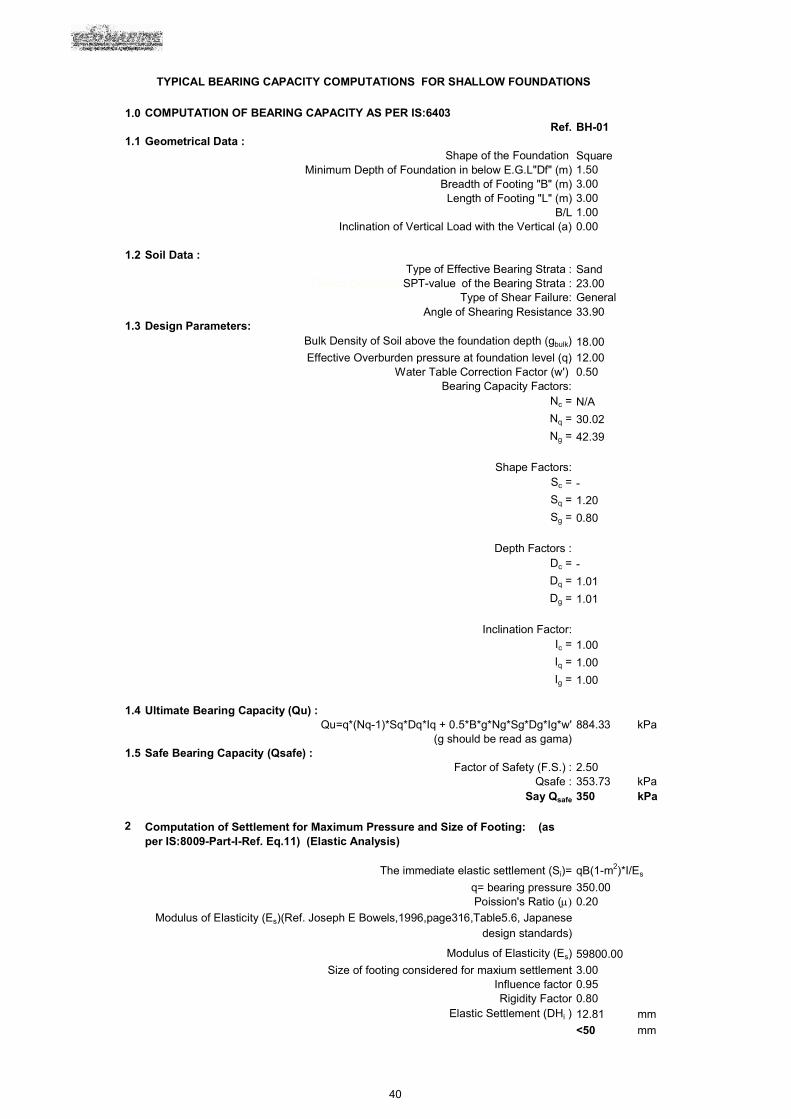
1.0 COMPUTATION OF BEARING CAPACITY AS PER IS:6403Ref. BH-01
1.1 Geometrical Data :Shape of the Foundation Square
Minimum Depth of Foundation in below E.G.L"Df" (m) 1.50Breadth of Footing "B" (m) 3.00
Length of Footing "L" (m) 3.00B/L 1.00
Inclination of Vertical Load with the Vertical (a) 0.00
1.2 Soil Data :Type of Effective Bearing Strata : Sand
Angle of Shearing Resistance 33.901.3 Design Parameters:
Bulk Density of Soil above the foundation depth (gbulk) 18.00Effective Overburden pressure at foundation level (q) 12.00
Water Table Correction Factor (w') 0.50Bearing Capacity Factors:
Nc = N/A
Nq = 30.02
Ng = 42.39
Shape Factors:Sc = -
Sq = 1.20
Sg = 0.80
Depth Factors :Dc = -
Dq = 1.01
Dg = 1.01
Inclination Factor:Ic = 1.00
Iq = 1.00
Ig = 1.00
1.4 Ultimate Bearing Capacity (Qu) :Qu=q*(Nq-1)*Sq*Dq*Iq + 0.5*B*g*Ng*Sg*Dg*Ig*w' 884.33 kPa
(g should be read as gama)1.5 Safe Bearing Capacity (Qsafe) :
Factor of Safety (F.S.) : 2.50Qsafe : 353.73 kPa
Say Qsafe 350 kPa
2 Computation of Settlement for Maximum Pressure and Size of Footing: (as per IS:8009-Part-I-Ref. Eq.11) (Elastic Analysis)
The immediate elastic settlement (Si)= qB(1-m2)*I/Es
q= bearing pressure 350.00Poission's Ratio ( 0.20
Modulus of Elasticity (Es)(Ref. Joseph E Bowels,1996,page316,Table5.6, Japanese design standards)
Modulus of Elasticity (Es) 59800.00
Size of footing considered for maxium settlement 3.00Influence factor 0.95Rigidity Factor 0.80
Elastic Settlement (DHi ) 12.81 mm
<50 mm
TYPICAL BEARING CAPACITY COMPUTATIONS FOR SHALLOW FOUNDATIONS
40
Design Corrected SPT-value of the Bearing Strata : 23.00Type of Shear Failure: General

41

TAMIL NADU WATER SUPPLY AND DRAINAGE BOARD CHENNAI.
INTERNATIONAL COMPETITIVE BIDDING
BID DOCUMENT
FOR
DESIGN, BUILD 60 MLD CAPACITY DESALINATION PLANT BASED
ON SEA WATER REVERSE OSMOSIS AT KOONIMEDU IN
VILLUPURAM DISTRICT, TAMIL NADU AND OPERATION AND
MAINTENANCE FOR 20 YEARS
IFB No: 15/DSP-VPM PkgI /DO/CE/VLR/2021/Dt.07-01-2021
VOLUME - II
SECTION VI – EMPLOYER’S REQUIREMENT
PART– II – STANDARDS AND SPECIFICATIONS
B. ELECTRICAL WORKS, SCADA,
INSTRUMENTATION CONTROL AND
AUTOMATION
The Chief Engineer, Tamilnadu Water supply and Drainage Board,
8, 1st East Main Road, Gandhinagar
Vellore - 632006 Phone No: 0416 2243743
Email ID: [email protected] Website: https://www.twadboard/tn.gov.in/tenders.html

PART II ELECTRICAL, SCADA, INSTRUMENTATION,
CONTROL AND AUTOMATION WORK

60 MLD Reverse Osmosis based Sea Water Desalination Plant near Koonimedu, Villupuram Tamil Nadu
i
TABLE OF CONTENTS
1.0 OBJECTIVE: .......................................................................................................................... 1
2.0 DESIGN CALCULATIONS REQUIREMENTS: ..................................................................... 15
3.0 PLANT POWER SUPPLY AND DISTRIBUTION: ................................................................. 19
4.0 OUTDOOR 110 KV SWITCH YARD: .................................................................................... 22
5.0 MAIN 110 KV/11 KV POWER TRANSFORMERS: ............................................................... 88
6.0 DISTRIBUTION TRANSFORMERS : .................................................................................... 91
7.0 11 KV INDOOR SUB STATION: ........................................................................................... 93
8.0 LOW VOLTAGE SWITCH GEAR:......................................................................................... 96
9.0 AUTOMATIC POWER FACTOR CORRECTION SYSTEM AND HARMONIC SUPPRESSION SYSTEM: ............................................................................................................................. 98
10.0 ELECTRIC MOTORS: ...................................................................................................... 100
11.0 VARIABLE FREQUENCY DRIVES: .................................................................................. 105
12.0 CABLES AND CABLE TRAYS/LADDERS: ....................................................................... 107
13.0 110 V DC BATTERIES, BATTERY CHARGERS AND UPS: ............................................ 109
14.0 LIGHTING AND SMALL POWER SYSTEM ...................................................................... 112
15.0 FIRE PROTECTION AND ALARM SYSTEM : .................................................................. 119
16.0 EARTHING AND BONDING: ............................................................................................ 121
17.0 LIGHTNING PROTECTION SYSTEM: ............................................................................. 122
18.0 LOCAL PUSH BUTTON PANELS (LPBS): ....................................................................... 123
19.0 DIESEL GENERATOR (DG): ............................................................................................ 123
20.0 ELECTRICAL INSULATION RUBBER MAT ..................................................................... 126
60 MLD Reverse Osmosis based Sea Water Desalination Plant near Koonimedu, Villupuram Tamil Nadu
1
1.0 OBJECTIVE:
The objective of this section is to broadly define the project requirement related to electrical
system design, equipment selection, filed installation, testing and commissioning. For specific
requirements related to individual equipment or sub system, contractor should refer to
corresponding sections of this specification. Only basic data sheets of equipment are provided in
the specification. Detailed vendor data sheet shall be submitted for approval by Engineer.
1.1. SCOPE WORK:
The Contractor shall design, fabricate, furnish, deliver, install, calibrate and shop test and site
test all power system equipment such as 110 kV supply outdoor, switchyard equipment,
transformers, switchgears, cabling, motors, generators, lighting, cathodic protection, fire system,
controllers all panels, control devices and interlocking equipment required to ensure the safe,
reliable and efficient operation of the plant in accordance with the requirement of Indian and
International.
The drawings are provided in the Tender Document as conceptual design guide and are not
complete. It is the responsibility of the contractor and their suppliers to provide detailed design &
engineering with all components necessary as per international standards to provide safe power
system to the entire plant.
The electrical scope of works shall comprise the design, supply, erection, testing and
successful commissioning of the following Electrical Items and Operation and maintenance.
110kV Outdoor Switchyard ( Power Supply through State DISCOM: TANGEDCO)
110/11 kV Power Transformers
415V Emergency Diesel Generator Set
11kV HV Switchgears, Motor Control Centre’s
11kV HV Bus duct
11/0.433 kV Distribution Transformers
LV Bus ducts
LV Switchgears, Motor Control centre’s & Distribution Boards
Power Factor Correction Capacitor Bank
MV VFDs

60 MLD Reverse Osmosis based Sea Water Desalination Plant near Koonimedu, Villupuram Tamil Nadu
2
LV VFDs & Soft Starters
Local Push Button Stations
Low voltage cables and terminations
Cable Trays & supports
Earthing and bonding system
Lightning Protection System
Lighting & Small power system
AC Uninterrupted Power Supply (UPS)
110V DC Battery & Battery Charger
Miscellaneous items
Submission of design documents/drawings, Installation, QA/QC procedures,
Commissioning procedures, training and O&M manuals.
Obtaining statutory clearance for installation, Operation and maintenance of HV / MV
Electrical Equipment from Department of Electrical Inspectorate, Govt. of Tamilnadu.
1.2. ENVIRONMENTAL REQUIREMENTS:
The site location of this plant is in a salt and dust laden atmosphere of up to 85% Relative
humidity. Peak summer temperature reaches 40°C as per IS-9676. The temperature at night
drops, resulting in condensation. These conditions attack instrumentation electric terminals,
contacts, etc., for which the Contractor must design protective measures. Any instrumentation,
not in an air conditioned atmosphere, shall be supplied with water proof, dust tight enclosures
confirming to IS/ IEC standard for the intended application. In addition, local instrument cabinets
shall also be weather proof and equipped with space heaters. Sun shields shall also be provided
and designed to protect cabinets from direct rays of the sun.
It is the Contractor's responsibility to design, furnish and install the electrical equipment, panels
to withstand and operate properly under the prevailing ambient conditions described above and
in the project requirements. This Standard serves as a guideline to the Contractor. The
Contractor shall make recommendations and include all the necessary equipment or protecting
devices based on his previous experience on similar installations.
Special precautions shall be taken in the selection of materials and the design of enclosures to
prevent failure and deterioration of mechanical and electrical components due to the prevailing

60 MLD Reverse Osmosis based Sea Water Desalination Plant near Koonimedu, Villupuram Tamil Nadu
3
humidity, high temperature and very corrosive atmosphere. As a minimum, all equipment
mounted in control rooms shall be suitable for operation at 40°C even with shutdown of air
conditioners. Field mounted equipment shall be suitable for operation up to 50°C and shall be
provided with sun/dust/rain shields. Electrical equipment located in area such as RO membrane
hall subject to water splash from leaking flanges or valves .All such installations like Junction
boxes, local panels should be sealed and fitted with drip shield.
1.3. DESIGN REQUIREMENTS:
1.3.1 DESIGN BASIS:
Equipment and system design should be based on Indian (IS) and International Standards (IEC,
ISO, IEEE) depending on the country of origin. Contractor should carry out the following design
studies:
Load flow studies
Insulation coordination
Short Circuit Calculations
Transient stability studies –particularly the operation of under voltage relay and bus
changeover condition
Motor start up studies including voltage drop calculation
Relay coordination studies.
The Contractor shall, where possible, use one manufacturer of International standing for the
supply of all similar equipment included in the Contract and shall obtain the maximum uniformity
of equipment.
The equipment shall be constructed to operate accurately and safely under the operating
conditions described or implied in this standard and the project specifications, without undue
strain, wear heating, vibration, corrosion or other operating troubles. Control panels and
instrument racks shall be arranged to permit convenient access to all handles, adjusting screws
and other elements which may require manipulation, and convenient observation of all dials or
scales used in operation or calibration.

60 MLD Reverse Osmosis based Sea Water Desalination Plant near Koonimedu, Villupuram Tamil Nadu
4
The electrical system and installation shall be designed to provide safety and reliability
avoidance of excessive voltage dip and copper losses; convenience of operation; provision for
supplying additional or increased loads and ease of maintenance
The Electrical System Frequency shall be 50 Hertz 3 phase.
Standard voltages are as follows:
110 kV Grid supply from TANGEDCO & Step down Voltage level of 11 kV - HV supply & 415 V -
LV supply
Indicating light shall be Red for ON, OPEN, in service, etc., and Green for OFF, closed etc. Both
red and green lights shall be on the intermediate position for motor actuated valves, dampers
etc.,
1.3.2 STANDARDS, CODES AND REGULATIONS:
All equipment to be supplied by the bidder shall conform to the requirements of latest revisions
of IEC, Indian Standards, Indian Electricity Rules, Relevant Code of Practices and requirement
of Electrical Inspectorate, Respective State Governments, Local Rules and Regulations etc.,
Wherever the Indian Standards do not exist the equipment / components shall be designed,
assembled and tested in accordance with the latest editions of the Standards of the International
Institutions, BS, Institution of Electrical & Electronic Engineers, USA (IEEE), National Electrical
Manufacture Association, USA (NEMA) and International Electro-Technical Commission (IEC).
In such a case the Bidder shall clearly indicate the standards adopted, furnish a copy of the
latest revision of standard along with copies of all official amendments and revisions in force as
on the date of submission of bid and clearly bring out the salient features for comparison. In
case of conflict, the most stringent one shall govern.
Copies of applied standard should be supplied to Client and the Consultant during design
review. If contractor wish to use standard of their country then a comparison table listing
features of specified standard and local standard with copies of both should be submitted.
A list of reference IS standard relevant to this project is listed in the table below:

60 MLD Reverse Osmosis based Sea Water Desalination Plant near Koonimedu, Villupuram Tamil Nadu
5
Sl. No
Standards Subject
1. IS :2026 Power Transformers
2. IS/IEC :60529 Degree of protection provided for enclosures
3. IS :2705 Current transformers.
4. IS:1180 Distribution Transformer
5. IS :3070 Lightning Arresters.
6. IS:9921 AC Isolators and Earthing Switches
7. IS:13118 Specification for HV Circuit Breakers.
8. IS:694 PVC cables 450/750 V
9. IS:9792 Testing ,Calibration and Maintenance of Electricity Meters
10. IS:15707 Testing ,Evaluation and Installation of AC Electricity Meters
11. IS:8623 Specification for LV Switch Gear
12. IS:2675 Specification for enclosed Distribution boards and cut outs.
13. IS:3231 Specification for electrical relays and power system protection
14. IS :3842 Application guide for Electrical Relays for AC system
15. IS:4146 Application guide for Voltage Transformers
16. IS:4201 Application guide for Current Transformers
17. IS:5578 Guide for marking insulated conductors
18. IS:10118 Code of practice for selection, installation and maintenance of switchgears and control gears
19. IS:8686 Specification for static protective relays
20. IS:11353 Guide for uniform system of Marking and identification of conductors and apparatus terminals
21. IS:13703 Specification of LV Fuses
22. IS:13947 LV Switchgear and Control gear specification

60 MLD Reverse Osmosis based Sea Water Desalination Plant near Koonimedu, Villupuram Tamil Nadu
6
Sl. No
Standards Subject
23. IS:15382 Insulation coordination for equipment within LV system
24. IS:3156 Voltage Transformer Specification
25. IS:325 Three Phase Induction Motor Specification
26. IS:1271 Specification for Thermal Evaluation and Classification Electrical Evaluation
27. IS:2253 Designation for type of construction and mounting of rotating electrical machines
28. IS:3043 Code of practice for earthing
29. IS:4029 Guide for testing of three phase induction motors
30. IS/IEC:60034 Rotating Machines
31. IS:4722 Rotating Electrical Machines-Specification
32. IS:4889 Method of determining efficiency of rotating machines
33. IS:6362 Designation of method of cooling of rotating electrical machines
34. IS :8789 Performance characteristics of three phase induction motors
35. IS:12065 Permissible limit for noise level for rotating electrical machines
36. IS:12615 Energy efficient induction motors
37. IS:14112 Impulse voltage withstands levels of rotating A.C machines with form wound stator coils.
38. IS:12824 Type of duty and classes of rating assigned to rotating electrical machines
39. IS:12802 Temperature rise measurement of rotating electrical machines
40. IS:12705 Measurement and evaluation of vibration severity of electrical rotating machines
41. IS:8223 Dimensions and output series of rotating electrical machines
42. IS:7816 Guide for testing insulation resistance of rotating electrical machines
43. IS:2848 Specification for Industrial Platinum Resistance Thermistors
44. IS:13925 Shunt capacitors for AC Power System

60 MLD Reverse Osmosis based Sea Water Desalination Plant near Koonimedu, Villupuram Tamil Nadu
7
Sl. No
Standards Subject
45. IS:2071 High Voltage Testing Techniques
46.
Regulations for measures related to safety and electric supply as per Central Electricity Authority Notification dated 20-9-2010
Electrical substation, outdoor switch yard
47. IS:9921 Alternating current Disconnectors and earthing switches
48. IS:2544 Porcelain post insulators
49. IS:3975 Mild steel wires for armouring of cables
50. IS:2486 Insulators for Overhead lines
51. IS:6745 Method of testing zinc coating
52. IS:3427 AC Metal enclosed switchgear and control gear
53. IS:4691 Degree of protection provided by enclosures for rotating electrical machinery
54. IS:4728 Terminal marking and direction of rotation for rotating electrical machinery
55. IS:6098 Noise Measurement
56. IS:12802 Temperature rise measurement of rotating electrical machines
57. IS:1885 Power Electronics
58. IEEE:519 Recommended Practice and requirement for harmonic control in electrical power systems.
59. IS :1554 PVC insulated (heavy duty) electric cables (for working voltages from 3.3kV upto and including 11kV)
60. IS:3961 Recommended Current Ratings For Polyethylene Insulated Cables
61. IS:7098 Cross-linked polyethylene insulated PVC sheathed cables for working voltages from 3.3 kV.
62. IS:8130 Conductors for insulated electric cables and flexible cords
63. IS:6600 Guide for loading of Oil Immersed Transformers

60 MLD Reverse Osmosis based Sea Water Desalination Plant near Koonimedu, Villupuram Tamil Nadu
8
Sl. No
Standards Subject
64. IS:10028 Code of Practice for selection, installation and maintenance of transformers
65. IS:16636 Automatic power factor Correction ( APFC) Panels for voltage Rating upto and Including 1000 V
66. IS:13585 Shunt Capacitors for AC Power Systems. Protection of Shunt Capacitors and Shunt Capacitor Banks
67. IS:4700 Alternators
68. ISO:3046 Reciprocating internal combustion engines
69. IS:16101 General Lighting - LEDs and LED modules – Terms and Definitions
70. IS:16102 Self- Ballasted LED Lamps for General Lighting Services- Safety and Performance Requirements
71. IS:16103 LED Modules for General Lighting - Safety and performance Requirements
72. IS:16104 D.C. or A.C Supplied Electronic Control Gear for LED
73. LM80 Measuring Luminous Flux and Color Maintenance of LED Packages, Arrays and Modules
74. IS:418 Tungten Filament General Purpose lamps
75. IS:900 High Pressure Mercury Vapour Lamps
76. IS:9583 Emergency Lighting
77. IS:9974 High Pressure Sodium Vapour Lamps
78. IS:1258 Lamp Holders
79. IS:1885 Lamps and auxiliary apparatus
80. NACE–RP-0169,0387,0492
National Corrosion Engineers NACE (USA) Recommended Practice for Control External Corrosion
81. NACE-RP-05-72 Design, Installation, Operation and Maintenance of Impressed Current Deep Ground Beds
82. BS 7361 Cathodic Protection Code Practice for Land and Marine Application
83. IS 732:1989 Code of Practice for Electrical Wiring Installations.
84. IS 2309:1989 Protection of Buildings and Allied Structures Against Lightning - Code of Practice.
85. IS 2418:Part1:1977 Specification for Tubular Fluorescent Lamps for Lighting Services-Part1: Requirement & Tests.

60 MLD Reverse Osmosis based Sea Water Desalination Plant near Koonimedu, Villupuram Tamil Nadu
9
Sl. No
Standards Subject
86. IS 3231 Specification for Electrical Relays for Power System Protection.
87. IS 3854:1997 Switches for Domestic and Similar Purposes - Specification.
88. IS 6701:1985 Specification for Tungsten Filament Miscellaneous Electric Lamps.
89. IS 8686:1977 Specification for Static Protection Relays.
90. IS 13947-2:1993 Specification for Low Voltage switchgear and Low Voltage- Part 2: Circuit Breakers.
91. IS/IEC 309-1:1988 Plugs, Sockets-Outlets and Couplers for Industrial Purposes-Part 1: General Requirements.
92. IS/IEC 309-2:1989 Plugs, Sockets-Outlets and Couplers for Industrial Purposes-Part 2: Dimension Inter changeability Requirements for Pin and Contact Tube Accessories.
93. ISO 1461:1999 Hot dip galvanised coatings on fabricated iron and steel articles. Specifications and test methods.
94. ISO 2112:1990 Specification for amino plastic moulding materials.
95. ISO 5657:1986 Fire tests on building materials and structures. Method of measuring the ignitability of products subjected to thermal irradiance.
1.3.3 DESIGN DOCUMENTATION/DRAWINGS REQUIREMENTS:
Load Schedule :The Contractor shall prepare and submit a Master Load Schedule with details
on tag no of equipment, description, location, rating, intermittent or continuous service, duty or
standby service, duty factor, supplier, Ordering Code, Data Sheet No etc., The list shall
contain all electrical items, instrument panels ,Utilities panels such as Lighting, HVAC, Fire
System and their accessories, including items furnished as part of a package, such as lube oil
units etc.,. Microsoft EXCEL format with key for sorting shall be used for this purpose. Revisions
of this document should be made based on design progress of electrical works.
Specification Sheets - The Contractor shall complete specification sheets for all electrical items.
Specification sheets shall ordering code, purchase order number, equipment manufacturer and
local service centre address, web id and e- mail id and should be submitted along with the
technical literature of the manufacturer for approval.

60 MLD Reverse Osmosis based Sea Water Desalination Plant near Koonimedu, Villupuram Tamil Nadu
10
Drawings: All drawings should be produced using latest revision of AUTOCAD software.
Multilayer drawings should be prepared for cable routing to show all interference caused by
piping and equipment installed. Drawings containing more details such as single line diagram,
cable tray routing, earthing details etc., should be prepared in A0 size. Panel wiring details could
be printed in A2 or A3 size. Data sheets, terminal box drawing could be in A4 size.
Contractor shall furnish the following drawings and documents as a minimum:
-Individual Electrical Single Line Diagrams for HV, MV, LV ,DC distribution systems .These
signal line diagram should be in detail containing voltage, frequency ,maximum current,
interrupting capacity of breakers, bus short circuit ratings at specified temperature, transformer
ratings, % impedance, X/R ratio, primary and secondary winding configuration, interrupting
capacity of fuses ,grounding device ratings, protective devices and their ratings .motor starters
,motor ratings ,auxiliary transformers with ratings etc.,
Control schematic diagram.
Panel Layout in various switchgear rooms.
Wiring diagram of all switchgears and control panels containing panel construction
details ,painting details ,front panel layout ,component list ,interlock details etc.,
Cable routing (Above and Underground) drawings.
Cable tray and duct, manhole, channel, cable bridge drawings.
Motor terminal arrangement drawings.
Electrical loop drawings.
Earthing and bonding drawings.
Provision of lighting earthing.
Lighting layout drawings. Lighting panel wiring drawings.
Socket outlet drawings.
Wiring diagram of local panels, junction boxes.

60 MLD Reverse Osmosis based Sea Water Desalination Plant near Koonimedu, Villupuram Tamil Nadu
11
Cable schedule containing cable tag no, origin, destination ,tray no ,duct no ,size ,length,
voltage , type etc., Drawing of underground cable shall include detailed routing showing
interface to other underground utilities ,trenches ,manholes ,elevation of ducts,
coordinates etc.,
Cable Interconnection diagram showing vendor equipment terminal numbers.
Apart from these broadly defined drawings, contractor should submit other drawings
considered essential for operation and maintenance of the plant.
Units of Measurements: SI units in accordance with ISO 1000 shall be adopted.
1.4 .INSTALLATION REQUIREMENT:
Accessibility: All panel components shall be readily accessible from the floor level. Access
ladder and platform shall be provided wherever it is not possible to access panel components
Illumination: All the equipment and panels shall be located in areas well illuminated or separate
lights shall be fixed near the instrument stand to facilitate easy reading during day and night
shifts.
Provision for Thermal Expansion: Parts subject to substantial temperature changes shall be
designed and supported to permit free expansion and contraction without causing harmful
distortion or misalignment.
Vibration Dampeners: Vibration dampeners shall be furnished for isolation of equipment cubicles
and panels from vibrations transmitted through the supporting floors or structures.
Local Control Panels: LCP should be with a transparent front door to view the local indicator.
Material: As the site location near sea, air is very corrosive and hence all outdoor Electrical
Panels / accessories /Fittings shall be non- metallic. The MOC of Junction Boxes / Local Control
Panels (LCPs) shall be non- metallic and made of high quality thermos plastic either in
Polycarbonate / Polystyrene with IP 65/66/67, ANSIC136.20 1900 standard Glass Reinforced
Plastics lighting poles shall be used for Man way platform lighting & Street Light. All cable trays
and accessories shall be corrosion / chemical resistant, weather and ultraviolet light resistant.
Cabling: Cables carrying power supply to transmitters, PROFIBUS signals, and conventional 4 -
20 mA signals shall be segregated in the panels, cable trays and underground ducts. These

60 MLD Reverse Osmosis based Sea Water Desalination Plant near Koonimedu, Villupuram Tamil Nadu
12
signals and should be separated at least by 500 mm from high current cables and if required to
cross them then it should be at right angle to each other to avoid noise due to switching. All
cables should be numbered such a way as to identify its start and end point.
Cable Pits: Cable pits should be numbered and a site cable duct layout should be submitted for
approval. All deep cable pits shall be fitted with FRP ladder and light for maintenance.
Glands: Suitable glands to be used for all cable termination subject to material approval. Unused
cable glad ports are to be sealed.
Sealing: After installing the cable, base of all panels, conduits should be sealed using fire rated
material.
Enclosure Rating: All indoor electrical panels must meet IP 44 requirements and those located
outdoor shall meet IP55 requirement. However, the outdoor panels shall be fitted with rain and
sun shield .Electrical panel mounted inside electro chlorinator room must meet explosion proof
rating. Panels for fire system must meet NFPA standard.
Local Control Panels (LCP): Local control panels are to be used for local start /stop /emergency
stop of equipment, control of package systems like travelling screens, compressors, cathodic
protection etc., These LCPs should provide easy access for maintenance. Sufficient space
around the LCP to be provided to open the panel doors fully .Panel lighting with door switch and
space heaters should be provided.
The MOC of Local Control Panels (LCPs) shall be non- metallic and made of high quality
thermo- plastic ( Polycarbonate / Polystyrene) with IP 65/66/67. LCPs to be provided with safety
power earthing. All front panel controls should be accessible from the floor. Front panel should
be thicker and rigid to support panel components. Panels should be fitted with lifting hooks, door
lock and handle. Panels should be fitted with sealed transparent front panel view port to read the
panel meters .This view ports should withstand the high pressure water leaks from the
compression fittings. All panels mounted close to RO rack must be fitted with drip shield.
Painting:
Powder coating with primer and two coats capable of withstanding corrosive sea water contact
should be provided for metallic structures. Applicable standard IS 5.

60 MLD Reverse Osmosis based Sea Water Desalination Plant near Koonimedu, Villupuram Tamil Nadu
13
1.5. FACTORY ACCEPTANCE TESTING:
All equipment must be shop tested as per approved procedure confirming to Standards .All main
equipment used in this project should have been type tested and a copy of the test certificates
should be furnished.
If the supplier chosen for major equipment is new then type test certificate from the supplier
must be submitted for selected capacity of equipment supplied earlier as a part of pre-
qualification.
One month prior notice should be submitted to client and consultant containing details regarding
the place of test, schedule, test duration, list of approved applicable drg/doc.
Three copies of certified shop test documents with tester seal should be submitted in box files
immediately after the test for review and approval for shipment of equipment.
Client/Consultant will witness shop testing of major equipment such as Transformers , HV / MV
Motors, HV/MV cables, UPS/Rectifier, HV/MV/LV SWGRs, HV/MV VFDs and others as desired
by the client.LV
Equipment should not be shipped to site without prior permission of the client.
1.6. SITE TESTING:
All equipment should be subject to site test as per approved procedure under the supervision of
the consultant.
Contractor should arrange all test equipment at their cost and a certified tester to carry out these
tests. Test equipment must be calibrated with test record and its validity.
Records of all site test with signature of the tester and company seal should be submitted in 3
copies for review and approval in proper files. Individual test reports shall be bounded together
with all test reports associated with a system.
All tested equipment should be tagged containing the date of test and its validity period.
Any defect noticed during tests shall be recorded and informed to the client/ consultant and shall
be replaced if the defect is severe.

60 MLD Reverse Osmosis based Sea Water Desalination Plant near Koonimedu, Villupuram Tamil Nadu
14
1.7 TAG PLATES AND NAME PLATES:
Name plates of equipment containing its tag no, model no, serial no and other technical data as
per approved name plate drawing should be installed by the supplier of equipment at a visible
location fixed with two screws .It shall be made of 2 mm SS 316 L plate. All equipment should
also be fitted with 2 mm thick stainless steel 316 L Tag Plates containing tag no; tag description
in English engraved in the plate with black lettering. Size of fonts shall be as per consultant
approval.
1.8 PANEL WIRING:
All wires should carry approved ferrule, lugs.
Screws on terminal blocks should be non-removable type and accommodate the lugs selected.
Signal wires should separate from power wires in separate trucking.
Electrical power terminals and panel lighting should be protected from water splash at high
pressure from leaking instrument fittings .Panel lighting should be blast proof to meet water
splash
1.9 JUNCTION BOXES:
Standard cabinets with numbered terminal blocks are preferred for this application. JBs should
be fitted with earthing stud at the side for panel safety earthing. Cable gland plate with
prefabricated holes is required. Glanding should be at the bottom of the JB. Unused gland holes
should be sealed. JBs should be tagged.
1.10 SAFETY:
Extreme safety precaution shall be ensured during tests and energisation of electrical equipment
.Only qualified and certified persons shall be engaged in such works .Test are shall be cordoned
off in case it involves high voltage .All equipment having tendency to store electrical energy
shall be discharged after each test in a safe manner .
Fire hazard material such as paint cans, thinners and other inflammable materials shall not be
stored near electrical installations.

60 MLD Reverse Osmosis based Sea Water Desalination Plant near Koonimedu, Villupuram Tamil Nadu
15
No grinding and cutting activities which generate spark shall be done in the vicinity of electrical
installations.
1.11 CLEANING:
All unwanted materials such as bits of cables, wires, insulation etc., shall be thoroughly cleaned
immediately after completing the work. All accumulated dirt’s below raised floor must be cleaned
using vacuum cleaner on regular basis. Panel shall be cleaned using blower or vacuum clear in
reenergized condition without causing damage to sensitive components.
All cable trays, ladders, conduits and duct banks shall be cleaned before installing cables using
dry air and obstructions in ducts shall be checked using tennis ball of blown out by air.
2.0 DESIGN CALCULATIONS REQUIREMENTS:
2.1 INTRODUCTION:
This part describes the design calculations to be submitted by the contractor to prove the
adequacy of sizing of transformers, motors, cables, switchgears, grounding devices, busbars,
protective devices, rectifier, batteries and inverters, lighting, cathodic protection etc., All design
calculations should be as per relevant standards and copies of used standard should be
submitted along with the calculation for approval.
2.2 LOAD ANALYSIS:
In order to size the transformers, contractor should submit a load schedule based on process
design listing the capacity of all pumps and required motor capacity ,package unit power
requirement, HVAC loading, Lighting power required. While listing the load for analysis, duty
factor of motor should be taken in to account based on whether they are on duty /standby,
continuous or intermittent use etc., HVAC load estimate should be based on peak summer
demand. Lighting load estimate should be based on night time lighting requirement.
Contingency allowance of minimum 10 % should be provided in estimating total load demand.
Load list should be updated based on progress of process design.
2.3 CABLE SIZING:
Sizing cables and conductors should contain following supporting information:

60 MLD Reverse Osmosis based Sea Water Desalination Plant near Koonimedu, Villupuram Tamil Nadu
16
Manufacturer’s published data as per International standard containing the current ratings of
cables and conductors and short-circuit time-current curves.
Cable de-rating factors based on whether cable or conductor is rated in free air, underground
duct banks, above-grade conduits, wire ways or cable tray, ambient or soil temperatures
assumed and corresponding rating correction factors, raceway grouping correction factors and
per cent loading assumed for underground cables in duct banks and trenches and de-rating
factors for multiple conductors in raceways.
Voltage drop in the motor terminal is 5% during normal condition and 15% during starting and
voltage drop in the light fixtures to be maintained at 3%.
2.4 FAULT CURRENT CALCULATION:
Fault current calculation should be based on International Standard such as IEEE Standard 141,
-Recommended Practice for Electrical Power Distribution for Industrial Plants.
Fault current calculation submittal should include all supporting information on X/R ratio of
transformers, impedance of all connected loads, single line diagram with system impedances,
basic assumptions, contribution of motors to faults, symmetrical short circuit rating and latching
capability of the circuit breakers necessary for protecting the system.
The calculation shall establish the minimum and maximum fault current that may occur in the
system.
2.5 RELAY COORDINATION STUDIES:
In order to arrive at an optimum setting of all protective relays, contractor should carry out the
relay protection coordination study and submit their results along with
supporting details such as simplified single-line diagram showing the protective devices and
associated current and potential transformer, relay manufacturer type designation and ranges,
as applicable, for all protective devices., selected relay settings circuit breaker trip settings and
fuse sizes, Time-Current diagrams showing the coordinated minimum and maximum clearing
time curves for the selected settings and sizes of the protective devices, motor starting and
running currents, calculated fault currents, equipment protection requirements, inrush currents
and references that were used in establishing the settings and sizes of the protective devices,

60 MLD Reverse Osmosis based Sea Water Desalination Plant near Koonimedu, Villupuram Tamil Nadu
17
copies of the Vendor’s characteristic curves for all relays, fuses and circuit breaker trips used of
equipment protection and vendor’s instruction manuals for all protective devices, tripping
scheme for the main electrical equipment such as: main transformers, MV motors etc.. This
study report should be finalised when all the loads are clearly defined.
2.6 VOLTAGE REGULATION CALCULATIONS:
The Contractor should submit voltage drop calculation to verify worst case voltage drop and
available terminal voltage across the equipment to verify whether it is within limit stipulated by
the supplier.
Worst case voltage dip while starting of heavy duty motors should be submitted. Similarly the
Contractor shall give consideration to the maximum voltages that may occur in the electrical
System under lightly loaded conditions.
Based on the system evaluation, a listing of the recommended tap settings for all fixed tap
transformers should be submitted.
2.7 ILLUMINATION LEVEL CALCULATIONS:
Illumination calculation as per IS/IES requirement to be submitted for each area, rooms in
buildings taking into consideration the interference to direct light caused by obstruction in light
path, vendor data on lux level of selected light fittings, reflection and absorption from building
etc. Illumination required for each application and area shall be as specified in this contract.
2.8 POWER FACTOR IMPROVEMENT:
The power factor of all equipment shall be around 0.90 power factor improvement measures
should be adopted if the p.f value is expected to be below this limit and the design calculation
shall be submitted to check the voltage raise caused by the p.f improvement capacitor.
For maintaining a high overall power factor upto 0.99 lagging, static / automatic power factor
control capacitor banks of suitable kVAR rating and voltage grades shall be considered, as
required for the HV (11kV) system. For compensation of LV loads, multi-step Automatically
Controlled Capacitor Banks shall be installed for connection on the respective departmental
PCCs and MCCs to improve the power factor to 0.95 lagging and above (415V).

60 MLD Reverse Osmosis based Sea Water Desalination Plant near Koonimedu, Villupuram Tamil Nadu
18
2.9 INSULATION COORDINATION STUDY:
The Contractor shall carry out insulation coordination study, and if found necessary, shall
provide surge arrestors on each bus section of all switchgear. The study shall also be done to
determine undesirable level of residual voltage wave that may be transferred from the network
side arrestors.
Over voltages in motor feeders which may occur in the event of switching high voltage motors
by vacuum breakers shall be prevented by suitable measures.
2.10 EARTHING AND BONDING:
The contractor shall carry out earthing calculations based on soil resistivity test and detailed
design of the power system to achieve lowest earthing resistance and minimise touch potential
within safe limit. Base on this analysis the size and number of earthing rods, earthing cable
sizes shall be designed. All the metallic parts such as motor base, structural columns, cable
trays, Junction boxes, cabinets etc.,shall be bonded to site earthing system. HT and MV power
system shall be liked to two earthing wires to avoid danger in case of snapping of one earthing
cable. Signal earthing shall be isolated from electrical earthing. If any metallic structure such as
steel tank is linked to cathodic protection then isolation shall be provided at flanges.

60 MLD Reverse Osmosis based Sea Water Desalination Plant near Koonimedu, Villupuram Tamil Nadu
19
3.0 PLANT POWER SUPPLY AND DISTRIBUTION:
The objective of this specification is to broadly define the site power supply and its distribution to
various electrical utilities. This specification describes the design, supply, erection, testing and
commissioning of Site Power Supply and its distribution.
The scope of work of the bidder includes providing Incomer power switching yard. Tri Vector
tariff metering room for the Electricity Board. Transformer yard, Substation to locate the
switchgear, VFDs, converter transformers, Distribution transformers, Lighting transformer, PCC,
PMCC, MCC, DC system, PDBs etc.
The scope also includes coordination with other Contractors / TANGEDCO / Electrical
Inspectorate for obtaining statutory approval. Preparing and submitting drawings / documents for
approval by Client / Consultant the basic design, detailed design data sheets, vendor technical
documents shop test documents O & M manuals etc, It is contractor’s responsibility to obtain
statutory approvals related to the works as defined in this specification including preparation of
drawings, carrying out required rectification works if requested by the statutory authorities at no
extra cost to the client, preliminary and final acceptance tests, rectifying any defects observed
during carrying execution of preliminary and final acceptance tests, commissioning and handing
over of plant electrical power system and equipment to the Client.
The scope of work mentioned in various other sections of this specification shall be treated as
complementary to the scope mentioned here. The tenderer shall visit the site and assess the
complete scope of work and familiarize.
A dedicated 110 KV Power supply connection at Site has to be obtained through TANGEDCO. It
is contractor's responsibility to assess the cable routing and exact length. The Over-Head
/underground Lines shall terminate in the metering facility established by TANGEDCO inside the
periphery of plant boundary. The 110 kV feeder line shall be brought to the site as per
TANGEDCO norms. At the site land has to be allocated to enable TANGEDCO to install their
sub-station if any, pole switch, required incomer meter, inter trip load break switch etc. Area
around the pole structure shall be fenced with a lockable gate and warning signs.

60 MLD Reverse Osmosis based Sea Water Desalination Plant near Koonimedu, Villupuram Tamil Nadu
20
Power requirement for non-process requirement shall be reduced by using energy saving design
of lighting using LED lighting, Inverter A/C s for admin building, natural ventilation and lighting in
process areas etc.,
The plant has a large number of equipment which are to be driven by means of electric motors
for safe and efficient operation. It is envisaged that the major equipment like RO Feed High
Pressure Pumps, RO CIP Pumps etc. shall be driven by means of squirrel cage Medium Voltage
motors of suitable rating. It is also envisaged that suitable variable speed drives shall be used
wherever applicable for energy conservation such as RO High Pressure feed pumps, ERD
booster pumps, UF feed and back wash pumps.
The type of drives considered shall be based on following requirements:
Speed / torque characteristics of the driven equipment
Enclosure protection depending upon the work environment
Performance characteristics, i.e. high power factor and efficiency at operating points
Accuracy and range of speed control required for specific application.
All motors, generally above 250kW (>250kW) shall be connected at 11kV (either directly through
soft starter or through 11/xx/xx kV Inverter Transformer for VFD driven pump motors, where
“xx” stands for 6.6 or 3.3 or 0.69 kV) and motors up to 250kW (<=250kW) at 433V.Transformer
secondary voltage for VFD driven pumps shall be decided during detail design stage.
Voltage Levels:
1 Incoming HT 110kV ,50 Hz + 5%, 3 Ph, AC, Solidly Earthed
2 Distribution Voltage 11kV ,50 Hz + 5%, 3 Ph, AC, Resistance Earthed ; 415 V ,50 Hz,3 Ph, Solid ground
3 Control Voltage (for HT) 110V DC obtained from Batteries & Battery Charger
4 Control Voltage (for LT) 230V AC obtained from Control Transformers
5 Lighting Fixtures 230V AC
6 Small Power Sockets 230V, 3 Wire AC
7 Welding Receptacles 415V, 3 Ph, 4 Wire AC
8 Process Instrumentation 24V DC from DCS

60 MLD Reverse Osmosis based Sea Water Desalination Plant near Koonimedu, Villupuram Tamil Nadu
21
Power Supply Variations:
Voltage Level Voltage Variation Frequency Variation
230V + 10% + 5%
415V + 10% + 5%
11 kV + 10% + 5%
110 kV + 10% + 5%
Combined Voltage and Frequency Variation +10%
Fault Levels:
Voltage Level Short Circuit Rating in kA
110 kV 40 kA, 3 sec
11 kV 40 kA, 3 sec (Switch Yard & MRSS)
11 kV 40 kA, 1 sec (In process areas)
415 V 50 kA, 1 sec
System Earthing 110kV Side – Solidly Earthed 11kV Side – Resistance Earthed (NGR)
Climatic Conditions:
Ambient Temperature 500C
Relative Humidity 85%
Height above Mean Sea
Level
Very near the sea shore .Less than 10 M above
MSL.
Atmosphere Highly Saline and Dusty ,Rain during two monsoon
seasons

60 MLD Reverse Osmosis based Sea Water Desalination Plant near Koonimedu, Villupuram Tamil Nadu
22
4.0 OUTDOOR 110 KV SWITCH YARD:
4.1 SCOPE
The work shall include but not limited to the following:
Complete design, detail engineering, manufacture/procurement, supply, transportation to site,
storage and safe custody at site, installation, testing and commissioning and handling over the
switchyard related equipment.
Supply of materials and miscellaneous items for 110kV Switchyard shall include but not limited
to the following:
5 Nos. of 110 kV, 1250 A, 3 pole, 40 kA, 1 sec, SF6 breaker.
5 Sets of 36 kV, 1250 A, 40kA, 3 phase double break, center pole rotating type, manually
operated isolator with Earth switch.
4 Sets of 110 kV, Single phase, oil cooled current transformers.
4 set of 110 kV, Single phase, oil cooled potential transformers.
1 set of 110kV IPS tube bus arrangement with structure arrangement.
Control and Relay Panels for the line and transformer bays.
110V DC system shall be provided with 1x100% battery bank (Minimum 100AH) and
Battery Charger consists of two no’s (2) of Float cum Boost Chargers.
Complete power, control and instrument cabling from the switchyard to marshaling box,
junction boxes, I/Os for switchyard equipment, C&R Panel, etc.,
All Power cables shall be of Aluminium, XLPE insulated, Armoured and FRLS outer
sheath and all control and instrument cables shall be of Copper, PVC insulated, Ar-
moured and FRLS outer sheath.
Conduits, cable gland, lugs, clamps, cable marker, ferrules, etc.
Pre-fabricated cable trays and all supports (GI).

60 MLD Reverse Osmosis based Sea Water Desalination Plant near Koonimedu, Villupuram Tamil Nadu
23
One Lot - Aluminium Tubular busbar, Aluminium Tube, ACSR conductor, tension, sus-
pension and bus post insulators, clamps and connectors, nuts and bolts, washers, in-
serts, shim etc.,
Consumables such as welding rods and gas, oil and grease, cleaning fluids, insulating
tape, anti-corrosive paints / touch up paints, jute, cotton waste etc. as required for the
complete installation.
Switchyard AC Distribution Board, DC Distribution Board.
Illumination System, Lighting fixtures with lamps and accessories, switchboards, recep-
tacles, switch, etc.
Conduit and accessories, junction and pull boxes, terminal blocks.
All supports, brackets, anchors, clamps, Copper wire / flats and connection.
Lightning masts, towers and beams including all type of bolts, nuts, hangers, shackles,
clamps, step bolts/ ladders.
Lot complete grounding grid of the switchyard.
Lot complete lightning protection equipment.
Materials (CI Pipe/G.I. flat) for grounding and lightning protection.
Lot structural works required for equipment foundations, cable tray, supports and covers
for burnt oil tank soak pit, rails, fencing, gates, and drainage system.
Chequered plates inside control room.
Lot auxiliaries and safety equipment like caution boards, shock hazard chart, sand buck-
ets, portable fire extinguishers, first aid box, HT gloves etc.,
Set of design, detailing and construction drawings required for the RCC structures re-
quired for the items like foundations, cable trench, soak pit etc., and other statutory re-
quirements. The drawings shall include:
Foundation for equipment in switchyard area, trestles, towers, etc,
RCC cable trenches

60 MLD Reverse Osmosis based Sea Water Desalination Plant near Koonimedu, Villupuram Tamil Nadu
24
Preparation of fabrication drawings for all structural steel works and bar bending
schedule for all RCC works in switchyard area
Chain link fencing system and gates
Culvert RCC pavements showing the cable Pipe requirements
Lot special tools and tackles required for operation and maintenance.
4.2 OUTDOOR TYPE SF6 GAS OPERATED CIRCUIT BREAKERS
GENERAL
The equipment supplied by the vendor shall be complete in all respects. Any material or
accessories which may not have been specifically mentioned, but which are usual or necessary
for satisfactory and trouble free operation and maintenance of the equipment, shall be furnished.
CODES & STANDARDS
The design, construction, manufacture, inspection, testing and performance of circuit breakers
shall comply with all currently applicable statutes, regulations and safety codes. Circuit breakers
shall also conform to the latest revisions of relevant IEC Standards, some of which are listed
below:
IEC 62271-100 - High Voltage alternating current circuit breakers
IS: 2516 - Alternating Current Circuit Breakers Part 1 requirements
section 3 (Voltage above 11kV)
IS: 375 - Marking and arrangement for switchgear busbars, main and
connections auxiliary wiring
IS: 2165 - Insulation coordination
IS: 2544 - Porcelain post insulators for systems with nominal voltages
greater than 1000 volts.
IS: 5621 - Hollow insulators for use in electrical equipment
IS: 3202 - Code of practice for climate proofing

60 MLD Reverse Osmosis based Sea Water Desalination Plant near Koonimedu, Villupuram Tamil Nadu
25
DESIGN REQUIREMENTS OF EQUIPMENT
The breaker shall be of outdoor type, three phase system voltage 126 kV, 40 kA short time
breaking rating for duration of 3 Sec, Power frequency withstand voltage of 192kV rms, Impulse
withstand voltage of 550kV minimum and creepage distance suitable for polluted atmosphere
not less than 31 mm/kV. The breaker shall be designed for the operating duty of O-0.3s-CO-
3min-CO.
All materials used shall be suitable for operation under the conditions specified and shall
withstand the atmospheric conditions at site.
The maximum temperature rise in any part of the equipment at specified rating shall not exceed
the permissible limits, as stipulated in relevant standards. The derating of the equipment shall be
done, considering the ambient temperature for design of electrical equipment.
Circuit breaker shall be capable of interrupting low inductive currents such as magnetizing
current of power transformers without excessive over voltage factor shall be not more than 2.3
p.u.
The breaker shall be provided with local emergency tripping arrangement.
The minimum safe clearance of all live parts of equipment shall be as per relevant International
standards.
CONSTRUCTIONAL FEATURES
SF6 Circuit breaker shall consist of three identical single phase units with common spring
operating mechanism suitable for specified duty.
The breaker mechanism shall ensure that all the three poles of the breaker shall close
simultaneously.
Each circuit breaker pole shall consist of one breaking unit, support insulator, base frame and
connecting link.
In case the supporting structure forms an integral part of the circuit breaker, the same shall be
hot dip galvanized.

60 MLD Reverse Osmosis based Sea Water Desalination Plant near Koonimedu, Villupuram Tamil Nadu
26
The breaker shall be designed to ensure the condensation of moisture is controlled.
Two numbers of grounding pads shall be provided on each breaker pole and also on the
mechanism box for connection to the main earth grid.
Separate SF6 Gas cylinder along with suitable gas system incorporating required gas stop
valves, copper piping of suitable size shall be provided.
MAIN CONTACTS & AUXILIARY CONTACTS
The tip of the main contacts shall be heavily silver plated. The arcing ring and plug contact tip
shall be of copper tungsten. The auxiliary contacts shall be convertible type, so that "NO"
contact can be converted into "NC" contact and vice-versa and shall be located in an accessible
position for easy replacement.
All auxiliary contacts, including spares, shall be wired up to terminal block in the control cubicle.
OPERATING MECHANISM
The circuit breaker operating mechanism shall be of motorized spring charging type, provided
with electrical and mechanical anti-pumping device and trip free features. An insulated actuating
rod shall connect the moving contact with the lever of circuit breaker operating mechanism.
The circuit breaker shall normally be operated by remote electrical control. However, facility
shall also be provided for local electrical closing of the circuit breaker from local control cubicle
along with the provision of local/remote selector switch. Conveniently located manual tripping
arrangement shall be provided for tripping the circuit breaker locally. Closing and tripping coils of
the circuit breaker shall be rated for direct operation on 110V DC without the use of series
resistor.
The circuit breaker shall be provided with two trip coils. The trip coil shall operate correctly of
supply voltage between 90 to 110% of the rated voltage.
Mechanical `ON' - `OFF' indicator shall be provided for each pole of the circuit breaker.
Spring charge Motor Power circuit voltage shall be 230V AC, 50Hz supply.

60 MLD Reverse Osmosis based Sea Water Desalination Plant near Koonimedu, Villupuram Tamil Nadu
27
PORCELAIN INSULATORS
The porcelain insulators shall be made from wet process and shall be homogenous, free from
lamination, cavities and other flaws, which may impair the mechanical or dielectric strength.
They shall be thoroughly vitrified, tough and impervious to moisture.
Glazing of porcelain shall be of uniform brown colour, free from blisters, burns, cracks and other
defects.
The minimum creepage distance shall be as stipulated in specific requirements. The petticoats
shall be spaced for natural cleaning action of wind and rain so as to avoid concentrated hot
spots where local stress can precipitate a flashover. Insulators shall be suitable for satisfactory
operation in heavily polluted atmosphere.
All insulators of identical rating shall be interchangeable.
All joints shall be fluid-tight and air-tight. The design of insulators shall be such as to produce
uniform compression pressure joints.
Each bushing shall be provided with aluminium terminal connectors suitable for connection with
Aluminium IPS Tube.
ELECTRICAL AND MECHANICAL INTERLOCKS
All electrical and mechanical interlocks which are necessary for safe and satisfactory operation
of circuit breaker shall be incorporated in the design and construction of the circuit breaker.
Each circuit breaker shall be suitable for sequential interlocking with other associated
equipment, both for closing and tripping operations. Castle key interlock shall be provided for
each circuit breaker for interlocking with the isolators. Also two similar locks for mounting on
isolators shall be supplied along with each circuit breaker.
LOCAL CONTROL CUBICLE
The local control cubicles shall accommodate emergency hand trip devices, local/remote
selector switch, and local control switch, indicating lamps, auxiliary contacts, terminal boards,
fuses, space heater and necessary lockout features.

60 MLD Reverse Osmosis based Sea Water Desalination Plant near Koonimedu, Villupuram Tamil Nadu
28
Provision for padlocking all the cubicle doors, selector switches in either position and switches in
neutral position shall be made.
The control cubicle shall be fabricated out of minimum 2.5 mm thick CRCA sheet steel and shall
be of dust, damp and vermin proof construction. The enclosure shall be suitable for outdoor
installation, IP 55 as per IEC/IS Standards. A sheet steel canopy shall be provided as additional
protection from rain. The cubicle shall be free standing and shall have hinged doors at the front
and sides for access to the mechanism. All mating surfaces shall be provided with neoprene
gaskets. The control cubicle shall accommodate operating mechanism of the circuit breaker,
and other accessories to conform to the operating duty requirements.
A removable undrilled gland plate, 3.15 mm thick, shall be provided at the bottom of the cubicle
for termination of cables. All terminals shall be stud ELMEX type. The distance between gland
plate and terminal block shall be at least 200 mm.
Thermostat controlled anti-condensation space heaters with MCB, shall be provided. No space
heater shall be kept continuously energized. Suitable cubicle illumination lamps shall be
provided with door operated switch.
The cubicle shall be designed such that it will prevent mal-operation of any component due to
vibration. The height of the cubicle shall be adequate for ease of operation. Provision shall be
made to keep one set of the circuit diagram and wiring diagram, giving terminal numbers, etc.,
inside the cubicle for maintenance.
All components in the cubicle shall be fully wired up to terminal block, using minimum 2.5 mm²
stranded copper conductor PVC insulated wires. Not more than two wires shall be connected at
any one terminal. Colour code for wiring shall be provided.
Contacts of all auxiliary equipment such as density monitors pressure switches, auxiliary
contacts, etc., mounted on the circuit breaker shall be wired up to the terminal blocks in the
control cubicle. Wiring between auxiliary equipment and control cubicle shall be carried out
using conduits.

60 MLD Reverse Osmosis based Sea Water Desalination Plant near Koonimedu, Villupuram Tamil Nadu
29
Colour code and identification ferrules shall be used in accordance with wiring diagrams. Wires
shall be properly clamped and dressed inside the cubicle. All wire terminations shall be made
using crimping type lugs with insulating sleeves.
Multi way terminal blocks shall be provided with 20% spare terminals. All terminal blocks shall
be 650V grade stud type, except CT terminals. Terminal blocks shall be so located as to allow
easy access. Wiring shall be so arranged that individual wires of external cable can be
terminated on consecutive terminals. Termination of two wires at one terminal shall be avoided
and in such cases two independent terminals shall be provided adjacent to each other and
connected internally by a metallic shorting link. Additional Contacts required for the Data
Acquisition System shall be provided.
ACCESSORIES
Each circuit breaker shall be supplied with fittings and accessories as listed below:
Base frame and foundation anchor bolts and nuts for installation of circuit breaker. (Base
frame shall be hot dip galvanized.)
Two ground pads.
Ten (10) normally closed and ten (10) normally open potential free spare auxiliary co tacts
required for the circuit breaker's own operation/interlock requirements. (All contacts shall
be wired up to terminal block.) The contacts shall be rated for Min.10 Amps.
Necessary wiring and controls for the operating mechanism in the cubicle.
Close-Neutral-Trip control switch, spring return type with lost motion device.
Manual closing & tripping devices.
Mechanical `ON-OFF' indicators, Castle key interlock with loose locks.
Control supply voltage supervision relay.
Operation counter.
Any other standard accessories, which are not specified but required for efficient and trouble-
free operation.
SEECIAL TOOLS :
Hose - 1 No. (Applicable for SF6 CB)
Adapter - 1 No.

60 MLD Reverse Osmosis based Sea Water Desalination Plant near Koonimedu, Villupuram Tamil Nadu
30
Jack bar assembly for slow closing - 1 No
Ring pillars - 2 Nos.
PAINTING
All steel surfaces of circuit breaker, control cubicle shall be thoroughly cleaned by sand blasting
or chemical process as required to produce a smooth surface, free of scale, grease, rust and
foreign adhering matter.
All external surfaces, after cleaning, shall be given two coats of epoxy based primer paint.
All external surfaces shall be finished with RAL7032 with two coats of epoxy based paint.
The paint shall be carefully selected to withstand tropical heat, rain, etc. The paint shall not
scale off or crinkle or be removed by abrasion due to normal handling.
TESTS & TEST CERTIFICATES & DRAWINGS:
Vendor shall furnish copies of test certificates, drawings, literature etc.
Each circuit breaker shall be inspected and checked by the representative of
purchaser/consultant, prior to dispatch.
Each circuit breaker shall be completely assembled at works, to ascertain that all parts fit
correctly.
Routine tests shall be carried out on each circuit breaker as per IS: 2516 Part II.
Type test certificates for the following tests conducted earlier on similar equipment, as per
relevant standards shall be furnished before dispatch. Type test certificates shall also include
certificate of seismic withstand capability test carried out on identical circuit breaker:
Temperature rise test for main and auxiliary circuits
Impulse voltage test.
One-minute power frequency voltage wet withstands tests.

60 MLD Reverse Osmosis based Sea Water Desalination Plant near Koonimedu, Villupuram Tamil Nadu
31
Sl. No. ITEM DESCRIPTION REQUIREMENTS
1. Rated voltage (KV rms) (nominal) 110 KV
2. Highest System Voltage 132KV
3. Frequency (Hz). 50
4. Design ambient temperature (deg. C) 50
5. No. Of Trip Coil 2
6. Neutral grounding Solidly earthed
7. Continuous current rating 1250 A
8. Type KV Outdoor SF6
9. Mounting Hot dip galvanized/Epoxy painted steel support structure
10. Number of Poles 3
11. Type of operation Gang operated poles
12. Height of concrete plinth 300 mm
13. Minimum height of the lowest part of the support insulator from ground level (mm)
2550 mm
14. Clearances
(a) Centre to Centre distance between poles (b) Line to Ground
1700 mm 4572 mm
15. Operation mechanism Spring – Spring (Motor operated spring charged)
16. Auto reclosing duty Single and three phase
17. Rated operating duty cycle O-0.3 Sec.-CO-3Min-CO as per IEC – 62271-100
18. First pole to clear factor 1.3
19. Type of tripping Trip free
20. Maximum closing time (ms) 150 ms
21. Maximum total break time (ms) At rated breaking capacity
Less than 60 ms

60 MLD Reverse Osmosis based Sea Water Desalination Plant near Koonimedu, Villupuram Tamil Nadu
32
Sl. No. ITEM DESCRIPTION REQUIREMENTS
22.
1.2/50 microsecond impulse withstand voltage (dry) (KVp)
(i) To earth (KVp) (ii) Across open contacts with impulse on one terminal and power frequency voltage on opposite terminal (KVp/KV rms)
550 550
23. 1 minute power frequency withstand voltage (KV rms) (wet)
230
24. Max. radio interference Voltage (microvolts) for frequency between 0.5 MHz and 2 MHz
500 (at 92kV rms)
25. Minimum corona extinction voltage (KV rms) As per IEC
26. Rated breaking current capacity : (i) Line charging at rated voltage at 90 degrees leading power factor
50 A
The breaker shall be able to interrupt the rated line charging current with test voltage immediately before opening equal to the product of U/√3 & 1.4 as per IEC: 62271- 100)
27.
Rated breaking current capacity : ii) Short circuit current : AC component (KA) DC component
40 Corresponding to minimum Opening time as per IEC – 62271-100
28. Rated short circuit making current capacity (KA)s 78.75
29. Permissible limit of temperature rise As per IS applicable
30.
Max. acceptable difference in the instants of closing/opening of contacts :
(i) Within a pole (ms) (ii) Between poles (ms)
5 10
31. Min. creepage distance of support insulator (mm) 3400
32. Short time current carrying capability for three seconds (KA)
40
33. Rating of auxiliary contacts 10 A at 220V DC
34. Breaking capacity of auxiliary contacts 5 A DC with the circuit time constant less than 20ms at the rated voltage.
35. Noise level at base and upto 50metres 140 dB (max.)

60 MLD Reverse Osmosis based Sea Water Desalination Plant near Koonimedu, Villupuram Tamil Nadu
33
Sl. No. ITEM DESCRIPTION REQUIREMENTS
36. Seismic acceleration 0.3g
37. Auxiliary contacts
Besides requirement of Specification, the bidder shall wire up 10NO +10 NC Contacts for future use of purchaser per phase
38. No of terminals in common control cabinet
All contacts & control circuits to be Wired out up to common control Cabinet plus 24 terminals exclusively for Purchaser’s use.
39. Maximum allowable switching overvoltage Under any switching condition
As per IEC
40. Capacitance Current switching Line Charging Cable Charging Capacitor Banks
Conforming to Class C1 as per IEC 62271-100
41. Mechanical Endurance Test Conforming to class M1 as per IEC 62271-100
4.3 LIGHTNING ARRESTERS
GENERAL
Any materials or accessories which may not have been specifically mentioned but which are
usual or necessary for satisfactory operation shall be furnished without any extra cost to the
purchaser.
CODES AND STANDARDS
The design and workmanship shall be in accordance with the best engineering practice. The
equipment supplied by the vendor shall be complete in all respects.
The design, manufacture, inspection, testing and performance shall comply with the latest
revisions of the relevant Indian standards, provisions of the latest Indian Electricity Act, Indian
Electricity Rules and Regulations of Statutory Authorities and shall conform to the provisions of

60 MLD Reverse Osmosis based Sea Water Desalination Plant near Koonimedu, Villupuram Tamil Nadu
34
International Electro-technical Commission - Technical Committee No. 37 Recommendations for
Surge Arresters.
CONSTRUCTIONAL DETAILS
Lightning arrester shall be gapless metal oxide type comprising series connected zinc oxide
elements. The elements shall be in hollow cylindrical form, stacked together. Zinc oxide
elements shall be of heavy-duty type, having non-linear voltage vs current characteristic and
having high discharge capability.
The LA shall be designed for continuous system voltage, temporary over voltages and switching
surges.
The entire arrester unit shall be housed in a porcelain insulating casing of high strength, made
from brown/grey glazed wet process porcelain, with metallic cover plates and terminal
assemblies. The end castings shall be hermetically sealed, leak tested to protect the unit from
moisture absorption or breathing.
Pressure relief diaphragm shall be provided on the LA for the escape of gases formed.
Voltage grading rings along with the line terminal connectors shall be provided on the top. The
bottom flanges shall carry the ground terminals.
Lightning arresters shall be provided with insulated base and surge monitor unit comprising
current meter and surge counter. Surge counter shall be provided to maintain counts of
operations undergone by the arrester. Duly colour coded surge current meter shall be provided
to indicate healthy or defective status of the arrester. The surge monitoring unit shall be
complete with all fittings and necessary hardware for mounting at the bottom of the LA at
readable level. Facility shall be provided for tilting the surge monitor for viewing from a
convenient location.
All hardware such as clamps, screws, bolts, nuts, washers, etc., shall be electro galvanized.
Terminal connectors shall be suitable for connection of lightning arrester terminal with ACSR
conductor. In case the material of terminal arrester is such that there exists a possibility of
galvanic action with the ACSR conductor, bimetallic connectors shall be provided.

60 MLD Reverse Osmosis based Sea Water Desalination Plant near Koonimedu, Villupuram Tamil Nadu
35
INSULATORS & TERMINALS
Insulators shall be post type, brown/grey glazed and of stacked units, conforming to relevant
International standards.
Insulators shall be made by wet process, homogeneous, non-porous, free from cavities and
other cleaning action of wind and rain so as to avoid concentrated hot spots where local stress
can precipitate a flashover.
Flanges and other metal parts shall be of highest quality malleable iron or forged steel and
smoothly galvanized.
All insulators of identical rating shall be interchangeable.
The minimum creepage distance shall be suitable for 31mm/kV.
ACCESSORIES
Each lightning arrester shall be furnished complete with the accessories listed below:
Anti-contamination and pressure relief devices.
Arc transfer devices at both ends.
Two (2) grounding pads for connecting to purchaser's GI grounding strip.
Base plate suitable for mounting on GI structure.
Surge monitoring equipment comprising surge current meter and operation counter com-
plete with insulating base, fittings and the necessary hardware, etc.,
Voltage grading ring (if required).
Other standard accessories, which are not specifically mentioned but are usually necessary and
provided with lightning arrester of similar type and rating for efficient and trouble, free operation.
Stainless steel/anodized aluminium name plates fixed on lightning arresters giving full technical
details.

60 MLD Reverse Osmosis based Sea Water Desalination Plant near Koonimedu, Villupuram Tamil Nadu
36
DRAWINGS, TEST CERTIFICATES & OTHER INFORMATION
Vendor shall furnish copies of test certificates, drawings, literature, etc. The technical particulars
shall be furnished.
INSPECTION
Each LA unit shall be inspected at manufacturer’s works by the representative of
purchaser/consultant and only acceptance tests as listed in IEC Technical Committee report
shall be conducted in his presence. The manufacturer shall furnish routine test certificate.
Type test certificates for the tests conducted in the past on arresters of similar rating shall be
furnished before dispatch.
4.4 CURRENT AND VOLTAGE TRANSFORMERS
GENERAL
The equipment supplied by the vendor shall be complete in all respects. Any material or
accessories which may not have been specifically mentioned, but which are usual or necessary
for satisfactory and trouble free operation and maintenance of the equipment, shall be furnished.
CODES AND STANDARDS
The design, construction, manufacture, inspection, testing and performance of CTs and PTs
shall comply with all currently applicable statutes, regulations and safety codes, the provisions of
Indian Electricity Rules and to the regulations of Statutory Authorities. The CTs and PTs shall
also conform to the latest revisions of relevant Indian Standards, some of which are listed below:
IS: 2705 - Current transformers (Part I to IV)
IS: 3156 - Voltage transformers (Part I to IV)
IS: 2099 - Bushings for Alternating Voltages above 1000 V
IS: 2544 - Porcelain post Insulators for systems with nominal voltage greater than . 1000V
IS: 2165 - Insulation coordination
IS: 335 - Insulating oil for Transformer and switchgear
IS: 4146 - Application guide for voltage transformers

60 MLD Reverse Osmosis based Sea Water Desalination Plant near Koonimedu, Villupuram Tamil Nadu
37
IS: 4201 - Application guide for current transformers
CONSTRUCTION
Dead tank construction (For CTs):
The primary windings shall comprise copper cable/tube having a hairpin shape. Cable/tube shall
be insulated by paper insulation with intermediate conducting foils to form a condenser. The
complete assembly of primary and secondary windings with the core shall be supported inside
the tank. The ends of primary tube/cable shall project into the primary terminal chamber at the
top of the porcelain insulator. The tank, porcelain insulator and top chamber shall be filled with
insulating oil and shall be sealed with a nitrogen cushion at the top. Space in the top chamber
shall be adequate to absorb the change in oil volume due to temperature variations.
Tank:
The tank shall be made of sheet steel and given three coats of epoxy paint, both inside and
outside. Suitable clamping arrangement shall be provided inside the tank for firmly bolting the
core and coils.
Porcelain insulator:
The hollow porcelain insulator shall conform to the applicable standards and shall be made out
of homogeneous vitreous porcelain. The glazing of porcelain shall be of uniform brown or dark
brown colour. The creepage distance for the porcelain insulator shall be minimum of 31 mm/kV.
Neoprene rubber gaskets shall be provided for joints between tank and bushing to prevent
leakage of oil.
Secondary Connection Box:
Each CT/PT shall be provided with a weather proof terminal box housing the secondary
terminals. Facility shall be provided for short-circuiting and grounding the CT secondary’s inside
the terminal box. The terminal box shall be welded to the transformer tank/base. Suitable cable
glands and lugs shall be provided in the terminal box for terminating purchaser's cables.
Terminals and polarity marks shall be indelibly marked on each CT and PT on the associated
terminals.

60 MLD Reverse Osmosis based Sea Water Desalination Plant near Koonimedu, Villupuram Tamil Nadu
38
Secondary terminal box for PTs shall include necessary HRC fuses for protecting the secondary
circuits. Terminal arrangement shall be provided above and below the fuse terminals for
connecting fuse failure monitoring relay.
The ends of PT primary windings intended to be earthed shall be brought out through a bushing
into a separate terminal box for connection of external grounding strip.
Hardware:
All hardware, nuts, bolts and fasteners shall be hot dip galvanized.

60 MLD Reverse Osmosis based Sea Water Desalination Plant near Koonimedu, Villupuram Tamil Nadu
39
ACCESSORIES
Each voltage and current transformer shall be provided with the following accessories:
Oil sight window
Two grounding terminals on the opposite sides of the tank for connecting the purchaser's
grounding conductors.
Secondary terminal box with cable gland.
Terminal connectors suitable for IPS Al. Tube connection.
Shorting links
Oil for first filling
Facility for lifting bushings and tank.
Oil filling and draining hole with cover.
Rating and diagram plate of stainless steel/anodized aluminium material.
Pressure release arrangement.
Other standard accessories which are not specifically mentioned but which are usually provided
with CTs/PTs of similar type and rating shall be considered in the scope of supply.
PAINTING
All exposed metal parts shall be painted with two coats of RAL7032 shade.
TESTS
Each CT and PT shall be inspected at manufacturer's works by the representative of
Purchaser/Consultant prior to dispatch.
Routine tests shall be carried out as per the latest revisions of applicable International
Standards. In addition to routine tests, tan delta value shall be measured for all CTs and PTs
Type test certificates for following tests conducted earlier on similar equipment as per relevant
standards.
Temperature rise test on one CT and one PT.
Impulse voltage test.

60 MLD Reverse Osmosis based Sea Water Desalination Plant near Koonimedu, Villupuram Tamil Nadu
40
Short time rating test (on CTs only).
4.5 GANG OPERATED DISCONNECTING SWITCHES
GENERAL
Any materials or accessories which may not have been specifically mentioned, but which are
usual or necessary for satisfactory and trouble free operation and maintenance of equipment,
shall be furnished without any extra cost to the purchaser.
CODES & STANDARDS
The design and workmanship shall be in accordance with the best engineering practice to
ensure satisfactory performance and service life. The equipment supplied by the Vendor shall
be complete in all respects.
The design, construction, manufacture, inspection, testing and performance shall comply with all
currently applicable statutes, safety codes.
The list of applicable Standard Specifications is given below:
IS: 1818 - AC Isolators and Earthing Switches
IS: 9921 - Alternating current disconnectors and earthing switches for
Voltages above 1000V
IS: 2544 - Porcelain post insulators for systems with nominal voltage
greater than 1000V
IS: 3202 - Code of practice for climate proofing
IS: 2165 - Insulation coordination
IS: 3716 - Application guide for insulation coordination
IS: 2147 - Specification for degrees of protection provided by enclosures
For LV Switchgear & control gear
IS: 2633 - Hot dip galvanizing of steel
IEC-168 - Porcelain post insulators

60 MLD Reverse Osmosis based Sea Water Desalination Plant near Koonimedu, Villupuram Tamil Nadu
41
EQUIPMENT TO BE FURNISHED UNDER THIS SPECIFICATION
110 kV G.O.D switch with Earth switch complete with accessories, both having manual
operating mechanism and auxiliary equipment in accordance with this specification and as per
single line diagram.
CONSTRUCTION
All material used shall be suitable for operation under the conditions specified and shall
withstand the atmospheric conditions without distortion or deterioration.
G.O.D. switches shall be suitable for use in 110 kV outdoor switchyard.
The maximum temperature rise in any part of the equipment at specified rating shall not exceed
the permissible limits stipulated in the relevant standards. The derating of the equipment shall
be made considering the ambient temperature at site.
The minimum safe clearance of all live parts of equipment shall be as per the relevant
standards, Indian Electricity Rules and CBIP recommendations.
CONSTRUCTIONAL FEATURES
The G.O.D. switch shall be, Triple Pole, manually gang operated, air break, off load, centre post
rotating, double break type, with contact blade moving through horizontal plane, complete with
mechanism box and accessories.
Carry the rated current continuously and rated short circuit current for specified duration without
exceeding the temperature limits specified in the relevant standards.
Withstand the dynamic effects of the short circuit current of specified magnitude and duration
without damage to any of the equipment.
Capable of making and breaking the magnetizing current of the respective unloaded
transformer.
Design such that all the poles make and break simultaneously. It shall be suitable for horizontal
upright mounting on Galvanized steel structure as specified.

60 MLD Reverse Osmosis based Sea Water Desalination Plant near Koonimedu, Villupuram Tamil Nadu
42
Provide with padlocking arrangement in both open and closed position. In addition castle key
arrangement shall be provided for interlocking with HV circuit breaker and between the earth
switch.
All current carrying parts shall be of non-ferrous metal or alloy, heavily silver/electroplated. All
live parts shall be designed to avoid sharp points and edges.
All metal parts shall be of such material or treated in such a way as to avoid rust corrosion and
deterioration due to atmospheric condition. Ferrous parts especially the base channel, vertical
down pipe and operating rod shall be galvanized. Galvanizing thickness shall not be less than
80 microns.
Bolts, nuts, pins shall be provided with appropriate locking arrangement. All such hardware
shall be of stainless steel only.
Bearing housing shall be weather proof, with provision for lubrication. However, the design shall
be such that frequent lubrication is not required.
All bearings in the current path shall be shorted by flexible tinned copper conductor of adequate
size, (minimum 70 mm²) to allow the specified fault current through it without injury. The
conductor shall be provided with PVC sleeve for protection against atmospheric corrosion.
MAIN & AUXILIARY CONTACTS
G.O.D. switches shall be provided with main contacts of silver-plated hard drawn electrolytic
copper, and these shall be controlled by powerful springs for floating pressure contact. Silver
plating thickness shall not be less than 20 microns. The springs used in the contact assembly
shall preferably be of stainless steel.
The main contacts shall be adjustable type, to allow for wear and shall be easily replaceable.
Suitable rain guards shall be provided on the fixed contact assembly. Aluminium jumpers shall
be fixed on the fixed contact assembly using bimetallic strips at the jointing surfaces.
The main contacts shall be provided with suitable arcing horns which while closing, make
contact before making of main contacts. While opening the main contact will open first & then
the arcing hones.

60 MLD Reverse Osmosis based Sea Water Desalination Plant near Koonimedu, Villupuram Tamil Nadu
43
G.O.D. switches shall be provided with cam operated auxiliary contact block with 8 NO + 8 NC
potential free auxiliary contacts for Purchaser's use.
All auxiliary contacts shall be wired up to terminal blocks in the mechanism box.
The main contacts shall have sufficient area and pressure to prevent excessive heating liable to
pitting or welding during the specified operating conditions.
BLADES
Moving blades shall be made of solid drawn electrolytic copper tube of liberal section with
pressed and silver plated ends. Self-aligning contacts of wiring design shall be provided for
rotating blade travel.
OPERATING MECHANISM
The mechanism for G.O.D. switches shall be of rigid construction, equipped with motor/manual
operating device, with detachable/non-detachable operating handle.
The mechanism shall be designed such that all three blades are in positive continuous contact
throughout the cycle of operation. Suitable stoppers shall be provided to prevent over travel of
contacts.
Visible indication of switch position and means to prevent false indication, in case the
mechanism fails to complete the operation, shall be provided.
INTERLOCKS
All electrical and mechanical interlocks for safe and satisfactory operation of G.O.D. switch shall
be provided. It shall not be possible to operate the G.O.D. switch unless the respective breaker
is in "OPEN" condition. For this purpose, solenoid operated blocking device shall be provided.
G.O.D. switch shall have provision for sequential interlocks with other associated switchyard
equipment, both for closing and opening.
Interlock coils shall be suitable for operation on 110VDC auxiliary supply.
Castle key type arrangement shall be provided for interlocking the isolators with the associated
HV circuit breaker.

60 MLD Reverse Osmosis based Sea Water Desalination Plant near Koonimedu, Villupuram Tamil Nadu
44
MECHANISM BOX
Mechanism box shall house operating mechanism and all accessories such as limit switches,
auxiliary contacts, castle key interlocks, indications, etc., The box shall be dust, damp, vermin
proof and of weather proof construction, suitable for locating in outdoor switchyard. The box
shall be fabricated out of minimum 1.6mm thick sheet steel, with hinged door having gasket, for
degrees of enclosure protection IP 55 as per IS: 2147, with lock and key. Mechanism box shall
be supported from the base frame of the G.O.D. switch.
The box shall be provided with 3 mm thick, undrilled gland plate at bottom. Adequate space
shall be provided between gland plate and terminal blocks for termination and connection of
Purchaser's cables.
Anti-condensation, thermostat controlled space heater and cubicle illumination lamp shall be
provided.
Switch-fuse units of adequate capacity shall be provided in the box for the incoming AC and DC
supplies, which will be provided by the Purchaser.
All devices located in box shall be internally wired up to terminal block.
Mechanism box shall be painted with two coats of epoxy primer followed by two coats of epoxy
paint. Final coat shall be Pebble Grey, shade RAL7032, as per standards.
WIRING
Wiring shall be carried out using minimum 2.5 mm² stranded copper conductor, PVC insulated
wires. Not more than one wire shall be connected to one terminal.
Colour code shall be used and each wire shall be identified at both ends with ferrules as per
approved wiring diagram.
Terminal block shall be of stud type rated for 10 A, having multi way terminals, with binding
screws, washers, etc., 20% spare terminals shall be provided.
Live terminals shall be shrouded and shall be provided with caution nameplates.

60 MLD Reverse Osmosis based Sea Water Desalination Plant near Koonimedu, Villupuram Tamil Nadu
45
INSULATORS & TERMINALS
Insulators shall be solid core cylindrical post type, brown glazed and of stacked units,
conforming to relevant Indian Standards.
Insulators shall be homogeneous, non-porous, free from cavities and other flaws, made by wet
process. Petticoats shall be spaced for natural cleansing action of wind and rain so as to avoid
concentrated hot spots where local stress can precipitate a flashover. Solid core insulators shall
be of puncture proof design. All the insulators shall undergo ultrasonic test before acceptance.
Flanges and other metal parts shall be of highest quality malleable iron or forged steel and
smoothly galvanized. Galvanizing shall conform to the requirements of IEC Standards.
All insulators of identical rating shall be interchangeable.
Terminal connectors suitable for connection with IPS Al. tube shall be provided.
The minimum creepage distance shall be as 31 mm/kV.
ACCESSORIES
Each G.O.D. switch shall be supplied with fittings & accessories as listed below:
Base frame for installation of G.O.D. switch on foundation.
Two grounding pads suitable for connection of grounding conductor.
Auxiliary switches, limit switches and electromagnetic blocking devices for electrical inter-
lock, suitable for operation on 110V DC auxiliary supply.
Manual operating device with detachable/non-detachable handle for G.O.D. switch.
Position limit switches for each G.O.D. switch.
Weather proof, outdoor type mechanism box with lock and key.
Set of switch fuse units for AC and DC supplies.
Space heater with thermostat and switch, illumination lamp in mechanism box.
Name plates of stainless steel / anodized aluminium.

60 MLD Reverse Osmosis based Sea Water Desalination Plant near Koonimedu, Villupuram Tamil Nadu
46
PAINTING
All exposed steel surfaces shall be thoroughly cleaned by sand blasting or chemical process as
required to produce a smooth surface, free of scale, grease, rust and foreign adhering matter.
All un-galvanized external surfaces, after cleaning, shall be given two coats of epoxy based
primer paint. Thereafter the same shall be finished with RAL7032 shade with two coats of epoxy
based paint.
The paint shall be carefully selected to withstand tropical heat, rain, etc. The paint shall not
scale off or crinkle or be removed by abrasion due to normal handling. The paint shall be oven
baked or alternatively powder painting process shall be adopted.
TESTS AND TEST CERTIFICATES
ROUTINE TESTS:
The following Routine tests shall be carried out:
Metal parts of each G.O.D. switch shall be completely assembled at Vendor's works.
Routine tests shall be carried out as per the latest revisions of applicable International
Standards except Power frequency withstand voltage test.
One G.O.D. switch shall be completely assembled for verifying the performance of oper-
ating mechanism and interlocks.
TYPE TESTS:
Type test certificates for the following tests conducted earlier on similar equipment, as per
relevant standards or equivalent, shall be furnished before dispatch:
Impulse voltage test.
Temperature rise test.
Test to prove capability to carry rated short time current.
Type test certificates for identical design solid core porcelain insulators.

60 MLD Reverse Osmosis based Sea Water Desalination Plant near Koonimedu, Villupuram Tamil Nadu
47
4.6 CONTROL AND RELAY PANELS
GENERAL
Any materials or accessories which may not have been specifically mentioned, but which are
usual or necessary for satisfactory and trouble free operation and maintenance of equipment,
shall be furnished.
STANDARD
The equipment covered by this specification shall, unless otherwise stated, be designed,
constructed and tested in accordance with the latest revisions of relevant, International Electro-
Technical Commission (IEC) publications, currently applicable statutes, regulations and safety
codes in the locality where the equipment will be installed.
IS: 3231 - Electrical relays for power system protection
IS: 2705 - Auxiliary current transformers
IS: 3156 - Auxiliary potential transformers
IS: 3202 - Code of practice for climatic proofing of electrical Equipment
IS: 4237 - General requirements for switchyard & control gear for
Voltages not exceeding 1000 V
IS: 375 - Marking and arrangement for switchgear busbars, main
Connections and auxiliary wiring
IS: 2147 - Degrees of protection provided by enclosures for low
Voltage switchgear and control gear
IS: 1248 - Direct acting electrical indicating instruments
IS: 722 - AC electric meters (all relevant parts)
IS: 2208 - HRC cartridge fuse links up to 650V
IS: 4064 - Air break switches, disconnectors and fuse Combination units
for voltages not exceeding 1000 V AC or 1200V DC
IS: 3842 - Application guide for electrical relays for AC systems
IS: 6875 - Control switches for voltages up to and including
1000V AC or 1200V DC (relevant parts)
IS: 6005 - Code of practice for phosphating iron and steel
IS: 5 - Paint Shades

60 MLD Reverse Osmosis based Sea Water Desalination Plant near Koonimedu, Villupuram Tamil Nadu
48
GENERAL REQUIREMENTS
Control and relay panels shall be sheet steel enclosed and shall be dust and vermin proof.
Enclosure shall provide degree of protection of IP 42 in accordance with IS: 2147. All doors and
removable covers shall be gasketed all around, preferably with neoprene gaskets. Ventilating
louvers if provided shall be backed by brass wire mesh.
Control and Relay Panels shall be Simplex type, free standing, and floor mounting, indoor type
and shall be provided with double leaf door with lift off hinges on the rear side, with padlocking
arrangement.
The panels shall be made of rigid welded structural steel frames enclosed completely with
CRCA steel sheets of thickness not less than 3.15 mm for front base frame and gland plates 2.5
mm thickness for others. Suitable stiffeners shall be provided wherever necessary.
Design, material selection and workmanship shall be such as to result in neat appearance both
inside and outside, having smooth exterior surfaces with no welds, rivets or bolt heads apparent
from outside.
Design of Simplex type panels shall be such that the top portion (up to approx. 1250 mm from
top) on the front of the Panels shall accommodate all control equipment, indicating lamps, mimic
diagram, Annunciators, etc. The bottom portion of the panel (up to approx. 1000 mm from
bottom) shall accommodate protective and auxiliary relays etc. The access to all the equipment,
internal wiring and external cable connections, etc., shall be from the rear.
Cable entries to the panel shall be from the bottom. The bottom plates of the panel shall be fitted
with removable gland plates of adequate size for fixing the cable glands. All equipment on the
panel front shall be mounted flush or semi-flush. Cut-outs if any, provided for mounting future
equipment, shall be properly blanked off.
Equipment shall be mounted such that removal and replacement can be accomplished
individually, without interruption of service of adjacent equipment. Equipment mounted inside the
panel shall be so located that terminals and adjacent devices are readily accessible without the
use of special tools. Terminal markings shall be clearly visible.

60 MLD Reverse Osmosis based Sea Water Desalination Plant near Koonimedu, Villupuram Tamil Nadu
49
The centre lines of switches, push buttons and indicating lamps shall not be less than 750 mm
from the bottom of the panel. The centre lines of meters and recorders shall not be less than
450 mm from the bottom of the panel. Centre lines of relays shall not be less than 300 mm from
bottom of the panel. The height of equipment to be operated manually by operator shall not
exceed 1400 mm.
Wherever required, panel shall be matched with other panels in the control room in respect of
dimensions, colour, appearance and arrangement of equipment on the front. Height of panel
shall be approximately 2350 mm. The panels shall be suitable for extension on both sides.
All control, indication, alarm and annunciation equipment shall be suitable for 110V DC ± 10%, 2
wire ungrounded system.
MIMIC DIAGRAMS
A mimic diagram shall be provided on all the Control and relay panels. Mimic diagram shall be
screwed on to the panel and shall be made of anodized aluminium or plastic of approved fast
colour. The mimic shall be 10 mm wide for horizontal run and 5 mm wide for vertical run.
Semaphore indicators shall be provided for isolator and breaker positions.
For the semaphore indicators for isolator positions, they shall be so mounted in the mimic that
isolator (or breaker) closed position shall complete the continuity of the mimic. The mimic
diagram shall incorporate red and green lamps for isolators position indication and controlling
switches with indicating lamps for breakers.
Alternatively, automatic semaphore indicators for isolators and built in hand operated
semaphore and position indicating lamps for breaker control switches may be provided.
The lamps will remain steady where the hand operated semaphore position corresponds with
the breaker position.
The lamps shall flicker with a time delayed alarm if the semaphore position does not correspond
with the breaker position.
The Mimic diagram and all the necessary control switches, indicating lamps, semaphores.

60 MLD Reverse Osmosis based Sea Water Desalination Plant near Koonimedu, Villupuram Tamil Nadu
50
ANNUNCIATORS
Annunciators shall be completely wired for the annunciation scheme and shall include the facia
annunciators, flag relays, alarm buzzer bell and alarm cancellation scheme. Separate audible
alarms of dual frequency shall be provided for trip and non-trip alarm annunciation.
Facia annunciator shall have one translucent window of minimum size 35 mm x 50 mm for each
alarm point. Each window shall have two lamps and the inscription on the window shall be
visible only when the lamps glow. Annunciators shall be suitable for normally open initiating
contacts of either hand or self-reset type.
In case of static annunciator schemes, special care shall be taken to ensure that spurious
alarms do not appear on the annunciator wiring due to the influence of external magnetic fields
and switching disturbances from neighbouring circuits within the panel.
Annunciator shall be provided with three push buttons, one each for alarm ACCEPT, RESET
and TEST. Operation sequence for the annunciator shall be as follows:
Status Audible Annunciator Visual Annunciator
Normal OFF OFF
Fault ON Flashing
Accept OFF Steady Glow
Reset OFF OFF
Test ON Steady Glow
In case the RESET push button is pressed before the abnormality is cleared, the lamp shall
continue to glow steady and shall go out only when normal condition is restored.
Any new annunciation appearing after the operation of ACCEPT of previous annunciation shall
provide a fresh audible alarm accompanied by visual annunciation. This repeat alarm facility
shall be functional even if the action of Accepting or Resetting of previous alarm is in progress.
The annunciator shall have RS 485 port communication facility.

60 MLD Reverse Osmosis based Sea Water Desalination Plant near Koonimedu, Villupuram Tamil Nadu
51
PANEL ACCESSORIES & WIRING
All wiring shall be carried out with 650V / 1100V grade, single core, stranded copper conductor
wires with FRLS PVC insulation, and shall be vermin and rodent proof. The minimum size of the
stranded copper conductor used for the panel wiring shall be as follows:
All circuits, except CT circuit: 1.5 mm² per lead.
CT circuits: 2.5 mm² per lead
PT circuits: 2.5mm²
Wire terminations shall be made with solder less crimping type tinned copper lugs, which firmly
grip the conductor and insulation. Insulated sleeves shall be provided at all the wire
terminations. Engraved plastic core identification ferrules, marked to correspond with the panel
wiring diagram shall be fitted at both ends of each wire. All wires directly connected to the trip
circuit of a breaker or device shall be distinguished by the addition of a red coloured ferrule
marked `T'. Wiring shall be neatly bunched and accommodated in PVC troughs provided with
covers.
Interconnections to adjacent panels shall be brought out to a separate set of terminal blocks
located near slots or openings provided for routing interconnecting wires.
The vendor shall be solely responsible for the completeness and correctness of the internal
wiring and for correct functioning of the connected equipment.
TERMINAL BLOCKS
Terminal blocks shall be 650V grade, 10 A rated, one piece moulded, complete with insulating
barriers, stud type brass terminals, washers, nuts and lock nuts and identification strips. Marking
on the terminal strips shall correspond to numbers on the wiring diagrams.
CT and PT leads shall be terminated on test terminal blocks provided with test links and
isolating facilities. Also, CT secondary leads shall be provided with short circulating and
grounding facilities.
Each terminal shall have a maximum of 2 wires terminated on it. Where duplication of a terminal
is necessary, it shall be achieved by solid bonding links. Terminal blocks shall be located so as

60 MLD Reverse Osmosis based Sea Water Desalination Plant near Koonimedu, Villupuram Tamil Nadu
52
to allow easy access. Wiring shall be so arranged that individual wires of external cable can be
terminated on consecutive terminals.
All spare contacts and terminals of the panel mounted equipment and devices shall be wired to
terminal blocks. At least 20% spare terminals shall be provided on each panel.
Each panel shall be provided with necessary arrangements for receiving, distributing and
isolating power supplies for various control, protection and signalling circuits. The incoming and
sub-circuits shall be provided with separate fuse units.
CABLE TERMINATION
Supporting clamps and brackets, wiring troughs, etc., for terminating the purchaser's cables
shall be included in the Vendor's scope of supply. Cable glands shall however to be provided.
INDICATING INSTRUMENTS & METERS
Instrument dials shall be white with black numerals and lettering. Knife-edge pointers shall be
provided. Movement of pointers shall not be affected by the accumulation of static charge on the
covers.
Indicating instruments shall be of Taut band type, 96 mm x 96 mm in dimension with 240°C
scale and antiglare glass. The accuracy class of indicating meters shall be class 0.5. Each
meter shall have zero adjuster on the front. The meters shall be driven by transducers. The
transducers shall have one no. additional 4-20mA output for communication.
Watt-hour, Var-hour meter, Power factor, and TVM shall be suitable for bi-directional power flow
measurement and measurement of unbalanced loads in 3 phase 3 wire or 3 phase 4 wire
system as specified in the single line diagram.
All panels shall be provided with separate 3 phase 4 wire type test blocks for the on-load testing
of the meters without disturbing the CT & PT secondary connections.
Maximum demand indicators shall have an integration period of 30 minutes.

60 MLD Reverse Osmosis based Sea Water Desalination Plant near Koonimedu, Villupuram Tamil Nadu
53
RELAYS
Main & backup relays shall be of Numerical type multifunctional relays.
All main protective relays shall have built in test facilities. Necessary test plugs shall be supplied
and shall be included in the scope of supply for electromagnetic relays.
All protective relays, auxiliary relays and timers shall be provided with hand reset type operation
indicators. Wherever built-in flags are not provided for operation indication, separate flag relays
shall be provided for all protection and tripping relays
Access to the setting knobs shall be from the front on removing the external cover; resetting
knobs shall be accessible from the front without the need for opening the relay cover.
Electronic components used for manufacture of static relays shall be of defence grade, reputed
make and shall undergo stringent quality checks before acceptance. Soldering of various
components on PCBs shall be by wave soldering so as to avoid dry solders. Fully assembled
modules of relays shall be subjected to burn-in tests at relay manufacturer's works.
All main protection relays shall have RS 485 communication facility.
SEMAPHORE INDICATORS
Semaphore indicators shall form a part of mimic bus on control panels. Semaphores shall be
suitable for flush mounting with only the front side projecting and terminal connectors at the rear.
Semaphore shall be suitable for 110V DC operation. With the supervised object in CLOSED
position, the semaphore pointer shall be in line with the mimic bus and when the object is in
OPEN position, arrow of the indicator shall be at right angles to the mimic bus. During `no
supply' condition, the pointer of semaphore indicator shall take up an intermediate position.
CONTROL & SELECTOR SWITCHES
Control and instrument switches shall be rotary type, provided with plates, clearly marked to
indicate the operating position, as well as function of switch. Connection to the switches shall be
from the back where the contact assembly shall be enclosed in dust tight removable covers.
Circuit breaker control switches shall be of discrepancy type with built-in indicating lamps.

60 MLD Reverse Osmosis based Sea Water Desalination Plant near Koonimedu, Villupuram Tamil Nadu
54
Instrument selector switches shall be of the maintained contact (stay put) type.
Contacts of the switches shall be spring assisted and the contact faces shall be silver plated.
Springs shall not be used as current carrying parts.
PUSH BUTTONS
All push buttons shall be momentary contact type with rear terminal connections, two normally
open and two normally closed silver plated contacts, unless specified otherwise. The contacts
shall be able to make and carry 6A at 110V DC and shall be capable of breaking 2A inductive
load at 110V DC. Wherever required, the push buttons shall be suitably shrouded to prevent
their inadvertent operation.
INDICATING LAMPS
Indicating lamps shall be of bunched LED type. Lamps shall have translucent lenses to diffuse
light. Bulbs and lenses shall be interchangeable and easily replaceable from the front of the
panel. The translucent lens shall be red, green, amber, blue, or clear white to match the
respective function.
POWER & CONTROL SUPPLIES
Control and Relay Panels shall be provided with necessary MCBs for receiving and distributing
110V DC and 230 V AC supplies from power distribution boards. The incoming and sub-circuits
shall be separately provided with MCBs units. Selection of the main and sub-circuit fuse rating
shall be such as to ensure selective clearance of sub-circuit faults. Protection circuits for
relaying and metering shall be protected by fuses. If auxiliary voltages other than those
mentioned above are required, necessary arrangement shall be made by vendor within the
panel to obtain the desired voltage by providing step down transformers and inverter/converter
etc.,
SPACE HEATERS
Each panel shall be equipped with space heaters to prevent moisture condensation within the
enclosure. Space heaters shall be complete with MCB and thermostat to cut off the space
heaters to maintain the panel internal temperature. Heaters shall be suitable for 230V, 1 Phase,
50Hz AC supply.

60 MLD Reverse Osmosis based Sea Water Desalination Plant near Koonimedu, Villupuram Tamil Nadu
55
PLUG POINTS
A 230V, 1 phase, 50Hz,AC three pin plug point shall be provided in the interior of each cubicle
with an ON/OFF control switch and fuse, for connection of hand lamps. An interior illuminating
lamp, together with the operating door switch and MCB, shall also be provided.
LABELS
All front mounted equipment as well as equipment mounted inside the panels shall be provided
with individual labels having the equipment designation engraved on them.
The panel shall also be provided with a label at the top, engraved with the panel designation.
Lettering for panel designation shall be 25 mm high. Labels shall be made of non-rusting metal
or 3 ply Lamacoid.
The minimum lettering size for device labels shall be 3 mm. The lettering on the labels shall be
subject to purchaser's approval.
GROUNDING
All panels shall be equipped with an earth bus securely fixed inside the panels.
Earth conductor shall be GI flat. When several panels are mounted adjoining one another, the
earth bus shall be made continuous and necessary connectors and clamps for this purpose shall
be included in the scope of supply. Provision shall be made to extend the earth busbar to future
adjoining panels on either side.
Provision shall also be made on the earth busbar of the end panels for connecting the earth bus
to the nearest earth risers.
All metallic cases/frames of relays, instruments and other panel mounted equipment shall be
connected to the earth bus by independent copper wires of minimum size 2.5 mm².
Suitable clamp connectors shall be used. Soldering shall not be permitted. Green wires shall be
used for earth connections.

60 MLD Reverse Osmosis based Sea Water Desalination Plant near Koonimedu, Villupuram Tamil Nadu
56
PAINTING
Panels shall be painted with two coats of epoxy based primer after the pre-treatment of surface
like derusting, degreasing, descaling, etc., Subsequent to application of two coats of primer,
stove after each coat, final two coats of shade RAL 7032 shall be applied. Final paint shade for
inside surface shall be eggshell white. The paint thickness shall not be less than 50 microns.
TESTS
Control and relay panels shall be subjected to the following tests:
Electrical control, interlock and sequential operation test.
Verification of wiring as per approved schematics.
High voltage test on control wiring (2000V for 1 minute).
Calibration check of all relays by secondary injection method.
Type test certificates shall be furnished before dispatch for tests carried out on similar relays
and associated equipment as per applicable standards.
4 .7 DC SYSTEM
GENERAL
The equipment supplied by the vendor shall be complete in all respects. Any material or
accessories which may not have been specifically mentioned, but which are usual or necessary
for satisfactory and trouble free operation and maintenance of the equipment, shall be furnished.
CODES AND STANDARDS
The design, construction, manufacture, inspection, testing and performance of Battery and
Battery charger shall comply with all currently applicable statutes, regulations and safety codes,
the provisions of Indian Electricity Rules and to the regulations of Statutory Authorities.
GENERAL
The batteries shall be Valve regulated lead acid, Rechargeable battery, heavy duty type and
shall be provided for the following applications:
110V DC system shall be provided with 1x100% battery bank (Minimum 100AH) and Bat-

60 MLD Reverse Osmosis based Sea Water Desalination Plant near Koonimedu, Villupuram Tamil Nadu
57
tery Charger consists of two nos(2) of Float cum Boost Chargers.
One set of special tools and tackle.
Mandatory spares.
All relevant drawings, data and instruction manuals.
TECHNICAL REQUIREMENTS
The 110V battery and battery charger will constitute the D.C. Power supply. The batteries and
chargers will be installed indoor in a clean but hot, humid and tropical atmosphere. The battery
and charger combinations shall be such as to ensure continuity of D.C. supply at load terminals
without even momentary interruption. For continuous operation at specified ratings, temperature
rise of the various components of battery and charger shall be limited to the permissible values
as stipulated in relevant standards. Further the voltage at load terminals shall never exceed the
limits of +10% and -15% of the nominal system voltage. The batteries shall be so sized as to
meet continuous load for 10 hrs, emergency load duty cycle requirements for one (1) hour and
intermittent/momentary loads for 1 minute. While estimating battery capacities, a design margin
of 10% shall be kept. For the purpose of estimating battery capacities, the maximum and
minimum temperatures shall be considered as 50°C and -2 °C respectively. All momentary loads
shall be treated as one minute loads. The procedure for estimating battery capacities shall be as
per guidelines stipulated in IEEE-485.
The battery will be sized such that the voltage at any time during the duty cycle shall not be less
that 1.85 volt per cell.
The float-cum-boost charger shall be sized to restore the fully discharged battery to full charge
condition in ten (10) hours with 20% margin over maximum charging rate or to operate as a float
charger with duty requirement to cater the total continuous load and the trickle charging current
of the battery plus a 20% margin. The batteries & chargers shall be so designed that the
maximum fault level on DCDB is limited to 15KA.
The float-cum-boost charger will be normally operated as a float charger will be normally ON,
supplying the D.C. load and at the same time trickle charging the battery. The characteristics
shall be such that if load is high and exceeds the charger capacity, the excess load will be

60 MLD Reverse Osmosis based Sea Water Desalination Plant near Koonimedu, Villupuram Tamil Nadu
58
supplied by the battery & in boost charging mode to boost charge the battery upto 2.75 Volts per
cell.
The float-cum-boost charger shall also have provision for float, equalizing, and boost charging
the battery through manual selection.
On failure of A.C. supply, float-cum-boost charger will go out of service and battery will take over
to supply emergency loads.
CONSTRUCTIONAL DETAIL
Layout
The battery and battery charger will be located indoor.
Sufficient clear space shall be provided for attending individual cells.
Battery
The battery shall be VRLA type, long life and sealed maintenance free type sized to meet the
DC load requirements
The battery shall be designed for maximum durability during all service conditions including high
rate of discharge or over boost charge, accidental shorting, polarity reversals, rapid fluctuation of
load and for severe shock & vibration.
The Battery shall normally be permanently connected to the load in parallel with battery charger
and shall supply the load during emergency conditions when AC supply is lost.
DC system shall operate as ungrounded system.
Necessary ageing margin (at least 25%) on capacity shall be considered. Battery shall be
adequately sized considering necessary design margin (at least 10%) and derating factors due
to minimum and maximum ambient temperatures.
Battery shall be suitable for being boost charged to fully charged condition from fully discharged
condition within 10 hours.

60 MLD Reverse Osmosis based Sea Water Desalination Plant near Koonimedu, Villupuram Tamil Nadu
59
The battery shall be of high ampere-hour efficiency and suitable for indoor installation in humid
and tropical atmosphere.
The batteries shall be sealed type and assembled in heat resistant shock absorbing containers
with covers fixed in place to form a permanent leak proof seal. Explosion proof vent plugs shall
be provided.
Terminal posts shall be of solid Brass and adequately dimensioned for strong construction with
least electrical resistance and complete with acid resisting connecting strips, bolts and nuts.
Positive and negative terminal posts shall be clearly and indelibly marked for easy identification.
The cells shall be supported on porcelain insulators fixed on to the rack with adequate clearance
between adjacent cells.
Lead-coated bent copper plate, tubular copper lugs, teak wood clamps, bolts, nuts, washers,
etc., shall be furnished for connection of outgoing cables.
The batteries shall be furnished complete with cell inter-connectors, inter-row/inter-tier
connectors and wooden racks.
The construction of the racks, unless otherwise mentioned shall be suitable for fixing to a flat
concrete floor. The arrangement of the rack shall be such as to allow easy access with adequate
space for normal maintenance in battery room.
The end cell voltage shall be selected so that it will suit the system requirement considering the
full duration of duty cycle, normal operating voltage, voltage drop on cables and voltage
variation for which DC consumers are designed.
Accessories
Each Battery bank for the service indicated shall be complete with accessories and devices
including but not limited to the following:
Battery rack shall be of good quality, Teakwood and painted with 2 coats of approved acid
resisting paint. The complete racks shall be suitable for being bolted end to end to form a
continuous row.
Stand and cell Porcelain insulators and rubber pads.
Set of inter cell, inter-tier and interbank connectors as required for the complete installation.

60 MLD Reverse Osmosis based Sea Water Desalination Plant near Koonimedu, Villupuram Tamil Nadu
60
One (1) (-3V to 0 to +3V) DC voltmeter with suitable leads for measuring cell voltage.
Numbering tags for each cell shall be attached on to the racks.
Accessories for testing and maintenance:
One set spare connectors
One set spare nuts and bolts
Terminals connecting cables as required.
Suitable set of spanners, assembly wrenches, Thermometer with plug and cap having
specific gravity correction scale.
Battery charger
The two nos. of battery chargers shall operate in parallel feeding the DC load and float charging
the batteries under normal operation. The battery chargers shall have one no. of Float cum
Boost charging section with redundancy (i.e.) there will be two independent Float cum Boost
charge unit, so that in case of outage of one unit, the other will take over bumplessly.
The float cum boost charger shall be suitable for float charging as well as boost charging the
battery. Each battery charger shall be capable of float charging the battery, while supplying the
station normal DC load. The design shall be such that, in case the load exceeds the charger
capacity, the excess load current shall be supplied by the battery.
The other float cum boost charger will be normally in float mode and will cut in to the circuit
automatically to take over the functions of other charger in case of its failure.
On failure of A.C. supply, both float cum boost chargers will go out of service and battery will
take over to supply station emergency loads automatically. In the event of float charger failure,
when battery is boost charged by boost charger, continuity in DC supply shall be maintained
from the battery to the load.
The process of change over from float to boost charging and from boost to float charging shall
be selectable by an auto / manual selector switch. In auto mode, the changeover shall be
initiated through a current sensor.

60 MLD Reverse Osmosis based Sea Water Desalination Plant near Koonimedu, Villupuram Tamil Nadu
61
In manual mode, the changeover shall be performed manually using push buttons. Manual
switch shall have priority over automatic switching.
Suitable Potentiometers for Voltage and Current adjustment shall be provided under float mode
& Boost mode.
When boost charging mode is selected, the battery shall be charged by constant current mode
or by constant voltage mode as per battery manufacturer’s recommendation. Selection of
constant current mode or constant voltage mode shall be fully automatic.
A digital timer shall be provided for initiating the changeover to float mode by default after a Pre-
set time period.
In the event of failure of the charger feeding the load, when battery is being boost charged by
the other charger, DC supply to the loads shall be maintained from the battery through tap cell (if
required) or through a contactor. Interlock shall be provided in each charger to disconnect the
charger from both the DC load and the charger operating under float mode.
The battery charger shall be of solid state using silicon rectifiers with full wave, fully controlled
bridge configuration and complete with automatic voltage regulator, current limiting circuitry,
surge suppression network, smoothing filter circuits and soft-start feature. The battery charger
shall have an isolator at the incomer, to facilitate panel maintenance. The battery charger shall
be suitable for installation and satisfactory operation in a pressurised or non-pressurised room
with restricted natural air ventilation.
The battery charger shall be suitable for input power supply of 415 V ± 10%, 3 phase, 50 Hz
±5% incoming supply. The voltage regulation shall be within ± 1% for a (0-100%) load variation
and +/-10% combined input AC voltage and frequency variation on the AC side. The battery
charger shall be provided with 2 x 100% capacity cooling fans.
Each charger shall be sized for the most stringent of the following duty conditions, whichever is
higher:
The charger shall be sized considering off line boost charging current in Amps of 0.2
Ah (C10) of VRLA battery.

60 MLD Reverse Osmosis based Sea Water Desalination Plant near Koonimedu, Villupuram Tamil Nadu
62
With on line float charging of battery, the charger current in Amps shall be 1.20 x Aver-
age DC load + Float charging current. The loading conditions shall be as elaborated in
battery specifications.
Initial charging of uncharged battery assembly to fully charged condition
The charger shall be self-protecting against all AC and DC transients and steady state abnormal
currents and voltages.
Charger will have a separate over voltage relay with a variable setting from 100% to 120% in
steps of 5% of Voltage.
Filter circuits consisting of smoothing choke and condenser to limit the ripple content at the
output to the maximum of 1/2 - 1% of the DC voltage.
All electronic power devices like Thyristor, transistors, diodes etc. shall be rated under operating
conditions for at least 150% of the maximum current carried by the device.
All electrical components such as transformers, reactors, contactors, switches, busbars etc.
shall be rated for at least 125% of the maximum required rating. No electronic device shall
experience a PIV greater than 50% of its rated value. The output voltage shall be restored within
the steady state limits within 250 mili sec.
The maximum noise level from the charges measured at 1 metre distance in any position, at any
load between (0-100)% shall not exceed 75 dB (A).
The DC Distribution Board in both the battery chargers shall be provided as per the system
requirement.
Construction – Battery charger
The battery charger set shall be assembled in a free standing type, sheet metal cubicle
completely wired for indoor installation confirming to IP 42° of protection.
The battery charger assembly shall have a height of 2200 mm with base channel of 100 mm.
The charger shall be fabricated with 2.0 / 2.5 mm thick sheet steel and structural steel. It
shall be free-standing with suitable louvers for ventilation and must be suitable for use in
tropical climate. Hinged doors shall be provided at the front and back where required.

60 MLD Reverse Osmosis based Sea Water Desalination Plant near Koonimedu, Villupuram Tamil Nadu
63
Inter panel sheet steel barriers shall be provided. The sheet steel used for fabrication
shall be thoroughly cleaned and degreased to remove mill scale, rust, grease and dirt.
Fabricated structures shall be pickled and then rinsed to remove any trace of acid.
All instruments shall be switchboard type & back connected. Stranded copper wires 2.5
sq.mm/1.5 sq.mm minimum shall be used for internal wiring. The insulation for all equip-
ment where provided shall be heat resistant, moisture proof and tropicalized. All fuses
shall be provided inside the panel.
All fuses shall be link type. Dazed fuses will not be acceptable.
All potential free metallic parts shall be earthed with soft drawn copper conductor. An
earth bus of 25 x 6 mm Sq.mm Cu. (or equivalent Al.) shall run through the panel. The
main earth connection shall be brought out to two terminals for connection to station
earthing system.
All live parts shall be properly shrouded. This shall ensure complete safety to personnel
intending routine maintenance by opening the panel doors. Busbars shall be colour
coded. All the equipment inside the panel shall have suitable name plates.
Access to internal equipment shall be through a hinged door equipped with latches.
Louvers shall be provided for ventilation as necessary. The ventilation openings shall be
screened to prevent access to insects and other foreign material.
The charger compartment shall be provided with a door operated LED light for internal il-
lumination.
Painting shall be at least one coat of anti-corrosive prime, one coat of finishing under coat
and two coats of Siemens Grey, shade RAL 7032.
The battery charger shall be equipped with, but not limited to the following.
MCCB on AC & DC side
Solid state rectifier circuits
Dry type, double wound with copper conductor rectifier transformers with class F
insulation & temperature rise shall be limited to Class B.
Fully rated blocking diode with redundancy for reliability, so that failure of one diode will

60 MLD Reverse Osmosis based Sea Water Desalination Plant near Koonimedu, Villupuram Tamil Nadu
64
not affect the system.
Protection against reverse battery connection.
A high impedance earth fault relay shall be provided for the protection of the battery.
Silicon blocking diodes shall be provided in the charger output circuit to prevent back-feed
from battery into the charger and filters
Air break type incoming AC contactor with thermal overload relays
Heavy duty, load-break type incoming isolating switches operated by a handle with
padlocking facility in ON and OFF position.
HRC and fast acting semi conducting fuses with indication for float cum boost charger.
LED type indicating lamps.
Manual / Auto control for selection of float and boost charger.
Voltage setters for setting the output of float/ boost charger independently.
Current limit setters
Alarm acknowledges, reset and test button
Solid state surge protectors on both AC & DC side.
Lamps to indicate float/boost mode of operation.
4.8 ACDB AND DCDB
The DB shall be single front; metal clad, wall mounting, dust and vermin proof, IP54 type
enclosure. Electrical design ambient temperature shall be of 50°C.
ACDB & DCDB shall be provided for all the switchyard equipment control supply and auxiliary
supply, with 30% spares on outgoing feeders or minimum 1 no. feeder of each rating & type.
CONSTRUCTION
The DB shall be designed, manufactured and tested in accordance with the latest revi-
sions of the relevant applicable IS/ IEC standards listed elsewhere in this document.
Cold Rolled Sheet Steel of 2.0 mm. thickness shall be used for all members, other than

60 MLD Reverse Osmosis based Sea Water Desalination Plant near Koonimedu, Villupuram Tamil Nadu
65
doors and covers.
Doors and covers shall be of sheet steel of thickness not less than 1.6 mm cold rolled and
the edges shall be reinforced against distortion by rolling/bending/ or by addition of
welded reinforcement members.
Doors of distribution boards shall be lockable type
Cut outs shall be true in shape and free from sharp edges.
All components including the busbar shall be capable of being removed from front.
DB shall be suitable for cable entry at bottom. Undrilled, removable gland plates shall be
provided at the bottom of the DB to suit entry of the cables as required.
The busbar shall be of hard drawn high conductivity Copper Conductor. The busbar shall
be of uniform cross section along its entire length.
The busbar shall be designed for maximum current density of 1.2 A/sq.mm for copper
busbar. Busbar shall be provided with PVC coloured sleeves of high quality.
The busbar and all the equipment’s shall have a short circuit withstand capacity as per
the system.
Busbars shall be rated for 35° C temperature rise over an ambient of 50° C.
Indication lamps shall be provided for the incoming feeders. All Indicating lamps shall be
cluster LED type with removable cover and should have LVGP protection.
Incomer for DB shall be provided with MCCB (TPN, O/C & S/C) & necessary outgoing
shall be provided with MCB outgoing distributions.
The terminal blocks provided in the DB shall be mounted vertically near the bottom side.
Each wire at the terminal blocks shall bear appropriate number / letter ferrules.
All terminations shall be of adequate current rating and shall be sized to suit individual
feeder requirements.
Terminal block shall have 20% spare terminals.
TESTS

60 MLD Reverse Osmosis based Sea Water Desalination Plant near Koonimedu, Villupuram Tamil Nadu
66
Type Test and Routine test for DB shall be conducted in accordance to the relevant IS/IEC
standards.
4.9 BUSBARS, INSULATORS AND ACCESSORIES
GENERAL
Any materials or accessories which may not have been specifically mentioned, but which are
usual or necessary for satisfactory and trouble free operation and maintenance of equipment.
STANDARD
IS: 398 : Aluminium conductors for overhead purposes
IS: 2633 : Galvanizing.
IS: 731 : Porcelain insulators for overhead power lines
IS: 2121 : Conductors and earth wire accessories for overhead power
IS: 4826 : Specification for galvanized coating on round steel wires
GENERAL REQUIREMENT
Busbars and electrical connections in the outdoor area shall be of aluminium IPS tube.
Busbars shall be in continuous lengths between supports and provision shall be made for
expansion and contraction with variation in conductor temperature including sliding sup-
ports where necessary. Materials used for busbars and connection shall be stressed not
more than forty (40) per cent of their elastic limits.
The busbars, insulators and connectors shall be mechanically dimensioned to safely
withstand the efforts of temperature, wind load, tensile forces and movement of connec-
tions as well as short circuit forces.
Connections between two dissimilar metals shall be of bimetallic type.
Unless otherwise approved, busbars and connections shall be so arranged and supported
that under all circumstances, including short circuit conditions, the clearances specified
shall be maintained.
The temperature rise of conductors and connections shall not exceed 35°C, over 50°C
design ambient.

60 MLD Reverse Osmosis based Sea Water Desalination Plant near Koonimedu, Villupuram Tamil Nadu
67
All connectors for busbars, equipment etc. shall be of suitable design to permit easy dis-
mantling for maintenance purposes.
TUBULAR BUS
The tubular buses shall be of aluminium alloy for electrical purposes. The tubes shall be
hard drawn extruded from pure electrolytic aluminium rods and shall conform to IEC. The
alloy shall be of 63401 grade in WP temper having high aluminium purity and maximum
fifty five (55) per cent IACS conductivity.
The surface shall be clean, smooth and uniform.
The tube sizes shall be offered as per standard international pipe sizes (IPS) (Minimum 2 inch
dia. IPS tube shall be considered by the vendor)
For the inside diameter (ID) of the tube there shall be no plus tolerance and for the out-
side diameter (OD) there shall be no minus tolerance.
End plugs shall be provided wherever the tube extends beyond the clamps.
STRANDED CONDUCTOR
The stranded conductors shall be ACSR, and shall be drawn from ninety nine and half
(99.5) per cent pure electrolytic aluminium rods with 60% IACS conductivity and shall
conform to IS: 398.
The surface shall be clean, dry and free from grease and burns.
Steel wires used in ACSR conductors shall be hot dip galvanized. Zinc coating shall be
uniform and even.
Grease used shall be chemically neutral with respect to aluminium, zinc and steel.
PORCELAIN INSULATORS AND HARDWARE
Porcelain string insulators shall be long rod type in two parts and post insulators shall be of solid
core type.
Porcelain shall be thoroughly vitrified of uniform brown colour and free from defects. It shall be
smoothly glazed so as not to be affected by atmospheric pollution. All insulators shall undergo
ultrasonic scanning test and pollution performance test as per IEC-507, before cementing metal
parts to check voids or cracks in the porcelain. Petticoats shall be spaced for natural cleaning

60 MLD Reverse Osmosis based Sea Water Desalination Plant near Koonimedu, Villupuram Tamil Nadu
68
action by wind and rain in order to avoid concentrated hot spots where local stresses can
precipitate a flashover.
All metal parts shall be cemented at both the ends of long rods/solid cores to connect insulator
and transfer mechanical loads.
Insulators shall be of puncture proof design and the radio interference level shall be kept
extremely low. Grading rings shall be of GI pipe / Aluminium tube with thickness greater than
2.5mm. Working stress on the insulator shall be limited to 80% of permissible cantilever
strength.
All hardware shall be of high carbon steel and hot dip galvanized as per IS: 2633. Locking pins
shall be of hard drawn brass, bronze or stainless steel.
Brief technical particulars for the insulators are as under:
Rated voltage - 126 kV
Power frequency withstand voltage (wet) - 192 kV (rms)
Impulse withstand voltage (1.2/50 µs) - 550 kV (peak)
Ratio of creepage distance to insulator length - 3:1
Minimum creepage distance - 31 mm/kV
4.10 CLAMPS, CONNECTORS & SPACERS
The clamps shall be corrosion resistant, light in weight, easy to handle, corrosion free and
shall have at least 20% extra current carrying capacity over the conductor. The tempera-
ture rise under these conditions shall not exceed 50% of that of main conductor.
Aluminium alloy clamps shall have body of A-6 grade alloy as per IS: 617 and steel bolts.
All clamps and connectors shall be of crimping type and vibration proof design. They shall
have smooth edges and shall be free from visible corona at the operating voltage.
All clamps and connectors shall be of suitable material to prevent bimetallic corrosion,
wherever bimetallic connections such as those between aluminium conductor and copper
terminal are to be made.

60 MLD Reverse Osmosis based Sea Water Desalination Plant near Koonimedu, Villupuram Tamil Nadu
69
Size of terminal/conductor for which the clamps are suitable shall be embossed on each
clamp.
Spacers shall be of cast aluminium type suitable for ACSR conductors.
Tests certificates for all type tests as per IS: 5561 shall be furnished.
4.11 FABRICATION OF GALVANIZED STEEL TOWERS & GANTRY STRUCTURES
The design and manufacture shall comply with all currently applicable Indian Standards and
Statutory Regulations.
Switchyard supporting structures shall be of MS galvanized, lattice type. The overall
dimensions indicated in substation drawings are indicative. However, design of supporting
structure shall be based on the following considerations:
Conductor stringing tension - 1000 kg
Factor of safety - 2
Wind loading - As per project Information and IEC
Fabrication and Workmanship:
All material shall be clean, straight, free from defects, scales, flakes, rust, etc.
Holes and Bolting:
Holes for unfinished bolts shall be not more than 1.5mm larger in diameter than the nominal
diameter of bolt.
Joints shall be accurate to avoid eccentricity as far as possible. Gusset plates and spacer plates
shall be used in conformity with the best modern practice.
Bolts at a joint shall be staggered so that nut can be tightened with spanners without any
obstruction.
All bolts shall be with hexagonal head, flat and spring washers and hexagonal nuts. All nuts,
bolts and washers shall be hot dip galvanized. Bevelled washers shall be provided for all bolts in
sloping flanges.

60 MLD Reverse Osmosis based Sea Water Desalination Plant near Koonimedu, Villupuram Tamil Nadu
70
Welding:
Welding shall be minimum but where necessary. It shall be carried out before galvanizing.
Welding shall be continuous. Double welding shall be employed at all critical points.
Tolerances:
Finished members, without ends finished for contact bearing shall have a tolerance of ± 1.5 mm
for member’s up to 3 m in length. For members over 3 m long, an additional 1 mm for every 3 m
length may be allowed but in no case a tolerance of more than 3 mm shall be allowed for any
member.
Surface preparation for galvanizing:
All members, plates, etc. shall be free from grease, paint or any other foreign matter. A chemical
solvent such as trichloroethylene or carbon tetrachloride or a combination of solvent cleaning
and heating shall be employed for cleaning.
Immediately after degreasing, the material shall be rinsed with hot/cold water.
Pickling:
Both hydrochloric acid and sulphuric acid solutions may be used for pickling.
After pickling, the material shall be rinsed in running water.
Galvanizing:
Galvanizing works shall conform in all respects to relevant IS/IEC and shall perform by
the hot dip process.
Zinc conforming to grade Zn 98 of IS: 209 shall normally be used for galvanizing.
As far as practicable, the article shall not be sunk to the bottom of the bath during galva-
nizing.
Articles shall be galvanized at the lowest possible temperature which will allow the free
drainage of zinc from the work piece during withdrawal.
The thickness of the coating shall be at least 100 microns and shall be checked by mag-
netic method IS: 3203. The zinc deposit shall not be less than approximately 900 g/m².

60 MLD Reverse Osmosis based Sea Water Desalination Plant near Koonimedu, Villupuram Tamil Nadu
71
Small articles handled in baskets shall be centrifuged to remove excess of zinc immedi-
ately after galvanizing while the coating is still in molten condition.
Tests:
The following tests shall be carried out at site before assembly and installation:
Coating Thickness as per relevant IS/IEC
Visual inspection
4.12 SWITCHYARD MARSHALLING BOXES
Marshalling boxes shall be sheet steel fabricated using 2.5 mm thick sheet and suitable for
floor/wall/structure mounting and shall have gasket hinged door.
Sheet steel shall be subjected to chemical cleaning. After phosphating of the surface and
application of epoxy based primer, two coats of epoxy paint of shade RAL7032 shall be applied
on interior and exterior surfaces.
Marshalling boxes shall have degree of enclosure protection of IP 55 as per IS: 2147. A sloping
canopy shall be provided on the top of junction box for protection against rain.
Each Marshalling box shall accommodate 40 nos. stud type, single piece moulded terminals in
two vertical rows.
Each Marshalling box shall be provided with gland plate for accommodating minimum 6 nos.
double compression type cable glands suitable for multicore control cable terminations. Gland
plate shall be located 300 mm below the bottom most terminal of the terminal strip.
Marshalling boxes shall be provided with two external grounding terminals complete with
necessary hardware. Provision shall be made in the marshalling box to fix at least 25% extra
terminals, if required.
All the hardware required for mounting/installation of marshalling boxes shall be included in the
Vendor's scope.
TERMINALS

60 MLD Reverse Osmosis based Sea Water Desalination Plant near Koonimedu, Villupuram Tamil Nadu
72
Terminals to be fitted in various junction boxes as well as other electrical boxes to be supplied
by the Contractor shall be stud type, 650 V grade, adequately rated. Each terminal shall be
suitable for termination of 2 nos. of conductors of same size. Size shall be specified by the
Owner/Consultant.
GROUNDING SYSTEM
All grounding material such as earth strips, nuts, bolts, washers, etc., shall be hot dip
galvanized. The galvanizing shall be uniform, clean, smooth, continuous and free from acid
spots. Should the galvanizing of the samples be found defective, the entire batch of steel will
have to be re-galvanized. The amount of zinc deposit shall not be less than 900
grams per square meter of surface area and in addition the thickness of zinc deposit at any spot
whatsoever shall not be less than 100 microns.
The scope also includes the supply of accessories such as bolts, nuts, washers, fasteners, etc.,
and welding as required.
4.13 EARTHING SYSTEM
The earthing system shall consist of earth grids and electrodes should be underneath the
concrete buried in soil and embedded in concrete inside buildings to which all the electrical
equipment and metallic structures shall be connected to have earth continuity for safety reasons
GENERAL
Metallic frames of all current carrying equipment, supporting structures adjacent to current
carrying conductors, structures in contact with switchyard earth, lightning protection system
conductors and neutral points of various systems shall be connected to a single earthing
system. Metallic structures adjacent to electrical equipment shall be earthed by one earthing
lead.
The maximum values of earth fault current for the design of the earthing system are taken as
follows:
a) 110 kV System: 40 kA
b) 11 kV System: 40 kA

60 MLD Reverse Osmosis based Sea Water Desalination Plant near Koonimedu, Villupuram Tamil Nadu
73
c) 415V System: 50 kA
Fault clearing time for sizing the main earthing conductor is taken as one (1) second.
The shock duration for calculating the step and touch potential is taken as 0.5 second.
The contractor shall assess the soil quality and site conditions and design the grounding system
accordingly.
Every equipment including Transformers, Switch boards, All Lighting DB’s, Power DB’s, and
non-current carrying or supporting metal structures shall be earthed with two separate and
distinct earth connections.
Earthing conductors in outdoor areas shall be installed at a minimum depth of 600 mm.
All cable trays in the plant buildings as well as inside the trenches shall be connected to earth
grid at an interval of about 10 m
BASIC REQUIREMENTS FOR ELECTRICAL EARTH
An ideal grounding system should provide a near zero resistance from the non-current carrying
metal to remote earth. In practice, the ground potential rise at the station site increases
proportionally to the fault current; the higher the current, the lower value of a total system
resistance has to be obtained. For most transmission and other large substations, the Earth
resistance (Earth Electrode resistance to Earth) should be less or equal to 1Ω.
CODE AND STANDARDS
The building and equipment grounding shall be designed and constructed in accordance with
requirements of Applicable Standards and Codes specified in General Project Requirements.
Design Requirements - IEC60364,
Ground Conductor - IEC 60228, IEC61024
Touch and Step Voltage - IEEE - 80
Maximum allowable contact voltages prescribed in - VDE0141/07.76
British standard Code of Practice - CP 1013, BS 6376, BS 6346
Instrument earthing - IEC 79-0, PTS20181

60 MLD Reverse Osmosis based Sea Water Desalination Plant near Koonimedu, Villupuram Tamil Nadu
74
Control cable shielding - DIN VDE 0080, 0160
Guide for Generating station grounding - IEEE 66
CONDUCTOR MATERIAL
The earthing system conductors and accessories shall be as follows:
Conductors buried in ground - GI Rod/GI Strip
Electrodes - CI Pipe
As per soil resistivity prevailing in the site, the design of earthing system shall be carried out as
per IEC/IEEE Standards
ROD ELECTRODES:
CI Pipe electrodes of suitable diameter and length shall be used with minimum 150 microns.
Electrodes installed in the test pits shall have disconnecting facilities
EQUIPMENT’S EARTHING LEADS:
Metal parts of all equipment, other than those forming an electrical circuit, shall be directly
connected to the main station earth system via a single conductor. The arrangement of the main
earth system shall be such as to minimize the length of these connections.
EARTHING SYSTEM LAYOUT:
The earthing system design and installation shall generally comply with the following standard.
IEEE-80: Guide for Safety in Alternating current sub-station grounding
Miscellaneous Instruments:
The frame of draw out equipment shall be connected to the earth bar through a substan-
tial plug type contact.
Current and Voltage Transformers:
Current transformers and voltage transformer secondary circuits shall be earthed at one
point only through links situated in an accessible position.
EARTHING CONDUCTOR LAYOUT IN SWITCHYARD:

60 MLD Reverse Osmosis based Sea Water Desalination Plant near Koonimedu, Villupuram Tamil Nadu
75
Main earthing conductors shall be laid in the form of a grid. Spacing between conductors,
number of parallel conductors, etc., shall be decided such that step and touch potential are
within safe limits. The calculation for arriving for such size of Earth strip/ Conductor grid to
control the Step & Touch potentials shall be submitted by the vendor and got approved by
Owner/consultant.
The maximum permissible step and touch potentials shall be calculated in accordance with the
formula given in IEEE-80.
Earthing conductors shall be provided around the outside edge of the fence at a distance of
approximately 1000 mm. This shall be connected to the switchyard earthing grid.
An earthing mat comprising closely spaced (about 150 mm) conductors shall be provided below
the operating handles of disconnecting switches and breaker operating kiosk for additional
safety of operating personnel.
Transformer neutral earth leads, lightning arrester earth leads and PTs earth leads shall be
directly connected to two separate electrodes. Lightning protection down conductor shall be
directly connected to a separate earth electrode. All earth electrodes in turn shall be connected
to the station earthing system. The earth grids of different areas of the plant shall be
interconnected through test pits to enable measurement of earth resistance for each area
separately.
Transformers Neutral earthing and Generator Neutral earthing shall be done invariably with
copper plate earthing system of suitable size depending on the maximum fault current
calculated with the temperature raise limitation, as per standards.
Earthing for high frequency coupling equipment and surge arresters shall be via a GI rod driven
directly into the ground at a position immediately adjacent to the equipment being earthed
EARTHING SYSTEM INSTALLATION
The spacing between two Earth electrodes shall be at least equivalent to twice the Depth
of the Earth electrode.
Earthing conductor around the building shall be buried in earth at a minimum distance of
1500 mm from the outer boundary of the building. In case high temperature is encoun-

60 MLD Reverse Osmosis based Sea Water Desalination Plant near Koonimedu, Villupuram Tamil Nadu
76
tered at some location, earthing conductor shall be laid minimum 1500 mm away from
such location.
Earthing conductors embedded in the concrete floor of the building shall have approxi-
mately 50mm concrete cover.
Earthing conductors running exposed on column, walls, etc., shall be supported by suit-
able welding/cleating, at intervals of 750 mm (minimum).
Earthing conductors crossing roads / rail track shall be laid in Hume pipes or laid at a
greater depth to avoid damage.
When earth conductor passes through floors, walls, etc., suitable pipe sleeves shall be
provided and the same shall be sealed after installation.
The connection between earthing pads / terminals and the earth grid shall be made short
and direct and shall be free from kinks & splices.
Metallic conduits and pipes shall not be used as earth continuity conductor.
Wherever earthing conductor cross underground service ducts, pipes, trenches, tunnels,
railway tracks, etc., it shall be laid minimum 300 mm below them. The earthing conductor
shall be rerouted in case it fouls with equipment foundations.
Street lighting poles, flood light poles & towers and their junction boxes shall be con-
nected to the earthing conductor to be run along with the supply cable. This earth conduc-
tor shall be in turn connected to the earth grid at two extreme points.
Flexible earth conductors shall be provided at expansion joints for earthing the gates, op-
erating handles, etc.
Equipment bolted connection after being checked and tested shall be painted with anti-
corrosive paint / compound.
Connection between the equipment earth lead and the grid conductor shall be welded.
For rust protection, the welds shall be treated with zinc chromate primer and coated with
zinc rich paint.
The cable sheaths and screens armour shall be earthed at both ends for multi-core ca-
bles. For single core cables, the same shall be done at one end (switchgear end) only.
All bimetallic connections shall be treated with suitable compound to prevent moisture in-
gression

60 MLD Reverse Osmosis based Sea Water Desalination Plant near Koonimedu, Villupuram Tamil Nadu
77
The earth pit erection work also includes excavation, laying & termination with given size
GI earth strips, filling with alternate layers of charcoal & salt as required, back filling with
earth, making chamber with masonry work and providing CI cover above the chamber,
shall be in the scope of switchyard vendor only.
PERFORMANCE TESTING AND GUARANTEES
a) The grounding systems shall comply with this specification. Measurement of earth resis-
tance of each electrode installation and each complete grounding system should be noted
and recorded. All exothermic welds shall be inspected and received by the vendor in writ-
ing from the Owner having approved before the joints are sealed.
b) Visual Inspection
Size of conductors.
Check correct fastening of conductors and interval of clips.
Completeness, tightness, material of grounding joints/connections and correct type of
clamps/joints and connections.
Size of ground electrodes and ground link chamber/ground test chamber.
Protection against mechanical damage to the conductor.
Check provision and correctness of labels.
Protection against corrosion
c) Bonding/Conductivity Tests
Tests shall be made on the effectiveness of the bonding and grounding which shall include
conductivity tests on selected joints on the main grounding system and at the connections to
equipment and structures. All exothermic welds shall be inspected before the joints are
sealed.
d) Ground Resistance Tests
All ground resistance measurements shall be made with proven, valid and accurate
measurement method in respect to the size of the ground grid system, ground resistivity
values, soil conditions, and water table and weather conditions.

60 MLD Reverse Osmosis based Sea Water Desalination Plant near Koonimedu, Villupuram Tamil Nadu
78
Test probes at approximately 300 and 600 meters separation shall normally be required to
effectively test at the grounding system. The use of transmission line conductors may be
arranged to simplify these testing procedures. The ground resistance shall be measured
during the installation and on completion and recorded as detailed in the Specification.
e) Step and Touch Voltage Measurement
All the measured ground resistance values shall be reviewed and if there are gross
discrepancies with the measured resistance and calculated resistance values approved, a
measurement of touch and step voltage are to be taken. In such measurements, a test
current shall be passed through the ground mat via a remote current electrode and
measurement of potential gradients shall be taken at selected locations throughout the
station and around its perimeter. To obtain the potentials existing under fault conditions, the
test values shall be multiplied by the ratio of actual ground fault current to test current. High-
impedance voltmeter and ammeter method shall be used to measure and record the potential
gradients.
f) Continuity Test
Final measurement of ground resistance after completing all the ground connections to the
system shall be done to ensure the continuity of all connection.
4.14 LIGHTNING PROTECTION SYSTEM
The lightning protection of switchyard shall be by means providing lightning masts. The zone of
coverage shall be considered as per latest IEC standards
The criteria for deciding phase to phase clearance in case of strung conductors shall take into
account the conductor swing of one of the conductors (say R Phase) with maximum wind
velocity and the adjacent conductor (say Y phase) with 80% of maximum wind velocity at
maximum sag conditions.
In the transformer yard, the power conductor termination shall not be tapped off directly to the
generator transformer from the strung bus. The tap-off conductor shall be routed through a bus
post insulator located near the transformer.

60 MLD Reverse Osmosis based Sea Water Desalination Plant near Koonimedu, Villupuram Tamil Nadu
79
For the layout proposed by the Contractor, the adequacy of the cantilever strength adopted shall
be checked considering the following factors of safety:
a) Sum of all permanent normal loads (wind load on tubular bus + wind load on stack + dead
weight of the tubes) = 2.5.
b) Combination of all normal loads plus either short circuit or earth quake load, whichever is
higher = 1.
The switchyard shall be designed for the seismic coefficient and wind pressures as per the site
data.
4.15 ILLUMINATION, RECEPTACLES AND POWER OUTLET
The switchyard illumination shall be done with flood light fittings complete with LED lamps &
accessories mounted on lighting masts/poles/tower.
The lighting system shall be designed in accordance with the Illuminating Engineering Society
(IES) to provide illumination levels recommended by the codes and standards.
Switchyard lighting feeders shall be normal power 230 Volt AC drawn from 415 Volt, three-
phase, four (4) wire from Lighting Switch board.
The lighting wiring for outdoor shall be by GI conduit and the junction boxes indoor shall be of GI
and outdoor area shall be of water proof type.
Light sources and fixture selections shall be based on the applicability of the luminaries for the
area under consideration.
Heavy duty LED fixtures shall be used in outdoor areas.
The Switchyard average illumination levels and type of luminaries shall be as below:
Sl. No Area Illumination Level (Lux)
Type of Luminaries
1 Roads (if applicable) 20 120W LED lamp
2 Perimeter (compound) lighting 10 120W LED lamp
3 Yard lighting 20 1 x 150W LED & 2 x 150 W LED High Beam

60 MLD Reverse Osmosis based Sea Water Desalination Plant near Koonimedu, Villupuram Tamil Nadu
80
Sl. No Area Illumination Level (Lux)
Type of Luminaries
4 Switchyard control room 200 1 x 36W LED
The above selection of fixtures is for general guidance only. Based on actual requirement layout
shall be finalized during detailed engineering.
Wiring Devices
Convenience outlets located indoor shall be duplex, straight blade, grounding type receptacles
rated at 13/15 amperes and 230 volts. Convenience outlets located outdoors shall be duplex
receptacles with weather proof snap-action covers. The outlets shall be spaced to provide
access to almost any point in the plant or structure with a 15 meter extension cord.
Switches used shall be sized for the switched load and rated at 230V AC with enclosures
suitable for the location in which they are installed.
415V & 230V Power outlet shall be provided at suitable locations in the Switchyard control room
and in the Switchyard.
4.16 STEEL STRUCTURE
GENERAL
Any materials or accessories which may not have been specifically mentioned, but which are
usual or necessary for satisfactory and trouble free operation and maintenance of equipment,
shall be furnished.
Minimum guaranteed weights for the structural works shall be provided for the following:
Complete structural steel works.
Complete cable trench structural steel work.
The arrangement of cable trays, support hangers and embedment etc. are to be provided

60 MLD Reverse Osmosis based Sea Water Desalination Plant near Koonimedu, Villupuram Tamil Nadu
81
STANDARDS
All materials supplied and erected shall conforming to the relevant IS standards and all the work
done shall be strictly as per the specifications and the latest relevant IS standards and IS codes
of practices whether mentioned in the specification or otherwise.
Any material, not specified herein and for which there is no IS shall conform to the latest British
Standards (BS.). The materials for which no Indian or British Standards are not exists, shall be
new and the best of its kind and subject to the approval of the Engineer-in-Charge.
The following standards latest Revisions are applicable in general:
Specification for standard quality structural steel : IS: 226
Codes of practice for use of structural steel in Overhead
Transmission line towers loads and permissible stresses : IS: 802 Part I
Codes of practice for use of structural steel in Overhead
Transmission line towers fabrication, galvanizing, Inspection : IS: 802 Part II
& packing
Specification for Rolled Steel beam Channel & Angle Sections. : IS: 808
Code of practice for use of metal arc welding for general : IS: 816
construction in mild steel
Specification for Black hexagonal bolts, nuts and lock nuts and : IS: 1363
black hexagonal screws
Specification for precision and semi-precisions, hexagonal bolts : IS: 1364
nuts, screw and lock nuts
Technical supply conditions for nuts and threaded fasteners : IS: 1367
Specification for Structural steel fusion welding quality : IS: 2062
Recommended practice for hot dip galvanizing of iron and steel : IS: 2629
Specification for single coil rectangular section for spring washers : IS: 3063

60 MLD Reverse Osmosis based Sea Water Desalination Plant near Koonimedu, Villupuram Tamil Nadu
82
for bolts, nuts and screws.
Code of practice for use of steel tubes in general building construction : IS: 806
Specification for steel tubes for structural purposes : IS: 1161
Code of procedure for manual metal arc welding of mild steel : IS: 823
Code of practice for use of structural steel in general building : IS: 800
Construction
DESIGN
All structures shall be designed for the worst combination of dead loads, and live loads, short
circuit forces, wind loads, seismic forces and secondary effects, as shrinkage, changes in
temperature, etc.
The structures shall be designed for the stringing tensions at the elevations as shown on
enclosed structural arrangement drawing. The sequence of applying tension during shall also be
specified by the Contractor on the drawings and taken care of in the design of the structure.
Steel shall conform to IS: 2062. Cut pieces out of plates are used by butt welding to form a part
of either flange plates or web plates of fabricated columns and main frame beams, the length of
such pieces shall not be less than three meters. When cut pieces out of rolled sections are to
be jointed by butt welding splicing for making beam members, truss members, rolled
components of columns, the length of such pieces shall not be less than three meters nor shall
the total number of pieces in any member exceed three.
FABRICATION
All fabrication work shall be done at the project site and no steel once brought to the worksite
shall be taken out of the project area without written consent of the Engineer-in-Charge, unless
the fabrication at Contractor’s shop either in full or part is accepted as an alternative.
The erection clearances for cleated ends of members connecting steel to steel shall not be
greater than 2 mm at each end unless specifically approved by the Engineer-in-Charge in which
case suitably designed seating shall be provided.

60 MLD Reverse Osmosis based Sea Water Desalination Plant near Koonimedu, Villupuram Tamil Nadu
83
Holes through more than one mm thickness of material for members such as compound
stanchion and girders, flanges shall where possible be drilled after the members are assembled
and tightly clamped or bolted together. Sub-punching may be permitted before assembly,
provided the holes are punched 3 mm less in diameter than the required size and reamed after
assembly to the full size. Punching shall not be adopted where the thickness of metal exceeds
16 mm. When the holes are drilled in one operation through two or more separable parts, those
parts, when so specified by the Engineer-in-Charge, shall be separated after drilling and burrs
removed.
Holes in connecting angles and plates, other than splices, also may be punched in full size
through material not over 13 mm thick except where required for close tolerance.
Matching holes for rivets and black bolts shall register with each other so that a gauge of 1.5
mm or 20 mm (as the case may be, depending on whether the diameter of the bolt is less than
or more than 25 mm) less in diameter than the diameter of the hole will pass freely through the
assembled members in a direction at right angle to such members. Finished holes shall not be
more than 1.5 mm or 2.0 mm (as the case may be) larger in diameter than the diameter of the
black bolt passing through them, unless otherwise specified by the Engineer-in-Charge.
Holes of bolts shall not be formed by a gas cutting process, except in special cases with specific
permission of the Engineer-in-Charge. Wherever a horizontal member is likely to collect water,
suitable holes for drainage shall be provided.
The ends of all joints, beams and girders shall be cut truly square unless required otherwise and
joint flanges shall be neatly cut away or notched where necessary, the notches being kept as
same as possible.
The component parts shall be assembled in such a manner that they are neither twisted nor
otherwise damaged and shall be so prepared that the specified chamber, if any, is provided. In
order to minimize distortion in a member the component parts shall be positioned by using
clamps, clips, jigs and other suitable means and fasteners (bolts and welds) shall be placed in a
balanced pattern. If the individual components are to be bolted, parallel and tapered drifts shall
be used to align the parts so that the bolts can be accurately positioned.

60 MLD Reverse Osmosis based Sea Water Desalination Plant near Koonimedu, Villupuram Tamil Nadu
84
Towers, beams, etc. shall be trial assembled keeping in view the actual site condition prior to
dispatch to site of erection so that they can be conveniently pre-assembled before erection or
conveniently pre-assembled during erection. Necessary match marks shall be made on these
components before disassembly in the shop and dispatching.
BOLTING
Every bolt shall be provided with a steel washer under the nut so that no part of the threaded
portion of the bolt is within the thickness of the parts bolted together.
Flat washer shall be circular of a diameter 2½ times that of bolt and of suitable thickness.
Where bolt heads / nuts bear upon the bevelled surfaces they shall be provided with square
tapered washer of suitable thickness to afford a seating square with the axis of the bolt.
All bolts and nuts shall be of steel with well-formed hexagonal heads unless specified otherwise
forged from the solid and shall be dipped in hot boiled linseed oil as soon as they are made. The
nuts shall be good fit on the bolts and two clear threads shall show through the nut when it has
been finally tightened up.
Notwithstanding anything to the contrary contained in IS: 1363, IS: 1364 and IS: 1367. the
unthreaded length of the bolt shank shall be equal to total thickness of metal being bolted
together plus 2 mm. The threaded length shall be equal to at least the diameter of bolt plus 6
mm.
GALVANIZING
All structural steel works and single pipe supports shall be galvanized after fabrication.
Zinc required for galvanizing will have to be arranged for by the Fabricator. Purity of zinc to be
used shall be Zn 99.5 as per IS-209-1966.
All burrs and irregular edges will be ground smooth before galvanizing.
After all shop work is complete, all structural material shall be punched with the Erection Mark
and be hot-dip galvanized. Members embedded in concrete shall be galvanized from the top to
a point at least 300 mm below the proposed elevation of the concrete foundation. Before
galvanizing the steel section shall be thoroughly cleaned of nay paint, grease, rust, scale, acid

60 MLD Reverse Osmosis based Sea Water Desalination Plant near Koonimedu, Villupuram Tamil Nadu
85
or alkali or such other foreign matters as are likely to interfere with the galvanizing process or
with the quality and durability of the zinc coating. Pickling shall be very carefully done and shall
be proper.
The amount of zinc deposit shall not be less than 900 gm/m² and addition the thickness of zinc
deposit at any spot shall not less than 100 microns. The Owner / Consultant reserve the right to
measure the thickness of zinc deposit by a suitable instrument and reject any material which
shows the thickness of zinc at any location to be less than 100 microns.
The galvanized surface shall consist of a continuous and uniformly thick coating of zinc, firmly
adhering to the surface of steel. The finished surface shall be clean and smooth and shall be
free from defects like discoloured patches, unevenness of coating, bare spots, splatter which is
loosely attached to the steel, globules, spiky deposits, blistered surface flaking or peeling off etc.
The presence of any of these defects noticed on visual or microscopic inspection shall render
the material liable to rejection.
There shall be no flaking or loosening when struck squarely with a chisel faced hammer. The
galvanized steel member shall withstand minimum four one minute dips in copper sulphate
solution as per IS: 2633.
Galvanizing of each member shall be carried out in one complete immersion Double dipping
shall not be permitted. When the steel section is removed from the galvanizing kettle, excess
splatter shall be removed by ‘bumping’. The processes known as ‘wiping’ or scrapp ing shall not
be used for this purpose.
All bolts, nuts, locknuts, washers etc. shall be hot dip galvanized and spring washers shall be
electro galvanized. Excess splatter from bolts, nuts, etc. shall be removed by centrifugal
spinning of bolts & nuts. Threading after galvanizing, shall not be permitted Nuts however may
be tapped, but not to cause appreciable racking of the nuts on the bolts.
Defects in certain members indicating presence of impurities in the galvanizing bath in quantities
larger than that permitted by the specifications, or lack or quality control in any manner in the
galvanizing plant shall render the entire production in the relevant shift liable to rejection.

60 MLD Reverse Osmosis based Sea Water Desalination Plant near Koonimedu, Villupuram Tamil Nadu
86
All towers and accessories shall be treated with Sodium Dichromate or an approved equivalent
solution after galvanizing, so as to prevent white storage stains.
Fabricator shall furnish sufficient quantity of appropriate paint free of cost, for repairing
galvanized surfaces, damaged in transit.
WELDING
The works shall be done as per approved fabrication drawings, which should clearly indicate
various details of joints to be welded, type of weld length and size of weld whether shop weld or
site weld. Symbol for welding on erection and shop drawings shall be according to IS: 813.
Efforts shall be made to reduce site welding so as to avoid improper welding due to
constructional difficulties.
Random liquid penetrate test shall be conducted after welding
ERECTION
All steel work shall be efficiently and sufficiently protected against damage in transit to site from
any cause whatever. Distorted steel received during the transport from stores to the fabrication
yard shall not be used in fabrication.
Before erection of columns on their foundations the top surface of base concrete shall be
thoroughly cleaned with wire brushes and by chipping to remove all loose material and shall be
chipped with a chisel to ensure proper bond between the grout and the foundation concrete. In
case of the foundation as cast is lower than the desired level, it should be make up by providing
additional shims. No steel structures shall be erected on their foundations unless such
foundations have been certified fit for erection of steel.
The steel structure should be stable, at all stages of its erection at site and all necessary
measures shall be taken by the additions of temporary bracing and guying to ensure adequate
resistance to wind and also to loads due to erection equipment and their operation. Guying and
bracing shall be done in such a way that it does not interfere with the movement of working of
other agencies working in the area.
TESTS
Tests and Works

60 MLD Reverse Osmosis based Sea Water Desalination Plant near Koonimedu, Villupuram Tamil Nadu
87
The steel materials shall be tested as per Standards.
Test samples shall be cut out of the materials from the locations indicated by the Engineer-in-
Charge and samples shall be prepared in accordance with the requirements of Indian Standard
Specification for conducting such tests. For each set of test, three samples shall be taken for
tensile strength test and bend test. All these tests will be carried out by the Contractor within his
quoted price.
MARKING
All steel shall be tested quality in accordance with the requirements of IS obtained either from
the producer or from the open market. Such materials, test certificate, co-related with the
materials obtained at site shall be available.
TESTING
For testing of Materials, the following standards shall be adopted:
Method of Tensile Testing of Steel product’s other than sheet, strip, wire and tube, IS:
1608.
Method of bend tests for steel products other than sheet, wire and tube IS: 1599.
Method of Chemical Analysis of pig iron Cast iron and plain carbon and low alloy steel IS:
228.
Code of practice for Radiographic Testing IS: 2595.
i. Recommended practice for Radiographic examination of fusion, welded butt joints
in steel plates IS: 1182.
ii. Code of practice for Ultrasonic testing by Pulse echo-method IS: 3664.
All steel sections shall be straight, sound, and free from twists, cracks, flaws, laminations,
rough, jagged and imperfect edges and all other Defects.
All steel sections, including nuts, bolts, etc. shall be as per relevant standards.

60 MLD Reverse Osmosis based Sea Water Desalination Plant near Koonimedu, Villupuram Tamil Nadu
88
5.0 MAIN 110 KV/11 KV POWER TRANSFORMERS:
5.1 Construction Features:
The power transformers shall confirm to IS 2026 Two transformers shall be installed to ensure
100 % redundancy to ensure continuity of power to the plant. The transformers shall be of
110kV/11.5kV, Ynyn11, ONAN/ONAF, 50Hz with Oil filled and naturally air cooled / Oil natural
air forced cooling outdoor type with winding temperature indicator incorporating alarm and trip
contacts for remote indications, pressure relief device with trip contacts and primary/secondary
cable boxes.
The transformers shall be provided with the OLTC with tapping range as per technical
specification to ensure voltage stability. Primary side of the power transformer shall be suitable
for connecting 110 kV supply cable and secondary of the transformer shall be suitable for
terminating busduct.
Efficiency of the transformer at 50 to 100 % load should be upto 99.5 %. No load loss shall be
as minimum as possible. Noise level shall be limited to less than 80 dB measured at 1 meter
distance from the transformer with fans in running condition.
Transformer shall be provided with on-load tap changing (OLTC) facility with sufficient number
of taps for smooth voltage regulation. The on-load tap changer shall be equipped with motor
drive and remote position indication; the tap changer position indicator and its remote control
equipment shall be situated in the central control room. The tap changer shall be fitted in a
separate part of the transformer tank with its own tap changer protection.
The transformers shall be equipped with oil conservator, Buchholz relay, pressure relief device,
and oil level indicator, contact thermometer, dehydrating breather, transport wheels and other
accessories. Suitable cable clamps shall be provided on the transformer tank for all the power
cables, control cables and monitoring cables.
The transformer shall be designed so that the 110 kV cables, coming out of the cable duct, can
be connected directly by means of cable sealing end fittings with protecting funnels, to the high
voltage side. External cable sealing ends, exposed transformer bushings and cable connections
shall not be accepted.

60 MLD Reverse Osmosis based Sea Water Desalination Plant near Koonimedu, Villupuram Tamil Nadu
89
The instruments and equipment necessary for temperature, oil-level, control and monitoring
shall be housed in a cabinet and mounted on the transformer. These shall be wired complete up
to the terminal strips of the cabinet. The necessary supervision devices shall be provided in the
central control room.
The transformer shall be provided with a suitable steel tank of substantial construction which is
oil-tight. The tank shall have sufficient strength to withstand an internal pressure and full vacuum
drying without damage or permanent deformation.
The transformer shall be provided with lugs for lifting the essential parts for lifting the completely
assembles transformer, filled with oil.
The core shall be built up of high-grade, non-aging, low-loss high permeability, cold-rolled, grain-
oriented, silicon steel, and shall be thinly laminated and also both sides of each sheet will be
insulated with chemical treatment. The core shall be grounded to the transformer tank through
the insulate conductor with link for disconnection without complete removal of hardware and
lowering the oil level.
Impact recorder shall be attached to tank if transformers are transported over long distance.
The transformers shall be provided with flange connected oil radiators designed suitably for
natural cooling .A remote-reading dial type thermometer shall also be provided. The radiators of
transformers and control and monitoring cabinets shall be hot-dip galvanized or spray
galvanized to a minimum thickness of 80 microns.
Two earthing strip of copper shall be provided to earth the body.
5.2 Transformer Bay Requirements:
An oil catch pit shall be provided below each transformer. The catch pit of all transformers shall
be connected to a distant underground burnt oil concrete tank of suitable capacity by steel pipe
line of adequate diameter and suitable gradient. A portable submersible pump shall be provident
to drain out any accumulated water in the underground tank. In the event of transformer fire the
power supply to the pump shall be automatically disconnected.

60 MLD Reverse Osmosis based Sea Water Desalination Plant near Koonimedu, Villupuram Tamil Nadu
90
Transformers shall be installed outdoors near the substation. Railing shall be provided for
installing the transformers and pulling it out for repairs.
Fire barrier walls of minimum two hour fire rating shall be provided between two adjacent
transformers and also between transformer and any close-by building. These walls shall be of
adequate height and constructed such that free air ventilation of transformers shall not be
affected. Fire protection suitable for outdoor transformers shall be installed.
Transformer bay shall be filled with gravel. The area shall be fenced with a lockable gate.
Warning signs shall be installed all the sides.
Power Transformer Specification:
Sl .NO ITEM UNIT DESCRIPTION
1 Manufacturer As per approved vendor list
2 Capacity ONAN/ONAF
kVA Based on electrical load list for ultimate flow of 72 MLD
3 Frequency Hz 50
4 No of phases number 3
5 Primary Voltage kV 121 kV (Max) /110 (rated)
6 Secondary Voltage kV 11.5 ( Rated)
7 Max.3 phase Fault Current
kA 40
8 Fault withstand duration
Sec 3
9 % Impedance To be decided during detail design stage
10 Tappings 110 kV side +10% to -15% each step of 1.25%
11 Type of tap changer OLTC
12 Method of cooling ONAN/ONAF
13 Vector symbol Ynyn11
14 Hermetically sealed/Conservator
Conservator
15 Type of earthing Solidly earthed - Primary Resistance Earthed - Secondary
16 Power Frequency withstand voltage
kV (RMS) HV side :192 ; LV side : 28
17 Impulse withstand voltage
kVP HV side: 550 LV side :75
18 Quantity Nos. 2 (1 Working+ 1 Standby)

60 MLD Reverse Osmosis based Sea Water Desalination Plant near Koonimedu, Villupuram Tamil Nadu
91
6.0 DISTRIBUTION TRANSFORMERS :
Construction Features:
The distribution transformers shall confirm to IS 1180-Level 2. It shall be ONAN, 11 / 0.433 kV,
50 Hz, 3 phase DYn 11 connected (without tertiary), mineral oil filled (IS335) transformer
suitable for outdoor installation complete with first filling of oil and accessories. The transformer
shall be complete with marshalling box. The transformer shall be fitted with winding temperature
indicator incorporating alarm and trip contacts for remote indications, pressure relief device with
trip contacts and primary/secondary cable boxes. The transformers shall be provided with the
Off Load Tap Changing facility with tapping range + / - 5% in steps of 2.5%.Tap-changer shall
be manual operating type with provision for pad lock key arrangement.
Tanks shall be of MS Plates and structural steel. The construction shall be robust, substantial,
and suitable for road / rail transport and to withstand vibrations
Fittings such as Oil conservator, Oil drain and filling valves, silica gel breather, sight glass, vent,
pressure relief valve, four lifting hooks, two earthing stud, four wheels, base channels, name
plate, radiators shall be included in the supply.
All the outer surfaces shall be subject to 2 coat epoxy paint with finish confirming to RAL 7032.
Basic Data Sheet:
Sl. No Parameter Value
1 Number of Phases 3
2 Primary Voltage 11 kV
3 Secondary Voltage 433 V
4 Frequency 50 Hz
5 Type of cooling medium Mineral oil as per IS 335
6 Rates MVA To be estimated by contractor as per load schedule
7 Earthing System Solidly earthed on secondary side
8 Tape changer Manual +/- 10 % in steps of 2.5 %
9 Configuration Delta/Star
10 Type of cooling ONAN
11 Location Outdoor
12 HV connection Aluminium armoured XLPE cable

60 MLD Reverse Osmosis based Sea Water Desalination Plant near Koonimedu, Villupuram Tamil Nadu
92
Sl. No Parameter Value
13 LV Connection Aluminium bus duct
14 Efficiency Maximum at 70 % load
15 No load losses To be specified by vendor. Shall be as low as possible
16 Winding aluminium
17 Percentage impedance To be specified by vendor to get best voltage regulation.
18 Protection Buchholz relay, Oil temperature monitor, oil level monitor, winding temperature monitor

60 MLD Reverse Osmosis based Sea Water Desalination Plant near Koonimedu, Villupuram Tamil Nadu
93
7.0 11 KV INDOOR SUB STATION:
General Requirement:
The equipment belonging to 11kV substation shall be housed in an air conditioned building
adjacent to transformer yard & MCC/PCC/VFD panel. The layout of panels shall confirm to
safety standards. Adequate laydown area shall be ensured for maintenance. The flooring shall
be smooth with epoxy. Fire sensors of suitable type shall be installed both on the ceiling and in
the cable cellar. Fire exit door with push bar from inside shall be installed. Wider entrance with
air /dust tight roller shutter door shall be installed to transport the bigger size panels. All doors
shall be fire rated as per NFPA. Entry holes of bus ducts from transformer yard and outgoing
cable ports shall be sealed with fire resistant putty. Electrical hoist of suitable lifting capacity
shall be installed to handle the panels and bus duct. Floor mates suitable for electrical
substation shall be installed in front of the panels. Adequate lighting shall be installed to ensure
lux level as per IS standard.
Construction Features :
This 11kV switchgear shall be a double busbar system with automatic bus coupler. The system
design shall be based on maximum operational safety and environmental friendliness according
to IEC 61850
The switchgears shall be of free-standing, indoor type, designed for operation on 11kV,
40kA/1Sec, 3 phase, 50 Hz Vacuum Circuit breakers. Busbars shall be of high conductivity
Aluminium with continuous current without exceeding the temperature rise as recommended by
IS. The contact surfaces shall be silver coated to reduce contact resistance.
The circuit breakers shall be of horizontal draw out type construction. Draw-out mechanism shall
facilitate easy rack-out and rack-in of switchgear in minimum time. Suitable guides shall be
provided to accommodate variation in room floor finish. The
Switchboard shall be provided with the protection and metering as per the tender specif ication
and relevant standards. All control and monitoring signals shall be wired to the nearest
instrumentation panel. Microprocessor based numerical multifunction relays with dual redundant
PROFIBUS based communication to SCADA system shall be installed.

60 MLD Reverse Osmosis based Sea Water Desalination Plant near Koonimedu, Villupuram Tamil Nadu
94
The panel is considered as extendable type to add verticals if required in the future. 11kV HV
Switchgear is in the MRSS building.
The busduct shall serve as interconnection between secondary terminal of the power
transformer and the 11kV HV Panel in the MRSS building. Bus entry opening on the wall shall
be well coordinated between civil plan and electrical panel layout to avoid mismatch. After
installation of the bus ducts the space on the wall shall be closed with fire retardant putty and
sealed.
The busduct shall be of 11.5kV, 3 Phase and Earth, electrolytic grade Aluminium, 40kA / 3Sec.
with all necessary arrangements for the connection (Elbows, offset, reduction etc.) compliance
with IS 502. The temperature rise shall be 45° C above an ambient temperature of 45° C. The IP
for the bus duct is IP 54. Contact surface shall be silver coated to reduce contact resistance.
The busduct shall be with Phase-segregated type construction and with Aluminium enclosure
along with accessories. All the three phases shall be enclosed in vermin and weatherproof, dust
tight enclosure.
From the power transformer the power is to be transferred to the 11kV Panel located in the
MRSS building through 11kV MV busduct. The outgoing feeders from the 11kV Panels in the
MRSS building shall feed power to the 11kV Panels in the RO building located inside 60 MLD
Desalination plant. The power supply cum Motor Control MV panel in the RO building shall
distribute 11kV supply to the entire 60 MLD RO plant extendable to 72 MLD as per the
requirements. 4 Nos of 2 MVA distribution transformers are considered for supplying power to
the LV loads and other utility purpose. The MCCs and auxiliary panels shall feed the auxiliary
loads, Distribution Boards, Motors, etc., the distribution boards shall feed the power sockets,
light fixtures, UPS, batteries etc. as per the requirement.

60 MLD Reverse Osmosis based Sea Water Desalination Plant near Koonimedu, Villupuram Tamil Nadu
95
Basic Data Sheet:
Sl. No Parameter Value
1 Applicable Standard IS 12729/ IEC 60694 , 62271
2 Rated Voltage/Frequency 11 kV /50 Hz
3 SC current 3 sec 40 kA
4 PF withstand Voltage 27 kV RMS 1 min
5 Impulse withstand Voltage 75 KV peak
6 Space heater with thermostat
7 Panel illumination Panel Light to be provided
8 Busbar MOC Aluminium with silver coating at joints
9 MFM Digital To measure supply voltage, current, pf, KWHr
10 Locks Lock with key for each breaker
11 Safety Automatic shutters for busbar
12 3 pin Power Socket with switch to be provided
13 Protection class IP 45 ( indoor )

60 MLD Reverse Osmosis based Sea Water Desalination Plant near Koonimedu, Villupuram Tamil Nadu
96
8.0 LOW VOLTAGE SWITCH GEAR:
Construction features:
The switchboards shall be as per IS 13947. It shall be floor mounted, free standing, totally
enclosed, single front / double front, draw-out type suitable for 415V, 3Phase, 50Hz, with
Aluminium bus-bars with ACBs, MCCBs, MPCBs and motor starters as appropriate. In all
switchgear, busbars and primary conductors shall be contained in segregated compartments
accessed only by bolted removable cover plates. The enclosure shall be IP 54.The LV Busducts
shall be of 433V, 3 Phase and Neutral, electrolytic grade Aluminium, 50kA / 1Sec. with all
necessary arrangements for the connection (Elbows, offset, reduction etc.) compliance with IS
5082. The temperature rise shall be 45ºC above an ambient temperature of 45ºC. The IP for the
bus duct is IP 55. The LV Busduct shall be sandwich type with aluminium enclosures along with
accessories.
The type of panel segregation shall be form 3B. The PCC / PMCC / MCC shall be constructed
with cold rolled sheet steel of not less than 2 mm thick for load bearing members and 1.6 mm
thick for the rest. Minimum control wiring shall not be less than 1.5 sq.mm, for CT it is 2.5
sq.mm. The panel shall be provided with Anti-condensation heaters, Transducers, control
transformers, Panel illumination and sockets, voltage transformers wherever necessary.
All incomers shall be provided with appropriate meters like KVA, KW, KWh, PF, V, I relevant to
the type of panels as per the tender specification with provision of RS 485 communication with
interlocking facility for Incomers and bus-couplers. All necessary Protection and metering shall
be as per the SLD, the tender specification and the IS.
Low-voltage switch and control boards and individual enclosures for location in purpose-
designed controlled-environment The PMCC and MCC panel are of conventional type. The LV
switchgears shall comply with the relevant IS. Low-voltage motor starters shall be combination-
type and complying with IS 13947 and shall comprise combinations of fused switch
connector/contactors or circuit breaker/contactors as appropriate. Motor starter contactors shall
be of the electrically held electromagnetic type; Utilization Category shall be AC–3. Motor starter
operating and control circuits shall be 110V AC. Motor starters shall have Type 2 short-circuit
co-ordination.

60 MLD Reverse Osmosis based Sea Water Desalination Plant near Koonimedu, Villupuram Tamil Nadu
97
Motor starters selected as per the below strategy;
Motors rated up to 5.5 kW – Direct-on-line starters (DOL);
Motors rated above 5.5 kW - upto 37 KW Direct-on-line starters (DOL);
Motors rated above 37 kW–Soft starters with bypass Contactor/ VFD.
As per process requirement – VFD (Irrespective of Motor ratings)
Basic Data sheet:
Sl. No Parameter Value
1 Nominal Voltage/Frequency 415 V +/-10% ; 50 Hz +/- 5 %
2 Fault level 1 sec 50 kA
3 Protection Class IP52
4 Tier formation Single for ACB, Multiple for others.
5 1 min P.F. withstand voltage 2.5 kV (RMS)
6 Impulse withstand voltage 8 kV
7 Busbar MOC Aluminium
8 Type of breaker Fully draw out
9 System earthing Solidly grounded
10 Control Voltage 110 V AC 50 Hz
11 Painting 2 coat epoxy .Finish RAL 7032

60 MLD Reverse Osmosis based Sea Water Desalination Plant near Koonimedu, Villupuram Tamil Nadu
98
9.0 AUTOMATIC POWER FACTOR CORRECTION SYSTEM AND HARMONIC SUPPRESSION SYSTEM:
The APFC shall be an indoor, floor mounted, self-supporting panel made of 2 mm thick cold
rolled sheet steel. Ventilation grills if any shall be fitted with filters. Hinged door with
rubbergaskets shall be provided at front and back for easy access to internals. The protection
class shall be IP42 as per IS 13947.
The panel should include capacitor banks, series reactor, vacuum switch/contactors, HT fuse,
isolators, panel meters, Power factor compensation is considered at the 11kV level to have
centralized compensation. The capacitors shall be Poly Propylene outdoor fixed bank type. The
capacitor banks shall be complete with the required capacitors along with the supporting post
insulators, steel rack assembly.
The capacitors shall be of low loss type .Loss shall be limited to 0.2 kW per KVAR .Each
capacitor unit shall be fitted with a fuse of 12 kV class with required current rating. The dielectric
medium used in the capacitor shall be nontoxic and environmental friendly. The capacitors shall
withstand ambient temperature of 45º C.
The capacitor unit shall operate continuously and capable of working at 11 kV +10 %, 50 Hz + 3
%, non-sinusoidal waveform without undue increase current. Each capacitor unit shall contain
direct connected internal discharge resistors in accordance with IS:13925 ,capable of reducing
the residual value of crest value of rated voltage to less than 50 V or less in less than 10
minutes after the capacitor unit is disconnected from the source of supply. Vendor shall specify
this time limit in the data sheet.
The limit of over voltage, current and reactive output shall not exceed the limit specified in IS:
13925. The power factor of the plant shall be corrected to achieve targeted P.F of 0.99 lag.
APFC capacitors shall confirm to IS: 13925 /IEC60871.The capacitor switch shall confirm to IS:
9920/IEC: 62271.
The series reactors shall confirm to IS: 5553. The series reactor shall reduce inrush current due
to capacitor switching, harmonics and avoid parallel resonance due to addition of capacitor in
the bus. The reactor shall be capable of carrying 130 % of related current of the capacitor unit.
The reactor shall be dry type mounted inside the APFC panel. It shall be subject to routine test
as per IS: 5553. The reactor insulation shall be Class 'F' type.

60 MLD Reverse Osmosis based Sea Water Desalination Plant near Koonimedu, Villupuram Tamil Nadu
99
The vacuum contactor shall be suitable for capacitor switching. It should withstand symmetrical
short circuit current of 10 kA for 1 sec. The vacuum contactor shall be fitted with counter to
check number of operation and a trip lever for emergency. The contactor shall withstand impulse
voltage of 75 kV. The contactors shall be subject to routine test as per IS: 62271.
The busbar shall be electrolytic grade aluminium alloy mounted on non-hygroscopic anti -
trekking epoxy insulators rated for 12 kV. The contact surface of busbar shall be silver plated to
reduce contact resistance. The busbar shall be insulated with fire retardant heat shrink sleeve.
The APFC shall be fitted with 11 kV isolator shall confirm to IS: 9921/IEC: 62271. It shall include
and earth switch. It shall withstand short circuit current of 40 kA for 3 sec and 10 % over voltage.
Power frequency withstand voltage shall be 28 kV and impulse withstand voltage shall be 75 kV.
The system shall be microprocessor based .It shall continuously monitor the KVAr requirement
and automatically switch ON/OFF the capacitor banks. Built in timer shall be included to provide
required time delay between switching of the capacitors. It shall be possible to set the target
power factor, switching time and number of steps from the controller key pad .Controller display
shall indicate present power factor.
Multi-Function Meter shall be mounted on the front panel. On/OFF indication shall be provided
for each vacuum contactors. Multifunction numerical relay for over current, over voltage, under
voltage, earth fault shall be provided and mounted on the front panel.
The APFC panel shall be subject to routine factory acceptance test .The test shall include IR
test, capacitance measurement, measurement of tan delta, discharge test, automatic capacitor
switching function test through simulation and others as per standard IS: 13925.
Harmonic suppression panel shall be provided to limit the Total Harmonic Distortion for voltage
(THDv) within 5%, no Individual Voltage Harmonic (IHDv) higher than 3% and Total Harmonic
Distortion for current (THDi) within 8%. The measuring and metering arrangement for harmonic
distortion shall be compiling with provision of IEEE 519-2014 / IEC-61000-4-30, class A when
plant is under operation with >70% load.

60 MLD Reverse Osmosis based Sea Water Desalination Plant near Koonimedu, Villupuram Tamil Nadu
100
10.0 ELECTRIC MOTORS:
10.1 HT MOTORS:
Construction:
Motors rated above 250 KW are to be powered from HT supply. The HT motors shall confirm to
IS: 325, IS: 900. VFD driven motors shall be powered from 11 kV bus through inverter
transformer of suitable secondary voltage as per VFD supplier's standard design. Higher
capacity motor shall be Totally Enclosed Tube Ventilated type.
The stator and rotor core laminations shall be made of burr free low thickness magnetic silicon
steel confirming to IS: 648 with high permeability and low hysteresis loss and shall be varnished
to reduce eddy current loss.
Rotor shaft shall be forged high carbon steel of sufficient diameter to ensure high torsional
strength and less deflection. Rotor shall be dynamically balanced confirming to IS: 11723. The
motor shall be fitted with grease lubricated anti friction bearing with grease filling nipple with
plug. The bearing shall be insulated to avoid circulating current.
The winding shall be fitted with duplex three or four wire Pt100 RTDs in each phase. There shall
be similar RTD for the bearing as well. The winding RTDs shall be subject to IR test and HV
test.
Phase segregated cable end box shall be installed with facility for 360 Deg rotation in steps of
90 deg. It shall withstand 40 kA fault current for 250 milli seconds. The cable end box shall
accommodate XLPE aluminium power cable Separate terminal box shall be installed for the
RTDs with facility for terminating 1.5 sq mm signal cables. There shall be two earthing studs on
the motor. The frame shall be fitted with lifting hooks and jacking facility.
Ant condensation heater element with thermistor cut off shall be included with a separate
terminal box. SS 316 name plate shall be provided with details on power rating ,rated voltage
,frequency, full load current, pf ,insulation class, model and serial number ,year of manufacture
,manufacturer name as per IS:325.
The motor shall have class F insulation with Class B temperature rating. Stator winding shall be
vacuum dried and vacuum impregnated. Protection class shall be IP55.

60 MLD Reverse Osmosis based Sea Water Desalination Plant near Koonimedu, Villupuram Tamil Nadu
101
Painting shall be epoxy powder coating. Motor shall be suitable for both DOL through soft starter
/VFD starting. Vibration monitoring pads shall be provided both at drive end and non-drive end of the
frame. Direction of rotation shall be marked on the frame.
Basic Data Sheet:
Sl. No Parameter Value
1 Rated Voltage/Frequency voltage to be decided by VFD vendor / frequency 50 Hz +/- 5 %
2 Power rating To be decided based on load
3 Protection IP55
4 Insulation Class F with Class B temperature rating. VFD motors Class H
5 Applicable Standard IS 325,12615,4722
6 Fault current Cable Box 40 kA 1 sec
7 Earthing Solidly grounded
8 Cooling Totally enclosed Tube Ventilated with internal fan
9 Duty Continuous
10 Painting Corrosion resistant powder coating
11 Starting current 6 * full load current
12 Overload capacity 150 % 15 sec
13 Number of starts 4 hot start per hour
14 Starting torque 160% Full load torque
15 Pullout torque 250% Full load torque
16 Motor Protection PTC to be provided for all the VFD driven motors and RTD of duplex type per phase and BTD for DE & NDE to be provided for all the HT motors.

60 MLD Reverse Osmosis based Sea Water Desalination Plant near Koonimedu, Villupuram Tamil Nadu
102
10.2 LV MOTORS:
Construction:
The design, manufacture, supply, testing and commissioning of LV Induction Motors shall be
carried out as per the latest applicable Indian Standards IS 325, 1231, 4722. Stator frames shall
be of robust cast iron or fabricated steel construction with accessories to ensure efficient cooling
and shall be provided with integral pedestal as well as accessories such as lifting eye bolts,
nameplates and two grounding terminals. Stator lamination shall be of high magnetic quality.
The stator end turns shall be fully secured for protection against damage of windings due to
leakage fluxes and mechanical damage repeated start and to withstand repeated full voltage
starts. The construction shall be such as to eliminate all vibrations under normal operating as
well as high starting current conditions.
Winding shall be vapour impregnated and tropicalized. Anti-condensation heaters automatically
operated as soon as supply voltage is switched off and stopped by thermistor are required for
motor capacity exceeding 75 kW. Cable end box shall be suitable for connecting armoured
XLPE aluminium power cables. Drain hole with plug is required on the frame to drain any
condensate water. Bearings shall be housed in dust tight housing with greasing nipples.
Earthing lugs shall be provided for body earthing. Lifting hooks shall be provided for handling.
Rotor shall be dynamically balanced. Motor shall be energy efficient type ensuring minimum
efficiency of 96 % .Motors linked to VFD shall withstand harmonics without overheating. SS316
L name plates with full details on rated KW, voltage, current, frequency, protection class, weight,
model and serial number, year of manufacturing, body weight shall be firmly fixed at an easily
readable place. Direction of rotation shall be marked.
Basic Data Sheet:
Sl. No Parameter Value
1 Rated Voltage / Frequency 415 V +/- 10 % , 50 Hz +/- 5 %
2 Power rating To be decided based on load
3 Protection IP55
4 Insulation Class F limited B, temperature rating. VFD motors Class H
5 Applicable Standard IS 325,12615,4722

60 MLD Reverse Osmosis based Sea Water Desalination Plant near Koonimedu, Villupuram Tamil Nadu
103
Sl. No Parameter Value
6 Fault current 50 kA 1 sec
7 Earthing Solidly grounded
8 Cooling Totally enclosed Fan Cooled IS:6362
9 Duty Continuous
10 Painting Corrosion resistant .Finish RAL 7032
11 Starting current 6 * full load current
12 Overload capacity 150 % 15 sec
13 Number of starts 4 hot start per hour
14 Starting torque 200% Full load torque
15 Pullout torque 300% Full load torque
16 Vibration severity as per IS:12075 normal class
17 Noise level as per IS:12065 reduced sound power
Factory Acceptance Tests:
FAT shall include both type test and routine test .Type test is applicable for one motor of each
rating and routine test is required for all motors.
Type Tests shall include the following tests/checks
Measurement of stator and rotor resistance.
No-load test at rated voltage to determine input current, power and speed.
Open circuit voltage ratio (slip ring motors only)
Locked rotor readings of voltage, current, power input and torque value at reduced volt-
age
Full load test to determine efficiency, power factor and slip by direct loading or mixed fre-
quency as applicable.
Temperature rise test at full load by back to back connection in case of identical motors
and load test in case of others.
Overload test by direct loading or mixed frequency method as applicable
Vibration measurement test
Insulation resistance test (both before and after the high voltage test)

60 MLD Reverse Osmosis based Sea Water Desalination Plant near Koonimedu, Villupuram Tamil Nadu
104
High voltage test after heat run test
Over Speed test
Noise level test
Routine Tests shall include the following tests/checks:
Physical inspection for workmanship with end covers removed
Measurement of stator and rotor resistance.
Insulation resistance test (before and after high voltage test)
No-load running of motor and reading of current and voltage
Open circuit voltage ratio measurement (slip ring motors only)
Noise level test
Over speed test
Shaft voltage measurement
Polarization Index
High Voltage test

60 MLD Reverse Osmosis based Sea Water Desalination Plant near Koonimedu, Villupuram Tamil Nadu
105
11.0 VARIABLE FREQUENCY DRIVES:
11.1. HT VARIABLE FREQUENCY DRIVES:
The 11kV/6.6kV, 3-phase, 50 Hz VFD shall be able to start and control the speed of a standard
squirrel cage induction AC motor. All HT drives shall be with 18 Pulse / 36 Pulse Configurations
depending on capacity of the motor.
All HT drive shall contain an integrated inverter duty transformer (11/6.6kV or 11/690V).The
power factor, efficiency, temperature and specified technical shall be complied with the tender
specification. The inverter transformer shall confirm to IS: 2026. The primary/secondary winding
configuration shall be as per VFD vendor standard design.
The VFD shall be a digitally controlled drive, using the pulse width modulation (PWM). It shall
have 3 phase bridge rectifier with power diodes in the converter section and IGBTs in the
inverter section. Both the converter and inverter section shall be designed to withstand three
phase short circuit current. The peak inverse voltage of the IGBT shall be 2.5 times the peak
voltage.
Harmonics in the system shall be limited as per IEEE-519. Chokes and filters are to be provided
to reduce amplitude of harmonics current. Filter capacitors shall include a discharge circuit to
reduce terminal voltage to safe limit after loss of power.
The controller shall be microprocessor based with communication link to SCADA system. Noise
level of the VFD shall be less than 70 dB. Accuracy of speed control shall be better than +/0.5 %
.Efficiency of the VFD shall be more than 98 %.
The unit shall include a circuit breaker with thermal overload, short circuit and earth fault
protection. The unit shall work safely with 11 kV +/- 10 % and 50 Hz +/- 5 %variation. The power
electronic components shall be fully protected against all defects arising out of external factors
such as cooling system failure, voltage and frequency fluctuations ,short circuit ,earth fault,
phase imbalance etc.,
VFD panel shall include Local/Remote selector switch. It shall be possible to set the required
speed from the SCADA. The panel shall be floor mounted .Protection class shall be IP45. Front
panel wherein switches and meters are mounted shall be 2 mm thick and the rest 1.5 mm thick

60 MLD Reverse Osmosis based Sea Water Desalination Plant near Koonimedu, Villupuram Tamil Nadu
106
sheet. Panel shall be epoxy painted with RAL 7032 finish. Lifting hooks shall be fitted on the top
of the panel.
The HT side and LV side shall be separated inside the panel for safety. Hinged front door with
locking facility shall be provided. Drawing holder shall be provided inside the front panel. The
system shall not cause any electromagnetic interference to nearby sensitive equipment as per
NAMUR standard. Ventilation grills if any shall be fitted with washable dust filters. Panel internal
illumination shall be provided.
Busbar and all live parts shall be suitably guarded using acrylic sheet .All components shall be
identified with heat resistant tag as per wiring diagram. Panel wiring shall be using XLPE wires
of cross section 2.5 sq mm for control and 1.5 sq mm for signal wires. All external power and
control cable termination shall be brought to a terminal strip at an easily accessible location in
the panel .Control wire termination shall be scree less spring press type.
11.2 LV VARIABLE FREQUENCY DRIVES:
The 415V, 3-phase, 50 Hz VFD shall be able to start and control the speed of a standard
squirrel cage induction AC motor and shall be minimum of 6 pulse with passive filter
construction. As per the process requirement VFDs are provided for the motors like dosing
system drives and all VFDs above 110kW are mounted in the separate VFD panel along with
the necessary protection and metering as per requirement.
The power factor, efficiency, temperature and specified technical particulars shall be complied
with the tender specification. The VFD shall be a digitally controlled drive, using as a minimum,
the pulse width modulation (PWM) with flux vector control, and direct torque control (DTC), or
equivalent. It shall have IGBTs in the inverter section throughout the power range.
The Soft starters built-in or external and shall be selected for standard 3 wire Inline connection
only. The soft starter enclosed / cubicle shall be to ensure that temperature rise within enclosure
does not exceed 5º Cover maximum ambient temperature of 40º C. Soft starter shall be with
RS-485 serial port for remote communication. Soft Starter shall be provided with line
contactor and semi-conductor (Fast Acting) Fuse of rating as recommended by vendor and
meeting Type-2 co-ordination requirement. Harmonic suppressors shall be installed in panels
with more number of VFD driven motors.

60 MLD Reverse Osmosis based Sea Water Desalination Plant near Koonimedu, Villupuram Tamil Nadu
107
12.0 CABLES AND CABLE TRAYS/LADDERS:
12.1 HT CABLES:
The 11kV power cables shall be 11kV grade cross-linked low-density, polyethylene-insulated,
stranded Aluminium conductors, galvanized steel wire armoured, PVC sheathed.
Overall confirming to IS: 7098 .The aluminium conductor shall confirm to IS: 8130 .armouring
shall confirm to IS: 3975. Outer PVC sheath shall confirm to IS: 5831.
Cable sizing calculation shall be submitted based on full current of the equipment, method of
laying of the cable and short circuit withstand capacity. All cables shall be of No Smoke Zero
Halogen Fire Retardant type.
Conductor type shall be compact circular stranded (rm/V) aluminium conductor, with conductor
screening of extruded semiconducting material. Conductor construction class-2 as per IS
8130.Outer sheath color should not fade if the cable is exposed to sun light while laid on cable
trays. Maximum conductor withstand temperature during short circuit shall be 250ºC.
12.2 LOW VOLTAGE CABLES:
The 415V power cables and control cables shall be 1.1kV grade cross-linked low-density,
polyethylene-insulated, stranded Aluminum conductors (copper conductors for control cables),
galvanized steel wire Armoured, PVC sheathed overall, suitable for use on an earthed system at
a rated voltage of 600V/1000V.
LV cables shall confirm to IS:7098.Armour shall confirm to IS:3975.The aluminium conductor
shall confirm to IS:8130.Outer PVC sheath shall confirm to IS:5831.All cables shall be of No
Smoke Zero Halogen Fire Retardant type. The cable shall be laid partly in trays in air and partly
in closed trenches / tunnels.
Cable sizing calculation shall be submitted for approval taking into consideration the load current
of the equipment, short circuit current rating and method of laying. Core shall be identified as R
,Y,B with earth wire black. The maximum short circuit conductor temperature shall not exceed
250oC.

60 MLD Reverse Osmosis based Sea Water Desalination Plant near Koonimedu, Villupuram Tamil Nadu
108
12.3 CABLE TRAYS, LADDERS AND SUPPORTS:
Cables installed within buildings, on civil structures or within structural trenches shall be installed
on cable tray or ladder systems. Cable tray shall be of heavy duty FRP material. The thickness,
height & other technical particulars of the trays shall be as per the tender specification &
relevant standards. FRP cable trays and ladders shall confirm to NEMA FG1 standard for
loading, IS: 6746 for fire retardant properties of FRP cable trays, relevant ASTM standards for
mechanical strength. The trays shall be flame retardant as per UL: 94. The cable trays shall be
antistatic. It shall be ultraviolet resistant confirming to ASTM G 154. All accessories such as
FRP coupler plates horizontal bends, vertical bends, reducers, TEE joints and fasteners shall be
supplied from the same supplier.

60 MLD Reverse Osmosis based Sea Water Desalination Plant near Koonimedu, Villupuram Tamil Nadu
109
13.0 110 V DC BATTERIES, BATTERY CHARGERS AND UPS:
13.1 OVERALL REQUIREMENT:
DC Battery and Battery Charger are considered for protections and controls of 110kV and
11kV meters and relays and trip / closing coils of 110kV and11kV switchgears.DC system
shall consists of 110V DC maintenance free valve regulated lead acid (VRLA) batteries
suitable for backup , battery charger and DC distribution boards.The 110V DC system shall
comply with the relevant IS :3895,6619.The battery set shall be complete with inter-cell /
inter row connectors, nuts & bolts and Covered MS Stand for maintenance free battery.
13.2 BATTERY CHARGER:
The battery chargers shall have independent circuits for float and boost facilities for each
rated capacities respectively. The voltage range of float charger circuit shall be 110V DC to
120V DC (settable as per requirement) and for boost charger circuit shall be 110V DC to
145V DC (settable as per requirement).
The charger shall consist of input switchgear, transformer, thyristers and diodes, regulator,
filter circuit, output switchgear, metering and protective devices for under voltage, over
voltage and earth fault, alarm indicator circuit and integral DC distribution board. All
necessary indications and meters like AC voltmeter, DC voltmeter, DC ammeter (Digital
Meters) etc. shall be provided. Indication for DC Battery connected to load shall also be
provided.
There shall be two modes of operation i.e. Auto mode and Manual mode. In Auto mode,
the changeover from float to boost or from boost to float shall be automatic depending upon
the condition of battery. In normal mode i.e. when power is available and battery is in
charged condition or partially discharged, the float circuit shall supply the load current as
well as supply trickle charging current to the battery. In this case boost charger will remain
idle. In the event of power failure, the battery shall supply the load current. On resuming the
power & in the event of deep discharge of the battery, the boost circuit will charge the
battery and float circuit will supply the load current. When the battery current becomes
normal, then boost circuit will come out from the battery charging circuit and float circuit will
supply the load current and battery charging current again. The boost circuit will come in to
the picture only in the event of deep discharge of the battery. In manual mode, the

60 MLD Reverse Osmosis based Sea Water Desalination Plant near Koonimedu, Villupuram Tamil Nadu
110
changeover from float to boost or from boost to float shall be manual and done by operator
from the panel from depending upon the requirement. Rest of the operation of the charger
shall be similar as explained in auto mode.
The front panel of the charger shall house all meters and indication LEDs .Indications shall
be provided for AC input mains ON (R-Y-B) ,Float charger ON, Boost charger ON, Float
charger fail, Boost charger fail, Load over /under voltage, DC earth fault, DC contactor ON,
Mains failure, load on battery, AC Input fuse fail ,DC Output fuse fail ,Charger Fuse fail, AC
Overload trip ,AC Under Voltage Battery Reverse Polarity.
The charger shall include adequate protection. The protections required are -AC input fuses for
both float and boost charger, DC output fuses for both float and boost charger, Semiconductor
fuses for both float and boost charger ,Over-voltage cutback, Charger over-load protection,
Battery input fuses, Thermal over-load relay at AC input, AC Under Voltage protection, Earth
fault protection, Fuse monitoring protection for semiconductor fuses provided in AC side of
chargers, DC Under Voltage, DC side Earth Leakage Relay, Battery Charging Current Limit
Protection, Filter Capacitor Fuse.
Battery chargers shall conform to all type tests as per relevant Indian Standard. Rectifier
transformers shall conform to all type tests specified in IS: 4540 and short circuit test as per
IS: 2026. Type test certificate shall be furnished by the vendor. The battery charger shall be
subject to routine factory tests acceptance which shall include Insulation resistance HV test,
Ripple content measurement, No load test, Load test, Efficiency tests, Operational tests for
protection, alarm, indication, Auto/Manual operation test.
The battery charger shall be supplied with all special tools and spare fuses.
13.3 DC DISTRIBUTION BOARD:
Distribution board shall be fabricated out sheet steel and shall be single cabinet free
standing, floor mounting type painted in shade RAL 7032 Pebble grey. Enclosure protection
shall be IP42. The charger shall be provided with hinged door at the front and rear and
bolted panel at the sides. The panel shall be natural cooled. The cable entry shall be from
the front bottom of the cabinet. Two separate terminals for earthing shall be provided on the
panel. Digital type meters of accuracy class 1.0% shall be provided.

60 MLD Reverse Osmosis based Sea Water Desalination Plant near Koonimedu, Villupuram Tamil Nadu
111
13.4 UNINTERRUPTED POWER SUPPLY:
The AC Uninterrupted Power Supply shall feed the PLC and SCADA, emergency lighting
system, fire detection and alarm system, field instruments, critical motorised valves (fpr safe
closure/open) during the period of mains power failure. The AC UPS shall be floor mounted,
self-contained and metal clad and shall be suitable for supplying a non-linear load for a
back-up time of 60 minutes.
The UPS shall be on-line type incorporating a six-pulse rectifier and pulse width modulation
inverter technology with microprocessor control. It shall incorporate a static bypass switch
that shall operate in event of UPS failure, overload or manual initiation in order to transfer
the output supply to mains without disturbance to the output supply. The UPS system shall
comply with the relevant IS:16242/IEC :62040.Total harmonic distortion of output shall be
less than 3 %.Output voltage shall be regulate within +/- 1 % and frequent +/- 0.5 %.

60 MLD Reverse Osmosis based Sea Water Desalination Plant near Koonimedu, Villupuram Tamil Nadu
112
14.0 LIGHTING AND SMALL POWER SYSTEM
14.1 SCOPE OF WORK:
The broad scope of services & supply shall include design, manufacture, testing at works and
supply, installation, testing and commissioning of Lighting Equipment which includes the
following:
Lighting and Power Distribution Boards shall be fabricated from Engineering Plastic /
Polycarbonate / GRP material
Power Receptacles / Sockets (Moulded Switch Socket Units);
Lighting Fixtures
Energy Saver Lighting Transformers;
Solar Lighting System;
High Masts;
Street Light Poles;
Accessories including Junction Boxes
Erection, testing and commissioning.
14.2 DESIGN REQUIREMENT:
Design calculation shall be submitted for approval to verify the LUX level selected for indoor
and outdoor illumination as per IS:3646. The design calculation shall take into consideration
the drop in LUX level of lamps due to accumulation of dust, ageing and ensure design lux at
worst case condition.
The following minimum requirement shall be considered while designing lighting for indoor
area:
Maintenance factor 0.7
Uniformity factor 0.65
Ceiling reflection factor 0.3
Wall reflection factor 0.5

60 MLD Reverse Osmosis based Sea Water Desalination Plant near Koonimedu, Villupuram Tamil Nadu
113
Floor reflection factor 0.1
The minimum illumination level shall be as follows.
i. Electrical Switch Gear Room -200 lux
ii. Control room/Office rooms -300 lux
iii. Chemical solution preparation area -200 lux
iv. Blower & compressor rooms and pump rooms -200 lux
v. Laboratories/Store rooms -200 lux
vi. Pantry / Wash Room / Corridors -100 lux
vii. Other indoor rooms -200 lux
viii. Outdoor equipment -20 lux
ix. Conference rooms -250 lux
Lighting installations shall be designed to provide the average in-service illumination levels, in
LUX, specified for each of the area. The illumination design should take into consideration the
loss of light due to light absorption in wall painting, lamp aging, light fixture design,
environmental conditions, lamp replacement and maintenance.
Lighting fixtures shall be distributed in such a way as to provide uniform illumination throughout
the area being illuminated.
Lighting design shall consider all obstruction due to piping, cable trays, bridges, and racks
beneath the lighting fixture affecting the light path. Fixing location of fixtures shall be altered in
such areas to minimize shading effect and loss of illumination. If required additional lighting
fixtures shall be fixed in such areas to ensure sufficient illumination for equipment and panels
installed beneath these structures Both the front and rear side of panels and equipment shall be
uniformly illuminated .
Location of lighting fixtures in the control room shall not cause undue glare for seeing the
computer screens for the control room operator.

60 MLD Reverse Osmosis based Sea Water Desalination Plant near Koonimedu, Villupuram Tamil Nadu
114
Outdoor lighting should ensure clear visibility at night for outdoor mounted equipment operation
and maintenance, walk ways and vehicular traffic in access roads.
Contractor shall submit vendor design showing lighting schedule for each area in which lighting
will be installed, the calculated minimum average initial and in-service levels of Illumination.
Outdoor lights shall be controlled by photo cell with manual override .This control could before a
group of light fixtures in an area .The photo cell should be fixed in such a way to receive day
light and at the same time avoid dust accumulation on the sensor. Photoelectric control
elements shall be replaceable, weather proof. plug-in or twist-lock assembly with adjustable
operation range of approximately 5 to 50 lux.
The ballast on light fixtures shall be of high power factor type.
In general energy efficient LED lighting system shall be used for all areas. The LED lighting
system shall confirm to IS: 16101, IS: 16102 and IS: 16103. Electronic control gear for LED
lighting system shall confirm to IS: 16104 and IS: 15885. The efficiency of LED lighting system
shall be measured as per Illuminating Engineering Society IES standard LM: 79 and LM80.
Wall mounted / surface mounted / pendant type / pole mounted type of fixtures shall be used
for the illumination. Illumination level at various buildings and process areas shall confirm to IS:
3646.
Various type of single phase and three phase small power sockets shall be used for the utility
power usage. The lighting and small power system shall comply with the relevant IS.
Wall mounted distribution boards with appropriate configurations are considered to provide
supply for the Light fixtures and small power sockets for the utility distribution. Miniature circuit-
breakers shall be fitted and shall be non-adjustable, magnetic and thermal tripping type.
These distributions boards shall be supplied from the Main Lighting and Power Distribution
boards located in the appropriate Substation. The Main Lighting distribution board shall be
supplied from dedicated lighting transformer. There shall be emergency lighting distribution
boards with dedicated inverters for the emergency lights. The LV distribution boards shall
comply with IS:3646.

60 MLD Reverse Osmosis based Sea Water Desalination Plant near Koonimedu, Villupuram Tamil Nadu
115
The MOC of should be per ANSIC136.20 1900 standard Glass Reinforced Plastics lighting
poles shall be used for Man Way Platform lighting & Street Light.
The lighting panel shall conform to IS-8623. The Outdoor and Street Lighting panels shall be
provided with a timer device having twenty-four hours hand set dial with a facility for setting
ON & OFF times. There will be a provision of selecting either the manual control or the
automatic control.
The lighting transformer shall be 433 / 433 Volts with multiple tap setting in secondary winding
to vary voltage, suitable rating as per the lighting load schedule.
Low bay & high bay LED light fixtures shall be provided for filtration section & chemical house
and wherever necessary.
14.3 LIGHTING FIXTURE INSTALLATION:
Lighting fixtures normally shall be mounted 3.5 meters or more above grade of finished floor.
When head room is limited, the minimum height shall be limited to 2.5 meters unless a suitable
fixture can be installed that will not be an obstruction hazard and will not create objectionable
glare.
Suspended fixtures shall be provided with swivel hangers to insure a plumb installation.
Pendants one meter or longer installed shall be braced to limit swinging.
Single-unit suspended fluorescent fixtures shall have twin-stem hangers. Rods shall not be used
in lie of stems. Multiple-unit or continuous-row fluorescent units shall have a tubing or stem for
wiring at one point, and a tubing or rod suspension provided for each unit length of chassis
including one at each end, rods shall be of not less than 50 millimetre diameter.
Recessed fluorescent fixtures shall be installed in suspended ceiling openings. The fixtures
shall have adjustable fittings to permit alignment with ceiling panels
14.4 MAN WAY PLATFORMS LIGHTING:
Lighting fixtures with reflector shall be mounted 2.5 meters above platforms on tubular
stanchions fabricated from pipes with free access for changing lamps.

60 MLD Reverse Osmosis based Sea Water Desalination Plant near Koonimedu, Villupuram Tamil Nadu
116
Lighting stanchions and supports shall not block free access to platform handrails.
Fixtures shall not be mounted at low levels directly over equipment having exposed moving
parts or which emit heat or fumes.
Enclosed and gasketed lighting fixtures shall be installed in non- hazardous outdoor locations
and in non-hazardous indoor locations that are continually damp or are subjected to corrosive
vapours. Bodies and reflectors shall be made of fibreglass reinforced polyester.
Lighting fixtures installed in areas subject to corrosion by chlorine shall be plastic coated.
Enclosed and gasketed lighting fixtures having a specified maximum surface temperature that
does not exceed the ignition temperature of the specified flammable gas or vapour to be
encountered shall be installed in Class I, Division 2 locations such as the Fuel Oil Tank Farm
and the Sea-water Chlorination Pad. Refer to ANSI/NFPA Publication No. 70. The National
Electrical Code, for definition of hazardous locations and special precautions required. These
fixtures shall be provided with guards.
Roadway lighting posts material should be non-metallic (fibre glass).
Lighting fixtures shall be located in an accessible point easy for maintenance .If higher
elevation fixing is required then suitable telescopic motorized man lifting device shall be
provided for maintenance
14.5 STREET LIGHT / COMPOUND LIGHTING:
The detailed drawings showing the lighting layout shall be prepared by the contractor and
submitted for approval.
The contractor shall be fabricated, supply, erection, testing, commissioning of Glass
Reinforced Polyester (GRP) Poles for street light and compound lighting.
1. MOC of lighting poles shall be Glass Reinforced Polyester (GRP).
2. Nominal Height of pole shall be 7.0 meters from finished level.
3. The poles shall be anchor type with suitable cable access.
4. Anchor base plates shall be of galvanized steel equal in construction to flange plates used

60 MLD Reverse Osmosis based Sea Water Desalination Plant near Koonimedu, Villupuram Tamil Nadu
117
on steel columns (20mm thickness) with four anchor bolt / holes and convenient cable en-
try.
5. Accessories of non-metallic Junction box, Fibre brackets, mounting plates, GRP base plate
cover shall be supplied along with poles.
6. Colour for Street light pole shall be finalized with project representative /client.
7. GRP poles shall be corrosion proof, resistant to chemical reactions with UV protection
against weather ability
8. GRP poles shall be manufactured by the CNC 4 axial filament winding process and design
withstand to wind speed 250/275 KM/Hr
9. All the items covered under this section should be tested, design and confirming to the rele-
vant standard.
9.1. STANDARDS FOR GRP POLES SHALL BE AS FOLLOWS:
9.1.1. SPECIFIC GRAVITY/DENSITY: 1.5 TO 1.9 GM/CM3
9.1.2. GLASS FIBER CONTENT (% BY WEIGHT); ≥60%. ( ASTM ‐2584‐11)
9.1.3. WATER ABSORPTION: ≤ 0.5% (ASTM D 570).
9.1.4. TENSILE STRENGTH: 200 ± 50 MPA (ASTM D 5083‐10).
9.1.5. FLEXURAL STRENGTH: 250 ± 50 MPA (ASTM D 790).
9.1.6. COMPRESSIVE STRENGTH: 200 ± 50 MPA (ASTM D 695).
9.1.7. IMPACT STRENGTH :> 180 KJ/M2 (ASTM D 6110).
9.1.8. DIELECTRIC STRENGTH :35 KV/INCH (ASTM D 149‐97A)
9.1.9. CONICITY (SLOPE TO DETERMINE THE BOTTOM): 10 MM. PER LINEAR METER LENGTH (APPROX).
9.2. TEST AND APPROVALS FOR GRP COLUMNS SHALL CONFORM TO THE FOL-LOWING STANDARDS:
9.2.1. GENERAL OUTDOOR LIGHTING POLE SPECIFICATION: ASTM‐D 4923‐01.
9.2.2. TENSILE STRENGTH : ASTM D: 5083‐10 /ASTM D 638
9.2.3. FLEXURAL TEST (BENDING): ASTM D 790
9.2.4. COMPRESSIVE STRENGTH: ASTM D 695
9.2.5. CHARPY IMPACT STRENGTH: ASTM D 6110.
9.2.6. DIELECTRIC BREAKDOWN VOLTAGE: ASTM‐D149‐97a.
9.2.7. GLASS CONTENT: ASTM D 2584‐11

60 MLD Reverse Osmosis based Sea Water Desalination Plant near Koonimedu, Villupuram Tamil Nadu
118
9.3. MECHANICAL PROPERTIES FOR GRP COLUMNS SHALL CONFORM TO THE FOLLOWING STANDARDS:
9.3.1. TENSILE STRENGTH: ASTM D 5083‐10
9.3.2. BENDING STRENGTH: ASTM D 4923
9.3.3. IMPACT STRENGTH: ASTM D 6110
9.3.4. COMPRESSIVE STRENGTH: ASTM D 695
9.3.5. FLEXURAL STRENGTH : ASTM D 790
14.7 High Mast Light:
Design, supply, installation, erection, testing & commissioning of 16 meters high mast light pole with the following specifications.
a) Polygonal High mast pole shall be made high tension steel confirming to BSEN 10025
grade S355.
b) Heavy duty flood light non-integral luminaires (Cat-Ill) comprised die cast aluminium pow-
der coated body with heat resistant toughened front glass, silicon rubber gasket anodized
reflector. Hot deep powder coated cradle clamp complete with flood light.
c) SS 316 control panel with MCB, Timer, contactors, push buttons, indication lamps etc.
d) Maximum telescopic section not more than four.
e) High mast shall be suitable wind velocity based on site conditions.
f) High mast assembly shall be housed in a chassis and is secured axially. The pulley shall
be made of non-corrosive material and runs on self-lubricating bearings with stainless
steel spindles. The complete assembly should be hot dip galvanized.
g) The double drum winch driven by a single speed reversible power tool shall be a self-
sustaining mechanism which does not get affected by weather or moisture. It shall be de-
signed as a self-lubricating winch by using oil bath.
h) The lantern carriage shall be made of durable steel tube and serves the dual purpose of
carrying luminaires as well as acts as an electrical conduit. It should be provided with
rubber gaskets internally which allows easy movement and avoids scratches on the mast
surface during movement.
i) Flexible, marine-grade stainless steel wire ropes (AISI SS316), trailing cable, cable
connections, lightning arrester, power tool, feeder pillar box, aviation obstruction
luminaire, supports, set of fasteners and special tools & tackles shall be provided to
complete the entire works.
j) Necessary Cement Concrete foundation as per IS including testing &commissioning
of the entire structure for following size of High Mast poles (CAT.Ill).

60 MLD Reverse Osmosis based Sea Water Desalination Plant near Koonimedu, Villupuram Tamil Nadu
119
15.0 FIRE PROTECTION AND ALARM SYSTEM :
15.1 GENERAL REQUIRMENTS:
This specification defines the requirements of a complete fire protection system designed
and to be installed in accordance with the latest editions National Fire codes of the National
Fire Protection Association (NFPA), the occupational Safety and Health Standards of the
Occupational Safety and Health Administration (OSHA), and IS : 1642 -Code of Practice for
fire safety of buildings
The Contractor shall provide and install all ring main, piping, hoses, hydrants, sprinklers,
extinguishers, and auxiliary equipment to provide a complete and operable fire protection
system consisting of the following sub systems:
Fire water supply and distribution system
Hose Housing and Stations
Fire Hydrants
Portable Fire Extinguishing Equipment
Deluge Water Spray System
Fire Detection and Alarms
This part of specification is limited to fire sensing and alarm system.
The DBO contractor shall submit a fire protection methodology and implementation scheme
clearly defining the fire HAZOP condition expected in different areas of the plant, NFPA
requirement to mitigate the hazard and method of meeting the emergency condition occurring
due to fire hazard if it occurs.
15.2 TYPE OF FIRE SENSORS AND THEIR APPLICATION:
Thermal Fire Detection Device: The thermal fire detection devices shall be rate of rise of
temperature thermistor sensors and are required for the deluge water spray systems for the
main transformers (if they are installed under a roof and not open to atmosphere) . These
sensors shall be linked to deluge system control panels with pre alarm and valve actuation
alarm.

60 MLD Reverse Osmosis based Sea Water Desalination Plant near Koonimedu, Villupuram Tamil Nadu
120
Ionization Fire Detection Device (Smoke Detectors): Smoke detectors are required in human
occupied areas like admin building, control room, switchgear room, store rooms, cable trenches,
pantry, workshops etc., these fire detectors shall be calibrated for dual level detection, pre-alarm
and fire alarm. These levels shall be adjustable.
Flame Sensor: Flame sensors are required for areas subject to visible fire such as fuel storage
area and storage of inflammable items.
Areas where false ceiling is installed, fire sensors shall be installed in an aluminium ceiling
plate and not on the light weight false ceiling material.
Sensors shall be connected to the fire panel using fire retardant signal cable of size 1.5 sq mm.
Manual Fire Alarm Station :Manual fire alarm actuation stations with break glass shall be
provided in areas not covered by sensors to initiate fire alarm manually in case of occurrence.
Fire System Panel:
Fire alarm panel shall be microprocessor based a with operator console displaying the fire
zones, location of fire sensors and manual pull points through graphics .It shall be located in the
control room.
Upon occurrence of fire alarm ,the system shall display the Zone where from the alarm is
actuated .If the area is air conditioned then shut down signal shall be initiated form the fire panel
to the MCC to shut down the air conditioner and close the fire damper if any.
Overall fire siren shall be actuated in case of major fire outbreak.
The fire sensors shall be addressable type controlled from the fire alarm system HMI.

60 MLD Reverse Osmosis based Sea Water Desalination Plant near Koonimedu, Villupuram Tamil Nadu
121
16.0 EARTHING AND BONDING:
A complete and fully interconnected high and low voltage earthing installation comprising earth
electrodes, earthing terminals and all earthing, protective and equipotential bonding conductors
shall be provided to maintain an overall resistance to earth not greater than the specified value
in IE Rules.
The earthing system shall mainly comprise of;
Earthing Electrodes
Earthing conductors.
Earth Bus / Flats / Stranded wire /Fixing accessories
The number of earthing electrode, the earth pits, sizes of the electrodes, earth bus etc.
Shall be decided by the soil resistivity, electrode resistance and various factors as per IS
3043. All the conducting / non-conducting metals / light fixtures & all the equipment should
be earthed as per the tender specification for the safe working and the protection of
human beings & equipment.
The GI earthing rods as per IS, 3 M long with earth pits shall be used to achieve a ground
resistance of 1.0 Ohms or less. The earthing rods shall be arranged, driven into the ground
and connected etc. to the manufacturer instructions. The earthing rods shall be connected
together and wired to a new main earth bar via suitably sized flat(s).

60 MLD Reverse Osmosis based Sea Water Desalination Plant near Koonimedu, Villupuram Tamil Nadu
122
17.0 LIGHTNING PROTECTION SYSTEM:
The lightning protection system shall be provided on all main structures / buildings as
per IS: 2309/IEC: 62305.Air terminations and down conductors shall be GI.
Lightning protection rod of 3000 mm long GI rod with required mounting base and
down conductors shall be provided.
For lightning protection, the value of 5 ohms as earth resistance shall be considered
for calculation.
Down conductor from lightning independent earth pit. Lightning Discharge Receiver
shall be provided on any structure having height 15 metre or more.
The height of the receiver shall be 2 metre above the fixing point. The spacing
between two adjacent receivers shall be not more than 20 metres. 6.3 Lightning
conductor shall be connected through test link to earthing system.
Down conductors shall be as short and straight as practicable and shall follow a direct
path to earth.
Down conductor shall not be connected to other earthing conductors above ground
level. Each down conductor shall be provided with a test link at 1000 mm above
ground for testing.
Down conductors shall be cleated on outer side of building wall, at 500 mm interval or
welded to outside building columns at 1000 mm interval.
Lightning conductor on roof shall not be directly cleated on surface.
Supporting hold fast blocks of PCC/insulating material shall be used for conductor
fixing.
All metallic structures within a vicinity of two meters of the conductors shall be bonded
to conductors of lighting protection system.

60 MLD Reverse Osmosis based Sea Water Desalination Plant near Koonimedu, Villupuram Tamil Nadu
123
18.0 LOCAL PUSH BUTTON PANELS (LPBS):
Local Push Button Stations shall be of FRP / GRP / Polycarbonate material which shall be
provided for each motor drive and shall be located nearby to its motor for the functions
“Emergency STOP”, “Local START”, “Local STOP”, “Forward”, “Reverse as appropriate to the
type of starter. All LPBS shall be mounted on stand and not on building structures. Each LPBS
shall be of robust construction suitable for the environmental conditions.
19.0 DIESEL GENERATOR (DG):
Purpose: DG sets are intend for feeding essential loads such as emergency lighting ,RO
membrane flushing pumps, fire pumps and necessary equipment as per the process
requirement. Contractor has to decide the capacity required based on loads to be connected.
CIEG inspection need to be arranged after complete installation before starting the unit.
19.1 CONSTRUCTION FEATURES:
The generating sets shall be robust in construction, factory tested and assembled to ensure
perfect alignment of Engine and Alternator on a common base frame. The base frame shall be
fabricated out of adequate thickness rolled steel sections. The Generator shall be of silent type,
air Cooled, with acoustic enclosures, anti- vibration mountings, foundation etc and provided with
standard control panel. The equipment shall be suitable for operating at a corrosive
environment, hot humid and saline atmosphere at an ambient temperature of up to 40ºC near
sea coast at a desalination plant.
Diesel Engine: The diesel engine shall be Prime power rated from reputed suppliers like
Cummins / Caterpiller. It shall be multi-cylinders, vertical, 4 strokes, direct Injection type,
Air/water cooled type, developing the rated Horsepower at a speed of 1500 rpm. The engine
shall be fitted with an Hour meter to record the hours of operation to schedule the maintenance.
Suitable engine heaters shall be provided to ensure quick starting of the engine after prolonged
shut off.
The engine starting shall be by means of totally enclosed axial type electric starter suitable for
12 volts DC. The DC supply shall be derived from a heavy duty 12 volts maintenance free
battery

60 MLD Reverse Osmosis based Sea Water Desalination Plant near Koonimedu, Villupuram Tamil Nadu
124
Cooling: The engine and the lube oil shall be cooled using a fan driven mechanically by the
engine. The cooling system shall be adequate for running on continuous full load and on 10%
overload for one hour. The cooling air discharges into or is drawn through a reasonably airtight
ducted. Engine shall cut off if the cooling fan stops or temperature increases beyond set point.
Governor: The governor shall be of electronic type suitable for monitoring constant engine
speed within the specified limits.
Lubrication System: The lubrication system shall be pressurised with engine driven pump and
built in oil coolant heat exchangers and filters. An oil pressure gauge shall be provided to
monitor the lubrication oil pressure and an indicator for tank oil level. The gauge shall be
provided with contacts for stopping the engine on low pressure.
Exhaust: The exhaust piping system shall be supplied with a silencer. The exhaust piping and
the silencer shall be wrapped with rock wool. The outside shall be neatly wrapped with
aluminum cladding. The exhaust line shall be extended beyond the height of the utility building
roof as required by pollution control norms.
Fuel Tank: A fuel tank to run the DG set for 12 hours shall be supplied and installed with fuel
gauge and necessary fire sensor with alarm as per NFPA regulation.
Pipes and Fittings: The DG supply shall include all necessary pipes and accessories for cooling
water, lubricating oil, fuel, oil and exhaust designed and supplied to suit the standard
arrangement for a system, mounted on anti-vibration mountings.
Alternator: The alternator shall be of required capacity to supply 3 phase, 0.8 Pf, 415V to the
emergency power distribution panel. The speed shall be 1500 rpm. The alternator shall be
housed in a screen protected drip proof enclosure. Terminal voltage shall be maintained within
+/- 5% of rated voltage. Supply frequency shall be maintained within +/-0.5% of 50 Hz. Short
circuit capacity shall be 300% for 10 seconds. Over load capacity shall be 110% for one hour.
The insulation shall be class H and shall be fully impregnated for use in hot, humid, tropical
climate conditions, with an ambient temperature of up to 50º C. The stator and rotor windings of
the alternator and the exciter shall be provided with acid resistant varnish finish. Earthing shall
be provided as per IS 3043: The alternator should be of reputed make like Kirloskar, Stamford,
Leroy etc.

60 MLD Reverse Osmosis based Sea Water Desalination Plant near Koonimedu, Villupuram Tamil Nadu
125
Voltage Regulator: The excitation system shall be designed to promote rapid voltage recovery
following sudden application and disconnection of load. The voltage regulator shall be of rapid
response type. The overall regulations from no load to full load, including cold to hot variation
and load power factor of 0.8 lag to unity shall be within 2% of the normal voltage. Acoustic
Enclosure: Acoustic enclosure shall be designed to limit the noise within the limit stipulated ISO
3744/ ISO 8528 (Part 10) standard. Acoustic enclosure shall be powder coated. The canopy
shall have four hinged doors, one door with glass window to view the panel meters. The canopy
and doors shall have inside lining of fire retardant foam/glass wool as acoustic materials. The
base frame shall be fabricated with lifting hooks for convenient lifting of complete set. The sound
level shall have less than 75 db (A) at a distance of 1 meter. The allowable temperature raise
inside the canopy is 5 to 7ºC.
Designing of Stack height: The emission limit for D.G set shall be as per the Environment
(Protection) (Second Amendment) Rules, 2015
The calculation minimum height of stack as per as per the emission norms is given below:
H = h + 0.2 x √KVA,
Where, H = Height of stack in metre
h = Height of the building in metre where the generator set is installed. In this case height of
acoustic enclosure of the D.G set shall be considered since D.G sets will be housed in the
acoustic enclosure.
Noise limit for diesel generator sets
The maximum permissible sound pressure level (upto 1000 KVA) is within 75 dB(A) at 1 metre
from the enclosure surface. For which, the diesel generator sets should be provided with integral
acoustic enclosure at the manufacturing stage itself.

60 MLD Reverse Osmosis based Sea Water Desalination Plant near Koonimedu, Villupuram Tamil Nadu
126
20.0 ELECTRICAL INSULATION RUBBER MAT
Electrical insulation rubber mat confirms with IS 15652:2006 & made up of synthetic insulating
rubber and MOC of the Elastromer polymer, Anti-skid without metallic derivatives.
Class/User Voltage / Di-electric strength (AC rms)
Thickness (mm)
A / 0 to 3.3 KV / 30 KV 2.0
B / 3.3 to 11 KV / 45 KV 2.5
C / 11 to 33 KV / 65 KV 3.0

INSTRUMENTATION CONTROL AND AUTOMATION

60 MLD Reverse Osmosis based Sea Water Desalination Plant near Koonimedu, Villupuram, Tamil Nadu
i
Table of Contents
1.0 GENERAL REQUIREMENTS: .......................................................................................... 1
2.0 FLOW MEASUREMENT ................................................................................................ 15
3.0 FLOW SWITCHES: ........................................................................................................ 22
4.0 PRESSURE MEASUREMENT ....................................................................................... 23
5.0 PRESSURE AND DIFFERENTIAL PRESSURE GAUGES: ............................................ 25
6.0 PRESSURE AND DIFF. PRESSURE TRANSMITTERS:................................................ 27
7.0 PRESSURE SWITCHES: ............................................................................................... 29
8.0 TEMPERATURE MEASUREMENT ................................................................................ 30
9.0 LEVEL MEASUREMENT ............................................................................................... 34
10.0 ELECTRO CHEMICAL ANALYSERS ............................................................................. 40
11.0 VALVE ACTUATORS ..................................................................................................... 45
12.0 DCS / PLC and SCADA SYSTEM SPECIFICATION ..................................................... 52
13.0 ENGINEERING, DETAILED DESIGN AND IMPLEMENTATION: ................................... 85
14.0 INSPECTION AND TESTING: ........................................................................................ 87
15.0 INSTALLATION AND COMMISSIONING ....................................................................... 90

60 MLD Reverse Osmosis based Sea Water Desalination Plant near Koonimedu, Villupuram, Tamil Nadu
1
1.0 GENERAL REQUIREMENTS:
The objective of this specification is to broadly define the project requirement related to control
and instrumentation system design, equipment selection, field installation, testing and
commissioning. For specific requirements related to instruments and controls, contractor should
refer to corresponding sections.
1.1 SCOPE OF WORK:
The Contractor shall design, fabricate, furnish, deliver, install, calibrate and test state of art
DCS/PLC and SCADA system, all panels, field instruments, control devices and interlocking
equipment required to ensure the safe, reliable and efficient operation of the plant in accordance
with the requirements of International Standards on a turnkey basis. Automatic measurement
and alarm system for all HAZOP condition expected in the plant due to process and equipment
shall be properly implemented to avoid hazard to equipment and O&M team.
Each control and instrument loop or system shall be furnished with sensors, transmitters,
receivers, controllers, final control elements, meters, relays and all required accessories such
as power supplies, filter regulator etc., to make it complete in all respect. Primary
sensors/transmitters for protection/ safety or control of equipment and personnel shall be
independent of those for monitoring and alarm.
The Contractor shall select, furnish, install and test, to the satisfaction of the engineer and
owner, all instruments and devices which are to be installed directly on, or adjacent to,
equipment and piping, such as pressure gauges, industrial thermometers, gauge glasses,
flow indicators, temperature test wells, test thermocouples, test pressure connections, etc., as
indicated by means of appropriate symbol on the P&I diagrams and as necessary for the proper
operation, supervision ,protection and testing of equipment, regardless of whether or not such
instruments are specifically called for on the P&I diagram or in the equipment specifications.
Sufficient instrument and test connection shall also be provided.
The piping and instrument diagram (P&ID) included with the project specification show the
extent of the basic instrumentation and control system for the process. The contractor is to
assure himself of the accuracy and content of these system and include such additional
instrumentation and control system as required for the complete plant and also auxiliary

60 MLD Reverse Osmosis based Sea Water Desalination Plant near Koonimedu, Villupuram, Tamil Nadu
2
equipment. All additional instrumentation and controls shall be of the same quality and content
as specified herein.
The Contractor shall submit, as part of his bid, details of DCS/ PLC and SCADA system and
local control panels. In the detailed design stage of the contract, the Contractor shall obtain
approval from the engineer with respect of the system of choice, taking into consideration the
state of art design philosophy and local after sales support by the vendor.
Package system with vendor standard PLC based controllers are acceptable provided these
PLC includes TCP/IP/ Modbus TCP/IP/ Profinet/Profibus DP ports to communicate with Main
controller as concluded by the employer or employer representative.
1.2 ENVIRONMENTAL REQUIREMENTS:
The site location of this plant is in a salt and dust laden atmosphere of up to l00% humidity.
Peak summer temperature goes upto 42 Deg C. The temperature at night drops, resulting in
condensation. These conditions attack instrumentation electric terminals, contacts, etc., for
which the Contractor must design protective measures. Any instrumentation, not in an air-
conditioned atmosphere, shall be supplied with NEMA-4X or equivalent water proof, dust tight
enclosures. In addition, local instrument cabinets shall also be weatherproof and equipped with
space heaters. Sun shields shall also be provided and designed to protect cabinets from direct
rays of the sun.
It is the Contractor's responsibility to design, furnish and install the instruments and control
equipment to withstand and operate properly under the prevailing ambient conditions described
above and in the project requirements. This specification is intended to serve as a guideline to
the Contractor. The Contractor shall make recommendations and include all the necessary
equipment or protecting devices based on his previous experience on similar installations.
Special precautions shall be taken in the selection of materials and the design of enclosures to
prevent failure and deterioration of mechanical and electrical components due to the prevailing
humidity, high temperature and very corrosive atmosphere. As a minimum, all equipment
mounted in control rooms shall be suitable for operation at 30 Deg C even with shutdown of air
conditioners. Field mounted equipment shall be suitable for operation up to 45 Deg C and shall
be provided with suitable canopies / enclosures.

60 MLD Reverse Osmosis based Sea Water Desalination Plant near Koonimedu, Villupuram, Tamil Nadu
3
Instruments and actuators located in area such as RO membrane hall subject to water leaks
should be fitted with drip shield. Motorised valve actuators with sensitive electronic components
shall be mounted away from the drive unit. Since the plant is at the sea-shore, all the
enclosures- MOC shall be suitable for corrosive environment. Epoxy coating shall be applied to
C5M grade and the same shall be decided by the Employer or Employer representative.
1.3 DESIGN REQUIREMENTS:
The Contractor shall choose common reputed Makes for field instruments to ensure uniformity
across the plant including packages.
The equipment shall be constructed to operate accurately and safely under the operating
conditions described or implied in this standard and the project specifications, without undue
strain, wear heating, vibration, corrosion or other operating troubles. Control panels and
instrument racks shall be arranged to permit convenient access to all handles, adjusting screws
and other elements which may require manipulation, and convenient observation of all dials or
scales used in operation or calibration. Wherever direct O&M access is not possible, contractor
shall design and install permanent access ladders and platforms.
Power supply for 4 wire instruments such as Mag Flow meters, Analysers shall be from
Uninterrupted power source ( UPS ).Solenoid valves shall be 24V DC operated and shall be fed
from dedicated SMPS power supplies from the control panels or marshalling racks.
All equipment, both electric and pneumatic, shall be designed and applied for fail safe operation.
The term loss of excitation (air or electric power supply) or failure or abnormal operation of any
component will not permit nor produce the development or occurrence of a hazardous condition.
The fail-safe direction may be open, close or lockup, and shall be determined by the individual
parameters under consideration. Fail-safe position specially applicable for pneumatic valves.
Contractor should include fail safe conditions in the P&ID and mention the same PLC and
SCADA graphics as well.
Indicating light shall be Red for ON, OPEN, in service, etc., and green for OFF, closed etc.
Ambur or Yellow shall be TRIP, under maintenance, out of service etc., Toggle of both red and
green lights shall be on the intermediate position for motor actuated valves, dampers and
relative equipment’s etc.

60 MLD Reverse Osmosis based Sea Water Desalination Plant near Koonimedu, Villupuram, Tamil Nadu
4
Instruments and controllers located in Hazardous area such as Electro chlorinators, Chemical
ACID shall meet relevant International Hazardous Standard requirement.
1.3.1 CODES AND STANDARDS:
Contractor shall adhere to the latest editions of all other Codes and Standards of IS, ISA,
IEC, IEEE, ASME, ASTM, API as they may apply.
Copies of applied standard should be supplied to Client and the Consultant during design
review. If contractor /supplier wish to use standard of their country then a comparison table
listing features of specified standard and local standard with copies of both should be
submitted for final conclusion by the employer or employer representative.
1.3.2 DESIGN DOCUMENTATION/DRAWINGS REQUIREMENTS:
Master Instrument Index - The Contractor shall prepare and submit for approval a Master
Instrument Index with details on tag number, Description, Location, Range, Supplier.
Ordering Code, Loop Drawing Number, Data Sheet Number, etc. The list shall contain all
instruments, control valves, solenoid valves and accessories, including items furnished as
part of a package, such as lube oil unit’s instrumentation. Microsoft EXCEL format with key
for sorting shall be used for this purpose. Revisions of this document should be made based
on design progress of instrumentation works.
Vendor Data Sheets - The Contractor shall complete specification sheets for all instrument
items. Specification sheets shall contain ordering code, purchase order number, equipment
manufacturer and local service centre address, web id and e mail id and should be submitted
along with the technical literature of the manufacturer for approval. All irrelevant features not
included in the offer but mentioned in the supplier’s technical literature shall be stamped as
N/A.
1.3.3. DRAWINGS:
Contractor shall furnish the following drawings and documents:
Instrument and control drawing /document schedule.
Plant Control Philosophy.
Control Logic Diagram.
DCS / PLC and SCADA Architecture Drawing.

60 MLD Reverse Osmosis based Sea Water Desalination Plant near Koonimedu, Villupuram, Tamil Nadu
5
DCS/ PLC and SCADA system Design concept including redundancy concept.
Instrument / JB location layout superimposed on GA drawings of Mechanical/Piping.
I/O allocation list.
DCS / PLC and SCADA communication bus arrangement, cable termination and cable routing drawing.
Instrument analogue, digital and data communication cable specification.
Instrument local panel drawings.
Instrument cable schedule.
Instrument cable tray, cable duct arrangement drawings.
Instrument hook up drawings.
Instrument field installation bulk material specification.
Set Point List.
Instrument software loop diagram.
Instrument loop diagram (wiring).
PLC logic diagram with function blocks.
SCADA graphics list and diagrams.
SCADA trend List.
SCADA alarm list with description.
Soft IO mapping list
Instrument power supply drawings.
Instrument shielding and earthling drawings.
Control valve, orifice sizing calculation.
Actuator data sheet and sizing calculation.
Specification of local PLCs and panel drawings.
Pneumatic valve air tubing diagram with manifold arrangement.
1.3.4 INSTALLATION REQUIREMENTS:
Accessibility:
All instruments shall be readily accessible from grade, platform, walkways or ladders. The
instrument shall be mounted at 1.5 meter from grade for easy viewing and capable of
convenient removal. Parts subject to wear shall have adequate means of adjustment, and
replacement.
Illumination:
All instruments shall be located in areas well illuminated or separate lights shall be fixed near
the instrument stand to facilitate easy reading and maintenance during day and night shifts.
Provision for Thermal Expansion:

60 MLD Reverse Osmosis based Sea Water Desalination Plant near Koonimedu, Villupuram, Tamil Nadu
6
Parts subject to substantial temperature changes shall be designed and supported to permit
free expansion and contraction without causing fluid leakage, harmful distortion or
misalignment.
Vibration Control:
Vibration dampeners shall be furnished for isolation of equipment cubicles and panels from
vibrations transmitted through the supporting floors or structures. Direct mounting of
instruments near pumps or on piping subject to vibration shall be avoided.
Vendors of instruments and panels should state in their data sheet, allowable vibration in all
three directions.
Contractor should verify the actual vibration on piping, valves, pipe mounted instruments to
check whether the actual vibration while plant is in full operation is within limit specified by the
supplier and if not take corrective action to mitigate the vibration.
Drain Connection:
Drain connections from the instruments, flow tubes of analysers should be directed to nearest
plant drain.
Cabling:
Cables carrying power supply to transmitters, PROFIBUS signals, and conventional 4 -20 mA
signals shall be segregated in the panels, cable trays and underground ducts. These signals
and should be separated at least by 500 mm from high current cables and if required to cross
them then it should be at right angle to each other to avoid noise due to switching. All cables
should be numbered such a way as to identify its start and end point.
Cable Pits:
Preferably separate cable route and man holes shall be adopted for I&C cables. I&C cables
should be separated from power cable if installed in the same cable pit with rigid cover to
protect from damages and act as EMI shield. Cable pits should be numbered and a site cable
duct layout should be submitted for approval. All cables in the cable pits shall be tagged
properly with marking on “From” and “To” to identify the source and destination.

60 MLD Reverse Osmosis based Sea Water Desalination Plant near Koonimedu, Villupuram, Tamil Nadu
7
Glands:
Suitable double compression type glands shall be used for all cable termination .Unused
cable glad ports are to be sealed .For terminating small size able for which standard cable
glands are not available suitable “Grommet” shall be used and the cable entry shall be sealed
using shroud to prevent water entry from splashing .For outdoor installations cable glands
suitable for corrosive water spill shall be selected.
Sealing:
After installing the cable, base of all panels, conduits should be sealed using suitable fire
rated material.
Enclosure Rating:
All field instruments should be as per NEMA 4x (IP66 with corrosion protection). Those
instruments mounted in a pit should meet immersion proof IP 68 standard Instruments and
actuators mounted hazardous must meet explosion proof rating. Instruments in fire system
must meet NFPA standard.
Local Instrument Panels (LIP):
LIP should be with a transparent front door to view the local indicator. Foundation pad of LIP
shall be at least 50 mm above the floor level to prevent corrosion of metallic base of
instrument stand from corrosive water spills.
All analyzer cabinets must be fitted with air conditioner, drip trays and drain. At each analyzer
cabinet location, a manual sampling facility to be provided to enable lab technicians to take
grab sample for analyzer should be provided with sample tray and drain connected to nearest
plant drain.
LIPs for transmitters should be provided both in indoor and outdoor areas. These LIPs should
provide easy access for maintenance of instruments and tube fittings. Drain should be
provided at the bottom plate. Manifolds and fittings could be mounted at the back side of the
panel to prevent water leak inside the transmitter area.

60 MLD Reverse Osmosis based Sea Water Desalination Plant near Koonimedu, Villupuram, Tamil Nadu
8
Panel lighting with door switch and space heaters (if allowed by instrument supplier) should
be provided.
Powder coated 2.5mm thick CRCA sheet shall be used for LIPs are preferred. However,
contractor could propose non-metallic LIPs for corrosive area and it is rigidly designed
withstanding with high ambient temperature. Signal earthling and safety power earthling
should be separated and identified.
All front panel controls should be accessible from the floor.Front panel should be thicker and
rigid to support panel components.Panels should be fitted with lifting hooks, door lock and
suitable handle.
Panels should be fitted with sealed transparent front panel view port to read the panel
meters. This view ports should withstand the high pressure water leaks from the compression
fittings.
Drip shield:
All Instrument and actuators mounted close to RO rack must be fitted with drip shield.
Painting:
Epoxy based Powder coating of minimum 120 micron or higher to capable of withstanding
corrosive sea water contact should be provided.
Instrument Hook Up:
Contractor should submit field instrument hook up drawing, material samples for approval by
the employer or employer representative.
Hook up materials shall be seamless tubes should be ½ inch diameter and fitting thread
should be ½ inch NPT type. Hook up material shall be SS316L for product water and Montel
400 for corrosive water /chemical applications. Tubes should be well supported using cable
trays and corrosion resistant tube holding clips.Downward slope of tubing should be provided
for all water service as per site requirement.

60 MLD Reverse Osmosis based Sea Water Desalination Plant near Koonimedu, Villupuram, Tamil Nadu
9
In order to reduce the number of leaking points inside the Local Instrument Panels, it is
preferred to mount the 2/3 /5 valve manifolds outside the LIPs and limit the water connection
to one for PITs and 2 for pits.
For air supply from the manifold to the pneumatic actuators, PVC covered copper tubes with
½ inch NPT threaded compression fitting is required .The PVC covered tubes should be held
in non-metallic tube clamps and routed through cable tray or proper support up to actuators.
For all process connections, root valve should be installed under piping scope of work
followed by instrument isolation valve under I&C scope. All root valves shall be properly
tagged to avoid wrong isolation.
For all PITs and pits mounted inside the LIP, drain should be provided at the bottom plate of
LIP to nearest plant drain to avoid water accumulation due to leakages.
Fully trained instrument fitters must be engaged for hook up works and proper bending tools,
spanners, mallets should be used to ensure aesthetic aspects hook up work. Normal
hammers, nose players or cutting players should not be used at all for this purpose.
Bulk head unions should be used at the tube entrance to panels and long tubing’s runs to
facilitate easy dismantling.
Teflon tapes to be used in all threaded connections.
Still wells:
All level sensors located inside the tanks should be mounted away from the inlet pipe /
agitator. Wherever necessary still well shall be used.
Pneumatic Controls &Instruments:
The instrument air supply shall be dry, clean filtered to 5 microns and shall satisfy relevant
ISA standard S7.3 (ANSI MC 11.1) or equivalent.
Compressed air line pressure shall be 10 bars and the regulated pressure shall be as per
valve actuator requirement.

60 MLD Reverse Osmosis based Sea Water Desalination Plant near Koonimedu, Villupuram, Tamil Nadu
10
The Contractor shall design and furnish all instrument air piping, valve manifolds, all pressure
reducing and filtering equipment to establish the air supply system for all pneumatic
equipment to be installed in the plant.
Fully supported PVC sheathed copper tubing with compression coupling is to be used for
pneumatic connection from the manifold root valve to actuators.
For remotely located valves or valves with large size actuators requiring large quantity of air,
local air receiver must be installed to ensure correct speed of response of the valve.
Air exhaust ports of valve actuators should be fitted with filters to prevent blocking of ports by
dust or insects.
Material Selection:
As the site is located very near sea and the process fluid is highly corrosive sea water or
concentrated brine with chemicals with low pH, contractor should select wetted parts of filed
instruments and component capable of resisting pitting, inter-granular and galvanic corrosion.
Hook Up Tubing and fittings - Monel 400 / Hastalloy-C276 for sea water and brine
application and SS 316 L for product water application.
Wetted Parts – To be selected by the instrument vendor according to process water
chemistry. Normally SS 316 L is used for product water and Monel 400, Hastalloy- C276 and
Tantalum are used depending upon application.
Fasteners – SS 316 L shall be used for all areas including the anchor bolts for preventing the
corrosion and erosion.
Instrument Stand: Galvanised pipe or standard UNISTRAT mounted 100 mm from floor to
prevent corrosion from water area and SS316L pipe or better shall be used for chemical and
open area for sea wind areas. Rubber gasket to be used for tubing and fittings made of other
material to prevent galvanic corrosion . Anti-corrosion piping conduits conduits could be used
for cabling.

60 MLD Reverse Osmosis based Sea Water Desalination Plant near Koonimedu, Villupuram, Tamil Nadu
11
1.4 FACTORY ACCEPTANCE TESTING REQUIREMENTS:
Factory Calibration should be done both upward and downward at 0% ,25%,50%,75%,100 % of
range and the calibration record should include error graph and standard deviation.
Repeatability test is required.
Mag Flow Meter –Primary Calibration in an International Lab by mass flow or volumetric method
with traceability to international flow standard. The sensor tip should be titanium for sea water
and product water applications as well.
Hydro static test at 1.5 times max operating pressure is required flow tubes .Type test certificate
is sufficient for pressure instruments.
Supplier should provide certificate of compliance for EMI as per International Standard. Material
certificate is required for the wetted parts.
For magnetic flow tubes with lining, vendor should carry out high voltage lining break deduction
test for all flow tubes and provide certificate of integrity of lining.
For all instruments with external supply IR test should be done for power terminals, electrodes at
the factory and the value should be recorded.
All the shop test certificate shall be signed and stamped by the vendor for passing the test
criteria and countersigned and stamped by the contractor for verification.
Employer or Employer representative will witness factory testing of Magnetic Flow Meters and
PLC and SCADA system in particular.
1.5 SITE TESTING REQUIREMENTS:
Site calibration is required only to verify defects in the instruments .Verification of shop test
calibration record without any adjustment is to be carried out and instruments out of calibration
are to be replaced.
Analysers are to be calibrated at site with standard solutions followed by the grab sample
analysis of process fluid. Analyser reading and lab equipment reading should be recorded to
check deviation.

60 MLD Reverse Osmosis based Sea Water Desalination Plant near Koonimedu, Villupuram, Tamil Nadu
12
Pneumatic and mortorised valves should be spool tested to check limit switch end positions
confirming to physical end position to correct errors if any.
Tank level instrument accuracy should be checked by physical measurement of fluid level.
Temperature instruments calibration to be verified using constant temperature bath. RTD loops
are to be checked using decade resistance box.
Contractor should set up an air-conditioned site calibration lab with all test gauges with
calibration certificate and calibrators and a computer to enter calibration records. For pressure
calibration primary gauge size should be 250 mm dia with less than 0.5 % accuracy with minor
divisions on dial.
Site Acceptance of PLC and SCADA should include the following:
Verification of Graphics, Trends.
Redundancy Checks.
System alarm simulation.
Start up checks of servers from power blackout.
Verification of file structure of composer.
Sealing of all panels after cable termination and cleaning.
Panel transit damages and confirmations
Instrument dimensions and acceptances
Tag Plates:
All instruments and controllers should be fitted with stainless steel 316 L Tag Plates containing
AKZ tag no ; tag description .Tag plate must be fixed to the instrument firmly using a SS 316 L
wire .In the case of process switches ,set point should be provided after final site acceptance
test.
Panel Wiring:
All wires should carry approved ferrule, lugs.
Screws on terminal blocks should be non-removable type and accommodate the lugs selected.
Signal wires should separate from power wires in separate trucking. Type of signal wires shall
be in different colours and shall be taken the prior approval from the employer or employer
representative.

60 MLD Reverse Osmosis based Sea Water Desalination Plant near Koonimedu, Villupuram, Tamil Nadu
13
Electrical power terminals and panel lighting should be protected from water splash at high
pressure from leaking instrument fittings .Panel lighting should be blast proof to meet water
splash.
Signal Earthling:
Dedicated earth pits isolated from electrical earth grid should be provided for signal earthling
near PLC and SCADA panel rooms as per PLC and SCADA vendor recommendations. This pit
location should be sown in the overall earthling drawing.
Shielded cable should be earthed at DCS/ PLC and SCADA marshalling panels in the dedicated
earth bar .In the field, the shield should insulated with heat shrink from the entry cable end up to
terminal connection. For PROFIBUS DP cables shield earthling should be done as per PLC
vendor recommendation.
PLC Panels/Junction Boxes:
PLC panels shall be 2.5mm CRCA sheet cabinets with numbered terminal blocks are preferred
for this application. JBs should be fitted with earthling stud at the side for panel safety earthling.
3mm thick Cable gland plate with prefabricated holes is required, Glanding should be at the
bottom of the JB .Unused gland holes should be sealed .JBs should be tagged.
LIP Key Chest:
Contractor shall handover to client all the original and duplicate keys of all panels arranged with
tags inside a lockable key chest mounted in the instrument panel room.
Spare Parts:
Contractor shall submit a list of spare parts for each instruments PLC and mention the total
number of identical installation and total quantity of each spares items, address of the supplier
with e-mail id, original ordering reference etc., in Microsoft EXCEL format.
O&M Manuals:
Contractor shall submit original O&M manuals in 6 Nos. of soft copy in original format with
Pendrive and 6 sets of hardcopy of all instruments, PLCs with stamping N/A against all
irrelevant information in proper sturdy folders suitable for use for long time.

60 MLD Reverse Osmosis based Sea Water Desalination Plant near Koonimedu, Villupuram, Tamil Nadu
14
Coordination between PLC and Filed Instrument Vendors.
Contractor should well coordinate between the PLC vendor and the filed instrument suppliers at
the design stage onwards to ensure full compatibility of the bus protocol between field bus
signals of the instruments and the engineering workstation software of PLC and SCADA
particularly for PROFIBUS DP and PA protocol to enable client to use full asset management
features of PROFIBUS using GSD and DTM files.
RFI and EMI Immunity:
Usage of mobile phones, walki talky is very common in the plant and many high current medium
voltage motors are to be installed in the plant. All the filed instrument and PLC/DCS controller
vendors should state clearly compliance as per International Standards such as Namur total
immunity of their devices against RFI and EMI.

60 MLD Reverse Osmosis based Sea Water Desalination Plant near Koonimedu, Villupuram, Tamil Nadu
15
2.0 FLOW MEASUREMENT
2.1 Scope:
The scope of this specification is to provide broad guidelines for the selection, installation and
testing of Flow Gauges, Transmitters, Switches and controllers .It is the responsibility of the
contractor to include necessary gauges ,transmitters and controllers at appropriate locations in
the process pipeline and equipment and submit vendor specification for approval .While
submitting vendor specification for approval the Contractor shall submit the full technical
literature and the table of deviation between the offered instrument and the specification
requirement with justification for seeking deviation.
2.2 General
The Electromagnetic Flow Meters shall be installed in RCC chambers/open pits or buried for
indication of flow rate and total consumption of water.
The Electromagnetic Flow meters shall withstand maximum working temperature of about 60
Deg C and working pressure shall be designed min 2 times of rating according to the process
requirement unless specified otherwise. Full bore electromagnetic flow meters should be
designed, manufactured and calibrated according to ISO standard. The flow meter shall be
capable of measuring bi-directional flow.
2.3 General Specification
Electromagnetic Flow Meter shall be a velocity sensing electromagnetic type, separate
microprocessor-based signal converter with the cable length distance of 15 Mtr, sealed housing,
welded flange tube meter for min 1.0 Mpa working pressure or as per process requirement
pressure rating. The meter shall be manufactured to highest standard available for mag-meters.
The meter shall be equipped with minimum eight-digit digital totalizers with pulse output for
SCADA, reading in units of kiloliter and shall be accurate within 0.5% of true flow. The accuracy
should be inclusive of linearity, hysterisis, repeatability, temperature and pressure effects. The
meter assembly shall operate within a range of 0.5 m/sec to 4 m/sec and be constructed as
follows:
Meter Tube (Sensor) shall be fabricated from stainless steel tube and use class PN10 flat face
carbon steel flanges in accordance with DIN PN10. The internal and external of the meter tube

60 MLD Reverse Osmosis based Sea Water Desalination Plant near Koonimedu, Villupuram, Tamil Nadu
16
shall be blasted to near white and lined with hard rubber. eter tube shall have a constant
nominal inside diameter offering no obstruction to the flow.
Coil Housing shall be fabricated from stainless steel for corrosion resistance and welded to the
tube providing a completely sealed environment for all coils, electrode connections and wiring
harness capable of submerged or buried operation. Signal Converter shall be pulsed DC coil
excitation type with auto zeroing. The signal converter cum transmitter shall be remotely
mounted away from the meter with the distance of min 15 Mtr.
The converter shall indicate direction of flow and provide a flow rate indication and a total of flow
volume for both forward and revere directions. The converter shall provide an isolated 4-20 mA
output into minimum 500-ohm load and a frequency output of a maximum of 0-10 KHZ and a
scaled pulse output.
The microprocessor-based signal converter shall have a self-diagnostic test mode and a backlit
display that continuously displays ‘Rate of Flow’ and ‘Total Volume’. The converter shall be
compatible with Microsoft Windows and other software programs with built in terminal
communication capabilities of RS 485, HART for interface.
Converter shall be supplied with a programmable low flow drop out and empty pipe zero return.
The signal converter housing should be die-cast aluminum with glass window with polyester
topcoat to perform in area of salt water, extreme humidity and prone to flooding area. The
converter cum transmitter should be fully programmable from the front facia.
The programming should be user friendly, self-prompting menu driven.
Volumetric Testing of all meters must be performed and approved prior to shipment. The
complete meter assembly and signal converter must be wet accuracy tested and calibrated as a
unit near minimum, intermediate, and maximum specified flow ranges of the meter (full range of
flow).
The overall uncertainty of the calibration rig should be at least three times better than the
uncertainty of the full-bore electromagnetic flow meter.

60 MLD Reverse Osmosis based Sea Water Desalination Plant near Koonimedu, Villupuram, Tamil Nadu
17
The competent Government authority such as FCRI/NABL must certify the test facility. All the
meters shall be calibrated for a minimum of 3 point.
The manufacturer should have an ISO 9001 certification. The magnetic flow meter should
perform within the required accuracy of measured value without being affected by change in
pressure due to demand fluctuation. Only, one manufacture shall make all meter sizes and
styles required for this contract. Supplier should have in-house calibration facility and should
give calibration certificate for all the flow meters. The flow meter should have SS 316L
grounding rings only. The test bench of such manufacturer should be certified by a reputed
government organization like FCRI / NABL.
Supplier must have test facilities, spare parts, and personnel to maintain, instruct, train or
whatever is necessary to assure that meters shall be maintained throughout the
guarantee/maintenance period for 10Years from the date of installation.
The Bidder should submit data sheet of Full bore Electromagnetic flow meter to be supplied
along with the proposals. After award of contract, the contractor shall submit the work plan,
quality assurance plan and different check lists to the concern employer or employer
representative for conclusion.
2.4 Technical Specification
1) Process Liquid
a. Liquid Type : Potable water/raw Sea water
b. Type of solid : Silt particles
2) Operating Condition
a. Operating pressure : As per flange rating
b. Operating temperature : 0o C to 50o C.
3) Flow Sensor
a. Type : Pulsed DC excitation
b. System : Separate with cable output
c. Power supply : 230 V AC, 50 Hz
d. End Connections : Flanges of Carbon Steel PN 40 –from Size 25 mm to size 80 mm PN 16 – from size 100 mm to size 150 mm

60 MLD Reverse Osmosis based Sea Water Desalination Plant near Koonimedu, Villupuram, Tamil Nadu
18
e. Flange Rating : PN16 – from size 200 mm to size 1000 mm PN10 -from size 1200 mm to size 2000mm
f. Electrode material : SS 316L (Stainless steel)
g. Meter tube : SS 304 (Stainless steel)
h. Electrode type : Round head electrodes, self cleaning type
i. Lining material : Teflon, Hard Rubber
j. Protection category : IP 68
k. Measuring accuracy : Measuring accuracy +/-0.5% of Measured Value
l. Coil Housing : SS 304 with fully welded construction
m. Connection / Junction Box
: SS 304
n. Earthing : Grounding Rings in SS316L
o. Fluid conductivity : > 20 Siemens/cm
p. Marking : Direction of flow with arrow, size, Sr. no, make
4) Flow Transmitter/Converter
a. Type : Microprocessor based, remote mounting
b. Display language : English
c. Ambient temperature : -20 C to +600 C
d. Display : Large Graphic display for indication of actual flow rate, forward, reverse, sum totalizes, flow velocity
e. Outputs : One Current output (4 – 20 mA) HART One RS 485 One scalable pulse output One Status output
f. Protection Category : IP 68
g. Enclosure : Die Cast Aluminum
h. Programming : Through Key /keypad on front facia /optical touch key/magnetic pin programming
i. Power Supply : 100-240 VAC, 50/60 Hz
j. Cable Gland : ½” NPTF (4 glands of double compression type)

60 MLD Reverse Osmosis based Sea Water Desalination Plant near Koonimedu, Villupuram, Tamil Nadu
19
k. Mounting : Wall mounted/Panel Mounted
l. Interface : RS 485, based on EIA R 422/485 standard
m. Power failure mode : Provision of RAM/PROM to store parameter entered and measured flow data during power failure
n. Max. Separation : Up to 200mtrs. between sensor & transmitters
o. Terminals : Shock – Hazard – protected push lock terminals
p. Error Identification : 0/3.5/22 m Amp
q. Power Consumption : 8 VA
r. Interchangeability : Fully interchangeable with all sizes of flow sensors
s. Safety classification : General purpose certification
t. Flow Indicator Totalizes : Internal graphical display with 10-digit totalizer
u. Diagnostics
: Empty pipe Detection, coil temperature
v. Calibration Standard ISO 17025/NABL Approved Lab
2.5 Construction:
While selecting this flow meter, contractor should take into consideration the conductivity and
the pH of the water. The material of the flow tube and lining, electrode should be compatible for
the service. Electrode should be self-cleaning bullet nose type unless the vendor has better
option. However, the shape of the electrode shall ensure non adherence of any coating, algae
etc., expected in sea water and in chemical dosing lines.
The lining should be wrapped around the flange. Lining protector should be supplied .Integrity of
the lining shall be confirmed by high voltage test. For non-conducting RTR pipe grounding ring
of SS 316L should be provided with earthling studs with serrated washer to provide firm contact.

60 MLD Reverse Osmosis based Sea Water Desalination Plant near Koonimedu, Villupuram, Tamil Nadu
20
2.6 Transmitter:
Transmitter shall be remote mountable in a LIP. The transmitter should of HART type.Loop
accuracy of the flow meter shall be better than + /- 0.5 %. Repeatability shall be within + /- 0.5
%.
2.7 Installation:
To facilitate easy removal and installation of the flow tube, flexible bellows to be installed on the
header near the flow meter. Flow meter should not be supported on the header. Separate
support to be installed. If the flow meter is exposed then a sunshield is to be erected to cover
the flow tube and the transmitter. If the flow tube is installed in a pit then the flow meter should
be rated for IP68.To ensure turbulent free flow there should be 5 D on upstream and 3 D on
downstream of flow sensor where D refers to pipe diameter.
Access platform should be provided with ladder if flow tubes are mounted at higher elevation.
Vendor should provide specified torque to avoid over tightening of flange bolts resulting in lining
damage. Recommended torque vale shall be printed on the flange. Installation contractor must
use torque wrench with recommended torque setting.
Mag flow sensors installed in small size lines should be fitted with a bypass line with isolation
valves to enable removal of sensor for cleaning .For mag flow meters installed in process lines
common for the plant, contractor should supply flanged spool pieces to enable removal of flow
tubes for maintenance work or replacement in case of defect.
2.8 Accessories:
Necessary hand HART calibrator to be supplied for future calibration.
2.9 Applicable Standards:
ISO 6817: Measurement of conductive liquid flow in closed conduits –Method using Electro Magnetic Flow Meters
ISO 8316: Measurement of conductive liquid flow in closed conduits – Method by collection of the liquid in a volumetric tank
National Institute of Standards and Testing (NIST) for traceability of calibration
2.10 Name/Tag Plate:
Mag meter name plate should confirm to ASME –MFC -16 M requirements and contain following information:
Manufacturer Name, Address, Model/Serial no
Nominal dia in mm
Calibration constant
Liner /Electrode Material
Flange rating

60 MLD Reverse Osmosis based Sea Water Desalination Plant near Koonimedu, Villupuram, Tamil Nadu
21
Max temp /pressure
Enclosure Ratings
Coil current
UL/FM approval (if called for)
Transmitter supply voltage, frequency, tolerance, power consumption.
Flow direction
Earthling ring material

60 MLD Reverse Osmosis based Sea Water Desalination Plant near Koonimedu, Villupuram, Tamil Nadu
22
3.0 FLOW SWITCHES:
3.1 General Requirements:
The set point of each switch shall be adjustable, from inside the case, over the full range
specified. The dead band (reset point) of each switch shall be adjustable from inside the case.
The set point and reset point shall be indicated on the adjusting mechanism. Each switch shall
be housed in a durable metallic case with Contractor's standard finish and with gasket cover.
The casing shall confirm to NEMA 4X.
All switches shall have one DPDT or two SPDT as per application in the process and the power
rating shall be as per project design requirement for direct hardwired tripping of essential
equipment and additional contact shall be provided for interface to PLC as isolated digital input.
Switches for fire protection shall be UL recognized. Switches used in fire hazard areas like
electro chlorinator shall confirm to International Hazardous standard related to the application.
If variable area flow meter with switch is to be used for some application then there should be a
pulsation dampeners to avoid perturbation caused by piston pumps or any other equipment
causing flow fluctuations .The flow tube if made of glass or plastic should be fitted with a metal
guard tube to prevent breakage .Float should be designed as per specific gravity of fluid and it
should be compatible for the fluid in service.
3.2 Performance:
Accuracy - +/- 1% of range including all sources of error such as hysteresis and linearity.
Repeatability - +/- 0.5% of the adjustable range.
Accuracy and repeatability shall be recorded during shop test with minimum 3 consecutive trails.

60 MLD Reverse Osmosis based Sea Water Desalination Plant near Koonimedu, Villupuram, Tamil Nadu
23
4.0 PRESSURE MEASUREMENT
4.1 Scope
The scope of this specification is to provide broad guidelines for the selection, installation and
testing of Pressure and Differential Gauges, Transmitters, Switches and controllers. It is the
responsibility of the contractor to include necessary gauges, transmitters and controllers at
appropriate locations in the process pipeline and equipment and submit vendor specification for
approval. While submitting vendor specification for approval the Contractor shall submit the full
technical literature and the table of deviation between the offered instrument and the
specification requirement with justification for seeking deviation.
4.2 General requirement:
All aspects of General Requirements mentioned in specification I-001 are applicable along with
specific requirements mentioned in this section. Following specification aspects are applicable
for all pressure instruments namely pressure gauges, transmitters, switches covered in this
specification.
For all manual control valves controlling pressure, a local pressure indicator shall be fixed near
the valve.
Pump /Energy Recovery Devices Gauges:
Pumps and energy recovery devices shall be fitted with gauges both in the suction and
discharge side irrespective of whether they are shown in the P&I d or not.
4.3 Mounting:
Instruments shall not be mounted directly on the pump casing or piping if these locations are
subjected to vibration. In such cases, separate vibration free instrument stand shall be used for
mounting instruments. A group of instruments belonging to a system could be mounted in an
instrument stand for unified measurement. The instruments shall be easily accessible for
maintenance.

60 MLD Reverse Osmosis based Sea Water Desalination Plant near Koonimedu, Villupuram, Tamil Nadu
24
4.4 Pulsation:
Pressure instruments located in pulsation services such as metering pumps, compressors, and
reciprocating pumps shall be equipped with suitable pulsation dampers and filled with glycerin or
suitable filling liquid.
4.5 Isolation diaphragm:
Pressure instruments used in corrosive process conditions such as chemicals, sea water, and
brine shall be fitted in the factory with isolating diaphragm with flushing ports.
4.6 Material:
The wetted parts shall be compatible for the process fluid. It shall be SS 316 L for product water,
Monel 400 for sea water, acid resistance material for chemical applications. The external
fasteners used for mounting shall be made of SS 316. Compatible material shall be selected for
Chemical applications.
4.7 Process Connection:
Process connection to the pressure instrument shall be ½ inch NPT. Impulse tube also shall be
of this size and made of SS 316 L for product water and Monel 400 for corrosive services.
Impulse tubes shall be seamless. Approves compression fittings shall be used for connection.
4.8 Manifold:
Two valve manifolds with isolation, drain ports shall be used. Differential pressure instrument
shall be fitted with 5 valve manifold. Drain ports should be directed to nearest drain channel.

60 MLD Reverse Osmosis based Sea Water Desalination Plant near Koonimedu, Villupuram, Tamil Nadu
25
5.0 PRESSURE AND DIFFERENTIAL PRESSURE GAUGES:
5.1 Case Material:
Each pressure gage shall be housed in a durable, black, aluminium case.
5.2 Safety Device:
All pressure and differential gauges shall be fitted with blowout disc designed to relieve the
excess case pressure. The casing shall be of the solid front type with blowout disk in the rear.
The front cover shall be a threaded ring and safety glass.
5.3 Dial:
The dial shall be white with black markings and pointer. Size shall be 150 mm (6 inches) for all
gages except supply gages on air filter regulators, or positioners. The gauges on the filter
regulators and positioners may be 50 mm (2 inches) in size. The dial shall be calibrated in Bar.
5.4 Pointer and Movement:
The pointer shall be operated by a stainless-steel movement. The pointer shall have micrometre
adjustment, adjustable from outside the case without removing the cover. The pointer shall be
black in colour.
5.5 Range:
Each pressure gage shall have a range such that the normal operating pressure is between 1
and 3 o'clock on the dial.
5.6 Overpressure:
Each pressure gage shall have a proof pressure of 2 times the maximum operating pressure
and bursting pressure of 3 times the maximum operating pressure. The pressure gage shall be
capable of withstanding this pressure without damaging the sensing element and without
affecting the calibration and performance. Stoppers shall be provided to prevent to gauge under
over or under pressure.

60 MLD Reverse Osmosis based Sea Water Desalination Plant near Koonimedu, Villupuram, Tamil Nadu
26
5.7 Vacuum Protection and Seals:
All pressure gage potentially subjected to vacuum shall be capable of withstanding 1.03 kg/cm2
vacuum without damage.
5.8 Accuracy:
All pressure gages shall have accuracy within +1% of full scale range. Accuracy shall include all
sources of error such as hysteresis and linearity.
5.9 Repeatability:
All pressure gauges shall be repeatable within +0.25% of the scale range. Repeatability is
defined as the maximum difference in operation for any given identically repeated stimulus with
no change in other test conditions.
5.10 Drift:
Pressure gauges shall not drift due to temperature by more than 0.5% of adjustable range and
shall not drift with time more than 0.5% of scale range over a period of 6 months.
5.11 Calibration Frequency:
Each pressure gauge shall require recalibration no more than one every six months to maintain
these performance limits.

60 MLD Reverse Osmosis based Sea Water Desalination Plant near Koonimedu, Villupuram, Tamil Nadu
27
6.0 PRESSURE AND DIFF. PRESSURE TRANSMITTERS:
6.1 Functions:
Transmitter’s protocol shall be with HART communication.
Pneumatic transmitters shall each have a filter regulator and pressure gauge. Pneumatic transmitters shall have an output pressure gauge built-in or mounted as close to the transmitter as practical.
Transmitters shall have an output digital signal indicator calibrated/marked in bar.
6.2 Construction Details:
Case: Each transmitter shall be housed in a durable metallic 316 L / Die-cast aluminium with
epoxy coating with Manufacturer's standard finish. The casing shall be watertight, dust tight and
corrosion protection as per NEMA-4X. Fasteners shall be made of 316 L stainless steel.
6.3 Mounting:
All transmitters shall be of the surface or pipe mounted type. All brackets for mounting shall be
provided.
6.4 Over range:
Differential pressure transmitters shall be capable of withstanding process maximum operating
pressure on either high or low connection while the other connection is vented to atmosphere,
without damage to the instrument or shift in calibration.
6.5 Terminals and Wiring:
Wiring and terminals shall be in accordance with ANSI Standard C33.5. All terminals shall be
easily identified by permanent markings.
6.6 Adjustments:
Transmitters shall zero and range adjustment facility from DCS or HART calibrator.
6.7 Calibration:
If the differential pressure transmitters are calibrated at atmospheric pressure (the "low side" is
vented and a variable air or water pressure is used to calibrate the "high side"), and then the
transmitter is reconnected to the process static pressure, there shall be no effect on the
calibration of the transmitter.

60 MLD Reverse Osmosis based Sea Water Desalination Plant near Koonimedu, Villupuram, Tamil Nadu
28
6.8 Sensing Element
The sensing element material shall be SS316 L for Product Water services and Monel 400 for
corrosive services. The material specification shall apply to the sensing element and all wetted
parts. The following are requirements for each type of sensing element.
6.9 Capsule
The sensing components shall be sandwiched between two diaphragms and isolated from the
process fluid.
6.10 Diaphragm:
Diaphragm elements shall be provided with a backup plate for protection against excessive
pressures. Design shall be such that return from overpressure will not cause diaphragm to stick
or otherwise prevent normal operation.
6.11 Bellows:
Bellows shall be of seamless construction and filled with a silicone or similar fluid.
6.12 Performance:
a. All transmitters shall operate with accuracy within + 0.25% of the adjustable range. Accuracy shall include all sources of error such as hysteresis and linearity.
b. All transmitters shall be repeatable within + 0.10% of the adjustable range. Repeatability is defined as the maximum difference in operation for any given identically repeated stimulus with no change in other test conditions.
c. Transmitters shall not drift due to temperature by more than 0.5% of adjustable range per 38 C and shall not drift with time more than 0.5% of adjustable range over a period of 6 months.
d. Transmitter shall be immune to EMI/RFI interference .Immunity level shall be mentioned by the supplier.
e. Proof pressure shall be 2 times the maximum operating pressure and burst pressure shall be 5 times the maximum operating pressure.

60 MLD Reverse Osmosis based Sea Water Desalination Plant near Koonimedu, Villupuram, Tamil Nadu
29
7.0 PRESSURE SWITCHES:
7.1 General Requirements:
a. The set point of each switch shall be adjustable, from inside the case, over the full range
specified. The dead band (reset point) of each switch shall be adjustable from inside the
case. The set point and reset point shall be indicated on the adjusting mechanism.
b. Each switch shall be housed in a durable metallic case with Contractor's standard finish
and with gasket cover. The casing shall confirm to NEMA 4X except in hazardous areas
where NEMA Type 7 shall be used.
c. All switches shall have one DPDT or two number of SPDT as per application in the
process and the power rating shall be as per project design requirement for direct
hardwired tripping of essential equipment and additional contact shall be provided for
interface to PLC as isolated digital input.
7.2 Performance:
a. Accuracy - All switches shall operate at the indicated set point with accuracy within 1% of
range, Accuracy shall include all sources of error such as hysteresis and linearity.
b. Repeatability - All switches shall be repeatable within +0.5% of the adjustable range.
c. Drift - Switches shall not drift due to temperature by more than 0.5% of adjustable range
per 38 C. Switches shall not drift with time more than 0.5% adjustable range over a
period of 6 months.

60 MLD Reverse Osmosis based Sea Water Desalination Plant near Koonimedu, Villupuram, Tamil Nadu
30
8.0 TEMPERATURE MEASUREMENT
8.1 Scope:
The scope of this specification is to provide broad guidelines for the selection, installation and
testing of Temperature Gauges, Transmitters, Switches and controllers. It is the responsibility of
the contractor to include necessary gauges. Transmitters and controllers at appropriate
locations in the process pipeline and equipment and submit vendor specification for approval.
While submitting vendor specification for approval the Contractor shall submit the full technical
literature and the table of deviation between the offered instrument and the specification
requirement with justification for seeking deviation.
8.2 General requirement:
All general requirements are enumerated in Spec -001. Special requirements applicable for
temperature measurement are mentioned below.
8.3 Manual Control:
For all manual control valves controlling temperature, a local temperature indicator shall be fixed
near the valve.
8.4 Mounting:
All temperature sensors should be mounted inside a thermo well with spring head to ensure
tightness of insertion of RTD. Sensor and thermo well should penetrate half the diameter of the
pipe .Mounting arrangement should not cause undue vibration causing breakage of sensor or
damage to the transmitter.
8.5 Temperature Sensor:
i. All measurements requiring good accuracy and shall use Pt 100-ohm platinum resistance
temperature detectors (RTD). For other applications beyond this range suitable
thermocouple could be used.
ii. RTDs should be 4 wire types if directly terminated on remotely located PLC marshalling
panel. For field mounted temperature transmitters near the RTD ,3 wire sensor is
sufficient .For medium voltage motor windings and pump and motor bearing RTDs locally
installed remote I/O module with fiber optic cable link to PLC is preferred to reduce long

60 MLD Reverse Osmosis based Sea Water Desalination Plant near Koonimedu, Villupuram, Tamil Nadu
31
cabling and associated error. For winding temperature measurement, dual redundant
RTDs are to be used with proper isolation from induced high voltage.
8.6 Thermo Wells:
i. Well materials shall be SS 316 L for all applications except brine and saltwater where
Monel 400 shall be used.
ii. Temperature test wells shall consist of the well and plug, or cap, with chain.
iii. Spring loading shall be employed on all RTD's and thermocouple elements to assure
positive sheath to the thermo well contact. Spring constant, wire diameter, coil diameter,
free length and depressed length shall be held to close tolerances to guarantee uniformity
of grounding for all the thermocouples.
iv. The head shall be housed in a durable metallic NEMA 4X, with hub for 20mm (3/4 inch)
conduit (Universal head). There shall be an insulating barrier for isolating exposed
thermocouple leads leading to the terminal strip within the head from the temperature well.
v. The head cover shall be screwed type with gasket and cover chain.
vi. Insertion length shall be selected to measure the temperature with good accuracy and fast
response. When the thermo well is installed perpendicular or at 45 Deg angle to the pipe
wall, the tip of the thermo well should be located in the center of the pipe. When the
thermo well is fixed in an angle the tip of the thermo well should point towards the flow in
the process line.
vii. Thermo wells installed in pipelines having higher velocity shall be suitably designed to
prevent vibration and rupture of the well.
viii. Thermo well shall be flange type. Flange size and rating shall confirm to pipe specification.
ix. Each well shall have the Tag No. stamped on the top edge and shall also have the Tag
No. stamped on the head. Wired or chained tags are not acceptable.
8.7 Bimetallic Dial Thermometer:
i. Bimetal-type thermometers shall be used for all local temperature measurements. Dial
shall be white with black marking and black pointer.

60 MLD Reverse Osmosis based Sea Water Desalination Plant near Koonimedu, Villupuram, Tamil Nadu
32
ii. Thermometers shall be of the bimetallic type with a 150mm (6 inch) dial having black
figures on a white background. The case shall be of stainless steel with a plate-glass
cover, sealed for protection and removable for servicing. External calibration adjustment
shall be included.
iii. Accuracy shall. be + 1% of full scale range1 and minor divisions shall be appropriate for
the range specified.
iv. Dial thermometers shall be straight or angle mounted, depending on the individual
application. The angle of the dial shall be adjustable.
v. Each thermometer shall be mounted in a thermo-well to permit removal of the
thermometer without interrupting the process
8.8 Temperature Switches:
i. Temperature switches shall be mounted in a thermo well.
ii. Repeatability and accuracy of switches shall be =< 1 %
iii. Switch should reset within 1 Dec C.
iv. Switch shall be fitted with DPDT or two SPST switches with current rating as per design
requirement.
8.9 Temperature Transmitters:
i. Functions:
a. Transmitters shall be HART type.
b. Transmitters shall have an output digital signal indicator calibrated/marked in
engineering units (Deg C) locally mounted at the transmitter and an external test
facility to enable the output signal to be measured without interrupting the process.
ii. Construction Details:
a. Case: Each transmitter shall be housed in a durable metallic 316 L / Die-cast
aluminium with epoxy coated case with Manufacturer's standard finish. The casing
shall be watertight, dust tight and corrosion protection as per NEMA-4X. Fasteners
shall be made of 316 L stainless steel.

60 MLD Reverse Osmosis based Sea Water Desalination Plant near Koonimedu, Villupuram, Tamil Nadu
33
b. Mounting: All transmitters shall be of the surface or pipe mounted type. All brackets for
mounting shall be provided.
c. Terminals and Wiring: - Wiring and terminals shall be in accordance with ANSI
Standard C33.5. All terminals shall be easily identified by permanent markings.
d. Adjustments: Transmitters shall have zero and span adjustments.
e. Transmitters shall be capable of automatic cold junction compensation in case of
thermo couple sensors.
f. Transmitters should accept both three and four wire RTDs.
8.10 Performance :
a. All transmitters shall operate with an accuracy within + 0.25% of the adjustable range.
Accuracy shall include all sources of error such as hysteresis and linearity.
b. All transmitters shall be repeatable within + 0.10% of the adjustable range.
Repeatability is defined as the maximum difference in operation for any given
identically repeated stimulus with no change in other test conditions.
c. Transmitters shall not drift due to temperature by more than 0.5% of adjustable range
per 38 C and shall not drift with time more than 0.5% of adjustable range over a period
of 6 months.
d. Transmitter shall be immune to EMI/RFI interference. Immunity level shall be
mentioned by the supplier.

60 MLD Reverse Osmosis based Sea Water Desalination Plant near Koonimedu, Villupuram, Tamil Nadu
34
9.0 LEVEL MEASUREMENT
9.1 Scope:
The scope of this specification is to provide broad guidelines for the selection, installation and
testing of Level Gauges, Transmitters, Switches and controllers. It is the responsibility of the
contractor to include necessary level gauges, transmitters and controllers at appropriate
locations in the tanks and submit vendor specification for approval. While submitting vendor
specification for approval the Contractor shall submit the full technical literature and the table of
deviation between the offered instrument and the specification requirement with justification for
seeking deviation.
9.2 General Requirement:
Following specification aspects are applicable for all pressure instruments namely level gauges,
transmitters, switches covered in this specification.
i. Accessibility:
a. Externally mounted level devices are preferred to ease maintenance and avoid
shutdown or emptying the tank to access the level sensor. Internal float sensor or
switches are allowed only in those services where a shutdown for maintenance is
acceptable.
b. Access ladder and platform should be provided for servicing all the sensors mounted
on the top of tanks.
c. Removable cover shall be provided for all sensors mounted on floor slabs of Sea
Water Intake chamber, clear well, other tanks etc., Mounting flanges of these sensors
shall be epoxy coated to prevent corrosion.
ii. Manual Control:
For all manual control valves controlling level, a local level indicator shall be fixed near the
valve.
iii. Mounting
Level sensors shall be flange mounted either on the top or side as per sensor mounting
requirement. The instruments shall be easily accessible for maintenance. When more than

60 MLD Reverse Osmosis based Sea Water Desalination Plant near Koonimedu, Villupuram, Tamil Nadu
35
one level instrument is required for any application such as gage glass, switch, transmitter
etc., they shall mount in such a way as to minimize the number of opening in the vessel.
Block valve shall be used between a vessel nozzle and the instrument. Material, size and
pressure rating of the flanges, block valve shall confirm to the process design conditions.
Drain and vents shall be provided for all gauge glass level instruments.
iv. Pulsation Prevention:
Level sensors shall be mounted in such a way as to avoid oscillation in the level indication
due to incoming fluid in the tank. Still wells shall be used where ever required.
v. Isolation diaphragm:
Flange mounted tank gauges shall be isolated from the corrosive process conditions such
as chemicals, sea water with isolating diaphragm with flushing ports.
vi. Material:
The wetted parts such as float, sensing rods shall be compatible for the process fluid. It
shall be SS 316 L for product water and Monel 400, Inconel for corrosive fluids such as
sea water, acid etc. The external fasteners used for mounting shall be made of SS 316L.
vii. Dead Band:
Dead band (blocking distance) of the sensor for measurement shall be less and shall be
mentioned in the vendor data sheet.
9.3 Level Gauges:
i. Gauge Glass:
a. Application:
Gauge Glass is allowed for chemical tank level measurement.
b. Type:
Gauge glasses shall be of the through-vision type with resilient transparent plastic
shields and guard rods for protection against breakage. Reflex-type gages or gages

60 MLD Reverse Osmosis based Sea Water Desalination Plant near Koonimedu, Villupuram, Tamil Nadu
36
of the completely shielded type may be used. Mica shields to prevent glass erosion
may be used. Magnetic coupling shall be used for indication.
c. Valves:
Top and bottom valves with 20mm (3/4 inch) NPT (male) vessel connection shall be
provided. Glass shall be 20mm (3/4 inch) OD. The design shall permit replacement of
the gage glass without disruption of the process. Provisions for venting and drawing
shall be included. Valves shall include ball checks except where the service is for
vacuum.
d. Materials:
Wetted parts shall be Monel 400 for the seawater and brine service and 316
stainless steel for the other services. Teflon shall be used for packing material.
All parts of each gage glass shall be capable of withstanding pressures up to 18
kg/cm2g at 150°C unless otherwise required for higher pressure and temperature
services.
ii. Displacement Type Gauges:
Gages with float is allowed for water storage tanks .The float, guide wire, support shall be
SS 316 L. Float shall be installed away from the incoming water pipe nozzle to avoid
oscillation of level indication. The indication dial shall be calibrated in meters.
9.4 Performance:
a. Accuracy:
Accuracy within +1% of full-scale range. Accuracy shall include all sources of error
such as hysteresis and linearity.
b. Repeatability:
Repeatable within +0.25% of the scale range.
c. Drift:

60 MLD Reverse Osmosis based Sea Water Desalination Plant near Koonimedu, Villupuram, Tamil Nadu
37
Shall not drift due to temperature by more than 0.5% of adjustable range per 380C
and shall not drift with time more than 0.5% of scale range over a period of 6 months.
9.5 Level Switches:
i. Process Applications:
Level switches of conductivity or capacitance or ultrasonic type sensors are preferred than
float type sensor. Electronic switching module shall be mounted at easily accessible
location. Calibrator shall be supplied with the instrument. Material shall be compatible for
the process conditions.
ii. Sump Pumps:
Sump pumps shall have integrated level switches for direct alarm and trip. Material shall
be compatible for the process condition.
iii. Switch Rating:
Level switches shall have two volt free contact used for direct hard wired trip of pump
motor and interlock through DCS/PLC and SCADA. Switch rating shall confirm to
electrical and control interface requirement.
iv. Alarm/Trips:
Level switches shall be separate for Low alarm, Low-Low trip, High Alarm, High-High trip
depending upon logic design.
v. Performance:
a. Accuracy - All switches shall operate at the indicated set point with accuracy within 1%
of range. Accuracy shall include all sources of error such as hysteresis and linearity.
b. Repeatability - All switches shall be repeatable within +0.5% of the adjustable range.
Repeatability is defined as the maximum difference in operation for any given
identically repeated stimulus with no change in other test conditions.
c. Drift - Switches shall not drift due to temperature by more than 0.5% 0.5% of
adjustable range per 38 C. Switches shall not drift with time more than 0.5% adjustable
range over a period of 6 months.

60 MLD Reverse Osmosis based Sea Water Desalination Plant near Koonimedu, Villupuram, Tamil Nadu
38
9.6 Level Transmitters:
i. Functions:
a. Transmitters shall be of HART type.
b. Transmitters shall have an output digital signal indicator calibrated/marked in
engineering units (meters) locally mounted at the transmitter and an external test
Facility to enable the output signal to be measured without interrupting the process.
ii. Construction Details:
a. Case: Each transmitter shall be housed in a durable metallic 316 L / Die-cast
aluminium with epoxy coated case with Manufacturer's standard finish. The casing
shall be watertight, dust tight and corrosion protection as per NEMA-4X. Fasteners
shall be made of 316 L stainless steel.
b. Mounting: All transmitters shall be of the surface or pipe mounted type. All brackets for
mounting shall be provided.
c. Terminals and Wiring: - Wiring and terminals shall be in accordance with ANSI
Standard C33.5. All terminals shall be easily identified by permanent markings.
d. Adjustments: Transmitters shall have zero and span adjustments.
e. Sensing Element - The sensing element material shall be SS316 L for Product Water
services and Monel 400 for corrosive services. The material specification shall apply to
the sensing element and all wetted parts. The following are requirements for each type
of sensing element.
f. Diaphragm Seal:
g. Hydrostatic level transmitters shall be fitted with isolating diaphragm to prevent
corrosion of the sensor.
iii. Performance:
a. All transmitters shall operate with accuracy within + 0.25% of the adjustable range.
Accuracy shall include all sources of error such as hysteresis and linearity.

60 MLD Reverse Osmosis based Sea Water Desalination Plant near Koonimedu, Villupuram, Tamil Nadu
39
b. All transmitters shall be repeatable within + 0.10% of the adjustable range.
Repeatability is defined as the maximum difference in operation for any given
identically repeated stimulus with no change in other test conditions.
c. Transmitters shall not drift due to temperature by more than 0.5% of adjustable range
per 38 C and shall not drift with time more than 0.5% of adjustable range over a period
of 6 months.
d. Transmitter shall be immune to EMI/RFI interference. Immunity level shall be
mentioned by the supplier.
e. Proof pressure shall be 2 times the maximum operating pressure and burst pressure
shall be 5 times the maximum operating pressure.
iv. Preferred Type:
Non-Contact RADAR type level sensors are preferred for application with Fumes, such as
Acid storage tanks. For other services Non-contact Ultrasonic type or DP type can be
used.

60 MLD Reverse Osmosis based Sea Water Desalination Plant near Koonimedu, Villupuram, Tamil Nadu
40
10.0 ELECTRO CHEMICAL ANALYSERS
10.1 Scope
The scope of this specification is to provide broad guidelines for the selection, installation and
testing of Electro Chemical on-line analysers. This specification is applicable for oil-in-water,
conductivity, pH, Hardness, Residual Chlorine, Redox, Turbidity and other analysers as required
in the process design and as shown in the P&I diagram.
Process Analysers should be of reliable and latest model from reputed companies whose
products are already in use in similar plants.
While submitting vendor specification for approval the Contractor shall submit the full technical
literature and the table of deviation between the offered instrument and the specification
requirement with justification for seeking deviation.
All measurement shall be traceable to NIST standard. All measurement must tally with
laboratory measurement using ASTM procedure for the measured parameter within the
accuracy limit.
10.2 General requirement:
General aspects are enumerated in Spec -001. In addition; following special aspects are
applicable for all the analysers covered in this specification.
Measuring principle and accuracy shall comply with International Standards. Turbidity
measurement shall comply with ISO 7027 standard.
10.2.1 Mounting:
All analysers are to be installed in an air-conditioned cabinet with adequate thermal
insulation. Proper drain is to be provided from the cabinet and it is to be connected to nearest
plant drain. Photosensitive reagent container should be protected from sunlight.
10.2.2 Material:
The wetted parts, isolation valves, drain valves shall be compatible for the process fluid.

60 MLD Reverse Osmosis based Sea Water Desalination Plant near Koonimedu, Villupuram, Tamil Nadu
41
10.2.3 Hook Up:
Contractor shall submit the instrument hook up drawing for approval. Each analyzer to be
provided an independent sample tapping from the header with 1 inch process isolation valve
with tag plate at the tapping point in the header and ½ inch NPT instrument isolation valve at
the analyzer cabinet.
From the instrument sample feed point, a separate sample hookup tube of compatible
material to be installed with ½ inch NPT valve for lab sample measurement along with
permanent sample collection tray.
The instrument shall be installed at site as per approve hook up diagram. Filters on the
sample line and flow regulator to be installed as per manufacturer’s recommendation.
Process connection shall be ½ inch NPT. Hook up material shall be Monel 400 / Hastelloy-C
/ SS- Super Duplex for sea water and brine application and SS 316 L for product water
application. Compression fittings from reputed supplier as approved by engineer shall be
used. Bulkheads to be used for all tube entry to the panel for easy maintenance. Slopping of
the hookup tubes shall be adequate for proper draining .Hook up tube diameter shall be
selected to limit the fluid velocity between 1.5 to 3 m/s.
10.2.4 Sensor:
Analysers should be of flow through type. Direct insert type is not allowed. Sensor should be
mounted in a flow tube of suitable material compatible for the process fluid. Flow tube shall
be made of material compatible for the process fluid and shall be sealed to avoid
contamination of process fluid. Sensors such as ORP reacting to variation in process pH
should be compensated against drift in reading caused by such changes. pH sensor shall be
with preamplifier.
10.2.5 Transmitter:
Transmitters shall be HART type. Local display should be LCD in the relevant unit. Portable
HART calibrator shall be supplied.

60 MLD Reverse Osmosis based Sea Water Desalination Plant near Koonimedu, Villupuram, Tamil Nadu
42
10.2.6 Temperature Compensation:
All analyzer should be fitted with automatic temperature compensation to accommodate
sample water temperature variation. Contractor to get relevant date on sample water
temperature before selecting the analyzer.
10.2.7 Environmental Capability:
Analyses should be able to withstand high temperature reaching up to 50 Deg C and 100 %
humidity in the case of failure of the air conditioner in the analyzer panel without causing drift
in reading and failure of electronic components.
10.2.8 Shop Test Document:
Shop test document of the instrument shall consist of following information as minimum:
All analysers are to be shop tested with correct range of sample solution matching plant
water quality as per traceable International Standards for the full range with error plot. Both
the shop and site calibration of the analysers shall be done by comparing the actual reading
of the analyser with the laboratory sample analysis value. Repeatability and accuracy shall be
confirmed with minimum three samples at each calibration point.
Hydrostatic pressure test data of the sensor flow tube at 1.5 times the maximum operating
pressure of the process design.
Material certificate of the wetted parts.
10.2.9 Sensor selection:
Contractor should submit full water analysis to the vendor for proper selection of sensors and
its material.
Cell constant of conductivity sensors shall match with expected conductivity range of the
process fluid to ensure accurate measurement. Toroidal sensors to be used for low
conductivity measurement.

60 MLD Reverse Osmosis based Sea Water Desalination Plant near Koonimedu, Villupuram, Tamil Nadu
43
10.2.10 Reagent:
Reagent free analysers are preferred if accurate measurement matching with laboratory
measurement could be achieved.
10.2.11 Consumables:
Contractor should supply enough supply of reagents and calibration solutions for
commissioning and one year use.
10.2.12 Self-Cleaning Facility:
Sensors installed in raw water application and near chemical dosing area where coating of
sensor is expected shall be equipped with self-cleaning facility.
10.2.13 Sampling:
Sampling point shall be located in such a way as to provide true representative sample of the
process fluid. Sample tube size shall be selected to provide required velocity of fluid to avoid
accumulation of sediments and avoid undue pressure on the sensor.
There shall be no back pressure from the discharge which shall be let to plant drain channel
at atmospheric pressure.
10.2.14 Sensor to Transmitter cable:
Considering the sensitivity of signal, cable from the sensor to transmitter shall be supplied by
the vendor.
10.3 Type of analysers and measuring ranges:
SWRO plant requirements of electro chemical analysers are as follows:
Sea Water Intake - Residual Chlorine analyser, Conductivity analyser Cartridge Filter
Outlet
Feed to RO skids – Residual Chlorine, ORP, pH analysers, SDI analyser
RO permeate - Conductivity analyser
Product water: pH analyser

60 MLD Reverse Osmosis based Sea Water Desalination Plant near Koonimedu, Villupuram, Tamil Nadu
44
Residual Chlorine, pH ,OR analysers :shall be based on a sensors suitable to the respective
measurement .the analyser should be dedicated to each type measurement but it shall be a
multifunction type suitable for interchangeable for any type of measurement with necessary
input to the front panel LCD based HMI .Speed of response of the ORP analyser shall be fast
enough to shut down the RO units in-case of deduction of chlorine .
Conductivity sensors shall be selected base on the constant required for each range of
measurement namely sea water 0 to 100,000 Micro Siemens per CM and Product Water 0 to
1000 Micro Siemens per CM. Product conductivity sensors shall be toroidal ring type. The
sensor material shall be compatible for the process fluid.
SDI analyser shall be fully automatic type with double stage pressure regulator, 0.45 micron
filter paper spool, filter paper tension adjustment, multi sample capability with auto sampling
facility for 4 samples. Reading shall be time stamped and communicated to the DCS with
sample number, date, time and measured values.

60 MLD Reverse Osmosis based Sea Water Desalination Plant near Koonimedu, Villupuram, Tamil Nadu
45
11.0 VALVE ACTUATORS
11.1 Scope:
This specification describes the general requirements of actuated valves to be operated
automatically from the PLC.
11.2 Solenoid Valves
11.2.1 General
For the sake of uniformity, contractor shall furnish all solenoid valves on this project from one
manufacturer, regardless of what might have been listed in other parts of this project
specification. Direct acting solenoid valves shall use similar bodies with uniform size, whether
use for 2-way, 3-way or 4-way applications.
11.2.2 Coils
All coils shall be interchangeable for the same voltage operation. Coils shall have a high
temperature rating (90°C or better). Engineer’s approval to be obtained prior to selection.
11.2.3 Pilots valve:
Where pilot type solenoids are used, pilots shall be interchangeable, have a manual override
feature and be screwed onto the solenoid valve body. Plug-in pilots (NAMUR) shall not be
used.
11.3 Pneumatic Actuators:
11.3.1 Design Requirement:
i. Actuator selected should generate required torque to open and close the valve at
maximum line pressure from fully closed and open position respectively. Vendor
should submit calculation to justify the selection of actuators according to maximum
torque requirement of the valve.
ii. For all control valves with pneumatic actuators, contractor shall furnish and mount a
cylinder or diaphragm actuator suitable to operate the valve with the maximum
pressure differential across it.

60 MLD Reverse Osmosis based Sea Water Desalination Plant near Koonimedu, Villupuram, Tamil Nadu
46
iii. Air supply pressures shall be between 5.6 and 7.04 kg/cm2 gauge. Actuators shall be
designed for 5 Kg/cm2 air pressure while being capable of withstanding the maximum
air pressure. Local accumulators shall be provided where required by the type of
actuator selected and/or service conditions.
11.3.2 Positioners:
i. Positioners shall be SMART type with position feedback.
ii. Pressure gauges shall be mounted on the positioner to indicate output air pressure.
iii. All positioners shall use a standard 0.2 to 1.02 kg/cm2 gauge (3 to 15 psig) pneumatic
input signal and shall have a weather proof enclosure. Air supply pressure shall have a
weather-proof enclosure. Air supply pressure shall be 5.6 kg/cm2 gauge minimum. All
positioners shall be equipped with cams to characterize the input-out relationships.
Contractor shall furnish standard interchangeable, linear, square root and square cams
for all positioners, which shall be easily changed in the field.
11.4 Limit Switches
i. Limit position should be indicated in DCS through limit switches for both fully open and
closed position.
ii. Namur non-contact limit switches are preferred over conventional contact type limit
switches
11.5 Accessories:
Any accessories, such as air sets and lubricators, which are not mounted on the valve, shall
have the same Tag. No. as the valve stamped on their nameplate or marked on a securely.
11.6 Motor Operated Valves:
Design requirements:
i. Actuators shall be designed for valve operation to ensure proper function in accordance
to EN 15714-2:2010 electric actuators for industrial valves - basic requirements.
ii. Depending on application actuators shall be designed for ON-OFF, short-time duty (S2-
15min) respectively Class A and B according to EN 15714-2 or MODULATING,
intermittent duty (S4-25%) respectively Class C.

60 MLD Reverse Osmosis based Sea Water Desalination Plant near Koonimedu, Villupuram, Tamil Nadu
47
iii. Actuator shall have a design life of 10000 OPEN-CLOSE-OPEN cycles, each consisting
of 30 turns per sense of rotation and must be suitable for operating in any mounting
position. Actuator design must provide simple setting, testing, maintenance and repair.
iv. MOVs shall be conventional, hardwired type.
v. Electrical connection of actuators to be multi pin plug and socket connector, allowing
quick disconnection in case of maintenance or repair.
vi. In order to prevent loss of screws during commissioning or maintenance, all covers shall
be fixed with captive screws.
vii. In order to minimize the amount of spare parts required, parts such as covers, plug and
sockets, parts must be interchangeable throughout all model sizes.
viii. Torque-transmitting housings must be made of cast iron, except motor housing.
ix. No plastic parts of any type shall be used, except for electric / electronic components,
operating knobs / levers, indicator mechanism and sealing elements as far as applicable.
x. Depending on valve application, actuators shall be self-locking. Self-locking shall remain
active if actuator is switched to hand-operation-mode. For non self-locking actuators with
high output speeds a mechanical anti-back drive device shall be provided attached to the
actuator.
xi. Valve mounting dimensions shall be according to ISO 5210 with use of a plug sleeve
connection adapting to valve shaft. For rising stem applications, actuator design must
allow actuator removal from output drive without disturbing the valve function.
11.7 Electric motors :
i. Motors must be suitable for operating at 3 phase power supply voltage of 415 Volt AC (+/-
10%), 50Hz (+/- 2%) and shall be specifically designed for valve-actuator operation,
characterized by high starting torque, low stall torque and low inertia.
ii. Motors shall be totally enclosed non ventilated type (TENV). Motor housings and covers
to be made of sea water resistant aluminium.
iii. Motor-insulation must be in accordance with IEC 85 Class F (155° C).

60 MLD Reverse Osmosis based Sea Water Desalination Plant near Koonimedu, Villupuram, Tamil Nadu
48
iv. Motors must be protected by 3 thermal monitoring devices which are embedded in motor
windings.
v. Motor connections shall be internal by means of plug and socket.
vi. Motors must be totally separated from lubricant-filled gearing of actuator, allowing
replacement of motor without loss of lubricant regardless of mounting position.
vii. Motors shall have a dog coupling as mechanical connection to actuators worm shaft.
viii. Actuator motors must develop full torque when power is turned on.
ix. All motors shall be of high starting torque type to facilitate 'unseating' of the valve.
x. Each motor shall have a rating plate marked in accordance with IEC 34.1 as far as
applicable.
11.8 Actuator Sizing :
i. One actuator size (same outside dimensions) shall be available covering output speeds
from 4 to 180 rpm for a given torque range, to avoid over sizing and unnecessary weight
load on valve stem, flange and yoke.
ii. An increase of actuator size caused by higher actuator output speed is not acceptable to
avoid weight over sizing of actuators.
iii. Actuators must be selected to provide sufficient torque required for safe valve operation.
Actuator output torque must be available at 90 % of nominal voltage.
iv. In order to enable proper sizing of applicable electric equipment, actuator supplier has to
disclose current value at maximum setting torque.
v. Actuator shall be capable of opening and closing the valve against full differential
pressure within specified time on valve data sheet.
11.9 Limit and Torque Monitoring:
i. No battery backed limit sensing shall be used to avoid actuator malfunction in case of
power failure. Actuators shall have a hall sensor principle based absolute encoder for limit
sensing with a resolution of 3° or better. Actuator shall not be equipped with a battery.
ii. Torque sensing shall be of mechanical sliding worm principle with torque values
independently settable for 'OPEN' and 'CLOSE' direction. No electronic torque sensing

60 MLD Reverse Osmosis based Sea Water Desalination Plant near Koonimedu, Villupuram, Tamil Nadu
49
derived from motor current or piezo-electric torque sensing at worm shaft. Torque setting
shall be possible for 40% to 100% of rated torque.
11.10 Diagnosis:
MOV actuator shall have features to log diagnostic information.
11.11 Motor and local controls:
i. Integral motor controls shall be microprocessor based and include mechanically and
electrically interlocked reversing contactors for ON-OFF duty and solid-state contacts
(thyristors) for MODULATING duty actuators.
ii. Local controls shall consist of motor controls, push buttons OPEN-STOP–CLOSE–
RESET, lockable selector switch LOCAL-OFF-REMOTE and a LCD graphic display
clearly visible under all lighting conditions with plain text and in world languages,
diagnosis symbols, graphs. Five indication lights, available in different color codes,
showing status information such as end position open/close, torque fault in both
directions and motor protection tripped.
iii. Local controls shall be electrically attached to actuator via plug and socket connection. It
shall be possible to re-position local controls at every 90°, so that push buttons and
indication lights will face the operator.
iv. In case actuators have to be mounted in difficult to access positions or areas where water
spill cannot be avoided, it shall be possible to separate local controls (including motor
controls) from actuator. In such areas contractor should mount the controller in an
instrument cabinet.
v. All relevant signals such as valve position (%), end positions (OPEN/CLOSE), selector
switch position and high torque alarm in OPEN/CLOSE direction must be available via
fieldbus. In addition to this, actuator must provide a dedicated fault signal if there is a
phase failure, motor protection tripped and/or high torque in OPEN/CLOSE direction or if
the hand wheel is engaged.
vi. All control signals, communication signals as well as main power supply must be wired to
a multi pin plug and socket for customer connection.

60 MLD Reverse Osmosis based Sea Water Desalination Plant near Koonimedu, Villupuram, Tamil Nadu
50
vii. Terminal compartment shall provide sufficient space to accommodate the possible
maximum number of incoming wires.
viii. A minimum of three cable entries must be provided for motor power cable and digital/
analogue inputs and outputs. Each cable entry shall be properly sealed by cable glands
during site installation. Cable glands shall be chosen by contractor, responsible for wiring
during commissioning phase. Each actuator shall provide an adequately sized internal
and external connection for grounding.
11.12 Anti-condensation heater:
In order to prevent condensation, a heater must be installed inside the actuator, suitable for
continuous operation. Actuator must provide an alarm signal in case of failure of anti-
condensation heater.
11.13 Enclosures:
Protection class of actuator, including motor, shall be IP 68, according to EN 60529 against
submersion up to 8 m head of water for at least 96 hours. During submersion it must be possible
to operate the actuator at least 10 times.
11.14 Hand wheel:
i. Actuators must be equipped with a hand wheel for manual operation. Clockwise operation
of hand wheel shall cause clockwise movement of output drive. Hand wheel shall be
clearly marked with an arrow and the word 'CLOSE'.
ii. Hand wheel engagement shall be of spring-loaded push mechanism type and required
manual declutching. Actuator must provide a switch signal when in manual mode. Under
manual operation, hand wheel shall drive the worm shaft. Self locking shall be maintained
in hand operation. Motor must be disengaged during manual operation. Hand wheel shall
automatically disengage when the electric motor is energized.
iii. Hand wheel must be sized allowing easy manual operation of output drive. The over
torque indication shall be active in manual operation as well as motor operation, thus
allowing a signal to be provided when the set-torque has been reached.
11.15 Bearings and gears
Bearings shall be of antifriction or self-lubricating type. Bearings shall not require any
maintenance between general overhauls. Power gears shall be made from heat treated steel.

60 MLD Reverse Osmosis based Sea Water Desalination Plant near Koonimedu, Villupuram, Tamil Nadu
51
Worm-wheels shall be made of bronze material. Actuator gear housing shall be filled with an
adequate quantity of lubricant. Re-lubrication between general overhauls shall not be required.
11.16 Noise level
Under all operating conditions the noise level of actuators shall not exceed 75 dB(A) at 1 m.
11.17 Name plates
Two nameplates, made of aluminum, shall be attached to each actuator; one on the motor
housing, showing all relevant motor data, one on the actuator housing showing all relevant
actuator data. Special information, such as valve tag no., shall be shown if required. Nameplates
shall be securely fixed to actuator and motor, so that they cannot be removed or scratched off
during shipment, installation, operation or maintenance.
11.18 Painting and corrosion protection ;
Actuator corrosion protection shall fulfil the requirements of EN ISO 12944-2, classification of
environments C5 with a specified salt spray test of 720h. Actuator painting must be performed in
such a way, that no corrosion takes place under ambient conditions as specified. All outside
screws or bolts shall be made of stainless steel (A2). Actuators shall be corrosion protected with
a primer coating and a two layer powder coating consisting of an epoxy coating and a
polyurethane top coating with a total film thickness of at least 140µm. Final color shall be silver
grey similar to RAL 7037.
11.19 Inspection and Testing at Manufacturer's work:
Each actuator shall be factory tested. Tests shall be performed in accordance with IEC
standards as far as applicable. A final inspection record shall be supplied with each actuator
showing general actuator data, nominal current, no load current, starting current, power factor at
rated torque, output speed, torque setting, limit setting (turns/stroke), high voltage test,
functional test (including all options) and visual test.
11.20 Documentation:
Supplier to provide storage- installation- and operation instruction as well as electric wiring
diagram, dimensional drawings and technical data sheet including motor data as per
manufacturer standard.

60 MLD Reverse Osmosis based Sea Water Desalination Plant near Koonimedu, Villupuram, Tamil Nadu
52
12.0 DCS / PLC and SCADA SYSTEM SPECIFICATION
12.1 Introduction:
The control and instrumentation design shall enable fully automatic operation and monitoring of
the desalination plant based on modern state of art control and monitoring system. The
Distributed Control System (DCS)/ Programmable Logic Controller (PLC) / Supervisory control
and data acquisition (SCADA) system hardware and software shall be well proven and widely
used system in desalination plants around the world. The DCS/ PLC and SCADA vendor/ should
have past experience who handled 2000 IO’s or more for desalination plant application or TTRO
application. The Systems should preferably offer by Direct OEM or through Authorized System
Integrator, However Authorized system integrator letter need to submit the OEM authorization
letter with the competency declaration for taking part in this enquiry to fulfil the technical
expectation and execution capability. The DCS / PLC and SCADA vendor submit the relevant
documents like completion certificates obtain from any desalination or water treatment projects
executed in the last 5 years.
12.2 Applicable Standards:
IEC 79 Electrical Apparatus in Explosive Atmosphere
IEE Guidelines for the documentation of software in industrial computer systems
89/336/EEC European Union EMC Directives
EN 5008 1-2 Emission, Industrial Environments
EN 5008 2-2 Immunity, Industrial Environment
IEC 61000-4 Electromagnetic Compatibility
MIL-STD-217E Military Handbook - Reliability Prediction of Electronic Equipment
ISO 11064-3 Ergonomic Design of Control Centers
ISO 9241-3, -5 Ergonomics requirements for office work with Visual Display Terminals
(VDTs)
IEC 62443, 61499 Standards for creating DCS

60 MLD Reverse Osmosis based Sea Water Desalination Plant near Koonimedu, Villupuram, Tamil Nadu
53
12.3 Environmental Requirements:
PLC & SCADA will located in the Air-conditioned control room (25°C ± 1°C and relative humidity
not exceeding 60%). However, Products shall be capable to support the following Temperature
condition.
Working conditions: 0 to 50 Degree
Storage conditions: 0 to 60 Degree
Humidity: 0 to 95% non-condensed
12.4 Warranty and product Life Cycle :
Vendor shall supply proven latest version of hardware and software available at the time of
system designing. All software user licenses shall be valid for entire life of power plant. User
should not have to pay any recurring license fee during the usage period of the system. In case
of future up-gradation of software, Vendor shall remain committed to upgrade the supplied
system at par with the new version within the warranty period and ensure successful integration
of the system without any additional cost to owner. Beyond the warranty period and during the
remaining life of the plant, any upgradation in hardware and software shall be brought to the
notice of Owner indicating whether it shall be possible to upgrade the system by partially
replacing, modifying and/or patching of hardware /software.
Vendor shall comply the Guarantee period of 36 months from the date of receipt of materials to
Store. Vendor shall confirm that PLC Product life cycle and availability of the quoted items has
to be for a span of 15 years and provide the letter from OEM for the product existence and
availability of spares for next 15 years from the date of invoice.
12.5 Scope of Work:
The bidder shall consist of following scope in your offer for Subjected project.
Design
Engineering
Manufacturing
Testing
Factory acceptance Test (FAT)

60 MLD Reverse Osmosis based Sea Water Desalination Plant near Koonimedu, Villupuram, Tamil Nadu
54
Packing, Transport
PLC Documentation
Service & Supervision of Site Erection
O&M Spares
The Vendor shall furnish all labor, material, equipment, transportation and facilities necessary to
perform all work as defined in this specification and on the related drawings.
The work required of the Vendor includes design, engineering, procurement, transportation,
installation, commissioning and start-up of DCS hardware and software required for the
monitoring and control of the project facilities ,carryout software update as required during
commissioning tests and prepare as built documentation including drawings, O&M documents
,recommended spare parts list .
The vendor shall be the single source of supply, engineering, installation and testing of the Plant
Information Management System and Plant Resource Management System.
The vendor should be a well reputed firm with user list of supply to similar applications adopting
ISO 9000 standards for design, manufacture and testing.
Vendor should provide guarantee to support the software and hardware for at least 15 years
form the date of acceptance.
The vendor should provide elaborate training in two batches to a group of 10 engineers
/technicians at their works and at site to end user in system configuration, software and hard
ware maintenance.
The proposed PLC configuration shall be in-line with System Configuration diagram attached.
Full operational data to the centralized display at the Central Control Room 1 (CCR-1) located in
the Desal Treatment Works and Central Control Room 2 (CCR-2) located at the Project Office of
TWAD Board and responds to operating commands being issued from these two CCRs.
Depending on the distance, Fibre optic wired if the distance not more than 20kM or GSM or
Wired Broadband connectivity at both ends can be employed.

60 MLD Reverse Osmosis based Sea Water Desalination Plant near Koonimedu, Villupuram, Tamil Nadu
55
Engineering and Operator Stations, Printers, Servers (if applicable), Controller panels and part
of Marshalling and IO Panels shall be placed in the Central Control Room.
i. Field cables and MCC Cables shall be terminated in the Control Room. All the Third
party communication originating from various part of the plant shall be taken to the
Central Control Room by the purchaser.
ii. The following shall be offered as a minimum
Redundant Controllers.
Operator Stations - 2 no, and Engineering work station (Minimum 1 TB SSD or dual drive config, 8 GB RAM)
Redundant Servers with one 22” TFT Monitor and KVM Switch (if applicable) (RAID 1 Configurations).
Required PLC related software, Latest Windows Operating System, Latest MS Office (for Excel Reporting) and Anti-Virus software for all the stations.
Two Numbers of each Laser network colour and B/w A4 printer (Network Printer).
One number network A3 size DOT matrix Printer for report recording.
TFT Monitor size shall be 22” with minimum resolution 1920 x 1086.
Third party devices Interface,
Controller, Marshalling and IO Panels, as required.
Consoles Printer Stands and Operator Chairs.
Field DO signals supply shall be fed from dedicated redundant SMPS/Power supply module. (This Power supply shall be over & above the redundant bulk power supply).
Control desk for all PC and Printers.
Network cords and devices
EPABX and Executive Selectable desktop phone
12.6 System Overview:
i. The functions of the PLC and SCADA are to control and monitor the project facilities to
ensure uninterrupted water production.
ii. The system offered must be vendor’s latest well proven design with upward compatibility
for future developments.

60 MLD Reverse Osmosis based Sea Water Desalination Plant near Koonimedu, Villupuram, Tamil Nadu
56
iii. The system shall consist of a network of the Field Control Stations and Human Machine
interface work stations (HMI) which shall be located at the new Control Building.
They shall provide the core functions of:
Acquiring data from field instrument devices
Acquiring data from the local PLCs of package units
Processing the field data to detect alarms and other significant process / data changes.
Performing process and sequence control functions.
Presenting the data to the user via easy to understand graphical displays and reports.
Performing system monitoring and diagnostics to detect failure of system hardware and / or software and take appropriate actions.
Performing periodic check of data of field devices to predict on coming faults and report.
iv. The control and data acquisition equipment shall be housed at the instrument rack room
in the new control building.
v. The system shall utilize a dual redundant Fast Ethernet LAN as the core communication
backbone of the system.
vi. Industrial type PC-based Operator workstations capable of operating 24 hours a day and
through the year without stopping shall be used to access the process information.
vii. The Operator workstations functions shall include at least:
Graphical displays showing the process and equipment conditions of the main process equipment, systems, and electrical equipment and package units.
Trends of selected process variables.
Alarm / Event management including alarm acknowledgement.
Commands and controls to change the operating state of the installed equipment and system including package units.
Summaries and reports.
Long-time storage of process data in a redundant networked hard disc.
Faceplate for equipment with facility for AUTO / MANUAL / LOCAL / REMOTE operation. Group display of control loops.

60 MLD Reverse Osmosis based Sea Water Desalination Plant near Koonimedu, Villupuram, Tamil Nadu
57
viii. The system shall support open interfaces with other systems such as higher level
management information systems and other business systems. The system shall
support TCP / IP based links to these external systems. The system shall support the
use of “standards” commonly used in the Microsoft environment, including OPC and
COM.
12.7 General Requirements:
Control system design will aim at high availability, plant & personnel security and high
level of automation with minimum deployment of operational man-power.
Equipment located in air condition environment shall be capable of operating without any
degradation of performance or damage to keep the plant in running condition in case
failure of air conditioning units
Vendor shall guarantee the total system availability of 99.7% by selecting suitable
components and by judicious incorporation of redundancies.
On-line automatic periodic testing, self-checking & diagnostic facility shall be provided
with fault indication for easy identification of the faulty module. The system shall have
self-surveillance, monitoring and diagnostic facility so that failure/malfunction can be
diagnosed automatically up to individual modules. The system shall be provided with
extensive diagnostic features up to module level, so that a system failure can be
diagnosed down to the module and the nature of fault. All the diagnostic routines shall be
performed at start up, during operation, on a periodic or continuous basis and on
demand.
Due to control system failure, if a final control element or plant item does not respond
then the control element shall go into a failsafe status.
Control system shall be structured with redundancy so that no single failure within the
control system can cause the failure of plant on duty and at the same time cause the
standby plant to be unavailable.
There shall be Redundancy in the system for high reliability of communication. The
redundant buses shall work continuously. Apart from CPU, Power Supply, Operator work
station redundancy ,all communication modules, bus couplers, bus interfaces etc. shall
also be hot redundant.

60 MLD Reverse Osmosis based Sea Water Desalination Plant near Koonimedu, Villupuram, Tamil Nadu
58
Communication between the operator station and the functional groups of control
microprocessors shall be by means of hot redundant data highways. Redundancy failure
shall also be indicated in operating station.
12.8 System Architecture:
A fully integrated Programmable logic controller (PLC) shall be supplied to execute the
Regulatory Controls, Interlocking & Protection and Sequential Controls as well as to
monitor and record the process and electrical parameters associated with the plant areas
through Engineering/Operator Stations. The PLC shall be offered with third party
interface functionality.
The proposed system configuration drawing is attached as a guideline. It is vendor
responsibility to carryout detailed design and submit architecture drawing with design
concept for approval.
Since each vendor’s offering differs widely, the vendor shall accept full responsibility for
the sufficiency in terms of quantity and functionality of all hardware, software, application
configuration and integration of the system components. The Vendor proposal shall
include all hardware and software required to operate the plant successfully.
The network system shall be based on fast dual redundant Ethernet LAN network. The
failure of one network cable shall not have any impact to the operation of the system.
The arrangement for the RTUs/Field Control Stations shall prevent the common cause of
inoperability for the equipment /system /RO trains when the FCS / its parts fail or are
under maintenance. I/O s two or more equipment should not be connected to same I/O
card and same FCS to prevent common mode failure. Contractor should prove this
allocation by submitting I/O allocation document.
12.9 Response Time :
The system shall have fast response. The scan/cycle time and the real time update for
open loops/closed loops are furnished herewith. The scan/cycle time shall include
scanning, signal conditioning and execution of the control software function blocks and
output signal conditioning. The scan/cycle time shall be selectable based on the process
requirements and these shall be same under all loading conditions.
For operator requested display, the response time shall be one second. The time

60 MLD Reverse Osmosis based Sea Water Desalination Plant near Koonimedu, Villupuram, Tamil Nadu
59
is defined as the time between pressing of specific key and appearance of the
display with all dynamic parameters.
The graphics display with many dynamic parameters shall be within 1sec.
Configurable scan/cycle time for protection & interlock shall be 100ms.
Configurable scan/cycle time for digital signals other than protection & interlock
shall be 250ms.
Configurable scan/cycle time for closed loop analog signals shall be 250ms.
Configurable scan/cycle time for open loop analog signals shall be 500ms.
12.10 System Spare Capacity, Loading and Expansion Requirements:
a. The system shall be designed such that after the completion of commissioning, the
following evenly distributed spare capacity shall be available:
I/O Modules: 20% installed, wired and fully functional I/O of all types used
I/O Racks :20% fully wired spare rack
Terminal Blocks :20% spare terminal blocks shall be provided in cabinets
containing terminal blocks
System Cabling :20% spare pairs over and above the I/O module/rack
spare requirements
Fiber Optic Cables: 100% spare Fibers
Communication Port: 100% spare
b. The system shall be designed such that, after the completion of commissioning, no
more than 60% of processing capacity and/or memory is utilized.
c. The system communication network shall also be designed so as not to exceed 60%
loading after the completion of commissioning.
d. The system power supply units shall include 30% spare capacity over the required
loading.

60 MLD Reverse Osmosis based Sea Water Desalination Plant near Koonimedu, Villupuram, Tamil Nadu
60
e. The system shall be designed such that 30% future expansion can be
accommodated without any modification or replacement of existing equipment,
communication systems or software.
12.11 System Availability and Redundancy:
a. The system shall be designed to achieve an availability of 99% with an assumed Mean
Time to Repair (MTTR) of eight hours or less and highest possible Mean Time between
Failure (MTBF). This shall be demonstrated by submitting any type test certified by
International Agencies or standards.
b. In order to meet the required system availability, redundant and/or fault tolerant
technology shall be incorporated.
c. The system database shall be periodically and automatically backed up in the networked
hard disc.
d. Redundancy shall be provided as specified to improve the system availability and
reliability. The system shall be designed and implemented such that no single failure will
cause loss of other loops (other than the affected one). The failure shall be identified and
rectified without taking the system off line or affecting the operation of the rest of the
system.
e. All the communication networks shall be designed to operate satisfactory without any
degradation under all plant operating conditions including heavy traffic conditions, such
as during a major plant upset.
f. The redundant system shall be designed such that, on failure, automatic bump less
changeover to the other unit shall take place. It shall also be possible to replace and test
the failed unit without disrupting the control of the process.
g. The PLC & SCADA system shall have redundancy for the important components and
software. Vendor offering shall not limit the following redundancy part.
CPU Redundancy.
Power supply redundancy In main & IO rack
Communication Module redundancy –Upper level Network

60 MLD Reverse Osmosis based Sea Water Desalination Plant near Koonimedu, Villupuram, Tamil Nadu
61
Communication Module redundancy in Main & IO rack
SCADA, Data base & Historian Server redundancy.
Communication Module redundancy for filed device(Modbus)
12.12 System Protection Requirements:
a. The system shall support at least three different levels of access control with password
protection. It shall also be possible to configure user-specified functions to the following
levels:
Operator Level-This level shall include typical operator functions with operator
password.
Supervisor level-This level shall include all the operator functions as well as
the pre-configured supervisory functions and shall require an operation in
charge password.
Engineering level-This level shall include all functions and require a system
engineer password.
b. Once the supervisory and engineering levels operations are logged out, the access shall
automatically revert to the operator level.
c. The system shall be provided with the firewall to protect the unauthorized access from
outside. The firewall shall be from a reputed supplier.
d. The system shall be provided with anti-virus software. The anti-virus server shall be
provided to receive the update version of anti-virus software via the internet and then
distribute to the system. The supplier shall configure the antivirus server to prevent
unauthorized access from outside.
e. The Plant Information Resource Management System shall be connected to the network
via firewall.
12.13 System Electrical Requirements:
a. The equipment shall be installed in the new control building and auxiliary equipment
rooms, which shall be considered as safe areas. Equipment connected to the normally
situated in areas classified as hazardous, shall be connected to the via approved

60 MLD Reverse Osmosis based Sea Water Desalination Plant near Koonimedu, Villupuram, Tamil Nadu
62
interfacing equipment. All cable entry from outdoor areas must be sealed with fire
retardant sealant.
b. The preferred method of hazardous area protection is intrinsically safe. The use of IS
certified I/O modules shall be preferred to discrete IS barriers. In such cases, the
VENDOR shall provide the certified I/O termination units for installation into the Client’s
marshalling cabinets.
c. The system shall comply with all relevant European Union Electromagnetic compatibility
(EMC) directives and, in particular, compliance with IEC 61000-4 or equivalent.
d. The system shall be powered by two A.C. feeders connected to two independent
Uninterruptible Power Supplies (UPSs). The power shall be derived from these including
all necessary distribution and protection. Each cabinet/system shall be provided with
redundant power supply units, each sized and networked such that a system shutdown
shall not be caused by the failure of one of these units. Any power supply unit failure shall
generate both local and control room alarms. Minimum 1 hour battery backup should be
provided to UPS supply to shut down the system properly.
e. Where possible, field devices, connected at 24 volts DC, shall be powered with all
necessary protection of the field circuits such as surge protection etc.
12.14 Standard Hardware and Software:
a. The system shall comprise of standard hardware and software configured to meet the stated
requirements.
b. The system’s standard operating software shall not be modified to meet the project
requirements.
c. The system software shall be the latest commercially released version at the time of order
placement and shall be updated if new version is available at the time of final acceptance of
the system during Preliminary Acceptance of the Plant.
d. All necessary software licenses shall be provided, enabling the right to exercise the use of all
relevant and applicable software.
12.15 Hardware Requirements:
i. Operator Console:

60 MLD Reverse Osmosis based Sea Water Desalination Plant near Koonimedu, Villupuram, Tamil Nadu
63
a. The Operator Workstations shall be housed in a purpose made console designed
specifically to be used as a control console for the control systems.
b. The consoles shall provide three operating positions, each with space for 2 display units.
c. The space between operating position shall be wide enough to prevent the congestion of
the operator position.
d. Console shall be modular in design and construction, capable of being expanded in the
future to add additional modules and positions.
e. One big size screen with motorized stand shall be provided with its own workstation.
f. Vendor shall design and supply ergonomic furniture layout and submit design for
approval.
g. The console shall be specifically designed to work with flat panel displays. The display
modules shall be equipped with a non-glare glass protective cover for the LCD display
panels.
h. Non-glare area task lighting shall be provided for the console by a hidden lighting strip at
the top edge of the console. Intensity of the lighting shall be user controllable.
i. The console system shall be designed to provide adequate ventilation to the equipment
inside through the use of ventilation grills (and fans, if necessary).
j. Hardware, such as CPU’s and networking equipment, mounted inside the console shall
utilize pull out drawers or shelves to allow easy access for maintenance and service of
the equipment.
k. Ethernet Switch :
The communication between the Controllers and Engineering/Operator Stations shall
be through Ethernet switch. The overall system performance shall not be degraded
whether communication network is loaded minimum or maximum. Communication speed
on the communication network shall be fast enough to meet the performance
requirements. The Ethernet switches shall have 20% of spare port.
ii. Engineering and Operator Work Stations:
a. General Requirements:

60 MLD Reverse Osmosis based Sea Water Desalination Plant near Koonimedu, Villupuram, Tamil Nadu
64
The Engineering & Operator work station /Operation station shall be for configuration of
all the controls, interlocks, various display screens, logging & reporting and shall perform
as interface for the operator for operation of the entire plant. The system shall
automatically refresh all real-time data once display is opened and this should be
continuous.
The Engineering and Operator work stations shall operate on full-screen mode.
However, whenever required multiple windows shall be possible to open. If windows
opened, the operator shall be free to move windows anywhere in the screen overlap
windows and bring them forward/backward. The system shall be capable of opening
multiple windows up to minimum five at the same time. The window shall not hide the
important information like the latest alarm messages. The system shall have zooming
capabilities to expand/reduce the window size as required.
The system shall have global data base available at server or engineering and each
operator stations. Any change made in the database of one station shall automatically
update the database of other stations.
The Operating system shall be well proven, multitasking and multi user type. The vendor
shall offer the latest Window Operating System. All the operator stations and engineering
station shall be with latest Pentium based Personal computer with 22” size colour TFT
monitor, 1 TB or higher hard disk. TFT screen size shall be 22" Wide Screen, with high
resolution (1920 x 1086 pixels) colour TFT. Foreground and background colours shall be
chosen, mixed, assigned to any parameters during formatting.
Both engineering and operator work stations hardware shall be offered with required type
and number of peripherals. Peripherals includes TFT Monitors, Hard disk drive units,
DVD drive, USB drive, Keyboard, optical mouse, Sound cards with multimedia speakers,
etc. All the peripherals shall be functionally assignable & interchangeable and the same
shall be obtain the manufacturing clearance from the Employer or Employer
representative.
b. Operator Work Station :
All Operator workstation shall be same type of hardware and interchangeable.

60 MLD Reverse Osmosis based Sea Water Desalination Plant near Koonimedu, Villupuram, Tamil Nadu
65
The operator station shall be for monitoring, supervising, and operating the plant during
start up, operation and shutdown conditions. It shall be well-engineered human interface
system to permit error-free interactions between the user and the automated process
control system. The OS shall cater to the following requirements as a minimum:
Indication of all analog and digital process variables of control loops, open loops
and other loop related parameters.
Manipulation of control loops including changing set point, mode, output,
configuration, tuning and computational constants.
Operation from Dynamic Graphic screens, Group displays and Face-plate
displays.
Alarm displays, group alarms, masking of alarms in particular stations and
disabling/enabling the alarms.
Assignment of trending including historical trend recording. It shall be possible to
convert the trending into Excel based reports. X-Y plotting shall be possible.
Historical trend, alarm and logging archiving and backups in external media.
Logging and report generations. Report format shall be freely configurable.
Self-diagnostic messages and system running status through Graphics.
Vendor shall furnish the available type of displays like Overview, Group, graphics,
Trend, Alarm, Diagnostic, Face Plate, etc. Sample colour print-out of the various displays
or catalogue in pdf format shall be furnished along with the offer.
Through these displays, operator shall be able to obtain loop information and manipulate
loop parameters by using key board/mouse. List of parameters possible in the Loop
display as well as face plate display shall be listed out in the offer. Each console shall
support historical trending for at least 300 points. The alarm summary shall handle at
least past 90 days.
Operator's console shall be capable of displaying system status displays, giving
operational status of the system on communication network and status of each module
shall also be displayed.

60 MLD Reverse Osmosis based Sea Water Desalination Plant near Koonimedu, Villupuram, Tamil Nadu
66
c. Engineering Work Station :
One number of redundant server shall be considered for engineering & operator
workstation.
Redundant Servers with one 22-inch TFT Monitor and KVM Switch
PC shall be server Grade
Web server & Two numbers of Web view shall be considered.
Web server shall be installed in the engineering station.
The engineering station shall be for configuration purpose for setting up of the control
system initially and adjusting and maintaining it from time to time afterwards. The
engineering station shall cater to the following requirements as a minimum:
The Engineering Station shall be used for Operator functions also. The
operator and Engineering functions shall be separated out in a password lock.
Database configuration and/or re-configuration of all displays like
overview, group, loop, multi-loop, etc. for various sub-systems.
Configuration and/or re-configuration of various Control functions and
interlock schemes to implement various control strategies.
Tuning of control loops like changing PID values, timer function, etc.
Implementation of auto-tuning, whenever is required.
Online configuration changes shall be possible. The modification done
shall be automatically downloaded to modules, tags and subsystems, as applicable.
Online configuration changes shall follow a prompt validation sequence requiring a
final acknowledgement step before the change is transmitted.
Configuration and/or reconfiguration of alarm settings, their values,
grouping alarms equipment-wise, area-wise, addition/deletion of alarms, alarm
inhibit function, etc.
It shall be possible to save all database and configuration data on both
removable and non-removable media for back up purposes without
taking the system off line.
It shall be possible to down load the data bases and configuration data to all

60 MLD Reverse Osmosis based Sea Water Desalination Plant near Koonimedu, Villupuram, Tamil Nadu
67
modules from a single location.
Enabling & disabling of different peripheral like printers connected to the system.
Defining security levels and Engineer keyboard functions.
Calling of detailed self-diagnostic displays for maintenance aid.
Enabling & disabling of different instruments / tags connected to the system.
Assignment of trends, trend groups, historical trend archiving, backups in external
media, etc
Configuration and compilation of various logs & reports and the same is user
configurable formats.
d. Programming Tool :
Application programs should be sent to the unit locally or remotely by modem. Firmware
update: a new Operating System should also be able to upload locally or remotely by any
modem, avoiding a change of EPROM in the outstation.
Programming software must be full 32 bits and able to run under latest version of
Windows. The programming tool must be developed in object programming
language and must be IEC 61131-3 compatible. It has to permit:
To program the automation in Ladder Diagram and in BASIC
To insert program lines
To delete program line.
To define Functions and Function Blocks saved in libraries
To import Functions and Function Blocks from an external libraries
To move entire or part of program lines
To detect automatically faulty programming lines
To visualize in real time the entire program remotely, step-by-step
To display and print a cross-reference report
e. The total of 2 operator workstations and 1 engineering workstation along with 2 nos
of 22 inch screens shall be provided.

60 MLD Reverse Osmosis based Sea Water Desalination Plant near Koonimedu, Villupuram, Tamil Nadu
68
f. The operator workstations shall be the latest industrial grade PC from the reliable and
proven manufacturer. The performance and specification for these workstations shall
meet the intended purposes.
g. Only one keyboard and pointing facility are required to access both screens.
h. Each operator workstation shall be powered from a redundant power supply
arrangement and also have dual redundant network connections to each of the
networks to which it is connected.
i. The screen display units shall be as a minimum of 21” diagonal screens with higher
resolution graphics (minimum 1600 X 1200 pixels), with controls
(increment/decrement) key built-in with optical mouse. The LCD shall be flicker-free
and glare-free. Standard screen controls such as brightness, etc., shall be accessible
to the operator.
j. The typical computer keyboard shall be provided for each operator workstation.
k. All the workstations shall be configured to operate and monitor the entire plant
facilities and act as totally redundant system.
l. Operator keyboards shall be spill proof membrane type keyboards with a minimum of
64 dedicated and/or variable function keys (configurable).
m. Engineering Workstation: A separate engineering workstation shall be provided. It
shall be a desktop style industrial type PC and include all the functionality as
specified for the operator workstation. In addition, it shall provide all of the
engineering tools necessary to configure the system database, include a HDD for
loading or storing software, an alpha/numeric keyboard and any other enhanced
hardware features as required by the system vendor.
n. A detachable engineering keyboard shall be provided, and shall be used for
connection to any of the operator consoles.
o. A Plant Resource Management System (PRM) shall be provided to enable predictive
maintenance of installed field instruments and automation system. This system shall be
installed in the control room.

60 MLD Reverse Osmosis based Sea Water Desalination Plant near Koonimedu, Villupuram, Tamil Nadu
69
12.16 Printers:
a. One network based A3 DOT matrix and Two Network based A4 size color and B/w laser
printers shall be provided. These printers shall configured as dual redundant and be
connected to the main hub to allow each operator or engineering workstation to print out
the selected logging of alarm, events, reports, system configuration and any other
information in color.
b. The operator shall be able to print out any graphical display in color from any operator
workstation.
c. The printer shall be equipped with the hot-stand by redundant network cards and be
connected to both LAN of the redundant network.
d. Both printers shall be equipped with 512 MB RAM as minimum.
e. Printers should be installed with anti-dust cover.
12.17 Networked Mass Storage:
The DCS / PLC and SCADA system shall include dual redundant network based mass storage
of capacity minimum 4TB to automatically store daily process log.
12.18 System Control Processor Requirements:
a. PLC Controller shall support the IEC programming languages.
b. The system shall have a set of standard library of control and computational functions as
well as user pre-programmed functions stored as part of library. During the system
configuration or configuration change, the user shall be able to select the appropriate
functional blocks from the library, link them together, set the various inputs/outputs and
tune parameters associated with each control block.
c. The system shall have on-line configuration facility, which means additions, deletions
and modifications of any control loop or loop when the controller is in operational mode.
The modification done in the Main controller shall be automatically downloaded in
redundant controller also.
d. Controller shall be able to operate in either manual, auto, cascade mode. Mode change
over in either direction shall be procedure less and bump less. The controllers shall have

60 MLD Reverse Osmosis based Sea Water Desalination Plant near Koonimedu, Villupuram, Tamil Nadu
70
the Auto-Tuning facility and anti-reset wind up as a standard. It shall be possible to do
the set point and output ramping both slow and fast mode.
e. I/O Bit forcing in Primary to reflect in secondary immediately. (single scan update)
f. In case of failure of Main controller, the functionality shall switch over to redundant
controller and the same shall be bump-less. While switch over, all functionality shall be
transferred and switch over should not affect or skip any control & logics execution. In
any case, the switchover time from main to standby processor shall be better than 10
msec without tripping the plant or any sub systems. This feature shall be demonstrated
while the plant is running at full capacity.
g. The controller loading shall be maximum of 50% during FAT and shall not exceed 60%
after the commissioning, while handing over the system. The loading as indicated is the
worst case of high system activity referred to the use of memory, CPU time and
communication capacity for the offered system.
h. Each controller shall have 40% functional capacity to implement additional functional
blocks over and above implemented logic / loops under worst loading conditions.
i. In case of Power failure, configurations stored in the Controller shall be available for 1
year. Vendor shall provide sufficient battery / NVRAM to for back-up. Battery backup if
provided shall be of maximum 72 hrs. Battery shall be of rechargeable type and easily
replaceable.
j. Processor Minimum memory shall be 16 MB. It should be 32 Bit
k. Controller card shall be removable on-line without disturbance to plant operation and
should not cause sparks or card failure .Suitable handle shall be provided to remove the
card on-line without causing damage to devices due to static charge.
l. In the event of total communication system failure, the controllers shall continue to
operate with the last valid information received. In addition, each output shall be
configurable to either maintain its current value or be driven to a predefined state on
input or processor failure.
m. The controller shall support Profibus DP communication with dedicated dual redundant
ports and MODUS communication as well.

60 MLD Reverse Osmosis based Sea Water Desalination Plant near Koonimedu, Villupuram, Tamil Nadu
71
12.19 System I/O Requirements:
a. All input/outputs shall be isolated from the external control circuits and shall be protected
from short circuit and reverse polarity of power voltage.
b. All process input/output cards shall have built in (Galvanic/Optical) isolation group Wise
for input & output channel. All input channels shall be provided with filters to filter out any
noise in the input line and contact bouncing noise.
c. All I/O modules shall have LED indication for the Module Status. All digital I/O modules
shall have LED indication for each channel to indicate the status of each I/O.
d. The interrogation voltage to the input contacts will be provided from the input cards. The
output from the system will be potential free dry contacts with contact rating of 5A @
240V AC. All outputs will be short circuit proof and protected by fuse.
e. All I/O modules shall support configurable safe mode upon losing communication with
the Controller or failure of Controller. The configurable safe mode shall have two modes:
either causes the input/output to hold last value or drive it to any pre-defined value. It
shall be possible to select the safe mode on individual channel basis.
Analog input modules :
Analog input (AI) modules are used to accept field analog signals. Modules shall be
capable of accepting 4-20 mA DC signals and shall provide 24 V DC power to field
transmitter on a 2-Wire System for each channel. In case of signals from 4- wire
transmitters, Analog Input Cards shall be capable of accepting 4-20 mA DC isolated
signal.
AI modules shall have 8 channel per module.
LED indication for the Module Status.
All process input/output cards shall have built in group wise (Galvanic/Optical)
isolation.
Minimum of 14-bit A/D conversion with an accuracy of ±0.1%.
Analog output modules

60 MLD Reverse Osmosis based Sea Water Desalination Plant near Koonimedu, Villupuram, Tamil Nadu
72
The analog output (AO) modules shall be suitable for the signal transmission
level of 4-20mA DC to the final control elements. Modules shall be capable of
driving up to 600 ohms total loop resistance at 4-20 mA DC
AO modules shall have 8 channels per card.
LED indication for the Module Status.
Minimum of 12 Bit D/A conversion with an accuracy of ±0.1%
Digital Input (DI) Modules
Digital Input (DI) Modules shall be suitable for accepting potential free
contacts from the field instruments and from MCC.
DI modules shall have 16/32 channel per module, with status indication for
each channel.
Input interrogation voltage shall be 24 V DC for the DI cards.
LED indication for the Module Status.
Digital Output (DO) Modules
Digital Output (DO) Modules shall convert the internal voltage level of PLC in
to external binary signal level required to operate actuating/indicating devices.
The digital Output Module shall be suitable for both wet contact and dry
contacts. The exact no of wet and dry contacts shall be decided during the
engineering stage.
DO modules shall have 16/32 channel per module, with status indication for
each channel.
LED indication for the Module Status.
Each Digital Output shall be short circuit proof.
For all Digital output signals, necessary interposing relays shall be
considered. All relays shall be individually replaceable type.

60 MLD Reverse Osmosis based Sea Water Desalination Plant near Koonimedu, Villupuram, Tamil Nadu
73
Field DO signals supply shall be fed from dedicated SMPS / Power supply
module (This Power supply shall be over & above the redundant bulk power
supply).
The Relays shall have 2NO+2NC Configuration and wired fully.
f. The required segregation and allocation of I/Os shall be confirmed during detailed
engineering of I/O grouping schedule.
g. All analogue inputs and outputs shall be short circuit proof and individually fused or
isolated to provide electrical input isolation.
h. All digital inputs and outputs shall be short circuit proof and individually fused or
isolated to provide electrical input isolation. Digital outputs shall also be short circuit
proof.
i. All system I/O shall be local to the controller equipment (within 50 meters). The use
of remote I/O shall only be employed when necessary.
The overall accuracy of the analogue signals shall be better than +/- 0.2 % of span
and +/- 0.5 % of the maximum range for the selected type of thermocouple.
PLC vendor should specify accuracy with 3 and 4 wires RTD.
j. Input isolation shall be provided for all I/O devices with external AC supplies or with
grounded 4 - 20 mA signals.
k. All analogue inputs shall be 4 - 20 mA, fully isolated from ground and be capable to
drive resistive loads of 750 ohms. The overall accuracy shall be + 0.25 % of full scale
and a resolution of + 0.1 %.
l. Digital inputs: This system shall support both normally open and normally closed
contacts with circuitry to ensure that “chatter” or “bounce” encountered during contact
closure, does not initiate an erroneous signal. Auxiliary Relays shall be fitted with
freewheeling diode .Directly connected motor winding temperature RTDs must be
protected (with back to back connected sneer diode) from inducing high voltage in
the PLC system.

60 MLD Reverse Osmosis based Sea Water Desalination Plant near Koonimedu, Villupuram, Tamil Nadu
74
m. External contacts shall be voltage and ground free and shall normally be powered
from the system.
n. Digital outputs: The system shall support both solid state and relay contact type
outputs.
o. Solid state outputs shall be capable of supplying a 1 amp non-inductive load at 24
volts DC and be isolated from ground.
p. Relay contact type outputs shall be voltage free, isolated from ground, and fully
independent from each other, with a minimum contact rating of 2 amps.
q. The system shall support pulse type inputs of rectangular and/or sine waves with
pulse frequencies up to 10 KHz and levels between 12 and 24 volts dc.
12.20 Data Storage, Backup and Restoral Requirements:
a. The data storage system shall be fully redundant and sized sufficiently to cope with all
historical data collection requirements. The storage system shall be through networked
hard disc of minimum 1 TB capacity.
b. Data on the storage array that has “aged” sufficiently shall be automatically archived onto
compact disk media. Upon the successful data archive, the system shall clean up the
data in the storage disk.
c. Data archiving and clean up shall be automated with no need for user interaction except
for media replacement.
d. The system shall perform an incremental backup monthly for entire disk system,
including program files and system files for all operator workstations, engineering
workstations, and Longtime trend and log server to Optical media
12.21 System Cabinet Requirements :
The panel shall be Indoor located free-standing vertical type with minimum IP-42 protection.
Height of each system cabinet, I/O cabinets, Marshalling cabinets and Relay cabinets, as
applicable, shall be of 2115mm H including plinth & anti vibration pads.
a. The panel shell material shall be of CRCA 2.5 mm thick and powder coated/dip coated
with RAL 7035 finish and the mounting plate shall be of RAL 2000 or as per Rittal

60 MLD Reverse Osmosis based Sea Water Desalination Plant near Koonimedu, Villupuram, Tamil Nadu
75
Standard (Galvanized). Doors shall be fabricated single or double from CRCA of
minimum 2 mm thick.
b. The panel base frame shall be CRCA 3mm thick with black colour powder coated finish,
slotted foundation holes suitable for M16 bolt. 15 mm Anti vibration pad shall be provided
between the base frame and shell. 4nos.of lifting hooks shall be provided on top corners.
The panel shall have cable entry at bottom with CRCA 3mm thick removal gland plates/
overlapped 2mm thick. The minimum height between the bottom terminal and the gland
plate shall be 300mm.
c. Double Doors shall be concealed hinges to swing of 100 Deg., on the side,
neoprene/polyethylene cross linked foam gaskets, 3 point locking system. The panel
shall be provided with Front and Rear ventilation with bottom suction fan & louvers, top
exhaust fan & louvers.
d. Panel shall have front & rear fluorescent illumination with individually operated door limit
switch. The no of fluorescent illumination lamps shall be two in each side.
e. Earthing studs with tag marking shall be provided at both sides with internally
interconnected tinned copper bus bar of size 25 x 3. Separate insulated shield bus and
system bus shall be provided. All doors shall be earthed with flexible wires.
f. All panel wiring, except power and thermocouple circuits shall be made with 650V grade
PVC insulated multi stranded copper conductor.
g. All wires shall be neatly dressed using nylon clippers. Insulated end sealing ferrule type
lugs shall be used for all terminations. All wires shall be provided with printed sleeve
ferrules for identification.
h. Standard colour coding shall be followed for different power distribution. Power supply
distribution shall be provided on per cabinets basis with all associated MCBs,
protections, etc. 240V AC 5 Amps with indicator and switch control Service socket of 2
numbers shall be provided for individual panels on individual sides.
i. Equipment inside the panel shall be located such that their terminals and adjustments
are readily accessible for inspection and maintenance. All the cabinets, racks,
components and terminals shall be provided with identification tags and numbering.
Clamping rails shall be provided for incoming cables to prevent excessive stress on

60 MLD Reverse Osmosis based Sea Water Desalination Plant near Koonimedu, Villupuram, Tamil Nadu
76
individual terminal. All metal parts of the cabinet including doors shall be electrically
continuous and shall be provided with a common grounding lug.
j. Each panel, console and other equipment’s in control room shall be providing with
earthing lug. All these lugs shall be properly connected to AC mains earthing bus.
k. Signals from field / MCC will be terminated to terminals blocks in marshalling panels. The
PLC Marshalling panels shall be separate or part of the I/O Panel (Front shall house IO
Module and rear can be used for Field Terminations and Relays. No components shall
be mounted in the sides of the panel and doors.
l. Terminal block shall be of fused type with LED indication. The make of terminal blocks
and fused terminals should be only Phoenix / Elmex. Interposing output relays shall be
individual plug-in relay of 24V DC coils with 2 change over (2NO +2NC) of 240V, 5A
contact rating.
m. Panel door shall be equipped with drawing packet and Laptop holding facility for local
programming purpose.
The system cabinets shall be used RITTAL or equivalent and comply with the following
requirements:
Cabinets to be free standing and constructed taking into account delivery and installation requirements
Cabinets to be mounted on sub-floor mountings suitably designed to withstand normal plant vibrations with vibration dampers (if required).
Overall cabinet dimensions to be 2100 mm high X 800 mm wide and 800 mm deep with double front and rear removable and lockable hinged doors.
Cabinet protection class IP 42.
Cabinet finish to be smooth .and painted as per standard specification of vendor .Painting should be minimum double coat with primer, scratch proof, anti-corrosive type .Spare cans to be provided for site touch ups.
Separate and isolated cabinet earth connections shall be provided as follows:
Safety earth (cabinets and steelwork)
Signal earth (cable screens and signal common)
The cabinet layouts are to allow full and easy access for installation and maintenance requirements.

60 MLD Reverse Osmosis based Sea Water Desalination Plant near Koonimedu, Villupuram, Tamil Nadu
77
Cable access shall be bottom entry via suitable cable clamping mechanisms with split bottom plate.
Utility power supplies shall be provided separated from UPS such as conventional type receptacles, fluorescent Lighting.
Bottom plate shall be installed after cabling and sealed using fire retardant sealant.
12.22 System Wiring Requirements:
a. All wiring inside cabinets shall run in dedicated plastic ducts and secured with tie-wraps
and anchors.
b. All discrete wiring shall be single core with sufficient current carrying capacity. A
minimum core size of 0.5 sq.mm shall be used unless otherwise stated.
c. Wire ways/ducting shall be routed to provide sufficient segregation between AC and DC
wiring and will be able to accommodate 30% more wiring.
d. System card bins shall be interconnected with plug and socket type system cables or
ribbon type cables and edge connectors. The sockets and both ends of the cables shall
be labeled with the “origin” and “Destination” tags.
iii. All internal panel wiring wires shall be XLPE insulated to withstand high temperature.
12.23 Other System Requirements:
a. Marshalling cabinets shall be provided with an identical outward appearance to the
system cabinets. RETALL make cabinets are preferred.
b. Within the marshalling cabinets, the incoming field multi-pair cables shall terminate either
sequentially onto terminals or directly onto the IS barrier terminals. The output side shall
be connected to the system I/O termination units or to empty sockets where no I/O
termination units are available.
c. The system cabling or pre-made and tested system cables with standard plugs shall be
used to connect to the system cabinets. Vendor shall provide spare cables with plugs for
future use.
d. The Plant Information Management System (PIMS) shall be configured to record all
Operation Logs, reports, process/system alarms and shall have the facility to print any of
the logs, reports or alarms on demand using a Network Laser printer also supplied with

60 MLD Reverse Osmosis based Sea Water Desalination Plant near Koonimedu, Villupuram, Tamil Nadu
78
the System. The PIMS shall be equipped with Alarm and event analysis software. The
software shall provide the tools and be configured to allow PTT to analyse the alarm and
event in the system in all aspects. The detailed requirements for the PIMS are specified
in the related specification.
e. Long Term Historical Data Recording Package and server:
f. The vendor shall provide the HDD connected directly to the network to store the
historical long term trend and alarm/event log for 14 days.
g. The System as a minimum shall be able to keep data such as PV, MV, SV, Operator
actions, System alarms, Process Alarms etc. in the Long term historical data recording
package. The System shall have the facility to select the data required to be put in the
Long term historical package and to display their trending in any selective time span. Any
Operator station can access this database via System data highway and intuitive
graphical interface displays.
12.24 Functional Requirements:
i. Process Control and Data Acquisition Requirements:
a. The system process control functions shall be performed by predefined algorithms as
function blocks with configurable parameters. The vendor shall provide the list of
function blocks with their functions and configuration requirements.
ii. Graphic Display Requirements:
a. Graphic displays can be divided into “standard” and “custom” types. The custom
graphic details a schematic presentation of the station at different levels, from
overview level right through to equipment detail level. The standard graphic displays
provide the operator with a standard format for displaying information as in P&ID s
and SLDs and are configurable and normally accessible from dedicated function
keys.
b. The graphic displays, together with the keyboards shall provide a complete window to
the station for all control and monitoring requirements.
c. The real time data within these displays shall be automatically updated without the
need for operator action with a configurable refresh rate of four seconds or less.

60 MLD Reverse Osmosis based Sea Water Desalination Plant near Koonimedu, Villupuram, Tamil Nadu
79
d. The following standard type of graphic displays shall be provided and accessible from
dedicated function keys:
Loop (Faceplate Displays.) The loop display shall contain, in engineering units
and bar graph format, the process variable, set point and loop output values. In
addition, all control and configuration parameters including tuning constants shall
be displayed. All adjustable parameters shall be changeable from within the
display.
Group displays: Predefined and operator configurable group displays shall
consist of approximately eight loops displayed in similar format as in Loop
Displays. Configuration parameters shall not normally be changeable from within
this display.
Trend displays: Both historical and real time trend displays shall be available for
any variable point. Trend displays shall be available to accommodate at least
eight different points simultaneously in different colours.
Alarm displays: Alarm displays shall contain the alarm summary in chronological
order and alarm groups for the configurable plant area/group.
System Diagnostic Displays: Diagnostic displays shall be specifically designed to
facilitate system maintenance and shall, as a minimum, list all the system
devices, including communication systems and their associated status. System
maintenance functions such as module restarts/switchovers, accepting errors,
etc. shall be triggered from this display.
e. The system shall support a powerful and flexible graphic display capacity which shall
include, as a minimum, the following:
Hierarchical display relationship for ease of movement
Display capacity of at least 200 dynamic elements per graphic including
calculated values
Symbolic presentation of data by means of change in colour/shape and/or
flashing

60 MLD Reverse Osmosis based Sea Water Desalination Plant near Koonimedu, Villupuram, Tamil Nadu
80
Configurable data/numeric format including colour
Unique colour combination display capability for multi-state devices
Suppression of inactive status messages and/or alarms
At least two different text/data sizes
Movement of displays from one screen to another
f. The system shall contain custom graphic pages to display the status of all inputs and
outputs to/from the package equipment control systems.
g. The system shall support latest Microsoft windows technology which shall, as a
minimum, provide the following added features:
displaying data from other latest Microsoft windows devices connected to the
workstation
Displaying multiple sets of data on a single screen
Display resizing, repositioning including reduction to icon size
Running other standard software packages such as Microsoft Office etc.
12.25 Alarm and Event Management Requirements:
a. The alarm management system shall be a fully configurable system capable of
processing all alarms in an appropriate manner to maximize the information
provided, but to minimize the number of alarms displayed.
b. In order to minimize the number of alarms, grouping, suppression and/or filtering
techniques shall be available. Suppressing and/or filtering of alarms shall include:-
Automatic suppression of individual and/or groups of alarms based on the
occurrence of a preselected alarm or event.
Automatic disabling of alarms based on the associated equipment running
status.
c. Each alarm point shall be capable of being configured to at least three different alarm
priority levels in order to discriminate between critical and non-critical alarms.

60 MLD Reverse Osmosis based Sea Water Desalination Plant near Koonimedu, Villupuram, Tamil Nadu
81
d. Each alarm shall activate an audible and visual alarm at the configured operator
console. The alarm shall be displayed on the alarm summary and on the respective
graphic displays. In addition, each workstation screen shall display a warning that a
point is an alarm state including the number of unacknowledged alarms.
e. Once the alarm has been acknowledged:-
The alarm shall change from flashing to steady state
The audible alarm signal shall be silenced at all the assigned consoles
f. Once the alarm returns to the normal state:-
The alarm shall be removed from the alarm summary (if acknowledged).
The displays shall return to normal
g. All alarms and first out alarms from other machinery packages, Safety Instrumented
System, electrical systems, machine monitoring system, and fire and gas systems
shall be time stamped with a resolution of at least one second. Both the alarm
occurrence and acceptance times shall be recorded.
h. All critical alarms and associated information shall be stored on the mass data
storage medium for historical purposes.
i. The system shall support a sequence of event capability to record all events prior to
and after tripping of any equipment .The time stamping resolution shall be 1
milliseconds or less.
j. The system shall automatically record the following events information and store in
the historical database in the long term trend and historical server and PIMS:
Period of occurring
Tag name
Tag description
Event type
System generating alarm/event

60 MLD Reverse Osmosis based Sea Water Desalination Plant near Koonimedu, Villupuram, Tamil Nadu
82
Process Events: Points going in and out of alarm, Points changing state,
Sequence of event records
The action of the operator,
Command from the systems/logic
Configuration changes
Response from the field devices whether commanded or uncommanded state
change other events generated by the systems interfacing with the PLC and
SCADA system.
k. The system shall provide the capability for alarm and event filtering. The operator
shall be able to filter the interested alarm and event list based on the following:
Period of occurring
Tag name
Tag description
Event type
System generating alarm/event
The intuitive graphical displays shall be provided for the filtering operation.
l. The sequence of event facility shall allow reports to be displayed or printed
automatically and/or on demand.
12.26 Data Collection and Trend Requirements
a. All measured and calculated variables shall be stored as follows:
1 second snapshots for 14 days
1 minute average for 14 days
b. The system shall perform the data aggregation for the data mentioned in 12.26(a)
and store as per the following:
1 hour averages for 1 month
Daily averages for 1 year

60 MLD Reverse Osmosis based Sea Water Desalination Plant near Koonimedu, Villupuram, Tamil Nadu
83
Monthly averages for 2 years
The vendor may propose to PIMS to perform these functions.
c. The system shall support both real time and historical trend facility at any
workstation. Each trend shall consist of the plotted trend graph and a table containing
the trend parameters. The point’s engineering units shall be displayed on the vertical
axis and the time scale on the horizontal axis. If more than one point is displayed, the
vertical axis shall be in percentage or displayed in the multiple vertical axis.
d. Real time trends shall be available for all measured and calculated variables in
similar time scales within a 1 second sampling time. This is expected to cater for
approximately 2000 points.
e. Historical trends shall be available for any of the recorded variables at the specific
sampling time as per 12.26 (b).
f. The system shall provide the intuitive graphical display for the operator to customize
the required trend set. The operator shall be able to select the following parameters
to be displayed in the trend:
Tag name/ID
Type of data such as second, 1 minute average, hourly average, daily
average, etc.
Period of data
The operator shall be able to save the new configured trend set in the system.
12.27 System Diagnostic Requirements:
a. The system shall include a full diagnostic facility which shall intelligently identify all
system faults and failures to ensure that a fully operable system is maintained.
b. The system shall generate the alarm and log for the event when detecting the
faults.
c. The system shall display the location of the fault components in the graphical
displays.

60 MLD Reverse Osmosis based Sea Water Desalination Plant near Koonimedu, Villupuram, Tamil Nadu
84
12.28 System Clock and Synchronization:
a. The clock source shall be a GPS based clock source. This shall be provided by a
GPS receiver and all necessary software and interfaces to retrieve the GPS clock
data into the DCS / PLC and SCADA system.
b. The DCS / PLC and SCADA shall then distribute the clock information to any other
system controllers connected to it.
c. Clock updates shall be performed at a minimum of once per day and shall not be
scheduled during or near end of day rollover times or other critical periods in the
day.

60 MLD Reverse Osmosis based Sea Water Desalination Plant near Koonimedu, Villupuram, Tamil Nadu
85
13.0 ENGINEERING, DETAILED DESIGN AND IMPLEMENTATION:
13.1 General:
a. The main contractor shall submit the I/O list with description, logic diagram, and control
philosophy as preliminary document for approval.
b. PLC vendor should submit their design concept ,system architecture, graphics based on
P&ID and SLD ,I/O allocation ,software loop diagram ,logic diagram with function blocks ,
redundancy concept ,signal earthling concept ,control room furniture layout ,panel layout
,panel construction drawings ,painting procedure etc., as preliminary design document .
c. Further to approval of basic design documents, PLC vendor shall submit for approval
following detailed design documents:
-Data sheet of system components (internal and external).
-System panel drawings.
-Marshalling panel drawings.
-Interconnection drawings.
-Power supply design calculation.
-Power supply panel drawings.
-External and internal communication cable specification and routing drawings.
-Signal earthling drawings.
-PROFIBUS design and implementation drawings.
-Alarm list with description.
-Trend list.
-Composer files structure.
-Spare parts list.
-O&M Manuals.
-Training Manuals.
-Shop acceptance test procedure.
-Site acceptance test procedure.
-Copies of relevant standards.
-Type test report of system components.
-End user licenses and back of system software.
-List of free Special tools.
13.2 Detailed Configuration and Population:
a. Detailed design shall include complete configuration of each of the DCS / PLC and
SCADA databases and populating them with data based on the information on the project
P&ID and process/instrument datasheets.

60 MLD Reverse Osmosis based Sea Water Desalination Plant near Koonimedu, Villupuram, Tamil Nadu
86
b. This work shall include configuration of alarm limits, alarm actions and data achieving rate
for each database point.
c. The database point shall also include the data of the other systems which interface with it.
13.3 Graphical Displays:
a. The contractor and vendor shall design and implement all graphical display screens
b. The displays shall be designed to allow simple and efficient maneuvering from one
display to the next in a structured hierarchical flow.
c. Client shall be consulted regarding the conventions for the use of colors and other
attributes for denoting the various states of a signal.
d. Contractor shall choose a simple way to understand icons and symbols that are
sufficiently large to be clearly visible.
e. Screens shall be kept as uncluttered as possible.
f. 3D graphics are preferred.

60 MLD Reverse Osmosis based Sea Water Desalination Plant near Koonimedu, Villupuram, Tamil Nadu
87
14.0 INSPECTION AND TESTING:
i. General
a. Client reserves the right to carryout inspections at any time during fabrication and
configuration of system.
b. The Contractor shall supply all calibration, test and simulation equipment that are
required to demonstrate correct operation of the system. Certificates of the test
equipment shall be traceable to National Standards.
c. Calibration, test, and simulation equipment shall be used at pre-commissioning,
commissioning, and site testing. During the commissioning and testing period, the
Contractor must ensure that all the equipment is maintained in calibration.
d. All calibration, test, and simulation equipment, used during the Site Acceptance Test
and commissioning, shall be handed over to client after the completion of the
commissioning and testing period. Current test certificates for all calibration
equipment shall be supplied and included as a part of the official test results.
e. If, for any reason, client waives any part of the inspection, this does not relive the
Contractor and vendor of the responsibility to effect repairs at their own expense to
any defects found later, including within the guarantee period.
f. The Contractor and vendor shall submit to client, a complete test schedule and
procedure for the Factory Acceptance Test and the Site Acceptance Test at least two
months prior to each test being performed.
g. The Contractor and vendor shall provide two copies of hand-written test reports at the
time of inspection. Four copies of typewritten official certificates complete with all
necessary details with QA/QC stamp and signature shall be supplied to client for
approval within one week after test completion. The results of all tests and checks
are to be recorded in the form of a Test Certificate, copies of which shall be supplied
to client.
60 MLD Reverse Osmosis based Sea Water Desalination Plant near Koonimedu, Villupuram, Tamil Nadu
88
ii. Factory Acceptance Test (FAT):
a. The FAT procedures shall be submitted to client for approval at least two months in
advance of any testing. The FAT procedure must be agreed in full by client /engineer
prior to commencement of any testing.
b. The Contractor and vendor shall supply all test, simulation, and other equipment
necessary to perform the FAT. The simulation equipment shall be able to simulate
the AI, DI, and the status of the output from the status of the output from the PLC
such as AO and DO. Typical sequence logic, start /stop /trip conditions should be
tested using simulation software or using external test devices.
c. The test and simulation equipment shall allow the test of all provided Field Control
Stations simultaneously. This means that the FAT shall be able to demonstrate the
redundancy functions and performance of the PLC system as per the real operating
conditions.
d. The Contractor shall perform the following tests as a minimum during FAT:
Visual Inspection: All equipment shall be checked for conformity with the approved
drawings and with the contract/vendor documents.
Hardware Functional Tests: Sub-system tests shall be performed on any equipment
providedby the vendor. The equipment shall be tested for correct configuration,
functionality and fault handling.
Software Testing: Software tests shall be performed to demonstrate the satisfactory
operation of the software. Testing shall include:
I/O processing, speed and accuracy Display operation and performance Application Software Alarm handling Database configuration Logging facilities System utilities Historical data collection Logic Links to the other systems interfacing with the DCS
Any other test required to demonstrate that the provided DCS system complies with this
specification.

60 MLD Reverse Osmosis based Sea Water Desalination Plant near Koonimedu, Villupuram, Tamil Nadu
89
iii. Site Acceptance Test (SAT) :
a. The SAT procedures shall be submitted to client for approval at least two months in
advance of any testing. The SAT procedure must be agreed in full prior to
commencement of any testing.
b. The Contractor shall supply all test, simulation and other equipment necessary to
perform the SAT.
c. In general, the SAT shall follow the same procedure as the FAT except that the I/O
signals shall be live.
d. The vendor shall perform the system integration test which includes the interface and
functions with the package units.

60 MLD Reverse Osmosis based Sea Water Desalination Plant near Koonimedu, Villupuram, Tamil Nadu
90
15.0 INSTALLATION AND COMMISSIONING
i. A minimum of thirty days prior to commencement of any installation work, the Contractor
shall provide a schedule detailing the dates when work will be undertaken.
ii. The Contractor shall provide a written plan detailing the work to be performed for the
installation of the system. The site installation plan shall be submitted for approval at a
minimum of thirty calendar days prior to the commencement of any work.
iii. No installation or commissioning work shall be started at any site until the Contractor
has obtained client approval for the FAT results and approval for the applicable ‘issued
for construction’ drawings.
iv. The Contractor shall be responsible for obtaining all necessary permits and permissions
to perform the required installation work.
v. The Contractor shall check the system as soon as it is installed at site to confirm that the
system is still fully calibrated and functional after shipment and installation.
vi. The Contractor shall be required to maintain the commissioning team of the vendor on
site to cover any failures during the commissioning period.
vii. The Contractor shall supply on site, software and hardware support expertise during
commissioning of the system and during the complete thirty day performance test period
from the DCS / PLC and SCADA system vendor.
15.1 Vendor Support Service:
PLC vendor shall submit an undertaking to support the software, firmware and hardware for a
period of not less than 15 years from the date of preliminary acceptance of the plant.
15.2 Documentation Requirement
The Contractor and vendor shall provide the following documents in both hardcopy form (five
copies) and electronic form on Compact Disk (three copies). The format of the document files
shall be compiled with the related client specification. The table of contents for each document
shall be submitted to client for approval.
a) Basic Data
b) Design formulae and calculations

60 MLD Reverse Osmosis based Sea Water Desalination Plant near Koonimedu, Villupuram, Tamil Nadu
91
c) Overall accuracy or uncertainty in measurement
d) Outline of calibration and verification methods
e) Network setup and troubleshooting
f) Reliability details of all equipment
g) Equipment details / drawings for all components
h) Full software documentation
i) Wiring diagrams, including loop drawings
j) Terminal schedule including tag identifier and point description
k) System or component installation drawings and details
l) Equipment lists and data sheets
m) Drawing index
n) Factory acceptance test procedure
o) Site commissioning plan
p) Site installation plan
q) Site acceptance test procedure
r) Thirty day performance test procedure
s) Site technical manuals
t) Utility consumption data
u) Comprehensive operation and maintenance manual which will enable O&M contractor's personnel to operate and service the equipment without reference to the vendor.
v) Comprehensive spare parts list and priced quotation for three years operation
w) Functional design specification which shall describe the system hardware and software from the user’s point of view
x) Complete and revised version of the detailed design manual which provides details on the implementation and configuration of each software component
--------------------------------------

TAMIL NADU WATER SUPPLY AND DRAINAGE BOARD CHENNAI.
INTERNATIONAL COMPETITIVE BIDDING
BID DOCUMENT
FOR
DESIGN, BUILD 60 MLD CAPACITY DESALINATION PLANT
BASED ON SEA WATER REVERSE OSMOSIS AT KOONIMEDU
IN VILLUPURAM DISTRICT, TAMIL NADU AND OPERATION &
MAINTENANCE FOR 20 YEARS
IFB No:15/DSP-VPM Pkg I/DO/CE/VLR/2021/Dt.07-01-2021
VOLUME – II
SECTION VI – EMPLOYER’S REQUIREMENT
PART– II STANDARDS AND SPECIFICATIONS
C. Mechanical and Piping Specifications
The Chief Engineer, Tamilnadu Water supply and Drainage Board,
8, 1st East Main Road, Gandhinagar
Vellore - 632006 Phone No: 0416 2243743
Email ID: [email protected] Website: https://www.twadboard/tn.gov.in/tenders.html

Table of Contents
Chapter No. Description Page No.
1.0 Design and Fabrication Requirements 1
2.0 Pumps 7
3.0 Chemical Dosing System 14
4.0 Micron Cartridge Filters 26
5.0 Static Mixers 29
6.0 Blowers 30
7.0 FRP Tanks 31
8.0 Valves 39
9.0 Instrument and Service Air System 74
10 Overhead Cranes and Hoists 80
11 Service and Domestic Water System 94
12 Fire Alarm and Protection System 96
13 Piping Specification 101
14 HVAC System 113
15 Diesel Generator 130

60 MLD Reverse Osmosis based Sea Water Desalination Plant near Koonimedu, Villupuram Tamil Nadu
1
1.0 DESIGN AND FABRICATION REQUIREMENTS
1.1 SCOPE:
This Specification covers the specific design and fabrication requirements, materials of
construction of mechanical equipment and systems detailed in the respective sections of
equipment /system.
1.2 GENERAL REQUIREMENTS:
i. The SWRO plant mechanical system shall be designed for a minimum service life of 15
years under corrosive environment.
ii. All the outdoor mounted equipment shall withstand hot (45° C), Humidity (> 80%),
windy & corrosive atmosphere.
iii. Equipment and systems offered shall be only from reputed suppliers having wide and
long term experience in supplying them for SWRO projects.
iv. The plant design shall be with highest reliability, well proven ensuring highest plant
availability at low operation and maintenance cost.
v. All the standards stipulated shall be strictly adhered in the design and fabrication.
Equivalent standards could be proposed if they are superior.
vi. Within 3 months from the date of award of the contract, basic design calculations are to
be submitted with Process Flow Diagram for approval.
vii. Based on approved sizing calculations, data sheets of all equipment shall be submitted
for approval with vendor technical documents.
1.3 CODES AND STANDARDS:
In general Indian Standards shall be used for design and fabrication. In addition following
International Standards are acceptable wherever imported equipment are required or IS
standards are not available.
1. American Society for Testing Material (ASTM)
2. American Welding Society Standards (AWS)
3. American Institute of Steel Construction (AISC)
4. American National Standard Code for pressure piping. (ANSI)
5. American Petroleum Industries Standards (API)
6. American Water Works Association Standard (AWWA)

60 MLD Reverse Osmosis based Sea Water Desalination Plant near Koonimedu, Villupuram Tamil Nadu
2
Equivalent standards are acceptable subject to Employer’s approval. Contractor shall submit
copies of the relevant standards along with their submittal for Employer’s review and check
compliance to specifications and standards.
1.4 BASIC DESIGN CONCEPTS TO BE ADOPTED:
The P&I diagram included in the tender document provides only the overall plant minimum
requirement. It is contractor’s responsibility to develop the detailed design to finalise the plant
layout.
The plant shall be designed for continuous production with minimum interruption due to
maintenance of equipment, power cuts. Cleaning frequency and cleaning time for UF and
SWRO membranes are as least as possible to avoid loss of production. Plant availability shall
be >95 %
All main equipment shall be designed based on duty/stand by concept. The standby units shall
be put into operation automatically based on control logic. If manual changeover is required,
then the operation shall not cause much loss to plant production.
Ergonomically designed plant layout shall facilitate lifting, handling, removal of equipment for
maintenance and approach to all equipment for local operation.
Overhead crane or hoist shall be installed wherever heavy equipment is installed and
consumables are to be handled in bulk. Battery operated low bed trailers and fork lifts shall be
supplied for transporting equipment to workshop. Battery operated telescopic lift with facility
for operator to move up in safe manner shall be supplied for handling membrane.
Manual sampling facilities shall be provided in equipment, piping for chemical analysis of the
water. The grab sample area shall be fitted with sampling valve with non-metallic sample
collection tray, drain connected to nearest plant drain and sun shield.
All outdoor equipment and pumps shall be installed under sun /rain shades.
The chemical dosing and storing equipment shall be provided with epoxy coated concrete pad
& Acid resistant tiles shall be installed around acid handling areas.
Stairways and platforms shall be provided for easy access to all instruments and valves.

60 MLD Reverse Osmosis based Sea Water Desalination Plant near Koonimedu, Villupuram Tamil Nadu
3
A typical plant layout arrangement is included as part of the tender drawing. The Contractor
can revise this layout to suit his particular design considering the selected equipment size,
free maintenance space around equipment etc.
Barricades with warning sign to be provided for piping, valves or equipment mounted in areas
adjacent to roads.
1.5 MATERIAL OF CONSTRUCTION:
Pumps in contact with sea water shall be made of Super Duplex confirming to UNS S32750
(2507). Pumps for product water services shall be made of SS 316 L.
Process Piping and valves in contact with seawater at low pressure shall be of GRP and high
pressure shall be 254 SMO or Super Duplex as per piping specification
Low pressure valves in contact with sea water shall be rubber lined as per AWWA standard.
Instrument impulse tubes in sea water services shall be made of MONEL 400.
Sacrificial anodes shall be used for the travelling band screens, trash racks and band screens.
All parts of the plant shall be fabricated by food grade certified material & selected material
shall not affect the quality of the water and shall be compatible for the chemistry of water and
other chemicals to be handled.
Where materials of fabrication are not specified in this specification or elsewhere, materials
proposed by Contractor is to be submitted for approval of the Employer.
All stainless steel material used for piping or tubing handling chloride containing liquids
saturated with dissolved oxygen shall be alloyed with chromium and molybdenum to
concentrations that prevent the occurrence of crevice corrosion.
All piping tubing shall be tested for mechanical and chemical properties in accordance with the
above referenced code.
All piping fabricated from polyvinyl chloride (PVC) material shall be furnished in accordance
with ASTM 1788 (latest edition).

60 MLD Reverse Osmosis based Sea Water Desalination Plant near Koonimedu, Villupuram Tamil Nadu
4
All bolts and nuts used for fixing of the equipment shall be fabricated in accordance with
ASTM A193, (AISI type 316 L).
1.6 PRE-TREATMENT SYSTEM:
The pre-treatment system shall be capable of processing all the feed water to the SWRO units
during all routine modes of operation and Pre-treatment service water requirements. Adequate
margin shall be included in the design to allow for at least 10 % excess capacity in future.
The pre-treatment system shall be designed to reduce the suspended solids level in the
incoming seawater at the worst condition in the sea and guarantee Silt Density Index (SDI)
level as required by the membrane supplier but limited to maximum peak value of 3.
Pre-treatment system shall consists of Flash mixers, Flocculator, Lamella Clarifier, UF, Micron
cartridge filters, Chemical dosing system, Static mixers, Dechlorinaiton system etc.
The design of the sea water supply line to the pre-treatment section shall consists of
automatic flow control valve (FCV), associated manual isolation valves, and a by-pass line
with a manual FCV. PLC and SCADA control shall allow plant output to be regulated based on
demand.
The pre-treatment system shall be designed for continuous automatic operation, normally
base loaded, but shall also be capable of operation at conditions other than normal base
loaded condition. The various operating modes are specified elsewhere in the specification.
Instrumentation shall be designed so that start-up and shut-down can be carried out manually
from the control room.
1.7 INSTRUMENTATION AND CONTROL:
The instrumentation and controls shall be furnished in accordance with C&I sections of this
specification.
The instrumentation and controls to be furnished for this project are depicted on the piping and
instrument drawings included with this specification. The instrumentation shown on the
drawings is considered as the minimum required for this project. The contractor is responsible
for checking the accuracy and content given on the drawings and any changes recommended
are to be submitted to the Employer for review and approval. It is the responsibility of the
Contractor to provide adequate instruments and controls to ensure safety and security of the

60 MLD Reverse Osmosis based Sea Water Desalination Plant near Koonimedu, Villupuram Tamil Nadu
5
plant, reliability and redundancy and facilitate both automatic operations from PLC and
SCADA and from local control panels.
As a minimum, the following auto/manual open/close loop controls shall be included in the
design in as far as they conform to the final P & I diagram.
Sea Water flow control to UF filters.
UF Back washes sequence control.
Chemical dosing feed forward and feedback controls.
Purified water level control.
Disinfection control in purified water.
Automatic start of stand by pumps.
Automatic shutdown of RO and UF trains.
Plant or Train emergency shut down.
All the pumps shall be fitted with suction and discharge pressure gauges. Wherever required
redundant measurement is required to ensure highest plant protection and reliability.
SWRO Membrane performance monitoring software (Normalised Data Sheet) from supplier
shall be installed in the PLC and SCADA.
1.8 PIPING SYSTEM:
Piping materials are to be furnished in accordance with these and other sections of this
specification.
Pipe sizing for the required services shall conform to the following velocity criteria:
Water Suction : 0.8 – 1.0 m/s
Water Discharge : 1.5 – 2.0 m/s
Pipelines under gravity flow : 1.0 m/s
Compressed air : 15.0 m/s
Note: All chemical dosing pipe line minimum size shall be 25 mm NB.
The following requirements shall apply to header piping:

60 MLD Reverse Osmosis based Sea Water Desalination Plant near Koonimedu, Villupuram Tamil Nadu
6
Header sizes shall be reduced as flow rates reduce in the branch connections feeding
individual trains. However, straight pipe header is also acceptable.
Final branch connections on header ends are to be made with elbows. However, header and
caps are acceptable but to be as short as possible, and where approved by the Engineer.
Socket welded fittings are not allowed when designing with stainless steel materials. Standard
Weldolets or compatible material is preferred.
All stainless steel piping shall be pickled and passivated in accordance with ASTM A390 after
site fabrication has been completed.
1.9 PUMPS:
Pumps shall be designed, furnished, and installed in accordance with other sections of this
specification.
1.10 TESTING:
All the equipment shall be shop tested as per design and testing standards. Performance shall
be verified during site test .All piping, equipment and fittings shall be hydrostatically tested
after completion of installation and cleaning in accordance with other sections of this standard.

60 MLD Reverse Osmosis based Sea Water Desalination Plant near Koonimedu, Villupuram Tamil Nadu
7
2.0 PUMPS
2.1 GENERAL REQUIREMENTS:
i. Pumps shall be purchased preferably from a single manufacturer with proven record of
supplying pumps for Sea Water Desalination plants to simplify maintenance and spares
provision.
ii. All pumps shall be suitable for outdoor continuous operation without shutdown over
their entire range of capacities and heads, in a humid salt laden environment
throughout the year.
iii. Pump material shall be as specified. Pump material in contact with media should be
selected for sea water with hypochlorite dosing. It is supplier’s responsibility to review
the chemical analysis of water at maximum chemical dosing and select wetted parts
accordingly to avoid all forms of corrosion during running and under long time shut
down. If the supplier feels that better materials are available other than those specified
then supporting document shall be submitted to prove its superiority. Pumps installed
for parallel operation or as standby sets are to be of identical design and
interchangeable.
iv. All pipe work connecting such pumps including vent, seal, and relief pipe work, is to be
so designed and installed such that either of the pumps can be easily removed for
maintenance without stopping the running pump or affecting plant operation in any
manner.
v. Critical speed of pump and motor shall be minimum 25 % above the normal operating
speed.
vi. Motor shall be supplied meeting electrical specification and IEC standards. Motor and
pump shall be mounted on a common base plate.
vii. The purchase specification approved by Client / Engineer specifies only the main
components and does not cover the detailed design of the pumps. It is vendor
responsibility to submit detailed manufacturing specification with drawings based on
their long time experience on similar applications. The pump and motor furnished shall
be designed, constructed, and installed in conformity with accepted high quality
standards.

60 MLD Reverse Osmosis based Sea Water Desalination Plant near Koonimedu, Villupuram Tamil Nadu
8
viii. The manufacturer shall have the ability to promptly furnish any and all interchangeable
replacement parts as may be needed at any time within the expected life of the pumps.
ix. Pumps shall be equipped with lifting eyes or bolts to facilitate handling.
x. Pump impellers and couplings shall be dynamically balanced.
xi. Pump design point shall take into account the system losses under worst service
conditions and the plant life of 20 years.
xii. Pump design shall include a factor of safety of 20% in friction loss calculations.
xiii. Instrumentation for Pumps:
All pumps shall be fitted with suction and discharge pressure gauges of suitable calibration
range to indicate operating pressure within 10 to 2 clock position to get accurate readings.
For Pumps driven by high voltage motors, Pt100, 3 wire, duplex RTDs shall be fitted on the
drive and non-drive end bearings. In addition vibration sensor shall be fitted on the bearings.
2.2 CODES AND STANDARDS:
All pumps shall be designed, fabricated, inspected, and tested in accordance with these
specifications and the following codes and standards of latest edition and its amendments.
IS: 1710: Vertical Turbine Pumps for clear cold fresh water.
IS: 5120: Technical requirement of rotor dynamic special purpose pumps. HIS:
Hydraulic Institute Standards U.S.A.
API: 610: Centrifugal pumps for general refinery purposes.
IS: 1520: Horizontal Centrifugal Pumps for clear cold fresh water. IS: 5639 : Pumps
Handling Chemicals & corrosion liquids.
IS: 5659: Pumps for process water
ISO 5199: Technical specifications for centrifugal pumps -- Class II
ISO 9906: Roto dynamic pumps -- Hydraulic performance acceptance tests - Grades 1,
2 and 3
IS 9137: Code for acceptance tests for centrifugal, mixed flow and axial pumps – Class
C

60 MLD Reverse Osmosis based Sea Water Desalination Plant near Koonimedu, Villupuram Tamil Nadu
9
Hydraulic Institute Standards for centrifugal, rotary, and reciprocating pumps - Latest edition
for pump classes, types, nomenclature, ratings, test code and installation.
ANSI/ASME B 31.1 code for pressure piping, latest edition, for piping (where applicable).
Piping material standards shall be in accordance with other sections of this specification.
All flanges and pipe fittings shall conform to ANSI /ASME B16.5 standards, latest edition.
2.3 DESIGN:
Horizontal Pumps:
General:
i. Horizontal pumps shall not be used where the level of the liquid to be pumped is
below the pump centreline, except as specified.
ii. Where pipe reductions are required in the suction and discharge lines of pumps to
meet pipe velocity requirements, the reducers are to be located on the pump flanges.
iii. For all pumps, where reducers are installed upstream of the pump flanges, the
reducers shall be of eccentric type, with the straight edge on the top and the sloping
edge at the bottom. Particular attention shall be paid to draining these tapered pipe
sections.
iv. Start-up strainers shall be installed in all pump suction lines. They shall be of the
cone type and fabricated of super duplex steel material.
v. Coupling guards shall be provided and rigidly fixed over each pump drive coupling.
The guards shall be easily detachable and made of non-corrodible material including
bolts, studs, nuts, washers, etc.
vi. Low TDS product water flushing connections are to be provided for the pumps and
energy recovery turbines handling sea water or brine to avoid corrosion if the pump is
out of operation for extended periods.
vii. The available NPSH (net positive suction head) is to be a minimum of 610 mm
greater than that required by the pump at any operating condition.
viii. All pumps shall be designed (and their drivers accordingly sized), such that the rated
capacity is at least 10% in excess of design capacity, corresponding to the design

60 MLD Reverse Osmosis based Sea Water Desalination Plant near Koonimedu, Villupuram Tamil Nadu
10
head. The rated condition point shall be guaranteed by the manufacturer for capacity,
head, speed, NPSH and power.
ix. The pump casing shall be large enough to allow the future addition of larger sized
impeller. High pressure feed pumps shall be capable of at least a 2% head increase
at rated conditions by installing larger impellers. For other pumps at least a 5% head
increase, as required by API 610, shall be possible.
x. Liquid velocity: The liquid velocities in pipelines shall be to the following maximum
values.
Location Max velocity in m/s
Suction manifolds : 0.8 – 1.0
Pump Suction/Discharge Branch : 1.5 – 2.0
Discharge Manifolds : 1.5 – 2.0
xi. Horizontal centrifugal pumps pumping liquids at saturated conditions shall have
suction lines sized so that fluid velocity does not exceed 0.61 m/sec at the normal
operating design flow rate.
xii. Duplicate pump installations pumping liquids at saturated conditions shall not use
common suction piping. Each pump shall be installed with its own suction pipe, sized
in accordance with the above clause. These suction pipes shall have a gradual rise to
the liquid source. Only long radius type elbows shall be employed in this suction
piping. Pumps in this service shall be vented to the liquid source. Horizontal pumps
shall be vented on the suction side. Minimum vent size shall be 25 mm.
xiii. Mixed flow pumps shall be vented at both the suction and discharge sides. Vent size
shall be not less than the following:
Vent Point Size of vent in mm
Suction : 80
Discharge : 50
xiv. Pump suction limitations:
The specific speed curves presented in the Hydraulic Institute Standards are to be
employed when selecting centrifugal pumps to avoid cavitation for various operating
conditions. The specific speed limitations presented in these curves represent

60 MLD Reverse Osmosis based Sea Water Desalination Plant near Koonimedu, Villupuram Tamil Nadu
11
generally attainable limits of specific speed in respect to capacity, speed, head, and
suction lift (or minimum suction head).
xv. All pumps shall be mounted above grade level. The pumps can be foot mounted or
centre line mounted. Horizontal pumps shall be mounted with its driver on a common
base plate of rigid construction.
xvi. All horizontal centrifugal pumps of 50 HP size and above shall be of the horizontal
split case type with side or top suction.
xvii. The suction and discharge nozzles of all pumps shall be flanged.
xviii. Removable casing and impeller wearing rings are to be provided. Wearing ring
clearances shall conform to API standard 610 or approved equal. Opposed wear
surfaces shall have a hardness difference of at least 50 BHN.
xix. For split case, side or top suction pumps, impellers are to be closed. For end suction
type pumps, impellers can be open type.
xx. The pumps shall be fitted with mechanical seals and suitable sealing fluid
arrangements (internal or external) to ensure complete leak proof.
xxi. The pump bearings are to be protected by approved type oil seals, to keep the oil in
and keep water out, even when the gland drip well is full and overflowing at the top,
with the pump shaft partly submerged where it passes through the drip wells.
xxii. All pump main and thrust bearings except for high pressure pumps are to be of ball or
roller type. Plain sleeve bearing for pumps will not be accepted. For high pressure
pumps sleeve bearings are to be used.
xxiii. All pumps are to have renewable shaft sleeves, keyed to the shaft.
xxiv. Horizontal Pump Material :
The components shall be made of super duplex 2507 (UNS 32750) for pumps employed in
sea water applications.
The components shall be made of Stainless Steel 316 L for pumps employed in potable water
applications and for CIP.

60 MLD Reverse Osmosis based Sea Water Desalination Plant near Koonimedu, Villupuram Tamil Nadu
12
2.4 PUMP INSTALLATION REQUIREMENTS:
i. All pumps are to be installed in accordance with the pump manufacturer's
recommendations and the requirements of the Hydraulic Institute Standards.
ii. Arrangement at the pumps and associated pipework shall be such as to prevent
transmission of vibration to non-metallic pipework
2.5 SHOP TEST:
i. Testing shall be performed in accordance with the Test Code of the Hydraulic
Institute Standards (BS EN ISO 5198:1999 Centrifugal, mixed flow and axial pumps.
Code for hydraulic performance tests. Precision class)
ii. All pumps larger than 50 HP shall be shop tested. Shop test requirements for the
hydro test, performance test and NPSH tests are to be shown in the pump technical
data sheets.
iii. Shop these tests may be witnessed by the Client and Engineer. All the test
certificates and performance curves shall be furnished to the Client / Engineer.
iv. Shop test of pump to be conducted with the motor intended for the project at the
specified supply voltage and frequency.
v. During shop test vibration spectrum should be recorded to verify the presence of
resonance conditions.
vi. All the pump casings shall be hydrostatically tested at 1-1/2 times the shut off head
plus the suction pressure. Test pressure shall be maintained for a minimum of 30
minutes with no loss of pressure and no leaks.
2.6 SITE STRING TEST:
i. Pump-motor-turbine sets shall be subjected to string tests to verify that the vibration
levels in the entire train are within permissible limits of API 610 and that there are no
resonance frequencies in the train.
2.7 PAINTING:
i. Pumps shall be painted in accordance with the supplier’s standard procedure
submitted with their data sheet .Minimum one primer and one finish coat should be
applied .Paint material should with stand corrosive atmosphere and sea water /brine
splashing on the pump component

60 MLD Reverse Osmosis based Sea Water Desalination Plant near Koonimedu, Villupuram Tamil Nadu
13
2.8 SHIPPING:
i. All pumps shall be export crated for shipping.
ii. All exposed flanges, nozzles, etc. shall be protected against damage and corrosion
during transit.
iii. Before shipping pump should be drained and dried of shop test fluid.

60 MLD Reverse Osmosis based Sea Water Desalination Plant near Koonimedu, Villupuram Tamil Nadu
14
3.0 CHEMICAL DOSING SYSTEM
3.1 SCOPE:
This specification defines general and specific requirements of design, supply, installation,
testing and commissioning of chemical dosing systems consisting of day tanks, transfer
pumps, dosing pumps, agitators and associated instruments and controls.
3.2 DESIGN REQUIREMENTS:
i. Capacity of chemical dosing tanks and pumps should be designed after finalizing
maximum and minimum chemical dosing requirements as per process requirement.
Maximum capacity shall include 10 % design margin.
ii. Dosing system shall be designed based on 100 % duty / standby concept with a
minimum two tank and two pumps etc.,
iii. Material of construction should be compatible for the fluid handled and the
atmospheric condition as defined in project general conditions.
iv. Safety shower and eye wash shall be installed near each dosing skid with necessary
domestic water supply and drainage system.
v. Barrel pumps one duty and one standby are to be installed for transferring chemicals
supplied as liquid (except acid).
vi. Drains from the chemical building shall be directed to neutralisation pit.
vii. Separate MCC with breakers shall be provided for chemical dosing system and the
same shall be installed in an enclosure with adequate protection against corrosive
chemical atmosphere.
viii. Exhaust fan to be installed near loading hopper of tanks for chemicals supplied in the
form of powder or granule.
ix. Package skid mounted dosing unit must be designed with adequate space between
the units to enable easy approach for maintenance.
x. All weld joints should be pickled and passivated.
xi. Applicable design codes:
Pumps –API 675

60 MLD Reverse Osmosis based Sea Water Desalination Plant near Koonimedu, Villupuram Tamil Nadu
15
Steel tanks –- ASME Section VIII ,- API 620, API 650, API 653, NACE SP0294, API
2000
ANSI Z358.1 Compliance requirements- Emergency shower and eye wash stations
3.3 DOSING PUMPS:
i. Design and construction Criteria:
ii. These pumps are to be furnished in accordance with the International Standards such
as Hydraulic Institute Standards and ANSI .
iii. Pump and associated equipment such as inlet and outlet check valves, reciprocating
mechanism, gear reducer, coupling, coupling guard, and driver all should be
assembled, alignment and mounted on a common base plate, ready for installation.
iv. Each pump shall provide the design flow rate at the design discharge pressure as per
maximum dosing requirement. The selected pump shall meet the design conditions
without exceeding piston size vs. speed and other design limitations in normal use.
v. Pump shall have 10% over capacity for future needs under increased product
demand condition.
vi. Motors furnished shall conform to Electrical Specifications entitled, “Low Voltage
Induction Motors” and shall be non-over loading up to the pressure relief valve setting
at design flow as stated on the Pump Data Schedule.
vii. All pumps shall be provided with automatic stroke controller with position feedback for
continuous adjustment of dosing rate.
viii. Guided, controlled travel, double ball check valves, or equivalent, on both suction and
discharge shall be provided. Valves shall have renewable seats either screwed in or
shouldered.
ix. Manufacturer is to size and furnish a discharge relief valve matching pump capacity
and pressure rating of case. Materials for the valve are to match those specified for
the pump. Discharge of relief valve should be piped back to tank.
x. Plungers shall be replaceable without disturbing stroke adjustment or removing
crosshead.

60 MLD Reverse Osmosis based Sea Water Desalination Plant near Koonimedu, Villupuram Tamil Nadu
16
xi. Liquid ends shall be bolted or screwed to drive housing to facilitate replacement with
the mounting desired to achieve and maintain alignment during the operating and
maintenance.
xii. When packed plunger is used, plungers are to be packed with a threaded or bolted
gland, deep stuffing box and a cage of lantern ring fed by a readily accessible grease
fitting.
xiii. There should be a space between the plunger packing and the gearing housing to
permit packing adjustment and visual observation of packing performance
xiv. When diaphragm liquid is used the diaphragm shall be constructed of Teflon. Means
shall be provided in the pump to automatically eliminate air binding of the liquid end: a
built-in relief valve to relieve full capacity of pump and an automatic hydraulic make-
up valve for the pumps hydraulic reservoir shall be installed.
xv. A suitable cartridge type oil seal shall be provided between the drive housing and the
liquid end distance piece.
xvi. Pump speed at 100% capacity shall be as slow as is economically possible and shall
not exceed 1.7 strokes per second.
xvii. Metric threads to be used for studs, nuts, bolts, screws, etc.
xviii. The pump capacity shall be adjustable, while the pump is running, from 0% to 100%
of maximum capacity. Settings shall be repeatable within plus or minus 1% over the
entire range. Capacity must be externally adjustable without having to remove any
crank or shaft guards.
xix. All pumps shall be direct driven and belt driven pumps are not acceptable.
xx. Flushing facility to be provided for the pumps and piping .
xxi. Materials of construction:
a. All wetted metal parts for chemical pumps shall be compatible for the fluid to be
pumped such as 1.4571/Viton, PVDF, PTFE depending on chemical handled.
xxii. Measurements and Controls:
a. Dosing flow shall be adjustable using VFD controller based on process flow and
chemical measurement such as pH using a microprocessor based controllers

60 MLD Reverse Osmosis based Sea Water Desalination Plant near Koonimedu, Villupuram Tamil Nadu
17
compatible for operation from Plant PLC System. VFDs shall include filters to
minimize the Harmonic Distortion to limit specified in IEEE .
b. Local push button station shall be provided with “Start “ and “Stop “ push button
and an emergency push button ,indication lamps for running and stopped
condition .Local operation must be authorized from PLC .Emergency push button
must be covered and direct hard wired to breaker. In case of chemical spill, group
emergency push button with cover to be installed away from the skid to stop the
system.
c. Mag flow meter (With properly designed pulsation dampeners) shall be installed
to measure dosing flow.
d. Calibration pot with graduation shall be installed to verify dosing flow and
calibration of stroke adjustment.
e. Diaphragm isolated suction and discharge pressure gauges, switches shall be
installed for every pump .Flushing connection to be provided for diaphragm with
proper drain.
xxiii. Pulsation Dampers:
Air/Gas or process liquid filled pulsation dampers with separating diaphragm are to be
installed in the pipe works of the dosing system with a pressure gauge. Pressure
gauge shall be installed with an isolating valve using compression fitting.
3.4 CHEMICAL DOSING TANKS:
i. Design Requirement:
ii. Material of the tank is as follows :
Ferric Chloride, Poly electrolyte, Sodium Hypochlorite - FRP
Sodium Bisulphite - 316 L
98 % Sulphuric acid – Carbon Steel
iii. Tanks shall be designed and tested as per ASME standard.
iv. They shall be of the vertical type with a conical bottom and have a full size lid plate
bolted to the top of the tank. The lids shall be pivoted type provided with stainless
steel hinges.

60 MLD Reverse Osmosis based Sea Water Desalination Plant near Koonimedu, Villupuram Tamil Nadu
18
v. Tanks structural supporting steel shall be grade 316L.
vi. All tanks shall be provided with mixing baskets, for insertion of chemicals.
vii. The effective storage capacity of each tank shall be 24 hours of treatment chemical
for plant operation at full capacity. There shall be minimum 2 tanks for each dosing
system – one duty/one stand by.
viii. All tanks shall be furnished with suitable clean out connections.
ix. Each tank shall be equipped with the following fittings:
x. Liquid level gauges and transmitters for monitoring and level switches for high, low,
high-high, and low-low level alarm and trip action.
xi. Flanged overflow, branch and bottom drain connections, and fresh water supply
connections.
xii. Tanks shall be fitted with flanged outlet connections.
xiii. Tanks shall be fitted with flanged relief line connections (from pump discharge).
xiv. All tanks shall contain Inspection manhole covers.
xv. Installation Requirement:
xvi. Each tank shall be mounted on concrete plinths above a concrete pad. This pad shall
be surrounded by a low 610 mm high dike (bund) wall. The volume enclosed shall be
equal to the tank contents plus 15%. The enclosed area shall be provided with drains
for releasing water or chemical/water solutions that will accumulate from time to time.
These drains shall be with valve and piped to neutralization tank. All concrete used in
the construction of these areas shall be a chemical resistant type to the approval of
the Employer. High Level sensors shall be installed to provide alarm at PLC.
xvii. Provisions shall be made for isolating the tanks so that each can be cleaned,
maintained, and recharged independently.
xviii. Access step ladder and platforms with safety guard shall be provided for access to
the loading hopper, agitator and roof mounted level instruments and valves.
xix. During Operation and Maintenance period, a mobile crane of suitable capacity shall
be provided for the chemical tanks area, to facilitate the unloading of drums from
transport.

60 MLD Reverse Osmosis based Sea Water Desalination Plant near Koonimedu, Villupuram Tamil Nadu
19
xx. After fabrication the interior of all stainless steel tanks and equipment are to be
cleaned in accordance with ASTM A380.
xxi. Tanks shall be hydrostatically tested using chloride free water.
3.5 AGITATORS:
i. Scope:
This specification describes the minimum requirements for the design, manufacture,
testing, inspection, and delivery of agitators for chemical dosing tanks .The system
shall include motor, couplings, guards, gear reducer, mounting base, shaft, shaft
seals, impeller, and locking devices and where practicable completely assembled
ready for installation.
ii. Codes and Standards:
a. The design, fabrication, assembly and testing of all equipment furnished under
this specification shall be as per International Standard DIN 28131, AGMA or
equivalent.
b. Engineering specification entitled “Low Voltage Induction Motors" is applicable to
the Motor. Motor shall withstand corrosive environment of chemical.
iii. Performance Criteria:
a. The manufacturer shall select impeller diameter and agitator RPM to meet the
specified conditions without overload of the motor driver and excessive vibration.
iv. Design Details:
a. Agitator’s critical speeds should be above the normal operating speeds.
b. The maximum power drawn in the liquid being mixed shall not exceed 85% of the
driver nameplate horsepower.
c. All bearings in the agitator assembly shall have a minimum service life of 30,000
hours, based on the maximum permissible AGMA continuous horsepower of the
assembly. Side entering mixers shall be equipped with a sealing device to allow
seal maintenance without draining the tank contents.
d. Agitator shaft design shall be suitable for stable operation during fill-up and draw
off.

60 MLD Reverse Osmosis based Sea Water Desalination Plant near Koonimedu, Villupuram Tamil Nadu
20
e. Mounting flanges shall correspond to the support flanges of mixing tanks, and be
designed to rigidly support the gear and motor assembly and maintain accurate
alignment under overload conditions. Mounting flanges mating to ASME Code
constructed vessels shall confirm to ASME requirement.
f. All couplings and connections that are a part of the rotating assembly shall have
their fasteners safety locked against loosening.
g. All impellers shall have their hubs driven by a key instead of a set screw.
h. Shaft and Impeller Coating: If required shaft and impeller shall be coated to
protect against corrosive fluid.
v. Material of Construction:
a. Materials of construction shall be in accordance with the standard of the
manufacturer but compatible for the fluid to be handled. As a minimum, the shaft
and the agitator element shall be SS 316L.
3.6 ACID BULK STORAGE TANK:
i. Design Requirements:
a. Sulphuric acid storage tank should be designed to store 98 % concentrated acid.
b. Design and fabrication should comply with International standards ASME Section
VIII, API 620, API 650, API 653, NACE SP0294, API 2000 requirements.
c. Contractor should submit capacity calculation to decide the effective storage
volume of the tank between high and low alarm limit .Minimum storage capacity
required is 30 days of consumption at peak acid dosing rate to achieve required
feed pH for Intake and RO trains. Tank volume and levels are to be estimated as
per API 650 –Section 5.2.6.
d. An internal corrosion allowance of at least 4 mm (nom.) shall be provided on the
base and vertical sides of each tank. API 650 - 5.3.2 corrosion allowance criteria
to be considered.
e. Impressed current cathodic protection to be installed.
ii. Material of construction:

60 MLD Reverse Osmosis based Sea Water Desalination Plant near Koonimedu, Villupuram Tamil Nadu
21
a. The tank shall be constructed from low carbon steel with suitable internal
compatible for acid application as per API 650 standard and external painting to
meet corrosive ambient condition near sea shore.
b. Mill certificate of material, specification of paint, welding procedure, painting
procedure shall be submitted for approval.
c. Acid Inlet - carbon steel.
d. Acid Outlet - Alloy 20; Alloy 20 Plug Valve
e. Shell Man way -Top half with Alloy 20 for hydrogen grooving protection; Full Alloy
20 liner (preferred)
f. Vent - 316L stainless steel; Min. size = One pipe size larger than size of acid
outlet; Located at highest point in roof.
iii. Fabrication Requirements:
a. The storage tank will be equipped with suitable means to prevent any moisture
from entering into the tank and sulphuric acid vapours from entering the
atmosphere. A desiccant dryer may be utilised to prevent moisture from entering
the tank. All vents and drains shall be routed through moister preventive traps.
b. A maximum of shop fabrication is desired. Field fabrication or assembly shall be
limited to only those parts found to be too large or heavy for shipment. All
nozzles, manholes or other attachments shall be attached to the sections in the
shop prior to shipment.
c. All shell rings are to be set up, fitted and match marked for easy assembly in the
field. Shell rings as set up in the shop shall be dismantled and prepared for
shipment. The Employer inspector shall have access to the shop at all times
during fabrication. At least two (2) shell rings shall be set up at one time.
d. Tank shall be furnished with the following minimum items:
Top handrails
Shell and roof manholes
Radar type level transmitter for PLC indication ,trending ,alarm, consumption,
and cost calculation

60 MLD Reverse Osmosis based Sea Water Desalination Plant near Koonimedu, Villupuram Tamil Nadu
22
Level switch for L, LL, H, HH through Radar or Ultrasonic type for interlock to
tanker to storage tank filling pump, alarm at PLC
Vent to desiccators
Fill, drain, and outlet connections
Three (3) 150 mm gauging inlets in roof for tank sounding
Overflow pipe leading to a suitable neutralization facility
e. The stairway to the top of the tank shall be accessible from outside the bund wall.
f. All welders engaged in tank fabrication both at shop and at site shall possess
valid welder qualification certificate as per ASME Section IX requirement certified
by approved third party testing agencies.
g. Fabricator should submit WPS for various types of welding and mark the type of
welding on the fabrication drawing as per ASME Section IX requirements. But
welding is preferred than fillet welding. API 650 –Section 5.1 requirement shall be
met for all weld joints.
h. Type of weld joint Butt or Fillet should confirm to API 650,620 requirement.
Full Penetration Butt Welds - Floor welds; Shell welds; Man way necks; Roof
welds.
Full penetration groove & fillet welds - Floor-to-shell weld; Man way neck-to-
shell welds.
iv. Civil Foundation Requirements:
a. Civil foundation design shall confirm to API 650 – Section 5.2 and Appendix –B
design loading requirement including external factors such as wind load, seismic
factors are to be taken into consideration Each tank shall be set on a concrete
foundation pad surrounded by a concrete bund. The volume enclosed shall be
equal to the tank contents plus 15%. The enclosed area shall be finished in acid
resistant tiles, or other material to the approval of the Engineer. Bund drains shall
be provided for releasing water or acid that may accumulate. These drains shall
be fitted with valve and piped to a neutralization facility and then to waste.
b. All concrete used in the construction of these areas shall be a chemical resistant
type to the approval of the Employer.

60 MLD Reverse Osmosis based Sea Water Desalination Plant near Koonimedu, Villupuram Tamil Nadu
23
c. At acid filling point suitable concrete floor with acid resistance tiles shall be
provided to take care of any acid spill from the pipe.
v. Acid Loading Facility Requirement:
a. Acid filling pipe line shall be brought to a convenient location along the road
where acid tanker could be parked safely without obstructing the main traffic. The
acid filling station shall be complete with air supply for pressurizing acid tanker
trucks to 2 Bar g. with airline valve located at a safe distance from the coupling
point of pipe from tanker to tank filling line. Safety shower, drain shall be installed
near the filling point .Safety cabinet with safety overall, gloves, goggles etc., shall
be provided near acid filling station.
vi. Welding Inspection:
a. Welding inspection using PT, Radiography shall be done as per API 650-Section
8.1 code requirements to be carried out both at shop and at site during various
stages of fabrication.
b. Vacuum testing to be done as per API 650-Section 8.6 requirement.
vii. Site Testing:
Upon completion of the tank, but prior to field painting, the Contractor shall perform a
hydrostatic test as required under AWWA D-100. After filling, the tank shall stand full
for a minimum period of 24 hours without leakage before the test is considered
complete. After cleaning, all necessary repairs shall be made to correct any defects in
the structure, as specified in the appropriate code. Following successful testing, the
tank interiors and exteriors shall be sand blasted to white metal and cleaned with an
appropriate surface cleaner.
viii. Tag / Name Plate:
a. Tag plate to be located in a visible place and shall confirm to API -650 –Section
10.1 requirement. It shall be made of SS 316 L and attached to the tank on the
prefabricated bracket welded to tank surface. The name plate should also contain
as a minimum AKZ tag number and description ,information regarding tank
volume, material, design code, date of fabrication / erection, supplier, client
emblem and name etc.
ix. Manufacturer’s confirmation certificate:

60 MLD Reverse Osmosis based Sea Water Desalination Plant near Koonimedu, Villupuram Tamil Nadu
24
Fabricator should submit signed and stamped certification of conformity of design, fabrication,
erection and testing as per API -650.
3.7 DOSING AND SERVICE (DAY) TANK:(Optional, the Bidder can also directly dose sulphuric acid from the bulk storage tank without providing separate dosing tank)
i. From the ease of Operation and Maintenance point of view, it is suggested to provide
for sulphuric acid, separate bulk storage, and dosing tanks. It is suggested to provide
2 number day tank operating on duty / standby status.
ii. Outlet from both tanks to be connected to dosing pump suction with automatic valve
for switchover.
iii. Bulk storage to day tank filling should be automatic, triggered by Low and High level
switches.
iv. Design, fabrication, installation, and testing shall confirm to API 650 standard and all
aspects detailed in section 6.0 for bulk storage tank is applicable for day tanks as
well.
v. The tank shall be furnished with the following outfitting:
Stairway
Top handrails
Shell and roof manholes
Radar type level transmitter for PLC indication, trending ,alarm, consumption,
and cost calculation
Level switch for L, LL, H, HH through Radar or Ultrasonic type for interlock to
tanker to storage tank filling pump, alarm at PLC
Vent pipe with desiccators
Fill, drain, and outlet connections
Three (3) 150 mm gauging inlets in roof for tank sounding
Overflow pipe leading to a suitable neutralization facility
Emergency shut off valve for remote operation.
Relief valve return line connection
60 MLD Reverse Osmosis based Sea Water Desalination Plant near Koonimedu, Villupuram Tamil Nadu
25
3.8 FRP CHEMICAL STORAGE DAY TANKS:
i. Day tank (24 hours supply) for all chemicals except sulphuric acid shall be made of
RTR. Resin used for fabrication should be compatible for the chemical to be stored.
ii. Tank design calculation to be submitted by tank fabricator.
iii. All tanks shall be vertical type with conical bottom with suitably sized lid for chemical
loading bolted to top of the tank. The lid shall be pivoted type with SS 316 L hinges .
iv. Supporting structure of tank shall be made of SS 316 L.
v. Mixing basket to be provided for chemical loading.
vi. Exhaust fan to be installed near the lid for loading powder or granulated chemicals.
vii. Agitators are to be fixed for all dosing tanks from the top cover.
viii. Contractor should submit for approval tank capacity calculation at maximum dosing
rate with full flow.
ix. All dosing tank shall be fitted with the following instruments:
Level transmitter for PLC display, trending, alarm, consumption calculation.
Externally mounted target gauge with magnetic level switch with L, LL, H, HH
alarm points for dosing pump trip ,overflow safety etc.
x. Following fittings are required with the tank.
Outlet connection with suitable flange.
Flanged relief valve line connected from pump discharge PRV.
Inspection manhole with swivelling cover.
Flanged overflow, drain, carrier water supply connections.
Side flanges at top and bottom for target level gauge with switches.
Support for installing cable tray for power cable to agitator and exhaust fan,
instrument signal cable to top mounted level transmitter and side mounted level
switches.
xi. Clean out connection shall be provided for all tanks.
xii. Bund wall with sump, sump pump and control shall be provided with discharge piping
linked to neutralization tank.
xiii. Non-metallic access step ladder, walk ways, platform to be provided for each tank
with safety handrail for the ladder and tank top.
xiv. Chemical loading hopper at the top of tank shall be fitted with cone type strainer
made of SS 316 L.
60 MLD Reverse Osmosis based Sea Water Desalination Plant near Koonimedu, Villupuram Tamil Nadu
26
4.0 MICRON CARTRIDGE FILTERS
4.1 SCOPE:
This specification defines the scope of design, fabrication, installation of micron cartridge filter
vessels and elements for the Sea Water RO Desalination plant.
4.2 DESIGN AND TESTING CODE:
i. Pressure vessels are to be designed, fabricated, tested, and certified as per ASME
Section VIII, Division 1 – Design Code for Pressure Vessels
ii. Hydro static test pressure shall be 1.5 times maximum operating pressure in clogged
condition of filter. Strain gauge measurement shall be done during shop hydrostatic
test.
4.3 MATERIAL:
i. Filter vessels and bottom element holding plate shall be made from FRP or FRP lined
Carbon Steel.
ii. Filter element shall be polypropylene.
iii. Bolts and nuts on vessel lid – Each vessel shall have type SS316L swing bolts and
powder coated nuts on the cover closure.
iv. O-ring –EPDM
v. Legs – Carbon Steel with epoxy powder coating.
4.4 CARTRIDGE ELEMENT:
i. The filter elements shall be cylindrical cartridges constructed from continuously
wound polypropylene fibres, which have a 5 micron nominal 90% efficient rating. The
filter elements used in the membrane cleaning system shall be identical to the filter
elements used to treat the RO feed water.
ii. The filter element must ensure high dirt holding capacity, compatible for acidified sea
water.
iii. The 2.5” x 40” cartridge filter (suggested, the DBO contractor can vary it subject to
the approval of the Engineer during Detailed Engineering stage) element must be
designed with higher filtration area per cartridge, allow higher flow rate, offer low dP
and ensure longer service life.

60 MLD Reverse Osmosis based Sea Water Desalination Plant near Koonimedu, Villupuram Tamil Nadu
27
iv. Absolute (beta ratio 5000) retention rating from 1 to 40 micron meter.
v. Flow pattern shall be inside to outside to retain the dirt inside of filter element and
prevent dirt carry away to RO side while changing the cartridges.
vi. Filter cartridge filter shall be easily disposable without causing environmental
pollution.
vii. Filter cartridge shall be FDA approved material for potable water application.
viii. Cartridge shall be self-supporting with no reinforcing structures or resins.
4.5 PERFORMANCE MONITORING:
i. In order to monitor the performance of the individual filters dP transmitters across
each vessel and flow transmitters shall be fitted at each filter discharge.
4.6 VENT AND PRESSURE RELEASE:
ii. Each pressure vessel shall be fitted with an air release valve.
iii. PRV shall be fitted at inlet header.
iv. Drain tube with valve shall be fitted to each pressure vessels.
4.7 PRESSURE VESSELS:
i. The vessel shall be equipped with a portal (cover plate) which provides easy access
for filter cartridge exchanges. During normal operations, the portal shall be secured to
the main body of the vessel by stainless steel suitable clamps.
ii. A davit shall be attached to the portal so that the portal can be easily repositioned
during filter cartridge exchanges. The davit assembly shall be fabricated entirely from
stainless steel, including the hand wheel, bushing, arm, screw, and pin. However, the
davit assembly may be waived if the micron filter area is provided with an overhead
crane; in this case, supportive stainless steel handles shall be provided.
iii. Each vessel shall be equipped with a BUNA N “O” ring, and one replacement.
iv. The non-tube plate end of this tie rod shall be secured by this tube sheet to avoid
wobbling and breakage.
v. The inlet nozzle location shall be such as to avoid direct impingement of inlet waters
on to the cartridge bundle.

60 MLD Reverse Osmosis based Sea Water Desalination Plant near Koonimedu, Villupuram Tamil Nadu
28
vi. One spare vessel per stream shall be installed as stand by with element loaded in
position.
vii. A flanged inspection port shall be installed on the clean side plenum 90 degree from
the inlet centreline.
4.8 INSTALLATION:
i. Filter vessels shall be installed in a row under roofed structure.
ii. Adequate space shall be provided between the vessels for piping, maintenance, and
operation.
iii. Inlet and outlet valve shall be located at a convenient location for easy operation and
maintenance.
iv. All instrument transmitters shall be installed in side a local instrument panel.
v. Mag flow meters installed on pipe shall be fitted with a shield to prevent water
splashing on it due to leakage or filter element changing operation.

60 MLD Reverse Osmosis based Sea Water Desalination Plant near Koonimedu, Villupuram Tamil Nadu
29
5.0 STATIC MIXERS
5.1 SCOPE:
This specification provides the design, fabrication, and performance requirements for in-line
fluid mixers with no mechanically-operated components.
5.2 CODES AND STANDARDS:
The design and fabrication of Static Mixer shall be in accordance to recognized international
standards ASTM/ASME.
5.3 DESIGN DETAILS:
i. The internal structure shall be of helical type with robust construction and mixing
ratios 1:1 to 1:10,000.
ii. The minimum fluid velocity through the device shall be 0.15 m/sec.
iii. Pressure loss through the device shall be as low as possible and shall be confirmed
by supplier (around 0.1 to 0.2 bar).
iv. The mixing element shall be a complete integral assembly, which has no moving
parts.
v. The mixing device shall be fabricated entirely from FRP including internals, exterior
and flanges.
5.4 PERFORMANCE:
i. The mixer shall be capable of ensuring complete mixing of the dosed chemical over
the entire range of feed water flow rates.
ii. The mixer shall be capable of effectively treating 100% of the its designed production
for a period of not less than 20 years.
5.5 TESTING:
The static mixers shall be subjected to a hydrostatic test pressure of 1.5 times the design
pressure for at least 10 minutes without any drop in the pressure and without any visible leaks.
Manufacturer’s fabrications and shop test procedure shall be as per internationally recognized
standards.

60 MLD Reverse Osmosis based Sea Water Desalination Plant near Koonimedu, Villupuram Tamil Nadu
30
6.0 BLOWERS
DMGF AIR SCOURING BLOWERS:
Compressor blowers shall be of the Roots type, each provided with inlet filter and silencer,
pressure reducing valve, pressure gauges, pressure relief valve, drain, and acoustic bend or
silencer in the delivery branch. Bearing housings and gear boxes shall be separated from the
blower housings by air spaces. The units shall be complete with a self-contained oil cooling
system for the bearings. The blowers shall be housed in a separate sound proof room to
reduce the noise level or inside acoustic enclosure. The noise level shall not exceed 65 dBA
at 1.0 metre from the Blower.

60 MLD Reverse Osmosis based Sea Water Desalination Plant near Koonimedu, Villupuram Tamil Nadu
31
7.0 FRP TANKS
7.1 SCOPE:
This specification defines the design, fabrication, installation and testing of FRP tanks for
chemical storage ( except acid ) for dosing system and Chemical Cleaning System, RO
drawback tank and water storage applications.
7.2 DESIGN REQUIREMENTS:
i. Tanks shall be designed, fabricated, and inspected in accordance with the latest
issue of the following standards:
ASTM D-3299, Filament-Wound Glass-Reinforced Chemical-Resistant Tanks,
latest edition.
ASTM C-582, Contact-Moulded Reinforced Thermosetting Plastic Laminates for
Corrosion-Resistant Equipment.
ANSI B 16.5, Flange Dimensions.
ASTM D-2583, Test Method for Indentation Hardness of Rigid Plastics by Means
of a Barcol Impression tester.
ASTM D-2584, Test Method for Ignition Loss of Cured Reinforced Resins.
ASTM D-4097, Contact moulded Glass – Fibre Reinforced Thermosetting Resin
Chemical-Resistant Tanks.
ASTM D-2563, Classifying Visual Defects in Glass-Reinforced Plastic Laminate
Parts.
ii. FRP tanks shall have roofs capable of withstanding an external uniformly distributed
loading of 50 pounds per square foot. Flat-top tanks to have a maximum 25 pounds
per square foot. Additional loads from mixers, pumps, or catwalks shall be supported
externally from the tank.
iii. Dimensional Requirements-Cylindrical Vessels and Tanks: Diameters shall be
measured internally. Tolerance on nominal diameter including out-of-roundness shall
be plus or minus 1 percent. Measurements shall be taken with the tank in the vertical
position. Taper shall not exceed 0.25 percent per side.
60 MLD Reverse Osmosis based Sea Water Desalination Plant near Koonimedu, Villupuram Tamil Nadu
32
iv. The final locations of nozzles and accessories shall be subject to change until shop
drawing approvals.
v. All FRP tanks shall be designed for outdoor service with direct sunlight exposure. UV
inhibitor shall be used in fabrication.
vi. Tanks shall be designed to meet pressure, loading or seismic criteria using
strengthening ribs, unless otherwise indicated on the data sheets. Where no
strengthening ribs are specified, loads shall be distributed over a uniform side shell.
7.3 QUALITY ASSURANCE:
i. Quality Control Program.
a. The fabricator shall have a quality control program in place.
b. All phases of the tank fabrication shall be certified as passing the fabricator’s
quality control program.
c. A current production schedule shall be available for inspection that identifies the
vessel fabrication or storage location, current status, and expected completion
data for each vessel.
d. All areas of the facility where vessels are being fabricated or stored under this
specification shall be available for inspection during normal working hours.
e. Prior to the start of initial manufacturing, the fabricator shall have approved shop
drawings showing the fabrication procedure.
7.4 TESTING, INSPECTION:
i. Tanks shall be tested and inspected at the point of manufacture based on approved
shop test procedure .Advance notification to be submitted for shop test .Notification
period is 1 month for shop tests outside the country and 2 weeks for inside the
country.
ii. Shop Tests shall include, but are not limited to the following:
a. Visual internal and external examination of all tank surfaces and fittings, including
nozzle interiors and FRP accessories per ASTM D-2563. The outer surface of the
tank shall be smooth and have no glass fibres exposed. Compliance check of
tank and accessory will be done to check dimension as per approved data sheet
and drawing.

60 MLD Reverse Osmosis based Sea Water Desalination Plant near Koonimedu, Villupuram Tamil Nadu
33
b. 4.2.2 Barcol hardness measurements per ASTM D-2583. Cure development test
per ASTM D - 3418. This test will be performed at the following locations as a
minimum:
Four equally spaced points on the tank top exterior surface and four equally
spaced points on the tank top inner surface (unlined tanks).
Four equally spaced points on the inner surface at ¼, ½, and ¾ on the tank
straight wall height (total of 12 points).
Two points at each nozzle and man way where it is joined on the inner surface
(floor, wall or top) of the tank.
Four equally spaced points on the tank bottom inner surface.
iii. Fabricator shall carry out following internal quality inspection and submit report.
Resin cure development test (gel test) shall be performed on each tank
exterior resin mix.
Acetone test at equally spaced external locations, to detect inadequate cure.
iv. Tanks shall not be shipped without approval from the Contractor. A clearance for
shipment shall not relieve the fabricator’s responsibility as to performance
guarantees, quality of materials and workmanship, and dimensional conformity with
the drawings.
v. Laminate Quality: Laminate quality shall meet the requirements of the visual
acceptance criteria in ASTM C-582, NBS PS15-69, and ASTM D-2583, including, but
not limited to the following:
vi. Appearance, Defects, Cut edges, Construction joints.
vii. Repair of Defects – Structural Defects: Defects extending into the structural layer
shall not be ground out, but shall be surface ground and built up using hand lay up
techniques per ASTM D-4097 to repair the corrosion barrier and external filament
winding to restore structural integrity. List of defect noted and repair procedure
adopted shall be recorded for verification by client.

60 MLD Reverse Osmosis based Sea Water Desalination Plant near Koonimedu, Villupuram Tamil Nadu
34
7.5 DELIVERY AND HANDLING:
i. Preparation for Shipment:
a. In addition to any special requirements for shipping, handling, storage, and
protection provided in this specification, the tanks shall be prepared and protected
for shipment and shipped as specified in ASTM D-3299.
b. Prior to inspection and loading, all dirt and extraneous materials shall be removed
from the tank interior. All exterior surface markings, coatings, or contaminants
shall be removed prior to shipment.
c. Tanks designed for high-purity water service shall be internally pressure washed.
Non high purity tanks shall be rinsed with potable water.
ii. Packing and Loading:
a. All materials fabricated to this Specification shall be packaged, crated, or
protected in such a manner as to prevent damage in handling and while in transit.
b. No components or other pieces shall be shipped loose inside the tanks.
c. Regardless of the mode of transportation, all components shipped shall be firmly
fastened and padded to prevent shifting of the load or flexing of components while
in transit.
d. The fabricator shall deliver undamaged tanks meeting all specifications and
standards to the job site
e. Pipe, tubing, fittings, gaskets and bolts to any other small miscellaneous parts
and accessories shall be padded and packaged in a crate or box and shall be
shipped separately. Ladders do not need to be crated.
7.6 DESIGN AND FABRICATION DRAWINGS / DOCUMENTS TO BE SUBMITTED:
Following list of drawings and documents are to be submitted for approval.
i. Tank capacity calculation.
ii. Data Sheet and Dimensional drawings.
iii. Fabrication procedure with details on Resin used, mat layers used, corrosion lining,
UV protection etc.

60 MLD Reverse Osmosis based Sea Water Desalination Plant near Koonimedu, Villupuram Tamil Nadu
35
iv. Detailed shop drawings showing dimensions of equipment, all nozzles and man
ways, and construction materials.
v. The calculations to show that the proposed tank design is structurally suitable to the
service.
vi. Anchor bolt size, type, number, and location.
vii. Tank warranty certificate.
7.7 FABRICATION:
i. All tanks shall be filament/chop-hoop shell construction wound in accordance with
ASTM D - 3299 with continuously supported flat bottoms and straight sides.
ii. Corrosion barrier construction (number of veil and mat layers) and minimum
thickness shall be as per manufacturer’s standard. The corrosion barrier strength
shall not be included in tank structural calculations.
iii. The mechanical properties of any contact-moulded reinforced laminate shall meet or
exceed all requirements of ASTM C582.
iv. Lifting Lugs: Closed-top tanks shall be provided with at least two lifting lugs equally
spaced and located appropriately. Lifting lugs shall be designed to limit flexing when
used to lift the tank vertically or horizontally. Lifting lugs shall be of manufacturer’s
design using galvanized steel. Eyebolts shall be commercially available steel eyebolts
suitable for supporting the tank at any angle during unloading and installation.
Handling procedure shall be provided by the fabricator.
v. Nozzles and man ways shall be fabricated per ASTM D3299 and in compliance with
ANSI B. 16.5 for 150-pound drilling. All nozzles shall be single-piece construction,
contact moulded by hand lay-up. No slip-on flanges are permitted. Machine facing of
the back of the flanges is not permitted. All nozzles and flanges shall have a minimum
thickness as specified by ASTM D4097-881. Compression-moulded and filament-
wound flanges are not acceptable. Nozzle bolt holes shall straddle tank vertical
centreline or radial centrelines on tank tops. Tolerance in bolt hole locations and bolt
circle diameter shall be with ¼ inch. Bolt holes shall be spot faced for SAE washers.
Bolt/nuts for man ways and blind flanges shall be a minimum of zinc plated steel.
vi. All flanges 12” and under shall be reinforced with 3/8-inch minimum thickness flat
plate gussets, except for drain nozzles, which require specially designed reinforcing.

60 MLD Reverse Osmosis based Sea Water Desalination Plant near Koonimedu, Villupuram Tamil Nadu
36
Nozzles shall include four plate gussets each. Gusset locations shall not interfere with
flange bolting. Gussets shall continuously contact the nozzle exterior surface and the
tank wall (or top). Gusset contact length at tank wall and nozzle shall be equal.
vii. Gaskets: The man way and blind flange nozzles shall be provided with the gaskets.
MOC for the gasket shall be EPDM
viii. All cured resin surfaces to be joined shall be roughened by sanding or grinding
extending beyond the work area. Surfaces shall be clean and dry prior to lay-up prior
or winding. The entire sanded surface shall be resin coated when the joint is made.
ix. The tanks shall be shipped as a single integral unit, except for ladders, catwalks, and
other large appurtenances, which may be shipped separately.
7.8 ACCESSORIES:
i. Railings:
Safety railings are required at tank top .They shall comply with the following:
a. 42-inch high minimum railing height.
b. FRP frame construction as per data sheet.
c. Removable, attached to tank with fasteners
ii. Ladders:
Where ladders are specified on the tank data sheets, they shall be of FRP
construction bolted to tank brackets. Ladders will be attached to the tank brackets
with bolts, nuts, and double washers. Ladder Fabrication Requirements are listed as
follows:
a. Shall meet all regulatory requirements.
b. Bottom rung shall be no higher than 8 inches above the tank bottom.
c. Rungs shall be evenly spaced not more than 12 inches on centre.
d. Top rungs shall be flush with landing surface.
e. Clear Rung Width: 16 inches min.
f. Rungs shall be 7 inches from centreline of rungs to surfaces behind the ladder.

60 MLD Reverse Osmosis based Sea Water Desalination Plant near Koonimedu, Villupuram Tamil Nadu
37
g. Standoff clips shall be evenly spaced but not more than 8 feet on centre at each
side rail.
h. Top standoff clips shall be 6 inches below landing surface.
i. Side rails shall extend 42 inches above landing surface.
j. Safety cages shall be provided with all ladders over 20 feet in height.
iii. Walkways:
Where tank-mounted walkways or catwalks are required on the attached tank data
sheets, they shall comply with the following:
a. 30-inch minimum inside width.
b. 42-inch high minimum railing height.
c. Fabricated in compliance with OSHA
d. Hot dipped galvanized steel frame.
e. Grated hot dipped galvanized steel walkway.
iv. Nameplates: Attach a permanent weather-proof equipment identification label to each
tank.
The label shall state the following information:
a. Equipment identification number.
b. Capacity in CuM
c. Name of manufacturer.
d. Manufacturer serial number.
e. Year built.
f. Purchase order number.
g. Resin blend and catalyst/promoter system.
h. Surface veil.
i. Liner material.
j. Design temperature and pressure.
k. Tank dimensions.
l. Tank weight (empty).

60 MLD Reverse Osmosis based Sea Water Desalination Plant near Koonimedu, Villupuram Tamil Nadu
38
m. Tank weight (full of water).
The label shall be clear coated to prevent chemical corrosion steel.
7.9 SITE INSTALLATION:
i. During installation of the tanks, care shall be taken to prevent contamination of the
interior of the tank. Nozzles and man ways shall be covered except when work is
being done on the tank. At least one nozzle shall remain open to prevent pressure
build-up in the tank.
ii. Entry into tanks shall be minimized. When working in the tanks, care shall be taken
not to damage the interior surfaces. If ladders are placed in the tank, protection shall
be provided between the tank surface and the ladder.
iii. Tanks are considered a confined space. A confined space entry permit shall be
obtained, and all contractor confined space entry procedures shall be followed.
iv. After hydrostatic testing, tanks shall be thoroughly rinsed, drained, and dried. Tanks
for high purity services shall be dried within 24 hours of testing.
v. The tank shall be offered for inspected by the Employer after completion of field
assembly and testing and prior to field cleaning.
60 MLD Reverse Osmosis based Sea Water Desalination Plant near Koonimedu, Villupuram Tamil Nadu
39
8.0 VALVES
8.1 INTRODUCTION:
This specification is designed to cover the design, manufacturing, testing and installation of
various types of valves for general and specific applications in the SWRO plant. All valves of
one type shall be purchased from a single manufacturer having good track record of supplying
valves for SWRO plants. Manufacturer shall have a quality management system in
accordance with ISO 9001 by an accredited certifying body .The manufacturer furnishing
valves under this specification shall be prepared to submit proof of design certificate for
specific valves in critical application. The manufacturer should declare the country of origin of
casting and other sub-assemblies of the valve.
8.2 BUTTERFLY VALVES:
i. Application:
a. Rubber seated or metal seated butter fly valves are preferred for all low pressure
applications for isolation and modulation.
ii. Applicable Standards:
a. Butterfly valves shall be designed, manufactured and tested in accordance with
the American Water Works Association standard ANSI/AWWA C504 and C516.
b. Manufacturer shall submit proof of design test certificate for each pressure class
in accordance with ANSI/AWWA C504/C516.
c. Valves used in product water service should be certified to NSF/ANSI 61 drinking
water system components – Health effects and certified to be lead free.
d. Valve flange rating shall be as per AWWA C 207 and matching pipe connection
shall fully confirm to ANSI standards specified in pipe specification.
iii. Material:
Refer attached data sheet of valves. If the valve supplier feels that better materials are
provided as compared to the data sheet specified valve materials then justification
should be submitted for deviation approval.
60 MLD Reverse Osmosis based Sea Water Desalination Plant near Koonimedu, Villupuram Tamil Nadu
40
iv. Construction Features:
a. The valve shall be designed to provide long life and trouble free performance
under highly corrosive process conditions in the SWRO plant.
b. The valve shall be designed for easy field maintenance .Shaft seal shall be
replaceable without removing the valve for the line or the shaft from the valve.
c. Valve discs shall be of the solid type without external ribs or vanes to obstruct
flow.
d. Shaft shall be locked to the disc suitable ‘O’ ring sealed tapered pin retained with
stainless steel nut.
e. Valve shall be painted with fusion bonded epoxy including primer .One coat
primer and 2 coats of finish painting is required. Interior painting material shall
meet ANSI 61 epoxy coating approved for potable water use for valve installed in
product water system.
f. The valve shall ensure 100 % tight shut off in closed position.
g. The disc shall be low profiled and streamlined profile such a way as to offer very
low resistance and turbulence in open condition.
h. Shaft friction and wear shall be minimum.
i. Valve shall operate without any lubrication .Bearing shall be non-lubricating type
j. Valve (Manual / actuators) shall confirm to AWWA C 504.
k. Actuators for automatic valves shall be either pneumatic or motorized type as
shown in P&ID. These actuators shall comply with I&C specification.
l. Valves located in an inaccessible area inside a trench should be fitted with
extended shaft for operation from above grade .Similarly for valves located above
ground beyond reach access ladder with landing platform shall be provided.

60 MLD Reverse Osmosis based Sea Water Desalination Plant near Koonimedu, Villupuram Tamil Nadu
41
8.3 PLUG VALVES:
i. Application:
Plug valves are required for high pressure applications in flow control of RO feed and
reject, energy recovery device bypass and open /close isolation in chemical cleaning
applications.
ii. Actuators:
Motorised actuators as per I&C specification of actuators to be provided for these
valves with panel mounted controls .Only the motor drive and gear to be mounted on
the valve shaft. Actuator should include hand wheel for manual operation.
iii. Design Standards:
Plug valve should meet the requirements of API 598, 599, 6D, ASME 16.34
requirements for design and testing.
iv. Material:
Material of the valve shall be super duplex A351 CK 3MCuN ( 254 SMO ) or ASTM A-
890 of suitable grade compatible for highly corrosive acidified and chlorinated RO feed,
brine applications and Chemical cleaning solutions .Seat shall be from PTFE with long
service life.
v. Construction Features:
a. Valve plug should be easily removable for maintenance works.
b. To ensure perfect balance under high differential pressure suitable guiding
system shall be provided.
c. To prevent leakage through the bonnet in case of failure of sealing, secondary
leak arrest mechanism to be provided
d. It shall be possible to change gaskets and packing without dismantling the valve
from the pipeline.
e. All the fasteners used on the valve shall withstand highly corrosive sea water and
brine. MOC for the fastener shall be Monel K 500.
f. Suitable means to be provided to prevent jamming of plug in operation.

60 MLD Reverse Osmosis based Sea Water Desalination Plant near Koonimedu, Villupuram Tamil Nadu
42
vi. Testing:
Following shop testing are to be done before shipment of the valves.
Valve body shall be tested using radiography as per ASTM E446-E186-E280
standards
Hard faced surface shall be 100 % dye penetrant tested as per ASTM E165,
ASME V requirements.
Visual and Dimensional Examination as per MSS SP55 standard.
Hydrostatic tests as per API 598 /API 6D requirements.
Valve with actuator is to be spool tested to check the end points of travel and
adjust the position and torque limit set point if required.
8.4 CHECK VALVES (NON RETURN VALVES):
i. General Requirements:
a. Check valve shall be sized and selected correctly to perform flawlessly during its
design life without need for maintenance.
b. The valve shall be designed for rapid closing without slamming coinciding with the
stoppage of the pump and forward flow .lf closing without slamming is not
possible then an external mechanism such as counterweight may be employed to
control the rate of closing.
c. The valve shall offer very low friction loss under full flow condition.
d. The valve shall have short face to face distance and of less weight.
e. Valve should be fitted with a lifting eye bolt.
f. In applications where pressure surges and water hammer is anticipated, suitable
anti-pressure serge feature shall be built in the valve.
g. Closing time of the valve at specified process condition shall be mentioned in the
data sheet.
ii. Design:
a. Vendor should submit pressure loss calculation as per ISA –S75.01 for turbulent
flow.

60 MLD Reverse Osmosis based Sea Water Desalination Plant near Koonimedu, Villupuram Tamil Nadu
43
b. Supplier should state the cracking pressure and it should be based on process
design.
c. The valve shall be sized to have critical velocity matching with process flow
velocity .
iii. Applicable Standards:
a. Valve shall be designed as per API 594 and flange as per ASME B16.5.
b. Testing according to API 598.
iv. Material of Construction:
a. Refer attached data sheet of valves. If the valve supplier feels that better
materials are provided as compared to the data sheet specified valve materials
then justification should be submitted for deviation approval.
v. Installation:
a. Check valve shall be installed minimum 5 * pipe diameter downstream of any
reducer or expander or throttling valve to ensure laminar flow through the valve.
b. Check valve shall be installed minimum 5 * pipe diameter upstream of a reducer
or bend to avoid chocked flow condition preventing full opening of the valve.
c. There should be minimum 2 * pipe diameter space between check valve and any
bend in pipe.
d. If check valve is installed downstream of a throttling valve, there should 2 * pipe
diameter space between them to ensure full pressure recovery after check valve.
vi. Shop Test:
a. Following aspects to be checked during shop test:
Visual Inspection and dimensional check.
Review of material certificates and NDT certificates.
Flow check
Hydro static test as per API 598.
8.5 RELIEF VALVES:
i. Pressure Relief Valves:
a. Applicable Codes and Standards: API 520, ASME Section VIII; ASME for flanges

60 MLD Reverse Osmosis based Sea Water Desalination Plant near Koonimedu, Villupuram Tamil Nadu
44
b. Material:
Sea Water Applications: Monel 400, super duplex, or equivalent non-corrosive
material.
Product water applications: 316 L SA 351 CF3M
c. Calculation: Supplier should submit the sizing calculation along with the data
sheet for approval.
d. Installation:
Relief valve discharge for non-hazardous application like water shall be
directed to nearest drain pit.
Relief valve discharge for hazardous application like acid or any chemical shall
be directed to the chemical storage tank.
Relief valve shall be mounted in vertical position.
Connecting pipe between the main pipe or tank to relief valve shall be as short
as possible.
Isolation valve shall be installed for all relief valves.
Vent piping shall be independently supported to avoid undue stress on the
valve.
Set relief pressure shall be marked in bold letter on the valve tag plate.
Relief valve shall be easily accessible.
ii. Automatic Air Release Valves:
a. Location:
Automatic air release valve should be installed at the piping to discharge air during
initial filling of the pipes, admit air during emptying of the pipe work and discharge
accumulated air inside pipe during normal operation.

60 MLD Reverse Osmosis based Sea Water Desalination Plant near Koonimedu, Villupuram Tamil Nadu
45
b. Codes and Standards:
Air release valve shall be designed and tested as per AWWA or API standard
applicable for the particular service.
c. Design:
Supplier shall submit the sizing calculation for the proposed valve.
d. Material:
Material of the wetted parts shall be Monel 400 for sea water application and SS
316 L for product water application.
8.6 GENERAL GUIDELINES FOR SELECTION AND INSTALLATION OF VALVES:
i. Selection of Valves:
The specific valve for any service may be determined in the following manner:
a. Valve symbol will identify the valve type (such as gate, globe, ball, etc.)
b. The pipe line specification will generally describe the valves type and materials of
construction.
c. Double block and bleed valve shall be used wherever two or more lines connect
to a common header and the possibility of leakage must be held to a minimum.
d. Bypasses may be required around gate valves for warm-up and for pressure
equalizing. The bypass valve installation shall be in accordance with MSS SP-45.
e. Block and bypass valves, when required around control valves will be as follows:
f. For lines sizes 80 mm and smaller, block valves and bypass will be line size.
g. For line sizes 100 mm and larger, block valves will be line size and bypass valve
will be sized based on control valves.
h. Blinds shall normally be installed on all process lines at battery limits and where
required to facilitate testing, inspection, or maintenance of equipment.
i. Circular blinds with 80 mm tell-tale shall be used when required. Line blinds and
spacers shall be provided with jack screws and shall be installed with jack screw
holes located so that adjacent piping or equipment will not interfere with reversing
the blinds.
j. All piping connections to tanks, towers, heat exchangers and similar equipment,
which may be entered must be designed so that a physical disconnect may be

60 MLD Reverse Osmosis based Sea Water Desalination Plant near Koonimedu, Villupuram Tamil Nadu
46
made at or near the equipment by removal of valves, spool pieces, or expansion
joints and so that a blind flange may be placed in the lines. The place of the
physical disconnect shall be shown or noted on the drawings.
ii. Guidelines for Valve Installation:
a. All valves which must be used during operation, all control valve assemblies,
instrument control cases, liquid level control, gauge glasses, orifices, relief valves
and other equipment which must be observed, adjusted, or regularly serviced
during operation, shall be located conveniently accessible from an operating
platform or grade.
b. Frequently operated valves, on which the centreline of the stein is more than 2.2
m above the pavement or platform levels shall be provided with stem to permit
ease of operation. Chain wheels shall not be used on screwed valves. Chains
shall hang to within 1 m of the operating level and they shall be attached to
columns or walls so as not to obstruct passageways.
c. Frequently operated valves in trenches or below platforms shall be provided with
extension stems and hand wheels above the platform to be located in an
accessible position. The piping drawings shall identify the valves, which are to be
provided with remote operating devices.
d. All manually operated valves of sizes 350 mm (nominal bore) and above shall be
equipped with gear operator arrangement.
e. Valves at vessels shall be located directly against or close to the vessel nozzles
unless physical interference’s would prevent proper operation of the valves.
Locating valves inside vessel skirts should be avoided.
f. All valve outlets in process and steam service, which do not connect to a piping
system, shall be provided with blind flanges.
g. Manually operated valves, which are used in conjunction with locally mounted
flow indicators, shall be placed at the same operating level and located where the
instruments may be readily observed.
h. In general, relief valves within processing unit limits shall be connected as follows:
i. Those in non-hazardous service, such as water, shall discharge directly to
collector drains, through open and visible connections.
j. Relief valves used in process and steam services shall discharge straight-up to
atmosphere through discharge piping extending 3 meters above any platform or
working area within an 8 meter radius of the point of discharge. The low point of

60 MLD Reverse Osmosis based Sea Water Desalination Plant near Koonimedu, Villupuram Tamil Nadu
47
the outlet piping shall be provided with 10 mm minimum weep hole when
discharging to atmosphere.
k. Relief valves should have minimum piping between the vessel or line and the
valve inlet, and shall be in accordance with ASME Boiler and Pressure Vessel
Code, Section VIII and API RP 520 parts 1 and 2 for Design and Installation of
Pressure Relieving Systems.
l. Relief valves shall be installed in a vertical position.
m. Relief valve for hazardous service such as acid or another chemical should be
discharged back to suction or to storage tank.
n. Vent piping shall be braced and supported in a manner that will not produce
excessive stresses in the relief valve and will permit removal of the relief valve
without necessitating temporary supports for the vent lines.
o. All discharge piping for relief valves shall be arranged to avoid pockets.
p. Shut off valves shall be installed on bottom outlet of vessels and shall be located
as close as conveniently possible to the vessel.
q. Regulators, valves, piping, and gauges at compressed gas cylinders shall be
supplied and installed in the field in accordance with the requirements of the
supplier of the bottled compressed gases.

60 MLD Reverse Osmosis based Sea Water Desalination Plant near Koonimedu, Villupuram Tamil Nadu
48
DATA SHEET FOR BALL VALVES
Valve Type Flanged
Make *
Fluid Handled 98% sulphuric acid solution, RO permeate ,
carbon di oxide ,service water
Piping material As per requirement
Size range As per requirement
Rating As per requirement
Max. Operating Pressure Kg/ cm 2 10
Operating Temp. ° C 22-35
Material
Body & Side/Tail Piece ASTM A351 CF8M
Ball ASTM A351 CF8M
Seat ASTM A351 CF8M
Spindle ASTM A351 CF8M
Stem packing & seats ring PTFE
Hand lever Ductile iron
Studs & nuts SS 316
Gasket Spirally wound SS 316 L with CAF
End connection
Flanged as per ANSI B 16.5,RF (Size as per
requirement),(Size as per requirement) AARH
Design Code BS: 5351
Testing Code BS: 6755 part -1
Test Pressure As per manufacturing standards
Operation Manual
Note:
1) Vendor to submit dimensional G.A. drawings indicating Part Numbers & MOC along with
offer.
2) All the valves shall be supplied with companion flanges, nuts, bolts & gaskets and the
same shall be included along with the valve BOQ .
3) * Denotes vendor to indicate.

60 MLD Reverse Osmosis based Sea Water Desalination Plant near Koonimedu, Villupuram Tamil Nadu
49
DATA SHEET FOR BALL VALVE
Valve Type Ball
Make *
Fluid Handled
High pressure filtered sea water from Pressure
exchangers, high pressure reject brine from
RO
Piping material As per requirement
Size range As per requirement
Rating As per requirement
Operating Pressure Kg/ cm 2 70
Operating Temp. ° C 22-35
Material
Body , Side piece
ASTM A 890 Gr 5A / UNS J 93404/ UNS S
31254 (ALLOY -2507 ) having PREN > 40
Ball & stem ASTM A 473 S 32760
Seat ring PTFE
Seat ASTM A 276 S 31700 / ASTM A 890 J 93404
Hand lever Ductile iron
Bolts & nuts SS 316
Gasket Spirally wound SS 316 L with CAF
End connection
Flanged (Size as per requirement) as per
ANSI B 16.5,RF ,(Size as per requirement)
AARH
Design Code BS: 5351
Testing Code BS: 6755 part -1
Test Pressure As per manufacturing standards
Operation Manual
Note:
1) Vendor to submit dimensional G.A. drawings indicating Part Numbers & MOC along with
offer.
2) All the valves shall be supplied with companion flanges, nuts, bolts & gaskets and the
same shall be included along with the valve BOQ
3) * Denotes vendor to indicate.

60 MLD Reverse Osmosis based Sea Water Desalination Plant near Koonimedu, Villupuram Tamil Nadu
50
DATA SHEET FOR BALL VALVE
Valve Type Ball valve
Make *
Fluid Handled Calcium carbonate slurry feed to limestone filters
& sodium hydroxide
Piping material As per requirement
Size range As per requirement
Rating As per requirement
Max. Operating Pressure Kg/ cm 2 10
Operating Temp. ° C 22-35
Material
Body & Disc
ASTM A 216 Gr WCB / Equivalent and internally
lined with natural rubber
Ball & stem Stainless steel ANSI 410
Seat & seat ring PTFE
Hand lever Ductile iron
Studs & nuts A 193 Gr B 7 and nut shall be A 194 Gr 2 H
Gasket Spirally wound SS 316 L with CAF
End connection
RF, (Size as per requirement) as per ANSI B
16.5 , (Size as per requirement) AARH
Design Code BS: 5351
Testing Code BS: 6755
Test Pressure As per manufacturing standards
Operation Manual
Note:
1) Vendor to submit dimensional G.A. drawings indicating Part Numbers & MOC along with
offer.
2) * Denotes vendor to indicate.

60 MLD Reverse Osmosis based Sea Water Desalination Plant near Koonimedu, Villupuram Tamil Nadu
51
DATA SHEET FOR CHECK VALVES
Valve Type Swing check flanged
Make *
Fluid Handled Plant air , instrumentation air
Piping material As per requirement
Size range As per requirement
Rating As per requirement
Max. Operating Pressure Kg/ cm 2 10
Operating Temp. ° C 22-35
Material
Body & Cover, hinge disk /door CI IS:210Gr.FG260/BS 1452 Gr 220 or
equivalent
Hinge pin & door / disk pin ASTM A 216 Gr WCB
Body seat ring & disc facing ring SS 316
Bearing bushes SS 316
Bolt & Nuts A 193 Gr B 7 and nut shall be A 194 Gr 2 H
Gasket Spirally wound SS 316 L with CAF
End connection RF, (Size as per requirement) as per ANSI B
16.5 , (Size as per requirement) AARH
Design Code BS-1868/API-594
Testing Code BS – 6755 Part -1/API-598
Test Pressure As per manufacturing standards
Operation Manual
Note:
1) Vendor to submit dimensional G.A. drawings indicating Part Numbers & MOC along with offer.
2) All the valves shall be supplied with companion flanges, nuts, bolts & gaskets and
the same shall be included along with the valve BOQ
3) * Denotes vendor to indicate.

60 MLD Reverse Osmosis based Sea Water Desalination Plant near Koonimedu, Villupuram Tamil Nadu
52
DATA SHEET FOR CHECK VALVES
Valve Type Check
Make *
Fluid Handled
Permeate water from RO (TDS below 500
ppm), sulphuric acid solution ,carbon di oxide,
service water
Piping material As per requirement
Size range As per requirement
Rating As per requirement
Max. Operating Pressure Kg/ cm 2 6
Operating Temp. ° C 22-35
Material
Body ASTM A 182 Gr CF8M
Cover ASTM A 182 Gr CF8M
Hinge ASTM A 182 Gr CF8M
Disc ASTM A 182 Gr CF8M
Seat ring ASTM A 182 Gr CF8M
Hinge pin ASTM A 182 Gr CF8M
Pin plug ASTM A 182 Gr CF8M
Bolt & Nuts SS 316
Gasket Spirally wound SS 316 L with CAF
End connection
Socket weld end (weld end of the valve shall be
as per the corresponding fitting ends of the
piping class, unless otherwise specified )
Design Code BS-5352
Testing Code BS – 6755 Part -1
Test Pressure As per manufacturing standards
Operation Manual
Note:
1) Vendor to submit dimensional G.A. drawings indicating Part Numbers & MOC along with
offer.
2) * Denotes vendor to indicate.

60 MLD Reverse Osmosis based Sea Water Desalination Plant near Koonimedu, Villupuram Tamil Nadu
53
DATA SHEET FOR CHECK (NON RETURN ) VALVES
Valve Type Flanged
Make *
Fluid Handled Calcium carbonate slurry feed to limestone
filters & sodium hydroxide
Piping material As per requirement
Size range As per requirement
Rating As per requirement
Max. Operating Pressure Kg/ cm 2 10
Operating Temp. ° C 22-35
Material
Body & Cover, hinge disk /door
CI IS:210Gr.FG260/CS, ASTM-A216 GR WCB
and shall be internally lined with soft natural
rubber/PTFE / viton
Hinge pin & door / disk pin ASTM A 216 Gr WCB and shall be coated with
PVDF or suitable elastomer or SS 316
Body seat ring & disc facing ring SS 316
Bearing bushes SS 316
Bolt & Nuts A 193 Gr B 7 and nut shall be A 194 Gr 2 H
Gasket Spirally wound SS 316 L with CAF
End connection RF, (Size as per requirement) as per ANSI B
16.5 , (Size as per requirement) AARH
Design Code BS-1868
Testing Code BS – 6755 Part -1
Test Pressure As per manufacturing standards
Operation Manual
Note:
1) Vendor to submit dimensional G.A. drawings indicating Part Numbers & MOC along with
offer.
2) * Denotes vendor to indicate.

60 MLD Reverse Osmosis based Sea Water Desalination Plant near Koonimedu, Villupuram Tamil Nadu
54
DATA SHEET FOR CHECK VALVES
Valve Type Swing check flanged
Make *
Fluid Handled
Highly corrosive sea water having TDS from
35,000 to 64000 , filtered water from Ultra filter ,
low pressure brine outlet from pressure
exchanger, Anti-scalant solution, Sodium
hypochlorite solution and sodium bisulphate
solution
Piping class As per requirement
Size range As per requirement
Rating As per requirement
Maximum operating Pressure Kg/ cm 2 10
Operating Temp. ° C 22-35
Material
Body, Cover, Hinge, Seat ring, Disc ASTM A 890 Gr 5A / UNS J 93404/ UNSS 31254
(ALLOY -2507 ) having PREN > 40
Hinge pin & door /Disc pin ASTM A 473 SS 316L
Bearing bushes, disc facing ASTM A 473 SS 316L
Body seat ring ASTM A 473 SS 316L
Bolt & Nuts SS 316 L
End connection RF, (Size as per requirement) as per ANSI B 16.5
,(Size as per requirement) AARH
Design Code API –594/BS 1868/API 6D
Testing Code BS-6755 part 1/API-598
Test Pressure As per manufacturing standards
Operation Manual
Note:
1) Vendor to submit dimensional G.A. drawings indicating Part Numbers & MOC along with offer.
2) All the valves shall be supplied with companion flanges, nuts, bolts & gaskets and the
same shall be included along with the valve BOQ .
3) * Denotes vendor to indicate.

60 MLD Reverse Osmosis based Sea Water Desalination Plant near Koonimedu, Villupuram Tamil Nadu
55
DATA SHEET FOR CHECK VALVES
Valve Type Swing check flanged
Make *
Fluid Handled
High pressure filtered sea water from
Pressure exchangers, high pressure reject
brine from RO
Piping class As per requirement
Size range As per requirement
Rating As per requirement
Operating Pressure Kg/ cm 2 70
Operating Temp. ° C 22-35
Material
Body, Cover, Hinge, Seat ring, Disc ASTM A 890 Gr 5A / UNS J 93404/ UNSS
31254 (ALLOY -2507 ) having PREN > 40
Hinge pin & door /Disc pin ASTM A 473 SS 316L
Bearing bushes, disc facing ASTM A 473 SS 316L
Body seat ring ASTM A 473 SS 316L
Bolt & Nuts SS 316 L
End connection RF, (Size as per requirement) as per ANSI B
16.5 ,(Size as per requirement) AARH
Design Code API –594/BS 1868/API 6D
Testing Code BS-6755 part 1/API-598
Test Pressure As per manufacturing standards
Operation Manual
Note:
1) Vendor to submit dimensional G.A. drawings indicating Part Numbers & MOC along with offer.
2) All the valves shall be supplied with companion flanges, nuts, bolts & gaskets and the same shall be included along with the valve BOQ
3) * Denotes vendor to indicate.

60 MLD Reverse Osmosis based Sea Water Desalination Plant near Koonimedu, Villupuram Tamil Nadu
56
DATA SHEET FOR CHECK VALVES
Valve Type Swing check flanged
Make *
Fluid Handled
Permeate water from RO (TDS below 500
ppm), sulphuric acid solution ,carbon di oxide,
service water
Piping class As per requirement
Size range As per requirement
Rating As per requirement
Max. Operating Pressure Kg/ cm 2 6
Operating Temp. ° C 22-35
Material
Body ASTM A 351 Gr CF8M
Cover ASTM A 351 Gr CF8M
Hinge ASTM A 351 Gr CF8M
Disc ASTM A 351 Gr CF8M
Seat ring ASTM A 351 Gr CF8M
Hinge pin SS 316 L
Pin plug SS 316 L
Bolt & Nuts SS 316
Disc washer/Nut SS 316 L
Gasket Spirally wound SS 316 L with CAF
End connection RF, (Size as per requirement) as per ANSI B
16.5 , (Size as per requirement) AARH
Design Code BS-1868/API-594
Testing Code BS– 6755 Part -1/API-598
Test Pressure As per manufacturing standards
Operation Manual
Note:
1) Vendor to submit dimensional G.A. drawings indicating Part Numbers & MOC along with offer.
2) All the valves shall be supplied with companion flanges, nuts, bolts & gaskets and the same shall be included along with the valve BOQ
3) * Denotes vendor to indicate.

60 MLD Reverse Osmosis based Sea Water Desalination Plant near Koonimedu, Villupuram Tamil Nadu
57
DATA SHEET FOR DIAPHRAGM VALVES
Valve Type Flanged
Make *
Fluid Handled Calcium carbonate slurry feed to limestone filters & sodium
hydroxide
Piping class As per requirement
Size range As per requirement
Rating As per requirement
Max Operating Pressure Kg/
cm 2 10
Operating Temp. ° C 22-35
Material
Body & Bonnet CI IS:210Gr.FG260/CS ASTM-A216 GR WCB and body shall
be internally lined with soft natural rubber/ PTFE / viton
Diaphragm Reinforced rubber / Hypalon
Stem, compressor& bush Stainless steel
Hand wheel CI
Gasket Spiral wound SS 316 L + CAF
Bolt & Nuts SA 193 Gr. B7 / SA 194Gr. 2H
End connection Flanged as per ANSI B 16.5, RF (Size as per requirement),
(Size as per requirement) AARH
Design Code BS- 5156
Testing Code BS- 6755 part 1
Test Pressure As per manufacturing standard
Note:
1) Vendor to submit dimensional G.A. drawings indicating Part Numbers & MOC along with offer.
2) All the valves shall be supplied with companion flanges, nuts, bolts & gaskets and the same shall be included along with the valve BOQ
3) * Denotes vendor to indicate.

60 MLD Reverse Osmosis based Sea Water Desalination Plant near Koonimedu, Villupuram Tamil Nadu
58
DATA SHEET FOR GATE VALVES
Valve Type Flanged
Make *
Fluid Handled Plant air , instrumentation air
Piping class As per requirement
Size range As per requirement
Rating As per requirement
Max. Operating Pressure Kg/ cm 2 10
Operating Temp. ° C 22-35
Material
Body & Bonnet ASTM A 216 Gr WCB ,13 % Cr TRIM
Stem, Seat ring, Back seat & Wedge disc SS 316L
Gland packing Grafoil
Gasket Spirally wound SS 316 L with CAF
Hand lever Ductile iron
Bolts & nuts A 193 Gr B 7 and nut shall be A 194 Gr 2 H
End connection
Flanged as per ANSI B 16.5, RF (Size as per
requirement), (Size as per requirement) AARH
Design Code API-600/API-6D
Testing Code API - 598
Test Pressure As per manufacturing standards
Operation Manual
Note:
1) Vendor to submit dimensional G.A. drawings indicating Part Numbers & MOC along with
offer.
2) All the valves shall be supplied with companion flanges, nuts, bolts & gaskets and the
same shall be included along with the valve BOQ
3) * Denotes vendor to indicate.

60 MLD Reverse Osmosis based Sea Water Desalination Plant near Koonimedu, Villupuram Tamil Nadu
59
DATA SHEET FOR GATE VALVES
Valve Type Gate valve
Make *
Fluid Handled
Highly corrosive sea water having TDS from 35,000 to
64000 , filtered water from Ultra filter , low pressure
brine outlet from pressure exchanger, Anti-scalant
solution, Sodium hypochlorite solution and sodium
bisulphite solution
Piping class As per requirement
Size range As per requirement
Rating As per requirement
Operating Pressure Kg/ cm 2 10
Operating Temp. ° C 22-35
Material
Body& bonnet ASTM A 890 Gr 5A / UNS J 93404/ UNSS 31254
(ALLOY -2507 ) having PREN > 40
Stem , Seat ring, Back seat &
Wedge disc UNS J 93404
Gland packing UNS J 93404
Gasket Spirally wound SS 316 L with CAF
Hand lever Ductile iron
Bolts & nuts SS316
End connection
screwed / flanged/Socket weld end (weld end of the
valve shall be as per the corresponding fitting ends of
the piping class, unless otherwise specified )
Design Code API-602
Testing Code API - 598
Test Pressure As per manufacturing standards
Operation Manual
Note:
1) Vendor to submit dimensional G.A. drawings indicating Part Numbers & MOC along
with offer.
2) * Denotes vendor to indicate.

60 MLD Reverse Osmosis based Sea Water Desalination Plant near Koonimedu, Villupuram Tamil Nadu
60
DATA SHEET FOR GATE VALVES
Valve Type Gate valve
Make *
Fluid Handled High pressure filtered sea water from Pressure
exchangers, high pressure reject brine from RO
Piping class As per requirement
Size range As per requirement
Rating As per requirement
Operating Pressure Kg/ cm 2 70
Operating Temp. ° C 22-35
Material
Body& bonnet ASTM A 890 Gr 5A / UNS J 93404/ UNSS
31254 (ALLOY -2507 ) having PREN > 40
Stem , Seat ring, Back seat & Wedge disc UNS J 93404
Gland packing UNS J 93404
Gasket Spirally wound SS 316 L with CAF
Hand lever Ductile iron
Bolts & nuts SS316
End connection
Socket weld end (weld end of the valve shall be
as per the corresponding fitting ends of the
piping class, unless otherwise specified )
Design Code API-602
Testing Code API - 598
Test Pressure As per manufacturing standards
Operation Manual
Note:
1) Vendor to submit dimensional G.A. drawings indicating Part Numbers & MOC along with
offer.
2) * Denotes vendor to indicate.

60 MLD Reverse Osmosis based Sea Water Desalination Plant near Koonimedu, Villupuram Tamil Nadu
61
DATA SHEET FOR GATE VALVES
Valve Type Gate valve
Make *
Fluid Handled
Permeate from RO (TDS below 500 ppm),
sulphuric acid solution, carbon di oxide, service
water
Piping class As per requirement
Size range As per requirement
Rating As per requirement
Max. Operating Pressure Kg/ cm 2 6
Operating Temp. ° C 22-35
Material
Body & Bonnet ASTM A 182, SS 316L
Stem SS 316L
Trim A 473 SS 316L
Wedge disc SS 316L
Seat ring SS 316L
Back seat SS 316L
Gland packing Grafoil
Gasket Spirally wound SS 316 L with CAF
Hand lever Ductile iron
Bolts & nuts SS316
End connection
Socket weld end (weld end of the valve shall be
as per the corresponding fitting ends of the
piping class, unless otherwise specified )
Design Code API-602/IS:778
Testing Code API - 598
Test Pressure As per manufacturing standards
Operation Manual
Note:
1) Vendor to submit dimensional G.A. drawings indicating Part Numbers & MOC along with
offer.
2) * Denotes vendor to indicate.

60 MLD Reverse Osmosis based Sea Water Desalination Plant near Koonimedu, Villupuram Tamil Nadu
62
DATA SHEET FOR GLOBE VALVES
Valve Type Globe valve
Make *
Fluid Handled High pressure filtered sea water from Pressure
exchangers, high pressure reject brine from RO
Piping class As per requirement
Size range As per requirement
Rating As per requirement
Operating Pressure Kg/ cm 2 70
Operating Temp. ° C 22-35
Material
Body, disc, seat, seat ring ASTM A 182 Gr 5A / UNS J 93404/ UNS S
31254 (ALLOY -2507 ) having PREN > 40
shaft ASTM A 473 S 32760
Back seat Duplex
Gland packing SS 316L
Seal Nitrile rubber ,EPDM ,Hypalon
Gasket Spirally wound SS 316 L with CAF
Hand lever Ductile iron
Bolts & nuts SS316
End connection
Socket weld end (weld end of the valve shall be
as per the corresponding fitting ends of the
piping class, unless otherwise specified )
Design Code BS-5352
Testing Code BS -6755 PART 1
Test Pressure As per manufacturing standards
Operation Manual
Note:
1) Vendor to submit dimensional G.A. drawings indicating Part Numbers & MOC along with
offer.
2) * Denotes vendor to indicate.

60 MLD Reverse Osmosis based Sea Water Desalination Plant near Koonimedu, Villupuram Tamil Nadu
63
DATA SHEET FOR GLOBE VALVES
Valve Type Globe
Make *
Fluid Handled Calcium carbonate slurry feed to limestone
filters & sodium hydroxide
Piping class As per requirement
Size range As per requirement
Rating As per requirement
Max. Operating Pressure Kg/ cm 2 10
Operating Temp. ° C 22-35
Material
Body & disc
CI IS:210Gr.FG260/CS ASTM-A216 GR WCB
and shall be internally lined with soft natural
rubber/PTFE / viton
Stem AISI 410/ 13 % Cr
Seat & seat ring Nitril rubber, EPDM, Hypalon
Gasket Spiral Wound SS 316L Grafoil Filled
Gland packing Grafoil/PTFE
Bolt & Nuts A 193 Gr B 7 and nut shall be A 194 Gr 2 H
Hand Wheel Ductile iron
End connection RF, (Size as per requirement) as per ANSI B
16.5 , (Size as per requirement) AARH
Design code BS-1873
Testing Code BS: 6755 PART-1
Test Pressure As per manufacturing standards
Operation Manual
Note:
1) Vendor to submit dimensional G.A. drawings indicating Part Numbers & MOC along
with offer.
2) All the valves shall be supplied with companion flanges, nuts, bolts & gaskets and the
same shall be included along with the valve BOQ
3) * Denotes vendor to indicate.

60 MLD Reverse Osmosis based Sea Water Desalination Plant near Koonimedu, Villupuram Tamil Nadu
64
DATA SHEET FOR GLOBE VALVES
Valve Type Globe
Make *
Fluid Handled
Permeate water from RO (TDS below 500
ppm), sulphuric acid solution ,carbon di oxide,
service water
Piping material As per requirement
Size range As per requirement
Rating As per requirement
Max. Operating Pressure Kg/ cm 2 10
Operating Temp. ° C 22-35
Material
Body, spindle & Seat ASTM A351CF8M
Shaft ASTM A 473 SS316L
Disc SS 316L
Seat Ring SS 316L
Seal Nitril rubber, EPDM, Hypalon
Gasket Spiral Wound SS 316L Grafoil Filled
Gland packing Grafoil
Bonnet Bolt & Nuts SS316
Hand Wheel Ductile iron
End connection Flanged (Size as per requirement) ,ANSI B
16.5 , RF (Size as per requirement) AARH
Design code BS-1873
Testing Code BS: 6755 PART-1
Test Pressure As per manufacturing standards
Operation Manual
Note:
1) Vendor to submit dimensional G.A. drawings indicating Part Numbers & MOC along
with offer.
2) All the valves shall be supplied with companion flanges, nuts, bolts & gaskets and the
same shall be included along with the valve BOQ
3) * Denotes vendor to indicate.

60 MLD Reverse Osmosis based Sea Water Desalination Plant near Koonimedu, Villupuram Tamil Nadu
65
DATA SHEET FOR BUTTERFLY VALVES
Valve Type
Flanged
Make
*
Fluid Handled Plant air , instrumentation air
Piping class As per requirement
Size range As per requirement
Rating As per requirement
Operating Pressure Kg/ cm 2 10
Operating Temp. ° C 22-35
Material
Body & disc ASTM A 216 Gr WCB or equivalent
Shaft ASTM A 296 Gr CF8M
Seating ring Nitrile rubber/ EPDM/Hypalon
Packing Graphite
Bolt & Nuts SA 193 Gr. B7 / SA 194Gr.2H
End connection
Flanged as per ANSI B 16.5, RF (Size as per
requirement), (Size as per requirement)
AARH
Seat leakage tight shut off
Design Code API – 609 (up to 24”)/BS 5155/ISO-
5752(Above 24”)
Testing Code BS-6755 PART 1/API-598
Test Pressure As per manufacturing standards
Note:
1) Vendor to submit dimensional G.A. drawings indicating Part Numbers & MOC along with offer.
2) All the valves shall be supplied with companion flanges, nuts, bolts & gaskets
and the same shall be included along with the valve BOQ
3) * Denotes vendor to indicate.

60 MLD Reverse Osmosis based Sea Water Desalination Plant near Koonimedu, Villupuram Tamil Nadu
66
DATA SHEET FOR BUTTERFLY VALVES
Valve Type Flanged
Make *
Fluid Handled
Highly corrosive sea water having TDS from
35,000 to 64000 , filtered water from Ultra filter ,
CIP for RO & UF, **Concentrate inlet –outlet of
UF, low pressure brine outlet from pressure
exchanger, Anti-scalant solution, Sodium
hypochlorite solution and sodium bisulphite
solution
Piping material As per requirement
Size range As per requirement
Rating As per requirement
Maximum Operating Pressure Kg/ cm 2 10
Operating Temp. ° C 22-35
Material
Body , Disc, Seat & Stem ASTM A 890 Gr 5A / UNS J 93404/ UNS S 31254
(ALLOY -2507 ) having PREN > 40
Shaft ASTM A 473 ,S 32760
Seal Nitrile rubber, EPDM, Hypalon
Bolt & Nuts SS 316
End connection RF, (Size as per requirement) as per ANSI B
16.5,(Size as per requirement) AARH
Seat leakage Up to DN 300 - tight shut off, DN 350 & above -
ANSI B 16.104 Class V
Design Code API –609 ( up to 24”) / BS 5155 ,ISO 5752(above
24”)
Testing Code API 598 /BS 6755 part 1
Test Pressure As per manufacturing standards
Operation Manual
Note:
1) Vendor to submit dimensional G.A. drawings indicating Part Numbers & MOC along with offer.
2) All the valves shall be supplied with companion flanges, nuts, bolts & gaskets and the same shall be included along with the valve BOQ

60 MLD Reverse Osmosis based Sea Water Desalination Plant near Koonimedu, Villupuram Tamil Nadu
67
DATA SHEET FOR BUTTERFLY VALVES
Valve Type Flanged
Make *
Fluid Handled High pressure filtered sea water from Pressure
exchangers, high pressure reject brine from RO
Piping class As per requirement
Size range As per requirement
Rating As per requirement
Operating Pressure Kg/ cm 2 70
Operating Temp. ° C 22-35
Material
Body , Disc, Seat & Stem ASTM A 890 Gr 5A / UNS J 93404/ UNS S 31254
(ALLOY -2507 ) having PREN > 40
Shaft ASTM A 473 ,S 32760
Seal Nitrile rubber, EPDM, Hypalon
Bolt & Nuts SS 316
End connection RF, (Size as per requirement) as per ANSI B
16.5,(Size as per requirement) AARH
Seat leakage Up to DN 300 - tight shut off, DN 350 & above -
ANSI B 16.104 Class V
Design Code API –609 / BS 5155
Testing Code API 598 /BS 6755 part 1
Test Pressure As per manufacturing standards
Operation Manual
Note:
1) Vendor to submit dimensional G.A. drawings indicating Part Numbers & MOC along with offer.
2) All the valves shall be supplied with companion flanges, nuts, bolts & gaskets and the
same shall be included along with the valve BOQ
3)* Denotes vendor to indicate.

60 MLD Reverse Osmosis based Sea Water Desalination Plant near Koonimedu, Villupuram Tamil Nadu
68
DATA SHEET FOR BUTTERFLY VALVES
Valve Type Flanged
Make *
Fluid Handled
Permeate water from RO (TDS below 500 ppm),
sulphuric acid solution and carbon di oxide, service
water
Piping class As per requirement
Size range As per requirement
Rating As per requirement
Max. Operating Pressure Kg/ cm 2 6
Operating Temp. ° C 22-35
Material
Body ASTM A 351 Gr CF8M
Disc ASTM A 351 Gr CF8M
Shaft ASTM A 473 SS 316L
Seat ASTM A 182 SS 316L
Seating ring PTFE
Packing Graphite
Bolt & Nuts SS 316
End connection Flanged as per ANSI B 16.5, RF (Size as per
requirement), (Size as per requirement) AARH
Design Code API – 5155/API-609
Testing Code BS-6755 PART-1,API-598
Test Pressure As per manufacturing standards
Note:
1) Vendor to submit dimensional G.A. drawings indicating Part Numbers & MOC along with offer.
2) All the valves shall be supplied with companion flanges, nuts, bolts & gaskets and the
same shall be included along with the valve BOQ
3) * Denotes vendor to indicate.

60 MLD Reverse Osmosis based Sea Water Desalination Plant near Koonimedu, Villupuram Tamil Nadu
69
DATA SHEET FOR MOTORISED BUTTERFLY VALVES
Valve Type Flanged
Make *
Fluid Handled
Highly corrosive sea water having TDS from
35,000 to 64000 , filtered water from Ultra filter ,
low pressure brine outlet from pressure exchanger,
Anti-scalant solution, Sodium hypochlorite solution
and sodium bisulphite solution
Piping material As per requirement
Size range As per requirement
Rating As per requirement
Maximum Operating Pressure Kg/ cm 2 10
Operating Temp. ° C 22-35
Material
Body , Disc, Seat & Stem ASTM A 890 Gr 5A / UNS J 93404/ UNS S 31254
(ALLOY -2507 ) having PREN > 40
Shaft ASTM A 473 ,S 32760
Seal Nitrile rubber, EPDM, Hypalon
Bolt & Nuts SS 316
End connection RF, (Size as per requirement) as per ANSI B
16.5,(Size as per requirement) AARH
Actuator
Electric actuator along with manual override
(lever/handwheel), including positioner for
feedback to the control room.
Seat leakage Up to DN 300 - tight shut off, DN 350 & above -
ANSI B 16.104 Class V
Design Code API –609 / BS 5155
Testing Code API 598 /BS 6755 part 1
Test Pressure As per manufacturing standards
Note:
1) Vendor to submit dimensional G.A. drawings indicating Part Numbers & MOC along with offer.
2) All the valves shall be supplied with companion flanges, nuts, bolts & gaskets and the
same shall be included along with the valve BOQ.

60 MLD Reverse Osmosis based Sea Water Desalination Plant near Koonimedu, Villupuram Tamil Nadu
70
DATA SHEET FOR MOTORISED BUTTERFLY VALVES
Valve Type Flanged
Make *
Fluid Handled High pressure filtered sea water from Pressure
exchangers, high pressure reject brine from RO
Piping class As per requirement
Size range As per requirement
Rating As per requirement
Operating Pressure Kg/ cm 2 70
Operating Temp. ° C 22-35
Material
Body , Disc, Seat & Stem ASTM A 890 Gr 5A / UNS J 93404/ UNS S 31254
(ALLOY -2507 ) having PREN > 40
Shaft ASTM A 473 ,S 32760
Seal Nitrile rubber, EPDM, Hypalon
Bolt & Nuts SS 316
End connection RF (Size as per requirement), as per ANSI B
16.5,(Size as per requirement) AARH
Actuator
Electric actuator along with manual override
(lever/handwheel), including positioner for
feedback to the control room.
Seat leakage Up to DN 300 - tight shut off, DN 350 & above -
ANSI B 16.104 Class V
Design Code API –609 / BS 5155
Testing Code API 598 /BS 6755 part 1
Test Pressure As per manufacturing standards
Note:
1) Vendor to submit dimensional G.A. drawings indicating Part Numbers & MOC along with offer.
2) All the valves shall be supplied with companion flanges, nuts, bolts & gaskets and the
same shall be included along with the valve BOQ
3)* Denotes vendor to indicate.

60 MLD Reverse Osmosis based Sea Water Desalination Plant near Koonimedu, Villupuram Tamil Nadu
71
DATA SHEET FOR MOTORISED BUTTERFLY VALVES
Valve Type
Flanged
Make
*
Fluid Handled
Permeate water from RO (TDS below 500
ppm), sulphuric acid solution and carbon di
oxide, service water
Piping class As per requirement
Size range As per requirement
Rating As per requirement
Max. Operating Pressure Kg/ cm 2 6
Operating Temp. ° C 22-35
Material
Body ASTM A 351 Gr CF8M
Disc ASTM A 351 Gr CF8M
Shaft ASTM A 473 SS 316L
Seat ASTM A 182 SS 316L
Seating ring PTFE
Packing Graphite
Bolt & Nuts SS316
End connection
Flanged as per ANSI B 16.5, RF (Size as per
requirement), (Size as per requirement)
AARH
Actuator
Electric actuator along with manual override
(lever/handwheel), including positioner for
feedback to the control room.
Design Code API – 5155/API-609
Testing Code BS-6755 PART-1,API-598
Test Pressure As per manufacturing standards
Note:
1) Vendor to submit dimensional G.A. drawings indicating Part Numbers & MOC along with offer.
2) All the valves shall be supplied with companion flanges, nuts, bolts & gaskets and the
same shall be included along with the valve BOQ
3) * Denotes vendor to indicate.

60 MLD Reverse Osmosis based Sea Water Desalination Plant near Koonimedu, Villupuram Tamil Nadu
72
Data Sheet for Pneumatic Butterfly Valves
Valve Type
Flanged
Make
*
Fluid Handled Plant air , instrumentation air
Piping class As per requirement
Size range As per requirement
Rating As per requirement
Operating Pressure Kg/ cm 2 10
Operating Temp. ° C 22-35
Material
Body & disc ASTM A 216 Gr WCB or equivalent
Shaft ASTM A 296 Gr CF8M
Seating ring Nitrile rubber/ EPDM/Hypalon
Packing Graphite
Bolt & Nuts SA 193 Gr. B7 / SA 194Gr.2H
End connection Flanged as per ANSI B 16.5, RF (Size as per
requirement), (Size as per requirement) AARH
Actuator
Pneumatic along with manual override
(lever/handwheel), including positioner for
feedback to the control room.
Seat leakage tight shut off
Design Code API – 609/BS 5155
Testing Code BS-6755 PART 1/API-598
Test Pressure As per manufacturing standards
Note:
1) Vendor to submit dimensional G.A. drawings indicating Part Numbers & MOC along with offer.
2) All the valves shall be supplied with companion flanges, nuts, bolts & gaskets and the same shall be included along with the valve BOQ
3) * Denotes vendor to indicate. Volume II A.

60 MLD Reverse Osmosis based Sea Water Desalination Plant near Koonimedu, Villupuram Tamil Nadu
73
Data Sheet for Pneumatic Butterfly Valves
Valve Type Flanged
Make *
Fluid Handled High pressure filtered sea water from Pressure
exchangers, high pressure reject brine from RO
Piping material As per requirement
Size range As per requirement
Rating As per requirement
Operating Pressure Kg/ cm 2 70
Operating Temp. ° C 22-35
Material
Body , Disc, Seat & Stem ASTM A 890 Gr 5A / UNS J 93404/ UNS S
31254 (ALLOY -2507 ) having PREN > 40
Shaft ASTM A 473 ,S 32760
Seal Nitrile rubber, EPDM, Hypalon
Bolt & Nuts SS 316
End connection RF, (Size as per requirement) as per ANSI B
16.5,(Size as per requirement) AARH
Actuator
Pneumatic along with manual override
(lever/handwheel), including positioner for
feedback to the control room..
Seat leakage Up to DN 300 - tight shut off, DN 350 & above -
ANSI B 16.104 Class V
Design Code API –609 / BS 5155
Testing Code API 598 /BS 6755 part 1
Test Pressure As per manufacturing standards
Note:
1) Vendor to submit dimensional G.A. drawings indicating Part Numbers & MOC along with offer.
2) All the valves shall be supplied with companion flanges, nuts, bolts & gaskets and the same shall be included along with the valve BOQ
3) * Denotes vendor to indicate

60 MLD Reverse Osmosis based Sea Water Desalination Plant near Koonimedu, Villupuram Tamil Nadu
74
9.0 INSTRUMENT AND SERVICE AIR SYSTEM
9.1 SCOPE:
This standard covers the design, fabrication, and specification of an on-site system for the
provision of plant service air and instrument air and the equipment necessary to clean and
dehumidify the air so that it is suitable for use with pneumatic instrumentation and for general
plant use.
The contractor shall furnish under this specification two pre-assembled packages of
compressors and dryers with necessary accessories ready for installation, each one capable
of supplying 125% minimum of total service and instrument air requirements for the entire
plant.
9.1.1 Components
Each compressor shall be a pre-assembled package complete with electric motor, controls,
instrumentation, air intake filter, silencer, after cooler, air receiver accessories and an
integral piping and wiring.
A regenerative desiccant type air dryer shall be furnished, and shall be capable of drying
the full output of, each compressor.
Each air dryer shall be equipped with an after filter to remove entrained particles confirming
to ISA standard for purity of instrument air.
Each compressor shall discharge into a receiver of specified size.
All instruments required for the safe and reliable operation of the system shall be furnished.
9.2 DESIGN REQUIREMENTS:
9.2.1 Oil-Free Air Compressor Package Units:
Each compressor unit shall be a completely self-contained air system with all components
mounted on a common base. It shall consist of oil-free compressor. electric motor, motor
starter, after-cooler, all interconnecting piping, and control panel.
The air compressor shall be capable of continuously delivering at 10 Bar, 125% of the
compressed air required by the entire plant.

60 MLD Reverse Osmosis based Sea Water Desalination Plant near Koonimedu, Villupuram Tamil Nadu
75
The air compressor shall be an oil-free vertical reciprocating type with replaceable cylinder
liners and long lasting piston rings which require no lubrication. Pistons rings shall be of the
gapless T-blocks design and shall be made of long lasting, wear-free Teflon, which will
withstand maximum cylinder temperatures and provide maximum efficiency in compressor
operation, or of equal design approved by Engineer.
Inlet and discharge valves shall be reversible, concentric ring type which will have
interchangeable parts and be capable of working in an “oil-free” service.
Inlet air will be atmospheric at sea level and may be salt laden. Ambient air temperature
may reach a maximum 490 C.
The air compressor shall have an oversized water jacket and an after-cooler recirculation
cooling water system which shall be designed for a cooling water temperature of 40.60 C.
The after cooler shall be sized to cool the full output of the air compressor to within 8.30 C
of the cooling water temperature. Makeup cooling water shall be supplied from the
domestic service water system. Instead of water cooling air cooled after cooler system
could be proposed.
A circulating lubricating system shall be provided to lubricate such parts as bearings,
connecting rods. Cross head, etc., which require lubrication. Lubricants shall be circulated
under pressure through a full flow cartridge type filter and various lubricated points. Oil
pressure switches shall be provided to give warning in case of pressure failure in the
lubricating system and trip the compressor. Low lube oil level switch shall be provided.
Each compressor shall be motor driven. The motor shall be in accordance with applicable
specifications. It shall be designed for full voltage starting.
The controls shall be mounted in a NEMA type 4X enclosure and shall be operated from
230 volts. Single phase 50 Hz AC supply from its own control transformer. The compressor
shall be furnished with two (2) temperature switches for mounting in the air outlet piping,
one switch to be used for remote high temperature alarm, the other for shutting down the
compressor.
Each compressor shall automatically unload during starting and will remain unloaded while
the compressor is regaining speed until the compressor reaches full speed.

60 MLD Reverse Osmosis based Sea Water Desalination Plant near Koonimedu, Villupuram Tamil Nadu
76
Each compressor shall include a pneumatically operated unloading system with 0, 50, and
100 percent capacity stops controlled by air receiver pressure. Compressor loading shall be
indicated by lights on the front of the control cabinet. Unloading shall be accomplished by
holding open the suction valves.
In the "Run" mode the compressor shall run continuously and maintain pressure within the
"Run" pressure range by loading and unloading or step control. In the "Stand by" mode the
compressor shall auto start if pressure falls below the "Run" pressure range.
All instruments and local panels are supplied with the air compressors and dryers which
include electric contacts, electric terminals, etc. such as transmitters, pressure switches,
level switches, temperature switches, etc., shall be housed in dustproof enclosures to
operate satisfactorily in salty, humid, and condensing atmospheric conditions.
The inlet air filter silencer shall be a dry type, with replaceable or cleanable elements. Each
filter shall be furnished with differential pressure indicator.
The after-cooler and moisture separator of suitable size for compressor shall be provided.
The after-cooler shall be the air to water horizontal shell and tube type heat exchanger (air
through the tubes), with sufficient capacity to cool the full air output of one compressor to
within 80 C of cooling water temperature. The unit shall be designed in accordance with the
ASME Code for Unfired Pressure Vessels and shall be properly tested and stamped as
required by the Code. It shall have a steel shell, and shall be provided with the following
accessories:
A moisture trap with an automatic drain valve.
A safety valve, gauge glass, pressure gauge and thermometer.
Instrumentation:
a. High compressor outlet air temperature alarm switch.
b. High air temperature compressor trip switch.
c. Air temperature indicators.
d. Automatic drainers.
e. Pressure gauges.

60 MLD Reverse Osmosis based Sea Water Desalination Plant near Koonimedu, Villupuram Tamil Nadu
77
9.2.2 Vertical Air Receiver
The vertical type air receiver shall be designed to meet the ASME Code for Unfired
Pressure Vessels and shall be properly tested and stamped as required by the code. It
shall be complete with a ring base for floor mounting, safety valve, pressure gauge,
automatic drain valve, and inspection manhole. Each air receiver shall be sized so that it
requires 5 minutes to bring the pressure from 0 to 8.79 kg/cm2 using one compressor.
9.2.3 Accessories
The following additional accessories shall be furnished with each Compressor Package
Unit:
i. Drain traps.
ii. Safety Valves.
iii. Pressure gauges.
iv. Temperature Indicators.
v. Water Flow Sight Indicators.
vi. Solenoid Operated Water Valves.
vii. Special Wrenches and Tools.
9.2.4 Regenerative Desiccant Type Air Dryers:
The regenerative desiccant type air dryers shall have sufficient capacity to take 110% of
the maximum output of one air compressor at 8.79 kg / cm2 and dry the air to a dew point of
250 C with saturated air entering at 48.90 C arranged for automatic operation.
Each dryer shall have two (2) towers with automatic controls to switch air flow after each
standard drying cycle. It shall have guard tubes to prevent any contact between the electric
heaters and the desiccant while directing the air flow evenly over the desiccant bed. A
stainless steel perforated plate and screen shall be provided at air outlet to form a safety
zone to prevent any loss of desiccant. The unit shall conform to the ASME Code and
properly tested and stamped. The air dryer design and drying cycle shall conform to the
NEMA Standards.
Each dryer shall have a rated drying capacity at least equal to 10 hours at maximum
through flow.

60 MLD Reverse Osmosis based Sea Water Desalination Plant near Koonimedu, Villupuram Tamil Nadu
78
Regeneration of each dryer shall not take more than 6 hours including cooling of vessels.
A bypass valve shall be provided for each dryer.
9.2.5 Compressed Air After-filter
Each after-filter shall be sufficient size and capacity to handle the full output of one
compressor. It shall be installed downstream of air dryer fines and shall be capable of
removing desiccant fines down to 5 micro meter particle size. The after-filter media shall be
capable of withstanding maximum air temperature leaving the air dryer.
9.2.6 Piping Layout
Two separate pipes with isolating control valve on service air lines shall be provided from
the air receivers. One goes to hose stations for service air. Another one goes to air dryer
for instrument air.
The isolating control valve shall be normally open type with exception during peak load
demand, when pressure drops below 5.6 kg/cm2. All the air shall be supplied to air dryer
for instrument air until the air receiver pressure returns to normal range.
All distributing piping and valves are to be provided and so arranged that each item of
equipment or unit can be shut down individually for servicing without disruption to the
system.
Interconnection piping shall be analysed for possible resonance at compressor pulsation
frequency. Pulsation bottles shall be supplied if required.
9.2.7 Controls:
Compressor shall be operable both from local push button and from PLC. Status of
Running / stopped / tripped, shall be indicated in the PLC with necessary alarm. Instrument
air header shall be equipped with pressure, flow transmitters linked to PLC.

60 MLD Reverse Osmosis based Sea Water Desalination Plant near Koonimedu, Villupuram Tamil Nadu
79
9.3 TESTING:
9.3.1 Shop Testing:
The compressor, motor, controls and all pneumatic equipment, air receivers and air dryers
shall be shop tested before shipment with manufacturer's standard shop tests, and certified
copies of the test reports shall be submitted to the Client / Engineer for his approval.
9.3.2 Field Testing:
After installation is complete and prior to "start-up", the contractor shall test the pneumatic
machinery and equipment to its maximum capacity under operating conditions to assure
that all controls and safety devices are' functioning properly and all adjustments correctly
made. Such tests shall be witnessed by the Engineer, and certified copies of the Field Test
Reports shall be submitted to the Engineer for approval.
All pressure containing boundaries both air and water shall be hydrostatically tested to 1.5
times the design pressure.
Each compressor and air dryer shall be assembled and given a run-in test. Run-in test
procedures shall be submitted to the Employer for approval.

60 MLD Reverse Osmosis based Sea Water Desalination Plant near Koonimedu, Villupuram Tamil Nadu
80
10.0 OVERHEAD CRANES AND HOISTS
10.1 SCOPE:
This Specification establishes the minimum requirements for the performance, design, testing,
inspection, shipment, and installation of overhead traveling cranes for equipment handling for
maintenance service. Motorised overhead cranes are required in the sea water lifting vertical
pump, RO High Pressure Pump area; other areas where such handling is required shall be
equipped with motorized hoists. However, it is contractor’s responsibility provide additional
handling facilities based on actual operation and maintenance requirements. All the cranes
and hoists shall be supplied from reputed firms fully complying with the safety codes for
design, installation, and testing.
i. Manually operated chain hoists, each crane installation, including but not restricted to
have a) Manually operated trolley, b) the crab with drive and drive chain and c) the hoist
complete with load chain, load hook and drive chain.
ii. Electrically operated wire rope hoists , each crane installation, including but not
restricted to have a) The crab with electric drive b) the hoist complete with inching
motor, ropes and hooks and c) The complete electrical equipment, basically including
all the requirement.
iii. Electric overhead travelling cranes, each crane installation, including but not
restricted to have a) The gantries, crane rails and end stops complete with all
fastenings b) The gangway alongside the runway girders of the hall c) The crane bridge
with crane drive gear and rail clamps (for Overhead crane) d) Ropes and shackles e)
The lockable multi-pole mains isolator switches (main crane switch) operating on all
poles, for the main power supply f) Maintenance platforms and access ladders,
wherever applicable g) The rising cable from the multi-pole main isolator switch up to
the feed point of the main power supply h) All electric motors i) The necessary
equipment to provide precision speeds (creep speed motor, and planetary gear
arrangement ) j) The main power supply arrangement including current collector k) The
main contactor (crane switch) with short circuit protection and thermal protection by
means of bimetallic tripping device l) The crab power supply m) The motor protection
and all the equipment necessary for this n) The equipment for the double-shoe brakes
(where necessary) o) The limit switches for the lifting gear p) The limit switches for the
travel gears, including all the necessary strikers q) Motor control centre r) Bus bar

60 MLD Reverse Osmosis based Sea Water Desalination Plant near Koonimedu, Villupuram Tamil Nadu
81
conductors / cable reeling drum as applicable s) All cable including festooned type
cables with caviel clips and miscellaneous material for the complete installation of the
crane t) All the necessary contactors and relays as well as the necessary contactor
cabinets for these u) Resistor panel v) The control and lighting transformer w) The
circuit outlets on the crane girders x) The complete wiring of the crane y) The control
panel pendant control with operation switches and other controls z) The work-area light
fittings with the crane to match with the turbine hall light aa) The work-area lighting in
the form of floodlights, with gantry crane.
The hoist working load, lifting and travel distance information mentioned herein is
indicative only. Contractor shall take full responsibility for system sizing based upon
actual equipment to be provided. Contractor shall confirm sizing of all cranes and hoist
and components, including ancillary systems.
The contractor shall design and provide cables, conduits, cable trays, installation, and
fittings to connect motor and electrical and instrumentation devices furnished under this
part of this specification.
10.2 CODES AND STANDARDS:
Design, fabrication, installation and testing of all cranes and hoists shall confirm to
requirements stipulated in the latest editions of the following standards.
IS 325 : Three Phase Induction Motors.
IS 807 : Code of practice for design, manufacture, erection, and testing (structural
portion) of cranes and hoists
IS 816 : Code Of Practice For Use Of Metal Arc Welding For General Construction In
Mild Steel.
IS 1323 : Code of Practice for Oxy-Acetylene Welding for Structural Work in Mild
Steel.
IS 2048 : Specification for Parallel Keys and Keyways.
IS 2062 : Steel for General Structural Purposes.
IS 2266 : Steel Wire Ropes for General Engineering Purposes.
IS 2291 : Tangential Keys and Keyways.
IS 2292 : Specification for Taper Keys and Keyways.

60 MLD Reverse Osmosis based Sea Water Desalination Plant near Koonimedu, Villupuram Tamil Nadu
82
IS 2293 : Specification for Gib-Head Key and Keyways.
IS 2327 : Straight Sided Splines for Cylindrical Shafts with Internal Centering-
Dimensions, Tolerances and Verification.
IS 2610 : Power Transmission Straight-Sided Splines for Machine Tools-Dimensions.
IS 3177 : Code of Practice for Electric Overhead Travelling Cranes and Gantry
Cranes other than Steel Work Cranes
IS 3443 : Crane Rail Sections.
IS: 3815 : Point Hook with Shanks for General Engineering Purpose
IS 3832 : Specification for Hand-Operated Chain Pulley Blocks
IS 3938 : Specification for Electric Wire Rope Hoists
IS 4029 : Guide for Testing Three Phase Induction Motors
IS 5749 : Forged Ramshorn Hooks.
IS 6427 : Specification for Electric Chain Hoists
IS 7318 (Part-I) : Fusion Welding of Steel.
IS 9595 : Recommendations for Metal Arc Welding of Carbon Manganese Steels.
IS 15560 : Point Hooks with Shank up to 160 Tonne specification
CMM Spec #70 Crane Manufacturers Association of America Specification for electric O/H
cranes
OSHA Occupational Safety and Health Act
ANSI American National Standard Institute Standards B30.10 – Hooks ;B30.16 –Hoists;
B30.17 -Overhead and Gantry cranes ;HST -4M – Performance Standard for overhead electric
wire rope hoists
NEC National Electric Code
NEMA National Electric Manufacturing Association Inc. for motors
AWS American Welding Society guidelines for welding of structural members
ASTM American Society of Testing Materials for material selection

60 MLD Reverse Osmosis based Sea Water Desalination Plant near Koonimedu, Villupuram Tamil Nadu
83
AISC American Institute of Steel construction
Equivalent standard of supplier is acceptable if proved equivalent or superior.
10.3 SPECIFIC REQUIREMENTS:
10.3.1 Sizing Criteria
Adequate number of electrical / manual hoists and cranes with required monorails and
trolleys shall be provided for handling the Machinery / Equipment / Components, etc.
The following selection criteria shall be followed:-
Crane shall be provided in the areas where the handling of the Machinery / Equipment /
Components having requirement in both longitudinal and transverse direction. Otherwise,
hoist shall be provided. Curved monorail with hoist shall also be considered, if the
Machinery / Equipment / Components are located in line with the monorail. Taking into
account the required lift over other Machinery / Equipment / Components / piping etc, the
height of the building shall be arrived at and provided.
Capacity of cranes & hoists shall be selected considering a minimum margin of 25% over
the maximum weight of the heaviest Machinery / Equipment / Components to be handled
by the Crane/Hoist.
Hook shall be provided for all Machinery / Equipment / Components maintenance location
for the weight less 0.3 t.
Electrical hoists shall be provided at all Machinery / Equipment / Components location
which has a lift more than 10 m (for all > 0.3 t and <1.0 t).
S.No Type of Handling equipment Hoist and Crane Safe Working Load (SWL) in tonnes
1 HOIST
1.1 Manual hoists with trolley > 0.3 and < 1.0
1.2 Electric hoists ≥ 1.0
2 CRANE
2.1 Single Girder overhead / Under Slung cranes
≤ 7.5
2.2 Double Girder EOT Crane > 7.5

60 MLD Reverse Osmosis based Sea Water Desalination Plant near Koonimedu, Villupuram Tamil Nadu
84
10.3.2 Deflections and Camber
i. The girder shall be cambered by a quantity equal to the calculated maximum
deflection due to dead load plus 50% of the live load and trolley.
ii. The total maximum vertical deflections of the girders for the safe weight of working
load plus the weight of the crab in central position (without taking into consideration
the impact factor) shall not exceed limit as per IS 807 “Code of practice for design,
manufacture, erection and testing (structural portion) of cranes and hoists”.
10.4 HOISTS
The hoists used shall be standard production hoists and shall be designed in accordance with
the principles of IS, ISO 13535, BS 7212, and BS 6037.
10.4.1 Manual Hoist Design Requirements
a. The chain pulley block (wherever required) shall be a complete unit with the required
trolley, hand chain wheel, hand chain, load chain wheel, load chain, necessary
gearing, brakes for hoisting, hook, and all other required accessories.
b. Chain pulley block shall be of worm or spur gear type.
c. For chain pulley block a factor of safety shall be (5) five.
d. Load chain shall be heat treated to give required toughness and ductility and shall be
electrically welded, accurately calibrated, and pitched and shall conform to IS: 3832.
e. The forged hook shall be properly heat treated and so designed that in loaded
condition, it is free to swivel without twisting the load chain. The hook shall conform to
IS.
f. All other components of chain pulley block such as guide, anchorage, pawl, stripper
etc. shall be designed and provided as per IS: 3832.
g. Effort on the hand chain for traveling motion of manual hoist shall not be more than
20 kg force.

60 MLD Reverse Osmosis based Sea Water Desalination Plant near Koonimedu, Villupuram Tamil Nadu
85
10.4.2 Electrical Hoist Design Requirements
a. Electrically operated hoist shall be of a complete unit with hoisting motor, travel
motor, traveling trolley, wire rope, rope drum, necessary gearing, hook, sheaves,
brakes, pendent push button station, contactor panel, conductor for travel motion,
limit switches, end stops, buffers, earthing terminals and all other accessories to
make the equipment complete in all respects.
b. Equipment shall include the devices as required and comply with applicable
standards requirements.
c. Both hoists and trolleys are driven electrically as specified.
d. For electrically operated hoist a factor of safety shall be (5) five.
e. Parts requiring lubrication or replacement shall be non-dismounting type for easy
accessibility.
f. All brake shall be of “fail to safe” design and shall capable of operation automatically
in case power failure.
g. Rope Drum: Rope drum shall be as per IS 3938 “Specification for Electric Wire Rope
Hoists” and shall be either welded or cast to sustain concentrated loads resulting from
rope pull. Drum length shall be such that when the hook is at its lowest position, each
lead of wire rope has a minimum of two full turns on the drum without considering
turns covered by wire rope anchorage and when the hook is at its highest position
one spare groove for each lead of wire rope on the drum.
h. Hook: It shall be forged steel supported on a roller / ball bearing so that the hook can
rotate freely on this bearing. It shall have safety latch and swivels. To prevent
swivelling of hook locking pin shall be installed. The sleeves of hook block shall be
encased in an oil tight casing so as to allow good lubrication of sheaves, wire ropes
and at the same time also prevent any accidental trapping of hands.
i. Wire ropes: It shall be of Right Hand Ordinary (RHO) lay construction and shall be
extra flexible with well lubricated hemp core having thirty-six (6X36) wires per strand.
j. Sheaves: It shall be of fabricated steel or cast steel with anti-friction bearings and
shall be fully guarded to prevent rope coming off.

60 MLD Reverse Osmosis based Sea Water Desalination Plant near Koonimedu, Villupuram Tamil Nadu
86
10.5 EOT CRANES
The cranes shall be designed in accordance with the principles of IS 807 “Code of practice for
design, manufacture, erection and testing (structural portion) of cranes and hoists” and IS
3177 “Code of Practice for Electric Overhead Travelling Cranes and Gantry Cranes other than
Steel Work Cranes”.
10.5.1 Single girder/under slung EOT crane Design Requirements
a. EOT Cranes shall conform to Class M5 of Mechanical and structural components of
IS:3177 “Code of Practice for Electric Overhead Travelling Cranes and Gantry
Cranes other than Steel Work Cranes”. Motor shall conform to class M7 and all other
electrical shall conform to class M5.
b. Temperature Effects: Where any portion of the structure under variation of
temperature is not free to contract or expand, allowance shall be made for stress
resulting from these conditions, the coefficient of expansion for each degree
centigrade variation of temperature above and below normal shall be taken as
0.000012 for mild steel of IS: 800 “Code of Practice for use of Structural Steel in
General Building Construction”.
c. Suitable safety arrangements shall be incorporated to prevent damage to motors on
account of electrical faults and mechanical overload besides to gearing shafts and
others due to over stressing and other damaging conditions.
d. All fabrication by welding shall be carried out only by certified and qualified welders
as per IS: 7318 (Part I) “Fusion Welding of Steel” / ASME SEC IX.
e. No wood or other combustible material shall be used in any part of the crane besides
except for electrical equipment no cast iron part shall be used on the crane.
f. Design shall be such that so as to provide for easy maintenance of all parts,
especially the wheel bearings on the end carriage. Jacking pad shall be installed to
facilitate replacement of all wheels and bearings.
g. At both ends of the end carriages, Sweeping plates shall be installed.
h. For welded construction such as bridge girders, gearboxes, end carriages, rope drum
etc steel shall be conforming to IS-2062 “Steel for General Structural Purposes
quality”.

60 MLD Reverse Osmosis based Sea Water Desalination Plant near Koonimedu, Villupuram Tamil Nadu
87
i. All bolts except those with locknut shall be provided with spring washers or grip lock
nuts.
j. Parts requiring lubrication or replacement shall easily be accessible without
dismantling the other equipment and structures.
k. Overload protection system shall be considered for Hoist.
l. Hoist rope: It shall be flexible steel with lubricated hemp (fibre) core
construction/steel core and shall be 6x36 / 6X37. Suitable attachment to the rope
shall be provided for fastening to the drum. Rope shall be of sufficient length so that
drum has two full turns when hook is at the lowest position. Factor of safety shall be
as per IS or minimum 5 whichever is higher.
m. Drums Rope-drums shall be grooved and welded steel conforming to IS 3177 and it
shall have minimum one spare groove when this hook is at its highest position.
Fabricated from Carbon Steel as per IS: 2062 and stress relieved or of seamless
steel pipe as per ASTM A -106 grade A or B
n. Hooks: It shall have swivels and safety latch. Locking pin shall be provided to
prevent swivelling of hook. MOC of the hook shall be EN-3A –BS 970 Class 2/ Grade
2.
o. Sheaves: Rope sheaves shall be of cast steel or fabricated steel with anti-friction
bearings. Sheaves shall be fully guarded to prevent rope coming off.
p. Gears: Gears shall be cut from solid cast or forged steel blanks or shall be of stress
relieved welded steel construction. Pinions shall be of forged carbon or heat treated
alloy steel. Split gears shall not be used. Gears and pinions shall be totally enclosed
for all motions and must be dust proof so as to prevent oil leakage. Gear boxes shall
have oil bath type for lubrication and it shall have covers split horizontally for
inspection. Necessary level gauge for indicating oil level, Lifting lugs, Drain plugs, and
guards shall be provided.
q. Bridge and Trolley Frames: It shall be of fabricated structural steel sections.
Mountings shall be designed to facilitate easy removal of the bearings, wheels, and
journals. Buffers shall be provided on trolley and bridge frames to absorb shock of
impact without transferring to the frame.

60 MLD Reverse Osmosis based Sea Water Desalination Plant near Koonimedu, Villupuram Tamil Nadu
88
r. Slings: It shall be made from steel and shall have the design factor of minimum 4. By
considering safety of the equipment and operating personal, the sling angle shall not
be less than 45 degrees during loaded condition.
s. Stoppers: Steel made rail stops shall be provided at ends of rails for Bridge and
trolley welded to crane girders to prevent creeping of rails and running off of trolley.
Stops shall match wheel radius and buffers shall be provided as required.
t. Wheels: The long travel wheels for single girder crane shall be of forged steel and
double flanged with cylindrical straight tread and shall have hardness not less than
300 to 350 BHN with minimum depth of 10 mm. The wheel diameter and rail sizes
shall be suitable for the wheel load and duty class. Material shall be C55MN-75 as
per IS: 3177. Bearings of wheel shall be Antifriction. The long travel wheel for under
slung crane and cross travel wheel for both type of crane shall be forged steel with
hardness of 180 to 200 BHN.
u. Brakes: The brakes shall be designed for 125% of rated torque for CT and LT and
150% of rated torque for hoisting.
10.5.2 .Double girder EOT crane Design Requirements
a. EOT Cranes shall conform to Class M5 of Mechanical and structural components of
IS:3177 “Code of Practice for Electric Overhead Travelling Cranes and Gantry
Cranes other than Steel Work Cranes”. Motor shall conform to class M7 and all other
electrical shall conform to class M5.
b. Temperature Effects: Where any portion of the structure under variation of
temperature is not free to contract or expand, allowance shall be made for stress
resulting from these conditions, the coefficient of expansion for each degree
centigrade variation of temperature above and below normal shall be taken as
0.000012 for mild steel of IS: 800 “Code of Practice for use of Structural Steel in
General Building Construction”.
c. Suitable safety arrangements shall be incorporated to prevent damage to motors on
account of electrical faults and mechanical overload besides to gearing shafts and
others due to over stressing and other damaging conditions.
d. All fabrication by welding shall be carried out only by certified and qualified welders
as per IS: 7318 (Part I) “Fusion Welding of Steel” / ASME SEC IX.

60 MLD Reverse Osmosis based Sea Water Desalination Plant near Koonimedu, Villupuram Tamil Nadu
89
e. No wood or other combustible material shall be used in any part of the crane besides
except for electrical equipment no cast iron part shall be used on the crane.
f. For load carrying members the component angles, plates, bars, and other rolled
sections shall be minimum 8 mm thick. The platforms chequered plates shall be
minimum 8 mm thick over plain.
g. Design shall be such that so as to provide for easy maintenance of all parts,
especially the wheel bearings on the end carriage. Jacking pad shall be installed to
facilitate replacement of all wheels and bearings.
h. At both ends of the end carriages, Sweeping plates shall be installed.
i. For welded construction such as bridge girders, gearboxes, end carriages, rope drum
etc steel shall be conforming to IS-2062 “Steel for General Structural Purposes
quality”.
j. All bolts except those with locknut shall be provided with spring washers or grip lock
nuts.
k. Parts requiring lubrication or replacement shall easily be accessible without
dismantling the other equipment and structures.
l. Overload protection system shall be considered for Hoist.
m. Down shop leads guard structure shall be provided on the crane.
n. Guard shall be provided on crane to prevent the hoist ropes coming in contact with
down shop leads. Suitable guards shall be provided to revolving shafts, coupling etc.
o. Guard up to a height of 150 mm shall be provided on all sides of the platform to
prevent falling of any tools from platform during maintenance of EOT Crane.
p. The crane shall be controlled individually for all three motions from the pendent bush
button.
q. Hoist rope: It shall be flexible steel with lubricated hemp (fibre) core
construction/steel core and shall be 6x36. Suitable attachment to the rope shall be
provided for fastening to the drum. Rope shall be of sufficient length so that drum has
two full turns when hook is at the lowest position. Factor of safety shall be as per IS
or minimum 5 whichever is higher.

60 MLD Reverse Osmosis based Sea Water Desalination Plant near Koonimedu, Villupuram Tamil Nadu
90
r. Drums Rope-drums shall be grooved and welded steel conforming to IS 3177 and it
shall have minimum one spare groove when this hook is at its highest position.
Fabricated from Carbon Steel as per IS: 2062 and stress relieved or of seamless
steel pipe as per ASTM A -106 grade A or B
s. Hooks: It shall have swivels and safety latch. Locking pin shall be provided to
prevent swivelling of hook. MOC of the hook shall be EN-3A –BS 970 Class 2/ Grade
2.
t. Sheaves: Rope sheaves shall be of cast steel or fabricated steel with anti-friction
bearings. Sheaves shall be fully guarded to prevent rope coming off.
u. Gears: Gears shall be cut from solid cast or forged steel blanks or shall be of stress
relieved welded steel construction. Pinions shall be of forged carbon or heat treated
alloy steel. Split gears shall not be used. Gears and pinions shall be totally enclosed
for all motions and must be dust proof so as to prevent oil leakage. Gear boxes shall
have oil bath type for lubrication and it shall have covers split horizontally for
inspection. Necessary level gauge for indicating oil level, Lifting lugs, Drain plugs, and
guards shall be provided.
v. Bridge and Trolley Frames: It shall be of fabricated structural steel sections.
Mountings shall be designed to facilitate easy removal of the bearings, wheels, and
journals. Buffers shall be provided on trolley and bridge frames to absorb shock of
impact without transferring to the frame.
w. Slings: It shall be made from steel and shall have the design factor of minimum 4. By
considering safety of the equipment and operating personal, the sling angle shall not
be less than 45 degrees during loaded condition.
x. Stoppers: Steel made rail stops shall be provided at ends of rails for Bridge and
trolley welded to crane girders to prevent creeping of rails and running off of trolley.
Stops shall match wheel radius and buffers shall be provided as required.
y. Wheels: The Track wheels of Bridge and Trolley shall be of forged steel and double
flanged with cylindrical straight tread and shall have hardness not less than 300 to
350 BHN with minimum depth of 10 mm. The wheel diameter and rail sizes shall be
suitable for the wheel load and duty class. Material shall be C55MN-75 as per IS:
3177. Bearings of wheel shall be Antifriction.

60 MLD Reverse Osmosis based Sea Water Desalination Plant near Koonimedu, Villupuram Tamil Nadu
91
z. Brakes: The brakes shall be designed for 125% of rated torque for CT and LT and
150% of rated torque for hoisting. Brakes shall be provided on the high speed side of
gear reducer. It can also be located on input shaft / extension of input shaft of gear
reducer.
10.6 ELECTRICAL REQUIREMENT
Electrical equipment shall be adequately rated to permit simultaneous operation of any
combination of motions of the crane for it duty service.
10.6.1 Motors
a. Motor ratings shall be 25% (at least) over the maximum power requirement.
b. Hoist motors shall be rated to lift 125% of the design load at rated speed.
c. Motors shall suit the duty class S4, cyclic duration factor of 60% and 300 starts per hour
and shall be suitable for VVF operation.
d. Motor pull-out torque shall not be less than 2.75 times/rated torque.
e. Motor shall have class F insulation temperature rise limited to class B and enclosures
shall conform to the degree of protection IP-55.
f. All motors shall be capable of i) Withstand 120% of rated speed for two minutes ii)
Withstanding the stresses imposed if started at 110% rated voltage iii) Current shall not
exceed 6 times full load current for creep speed motor iv) Operating satisfactorily at full
load for 5 minutes without injurious heating with 75% rated voltage at motor terminals v)
The locked rotor motor with stand time under hot condition at 110% rated voltage shall be
more than motor starting time at minimum permissible voltage by at least 3 seconds for
motors up to 20 seconds starting time vi) Start with rated load and accelerate to full
speed with 80% rated voltage at motor terminals vii) Maximum torque shall not be below
200% of full load torque
g. Each motor more than 30 kW rating shall be provided with space heater. All electrical
equipment accessories and wiring shall have tropical protection.
h. The VVF drive control shall be used for control of each motion. The VVF drive shall be
equipped at least with 1024 pulse in card, droop control for synchronization and crane
software. The rating of VVF shall be decided considering 250% of full load current of

60 MLD Reverse Osmosis based Sea Water Desalination Plant near Koonimedu, Villupuram Tamil Nadu
92
respective drive motor based on in panel rating with de-rated at 50 Deg C ambient
temperature.
i. The crane(s) shall be furnished complete with all electrical equipment, accessories, like
drive motors with VVF drives, insulators, protective & operating devices, conductors,
cables, current collectors, anti-collision limit switches, all protective devices, mechanical
overload and anti-collision limit switches, protection for electrical faults etc
10.6.2 DSL
DSL shall meet the following requirements:
a. For sizing minimum 20% allowance for wear and tear shall be considered.
b. Voltage drop for all conductors and wires / cables shall be limited to 3% of rated
voltage between the main disconnect switch and motor terminals.
c. Shrouded bus bar type.
10.6.3 Limit Switches
The limit switches shall be totally enclosed type IP-55.
Each hoist shall be furnished with two (2) limit switches meeting the following requirements:
a. A screw type limit switch with self-resetting features which will act in case of over
hoisting.
b. A gravity operated hand reset type limit switch as a back-up protection against over
hoisting.
c. Track type limit switches shall be provided on the bridge and trolley to prevent over
travelling in either direction.
d. Trailing cable shall be 1100 V grade, tinned copper, heat resistant, with EPR
insulation and as per Class– 5 of IS 8130 “Conductors for insulated electric cables
and flexible cords”. Also should have inner PCP sheath and outer CSP sheath with
nylon chord reinforcement & heat resistant, oil resistant and flame retardant heavy
duty Flame Retardant Low Smoke (FRLS) type.

60 MLD Reverse Osmosis based Sea Water Desalination Plant near Koonimedu, Villupuram Tamil Nadu
93
10.6.4 Electrical Power Supply
Hoists and Cranes located at offsite buildings shall be fed from the respective area
electrical switchgears.
10.7 OPERATION AND CONTROL PHILOSOPHY
Necessary start/stop and emergency controls shall be provided. Automatic reset type limit
switches shall be provided to prevent over-travel for
Electric hoist:
a. Over hoisting and lowering motions of the hook.
b. Cross travel motion
Cranes:
a.
b. Over hoisting and lowering motions of the hook.
c. Cross travel motion

60 MLD Reverse Osmosis based Sea Water Desalination Plant near Koonimedu, Villupuram Tamil Nadu
94
11.0 SERVICE AND DOMESTIC WATER SYSTEM
11.1 SCOPE:
This specification defines the requirements of hydro pneumatic tank based serviced and
domestic water supply system with automatic control based on demand of water supply.
11.2 SYSTEM DESCRIPTION:
The system shall consists of duty /standby domestic service water pumps with suction from
product water tank and discharge linked to the hydro-pneumatic tank. The operation of the
system shall be automatic for peak demand and through the charged hydro-pneumatic tank
for intermittent small demands. When the water demand continue the system pressure will dip
to a pre-set pump cut-in point when the duty pump starts to operate . When the lead pump is
not able to meet the system pressure, the standby pump also starts to operate. If there is a
drop in water demand the duty pump speed starts to reduce, then standby pumps cuts-off,
followed by stopping of the duty pump. The closed diaphragm pressure vessel (hydro
pneumatic tank) shall be of polyethylene material with a pressure gauge and isolating valve.
The interior shall be of nontoxic lining suitable for use with potable water. The vessel shall be
manufactured to conform to ASME pressure vessel standards.
The system shall be under the control of a microprocessor based RTU linked to plant PLC. A
pressure transmitter shall detect the pressure at the delivery manifold and feedback to the
control panel.
11.3 PUMPS:
i. The pump shall be capable of developing required total head at rated capacity.
Impeller shall be closed type and shall be dynamically balanced. The pump shall
have non-overloading characteristics.
ii. The pump motor shall be suitable for 3 Ph., 415 V, 50 Hz. AC power supply. The
pump shall be installed with isolation gate/ butterfly valve, non-return valve, etc.
Pump shall be driven by directly coupled squirrel cage induction motor having TEFC
enclosure, IP 55 protection & shall be of Class F insulation.
iii. The casing shall be of rigid construction side suction and central delivery .The pump
shall have very small length suction and delivery pipe connections which will result in
minimum friction loss.
iv. Impeller shall be of one piece and shall be of SS CF8 M. The shaft shall be of S.S.
and its surface shall be properly finished. Shaft sleeves shall be provided to protect
shaft from any damage.

60 MLD Reverse Osmosis based Sea Water Desalination Plant near Koonimedu, Villupuram Tamil Nadu
95
v. Bearing shall be ball or roller type.
vi. Mechanical seal shall be provided to avoid any leakage.
vii. Pump shall be mounted on a concrete foundation with an anti-vibration pad.
viii. Pumps shall be so selected that the design duty point is within 5% of the maximum
efficiency point. Shut off head shall be 120% of duty point head.
ix. Interlock from the product water tank level transmitter to the pump motor control shall
be provided to trip the motor at low level .Facilities to select which pump to be duty
pump and standby pump shall be provided and be interchangeable.
x. It shall be possible to change the shaft seal without the need to remove the motor.
11.4 HYDRO-PNEUMATIC TANK (DIAPHRAGM PRESSURE VESSEL):
The pressure vessel shall be of adequate capacity to accommodate a considerable fluctuation
in water demand in the distribution network with minimum start/ stop cycles of the pumps. The
vessel shall be constructed of steel plate built to ASME Standards for Unfired Pressure
Vessel. A rubber diaphragm shall be provided in the vessel for separating the water and pre-
charge nitrogen. The pre-charge pressure shall be adjustable and charging port with non-
return device shall be provided. The adjustable cut-in and cut-off pressure unit for the pumps
shall be built-in at the vessel to suit the system.
11.5 PIPING:
For suction and discharge piping shall be schedule 80 UPVC with proper pipe supports.
11.6 INSTRUMENTATION:
Following instruments are to be fitted in the skid:
Pump common suction and individual discharge line pressure gauges
Pump common discharge line electromagnetic flow meter
Pump discharge line Pressure Transmitter for monitoring and control of pump
operation
Pressure Gauge for the diaphragm tank
Local Push button station for pump motor with Local/Remote Selector switch,
Running / Stopped indication lamps

60 MLD Reverse Osmosis based Sea Water Desalination Plant near Koonimedu, Villupuram Tamil Nadu
96
12.0 FIRE ALARM AND PROTECTION SYSTEM
12.1 SCOPE:
This specification defines the requirements of a complete fire protection system designed and
to be installed in accordance with the latest editions National Fire codes of the National Fire
Protection Association (NFPA), the occupational Safety and Health Standards of the
Occupational Safety and Health Administration (OSHA), and any local fire codes which must
be satisfied
The Contractor shall provide and install all ring main, piping, hoses, hydrants, sprinklers,
extinguishers, and auxiliary equipment to provide a complete and operable fire protection
system consisting of the following sub systems:
Fire water supply and distribution system.
Hose Housing and Stations.
Fire Hydrants.
Portable Fire Extinguishing Equipment.
Deluge Water Spray System.
Fire Detection and Alarms.
12.2 DESIGN REQUIREMENTS:
i. Fire Water Supply and Distribution:
Source of the fire water supply and distribution shall be product water from the product
water tank. Fire water pump (Electric & Diesel Driven ) and Jackey pump shall be
provided for supply and distribution.
A pressurized ring main fire hydrant line shall be provided linked to the product water
with necessary isolation valves at different sections.
Hose House and Stations:
The number of hose stations required shall be such that all portions of each operating
level are within 10 meters of a nozzle when attached to 30 meters of 38 mm in hose.
The hose stations shall be aesthetically arranged strategic locations with the real hose
kept in a wall mounted box with transparent cover. The hose stations shall include a

60 MLD Reverse Osmosis based Sea Water Desalination Plant near Koonimedu, Villupuram Tamil Nadu
97
hose valve with nipple, rubber lined fore hose. The hose house shall be suitable for
outdoor installation and shall be of heavy duty fiberglass construction or epoxy coated
steel and of suitable dimensions to adequately house all the required equipment to be
used in each location. Necessary tools to open the valve shall be included in each hose
station.
ii. Fire Hydrants:
Hydrants system shall be designed as per NFPA requirement. Hydrant connection to
Fire Main shall be with hydrant isolation shut off valve of suitable size. All fire hydrants
shall be painted red. The hydrants shall be set on the final grade line so that the outlet
nozzles will be about 0.6 m above the ground. Each hydrant shall be protected to
prevent mechanical damages by 4 steel posts forming a square of side 1 m with
replaceable chains. Each hydrant together with its isolation valve is to be installed
inside a concrete pit large enough to allow maintenance to be carried out. Each hydrant
location shall be numbered in sequence be shown on the overall site layout drawing.
iii. Portable Fire Extinguishers:
Portable fire extinguishers shall be suitable to put out fire emanating from combustibles
such as wood, paper cloth, chemicals etc. Flammable liquids, Electrical equipment.
All portable Fire extinguishers shall be classified by a letter indicating the type of fire
the extinguisher can effectively extinguish.
The method by which an extinguisher is operated shall be indicated on the extinguisher
and face outward in the normal mounting position.
Fire extinguishers shall have a pressure gauge to indicate the extinguisher is charged
or need of recharge.
Fire extinguishers shall be equipped with a mounting bracket which shall not be subject
to corrosion in the anticipated environment.
Extinguishers protecting hazards shall be of the water type or dry chemical type or CO2
depending upon the type of fire expected.
Extinguishers shall be conspicuously located where they will be easily and readily
accessible in the event of a fire situation.

60 MLD Reverse Osmosis based Sea Water Desalination Plant near Koonimedu, Villupuram Tamil Nadu
98
All appropriate areas shall have a minimum of one Fire extinguisher.
Extinguishers shall be mounted 1.5 m above finished floor with a sign mounted above
each fire detector to indicate the location of the nearest extinguisher.
iv. Deluge Water Spray System:
Deluge water Spray System shall be adopted for fire caused by Transformers located
in enclosed area.
Each deluge valve shall be electrically activated. A manual release shall also be
provided. Two remote break-glass stations shall be provided for each valve. One
station shall be located at a point overlooking the transformers and the equipment that
the deluge valve protects, and the other shall be located in the main control room.
Valves shall be designed for maximum working pressure and shall be complete,
including the following accessories: main drain valve, bronze check and shut-off valves,
and all associated piping, valves, and fittings. Body of the valve shall be cast iron; the
clapper assembly, pilot valve and all moving parts shall be bronze or brass; the seat
ring shall be rubber.
Each deluge system shall be equipped with open spray nozzles - fogging type. Each
spray system shall be designed to provide direct impingement of water on equipment to
be protected. Each deluge system shall be designed for complete and automatic
drainage of all piping in the system.
All spray nozzles shall discharge at least 1 meter above the protected equipment.
Spray water piping shall not be carried across the top transformer tank. The general
clearance to any exposed energized portions of the transformer shall be of such a
distance as to prevent flashover. In order to prevent damage to energized bushings or
lightning arrestors, water spray shall not envelop this requirement by direct
impingement. A continuous thermistor sensor shall be used to detect temperature rise
and is to initiate the impulse for actuation of each electricity operated deluge valve. A
strainer shall be provided on the inlet to each deluge water spray system. Each water
motor alarm shall be complete, including the following: water motor gong, water strainer
and all associated piping, valves, and fittings.

60 MLD Reverse Osmosis based Sea Water Desalination Plant near Koonimedu, Villupuram Tamil Nadu
99
The Fire detection system shall be electrically interlocked with each transformer so that
in the event of a Fire, the transformer shall be tripped off before its spray system is
activated.
A continuous thermistor sensor shall be used to detect temperature rise and is to
initiate the impulse for actuation of electricity operated deluge valve. Detection shall be
Quartzoid Bulb detectors.
v. Fire Detection and Alarms:
a. Thermal Fire Detection Device:
The thermal fire detection devices shall be rate of rise of temperature thermistor
sensors and are required for the deluge water spray systems, and the main
transformer. These sensors shall be linked to deluge system control panels with
pre alarm and valve actuation alarm.
b. Photoelectric type Fire Detection Device (Smoke Detectors):
Smoke detectors are required in human occupied areas like admin building,
control room, switchgear room, store rooms, cable trenches etc., These fire
detectors shall be calibrated for dual level detection, pre-alarm and fire alarm.
These levels shall be adjustable.
c. Flame Sensor:
For areas subject to visible fire suitable sensor shall be selected.
d. All the sensors shall be addressable type.
12.3 MANUAL FIRE ALARM STATION:
Manual fire alarm actuation stations with break glass shall be provided in areas not covered by
sensors to initiate fire alarm in case of occurrence.
12.4 FIRE SYSTEM PANEL:
Fire alarm panel shall be microprocessor based a with operator console displaying the fire
zones, location of fire sensors and manual pull points through graphics .It shall be located in
the control room. Upon occurrence of fire alarm ,the system shall display the Zone where from
the alarm is actuated .If the area is air conditioned then shut down signal shall be initiated

60 MLD Reverse Osmosis based Sea Water Desalination Plant near Koonimedu, Villupuram Tamil Nadu
100
form the fire panel to the MCC to shut down the air conditioner and close the fire damper if
any.
Overall fire siren shall be actuated in case of major fire outbreak. The fire sensors shall be
addressable type controlled from the fire alarm system HMI.

60 MLD Reverse Osmosis based Sea Water Desalination Plant near Koonimedu, Villupuram Tamil Nadu
101
13.0 PIPING SPECIFICATION
13.1 SCOPE:
This specification defines the broad scope of work for piping for sea water RO desalination
plant. As the process fluid chemical and mechanical characteristics widely vary, it is
contractor’s responsibility to select compatible material, size, orientation to avoid corrosion,
water hammer, surges.
13.2 APPLICABLE CODES AND STANDARDS:
i. ANSI Standards:
Code Description
B1.1 Unified Inch Screw threads
B1.20.1 Pipe Thread for general purpose
B2.1 Pipe Threads
B16.1 Cat Iron Piper Flanges and Flanged Fittings
B16.3 Malleable Iron Threaded Fittings
B16.4 Cast Iron Threaded Fittings
B16.5 Steel Pipe Flanges and Flanged Fittings
B16.9 Steel Butt Welding Fittings
B16.10 Face to face and End to End dimensions of Valves
B16.11 Forged Steel Fittings
B16.15 Cast Bronze Threaded Fittings
B16.18 Cast Bronze Soldered Joint Pressure Fittings
B16.20 Metallic gaskets for Pipe Flanges
B16.21 Non-metallic gaskets for Pipe Flanges
B16.22 Wrought Copper Solder Joint Pressure Fittings
B16.24 Bronze Flanges and Fittings for pipe ,valves
B16.25 Butt Welding Ends
BB16.42 Ductile Iron Pipe Flanges and Fittings

60 MLD Reverse Osmosis based Sea Water Desalination Plant near Koonimedu, Villupuram Tamil Nadu
102
B18.2.1, 2.2 Square and Hex bolts ,cap screws
B31.3 Chemical Plant Piping
B36.10 Welded and Seamless Wrought Steel Pipe
B36.19 Austenitic Stainless Steel Piping
Manufacturer’s Standard Society (MSS) Standard Practice:
Code Description
MSS –SP-56 Pipe hangers, supports – Material, design, and manufacturer
MSS-SP-58 Pipe Hangers and Supports
MSS-SP-69 Pipe Hangers and Supports – Selection and application
MSS-SP-89 Pipe supports and hangers – fabrication and installation practices
MSS-SP-90 Pipe hangers and supports – guidelines on terminology
ii. NFPA standards
NFPA-13, NFPA-14, NFPA -24 for Fire Hydrants, sprinkler system, deluge piping etc.,
iii. PVC piping – ASTM 1788
iv. All bolts and nuts in areas exposed sea water or brine spilling should be coated with
anticorrosion paint irrespective of material of these bolts and nuts .
13.3 PIPING DESIGN REQUIREMENTS:
i. 3Design and construction Document Submittal:
ii. Following design drawings and documents as minimum shall be submitted for
approval.
S.No. Description
1 P&IDs with flows and line sizes
2 Piping class and pressure rating, vendor data sheets
3 Underground Piping layout as a multilayer drawing of site plot plan –
Plan, sections for each change in elevation in 3D
4 Above ground piping – plan and elevation around each equipment and
overall

60 MLD Reverse Osmosis based Sea Water Desalination Plant near Koonimedu, Villupuram Tamil Nadu
103
5 Friction loss calculations for each section in EXCEL format
6 CESAR analysis with isometric drawing, design of pie supports
7 General Arrangement Drawing with sections, plan, and elevations –
Preferably in 3 D
8 Water hammer analysis
9 Pipe Support Structural calculations
10 Underground pipe installation drawings with sections
11 Site weld location drawing with weld symbols
iii. Piping Material:
Application Material
Low pressure sea water, brine,
permeate, product Super Duplex
High pressure sea water, brine
application, membrane connection
ASTM A-312-S31254
Membrane connection permeate side Sch80 CPVC
98 % concentrated Sulphuric acid PVDF
Ferric, Polymer, SBS, sodium
hypochlorite
Poly Vinyl Easter RTR pipe ( with
anti UV protection for outdoor
installations)
Chemical cleaning ,air scour RTR epoxy with anti UV protection
Instrument and service air SS 316 L with epoxy painting
Instrument air line between manifold
and valve Copper tube with rubber insulation
Instrument tubing in sea water and
brine application
Monel 400
Instrument tubing in product water
application SS 316 L
Concrete embedded conduits PVC schedule 80
HVAC refrigerant piping Copper with thermal insulation
Fire system hydrant Ductile iron /RTR Vinyl Easter
Acid piping PTFE lined carbon steel

60 MLD Reverse Osmosis based Sea Water Desalination Plant near Koonimedu, Villupuram Tamil Nadu
104
iv. RTR Piping Design Requirements:
a. RTR pipes are to be used at ambient temperature.
b. For application wherein fluid temperature is expected to be high then epoxy pipes
are to be used.
c. RTR pipe to be replaced with metallic pipe compatible for the service at
downstream of control valve for a minimum 20 D length where ‘D’ is the pipe
diameter.
d. Reducers shall be designed wherever required to meet fluid velocity within
specified limit.
e. Surge arresters, automatic pressure and vacuum relief valves, vents and drains
shall be designed wherever required .
f. Hydraulic analysis shall be carried out using latest version of CESAR software to
decide the type and location of supports .
g. Piping layout shall be given priority than underground utilities to maintain piping
route without many bends and level changes to minimize friction loss.
h. Usage of orifice to adjust pressure loss to be avoided as far as possible or kept
minimum to avoid unnecessary energy loss .
i. Minimum clearances of straight pipes of length 5D and 3 D on upstream and
downstream of mag flow meters ,control valves ,orifice plates ,distance between
relief valves and elbows etc.,
j. Small size drain and vent connection on RTR pipe shall be laminated securely to
avoid weak spots.
k. Small size branches in underground piping shall be avoided.
l. Header ends shall be adequately supported using blocks to avoid heavy thrust
forces during sudden shutdown.
m. Fluid velocity to be limited to less than maximum stipulated by the supplier 3 m/s
n. All joints shall be laminated on both inside and outside wherever access for inside
lamination exists .Additional reinforcement is required if single side lamination has
to be done.

60 MLD Reverse Osmosis based Sea Water Desalination Plant near Koonimedu, Villupuram Tamil Nadu
105
o. Stiffness of pipe should meet the loading conditions for underground piping
particularly those installed below the road.
p. Flexible bellows with retainer rings and tie roads having sufficient strength to
withstand surges shall be used near valves, pumps, and on-line flanged flow
meters for their easy removal. Material of these flexible bellows shall with stand
corrosive fluid and should not collapse on surge pressure.
q. Chemical sampling points with permanently installed impulse tube, valve, collection
tray and drain shall be provided in piping as per requirements shown in P&ID for
SDI measurement and other daily sampling requirements.
v. Stainless Steel Piping Design Requirements:
a. Material shall be purchased form reputed suppliers with proven record of supplying
good quality pipes for similar applications.
b. All stainless steel pipes installed at site shall be pickled in accordance with ASTM A
380 after site fabrication.
c. Piping shall be seamless as far as the standard size is available from the supplier.
For larger diameters seam welded pipes area acceptable after review of the
manufacturing process and post weld heat treatment.
d. Standard elbows dimensions shall fit the pipe without any need for grinding to
match the thickness at the weld joint .To avoid this problem all the fittings for piping
shall be purchased from one vendor .
e. Socket weld are not acceptable. Weldolets suitable for full penetration welding shall
be used for branch connections for instrument feed, relief valves .
f. Piping design shall include allowances for thermal expansion and dead weight
loads to limit stresses within limits stipulated by ANSI B31.3 or manufacturer’s
recommendations
g. Piping layout shall be designed considering ergonomics of the plant with due
consideration for access for operation and maintenance of valves, instruments, and
equipment. Contractor shall submit a 3D pipe layout to verify this feature.
h. Fluid velocity shall be limited below the maximum allowed for the application
including fluid flow in reduces.

60 MLD Reverse Osmosis based Sea Water Desalination Plant near Koonimedu, Villupuram Tamil Nadu
106
i. Stainless steel piping shall be designed to minimize site welding .Standard Victaulic
coupling could be considered for joints wherever possible.
j. Minimum clearances of straight pipes of length 5D and 3 D on upstream and
downstream of mag flow meters ,control valves ,orifice plates ,distance between
relief valves and elbows etc.,
13.4 PIPING INSTALLATION REQUIREMENTS:
i. Adequate supports shall be provided as per the results of surge analysis carried out
using CASER software or equivalent.
ii. No change in type or location of supports shall be made without rechecking the
stresses.
iii. There shall be minimum 300 mm clearance of pipe from the floor level and between
the pipe and the building roof or any overhead platform.
iv. Cross over platform and access ladder shall be provided all along the pipe route for
maintenance.
v. All bolts used for clamping shall be epoxy coated.
vi. Rubber pads/sleeves shall be used between the pipe support and the pipe and
around the pipe clamps.
vii. Drain shall be provided with valve at lowest location for draining the pipe during
maintenance. All drains shall be tubes to area drain pit.
viii. Vent vales and relief valves shall be provided as per requirement along the pipe
route. All these valves shall be properly supported.
ix. All the nozzles on the RTR pipe shall be reinforced to avoid vibration and breakage.
x. All the stubs on the pipe shall be as short as possible to avoid vibration.
xi. Pipe raisers shall run near building columns.
xii. Root valve on piping shall be located in an easily accessible location from the floor
level.
xiii. Discharge of all vent valves shall be piped to nearest drain without spillage.
xiv. PVC or breakable piping installed in floor level shall be covered with metallic shield to
prevent accidental stamping by operators.

60 MLD Reverse Osmosis based Sea Water Desalination Plant near Koonimedu, Villupuram Tamil Nadu
107
xv. All bolts on piping shall be tightened using torque wrenches at recommended torque.
xvi. No chipping, hammering is allowed during pipe installation.
xvii. All the valves shall be installed above pipe trenches.
xviii. Above ground piping crossing the walk way or road shall be located in pipe bridges
with sufficient clearance for vehicle passing.
xix. Pump suction pipes shall have adequate clearance for inserting and removing start
up strainers.
xx. Adequate number of manholes shall be provided for underground header for draining
the pipe using drain pumps and internal inspection.
xxi. All flanges in acid piping shall be covered to prevent pressurized acid leaks harming
operators nearby.
xxii. Automatic flushing arrangement shall be provided for chemical piping after shut down
of individual equipment.
xxiii. Valve hand wheels, bracket supports and other attachments protruding from the pipe
shall be elevated and kept away from passage in such a way as to avoid injury to
operator.
xxiv. All horizontal runs of outdoor piping installed in pipe bridges shall be supported at
regular intervals to avoid sagging of pipe.
13.5 Super Duplex Piping and fittings (wherever applicable)
13.5.1 General
This specification covers Seamless and straight seam welded Austenitic / ferritic steel pipe
intended to use under corrosive service with particular emphasis on resistance to stress
corrosion cracking.
The manufacturing, testing, supplying, joining, and testing at work site of Super duplex
pipes shall comply with all currently applicable statues, regulations, standards, and codes.
In particular, the following standards unless otherwise specified here in, shall be referred. In
all cases, the latest revision of the codes shall be referred to. If requirements of this
specification conflicts with the requirements of the codes and standards, this specification
shall govern.

60 MLD Reverse Osmosis based Sea Water Desalination Plant near Koonimedu, Villupuram Tamil Nadu
108
13.5.2 Applicable Codes
ASTM A 815 Standard specification for Wrought ferritic, ferritic / Austenitic , and Martensitic stainless steel fittings
ASTM A 262 Practice for detecting Susceptibility to intergranular Attack in Austenitic stainless Steel
ASTM A 388/ A388 M Practice for ultrasonic examination of heavy steel forgings
ASTM A 960/A 960M Specification for common requirements for wrought steel piping fittings
ASTM A 763 Practice for detecting Susceptibility to intergranular Attack in Ferritic stainless Steel
ASTM A 234/ A 234M Specification for piping fitting of wrought carbon steel and alloy for moderate and elevated temperatures
ASTM A 275/275M Test method for magnetic particle examination of steel forgings
ASTM A 336/336M Specification for steel forgings ,alloy for high pressure and high temperature parts
ASTM A 403/403A Specification for Wrought austenitic stainless steel piping fittings
ASTM A 479/A 479M Specification for stainless and heat resistant bar and shapes for use in boilers and other pressure vessel
ASTM A 484/A 484M Specification for general requirements for stainless steel and heat-resistant bars, billets, and forgings
ASTM A 739 Specification for steel bars, Alloy ,Hot-Wrought for elevated temperature for pressure containing parts, or both
ASTM A 751 Test methods ,practices , and terminology for Chemical Analysis of steel products
MSS SP-43 Standard practice for light weight stainless butt-welding fittings
MSS SP-79 Socket welding reducer inserts
MSS SP-83 Steel pipe unions, Socket-Welding and threaded
MSS SP-95 Swage nipples and plugs
ASME B 16.9 Wrought Steel Butt-welding fittings
ASME B 16.11 Forged Steel fittings ,socket welding and threaded
ASME B 16.5 Dimensional Standard for steel pipe flanges and flanged fittings
ASME B 16.10 Face-to-face and End-to-End Dimension of ferrous fittings
ASME Section IX- Welding Qualification
SFA- 5.4 Specification for corrosion-resistance chromium and chromium-Nickel steel covered welding electrodes
SFA- 5.5 Specification for low-Alloy steel covered arc welding electrodes
SFA- 5.9 Specification for corrosion-resistance chromium and chromium-Nickel steel welding rods and electrodes
SFA- 5.11 Specification for nickel and nickel alloy covered welding electrodes

60 MLD Reverse Osmosis based Sea Water Desalination Plant near Koonimedu, Villupuram Tamil Nadu
109
13.6 GRP Pipes (wherever applicable)
The manufacturing, testing, supplying, joining, and testing at work site of GRP pipes shall
comply with all currently applicable statues, regulations, standards, and codes. In
particular, the following standards unless otherwise specified here in, shall be referred. In
all cases, the latest revision of the codes shall be referred to. If requirements of this
specification conflicts with the requirements of the codes and standards, this specification
shall govern.
Design of GRP Pipes shall confirm to AWWA C-950/AWWA M45/ASTM 3517/ASTM 2310
or equivalent. The surfaces and edges of the pipes shall be well defined and true and shall
have squareness of pipe ends as specified in IS : 14402 and ASTM D 3262.
The pressure class shall be established based on long term hydrostatic or pressure design
basis in accordance with ASTM D 2992.
The resign and fibre glass to be used for pipe construction shall be suitable for handling
fluid with deleterious effect for minimum 30 years and be in accordance with relevant
clauses of IS 14402 and ASTM D 3262. The materials used shall be in accordance with the
relevant clauses of IS : 6746, IS 14402, IS : 11320 and IS : 11551 and ASTM D 3262.
Codes for GRP pipes
i. I.S. 14402: Glass fibre reinforced plastics (GRP) pipes, joints, and fittings for use for
Sewerage, Industrial waste & Water (other than potable)- specification
ii. I.S. 12709: Specification for glass fibre reinforced plastics (GRP) pipes for use for
water supply and sewerage.
iii. I.S. 6746: Unsaturated, polyester resin systems for low pressure fibre reinforced
plastics.
iv. I.S. 11273: Woven roving fabrics of ‘E’ glass fibre.
v. I.S. 11320: Glass fibre roving for the reinforcement of polyester and of epoxide resin
systems.
vi. I.S. 11551: Wherever for certain specific requirements the information given in above
mentioned IS codes is found to be inadequate, following international codes shall be

60 MLD Reverse Osmosis based Sea Water Desalination Plant near Koonimedu, Villupuram Tamil Nadu
110
referred to. However, in case of any discrepancy, decision of Engineer shall be final
and implemented by the Contractor.
vii. ASTM D 2412: W Standard test method for determination of external loading
characteristics of plastic pipe by parallel plate loading.’’
viii. ASTM D 3262: Standard specification for reinforced plastic mortar sewer pipe.
ix. ASTM D 3517: Standard specification for glass fibre reinforced thermosetting resin
pressure Pipe.
x. ASTM D 3618: Test for chemical resistance of reinforced thermosetting resin pipe in
a deflected Condition.
xi. ASTM D 3839: Standard practice for underground installation of flexible reinforced
Thermosetting resin pipe and reinforced plastic mortar pipe.
xii. ASTM D 4161: Standard specification for “Fibre glass” (glass-fibre – reinforced
thermosetting resin) pipe joints using flexible elastomeric seals.
xiii. ASTM D 477: Standard specification for elastomeric seals (Gaskets) for joining plastic
pipe.
xiv. ASNI/AWWA C 950-88 AWWA standard for fibre glass pressure pipe.
xv. IS 13916: Installation of GRP piping system – code of practice
xvi. IS 5382: 1 Rubber sealing rings for gas mains, water mains and sewers.
xvii. American Society for Testing & Material (ASTM) 2563: Standard practice for clarifying
visual defects in glass reinforced plastic laminated parts.
xviii. ASTM D 5421 Standard specification for contact moulded “Fibre glass” flanges.
xix. British Standard (BS) – 5480 Specification for Glass Fibre resin forced Plastic
Pressure Pipes, Joints & Fittings.

60 MLD Reverse Osmosis based Sea Water Desalination Plant near Koonimedu, Villupuram Tamil Nadu
111
13.7 HDPE Pipes (wherever applicable)
13.7.1 Applicable Codes
Code No. Title/ Specification
ISO 4427E High Density polyethylene pipes
-EN12201
IS 4984 - 2012 High Density polyethylene pipes for Water Supply
S 5382 Rubber sealing rings for gas mains, water mains and sewers
IS 7634 Laying & jointing of polyethylene (PE) pipes
IS 2530 Methods of test for polyethylene moulding materials and
polyethylene compounds
IS 4905 Methods for random sampling
13.7.2 Jointing
HDPE pipe shall be jointed properly with HDPE socketed specials to get smooth inner side
surface without any extrusion to avoid any obstruction to the flow of liquid. If in any
particular case butt welding has to be done, smooth inner surface of pipe without intrusion
inside shall be ensured.
13.8 CPVC Pipe (wherever applicable)
This specification outlines minimum manufacturing requirements for Chlorinated Polyvinyl
Chloride (CPVC) pipes. This pipe is intended for use in applications where the fluid conveyed
does not exceed 140°F. This pipe meets and or exceeds the industry standards and
requirements as set forth by the American Society for Testing and Materials (ASTM), ISO and
the National Sanitation Foundation (NSF International).
The material used in the manufacture of the pipe shall be a rigid chlorinated polyvinyl chloride
(CPVC) compound, Type IV Grade I, with a Cell Classification of 23447 as defined in ASTM
D1784. This compound shall be light grey in colour, and shall be approved by NSF for use
with potable water. The pipe shall be manufactured in strict compliance to ASTM F441,
consistently meeting the Quality Assurance test requirements of this standard with regard to
material, workmanship, burst pressure, flattening, and extrusion quality. The chlorine content
in pipe at a time shall not be less than 66.5%.
The pipes shall be as per IS 15778, latest edition for water supply. Solvent-cemented joints
should be utilized when working at or near maximum temperatures. The use of PVC for

60 MLD Reverse Osmosis based Sea Water Desalination Plant near Koonimedu, Villupuram Tamil Nadu
112
threaded connections at temperatures above 110° F; is not recommended, above the same
flanged joints, unions, or roll grooved couplings where disassembly is necessary at elevated
temperatures shall be used.
Thread only Schedule 80 or heavier walls. Threading requires a 50% reduction in pressure
rating stated for plain end pipe @73° F. Threading of Schedule 40 PVC pipe is not a
recommended practice due to insufficient wall thickness.
Chemical resistance data should be referenced for proper material selection and possible de-
rating when working with fluids other than water.

60 MLD Reverse Osmosis based Sea Water Desalination Plant near Koonimedu, Villupuram Tamil Nadu
113
14.0 HVAC SYSTEM
14.1 SCOPE:
This Part of the Specification governs the design, fabrication, installation testing and
commissioning of: Low pressure ductwork for air conditioning, ventilation: exhaust systems
including louvers and dampers, registers, grilles, diffusers, and the like. Self-
Contained Roof-Type Air Conditioning Units Room Air Conditioners Centrifugal Fans Wall and
Roof Ventilators (Exhausters) Air Cooled Condensing Units Air Conditioning Units.
14.2 CODES AND STANDARDS:
The following industry, codes and standards shall be followed as applicable to the design,
fabrication and assembly and testing of all equipment provided under this Part of the
Specification.
ASHRAE American Society of Heating, Refrigerating and Air-Conditioning Engineers, Inc.,
345 East 47 St., New York, NY 10017
ASME American Society of Mechanical Engineers, 345 East 47 St., New York, NY 10017
ASTM American Society for Testing and Materials, 1916 Race St., Philadelphia, PA 19103
NEMA National Electrical Manufacturers Association, 155 East 44 St., New York, NY 10017
NFPA National Fire Protection Association, 470 Atlantic Ave., Boston, MA 02210
SMACNA Sheet Metal and Air conditioning Contractors National Association, 8224 Old
Courthouse, Rd., Tyson’s Corner, Vienna, VA 22180
UL Underwriters’ Laboratories, Inc., 207 East Ohio St., Chicago, IL 60611
Equivalent National /International Standards are acceptable.
14.3 CONTRACTOR’S RESPONSIBILITY:
i. The Contractor shall engage a Specialised Sub having good long term experience in
HVAC works. The subcontractor’s credentials shall be submitted to Client / Employer
for approval.

60 MLD Reverse Osmosis based Sea Water Desalination Plant near Koonimedu, Villupuram Tamil Nadu
114
However the Contractor shall be responsible for the design, supply installation,
testing and commissioning of all necessary ventilation and air conditioning systems
including the preparation of design criteria, specifications preparation of detailed
drawings and shop drawings, submission of all data and obtaining the Employer’s
approval.
Work shall include but will not be limited to:
Installation of air conditioning and ventilating equipment and all associated equipment
All electrical connections.
All automatic controls.
14.4 DESIGN REQUIREMENTS:
i. The Contractor shall determine plant and equipment heat gains and take these into
account in the design.
ii. The Contractor shall provide a tabulated and totalized list for each conditioned space
and each conditioned building indicating time of day and time of year, diversity,
orientation, thermal inertia, etc., and any-other factors relevant to the selection of the
type of system and air conditioning equipment. As a minimum these lists shall contain:
Conduction sensible heat gains (losses) through exterior walls, skylights, glass, floor,
ceilings or roof, partitions, doors, etc.
Excess solar heat gains for any of the above taking into account any shading or other
fenestration gains. (losses).
Any duct or air conditioning motor heat gains (losses).
Body sensible and latent heat gains.
Lighting and equipment heat gains.
Infiltration, exfiltration exhaust and ventilation requirements.
The Contractor shall submit calculations as computerized printouts or other formal
engineering calculations
iii. The Contractor shall select the air conditioning elements including equipment, pipes
and ducts indicating specific performance factors such as efficiency, friction or head
loss, fluid quantities, velocities and throws, size, weight, and performance capacities of
elements, electrical characteristics equipment maintenance and access spaces and
combine these factors into a complete system layout. The layouts shall include plan and
elevation views, details and sections, duct sizes, labelling and scheduling register,
diffusers, and all other equipment and components, including controls.

60 MLD Reverse Osmosis based Sea Water Desalination Plant near Koonimedu, Villupuram Tamil Nadu
115
iv. Locker and/or toilet rooms shall be mechanically ventilated with individually controlled
forced exhaust systems providing a minimum of 15 air changes per hour and provide
door louvers.
v. Chemical laboratories, and storage rooms,- first aid rooms, and other rooms in which
noxious or toxic gases or fumes may be generated shall have integral mechanical
exhaust systems and shall exhaust all supply air to space (if any) and maintain a
negative space pressure relative to adjacent rooms and corridors.
vi. A minimum of 6 air changes per hour mechanical air circulation with a minimum of one
air change per hour ventilation with outside air shall be provided for all conditioned
spaces. Full ventilation cycle or economizer cycle using all outside air with forced
exhaust may be incorporated into the cooling systems. Rooms and buildings in general,
shall be pressurized slightly to prevent infiltration of dust. The pressurization shall be
adjustable to prevent air leakage noise and allow proper door Operation.
vii. Uncooled and unheated spaces, whether general plant or storage area of buildings or
enclosed rooms, shall be mechanically ventilated to prevent air stagnation
viii. All wall mounted exhaust fans and louvers shall be located at high points of ventilated
spaces discharging a minimum of 2.5 meters above walkways, personnel, or grade. All
air intake louvers shall be located at a minimum of one meter above grade air filters and
traps shall be provided to prevent dust and sand infiltration.. Mechanical dampers shall
be controlled to only open when integral fans are in operation. Thermostatically
controlled systems shall be utilized where applicable.
ix. All 24 hour continuous duty built-up air conditioning systems shall have inertial dust
separators for outside air intakes.
x. Explosion proof motors, controls and spark proof impellers and static proof belts shall
be used in all fuel handling, foam and metering and other hazardous areas, as
necessary.
14.5 BUILDING AREA DESIGN CRITERIA
i. Occupied Control Rooms, Switchgear Rooms
a. Control rooms shall be continuously air-conditioned to maintain 22 Deg C in
summer and pressurized with a minimum of 2 mm water gage positive pressure to
prevent sand penetration.
b. Outside air intake shall be located a minimum of 8 meters above grade elevation
using a vertical duct or shall be a minimum of one meter above the top of the roof.

60 MLD Reverse Osmosis based Sea Water Desalination Plant near Koonimedu, Villupuram Tamil Nadu
116
c. Utility fans for fresh air intakes shall blow through inertial dust separators. The
separators shall be of the self-cleaning type, arranged for continuous removal of
sand. The unit shall be constructed of one or more cells assembled in a welded
steel housing. The inertial separator filter unit shall be fabricated of polypropylene
construction, or approved equal. The housing material shall be coated with baked
“Heresite” or similar coating. The unit shall remove 88% of all dust particles 5
micron size or larger, 95% on dust particles 20 micron or larger. A centrifugal air
fan shall be furnished with each inertial separator. The fan shall be an industrial
type exhauster designed to withstand severe requirements of heavy dust
concentrations, corrosion, and abrasion. The fan shall be factory assembled and
tested in accordance with AMCA standards.
d. Secondary filter section shall be high efficiency consisting of a holding frame and a
replaceable, factory-assembled filter element incorporating a fine-fibered, all glass
medium. The holding frame shall be supplied with suitable gaskets and retaining
clips to maintain a positive seal between the frame and filter element. The filter
housing shall be factory assembled and coated with baked “Heresite” coating or
approved equal.
14.6 LARGE PUMP ROOMS:
i. Enclosed, pump rooms shall be thermostatically controlled and-ventilated by means of
roof or high level wall exhaust fans and wall louvers.
ii. The number of air changes to ventilate the area shall limit the inside temperature to no
more than 3°C above outside maximum temperature.
iii. Several wall exhaust fans shall be provided (example one for each bay).
iv. An equal numbers of air intake louvers as exhaust fans shall be provided and installed
on opposite walls. The louvers sizes shall be selected so that the gross face velocity of
intake air shall not exceed 2.5 m/sec (500 fpm). The pressure drop shall not exceed 3.8
mm water. Dampers shall be interlocked to each wall exhaust fan.
14.7 MATERIALS AND PRODUCTS:
i. Low Pressure Ductwork
a. The Contractor drawings shall show the extent, materials, and general
arrangement of all ductwork systems.

60 MLD Reverse Osmosis based Sea Water Desalination Plant near Koonimedu, Villupuram Tamil Nadu
117
b. The Contractor shall coordinate all ventilation work with other plant and equipment
work, building services and construction openings and shall immediately advise the
Employer of any conflict. The contractor shall be responsible for any amendments
to any part of the works to avoid conflicts.
c. All ductwork shall be designed for a pressure drop not to exceed 2.5 mm water
gage per 30 m of duct run.
14.8 SHEET METAL AND STRUCTURAL SHAPES:
i. Sheet metal gauges shall be as per listing on SMACNA construction details using
ASTM A527 galvanized carbon steel sheet, except exhaust ductwork in laboratory area,
which shall be constructed of Type 316 stainless steel.
ii. Structural shapes and sizes shall be per listing on SMACNA construction details in
accordance with ASTM A36 and A123.
14.9 ACCESSORIES:
i. Fasteners such as bolts, nuts, sheet metal screws, etc. shall be zinc coated steel.
ii. Gaskets for flanged-duct joints shall be 65 mm thick, full- face, closed cell, expanded
Neoprene sponge or approved equal¬
iii. Instrument test openings shall be as per manufacturer’s standard..
iv. Locking quadrants for manual balancing-dampers shall be provided and shall be as per
manufacturer’s standard.
14.10 INSULATING MATERIAL:
i. All supply ductwork shall be thermally insulated with 25 mm fibre glass insulation having
68 kg/m3 density. Ductwork exposed to unconditioned areas and supply and return
ductwork running under the roof shall be thermally insulated with 50 mm fibre glass
having 96 kg/m3 density. Insulation shall have a vapour barrier facing of 0.025 mm
aluminium foil, reinforced with fibreglass and Kraft laminate. All joints shall be sealed.
ii. Ductwork in air conditioning equipment room and for a minimum distance of 7.5 m
downstream of air handling unit shall have acoustic linings. Omit thermal insulation
where acoustical insulation is applied. Acoustical insulation shall be 25.4 mm thick and
shall be lined inside of the duct with neoprene or plastic coating to prevent erosion.
14.11 REGISTERS, GRILLES AND DIFFUSERS:
i. Air outlets shall be square, rectangular, or circular shape, located and selected to suit
the architectural layout. They shall be constructed of galvanized steel with prime
coating and finished to suit the architectural finish.

60 MLD Reverse Osmosis based Sea Water Desalination Plant near Koonimedu, Villupuram Tamil Nadu
118
ii. Diffusers shall have a minimum of four louvered vane assemblies. Inner vane assembly
shall be removable without the use of tools. The inner vane assembly shall be
adjustable to provide proper air distribution. All outlets shall conform to NC-35 curve as
explained in ASHRAE guide. Furnish Sound Power Levels for all outlets.
iii. Supply air grilles and registers shall be double deflection type with air volume extractors
where needed. Return-air grilles shall match supply air outlet in the area. The face bars
shall be either horizontal or vertical and they shall be non-adjustable type, factory set at
either 0 or 45 Deg. The damper blades shall be gang operated by means of a key.
14.12 FLEXIBLE CONNECTIONS:
i. Suction and discharge connections to fans or unit equipment shall be made with 0.34
kg fireproof treated cotton canvas which shall not be installed taut. Flexible connections
shall be held in place by 50 mm x 3.0 mm galvanized steel band drawn together with
6.5 mm bolts. All flexible connections shall be bridged with a braided copper strap
soldered to metal on each side of the connection.
14.13 DUCT WORK FABRICATION:
i. Ductwork systems shall be fabricated in accordance with details and recommendations
of the SMACNA Low Velocity Duct Construction Standards and design drawings.
Where plate or table numbers are shown they refer to plates in the SMACNA Low
Velocity Duct Construction Standards, unless otherwise noted.
ii. Field joints shall be provided where shown on the drawings; as required for connecting
to equipment; or as required to obtain a neat appearance or close fit to walls, etc. A 150
mm long extra section of duct shall be allowed at each field joint to permit cutting to
desired length on site.
iii. All duct work radius elbows shall be of the standard radius.
iv. All square elbows shall be of double vanned construction. The vanes may be either
shop fabricated or comparable purchased units.
14.14 LOUVERS:
i. Louvers shall be selected based on a gross velocity of 2.5 m/s across the face area of
the louver. Pressure drop shall not exceed 3.0 mm water gage. All louvers shall be
rated based on tests made in accordance with AMCA Standard 500 and comply with
the AMCA Certified Ratings Program in terms of air performance and water penetration.
ii. Louvers shall have the following construction features:
All formed section shall be .type 316L Stainless-steel having a minimum thickness of
18 gage (1.2 mm).

60 MLD Reverse Osmosis based Sea Water Desalination Plant near Koonimedu, Villupuram Tamil Nadu
119
All fastenings shall be stainless steel.
Louvers shall be 100 mm wide minimum. Blades shall be storm-proof -type. Head, sill,
and jamb sections shall be one piece framed sections. Heavy gage stainless steel
mullions shall be provided where necessary. Caulking slots shall be provided around
the frames.
All fastenings to the wall shall be stainless steel.
14.15 DAMPERS:
i. Furnish and install opposed-blade type dampers behind fresh a maximum of 78 mm
wide with 12.7 mm steel axles and bronze bearings. All damper blades shall be
equipped with vinyl gaskets. When damper is placed in a closed position, vinyl gaskets
shall effect positive closure, the full width of each blade.
ii. Dampers shall be completely lined for motor operation and furnished with motor
mounting plate.
iii. Fire dampers shall be UL approved. Fire dampers shall be provided at various at
locations in VAC system as per National Fire Protection Association (NFPA), USA 90A
recommendation. The dampers shall be designed as per UL-555 “Fire dampers” and
consisting of the housing made of galvanised sheet metal, lamellas made of special
insulating material, lamella bearings in stainless steel, brass sleeves, serving control
elements arranged on the outside such as inspection door, levers and position
indicators, manual release, notching arrangement, thermal release by melting solder at
72°C, electrical and position switch for indicating of position on the switch board, and
with potential free contact for fire alarm panel of fire detection system.
14.16 SELF-CONTAINED CENTRAL FLOOR MOUNTED / ROOF TYPE AIR CONDITIONING UNIT:
i. Each unit shall consist of one or more compressors and compressor motors,
condensers, evaporator coil, electric heating coil where required, interconnecting
refrigerant piping, refrigerant controls, filters, fan, fan motor and V-belt drive, all
mounted in a common casing.
ii. The casing shall be constructed of not less than 16 gauge. Reinforced and braced with
steel angle frame work for maximum rigidity. The unit as supplied by the manufacturer
shall be rugged, and the installation plus protective provisions installed in the field by
the Contractor shall be designed to withstand a sand storm up to 90 MPG velocity.

60 MLD Reverse Osmosis based Sea Water Desalination Plant near Koonimedu, Villupuram Tamil Nadu
120
iii. The casing shall be prime coated with one coat of industrial quality metal primer as
manufactured by a reputable paint supplier. All exposed structural and underside of the
unit shall be finished as follows:
a. One coat of Industrial quality metal primer, compatible With the surface to be
primed.
b. Three coats of industrial quality epoxy ename1, 9mils (0. 23 mm).
iv. Each compressor shall be of the Dual Scroll type and shall be directly connected to the
driving motor. It shall be designed for use with refrigerant 134a. The compressor design
shall involve a semi-hermetic design with a scroll set mounted at each end of the
central motor. The compressors shall operate in sequence for part load operation. The
compressor shall be isolated from unit structure with approved vibration isolators, if
required.
v. The condenser coil shall be constructed of copper fins and copper tubes with factory
baked “Heresite” coating. Condenser shall be factory tested at 425 psig (2930 KPa
gage) air pressure under water and vacuum dehydrated at 800C. The condenser fans
shall be direct drive, vertical discharge, statistically and dynamically balanced, with steel
blades and zinc plated steel hubs. Heavy duty fan motor shall have permanently
lubricated ball bearing.
vi. The evaporator coil shall be constructed of copper tubes with copper fins with factory
baked “Heresite” coating or equal. The coil shall be successfully tested at 300 psi under
water. The coil shall be complete with a thermal expansion valve and liquid solenoid
valve.
14.17 BLOWER BEARINGS
i. The fan bearing shall be selected in accordance with the standard rating method of the
Anti- Friction Bearing Manufacturer’s Association. Using B-10 Minimum Life
Designation so that the “Rating Life” shall be 60,000 continuous life hours at a
maximum design speed for each AMCA fan class, so that 90% of the bearing will
complete or exceed this “Rating Life” before the first perceptible sign of fatigue sets in.
The average life shall be 30,000 continuous life hours. Use split housing roller bearings.
ii. The fan motor shall conform to the requirements of Engineering Specification, entitled:
“Low Voltage Induction Motors”. It shall have a horsepower at least equal to the
maximum brake horsepower required by the fan at rated speed plus 5%.
iii. The V-belt drive if required shall have a rating of at least 50% greater than the
nameplate rating of the motor and shall consist of at least two belts. The Motor sheave
shall permit a speed variation of ± 10%.

60 MLD Reverse Osmosis based Sea Water Desalination Plant near Koonimedu, Villupuram Tamil Nadu
121
iv. Blower shafts shall be constructed of AISI 1025 or 1045 ground and polished steel
shafting material. Machined key ways shall be provided for blower hubs, coupling and
driven sheave. The shaft shall be designed so that the first critical speed shall be a
minimum of 125% greater than the maximum blower speed specified. Provisions shall
be made at the bearings for control of shaft and thrust.
v. The unit shall be completely prewired and pre piped with a control panel and shall have
a high and low pressure cut out, an oil pressure safety switch and a non-cycling pump
down control relay. The control panel shall contain magnetic starters for all motors and
main power disconnect switch.
vi. The unit shall be equipped with filters which shall be removable from the side of the
unit.
14.18 CENTRIFUGAL FANS:
i. The fan sizes as well as the arrangement, construction class and motor locations for
each fan shall conform to the -standards (such as Air Moving and Conditioning
Association, Standard 500-75.
ii. Each fan shall be statically and dynamically balanced. Maximum peak to peak
displacement shall not exceed 1.5 mils.
iii. Fan housing shall be constructed of fiberglass, stainless steel, 316 L or carbon steel
coated with corrosion resistant material impervious to salt-laden air.
iv. Flanged Inlet and outlet connections. Flanged connections for connecting to ductwork
shall be provided.
v. Drain - An opening with a threaded pipe nipple shall be provided at the low point of the
fan housing.
vi. The belt drive shall be in accordance with the standards of the Air Moving and
Conditioning Association (Standard 500-75). The V-belt drives, of motors to nominal 7.5
HP, shall be of the adjustable type with the rated fan speed at the mid-range of the
drive and shall be sized for 150% of the rated brake horsepower of the fan motor. Each
drive shall have at least one (1) more groove and belt than required for 100% motor
rated horsepower.
vii. The rated horsepower of the fan motor for a fan having backwardly curved blades shall
be not less than the maximum brake horsepower required by the fan at the design
speed plus 5% to allow for drive losses. The rated horsepower of the drive motor for all
other fans shall be not less than 150% of the design brake horsepower of the fan.
Motors shall be in accordance with DSS Engineering Standard, entitled: “Low Voltage
Induction Motors”.

60 MLD Reverse Osmosis based Sea Water Desalination Plant near Koonimedu, Villupuram Tamil Nadu
122
viii. Fan bearings shall be ball -bearings of the pillow block type and shall be effectively
sealed against the entrance of dirt and the loss of lubrication. One or both bearings
shall be of the self-aligning type.
ix. Vibration Eliminator Base - A prefabricated base of steel shapes with spring type
vibration isolators shall be supplied to be placed under both the fan and the drive motor
as a unit.
x. Each fan shall be equipped with a guard in accordance with OSHA Standard
(Occupational Safety and Health Administration) to protect personnel from all moving
parts of the fan and fan drive. Each guard shall be easily removable and shall be
provided with openings for the use of a revolution counter on the fan and motor shafts.
xi. Each fan shall be provided with a disconnect switch mounted on the fan housing. The
fan manufacturer shall provide the necessary wiring between this disconnect switch and
the fan motor.
xii. Fans shall be manufactured by New York Blower, Buffalo Forge Co. or approved equal.
14.19 AIR COOLED CONDENSING UNIT:
i. Each air cooled condensing unit shall consist of a dual scroll type compressor and
motor, air cooled condenser, interconnecting piping between the compressor and
condenser and controls, all as described in detail hereafter.
ii. The casing shall be constructed of not less than 16 gauge steel, reinforced, and braced
with steel angle frame work for maximum rigidity. The unit as supplied by the
manufacturer shall be rugged, and the installation plus protective provisions installed in
the field by the Contractor shall be designed to withstand a sand storm up to 90 MPH
velocity. The casing shall be prime coated with one coat of industrial quality metal
primer as manufactured by a reputable paint supplier, All exposed structural and
underside of the unit shall be finished as follows.
One coat of industrial quality metal primer, compatible with surface to be primed.
Three coats of industrial quality epoxy enamel.
iii. Each compressor shall be of the Dual Scroll type and shall be directly connected to the
driving motor. The compressor design shall involve a semi-hermetic design with a scroll
set mounted at each end of the central motor. The compressors shall operate in
sequence for part load operation. The compressor shall be isolated from unit structure
with approved vibration isolators, if required.
iv. The condenser coil shall be constructed of copper fins and copper tubes with factory
baked “Heresite” coating. Condenser shall DC factory-tested at 425 psig (2390 KPa
gage) air pressure under water and vacuum dehydrated at 80°C. The condenser fans
shall be direct drive, vertical discharge, statistically and dynamically balanced, with steel

60 MLD Reverse Osmosis based Sea Water Desalination Plant near Koonimedu, Villupuram Tamil Nadu
123
blades and zinc plated steel hubs. Heavy duty fan motor shall have permanently
lubricated ball bearing.
v. Each condensing unit shall have at least the following controls: high pressure cut-out,
low pressure cut-out, oil pressure switch, crankcase heater control and motor overload
protection. A wiring diagram for each condensing unit showing control equipment to be
furnished by the Contractor shall be furnished with each condensing unit.
14.20 REFRIGERANT PIPING:
i. Air conditioning units shall use only Eco-friendly refrigerant gas like R134a / R 407C.
Piping to interconnect air conditioning unit cooling coil with the condensing unit shall be
copper tubing.
ii. Each length shall be factory cleaned and dehydrated with the ends suitably capped or
sealed to keep it in that condition when delivered to the job site. Fittings shall be
wrought copper of high quality suitable for refrigerant use with solder connections.
iii. Solenoid valves and other parts exposed to heat shall be disassembled with internal
parts removed while their bodies are in process of being soldered into the piping.
During installation, piping ends shall not be left open but shall be capped with metal or
plastic closures, made for that purpose, to exclude all dirt, metal filings, moisture, etc.
Rags, paper, or wood shall not be used for temporary pipe closures.
iv. Contractor shall furnish and install all solenoid valves, stop valves, expansion valves,
distributors, strainers, sight glass (with moisture indicator), pressure gauges, 228.6 mm
thermometers (with wells), replaceable cartridge type filter-dryer (Henry or equal) with a
spare set of cartridges, as required by the refrigeration unit manufacturer.
v. After installing the refrigerant piping, test it to make sure it is free from leaks. The test
shall be done with a halide torch.
vi. Contractor shall provide an initial charge of refrigerant and oil and charge the system.
14.21 Room Air Conditioner:
The entire surface of the steel casing shall have a baked epoxy primer-and a baked enamel
finish. The condenser coil shall be protected by a metal grille.
14.22 Supply - Air Louvers:
Supply air lovers shall have adjustable louvers and provide horizontal supply air distribution
and a permanent, cleanable filter.

60 MLD Reverse Osmosis based Sea Water Desalination Plant near Koonimedu, Villupuram Tamil Nadu
124
14.23 CONDENSATE DISPOSAL:
i. The condenser fan’s slinger wheel shall lift the condensate from the bottom pan and
distribute it across the condenser coil where it is evaporated.
ii. Indoor air is drawn through the filter, across the cooling coil and discharge throughout
the adjustable louvers. The blower or fans shall also circulate and filter indoor air when
cooling is not required.
14.24 2COMPRESSOR:
i. Compressors shall be hermetically sealed, permanently lubricated and externally
protected against motor overload. They shall have internal spring isolator and external
rubber mounts.
14.25 COILS:
i. Both coils shall consist of staggered rows of copper tubing with aluminium fins. A
capillary tube is used for refrigerant control.
14.26 PACKAGE AIR CONDITIONING UNIT:
i. The unit shall be a completely integrated assembly capable of Installation as a single
unit. Unit shall consist of fan section, motor and drive, cooling coil section, electric
heating coil where required, drain pan, and filter section. Unit shall be insulated
throughout to prevent sweating and conserve heat energy. The basic unit shall be
fabricated of heavy gauge carbon steel frames with removable reinforced enclosure
panels. All cabinet surfaces shall be phosphatized and finished with baked enamel on
both sides. The entire cabinet shall be insulated with a minimum of 25 mm neoprene-
coated, 250 gram density glass fibre insulation. Unit shall be horizontal type suitable for
indoor or outdoor Installation.
ii. The fan section shall contain Class I forward curved, double width, double inlet
centrifugal wheels that are dynamically and statically balanced and tested at their rated
speeds.
iii. Motors shall have nameplate rating equal to, or greater than 125% of the total
horsepower of the fan at design conditions or maximum shaft HP possible at design
speed, whichever is greater, plus the horsepower of the V-belt drive. Drive shall be of
the multiple V-belt type so designed that if any one belt should fail in service, the
remaining belt or belts would have a rating equal to the nameplate horsepower rating of
the drive motor. It shall consist of an adjustable drive sheave. Drive shall include
suitable, readily removable guards on all moving parts. Covered access openings shall
be provided at fan and motor shaft for checking speeds. Maximum motor speed 1800
RPM.

60 MLD Reverse Osmosis based Sea Water Desalination Plant near Koonimedu, Villupuram Tamil Nadu
125
iv. Coils - General
Coils shall be of the tube and continuous plate fin type. Copper fins are to be
mechanically bonded to nominal 5/8” O.D. copper tubes. The fins shall be spaced by
means of a collar formed integral with the fin. The tubes shall be staggered in the
direction of the air flow. Coil frames shall be of hot dipped steel, of sufficiently heavy
gage to maintain rigidity
Direct expansion cooling coils shall be complete with an equalizing type distributor to
make certain that every coil circuit receives equal amounts of liquid. . The coils shall be
dehydrated, pressure tested with refrigerant, and sealed with a holding charge of dry
nitrogen before assembly into the units. The coil shall be constructed of copper tubes
with copper fins with factory baked “Heresite” coating, or approved equal.
v. Control panels shall be fabricated from heavy gage galvanized steel and conform to
NEMA I Construction Standards. All control panels shall be completely factory wired,
assembled, and fused.
vi. The drain pan shall be heavy-gate all-welded construction internally insulated with
foamed plastic and covered with a mastic coating to prevent external sweating.
vii. Filters:
Filter boxes shall have either hinged access doors or quickly removable panels at both
ends. Standard size filters of throw-away type shall be used no less than 50 mm thick.
The filters shall slide in tracks provided in the filter box and shall fit snugly to prevent air
bypass.
14.27 WALL AND ROOF VENTILATOR:
i. Each exhaust fan shall consist of a fan wheel, motor, housing, and back draft dampers.
ii. The fan shell shall be of backward inclined blade or propeller type. Each shell shall be
statically and dynamically balanced and shall be suitable for long-life intended service
and shall be fabricated of stainless steel 316L, fiberglass or galvanized steel coated
with corrosion resistant material impervious to salt-laden air.
iii. The fan motor shall comply with the relevant Parts of the Specification, for low voltage
induction motors”.
iv. Exhaust fans shall be water tight under all normal positive pressure conditions and shall
be designed to withstand 200 km/h wind velocities. Fans shall be direct or belt driven.
Housings shall be fiberglass or galvanized steel coated with corrosion resistant
material.
v. Each fan shall be provided with a gravity-operated back draft damper, which shall be
constructed of the same material as the housing.

60 MLD Reverse Osmosis based Sea Water Desalination Plant near Koonimedu, Villupuram Tamil Nadu
126
vi. Each fan shall be fitted with an insect screen.
vii. Each exhaust fan-shall be provided with a disconnect switch mounted on the fan
housing.
viii. Each roof fan shall be provided with a base for mounting on a roof curb. This base shall
be constructed of fibreglass or of non-corrosive material.
ix. The air quantity and static pressure, for each fan shall be as indicated on the drawings.
14.28 INSTALLATION:
i. Ductwork
a. Ductwork systems shall be installed in accordance with details and
recommendations of the SMACNA Low Velocity Duct Construction Standards and
design drawings. Where plate numbers are used, they refer to SMACNA Low
Velocity Duct Construction Standards.
b. Field joints, where designated to have an extra 150 mm length of ductwork, shall
be cut and assembled in accordance with the appropriate SMACNA Standard
details.
c. Flexible connections shall be installed using a UL approved, flame retardant
material as close as possible to the equipment being isolated.
d. Furnish balancing dampers in all duct branches. Furnish motor operated dampers
In front of all exhaust and fresh air intake louvers, and in main return air ductwork
prior to being diluted by outside air.
e. Insulated ducts shall be lined by cutting pieces to fit snugly against all of the interior
duct surfaces. The top and bottom pieces are to lap the side pieces. The coated
surface of the cut liner board shall face the air stream.
f. Duct liner board shall be adhered to the sheet metal duct with 100 percent
coverage of adhesive. In addition to the adhesive, pins shall be installed at a
maximum of 300 mm on centres, starting within 76 mm of the edge of the duct
liner, to secure the duct liner board to the duct.
g. All ductwork shall be supported from the building structure. Access doors shall be
provided near reheat coils, fire dampers and automatic dampers.
h. Automatic fire dampers shall be installed in all ducts crossing fire rated walls, floor
slabs, etc., and they shall be constructed and located in accordance with the

60 MLD Reverse Osmosis based Sea Water Desalination Plant near Koonimedu, Villupuram Tamil Nadu
127
requirements of NFPA Volume 9 and interlocked with fire protection system for the
specific area.
i. All girth and longitudinal joints of ductwork shall be properly sealed with UL
approved sealant.
14.29 INSPECTION –DUCT WORKS:
i. Before the ductwork is installed, verify that all openings for the duct system are of the
size and in the location shown on the drawings and that all openings are clear of all
foreign matter which might interfere with the installation of the ductwork or accessories.
ii. After the ductwork is installed, inspect it to make sure that:
The material is of the type shown on the drawings and of the thickness as shown in the
SMACNA Low Velocity Duct Construction Standards.
All flexible connections are supplied and of the construction specified.
All splitter dampers and balancing dampers are installed and that adjustment
devices and access doors are provided.
All ducts, registers, diffusers, and grilles are of the size and in the location
shown on the drawings.
All elbows are of the size shown on the drawings and provided with vanes when
required.
All joints are tight.
All ducts are supported as shown in the SMACNA Low Velocity Duct
Construction Standards.
14.30 INSPECTION OF LOUVERS AND DAMPERS:
Inspection before Installation:
Inspect the opening for each louver to make sure that it is in the location and of the size
shown on the drawings.
Inspect each louver and damper opening to make sure that it is clean and free of debris.
Inspect each louver and damper to verify that It is of the size and type specified and that it
carries an AMCA Certification.

60 MLD Reverse Osmosis based Sea Water Desalination Plant near Koonimedu, Villupuram Tamil Nadu
128
Inspection after Installation.
Inspect each louver and damper to make sure that it has been installed in accordance with the
drawings and Plated 40 as shown in the SMACNA Low Velocity - Duct Construction
Standards.
Inspect each louver to make sure that the screen specified has been installed.
14.31 INSPECTION OF WALL AND ROOF VENTILATORS:
Inspection before Installation:
The opening for each roof ventilator shall be curbed, flashed and counter-flashed and the
opening for each wall ventilator shall be square with provisions for water seal.
Examine curbs to receive roof ventilators for:
Horizontal ventilator mounting surface
Water tightness
Proper anchoring
Unevenness, irregularities, and incorrect dimensions that would affect quality and execution of
installation
Check that each roof or wall ventilator is free of visible defects and complies with the
specification as to type, impeller construction, curb cap, housing, bird screen, and motor.
Check that all accessories have been provided.
Check evidence of certified rating of ventilator (usually label of tag on unit).
Inspection after Installation:
Check unsealed bearings for lubrication.
. Check for correct electrical connections, with no loose wires.
. Verify that bird screen is installed.
. Operate roof ventilators.

60 MLD Reverse Osmosis based Sea Water Desalination Plant near Koonimedu, Villupuram Tamil Nadu
129
. Make sure that ventilator runs smoothly without excessive vibration.
. Check for strange noises which are abnormal to mechanical equipment.
. Check for correct direction of rotation of impeller.
. Check bearings for overheating.
. Check motor for overload.
. Check damper operation.
Check air tight sealing of joints

60 MLD Reverse Osmosis based Sea Water Desalination Plant near Koonimedu, Villupuram Tamil Nadu
130
15.0 DIESEL GENERATOR:
15.1 SCOPE:
This specification defines the requirements of the Diesel generator sets to be supplied for the
project. The scope of supply includes the design, manufacture, factory acceptance tests,
transport to site, site installation, testing and commissioning, Site Acceptance Testing, and
training.
15.2 DESIGN CRITERIA:
Applicable Standards:
The design, material, construction, manufacture inspection, testing and commissioning of
Diesel Generator sets shall comply with all currently applicable local regulations and safety
codes and in particular shall comply with NEMA-MGI-22 and IEC-39-1.
The equipment shall also confirm to the latest applicable standards and code of practice.
Engine : ISO 3046 / DIN 6271 / BS-5514 / BS-649
Alternator : BS 2613 / IS 4722 / IEC 60034-1 & 2
Control Panel : IS 4230 for manufacturing standards
DG Sets are intended to provide prime rated of 415V, 3 Ph. 4 wire, 50 Hz to various loads of
plant.
a. All controls shall be of 24V DC.
b. DG Sets shall be suitable for continuous operation (Prime duty).
c. DG Sets shall be started/ stopped from Engine / DG Panel/ Remote.
d. The height of exhaust pipes shall be in line with requirements of pollution
control rules.
15.3 SERVICE CONDITION:
The DG set shall be designed for outdoor application with sun/rain shield in coastal area with
salt laden wind, high humidity, and ambient temperature 45 Deg C with possibility of
condensation under high humidity condition .

60 MLD Reverse Osmosis based Sea Water Desalination Plant near Koonimedu, Villupuram Tamil Nadu
131
15.4 CONSTRUCTION REQUIREMENTS:
All materials used shall be of best quality and of the class most suitable for working under the
Conditions specified and shall withstand the variations of temperature and atmospheric
conditions at project site without distortion or deterioration or setting up of under stresses in
any part, and also without affecting the strength and suitability of the various parts for the work
which they have to perform.
Crankcase shall be made from Single piece case and shall be made from alloyed cast iron,
dimensionally stable due to high side walls; suspended main bearing; water cooled cylinder
liners made from highly wear resistant spun type casting; light alloy oil pan.
Pipes and pipe fittings, screws, studs, nuts, and bolts used for external connections shall
withstand highly corrosive atmospheric condition at the sea coast and shall be adequately
protected against corrosion.
Nuts, bolts, and pins used inside the equipment shall be provided with lock washers or lock
nuts.
Surface in contact of lubricating oil shall not be effected by the formation of acid in oil. The
material of construction of the part shall confirm the non-corrosive against acid .Surface in
contact with oil shall not be galvanized or cadmium plated.
Rating and terminal marking plates indelibly marked shall be provided. All label plates shall be
of non-corrodible material.
All internal connections and fastenings shall be capable of operating under overloads and over
excitation allowed as per specified standards without injury. Diesel Generator shall operate
continuously without injurious heating at the rated KVA.
Diesel Generator set shall be capable of delivering the rated current at a voltage equal to 110
percent of the rated voltage without exceeding the limiting temperature rise.
The DG set shall be capable of operating continuously in accordance with the applicable
standard loading guide at their KVA.
Generator set complete shall be Designed and constructed to withstand without damage, the
effects of external short-circuits as per the specified standards. Account shall be taken of the

60 MLD Reverse Osmosis based Sea Water Desalination Plant near Koonimedu, Villupuram Tamil Nadu
132
different forms of systems faults that can arise in service, such as line to earth faults and line
to line faults associated with the relevant system and equipment earthing conditions.
The design and construction of the equipment shall ensure low noise and vibration to the
Level acceptable to Safety norms. The supplier shall ensure that the noise level shall not be
more than specified in the standards. If required noise hood shall be supplied.
The DG sets shall be designed with particular attention to the Suppression of harmonic
voltage, so as to eliminate wave form distortion and form any possibility of high frequency
disturbances reaching such a magnitude as to cause interference with communication system.
It is supplier’s responsibility to fulfil the following requirements:
Obtaining statutory approvals such as TNEB and Pollution Control Board, NOC, and approval
of Electrical inspector (CEA) for installation drawing and installation work is in supplier’s
scope.
Earthing Grid for DG and panel/Busduct earth pit.
Interconnecting piping /hose between day tank and DG sets.
Anti-Vibration pads for the engines and Generators.
Cabling between DG and Control panel.
15.5 TECHNICAL REQUIREMENTS:
i. Diesel Engine
Diesel Engine shall be of heavy duty robust construction, suitable for both intermittent
and continuous duty.
The supply shall be for a direct injection Diesel Engine of suitable capacity to drive the
Generator to produce 1250 KVA power, turbo charged, Radiator cooled, 4 stroke multi
cylinder vertical in line, suitable for cold weather starting, heavy duty industrial design
continuous rating, low noise, suitable for generating set application, coupled to
alternator and complete with the necessary accessories mounted on a common base
frame, suitable for erection on anti-vibration pads.

60 MLD Reverse Osmosis based Sea Water Desalination Plant near Koonimedu, Villupuram Tamil Nadu
133
The DG set shall be designed for ambient temperature of 45ºC. The engine BHP and
alternator KVA shall be designed to deliver the rated output 1250 kVA at 45ºC. The
bidder should submit sizing calculation for the offered engine and alternator.
All parts subjected to substantial temperature variations shall be designed & supported
to permit free expansion and contraction without resulting in leakage, excess of
clearance, harmful distortion, or misalignment.
Vibration, noise, mechanical, thermal stresses, and exhaust gas conditions shall be not
exceed the permissible or acceptable limits of the guiding standards / codes
The diesel engine shall be provided with the following:-
Generator set Protection panel and Electronic governor with all accessories suitable for
Grid and other sources synchronization.
Lubricating oil distribution arrangements shall be of force- feed type with gear pump, oil
pan, oil filters and high pressure relief valve and lubricating oil cooler.
Fuel injection system comprising of a common fuel pump for all cylinders with fuel
pumps for individual cylinder with filters, etc.
Starting system consisting of a 24 V DC electric motor operated by a Maintenance free
VRLA battery.
The engine shall be suitable for Prime power application and should be capable to run
on 10% overload for 1 hour duration in every 12 hours of operation as per ISO
regulations.
Radiator cooled system with high water temperature safety with thermostat / motorized
modulating type control valves to keep the temperature of the water in the engine at all
loads to avoid engine tripping on high water temperature.
Air cleaner dry type filter with suction.
Exhaust pipe with flexible coupling (flanged type) with necessary flanges, class pipe
mineral wool insulation with aluminium sheet cladding and residential silencer as
mentioned in data sheet.

60 MLD Reverse Osmosis based Sea Water Desalination Plant near Koonimedu, Villupuram Tamil Nadu
134
Turbo charge / after cooler, whichever is applicable.
Engine speed adjusting /stopping lever.
Sensors for safety alarm and trips like over temperature of water, low lube oil pressure,
over speed etc.
Suitable ‘stop’ device to stop the engine in case of any of the controlled variables
exceed the upper or lower limit (temperature of cooling water and lubricant oil and
pressures of lubricant oil)
Engine control panel:
The engine control panel shall be microprocessor based to enable the operator to
determine the Genset status and allow access to the real time data for the unit. The
control panel shall facilitate monitoring the following data related to the DG set.
Diesel engine and Generator Operating Parameters and set point valves
Electrical Parameters such as Power, Voltage, pf, Frequency, Current:
Engine running hours, speed, Oil pressure
Alarms and status messages.
The control panel shall contain Auto/Manual selector Switch, Start / Emergency Stop
Push Buttons, Running / Stopped/tripped indication lamps .
Following Panel Mounted instruments shall be included in the supply.
Lube Oil Pressure, temperature Indicators
Cooling water temperature Indicator
Diesel oil Tank Level Indicator
Starter Battery Voltage Indicator
Following minimum safety trip shall be provided.
Low lube oil pressure ,high lob oil temperature
High cooling water temperature

60 MLD Reverse Osmosis based Sea Water Desalination Plant near Koonimedu, Villupuram Tamil Nadu
135
Low Low Diesel tank Level
Following Instrumentation shall be provided on genset:
Starting push button and switch with key.
AUTO / MANUAL Selector Switch.
Fire safety devices shall be provided for the DG set location as per NFPA standard.
The DG set Automatic Control and protection shall consist of the following features:
Digital Voltage Regulation
Digital Synchronizer (Frequency, Phase, Volts)
Isochronous Load share
Generator set monitoring and protection
High / Low AC voltage shut down
Under Frequency shut down
Over current warning / shut down
Overload warning / shutdown
Loss of Excitation shut down
Reverse power
Short circuit
Reverse Var shutdown
Sync Check, fail to synch
Phase rotation
Mounting Arrangement:
The engine and alternator shall be coupled with monoblock flexible coupling aligned
and mounted on a sturdily fabricated, welded construction and properly machined base
frame made of high quality mild steel channels with lifting holes and holes for
foundation bolts .Anti Vibration Pads hall be used for the mounting.

60 MLD Reverse Osmosis based Sea Water Desalination Plant near Koonimedu, Villupuram Tamil Nadu
136
Engine Cooling Arrangement:
Radiator cooling system shall be adopted for engine cooling with forced water
circulation at required inlet temperature. It shall be well equipped with temperature
switch, low flow, and low pressure switches for protection interlock. Corrosion inhibitor
shall be provided in the cooling water.
Engine Lube Oil System:
The engine lubricating oil system shall be an engine driven pump. It shall include oil
coolers, oil filters, bypass filters, strainers, lube oil sump pan .The priming pump shall
be provided with Auto ON/OFF during Standstill condition.
Lubricating system monitoring and protection shall consist of pressure gauge,
temperature and oil level indicators, pressure switch for “oil pressure low” alarm for
interlock and alarm along with necessary piping, fittings, valves etc.
Fuel oil:
The Diesel Engine shall be suitable to run on High-Speed Diesel fuel. The fuel oil
system of the engine shall be direct injection type provided with fuel filter with
separator, fuel hoses, fuel piping, governor, injectors, shutdown valve with fuel strainer
and filters. Fuel day tank of suitable capacity for each DG set shall be provided with
level gauge with low and low low level switches, valve, and complete piping up to
engine.
Governor:
The DG set shall include an electronic governor for automatic load control.
Exhaust System:
Exhaust manifold and exhaust pipe shall be suitably insulated with mineral wool.
Exhaust system shall be insulated and shall be fitted with bellows type coupling.
Silencer shall be of the residential type. The height and size of the exhaust hooks shall
be fixed considering the emission of gases and the environmental law of Government
of India and the local authorities.
The noise level and gas emission temperature and volume shall be as per relevant
standards.

60 MLD Reverse Osmosis based Sea Water Desalination Plant near Koonimedu, Villupuram Tamil Nadu
137
ii. Generator:
General:
The Generator shall be of Rated 1250 KVA output at 0.8 power factor and suitable for
3 phase, 4 wire, 415 volts, 50 HZ system continuously rated confirming to IS 4722.
The Generator shall be of brushless type self-excited; self-regulated, provided with
auto voltage regulator. Band of voltage regulation shall be ±1% or better of rated
voltage from no load to full load. The frequency shall not differ by more than + 4% of
rated value.
The Generator shall be self-air cooled fully tropicalised, screen protected, drip proof
construction with insulation class ‘H’. The terminal box shall be of detachable type and
suitable for top Bus Duct outgoings either on entry i.e. on left or right side looking from
rear.
The adaptor box shall be liberally sized to take the flexible connection of Bus duct Auto
voltage Regulator – AVR shall be suitable for independent running and parallel
operation with identical D.G. Set.
The generator shall withstand 50 % overloads for 3 sec as per standard.
Stator:
Stator core shall be built up of silicon steel laminations compressed hydraulically and
rigidly supported by either case iron or steel end rings. The core shall be designed for
a minimum reactance, low voltage wave form distortion and maximum efficiency stator
coils shall be wound with synthetic enamel coated copper wires and main slot
insulation shall be of tropicalised mica or leather old. End windings shall be taped with
fibre glass tape and the complete windings are impregnated with spray finished with
moisture protection varnish. Otherwise, 100% epoxy impregnation with an overcoat of
resilient insulating material shall be carried out.
End Frames: End frames shall be of well ribbed cast iron /fabricated sheet steel
design. The end frames shall be spigot ended to the stator frame and secured by
easily available set screws dowels. Ventilation openings shall be cast into the vertical
and bottom side faces which shall be screen protected and drip proof.

60 MLD Reverse Osmosis based Sea Water Desalination Plant near Koonimedu, Villupuram Tamil Nadu
138
Bearings: The bearings shall be of heavy duty pre lubricated cartridge design, ball, or
roller bearings. Single bearing alternators shall have self-aligning ball or roller
bearings. The end frames of the rotor shall be removable (from stator) without
disturbing the bearings.
The Rotor: Rotor shaft shall be turned either from high tensile mild steel. Field coils
shall be wound with synthetic enamel covered or varnish bonded and glass covered
copper strips of high conductivity. Poles shall be of bolt-up type made of sheet steel of
high permeability. The insulation between the pole and coil shall comprise of vanished
fibre glass cloth backed mica around the body and thick insulating washers on the top
and bottom of the coil. Coils shall be impregnated with resin and the complete rotor is
spray finished with a moisture protection vanish suitable for tropical Conditions.
Ventilation: A direct driven centrifugal fan shall be fitted on the shaft and direct
adequate airflow for efficient cooling of the alternator.
Terminals: Terminals shall be housed in a suitable cable end box fixed on to the stator
frame. The terminals shall have ample clearance between phases and between
phases to earth and shall be readily accessible. It shall meet NEMA 4X protection
class.
Temperature rise: The alternator shall be suitable for ambient temperature of 50ºC and
shall be capable of withstanding 10% over load for one hour continuously.
Brushless Exciter – Voltage Regulators: The exciter shall be rotating type without any
bearings.
Exciter with semiconductor type to be provided. Solid-state voltage regulator with all
accessories and relays shall be provided for proper voltage regulation.
The supply of the exciter stator will be made through the automatic voltage regulator.
Dynamic Balancing: The alternator rotating parts shall be dynamically balanced to a
level to ensure smooth vibration free running.
The alternator shall be provided with six numbers of RTDs in stator winding and four
nos. in both ends bearing for monitoring and protection.

60 MLD Reverse Osmosis based Sea Water Desalination Plant near Koonimedu, Villupuram Tamil Nadu
139
Anti-Condensation heater of 240V, 1Ph, 50Hz shall be provided with thermostat control
switch. The heater should operator automatically whenever the generator is not in
operation.
Enclosure: Sound proofing of enclosure shall be done with high quality rock
wool/mineral wool confirming to IS 8183. The sound control system shall be designed
to reduce the sound level by 25 db in open free field environment as per ISO 8528.
15.6 DOCUMENTATION:
The DG set vendor shall submit the following drawings and documents.
Layout drawings.
Room Dimensions indicating height etc.
Exhaust piping arrangement including height of exhaust. e) Exhaust stacks support
calculation.
O&M Manuals
15.7 FACTORY ACCEPTANCE TEST:
The vendor shall arrange FAT at their own cost as and when the DG sets are ready for
inspection by the Client /Consultant .Following minimum tests are to be conducted at the
factory.
Routine Tests of alternator and Engine at respective manufacturer’s works.
Load Test of the complete DG set with control panel at UPF at 100% load
about 1Hrs. (FAT) and 1 Hrs. (FAT) on 110% load. Total 2 Hrs. FAT.
Fuel consumption tests by using flow meters. (Fuel costs shall be included)
Functional test of control panels
15.8 SITE ACCEPTANCE TEST:
Following Site Acceptance Test shall be performed by the vendor after the DG sets are
installed in their permanent location.
Insulation resistance of the generator.

60 MLD Reverse Osmosis based Sea Water Desalination Plant near Koonimedu, Villupuram Tamil Nadu
140
Speed, no-load voltage, and full load voltage regulation.
Load Test of the complete DG set with control panel at 100% load 8 Hrs.
Fuel consumption tests by using flow meters.
Sequence checking, interlocks checking, measurement of starting time, loading of generator etc.
15.9 TRAINING:
The vendor should provide O&M training to the Client O&M staff.
15.10 SPARE PARTS:
The vendor shall include in their supply essential spares for 20 years of O&M.