GEOPAK Drainage Course Guide
134
GEOPAK Drainage Course Guide Bureau of Highway Development Design Division Lansing, Michigan October 2014
-
Upload
khangminh22 -
Category
Documents
-
view
5 -
download
0
Transcript of GEOPAK Drainage Course Guide

GEOPAK Drainage
Course Guide
Bureau of Highway Development Design Division
Lansing, Michigan October 2014
October 2014 MDOT GEOPAK Drainage Course Guide
FOREWARD
Description
The MDOT GEOPAK Drainage Course Guide will allow the students to review the hydraulic design
capabilities of a MDOT project and complete the plans preparation process. When completed, students
will be able to place drainage structures, connect them with a conveyance system, compute the
hydraulics of a drainage network and label the plans. Reports will be generated as well such as the
Storm Sewer, Inlet Spacing and Hydraulic Grade Line Tabulation Sheets.
Topics Covered
Drainage Library
Project Preferences
Drainage Nodes
Drainage Areas
Drainage Links
Drainage Networks
Drainage Profiles
Design Revisions
Drainage Navigator
Drainage Reports
Plans Preparation
Automated Quantities
Warning Messages
Prerequisites
Experience with CADD software, specifically MicroStation and GEOPAK is useful. The following course is
recommended before attending GEOPAK Drainage training:
Microstation Essentials from Bentley LEARN

TableofContents
October2014 MDOTGEOPAKDrainageCourseGuide i
MDOTGEOPAKDrainageCourseGuide
1INTRODUCTION 1‐1
1.1 Project Files 1‐2 1.2 Drainage Components 1‐2 1.3 Accessing GEOPAK Drainage 1‐2 1.4 Creating a Drainage Project 1‐3
2DRAINAGELIBRARY 2‐1
2.1 Introduction 2‐1 2.2 Rainfall 2‐2 2.3 Land Use 2‐2 2.4 Nodes 2‐3 2.5 Links 2‐4 2.6 Spread Section 2‐5 Exercise 2.1 – Getting to Know the Drainage Library 2‐7
3PROJECTPREFERENCES 3‐1
3.1 Introduction 3‐1 3.2 Units 3‐1 3.3 Project Components 3‐2 3.4 Rainfall Parameters 3‐3 3.5 Land Use Options 3‐4 3.6 Frequency Options 3‐4 3.7 Intensity Option 3‐5 3.8 Junction Losses 3‐6 3.9 Inlet Options 3‐7 3.10 Node Options 3‐8 3.11 Link Options 3‐9 3.12 Profile Options 3‐10 3.13 Plan Symbology 3‐11 3.14 Updates 3‐12 3.15 Save Options 3‐13 3.16 Drainage Preference File 3‐13 3.17 Drainage Project 3‐13 Exercise 3.1 – Create a Drainage Project 3‐14 Exercise 3.2 – Create a Project Preferences File 3‐17
4DRAINAGENODES 4‐1
4.1 Introduction 4‐1 4.2 Node Configuration Dialog 4‐1
4.2.1 Properties 4‐2 4.2.2 Location 4‐2 4.2.3 Spread Criteria 4‐4 4.2.4 Elevations 4‐6 4.2.5 Junction Loss 4‐8 4.2.6 Discharge Options 4‐8 4.2.7 Computations 4‐9
Exercise 4.1 – Create Nodes 4‐10

TableofContents
October2014 MDOTGEOPAKDrainageCourseGuide ii
5DRAINAGEAREAS 5‐1 5.1 Introduction 5‐1 5.2 Drainage Area Dialog 5‐2
5.2.1 Definition 5‐2 5.2.2 Subareas 5‐3 5.2.3 Computation 5‐4
5.3 DTM Drainage Tools 5‐4 Exercise 5.1 – Create Areas 5‐7
6DRAINAGELINKS 6‐1
6.1 Introduction 6‐1 6.2 Link Configuration Dialog 6‐2
6.2.1 Definition 6‐2 6.2.2 Conditions 6‐4 6.2.3 Constraints 6‐5 6.2.4 Computation 6‐5
Exercise 6.1 – Create Links 6‐6 7DRAINAGENETWORKS 7‐1
7.1 Introduction 7‐1 7.2 Network Configuration Dialog 7‐1 Exercise 7.1 – Create a Network 7‐3
8DRAINAGEPROFILES 8‐1
8.1 Introduction 8‐1 8.2 Edit Drainage Profile Dialog 8‐2
8.2.1 Registration 8‐2 8.2.2 Display 8‐3 8.2.3 Drainage Information 8‐4 8.2.4 Grid & Labels 8‐4 8.2.5 Link Profile 8‐5
8.3 Preference File 8‐5 8.4 Automated Profile Builder 8‐5 8.5 Miscellaneous Utilities 8‐7 Exercise 8.1 – Create a Profile 8‐8 Exercise 8.2 – Check for Utility Conflicts 8‐10
9DESIGNREVISIONS 9‐1
9.1 Edit Area, Node & Link Dialogs 9‐1 Exercise 9.1 – Common Network Modifications 9‐3
9.1.1 Adding a New Node 9‐3 9.1.2 Modify Link Connections 9‐6 9.1.3 Redesign a Network 9‐8
Exercise 9.2 – Analyze Different Storm Frequencies 9‐10
10DRAINAGENAVIGATOR 10‐1
10.1 Introduction 10‐1 10.2 Navigator Dialog 10‐2 10.3 Global Editor Dialog 10‐3 Exercise 10.1 – Querying 10‐4 Exercise 10.2 – Batch Editing 10‐5

TableofContents
October2014 MDOTGEOPAKDrainageCourseGuide iii
11DRAINAGEREPORTS 11‐1
11.1 Introduction 11‐1 11.2 Standard Reports 11‐1 11.3 Report Builder 11‐3 11.4 MDOT Drainage Tabulation Sheets 11‐5 Exercise 11.1 – Customized Reports 11‐7 Exercise 11.2 – Create MDOT Drainage Tabulation Sheets. 11‐8
12PLANSPREPARATION 12‐1
12.1 Introduction 12‐1 12.2 Renumber Nodes 12‐1 12.3 Drainage Labeler 12‐3 Exercise 12.1 – Renumbering 12‐4 Exercise 12.2 – Plan View Labeling 12‐5
12.2.1 Labeling Drainage Structures 12‐5 12.2.2 Labeling Pipes 12‐9
13AUTOMATEDQUANTITIES 13‐1Pending…
14WARNINGMESSAGES 14‐1
14.1 Preferences 14‐1 14.2 Areas 14‐1 14.3 Nodes 14‐1 14.4 Links 14‐2 14.5 Networks 14‐3 14.6 Profiles 14‐4 14.7 Navigator 14‐4 14.8 Renumbering Nodes 14‐4 14.9 Reports 14‐4

Introduction
October 2014 MDOT GEOPAK Drainage Course Guide 1-1
1 INTRODUCTION
GEOPAK Drainage is a comprehensive software program for designing and analyzing drainage
conveyance facilities. This program has the ability to integrate with roadway geometric design
parameters to create a seamless exchange of data for the drainage design process. During this process,
the drainage graphics are simultaneously created as modeling computations are carried out. These
computations include both hydrologic and hydraulic aspects, offering a complete model all in one
program. Any one project can contain multiple networks, in which drainage areas, catch basins,
manholes, storm sewers and ditches can comprise a complete surface runoff collection system. The
workflow of this software is traditional to the conventional drainage design process starting with placing
drainage structures where needed to handle contributing runoff areas and subsequently connecting
them with conveyance measures to discharge to an outfall. The placement of drainage facilities utilizes
interactive dialogs and visualization within a geospatial environment to promote a user-friendly,
accurate design.
The ability to sync with roadway geometrics creates superior efficiency during drainage design. These
geometrics include alignments, profiles and digital terrain models with which GEOPAK Drainage reads
directly. Any modifications to the roadway design will be automatically updated in the drainage design.
This reduces risk for errors and enhances efficiency for design changes or redesigns concerning drainage
facilities. Not only will the modifications be able to be visualized in real-time, but updated data such as
station, offset and elevation will be generated at the new location.
Most computations in GEOPAK Drainage use recommended methodologies as presented in the FHWA
publication “Drainage of Highway Pavements” and the AASHTO Model Drainage Manual. These
methodologies along with the formulas used can be found in the Technical Reference section of the
Help menu. As of October 2014, GEOPAK Drainage is only approved by MDOT for use in designing
drainage conveyance systems consisting of storm sewer or ditch facilities using the Rational Method.
Culvert design capabilities with this software are not approved for use on any MDOT projects.
NOTE: This Course Guide contains directory references specific to MDOT users. External users will need
to refer to equivalent directories on their respective data network. For technical issues and/or guidance
regarding the calculations performed by GEOPAK Drainage, please contact the MDOT Hydraulics Unit
Supervisor.
The MDOT GEOPAK Drainage Course Guide is to be used for software guidance only and is not meant to
provide drainage design criteria, which can be found in the MDOT Drainage Manual.

Introduction
October 2014 MDOT GEOPAK Drainage Course Guide 1-2
1.1 Project Files
GEOPAK Drainage requires five major files in order to provide a complete functioning product to the
drainage designer:
File Type Description
GEOPAK Drainage File (.gdf)
This binary file contains all the hydrologic and hydraulic information about a project’s drainage systems. This includes preferences, element symbology, geospatial data, connectivity and hydraulic properties.
Drainage Library File (.dlb) Utilizes MDOT standards for rainfall, land use, drainage structures, storm sewers and typical spread sections.
Drainage Cell Library File (.cel) Contains cells for MDOT drainage structures. The Drainage Library references these cells to create nodes.
File Type Description
Design and Computation Manager Database (.ddb) Contains Pay Items to be assigned to drainage materials. Allows for automating quantity calculations.
MicroStation Design File (.dgn) A graphics file for the visualization of 2D elements that make up the drainage project.
1.2 Drainage Components
Component Description
Node A drainage structure located at a user-defined point.
Drainage Area
A closed boundary or defined value per node. Since each area is associated with one node, the ID for each should be the same. Multiple subareas of various land uses with different ‘C’ values can comprise a single drainage area with a composite ‘C’ value.
Link A storm sewer or ditch that connects two nodes from upstream to downstream.
Network A system of connected nodes and links with a single outfall. One project can have multiple networks.
1.3 Accessing GEOPAK Drainage
Once a two dimensional MicroStation file has been created, GEOPAK Drainage is accessed through the
MicroStation pull-down menu bar: GEOPAK > Drainage > Drainage. Once this has been invoked a pull-
down menu item will appear called “Drainage”.

Introduction
October 2014 MDOT GEOPAK Drainage Course Guide 1-3
The Drainage menu bar will also be displayed at this point:
The Drainage Tool Box can be accessed under Tool Boxes > Main.
All GEOPAK Drainage functions and tools can be accessed through either of these menus to complete a
project. By default, Drainage starts in an “Untitled”, new project each time it is started. Users will have
to create a new project or open an existing project under Project > Open… and navigate to the file path
where it is saved.
1.4 Creating a Drainage Project
From the MicroStation pull-down menu: Drainage > Project > New
From the Drainage menu bar: Project > New
From the Drainage Tool Box:
Type a logical name into the File Name field and navigate to the desired project directory.
Click Save

Drainage Library
October 2014 MDOT GEOPAK Drainage Course Guide 2-1
2 DRAINAGE LIBRARY 2.1 Introduction
The Drainage Library contains standards specific to MDOT approved for use on all MDOT projects. Each
GEOPAK Drainage project accesses this library by default and is located at M:\MDOT_02
Workspace\Projects\MDOT_02\Civil Classic\Drainage\MDOT_Drain_Lib.dlb. This library can be
opened from the MicroStation pull-down menu, Drainage menu bar or the Drainage Tool Box.
MicroStation pull-down menu: Drainage > Project > Drainage Library
From the Drainage menu bar: Project > Drainage Library
From the Drainage Tool Box:
Once invoked, the library dialog will appear:
There are five categories the standards are stored in:
Rainfall Tables
Land Use
Nodes (catch basins, manholes, etc.)
Links (storm sewers)
Spread Sections

Drainage Library
October 2014 MDOT GEOPAK Drainage Course Guide 2-2
2.2 Rainfall
The Drainage Library contains rainfall data for the 10 rainfall frequency zones in the state of Michigan.
This data is in the form of Intensity-Duration Frequency (IDF) Tables to be utilized by the Rational
Method for hydrology computation. To open these tables simply double click a zone and the following
dialog will appear:
2.3 Land Use
Land Use items store runoff ‘C’ values through level symbology. There are 11 land use items stored to account for the different types of land uses that could be encountered on a project.
By utilizing the Land Use Boundary Tools to set the correct symbology along with the Automatic Delineation tool to create subareas (See “Drainage Areas”), composite ‘C’ values can be automatically computed. Creating shapes can be completed by picking boundary elements or by data points. Shapes that have been previously created can be changed to the correct symbology through the “Select Shape” tool. These tools can be accessed through the following methods:

Drainage Library
October 2014 MDOT GEOPAK Drainage Course Guide 2-3
From the MicroStation pull-down menu: Drainage > Component > Land Uses
From the Drainage menu bar: Component > Land Uses
From the Drainage Tool Box:
Once opened, the Land Use Boundary Tools dialog will appear as shown below:
2.4 Nodes
The Nodes tab stores drainage structures, end sections and headwalls standard to MDOT. Different Node Types such as Grate, Curb and Grate, Junction, Outlet and Headwall contain the respective standard MDOT drainage structures as shown below:

Drainage Library
October 2014 MDOT GEOPAK Drainage Course Guide 2-4
Contained within each individual node is the Item ID, Description, Plan View Cell path and dimensions needed for inlet and spread computations. Double-clicking each Element ID will open the individual properties for that Node Item. Below is an example of an individual Node Item:
2.5 Links
The Links tab contains Pipe items approved for use on a MDOT project. Different shapes such as circular, elliptical and box as well as different materials such as concrete, aluminum, plastic and steel can be used from the Drainage Library.

Drainage Library
October 2014 MDOT GEOPAK Drainage Course Guide 2-5
Double-clicking each Element ID opens a Pipe item for each link size. This is where specific information about size, roughness coefficient, thickness and trench details are stored. This information is needed for hydraulic and minimum cover computations.
2.6 Spread Section
Spread sections are library items that store pavement widths, cross slopes and roughness coefficients for MDOT roadway typical sections. These typical sections include urban and rural freeways, ramps and shoulders. The Department has created typical spread sections without gutter widths or cross slopes. Users will need to add gutter sections and non-typical roadway sections to the Spread Criteria Option in the Node Configuration dialog for accurate spread computations to be carried out (See “Drainage Nodes”).

Drainage Library
October 2014 MDOT GEOPAK Drainage Course Guide 2-6
By double-clicking each Element ID, each spread section’s properties can be reviewed. Here is an example of an urban freeway spread section:
Spread computations are based on the following composite gutter diagram:
NOTE: Numbers 1, 2 and 3 refer to the entry slots under the Spread Criteria in the Node Configuration dialog.

Drainage Library
October 2014 MDOT GEOPAK Drainage Course Guide 2-7
Exercise 2.1 – Getting to Know the Drainage Library
2.1.1 Rainfall
1. Open the MicroStation file: C:\Temp\MDOT_GEOPAKDrainageTrainingClass\118329drain.dgn
2. Open GEOPAK Drainage from the MicroStation pull-down menu: GEOPAK > Drainage >
Drainage
3. Open the Drainage Library from the Drainage menu bar: Project > Drainage Library 4. Go to File > Open to open the MDOT standard Drainage Library at M:\MDOT_02
Workspace\Projects\MDOT_02\Civil Classic\Drainage\MDOT_Drain_Lib.dlb. 5. Select the Rainfall tab. 6. Double-click Zone 1.
7. Review the Data Source Item. The rainfall values in this table are from the MDOT Drainage Manual, Chapter 3 – Hydrology.
8. Click Cancel, but do not close the Drainage Library.

Drainage Library
October 2014 MDOT GEOPAK Drainage Course Guide 2-8
2.1.2 Land Use
1. Select the Land Use tab.
2. Double-click the MDOT Rational Runoff Coefficients (C) Element ID.
3. Review the runoff coefficients and level symbology associated with the different Land Use
Descriptions.
4. Click Cancel.
2.1.3 Spread Section
1. Select the Spread Section tab.
2. Double-click the Rural 12’ Lane + 10’ Outside Shld Element ID (MDOT Rural Freeway Outside).
3. Review the spread section data for each cross slope.
4. Click Cancel.
5. Close the Drainage Library.
6. Exit GEOPAK Drainage.
7. Exit MicroStation.
Project Preferences
October 2014 MDOT GEOPAK Drainage Course Guide 3-1
3 PROJECT PREFERENCES
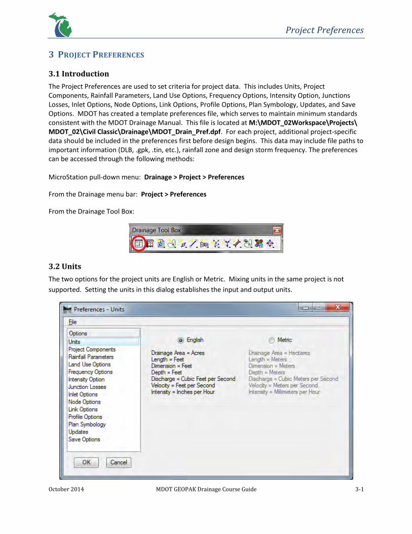
3.1 Introduction
The Project Preferences are used to set criteria for project data. This includes Units, Project Components, Rainfall Parameters, Land Use Options, Frequency Options, Intensity Option, Junctions Losses, Inlet Options, Node Options, Link Options, Profile Options, Plan Symbology, Updates, and Save Options. MDOT has created a template preferences file, which serves to maintain minimum standards consistent with the MDOT Drainage Manual. This file is located at M:\MDOT_02Workspace\Projects\ MDOT_02\Civil Classic\Drainage\MDOT_Drain_Pref.dpf. For each project, additional project-specific data should be included in the preferences first before design begins. This data may include file paths to important information (DLB, .gpk, .tin, etc.), rainfall zone and design storm frequency. The preferences can be accessed through the following methods: MicroStation pull-down menu: Drainage > Project > Preferences
From the Drainage menu bar: Project > Preferences
From the Drainage Tool Box:
3.2 Units
The two options for the project units are English or Metric. Mixing units in the same project is not
supported. Setting the units in this dialog establishes the input and output units.

Project Preferences
October 2014 MDOT GEOPAK Drainage Course Guide 3-2
3.3 Project Components
This dialog contains the directories of the files to be used by a project.
Field Description
Drainage Library File (DLB) This specifies the Drainage Library file to be used on a project. This file can be found at M:\MDOT_02 Workspace\Projects\MDOT_02\Civil Classic\Drainage\MDOT_Drain_Lib.dlb
GPK Job Number This is the GEOPAK coordinate geometry database, which stores the roadway design geometrics such as chains (alignments), points and profiles. This can only be used if there is a GEOPAK Road project.
User Preferences These are the User Preferences from the GEOPAK Road project.
Drainage Cell Library This file stores the cells that are used for the nodes in the DLB. This should be set to M:\MDOT_02Workspace\Projects\MDOT_02\Elements\Cells\ Dr_Drain_2D.cel
Criteria Directory Not applicable for MDOT projects
DDB The Design and Computation Manager database can be used to match pay items to Drainage Library items. However, due to some drainage pay items being based on depth and other factors, manual assignment of pay items may be necessary after the network design is completed.
Water and Sewer Project This is an optional file path for a Geopak Water and Sewer Project.
Superelevation Shapes File Not applicable for MDOT projects
Site Project Not applicable for MDOT projects
Original Ground
A TIN file can be selected to reference existing elevations and spread sections automatically or to display the existing ground on drainage profiles.

Project Preferences
October 2014 MDOT GEOPAK Drainage Course Guide 3-3
Design Surface A TIN file can be selected to reference proposed elevations and spread sections automatically or to display the proposed ground on drainage profiles.
3.4 Rainfall Parameters
The Rainfall Parameters set the Rainfall Source that will be used to calculate the intensities and discharges on a project. These come from the Drainage Library loaded under Project Components.
Field Description
Rational Method Rainfall Source
The Rational Method is standard for the design of drainage conveyance systems on MDOT projects. The Rainfall Source for this method should be set to the MDOT Rainfall Frequency Zone that the project is located in.
SCS Method Rainfall Source The SCS Method is not standard for the design of MDOT drainage conveyance systems using GEOPAK Drainage and should not be used.

Project Preferences
October 2014 MDOT GEOPAK Drainage Course Guide 3-4
3.5 Land Use Options
The Land Use Options can be used to automate runoff coefficient computations for drainage areas by delineating subareas for a project. Land Use Items are stored in the Drainage Library consistent with the MDOT Drainage Manual.
3.6 Frequency Options
The Frequency Options is the source for the frequency at which discharge computations will be based. Other storm frequencies can be designed for by simply changing the drop-down menu. However, multiple storm frequencies cannot be computed simultaneously. Each network needs to be designed or analyzed (See “Drainage Networks”) in order for the active frequency to be applied. The Drainage Library that is displayed here is set in the Project Components. The Computation Frequency for the Rational Method was established within the library based on MDOT Rainfall IDF Tables for each Michigan Rainfall Frequency Zone. The SCS Frequency Options will not be supported on MDOT projects. A Runoff Coefficient Peaking Factor can also be set here.

Project Preferences
October 2014 MDOT GEOPAK Drainage Course Guide 3-5
3.7 Intensity Option
This Intensity Option contains the intensity computation options for a project.

Project Preferences
October 2014 MDOT GEOPAK Drainage Course Guide 3-6
Field Description
Drainage Library (DLB) This is the file set in the Project Components.
Minimum Time of Concentration The minimum allowable time to be used for discharge computations (minutes).
Accumulate Pipe Flow Time by Select one of the three travel time options through the pipes: Iterative Velocity, Full Flow Velocity and Uniform Velocity.
Intensity Options This option allows for absolute (constant) or computed intensities to be used in discharge computations. The Weight Time of Concentration option will limit the discharge from decreasing.
Inlet Computation Only Absolute Intensity values will override the DLB values. This number is based on in/hr or mm/hr based on the units specified previously.
3.8 Junction Losses
For MDOT projects, junction losses will be defined for each individual node through an Absolute Loss.
This sets a fixed head loss to nodes using values of 0.1 for 180° storm sewer orientations between an
inlet and outlet pipe and 0.2 for any bends in storm sewer orientation or multiple inlet pipes at a node.
Exit losses will be computed per the MDOT Drainage Manual by using the Loss Coefficients listed below
and the defined equations in the software. Absolute Loss values can be placed under the Node
Configuration – Junction Loss Option (See “Drainage Nodes”). If ‘Disable All Junction Loss Computations’
is toggled on it will be applied throughout a project.

Project Preferences
October 2014 MDOT GEOPAK Drainage Course Guide 3-7
3.9 Inlet Options
This Inlet Options allow the user to set default inlet variables that will be used in the Node Configuration
dialog throughout a project.
Field Description
Inlet By Pass Options Determines the method of how Inlet By Pass flows are accounted for in the storm sewer system.
Link By Pass Flow Options Determines the method of how Inlet By Pass flows are accounted for in Link discharge computations.
Default Spread N Value This is the default Manning’s roughness coefficient (n) for pavement runoff to be used in spread computations.
Extend Superelevation Shapes to Inlet at Shape Slope
Not applicable for MDOT projects.

Project Preferences
October 2014 MDOT GEOPAK Drainage Course Guide 3-8
3.10 Node Options
The Node Options allows the user to set default node variables for a project.
Field Description
Default Node ID Prefix The Node Prefix will be added to the node name and then automatically sequenced by one. For example, if the Node prefix is ‘CB-‘ the first Node stored will be CB-1, followed by CB-2, CB-3 and so on.
Scale Node Cells A scale can be given to adjust the size of node cells.
Minimum Freeboard
This is the minimum distance allowed from the node elevation to the hydraulic grade line. If the hydraulic grade line goes above this distance a warning will be triggered.
Project Preferences
October 2014 MDOT GEOPAK Drainage Course Guide 3-9
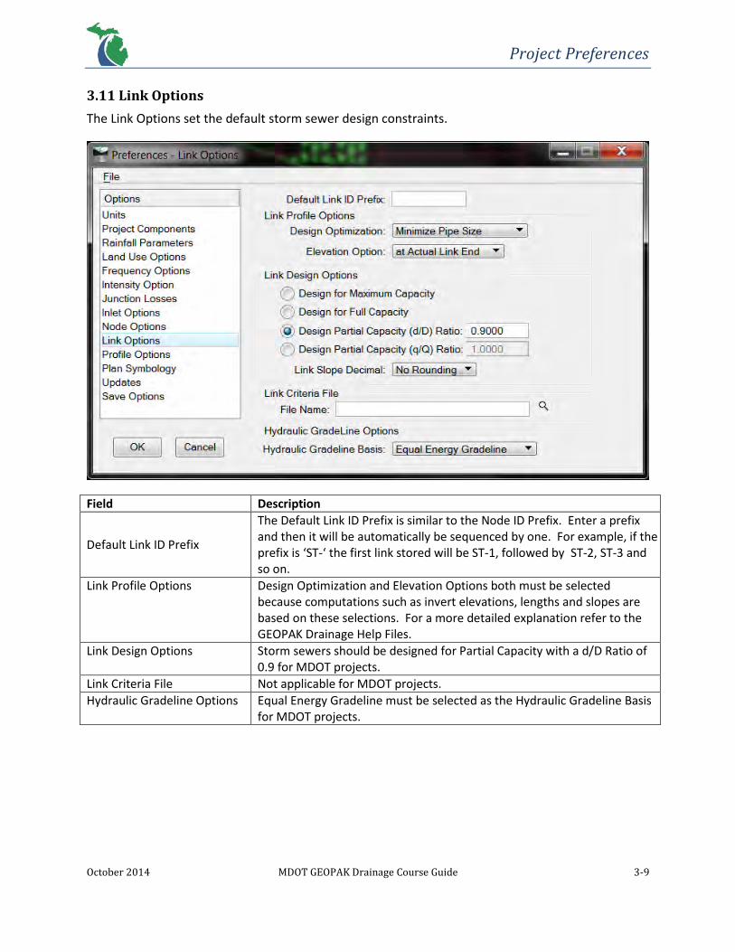
3.11 Link Options
The Link Options set the default storm sewer design constraints.
Field Description
Default Link ID Prefix
The Default Link ID Prefix is similar to the Node ID Prefix. Enter a prefix and then it will be automatically be sequenced by one. For example, if the prefix is ‘ST-‘ the first link stored will be ST-1, followed by ST-2, ST-3 and so on.
Link Profile Options Design Optimization and Elevation Options both must be selected because computations such as invert elevations, lengths and slopes are based on these selections. For a more detailed explanation refer to the GEOPAK Drainage Help Files.
Link Design Options Storm sewers should be designed for Partial Capacity with a d/D Ratio of 0.9 for MDOT projects.
Link Criteria File Not applicable for MDOT projects.
Hydraulic Gradeline Options Equal Energy Gradeline must be selected as the Hydraulic Gradeline Basis for MDOT projects.

Project Preferences
October 2014 MDOT GEOPAK Drainage Course Guide 3-10
3.12 Profile Options
The Profile Options set the default profile variables for a project.
Field Description
Default Profile ID Prefix
The Default Profile ID Prefix is similar to the Node and Link ID Prefixes. Enter a prefix and then it will be automatically sequenced by one. For example, if the prefix is ‘PRO-‘ the first profile stored will be PRO-1, followed by PRO-2, PRO-3 and so on.
Create Cogo Chains and Profiles With this option, links will be stored in the coordinate geometry (COGO) database (.gpk). The chains and profiles created will be stored with the same naming convention as the link.

Project Preferences
October 2014 MDOT GEOPAK Drainage Course Guide 3-11
3.13 Plan Symbology
The Plan Symbology option sets the plan view parameters for the drainage graphics. The Linear
symbology sets parameters for elements and the Text symbology sets parameters for MicroStation text.
This symbology has been set by MDOT to standard levels. “Set Node Cell Symbology” should always be
turned off so as to not override the cell symbology for nodes.

Project Preferences
October 2014 MDOT GEOPAK Drainage Course Guide 3-12
3.14 Updates
The Updates Option allows the user to determine what automatic updates will occur when design
changes are made. These can be changed anytime during the design process.

Project Preferences
October 2014 MDOT GEOPAK Drainage Course Guide 3-13
3.15 Save Options
The Save Options allows the user automatically save the preferences. It’s recommended that the
‘Automatically Save Drainage Updates’ and the ‘Automatic Save’ is toggled on. Toggling ‘Automatic
Backup’ on will create a backup file (.bak) in the current working directory when a project is opened.
3.16 Drainage Preference File
To save the Project Preferences simply select File > Save As… and save the file (.dpf) to a location in the
project directory.
NOTE: It is recommended that a copy of a project-specific preferences file be saved to the project
directory, separate from the MDOT template Project Preferences file. This allows for a one-time setup
of the Project Preferences to be loaded each time a project is opened.
To print the Project Preferences simply go to the Drainage menu bar and select Project > Export >
Preferences to ASCII. Save the ASCII file (.drp) to the project directory. Open this file with Notepad to
view the preferences being used for a particular project.
3.17 Drainage Project
To save a Drainage project go to the Drainage menu bar and select Project > Save.
To exit go to the Drainage menu bar and select Project > Exit.
It is good practice to save then exit a Drainage project before closing MicroStation.

Project Preferences
October 2014 MDOT GEOPAK Drainage Course Guide 3-14
Exercise 3.1 – Create a Drainage Project
1. Open the MicroStation file: C:\Temp\MDOT_GEOPAKDrainageTrainingClass\118329drain.dgn
2. Open Project Manager: GEOPAK > ROAD > Project Manager
3. Select project: C:\Temp\MDOT_GEOPAKDrainageTrainingClass\118329.prj and click OK.
4. Select Users > New…

Project Preferences
October 2014 MDOT GEOPAK Drainage Course Guide 3-15
5. Type in your Name, Full Name and OP Code (initials) and click OK.
Click No when prompted to define a password.
6. Highlight [Your First Name] and click OK.

Project Preferences
October 2014 MDOT GEOPAK Drainage Course Guide 3-16
7. The Road Project dialog will then appear. Set the Working Directory from the MicroStation pull-
down menu: GEOPAK > Road > User Preferences. In the Working Directory field click the
spyglass icon and navigate to C:\Temp\MDOT_GEOPAKDrainageTrainingClass and click OK
twice.
8. Open GEOPAK Drainage from the MicroStation pull-down menu: GEOPAK > Drainage >
Drainage
9. Create a new drainage project from the Drainage menu bar: Project > New…
Type the job number 118329 as the name of the project in the File name field and click Save to
save the new project as a GEOPAK Drainage File (.gdf) to the following directory:
C:\Temp\MDOT_GEOPAKDrainageTrainingClass\118329.gdf

Project Preferences
October 2014 MDOT GEOPAK Drainage Course Guide 3-17
Exercise 3.2 – Create a Project Preferences File
1. Open the Preferences dialog from the Drainage menu bar: Project > Preferences
2. Open the MDOT standard project preferences file: File > Open… then navigate to M:\MDOT_02
Workspace\Projects\MDOT_02\Civil Classic\Drainage\MDOT_Drain_Pref.dpf and click Open.
3. Under the Project Components Option load the GPK Job Number, Original Ground TIN file and
the Design Surface TIN file by clicking on the spyglass icons next to each field ( ).
Project Preferences
October 2014 MDOT GEOPAK Drainage Course Guide 3-18
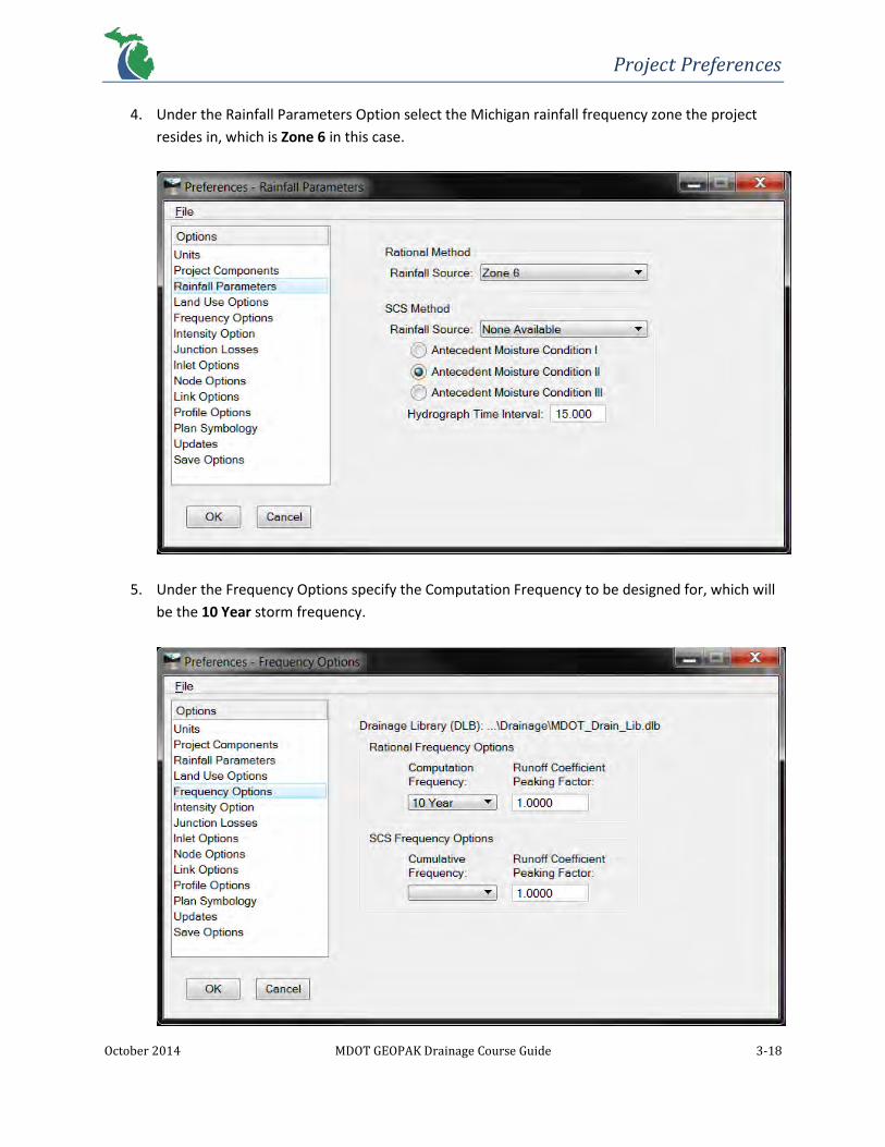
4. Under the Rainfall Parameters Option select the Michigan rainfall frequency zone the project
resides in, which is Zone 6 in this case.
5. Under the Frequency Options specify the Computation Frequency to be designed for, which will
be the 10 Year storm frequency.

Project Preferences
October 2014 MDOT GEOPAK Drainage Course Guide 3-19
6. Under the Intensity Option specify the correct Minimum Tim of Concentration. For this project
it will be 15 minutes.
7. Save these project preferences in the project directory to be used in the future: File > Save As…
> C:\Temp\MDOT_GEOPAKDrainageTrainingClass\118329_GD_Pref.dpf
8. Click OK and Yes to store the changes.

Drainage Nodes
October 2014 MDOT GEOPAK Drainage Course Guide 4-1
4 DRAINAGE NODES
4.1 Introduction
Drainage nodes in GEOPAK Drainage consist of the drainage structures that collect stormwater runoff,
connect storm sewers or discharge flow to appropriate outfalls. They define the type of drainage
structure, location, geometric parameters and spread criteria to be considered. These properties are
derived from the Drainage Library, which references the standard MDOT drainage cell library. Drainage
nodes can be created and modified by executing the following commands:
MicroStation pull-down menu: Drainage > Component > Node
From the Drainage menu bar: Component > Node
From the Drainage Tool Box:
4.2 Node Configuration Dialog
The Node Configuration dialog contains seven Option panels, which define or output all the data needed
to successfully create a drainage node.

Drainage Nodes
October 2014 MDOT GEOPAK Drainage Course Guide 4-2
The Node ID at the top of the dialog confirms which node the dialog is referring to. There are also tools
to toggle which can Window Center or Highlight the active Node ID in the current View. The button
tools from left to right are ID Drainage Node, Add Node, Delete Node, Rename Node and Edit Area. By
clicking Apply, data entered into the fields contained within each of the different Options will be stored
for the active Node ID.
4.2.1 Properties
The Properties Option contains the following fields that are applicable to MDOT drainage design:
Field Description
Description (optional) Additional description as necessary
Node Type Defines the standard MDOT drainage structure to be used. These structures are divided into the following categories according to their inherent properties: Grate, Curb and Grate, Junction, Other, Outlet and Headwall.
Profile Specifies the roadway profile condition at the node location – either On Grade or Sag. This field affects spread computations.
Library Item Provides a list of drainage structures according to the Node Type. Reads stored Drainage Library Node Element ID’s.
By Pass to Node The downstream node from which the active node’s by-pass runoff flow will discharge into.
Max By Pass The allowable by-pass flow of the active node. Use for querying purposes.
Override Library Payitem
Allows the user to define a node with a quantity pay item through a Design and Computation Manager database (DDB).
NOTE: The Node Bottom field is not applicable for MDOT projects.
4.2.2 Location
The Location Option locates nodes with accuracy anywhere on a project. Utilizing data stored in a
geometric database (.gpk) is possible, which allows different chains and profiles to be chosen

Drainage Nodes
October 2014 MDOT GEOPAK Drainage Course Guide 4-3
depending on which roadway the user needs to design. This allows stations and offsets to be
entered for various horizontal alignments. Also, the node elevation can be automated in this way
by reading the vertical profile alignment. If no chain or profile is available, nodes are placed
according to the coordinates in the MicroStation design file.
Field Description
Chain A defined horizontal alignment stored in the geometric database (.gpk) file.
Profile A defined vertical alignment stored in the geometric database (.gpk) file.
Align
Defines the orientation of a node. At Point places a node at the active angle at the current or dynamic coordinates. Tangent to Chain places a node tangent to the selected chain. Tangent to Element places a node tangent to any element along its length by
using the ID button to the right. Tangent on Element places a node tangent directly on any element, again using the ID button.
Angle Rotates a node to be properly aligned by a defined angle of rotation.
Station and Offset
Nodes can be set at manually entered station and offset values. Using the Tangent on Element setting will compute the offset automatically. Station equations are supported; however the user will need to enter the region name (R 1, R 2, R 3, etc.) in the station field. NOTE: Negative offsets refer to the left side of an alignment and positive offsets refer to the right side.
Mirror Node When checked, the node orientation will be flipped about the active angle axis or the tangential axis relative to the chain or element selected.
Offset to Gutter to Inlet
Hydraulic computations assume the cover is at the curb. If a distance between the cover and the curb is required, that value may be entered in this field. This will allow for the computations to account for the by-pass flow that will occur and adjust the discharge into the node accordingly.
NOTE: Offsets for catch basins or inlets with a Cover K will have to be adjusted to hold the back of curb instead of the edge of
pavement.

Drainage Nodes
October 2014 MDOT GEOPAK Drainage Course Guide 4-4
4.2.3 Spread Criteria
The Spread Criteria Option contains the geometric parameters of the roadway to compute spread
or inlet spacing calculations. These calculations are based on the FHWA Hydraulic Engineering
Circular No. 22 (HEC-22) methodology and the following composite gutter section:
NOTE: Numbers 1, 2 and 3 refer to the entry slots for Spread Source under the Spread Criteria in the Node Configuration dialog
There are two different profile conditions taken into consideration for spread computations. The
first is for On Grade nodes that are located somewhere between a crest and sag curve of a profile.
The second is for Sag nodes, which are located at the low point of a sag curve of a profile.
On Grade Nodes: The Spread Criteria panel for On Grade nodes looks as follows:
Field Description
Longitudinal Slope Source
User Supplied Manually entered value in terms of percentage.
Reference PGL (Profile Grade Line)
Slope will be automatically populated by reading the geometric database (.gpk) file at the specific node station. Any updates made to the referenced profile will be reflected in this field using this option. NOTE: The longitudinal slope may not be the same at the node location as it is at the PGL in a super-elevated roadway section.
Shape Not applicable

Drainage Nodes
October 2014 MDOT GEOPAK Drainage Course Guide 4-5
Spread Source
User Supplied
Manually entered values for spread section width, cross slope (%) and roughness coefficient per cross slope break. Users should start at the curb and proceed towards the travel way.
Reference TIN
Spread sections will be automated by reading a TIN file based on the DTM. Proper consideration should be made to ensure the correct TIN file is populated in the Elevations Option (existing vs. proposed).
Library Item
A pre-determined Spread Section based on a roadway typical section from the Drainage Library can be chosen. This section will be applied to the entire drainage area to the node. NOTE: After a Library Item has been selected, the Spread Source can be changed to User Supplied to allow for gutter sections and non-typical sections to be added.
Shape/Shape and Lib. Item
Not applicable
Maximums
Pond Depth
Maximum depth of gutter flow allowed. Does not affect computations, but will invoke a warning message if computed values are greater. Used to compute capacities of nodes located in a sag condition.
Pond Width
Maximum width of gutter flow allowed. Does not affect computations, but will invoke a warning message if computed values are greater.
Sag Nodes: The Spread Criteria panel for Sag nodes looks as follows:

Drainage Nodes
October 2014 MDOT GEOPAK Drainage Course Guide 4-6
The only difference between the On Grade and Sag Spread Criteria options is that the Longitudinal
Slope Source field is substituted for percentage fields for slope and discharge, left and right of the
node. This is because spread computations do not depend on flow characteristics in the longitudinal
direction at the sag location. However, the approaching spread must be calculated near sag
locations. The fields specific to sag locations are described as follows:
Field Description
% Slope Left and Right Defines the slope in percentage approaching the sag location from the left and right. The left and right directions are arbitrary, however it is recommended that Left = Back Station and Right = Ahead Station.
% Discharge Left and Right Defines the percentage of discharge approaching the sag location from the left and right. The left and right directions are arbitrary, however it is recommended that Left = Back Station and Right = Ahead Station.1
1 If a sag location receives bypass flow from upstream, the bypass flow will be split according to the % Discharge Left and
Right ratio by default. To account for this, spread computations will have to be carried out twice. The first calculation will
be to obtain the amount bypass flow. The second will be to adjust the % Discharge Left and Right ratio to accurately
account for any bypass flow from the direction it is coming from.
NOTE: For questions on when to use additional sag inlets, please contact the MDOT Hydraulics Unit
Supervisor.
4.2.4 Elevations
The Elevations Option allows the elevation of a node to be set from a variety of different sources,
determine how attached storm sewers are to be aligned and provide limits to the minimum and
maximum depths. Referencing a TIN file, PGL or PGL + Spread Section as an Elevation Source will
allow for automatic updates to the node elevation and spread criteria based on roadway geometry
design changes.

Drainage Nodes
October 2014 MDOT GEOPAK Drainage Course Guide 4-7
Field Description
Reference Surface TIN File Specify the TIN file to be used as the elevation and spread criteria source of a node.
Elevation Source
User Supplied A manually entered value for an elevation. NOTE: This option does not allow automatic updates with roadway design changes.
Reference TIN Calculates an elevation from a surface stored in a TIN file at the node location.
Reference PGL Applies the elevation to a node of the exact station on a profile grade line (PGL).
Elevation Source PGL + Spread Section
Applies the elevation to a node at the exact station on a PGL, which is then projected along the spread section specified in the Spread Criteria Option.
Node Elevation Option
Same as Source Matches the node elevation to the elevation source.
Constant Offset Applies an offset (±) to the elevation. Useful for PGL or PGL + Spread Section Elevation Source options.
User Supplied An elevation may be manually entered.
Vertical Alignment
Match Soffit Storm sewers will be aligned to the top of the pipe.
Match Invert Storm sewers will be aligned to the bottom of the pipe.
Match Surface Storm sewers are aligned by the water surface in the pipe.
Allow Drop Manhole Storm sewers will not be aligned to each other. Allows for an elevation difference between connecting pipes.
Min. Fixed Drop Storm sewers will not be aligned to each other. Sets a minimum elevation difference between connecting pipes.
Match Centerline Storm sewers are aligned by the centerline of the pipe.
Minimum Depth Specifies the minimum cover measured from the node elevation to the soffit of the highest pipe that is connected.
Maximum Depth Specifies the maximum of a node measured from the node elevation to the invert of the lowest pipe that is connected.
Add Sump Depth Additional depth to be added to a node below the computed depth of a drainage structure.

Drainage Nodes
October 2014 MDOT GEOPAK Drainage Course Guide 4-8
4.2.5 Junction Loss
The Junction Loss Option allows for a variety of methods to compute junction losses within a node.
For MDOT projects, junction losses will be defined for each individual node through an Absolute
Loss. This sets a fixed head loss to nodes using values of 0.1 for 180° storm sewer orientations
between an inlet and outlet pipe and 0.2 for any bends in storm sewer orientation or multiple inlet
pipes at a node. Exit losses will be computed per the MDOT Drainage Manual. These options will
override the settings in the preferences if the “Disable All Junction Loss Computations” toggle is not
turned on in the Project Preferences.
4.2.6 Discharge Options
The Discharge Options allow the discharge to be computed from different sources.

Drainage Nodes
October 2014 MDOT GEOPAK Drainage Course Guide 4-9
Field Description
Use Computed Discharge Specifies the discharge from the corresponding Drainage Area should be used.
Supplied Discharge A manually entered discharge value, which will override discharge computations from a Drainage Area.
Disable Inlet Calculations Capacity A manually entered value may be entered instead of using the calculated value.
Link Base Flow Area Additional drainage area can be specified to be accounted for. NOTE: The area is included with respect to the pipe, but not the spread calculations.
Link Base Flow Discharge Additional discharge can be specified with this option. NOTE: This discharge is included with respect to the pipe, but not the spread calculations.
4.2.7 Computations
The Computations Option is used to list all of the node computations. After all input has been
specified for a node, clicking this Option will display the spread calculation results. Warning or error
messages will appear if there is insufficient input data.
Drainage Nodes
October 2014 MDOT GEOPAK Drainage Course Guide 4-10
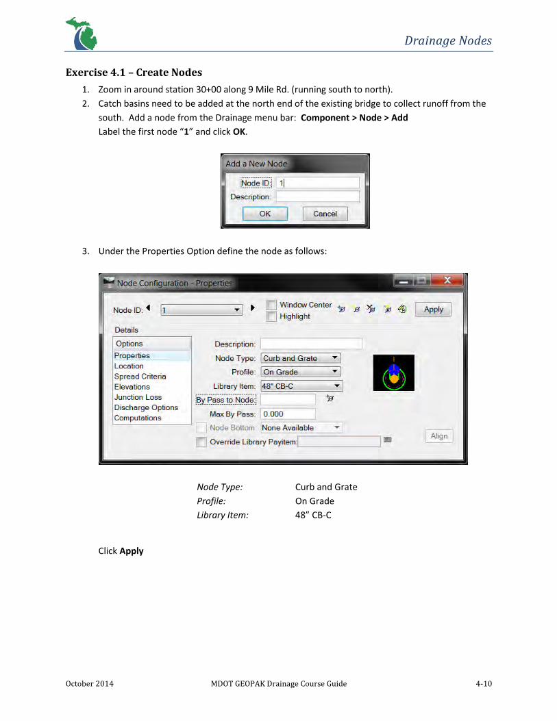
Exercise 4.1 – Create Nodes
1. Zoom in around station 30+00 along 9 Mile Rd. (running south to north).
2. Catch basins need to be added at the north end of the existing bridge to collect runoff from the
south. Add a node from the Drainage menu bar: Component > Node > Add
Label the first node “1” and click OK.
3. Under the Properties Option define the node as follows:
Node Type: Curb and Grate
Profile: On Grade
Library Item: 48” CB-C
Click Apply

Drainage Nodes
October 2014 MDOT GEOPAK Drainage Course Guide 4-11
4. Under the Location Option place the node with the following settings:
Chain: 9MILE_D
Profile: NINEMILE_D
Align: Tangent to Element
Click the Select MS Alignment Element button and select
the EOP.
+ Angle: 270.00 (set angle to properly fit node to roadway design)
Station: 30+30.00
Offset: -14.00
Click Apply
Drainage Nodes
October 2014 MDOT GEOPAK Drainage Course Guide 4-12
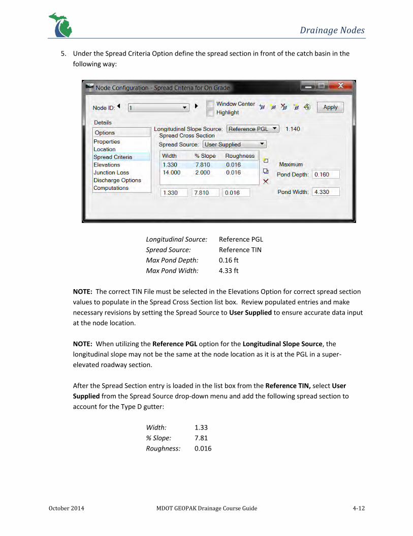
5. Under the Spread Criteria Option define the spread section in front of the catch basin in the
following way:
Longitudinal Source: Reference PGL
Spread Source: Reference TIN
Max Pond Depth: 0.16 ft
Max Pond Width: 4.33 ft
NOTE: The correct TIN File must be selected in the Elevations Option for correct spread section
values to populate in the Spread Cross Section list box. Review populated entries and make
necessary revisions by setting the Spread Source to User Supplied to ensure accurate data input
at the node location.
NOTE: When utilizing the Reference PGL option for the Longitudinal Slope Source, the
longitudinal slope may not be the same at the node location as it is at the PGL in a super-
elevated roadway section.
After the Spread Section entry is loaded in the list box from the Reference TIN, select User
Supplied from the Spread Source drop-down menu and add the following spread section to
account for the Type D gutter:
Width: 1.33
% Slope: 7.81
Roughness: 0.016

Drainage Nodes
October 2014 MDOT GEOPAK Drainage Course Guide 4-13
6. Under the Elevations Option define the drainage structure’s vertical elevation and storm sewer
alignment:
Reference Surface: TIN File
NOTE: Make sure the correct TIN file is loaded in the
box to the right from the project preferences.
Elevation Source: Reference TIN
Node Elevation Option: Same as Source
Vertical Alignment: Allow Drop Manhole
Minimum Depth: 4.00 ft (will vary depending on drainage structure type)
Maximum Depth: 12.30 ft (may be increased if needed)
Add Sump Depth: 2.00
7. Under the Junction Loss Option click the Absolute Loss toggle and add the correct value for the
pipe orientation: 0.1 in this case (0.2 for bends or multiple inlet pipes).
8. Under Discharge Options make sure Use Computed Discharge is the selected option.
9. Click Apply
10. Repeat the previous steps to create the rest of the nodes in the project from the data listed
below:
Node ID’s 2 and 4
Offset: 14.00
Add Sump Depth: 2.00
Node ID 3
Offset: -14.00
Add Sump Depth: 2.00

Drainage Nodes
October 2014 MDOT GEOPAK Drainage Course Guide 4-14
Node ID 5
Offset: -15.52
Add Sump Depth: 2.00
Node ID 6
Offset: 15.52
Add Sump Depth: 2.00
Node ID 7
Node ID: 7
Node Type: Junction
Library Item: 48” MH-B
Offset: 65.00’ RT
Minimum Depth: 2.20 (flat slab top required)
Maximum Depth: 14.30 (no sump depth)
Outlet Node
Node ID: 8
Node Type: Outlet
Library Item: 15” CONC ES (educated guess prior to initial Network design)
Fix Tailwater at: Soffit
Station: 34+82.00
Offset: 68.00’ RT
Elevation Source: User Supplied – 618.25’ (use soffit of end section as a reference)
Minimum Depth: 0.00 (end section)
Junction Loss: Defined Equations (outlet node)

Drainage Nodes
October 2014 MDOT GEOPAK Drainage Course Guide 4-15

Drainage Nodes
October 2014 MDOT GEOPAK Drainage Course Guide 4-16
Structure No. Inlet (Node)
Type Profile
Bypass Structure No.
6 48” CB-C On Grade
5 48” CB-C On Grade
3 48” CB-C On Grade 5
1 48” CB-C On Grade 3
4 48” CB-C On Grade
2 48” CB-C On Grade 4

Drainage Nodes
October 2014 MDOT GEOPAK Drainage Course Guide 4-17
11. Save the project from the Drainage menu bar: Project > Save

Drainage Areas
October 2014 MDOT GEOPAK Drainage Course Guide 5-1
5 DRAINAGE AREAS
5.1 Introduction
Drainage Areas are used to compute peak flows or attach computed discharge values to nodes within a
project. Drainage Areas may be created by being automatically delineated through DTM Drainage Tools
by referencing a TIN file, drawn using basic MicroStation tools or values may be manually entered in the
Drainage Area Definition dialog. For assistance with delineating drainage areas, contact the MDOT
Hydraulic Unit Supervisor. The Drainage Area tools can be accessed in three ways:
MicroStation pull-down menu: Drainage > Component > Area
Drainage menu bar: Component > Area
Drainage Tool Box:

Drainage Areas
October 2014 MDOT GEOPAK Drainage Course Guide 5-2
5.2 Drainage Area Dialog
The Drainage Area dialog contains the parameters needed to define a Drainage Area. This dialog can be
invoked by selecting Add Area or Edit Area. There are three Options: Definition, Subareas, and
Computation.
The Area ID at the top of the dialog confirms which area the dialog is referring to. There are also tools
to toggle which can Window Center or Highlight the active Area ID in the current View. The button tools
from left to right are ID Area, Add Area, Delete Area and Rename Area. By clicking Apply, data entered
into the fields contained within each of the different Options will be stored for the active Area ID.
5.2.1 Definition
The Definition Option consists of six fields.
Field Description
Description Used to further describe a Drainage Area (optional).
Hydro Method Rational and SCS Methods are supported by Geopak Drainage. However, only the Rational Method is approved for use on MDOT projects.
Drainage Area Selection of a MicroStation shape for the Drainage Area will populate this field automatically or it can be manually entered.
Base C Value
This applies to the entire drainage area unless subareas are delineated and have individual C values. “Remaining” subareas will use the Base C Value.
Time of Concentration Defined in minutes, the minimum TC entered in the Intensity Option within the Project Preferences will override the value in this field if it is smaller.
Compute TC Opens the Time of Concentration dialog box. This calculator distinguishes between Sheet, Shallow and

Drainage Areas
October 2014 MDOT GEOPAK Drainage Course Guide 5-3
Concentrated flow. The path can be defined through a Trace of the DTM, ID of an element or through ID – Segments which will identify the limits of the three specific types of flow. More specific flow segments can be added by clicking the right
button at the bottom of this dialog . Refer to the GEOPAK Drainage Help Command Reference for more information.
Area Selection / Creation
Select Shape Select previously drawn shapes in MicroStation.
Pick Boundary Elements / DP Create Shape
Sets the boundary elements that will enclose a drainage area. Once the area is defined by a boundary click on the DP Create Shape button and Data Point within the area to accept it.
Create DTM Shape
Creates shapes using the Delineate Watershed DTM Drainage Tool. This tool can also be accessed from the Drainage menu bar click: Utilities > DTM Drainage Tools
5.2.2 Subareas
The Subareas Option defines subareas within a single Drainage Area. These areas will have a
different land use or runoff coefficient (C value) from the Base C Value. For example, this will be
useful when determining impervious and pervious areas. The entries can be set manually or by
using the Automatic Delineation button. If done automatically, land use boundaries need to be
set on the symbology defined in the Drainage Library. The Land Use Boundary Tools provide an
easy way to create these boundaries. The subareas will be drawn in the active MicroStation file
if the Display Only toggle is not turned on.

Drainage Areas
October 2014 MDOT GEOPAK Drainage Course Guide 5-4
5.2.3 Computation
The Computation Option uses the Composite C Value and the rainfall intensity associated with
the specified time of concentration to compute the discharge for the Drainage Area. This
Option does not account for the absolute intensity which can be set in the Project Preferences.
5.3 DTM Drainage Tools
A Digital Terrain Model (DTM) represents the topography or existing ground of a project through
triangulation. This model is often contained in a TIN file, in which the DTM Drainage Tools reference to
analyze drainage patterns. These tools can be found in various ways:
MicroStation pull-down menu: Drainage > Utilities > DTM Drainage Tools
Drainage menu bar: Utilities > DTM Drainage Tools
Drainage Tool Box:

Drainage Areas
October 2014 MDOT GEOPAK Drainage Course Guide 5-5
Road DTM Tools:
By invoking one of these commands the following dialog box will appear:
Field Description
Delineate All Watersheds
Displays watershed boundaries within an entire DTM.
Minimum Low Point Depth
The minimum depth at which runoff can travel to. Accounts for small depressions in the TIN file that may be interpreted as a false low point.
Refine Watershed Allows for more accurate flow boundaries to be defined within triangles.
Delineate Watershed Displays watershed boundaries at a specific location in a DTM.
Drainage Patterns Evaluates flow paths of a DTM through a downstream trace from each triangle.
Downstream Trace Displays a downstream flow path from any given point in a DTM.
Upstream Trace Displays an upstream flow path from any given point in a DTM.
Flow Arrows Displays the direction of flow within a DTM.

Drainage Areas
October 2014 MDOT GEOPAK Drainage Course Guide 5-6
Delineate Low Points Locates all Low Points and displays text as “LP”.
Delineate High Points Locates all the High Points and displays text as “HP”.
Ridge lines Triangles in which one edge flows away from each side.
Sump Lines Triangles in which one edge receives flow from either side.
Surface Ponds Displays areas of ponded water.
Pond Analysis Delineates any ponds within a DTM that can be queried for area, volume, elevation and depth.

Drainage Areas
October 2014 MDOT GEOPAK Drainage Course Guide 5-7
Exercise 5.1 – Create Areas
MicroStation shapes have been drawn in the file 118329drain.dgn to be used as drainage areas to
expedite training time. Land Use boundaries have also been delineated to quickly feature subarea
computations. When designing a project, users will have to delineate these areas by reading roadway
geometry, contours and/or maps. The DTM Drainage Tools can assist in these efforts.
1. Make sure level Drain_Gpk_Area is turned on.
2. Add an area from the Drainage menu bar: Component > Area > Add
Label the first area 1 and click OK. NOTE: It’s good practice to label Drainage Areas in the same
fashion as its corresponding node to avoid confusion.
3. The Drainage Area Definition dialog will then appear. Enter the following definition data:
Base C Value: 0.9 (Pavement)
Time of Conc.: 15.0 minutes (minimum)

Drainage Areas
October 2014 MDOT GEOPAK Drainage Course Guide 5-8
4. Click the Select Shape button. Select the MicroStation shape draining to Node ID 1 (bridge area
to the south) and accept. Notice how the Drainage Area value (in acres) populates in the
respective field.
5. Under the Subareas Option, no entries will be needed since this area consists of only pavement.
NOTE: If different land uses existed within one area, subareas could be automatically generated
by clicking the Automatic Delineation button to the right based on previously defined Land Use
boundaries.

Drainage Areas
October 2014 MDOT GEOPAK Drainage Course Guide 5-9
6. Under the Computation Option click Compute Discharge. Notice the Computed Discharge at
the bottom of the dialog.
Click Apply
Save the project from the Drainage menu bar: Project > Save
7. Repeat the previous steps and use the data below to create drainage areas around the rest of
the nodes created in the last chapter as defined below:

Drainage Areas
October 2014 MDOT GEOPAK Drainage Course Guide 5-10
8. Save the project from the Drainage menu bar: Project > Save
Structure No.
Drainage Area
Runoff Coefficient
Time of Concentration
6 0.093 0.90 15.00
5 0.108 0.90 15.00
3 0.019 0.90 15.00
4 0.019 0.90 15.00
2 0.050 0.90 15.00
NOTE: These areas do not have subareas.

Drainage Links
October 2014 MDOT GEOPAK Drainage Course Guide 6-1
6 DRAINAGE LINKS
6.1 Introduction
Drainage Links are linear features connecting two nodes from upstream to downstream consisting of
conduits or ditches. The Drainage Links tools can be accessed by carrying out one of the following
commands:
MicroStation pull-down menu: Drainage > Component > Link
From the Drainage menu bar: Component > Link
From the Drainage Tool Box:

Drainage Links
October 2014 MDOT GEOPAK Drainage Course Guide 6-2
6.2 Link Configuration Dialog
The Links Configuration Dialog is used to set the parameters of a conveyance facility to make a
connection between two Nodes. Four Options are included in this dialog to fully define a link.
The Link ID at the top identifies the active Link ID the dialog is referring to. It is good practice to name
Drainage Links in some fashion according to the upstream node name. This helps to simplify the
Network and provides easy identification of link locations. There are also tools to toggle which can
Window Center or Highlight the active Link ID in the current View. The button tools from left to right
are ID Link, Add Link, Delete Link and Rename Link. By clicking Apply, data entered into the fields
contained within each of the different options will be stored for the active Link ID.
6.2.1 Definition
The Definition Option defines the standard properties of either a Pipe or a Ditch. If the Pipe
Type is selected the Definition dialog will look as follows:

Drainage Links
October 2014 MDOT GEOPAK Drainage Course Guide 6-3
If the Ditch Type is selected the Definition dialog will look as follows:
Field Description
Description (optional) Further describes a link .
From Node The first node for which a link originates. Flow direction does not need to be established since this will be determined by connectivity. If an downstream node is defined as a From Node, GEOPAK Drainage will switch the From/To Nodes based on flow direction.
To Node The second node from which a link originates
ID Identifies the From and To Nodes
Length Once a link has From and To Nodes set, a length will populate here based on the distance between nodes. Lengths will be based on the hydraulic center of a node.
Use MS Element Defines links using MicroStation lines.
Type: Pipe or Ditch Determines if pipes or ditches are being used as links
Configuration if the Pipe Type is selected:
Shape Defines the pipe shape.
Material Defines the pipe material.
Design Size Defines the size of a pipe. If toggled on, the pipe size will be determined from hydraulic computations and constraints once the network is designed. If toggled off, a pipe size can be manually entered from the Drainage Library (DLB) by clicking Select…
Design Barrels Defines the number of pipes to be designed for. By default, one barrel is designed for.
Manning’s n The roughness coefficient of a pipe. By default, the n-value is the stored value in the DLB for the specific pipe material selected.
Override Library Payitem
Overrides the pay item link between the DLB and the D&C Manager allowing the user to specify a desired, link-specific pay item.

Drainage Links
October 2014 MDOT GEOPAK Drainage Course Guide 6-4
Configuration if the Ditch Type is selected:
Ditch Type Fixed shape or cross-section based can be used.
Ditch Width Width of the ditch bottom.
Ditch Depth Depth of the ditch.
Side Slope Ratio Left Left Side Slope of the ditch.
Side Slope Ratio Right Right Side Slope of the ditch.
Manning’s Roughness The n-value coefficient of the ditch lining.
Number of Cross Sections
If ditch type is cross-section based, this specifies the number of sections to create along a ditch link.
Width of Cross Sections
Width of the cross-sections along a ditch link.
NOTE: Ditch type links require a pipe size to be selected in order for a network to carry out hydraulic computations.
NOTE: Ditch links are only to be used for necessary ditch capacity computations separate from
closed storm sewer system computations.
6.2.2 Conditions
The Conditions Option is used to set or review data for the minimum cover, soffit, invert,
maximum depth and slope of a Drainage Link. Min Cover is measured from the Node Elevation
to maximum soffit of a pipe. Max Depth is measured from the Node Elevation to the minimum
invert of a pipe.
The Soffit, Invert and Slope will be calculated once the network is designed. After this, the user
has the option to lock and change these values by toggling on the desired boxes. By doing this,
GEOPAK Drainage will NOT adjust these values next time the network is designed.
NOTE: Only two boxes in a row can be selected at a time with no more than one box per
column.

Drainage Links
October 2014 MDOT GEOPAK Drainage Course Guide 6-5
6.2.3 Constraints
The Constraints Option uses the values set for Minimum and Maximum Rise and Slope for
proper configuration of Drainage Links. If link parameters are set in such a way to where the
calculated velocity falls outside of the specified range a warning message will appear upon
hydraulic computation.
NOTE: Special care should be used when storm sewers are found to be either in supercritical or
pressure flow. Refer to Chapter 7 in the MDOT Drainage Manual or contact the MDOT
Hydraulics Unit Supervisor for assistance.
6.2.4 Computation
The Computation Option displays the calculated hydraulic results within a Drainage Link. These
hydraulics are not made available until the network which the link resides in is successfully
designed or analyzed.

Drainage Links
October 2014 MDOT GEOPAK Drainage Course Guide 6-6
Exercise 6.1 – Create Links
1. Add a link from the Drainage menu bar: Component > Link > Add
2. Name the first link “1” to correspond with the upstream Node 1 and click OK. NOTE: It’s good
practice to label Links the same as its corresponding upstream node for quick identification.
The Link Configuration dialog will then appear…
3. Under the Definition Option set the From and To Nodes graphically by clicking the From/To
Node ID buttons . Click the From Node ID button and click on the Node 1 cell. Repeat for the
To Node, but instead click the downstream Node 3 cell.

Drainage Links
October 2014 MDOT GEOPAK Drainage Course Guide 6-7
4. Set the following parameters for the Configuration of the Link:
Shape: Circular
Material: Concrete
Design Size: Toggle ON (allows pipe sizing to be calculated by
GEOPAK Drainage)
5. Under the Conditions Option no input is needed. Make sure all toggles are OFF to allow the
software to calculate elevations of the link based on node elevations and minimum/maximum
depth constraints.

Drainage Links
October 2014 MDOT GEOPAK Drainage Course Guide 6-8
6. Under the Constraints Option set the minimum and maximum design criteria for the link.
Rise Min/Max: 1.0/12.0 (feet)
Slope Min/Max: 0.06/2.00 (%)
Velocity Min/Max: 3.00/12.00 (fps)
NOTE: Designed pipes must meet the minimum slopes for self-cleaning velocities, as defined by
Table 7-6 in the MDOT Drainage Manual.
7. Computations will not be available until a network has been created. Once a network is
designed or analyzed, hydraulic calculations will become available in this option.
8. Click Apply to save the link to the project.

Drainage Links
October 2014 MDOT GEOPAK Drainage Course Guide 6-9
9. Repeat the previous steps to create the rest of the links in the project, which are listed below:
Link ID From Node To Node
2 2 To 4
3 3 To 5
4 4 To 3
5 5 To 6
6 6 To 7
7 7 To 8 NOTE: Most dialog values from the previously created link will be automatically populated in their respective fields for
a new link.
Link ID 7
To Node Invert: 617.00
10. Save the project from the Drainage menu bar: Project > Save

Drainage Networks
October 2014 MDOT GEOPAK Drainage Course Guide 7-1
7 DRAINAGE NETWORKS
7.1 Introduction
Drainage Networks consist of interconnected nodes, links and areas needed to create a complete
drainage conveyance system. Ultimately, there is one outlet per network; however multiple networks
can be created in a single drainage project. After a successful system is built, a network can be designed
or analyzed to complete computations. Hydraulic computations for nodes or areas can be computed
independently, but links are dependent upon connectivity which requires a network to perform
computations for these features. Drainage Network tools can be found in several places:
MicroStation pull-down menu: Drainage > Network
From the Drainage menu bar: Network
From the Drainage Tool Box:
7.2 Network Configuration Dialog
The Network Configuration Dialog is used to build and compute hydraulic computations of drainage
conveyance systems.

Drainage Networks
October 2014 MDOT GEOPAK Drainage Course Guide 7-2
The Network ID at the top identifies the Active Network the dialog is referring to. The button tools from
left to right are Add Network, Delete Network, Rename Network and Set Active Network. By clicking
Apply, settings in this dialog will be applied to the entire network.
Field Description
Description (optional) Further describes a network
Validation – Build Network
Builds a drainage conveyance system starting with the Outlet Node. This function validates topology and connectivity within a system to determine if it is ready to be designed or analyzed. Flow direction through all links at this point is established.
Validation – Highlight Network Accents all nodes, areas and links within the Active Network to give users a visual graphic of what is included in the network.
Computations – Design Network Executes the hydraulic design of all elements that comprise the Active Network by setting values to any options that were to be designed for.
Computations – Analyze Network Executes the hydraulic analysis of all elements that comprise the Active Network by maintaining current settings without considering design toggles.
Lock/Unlock Sizes Locks or Unlocks pipe sizes before computations are executed.
Lock/Unlock Elevations Locks or Unlocks invert elevations before computations are executed.

Drainage Networks
October 2014 MDOT GEOPAK Drainage Course Guide 7-3
Exercise 7.1 – Create a Network
1. Add a network from the Drainage menu bar: Network > Add
Network ID: 9 Mile
Outlet Node: 8
2. Click OK
3. Under Validation click Build Network. This tool confirms topology of nodes and the
connectivity of links. Click Highlight Network to accent all components associated with the
Active Network.

Drainage Networks
October 2014 MDOT GEOPAK Drainage Course Guide 7-4
4. Click Apply to save the network to the project.
5. Under Computations click Design Network. This will design the network and show any warning
messages (if any) in a Text Editor dialog and an ASCII file called drgmsg.txt in the current
working directory.
6. Modify node and link properties from the designed values to those listed below. These changes
will include elevations, inverts and pipe sizes. Toggle off the “Design Size” options and toggle
on invert elevation boxes to enter the values below. Click Apply after modifying each
component dialog:

Drainage Networks
October 2014 MDOT GEOPAK Drainage Course Guide 7-5

Drainage Networks
October 2014 MDOT GEOPAK Drainage Course Guide 7-6
7. In the Network Configuration dialog, under Computations click Analyze. This will re-compute
the hydraulics of the system by using the values defined in each dialog without redesigning or
modifying them.
8. Save the project from the Drainage menu bar: Project > Save

Drainage Profiles
October 2014 MDOT GEOPAK Drainage Course Guide 8-1
8 DRAINAGE PROFILES
8.1 Introduction
Drainage Profiles can be created automatically in GEOPAK Drainage between at least two nodes and one
link. Design graphics such as surfaces, pipes, minimum cover and hydraulic grade lines can be drawn in
these profiles to simplify the design process by providing visualization of drainage system to quickly
identify problem areas to rectify. Drainage Profile tools can be accessed from a variety of different
commands:
MicroStation pull-down menu: Drainage > Component > Profile
From the Drainage menu bar: Component > Profile
From the Drainage Tool Box:

Drainage Profiles
October 2014 MDOT GEOPAK Drainage Course Guide 8-2
8.2 Edit Drainage Profile Dialog
The Edit Drainage Profile Dialog contains the settings to successfully create a Drainage Profile from any
network. This window is displayed when the Add or Edit commands are executed.
The Description field at the top of the dialog is optional and allows the user to further describe a profile.
The View Number indicates the View in which the profile will be drawn. The Center Profile button ( )
centers the profile in the current view. By clicking Apply, data entered into the five tabs of this dialog
will be stored to define a Drainage Profile.
8.2.1 Registration
The Registration tab controls the display of a profile by defining the following parameters:
Field Description
Registration Point
The location at which the profile grid will be placed. This point can be derived from manually entering values for the X and Y coordinates or by utilizing the DP (Data Point) button to dynamically place the profile grid.
Scale Sets the horizontal and vertical scale of the profile.
Node Information
Sets the starting and ending points of the profile. The From Node will be displayed on the left side and the To Node will be on the right. Reset Profile will adjust the profile to the current settings of the dialog after the Project to Chain toggle is unchecked.
Projection The Project to Chain toggle will allow utilization of a previously created profile’s stationing.

Drainage Profiles
October 2014 MDOT GEOPAK Drainage Course Guide 8-3
Grid Stationing and Elevations
If the Project to Chain toggle is used, the Begin and End Stations as well as the Min and Max Elevations will be populated. If not, the stationing will start at 0+00 and extend the length of the distance between the From and To Nodes. Min and Max Elevations may be manually entered in this case.
Reference Surface A TIN file may be chosen to represent the existing or proposed ground above the network. A constant Vertical Offset may be applied also.
8.2.2 Display
The Display tab determines what information will be displayed in a profile and also sets the
symbology of each feature including labels.

Drainage Profiles
October 2014 MDOT GEOPAK Drainage Course Guide 8-4
8.2.3 Drainage Information
The Drainage Information tab allows for optional design related information to be visually
displayed. This information can help out with design optimization of a network. To activate, toggle
on desired features with the correct symbology, however this information will only be displayed
once a network is designed or analyzed.
8.2.4 Grid & Labels
Six options exist in this tab to format the Grid & Labels of a profile. They are: Node, Link Label,
Elevations, Grid Boundary, Horizontal Grid and Vertical Grid. Double clicking each of them, toggles
them on or off depending on what is desired to be shown. Each option contains a variety of
different settings to choose from.

Drainage Profiles
October 2014 MDOT GEOPAK Drainage Course Guide 8-5
8.2.5 Link Profile
The Link Profile tab contains geometric information for each Link ID. A link can be highlighted in
which Min. Cover, Invert and Pipe Size data will appear to modify, if desired. Toggles also exist to
hold inverts and/or the slope. If changes are made, the Modify button ( ) must be clicked to
modify the Link ID and Apply must be clicked to save the changes to the project.
NOTE: Depending on the settings in the Updates option of the Project Preferences, a network may
be changed from this tab.
8.3 Preference File
The settings contained in the Edit Drainage Profile Dialog can be saved to a preference file to be applied
to future profiles. MDOT has created a standard Drainage Profile Preference File to be used as a
template for level symbology. This file can be found at the following location: M:\MDOT_02
Workspace\Projects\MDOT_02\Civil Classic\Drainage\ MDOT_Drain_Pref_Prof.ppf. To create a
preference file for a specific project, simply go to File > Save As… to save a copy to the project directory.
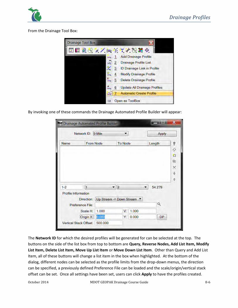
8.4 Automated Profile Builder
The Drainage Automated Profile Builder allows for multiple profiles to be created at once. These
profiles can be any combination of upstream to downstream nodes or vice versa. The Query button ( )
can also be clicked to populate the list box with the each leg of a drainage system starting with the
longest. This feature can be accessed in the following way:
From the MicroStation pull-down: Drainage > Component > Profile > Auto Create
From the Drainage menu bar: Component > Profile > Auto Create
Drainage Profiles
October 2014 MDOT GEOPAK Drainage Course Guide 8-6
From the Drainage Tool Box:
By invoking one of these commands the Drainage Automated Profile Builder will appear:
The Network ID for which the desired profiles will be generated for can be selected at the top. The
buttons on the side of the list box from top to bottom are Query, Reverse Nodes, Add List Item, Modify
List Item, Delete List Item, Move Up List Item or Move Down List Item. Other than Query and Add List
Item, all of these buttons will change a list item in the box when highlighted. At the bottom of the
dialog, different nodes can be selected as the profile limits from the drop-down menus, the direction
can be specified, a previously defined Preference File can be loaded and the scale/origin/vertical stack
offset can be set. Once all settings have been set, users can click Apply to have the profiles created.

Drainage Profiles
October 2014 MDOT GEOPAK Drainage Course Guide 8-7
8.5 Miscellaneous Utilities
Utilities within a project corridor can be stored in GEOPAK Drainage to check for conflicts with a
drainage system. Several types of utilities can be stored into one group. For instance, all utilities that
exist (gas, water, sanitary sewer, etc.) at an intersection could be added into a group rather than only
water mains along a roadway.
Miscellaneous utilities can be added through Component > Miscellaneous Utilities > Add…
Field Description
Alignment Chain Allows the selection of the desired alignment to analyze utilities.
Element Defines the symbology of a utility line.
Elevation Source
TIN File Allows for the selection of the DTM of a project.
GPK Profile Allows for the selection of a vertical profile stored in the .gpk. Only available if the Alignment > Chain option is selected.
Size Specifies the diameter of a utility based on the master units.
Offset Specifies the vertical distance from the Elevation Source. Negative values indicate below grade while positive is above grade.

Drainage Profiles
October 2014 MDOT GEOPAK Drainage Course Guide 8-8
Exercise 8.1 – Create a Profile
1. Add a node from the Drainage menu bar: Component > Profile > Add
2. Enter the following information in the dialog:
Profile ID: 9 Mile
From Node: 1
To Node: 8
Click Apply
3. Load the standard MDOT Drainage Profile Preferences from the following directory:
M:\MDOT_02 Workspace\Projects\MDOT_02\Civil Classic\Drainage\
MDOT_Drain_Pref_Prof.ppf by clicking File > Open… This file sets preferences in the Edit
Drainage Profile dialog.

Drainage Profiles
October 2014 MDOT GEOPAK Drainage Course Guide 8-9
4. Enter the following data under the Registration tab:
Max. Elevation: 650.00
Min. Elevation: 600.00
5. Click DP and choose a point in MicroStation to set the location of the profile.
NOTE: If the Project to Chain toggle is selected the DP button will be ghosted, prompting the
user to identify a roadway alignment profile cell to project onto.
6. Click Apply to draw the profile.
7. Go to File > Save As… to save the profile preferences to the project directory for future use.
8. Save the project from the Drainage menu bar: Project > Save

Drainage Profiles
October 2014 MDOT GEOPAK Drainage Course Guide 8-10
Exercise 8.2 – Check for Utility Conflicts
1. Add Miscellaneous Utilities that exist within the area of this drainage system by clicking
Component > Miscellaneous Utilities > Add…
ID: Ex_Utils
Description: Existing Utilities
Click OK
2. Enter the electrical conduit and gas main crossing the drainage system:
Electric
Alignment: Element
Level = Elec_Cable_All_Ex_UG_GS
(all ByLevel symbology)
Elevation Source: TIN File
C:\Temp\MDOT_GEOPAKDrainageTrainingClass\EXRD.tin
Size: 0.25
Offset: -3.0
Gas
Alignment: Element
Level = Util_Fuel_NatGas_Ex_Line_GS
(all ByLevel symbology)
Elevation Source: TIN File
C:\Temp\MDOT_GEOPAKDrainageTrainingClass\EXRD.tin
Size: 0.5
Offset: -4.0

Drainage Profiles
October 2014 MDOT GEOPAK Drainage Course Guide 8-11
3. Click Apply and Close.
4. Under Component > Profile > Edit List… select the 9 Mile profile to edit. Click OK.
5. In the Edit Drainage Profile dialog, select the Display tab and make sure the Ex_Utils
Miscellaneous Utility group just added has populated under the Misc. Utility Crossings ID. If
not, select it from the drop-down menu.
6. Click Apply to update the profile with existing utility crossings.
7. Save the project from the Drainage menu bar: Project > Save
EX 6” GAS
EX 3” ELEC
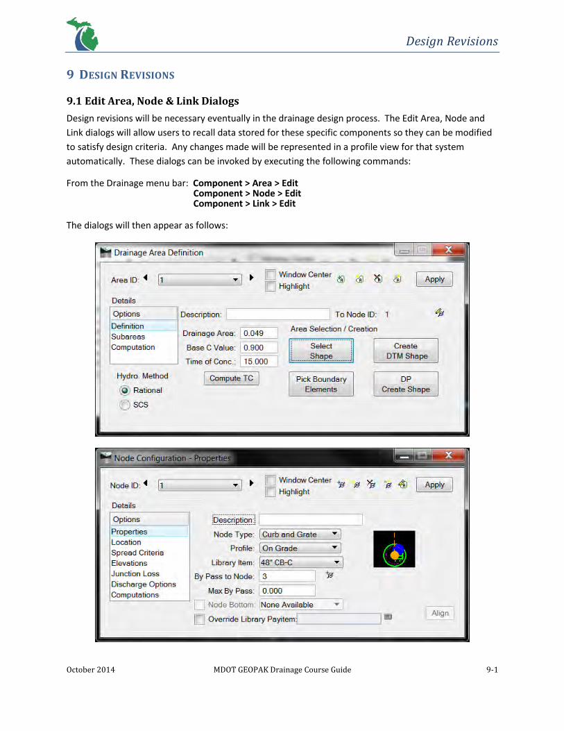
Design Revisions
October 2014 MDOT GEOPAK Drainage Course Guide 9-1
9 DESIGN REVISIONS
9.1 Edit Area, Node & Link Dialogs
Design revisions will be necessary eventually in the drainage design process. The Edit Area, Node and
Link dialogs will allow users to recall data stored for these specific components so they can be modified
to satisfy design criteria. Any changes made will be represented in a profile view for that system
automatically. These dialogs can be invoked by executing the following commands:
From the Drainage menu bar: Component > Area > Edit Component > Node > Edit Component > Link > Edit
The dialogs will then appear as follows:

Design Revisions
October 2014 MDOT GEOPAK Drainage Course Guide 9-2
From here, all of the data that was originally input for these three components can be edited as needed.
By clicking Apply, these revisions will be stored and the network can then be redesigned or reanalyzed
to update hydraulic computations.

Design Revisions
October 2014 MDOT GEOPAK Drainage Course Guide 9-3
Exercise 9.1 – Common Network Modifications
9.1.1 Adding a New Node
1. Add a node from the Drainage menu bar: Component > Node > Add
2. Name the Node ID 5A and click OK.
3. Set the Properties of the node:
Node Type: Curb and Grate
Profile: Sag
Library Item: 48” CB-K
4. Set the Location of the node:

Design Revisions
October 2014 MDOT GEOPAK Drainage Course Guide 9-4
Reference Chain: 9MILE_D
Reference Profile: NINEMILE_D
Align: Tangent to Element (use the Select MS Alignment
Element to select the back of curb)
Station: 34+00.00
Offset: Toggle on and enter -16.54
NOTE: Cover K’s need to hold the back of curb. The
width of the cover must be subtracted from the offset
value (1.96 ft).
Angle: 270.00
5. Set the Spread Criteria of the node:
% Slope Left: 4.00 (left refers to back stationing)
% Slope Right: 0.50 (right refers to ahead stationing)
% Discharge Left: 50.00
% Discharge Right: 50.00
Spread Source: Reference Surface
Max. Pond Depth: 0.16
Max. Pond Width: 4.33
NOTE: The correct TIN File must be selected in the Elevations Option for correct spread section
values to populate in the Spread Cross Section list box. Review populated entries and make
necessary revisions by setting the Spread Source to User Supplied to ensure accurate data input
at the node location.

Design Revisions
October 2014 MDOT GEOPAK Drainage Course Guide 9-5
6. Set the Elevations of the node:
Reference Surface: TIN File (Proposed – PRRD.tin)
Elevation Source: Reference TIN
Node Elevation Option: Same as Source
Vertical Alignment: Allow Drop Manhole
Minimum Depth: 4.00
Maximum Depth: 12.30
Add Sump Depth: 2.00
7. Set the Junction Loss of the node:
Absolute Loss: 0.10

Design Revisions
October 2014 MDOT GEOPAK Drainage Course Guide 9-6
8. Set the Discharge Options of the node:
9. Click Apply to add the node.
10. Set the By Pass to Node to 5A for Node ID 5 and click Apply.
9.1.2 Modify Link Connections
1. Add a link from the Drainage menu bar: Component > Link > Add…
2. Name the Link ID 5A and click OK.
3. Set the Definition of the link
From Node: 5A (use the ID button )
To Node: 5
Design Size: Toggle on

Design Revisions
October 2014 MDOT GEOPAK Drainage Course Guide 9-7
4. Set the Conditions for the link:
From Node Invert: Check to make sure toggle is off
To Node Invert: Check to make sure toggle is off
5. Constraints should be automatically populated from previously defined links:
6. Click Apply to add the link.
7. Under Link ID 5A’s Definition Option click the ID button for the To Node.
8. Find Node 6 and data point on the drainage structure cell. Notice how a new link is drawn from
Node 5A to Node 6.
9. Click Apply to save the new link connection. The old link disappears and the length is updated
automatically.

Design Revisions
October 2014 MDOT GEOPAK Drainage Course Guide 9-8
9.1.3 Redesign a Network
1. Add an area from the Drainage menu bar: Component > Area > Add…
2. Label the Area ID 5A and click OK.
3. Set the Definition of the area
Drainage Area: 0.04
Base C Value: 0.90
Time of Conc.: 15.00
Click Apply
4. Edit a network from the Drainage menu bar: Network > Edit
5. Edit Network ID: 9 Mile

Design Revisions
October 2014 MDOT GEOPAK Drainage Course Guide 9-9
6. Under Validation click Build Network
Click OK
7. Click Design Network to redesign the network with the new Node 5A included.
Click OK
Under the Link Configuration Conditions dialog for Link ID 5A notice how the inverts for the link
were established. Check these values against minimum depth constraints at each node. Toggle
on the From and To Node Invert boxes and enter 626.90 and 626.00, respectively. Click Apply.
8. Under the Network Configuration dialog Analyze Network ID 9 Mile to compute the hydraulics
of the system including the latest invert changes.
9. Save the project from the Drainage menu bar: Project > Save

Design Revisions
October 2014 MDOT GEOPAK Drainage Course Guide 9-10
Exercise 9.2 – Analyze Different Storm Frequencies
Conveyance systems sometimes need to be analyzed based on storm frequencies other than the design
storm. For example, this would be applicable if a system was designed to the 10-year frequency, but a
sag point needed to be checked to make sure the 50-year frequency spread does not encroach into the
travel way.
1. Open Project > Preferences from the Drainage menu bar to change the design frequency of the
project.
2. Go to File > Open and navigate to the Project Preferences file created earlier at:
C:\Temp\MDOT_GEOPAKDrainageTrainingClass\118329_GD_Pref.dpf
3. Under the Frequency Options set the Computation Frequency to 50 Year.
4. Click OK
5. Go to Network > Edit to open the Network Configuration dialog and click Analyze. This will
apply the new storm frequency to the system.

Design Revisions
October 2014 MDOT GEOPAK Drainage Course Guide 9-11
6. Review the standard Sag Inlet Computation Summary report by going to Reports > Inlets > Sag
Inlets to check to make sure the 50-year frequency Ponded Width values are within the
Maximum Ponded Width constraints set previously. Make any necessary changes to keep the
hydraulic computations within design constraints, if needed.
7. After reviewing the calculations for the 50-year frequency change it back to the 10-year
frequency by going back to Project > Preferences and Analyze the network again.
8. Save the project from the Drainage menu bar: Project > Save

Drainage Navigator
October 2014 MDOT GEOPAK Drainage Course Guide 10-1
10 DRAINAGE NAVIGATOR
10.1 Introduction
The Drainage Navigator provides the capability to manage all components of a network including Areas,
Inlets, Nodes, Links, Profiles, Culverts and Routings of a drainage project in one central location. This
tool provides an efficient way to identify, add, edit, delete, rename and query these components.
Within the Drainage Navigator exists a Global Editor, which allows for different variables of each type of
component to be revised within an entire project at once. The Drainage Navigator can be accessed from
the following commands:
MicroStation pull-down menu: Drainage > Utilities > Navigator
From the Drainage menu bar: Utilities > Navigator
From the Drainage Tool Box:
The Navigator dialog will then appear:

Drainage Navigator
October 2014 MDOT GEOPAK Drainage Course Guide 10-2
10.2 Navigator Dialog
The button tools from left to right are: All Networks, Active Network, Area, Inlet, Node, Link, Profile,
Culvert and Routing. Depending on which component button on the right is highlighted, component
ID’s will appear in the window below to be selected. These ID’s will either be from all networks in a
project or just from the Active Network based on which button is selected to the upper left.
Visualization tools are also provided to locate highlighted component ID’s without searching for them.
This can be accomplished through the Window Center and Highlight toggles at the bottom. The Query
toggle can be checked to expand the Navigator dialog below, which introduces Query Options as
described below:
Field Description
Query Type Provides the option of querying for Values or Constraints
Condition Greater than, less than or equal to can be chosen
Variable Each type of variable for certain components can be selected
Value Depending on which component and variable are chosen, a specific number can be input or an attribute can be selected from a drop-down menu
Apply Query Applies the query settings input and populates the window above with only the ID’s meeting the query criteria

Drainage Navigator
October 2014 MDOT GEOPAK Drainage Course Guide 10-3
10.3 Global Editor Dialog
The Global Editor Dialog can be utilized to make edits to components of entire projects or just the Active
Network. This dialog is an extension of the Drainage Navigator and can be accessed by clicking View >
Global Editor from the Navigator dialog.
To edit variables, first highlight the All Networks or Active Network button to the upper left. Select the
type of component, the specific ID’s and the variable desired to be revised. A New Value/Text field will
appear to the right, in which a value can be manually entered. Once this value is entered either Apply
Edit With Confirm or Apply Edit No Confirm will need to be clicked to apply the revision. The difference
between the two is that Apply Edit With Confirm will alert users of the pending edit and prompt them
to click Yes before any edits are made.

Drainage Navigator
October 2014 MDOT GEOPAK Drainage Course Guide 10-4
Exercise 10.1 – Querying
1. Access the Drainage Navigator from the Drainage menu bar: Utilities > Navigator
2. Make sure the All Networks button is highlighted.
3. Set the Active Component Type to Link and toggle on the Query option.
4. Next use the Query Options to determine which links have a flow velocity less than 3 fps. The
Component ID’s remaining in window after clicking Apply Query meet the conditions of the
query.
Query Type: Values
Condition: <
Variable: Velocity
Value: 3.00
5. Determine the following using the same procedures as previously described.
a. Which links have slopes less than the minimum required?
b. Which links have lengths greater than 300 ft?

Drainage Navigator
October 2014 MDOT GEOPAK Drainage Course Guide 10-5
Exercise 10.2 – Batch Editing
1. Access the Drainage Navigator from the Drainage menu bar: Utilities > Navigator
2. Make sure the All Networks button is highlighted.
3. Set the Active Component Type to Inlet and toggle ON the Highlight and Window Center
options.
4. Next select View > Global Editor
5. Select all the Inlet Component ID’s. (Selecting the first ID then holding the shift key and
selecting the last ID highlights them all)
6. In the Variable to Edit window select Inlet – Max Ponded Width
7. Enter a New Value of 5.00
8. Click Apply Edit No Confirm. This will apply all the changes without a confirmation warning.
9. Open the Node Configuration dialog (Component > Node > Edit from the Drainage menu bar)
10. Check under Spread Criteria that the Maximum Pond Width is now 5.00 for all inlets.

Drainage Reports
October 2014 MDOT GEOPAK Drainage Course Guide 11-1
11 DRAINAGE REPORTS
11.1 Introduction
GEOPAK Drainage has the ability to produce both standard and custom drainage reports as output for
hydraulic computations for each component. Standard reports are simultaneously updated as design
changes are made and after network computations have been performed. This provides an organized
summary of an entire drainage system in order to review how changes affect a network as a whole.
Custom reports can be created through the Report Builder to include specific data of a network needed
for review.
Also, MDOT has developed a Visual Basic Application (VBA) program to output standard MDOT drainage
tabulation sheets. These reports are for storm sewer, inlet spacing and hydraulic grade line
computations which put the data into a standardized deliverable format.
Standard and custom Report tools can be accessed in the following ways:
MicroStation pull-down menu: Drainage > Reports
From the Drainage menu bar: Reports
From the Drainage Tool Box:
11.2 Standard Reports
Five standard reports are provided for drainage areas, on grade inlets, sag inlets, link configuration and
link hydraulic computations. These reports can be output to an ASCII file to be reviewed in either
Notepad, Excel or WordPad. Reports for drainage areas and inlets do not require an Active Network to
be selected for reporting, however reports for links do require an Active Network. Once a network has
been redesigned or reanalyzed, computations are immediately updated in these reports:

Drainage Reports
October 2014 MDOT GEOPAK Drainage Course Guide 11-2

Drainage Reports
October 2014 MDOT GEOPAK Drainage Course Guide 11-3
11.3 Report Builder
The Report Builder provides the ability to generate custom reports for any of the data contained in a
drainage project. These can include input as well as computed values for each component. Upon setup
of a custom report, the format may be saved for future use. The format will consist of the chosen data
in rows and columns to easily be viewed in Microsoft Excel. The Report Builder can be accessed by
carrying out the following commands:
MicroStation pull-down menu: Drainage > Reports > Builder…
From the Drainage menu bar: Reports > Builder…
From the Drainage Tool Box:
By executing one of those commands, the Report Builder dialog will appear:

Drainage Reports
October 2014 MDOT GEOPAK Drainage Course Guide 11-4
Field Description
Report File Menu
Contains standard file managing functions such as New…, Open…, Save and Save As… The extension for the format of a custom report is .drf. This file can be applied in the future through Reports > Generate.
Component Report Basis
All components (Area, Inlet, Node, Link, etc.) used in a drainage project can be selected in the drop-down menu for reporting purposes. Component Data options depend on this basis.
Include Active Network Only When activated, this toggle controls reporting just the Active Network versus All Networks.
Component Data Depending on the Component Report Basis selection, applicable options will populate in this field.
Available Data Depending on the Component Data selection, applicable variables will populate in this window to be utilized in reports.
Report Data Lists Available Data items selected for reporting. The order from top to bottom determines column headings from left to right, respectively.
Include > This button is used to transfer highlighted Available Data items to the Report Data window to be included in a report.
< Exclude This button is used to transfer highlighted items in the Report Data window back to the Available Data window if it should not be included in a report.
Move Up Moves highlighted items in the Report Data window up in order.
Move Down Moves highlighted items in the Report Data window down in order.
Output
Default Output File Name File name for the output report file is manually entered in this field.
Default Output File Extension The extension in which the report file will be saved as. CSV extensions will allow reports to open in Microsoft Excel.
Decimal Places Determines the accuracy of output data.
Delimiter Determines the type of spacer between report data.
Generate Executes the report to be built.
View Opens the text editor to view, edit and print if desired.
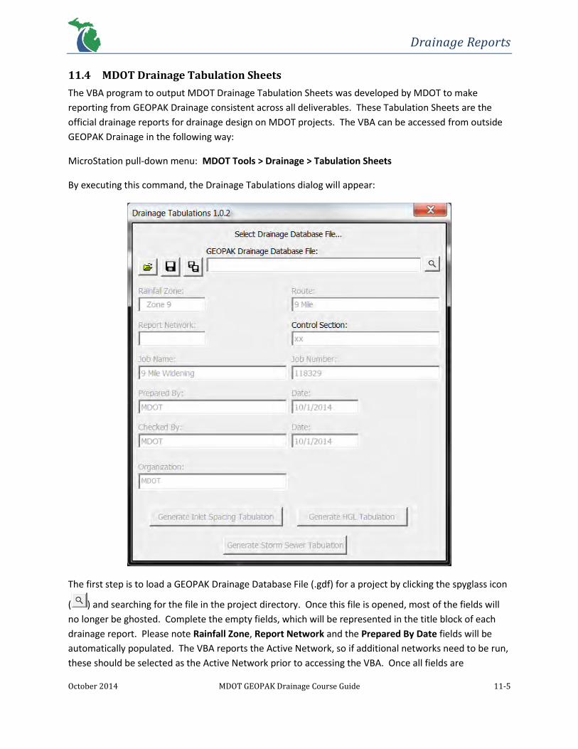
Drainage Reports
October 2014 MDOT GEOPAK Drainage Course Guide 11-5
11.4 MDOT Drainage Tabulation Sheets
The VBA program to output MDOT Drainage Tabulation Sheets was developed by MDOT to make
reporting from GEOPAK Drainage consistent across all deliverables. These Tabulation Sheets are the
official drainage reports for drainage design on MDOT projects. The VBA can be accessed from outside
GEOPAK Drainage in the following way:
MicroStation pull-down menu: MDOT Tools > Drainage > Tabulation Sheets
By executing this command, the Drainage Tabulations dialog will appear:
The first step is to load a GEOPAK Drainage Database File (.gdf) for a project by clicking the spyglass icon
( ) and searching for the file in the project directory. Once this file is opened, most of the fields will
no longer be ghosted. Complete the empty fields, which will be represented in the title block of each
drainage report. Please note Rainfall Zone, Report Network and the Prepared By Date fields will be
automatically populated. The VBA reports the Active Network, so if additional networks need to be run,
these should be selected as the Active Network prior to accessing the VBA. Once all fields are

Drainage Reports
October 2014 MDOT GEOPAK Drainage Course Guide 11-6
completed, drainage reports can be generated by clicking on one of three Tabulation buttons at the
bottom. These buttons correspond to the three drainage reports that are required for storm sewer
design: Inlet Spacing, HGL and Storm Sewer Tabulation Sheets. A Microsoft Excel file (.xls) with a
standard reporting format containing hydraulic computations for the Active Network can then be saved
in the project directory.
Tip: Reference .csv files are generated for each report where the actual report files (.xls) are saved. If
the report files become corrupted, try deleting all drainage .csv files and recreating the Tabulation
Sheets.
The following are examples of the format of each Drainage Tabulation Sheet:
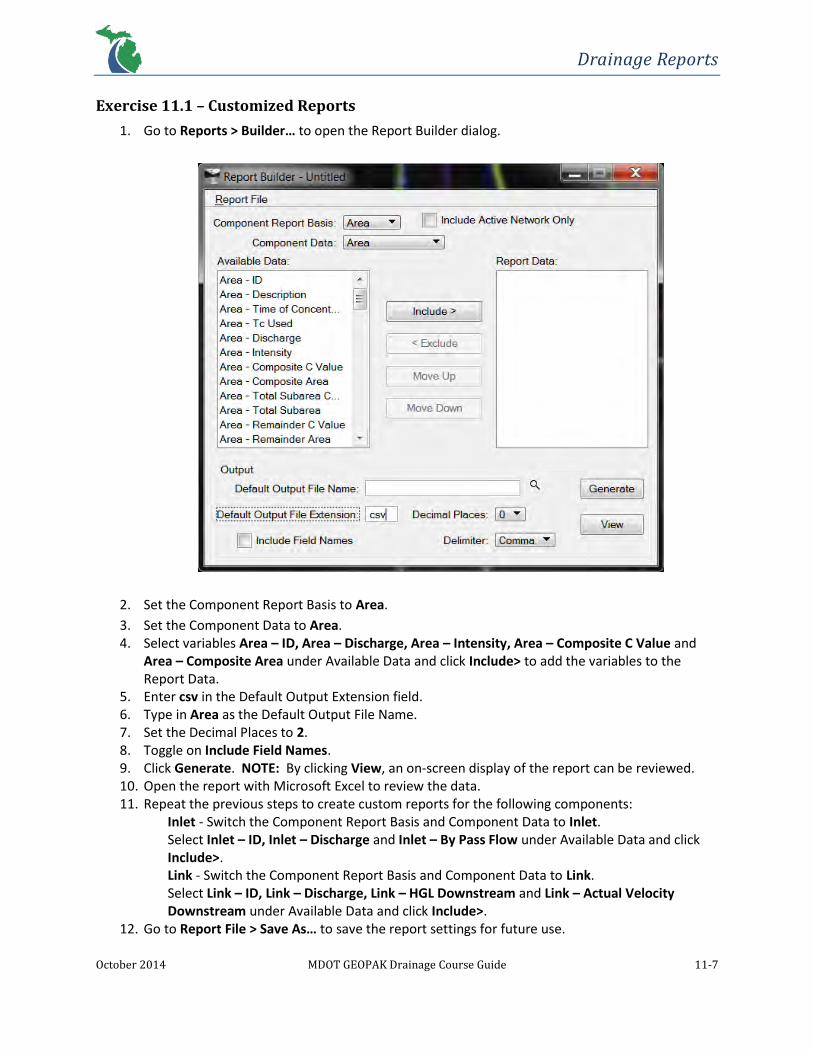
Drainage Reports
October 2014 MDOT GEOPAK Drainage Course Guide 11-7
Exercise 11.1 – Customized Reports
1. Go to Reports > Builder… to open the Report Builder dialog.
2. Set the Component Report Basis to Area.
3. Set the Component Data to Area. 4. Select variables Area – ID, Area – Discharge, Area – Intensity, Area – Composite C Value and
Area – Composite Area under Available Data and click Include> to add the variables to the Report Data.
5. Enter csv in the Default Output Extension field. 6. Type in Area as the Default Output File Name. 7. Set the Decimal Places to 2. 8. Toggle on Include Field Names. 9. Click Generate. NOTE: By clicking View, an on-screen display of the report can be reviewed. 10. Open the report with Microsoft Excel to review the data. 11. Repeat the previous steps to create custom reports for the following components:
Inlet - Switch the Component Report Basis and Component Data to Inlet. Select Inlet – ID, Inlet – Discharge and Inlet – By Pass Flow under Available Data and click Include>. Link - Switch the Component Report Basis and Component Data to Link. Select Link – ID, Link – Discharge, Link – HGL Downstream and Link – Actual Velocity Downstream under Available Data and click Include>.
12. Go to Report File > Save As… to save the report settings for future use.

Drainage Reports
October 2014 MDOT GEOPAK Drainage Course Guide 11-8
Exercise 11.2 – Creating MDOT Drainage Tabulation Sheets
1. Set the network “9 Mile” as the Active Network.
2. Click Network > Edit > Analyze to update hydraulic computations throughout the system to
ensure the latest design will be reported.
3. Go to MDOT Tools > Drainage > Tabulation Sheets to open the Drainage Tabulation Sheets VBA
dialog from the MicroStation pull-down menu.
4. Click the spyglass icon ( ) to search for the drainage project file:
C:\Temp\MDOT_GEOPAKDrainageTrainingClass\118329.gdf
Click Open.

Drainage Reports
October 2014 MDOT GEOPAK Drainage Course Guide 11-9
5. Fill out the project information for each field and click the Save Settings As… button ( ) to
save these settings to the project directory for future reporting.
6. Click a button at the bottom for the desired report to be generated.

Drainage Reports
October 2014 MDOT GEOPAK Drainage Course Guide 11-10
7. Type a report name in the File name: field and click Save to save the report to the project
directory.
8. Click OK in the pop-up dialog.
9. Open the report in Microsoft Excel to review the results.
NOTE: The Inlet Spacing Tabulation Sheet requires manual data entry for the Allowable Spread
field and the Gutter Width column since these values are project specific. Also, remarks about
special details pertaining to certain components of the network can be entered under the
Remarks column.

Drainage Reports
October 2014 MDOT GEOPAK Drainage Course Guide 11-11

Drainage Reports
October 2014 MDOT GEOPAK Drainage Course Guide 11-12

Drainage Reports
October 2014 MDOT GEOPAK Drainage Course Guide 11-13

Plan Preparation
October 2014 MDOT GEOPAK Drainage Course Guide 12-1
12 PLANS PREPARATION
12.1 Introduction
During the drainage design process, renumbering nodes will be required as they are added or deleted in
a project. GEOPAK Drainage provides an automated tool to search for and renumber nodes as needed.
Utilizing this tool will not only renumber nodes, but also any drainage areas or profiles they are
associated with. A conflict naming feature is also incorporated to eliminate duplicate node names.
The Drainage Labeler tool exists to place labels in the plan view of a drawing to increase efficiency of
labeling repetitive features such as: drainage areas, inlets, nodes and links. This tool is very similar to
the GEOPAK Road Plan View Labeler except that GEOPAK Drainage components are populated instead
of coordinate geometry elements. Users can label computed data from a drainage project and/or user
defined text.
12.2 Renumber Nodes
The Renumber Nodes tool can be accessed in the following ways:
From the MicroStation pull-down menu: Drainage > Component > Node > Renumber
From the Drainage menu bar: Component > Node > Renumber

Plan Preparation
October 2014 MDOT GEOPAK Drainage Course Guide 12-2
Field Description
Alignment Nodes will be scanned along a specified chain, station range and offset distance to be detected for renumbering.
Numbering Renumbers nodes inside the scan range to a Prefix, Number and/or Suffix as defined.
Nodes inside the scan range
Populates with nodes detected during the scanning process.
Node Name Conflicts outside the scan range
Displays conflicting node names outside the scan range for new node numbers. Conflicts can be resolved by renaming these nodes and moving to the Scan Range list box for further renumbering.
To renumber nodes, the following steps must be taken:
1. Load the .gpk file in the Job Number field if it hasn’t already been populated from the Project
Manager.
2. Specify the Start and End stations by either inputting specific values or dynamically by clicking
along the project corridor.
3. Specify the left and right search distances (in feet).
4. Click Find to scan the defined range.
5. Enter the desired Prefix, Number and/or Suffix for the new numbering sequence.
6. Resolve any conflicts by renaming Conflict ID’s, if applicable.
7. Check to make sure a node’s Current ID listed will be renumbered with the correct Renumber ID
inside the scan range. If not, revise the Numbering values in the upper right corner or delete
nodes that will be out of sequence.
8. Click Renumber Nodes to complete the process.

Plan Preparation
October 2014 MDOT GEOPAK Drainage Course Guide 12-3
12.3 Drainage Labeler
NOTE: Text placed with the Drainage Labeler is not annotative. Users should consider the possibility of
construction plan scale changes before using the Labeler tool to place drainage labels.
The Drainage Labeler can be accessed in one of two ways:
From the MicroStation pull-down menu: Drainage > Utilities > Labeler
From the Drainage menu bar: Utilities > Labeler
Tab Description
Text Can be placed with Computed Text or user defined text.
Params. Sets text preferences/symbology.
Shape Sets the shape preferences (if any) of a shape around a text label.
Leader Defines the type of leader and terminator for a given label.
Rotate Defines the angle of text in a variety of ways.
Styles Select a predefined set of parameters for a label or save a New Style to be used in the future.
Once label settings have been established, Computed Text can be entered into the Label Edit Field to
the right of the dialog. To do this, an Element ID can be chosen to be labeled, which change with the
selected type of drainage component. Once an Element ID is chosen, the desired Computed Text
property can be double clicked to automatically populate the Label Edit Field. User defined text can also
be input into this field as well by simply typing the desired text, but using the commands below to insert
symbols, spaces, multiple lines (return) and delimiters. There is also a “Clear” button to erase previously
specified labels. To place a label, click “Place Label” and data point in MicroStation. Multiple data
points may be necessary based on the leader type selected.

Plan Preparation
October 2014 MDOT GEOPAK Drainage Course Guide 12-4
Exercise 12.1 – Renumbering
NOTE: It is recommended to make a copy of the MicroStation and drainage project (.gdf) files prior to
renumbering in case the original numbering is needed later.
1. From the Drainage menu bar select the Renumber tool by going to: Component > Node >
Renumber
2. Complete the dialog as shown below and click Find.
3. Click Renumber Nodes. GEOPAK Drainage will renumber all nodes and drainage areas as well as
update link connections, calculations and profiles based on the settings in the Updates option of
the Project Preferences. NOTE: Link ID’s will not be renumbered to match the upstream Node
ID. Only the From/To Node ID’s will be changed within the Link Configuration dialog.
4. Close the dialog when finished.
5. Save the project from the Drainage menu bar: Project > Save

Plan Preparation
October 2014 MDOT GEOPAK Drainage Course Guide 12-5
Exercise 12.2 – Plan View Labeling
NOTE: Standard MDOT Drainage Label Styles have been developed for plan view drainage labels for
standard construction plan scales, which can be loaded under the Styles tab in the Drainage Labeler
by going to Style Files > Open... and opening the following file M:\MDOT_02
Workspace\Projects\MDOT_02\Civil Classic\Labeler Style Files\MDOT_Drainage.lsf. The following
exercises will step through the process of creating a custom label style, if needed.
12.2.1 Labeling Drainage Structures
1. From the Drainage menu bar open the Drainage Labeler tool: Utilities > Labeler
2. Select the Text tab and set it to the node component.
3. Select the first Element ID: 1
4. Double click the Node – ID in the Computed Text window to add it to the Label Edit Field.

Plan Preparation
October 2014 MDOT GEOPAK Drainage Course Guide 12-6
5. Next select the Params. Tab and double-click on the Text Preferences/Symbology - ‘Sample’
box to set the text features. Set them as shown below:

Plan Preparation
October 2014 MDOT GEOPAK Drainage Course Guide 12-7
6. To set the Shape Preferences select the Shape tab. Set this tab as shown below:
7. Select the Leader tab to define the type of leader and terminator. Define as shown below:

Plan Preparation
October 2014 MDOT GEOPAK Drainage Course Guide 12-8
8. Select the Rotate tab to define the current angle of the text. Set as shown below:
9. Click on Place Label and data point in MicroStation to place the label and leader.
10. To create a new style, place a label and click on the Styles tab then New Style… Name it, define
the scale and click OK.
11. To save a style select Style Files > Save As… to save the .lsf file to the project directory.
12. Go back and re-select the Text tab and select the second structure: 2. Then Toggle On the
Hightlight and Window Center so the Drainage Labeler will zoom to the selected structure
location in the MicroStation file.
13. Repeat steps defined above to label the rest of the drainage structures.
14. Save the MicroStation file: File > Save

Plan Preparation
October 2014 MDOT GEOPAK Drainage Course Guide 12-9
12.2.2 Labeling Pipes
1. When all drainage structures have been labeled click the Clear button to clear the Label Edit
Field.
2. Select the Text tab and set the component to Links
3. Select the first Element ID: 1
4. In the Computed Text box double-click: Link – Library Item.

Plan Preparation
October 2014 MDOT GEOPAK Drainage Course Guide 12-10
5. Next select the Params. tab. Double-click on the Text Preferences/Symbology: ‘Sample’ box to
set the text features. Set them as shown below:

Plan Preparation
October 2014 MDOT GEOPAK Drainage Course Guide 12-11
6. To set the Shape Preferences select the Shape tab. Set this tab as shown below:
7. Select the Leader tab to define the type of leader and terminator. Define as shown below:

Plan Preparation
October 2014 MDOT GEOPAK Drainage Course Guide 12-12
8. Select the Rotate tab to define the angle of text to be the Element Angle as shown below:
9. Click on Place Label to choose the label location in the MicroStation file.
10. Go back and re-select the Text tab and select Element ID 2. The current view should zoom to
the selected pipe since Highlight and Window Center are toggled on.
11. Repeat steps defined above to label the rest of the drainage pipes and Close the Drainage
Labeler when finished.
12. Save the MicroStation file: File > Save

Automated Quantities
October 2014 MDOT GEOPAK Drainage Course Guide 13-1
13 AUTOMATED QUANTITIES
Pending…

Warning Messages
October 2014 MDOT GEOPAK Drainage Course Guide 14-1
14 WARNING MESSAGES
Below are common warning messages users may run across when utilizing GEOPAK Drainage along with possible explanations as to why they were invoked: 14.1 Preferences
Message Explanation
Error Opening GPK file The directory path of the project’s geometric database (.gpk file) is not properly defined in the Project Preferences.
Error Opening Drainage Library The directory path of the project’s drainage library (.dlb file) is not properly defined in the Project Preferences.
Close All Open Library Item Dialogs Before Exiting Librarian
All edit dialogs must be saved or closed before exiting the drainage library dialog.
Unable to load path data The directory path of one or more of the project components are invalid or do not exist in the Project Preferences.
14.2 Areas
Message Explanation
No element meets the boundary level/symbology criteria
The MicroStation file element symbology, specified as search criteria for the area definition, does not match any of the elements in the MicroStation file.
Area Creation Failed or Aborted - Area Must be Enclosed
A drainage area must be an enclosed shape.
No Boundary Elements Selected Borderline MicroStation elements to enclose a drainage area were not selected.
Sum of Subareas = ## Exceeds Total Drainage Area = ## Do You wish to Reset Total
The sum of the subareas entered in the Area > Subareas option exceeds the total area defined in the Area > Definition dialog. GEOPAK Drainage will adjust the total area to be the total sum of the subareas.
14.3 Nodes
Message Explanation
Error Retrieving Cell
The cell library containing the drainage node cells is not attached to the .dgn file.
NO element identified
User has not selected a MicroStation element for which a node would use as a reference for placement while using the Tangent to Element or Tangent on Element methods in the Location option of the Node configuration dialog.

Warning Messages
October 2014 MDOT GEOPAK Drainage Course Guide 14-2
Unable to determine PGL Elevation
The station where the node is placed does not exist along the referenced profile.
Unable to compute TIN Elevation The node is placed outside the limits of the TIN file specified or the TIN file does not exist.
Error Finding D&C Manager
The D&C Manager database (.ddb file) is not found at the directory specified in the Project Preferences.
Error Computing Inlets Calculations for Network
GEOPAK Drainage was not able to compute any hydraulics for the specified inlet since there is no defined flow. This could be caused by having a negative slope in the spread criteria definition or by having no drainage area or discharge specified for the node.
Error Opening ACBOOK
The D&C Manager database (.ddb file) is not found at the directory specified in the Project Preferences.
Error Accessing TIN or Model
The TIN file does not exist at the directory specified in the Project Preferences.
Error in Inlet By Pass Designations - Loop Detected
Bypass flow is defined to discharge into the same node.
14.4 Links
Message Explanation
Link placement ERROR
Link was not placed and stored in the drainage database (.gdf file). This could be caused by having the From and To Nodes defined as the same Node ID or a MicroStation element to define the link was not selected.
Cannot Hold the Slope and From and To Node Elevations
Values for both inverts and the slope of a link cannot be held simultaneously. Inverts should be specified, while allowing the slope to be calculated by the software.
Cannot Hold From Node Soffit and Invert Elevations
Values for both soffit and invert elevations cannot be defined for the same FROM node. One of them should be defined, while allowing the software to calculate the remaining elevation based on the pipe diameter.
Cannot Hold To Node Soffit and Invert Elevations
Values for both soffit and invert elevations cannot be defined for the same TO node. One of them should be defined, while allowing the software to calculate the remaining elevation based on the pipe diameter.
Cannot Hold More than Two Conditions Values for both inverts and the slope of a link

Warning Messages
October 2014 MDOT GEOPAK Drainage Course Guide 14-3
cannot be held simultaneously.
Rise Exceeds Maximum allowed by Profile Envelope
The selected link is encroaching the minimum depths defined by the constraints of the connecting nodes.
Downstream HGL sufficient for Hydraulic Jump GEOPAK Drainage does not calculate the exact location of a hydraulic jump, but instead warns users of the possibility.
Minimum Slope used for Positive Drainage Link slopes were adjusted to the minimum specified slope in order to assure positive flow. Adverse pipe slopes are not allowed.
Min Depth Exceeded at Upstream or Downstream of Link
Link rise is encroaching into the upper profile envelope defined by: Node Elevation - Minimum Depth (to the soffit).
14.5 Networks
Message Explanation
Error Building Network An invalid network has been identified. Multiple outlet nodes or “loops” could cause this.
Network Calculations Containing Profile are not up to date, Please Perform Network Calculations
Shown results may not be the most recent since possible edit operations have occurred in the network.
An Active Network must be selected The Drainage > Network > Active Network command needs to be carried out to choose an Active Network.
Network Computations are not up to date show results anyway?
Shown results may not be the most recent since possible edit operations have occurred in the network.
Network Calculations involving link are not up to date, Please perform Network Computations
Shown results may not be the most recent since possible edit operations have occurred in the network.
Errors Preclude Computations
GEOPAK Drainage was unable to calculate the network. This could be caused by zero values in the node/link definitions or no drainage areas/supplied discharges assigned to nodes, thus producing no flow.
HGL Blowout at upstream end The hydraulic grade line is encroaching the limit defined by: Node Elevation - Minimum Freeboard (defined in the Project Preferences).
Commingling Runoff Methods not supported Both the Rational and SCS method are selected for different drainage area definitions.
Error Building Network - More than One Outlet found
An invalid network has been defined. Multiple outlet nodes are not supported.
Error Building Network - Loop or Multiple Downstream Links
An invalid network has been defined. Loop or closed circuits connections are not supported.
Error Building Network - More than five Incoming Links for Node
GEOPAK Drainage does not allow more than five pipe connections to a node.
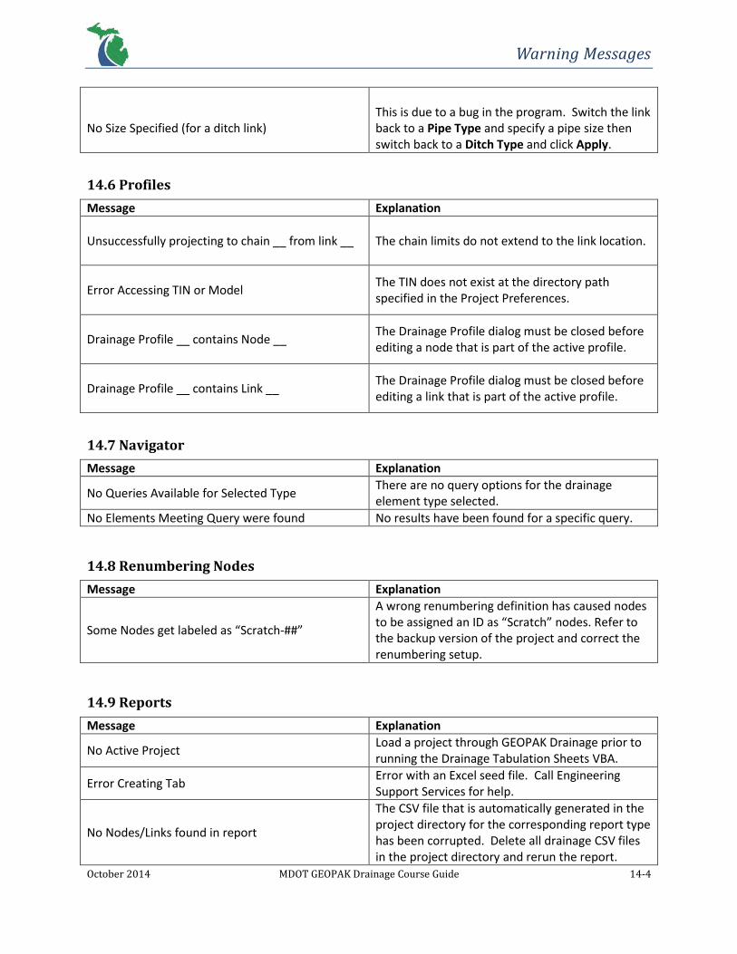
Warning Messages
October 2014 MDOT GEOPAK Drainage Course Guide 14-4
No Size Specified (for a ditch link)
This is due to a bug in the program. Switch the link back to a Pipe Type and specify a pipe size then switch back to a Ditch Type and click Apply.
14.6 Profiles
Message Explanation
Unsuccessfully projecting to chain __ from link __
The chain limits do not extend to the link location.
Error Accessing TIN or Model
The TIN does not exist at the directory path specified in the Project Preferences.
Drainage Profile __ contains Node __
The Drainage Profile dialog must be closed before editing a node that is part of the active profile.
Drainage Profile __ contains Link __
The Drainage Profile dialog must be closed before editing a link that is part of the active profile.
14.7 Navigator
Message Explanation
No Queries Available for Selected Type There are no query options for the drainage element type selected.
No Elements Meeting Query were found No results have been found for a specific query.
14.8 Renumbering Nodes
Message Explanation
Some Nodes get labeled as “Scratch-##”
A wrong renumbering definition has caused nodes to be assigned an ID as “Scratch” nodes. Refer to the backup version of the project and correct the renumbering setup.
14.9 Reports
Message Explanation
No Active Project Load a project through GEOPAK Drainage prior to running the Drainage Tabulation Sheets VBA.
Error Creating Tab Error with an Excel seed file. Call Engineering Support Services for help.
No Nodes/Links found in report
The CSV file that is automatically generated in the project directory for the corresponding report type has been corrupted. Delete all drainage CSV files in the project directory and rerun the report.