Conceptual tribo-energetic analysis of cutting tool protective coating delamination in dry cutting...
13
ORIGINAL ARTICLE Conceptual tribo-energetic analysis of cutting tool protective coating delamination in dry cutting of hard-to-cut aero engine alloys H. A. Abdel-Aal & M. Nouari & M. El Mansori & A. Ginting Received: 7 July 2006 / Accepted: 4 October 2006 / Published online: 14 November 2006 # Springer-Verlag London Limited 2006 Abstract Machining in dry mode is characterized by intense thermo-mechanical loading. The coupling between the thermal and the mechanical loads may lead to tool failure, especially when machining the so-called hard-to-cut alloys. Within such environments the efficiency of heat removal plays an important role in preserving the structural integrity of the tool. Efficient heat removal in dry machining depends solely on the intrinsic thermal proper- ties of the tool for uncoated tools and on the effective properties of the tool-coating combinations for coated tools. Thermal loads may also accelerate wear of the tool. As such, a relationship between the wear and the intrinsic thermal properties of the tool is worthy of investigation. This paper investigates such a relationship. Here we team numerical simulations to SEM-imagery to map the thermal conductivity within the tool zone of action of a coated carbide tool. The results indicate that, depending on the temperature rise, the tool-tip might undergo a severe drop in thermal conduction. This drop may locally restrict the ability of the tool material to dissipate the applied thermal load. This may nucleate thermally congested clusters within the tool-tip where the material completely loses the ability to transport heat. Thermal congestion renders an energeti- cally active zone where the thermal energy available may be used to activate wear through different mechanisms. It is also found that the immediate layer under the surface of the tool tip is important to enhance the ability of the tool material to dissipate the thermal loads. The results also highlight the importance of matching the temperature dependant properties of the different coating layers in order to enhance delamination resistance. Keywords Coating delamination . Titanium machining . Tool wear . Hard to cut alloys . Temperature rise . Thermal conductivity 1 Introduction Material removal in dry mode is an environmentally friendly practice which is gaining prominence in manufac- turing. From an engineering point of view, however, removing material in the absence of a lubrication-cooling medium introduces several technical difficulties that have to be addressed to fully benefit from the advantages offered by such mode of operation. The technical challenges in dry machining arise due to the nature of the environment through which the material removal process has to take place. In the absence of cooling or lubrication, friction forces as well as friction-induced- heat (FIH) will dominate. The dominant effects of friction Int J Adv Manuf Technol (2008) 36:213–225 DOI 10.1007/s00170-006-0837-3 H. A. Abdel-Aal (*) Department of General Engineering, 151 Ottensman Hall, University of Wisconsin-Platteville, 1 University Plaza, Platteville, WI 53818-3099, USA e-mail: [email protected] M. Nouari Laboratoire Matériaux Endommagement Fiabilité Ingénierie des Procédés (LAMEFIP), ENSAM CER Bordeaux, Esplanade des Arts et Métiers, 33405 Talence Cedex, France M. El Mansori Laboratoire de Mécanique et Procédés de Fabrication (LMPF), ENSAM CER Châlons-en-Champagne, Rue Saint Dominique BP 508, 51006 Châlons-en-Champagne, France A. Ginting Department of Mechanical Engineering, Faculty of Engineering, University of Sumatera Utara, Jalan Almamater, 20155 Medan, North Sumatera, Indonesia
-
Upload
independent -
Category
Documents
-
view
3 -
download
0
Transcript of Conceptual tribo-energetic analysis of cutting tool protective coating delamination in dry cutting...

ORIGINAL ARTICLE
Conceptual tribo-energetic analysis of cutting tool protectivecoating delamination in dry cutting of hard-to-cut aeroengine alloys
H. A. Abdel-Aal & M. Nouari & M. El Mansori &A. Ginting
Received: 7 July 2006 /Accepted: 4 October 2006 /Published online: 14 November 2006# Springer-Verlag London Limited 2006
Abstract Machining in dry mode is characterized byintense thermo-mechanical loading. The coupling betweenthe thermal and the mechanical loads may lead to toolfailure, especially when machining the so-called hard-to-cutalloys. Within such environments the efficiency of heatremoval plays an important role in preserving the structuralintegrity of the tool. Efficient heat removal in drymachining depends solely on the intrinsic thermal proper-ties of the tool for uncoated tools and on the effectiveproperties of the tool-coating combinations for coated tools.Thermal loads may also accelerate wear of the tool. Assuch, a relationship between the wear and the intrinsicthermal properties of the tool is worthy of investigation.This paper investigates such a relationship. Here we teamnumerical simulations to SEM-imagery to map the thermal
conductivity within the tool zone of action of a coatedcarbide tool. The results indicate that, depending on thetemperature rise, the tool-tip might undergo a severe drop inthermal conduction. This drop may locally restrict theability of the tool material to dissipate the applied thermalload. This may nucleate thermally congested clusters withinthe tool-tip where the material completely loses the abilityto transport heat. Thermal congestion renders an energeti-cally active zone where the thermal energy available maybe used to activate wear through different mechanisms. It isalso found that the immediate layer under the surface of thetool tip is important to enhance the ability of the toolmaterial to dissipate the thermal loads. The results alsohighlight the importance of matching the temperaturedependant properties of the different coating layers in orderto enhance delamination resistance.
Keywords Coating delamination . Titaniummachining .
Tool wear . Hard to cut alloys . Temperature rise .
Thermal conductivity
1 Introduction
Material removal in dry mode is an environmentallyfriendly practice which is gaining prominence in manufac-turing. From an engineering point of view, however,removing material in the absence of a lubrication-coolingmedium introduces several technical difficulties that have tobe addressed to fully benefit from the advantages offered bysuch mode of operation.
The technical challenges in dry machining arise due tothe nature of the environment through which the materialremoval process has to take place. In the absence of coolingor lubrication, friction forces as well as friction-induced-heat (FIH) will dominate. The dominant effects of friction
Int J Adv Manuf Technol (2008) 36:213–225DOI 10.1007/s00170-006-0837-3
H. A. Abdel-Aal (*)Department of General Engineering, 151 Ottensman Hall,University of Wisconsin-Platteville,1 University Plaza,Platteville, WI 53818-3099, USAe-mail: [email protected]
M. NouariLaboratoire Matériaux Endommagement Fiabilité Ingénierie desProcédés (LAMEFIP), ENSAM CER Bordeaux,Esplanade des Arts et Métiers,33405 Talence Cedex, France
M. El MansoriLaboratoire de Mécanique et Procédés de Fabrication (LMPF),ENSAM CER Châlons-en-Champagne,Rue Saint Dominique BP 508,51006 Châlons-en-Champagne, France
A. GintingDepartment of Mechanical Engineering, Faculty of Engineering,University of Sumatera Utara,Jalan Almamater,20155 Medan, North Sumatera, Indonesia

and FIH render the dry machining operation environment(DMOE) hostile. This hostility is manifested in high contactpressures, intense heat release, and considerably elevatedtemperatures. The hostility of the DMOE is especiallypronounced in the machining of the so-called hard-to-cutalloys which are widely used in the aeronautical industries.In machining such materials there is a need to enhance theperformance of the tool in regards to the resistance to wearand to softening.
There are several approaches to improve the resistanceof the cutting tool in dry machining. These vary betweendeveloping new materials that resist softening at elevatedtemperature, modification of the tool geometry to enhanceheat transfer and reduce the effective stresses, and to coatthe tool with a thin layer, or multi-layers, of a wear resistingmaterial, i.e., applying a thin protective coating to the tool.It is worth noting that the application of protective coatingsis the solution that is widely employed [1–3].
Typical materials used for coatings are ceramic nitridesor carbides such as titanium carbide TiC, titanium nitride,TiN, or aluminium oxide Al2O3. Application of the coatingto the carbide inserts may be performed through thedeposition of a layer, or layers, of the protective materialin vapour form either through physical assistance (PVD) orthrough chemical assistance (CVD).
Application of the protective coatings enhances theperformance of the cutting tool, reduces wear and enhancesproductivity [1–7]. Albeit, there are several technicaldifficulties that have to be addressed in order to harvest thefull benefits that protective coatings stand to offer. Thesemainly pertain to the structure integrity of the coatingsthemselves especially with respect to the adherence of thecoating to the tool substrate. When the coating undergoescatastrophic failure it will expose the tool substrate, hence itwill accelerate the failure of the cutting insert and in themean time will affect the quality of the resulting surface.
One of the frequently encountered modes of coating failureis the so-called coating delamination. This is the local removalor peeling of the coating material to expose the tool substrate.In general, the investigation of coating delamination is not aneasy task. This is because of the complex interaction betweenthe factors that contribute to delamination: DMOE, theintrinsic properties of the coating material, and the interactionbetween the tool, the coating, and the work piece. It ispossible to approach coating delamination from a chemical,mechanical, or a thermal point of view. Thus one can attributecoating failure to chemical reactions, mechanical forceinteraction or thermally activated mechanisms.
The parametric mechanistic steps through which delam-ination takes place are sketchy, at best, as of yet. However,it is envisioned that adhesion is a precursor to delamination.Adhesion may have chemical origins such as the case ofmachining of titanium alloys where the high chemical
reactivity of titanium with many tool materials facilitatesthe formation of an adhesive layer between the tool and thework piece [8]. Adhesion may also take place due to severeplastic deformation of the tool leading cutting edge [9–11].In such a case the plastic deformation, which is indicativeof high contact pressure, will modify the shape of theleading edge. Moreover, plastic deformation will increasethe area of contact at the tool-chip interface, hence causingan adhesive layer to form. Following adhesion and in orderto break the contact, cracks will form and delamination ofthe coating will take place. At any rate, however, regardlessof the explanation of the origin of delamination that onemay adopt, chemical or mechanical, adhesion is a necessarytrigger. Moreover, within a DMOE the temperature shouldplay a certain role in inducing adhesion.
The role of the temperature follows from an argumentthat is two-fold. Firstly, an elevated temperature generallyleads to the degradation of the thermal and the mechanicalproperties of the tool-coating combination. This degrada-tion may affect the resistance of the materials involved tocrack formation. Secondly, moreover, an elevated temper-ature implies intense heat flux generation. This flux is ineffect a source of energy that can activate chemicaldiffusion and affect the chemical affinities of the tool andthe coating materials. As such, the study of the influence ofthe thermal environment in dry machining on coatingdelamination and wear in general may lend clarification tothe mechanisms responsible for the delamination process.
This paper, therefore, is concerned with the study of theinfluence of temperature elevation on initiating catastrophicprotective coating delamination (CPCD). The study is anextension of earlier experimental work [9–11] that aimed atthe identification of CPCD in dry end milling of aeronau-tical titanium alloys. The analysis presented herein empha-sizes the physical mechanisms that are triggered due to thesharp temperature rise rather than focusing on enhancedcalculation of the magnitude of that rise. Additionally, aninitial postulate concerning the role that the thermaltransport properties of the coatings assume in triggeringCPCD is presented.
2 Experimental tests
As detailed elsewhere [10, 11] several dry end-millingexperiments were performed using the α-β titanium alloyTi-6242S as a work-piece material. The chemical compo-sition and physical properties are given in Tables 1 and 2,respectively. Two groups of alloyed carbide inserts wereemployed; the first is an uncoated alloyed carbide-WC-Ti/Ta/Nb-Co (reference material), and the second is an alloyedcoated carbide tool using a multi-layer CVD depositiontechnique with consecutive layers of TiN, TiCN and TiC.
214 Int J Adv Manuf Technol (2008) 36:213–225
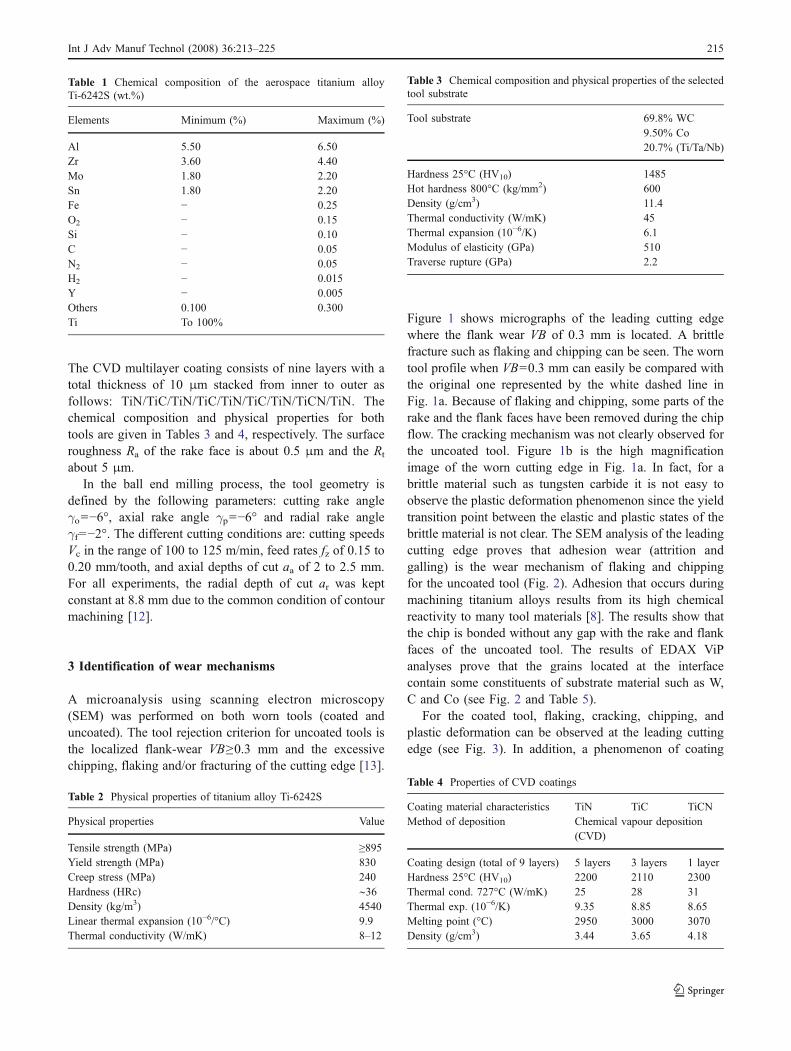
The CVD multilayer coating consists of nine layers with atotal thickness of 10 μm stacked from inner to outer asfollows: TiN/TiC/TiN/TiC/TiN/TiC/TiN/TiCN/TiN. Thechemical composition and physical properties for bothtools are given in Tables 3 and 4, respectively. The surfaceroughness Ra of the rake face is about 0.5 μm and the Rt
about 5 μm.In the ball end milling process, the tool geometry is
defined by the following parameters: cutting rake angleγo=−6°, axial rake angle γp=−6° and radial rake angleγf=−2°. The different cutting conditions are: cutting speedsVc in the range of 100 to 125 m/min, feed rates fz of 0.15 to0.20 mm/tooth, and axial depths of cut aa of 2 to 2.5 mm.For all experiments, the radial depth of cut ar was keptconstant at 8.8 mm due to the common condition of contourmachining [12].
3 Identification of wear mechanisms
A microanalysis using scanning electron microscopy(SEM) was performed on both worn tools (coated anduncoated). The tool rejection criterion for uncoated tools isthe localized flank-wear VB≥0.3 mm and the excessivechipping, flaking and/or fracturing of the cutting edge [13].
Figure 1 shows micrographs of the leading cutting edgewhere the flank wear VB of 0.3 mm is located. A brittlefracture such as flaking and chipping can be seen. The worntool profile when VB=0.3 mm can easily be compared withthe original one represented by the white dashed line inFig. 1a. Because of flaking and chipping, some parts of therake and the flank faces have been removed during the chipflow. The cracking mechanism was not clearly observed forthe uncoated tool. Figure 1b is the high magnificationimage of the worn cutting edge in Fig. 1a. In fact, for abrittle material such as tungsten carbide it is not easy toobserve the plastic deformation phenomenon since the yieldtransition point between the elastic and plastic states of thebrittle material is not clear. The SEM analysis of the leadingcutting edge proves that adhesion wear (attrition andgalling) is the wear mechanism of flaking and chippingfor the uncoated tool (Fig. 2). Adhesion that occurs duringmachining titanium alloys results from its high chemicalreactivity to many tool materials [8]. The results show thatthe chip is bonded without any gap with the rake and flankfaces of the uncoated tool. The results of EDAX ViPanalyses prove that the grains located at the interfacecontain some constituents of substrate material such as W,C and Co (see Fig. 2 and Table 5).
For the coated tool, flaking, cracking, chipping, andplastic deformation can be observed at the leading cuttingedge (see Fig. 3). In addition, a phenomenon of coating
Table 2 Physical properties of titanium alloy Ti-6242S
Physical properties Value
Tensile strength (MPa) ≥895Yield strength (MPa) 830Creep stress (MPa) 240Hardness (HRc) ∼36Density (kg/m3) 4540Linear thermal expansion (10−6/°C) 9.9Thermal conductivity (W/mK) 8–12
Table 3 Chemical composition and physical properties of the selectedtool substrate
Tool substrate 69.8% WC9.50% Co20.7% (Ti/Ta/Nb)
Hardness 25°C (HV10) 1485Hot hardness 800°C (kg/mm2) 600Density (g/cm3) 11.4Thermal conductivity (W/mK) 45Thermal expansion (10−6/K) 6.1Modulus of elasticity (GPa) 510Traverse rupture (GPa) 2.2
Table 1 Chemical composition of the aerospace titanium alloyTi-6242S (wt.%)
Elements Minimum (%) Maximum (%)
Al 5.50 6.50Zr 3.60 4.40Mo 1.80 2.20Sn 1.80 2.20Fe − 0.25O2 − 0.15Si − 0.10C − 0.05N2 − 0.05H2 − 0.015Y − 0.005Others 0.100 0.300Ti To 100%
Table 4 Properties of CVD coatings
Coating material characteristics TiN TiC TiCNMethod of deposition Chemical vapour deposition
(CVD)
Coating design (total of 9 layers) 5 layers 3 layers 1 layerHardness 25°C (HV10) 2200 2110 2300Thermal cond. 727°C (W/mK) 25 28 31Thermal exp. (10−6/K) 9.35 8.85 8.65Melting point (°C) 2950 3000 3070Density (g/cm3) 3.44 3.65 4.18
Int J Adv Manuf Technol (2008) 36:213–225 215

delamination is clearly distinguished (Fig. 3b). As for theuncoated tool, the results of the chemical analyses(EDAX) confirm that adhesion is the wear mechanism ofthe coated one. Adhesion wear is caused by themechanical removal of the tool material when theadhesive junctions are broken. Compared to the uncoatedtool, the SEM analysis of the coated tool shows thatmicro-cracks take place in the coating layer and they areimmediately followed by the removal of the coatingmaterial (Fig. 3b). Furthermore, the analysis reveals thatmicro-cracks in the coating layer propagate not only in thehorizontal direction but also in the vertical one through theinterface between the tool substrate and the coatingmaterials. This causes the delamination of the coating onthe tool surface.
4 Analysis of coating delamination mechanisms
4.1 Initial tool wear
To understand the initial tool wear, supplementary drymachining tests were performed with the coated tool. Foreach cutting test only one passage of the cutting edge on theworkpiece surface was authorized (only one machiningpass); the total cutting length considered in the experimentswas about 250 mm. The worn tool was sectioned andexamined at the area where the initial flank wear waslocated (see Fig. 4). As shown in Fig. 4b, the removedcoating layers at the tool cutting edge can clearly be seen.
Experimental investigations show that the coatingdelamination phenomenon is the initial wear mode of thecoated tool. Initially, it may be supposed that the coatingdelamination is due to mechanical wear. The coatingmaterial is subject to great thermal and mechanical loadsand cannot resist the wear during the interrupted cutting ofthe milling process. Nevertheless, the cutting forcesobtained when machining titanium alloys and steels areroughly similar [6]. When machining steels, coatingmaterials such as TiN, TiCN and TiC have a beneficial
Fig. 1 Uncoated tool at cutting condition of 100 m/min, 0.15 mm/tooth, 2 mm, 8.8 mm and VB=0.3 mm. a Brittle fracture. b Highmagnification on brittle fracture area. (❶ flaking, ❷ chipping, ❸plastic deformation, and the white dashed line is the original profile ofthe uncoated tool)
Fig. 2 Adhesive wear mechanism (attrition/galling) on uncoated tool(100 m/min, 0.15 mm/tooth, 2 mm, 8.8 mm and the analysis of EDAXViP on the grain pointed by arrow number 1 is presented in Table 5)
Table 5 EDAX ViP (Variable Pressure) analysis on the area located atthe uncoated tool-chip interface
Element Symbol Wt (%)
Tungsten W 40.01Titanium Ti 3.14Tantalum Ta 7.25Niobium Nb 15.09Carbon C 5.59Cobalt Co 1.15
216 Int J Adv Manuf Technol (2008) 36:213–225

effect on friction and the tool life is generally extended [1,5, 6].
4.2 Thermal aspects of coating delamination
According to the experimental results presented above, adescription of the physical mechanisms of coating delam-ination is proposed. Investigations show that the tool-chipinterface is controlled by the contact temperature which canattain large values and affects drastically the wear behav-iour of the coating and substrate materials, especially in drymachining.
Previous work showed that high temperatures and theintimate contact between tool and chip interface provide anideal environment for wear progression [9–11]. Thecalculated temperature distribution shown in Fig. 5 indi-cates that the maximum temperature is located away fromthe cutting edge. In particular, it is located at a distance ofa few hundred microns from the tool chip interface. This isindicative of severe plastic deformation under the surface;
see Fig. 3a. Such deformation gives rise to internal heatgeneration. That is, the combination of plastic stresses andplastic strains will cause a strong internal heat source todevelop under the surface of contact. This also will affectthe quality of heat dissipation within the interface [14]. Asa consequence of the location of the maximum tempera-ture, two temperature gradients will develop, each ofwhich will start at the location of the maximum temper-ature. The primary gradient will be directed toward thebulk of the substrate tool material. Meanwhile, thesecondary one will be directed toward the tool-chipinterface (nominal contact surface). This situation willlead to a secondary thermal flux directed toward thecutting edge q1B and q1A for coated and uncoated tools,respectively, as shown schematically in Fig. 5. Thestrength of the secondary flux will depend on the strengthof the corresponding gradients and the local value of thethermal conductivity at points B and A respectively.
Fig. 4 Coating delamination as the initial wear of the coated tool.a New sectioned cutting edge. b Worn cutting edge just after totalcutting length 250 mm (115 m/min, 0.165 mm/tooth, 2.25 mm,8.8 mm)
Fig. 3 Wear mechanisms of coated tool (125 m/min, 0.2 mm/tooth,2.5 mm, 8.8 mm). a Plastic deformation, the dashed line is the originaltool profile. b High magnification of the area located by the whitecircle showing cracks and delamination failures in the coating layer
Int J Adv Manuf Technol (2008) 36:213–225 217

Moreover for tool B, the coated tool, the strength of thesecondary flux will also depend on the effective thermalconductivity of the coatings combination.
The effect of the secondary flux may not be appreciablefor the uncoated tool (tool A) since the amount of heat q2Amay be considerably less than that of q2B and of the totalamount generated at the surface of contact. However, forthe coated tool the secondary flux will act as an additionalthermal resistance. It will give rise, locally, to thermalinertia effects that will oppose the penetration of the mainthermal flux generated at the surface of contact through thecoatings, see the schematic view presented in Figs. 6 and 7.
Such a process will lead, locally, to an increased thermalintensity depending on the manner in which the thermo-mechanical properties of the coatings vary with temperature[15].
A useful insight into the thermal aspects of coatingdelamination may be gained by studying the variation ofthe thermal properties of the coating materials withtemperature especially at the interface temperature, that is,at the dominant temperature at the interface between theTiN coating and the TiC coating, point M in Fig. 6.
The temperature of the interface between the TiN coatingand the TiC coating, point M, is around 950°C (as seen inFig. 6). At this temperature, however, the coefficient ofthermal expansion of the TiC coating material is around8.47 ppm whereas that of the TiN coating material isaround 6.35 ppm [16]. This creates a considerablemismatch in the thermal strain at the boundary, αth(TiC)/αth(TiN)≈1.4, that will contribute to the delamination of thecoating.
At the interface between the TiC coating and the toolsubstrate for tool B, point N, the temperature is approxi-mately 850°C. At this temperature, the coefficient ofthermal expansion of the tool substrate is around 6.5 ppm[16]. Again this will cause a thermal strain mismatch sinceαth(substrate)/αth(TiC)≈1.2.
The resistance of materials to the formation of microcracks is a function of the mechanical properties as well asthe heat transfer conditions. This function assumes theform:
RMC ¼ s t
EaBið1Þ
where σt is the tensile strength of the materials, E is theYoung’s Modulus, α is the coefficient of linear thermalexpansion and Bi is the Biot number given by: Bi ¼ h L=k,where h is the heat transfer coefficient L is a characteristiclength and k is the thermal conductivity. In the frame of thiswork both L and h may be considered constant for thematerials involved. Now using Equation (1) the ratiobetween the resistances to the formation of micro-cracks(MC) for two materials, A (II) and B (I) for example will begiven by,
RMC I
RMC II¼ σt IEIIαII kI
σt IEIIαI kIIð2Þ
Using the values given in Table 6 in Eq. 2, the ratio ofthe resistance to micro-crack formation of the TiN coatingto that of the TiC, at the temperature of point M (in Fig. 6,950°C), is found to vary between 0.97–1.2. Interestingly,moreover, the ratio of the resistance of TiC coating to thatof the tool substrate, at the temperature of point N (about850°C), is found to be 0.5. That is, within the presentcoating configuration the TiC coating is the weakest link
M
N
TiN
TiC
Tool Substrate
5.09 5.11 5.13 5.15600
700
800
900
1000
1050
Tool B
Tool A
Distance mm
Tem
per
atu
re C
Fig. 6 Evolution of temperature through the coating and the substratematerials
A
B
A
B
A
B
Tool B
Tool A
0.5 1.0 1.50
100
300
500
700
1100
900
Distance from Cutting Edge (mm)
Tool
chi
p in
terf
ace
tem
per
atur
e C
Tool A
Tool BI
II
q2A
Fig. 5 Evolution of the cutting temperatures on the tool surface. Thecutting conditions for both coated and uncoated tools are similar tothose of Fig. 4 (uncoated=tool A, coated=tool B)
218 Int J Adv Manuf Technol (2008) 36:213–225

and is more likely to initiate a micro-crack at the stressesdominant during machining.
4.3 Relationship between thermal conduction and wear
The preceding analysis indicated a correlation between thetemperature reached by the tool and delamination of thecoating. This correlation seems to be facilitated throughthe mismatch in the resistance to crack formation betweenthe coating material and that of the substrate (Eqs. 1 and2). Recall that, this mismatch is due to the different rates by
which the thermo-physical properties of the particularmaterials vary with temperature. As such, one mayhypothesize that temperature rise, qualitatively at least, isthe main catalyst to delamination. From a physicalthermodynamic point of view, however, temperature eleva-tion is a manifestation of the amount of heat (thermal load)that acts on a given volume of the solid. It follows that thesharp temperature rise that is encountered at the contactspot between the tool and the work piece is also amanifestation of the intense local thermal load acting onthe tool volume in direct contact with the work piece (tooltip). This hypotheses is verified through inspecting the wearpattern of the tool (refer to Figs. 2, 3 and 4). It is noted inFig. 2, that galling may be the trigger of flaking for theuncoated tool, whereas for the coated tool in Figs. 3 and 4,delamination and cracks appear at the tool cutting leadingedge (front edge of the tool nose). Moreover, severe plasticdeformation, at the nose area and its close proximity, isobserved in the figures. So we can additionally postulatethat the areas where heat removal is constrained are theareas that suffer severe mass loss due to wear. The
Fig. 7 A schematic view of the coating delamination
Table 6 Summary of material properties at the TiN/TiC coatinginterface at the TiC/ substrate interface
Material Vh(Gpa)
E(GPa)
k W/m°C@TM
k W/m°C@TN
T melt°C
TiN 18–21 251 26.00 2950TiC 28–35 410 31.43 31.00 3067WC 22 510 60.00
@8502870
Int J Adv Manuf Technol (2008) 36:213–225 219

constraint of heat removal due to severe plastic deforma-tions and straining conditions in sliding systems wasoriginally presented by Abdel-Aal [14, 15, 17–21] in thecontext of wear analysis of titanium (sliding on similarcounter parts and on M2-steel samples under machiningtype loading). Wear encountered by the sliding samples inthese works was correlated to the “thermal effusivity”distribution within the contacting layers.
The thermal effusivity, also known as the coefficient ofheat penetration, represents the ability of the thermal flux topenetrate into a surface in transient mode. Alternatively it isa measure of resistance to heat penetration or impedance ofthe heat flux. Thus, a solid body at a higher effusivity offersmore resistance to thermal flux penetration than a solid at alower effusivity [20]. This parameter, the effusivity, is alsoan indicator of the balance between the ability of the solidto conduct heat and its ability to store a thermal load. Thusit can be defined as: B ¼ ffiffiffiffiffiffiffiffiffiffi
rCKp
. On the other hand,thermal effusion may be interpreted as the balance betweenthermal conduction and thermal diffusion whence theeffusivity may be written as: B ¼ K
ffiffiffi
Dp . This later form was
argued to be the parameter that represents the thermalcompatibility of two contacting solid layers [18].
Within the definition of the effusivity, it is noted that thethermal conductivity is the sub-parameter of dominance.The variation in the thermal conductivity for most engi-neering materials with temperature falls into three basiccategories. These were summarized by Abdel-Aal [22].Mathematically, the variation of the thermal conductivitywith temperature may be represented in several forms (i.e.,exponential, linear, biharmonic, etc.). The choice of aparticular mathematical form depends, mainly, on theallowable error margin introduced when fitting experimen-tal measurements. For many practical applications a linearrepresentation of the form K Tð Þ ¼ Ko 1þ bTð Þ is sufficient[22].
4.3.1 Mapping of the thermal conductivity
To investigate the postulated link between wear and thermalconduction, there is a need to generate a thermal conduc-tivity map of the active zone of the tool. Satisfying such arequirement meanwhile depends on the availability of thelocal temperature distribution at the particular points withinthe zone of interest (ZOI). The temperatures may beobtained through measurements or by computations. Mea-suring the temperature distribution at the tool tip with therequired precision and resolution is a tedious task thatentertains considerable uncertainties, which are at the samelevel of those implied by computations. As such, in thiswork, the local temperature distributions were obtainedfrom finite element simulations. All simulations wereperformed using the commercial code Thirdwave. Details
of the numerical aspects of the simulation and thegeometrical meshing procedure are detailed elsewhere [10].
The points comprising the ZOI within the tool werechosen based on the wear patterns observed in Figs. 3 and4. Figure 8 is an illustration of the grid of pointsrepresenting the ZOI of the tool. Figure 8a is a plot of thecomputational grid for the ZOI. Figure 8b is a schematicillustration of the position of the computational grid onthe coated tool. Finally, the relative position of the ZOIwith respect to the tool work piece interface is shown inFig. 8c.
Within the ZOI four banks of points were identified.These represent a pair of two consecutive layers, approx-imately 1 μm apart on the tool physical space, one at theflank face and the other at the rake face of the tool. Thus,the line labeled Layer-1 in Fig. 8b represents the loci of thepoints located on the surface of the tool from the flank side.The line labeled Layer-2, again in Fig. 8b, is the loci of thepoints located within a sublayer that is 1 μm underneath thetool surface from the flank side. Similarly, the line labeledLayer-3 represents the loci of the points that are located onthe surface of the tool from the rake side, and the linelabeled Layer-4 is the loci of those points located within asublayer located 1 μm under the surface of the tool from therake side.
The local temperatures for each of the points, located onlayers 1 through 4, were extracted from the finite elementsimulation. This data allowed the mapping of two quantitieswithin the ZOI: the local value of the thermal conductivityand the temperature gradient between each of the consec-utive layers on each side of the tool.
Figure 9a is a plot of the local temperatures at the pointslocated on Layer-3 (dark symbols) and on Layer-4 (opensymbols). Temperature data are plotted against an arbitrarynon-dimensional coordinate. This coordinate is constructedin two steps. The first entails finding the distance betweenthe first point in the particular layer, which is located at thetip of the tool, and each of the following points. The secondstep entails finding the ratio between these distances andthe distance between the tip point and the last point on thegrid within the particular layer. As such, the zero-coordinaterepresents the points at the tool tip, or alternatively thepoint that is in actual contact with the work piece, and theone-coordinate represents the farthest point on the particu-lar layer away from the contact spot.
It is noted that the temperature rise is the highest at thetool tip, and relatively lower away from the tool tip. Asimilar trend is noticed for the subsurface layer, Layer-4,where the temperature drops in the direction away from thetip toward the bulk of the tool. The temperature rise for thelayers that are located on the flank end of the tool reflects asimilar trend as seen in Fig. 9b. It is also noted that thepoints located at the surface exhibit a temperature rise
220 Int J Adv Manuf Technol (2008) 36:213–225

higher than the subsurface points. Such a trend is reversedaway from the tool tip, toward the bulk of the tool. Alongthis direction, substrate temperatures are higher than thesurface temperatures.
The temperature dependent conductivity in this work isrepresented by the linear form, K Tð Þ ¼ Ko 1þ bTð Þ, whereKo is the conductivity at room temperature (or a referencetemperature), and β is the temperature coefficient ofconductivity. The value of Ko in this work represents theequivalent room temperature conductivity of the tool-coating substrate. This was calculated by considering thethermal conductivity of the tool material and that of thecoating material [16] using the procedure outlined bySalazar [23]. The value of the β-coefficient was obtainedby linear regression of the equivalent values of the
(a)
(b)
Non-dimensional width X/L
0.0 0.2 0.4 0.6 0.8 1.0
Tem
pera
ture
ris
e ˚C
0
200
400
600
800
1000
1200
Layer-1
Layer-2
Non-dimensional layer width X/L
0.0 0.2 0.4 0.6 0.8 1.0
Tem
pera
ture
ris
e ˚C
0
200
400
600
800
1000
1200
Layer-3
Layer-4
0.0 0.2 0.4 0.6 0.8 1.0
0
200
400
600
800
1000
1200
Layer-3
Layer-4
Fig. 9 Plot of the local temperature vs. an arbitrary non-dimensionalcoordinate. a Layers 3 and 4. b Layers 1 and 2
Fig. 8 The zone of interest (ZOI) at the tool tip. a A plot of thecomputational grid. b A schematic illustration of the position of thecomputational grid. c Relative position of the ZOI with respect tothe tool–work piece interface
Int J Adv Manuf Technol (2008) 36:213–225 221

conductivity at the temperature range (0<T<1400°C). Thus,the working equation for the temperature dependantconductivity is written as, K Tð Þ ¼ 45:0 1� 0:000507 Tð Þ.
Figure 10a and b depict the distribution of thetemperature dependent conductivity within the four selectedlayers on the tool. The conductivity is plotted as a non-dimensional quantity that represents the local value of theconductivity referenced to the room temperature conduc-tivity of the tool-coating combination. In consistence withthe temperature distribution, the conductivity drops at thepoints where the highest temperature rise is experienced.
Such points, which are located at the tool tip, are intenselyloaded both thermally and mechanically. The relatively lowvalue of the conductivity, as seen in the figures, renders theZOI of the tool practically thermally congested. That is, theability of the tool material to dissipate the applied thermalload will be appreciably degraded. As explained elsewhere,failure of efficient dissipation of the thermal load willtrigger several responses by the tool material that aim atdissipating this available energy. These can be chemicalreactions, crack initiation, etc.
To further clarify the connection between efficientthermal dissipation and tool performance, eight points ofinterest were selected on the tool. The arrangement of thesepoints was such that they represent two consecutive layersaround the contour of the tool nose. The arrangement of thepoints on the physical space of the tool is shown inFig. 11a. It is seen that the points represent two layers, asurface layer (closed symbols) that is located on the contourof the tool nose, and a sublayer that is about 1 μm beneaththe surface.
Figure 11b depicts the worn tool tip, and Fig. 11c depictsthe conductivity distribution of the selected points. Surfacepoints in Fig. 11c are denoted by closed symbols whilesubsurface points are identified by open symbols. Observethat the tool tip exhibits considerable wear; compare thevirgin tool (Fig. 11a) to the worn tool (Fig. 11b). In themeantime, comparing Figs. 11c and 11b, it is noted that allthe points on the surface undergo a severe drop in thethermal conductivity (0.4=K(T)=0.5). Interestingly, thesubsurface layer points I’, II’ and IV’ (open symbols) arerelatively more conductive than their corresponding surfacepoints I, II and IV (closed symbols). Point III’, however,doesn’t display a similar trend. The difference in conduc-tivity between the various points is interesting on twocounts. Firstly, the alternating behavior of the conductivity(Ksurf>Ksubst and vice versa), which is expected to be morevisible if more points are chosen for analysis, will lead tomore pronounced local heating. This is because the pointswhere the surface conductivity is higher than that at thesubstrate will offer less resistance to the heat flow, whereaspoints were the situation is reversed will offer moreresistance. Thus the thermal flux will tend to flow throughthe path of least resistance (points of higher conduction).This will cause a constriction resistance effect similar tothat encountered in rubbing solids where thermal flux flowsthrough points of intimate contact. Secondly, at the pointswhere the surface thermal conductivity is lower than that ofthe substrate, thermal effusion will contribute to the thermalcongestion of the ZOI within the tool.
Recalling the definition of the thermal effusivity,B ¼ K
ffiffiffi
Dp , it is seen that for points on the surface, with low
conductivity, the effusivity will be lower than that at thesublayer. This means that the thermal flux that penetrates
(a)
(b)
Non-dimensional width X/L
0.0 0.2 0.4 0.6 0.8 1.0
Con
duct
ivity
Rat
io K
(T)/
KO
0.0
0.2
0.4
0.6
0.8
1.0
Layer 2
Layer 1
0.0 0.2 0.4 0.6 0.8 1.00.0
0.2
0.4
0.6
0.8
1.0
Layer 3
Layer 4
Non-dimensional width X/L
Con
duct
ivity
Rat
io K
(T)/
KO
Fig. 10 The distribution of the temperature dependent conductivitywithin 4 layers at ZOI. a Layers 1 and 2. b Layers 3 and 4
222 Int J Adv Manuf Technol (2008) 36:213–225

through the surface will encounter resistance to deeperpenetration in the tool material since the subsurface is athigher effusivity. So at least for a short time, thermalaccumulation will take place. For the duration of thecongestion time, the thermal energy will be available totrigger or activate various mechanisms within the material;the details of which are deemed outside the scope of thiswork.
The idea of a congested layer, proposed in this work,may explain experimental observations reported both in thetribology and machining literature. Singh and Alpas [24]observed that the surface temperature of a wroughtaluminum alloy (6061AL) worn against an SAE 52100steel counter face reached a constant value of 125°C±10°Cat the onset of mild-to-severe wear transition. Thisobservation was equally valid for both velocity-induced
and load-induced transitions. Therefore, Singh and Alpassuggested that attainment of a critical temperature is anecessary condition for wear transition. Further evidencesupporting this proposition was provided by Zhang andAlpas [25] who studied wear transition of the same materialconfiguration used both in dry sliding conditions and underthe effect of forced cooling. When the aluminum samplewas slid for 500 m at a test load of 98 N and a speed of0.8 m/sec without cooling the critical temperature wasexceeded and a mild-to-severe wear transition was ob-served. However, when the aluminum sample was wornunder the same load and speed, but was subjected to forced-cooling (by circulating chilled water around the sampleholder), the critical temperature was not reached, and notransition was observed. Interestingly, Wilson and Alpas[26] noted that the critical temperature measured in [24]
Fig. 11 The arrangement of8 points at ZOI. a The arrange-ment of the selected 8 points onthe physical space of the tooltip. b The worn tool tip. c Theconductivity distribution of theselected 8 points
Int J Adv Manuf Technol (2008) 36:213–225 223

and [25] corresponded to the average temperature of a layerof material about 10–100 μm below the nominal contactsurface. This depth correlated well with the scale of materialthat was subjected to deformation and plastic damage duringwear (i.e., the MAL). Tool wear was also significantlyreduced in machining experiments on hard-to-cut materialsthrough thermal de-congestion of the tool-work piececontact layer by forced cooling using liquid nitrogen andthrough forcing compressed air at the tool tip [27–29].
It is generally known that the progressive tool wear isproduced by temperature dependent mechanisms [30]. Tem-perature rise is due to the thermal energy that is generatedduring cutting and accumulated in the vicinity of the cuttingedge with time, whence the observation by some authors [31]that the location of the maximum temperature would be anarea of high tool wear. It was shown in this work that theaccumulation of thermal energy takes place because of thechange in the thermal transport properties of the tool-coatingcombination. This change is partly induced by the tempera-ture rise and partly by the mechanical conditions at the cuttinginterface. These are also a manifestation of the externalcutting conditions (speed, load, feed, depth of cut, etc.).
The change in the thermal transport properties of the toolcoating combination depends on several factors includingthe physical features of the coating layer (thickness, numberof layers, and sequence of deposit), considering the coatingfeatures may cause a change in the numerical values of theconductivity maps. However, the general trend of thermaltransport should remain largely unaffected.
5 Conclusion
A study of the effect of the thermal environment, dominantin dry machining, on tool wear and coating delaminationwas presented.
The results indicate that a plausible cause of coatingdelamination is the mismatch between the temperaturedependent properties of the materials of the differentcoating layers. It was found that at high temperatures,typical of those reached in dry machining, a considerablemismatch in thermal expansion between the various coatinglayers may take place. The mismatch renders the coatingssusceptible to crack initiation and pealing which willexpose the tool substrate.
The mismatch of the coating materials, which istriggered by the temperature elevation, also leads todifferent resistance in crack formation between the differentcoating layers and materials. This suggests that the order oflayers of tool coating should be determined with theamount of property mismatch considered as a design factor.
The findings of this study highlight the detrimental roleof the temperature induced degradation in thermal conduc-
tivity of the tool-coating combination. It was suggested thatwhen the thermal conductivity drops, especially at the tooltip, the ability of the tool material to disperse the thermalloads acting on the surface is restricted. This facilitates theaction of destructive wear mechanisms (chemical andotherwise), since the thermal energy available can beutilized as a catalyst for chemical or mechanical events.Again, these results suggest that attention to thermalmatching of the tool and the coating materials should be afactor of design as it affects wear resistance.
Acknowledgements One of the authors would like to acknowledgethe financial support of the University of Wisconsin Platteville,through the Faculty Scholarly Achievement Grant SAIF, Grant no.102-271162-2, Grant Officer: Kathy Lomax.
This work was financed through funds provided by La Region DeChampagne-Ardenne, Chalons En Champagne France, aides auxchercheurs étrangers program contract no: DCPCR-ESR-0605-04,via Mr. Jean-Paul Bachy, Head of the Region.
References
1. Che Haron CH, Ginting A, Goh JH (2001) Wear of coated anduncoated carbides in turning tool steel. J Mater Process Technol116(1):49–54
2. Jawaid A, Sharif S, Koksal S (2000) Evaluation of wearmechanisms of coated carbide tools when face milling titaniumalloy. J Mater Process Technol 99(1):266–274
3. Fitzsimmons M, Sarin Vinod K (1995) Comparison of WCl-CH-Hand WF-CH-H systems for growth of WC coatings. Surf CoatTechnol 76–77(1–3):250–255
4. Cho S-S, Komvopoulos K (1997) Wear mechanisms of multi-layer coated cemented carbide cutting tools. J Tribol 119(1):8–17
5. Schintlmeister W, Wallgram W, Kanz J, Gigl K (1989) Cuttingtool materials coated by chemical vapour deposition. Wear100:153–169
6. Trent EM, Wright PK (2000) Metal cutting, 4th edn. Butterworth-Heinemann, Boston
7. Prengel HG, Jindal PC, Wendt KH, Santhanam AT, Hegde PL,Penich RM (2001) A new class of high performance PVDcoatings for carbide cutting tools. 139(1):25–34
8. Dearnley PA, Grearson AN (1986) Evaluation of principal wearmechanism of cemented carbides and ceramics used for machin-ing titanium alloys IMI318. J Mater Sci Technol 2:47–58
9. Nouari M, Molinari A (2005) Experimental verification of adiffusion tool wear model using a 42CrMo4 steel with anuncoated cemented tungsten carbide at various cutting speeds.Wear 259(7–12):1151–1159
10. Ginting A, Nouari M (2006) Experimental and numerical studieson the performance of alloyed carbide tool in dry milling ofaerospace materials. J Mach Tools Manuf 46(7–8):758–768
11. Nouari M, Ginting A (2006) Wear characteristics andperformance of multi-layer CVD-coated alloyed carbide toolin dry end milling of titanium alloy. Surf Coat Technol 200(18–19):5663–5676
12. Ginting A (1999) Tool-path generation for tapered machiningfeatures. Masters Thesis, Toyohashi University of Technology(TUT), Toyohashi, Japan
13. ISO (1989) ISO 8688-2 Tool life testing in milling–part 2. Endmilling. International Organization for Standardization, Geneva,Switzerland
224 Int J Adv Manuf Technol (2008) 36:213–225

14. Abdel-Aal HA (1999) On the bulk temperatures of dry rubbingmetallic solid pairs. Int Commun Heat Mass Transf 26(4):587–596
15. Abdel-Aal HA (2001) On the influence of tribo-induced super-heating on protective layer formation in dry sliding of metallicpairs. Int J Therm Sci 40(6):571–580
16. Pierson HO (2002) Handbook of refractory Carbides and Nitrides.William Andrew, NY, USA
17. Abdel-Aal HA (2001) On the connection of thermal dilatation toprotective layer formation in the fretting of metallic tribo-speci-mens. Wear 247(1):76–87
18. Abdel-Aal HA (2001) Correlating thermal dilatation to protectivelayer formation in fretting wear. Int Commun Heat Mass Transf 28(1):97–106
19. Abdel-Aal HA (2000) On the influence of thermal properties onwear resistance of rubbing metals at elevated temperatures. J Tribol122(3):657–660
20. Abdel-Aal HA (2000) The correlation between thermal propertyvariation and high temperature wear transition of rubbing metals.Wear 237(1):147–151
21. Abdel-Aal HA (2005) On the role of intrinsic material response infailure of tribo systems. Wear 259(7–12):1372–1381
22. Abdel-Aal HA (1998) Error bounds of variable conductivitytemperature estimates in frictionally heated contacts. Int CommunHeat Mass Transf 25(1):99–108
23. Salazar A (2003) On thermal diffusivity. Eur J Phys 24:351–35824. Singh J, Alpas AT (1996) High-temperature wear and deformation
processes in metal matrix composites. Metall Mater Trans A27A:3135–3148
25. Zhang J, Alpas TA (1997) Transition between mild and severewear in aluminium alloys. Acta Mat 45:513–528
26. Wilson S, Alpas AT (1997) Wear mechanism maps for metalmatrix composites. Wear 212:41–49
27. Wang Z, Rajkupar KP (2000) Cryogenic machining of hard-to-cutmaterials. Wear 239:168–175
28. Hong SY, Imakos W, Jeong C (2001) New cooling approach andtool life improvement in cryogenic machining of titanium alloyTi-6Al-4V. Int J Mach Tool Manuf 41:2245–2260
29. Kim SW, Lee DW, Kang MC, Kim JS (2001) Evaluation ofmachining by cutting environments in high speed milling ofdifficult to cut materials. J Process Technol 111:256–260
30. Wanigarathne PC, Kardekar AD, Dillon OW, Poulachon G,Jawahir IS (2005) Progressive tool-wear in machining with coatedgrooved tools and its correlation with cutting temperature. Wear259:1215–1224
31. Rossi F, Sermet E, Poulachon, Dillon OW, Saito K, Jawahir IS(2001) Numerical and experimental studies on temperaturedistribution in machining with flat-faced and grooved tools. In:Proceedings of the ESAFORM 2001, Liege, Belgium
Int J Adv Manuf Technol (2008) 36:213–225 225