Hypertherm Shape Cutting Control
228
Hypertherm Shape Cutting Control Installation & Setup Guide Software Version 7.00 for Touch Screen CNCs Making people and machines more productive through process Automation
-
Upload
khangminh22 -
Category
Documents
-
view
3 -
download
0
Transcript of Hypertherm Shape Cutting Control

Hypertherm
Shape Cutting Control
Installation & Setup Guide Software Version 7.00 for Touch Screen CNCs
Making people and machines more productive through process Automation

DISCLAIMER The information in this document is subject to change without notice and should not
be construed as a commitment by Hypertherm Automation®. Hypertherm Automation® assumes no responsibility for any errors that may appear.
TRADEMARKS Hypertherm Automation is a wholly owned subsidiary of Hypertherm®, Inc. ShapeWizard® and EDGE® are reg. trademarks of Hypertherm Automation. Gemini™, Voyager™ and Mariner™ are trademarks of Hypertherm Automation. HyperNest®, HyperCAD® and HyperNet® are reg. trademarks of Hypertherm
Automation. Nester™, APC™ and Sensor™ THC are trademarks of Hypertherm Automation. Command® THC and HT 4400® are registered trademarks of Hypertherm®, Inc. HD3070® and HD4070® HyDefinition® Plasma are reg. trademarks of Hypertherm®, Inc. HyPerformance™ and HPR130™ are trademarks of Hypertherm Automation. Microsoft® and Microsoft logo are registered trademarks of the Microsoft Corporation. Pentium® and Celeron® are registered trademarks of Intel Corporation. NJWIN® is a registered trademark of NJStar Software Corporation. Virus Scan® is a registered trademark of McAfee Associates, Inc. Norton AntiVirus™ and Norton Ghost are Trademarks of Symantec™ Corp. HASP® is a registered trademark of Aladdin Knowledge Systems Ltd. SERCOS Interface™ is a trademark of SERCOS North America. Indramat™ is a trademark of Bosch Rexroth. Pacific Scientific™ is a trademark of Danaher Motion. PATENTS Hypertherm Automation CNC products may be covered by one or all of the following
US Patents - US 6772040, US 6622058 or US6359251. COPYRIGHT ©2006 by Hypertherm Automation. All rights Reserved
Printed in USA
Installation & Setup Guide I
TABLE OF CONTENTS SECTION 1: SAFETY ............................................................................................................................1
Read This Manual...............................................................................................................................1 Dangerous Machinery.........................................................................................................................1 High Voltages......................................................................................................................................1 Product Listings ..................................................................................................................................2 Type “M” and “P” Controls ..................................................................................................................2
SECTION 2: OVERVIEW .......................................................................................................................3 Front Panel Layout..............................................................................................................................3 PC Keyboard Layout...........................................................................................................................6 Operation Summary............................................................................................................................9
Screen Hierarchy.............................................................................................................................9 SECTION 3: DIAGNOSTICS ...............................................................................................................11
Control Information ...........................................................................................................................11 Hardware .......................................................................................................................................11 Software Versions .........................................................................................................................11 Control Information........................................................................................................................12 Software Modules..........................................................................................................................12 Voltage ..........................................................................................................................................12 Fans...............................................................................................................................................12 Limited Version..............................................................................................................................12 THC Revision ................................................................................................................................12 System Diagnostics.......................................................................................................................12
I/O .....................................................................................................................................................13 Inputs.............................................................................................................................................13 Outputs ..........................................................................................................................................14 Expaned I/O...................................................................................................................................15
Analog Input Diagnostics ..................................................................................................................16 Inputs.............................................................................................................................................16 Analog Inputs.................................................................................................................................16
Serial Port .........................................................................................................................................17 Port ................................................................................................................................................17 Test................................................................................................................................................17 Send ..............................................................................................................................................17 Received........................................................................................................................................17 Test Port ........................................................................................................................................17
Drives and Motors.............................................................................................................................18 Pulse Type.....................................................................................................................................19 Pulse Direction ..............................................................................................................................19 Pulse Magnitude............................................................................................................................19 Pulse Duration...............................................................................................................................19 Test Transverse/Rail/Dual Gantry/CBH ........................................................................................19 Test All...........................................................................................................................................19 Speed ............................................................................................................................................19
SERCOS Drives & Motors ................................................................................................................20 Error Messages.................................................................................................................................22
Unable to Find HASP ....................................................................................................................24 Norton Ghost™ Utility .......................................................................................................................25
Instructions for Ghost Recovery....................................................................................................25 SECTION 4: PASSWORD SETUPS....................................................................................................29
Machine.............................................................................................................................................29

II Installation & Setup Guide
X Axis Orientation ......................................................................................................................... 29 Up Direction .................................................................................................................................. 30 Right Direction .............................................................................................................................. 30 Dual Gantry Installed .................................................................................................................... 30 CBH Installed ................................................................................................................................ 30 X and Y Motor/Encoder................................................................................................................. 30 Auto Torch Spacing ...................................................................................................................... 30 Tilt Rotator Installed ...................................................................................................................... 30 Auto Home at Power Up ............................................................................................................... 30 Follower Initially ............................................................................................................................ 30 Dual Tilting Rotator Mode ............................................................................................................. 30 Key Press Logging........................................................................................................................ 30 Table Size ..................................................................................................................................... 31 THCs Installed .............................................................................................................................. 31 THC Installed On Axis / Analog ................................................................................................... 31 Ignore Torch Collision During IHS ................................................................................................ 31 Command THCs Installed............................................................................................................. 31
SERCOS .......................................................................................................................................... 32 Drive Type..................................................................................................................................... 32 Update Rate.................................................................................................................................. 32 Baud Rate ..................................................................................................................................... 32 Light Level..................................................................................................................................... 32 Drive I/O........................................................................................................................................ 32 RECO/Beckoff I/O at Address 50 ................................................................................................ 33 HPR/4070 at address 60 .............................................................................................................. 33 HTA I/O at Address 70.................................................................................................................. 33
Speeds.............................................................................................................................................. 34 Speed 0 To ................................................................................................................................... 34 Acceleration Rate.......................................................................................................................... 34 Fast Stop Deceleration Rate......................................................................................................... 35 Maximum Machine Speed ............................................................................................................ 35 Limited Machine Speed ................................................................................................................ 35 High Jog Speed ............................................................................................................................ 35 Medium Jog Speed....................................................................................................................... 35 Low Jog Speed ............................................................................................................................. 35 Minimum Corner Speed................................................................................................................ 35 Fast Home Speed ......................................................................................................................... 35 Slow Home Speed ........................................................................................................................ 36 Creep Speed Percentage ............................................................................................................. 36 Plasma Hi/Lo Speed Percentage.................................................................................................. 36 Plasma Distance To Corner.......................................................................................................... 36 Plasma Distance From Corner ..................................................................................................... 36
CBH Speed Setups (Shown only when enabled)............................................................................. 36 CBH Acceleration Rate................................................................................................................. 36 Maximum CBH Speed .................................................................................................................. 36 CBH High Jog / Home Speed ....................................................................................................... 36 CBH Low Jog / Home Speed........................................................................................................ 36
THC Speed Setups (Shown only when enabled)............................................................................. 37 THC Acceleration Rate ................................................................................................................. 37 Maximum THC Speed................................................................................................................... 37 THC Jog Speed ............................................................................................................................ 37 THC Home/Fast IHS Speed ......................................................................................................... 37 THC Slow IHS Speed ................................................................................................................... 37 Rotate Acceleration Rate.............................................................................................................. 38 Maximum Rotate Speed ............................................................................................................... 38 Rotate High Jog Speed................................................................................................................. 38

Installation & Setup Guide III
Rotate Low Jog Speed ..................................................................................................................38 Tilt Acceleration Rate ....................................................................................................................38 Maximum Tilt Speed......................................................................................................................38 Tilt High Jog Speed .......................................................................................................................38 Tilt Low Jog Speed........................................................................................................................38
Torch Height Disable Feature ...........................................................................................................38 Tangent Angle ...............................................................................................................................38 Plasma Hi/Lo Speed Percentage ..................................................................................................38 Plasma Distance To Corner ..........................................................................................................39 Plasma Distance From Corner ......................................................................................................39
Ports..................................................................................................................................................40 Port Designation............................................................................................................................40 Baud Rate......................................................................................................................................41 Parity .............................................................................................................................................41 Data Bits ........................................................................................................................................41 Time Out Delay .............................................................................................................................41 Transmit Delay ..............................................................................................................................41 Rewind...........................................................................................................................................41 Dialog Start....................................................................................................................................41 Dialog Done...................................................................................................................................41 Dialog Prompt................................................................................................................................41 Dialog Pause .................................................................................................................................41 Dialog Acknowledge......................................................................................................................41 End of Transmission......................................................................................................................42 Using Phoenix Link........................................................................................................................42 Show Host File Names..................................................................................................................42 File Dump Mode ............................................................................................................................42 Allow M65 Auto Reload .................................................................................................................42 Auto Home before Auto Reload ....................................................................................................42 ESSI Program Termination ...........................................................................................................42 Download Updates ........................................................................................................................42 Use Multi Drop...............................................................................................................................42 Address .........................................................................................................................................42 Control Monitoring .........................................................................................................................43 Flow control ...................................................................................................................................43 During Jog on Path........................................................................................................................43 Retry on Time Out .........................................................................................................................43 Time Out........................................................................................................................................43
I/O .....................................................................................................................................................44 Input Logic .....................................................................................................................................44 Logic Selection Box.......................................................................................................................44 Input Selection...............................................................................................................................45 Torch Collision Uses .....................................................................................................................45 Inputs Inverted...............................................................................................................................45 Drive Enables ................................................................................................................................45 Initial Feedback Delay ...................................................................................................................45
Speed Pot and Joystick Overview ....................................................................................................45 Joystick Installed ...........................................................................................................................45 Speed Pot Installed .......................................................................................................................45 Plasma Override % .......................................................................................................................45 Oxy Fuel Override % .....................................................................................................................46 Trial Override %.............................................................................................................................46 Speed Pot Installed On .................................................................................................................46 Analog Offset 1- 12 .......................................................................................................................46 Input Definitions.............................................................................................................................47 Output Logic ..................................................................................................................................52

IV Installation & Setup Guide
Logic Selection Box ...................................................................................................................... 52 Output Selection ........................................................................................................................... 52 Output Definitions ......................................................................................................................... 52
Axes.................................................................................................................................................. 56 Transverse/Rail ................................................................................................................................ 56
Speed 0 To ................................................................................................................................... 56 Proportional Gain .......................................................................................................................... 56 Integral Gain ................................................................................................................................. 57 Derivative Gain ............................................................................................................................. 57 Feedforward Gain ......................................................................................................................... 57 Velocity Gain................................................................................................................................. 57 Servo Error Tolerance................................................................................................................... 57 Encoder Counts per inch .............................................................................................................. 57 Fault Ramp Time .......................................................................................................................... 57 Drive Type..................................................................................................................................... 58 DAC Polarity ................................................................................................................................. 58 Encoder Polarity............................................................................................................................ 58 Encoder Decode Mode ................................................................................................................. 58 Use Hardware Overtravels............................................................................................................ 58 Backlash Compensation ............................................................................................................... 58 Home............................................................................................................................................. 58 Absolute Home Position................................................................................................................ 58 Home Offset Distance................................................................................................................... 58 Home Switch Normally.................................................................................................................. 58 Home Direction ............................................................................................................................. 58 Use Marker Pulse ......................................................................................................................... 59 Use Software Travel Limits ........................................................................................................... 59 Maximum Travel Limit................................................................................................................... 59 Minimum Travel Limit.................................................................................................................... 59 SERCOS AXES ............................................................................................................................ 60 SERCOS Drive Address ............................................................................................................... 60 Emulated Encoder Counts/ motor rev........................................................................................... 60
Dual Gantry ...................................................................................................................................... 61 Speed 0 To ................................................................................................................................... 61 Proportional Gain .......................................................................................................................... 61 Integral Gain ................................................................................................................................. 62 Derivative Gain ............................................................................................................................. 62 Feedforward Gain ......................................................................................................................... 62 Velocity Gain................................................................................................................................. 62 Skew Error Tolerance ................................................................................................................... 62 Encoder Counts per inch .............................................................................................................. 62 Drive Type..................................................................................................................................... 63 DAC Polarity ................................................................................................................................. 63 Encoder Polarity............................................................................................................................ 63 Encoder Decode Mode ................................................................................................................. 63 Use Home Limit Switch................................................................................................................. 63 Switch Offset Distance.................................................................................................................. 63 Backlash Compensation ............................................................................................................... 63
CBH .................................................................................................................................................. 64 Proportional Gain .......................................................................................................................... 64 Integral Gain ................................................................................................................................. 65 Derivative Gain ............................................................................................................................. 65 Feedforward Gain ......................................................................................................................... 65 Velocity Gain................................................................................................................................. 65 Servo Error Tolerance................................................................................................................... 65 Encoder Counts per rev................................................................................................................ 65

Installation & Setup Guide V
Drive Type .....................................................................................................................................65 DAC Polarity ..................................................................................................................................66 Encoder Polarity ............................................................................................................................66 Encoder Decode Mode..................................................................................................................66 Follower Initially .............................................................................................................................66 Auto Home At Power Up ...............................................................................................................66 Absolute Home Angle....................................................................................................................66 Home Offset Angle ........................................................................................................................66 Use Home Limit Switch .................................................................................................................66 Home Direction..............................................................................................................................66 Use Marker Pulse..........................................................................................................................66
Rotate................................................................................................................................................67 Absolute Home Angle....................................................................................................................67 Home Offset Angle ........................................................................................................................67
Tilt .....................................................................................................................................................68 Absolute Home Angle....................................................................................................................68 Home Offset Angle ........................................................................................................................68
Transverse 2 Axis .............................................................................................................................69 Minimum Torch Spacing................................................................................................................69 Mirrored Marker Offsets ................................................................................................................69
Station Configuration ........................................................................................................................70 Stations 1-4 / 5-8 ...........................................................................................................................70 Reset .............................................................................................................................................70 Part Program Support ...................................................................................................................71 Station Selects ..............................................................................................................................71 Process Selects.............................................................................................................................71 Station Configuration Variables.....................................................................................................71 Overview........................................................................................................................................72 Command® THC Support ..............................................................................................................73 HD4070® Support ..........................................................................................................................73 FineLine 100 / 200 Support ...........................................................................................................74
Special ..............................................................................................................................................75 Date ...............................................................................................................................................75 Time...............................................................................................................................................75 Display Time..................................................................................................................................75 Mouse Pointer ...............................................................................................................................75 Keyboard .......................................................................................................................................75 User Level .....................................................................................................................................75 Motion Cursor ................................................................................................................................75 File Extensions ..............................................................................................................................76 Adding Folders ..............................................................................................................................76 Deleting Folders ............................................................................................................................76 Deleting Files.................................................................................................................................76 Mapping Drives .............................................................................................................................76 Configuring Watch.........................................................................................................................76 Adding Processes .........................................................................................................................76 Removing Processes ....................................................................................................................76 Force Simulation ...........................................................................................................................76 Temperature..................................................................................................................................76 Tools Installed ...............................................................................................................................76 Message Enables..........................................................................................................................76 Ready to Start Cutting Message ...................................................................................................76 Kerf Too Large Warning Message ................................................................................................76 Homing Must Be Performed Message ..........................................................................................77 Values Have been Changed Message..........................................................................................77 Home Torch Height Control Message...........................................................................................77

VI Installation & Setup Guide
Ready to Final Align Message ...................................................................................................... 77 Part Larger than Plate Message ................................................................................................... 77 Cut Chart Data Has Changed Message ....................................................................................... 77 Save Part for Rush Job................................................................................................................. 77 Latched Manual Keys ................................................................................................................... 77 Auto Drop Down............................................................................................................................ 77 Zero Positions ............................................................................................................................... 78 Auto Size App. .............................................................................................................................. 78 Language ...................................................................................................................................... 78 Tangent Angle............................................................................................................................... 78 Password ...................................................................................................................................... 78 Special Password ......................................................................................................................... 78 Station Configuration Password ................................................................................................... 78 Auto Update Max Consumable Life .............................................................................................. 78 Machine Position Resets .............................................................................................................. 78 Arc Speed Limit Check ................................................................................................................. 78 HD3070 Auto Gas......................................................................................................................... 78 Front Panel ................................................................................................................................... 78 Save Setups.................................................................................................................................. 79 Load Setups.................................................................................................................................. 79 Update Software ........................................................................................................................... 79 Update Help .................................................................................................................................. 79 System Tools ................................................................................................................................ 79 Restore Last Version .................................................................................................................... 79 Make Link Disk.............................................................................................................................. 79
System Tools – Windows® XP.......................................................................................................... 80 System Tools ................................................................................................................................ 80 Automated Backup........................................................................................................................ 80 Backup Hard Drive........................................................................................................................ 81 Scan Hard Disk ............................................................................................................................. 81 Antivirus™...................................................................................................................................... 83 Defragment Hard Disk .................................................................................................................. 84 Format Floppy Disk....................................................................................................................... 85 Reset Setups ................................................................................................................................ 85 Network and Remote Tools .......................................................................................................... 86 Windows XP® Remote Assistant................................................................................................... 86 Network Connection...................................................................................................................... 88 Network System Requirements: ................................................................................................... 88
SECTION 5: PHOENIX LINK .............................................................................................................. 89 Phoenix Link Overview..................................................................................................................... 89
Phoenix Link ................................................................................................................................. 89 Port................................................................................................................................................ 89 Baud.............................................................................................................................................. 89 Folder ............................................................................................................................................ 89 Files............................................................................................................................................... 90 Settings ......................................................................................................................................... 90 Test ............................................................................................................................................... 90
Files .................................................................................................................................................. 90 Show All Files ............................................................................................................................... 91 Show Extension in Name.............................................................................................................. 91 Add to Files ................................................................................................................................... 91 Remove from Files........................................................................................................................ 91
Settings............................................................................................................................................. 92 Allow M65 Auto Reload................................................................................................................. 92 Use Multi Drop .............................................................................................................................. 92
Installation & Setup Guide VII
Add Control....................................................................................................................................92 Remove Control ............................................................................................................................92 Control Monitoring .........................................................................................................................92
Installation.........................................................................................................................................93 Minimum System Requirements ...................................................................................................93
Software ............................................................................................................................................93 Change Master Folder...................................................................................................................94 Operating Multiple Links................................................................................................................95
Hardware...........................................................................................................................................97 Operating Phoenix Link.....................................................................................................................97 Common Errors.................................................................................................................................98 Error Messages.................................................................................................................................99
Unable to Open Port (control) .......................................................................................................99 Unable to Open Port (host) ...........................................................................................................99 Unable to Initialize Port .................................................................................................................99 Port Failed .....................................................................................................................................99 Host Not Responding ....................................................................................................................99 Communication Failed...................................................................................................................99 Communications Time Out..........................................................................................................100 Checksum Error ..........................................................................................................................100 Warning: The Master Folder Selected does Not Contain any Folders ......................................100
APPENDIX A: MOTION OVERVIEW.................................................................................................101 General Motion Theory – Servo Loop Control ................................................................................101
Velocity Gain ...............................................................................................................................105 Motion Tuning Watch Windows...................................................................................................108
SERCOS Interface™ Overview ......................................................................................................110 APPENDIX B: ASCII CODES............................................................................................................111
Control Codes..............................................................................................................................111 All Codes .....................................................................................................................................112
APPENDIX C: PROGRAM CODES...................................................................................................113 EIA RS-274D...................................................................................................................................113
Directly Supported EIA Codes.....................................................................................................113 Mapped EIA Codes .....................................................................................................................115 Unsupported EIA Codes..............................................................................................................117 Unsupported EIA Codes (cont.) ..................................................................................................118 EIA Comments ............................................................................................................................118
ESSI ................................................................................................................................................119 Mapped ESSI Codes...................................................................................................................119 Unsupported ESSI Codes ...........................................................................................................121 ESSI Comments..........................................................................................................................122
Advanced Feature Codes ..............................................................................................................123 Tilt / Rotator Part Codes..............................................................................................................123 Automatic Torch Spacing Program Codes..................................................................................123
Station Selects ................................................................................................................................124 Process Selects...........................................................................................................................124 Station Configuration Variables...................................................................................................124
HD3070® Auto Gas Interface ..........................................................................................................125 Save Data....................................................................................................................................125 Load Data....................................................................................................................................125 Test Cutting Gases......................................................................................................................126 Test Preflow Gases .....................................................................................................................126 HD3070® Auto Gas I/O................................................................................................................127 Inputs...........................................................................................................................................127

VIII Installation & Setup Guide
Outputs ....................................................................................................................................... 127 HD3070® Part Program Support ................................................................................................. 127
HD4070® and HPR™ Interface ...................................................................................................... 128 Cut Chart..................................................................................................................................... 128 I/O and Diagnostics..................................................................................................................... 129 Miscellaneous ............................................................................................................................. 129 HD4070 Diagnostics ................................................................................................................... 129 Remote Tools.............................................................................................................................. 129 HPR Diagnostics......................................................................................................................... 130 Remote Tools.............................................................................................................................. 130 Test Preflow ................................................................................................................................ 130 Test Cutflow ................................................................................................................................ 130 Test HPR Gas Console............................................................................................................... 130 Coolant Override......................................................................................................................... 130 Update Software ......................................................................................................................... 130 Inputs .......................................................................................................................................... 131 Outputs ....................................................................................................................................... 132 Outputs ....................................................................................................................................... 132 Serial Communication Interface.................................................................................................. 133 Multiple Supplies......................................................................................................................... 134 Inputs and Outputs...................................................................................................................... 134 Raise 1-4 and Lower 1-4........................................................................................................... 134 Cut Sense 1-4 ............................................................................................................................. 134 Ready to Fire PS 1-4 .................................................................................................................. 134 Hold Ignition ................................................................................................................................ 134 Reduce Current........................................................................................................................... 134
HD4070® and HPR Part Program Support..................................................................................... 136 FineLine® Overview ........................................................................................................................ 138 FineLine Part Program Support...................................................................................................... 139 Automatic Torch Spacing ............................................................................................................... 141
Automatic Torch Spacing Program Codes ................................................................................. 143 Automatic Torch Spacing I/O...................................................................................................... 143
Sensor™ THC Part Program Support ............................................................................................ 144 THC Index code .......................................................................................................................... 144
Sub Parts........................................................................................................................................ 145 Marker Font Generator ................................................................................................................... 147
Internal Fonts .............................................................................................................................. 148 External Fonts............................................................................................................................. 148 Custom Fonts.............................................................................................................................. 149
Serial Messaging ............................................................................................................................ 150 Overview ..................................................................................................................................... 150 Baud Rate ................................................................................................................................... 151 Parity ........................................................................................................................................... 151 Data Bits ..................................................................................................................................... 151 Flow Control................................................................................................................................ 151 During Jog on Path ..................................................................................................................... 151 Retry on Time Out....................................................................................................................... 151 Time Out ..................................................................................................................................... 151 Programming Code..................................................................................................................... 152 Message Information .................................................................................................................. 152 Message Command Type........................................................................................................... 153 Optional Format Value................................................................................................................ 153 Specialty Characters Supported ................................................................................................. 153 Optional Format Character Assignments.................................................................................... 154 Optional Delay Time/Time Out Value ......................................................................................... 154 Message Text Content................................................................................................................ 154

Installation & Setup Guide IX
Non – Printing Characters ...........................................................................................................155 Exceptions / Additions .................................................................................................................155 Non Printing Character Table......................................................................................................156
APPENDIX D: MICROEDGE™..........................................................................................................157 Overview .........................................................................................................................................157 Keyboard Layout.............................................................................................................................157 Keyboard Layout.............................................................................................................................158 System Requirements.....................................................................................................................158
Monitor Requirements (CRT or LCD)..........................................................................................158 Keyboard Requirements..............................................................................................................158 Optional Mouse Requirements....................................................................................................158 THC, Joystick & Speedpots.........................................................................................................158
Machine Interface ...........................................................................................................................159 Serial Port....................................................................................................................................159
I/O Configuration.............................................................................................................................160 I/O Connector ..............................................................................................................................160
I/O Interface ....................................................................................................................................161 Single Ended I/O Pinout ..............................................................................................................162 Drive/Encoder Connector ............................................................................................................163 Axes Assignments.......................................................................................................................163 Drive/Encoder Pinout ..................................................................................................................164 Drive/Encoder Pinout (For 3 and 4 Axes units)...........................................................................164
THC and Joystick Interface.............................................................................................................165 Series 1 PCI Analog Card ...........................................................................................................165 THC 1 ..........................................................................................................................................165 THC 2 ..........................................................................................................................................165 Joystick........................................................................................................................................166 THC and Joystick Cable Grounding............................................................................................166 Sensor™ THC .............................................................................................................................167 Voltage Divider Card Pinout (Series 3) .......................................................................................167 Control & Cable Pinout for Sensor™ THC ..................................................................................168 I/O Configuration Type “P” ..........................................................................................................168
Calibration.......................................................................................................................................169 Series 1 Analog Card ..................................................................................................................169
APPENDIX E: EDGE® TI....................................................................................................................171 Overview .........................................................................................................................................171 Machine Interface ...........................................................................................................................171 Machine Interface ...........................................................................................................................172
AC Input.......................................................................................................................................172 Serial Port....................................................................................................................................172
I/O Configuration.............................................................................................................................173 Input Mode...................................................................................................................................173
I/O Interface ....................................................................................................................................174 I/O Pinout.....................................................................................................................................175 I/O Setup Screen.........................................................................................................................176
Lifter Interface .................................................................................................................................177 Lifter Pinout (9 Pin Dsub) ............................................................................................................177
Plasma Interface .............................................................................................................................178 External Interlock ............................................................................................................................178
Motor Encoder Connections........................................................................................................179 Axes Assignments.......................................................................................................................179
APPENDIX F: VOYAGER III™ ..........................................................................................................181 Overview .........................................................................................................................................181

X Installation & Setup Guide
Overview......................................................................................................................................... 181 Overview......................................................................................................................................... 182 SETUPS ......................................................................................................................................... 183
Drive Type................................................................................................................................... 183 Update Rate................................................................................................................................ 183 Baud Rate ................................................................................................................................... 183 Light Level................................................................................................................................... 183 Drive I/O...................................................................................................................................... 183 RECO I/O at Address 50............................................................................................................. 184 HTA I/O at Address 70................................................................................................................ 184
Common Status Messages ............................................................................................................ 184 Machine Interface ........................................................................................................................... 185
I/O Configuration Type “V” ( Positive Logic Single Ended I/O ).................................................. 185 Single Ended I/O Pinout.............................................................................................................. 186 I/O Connector.............................................................................................................................. 186 Mating Connector........................................................................................................................ 186 Drive/ Encoder Pinout ................................................................................................................. 187 Drive/ Encoder Input Mating Connector...................................................................................... 187 Analog Connection Pinout .......................................................................................................... 188 Analog 1...................................................................................................................................... 188 Mating Connector........................................................................................................................ 188 Sensor THC Interface ................................................................................................................. 189 Mating Connector........................................................................................................................ 189 Voltage Divider Card Pinout ( Series 3 )..................................................................................... 189 Mating Connector........................................................................................................................ 189 Mating Connector........................................................................................................................ 189
SERCOS to Analog Conversion Card ............................................................................................ 190 Decimal Read Out....................................................................................................................... 190 Address Rotary Hex Switches ( for I/O only ) ............................................................................. 191 Programming Port....................................................................................................................... 191 Dip Switch Settings ..................................................................................................................... 191 Fiber Optic Light Level: ............................................................................................................... 191 Baud Rate: .................................................................................................................................. 191 Error Codes:................................................................................................................................ 191
APPENDIX G: MARINER™ .............................................................................................................. 193 Overview......................................................................................................................................... 193
AC Input Pinout........................................................................................................................... 194 E-Stop ......................................................................................................................................... 194 SERCOS Motion and I/O ............................................................................................................ 194
APPENDIX H: SERIAL PORTS ........................................................................................................ 195 Control RS-232C DB-9 Pinout .................................................................................................... 195 RS-232C Connections to Host PC with 9-pin D-type connector................................................. 195 RS-232C Connections to Host PC with 25-pin D-type connector............................................... 196 Control RS-422 DB-9 Pinout....................................................................................................... 196 RS-422C Connections to Host PC with 9-pin D-type connector................................................. 196 RS-422 Connections to Host PC with 25-pin D-type connector ................................................. 196 Serial Port Jumpers .................................................................................................................... 197 RS- 232 / 422 Configuration ....................................................................................................... 197
APPENDIX I: SENSOR™ THC ......................................................................................................... 199 Analog Input ................................................................................................................................... 199
Inputs / Outputs........................................................................................................................... 199 Analog Inputs .............................................................................................................................. 199
Sensor™ THC Axis Setups ............................................................................................................ 200

Installation & Setup Guide XI
Stall Force ...................................................................................................................................200 Slide Length.................................................................................................................................200 Home...........................................................................................................................................200 SERCOS Sensor THC Axis.........................................................................................................201 Home/ IHS Current Limit .............................................................................................................201 THC Acceleration Rate................................................................................................................202 Maximum THC Speed .................................................................................................................202 THC Jog Speed...........................................................................................................................202 THC Home/Fast IHS Speed ........................................................................................................202 THC Slow IHS Speed..................................................................................................................202
THC I/O ...........................................................................................................................................203 Analog Offset 1 - 12 ....................................................................................................................203 Sensor™ THC Part Program Support.........................................................................................204 Installation and THC Interface.....................................................................................................204
APPENDIX J: COMMAND® THC.......................................................................................................205 Machine Interface ...........................................................................................................................205
Port Designation..........................................................................................................................205 RS-422 Connections to Command® THC with 25-pin D-type connector ...................................205
APPENDIX K: NETWORKING ..........................................................................................................207 Network Operating System .........................................................................................................207 Configuring the Controller ...........................................................................................................207 Hardware Considerations............................................................................................................209

XII Installation & Setup Guide

Section 1: Safety 1
Section 1: Safety Read This Manual Read and understand this instructional manual, the cutting machine manuals, and your employer’s safety practices. Note: This product is not designed to be field serviceable. Please return to an authorized repair cOK for any required service.
Dangerous Machinery
Operation and maintenance of automated equipment involves potential hazards. Personnel should take precautions to avoid injury. Injury and entanglement may occur if hands and limbs come in contact with moving machinery. KEEP HANDS CLEAR of dangerous moving machinery. All control, including manual, can be effected using the front panel keys or remote interface. Loose fitting clothing or ties may become entangled in the machinery. These items should not be worn while operating or servicing the machine.
High Voltages
Electric shock can kill. Be sure this equipment is safely installed in accordance with enclosed procedures and specifications. Avoid contact with electrical wires and cabling while power is on. This equipment should only be opened by trained service personnel.

2 Installation & Setup Guide
Product Listings
Type “M” and “P” Controls
Note: This product has been designed and manufactured in accordance with CE and UL Safety Standards. UL has successfully tested and listed the type “ M” and ”P” control products in accordance with the applicable U.S. and Canadian Safety Standards. File number E178333. Note: Suitable for pollution degree 2 environment only. This appliance has been successfully tested and listed by CE under the following standards; EN 500081-2 1994, EN 61000-6-2 1999 and EN 55011:1998. Certificate number: Retlif R-3909N

Section 2: Overview 3
Section 2: Overview Front Panel Layout This software is designed specifically for 15” TFT Touch Screen operation with 1024 x 768 or higher resolution and is used on all CNC models. Individual man machine interface (MMI) and front panels may vary. Power Switch Hypertherm Automation controls are equipped with a momentary contact power switch. Press briefly and release for controlled power on and power off the control. Pressing the power switch for 10 seconds will force a hard system shutdown of Windows and the control. Generally, a hard shutdown is not recommended. Touch Screen The touch screen software interface allows direct key input on the screen through the use of check boxes, radial boxes, drop down selections and data input. Data input boxes will automatically display a numeric or alphanumeric keypad depending on data type. Front Panel (selected models)
ICON Legend
Emergency Stop
Start
Stop
Forward and Backward on Path
Torch Up / Down
Manual
Speed Pot (Manual Feedrate)

4 Installation & Setup Guide
Front Panel Keypad (selected models) The yellow key labeled HELP is for on-line documentation and help. Simply press this key at any time and this document will be displayed. The keys to the lower right of the front panel comprise the alpha numeric keypad, which is used for entering data. To the far left, under the label Machine/Screen Navigation, are keys which control manual motion and cursor location during data input. These include the MANUAL key (for Manual Mode jogs) and the eight arrow keys (for jog and cursor direction). The two keys under the label CUT are for program start and stop.
Key Functions
The alpha–numeric keypad is used to enter numeric data or text. To enter a number, simply press the key. To enter a word, press and hold the matching colored shift key (up arrow) while pressing the desired letter key. The + (plus) and – (minus) keys are used to add and delete features at selection and check boxes.
An alternate (ALT) soft key indicates that more soft keys and features are available by pressing this soft key on screen. When the alternate soft key is displayed, the purple shift can also be used to view additional soft keys.

Section 2: Overview 5
These keys activate jogging using the arrow keys when in the manual mode. Manual key functions (indicated in green) are available at the Manual, Pause and Align Screens. This keypad is also used for navigating through a multi-variable dialog box (indicated in yellow). The Prev/Next buttons are used to move through the field boxes, Page Up/Down is used to scroll and the arrow keys are used to select items in a dialog box.
Can be pressed at any time (except during cut) to return to the previous menu without saving any changes. Located above the Cancel key are the \ and : characters which are used for mapping network drives.
Causes the last number entered/toggled to be accepted. Located above the enter key are the < and > characters which are used for mapping network drives.
Deletes the current character in the data entry field and backs up one position in the field. Located above the Back Space key are the * and ? characters which are used as wild cards to search for files.
Pressing the space key inserts a space into the current data entry field. The space key is also used to toggle between fixed logic settings ( i.e. setups - preheat sense input open/closed ). The space key may also be used to add and delete features at selection and check boxes.

6 Installation & Setup Guide
PC Keyboard Layout Available as standard on selected models but may be added to all controls.
Keyboard Functions Function Keys F1-F8 are equivalent to the soft keys on the display screen. Function Key F9 is equivalent to the START key. Function Key F10 and Pause Key are equivalent to the STOP key. Function Key F11 is equivalent to the MANUAL MODE key. Function Key F12 is equivalent to the HELP key. Arrow direction keys are used for manual motion. The HOME key is equivalent to the PREV field key. The END key is equivalent to the NEXT field key. The [ key is equivalent to the purple arrow shift key. The ] key is equivalent to the blue arrow shift key. The Esc key is equivalent to the CANCEL key. To exit the control software press Alt F4. Warning: This will terminate the current application. To switch between applications press Alt Tab. Warning: The selected application window to be on top of the desktop and may cover or hide the control software application window.

Section 2: Overview 7
Optional USB Front Panel (selected models)
ICON Legend
Single station torch selection. Upper switch position is automatic operation. Center switch position is OFF. Lower switch position is manual operation.
Manual Raise and Lower of selected station.
Manual ignition of torch.
Manual High Preheat.
Manual Low Preheat
Manual Cut Oxygen
All stations UP.
Automatic plate sensing (IHS) for pre-selected stations
Speed Pot

8 Installation & Setup Guide
Model Numbering System The control is available with the following hardware and software configurations. Features and control configuration options in software are based on the I/O configuration of the control. Generally, the information presented in this guide is based on the I/O configuration as outlined below. Please refer to your control I/O configuration for available features and product information. The specific configuration is determined by the Model Number, as shown below:
--
Axis Configuration2 = 2 Servo Axes3 = 3 Servo Axes4 = 4 Servo Axes5 = 5 Servo Axes6 = 6 Servo Axes7 = 7 Servo Axes8 = 8 Servo Axes9 = 9 Servo AxesA = 10 Servo AxesB = 11 Servo AxesC = 12 Servo AxesS = Sercos
I / O ConfigurationB = Burny 3 / 5M = MicroPathP = PicoPathV = VoyagerS = SercosD = Edge Ti - DC amps
Power Supplies0 = Standard Logic Supply2 = Standard Logic Supply & Auxiliary Supply with +5, +/-12 & +24 vdc
Pointing Device0 = None1 = Industrial Mouse
LCD TypeX = None0 = 10.4" Dual Scan DSTN1 = 10.4" Active Matrix TFT2 = 15" Active Matrix TFT3 = 15" Touch Screen4 = 12.1" Active Matrix TFT
Memory0 = 16 MBytes1 = 32 MBytes2 = 64 MBytes3 = 128 MBytes4 = 256 MBytes5 = 512 MBytes
Processor
Backup Hard Drive0 = None1 = Installed
-H
THC0 = None1 = 1 THC2 = 2 THC's
Speed Pots0 = None1 = 1 Speed Pot2 = 2 Speed Pots
Joystick0 = None1 = Joystick
Operating System
APC0 = None1 = Laser2 = Plasma
0 = Windows 95 / 981 = Windows NT2 = Windows XP
0 = 166 MHz1 = 200 MHz2 = 266 MHz3 = 433 MHz4 = 566 MHz5 = 1.2 GHz6 = 2.4 GHz7 = 3.06 GHz8 = 1.3 GHz M
Model Numbers You may wish to record your Model Number in the space provided below.
Model Number Information Model Number: Serial Number:

Section 2: Overview 9
Operation Summary The programming and operation of the control is menu-driven. The following diagram shows the Screen Hierarchy for the menu structure. The menu that appears in the display when the unit is first turned on is referred to throughout this manual as the Main Menu. All other menus and functions are accessed at some level under Main Menu, or else appear as part of a special operational sequence, such as when the cutting process is interrupted during the middle of a part. The OK and CANCEL keys have special functions in relation to the menu structure. The OK soft key returns to the menu from which the present selection was entered and retains any changes that were made. The CANCEL key returns to the menu from which it was entered and deletes/discards any changes that were made. There are, however, some operations during which CANCEL is not active. Screen Hierarchy
View Text
Text Editor
Upload to Host
Teach Trace
Load from Disk
Repeat
Repeat
Cutting
WatchMachine
Speeds
Link
Transverse
Rail
Dual Gantry
CBH
Control Information
Serial Port
Drives and Motors
Inputs
Shape Library
Simple Shape
Part Options
Shape Wizard
Part Options
Cut Types Password 1Diagnostics
Repeat
Manual
Manual Options
Home Axes
Cut
Pause
Manual Options
Manual Options
Change Consumable
Download from Host
Change Consumable
Axes
I/O
Tilt
Part OptionsFiles
Password 2
Backup Hard Drive
Scan Hard Disk
System Tools
Outputs
Analog Inputs
I / O
Manual Options
Align
Timing Diagram
Cut Chart
Cut Chart
Station Configuration
Password 3
Rotate
THC
Lens
Save Log to Disk
Save to Disk
Inputs
Outputs
Supply Information
Plasma System
USB Front Panel
Keyboard
Process Monitoring
Cut Chart
Manual Options
Align
Load from Disk
Download from Host
Shape Library
Simple Shape
Nester Setups
Nester
Manual Options
Align
Cut Chart
Oxy Fuel
Timing Diagram
Water Jet
Plasma
Marker
Timing Diagram
Timing Diagram
Laser
Timing Diagram
Defrag Hard Disk
Format Floppy Disk
Network Tools
Remote Assistant
Setups
Main Screen
Shape Manager
HyperCAD
HyperNest
Sercos

10 Installation & Setup Guide

Section 3: Diagnostics 11
Section 3: Diagnostics Control Information Shows the current software versions and hardware configuration of the control. This information is required when contacting the factory for support. Below is a typical control information screen.
Hardware The Hardware section shows the current hardware configuration which includes the Processor Type, Processor Speed, Memory Installed, Hard Drive Size, Hard Drive Free Space and Motion Control Card revision. Software Versions The Software Versions section shows the current version of the Control’s Operating System, Operator Interface (software version), Virtual Device Driver and the Motion Control Card software.

12 Installation & Setup Guide
Control Information The control Information section displays the Hardware Key number, the control model number, serial number, control I/O type, axes enabled and I/O enabled. Software Modules The Software Modules information will display the optional software features which have been loaded or have been enabled for use (e.g. DXF Translator, McAfee VirusScan Software or NJWIN font Viewer). Voltage System Voltages at the motherboard will be displayed for motherboards equipped with this monitoring feature. Temperature Temperature at the motherboard will be displayed for motherboards equipped with this monitoring feature. Fans Fans speed at the motherboard will be displayed for motherboards equipped with this monitoring feature. Limited Version The Limited Version information will be displayed if the control is operating on a trial version of software. The version of software is available for 90 days of use and may be enabled for permanent use through use of a password available from the control vendor.
THC Revision The current Command® THC Interface and Real Time Revision Levels will be displayed at the Control Information screen when enabled.
System Diagnostics Pressing the System Diagnostics Softkey accesses the touch screen calibration utility for tuning touch screen response.
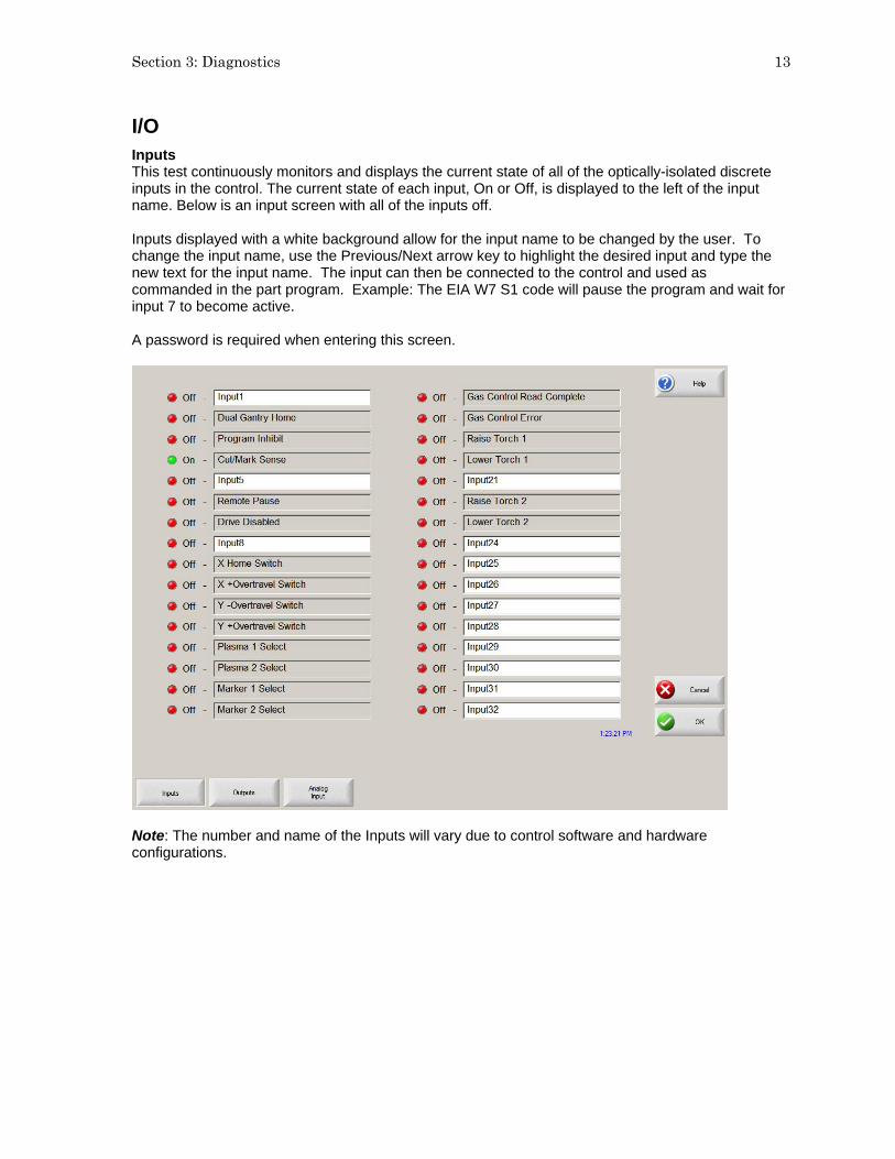
Section 3: Diagnostics 13
I/O Inputs This test continuously monitors and displays the current state of all of the optically-isolated discrete inputs in the control. The current state of each input, On or Off, is displayed to the left of the input name. Below is an input screen with all of the inputs off. Inputs displayed with a white background allow for the input name to be changed by the user. To change the input name, use the Previous/Next arrow key to highlight the desired input and type the new text for the input name. The input can then be connected to the control and used as commanded in the part program. Example: The EIA W7 S1 code will pause the program and wait for input 7 to become active. A password is required when entering this screen.
Note: The number and name of the Inputs will vary due to control software and hardware configurations.

14 Installation & Setup Guide
Outputs This test allows the activation of all optically-isolated discrete outputs in the control. Each Output’s state can be changed by selecting the desired output with the PREV and NEXT keys and then pressing the SPACE key. The current state of each output, On or Off, is displayed to the left of the output name. Below is an output screen with all of the outputs Off.
Warning: When manually activating the control’s outputs, Machine, Torch and Marker motion may occur and the cutting device may activate.
Outputs displayed with a white background allow for the Output name to be selected by the user. To change the output name, use the Previous/Next arrow key to highlight the desired output and type the new text for the output name. The output can then be connected to the control and used as commanded in the part program. Example: The EIA M22 and M23 code will turn on and off output 12. Note: The number and name of the Outputs will vary due to control software and hardware configurations.

Section 3: Diagnostics 15
Expaned I/O For controls equpped with more than 64 I/O a series of selection softkeys are available to access the required Inputs, Ouputs and Analog I/O.
Note: The optional USB Front Panel I/O are not accessible from the I/O Diagnostics screen. Functionality for the USB Front Panel may be tested through the Keyboard Diagnostics.
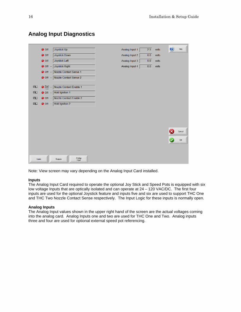
16 Installation & Setup Guide
Analog Input Diagnostics
Note: View screen may vary depending on the Analog Input Card installed. Inputs The Analog Input Card required to operate the optional Joy Stick and Speed Pots is equipped with six low voltage Inputs that are optically isolated and can operate at 24 – 120 VAC/DC. The first four inputs are used for the optional Joystick feature and inputs five and six are used to support THC One and THC Two Nozzle Contact Sense respectively. The Input Logic for these inputs is normally open. Analog Inputs The Analog Input values shown in the upper right hand of the screen are the actual voltages coming into the analog card. Analog Inputs one and two are used for THC One and Two. Analog inputs three and four are used for optional external speed pot referencing.

Section 3: Diagnostics 17
Serial Port This diagnostic screen allows the testing of the control serial ports. To perform the test, install the appropriate jumper or jumpers. If the serial port being tested is configured for RS-232, jump pin 2 to pin 3. If the serial port being tested is configured for RS-422, jump pin 2 to pin 3 and pin 4 to pin 7. Select the appropriate serial port to test and press the Test Port softkey to initiate the test. If the serial port is functioning properly, the exact text in the Send window will appear in the Received window. If the serial port is not functioning properly, a Communications Time Out message will appear below the Received window. If the serial port test fails, then the control may be defective and the factory should be consulted for further instructions. Below is a serial port test screen with a successful test.
Port The Port parameter is used to select which port will be tested. Test The Test feature is used to select a single or continuous signal is to be sent for testing. Send This window contains the text that will be transmitted during the serial port test. Received This window will contain the text that is received during the serial port test. If the test is successful, it should match the text contained in the Send window. Test Port Used to initiate the serial port test on the selected port.
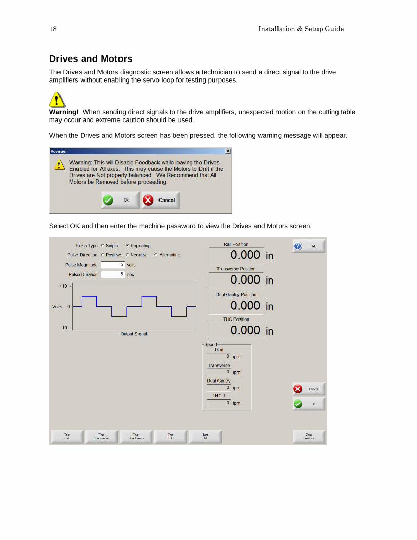
18 Installation & Setup Guide
Drives and Motors The Drives and Motors diagnostic screen allows a technician to send a direct signal to the drive amplifiers without enabling the servo loop for testing purposes.
Warning! When sending direct signals to the drive amplifiers, unexpected motion on the cutting table may occur and extreme caution should be used. When the Drives and Motors screen has been pressed, the following warning message will appear.
Select OK and then enter the machine password to view the Drives and Motors screen.
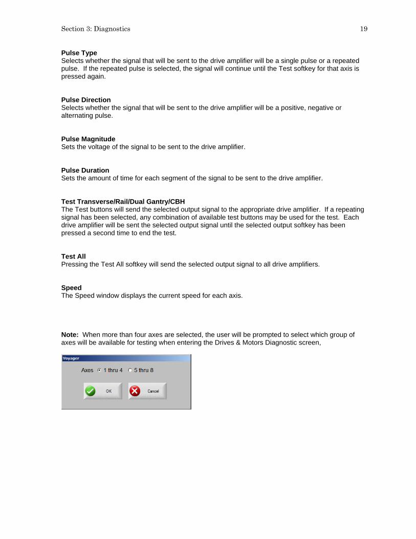
Section 3: Diagnostics 19
Pulse Type Selects whether the signal that will be sent to the drive amplifier will be a single pulse or a repeated pulse. If the repeated pulse is selected, the signal will continue until the Test softkey for that axis is pressed again. Pulse Direction Selects whether the signal that will be sent to the drive amplifier will be a positive, negative or alternating pulse. Pulse Magnitude Sets the voltage of the signal to be sent to the drive amplifier. Pulse Duration Sets the amount of time for each segment of the signal to be sent to the drive amplifier. Test Transverse/Rail/Dual Gantry/CBH The Test buttons will send the selected output signal to the appropriate drive amplifier. If a repeating signal has been selected, any combination of available test buttons may be used for the test. Each drive amplifier will be sent the selected output signal until the selected output softkey has been pressed a second time to end the test. Test All Pressing the Test All softkey will send the selected output signal to all drive amplifiers. Speed The Speed window displays the current speed for each axis. Note: When more than four axes are selected, the user will be prompted to select which group of axes will be available for testing when entering the Drives & Motors Diagnostic screen,
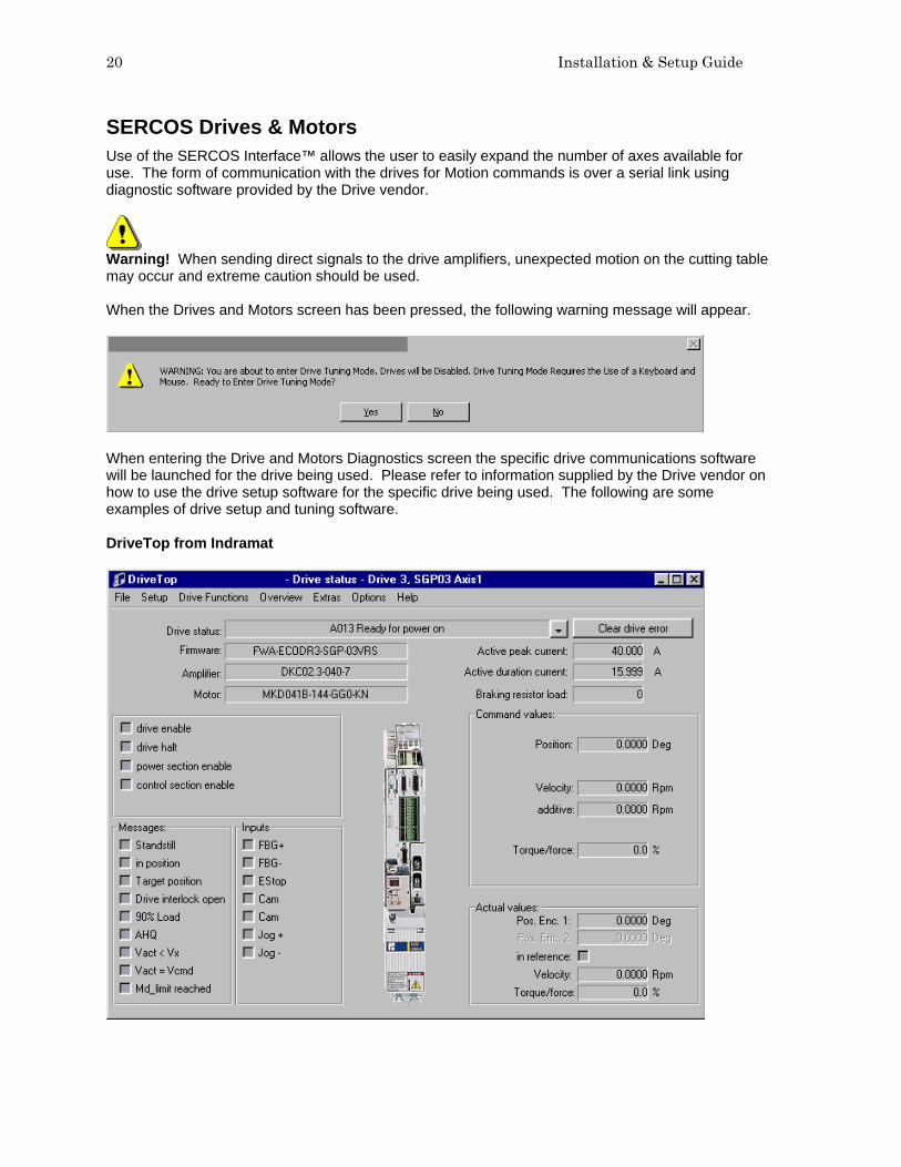
20 Installation & Setup Guide
SERCOS Drives & Motors Use of the SERCOS Interface™ allows the user to easily expand the number of axes available for use. The form of communication with the drives for Motion commands is over a serial link using diagnostic software provided by the Drive vendor.
Warning! When sending direct signals to the drive amplifiers, unexpected motion on the cutting table may occur and extreme caution should be used. When the Drives and Motors screen has been pressed, the following warning message will appear.
When entering the Drive and Motors Diagnostics screen the specific drive communications software will be launched for the drive being used. Please refer to information supplied by the Drive vendor on how to use the drive setup software for the specific drive being used. The following are some examples of drive setup and tuning software. DriveTop from Indramat

Section 3: Diagnostics 21
PacSci 800Tools from Pacific Scientific
Note: screen resolution may temporarily change during use of the above utilities.

22 Installation & Setup Guide
Error Messages The control contains a number of error messages that will be displayed when programming, machine, or internal errors are detected. A list of the more common error messages are explained below. SERCOS Errors A number of different errors can be posted from the SERCOS Interface™ for both motor and I/O performance. The error messages are specific to the drive and I/O modules being used. Please refer to information supplied by the Drive and I/O hardware supplier for appropriate response. SERCOS Ring Not Running This error indicates that communication with the SERCOS ring has been lost. Generally this is due to a fault condition on the ring. Check SERCOS hardware and cycle power. No Part Loaded This message is displayed whenever the control does not contain a valid part program in memory. To clear this error message, load a valid part program from either the Shape Library, hard drive, diskette USB Memory or from a Host system. Part Larger than Plate This message will be displayed if the part program that has been loaded is larger than the plate size information in Setups. The operator may choose to ignore and continue the cut or return to Setups to correct the plate size. Kerf too Large, Arc/Line has Disappeared. Abort Cut? This message is displayed when the Kerf size selected is too large and will affect the shape of the part. The operator can continue to cut the part, abort the cut to review the Kerf information selected or abort the cut to review the part program for any errors. Electing to continue cutting of a part program which prompts the display of this error, may lead to unexpected results. Cut Sense Lost This message is displayed if the Arc ON Feedback setup parameter is enabled and the Cut Sense input is deactivated by the plasma unit while cutting. When this condition occurs, the control displays the Pause screen, which allows use of the Cut Recovery features to finish cutting the piece. Communications Time Out This message is displayed whenever the Host system does not respond within the Link Time Out setup parameter for either a Host Upload or Download. To correct this problem, increase the Link Time Out setup parameter and check the communications setup parameters on the Host system and the control. Host Not Responding This message is displayed whenever the communications is lost to the Host system after the initial communication was established. To correct this problem, try exiting and re-entering the Upload or Download to Host screens to re-establish communications and/ or check the communications setup parameters on the Host system and the control. Scale Factor must be between .001 and 1000 This message is displayed whenever a value less than .001 or greater than 1000 is entered for a Scaling Factor. To correct this problem, enter a value between .001 and 1000 for the Scaling Factor.

Section 3: Diagnostics 23
Radius at Arc Beginning and Radius at Arc End are not within the Arc Radial Error Tolerance This message is displayed whenever the radius beginning-arc and the radius-ending arc of a part program are not within the Arc Radial Error setup parameter in the Main Setup screen. To correct this problem, either increase the Arc Radial Error Tolerance setup parameter or correct the part program itself. Transverse Position Error Exceeded This message is displayed whenever the current Transverse position error exceeds the Servo Error Tolerance Setup parameter in the machine setups screen. It also may appear if the position feedback loops are not operating properly, or the machine is being commanded to move or accelerate faster than it is capable. To correct this problem, either increase the Servo Error Tolerance Setup parameter in the machine setups screen, re-tune the system, decrease the Maximum machine speed setup parameter or the acceleration rate setup parameter. Generally, this error is displayed when the setting for Incremental or Absolute EIA I and J codes is set to the wrong state for the active part program. Rail Position Error Exceeded This message is displayed whenever the current Rail position error exceeds the Servo Error Tolerance Setup parameter in the machine setups screen. It also may appear if the position feedback loops are not operating properly or the machine is being commanded to move or accelerate faster than it is capable. To correct this problem, either increase the Servo Error Tolerance Setup parameter in the machine setups screen, re-tune the system, decrease the maximum machine speed setup parameter, or the acceleration rate setup parameter. This error generally indicates a servo drive or motor problem. First check for fault indications on the servo drives. Dual Gantry Position Error Exceeded This message is displayed whenever the current Dual Gantry position error exceeds the Servo Error Tolerance Setup parameter in the machine setups screen. It also may appear if the position feedback loops are not operating properly or the machine is being commanded to move or accelerate faster than it is capable. To correct this problem, either increase the Servo Error Tolerance Setup parameter in the machine setups screen, re-tune the system, decrease the Maximum machine speed setup parameter, or the acceleration rate setup parameter. This error generally indicates a servo drive or motor problem. First check for fault indications on the servo drives. Transverse Positive Hardware Overtravel Reached This message is displayed whenever the control detects a positive limit switch in the Transverse axis. This can also occur if the limit switch input is set for the wrong polarity or the limit switch wiring is not properly connected. If the Transverse axis did trip the positive limit switch, use Manual mode to jog the Transverse axis away from the limit switch. This error generally indicates a servo drive or motor problem. First check for fault indications on the servo drives. Rail Positive Hardware Overtravel Reached This message is displayed whenever the control detects a positive limit switch in the Rail axis. This can also occur if the limit switch input is set for the wrong polarity or the limit switch wiring is not properly connected. If the Rail axis did trip the positive limit switch, use Manual mode to jog the Rail axis away from the limit switch. Transverse Negative Hardware Overtravel Reached This message is displayed whenever the control detects a negative limit switch in the Transverse axis. This can also occur if the limit switch input is set for the wrong polarity or the limit switch wiring is not properly connected. If the Transverse axis did trip the negative limit switch, use Manual mode to jog the Transverse axis away from the limit switch.

24 Installation & Setup Guide
Rail Negative Hardware Overtravel Reached This message is displayed whenever the control detects a negative limit switch in the Rail axis. This can also occur if the limit switch input is set for the wrong polarity or the limit switch wiring is not properly connected. If the Rail axis did trip the negative limit switch, use Manual mode to jog the Rail axis away from the limit switch. Transverse Positive Software Overtravel Reached This message is displayed whenever the Transverse axis position is greater than the Maximum Travel Limit setup parameter for the Transverse axis. When this occurs, use Manual mode to jog the Transverse axis to a position within the Travel Limit setup parameters. Rail Positive Software Overtravel Reached This message is displayed whenever the Rail axis position is greater than the Maximum Travel Limit setup parameter for the Rail axis. When this occurs, use Manual mode to jog the Rail axis to a position within the Travel Limit setup parameters. Transverse Negative Software Overtravel Reached This message is displayed whenever the Transverse axis position is less than the Minimum Travel Limit setup parameter for the Transverse axis. When this occurs, use Manual mode to jog the Transverse axis to a position within the Travel Limit setup parameters. Rail Negative Software Overtravel Reached This message is displayed whenever the Rail axis position is less than the Minimum Travel Limit setup parameter for the Rail axis. When this occurs, use Manual mode to jog the Rail axis to a position within the Travel Limit setup parameters. Dual Gantry Skew Error Exceeded This error message is displayed when the control has detected a position error fault between the two drive axes on the dual gantry. It also may appear if the position feedback loops are not operating properly, or the machine is being commanded to move or accelerate faster than it is capable. To correct this problem, either increase the Skew Error Tolerance Setup parameter in the machine setups screen, re-tune the system, decrease the maximum machine speed setup parameter or the acceleration rate setup parameter. Need Station Selection The Need Station Selection error message is displayed if the input for a station or process has not been activated. Example: When cutting in Plasma mode, a Plasma 1 or Plasma 2 input may be required to execute the selected Plasma cut process. Buffer Time Out This may appear if there is an instance where the motion buffer is full and cannot record the data being saved. This error allows the operator to stop the motion, back up on path to the last pierce and start over without a position error. This error should be reported to the control vendor. CNC Time Out This is a general error that may appear if there is an instance when any buffer is full and cannot record the data being saved. This error allows the operator to stop the motion, back up on path to the last pierce and start over. This error should be reported to the control vendor. Unable to Find HASP The HASP is a hardware protection key (dongle) that enables the software and features for use. If the HASP is not installed, the control will not work. If this message appears and the hardware key is in place, please contact your control vendor for assistance.

Section 3: Diagnostics 25
Norton Ghost™ Utility In the unlikely event that an extreme system error has occurred which prevents the control from operating, the Norton Ghost™ Utility is available on specified controls to replace core system files and re-enable operation of the control. Norton Ghost™ must be previously installed on the control hard drive with an appropriate ghost image file. The Norton Ghost Utility works by allowing the user to retrieve an image file from the D: partition of the hard drive to replace all data on drive C: The Ghost Image may be a factory default or custom user created image files. NOTE: All current information on Drive C: will be lost. It is recommended that a unique user image be created after table configuration which will include all the important table settings. This feature may be executed from the System Tools screen or through use of a Ghost image utility. This tool may obtained from the control supplier and transmitted via the Internet. Norton Ghost™ is a Trademark of Symantec™ Corporation. Create Utility from E-mail To create a Norton Ghost tool utility from the compressed software sent via the Internet: USB Memory Instructions to download USB format tools and files are available to create a bootable USB device. Specific batch files to run the utility are included. Diskette The file sent by the Internet will be an auto-executable file which will place the required files onto a diskette to be used at the control. First place a blank diskette into your PC. Double click on the recovery EXE file. A message box will be displayed. Click on the “Create Floppy” button to execute. The EXE will copy the new files to the floppy disk to take to the control. Instructions for Ghost Recovery Creating a Custom Image File: Place the Norton Diskette or USB memory device into the control and turn the unit on. Norton Ghost will progress as follows. “Starting PC DOS.......” Current Copyright information will be displayed “Select 1 to make a New Backup Image or 2 to restore existing [1,2]” Press 1 to create a new back up image. Up to three custom images may be created. They are created as “newest” to “oldest” image and are automatically assigned. The “original” ghost image is the factory default and may not be over written. Back up will begin automatically.

26 Installation & Setup Guide
“--------------------------------Backing Up Drive, Please Wait --------------------------------“ Norton Ghost will launch as above indicating back up progress. The following Message will appear when complete. “-------------------- Back Up Complete, Please Remove Disk and Reboot -----------------------“ Remove the diskette or USB memory device. Turn the control Off and then On. Table setups and software updates may need to be reloaded if the image is not current.

Section 3: Diagnostics 27
Retrieving an Image File Place the Norton Diskette or USB memory device into the control and turn the unit on. Norton Ghost will progress as follows. “Starting PC DOS.......” Current Copyright information will be displayed “Select 1 to make a New Backup Image or 2 to restore existing [1,2]” Press 2 to retrieve the back up image. Up to three custom images may be created. They are created as “newest” to “oldest” image. The “original” ghost image is the factory default. The next message allows the user to select which version to use when restoring. “1. Newest.gho” “2. Older.gho” “3. Oldest.gho” “4. Original.gho” “Select the Number of the Image to restore from the choices above [1,2,3.4 ]” Press the number for the desired image. “--------------------------------Restoring, Please Wait --------------------------------“ Norton Ghost will launch as above indicating restore progress. The following Message will appear when complete. “--------------------End Restoring, Please Remove Disk and Reboot -----------------------“ Remove the diskette or USB memory device. Turn the control Off and then On. Table setups and software updates may need to be reloaded if the image is not current.

28 Installation & Setup Guide
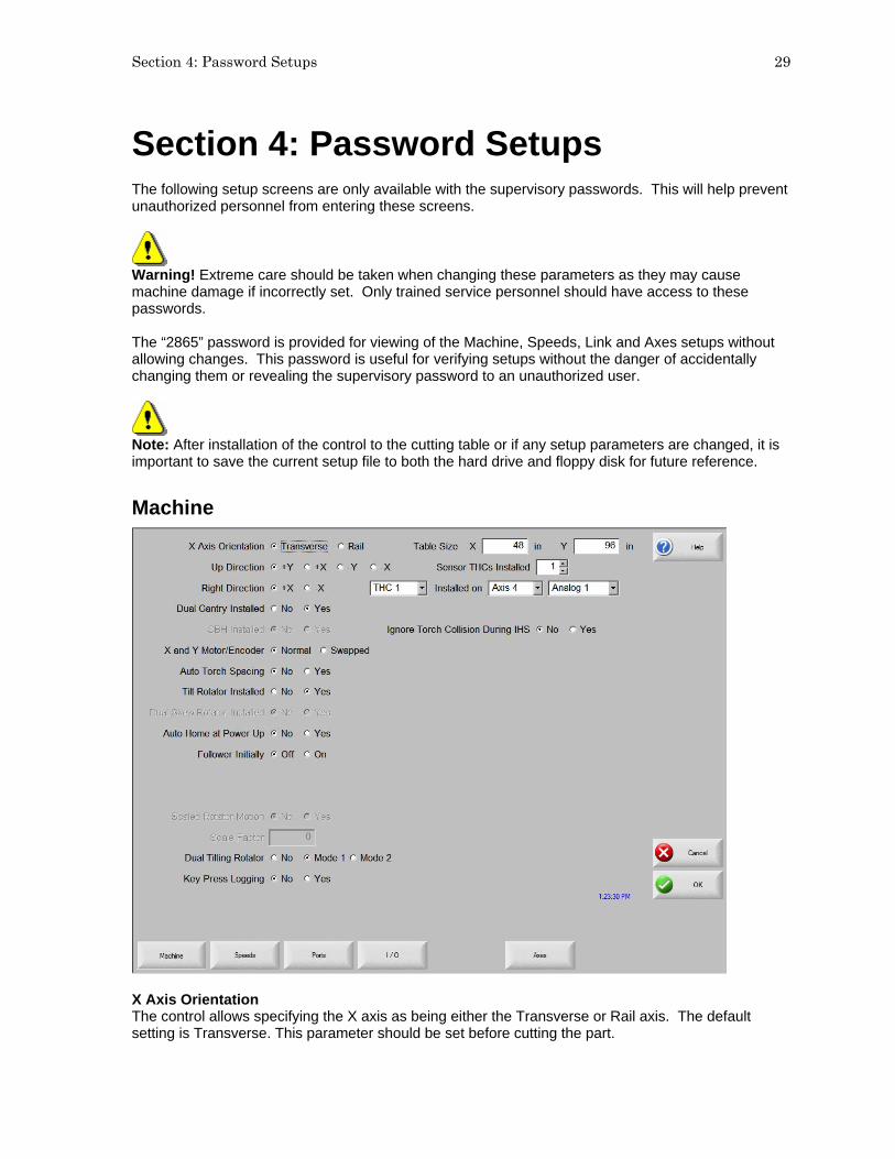
Section 4: Password Setups 29
Section 4: Password Setups The following setup screens are only available with the supervisory passwords. This will help prevent unauthorized personnel from entering these screens.
Warning! Extreme care should be taken when changing these parameters as they may cause machine damage if incorrectly set. Only trained service personnel should have access to these passwords. The “2865” password is provided for viewing of the Machine, Speeds, Link and Axes setups without allowing changes. This password is useful for verifying setups without the danger of accidentally changing them or revealing the supervisory password to an unauthorized user.
Note: After installation of the control to the cutting table or if any setup parameters are changed, it is important to save the current setup file to both the hard drive and floppy disk for future reference.
Machine
X Axis Orientation The control allows specifying the X axis as being either the Transverse or Rail axis. The default setting is Transverse. This parameter should be set before cutting the part.

30 Installation & Setup Guide
Up Direction This parameter defines the machine motion that will occur when the ↑ arrow key is pressed during manual mode. Right Direction This parameter defines the machine motion that will occur when the → arrow key is pressed during manual mode. Dual Gantry Installed Selecting Yes will enable the Dual Gantry axis and allows configuring of that axis. CBH Installed Selecting Yes will enable the Contour Bevel Head axis and allows configuring of that axis. X and Y Motor/Encoder Selecting this feature as Swapped will internally swap the X and Y Axis encoder signals. This feature simplifies the installation to systems with alternate wiring configurations. Auto Torch Spacing Selecting Yes enables an automatic torch spacing feature for use. This feature uses embedded part program codes and dedicated outputs to control individual torch stations to set spacing and clamping of direct and mirrored cutting. Please refer to the Auto Torch Spacing information provided in this guide for additional information. Tilt Rotator Installed The Tilt Rotator Installed parameter is used to enable use of the Tilt Rotator feature. Tilt Rotator is a unique rotational cutting tool which combines a rotational axis with a Tilt (bevel) axis allowing for compound cutting. Note: The Tilt Rotator feature will execute the commanded Tilt Angle motion over the length of the line segment (linear interpolation). Dual Tilt Rotator Installed This parameter enables use of a second Tilt Rotator feature. Additionally a second Transverse Axis is enabled for use allowing individual, parallel and Mirror cutting. Auto Home at Power Up Determines if the Contour Bevel Head (CBH) and Tilt / Rotate axes will automatically go into the homing routine upon powering up the control. Follower Initially This parameter is used to determine if the CBH and Rotate features will always be enabled after power up or would be enabled through the part program. Dual Tilting Rotator Mode The Dual Tilting Rotator Mode defines the Tilt Rotator to use two Tilt Axes rather than a Rotation Axis and Tilt Axis for Rotational Bevel Cutting. Tilt Rotator parameter must be active for this feature. Key Press Logging The Key Logging feature is used to record key press and other related information in a daily log file. This is intended for use by Service Technicians when a fault occurs to help review events prior to the fault experienced. When enabled, the file will be saved to the hard drive which then may be retrieved through the Files feature by transferring the file to floppy diskette or USB memory . Generally, this parameter is set to NO unless instructed by a technician to be enabled.

Section 4: Password Setups 31
Table Size Enter a value for the active cutting area for the X and Y axis. These values are used to limit the Plate size parameter in the cutting setup screen to the maximum size of the table. THCs Installed The THC Installed parameter defines the total number of Sensor™ THC Axes assigned for operation at the control.
THC Installed On Axis / Analog This setup parameter is used to define the THC axis for use. The user can select which axis the THC is to be commanded on, and the analog input to use (arc voltage feedback) Note: Refer to the Station Configuration and Sensor™ THC sections of this guide for additional information on the setup and use of the Sensor™ THC. Ignore Torch Collision During IHS This allows the user to ignore the torch collision input during the initial height sense cycle. This may be advantageous for some THC mechanics. Command THCs Installed The Command® THC selection is used to enable the Command THC serial Link. For more information on this feature, please refer to the Command® THC section of this guide. Shown in Type P mode only.

32 Installation & Setup Guide
SERCOS The SERCOS interface requires configuration to establish communications for motion and I/O.
Drive Type The manufacturer of the SERCOS style drive being used would be selected. This allows proper operation and tuning parameters to be available. Update Rate The update rate for the ring may be selected for motion and I/O. One millisecond is recommended but it is dependent on the capabilities of the hardware being used. Baud Rate Communication rate for the ring may be selected. This is determined by the type of drive and I/O being used. Light Level The user has the ability to adjust the intensity of the light pulses used on the fiber optic ring. This feature is used to compensate for diminished signal due to issues such as ring distance. Drive I/O The user may select to use I/O options directly supported on the Drive Amplifier. Options are None, Overtravel and Home Switches only or All I/O. Note: The Drive I/O will populate the general purpose I/O (both analog and digital) in order from the lowest SERCOS drive axis to the highest SERCOS drive axis. All I/O is the default setting for SMCC interface.

Section 4: Password Setups 33
RECO/Beckoff I/O at Address 50 This parameter is set to Yes if the Indramat RECO or Bechkoff I/O module is being used to expand the total number of I/O being used on the fiber optic ring. Note: The RECO I/O will populate the general purpose I/O (both analog and digital) following all drive I/O. HPR/4070 at address 60 This parameter is set to Yes if the optional SERCOS interface for HPR/4070 is being used. HTA I/O at Address 70 This parameter is set to Yes if the optional Hypertherm SERCOS interface card is being used.

34 Installation & Setup Guide
Speeds The Speeds setup screen is used for setting the various machine speeds for different operating modes. Given that the drives, motors, gearboxes and mechanics are capable, the control is capable of operating over a wide range of speeds.
Speed 0 To This parameter allows the technician to input selected speed ranges to customize the acceleration rates for the various speeds selected. When a speed range lower than the maximum speed is entered, a new range at the maximum machine speed setting will be created, up to a maximum of five. To reduce the number of Speed To ranges, input the maximum machine speed into the range that is to be the highest speed selection and the additional range fields will be removed from the screen. Acceleration Rate All mechanical systems have different acceleration and deceleration rates to move the cutting device smoothly. The higher the acceleration rate, the quicker the machine will get up to speed. The lower the acceleration rate the smoother the machine will position the cutting device. This setup parameter is used to determine both the acceleration and deceleration rate for all motion. Enter a value in milligees for the desired acceleration rate. A milligee (milliG) is 1/1000 of a G, which is the acceleration due to gravity. One milligee is approximately 0.384 inches per second2. A good starting point for most systems is 10 mgee’s.

Section 4: Password Setups 35
Fast Stop Deceleration Rate Activated by the Fast Stop or Torch Collision Input, the Fast Stop Deceleration Rate Parameter specifies in milligees how quickly the system will stop when the Fast Stop Input is active. Generally, this value is much higher then the Acceleration rate. A milligee (milliG) is 1/1000 of a G, which is the acceleration due to gravity. One milligee is approximately 0.384 inches per second2. Maximum Machine Speed Enter the maximum value at which the system is capable of contouring. This parameter will be used to range limit all subsequent speed entries. In addition, it is used to scale the speedometer widget in the Watch window during runtime operation. The maximum speed at which the control can contour can be calculated with the following equation. Maximum Contouring Rate (IPM) = 60 seconds 1 Inch 100,000 edges minute User edges second For example: the control could command a cutting machine with 4000 edges per inch resolution at 1,500 IPM. Limited Machine Speed The Limited Speed feature allows for a user-defined maximum machine speed when the Limited Speed Input is active. This is commonly used to set a reduced machine speed for the purpose of increased safety when testing or maintenance of the machine is being performed. High Jog Speed Enter a value for the desired high manual motion speed. Medium Jog Speed Enter a value for the desired medium manual motion speed. Low Jog Speed Enter a value for the desired low manual motion speed. Minimum Corner Speed This is the minimum speed to use when negotiating corners. The control has sophisticated centripetal velocity and acceleration contouring algorithms, which should provide optimal cut quality for most cut operations. In some situations it may be desirable to enter a minimum corner speed to prevent over-burning at corners. In normal operations, this parameter should be set to zero. Fast Home Speed Enter the machine speed the control will use during the first phase of the homing sequence. During the first phase, the cutting device will move towards the home limit switches at the fast rate.

36 Installation & Setup Guide
Slow Home Speed Enter the machine speed the control will use during the second phase of the homing sequence. During the second phase, the cutting device will move off the home limit switch and proceed to the marker pulse. Upon detection of the marker pulse, the control will decelerate to a stop and perform a small move in the opposite direction to the marker pulse. Creep Speed Percentage The Creep Speed Percentage parameter allows the operator to select what percentage of the machine cut speed will be used when creeping. Generally, this is 25% of the cut speed. Plasma Hi/Lo Speed Percentage The Hi/Lo Speed specifies the percentage of the entered Cut Speed below which the control will activate the Torch Height Disable output. The plasma system may use this output to switch from low to high current or to disable the height control. Note: The Dual Grid/THC feature must first be enabled at the Plasma Setups Screen. Plasma Distance To Corner The Plasma Distance to Corner parameter specifies the distance to the corner at which the plasma system should switch from High current to low current and disable the Automated Height Sensor. Distance to Corner is active whenever the speed drops below the Plasma Hi/Lo Percentage, or segments intersect at an angle greater than the tangent angle. Note: The Dual Grid/THC feature must first be enabled at the Plasma Setups Screen. Plasma Distance From Corner The Plasma Distance from Corner parameter specifies the distance from the corner when exiting, at which the plasma system should enable the Automated Height Sensor. Distance from Corner is active whenever the speed drops below the Plasma Hi/Lo Percentage, or segments intersect at an angle greater than the tangent angle. Note: The Dual Grid/THC feature must first be enabled at the Plasma Setups Screen. For additional details on how the Torch Height Disable feature of this control operates, please refer to the Cutting Section of this guide. CBH Speed Setups (Shown only when enabled) CBH Acceleration Rate This parameter allows the operator to set the acceleration rate for smooth and stable movement of the contoured bevel head. The higher the acceleration rate the quicker the CBH will get up to speed. The lower the acceleration rate the smoother the machine will position the cutting device. Values are entered in Rev/ Sec^2. Maximum CBH Speed Enter the maximum speed for the CBH rotation in Rev/Min. CBH High Jog / Home Speed Enter a value for the desired manual CBH jog and fast Home speed. CBH Low Jog / Home Speed Enter a value for the desired CBH slow home speed.

Section 4: Password Setups 37
THC Speed Setups (Shown only when enabled) THC Acceleration Rate This parameter allows the operator to set the acceleration rate for smooth and stable movement of the Sensor™ Torch Height Control. The higher the acceleration rate, the quicker the THC will get up to speed. The lower the acceleration rate, the smoother the machine will position the cutting device. Values are entered in milligees. Maximum THC Speed Enter the maximum speed for the Sensor™ THC movement in inches per minute. THC Jog Speed Enter a value for the desired THC jog speed. THC Home/Fast IHS Speed The THC Home/Fast IHS Speed entered here is used to home the torch at the top of the slide and to move the torch from the selected IHS height towards the plate, looking for the surface of the plate. THC Slow IHS Speed The THC IHS Speed is used to retract the torch after the plate has been sensed. The torch will retract at this speed until the contact sense is lost. This determines the exact distance to the plate regardless of any flexing of the plate. A very small speed is recommended for optimal accuracy. The following Speeds setup parameter will be available when Tilt Rotator has been enabled.

38 Installation & Setup Guide
Rotate Acceleration Rate This parameter allows the operator to set the acceleration rate for smooth and stable movement of the contoured bevel head. The higher the acceleration rate, the quicker the Rotate Axis will get up to speed. The lower the acceleration rate, the smoother the machine will position the cutting device. Values are entered in Rev/ Sec^2. Maximum Rotate Speed Enter the maximum speed for the Rotate Axis rotation in RPM. Rotate High Jog Speed Enter a value for the desired Rotate Axis High Jog Speed. Rotate Low Jog Speed Enter a value for the desired Rotate Axis Low Jog Speed. Tilt Acceleration Rate This parameter allows the operator to set the acceleration rate for smooth and stable movement of the contoured bevel head. The higher the acceleration rate the quicker the Tilt Axis will get up to speed. The lower the acceleration rate the smoother the machine will position the cutting device. Values are entered in Rev/ Sec^2. Maximum Tilt Speed Enter the maximum speed for the Tilt Axis in RPM. Tilt High Jog Speed Enter a value for the desired Tilt Axis High Jog Speed. Tilt Low Jog Speed Enter a value for the desired Tilt Axis Low Jog Speed.
Torch Height Disable Feature The Torch Height Disable Feature is used to activate the Torch Height Disable output and “freeze” or disable the automatic adjustment of the Automated Torch Height Control system and prevent diving or crashing of the torch in corners. Note: The Dual Grid/THC feature must first be enabled in the Plasma Setups screen. This output is activated by the control based on the values of Plasma Hi/Lo % of Cut Speed, Plasma Distance to Corner and Plasma Distance from Corner setup parameters. When any one of these conditions is met, the Torch Height Disable feature will be implemented. The definition of a corner is based on the tangent angle in the Special Password screen and the value of the Plasma Hi/Lo speed. Tangent Angle This parameter is used to set degree of the tangent angle for control motion. Segments within a part that intersect at angles greater than the selected tangent angle will decel to zero or minimum corner speed. Segments within a part that intersect at angles less than or equal to the selected tangent angle will not decel, unless the next segment is a speed limited arc. Plasma Hi/Lo Speed Percentage The Hi/Lo Speed specifies the percentage of the entered Cut Speed below which the control will activate the Torch Height Disable output. The plasma system may use this output to switch from low to high current or to disable the height control.

Section 4: Password Setups 39
Plasma Distance To Corner The Plasma Distance to Corner parameter specifies the distance to the corner at which the plasma system should switch from low current to high current or disable the Automated Height Sensor. Distance to Corner is active whenever the speed drops below the Plasma Hi/Lo Percentage, or segments intersect at an angle greater than the tangent angle. Plasma Distance From Corner The Plasma Distance from Corner parameter specifies the distance from the corner when exiting, at which the plasma system should enable the Automated Height Sensor. Distance from Corner is active whenever the speed drops below the Plasma Hi/Lo Percentage, or segments intersect at an angle greater than the tangent angle. Example: For the example illustrated below, the Torch Height Disable output will be activated based on the values of the setup parameters.
Plasma Hi/Lo Percentage Value 90% Distance to Corner Value .2 inches Distance from Corner Value .2 inches Tangent Angle Value 20 Degrees For the above listed values, the Torch Height Disable output is active .5 inches before and .5 inches after each 90 degree corner. The THD output is also activated as the torch accelerates away from the pierce and through the arc due to the speed being below the Plasma Hi/Lo value. Finally, because the arc intersects at greater than the 20 degree tangent angle, the THD output is activated for .2 inches before and after the beginning of the arc, and is activated for .2 inches before and after the end of the arc.

40 Installation & Setup Guide
Ports The control comes standard with two RS-232C serial ports, which may be converted to an RS-422 configuration. For more information on the how to change the serial ports to the RS-422 configuration, please refer to Serial Port Connections. This port has been specially designed with opto-isolation and filtering to minimize EMI/RFI noise problems common in many cutting operations. Parameters are enabled and disabled depending on Port feature selections. The control may be configured to use the communication link provided on the control or the user may enter information to create a custom communication link at the Link Screen to communicate with a host computer. Information on how to access the Phoenix Communication Link Software is provided later in this section. Up to eight ports may be configured for use in software. Hardware provided with your control may support a smaller number of communication ports. The following parameters are available to help configure the Serial Ports for your specific communications package and selected communication features.
Port Designation This parameter allows the user to select which serial port will be configured for link use with the following remote communication settings. Select Link, Messaging, HD4070, FineLine or Command THC (type”V” controls).

Section 4: Password Setups 41
Baud Rate Allows selection of the desired baud rate for the remote Communications Link. The available Baud rates are shown. The control also incorporates a unique compression utility that allows the effective baud rate to be doubled. For example, for links configured to run at 9600 baud, the effective rate will be 19.2K Baud. Note: For Serial Messaging communication speeds from 1200 Baud to 115200 Baud are available. See Serial Messaging in the Program Code section for more information. Parity Enter the desired parity for the remote Communications Link. Data Bits Enter the number of data bits the remote link is using. This value is 8 for the link software included with the control. Time Out Delay Enter the amount of time the control will wait prior to display communications error should it not be able to establish a link with a remote device. Transmit Delay Enter the amount of delay the control will insert between each character that is transmitted over the serial port. Some communications links require a small delay to avoid missing characters that have been sent to them. This parameter should normally be set to zero. The following parameters allow the user to create a custom communication link on the control by entering the ASCII code equivalent to the character or symbol used by the host computer for dialog start. For example: The ASCII Decimal Code 33 is equal to the ! symbol Rewind This setup parameter is only enabled when Link File Dump Mode has been enable. Enter the ASCII code equivalent to the character or symbol used by the host computer for tape rewind at the host tape drive system. Enter the number zero to eliminate the rewind command. Dialog Start Enter the ASCII code equivalent to the character or symbol used by the host computer for dialog start. Dialog Done Enter the ASCII code equivalent to the character or symbol used by the host computer for dialog done. Dialog Prompt Enter the ASCII code equivalent to the character or symbol used by the host computer for dialog rompt. Dialog Pause Enter the ASCII code equivalent to the character or symbol used by the host computer for dialog pause. Dialog Acknowledge Enter the ASCII code equivalent to the character or symbol used by the host computer for dialog acknowledge.

42 Installation & Setup Guide
End of Transmission Enter the ASCII code equivalent to the character or symbol used by the host computer for dialog acknowledge. Using Phoenix Link If you are using the Phoenix Communication link program supplied on the control select Yes and the control will automatically enter the appropriate ASCII codes in to the communication link dialog parameters listed above. Show Host File Names The Show Host File Names feature allows the user to select whether or not File Names are shown at the Download from Host screen. This is a time saving feature for operators who have very large part folders at the host computer and know the exact file name of the part program to be loaded. The Using Phoenix Link parameter must be set to ON to enable this feature. File Dump Mode Select On to configure the link communication protocol to communicate with link programs which operate in File Dump Mode. This will allow the control to accept part programs as one long uninterrupted stream of information as with a tape reader style link. Allow M65 Auto Reload Available when a generic link communication has been enabled, this parameter allows the user to select whether the EIA M65 code will be used as an Auto-reload code or ignored. Auto Home before Auto Reload When enabled, this feature automatically “homes” the machine before the next Auto reload (EIA M65 code), either serial Link, USB memory or from Diskette, is executed ESSI Program Termination This parameter allows the operator to tell the control which ESSI code (0,63, 64 99, / or =) is to be used as machine stop. Download Updates The Download Updates parameter allows the operator to download control software updates through the link communications to the host PC. To use this feature, the “Using Phoenix Link” parameter must be set to yes. The new update file would then be placed in the same folder location as the Link software. When the Update Software softkey is pressed at the Special Password screen, the control will search for the new software update via the link rather than the floppy drive. Use Multi Drop Selecting the Use Multi Drop feature will allow the control to be enabled to work with the Phoenix link software Multi Drop feature. The Multi Drop feature allows the Phoenix Link software to communicate with multiple controls to one communications port at the host PC. Up to eight controls may be supported with the Multi Drop feature. Please note: The “Using Phoenix Link” parameter must be set to YES to enable this feature and specific hardware (serial communications board Rev C or higher) may be required to support this feature. Please contact your control supplier for more details. Address The Address Parameter defines the control identification address when using the Multi Drop communications feature. The Phoenix Link software uses this address at the Host PC to know which control it is communicating with.

Section 4: Password Setups 43
Control Monitoring When enabled, the Control Monitoring feature allows the user to view control status at the host PC. Status for File Name, position, cut mode and cut information is displayed. This feature is only available with the Phoenix Link communication software. Please refer to the Phoenix Link information section of this guide for additional information on the Phoenix link. The following additional parameters are available when Serial Messaging has been enabled. See Serial Messaging in the Program Code section of this guide for more information. Flow control Select to use None, Xon/Xoff or Hardware. During Jog on Path The user may select whether messages will be sent when jogging Forward or Backward on Path while at the Pause screen. Note: All messaging will stop when the Stop Key has been pressed or the Remote Pause input becomes active. Note: The Message Type 21 will not be executed for “Backup on Path”. Retry on Time Out For the Message Type 22 (which requires an acknowledgement from the external device after the message) an automatic retransmit of the message may be sent. The user may select the number of retries allowed before faulting from a lack of response from the external device. The fault prompt “Message Error” will be displayed when in a Time Out condition. Time Out The Time Out value may be used for the Message Type 22 (which requires an acknowledgement from the external device after the message) if there is no Time Out value used in the command string of the program code. Refer to the Delay Time / Time Out information for more information.

44 Installation & Setup Guide
I/O Pressing the I/O softkey allows the operator to configure the inputs and outputs for the shape cutting table.
Expanded I/O When more than 64 I/O have been selected a pull down box will be available to assign I/O in the higher I/O ranges. Note: When the optional USB Front Panel is used, the top 128 I/O will be assigned to USB I/O to support the front panel Input Logic The control comes standard with up to 32 discrete inputs. The Input Logic parameter is used as a mask to determine whether or not the input is to be treated as a normally open contact or normally closed contact. Entering a numerical value here will set all the Inputs to a predefined set of logic states for all of the inputs. With Input Logic set to zero (0), an active input will be displayed as active or On (green lamp) in the input diagnostic screen. Logic Selection Box The Logic Selection Box allows the user to select the Logic state for each input to be either normally open or normally closed. The Logic state for the inputs may be switched by selecting the desired input and pressing the space key.

Section 4: Password Setups 45
Input Selection The Input Selection box feature is used to define which inputs will be used by the control and their physical location on the control interface. All controls are shipped with the default selection of Inputs and interface locations for the selected control Interface (I/O) configuration. Torch Collision Uses This parameter allows the user to select the type of response used when the Torch Collision input is active. The user may select to use a Fast Stop Decel value or the Fault Ramp time selected for the individual axis. Inputs Inverted The Input Selection box feature is used to define which inputs will be used by the control and their physical location on the control interface. All controls are shipped with the default selection of Inputs and interface locations for the selected control Interface (I/O) configuration. Drive Enables This setup parameter allows the user to select how the control responds to drive faults. If the setting is Series, then all axes must complete their individual fault ramp times before the drives are disabled. If the setting is independent, each drive is disabled immediately as soon as its axis fault ramp time is finished. Initial Feedback Delay This feature allows the initial feedback from the Drive System to be held off after initial power up. This allows the Drive System to fully enable prior to enabling the position loop.
Speed Pot and Joystick Overview Through the use of Single Ended Inputs to an optional Analog Input Card installed in the control, your shape cutting control may be configured to support an external Joystick or Two Speed Potentiometers. Note: These features are not available for all control types and optional control hardware is required. The external Joystick is used as a directional command signal when in manual motion. The optional Speed Pot may be used to adjust the current motion speed. These features must first be enabled at the password protected I/O screen for use. Joystick Installed Select “Yes” to enable the optional external Joystick. Not available for all control types and optional control hardware required. Speed Pot Installed Select “Yes” to enable the optional external Speed Potentiometer. Not available for all control types and optional control hardware required. Plasma Override % The Plasma Override feature is used in conjunction with the Speed Pot feature to set the minimum and maximum range of adjustment of the plasma Speed Pot based on a percentage of the set cut speed. The Speed Pot feature must be enabled for use.

46 Installation & Setup Guide
Oxy Fuel Override % The Oxy Fuel Override feature is used in conjunction with the Speed Pot feature to set the minimum and maximum range of adjustment of the oxy fuel Speed Pot based on a percentage of the set cut speed. The Speed Pot feature must be enabled for use. Trial Override % The Trial Override feature is used in conjunction with the Speed Pot feature to set the minimum and maximum range of adjustment of the Trial Speed Pot based on a percentage of the set Trial speed. The Speed Pot feature must be enabled for use. Speed Pot Installed On The Speed Pot installed on Parameter is used to assign Speed Pot inputs to the desired Analog Input if a dedicated Speed Pot input is not available on the Analog input card being used. Analog Offset 1- 12 The Analog Offsets 1 through 12 are used to correct for any imbalance or “Zero” the incoming analog voltage to the Analog Input Card Note: To calibrate the Analog Inputs, jumper the two pins specific to the input together and view the incoming voltage at the Diagnostics Analog I/O screen. The incoming voltage should be zero. If any voltage is displayed at the diagnostic screen, an Offset Voltage equal to the incoming voltage being read can be entered here to “Zero” the incoming voltage. Please refer to the installation instructions later in this section for more details.

Section 4: Password Setups 47
Input Definitions Input Description Spare Spare inputs are activated through the part program. If a Spare input is
located in the part program, the control will pause the process until the input state is detected. The Spare inputs may be used by use of specific EIA “O” and “M” codes indicating the input number and function. Refer to Appendix A in the operator’s manual for a complete description of these commands.
Torch Up Sense Confirmation signal indicating that the torch is in the full up position. Torch Down Sense Confirmation signal indicating that the torch is in the full down position. Preheat Sense Confirmation signal indicating that the Preheat Input from the torch is
active. Cut Sense Activation of this input indicates that the plasma arc has transferred to
the work piece. If the “Arc On Feedback” setup parameter is ON, then machine motion will begin at the activation of this input. Type “M” and “P” controls.
Tracer on Path Tracer On Path is used with the Teach Trace feature and indicates that
the tracing system has detected the template line. Drive Disabled If the Drive Disabled input is activated, the control will stop all motion and
generate a fault message. Position information will be lost. Remote Pause A Remote Pause input, when activated, will stop all control motion and
display the Pause screen. No motion will be allowed until this input is deactivated.
Remote Start When a Remote Start input is detected, it will begin the selected program
cycle as if the Start button on the control had been pressed. Program Inhibit The Program Inhibit input will force the control to command the motion
output to a zero (0) speed. This is generally used as a dwell to pause motion during a tool change or as a pause from a PLC interface.
Raise/ Lower Torch The type “V” control has the ability to operate multiple Sensor™ THCs
which are commanded by the control, as separate axes. The Sensor™ THC Torch Raise and Torch Lower commands may be made through the software softkeys or through the use of these external inputs to the control.
Station Select Input The type “V” control system has the ability to operate multiple Sensor™
THCs which are commanded by the control as separate axes. The control requires an input to indicate which Sensor™ THCs are active. This Input is also used for tracking of consumable data for the specified Plasma or Oxy Torch. Stations 1-8 are designated for Plasma and stations 9-20 are designated for Oxy Fuel.

48 Installation & Setup Guide
X Home Switch This input indicates that the machine has traveled to its X axis home position. If the X axis “Use Home Limit Switch” parameter is set to YES and a Homing function is performed, the X axis moves in the specified home direction at the Fast Home Speed until the input is activated. The X axis then decelerates to a stop and moves in the opposite direction at the Slow Home Speed until the switch is deactivated. Once the switch is deactivated, the X axis will either decel to a stop or continue on until the encoder marker pulse is detected, if the “Use Marker Pulse” parameter is set to YES.
Y Home Switch This input indicates that the machine has traveled to its Y axis home
position. If the Y axis “Use Home Limit Switch” parameter is set to YES and a Homing function is performed, the Y axis moves in the specified home direction at the Fast Home Speed until the input is activated. The Y axis then decelerates to a stop and moves in the opposite direction at the Slow Home Speed until the switch is deactivated. Once the switch is deactivated, the Y axis will either decel to a stop or continue on until the encoder marker pulse is detected, if the “Use Marker Pulse” parameter is set to YES.
Z Home Switch Z Axis Home Limit Switch indicates that the machine has traveled to its Z
axis home position. If the Z axis “Use Home Limit Switch” parameter is set to YES and a Homing function is performed, the Z axis moves in the specified home direction at the Fast Home Speed until the input is activated. The Z axis then decelerates to a stop and moves in the opposite direction at the Slow Home Speed until the switch is deactivated. Once the switch is deactivated, the Z axis will either decel to a stop or continue on until the encoder marker pulse is detected, if the “Use Marker Pulse” parameter is set to YES.
Y Overtravel Switch This input indicates that the machine has traveled into its full positive
travel of a Y axis. If the hardware overtravels are enabled and this input is activated, the control will stop all motion and generate a fault message. Motion will not be re-enabled until the switch is deactivated.
X Overtravel Switch This input indicates that the machine has traveled into its full positive
travel of a X axis. If the hardware overtravels are enabled and this input is activated, the control will stop all motion and generate a fault message. Motion will not be re-enabled until the switch is deactivated.
Limit Switch This input indicates that the machine has traveled into its full positive
travel of an axis. If the hardware overtravels are enabled and this input is activated, the control will stop all motion and generate a fault message. Motion will not be re-enabled until the switch is deactivated. (Type “M” configuration only)
Ready to Fire PS 1-4 Exclusive to the HD4070® multiple power supply configuration, the
Ready to Fire Input is used to ensure that all HD4070® power supplies have completed each individual Initial Height Sense and are ready for use. The torch ignition is held off by the Hold Ignition Input to the power supply from the control.
Raise /Lower 4070 1-2 Exclusive to the HD4070® multiple power supply configuration, the Raise
/ Lower 4070 Torch Input is used as a manual raise/lower command to the selected HD4070® integrated THC through the control serial – power supply communication link.

Section 4: Password Setups 49
X +Overtravel Switch This input indicates that the machine has traveled into its full positive
travel in the X axis. If the hardware overtravels are enabled and this input is activated, the control will stop all motion, generate a fault message and only allow manual motion in the X axis negative direction.
X –Overtravel Switch This input indicates that the machine has traveled into its full negative
travel in the X axis. If the hardware overtravels are enabled and this input is activated, the control will stop all motion, generate a fault message and only allow manual motion in the X axis positive direction.
Y +Overtravel Switch This input indicates that the machine has traveled into its full positive
travel in the Y axis. If the hardware overtravels are enabled and this input is activated, the control will stop all motion, generate a fault message and only allow manual motion in the Y axis negative direction.
Y –Overtravel Switch This input indicates that the machine has traveled into its full negative
travel in the Y axis. If the hardware overtravels are enabled and this input is activated, the control will stop all motion, generate a fault message and only allow manual motion in the Y axis positive direction.
Power Supply OK This is an input used for the optional Automated Process Controller
(APC). It is used to confirm a ready condition from the Plasma Power Supply before beginning the cut process.
Fast Stop The Fast Stop input is used as an urgent stop input command to the
control. When the Fast Stop input becomes active, the control will decelerate motion using a special Fast Stop Decel parameter, and forces the operator to the Pause Screen. One second after the input becomes active, the Drive Enable output from the control will turn off and disable motion. Position information and I/O points will be maintained while the input is active. This will allow the operator to recover the last position after the input has been cleared. Note: The Fast Stop Decel parameter is located on the password protected Speeds setup screen.
Torch Collision The Torch collision input is used on torch systems with “break away”
style mounts. In the event that a torch should make contact with the plate or any obstacle which causes the break away mount to release, an input for the mount would be tied back to the control indicating a torch collision has occurred. The operator will then be forced to the Pause screen. While the input is active, the Cut output will be turned off and manual motion will be enabled, allowing the operator to raise, lower and move the torch position to clear the fault. Note: Position information, motion command and I/O points are maintained, allowing the operator to return to the cut path and resume cutting. This feature uses the Fast Stop Deceleration rate. Manual raise inputs may be used.
Joystick (Direction) The Joystick directional inputs (Up, Down, Left and Right) are used to
command manual motion when using and external joystick. Fume Extraction Sense If selected, the Fume Extraction input is used to confirm that an
external Fume Extraction system on the cutting table is operational prior to beginning the cut. An option to override is displayed if the input has not been satisfied at the time of the cut.

50 Installation & Setup Guide
Cut/Mark Sense 1& 2 Cut/Mark Sense (arc on feedback) is used to verify that the plasma torch or marker tool has established the Arc for the selected process. This indicates to the control that motion can begin. (Type “V” controls).
THC Cut Sense THC Cut Sense (arc on feedback) is used to verify that the plasma torch
or marker tool has established the Arc for the selected Sensor™ THC . This indicates to the control that motion can begin. (Type “V” controls).
Plasma Select 1 & 2 The Plasma Select 1 & 2 are used to select which Plasma process logic
will be used by the control. These inputs are generally run by external switches. (Type “V” controls).
Marker Select 1 & 2 The Marker Select 1 & 2 are used to select which Marker process logic
will be used by the control. These inputs are generally run by external switches. (Type “V” controls).
Sensor THC Enable The type “V” control system has the ability to operate multiple Sensor™
THCs which are commanded by the control, as separate axes. The control requires an input to indicate which Sensor™ THCs are active. This input is now supported by the Station Select input.
THC Homing to Limit The THC Enable Input is used during Sensor™ THC Homing as the
Current Limit input if the “Home to Hard Stop Current Limited” option is selected.
Nozzle Contact Sense The Nozzle Contact Sense Input is used during Sensor™ THC Initial
Height Sense to detect the location of the cut surface. This input is tied back to the control through the external Voltage Divider Card.
THC Homing to Switch The Nozzle Contact Sense Input is used during Sensor™ THC Homing
as the Home Switch input, if the “Home to Switch” option is selected. THC Automatic This input is used as an external input to switch the Sensor™ THC
between Automatic and Manual operation. Speed Limit Input The Speed Limit Input is used to limit the machine speed for safety
during machine testing and maintenance. When active, motion will be limited to the user defined Limited Machine Speed selected in the password protected Speeds screen
Tilt +/– Overtravel Switch This input indicates that the machine has traveled into its full positive
travel in the Tilt axis. If the hardware overtravels are enabled and this input is activated, the control will stop all motion, generate a fault message and only allow manual motion in the Tilt axis opposite direction. The Tilt Overtravel Input is also used for Homing of the Tilt Axis.
Tilt +/– Tilt +/- inputs are used for manual jog commands for the Tilt Axis. Tilt Home Feature This feature uses the Tilt Overtravel Switch input to indicate that the
machine has traveled to its Tilt axis home position. When a Homing function is performed, the Tilt axis moves in the specified home direction at the Fast Home Speed until the input is activated. The Tilt axis then decelerates to a stop and moves in the opposite direction at

Section 4: Password Setups 51
the Slow Home Speed until the switch is deactivated. Also see Tilt Overtravel Switch
Rotate +/– Rotate +/- inputs are used for manual jog commands for the Rotate
Axis. Rotate Home Switch This input indicates that the machine has traveled to its Rotate axis
home position. When a Homing function is performed, the Rotate axis moves in the specified home direction at the Fast Home Speed until the input is activated. The Rotate axis then decelerates to a stop, moves in the opposite direction at the Slow Home Speed until the switch is deactivated.
Pierce Complete The Pierce Complete input is used for the Laser Cut Process and is
used to confirm that the pierce is complete. Gas Control Read Comp. The Gas Control Read Complete input is used as part of the HD3070®
Automatic Gas Console communications to confirm communications is complete.
Gas Control Error The Gas Control Error input is used as part of the HD3070® Automatic
Gas Console communications to notify of an error from the Auto Gas Console.
Enable Oxy Fuel 1-12 These inputs are used for tracking of consumable data for the specified
Oxy Torch. This input is now supported by the Station Select input. Enable Plasma 1-8 These inputs are used for tracking of consumable data for the specified
Plasma Torch. This input is now supported by the Station Select input. Arc Error Counter 1-8 Used as part of the tracking for consumable data, this input triggers a
counter on the Change Consumable Screen. A Plasma Enable Input must be mapped to have this enable available for use.
Test Lifter This Input is used to perform a test IHS function with a Sensor™ THC.

52 Installation & Setup Guide
Output Logic The control comes standard with up to 32 discrete outputs. The Output Logic parameter is used as a mask to determine whether or not the output is to be treated as a normally open contact or normally closed contact. Logic Selection Box The Logic Selection Box allows the user to select the Logic state for each input to be either normally open or normally closed. The logic state for the inputs may be switched by selecting the desired Output and pressing the space key. Output Selection The Output Selection box feature is used to define which inputs will be used by the control, and their physical location on the control interface. All controls are shipped with the default selection of Outputs and interface locations for the selected control Interface (I/O) configuration. Output Definitions Output Description Spare Spare outputs are activated through the part program. If a Spare
output is located in the part, the control will turn on the output as directed. The Spare outputs may be used by use of specific EIA “W” and “M” codes indicating the output number and function. Refer to Appendix A in the operator’s manual for a complete description of these commands.
Torch Up This output is used to raise the cutting torch. It is activated for the
“Primary Torch Up Time” and the “Pierce Torch Up Time” in oxy fuel mode. It is activated for the “Torch Up Time” in plasma mode.
Torch Down This output is used to lower the cutting torch. It is activated for the
“Primary Torch Down Time” and the “Pierce Torch Down Time” in oxy fuel mode. It is activated for the “Torch Down Time” in plasma mode.
Ignition Control This output is used to turn on the igniters in oxy fuel mode or ignite
the plasma system in plasma mode. Torch Height Disable /Dual Grid Control This output is used to disable the automatic torch height controller in
plasma mode. It is activated whenever the current axis position is within the “Plasma Distance To Corner” or the “Plasma Distance From Corner” parameters while cutting a part. It is also active whenever the current cutting speed drops below the result of (Programmed Cut Speed x (Plasma High/Lo Speed/100)).
This Output is also used to reduce the plasma current in a switchable current plasma system when the machine speed is less than the Plasma Hi/Lo speed percentage.
Reduce Current Used with the HD4070®, this output switches the plasma to low current mode.

Section 4: Password Setups 53
CNC/Tracer This output is used to control a CNC relay. The CNC relay determines whether the control, tracing system or joystick is commanding the amplifiers. This output is deactivated whenever the control is off, in Teach Trace mode or is disabled. Otherwise it is always activated.
Marker / Marker Enable This output is used to activate an external marking device. It can only
be activated by the appropriate “M” code in the part program. Refer to Appendix A in the operator’s manual for a complete description of appropriate “M” code commands.
Cut Control This output is used to enable the cutting oxygen in oxy fuel mode or
start the plasma system in plasma mode. This output can also be used to activate a marking device.
Low Preheat Control The Low Preheat Control output is used to enable the low preheat
gas when cutting in oxy fuel mode. It is activated for the “Low Preheat Time” when initiating a cut.
Preheat Control This output is used to enable the high preheat gas when cutting in
oxy fuel mode. It is activated for the “High Preheat Time” when initiating a cut.
Key Press Indicator The Key Press Indicator output is activated whenever a key is
pressed on the control. Motion Indicator The Motion Indicator output is activated whenever the control is
commanding machine motion. Plasma Select The Plasma Select output is activated whenever the control is in the
Plasma cutting mode. Bleed Off Gas The Bleed Off Gas Output is used by the Oxy fuel cut logic to send
an output to the Oxy torch to purge gases at the end of a cut. This Output is on for the duration of the Bleed Off Time selected in setups.
Pierce Control The Pierce Control Output is used by the Plasma and Oxy fuel cut
logic to send an output to the torch during the pierce. This Output is on for the duration of the Pierce Time selected in setups.
Turn ON / Off Supply The Turn ON OR Turn Off Supply Output is used by the Optional
APC (Automated Process Controller) to turn On or Off the plasma supply through the control
N2 Select The Turn On Supply Output is used by the Optional APC (Automated
Process Controller) to enable the use of nitrogen while cutting. Drive Enable The Drive Enable Output is used to enable the Drives during normal
functions and to disable the Drives during fault conditions. Shutter Open The Shutter Open Output is used exclusively with the Laser
cut logic and is used to open the Laser Shutter for use. Assist Gas The Assist Gas Output is used exclusively with the Laser cut logic
and is used to activate the Assist gas.

54 Installation & Setup Guide
Digital Beam The Digital Beam Output is used exclusively with the Laser cut logic
and is used to activate the Digital Beam. Laser Start The Laser Start Output is used exclusively with the Laser cut logic
and is used to activate the Laser System. Abrasive Control The Abrasive Control Output is used exclusively with Water Jet cut
logic and activates the abrasive control adding abrasive to the cut stream while cutting or for charging the abrasive prior to cutting.
Plasma Enables These outputs are used for external logic. The appropriate Output(s)
is on during plasma cutting, based on the Plasma Select Inputs. Marker Enables These outputs are used for external logic. The appropriate Output(s)
is on during marking, based on the Marker Select Inputs. Nozzle Contact Enable The Nozzle Contact Enable Output is active during Sensor™ THC
Initial Height Sense. This input is tied back to the control through the external Voltage Divider Card. This output may also be used to switch an external drive system to low output mode (if equipped) during IHS for stall force plate sensing.
Hold Ignition The Hold Ignition Output is part of the Sensor™ THC operation and
used to hold ignition of the external Plasma Supply. This output may be tied back to the control through the external Voltage Divider Card or direct to the Power Supply depending on configuration.
Gas Flow Set 1 – 100 The Gas flow Set Output is used as part of the HD3070® Automatic
Gas Console communications (BCD) to set Gas Flow rates. Valve Select 1 – 8 The Valve Select Output is used as part of the HD3070® Automatic
Gas Console communications to select the appropriate valves for operation.
Gas Control Write The Gas Control Write Output is used as part of the HD3070®
Automatic Gas Console communications to configure the unit for operation.
Remote Test Operate The Remote Test Operate Output is used as part of the HD3070®
Automatic Gas Console communications to Initiate the Remote Test. Remote Test Preflow The Remote Test Preflow Output is used as part of the HD3070®
Automatic Gas Console communications to test operation of Preflow gases.
Remote Air Plasma The Remote Air Plasma Output is used as part of the HD3070®
Automatic Gas Console communications to signal the Air Plasma Output.
Remote H35/ N2 Plasma The Remote H35/N2 Plasma Output is used as part of the HD3070®
Automatic Gas Console communications to signal the H35/N2 Output.
Remote O2 Plasma The Remote O2 Plasma Output is used as part of the HD3070®
Automatic Gas Console communications to signal the O2 Output.

Section 4: Password Setups 55
Change Consumable This output becomes active when a consumable data value at the
Change Consumable Screen has reached it’s preset maximum. Generally, this output is tied to an external indicator light or audible alarm to prompt the system operator to change the appropriate consumable (torch tip / electrode). The affected consumable data must be reset at the Change Consumable Screen to clear the output.
Current Set BCD The Current Set BCD outputs are used to set the current at the
plasma power supply or marker supply for use. These outputs are tied to the BCD inputs. Combinations of the current values are used to attain the desired current set point.
Marker Control The Marker Control Output is used to activate the Marker tool when
in the Marking Process. Traditionally, the Marker tool is activated through the combination of Marker Enable and Cut Control Outputs. All the noted options are available and may be configured at the Marker Setup screen for the desired process timing and operational results.
Program Running The Program Running Output is active any time the control is
operating within a part program. Station Enable 1-20 Station Select outputs are used to activate any function specific to a
torch station and are controlled through M37T and M38T codes within a part program. Typically these are used to enable a torch station for use. Stations 1-8 are plasma and stations 9-20 are oxy fuel / other.
Station Lock 1-19 The Station Lock Outputs are used as part of the Automated Torch
Spacing feature. The Station lock is used to Lock the unused torch station to the gantry or beam when not in use.
Station Clamp 1-19 The Station Clamp Outputs are used as part of the Automated Torch
Spacing feature. The Station Clamp is used to clamp the selected torch station to the transverse axis for standard cutting.
Station Mirror 1-19 The Station Mirror Outputs are used as part of the Automated Torch
Spacing feature. The Station mirror is used to clamp the selected torch station to the transverse axis for mirrored cutting.
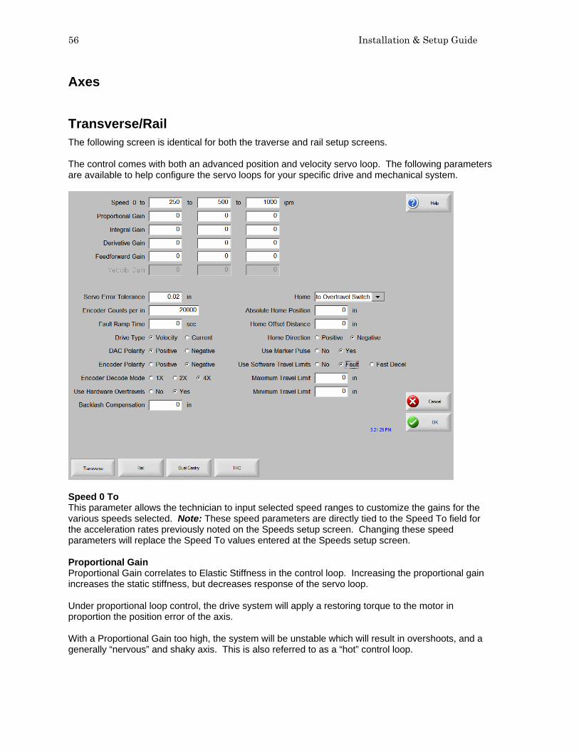
56 Installation & Setup Guide
Axes Transverse/Rail The following screen is identical for both the traverse and rail setup screens. The control comes with both an advanced position and velocity servo loop. The following parameters are available to help configure the servo loops for your specific drive and mechanical system.
Speed 0 To This parameter allows the technician to input selected speed ranges to customize the gains for the various speeds selected. Note: These speed parameters are directly tied to the Speed To field for the acceleration rates previously noted on the Speeds setup screen. Changing these speed parameters will replace the Speed To values entered at the Speeds setup screen. Proportional Gain Proportional Gain correlates to Elastic Stiffness in the control loop. Increasing the proportional gain increases the static stiffness, but decreases response of the servo loop. Under proportional loop control, the drive system will apply a restoring torque to the motor in proportion the position error of the axis. With a Proportional Gain too high, the system will be unstable which will result in overshoots, and a generally “nervous” and shaky axis. This is also referred to as a “hot” control loop.

Section 4: Password Setups 57
With a proportional gain too low, the system will respond in a loose or sloppy manner. This can be seen in the test pattern when the outside corners become rounded and the circle segments do not all meet in the center. Integral Gain Integral Gain improves the positioning accuracy of the control loop. Integral Gain can be used to compensate for static friction or gravity. Excessive Integral Gain can result in system instability. For most shape cutting machines, this parameter should be set to Zero (0). Derivative Gain Derivative Gain helps to dampen out sudden changes in velocity. The higher the derivative gain, the slower the response time to the control loop. For most velocity loop drives, this parameter will be set to Zero (0). Feedforward Gain Feedforward Gain can be used to drive the following error to zero during machine motion. In all digital control loops there is a finite amount of error that is introduced by the velocity command. Increasing Feedforward Gain can reduce this introduced error. Velocity Gain When using a current loop amplifier, the internal velocity loop in the control can be used to provide dampening without an external tachometer. Using the internal velocity loop with a current loop amplifier can result in higher static stiffness, smoother machine motion, and less overshoot. Servo Error Tolerance Allows the user to program the amount of servo loop Following Error to be allowed prior to display an error message. The parameter is limited to a maximum value of five inches. Encoder Counts per inch Enter a value that is the number of encoder edges per inch of machine travel. It is possible to enter fractional encoder units and the control will keep track of these fractions automatically. Encoder Counts per inch are equal to the resolution of the encoder, multiplied by the encoder revolutions per inch or mm (based on the machine drive gearing). For example: The resolution of a 4X – 1000 line encoder counts both edges (lines) of channel A and channel B to equal 4 counts per line multiplied by the 1000 lines per revolution would equal 4000 counts per revolution. If the encoder revolutions per inch to travel are 1:1, we would have 4000 encoder counts per inch of travel. Encoder Counts/ Inch = 4 Counts/ Line x 1000 Lines/ Rev x 1 Rev/ Inch = 4000 Fault Ramp Time This parameter sets the motion deceleration time after a fault occurs. At the end of “Fault Ramp Time, The drives will be disabled.

58 Installation & Setup Guide
Drive Type This parameter is used to tell the control what type of control loop to run. If you are running an external velocity loop drive (indicated by having an integrated tachometer in the motor), select Velocity. If you are running in torque mode (no tachometer), select Current. DAC Polarity This parameter allows changing of the analog output polarity to establish proper control loop feedback without any wiring changes. Encoder Polarity This parameter allows changing of the encoder input polarity to establish proper counting for positive machine motion without any wiring changes. Encoder Decode Mode Currently, the control only supports 4X encoder decode mode. This has been done to increase positional accuracy. Use Hardware Overtravels Select whether or not the cutting machine will be using Hardware Overtravels. If Hardware Overtravels are used, the control will disable feedback and display an error message if the inputs become active. It is recommended that Hardware Overtravels be installed. Backlash Compensation The Backlash Compensation parameter is used to offset or compensate for any backlash in the mechanics of the drive system. Home The Home parameter is used to activate use of the Home feature. Depending on control I/O configuration, the table may be Homed to either a designated Home Switch or an Overtravel Switch. The Home feature is used to set a known absolute physical position location on the cutting table that is used for referencing future manual “Go to Home” and other motion commands. This is generally performed through activation of a home switch positioned on the appropriate axis giving it a known physical location. When the Homing command is entered at the control, the control will move the axis towards the Home Switches at the Fast Home Speed until the switches have been activated. Once the switches have been activated, motion stops and then the axis moves in the opposite direction off switch at the Slow Home Speed. The moment that the switch is deactivated, the position is recorded at the control, providing an absolute reference point for future motion commands. Absolute Home Position Defines the position of the axis when the Home Limit Switch or Marker Pulse is detected. Home Offset Distance Allows the user to set an offset distance from the Home Limit Switch. Home Switch Normally If a Home Limit Switch is used, the user is prompted for switch polarity. Home Direction Determines which direction the axes will travel during phase one of the homing sequence.

Section 4: Password Setups 59
Use Marker Pulse When enabled, the absolute home position will be assigned at the instant the marker pulse is detected. It is recommended that the Marker Pulse be used for optimal homing repeatability. Use Software Travel Limits The control is capable of running with software Overtravel limit switches based on position. when enabled, this feature allows the user to select the fault logic of fault or Fast Decel when active. Fault operates as hardware switches with immediate fault. Fast Decel uses the fast Decel value to ramp down motion. Maximum Travel Limit If Software Overtravels are enabled, the user is prompted for the maximum travel of the cutting machine. Minimum Travel Limit If Software Overtravels are enabled, the user is prompted for the minimum travel of the cutting machine.
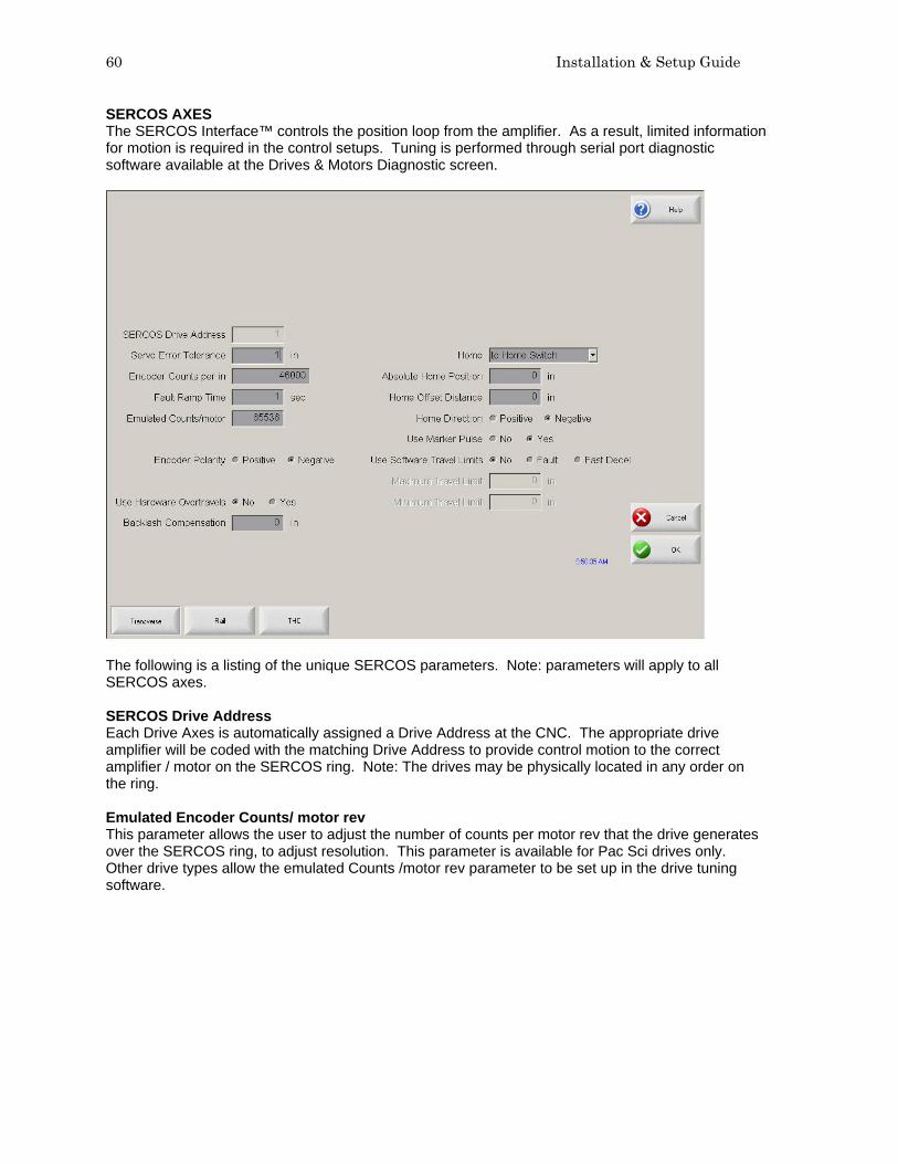
60 Installation & Setup Guide
SERCOS AXES The SERCOS Interface™ controls the position loop from the amplifier. As a result, limited information for motion is required in the control setups. Tuning is performed through serial port diagnostic software available at the Drives & Motors Diagnostic screen.
The following is a listing of the unique SERCOS parameters. Note: parameters will apply to all SERCOS axes. SERCOS Drive Address Each Drive Axes is automatically assigned a Drive Address at the CNC. The appropriate drive amplifier will be coded with the matching Drive Address to provide control motion to the correct amplifier / motor on the SERCOS ring. Note: The drives may be physically located in any order on the ring. Emulated Encoder Counts/ motor rev This parameter allows the user to adjust the number of counts per motor rev that the drive generates over the SERCOS ring, to adjust resolution. This parameter is available for Pac Sci drives only. Other drive types allow the emulated Counts /motor rev parameter to be set up in the drive tuning software.
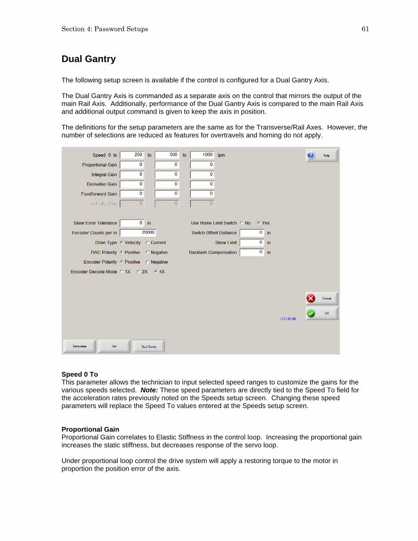
Section 4: Password Setups 61
Dual Gantry The following setup screen is available if the control is configured for a Dual Gantry Axis. The Dual Gantry Axis is commanded as a separate axis on the control that mirrors the output of the main Rail Axis. Additionally, performance of the Dual Gantry Axis is compared to the main Rail Axis and additional output command is given to keep the axis in position. The definitions for the setup parameters are the same as for the Transverse/Rail Axes. However, the number of selections are reduced as features for overtravels and homing do not apply.
Speed 0 To This parameter allows the technician to input selected speed ranges to customize the gains for the various speeds selected. Note: These speed parameters are directly tied to the Speed To field for the acceleration rates previously noted on the Speeds setup screen. Changing these speed parameters will replace the Speed To values entered at the Speeds setup screen. Proportional Gain Proportional Gain correlates to Elastic Stiffness in the control loop. Increasing the proportional gain increases the static stiffness, but decreases response of the servo loop. Under proportional loop control the drive system will apply a restoring torque to the motor in proportion the position error of the axis.

62 Installation & Setup Guide
With a Proportional Gain too high, the system will be unstable which will result in overshoots, and a generally “nervous” and shaky axis. This is also referred to as a “hot” control loop. With a proportional gain too low, the system will respond in a loose or sloppy manner. This can be seen in the test pattern when the outside corners become rounded and the circle segments do not all meet in the center. Integral Gain Integral Gain improves the positioning accuracy of the control loop. Integral gain can be used to compensate for static friction or gravity. Excessive Integral Gain can result in system instability. For most shape cutting machines this parameter should be set to zero (0). Derivative Gain Derivative Gain helps to dampen out sudden changes in velocity. The higher the derivative gain, the slower the response time to the control loop. For most velocity loop drives this parameter will be set to zero (0). Feedforward Gain Feedforward Gain can be used to drive the following error to zero during machine motion. In all digital control loops there is a finite amount of error that is introduced by the velocity command. Increasing Feedforward Gain can reduce this introduced error. Velocity Gain When using a current loop amplifier, the internal velocity loop in the control can be used to provide dampening without an external tachometer. Using the internal velocity loop with a current loop amplifier can result in higher static stiffness, smoother machine motion, and less overshoot. Skew Error Tolerance If the Dual Gantry Axis is installed, the user will be prompted for Skew Error Tolerance. This is the amount of position error allowed between the master and slave gantry drive axes prior to an error message being displayed. Encoder Counts per inch Enter a value that is the number of encoder edges per inch of machine travel. It is possible to enter fractional encoder units and the control will keep track of these fractions automatically. Encoder Counts per inch are equal to the resolution of the encoder, multiplied by the encoder revolutions per inch (based on the machine drive gearing). For example: The Resolution of a 4X – 1000 line encoder counts both edges (lines) of channel A and channel B to equal 4 counts per line multiplied by the 1000 lines per revolution would equal 4000 counts per revolution. If the encoder revolutions per inch to travel is 1:1, we would have 4000 encoder counts per inch of travel. Encoder Counts/Inch = 4 Counts/Line x 1000 Lines/Rev x 1 Rev/Inch = 4000 Note: This value should match the value used for the Rail for proper operation.

Section 4: Password Setups 63
Drive Type This parameter is used to tell the control what type of control loop to run. If you are running an external velocity loop drive (indicated by having an integrated tachometer in the motor), select Velocity. If you are running in torque mode (no tachometer), select Current. DAC Polarity This parameter allows changing of the analog output polarity to establish proper control loop feedback without any wiring changes. Encoder Polarity This parameter allows changing of the encoder input polarity to establish proper counting for positive machine motion without any wiring changes. Encoder Decode Mode Currently the control only supports 4X encoder decode mode. This has been done to increase positional accuracy. Use Home Limit Switch Selecting “Yes” will enable the Home feature for the Dual Gantry Axis. Note: The Z Home Switch must first be defined and mapped to an input location in the I/O screen to enable this feature. Switch Offset Distance The Switch Offset Distance is used to specify any physical position offset between the Dual Gantry and Rail Home Switch positions. This allows the control to very accurately position the two axes for operation and remove any skew of the gantry. Backlash Compensation The Backlash Compensation parameter is used to offset or compensate for any backlash in the mechanics of the drive system.

64 Installation & Setup Guide
CBH The following setup screen is available if the control is configured for a Contour Bevel Head. The definitions for the setup parameters are the same as for the Transverse/Rail Axes, with the exception of Absolute Home Angle and Home Offset Angle. These two setup parameters serve the same basic function as previously described but are measured in degrees of rotation rather than inches or millimeters. However, the number of selections are reduced as these parameters are not used with a Contour Bevel Head.
Proportional Gain Proportional Gain correlates to Elastic Stiffness in the control loop. Increasing the proportional gain increases the static stiffness, but decreases response of the servo loop. Under proportional loop control, the drive system will apply a restoring torque to the motor in proportion the position error of the axis. With a Proportional Gain too high, the system will be unstable which will result in overshoots and a generally “nervous” and shaky axis. This is also referred to as a “hot” control loop. With a proportional gain too low, the system will respond in a loose or sloppy manner. This can be seen in the test pattern when the outside corners become rounded and the circle segments do not all meet in the center.

Section 4: Password Setups 65
Integral Gain Integral Gain improves the positioning accuracy of the control loop. Integral Gain can be used to compensate for static friction or gravity. Excessive Integral Gain can result in system instability. For most shape cutting machines, this parameter should be set to zero (0). Derivative Gain Derivative Gain helps to dampen out sudden changes in velocity. The higher the Derivative Gain, the slower the response time to the control loop. For most velocity loop drives, this parameter will be set to zero (0). Feedforward Gain Feedforward Gain can be used to drive the following error to zero during machine motion. In all digital control loops there is a finite amount of error that is introduced by the velocity command. Increasing Feedforward Gain can reduce this introduced error. Velocity Gain When using a current loop amplifier, the internal velocity loop in the control can be used to provide dampening without an external tachometer. Using the internal velocity loop with a current loop amplifier can result in higher static stiffness, smoother machine motion, and less overshoot. Servo Error Tolerance Allows the user to program the amount of servo loop Following Error to be allowed prior to display an error message. The parameter is limited to a maximum value of 90 degrees. Encoder Counts per rev Enter a value that is the number of encoder edges per revolution of the Contour Bevel Head axis. It is possible to enter fractional encoder units and the control will keep track of these fractions automatically. Encoder Counts per rev are equal to the resolution of the encoder multiplied by the encoder revolutions per rev. For example: The Resolution of a 4X – 1000 line encoder counts both edges (lines) of channel A and channel B to equal 4 counts per line time multiplied by the 1000 lines per revolution would equal 4000 counts per revolution. Encoder Counts/Rev = 4 Counts/Line x 1000 Lines/Rev = 4000 Drive Type This parameter is used to tell the control what type of control loop to run. If you are running an external velocity loop drive (indicated by having an integrated tachometer in the motor), select Velocity. If you are running in torque mode (no tachometer), select Current.

66 Installation & Setup Guide
DAC Polarity This parameter allows changing of the analog output polarity to establish proper control loop feedback without any wiring changes. Encoder Polarity This parameter allows changing of the encoder input polarity to establish proper counting for positive machine motion without any wiring changes. Encoder Decode Mode Currently the control only supports 4X encoder decode mode. This has been done to increase positional accuracy. Follower Initially This parameter is used to determine if the CBH axis will be On when the control is first powered up. Auto Home At Power Up Determines if the Contour Bevel Head will automatically go into the homing routine upon powering up the control. Absolute Home Angle Defines the position of the axis when the home limit switch or marker pulse is detected. Home Offset Angle Allows the user to set an offset angle from the home limit switch. Use Home Limit Switch Tells the control to look for a home limit switch during phase one of the homing sequence. Home Direction Determines which direction the axes will travel during phase one of the homing sequence. Use Marker Pulse When enabled, the absolute home position will be assigned at the instant the marker pulse is detected. It is recommended that the marker pulse be used for optimal homing repeatability.
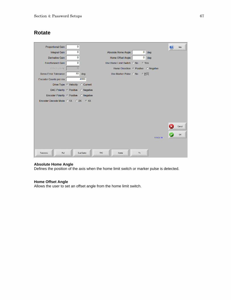
Section 4: Password Setups 67
Rotate
Absolute Home Angle Defines the position of the axis when the home limit switch or marker pulse is detected. Home Offset Angle Allows the user to set an offset angle from the home limit switch.
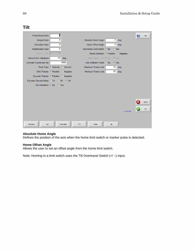
68 Installation & Setup Guide
Tilt
Absolute Home Angle Defines the position of the axis when the home limit switch or marker pulse is detected. Home Offset Angle Allows the user to set an offset angle from the home limit switch. Note: Homing to a limit switch uses the Tilt Overtravel Switch (+/ –) input.
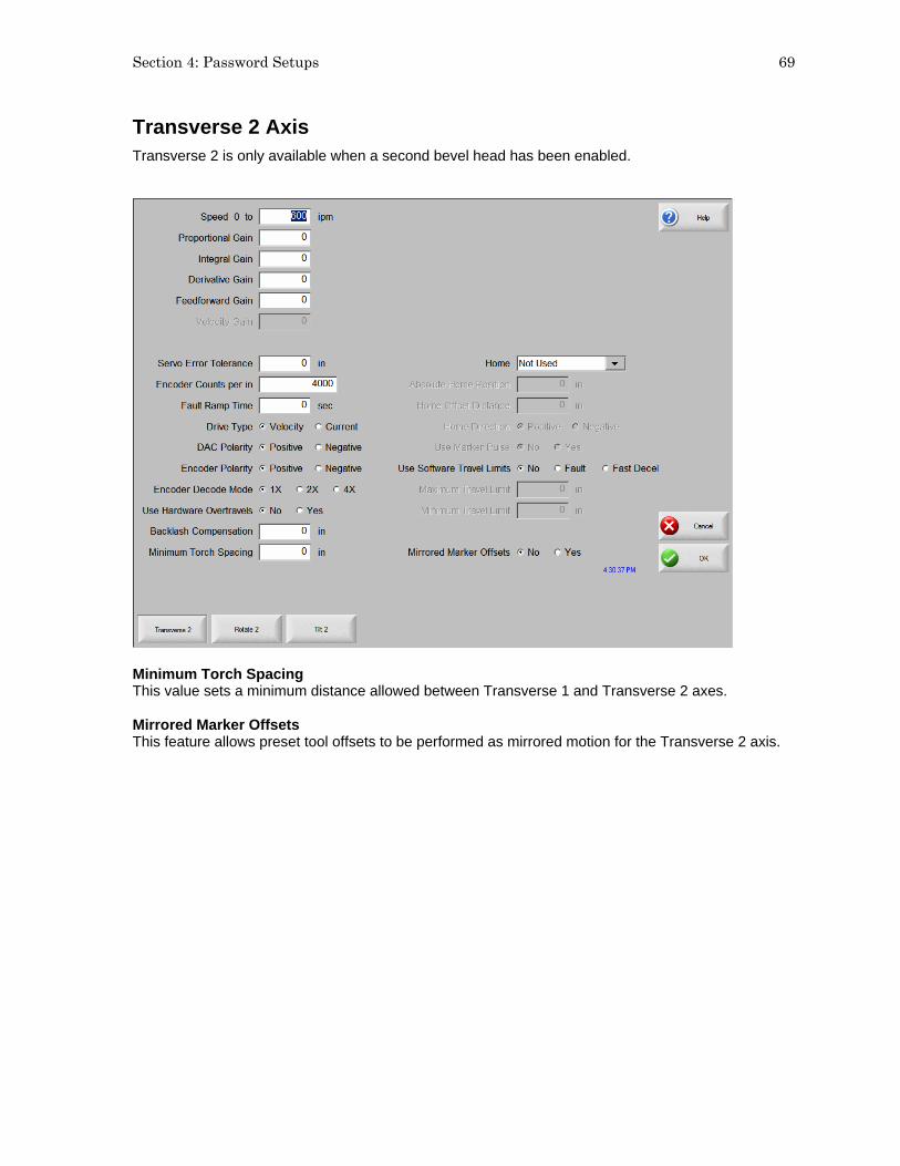
Section 4: Password Setups 69
Transverse 2 Axis Transverse 2 is only available when a second bevel head has been enabled.
Minimum Torch Spacing This value sets a minimum distance allowed between Transverse 1 and Transverse 2 axes. Mirrored Marker Offsets This feature allows preset tool offsets to be performed as mirrored motion for the Transverse 2 axis.

70 Installation & Setup Guide
Station Configuration This password protected screen for the Voyager™ III and Mariner™ controls is used to configure a Plasma, Marker or Laser torch station for use. This provides a single location to assign the Tool Selection, Process Selection and Lifter selection for the station. Up to eight stations for the Plasma 1 & 2 and Marker 1 & 2 process selections may be configured. The “4532” password is provided for viewing of the Station Configuration setup screen without allowing changes. This password is useful for verifying setups without the danger of accidentally changing them or revealing the supervisory password to an unauthorized user. This Station configuration screen is also used to enable the serial link for the Command® THC as well as serial communication for the HD4070® and HPR130™ Plasma Systems.
These stations may be selected for use through codes within the part program. These codes enable the desired Station (THC) and are used in conjunction with the Process Select codes to configure the desired cut / mark process for use. When a Station Select has been executed through the program codes the corresponding Station Select Output will be active. Stations 1-4 / 5-8 The Stations 1-4 / 5-8 Softkey is used to access the desired Station for configuration. Reset The Reset Softkey may be used to reset or clear all Station setup parameters setting the values to “None”.

Section 4: Password Setups 71
Part Program Support The following program codes are used to enable a station for use. Station Select and Process Select codes should be placed prior to the cut / mark. Station Selects Stations (Lifter / THCs) may be selected / de-selected using an EIA-274D program code with the following format. Code Description M19 Tvalue Cancel All Station Selections M37 Tvalue Select Station 1-20 (Tvalue) M38 Tvalue De-Select Station 1-20 (Tvalue) Additionally, these Station Select program codes may be overridden using the user selected THC inputs to the control. The feature to override the part program must be enabled at the Cutting Setup Screen. Process Selects Process Selections may be selected using an EIA-274D program code with the following format. Example: M36 Tvalue Misc. M Code Valve Identity T1 = Plasma Process 1 T2 = Plasma Process 2 T3 = Marker Process 1 T4 = Marker Process 2 T5 = Laser Process Station Configuration Variables The following options are available for the station configuration
Lifter None Sensor THC Command THC (w/ Serial Link) HD4070 Integrated THC 1 or 2 (used only with the HD4070® power supply) Other (any stand alone Lifter Station) Power Supplies None HD4070 Torch 1or 2 Powermax series Max100/ 100D HT4001 FineLine 100 Max200 HT4100 FineLine 200 HT2000 HT4400 Other (any other Plasma system) HD3070 HPR130 Marker None ArcWriter FineLine 100 & 200 HD4070 Torch 1or 2 HPR130 Other (any stand alone Marker) Laser Rofin RF 40 & 50 Rofin DC 35 Rofin TR 60 Other
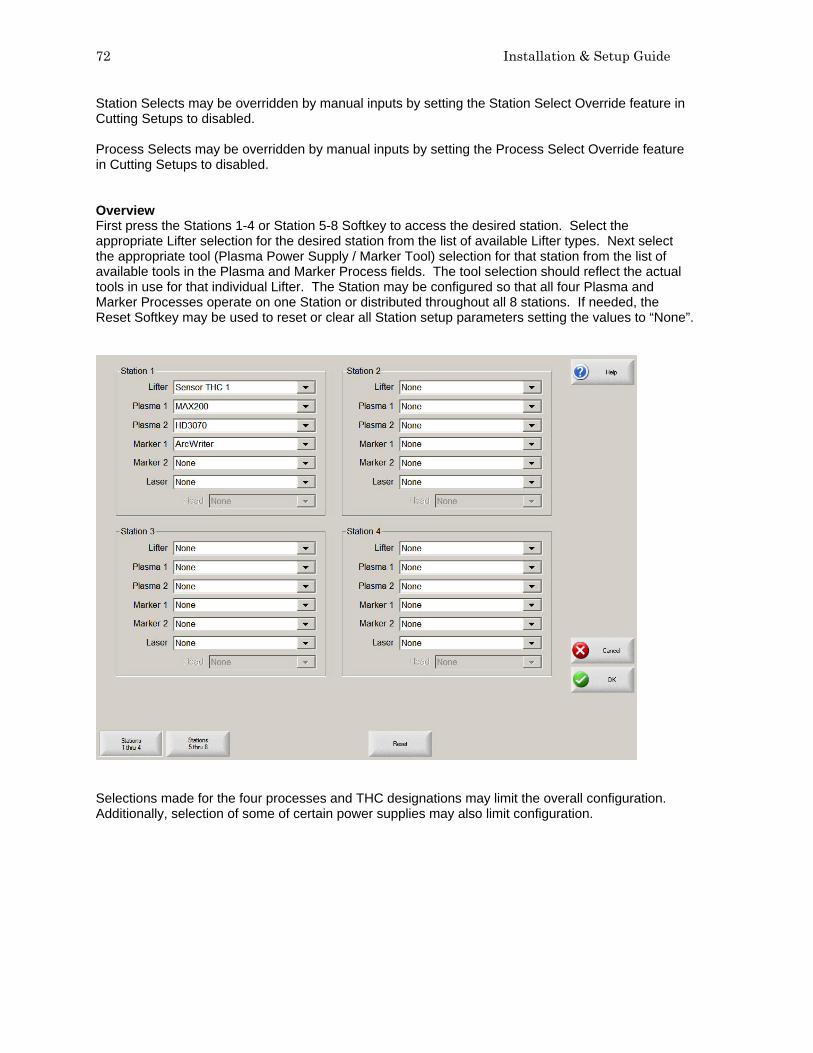
72 Installation & Setup Guide
Station Selects may be overridden by manual inputs by setting the Station Select Override feature in Cutting Setups to disabled. Process Selects may be overridden by manual inputs by setting the Process Select Override feature in Cutting Setups to disabled. Overview First press the Stations 1-4 or Station 5-8 Softkey to access the desired station. Select the appropriate Lifter selection for the desired station from the list of available Lifter types. Next select the appropriate tool (Plasma Power Supply / Marker Tool) selection for that station from the list of available tools in the Plasma and Marker Process fields. The tool selection should reflect the actual tools in use for that individual Lifter. The Station may be configured so that all four Plasma and Marker Processes operate on one Station or distributed throughout all 8 stations. If needed, the Reset Softkey may be used to reset or clear all Station setup parameters setting the values to “None”.
Selections made for the four processes and THC designations may limit the overall configuration. Additionally, selection of some of certain power supplies may also limit configuration.

Section 4: Password Setups 73
Example: If Station 1 has been defined as having a Sensor™ THC and a MAX200® for Plasma Process 1, no other power supply type can be selected for Plasma Process 1. However, MAX200® for Plasma Process 1 may be select at other stations if a Sensor THC has been selected.
Command® THC Support Selecting a Command THC as the lifter for a process enables the serial Link to be assigned for a single Command® THC. Note: The actual serial port must be assigned on the Ports setup screen. This also configures the selected Plasma / Marker Cut Types screen to display the Command® THC features. If a Command® THC has been selected for a station but does not use the serial communication feature to the control, then the Lifter type should be set to “Other”. Please refer to the Command® THC section of this manual for additional information on the operation of the Command® THC HD4070® Support The HD4070® feature establishes the Serial Link HD4070® Power Supply communication link and configures the selected Plasma / Marker Cut Types screen to display the HD4070® features. A single HD4070® must be assigned to Stations 1 & 2. A second multi-dropped HD4070 may be assigned on stations 3 & 4. Each HD4070® has the ability to use two Integrated Command® THCs. These are controlled by the HD4070® and as such have designated Station locations.

74 Installation & Setup Guide
In the previous example, you can see that the Cutting and Marking with the HD4070® Integrated Torch 1 is limited to Plasma Process 1 / Maker Process 1 on Station 1. Additionally, the Cutting and Marking with HD4070® Integrated Torch 2 is limited to Plasma Process 2 / Maker Process 2 on Station 2. These stations may be configured to Cut or Mark or both. A second multi-dropped HD4070 may be also be assigned on stations 3 & 4. FineLine 100 / 200 Support Serial communications to INNERLOGIC’s FineLine 100 and FineLine 200 may be enabled and configured for use with selected THCs.

Section 4: Password Setups 75
Special
Date Allows the user to enter the current date. Time The value for the current time would be entered at this parameter and displayed at the main screen. Display Time The Display Time parameter allows the user to select the display time to be shown in either AM/PM format or 24 hour clock format. Mouse Pointer Select On to use and external mouse or touch screen. Keyboard When set to Not Installed, on screen keypad will be displayed for editing parameters. If an external key board is being used this can be set to Installed and avoid the on screen keypad use. User Level This feature is used to adjust view screens and what features are available for use based on operator experience level. The intermediate level provides a larger preview area and an ALT soft key to access additional screens. Motion Cursor This parameter allows the user to select the style of Motion Cursor used.

76 Installation & Setup Guide
File Extensions The parameter allows the user to enter the file extensions of the part files that will accepted at the control. Adding Folders This parameter determines whether the control operator has the ability to add Folders from the parts directory on the control or the host computer. Deleting Folders This parameter determines whether the control operator has the ability to delete Folders from the parts directory on the control or the host computer. Deleting Files This parameter determines whether the control operator has the ability to delete Folders from the parts directory on the control or the host computer. Mapping Drives This parameter determines whether the control operator has the ability to map to external drives from the control through the optional Network feature. Configuring Watch When enabled, this parameter will allow the control operator to change the selected items in the Watch Window. Adding Processes This feature allows the user to add new processes to the Laser cut charts when enabled. Removing Processes This feature allows the user to remove processes to the Laser cut charts when enabled. . Force Simulation When activated, this feature will force the control into a simulation mode that will allow the control to operate with motioned disabled and I/O feedback enabled. Temperature The Temperature parameter allows the user to select that the internal control temperature be displayed in Fahrenheit or Celsius in the Watch Window. Note: Not available for all control types and optional control hardware required. Tools Installed This setup parameter is used to select or limit the cut modes available to the control operator. Message Enables The following pull down box is used to enable and disable system messages. To change the status of a message, highlight the selected message and press the Space key. Ready to Start Cutting Message When enabled, the Ready Message feature will display a ready message when the Start button is pressed. Kerf Too Large Warning Message The Kerf Too Large Warning setup parameter allows the user to disable the “ Kerf Too Large” warning message. This message is used to notify the user that when a part has been loaded and translated at the control, a conflict with the cut paths has been detected for the given Kerf value and
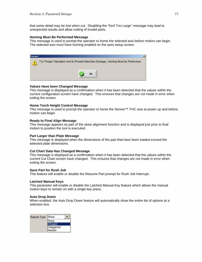
Section 4: Password Setups 77
that some detail may be lost when cut. Disabling the “Kerf Too Large” message may lead to unexpected results and allow cutting of invalid parts. Homing Must Be Performed Message This message is used to prompt the operator to home the selected axis before motion can begin. The selected axis must have homing enabled on the axes setup screen.
Values Have been Changed Message This message is displayed as a confirmation when it has been detected that the values within the current configuration screen have changed. This ensures that changes are not made in error when exiting the screen. Home Torch Height Control Message This message is used to prompt the operator to home the Sensor™ THC axis at power up and before motion can begin. Ready to Final Align Message This message appears as part of the skew alignment function and is displayed just prior to final motion to position the tool is executed. Part Larger than Plate Message This message is displayed when the dimensions of the part that have been loaded exceed the selected plate dimensions. Cut Chart Data Has Changed Message This message is displayed as a confirmation when it has been detected that the values within the current Cut Chart screen have changed. This ensures that changes are not made in error when exiting the screen. Save Part for Rush Job This feature will enable or disable the Resume Part prompt for Rush Job Interrupt. Latched Manual Keys This parameter will enable or disable the Latched Manual Key feature which allows the manual motion keys to remain on with a single key press. Auto Drop Down When enabled, the Auto Drop Down feature will automatically show the entire list of options at a selection box.

78 Installation & Setup Guide
Zero Positions This parameter determines whether the control operator has the ability to zero positions. When disabled, the zero positions softkey will be grayed out and will be unavailable to the operator. Auto Size App. When enabled, the Auto Size App. feature is used for the demo software to size the application software to full screen display or the standard size of 640x480 (disabled). Language The language selection parameter allows the user to select the language displayed on the control from the available languages stored on the control. Languages may be added to the control by performing the standard software update with a language specific update file. Eastern languages may also require the installation of a font viewer to properly display the required characters. To change to a different language, select the desired language and press the OK softkey. You will then be prompted to cycle power on the control for the new language to be displayed. Tangent Angle This parameter is used to set the degree of the tangent angle for control motion. Segments within a part that intersect at angles greater than the selected tangent angle will decel to zero or minimum corner speed. Segments within a part that intersect at angles less than or equal to the selected tangent angle, will not decel unless the next segment is a speed limited arc. Password The password parameter allows the user to enter a new password for machine setups. Numbers or letters may be used. Special Password The password parameter allows the user to enter a new password for special setups. Numbers or letters may be used. Station Configuration Password The password parameter allows the user to enter a new password for Station Configuration setups. Numbers or letters may be used. Auto Update Max Consumable Life When enabled, this feature will continue to track the consumable life values beyond the user defined set point and assign that maximum value as the new set point. If disabled, the user defined set point for maximum consumable life will not be updated. Machine Position Resets When enabled, the Machine Position Resets feature will reset the absolute machine position when the Zero Positions softkey is pressed. When disabled, pressing the Zero Positions softkey will not reset the absolute machine position. Position information based on homing will not be lost. Only the current incremental motion (part) position will be reset to zero. Arc Speed Limit Check This feature allows the user the ability to turn off the Speed Limit Check performed by Softmotion for arcs larger than 10”. This may be used to compensate for abrupt motion commands caused by non-tangent line arc segments, smoothing out motion. HD3070 Auto Gas When enabled, this feature allows the control to communicate with the Auto Gas Console for the HD3070® and allows access to the related setup parameters. Front Panel This feature defines use of an optional 12 station or 6 station operator console.

Section 4: Password Setups 79
Save Setups Pressing the Save Setups button will save the current control setting to the floppy disk or hard drive. A window will be displayed to select the drive and enter a file name.
Note: After installation of the control on the cutting table or if any setup parameters are changed, it is important to save the current setup file to both the hard drive and floppy disk for future reference. Load Setups Pressing the Load Setups will load the selected control setting from the floppy or hard drive on to the control. A window will be displayed to select the drive and enter the file name. Update Software Pressing the Update Software button will update the control operating software from a floppy disk. Update Help Pressing the Update Help button will update the control help files from a floppy disk. System Tools Pressing the System Tools button will access core Windows® features for system performance. Features include Update Registry, Scan Hard Disk, Defrag Hard Disk and Format Disk. System Tools also accesses features for virus scanning and adding special fonts for some languages. Restore Last Version Restore Last Version will restore the control to the previous version of system software. Make Link Disk The control is shipped with a proprietary Communication Link software used to communicate with a host computer. Pressing this softkey will transfer the Link software to a floppy disk so it may be loaded on to a host computer for use. Included with the software is a text file to instruct the user on setup and use of the link.

80 Installation & Setup Guide
System Tools – Windows® XP
The control Systems Tools involves operational knowledge of Windows® XP operating system and should only be performed by qualified personnel. Note: A reminder will be posted on screen when entering the Systems Tools that a Mouse and Keyboard will be required for proper operation. The Mouse and Keyboard should be connected to the control before entering the System Tools.
System Tools
Automated Backup The Automated Backup feature allows the user to select the frequency of the automatic reminder for the backup of main hard drive information. At the selected time, the user will be prompted to backup the system at power up.

Section 4: Password Setups 81
Backup Hard Drive Pressing the Backup Hard Drive softkey will manually save the contents of the main hard drive to a specified location on the control hard drive or mapped location using the Norton Ghost™ Utility. Example
Note: After using Norton Ghost™, all files on Drive C: will be replaced. Control setups will need to be reloaded. Scan Hard Disk Pressing the Scan Hard Disk softkey allows the user to scan the Hard Drive for viruses or to Scan the Hard Drive for disk errors.
Scan Hard Disk – Selecting NO will allow the user to scan the Hard Drive for errors and correct them using the Windows® XP CHKDSK (check disk) utility. This task should be performed approximately every three months depending on the number of files loaded to and removed from the control. The Check Disk (CHKDSK) function cannot operate while the control software is in operation. You will be prompted to press “Y” for yes to perform the Check Disk at the next boot up of the control.

82 Installation & Setup Guide
Scan Hard Disk – Selecting YES will allow the user to scan the Hard Drive for viruses using Norton’s Anti-virus software.
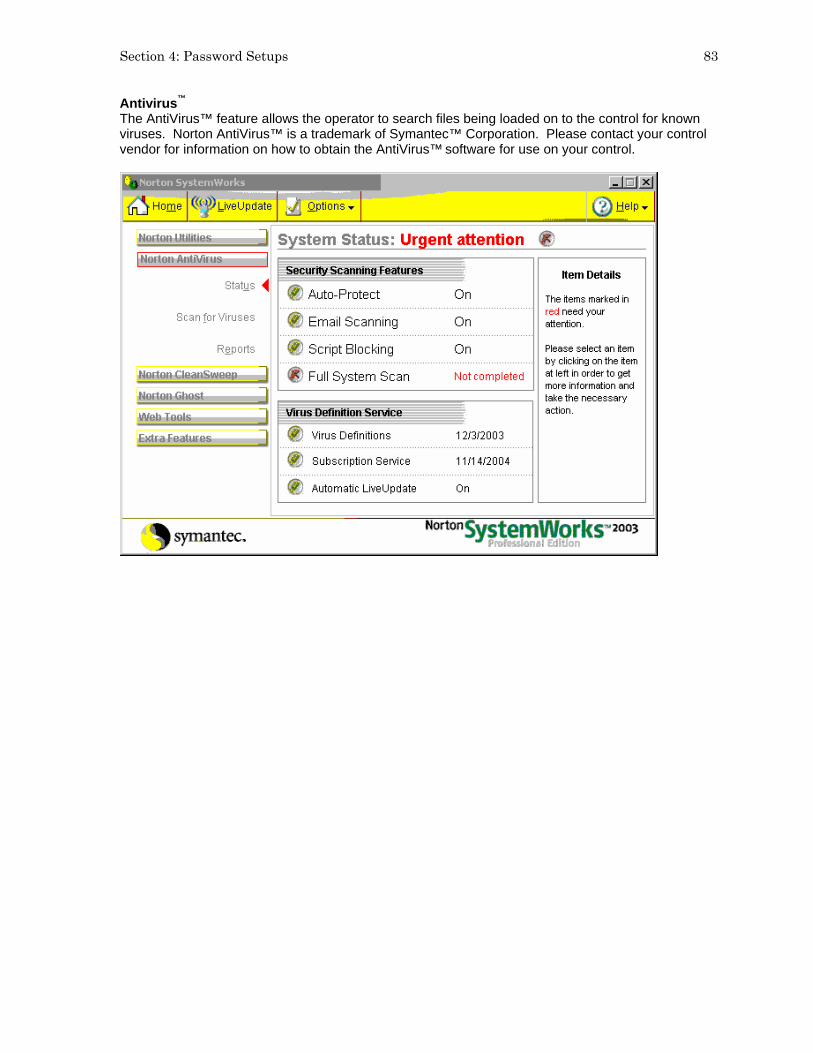
Section 4: Password Setups 83
Antivirus™ The AntiVirus™ feature allows the operator to search files being loaded on to the control for known viruses. Norton AntiVirus™ is a trademark of Symantec™ Corporation. Please contact your control vendor for information on how to obtain the AntiVirus™ software for use on your control.

84 Installation & Setup Guide
Defragment Hard Disk The Defragment Hard Disk feature will scan the control hard disk for file locations and rearranges them for optimum performance. This task should be performed approximately every three months.

Section 4: Password Setups 85
Format Floppy Disk Pressing the Format Floppy Disk softkey will format a floppy disk placed into the floppy drive. This is advantageous in the event that the control has difficulty reading a floppy disk formatted by a computer. Note: Formatting the diskette will remove any files that are stored on the diskette.
Reset Setups Reset Setups will delete the current setup file, forcing default values to be loaded. A new setup file can then be loaded on the control through the Special Password screen. If the control supplier has installed a customized setup file containing information specific to the cutting table, the Reset Setups Softkey is renamed Restore Setups. This custom setup file then becomes the new default setup file and pressing the Restore Setup Key will return the control to the original factory settings, as configured by the control supplier.

86 Installation & Setup Guide
Network and Remote Tools
The Network and Remote Tools functions involves operational knowledge of Windows® XP operating system and should only be performed by qualified personnel. Pressing the Network Tools softkey accesses the Windows® XP Network Connection Utility and Remote Assistant Utility.
Windows XP® Remote Assistant Remote Assistance is a feature within Windows XP® and allows a Remote Helper to view and chat over a TCP/IP connection with a control running the Windows XP® Embedded operating system. The Remote Helper can also request to share control of the keyboard and mouse.

Section 4: Password Setups 87
Some applications for Remote Assistance are: 1. Remote demonstrations of CNC software. 2. Show an operator certain features he may not be familiar with. 3. Online chat feature allows direct communication 4. Send or retrieve Software Updates, Database Files or other files with a Remote User. 5. Debug certain customer issues using Log Files. 6. Allow an operator to demonstrate a problem remotely.
Basic Instructions for use of Remote Assistance: 1. Operator connects control to network/internet. 2. Operator launches Remote Assistance Wizard and creates a Remote Assistance Invitation File
with password and saves it to floppy disk. 3. Operator E-mails the Remote Assistance Invitation File and password to the Remote Helper. 4. Remote Helper connects to network/internet and launches Remote Assistance Invitation File. 5. Operator accepts Remote Assistance dialog. 6. Chat windows are available to both the operator and Remote Helper to allow them to discuss the
feature or issue that is being reviewed remotely. Requirements for the use of Remote Assistance on the Control: Windows XP Embedded and Phoenix version 4.5 or 5.0 or higher. Keyboard, mouse and internet connection (network, dial-up, DSL or other TCP/IP compatible network) is required for Remote Assistance. High speed connections preferred. Note: The Remote Helper is not allowed to perform motion unless the control is in forced simulation mode or is a demo version of software running on a desktop. Audio feature is not used.
This feature would only be used with the assistance of and external technician. Please contact your control vendor if you require additional details on the use of this feature.
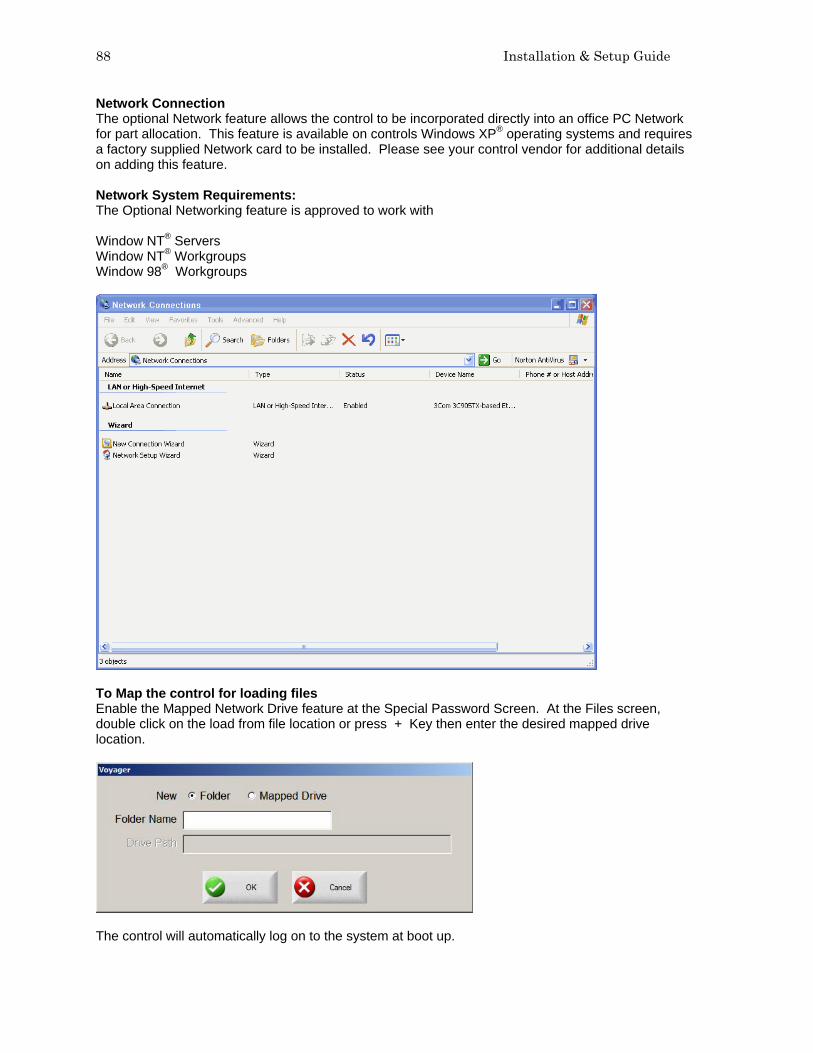
88 Installation & Setup Guide
Network Connection The optional Network feature allows the control to be incorporated directly into an office PC Network for part allocation. This feature is available on controls Windows XP® operating systems and requires a factory supplied Network card to be installed. Please see your control vendor for additional details on adding this feature. Network System Requirements: The Optional Networking feature is approved to work with Window NT® Servers Window NT® Workgroups Window 98® Workgroups
To Map the control for loading files Enable the Mapped Network Drive feature at the Special Password Screen. At the Files screen, double click on the load from file location or press + Key then enter the desired mapped drive location.
The control will automatically log on to the system at boot up.

Section 5: Phoenix Link 89
Section 5: Phoenix Link Phoenix Link Overview The Phoenix Link Communication Software is a proprietary communication package supplied with the control for optimal communication of part files and consumable database files between the control and the host computer. The program uses a 2X compression feature that allows the communications system to operate at speeds up to 230K Baud. Phoenix Link When the Phoenix Link Communication Software is operating, the following window will be displayed at the host computer for configuration. Once the software is running, the window may be minimized.
The following is a brief description of the available setup parameters for the Phoenix Link. Simply left click with the computer mouse on the selected feature in the drop down box to select, enable or execute that feature. Port This setup parameter allows the user to select the communication port to be used on the host computer. Baud This setup parameter allows the user to select the Baud rate used for communication on the host computer. Baud Rates: Min 9600 bps – Max 115,200 bps Folder The Folder setup parameter allows the operator to change the path of the Master Folder (Parts Folder). Sub folders and the part files within this Folder will be viewed at the control.

90 Installation & Setup Guide
Files The files setup parameter allows the user to indicate which file extensions will be recognized as acceptable part program files for download by the link software and will be viewed at the control. Settings The Settings setup parameter allows the user to configure the link to allow the Auto Reload (M65) feature to be enabled and recognized during communication. Additionally, the user may also select to communicate to multiple controls using the Multi Drop feature and configure it for use. Test The Test feature is used to test the operation of the selected communications port. To test, simply connect the transmit and receive signals on the selected communications port by inserting a paper clip and click on the desired port to test. The status of the test will be displayed in the lower left corner of the window. Help Selecting Help will display the current version of link software being used.
Files The Files setup parameter allows the user to indicate which file extensions will be recognized as acceptable part program files for download by the link software and will be viewed at the control. Once a file has been successfully saved on the control, it is assigned the “txt” file extension for use internally on the control. The operator must be aware of this as part programs with the same name, but different file extensions, will be overwritten during multiple file downloads. A warning will be displayed at the control prior to a file being overwritten. Care must be taken when downloading. The list of acceptable part program types is listed in the lower half of the of the Files option box. The checkmark (√) before the file extension indicates which selected file type will be displayed at the control. Please note that the checkmark (√) in the file extension listing also indicates the file extension which will be placed on a part program when uploading a file to the host.

Section 5: Phoenix Link 91
The following options are available to define what part programs may be viewed at the control. Show All Files Enabling this feature allows all file types in the selected parts folder to be viewed at the control. A checkmark (√) located before this feature indicates that it has been enabled. Show Extension in Name This feature allows the user to view the file extension as part of the name at the control. For the file name “Job123.CNC”, the control would only display “Job123_CNC” in the filename location of the download screen. The control would display “Job 123” if this feature was not enabled. This feature is advantageous if more than one file has the same file name with different file extensions is being used. A checkmark (√) located before this feature indicates that it has been enabled. Add to Files The Add to Files feature allows the user to add to the list of acceptable part program types to be viewed at the control. Up to four file types (extensions) may be added to the default .txt extension. A checkmark (√) located before a file extension will indicate which file extension will be placed onto any part file being uploaded to the host. Remove from Files The Remove from Files feature allows the user to remove file extensions from the list of acceptable part program types.

92 Installation & Setup Guide
Settings
Allow M65 Auto Reload Selecting the M65 Auto Reload Feature allows part programs to be partitioned into smaller part programs separated by the M65 code. During the download, the control will download the individual sections of the part program and allow the operator to execute that section of the part. When that section of the program has been completed, the next section of the program will be automatically downloaded for execution. The downloads will continue until an end of program (M02) code is detected. Use Multi Drop The Use Multi Drop feature allows the Link to be configured to communicate with multiple controls through one communication port on the host PC. Up to eight controls may be supported with the Multi Drop feature. Please note: The “Using Phoenix Link” parameter must be set to yes at the control to enable this feature and specific hardware for the control (serial communications board Rev D or higher) and host PC may be required to support this feature. Please contact your control supplier for more details. Add Control The Add Control feature is used to add a new control to the list of controls to communicate with. The corresponding control number must then be assigned to the new control in the link set up screen. Remove Control The Remove Control feature is used to remove a control from the list of controls that the host PC will communicate with. Control Monitoring When enabled, the Control Monitoring feature allows the user to view control status at the host PC. Status for File Name, position, cut mode and cut information is displayed. This feature is only available with the Phoenix Link Communication Software.

Section 5: Phoenix Link 93
Installation Below is an item list to outline the step by step procedure for the communication setup of the control and installation of the Phoenix Link Communication software: Disclaimer of Warranty: This link software and accompanying written material (including instructions for use) are provided “as is” without warranty of any kind. Minimum System Requirements Processor: Pentium® 100MHZ Hard Drive Space 0.5 MB Memory: 4MB Display: VGA Floppy Drive: 3.5” Operating System: MS Windows® 95, 98, NT, 2000, ME or XP Serial Port: One RS-232 or RS422 serial port will be required per control.
Software 1) At the control, access the Special Password screen, place a diskette or USB memory device into
the floppy drive and press the Make Link Disk softkey. Three files will be transferred to the floppy disk. The Link software (Link.exe), a Setup file (Setup.exe) and a Readme file (Readme.txt). The Setup file will create a Link folder on the root directory of the host PC and will copy the Link software into it. The “Readme” file contains additional information about installation and setup of the Link software on to the host computer.
2) When the light goes out on the floppy drive, transfer the floppy disk to the host computer and
place the disk into the floppy (A) drive. From the Windows® Start button, select Run. At the opening prompt type A:\Setup.bat and select OK. The setup file will expand the files and create a “Link” directory on the root directory. Placed in this directory will be the Link.exe file. Please note: The Link software must be located and run on the PC that is connected to the communication cable coming from the control.
3) From the Windows® Start button, select Run. At the opening prompt, type A:\Link\Link.exe and
select OK. After the link software has been launched, two other files will be created. A link.ini file, which contains the Link software configuration information, and a Parts folder, which is the default Master parts folder. It is recommended that a shortcut to the Link.exe be placed on the desktop of the host PC for ease of use.
4) At the host computer, create one or more folders under the “Parts” directory. Place any part
programs to be accessed by the control into these folders.
For example, if you wish to add the folders ”Workfile 1” and “Workfile 2” to the parts directory, the structure of the files would look as below:

94 Installation & Setup Guide
Path C:\Link\Parts\Workfile 1 and C:\Link\Parts\Workfile 2
Any part programs to be viewed and downloaded at the control would be placed here. Only the sub folders Workfile 1 and Workfile 2 and the program files located within them will be viewed at the control. Change Master Folder If the host computer currently has existing part programs and folders, the Link software may be configured to operate with the current folder names. This master parts folder may be located on the host PC or another PC that is networked to the host PC. Please note: The Link software must be located and run on the PC that is connected to the communication cable coming from the control. This is accomplished by configuring the Link software through the “Change Master Folder” feature to point the Link to the folder that contains the required part programs. Launch the Link Software at the host computer and the Link window will be displayed.
Select Files\Change Master Folder.
The Master file may now be changed from the current folder to the selected folder by typing in the selected path. Select OK to accept the change.

Section 5: Phoenix Link 95
The same procedure would also apply when selecting a master folder located on a network. For example, if the folders which contain the part programs are currently located in a folder named “Jobs” located on the PC named “R” drive, the Link.exe could be configured to the Change Master folder option to access these files. Example path: R:\Cad\Production\Jobs
Again, start by launching the Link Software at the host computer. Select Files\Change Master Folder.
The Master file may now be changed from the current folder to the selected “Jobs” folder by typing in the path R:\Cad\Production\Jobs. Select OK to accept the change. The final step to setup the Link software is to configure the Link software for Port, Baud, Files and Settings to match those being used at the control. It is recommended that a shortcut to the Link.exe be placed on the desktop of the host PC for ease of use. Operating Multiple Links To connect more than one control to the host PC without the use of the Multi Drop feature, a Link software specific to each control may be installed. Each version of Link being operated will require its own dedicated communications port on the host PC. Start by creating individual folders for each cutting table and placing a copy of the Link.exe into each folder. Create a shortcut for each Link.exe and place the shortcut on the desktop. Using a mouse, right click on the shortcut to open the shortcut properties dialog box. Add to the shortcut target command line information to indicate which table the Link will be in communication with.

96 Installation & Setup Guide
In the target command line example below, “Table1” has been added to the end of the command line to indicate the Link will be specific to communications with Table 1.
This “table” information, added to the Target command line, will then be noted in the title bar of the Link window. The Link may now be launched from the shortcut and configured specifically for this “table”. When the Link is closed, a “Table1.ini” with the specific Link setup file will be saved in the folder.
Continue to configure each additional Link for communication to each control. The separate Link files may be configured to point to the same or different master parts folders.

Section 5: Phoenix Link 97
Hardware Note: It is suggested for the purpose of establishing the proper setup of communications, that the control be placed next to the host computer and connected via a short communication cable. Once communications have been successfully established, the control can then be located on the cutting table and connected to the host computer via the appropriate cable or short haul modem system. 1) Configure the selected RS232/RS422 serial port on the control for operation, as described in the
Serial Port information of this guide. 2) Test the control’s communication port in the Diagnostic Screen to confirm proper operation of the
serial port. Directions for testing of the serial port are described in the Diagnostic section of this guide.
3) Enter the control’s Link setup screen to select the use of the desired communication port, select
the Baud rate and select to use Phoenix Link. It is suggested to start at the lowest baud rate and increase until the maximum is achieved. Communicating at too high a speed may cause error messages to be displayed due to lost characters or information.
4) Enter the control’s Special Password screen to add the file extension of the part programs being
used to the current list of acceptable file extensions. 5) Load and configure the Link software at the host computer as previously described in this section. 6) Test the host computer’s selected serial port through the “Test Port” feature of the Link software
as outlined in the Phoenix Link software overview. 7) Connect the control to the host computer’s selected communications port with the appropriate
cable or modem system.
Operating Phoenix Link 1) The Phoenix Link software must be running at the host computer to communicate with your
shape cutting control. Start the Link software at the host PC from the desktop shortcut or select the Windows Start Button, then select Run. From the opening prompt, type C:\Link\Parts\Link.exe (or appropriate path to the Link.exe) and select OK. The Phoenix Link window will appear. The Link software window may be minimized during operation if desired.
2) At the control, press the Files softkey and select to Upload or Download to Host. As the control is
connecting to the host computer, a status display in blue text for the communication can be viewed in the lower right corner of the screen.
3) The control will initialize the port, open the port, and then try to contact the host. If this attempt at
communication fails, an error message will be displayed in red. If successful, the control will download the available folder and part file names to be viewed on screen. Note: If the “Show Host File Names” parameter at the control has been set to “No”, only folder names will be viewed.

98 Installation & Setup Guide
Common Errors Below is a listing of common errors encountered when installing a communications system. 1) The port selected at the host computer has already been assigned to another software program. 2) The host and control have been configured to different setup values. 3) The cable has been connected to the incorrect port or software has been configured to the
incorrect port. 4) The selected modem or cabling system being used has swapped the transit and received signals,
causing a communications failure. 5) Trying to transmit over too long a cable without a modem or using incorrect wire for the distance
being traveled. 6) Trying to communicate at too high a baud rate for the modem system selected. 7) The correct file extension has not been entered at the control’s Special Password screen,
preventing part programs from being displayed at the control.

Section 5: Phoenix Link 99
Error Messages Below is a listing of common error messages and some possible causes. Unable to Open Port (control) The selected communications port could not be opened. The wrong port has been selected or the communications port has failed. Unable to Open Port (host) The selected communications port could be opened. The wrong port has been selected, the communications port has failed or another software application is using the port. Unable to Initialize Port The selected communications port was unable to be initialized. The wrong port has been selected, the communications port has failed or another software application is using the port. Port Failed The Port Failed error message will be displayed if the communications port test has failed for the selected port. This may be due to a fault with the test wire connection, incorrectly connecting to the proper transmit and receive pins location, or failure of the communications port. Host Not Responding This message will be displayed if the communications port has successfully opened the port, but has failed to establish communication with the Link software. This may be due to a fault with the cable connection, cable configuration or the host computer’s communications port. Communication Failed This message will be displayed if after establishing communication with the host, an expected message from the host is not correct.

100 Installation & Setup Guide
Communications Time Out This message will be displayed if the specified amount of time allowed for a response from the host computer expires. This amount of time can be configured in the Link setup screen. This may be due to a fault with the cable connection, cable configuration or the host computer’s communications port. Checksum Error The Checksum Error message will be displayed at the control if after a part has been uploaded or downloaded, the checksum calculated by the host and the control do not match. The Checksum calculation is performed by adding the numeric values of the ASCII codes used. This error may be due to incorrect cabling or transmitting at too high a speed for the communications system selected. Warning: The Master Folder Selected does Not Contain any Folders This error message will be displayed at the host computer if the selected master folder does not contain any subfolders. You may choose to add subfolders if they do not exist. If subfolders do exist, the path to the master folder may be incorrect. For additional assistance in trouble shooting the Phoenix Link in the event of a failure, please contact your control vendor or representative.

Appendix A: Motion Overview 101
Appendix A: Motion Overview
General Motion Theory – Servo Loop Control
The following is intended to assist customers / control system users in better understanding motion theory. Note: It is highly recommended that any system tuning be performed by qualified service technician as incorrect tuning may cause damage to the system or personal injury.
Outline of Information 1) What is closed loop servo control?
a) What is an Encoder? b) What is Following Error? c) What is a Position / Servo Error?
2) Determining Edge per Inch Parameter 3) Gain Term Definitions 4) Recommended Tuning Procedures 1) What is Closed Loop Servo control? A Servo System is the means of accurately controlling electrical motors to create force. The motor output is generally connected to a gearing system to translate the rotational force of the motor into linear motion. Additionally this gearing system is used to modify the strength and speed of the motion. Closed Loop Servo control is the continuous process of monitoring position and/or velocity commands compared to actual position and velocity and adjusting the output accordingly. A servo system without feedback devices and automatic adjustment capabilities would be referred to as Open Loop Servo control. The drawing below outlines a typical Velocity and Position Loop System. The most important aspect of this for our motion control is the Position Loop. The process starts with the motion control providing a motion command (voltage) to the motor to move at a specific speed to a desired position. Position is tracked during the motion by means of a feedback device (Encoder) that provides both directional and distance information. Based on that feedback, the control adjusts it’s motion command (voltage) to the motor to ensure that the motor is accurately positioning on the designated motion path at the correct speed.
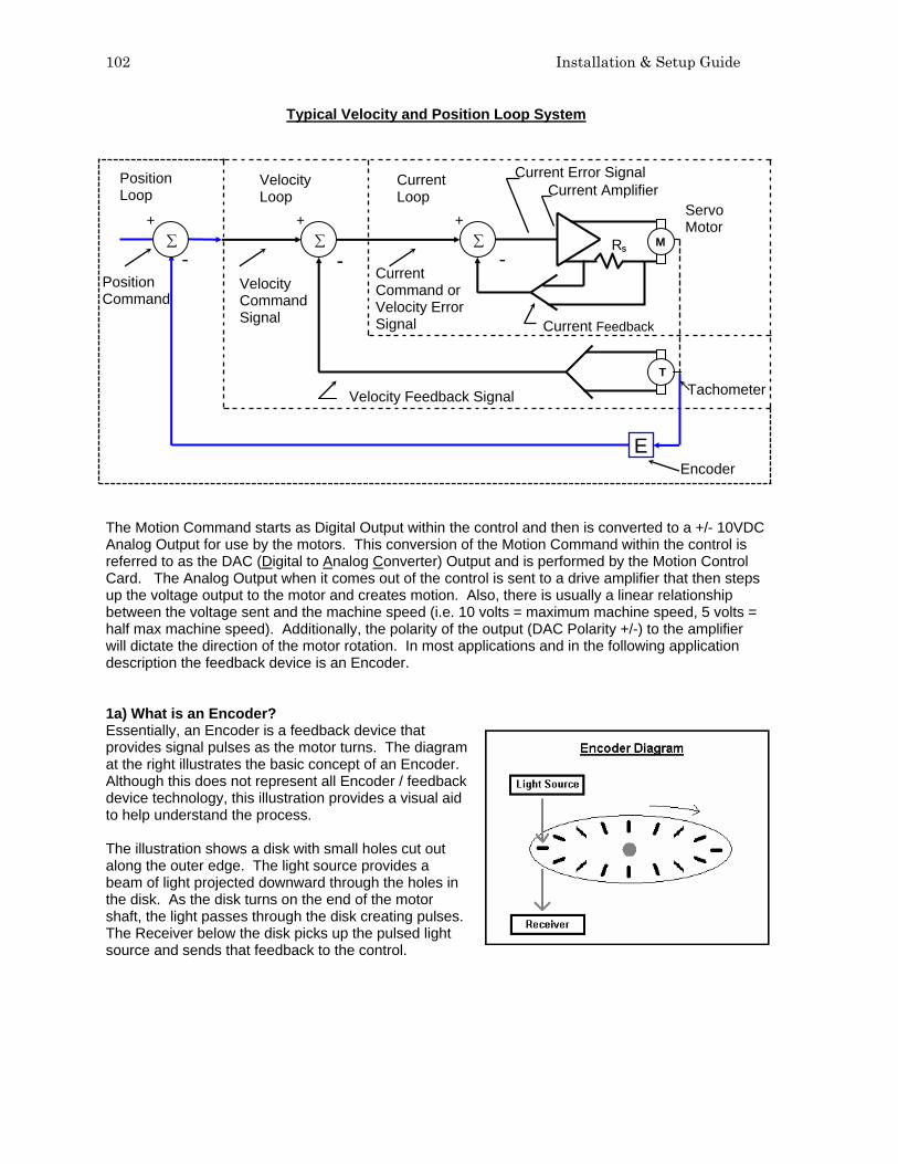
102 Installation & Setup Guide
Typical Velocity and Position Loop System
The Motion Command starts as Digital Output within the control and then is converted to a +/- 10VDC Analog Output for use by the motors. This conversion of the Motion Command within the control is referred to as the DAC (Digital to Analog Converter) Output and is performed by the Motion Control Card. The Analog Output when it comes out of the control is sent to a drive amplifier that then steps up the voltage output to the motor and creates motion. Also, there is usually a linear relationship between the voltage sent and the machine speed (i.e. 10 volts = maximum machine speed, 5 volts = half max machine speed). Additionally, the polarity of the output (DAC Polarity +/-) to the amplifier will dictate the direction of the motor rotation. In most applications and in the following application description the feedback device is an Encoder. 1a) What is an Encoder? Essentially, an Encoder is a feedback device that provides signal pulses as the motor turns. The diagram at the right illustrates the basic concept of an Encoder. Although this does not represent all Encoder / feedback device technology, this illustration provides a visual aid to help understand the process. The illustration shows a disk with small holes cut out along the outer edge. The light source provides a beam of light projected downward through the holes in the disk. As the disk turns on the end of the motor shaft, the light passes through the disk creating pulses. The Receiver below the disk picks up the pulsed light source and sends that feedback to the control.
Current Command or Velocity Error Signal
Velocity Command Signal
Servo Motor
Current Amplifier Current Error Signal
Current Feedback
Tachometer
Velocity Loop
Current Loop
Position Loop
E
Position Command
Encoder
+
-
Velocity Feedback Signal
+ +
- - ∑ ∑ ∑ M
T
RS

Appendix A: Motion Overview 103
As there is a direct relationship between the rotation of the motor shaft, the Encoder Pulses and the distance of motion traveled (when the motor shaft turns) the control is able to calculate distance by counting the encoder pulses received, thus closing the Position loop. So this relationship, shown as a simplified formula would be: Encoder Pulses x Motor Revs = Distance The Encoder generates a Square Wave type signal as illustrated at the diagram to the right. Generally, most encoders provide two main signals (A & B) and the complements (A/ & B/). These signals are also referred to as channels. The Compliment channels are not always used but can provide increased noise immunity when used. The rotational direction (Encoder Polarity) can be determined by the signal received (e.g. ABABA or BABAB). The Z signal shown here is produced only once per revolution and is often referred to as the Marker Pulse. This marker pulse is quite often used for accuracy in “Homing” routines. The pulses generated are generally referred to as counts. The holes in the disk are also commonly referred to as lines. You may hear someone mention that they have a 1000 line encoder. The pulses picked up by the receiver may actual be the beginning and end of each light pulse per line for each the two channels (A&B) resulting in a 4x mode encoder. Thus a 1000 line Encoder in 4x mode would produce 4000 pulses or counts per revolution of the disk/ motor. The more pulses/ counts produced by the Encoder for a given distance, the more accurate the motion will be. 1b) What is Following Error? Following Error or Servo Error is the distance between the ideal commanded position from the control and the actual position of motion. Some Following Error is to be expected as the response of the motor can rarely ever reach the ideal command of the system due to the resistance of load being moved. It is easiest to think of this latent response as being very much like driving a car away from a stop light. For the car, it takes time for the engine to produce the force required to move the weight of the car up to the desired speed. Following Error for each axis can be selected to be viewed in the Watch Window / Status Window of the control. This is a quick reference tool for monitoring the performance of the actual machine motion as compared to the control command. The important consideration for X/Y coordinate motion is that the response for the X and Y motion is similar. If the response is dissimilar, poor results for commanded motion will result. An example of a dissimilar tuned response would be that when a circular motion is commanded, an oval or elliptical motion will result as one axis out performs the other.

104 Installation & Setup Guide
1c) What is a Position / Servo Error? A Position Error or Servo Error occurs when the distance between the ideal motion position and the actual motion position exceeds a pre-defined Servo Error tolerance value. A Position Error indicates that the response from the motion command was not executed, executed too slowly or executed incorrectly. The Servo Error Tolerance is user definable value within the control and is usually set to be a value twice the noted following error during normal operation. This allows the system to operate without nuisance faults caused by temporary resistance to the motion, such as dirt on motion rails or temporary tension from motor cabling, etc. Note: It is important to remember that in the Closed Position Loop, the output command will adjust to try and maintain the desired speed and positioning. As a result, a loss of Encoder Feedback would result in the control sending out it’s maximum motion command to the motor causing it to “run away” without control. Conversely, failure of the motor to turn while feedback is enabled, will result in a position error and the command output will stop when the fault occurs. 2) Determining the Encoder Counts per Inch Parameter and Maximum Machine Speed Remembering that the position loop uses the pulses/ counts from the encoder to calculate distance, it is important to determine how many encoder pulses are equal to a specific distance of machine motion. The control uses the Encoder Counts Per Inch/mm value as the constant to calculate distance and speed. The Encoder Counts per Inch/mm is a calculation based on the number of pulses generated by the encoder for one revolution of the motor and how much distance is traveled from that motor motion through the gearing being used. So this relationship shown as a formula would be: Counts / Line x Counts / Rev x 1 Rev / Inch = Encoder Counts/ Inch encoder mode e.g 4x Pulses per Rev gear box ratio & rack /pinion ratios For example: The resolution of a 4X – 1000 line encoder counts both edges (lines) of channel A and channel B to equal 4 counts per line multiplied by the 1000 lines per revolution equaling 4000 counts per revolution. If the encoder revolutions per inch of travel are 1:1, we would have 4000 encoder counts per inch of travel. 4 Counts/ Line x 1000 Lines/ Rev x 1 Rev/ Inch = 4000 Encoder Counts/ Inch Determining Maximum Machine Speed The following information is used to establish the proper value for determining max machine speed. Multiply the max RPM of the motor by the number of inches of travel per revolution to get the resulting Maximum Machine Speed in Inches per Minute. For example* 4000 RPM Motors x .125 inches per rev = 500 inches per minute *Note: Through test or calculation it is determined that the table moves 1/8 inches per revolution of the encoder. With the Maximum Speed, Encoder Counts per Inch, DAC and Encoder polarities determined and entered into control setups, a simple test of machine motion can be made in the control Drive Diagnostics screen. This test should be made with the motors disengaged for safety. This is a basic

Appendix A: Motion Overview 105
motion test of the system and does not use gain terms or the position loop for motion. Please refer to the Speeds information in this guide for more information on this feature. 3) Gain Term Definitions Proportional Gain In a feedback control system the error term is acted on by the control system and it in turn alters the output. Proportional Gain is pure amplification of the error term. In a closed loop control system this is proportional to the error signal. Simply put, the output is Proportional Gain times error. In most systems Proportional Gain is the primary tuning parameter to improve the response of the position loop. Integral Gain Perhaps the best understanding comes from realizing that the limit of Proportional Gain is that it cannot completely eliminate error. The system can become unstable if only Proportional Gain is used to try and eliminate all the error in a system. When the response of a system is considered satisfactory, but steady state error is excessive, the error can be further reduced by increasing system gain only for long term accumulations of error over time. Integral gain is sometimes used to compensate for static load disturbances like torque loading, gravity bias, and offset. NOTE: This term can cause instability in a system as it has a more instant effect at the beginning of a move profile. Therefore, it is rarely used for velocity type drives. However, it can provide improved response with current type drives. Only small adjustments to Integral Gain should be made if indications of steady state error exist. In almost all applications this value is set to zero. We recommend using the Feed Forward Gain for closing following error occurring during a move profile. Derivative Gain Derivative Gain responds to the rate of change of the signal and can produce corrections before the error term becomes large, therefore it is useful in improving the transient response of a system. Since it opposes change in the controlled output, it can produce a stabilizing effect by damping a tendency toward oscillation. This is the reason we promote tuning by following error to the maximum Proportional Gain then setting Derivative Gain at 10% of Proportional Gain as a rule of thumb. Do not overdo Derivative Gain as it can have a detrimental effect on the overall response of the system. Feed Forward Acts to “push” the commanded output ahead to reduce or eliminate dynamic following error. Where dynamic following error is defined as the difference in actual position to commanded position that exists during motion. It is a more pure term than integral gain. It could be defined as the ability to correct for a “lag” in the system with an effect similar to Proportional Gain. Do not increase feed forward gain to the extreme as it can result in positive following error and excessive overshoot. Velocity Gain When using a current loop amplifier, the internal velocity loop in the control can be used to provide dampening without an external tachometer. Using the internal velocity loop with a current loop amplifier can result in higher static stiffness, smoother machine motion, and less overshoot.

106 Installation & Setup Guide
4) Recommended Tuning Procedures for Hypertherm Automation Motion Controls Using the information previously provided as a core understanding of the position loop process, we can now look at tuning motion for the desired motion performance. Due to potential safety hazards and the potential possibility for machine damage from incorrect tuning, it is recommended that this operation be performed by trained and experienced personnel. Prior to performing motion tuning, values for DAC Polarity, Encoder Polarity and maximum machine speed should be calculated and entered into control setups. Servo Error Tolerance for the axes should be set to maximum (5 inch max for X/Y motion). Initially, it is recommended that basic tuning start with the motors disengaged from the machine to allow the user to confirm controlled motion and response of the motion axes. An initial Acceleration Rate of 10 Mg’s can be used to begin the motion tuning. It is important to remember that after the motors are engaged to the machine for motion, the load requirements for each axis will change requiring additional tuning. Additionally, if the acceleration rate is increased after the initial tuning, additional adjustments to Gain tuning may be required for proper machine motion. Procedure for Velocity Type Drives We recommend tuning the system by performing manual moves at a slow speed with all gains set to zero with the exception of Proportional Gain. Proportional Gain should start with a small value of 10. Engage the motors to the machine frame and beginning raising the Proportional Gain to allow movement. If the axes start to vibrate or oscillate, this indicates the selected gain value is too high and should be lowered. It may also require de-tuning the response of the Drive amplifier. Now that you have some basic control of the system, set up the Watch Window to display Position and Following Error for the selected Axes. Load and automatically “Trial” the Test Pattern simple shape from the shape library. You will be able to follow the response of the system by watching the performance of the Motor /Encoder feedback and its ability to maintain path on the control preview screen. Systematically increase Proportional Gain until it has little or no effect on the following error or until instability becomes noticeable. Then reduce Proportional Gain to eliminate instability. Derivative Gain may be used to provide a dampening effect. For a Velocity Loop Servo Drive, Integral Gain should be set to zero. After tuning for the best response, increase Feed Forward Gain systematically to further reduce following error if necessary. It is not required that you eliminate following error but it is wise to ensure that Following Error for each axis is similar. Please Note: Feed Forward Gain will reduce steady state following error, but may cause overshoot. It is important to note that some following error is desirable, following error terms should be nearly the same from one axis to another, and the polarity of the following error term must be the same as the direction of travel. Finally, check the system tuning by placing a pen on the system. “Draw” the test pattern provided in the simple shape library and observe the cornering capability, arc/ circle contouring and the ability to position at the center crossings. When troubleshooting tuning issues, varying the size and trial speed can often provide valuable information through observations of the pen tracing. After the system has been successfully tuned, adjust the Servo Error Tolerance to equal twice the normal Following Error for the axes (note: This is a common approach to setting the Servo Error Tolerance but is up to the discretion of the service agent) . This is allows the system to operate without nuisance faults caused by temporary resistance to the motion, such as dirt on motion rails or temporary tension from motor cabling, etc.

Appendix A: Motion Overview 107
Procedure for Current Type Drives Similar to tuning for Velocity Type Drives, the recommended tuning procedure focuses on response of the motion. The process begins with low initial values that are increased to get a desired response. If the axes start to vibrate or oscillate, this indicates the selected gain value is too high and should be lowered. It is recommended that basic tuning start with the motors disengaged from the machine to allow the user to confirm controlled motion and response of the motion axes. Motors can then be engaged to fine tune for desired performance. Set up the Watch Window to display Position and Following Error for the selected Axes. Load and automatically “Trial” the Test Pattern simple shape from the shape library. You will be able to follow the response of the system by watching the performance of the Motor /Encoder feedback and its ability to maintain path on the control preview screen. Systematically increase the Velocity Gain until it has little or no effect on the following error or until instability becomes noticeable. Proportional Gain would then be used to increase the “stiffness” of response. Integral Gain can be used to improve the steady state performance. Derivative Gain may then be used to provide a dampening effect. After tuning for the best response, increase Feed Forward Gain systematically to further reduce following error if necessary. It is not required that you eliminate following error but it is wise to ensure that Following Error for each axis is similar. Please Note: Feed Forward Gain will reduce steady state following error, but may cause overshoot. It is important to note that some following error is desirable, following error terms should be nearly the same from one axis to another, and the polarity of the following error term must be the same as the direction of travel. Finally, check the system tuning by placing a pen on the system. “Draw” the test pattern provided in the simple shape library and observe the cornering capability, arc/ circle contouring and the ability to position at the center crossings. When troubleshooting tuning issues, varying the size and trial speed can often provide valuable information through observations of the pen tracing. After the system has been successfully tuned, adjust the Servo Error Tolerance to equal twice the normal Following Error for the axes (note: This is a common approach to setting the Servo Error Tolerance but is up to the discretion of the service agent) . This is allows the system to operate without nuisance faults caused by temporary resistance to the motion, such as dirt on motion rails or temporary tension from motor cabling, etc.

108 Installation & Setup Guide
Motion Tuning Watch Windows Position and Following Error may be displayed.

Appendix A: Motion Overview 109
Command Voltage allows the user to view directional motion command voltage being sent to the amplifier for velocity type drives. This displayed voltage also equates to current being commanded for motion in current type drives. Peak voltage can be displayed for a specified amount of time.

110 Installation & Setup Guide
SERCOS Interface™ Overview The acronym “SERCOS” refers to SErial Real time COmmunication System servo drive interface. This approach to communication with the drive amplifiers is performed through use of a fiber optic ring and would replace the traditional +/- 10VDC analog output motion control card with a new fiber optic driver card. Motion commands from the amplifier to the motor are the same as in a traditional servo loop. Developed in Europe in 1991 by a group of machine control vendors, SERCOS has been widely accepted and is approved by International standard (IEC 61491 in 1995) and European standard (EN 61491 in 1998). Due to the expandable nature of the SERCOS interface, Mariner can support up to 12 axes of motion currently available in control software. Additional I/O modules may be added to expand the total number of digital and analog I/O.
The SERCOS Drive Interface has a number of unique advantages.
1. Reduced CNC - machine interface wiring by use of a single fiber optic connector. 2. Fast 32 bit communications between the drive and CNC. 3. Improved noise immunity due to the fiber optic communication. 4. Long fiber optic cable lengths supported. 5. SERCOS is an open standard that is cross vendor compatible.
For more information on SERCOS, contact SERCOS North America at http://www.sercos.com/ SERCOS™ Interface is a registered Trademark of SERCOS North America.

Appendix B: ASCII Codes 111
Appendix B: ASCII Codes This appendix provides the 128 ASCII codes (American Standard Code for Information Interchange) as defined by ANSI (American National Standards Institute) Standard X3.4-1977. Control Codes Hex Dec Character Name Description 00 0 ^ @ NUL Null 01 1 ^A SOH Start of Header 02 2 ^B STX Start of Text 03 3 ^C ETX End of Text 04 4 ^D EOT End of Transmission 05 5 ^E ENQ Enquiry 06 6 ^F ACK Acknowledge 07 7 ^G BEL Bell 08 8 ^H BS Backspace 09 9 ^I HT Horizontal Tab 0A 10 ^J LF Line Feed 0B 11 ^K VT Vertical Tab 0C 12 ^L FF Form Feed 0D 13 ^M CR Carriage Return 0E 14 ^N SO Shift Out 0F 15 ^O SI Shift In 10 16 ^P DLE Data Link Escape 11 17 ^Q DCI Device Control 1 12 18 ^R DC2 Device Control 2 13 19 ^S DC3 Device Control 3 14 20 ^T DC4 Device Control 4 15 21 ^U NAK Negative Acknowledge 16 22 ^V SYN Synchronous Idle 17 23 ^W ETB End Transmission Block 18 24 ^X CAN Cancel 19 25 ^Y EM End of Medium 1A 26 ^Z Sub Substitute 1B 27 ^[ ESC Escape 1C 28 ^\ FS File Separator 1D 29 ^] GS Group Separator 1E 30 ^^ RS Record Separator 1F 31 ^_ US Unit Separator 20 32 SP Space
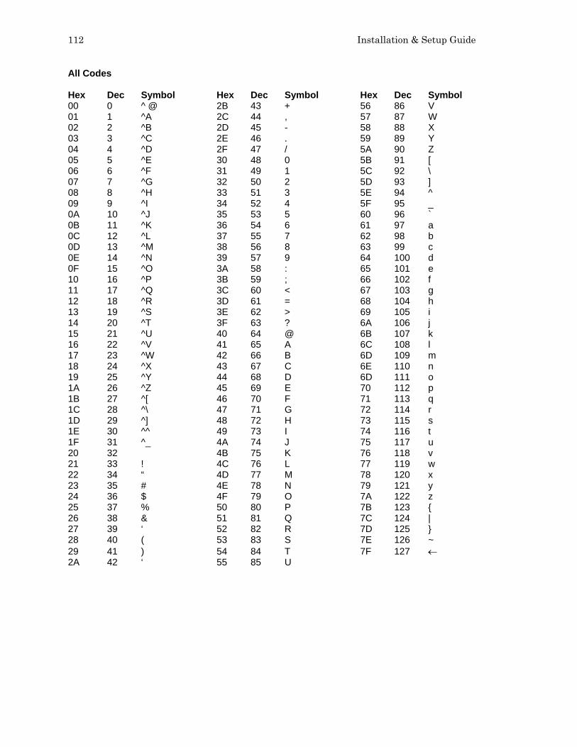
112 Installation & Setup Guide
All Codes Hex Dec Symbol Hex Dec Symbol Hex Dec Symbol 00 0 ^ @ 2B 43 + 56 86 V 01 1 ^A 2C 44 , 57 87 W 02 2 ^B 2D 45 - 58 88 X 03 3 ^C 2E 46 . 59 89 Y 04 4 ^D 2F 47 / 5A 90 Z 05 5 ^E 30 48 0 5B 91 [ 06 6 ^F 31 49 1 5C 92 \ 07 7 ^G 32 50 2 5D 93 ] 08 8 ^H 33 51 3 5E 94 ^ 09 9 ^I 34 52 4 5F 95 _ 0A 10 ^J 35 53 5 60 96 ` 0B 11 ^K 36 54 6 61 97 a 0C 12 ^L 37 55 7 62 98 b 0D 13 ^M 38 56 8 63 99 c 0E 14 ^N 39 57 9 64 100 d 0F 15 ^O 3A 58 : 65 101 e 10 16 ^P 3B 59 ; 66 102 f 11 17 ^Q 3C 60 < 67 103 g 12 18 ^R 3D 61 = 68 104 h 13 19 ^S 3E 62 > 69 105 i 14 20 ^T 3F 63 ? 6A 106 j 15 21 ^U 40 64 @ 6B 107 k 16 22 ^V 41 65 A 6C 108 l 17 23 ^W 42 66 B 6D 109 m 18 24 ^X 43 67 C 6E 110 n 19 25 ^Y 44 68 D 6D 111 o 1A 26 ^Z 45 69 E 70 112 p 1B 27 ^[ 46 70 F 71 113 q 1C 28 ^\ 47 71 G 72 114 r 1D 29 ^] 48 72 H 73 115 s 1E 30 ^^ 49 73 I 74 116 t 1F 31 ^_ 4A 74 J 75 117 u 20 32 4B 75 K 76 118 v 21 33 ! 4C 76 L 77 119 w 22 34 “ 4D 77 M 78 120 x 23 35 # 4E 78 N 79 121 y 24 36 $ 4F 79 O 7A 122 z 25 37 % 50 80 P 7B 123 { 26 38 & 51 81 Q 7C 124 | 27 39 ‘ 52 82 R 7D 125 } 28 40 ( 53 83 S 7E 126 ~ 29 41 ) 54 84 T 7F 127 ← 2A 42 ‘ 55 85 U

Appendix C: Program Codes 113
Appendix C: Program Codes EIA RS-274D The control supports EIA RS-274D part programs. An EIA RS-274D program lists the sequence of Lines, Arcs, Speeds, Kerf and I/O functions used to create a part. While the user is free to program in EIA using the standard text editor, it is recommended that the ShapeWizard® Graphical Programming environment be used instead. Following is a list of the EIA codes that are directly supported, mapped, or currently unsupported by the control. Mapped EIA codes are automatically converted upon program load into directly supported EIA codes. Unsupported EIA codes are ignored. All other EIA codes will generate an error. Directly Supported EIA Codes EIA CODE DESCRIPTION Fvalue Machine Speed (if Speed Override enabled) Nvalue Line Number (text) Comments Xvalue X Axis Endpoint or other Data Yvalue Y Axis Endpoint or other Data Ivalue I Axis Integrand or Part Option Data Jvalue J Axis Integrand or Part Option Data Ovalue Svalue Output (1-64), State (0-Off or 1-On) Wvalue Svalue Wait for Input (1-64), State (0-Off or 1-On) G00 Rapid Traverse Linear Interpolation G00 Avalue Sets Tilt angle – A is the angle value in degrees G00 XYvalue Avalue Performs Linear Interpolation of Tilt angle along line segment. G00 Avalue Fvalue Sets Tilt angle – Angle value in degrees with a speed command in RPM G00 Xn Yn Traverse command where n = value to move the desired axes a distance. G00 Zx.xx Tx Index Sensor™ THC height “Z” distance for torch “T”. Manual mode only. G00 Cxx Move to rotate “C” position G01 Cxx Fxx Move to rotate “C” position with Speed “F” command G00 C180- Rotate Axis align 180 degrees will continue to rotate in the proper direction G00 C-180- Rotate Axis align -180 degrees will continue to rotate in the proper direction G01 C180- Fxx Rotate Axis align 180 degrees with speed G01 C-180- Fxx Rotate Axis align -180 degrees with speed G01 Linear Interpolation (at Cut Speed) G02 Clockwise Circular Interpolation G03 Counterclockwise Circular Interpolation G04 Preset Dwell (uses Setup Dwell Time) G04 Xvalue Program Dwell in Seconds G08 Xvalue Repeat Subroutine X Times G20 Select English Units (inches) G21 Select Metric Units (mm) G40 Disable Kerf Compensation G41 Enable Left Kerf Compensation G42 Enable Right Kerf Compensation G43 Xvalue Kerf Value G41 D1-200 Enables Left Kerf using a Kerf Table variable G42 D1-200 Enables Right Kerf using a Kerf Table variable

114 Installation & Setup Guide
EIA CODE DESCRIPTION G43 D1-200 Sets the current Kerf value via the Kerf Table using prior set Left / Right Kerf G59 D1-200Xvalue Sets Kerf table variable from 1-200 G59 Vvalue Fvalue Sets the Plasma Supply current through Outputs or Serial Link for Vprocess
(504,514,524,534) at Fcurrent value V504 – Current Setting Plasma 1 V514 – Current Setting Plasma 2 V524 – Current Setting Marker 1 V534 – Current Setting Marker 2 G82 Oxy-Fuel Cut Mode G83 Oxy-Fuel Cut Mode Contour Bevel Head G84 Plasma Cut Mode G85 Plasma Cut Mode Contour Bevel Head G90 Absolute Programming Mode G91 Incremental Programming Mode G92 Set Axis Presets G97 Program Repeat Pointer G97 Tvalue Program Repeat Pointer. Executes the repeat T times G98 Repeat at G97, or start of program if no G97 G99 Part Options M00 Program Stop M01 Optional Program Stop (uses Setup Parameter) M02 End of Program M07 Cutting Device On M08 Cutting Device Off M09 Enable Marker 1 M10 Disable Marker 1 M11 Marker Offset 1 On M12 Marker Offset 1 Off M13 Enable Marker 2 M14 Disable Marker 2 M15 Cut On M16 Cut Off M17 Oxy Gas On M18 Oxy Gas Off M19 Cancel All Stations M26 Station Select On M27 Station Select Off M28 CBH / Rotator Disable M29 CBH Rotator Enable M30 End of Program (same as M02) M31 Reset Functions (Cut Off, Marker Off, Kerf Off) M32 Unclamp / Unlock All Stations M33 Unclamp / Lock All Stations M34 Clamp / Unlock All Stations M34Tvalue Clamp / Unlock ‘T” Station, where T = 1 through 19 M35 Clamp / Unlock All Stations Mirror M35Tvalue Clamp / Unlock Mirror “T” Station, where T = 1 through 19 M36 Tvalue Process Select “T” where T value selects the process
1- Plasma 1 2- Plasma 2 3- Marker 1 4- Marker 2 5- Laser
M37 Tvalue (1-20) Select Station “T” where T = 1 through 20

Appendix C: Program Codes 115
EIA CODE DESCRIPTION M38 Tvalue (1-20) Deselect Station “T” where T = 1 through 20 M40 Start of Subroutine M40 Xvalue Start of Subroutine. Executes the repeat X times M41 End of Subroutine M50 Height Sensor Disable M51 Height Sensor Enable M52 Height Sensor Disable and Raise Torch M53 Height Sensor Enable and Lower Torch M65 End of Program (same as M02) M72 Marker Offset 2 Off M73 Marker Offset 2 On M75 A Axis/Tilt Go to Home Command - Rapid Index M76 C Axis/Rotate Go to Home Command - Rapid Index M77 Go to Home position Y Axis M78 Go to Home position X Axis M79 Tvalue (1-4) Go To Home Position (1-4) M90 Aligns CBH / Rotator to Tangent angle of next cut segment M90- Align rotator when not using shortest path motion M274 Marker Offset 3 Off M275 Marker Offset 3 On M276 Marker Offset 4 Off M277 Marker Offset 4 On M278 Marker Offset 5 Off M279 Marker Offset 5 On M280 Marker Offset 6 Off M281 Marker Offset 6 On M282 Marker Offset 7 Off M283 Marker Offset 7 On M284 Marker Offset 8 Off M285 Marker Offset 8 On M286 Marker Offset 9 Off M287 Marker Offset 9 On M288 Marker Offset 10 Off M289 Marker Offset 10 On M290 Marker Offset 11 Off M291 Marker Offset 11 On M292 Marker Offset 12 On M293 Marker Offset 12 On M301 Assigns the current X/Y position to Home Position 1 M302 Assigns the current X/Y position to Home Position 2 M303 Assigns the current X/Y position to Home Position 3 M304 Assigns the current X/Y position to Home Position 4 Mapped EIA Codes EIA CODE DESCRIPTION MAPPED TO G04 Fvalue Program Dwell G04 Xvalue G05 Set Axis Presets G92 G21 Linear Interpolation G01 (at cut speed) G22 CW Circular Interpolation G02 G23 CCW Circular Interpolation G03 G41 Kvalue Left Kerf with Value G41 with Kerf Value G42 Kvalue Right Kerf with Value G42 with Kerf Value G97 TValue Subroutine Loop G08 Xvalue and M40

116 Installation & Setup Guide
EIA CODE DESCRIPTION MAPPED TO G45 Lead In to Kerfed Part G01, G02, or G03 G70 Select English Units G20 G71 Select Metric Units G21 G98 End of Subroutine Loop M41 M03 Cutting Device On/Off M07 (Oxy Fuel) or M08 as appropriate M04 Cutting Device On M07 M05 Cutting Device Off M08 (Oxy Fuel) M06 Cutting Device Off M08 M06 Enable Marker 2 M13 M07 Disable Marker 1 or 2 M10 or M14 as appropriate M08 Enable Marker 1 M09 M09 Disable Marker 1 or 2 M10 or M14 as appropriate M10 Enable Marker 2 M13 M14 Height Sensor Disable M50 M15 Height Sensor Enable M51 M20 Cutting Device On/Off M07 or M08 as appropriate (Plasma) M21 Cutting Device On/Off M07 or M08 as appropriate (Plasma) M20 Output 9 On O9 S1 M21 Output 9 Off O9 S0 M22 Output 12 On O12 S1 M23 Output 12 Off O12 S0 M24 Wait for Input 7 On W7 S1 M25 Wait for Input 8 On W8 S1 M25 CBH Enable M29 M26 Wait for Input 7 Off W7 S0 M26 CBH Disable M28 M27 Wait for Input 8 Off W8 S0 M67, M02 Kerf Left G41 M68, M03 Kerf Right G42 M69, M04 Kerf Off G40 M65, M70 Cutting Device On M07 M66, M71, M73 Cutting Device Off M08 M70 Marker Offset 1 Off M12 M71 Marker Offset 1 On M11 M70T01 Marker Offset 1 Off M12 M71T01 Marker Offset 1 On M11 M70T02 Marker Offset 2 Off M72 M71T02 Marker Offset 2 On M73 M70T03 Marker Offset 3 Off M274 M71T03 Marker Offset 3 On M275 M70T04 Marker Offset 4 Off M276 M71T04 Marker Offset 4 On M277 M70T05 Marker Offset 5 Off M278 M71T05 Marker Offset 5 On M279 M70T06 Marker Offset 6 Off M280 M71T06 Marker Offset 6 On M281 M70T07 Marker Offset 7 Off M282 M71T07 Marker Offset 7 On M283 M70T08 Marker Offset 8 Off M284 M71T08 Marker Offset 8 On M285 M98 End Comment )

Appendix C: Program Codes 117
EIA CODE DESCRIPTION MAPPED TO M99 Start Comment ( M221 No Mirror, No Rotate G99 X1 Y0 I0 J0 M222 Mirror Y, No Rotate G99 X1 Y0 I0 J1 M223 Mirror X and Y G99 X1 Y0 I1 J1 M224 Mirror X, No Rotate G99 X1 Y0 I1 J0 M225 Mirror X/Y on -45 Deg G99 X1 Y270 I1 J0 M226 Rotate 90 Deg CCW G99 X1 Y90 I0 J0 M227 Mirror X/Y on +45 Deg G99 X1 Y270 I0 J1 M228 Rotate 90 Deg CW G99 X1 Y270 I0 J0 M245 Output 1 On O1 S1 M246 Output 1 Off O1 S0 M247 Output 2 On O2 S1 M248 Output 2 Off O2 S0 M249 Output 3 On O3 S1 M250 Output 3 Off O3 S0 M251 Output 4 On O4 S1 M252 Output 4 Off O4 S0 M253 Wait for Input 1 On W1 S1 M254 Wait for Input 1 Off W1 S0 M255 Wait for Input 2 On W2 S1 M256 Wait for Input 2 Off W2 S0 M257 Wait for Input 3 On W3 S1 M258 Wait for Input 3 Off W3 S0 M259 Wait for Input 4 On W4 S1 M260 Wait for Input 4 Off W4 S0 Unsupported EIA Codes EIA CODE DESCRIPTION G46 Table 0 Select G99 Freestanding G99 G103 Qname Stop Current Program/ Load New Program G201 Incremental Line In2 G202 Incremental CW Arc In2 G203 Incremental CCW Arc In2 G211 Incremental Line In3 G212 Incremental CW Arc In3 G213 Incremental CCW Arc In3 G221 Absolute Line In2 G222 Absolute CW Arc In2 G223 Absolute CCW Arc In2 G231 Absolute Line In3 G232 Absolute CW Arc In3 G233 Absolute CCW Arc In3 G240 Programmable Kerf G247 Table 1 Select G248 Table 2 Select G249 Table 3 Select G250 Table 4 Select G276 Internal Variable Load

118 Installation & Setup Guide
Unsupported EIA Codes (cont.) EIA CODE DESCRIPTION G277 External Variable Load G278 X Axis Home G279 Y Axis Home G280 X Home Return G281 Y Home Return M22 PLC Control Code M75 PLC Control Code M210 X Sign Toggle M211 Y Sign Toggle M212 X and Y Swap and Toggle M231 Aux. State Reset M261 Aux. Torch Master On M262 Aux. Torch Master Off The unsupported EIA codes previously noted are ignored when read. Some of these codes may be supported in the future. Any EIA codes that are not listed above will result in a translator error upon loading the EIA program. Known EIA codes that will not be accepted include, but are not limited to: Pvalue Program Number Dvalue Indexed Kerf Operations Vvalue Internal Variable Load EIA Comments Comments may be placed into the part program to be displayed on screen and viewed by the operator. The comment line must first be preceded by a program stop command (EIA M00 code or ESSI 0 code). EIA Example:
M00 – Pauses Program (Comment) – Text to be displayed

Appendix C: Program Codes 119
ESSI The control supports ESSI part programs as defined by the International Standards Organization in ISO 6582. An ESSI program lists the sequence of Lines, Arcs, Speeds, Kerf and I/O Functions used to create a part. While the user is free to program in ESSI using a standard text editor, it is recommended that the ShapeWizard® Graphical Programming environment be used instead. While the user is free to download ESSI programs to the control, it is important to note that all Part Programs will be internally converted to EIA for execution in the control. Following is a list of the ESSI codes that are mapped into the control, or currently unsupported by the control. Mapped ESSI codes are automatically converted upon program load into directly supported EIA codes. Unsupported ESSI codes are ignored. All other ESSI codes will generate an error. Mapped ESSI Codes ESSI CODE DESCRIPTION MAPPED TO EIA % Start of Program Not Used-Automatic +/-value… Line or Arc G00, G01, G02 or G03 as appropriate 0 End Program or Stop M02 or M00 (if 64 is End Program) 3 Start Comment ( 4 End Comment ) 5 Enable Rapid Traverse Not Used-Automatic 6 Disable Rapid Traverse Not Used-Automatic 7 Cutting Device On M07 8 Cutting Device Off M08 9 Enable Marker 1 M09 10 Disable Marker 1 M10 11 Marker Offset 1 On M11 12 Marker Offset 1 Off M12 11+1 Marker Offset 1 On M11 12+1 Marker Offset 1 Off M12 11+2 Marker Offset 2 On M73 12+2 Marker Offset 2 Off M72 11+3 Marker Offset 3 On M275 12+3 Marker Offset 3 Off M274 11+4 Marker Offset 4 On M277 12+4 Marker Offset 4 Off M276 11+5 Marker Offset 5 On M279 12+5 Marker Offset 5 Off M278 11+6 Marker Offset 6 On M281 12+6 Marker Offset 6 Off M280

120 Installation & Setup Guide
ESSI CODE DESCRIPTION MAPPED TO EIA 11+7 Marker Offset 7 On M283 12+7 Marker Offset 7 Off M282 11+8 Marker Offset 8 On M285 12+8 Marker Offset 8 Off M284 13 Enable Marker 2 M13 14 Disable Marker 2 M14 15 Marker Offset 2 On M73 16 Marker Offset 2 Off M72 21 No Mirror, No Rotate G99 X1 Y0 I0 J0 22 Mirror Y, No Rotate G99 X1 Y0 I0 J1 23 Mirror X and Y G99 X1 Y0 I1 J1 24 Mirror X, No Rotate G99 X1 Y0 I1 J0 25 Mirror X/Y on -45 Deg G99 X1 Y270 I1 J0 26 Rotate 90 Deg CCW G99 X1 Y90 I0 J0 27 Mirror X/Y on +45 Deg G99 X1 Y270 I0 J1 28 Rotate 90 Deg CW G99 X1 Y270 I0 J0 29 Enable Left Kerf Comp G41 30 Enable Right Kerf Comp G42 38 Disable Kerf G40 39+value Machine Speed Fvalue 40+value Programmable Kerf G43 Xvalue 41 Preset Dwell G04 41+value Program Dwell in mSec G04 Xvalue 45 Ht Sensor Enable/Lower M53 46 Ht Sensor Disable/Raise M52 47 Ht Sensor Enable M51 48 Ht Sensor Disable M50 51 CBH Enable M29 52 CBH Disable M28 53 Cutting Device On M07 54 Cutting Device Off M08 63 Reset Functions M31 64 End Program M02 65 End of Program/ Reload M65 67 Ht Sensor Disable M50 68 Ht Sensor Enable M51 70 Select English Units (in) G20 71 Select Metric Units (mm) G21 79+1 Go To Home Position 1 M79 T1 79+2 Go To Home Position 2 M79 T2 79+3 Go To Home Position 3 M79 T3 79+4 Go To Home Position 4 M79 T4 81 Incremental Mode G91 82 Absolute Mode G90 83 Set Axis Presets G92 90 End of Program M02 97 Program Repeat Pointer G97 97+value Subroutine Loop M40 Xvalue 98 Repeat at 97, Subroutine loop G97, G98 or M41 as appropriate or start of program if no 97 99 End of Program M02

Appendix C: Program Codes 121
ESSI CODE DESCRIPTION MAPPED TO EIA 245 Output 1 On O1 S1 246 Output 1 Off O1 S0 247 Output 2 On O2 S1 248 Output 2 Off O2 S0 249 Output 3 On O3 S1 250 Output 3 Off O3 S0 251 Output 4 On O4 S1 252 Output 4 Off O4 S0 253 Wait for Input 1 On W1 S1 254 Wait for Input 1 Off W1 S0 255 Wait for Input 2 On W2 S1 256 Wait for Input 2 Off W2 S0 257 Wait for Input 3 On W3 S1 258 Wait for Input 3 Off W3 S0 259 Wait for Input 4 On W4 S1 260 Wait for Input 4 Off W4 S0 282 Marker Offset 3 On M275 283 Marker Offset 3 Off M274 284 Marker Offset 4 On M277 285 Marker Offset 4 Off M276 286 Marker Offset 5 On M279 287 Marker Offset 5 Off M278 288 Marker Offset 6 On M281 289 Marker Offset 6 Off M280 290 Marker Offset 7 On M283 291 Marker Offset 7 Off M282 292 Marker Offset 8 On M285 293 Marker Offset 8 Off M284 Unsupported ESSI Codes ESSI CODE DESCRIPTION 103+Name Stop Current Program/ Load New Program 237 X Sign Toggle 238 Y Sign Toggle 239 X and Y Swap and Toggle 266 Table 1 Select 267 Table 2 Select 268 Table 3 Select 269 Table 4 Select 276 Internal Variable Load 277 External Variable Load 278 X Axis Home 279 Y Axis Home 280 X Home Return 281 Y Home Return The unsupported ESSI codes above are ignored when read. Some of these codes may be supported in the future. Any ESSI codes that are not listed above will result in a translator error upon loading the ESSI program.

122 Installation & Setup Guide
ESSI Comments Comments may be placed in to the part program to be displayed on screen and viewed by the operator. The comment line must first be preceded by a program stop command (EIA M00 code or ESSI 0 code). ESSI Example:
0 – Pauses Program 3 – Start Comment Comment – Text to be displayed 4 – End Comment

Appendix C: Program Codes 123
Advanced Feature Codes Kerf Table Code Description G59 D1-200Xvalue Sets kerf table variable from 1-200 G41 D1-200 Enables Left Kerf using a Kerf Table variable G42 D1-200 Enables Right Kerf using a Kerf Table variable G43 D1-200 Changes current kerf value via Kerf Table using previously set Left or Right
kerf Tilt / Rotator Part Codes Code Description G00 Avalue Sets Tilt angle as a preparatory command – A is the angle value in degrees G00 XYvalue Avalue Performs Linear Interpolation of Tilt angle along line segment. G00 Avalue Fvalue Sets Tilt angle – Angle value in degrees with a speed command in RPM M28 Disables Follower M29 Enables Follower M90 Preparatory Cmd - Aligns Rotator to Tangent angle of next cut segment M90- Align rotator when not using shortest path motion M75 A axis/Tilt Goto Home Cmd - Rapid Index G00 Cxx Move to rotate “C” position G01 Cxx Fxx Move to rotate “C” position with Speed “F” command G00 C180- Rotate Axis align 180 degrees will continue to rotate in the proper direction G00 C-180- Rotate Axis align -180 degrees will continue to rotate in the proper direction G01 C180- Fxx Rotate Axis align 180 degrees with speed G01 C-180- Fxx Rotate Axis align -180 degrees with speed Automatic Torch Spacing Program Codes Code Description M32 Unclamp / Unlock All Stations M33 Unclamp / Lock All Stations M34 Clamp / Unlock All Stations M34Tvalue Clamp / Unlock ‘T” Station, where T = 1 through 19 M35 Clamp / Unlock All Stations Mirror M35Tvalue Clamp / Unlock Mirror “T” Station, where T = 1 through 19 M77 Go to Home position Y Axis M78 Go to Home position X Axis
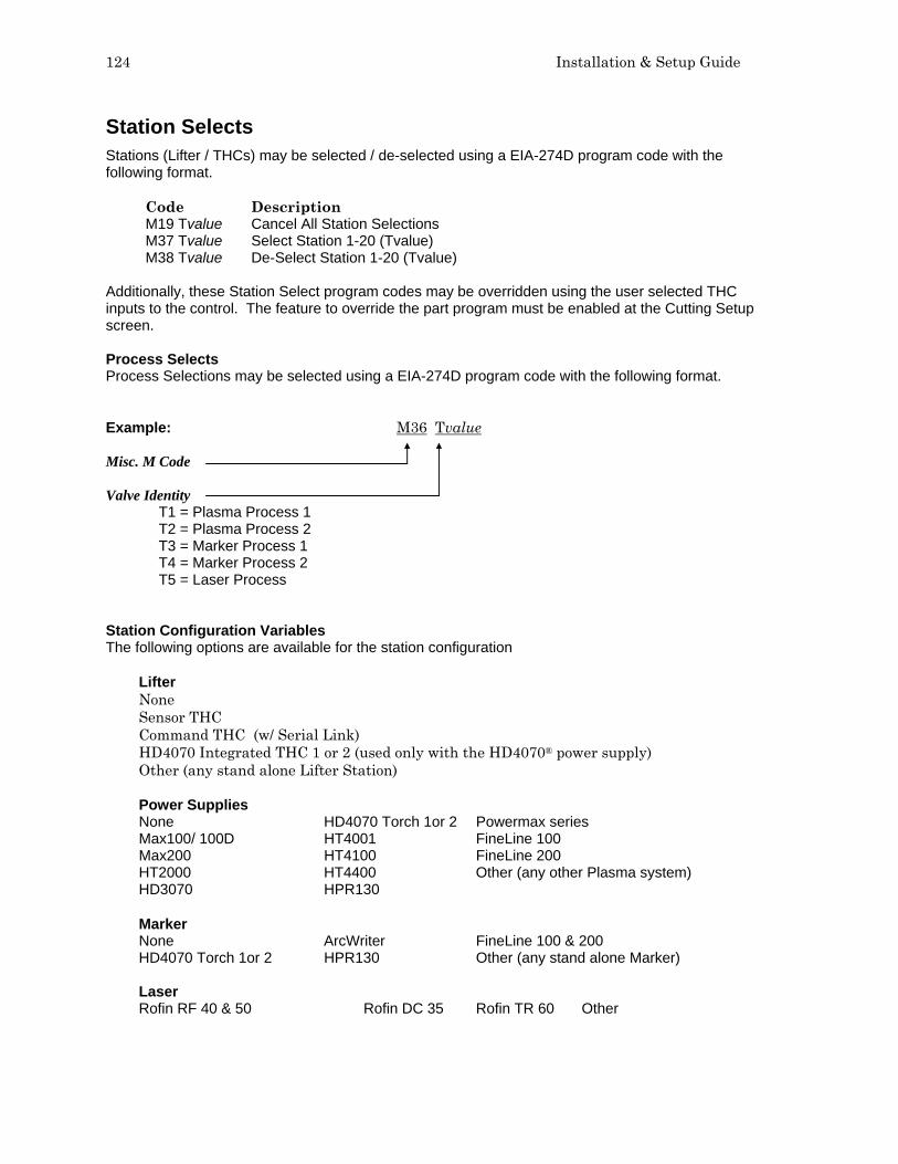
124 Installation & Setup Guide
Station Selects Stations (Lifter / THCs) may be selected / de-selected using a EIA-274D program code with the following format. Code Description M19 Tvalue Cancel All Station Selections M37 Tvalue Select Station 1-20 (Tvalue) M38 Tvalue De-Select Station 1-20 (Tvalue) Additionally, these Station Select program codes may be overridden using the user selected THC inputs to the control. The feature to override the part program must be enabled at the Cutting Setup screen. Process Selects Process Selections may be selected using a EIA-274D program code with the following format. Example: M36 Tvalue Misc. M Code Valve Identity T1 = Plasma Process 1 T2 = Plasma Process 2 T3 = Marker Process 1 T4 = Marker Process 2 T5 = Laser Process Station Configuration Variables The following options are available for the station configuration
Lifter None Sensor THC Command THC (w/ Serial Link) HD4070 Integrated THC 1 or 2 (used only with the HD4070® power supply) Other (any stand alone Lifter Station) Power Supplies None HD4070 Torch 1or 2 Powermax series Max100/ 100D HT4001 FineLine 100 Max200 HT4100 FineLine 200 HT2000 HT4400 Other (any other Plasma system) HD3070 HPR130 Marker None ArcWriter FineLine 100 & 200 HD4070 Torch 1or 2 HPR130 Other (any stand alone Marker) Laser Rofin RF 40 & 50 Rofin DC 35 Rofin TR 60 Other

Appendix C: Program Codes 125
HD3070® Auto Gas Interface This section outlines information specific to the HD3070® six valve Auto Gas Interface. The Auto Gas screen is available from the Cut Types screen. Note: The Auto Gas feature must first be enabled at the Special Password screen.
The top of the Auto Gas screen lists the valve parameter settings for the HD3070®. Valve settings for the 3070® Auto Gas console are documented in the HD3070® manual. When the values are set, these become the current setting and the operator can choose to save the file to the diskette, USB memory or hard drive. The settings at the supply are updated at control power up, whenever the settings are changed at this screen or through commands in a part program. Supply settings are also updated if power is lost and re-enabled at the power supply. There may be a brief delay as these power supply settings are communicated from the control to the power supply. Save Data Pressing the Save Data softkey will allow the operator to save the current Autogases setting to diskette, USB memory or hard drive for future use. Load Data Pressing the Load Data softkey will allow the operator to Load stored Autogases setting from diskette, USB memeory or hard drive for use.

126 Installation & Setup Guide
If you save the data, a file is created with G59 codes with the selected valve settings. Here is an example of the data file where all percentages are set to zero.
G59 V65 B0 G59 V66 B0 G59 V67 B0 G59 V68 B0 G59 V69 B0 G59 V70 B0 G59 V71 B0
Test Cutting Gases Pressing the Test Cutting Gases softkey allows the operator to test the HD3070® Cut Gases. Test Preflow Gases Pressing the Test Preflow Gases softkey allows the operator to test the HD3070® Preflow Gases.

Appendix C: Program Codes 127
HD3070® Auto Gas I/O The Interface to the HD3070® Auto Gas console is made through use of Single Ended and BCD (Binary Coded Decimal) inputs. The BCD style of interface allows for exact settings by use of multiple inputs being active at any time. The active BCD input values are summed together to obtain the exact set point. These I/O points are wired in the same fashion as our other Single Ended I/O points. The following I/O points are supplied for use with the HD3070® Auto Gas Console Inputs Gas Control Read Complete Gas Control Error Outputs Gas Control Write Remote Test Operate Remote Test Preflow Remote Air Plasma Remote H35/ N2 Plasma Remote O2 Plasma Gas Flow Set 1-100 (BCD) Valve Select 1-8 (BCD) Cut Chart Setup through part program codes is supported. Refer to Part Programming section of the Installation Guide. HD3070® Part Program Support The same valve setting data which is used at the Auto Gas setup screen may also be used within a part program to configure the HD3070® for use. This code is used to select the valve and indicate the valve set point. Using a EIA-274D G59 code with the following format. Example: G59 V65 B5 Misc. G Code Valve Identity V65 = Preflow Shield Gas - Valve 1 V66 = Preflow Shield Gas - Valve 2 V67 = Cut Shield Gas - Valve 3 V68 = Cut Shield Gas - Valve 4 V69 = Cut Plasma Gas - Valve 5 V70 = Cut Plasma Gas - Valve 6 V71 = Remote Plasma Gas Type Valve Value For Valves V65 – V70 A whole integer is used to set the desired percentage value. For Valve 71 0 = Oxygen 1 = H35/N2 2 = O2 For the example given, the part program code (G59 V65 B5) would set the Autogas Preflow Shield Gas valve to 5%. Multiple G59 codes can be used to set and adjust the all desired valves.

128 Installation & Setup Guide
HD4070® and HPR™ Interface Hypertherm Automation controls offer the additional option of interfacing directly to Hypertherm’s HD4070® HyDefinition® and HPR Power Supplies for setup. Note: MicroEdge and Edge II controls can be operated in Voyager mode to add this feature. This feature has the ability to improve the ease of power supply setup and operational accuracy, while having the flexibility to fine tune the process specific to the operator’s needs. Using this advanced feature, all necessary power supply settings are transmitted from the control directly to the power supply configuring it for use via serial communications. The power supply setup is performed through the use of a Cut Chart (cut process parameter database) which is based on eight process selections. The combination of these eight process selections are used as key reference settings to transmit all necessary cut process parameters (e.g. arc voltage, pierce delay, etc.) to the supply. This database allows the user to select factory recommended settings or amend the database for personalized settings. The Cut Chart information may be saved or loaded via the hard drive or floppy drive. The Cut Chart files containing the factory recommended settings are available from Hypertherm®. Similar screens and features are available for HPR. Cut Chart
Please refer to the control Operator’s Guide for additional information on setup and use of the Cut Chart. Cut Chart Setup through part program codes is supported. Refer to Part Programming section of the Installation Guide.
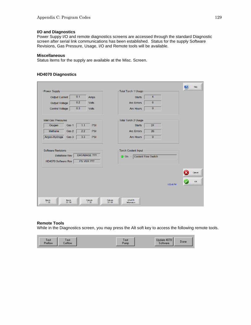
Appendix C: Program Codes 129
I/O and Diagnostics Power Suppy I/O and remote diagnostics screens are accessed through the standard Diagnostic screen after serial link communications has been established. Status for the supply Software Revisions, Gas Pressure, Usage, I/O and Remote tools will be available. Miscellaneous Status items for the supply are available at the Misc. Screen. HD4070 Diagnostics
Remote Tools While in the Diagnostics screen, you may press the Alt soft key to access the following remote tools.

130 Installation & Setup Guide
HPR Diagnostics
Remote Tools While in the Diagnostics screen, you may press the Alt soft Key to access remote tools.
Test Preflow Pressing the Test Preflow Softkey performs the Test Preflow Gases feature at the power supply. This feature is used to set the inlet gas pressures under normal flow conditions to the recommended level. Test Cutflow Pressing the Test Cutflow softkey performs the Test Cutflow Gases feature at the power supply. This feature is used to set the inlet gas pressures under normal flow conditions to the recommended level. Test HPR Gas Console This feature provides automated test features for the HPR AutoGas console. Please contact an authorized service agent for use of these tests. Coolant Override Pressing the Coolant Override softkey allows to user to override a coolant error and to test the coolant pump. This is useful to bypass the error and purge the coolant line of air bubbles at initial power up. Update Software Pressing the Update Software softkey will initiate the process of the Software Update at the power supply. Step by step instructions will be displayed on screen to guide the user through the process.
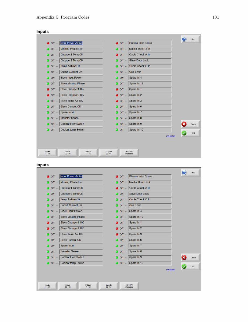
Appendix C: Program Codes 131
Inputs
Inputs

132 Installation & Setup Guide
Outputs
Outputs

Appendix C: Program Codes 133
Note: Similar to the standard Output Diagnostic screen, the output screen shows the current status of the listed supply outputs. Note: Outputs for the supply cannot be activated through the diagnostic screen. Serial Communication Interface RS-422C Connections to HD4070® CNC Interface Control (male) Supply (male) Signal Name DB-9 Pin Signal Name DB-37 Pin TxD- 2 RxD- 2 RxD- 3 TxD- 1 TxD+ 4 RxD+ 21 RxD+ 7 TxD+ 20 RS-422C Connections to HPR™ CNC Interface Control (male) Supply (male) Signal Name DB-9 Pin Signal Name DB-37 Pin TxD- 2 RxD- 1 RxD- 3 TxD- 2 TxD+ 4 RxD+ 20 RxD+ 7 TxD+ 21

134 Installation & Setup Guide
Multiple Supplies The Serial Communication Link supported by the CNC can also be extended to multiple power supplies. This unique feature is implemented through the use of the serial link and I/O points. It is assumed that the all systems are configured similarly and will be used simultaneously. If any of the selected power supplies has a fault, the fault must be cleared before the cut can begin. Specific hardware and software versions for both the control and the power supply are required. Please refer to the power supply manual for additional information on operation and installation. Inputs and Outputs Raise 1-4 and Lower 1-4 The Raise / Lower inputs will be used to control the Integrated Command™ THC lifters on multi-dropped supplies for the selected process. Note: When using this feature with the Sensor™ THCs rather than the Integrated Command™ THCs, the Sensor™ THC Torch Raise and Torch Lower commands for the selected process may be made through the software softkeys or through the use of these external inputs to the control. Cut Sense 1-4 THC Cut Sense Input (arc on feedback) is used to verify that the plasma torch or marker tool has established the arc for the selected torch. This indicates to the control that motion can begin. Ready to Fire PS 1-4 This signal is an output from each supply and is used in multiple plasma systems. It notifies the CNC that the THC has completed the IHS cycle and Preflow is complete. This indicates that the torch is ready to fire. On the supply this signal is used along with the CNC Plasma Sync Input. The CNC Hold Ignition output is connected to the supply “CNC Plasma Sync” inputs. When all configured supplies return active “Ready to Fire” signals, the “Hold Ignition” signals are removed. Hold Ignition The Hold Ignition Output is used to delay ignition of the external plasma supply and allow the individual supplies to complete Preflow and IHS before torch ignition. For this application, the Hold Ignition would be tied to the Plasma Sync Inputs for multi-dropped supplies. Reduce Current Used with the supply to switch the plasma to low current mode. This signal is functionally different from the Torch Height Disable Output in that it is not active during the initial torch ignition, pierce, and accelerate to speed after Plasma Start. For this application, the Reduced Current output would be tied to the Corner Hold Inputs for multi-dropped power supplies. The Corner Current Parameter located on the Plasma Setup Screen, is a user defined value for setting the percentage of the corner current. NOTE HD4070®: Proper mult-drop operation requires a Rev C or higher Breakout board in the HD4070® as well as Rev K or higher control software in the HD4070®.

Appendix C: Program Codes 135
RS-422 Multidrop Interface to Multiple power supplies
CNC Controller Interlock
Cut Sense 1,2
Rdy to Fire 1, 2 Hold Ignition
Reduce Current
Plasma Start
RS422 RX
RS422 TX
Cut Sense 3,
Rdy to Fire 3,
Raise 1 Lower 1
Raise 2 Lower 2
Interlock
Transfer
Ready to Fire
Plasma Sync
Corner Hold
System Start
RS422 TX
RS422 RX
Interlock
Transfer
Ready to Fire
Plasma Sync
Corner Hold
System Start
RS422 TX
RS422 RX
Termination Resistor by DIP switch
ID = 0 Determined by DIP switch
Supply #1
Supply #2
Torch #1 Torch #2
Torch #1 Torch #2
Note: Active Torch determined by selected process
ID = 1 Determined by DIP switch

136 Installation & Setup Guide
HD4070® and HPR Part Program Support The same Cut Chart data which is used at the Cut Chart setup screen may also be used within a part program to configure the power supply for use. This code is used to select the set point for each variable. It is not necessary to have a line of code for each Cut Chart variable within a part program. Only those variables which are changing need be inserted into the part program (e.g. Material Thickness or Material Type). Part program codes for the power supply should be grouped together at the beginning of the program. The three variables which may be set through the part program are Material Type, Current Setting and Material Thickness. Cut parameters for the power supply may be configured using the EIA-274D G59 code with the following format. Example: G59 V503 F5 Misc. G Code Variable Identity V503 – Material Type Plasma 1 V513 – Material Type Plasma 2 V523 – Material Type Marker 1 V533 – Material Type Marker 2 V504 – Current Setting Plasma 1 V514 – Current Setting Plasma 2 V524 – Current Setting Marker 1 V534 – Current Setting Marker 2 V507 – Material Thickness Plasma 1 V517 – Material Thickness Plasma 2 V527 – Material Thickness Marker 1 V537 – Material Thickness Marker 2 Variable Value V503, V513, V523, V533 – Material Type
1 = Mild Steel 2 = Stainless Steel 3 = Aluminum V504, V514, V524, 534 – Current Setting 7 = 7A 70 = 70A 10 = 10A 80 = 80A 15 = 15A 100 = 100A 18 = 18A 130 = 130A 30 = 30A 200 = 200A 45 = 45A

Appendix C: Program Codes 137
Variable Value (continued ) V507, 517, 527, 537 – Material Thickness 1 = None 16 = .048” & 1.2mm 31 = 3/8” & 10mm 2 = 28GA 17 = 16GA 32 = 7/16” & 11mm 3 = .015” & .38mm 18 = .060” & 1.5mm 33 = 1/2”& 12mm 4 = 27GA 19 = 1/16” & 1.6mm 34 = 9/16” & 14mm 5 = .016” & .4mm 20 = 14GA 35 = 5/8” & 15mm 6 = 26GA 21 = .075” & 2mm 36 = 3/4” & 19mm 7 = .018” & .5mm 22 = 3/32” & 2.4mm 37 = 7/8” & 22mm 8 = 24GA 23 = 12GA 38 = 1” & 25mm 9 = .024” & .6mm 24 = .105” & 2.5mm 39 = 1 1/8” & 29mm 10 = 22GA 25 = 1/8” & 3mm 40 = 1 1/4” & 32mm 11 = .030” & .8mm 26 = 10GA 41 = 1 3/8” & 35mm 12 = 20GA 27 = .135” & 3.5mm 42 = 1 1/2” & 38mm 13 = .036 & .9mm 28 = 3/16” & 5mm 43 = 1 3/4” & 44mm 14 = .040” & 1.0mm 29 = 1/4” & 6mm 44 = 2” & 50mm 15 = 18GA 30 = 5/16” & 8mm

138 Installation & Setup Guide
FineLine® Overview Hypertherm Automation controls offer the additional option of interfacing directly to INNERLOGIC’s FineLine Power Supply for setup via a user selected RS-422 serial port. This advanced feature transmits all necessary power supply settings from the control directly to the FineLine power supply configuring it for use. The power supply setup is performed through the use of a Cut Chart (cut process parameter database) which is based on eight process variables. The combination of these eight process variables are tied to the settings for the cut process parameters (e.g. arc voltage, pierce delay, etc.) that are transmitted to the supply. For additional convenience, consumable part numbers for the FineLine are displayed at the Change Consumable screen. This database allows the user to select factory recommended settings or amend the database for personalized settings. The Cut Chart information may be saved or loaded via the hard drive or floppy drive. Specialized Cut Chart files containing the factory recommended settings are available from the control vendor. The Power Supply parameter must first be enabled in the password protected Station Configuration setups to allow the Cut Chart Information for the feature to be enabled for use. Once selected at the Station Configurations screen, the port must then be selected for communications on the Ports setup screen and the selected port must then be configured as RS-422. For more information on configuration of the port, refer to the Ports information section of this guide. Station Configuration (example)

Appendix C: Program Codes 139
Notes: - Please refer to the power supply operators manual for complete information on the operation and
setup of the FineLine Power Supply. - The FineLine Power Supply parameters must first be enabled in the password protected Station
Configuration Screen to allow the Cut Chart Information for the FineLine to be available for use. - Serial communications for the FineLine Power supply are established on the user selected
communication port. The port must be configured for RS-422 operation. - Cut Chart Setup through part program codes is supported. Refer to Part Programming section of
the Installation Guide.
FineLine Part Program Support The same Cut Chart data which is used at the Cut Chart setup screen may also be used within a part program to configure the FineLine for use. This code is used to select the set point for each variable. It is not necessary to have a line of code for each Cut Chart variable within a part program. Only those variables which are changing need be inserted into the part program (e.g. Material Thickness or Material Type). Part program codes for the FineLine should be grouped together at the beginning of the program. The three variables which may be set through the part program are Material Type, Current Setting and Material Thickness. Cut parameters for the FineLine may be configured using a EIA-274D G59 code with the following format. Example: G59 V503 F5 Misc. G Code Variable Identity V503 – Material Type Plasma 1 V513 – Material Type Plasma 2 V523 – Material Type Marker 1 V533 – Material Type Marker 2 V504 – Current Setting Plasma 1 V514 – Current Setting Plasma 2 V524 – Current Setting Marker 1 V534 – Current Setting Marker 2 V507 – Material Thickness Plasma 1 V517 – Material Thickness Plasma 2 V527 – Material Thickness Marker 1 V537 – Material Thickness Marker 2 Variable Value V503, V513, V523, V533 – Material Type
1 = Mild Steel 2 = Stainless Steel 3 = Aluminum

140 Installation & Setup Guide
V504, V514, V524, 534 – Current Setting 8 = 8A 50 = 50A 9 = 9A 70 = 70A 10 = 10A 100 = 100A 30 = 30A 200 = 200A Variable Value (continued) V507, 517, 527, 537 – Material Thickness 1 = None 16 = .048” & 1.2mm 31 = 3/8” & 10mm 2 = 28GA 17 = 16GA 32 = 7/16” & 11mm 3 = .015” & .38mm 18 = .060” & 1.5mm 33 = 1/2”& 12mm 4 = 27GA 19 = 1/16” & 1.6mm 34 = 9/16” & 14mm 5 = .016” & .4mm 20 = 14GA 35 = 5/8” & 15mm 6 = 26GA 21 = .075” & 2mm 36 = 3/4” & 19mm 7 = .018” & .5mm 22 = 3/32” & 2.4mm 37 = 7/8” & 22mm 8 = 24GA 23 = 12GA 38 = 1” & 25mm 9 = .024” & .6mm 24 = .105” & 2.5mm 39 = 1 1/8” & 29mm 10 = 22GA 25 = 1/8” & 3mm 40 = 1 1/4” & 32mm 11 = .030” & .8mm 26 = 10GA 41 = 1 3/8” & 35mm 12 = 20GA 27 = .135” & 3.5mm 42 = 1 1/2” & 38mm 13 = .036 & .9mm 28 = 3/16” & 5mm 43 = 1 3/4” & 44mm 14 = .040” & 1.0mm 29 = 1/4” & 6mm 44 = 2” & 50mm 15 = 18GA 30 = 5/16” & 8mm

Appendix C: Program Codes 141
Automatic Torch Spacing The Automatic Torch Spacing feature uses codes within the part program, and designated outputs, to perform precise positioning of individual torch stations for multi-torch cutting processes. This Feature must be enabled in Machine Setups for use. The Auto Torch Spacing Override feature in Cutting Setups must also be enabled. In this process, the master torch station has a fixed mount to the transverse axis and the other slave torch stations have the ability to clamp to the mechanics of the transverse axis during use or lock to the gantry or beam when not in use. For the example, below Torch 1 is the master station and Torch 2-4 are the slave stations. Typical use is as follows: 1) Unclamp and Unlock all stations (except the first which is fixed and slides the others) 2) Go to Home Command on Transverse Axis (M77 or M78 depending on orientation)
CNC
Gantry
Cutting Table
1 2 3 4
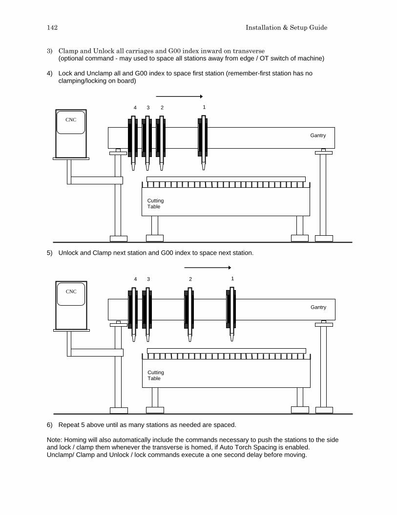
142 Installation & Setup Guide
3) Clamp and Unlock all carriages and G00 index inward on transverse (optional command - may used to space all stations away from edge / OT switch of machine)
4) Lock and Unclamp all and G00 index to space first station (remember-first station has no clamping/locking on board)
5) Unlock and Clamp next station and G00 index to space next station. 6) Repeat 5 above until as many stations as needed are spaced. Note: Homing will also automatically include the commands necessary to push the stations to the side and lock / clamp them whenever the transverse is homed, if Auto Torch Spacing is enabled. Unclamp/ Clamp and Unlock / lock commands execute a one second delay before moving.
CNC
Gantry
Cutting Table
1 2 3 4
CNC
Gantry
Cutting Table
3 4 1 2

Appendix C: Program Codes 143
Automatic Torch Spacing Program Codes Code Description M32 Unclamp / Unlock All Stations M33 Unclamp / Lock All Stations M34 Clamp / Unlock All Stations M34Tvalue Clamp / Unlock ‘T” Station, where T = 1 through 19 M35 Clamp / Unlock All Stations Mirror M35Tvalue Clamp / Unlock Mirror “T” Station, where T = 1 through 19 M77 Go to Home position Y Axis M78 Go to Home position X Axis G00 Xn Yn Traverse command where n = value to move the desired axes a distance. Automatic Torch Spacing I/O Station Lock 1-19 The Station lock is used to Lock the unused torch station to the
gantry or beam when not in use. Station Clamp 1-19 The Station Clamp is used to Clamp the selected torch station to the
transverse axis for standard cutting. Station Mirror 1-19 Station Clamp is used to Clamp the selected torch station to the
transverse axis for mirrored cutting. Example Part Program Transverse axis defined as X axis Three station cut of 20 inch vertical rip. Code Description G70 English Units G91 Incremental Mode G99 X1 Y0 I0 J0 Axes Preset zero Scaling M32 Unclamp / Unlock All Stations M78 Home X Axis (move all stations to Home position) M34 Clamp All / Unlock All G00X2Y0 Traverse X axis 2 inches (to move off edge/ switch) M33 Unclamp All / Lock All G00X10Y0 Traverse X axis 10 inches (to set 10 inch space – station 1) M34 T1 Clamp Station 1 / Unlock Station 1 G00X10Y0 Traverse X axis 10 inches (to set 10 inch space– station 2) M34 T2 Clamp Station 2 / Unlock Station 2 G41 Left Kerf M07 Cut On G01 X0 Y20 Line segment (Y axis 20 inches) M08 Cut Off G40 Kerf Off M02 End of Program

144 Installation & Setup Guide
Sensor™ THC Part Program Support Sensor™ THC offers the ability to configure THC setup parameters through part program codes. The following parameters are available for use using EIA-274D G59 codes:
Arc Voltage Pierce / Start Time
Pierce/ Start Height Factor Cut / Mark Height
Setup is obtained using the following format. Example: G59 V601 Fvalue Misc. G Code Variable Identity
V600 = Plasma 1 Arc Voltage V601 = Plasma 1 Pierce Time V602 = Plasma 1 Pierce Height Factor V603 = Plasma 1 Cut Height V625 = Plasma 2 Arc Voltage V626 = Plasma 2 Pierce Time V627 = Plasma 2 Pierce Height Factor V628 = Plasma 2 Cut Height V650 = Marker 1 Arc Voltage V651 = Marker 1 Start Time V652 = Marker 1 Start Height Factor V653 = Marker 1 Mark Height V675 = Marker 2 Arc Voltage V676 = Marker 2 Start Time V677 = Marker 2 Start Height Factor V678 = Marker 2 Mark Height
Variable Value The selected value for the variable THC Index code G00 Zx.xx Tx Index Sensor™ THC height “Z” distance for torch “T”. Manual mode only.
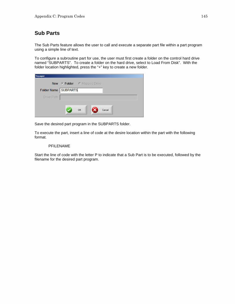
Appendix C: Program Codes 145
Sub Parts The Sub Parts feature allows the user to call and execute a separate part file within a part program using a simple line of text. To configure a subroutine part for use, the user must first create a folder on the control hard drive named “SUBPARTS”. To create a folder on the hard drive, select to Load From Disk”. With the folder location highlighted, press the “+” key to create a new folder.
Save the desired part program in the SUBPARTS folder. To execute the part, insert a line of code at the desire location within the part with the following format.
PFILENAME Start the line of code with the letter P to indicate that a Sub Part is to be executed, followed by the filename for the desired part program.
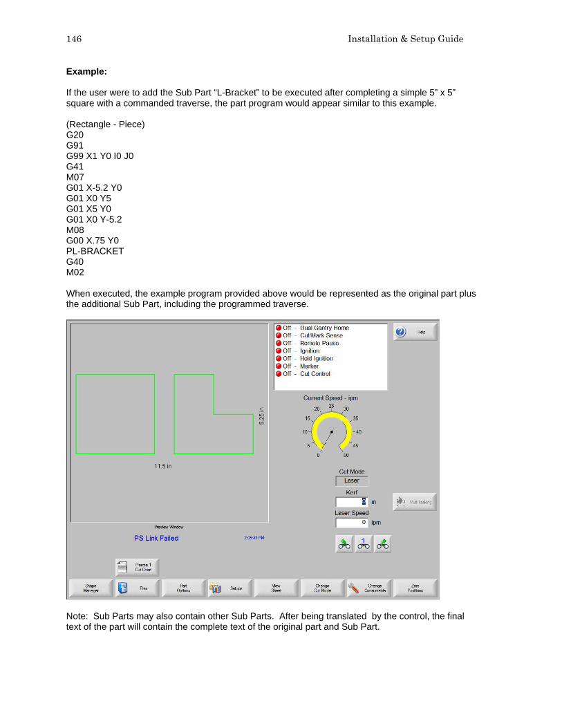
146 Installation & Setup Guide
Example: If the user were to add the Sub Part “L-Bracket” to be executed after completing a simple 5” x 5” square with a commanded traverse, the part program would appear similar to this example. (Rectangle - Piece) G20 G91 G99 X1 Y0 I0 J0 G41 M07 G01 X-5.2 Y0 G01 X0 Y5 G01 X5 Y0 G01 X0 Y-5.2 M08 G00 X.75 Y0 PL-BRACKET G40 M02 When executed, the example program provided above would be represented as the original part plus the additional Sub Part, including the programmed traverse.
Note: Sub Parts may also contain other Sub Parts. After being translated by the control, the final text of the part will contain the complete text of the original part and Sub Part.

Appendix C: Program Codes 147
Marker Font Generator The Marker Font Generator feature may be used to label or identify parts with a marking devise prior to cutting. This is accomplished by use of a simple command string within the part program code to call existing text characters (fonts) and execute marking of the selected text. The program code uses a specific format and is structured to provide information to be used when marking. Information on the Font source location, Scale Factor, Angle, Marker Tool, Tool Offset and Text are entered as information blocks in the command string. Each section or information block in the command string is separated by a space. The format of this command code is outlined as follows: Note: If a value is not present for a specific information block, the default values will be used. The default values are: Font (F): Internal Angle (A): 0° Offset (O): #1 Scale (S): One Marker (M): #1 Example of a simple command string: <F2 S1 A45 M2 O2 <TEST 123> < The program command must begin with the “<” symbol to indicate the Marker Font Generator
feature is being used. F The first block of information is the Font Source location. The “F” indicates “Font” and is
followed by a digit to indicate the location. Number 1 indicates the internal font in the control software, number 2 indicates to use a font located on the control hard drive, and number 3 indicates to source the font to be used from diskette or USB memory. If no font is found at the selected location, the default internal font will be used. For the example given, the font location would be from the hard drive.
S The second information block determines the scale of the text. The “S” is used to indicate
“Scale” and is followed by a digit to indicate a numeric scale factor. For the example given, the Scale factor would be two or twice as large as the original font dimensions.
A The third information block determines the angle of the text. The “A” is used to indicate “Angle”
and is followed by a numeric value for the degree of angle. For the example given, the angle would be 45°.
M The fourth information block determines the Marker Tool to be used. The “M” is used to
indicate “Marker” followed by the number of the Marker Tool (Marker Enable Output) to be used. Up to two marker enables are supported.
O The fifth information block determines which tool Offset to be used. The “O” indicates offset
followed by a number indicating one of the nine different tool offsets previously configured in control setups is to be used. The example shown indicates that tool offset number two should be used.
< > The final information block is used to specify the marker text to be executed. The text must be
enclosed in the ”<” and “>” marks to be valid and understood as the selected text. For the example given, the marker text executed would be “TEST 123”
Translated by the control, the example command string given above would generate the Marker Text “TEST 123” onto the plate as shown here in Shape Wizard.

148 Installation & Setup Guide
To improve the ease of use for the part program designer and control operator, the Marker Font Generator feature will always insert a traverse segment to return to the original start point at the beginning of the marking text. Internal Fonts The internal fonts located within the control software are 1” high and are limited to characters available on the control keypad. Alphabetical characters are limited to upper case letters only. External Fonts External Fonts may be loaded from a floppy disk or from the control hard drive. When generating the text, the control searches for part files to correspond to the selected character. The part file names must be based on their ASCII numeric equivalent and have a .txt file extension. Example: For the marker text “Ab 12”, the control will search for the following files to generate the text.
Text ASCII No. File Name Capital A 65 Ascii65.txt Lower Case b 98 Ascii98.txt Space 32 Ascii32.txt No 1 49 Ascii49.txt No 2 50 Ascii50.txt Please refer to the ASCII Codes section of this guide for additional ASCII code information. Font programs may be saved on the control hard drive by creating a folder labeled “Fonts” through the “Save to Disk” feature and saving the font programs within this folder. Remember, if a corresponding part file to text requested is not found at the selected source location, the internal font file will be used.

Appendix C: Program Codes 149
Custom Fonts As previously noted, customer selected custom fonts may be used when using the Marker Font Generator feature. To construct these font files, certain guidelines should be adhered to. 1) Programming format must be EIA 2) Only M09 and M10 maybe used to enable and disable the marker. 3) Only G00, G01, G02 and G03 codes may be used. 4) The program must end in an M02. 5) The proper file name must be assigned to the font program. 6) The font program must begin in the lower left and end in the lower right. 7) Font programs should have the consistent dimensional limits (i.e. 1’ high, etc.). Example: The letter “B” – File Name Ascii66.txt M09 G01 X0 Y1 G01 X0.321429 Y0 G02 X0 Y-0.5 I0 J-0.25 G01 X-0.321429 Y0 M10 G00 X0.321429 Y0 M09 G02 X0 Y-0.5 I0 J-0.25 G01 X-0.321429 Y0 M10 G00 X0.571 Y0 M02 The darker lines in the drawing represent the Traverse segment and the lighter lines represent the Marking lines. You can see by this illustration that at the end of the font program, a traverse is used to continue motion to the bottom right corner. Note: The Burny 3/5 style of programming for the Marker Font Generator feature is also supported for the default internal font source.

150 Installation & Setup Guide
Serial Messaging The Serial Messaging feature may be used to pass commands embedded within a part program through a selected serial port to an external device. Both RS-232 and RS-422 are supported. TCP/ IP protocol is not supported at this time. Overview Serial Messaging has a fairly basic communication protocol that has three simple formats to send ASCII codes as command strings. During the messaging function, a status indicator for “Message Transmit”, “Message Delay” or “Message Verify” will be displayed in the Watch window. Options
1) While the selected message is sent to the external device, the part program will be temporarily suspended. After completion of the transmission, the part program will then automatically resume. No acknowledgement from the external device is required. An additional Time Delay may also be added.
2) A message is sent concurrent to execution of the part program and no delay is encountered.
No acknowledge is required. No Delay Time is allowed. 3) The message is sent with a suspension of the program during transmission as in option one,
but an Acknowledge from the external device (ACK) is required before the part program can continue. A Non-Acknowledge (NAK) response from the external device will prompt a retransmit of the message from the control. An optional Time Out value may be added to the program code. If no Time Out code is used in the program code the Default time out value at the Ports setup screen will be used. Additionally, an optional automatic retry feature may be enabled at the Ports setup screen.
To enable use of this feature, assign Messaging to the select port at the Ports setup screen.

Appendix C: Program Codes 151
After enabling Messaging, the flow control parameters to communicate with the external device will then need to be selected. The user may also select how messaging is handled for the Jogging Forward/Backward on Path. Additionally, the Retry on Time Out and Time Out parameters are available . The following parameters must be configured for use. Hardware and flow control configuration information must match the external device. Baud Rate Select a communication speed from 1200 Baud to 115200 Baud Parity Select None, Odd or Even. Data Bits Select 7 or 8 Data Bits. Flow Control Select to use None, Xon/Xoff or Hardware. During Jog on Path The user may select whether messages will be sent when jogging Forward or Backward on Path while at the Pause screen. Note: All messaging will stop when the Stop Key has been pressed or the Remote Pause input becomes active. Note: The Message Type 21 will transmit the message concurrent to the associated motion segment during “Backup on Path”. Retry on Time Out For the Message Type 22 (which requires an acknowledgement from the external device after the message) an automatic retransmit of the message may be sent. The user may select the number of retries allowed before faulting from a lack of response from the external device. The fault prompt “Message Error” will be displayed when in a Time Out condition. Time Out The Time Out value may be used for the Message Type 22 (which requires an acknowledgement from the external device after the message) if there is no Time Out value used in the command string of the program code. Refer to the Delay Time / Time Out information for more information.
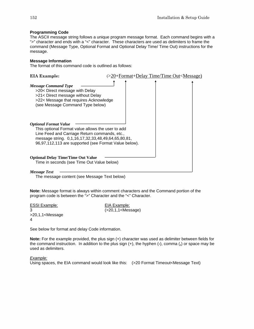
152 Installation & Setup Guide
Programming Code The ASCII message string follows a unique program message format. Each command begins with a “>” character and ends with a “<” character. These characters are used as delimiters to frame the command (Message Type, Optional Format and Optional Delay Time/ Time Out) instructions for the message. Message Information The format of this command code is outlined as follows: EIA Example: (>20+Format+Delay Time/Time Out<Message) Message Command Type
>20< Direct message with Delay >21< Direct message without Delay >22< Message that requires Acknowledge (see Message Command Type below)
Optional Format Value
This optional Format value allows the user to add Line Feed and Carriage Return commands, etc., message string. 0,1,16,17,32,33,48,49,64,65,80,81, 96,97,112,113 are supported (see Format Value below).
Optional Delay Time/Time Out Value
Time in seconds (see Time Out Value below) Message Text
The message content (see Message Text below) Note: Message format is always within comment characters and the Command portion of the program code is between the “>” Character and the “<” Character. ESSI Example: EIA Example: 3 (>20,1,1<Message) >20,1,1<Message 4 See below for format and delay Code information. Note: For the example provided, the plus sign (+) character was used as delimiter between fields for the command instruction. In addition to the plus sign (+), the hyphen (-), comma (,) or space may be used as delimiters. Example: Using spaces, the EIA command would look like this: (>20 Format Timeout<Message Text)

Appendix C: Program Codes 153
Message Command Type >20< This command delays the part program until all bytes have been transmitted, then optionally
waits the Delay Time, if specified. >21< A message is sent concurrent to execution of the part program and no delay is encountered.
No acknowledge is required. >22< The message is sent with a suspension of the program during transmission as in option one,
but an Acknowledge from the external device (ACK = Hexadecimal 06 ) is required before the part program can continue. A Non-Acknowledge (NAK = Hexadecimal 15) response from the external device will prompt a retransmit of the message from the control.
An optional Time Out value may be added to the program code. If no Time Out code is used in the program code the Default time out value at the Ports setup screen will be used. Additionally, an optional automatic retry feature may be enabled at the Ports setup screen. With the automatic retry feature the message will automatically be retransmitted if no response is detected. The retry is executed after the Time Out value has elapsed. The number of retries can be defined on the Ports configuration screen.
Optional Format Value Specialty characters for the format may be sent in addition to command string. Specialty Characters Supported HEX Name Description 01 SOH Start of Header 02 STX Start of Text 03 ETX End of Text 04 EOT End of Transmission 0A LF Line Feed 0D CR Carriage Return BCC “Exclusive Or” Check Byte Note: Checksum is always an 'Exclusive OR' of the Data ONLY as it does not include any of the 'Format' chars including the CR/LF option.

154 Installation & Setup Guide
Optional Format Character Assignments Value Assignment
0 No Special Assignment (Must be used in the format location is a Delay is required but no Format options are required).
1 Append a Carriage Return (<CR> = Hex value OD) and a Line Feed (<LF> = Hex Value0A)
16 Append an “Exclusive OR” (<BCC>) to the end of the message. 17 Appends a combination of 16 and 1. 32 Encloses the message with Start of Text (<STX> = Hex Value 02) and End of Text
(<ETX> = Hex Value 03). The <ETX> follows the message and the optional <CR><LF>> append codes but precedes the Check Byte <BCC>.
33 Appends a combination of 1 and 32. 48 Appends a combination of 16 and 32. 49 Appends a combination of 1, 16 and 32. 64 Append a Start of Header(<SOH> = Hex value 01) and a End of Transmission (<EOT>
= Hex Value04) to the Message. 65 Appends a combination of 1and 64. 80 Appends a combination of 16 and 64. 81 Appends a combination of 1, 16 and 64. 96 Appends a combination of 32 and 64. 97 Appends a combination of 1, 32, and 64. 112 Appends a combination of 16, 32 and 64. 113 Appends a combination of 1, 16, 32 and 64.
Optional Delay Time/Time Out Value The Delay Value will issue a delay in seconds at the end of the message for Message Type 20. No delay is supported for Message Type 21. This value also works as a Time Out value for Message Type 22. An error will be displayed if the message is not Acknowledged (ACK Hexadecimal 06) with in the specified time. If no Time Out Delay is defined in the command, the Time Out parameter on the Ports screen will be used. The value is in a 3.2 format where a value of 5 is equal to 5.00 seconds. Accepted limits for the value is range of 0.00 to 999.99 seconds. Message Text Content Up to 300 data characters in each command string may be sent. The Command characters (information between and including the “>” and “<” signs) are included in this maximum. Printable and Non- Printing ASCII codes can be used in the message string. Refer to the ASCII Code appendix of this manual for more information on ASCII codes and the Hexidecimal value. Non-printing characters are supported by use of a two-character command and can send a Binary Code in the Range from 0-255. Double byte character to support combinations will affect the maximum length count with each pair reducing the maximum data characters by 1. Refer to the Non-printing Character information later in this section for information on these values.

Appendix C: Program Codes 155
Non – Printing Characters Non Printing Characters are supported through use of a pair of two printing codes to equal the non-printing code. This pair of characters is retained in the program code but sent as single 8-bit code when transmitted. There are three types of character pairs and each performs a different operation based on the first character of the pair. This produces a single modified character for transmission. Character Options
1) The “&” two-character pair clears the 0x40 bit from the 2nd character code value. 2) The “!” two-character pair clears the 0x40 bit and sets the 0x80 bit set in the 2nd character
code. 3) The “$” two-character pair clears the 0xC0 bit in the 2nd character.
To transmit the single character with a value 0x01, use the two character sequence ”&A”. This converts the “A” value of 0x41 to 0x01 by clearing the 0x40 bit. To transmit 0x81, use “!A” or to transmit)xC1 use “$A”. Exceptions / Additions As the “&”, “!” and “$” are used as key indicators for the Non-print characters, there is a special format used when these characters are used as a print character in the message text. Simply use the character twice. “&&” = “&” The ESSI style part program uses several unique characters which requires special two character codes to be used. For example, the message code “&K” in the part program will transmit the code value of 0x2B which is the ASCII code for the plus sign (+). In order to send the + character the code “&K” must be used. The following are unique codes used in WORD ADDRESS and ESSI programs Code Code Value Description &’ 0x20=space At end of ESSI program &h 0x28 = “(“ To transmit “(” from WORD ADDRESS program &i 0x29 = “)“ To transmit “)” from WORD ADDRESS program &? 0x7F = DEL Non-printable DELETE code
&K 0x2B = “+” To transmit “+” from ESSI program

156 Installation & Setup Guide
Non Printing Character Table ASCII codes less than Hexidecimal 20 Code Hex Code Hex Code Hex Code Hex &A 00 &H 08 &P 10 &X 18 &A 01 &I 09 &Q 11 &Y 19 &B 02 &J 0A &R 12 &Z 1A &C 03 &K 0B &S 13 &[ 1B &D 04 &L 0C &T 14 &\ 1C &E 05 &M 0D &U 15 &] 1D &F 06 &N 0E &V 16 &^ 1E &G 07 &O 0F &W 17 &_ 1F 8 bit character codes greater than Hexidecimal 80 Code Hex Code Hex Code Hex Code Hex !@ 80 !H 88 !P 90 !X 98 !A 81 !I 89 !Q 91 !Y 99 !B 82 !J 8A !R 92 !Z 9A !C 83 !K 8B !S 93 ![ 9B !D 84 !L 8C !T 94 !\ 9C !E 85 !M 8D !U 95 !] 9D !F 86 !N 8E !V 96 !^ 9E !G 87 !O 8F !W 97 !_ 9D !` A0 !h A8 !p B0 !x B8 !a A1 !I A9 !q B1 !y B9 !b A2 !j AA !r B2 !z BA !c A3 !k AB !s B3 !; BB !d A4 !l AC !t B4 !< BC !e A5 !m AD !u B5 != BD !f A6 !n AE !v B6 !> BE !g A7 !o AF !w B7 !? BF $@ C0 $H C8 $P D0 $X D8 $A C1 $I C9 $Q D1 $Y DD $B C2 $J CA $R D2 $Z DA $C C3 $K CB $S D3 $[ DB $D C4 $L CC $T D4 $\ DC $E C5 $M CD $U D5 $] DD $F C6 $N CE $V D6 $^ DE $G C7 $O CF $W D7 $_ DF $` E0 $h E8 $p F0 $x F8 $a E1 $I E9 $q F1 $y F9 $b E2 $j EA $r F2 $z FA $c E3 $k EB $s F3 $; FB $d E4 $l EC $t F4 $< FC $e E5 $m ED $u F5 $= FD $f E6 $n EE $v F6 $> FE $g E7 $o EF $w F7 $? FF

Appendix D: MicroEdge™ 157
Appendix D: MicroEdge™ Overview
The MicroEDGE™ PC based motion control from Hypertherm® Automation is specifically for the metal cutting industry. This control package provides a unique combination of flexible table configurations, expandable features and an unparalleled ease of use. MicroEDGE™ utilizes our proprietary Graphical User Interface (GUI) and SoftMotion Technology with motion control operation of up to four axes with 24 I/O signals. This product offers a unique approach to the motion control market by allowing custom configuration the final package by adding a PC style Monitor, Keyboard and Mouse. Additional features such as Joystick, Speed Pots, Integrated Sensor™ THC, networking, CAD/CAM Software, Nesting Software provide unlimited combinations of options for increased productivity.
Operation and maintenance of automated equipment involves potential hazards. Personnel should take precautions to avoid injury. This equipment should only be opened by trained service personnel.
MicroEDGE™
Rear View

158 Installation & Setup Guide
Keyboard Layout
Typical Keyboard Layout Keyboard Functions Function Keys F1-F8 are equivalent to the soft keys on the display screen. Function Key F9 is equivalent to the START key. Function Key F10 and Pause Key are equivalent to the STOP key. Function Key F11 is equivalent to the MANUAL MODE key. Function Key F12 is equivalent to the HELP key. Arrow direction keys are used for manual motion. The HOME key is equivalent to the PREV field key. The END key is equivalent to the NEXT field key. The [ key is equivalent to the purple arrow shift key. The ] key is equivalent to the blue arrow shift key. The Esc key is equivalent to the CANCEL key. To exit the control software press Alt F4. To switch between applications press Alt Tab. A color coded key cap sticker set is provided to allow easy reference to the keys used by the control software.
System Requirements Monitor Requirements (CRT or LCD) Standard VGA capable 1240 x780 analog monitors or better with 15 pin High Density D-sub connector. Touch screen displays are also supported. Keyboard Requirements Standard 101/ 104 Key PS/2 or USB Compatible Keyboard Optional Mouse Requirements PS/2 or USB Compatible Mouse THC, Joystick & Speedpots Optional features for two Sensor THC, one Joystick and two Speedpots are offered. Note: Use of some monitors and other devices may require loading of a device driver for operation. Many standard device drivers are located in the C:\CABS or C:\CABS\I386 folders.

Appendix D: MicroEdge™ 159
Machine Interface The MicroEDGE™ shape cutting control is an extremely versatile product offering up to four configurable axes of motion, configurable I/O locations and a convenient table interface for ease of installation. The control features may also be expanded through use of optional analog and network interface cards.
The rear panel of the control has several cable connectors to connect the control to power, I/O and communication ports. These connectors are clearly labeled as to their function. AC Input The AC power cable is inserted into the AC power connector and plugged into a standard 3-way 110 or 220 volt outlet. The control has a universal AC input power module that allows the user to plug into either voltage without changing additional jumpers. In addition, the AC Power connector contains an integral fuse receptacle and line filter. A remote communications link can be connected to one of the two serial ports and an external ground (PE) lug for earth grounding of the unit is also provided. Serial Port Please refer to the Ports Information section of the Installation Guide for additional information on configuration of Serial ports for communication. Note: Serial ports for the MicroEDGE are not optically isolated. Appropriate grounding or after market port isolator or protocol converter to add optical isolation is recommended.

160 Installation & Setup Guide
I/O Configuration The cables that connect the control to the cutting machine are attached to the I/O (Input/Output), and the DRIVE/ENCODER connectors. For the purposes of this guide Single Ended I/O is referred to as Type “P” configuration. The information provided here is the basic information for connection of the shape cutting control to the cutting table. Each machine interface will vary slightly based on the cutting table configuration and features. Additionally, I/O pinout information may vary slightly based on the configuration of the selected I/O and their locations. Changes to the I/O configuration may be made in the password protected I/O screen. All controls are shipped with the default selection of Inputs and interface locations for the selected control Interface (I/O) configuration. Installation and service should only be performed by a qualified service technician. I/O Connector The I/O connector is a standard sex circular CPC connector from AMP. This connector was specifically chosen for its rugged industrial design and its metal insulation characteristics for EMI/RFI noise immunity. In the single ended I/O scheme, a ground is provided on the I/O pin. The advantage to single ended I/O is that it takes one pin for each point versus two for the double-ended I/O scheme, thus increasing the total number of I/O points available to the user. I/O Mating Connector Connector AMP #208470-1 Backshell AMP #208945-8 Sockets (16-18 ga) AMP #66101-3 Sockets (20-24 ga) AMP #66105-3

Appendix D: MicroEdge™ 161
I/O Interface Connecting single ended I/O to the control. These examples assume a +24V power supply has been connected across pins 34 and 36 of the control, or that the optional internal +24V power supply has been installed. Output tied to external Cut On Input tied to Cut Sense Relay
Examples of possible circuits
Output
Input

162 Installation & Setup Guide
Single Ended I/O Pinout The Single Ended I/O offers 12 outputs which are rated at 24VDC for up to 1-amp loads and 12 inputs rated for 24VDC. Pin I/O Description 1 Input 1 Torch Up Sense 2 Input 2 Torch Down Sense 3 Input 3 Preheat Sense or X -Overtravel Switch 4 Input 4 Cut Sense 5 Input 5 Tracer on Path or Z Home Switch 6 Input 6 Spare or Y -Overtravel Switch 7 Input 7 Spare 8 Input 8 Spare or Remote Pause 9 Input 9 X Home Switch 10 Input 10 X Overtravel Switch or X +Overtravel Switch 11 Input 11 Y Home Switch 12 Input 12 Y Overtravel Switch or Y +Overtravel Switch 13 N/C No Connection 14 +24 VDC + I/O Power Supply 15 +24 VDC + I/O Power Supply 16 N/C No Connection 17 24V Common I/O Power Supply Common 18 24V Common I/O Power Supply Common 19 N/C No Connection 20 N/C No Connection 21 Output 1 Torch Up 22 Output 2 Torch Down 23 Output 3 Ignition Control 24 Output 4 Torch Height Disable/Dual Grid Control 25 Output 5 CNC/Tracer 26 Output 6 Marker Enable 27 Output 7 Cut Control 28 Output 8 Spare 29 Output 9 Spare or Low Preheat 30 Output 10 Preheat Control 31 Output 11 Key Press Indicator or Motion Indicator 32 Output 12 Spare or Plasma Select 33 I/O Shield Chassis Ground 34 +24 VDC +I/O Power Supply 35 +24 VDC +I/O Power Supply 36 24 V Common I/O Power Supply Common 37 24 V Common I/O Power Supply Common

Appendix D: MicroEdge™ 163
Drive/Encoder Connector The Drive/Encoder connector is a reverse sex circular CPC connector from AMP. This connector was specifically chosen for its rugged industrial design and its metal insulation characteristics for EMI/RFI noise immunity. NOTE: For optimum noise immunity, cable shields may be tied externally to the control enclosure or to the metal AMP connectors. Drive/Encoder Mating Connector and Cable Connector AMP #208472-1 Backshell AMP #208945-8 Pins (16-18 ga) AMP #66099-3 Pins (20-24 ga) AMP #66103-3 Cabling: Use Belden # 9504 or equivalent for encoder signals Cabling: Use Belden # 9501 or equivalent for drive signals
Axes Assignments Axes Axes Assignment 1 (X) Transverse or Rail 2 (Y) Transverse or Rail 3 (Z) Dual Gantry, CBH, Rotate or THC 4 (W) CBH, Tilt or THC

164 Installation & Setup Guide
Drive/Encoder Pinout Pin Description 2 Encoder Power Supply Input (+5V or +12V*) 3 Encoder Power Supply Common 7 Encoder Power Supply Shield 8 *NOTE: For Rev A + B MCC’s +12V Encoders require a switch to be set on the interface board. X Axis Y Axis Description 4 1 Encoder Power Output 8 6 Encoder Power Common 9 5 Encoder Channel A input 14 11 Encoder Channel /A Input 15 10 Encoder Channel B Input 21 17 Encoder Channel /B Input 22 16 Encoder Channel Z Input 28 23 Encoder Channel /Z Input 13 12 Encoder Shields 24 26 Drive Enable In (relay contact) 25 27 Drive Enable Out (relay contact) 37 34 Drive Power Input (+12 or +15) 33 29 Servo Output (± 10V) 32 30 Drive Power Common 36 35 Drive Power Input (-12 or –15) 20 18 Servo Output Common 19 31 Drive/Servo Shield Drive/Encoder Pinout (For 3 and 4 Axes units) Pin Description 2 Encoder Power Supply Input (+5V or +12V) 3 Encoder Power Supply Common 7 Encoder Power Supply Shield Z Axis W Axis Description 4 1 Encoder Power Output 8 6 Encoder Power Common 9 5 Encoder Channel A input 14 11 Encoder Channel /A Input 15 10 Encoder Channel B Input 21 17 Encoder Channel /B Input 22 16 Encoder Channel Z Input 28 23 Encoder Channel /Z Input 13 12 Encoder Shields 24 26 Drive Enable In (relay contact) 25 27 Drive Enable Out (relay contact) 37 34 Drive Power Input (+12 or +15) 33 29 Servo Output (± 10V) 32 30 Drive Power Common 36 35 Drive Power Input (-12 or –15) 20 18 Servo Output Common 19 31 Drive/Servo Shield
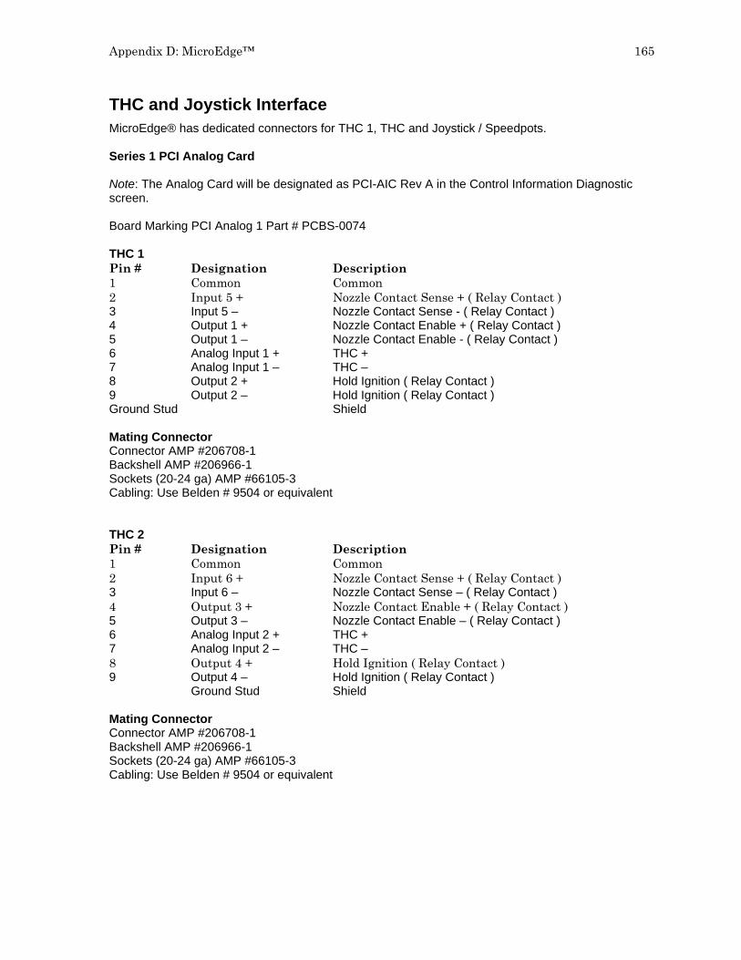
Appendix D: MicroEdge™ 165
THC and Joystick Interface MicroEdge® has dedicated connectors for THC 1, THC and Joystick / Speedpots. Series 1 PCI Analog Card Note: The Analog Card will be designated as PCI-AIC Rev A in the Control Information Diagnostic screen. Board Marking PCI Analog 1 Part # PCBS-0074 THC 1 Pin # Designation Description 1 Common Common 2 Input 5 + Nozzle Contact Sense + ( Relay Contact ) 3 Input 5 – Nozzle Contact Sense - ( Relay Contact ) 4 Output 1 + Nozzle Contact Enable + ( Relay Contact ) 5 Output 1 – Nozzle Contact Enable - ( Relay Contact ) 6 Analog Input 1 + THC + 7 Analog Input 1 – THC – 8 Output 2 + Hold Ignition ( Relay Contact ) 9 Output 2 – Hold Ignition ( Relay Contact ) Ground Stud Shield Mating Connector Connector AMP #206708-1 Backshell AMP #206966-1 Sockets (20-24 ga) AMP #66105-3 Cabling: Use Belden # 9504 or equivalent THC 2 Pin # Designation Description 1 Common Common 2 Input 6 + Nozzle Contact Sense + ( Relay Contact ) 3 Input 6 – Nozzle Contact Sense – ( Relay Contact ) 4 Output 3 + Nozzle Contact Enable + ( Relay Contact ) 5 Output 3 – Nozzle Contact Enable – ( Relay Contact ) 6 Analog Input 2 + THC + 7 Analog Input 2 – THC – 8 Output 4 + Hold Ignition ( Relay Contact ) 9 Output 4 – Hold Ignition ( Relay Contact ) Ground Stud Shield Mating Connector Connector AMP #206708-1 Backshell AMP #206966-1 Sockets (20-24 ga) AMP #66105-3 Cabling: Use Belden # 9504 or equivalent

166 Installation & Setup Guide
Joystick Pin # Designation Description 1 Input 1 Joystick UP 2 Input 2 Joystick DWN 3 Input 3 Joystick LT 4 Input 4 Joystick RT 5 Common Common 6 Analog Input 3 + Speed Pot 1 7 Analog Input 3 – Speed Pot 1 8 Analog Input 4 + Speed Pot 2 9 Analog Input 4 – Speed Pot 2 Ground Stud Shield Note: Joystick inputs are activated by passing the Common signal ( pin 5 ) to the desired input. Analog inputs for the speedpots are rated at 0 - +10VDC Mating Connector Connector AMP #206708-1 Backshell AMP #206966-1 Sockets (20-24 ga) AMP #66105-3 Cabling: Use Belden # 9504 or equivalent THC and Joystick Cable Grounding Cable shields should be tied to the external PE studs for optimum noise immunity.

Appendix D: MicroEdge™ 167
Sensor™ THC This section refers to following hardware configuration. Note: The Analog Card will be designated as Rev 0 in the Control Information Diagnostic screen. Series 1 PCI Analog Card (Board Marking PCBS-0073) Part # PCBS-0074 Series 3 Voltage Divider Card Part # PCBS-0061 Instructions If the voltage divider card has not been installed in the plasma power supply, mount the card in an accessible location away from high electrical noise areas. Wire the VDC to the appropriate signal inside the power supply as outlined in the following pinout information Voltage Divider Card Pinout (Series 3) Divider PCB - 2C Connector J1 Pin # Description 1 85 -265 VAC Power Input (47-63Hz) 2 285 -265 VAC Neutral Input Mating Connector 2C Phoenix Connector – Phoenix Part # 1840366 Divider PCB - 8C Connector J2 To Control Pin # Description 1 +24 VDC Common 2 +24 VDC 3 Nozzle Contact Sense 4 Nozzle Contact Enable 5 +24 VDC Common 6 Analog Out + 7 Analog Out – 8 E Ground Mating Connector 8C Phoenix Connector – Phoenix Part # 1803633 Divider PCB - 5C Connector J3 to Power Supply / Table Pin Number Description 1 Ground (Chassis Ground) 2 Electrode (Plasma DC –) 3 Work (Plasma DC +) 4 NC 5 Shield (Nozzle Contact) Mating Connector Terminal Connections

168 Installation & Setup Guide
Control & Cable Pinout for Sensor™ THC I/O Configuration Type “P” Note: A 9C Amp connector is provided on the back of the control (I/O Type “P”) for interfacing. Control 9C Divider J2 Analog Pin # Description Pin # 1 24V Common 1 2 Nozzle Contact Sense + 2 3 Nozzle Contact Sense – 3 4 Nozzle Contact Enable + 4 5 Nozzle Contact Enable – 5 6 Analog + 6 7 Analog – 7 8 Hold Ignition + N/A (direct to power supply)* 9 Hold Ignition – N/A (direct to power supply)* Ground Stud Shield No Connection Analog Mating Connector Connector AMP # 206708-1 Backshell AMP #206966-1 Sockets #66105-3 (20-24 ga) VDC Mating Connector 8C Phoenix Connector – Phoenix Part # 1803633 Cable Belden #9505 or equivalent * Note: It is recommended that the Hold Ignition input be wired to the Power Supply through an external relay for noise immunity. Please refer to Instructions from the supply manufacturer for details on connection to the Hold Ignition Input.

Appendix D: MicroEdge™ 169
Calibration Series 1 Analog Card Note: The Series 1 Analog Card will be designated as Rev 0 in the Control Information Diagnostic screen. Board Marking PC-012-1098 Rev. B Part # PCBS-0010-B After the voltage divider card and control cabling have been connected, the system is ready to be calibrated for use. Analog Offset: To adjust the Analog Offset, place a jumper on the Analog In signals on the Analog input card or at the 9C connection for the Analog Input Card located at the back of the control. The analog input voltage would then be viewed at the I/O Diagnostics screen to read any incoming voltage for the THC. If any voltage is displayed at the diagnostic screen, an Offset Voltage equal to the incoming voltage being read can be entered at the Password protected Analog I/O screen to correct for any imbalance and “zero” the incoming voltage Example: If an incoming Analog Input Voltage is reading .1 volts, simply enter .1 at the Analog Offset and correct the imbalance.

170 Installation & Setup Guide
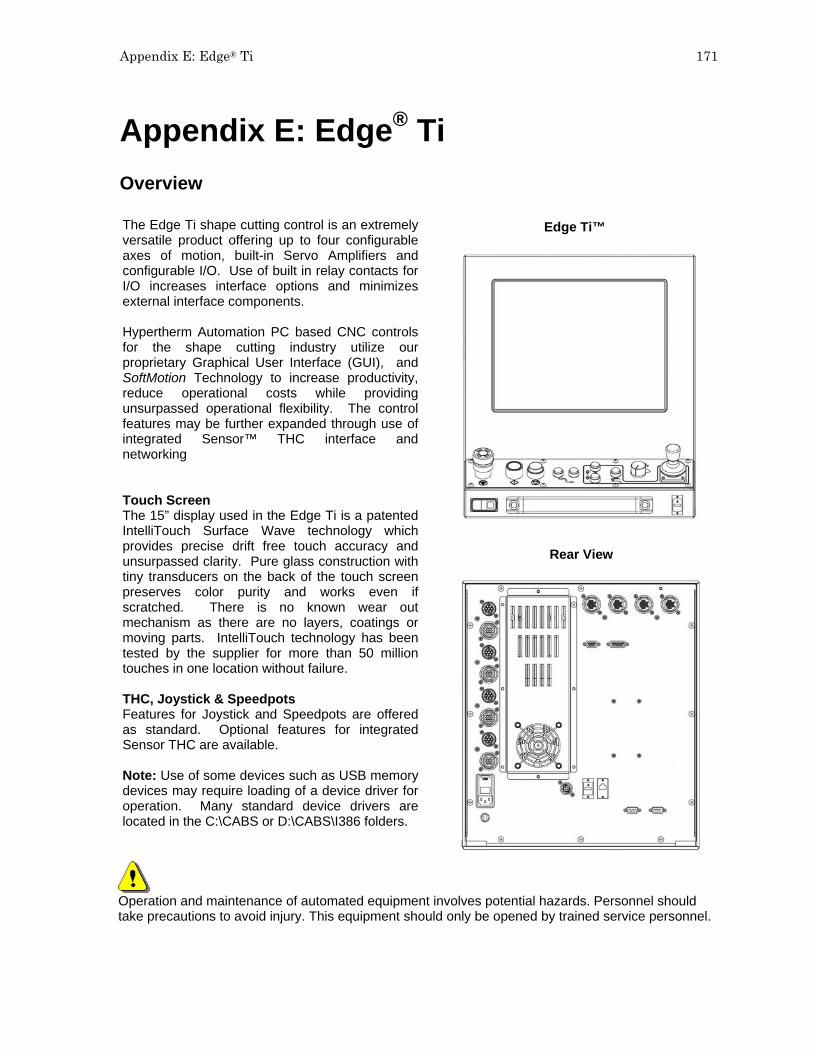
Appendix E: Edge® Ti 171
Appendix E: Edge® Ti Overview
The Edge Ti shape cutting control is an extremely versatile product offering up to four configurable axes of motion, built-in Servo Amplifiers and configurable I/O. Use of built in relay contacts forI/O increases interface options and minimizes external interface components. Hypertherm Automation PC based CNC controlsfor the shape cutting industry utilize our proprietary Graphical User Interface (GUI), and SoftMotion Technology to increase productivity, reduce operational costs while providing unsurpassed operational flexibility. The control features may be further expanded through use of integrated Sensor™ THC interface and networking Touch Screen The 15” display used in the Edge Ti is a patented IntelliTouch Surface Wave technology which provides precise drift free touch accuracy and unsurpassed clarity. Pure glass construction with tiny transducers on the back of the touch screen preserves color purity and works even if scratched. There is no known wear out mechanism as there are no layers, coatings or moving parts. IntelliTouch technology has been tested by the supplier for more than 50 million touches in one location without failure. THC, Joystick & Speedpots Features for Joystick and Speedpots are offered as standard. Optional features for integrated Sensor THC are available. Note: Use of some devices such as USB memory devices may require loading of a device driver for operation. Many standard device drivers are located in the C:\CABS or D:\CABS\I386 folders.
Edge Ti™
Rear View
Operation and maintenance of automated equipment involves potential hazards. Personnel should take precautions to avoid injury. This equipment should only be opened by trained service personnel.

172 Installation & Setup Guide
Machine Interface
The information provided here is the basic information for connection of the shape cutting control to the cutting table. Each machine interface will vary slightly based on the cutting table configuration and features. Additionally, I/O pinout information may vary slightly based on the configuration of the selected I/O and their locations. Changes to the I/O configuration may be made in the password protected I/O screen. All controls are shipped with a default selection of Inputs and interface locations for the selected control Interface (I/O) configuration. Installation and service should only be performed by a qualified service technician. The rear panel of the control has several cable connectors to connect the control to power, I/O and communication ports. These connectors are clearly labeled as to their function. AC Input The AC power cable is inserted into the AC power connector and plugged into a standard 3-way 115 or 230 volt outlet. The AC Power connector contains an integral fuse module and line filter. AC input power can be selected by the user by changing position of the fuse module so that the selected voltage is displayed.
WARNING! Ensure proper orientation of fuse module for input power before applying power to the CNC. Component damage could occur with incorrect voltage setting. Recommended AC Fuses Different fuse ratings are recommended based on incoming voltage selected. Voltage Input: 120Vac uses 8 amp (slow blow) Littlefuse part #313008 Voltage Input: 220Vac uses 5 amp (slow blow) Littlefuse part #313005 Size: ¼” x 1¼” or 5mm x 20MM fuse can be used Serial Port Please refer to the Ports Information section of the Installation Guide for additional information on configuration of Serial ports for communication. A remote communications link can be connected to one of the two serial ports and an external ground (PE) lug for earth grounding of the unit is also provided.

Appendix E: Edge® Ti 173
I/O Configuration The Edge – Ti provides several options for I/O interfacing with built in circuitry providing interface flexibility and reducing the need for external components. Inputs are through optoisolators and outputs are through relays. Contacts for both normally closed and normally open outputs are available for use.
Input Mode Note that the inputs have two different modes that are selectable using DIP switch SW1-3. When this switch is OFF the inputs are in the sourced input mode and an external voltage source of between 12V and 24V is required to activate each input. When DIP switch SW1-3 is ON, the inputs are all in the dry contact mode and require an external switch to common to activate the inputs. The logic states sensed by the CNC are reversed between the two input modes. In a sourced input circuit, an inactive input will produce a logic low and an active input will produce logic high. In dry contact mode these logic levels are reversed with an inactive input producing logic high and an active input producing a logic low. Switch SW1-3

174 Installation & Setup Guide
I/O Interface The following illustration shows the details of connecting the I/O to common circuitry. All outputs are relay contacts rated at 1 AMP 250VAC maximum
RESISTOR
LED
12V
Use External +12V Supply& normally Closed Contact
24V+
GND_External
+
RESISTOR
Use External +5V Supply& normally Open Contact
RELAY SPDT
Normal Sourced InputsUse External +24V Supply
GND_External
5V
NC
NO
+
COM
12V
GND_ExternalGND_External
RELAY
GND
External Circuitry
OPTO ISOLATOR
+
Use External 120 Vac& normally open contact
RELAY SPDT
COM
NO
NC
3900
RELAY SPDT
NC
COM
NO
Dry Contact InputsNote: Logic Level Reversal
SWITCH
Normal Sourced InputsDIP Sw 1-C Open
Edge-Ti Internal CircuitryOutputs External Circuitry
OPTO ISOLATOR
Inputs
GND
3900
Example Inputs
3900
GND
3900
3900
Open
Open
+24V Field
3900
RELAY
120 Vac
Normal Sourced InputsUse External +12V Supply
Normal Sourced InputsDIP Sw 1-C Open
Dry Contact InputsDIP Sw 1-C Closed
GND_External
Example Outputs
WARNING! Do not exceed 24Vdc or 10mA into any optoisolator input. Use care to observe the correct signal polarities or damage may occur! Do not exceed 250 Vac or 1 Amp through any relay output.

Appendix E: Edge® Ti 175
I/O Pinout Three inputs and three outputs are provided per connector Connector I/O 1-3 Connector I/O 4-6 Pin# Signal Pin# Signal 1 OUT1 Common 1 OUT4 Common 2 OUT1 Normally Closed 2 OUT4 Normally Closed 3 OUT1 Normally Open 3 OUT4 Normally Open 4 OUT2 Common 4 OUT5 Common 5 OUT2 Normally Closed 5 OUT5 Normally Closed 6 OUT2 Normally Open 6 OUT5 Normally Open 7 OUT3 Common 7 OUT6 Common 8 OUT3 Normally Closed 8 OUT6 Normally Closed 9 OUT3 Normally Open 9 OUT6 Normally Open 10 IN1 10 IN4 11 IN1 Common 11 IN4 Common 12 IN2 12 IN5 13 IN2 Common 13 IN5 Common 14 IN3 14 IN6 15 IN3 Common 15 IN6 Common 16 Cable Shield 16 Cable Shield Connector I/O 7-9 Connector I/O 10-12 Pin# Signal Pin# Signal 1 OUT7 Common 1 OUT10 Common 2 OUT7 Normally Closed 2 OUT10 Normally Closed 3 OUT7 Normally Open 3 OUT10 Normally Open 4 OUT8 Common 4 OUT11 Common 5 OUT8 Normally Closed 5 OUT11 Normally Closed 6 OUT8 Normally Open 6 OUT11 Normally Open 7 OUT9 Common 7 OUT12 Common 8 OUT9 Normally Closed 8 OUT12 Normally Closed 9 OUT9 Normally Open 9 OUT12 Normally Open 10 IN7 10 IN10 11 IN7 Common 11 IN10 Common 12 IN8 12 IN11 (shared w/ lifter Lower limit input) 13 IN8 Common 13 IN11 Common 14 IN9 14 IN12 (shared w/ lifter Upper limit input) 15 IN9 Common 15 IN12 Common 16 Cable Shield 16 Cable Shield Shared Inputs Note that general inputs #11 and #12 are shared with the Lifter Interface Limit Switch inputs. These inputs can only be used as general purpose inputs if they are NOT used by the Lifter limit switches. If you are using the Lifter Interface and limit switches are connected to these inputs you must set DIP switches SW1-1 and SW1-2 to ON and you should not connect to inputs #11 and #12. Note that the standard Hypertherm Lifter does not use limit switches and the DIP switches SW1-1 & SW1-2 should be OFF so that inputs #11 and #12 can be used. Switch SW1-1 and SW1-2
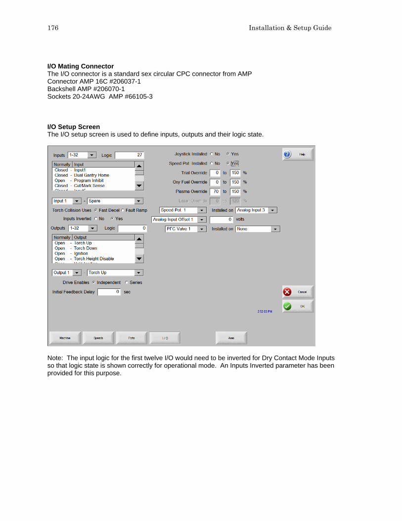
176 Installation & Setup Guide
I/O Mating Connector The I/O connector is a standard sex circular CPC connector from AMP Connector AMP 16C #206037-1 Backshell AMP #206070-1 Sockets 20-24AWG AMP #66105-3 I/O Setup Screen The I/O setup screen is used to define inputs, outputs and their logic state.
Note: The input logic for the first twelve I/O would need to be inverted for Dry Contact Mode Inputs so that logic state is shown correctly for operational mode. An Inputs Inverted parameter has been provided for this purpose.

Appendix E: Edge® Ti 177
Front Panel I/O Edge TI has dedicated I/O for operation of front panel switches. NOTE: For proper operation, these inputs should not be reassigned. Input # Description 24 Front Panel Start 25 Front Panel Stop 26 Front Panel Forward on Path 27 Front Panel Forward on Path 28 Raise Torch 1 29 Lower Torch 1 30 Front Panel Manual 31 Front Panel E-Stop
Lifter Interface Edge Ti offers the option of an integrated Torch Height Control. The lifter interface connector is provided for this use. Lower Limit, Upper Limit and Breakaway inputs are sinking inputs to Field Common. Please refer to Sensor™ PHC manual for additional information. Lifter Pinout (9 Pin Dsub) Pin# Description 1 Field +12VDC 2 Lower Limit (shared w/ general input 11) 3 Upper Limit (shared w/ general input 12) 4 Breakaway (Torch Collision) 5 Field Common 6 Field Common 7 Plate Contact -12Vdc 8 Plate Contact Sense 9 Plate Contact Common Shared Inputs Note that general inputs #11 and #12 are shared with the Lifter Interface Limit Switch inputs. These inputs can only be used as general purpose inputs if they are NOT used by the Lifter limit switches. If you are using the Lifter Interface and limit switches are connected to these inputs you must, close DIP switches SW1-1 and SW1-2 and you should not connect to inputs #11 and #12. Note that the standard Hypertherm Lifter does not use limit switches and that the DIP switches SW1-1 & SW1-2 should be left open so that inputs #11 and #12 can be used. Switch SW1-1 and SW1-2
Mating Connector Use Hypertherm cable CABL-0207 or recommended 9 Pin Dsub (or equivalent) Connector AMP #205204-3 Backshell Northern Technology #C88000209 Pins AMP #1-66506-0 Cabling: Use Belden # 9540 or equivalent

178 Installation & Setup Guide
Plasma Interface A plasma interface is provided as standard for Edge TI. This feature is used in conjunction with a Plasma Interface Module to provide connections at the Plasma Supply. Inputs and outputs are dry contact mode. Arc voltage is assigned to Analog Input 5. Please refer to Sensor™ PHC manual for additional information. Plasma Interface Pinout (15 Pin Dsub) Pin# Description 1 Field +12VDC 9 Field +12VDC 2 Plasma Start Output (Cut Control) 10 Plasma Start Output (Cut Control) 3 Hold Ignition Output + 11 Hold Ignition Output - 4 Transfer Input + (Cut Sense) 12 Transfer Input - (Cut Sense) 5 Field Common 6 Field Common 7 Field Common 13 Field Common 14 Field Common 15 Electrode Arc Voltage (–) 8 Work Arc Voltage (+) Mating Connector Use Hypertherm cable CABL-0208 or recommended 15 Pin Dsub (or equivalent). Connector AMP #205206-1 Backshell Northern Technology #C88000207 Pins AMP #1-66506-0 Cabling: Use Belden # 9541
External Interlock An external interlock is provided to remotely disable servo power. Interlock Pinout Pin# Description 1 Interlock Relay Coil (24VDC) 2 GND 3 GND 4 +24VDC (50 milliamps maximum) Additional Notes:
1. For Servo Drive Amplifiers to operate, Pin 1 must be connected to GND Pin 2, typically through a remote mushroom type switch. If no remote switch is to be used, connect pin 1 to pin 2 with a jumper or the servo drives will not power on.
2. 24VDC is provided for use to activate the digital inputs only in the case where sourced inputs are selected, it must not be used for any other auxiliary purpose.
Mating Connector Connector AMP #206060-1 Backshell AMP #206062-3 Sockets 20-24AWG AMP #66105-3

Appendix E: Edge® Ti 179
Motor Encoder Connections Edge Ti supports DC brush and brushless motors. Switch SW1 on the drive interface can be used to select motor type being used. Please note the location and setting in the following illustration. Drive Type selection on Axes Setup screen must be set to CURRENT mode.
Motor Requirements 250 Watts (each amplifier, 1,000 watts total) 70 VDC Bus 4 Amps Continuous, 6 Amps Peak (for 2 seconds) +5VDC differential encoders Brushless motors also require Hall Effect sensors phased at 120 degrees Axes Assignments Axes Axes Assignment 1 (X) Transverse or Rail 2 (Y) Transverse or Rail 3 (Z) Dual Gantry, CBH, or THC 4 (W) CBH, or THC

180 Installation & Setup Guide
Motor Power Pinout Pin# Description 1 Brushless Motor-A or Brush + 2 Brushless Motor-B or Brush - 3 Brushless Motor-C 4 Brake + (24VDC, 250ma max) 5 Brake - 6 Cable Shield 7 No Connect Additional Notes: 1. Brake output is limited to 250ma total. This output is only used on the THC vertical axis. Drive Motor Mating Connector Connector AMP #211399-1 Backshell AMP #206966-1 Sockets 16-18AWG AMP #66101-3 Cabling: Use Belden # 9552 or equivalent for brushed motor signals Cabling: Use Belden # 9553 or equivalent for brushless motor signals
Encoder Pinout: 1 Encoder +5V 2 Encoder GND 3 Encoder Channel A 4 Encoder Channel A/ 5 Encoder Channel B 6 Encoder Channel B/ 7 Encoder Channel Z 8 Encoder Channel Z/ 9 +V Hall Out (6V @ 30MA max) 10 Hall GND 11 Hall - A 12 Hall - B 13 Hall - C 14 Cable Shield Additional Notes:
1. Only 5 Volt encoders are supported. 2. Hall Sensors are used with Brushless motors only. 3. Inside the Edge Ti, dipswitches are used to select Brush or Brushless mode, 2 switches per
axis. Can mix Brushed and Brushless if switches are set properly. 4. For optimum noise immunity, cable shields may be tied externally to the control enclosure.
Encoder Mating Connector Connector AMP #206044-1 Backshell AMP #206070-1 Pins (20-14AWG) AMP #66103-3 Cabling: Use Belden # 9504 or equivalent for brushed motor signals Cabling: Use Belden # 9507 or equivalent for brushless motor signals Reminder: Drive Type selection on Axes Setup screen must be set to CURRENT mode

Appendix F: Voyager III™ 181
Appendix F: Voyager III™ Overview
The Voyager III™ PC based CNC control for the metal cutting industry utilizes our proprietary Graphical User Interface (GUI) and SoftMotionTechnology. Voyager III provides the user with increased performance and greater operational flexibility utilizing a 15” touch screen display, 2.4Ghz Intel processor, proprietary operational software and a unique SERCOS/Analog machine interface. Common applications for Voyager class controls include: bevel head systems, multiple Sensor Torch Height Controls and other advanced systems requiring more than four axes for machine interfacing. Touch Screen The 15” display used in the Voyager III is a patented IntelliTouch Surface Wave technology which provides precise drift free touch accuracy and unsurpassed clarity. Pure glass construction with tiny transducers on the back of the touch screen preserves color purity and works even if scratched. There is no known wear out mechanism as there are no layers, coatings or moving parts. IntelliTouch technology has been tested by the supplier for more than 50 million touches in one location without failure. THC, Joystick & Speedpots Optional features for Sensor THC, Joystick and Speedpots are offered. Note: Use of some devices such as USB memory devices may require loading of a device driver for operation. Many standard device drivers are located in the C:\CABS or D:\CABS\I386 folders.
Operation and maintenance of automated equipment involves potential hazards. Personnel should take precautions to avoid injury. This equipment should only be opened by trained service personnel.
Voyager III™
Rear View

182 Installation & Setup Guide
Overview
Voyager III incorporates a unique machine interface designed by Hypertherm Automation to convert SERCOS (Serial Real Time Communication) to a traditional analog interface. For those not familiar with SERCOS, it is a fiber optic communication ring for commanding motion and controlling I/O that is available from many drive suppliers. This new interface approach allows Voyager III to offer three styles of machine interface, increasing system flexibility for wiring and features. Interface options: 1) The standard configuration of Voyager III uses SERCOS internally but provides a traditional and familiar analog machine interface on the back of the CNC. 2) Standard SERCOS interface with a fiber optic cable connected to SERCOS amplifiers and I/O. 3) The new SERCOS to Analog conversion card (part # ASSY-0191) is mounted externally using fiber optic communications to the card. The card then provides a traditional analog interface output to motion amplifiers and I/O. Each interface card offers two axes of motion, thirty-two (16/16) 24VDC positive logic inputs and outputs, plus two analog inputs for Speedpot and Sensor THCs. The information contained in this section is intended to provide the basic information for connection of the Voyager III™ Shape Cutting Control to the cutting table. Each machine interface will vary slightly based on the cutting table configuration and features. Additionally, I/O pinout information may vary slightly based on the configuration of the selected I/O and their locations. Changes to the I/O configuration may be made in the password protected I/O screen. All controls are shipped with the default selection of Inputs and interface locations for the selected control Interface (I/O) configuration. Installation and service should only be performed by a qualified service technician. For more information regarding the I/O process definitions, please refer to the Setups section of this guide.

Appendix F: Voyager III™ 183
SETUPS
Drive Type The manufacturer of the SERCOS style drive being used would be selected. This allows proper operation and tuning parameters to be available. SMCC is the default setting for Voyager III. Update Rate The update rate for the ring may be selected for motion and I/O. One millisecond is the default setting for Voyager III. Baud Rate Communication rate for the ring may be selected. 16 Mbaud is the default setting for Voyager III. Light Level The user has the ability to adjust the intensity of the light pulses used on the fiber optic ring. This feature is used to compensate for diminished signal due to issues such as ring distance. Low is the default setting for Voyager III Drive I/O The user may select to use I/O options directly supported on the Drive Amplifier. Options are None, Overtravel and Home Switches only or All I/O. Note: The Drive I/O will populate the general purpose I/O (both analog and digital) in order from the lowest SERCOS drive axis to the highest SERCOS drive axis. All I/O is the default setting for SMCC / Voyager III interface.

184 Installation & Setup Guide
RECO I/O at Address 50 This parameter is set to Yes if the Indramat RECO I/O module is being used to expand the total number of I/O being used on the standard fiber optic ring. Note: The RECO I/O will populate the general purpose I/O (both analog and digital) following all drive I/O. The default setting for Voyager III is NO. HTA I/O at Address 70 This parameter is set to Yes if one of the SERCOS to Analog cards is set to be used for I/O expansion.
Common Status Messages Starting Up Drives on SERCOS Ring. Phase 1 -4 This is a status message to indicate the SERCOS ring power up and will advance through phases 1-4. Failure to reach phase 4 indicates a problem with power up. Cycle power to initiate SERCOS phase up again. If the system repeatedly fails to enable the SERCOS ring, contact your vendor for assistance. SERCOS Ring not Running. Restart Ring? This status message indicates the SERCOS ring is currently not running. You may see this when a command such as a motion command is requested but the RING was not enabled. Restart of the ring is recommended. Updating SMCC software..... After a control software update, the SERCOS to Analog card software may also be updated at restart of SERCOS ring. It is important not to interrupt this update sequence. SERCOS Ring Not Running. Please Check Power, Status of LEDs on Drives and I/O Modules, Fiber Optic Ring Connections and SERCOS Baud Rate. This status message indicates the SERCOS ring is not running after power up. It is recommended to check hardware and parameters then restart the ring by power cycle. New Setups May Require Restarting SERCOS Ring to Take Effect. Restart SERCOS Ring? When changes are made to system configuration that affect the SERCOS ring operation, you may be prompted to restart the ring. Restart of the ring is recommended. SERCOS Drives Not Enabled and Ready. Please Check Drive are Enabled and Ready with No Errors. This status message indicates the SERCOS ring is not running due to a missing enable signal. First check that the Control Enable Disabled softkey is correct. The softkey should read DISABLE CONTROL. Then check status of ring hardware or external drives to ensure there are no errors displayed.

Appendix F: Voyager III™ 185
Machine Interface I/O Configuration Type “V” ( Positive Logic Single Ended I/O ) Connecting single ended I/O to the control. The control provides +24V power on pins 22, 23 & 24 (+24 VDC) and pins 9, 10, 11 &12 (24 VDC Common) on the I/O connector. Output tied to external Cut On Input tied to Cut Sense Relay Examples of possible circuits
Output
Input
24 VDC Com

186 Installation & Setup Guide
Single Ended I/O Pinout The Single Ended I/O offers up to 48 outputs which are rated at 24VDC for up to 1-amp loads and 32 inputs rated for 24VDC as standard I/O Connector Pin Description 1 Output 1 2 Output 2 3 Output 3 4 Output 4 5 Output 5 6 Output 6 7 Output 7 8 Output 8 9 +24 VDC Common 10 +24 VDC Common 11 +24 VDC Common 12 +24 VDC Common 13 Watchdog Contact 14 Input 1 15 Input 2 16 Input 3 17 Input 4 18 Input 5 19 Input 6 20 Input 7 21 Input 8 22 +24 VDC 23 +24 VDC 24 +24 VDC 25 Watchdog Contact Note: Wiring pattern continues incrementally for I/O 9-16, 17- 24, 25-32, 33-40, 41-48 Mating Connector Connector: 25C D-Sub Amp # 207464-2 or equivalent Backshell: Amp #748676-3 or equivalent Pins: Amp #5-66506-9 ( 20-24 AWG ) or equivalent

Appendix F: Voyager III™ 187
Axes Connector Location* Axes Assignment 1 Axis 0 X- Transverse or Rail 2 Axis 1 Y- Transverse or Rail 3 Axis 2 Dual Gantry, CBH, Rotate or THC 4 Axis 3 CBH, Tilt or THC 5 Axis 4 Rotate or THC 6 Axis 5 Tilt or THC Note: Markings on backdoor machine interface for Axes are zero based. Drive/ Encoder Pinout Pin Description
1 Channel A Input 2 Channel B Input 3 Channel Z Input 4 Encoder Power Output ( 5 VDC supplied as standard ) 5 Field Common 6 Servo Output (± 10V) 7 Drive Enable In ( relay contact ) 8 Field Common 9 Channel /A Input 10 Channel /B Input 11 Channel /Z Input 12 Field Common 13 Field Common 14 Servo Output Common 15 Drive Enable Out ( relay contact )
Note: Cable Shields should be connected to chassis ground. Drive/ Encoder Input Mating Connector Connector: 15C D-Sub Amp # 25206-3 or equivalent Backshell: Amp #748676-2 or equivalent Pins: Amp #5-66506-9 ( 20-24 AWG ) or equivalent Note: Wiring pattern continues for additional Axes

188 Installation & Setup Guide
Analog Connection Pinout Note on analog connector: For opertional flexibility, inputs and outputs have a shared logic and are provided in both positive logic (+24VDC) and negative logic (24VDC common). In this application shared I/O means that a single I/O assignment is offered at three locations. Example: Output 15 could be assigned as the I/O connector a Nozzle Contact Enable. Once assigned in software, this output signal would be available as: - A positive logic output on second I/O connector Pin 20 - A positive logic output on analog connector Pin 7 - A negative logic output on analog connector Pin 8 Analog 1 Pin # Designation Description 1 Analog 1 + Analog Input ( 0-10VDC) 2 Analog 1 - Analog Common 3 +24VDC 4 Duplicate Input 15 Positive logic shared input 15 5 Field Common 6 Alternate Input 15 Negative logic shared input 15 7 Duplicate Output 15 Positive logic shared output 15 8 Alternate Output 15 Negative logic shared output 15 9 Field Common Note: Wiring pattern continues for Analog 2-6 Assignable shared I/O locations are 15, 16, 31, 32, 47, 48 Mating Connector Connector: 9C D-Sub Amp # 205204-4 or equivalent Backshell: Amp #748676-1 or equivalent Pins: Amp #5-66506-9 ( 20-24 AWG ) or equivalent

Appendix F: Voyager III™ 189
Sensor THC Interface Analog 9C Divider J2 Pin # Description Pin # 5 24V Common 1 6 Nozzle Contact Sense 3 8 Nozzle Contact Enable 4 1 Analog In+ 6 2 Analog In– 7 Chassis Shield No Connection Mating Connector Connector: 9C D-Sub Amp # 205204-4 or equivalent Backshell: Amp #748676-1 or equivalent Pins: Amp #5-66506-9 ( 20-24 AWG ) or equivalent Cable Belden #9505 or equivalent Note: Wiring pattern continues for Analog 2-6 It is recommended that the Hold Ignition Input be wired to the Power Supply through an external relay from the I/O connector. Please refer to instructions from supply manufacturer for details on connection to the Hold Ignition Input. Voltage Divider Card Pinout ( Series 3 ) Part # PBS-0061 Divider PCB - 2C Connector J1 Pin # Description 1 85 -265 VAC Power Input ( 47-63Hz ) 2 85 -265 VAC Neutral Input Mating Connector 2C Phoenix Connector – Phoenix Part # 1840366 Divider PCB - 8C Connector J2 to Control Analog Connector Pin # Description 1 +24 VDC Common 3 Nozzle Contact Sense 4 Nozzle Contact Enable 6 Analog Out + 7 Analog Out – 8 E Ground Mating Connector 8C Phoenix Connector – Phoenix Part # 1803633 Divider PCB - 5C Connector J3 to Plasma Supply / Table Pin Number Description 1 Ground ( Chassis Ground ) 2 Electrode ( Plasma DC – ) 3 Work ( Plasma DC + ) 4 NC 5 Shield ( Nozzle Contact )

190 Installation & Setup Guide
SERCOS to Analog Conversion Card
` Decimal Read Out The 7 segment display indicates SERCOS ring phases status 1-4. Additionally, the 2 decimal points in the 7 segment display indicate phase condition for the SERCOS ring and are on immediately after CNC boot up and reset. They remain on until the ring is successfully phased up to phase 4. After that the decimal points remain off even if the ring drops from phase 4. With this approach, if the SERCOS ring is not running, you can determine if the ring has ever made it to phase 4 during that power on cycle. This assumes the card has not been reset or lost power. Status Indicator Lights A Red and Green light are provided to indicate status of the SERCOS ring. Red indicates a Fault and Green indicates a RUN status. Drive Address Rotary Hex Switches Factory settings are as follows: For Axes 1 and 2: SW1 = 0, SW2 = 1 For Axes 3 and 4: SW1 = 0, SW2 = 3 For Axes 5 and 6: SW1 = 0, SW2 = 5 For Axes 7 and 8: SW1 = 0, SW2 = 7 For Axes 9 and 10: SW1 = 0, SW2 = 9 For Axes 11 and 12: SW1 = 0, SW2 = B Note: Markings on backdoor machine interface for Axes are zero based.
Decimal Read Out
RX Fiber Connection
I/O indicatorLights
Drive Address
Dip Switches
Power Connector
Status Indicator Lights
Axis Enable Lights
Programming Port
TX Fiber Connection

Appendix F: Voyager III™ 191
Address Rotary Hex Switches ( for I/O only ) For I/O Expansion Interface ( no Axes being used ): SW1 = 7, SW2 = 0 Programming Port This is for factory use only. Dip Switch Settings Fiber Optic Light Level: Location SW3 Low Level (0-15 meters): 1 = OFF, 2 = OFF ( Default setting ) Medium Level (15-30 meters): 1 = OFF, 2 = ON High Level (30-45 meters): 1 = ON, 2 = OFF Highest Level (>45 meters): 1 = ON, 2 = ON Baud Rate: Location SW3 16 MBAUD 3 = ON, 4 = ON (Default setting) 8 MBAUD 3 = ON, 4 = OFF 4 MBAUD 3 = OFF, 4 = ON 2 MBAUD 3 = OFF, 4 = OFF Reserved: Location SW3 5 = OFF, 6 = OFF, 7 = OFF, 8 = OFF Flash Write Jumpers: Location SW4 1 = ON, 2 = ON Reset Button: SW5 – Press to reset card Error Codes: E1 Display Code = "Voltage or Temperature Error Detected!" Displayed if voltage or temperature sensors on Field Interface board indicate an error. Please check power supply, wiring and connections. E2 Display Code = "Bad Checksum for SMCC Software!" Displayed if checksum for SERCOS Slave Flash Program is not correct. Program needs to be reloaded using the Serial Port connection. E3 Display Code = "Wrong Interface Board Detected for Selected SERCOS Address!" Displayed if the selected SERCOS Slave Address/SERCOS Slave mode does not match the Field Interface functionality. For example, using an HPR Field Interface with a SERCOS Slave card set to Drive Address 1-12 is not possible, since these are axes SERCOS addresses only, not peripheral I/O SERCOS addresses.

192 Installation & Setup Guide

Appendix G: Mariner™ 193
Mariner ™ offers motion control operation of up to 12 axes with 1024 I/O signals with SERCOS™ Interface, providing a high degree of flexibility in operation and table configurations. This control system supports Multiple Sensor™ Torch Height Controls, Tilt/Rotate, Dual Tilt/Rotate and Dual Transverse motion axes along with direct communication to Hypertherm’s HD3070®
HyDefinition® Autogas Console, HD4070®
HyDefinition® and HPR™ Plasma systems. A unique Laser process screen directly integrates to Hypertherm’s FASTLaser head. This product uses type “V” software. Touch Screen The 15” display used in the Mariner control is a patented IntelliTouch Surface Wave technology which provides precise drift free touch accuracy and unsurpassed clarity. Pure glass construction with tiny transducers on the back of the touch screen preserves color purity and works even if scratched. There is no known wear out mechanism as there are no layers, coatings or moving parts. IntelliTouch technology has been tested by the supplier for more than 50 million touches in one location without failure. THC, Joystick & Speedpots Features for Sensor THC, Joystick and Speedpots are provided as standard. Connection and operation information is provided in the Operators and Installation Guide provided with this product. Note: Use of some devices such as USB memory devices may require loading of a device driver for operation. Many standard device drivers are located in the C:\CABS or D:\CABS\I386 folders.
Mariner™
Appendix G: Mariner™ Overview
Operation and maintenance of automated equipment involves potential hazards. Personnel should take precautions to avoid injury. This equipment should only be opened by trained service personnel.

194 Installation & Setup Guide
The Mariner™ Shape Cutting Control is designed with all machine interface connections passing through the pedestal mount at the base of the enclosure. Motion and I/O are supported via the fiber optic communication ring of the SERCOS Interface™. The information contained in this section is intended to provide the basic information for connection of the Mariner™ Shape Cutting Control to the cutting table. Each machine interface will vary slightly based on the cutting table configuration and features. AC Input Pinout TB connector Description 101 110VAC or 220VAC Input (Hot) 102 110VAC or 220VAC Input (Neutral) AC Power Ground Recommended Wire 14 AWG or greater E-Stop The E-stop Switch provides normally open contacts rated at 20VAC/500mA minimum to 250VAC/6A maximum. TB connector Description 103 Contact Closure 104 Contact Closure Diagram Location Din-02
SERCOS Motion and I/O As noted previously, Motion and I/O are supported via the fiber optic communication ring of the SERCOS Interface™. Digital and Analog I/O are supported. Motion is controlled through address assignments for the axes. Inputs and Outputs work on a similar assignment in SERCOS and may be mapped at the I/O configuration screen. Details for wiring the motion and /O are specific to the specific SERCOS hardware being used. Please refer to the appropriate supplier for interfacing information.
Appendix H: Serial Ports 195
Appendix H: Serial Ports Both serial ports provided are shipped in the RS-232C wiring configuration. To change either port to an RS-422 configuration requires changing a jumper setting on the Serial Isolation Board located inside the control on the back panel. Simply locate the appropriate jumper for the desired port at the bottom of the board and move the jumper from the RS-232C position to the RS-422 position, which is clearly marked on the board.
Warning! Configure the port for RS-422 Operation before connecting RS-422 compatible devises. The serial ports in the control are specifically designed to operate with a standard nine pin serial port connector. Specifications for these ports are as follows: Channel Type Optically Isolated RS-232C or RS-422. Information Code ASCII (American Standard Code for Information Interchange). Baud Rate User selectable up to 115.2K baud. Number of Start Bits 1 Number or Stop Bits 1 Word Length User selectable 7 or 8 bits. Parity User selectable None, Even or Odd. Data Synchronization XON (Control-Q) / XOFF (Control-S). Time Out User selectable in one-second increments. Transmit Delay User selectable in one one/hundredths of a second increments. Rear Panel Connector IBM-PC/AT compatible 9-pin D-type female. Control RS-232C DB-9 Pinout Pin Signal Name Description 1 Shield Chassis Ground 2 TxD Transmit Data to External Device 3 RxD Receive data from External Device 4 No Connection 5 Common Ground 6 No Connection 7 No Connection 8 No Connection 9 No Connection RS-232C Connections to Host PC with 9-pin D-type connector Host PC Control Signal Name DB-9 Pin Signal Name DB-9 Pin Shield 1 Shield 1 RxD 2 TxD 2 TxD 3 RxD 3 Common 5 Common 5
196 Installation & Setup Guide
RS-232C Connections to Host PC with 25-pin D-type connector Host PC Control Signal Name DB-25 Pin Signal Name DB-9 Pin Shield 1 Shield N/C RxD 3 TxD 2 TxD 2 RxD 3 Common 7 Common 5 Control RS-422 DB-9 Pinout Pin Signal Name Description 1 Shield Chassis Ground 2 TxD- Transmit Data - to External Device 3 RxD- Receive Data - from External Device 4 TxD+ Transmit Data + to External Device 5 Common Ground 6 No Connection 7 RxD+ Receive Data + from External Device 8 No Connection 9 No Connection RS-422C Connections to Host PC with 9-pin D-type connector Host PC Control Signal Name DB-9 Pin Signal Name DB-9 Pin Shield 1 Shield N/C RxD- 3 TxD- 2 TxD- 2 RxD- 3 RxD+ 7 TxD+ 4 TxD+ 4 RxD+ 7 Common 5 Common 5 RS-422 Connections to Host PC with 25-pin D-type connector Host PC Control Signal Name DB-25 Pin Signal Name DB-9 Pin Shield 1 Shield N/C RxD - 3 TxD - 2 TxD - 2 RxD - 3 RxD + 14 TxD + 4 TxD + 16 RxD + 7 Common 7 Common 5

Appendix H: Serial Ports 197
Serial Port Jumpers The following Jumper selections for proper operation of the Rev D serial communication card. Jumper Settings Location Designation Description J3 AMD Port A Multidrop . J2 BMD Port B Multidrop J6 AHST Port A Host J5 BHST Port B Host J8 ATR Port A Termination Resistor J7 BTR Port B Termination Resistor J9 RS-232 / RS-422 RS-232 / RS-422 selection jumper J10 RS-232 / RS-422 RS-232 / RS-422 selection jumper Definitions Multi-drop Used to enable / disable the multi-drop feature for communication to
multiple controls through one link program.. Host Used to configure the card as a host serial card for multi-drop. Requires
additional Hardware. Termination Resistor The Termination Resistor is used to add resistance to the communications
system for the end controls in a multi-drop system. RS- 232 / 422 Configuration The jumpers on J9 and J10 would be placed in position for RS-232 or RS-422 for operation on the appropriate port. Selection may very slightly depending on control type. Serial Isolation card ( selected models)
J1 RI BBON CABLE
BMD AMD
BTR ATR
RS-422 RS-422
AHST
5V
BHST J5 J6
J2 J3
J7 J8
RS-232 RS-232
J9 J10

198 Installation & Setup Guide
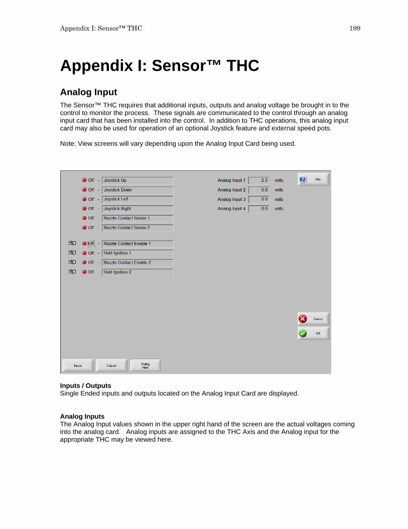
Appendix I: Sensor™ THC 199
Appendix I: Sensor™ THC Analog Input The Sensor™ THC requires that additional inputs, outputs and analog voltage be brought in to the control to monitor the process. These signals are communicated to the control through an analog input card that has been installed into the control. In addition to THC operations, this analog input card may also be used for operation of an optional Joystick feature and external speed pots. Note: View screens will vary depending upon the Analog Input Card being used.
Inputs / Outputs Single Ended inputs and outputs located on the Analog Input Card are displayed. Analog Inputs The Analog Input values shown in the upper right hand of the screen are the actual voltages coming into the analog card. Analog inputs are assigned to the THC Axis and the Analog input for the appropriate THC may be viewed here.

200 Installation & Setup Guide
Sensor™ THC Axis Setups The THC Axis screen is designed specifically for use with the Sensor™ THC.
Note: for proper operation, Sensor THC encoder counts should be approximately 20, 000 counts/ inch. Stall Force The Stall Force Parameter allows the user to select the amount of Following Error (inches / mm) to be used as the motion limit when Homing or performing manual IHS / plate sensing. Example: If the value is set to .1 inches, the THC Axis will continue to move the axis until .1 inches of following error has been reached. This will indicate the Plate location during IHS and will indicate the top of the slide during homing. Slide Length This parameter is used to specify the overall motion length of the Slide mechanism being used for the THC. This information is used to set the travel limits of the slide after homing. Home The Home parameter is used to activate use of the Home feature for the THC Axis. Depending on the Slide mechanism used, the THC may be Homed to Hard Stop, Hard Stop w/ Current Limit or Home Switch. Note: If the “Home to Hard Stop Current Limited” option is selected, the CNC Nozzle Contact Enable Output should be connected to the Current Limit Input of the amplifier to reduce torque during homing.

Appendix I: Sensor™ THC 201
The CNC Nozzle Contact Sense Input is used during Sensor™ THC Homing as the Home Switch Input if the “Home to Switch” option is selected. SERCOS Sensor THC Axis
Home/ IHS Current Limit The Home / IHS Current limit parameter allows the user to select a percentage of current limit to be used during homing and IHS functions.

202 Installation & Setup Guide
THC Speeds
THC Acceleration Rate This parameter allows the operator to set the acceleration rate for smooth and stable movement of the Sensor™ Torch Height Control. The higher the acceleration rate, the quicker the THC will get up to speed. The lower the acceleration rate, the smoother the machine will position the cutting device. Values are entered in Milligees. Maximum THC Speed Enter the maximum speed for the Sensor™ THC movement in inches/millimeters per minute. THC Jog Speed Enter a value for the desired THC jog speed. THC Home/Fast IHS Speed The THC Home/Fast IHS Speed entered here is used to home the torch at the top of the slide and to quickly maneuver the torch from the selected IHS height to the plate. THC Slow IHS Speed The THC IHS Speed is used to retract the torch after the plate has been sensed. The torch will retract at this speed until the contact sense is lost. This determines the exact distance to the plate, regardless of any flexing of the plate. A very small speed is recommended for optimal accuracy. Note: Due to the quick response time of the Sensor™ THC, generally there is no need for a value to be entered at the “Distance to Corner” parameter to lock or “freeze” the position of the torch. It is, however, suggested that a value be entered for the “Distance from Corner” to stabilize the torch during acceleration.

Appendix I: Sensor™ THC 203
THC I/O
Analog Offset 1 - 12 The Analog Offsets 1 through 12 are used to correct for any imbalance or “zero” the incoming analog voltage to the Analog Input Card. Analog inputs are assigned to the THC Axis and the Analog Offsets for the appropriate THC Analog input may be adjusted here. To calibrate the Analog Inputs, jumper the two pins specific to the input together and view the incoming voltage at the Diagnostics Analog I/O screen. The incoming voltage should be zero. If any voltage is displayed at the diagnostic screen, an Offset Voltage equal to the incoming voltage being read can be entered here to “zero” the incoming voltage. Please refer to the installation instructions later in this section for more details.

204 Installation & Setup Guide
Sensor™ THC Part Program Support Sensor™ THC offers the ability to configure THC setup parameters through part program codes. The following parameters are available for use using EIA-274D G59 codes:
Arc Voltage Pierce / Start Time Pierce/ Start Height Factor Cut / Mark Height
Setup is obtained using the following format. Example: G59 V601 Fvalue Misc. G Code Variable Identity
V600 = Plasma 1 Arc Voltage V601 = Plasma 1 Pierce Time V602 = Plasma 1 Pierce Height Factor V603 = Plasma 1 Cut Height V625 = Plasma 2 Arc Voltage V626 = Plasma 2 Pierce Time V627 = Plasma 2 Pierce Height Factor V628 = Plasma 2 Cut Height V650 = Marker 1 Arc Voltage V651 = Marker 1 Start Time V652 = Marker 1 Start Height Factor V653 = Marker 1 Mark Height V675 = Marker 2 Arc Voltage V676 = Marker 2 Start Time V677 = Marker 2 Start Height Factor V678 = Marker 2 Mark Height
Variable Value The selected value for the variable
Installation and THC Interface The Sensor ™ THC is supported through various hardware configurations to offer single and multiple Sensor™ THC operation. Please refer to your exact CNC hardware configuration when installing the Sensor™ THC.
Warning! Due to potentially high voltages, extreme care should be taken when working inside the plasma power supply. Work should only be performed by trained service personnel. Please refer to Power Supply manufacturer instructions.

Appendix J: Command® THC 205
Appendix J: Command® THC Machine Interface
Warning! Configure the port for RS-422 operation before connecting to the Command® THC. The Command THC Link must first be enabled in Machine Setups for Type “P” controls and at the Station configuration for type “V” controls. Refer to the Serial Port section of this guide for additional information on configuring the serial port for RS-422 communication. Port Designation Serial communications for the Command® THC would automatically be set to the serial port which is not selected for serial communications. Example: If Serial Port 1 is designated for use as the link to the Host PC for Downloading of part programs, the HD4070® communications would be established on Serial Port 2. Type “V” control may select the serial port designation at the Ports configuration screen. RS-422 Connections to Command® THC with 25-pin D-type connector Command® THC Control Signal Name DB-9 Pin Signal Name DB-9 Pin RxD - 1 TxD - 2 TxD - 2 RxD - 3 RxD + 20 TxD + 4 TxD + 21 RxD + 7 For improved noise immunity, it is recommended that the cable shields for communication be tied to ground. Ferrite bead with several wraps on the cable may also be used.

206 Installation & Setup Guide

Appendix K: Networking 207
Appendix K: Networking This information is provided to assist in the connection of the control to a customer’s local area network and some of the issues that may arise due to that connection. This list is by no means all inclusive but attempts to shed some light on the process. Because there are many different network systems, the general connection rules may need to be altered by a qualified network technician on a case by case basis. Network Operating System The Hypertherm Automation controllers are designed to work with Microsoft based network operating systems including: Windows NT 4.0 or later Workgroups Windows NT 4.0 or later Domains Windows 98 Workgroups In each case, the control has the name “CNC” and the user is “operator” with a password of “1396”. If you are connecting to a Domain then these names must be valid for the domain to which the controller is connecting. The controller is set up at the factory to automatically log into the network on power up. If it is necessary to change the user names and/or password you may have to go to the registry editor to make these changes. The appropriate keys are located in: HKEY_LOCAL_MACHINE->Software->Microsoft->Windows NT->CurrentVersion->WinLogon Entries must be provided here for the domain name (if used) and for the user name and password.
The Network functions involves operational knowledge of Windows® XP operating system and should only be performed by qualified personnel. Configuring the Controller There are several things that you need to be aware of in order to make the control work on the network. Setting these up will usually involve attaching a keyboard and mouse to the controller. Before you begin you need to know: A. Will you be using a DHCP Server on the network?
a. If NOT using a DHCP Server what are the TCP/IP network settings A. Will the controller be part of a Windows Domain or Workgroup? B. What is the name of the Domain or Workgroup? C. Has the “operator” user and password been added to the server? D. If using a Domain – you will need an administrator, or a user and password which allows joining a
new computer to the Domain.

208 Installation & Setup Guide
In the following steps when you need to enter a name or number, do NOT include the quotes " ! 1. Be sure that to create a user account on your network file server (Windows Server ?). a. The user name should be "operator" b. The password should be set to "1396" 2. Attach the keyboard and mouse to the controller, and plug the fiber optic card into the fiber to copper
converter box. 3. Plug the LAN cable into the network connector on the converter box, and supply power to the
converter box. 4. Turn on power to the controller. 5. When the control is up and running, press Setups (F4), then Password (F5), and enter "6931" for the
password. 6. Press the System (F5) button. 7. Press the "Network and Remote Tools" (F6) button. 8. When asked about Remote Assistant answer NO. 9. Double Click on the network interface connected to your LAN. 10. Click on Properties. 11. Scroll down to the Internet Protocol (TCP/IP) item and Double Click it. 12. If you are using a DHCP Server, then make sure that the IP address and DNS Server addresses are
set to automatic. 13. If you are NOT using DHCP then you will need to make these entries manually, see the attached
documents. 14. Press the Done or OK keys to get back to the Control program. 15. Press the Alt-F4 key pair to cancel out of the program and get back to Windows. 16. Go to the windows "Control Panel" 17. Double click on the "System". Select the "Computer Name" tab. Click on the "Change" button. 19. The computer name should be listed as CNC. Select either Domain or Workgroup, and enter the
appropriate name. 20. You will be asked for a name and password of an account to add to the Domain. This is the name
and password of an administrator who can add or change accounts on your server. 21. You should see a message welcoming you to the Domain. 22. Power down the controller and remove the keyboard and mouse. When you power up the control it
should log onto the network and you will be able to map to shared network directories.
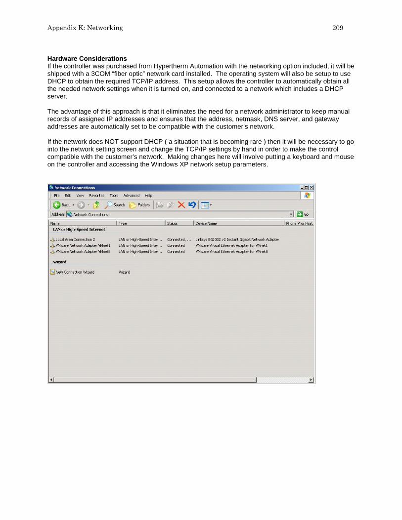
Appendix K: Networking 209
Hardware Considerations If the controller was purchased from Hypertherm Automation with the networking option included, it will be shipped with a 3COM “fiber optic” network card installed. The operating system will also be setup to use DHCP to obtain the required TCP/IP address. This setup allows the controller to automatically obtain all the needed network settings when it is turned on, and connected to a network which includes a DHCP server. The advantage of this approach is that it eliminates the need for a network administrator to keep manual records of assigned IP addresses and ensures that the address, netmask, DNS server, and gateway addresses are automatically set to be compatible with the customer’s network. If the network does NOT support DHCP ( a situation that is becoming rare ) then it will be necessary to go into the network setting screen and change the TCP/IP settings by hand in order to make the control compatible with the customer’s network. Making changes here will involve putting a keyboard and mouse on the controller and accessing the Windows XP network setup parameters.

210 Installation & Setup Guide
Select any listed network adapters that are NOT being used and double click.
Click on the “Disable” button to stop Windows from trying to service these unused adapters Select the Network adapter that is being used and double click on it.
Then Click on the “Properties” Button

Appendix K: Networking 211
You will now see a screen for setting the connection properties for the adapter actually being used for the network connection.
Scroll down and select the Internet Protocol (TCP/IP) entry. Then click on “Properties”
To use DHCP to assign the network parameters leave the settings set to obtain automatically.

212 Installation & Setup Guide
If a DHCP is NOT available, or if the intent is NOT to utilize one, then specify the needed address information. Note that in this case you MUST provide a valid IP address ( not used elsewhere in the network ) and the appropriate netmask and DNS Server address, as shown below. NOTE: These settings are EXAMPLES and NOT the ones to use for YOUR network.
Once the needed entries are made double check that only one network card is active and reboot the system. In some cases it may be desirable to install an alternative networking method, such as a wireless interface card. Hypertherm Automation has not tested all alternate systems here but customers have reported some degree of success with them. In any event, if a different network card is installed in the system then you MUST either remove the existing network card, or disable it. If a networking card is setup for DHCP operation, and is NOT connected to a DHCP server, then it will cause significant delays in the startup process and may lead to other problems. NOTE: The general rule should be that there is only ONE active network interface installed in the controller at any time.


Printed in the USARev 7.00
MANU-0050