A thermodynamic and experimental study of the conditions of thaumasite formation
13
A thermodynamic and experimental study of the conditions of thaumasite formation Thomas Schmidt a, ⁎ , Barbara Lothenbach a , Michael Romer a,c , Karen Scrivener b , Daniel Rentsch a , Renato Figi a a Empa, Swiss Federal Institute for Material Testing and Research, 8600 Dübendorf, Switzerland b EPFL, Swiss Federal Institute of Technology, Laboratory of Construction Materials, 1015 Lausanne, Switzerland c Holcim Group Support Ltd, 5113 Holderbank, Switzerland Received 25 May 2007; accepted 4 November 2007 Abstract The formation of thaumasite was investigated with the progressive equilibrium approach (PEA). This approach experimentally simulates the conditions of various levels of sulfate addition in hardened cement pastes. The influence of limestone, time, C 3 A content, temperature and leaching on thaumasite formation was investigated. The results show that thaumasite formation is favoured at lower temperatures (8 °C) independently of the type of cement clinker (high or low C 3 A content) used. Thaumasite was found to form only in systems where limestone was present and where sufficient sulfate had been added. Thaumasite precipitated only in systems where the Al present has already been consumed to form ettringite and the molar SO 3 /Al 2 O 3 ratio exceeded 3. In leached samples (reduction of portlandite and alkalis) slightly less thaumasite was formed whereas gypsum and ettringite are favoured under these conditions. The PEA, used to investigate the chemical aspects of sulfate attack was found to be a good tool for simulating external sulfate attack. Generally, thaumasite was detected were it was modelled to be stable in significant amounts. However, in this study equilibrium conditions were not reached after 9 months. © 2007 Elsevier Ltd. All rights reserved. Keywords: Thaumasite; Sulfate attack; Leaching; Temperature; Thermodynamic modelling 1. Introduction Sulfate attack in mortars and concretes causes the formation of sulfate containing phases such as ettringite (3CaO · Al 2 O 3 · 3CaSO 4 · 32H 2 O) and gypsum (CaSO 4 ·2H 2 O), which may lead to expansion. However, in cements and concretes containing a source of carbonate the formation of thaumasite (CaSiO 3 · CaCO 3 · CaSO 4 · 15H 2 O) can also be observed. In recent years thaumasite formation has been studied and some risk factors have been identified [1]. The thaumasite form of sulfate attack requires a source of calcium silicate, sulfate, carbonate and excess of humidity [2–5]. It has been found that thaumasite is more stable at lower temperatures. It has been suggested by Bensted [2,3] that silicon tends to adopt the octahedral co-ordination found in thaumasite more easily at lower temperatures. Nevertheless, thaumasite is formed also at temperatures around 20 °C and above as reported for buildings in Southern California [6] and Italy [7]. Once thaumasite has formed it remains stable up to 30 °C [8]. Thaumasite has been found in cement systems with both high and low C 3 A contents [9–11]. Thaumasite itself contains no alumina but it has been proposed that the presence of aluminium promotes thaumasite formation [11]. In contrast, Blanco-Valera et al. [9] found that low C 3 A cements produce higher amounts of thaumasite. The formation of thaumasite needs a source of carbonate which can be supplied from the limestone contained in the cement itself [12], from carbonate containing aggregates, ground waters [13], soils [5] or the air (CO 2 ) [14]. The presence of limestone used as filler in cement has been found to influence the type of AFm phase present; monocarbonate (C 3 A · CaCO 3 · 11H 2 O) forms instead of monosulfate (C 3 A · CaSO 4 · 12H 2 O) in the presence of calcite [15]. Available online at www.sciencedirect.com Cement and Concrete Research 38 (2008) 337 – 349 ⁎ Corresponding author. Tel.: +41 21 6932852; fax: +41 21 6935800. E-mail address: [email protected] (T. Schmidt). 0008-8846/$ - see front matter © 2007 Elsevier Ltd. All rights reserved. doi:10.1016/j.cemconres.2007.11.003
Transcript of A thermodynamic and experimental study of the conditions of thaumasite formation
Available online at www.sciencedirect.com
38 (2008) 337–349
Cement and Concrete ResearchA thermodynamic and experimental study of the conditionsof thaumasite formation
Thomas Schmidt a,⁎, Barbara Lothenbach a, Michael Romer a,c,Karen Scrivener b, Daniel Rentsch a, Renato Figi a
a Empa, Swiss Federal Institute for Material Testing and Research, 8600 Dübendorf, Switzerlandb EPFL, Swiss Federal Institute of Technology, Laboratory of Construction Materials, 1015 Lausanne, Switzerland
c Holcim Group Support Ltd, 5113 Holderbank, Switzerland
Received 25 May 2007; accepted 4 November 2007
Abstract
The formation of thaumasite was investigated with the progressive equilibrium approach (PEA). This approach experimentally simulates theconditions of various levels of sulfate addition in hardened cement pastes. The influence of limestone, time, C3A content, temperature andleaching on thaumasite formation was investigated. The results show that thaumasite formation is favoured at lower temperatures (8 °C)independently of the type of cement clinker (high or low C3A content) used. Thaumasite was found to form only in systems where limestone waspresent and where sufficient sulfate had been added. Thaumasite precipitated only in systems where the Al present has already been consumed toform ettringite and the molar SO3/Al2O3 ratio exceeded 3. In leached samples (reduction of portlandite and alkalis) slightly less thaumasite wasformed whereas gypsum and ettringite are favoured under these conditions. The PEA, used to investigate the chemical aspects of sulfate attackwas found to be a good tool for simulating external sulfate attack. Generally, thaumasite was detected were it was modelled to be stable insignificant amounts. However, in this study equilibrium conditions were not reached after 9 months.© 2007 Elsevier Ltd. All rights reserved.
Keywords: Thaumasite; Sulfate attack; Leaching; Temperature; Thermodynamic modelling
1. Introduction
Sulfate attack in mortars and concretes causes the formationof sulfate containing phases such as ettringite (3CaO·Al2O3 ·3CaSO4 ·32H2O) and gypsum (CaSO4 ·2H2O), which maylead to expansion. However, in cements and concretescontaining a source of carbonate the formation of thaumasite(CaSiO3 ·CaCO3 ·CaSO4 ·15H2O) can also be observed.
In recent years thaumasite formation has been studied andsome risk factors have been identified [1]. The thaumasite formof sulfate attack requires a source of calcium silicate, sulfate,carbonate and excess of humidity [2–5].
It has been found that thaumasite is more stable at lowertemperatures. It has been suggested by Bensted [2,3] that silicontends to adopt the octahedral co-ordination found in thaumasite
⁎ Corresponding author. Tel.: +41 21 6932852; fax: +41 21 6935800.E-mail address: [email protected] (T. Schmidt).
0008-8846/$ - see front matter © 2007 Elsevier Ltd. All rights reserved.doi:10.1016/j.cemconres.2007.11.003
more easily at lower temperatures. Nevertheless, thaumasite isformed also at temperatures around 20 °C and above as reportedfor buildings in Southern California [6] and Italy [7]. Oncethaumasite has formed it remains stable up to 30 °C [8].
Thaumasite has been found in cement systems with bothhigh and low C3A contents [9–11]. Thaumasite itself containsno alumina but it has been proposed that the presence ofaluminium promotes thaumasite formation [11]. In contrast,Blanco-Valera et al. [9] found that low C3A cements producehigher amounts of thaumasite.
The formation of thaumasite needs a source of carbonatewhich can be supplied from the limestone contained in the cementitself [12], from carbonate containing aggregates, ground waters[13], soils [5] or the air (CO2) [14]. The presence of limestoneused as filler in cement has been found to influence the type ofAFm phase present; monocarbonate (C3A·CaCO3·11H2O)forms instead of monosulfate (C3A·CaSO4·12H2O) in thepresence of calcite [15].
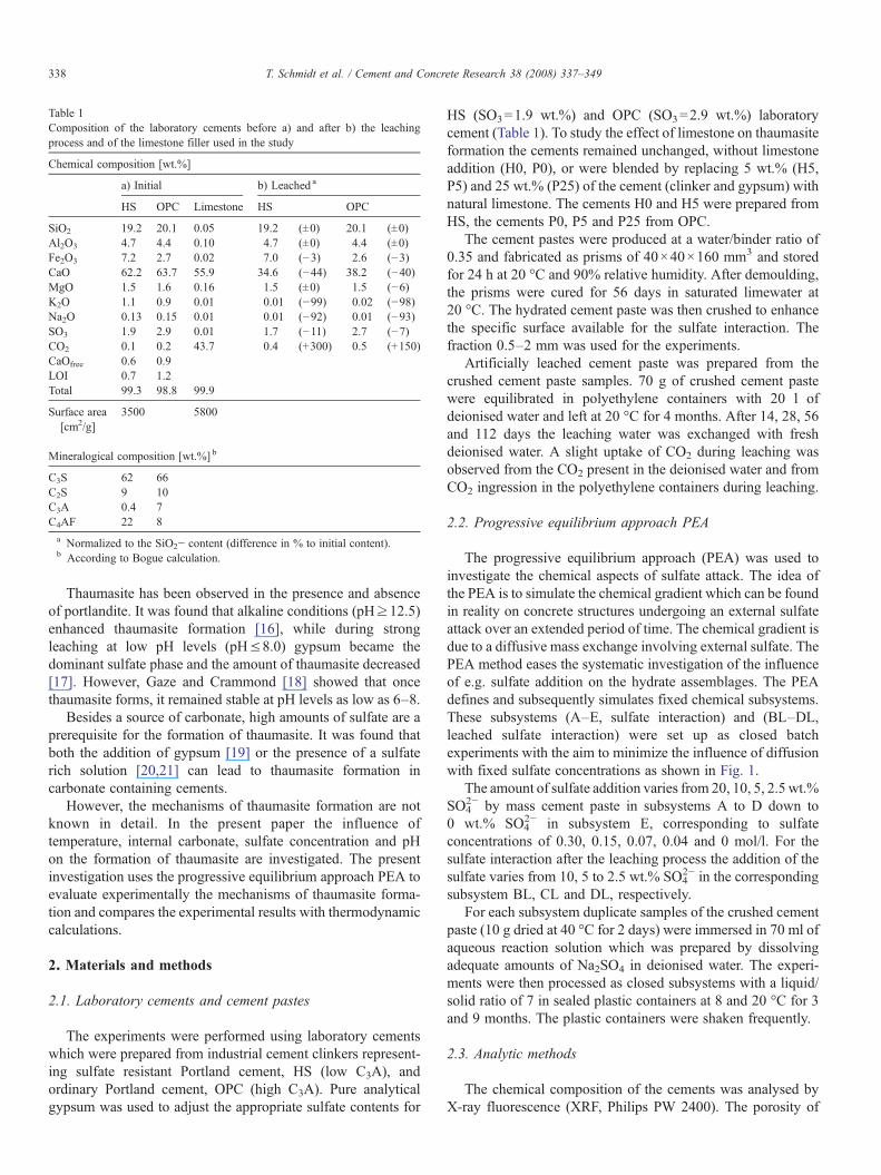
Table 1Composition of the laboratory cements before a) and after b) the leachingprocess and of the limestone filler used in the study
Chemical composition [wt.%]
a) Initial b) Leached a
HS OPC Limestone HS OPC
SiO2 19.2 20.1 0.05 19.2 (±0) 20.1 (±0)Al2O3 4.7 4.4 0.10 4.7 (±0) 4.4 (±0)Fe2O3 7.2 2.7 0.02 7.0 (−3) 2.6 (−3)CaO 62.2 63.7 55.9 34.6 (−44) 38.2 (−40)MgO 1.5 1.6 0.16 1.5 (±0) 1.5 (−6)K2O 1.1 0.9 0.01 0.01 (−99) 0.02 (−98)Na2O 0.13 0.15 0.01 0.01 (−92) 0.01 (−93)SO3 1.9 2.9 0.01 1.7 (−11) 2.7 (−7)CO2 0.1 0.2 43.7 0.4 (+300) 0.5 (+150)CaOfree 0.6 0.9LOI 0.7 1.2Total 99.3 98.8 99.9
Surface area[cm2/g]
3500 5800
Mineralogical composition [wt.%] b
C3S 62 66C2S 9 10C3A 0.4 7C4AF 22 8a Normalized to the SiO2− content (difference in % to initial content).b According to Bogue calculation.
338 T. Schmidt et al. / Cement and Concrete Research 38 (2008) 337–349
Thaumasite has been observed in the presence and absenceof portlandite. It was found that alkaline conditions (pH≥12.5)enhanced thaumasite formation [16], while during strongleaching at low pH levels (pH≤8.0) gypsum became thedominant sulfate phase and the amount of thaumasite decreased[17]. However, Gaze and Crammond [18] showed that oncethaumasite forms, it remained stable at pH levels as low as 6–8.
Besides a source of carbonate, high amounts of sulfate are aprerequisite for the formation of thaumasite. It was found thatboth the addition of gypsum [19] or the presence of a sulfaterich solution [20,21] can lead to thaumasite formation incarbonate containing cements.
However, the mechanisms of thaumasite formation are notknown in detail. In the present paper the influence oftemperature, internal carbonate, sulfate concentration and pHon the formation of thaumasite are investigated. The presentinvestigation uses the progressive equilibrium approach PEA toevaluate experimentally the mechanisms of thaumasite forma-tion and compares the experimental results with thermodynamiccalculations.
2. Materials and methods
2.1. Laboratory cements and cement pastes
The experiments were performed using laboratory cementswhich were prepared from industrial cement clinkers represent-ing sulfate resistant Portland cement, HS (low C3A), andordinary Portland cement, OPC (high C3A). Pure analyticalgypsum was used to adjust the appropriate sulfate contents for
HS (SO3=1.9 wt.%) and OPC (SO3=2.9 wt.%) laboratorycement (Table 1). To study the effect of limestone on thaumasiteformation the cements remained unchanged, without limestoneaddition (H0, P0), or were blended by replacing 5 wt.% (H5,P5) and 25 wt.% (P25) of the cement (clinker and gypsum) withnatural limestone. The cements H0 and H5 were prepared fromHS, the cements P0, P5 and P25 from OPC.
The cement pastes were produced at a water/binder ratio of0.35 and fabricated as prisms of 40×40×160 mm3 and storedfor 24 h at 20 °C and 90% relative humidity. After demoulding,the prisms were cured for 56 days in saturated limewater at20 °C. The hydrated cement paste was then crushed to enhancethe specific surface available for the sulfate interaction. Thefraction 0.5–2 mm was used for the experiments.
Artificially leached cement paste was prepared from thecrushed cement paste samples. 70 g of crushed cement pastewere equilibrated in polyethylene containers with 20 l ofdeionised water and left at 20 °C for 4 months. After 14, 28, 56and 112 days the leaching water was exchanged with freshdeionised water. A slight uptake of CO2 during leaching wasobserved from the CO2 present in the deionised water and fromCO2 ingression in the polyethylene containers during leaching.
2.2. Progressive equilibrium approach PEA
The progressive equilibrium approach (PEA) was used toinvestigate the chemical aspects of sulfate attack. The idea ofthe PEA is to simulate the chemical gradient which can be foundin reality on concrete structures undergoing an external sulfateattack over an extended period of time. The chemical gradient isdue to a diffusive mass exchange involving external sulfate. ThePEA method eases the systematic investigation of the influenceof e.g. sulfate addition on the hydrate assemblages. The PEAdefines and subsequently simulates fixed chemical subsystems.These subsystems (A–E, sulfate interaction) and (BL–DL,leached sulfate interaction) were set up as closed batchexperiments with the aim to minimize the influence of diffusionwith fixed sulfate concentrations as shown in Fig. 1.
The amount of sulfate addition varies from 20, 10, 5, 2.5 wt.%SO4
2− by mass cement paste in subsystems A to D down to0 wt.% SO4
2− in subsystem E, corresponding to sulfateconcentrations of 0.30, 0.15, 0.07, 0.04 and 0 mol/l. For thesulfate interaction after the leaching process the addition of thesulfate varies from 10, 5 to 2.5 wt.% SO4
2− in the correspondingsubsystem BL, CL and DL, respectively.
For each subsystem duplicate samples of the crushed cementpaste (10 g dried at 40 °C for 2 days) were immersed in 70 ml ofaqueous reaction solution which was prepared by dissolvingadequate amounts of Na2SO4 in deionised water. The experi-ments were then processed as closed subsystems with a liquid/solid ratio of 7 in sealed plastic containers at 8 and 20 °C for 3and 9 months. The plastic containers were shaken frequently.
2.3. Analytic methods
The chemical composition of the cements was analysed byX-ray fluorescence (XRF, Philips PW 2400). The porosity of
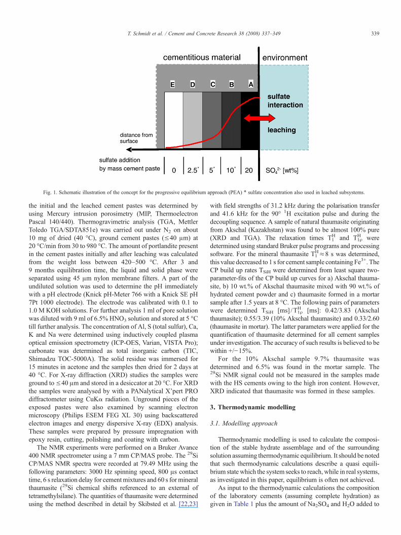
Fig. 1. Schematic illustration of the concept for the progressive equilibrium approach (PEA) ⁎ sulfate concentration also used in leached subsystems.
339T. Schmidt et al. / Cement and Concrete Research 38 (2008) 337–349
the initial and the leached cement pastes was determined byusing Mercury intrusion porosimetry (MIP, ThermoelectronPascal 140/440). Thermogravimetric analysis (TGA, MettlerToledo TGA/SDTA851e) was carried out under N2 on about10 mg of dried (40 °C), ground cement pastes (≤40 μm) at20 °C/min from 30 to 980 °C. The amount of portlandite presentin the cement pastes initially and after leaching was calculatedfrom the weight loss between 420–500 °C. After 3 and9 months equilibration time, the liquid and solid phase wereseparated using 45 μm nylon membrane filters. A part of theundiluted solution was used to determine the pH immediatelywith a pH electrode (Knick pH-Meter 766 with a Knick SE pH7Pt 1000 electrode). The electrode was calibrated with 0.1 to1.0 M KOH solutions. For further analysis 1 ml of pore solutionwas diluted with 9 ml of 6.5% HNO3 solution and stored at 5 °Ctill further analysis. The concentration of Al, S (total sulfur), Ca,K and Na were determined using inductively coupled plasmaoptical emission spectrometry (ICP-OES, Varian, VISTA Pro);carbonate was determined as total inorganic carbon (TIC,Shimadzu TOC-5000A). The solid residue was immersed for15 minutes in acetone and the samples then dried for 2 days at40 °C. For X-ray diffraction (XRD) studies the samples wereground to≤40 μm and stored in a desiccator at 20 °C. For XRDthe samples were analysed by with a PANalytical X'pert PROdiffractometer using CuKα radiation. Unground pieces of theexposed pastes were also examined by scanning electronmicroscopy (Philips ESEM FEG XL 30) using backscatteredelectron images and energy dispersive X-ray (EDX) analysis.These samples were prepared by pressure impregnation withepoxy resin, cutting, polishing and coating with carbon.
The NMR experiments were performed on a Bruker Avance400 NMR spectrometer using a 7 mm CP/MAS probe. The 29SiCP/MAS NMR spectra were recorded at 79.49 MHz using thefollowing parameters: 3000 Hz spinning speed, 800 μs contacttime, 6 s relaxation delay for cementmixtures and 60 s for mineralthaumasite (29Si chemical shifts referenced to an external oftetramethylsilane). The quantities of thaumasite were determinedusing the method described in detail by Skibsted et al. [22,23]
with field strengths of 31.2 kHz during the polarisation transferand 41.6 kHz for the 90° 1H excitation pulse and during thedecoupling sequence. A sample of natural thaumasite originatingfrom Akschal (Kazakhstan) was found to be almost 100% pure(XRD and TGA). The relaxation times T1
H and T1ρH were
determined using standard Bruker pulse programs and processingsoftware. For the mineral thaumasite T1
H≈8 s was determined,this value decreased to 1 s for cement sample containing Fe3+. TheCP build up rates TSiH were determined from least square two-parameter-fits of the CP build up curves for a) Akschal thauma-site, b) 10 wt.% of Akschal thaumasite mixed with 90 wt.% ofhydrated cement powder and c) thaumasite formed in a mortarsample after 1.5 years at 8 °C. The following pairs of parameterswere determined TSiH [ms] /T1ρ
H [ms]: 0.42/3.83 (Akschalthaumasite); 0.55/3.39 (10% Akschal thaumasite) and 0.33/2.60(thaumasite in mortar). The latter parameters were applied for thequantification of thaumasite determined for all cement samplesunder investigation. The accuracy of such results is believed to bewithin +/−15%.
For the 10% Akschal sample 9.7% thaumasite wasdetermined and 6.5% was found in the mortar sample. The29Si NMR signal could not be measured in the samples madewith the HS cements owing to the high iron content. However,XRD indicated that thaumasite was formed in these samples.
3. Thermodynamic modelling
3.1. Modelling approach
Thermodynamic modelling is used to calculate the composi-tion of the stable hydrate assemblage and of the surroundingsolution assuming thermodynamic equilibrium. It should be notedthat such thermodynamic calculations describe a quasi equili-brium state which the system seeks to reach, while in real systems,as investigated in this paper, equilibrium is often not achieved.
As input to the thermodynamic calculations the compositionof the laboratory cements (assuming complete hydration) asgiven in Table 1 plus the amount of Na2SO4 and H2O added to
340 T. Schmidt et al. / Cement and Concrete Research 38 (2008) 337–349
the systemwas used. The hydrate phases which were found to bestable in the investigated systems comprise C–S–H, portlandite,ettringite, thaumasite, monosulfate, monocarbonate, hemicarbo-nate (C3A∙0.5CaCO3∙12H2O), calcite, gypsum and hydrotalcite(M4AH10). For iron the precipitation of iron hydroxide (Fe(OH)3or FH3) was assumed. As detailed elsewhere [24,25] C–S–Hwas calculated as a ideal solid solution between the end-membersjennite C1.67SH2.1 and tobermorite C0.83SH1.3. For the modellingitwas considered that the alkalis which originate from the cementsand from the Na2SO4 solution used, partition between theaqueous solution and the precipitating C–S–H. The uptake of Naand K by C–S–H was calculated using a distribution ratio Rd of0.42 ml/g [24,25], where Rd ¼ csw
cdsmlg
h i, cs alkali concentration in
the solid phase [mol/l], cd alkali concentration in the solution[mol/l] and w/s is the water/C–S–H ratio in ml/g.
3.2. Thermodynamic model and data
GEMS [26] is a broad-purpose geochemical modelling codewhich uses Gibbs energy minimization and computes equili-brium phase assemblage and speciation in a complex chemicalsystem from its total bulk elemental composition. Chemicalinteractions involving solids, solid solutions, and aqueouselectrolyte are considered simultaneously.
Thermodynamic data for aqueous species as well as formany solids were taken from the PSI thermodynamic dataset[27], which has been adapted for the use in GEMS [28].Solubility products for cement minerals at 25 °C were takenfrom the compilation of Lothenbach et al., [24] who prepared a
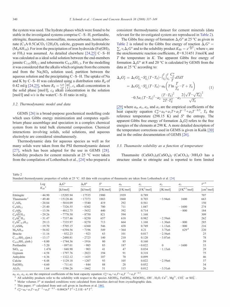
Table 2Standard thermodynamic properties of solids at 25 °C. All data with exception of th
LogKS0
aΔfG° ΔfH° S°
[kJ/mol] [kJ/mol] [J/K/mol]
Ettringite −44.90 −15205.94 −17535 1900Thaumasite c −49.40 −15128.46 −17373 1883C3AH6 −20.84 −5010.09 −5540 419C4AH13 −25.40 −7326.55 −8302 700C2AH8 −13.56 −4812.75 −5432 440C4AS
PH12 −29.26 −7778.50 −8750 821
C4ACP
H11 −31.47 −7337.46 −8250 657C4AC
P0.5H12 29.13 −7335.97 −8270 713
C2ASH8 −19.70 −5705.15 −6360 546M4AH10 −56.02 −6394.56 −7196 549Brucite −11.16 −832.23 −923 63C1.67SH2.1(jen.) −13.17 −2480.81 −2723 140C0.83SH1.3(tob.) −8.00 −1744.36 −1916 80Portlandite −5.20 −897.01 −985 83SiO2, am 1.476 −848.90 −903 41Gypsum −4.58 −1797.76 −2023 194Anhydrite −4.36 −1322.12 −1435 107Calcite −8.48 −1129.18 −1207 93Fe(OH)3 −4.60 −711.61 −844 88Al2O3 1.64 −1586.26 −1662 51
a0, a1, a2, a3 are the empirical coefficients of the heat capacity equation: C°p=a0+a1a All solubility products refer to the solubility with respect to the species Al(OHb Molar volumes V° at standard conditions were calculated from densities derivec This paper; V° calculated from unit cell given in Jacobson et al. [46].d C°p=a0+a1T+a2T
−2+a3T−0.5−0.00424⁎T 2+2.11E−6⁎T 3.
consistent thermodynamic dataset for cement minerals (datarelevant for the investigated system are reproduced in Table 2).
The Gibbs free energy of formationΔfG° at 25 °C as given inTable 2 is related to the Gibbs free energy of reaction ΔrG- ¼∑i viΔfG- and to the solubility product KS0 ¼ e
−ΔrG-RT ; where vi are
the stoichiometric reaction coefficients, R=8.31451 J/mol/K andT the temperature in K. The apparent Gibbs free energy offormation ΔaG° at 8 and 20 °C is calculated by GEMS from thedata at 25 °C according to:
ΔaGoT ¼ ΔfGo
T0−SoT0 T−T0ð Þ−∫TT0 ∫
T
T0
Cop
TdTdT
¼ ΔfGoT0−S
oT0 T−T0ð Þ−a0 T ln
TT0
−T þ T0
� �
−0:5a1 T−T0ð Þ2−a2 T−T0ð Þ22T⋅T2
0
−a32
ffiffiffiffiT
p−
ffiffiffiffiffiT0
p� �2ffiffiffiffiffiT0
p
ð1Þ
[29] where a0, a1, a2, and a3 are the empirical coefficients of theheat capacity equation C°p=a0+a1T+a2T
−2+a3T−0.5, T0 the
reference temperature (298.15 K) and S° the entropy. Theapparent Gibbs free energy of formation ΔaG°T refers to the freeenergies of the elements at 298 K. A more detailed description ofthe temperature corrections used in GEMS is given in Kulik [30]and in the online documentation of GEMS [26].
3.3. Thaumasite solubility as a function of temperature
Thaumasite (CaSiO3)2(CaSO4)2 · (CaCO3)2 ·30H2O has astructure similar to ettringite and is reported to form limited
aumasite are taken from Lothenbach et al. [24]
a0 a1 a2 a3 V° b
[J/K/mol] [J/K2/mol] [JK/mol] [J/K0.5/mol] [cm3/mol]
1939 0.789 7071860 0.703 −3.94e6 1600 663292 0.561 150711 1.047 −1600 274392 0.714 −800 184594 1.168 309618 0.982 −2.59e6 262664 1.168 −1.30e6 −800 285438 0.749 −1.13e6 −800 216
−364 4.21 3.75e6 629 d 220101 0.017 −2.56e6 25210 0.120 −3.07e6 7885 0.160 59187 −0.022 0 −1600 3347 0.034 −1.13e6 2991 0.318 7570 0.099 46105 0.022 −2.59e6 3728 0.052 34115 0.012 −3.51e6 26
T+a2T−2+a3T
−0.5.)4−, Fe(OH)4
−, SiO(OH)3−, OH−, H2O, Ca
2+, Mg2+, CO32− or SO4
2−.d from crystallographic data.
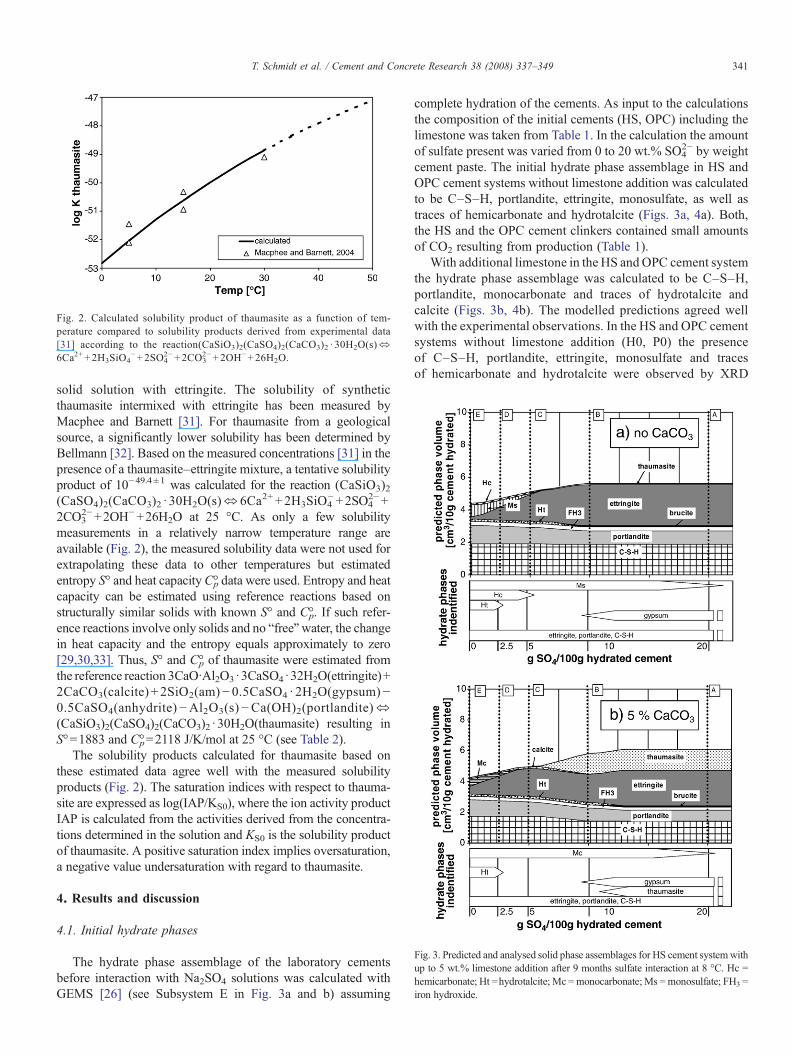
Fig. 2. Calculated solubility product of thaumasite as a function of tem-perature compared to solubility products derived from experimental data[31] according to the reaction(CaSiO3)2(CaSO4)2(CaCO3)2 · 30H2O(s)⬄6Ca2++2H3SiO4
−+2SO42−+2CO3
2−+2OH−+26H2O.
Fig. 3. Predicted and analysed solid phase assemblages for HS cement systemwithup to 5 wt.% limestone addition after 9 months sulfate interaction at 8 °C. Hc =hemicarbonate; Ht =hydrotalcite; Mc =monocarbonate; Ms =monosulfate; FH3 =iron hydroxide.
341T. Schmidt et al. / Cement and Concrete Research 38 (2008) 337–349
solid solution with ettringite. The solubility of syntheticthaumasite intermixed with ettringite has been measured byMacphee and Barnett [31]. For thaumasite from a geologicalsource, a significantly lower solubility has been determined byBellmann [32]. Based on the measured concentrations [31] in thepresence of a thaumasite–ettringite mixture, a tentative solubilityproduct of 10−49.4±1 was calculated for the reaction (CaSiO3)2(CaSO4)2(CaCO3)2 · 30H2O(s)⇔6Ca2+ +2H3SiO4
−+2SO42−+
2CO32−+2OH−+26H2O at 25 °C. As only a few solubility
measurements in a relatively narrow temperature range areavailable (Fig. 2), the measured solubility data were not used forextrapolating these data to other temperatures but estimatedentropy S° and heat capacityC°p data were used. Entropy and heatcapacity can be estimated using reference reactions based onstructurally similar solids with known S° and C°p. If such refer-ence reactions involve only solids and no “free”water, the changein heat capacity and the entropy equals approximately to zero[29,30,33]. Thus, S° and C°p of thaumasite were estimated fromthe reference reaction 3CaO·Al2O3·3CaSO4·32H2O(ettringite)+2CaCO3(calcite) + 2SiO2(am)−0.5CaSO4 · 2H2O(gypsum)−0.5CaSO4(anhydrite)−Al2O3(s)−Ca(OH)2(portlandite)⬄(CaSiO3)2(CaSO4)2(CaCO3)2 ·30H2O(thaumasite) resulting inS°=1883 and C°p=2118 J/K/mol at 25 °C (see Table 2).
The solubility products calculated for thaumasite based onthese estimated data agree well with the measured solubilityproducts (Fig. 2). The saturation indices with respect to thauma-site are expressed as log(IAP/KS0), where the ion activity productIAP is calculated from the activities derived from the concentra-tions determined in the solution and KS0 is the solubility productof thaumasite. A positive saturation index implies oversaturation,a negative value undersaturation with regard to thaumasite.
4. Results and discussion
4.1. Initial hydrate phases
The hydrate phase assemblage of the laboratory cementsbefore interaction with Na2SO4 solutions was calculated withGEMS [26] (see Subsystem E in Fig. 3a and b) assuming
complete hydration of the cements. As input to the calculationsthe composition of the initial cements (HS, OPC) including thelimestone was taken from Table 1. In the calculation the amountof sulfate present was varied from 0 to 20 wt.% SO4
2− by weightcement paste. The initial hydrate phase assemblage in HS andOPC cement systems without limestone addition was calculatedto be C–S–H, portlandite, ettringite, monosulfate, as well astraces of hemicarbonate and hydrotalcite (Figs. 3a, 4a). Both,the HS and the OPC cement clinkers contained small amountsof CO2 resulting from production (Table 1).
With additional limestone in the HS and OPC cement systemthe hydrate phase assemblage was calculated to be C–S–H,portlandite, monocarbonate and traces of hydrotalcite andcalcite (Figs. 3b, 4b). The modelled predictions agreed wellwith the experimental observations. In the HS and OPC cementsystems without limestone addition (H0, P0) the presenceof C–S–H, portlandite, ettringite, monosulfate and tracesof hemicarbonate and hydrotalcite were observed by XRD
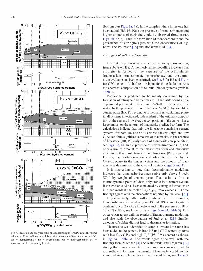
Fig. 4. Predicted and analysed solid phase assemblages for OPC cement systemswith up to 25 wt.% limestone addition after 9 months sulfate interaction at 8 °C.Hc = hemicarbonate; Ht = hydrotalcite; Mc = monocarbonate; Ms =monosulfate; FH3 = iron hydroxide.
342 T. Schmidt et al. / Cement and Concrete Research 38 (2008) 337–349
(bottom part Figs. 3a, 4a). In the samples where limestone hasbeen added (H5, P5, P25) the presence of monocarbonate andhigher amounts of ettringite could be observed (bottom partFigs. 3b, 4b, c). Thus, the formation of monocarbonate and thepersistence of ettringite agree with the observations of e.g.Kuzel and Pöllmann [15] and Bonavetti et al. [34].
4.2. Effect of sulfate interaction
If sulfate is progressively added to the subsystems movingfrom subsystem E to A thermodynamic modelling indicates thatettringite is formed at the expense of the AFm-phases(monosulfate, monocarbonate, hemicarbonate) until the alumi-nium available has been consumed, see Fig. 3 for HS and Fig. 4for OPC cement. As before, the input for the calculations wasthe chemical composition of the initial binder systems given inTable 1.
Portlandite is predicted to be mainly consumed by theformation of ettringite and thaumasite. Thaumasite forms at theexpense of portlandite, calcite and C–S–H in the presence ofwater. In the presence of more than 5 wt.% SO4
2− by weight ofcement paste (H5, P5), ettringite is the main Al-containing phasein all systems investigated, independent of the original composi-tion of the cement. However, the composition of the cement has alarge impact on the amount of thaumasite predicted to form. Thecalculations indicate that only the limestone containing cementsystems, for both HS and OPC cement clinkers (high and lowC3A) can form significant amounts of thaumasite. In the absenceof limestone (H0, P0) only traces of thaumasite can precipitate,see Figs. 3a, 4a. In the presence of 5 wt.% limestone (H5, P5),only a limited amount of thaumasite can form and obviouslymuch more thaumasite forms if more limestone (P25) is present.Further, thaumasite formation is calculated to be limited by theC–S–H phase in the binder system and the amount of thau-masite is detrimental to the C–S–H content (Figs. 3 and 4).
It is interesting to note that thermodynamic modellingindicates that thaumasite becomes stable only above 5 wt.%SO4
2− by weight of cement paste. Thaumasite is, from athermodynamic point of view, only stable in a cement systemif the available Al has been consumed by ettringite formation orin other words if the molar SO3/Al2O3 ratio exceeds 3. Thesefindings agrees with the observations reported by Juel et al. [21].
Experimentally, after sulfate interaction of 9 months,thaumasite was observed only in HS and OPC cement systemscontaining 5 or 25 wt.% limestone and in the presence of 10 or20 wt.% sulfate, see lower parts of Figs. 3 and 4, Table 3). Thisobservation agrees with the results of thermodynamic modellingand also with the observations of Juel et al. [21]. Smalleramounts of sulfate did not lead to thaumasite formation.
Thaumasite was identified in samples where limestone hasbeen added to the cement, in both HS and OPC cement systemswith low C3A (H5) and high C3A (P5, P25) content as shownin Fig. 5a, Table 3). The results agree quite well with thefindings from Macphee [8] and Kalinowski and Trägardh [12]stating that minor amounts of carbonate in cements (5 wt.%)are sufficient to form thaumasite. Thaumasite could not beidentified in samples without limestone addition, see Table 3.
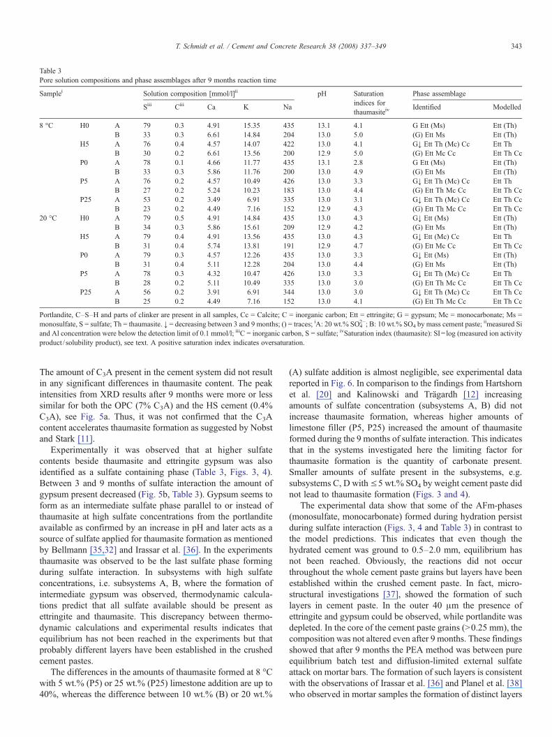
Table 3Pore solution compositions and phase assemblages after 9 months reaction time
Samplei Solution composition [mmol/l]ii pH Saturationindices forthaumasiteiv
Phase assemblage
Siii Ciii Ca K Na Identified Modelled
8 °C H0 A 79 0.3 4.91 15.35 435 13.1 4.1 G Ett (Ms) Ett (Th)B 33 0.3 6.61 14.84 204 13.0 5.0 (G) Ett Ms Ett (Th)
H5 A 76 0.4 4.57 14.07 422 13.0 4.1 G↓ Ett Th (Mc) Cc Ett ThB 30 0.2 6.61 13.56 200 12.9 5.0 (G) Ett Mc Cc Ett Th Cc
P0 A 78 0.1 4.66 11.77 435 13.1 2.8 G Ett (Ms) Ett (Th)B 33 0.3 5.86 11.76 200 13.0 4.9 (G) Ett Ms Ett (Th)
P5 A 76 0.2 4.57 10.49 426 13.0 3.3 G↓ Ett Th (Mc) Cc Ett ThB 27 0.2 5.24 10.23 183 13.0 4.4 (G) Ett Th Mc Cc Ett Th Cc
P25 A 53 0.2 3.49 6.91 335 13.0 3.1 G↓ Ett Th (Mc) Cc Ett Th CcB 23 0.2 4.49 7.16 152 12.9 4.3 (G) Ett Th Mc Cc Ett Th Cc
20 °C H0 A 79 0.5 4.91 14.84 435 13.0 4.3 G↓ Ett (Ms) Ett (Th)B 34 0.3 5.86 15.61 209 12.9 4.2 (G) Ett Ms Ett (Th)
H5 A 79 0.4 4.91 13.56 435 13.0 4.3 G↓ Ett (Mc) Cc Ett ThB 31 0.4 5.74 13.81 191 12.9 4.7 (G) Ett Mc Cc Ett Th Cc
P0 A 79 0.3 4.57 12.26 435 13.0 3.3 G↓ Ett (Ms) Ett (Th)B 31 0.4 5.11 12.28 204 13.0 4.4 (G) Ett Ms Ett (Th)
P5 A 78 0.3 4.32 10.47 426 13.0 3.3 G↓ Ett Th (Mc) Cc Ett ThB 28 0.2 5.11 10.49 335 13.0 3.0 (G) Ett Th Mc Cc Ett Th Cc
P25 A 56 0.2 3.91 6.91 344 13.0 3.0 G↓ Ett Th (Mc) Cc Ett Th CcB 25 0.2 4.49 7.16 152 13.0 4.1 (G) Ett Th Mc Cc Ett Th Cc
Portlandite, C–S–H and parts of clinker are present in all samples, Cc = Calcite; C = inorganic carbon; Ett = ettringite; G = gypsum; Mc = monocarbonate; Ms =monosulfate, S = sulfate; Th = thaumasite. ↓ = decreasing between 3 and 9 months; () = traces; iA: 20 wt.% SO4
2−; B: 10 wt.% SO4 by mass cement paste; iimeasured Siand Al concentration were below the detection limit of 0.1 mmol/l; iiiC = inorganic carbon, S = sulfate; ivSaturation index (thaumasite): SI= log (measured ion activityproduct / solubility product), see text. A positive saturation index indicates oversaturation.
343T. Schmidt et al. / Cement and Concrete Research 38 (2008) 337–349
The amount of C3A present in the cement system did not resultin any significant differences in thaumasite content. The peakintensities from XRD results after 9 months were more or lesssimilar for both the OPC (7% C3A) and the HS cement (0.4%C3A), see Fig. 5a. Thus, it was not confirmed that the C3Acontent accelerates thaumasite formation as suggested by Nobstand Stark [11].
Experimentally it was observed that at higher sulfatecontents beside thaumasite and ettringite gypsum was alsoidentified as a sulfate containing phase (Table 3, Figs. 3, 4).Between 3 and 9 months of sulfate interaction the amount ofgypsum present decreased (Fig. 5b, Table 3). Gypsum seems toform as an intermediate sulfate phase parallel to or instead ofthaumasite at high sulfate concentrations from the portlanditeavailable as confirmed by an increase in pH and later acts as asource of sulfate applied for thaumasite formation as mentionedby Bellmann [35,32] and Irassar et al. [36]. In the experimentsthaumasite was observed to be the last sulfate phase formingduring sulfate interaction. In subsystems with high sulfateconcentrations, i.e. subsystems A, B, where the formation ofintermediate gypsum was observed, thermodynamic calcula-tions predict that all sulfate available should be present asettringite and thaumasite. This discrepancy between thermo-dynamic calculations and experimental results indicates thatequilibrium has not been reached in the experiments but thatprobably different layers have been established in the crushedcement pastes.
The differences in the amounts of thaumasite formed at 8 °Cwith 5 wt.% (P5) or 25 wt.% (P25) limestone addition are up to40%, whereas the difference between 10 wt.% (B) or 20 wt.%
(A) sulfate addition is almost negligible, see experimental datareported in Fig. 6. In comparison to the findings from Hartshornet al. [20] and Kalinowski and Trägardh [12] increasingamounts of sulfate concentration (subsystems A, B) did notincrease thaumasite formation, whereas higher amounts oflimestone filler (P5, P25) increased the amount of thaumasiteformed during the 9 months of sulfate interaction. This indicatesthat in the systems investigated here the limiting factor forthaumasite formation is the quantity of carbonate present.Smaller amounts of sulfate present in the subsystems, e.g.subsystems C, D with≤5 wt.% SO4 by weight cement paste didnot lead to thaumasite formation (Figs. 3 and 4).
The experimental data show that some of the AFm-phases(monosulfate, monocarbonate) formed during hydration persistduring sulfate interaction (Figs. 3, 4 and Table 3) in contrast tothe model predictions. This indicates that even though thehydrated cement was ground to 0.5–2.0 mm, equilibrium hasnot been reached. Obviously, the reactions did not occurthroughout the whole cement paste grains but layers have beenestablished within the crushed cement paste. In fact, micro-structural investigations [37], showed the formation of suchlayers in cement paste. In the outer 40 μm the presence ofettringite and gypsum could be observed, while portlandite wasdepleted. In the core of the cement paste grains (N0.25 mm), thecomposition was not altered even after 9 months. These findingsshowed that after 9 months the PEA method was between pureequilibrium batch test and diffusion-limited external sulfateattack on mortar bars. The formation of such layers is consistentwith the observations of Irassar et al. [36] and Planel et al. [38]who observed in mortar samples the formation of distinct layers
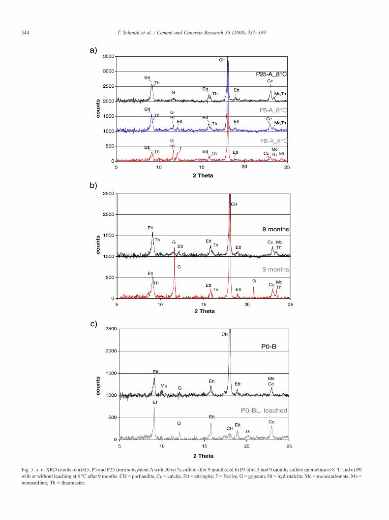
Fig. 5. a–c: XRD results of a) H5, P5 and P25 from subsystem Awith 20 wt.% sulfate after 9 months; of b) P5 after 3 and 9 months sulfate interaction at 8 °C and c) P0with or without leaching at 8 °C after 9 months. CH = portlandite, Cc = calcite, Ett = ettringite; F = Ferrite, G = gypsum; Ht = hydrotalcite; Mc = monocarbonate, Ms =monosulfate, Th = thaumasite.
344 T. Schmidt et al. / Cement and Concrete Research 38 (2008) 337–349
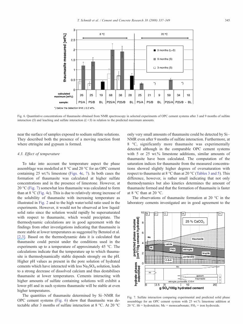
Fig. 6. Quantitative concentrations of thaumasite obtained from NMR spectroscopy in selected experiments of OPC cement systems after 3 and 9 months of sulfateinteraction (S) and leaching and sulfate interaction (L+S) in relation to the predicted maximum amounts.
Fig. 7. Sulfate interaction comparing experimental and predicted solid phaseassemblage for an OPC cement system with 25 wt.% limestone addition at20 °C. Ht = hydrotalcite; Mc = monocarbonate; FH3 = iron hydroxide.
345T. Schmidt et al. / Cement and Concrete Research 38 (2008) 337–349
near the surface of samples exposed to sodium sulfate solutions.They described both the presence of a moving reaction frontwhere ettringite and gypsum is formed.
4.3. Effect of temperature
To take into account the temperature aspect the phaseassemblage was modelled at 8 °C and 20 °C for an OPC cementcontaining 25 wt.% limestone (Figs. 4c, 7). In both cases theformation of thaumasite was calculated at higher sulfateconcentrations and in the presence of limestone. However, at20 °C (Fig. 7) somewhat less thaumasite was calculated to formthan at 8 °C (Fig. 4c). This is due to relatively strong increase ofthe solubility of thaumasite with increasing temperature asillustrated in Fig. 2 and to the high water/solid ratio used in theexperiments. However, it would not be observed at low liquid/solid ratio since the solution would rapidly be supersaturatedwith respect to thaumasite, which would precipitate. Thethermodynamic calculations are in good agreement with thefindings from other investigations indicating that thaumasite ismore stable at lower temperatures as suggested by Bensted et al.[2,3]. Based on the thermodynamic data it is calculated thatthaumasite could persist under the conditions used in theexperiments up to a temperature of approximately 45 °C. Thecalculations indicate that the temperature up to which thauma-site is thermodynamically stable depends strongly on the pH.Higher pH values as present in the pore solution of hydratedcements which have interacted with less Na2SO4 solution, leadsto a strong decrease of dissolved calcium and thus destabilisesthaumasite at lower temperatures. Cements interacting withhigher amounts of sulfate containing solutions will exhibit alower pH and in such systems thaumasite will be stable at evenhigher temperatures.
The quantities of thaumasite determined by Si–NMR forOPC cement systems (Fig. 6) show that thaumasite was de-tectable after 3 months of sulfate interaction at 8 °C. At 20 °C
only very small amounts of thaumasite could be detected by Si–NMR even after 9 months of sulfate interaction. Furthermore, at8 °C, significantly more thaumasite was experimentallydetected although in the comparable OPC cement systemswith 5 or 25 wt.% limestone additions, similar amounts ofthaumasite have been calculated. The computation of thesaturation indices for thaumasite from the measured concentra-tions showed slightly higher degrees of oversaturation withrespect to thaumasite at 8 °C than at 20 °C (Tables 3 and 5). Thisdifference, however, is rather small indicating that not onlythermodynamics but also kinetics determines the amount ofthaumasite formed and that the formation of thaumasite is fasterat 8 °C than at 20 °C.
The observations of thaumasite formation at 20 °C in thelaboratory cements investigated are in good agreement to the
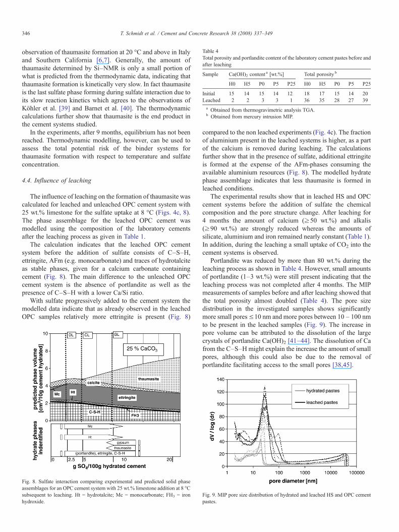
Table 4Total porosity and portlandite content of the laboratory cement pastes before andafter leaching
Sample Ca(OH)2 contenta [wt.%] Total porosity b
H0 H5 P0 P5 P25 H0 H5 P0 P5 P25
Initial 15 14 15 14 12 18 17 15 14 20Leached 2 2 3 3 1 36 35 28 27 39a Obtained from thermogravimetric analysis TGA.b Obtained from mercury intrusion MIP.
346 T. Schmidt et al. / Cement and Concrete Research 38 (2008) 337–349
observation of thaumasite formation at 20 °C and above in Italyand Southern California [6,7]. Generally, the amount ofthaumasite determined by Si–NMR is only a small portion ofwhat is predicted from the thermodynamic data, indicating thatthaumasite formation is kinetically very slow. In fact thaumasiteis the last sulfate phase forming during sulfate interaction due toits slow reaction kinetics which agrees to the observations ofKöhler et al. [39] and Barnet et al. [40]. The thermodynamiccalculations further show that thaumasite is the end product inthe cement systems studied.
In the experiments, after 9 months, equilibrium has not beenreached. Thermodynamic modelling, however, can be used toassess the total potential risk of the binder systems forthaumasite formation with respect to temperature and sulfateconcentration.
4.4. Influence of leaching
The influence of leaching on the formation of thaumasite wascalculated for leached and unleached OPC cement system with25 wt.% limestone for the sulfate uptake at 8 °C (Figs. 4c, 8).The phase assemblage for the leached OPC cement wasmodelled using the composition of the laboratory cementsafter the leaching process as given in Table 1.
The calculation indicates that the leached OPC cementsystem before the addition of sulfate consists of C–S–H,ettringite, AFm (e.g. monocarbonate) and traces of hydrotalciteas stable phases, given for a calcium carbonate containingcement (Fig. 8). The main difference to the unleached OPCcement system is the absence of portlandite as well as thepresence of C–S–H with a lower Ca/Si ratio.
With sulfate progressively added to the cement system themodelled data indicate that as already observed in the leachedOPC samples relatively more ettringite is present (Fig. 8)
Fig. 8. Sulfate interaction comparing experimental and predicted solid phaseassemblages for an OPC cement system with 25 wt.% limestone addition at 8 °Csubsequent to leaching. Ht = hydrotalcite; Mc = monocarbonate; FH3 = ironhydroxide.
compared to the non leached experiments (Fig. 4c). The fractionof aluminium present in the leached systems is higher, as a partof the calcium is removed during leaching. The calculationsfurther show that in the presence of sulfate, additional ettringiteis formed at the expense of the AFm-phases consuming theavailable aluminium resources (Fig. 8). The modelled hydratephase assemblage indicates that less thaumasite is formed inleached conditions.
The experimental results show that in leached HS and OPCcement systems before the addition of sulfate the chemicalcomposition and the pore structure change. After leaching for4 months the amount of calcium (≥50 wt.%) and alkalis(≥90 wt.%) are strongly reduced whereas the amounts ofsilicate, aluminium and iron remained nearly constant (Table 1).In addition, during the leaching a small uptake of CO2 into thecement systems is observed.
Portlandite was reduced by more than 80 wt.% during theleaching process as shown in Table 4. However, small amountsof portlandite (1–3 wt.%) were still present indicating that theleaching process was not completed after 4 months. The MIPmeasurements of samples before and after leaching showed thatthe total porosity almost doubled (Table 4). The pore sizedistribution in the investigated samples shows significantlymore small pores≤10 nm and more pores between 10 – 100 nmto be present in the leached samples (Fig. 9). The increase inpore volume can be attributed to the dissolution of the largecrystals of portlandite Ca(OH)2 [41–44]. The dissolution of Cafrom the C–S–Hmight explain the increase the amount of smallpores, although this could also be due to the removal ofportlandite facilitating access to the small pores [38,45].
Fig. 9. MIP pore size distribution of hydrated and leached HS and OPC cementpastes.
347T. Schmidt et al. / Cement and Concrete Research 38 (2008) 337–349
The experimental results of the leached samples indicate thatwith 2.5 wt.% sulfate addition ettringite, monocarbonate andtraces of hydrotalcite are present, see bottom part of Fig. 8,subsystem DL. With more sulfate added to the cement systemsmore ettringite is present than in the non leached experiments(Fig. 5c). These observations agree with the calculated data. Inaddition, the increase of porosity in the leached systems canenhance sulfate interaction and thus ettringite formation due tofaster diffusion into the grains.
The Si–NMR results show that significantly less thaumasitewas formed in the leached OPC cement systems with high C3Acontent (P5, P25) as shown in Fig. 6. Thaumasite could not beidentified in the leached HS cement systems with low C3Acontent (H0, H5) after 9 months of sulfate interaction which is incontrast to the non leached systems (Table 5) where thaumasitewas observed. These findings agreewith the observations of Zhouand Sharp [17], who found decreasing amounts of thaumasitewith decreasing pH but it is in contrast to the conclusions ofRomer et al. [13], who suggested that leaching facilitatesthaumasite formation.
Although, leaching increased the porosity of the OPC cementpastes and therefore accelerates sulfate interaction, thaumasiteformation is not enhanced. Thaumasite formation was found tobe even slower in leached samples than in non leached samplesat the same sulfate concentrations and exposition time. Thisindicates that the precipitation kinetics of thaumasite might notonly be diffusion controlled but also influenced by the differentmineralogical composition of the cement systems under theseconditions.
The XRD results show that slightly more gypsum is present inleached subsystems with 10 wt.% sulfate addition compared tothe unleached subsystems (Fig. 5c) due to the very slowthaumasite formation. As most of the portlandite has beenremoved from these systems, this formation of gypsum impliesdecalcification of the C–S–H. Although slower than in theunleached samples, thaumasite formation in the leached OPCcement systems is still faster at 8 °C than 20 °C (Fig. 6).
Table 5Pore solution compositions and phase assemblages for sulfate interaction (9 months
Samplei Solution composition [mmol/l]ii
Siii Ciii Ca K N
8 °C H0 BL 33 0.8 0.87 0.16 1H5 BL 33 1.2 0.50 0.21 1P0 BL 33 1.0 0.55 0.25 1P5 BL 29 1.0 0.52 0.28 1P25 BL 29 1.4 0.40 0.10 1
20 °C H0 BL 31 0.8 0.72 0.20 1H5 BL 33 1.0 0.42 0.25 1P0 BL 33 0.8 0.62 0.33 1P5 BL 29 0.8 0.62 0.38 1P25 BL 27 1.0 0.50 0.12 1
Portlandite and C–S–H present in all samples, Cc = Calcite; Ett = ettringite; G = gy↑ = increasing after leaching; () = traces; iBL: 10 wt.% SO4 by mass cement p0.1 mmol/l; iiiC = inorganic carbon, S = sulfate; ivSaturation index (thaumasite): Ssaturation index indicates oversaturation.
4.5. Composition of reaction solutions
Beside the solid phases the composition of the reactionsolutions of the PEA experiments was also investigated. Thecomposition of the solution was calculated by thermodynamicmodelling for all experiments at 8 and 20 °C. The calculatedconcentrations of selected ions for an OPC cement system with25 wt.% limestone addition are given in Fig. 10.
In the subsystems where no sulfate was added, the calculatedsolution compositions are dominated by OH−, Ca, K and Na.The addition of Na2SO4 leads not only to an increase in thecalculated sodium and sulfate concentrations but also to anincrease of the hydroxide concentration as a part of the sulfateadded precipitates as sulfate containing phases. The concentra-tion of Ca which is determined by the presence of Ca(OH)2,decreases accordingly (Fig. 10a).
The concentrations of ions in solutionweremeasured after 3 and9 months. In Fig. 10a the data for an OPC with 25 wt.% limestoneaddition are compared to the modelled concentrations assumingequilibrium. The concentrations measured in the subsystems with-out sulfate addition agree well with themodelled data. The additionof sulfate leads to a significant difference between calculated andmeasured data. The observed trends of the measured ion concen-trations over time indicate an evolution towards the predicted ionconcentrations. After 9 months, only a fraction of sulfate added tothe subsystems has been consumed due to the formation of et-tringite and thaumasite; gypsum has precipitated instead. At highersulfate additions, the measured Ca2+ and SO4
2− concentrations arebuffered by the gypsum present. This indicates that equilibrium hasnot yet been reached after 9 months of sulfate interaction.
The composition of the reaction solutions for the leachedcement systems containing 25 wt.% limestone is reproduced inFig. 10b. The prediction indicates that leaching reduces theconcentration of Ca, Na and K aswell as OH− in the solution. Thecarbonate, aluminium and silicate concentrations in the solutionare calculated to be higher in leached than in non leached systems(Fig. 10a, b).
) subsequent to leaching
pH Saturationindices forthaumasiteiv
Phase assemblage
a Identified Modelled
69 12.5 4.1 G Ett Ms (Cc) Ett (Th)57 12.4 3.3 G Ett Mc Cc↑ Ett Th Cc69 12.7 3.2 G Ett Ms (Cc) Ett (Th)57 12.7 3.1 G Ett Th Mc Cc↑ Ett Th Cc22 12.5 3.1 G Ett Th Mc Cc↑ Ett Th Cc69 12.6 3.0 G Ett Ms (Cc) Ett (Th)61 12.7 2.0 G Ett Ms Cc↑ Ett Th Cc74 12.7 2.5 G Ett Ms (Cc) Ett (Th)65 12.8 2.6 G Ett (Th) Cc↑ Ett Th Cc22 12.6 2.8 G Ett (Th) Mc Cc↑ Ett Th Cc
psum; Mc = monocarbonate; Ms = monosulfate, S = sulfate; Th = thaumasite.aste; iimeasured Si and Al concentration were below the detection limit ofI= log (measured ion activity product / solubility product), see text. A positive
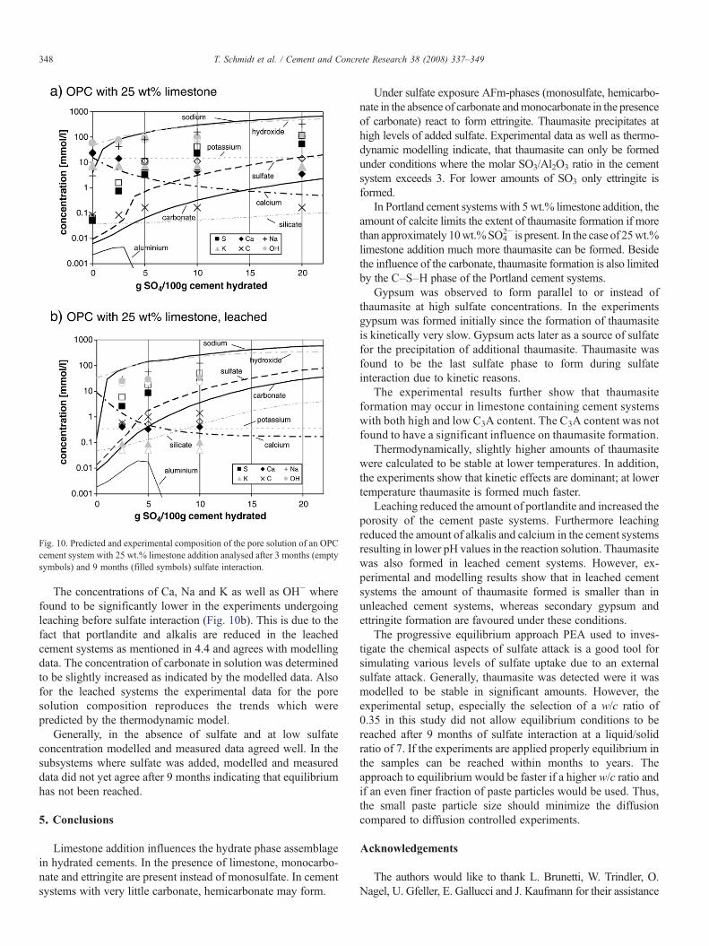
Fig. 10. Predicted and experimental composition of the pore solution of an OPCcement system with 25 wt.% limestone addition analysed after 3 months (emptysymbols) and 9 months (filled symbols) sulfate interaction.
348 T. Schmidt et al. / Cement and Concrete Research 38 (2008) 337–349
The concentrations of Ca, Na and K as well as OH− wherefound to be significantly lower in the experiments undergoingleaching before sulfate interaction (Fig. 10b). This is due to thefact that portlandite and alkalis are reduced in the leachedcement systems as mentioned in 4.4 and agrees with modellingdata. The concentration of carbonate in solution was determinedto be slightly increased as indicated by the modelled data. Alsofor the leached systems the experimental data for the poresolution composition reproduces the trends which werepredicted by the thermodynamic model.
Generally, in the absence of sulfate and at low sulfateconcentration modelled and measured data agreed well. In thesubsystems where sulfate was added, modelled and measureddata did not yet agree after 9 months indicating that equilibriumhas not been reached.
5. Conclusions
Limestone addition influences the hydrate phase assemblagein hydrated cements. In the presence of limestone, monocarbo-nate and ettringite are present instead of monosulfate. In cementsystems with very little carbonate, hemicarbonate may form.
Under sulfate exposure AFm-phases (monosulfate, hemicarbo-nate in the absence of carbonate andmonocarbonate in the presenceof carbonate) react to form ettringite. Thaumasite precipitates athigh levels of added sulfate. Experimental data as well as thermo-dynamic modelling indicate, that thaumasite can only be formedunder conditions where the molar SO3/Al2O3 ratio in the cementsystem exceeds 3. For lower amounts of SO3 only ettringite isformed.
In Portland cement systems with 5 wt.% limestone addition, theamount of calcite limits the extent of thaumasite formation if morethan approximately 10wt.%SO4
2− is present. In the case of 25wt.%limestone addition much more thaumasite can be formed. Besidethe influence of the carbonate, thaumasite formation is also limitedby the C–S–H phase of the Portland cement systems.
Gypsum was observed to form parallel to or instead ofthaumasite at high sulfate concentrations. In the experimentsgypsum was formed initially since the formation of thaumasiteis kinetically very slow. Gypsum acts later as a source of sulfatefor the precipitation of additional thaumasite. Thaumasite wasfound to be the last sulfate phase to form during sulfateinteraction due to kinetic reasons.
The experimental results further show that thaumasiteformation may occur in limestone containing cement systemswith both high and low C3A content. The C3A content was notfound to have a significant influence on thaumasite formation.
Thermodynamically, slightly higher amounts of thaumasitewere calculated to be stable at lower temperatures. In addition,the experiments show that kinetic effects are dominant; at lowertemperature thaumasite is formed much faster.
Leaching reduced the amount of portlandite and increased theporosity of the cement paste systems. Furthermore leachingreduced the amount of alkalis and calcium in the cement systemsresulting in lower pH values in the reaction solution. Thaumasitewas also formed in leached cement systems. However, ex-perimental and modelling results show that in leached cementsystems the amount of thaumasite formed is smaller than inunleached cement systems, whereas secondary gypsum andettringite formation are favoured under these conditions.
The progressive equilibrium approach PEA used to inves-tigate the chemical aspects of sulfate attack is a good tool forsimulating various levels of sulfate uptake due to an externalsulfate attack. Generally, thaumasite was detected were it wasmodelled to be stable in significant amounts. However, theexperimental setup, especially the selection of a w/c ratio of0.35 in this study did not allow equilibrium conditions to bereached after 9 months of sulfate interaction at a liquid/solidratio of 7. If the experiments are applied properly equilibrium inthe samples can be reached within months to years. Theapproach to equilibrium would be faster if a higher w/c ratio andif an even finer fraction of paste particles would be used. Thus,the small paste particle size should minimize the diffusioncompared to diffusion controlled experiments.
Acknowledgements
The authors would like to thank L. Brunetti, W. Trindler, O.Nagel, U. Gfeller, E. Gallucci and J. Kaufmann for their assistance
349T. Schmidt et al. / Cement and Concrete Research 38 (2008) 337–349
in the experimental part of this study. Special thanks to Cemsuisse,the association of the Swiss Cement Industry for financial support.
References
[1] The Thaumasite Expert Group, The thaumasite form of sulfate attack:risks, diagnosis, remedial works and guidance on new constructions,Department of the Environment, Transport London, 1999.
[2] J. Bensted, Mechanism of thaumasite sulphate attack in cements, mortarsand concretes, Zem.-Kalk-Gips 53 (2000) 704–709.
[3] J. Bensted, Thaumasite— background and nature in deterioration of cements,mortars and concretes, Cem. Concr. Compos. 21 (2) (1999) 117–121.
[4] N.J. Crammond, The thaumasite form of sulfate attack in the UK, Cem.Concr. Compos. 25 (8) (2003) 809–818.
[5] N.J. Crammond, M.A. Halliwell, The thaumasite form of sulfate attack inconcretes containing a source of carbonate ions— amicrostructural overview,International Symposium for Advances in Concrete Technology, 1995.
[6] S. Diamond, Thaumasite in Orange County, Southern California: aninquiry into the effect of low temperature, Cem. Concr. Compos. 25 (8)(2003) 1161–1164.
[7] M. Collepardi, Thaumasite formation and deterioration in historicbuildings, Cem. Concr. Compos. 21 (2) (1999) 147–154.
[8] D. Macphee, S. Diamond, Thaumasite in cementitious materials, Cem.Concr. Compos. 25 (8) (2003) 805–807.
[9] M.T. Blanco-Varela, J. Aguilera, S. Martinez-Ramirez, Effect of cementC3A content, temperature and storage medium on thaumasite formation incarbonated mortars, Cem. Concr. Compos. 36 (4) (2006) 707–715.
[10] P. Brown, R.D. Hooton, Ettringite and thaumasite formation in laboratoryconcretes prepared using sulfate-resisting cements, Cem. Concr. Compos.24 (3–4) (2002) 361–370.
[11] P. Nobst, J. Stark, Investigations on the influence of cement type onthaumasite formation, Cem. Concr. Compos. 25 (8) (2003) 899–906.
[12] M. Kalinowski, J. Trägardh, Thaumasite and gypsum formation in SCCwith sulfate resistant cement exposed to a moderate sulfate concentration,Second North American Conference on the Design and Use of Self-Consolidating Concrete, 2005, pp. 319–325, (3).
[13] M. Romer, L. Holzer, M. Pfiffner, Swiss tunnel structures: concretedamage by formation of thaumasite, Cem. Concr. Compos. 25 (8) (2003)1111–1117.
[14] G. Collett, N.J. Crammond, R.N. Swamy, J.H. Sharp, The role of carbondioxide in the formation of thaumasite, Cem. Concr. Res. 34 (2004)1599–1612.
[15] H.-J. Kuzel, H. Pöllmann, Hydration of C3A in the presence of Ca(OH)2,CaSO4·2H2O and CaCO3, Cem. Concr. Res. 21 (5) (1991) 885–895.
[16] D.W. Hobbs, M.G. Taylor, Nature of the thaumasite sulfate attackmechanism in field concrete, Cem. Concr. Res. 30 (4) (2000) 529–533.
[17] Q. Zhou, J. Hill, E.A. Byars, J.C. Cripps, C.J. Lynsdale, J.H. Sharp, The roleof pH in thaumasite sulfate attack, Cem. Concr. Res. 36 (1) (2006) 160–170.
[18] M.E. Gaze, N.J. Crammond, The formation of thaumasite in a cement:lime:sand mortar exposed to cold magnesium and potassium sulfatesolutions, Cem. Concr. Compos. 22 (3) (2000) 209–222.
[19] M.E. Gaze, The effects of varying gypsum content on thaumasiteformation in a cement:lime:sand mortar at 5 °C, Cem. Concr. Res. 27(2) (1997) 259–265.
[20] S.A. Hartshorn, J.H. Sharp, R.N. Swamy, The thaumasite form of sulfateattack in Portland-limestone cement mortars stored in magnesium sulfatesolution, Cem. Concr. Compos. 24 (3–4) (2002) 351–359.
[21] I. Juel, D. Herfort, R. Gollop, J. Konnerup-Madsen, H.J. Jakobsen, J.Skibsted, A thermodynamic model for predicting the stability ofthaumasite, Cem. Concr. Compos. 25 (8) (2003) 867–872.
[22] J. Skibsted, S. Rasmussen, D. Herfort, H.J. Jakobsen, 29Si cross-polarization magic-angle spinning NMR spectroscopy—an efficient toolfor quantification of thaumasite in cement-based materials, Cem. Concr.Compos. 25 (8) (2003) 823–829.
[23] J. Skipsted, L. Hjorth, H.J. Jakobsen, Quantification of thaumasite incementitious materials by 29Si{1H} cross-polarisation magic-anglespinning NMR spectroscopy, Adv. Cem. Res. (7) (1995) 69–83.
[24] B. Lothenbach, T. Matschei, G. Möschner, F.P. Glasser, Thermodynamicmodelling of the effect of temperature on the hydration and porosity ofPortland cement, Cem. Concr. Res. 38 (1) (2008) 1–18.
[25] B. Lothenbach, F. Winnefeld, Thermodynamic modelling of the hydrationof Portland cement, Cem. Concr. Res. 36 (2) (2006) 209–226.
[26] D. Kulik, GEMS-PSI 2.1, PSI, Villigen, Switzerland, 2006 available athttp://leswebpsi.ch/software/GEMS-PSI.
[27] W. Hummel, U. Berner, E. Curti, F.J. Pearson, T. Thoenen, Nagra/PSIChemical Thermodynamic Data Base 01/01, University Publishers/uPUBLISH.com, USA, also published as Nagra Technical Report NTB02–16, Wettingen, Switzerland. 2002.
[28] T. Thoenen, D. Kulik, Nagra/PSI chemical thermodynamic database 01/01for the GEM-Selektor (V.2-PSI) geochemical modeling code, PSI,Villigen, 2003 available at http://les.web.psi.ch/software/GEMS-PSI/doc/pdf/TM-44-03-04-web.pdf.
[29] G.M. Anderson, D.A. Crerar, Thermodynamics in geochemistry: theequilibrium model, Oxford University Press, Oxford, 1993.
[30] D. Kulik, Minimising uncertainty induced by temperature extrapolations ofthermodynamic data: a pragmatic view on the integration of thermo-dynamic databases into geochemical computer codes, The Use of Thermo-dynamic Databases in Performance Assessment, OECD, Barcelona, 2002,pp. 125–137.
[31] D.E. Macphee, S.J. Barnett, Solution properties of solids in the ettringite–thaumasite solid solution series, Cem. Concr. Res. 34 (2004) 1591–1598.
[32] F. Bellmann, On the formation of thaumasite part I, Adv. Cem. Res. 16 (2)(2004) 55–60.
[33] Y.D. Gu, M.S. Gammons, M.S. Bloom, A one-term extrapolation methodfor estimating equilibrium constants of aqueous reactions at elevatedtemperatures, Geochim. Cosmochim. Acta 58 (17) (1994) 3545–3560.
[34] V.L. Bonavetti, V.F. Rahhal, E.F. Irassar, Sudies on the carboaluminateformation in limestone filler-blended cements, Cem. Concr. Res. 31 (2001)853–859.
[35] F. Bellmann,On the formation of thaumasite CaSiO3CaSO4CaCO315H2OPart II, Adv. Cem. Res. 16 (2004) 89–94.
[36] E.F. Irassar, M.A. Bonavetti, M.A. Trezza, M. Gonzalez, Thaumasiteformation in limestone filler cements exposed to sodium sulphate solutionat 20 °C, Cem. Concr. Compos. 27 (2005) 77–84.
[37] T. Schmidt, Sulfate attack and the role of internal carbonate on theformation of thaumasite. PhD thesis, École Polytechnique Fédérale deLausanne, Lausanne, 2007.
[38] D. Planel, J. Sercombe, P. Le Besop, F. Adenot, J.M. Torrenti, Long-termperformance of cement paste during combined calcium leaching-sulfateattack: kinetics and size effect, Cem. Concr. Res. 36 (2006) 137–143.
[39] S. Köhler, D. Heinz, L. Urbonas, Mechanismus der Thaumasitbildung inverschiedenen Bindemittelsystemem, Ibausil, 2003, pp. 0711–0718, (2).
[40] S.J. Barnett, C.D. Adam, A.R.W. Jackson, Solid solutions betweenettringite and thaumasite, Mater. Sci. 35 (2000) 4109–4114.
[41] A. Muberra, F.P. Glasser, Long-term leaching mechanisms of Portlandcement-stabilized municipal solid waste fly ash in carbonated water, Cem.Concr. Res. 29 (2) (1999) 179–186.
[42] S. Catinaud, J.J. Beaudoin, J. Marchand, Influence of limestone additionon calcium leaching mechanisms in cement-based materials, Cem. Concr.Res. 30 (12) (2000) 1961–1968.
[43] K. Haga, M. Shibata, M. Hironaga, S. Tanaka, S. Nagasaki, Change in porestructure and composition of hardened cement paste during the process ofdissolution, Cem. Concr. Res. 35 (5) (2005) 943–950.
[44] K. Haga, S. Sutou, M. Hironaga, S. Tanaka, S. Nagasaki, Effects ofporosity on leaching of Ca from hardened ordinary Portland cement paste,Cem. Concr. Res. 35 (9) (2005) 1764–1775.
[45] C. Galle, H. Peycelon, P. Le Bescop, Effect of an accelerated chemicaldegradation on water permeability and pore structure of cement-basedmaterials, Adv. Cem. Res. 16 (2004) 105–114.
[46] S.D. Jacobsen, J.R. Smyth, R.J. Swope, Thermal expansion of hydratedsix-coordinate silicon in thaumasite, Ca3Si(OH)6(CO3)(SO4)12H2O,Phys. Chem. Min. 30 (6) (2003) 321–329.