A STRUCTURED APPROACH TO TEST CASE DEFINITION WITH AN EXEMPLARY ILLUSTRATION A Structured Approach...
21
A STRUCTURED APPROACH TO TEST CASE DEFINITION WITH AN EXEMPLARY ILLUSTRATION PAGE 1 A Structured Approach to Test Case Definition with an Exemplary Illustration Abstract— Test cases (TC) are fundamental units in software engineering in general, and particularly in software testing. In addition, TCs are often used as a metric and work unit in monitoring and controlling test efforts. A thorough review of the literature reveals that there is no formal and agreed-upon definition of a TC, hence, we see benefits in formalizing a unified, well defined and structured TC definition. In this paper we present a brief literature review of the TC concept, explore the definitions of TCs, propose a classification of the various definitions into four categories, and highlight the conceptualization underlying each category. The focus of the paper is the introduction of an alternative structured definition of a TC, illustrated by a real-world example. The proposed definition presents a TC as a composition of five structures: TC factors, Internal Activities and Flows, Dynamic External Interaction Element, Basic Verification Calls, and the TC Output and Results. We elaborate on the five structures, illustrate their content using a real- world example, and suggest benefits accrued by generating TCs structured accordingly. In conclusion we discuss implications of this work for theory and practice, limitations, and future research trajectories opened by the proposed TC definition. Index Terms— Design, Standardization, Theory, Verification, Software testing, Test case, Test case definition. 1. INTRODUCTION Test cases (TCs) are fundamental components of software testing, used not only as a primary testing function but also to estimate testing effort and monitor progress. A thorough literature review in search for an agreed upon definition for a TC [1] resulted in mixed evidence. Of 267 reviewed papers that discussed software testing, only 38 (14%) included formal definitions of a TC. The definitions elicited from the 38 papers could be classified into four dominant approaches or categories [1]: 1) the input-process-output-objectives approach, 2) the states and transitions approach, 3) the contractual approach, and 4) other definitions (see Appendix 1 for a details). The input-process-output-objectives perspective conceptualizes a TC as a set of inputs into a pre-defined process, aimed at yielding a desired output, based on the test objective. This approach was in fact adopted by IEEE STD 829.1998 [2]. The states and transitions approach considers a TC as a set of transition patterns among
Transcript of A STRUCTURED APPROACH TO TEST CASE DEFINITION WITH AN EXEMPLARY ILLUSTRATION A Structured Approach...
A STRUCTURED APPROACH TO TEST CASE DEFINITION WITH AN EXEMPLARY ILLUSTRATION
PAGE 1
A Structured Approach to Test Case Definition with an Exemplary
Illustration Abstract— Test cases (TC) are fundamental units in software engineering in general,
and particularly in software testing. In addition, TCs are often used as a metric and
work unit in monitoring and controlling test efforts. A thorough review of the
literature reveals that there is no formal and agreed-upon definition of a TC, hence,
we see benefits in formalizing a unified, well defined and structured TC definition. In
this paper we present a brief literature review of the TC concept, explore the
definitions of TCs, propose a classification of the various definitions into four
categories, and highlight the conceptualization underlying each category. The focus
of the paper is the introduction of an alternative structured definition of a TC,
illustrated by a real-world example. The proposed definition presents a TC as a
composition of five structures: TC factors, Internal Activities and Flows, Dynamic
External Interaction Element, Basic Verification Calls, and the TC Output and
Results. We elaborate on the five structures, illustrate their content using a real-
world example, and suggest benefits accrued by generating TCs structured
accordingly. In conclusion we discuss implications of this work for theory and
practice, limitations, and future research trajectories opened by the proposed TC
definition.
Index Terms— Design, Standardization, Theory, Verification, Software testing, Test case, Test case
definition.
1. INTRODUCTION
Test cases (TCs) are fundamental components of software testing, used not only as
a primary testing function but also to estimate testing effort and monitor progress.
A thorough literature review in search for an agreed upon definition for a TC [1]
resulted in mixed evidence. Of 267 reviewed papers that discussed software testing,
only 38 (14%) included formal definitions of a TC. The definitions elicited from the
38 papers could be classified into four dominant approaches or categories [1]: 1)
the input-process-output-objectives approach, 2) the states and transitions
approach, 3) the contractual approach, and 4) other definitions (see Appendix 1 for
a details).
The input-process-output-objectives perspective conceptualizes a TC as a set of
inputs into a pre-defined process, aimed at yielding a desired output, based on the
test objective. This approach was in fact adopted by IEEE STD 829.1998 [2]. The
states and transitions approach considers a TC as a set of transition patterns among
A STRUCTURED APPROACH TO TEST CASE DEFINITION WITH AN EXEMPLARY ILLUSTRATION
PAGE 2
states [3]. The contractual approach defines TC as a contract since the outcomes of
pre-defined conditions are fully defined. Finally, there are several other definitions
stemming from various contexts. Notably, only the first two categories represent
structured definitions that specifically point at TC components and their
relationships (in line with the Wikipedia definition for 'structure'), whereas the
other two are rather symbolic and unstructured. Of these two, contract is closer to
the software engineering discipline, while definitions included in the last category
generally stem from domains alien to the software engineering world and are far
from structured.
The lack of an agreed upon formal TC definition and the fact that most studies do
not include any definition raise several questions: Is such a definition required?
What are the deficiencies of the existing definitions? What are the implications of
the lack of a formal definition?
We maintain that a formal definition is indeed required. In fact, in real-world testing
of life-threatening projects such as a nuclear reactor, a formal definition is an
important part of the testing guidelines. For example, based on the IEEE standard,
chapter 6 of a manual for testing safety applications in a nuclear reactor
environment greatly elaborates on TC types, definitions, content, and
documentation [4]. The recommendation is that each TC should be defined by a
general description including reference number, geometry, flow features,
experimental data, existing simulations, related experiments, and rating of the
challenge the test case poses. These details should be accompanied by further
documentation describing the test environment for each TC. This may attest to the
importance of a formal definition.
In order to improve TC handling, including generation, storage, use, and re-use, it is
suggested that TCs should be unambiguous, generalizable, quantifiable, and
automatable. Unambiguousness ensures a unified view shared by all professionals
and users involved in software testing regardless of their prior experience,
background, testing environments, methods and techniques. This can further drive
sharing expertise among various testing schools and perceptions. TC generalizability
ensures maintaining and re-using testing assets, leveraging the invested resources
along various testing efforts, and in different testing environments. When defined
in a quantifiable manner TCs can be sensibly measured, compared, and used as
metrics. Currently, measurements involving counting TCs as a common metric are
clearly inconsistent due to the variance among TCs in terms of size and complexity.
Finally, there is no need to elaborate on the benefits rendered by automating TC
generation, execution and management, a means believed to optimize testing
efforts and contain costs.
A STRUCTURED APPROACH TO TEST CASE DEFINITION WITH AN EXEMPLARY ILLUSTRATION
PAGE 3
Examining the existing definitions through the lens of the above characteristics
illustrates the deficiencies in each type. The input-process-output-objective
definitions are generally unambiguous, but not necessarily measureable and
quantifiable. For example, the 'Process' part of the TC can vary in size and
complexity. Likewise, a process can be as simple as 'check for existence of a certain
value' or quite complex as 'create a customer order'.
The state & transitions definition may satisfy the unambiguousness and
quantifiability traits but is hardly generalizable since it stems from the state-
machine world, therefore not transferrable to other testing domains. For example
processes at are a result of dynamic environmental conditions and data interactions
would be rather impossible to define as a finite number of states and transitions.
TCs defined as states & transitions, however, are quite convenient to quantify and
automate due to their relative simplicity.
The Contract group of definitions is becoming popular, mainly in SOA platforms, yet
these definitions clearly violate the unambiguousness criterion. For example,
Aichernig [5] defined a test as a contract between the user and the software
provider, whereas Mikhailova et al. [6] defined testing as a contract between the
system under test and its environment. Clearly, only a formal definition of the
contract, such as the one attempted by Aichernig [5] is unambiguous. For similar
reasons it cannot be generalized, quantifiable or automated unless formalized.
Finally, it is quite obvious that the 'Other' definitions do not meet most of the above
requirements.
We suggest that the absence of a formal definition for TCs causes ambiguity
concerning test cases size and content as illustrated next in our running example.
This ambiguity, in turn, may entail test planning, execution, and monitoring
malfunctioning when estimating testing effort or testing progress by number of
executed or passed TCs. Moreover, testing automation efforts are contingent upon
a formal definition of TCs, hence its absence is possibly one of the barriers to a
broader diffusion of automation tools even in cases where automation is clearly
feasible. These shortcomings are quite likely among the causes for the annual
economic damage equivalent to $20 – $52 billion as a result of inadequate software
testing infrastructure and processes, reported by the US National Institute of
Standards as published in 2002 [7]. Hence, further work towards a formal TC
definition that meets the above requirements is clearly warranted.
2. BACKGROUND AND RUNNING EXAMPLE
To illustrate the proposed definition we draw upon a real-world business process
taken from the realm of a large company that develops billing software for Telco

A STRUCTURED APPROACH TO TEST CASE DEFINITION WITH AN EXEMPLARY ILLUSTRATION
PAGE 4
firms. Call records are accumulated, parsed, and charged, based on rules stemming
from contracts between providers and customers. Figure 1 describes a basic cost
calculation process, which serves as our running example. This scenario is a part of
the User Acceptance Tests undertaken by a Telco in order to certify new billing
software.
Test case objective – verify that a charge of a call started on Sunday 23:55 ended
Monday 00:05 is correctly calculated (requiring identification that the call spans
over two different charging rates - weekend and regular).
Fig.1. A graphical representation of the tested business process
2.1 Terminology Used
CDR – Call Data Record created on a network computerized switch, which records
all call details such as caller identification, call destination identification, time of call
start and call end, and additional technical information regarding switching and call
quality. The record format varies based on the specific switch. One call can be
composed of several CDRs.
CDR server – storage machine that stores all CDRs transferred from all switches.
CDR (b)
CFR
Charge Calculations
•Fetch Customer •Fetch agreement
•Calculate rate•Update storages
Format
CDR Server
Calls Record Server
Customer DB
Charge Server
Customer Agreements
Billing Activator
CDR (a)
A STRUCTURED APPROACH TO TEST CASE DEFINITION WITH AN EXEMPLARY ILLUSTRATION
PAGE 5
Format process – collection of all CDRs related to a specific call to form a single call
record termed Call Formatted Record (CFR).
CFR – Call Formatted Record created by the Format process. The record is an
assembly of all information regarding a call, which will serve as the call information
record throughout the billing calculation.
Calls Record Server – a storage machine that stores all CFRs. This server receives
two transactions: 1) add a new CFR, and 2) update an existing CFR by adding the
calculated call charge as the result of the charge calculation process. Charge
calculations can be executed on a single record or on a stream of records thus
performing batch calculation and update.
Charge Calculation Process – a step by step description:
1. Access CFR from Call record server
2. Identify caller in customer DB
3. Extract caller contract details from customer contract storage
4. Charge calculation – the call charge is calculated based on all extracted data
and is assigned to the CFR (note that sometimes the calculation requires
previous balance of calls which are stored on the Charge Server).
Billing activator – the trigger that activates the charge calculation processes. There
are two major activation methods: 1) a single calculation demand – mostly
originated by the customer relationship management (CRM) package when a clerk
needs to present call details during a customer service session, and 2) a regular
execution of call charges calculation as part of a billing process.
Customer DB – a storage machine that stores customer data such as
personal/business information, address, identifiers and other information.
Customer Agreements – a highly complex data record, representing all legal and
business contracts regarding the way a call charge should be calculated.
Charging server – a storage machine that stores call customer charge information,
including call record charges and other types of charges, if applicable.
2.2 TCs Associated with the Tested Process
In spite of a rather simple business process to be tested, determining the actual test
case is quite ambiguous, as several alternatives exist. Figure 2 illustrates (by
assigning different colors) four different alternatives for test cases differing by the
tested processes and boundaries.

A STRUCTURED APPROACH TO TEST CASE DEFINITION WITH AN EXEMPLARY ILLUSTRATION
PAGE 6
Fig.2. Alternative TCs
The four TC options are: 1) the whole process is part of the test case – starting from
the actual call where the different CDRs are the input to the test case and newly
stored data records that include charges are the output. 2) the formatting process is
considered an external input into the TC, and the actual test concerns the
correctness of the CFR, storing the already formatted CFR on the Call Records
Server, as well as charge calculation and storing the call charge on the Charge
Server. 3) assume that a correct CFR (checked elsewhere) is an external input to the
TC, which starts by extracting the CFR from the Call Records Server followed by
activating the billing process and concluding as the previous TC options. 4) the test
case includes the charge calculation only, with all other elements treated as
external inputs checked elsewhere, and concludes with the new stored data records
on the two output servers.
As can be seen, there are several options to determine which of the elements in the
application will be included as internal parts of the TC and which of them will be
external, rendering the resulting TCs to significantly differ by size and complexity.
Option 4 is selected as the running example used in this paper to illustrate the
proposed TC structured definition. Figure 3 presents the chosen option highlighting
internal and external components.
TC Option 1
TC Option 2
TC Option 3
CDR (b)
CFR
Charge Calculations
Format
CDR Server
Calls Record Server
Customer DB
Charge Server
Customer Agreements
Billing Activator
CDR (a)
TC Option 4

A STRUCTURED APPROACH TO TEST CASE DEFINITION WITH AN EXEMPLARY ILLUSTRATION
PAGE 7
CDR (b)
CFR
Charge Calculations
Format
CDR Server
Call Records Server
Customer DB
Charge Server
Customer Agreements
Billing Activator
CDR (a)
Chosen TC
Included within the TC Scope
Fig.3. Internal and external components of the TC chosen as the paper's running example
3. A TC DEFINITION
Figure 4 presents a definition of a test case as a composite of five separate
interacting structures, each of which contains internal elements. Each set of
elements in a structure has its own properties and may or may not participate in the
actual execution of a specific test case. Hence, a structure may be empty thereby
not a part of a particular TC when its functionality is outside the scope of the
specific TC objective.
Fig.4. TC Structured Definition
We propose that a TC is composed of the following five structures: 1) TC Factors –
all preliminary properties required to be set up prior to the execution of the TC, 2)
Script
manipu.
Set Up
End
Prep
Job exec.
API
{2}
TC Outputs
TC Factors
Verification
Call
Verification
Call
Verification
Call
verification
Call
{4}
LOGDBs Direct Internal
{5}
{3}
Dynamic Inputs
{1}
(TF)(DI) (VC)
A STRUCTURED APPROACH TO TEST CASE DEFINITION WITH AN EXEMPLARY ILLUSTRATION
PAGE 8
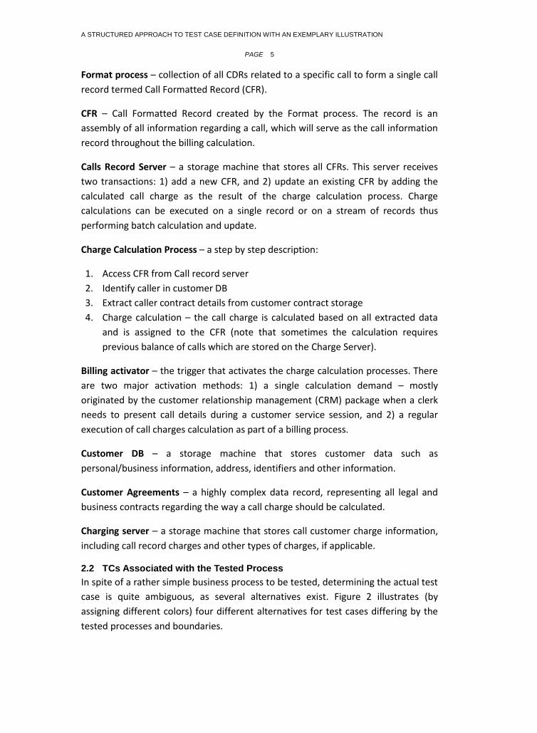
TC Internal Activities and Flows (TF) – containing the set of elements defining the
core execution path under test, 3) Dynamic External Interaction Elements (DI) –
mostly data items and results of external interactions with the TF, 4) Basic
Verification Call (VC) – external operational elements that observe selective data
items determining the validity of their value at specific moments during the TC
execution. 5) TC Outputs and Results - the verification of the final results of the
overall TC execution using designated VCs which represent the test oracle. This part
pertains only to TCs which produce results that can be interpreted by mathematical
and/or logical operators. We are aware of the fact that there are cases where
automatic results verification is infeasible and interpretation by a human tester
makes more sense. These instances are outside the scope of the present TC
definition which rather focuses on the many cases that produce results which can
be automatically verified, including those requiring complex verification engines.
3.1 An Exemplary TC Represented by the Structured Definition
Figure 5 illustrates the five exemplary TC components based on the proposed
structured definition. Following is a general description of each component and a
reference to the specific example for clarity sake.
Fig.5. A TC as a Structured Composite - Example
Hardware, Software Configuration, Oracle ,Populated DB’s, uploaded Servers, operational flags, enc…
Verify CFR correctness
Verify customer
Verify correct split of the call
Verify correct rate calculation
Verify correct sum for record
Call Record
ServerGet next
CFR
Indentify
Customer
Fetch customer
record
Split CFR to
time fractions
Fetch customer
matched calculation
agreement
Add calculated sum to
billed in CFR rate
next time
fraction
Calculate time
fraction rate
Calculation loop
CFR
1. Verify correct storage
in Charging server2. Verify correct update
of Call record Server
Charge ServerCall Record Server
Customer
Agreement DB
Customer Agreement
Customer DB
Customer record
Main CFR loop
A STRUCTURED APPROACH TO TEST CASE DEFINITION WITH AN EXEMPLARY ILLUSTRATION
PAGE 9
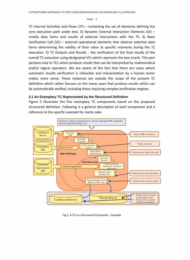
3.2 TC Factors
A TC factor element is defined as any current external variable whose values are to
be controlled during the tests. Examples are hardware and operating system
configurations, load characteristics, software versions, operating modes, input data,
and so forth [8]. The TC factor structure enables the test to start from a pre-defined
initial state that can be replicated.
A TC factor element value is a specific value assigned to one of the factors during
the test. For example, a browser value can be IE 7.0 or Firefox 3.0. Display
resolution values can be low, medium or high.
TC Factors should by definition be stable during execution, ensuring that no
nondeterministic shifts occur throughout an execution cycle, and usually represent
a customer environment setup or another environment the software should run in.
Typical factor items are hardware – for example: a specific machine, CPU, file
system, storage etc., operating system –the type of operating system and other
system characteristics such as file system, databases etc.; software configuration
such as: load characteristics, software versions, operating modes, security flags,
runtime parameters, etc.; preliminary input data items such as: application setup
parameters, application data set requirements etc.; preliminary operational running
jobs – a set of executables that may be needed to function in the background, such
as – servers, demons, processes, network elements etc. These are required in order
to start a test from a specific, pre-defined application state.
In our example the TC factors may contain the following elements: Hardware –a
specific customer platform, CPU, file system, storages (e.g. IBM RS2000, etc.),
operating system – e.g. Unix ver. 10, or Oracle 10; software configuration - load
characteristics, software versions, operating modes, security flags, runtime
parameters; preliminary input data items such as a set of CFRs with the correct call
time already stored at the Call Record storage with the correlated customer data;
preliminary operational running jobs, for example verifying that the billing activator
trigger ought to be alive. These are represented in structure 1 of Figure 5.
3.3 TC Internal Activities & Flow (TF)
The TF is defined as a list of activities and their relationships, termed as flows, which
describe the executable path tested by the specific TC. For example, a TF can be
described by three activities (elements) that are related by a branch choice (flow
element) together composing the TF structure. TF can relate to black-box testing,
causing the items to collapse into just a few or even one entity, or to gray-box or
white-box testing, resulting in a detailed list of elements. Thus, the TF actually
describes the flow of the process under test.

A STRUCTURED APPROACH TO TEST CASE DEFINITION WITH AN EXEMPLARY ILLUSTRATION
PAGE 10
A common representation of this structure of activities and flows is state transitions
[9]. Another can be a more loosely bound yet deterministic flow of events operated
by a certain algorithm for the testing flow. For example Ding et al [10] suggested the
following optional elements for a test case flow: Sequential, Branch and Choice,
Loop, and Parallel, which are collected by using several program slicing algorithms
[11]. Regardless of the approach adopted, activity and flow elements identify
atomic elements, such that further decomposing them is infeasible, which together
form the actual test case execution flow.
A TF element should have a single access and/or exit point, in order to ensure the
atomic property of the element. Although it might be sometimes challenging to
identify these single points, we believe it is possible in many cases.
TF activity element types may include dynamic parameter set up action when
parameters need to be modified during execution; job execution request –the most
common type of activity which can vary from calling a service to execution of a
single command; script manipulation which allows applying a sequence of events
upon a single action. This activity however, should be cautiously used since it may
result in losing control during the script execution. Other types are API activation,
either internal or external; a status report which is an intermediate report
presenting the current position and status of the TC during its execution; a
verification call discussed in more details hereafter, and external interface call – a
simple call to an interfacing entity. In order to maintain TC size and complexity
control, each TF element is counted as one entity.
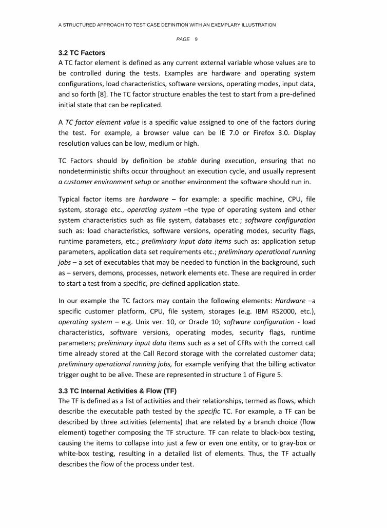
The exemplary TC internal flow is presented in figure 5 in structure number 2, and is
more explicitly detailed in Figure 6, where a single calculation cycle and few other
actions are described. The flow elements are presented by two loops: the CFR and
the calculation loops.
A STRUCTURED APPROACH TO TEST CASE DEFINITION WITH AN EXEMPLARY ILLUSTRATION
PAGE 11
Fig.6. TF elements of the exemplary TC
3.4 Dynamic External Interaction Elements (DI)
DI is defined as a structure representing the results of interacting with external
entities. Examples of DI are data returned by a service called by the TC [12], or the
location of a piece of data. In contrast to test factors that are steady throughout the
test process DIs are dynamic interactions occurring as a part of the test flow.
The DI is an important component since TC execution may often require interaction
with external input/output, or execution of external entities. These entities will
usually be pre-planned but be dynamically operated. Thus, a DI can be described as
a result of an external interaction with a data injection mechanism, a stub, or
another mechanism enabling the TC to complete its task.
Each DI should relate to a specific TF in order to ensure singularity of behavior. This
means that results can be uniquely predicted each time the TC is executed. A DI
entity is treated as atomic regardless of its actual structure because these items are
external to the TC hence their testing is beyond the scope of the particular TC. In
fact, the atomic DI item is the result of the interaction, rather than the interaction
itself or the interacted external item. Therefore, each DI can be counted as one
item, and all DI items can be equally weighted. Examples of DI items are
single/multi data Item, memory resident data or data address, memory temporary
flag, data retrieved from an external API, etc.
In the exemplary TC the DI elements are the CFR to be calculated, customer details
from Customer DB, agreements from Customer Agreement File as illustrated in
structure 3 of Figure 5.
Get next CFR
Indentify
Customer
Fetch customer
record
Split CFR to
time fractions
Fetch customer matched
calculation agreement
Add calculated sum to
billed in CFR rate
Store
updated
CFR
next
time fraction
Calculate time fraction
rate
CFR loop
Calculation loop
Update
charge
server
A STRUCTURED APPROACH TO TEST CASE DEFINITION WITH AN EXEMPLARY ILLUSTRATION
PAGE 12
3.5 Verification Call (VC) Elements
A VC element is an external investigator that observes and documents selective
states and occurrences represented by data items during the TC execution, and
signals their validity at a specific time [13]. By anticipating, controlling and
documenting certain behaviors during a TC execution, it may be possible to
determine the exact location and time of the occurrence of a fault. When applied to
the TC final output, the VC is a logical representation of the test oracle. We further
elaborate on the test oracle representation later on.
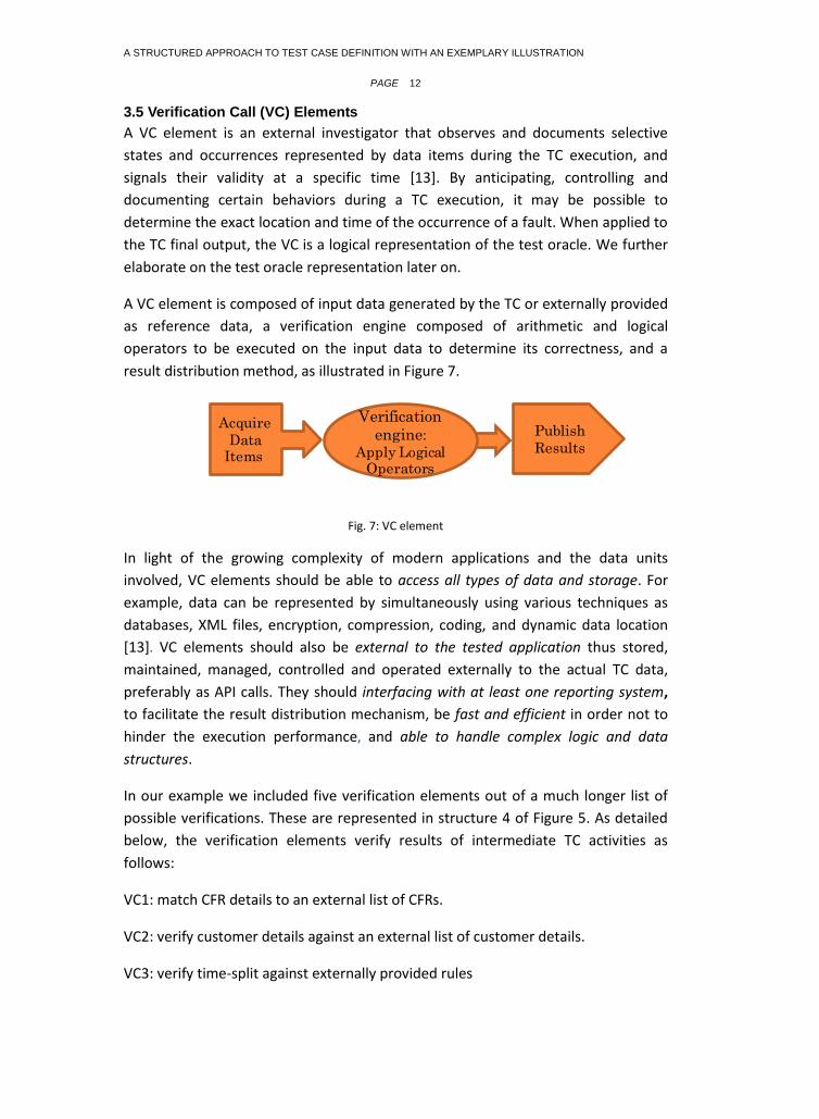
A VC element is composed of input data generated by the TC or externally provided
as reference data, a verification engine composed of arithmetic and logical
operators to be executed on the input data to determine its correctness, and a
result distribution method, as illustrated in Figure 7.
Fig. 7: VC element
In light of the growing complexity of modern applications and the data units
involved, VC elements should be able to access all types of data and storage. For
example, data can be represented by simultaneously using various techniques as
databases, XML files, encryption, compression, coding, and dynamic data location
[13]. VC elements should also be external to the tested application thus stored,
maintained, managed, controlled and operated externally to the actual TC data,
preferably as API calls. They should interfacing with at least one reporting system,
to facilitate the result distribution mechanism, be fast and efficient in order not to
hinder the execution performance, and able to handle complex logic and data
structures.
In our example we included five verification elements out of a much longer list of
possible verifications. These are represented in structure 4 of Figure 5. As detailed
below, the verification elements verify results of intermediate TC activities as
follows:
VC1: match CFR details to an external list of CFRs.
VC2: verify customer details against an external list of customer details.
VC3: verify time-split against externally provided rules
Verification
engine:
Apply Logical Operators
Acquire
Data Items
Publish
Results
A STRUCTURED APPROACH TO TEST CASE DEFINITION WITH AN EXEMPLARY ILLUSTRATION
PAGE 13
VC4: verify calculation for each time fraction against external expected results
VC5: verify the stored record on the Charging Server.
3.6 TC Output and Results
It is generally accepted that interpretation of the TC outcomes can be complex, as
stated by Kaner and Bach: "Our ability to automate testing is fundamentally
constrained by our ability to create and use oracles" [14, p. 23]. Nonetheless, there
is a substantial number of TCs whose results can be automatically interpreted, and
the present structured TC definition relates to these cases. Hence, the TC output
and results are the outcomes of applying a set of VC items to the results of the TC.
In our example the final results are verified after the last iteration of the loop, and
contain two verification elements (structure 5 in Figure 5): verify record stored on
the Call Record Server, and verify the record stored on the Charge Server.
4. DISCUSSION
In this work we propose a new, structured TC definition, where a TC is composed of
five distinctive structures, each of which possesses characteristics allowing more
precise identification, quantification, and documentation of TCs. The proposed TC
structures are illustrated by a real-world example.
Although some efforts in this direction have been seen in specific domains, for
example testing Java code (the JUnit tools by Sun Microsystems) or the rapidly
progressing TTCN-3 testing language [15], the present work takes these efforts a
step forward by suggesting a formal and generic definition, which can be used for
functional, non-functional and business rules testing.
Due to its generic nature, it can be applied to the two common approaches of
describing TC behaviors: the stateless approach where the actual flow of the TC is
less rigid and can be described in a flow chart [16], and the state machine approach
– where each step taken during the TC execution is considered a transition between
states [17]. The TC as a stateless machine approach is taken when creating rather
complex test cases. For example testing a multi layer service, where a service is
calling another service as part of the internal flow [12], or when viewing TCs using
the gray box approach [16, 18]. Our running example presents a stateless TC.
The TC as a sequence of transitions between states, or state machine, was adopted
by Microsoft for Model Based Testing (MBT) [17], although a formal definition for a
TC could not be found in the relevant documentation. Figure 8 presents the way
such a model is implemented by the proposed structured approach. When the
States & Transitions model is applied verification calls are used to check each state
upon completion of a transition. It is thus notable that the TC output can be actually

A STRUCTURED APPROACH TO TEST CASE DEFINITION WITH AN EXEMPLARY ILLUSTRATION
PAGE 14
merged with the final state reached by the test case. This approach enables the
breakdown of a multi state test case into smaller cases where the previous state
serves as the test factor for the next state, simplifying the TC schema to the one
illustrated in Figure 8. This presentation extends some of the original definitions and
should be further considered in future works.
Fig. 8: TC as a state machine
4.1 The New TC Definition and Existing Definitions
As illustrated in Appendix 1, TCs are generally defined under four main categories:
input-process-output-objectives, states and transitions, contract, and others. We
maintain that the proposed definition encompasses the first three of the four
categories. A more sophisticated alignment is proposed between the verification
structure and the contract definition category. It is suggested that the VC elements
can be easily converted into contract items presenting business rules, yet this
should be elaborated in future research.
Evidently, the proposed structure cannot support symbolic definitions such as
'predator and prey', and a question such as "what happens to the system when
event X happens" is not well supported by TCs formulated based on our structured
definition, unless it can be converted to definitive flows. In most cases, however,
this type of testing should be differently dealt with.
4.2 Limitations
Several limitations should be noted. First, as in many novel thoughts, our work is
still at its infancy and clearly merits further research and elaboration, as well as
A STRUCTURED APPROACH TO TEST CASE DEFINITION WITH AN EXEMPLARY ILLUSTRATION
PAGE 15
empirical testing to substantiate the proposed benefits. We believe its publication
may arouse a productive discussion of both academia and practice that will
contribute to the refinement of this work. Second, it should be noted that the
suggested work refers only to the TC itself in isolation from the testing environment
and platforms, such as operating systems, data, stubs and simulations required for
the actual test execution. This is important when referring to the measurability and
quantifiability attributes of the various items and components
Finally, we acknowledge that this definition does not apply to all types of TCs, since
some TCs produce results that are too complex to define under the proposed
structures. For example, we do not suggest using this definition for TCs aimed at
testing GUI appearance and usability. Moreover, the structured TC approach
complements the soft and flexible modern attitude towards software testing, which
highlights the unique skills and special position of the testing experts. Approaches
such as exploratory testing, where rather 'artistic' conceptualization is appropriate,
may perhaps co-exist alongside the proposed approach. Test cases like: "It should
take < 4 seconds to compute the result; preferably < 2" , or "The cancel button
should NOT suddenly grey itself out", or "The number four should appear in BLACK,
not RED", makes sense to a freehand tester but can be unfeasibly costly when
attempting a translation to the new structured model.
4.3 Contribution and Future Enhancements
The suggested structured definition contributes to research and practice in the
following ways:
On the theoretical side, the definition creates a common framework for three of the
four TC definition categories presented in Appendix 1. It also pertains to various
application domains since the approach underlying the development of the
structures is generic. Further, our definition advances the likelihood of TCs being
unambiguous, generalizable, quantifiable, and automatable. We maintain that TCs
defined by the structured definition can be quantified and compared by size and
complexity based on the number and size of elements in their structures. Defining
measures for TC evaluation can open new research trajectories.
Four contributions to practice are suggested. First, the TF can be extended to map
unto business entities by replacing TF with BF (business activities & flow), enabling
the description of the TC internal flow in a formal business terminology. Introducing
BF may close a gap between the technical aspects of software usage and its actual
business representation. Thus, it would be possible for business users to define the
TC TF (or BF), and it would also bring the TC notion closer to the 'contract' definition
category. This, however, requires extensive further elaboration and is suggested for
future research.

A STRUCTURED APPROACH TO TEST CASE DEFINITION WITH AN EXEMPLARY ILLUSTRATION
PAGE 16
Second, it might be possible to consider separation of testing items such as DI, VC,
as distinctive inventory DBs that are separately generated, maintained, and can be
used by many TCs several times. This would clearly ease testing management. Thus,
the proposed structure might facilitate re-thinking the way test cases are
developed; build the DI and VC, as well as other TC structure inventories before
generating the actual TCs, in collaboration with the software developers during the
design process. For example, quite often the external interactions and verifications
are known during the design phase, and can therefore be generated and stored
before the actual testing phase is reached. This concept is particularly attractive
when using agile development processes. Third, since the proposed definition is
structured, it allows designing test cases with automation intention and mechanism
from the outset, facilitating actual automation when available and feasible. Finally,
the proposed structured definition may drive development of new testing tool-sets.
ACKNOWLEDGMENT
The authors wish to thank Matt Hauser for his insightful remarks.
A STRUCTURED APPROACH TO TEST CASE DEFINITION WITH AN EXEMPLARY ILLUSTRATION
PAGE 17
REFERENCES
1. Almog, D. and T. Heart, What Is a Test Case? Revisiting the Software Test Case Concept, in Software Process Improvement. 2009: Madrid, Spain. p. 13-31.
2. Craig, R.D. and S.P. Jaskiel, Systematic Software Testing. 2002: Artech House.
3. Memon, A.M., An event-flow model of GUI-based applications for testing. Software Testing, Verification and Reliability, 2007.
17(3): p. 137-157.
4. Coulter, A.C. Graybox Software Testing Methodology: Embedded Software Testing Technique. in The18th Digital Avionics
Systems Conference. 1999. St. Louis, mo, USA.
5. Aichernig, B.K. Test-Case Calculation through Abstraction. in International Symposium of Formal Methods 2001. Berlin, Germany: Springer.
6. Mikhailova, A., M. Doche, and M. Butler. Contracts for Scenario-Based Testing of Object-Oriented Programs. 2002 [cited;
Available from: http://eprints.ecs.soton.ac.uk/6236/
7. Tassey, G., The Economic Impacts of Inadequate Infrastructure for Software Testing. 2002, National Institute of Standards and
Technology.
8. Testcover.com (2008) TestCover - Test Case generator. Volume,
9. Gnesi, S., D. Latella, and M. Massink. Formal Test-case Generation for UML Statecharts. in the 9th IEEE International Conf. on Engineering Complex Computer Systems. 2004. Florence, Italy.
10. Ding, Z., K. Zhang, and J. Hu, A rigorous approach towards test case generation. Information Sciences, 2008. 178(21): p.
4057-4079.
11. Tip, F., A survey of program slicing techniques. 1994: Centrum voor Wiskunde en Informatica.
12. Karam, M., H. Safa, and H. Artail. An Abstract Workflow-Based Framework for Testing Composed Web Services. in
IEEE/ACS International Conference on Computer Systems and Applications (AICCSA) 2007. Amman, Jordan.
13. Almog, D. Verification Points for Better Testing Efficiency. in StarEast 2007. Orlanodo FA: SQE.
14. Kaner, C. and J. Bach. Lecture notes on test Oracle. Black Box Software Testing 2004 [cited; Available from: http://www.testingeducation.org/k04/bbst1_2004.pdf.
15. Calam, J.R., N. Ioustinova, and J. Pol, Towards Automatic Generation of Parameterized Test Cases from Abstractions. 2006,
Technical Report SEN-E0602, Centrum voor Wiskunde en Informatica.
16. Tyler, B. and N. Soundarajan, Black-box testing of grey-box behavior. Lecture notes in computer science, 2004. FATES 2003,
LNCS 2931, pp. 1–14, 2004: p. 1-14.
17. Stobie, K., Model Based Testing in Practice at Microsoft. Electronic Notes in Theoretical Computer Science, 2005. 111: p. 5-12.
18. Yizheng, Y. and W. Yingxu. A new approach to test case generation based on real-time process algebra (RTPA). in CCECE
2004. 2004. Niagara Falls, Canada.
19. Stocks, P.A. and D.A. Carrington. Test Templates: A Specification-Based Testing Framework. in The 15th International
Conference on Software Engineering. 1993. Baltimore, Maryland: IEEE Computer Society Press.
20. Jorgensen, P., Software Testing: A Craftsman's Approach. 2002: CRC Press.
21. Utting, M., B. Legeard, and A. Pretschner, A Taxonomy of Model-based Testing. 2006, Dept. of Computer Science, University of Waikato: Hamilton, New Zealand.
22. Beizer, B., Black-Box Testing: Techniques for Functional Testing of Software and Systems. 1995: John Wiley & Sons, Inc.
294.
23. Binder, R., Testing Object-Oriented Systems: Models, Patterns, and Tools. 2000: Addison-Wesley Professional.
A STRUCTURED APPROACH TO TEST CASE DEFINITION WITH AN EXEMPLARY ILLUSTRATION
PAGE 18
24. Offutt, J. and A. Abdurazik, Generating tests from UML specifications. Proc. Second International Conference on the Unified
Modeling Language, 1999.
25. Grabowski, J. TTCN-3-A new Test Specification Language for Black-Box Testing of Distributed Systems. in 17th International Conference and Exposition on Testing Computer Software (TCS’2000). 2000. Washington DC: Citeseer.
26. Taylor, C.M. EPDAV – A Model for Test Case Definition. in Association of Software Testing (CAST2006). 2006.
Indianapolis, Indiana
27. Kai-Yuan, C., et al. On the test case definition for GUI testing. in (QSIC 2005). Fifth International Conference on Quality
Software. 2005.
28. Bruno, M., et al., Using Test Cases as Contract to Ensure Service Compliance Across Releases. LECTURE NOTES IN COMPUTER SCIENCE, 2005. 3826: p. 87.
29. Kaner, C., J.L. Falk, and H.Q. Nguyen, Testing Computer Software. 1999: John Wiley & Sons, Inc. New York, NY, USA.
30. Kaner, C. What Is a Good Test Case? in Star East. 2003. Orlando, FA.
31. Maletic, J.I., et al. Identification of Test Cases from Business Requirements of Software Systems. in American Conference on
Information Systems AMCIS. 1999. Milwaukee, WI.
32. Baudry, B., et al. Genes and Bacteria for Automatic Test Cases Optimization in the .NET Environment. in The13th
International Symposium on Software Reliability Engineering, ISSRE 2002. Annapolis, USA.
A STRUCTURED APPROACH TO TEST CASE DEFINITION WITH AN EXEMPLARY ILLUSTRATION
PAGE 19
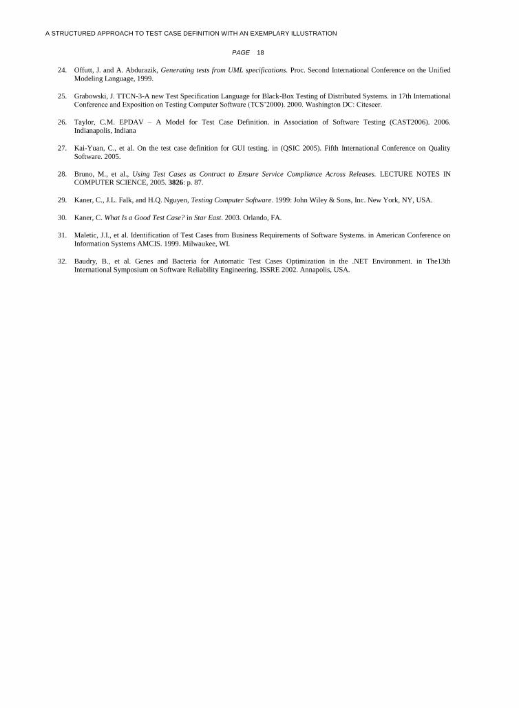
APPENDIX 1: TC DEFINITIONS
Category Definition Source
Input-Process-Output-Objectives
"A set of conditions or variables under which a tester will determine if an application or a software system meets specifications…. It may take many test cases to determine that a software program or system is functioning correctly"
www.wikipedia.org
"A test case is the combination of test data and oracle information to determine the validity of the test" [19, p. 9]
"A set of test inputs, execution conditions, and expected results developed for a particular objective, such as to exercise a particular program path or to verify compliance with a specific requirement"
[2, p. 187]
"Test case is a test vector consisting of a set of test inputs and the corresponding test outputs (pre and post conditional assertions)"
[4, p. 2]
"Test Case is an identified set of information including inputs and expected outputs associated with a particular program behavior"
[20, p. 7]
"A test case is a finite structure of input and expected output: a pair of input and output in the case of deterministic transformative systems, a sequence of input and output in the case of deterministic reactive systems, and a tree or a graph in the case of non-deterministic reactive systems
[21, p. 2]
States and Transitions
"A sequence of one or more subtests executed as a sequence because the outcome and/or final state of one subtest is the input and/or initial state of the next. The word ‘test’ is used to include subtests, tests properties, and test suites".
[22, p. 13]
"A test case specifies the pretest state of the implementation under test (IUT) and its environment, the test inputs or conditions, and the expected result. The expected result specifies what the IUT should produce from the test inputs. This specification includes messages generated by the IUT, exceptions, returned values, and resultant state of the IUT and its environment. Test cases may also specify initial and resulting conditions for other objects that constitute the IUT and its environment.”
[23, p. 47]
A STRUCTURED APPROACH TO TEST CASE DEFINITION WITH AN EXEMPLARY ILLUSTRATION
PAGE 20
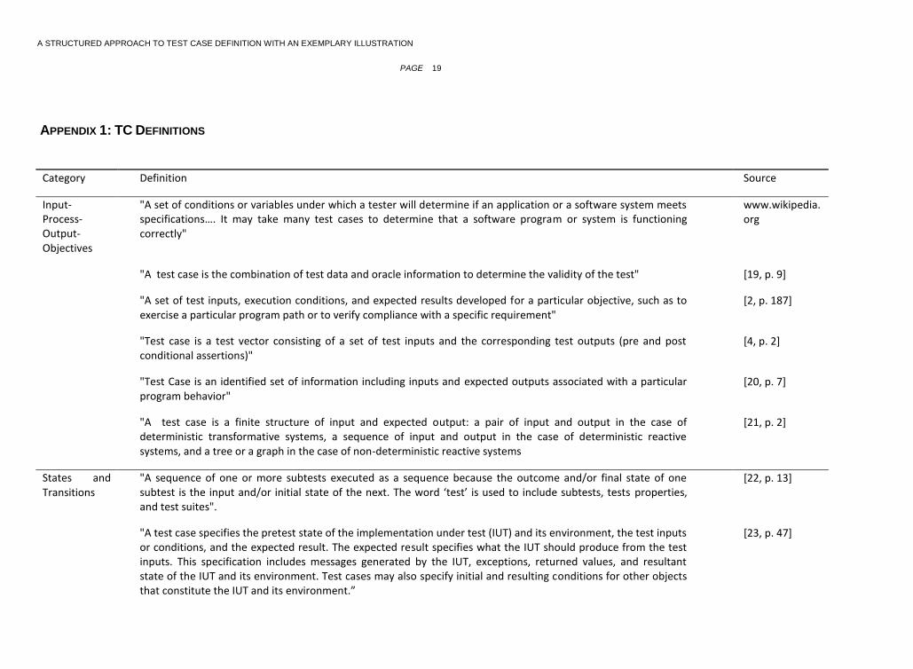
Category Definition Source
"Test case is composed of several components: test case values, prefix values, verify values, exit commands and expected outputs"
[24, p. 28]
"Test cases describe sequences of stimuli to and expected responses from the IUT". [25]
"Test Case is a verification of some aspect of the System Under Test (SUT). Test Case for any feature of any SUT can be defined as follows:
Perform verification, Vv
Which may be preceded by a sequence of actions, Aa
Which may require a set of data, Dd
Which may require preconditions, Pp
All of which runs in environment, Ee
Hence, a Test Case, Tt = Ee Pp Dd Aa Vv"
[26, p. 51]
A GUI test case is of the form _S0, e1; e2; . . . ; en , where S0 is a state of the GUI in which the event sequence e1; e2; . . . ; en is executed.
GUI test cases as a sequence of primitive
[3] ,p. 426]
[27], p.8]
Contract "Test-cases common in software engineering are in fact contracts (highly abstract contracts)… However, our result that test-cases are abstractions holds for general contract statements involving user inter-action".
[5, p. 8]
"a form of contract between a service provider and a service user" [28, p. 2]
Other "An empirical frame of reference, rather than a theoretical one" [29, p.359]
"…test case is a question that you ask of the program. The point of running the test is to gain information, for example, whether the program will pass or fail the test"
[30, p. 2]

A STRUCTURED APPROACH TO TEST CASE DEFINITION WITH AN EXEMPLARY ILLUSTRATION
PAGE 21
Category Definition Source
"A test idea is a brief statement of something that should be tested. For example, if you're testing a square root function, one idea for a test would be ‘test a number less than zero’. The idea is to check if the code handles an error case"
[30, p. 2]
"a specific set of attribute values that tests a given logical situation" [31, p. 3]
"a test case can be considered as a predator while a mutant program is analogous to a prey" [32]