A motion control algorithm for a continuous mining machine based on a hierarchical Real-time Control...
21
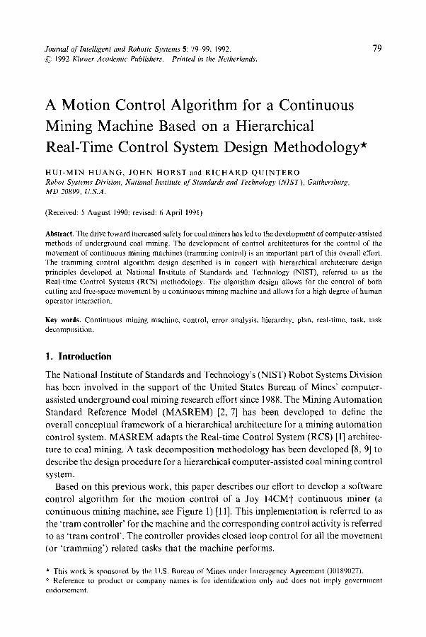
Journal of lntelligent and Robotic Systems 5: 79-99, 1992. 79 1992 Kluwer Academic Publishers. Printed in the Netherlands'. A Motion Control Algorithm for a Continuous Mining Machine Based on a Hierarchical Real-Time Control System Design Methodology* HUI-MIN HUANG, JOHN HORST and RICHARD QUINTERO Robot Systems Division, National Institute of Standards and Technology (NIST), Gaithersburg, MD 20899, U.S.A. (Received: 5 August 1990; revised: 6 April 1991) Abstract. The drive toward increased safety for coal miners has led to the development of computer-assisted methods of underground coal mining. The development of control architectures for the control of the movement of continuous mining machines (tramming control) is an important part of this overall effort. The tramming control algorithm design described is in concert with hierarchical architecture design principles developed at National Institute of Standards and Technology (NIST), referred to as the Real-time Control Systems (RCS) methodology. The algorithm design allows for the control of both cutting and free-space movement by a continuous mining machine and allows for a high degree of human operator interaction. Key words. Continuous mining machine, control, error analysis, hierarchy, plan, real-time, task, task decomposition. 1. Introduction The National Institute of Standards and Technology's (NIST) Robot Systems Division has been involved in the support of the United States Bureau of Mines' computer- assisted underground coal mining research effort since 1988. The Mining Automation Standard Reference Model (MASREM) [2, 7] has been developed to define the overall conceptual framework of a hierarchical architecture for a mining automation control system. MASREM adapts the Real-time Control System (RCS) [1] architec- ture to coal mining. A task decomposition methodology has been developed [8, 9] to describe the design procedure for a hierarchical computer-assisted coal mining control system. Based on this previous work, this paper describes our effort to develop a software control algorithm for the motion control of a Joy 14CMt continuous miner (a continuous mining machine, see Figure 1) [11]. This implementation is referred to as the 'tram controller' for the machine and the corresponding control activity is referred to as 'tram control'. The controller provides closed loop control for all the movement (or 'tramming') related tasks that the machine performs. * This work is sponsored by the U.S. Bureau of Mines under Interagency Agreement (J0189027). t Reference to product or company names is for identification only and does not imply government endorsement.
-
Upload
independent -
Category
Documents
-
view
4 -
download
0
Transcript of A motion control algorithm for a continuous mining machine based on a hierarchical Real-time Control...
Journal of lntelligent and Robotic Systems 5: 79-99, 1992. 79 1992 Kluwer Academic Publishers. Printed in the Netherlands'.
A Motion Control Algorithm for a Continuous Mining Machine Based on a Hierarchical Real-Time Control System Design Methodology*
HUI-MIN HUANG, JOHN HORST and RICHARD QUINTERO Robot Systems Division, National Institute of Standards and Technology (NIST), Gaithersburg, MD 20899, U.S.A.
(Received: 5 August 1990; revised: 6 April 1991)
Abstract. The drive toward increased safety for coal miners has led to the development of computer-assisted methods of underground coal mining. The development of control architectures for the control of the movement of continuous mining machines (tramming control) is an important part of this overall effort. The tramming control algorithm design described is in concert with hierarchical architecture design principles developed at National Institute of Standards and Technology (NIST), referred to as the Real-time Control Systems (RCS) methodology. The algorithm design allows for the control of both cutting and free-space movement by a continuous mining machine and allows for a high degree of human operator interaction.
Key words. Continuous mining machine, control, error analysis, hierarchy, plan, real-time, task, task decomposition.
1. In troduc t ion
The National Institute of Standards and Technology's (NIST) Robot Systems Division
has been involved in the support o f the United States Bureau o f Mines' computer-
assisted underground coal mining research effort since 1988. The Mining Automat ion
Standard Reference Model ( M A S R E M ) [2, 7] has been developed to define the
overall conceptual f ramework of a hierarchical architecture for a mining au tomat ion
control system. M A S R E M adapts the Real-time Control System (RCS) [1] architec-
ture to coal mining. A task decomposi t ion methodology has been developed [8, 9] to
describe the design procedure for a hierarchical computer-assisted coal mining control
system.
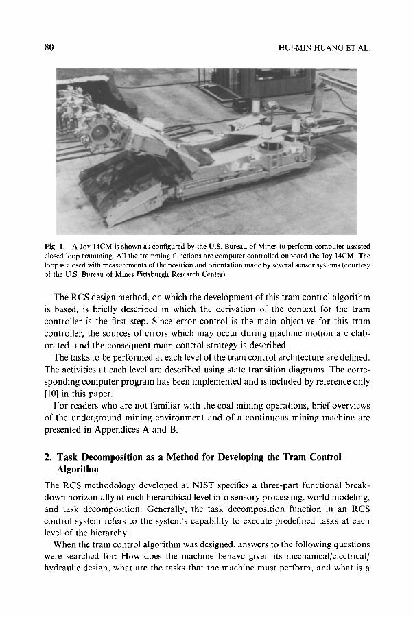
Based on this previous work, this paper describes our effort to develop a software
control algori thm for the mot ion control o f a Joy 14CMt cont inuous miner (a
cont inuous mining machine, see Figure 1) [11]. This implementat ion is referred to as
the ' t ram controller ' for the machine and the corresponding control activity is referred to as ' t ram control ' . The controller provides closed loop control for all the movement
(or ' t ramming ' ) related tasks that the machine performs.
* This work is sponsored by the U.S. Bureau of Mines under Interagency Agreement (J0189027). t Reference to product or company names is for identification only and does not imply government endorsement.
80 HUI-MIN HUANG ET A L
Fig. i. A Joy 14CM is shown as configured by the U.S. Bureau of Mines to perform computer-assisted closed loop tramming. All the tramming functions are computer controlled onboard the Joy 14CM. The loop is closed with measurements of the position and orientation made by several sensor systems (courtesy of the U.S. Bureau of Mines Pittsburgh Research Center).
The RCS design method, on which the development of this tram control algorithm is based, is briefly described in which the derivation of the context for the tram controller is the first step. Since error control is the main objective for this tram controller, the sources of errors which may occur during machine motion are elab-
orated, and the consequent main control strategy is described. The tasks to be performed at each level of the tram control architecture are defined.
The activities at each level are described using state transition diagrams. The corre- sponding computer program has been implemented and is included by reference only
[10] in this paper. For readers who are not familiar with the coal mining operations, brief overviews
of the underground mining environment and of a continuous mining machine are presented in Appendices A and B.
2. Task Decomposition as a Method for Developing the Tram Control Algorithm
The RCS methodology developed at NIST specifies a three-part functional break- down horizontally at each hierarchical level into sensory processing, world modeling, and task decomposition. Generally, the task decomposition function in an RCS control system refers to the system's capability to execute predefined tasks at each level of the hierarchy.
When the tram control algorithm was designed, answers to the following questions were searched for: How does the machine behave given its mechanical/electrical/ hydraulic design, what are the tasks that the machine must perform, and what is a
A MOTION CONTROL ALGORITHM 81
natural hierarchical organization of those tasks? This entire activity may also be referred to as the task decomposition method or process.
Internal to an intelligent RCS, hierarchical and heterarchical (at a same level) task decomposition, as well as temporal and spatial task decomposition, occur. Task decomposition between two successive levels may be described as follows: the higher level sends down 'what needs to be done' and the lower level generates 'how it is to be done'. The task decomposition method can involve an iteration of the following steps:
�9 Establish the context. In designing an RCS, the definition of context is the first step. This design step includes the establishment of the system's objectives, the problem domain, the constraints, and the assumptions. This design step must also include a narrative description of the approach selected to achieve the system goals. Scenarios are often used to develop typical operational descriptions.
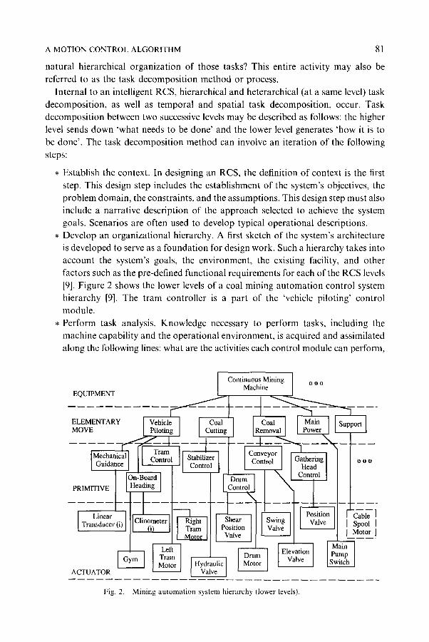
�9 Develop an organizational hierarchy. A first sketch of the system's architecture is developed to serve as a foundation for design work. Such a hierarchy takes into account the system's goals, the environment, the existing facility, and other factors such as the pre-defined functional requirements for each of the RCS levels [9]. Figure 2 shows the lower levels of a coal mining automation control system hierarchy [9]. The tram controller is a part of the 'vehicle piloting' control module.
�9 Perform task analysis. Knowledge necessary to perform tasks, including the machine capability and the operational environment, is acquired and assimilated along the following lines: what are the activities each control module can perform,
ELEI~ MOV
PRII~
L
EQU]
ACTI_
Fig. 2. Mining automation system hierarchy (lower levels).
82 HUI-MIN HUANG ET AL.
what are the associated constraints, and what is the information required to per-
form a given task? Task commands for each module at each level are developed in this design step.
�9 Develop RCS plans. Task commands defined above are used to develop RCS plans using state transition diagrams. These RCS plans describe how higher level tasks are decomposed into lower level tasks, and how the constraints for the commands are implemented as transition requirements among the different states.
3. The Context for the Tram Controller
This section and Section 4 generally define the tram control problem and the solution approach. These issues are regarded as the first step of the task decomposition method, as described in Section 2. The primary responsibility for the tram controller is to move the machine to desired locations. During the performance of tram control, problems including tread slippage along the lateral or rotational directions may be encountered. Tram control is a fundamental problem in that it interacts with other aspects of the machine control/mining process (such as the control of the conveyor boom and the cutter drum). Therefore, issues such as problem scope and developing a typical scenario all have to be established before task analysis can be performed.
3.1. SCOPE FOR TRAM CONTROL
Closed loop tramming for continuous mining machines may be categorized into the following two types: free-space tramming and cutting. The current focus of this paper for free-space tramming is in the vicinity of the face area. Obstacle avoidance is assumed to be a human operator function. The current focus for cutting tasks is on the first pass of a cut.
The scope of the tram controller is further defined by existing constraints and assumptions (they are also important references for the tram controller to be integrated into the overall system [15]). A comprehensive list of such constraints and assump- tions has been generated [10] and a part of it is shown in the following:
* A coal haulage unit is available to transport coal to a main coal transportation conveyor system.
, No obstacle avoidance is involved. , The machine will pivot only to adjust its orientation (the term 'yaw' is used
interchangeably with 'orientation'). Assume that the pivot action does not change the position of the machine.
, The pivotal point for the machine is used as a reference for the machine position. , The operation of the stabilization jack is crucial to tramming control and is
included in the tram controller.
The tram controller assumes the existence of the following conditions before it performs a cutting task:
A MOTION CONTROL ALGORITHM 83
�9 Adequate machine power for the electrical, hydraulic and mechanical systems
exists.
�9 The cutter drum is at the cut-height position.
�9 The gathering head is in a floating position.
3.2. BREAKDOWN AND GENERAL DESCRIPTION OF MACHINE MOVEMENT CONTROL
In order to accomplish free space tramming tasks, the continuous miner (CM) will be
given goal position coordinates. The machine will then tram to the position through
sensory interactive, closed loop control. Typical machine movements include pivoting
and pointing the machine towards the position, and tramming-forward to approach
the goal. Section 4 describes the error control issue. For cutting tasks, the machine will receive a desired cut distance and repeat as many
times as necessary a so-called sump-and-shear cycle, which includes the following
primitive functions: approach the face, sump into the coal face by tramming forward,
shear coal by moving the cutting drum down to the floor, gather the cut coal and move
it to the rear of the machine, then cut the remaining coal on the floor while tramming
in reverse (see Sections 5 and 6 for definitions). Similar error control (as in free-space
tramming) is used. However, more frequency correction activity is expected (due to the cutting process).
A combined scenario may include first a free-space-tramming task to move the
machine to the coal face followed by a cutting task to extract the coal.
3.3. CUTTING TASK COORDINATE FRAME
As described in the previous work [9], successive transitions in coordinate frames or
resolutions can be seen among different levels in the hierarchical control architecture.
Higher levels are concerned with larger areas but with coarser resolution, and a global
coordinate frame is generally used. At the lower levels, machine centered local frames
are used. In a global frame, further subclassification in terms of resolution typically
is required for different levels.* For example, at a higher level, a mine map might refer
to objects such as panels. At a lower level, a map typically has a finer resolution.
Objects within a panel would be referenced, such as a specific pillar or entry. At another level down, pillars may be represented in even finer detail. The shapes of
objects (e.g., pillars) may be represented in vectors, arrays (polygons), or a quad-tree spatial data structure format [13].
The tram controller uses a local path coordinate frame originating at the starting
point of either a cutting or a free-space tramming task to simplify computation. The vector from the starting point to the goal is used as the forward (or Y) axis (Figure 3).
The starting point for a cut is set at a point such that the cutter drum is about one
* A similar transition in time domain can also be seen. The upper levels deal with plans or events that cover greater periods of time but with less detail, while the lower levels deal with specific tasks or events that cover shorter periods of time.

84 HU1-MIN H U A N G ET AL.
Y
face
1 meter
I
\ Fig. 3.
m m - - I ~
X (path coordinates)
I /
X' (machine coordinates)
(other possible sensory
X" coordinates) 517190
Different local coordinate frames.
meter away from the coal face. At this point any necessary (albeit minor) adjustment
of the yaw of the machine can be made to allow the machine to become in line with
the direction of the cut.
4. Error Analysis and Control
In order to more fully characterize the performance of the tram controller, some
understanding of the sources and kinds of errors affecting control must be acquired.
The basic control strategy and some related issues for the performance of the error
control of the machine motion must be disclosed as well. These issues are discussed
in this section.
4.1. SOURCE A N D KINDS OF ERRORS A F F E C T I N G T R A M C O N T R O L
Problems affecting tram control are grouped into the following categories:
(a) Environmental. Coal seams are generally not flat throughout the mine. Irregu- larities of concern in the nature of the coal seams include:
�9 oblique grade of the floor, which can be a few degrees either sideways or in
the front direction; �9 anomalies, such as faults in the earth, rocks, etc.; �9 varying height or width.*
�9 Excavation of coal becomes not economical if the height becomes too thin.
A MOTION CONTROL ALGORITHM 85
The floor can also cause control errors for other reasons such as a wet or muddy
surface which would make the CM motion unpredictable (the machine may slip
or slide).
(b) Machine.
�9 mechanical/electrical delay between issuance of a stop command and the
actual stoppage of the tram motors [14], and similarly, the issuance of a motion command and the actual movement of the machine;
�9 uneven speeds between two tram motors;
�9 uneven wearing conditions between two tread sets.
(c) Sensory or communication fault. Control errors may be introduced by prob-
lems in:
�9 sensory data query time;
�9 measurement error propagation [6];
�9 communication failures in the network.
All these problems, uncorrected, can result in deviations from the intended cutting or
free-space tramming paths.
4.2. ERROR CONTROL STRATEGY AND SOME RELATED ISSUES
The problems identified in Section 4.1 are rich enough (they suggest that the under-
lying system is non-linear) to warrant the consideration of applying more advanced
techniques such as on-line system identification [5] or adaptive control [4] as control
solutions. For example, one system identification technique uses the on-line iterative
Auto Regression Moving Average (ARMA) model to linearly approximate the motion pattern. Error can be predicted and control can be applied.
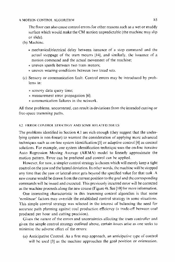
However, for now, a simpler control strategy is chosen which will merely keep a tight
control on the yaw and the lateral deviation. In other words, the machine will be stopped any time that the yaw or lateral error gets beyond the specified value for that task. A
new course would be drawn from the current position to the goal and the corresponding
commands will be issued and executed. This previously incurred error will be corrected as the machine proceeds along the new course (Figure 4). See [10] for more information.
One interesting characteristic in this t ramming control algorithm is that some
~nonlinear' factors may override the established control strategy in some situations. This simple control strategy was selected in the interest of balancing the need for
accurate path planning against coal production efficiency (a trade-off between coal
produced per hour and cutting precision). Given the nature of the errors and uncertainties affecting the tram controller and
given the simple control strategy outlined above, certain issues arise as one seeks to
minimize the adverse effect of the errors:
(a) Anticipative Control. As a first step approach, an anticipative type of control will be used [3] as the machine approaches the goal position or orientation.
86
(b)
HUI-MIN HUANG ET AL.
Original Path -
Fig. 4.
Goal
Y T~New Course \ ~ t Yaw
~Starting Point 2 Path revectoring during free-space tramming.
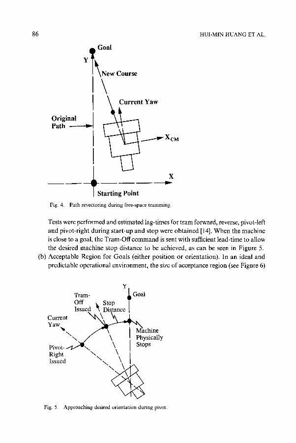
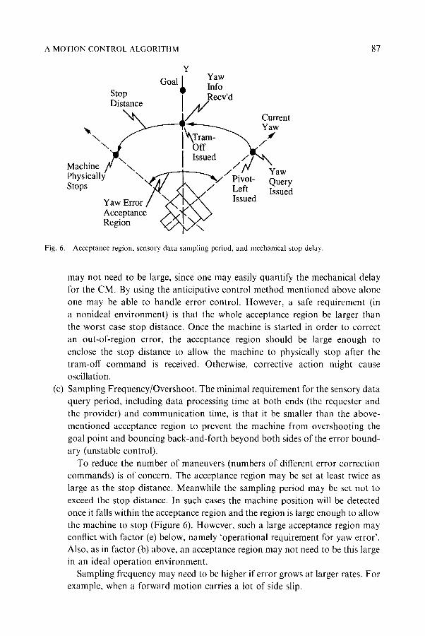
Tests were performed and estimated lag-times for tram forward, reverse, pivot-left and pivot-right during start-up and stop were obtained [14]. When the machine is close to a goal, the Tram-Offcommand is sent with sufficient lead-time to allow the desired machine stop distance to be achieved, as can be seen in Figure 5. Acceptable Region for Goals (either position or orientation). In an ideal and predictable operational environment, the size of acceptance region (see Figure 6)
Y Tram- ~ Goal Off ~, Stop I Issued '~ Distance I
Current Yaw ~ a
~ ~ chine \ \ \ Physically
Pivot- \ Stops Right \ \ I s sued \ \ \ ~
Fig. 5. Approaching desired orientation during pivot.
A MOTION CONTROL ALGORITHM 87
Y
Goal ~ YaWlnfo Stop Recv'd Ulstance I / 1 / '
x ~ .[,/ Current ,~ ~ - " ~ V(~--"' '---.~ Yaw
\ ~ ~Tram- ~ -4 \. d I 'b-iT-- "k., /
.~\ [ Issued X/g%,, Machine /q " ~ ~ ///~/''" ~'aw rnyslcauy "" "~ ~ ~ ~ " Pivot- Stops x~/~// ~ .,~," Left Query
Yaw Error / ~ '~ . , / ' ~ X Issued Acceptance .,~V'~', N~ ,> Region ~ x / N ~ "
Fig. 6. Acceptance region, sensory data sampling period, and mechanical stop delay.
(c)
may not need to be large, since one may easily quantify the mechanical delay for the CM. By using the anticipative control method mentioned above alone one may be able to handle error control. However, a safe requirement (in a nonideal environment) is that the whole acceptance region be larger than the worst case stop distance. Once the machine is started in order to correct an out-of-region error, the acceptance region should be large enough to enclose the stop distance to allow the machine to physically stop after the tram-off command is received. Otherwise, corrective action might cause oscillation. Sampling Frequency/Overshoot. The minimal requirement for the sensory data query period, including data processing time at both ends (the requester and the provider) and communication time, is that it be smaller than the above- mentioned acceptance region to prevent the machine from overshooting the goal point and bouncing back-and-forth beyond both sides of the error bound- ary (unstable control).
To reduce the number of maneuvers (numbers of different error correction commands) is of concern. The acceptance region may be set at least twice as large as the stop distance. Meanwhile the sampling period may be set not to exceed the stop distance. In such cases the machine position will be detected once it falls within the acceptance region and the region is large enough to allow the machine to stop (Figure 6). However, such a large acceptance region may conflict with factor (e) below, namely 'operational requirement for yaw error'. Also, as in factor (b) above, an acceptance region may not need to be this large in an ideal operation environment.
Sampling frequency may need to be higher if error grows at larger rates. For example, when a forward motion carries a lot of side slip.
88
(~)
(e)
HUI-MIN HUANG ET AL.
Yaw-Error Boundary during Tramming Forward. When the current orientation of the machine exceeds the error specification (threshold), forward commands will cease and the machine will pivot. There is a trade-off between the path-following
accuracy that the controller can achieve and frequency of tram, stop, and pivot commands required. Frequent error correction is highly undesirable from the standpoint of machine maintenance, power consumption, and coal production
efficiency. A very tight yaw tolerance in a poor (slippery) operational environ- ment may result in an inefficient 'forward - stop - pivot-left - stop - forward - stop - pivot-right - stop' loop without advancing the machine significantly.
The Operational Requirement for the Yaw Error. When the machine is farther off from the goal, yaw error is less critical since the machine has a longer time
to correct for it. However, one must also realize that a yaw error accumulating over a larger distance translates into a larger lateral offset at the goal (arc equals angle times distance). A lateral deviation at a position closer to the goal means a larger pivot correction is needed which in many situations may not be feasible since the machine must maneuver in very tight quarters.
Non-symmetrical error boundaries may be required due to the environment constraints or the machine's mechanical conditions (e.g. one motor may be faster than the other).
5. Task Analysis
This section deals with the second and the third steps of the task decomposition method (Section 2). The control hierarchy for the tram controller is discussed in Section 5.1. Tram control tasks are defined (in Section 5.2) according to the hierarchy. The terms 'task' and 'command' are used interchangeably. They also correspond to 'plan' in Section 6.
5.1. ARCHITECTURAL CONSIDERATION
As shown in Figure 2 [9], the tram control is a part of the 'vehicle piloting' control module at the elementary move (e-move) level and the 'tram motion' control module at the primitive level (these control modules assume additional duties including obstacle avoidance). The output of the tram controller conforms to the existing lowest level tram control commands implemented by the U.S. Bureau of Mines' (BOM) researchers [15].
The tram controller is also designed so that human operators can interact with the system at each level. The operator can elect to have the CM perform a complete cut task (involving operator interaction at the e-move level), or perform any primitive task (involving operator interaction at the primitive level).
5.2. TASKS DEFINED FOR THE TRAM CONTROLLER
Based on the pre-established context (Section 3), a set of necessary commands have been defined to enable the tram controller to perform given cutting or tramming tasks.
A MOTION CONTROL ALGORITHM 89
While a full analysis for them can be seen in [10], the names for these commands are identified here: CUT and FREE-SPACE-TRAM at the e-move level and
INITIAL-APPROACH-TO-THE-FACE, SUMP, SHEAR, CUSP-REMOVAL, RE-APPROACH-TO-THE-FACE, BACKOUT, LOCATE-FORWARD, and LOCATE-PIVOT at the primitive level.
6. RCS Plans
As the fourth step of the task decomposition methodology described (Section 4), state transition diagrams have been developed which essentially utilize the above defined commands to graphically represent RCS plans. The constraints for the commands
may be represented as transition requirements for the states.
6.1. E-MOVE LEVEL PLANS
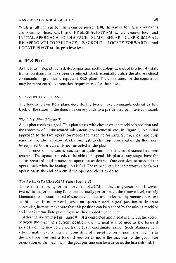
The following two RCS plans describe the two e-move commands defined earlier. Each of the states in the diagrams corresponds to a pre-defined primitive command.
The C U T Plan (Figure 7) A cut plan receives a goal. This plan starts with checks on the machine's position and the readiness of all the related subsystems (coal removal, etc,, in Figure 2). An initial approach to the face operation moves the machine forward. Sump, shear and cusp
removal operations follow. A clean-up task to clean up loose coal on the floor may be required but is currently not included in the plan.
This series of operations executes in cycles until the 5m cut distance has been reached. The operator needs to be able to suspend this plan at any stage, have the status recorded, and resume the operation as desired. One occasion to suspend the operation is when the haulage unit is full. The tram controller can perform a back-out operation at the end of a cut if the operator elects to do so.
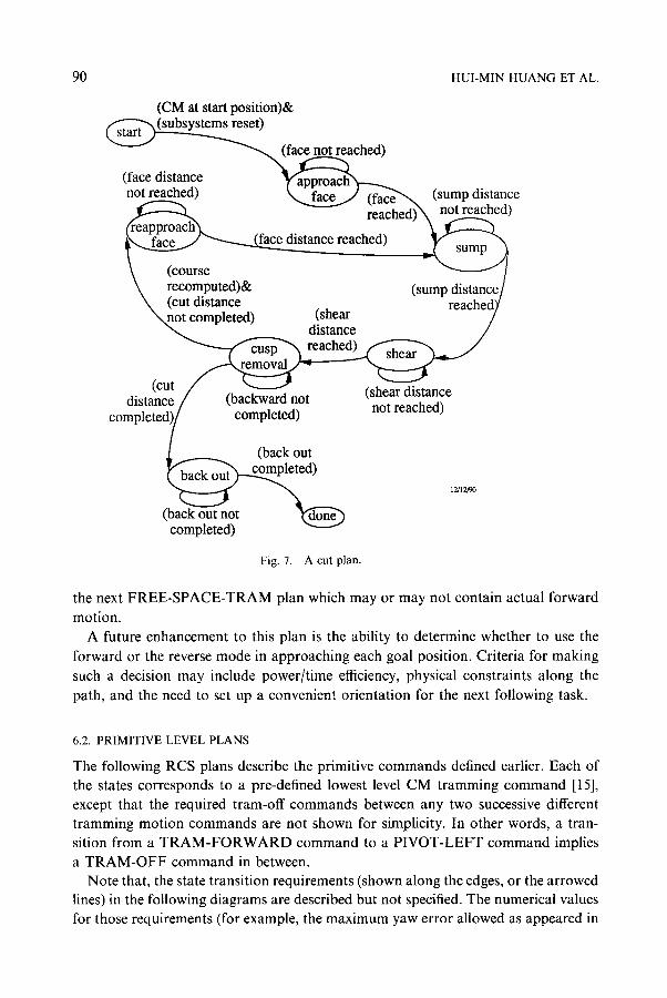
The F R E E - S P A C E - T R A M Plan (Figure 8) This is a plan allowing for the movement o f a CM in noncutting situations. However, two of the major planning functions normally performed at the e-move level, namely kinematics computation and obstacle avoidance, are performed by human operators
at this stage. In other words, when an operator sends a goal position to the tram controller, he must make sure that this position can be reached by the mining machine and that intermediate planning is neither needed nor intended.
After the system reset in Figure 8 [10] is completed and a goal is entered, the vector between the machine's current position and the goal will be used as the forward axis (Y) of the new reference frame (path coordinate frame). Such planning acti- vity normally results in a plan consisting of a pivot action to point the machine to the goal position and a forward motion to move the machine to the goal. The orientation of the machine at the goal position can be treated as the first sub-task for
90 HUI-MIN HUANG ET AL.
(CM at start position)&
(face distance not reached) \ (sump distance
not reached)
(course recomputed)& (cut distance not completed)
distance reached)
(shear distance reached)
sump
(sump distance reached)
(cut distance (backward not
completed)
(shear distance not reached)
(back out
1~12/90
(back out not completed)
Fig. 7. A cut plan.
the next FREE-SPACE-TRAM plan which may or may not contain actual forward
motion. A future enhancement to this plan is the ability to determine whether to use the
forward or the reverse mode in approaching each goal position. Criteria for making such a decision may include power/time efficiency, physical constraints along the path, and the need to set up a convenient orientation for the next following task.
6.2. PRIMITIVE LEVEL PLANS
The following RCS plans describe the primitive commands defined earlier. Each of the states corresponds to a pre-defined lowest level CM tramming command [15], except that the required tram-off commands between any two successive different tramming motion commands are not shown for simplicity. In other words, a tran- sition from a T R A M - F O R W A R D command to a PIVOT-LEFT command implies a TR AM-OF F command in between.
Note that, the state transition requirements (shown along the edges, or the arrowed lines) in the following diagrams are described but not specified. The numerical values for those requirements (for example, the maximum yaw error allowed as appeared in
A MOTION C O N T R O L A L G O R I T H M
(Current Position Verified)&&
oal Position Received)
(Coordinates Transformed)
91
done
(Position Error < Specified)
(Pivot C o m p l e ~ (Position Deviation Exceeds Specification)
Locate_]
(Yaw Error < Specified)&& (Position Within range),
1~27~0
Fig. 8. Tram control for a free space t ramming task.
Figure 9) should be computed according to the error control strategy described in Section 4. These values may be computed either in advance or on-line in world model.
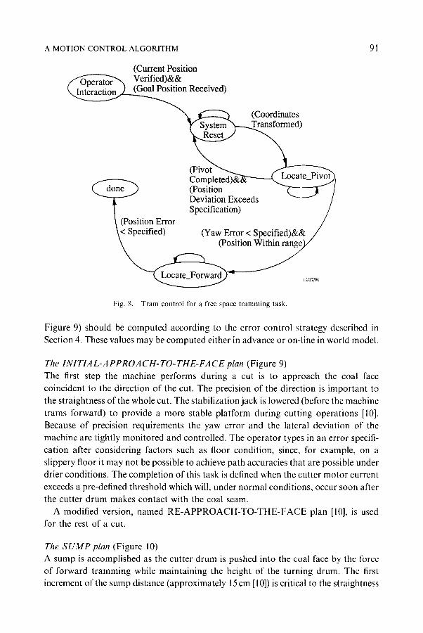
The 1NITIA L-A PPROA CH- TO- THE-FA CE plan (Figure 9) The first step the machine performs during a cut is to approach the coal face coincident to the direction of the cut. The precision of the direction is important to the straightness of the whole cut. The stabilization jack is lowered (before the machine trams forward) to provide a more stable platform during cutting operations [10]. Because of precision requirements the yaw error and the lateral deviation of the machine are tightly monitored and controlled. The operator types in an error specifi- cation after considering factors such as floor condition, since, for example, on a slippery floor it may not be possible to achieve path accuracies that are possible under drier conditions. The completion of this task is defined when the cutter motor current exceeds a pre-defined threshold which will, under normal conditions, occur soon after the cutter drum makes contact with the coal seam.
A modified version, named RE-APPROACH-TO-THE-FACE plan [10], is used for the rest of a cut.
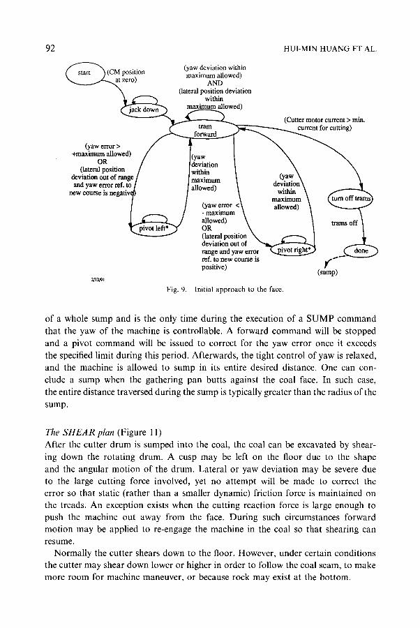
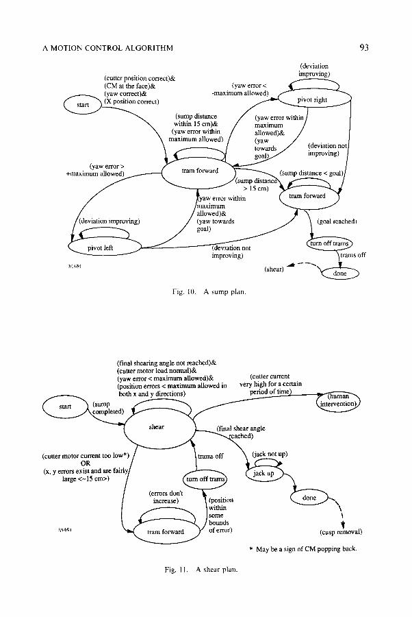
The SUMP plan (Figure 10) A sump is accomplished as the cutter drum is pushed into the coal face by the force of forward tramming while maintaining the height of the turning drum. The first increment of the sump distance (approximately 15 cm [10]) is critical to the straightness
92 HUI-MIN HUANG ET AL.
"CM osition (yaw deviation within (, start ) t~ . P , maximum allowed) " ~ _ _ . . . ~ t zero) AND
(lateral position deviation k ~ within
maximum allowed), u u w ~ (Cutter motor current > min.
(yaw error > / I ] ~ +maximum allowed) / (yaw ~ ~
OR (lateralOp R~176 / ~e~anti~ / . ~ d e v ~ ~ . m I ~ ~ya~__\ \ ~ - ) - " 1 a.evl~l_on \
new course is n e g a t l v ~ ~ ~ ~ : ~ i o n ~ m a ~ ~ / ~
deviation out of ~ range and yaw error ref. to new course is ,-~'~ positive) Y (sump)
2/13/91 Fig. 9. Initial approach to the face.
of a whole sump and is the only time during the execution of a SUMP command
that the yaw of the machine is controllable. A forward command will be stopped
and a pivot command will be issued to correct for the yaw error once it exceeds
the specified limit during this period. Afterwards, the tight control of yaw is relaxed,
and the machine is allowed to sump in its entire desired distance. One can con-
clude a sump when the gathering pan butts against the coal face. In such case, the entire distance traversed during the sump is typically greater than the radius of the
sump.
The SHEAR plan (Figure 11)
After the cutter drum is sumped into the coal, the coal can be excavated by shear-
ing down the rotating drum. A cusp may be left on the floor due to the shape
and the angular motion of the drum. Lateral or yaw deviation may be severe due to the large cutting force involved, yet no attempt will be made to correct the error so that static (rather than a smaller dynamic) friction force is maintained on the treads. An exception exists when the cutting reaction force is large enough to push the machine out away from the face. During such circumstances forward motion may be applied to re-engage the machine in the coal so that shearing can resume.
Normally the cutter shears down to the floor. However, under certain conditions the cutter may shear down lower or higher in order to follow the coal seam, to make more room for machine maneuver, or because rock may exist at the bottom.
A MOTION CONTROL ALGORITHM 93
(deviation (cutter position correct)& 1 . , - - improving) (CM at the face)& (yaw error < ~ (yaw correct)& -maximum allowed) ~ t" '-" �9 . (X position correct)
s t ~ ~ ~ w(Sit~iP d~Stcma~& / (mYaWieurr~ within/
(yaw error within / allowed)& / maximum allowed) / (vaw /
' ~ ~ ~ / (deviatmn not I ~ ~ ~ impmving) )
+m (yaw error > f r ~ !
~ o n , , , ~ g ) / ~Yoaa~) t o w a r d ~ ~ o i 1 re2ed )
~ ~ ~ off tram~ k,~ ~ not ~ ........ improving) "~trams off
3/14/9I (shear) ~d-~--'~\~"7"ff"""~
Fig. 10. A sump plan.
(final sheafing angle not reached)& (cutter motor load normal)& (yaw error < maximum allowed)& (cutter current (position errors < maximum allowed in very high for a certain both x and y directions) period of time)
[ ~ s t a r t ~ (sump ~ ' ~ ~ ~ tdnterventinn)J
- ' ~ shear ~__...,,~(final shear angle
(cutter motor current too low*) (jack not up)
/ (errors don't ~ . .. ~ . . . . / increase) ~ (P?smon ~ . ~ . . ~ . / " - \
( f2_ 2 " a Iw2: ', 3/'4/91 ~ ob~71T~Ji " ) (cusp LoYal)
* May be a sign of CM popping back.
Fig. 11, A shear plan.
94 HULMIN HUANG ET AL.
(cutter not k,,, ~tart j at the fl~r) (CM not yet
~----'--"~ (cutter backwards 45 cm) ((CM backwards by 45 ~ " - ~ _ _~ at t h e f l o o r ) ~ cm) OR (CM stuck))&
...... ~ ~ . . . . . . ~ ((cutting goat not - X,o.~2222~T_o,,) reached) a (yaw e~o~ >
"'~ . . . . _.~/-------....~m a ximum allowed))
cm) / \ \ (yaw no,
,~,u~ ~, , / ((CM backwards\ \ toward goal) /CM StUCK))O. / by 45cm) \ \ - - (cutfmg goal/ "'6R ..... \ \ ~
~ ~ ~ . . . . . . . . . . . . . s , ~ / (re-approach �9 face)
~ " N ~ 3 a w t o ~ go~)~ ~i a2 ~ t 7 ~ t O R u ~ (ba~out) ~h"ea i2e R
(yaw toward goal) OR (timeout)
Fig. 12. A cusp removal plan.
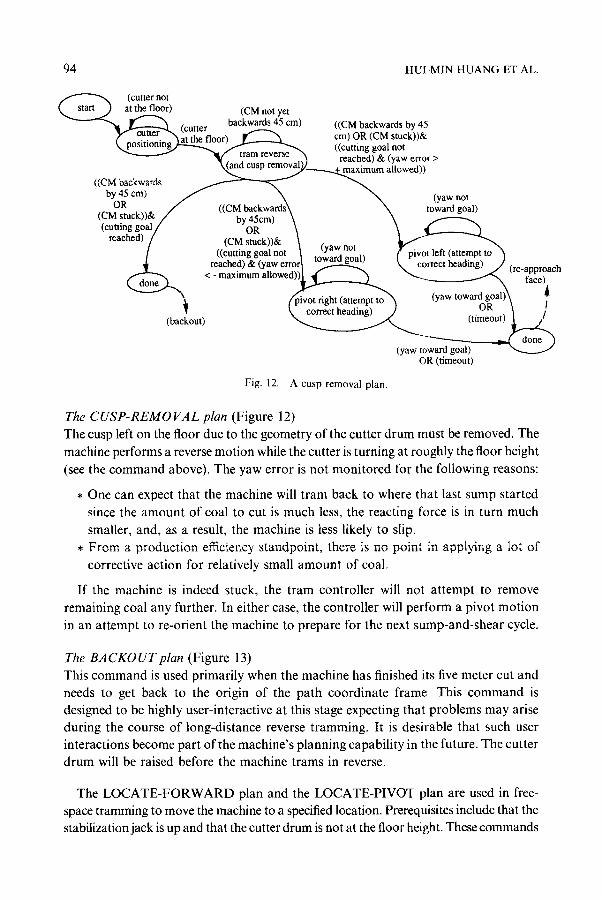
The C U S P - R E M O V A L plan (Figure 12) The cusp left on the floor due to the geometry of the cutter drum must be removed. The machine performs a reverse motion while the cutter is turning at roughly the floor height (see the command above). The yaw error is not monitored for the following reasons:
�9 One can expect that the machine will tram back to where that last sump started since the amount of coal to cut is much less, the reacting force is in turn much
smaller, and, as a result, the machine is less likely to slip. �9 From a production efficiency standpoint, there is no point in applying a lot of
corrective action for relatively small amount of coal,
If the machine is indeed stuck, the tram controller will not attempt to remove remaining coal any further. In either case, the controller will perform a pivot motion in an attempt to re-orient the machine to prepare for the next sump-and-shear cycle.
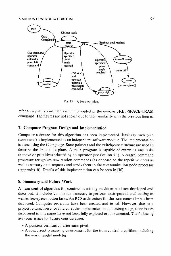
The B A C K O U T plan (Figure 13) This command is used primarily when the machine has finished its five meter cut and needs to get back to the origin of the path coordinate frame_ This command is designed to be highly user-interactive at this stage expecting that problems may arise during the course of long-distance reverse tramming. It is desirable that such user interactions become part of the machine's planning capability in the future. The cutter drum will be raised before the machine trams in reverse.
The LOCATE-FORWARD plan and the LOCATE-PIVOT plan are used in free- space tramming to move the machine to a specified location. Prerequisites include that the stabilization jack is up and that the cutter drum is not at the floor height. These commands
A MOTION CONTROL ALGORITHM
CM not stuck
ched
CM stuck and / I Ope~!or I ~ "~ operator / J specified I \ entered a [ I pivot ~ Ooeratolk (~m off trams) comm reach ~ / [anglee I s~r \
Fig, 13. A back out plan.
95
refer to a path coordinate system computed in the e-move FREE-SPACE-TRAM command. The figures are not shown due to their similarity with the previous figures.
7. Computer Program Design and Implementation
Computer software for this algorithm has been implemented. Basically each plan (command) is implemented as an independent software module. The implementation is done using the C language. State pointers and the switch/case structure are used to describe the finite state plans. A main program is capable of executing any tasks (e-move or primitive) selected by an operator (see Section 5.1). A central command processor recognizes new motion commands (as opposed to the repetitive ones) as well as sensory data requests and sends them to the communication node processor (Appendix B). Details of this implementation can be seen in [10].
8. Summary and Future Work
A tram control algorithm for continuous mining machines has been developed and described. It includes commands necessary to perform underground coal cutting as well as free-space motion tasks. An RCS architecture for the tram controller has been discussed. Computer programs have been created and tested. However, due to a project re-direction encountered at the implementation and testing stage, some issues discovered in this paper have not been fully explored or implemented. The following are some issues for future consideration:
* A position verification after each pivot. * A concurrent processing environment for the tram control algorithm, including
the world model modules.
96 HUI-MIN HUANG ET AL.
�9 A decision process in free-space tramming to determine whether forward or reverse motion is to be used to approach a given goal position.
The following summarizes this tram control design and implementation work:
�9 This work is another demonstration showing that the NIST RCS task decompo- sition method can be an effective approach for solving complex real-time system control problems. This method utilizes a generic approach to describe system behavior. In addition, system configuration, integration, and modification are
facilitated. �9 It was discovered that the implementation procedure for this method could be
described in more detail and generic software templates could be developed to facilitate implementation. Such improvements are ongoing at NIST. A formal theory of intelligent machine systems and an RCS textbook with implementation examples are expected to be developed as a result of this effort.
Appendix A: Overview of Underground Coal Mining Environment
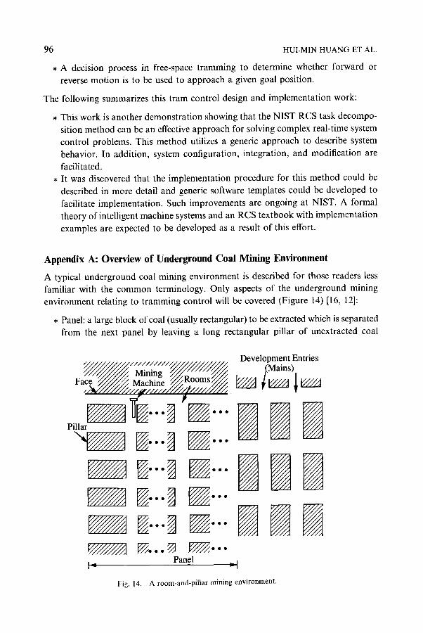
A typical underground coal mining environment is described for those readers less familiar with the common terminology. Only aspects of the underground mining environment relating to tramming control will be covered (Figure 14) [16, 12]:
�9 Panel: a large block of coal (usually rectangular) to be extracted which is separated from the next panel by leaving a long rectangular pillar of unextracted coal
Development Entries y, , , , , , . . . . . ~ ~/,~, Y~/'///~ Mining ~ / ~ " " / /~ / . .(Mains) Face //////,/// Machine ~Roomsx///~. ~ , ~ l~/ / / / j ~ / / / A
, ~ / / / / / / / / / / ' / / / / / 2 " / / / ,
Pillar ~ ~...~ ~ . . .
~ D--~ ~---
V///////A ~,...~ D~,... Panel _ t
I= v I
Fig. 14. A room-and-pillar mining environment.
A MOTION CONTROL ALGORITHM 97
between panels. The long unextracted pillar is a safety precaution to prevent the
collapse of the coal roof over any more than one panel in the event of a cave in.
* Pillar: generally means a small (compared to panel) block of unextracted coal,
36m or less in length and 4.5 to 18m in width. As long as they are of sufficient
size and separation from one another, pillars (along with roof bolts) help keep the roof of the mine from caving in.
, Face: the front of the coal seam where cutting operations occur.
* Entry: a passage way in a panel where coal has been extracted [12], typically 9 to
14m in width. Entries can be used as haulage roads, transporation roads, or
ventilation paths. Entries are formed by removing coal and leaving pillars that are
nominally rectangular in shape.
, Cut: The action that the mining machine takes to excavate a block of coal (see [10] for a discussion on the size of a cut). Usually the mining machine cuts in two
passes to achieve a desired width of a cut (typically the width of an entry).
, Room-and-Pil lar Mining: a mining method that also features the development of
main entries at both side of a panel. Coal is extracted forming rooms [16] with
pillars left. Pillars may be extracted at a later stage in retracting operation. Sizes
of pillars and width of entries may vary depending on the roof support and the
transportation support requirements.
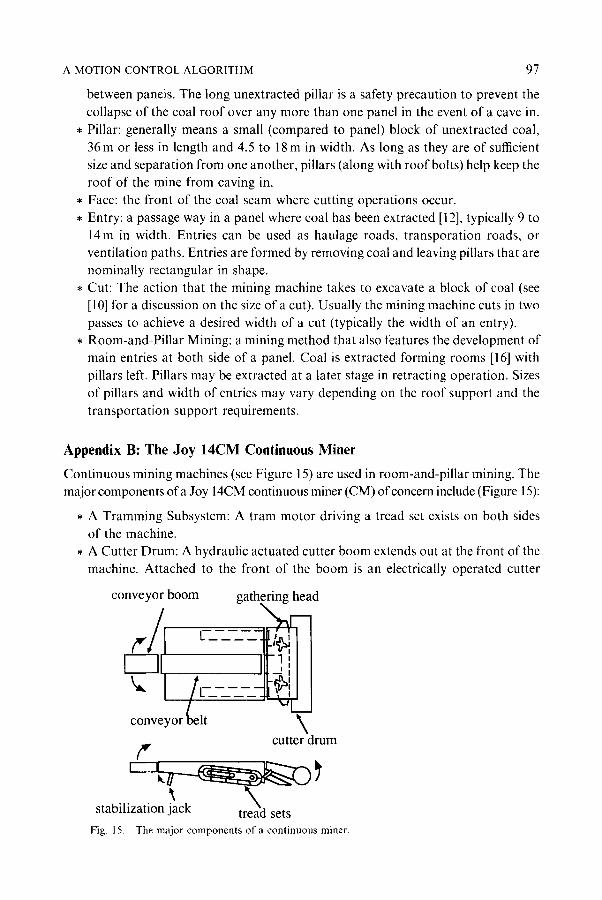
Appendix B: The Joy 14CM Continuous Miner
Continuous mining machines (see Figure 15) are used in room-and-pillar mining. The
major components of a Joy 14CM continuous miner (CM) of concern include (Figure 15):
�9 A Tramming Subsystem: A tram motor driving a tread set exists on both sides
of the machine.
�9 A Cutter Drum: A hydraulic actuated cutter boom extends out at the front of the
machine. Attached to the front of the boom is an electrically operated cutter
conveyor boom gathering head
conveyor belt
cutter drum
stabilization jack sets
Fig. 15. The major components of a continuous miner.

98 HUI-MIN HUANG ET AL.
drum. Replaceable cutting bits are installed at the surface of the cutter drum which fracture the coal as the drum is pushed into the coal face while turning.
�9 A Gathering Head Subsystem: This subsystem is located at the bottom of the front end of the machine. A gathering pan can be set to float on the floor. The
gathering head, using a rotary motion, scoops the coal inwawrd onto the gather- ing pan. A conveyor belt is behind the gathering head and moves the coal to the rear of the machine.
�9 A Conveyor Subsystem: The conveyor extends from the gathering head to the
rear of the machine. An adjustable position conveyor boom forms the end of the conveyor system. It can move from right to left as well as up or down. Coal is dumped from the conveyor boom onto a haulage unit behind the CM.
�9 A Stabilization Jack: This hydraulic jack provides a stabilizing force to counter- balance the cutting force.
The continuous mining machine has ten tram control commands: slow/fast speed forward, slow/fast speed reverse, pivot /eft/right, turn left/right forward, and turn
left/right reverse. These are open-loop commands. Execution of any of these com- mands can be terminated by either a stop command (implying the tram control loop is closed at a higher level where the sensory information is processed), or by a condition that some maximum time has expired (a safety time-out condition associated with this command).
The U.S. Bureau of Mines has been implementing a computer control system testbed [15]. This testbed is a distributed network linking the continuous mining machine, various sensor systems (length and angle measuring systems and a gyro, see Figure 1), and an operator console which are all nodes on the network.
Acknowledgement
The authors extend their appreciation to Mr Timothy Matty, Dr George Schnaken- berg, Dr Christopher Jobes, and Mr Edward Fries of the U.S. Bureau of Mines for their insightful input, especially regarding coal mining practice, to this project. The authors also extend their acknowledgement to Mr Don Orser of NIST for his participation in this project.
References
I. AIbus, J.S., McCMn, H.G.. and Lurnia, R., i987, NASA/NBS standard reference model for telerobot control system architecture (NASREM), NSS Technical Note 1235, National Bureau of Standards, U.S. Department of Commerce.
2. Albus, J , Quintero, R., Huang, H., and Roche, M., 1989, mining automation real-time control system architecture standard reference model (MASREM), NIST Technical Note 1261 Volume 1, National Institute of Standards and Technology, U.S. Department of Commerce.
3. Anderson, DL., 1990, Laser 485.c, Computer Program, Bureau of Mines. 4. Astrom, K.J, and Wittenmark, B., 1984, Computer Controller Systems, Theory and Design, Prentice-
Hall Information and System Sciences Series, Prentice-Hall, Englewood Cliff, N.J.
A MOTION CONTROL ALGORITHM 99
5. Eykhoff~ P., 1974, System htentifieation, Parameter and State Estimation, Wiley, New York. 6. Horst, LA., 1990, An application of measurement error propagation theory to two measurement
systems used to calculate the position and heading of a vehicle on a flat surface, NIST lnteragency Report NISTIR 90-4434, National Institute of Standards and Technology, U.S. Department of Commerce.
7. Huang, H., 1990a, A hierarchical real-time control system for use with coal mining automation, 4th Conference on the Use of Computers in the Coal Industry, West Virginia University, Morgantown, West Virginia.
8. Huang, H., 1990b, Hierarchical real-time control task decomposition for a coal mining automation project, NIST lnteragency Report NISTIR 90-4271, National Institute of Standards and Technology, U.S. Department of Commerce.
9. Huang, H., 1990c, Task decomposition methodology for the design of a coal mining automation hierarchical real-time control system, 5th IEEE International Symposium on Intelligent Control, Philadelphia, PA.
I0. Huang, H., Horsl, J.A., and Richard Quintero, 1991, Algorithm design and task decomposition for a continuous mining machine motion control algorithm, NIST Interagency Report, NTIS PB91- 23t597/AS, National Institute of Standards and Technology, U.S. Department of Commerce.
11, Joy Technologies lnc., 1987, Technical Service Manual, Joy 14CM Continuous Miner. 12. U.S. Bureau of Mines, 1968, A Dictionap 3' qf Mining, Minerals, and Related TeJw~s. 13. Samet, 1--I., 1990, The Design and Analysis o! Spatial Data Structures, Addison-Wesley, New York. 14. Schnakenberg, G. and Sammarco, J., I990, Joy 14CM machine test data, US. Bureau of Mines
Internal Document. 15. Schifl'baur, W.H., et al., 1990, Computer network for continuous mining machine (Joy 14CM) control
- Documentation of node functions and communications, U.S. Bureau of Mines Internal Document. 16. Stefanko, R., 1983, Coal Mining Technology, Theo O, and Practice, Society of Mining Engineers of the
American Institute of Mining, Metallurgical, and Petroleum Engineers, New York.