
Hierarchical Network Topographical Routing
312
Glasgow Theses Service http://theses.gla.ac.uk/ [email protected] Windmill, Christopher (2013) Hierarchical network topographical routing. EngD thesis, University of Glasgow. http://theses.gla.ac.uk/4607 Copyright and moral rights for this thesis are retained by the author A copy can be downloaded for personal non-commercial research or study, without prior permission or charge This thesis cannot be reproduced or quoted extensively from without first obtaining permission in writing from the Author The content must not be changed in any way or sold commercially in any format or medium without the formal permission of the Author When referring to this work, full bibliographic details including the author, title, awarding institution and date of the thesis must be given
-
Upload
khangminh22 -
Category
Documents
-
view
0 -
download
0
Transcript of Hierarchical Network Topographical Routing

Glasgow Theses Service http://theses.gla.ac.uk/
Windmill, Christopher (2013) Hierarchical network topographical routing. EngD thesis, University of Glasgow. http://theses.gla.ac.uk/4607 Copyright and moral rights for this thesis are retained by the author A copy can be downloaded for personal non-commercial research or study, without prior permission or charge This thesis cannot be reproduced or quoted extensively from without first obtaining permission in writing from the Author The content must not be changed in any way or sold commercially in any format or medium without the formal permission of the Author When referring to this work, full bibliographic details including the author, title, awarding institution and date of the thesis must be given
Hierarchical NetworkTopographical Routing
Christopher Mark WindmillMEng (Hons) Electronics and Computer Science
Submitted in fulfilment of the requirements for the Degree of
Doctor of Engineering in System Level Integration
School of Engineering
University of Glasgow
December 2013

Abstract
Within the last 10 years the content consumption model that underlies
many of the assumptions about traffic aggregation within the Internet
has changed; the previous short burst transfer followed by longer periods
of inactivity that allowed for statistical aggregation of traffic has been
increasingly replaced by continuous data transfer models. Approaching
this issue from a clean slate perspective; this work looks at the design
of a network routing structure and supporting protocols for assisting in
the delivery of large scale content services. Rather than approaching a
content support model through existing IP models the work takes a fresh
look at Internet routing through a hierarchical model in order to highlight
the benefits that can be gained with a new structural Internet or through
similar modifications to the existing IP model. The work is divided into
three major sections: investigating the existing UK based Internet struc-
ture as compared to the traditional Autonomous System (AS) Internet
structural model; a localised hierarchical network topographical routing
model; and intelligent distributed localised service models.
The work begins by looking at the United Kingdom (UK) Internet struc-
ture as an example of a current generation technical and economic model
with shared access to the last mile connectivity and a large scale wholesale
network between Internet Service Providers (ISPs) and the end user. This
model combined with the Internet Protocol (IP) address allocation and
transparency of the wholesale network results in an enforced inefficiency
within the overall network restricting the ability of ISPs to collaborate.
From this model a core / edge separation hierarchical virtual tree based
routing protocol based on the physical network topography (layers 2 and
3) is developed to remove this enforced inefficiency by allowing direct
management and control at the lowest levels of the network. This model
acts as the base layer for further distributed intelligent services such as
management and content delivery to enable both ISPs and third parties
to actively collaborate and provide content from the most efficient source.

Contents
List of Tables 11
List of Figures 12
Author’s Declaration 18
Acronyms and Abbreviations 19
1 Introduction 26
1.1 Introduction . . . . . . . . . . . . . . . . . . . . . . . . . . . . . . . . 26
1.2 Project Overview . . . . . . . . . . . . . . . . . . . . . . . . . . . . . 26
1.3 Project Aim . . . . . . . . . . . . . . . . . . . . . . . . . . . . . . . . 27
1.4 Project Objectives . . . . . . . . . . . . . . . . . . . . . . . . . . . . 28
1.4.1 Review of Existing Network Strategies . . . . . . . . . . . . . 28
1.4.2 An Integrated Approach to Future Networks . . . . . . . . . . 29
1.5 Approach to Project . . . . . . . . . . . . . . . . . . . . . . . . . . . 29
1.6 Research Rationale . . . . . . . . . . . . . . . . . . . . . . . . . . . . 30
1.6.1 Research Relevance . . . . . . . . . . . . . . . . . . . . . . . . 30
1.6.2 Wider Industry Relevance . . . . . . . . . . . . . . . . . . . . 31
1.7 Thesis Overview . . . . . . . . . . . . . . . . . . . . . . . . . . . . . . 31
2 Background 33
2.1 Introduction . . . . . . . . . . . . . . . . . . . . . . . . . . . . . . . . 33
2.2 Internet Routing and Switching . . . . . . . . . . . . . . . . . . . . . 34
2.2.1 Address Space Exhaustion . . . . . . . . . . . . . . . . . . . . 35
2.2.2 Extensions to IP for Layer 3 . . . . . . . . . . . . . . . . . . . 36
2.2.3 Switching (Layers 2 and 3) . . . . . . . . . . . . . . . . . . . . 36
2.2.3.1 Switch and Router Virtualisation . . . . . . . . . . . 37
2.2.3.2 Logical and Physical Network Topologies . . . . . . . 41
3

2.2.4 Routing (layer 3) . . . . . . . . . . . . . . . . . . . . . . . . . 42
2.2.4.1 Routing Types . . . . . . . . . . . . . . . . . . . . . 43
2.2.5 Network Structure . . . . . . . . . . . . . . . . . . . . . . . . 43
2.2.5.1 Intra-network Dynamic Routing . . . . . . . . . . . . 45
2.2.5.2 Inter-network Dynamic Routing . . . . . . . . . . . . 46
2.2.5.3 Administrative and Policy Control . . . . . . . . . . 46
2.2.6 IPv4 . . . . . . . . . . . . . . . . . . . . . . . . . . . . . . . . 47
2.2.6.1 subnet masking and CIDR . . . . . . . . . . . . . . . 47
2.2.6.2 Domain Name System . . . . . . . . . . . . . . . . . 48
2.2.6.3 Network Address Translation and IPv4 . . . . . . . . 49
2.2.7 IPv6 . . . . . . . . . . . . . . . . . . . . . . . . . . . . . . . . 49
2.2.8 IP Routing Extensions . . . . . . . . . . . . . . . . . . . . . . 50
2.2.8.1 MPLS and Aggregation . . . . . . . . . . . . . . . . 50
2.2.8.2 Compact Routing . . . . . . . . . . . . . . . . . . . . 50
2.2.8.3 Separation of Identity and Location . . . . . . . . . . 51
2.2.8.4 Location / Identity Separation Protocol . . . . . . . 52
2.2.8.5 Host Identity Protocol . . . . . . . . . . . . . . . . . 52
2.2.8.6 GSE/8+8 . . . . . . . . . . . . . . . . . . . . . . . . 52
2.2.8.7 Identifier-Locator Network Protocol . . . . . . . . . . 53
2.2.8.8 Site Multihoming by IPv6 Intermediation . . . . . . 53
2.2.9 IP and Mobility . . . . . . . . . . . . . . . . . . . . . . . . . . 53
2.2.9.1 Mobile IP . . . . . . . . . . . . . . . . . . . . . . . . 54
2.2.9.2 Mobile Ad Hoc Network (MANET) . . . . . . . . . . 54
2.2.9.3 Network Mobility (NEMO) . . . . . . . . . . . . . . 55
2.2.9.4 Mobile Ad hoc Network Mobility (MANEMO) . . . . 55
2.2.9.5 Interactive Protocol for Mobile Networking . . . . . 56
2.3 Next Generation Architectures . . . . . . . . . . . . . . . . . . . . . . 56
2.3.1 Accountable Internet Protocol . . . . . . . . . . . . . . . . . . 57
2.3.2 Content Delivery Networks . . . . . . . . . . . . . . . . . . . . 57
2.3.3 Content Centric Networking . . . . . . . . . . . . . . . . . . . 58
2.3.3.1 Data-Orientated Network Architecture . . . . . . . . 58
2.3.3.2 Content Centric Networking Project . . . . . . . . . 58
2.3.3.3 Juno Content-Centric Middleware . . . . . . . . . . . 59
2.3.3.4 PSIRP . . . . . . . . . . . . . . . . . . . . . . . . . . 59
2.3.3.5 PURSUIT . . . . . . . . . . . . . . . . . . . . . . . . 59
2.3.4 Content Centric Transport . . . . . . . . . . . . . . . . . . . . 60
4
2.3.4.1 Bit Torrent . . . . . . . . . . . . . . . . . . . . . . . 60
2.3.5 Localised Bit Torrent . . . . . . . . . . . . . . . . . . . . . . . 60
2.3.5.1 Splitstream . . . . . . . . . . . . . . . . . . . . . . . 61
2.3.5.2 DOT and Ditto . . . . . . . . . . . . . . . . . . . . . 61
2.4 IP Security and Privacy . . . . . . . . . . . . . . . . . . . . . . . . . 62
2.4.1 IP Security . . . . . . . . . . . . . . . . . . . . . . . . . . . . 62
2.4.2 DNS Security . . . . . . . . . . . . . . . . . . . . . . . . . . . 62
2.4.3 Tor Onion Routing . . . . . . . . . . . . . . . . . . . . . . . . 62
2.4.4 BitBlender . . . . . . . . . . . . . . . . . . . . . . . . . . . . . 63
2.5 Internet Structure . . . . . . . . . . . . . . . . . . . . . . . . . . . . . 63
2.5.1 UK Internet Structure . . . . . . . . . . . . . . . . . . . . . . 64
2.5.2 BT Network Architecture . . . . . . . . . . . . . . . . . . . . 64
2.5.2.1 Premises Nodes . . . . . . . . . . . . . . . . . . . . . 65
2.5.2.2 Access Nodes . . . . . . . . . . . . . . . . . . . . . . 65
2.5.2.3 Metro Nodes . . . . . . . . . . . . . . . . . . . . . . 65
2.5.2.4 Core Nodes . . . . . . . . . . . . . . . . . . . . . . . 65
2.5.2.5 iNodes . . . . . . . . . . . . . . . . . . . . . . . . . . 65
2.5.2.6 Network Architecture . . . . . . . . . . . . . . . . . 66
2.5.3 Independent ISP Architectures . . . . . . . . . . . . . . . . . 69
2.5.3.1 JA.NET . . . . . . . . . . . . . . . . . . . . . . . . . 69
2.5.3.2 Enta.net . . . . . . . . . . . . . . . . . . . . . . . . . 69
2.5.3.3 Sky Broadband . . . . . . . . . . . . . . . . . . . . . 74
2.5.4 Overlaid Network Structures . . . . . . . . . . . . . . . . . . . 74
2.5.5 UK Provisioning Growth . . . . . . . . . . . . . . . . . . . . . 74
2.5.5.1 ADSL Services . . . . . . . . . . . . . . . . . . . . . 79
2.5.5.2 Cable Services . . . . . . . . . . . . . . . . . . . . . 79
2.5.5.3 Fibre Services . . . . . . . . . . . . . . . . . . . . . . 79
2.5.5.4 Backhaul Growth . . . . . . . . . . . . . . . . . . . . 80
2.6 Conclusions . . . . . . . . . . . . . . . . . . . . . . . . . . . . . . . . 80
3 UK Internet Structure and Future Network Requirements 82
3.1 Introduction . . . . . . . . . . . . . . . . . . . . . . . . . . . . . . . . 82
3.2 The UK Internet . . . . . . . . . . . . . . . . . . . . . . . . . . . . . 82
3.2.1 Internet Network Components . . . . . . . . . . . . . . . . . . 83
3.2.1.1 Internet Backbone . . . . . . . . . . . . . . . . . . . 83
3.2.1.2 Internet Exchanges . . . . . . . . . . . . . . . . . . . 84
5

3.2.1.3 Interconnection Points . . . . . . . . . . . . . . . . . 87
3.2.1.4 Aggregation Points . . . . . . . . . . . . . . . . . . . 87
3.2.1.5 Multiple Three Layer Model . . . . . . . . . . . . . . 88
3.2.2 Internet Network Functionality . . . . . . . . . . . . . . . . . 91
3.2.2.1 Authentication, Authorisation, and Auditing . . . . . 91
3.2.2.2 Protocol and / or Application Support . . . . . . . . 93
3.2.2.3 Service Provision . . . . . . . . . . . . . . . . . . . . 94
3.2.3 Model Structures . . . . . . . . . . . . . . . . . . . . . . . . . 95
3.2.4 Cost Modelling . . . . . . . . . . . . . . . . . . . . . . . . . . 97
3.2.4.1 Last Mile Charges . . . . . . . . . . . . . . . . . . . 98
3.2.4.2 Access Network Charges . . . . . . . . . . . . . . . . 98
3.2.4.3 Metro and Core (Backhaul) Network Charges . . . . 98
3.2.4.4 Real World Deployability and Composibility . . . . . 99
3.2.4.5 Content Delivery Networks . . . . . . . . . . . . . . 100
3.2.4.6 ISP - NP Interaction . . . . . . . . . . . . . . . . . . 101
3.2.4.7 ISP - ISP Interaction . . . . . . . . . . . . . . . . . . 106
3.2.4.8 ISP Caching Model . . . . . . . . . . . . . . . . . . . 107
3.2.4.9 NP Caching Model . . . . . . . . . . . . . . . . . . . 109
3.2.5 Access Network Model . . . . . . . . . . . . . . . . . . . . . . 110
3.2.6 Internet traffic . . . . . . . . . . . . . . . . . . . . . . . . . . . 112
3.2.7 Traffic Patterns . . . . . . . . . . . . . . . . . . . . . . . . . . 114
3.2.7.1 HTTP Traffic . . . . . . . . . . . . . . . . . . . . . . 114
3.2.7.2 P2P Traffic . . . . . . . . . . . . . . . . . . . . . . . 115
3.2.7.3 Other Traffic . . . . . . . . . . . . . . . . . . . . . . 115
3.2.7.4 Streaming Traffic Growth . . . . . . . . . . . . . . . 115
3.2.7.5 Future Trends in Streaming . . . . . . . . . . . . . . 117
3.2.8 The cloud . . . . . . . . . . . . . . . . . . . . . . . . . . . . . 119
3.2.9 The Role of the ISP . . . . . . . . . . . . . . . . . . . . . . . 119
3.3 Next Generation Network Requirements . . . . . . . . . . . . . . . . 120
3.3.1 Routing Requirements . . . . . . . . . . . . . . . . . . . . . . 121
3.3.1.1 Routing Scalability . . . . . . . . . . . . . . . . . . . 121
3.3.1.2 Traffic Engineering . . . . . . . . . . . . . . . . . . . 121
3.3.1.3 Multi-homing . . . . . . . . . . . . . . . . . . . . . 122
3.3.1.4 Simplified Internal Renumbering . . . . . . . . . . . 122
3.3.1.5 Modularity, Composability, and Seamlessness . . . . 122
3.3.1.6 Routing Quality . . . . . . . . . . . . . . . . . . . . 122
6

3.3.1.7 Location and identification split . . . . . . . . . . . . 123
3.3.1.8 Scalable mobility support . . . . . . . . . . . . . . . 123
3.3.1.9 Routing security . . . . . . . . . . . . . . . . . . . . 123
3.3.1.10 Deployability . . . . . . . . . . . . . . . . . . . . . . 123
3.3.2 Service Requirements . . . . . . . . . . . . . . . . . . . . . . . 123
3.3.2.1 Packet based transfer . . . . . . . . . . . . . . . . . . 124
3.3.2.2 Separation of control and data functionality . . . . . 124
3.3.2.3 Separating service provision and transport functionality125
3.3.2.4 Service building blocks . . . . . . . . . . . . . . . . . 125
3.3.2.5 Quality of service provision (end-to-end) . . . . . . . 126
3.3.2.6 Interworking with legacy networks . . . . . . . . . . 126
3.3.2.7 Generalised mobility . . . . . . . . . . . . . . . . . . 126
3.3.2.8 User access to multiple service providers . . . . . . . 126
3.3.2.9 End user transparency of service . . . . . . . . . . . 127
3.3.3 Network Intelligence . . . . . . . . . . . . . . . . . . . . . . . 127
3.3.3.1 Intelligent Caching . . . . . . . . . . . . . . . . . . . 127
3.3.3.2 Intelligent Service Provision . . . . . . . . . . . . . . 128
3.3.4 Comparing Implementations . . . . . . . . . . . . . . . . . . . 128
3.4 Next Generation Network Model . . . . . . . . . . . . . . . . . . . . 131
3.5 Conclusions . . . . . . . . . . . . . . . . . . . . . . . . . . . . . . . . 132
4 Hierarchical Network Topographical Routing 133
4.1 Introduction . . . . . . . . . . . . . . . . . . . . . . . . . . . . . . . . 133
4.2 Common Network Topographies . . . . . . . . . . . . . . . . . . . . . 133
4.2.1 Tree-consistent Model . . . . . . . . . . . . . . . . . . . . . . 137
4.2.2 Routing within the Internet . . . . . . . . . . . . . . . . . . . 142
4.3 Routing Address Space . . . . . . . . . . . . . . . . . . . . . . . . . . 146
4.3.1 Continental and Aggregation Networks . . . . . . . . . . . . . 147
4.3.2 Geographically Localised Network Address Space . . . . . . . 148
4.3.2.1 Benefits of a Non-shared Address Space . . . . . . . 152
4.4 Routing Concepts . . . . . . . . . . . . . . . . . . . . . . . . . . . . . 152
4.4.1 Unicast . . . . . . . . . . . . . . . . . . . . . . . . . . . . . . 153
4.4.1.1 HNTR XOR based Routing . . . . . . . . . . . . . . 153
4.4.1.2 Unicast Geographic Packets . . . . . . . . . . . . . . 155
4.4.1.3 Extensible Header Packets . . . . . . . . . . . . . . . 157
4.4.1.4 Site Local Packet Format . . . . . . . . . . . . . . . 157
7
4.4.1.5 Transport Control Identification Layer . . . . . . . . 158
4.4.1.6 Transport Control Flow Layer . . . . . . . . . . . . . 159
4.4.2 Multicast . . . . . . . . . . . . . . . . . . . . . . . . . . . . . 159
4.4.2.1 Multicast Functionality . . . . . . . . . . . . . . . . 161
4.4.2.2 Multicast Structuring . . . . . . . . . . . . . . . . . 161
4.4.2.3 Forming a Multicast Group . . . . . . . . . . . . . . 162
4.4.2.4 Multicast Group Management . . . . . . . . . . . . . 167
4.4.2.5 Multicast Packet Transfer . . . . . . . . . . . . . . . 167
4.4.2.6 Multicast Node Management . . . . . . . . . . . . . 168
4.4.2.7 Multicast Group Teardown . . . . . . . . . . . . . . 171
4.4.3 Anycast . . . . . . . . . . . . . . . . . . . . . . . . . . . . . . 174
4.4.3.1 Anycast Packet Structure . . . . . . . . . . . . . . . 176
4.4.3.2 Anycast within a Geographic Network . . . . . . . . 176
4.4.3.3 Anycast Services . . . . . . . . . . . . . . . . . . . . 177
4.4.3.4 Adding new Anycast services . . . . . . . . . . . . . 177
4.5 Location and Identity . . . . . . . . . . . . . . . . . . . . . . . . . . . 177
4.5.1 The Globally Routable Fallacy . . . . . . . . . . . . . . . . . . 178
4.5.1.1 Location Equivalence . . . . . . . . . . . . . . . . . . 181
4.5.2 Location . . . . . . . . . . . . . . . . . . . . . . . . . . . . . . 183
4.5.2.1 Lexical Meta Routing Areas . . . . . . . . . . . . . . 187
4.5.3 Identity . . . . . . . . . . . . . . . . . . . . . . . . . . . . . . 188
4.5.3.1 HNTR Identity . . . . . . . . . . . . . . . . . . . . . 188
4.5.3.2 User Identity . . . . . . . . . . . . . . . . . . . . . . 189
4.6 Conclusions . . . . . . . . . . . . . . . . . . . . . . . . . . . . . . . . 189
5 HNTR: Open Issues 191
5.1 Introduction . . . . . . . . . . . . . . . . . . . . . . . . . . . . . . . . 191
5.2 Routing Mobility . . . . . . . . . . . . . . . . . . . . . . . . . . . . . 191
5.2.1 Mobility Control Suite . . . . . . . . . . . . . . . . . . . . . . 193
5.2.2 Node Movement Modelling . . . . . . . . . . . . . . . . . . . . 195
5.3 Network Management . . . . . . . . . . . . . . . . . . . . . . . . . . 195
5.3.1 Traffic Engineering . . . . . . . . . . . . . . . . . . . . . . . . 196
5.3.1.1 Policy Implementation . . . . . . . . . . . . . . . . . 198
5.3.1.2 Path Handling . . . . . . . . . . . . . . . . . . . . . 198
5.3.1.3 Load Balancing . . . . . . . . . . . . . . . . . . . . . 199
5.3.1.4 Multi-homing and multi-site locations . . . . . . . . 200
8

5.4 Address Space Management . . . . . . . . . . . . . . . . . . . . . . . 201
5.4.1 Network Construction . . . . . . . . . . . . . . . . . . . . . . 201
5.4.1.1 Defining the Network . . . . . . . . . . . . . . . . . . 202
5.4.1.2 Routing Tree Root . . . . . . . . . . . . . . . . . . . 202
5.4.1.3 Node Management . . . . . . . . . . . . . . . . . . . 202
5.4.2 Network Operation . . . . . . . . . . . . . . . . . . . . . . . . 205
5.4.2.1 Node Failure . . . . . . . . . . . . . . . . . . . . . . 205
5.4.2.2 Link Failure . . . . . . . . . . . . . . . . . . . . . . . 208
5.4.2.3 Routing Path Alterations . . . . . . . . . . . . . . . 208
5.4.2.4 Routing Management . . . . . . . . . . . . . . . . . 209
5.5 Interoperation Policies . . . . . . . . . . . . . . . . . . . . . . . . . . 209
5.5.1 IPv6 Interaction . . . . . . . . . . . . . . . . . . . . . . . . . . 210
5.6 Hierarchical Network Topographical Routing Deployable Units . . . . 210
5.6.1 Basic Network Components . . . . . . . . . . . . . . . . . . . 211
5.7 Deployable Services Block . . . . . . . . . . . . . . . . . . . . . . . . 212
5.7.1 Domain Name Services . . . . . . . . . . . . . . . . . . . . . . 212
5.7.2 Personal Name Services . . . . . . . . . . . . . . . . . . . . . 213
5.7.3 Service Description Services . . . . . . . . . . . . . . . . . . . 213
5.7.4 Gateway Services . . . . . . . . . . . . . . . . . . . . . . . . . 213
5.7.5 Mapping Services . . . . . . . . . . . . . . . . . . . . . . . . . 214
5.7.6 Extensible Unit Deployment . . . . . . . . . . . . . . . . . . . 214
5.8 The Integration of the ISP . . . . . . . . . . . . . . . . . . . . . . . . 215
5.9 Conclusions . . . . . . . . . . . . . . . . . . . . . . . . . . . . . . . . 215
6 HNTR: Evaluation and Usage Scenarios 216
6.1 Introduction . . . . . . . . . . . . . . . . . . . . . . . . . . . . . . . . 216
6.2 Evaluating Aspects of HNTR . . . . . . . . . . . . . . . . . . . . . . 216
6.2.1 Small Office Environment . . . . . . . . . . . . . . . . . . . . 217
6.2.1.1 Network Setup . . . . . . . . . . . . . . . . . . . . . 217
6.2.1.2 Application / Traffic Patterns Under Test . . . . . . 217
6.2.1.3 Results . . . . . . . . . . . . . . . . . . . . . . . . . 219
6.2.1.4 Conclusions . . . . . . . . . . . . . . . . . . . . . . . 222
6.2.2 Last Mile Internet network . . . . . . . . . . . . . . . . . . . . 224
6.2.2.1 Network Setup . . . . . . . . . . . . . . . . . . . . . 224
6.2.2.2 Application / Traffic Patterns Under Test . . . . . . 226
6.2.2.3 Results . . . . . . . . . . . . . . . . . . . . . . . . . 226
9
6.2.2.4 Conclusions . . . . . . . . . . . . . . . . . . . . . . . 226
6.2.3 Co-operative Bit Torrent Network . . . . . . . . . . . . . . . . 228
6.2.3.1 Network Setup . . . . . . . . . . . . . . . . . . . . . 228
6.2.3.2 Application / Traffic Patterns Under Test . . . . . . 229
6.2.3.3 Results . . . . . . . . . . . . . . . . . . . . . . . . . 230
6.2.3.4 Conclusions . . . . . . . . . . . . . . . . . . . . . . . 231
6.2.4 Cached Video System . . . . . . . . . . . . . . . . . . . . . . . 231
6.2.4.1 Network Setup . . . . . . . . . . . . . . . . . . . . . 231
6.2.4.2 Application / Traffic Patterns Under Test . . . . . . 231
6.2.4.3 Results . . . . . . . . . . . . . . . . . . . . . . . . . 231
6.2.4.4 Conclusions . . . . . . . . . . . . . . . . . . . . . . . 233
6.2.5 Conclusions . . . . . . . . . . . . . . . . . . . . . . . . . . . . 234
6.3 Deployment and Usage Scenarios for HNTR Networks . . . . . . . . . 235
6.3.1 Multinational Networks . . . . . . . . . . . . . . . . . . . . . 235
6.3.2 Multi-presence Networks . . . . . . . . . . . . . . . . . . . . . 239
6.3.3 Virtual Circuits . . . . . . . . . . . . . . . . . . . . . . . . . . 240
6.3.4 Virtual Private Networks . . . . . . . . . . . . . . . . . . . . . 241
6.3.5 Proxy Connections . . . . . . . . . . . . . . . . . . . . . . . . 243
6.3.6 Chained Networks . . . . . . . . . . . . . . . . . . . . . . . . 245
6.3.7 Location Aware Network and Services . . . . . . . . . . . . . 246
6.3.8 Ubiquitous Deployment . . . . . . . . . . . . . . . . . . . . . 246
6.3.9 Intelligent Transport Network Deployment . . . . . . . . . . . 247
6.3.10 Review of Deployment and Usage Scenarios . . . . . . . . . . 248
6.4 Case Study 1: Transport Networks . . . . . . . . . . . . . . . . . . . 248
6.4.1 Description . . . . . . . . . . . . . . . . . . . . . . . . . . . . 249
6.4.2 IP Based Transit Model . . . . . . . . . . . . . . . . . . . . . 249
6.4.3 HNTR Based Transit Model . . . . . . . . . . . . . . . . . . . 252
6.4.4 Evaluation of HNTR Improvements . . . . . . . . . . . . . . . 255
6.4.5 Conclusions . . . . . . . . . . . . . . . . . . . . . . . . . . . . 256
6.5 Case Study 2: Mobile Workers . . . . . . . . . . . . . . . . . . . . . . 256
6.5.1 Description . . . . . . . . . . . . . . . . . . . . . . . . . . . . 257
6.5.2 IP Based Mobility Model . . . . . . . . . . . . . . . . . . . . . 258
6.5.3 HNTR Based Mobility Model . . . . . . . . . . . . . . . . . . 259
6.5.4 Evaluation of HNTR Improvements . . . . . . . . . . . . . . . 260
6.5.5 Conclusions . . . . . . . . . . . . . . . . . . . . . . . . . . . . 261
6.6 Case Study 3: Ubiquitous Streaming . . . . . . . . . . . . . . . . . . 261
10

6.6.1 Description . . . . . . . . . . . . . . . . . . . . . . . . . . . . 261
6.6.2 IP Based Model . . . . . . . . . . . . . . . . . . . . . . . . . . 262
6.6.3 HNTR Based Model . . . . . . . . . . . . . . . . . . . . . . . 264
6.6.4 Evaluation of HNTR Improvements . . . . . . . . . . . . . . . 268
6.6.5 Conclusions . . . . . . . . . . . . . . . . . . . . . . . . . . . . 269
6.7 Case Study 4: Localised Transfers . . . . . . . . . . . . . . . . . . . . 271
6.7.1 Description . . . . . . . . . . . . . . . . . . . . . . . . . . . . 271
6.7.2 IP Based Model . . . . . . . . . . . . . . . . . . . . . . . . . . 272
6.7.3 HNTR Based Model . . . . . . . . . . . . . . . . . . . . . . . 274
6.7.4 Evaluation of HNTR Improvements . . . . . . . . . . . . . . . 274
6.7.5 Conclusions . . . . . . . . . . . . . . . . . . . . . . . . . . . . 276
6.8 Case Study 5: Access Network Data Transfer . . . . . . . . . . . . . . 276
6.8.1 Description . . . . . . . . . . . . . . . . . . . . . . . . . . . . 276
6.8.2 IP Based Model . . . . . . . . . . . . . . . . . . . . . . . . . . 277
6.8.3 HNTR Based Model . . . . . . . . . . . . . . . . . . . . . . . 278
6.8.4 Evaluation of HNTR Improvements . . . . . . . . . . . . . . . 278
6.8.5 Conclusions . . . . . . . . . . . . . . . . . . . . . . . . . . . . 279
6.8.6 Review of Case Studies . . . . . . . . . . . . . . . . . . . . . . 279
6.9 Conclusions . . . . . . . . . . . . . . . . . . . . . . . . . . . . . . . . 280
7 Conclusions and Future Work 281
7.1 Introduction . . . . . . . . . . . . . . . . . . . . . . . . . . . . . . . . 281
7.2 Overview of Research Aim, Objectives, and programme . . . . . . . . 281
7.3 Summary of Research Contributions . . . . . . . . . . . . . . . . . . 282
7.3.1 Primary Research Contributions . . . . . . . . . . . . . . . . . 282
7.3.2 Secondary Research Contributions . . . . . . . . . . . . . . . . 283
7.4 Limitations of the Research . . . . . . . . . . . . . . . . . . . . . . . 283
7.4.1 Limitations of the research programme . . . . . . . . . . . . . 283
7.4.2 Limitations of the research findings . . . . . . . . . . . . . . . 284
7.5 Directions for future Research . . . . . . . . . . . . . . . . . . . . . . 284
7.6 Concluding Remarks . . . . . . . . . . . . . . . . . . . . . . . . . . . 285
Bibliography 286
11

List of Tables
2.1 Routing Type Descriptions . . . . . . . . . . . . . . . . . . . . . . . . 43
2.2 IPv4 Address Classes . . . . . . . . . . . . . . . . . . . . . . . . . . . 47
3.1 Openreach Fibre costs . . . . . . . . . . . . . . . . . . . . . . . . . . 104
3.2 Openreach costs per Mbps . . . . . . . . . . . . . . . . . . . . . . . . 104
3.3 Typical UK connection bandwidths . . . . . . . . . . . . . . . . . . . 113
3.4 Video streaming resolutions with associated typical bandwidth . . . . 116
4.1 Routing tables for nodes B and G from Figure 4.13 . . . . . . . . . . 152
4.2 Geographic routing packet types . . . . . . . . . . . . . . . . . . . . . 156
4.3 Comparing a postcode to IPv4 and IPv6 Addressing structures . . . . 181
4.4 Identity equivalence breakdown of an IPv4 address . . . . . . . . . . 182
4.5 Generic identity equivalence breakdown of an IPv4 address . . . . . . 182
4.6 Generic identity equivalence breakdown of address structures for routing182
4.7 A Geographic Address . . . . . . . . . . . . . . . . . . . . . . . . . . 184
4.8 Breakdown of a geographic routing address . . . . . . . . . . . . . . . 184
4.9 Where is Wales . . . . . . . . . . . . . . . . . . . . . . . . . . . . . . 187
4.10 Identity Modelling for a corporate user . . . . . . . . . . . . . . . . . 189
4.11 Identity Modelling for a family group . . . . . . . . . . . . . . . . . . 189
5.1 Tree Address Relationships . . . . . . . . . . . . . . . . . . . . . . . . 200
5.2 DNS Breakdown . . . . . . . . . . . . . . . . . . . . . . . . . . . . . 213
6.1 Strict hierarchical HNTR address assignment for site A - Japan . . . 238
6.2 Strict hierarchical HNTR address assignment for site A - USA . . . . 238
6.3 Encapsulation masks for R1 at site A - Japan . . . . . . . . . . . . . 238
12

List of Figures
2.1 Layer 2 Topology . . . . . . . . . . . . . . . . . . . . . . . . . . . . . 38
2.2 Layer 2 network showing the effect of adding VLANs . . . . . . . . . 38
2.3 Layer 2 Topology with Spanning Tree . . . . . . . . . . . . . . . . . . 39
2.4 Layer 3 Topology with Redundancy Protocol . . . . . . . . . . . . . . 40
2.5 BT 21CN Topologies . . . . . . . . . . . . . . . . . . . . . . . . . . . 66
2.6 BT 21CN Topologies . . . . . . . . . . . . . . . . . . . . . . . . . . . 67
2.7 BT 21CN Topology Connections . . . . . . . . . . . . . . . . . . . . . 68
2.8 JA.NET Logical Topology . . . . . . . . . . . . . . . . . . . . . . . . 70
2.9 JA.NET Physical Topology . . . . . . . . . . . . . . . . . . . . . . . 71
2.10 ENTA.net Logical Topology . . . . . . . . . . . . . . . . . . . . . . . 72
2.11 ENTA.net Physical Topology . . . . . . . . . . . . . . . . . . . . . . 73
2.12 SKY Logical Topology . . . . . . . . . . . . . . . . . . . . . . . . . . 75
2.13 SKY Physical Topology . . . . . . . . . . . . . . . . . . . . . . . . . 76
2.14 Overlay Maps . . . . . . . . . . . . . . . . . . . . . . . . . . . . . . . 77
2.15 Combined Overlay Maps . . . . . . . . . . . . . . . . . . . . . . . . . 78
3.1 Autonomous System Hierarchy . . . . . . . . . . . . . . . . . . . . . 85
3.2 Three Layer Network Models . . . . . . . . . . . . . . . . . . . . . . 90
3.3 BT 21CN network structure and data flow paths . . . . . . . . . . . . 96
3.4 NP - ISP Model . . . . . . . . . . . . . . . . . . . . . . . . . . . . . . 102
3.5 ISP - ISP Interaction . . . . . . . . . . . . . . . . . . . . . . . . . . . 106
3.6 ISP Caching Model . . . . . . . . . . . . . . . . . . . . . . . . . . . . 108
3.7 Access Network Model . . . . . . . . . . . . . . . . . . . . . . . . . . 112
3.8 Implementation costs based on concurrent users . . . . . . . . . . . . 129
3.9 Implementation costs based on concurrent users . . . . . . . . . . . . 130
4.1 Figure showing the 8 common network connection structures. . . . . . 135
4.2 Simple AS Interconnectivity . . . . . . . . . . . . . . . . . . . . . . . 136
4.3 AS Interconnection and Peering . . . . . . . . . . . . . . . . . . . . . 137
13

4.4 Transformation of common topologies to trees . . . . . . . . . . . . . 138
4.5 Network Transformations 2 . . . . . . . . . . . . . . . . . . . . . . . . 139
4.6 International Routing Example . . . . . . . . . . . . . . . . . . . . . 141
4.7 Telegeography International Connectivity . . . . . . . . . . . . . . . . 143
4.8 Figures showing the international connectivity by region . . . . . . . 144
4.9 Abstraction of the proposed three layer model of the internet . . . . . 145
4.10 Address space comparison . . . . . . . . . . . . . . . . . . . . . . . . 147
4.11 Regional breakdown of address space . . . . . . . . . . . . . . . . . . 148
4.12 Breakdown of the dynamically assigned address space . . . . . . . . . 150
4.13 Interconnection of two routing trees . . . . . . . . . . . . . . . . . . . 151
4.14 XOR Routing Algorithm Pseudo Code . . . . . . . . . . . . . . . . . 154
4.15 HNTR Basic Packet Structure . . . . . . . . . . . . . . . . . . . . . . 156
4.16 HNTR 32 bit Packet Structure . . . . . . . . . . . . . . . . . . . . . . 158
4.17 HNTR 64 bit Packet Structure . . . . . . . . . . . . . . . . . . . . . . 158
4.18 HNTR Basic TCID Packet Structure . . . . . . . . . . . . . . . . . . 159
4.19 HNTR TCP Packet Structure . . . . . . . . . . . . . . . . . . . . . . 159
4.20 HNTR UDP Packet Structure . . . . . . . . . . . . . . . . . . . . . . 160
4.21 Multicast group showing stable situation . . . . . . . . . . . . . . . . 162
4.22 Initial network state . . . . . . . . . . . . . . . . . . . . . . . . . . . 163
4.23 Node A initiates multicast group . . . . . . . . . . . . . . . . . . . . 164
4.24 Node A adds a second node to the group . . . . . . . . . . . . . . . . 164
4.25 Node A adds a third node to the group . . . . . . . . . . . . . . . . . 165
4.26 Stable multicast group established . . . . . . . . . . . . . . . . . . . . 165
4.27 Multicast group showing stable situation . . . . . . . . . . . . . . . . 166
4.28 HNTR Multicast Setup Packet . . . . . . . . . . . . . . . . . . . . . . 167
4.29 HNTR Multicast Setup Response Packet . . . . . . . . . . . . . . . . 168
4.30 Multicast group stable state . . . . . . . . . . . . . . . . . . . . . . . 169
4.31 Multicast group sending packets to group . . . . . . . . . . . . . . . . 170
4.32 HNTR Multicast Command Packet . . . . . . . . . . . . . . . . . . . 171
4.33 Multicast teardown 1 . . . . . . . . . . . . . . . . . . . . . . . . . . . 172
4.34 Multicast teardown 2 . . . . . . . . . . . . . . . . . . . . . . . . . . . 172
4.35 Multicast teardown 3 . . . . . . . . . . . . . . . . . . . . . . . . . . . 173
4.36 Multicast teardown 4 . . . . . . . . . . . . . . . . . . . . . . . . . . . 173
4.37 HNTR Multicast Node Leave Packet . . . . . . . . . . . . . . . . . . 174
4.38 HNTR Multicast Network Teardown Packet . . . . . . . . . . . . . . 174
4.39 HNTR Multicast Teardown Challenge Packet . . . . . . . . . . . . . 175
14

4.40 HNTR Multicast Teardown Challenge-Response Packet . . . . . . . . 175
4.41 HNTR Anycast Find Packet . . . . . . . . . . . . . . . . . . . . . . . 176
4.42 Inherent Hierarchy in ISP to ISP communication . . . . . . . . . . . 179
4.43 Geographic overlay onto ISP to ISP communication . . . . . . . . . . 180
4.44 Geographic Textual Address Breakdown . . . . . . . . . . . . . . . . 185
4.45 Bit-fields of Textual Address Breakdown . . . . . . . . . . . . . . . . 186
5.1 Mobility state diagrams . . . . . . . . . . . . . . . . . . . . . . . . . 192
5.2 Mobility Flow Chart . . . . . . . . . . . . . . . . . . . . . . . . . . . 194
5.3 Pseudo-code Assigning RRN Addresses . . . . . . . . . . . . . . . . . 203
5.4 Pseudo-code Assigning RRN/GLN Addresses . . . . . . . . . . . . . . 204
5.5 Node Addition Flowchart . . . . . . . . . . . . . . . . . . . . . . . . . 206
5.6 Node Removal Flowchart . . . . . . . . . . . . . . . . . . . . . . . . . 207
5.7 Geographic network building block and linkages . . . . . . . . . . . . 211
5.8 Sample building block of network . . . . . . . . . . . . . . . . . . . . 212
6.1 Analysis Scenario 1: Edge Only Networks Networks . . . . . . . . . . 218
6.2 Analysis Scenario 1: 3 Layer Network Setup . . . . . . . . . . . . . . 218
6.3 Analysis Scenario 1 Partially Routed Networks . . . . . . . . . . . . . 219
6.4 Analysis Scenario 1 linear hop count to server . . . . . . . . . . . . . 220
6.5 Analysis Scenario 1 Results Graphs . . . . . . . . . . . . . . . . . . . 221
6.6 Analysis Scenario 1 Delay Results Graphs . . . . . . . . . . . . . . . 222
6.7 Analysis Scenario 1 Delay Results Graphs . . . . . . . . . . . . . . . 223
6.8 Analysis Scenario 2 Network Setups . . . . . . . . . . . . . . . . . . . 225
6.9 Analysis Scenario 2 IP and HNTR model internetworks . . . . . . . . 227
6.10 Analysis Scenario 2 Bandwidth Potential Difference . . . . . . . . . . 227
6.11 Analysis Scenario 2 Network Setups . . . . . . . . . . . . . . . . . . . 229
6.12 Analysis Scenario 3 Cooperative Bit Torrent Model Results . . . . . . 230
6.13 Analysis Scenario 4 Cached Video System . . . . . . . . . . . . . . . 232
6.14 Analysis Scenario 2 Network Setups . . . . . . . . . . . . . . . . . . . 233
6.15 Multinational Site Locations . . . . . . . . . . . . . . . . . . . . . . . 237
6.16 Multinational Site Network Structures . . . . . . . . . . . . . . . . . 237
6.17 Client Side Virtual Circuit . . . . . . . . . . . . . . . . . . . . . . . . 242
6.18 3 Site VPN . . . . . . . . . . . . . . . . . . . . . . . . . . . . . . . . 244
6.19 Transit Vehicle Network . . . . . . . . . . . . . . . . . . . . . . . . . 250
6.20 Transit Vehicle Path . . . . . . . . . . . . . . . . . . . . . . . . . . . 251
6.21 Transit Vehicle IP Network . . . . . . . . . . . . . . . . . . . . . . . . 253
15

6.22 Transit Vehicle HNTR Network . . . . . . . . . . . . . . . . . . . . . 254
6.23 Kings Buildings Area Combined Map . . . . . . . . . . . . . . . . . . 257
6.24 Kings Buildings Wireless Access Network . . . . . . . . . . . . . . . . 258
6.25 IP Mobility Model . . . . . . . . . . . . . . . . . . . . . . . . . . . . 259
6.26 HNTR Mobility Model . . . . . . . . . . . . . . . . . . . . . . . . . . 260
6.27 Ubiquitous Streaming IP Network . . . . . . . . . . . . . . . . . . . . 263
6.28 IP UML sequence diagram . . . . . . . . . . . . . . . . . . . . . . . . 265
6.29 Ubiquitous Streaming HNTR Network . . . . . . . . . . . . . . . . . 266
6.30 HNTR UML sequence diagram . . . . . . . . . . . . . . . . . . . . . 267
6.31 Local Data Transfer IP Network . . . . . . . . . . . . . . . . . . . . . 273
6.32 Local Data Transfer HNTR Network . . . . . . . . . . . . . . . . . . 275
6.33 Local Data Transfer HNTR Network . . . . . . . . . . . . . . . . . . 277
6.34 Local Data Transfer HNTR Network . . . . . . . . . . . . . . . . . . 278
16

Acknowledgements
I would like to acknowledge the contributions of the following people to
my Engineering Doctorate as a whole and in the preparation of this dis-
sertation.
My parents, Ann and William Windmill
For always being there to offer an ear, a hand, or even the occasional
strange suggestion over dinner. Without them I would never have
embarked on this interesting and fraught journey.
and
My brother, David Windmill
for being willing to read documents at any hour of the day and provide
me with a sounding board for ideas.
and
My friend, Michelle Maben
for giving me a place to stay and listening to the many rants I have had,
sometimes a calm ocean needs a squall to shake it from its complacency.
and
My supervisor, Dave Laurenson
for his support and dedication to the project, it has been a long road
with many twists and turns that could not have been predicted but he
has always been willing to walk the path beside me.

Author’s Declaration
I declare that, except where explicit reference is made to the contribution of others,
that this dissertation is the result of my own work and has not been submitted for
any other degree at the University of Glasgow or any other institution.
Signature
Printed Name Christopher Mark Windmill
18
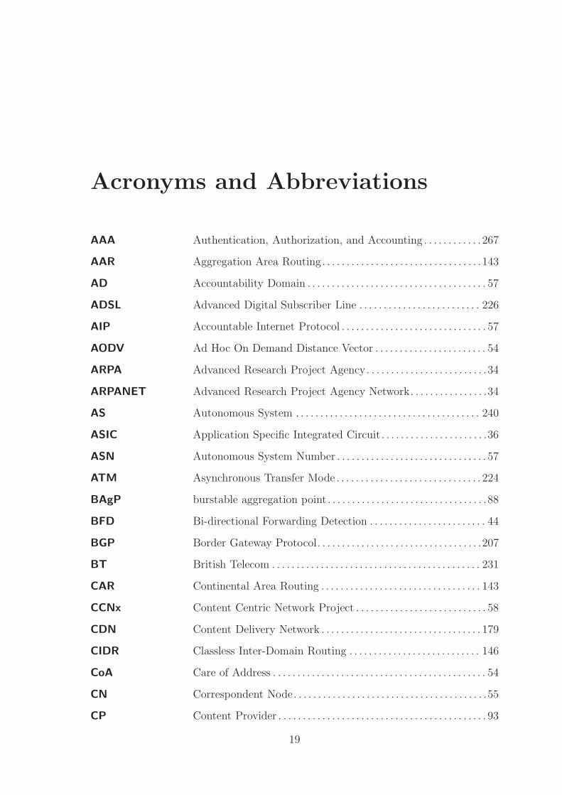
Acronyms and Abbreviations
AAA Authentication, Authorization, and Accounting . . . . . . . . . . . . 267
AAR Aggregation Area Routing. . . . . . . . . . . . . . . . . . . . . . . . . . . . . . . . .143
AD Accountability Domain . . . . . . . . . . . . . . . . . . . . . . . . . . . . . . . . . . . . . 57
ADSL Advanced Digital Subscriber Line . . . . . . . . . . . . . . . . . . . . . . . . . 226
AIP Accountable Internet Protocol . . . . . . . . . . . . . . . . . . . . . . . . . . . . . . 57
AODV Ad Hoc On Demand Distance Vector . . . . . . . . . . . . . . . . . . . . . . . 54
ARPA Advanced Research Project Agency. . . . . . . . . . . . . . . . . . . . . . . . .34
ARPANET Advanced Research Project Agency Network. . . . . . . . . . . . . . . .34
AS Autonomous System . . . . . . . . . . . . . . . . . . . . . . . . . . . . . . . . . . . . . . 240
ASIC Application Specific Integrated Circuit. . . . . . . . . . . . . . . . . . . . . .36
ASN Autonomous System Number . . . . . . . . . . . . . . . . . . . . . . . . . . . . . . . 57
ATM Asynchronous Transfer Mode . . . . . . . . . . . . . . . . . . . . . . . . . . . . . . 224
BAgP burstable aggregation point . . . . . . . . . . . . . . . . . . . . . . . . . . . . . . . . .88
BFD Bi-directional Forwarding Detection . . . . . . . . . . . . . . . . . . . . . . . . 44
BGP Border Gateway Protocol. . . . . . . . . . . . . . . . . . . . . . . . . . . . . . . . . .207
BT British Telecom . . . . . . . . . . . . . . . . . . . . . . . . . . . . . . . . . . . . . . . . . . . 231
CAR Continental Area Routing . . . . . . . . . . . . . . . . . . . . . . . . . . . . . . . . . 143
CCNx Content Centric Network Project . . . . . . . . . . . . . . . . . . . . . . . . . . . 58
CDN Content Delivery Network . . . . . . . . . . . . . . . . . . . . . . . . . . . . . . . . . 179
CIDR Classless Inter-Domain Routing . . . . . . . . . . . . . . . . . . . . . . . . . . . 146
CoA Care of Address . . . . . . . . . . . . . . . . . . . . . . . . . . . . . . . . . . . . . . . . . . . . 54
CN Correspondent Node. . . . . . . . . . . . . . . . . . . . . . . . . . . . . . . . . . . . . . . .55
CP Content Provider . . . . . . . . . . . . . . . . . . . . . . . . . . . . . . . . . . . . . . . . . . . 93
19

CPU Central Processing Unit . . . . . . . . . . . . . . . . . . . . . . . . . . . . . . . . . . . 199
CRN Continental Routing Network . . . . . . . . . . . . . . . . . . . . . . . . . . . . . 235
DAG directed acyclic graph . . . . . . . . . . . . . . . . . . . . . . . . . . . . . . . . . . . . . . 52
DiffServ Differentiated Services . . . . . . . . . . . . . . . . . . . . . . . . . . . . . . . . . . . . .196
DHCP Dynamic Host Configuration Protocol . . . . . . . . . . . . . . . . . . . . . 202
DHT Distributed Hash Table . . . . . . . . . . . . . . . . . . . . . . . . . . . . . . . . . . . . .59
DNS Domain Name Service . . . . . . . . . . . . . . . . . . . . . . . . . . . . . . . . . . . . . 235
DNSSEC Domain Name System Security Extensions. . . . . . . . . . . . . . . . . .48
DoD Department of Defense . . . . . . . . . . . . . . . . . . . . . . . . . . . . . . . . . . . . 245
DONA Data-Orientated Network Architecture . . . . . . . . . . . . . . . . . . . . . 58
DoS Denial of Service . . . . . . . . . . . . . . . . . . . . . . . . . . . . . . . . . . . . . . . . . . . 59
DOT Data-Orientated Transfer . . . . . . . . . . . . . . . . . . . . . . . . . . . . . . . . . . . 61
DSL Digital Subscriber Line . . . . . . . . . . . . . . . . . . . . . . . . . . . . . . . . . . . . 224
DSLAM Digital Subscriber Line Access Multiplexer . . . . . . . . . . . . . . . . 224
DSR Dynamic Source Routing . . . . . . . . . . . . . . . . . . . . . . . . . . . . . . . . . . . 54
EBGP External Border Gateway Protocol . . . . . . . . . . . . . . . . . . . . . . . . 136
EGRP External Gateway Routing Protocol . . . . . . . . . . . . . . . . . . . . . . . 134
EID End Point Identity . . . . . . . . . . . . . . . . . . . . . . . . . . . . . . . . . . . . . . . . . 52
EIGRP Enhanced Interior Gateway Routing Protocol . . . . . . . . . . . . . .134
ESD End-point System Designator . . . . . . . . . . . . . . . . . . . . . . . . . . . . . . .52
ESP Encapsulating Security Payload . . . . . . . . . . . . . . . . . . . . . . . . . . . . 35
FA Foreign Agent . . . . . . . . . . . . . . . . . . . . . . . . . . . . . . . . . . . . . . . . . . . . . 258
FDDI Fibre Data Distributed Interface . . . . . . . . . . . . . . . . . . . . . . . . . . 110
FPGA Field Programmable Gate Array . . . . . . . . . . . . . . . . . . . . . . . . . . 161
FTTC fibre to the cabinet . . . . . . . . . . . . . . . . . . . . . . . . . . . . . . . . . . . . . . . . 234
FTTH fibre to the home . . . . . . . . . . . . . . . . . . . . . . . . . . . . . . . . . . . . . . . . . . 110
FTTP fibre to the premises. . . . . . . . . . . . . . . . . . . . . . . . . . . . . . . . . . . . . . .234
Gbps Gigabits per second . . . . . . . . . . . . . . . . . . . . . . . . . . . . . . . . . . . . . . . . 98
GB Gigabyte . . . . . . . . . . . . . . . . . . . . . . . . . . . . . . . . . . . . . . . . . . . . . . . . . . 111
20

GLBP Gateway Load Balancing Protocol . . . . . . . . . . . . . . . . . . . . . . . . . . 37
GLN Geographically Localised Network . . . . . . . . . . . . . . . . . . . . . . . . . 235
GPS Global Positioning Service . . . . . . . . . . . . . . . . . . . . . . . . . . . . . . . . . 177
GRE Generic Routing Encapsulation . . . . . . . . . . . . . . . . . . . . . . . . . . . . . 35
GSE/8+8 Global, Site, End-system 8 + 8 . . . . . . . . . . . . . . . . . . . . . . . . . . . . . 52
HA Home Agent . . . . . . . . . . . . . . . . . . . . . . . . . . . . . . . . . . . . . . . . . . . . . . 258
HAIR Hierarchical Architecture for Internet Routing . . . . . . . . . . . . . . 89
HD High Definition. . . . . . . . . . . . . . . . . . . . . . . . . . . . . . . . . . . . . . . . . . . .276
HIP Host Identity Protocol . . . . . . . . . . . . . . . . . . . . . . . . . . . . . . . . . . . . . .52
HIT Host Identity Tag . . . . . . . . . . . . . . . . . . . . . . . . . . . . . . . . . . . . . . . . . . 52
HNTR Hierarchical Network Topographical Routing . . . . . . . . . . . . . . 282
HSRP Hot Standby Router Protocol . . . . . . . . . . . . . . . . . . . . . . . . . . . . . 208
HRA Hierarchical Routing Architecture . . . . . . . . . . . . . . . . . . . . . . . . . . 89
HTTP Hyper Text Transfer Protocol . . . . . . . . . . . . . . . . . . . . . . . . . . . . . 114
IAB Internet Architecture Board . . . . . . . . . . . . . . . . . . . . . . . . . . . . . . . . 51
IBGP Interior Border Gateway Protocol . . . . . . . . . . . . . . . . . . . . . . . . . 136
IEEE Institute for Electrical and Electronics Engineers . . . . . . . . . . . 36
IETF Internet Engineering Task Force . . . . . . . . . . . . . . . . . . . . . . . . . . . 120
IGP Interior Gateway Protocol . . . . . . . . . . . . . . . . . . . . . . . . . . . . . . . . . . 50
IGRP Interior Gateway Routing Protocol . . . . . . . . . . . . . . . . . . . . . . . . 198
ILNP Identity-Locator Network Protocol. . . . . . . . . . . . . . . . . . . . . . . . . .53
IMP Interface Message Processor . . . . . . . . . . . . . . . . . . . . . . . . . . . . . . . . 34
IP Internet Protocol . . . . . . . . . . . . . . . . . . . . . . . . . . . . . . . . . . . . . . . . . . 282
IPv4 Internet Protocol version 4 . . . . . . . . . . . . . . . . . . . . . . . . . . . . . . . . 241
IPv6 IP version 6 . . . . . . . . . . . . . . . . . . . . . . . . . . . . . . . . . . . . . . . . . . . . . . . 284
IPTV Internet Protocol Television . . . . . . . . . . . . . . . . . . . . . . . . . . . . . . . 279
IPMN Interactive Protocol for Mobile Networking . . . . . . . . . . . . . . . . . 56
IPSC IP Stream Connect . . . . . . . . . . . . . . . . . . . . . . . . . . . . . . . . . . . . . . . . . 69
IPSEC IP Security . . . . . . . . . . . . . . . . . . . . . . . . . . . . . . . . . . . . . . . . . . . . . . . . 241
21

ISDN Integrated Services Digital Network . . . . . . . . . . . . . . . . . . . . . . . 103
IS-IS intermediate system - intermediate system . . . . . . . . . . . . . . . . . . 45
ISO International Organisation for Standardisation . . . . . . . . . . . . . . 33
ISP Internet Service Provider . . . . . . . . . . . . . . . . . . . . . . . . . . . . . . . . . . 282
ITU International Telecommunications Union . . . . . . . . . . . . . . . . . . 188
IX Internet Exchange . . . . . . . . . . . . . . . . . . . . . . . . . . . . . . . . . . . . . . . . . 272
JANET Joint Academic Network. . . . . . . . . . . . . . . . . . . . . . . . . . . . . . . . . . . .69
kbps kilobits per second . . . . . . . . . . . . . . . . . . . . . . . . . . . . . . . . . . . . . . . . 115
LAN Local Area Network . . . . . . . . . . . . . . . . . . . . . . . . . . . . . . . . . . . . . . . 271
LISP Locator Identification Separation Protocol . . . . . . . . . . . . . . . . . . 52
LLU Local Loop Unbundling . . . . . . . . . . . . . . . . . . . . . . . . . . . . . . . . . . . . 87
LNP Local Network Protection . . . . . . . . . . . . . . . . . . . . . . . . . . . . . . . . . . 49
LTE Long Term Evolution. . . . . . . . . . . . . . . . . . . . . . . . . . . . . . . . . . . . . .247
L2TP Layer 2 Tunnelling Protocol . . . . . . . . . . . . . . . . . . . . . . . . . . . . . . . . 93
MAC Media Access Control . . . . . . . . . . . . . . . . . . . . . . . . . . . . . . . . . . . . . 235
MAN Metropolitan Area Network . . . . . . . . . . . . . . . . . . . . . . . . . . . . . . . 247
MANEMO Mobile Ad hoc Network Mobility . . . . . . . . . . . . . . . . . . . . . . . . . . . 55
MANET Mobile Ad hoc Network . . . . . . . . . . . . . . . . . . . . . . . . . . . . . . . . . . . . 54
MAP Mobility Anchor Point. . . . . . . . . . . . . . . . . . . . . . . . . . . . . . . . . . . . . .54
Mb Megabit . . . . . . . . . . . . . . . . . . . . . . . . . . . . . . . . . . . . . . . . . . . . . . . . . . . 101
MB megabyte. . . . . . . . . . . . . . . . . . . . . . . . . . . . . . . . . . . . . . . . . . . . . . . . . . .99
MBone Multicast Backbone . . . . . . . . . . . . . . . . . . . . . . . . . . . . . . . . . . . . . . . 160
Mbps Megabits per second. . . . . . . . . . . . . . . . . . . . . . . . . . . . . . . . . . . . . . .220
MCS Mobility Control Suite . . . . . . . . . . . . . . . . . . . . . . . . . . . . . . . . . . . . 193
MET Mobility Enabled Tunnelling . . . . . . . . . . . . . . . . . . . . . . . . . . . . . . 195
MIP Mobile IP . . . . . . . . . . . . . . . . . . . . . . . . . . . . . . . . . . . . . . . . . . . . . . . . . . 55
MNN Mobile Network Node . . . . . . . . . . . . . . . . . . . . . . . . . . . . . . . . . . . . . . 55
MPF Metallic Path Facility . . . . . . . . . . . . . . . . . . . . . . . . . . . . . . . . . . . . . 103
MPLS Multiprotocol Label Switching. . . . . . . . . . . . . . . . . . . . . . . . . . . . .240
22

MPR Multi-Point Relay . . . . . . . . . . . . . . . . . . . . . . . . . . . . . . . . . . . . . . . . . . 46
MR Mobile Router . . . . . . . . . . . . . . . . . . . . . . . . . . . . . . . . . . . . . . . . . . . . . .55
MSAN Multi-Service Access Nodes . . . . . . . . . . . . . . . . . . . . . . . . . . . . . . . . .65
NAS Network Access Server . . . . . . . . . . . . . . . . . . . . . . . . . . . . . . . . . . . . . 91
NAT Network Address Translation . . . . . . . . . . . . . . . . . . . . . . . . . . . . . . 236
NBAgP non-burstable aggregation point . . . . . . . . . . . . . . . . . . . . . . . . . . . . 88
NEMO Network Mobility . . . . . . . . . . . . . . . . . . . . . . . . . . . . . . . . . . . . . . . . . 252
NFL National Football League . . . . . . . . . . . . . . . . . . . . . . . . . . . . . . . . . . . 87
NFTP Network Forwarding and Tracking Protocol . . . . . . . . . . . . . . . .193
NLAS Network Level Autonomous System . . . . . . . . . . . . . . . . . . . . . . . 134
NP Network Provider . . . . . . . . . . . . . . . . . . . . . . . . . . . . . . . . . . . . . . . . . 262
OLSR Optimised Link State Routing . . . . . . . . . . . . . . . . . . . . . . . . . . . . . . 45
OSI Open Standards Interconnection . . . . . . . . . . . . . . . . . . . . . . . . . . . . 33
OSPF Open Shortest Path First . . . . . . . . . . . . . . . . . . . . . . . . . . . . . . . . . 134
PBR Policy Based Routing . . . . . . . . . . . . . . . . . . . . . . . . . . . . . . . . . . . . . 198
PLA Packet Level Authentication . . . . . . . . . . . . . . . . . . . . . . . . . . . . . . . . 59
PNS Personal Name Server . . . . . . . . . . . . . . . . . . . . . . . . . . . . . . . . . . . . . 248
PPTP Point to Point Tunnelling Protocol . . . . . . . . . . . . . . . . . . . . . . . . . 41
PoP Point of Presence . . . . . . . . . . . . . . . . . . . . . . . . . . . . . . . . . . . . . . . . . . . 82
PSTN public switched telephone network . . . . . . . . . . . . . . . . . . . . . . . . . . 44
P2P peer-to-peer . . . . . . . . . . . . . . . . . . . . . . . . . . . . . . . . . . . . . . . . . . . . . . . 114
QoS Quality of Service . . . . . . . . . . . . . . . . . . . . . . . . . . . . . . . . . . . . . . . . . 196
RADIUS Remote Authentication Dial In User Service . . . . . . . . . . . . . . . . 92
RAS Remote Access Server . . . . . . . . . . . . . . . . . . . . . . . . . . . . . . . . . . . . . . 92
RFC Request for Comment . . . . . . . . . . . . . . . . . . . . . . . . . . . . . . . . . . . . . 155
RH Resolution Handler . . . . . . . . . . . . . . . . . . . . . . . . . . . . . . . . . . . . . . . . . 58
RIP Router Information Protocol . . . . . . . . . . . . . . . . . . . . . . . . . . . . . . 134
RLOC Route locator . . . . . . . . . . . . . . . . . . . . . . . . . . . . . . . . . . . . . . . . . . . . . . 52
RO Route Optimisation . . . . . . . . . . . . . . . . . . . . . . . . . . . . . . . . . . . . . . . . 55
23

RRN Regional Routing Network . . . . . . . . . . . . . . . . . . . . . . . . . . . . . . . . 235
RSVP Resource reservation protocol. . . . . . . . . . . . . . . . . . . . . . . . . . . . . .196
RTCP Real Time Control Protocol . . . . . . . . . . . . . . . . . . . . . . . . . . . . . . . 268
RTMP Real Time Message Protocol. . . . . . . . . . . . . . . . . . . . . . . . . . . . . . . .35
SD Standard Definition . . . . . . . . . . . . . . . . . . . . . . . . . . . . . . . . . . . . . . . 276
SDS Service Definition Service. . . . . . . . . . . . . . . . . . . . . . . . . . . . . . . . . .212
SHIM6 Site Multihoming by IPv6 Intermediation. . . . . . . . . . . . . . . . . . .53
SIPP Simple Internet Protocol Plus . . . . . . . . . . . . . . . . . . . . . . . . . . . . . . 49
SMCP Service and Mobility Control Protocol . . . . . . . . . . . . . . . . . . . . . 195
SP Service Provider . . . . . . . . . . . . . . . . . . . . . . . . . . . . . . . . . . . . . . . . . . . . 93
SR Tree Simple Routing Tree . . . . . . . . . . . . . . . . . . . . . . . . . . . . . . . . . . . . . . 153
SSL Secure Sockets Layer . . . . . . . . . . . . . . . . . . . . . . . . . . . . . . . . . . . . . . 192
STB Set Top Box . . . . . . . . . . . . . . . . . . . . . . . . . . . . . . . . . . . . . . . . . . . . . . 276
STP Spanning Tree Protocol. . . . . . . . . . . . . . . . . . . . . . . . . . . . . . . . . . . . .37
SVC Scalable Video Coding . . . . . . . . . . . . . . . . . . . . . . . . . . . . . . . . . . . . 264
TB Terabyte . . . . . . . . . . . . . . . . . . . . . . . . . . . . . . . . . . . . . . . . . . . . . . . . . . 276
TBRPF Topology Dissemination Based on Reverse-Path Forwarding 54
TCP Transport Control Protocol . . . . . . . . . . . . . . . . . . . . . . . . . . . . . . . .248
TOR Tor Onion Routing . . . . . . . . . . . . . . . . . . . . . . . . . . . . . . . . . . . . . . . . 243
UDP User Datagram Protocol. . . . . . . . . . . . . . . . . . . . . . . . . . . . . . . . . . .198
UK United Kingdom . . . . . . . . . . . . . . . . . . . . . . . . . . . . . . . . . . . . . . . . . . 281
US United States . . . . . . . . . . . . . . . . . . . . . . . . . . . . . . . . . . . . . . . . . . . . . 239
VLAN Virtual Local Area Network . . . . . . . . . . . . . . . . . . . . . . . . . . . . . . . 217
VoD Video on Demand . . . . . . . . . . . . . . . . . . . . . . . . . . . . . . . . . . . . . . . . . 111
VOIP voice over IP . . . . . . . . . . . . . . . . . . . . . . . . . . . . . . . . . . . . . . . . . . . . . . . 91
VPN Virtual Private Network . . . . . . . . . . . . . . . . . . . . . . . . . . . . . . . . . . . 241
VRRP Virtual Router Redundancy Protocol . . . . . . . . . . . . . . . . . . . . . . 200
WBC Wholesale Broadband Connect . . . . . . . . . . . . . . . . . . . . . . . . . . . . . 97
WBMC Wholesale Broadband Managed Connect . . . . . . . . . . . . . . . . . . 101
24

WMBC Wholesale Managed Broadband Connect. . . . . . . . . . . . . . . . . . . .97
WDM Wave Division Multiplexing . . . . . . . . . . . . . . . . . . . . . . . . . . . . . . . . 65
WLR Wholesale Line Rental . . . . . . . . . . . . . . . . . . . . . . . . . . . . . . . . . . . . 103
WAN Wide Area Network . . . . . . . . . . . . . . . . . . . . . . . . . . . . . . . . . . . . . . . 133
XOR exclusive-or . . . . . . . . . . . . . . . . . . . . . . . . . . . . . . . . . . . . . . . . . . . . . . . 145
21CN 21st Century Network . . . . . . . . . . . . . . . . . . . . . . . . . . . . . . . . . . . . . . 97
25

Chapter 1
Introduction
1.1 Introduction
This chapter introduces the aims and objectives of this project. The two primary
objectives of this project are identified in section 1.4 while the approach towards
meeting these goals is presented in section 1.5. The relevance of this work is discussed
in section 1.6 and finally the structure of the thesis is described in section 1.7.
1.2 Project Overview
The Internet as of 2012 is the result of the organic growth and development of the
original Advanced Research Project Agency (ARPA) net following the principles set
out by the original developers of decentralised control, automated redundancy, and
growth through agreement. This organic growth has allowed for many improvements
in the interconnection of networks however has resulted in many areas of development
being addressed as individual problems rather than addressing inter-related issues
as a collective. The development is further affected by the nature of the Internet;
a global network connected over local and regional networks rather than a single
network with a unified control structure and growth pattern. This structure ensures
that each decision to alter the network are affected not only by a change’s technical
feasibility but by the local and international regulatory, economic, and administrative
infrastructure environments.
Many of the developments within the Internet are evolutions of past and present
technologies that carry with them the legacy of nearly 60 years of development efforts.
The design decisions and protocols implemented during the growth of the Internet
represent an attempt to maintain a visibly and effectively cohesive single protocol
network while providing a transparent substrate that is continually changing. These
26

technical changes to the environment have not been effectively reflected in the local
regulatory requirements and / or management structure of the local Internet as net-
works designed with a single controlling entity in mind are opened up to multiple
provider usage schemes such as local loop unbundling or shared access. These reg-
ulatory changes have reflected the economic non-viability of providing multiple sets
of infrastructure to many low population density, or remote rural areas of a coun-
try. Technologies such as multicast routing, content caching, and localised routing
have all been rendered more difficult to implement due to the fragmented nature of
the resulting market which is designed to allow ‘competition’ between ISPs rather
than promoting cooperation to share limited network resources between end-users.
Changes to the localised networks are therefore typically implemented through the
simplest, most organic, method resulting in the least disruption of the current net-
work. This localised resistance to change can therefore affect the overall Internet
design paradigm as each problem is considered in isolation. Services running over
the network have taken a more drastic change approach with many technologies such
as video streaming and end-user content sharing acting as a disruptive element as
they no longer follow one-to-many server-client paradigm resulting in inefficient (and
growing) traffic flow, volume, and management.
This work looks to provides a potential solution to the issues inherent in large
scale content delivery across a top down asymmetric bandwidth network through the
integration of localised services and routing. By providing the capability to route
traffic in a manner which crosses fewer points in the network where bandwidth is
aggregated (and therefore lost), and making as much use of the local routing infras-
tructure to reduce two way traffic flow the work provides a way to limit the scaling
of future content systems to a manageable factor.
1.3 Project Aim
The overall aim of this project is:
To investigate and design a network routing structure and protocol suitable for as-
sisting in the delivery of large scale content services such as video streaming services
in a more efficient and localised manner exploiting localised resources and services
where available.
While it is likely that improvements could be presented on existing IP network tech-
nologies this would add to the fragmentation of overlays and additions to the core
27

Internet routing protocols. This work therefore focuses on the Internet as a holistic
network: reflecting on the underlying topographical link to the continental geography
that can be exploited to provide improvements in the localisation and statistical ag-
gregation of traffic. As such this work focuses not on the existing network structures
which represent an idealised separation of networks and instead attempts to address
the underlying network structure identifying and working with shared network fea-
tures in a clean slate manner which can then be reapplied to the existing IP networks.
From this overall aim two primary objectives were derived; a review of existing net-
work strategies looking specifically at the UK; and to create a theoretical framework
for an integrated approach to future networks.
1.4 Project Objectives
The aim of the project can be divided into the two major primary objectives which
feed into the proposal for a future network structure aimed at large scale content
flows:
1. Review of existing network strategies
2. Design of integrated network routing strategy
Each of these objectives is further subdivided into tasks which can be more easily
realised and presented rather than approaching this as a single stage.
1.4.1 Review of Existing Network Strategies
There has been much research and development into the deployment of the next
generation Internet protocol - IP version 6 (IPv6) - however beyond the expanded
address space many compromises have been made in the development and deploy-
ment of this protocol to meet the perceived needs of multiple competing interests.
Many of these changes reflect the need to deploy a cohesive world wide protocol in a
primarily Internet Protocol version 4 (IPv4) environment under threat from address
space exhaustion.
As the next immediate issue of address space exhaustion has been addressed in
IPv6 future Internet protocols will need to focus on meta-issues relating to connected
layers to provide further improvements to network routing and service / content
growth. With this in mind it becomes key to look at the way in which content
services have changed over the course of the last decades and to aim to provide
28
a network structure which is capable of supporting these and similarly disruptive
technologies more effectively. It is therefore vital to understand how the real world
physical topological structure of the Internet maps to the theoretical models already
in use commercially, and from this mapping how the physical network can be used
more efficiently to support changing usage patterns.
From this review of structure two further tasks are identified: the simplified Inter-
net connectivity model ; and the identification of the case for an integrated content and
service delivery platform. The first task aims to actively look at how Internet models
are connected at a gross level allowing for simplifications of the overall structure to
enable it to be more easily parsed while the second aims to look at the deployment of
large scale content platforms that have the potential to overwhelm current and next
generation networks.
1.4.2 An Integrated Approach to Future Networks
From the review of the existing network structures which identifies the feasibility of
designing a network protocol more suited to large scale content delivery, the second
objective is to design a model for a future protocol which focuses on the capabili-
ties required for this kind of content scaling. This objective is further broken down
into four tasks addressing the specific requirements of a future network including:
the network topographical routing protocol itself, a service model, a mobility model,
and a deployment and integration model. The first task, network topographical rout-
ing protocol, aims to look at the creation of a simplified addressing protocol suitable
for line-speed forwarding while reducing the address space requirements of similar
IP based forwarding tables. The joint tasks of the service model and the mobility
model aim to address the capability of the new network structure to embed services
to improve localisation while simultaneously addressing the huge growth in mobile
network nodes fuelled by smart-phone and tablet developments. The final task, de-
ployment and integration model, looks at the explicit deployment issues encountered
when deploying a new network beside a well established and connected one and aims
to provide a model for interoperation with existing IP based networks.
1.5 Approach to Project
With a project looking at a large scale system such as the Internet it is possible
to become easily derailed by minutiae that could be projects in and of themselves.
An argument for evolutionary development of the Internet rather than a clean-slate
29

approach, by Constantine Dovrolis [1], stated that one of the primary reasons be-
hind taking an evolutionary approach should be the lack of knowledge available to
researchers and designers about the Internet’s structure. Taking an evolutionary ap-
proach therefore means that instead of working with insufficient knowledge about the
physical and traffic topologies of the network it is possible to work with knowledge of
where the current network is succeeding and failing at meeting the actual needs of the
users. With this lack of knowledge in mind, this work takes a revolutionary approach:
a future Internet from a top-down perspective assuming a complete redesign and de-
ployment of the existing network structure. By taking the revolutionary model it is
possible to work around the large number of small details inherent in such a project,
however, the changes theoretical changes are considered from an existing IP network
point of view such that improvements could be implemented as evolutionary changes.
This model looks to allow for the development of and integration of idealised tech-
nologies but to move them into a real world context where adoption can be managed
effectively.
1.6 Research Rationale
As a holistic approach to the Internet it is difficult to find a particular relevance to
any single company or industry since the Internet impacts upon and is the basis for
significant numbers of companies and technologies. In approaching this project the
relevance was considered from the perspective of academic research and the wider
industry.
1.6.1 Research Relevance
As a research project in the area of the Internet and networks there have been many
existing projects which have looked at specific sections of, or protocols underlying
the Internet, and a more limited number of overlay redesigns which integrate the
existing structure of the network into their service deployment model. The growth
of consumed content however has shown that while there is as yet no single ‘network
killer’ service there are multiple existing content delivery services that could easily
outpace the current network capacity growth if their use became more ubiquitous. It
is possible at current for network capacity growth to be consumed nearly instantly
by current generation services such as video streaming. As such this research looks
to provide a mechanism for the Internet to reduce the required scaling capacity such
that large scale shared content does not require the continued content paced growth
30

of the network. The work focuses on the wholesale Internet model and the limitations
of network geography to suggest improvements in service models.
1.6.2 Wider Industry Relevance
Within the wider industrial context it is clear that the deployment of IPv6 is in itself
not a panacea to the issues that currently affect the Internet and compromises have
been made in its design to reflect the availability and cost of devices. Redesigning
the Internet routing protocol from scratch allows for the more efficient deployment
of a technology to hardware devices that enable fast switching and processing of
packets rather than relying on costly and slower software processing. In addition the
creation of a single end-to-end protocol allows for the active development of a single
scaling device type rather than multiple devices at different layers of the network
making production of hardware and the deployment of networks more efficient and
effective. By focusing on an end-to-end redesign it is hoped that the system can be
more streamlined and simplistic allowing for the better use of resources towards more
efficient routing practices.
With this in mind the work looks to ISPs such as BSKYB who have a significant
interest in both Internet service provision as well as content provision. Companies
such as these could benefit immensely from the integration of multi-end-user tech-
nologies into the network and already have technology in place at the last-mile to
support a bottom up content provision service. As the technology is already in place
an evolutionary move towards localised routing becomes a more appealing commercial
choice than having to reprovision the network to support this.
1.7 Thesis Overview
This thesis is divided into 7 chapters including this chapter and the conclusions and
review chapter. The content is divided into background and research, technical con-
tent, case studies and scenarios, and future integration. Each chapter is discussed
below to give a greater understanding of the overall structure of the thesis.
Chapter 2: Background discusses the background work for the project including
discussion and investigation into the current state of the art in terms of network
platforms and protocols.
31

Chapter 3: UK Internet Structure and Future Network Requirements
details the structure of the existing UK Internet and details the requirements for a
next generation network structure within the UK
Chapter 4: Hierarchical Network Topographical Routing presents the fun-
damental structure for the proposed Hierarchical Network Topographical Routing
(HNTR) network.
Chapter 5: HNTR: Open Issues looks more closely at potential future issues
relating to: management and billing components, and additional support protocols
for mobility and node network awareness.
Chapter 6: HNTR: Evaluation and Usage Scenarios presents case studies
carried out looking at the feasibility and functionality offered by the proposed network
structure and that provided by the current incarnations of IP based networks.
Chapter 7: Conclusions and Future Work draws together the conclusions from
the previous chapters and applies them to this research project into the design of a
network protocol designed to support and assist in the large scale content delivery
using localised resources.
32
Chapter 2
Background
2.1 Introduction
This chapter gives an overview of the fundamental technologies underlying the cur-
rent Internet routing architectures and how these models are reflected in the United
Kingdom (UK) Internet structure. The chapter is broken down into four major sec-
tions consisting of: Internet routing and switching; Next generation architectures;
IP security and privacy; and Internet structure. The chapter looks at historical and
current developments to provide a sense of the growth and direction that routing
technology has taken in the last fifty years with current and future state of the art
to provide a sense of the direction that is being considered for future network growth
in the next ten to twenty years. Within this chapter we refer to layers in the Inter-
net using the International Organisation for Standardisation (ISO) Open Standards
Interconnection (OSI) model with a focus on layer 2 (switching), and layer 3 (routing).
Internet Routing and Switching focuses on the current generation Internet hard-
ware and protocols to give an understanding of the environment into which any up-
dates and alterations to the network structure must be made. The limitations of these
protocols defines the current Internet’s capabilities and potential for future growth in
an organic evolution or through revolution. This section further looks at extensions
to the Internet Protocol (IP) framework from which future architecture decisions may
be taken and integrated into a new network paradigm. Next Generation Architectures
looks at the historic and state of the art developments in routing protocols and net-
works with a focus on content centric networking as a design issue for future networks.
IP Security and Privacy considers the current and next generation security implemen-
tations within the Internet and the privacy issues which have recently become one
of the leading issues with Internet services and deployments. Internet Structure is
an overview of the Autonomous System (AS) model of the Internet and the specific
33
UK historical and current deployments in technology and legislation that create a
different model due to shared infrastructure and transparent network management.
2.2 Internet Routing and Switching
The Internet is a massive interconnection of networks however it is also an abstract
media for the delivery of content and services. We can view the Internet in four
major ways: as a layer 2 hardware routing environment concerned with local area
routing and interconnections; as a layer 3 network concerned with the interconnec-
tion of networks and data flows; as a layer 3 network masking the hardware routing
environment; or as a layer 4+ environment routing protocols over a ‘flat’ (ie: a single
visible layer 3 address space) network.
The Internet has evolved as an effectively unified network from the original 1960’s
Advanced Research Project Agency Network (ARPANET) [2] using IP as a ‘common’
layer 3 substrate for the visible inter-network with other layer 3 protocols being used
to provide transparent functionality to the network as required. While the Internet’s
use and structure has diverged massively from the original design intention it is still
a very visible evolution of the concepts and structures behind the original Advanced
Research Project Agency (ARPA) design including a virtual reintroduction of the site
access control Interface Message Processor (IMP) [3] devices as the access gateways in
today’s Internet Service Provider (ISP) and business architectures. This structure has
provided a high degree of flexibility, control, and longevity to the Internet by providing
an apparently seamless network layer to transport layers as well as applications and
services which utilise the Internet. While it is not strictly true that IP is the sole
network layer technology, the end-to-end reachability provided by this assumption
allows for the masking of layer 2 and 3 soft/hardware updates and variations. For over
30 years this process has been supported largely by Internet Protocol version 4 (IPv4)
however the exponential growth of the Internet [4, 5, 6] and layer 2/3 aware application
models have pushed this protocol towards the limits of its viability leading to research
and development of more modern architectures which support the changing traffic and
flow patterns of the network.
The ‘unified visible addressing space’ provided at layer 3 by IP and other layer 3
protocols transparently supporting IP are further supported by a wide range of layer 4
transport protocols. Layer 4 protocols are typically transport flow control or low level
application flow control protocols however in modern routing and switching devices
are often utilised to further inform the logical structuring and flow of traffic across the
34
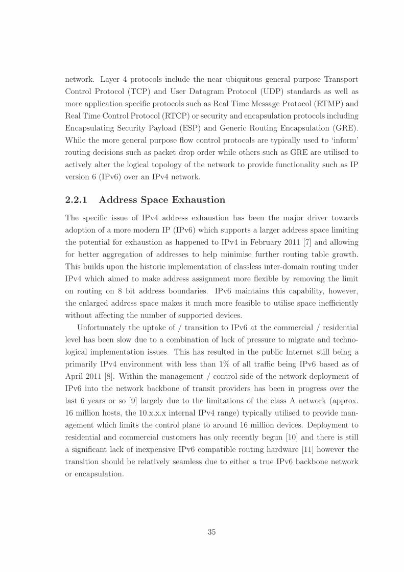
network. Layer 4 protocols include the near ubiquitous general purpose Transport
Control Protocol (TCP) and User Datagram Protocol (UDP) standards as well as
more application specific protocols such as Real Time Message Protocol (RTMP) and
Real Time Control Protocol (RTCP) or security and encapsulation protocols including
Encapsulating Security Payload (ESP) and Generic Routing Encapsulation (GRE).
While the more general purpose flow control protocols are typically used to ‘inform’
routing decisions such as packet drop order while others such as GRE are utilised to
actively alter the logical topology of the network to provide functionality such as IP
version 6 (IPv6) over an IPv4 network.
2.2.1 Address Space Exhaustion
The specific issue of IPv4 address exhaustion has been the major driver towards
adoption of a more modern IP (IPv6) which supports a larger address space limiting
the potential for exhaustion as happened to IPv4 in February 2011 [7] and allowing
for better aggregation of addresses to help minimise further routing table growth.
This builds upon the historic implementation of classless inter-domain routing under
IPv4 which aimed to make address assignment more flexible by removing the limit
on routing on 8 bit address boundaries. IPv6 maintains this capability, however,
the enlarged address space makes it much more feasible to utilise space inefficiently
without affecting the number of supported devices.
Unfortunately the uptake of / transition to IPv6 at the commercial / residential
level has been slow due to a combination of lack of pressure to migrate and techno-
logical implementation issues. This has resulted in the public Internet still being a
primarily IPv4 environment with less than 1% of all traffic being IPv6 based as of
April 2011 [8]. Within the management / control side of the network deployment of
IPv6 into the network backbone of transit providers has been in progress over the
last 6 years or so [9] largely due to the limitations of the class A network (approx.
16 million hosts, the 10.x.x.x internal IPv4 range) typically utilised to provide man-
agement which limits the control plane to around 16 million devices. Deployment to
residential and commercial customers has only recently begun [10] and there is still
a significant lack of inexpensive IPv6 compatible routing hardware [11] however the
transition should be relatively seamless due to either a true IPv6 backbone network
or encapsulation.
35

2.2.2 Extensions to IP for Layer 3
The limitations of IPv4 to address the growth and functionality of the current /
future Internet can be further seen in the adoption of other layer 3 protocols such as
Multiprotocol Label Switching (MPLS) to provide additional functionality to the ‘IP
Internet’ in a largely transparent manner. These assistive technologies have been at
the forefront of compatibility between IPv4 and IPv6 due to the lack of an explicit
compatibility mode for IPv4 within IPv6 and no formal transition process. Further
growth in routing paradigms such as flow based routing [12] and layer 2/3 topology
and network aware protocols can be limited in their capability to provide improved
efficiency due to the growth in these transparent assistive technologies at layer 2/3.
While each of these ‘transparent’ protocol additions expands the capability of the
network the increased number of topological views at different ‘routing’ aware layers
is a factor we must consider for future routing protocols and structures and especially
the possibility of software defined routing over a flexible hardware topology.
2.2.3 Switching (Layers 2 and 3)
Under the traditional ISO OSI model layer 2 represents the data-link layer of the net-
work sitting above the layer 1 physical layer consisting of connectors and interfaces.
While there are many layer 2 technologies at use within the wider context of the
Internet including Ethernet, serial, and Asynchronous Transfer Mode (ATM) we con-
sider Ethernet as the primary layer 2 switching technology due to its near ubiquitous
deployment in modern networks. Ethernet can be considered a defacto standard for
wired connectivity within the home environment as well as having a growing ubiquity
within the access and carrier networks as well as within data centres. While adoption
is still not widespread the Institute for Electrical and Electronics Engineers (IEEE)
802.3ah-2004 [13, 14] Ethernet in the first / last mile standard makes Ethernet a
possible ubiquitous future layer 2 standard.
Switching within layer 2 Ethernet brings all devices on the network into a single
‘broadcast domain’ allowing directed and shared communication between nodes de-
fined by their Media Access Control (MAC) addresses. These networks can be chained
together to provide multiple ‘broadcast domains’ through the use of switches. Layer
2 networks are typically designed with minimal control, management, and admin-
istrative functionality to minimise overhead and ensure a fast and efficient (ideally
line speed) distribution of data. This is not to say though that these features do not
exist at this level but rather that the switching is performed on dedicated Application
36
Specific Integrated Circuits (ASICs) which cannot easily be updated and so rely on a
control system which is typically based on a simpler allow / deny mechanism with ad-
ministrative functionality provided by a more general purpose processing device such
as the firmware on the switching device. It is typical to include additional modules to
provide higher level functionality on high quality layer 2 switches making them aware
of layers 3 as well as the ‘application’ specific layers 4-7.
Switching is of course not this simple in reality, layer 2 switching technologies
typically include at a minimum Virtual Local Area Network (VLAN)s and spanning
trees which ‘complicate’ the logical layout of the network while the layer 3 devices
add high availability / redundancy protocols which create virtual devices above the
‘transparent’ layer 2 network. Using VLANs a single network is typically partitioned
into multiple logical networks based on traffic source, destination, or layer 4 protocol
which gives each VLAN a seemingly different logical topology to the underlying phys-
ical topology of the network. If we consider the simple four switch full mesh network
shown in Figure 2.1 as the basic building block of a redundant network then a simple
two VLAN across the same switches will physically appear the same as shown in
Figure 2.2a however it can be conceptually viewed as two logically separate networks
consisting of two full meshes as shown in Figure 2.2b. The networks logical structure
can be further modified by spanning tree protocols [15] to provide a strict hierarchical
tree structure to a non-tree (mesh or partial mesh) network to simplify the traffic flow
and route management. The effect of this Spanning Tree Protocol (STP) applied to
the network is shown in Figure 2.3a showing how the logical network is now a subset
of the physical connectivity. This type of protocol is often further modified through
the presence of one or more VLAN [16] which act to separate traffic flows within the
logical network effectively creating two or more overlapping logical networks within
a single physical network as shown in Figure 2.3b.
2.2.3.1 Switch and Router Virtualisation
While STP and VLAN are the major two methods for separating the logical and
physical layer 2 networks there are additional protocols which can create logical net-
works distinct from their underlying physical structure. Typical examples include
high availability / redundancy protocols such as Virtual Router Redundancy Pro-
tocol (VRRP), Hot Standby Router Protocol (HSRP), or Gateway Load Balancing
Protocol (GLBP) which create virtual nodes within the logical topology responsible
for physical traffic flow management. Multiple physical nodes are then assigned to
37

Figure 2.1: Simple four switch full mesh network showing logical topology as identicalto physical topology
(a) Layer 2 Topology with attached hosts (b) Layer 2 physical topology with twoVLANs (red and green) showing logicaltopology as two identical copies of underlyingphysical topology, as no routers are presentthe VLANs are completely separate logicalnetworks
Figure 2.2: Layer 2 network topology showing the two logical topologies created bythe addition of the VLANs to the fully meshed physical network
38

(a) Layer 2 Spanning Tree Topol-ogy applied to full mesh network.Spanning tree creates a fully hi-erarchical logical network from afully meshed physical network
(b) Layer 2 Spanning Tree with two VLANs (red andgreen) showing the effective complete separation of thetwo tree topologies as no routing device is present tolink the networks
Figure 2.3: Layer 2 topology showing the effects of applying spanning tree protocolsto the fully meshed physical layer 2 network, and the effect of further modifying thelogical topology through the addition of two VLANs
39

(a) Layer 3 fully meshed physical networktopology
(b) Layer 3 logical topology showing the ad-dition of a virtual router which is managedby R1 and R2
Figure 2.4: Layer 3 Topology with Redundancy Protocol with the virtual routeracting as the default gateway for the network. Nodes R1 and R2 provide the physicalcapabilities of this virtual node
handle the traffic directed to these virtual nodes. An example of this kind of redun-
dancy is shown in Figure 2.4 showing the virtual router acting as the default gateway
/ forwarding node to the Internet however with routers 1 and 2 providing the phys-
ical interfaces for this functionality. This virtual node hierarchy is typically coupled
with one or more spanning tree sessions across multiple VLANs to provide further
redundancy and structure to the network. A similar kind of virtualisation is found in
layer 3 routing protocols such as Open Shortest Path First (OSPF) which generate
virtual areas to provide a simplified hierarchical network view based on tree struc-
tures. These virtualisations and overlays make it clear that the underlying process of
network routing / stability protocols is to assist in providing a simplified and redun-
dant view of the network which simplifies the real world topology to provide a more
reliable and robust network. By moving a real world network towards a redundant
tree structure we can simplify the real world of multiple connections, devices, and the
possibility of failure into a structure which is robust and simple to parse in real time.
While not directly related to this there is an increasing trend within data centres
40

to support virtualisation of services which allows for a more efficient use of processing
resources. These virtual services are often connected to software switches and routers
which are linked to real switching / routing hardware on each cabinet. This structure
allows services to seamlessly integrate with the network whether connected on physical
hardware or running as a virtual instance within another device. This methodology
highlights the need of future networks to consider seamless mobility not just in terms
of physical devices but also of services within the network which should be provided
so as to maximise efficiency and reduce stresses on the system.
2.2.3.2 Logical and Physical Network Topologies
Each of these technologies indicate that the physical layout of the network, while
important, is far less vital to the correct functionality of the network as the ability to
manage and control data flows in a simplified manner with redundancy to allow for
hardware and topological changes. Further topology modification is possible through
the use of tunnelling protocols such as Layer 2 Tunnelling Protocol (L2TP) [17]
based on Point to Point Tunnelling Protocol (PPTP) [18] which are typically layer 5
protocols that act to encapsulate traffic for transport across a Virtual Private Network
(VPN) or transport network to provide a layer 2 logical view of the network which
appears to be a single contiguous network but is in reality multiple disparate and not
directly connected networks.
The logical view of the network is further complicated by the layer at which the
network is viewed as layers above and below the view layer are typically invisible for
the purposes of connectivity. This means that combining the networks from figures 2.2
and 2.4b would not result in a single unified view that can be processed in terms of
data flows and useful statistics such as congestion, usage, dropped packets, and jitter,
but rather two (or more) disparate networks which must be managed separately. This
strongly suggests that any future network must be able to take a multi-layer approach
to management if a non-unified end-to-end model is utilised.
Layer 3 switching takes from layer 2 the hardware based switching model which
allows for layer 3 packets to be ‘routed’ as fast as layer 2 packets are switched how-
ever retains the inability to perform higher level processing on the packets. Layer 3
switching therefore relies on a layer 3 routing protocol to populate and control the
more advanced functionality which would otherwise slow down the switched routing
process. This separation of ‘control layer 3’ and ‘switched layer 3’ is very important
within current generation networks, and likely next generation networks, as general
purpose processing devices cannot generally sustain the throughput required on high
41

capacity devices. Unless there is a significant slowing in network speed / throughput
or a significant decrease in processing cost / power consumption of general purpose
processing this divide will likely remain for the forseeable future. Layer 3 routing is
in many ways required for layer 2 protocols such as VLANs to function correctly as
they create two or more disparate logical layer 2 networks which must be bridged.
This type of separation processing and the inclusion of higher level security, adminis-
tration, and policy controls are provided through the layer 3 switched routing devices
as the protocols have access to layer 3 addresses, layer 4 port, and in some cases
application layer identifiers that should be hidden from layer 2 devices. At a purely
functional level layer 3 switching and routing devices are nearly identical with the
exception of Wide Area Network (WAN) access as layer 3 routers typically are not
capable of media format translation - wired ethernet 802.3 to wireless 802.11 as an
example. This difference is primarily due to the requirement for hardware based high
speed switching against the time taken to reframe and populate data into a differ-
ent format however some layer 3 switching devices do include optional hardware to
perform these tasks.
2.2.4 Routing (layer 3)
Above the switching layer is the routing layer which provides the ability to logically
partition a single switched / bridged network into subnetworks and the transition of
traffic between two disparate layer 2 interface types. This subdivision provides sup-
port for scalability, security, and additional quality of service provisions. Security is
typically provided by content encryption or by encapsulation with full packet encryp-
tion, quality of service is typically provided by service differentiation based on either
address or layer 4 port number. An IP router will typically utilise the IP address of
the interface (the 32 bit IPv4 or 128 bit IPv6 address) to direct traffic between the
source and destination nodes; other layer 3 protocols can make use of their own ad-
dressing mechanisms however often also have access to the IP address of the source /
destination as additional classifiers for routing. It should be noted though that while
Quality of Service (QoS) can and is performed at all layers of the network through
technologies such as VLANs, or tagging protocols used in 802.3 (IEEE 802.1q) [13]
or 802.11 (IEEE 802.11e) [19] the layer 3 implementations of QoS are vitally impor-
tant as they connect disparate networks and so inform the cross-network / layer QoS
decisions.
42

Routing Type DescriptionUnicast one-to-one delivery
Broadcast one-to-all deliveryMulticast one-to-many deliveryAnycast one-to-one-of-many deliveryGeocast one-to-many within a geographic area
Table 2.1: Description of the five primary forms of routing utilised in current andnext generation routing protocols
2.2.4.1 Routing Types
Routing can be largely described as the process of directing packets or flows of data
from the source to the destination in one of five major methods: unicast, broadcast,
multicast, anycast, and geocast as defined in table 2.1. Within IPv4 based archi-
tectures unicast, broadcast and multicast are widely supported on most commercial
hardware however multicast is largely unusable from a service provider perspective
due to management and billing requirements1. Anycast and geocast are supported
by protocol extensions, overlays, and manipulation of naming services [20] such as
Domain Name Service (DNS) to provide localised results. The next generation IPv6
supports unicast and multicast however broadcasts have been replaced with scope-
local multicast routing which is more efficient in that nodes which are not actively
listening for the ‘pseudo broadcast’ will not receive the traffic as they would under
IPv4. As with IPv4 anycast and geocast are provided via protocol extensions, over-
lays, and manipulation of naming / addressing services. It should be noted at this
point that geocasting is a difficult routing protocol to implement in current layers 2
and 3 due to the lack of geographic and topographic information provided by both
IPv4 and IPv6 addresses below an ISP or country level.
2.2.5 Network Structure
Networks can be largely broken down into seven main primary topologies (line, bus,
ring, star, tree, partial mesh, and full mesh) which can be composed to construct
larger networks. These topologies are important considerations for layer 2 networks
as they reflect the scalability and connectivity of the network, at layer 3 and above the
1While the hardware and software support for multicast is widely available the administrativesupport for it is difficult to arrange across widely disparate end points especially if the multicastgroup would be required to span across multiple service providers
43

physical topology becomes less important as it is abstracted into multicast / broad-
cast areas, point-to-point for direct connections between hardware / virtual devices or
point-to-multipoint for virtual mappings across multiple point-to-point connections
provided by technologies such as frame-relay (p2p, p2mp, frame relay). The current
structure of a network is maintained through either a static (non-adaptive) routing,
or an adaptive (Dynamic / non-static) routing protocol. Both static and dynamic
routing protocols create a local routing table for each device in the network which de-
scribes connectivity within a certain area of the network. Typically small or localised
managed networks will utilise static routing with unmanaged or interconnections of
networks utilising dynamic routing to control changing configurations.
Static routing involves the pre-computation of routing tables for the network.
Typically these routing tables will include the most direct (primary) route to a desti-
nation as well as one or more fallback routes in case the primary route fails or become
inoperable. Static routing is further utilised within IPv4 and IPv6 networks to pro-
vide support for tunnelling, encapsulation, flow control, and flow management. An
example of a static routing network is the public switched telephone network (PSTN)
which relies on largely fixed hardware locations with known aggregation points within
the network. By utilising static routing as a backup to dynamically routed networks
failure of nodes / sites, or maintenance can largely be handled without further inter-
ference and only a potential (and smooth) degradation of service to the affected and
linked areas as the fall back path is known. Further protocols such as Bi-directional
Forwarding Detection (BFD) [21] allow the modification of the routing table to detect
the failure of static routes on a per-interface basis without the additional overhead of
dynamically calculating routes.
Dynamic routing in contrast to static routing involves the active solicitation of
information about the connected network topology and thus reacts to changes in the
topology in an approximately real-time basis. As this direct solicitation of topology
information scales with the size and complexity of the network it is typical to divide
dynamic routing protocols into localised intra-network protocols, and inter-network
protocols. Inter-network routing within the current Internet is a specific artifact of the
creation of the AS grouping for networks which separates potentially geographically
similar networks into administration and management units. While a similar routing
type may be required in other network routing types the specifics of inter-network
routing considered in this chapter are based on the IP and AS model for routing.
44

2.2.5.1 Intra-network Dynamic Routing
Intra-network dynamic routing protocols are designed to acquire and process topology
information across all active nodes within a particular network. Typically there are
two major branches of intra-network dynamic routing: distance vector, and link-state
based algorithms. Some hardware vendors have released dynamic-routing protocols
they have classed as a third category, such as advanced distance-vector, however all
commonly commercially implemented routing protocols can be classified as distance
vector or link-state.
Distance vector algorithms are the simplest form of dynamic routing. At defined
intervals each node exchanges with its neighbours (detected via hello style negotiation)
its current list of known nodes, the cost, and next hop (outgoing interface) to reach
that node. Each node then updates its routing table to reflect the state of the network
as seen by itself and its neighbours. This process is repeated at a specified interval
for each node (network wide or per node), and after a finite time (for a non-cyclical
network) the routing tables will stabilise at the best hop count or cost to all nodes
within the network. If a node is removed from a network in this stable state for
any reason the process will repeat until a stable state is reached. Neighbours of the
failed node remove it if it was listed as the next hop in any routes and redistribute
their routing tables. This process will eventually (assuming complete node failure
rather than node-to-node link failure) completely remove the failed node as it becomes
unreachable. In the current Internet the most common distance-vector algorithms
are Interior Gateway Routing Protocol (IGRP) [22], and Enhanced Interior Gateway
Routing Protocol (EIGRP) [23].
Link-state algorithms in contrast to the link-local approach of distance vector
algorithms flood the network with a copy of their local routing table (directly con-
nected neighbours) when they are first connected or a change occurs. Other nodes in
the network then assemble and determine the appropriate paths through the network
from this information. This process creates an active routing table in the form of a
best-route tree however allows for the direct creation of alternate or load balancing
routes because each node is aware of the entire network state. This process is typi-
cally faster than a distance vector algorithm as nodes are limited by local processing
power rather than stabilisation period however requires more memory and process-
ing power per node to be effective in large networks. Within the current Internet
the most common link-state algorithms deployed are OSPF [24], Router Information
Protocol (RIP) [25], intermediate system - intermediate system (IS-IS) [26], and
Optimised Link State Routing (OLSR) [27]. Some link-state algorithms reduce the
45

overhead of flooding the network with the connectivity list by utilising Multi-Point
Relays (MPRs) [28] however this process typically reduces the redundancy and re-
silience offered by full link-state flooding.
Both distance vector and link-state algorithms benefit from a hierarchical naming
structure [29] for node addresses as areas of the network can be condensed into a
single entry rather than approaching one (or more) entries per node. The naming
scheme is typically an analysis and design level decision with nodes not dynamically
renaming themselves to create a hierarchy or virtual hierarchy within the network.
2.2.5.2 Inter-network Dynamic Routing
As intra-network dynamic routing protocols are designed to maintain knowledge of
the entire network over which they operate they do not scale and become intractable
within very large networks (distance vector becoming unstable, and link-state requir-
ing a large volume of resources). To deal with this the intra-networking protocols
are applied within bounded network areas defined as AS which represent administra-
tive or business bounded networks. Within the Internet the interconnection of these
ASs is managed by a path-vector routing scheme known as Border Gateway Proto-
col (BGP) [30]. Each AS is reduced to a limited number of nodes (External Border
Gateway Protocol (EBGP) nodes) which perform a process similar to distance-vector
routing however with the added inclusion of the path required to reach that AS. This
path inclusion allows the the manipulation of routes by increasing the path length to
traverse certain ASs allowing the artificial increase in effective cost to certain traf-
fic sources. Within the AS a group of nodes connecting all of the EBGP nodes are
defined to ensure transit capability through the AS and are defined as the Interior
Border Gateway Protocol (IBGP) nodes.
2.2.5.3 Administrative and Policy Control
The path-vector BGP algorithm demonstrates the inherent recursive routing nature
of the Internet even with arbitrary boundaries imposed by ASs. The routing schemes
required to route between a simple mesh network are nearly identical to those of higher
level networks if redundant non-communicating nodes are removed. Administrative
and policy controls are often implemented in both intra-network and inter-network
routing protocols indicating the possibility of overlap between inter and intra-network
routing protocols if a policy layer can be created to span both.
46

Class Leading bits Size of network number Size of host identifierA 1 8 24B 10 16 16C 110 24 8
D (multicast) 1110 not defined not definedE (Reserved) 1111 not defined not defined
Table 2.2: Description of the five original classes of IPv4 addresses
2.2.6 IPv4
IPv4 is the primary layer 3 routing / switching protocol for the Internet with near
100% coverage at current; IPv6 is typically being deployed in parallel to this IPv4
network, or hidden behind an IPv6 to IPv4 tunnel. Fundamentally each node or
interface on the network is assigned an IPv4 address consisting of a 32 bit identifier
representing the end host and the provider of the identity. A node addresses packets
with the destination node’s address and attaches its own address as the return address.
A node receiving a packet compares the address to the routing table currently held
and either forwards the packet to the longest matched address or discards the packet.
As this discard is performed silently IPv4 does not provide any delivery guarantees
and instead relies on higher level protocols to handle quality of service.
The original IPv4 address space was divided into five classes of addresses sup-
porting the formats shown in table 2.2. The introduction of Classless Inter-Domain
Routing (CIDR) allowed for a finer granulation of this address space with a split of
network:subnet split at any point with 2 addresses reserved in subnetworks of larger
than 2 bits reserved for the network identity and broadcast addresses.
2.2.6.1 subnet masking and CIDR
In 1993 the introduction of CIDR [31, 32] was seen as a short term solution for
the address space allocation issues prevalent in IPv4 however the implementation re-
mained unchanged until 2006 [33] and remains in place as of 2011. This addressing
scheme moved away from the fixed addressing scheme originally embodied by the
classful boundaries as a class C address space (256 hosts) was typically too small for
a medium sized business while the class B space (65,535 hosts) was too large. By
allowing an arbitrary split using a network:host/network length identifier the address
space could be assigned more efficiently. It should be noted that these classful bound-
aries remain a requirement for many routing schemes and especially for backwards
47

compatibility with older protocols.
CIDR brought to the forefront the issue of routing table expansion within the In-
ternet, assigning large numbers of small blocks in a non-hierarchical manner results in
a very large routing table for top level routers which cannot rely on passing unknown
destinations towards another router via a default route. By utilising the variable
length address space of CIDR addresses could be managed in a more hierarchical
fashion reflecting the hierarchical nature of ISP provision in most countries.
2.2.6.2 Domain Name System
The DNS [34, 35] is a large distributed hierarchical naming and addressing system
designed to map primarily between the IP address space (v4 and v6) and the do-
main name hierarchy. The DNS acts as a keyword redirection system originally han-
dling addresses (A, AAAA records), however also covering the provision of alternate
DNS or subdomain DNS name servers (NS records), and domain aliases (CNAME
records) amongst many others [36]. The DNS provides a right-to-left period sep-
arated hierarchical breakdown of the hostname providing a hierarchical method to
resolve addresses by repeatedly querying subordinate DNS servers until a full match
is found. This kind of hierarchical distributed names space management device has
found a role in most future architectures and service models as it allows for a high
level of control with minimal overhead in terms of administration. Unfortunately the
open nature of the DNS leaves it open to being abused by outside entities. In or-
der to help resolve these potential vulnerabilities the Domain Name System Security
Extensions (DNSSEC) [37] was introduced which modifies the DNS to support cryp-
tographically signed responses however this has come under fire from Governments
through legislation such as the United States (US) PROTECT IP act [38, 39] which
aims to filter DNS responses. As the DNSSEC implementation has no ‘filtered’ re-
sponse there would be no difference, resulting in a failed lookup, between a filtered
result and a hacked / incorrect result making the system difficult to trust.
The security implementations presented in DNSSEC and other protocols suggest
that a cryptographically secured namespace will become important in the future
however this should be tied to some model of resistance such that lower level DNS
services can verify an update and limit the potential for hacked or altered records
being pushed down the network without further verification.
48

2.2.6.3 Network Address Translation and IPv4
Network Address Translation (NAT) under IPv4 utilises the TCP [40] or UDP [41]
port space to provide multiple devices access to the Internet through a single IP
address. This process is typically a dynamic one whereby a port mapping is created
on demand (outgoing) making NAT an effective security measure similar in function
to a deny-all firewall. This use of dynamic mappings however results in the inability
to communicate into a network resulting in numerous work arounds for push content
services. The existence of NAT is often seen as a negative factor however it highlights
part of the importance of separating a device’s identity from its routing address.
2.2.7 IPv6
With the known address space limitations and potential security issues of IPv4 an
updated version of the protocol was put out to working groups to produce the next
generation routing protocol under the IP next generation [42] working group. Com-
peting variants included CATNIP [43], TP/IX [44, 45], and Simple Internet Protocol
Plus (SIPP) [46] with SIPP being the successful variant and a modified version named
as IPv6 was developed under the Internet Engineering Task Force (IETF) and pub-
lished in 1998 [47]. The major changes in this updated routing protocol were the
increased address space (128 bits vs 32 bits), the removal of packet fragmentation
below 1280-bytes, the removal of header based checksums (which broke the layering
model), extension headers, and automated security and address creation.
As a major design decision IPv6 was not designed to be automatically interopera-
ble with IPv4 placing them as two independently supported networks with communi-
cation between them provided by translation. Communication between IPvX ‘islands’
is handled typically through the provision of dual protocol stacks where possible and
tunnelling or encapsulation where this is not possible. The design decision of IPv6 to
provide a large address space provides a reasonable expectation of end-to-end routing
with each device identified uniquely within the address space.
IPv6 introduces modified versions of the IPv4 Dynamic Host Configuration Pro-
tocol (DHCP), DNS, and CIDR protocols to maintain functionality that has become
expected through IPv4 usage however removes ‘support’ for NAT [48] services as
these break the end-to-end nature of IPv6 replacing them with Local Network Pro-
tection (LNP) [49].
49
2.2.8 IP Routing Extensions
While IP can be considered to be the main routing protocol for the Internet there are
many simultaneously deployed protocols and extensions that are in use or theoretical
to provide improvements to service while at the same time remaining transparent to
general Internet traffic. It is important to consider these protocol at this stage to
understand the types of additional functionality which have been built up to support
the existing IP network. This additional functionality is then considered for inclu-
sion in the Hierarchical Network Topographical Routing (HNTR) protocol described
in Chapter 4. In this section we are primarily interested in routing improvements
through identity and location services, or node labelling to assist in forwarding traf-
fic.
2.2.8.1 MPLS and Aggregation
MPLS [50] acts as a cross layer 2 and 3 protocol to provide a highly scalable and pro-
tocol agnostic transport mechanism for modern telecommunications networks. The
protocol acts as an encapsulation layer allowing the creation of ‘virtual’ links between
other networks which hide the underlying structure from the carried traffic. MPLS
supports the creation of ‘labels’ as its addressing mechanism and directs traffic only
based on this label. Labels are added and removed in a hierarchical manner as packets
approach a network boundary and are forwarded either to the next MPLS destination
or to the correct ‘other’ protocol stack for processing.
While MPLS is in theory a platform agnostic protocol it is heavily reliant on the
IP Interior Gateway Protocol (IGP) routing protocols to provide distance and qual-
ity measurements. MPLS acts to provide better control of virtual circuits and traffic
engineering to IP networks and provide seamless integration across different sites for
businesses which do not wish to purchase fixed lines. This direction is highly indica-
tive of the current Internet architecture whereby a transparent network is utilised to
transfer and control all traffic with users and devices seeing themselves as connected
appropriately for their service package.
2.2.8.2 Compact Routing
Compact routing [51, 52] is a routing proposal that has evolved from a mobile wireless
environment in to the more static Internet [53] as a whole. The protocol is designed
to find and select paths through the network based on a combined shortest path
and aggregated area metric. The compact routing model trades off the shortest path
50

between two nodes for a ‘short’ path that allows more aggregation of routes. This
trade off increases the average ‘cost’ of routing between two non-connected nodes
however can significantly reduce the overall routing table size. The two most common
compact routing algorithms are the Thorup-Zwick algorithm [54] and the Brady-
Cowen algorithm [55]. The Thorup-Zwick algorithm selects ‘Landmarks’from within
the network graph with a uniform probability and determines the cluster size around
each of these ‘landmarks’, each cluster is iteratively recalculated until it falls under the
maximum cluster size. Nodes route using the destination address, the destination’s
landmark address, and the next-hop towards the destination’s landmark address. The
Brady-Cowen algorithm in contrast generates a core network consisting of all nodes
within a specified number of hops from the highest degree node, the remainder of the
nodes become the fringe of the network. A spanning tree is generated within the core,
and within each fringe area, before being culled until the fringe areas are acyclic.
In both of these algorithms there is a need to know the full structure of the network
to fully construct the routing algorithm however on the currently available partial data
of the Internet structure [56] it is possible to construct reasonable routing tables.
At routing level time scales2 the Internet is a largely ‘stable’ structure in that few
large scale changes occur. This means it is likely possible to increase the efficiency of
these algorithms by pre-selecting potential aggregation points or manually configuring
certain ASs to reduce tree depths.
2.2.8.3 Separation of Identity and Location
The IP address of a node on a network serves two primary purposes, to identify
the node and to suggest the location of the node because the high order bits of the
address specify the network on which the node is located. If the attached device moves
subnet, provider, or geographic region the address it is assigned is likely to change
unless the node is utilising tunnelling or a mobility protocol. Following the October
2006 Internet Architecture Board (IAB) Routing and Addressing Workshop [57, 58]
concerns and solutions were raised over the scalability of the Internet’s addressing
system and have been addressed in either a network (LISP, GSE/8+8) based solution
or a host (SHIM6, ILNP, HIP) base solution. Solutions can generically be described
as either mapping and encapsulation or address rewriting.
2less than 5 minute intervals for route redistribution across the Internet for BGP, or an OSPFhello timer of 180 seconds
51

2.2.8.4 Location / Identity Separation Protocol
Locator Identification Separation Protocol (LISP) [59, 60] is a mapping and encapsu-
lation protocol running as an overlay to the IP network. Distributed address servers
host a mapping database of host End Point Identitys (EIDs) and a Route loca-
tor (RLOC) to a LISP enabled router within the region. Traffic directed through
the ingress LISP router is encapsulated and sent to the egress LISP enabled router
in the target region before normal IP routing carries the traffic to the end host in
a transparent manner. As the mapping and encapsulation is a transparent process
this can be utilised to provide active mobility, traffic engineering or even tunnelling
services to a network with no end host involvement. The routing table of each LISP
router is simplified as they only need to track the paths between regions rather than
the location of every subnet or node.
2.2.8.5 Host Identity Protocol
Host Identity Protocol (HIP) [61] decouples the identity of a node from the IP ad-
dress location by providing a separating layer between layers 3 and 4 of the OSI
model. Hosts generate a cryptographically ‘unique’ public key as their identity with
a matched private key to provide authentication. A 128 bit Host Identity Tag (HIT)
is then generated as a hash over the host identity and utilised for all layer 4 identity
requirements (the HIT and public key combination must be globally unique). This
identity is mapped through the DNS to an IP address.
2.2.8.6 GSE/8+8
Global, Site, End-system 8 + 8 (GSE/8+8) [62] is an address rewriting protocol
designed with multi-homing and site movement as a key factor. GSE/8+8 separates
the Internet into two components, the global Internet and sites acting as leaf networks
to the Internet. At the boundary between the leaf site and the global Internet the
address space is rewritten to specify the site location as a global attachment point
for outgoing traffic, or a site-local address for incoming traffic. The global Internet
is subdivided into directed acyclic graphs (DAGs) (informally trees) under ‘large
structures’ which act to manage the address space under them and each end point
interface is assigned one or more End-point System Designators (ESDs) consisting of
64bits which must be globally unique. Routing is performed in a hierarchical manner
(except where cut-through knowledge is maintained between the ‘large structure’
DAGs).
52

2.2.8.7 Identifier-Locator Network Protocol
Identity-Locator Network Protocol (ILNP) [63, 59] is typically applied to IPv6 (ILNPv6)
however other variants exist. The address space is split (64/64 bits for ILNPv6 into
a topologically significant locator and a non-topologically significant identifier used
as an identity. These labels are mapped using the DNS system by providing two new
records, the identifier (I) record, and locator (L) record. To force updates to a node
location to remain current within the DNS secure dynamic DNS updates are utilised.
As the system utilises the current DNS it requires either a globally unique identifier
or a node name which can be utilised to uniquely identify a node or network.
2.2.8.8 Site Multihoming by IPv6 Intermediation
Site Multihoming by IPv6 Intermediation (SHIM6) [64, 65] is an address rewriting
protocol which utilises the large IPv6 address space to provide multi-homing and
connection fault redundancy to sessions and services via a layer 3 protocol addition.
This ‘shim’ creates a connection using an initial IPv6 address as both the locator
and identifier for the session, however multiple redundant locators are available. In
the case of failure the client and server shims negotiate a new locator and retain the
original locator/identifier address as the identifier for the session. Acting as a host
level protocol this requires no modifications to the Internet infrastructure and non-
compliant hosts can be handled with traditional failure detection and maintenance
methods.
2.2.9 IP and Mobility
As noted above there is a large motivation within the current Internet research to look
at mobility and relocation issues. The further growth of mobile devices has spurred
this effort further as nodes have grown from largely static (servers, desktops), to static
while working (laptops), to mobile while working (tablets, smartphones) models of
productivity. This growth in both numbers of mobile devices and the level of mobility
is likely to increase further as time goes on. Addressing these mobility issues under
IPv4 and IPv6 are the Mobile IP, NEMO, MANET, and MANEMO protocols.
While the HNTR protocol described in Chapter 4 does not specifically address
mobility issues they are considered as a requirement for a next generation protocol
due to the growth in mobile devices. As such a mobility control suite is envisioned in
Chapter 5.
53

2.2.9.1 Mobile IP
IPv4 mobility [66] and IPv6 mobility [67] are designed to allow the movement of a
node from one network attachment point to another without changing its current IP
address. Under mobile IP a mobile node retains a permanent home address and a Care
of Address (CoA) which is associated with the current network the host is attached to.
Communication to the mobile node is via a home agent which redirects and tunnels
traffic to the foreign agent and then onto the mobile node. Communication from the
mobile node is handled by the foreign agent which forwards traffic appropriately to
the destination. Location updates are typically sent at intervals and upon movement
of the mobile node. Each of these transmissions can be considered to be a triangular
(angular) routing path as it includes at least one node which is not (typically) required
for direct end-to-end communication.
As an improvement to the IPv6 version of mobile IP hierarchical mobile IP [68]
separates local movement (site local) from global movement by adding a Mobility An-
chor Point (MAP) which acts as to maintain local site updates rather than updating
the home agent of the mobile node with site local movements. This change reduces
the overhead required for the protocol and also decreases hand off latency for local
address changes.
Mobile IP is typical of most mobility protocols in that it involves two new services
(the home and foreign agents) and relies upon a triangular routing path for data flows.
The implementation of the additional services means that devices must be aware of
the mobility effects to take advantage of it and triangular routing can become very
inefficient for large data flows.
2.2.9.2 Mobile Ad Hoc Network (MANET)
Mobile Ad hoc Network (MANET) [69] are originally designed to handle mobile wire-
less nodes with no fixed routing architecture however more recent additions handle
the addition of fixed gateways for access to functionality such as the Internet. Each
node is required to act as a router and must be capable of forwarding data flows to
other nodes. There are four major variants of MANET currently under Request for
Comment (RFC) by the IETF: Ad Hoc On Demand Distance Vector (AODV) [70],
OLSR [27], Dynamic Source Routing (DSR) [71], and Topology Dissemination Based
on Reverse-Path Forwarding (TBRPF) [72]. These protocols can largely be thought
of as modifications to the dynamic routing protocols discussed above. It should be
noted that MANET protocols do not provide mobility support for devices but rather
54

provide protocol for managing a group of nodes which are mobile and have at least
one node which has Internet access.
2.2.9.3 Network Mobility (NEMO)
Network Mobility (NEMO) [73] is a modified version of mobile IP designed to allow
the direct mobility of a Mobile Router (MR) [74] and its attached Mobile Network
Nodes (MNNs). This allows the MNNs to retain seamless connectivity to the Internet
with only a single device being required to perform mobility actions. As with mobile
IP the MR maintains two IP addresses, a home address and a CoA. Traffic from
within the mobile subnet is tunnelled to the Home Agent (HA) and then forwarded
as per IP routing to the Correspondent Node (CN) (destination node), incoming
traffic is sent to the HA and then tunnelled to the MR before being forwarded to the
appropriate MNN. By allowing a single device to perform the mobility actions for
the network the MNN can ‘perform’ mobility without being mobile aware and at the
same time reduce the linear scaling of traffic updates (O(n)) to a fixed scaling (O(1)).
NEMO as with Mobile IP suffers from triangular routing issues and compounds
this by allowing multiple NEMO instances to stack resulting in multi-triangular rout-
ing paths. This is partially addressed by combining MANET with NEMO. Further
NEMO does not make nodes within the mobility group mobility aware, all traffic is
routed as though the network is located at the CoA location irrespective of the po-
tential for localised traffic generation. This means only the mobile router can make
locality decisions rather than allowing individual devices and services the ability to
exploit locality.
2.2.9.4 Mobile Ad hoc Network Mobility (MANEMO)
While NEMO offers the capability to move a network as a whole it acts transparently
such that multiple NEMO instances can stack resulting in a convoluted ‘pinball’
(Multi-angular) routing whereby each layer of NEMO tunnels traffic out from the
mobile region to the fixed Internet. In addition to the direct latency increases caused
by this the encapsulation of each layer of NEMO results in a significant header size
increase. Route Optimisation (RO) by removing the tunnelling portion of Mobile
IP (MIP)v6 (direct MNN to CN communication) cannot be performed under a NEMO
architecture as the nodes inside the MR subnet are not mobility aware resulting in
excess traffic and latency to MNN flows. In order to address these issue Mobile Ad hoc
Network Mobility (MANEMO) [75] implements an intelligent NEMO aware routing
scheme using MANET principles within a nested NEMO environment to deliver traffic
55

only to the outermost NEMO MR and NEMO mechanisms from that point to the
Internet.
MANEMO attempts to address the multiple stacking of NEMO instances and
so does not further address the issues of only a single mobility aware device in the
network and relying on the CoA for traffic localisation.
2.2.9.5 Interactive Protocol for Mobile Networking
Unlike the other mobility protocols Interactive Protocol for Mobile Networking (IPMN)
[76] requires both end-host modifications as well as router layer 3 modifications. The
protocol negotiates the future IP address of a node before movement occurs and in-
forms the communicating parties of the change. This process is similar to the soft
handover of a 3G mobile network where the device maintains one primary link to the
current tower and a secondary link to the next or previous tower. This dual connec-
tion allows data to find the device during the handover period despite the node having
actively ‘moved’ to a new address. With this protocol when the address update from
the mobility action occurs the layer 3 middleware updates the outgoing packets source
with the new address triggering a corresponding alteration in the destination address
of the incoming packets. Identity is maintained by retaining the original IP address
as the identifier for rewriting addresses.
2.3 Next Generation Architectures
The limitations of IP have been widely discussed however under the practical paradigm
of the Internet the protocol is ”ideal” - it works. The ‘direct’ issues of IPv4 can be
addressed under the general areas of: address space limitations, address space allo-
cation, quality of service, data security, configuration complexity; however additional
indirect issues arise due to the ways in which IP is utilised and hidden by other pro-
tocols. Many services on the Internet, such as Content Delivery Networks (CDNs),
therefore make their own address and service overlays which map onto the IP address
space and topology. In each of the protocols addressed below some issue has been
identified with the existing IP networks and is addressed by the scheme in question.
By looking at these schemes it is possible to perform a meta analysis of potential
future routing solutions and from this develop an encompassing framework for a next
generation protocol.
56

2.3.1 Accountable Internet Protocol
Accountable Internet Protocol (AIP) [77] is designed as an IP replacement which
removes the central identification and authorisation required in systems like DNS or
the aggregation of CIDR and replaces them with one or more flat namespaces using
public key cryptography to encode and verify self selected names. AIP removes the
disconnect between the Autonomous System Number (ASN) and the route prefixes it
offers and by breaking the AS into multiple Accountability Domains (ADs) each with
a globally unique identifier. Each end host is assigned a globally unique EID giving a
full address of AD:EID. Typically the AD will be the hash of the self-certified public
key of the provider with the EID being the hash of the self certified public key of the
end point node. The namespace deaggregation allows for a more efficient organisation
of the routing tables within routers and allows nodes to perform mobility actions based
on their EID as a unique identifier rather than their full network position indicator
using the AD:EID combination.
2.3.2 Content Delivery Networks
While the Internet as a whole is not content-centric many services which run over
it are a combination of content-orientated and location-orientated in an attempt to
provide a more efficient way to provide content. The largest CDN currently deployed
is provided by Akamai. The Akamai model of CDN provision places content caches
around the world close to the ‘edge’ of the network (typically the ISP / transit AS
boundary). Traditional web caches typically have a large miss-rate due to the pro-
vision of dynamic content forcing a second lookup and content retrieval cycle, CDNs
like Akamai attempt to mitigate this high miss-rate. Systems like Akamai [78, 79]
typically utilise the DNS to provide their mapping service, a typical request is sent to
the core Akamai DNS servers and a server located near the requesting client which
is available and is likely to have the content the client has requested. Near is typi-
cally defined in terms of latency and topological distance, available is defined by the
network load and bandwidth, and likely as a function of which data centres carry
the content for that customer. The DNS time-to-live is kept very low at around 60
seconds to ensure content location and availability is up to date and fresh. The DNS
location system is further backed up by the ability to subdivide content into ‘frag-
ments’ which can be individually cached. By subdividing content into fragments the
number of cache misses is reduced because only non-fresh content must be served
from a larger content piece.
57

2.3.3 Content Centric Networking
The traditional Internet model supporting TCP/IPvX is considered a host centric
routing model focusing on end-to-end routing concepts whereby a single host retrieves
data from a single server. Content centric networking in contrast aims to move
towards a model whereby data is both identifiable and verifiable and therefore can
be cached further within the network meaning a data request can be served from the
lowest level of the cache hierarchy which has a copy of the data with backup copies
being replicated down to the distribution point to decrease the next requests latency
and bandwidth requirements. High levels of content caching [80] are typically involved
in the content centric networking architectures from a ‘pull’ / subscription direction
supporting either native or overlay multicasting [81]. We consider these services as
a first step towards a unified routing architecture which combines the traditional
end-to-end routing model with an in-network-supported caching architecture which
enables the efficient distribution of content across aggregation points.
2.3.3.1 Data-Orientated Network Architecture
Data-Orientated Network Architecture (DONA) [82] is one of the first ‘content centric’
networking deployments designed as a replacement for the existing DNS infrastructure
deployments for content location services. As it operates as an application layer
protocol DONA has no impact on current routing architectures. DONA is deployed
primarily at a BGP / AS level however allows for more localised content caches and
Resolution Handlers (RHs) to be added to the system. DONA follows the publish
/ locate model of anycast services with the distributed RHs returning the ‘nearest’
instance of the requested content. To perform this lookup an address space for content
is created which includes a cryptographic hash of the principal provider’s public key
(P), and a label for the content (L) chosen by the principal provider. As content labels
are distributed widely across the RH network rather than being resolved hierarchically
as with the DNS network the potential scaling of this system can become intractable
very quickly.
2.3.3.2 Content Centric Networking Project
Content Centric Network Project (CCNx) [83, 84, 85] aims to redesign the Inter-
net to provide a content-centric network approach [86] alongside the routing-centric
approach of the current Internet. This work focuses on the development of a con-
tent name space which allows the application neutral caching of content within the
58

network structure. This process involves the encryption and security of each piece
of content rather than an end-point focused security model allowing content to be
served from insecure nodes.
2.3.3.3 Juno Content-Centric Middleware
Juno [87] is a middleware solution acting between the operating system and appli-
cations to provide a service agnostic content location and delivery service. Juno is
designed as a plug-in framework which allows content providers to provide a module
(on demand) which can index provider sites and services and present these to the
application as a list of appropriate choices. As the solution acts as middleware no
modifications are made to the operating system or network which retains a rout-
ing centric model. Juno does not create a new name space for content but rather
utilises the magnet link demi-standard [88] which is common in BitTorrent and other
peer-to-peer software solutions.
2.3.3.4 PSIRP
PSIRP [89, 90, 91] is a clean slate redesign of the Internet from a content centric per-
spective using a publish/subscribe architecture with a design aim of security and scal-
ability at its core. The system obscures the layer 3 routing using temporary identifiers
and bases routing decisions on content location and availability rather than physical
topology or original host. Security and authentication within PSIRP are provided
via a packet signing mechanism using Packet Level Authentication (PLA) which is
designed to work at wire speeds allowing for no-slowdown of the network to account
for this overhead. Data Forwarding within PSIRP utilises identifiers generated for
each data path using zFilters over a set of ‘unique’ network node names limiting the
potential for Denial of Service (DoS) attacks on the network as the routing path is
obscured. Nodes attaching to the network are authenticated [92] protecting users
and the network however requiring some centralised control of the network. Content
within the network is identified and managed by a two tier hierarchical Distributed
Hash Table (DHT) system indicating the original creator / host of the content and
the content piece in a similar manner to the split addressing scheme used in the web
today of host.domain/content-path/contentid.
2.3.3.5 PURSUIT
The PURSUIT [93] project follows on from the work in PSIRP and considers the
publish / subscribe [94] model further and how value decisions are being built into
59

new content centric architectures [95]. Under PURSUIT all content is treated as
information, with complex content being treated as a graph of information constructs.
This scheme is furthered by content scoping to limit the forwarding of data across
the network and a request model to ensure that information is only transferred when
a request has been issued.
2.3.4 Content Centric Transport
While the underlying protocols on the Internet can largely be described as routing
centric many of the applications which run over the network are content centric with
separate name spaces and resolution policies as well as building in content-significant
fragmentation and multi-source availability options.
2.3.4.1 Bit Torrent
BitTorrent [96, 97], is based around the principle of peer-to-peer swarming that is
fragmenting a file into chunks with members of the swarm simultaneously uploading
downloading content to other peers. The simple peer management system utilises a
bartering scheme to minimise traffic flow to peers which do not contribute back to the
swarm. Each shared file is split into equal sized chunks and the hash of each chunk
recorded along with other metadata such as file size and chunk size in the .torrent
file. This file is then hosted on a tracker which maintains a list of peers in the current
swarm but does not join the swarm itself. Nodes wanting to join the swarm contact
the tracker for peer and file information before contacting peers within the swarm to
begin sharing content on a peer-to-peer basis.
2.3.5 Localised Bit Torrent
The peer-equality standard within basic BitTorrent implementations generally results
in an efficient distribution method in that it avoids the bottlenecks of centralised
distribution and ensures availability of content through cooperation of peers. The
arbitrary selection of peers however can result in very inefficient routing for packets.
Bindal et al [98] have suggested a topological basis for peer selection whereby the
tracker collects ISP locality information for each peer and offers peers only their local
peers and a subset of the full swarm outside of their locality. With ISP involvement
Aggrawal et al [99] suggested a modification for a peer-ranking service named the Or-
acle which maintains an ISP supported peer-selection criteria involving bandwidth,
congestion, and delay to minimise cross-ISP traffic. Further ISP involvement can
60

be leveraged by providing a heavily provisioned BitTorrent peer within the ISP net-
work which combined with biased peer selection [100] can result in improvements in
localising traffic flow.
Modified BitTorrent clients exist which attempt to provide localisation within an
AS or ISP network. Ono [101] attempts to provide a similar service to that suggested
by Aggrawal et al using the Akamai CDN network to provide localisation information
by querying their DNS. This solution should redirect nearby hosts to the same CDN
allowing peers to identify locality however is subjected to the load balancing and
management policies of Akamai. TopBT [102] acts similarly to Ono except that peers
utilise ping and traceroute to periodically probe the route to other peers to determine
locality. This probing acts in conjunction with the BitTorrent peer selection / choking
algorithms to select nearby peers in preference to further away peers.
2.3.5.1 Splitstream
Splitstream [103] acts as an application layer multicast system which achieves high
bandwidth streaming by striping the content being distributed and providing a sep-
arate multicast tree for each stripe. Nodes integral to one tree are automatically
added as leaves of the other trees to attempt to minimise overhead. All peers in the
splitstream forest of trees can therefore share the load of the multicast distribution.
2.3.5.2 DOT and Ditto
Data-Orientated Transfer (DOT) [104] provides for two layers of data transfer, a
content negotiation service with application specific content and a bulk data transfer
service which hosts the content to be transferred. Negotiation completes with the
content provider uploading the content to the bulk transfer service and the creation
of a unique object ID for that content. The content receiver accepts this object ID
and uses it to acquire the content from the bulk transfer agent. DOT splits files into
chunks similarly to BitTorrent with each chunk containing metadata relating it to
the full content.
DOT has been further leveraged in multi-hop wireless environments by Ditto [105]
which identifies DOT object identifiers and caches them at path-nodes or nodes which
overhear the transmission. These cached nodes then act as content-proxies for the
bulk transfer service serving chunks when requested if they have it otherwise forward-
ing the request.
61

2.4 IP Security and Privacy
Security and privacy have become major issues for both applications and routing
architectures in recent years with a large number of privacy violations and leaks having
been reported from social networking sites as well as other content providers. Privacy
is a tradeoff with accountability on the Internet with many solutions implementing
cryptographic solutions involving public and private keys to provide accountability
for self generated or anonymous accounts. To date no IP protocol has maintained the
security requirements into the deployment stage of the network, as such security is
considered as an overlay concept onto the network rather than as a core principle.
2.4.1 IP Security
IP Security (IPSEC) [106] is an end-to-end security protocol acting in either host-
to-host, host-to-network, or network-to-network mode as a layer 3 protocol meaning
applications and hosts do not need to be aware of IPSEC to benefit from it. There
are two primary security measures: authentication headers which provide integrity
and origin authentication to IP datagrams; and encapsulated security payloads which
provide confidentiality, data origin authentication; both act to provide replay attack
protection. Under host-to-host transfers the payload is typically encrypted leaving
the IP routing header intact allowing NAT, with header authentication IPSEC cannot
be utilised behind a NAT device without utilising the NAT-T mechanisms. Under
network-to-network implementations the whole packet is encrypted and encapsulated
for transit creating a virtual private network.
2.4.2 DNS Security
DNSSEC [37, 107, 108] provides public key cryptographically signed DNS records
which can be verified against the authoritative DNS server for a domain or record.
This allows the detection of tampering with the DNS records to be detected. Keys
can be verified in a chain of trust from the DNS root zone to the listed content, the
DNS root zone acts as the trusted third party in this process.
2.4.3 Tor Onion Routing
Tor Onion Routing (TOR) [109] acts as a set of virtual circuits through which traffic
is encrypted and forwarded through multiple routers before reaching an exit point.
This encryption and tunneling means that an outside source cannot determine which
62

end points a given host is communicating through giving some network level security
and privacy. Tor is however vulnerable to edge sniffing for traffic (when the content
is decrypted) and due to being an open network to having hostile nodes inserted into
the scheme allowing a third party to monitor traffic flows within the scheme.
2.4.4 BitBlender
BitBlender [110] acts as a pseudo-anonymity protocol for BitTorrent services. A
set of non-content seeking nodes along with real content seeking nodes act as ‘relay
nodes’ requesting and forwarding data chunks to other nodes (which may in turn be
relay nodes). These non-content seeking nodes are managed alongside the tracker
by a service identified as a blender. Given the nature of attacks on peer-to-peer
anonymity and privacy (fire and forget lawsuits) this security system is likely an
inefficient defense for many legal approaches since the act of acting as a relay peer
would likely qualify as distribution of content under many copyright laws.
2.5 Internet Structure
The traditional Internet model is one of ASs connected via peering and transit links
with the lowest level stub ASs providing access to the edge network and then last mile
/ end users via access technologies such as Advanced Digital Subscriber Line (ADSL).
Typically an AS is described as a collection of IP prefixes under a single [30] or unified
routing policy [111] attached to the Internet via at least one registered ASN. ASNs are
(as of 2007) represented as 32 bit address values with approximately 50,000 assigned
values and 35,000 active ASs listed in the registry. ASs are connected to at least one
other AS and are divided into three categories based on their transit status: stub,
multihomed, and transit. Stub ASs are connected to only a single other AS publically
and do act only as a termination point for traffic, multihomed ASs are a special subset
of stub ASs which are connected to multiple other ASs however again only act as a
termination point for traffic. Transit ASs represent AS which allow traffic to flow
through them between other AS and end point networks.
This model typically places transit ASs into tiers based on scale and connectivity.
This forms a hierarchical structure for connectivity similar to a DAG or a root-less
tree. A modification to the modern Internet is provided by CDN providers which can
‘shortcut’ the traditional data path through localised data replication, that is to say
that not all traffic which would normally require transit across multiple ASs actually
require this transit.
63

2.5.1 UK Internet Structure
The AS model is unfortunately only partially accurate for the UK due to the original
provision of a ‘country wide’ network by the government supported telephone utility /
monopoly in British Telecom (BT). During deregulation other operators were allowed
to deploy networks, however BT was also required by law to implement sharing of
its access network for independent3 ISPs and provide access to its backbone network
for dependant4 ISPs. This structure means there are multiple independent networks
which follow a similar model to the traditional AS model as well as a group of networks
which have a transparent, independently operated network between the ISP / AS
and the access network and end users. Typically there are two access models for this
network, utilising BT provided backbone capacity, and or implementing backbone
capacity from a BT exchange facility to the ISP facilities.
2.5.2 BT Network Architecture
The BT architecture consists of the older 20th century network (20CN) and the re-
placement 21st century network (21CN). The older 20CN was a combination of a large
number of access technologies and is largely being replaced so will not be considered
further, the 21CN in contrast is a fully IP (with transparent use of other protocols)
based solution.
The 21CN architecture consists of five classes of network nodes:
• Premises
• Access (MSAN)
• Metro
• Core
• iNode
The core nodes can be further subdivided into inner and outer core nodes indi-
cating the degree of interconnectivity with other core nodes, a full mesh architecture
for inner-core nodes and a partial mesh architecture for outer-core nodes.
3Independent ISPs either maintain their own backbone Internet structure, or are responsible forall data transit from the first exchange location beyond the last-mile
4A dependent ISP allows the wholesale network to provide data transit from the last-mile throughto a handover point beyond the first exchange location
64

2.5.2.1 Premises Nodes
Premises nodes represent Enterprise based sites connected to the network via high
speed links over copper or fibre links. These are the sites most likely to have VPN or
VLAN support provided further masking the network structure.
2.5.2.2 Access Nodes
Multi-Service Access Nodes (MSAN) provide the access layer between the street level
cabinets and the backhaul network. They are responsible for the aggregation of all
traffic flows into the IP domain and for the termination of copper and fibre lines from
the home or business premises. Approximately 4,000 access node sites are classed as
tier 2 or 3 and are connected to the 1,000 tier 1 facilities which perform Wave Division
Multiplexing (WDM) onto the backhaul fibre connections to the higher level sites.
2.5.2.3 Metro Nodes
Metro nodes maintain all of the functionality of access nodes and are outfitted as IP
level routing locations within the 21CN network as well as providing ethernet level
switching. Each is dual parented into the core points of presence using 10Gb/s links
and acts as a gateway for voice, data, and media transitioning into the core network.
2.5.2.4 Core Nodes
Core nodes maintain all of the functionality of metro nodes and act as the central core
of the BT 21CN network. Core nodes provide a high speed MPLS routing network
supporting 155Mb/s to 40Gb/s. Core nodes are linked via 10Gb/s links in a full
mesh for the inner-core nodes at least triple parenting for the outer-core nodes (with
some intra-outer-core node connectivity as well). A core node will provide full service
functionality at most locations in the network (ethernet, voice, DSL, media) with
some inner-core nodes having direct Internet access.
2.5.2.5 iNodes
Intelligent nodes represent locations within the network which provide service controls
such as authentication, profile and session management, and other administrative
functionality. There are currently 10 iNode locations within the 21CN architecture.
65

Figure 2.5: Logical and physical topologies for the BT 21CN network showing primaryconnectivity in green, secondary connectivity in red and the fully meshed core in blue.c©2012 BT PLC
2.5.2.6 Network Architecture
The BT 21CN network consists of an inner-core of 8 fully meshed core nodes support-
ing multiple 10Gb/s connections between each node. A further 12 outer-core nodes
are supported in at least a triple-parented manner onto the inner-core again through
multiple 10Gb/s links. 86 Metro nodes are subsequently dual-parented to core-nodes
and support the 1,000 tier 1 and 4,500 tier 2 and 3 access nodes spread across the
UK. 17 of the 20 core nodes offer interconnection facilities to other networks as well
as 3 additional sites in Edinburgh, London SW, and Nottingham. This structure is
shown logically in Figure 2.5 and physically in Figure 2.6 with the topology shown
more clearly in Figure 2.7, these network diagrams are correct as of 2006 (the most
recently available to the public) so a fuller roll out of the project will have been com-
pleted supporting the triple parented outer-core nodes and three additional inner-core
nodes.
66

London
NW
Glasgow
Clyde
Valley
Edinburgh
Derby
Guildford
Nottingham
London
SW
Birmingham
Cardiff
City of
London
ManchesterSheffield
Peterborough
Newcastle
Docklands
Milton
Keynes
Leeds
Wolverhampton
Southbank Slough
Bristol
Preston
Figure 2.6: Logical and physical topologies for the BT 21CN network showing primaryconnectivity in green, secondary connectivity in red and the fully meshed core in blue.
67
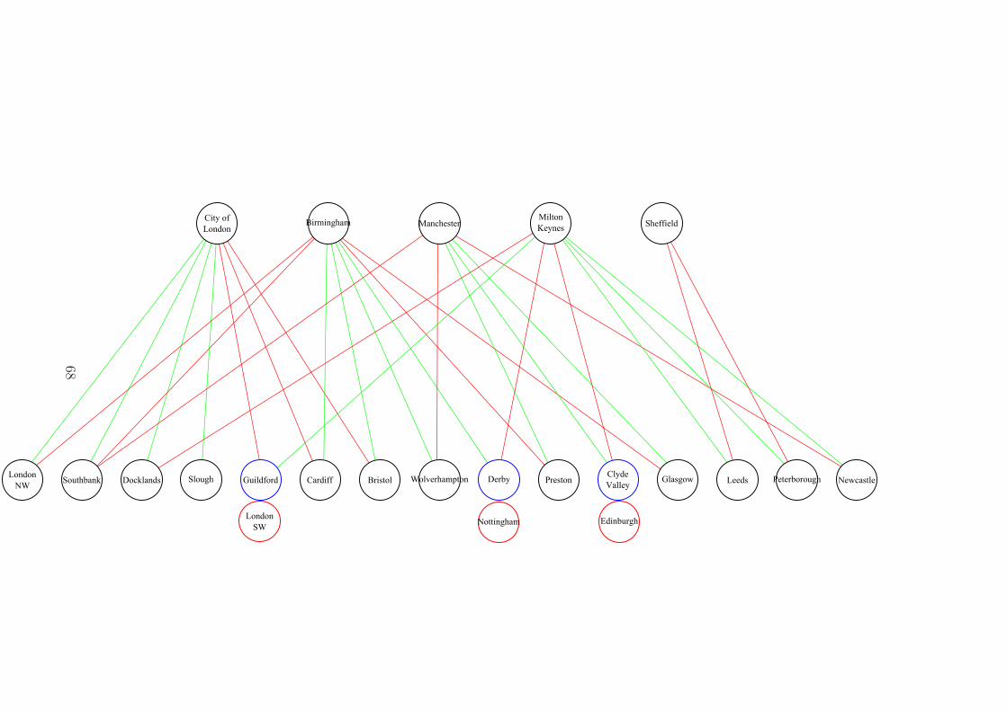
BirminghamCity of
LondonManchester Sheffield
Milton
Keynes
GlasgowClyde
Valley
Edinburgh
DerbyGuildford
NottinghamLondon
SW
Cardiff Peterborough NewcastleLondon
NWDocklands LeedsWolverhamptonSouthbank Slough Bristol Preston
68

2.5.3 Independent ISP Architectures
In addition to BT there are multiple independent ISPs which operate their own UK
based networks in addition to transit networks which cover parts of the UK provid-
ing international and Internet access. As example networks we take the JA.NET
academic network, Enta.net, and Sky broadband (which aggregated multiple smaller
providers). The models for this work will utilise the networks of these three providers
as examples of independent ISPs, while dependent ISP models will utilise the BT
network discussed above.
2.5.3.1 JA.NET
Joint Academic Network (JANET) is a private network which connects all research
councils, higher, and further education organisations in the UK. JANET consists of
a primary 3 ring topology backbone with regional loops connecting to this backbone
as shown in Figure 2.8. The backbone is composed of dual 10Gb/s links with regional
networks being deployed and provisioned to cope with local demand (usually 500Mb/s
- 1Gb/s links for smaller institutions). Interconnections occur primarily at London
and Manchester Internet Exchanges (IXs) however local institutions also have direct
Internet connections provided by other hosts. The physical mapping of the JANET
architecture is shown in Figure 2.9.
2.5.3.2 Enta.net
Enta.net is a large scale commercial network which acts as a direct seller and provider
to small, medium, and large enterprise as well as a offering resale opportunities for
home and business connections. The network is structured as shown in Figure 2.10
with an MPLS backbone providing transparent IP connectivity to large parts of the
UK through multiple 10Gb/s links on the backbone. Enta.net is the only non-BT
network to have currently rolled out its network to all 20 BT 21CN Wholesale Broad-
band Connect (WBC) interconnection points and 10 IP Stream Connect (IPSC) nodes
within the UK making it the least reliant network on the non-AS model, or a replace-
ment for the BT 21CN for its resellers. International connectivity and interconnection
is provided solely through London as shown in Figure 2.11. Enta.net utilises a 2 ring
major configuration with multiple redundant loops providing secondary connectivity
within the UK.
69

Figure 2.8: Logical topology for the JA.NET academic network within the UK c©2012Janet
70

Figure 2.9: Physical topology for the JA.NET academic network within the UKc©2012 Janet
71

Figure 2.10: Logical topology for the Enta.net network within the UK and Londoninterconnectivity to Europe and Worldwide c©2012 Entanet International Ltd
72

Figure 2.11: Physical topology for the Enta.net network within the UK and Londoninterconnectivity to Europe and Worldwide c©2012 Entanet International Ltd
73

2.5.3.3 Sky Broadband
Sky Broadband is the largest fibre deployed commercial broadband provider in the UK
having acquired multiple smaller providers including EasyNet. Their fibre deployment
is shown in Figure 2.13 with their 4 ring deployment shown in Figure 2.12. The Sky
network is currently one of the networks under the highest levels of development /
deployment as they expand their network throughout the major metropolitan areas of
the UK, however, their coverage is primarily in large city areas for direct deployment
with Local Loop Unbundling (LLU) covering 72% of the UK population.
2.5.4 Overlaid Network Structures
While each of the major UK networks is unique in the layout that it chooses to im-
plement there are a large number of common overlapping points including the 20
BT 21CN interconnection points and the 10 Wholesale Broadband Managed Con-
nect (WBMC) interconnection points. Looking at these networks together as in
Figure 2.14, and the full overlay in Figure 2.15 we can see that each of the networks
has a very similar deployed footprint indicating that in areas of overlap it should be
possible to share capacity and services to deliver a more efficient service. This would
likely be most beneficial under multicast or anycast situations whereby the end-point
of the network defines which network the traffic flows over given the current operating
conditions of the networks rather than the overlapping but separate situation whereby
each geographic set of users is divided by provider rather than content. Further cre-
ating an overlapped / shared network capability would allow for greater provision
of services to the non-overlapped areas by seamlessly adding virtual capacity to the
network.
2.5.5 UK Provisioning Growth
While the Internet or a precursor to it has been available for nearly 60 years the major
growth in the Internet began in the mid 1990’s with the development and deployment
of the ‘world wide web’ providing content and services not simply to research institutes
or large businesses (which could be provided for by a combination of shared and
private network fabric) but to every person in the UK. As an approximate time line
Internet services to end users were provided over the PSTN network using dial-up
services from the initial offerings until 1999 with the first release of ADSL trials from
BT and broadband via cable through NTL. From that point on the growth of the
74

Figure 2.12: Logical and physical topologies for the Sky Broadband fibre deploymentsin the UK c©2012 BSkyB Ltd
75
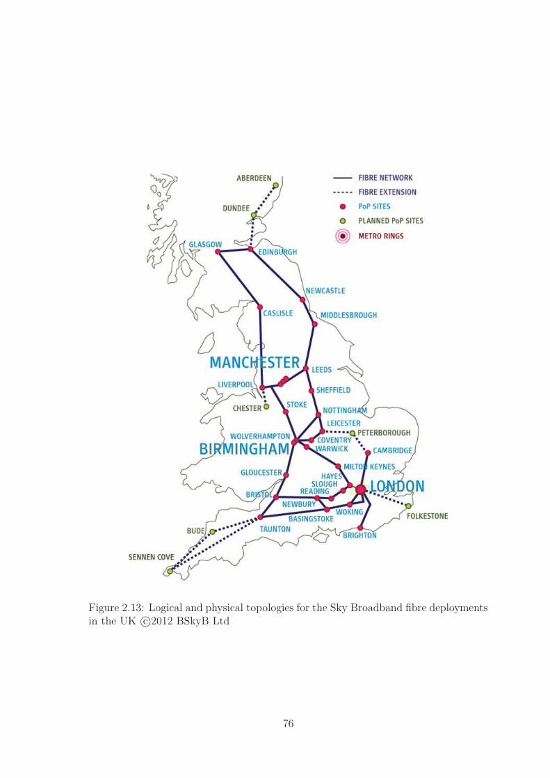
Figure 2.13: Logical and physical topologies for the Sky Broadband fibre deploymentsin the UK c©2012 BSkyB Ltd
76

(a) BT network overlaid on map of UK showing core network(10+ Mbps links) in green and the metro links in red
(b) Enta.net network overlaid on map of UK showing all linkswith 10+ Mbps
(c) Sky network overlaid on map of UK showing core network(10+ Mbps fibre links) in green and combined fibre / copperdeployments in red
Figure 2.14: Overlay maps for the BT, Enta.net, and JA.Net networks
77

London
NW
Glasgow
Clyde
Valley
Edinburgh
Derby
Guildford
Nottingham
London
SW
Birmingham
Cardiff
City of
London
ManchesterSheffield
Peterborough
Newcastle
Docklands
Milton
Keynes
Leeds
Wolverhampton
Southbank Slough
Bristol
Preston
Figure 2.15: Overlay map of three major UK networks overlapped to show geographicoverlaps creating redundant networks which serve a subset of the population. Byexploiting these overlaps the bandwidth within a single region, or the resiliency ofthe connection, can be increased by the same factor as the overlapping providers(2-3x)
78

Internet has been largely exponential in terms of content and bandwidth growth with
a doubling in traffic volume roughly every 18 months.
It is of course possible to address this issue simply through capacity provisioning
increases however in so doing we are likely to mask the problem rather than looking at
other potential approaches such as in-network caching and aggregation point systems
to enable efficient multicasting of video data.
2.5.5.1 ADSL Services
Initial ADSL offerings were in the 128Mb/s - 512Mb/s range in 1999, this grew to
1Mb/s with a 50:1 contention ratio by October 2010. The speed available through
ADSL services grew rapidly towards the limits of the technology at between 8Mb/s
and 16Mb/s however at the same time the fixed contention ratios were dropped and
dynamic contention systems introduced to manage the growing bandwidth issues the
network was having. Bandwidth caps were introduced to ADSL networks in 2004
and have existed since with modifications which remove the hard cap and instead
significantly throttle the users maximum speeds if they exceed their bandwidth non-
cap.
Seeing the limitations of ADSL an upgraded version, ADSL2+ was introduced
into the UK in September 2008 with speeds of up to 24Mb/s over limited distances
from the exchange. This system is proposed to be capable of supporting 40Mb/s
however these further additions have not yet been rolled out.
2.5.5.2 Cable Services
Cable services followed a growth pattern similar to that of ADSL however with the
growth being much more rapid and support for increased upload bandwidths as the
network technology was much more robust. Cable services saw speeds of 1Mb/s in
2003 with a rise to 40Mb/s in 2008, and potential deployments for 100Mb/s and
beyond in more recent times. The downside of the cable network is of course that
it is much more expensive to deploy than the ADSL equivalent and so has a much
lower penetration rate within the UK. Cable has been provided largely by a single
company throughout its lifetime, NTl and Telewest, NTL Telewest, and Virgin Media
though all have used the same network.
2.5.5.3 Fibre Services
While the provision of cable services offers high speeds and ADSL or ADSL2+ have
been relatively widespread the support for further downstream bandwidth and espe-
79
cially upstream bandwidth has been growing as services make use of any available
bandwidth to provide higher quality content. To support this growth there has been
a roll out of fibre in one of three major forms: fibre to the cabinet, fibre to the
premises, and fibre to the home. These services typically offer the same speeds as
ADSL2+ with the potential to support 40Mb/s and higher upstream bandwidths,
further scaling potential is available.
2.5.5.4 Backhaul Growth
The traditional backhaul network within the UK was provided through lines sup-
porting T1+ bandwidths with a rise to 1Gb/s as early as 2000. Provisioning since
then has grown to support for multiple 10Gb/s connections and a 40Gb/s standard
(4x10Gb/s lines + redundancy), and a proposed 100Gb/s standard (10x10Gb/s lines
+ redundancy) however there are calls for a true 1Gb/s and 1Tb/s backbone standard
using a single cable rather than multiple cables to achieve these speeds as this adds
additional cost in terms of terminating equipment and volume / cross-section of cable
to be laid. The network has attempted to achieve some future proofing in modern roll
outs (BT21CN, Entanet) using WDM to attempt to provide higher bandwidth poten-
tial by altering the end-point transmission hardware rather than the fibre supporting
the backhaul connection.
2.6 Conclusions
This chapter has given an overview of the routing and switching technologies at
the core of the modern Internet with a look at the future developments in terms of
deployment of IPv6 and other IP alternative layer 3 protocols. On top of this layer
the chapter considered the content and service architectures which are being deployed
or researched at current with the aim of providing a more content-centric network
which meets the needs of the current network trends better than the routing centric
model that is currently employed. Taking the lessons from this chapter it is clear that
there is currently no single next generation protocol design but rather many addressed
towards specific problem domains. This suggests that a future network protocol will
need to specifically address this need by being sufficiently flexible to meet challenges
which have not been considered today.
With the current state of the art in Internet development it is clear that for
the forseeable future the IPv4 and IPv6 Internets are likely to co-exist until such
time as there is a meaningful and directed push towards IPv6 with a financial and
80

business incentive that cannot be met through tunnelling or dual stack services.The
limited availability of cheap consumer orientated hardware capable of operating under
both of these environments further harms the adoption rate. The development of
overlay services such as the Internet of Things is likely to gain a large boost from
the ubiquity and uniqueness of IPv6 addresses however there is still no unifying
standard for the mechanisms behind these systems or a concrete business or consumer
reason to adopt them. Given recent copyright and Internet legal proposals such as
ACTA, PIPA, and the TPP it is likely that at some point in the near future content
tagging, management, and controlled dissemination will become a major issue for
service providers as well as network providers however the explicit form this will take
is not clear at the moment.
The direction of growth of the Internet suggests strongly that it is possible to
keep up with usage growth in terms of simply growing current usage however the
paradigm shift of this decade has not yet been seen. As such the asymmetrical
nature of most Internet connections as well as the heavily aggregated connections
which allow the Internet to actively scale to meet demand are likely to become points
of contention. It has been seen already that providers such as BT in the UK and
multiple US providers are offering premium access to bandwidth as a guaranteed
rate at the last mile indicating strongly that there is significant potential for further
contention. From these points it appears that part of the future growth of the Internet
must focus on relieving the stress at these aggregation points through some kind of
service model likely composed of a combination of caching, multicast, and predictive
content prefetching in order to better utilise available bandwidth.
When considered in terms of the growth of the Internet capacity and the lack of a
true ‘killer’ application for the next generation it becomes important to consider the
specific structure of the UK based Internet in terms of benefits and bottlenecks in
order to predict the requirements of a future network and the ‘killer’ application for
that network. In the next chapter we consider the UK Internet structure as a whole
taking the black-box approach of the wholesale networks identified in this chapter
and building a simple model for the UK Internet from which we can consider the
applications and services most likely to stress the network and the future requirements
that the proposed routing architecture must fulfil in order to provide an appropriate
level of service and future proofing.
81

Chapter 3
UK Internet Structure and FutureNetwork Requirements
3.1 Introduction
In Chapter 2 - Background we considered the overall structure of the UK Internet
as being composed of multiple overlapping provider networks interconnected at Point
of Presences (PoPs), interconnection points, and Internet exchanges. Each of these
networks has followed a similar growth pattern in terms of raw bandwidth capacity
and network latency / jitter as the hardware and software across the various providers
is provided by a limited range of providers and is often provided in a multi-vendor
environment to provide redundancy and resilience. In this chapter we take a step
back from the overview of the full network situation and instead consider the overall
topology of a single provider network in terms of aggregation, interconnection, and
provision. By taking a single network, in this case the BT 21CN network, we can
provide a greater depth of information on how the network functions and operates
before looking at how this information can be generalised to other networks which
follow similar parameters such as interconnection points. From this we can make
initial conclusions as to the requirements for a next generation network in terms of
research, industrial best practice, vendor best practice, and the realities of rolling out
a new network structure.
3.2 The UK Internet
Having looked at the overall structure of the United Kingdom (UK) Internet in Chap-
ter 2 - Background from an Autonomous System (AS) / independent network level we
now consider the common components and functionality of provided by the networks
82

in order to create a simplified model for analysis and design purposes. In terms of
common components we are interested in three main features which define the inter-
connectivity of the network and aggregatability of network sections: interconnection
points, Internet exchanges, and internal network aggregation points. In addition to
these core components we are interested in functionality provided within the network
again in three main areas: service provision, protocol and / or application support,
and authentication, authorisation, and auditing. It is important to recognise that this
work looks specifically at localised routing as a mechanism to improve efficiency and
as such the supporting areas of the network are addressed in less depth.
3.2.1 Internet Network Components
While it is important to consider the full range of hardware and features of a network
the very wide range of connectivity options in terms of individual router and / or
switch functionalities, implementation quality, and the speeds of interconnections
between these hardware devices makes this task one to consider from a much higher
level. To simplify the network models we therefore consider the features and structures
of the network which define interconnection between networks and layers of the same
network and the functionality which is / could be provided at these levels.
3.2.1.1 Internet Backbone
Between individual countries / regions there are a number of both large and smaller
scale transit networks providing the backbone of the Internet. Typically these net-
works cover inter-continent, inter-country, and a sub-section of intra-country transit
between major Internet exchanges and peering points. The traffic growth across
these networks has been growing at approximately 40-50% per year [112] however
the backbone growth recorded by Telegeography shows a sustained backbone growth
from 2004 of 45% [113] rising to 58% in 2010-2011 [114] indicating that current
technology and growth rates are sustainable for an organic growth of the Internet
with no major disrupting factors. Parts of this growth have been on the very cheap
fibre networks laid during the dot-com boom [115], however, large parts of this ‘dark
fibre’ being bought up by companies like Google for use in new deployments [116]
so sustained growth at current margins may not be sustainable in the future. At
current and for the purposes of this work however the backbone interconnection can
be largely ignored as it has shown a sustained capability to manage the traffic flow-
ing over it and is managed by sufficiently few players that co-operation is possible
83

and an accepted business strategy. Telegeography has further found that the relative
importance of these international links is being reduced by higher intra-continental
links [117] allowing for greater internal traffic flow without burdening the interconti-
nental links.
3.2.1.2 Internet Exchanges
Before discussing the structure of an Internet Exchange (IX) [118, 119] it is impor-
tant to define the two major forms of peering in use within the Internet hierarchy
currently:transit, and peering [120]. Transit networks are those in which there is
a bidirectional exchange of traffic however traffic is asymmetric and so a monetary
charge is applied to the transaction, this is typically a hierarchical agreement with a
larger footprint (higher tier) provider charing a lower footprint (lower tier) provider
for access ‘to the Internet’. Peering in contrast is still a bidirectional traffic exchange
but one in which the traffic flow / footprint / utility of the providers is typically
equal (or a trade off of these factors) resulting in a free traffic exchange / quid-pro-
quo policy. This model is shown in Figure 3.1 with transit relationships represented
vertically and peering relationships horizontally. The real world interaction between
these ASs is very unlikely to be as simple [121, 122] as this representation as different
types of traffic flows may be handled differently giving multiple relationships between
any two ASs. Peering is subdivided into private peering, performed through a private
link between the two companies, and public peering at a shared facility - typically
the IX. This is still an overly simplified view of the diversity of ASs present within
the Internet which should be represented more realistically indicating the interaction
of content and transport within the Internet [123]. The five base types of AS would
thus be: consumer access, providing access to end-users; content access, providing
access to content-suppliers; Content Delivery Network (CDN), providing distributed
hosting of content; pure transit, providing only data transmission functionality; and
hybrid transit, providing the functionality of a pure transit network alongside a CDN
or content access network [124].
An Internet exchange is typically a data centre hosting multiple Internet Service
Providers (ISPs) routing and management hardware devices such that interconnec-
tion between their networks is simplified due to proximity and available bandwidth
on switching / routing devices with no requirement for a third party network to in-
terconnect their networks [125]. Typically the interconnectivity is provided as layer
2 ethernet switching rather than layer 3 IP based routing / switching to ensure line
speed traffic flow. Space and power are not significant issues within Internet exchange
84

Peering
Transit Transit Transit
Peering
Peering
Transit
Transit Transit TransitTransit
AS1 AS2
AS3 AS5AS4
AS6 AS7 AS8
Figure 3.1: Autonomous system hierarchy showing peering and transit links
facilities, as compared to typical PoPs, due to the inherent design of a data centre
against a network routing facility. Due to these considerations the interconnection
bandwidth between two networks at these sites can be considered to be effectively
infinite / non-blocking [126] in relation to the rest of the network due to interconnec-
tion bandwidth being greater than the provisioned network-to-network links. This
available bandwidth is typically provided in fixed blocks of 100Mbps, 1Gbps, 10Gbps,
or 40Gbps following accepted Ethernet standards [127]. That is to say that if two
networks aim to peer at an Internet exchange the inter-exchange bandwidth will
not be the limiting factor on the expansion capability of the network either through
currently available switching capacity or through expansion capability to include ad-
ditional high bandwidth switches. There are edge cases where this assumption does
not hold due to sudden increases in bandwidth requirements or a new application
paradigm however these are sufficiently rare as to be considered on an individual
basis. Often though these issues are not so much an issue in terms of actual physical
connectivity but rather the peering / legal agreements between connecting entities
such as the 2010 dispute between Comcast and Level 3 Communications [128] over
Netflix traffic. This dispute centred around the movement of content hosting for Net-
flix content to the Level 3 CDN from the Akamai CDN resulting in an alteration of
the traffic balance; while Akamai maintained a paid transit peering arrangement with
Comcast as the traffic was largely unidirectional into the Comcast network, Comcast
85

and Level 3 had maintained a public / private peering arrangement as traffic was
largely bidirectional. The prior 2:1 ratio between traffic Comcast terminated to that
of Level 3 was considered a fair exchange given the footprint and utility of the net-
works involved, the 5:1 ratio after the Netflix hosting arrangement brings the balance
of utility to traffic into question. This is being disputed by Level 3 as a network neu-
trality issue (a tax on video traffic from L3/Netflix specifically) and by Comcast as
a peering arrangement dispute. This shift in traffic volume and source highlights the
fragility of the Internet traffic peering models and the difficulty of vertical integration
in the Internet - the previous balance was considered fair by both parties however
the new situation reverses the typical hierarchy of transit agreements as Level 3 is
now acting as a CDN rather than a transit network to Comcast. It is important to
recognise that this is a traffic flow issue and may not be under the direct control of
the providing ISP and may be affected by upstream traffic providers through content
multi-homing [129]. The providing ISP can provide traffic shaping and caching facil-
ities to help alleviate issues however they cannot actively alter the demands of their
clients and thus the source of traffic.
Within the UK there are seven major Internet exchange facilities, four located
within London, England - London Internet Exchange, London Internet Providers Ex-
change, London Network Access Point, and PacketExchange; one in Manchester, Eng-
land - Manchester Network Access Point; one in Leeds, England - IXLeeds Internet
Exchange; and one in Edinburgh, Scotland - WorldIX Internet Exchange. Interna-
tional peering is generally through London based sites or the south west / south east
coastline sites giving access to submarine cables to other countries.
At this point it is important to consider the difference in peering arrangements be-
tween large scale ‘backbone’ networks and more regionalised network providers. While
it is possible to reach many nearby networks through simple interconnectivity (creat-
ing a toroidal / donut network [130]) with the effect of reducing latency and packet
loss it can create issues for long distance routing and interconnectivity on a large scale
whereby traffic is routed inefficiently to exploit peering arrangements [131]. These
agreements however do not form a simple hierarchy but rather an interconnected web
of agreements with peering agreements at all levels of the network through PoPs and
IXs, with higher tiers offering transit connections to those lower in the hierarchy. This
connectivity model is backed up by k-shell decomposition models [132] creating an
effective three layer model of connectivity - a central mesh, a mid-layer donut, and
a low level tree network. As highlighted by the Comcast-Level 3 case it is uncertain
86

where the future lies in regards to the transit hierarchy as networks become more
vertically integrated.
3.2.1.3 Interconnection Points
Interconnection points are PoPs around the country at which ISPs have agreed to
provide co-location space for other ISPs such that their networks can interact. As
the dominant network in the UK has been the British Telecom (BT) network for
a long period of time these are largely dictated by the historical Advanced Digital
Subscriber Line (ADSL) and dial-up interconnection points provided by BT. As such
there are roughly 20 modern 21CN interconnection points and 10 older IP stream in-
terconnection points active within the UK. While there may be other interconnection
points between individual ISPs these are not as widely known or utilised so again can
be considered in edge cases rather than the simplified models. As the UK maintains
a ‘wholesale’ network approach through government regulation of BT Openreach we
maintain both interconnection points as well as IX sites. In contrast to the wholesale
model countries like the United States (US) which maintain a segregated market /
last mile tend to conflate interconnection points with IXs i.e. the 31 National Football
League (NFL) cities in the US [133].
Each interconnection site functions like an IX except the interconnection is typ-
ically guest ISP ↔ host ISP rather than the any ↔ any peering possible in an IX.
Typically an interconnection point requires the guest ISP to purchase sufficient up-
stream bandwidth to match the available downstream bandwidth to non-Local Loop
Unbundling (LLU) customers and additional bandwidth for actual peering services.
As such an interconnection point will often also act as an aggregation point reducing
the upstream bandwidth below that of the total bandwidth of the networks aggre-
gating to that point. There are also likely to be requirements on route redistribution,
traffic volume, and network size in order to successfully peer [134].
3.2.1.4 Aggregation Points
An aggregation point within the network is defined as a point where the network
operator performs bandwidth compression / statistical aggregation of traffic streams
eg: a point with less upstream bandwidth available than downstream. These points
allow any individual point within the network to access the full bandwidth and ca-
pacity assigned to it without fully provisioning the network on a 1:1 basis which is
generally prohibitively expensive under current bursty traffic models [135, 136]. Tak-
ing advantage of the statistical aggregation of traffic flows and traffic patterns in that
87

most user’s traffic is not correlated to other traffic it is unlikely that all users will
ever utilise their full bandwidth at any single point in time on the network making
it cost and hardware efficient to limit the available bandwidth and capacity to some
ratio less than 1 of the users-bandwidth:available-bandwidth.
We further consider two different forms of aggregation, burstable aggregation point
(BAgP) and non-burstable aggregation point (NBAgP). In NBAgP aggregation we
consider the hard limit of the provisioned links such that there is a predefined, finite
bandwidth and capacity available to a single provider to be shared amongst all users of
the network below that point. Within the BT 21CN network we see typical NBAgPs
as the Access-Metro, and Metro-Core boundaries - areas where the physical network
infrastructure cost is high due to the number of physical connections and requirement
for high bandwidth links. BAgPs are in contrast points within the network where
the provisioning is higher than the assigned available bandwidth, such as the scenario
for an ISP purchasing 155Mbps links from a wholesale provider. The BAgP link
allows the traffic flow to increase above the predefined limit to the physical limits of
the channel(s), in so doing the provider allows for higher perceived network quality
due to lower latency from packet loss and provides a new economic model through
differentiated pricing based on usage.
When we consider provisioning a model we must consider the worst-case scenario,
which is that of the wholesale provider who can only provide a limited total band-
width based on hardware capacity. Our models should therefore consist of primarily
NBAgPs aggregation points and consider BAgP as special cases. For NBAgP we can
consider the cost function of bandwidth to be linear / stepped across the available
bandwidth while BAgPs can be considered to be NBAgPs with a non-linear cost
function across the available bandwidth. When considering the current UK Internet
the division of networks into specific providers limits the capability to further provide
BAgP capacity to the network e.g. while the BT / Openreach network may reach
saturation the overlapping BSkyB network has not reached that point, the separation
and distinction of networks creates a bottleneck where one need not exist.
3.2.1.5 Multiple Three Layer Model
At the national scale it is clear that there are three major layers within the UK
Internet network defined by the aggregation layers within the many networks com-
posing it. These layers consist of the access and protocol switching layer, a distri-
bution layer above this which aggregates multiple smaller localised networks into a
regional network, and the core layer which provides large scale transport between
88
distribution layer networks. This model follows the Cisco Campus Enterprise Model
[137] closely and similar to models used in other current research including Hierar-
chical Architecture for Internet Routing (HAIR)[138], Hierarchical Routing Architec-
ture (HRA)[139], and a similar hierarchical structure from Internet AS radial mapping
[140] and k-shell decomposition [141]. From the deconstruction of the current UK In-
ternet and other research models it is therefore reasonable to assume that an Internet
model based on the self-similar nature of the different levels of the hierarchy is a good
model for at least the UK geographically national Internet. In Figure 3.2a the basic
three layer model is shown with the distribution layer as a typically insecure organ-
isation based network with double or triple parenting. The access layer represents
the connectivity to other networks and performs authentication and security aspects
relating to inter-network connectivity. Finally the core network acts as the linkage
between multiple distribution networks within the same organisation and to the ac-
cess layers of other networks. In Figure 3.2b this model is interconnected to a single
network in a peering-type arrangement and to multiple other networks as a transit-
type arrangement. In each case the core-access layer overlap represents the security
and traffic management section of the network isolating the distribution network from
having to perform these actions.
If we consider the wider implications of the Interconnection points, Internet ex-
changes, and international transit from the Internet exchanges we see that again a
three layer model of interconnectivity can be found inside the Internet ‘core’ [142].
Networks interact at an access layer through interconnection points for localised traf-
fic handling; then through a distribution layer of Internet exchanges for larger scale
traffic flows / peering with non-national networks; and the core layer as the inter-
connection of Internet exchanges through international peering links (transit ASs). It
should be noted at this point that there is some doubt as to the accuracy of current
Border Gateway Protocol (BGP) and AS level mapping techniques [143] in terms of
determining the interconnections between AS level networks [144] however the over-
all ‘gross’ connectivity is still distinguishable. This doubt comes from the lack of
fine grain observations that can be made at this level and the ‘hidden’ private con-
nections that are utilised for network traffic but not advertised to the wider world
through BGP updates.
This three layer repeating structure makes analysis of a network easier as we can
identify common functionality within each section of the network at any scale. By
simplifying the network to a three layer structure that is hierarchically repeating and
self-similar we move towards a simplified model for network design and management
89
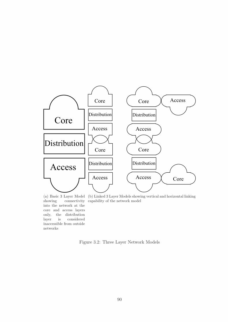
Access
Core
Distribution
(a) Basic 3 Layer Modelshowing connectivityinto the network at thecore and access layersonly, the distributionlayer is consideredinaccessible from outsidenetworks
Access
Core
Distribution
Access
Core
Distribution
Access
Core
Distribution
Access
Core
Distribution
Access
Core
(b) Linked 3 Layer Models showing vertical and horizontal linkingcapability of the network model
Figure 3.2: Three Layer Network Models
90

that can also be viewed as a tiered hierarchy. Research has shown the Internet is not
currently [145, 146] a fractal based network however it does grossly approximate one
based on the geographic distribution of population [147]. Using k-shell decomposition
it has further been shown [145] that analysing the Internet in terms of hop counts or
similar measures is not always the most effective method of modelling as the overall
layer 3 routing structure more closely approximates a three layer model composed of
the now identified core, distribution, and access layers. As always it is questionable
how much of the Internet these studies actually reflect given the large hidden layer
2 topology, and other non-Internet Protocol (IP) based protocols which are not de-
tectable via tools such as traceroute. Overall it is likely at least consistent to treat the
Internet structure as a tiered, self-similar, three-layer hierarchy. This model follows
typical vendor best practice for the lower levels of the network while also giving a
scaling model for other layers that recreates a central core and the toroidal routing
possible outside of this core.
3.2.2 Internet Network Functionality
Having looked at the base components of an internetwork1 we now proceed to look
at the network in terms of functionality required within the network. We consider
the fundamental requirements for: authentication, authorisation, and Accounting /
Auditing ; protocol and application support for services like video streaming or voice
over IP (VOIP); and network services such as caching and distribution. With these
three areas we can provide a base line service model for the current Internet and from
this derive the requirements for a next-generation network in terms of the minimum,
and desirable requirements it should provide to network users and other networks.
3.2.2.1 Authentication, Authorisation, and Auditing
In order to provide management, billing, and data flow control it is vital for a network
to provide methods for authentication, authorisation, and auditing (AAA) services at
least at the router level if not the network level. Under current industry working
standards it is common to provide AAA challenges [137] at the access layer of the
network with the rest of the network accepting traffic flows from non-access-edge
devices (the Network Access Server (NAS)) as being trusted. The authentication and
authorisation stages are typically not provided on the access-edge routers themselves
except in very small (<200 node) networks but rather by a networking protocol such
1Internetwork: a collection of interconnected networks
91

as Remote Authentication Dial In User Service (RADIUS). Accounting and auditing
are spread across both a protocol like RADIUS and the ISPs management system to
track both the user session data as well as Hyper Text Transfer Protocol accesses.
These services can be provided by proxied RADIUS servers allowing for roaming and
remote logins to be easily performed.
Authentication The authentication stage is typically carried out using the com-
bination of a RADIUS server provided by the ISP or institution providing the In-
ternet service, a NAS providing the end-point connectivity, and a Remote Access
Server (RAS) provided (typically) by the physical Network Provider. The NAS will
contact the RAS to determine the correct RAS which will pass the authentication
information (typically unencrypted) to the RADIUS server and expect one of three
result: access-accept, access-reject, or access-challenge. Only in the third case is a
secure channel established between the authenticating party and the RADIUS server
to provide further authentication before allowing network access. Under a single
provider / user model it is likely possible that this authentication could be provided
at the network edge similar to the Cisco Enterprise Campus model however with a
single provider - multiple user model it would require a more complex separation of
user processing potentially falling foul of data protection and integrity laws [148] if
sufficient separation wasn’t achieved at the authentication point. This implies that
under a wholesale model such as that in the UK there should be a distributed au-
thentication system in place in order to manage the authentication services of the
access providers and to provide authentication to the wholesale network. This then
places the legal and security burden on each service provider separately and allows
for scaling in the number of providers. While this standard need not be ‘open’ it is
likely beneficial to the infrastructure if a single protocol can be utilised across multiple
hardware platforms to provide implementation redundancy without added authenti-
cation complexity. This openness limits the potential for interoperability issues as
tests can be easily performed against the reference build while reducing the cost of
access to the market allowing for increased competition. As the current deployment
model for the UK is to sustain the unified last-mile network and this is likely to be
the case with other countries [149, 150] a distributed authentication method should
be classed as a firm requirement for current and future generation networks.
Authorisation The authorisation process defines the access and services available
to a client once it has authenticated against the network. These restrictions typically
92

include information such as access-lists, IP address assignment and lease length, Layer
2 Tunnelling Protocol (L2TP), Virtual Local Area Network (VLAN), or Quality of
Service (QoS) parameters. From this it is clear that authorisation must be capable
of assigning typical router level controls and ideally the ability to specify ‘advanced’
functionality if it is available (such as perhaps flow control, or multicast group con-
trol). The authorisation control can be provided as a separate service or integrated
into the authentication service.
Accounting / Auditing Basic accounting facilities are often currently provided
by the RADIUS protocol through RADIUS accounting [151] including the session
start and end times, assigned identifiers (IP and point of attachment), and a unique
session id. Interim, and session closure, updates include the number of packets and
data transferred to date including the session duration. Further session tracking can
be performed at the ISP gateways - monitoring and tracking being required by law
for certain types of traffic [152] - on a more detailed level as all traffic will currently
flow through a potentially monitored gateway. The distributed monitoring system
established by the RADIUS protocol is well suited to potential models as it does
not impose a service requirement on individual network sections other than there
being a service ‘somewhere’. The ability to track further information is currently
provided by centralised gateways and is often required by law, as these type of laws
become more strict such as the ‘voluntary’ support for part 11 of the Anti-terrorism,
Crime and Security Act 2001 [153] it is likely that the requirement to track both the
session details for the purposes of billing and legal action as well as the tracking of
intra-session activities will increase requiring a more active solution to auditing and
accounting. As the volume of data required for this kind of process is large it is likely
best approached in a similarly decentralised manner with aggregation during lower
usage periods.
3.2.2.2 Protocol and / or Application Support
Within the Network Provider (NP) network there is typically little support for pro-
tocol and application support beyond unicast transmission, basic security [106] and
QoS measures [154]. This can be in part attributed to the difficulty in acquiring the
minimum three way consent required for many services. Often integrated support
can include the ISP, underlying NP, the Service Provider (SP), and the Content
Provider (CP). Most modern routers and networks support more advanced transmis-
sions such as multicast or anycast however the administrative difficulty in enabling
93

this mechanism often results in the technology being disabled due to billing and pri-
vacy concerns. This limitation is very apparent in the UK network where all transmis-
sions originating outside the BT centrals as non-unicast traffic will be retransmitted
as unicast traffic.
From this it is clear that it is a requirement to provide basic security features to
the network and quality of service however providing mechanisms to support further
protocol and applications support such as dynamic multicasting or inline caching
is an area that must be considered for a next generation network. As support for
these services exists within the current networks, however cannot be utilised due
to non-technical constraints, the solution must approach the concept of application
support from a billing and management perspective. This suggests that the billing
and management structure put in place for a future generation network should be
capable of handling both well described protocols as well as those which can be
defined dynamically using pre-existing constructs such as ‘reserved bandwidth’ or
‘maximum jitter’.
3.2.2.3 Service Provision
In-network service provision is a growing area of concern, however currently deployed
networks do not support many in-network services - rather these services are provided
by external non-transparent service providers. The most common type of in-network
service currently provided is content caching as this provides potentially large effi-
ciency benefits to the host network. In the early stages of the Internet there was a
very strong correlation between a service provider and a content provider however this
has grown more distant recently. This trend was backed by the growth of third-party
content caching services such as Akamai which provided an intermediary between
content providers and service providers. This third party state has created interest-
ing routing issues as the third party host has more network knowledge than the hosts
it is working with and so can forward data in the most efficient manner (generally cost
based). In order to reduce transit costs many ISPs have aimed to integrate content
caching into their networks rather than relying on third party networks between the
content host and the service provider network. The additional knowledge of the third
party is gained as they have multiple peering and transit arrangements with differ-
ent providers enabling them to have a higher level view of interconnectivity and to
utilise this knowledge to provide themselves with the most cost efficient traffic rout-
ing options. This is further backed up by recent trends towards the NPs providing in
network caching [155, 156] to further assist in the dissemination of content efficiently.
94

This approach has similar logistical issues to multicast distribution due to the rights,
licenses, and contracts that must be established between the four parties: NP, ISP,
CP, and the end client.
Using the most common placements of caches / distribution points within the
network we can look further at the impact of network services and how they can be
deployed effectively. Under the following models it is important to consider caching
in terms of third-party, ISP, and various levels of NP service provision.
3.2.3 Model Structures
Considering the current BT 21CN network structure shown in Figure 2.5 and reorder-
ing this to match a more linear layout matching the physical hardware configuration
shown in Figure 3.3a there is a clear division of network layers and the aggregation
and deaggregation points within the network. Add simple traffic flows across the
network as shown in Figure 3.3b it is clear NP network will tend to aggregate traffic
flows (shown by ISP in green, red, and yellow) within the core network and deaggra-
gate it towards specific end point locations indicating that a solution that is transport
provider agnostic is feasible - services can be charged / managed by usage within the
network while still utilising conservation methods. From these real networks structure
models a set of simplified models are created using the identified hierarchical three
tiered self similar network structures for five scenarios based on the interaction of
ISP and NP: ISP-NP interaction, ISP-ISP interaction, the access network, and two
service orientated models: ISP provision, and NP provision.
From the discussion above models are created based on the hierarchical three tiered
self-similar network structure to represent Internet networks, regional and national
networks, and enterprise networks. Each layer then consists of the three components:
core, distribution, and access with the core layer linking together distribution layers
within the same network and providing a sub-region - the core-edge that links to the
access layer of the higher level network. Similarly the access layer of the current tier
provides a sub-region - the access-edge which links to the core-edge of the layer below.
In this manner each tier of the network is segregated from that below by traffic flow
management devices, however can traverse the network as though it is a single entity.
For the purposes of multi-parenting nodes, dual-parent nodes are considered to
be standard to ensure a path redundancy while higher resiliency areas utilise triple-
parented nodes. This meets industry standard network design patterns suggested
by companies such as Cisco[137] and Juniper[157]. While higher degree parenting is
possible the complexity in terms of software configuration and hardware provisioning
95

(a) Basic network structurefor the BT 21CN networkfrom end user to the dis-tribution points attached tothe core and metro layers
(b) Diagram showing threetraffic flows (red, green,yellow) being merged fortransit across the networkbefore being separated fordistribution to the individ-ual ISPs
Figure 3.3: BT 21CN network structure and data flow paths
96

is generally prohibitive to the creation of effective solutions and so 4 or more parent
solutions are ignored except under specific circumstances such as the fully meshed core
of the BT 21CN network. Multi-parenting above three nodes is generally considered
cost inefficient as the gained redundancy does not offset the additional complexity
required to interconnect the nodes which rises as the square of the connected nodes.
3.2.4 Cost Modelling
In order to verify that the current pricing structure of the combined BT and ISP
network is priced in accordance with this layered theory we look at the BT Internet
charges for Wholesale Broadband Connect (WBC), Wholesale Managed Broadband
Connect (WMBC), and IPStream implementations. The pricing structures for these
platforms are defined in internal BT documentation [158, 159]. From these documents
we identify the key charges at each level of the BT 21st Century Network (21CN)
model hierarchy and from this validate the above cost models. For the purposes of
this validation we consider: last mile, access network, and metro and core as backhaul.
BT wholesale provides prices on a three tier system covering varying levels of
competition in the served area, however, recent reports [160, 161] have given both
European and UK based authorities reasons to look into these pricing practices. As
modelling each individual tier leads to significant redundancy we model the cost
changes due to these regions as a separation of the core and metro charges though
this is not strictly correct. The division of costs in the calculated formulas refers to
the market segment split costs which result in either reduced costs across the Metro
area handover charges (for exchange regions covering up to 10,000 households), or
increases in costs (for exchange regions covering over 10,000 households). As this
market split is based on the geographic location of hand-over sites and connectivity
it is a viable model to separate these additional costs and deductions based on the
Metro area and treat the core area as a distinct cost.
The primary costs at each layer are identified below, constant charges are con-
sidered as fixed costs that cannot be varied on an intra-month basis while variable
charges are ones which can be altered relatively dynamically. From these components
and the equations derived as the cost model for each section it becomes clear that
the primary costs to the ISP come from the requirement to support large bandwidths
across the core network to their local interconnection point. As such the ability to
localise content transfers and maximise the number of users that the data can serve
can lead to large savings to individual ISPs and provide a reduction in the need to
scale the backbone of the network.
97

3.2.4.1 Last Mile Charges
Fixed Charges
• Connection Charge: £37.29 per activated line (one off cost)
• Line Rental: £6.10 per activated line per month (£73.20 per annum)
Variable Charges
• End user Bandwidth: £0.457 per Megabits per second (Mbps) per activated
line per month (£5.484 per Mbps per activated line per year)
• Contracted Bandwidth: £90.38 per Mbps per link (discrete 1Mbps links)
• Additional Bandwidth: £180.00 per Mbps per link (first 5% above limit at
normal rate)
3.2.4.2 Access Network Charges
Fixed Charges
• Handover Charge: per handover location - £8,057.50 per month (£96,690 per
annum)
Variable Charges
• Interconnect Bandwidth: £11,175.88 per Gigabits per second (Gbps) link (dis-
crete 1Gbps or 10Gbps links)
3.2.4.3 Metro and Core (Backhaul) Network Charges
Fixed Charges
• Central Network Access: per fibre pipe lit - £160,000 per annum (up to 4 fibres
per pipe)
Variable Charges
• Central Network Access: £166,800 per 155 (139 usable)Mbps fibre link
• Transit and Peering: £0.80 per fibre link per Mbps
98
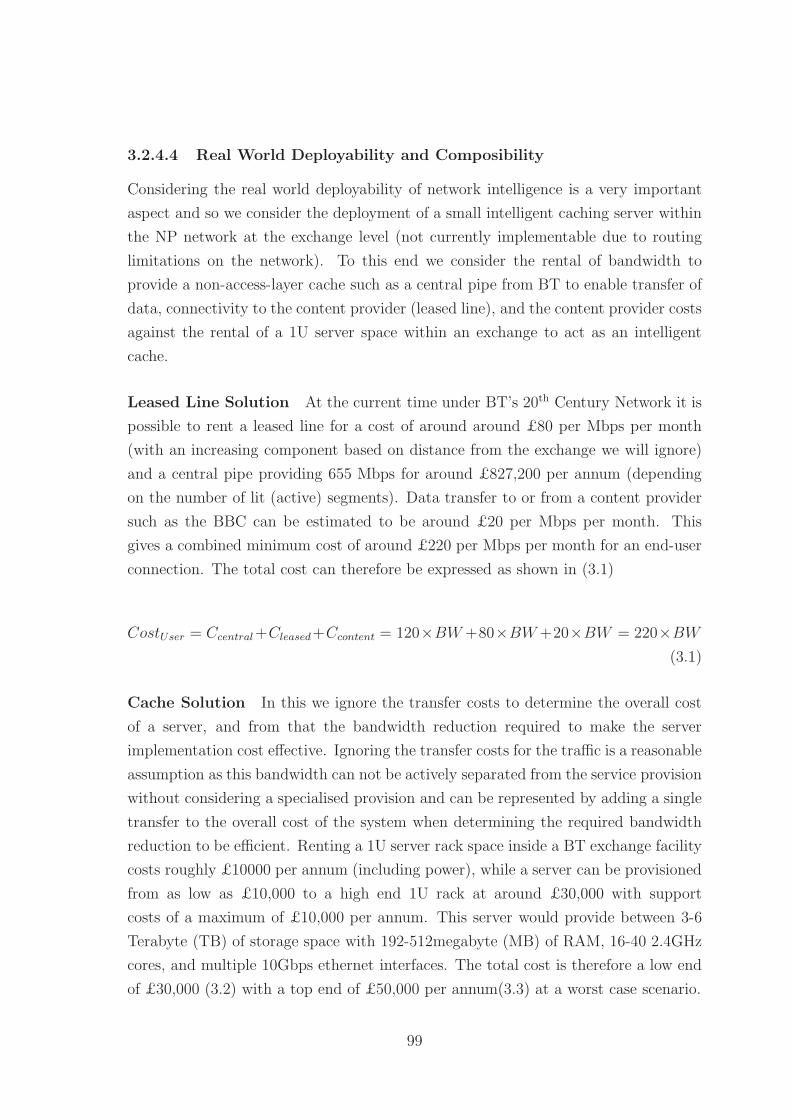
3.2.4.4 Real World Deployability and Composibility
Considering the real world deployability of network intelligence is a very important
aspect and so we consider the deployment of a small intelligent caching server within
the NP network at the exchange level (not currently implementable due to routing
limitations on the network). To this end we consider the rental of bandwidth to
provide a non-access-layer cache such as a central pipe from BT to enable transfer of
data, connectivity to the content provider (leased line), and the content provider costs
against the rental of a 1U server space within an exchange to act as an intelligent
cache.
Leased Line Solution At the current time under BT’s 20th Century Network it is
possible to rent a leased line for a cost of around around £80 per Mbps per month
(with an increasing component based on distance from the exchange we will ignore)
and a central pipe providing 655 Mbps for around £827,200 per annum (depending
on the number of lit (active) segments). Data transfer to or from a content provider
such as the BBC can be estimated to be around £20 per Mbps per month. This
gives a combined minimum cost of around £220 per Mbps per month for an end-user
connection. The total cost can therefore be expressed as shown in (3.1)
CostUser = Ccentral+Cleased+Ccontent = 120×BW+80×BW+20×BW = 220×BW
(3.1)
Cache Solution In this we ignore the transfer costs to determine the overall cost
of a server, and from that the bandwidth reduction required to make the server
implementation cost effective. Ignoring the transfer costs for the traffic is a reasonable
assumption as this bandwidth can not be actively separated from the service provision
without considering a specialised provision and can be represented by adding a single
transfer to the overall cost of the system when determining the required bandwidth
reduction to be efficient. Renting a 1U server rack space inside a BT exchange facility
costs roughly £10000 per annum (including power), while a server can be provisioned
from as low as £10,000 to a high end 1U rack at around £30,000 with support
costs of a maximum of £10,000 per annum. This server would provide between 3-6
Terabyte (TB) of storage space with 192-512megabyte (MB) of RAM, 16-40 2.4GHz
cores, and multiple 10Gbps ethernet interfaces. The total cost is therefore a low end
of £30,000 (3.2) with a top end of £50,000 per annum(3.3) at a worst case scenario.
99

Cost30k = 30000/12 = £2, 500/mo (3.2)
Cost50k = 50000/12 = £4, 166/mo (3.3)
Comparison From (3.1) we know that each user consumes roughly £220 per Mbps
per month. If we assume the peak requirement on bandwidth is higher than the
normal usage (since ISPs are billed on 95% peak bandwidth normally) then we need
to reduce this peak in order to make the caching solution effective. Assuming a 720p
stream at 3Mbps we can see the number of simultaneous users of a unicast system
to provide a reduction equivalent to the cache cost is shown in (3.4) and (3.5). As
a single stream must still be provisioned we need to provide at least 4 (low end)
or 8 (high end) simultaneous users at peak time in order to provide a cost effective
caching solution. As an exchange consists of approximately 5,000 users this represents
0.1-0.2% of the user population and so is likely a very feasible solution. Even with
costs out by an order of magnitude the uptake is still 1-2% which is very feasible
given the BBC viewing figures for content such as Eastenders which can have 250,000
simultaneous viewers at peak time (50 per exchange on average). As an alternative
version of making this cost efficient would be a drop of 1Mbps from the peak transfer
rate under BT WBC pricing strategies, an easily achievable strategy.
Users30k = 2, 500/(220× 3) = 3.78 (3.4)
Users50k = 4, 166/(220× 3) = 6.31 (3.5)
3.2.4.5 Content Delivery Networks
As shown above it is feasible to fund the installation of localised streaming media
caches at the exchange level of the network simply through the reduction in required
bandwidth. This model can be further justified by the inclusion of CDN costs. Typ-
ically for a large scale CDN prices will approach 0.10/GB of content delivered. To
meet the 30,000 cost equivalent this is 300,000GB of traffic delivered per year per
exchange. Assuming a typical 3Mbps stream the network requires we require 1.35GB
per hour of content streamed resulting in a yearly viewing requirement of 222,222
hours. Across the average 5,000 homes per exchange this is 44.4 hours per year, or
roughly a single 50 minute stream per week. Again the BBC viewing figures suggest
that this is a highly feasible solution for the delivery of streaming content.
100

This hybrid approach of reduced bandwidth usage coupled with reduced CDN
costs makes it feasible for an ISP to deploy their own content server close to the end
user at the exchange level, and a shared content cache across multiple ISPs a massive
cost reducing component.
3.2.4.6 ISP - NP Interaction
Considering the NP - ISP interaction specifically considering the costs associated with
the transfer of data across the NP to the end user from the perspective of an ISP.
This model shows that provision of services and data closer to the end user allows for
a more efficient use of the network resources as fewer levels of aggregation are involved
in the process. For the UK wide BT 21CN network there are multiple options for
service provision: Wholesale Broadband Managed Connect (WBMC), acWBC, and
LLU [162] to be considered as baseline cost models. Using the three-layer hierarchical
model and combining this with the BT 21CN network structure the model shown in
Figure 3.4 is achieved as the simplest costing model. While each layer of the transition
retains a similar point-to-point cost the aggregation layers mean that the expected
cost per Megabit (Mb) rises at each layer compounded by the increased connectivity
in that users are now paying for a point-to-multipoint network. It is assumed that
the last-mile is provided through BT Openreach services, the metro layer by either
BT or an independent wholesale provider, and the ISP provider link by a dedicated
link.
For the following equations we utilise the following terminology with bandwidths
(Bxx) specified in Mbps unless otherwise stated, associated costs (Cxx) per Mbps or
Mb as appropriate, and the fixed costs (Fxx) per Mbps or Mb.
LM Last mile connection (BLM, CLM,FLM)
CE Street cabinet to exchange connection (BCE, CCE,FCE)
EM Exchange facility to metro facility connection (BEM, CEM,FEM)
MC Metro facility to core facility connection (BMC, CMC,FMC)
CC Intra-core facility connection (BCC, CCC ,FC)
EIU Exchange to independent ISP connection (LLU connections, shared PoP) (BEIU,
CEIU ,FEIU)
MI:N Metro to independent ISP connection, NP section (BMI:N, CMI:N,FMI:N)
101
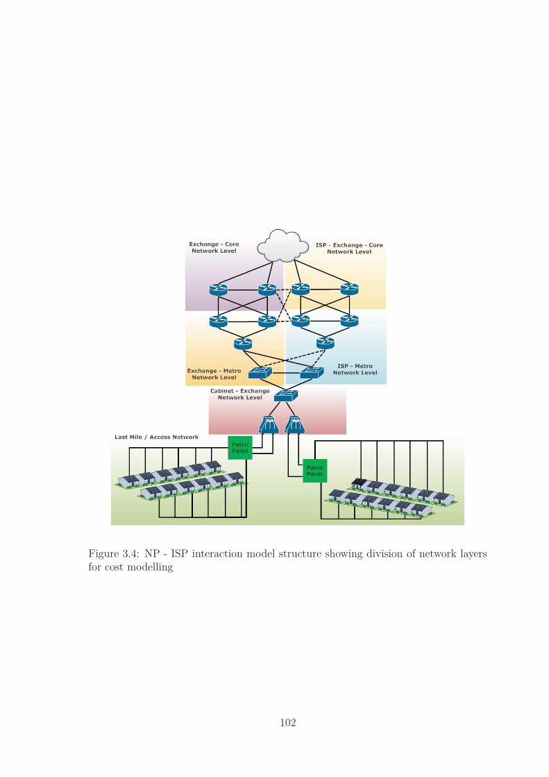
Figure 3.4: NP - ISP interaction model structure showing division of network layersfor cost modelling
102

MI:I Metro to independent ISP connection, ISP section (BMI:I, CMI:I,FMI:I)
CI:N Core to independent ISP connection, NP section (BCI:N, CCI:N,FCI:N)
CI:I Core to independent ISP connection, ISP section (BCI:I, CCI:I,FCI:I)
From the model above we calculate the intra-NP transit costs using equations:
CostCE(3.6), CostEM(3.8); and the cost to independent ISPs through CostLLUO(3.13).
These equations based on the BT IPStream and WBC pricing proposals provide a
variable cost dependent on the levels of the network traversed with the fixed costs
at each level representing the aggregate cost of the static infrastructure. Each of the
basic equations follows a fixed structure consisting of the variable per Mb cost of the
connection paired with the fixed cost of that provision. As can be seen from these
equations the per exchange cost can be kept very low and provide very high effective
bandwidths (> 300Mbps per user) if required however supplying this bandwidth at
higher layers even with a 50:1 real contention ratio through a BT central would give
a yearly cost of approximately 1,300 outside the budget of most families.
Access Layer For the access layer we consider equation 3.6 as the basic cost of
provision. For a standard provision of an Integrated Services Digital Network (ISDN)
line or a fibre line [163] this is reduced by the Openreach pricing structure to a
pair of fixed cost per annum - the Wholesale Line Rental (WLR) or Metallic Path
Facility (MPF) connection (con) cost and the fibre / copper (med) cost as shown in
equation 3.7. Costs for example connections are shown in table 3.1 with the medium
costs for a WLR digital line of £220.00 per annum, or an MPF cost of roughly £100
per annum giving the per Mbps costs shown in table 3.2. Typically these costs will be
borne by BT wholesale and passed on to the purchasing ISP at a fixed rate assuming
a line speed of 1-2Mbps.
CostCE =BW × (CLM + FLM + CCE + FCE) (3.6)
CostCE =(Fcon + Fmed) (3.7)
103

Downstream Upstream Connection Annual Rent40 2 £75 £82.8040 10 £75 £88.8080 20 £80 £119.40100 30 £80 £436.32330 20 £80 £295.32330 30 £80 £619.32
Table 3.1: Openreach last mile fibre costs
WLR MPF40/2 £7.57 £4.5740/10 £7.72 £4.7280/20 £4.24 £2.74100/30 £6.56 £5.36330/20 £1.56 £1.19330/30 £2.54 £2.18
Table 3.2: Openreach last mile fibre costs per Mbps
BT Wholesale IPStream Connection For the pure BT wholesale connection
across the metro and core layer the basic cost equation is shown in equation 3.8. For
a BT Wholesale IPStream provision equation 3.9 shows the price derivation for the
total bandwidth supplied. As shown there is a significant cost reduction achievable on
the BT central pipes when all 4 155Mbps segments are lit across a single central rather
than lighting multiple centrals or leaving segments unlit. The newer WBC connection
type is shown in equation 3.10, though not shown WBC requires an additional leased
line cost between the ISP facility and at least one of the BT nodes which brings its
cost closer to that of the IPStream pricing.
CostEM =dataMb × (CEM + FEM + CostCE) (3.8)
104

CostIPStream =Fport × users+ Fcentrals ×NoPipes+ Fsegments × segments (3.9)
+ Fdistance ×max(0, distance − 40)
CostIPStream =1.25× 12× users+ 160, 000×NoPipes+ 155, 000× segments
+ 2, 000×max(0, distance− 40)
CostWBC =(Fport × 12× users+ Fnodes × 12 + Fcapacity ×Mbps/month× 12)(3.10)
CostWBCFibre =(5.88× 12× users+ 15, 042× 12 + 40, 000× 12×Mbps/month)(3.11)
CostWBCADSL =((13.29)× users+ 15, 042× 12 + 40, 000× 12×Mbps/month)(3.12)
LLU Operator LLU costs are broadly similar to those offered by BT, the basic
costing equation is shown in equation 3.13 with a sample provision by JA.NET shown
in equation 3.14 assuming a 10Gbps ethernet backhaul. This equation is much less
well defined than those of the WBC or IPStream versions and connects only a single
exchange to the LLU operator. As such this variant can become very expensive to roll
out across the 5,000 or so exchanges given the cost of multiple backhaul connections.
CostLLU =BW × (CEIU + FEIU + CostCE) (3.13)
CostLLU = (CBT + FLocalBackhaul + CBackhaul + FBackhaul) (3.14)
CostFullLLU = (86.40 + 25, 750 + CBackhaul)
CostPartialLLU = (15.60 + 25, 750 + CBackhaul)
105

Figure 3.5: ISP - ISP interaction model showing metro / core network in full for threesites
3.2.4.7 ISP - ISP Interaction
For a cross-ISP traffic flow between users or service to a user we consider the costs
to be a two sided flow across the NP network. This connection path is shown in
Figure 3.5. from this model we can build a basic cost equation as shown in (3.15).
Where the ISPs have a direct connection between each other we can simplify this
model to that shown in (3.16). Again there are few conclusions that can be directly
drawn from this model, the ‘best’ solution to the inter-ISP connectivity issue is highly
dependent on the the infrastructure and distance over which data must be sent and
so the correct choice will depend on the particular ISP. We can note that transferring
data over the NP network can be considered the best-worst-case scenario since this
will allow full inter-connectivity at all points provided by the NP where as replicating
this with IX or direct links is likely prohibitively expensive.
106
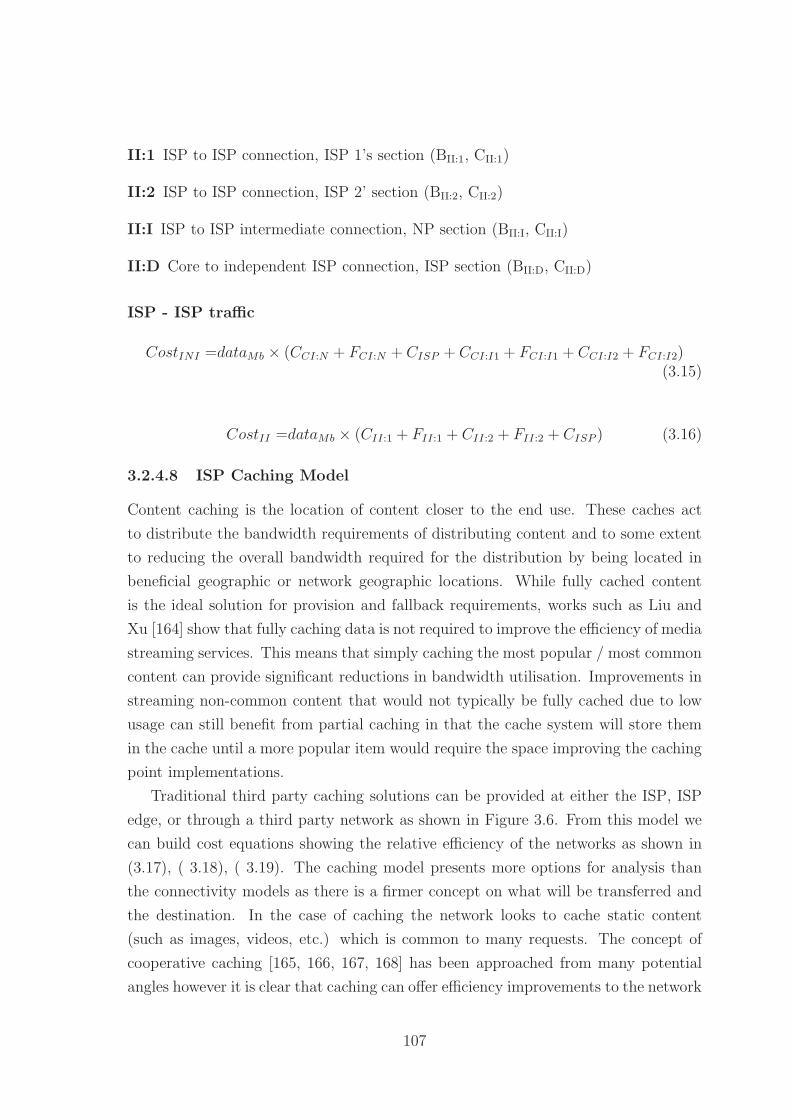
II:1 ISP to ISP connection, ISP 1’s section (BII:1, CII:1)
II:2 ISP to ISP connection, ISP 2’ section (BII:2, CII:2)
II:I ISP to ISP intermediate connection, NP section (BII:I, CII:I)
II:D Core to independent ISP connection, ISP section (BII:D, CII:D)
ISP - ISP traffic
CostINI =dataMb × (CCI:N + FCI:N + CISP + CCI:I1 + FCI:I1 + CCI:I2 + FCI:I2)(3.15)
CostII =dataMb × (CII:1 + FII:1 + CII:2 + FII:2 + CISP ) (3.16)
3.2.4.8 ISP Caching Model
Content caching is the location of content closer to the end use. These caches act
to distribute the bandwidth requirements of distributing content and to some extent
to reducing the overall bandwidth required for the distribution by being located in
beneficial geographic or network geographic locations. While fully cached content
is the ideal solution for provision and fallback requirements, works such as Liu and
Xu [164] show that fully caching data is not required to improve the efficiency of media
streaming services. This means that simply caching the most popular / most common
content can provide significant reductions in bandwidth utilisation. Improvements in
streaming non-common content that would not typically be fully cached due to low
usage can still benefit from partial caching in that the cache system will store them
in the cache until a more popular item would require the space improving the caching
point implementations.
Traditional third party caching solutions can be provided at either the ISP, ISP
edge, or through a third party network as shown in Figure 3.6. From this model we
can build cost equations showing the relative efficiency of the networks as shown in
(3.17), ( 3.18), ( 3.19). The caching model presents more options for analysis than
the connectivity models as there is a firmer concept on what will be transferred and
the destination. In the case of caching the network looks to cache static content
(such as images, videos, etc.) which is common to many requests. The concept of
cooperative caching [165, 166, 167, 168] has been approached from many potential
angles however it is clear that caching can offer efficiency improvements to the network
107
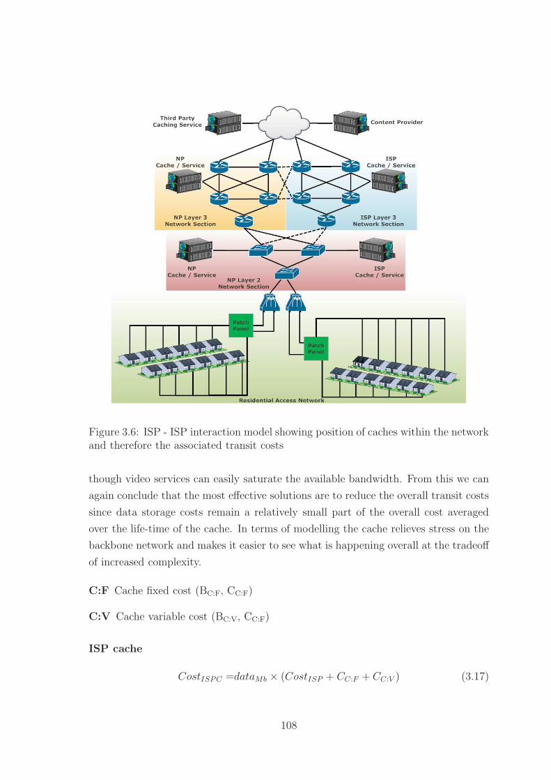
Figure 3.6: ISP - ISP interaction model showing position of caches within the networkand therefore the associated transit costs
though video services can easily saturate the available bandwidth. From this we can
again conclude that the most effective solutions are to reduce the overall transit costs
since data storage costs remain a relatively small part of the overall cost averaged
over the life-time of the cache. In terms of modelling the cache relieves stress on the
backbone network and makes it easier to see what is happening overall at the tradeoff
of increased complexity.
C:F Cache fixed cost (BC:F, CC:F)
C:V Cache variable cost (BC:V, CC:F)
ISP cache
CostISPC =dataMb × (CostISP + CC:F + CC:V ) (3.17)
108

ISP edge cache
CostISPEC =dataMb × (CII:1 + FII:1 + CII:2 + FII:2 + CostISP + CC:F + CC:V )(3.18)
Third party cache
CostTPC =dataMb × (CII:1 + FII:1 + CII:2 + FII:2 + CCC + FCC + CostISP + CC:F + CC:V )(3.19)
3.2.4.9 NP Caching Model
For a NP located cache as shown in Figure 3.6 the cost can be further reduced due to
the more limited number of stages the transfer must take place over, which incidentally
increases the effective bandwidth to an area based on the aggregation ratio at the
points below which the cache is placed. An example of the NP level caching is the
current proposal from BT moving the Cisco content delivery services [169] from the
edge of the network to a location within the backhaul network itself. This solution
moves a caching server within the metro node level of the 21CN network reducing the
overall load on the backhaul network
Metro level caching (3.20) shows a distinctly better cost proposition than that
shown for ISP or third-party caching solutions because of the reduced fixed infras-
tructure costs of transit. This can be further improved by access level caching (3.21)
however this is currently infeasible due to the layer 2 nature of most deployed access
layers - that is to say that it would require an infeasible amount of control and routing
flow management at layer 2 to effectively manage a caching solution as opposed to
the facilities ‘native’ to layer 3 solutions currently available. This failure in capability
is due to the features provided by layer 2 technologies such as Ethernet which do not
consider flow management or Authentication, Authorization, and Accounting (AAA)
but rather attempt to provide best effort transit to all traffic, without these capabil-
ities it is infeasible to deploy a caching system on a layer 2 network invisible to the
host layer 3 network.
Metro level cache
CostMLC =dataMb × (CostCE + CC:F + CC:V ) (3.20)
109

Access level cache
CostALC =dataMb × (CostEM + CC:F + CC:V ) (3.21)
We further consider the effects of the bandwidth aggregation on network caching
in the analysis in Chapter 6 where the cache position is analysed in terms of the
potential bandwidth gains (and therefore potential cost reductions) applied when a
cache is moved down the network hierarchy.
3.2.5 Access Network Model
Within the UK access networks there are multiple standards for fixed line and mobile
broadband services. At the current time the deployment of ADSL and ADSL2+ are
the most commonly available forms of broadband with almost 98% coverage of the
country. These standards are summarised in table 3.3. There are however multiple
forms of last-mile and access layer connection technologies which greatly affect the
ability of the ISP to deliver a high quality product. For most of the country the
deployed access technology is that of copper (or aluminium) wires as either direct
connections to the household from the switch board cabinet or deployed as in a
single / double ring which is far less common. Newer developments have moved
towards fibre to the cabinet (FTTC) to provide more back-bone bandwidth inside
the access layer and some deployments of either fibre to the premises (FTTP) or fibre
to the home (FTTH) to allow future scaling potential without altering the access
layer fabric. These solutions are a likely future option for a large proportion of the
country. As a final technology there are limited deployments of Fibre Data Distributed
Interface (FDDI) single and double rings facilitating fibre connectivity with a reduced
deployment cost as compared to FTTH. These options are shown in Figure 3.7.
The majority of the access layer model does not support active layer 3 routing
but rather acts as a set of layer 2 VLANs which direct traffic to a management point
with the associated ISP. This separation of end point nodes into distinct groupings
rather than a single accessible area serves to allow competition however in so doing
fractures an already small end-node grouping which could be used to provide better
statistical aggregation of traffic and caching efficiency.
It should be noted that the stability of the higher level network sections is far
higher than that of the last-mile connection where studies [170] have shown that
there can be very high variability in terms of the jitter, transmission and routing
delay, and even queueing times associated with the last mile. With this in mind it
is important that a future network attempts to ensure a greater stability within this
110

section of the network in order to improve at least the subjective Internet experience
of users if not the potential performance itself.
The average home connection is a contended solution with a contention ratio typi-
cally around 50:1 with premium and business services offering 20:1 at a corresponding
increase in cost, BT on their IPStream and WBC products typically aim for an ef-
fective contention of 8:1 over 90% of the day - however comparing this to a raw
contention values is difficult without usage traffic for an area. The use of bandwidth
caps as a measure to address network ‘congestion’ has been found to be a very loosely
correlated measure[171] and provides a disincentive to maximise network usage out-
side of peak times when bandwidth that must be provided to cope with peak periods
is less heavily utilised. This contention means the maximum bandwidth provided to
those subscribers is shared between a defined set of users giving an effective continu-
ous bandwidth allocation equivalent to the total bandwidth divided by the contention
ratio. While this contention system works very effectively for non-streaming services
which are typically modelled as a burst transfer section followed by a period of low or
no data transfer, such as web page access, the system quickly becomes deficient when
sustained bandwidths are required for long periods of time. To support a typical 3
Mbps streaming service for each household on an 8 Mbps connection would require
the equivalent of an 18.75 times bandwidth increase. This bandwidth deficiency is
further highlighted by the growth of multi-stream devices and multi-device households
whereby there are multiple active streams at once as well as ‘pre-viewing’ download
streams.
Further to their bandwidth limitations a typical home connection is further limited
by a data transfer cap, typically between 10Gigabyte (GB) and 40GB per month.
While there are products on offer which do not include a monthly data transfer limit
these often still retain a fair use policy which will limit the bandwidth available to a
user if they exceed limits within certain periods of the day - in effect no connection
is sold as offered. The worst case scaling scenario to consider is that of IP services
being utilised as a replacement for broadcast services as this provides a reasonable
upper limit to the requirements of a streaming media service. While it is more
likely that an IP based service acts as the data or additional content component
in a hybrid broadcast / IP service, or as a Video on Demand (VoD) service the
capability of set-top-boxes to hide the source of content means this replacement must
be considered as a viable future option. As such we must consider the monthly
transfer limit on the connection as well as a simple bandwidth analysis. For a 30
minute television programme at 3 Mbps the transfer of 675 MB of data limits a
111

Figure 3.7: Access Network Model showing multiple street level cabinets aggregatingconnections through DSLAMs before being passed into the backhaul network
40 GB capped connection to around 30 hours of streaming per month. This low
per-day usage cap shows that at the current growth ratio of network bandwidth to
usage cap the current system is unsuitable as a sustained VoD system without further
considering it as an alternative to a broadcast media system.
3.2.6 Internet traffic
Since the ‘inception’ of publicly accessible Internet network services in the early to
mid 1990s content provision has been the key to driving the wider scale public ac-
ceptance and expansion of the Internet. Over the last ten years there has been an
exponential increase in the use of streaming services, without the corresponding in-
crease in connection bandwidth required to support simultaneous use. These growth
patterns have been studied over many years and the direct growth of the routing
infrastructure in terms of complexity [172] has led towards a more expensive and less
flexible Internet structure for supporting the efficient economic deployment [173] of
streaming services using both traditional client-server and client-client peering [174]
technologies.
112

Name Download (Mbps) Upload (Mbps) ContentionADSL 8 0.768 50:1
ADSL 2+ 24 1 50:1FTTC 40 18 50:1FTTH 100 40 50:1Cable 50 8 50:1T1 1.544 1.544 1:1T3 45 45 1:13G 0.384 - 2 0.384 - 2 Users / cell:13.5G 1+ 1+ Users / cell:14G 100 - 1000 50 - 250 Users / cell:1
Table 3.3: Sample connection types showing upstream and downstream bandwidthsalongside contention ratios. Data for mobile standards is theoretical and assumes asingle occupancy mobile cell with a user to base station distance of less than 10m fortop end estimates.
There has been concern over the growth of Internet traffic for a long time with
traffic doubling (70-150% growth) roughly every 18-24 months[175, 176, 177] and a
very high growth in mobile device traffic[178]. This has led to many descriptions
of a network unable to handle the traffic flows and data ‘barriers’ to growth [179]
however it can seen that the Internet is expanding to meet both the growth in devices
[180] and traffic flows [181] as needed. The economic viability and feasibility of
further expansion is an issue which must be considered further as future paradigms
emerge [182]. Issues with growth should therefore be focused more on the ability of
the network to provide for future paradigms[183] and unforseen technologies rather
than for current generation traffic flows which tend to follow a cart-in-front-of-the-
horse development in which users do not uptake a technology until there is sufficient
bandwidth for it and it is implemented in a transparent manner[184]. These views
have been challenged however by data from countries like Japan which have a high
level of fibre deployment which should enable higher content volumes. Cho et al [185]
have shown through traffic studies that the traffic growth retains a similar 60% year
on year growth pattern. This can be considered somewhat to be mirrored by that
lack of adoption of high speed fibre based connections in London [186] however the
‘killer’ application is multi-user households. This growth pattern therefore appears
to suggest that the ‘explosion’ in terms of data usage will either be a point which
cannot be forseen at current or it will be in the deployment of transparent Internet
based services such that every household becomes a multi-user household even those
113

with single occupants.
It has been noted recently amidst recent implementations of additional data caps
and legislation over network neutrality that we currently do not gather information
effectively from the Internet[187]. While individual ISPs gather data from their own
networks and third party content providers can monitor content flow there is no
universal data set for analysis of content and traffic patterns that can be used to
inform debate. The structure of the Internet identified above help to obscure the
data gathering potential that exists within the Internet. An additional aim of a
future generation network is therefore to increase the capability for anonymous data
gathering to assist in future analysis.
3.2.7 Traffic Patterns
The patterns within Internet traffic are another interesting issue to consider with the
traditional poisson models for bursty traffic being questionable given the buffer length
in routers and the window framing of Transport Control Protocol (TCP) [188]however
the move towards a streaming media dominated model may make these kinds of
poisson models less accurate over time. It has been suggested that Internet traffic
modelling may be performed more efficiently using fractal models [189, 190]. For
the purposes of modelling the Internet however we are concerned more with the
breakdown of traffic into broad classifications based on source and destination and
the ratio of traffic between these, largely the peer-to-peer (P2P) [191] or client server
models such as Hyper Text Transfer Protocol (HTTP) video streaming [192, 193, 194]
3.2.7.1 HTTP Traffic
HTTP based traffic flows account for between 40 and 60% of all Internet traffic
[195, 196] encapsulating everything from simple static web-pages to streaming media
content. At the current levels of growth around 50% of this traffic is composed of
streaming media services [197]. While it is possible to discuss the exact model for
these flows in terms of distribution, length of session, and data volumes, however the
key factor that interests us in terms of this traffic is that it is largely asymmetric
- traffic flows largely from the server (content provider) to the client (end-user /
service) with some limited feedback. Future service models may move to equalise this
asymmetry as the underlying technology providing the last mile shifts from ADSL
over telephone connections to fibre or ethernet connections. With the large volume
of streaming video traffic it is a reasonable assumption that the majority of HTTP
114

traffic will remain asymmetric, however, there is the possibility that the future data
flows will utilise this symmetric bandwidth.
3.2.7.2 P2P Traffic
Direct peer-to-peer traffic accounts for between 20 and 40% of Internet traffic [198]
and unlike the client-server model of HTTP traffic is inefficiently routed between
ISP management points within the network. It should be noted that the growth in
mobile data traffic has not shown a similar [199] increase in P2P traffic which likely
accounts for the at least part of the recent drop in overall bandwidth consumed by
P2P traffic flows. The effect of P2P traffic is to artificially increase the stretch of the
path taken by P2P traffic as it must flow between ISP management points in order
to be routed back down to the destination end-user. This artificial stretch results
in an increased bandwidth requirement for the traffic flow and more importantly a
breaking of the asymmetric nature imposed by ADSL connections. It has yet to be
seen whether P2P traffic will remain a large component of Internet traffic or whether
content management systems will allow a more ‘natural’ client-server flow to resume.
3.2.7.3 Other Traffic
The growth in other traffic has been in a large part limited by the ubiquitousness
of firewalls and packet flow prioritisation services which have penalised traffic which
does not flow over the common HTTP port 80. This has created a rush towards
further inspection and flow management techniques to enable the classification of
traffic within HTTP packets. It is likely that a future Internet should attempt to
break this model by providing a better end-to-end QoS model whereby traffic is not
penalised for existing outwith the HTTP / port 80 pairing.
3.2.7.4 Streaming Traffic Growth
Within streaming media we are concerned with two primary forms of continuous
streaming - audio, and video. Of these two forms it is video that is of the highest
concern as even very high quality audio streams typically achieve a maximum rate of
192kilobits per second (kbps) while streaming video at its lowest typical bandwidth
is greater than 200kbps. Streaming video media services began with very low res-
olutions and high levels of compression to enable them to be usable over the then
typical 0.5 Mbps or lower broadband offerings in the UK. With the growth of connec-
tion speeds advertised as ‘up to 8 Mbps’ and beyond, the expected quality of these
services has risen in line with the available bandwidth; reaching the same level as
115

Name Resolution Video BW (Mbps) Audio BW (Mbps) Audio Channels240p 320x240 0.25 64 1320p 480x320 0.5 64 1640p 960x640 1 128 2720p 1280x720 3 196 2+1080i 1920x1080 5 364 2+1080p 1920x1080 8 364 2+2048p* 3860x2048 12 364 2+4096p* 6154x4096 16 512 2+4k 4000x2000 8+ 128 2+
Table 3.4: A selection of streaming media standards breaking down their associatedvideo and audio bandwidths showing the massive growth in minimum required band-widths. Audio channels represented as 2+ represent standards supporting surroundsound and lossless audio formats which utilise up to 8 channels per audio stream.
‘high definition’ TV standards. Table 3.4 shows a cross section of standards that
have been or will be utilised for streaming media services. As can be seen the video
bandwidth requirement has increased significantly for compressed video standards
however it remains relatively low compared to the distribution standards for storage
media; for example Blu-ray which offers 54 Mbps combined audio, video, and data
bandwidth. The inclusion of data bandwidth within storage formats is important
to consider for future scaling concerns as it alludes to potential ‘in channel’ data
services which represent a usage concept not yet applied to typical streaming media
services. Integrating data streams into content distribution is therefore a potential
future requirement for streaming media services and so its impact must be considered
in future scaling concerns.
The required bandwidth for high definition streaming services quickly approach
and exceed the ‘up to 8 Mbps’ connection speeds offered as general extra-urban broad-
band within the UK; dense urban areas supporting ADSL2+ connections, offering the
fastest Digital Subscriber Line (DSL) connection speeds of ‘upto 24 Mbps’, can still
only support between 3 and 8 concurrent uncontested streams at the headline rate.
The availability of headline rates is often limited with DSL services achieving be-
tween 30 and 70% of their headline rate [200] and cable or fibre services offering 60 to
80%. This ‘effective’ rate further reduces the capability of these services to provide
multi-user support for streaming services.
116

3.2.7.5 Future Trends in Streaming
As of 2010 streaming media services have yet to replace conventional broadcasting for
the majority of the population however the number of users has been growing at an
exponential rate for several years. This growth is likely to increase as these services
move from direct end user interactions (pull services) towards a ubiquitous model
(push) as they are integrated seamlessly into set top boxes and television services
masking the differences between broadcast and streamed content. This ubiquitous
model is likely to include much more support for peer-to-peer supported services [201,
202] however the current distribution architecture of the Internet does not make peer-
to-peer services efficient in terms of overall bandwidth usage.
As was demonstrated by the 2010 World Cup matches the core network of the UK
has support for less than 800,000 simultaneous unicast connections to a service like
the BBC iPlayer without significant degradation in both service and network qual-
ity. Such events indicate that for full streaming media support the network needs to
have a massive scaling potential, ideally as a fixed limit on the distribution require-
ments. Flash events like this also highlight the importance of locality [203] in video
on demand and live streaming models whereby the spread of users can be represented
as a set of geographically linked points from the perspective of the underlying ac-
cess networks providing the media streams and used to identify economically viable
placement locations for intelligent caches.
The current trend towards IP video as a broadcast support service is likely to
increase in the future as shown by the recent provision of new ‘catch-up’ services
including BT Vision, and Sky Anytime+.
BT Vision BT Vision was the first large scale deployment of an IPTV service by
an ISP and allows movie and television content to be viewed over a BT Internet
connection. The connection maintains some prioritisation over non-BT-Vision traffic
via their own set top boxes. The service is not available as a generic application.
Sky Anytime+ BSkyB in contrast to BT Vision released Sky Anytime+ to inte-
grate with their existing network of set-top-boxes to enable the download (over IP)
of a large amount of their back content and recently viewed content. This service
is backed up by a generic application that allows certain channels and content to
be viewed on other non-secure platforms. This move has indicated a real growth
towards on-demand media streaming as a replacement for TV services as content is
117

made available as soon as it can be downloaded to the user with no pre-planning
required beyond the download time.
Streaming Media as a replacement for Broadcast While streaming media
cannot currently compete with broadcast solutions it does make a very important
contribution to user-friendly on-demand or ‘catch-up’ services by enabling a subset of
the content to be delivered as needed. The growth in content availability and delivery
times suggests that in the near future it will be possible to provide a complete TV
service over IP without a broadcast backup. The scaling issues around this however
would require significant network support and a move away from the unicast model
of content distribution. It is unlikely that an IP solution will effectively replace
broadcast TV in the short term, the availability of caching and bandwidth is likely
to make this possible freeing up spectrum for us in wireless connectivity solutions
such as the white-space radio services. Considering a service such as Sky satellite TV
there are approximately 550 TV channels with 88 radio channels. Assuming a 3Mbps
stream (720p) for each channel with naive advertising solution and no replication
of content we would require approximately 1.7Gbps of connectivity to stream these
channels, removing channel duplication and assuming a 45 minute programme with 15
minutes of adverts with a 3:1 replication rate we can effectively reduce this to 1.3Gbps
(50 channels of duplicated content either through +1 or prior broadcast as a low end
estimate). For a full day of content this is approximately 20 TB of content (and
intra-day reductions of traffic will reduce this further) which could easily be stored
in an end point caching system in a 2-4U rack, and a 1U system within 5 years.
This trend is further driven by recent attempts by Governments to free up broadcast
network frequency ranges for use in mobile networks. This motivation combined with
the capability to provide usage and billing information makes it highly likely that the
future will hold a significant move towards IP based TV services.
True Future Trends We have seen over recent years the growth of streaming
media and broadcast TV in high definition quality, following this trend it is likely
that we will see higher resolutions and qualities becoming available in the future and
technologies such as over-the-air 3D TV. These improvements are likely to ensure a
further growth in streaming media bandwidth requirements for at least the next 5-10
years of Internet growth.
118

3.2.8 The cloud
During the research period of this work there has been a significant rise in ‘cloud’
based services which offer centralised and scalable computing and storage services to
end-users. This rise is further support for the provision of services within the network
as users require access to significant computing resources for short periods of time
that make purchasing bespoke hardware inefficient. Additionally the capability of the
cloud services to provide redundancy and move large volumes of data in a scalable
way makes this a major growth area for future networks. While this work is primarily
concerned with the effect of distributed services on the network, it is important to
understand what types of services are being offered through cloud models and from
that what network features are important to this development.
Cloud services have been utilised to provide growth to companies such as Netflix
and Facebook providing instantaneous scalability to these services that would other-
wise delay or hinder users. As these services expand they become more geographically
localised with this geographic locality being a selling feature to the providers. Real
time cloud services, such as On-Live, represent potential future processing services
allowing end-user computing power to scale beyond the typical desktop or laptop
system. These type of services allow users to access specific services such as graphics
processing hardware through a simple subscription service. The geographic location
of these services is very sensitive due to the speed of light limiting the distance a
cloud service can be from the end user before the round trip latency is too high for
real-time applications. Each of these growth areas indicate a strong geographic link
between cloud services and user access with non-localised sites providing additional
redundancy to localised resources.
3.2.9 The Role of the ISP
In the ‘original’ Internet model the ISP undertook the role of a physical network
provider providing hardware and telephony interconnection to the end user in a mar-
ket where there were few competing options. The development of dial-up connectivity
altered this role significantly allowing many new ISPs to enter the market offering
‘over-the-top’ connectivity services over providers’ networks however with their own
‘walled-garden’ of curated services and web-pages. The advent of ISDN and DSL
services eroded this walled garden environment as users began to move beyond the
curated Internet model towards a more service orientated architecture. This loss of
curated services reduced the capability of ISPs to differentiate their services beyond
119

pure price differentiation and limited ‘services’ understood by the average consumer.
The drive in early years of the 21st century to advertise ADSL services on their top
synchronisation speed (advertised as ‘up to x Mbps’) further eroded this capability.
In the modern Internet structure it is increasingly difficult for non-physical network
providing ISPs to actively differentiate their products. There have been alterations
in the way in which services are offered including non-Internet service related factors
- e.g. ‘UK based call centres’ - and the return of walled garden style environments
through the provision of non-capacity consuming services - e.g. Netflix through XBox
on certain US Internet providers.
As these alterations over time have shown there is no clear place or position
within the Internet system for the ISP that does not physically own and provide a
physical network service as they are at the mercy of the market for price controls. It
is therefore likely that the future of ISPs lies in the recreation of the walled garden
style environment through the provision of services to the user in a simpler and more
convenient manner similar to the environment found in cable or satellite networks.This
bundling of services allows ISPs to regain some of their differentiating factors without
forcing a change in the wholesale market. Within Hierarchical Network Topographical
Routing (HNTR) specifically the role of the ISP is envisioned as being comprised
primarily of a billing and identity service with differentiation based on the style and
provision within these with a secondary focus on the development of service packages.
By tying together identity management and service provision it becomes possible
to easily provide differentiated services such as ‘child friendly Internet’ on one sub-
account by routing traffic through the ISP and filtering while work traffic on a different
sub-account is routed directly to the work site / Virtual Private Network (VPN)
provider.
3.3 Next Generation Network Requirements
While there is no universal set of standards or requirements for a next generation
network there are multiple Internet focused groups that have produced industry sup-
ported visions of the next generation Internet. Considering the International Telecom-
munications Union (ITU) [204] which focus on service provision, and the Internet En-
gineering Task Force (IETF) routing research group / Cisco Systems [205] work which
focuses on routing requirements we can produce a set of common requirements and
desirables for a next generation network in terms of routing and traffic engineering.
120

3.3.1 Routing Requirements
• Routing scalability
• Traffic engineering
• Multi-homing
• Simplified internal renumbering
• Modularity, composibility, seamlessness
• Routing quality: convergence, stability, stretch
• Location and identification split
• Scalable mobility support
• Routing security
• Deployability
3.3.1.1 Routing Scalability
This requirement addresses the inter-domain routing growth that has occurred as the
Internet has become more widely supported and interconnected. The BGP routing
information growth and IP routing table growth combine to require information to
be carried at multiple levels with no / little benefit to the networks that are carrying
the data between administrative blocks. Further this point attempts to split the end-
user / node growth from the routing table scaling. This requirement indicates that a
future network system must offer support for ’regionalisation’ allowing traffic routing
to be performed in a manner which allows routes to be resolved on a more localised
basis as would be performed on a geographic map identifying the City and Country
only.
3.3.1.2 Traffic Engineering
Traffic engineering under IP based networks is typically represented by the creation of
more specific prefixes into the routing tables to enable traffic to flow in non-standard
routes through the network. Applying this process to the global routing tables results
in further scalability issues. It is a requirement therefore to provide a mechanism ei-
ther transparently or explicitly to network engineers to enable explicit traffic rerouting
in a scalable manner in accordance with the routing scalability criteria.
121

3.3.1.3 Multi-homing
This represents the capability of an organisation to provide multiple prefixes in the
global routing tables to represent either route diversity, connection redundancy, or
site diversity. This increase in non-aliased address prefixes further contributes to the
routing scalability issue. A mechanism must therefore exist such that address prefix
diversification can be provided without the increased load that is imposed to support
it currently.
3.3.1.4 Simplified Internal Renumbering
Under current IP arrangements most organisations do not own their own IP blocks
but rather have their address space provided by their current ISP. This therefore in-
curs a cost if / when the ISP is altered unless the internal network is hidden behind an
address rewriting proxy system to map an internal network to the new address space.
An addressing scheme which supports address space renumbering or has automated
support to enable renumbering is therefore a major benefit to a future Internet archi-
tecture as it reduces the opportunity cost of ISP switching allowing a (theoretically)
more efficient marketplace for provision.
3.3.1.5 Modularity, Composability, and Seamlessness
This requirement presents the issue that a new network architecture will not be rolled
out in a single wave - there is little option for a flag day in the current situation.
The network should therefore be composed of sections that can be deployed in a
modular and self-contained fashion and provide any transition mechanisms such as
tunneling in a transparent manner such that edge cases are not prevalent during the
deployment process or during combined network operations. This requirement should
be compared against the IP version 6 (IPv6) roll out [206] which has been ongoing
for many years and has yet to really gain traction amongst consumers and many
businesses [207]. This indicates strongly that the roll out strategy must include a
default method for determining what facade to present to the wider Internet - the
newly deployed technology or a compatibility mode to ensure connectivity.
3.3.1.6 Routing Quality
This addresses the point that a future network solution should not provide substan-
tially worse performance than the current Internet in terms of convergence times,
122

network stability, or path stretch. This means that a solution for the future Inter-
net cannot be universally centralised - it must support distributed functionality and
routing through the nearest authoritative point in the network.
3.3.1.7 Location and identification split
The split of location and identification of end-hosts has been identified as a major
issue for next generation networks and has some deployed functionality on current
networks. This issue is further confused though by the (potential) requirement to
separate the global routing system from the site routing system. As both of these
scenarios are envisioned as being appropriate and important it is therefore vital that
the location identification split is supported and supports the potential global:site
location split to improve routing scalability.
3.3.1.8 Scalable mobility support
Mobility support approaches considered in the previous chapter can be considered in
terms of node renumbering, tunneling, or new prefix announcement. Each of these
solutions presents a different routing issue that must be addressed in order to provide
support for mobility in a way that scales with the network. This point ties heavily into
the location and identifier split and routing scalability allowing nodes to be mobile
without an adverse impact on the network routing scalability or traffic path.
3.3.1.9 Routing security
A next generation network must be at least as capable of current generation networks
of supporting security protocols that are currently deployed and should present a more
secure platform for future use where appropriate.
3.3.1.10 Deployability
As the final point the network must be deployable in a real world context. This means
that it cannot ignore routing capabilities that are in use today such as policy based
routing. While the network can offer a different perspective on routing it must be
flexible enough to support classic routing paradigms during transition.
3.3.2 Service Requirements
Unlike the routing based requirements the service requirements identified by the ITU
present functions that are required by network providers, or should be provided to the
123

end user of the system to improve their Internet experience. The major functionality
issues presented can be summarised as follows.
• Packet based transfer
• Separation of control and data functionality
• Separation of service provision from transport functionality
• Service building blocks
• Quality of service provision (end-to-end)
• Interworking with legacy networks
• Generalised mobility
• User access to multiple service providers
• End user transparency of service
3.3.2.1 Packet based transfer
A next generation network must provide support for packet-based transfer of data to
provide legacy support and to allow for the efficient use of the network. The specific
implementation of the network is left undefined as long as a packet-based interface is
provided to service users for transparent transport over the network.
3.3.2.2 Separation of control and data functionality
The growth of networks has presented issues for large networks when the number of
routers within the network exceeds the possible number of addresses on even a class
A address space (16 million devices). It is therefore important to provide scalable
support for large network management and to separate the data plane from this
control plane in order to prevent data based attacks on the network from affecting
the overall health of the network.
124

3.3.2.3 Separating service provision and transport functionality
This point focuses more on regulatory issues than explicit technical requirements due
to the ability to share common infrastructure being a typically Government controlled
competition issue rather than a technical limit of the network. We can however take
from this the condition that the ISP providing service to the end-user should not
necessarily dictate the services or transport of data to that user. That is to say that
data and services can be aggregated in an efficient cross-ISP way without explicit
consent if it is advantageous for the end-user of NP to do so and the cost of doing so
would not exceed that of the regular transport costs.
3.3.2.4 Service building blocks
Service building blocks represent a major departure from currently deployed archi-
tectures - there is no common and easy way to deploy a service or infrastructure for
a service closer to the end-user without explicit negotiation with the NP to acquire
at a minimum rackspace in their facility. By creating a system similar to that of a
web-hosting provider or data-centre whereby services can be purchased in terms of
storage capacity, processor usage, and network usage it gives service providers the
flexibility to deploy client facing services to any ‘service point’ within the network
without extensive negotiation. This would mean that an end-user travelling to a
different country could automatically perform the negotiation and setup of a ‘UK
television cache’ in advance to enable cost / bandwidth efficient streaming in their
new location. Taking this example at a baseline the user contacts the content provider
/ service provider and indicates the duration and location of travel alongside the con-
tent they wish to push to the target location, under ideal circumstances (non-full
cache, unused Internet bandwidth overnight) this content is pushed at the appropri-
ate time for free, or under less ideal circumstances for a negotiated cost that can
be determined in advance due to the provision of service blocks. In these cases the
network is making intelligent trade offs between the user pulling content across the
network at view time against the capability to pull it at a network suitable time. By
a similar process service caches can co-operatively pull / push content to appropriate
locations, as an example the 2010 World Cup final could be streamed (in multiple
languages) to caches around the world cooperatively rather than flooding the network
with unicast streams.
125

3.3.2.5 Quality of service provision (end-to-end)
Quality of service provision is, at current, a ‘hit or miss’ proposal with no secure and
trusted method to setup end-to-end QoS (again) without explicit negotiation of the
service with service providers along the routing path. While some movement has been
made towards the pre-allocation of bandwidth and a charging model for this under
the BT 21CN model there appears to have been little progress. In combination with
the service building block model it is clear that a premium service could / should
be able to be deployed and managed in a simple autonomous way again providing it
does not go over certain network defined cost limits, a service to provide this kind
of guaranteed bandwidth has been deployed on the BT WBC network through the
the assured service service [208] however there is no automated management of this
facility.
3.3.2.6 Interworking with legacy networks
As IPv6 deployments have found the difficulty in operating in a world with a pre-
deployed network is vast when considered in terms of physical hardware and customer
mind set. To this end and in concurrence with the routing requirements of deploya-
bility, modularity, composability, and seamlessness it is clear that a next generation
network must maintain a transparent method of interactivity with existing network
architectures.
3.3.2.7 Generalised mobility
The difficulty in providing mobile nodes has already been discussed under both the
background and the routing requirements however from a service perspective the cost
and time for a node to move (up to 5 days to provision a phone line and 7 days to
enable broadband in the UK) physically is an undue and pointless issue. End-point
connections should be able to move across networks and have their connection remain
active rather than a connection being tied to both an identity and a location.
3.3.2.8 User access to multiple service providers
This point again considers the regulatory issues of the Internet, and requires the NP
to not restrict or artificially degrade the performance of competing services (though
it allows for increased service through QoS mechanisms) across its network. That is
to say that a video streaming service should receive the same baseline service as one
owned by the ISP or NP and should not be inaccessible. In essence packets must
126

be treated as equal unless there is a requirement not to (QoS), or the end-user has
requested a different priority level for their traffic.
3.3.2.9 End user transparency of service
This final point is key to both the generalised mobility and user access to multiple
service providers - the user should not need to be explicitly aware of how their service
is managed or provided but rather they receive the same service (subject to physical
limitations) irrespective of the underlying NP or SP.
3.3.3 Network Intelligence
From the routing requirements and especially from the service requirements for a
next generation network it is clear that a network with little internal intelligence
is not suitable for the future growth potential of the Internet. From the models
created of both caching and transit services it becomes clear that there is a drive
within the current Internet ecology to implement at least some intelligence within
the network. As the processing power of network devices increases with time it
is likely that more of this intelligence can be shifted into the network and away
from centralised management nodes. This has the added benefit of allowing a more
distributed control system as well as highlighting the infeasibility of maintaining the
current end-user divisions amongst network providers. To enable true transparency
to the end user the ability to be able to provide a service, and the related efficiency of
that service, should not solely be based on the ISP they are contracted with but rather
than infrastructure and Internet usage ecology around them. That is to say that an
improvement in service provided to one subset of users on a network branch should
provide some improvement to other users on the same network branch if they are
accessing the same content. This model of increased distributed intelligence coupled
with group service improvements allows us to finally consider the basis for a next
generation network platform in terms of intelligent caching and service provision, and
the real world deployability and composibility of the network.
3.3.3.1 Intelligent Caching
Intelligent caching and data recovery within a network is a well researched area and
leads into many next generation network projects using current technologies and
strategies [209, 210] as well as more diverse and exotic techniques [211]. as well as the
proposed Internet of Things [212]. The development of content centric networking
127
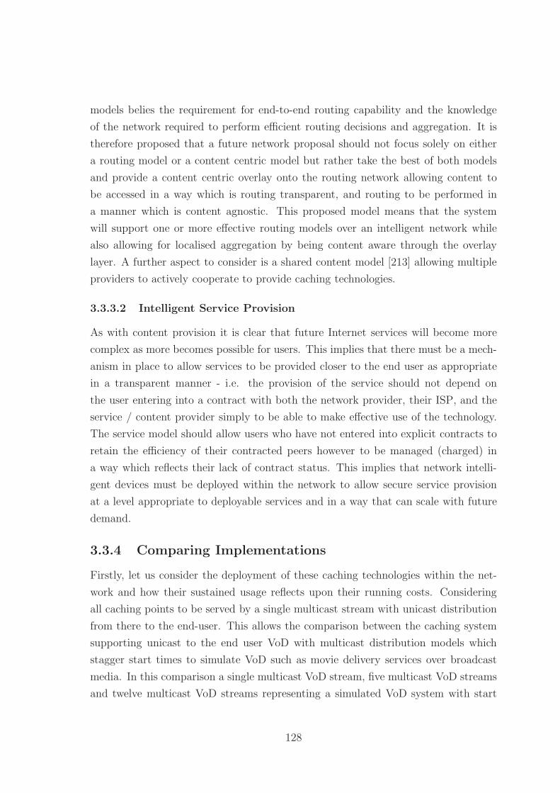
models belies the requirement for end-to-end routing capability and the knowledge
of the network required to perform efficient routing decisions and aggregation. It is
therefore proposed that a future network proposal should not focus solely on either
a routing model or a content centric model but rather take the best of both models
and provide a content centric overlay onto the routing network allowing content to
be accessed in a way which is routing transparent, and routing to be performed in
a manner which is content agnostic. This proposed model means that the system
will support one or more effective routing models over an intelligent network while
also allowing for localised aggregation by being content aware through the overlay
layer. A further aspect to consider is a shared content model [213] allowing multiple
providers to actively cooperate to provide caching technologies.
3.3.3.2 Intelligent Service Provision
As with content provision it is clear that future Internet services will become more
complex as more becomes possible for users. This implies that there must be a mech-
anism in place to allow services to be provided closer to the end user as appropriate
in a transparent manner - i.e. the provision of the service should not depend on
the user entering into a contract with both the network provider, their ISP, and the
service / content provider simply to be able to make effective use of the technology.
The service model should allow users who have not entered into explicit contracts to
retain the efficiency of their contracted peers however to be managed (charged) in
a way which reflects their lack of contract status. This implies that network intelli-
gent devices must be deployed within the network to allow secure service provision
at a level appropriate to deployable services and in a way that can scale with future
demand.
3.3.4 Comparing Implementations
Firstly, let us consider the deployment of these caching technologies within the net-
work and how their sustained usage reflects upon their running costs. Considering
all caching points to be served by a single multicast stream with unicast distribution
from there to the end-user. This allows the comparison between the caching system
supporting unicast to the end user VoD with multicast distribution models which
stagger start times to simulate VoD such as movie delivery services over broadcast
media. In this comparison a single multicast VoD stream, five multicast VoD streams
and twelve multicast VoD streams representing a simulated VoD system with start
128

Figure 3.8: Graph showing the cumulative distribution cost for delivering streamingcontent to users over 3 Mbps streams. Video on demand streams represent multi-streaming the same content in either 1 hour, 12 minute, or 5 minute intervals tosimulate the deployment of staggered start media services such as Sky Box Officeservices
intervals of 60, 12, and 5 minutes respectively. The graph in Figure 3.8 shows that
caching solutions will perform worse than a single VoD service due to the distribution
architecture, but shows significant improvement in performance for sustained access
over time to content even over unicast connections. Moving the caching systems to
offer multicast support over the access network then these results should improve
even further.
As can be seen from the cross over points in Figure 3.9 the cost of a caching
solution is very low in terms of absolute peak bandwidth reduction required to provide
a cost reduction over the unicast solution. The further within the network the cache
is placed the lower the cost scaling is for that model. These disregard the initial
cost of distribution to the caching points as this cost will remain constant across all
distribution models.
129

Figure 3.9: Graph showing the potential costs of deploying streaming services basedon the number of sequential users of a single stream
130

3.4 Next Generation Network Model
From the above work a working statement can be produced for the creation and
evaluation of a next generation network architecture to be deployed with the intent
of improving Internet routing capabilities, providing deployability alongside the ex-
isting Internet, and providing a mechanism to support intelligent network services.
Underlying many of these structures is the simple fact that knowledge is an approx-
imation for power [214] - without knowledge of the network topology and the traffic
currently on the network it is difficult to provide improved routing and traffic flow
capabilities. The requirements for a baseline next generation network can therefore
be broken down into three key areas of evaluation: routing model, service model, and
caching model, with the primary requirements of the network addressed as shown.
• Scalability (in terms of)
– Global routing
– Localised routing
– Site routing
• Traffic Engineering
– Alternate routing
– Multi-homing
– Policy based routing
– Localised routing capacity
• Site-level control
– Multi-homing
– Renumbering
– Modularity
• Quality
– Quality of service provision
– Security provision
– Minimised additional route loading
131

• Identity and route management
– Identity and location split
– Mobility
– Deployability
3.5 Conclusions
This chapter of this thesis has presented an overview of the current UK Internet
structure and those of similar wholesale based network / backbone countries and how
these networks can be modelled as a simple self-similar2 hierarchical three layer model
providing a tiering structure and approach to constructing a next generation network.
From current growth patterns and service requirements a list of the requirements for
a next generation network have been composed. Given the historic dominance of
BT within the UK telecommunications market the UK Internet makes an ideal case
study for the single large wholesale provider model. Linking this single provider to
the commonality within the structure of the Internet network architectures presented
by the major networks suggests that applying a geographical and topographical link
to the routing network would be beneficial in terms of service provision. The artifi-
ciality of the AS system within this kind of wholesale network can be better addressed
through different control models where there is shared information on content, usage,
and flow control to actively assist in improving the network service for all users. The
limitations imposed on the network in regards to multicast are unlikely to be lifted
as long as the network is viewed as being partitioned in a fixed and non-fluid way
where ISPs compete based on bandwidth and price. It is therefore suggested that
this model needs to be revisited and a better, more coherent, manner of competi-
tion is devised which allows ISPs to compete without sacrificing the stability and
sustainability of the underlying network. The next chapter builds upon this model
looking at the structure of a proposed next generation network structure designed to
provide improved localised routing and network topographical information to allow
for improved knowledge and structure within routing algorithms.
2Self similar in that each part of the network can be constructed as a core / distribution / accessnetwork for company, ISP, and wholesale networks
132

Chapter 4
Hierarchical NetworkTopographical Routing
4.1 Introduction
This chapter proposes a new routing scheme, Hierarchical Network Topographical
Routing (HNTR), it introduces the addressing, naming, and identity scheme used
within HNTR and the technical aspects associated with these tasks. This network
structure is designed as a next generation network either alongside or replacing the
current Internet Protocol (IP) based Internet structure. The work looks at common
network topographies within Local Area Network (LAN) and Wide Area Network
(WAN) environments before looking at the interconnection of these structures into
network level Autonomous Systems (ASs), and subsequently the Internet level ASs.
From these structures real world implementations of these networks are considered
from the perspective of the United Kingdom (UK) broadband Internet network with
the HNTR addressing scheme applied to a realistic network model to demonstrate
feasibility. Address space usage and management as well as an integrated services
model are subsequently considered as tools for assisting with and providing network
traffic management and policy control.
4.2 Common Network Topographies
Before considering the addressing and routing of a network it is important to under-
stand the underlying topologies of the network as well as the structures created when
these are combined to form a larger network. Figure 4.1 shows the seven common
network topologies and adds the linked tree structure common in real world networks
133

while omitting the star topology as a special instance of a tree topology. Each topol-
ogy shown requires knowledge of the directly connected nodes’s identities to route
between linked nodes and either a forwarding identity or aggregatable identity to
route to non-connected nodes. The knowledge required to route to a LAN of even a
few thousand nodes interconnected in a non-hierarchical configuration becomes very
memory intensive if each node must be aware of all nodes in the network. Protocols
that maintain a full network map are in use through the Router Information Proto-
col (RIP) [215] and RIPv2 [216] for Internet Protocol version 4 (IPv4) and RIPng [217]
for IP version 6 (IPv6) routing protocols. The large routing table required for a full
network map is typically mitigated by splitting the network into sub-areas with map-
pings to connected areas. The implication of this network sub-area creation is that
of a hybrid approach consisting of localised routing areas combined with a higher tier
connectivity model consisting of ‘blocks’ of networks to allow for bounded (limited
horizon) computation of routes. This model of sub-areas delineating a Network Level
Autonomous System (NLAS) is the current and likely evolution of a routing system
which is non-hierarchical and not geographically linked, these NLAS can then be com-
bined into a fully AS. This network division divides routing protocols into Interior
Gateway Routing Protocol (IGRP) and External Gateway Routing Protocol (EGRP),
first we consider IGRPs.
Interior Gateway Routing Protocol IGRPs can largely be divided into two
types: distance metric protocols such as Enhanced Interior Gateway Routing Pro-
tocol (EIGRP) and link state protocols such as Open Shortest Path First (OSPF).
The first category is concerned with aggregating neighbouring routing tables limiting
the effective horizon of a hierarchical network to one - directly connected nodes are
assigned to forward packets to non-connected nodes so the connectivity graph is lim-
ited to the fan-out of the device. The second type of protocols are concerned with the
state of the whole NLAS and so tend to subdivide the network to create artificial sub-
horizons. All of these protocols benefit from the hierarchical assignment of addresses
to minimise the redistributed identities through address aggregation. Each of these
networks can be represented as a tree structure using their individual connectivity
methods to generate routing paths, typically with either external connected nodes or
management nodes as the root of the tree. These trees will of course be non-idealised
due to internal loops or mesh sections within the NLAS which must be converted to
a tree-consistent model. These structural features are largely unavoidable, however
134

(a) 4 node full mesh network (b) 4 node partial mesh net-work
(c) 4 node uni-connection ring (d) 4 node multi-connectionring
(e) 4 node tree structure (f) 8 node linked tree structure
(g) 4 node line structure
(h) 4 node bus structure
Figure 4.1: Figure showing the 8 common network connection structures.
135
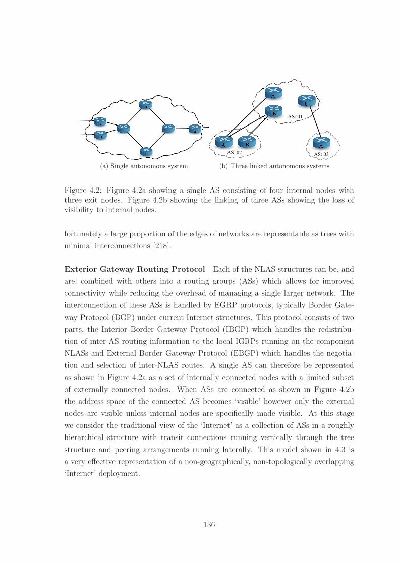
(a) Single autonomous system
AS: 02
AS: 01
AS: 03
(b) Three linked autonomous systems
Figure 4.2: Figure 4.2a showing a single AS consisting of four internal nodes withthree exit nodes. Figure 4.2b showing the linking of three ASs showing the loss ofvisibility to internal nodes.
fortunately a large proportion of the edges of networks are representable as trees with
minimal interconnections [218].
Exterior Gateway Routing Protocol Each of the NLAS structures can be, and
are, combined with others into a routing groups (ASs) which allows for improved
connectivity while reducing the overhead of managing a single larger network. The
interconnection of these ASs is handled by EGRP protocols, typically Border Gate-
way Protocol (BGP) under current Internet structures. This protocol consists of two
parts, the Interior Border Gateway Protocol (IBGP) which handles the redistribu-
tion of inter-AS routing information to the local IGRPs running on the component
NLASs and External Border Gateway Protocol (EBGP) which handles the negotia-
tion and selection of inter-NLAS routes. A single AS can therefore be represented
as shown in Figure 4.2a as a set of internally connected nodes with a limited subset
of externally connected nodes. When ASs are connected as shown in Figure 4.2b
the address space of the connected AS becomes ‘visible’ however only the external
nodes are visible unless internal nodes are specifically made visible. At this stage
we consider the traditional view of the ‘Internet’ as a collection of ASs in a roughly
hierarchical structure with transit connections running vertically through the tree
structure and peering arrangements running laterally. This model shown in 4.3 is
a very effective representation of a non-geographically, non-topologically overlapping
‘Internet’ deployment.
136

AS: 01
AS: 02 AS: 03
AS: 05
AS: 04 AS: 06
'Internet'
Transit
Peering
Peering
Transit Transit
TransitTransit Transit
Figure 4.3: Figure showing the interconnection of ASs with transit and peering con-nections indicated. Further interconnections are represented generically as ‘Internet’indicating that there is no single contiguous backbone or core AS
4.2.1 Tree-consistent Model
As noted above it is largely impractical to consider a real world network purely in
terms of a tree structure due to the presence of routing loops and multiple path replica-
tion requirements including redundancy, replication, load balancing, and connectivity.
Unfortunately representing a naming or routing scheme in a non-hierarchical manner
results in an increased knowledge requirement to determine where a particular loca-
tion is as location is divorced from path, this can be corrected using a tree structure.
A tree structure however does offer the best ability to automatically generate rout-
ing identities, location information, and paths since there is only a single route to
each node. We therefore want to imbue the network structure with a routing model
which is tree-consistent, meaning that we can provide route and location aggregation
by forming paths through the network that are hierarchically based on the network
topology. As with spanning tree protocols the aim of this tree consistent model is not
to make alternate routes truly invalid but to provide a simpler, more parsable net-
work model with no routing loops. This model of course encounters issues in terms of
redundancy, replication, and load balancing. We therefore must consider automated-
rerouting similar to that provided by IGRP protocols on the network level such that
NLAS units restructure the paths between them as appropriate while retaining the
overall view of a single routing tree, or through the provision of virtual network nodes
which actively present a tree structure to other NLAS units while providing an in-
ternal structure of their own choice. Drawing from real world geography we typically
137
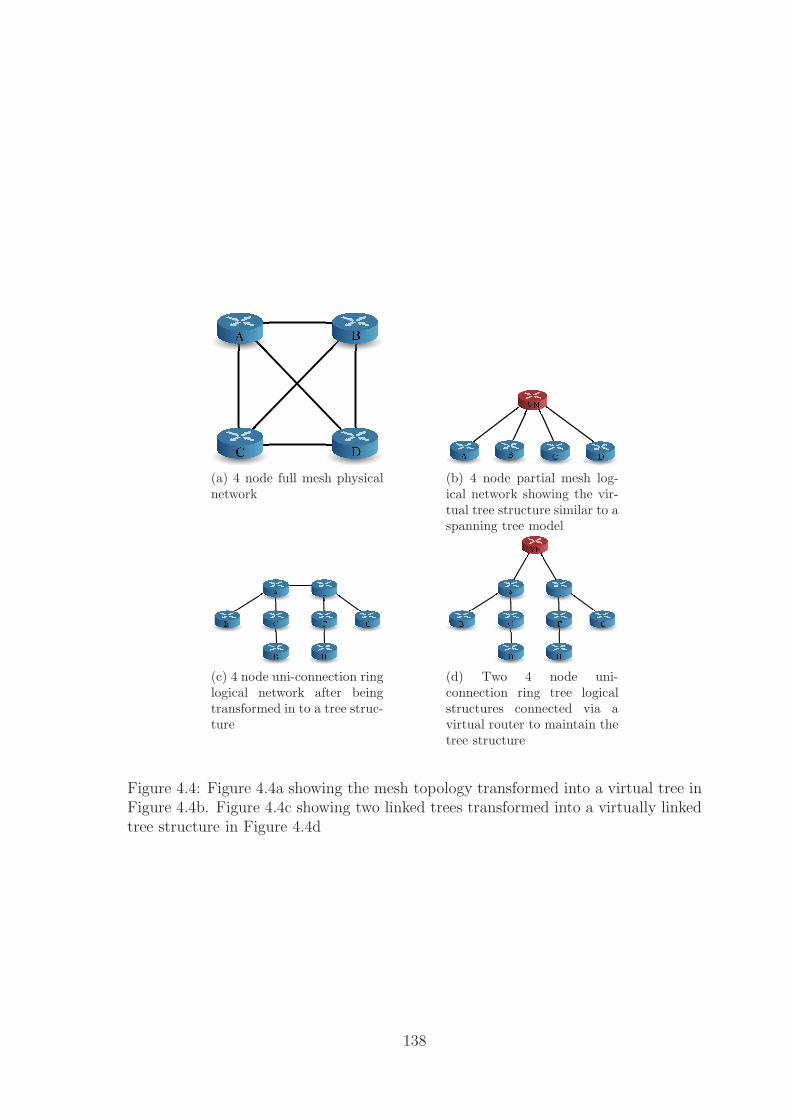
(a) 4 node full mesh physicalnetwork
(b) 4 node partial mesh log-ical network showing the vir-tual tree structure similar to aspanning tree model
(c) 4 node uni-connection ringlogical network after beingtransformed in to a tree struc-ture
(d) Two 4 node uni-connection ring tree logicalstructures connected via avirtual router to maintain thetree structure
Figure 4.4: Figure 4.4a showing the mesh topology transformed into a virtual tree inFigure 4.4b. Figure 4.4c showing two linked trees transformed into a virtually linkedtree structure in Figure 4.4d
138
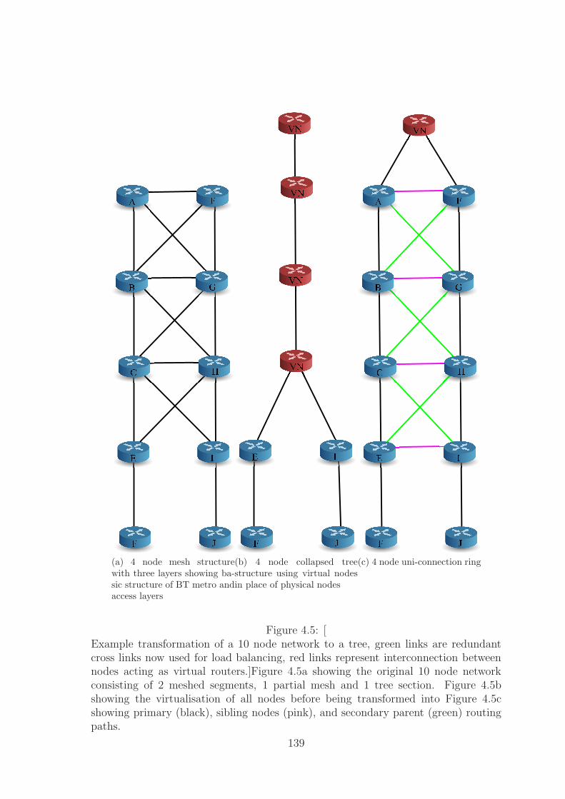
(a) 4 node mesh structurewith three layers showing ba-sic structure of BT metro andaccess layers
(b) 4 node collapsed treestructure using virtual nodesin place of physical nodes
(c) 4 node uni-connection ring
Figure 4.5: [Example transformation of a 10 node network to a tree, green links are redundantcross links now used for load balancing, red links represent interconnection betweennodes acting as virtual routers.]Figure 4.5a showing the original 10 node networkconsisting of 2 meshed segments, 1 partial mesh and 1 tree section. Figure 4.5bshowing the virtualisation of all nodes before being transformed into Figure 4.5cshowing primary (black), sibling nodes (pink), and secondary parent (green) routingpaths.
139

define a location as being a strict hierarchical tree breakdown - in that a location can
be uniquely identified by a single routing path to that location but which that overall
‘route’ implies little to nothing about the route taken to that location - such that
the UK is composed of four component units, England, Northern Ireland, Scotland,
and Wales however the breakdown of the connectivity between these units is defined
elsewhere however each can find the others simply by heading from themselves to ‘the
UK’ and resolving the path from there. This means that the hierarchical address is
a notion of a location that is hierarchically defined and not specifically related to the
explicit routing path. This means that there can be a consistent tree style breakdown
of the network in terms of location and primary connectivity with a secondary layer
of routing information added as and when needed to overcome the limitations of the
tree structure. In this way the routing tables for nodes which conform to the tree
structure are not required to perform complex redirection in general and required
redirection can handled with minimal additional effort.
In terms of the geographical analogy it is possible for two network locations to be
physically adjacent however to lack a common parent node between them meaning
that they are network topographically distinct. In these cases the network addresses
should reflect the lowest common location between the distinct locations indicating
the lack of topographical locality despite the geographic locality.
Typically this breakdown follows a model similar to that show in (4.1). The
connections between these areas are then known only in a localised region on the
scale of the structure we are looking at. At a continental level we are therefore
concerned with 7 areas in a partial mesh with the interconnections controlled by
the travel method - ground vehicles must follow paths connecting locations while air
travel can move directly between continents. That London is located in England is
of no concern to a continental level analysis rather simply that the destination is
somewhere (or reachable from) the continent of Europe.
Continent− > Country− > Region ∗ − > City ∗ − > Street− > Individual/P lace(4.1)
We can apply this scope sensitive model to reduce each of the common topologies
in Figure 4.1 to a tree structure by the addition of a virtual node or nodes to the
network which act as a common prefix under the addressing scheme to the nodes
connected to it. Each node connected to a virtual node shares routing information
about other nodes connected to the virtual node. Through this simple expedient we
140

US Internal
Network
Eastern
Seaboard
International
Connectivity
Western
Seaboard
International
Connectivity
UK Internal
Network
China
Internal
Network
European
Continental
Network
Asian
Continental
Network
Figure 4.6: Figure showing the international routing between the London - UK, NewYork - USA, and Beijing - China
can replace a loop or mesh within the network with a single node which allows for
the construction of a more idealised tree structure. In these cases the underlying
structure is treated as a ‘network blob’ which can be named in composite (the virtual
node identity) with the paths from or through that ‘network blob’ not considering the
individual components but rather the single virtual identity. In Figure 4.4 we show the
reworked topologies as trees indicating the real connectivity and virtual connectivity.
Applying this process recursively to the network graph allows us to take almost any
network structure and provide a tree equivalent topology. Key to this process is
that each virtualised area is on a scope local basis and so does not affect higher or
lower layers of the routing network, the discrete layering is retained. Taking a more
concrete example as in Figure 4.6 and considering the routing between New York and
London, and Beijing and London we arrive at two different forwarding models. New
York being directly connected via the Eastern Seaboard undersea links to Europe
and more specifically to the UK forwards packets to the USA internal network, then
the routing decisions send the data towards Europe via an explicit entry for the UK,
a similar entry could be found for France however not for Luxembourg as it is not
directly connected. The Beijing traffic in contrast has two optional routes, via the
USA networks or via the continental Asian / European networks. Given the higher
connectivity through the USA networks it is likely that the data will be routed to
Europe via the USA following a split horizon principle such that the Western Seaboard
forwards the data towards the Eastern Seaboard (following a path towards Europe
that isn’t retracing steps) and then onto London - UK.
141

4.2.2 Routing within the Internet
The AS-model represents the physical interconnectivity of areas in which a single
service provider over a single media provider is present, however for networks which
have a single media provider with multiple service providers this model becomes in-
efficient at representing the underlying connectivity due to the differing addressing
and management policies. This connectivity is further complicated by the semi-
geographic nature of ASs which range from a single building to 10,000km between
furthest nodes [219], yet are seen as a single contiguous network which may not be the
most efficient route to a distant node. The geographic overlap of the Internet Service
Providers (ISPs) and ASs results in widely distinct identities in a localised geographic
and potentially network topographical area. Beyond the AS system underlying the
current view of the Internet we note that the infrastructure provisioning is topograph-
ically related to the physical geography. It should be noted that IP was not designed
as a geographic routing scheme, however, to be most efficient the network begins to
resemble a hierarchical topology. This hierarchy minimises the increase in routing ta-
ble sizes though this has been partially addressed through additional routing schemes
such as BGP.
In addition to the geographical and topographical restrictions on the network con-
sideration must be given to administrative level constructs (the NLAS) against the
physical geography limited network topology. This administrative requirement is a
further issue to consider in terms of routing. Where a network is totally owned by
a single ISP and internal data usage / flow is not a centralised concern data can
flow by the most efficient route possible. However if the primary media provider is
not the ISP, or centralised management is required then data must flow from the
end points through the network to the ISP management point and then be routed to
the destination. This triangular routing is an artifact of a centralised administrative
model rather than the underlying routing model itself. To provide a more efficient
routing structure for multi-provider single media networks we need to further con-
sider geographical and topographical structure of the Internet and the location of
administrative facilities within those networks.
From K-shell decompositions [132] the Internet can be subdivided into three pri-
mary forms of AS. The core network consists of ˜100 ASs with very dense intercon-
nections providing world wide connectivity. Moving outwards we have a large number
of moderately interconnected ASs with links to the core, with sufficient interconnec-
tions between them to provide world wide connectivity outwith the core. Finally
there are smaller groups of linked ASs connected to the core but not to the majority
142

Figure 4.7: Figure showing the international connectivity and capacity of the currentInternet by region. c©Telegeography 2010 [220]
AS network. Taking this model and adding the underlying connectivity [218] we can
further decompose the network into 3 major structures, meshes, loops, and trees with
the majority of the Internet connectivity being present in tree structures.
Looking at the physical geography that these ASs are built over we note that there
are relatively few interconnections between continental areas as shown in Figure 4.7.
This indicates that traffic flow between continental areas is directed towards a con-
nection point before being redistributed from a similar connection point on the target
continent. We see a similar structure in place at country level geographic areas, a
‘local’ network linked into a limited number of interconnection points as can be seen
in figures 4.8a, 4.8b, 4.8c, 4.8d, 4.8e. These ‘local’ networks though geographically
overlapping may not be linked together except at a limited set of interconnection
points. We characterise this hierarchical structure as:
Continental ↔ Country ↔ Provider ↔ Region ↔ Local
This structure can be further simplified by combining the provider and region into
a single topographical mapping giving three component sections, Continental Area
Routing (CAR), Aggregation Area Routing (AAR), and Geographically Localised
143

(a) International connectivity map forthe US / Canada region
(b) International connectivity map forthe European region
(c) International connectivity map for theLatin America / Caribbean region
(d) International connectivity map forthe Asia-Pacific region
(e) International connectivity map forthe African region
Figure 4.8: Figures showing the international connectivity by region144

Continental Area Routing Network
(CAR)
Aggregation Network
Geographically Localised Network
(GLN)
Area Routing
(AAR)
Figure 4.9: An abstracted three layer model for the Internet showing the highlyconnected core (CAR), the more loosely connected geographic network (AAR), andthe tree overlay section used to simplify routing tables (GLN)
Network (GLN). These three sections form a hierarchical routing system with a strong
geographic attachment by separating the transit process into large scale distribution,
regional dissemination, and localised delivery. An abstract view of this model is
shown in Figure 4.9 showing the CAR network as a dense core, the AAR network
as a largely linearly interconnected network attached to the core and the attached
GLNs. Decomposing the network into these three sections serves two purposes: it
allows geographical areas to assign their address space in the manner best suited to
their underlying network structure, and allows for the simplification of routing tables
by limiting the required address resolution horizon to a single layer of the network.
Routing table expansion is a growing problem under IP based routing schemes [221],
HNTR attempts to reduce this growth by restricting the size of the global horizon
space (CAR) and requiring only direct relational information within the decentralised
GLN address space. This structure also automatically implements a limited version
of flow routing [12] through the limited exclusive-or (XOR)1 routing tables - traffic is
directed towards a destination not through a specific route.
1XOR routing is based on the exclusive OR boolean operation in which the output is true if oneand only one input is true. By comparing the target destination with the current location throughthe XOR process it is possible to determine if the addresses match very quickly in a pure hardwareimplementation.
145

4.3 Routing Address Space
The IPv4 and IPv6 address spaces are centrally assigned to individual ISPs and
then to the end user. Under IPv4 the locator:host split is arbitrary while IPv6 fixes
the split as 64:64 bits for network:host. This centralised assignment of addresses
complicates routing structures and tables because nodes located next to each other
topographically may not share similar IP addresses. Further each router must be
aware of the IP address blocks assigned through itself in the deployment topology in
order to successfully route traffic, this structure without explicit aggregation means
that each router must maintain an infinite horizon to nodes through itself in the
network. To simplify this structure we decentralise the GLN address space to allow
for the automated operation of the network. Under existing IP based networks this
aggregation typically takes the form of BGP tables advertising more limited routes
and some aggregation via Classless Inter-Domain Routing (CIDR). Under HNTR
the CAR and AAR networks hold the large scale geographic information related to
routing the information before the AS equivalent GLN sections are subrouted.
As an example network structure we take the existing 128 bit address space from
IPv6 and divide this into the three sections described above (CAR, AAR,and GLN)
gives a logical split of ˜43 bits per section. Given the improbability of requiring to
assign routing to 8.7 trillion continental areas or subregions we will restrict the CAR
and AAR networks to 16 bits each (still sufficient address space to cover roughly 256
planets if required) leaving a 96 bit address space for the GLN region. Shown in
Figure 4.10. Each of these address spaces is then routed individually using a location
aware routing protocol - that is to say that each section is divided into a separate
domain and routes are generated on a local basis. This means that only the top
level global connectivity needs to be arranged in an international manner because in
the case of international traffic the localised networks will detect a different conti-
nental routing tag and so pass the packet directly upwards towards a node capable
of handling international traffic. Following the format of IPv6 we also allow for the
option of including additional headers in the packets as this allows for intermediate or
fragmented routing to be handled easily. Fragmentation of this address space is still
possible as with similar IP based schemes, however, the effects of this fragmentation
should be more geographically localised and further minimised by actively relabelling
the network as required when new network sections are added to the network.
146

IPv4
IPv6
HNTR
24
16 16
64
96
8
24 328
Host Identity
Min.
Allocation
Global
Prefix
Min.
Prefix
Prefix +
Host Identity
Global
Prefix
Regional
Prefix
Topographical Location
Figure 4.10: Diagram showing the address space comparison between the current andnext generation IP networks and the proposed hierarchical geographic network
4.3.1 Continental and Aggregation Networks
The continental region is an aliased encapsulation network representing the major in-
terconnections between large scale geographic locations (typically continents or sim-
ilarly sized regions). This model opens the door for political interference with the
network structure, however, as recent events have shown the Internet as it stands is
not immune to this kind of geo-political interference. By separating each continent
and country within its own sub-network it is possible for these effects to be localised
to internal traffic while still passing international transit traffic untouched. Each of
these addresses is aliased to allow a minimised address space by routing towards the
closest entry point to that region. Within this region further routing is performed
using the aggregation network, or subdivisions within the continental address space.
The aggregation network is similarly designed to move traffic within a geographic
region however is not an aliased address space. This decomposition routing is shown
in Figure 4.11 with a) showing the European continental region, with b) breaking
this region down into the component regions. West bound international routing is
performed through France or the UK (the aliased access points for Western Europe)
while direct traffic can be routed between linked regions. As the full 16 bit CAR and
AAR address spaces are likely too large to sensibly route it is further suggested that
147
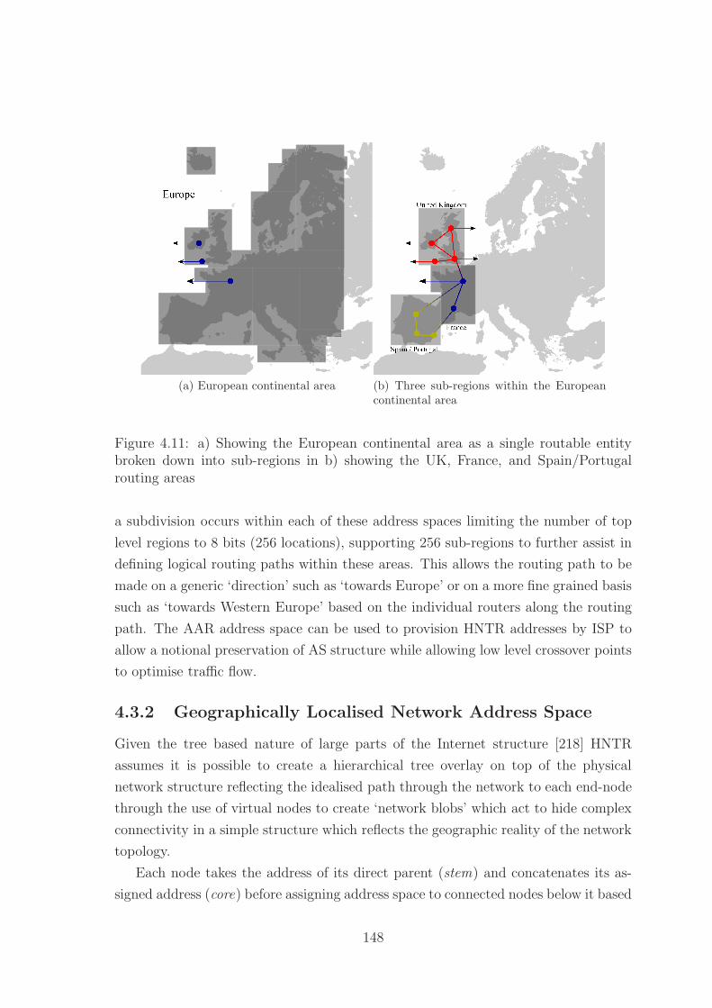
(a) European continental area (b) Three sub-regions within the Europeancontinental area
Figure 4.11: a) Showing the European continental area as a single routable entitybroken down into sub-regions in b) showing the UK, France, and Spain/Portugalrouting areas
a subdivision occurs within each of these address spaces limiting the number of top
level regions to 8 bits (256 locations), supporting 256 sub-regions to further assist in
defining logical routing paths within these areas. This allows the routing path to be
made on a generic ‘direction’ such as ‘towards Europe’ or on a more fine grained basis
such as ‘towards Western Europe’ based on the individual routers along the routing
path. The AAR address space can be used to provision HNTR addresses by ISP to
allow a notional preservation of AS structure while allowing low level crossover points
to optimise traffic flow.
4.3.2 Geographically Localised Network Address Space
Given the tree based nature of large parts of the Internet structure [218] HNTR
assumes it is possible to create a hierarchical tree overlay on top of the physical
network structure reflecting the idealised path through the network to each end-node
through the use of virtual nodes to create ‘network blobs’ which act to hide complex
connectivity in a simple structure which reflects the geographic reality of the network
topology.
Each node takes the address of its direct parent (stem) and concatenates its as-
signed address (core) before assigning address space to connected nodes below it based
148

on physical and virtual connections. This concatenated address space limits the rout-
ing table growth for a node to its physical connectivity (fan-out) and any routing
exceptions. The physical connection limit is defined as the horizon of a router and
defines how many network layers it maintains knowledge of. For idealised hierarchical
routing this horizon is one, however real world multi-parented and looped structures
may require a horizon of two or three to provide efficient routing in sparsely intercon-
nected areas with strong peering links. In the case of a virtual node the core address
is decomposed into two parts - the core alias and the core identity, when routing
through a virtual node the core identity is a wild-card field as all nodes within the
virtual node maintain a full horizon so can direct traffic appropriately.
The GLN is thus a 96 bit address for all nodes in the network consisting of a root
section composed of the parent node’s address, the node’s address, and 0’s padding
the remaining address space. Child nodes maintain their address space as the con-
catenation of their address with their parent’s. The address of each node is composed
of four components:
Stem The section of an address from the root to the parent node of the current node.
Core The section of an address containing the current node address and any non-
routing bits after the parent address.
Child The section of an address assigned to child nodes of the current node.
Remainder The remnant of the address space consisting of children of child nodes and the
unutilised address space.
This breakdown of the address space is shown in Figure 4.12. The decentralised
assignment of addresses allows a router to automatically reconfigure its required ad-
dress space to account for additional child nodes being added or virtual children with
real address spaces without the necessity of checking for overlaps with any other as-
signed address space as children are iteratively updated. This direct routing scheme
allows for simple XOR based routing within the network by comparing the masked
target location to the routing table within the router. Each node maintains a routing
table consisting of an ordered table of links, typically child nodes, exceptions, parent
nodes, and default. During the XOR routing process the binary destination address
is compared to the address in the routing table with an implicit mask of the same
length as the routing table address length.
149

Figure 4.12: Diagram showing the assignment of the dynamic address space for 3tiers of network nodes as root, child, and child of child
Virtual nodes can be created at this stage either through direct network manage-
ment and planning or through automatic analysis of traffic and routes. It is likely
easiest to consider each Country / regional unit to be represented by a single top level
virtual node representing the root and comprising all nodes / groups of nodes which
have international connectivity i.e. those to whom the capability to move outside of
the virtual tree hierarchy is important. Each of the nodes within this virtual node
maintain the location and forwarding information required to interconnect with each
other. From these nodes and the virtual node they comprise further virtual and real
nodes are added to the network to represent regional routing entities and large scale
blocks - e.g. within the UK it is likely that the four major regions / countries com-
prising England, Northern Ireland, Scotland, and Wales would be reasonable top level
virtual nodes with England further subdivided due to its size and population den-
sity. The concept of ‘up’ therefore always refers towards a virtual root of the network
which can provide full interconnectivity across the networked region and eventually
to international connectivity.
For the scenario in Figure 4.13 the addresses of each tree are represented as
R(outing)T(ree)#:P(arent), N(ode), and C(hild)#. The routing table for node B
in routing tree 1 will as shown in table 4.1a while the corresponding routing table for
node G in routing tree 2 is shown in table 4.1b. These show the routing nodes as an
interchange point between the two trees for any cross-traffic from their child nodes
while any traffic for another non-linked tree is directly routed upwards through the
parent nodes A and F respectively.
150

Figure 4.13: Diagram of the interconnection of two routing trees with a single linkbetween the two trees through nodes A and B showing the concatenation of addresseswithin the GLN address space
Considering only a three layer network there is little difference in the assigned
addresses between the HNTR network and an IP network due to the requirement
to list all physically connected nodes. If we consider moving beyond this one level
horizon the routing table for the HNTR network does not change because the child
of child nodes, or parent of parent can be considered to be super sets of the child or
parent nodes respectively and so can be reduced to the same routing table entry. The
IP routing table will have to expand to include all IP prefixes located through that
node and so a through-ward infinite horizon must be maintained at each router.
It should be noted at this point that it is possible to renumber existing networks
in a hierarchical manner using existing IP structures to gain many benefits of the
proposed structure. Performing this renumbering would require an alteration from
the centrally assigned IP address structure currently utilised as well as allowing the
automated expansion of the network to account for mobile nodes. This expansion
is likely to be limited by the address space of the IP protocols due to the inefficient
manner in which a decentralised address space must be managed. Addition of identity
protocols, multi-layer routing to add route / destination labelling, flow control, and
localised multicast further bring IP towards this model, however, amounts to an
effective rewrite of the IP protocol.
151

Type Address FwdChild RT1:P.N.C1 CChild RT1:P.N.C2 DChild RT1:P.N.C3 EPeer RT2:P.N G
Virtual RT2:P GParent RT1:P ADefault 0 A
(a) Node B in routing tree 1
Type Address FwdChild RT2:P.N.C1 HChild RT2:P.N.C2 IPeer RT1:P.N B
Virtual RT1:P BParent RT2:P FDefault 0 F
(b) Node G in routing tree 2
Table 4.1: Routing tables for nodes B and G from Figure 4.13
4.3.2.1 Benefits of a Non-shared Address Space
If the address space is collapsed, all nodes share the same address space and have full
address space length address. At this point it becomes impossible to automatically
generate unique addresses on a per-node basis without a centralised control algorithm
to determine which parts of the address space are unused. In comparison the dynamic
address space usage model guarantees that a node can allocate to any address space
below its core without requiring a centralised algorithm to update. If a node with
current children performs an address space update however its children must be up-
dated in a cascading update process. This decentralisation is key to allowing the
automatic generation and control of the network structure and to limiting the overall
destructive capability of a single update to the network structure.
This decentralisation allows effective network management as it ensures that there
should be no global address collision management. Localised collisions and address
space remappings update nodes strictly below the point of change and will interrupt
communication that passes above this point until the new address mappings are
known. This decentralisation enables the dynamic restructuring of a tree structure
at any point along its length and allows for easy node mobility and network creation.
4.4 Routing Concepts
HNTR approaches routing in a similar way to IGRP protocols such as EIGRP, basing
the output path on knowledge of the connected NLAS and creating generic routes to
further ranging destinations without a full network map. Bringing in the aspects of
OSPF routing protocols in the creation of virtual nodes to allow the generation of
tree-consistent routing models. Under this model we utilise a binary address space
152

which, due to the tree-consistent structure, allows us to simply apply a binary XOR
process to the address to determine its final location.
Routing devices do not merely route packets on their fan-out but use their pro-
cessing power to provide address management and services that can alter the flow and
multiplicity of packets generated. As such we consider the specific solutions under
HNTR for unicast, multicast, and anycast routing paradigms.
4.4.1 Unicast
HNTR unicast is a very simple directed routing scheme with the address space de-
signed to assist in the cut-through-routing model to facilitate fast streaming of data
for streaming traffic models. Under IP based protocols cut-through-routing has been
found to have minimal benefits due to the preponderance of non-streaming traffic
however as this model of traffic increases it is likely that cut-through routing will
assist in keeping data flowing at the line speed as pre-reservation of data can be
managed more efficiently.
4.4.1.1 HNTR XOR based Routing
Using the address space constructs we can design the basic unicast routing algorithm
for a tree using edge addresses as a direct addressing mode. This process is shown
in Figure 4.14 and can be applied to any node within the routing path. Initially
this algorithm seems relatively complex for the process of routing within a Simple
Routing Tree (SR Tree) given the comparison is simply between the child addresses.
This complexity is required as each node has a variable length address space within
the maximum overall address space to enable exclusive-or based route and output
node selection. The address space must be capable of being split into the component
parts described above consisting of the stem, core, child and remainder to enable
functional routing.
This process can be parallelised highly as each set of tests can be performed at
the same time with the highest length match providing the appropriate forwarding
destination. This follows a similar system to that provided by matching IP addresses
by longest match in the routing table however each address comparison is a simple
XOR process. This can be easily provided in hardware using a lookup table com-
paring the masked destination to known entries with the highest ranked entry taking
precedence. By addressing direct routing in as simple a method as possible we enable
line speed forwarding (cut through routing) with as minimal buffering as possible.
153

1 ∗ On r e c e i p t o f Packet P2 ∗ Packet has Source Address (AS) , Des t ina t i on Address (AD)3 ∗ Router (R) has Masks determin ing the length o f i t s Stem ( .MS) , Core ( .
MC) and Child ( .MCh)4 ∗ Router mainta ins i t s own stem ( . S) , co re ( .C) , c h i l d l i s t s ( .Ch) ,
connected l i s t ( .T)56 IF ( (P .AD ∧ R.MS)⊕R. S) THEN7 IF ( (P .AD ∧ R.MC)⊕AS.C) THEN8 IF (P.AD ∧ R.MCh.Ch == 0) THEN9 ∗ Forward packet to r oute r for p r o c e s s i n g
10 ELSE11 FOR EACH ( addres s in R.Ch)12 IF ( (P.AD.Ch ∧ Mask .Ch)⊕AS.Ch) THEN13 ∗ Forward packet to appropr i a t e ch i l d14 END IF15 END FOR16 IF (NOT FORWARDED) THEN17 ∗ Discard Packet18 ∗ Send e r r o r r ep ly to P.AS19 END IF20 END IF21 ELSE22 FOR EACH ( addres s in R.T)23 IF ( (P .AD.C ∧ Mask .T)⊕AS.C) THEN24 ∗ Forward packet to appropr i a t e connect ion25 END IF26 IF (NOT FORWARDED) THEN27 ∗ Forward packet to parent node28 END IF29 END IF30 ELSE31 FOR EACH ( addres s in R.T)32 IF ( (P .AD.R ∧ Mask .T)⊕AS.R) THEN33 ∗ Forward packet to appropr i a t e connect ion34 END IF35 IF (NOT FORWARDED) THEN36 ∗ Forward packet to parent node37 END IF38 END IF
Figure 4.14: Pseudo-code routing algorithm for SR Trees using Destination Address(AD), and Source Address (AS) breakdown into Stem(.S), Core(.C), Child(.Ch) andRemainder(.R)
154

4.4.1.2 Unicast Geographic Packets
Under IPv4 and IPv6 the IPpacket structure does not vary with the service or struc-
ture of the request, this is left to higher level protocols despite functionality such
as multicasting being officially structured at the IP level rather than at levels above
that. In return for this the routing protocol is simplified, however not to the extent
whereby the routing is truly simple. Geographic routing reduces the routing deci-
sions to a simple ‘up down’ concept allowing for additional complexity to be added
to the packets and automatically redirect these additional processing packets to the
non-hardware compatible section of the router.
We create a basic packet structure as shown in Figure 4.15, consisting of a 192 bit
header, falling directly between the IPv4 and IPv6 header sizes. The packet structure
consists primarily of the two 80 bit geographic addresses and a 32 bit overhead con-
taining the protocol version, the type of packet, traffic class and the payload length.
There is no hop limit specified in a geographic routing address due to the inherent
nature of the tree overlay structure, packets cannot be routed indefinitely around the
network unless a circular structure is introduced deliberately into the routing tables
to generate a non-finite routing path. Packets will traverse the network to a lowest
common point, and proceed downwards to their destination, at this point the packet
will be either forwarded on or dropped from the router leaving no generic capability
to generate excessively long paths.
In each HNTR packet the basic routing information is highlighted in green with
the flow, multicast, and other similar enhancements highlighted in red. As can be
seen each packet retains at least the version, packet type, and destination fields from
the basic routing information. Additional functionality added to the protocol is sup-
ported through the packet type field which allows the routing device to determine the
processing type at line speeds.
Version :Identifies the version of geographic IP used to generate the datagram.
Packet Type : Identifies the structure of the packet, currently defined types are
listed in table 4.2.
Traffic Class : Used to identify traffic type based on the Request for Comment
(RFC) 2474 differentiated services model.
Payload Length : Identifies the length of the payload attached to this datagram
header. As individual packet structures are defined this does not include any
extensions to the header formats.
155

Figure 4.15: Structure of a standard hierarchical network topographical routingpacket including full 128 bit source and destination addresses
Destination CRN : The 8 bit continental routing network address for the destina-
tion of the datagram.
Destination RRN : The 8 bit regional routing network address for the destination
of the datagram.
Source CRN : The 8 bit continental routing network address for the source of the
datagram.
Source RRN : The 8 bit regional routing network address for the source of the
datagram.
Geographic Destination ID : The 64 bit geographic routing field for the destina-
tion of the datagram.
Geographic Source ID : The 64 bit geographic routing field for the source of the
datagram.
Bit Pattern Value Packet Type0000:0000 0 Generic geographic routing packet0000:0001 0 Extended header routing packet0000:0100 0 Geographic multicast routing setup packet0000:0101 0 Geographic multicast routing ttl packet0000:0111 0 Geographic multicast removal packet
Table 4.2: Geographic routing packet types
156

Within the geographic routing structure we deal with a small number of specialised
types of packets. Typically these will be used to cover multicast, anycast, and broad-
cast services within the network. As an additional type we cover extensible header
formats allowing for specialised routing traffic and the handling of routing across
multiple routing networks such as an IPv4 section linking two geographic routing
structures.
4.4.1.3 Extensible Header Packets
As with IPv6 it is apparent that any future network is likely to support an increasing
number of headers and options within those headers as time goes by and the net-
work is utilised for tasks that it was not originally conceived of handling. As such
a similar structure is undertaken allowing additional headers to be chained in the
fashion of IPv6 headers under RFC2460 [47]. The major flaw identified within these
additional header structures is that of hop-by-hop routing which forces current layer
3 routers to rely on processor based computation of routes rather than simple hard-
ware forwarding. As the routes in a HNTR network are simpler it is more feasible
to offload the processing of hop-by-hop type processing to a hardware forwarding
engine. In addition to the simplified addressing scheme the ability to encode pseudo-
route-information into this kind of header of the format ‘route to America through
the UK’ giving some flexibility in route selection without the requirement to process
true hop-by-hop redirection.
4.4.1.4 Site Local Packet Format
For site local traffic consisting of traffic which would only ever utilise a subset of
the visible address space HNTR includes two limited address format packets which
enable simpler processing by pre-matching the Continental Routing Network (CRN),
Regional Routing Network (RRN) and considering the GLN only from the core of
the local ‘root’ router. These are shown in 32 bit format in Figure 4.16 and 64 bit
in Figure 4.17. This allows local routing to be entirely contained within the localised
network to provide additional security and reduced routing overhead to packet trans-
fer. This separation allows for the creation and management of localised resources
and the direct filtering and rewriting of packets to easily conform to site policy or to
allow a single multi-site network to act as though it was a single site network. By
considering site-local addresses it is possible to completely isolate a network from the
157

Figure 4.16: Structure of a site local hierarchical network topographical routing packetwith 32 bit source and destination addresses
Figure 4.17: Structure of a site local hierarchical network topographical routing packetwith 64 bit source and destination addresses
wider Internet giving many of the benefits associated with Network Address Transla-
tion (NAT) however in a more clearly defined way such that interaction can be more
well defined.
4.4.1.5 Transport Control Identification Layer
Under a geographic routing scheme end-point identity is stripped from the primary
routing information and re-added as a second layer between the routing information
and the end-point host. This separation allows the routing packets to be streamlined
to contain information relevant only to the routing hierarchy itself and not to end-
point identification or traffic classification details. The end-point identity is verified
through an Internet service provider to allow access to the Internet and provide billing
and additional services to users. The header consists of one of two formats: structure
one is shown in Figure 4.18 and consists of a 16 bit provider identification linked to
a 16-112 bit subscriber identification.
158

Figure 4.18: Structure of a standard hierarchical network topographical routing trans-port control identification packet showing full optional identity space
Figure 4.19: Structure of a standard hierarchical network topographical routing TCPpacket
4.4.1.6 Transport Control Flow Layer
The final component of the packet hierarchy is the process identifier - ports. As with
IP solutions we bring forward Transport Control Protocol (TCP) and User Datagram
Protocol (UDP) as sensible solutions to this layer. As with TCP under an IPv4 it
is important to allow a differentiation of flow identifiers from an end-point node to
allow traffic from different programs to be identified. As the TCP header format is
well known and understood already this has been ported directly to the geographic
transport control flow layer as shown in Figure 4.19.
Similarly to the controlled flow layer there is a need for unrestricted flow services,
this header format is similarly taken directly from UDP and is shown in Figure 4.20.
4.4.2 Multicast
Within current networks multicast addressing is a rarely utilised function due to the
difficulties of deploying a geographically diverse multicast group across many routers
159
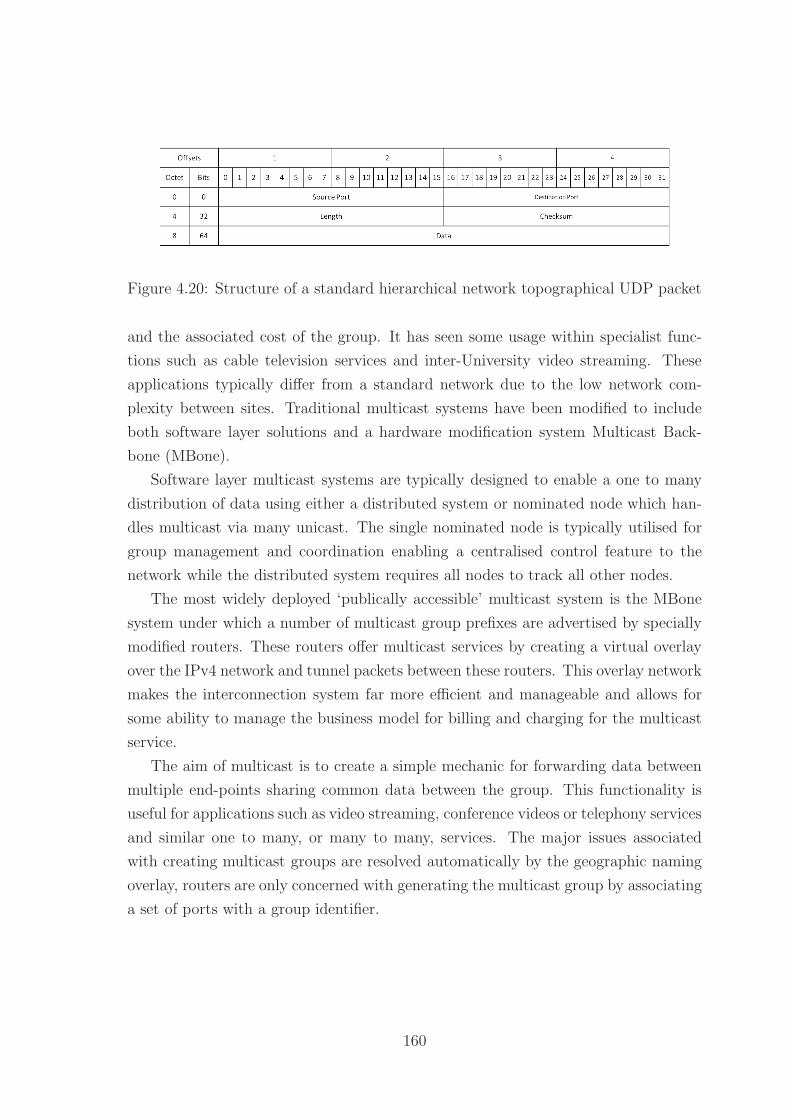
Figure 4.20: Structure of a standard hierarchical network topographical UDP packet
and the associated cost of the group. It has seen some usage within specialist func-
tions such as cable television services and inter-University video streaming. These
applications typically differ from a standard network due to the low network com-
plexity between sites. Traditional multicast systems have been modified to include
both software layer solutions and a hardware modification system Multicast Back-
bone (MBone).
Software layer multicast systems are typically designed to enable a one to many
distribution of data using either a distributed system or nominated node which han-
dles multicast via many unicast. The single nominated node is typically utilised for
group management and coordination enabling a centralised control feature to the
network while the distributed system requires all nodes to track all other nodes.
The most widely deployed ‘publically accessible’ multicast system is the MBone
system under which a number of multicast group prefixes are advertised by specially
modified routers. These routers offer multicast services by creating a virtual overlay
over the IPv4 network and tunnel packets between these routers. This overlay network
makes the interconnection system far more efficient and manageable and allows for
some ability to manage the business model for billing and charging for the multicast
service.
The aim of multicast is to create a simple mechanic for forwarding data between
multiple end-points sharing common data between the group. This functionality is
useful for applications such as video streaming, conference videos or telephony services
and similar one to many, or many to many, services. The major issues associated
with creating multicast groups are resolved automatically by the geographic naming
overlay, routers are only concerned with generating the multicast group by associating
a set of ports with a group identifier.
160

4.4.2.1 Multicast Functionality
A multicast network must offer as a minimum the ability to create, manage, and
disband a multicast group. This group must receive messages from any member of
the group and attempt to deliver it to every other member of the group, however
as with other services this is a best effort and not a guaranteed delivery, for that a
software overlay should be added to handle the reliability.
With HNTR we aim to facilitate group creation in a combination of hardware
and software suitable for implementation on a modifiable platform such as a Field
Programmable Gate Array (FPGA). The ‘software’ layer handles the creation, man-
agement, and breakdown of the group while the ‘hardware’ layer handles the packet
replication on the router through the use of the flow label as a routing device. As each
router manages its own flow groups the tuple of source(s):label(s) uniquely identify a
multicast traffic flow.
Multicast interaction with virtual nodes is a relative non-issue as each multicast
formation message passes through specific routers within the virtual node which sub-
sequently act to maintain the multicast group, with failure to maintain the active
communications link resulting in the teardown of that subsection of the group. It
would be feasible however to utilise virtual nodes to further add redundancy to the
multicast group by actively soliciting and utilising the nodes to forward traffic along
‘any’ available path while still maintaining a single management point per hierarchical
pathway.
Multicast control and functionality are broken down to the simplest structure
possibly requiring a horizon of one to actively participate in the group and maintain
all communications. Each router in the group is responsible for managing nodes below
it in the tree structure, meaning a recursive control system can exist that allows for
a very simple point to point management that effects control over the whole network
over a short period of time.
4.4.2.2 Multicast Structuring
Multicast in a geographic network consists of a setup phase, the data transfer stage
and a keep-alive / termination phase. The latter two phases are alternated in a period
of assumed functionality followed by a structured keep-alive test to determine which
parts of the network should be pruned. In the geographic network, due to the tree
structure overlay each node is only responsible for performing a keep alive for nodes
161

Figure 4.21: Multicast group showing stable situation
below that point to ensure the structure maintains effectiveness. The basic state
diagram for the process is shown in Figure 4.21.
The multicast node moves into the initiate state where it sends setup packets to
determine if a multicast group exists / the other node will accept the formation of
a multicast connection. While the group is forming each node (individually) enters
the forming state until it receives a full list of all nodes in the group and the routers
along the path acknowledge the creation of the group. Once the setup process is
complete the node moves into the stable state where it maintains membership using
keep-alive messages in a hierarchically aggregated manner. If a node or group of
nodes wishes to leave the group they enter the teardown state where they still listen
for and respond as if they are a member of the group, after the timeout period or
acknowledgement of the leaving message the node enters the wait state for the group
timeout period to ensure nodes further up the chain have actively removed the node
such that further requests to join the group or messages sent to / from the node to
the group are correctly handled.
4.4.2.3 Forming a Multicast Group
A multicast group is formed by sending a series of unicast packets tagged as multicast
setup packets from any node in the group to any other connected node. This process
moves the sending node into the initiate state until it receives a response from the
target node or times out. When the response is received both nodes move into the
forming state and test their multicast connectivity using the group id assigned by
their respective routers (unique to each multicast node). An example of this is shown
in Figures 4.22 - 4.26
162

Figure 4.22: Initial network state
Taking the network structure shown in Figure 4.22 node A sends a unicast mul-
ticast setup packet addressed to node C. The packet follows the path outlined in red
as seen in Figure 4.23 and is acknowledged resulting in the routers highlighted in red
becoming active multicast routers for this group as shown in Figure 4.24. Figure 4.24
also shows a second set of unicast multicast setup packets being forwarded to node E
thus adding the blue routers to the group as shown in Figure 4.25. The final node F
is added again by node A as shown in Figure 4.25 and once acknowledged the stable
state is entered as shown in Figure 4.26. Node A (or any other node in the group)
has the option to ‘find all members’ using by forwarding a ‘who is’ message into the
multicast group if the node has sufficient priority. In this example the ‘who is’ will
be controlled by node A once the network enters the stable state.
When a router receives a multicast setup packet it forwards it to the ‘software’
control layer and undertakes the operations specified in Figure 4.27. Each router
will thus attempt to map the desired flow label for the group if possible using a
source:label tuple. If this mapping is not possible the router will negotiate a label
that is possible and packets will be rewritten as appropriate
Multicast Setup Packet A multicast setup packet contains the standard informa-
tion carried in a unicast packet with the addition of two 16 bit flow IDs. The normal
flow ID is the preferred ID for the flow with the two additional IDs representing the
minimum and maximum ID in a preferred range, if the receiving node cannot accept
these it will respond with a new range. Each router may remap the flow ID on a per
163

Figure 4.23: Node A initiates multicast group
Figure 4.24: Node A adds a second node to the group
164

Figure 4.25: Node A adds a third node to the group
Figure 4.26: Stable multicast group established
165

Figure 4.27: Multicast group showing stable situation
166

Figure 4.28: Table showing an HNTR multicast setup packet with preferred flow IDand options range.
port basis. This setup packet is shown in Figure 4.28. Once setup the router sends
a response packet as shown in Figure 4.29 indicating the accepted port mapping for
this link.
4.4.2.4 Multicast Group Management
Management of the multicast group can be performed by any node with group ad-
ministrative privileges. Following from the previous example we retain the network
as shown in Figure 4.30a with node A as the only administrative node. Management
of nodes is performed in a hierarchical manner with node A forwarding a multicast
administrative packet into the network at router root:N1:N1:N1 which is forwarded to
the remainder of the group. As shown in Figure 4.30b routers root:N1 and root:N2:N1
split forward this packet to multiple destinations. Each will only forward a single re-
sponse to node A after either all responses or a timeout occurs. In this manner the
network management load on each node is minimised to its fan-out.
4.4.2.5 Multicast Packet Transfer
To send messages to the multicast group a node sends a multicast packet tagged with
the geographic source address of the sender and the multicast group identifier to the
closest router associated with the multicast group. As the geographic overlay network
is structured this router should always be the notional primary parent of a node. This
router then identifies the packet as not being a simple unicast packet and so processes
167

Figure 4.29: Table showing an HNTR multicast setup response packet with acceptedflow ID and group options.
the packet, sending the packet on to any number of output ports as identified by the
geographic multicast setup phase. This process is shown in Figure 4.31 where in 4.31a
node E sends a packet the multicast group. Routers root:N2 and root:N1 act as the
aggregation / control points for the traffic flow to the network. In 4.31b node C sends
a packet to the multicast group, in this cast only router root:N1 acts as a control /
aggregation point as all other routers consider only a forwarding node.
4.4.2.6 Multicast Node Management
Node management is the other key functionality of a multicast group management
system. This can largely be processed as managing the group timeouts and sending
keep alive requests to attached ports and waiting for at least one response per port.
This control system is a point to point system which cascades timeouts for node
removal. When a node receives no response the path can be pruned without having
to maintain an explicit knowledge of the number of children attached to that port.
Keep Alive The keep alive functionality of the group consists of a timeout set by
each router allowing for finer control of the network. Each node will send a Keep alive
request to each of the flow labelled ports which are children of this router indicating
the maximum timeout period for a response. If the router does not receive at least
one alive response from that port it is removed from the multicast group.
168
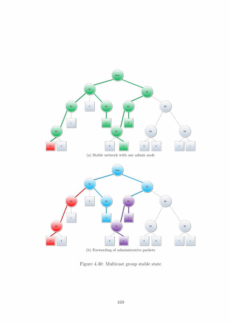
(a) Stable network with one admin node
(b) Forwarding of administrative packets
Figure 4.30: Multicast group stable state
169

(a) Multicast Packet Transfer 1
(b) Multicast Packet Transfer 2
Figure 4.31: Multicast group sending packets to group
170

Figure 4.32: Table showing an HNTR multicast command packet
This hierarchical structure handles the network termination gracefully and in a
limited function, no node is responsible for managing the whole of the multicast
group, but rather only nodes directly beneath it in the tree.
The keep alive packet structure is shown in Figure 4.32 and the response is the
same packet structure with different options set.
4.4.2.7 Multicast Group Teardown
Teardown begins with a node being evicted by an administrative node, or voluntarily
leaving / timing out. When this process happens the network needs to respond
appropriately. In the case of Figure 4.33 node F informs router root:N2:N1 that it
wishes to leave the multicast group as shown in Figure 4.34. Router root:N2:N1 has
other branches in the multicast group so does not remove itself from the routing
group so simply removes node F from the forwarding tables as shown in Figure 4.35.
When queried (or if router root:N2:N1 has administrative privileges) the node-depart
message is sent into the network with nodes root:N2:N1 and root:N1 performing the
branch aggregation.
Voluntary Termination Nodes should not voluntarily remove themselves from
the multicast group but instead rely upon the keep alive mechanism. This simplifi-
cation allows the end-point node to simply start ignoring the multicast group when
it wishes to leave, however means that the routers are not responsible for group size
mechanisms. A node is simply thus aware that there is or is not a large group attached
to itself, but rather simply that one or more node exists in that sub-tree.
Network Teardown Group teardown follows the opposite structure to the keep
alive process. A termination packet is sent to all lower nodes, and at least one response
171

Figure 4.33: Multicast teardown 1
Figure 4.34: Multicast teardown 2
172

Figure 4.35: Multicast teardown 3
Figure 4.36: Multicast teardown 4
173

Figure 4.37: Table showing an HNTR multicast node leave packet.
Figure 4.38: Table showing an HNTR multicast network teardown packet.
is required to negate the teardown on that port. If all ports are torn down the message
is passed up the network chain to parent nodes. This packet is shown in Figure 4.37.
A full network teardown can be performed by an authorised node using the structure
shown in figure 4.38, with the challenge / response pair shown in Figure 4.39 and
Figure 4.40 respectively.
4.4.3 Anycast
In traditional IP based networks the anycast system is based around a service adver-
tising multiple sites with a single IP address. Using this advertisement a service is
requested from the Domain Name Service (DNS) service and the single IP address is
returned, which is subsequently routed to the most appropriate and nearest / load
174

Figure 4.39: Table showing an HNTR multicast network teardown challenge packet.
Figure 4.40: Table showing an HNTR multicast network teardown challenge-responsepacket.
175

Figure 4.41: Table showing an HNTR anycast service provider locator packet (anycastfind).
balanced service. Under the geographic routing scheme the DNS service should return
(potentially) multiple addresses for the same service based on the geographic loca-
tion of that service. This removes the need and capability of the traditional anycast
network.
Instead anycast within a geographic network has the ability to specify a service by
name instead of by address. This system allows an end-point to locate services such
as DNS services by requesting information rather than through specific knowledge.
This enables in-tree structuring of services to be automatically found and utilised
allowing for the automatic mitigation of a central communications point failure.
This discovery structure allows the network to function even when known points
are removed or in the event of mandatory service failures (such as DNS).
4.4.3.1 Anycast Packet Structure
The anycast packet follows a similar structure to all other packets in the geographic
network with a different Packet Type specifier and two 16 bit fields, the service ID and
Service Provider ID. These allow for the provision of generic services to the network
(such as DNS) but also for the specific location of vendor services such as content
replication points. The packet is shown in Figure 4.41.
4.4.3.2 Anycast within a Geographic Network
Anycast location services are designed to help the network deal with control point
failures and ad-hoc routing. That is to say that because intelligence and routing
176

capability have been moved down the tree structure it should logically follow that
services move down the tree as well. By moving these services down the tree it
enables an efficiency in the network as the served group of users are relatively stable
(since users rarely change the physical locations of their dwellings). This stability
allows services to provide localised knowledge (service location, content provision)
such as the pre-download of video that the area is expected to utilise during a known
time period.
Anycast messages are strictly bound within a regional area and should not be
passed beyond the regional field. If they reach the regional router and no result has
been found a message will be sent back specifying service not found.
4.4.3.3 Anycast Services
Anycast services are designed to be in-tree services following the model of IP anycast,
that is to say that these services should be available in multiple places and the content
offered from them is relevant or useful to the area in which the service is located.
This might be a network location service such as DNS or a geographic location
service providing a service like Global Positioning Service (GPS), or simply an adver-
tising service providing localised adverts to customers without requiring more specific
information from them.
4.4.3.4 Adding new Anycast services
Services as noted are provided as a strictly regional routing network service, as such
the provision of services can vary between regions. To provide a service at least one
node within a region must have a service attached with a provider id and service id.
These services should be mapped and provided for by a common entity within the
regional network the Service Definition Service (SDS) server attached at the regional
router level.
4.5 Location and Identity
As we have already seen there is a strong requirement for a next generation network
to separate the location of a node from the identity that is used to identify it to
services and to allow its location to be identified. This motivation requires us to
look back at IPv4 and IPv6 design decisions which include the host ‘address’ within
the overall address space. IPv4 included this as a variable length address (1-24 bits
typically) while IPv6 utilised a fixed 64 bit field to enable the automatic generation
177

of host identifiers from the Media Access Control (MAC) address of the network
interface. This host identifier is however meaningless to the majority of nodes along
the communication path as they can only resolve the network portion of the address
outwith the assigning body’s network. This issue would be minimal if network services
required a separate identification protocol to determine who has authenticated and
/ or where packets should be sent however many services utilise the IP address as a
constant for the session which (though understandable at the time) undermines the
potential for mobility in future systems.
As an additional issue, the inclusion of an end point identity within the network
address has unfortunately lead to the limited development of identity determination
technologies limiting the ability of end to end communications to flow directly over
network masking functionality such as NAT. It is clear that a next generation network
will include an identifier and location separation however how this ties into node
mobility is still a largely unanswered question.
4.5.1 The Globally Routable Fallacy
Before addressing the specifics of the identity and location split proposed under
HNTR it is important to realise that current knowledge states that there are ‘glob-
ally routable’ addresses and ‘private addresses’ [222, 223, 224]. Knowing however
that the host portion of an IP address is in fact only routable from nodes which know
the nodes current position means that only certain points on the Internet are actu-
ally ‘globally routable’ - all others are locally routable from these global aggregation
points. This forms a secondary routing hierarchy restricting the flow of information
through ‘management points’ which have the ability to route this localised traffic -
that is to say that just because two nodes share a physical connection and know each
other’s IP addresses does not mean they can communicate directly. It is debatable as
to whether these ‘management points’ represent a break in the end-to-end principle,
however, they do represent a potentially unnecessary routing point for traffic flows
and as such will be addressed as an issue.
This communication through aggregation / management points makes logical
sense when we consider ASs to be disjoint networks connected through gateway /
edge routers. This disjoint view is shown logically in Figure 4.42, the ISP with
knowledge of the connection to the end point communicates directly with the ISP of
the target end point, both ISPs are globally routable entities. If we overlay a geo-
graphic map onto the process the need to traverse large geographic distances to reach
these managements becomes less clear as show in figure Figure 4.43. This situation
178

Figure 4.42: Inherent Hierarchy in ISP to ISP communication
becomes worse when we consider that often ASs are not physically disjoint networks
but rather logical overlays over a single physical network which could directly connect
the nodes if it was empowered to do so. As such it is clear that a large proportion
of the data transfers required to route between two end-points is likely to be taken
up with transfers required to get to and from the management points for localised
communications. This centralisation of traffic flow has the major benefit of making
accounting simpler in that traffic can be monitored and managed centrally and there
is a known path for data flow. Correspondingly to this benefit though is that the
real world network over which communications occur are rarely as simple as two ISPs
directly interacting and so there may be multiple management points for different
parts of a single traffic flow made more complex by the provision of Content Deliv-
ery Networks (CDNs). By shifting to a more network aware management model the
volume and difficulty of managing the network increases as control is decentralised,
however, in so doing we enable more efficient and effective use of localised resources
and services.
From this we consider the postal system as an alternative addressing scheme as
shown in table 4.3. Under the postal addressing scheme an end user can have multiple
identities as the end-user identity is irrelevant to the delivery process outside of the
building. The building (final router) is identified in a strict geographical manner
which states nothing about the interconnectivity of points but rather simply their
relation to each other. We also see that the postal address is broken down in a much
cleaner way, routing information is provided such that a point is reached as far up the
hierarchy as is required to route the data back down to the destination. This point
can be termed a pivot point and should represent the minimum distance / stretch
required by the routing structure to move data between two points. The lack of
information in IP addresses ensures that this cannot happen as only a management
179

Figure 4.43: Geographic overlay onto ISP to ISP communication
180

Postal Address IPv4 Address IPv6 Address(Title)*(First Name)*(Surname)*
(House Name)*(Number)(Street Name) (Routing)(8−32)(Identity)(0−24) (Routing](64)(Identity)(64)
(Town), (County)(Country)*(Post Code)*
Table 4.3: Comparing a postcode to IPv4 and IPv6 Addressing structures
points have knowledge of the end host location. Again it can be argued that the postal
system maintains similar management points within the network, however, these can
be bypassed by traffic and as such are not structurally necessary to the operation of
the network.
For a future generation network we need to enable truly globally routable addresses
such that the traffic / control tradeoff is minimised. Globally routable nodes should
only be required to transfer data as far up the network hierarchy as required to reach
the pivot point of the two nodes, that is to say that the address structure must
make logical sense at all stages such that two nodes located on a common gateway
should share a common address. This solution however must address the capability
to charge for traffic flow at any point in the network rather than taking centralised
measurements. Multiply parented nodes, and thus aliasing, can be addressed directly
at the address mapping stage using a DNS like service to provide both the most
effective route (primary) as well as secondary and known aliases.
4.5.1.1 Location Equivalence
It can be seen logically that, especially due to the management point routing issue,
an IP addresss host identifier can only be directly understood by the provider of that
address. Thus an IP address can be logically equated to an identity as shown in ta-
ble 4.4 or more generally as in table 4.5. These addresses are rarely so clearly cut as
this with a single IP address being theoretically capable of representing 65,535 differ-
ent users through NAT at any single instant in time and users of devices often being
assigned addresses and ports dynamically to assist in network management. Under
IPv6 the greater address space theoretically allows for a more limited relationship
between addresses and devices under which one or more IP addresses are assigned to
one device rather than the reverse. This paradigm does not account for multiple users
181
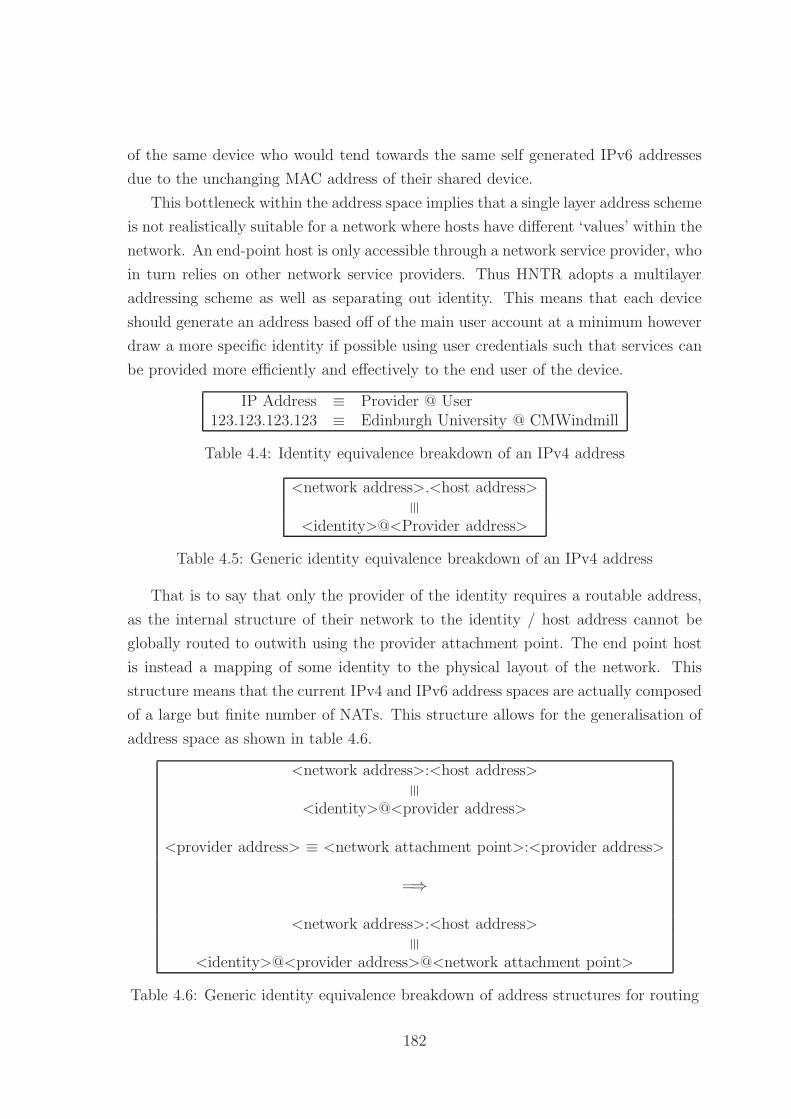
of the same device who would tend towards the same self generated IPv6 addresses
due to the unchanging MAC address of their shared device.
This bottleneck within the address space implies that a single layer address scheme
is not realistically suitable for a network where hosts have different ‘values’ within the
network. An end-point host is only accessible through a network service provider, who
in turn relies on other network service providers. Thus HNTR adopts a multilayer
addressing scheme as well as separating out identity. This means that each device
should generate an address based off of the main user account at a minimum however
draw a more specific identity if possible using user credentials such that services can
be provided more efficiently and effectively to the end user of the device.
IP Address ≡ Provider @ User123.123.123.123 ≡ Edinburgh University @ CMWindmill
Table 4.4: Identity equivalence breakdown of an IPv4 address
<network address>.<host address>
≡
<identity>@<Provider address>
Table 4.5: Generic identity equivalence breakdown of an IPv4 address
That is to say that only the provider of the identity requires a routable address,
as the internal structure of their network to the identity / host address cannot be
globally routed to outwith using the provider attachment point. The end point host
is instead a mapping of some identity to the physical layout of the network. This
structure means that the current IPv4 and IPv6 address spaces are actually composed
of a large but finite number of NATs. This structure allows for the generalisation of
address space as shown in table 4.6.
<network address>:<host address>
≡
<identity>@<provider address>
<provider address> ≡ <network attachment point>:<provider address>
=⇒
<network address>:<host address>
≡
<identity>@<provider address>@<network attachment point>
Table 4.6: Generic identity equivalence breakdown of address structures for routing
182

For an IPv4 network the provider address, and network attachment point are
identical, however by separating these concepts it becomes possible to attach to a
network at an arbitrary point, and provide a meaningful identity to that provider
such that your data transfer can be billed as appropriate. This means that network
attachment is simplified by default, the connection is a function of the user and not
the user and attachment point.
This separation of identity and routing information allows the routing network to
be separated from the billing network and instead link the two through an authen-
tication service. This separation allows an Internet connection to logically follow its
user through the network as only the user and not the attachment point is authen-
ticated. Furthermore this provides a basis for mobility, if a network identifies a host
not using their routing information, then that data can be routed differently without
reauthenticating the host.
By considering the attachment point of the network to be flexible we can enable
more generalised ad-hoc global routing. That is to say that it becomes possible to
route directly between and to other nodes without the associated bottlenecks. This
structure enables more efficient localised routing making it possible to save bandwidth
and costs over many connections. This also allows for a localisation of resources to a
fixed group of individuals rather than a dynamic pool of individuals linked only by
their ISP connection.
4.5.2 Location
Location addressing has already been discussed briefly under the HNTR routing ad-
dress space management however it should be further emphasised here that the ad-
dress space is a hierarchical breakdown of the network topology using virtual nodes to
enable a tree-centric routing path to be created. Nodes’ addresses therefore are binary
bit patterns between 34 and 128 bits long (zero padded) and reflect the topographic
geography (and therefore the real world geography) of the network.
While it is important to create a logical naming structure on top of the phys-
ical routing structure it is unlikely that many Humans could effectively remember
and utilise 96 bit addresses with regularity. As with other network protocols for the
Internet this requires a services to translate Human readable addresses into the identi-
fication scheme used by that protocol. Unlike other protocols however the geographic
breakdown of addressing gives us a textual control over the address space directly
linking the underlying bit pattern. This means a node can regenerate an address us-
ing contextual geographic information. This means that if a packet is actively routed
183

Geographic ID Textual Representation00100011:11110000 110010100101001010001011[0] UK.SCO.Lothian.EDI.UoE.KB.ENG.Alrick
Table 4.7: A geographic address for the Alrick building within King’s Buildings, TheUniversity of Edinburgh
Geographic ID Textual Representation00100011:11110000 United Kingdom (”UK”)
11 Scotland (”SCO”)0010 Lothian10 Edinburgh (”EDI”)010 University of Edinburgh (”UoE”)1001 King’s Buildings (”KB”)010 Engineering (”ENG”)
001011 Alrick Building (”Alrick”)
Table 4.8: Breakdown of a geographic routing address
in a particular direction or on a hop-by-hop transit and the connection cannot be
achieved in that way it is still possible to reconstruct a meaningful path since the
underlying geographic area (and thus the network topology) are meaningful concepts
in a HNTR routing scheme.
As such we can directly map an address space to a geographic name creating lexical
meta routing zones without requiring them to be logically represented that way within
the network. Taking a simple breakdown of a path from the top level UK to The
University of Edinburgh we can show the breakdown as in Figure 4.44. This structure
is relatively efficient breaking down from a Country level to an individual building
within a small region of the Country in 8 naming layers and using 24 of the available
96 bits assigned to the geographic address space as shown in Figure 4.45. Some of
these bit depths are somewhat unrealistic considering the whole of the Edinburgh
area as a 3 bit 7 region field as an example. For a fuller breakdown it would likely
be worthwhile to add in an additional layer breaking the city down into sub-areas
reflecting the physical connectivity of the regions.
The full address for an example building within the University of Edinburgh is
shown in table 4.7, with the corresponding breakdown of the address shown in ta-
ble 4.8. While still not as efficient as a true short name or universal resource locater,
the ability to break down an address into a sensible textual representation makes
remembering, and deriving addresses simpler.
184

Figure 4.44: Breakdown of a geographic textual address from the UK top level toindividual buildings within the University of Edinburgh
185

Figure 4.45: Breakdown of a textual address showing minimum weight assignmentsfor the bit fields
186

Geographic ID Textual Representation00100011:11110000 011110001[0] UK.Eng.Mid.Birmingham00100011:11110000 011110001[0] UK.Wales
Table 4.9: A textual description of geographic routing reflecting the viewed geographyand linking to the underlying network geography
4.5.2.1 Lexical Meta Routing Areas
It is unfortunately a simple fact of routing that certain geographic regions do not
easily fall from a common root that they logically should. If we take the example
of the United Kingdom it might be that the major routing path to Wales is in fact
through Birmingham. This is a nonsense term though for people reading and creating
a lexical address, Wales derives from the United Kingdom not from Birmingham. In
these cases it is simple to create a meta routing area that exists only within the naming
scheme to describe this, the underlying network description still represents the flow
as through Birmingham as shown in table 4.9. As can be seen the lexical mapping
to the bit patterns can be meaningfully represented as either the top level region
Wales, or as the network topographically relevant routing information in that Wales
is connected to the UK via the West Midlands - Birmingham region. This allows a
single region to be meaningfully represented to different groups and processed as text.
This lexical equivalence represents an overlay in the naming scheme which reflects
the true routing scheme name that would derive the correct network topographical
location of a node however represent it to the user in manner which is consistent
with the physical geographical location. As applied to geographically adjacent but
network topographically separate areas this allows the geographical link to be made
clear while the network topographical non-adjacency is represented in the underlying
geographic id.
Simply geographic areas can be sub-areas of others and named as though they
were not to reflect political, geographic, or other requirements not capable of being
represented by the underling structure. This again indicates why in the SR Tree
mesh one of the criteria we select strongest links by is the shorter address. In this
case if a second option opened up for Wales using only 2 bits rather than the 9
assigned here to the .Wales code it would likely be a better route (if the bandwidths
are remotely similar) as there are fewer higher level nodes on the path and so more of
the bandwidth can likely be devoted to .Wales, as well as giving areas within Wales
more geographic address space to subdivide themselves.
187

4.5.3 Identity
With the concept of a ‘location’ addressed within the network it becomes important
to consider the identity of a node. While every node in a network should have a
‘unique identity’ it is likely that there can be some reuse of ‘identities’ across the
world due to the unlikeliness of two identical identities being present and accessing
the same service in a single large scale geographic area. This ‘likely unique’ approach
is already taken with MAC addresses. Further we must consider ‘network masking’
technologies such as NAT which can be used by companies or individuals to hide the
specific identity of a node behind a common identity. While this was common under
IPv4 due to the limited address space it becomes a feature under more advanced
network protocols as it suggests that multiple identities is in fact a positive solution
if handled correctly. This feature must not however break the end to end paradigm
by becoming non-transparent.
4.5.3.1 HNTR Identity
Under HNTR we define the host identity layer as being nested above the TCP equiva-
lent layer enabling routing to the nearest attached router, then to the host, and finally
to a port within that host. Each node on the network is assigned a 16 bit provider
identity unique within a RRN + CRN routing area with a 16 - 112 bit unique provider
identity. This space can be assigned as desired by the identity provider however it is
suggested that a 64 bit identity is used split 16:32:16 allowing each provider to sup-
port approximately 4 billion accounts each with 65,535 sub-accounts / devices. This
can be expanded for large networks such as the Time-Warner cable network which
accounted for over 16 million devices simply by increasing the identity length.
Providing a variable length account identity with sub-accounts provides the mech-
anism for the separation of control and data planes as required by the International
Telecommunications Union (ITU). Further we can support a NAT like service to
both home and corporate users as data can be forwarded on a per sub-account basis
transparently. If individual programs further support an identity layer it becomes
possible to present different credentials to different services in an automated manner
allowing for partial Virtual Private Network (VPN) and / or encryption of a subset
of traffic or the creation of a walled garden Internet for children using a subaccount
of the master house account. This is covered further as user identity.
188

Base ID Account Sub AccountUoE CWindmill DesktopUoE CWindmill MobileUoE CWindmill Phone
Table 4.10: Identity Modelling for a corporate user
Base ID Account Sub Account DeviceISPnet Windmill Christopher DesktopISPnet Windmill Christopher MobileISPnet Windmill David DesktopISPnet Windmill Visitor Desktop
Table 4.11: Identity Modelling for a family group
4.5.3.2 User Identity
The obvious use of this identity model outside of a corporate environment is a family
environment whereby a single user can maintain multiple identities for themselves
and their family as well as work under a single account. By further subdividing the
address space we can for example identify a work user as shown in table 4.10 or a
family group as shown in table 4.11.
By allowing separate identities under a single global account we provide a mecha-
nism to enable ‘limited Internet’ functionality such as say a walled garden for younger
users, a speed limited connection for guests, or a transition mechanism to sync data
and connections between devices based on user behaviour.
4.6 Conclusions
In this chapter a basic model for the core concepts underlying the HNTR routing
model have been put forward to address the issues of localised routing and the switch
in technologies within the last mile from IP to layer 2 and back to IP. By providing a
consistent layer 3 approach to the last mile multiple new service models are opened up
as presented in the case studies in chapter 6 while allowing for geographic and network
topographical service provision. This model of network aggregation promotes the
more fluid and service based competition model suggested for the ISPs and meets the
regulatory requirements being enforced on large scale network operators to open their
networks to competition. By providing geographically based addresses the network
189

addressing system is simplified and the routing table growth can be restricted largely
to the fan-out of the device and the contents of any meta-areas that the device is part
of. The meta-area creation actively brings virtual routers and redundancy into the
network structure as a baseline feature allowing for increased reliability and simplicity
within the network structure.
190

Chapter 5
HNTR: Open Issues
5.1 Introduction
This chapter introduces some of the open issues within the Hierarchical Network
Topographical Routing (HNTR) routing environment as concepts rather than fully
fleshed out ideas. The chapter looks at the key remaining aspects of a next generation
network deployment: routing mobility, management and control, and deployment of
the network alongside an Internet Protocol version 4 (IPv4) network. Topics are
addressed under the major areas of:Routing Mobility, network management, address
space management, interoperation policies, HNTR deployable units, and deployable
service blocks. Finally the integration of the Internet Service Provider (ISP) is con-
sidered within this new framework and conclusions presented about the management
of a HNTR network.
5.2 Routing Mobility
Routing mobility is the last routing requirement we have to address before we con-
sider the network management and control side of the network. Since we have already
provided a mechanism to separate identity and location it becomes clear that the
mechanism to support mobility is the capability to locate a node, a Domain Name
Service (DNS) like service, and the capability to redirect traffic until a handover has
been completed. If we consider a non-mobility enabled service there is no considera-
tion of mobility - a node is assumed to remain fixed in place for the entire duration
of a session leading to the simple state diagram shown in Figure 5.1a. A mobility
model must allow a node to either directly initiate a movement, or to have its move-
ment acknowledged implicitly leading to the more complex state diagram shown in
191
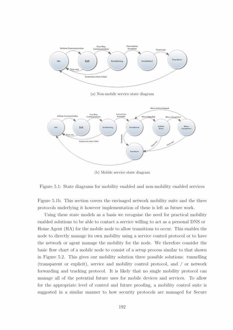
(a) Non-mobile service state diagram
(b) Mobile service state diagram
Figure 5.1: State diagrams for mobility enabled and non-mobility enabled services
Figure 5.1b. This section covers the envisaged network mobility suite and the three
protocols underlying it however implementation of these is left as future work.
Using these state models as a basis we recognise the need for practical mobility
enabled solutions to be able to contact a service willing to act as a personal DNS or
Home Agent (HA) for the mobile node to allow transitions to occur. This enables the
node to directly manage its own mobility using a service control protocol or to have
the network or agent manage the mobility for the node. We therefore consider the
basic flow chart of a mobile node to consist of a setup process similar to that shown
in Figure 5.2. This gives our mobility solution three possible solutions: tunnelling
(transparent or explicit), service and mobility control protocol, and / or network
forwarding and tracking protocol. It is likely that no single mobility protocol can
manage all of the potential future uses for mobile devices and services. To allow
for the appropriate level of control and future proofing, a mobility control suite is
suggested in a similar manner to how security protocols are managed for Secure
192

Sockets Layer (SSL).
5.2.1 Mobility Control Suite
Mobility is an active research area with many potential solutions to the problem of a
node which is actively mobile and a few solutions for a passively mobile node. As we
have the option with a clean slate redesign to actively promote good mobility prac-
tice we consider the three primary models for mobility as a comprehensive Mobility
Control Suite (MCS):
1. Passively mobile nodes
2. Actively mobile nodes
3. Actively mobile routing capable nodes
We consider passively mobile nodes to be the default case - that is a node which
migrates between attachment points without actively informing services it is attached
to that it is mobile or moving. For this process we utilise the network intelligence
available to us and utilise a network level forwarding and tracking protocol. This
means that the network itself is aware of node movement and responds by actively
forwarding packets to the new destination for a limited duration while informing the
service of the node migration.
Actively mobile nodes can be considered as either single mobile nodes or nodes
capable of performing routing functions. For both of these cases we consider two
solutions - mobility enabled tunnelling using a home agent and mobility aware routing
points to forward data, and a service and mobility control protocol to allow nodes to
actively inform services of their mobility status and condition.
Network Forward and Tracking Protocol Network Forwarding and Tracking
Protocol (NFTP) is the basis for active mobility in that nodes are capable and do
negotiate and inform the host network of their movement and intended movement
in order to facilitate the provision of services and data forwarding. This protocol
acts in a similar way to the handoff control for a mobile network in the negotiation
stages however the last visited nodes retain a forwarding address for the identity
which has moved for a limited duration. In this way a chain of forwarding can occur
(though geographically linked and therefore ideally topographically linked resulting
in minimal additional overhead) allowing content to be routed to a node which cannot
renegotiate its attachment point to a service or which is travelling too fast to do so.
193

Figure 5.2: Flow chart for mobile enabled applications
194

Mobility Enabled Tunnelling Mobility Enabled Tunnelling (MET) This protocol
mimics the capabilities of the IPv4 and IP version 6 (IPv6) mobility models which
support the creation of HA and Foreign Agent (FA) entities to facilitate mobility
in simple non-mobile nodes. The major extension suggested to these protocols is a
consolidation approach which operates on all nested mobility networks with a depth
greater than 1 which attempts to minimise the number of redirections to reduce the
volume of additional traffic that can occur with multiple HA/FA tunnels.
Service and Mobility Control Protocol Service and Mobility Control Proto-
col (SMCP) is the final aspect of the mobility control suite and represents a set of
common commands and capabilities to enable mobility in a service including start
/ stop, suspend / resume, and (re)authentication controls. In combination with the
transparently activated MET and actively controlled NFTP nodes can manage their
mobility and provision of services from localised services.
5.2.2 Node Movement Modelling
From the protocols contained within the MCS we have a solid foundation for network
mobility. One aspect we have not considered however is the potential future of a
nearly ubiquitous wireless connectivity solution through either a wifi like protocol or
a mobile communications standard like 4G. With this model in place we can consider
all nodes to have the potential for active mobility and the capability for network
nodes to actively solicit information to determine the physical connectivity of nodes
and areas to enable active services and data forwarding.
If we take the example of the Kings Buildings at the University of Edinburgh we
have a series of buildings on a self contained campus. Each building is connected
to the campus grid which in turn connects to two major road systems then into the
city itself. By recording connection transitions we can actively model the potential
destinations for mobile nodes and the expected data flows for those mobile nodes as
well as their actual data transitions.
5.3 Network Management
In Chapter 4: Hierarchical Network Topographical Routing a new network architec-
ture was proposed based upon a routing tree overlay onto the network topography
using virtual nodes and expanded routing horizons to provide a tree-consistent rout-
ing view of the network. While this will allow data to be routed between nodes
195

the Internet is far more than a simple routing network - it is a service provision
network as well as a set of mechanisms and protocols to enable the management of
a vast, physically diverse, interconnected network. As such we must consider the
management of the network as a major barrier to implementing any modifications or
clean-slate redesigns of the Internet. From this we consider the management in terms
of the following areas: traffic engineering ; policy implementation; path handling ; load
balancing and flow control ; and multi-homing and multiple site locations.
5.3.1 Traffic Engineering
The first major point to consider in the management of a routing network is the
ability to perform traffic engineering - that is the control, management, and optimi-
sation of Internet traffic and the evaluation of those flows. As HNTR can operate
in a manner very similar to that of Internet Protocol (IP) the majority of IP based
traffic engineering methodologies and techniques can simply be directly ported to
the new architecture. It is possible to replicate either directly or through a similar
mechanism the functionality of traffic engineering protocols and structures such as
Virtual Local Area Networks (VLANs) [225], Differentiated Services (DiffServ) [226],
Resource reservation protocol (RSVP) / Signalled Quality of Service (QoS) [227],
and Multiprotocol Label Switching (MPLS) as well as simpler measures such as flow
measurement and localised congestion / notification algorithms. As it is possible to
implement these features directly we will not consider them further in this chapter
however it should be noted that these can impact upon cut through routing efficiency
given the additional processing required on each packet.
Considering RFC3272 [228] as a basis for the considerations of traffic engineer-
ing we consider approaches under the categories of: Time-Dependent Versus State-
Dependent, Offline Versus Online, Centralised Versus Distributed, Local Versus Global,
Prescriptive Versus Descriptive, Open-Loop Versus Closed-Loop, andTactical vs Strate-
gic.
HNTR provides an idealised method for beginning automated traffic engineer-
ing. The use of virtual nodes allows network segments to be autonomously managed
without affecting the apparent routing path of data. Performing traffic routing at
the virtual node level however leads to very tactical routing decisions whereby each
section of network attempts to maximise its own efficiency without concern for lower
/ higher segments of the network. To fulfill the wider network routing requirements /
decisions and implement differing connectivity policies virtual nodes need to be capa-
ble of providing aggregatable data and metrics that can be managed more centrally
196

in a manner similar to Autonomous System (AS) level policy decisions under IPv4
or IPv6. This ‘strategic’ level of feedback is vital in a unified or cross-routable net-
work as it allows different providers to actively see the effects of their traffic on other
providers and data flows and to work co-operatively to manage the overall health of
the network. Low level strategic decisions fall below the level of network policy as
they should be based on real-time information on the network however should be fed
back into higher level policy decisions.
For the development of future traffic engineering solutions it is vital that the net-
work capabilities are made available to the automated and manual traffic engineering
software and that there is a way to query the availability of services. Without these
factors traffic engineering will always be reliant on theoretical or tested information
rather than the real-time situation a real router / group of routers encounters.
As an example of the kind of strategic vs tactical algorithms and network level
policy decisions consider two ISPs networks A and B feeding into a single wholesale
network using a two router redundancy tree similar to the Metro-Exchange level of the
British Telecom (BT) wholesale network. Under current IP paradigms the interface
between the ISPs and the wholesale network typically acts as barrier to both network
information status as well as the status / activity of traffic flowing to clients at the
edge of the network. This means that a high bandwidth request from different clients
at the edge of the network to their independent ISP though sharing data with the
same client on the second ISP will be served separately. At a tactical level each
meta-routing area attempts to achieve optimal balance of flows - sharing the two
streams equally until the final aggregation point. At a strategic level the network
performs the same analysis as there is no way to route around the bottleneck of the
final aggregation point. Finally at the policy level decisions can be made to alter this
state. By tracking the requests for content at the aggregation level through either
explicit requests or deep packet inspection and matching the two requests it becomes
possible to optimise the flow of shared content. This means it becomes possible for
a single ISP, or the wholesale network provider, to provide the data to the client (or
both to send the data into the wholesale network and have one flow dropped silently)
using a network level dynamic cache. At current it is not possible for the content
provider to easily provide this kind of service as the wholesale and ISP networks act
as blocks to this kind of multicast traffic. This could be considered naive as a business
point of view however the wholesale networks present in the United Kingdom (UK)
give at least the underlying entity a reason to pursue network level efficiency while the
197
higher level ISPs can utilise it as a cost reducing measure allowing them to provide a
more cost efficient service.
Without access to the state of the connected network it is much harder for an ISP
or content provider to actively help to maintain the state and quality of the network
service as well as invoke the use of caches or similar technologies within the network.
As actual / potential content growth continues to outstrip potential bandwidth growth
at the last mile it becomes more vital to actively assist the network in minimising
bottlenecks.
5.3.1.1 Policy Implementation
Policy Based Routing (PBR) [229] is the implementation of specific routing decisions
onto the routing network to enforce particular routing paths based on a set of criteria
that are outwith the generic routing algorithm. The criteria for PBR can be very
broad, ‘traffic from network A’, or very specific, ‘traffic from network A with a packet
size > 1200 bytes using the User Datagram Protocol (UDP) transport layer protocol
with a port number of 72’. As PBR is typically implemented as a set of conditionals
on the routing state / Interior Gateway Routing Protocol (IGRP) the implementation
of HNTR has little effect on this other than to alter the address space.
PBR controls are placed above automated route and flow control in the traffic
engineering hierarchy and should be followed if real-time cut through routing (whereby
the packet is forwarded at the line rate without being stored and forwarded) is not
implemented.
5.3.1.2 Path Handling
Multipath routing [230, 231, 232] has been an ideal of Internet traffic engineering for a
long time however the implementation of specific path control for packets is difficult to
balance in terms of the many transparent and autonomously load balanced / routed
sections of the Internet and the cost of hop-by-hop routing. While it has been a
goal of the IP community to enable this feature the lack of an explicit link between
a router and the path to a router makes it difficult to implement in a simple and
hardware friendly manner suitable for use in a forwarding engine. The fundamental
link between a router’s location and address within HNTR makes it very easy to
specify an exact routing path, to allow routers to handle multi-path autonomously,
or to simple allow the network to select the appropriate path to a region as the
decision can be matched to a limited prefix set.
198

Considering a router with at least dual parents, or dual grand parents, the node
will have the potential to have multiple physical routes to it. While these direct
physical addresses are ignored from the perspective of the default HNTR routing
scheme which considers the ‘strongest’ path to be the default addressing scheme they
can be utilised to directly access these alternate physical paths if they are present
or generate them through reverse flooding protocols. Considering a node with dual
parent and dual (1st) grandparents the nominal address for this node assigned by
the network is: CRN:RRN:[X]11001 0110 110[N] - a 5 bit (2nd) grandparent space
(11001), a 4 bit (1st) grandparent space (0110), and 3 bits of parent address space
(110) though the node is only directly aware of the parent address space. This routing
address will be utilised to direct traffic into the appropriate routing tree as needed
through entries in linked routers routing tables. If however there is a need to address
this node separately by different names (for instance as a policy routing decision) it
is possible to consider it as a separate node (a virtual meta-routing-node) deriving its
address from any of the parent combinations as shown within table 5.1. This allows
the node to directly appear within multiple routing trees and to offer either virtual
redundancy or to provide hidden load sharing capabilities with the virtual addresses
handled by different real routers. Each of the addresses generated represents the
network from a different routing tree perspective - while the aim of HNTR is to
reduce the identifying path and routes within the network it is sometimes necessary
to introduce complexity
Within the HNTR packet addressing scheme we can specify a route as specific,
static, or dynamic allowing us to have direct routing layer multipath as an imple-
mentable choice. Through the use of the DNS it is possible to find both multilisted
paths and paths which require either specific, that is routes which are specified hop-
by-hop, or static, that is routing through a specific network region, routing to reach
the target node. By allowing simple multipath selection and specification within the
network packet it becomes possible to avoid the downfall of IP based hop-by-hop rout-
ing which typically incurs a Central Processing Unit (CPU) based route calculation
at each hop.
5.3.1.3 Load Balancing
Load balancing in a logical overlay network is a difficult task to organise specifically
because the optimum route is typically defined by the network address of the node
itself. In the case of temporary node or path failure however traffic routing may be
very different to something approximating this optimum path. The use of virtual
199

CRN RRN GLN Relationship001101[0] 1101[0] 11001 0110 110[0] GP1-P1-N001101[0] 1101[0] 11001 110 1101[0] GP1-P2-N001101[0] 1101[0] 11011 0010 110[0] GP2-P1-N001101[0] 1101[0] 11011 1110 1101[0] GP2-P2-N001101[0] 1101[0] 11111 01111 110[0] GP3-P1-N
Table 5.1: Table showing the relationship between node addresses in a simple treestructure including full HNTR address
nodes and dynamic (re)routing at a local level addresses this issue by allowing any
of a virtual node’s constituents to handle the routing of the packet or the generation
of a localised meta-routing area to handle the temporary network issues. Where a
specific or static route is specified the node will attempt to directly follow the routing
path (not dynamically forwarding to non-listed addresses) however may attempt to
route around the area if required. As with IP we can further address load-balancing
through policy and IGRP decisions as well as through channel bonding, multiple
‘hidden’ routers, and similar techniques.
As a specific aside to address ‘hidden’ routers within a HNTR network it is impor-
tant to note that the concept of a node or router is in itself flexible. As redundancy
protocols such as Virtual Router Redundancy Protocol (VRRP) and similar create
virtual devices to be handled by a set of real devices so too can a single HNTR node
be handled by multiple real devices. In this specific case reference to the individual
routers is through the identity layer with the router HNTR identity representing what
is effectively a meta-routing-area that is not visible from the network layer.
5.3.1.4 Multi-homing and multi-site locations
Multihomed Networks Multihoming [233, 234] is the process of utilising two
Internet connections to two different ISPs in order to provide redundancy to a site
or network. This process is ‘costly’ in terms of routing table as it places two entries
for the same location in the global routing tables. This can be partly addressed
with systems like SHIMv6 however the fundamental underlying question remains
unanswered - if a site is physically located in a single location and is only served by a
single network should it hold multiple addresses? HNTR addresses this issue in three
possible ways: DNS, single site, and multi-network. The DNS solution utilises the
DNS to enable a single address to ‘point’ towards multiple physical addresses. Further
to this we have either a single physical network (but different ISPs) in which case
200
the site has multiple identities however a single physical address or we have multiple
identities and multiple connections under a multi-site system.
In effect this type of connectivity becomes similar to that discussed above in that
there are multiple possible physical addresses for the site based on the ISP as the
grandparent node. In this situation the normal or typical routing path should be
chosen with the site advertised at multiple locations much in the same way that a
city may be reachable by both a motorway and a series of smaller roads.
Multisite Networks Following on from the concept of multihoming we have the
issue of multiple physical sites sharing a single address space (using shorter subnet
masks for the sites) which further expands the global routing tables by providing
fine grained addresses at a global level. HNTR addresses this by providing the sites
with the capability to utilise an internal network structure with an address length
of 32 or 64 bits which is translated to the site location through address rewriting at
the gateway for external traffic or encapsulation for ‘internal’ traffic. This allows the
same subnet masking techniques to be utilised for site traffic without having multiple
physical addresses in the global routing table. Figure RefFigNeeded shows a sample
internal network structure linking two remote sites together and the translation which
occurs at the gateway nodes when a local address space is utilised.
5.4 Address Space Management
As we have now addressed the Human-centric side of network management we must
consider the autonomous side of network control - it would be an ideal goal to have
networks automatically configure themselves into an efficient and effective routing
layout without Human intervention. Further to this it would be ideal to have the
network capable of creating routing control structures such as VLANs or point-to-
point tunnels to assist flow routing. We now consider the autonomous creation and
management of a network in a real-time context.
5.4.1 Network Construction
As the mechanisms for a HNTR routing network supports a decentralised network
construction, management, and control structure we must consider the processes by
which the formal network tree is defined and managed. We consider this topic under
the areas of: defining the network, routing tree root node, node management, network
operation, and constructing overlays.
201

5.4.1.1 Defining the Network
The Continental Routing Network (CRN) routing portion of the network is assigned
statically to ensure traffic flow and management policy is observed. These network
routers form the basis for the determination of the Regional Routing Network (RRN)
and Geographically Localised Network (GLN) network sections. Each RRN section is
again an administrative region assigned on a more local basis taking the CRN root as
the ‘top’ of the network - that is the section that should be able to route any possible
address in the network. The CRN defines the global routing table. Typically RRN
nodes will be assigned statically as well however nodes can perform ‘root analysis’ as
shown in Figure 5.3.
5.4.1.2 Routing Tree Root
When the CRN has been established and the RRN assigned at the highest routing
level the remainder of the RRN space is utilised to define top level routing areas for
countries. Again this process is best performed using a manual configuration to match
the geographic / topographic structure of the country however it can be performed
programatically as shown in Figure 5.4. This process once performed defines the
‘root’ of the country wide network as a single virtual node with access through one
or more links to the CRN routing area. A root can be established with no CRN
access using the gateway service module to create a virtual root linking access to the
Internet through another protocol or as a tunnel to another HNTR network which is
considered ‘higher’ or closer to the ‘root’.
5.4.1.3 Node Management
As the routing tree is a tree there are many well known algorithms and structures
for implementing the addition, removal, and alteration of the tree structure itself. In
this section we give an overview of the process in pseudocode and then consider the
process stages from the parent and child node in each process.
Adding a Child Node Adding a child node to the routing tree involves the node
being physically attached to the network and then sending ‘node discover’ messages
into the network in a process similar to the Dynamic Host Configuration Proto-
col (DHCP) discover process. All connected nodes then return messages with the
‘node address offer’ indicating the address / connection properties that they offer
the prospective child node. The child node responds with an acknowledgement of
202

1 ON sta r tup2 // Check to see i f t he re i s a connected node with a s t a b l e address3 FOR EACH connected node4 IF connected node has addres s5 r eque s t addres s space n o t i f i e r6 ELSE7 add node to ch i l d / peer l i s t8 END IF9 FOR EACH returned addres s
10 IF addres s parameters $<$ cur r ent addres s parameters11 SET cur r ent addres s parameters to addres s parameters12 END IF13 FOR EACH returned addres s14 IF returned addres s EQUALS cur r ent addres s15 accept addres s16 ELSE17 r e j e c t addres s18 END IF1920 IF cur r ent addres s EQUALS NULL21 // There was no a c t i v e root node an address can be drawn from22 // Perform e l e c t i o n o f a temporary root , most connected /
s t r on g e s t23 FOR EACH node on ch i l d / peer l i s t24 r eque s t number o f c h i l d / pee r s25 r eque s t connect ion parameters26 WAIT a l l r e spons e s / timeout27 o f f e r nomination // shou ld be i d e n t i c a l across l o c a l nodes2829 WAIT timeout / r e j e c t i o n30 IF timeout31 r eque s t addres s from nominated root32 ELSE33 WHILE no root34 REPEAT e l e c t i o n pro ce s s35 END IF36 ELSE37 // Process c h i l d nodes / peers by o f f e r i n g address space38 FOR EACH node on ch i l d / peer l i s t39 o f f e r addres s space n o t i f i e r40 WAIT a l l r e spons e s / timeout41 FOR EACH response42 a s s i g n f i n a l i s e d addres s43 END IF
Figure 5.3: Pseudo-code Assigning RRN Addresses
203

1 ON sta r tup2 // Check to see i f t he re i s a connected node with a s t a b l e address3 FOR EACH connected node4 IF connected node has CRN addres s5 r eque s t addres s space n o t i f i e r6 ELSE7 add node to ch i l d / peer l i s t8 END IF9 FOR EACH returned addres s
10 IF addres s parameters $<$ cur r ent addres s parameters11 SET cur r ent addres s parameters to addres s parameters12 END IF13 FOR EACH returned addres s14 IF returned addres s EQUALS cur r ent addres s15 accept addres s16 ELSE17 r e j e c t addres s18 END IF1920 // I f no address found perform mapping proces s21 IF cur r ent addres s EQUALS NULL22 FOR EACH node on ch i l d / peer l i s t23 r eque s t c onne c t i v i t y map to GLN24 // b u i l d IGRP s t y l e rou t ing map o f the network to a depth o f 2
below GLN25 using r e turned conne c t i v i t y maps cons t ruc t s i n g l e map o f GLN26 bu i ld addres s space using l owest i d e n t i t y as group l e ad e r27 END IF
Figure 5.4: Pseudo-code Assigning RRN/GLN Root Addresses
204

the accepted offer and finally the new parent node broadcasts onto the network the
existence of the new node.
The overall process is shown in Figure 5.5 with the new node announcing its
presence onto the network through a node announce message. The node then waits
for the timeout period and determines which response if any meet the requirements for
this node’s parent selection criteria, if the timeout period is reached with no responses
the node can either begin the process again or assume root node status itself. Upon
accepting a parent node the node sends a parent accept message and waits for the
parent accept message response to confirm that it has been added to the network
successfully.
Removing a child node Node removal is a (potentially recursive) process which
removes a designated child node and allows for the restructuring of the tree. The
generic process follows that of tree removal algorithms and is shown in Figure 5.6.
When the node itself requests removal the parent node is notified of the removal
request to allow negotiation of removal for sessions in progress. Once the negotiation
is over the node notifies its child nodes of its impending removal. The process can be
initiated from the parent node through the sending of a node removal message with
the process then continuing as per self removal.
Reparenting a Node Reparenting allows a section of the tree to reconfigure itself
under a new parent node and is performed as a two step process with a removal then
addition performed on an active sub-tree. In this process the node maintains a pair
of HNTR addresses for a period of time to allow data from existing sessions to be
forwarded for the timeout period as though the tree was still a sub-tree of the original
parent node. The reparenting process follows the same process as the leaf addition
and removal with a final stage notifying the sub-tree of the address change through
a node address change message.
5.4.2 Network Operation
This section looks to address issues that occur during the operation of the network
including node failure,link failure, routing path alterations, and routing management.
5.4.2.1 Node Failure
In the event of node failure the first fallback will always be the IGRP which pro-
vides localised routing of areas. In terms of an HNTR network this fallback will
205
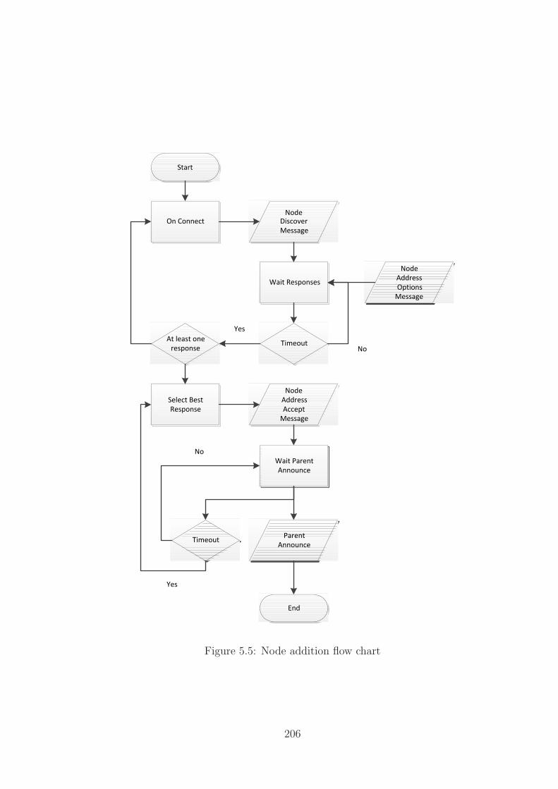
Start
End
On Connect
Node
Discover
Message
Wait Responses
Timeout
Select Best
Response
At least one
response
Node
Address
Accept
Message
Wait Parent
Announce
Node
Address
Options
Message
Parent
AnnounceTimeout
Yes
No
Yes
No
Figure 5.5: Node addition flow chart
206

Start
End
Removal Request
Wait Response
Node Parent
removal
request
Timeout
Parent
Removal
Acceptance
Remove Self
Remove Self
Node
Removal
Notification
Notify All Children
Wait Responses
Timeout
Remove Self
End
Yes
No
Yes
No
Figure 5.6: Node removal flow chart
be towards the virtual node routing area performing dynamic routing to allow the
other nodes in the area to automatically route around the damage. In the longer
timescale a node failure will result in either the redirection of traffic (ignore and for-
ward) or the alteration of the routing tree to account for the damage (restructure).
From the perspective of handling errors that will be fixed it is likely that the ignore
and forward methodology is used however if we consider longer term issues such as
the Egyptian Internet shutdown [235] the network should restructure itself to avoid
excessive rewriting and forwarding of data. Both of these processes can be handled
autonomously. In the case of the Egyptian network shutdown multiple autonomous
systems were withdrawn from the Border Gateway Protocol (BGP) tables connecting
Egyptian ISPs to the rest of the Internet. As HNTR attempts to remove the con-
cept of an AS to allow the more realistic representation of the underlying network
this would be represented by an alteration to the CRN to indicate that the Egyptian
roots nodes had been taken offline and alterante routes should therefore be taken
around the problem.
207

5.4.2.2 Link Failure
As with node failure, link failure is a common problem with varying degrees of seri-
ousness within the network. In terms of temporary link outage as with node outage
the detection of the link failure is crucial after which the local network area can decide
to route around the failed link temporarily (routing child traffic via another route) or
permanently through restructuring the addresses of the network. As restructuring is
an involved process it is typically more efficient to simply temporarily reroute traffic
for the duration of a short link failure.
5.4.2.3 Routing Path Alterations
Routing path alterations within the network can be performed using either a virtual
node process or non-virtual nodes.
Virtual Nodes Virtual nodes make the process of altering routing paths far simpler
as they can hide the alterations within the network by altering the router serving
the path within the virtual node as is performed in protocols such as Hot Standby
Router Protocol (HSRP) [236] without altering the addressing. As the change is local,
and only visible to management software, the effect is to alter the routing structure
without having to alter the higher level routing overlays. As with all redundancy
type protocols this process involves a small overhead in terms of both communication
within the group of nodes and the timeout of the nodes in the event of failure however
on a modern communications network the communication overhead is negligible and
the timeout can be reduced through active monitoring.
Non-Virtual Nodes In the scenario where we must alter a non-virtual node there
is the option to replace the real node (non-virtual) with a virtual node which is
served by one or more real nodes. In replacing a failed real node with a temporary
virtual node the network defaults to the virtual node scenario whereby the network
is unaware of the change on a non-local / non-management basis. If this solution
is not possible we default to altering the network setup and letting the IGRP and
network level protocols manage the routing overlay shift before updating the DNS
and similar structures to reflect the new status quo of the restructuring. During this
restructuring latency a virtual node will be created to manage traffic sent to the failed
real node for the duration of the update and the lag time associated with the DNS
changes within the update process.
208
5.4.2.4 Routing Management
The final operational concept we discuss is that of routing management, that is the
ability of the network to actively alter itself in response to ‘generic’ dictates from a
centralised source in a way which reflects the local routing situations. In the case of
HNTR routers this is a dynamic algorithm that alters the routing weights based on
the criteria set by the higher level authority. As an example if the pricing for transit
changes between two providers it can become beneficial to alter the routing path to
a cheaper solution however this must still reflect the reality of transit at a particular
location where the price alteration must be traded off (ideally dynamically) against
factors such as required QoS.
5.5 Interoperation Policies
The HNTR network is designed to be deployed alongside existing IPv4 and IPv6 de-
ployments and to interoperate through a combination of mapping, Network Address
Translation (NAT), and encapsulation. Between unconnected HNTR blocks the in-
teroperation block performs as an IP encapsulation point splitting the HNTR traffic
into IP compatible packets and forwarding these to the IP interface on the target
HNTR block where the content is reassembled and deencapsulated for routing as nor-
mal. NAT is explicitly supported via the ‘extensible header format’ allowing packets
to be directed through multiple layers of potentially non-heterogeneous address space
before reaching their final destination. A similar process can be repeated in reverse
providing encapsulation across IP segments of a majority HNTR network.
For interaction with IP networks the interoperation block performs two types
of mapping, fixed and dynamic. Fixed mapping is defined as a service offered to
HNTR nodes which can apply for a semi-permanent IPv6 or IPv4 address(dynamically
assigned by the block, or negotiated separately with the interoperability block simply
performing the mapping) which is mapped into the HNTR address space. Fixed
mapping is utilised to allow interoperation into an HNTR network from external IP
networks. Dynamic mapping is utilised for short term outgoing connections whereby
the outgoing node negotiates a temporary mapping from the available pool of IP
address / port space to its HNTR address. As these dynamic addresses are negotiated
on a short term basis they cannot be utilised for incoming traffic and so act as a
traditional firewall for the geographic network to prevent unrequested accesses.
Interoperation with IPv4 and IPv6 are handled in exactly the same way. In each
the interoperatbility block utilises assigned IP addresses and their port space to map
209

connections to end hosts within the geographic networks. Mapping functions in a
similar way to traditional NAT connections.
5.5.1 IPv6 Interaction
In contrast to IPv4 which can not represent large sections of the HNTR address
space it is possible to map large portions of the HNTR network onto IPv6 through a
mapping service. While the address spaces and identity spaces of the two networks
are not identical it is feasible to create a directory which maps the potentially dense
IPv6 address space of 64 bits to the sparse 128 bit address space of HNTR while
taking the remaining 64 bits of the IPv6 address as the identity of the node being
requested. While the exact mapping process is still non-linear (on a one to many
relationship) the relative density of the address spaces allows for a more effective
mapping and regional assignment of addresses using the ISP section of the unicast
IPv6 address space.
5.6 Hierarchical Network Topographical Routing
Deployable Units
Deploying a new network structure is always a difficult task due to the inherent
issue of limited connectivity to similar networks and interoperation with existing
network deployments. HNTR is designed to be rolled out utilising a geographic
building block approach whereby the construction can occur at any point in the
network. Each block consists of a self sufficient routing hierarchy composed of the
geographic routing block, a service and interoperation block, and the linked nodes
which may be other geographic building blocks. This structure is shown in Figure 5.7
a) with the root node defined as N and each of the child nodes down the hierarchy
defined as C# representing their position in the routing table. Each node’s address
is taken hierarchically as the concatenation of the parent nodes of this node, so for
node A the end address would be represented as N.C1.C1.A expressed as a binary
address pattern. This structure is recomposable with each section being able to be
connected to any other geographic routing block and renegotiate its position within
the existing hierarchy, acquire address space or other necessary information such as
disabled service block status.
The linkage of multiple blocks creates a self contained geographic routing network.
Each block performs an initial negotiation when connected following either an auto-
mated setup policy, or a master / slave block implementation to allow for manual
210

A B C D E F
C2
N
C1
C1 C1
C2
C2
Service Block
DNS
SDS
GWS
(a) Geographic network building block (b) Linked geographic network buildingblocks
Figure 5.7: a) Showing the fundamental building block of the geographic networkconsisting of a routing block, a service block (containing a domain name service, aservice description service and a gateway service), and linked nodes b) showing threelinked building blocks
configuration when no block has a higher connectivity or position in the network. In
the automated setup model the nodes determine the status of each of their connected
nodes and select from the offered network positions based on criteria set in the block
setup control. This selection may be based on the highest bandwidth upstream link,
bandwidth over all nodes, or any other appropriate criteria.
This composition is shown in Figure 5.7 b) with a top level routing block A being
attached to two other routing blocks B and C. Block A assumes a master / slave
connection and performs negotiation through R1 to the root nodes of the other routing
blocks R2 and R3 respectively. R1 assumes the root location (N) with the other two
routing blocks assuming child block positions and are renumbered sequentially within
the routing block A’s address space. R2 assumes address N.C1 while R3 assumes N.C2
and this address space change is cascaded down their routing blocks altering the stem
address of each node. Further negotiation will manage the status of each service block
and the routing entries for services.
5.6.1 Basic Network Components
Each section of the network consists of one or more routing levels (defined as N)
with child nodes associated with their own routing domains within the parent ad-
dress space. End-point nodes can be attached at any level of the network, service
211

Figure 5.8: Sample building block of network
blocks are attached at the highest point within a network block. This structure is
shown in Figure 5.8. The services typically required within a block are a DNS ser-
vice, an Service Definition Service (SDS), and an interconnection gateway to other
networks. Typically this will be a combination NAT and encapsulation service to
allow interaction with IPv4 networks. In this case the gateway device holds one or
more IPv4 addresses and maps outgoing IP connections to incoming geographic con-
nections. This service will never truly be capable of a direct mapping due to the
difference in address space sizes between HNTR and IPv4 however with the overlap
in UDP/Transport Control Protocol (TCP) connections it is a relatively simple task
to map the incoming and outgoing addresses to each other using port offsets assuming
sufficiently few HNTR nodes are mapping to each IPv4 address.
5.7 Deployable Services Block
5.7.1 Domain Name Services
As with the IP based Internet there is a requirement to map human readable and
more importantly memorable addresses for services and addresses on the web. These
services typically follow a dotted hierarchical notation following the pattern shown
in table 5.2. This DNS structure follows a hierarchy with the top level domains
redirecting requests to the specified domain name servers and continuing down this
chain until a specific server or service can be identified and linked to a specific HNTR
address. This service would typically be provided at an application level and therefore
not relevant to a routing protocol, however, as it is useful to be able to map textual
212

identities to more abstract concepts and so the service should be considered a baseline
requirement for a deployable network.
The structure of this service remains the same within a geographic network except
with the addition of additional DNS servers within the tree hierarchy. These servers,
due to the relatively stable nature of a geographic population, can maintain relatively
accurate addressing information without requiring large number of updates once they
reach an equilibrium state.
<Protocol>:// <Subsubdomain>. <Subdomain>. <Domain Identifier>. <Top Level Domain>: <Port >
Table 5.2: DNS Breakdown
5.7.2 Personal Name Services
As node mobility has been enabled by the separation of node identity from routing
information it becomes important to identify the location of a node through a fixed
service. This ability to directly locate a node acts to limit the triangular routing
problem that can occur in IP based mobility systems. The personal name service
acts like a DNS service to take requests for an identity and to return the currently
known, or last known attachment point of that identity.
Personal name services can act to store and forward data at a later date if the
node is currently offline.
5.7.3 Service Description Services
Service description services are a regional service to allow the automatic discovery of
localised services. These are identified by a provider and service ID of 16 bits each
with requests for this service never passed outwith the regional routing network. If
no SDS exists it is still possible for routers within the network to identify known
services and forward the packets appropriately with any reaching the regional level
being discarded.
5.7.4 Gateway Services
Gateway services are the provision for attaching a geographically named network
to a non-geographically named network. These services act as a combination NAT
and encapsulation/decapsulation service mapping the sending or receiving geographic
213

address to a network visible IP and port combination. This encapsulation service
enables a large number of nodes to be effectively hidden behind a relatively small
number of logical IP addresses. This service is activated using a specific geographic
packet type. Reverse communication is only possible if a semi-permanent forwarding
is setup however this is at the discretion of the individual gateway service.
There is of course the issue present with any mapping service whereby the network
which is not aware of the mapping process is unable to access nodes within the mapped
network which have not been actively registered with the service. Unfortunately this
process is unavoidable given the disparity in network address space size and mapping
between IPv4 and HNTR as it is under IPv6. While the reverse process is simple
via the implementation of a legacy address space within the new address space the
smaller to larger mapping requires active compression so must be performed upon
request or through a lookup service.
This encapsulation can also act to span other networks between geographic sec-
tions enabling networks to forward data between distinct geographic networks in a
transparent manner. This service allows for the deployment of the extensible units
making efficient deployment of small scale geographic networks possible.
5.7.5 Mapping Services
As it is not possible to directly map between the address spaces of IPv4, IPv6, and
HNTR one solution to the inability to perform contact across these address boundaries
is to utilise a system similar to the DNS which actively solicits and negotiates a NAT
on request. By mapping addresses spaces as a lexical value rather than treating them
as an address space it becomes possible to provide transparent interaction between
the three networks. This mechanism should be explored further in future work.
5.7.6 Extensible Unit Deployment
As noted above, the extensible unit is the core deployment in a geographic network.
Each consists of the service block with a mandatory gateway service linked to a
geographic routing tree. The gateway service is updated with currently known geo-
graphic networks and their mapped other network addresses enabling communication
in a completely transparent way, the geographic network will simply believe that data
is being carried correctly while the encapsulating network carries traffic between the
gateway nodes holding this routing information.
214

5.8 The Integration of the ISP
In chapter 2 it became apparent that future Internet trends may not be well aligned
with the business aspirations of current generation ISPs and that technologies are
moving around the network provider rather than with them. Chapter 3 further rein-
forced this lack of diversity through the imposition of regulation and management of
wholesale networks within the UK though similar legislative structures can be seen in
other countries worldwide. As a single ISP structure is unlikely to offer the consumer
a good service or foster innovation the increased service provision model of HNTR
and the service bundling allows for new models of competition and differentiation. It
is difficult to speculate on where the role of the ISP will eventually settle however as
it has moved nearly two full circles already it is likely to be in motion for some time
to come.
5.9 Conclusions
In this chapter further HNTR models have been explored including the explicit tag-
ging of packet headers to define how packets should be handled rather than in-lining
these within the data sections of the packets. By moving towards a more explicit sys-
tem the network is made more complicated on the surface however dedicated systems
become more easily constructed to deal with the limitations and requirements of each
service type. The proposed multicast structure integrates the simplified control model
and provides a mechanism for billing and management of the group such that client
focused multicasting becomes a viable technique within the Internet model. Further
the end-to-end nature of HNTR has been explored in that the same technology can
be deployed from the core network to the home environment allowing for increased
reuse of technology and systems across multiple levels of the network and ideally a
reduction in the cost of equipment provision.
215
Chapter 6
HNTR: Evaluation and UsageScenarios
6.1 Introduction
Having looked at the technical aspects of Hierarchical Network Topographical Rout-
ing (HNTR) in Chapter 4 and the open issues regarding HNTR as a fully formed
concept in Chapter 5 we can now place HNTR in the context of usage scenarios en-
visioned for a future Internet and perform an analysis of how its functionality differs
from what is available under current Internet Protocol (IP) based paradigms. This
chapter is broken into two major sections: evaluating aspects of HNTR, and deploy-
ment and usage scenarios for HNTR networks. The first section looks at various
traffic patterns and network setups providing validation data to show that HNTR
style networks provide efficiency gains over the existing IP based setup. The second
section looks with a softer focus at four usage scenarios: transport networks, mobile
workers, ubiquitous streaming, and localised transfers.
6.2 Evaluating Aspects of HNTR
A full network analysis of HNTR over a large network, given current traffic patterns
and usage, would show little in the way of improvement over existing routing systems
due to the physical configuration of the network with non-routable layers and central
routing points through Internet Service Provider (ISP)s. In order to demonstrate the
potential gains HNTR and typical IP routing setups are compared across four typical
scenarios: a small office network ; a typical last mile Internet network ; a co-operative
Bit Torrent environment; a cached video system. In these scenarios the network and
traffic are analysed as a perfectly co-operative system rather than through simulation
216

to give an indication of the maximum potential gains, or existing loses, within the
proposed system.
6.2.1 Small Office Environment
This scenario looks to show the comparative effectiveness of deploying HNTR against
a hierarchical IP network such as may be deployed in a typical small office. The first
networks compared look at a fully routed IP model. This network is then expanded
to show the effects of a more typical mixed layer 2 / 3 environment demonstrating
the effects of Virtual Local Area Network (VLAN)s and similar network sub-division
technologies on the routing topology as simple increases in routing distance.
6.2.1.1 Network Setup
The first network considered is a simple fully hierarchical network similar to many
very small company networks. The network design follows the pattern shown in
Figure 6.1a with a number of hosts (NH) attached to a single switched-router device.
NG of these units are attached to the main routing layer of the network. While it
is possible to consider deeper networks these would typically involve a mixed layer
2 / 3 environment due to the increased number of ports on layer 2 switch devices.
This scenario is used to evaluate the average node-to-node hop count. Figure 6.1b
modifies this setup to include a server attached at the top-most routing layer. This
network model looks at the average routing distance to the server in the fully routed
environment. As these network have only placed nodes at the very edges of the
network we finally consider the network shown in Figure 6.2 which places nodes off
each end point router.
Finally the network is expanded with layer 2 devices separating each end router
from the end hosts. The First network shown in Figure 6.3a places each VLAN on a
separate layer 2 switch as a well designed office environment with Figure 6.3b showing
the two VLANs intermixed requiring cross-network traffic to be routed across the full
network.
6.2.1.2 Application / Traffic Patterns Under Test
In this scenario we consider the hop counts between different points in the network in
order to verify that the HNTR type routing model provides improvements in potential
routing distances. In order to verify this we consider only IP networks setup either
as fully routed across all layers of the network or with non-routable layer 2 switches
217

(a) 2 Layer network with 3 routers, nodescommunicate directly with other nodes withno centralised control system
(b) 2 Layer network with 3 routers and cen-tralised server, nodes direct traffic to andfrom server representing centralised ISP man-agement mechanisms
Figure 6.1: 2 layer fully routed network structure. Nodes are linked only at edgerouters
Figure 6.2: 3 layer fully routed network structure with nodes attached at all edgerouters. This model more accurately reflects a typical office environment as opposedto previous models with fewer edge router attachment points
218
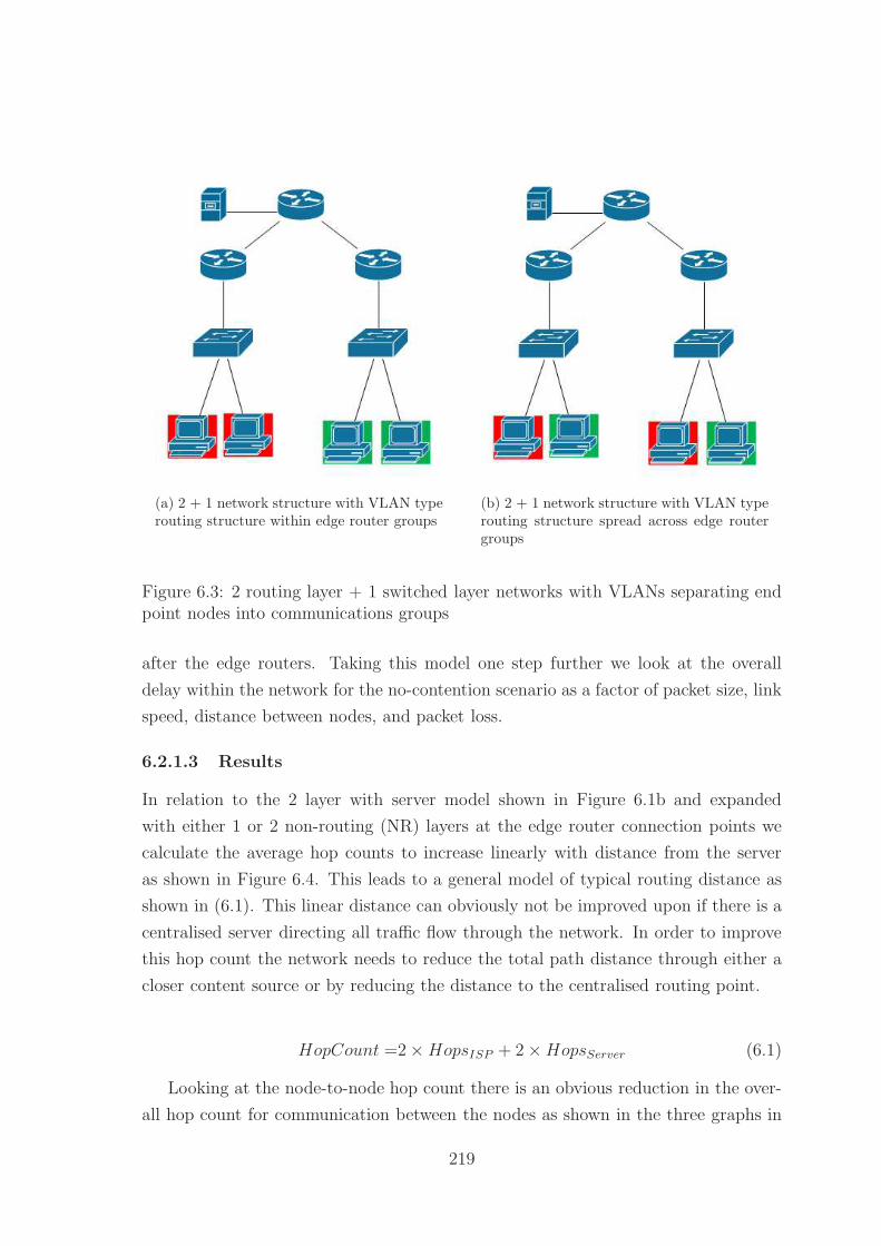
(a) 2 + 1 network structure with VLAN typerouting structure within edge router groups
(b) 2 + 1 network structure with VLAN typerouting structure spread across edge routergroups
Figure 6.3: 2 routing layer + 1 switched layer networks with VLANs separating endpoint nodes into communications groups
after the edge routers. Taking this model one step further we look at the overall
delay within the network for the no-contention scenario as a factor of packet size, link
speed, distance between nodes, and packet loss.
6.2.1.3 Results
In relation to the 2 layer with server model shown in Figure 6.1b and expanded
with either 1 or 2 non-routing (NR) layers at the edge router connection points we
calculate the average hop counts to increase linearly with distance from the server
as shown in Figure 6.4. This leads to a general model of typical routing distance as
shown in (6.1). This linear distance can obviously not be improved upon if there is a
centralised server directing all traffic flow through the network. In order to improve
this hop count the network needs to reduce the total path distance through either a
closer content source or by reducing the distance to the centralised routing point.
HopCount =2×HopsISP + 2×HopsServer (6.1)
Looking at the node-to-node hop count there is an obvious reduction in the over-
all hop count for communication between the nodes as shown in the three graphs in
219

Figure 6.4: Average hop count between end-router connected nodes and a centralisedserver for 0, 1, and 2 non-routing layers
Figure 6.5. In each of the pure-edge cases (figures 6.5a and 6.5b) the overall hop
count as the end-point node number (NH) increases towards infinity the hop count
approaches the maximum linear distance between the furthest two nodes in the hier-
archy. This effect remains true for the more realistic model with nodes attached at
all edge routers however the rate of approach is much lower as shown in Figure 6.5c.
From these results it is clear that decreasing the maximum linear distance between
nodes which need to communicate results in a more optimal solution for each node
group. Interpreting this data leads to the conclusion that bringing data closer to the
end points (lowering the point of inflexion in the network) reduces the number of hops
for peer-to-peer type scenarios.
The final results for this basic network setup are based around the delay within
the network based on distance between routing nodes and the packet loss within
the network. As we are most interested in the potential of utilising aggregation loss
bandwidth at the last-mile end of the network we do not consider packet loss due to
congestion. The graphs in Figure 6.6 show the average delay for cut through routing
models under varying network depths (for 1500 byte packets and a 100Megabits per
second (Mbps) connection bandwidth) of 1 to 7 layers. Figure 6.7 shows the results
for store and forward models under similar conditions. These graphs show that the
major impact on delay at the routing level is based primarily on distance rather than
the retransmit time at each individual router. The results for other packet sizes and
network connection bandwidths follow a similar trend with distance and number of
220

(a) Hop count vs nodes per end-point graph for a 2 layer routed network.Larger numbers of nodes increase the average distance between all nodes.
(b) Hop count vs nodes per end-point graph for a 3 layer routed network.Larger numbers of nodes increase the average distance between all nodes.
(c) Hop count vs nodes per end-point graph for a 3 layer routed network.Larger numbers of nodes increase the average distance between all nodeshowever the increased number of localised nodes reduces the rate of increasein hop count compared to previous graphs.
221

(a) Fully routed 1 layer network (b) Fully routed 3 layer network
(c) Fully routed 5 layer network (d) Fully routed 7 layer network
Figure 6.6: Delay graphs for cut-through routing model showing delay as a productof distance, network depth, packet loss for 1500 byte packets across a 100 Mbpsconnection
routers being the primary factors in delay increase.
6.2.1.4 Conclusions
These results of this scenario have shown that a fully routed hierarchical IP envi-
ronment (as a model for a HNTR network) at the worst case is capable of matching
the performance of a mixed environment network however has the capability to offer
more efficiency by reducing the routing tree between content source and destination.
The introduction of cross-layer technologies in a transparent manner to the network
results in reduced efficiency as the higher layers cannot provide localised routing and
storage to reduce the maximum linear distance between communicating nodes.
222

(a) Fully routed 1 layer network (b) Fully routed 3 layer network
(c) Fully routed 5 layer network (d) Fully routed 7 layer network
Figure 6.7: Delay graphs for cut-through routing model showing delay as a productof distance, network depth, packet loss for 1500 byte packets across a 100 Mbpsconnection
223

6.2.2 Last Mile Internet network
This scenario looks to evaluate the affect of last-mile aggregation points on traffic flow
within an Internet like environment. This scenario attempts to look at the effect of
adding aggregation layers to a traditional IP Internet as opposed to the fully routable
HNTR network design.
6.2.2.1 Network Setup
The IP network setup follows the typical last-mile Internet setup with a number of
end users connected via xDigital Subscriber Line (DSL) router / modems connected
to the telecoms network via a street level cabinet feeding into one or two layers
of Digital Subscriber Line Access Multiplexer (DSLAM) devices. The output from
these DSLAM layers is then put through contention before being forwarded into the
transit and ISP backbone networks. Traffic is encapsulated for transit over either
Asynchronous Transfer Mode (ATM) or Ethernet from the first DSLAM layer and so
is effectively un-routable from the IP network’s perspective. This setup is shown in
Figure 6.8a.
As further aggregation layers only reduce the capability of the IP network due to
the overall bandwidth reductions we consider a single level of aggregation only capped
at 1/Nth of the total bandwidth of the M end users with bandwidth B each; typically
N = M giving an upstream bandwidth of B. This is a simplification of the overall
network structure which typically would provide contention across multiple groups of
users to match the available backhaul bandwidth and provide better aggregation of
traffic flows.
The HNTR network follows a similar setup however introduces HNTR routers
below the first aggregation point. Internal traffic at this point will therefore be redi-
rected within the network rather than being forced through the aggregation layers
before being routable. The HNTR router design paradigm suits this kind of deploy-
ment as it allows for bottom up and last-mile content distribution. This setup is
shown in Figure 6.8b.
At the aggregation layers the same contention factor is assumed as the IP network
with M end users with an individual bandwidth B and an upstream bandwidth of B
giving a 1:M contention ratio.
224
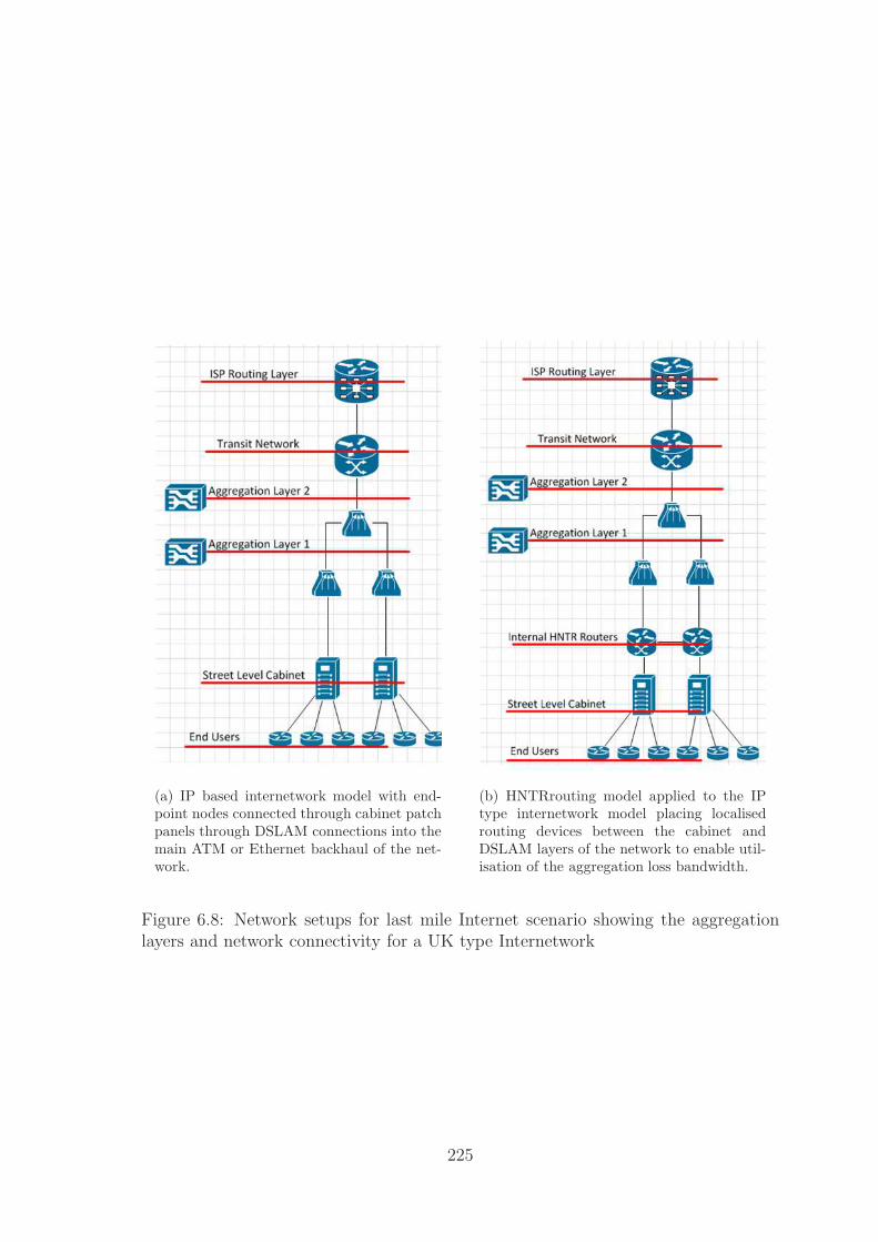
(a) IP based internetwork model with end-point nodes connected through cabinet patchpanels through DSLAM connections into themain ATM or Ethernet backhaul of the net-work.
(b) HNTRrouting model applied to the IPtype internetwork model placing localisedrouting devices between the cabinet andDSLAM layers of the network to enable util-isation of the aggregation loss bandwidth.
Figure 6.8: Network setups for last mile Internet scenario showing the aggregationlayers and network connectivity for a UK type Internetwork
225
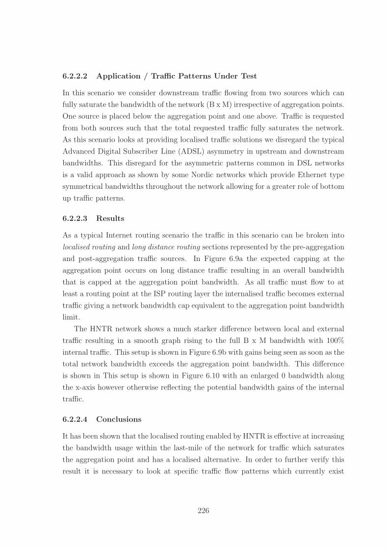
6.2.2.2 Application / Traffic Patterns Under Test
In this scenario we consider downstream traffic flowing from two sources which can
fully saturate the bandwidth of the network (B x M) irrespective of aggregation points.
One source is placed below the aggregation point and one above. Traffic is requested
from both sources such that the total requested traffic fully saturates the network.
As this scenario looks at providing localised traffic solutions we disregard the typical
Advanced Digital Subscriber Line (ADSL) asymmetry in upstream and downstream
bandwidths. This disregard for the asymmetric patterns common in DSL networks
is a valid approach as shown by some Nordic networks which provide Ethernet type
symmetrical bandwidths throughout the network allowing for a greater role of bottom
up traffic patterns.
6.2.2.3 Results
As a typical Internet routing scenario the traffic in this scenario can be broken into
localised routing and long distance routing sections represented by the pre-aggregation
and post-aggregation traffic sources. In Figure 6.9a the expected capping at the
aggregation point occurs on long distance traffic resulting in an overall bandwidth
that is capped at the aggregation point bandwidth. As all traffic must flow to at
least a routing point at the ISP routing layer the internalised traffic becomes external
traffic giving a network bandwidth cap equivalent to the aggregation point bandwidth
limit.
The HNTR network shows a much starker difference between local and external
traffic resulting in a smooth graph rising to the full B x M bandwidth with 100%
internal traffic. This setup is shown in Figure 6.9b with gains being seen as soon as the
total network bandwidth exceeds the aggregation point bandwidth. This difference
is shown in This setup is shown in Figure 6.10 with an enlarged 0 bandwidth along
the x-axis however otherwise reflecting the potential bandwidth gains of the internal
traffic.
6.2.2.4 Conclusions
It has been shown that the localised routing enabled by HNTR is effective at increasing
the bandwidth usage within the last-mile of the network for traffic which saturates
the aggregation point and has a localised alternative. In order to further verify this
result it is necessary to look at specific traffic flow patterns which currently exist
226
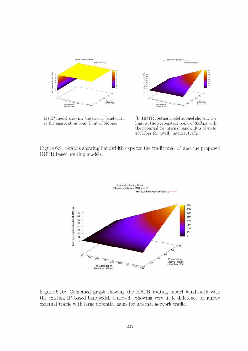
(a) IP model showing the cap in bandwidthat the aggregation point limit of 8Mbps.
(b) HNTR routing model applied showing thelimit at the aggregation point of 8Mbps withthe potential for internal bandwidths of up to400Mbps for totally internal traffic.
Figure 6.9: Graphs showing bandwidth caps for the traditional IP and the proposedHNTR based routing models.
Figure 6.10: Combined graph showing the HNTR routing model bandwidth withthe existing IP based bandwidth removed. Showing very little difference on purelyexternal traffic with large potential gains for internal network traffic.
227

that would benefit from this localised routing: co-operative bit torrent systems and
localised video caching / streaming systems.
6.2.3 Co-operative Bit Torrent Network
In modern content distribution systems the concept of peer-based redistribution is
becoming increasingly useful as a way to reduce the overall bandwidth required by
the original host as well as allowing the end points to decrease download times and
saturate their download capability. As this type of distributed system can benefit
from co-operation between end points we look at how co-operation below aggrega-
tion points can effectively mimic the benefits of multicast on non-multicast enabled
systems through the use of aggregation-loss bandwidth.
6.2.3.1 Network Setup
In this scenario we consider both a one and two aggregation layers between the original
content source and the end point nodes. The network is divided into zones represent-
ing sub-networks within the same aggregation layer (and therefore aggregation-loss
bandwidth). Co-operation is considered between zones and end-points within the
same sub-zones. We assume perfect co-operation between zones and no end-points
dropping from the swarm during the content delivery process. Each end-point router
is assumed to support M end-point hosts.
The single aggregation layer network shown in Figure 6.11a has 3 layered zones
with a co-operation policy pulling 2M parts of the content into zone 2. As last-mile
multicast is rarely possible on UK ISP networks it is not possible to simply have the
main router in zone 2 multicast the traffic down and there are no traffic-replication
protocols at the hardware level we sent M parts to each of the routers in zone 3. These
routers then co-operatively push their newest parts to the other router achieving the
co-operative multicast equivalent with a 1 chunk time unit delay.
The two aggregation layer network shown in Figure 6.11b again has 3 layered
zones with a co-operation policy pulling 2M parts of the content into zone 2 which
are split across the two zones. As we cannot push content in a single time unit past
to all other zones we must daisy chain the content to the other zones resulting in
an overall completion delay equivalent to the number of zones assuming a cross-bar
bandwidth equivalent to the maximum connected node bandwidth. This reduction
can either be used to reduce the load on the main server or to increase the distribution
rate of the content cooperatively. As there is no multicast assumed the cooperative
model creates a very similar traffic flow to the single aggregation point model.
228
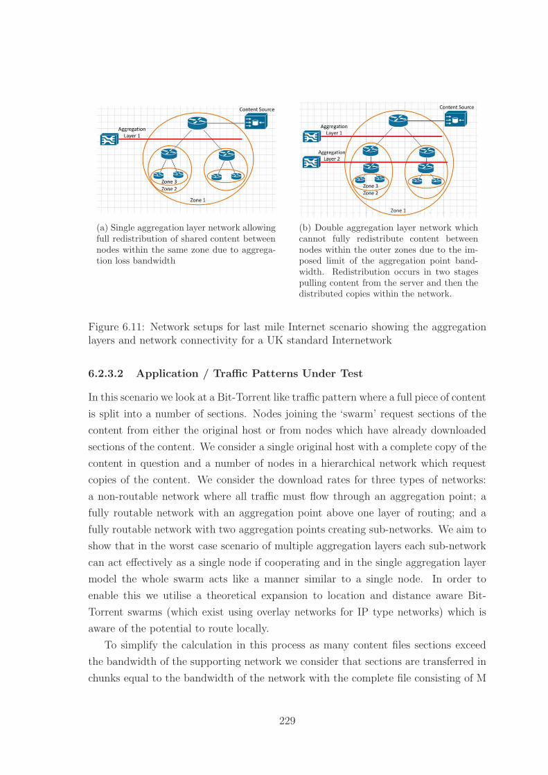
(a) Single aggregation layer network allowingfull redistribution of shared content betweennodes within the same zone due to aggrega-tion loss bandwidth
(b) Double aggregation layer network whichcannot fully redistribute content betweennodes within the outer zones due to the im-posed limit of the aggregation point band-width. Redistribution occurs in two stagespulling content from the server and then thedistributed copies within the network.
Figure 6.11: Network setups for last mile Internet scenario showing the aggregationlayers and network connectivity for a UK standard Internetwork
6.2.3.2 Application / Traffic Patterns Under Test
In this scenario we look at a Bit-Torrent like traffic pattern where a full piece of content
is split into a number of sections. Nodes joining the ‘swarm’ request sections of the
content from either the original host or from nodes which have already downloaded
sections of the content. We consider a single original host with a complete copy of the
content in question and a number of nodes in a hierarchical network which request
copies of the content. We consider the download rates for three types of networks:
a non-routable network where all traffic must flow through an aggregation point; a
fully routable network with an aggregation point above one layer of routing; and a
fully routable network with two aggregation points creating sub-networks. We aim to
show that in the worst case scenario of multiple aggregation layers each sub-network
can act effectively as a single node if cooperating and in the single aggregation layer
model the whole swarm acts like a manner similar to a single node. In order to
enable this we utilise a theoretical expansion to location and distance aware Bit-
Torrent swarms (which exist using overlay networks for IP type networks) which is
aware of the potential to route locally.
To simplify the calculation in this process as many content files sections exceed
the bandwidth of the supporting network we consider that sections are transferred in
chunks equal to the bandwidth of the network with the complete file consisting of M
229

Figure 6.12: Graph showing the linear scaling of the traditional Bit Torrent modelacross an aggregation point which acts as a bottleneck. By adding localised routingto the network we enable the fast O(1) scaling for the single aggregation layer model,or the slightly higher O(n) scaling for the 2 aggregation layer model.
= 50 sections. In cases of contention between multiple nodes a round robin policy is
applied to the traffic.
6.2.3.3 Results
The results for this scenario are shown in Figure 6.12 which shows that the traditional
Internet model which forces all traffic through aggregation points results in a linear
scaling of the time to download the full content to all nodes. This model’s primary
benefit is not in the reduction in traffic volume or speed but rather the reduction in
server load as other nodes begin to serve data to the network. In contrast we see that
the single aggregation point network makes use of the internal bandwidth within the
secondary zones to fully redistribute the aggregation point limited content to the all
nodes within the zone. The two layer aggregation point network is unable to achieve
this constant scaling due to the limitations in bandwidth however can effectively daisy
chain the content across multiple zones, before redistributing within each zone, giving
an effective linear scaling with the number of zones.
230

6.2.3.4 Conclusions
As has been shown co-operative bit-torrent solutions can effectively increase the ef-
ficiency of the system by reducing the load on the server, however, the reduction in
overall traffic can be questionable due to the requirement to redirect traffic through
a management or aggregation point which creates an effective bottleneck on the net-
work. By introducing routing capability below the aggregation point multiple nodes
can more effectively share content achieving either a constant or very small linear
increase in the overall time taken to serve the content. As this model is not aimed at
reducing the load on the server so much as actively decreasing content distribution
times the load on the server is maintained constantly through the swarm’s download-
ing. A more complex model of a cooperative Bit Torrent solution should look at the
sustained cost for transient nodes and nodes which join after the initial distribution
of the content in order to provide a fuller picture of the potential benefits in this area.
6.2.4 Cached Video System
6.2.4.1 Network Setup
This scenario considers a HNTR routing model applied to the traditional IP routing
model Internet last mile common in the UK as shown in Figure 6.13. This setup
includes two content sources for the cached content - one in the transit or network
core as either an ISP level cache or a British Telecom (BT) Connect style cache within
the transit network at the Metro equivalent layer.
6.2.4.2 Application / Traffic Patterns Under Test
In this scenario we consider a traffic pattern in which end nodes request content from
their local content server - A in the non-routable tests and B in the fully routable
tests. The overall quality of content stream as given by the bandwidth allocated
to each node is considered in terms of number of different content streams and the
number of nodes sharing a stream. We consider only the non-pre-cached situation for
this scenario as any content cached within server B will be able to make use of the
aggregation loss bandwidth and so will maintain the maximum quality available on
the non-shared bandwidth links.
6.2.4.3 Results
The per user per stream bandwidths were calculated as shown in Figure 6.14 for a
non-multicast, non-pre-cached scenario to demonstrate the benefits of utilising the
231

Figure 6.13: HNTR routing model applied to the existing IP model Internet modelfor a UK based internetwork
232

(a) Single aggregation layer network allowingfull redistribution of shared content betweennodes within the same zone due to aggrega-tion loss bandwidth
(b) Double aggregation layer network whichcannot fully redistribute content betweennodes within the outer zones due to the im-posed limit of the aggregation point band-width. Redistribution occurs in two stagespulling content from the server and then thedistributed copies within the network.
Figure 6.14: Network setups for last mile Internet scenario showing the aggregationlayers and network connectivity for a UK standard Internetwork
aggregation loss bandwidth to provide additional resources to the local network. Nei-
ther network handles multiple discrete streams at a reasonable quality ( 3Mbps)
due to the presence of the aggregation point throttling the bandwidth to the lower
cache / the end users. The IP model shown in Figure 6.14a manages to support 2
discrete streams with one user each under these conditions before dropping below
the threshold for high definition video. In contrast to this the HNTR model shown
in Figure 6.14b can support a full sub-network of users sharing up to two discrete
streams before dropping below the high definition threshold. In both of these cases we
can clearly see that it is content diversity that cannot be easily handled by a localised
caching system while a pure unicast distribution model cannot handle either content
diversity or user volume effectively.
6.2.4.4 Conclusions
From these tests it is clear that the aggregation layers present in the current Internet
structure are major hindrances to the deployment of efficient caching solutions within
the network in terms of content diversity at any given time period. Through statistical
analysis of viewing patterns though and pre-caching of popular content these barriers
can be reduced and low level caches implemented to maximise the use of aggregation
loss bandwidth. The further inability to route at all levels reduces the effectiveness of
233

caching solutions especially in co-operative environments where multicast cannot be
enabled. The deployment of a true bottom up caching solution, or video streaming,
is therefore greatly impeded by the current Internet last mile structure despite the
prevalence of last-mile content devices.
6.2.5 Conclusions
From the analyses carried out using a traditional IP model and an IP model using
HNTR routing policies the following has been demonstrated:
• HNTR demonstrates potential hop count improvements over IP routing for non-
centralised routing
• HNTR type routing can be implemented in IP systems with suitable subnet
deployment
• HNTR type routing is stymied in an IP environment by the layer 2 / 3 divide
• HNTR type routing is beneficial for co-operative routing environments and of-
fers excellent scaling capability
• Network technologies such as VLANs and spanning tree routing reduce the
capability to actively route the network
• Intelligent routing can make applications smarter and reduce the overall impact
of traffic on the network
While the results above demonstrate that none of the improvements in a HNTR
routing environment are impossible to replicate under an IP paradigm there are sig-
nificant barriers to this type of improvement in the existing network. These routing
improvements all focus in the last-mile type network environment which has been
shown to be the slowest evolving of the commercial Internet areas due to the very low
cost:benefit scaling. Backbone Internet services have shown potential improvements
towards 80Gbps speeds over existing fibre connections, however, these improvements
have not filtered down to the last mile effectively with fibre to the cabinet (FTTC)
and fibre to the premises (FTTP) deployments very limited within the UK. By taking
advantage of the available bandwidth in the last mile which is aggregated away it be-
comes possible to effectively increase the services providable and the user experience
at minimal additional cost.
234

6.3 Deployment and Usage Scenarios for HNTR
Networks
In this section we consider three common deployment scenarios, two future deploy-
ment scenarios, and three common usage scenarios as they exist under an IP paradigm
and how these would translate to a HNTR based deployment. Deployment scenarios
include: multinational networks, multi-presence networks, and virtual circuits. Future
deployment scenarios consider scenarios which are not common at current however
are feasible in the near future including ubiquitous deployment and transport net-
work deployment. Finally the usage scenarios include virtual private networks, proxy
connections, and chained networks.
6.3.1 Multinational Networks
It is common in the current Internet for large international corporations to have a
single large IP block to which they assign routable addresses across multiple global
sites. This involves the addition of multiple sub-blocks being added to the global
routing tables as well as directing Domain Name Service (DNS) based queries for
country specific web based services to the appropriate region. Under HNTR the
network loses the ability to directly assign a single ‘routing block’ to a corporation
because the concept of a non-topographical ‘routing block’ no longer exists. Rather
we can implement solutions to different parts of this problem under different guises.
Multiple Site Addresses Each regional site will have a region local address speci-
fied in the Continental Routing Network (CRN) : Regional Routing Network (RRN) :
Geographically Localised Network (GLN) 128 bit format that defines the connection
point for the site network. This address will be ‘fixed’ based on the network topo-
graphical position of the site in relation to others in the region. This global address
defines the main connectivity / location of the site within the network. Individual
sub-sites within this network can be directly numbered using the global address space
or an organisation can make use of the 32 / 64 bit site-local addresses. As these ad-
dresses are not strictly globally routable they can follow any routing protocol the
internal network wishes to utilise, for ease it is suggested that the internal network
follow a HNTR hierarchical numbering system however an IP type subnet approach
would also be simple to implement on a local scale. The lack of global routability
in these addresses is addressed through a similar mechanism to the network address
generated from the Media Access Control (MAC) address of the node in IP version
235

6 (IPv6) in that the site address is either appended to, or maps to, the site local
addresses transparently to the end point nodes.
Global or Site-Local Address Range If the organisation decides to maintain
addresses within the global pool the mechanisms for intra and inter-site follow the
standard HNTR routing mechanisms, use of the site-local addressing schemes can
be performed either in parallel or in place of the global-routing mechanism. In the
parallel scheme each network node is assigned both a global routing address and a
site-local address of either 32 or 64 bits, with solely site-local addressing the gateway
performs site level Network Address Translation (NAT) and provides each host with
a site-local address. If we consider the multinational company shown in Figure 6.15
with four sites: A - Japan, B - USA, C - UK, D - Australia connected via leased
lines to their ISPs with each site supported by a backup ADSL connection in case of
main leased line failure. In figures 6.16a and 6.16b we see the core of a traditional
three layer network model for site networks with a fully meshed core supporting dual
parented department distribution routers, with the Internet connection gateway /
router dual parented into the core mesh. The routing addresses for the networks at
sites A and B are shown in table 6.1 and table 6.2 respectively. Each table shows the
equivalent global address, the 32 bit address assuming a 3 bit continent code, 2 bit
site code, and a 2 bit source leaving 25 bits for the internal network, the 2 source bits
are contained within a meta-routing-area and so are considered unimportant for the
internal numbering system. The 64 bit local address scheme assumes a 3 bit continent
code and a 4 bit internal network identifier further into the address.
Internally the use of any of the 3 address pools (depending on setup) will route
correctly to the local address, and the global addresses allow full inter-site connectiv-
ity. If a local address is forwarded to the gateway which is not physically local to the
site but rather ‘local’ to the address pool it is transparently encapsulated and for-
warded to the appropriate connected ‘local’ site. This allows the company to utilise
a single internal address pool within multiple sites. If a site-local address pool is used
which maps directly to the global address pool it is possible to directly utilise these
interchangeably. An example of these masks is shown in table 6.3 for R1 in site A
however an equivalent set of masks would be present in either the Internet gateway
device or R1/R2 at each site depending on the network setup chosen.
Global Aliases As HNTR maintains the concept of a DNS global aliasing remains
possible and regions should default to their localised versions automatically unless
236

Figure 6.15: Multinational site locations shown on world map
(a) Site A - Japan - network structure (b) Site B - USA - network structure
Figure 6.16: Network diagrams of sites A and B of the multinational corporation
237

Router Global Site-32 Site-64Internet GW ASIA.JPN.Tokyo.MNC.(INET) 0010101[25] 001[29]0101[28]ADSL Backup ASIA.JPN.Tokyo.MNC.(BKUP) 0010110[25] 001[29]0110[28]
R1 ASIA.JPN.Tokyo.MNC.R1 00101XX01[23] 001[29]01XX01[26]R2 ASIA.JPN.Tokyo.MNC.R2 00101XX10[23] 001[29]01XX10[26]R3 ASIA.JPN.Tokyo.MNC.R1.R3 00101XX0101[21] 001[29]01XX0101[24]R4 ASIA.JPN.Tokyo.MNC.R2.R4 00101XX0110[21] 001[29]01XX1001[24]R5 ASIA.JPN.Tokyo.MNC.R1.R3.R5 00101XX010101[19] 001[29]01XX010101[22]R6 ASIA.JPN.Tokyo.MNC.R2.R4.R6 00101XX011001[23] 001[19]01XX100101[22]
Table 6.1: Strict hierarchical HNTR address assignment for site A - Japan
Router Global Site-32 Site-64Internet GW NA.US.EC.NY.NYC.MNC.(INET) 0100101[25] 010[29]0101[28]ADSL Backup NA.US.EC.NY.NYC.MNC.(BKUP) 0100110[25] 010[29]0110[28]
R1 NA.US.EC.NY.NYC.MNC.R1 01001XX01[23] 010[29]01XX01[26]R2 NA.US.EC.NY.NYC.MNC.R2 01001XX10[23] 010[29]01XX10[26]R3 NA.US.EC.NY.NYC.MNC.R1.R3 01001XX0101[21] 010[29]01XX0101[24]R4 NA.US.EC.NY.NYC.MNC.R2.R4 01001XX0110[21] 010[29]01XX1001[24]R5 NA.US.EC.NY.NYC.MNC.R1.R3.R5 01001XX010101[19] 010[29]01XX010101[22]R6 NA.US.EC.NY.NYC.MNC.R2.R4.R6 01001XX011001[23] 010[19]01XX100101[22]
Table 6.2: Strict hierarchical HNTR address assignment for site A - USA
Destination Global Mask 32 Mask 64 MaskSite B NA.US.EC.NY.NYC.MNC[0] 01001[0] 010[29]01[0]Site C EU.UK.ENG.LDN.MNC[0] 01101[0] 011[29]01[0]Site D PAC.AUS.EC.SYD.MNC[0] 10001[0] 100[29]01[0]Site A ASIA.JPN.Tokyo.MNC[0] 00101[0] 001[29]01[0]Internet [0] [0] [0]
Table 6.3: Encapsulation masks for R1 at site A - Japan
238

a different region is specified by specifically requesting a different DNS record from
the server, this means the DNS server should return either all matches or the version
with the same longest routing code as the requesting service unless otherwise speci-
fied. This functionality allows for the regionalisation of content in a similar manner
to emphexample.com/emph redirecting to emphexample.co.uk/emph automatically
however allows the user to deliberately override this regionalisation if required. As
the CRN and RRN of the host are known from the source field it is possible to auto-
matically determine the appropriate first sub-region to route users to giving similar
functionality to a geo-IP database lookup however with a lower overhead due to the
smaller lookup table size.
6.3.2 Multi-presence Networks
Multi-presence / multi-site networks under IP are common with a corporation or site
maintaining two separate Internet connections for redundancy and load balancing fea-
tures. Within the UK this style of redundancy is largely possible in densely populated
areas as multiple ISPs have overlapping network coverage as shown in section 2.5.1,
however outside of these large population centres the redundancy aspect is weakened
by the lack of alternate connections often leaving only the UK wide BT network as
the single point of failure. As such it is questionable as to whether true redundancy
can be achieved within a network structure such as is seen in the UK; this is further
shown in the United States (US) by the localised regional monopolies whereby the
only ISP choices in a wide area may be a single telecommunications service such as
Sprint or Comcast, and a single cable operator. If we assume however that this full
redundancy / independence of connectivity can actually be achieved then it becomes
beneficial to companies and Internet users to be able to make use of this dynamic
redundancy where possible. Within HNTR we assume that localised networking in-
terconnection points are generally shared due to the limitations on street level rack
space and security / ducting costs for larger facilities - this model works within the
UK especially where BT has a regulatory requirement to share facilities due to its
former monopoly position. As such rather than treating each ISP connection as sep-
arate we treat areas of the network as common and thus achieve potential dynamic
redundancy by allowing the routing of data between independent networks to a sin-
gle geographic / topographical location via a shared address space. This requires the
addition of a dynamic distributed billing structure [237, 238] where there exists a
centralised system currently. This change to a distributed model takes advantage of
the existing growth in general purpose computing power available on routing devices
239

and the reduced complexity offered by HNTR routing to enable the better use of this
power towards services rather than expensive software routing.
Assuming that networks do indeed share common points such as street level cab-
inets then this readdressing scheme makes a single location site appear as two nodes
attached to a single geographical / topographical routing point. This allows the net-
work to perform dynamic load sharing and avoid issues such as localised hotspots /
overloading a single network with a wider view than the site-local network view would
allow. Under this model there are two areas of control, the site local gateway and the
network provider. The local site’s gateways direct and rewrite traffic as appropriate
to their network view and / or requirements such as preferred routes for internal traf-
fic and the external routes they wish the packets to take. The network providers then
independently routes traffic either through their own network or directing it through
a linked competitor’s network depending on network conditions in a similar fashion to
current IP Autonomous System (AS) routing methods. In this way incoming traffic
is directed by the incoming party’s ISP chain policy, and outgoing traffic is directed
by a combination of the internal load-balancing / policy and the network state at
current rather than simply by the internal policy model. As always with HNTR the
DNS support model allows for multiple site listings for the Internet facing gateways
selected by appropriate policy or the inclusion of a meta-routing-area address which
will be served by any appropriate router in the area. Internally we should consider a
standard configuration to be a virtual node within a meta-routing-area with multiple
real gateway routers directing the traffic.
In contrast to the shared model if we have fully independent networks which are
separate topologically but not geographically we are limited to the internal routing
policies to direct traffic onto appropriate networks and therefore cannot actively man-
age the overall data flow across the network as a whole. This does however simplify
the network and billing model as seen under the current IP paradigm because con-
nections can not be actively managed across multiple providers with any reasonable
feedback to the local site.
6.3.3 Virtual Circuits
Virtual circuits are generally not available as a client side technology within a telecom-
munications network however are widely deployed as an administrative technology
through protocols such as Multiprotocol Label Switching (MPLS) which place labels
on locations in the network or paths through it and allow routers to forward encap-
sulated data directly along a predetermined path. Under a HNTR implementation
240

this type of policy is directly implementable using the flow label within the packet
(limited to 2× 10²⁰ addresses) allowing a similar type of virtual-circuit routing to be
performed on both client and administrative sides in a manner similar to constructing
a multicast group with only a single host / destination in the routing path. Taking
the network shown in Figure 6.17a with a host attached across a partially meshed
network to an Internet service we can construct a pseudo-virtual-circuit between the
two assuming the host has permission to create virtual paths in this network. In
Figure 6.17b the host adds R3 to the routing path, R1 and R2 are added to the group
by default as there is no path choice in this stage. The host then adds R7 to the
routing path as shown in Figure 6.17c, the network adds R5 as the optimal choice of
route between R3 and R7. Finally in Figure 6.17d we see the host add the service
itself as the destination which may add either R8-Service, or the direct path to the
service.
An alternate method of managing virtual circuits in a more administrative manner
is to add paths to the GLN routing space to provide virtual forwarding addresses
to other nodes within the network. This is managed by using one of the reserved
GLN numbers as a network specific routing prefix, typically the zero prefix would
be reserved for this purpose. As always there is the direct ability to chain network
headers within the packet allowing the directed forwarding of along the specified path
however this does not mimic the low overhead associated with an MPLS flow label.
6.3.4 Virtual Private Networks
Virtual Private Networks (VPNs) are very common in the Internet at current in either
remote-access or site-to-site variations which enable the secure transfer of data across
a public network. In terms of remote access and simple direct site-to-site a HNTR
implementation of a VPN would be no different to the solution under an IP paradigm
and the removal of IP Security (IPSEC) a mandatory requirement [239] on all IPv6
connections ensures parity in terms of optional and mandatory security between
Internet Protocol version 4 (IPv4), IPv6, and HNTR implementations. In terms of
the combination of inter-site VPN and remote-access HNTR allows for improvement
over IP based solutions due to the ability to directly route traffic between any two
connected nodes. This capability allows an organisation to maintain a single set of
authentications services at their central office and have multiple remote-to-site VPNs
rather than directing traffic through the central site in order to ensure traffic appears
to come from an internal network. If we consider the scenario in Figure 6.18 with a
central office in Birmingham, a site office in Glasgow, and a teleworker located in the
241

(a) Virtual Circuit Network
(b) Virtual Circuit Network Stage 1
(c) Virtual Circuit Network Stage 2
(d) Virtual Circuit Network Stage 3
Figure 6.17: Client side virtual circuit creation within an arbitrary network
242

Nottingham area we can consider the worst case scenarios for triangular routing under
IP and HNTR. Under IP we would consider the transit path to be worker - central
- site - central - worker for all traffic with each pairing potentially involving traffic
being routed through an Internet exchange such as found in London. In contrast
under HNTR we would have an initial setup phase consisting of worker - central and
central - site however additional traffic could then flow directly between the site and
teleworker reducing the latency and data transfer across the network. Assuming all
traffic flows through London we consider the round trip distance for an IP network to
be on the order of 2,000km, assuming 49c (speed of light in fibre optic lines), giving a
minimum latency of around 15ms, in contrast with direct site to site routing we drop
the sustained round trip distance to approximately 900km, decreasing the minimum
latency to 6.75ms. While these times appear insignificant it is likely that the number
of routers in a continental routing path will scale relatively linearly with this distance
and so the relatively real world latency would drop by a similar fraction. The linear
scaling will not hold for under-sea or long-haul routes which maintain repeaters /
signal regeneration technology instead as these should function at line speed and be
effectively undetectable.
6.3.5 Proxy Connections
A proxy connection is simply a network node acting to forward requests and responses
for another node in a non-transparent manner, the most visible variant of this is in
onion / garlic routing protocols such as Tor Onion Routing (TOR). As the basic form
of this kind of connection is typically implemented as an address rewriting protocol
with the proxy node performing the forward and backward translation of addresses
it maps directly onto HNTR as it would under IP. For a more complex version of
the proxy connection such as onion routing the same process would apply with the
original content being encrypted and encapsulated in a routing packet directing it
into the onion routing network, routers within the network then obfuscate the path
using multiple 1:1 proxy connections before the exit router removes the first layer
of encapsulation and forwards the encrypted and encapsulated inner packet to the
destination.
As there is no identity mechanism under IP it is not possible to easily manage
individual application profiles to automatically enable proxy routing where needed.
The mandatory addition of an identity layer under HNTR and the linking of sub-
identities it becomes a simpler process to automatically enable proxy routing where
needed. This mechanism allows for the redirection of certain accounts to a proxy
243

Figure 6.18: 3 site VPN showing triangular routing for IP network
244

server, such as the ISP, to allow the automatic restriction or filtering of content.This
type of filtering could be performed at an application layer however it would not be
easily possible to for example forward work based browsing via a VPN using a white
list while all other traffic is forwarded through a proxy connection. Under IP a similar
approach is taken with the private address spaces however the limitations on the size
of these networks places limitations on large scale distributed institutions such as the
Department of Defense (DoD) or Comcast.
The addition of this kind of automatic management tool allows for finer control
over the usage and management of traffic for the end-user. With the growing num-
ber of multi-user devices it becomes more important to ensure appropriate levels of
control.
6.3.6 Chained Networks
While it is not very common to have a ‘dark’ net attached to the Internet, or rather
their existence is hard to determine since they can only be accessed by knowing
they exist, there are scenarios which can be envisioned whereby a network is always
routed separately. As with IP, HNTR supports the ‘next header’ field allowing the
chaining of multiple routing protocols as well as simple encapsulation or address
rewriting of packets to handle this kind of connectivity. This ‘dark’ net routing is
seen partially in the current Internet through networks such as TOR which provide an
partial anonymising overlay onto the existing network. This kind of network is likely
to see an increase in popularity in the future as security of communication, and the
interception of communications through technologies such as McAfee Smartfilter [240]
as seen in Tunisia in January 2011 becomes more common. Taking this kind of
censorship into account it is feasible under HNTR to maintain an entirely separate
HNTR network with its own topological or geographic mapping attached to the ‘real’
Internet for the purposes of both widely dispersed secure networks or the masking of
‘real’ Internet traffic. In terms of widely distributed secure networks the limitations of
the private networks under IPv4 have placed limitations on very large networks such
as the US DoD which has a global presence, or Comcast which maintains more than
the 16million device limit on its control plane. Under IPv6 these space limitation
have been relaxed however the private address space of fc00::/7 is in fact a ‘globally
routable’ block, and the site-local address space of fec0::/10 has been deprecated since
September 2004. In terms of the virtual network to route around censorship there is
no explicit handling for this under either IPv4 or IPv6 other than a solution such as
transparent proxying, while HNTR also does not provide a ‘hidden network’ feature
245

the full 128 bit address space can be utilised, as can the reserved GLN blocks, and
the next network header to allow for improved access to non-visible networks.
6.3.7 Location Aware Network and Services
It is increasingly common for Internet advertising sources and services to attempt to
refine the location of their customers in an attempt to increase the relevance of what
can be offered to them. As was noted in chapter 3 within the UK this is very likely to
lead to London for the majority of the population unless further information can be
gathered. While this narrowing of location is perhaps not ideal for users concerned
with privacy the ability to tailor information to the specific user and location can
be beneficial. HNTR addresses this with the topological location awareness (which
is typically linked to geography except in long-range wireless / satellite systems)
allowing services to locate the sender of a message. Addressing privacy concerns in
this manner is handled by a system similar to that under IP with the ISP acting as
a proxy to the request. However, the ISP acting as a proxy limits the capability for
localised routing as the requests must be passed through the ISP. In a future ISP
model this functionality may be able to be offloaded / handled at the equivalent of
the access or exchange levels rather than a central point. A similar model to the
emergency 112 [241] which mandates location information be provided to emergency
services from mobile telephone and software telephony services could be developed
for IP based services. This possibility is unlikely to move quickly without a business
case for the ISPs as even with a European mandate the E112 services have taken
nearly 10 years to achieve near full deployment.
6.3.8 Ubiquitous Deployment
IP based or IP supporting networks have been widely implemented and reach nearly
every location on Earth through a combination of wired, wireless, and satellite tech-
nologies. With this growth has come the deployment of more content centric net-
works on top of the IP network to support advanced applications. As HNTR is fully
routable these higher level networks are not disturbed however as HNTR utilises the
same router design from end to end and performs the tasks of layer 2 and 3 it is envi-
sioned as being deployed in an end to end fashion improving access to these services
through improved localisation of traffic. As HNTR is inherently end-to-end routable
it allows for the localisation of traffic and data flow within the ubiquitous deployment
246

model as traffic should only flow between the lowest areas of the network (and fewest
aggregation layers) as possible.
The next logical stage of network deployment is to enable country wide deploy-
ment of short range wireless technologies to maximise data throughput and allow
seamless connection of devices as they move around the country. This kind of net-
work deployment has been seen with the 2G,3G,and 4G/Long Term Evolution (LTE)
networks for cellular devices and the Metropolitan Area Networks (MANs) provided
by WiMax and similar wireless networking technologies, and is likely to grow with the
inclusion of smart vehicles and infrastructure. Under an IPv4 network this kind of
infrastructure and mass nodes would not be possible without a large number of NAT
layers and overlay services to provide the location and location-relationship informa-
tion, with IPv6 there is the physical address space to perform this kind of large scale
deployment however it would still require overlay networks and services to provide
IP to location and location-relationship information about the system. In contrast
to these approaches the HNTR routing protocol automatically supports the network
topographical break down of node addresses and the location aware technologies al-
lowing data forwarding to be negotiated as well as handovers of physical connections.
Removing the requirement for at least one network overlay / service allows for a sim-
pler and more integrated deployment of a countrywide system which requires location
and location-relationship information to function effectively.
6.3.9 Intelligent Transport Network Deployment
Following on from the concept of ubiquitous deployment (or perhaps preceding it) is
the concept of intelligent transport networks [242] - that is allowing vehicle-to-vehicle
and vehicle-to-infrastructure communication in order to improve performance, safety,
and other factors related to the transport infrastructure. Work on this kind of infras-
tructure has been progressing for many years from simple control infrastructures [243]
to more integrated solutions attempting to offload much of the more complex pro-
cessing onto a cloud based infrastructure [244] due to the typically limited processing
power available on a mobile platform.
Under an IP based system implementing this kind of transport infrastructure net-
work would likely involve some kind of road-localised wireless network connected to
the vehicles with a technology like mobile IP being utilised to manage the movement
of devices along the road-network with a secondary protocol to manage hand-offs be-
tween road segments to minimise the overheads of multiple forwarding and introduce
relationship information into the networks allowing forwarding of data.
247

While HNTR cannot address the specifics of this kind of network its location
awareness makes it simpler to deploy a wireless infrastructure network which into
the transport infrastructure and allows for the automated learning and forwarding
of packets between network areas. This would integrate well into the proposed fixed
communications infrastructure and ubiquitous deployment model as the transport
network tends to follow the same hierarchical system that the underlying communica-
tions network does. The prediction capabilities allow data to be relayed to appropriate
locations and for traffic information to be generated and disseminated in a manner
which automatically resembles the physical topography of the transport infrastruc-
ture. There are of course overheads associated with this including similar overheads
to that involved in mobile IP to manage the Personal Name Server (PNS) architec-
ture associated with this type of network, however the innate location awareness and
ability to build in relationship information into the underlying network allows HNTR
to more easily integrate the requirements of a mobile transport network with the fixed
infrastructure without adding additional translation layers.
6.3.10 Review of Deployment and Usage Scenarios
In each of the common deployment and usage scenarios discussed above it can be
shown that HNTR can implement an equivalent network to that deployable under
an IP paradigm however can also bring further benefits by removing the artificial
limitations placed upon the IP network by the choice of a combined address and
identity space and no inherent location information. The capability to route locally
without excessively large routing tables and to manage internetwork movement fur-
ther suggests that the HNTR design is both valid and suitable as a future Internet
architecture.
6.4 Case Study 1: Transport Networks
This case study considers a mass transport system such as a public train / bus network
or an airliner with an integrated Internet connection allowing the passengers access
to web based content (at a minimum Transport Control Protocol (TCP) port 80).
The transit system intends to offer additional integrated services including localised
news as well as entertainment content that can be viewed / purchased while on-
board the transit vehicle. This case study considers the logical evolution of the
entertainment systems already offered on-board aircraft where users are able to view
one of multiple looped video stream however considers the system from a packet
248

network basis whereby there is no need to simply loop the content but rather an
on-demand model multicast model can be supported and further using the active
Internet connection and / or a fast data connection at stop-over points it is possible
to update the movie library on-board the transit vehicle to better meet the interests
and demands of the users. The ‘ideal’ scenario considers integrating the on-board
entertainment system into a third party system such as iTunes[245] whereby users can
purchase content directly (making it available on their own accounts), rent content
that is not currently available on-board (making it available on-board for rental by
other users as well), or view content included in the transit package. By integrating
with a third-party application it becomes possible to tailor the on-board content to
better suit the specific passengers as well as providing a suitable monetisation stream
by providing content users may like (iTunes Genius feature) or from their wish lists.
Content can be pre-loaded onto the transit vehicle in advance or streamed directly to
the vehicle.
6.4.1 Description
Our example network consists of a number of passengers onboard a transit vehicle
- each passenger is capable of connecting one or more devices to the transit vehicle
network which acts as a mobile router and service network to the connected devices
as shown in Figure 6.19. The transit vehicle provides service via a satellite connection
if no others are available or a ‘wifi’ like connection if one is available. Internal con-
nections between passenger devices and the vehicle are provided as either 802.11x,
a cellular access point, or wired ethernet type connections as this provides access
coverage to most devices currently on the commercial market. In this specific case we
consider a ground vehicle such as a bus which travels a ‘known’ path and will arrive
at destinations as shown in Figure 6.20 which provide high speed access to the vehicle
itself allowing it to synchronise local news and any large content users wish onboard.
The on-board network can provide either a locally authenticated network or utilise
an external authentications service and can support 2-4U hardware space on-board.
6.4.2 IP Based Transit Model
Under an IP model as shown in Figure 6.21 we minimally define the core of the network
as a multilayer switch / router to handle IP based services, attached to this switch are
modular access blocks consisting of a layer 2 switch connected to two access points
providing an 802.11x access point and a MobileIP / cellular access point to provide
249
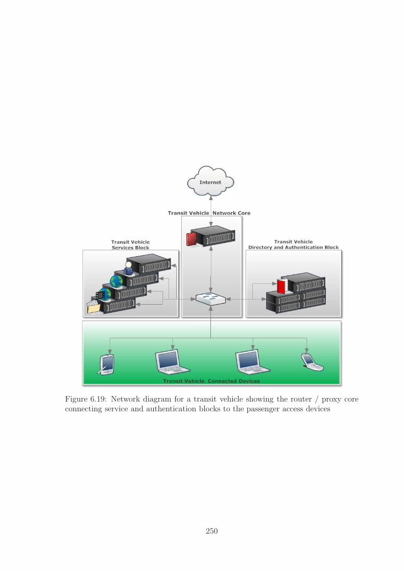
Figure 6.19: Network diagram for a transit vehicle showing the router / proxy coreconnecting service and authentication blocks to the passenger access devices
250

Figure 6.20: Map of the UK overlayed with the transit vehicle path and the locationof high speed access points
251

access to the end user devices. As there is no innate service model integrated into IP
networks we include a content caching / management service as discrete blocks and
connect at the minimum a web server handling authentication, the service directory,
and web services though this may be broken into discrete components as shown. The
vehicle connects via over a VPN via satellite or over wireless connectivity using the
transit provider VPN as there is no billing infrastructure currently in place for IP
based network to allow a direct MobileIP connection.
The connection to the transit vehicle is handled as a Network Mobility (NEMO)
type connectivity scenario with traffic being routed via the transit provider’s home
agent to access services. Internal connections are masked using NAT to provide
transparent mobility to the passenger devices. Service provision is as per a traditional
Internet service or through specific web based services offered to the users by the
transit provider e.g. limited video services on an aircraft. In terms of locating these
services there must be a mobility aware (NEMO) router within the transit vehicle
providing the mobility service to the user devices, the home agent location may be
a single fixed location within the transit provider’s network or it may be a layered
approach with multiple home agents providing a layered mobility approach.
6.4.3 HNTR Based Transit Model
While it is possible to set up the HNTR network to match that of the IP network with
services being dependent on the transit provider and a transparent mobility service
it is more illustrative to construct a network which offers more potential to the users
on the transit vehicle. The network we implement is shown in Figure 6.22.
In this network we replace the network core with a single HNTR router attached
to the 802.11x wireless, and the cellular access points as per the IP model. The HNTR
service block replicates the functionality required on the web server in the IP example
providing a service directory and authentication service allowing users to authenticate
either through their own service provider, or through the on-board transit provider
service. By allowing separate authentication methods the HNTR network allows the
user to maintain preferences and settings through their own account and possibly
bypass paying additional fees to the transit provider. The provision of direct access
via the provider allows for day-rate type services for the occasional user or loyalty
based schemes to be linked to their existing accounts. In a similar way to the IP
network we provide localised content caches and a transparent mobility service by
assigning ‘static’ HNTR addresses as needed to devices which are fixed in location.
In contrast to the IP based model however there are two connection methods - either
252

Figure 6.21: Transit vehicle IP based network showing multiple possible connectionsto a central HNTR router via wired ethernet, 3G interface, and wireless 802.11. TheHNTR router takes its address from the HNTR gateway which enables transparentmobility for legacy devices and provides forwarding of mobility notices to enableddevices.
253
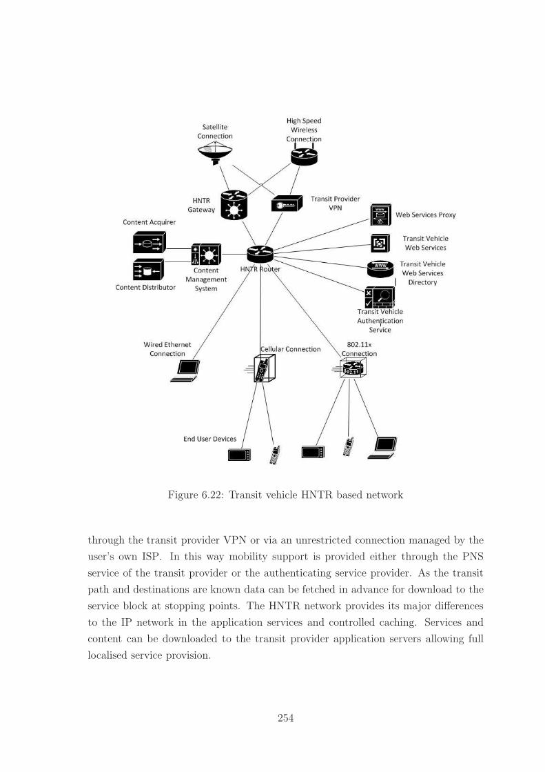
Figure 6.22: Transit vehicle HNTR based network
through the transit provider VPN or via an unrestricted connection managed by the
user’s own ISP. In this way mobility support is provided either through the PNS
service of the transit provider or the authenticating service provider. As the transit
path and destinations are known data can be fetched in advance for download to the
service block at stopping points. The HNTR network provides its major differences
to the IP network in the application services and controlled caching. Services and
content can be downloaded to the transit provider application servers allowing full
localised service provision.
254

6.4.4 Evaluation of HNTR Improvements
In this example there are few direct savings associated with the HNTR network due
to the limitations on localised routing from this scenario however there are improve-
ments in terms of mobility support and service deployment. In terms of mobility
the inclusion of user accounts and native location awareness allows devices to auto-
matically manage their own connection via the moving platform and so reduce the
overhead required by the triangular routing path of vehicle - transit provider - service
- transit provider - vehicle to a more efficient vehicle - service - vehicle. Under a strict
MobileIP solution without the transit provider acting as the sole access point we may
end up with a more convoluted situation of vehicle - transit provider - local routing
point - ISP - service - ISP - local routing point - transit provider - vehicle due to
the lack of true location awareness. As shown in section 6.3.4 this kind of triangular
routing and VPN can easily increase the latency and network paths traversed by the
data by double or more.
In terms of deployment structure the generic HNTR network with included service
block makes it ideal for this kind of localised usage as it achieves the majority of the
goals in an ‘out of the box’ fashion. As HNTR nodes expect there to be a service
directory and gateway / authentication services provided these can be integrated
directly into the user experience rather than relying on web browsers to provide web
based services. This capability allows for the development and integration of third-
party services and applications which provide new services using an on-demand model
simpler to sandbox and integrate into a mobile system. Through the direct integration
of services it becomes more easily possible to isolate the applications from the host
system enabling users behaviour to actively affect the services offered on board the
transit vehicle. The example situation for this would be an airline / bus company
service which wraps the user’s connection to iTunes or Netflix allowing them to pull
or purchase content and make it available within the network cache, this content then
becomes available for other users either directly through the iTunes or Netflix services
or via the transit provider wrapping the content rental service.
The integration of these two benefits is where we see the real improvements in
the HNTR model as the inclusion of mobility management and integration of loca-
tion aware services allows the passengers and vehicle to optimise their downloads by
maximising the use of available connections. As content can be provisioned in ad-
vance at locations within the network it is possible to further utilise the availability of
the high speed wireless connection to synchronise large data volumes quickly. While
this mechanism would be possible using a proxy cache under an IP system there is
255

no simple mechanism for ensuring the cache contains the relevant material at the
correct time since few caches can be pre-populated by request. This means that on
say a two way charter bus the provider notes that the users are using content from
a certain provider and with a certain genre or type - similar content can then be
provisioned at the mid-point to be available on the way back reducing the load on the
transit vehicle’s connection and providing content that the users are likely to consider
utilising.
6.4.5 Conclusions
While it is possible to fully implement a mobility solution under IP the lack of a
dedicated service mechanism and generic methods to control content flow and man-
agement make it more difficult to offer services to multiple users on different providers
or to make content available to others from a ‘different’ source even though the con-
tent is identical. The lack of services under IP to link together user accounts and to
provide a coherent location based service model mean it is very difficult to actively
provide pre-caching in a dynamic way. HNTR’s ability to offer both transparent and
active mobility allows the end user device more control over their settings and usage
than would be possible under a current IP paradigm. The final point to consider is
the reduced triangular routing overhead cause by HNTR mobility on the network as
a whole. As users direct traffic based on their PNS traffic does not flow through their
ISP (when using their own authenticated account) and so traffic is routed by the most
efficient route, though the effectiveness of this saving is as usual highly dependent on
the content and reuse of content on the transit vehicle.
6.5 Case Study 2: Mobile Workers
This case study considers a worker who telecommutes for part of the week. The
worker maintains a personal Internet account and is provided with an work account
that can be accessed securely through another Internet connection via a VPN. The
worker is expected to be logged into the work account from 9am-5pm Monday - Friday
to monitor attendance if they are telecommuting, they can use their own hardware
or a work laptop. The worker would like to automatically synchronise data between
work and home when they are not telecommuting.
256

Figure 6.23: Kings Buildings Area Combined Map, map data c©2012 Google usedunder fair use exception
6.5.1 Description
We consider the baseline for this scenario to be multi-site connection transfer problem
where a mobile node transitions from one physical location to another and across
network technologies / providers. A worker lives at a location not directly covered by
the wireless network of their employer however has independent access to the Internet
via a broadband technology or via a mobile 3G connection. The work location and
surrounding area is shown in Figure 6.23 with the wireless access points and main
Internet routers for the work site highlighted in Figure 6.24. This setup provides near
total wireless coverage of the work campus with a few areas outside lacking coverage
but covered by a mobile network data service.
When the worker is at home they must be authenticated against their work account
during the hours of 9am-5pm and should be authenticated against their home account
outside of this time unless they are working late. Non-work related Internet access is
allowable within these periods and follows the workplace code of conduct. When the
worker is within the site they should be connected to the work Internet connection via
a wired or wireless connection and should authenticate against their work account.
Data should be synchronised securely between their home location and the work
location.
257

Figure 6.24: Kings Buildings Wireless Access Network, imagery c©2012 DigitalGlobe,GeoEye, Getmapping plc, Infoterra Ltd, and bluesky, The Geoinformation Group,map data c©2012 Google used under fair use exception
6.5.2 IP Based Mobility Model
Under a basic mobility scenario it would be possible to use a combination of a VPN or
a MobileIP solution to effectively handle remote working or mobility, or a MobileVPN
solution [246] to handle both remote working and mobility however these solutions
typically rely on the static home agent to forward data and maintain / manage IPSEC
connections which introduces at least one additional layer of triangular routing if not
two or three including source - Home Agent (HA), HA - Foreign Agent (FA), and
HA/FA - mobile device. This issue again arises because many IP based services
link the IP address as the identity of the user. Working with this limitation on
mobility and identity we implement the solution as three independent networks: the
work network, the 3G mobile network provided by the mobile carrier, and the home
network provided by an ISP. The worker’s computer runs software to implement
the VPN between themselves and the work network providing authentication and
security with a synchronisation program employed to keep files synchronised between
the two locations. The VPN software is solely responsible for managing appearance
of continuity between all of the services and the tunneling over appropriate ports for
the network service. The connectivity of the three networks is shown in Figure 6.25.
258

Figure 6.25: Kings Buildings IP Mobility Model, imagery c©2012 DigitalGlobe, Geo-Eye, Getmapping plc, Infoterra Ltd, and bluesky, The Geoinformation Group, mapdata c©2012 Google used under fair use exception
This solution is functional though highly dependent on vendor hardware and software
to support the appropriate functionality.
6.5.3 HNTR Based Mobility Model
With a HNTR solution we have multiple options for implementing the solution in-
cluding directly copying the IP solution and implementing the work-home connection
via a mobile VPN however as we have seen it is possible due to the separation of
identity and location combined with localised routing for the traffic to traverse en-
tirely within the City of Edinburgh. As there is a viable solution to this problem and
the benefits to localised transfer for content such as medical imaging data are clear
we will focus on the second side of the scenario - the separation of work content and
home content. In this case solutions such as the IP based VPN typically encrypt and
transfer all outgoing and incoming content from the host however it would be more
viable given the low data caps on many home Internet connections to separate the
work traffic from typical home traffic. In this case HNTR allows the user to present
two or more identities to the network - with data flow being charged and consumed
on the appropriate account rather than billed to the single home account. With this
259

Figure 6.26: Kings Buildings HNTR Mobility Model, imagery c©2012 DigitalGlobe,GeoEye, Getmapping plc, Infoterra Ltd, and bluesky, The Geoinformation Group,map data c©2012 Google used under fair use exception
in place it is possible for the work authenticated traffic to be transparently assigned
to a VPN directing traffic flow to the work place while the non-work traffic flows over
the network normally. Implementing mobility across the network again requires less
reliance on the VPN software as the VPN is authenticated against the user account
rather than the source and so when the device transitions onto the mobile network
there is no need to reauthenticate against or have the HA perform this process.
To implement true mobility if the user moves from their home network onto the
3G network their account is again authenticated against their work account and data
is again routed via a transparent VPN from the mobile provider to the work location
allowing seamless mobility as shown in Figure 6.26 between all three of the networks
with the triangular routing steps identified in Figure 6.25 only required for the initial
authentication before data flows as locally as possible between the networks.
6.5.4 Evaluation of HNTR Improvements
While the IP based solution was viable in terms of implementing the requirements it
required the management of three different Internet accounts to maintain accessibility
to the worker and required the management of the VPN software which utilises the IP
260

address as part of the management process. The HNTR solution however is a much
more fluid solution in that the physical location of the node is considered irrelevant
but rather the credentials used to access the Internet determine the default security,
routing policy, network access policy, and services on offer to the user either auto-
matically or through user choice. Presenting the network as a transparent carrier for
information provides a method for enabling seamless mobility and service to the end
user without additional management overhead or user controlled programs making
network management simpler.
6.5.5 Conclusions
The capability to manage multiple Internet accounts moves the service provider role
to that of an actual service provider - services are the differentiator between two ISPs.
Billing for simple access can be handled by entities such as work places or private
accounts allowing users to migrate across multiple networks with minimal difficulty.
The management of the network being simplified by allowing the connected ISP to
determine the routing policy and protocol means that the system can automatically
configure to different users - the settings enabled for the parents in a household need
not apply to the children on a different account or device.
6.6 Case Study 3: Ubiquitous Streaming
This case study considers the potential growth in Internet media streaming and the
availability of caching solutions within the network to assist in reducing the network
load of unicast transmissions to end clients by creating multicast points within the
network, or the ability of the network to multicast content from source to a group of
disparate clients directly. With this case study we aim to look at the potential scaling
of media streaming solutions such as the BBC iPlayer which utilise unicast streaming
technologies and the impact that a single large event such as the 2010 World Cup can
have on the network performance. We will consider the creation and management of
a multicast group and caching solutions to the end users as additional options.
6.6.1 Description
The network consists of the standard network model for either IP or HNTR with
appropriate in-network caches for the streaming technology. We will consider two
independent situations with this case study, a single large scale streaming event such
261

as the World Cup and smaller scale streaming events such as a popular soap opera.
These two events give a range between a normal 2011 streaming event supporting
approximately 300,000 users over several days and a broadcast replacement model
streaming event supporting upwards of 1,000,000 simultaneous viewers. From these
two event sizes we can draw conclusions about the future potential scaling and de-
ployment of ubiquitous streaming media. This aims to address the idea that the
future ‘killer’ application for the Internet is not a single massive bandwidth applica-
tion, which could be cached, but rather a larger number of moderately sized streams
with time shifts. The latter ‘killer application’ is very likely to become a major ser-
vice model as stream based content systems become ubiquitously deployed through
computers, tablets, and set-top boxes.
6.6.2 IP Based Model
The IP based mode of streaming places caches in the possible layer 3 routing points
identified in Chapter 3 giving the network multicast enabled caches at the following
points: content provider, third-party content cache, ISP and Network Provider (NP)
caching at the core, metro, and exchange levels. Caches are not positioned below this
level due to the current lower levels not being IP based. While it would be possible
to further deploy caches to these levels it would require a restructuring of the current
Internet systems.
From this model it is feasible to multicast to the content caches within an individ-
ual NP or ISP network however across multiple NPs or ISPs this is likely to encounter
administrative issues due to the wholesale provider billing and management systems
thus scaling is limited to the number of ISPs serving a particular area. At a current
best case multicast scenario traffic to the last mile is capped using the equation shown
in 6.2 as the sum of the bandwidth for a particular stream on a particular ISP across
all ISPs receiving the ‘multicast’. If we assume there is a unique link to each client on
the last mile as is typical for ADSL deployments and the access / exchange hardware
supports multiple-unicast to clients there is no further bandwidth limit. For the uni-
cast scenario the bandwidth cap is increased by the number of subscribers per ISP as
shown in 6.3. At higher levels assuming multicast is available or appropriate caches
are provisioned the stream cost can be reduced to the multicast cost previously shown
in 6.2.
262

Figure 6.27: Ubiquitous Streaming IP Network
263

BWLM =
i=#ISP∑
i=0
(BWstream) (6.2)
BWLM =
i=#ISP∑
i=0
(BWstream × Subscribers) (6.3)
If we consider the flow of traffic in this kind of IP based system to be similar to
that shown in Figure 6.28 then it is possible to see the double path taken by control
information due to the content cache being either within the ISP (or a third party)
facility, or ‘hidden’ within the encapsulated wholesale network where the subscriber
cannot directly access it. This results in additional flow of data at a minimum between
the subscriber and the content cache and potentially between the cache and the
subscriber if the cache is not situated in-network. This control information is likely
not large in size however requires a real-time response model to be maintained in its
message-responses which can be problematic due to issues such as buffer-bloat within
modern routers.
6.6.3 HNTR Based Model
The HNTR model follows the same layout as the IP model however the routing
protocol and end-to-end layer 3 ensures a lack of layer switching allowing direct
routing to be performed at both the cabinet-exchange level and directly within the
cabinet if a micro-cache(s) is deployed. This produces the network structure shown in
Figure 6.29 with NP and third-party caches deployable down to local exchange level
with residential cache either provided through the NP due to space limitations in the
cabinet or a set of micro-caches within individual residences within the cabinet block.
As with IP the distribution cost for a stream to the caches in the worst case sce-
nario of a non-shared cache is the sum over all ISPs of the stream bandwidth as shown
in 6.4 which is identical to the bandwidth requirement of the IP solution shown in 6.2
however as caches can be provided in a co-operative fashion and support for third-
party caches we can reduce this to a single multicast stream to all caches reducing the
cost to that of a unicast stream as shown in 6.5 as the cache can dynamically reduce
the bandwidth of the stream to individual subscribers using an encoding format such
as Scalable Video Coding (SVC). Below the exchange level HNTR supports multicast
and so the multicast cost remains the same throughout the deployed network. If a
residential cache is utilised we can further reduce the future impact of a stream on
264

Figure 6.28: UML sequence diagram for IP caching model
265

Figure 6.29: Ubiquitous Streaming HNTR Networkk
266

Figure 6.30: UML sequence diagram for HNTR caching model
the network to effectively zero - ie: it is entirely contained within the last mile - as
traffic is directed internally within the cabinet level block.
BWLM =
i=#ISP∑
i=0
(BWstream) (6.4)
BWLM =BWstream (6.5)
In contrast to the IP solution depicted in Figure 6.28 the HNTR solution presented
in Figure 6.30 shows a much simpler model with each connected entity responsible
solely to the contacting layer and the authorising layer above. Combining this with
the direct ability to contact any node within the network allows for a simpler data
flow model which should bypass multiple aggregation layers.
On point to consider at this stage is the added administrative burden of managing
a cross-ISP streaming service. In terms of bandwidth this is a negligible cost as it is a
simple record of the destinations, identities, streaming time, and bandwidth consumed
by a customer which is a small overhead compared to a video stream. In terms of
management infrastructure this requires the integration of a micro-billing system (or
cross-billing) to allow ISPs to authorise the cache to release content, as layer 2 and
layer 3 switches and routers can already handle Authentication, Authorization, and
267

Accounting (AAA) redirection and management for at least cabinet and exchange
level numbers of customers this added burden is again considered minimal over the
sustained Real Time Control Protocol (RTCP) and management traffic that would
otherwise have to flow to the higher level content cache across one or more aggregation
layers. An example streaming record is shown in XML format in listing 6.1 with the
validating schema shown in listing 6.2. There are likely issues to be addressed in the
business case for AAA in relation to streaming content from the provider’s perspective
however there are already network devices available which can handle these indicating
that outsourced AAA is acceptable today. Further since the AAA is minimal in terms
of overhead if this model is not acceptable in the short term a three way handshake
type protocol can be easily implemented to actively involve the content source as well
as the cache and end user.
6.6.4 Evaluation of HNTR Improvements
The capability of HNTR networks to provide end to end routing as well as localised
point to point routing at any level of the network provides a very effective solution
to the media streaming growth issue presented by the growing ubiquity of streaming
services. The reduction of the normal cost from a per-ISP cost to a single cost to
provision the local caches makes the system very effective at providing content in
multi-provider areas where the fragmentation caused by network regulation would
otherwise increase the network cost of provision. Further the capability to exploit
residential caches within the network allows a provider to effectively provide content
beyond the first user at a zero cost to the network due to localised routing. This
deployment method allows for a smooth transition towards IP as a broadcast replace-
ment technology while improving the network performance as a whole because traffic
is limited to the local ‘tree’ defined by the lowest level cache that can support the
transaction. As with most improvements the exact numerical benefits of this im-
provement are widely variable with the number and type of users and the complexity
of the IP system implemented however it is very likely that streaming services are
likely to continue to grow in scale and with this growth a system must be put in place
to either limit the scaling required on behalf of the network or a network capacity
growth that mirrors the service growth.
268

6.6.5 Conclusions
While again it is possible to implement a streaming system under IP it is an admin-
istrative, management, and technological problem that provides no simple solution
due to the fragmentation of the market without a solid reason for cooperation. By
moving to a system which innately supports multicast, localised routing, and localised
management it becomes possible to enable the deployment of residential caches and
very low level caches that completely remove the end user scaling factor for stream-
ing content and instead base the scaling factor on the number of deployed caches and
their hierarchy structure.
1 <?xml v e r s i o n=” 1 .0 ” encoding=”UTF−8”?>2 <HNTR Content xmlns=”HNTR Content”3 xmlns : x s i=”http ://www.w3 . org /2001/XMLSchema−i n s tance ”4 x s i : schemaLocation=”HNTR Content f i l e : /C: / Users/Chr is /Documents/
HNTR Content . xsd”>5 <Group G ID=”G ID1”>6 <User>7 <User ID>User ID0</User ID>
8 <ISP ID>ISP ID0</ISP ID>
9 <Attachment Point>Attachment Point0</Attachment Point>10 </User>11 <Sess ion>12 <Stream>
13 <Stream ID>Stream ID0</Stream ID>
14 <Provider ID>Provider ID0</Provider ID>
15 <Content ID>Content ID0</Content ID>
16 <Average BW>0</Average BW>
17 <Peak BW>0</Peak BW>
18 </Stream>
19 <Time>20 <Start Time>2006−05−04T18 : 1 3 : 5 1 . 0Z</Start Time>21 <End Time>2006−05−04T18 : 1 3 : 5 1 . 0Z</End Time>22 </Time>23 </Sess ion>24 <Sess ion>25 <Stream>
26 <Stream ID>Stream ID1</Stream ID>
27 <Provider ID>Provider ID1</Provider ID>
28 <Content ID>Content ID1</Content ID>
29 <Average BW>0</Average BW>
30 <Peak BW>0</Peak BW>
31 </Stream>
32 <Time>33 <Start Time>2006−05−04T18 : 1 3 : 5 1 . 0Z</Start Time>34 <End Time>2006−05−04T18 : 1 3 : 5 1 . 0Z</End Time>35 </Time>36 </Sess ion>37 </Group>38 </HNTR Content>
269

Listing 6.1: Example XML format streaming session record
1 <?xml v e r s i o n=” 1 .0 ” encoding=”UTF−8”?>2 <xs : schema xmlns : xs=”http ://www.w3 . org /2001/XMLSchema”
elementFormDefault=” q u a l i f i e d ”3 targetNamespace=”HNTR Content” xmlns=”HNTR Content”>4 <xs : group name=”User”>5 <xs : sequence>6 <xs : element name=”User ID” type=”xs : s t r i n g ”/>7 <xs : element name=”ISP ID” type=”xs : s t r i n g ”/>8 <xs : element name=”Attachment Point” type=”xs : s t r i n g ”/>9 </xs : sequence>
10 </xs : group>11 <xs : group name=”Stream”>12 <xs : sequence>13 <xs : element name=”Stream ID” type=”xs : s t r i n g ”/>14 <xs : element name=”Provider ID ” type=”xs : s t r i n g ”/>15 <xs : element name=”Content ID” type=”xs : s t r i n g ”/>16 <xs : element name=”Average BW” type=”xs : double ”/>17 <xs : element name=”Peak BW” type=”xs : double ”/>18 </xs : sequence>19 </xs : group>20 <xs : group name=”Time”>21 <xs : sequence>22 <xs : element name=”Start Time” type=”xs : dateTime”/>23 <xs : element name=”End Time” type=”xs : dateTime”/>24 </xs : sequence>25 </xs : group>26 <xs : group name=”PerUser”>27 <xs : sequence>28 <xs : element name=”User” type=”User”/>29 <xs : element maxOccurs=”unbounded” name=” Ses s i on ” type=”
Ses s i on ”/>30 </xs : sequence>31 </xs : group>32 <xs : complexType name=”User”>33 <xs : group r e f=”User”/>34 </xs : complexType>35 <xs : complexType name=” Ses s i on ”>36 <xs : group r e f=” Se s s i on ”/>37 </xs : complexType>38 <xs : complexType name=”Stream”>39 <xs : group r e f=”Stream”/>40 </xs : complexType>41 <xs : complexType name=”Time”>42 <xs : group r e f=”Time”/>43 </xs : complexType>44 <xs : complexType name=”Group”>45 <xs : group r e f=”PerUser ”/>46 </xs : complexType>47 <xs : group name=”Group”>48 <xs : sequence>
270

49 <xs : element name=”Group”>50 <xs : complexType>51 <xs : complexContent>52 <xs : ex tens i on base=”Group”>53 <xs : a t t r i b u t e name=”G ID” type=”xs : s t r i n g ”
use=” r equ i r ed ”/>54 </xs : extens ion>55 </xs : complexContent>56 </xs : complexType>57 </xs : element>58 </xs : sequence>59 </xs : group>60 <xs : group name=” Ses s i on ”>61 <xs : sequence>62 <xs : element name=”Stream” type=”Stream”/>63 <xs : element name=”Time” type=”Time”/>64 </xs : sequence>65 </xs : group>66 <xs : element name=”HNTR Content”>67 <xs : complexType>68 <xs : group r e f=”Group”/>69 </xs : complexType>70 </xs : element>71 </xs : schema>
Listing 6.2: Example XML format streaming session record schema
6.7 Case Study 4: Localised Transfers
In this case study we consider localised data transfer such as a multi-player game
played by a group of friends in the same local area but not on the same network. In
this case we aim to provide the lowest possible latency and jitter to the players to
maximise their experience. While there is likely not much can be done to assist in
gaming between users who are geographically widely distributed there are often cases
when players are relatively local to each other outside of a Local Area Network (LAN)
environment which would benefit from reduced latency and jitter.
6.7.1 Description
The network in this example is based on the standard model developed with two differ-
ent residential blocks attempting to send traffic between themselves. We first consider
the case of two local sources within the same ISP but different physical connections
and then two local sources on different ISPs with different physical connections. The
players being local share a cabinet, local exchange, and major exchange facility. For
the purposes of calculation we will ignore the effects of the bandwidth-delay latency
271
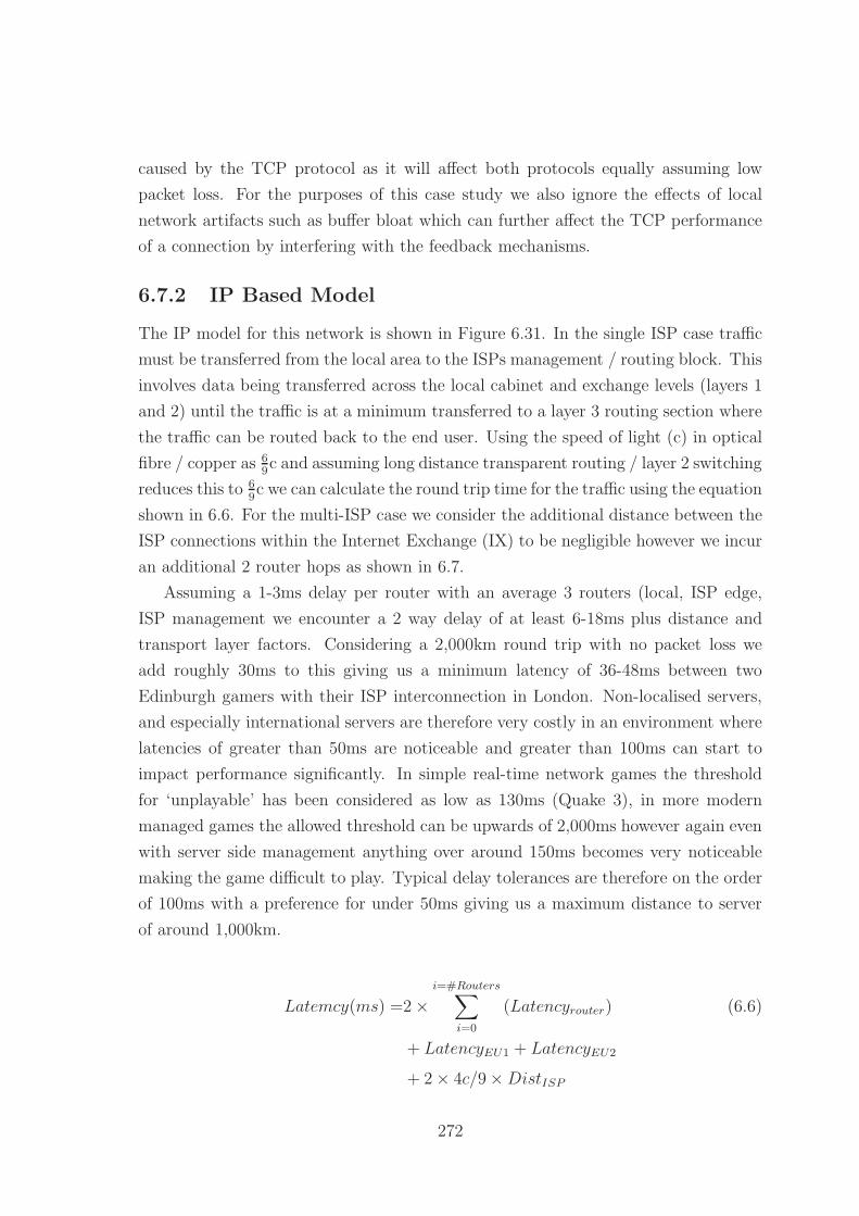
caused by the TCP protocol as it will affect both protocols equally assuming low
packet loss. For the purposes of this case study we also ignore the effects of local
network artifacts such as buffer bloat which can further affect the TCP performance
of a connection by interfering with the feedback mechanisms.
6.7.2 IP Based Model
The IP model for this network is shown in Figure 6.31. In the single ISP case traffic
must be transferred from the local area to the ISPs management / routing block. This
involves data being transferred across the local cabinet and exchange levels (layers 1
and 2) until the traffic is at a minimum transferred to a layer 3 routing section where
the traffic can be routed back to the end user. Using the speed of light (c) in optical
fibre / copper as 69c and assuming long distance transparent routing / layer 2 switching
reduces this to 69c we can calculate the round trip time for the traffic using the equation
shown in 6.6. For the multi-ISP case we consider the additional distance between the
ISP connections within the Internet Exchange (IX) to be negligible however we incur
an additional 2 router hops as shown in 6.7.
Assuming a 1-3ms delay per router with an average 3 routers (local, ISP edge,
ISP management we encounter a 2 way delay of at least 6-18ms plus distance and
transport layer factors. Considering a 2,000km round trip with no packet loss we
add roughly 30ms to this giving us a minimum latency of 36-48ms between two
Edinburgh gamers with their ISP interconnection in London. Non-localised servers,
and especially international servers are therefore very costly in an environment where
latencies of greater than 50ms are noticeable and greater than 100ms can start to
impact performance significantly. In simple real-time network games the threshold
for ‘unplayable’ has been considered as low as 130ms (Quake 3), in more modern
managed games the allowed threshold can be upwards of 2,000ms however again even
with server side management anything over around 150ms becomes very noticeable
making the game difficult to play. Typical delay tolerances are therefore on the order
of 100ms with a preference for under 50ms giving us a maximum distance to server
of around 1,000km.
Latemcy(ms) =2×
i=#Routers∑
i=0
(Latencyrouter) (6.6)
+ LatencyEU1 + LatencyEU2
+ 2× 4c/9×DistISP
272

Figure 6.31: Local Data Transfer IP Network
273

Latemcy(ms) =2×
i=#Routers∑
i=0
(Latencyrouter) (6.7)
+ LatencyISP1 + LatencyISP2
+ LatencyEU1 + LatencyEU2
+ 2× 4c/9×DistISP
6.7.3 HNTR Based Model
The HNTR based model follows the now established pattern of fully routable sections
down to the cabinet level as shown in Figure 6.32. The single ISP cost model can be
reduced to that shown in 6.8 as data is turned around at the lowest shared location
between the two nodes. In the case of two players on a single cabinet or local area
this will effectively be reduced to zero. Further if we move to the multi-ISP model the
latency model does not change as the traffic is still routed through the lowest point in
the network shared between the two users. In the case of a server hosted in London
there is nothing that can be realistically done for the two gamers in Edinburgh,
however if it is possible to host the server locally within the Edinburgh area assuming
an interconnect at for example cabinet level then we can effectively reduce their base
latency to less than 5ms (66km round trip, within the greater Edinburgh area).
Latemcy(ms) =2×
i=#Routers∑
i=0
(Latencyrouter) (6.8)
+ LatencyEU1 + LatencyEU2
+ 2× 4c/9×Distinf
6.7.4 Evaluation of HNTR Improvements
The ability to route traffic locally between the lowest common point in the routing
tree enables significant savings for clients who are geographically localised as traffic
does not need to be routed to a high level management point in order to decode the
IP address. While the billing and management data must still be transferred to this
point it is not delay sensitive and so can be ignored from the perspective of localised
data transfers.
274

Figure 6.32: Local Data Transfer HNTR Networkk
275

6.7.5 Conclusions
HNTR can be shown to improve the performance in terms of network latency for
localised data transfers by reducing the distance travelled by content to the minimum
tree path required by the network. This represents a large gain in terms of ‘twitch’
or latency sensitive applications where a localised transfer can be performed. For
larger distances or servers hosted centrally / internationally the the speed of light /
transit cost becomes the largest non-local network consideration and as such cannot
be altered feasibly. It is however feasible to provide localised improvements for players
by grouping and combining traffic locally thus reducing the average load in the core
network and with it the chance of packet loss which can cause major spikes in TCP
based latency.
6.8 Case Study 5: Access Network Data Transfer
This case study considers the growing number of set-top boxes and similar devices
which make transparent (to the end user) use of the Internet to provide services to
home users. The growth in multi-user households has been said to be the ‘killer
app’ [247] for super fast broadband such as FTTC. This case study therefore looks
at the impact of the network design on the presence of Set Top Boxs (STBs) and
possibility of using them in an assisted caching system.
6.8.1 Description
In a modern STB there is typically at least a 1Terabyte (TB) hard disk (and often
larger) with 33-50% of the space devoted to anytime (pre-recorded content that is
popular / current at the moment) content. This means that with an average of two
STBs per subscribed household, and an uptake of at least 50% of households for a
service like Sky television we can make the assumption that a street level cabinet with
approximately 50 households will contain 50 set top boxes with a combined anytime
storage of 25TB. As these devices are rarely turned off we can assume a high uptime,
so taking a factor of 5 for replication of content across the system gives us 5TB of
local storage. This is equivalent to the storage of 3,500 Standard Definition (SD)
movies or 2,500High Definition (HD) movies under similar compression to systems
such as iTunes.
In this case study we seek to create a system whereby we can exploit the local
network resources below the DSLAM layer of the network where each house has the
276

Figure 6.33: Local Data Transfer HNTR Networkk
full bandwidth they have subscribed to without the bandwidth aggregating effects of
higher network layers.
6.8.2 IP Based Model
Under the IP model it is simply not possible at current to replicate this network
structure. The setup of the network as shown in Figure 6.33 shows that the patch
panels at the cabinet level are not setup to enable switched or routed traffic, after
this point the DSLAMS act as the first aggregation layer reducing the outgoing band-
width before we even reach the first switched layer. As the management structure is
implemented under layer 3 the traffic must further travel upwards through the net-
work until it reaches an IP based router and can be turned around. If a switched /
routed layer was implemented in the cabinets before the DSLAM aggregation layer
this would be feasible however the system does not still support direct point to point
routing structures.
277

Figure 6.34: Local Data Transfer HNTR Networkk
6.8.3 HNTR Based Model
Under HNTR as the routing model extends to the lowest level of the network it is
possible to place a set of HNTR routers below the aggregation layer if a DSLAM
model is retained allowing for traffic to be routed entirely locally. As 98% of this
bandwidth is aggregated away under a typical IP model of 50:1 contention we can
consider the traffic to be effectively free as long as it doesn’t affect upstream traffic.
At this point it is therefore feasible to simply route localised traffic for free, or under
a micro-billing architecture. With small communities on a DSLAM it is possible that
there is little point in enabling this capability for these smaller populations, however,
the technology to do so will not require significant additional overhead and so its
provision will be largely provided for through economies of scale in the end-to-end
hardware model.
6.8.4 Evaluation of HNTR Improvements
As the structure of this case study is simply not implementable under the current
last mile architecture of the typical UK Internet we can consider any improvement
to be significant. The more important factor to consider here though is that simply
278

making use of effectively free resources available within the lower network layers we
can effectively distribute the equivalent of 160 full channels of 3Mbps streams to a
single street level cabinet with no additional overheads (assuming we could get it
there in the first place). If we further assume that roughly 20% of broadcast time
on an ad supported network is adverts with a 10:1 reuse rate we can increase this
to 176 channels of television deployed in a broadcast replacement manner. It is of
course unlikely that replacing broadcast with a system like this would be efficient
given the low viewing rates on some channels however utilising statistical aggregation
for common content we can further tailor the content available to suit the individual
cabinet.
6.8.5 Conclusions
In the eventual scaling of an Internet Protocol Television (IPTV) system it is clear
that multicast and storage are requirements in the network. By altering the network
structure to support low level routing at levels below the first aggregation point it
is possible to create and utilise a massive unseen resource to provide a broadcast re-
placement system, or an effective on-demand cache with low upkeep and maintenance
requirements due to the automatic refresh cycle on STBs in the home environment.
6.8.6 Review of Case Studies
In each of the case studies shown HNTR has been capable of implementing the same
solution as IP while offering an additional implementation path that allows for an im-
provement in terms of services, quality of service, ease of use, or network performance
and cost. It is not feasible to consider a full implementation of HNTR at this point
in time and a full simulation will merely confirm that routing delay scales largely
linearly with the number of routers in the path and the distance between the end
points of the network. It is feasible to consider localised ‘islands’ of HNTR or fully
interconnected IP networks which are connected into the core allowing for the large
scale improvements brought about by both location awareness and localised rout-
ing. This means that we can avoid the unfeasible need to increase the speed of light
by decreasing the average distance and number of routers by providing for localised
transfers where appropriate. This same solution allows for the localisation of caches
and enables the deployment of ISP agnostic services and protocols to handle caching
and services at a local level allowing for better utilisation of available resources and
reduction of the load in the core network.
279
6.9 Conclusions
The case studies presented in this chapter have looked at some of the potential new
service models opened up through the active use of geographic and topographical
network information to services. The capability to provide improved mobility services
and to actively move services with the user and provision appropriately ties this
project back to the original goals of improved video streaming services however from
a server side operation rather than a client side. By enabling services to easily migrate
and follow user movements new services can be developed and deployed which may not
make have made sense under current models such as true peer-to-peer communication
networks such as Bit Torrent. From the common scenarios and the case studies
presented it is clear that the HNTR network as described is capable of implementing
the features of an IP network or providing an approximation of them that is very
similar in functionality. In the majority of cases it has also been shown that true
global routing capability and localised routing capability can have a beneficial impact
on the performance of the network as a whole by minimising the traffic flowing within
the network thus limiting the scaling of large scale events to a fixed and know scale.
These features combined with the integrated service architecture allows for the rapid
and effective deployment of network services and infrastructure to cope with demand
as currently foreseen.
The legislative and regulatory issues associated with direct peer-to-peer commu-
nication have yet to be explored however this is likely to be an area of growth in
the near future as networks adapt to new traffic patterns. It is sufficient however
to say that technologies such as Bit Torrent make more efficient use of the network
when they are not forced through centralised routing points and have many potential
legitimate uses that could greatly assist in relieving some of the strain imposed on
the network through services such as video streaming.
280

Chapter 7
Conclusions and Future Work
7.1 Introduction
This research project set out to review the state of the art in terms of the current
United Kingdom (UK) Internet deployment and consider future developments and
from this develop a routing protocol suitable for the delivery of large scale content
flows. This chapter summaries the research contributions of the project, the limita-
tions of the project and the research findings, and presents a number of recommen-
dations for future work. Finally concluding remarks are given.
7.2 Overview of Research Aim, Objectives, and
programme
The research aim of this work was defined in the introductory chapter as:
To investigate and design a network routing structure and protocol suitable for assist-
ing in the delivery of large scale content services such as video streaming services in a
more efficient and localised manner exploiting localised resources and services where
available.
This research aim has been achieved by completing the primary research objectives
consisting of:
1. Review of existing network strategies
• simplified Internet connectivity model
• case for an integrated content and service delivery platform
281

2. Design of an integrated network routing strategy
• network topographical routing protocol
• service model
• mobility model
• deployment and integration model
7.3 Summary of Research Contributions
The research presented in this thesis makes two principle contributions to knowledge
regarding the subject of large scale content delivery using localised services. Further
in carrying out this research project a number of advances have been made that
are in themselves important contributions to the body of knowledge and deserve
highlighting. This section summarises both the primary and secondary contributions
of this research.
7.3.1 Primary Research Contributions
The primary research contributions of this project are the design of an Internet rout-
ing protocol which is based on network topography and the business rationale for the
deployment of localised services within the Internet model which supports the deploy-
ment and development of a more localised routing network. This business rationale
further suggests that inter-Internet Service Provider (ISP) cooperation is highly ben-
eficial in a media rich content environment where the traditional model has enforced
separation at this level.
• Design of Network Topographical Routing Protocol (Chapters 4 and 5)
• Business Rational for the Deployment of Localised Service Modules (Chapter
6)
The Hierarchical Network Topographical Routing (HNTR) protocol fundamentals
have been laid out in chapter 4 with the open issues that the protocol requires to
reach a more mature state identified and discussed in chapter 5. This protocol has
been evaluated against existing Internet Protocol (IP) based networks in chapter 6
and performance improvements shown. Further business rational has been shown in
common usage scenarios in chapter 6 which show how a HNTR type network and
service model could benefit existing and future deployment models.
282

7.3.2 Secondary Research Contributions
The secondary research contributions in support of the primary contributions have
aimed to show the benefits of a network allowing seamless migration between geo-
graphic locations and access to network topographical information. The secondary
contributions have shown the potential in additional services which could be devel-
oped with a single unified user / device identity space within the network beyond
that of simply providing additional routing aggregation.
• Mobility Model for Services
• Identity and Naming Scheme for Multiple Shared Identities within a Network
Identity
• Benefits of Localised Routing in an Internetwork for Large Scale Content De-
livery
7.4 Limitations of the Research
Although the primary objectives of this research have been achieved it is important
to consider the limitations of both the research programme and the research findings
themselves.
7.4.1 Limitations of the research programme
The limited capability to deploy and test the network given the available resources
has placed large sections of this project as a theoretical development rather than a
hardware tested deployment. Given this limitation on of the primary future work aims
would be to work to develop a hardware model of the network protocol allowing it
to be actively compared to similar IP network stacks. As any prototype development
would be less efficient and more prone to errors and failures than a well tested and
developed existing IP network stack there is no ‘fair’ way to develop comparison
metrics for the network protocols outside of a theoretical environment however the
capability to offload more data processing to specialised hardware by simplifying the
deployment rules suggests that the protocol should be more efficient than comparable
IP deployments. These gains in efficiency are supported by the results of simulation
and scenarios in chapter 6
Secondly the real world deployment of such a cooperative and integrated network
relies on the support and integration of existing providers into the network. This has
283

historically represented a major stumbling block for geographically based networking
services as networks see themselves as losing control of their customers and networks
rather than gaining flexibility and control over the flow of information. This work
presents a valid business case for the aggregation of the networks from a cost perspec-
tive and for the benefit of the end consumer however a further analysis would need
to be carried out to gain the acceptance of the cooperating networks.
7.4.2 Limitations of the research findings
As the research presents a network structure for the Internet it is very difficult to
evaluate the deployment and integration issues other than from a theoretical point
of view which may not reflect the realistic issues encountered during the deployment.
As the deployment of IP version 6 (IPv6) has shown even with ‘mature’ hardware and
software stacks there are a significant number of compatibility and interoperability
issues that can only be determined once the system is deployed in a large scale live
test environment.
7.5 Directions for future Research
Some of the key recommendations for further work are outlined below. The primary
aim of further research would be towards a working test bed and from that an inte-
grated deployment taking advantage of the localised resources available to a network
provider.
• Development of a hardware prototype network
• Development and integration of hardware or software model with existing net-
work provider to provide proof of concept service provision
• Development of software to add location and service awareness to end point
devices
• Expand upon the business case for the project presenting a firmer case for
deployment of a localised network in line with future UK based deployments
284

7.6 Concluding Remarks
The concluding chapter has given an account of the primary and secondary research
findings and contributions of this research project against the initial aims and objec-
tives of the project. The limitations of both the research programme itself and the
findings of the research have been identified to place the research within a wider con-
text and to allow for the creation of a set of recommendations for future research. This
research has made novel and significant contributions to the body of knowledge in
localised network protocols for the delivery of large scale content services. While the
final research has not aligned with the original aims of the sponsoring company due
to the unfortunate circumstances it is hoped that the deliverables from this project
will make a contribution in practice.
285

Bibliography
[1] Rexford J, C D. Future Internet Architecture: Clean-Slate Versus Evolutionary
Research. Communications of the ACM. 2010 September;53(9):36–40.
[2] THINK group, UT Austin and Edmundson-Yurkanon, C.
A Technical History of the ARPANET; 2001. Available:
http://www.cs.utexas.edu/users/chris/nph/ARPANET/ScottR/arpanet/index.htm.
Webpage.
[3] Palmer M. Hands-On Networking Fundamentals. 2nd ed. Cengage Learning;
2012.
[4] Roberts LG, Packetcom Inc, USA. Beyond Moore’s Law: Internet Growth
Trends. IEEE Computer Society: Computer. 2000 January;33(1):117–119.
[5] Huberman, Bernardo A . Internet: Growth Dynamics of the World-Wide Web.
Nature. 1999 September;401:131–131.
[6] Hong, Seung-Hyun. The recent growth of the internet and changes in household-
level demand for entertainment. Economics of the Media. 2007 October;19:304–
318.
[7] Smith L, Lipner I. Free Pool of IPv4 Address Space Depleted; 2011. Webpage.
Available from: http://www.nro.net/news/ipv4-free-pool-depleted.
[8] Labovitz C. Six Months, Six Providers and IPv6; 2011. Web-
page. Available from: http://ddos.arbornetworks.com/2011/04/
six-months-six-providers-and-ipv6/.
[9] Comcast. Comcast Demonstrates IPv6 Transition Readiness at NANOG46;
2009. Press release. Available from: http://www.comcast.com/about/
pressrelease/pressreleasedetail.ashx?SCRedirect=true&PRID=878.
286

[10] Livingood J. Deployment of IPv6 Begins; 2011. webpage. Available from:
http://blog.comcast.com/2011/11/ipv6-deployment.html.
[11] Andrews and Arnold ISP. Challenge to Router Manufacturers; 2011. Webpage.
Available from: http://aa.net.uk/news-ipv6-routers.html.
[12] Roberts LG. The Next Generation of IP - Flow Routing. In: SSGRR 2003S
International Conference; 2003. .
[13] IEEE. IEEE 802.3TM
: Ethernet; 2011. Available:
http://standards.ieee.org/about/get/802/802.3.html. IEEE Standards
Document.
[14] Frazier H, Pesavento G. Ethernet takes on the first mile. IEEE Computer
Society: IT Professional. 2001;3(4):17–22.
[15] Cisco Systems. STP and MST; 2013. Available:
http://www.cisco.com/en/US/docs/switches/lan/catalyst6500/ios/12.2SX/configuration/guide/span
Webpage.
[16] Systems C. VLANs; 2013. Available: http://www.cisco.com/en/US/docs/switches/lan/catalys
Webpage.
[17] Townsley W, Valencia A, Rubens A, Pall G, Zorn G, Palter B. Layer Two
Tunneling Protocol ”L2TP”. IETF; 1999. Available from: http://www.ietf.
org/rfc/rfc2661.txt.
[18] Hamzeh K, Pall G, Verthein W, Taarud J, Little W, Zorn G. Point-to-Point
Tunneling Protocol (PPTP). IETF; 1999. Available from: http://www.ietf.
org/rfc/rfc2637.txt.
[19] Mangold S, Choi S, May P, Klein O, Hiertz G, Stibor L, et al.. IEEE 802.11e
Wireless LAN for Quality of Service;.
[20] Akamai. Edge Platform; 2011. Webpage. Available from: http://www.akamai.
com/html/technology/edgeplatform.html.
[21] Katz D, Ward D. Bidirectional Forwarding Detection (BFD); 2010. Available:
http://datatracker.ietf.org/doc/rfc5880/. RFC 5880.
287
[22] Systems C. An Introduction to IGRP; 1991. Website. Available
from: http://www.cisco.com/en/US/tech/tk365/technologies_white_
paper09186a00800c8ae1.shtml.
[23] Systems C. Introduction to EIGRP; 2005. Doc ID 13669. Website. Avail-
able from: http://www.cisco.com/en/US/tech/tk365/technologies_tech_
note09186a0080093f07.shtml.
[24] Systems C. Open Shortest Path First v3; 2003. PDF. Available
from: http://www.cisco.com/application/pdf/en/us/guest/tech/tk480/
c1550/ccmigration_09186a0080187c6d.pdf.
[25] Republic T. RIP explained: The Gory Details;. web-
site. Available from: http://www.techrepublic.com/article/
rip-explained-the-gory-details/5033675.
[26] Systems C. Intermediate System-to-Intermediate System Protocol; 2006.
Website. Available from: http://www.cisco.com/en/US/tech/tk365/
technologies_white_paper09186a00800a3e6f.shtml.
[27] Clausen T, Jaquet P. Optimized Link State Routing Protocol (OLSR). IETF;
2003. Available from: http://www.ietf.org/rfc/rfc3626.txt.
[28] Baccelli E, Jacquet P, Nguyen D, Clausen T. OSPF Multipoint Relay (MPR)
Extension for Ad Hoc Networks. IETF; 2009. Available from: http://tools.
ietf.org/html/rfc5449.
[29] Doyle J, Jennifer DeHaven C. Routing TCP/IP. vol. 2 of CCIE Professional
Development. Cisco Press; 2011. ISBN-10: 1-57870-089-2 ISBN-13: 978-1-
57870-089-9.
[30] Rekhter Y, Li T. A Border Gateway Protocol 4 (BGP-4). IETF; 1995. Available
from: http://www.ietf.org/rfc/rfc1771.txt.
[31] Rekhter Y, Li T. An Architecture for IP Address Allocation with CIDR. IETF;
1993. Available from: http://tools.ietf.org/html/rfc1518.
[32] Fuller V, Li T, Yu J, Varadhan K. Classless Inter-Domain Routing (CIDR): an
Address Assignment and Aggregation Strategy. IETF; 1993. Available from:
http://tools.ietf.org/html/rfc1519.
288

[33] Fulle V, Li T. Classless Inter-domain Routing (CIDR): The Internet Address
Assignment and Aggregation Plan. IETF; 2006. Available from: http://
tools.ietf.org/html/rfc4632.
[34] Mockapetris P. Domain Names - Implementation and Specification. IETF;
1987. Available from: http://tools.ietf.org/html/rfc1035.
[35] Klensin J. Role of the Domain Name System (DNS). IETF; 2003. Available
from: http://tools.ietf.org/html/rfc3467.
[36] IANA. Domain Name System (DNS) Parameters; 2011. Webpage. Available
from: http://www.iana.org/assignments/dns-parameters.
[37] Arends R, Austein R, Larson M, Massey D, Rose S. DNS Security Introduction
and Requirements. IETF; 2005. Available from: http://tools.ietf.org/
html/rfc4033.
[38] Leahy, Hatch, Grassley, Schumer, Feinstein, Whitehouse, et al.. PROTECT IP
Bill; 2011. US Congress Bill. Available from: http://www.scribd.com/doc/
56417672/Bill-Protect-Ip-Act-2011.
[39] Crocker S, Dagon D, Kaminsky D, McPherson D, Vicie P. Security and Other
Technical Concerns Raised by the DNS Filtering Requirements in the PRO-
TECT IP Bill; 2011. White Paper. Available from: http://s3.amazonaws.
com/dmk/PROTECT-IP-Technical-Whitepaper-Final.pdf.
[40] Information Sciences Institute. Transmission Control Protocol v4. IETF; 1981.
Available from: http://tools.ietf.org/html/rfc793.
[41] Postel J. User Datagram Protocol. IETF; 1980. Available from: http://www.
faqs.org/rfcs/rfc768.html.
[42] Bradner S, Mankin A. IP: Next Generation (IPng) White Paper Solicitation.
IETF; 1993. Available from: http://tools.ietf.org/html/rfc1550.
[43] McGovern M, Ullman R. CATNIP: Common Architecture for the Internet.
IETF; 1994. Available from: http://tools.ietf.org/html/rfc1707.
[44] Ullman R. TP/IX: The Next Internet. IETF; 1993. Available from: http://
tools.ietf.org/html/rfc1475.
289

[45] Ullman R. RAP: Internet Route Access Protocol. IETF; 1993. Available from:
http://tools.ietf.org/html/rfc1476.
[46] Hinden R. Simple Internet Protocol Plus White Paper. IETF; 1994. Available
from: http://tools.ietf.org/html/rfc1710.
[47] Deering S, Hinden R. Internet Protcol, Version 6 (IPv6) Specification. IETF;
1998. Available from: http://tools.ietf.org/html/rfc2460.
[48] Srisuresh P, Egevang K. Traditional IP Network Address Translator (Tradi-
tional NAT). IETF; 2001. Available from: http://tools.ietf.org/html/
rfc3022.
[49] Velde G, Hain T, Droms R, Carpenter B, Klein E. Local Network Protection for
IPv6. IETF; 2007. Available from: http://tools.ietf.org/html/rfc4864.
[50] Rosen E, Rekhter Y. BGP/MPLS IP Virtual Private Networks (VPNs). IETF;
2006. Available from: http://www.ietf.org/rfc/rfc4364.txt.
[51] Arias M, Cowen LJ, Laing KA, Rajaraman R, Taka O. Compact routing with
name independence. In: Proceedings of the fifteenth annual ACM symposium
on Parallel algorithms and architectures. SPAA ’03. New York, NY, USA: ACM;
2003. p. 184–192. Available from: http://doi.acm.org/10.1145/777412.
777442.
[52] Abraham I, Gavoille C, Malkhi D, Nisan N, Thorup M. Compact name-
independent routing with minimum stretch. In: Proceedings of the sixteenth
annual ACM symposium on Parallelism in algorithms and architectures. SPAA
’04. New York, NY, USA: ACM; 2004. p. 20–24. Available from: http://doi.
acm.org/10.1145/1007912.1007916.
[53] Krioukov D, Fall K. Compact routing on Internet-like graphs. In: Proc. IEEE
INFOCOM. IEEE; 2004. p. 209–219.
[54] Thorup M, Zwick U. Compact routing schemes. In: in SPAA 01: Proceedings
of the thirteenth annual ACM symposium on Parallel algorithms and architec-
tures; 2001. p. 1–10.
[55] Brady A, Cowen L. Compact routing on power-law graphs with additive stretch.
In: Proceedings of the eight workshop on algorithm engineering and experiments
and the third workshop on analytic algorithmics and combinatorics; 2006. .
290

[56] Krioukov D, claffy kc, Fall K, Brady A. On compact routing for the inter-
net. SIGCOMM Comput Commun Rev. 2007 July;37:41–52. Available from:
http://doi.acm.org/10.1145/1273445.1273450.
[57] Meyer D, Zhang L, Fall. Report from the IAB Workshop on Routing and
Addressing. IETF; 2007. Available from: http://www.rfc-editor.org/
in-notes/rfc4984.txt.
[58] Meyer D, Lewis D. Architectural Implications of Locator/ID Separation draft-
meyer-loc-id-implications-01.txt; 2009. Internet Draft Memo. Available from:
http://tools.ietf.org/html/draft-meyer-loc-id-implications-01.
[59] Li T. Recommendation for a Routing Architecture. IETF; 2011. Available
from: http://tools.ietf.org/html/rfc6115.
[60] Farinacci D, Fuller V, Meyer D, Lewis D. Locator/ID Separation Proto-
col (LISP) draft-farinacci-lisp-12.txt; 2009. Internet Draft. Available from:
http://tools.ietf.org/html/draft-farinacci-lisp-12.
[61] Moskowitz R, Nikander P. Host Identity Protocol (HIP) Architecture. IETF;
2006. Available from: http://www.ietf.org/rfc/rfc4423.txt.
[62] O’Dell M. GSE - An Alternate Addressing Architecture for IPv6; 1997. In-
ternet Draft Memo. Available from: http://potaroo.net/ietf/all-ids/
draft-ietf-ipngwg-gseaddr-00.txt.
[63] Atkinson R, Bhatti S, Hailes S. ILNP: mobility, multi-homing, localised address-
ing and security through naming. Telecommunication Systems. 2009;42:273–
291. 10.1007/s11235-009-9186-5. Available from: http://dx.doi.org/10.
1007/s11235-009-9186-5.
[64] Nordmark E, Bagnulo M. Shim6: level 3 Multihoming Shim protcol for IPv6.
IETF; 2009. Available from: http://www.rfc-editor.org/rfc/rfc5533.txt.
[65] De Launois C, Bagnulo M. The paths toward IPv6 multihoming. Communica-
tions Surveys Tutorials, IEEE. 2006 quarter;8(2):38 –51.
[66] Perkins C. IP Mobility Support for IPv4. IETF; 2002. Available from: http://
tools.ietf.org/html/rfc3344.
291

[67] Perkins C, Johnson D, Arkko J. Mobility Support in IPv6. IETF; 2011. Avail-
able from: http://tools.ietf.org/html/rfc6275.
[68] Soliman H, Castelluccia C, ElMalki K, Bellier L. Hierarchical Mobile IPv6
(HMIPv6) Mobility Mangement. IETF; 2008. Available from: http://tools.
ietf.org/html/rfc5380.
[69] Corson S, Macker J. Mobile Ad hoc Networking (MANET): Routing Protocol
Performance Issues and Evaluation Considerations. IETF; 1999. Available from:
http://www.ietf.org/rfc/rfc2501.txt.
[70] Perkins C, Belding-Royer E, Das S. Ad hoc On-Demand Distance Vector
(AODV) Routing. IETF; 2003. Available from: http://www.ietf.org/rfc/
rfc3561.txt.
[71] Johnson D, Hu Y, Maltz D. The Dyanamic Source Routing Protocol (DSR) for
Mobile Ad Hoc Networks for IPv4. IETF; 2007. Available from: http://www.
ietf.org/rfc/rfc4728.txt.
[72] Ogier R, Templin F, Lewis M. Topology Dissemination Based on Reverse-Path
Forwarding (TBRPF). IETF; 2004. Available from: http://www.ietf.org/
rfc/rfc3684.txt.
[73] Devarapalli V, Wakikawa R, Petrescu A, Thubert P. Network Mobility (NEMO)
Basic Support Protocol. IETF; 2005. Available from: http://tools.ietf.
org/html/rfc3963.
[74] Manner J, Kojo M. Mobility Related Terminology. IETF; 2004. Available from:
http://www.ietf.org/rfc/rfc3753.txt.
[75] Wakikawa R, Thubert P, Boot T, Bound J, McCarthy B. MANEMO Prob-
lem Statement draft-wakikawa-manemo-problem-statement-00; 2007. Internet
Draft. Available from: http://tools.ietf.org/html/rfc3963.
[76] Khan JI, Davu S, Zaghal RY. High performance mobility without agent in-
frastructure for connection oriented service. Pervasive and Mobile Comput-
ing. 2008;4(4):526 – 545. Available from: http://www.sciencedirect.com/
science/article/pii/S1574119208000199.
292
[77] Andersen DG, Balakrishnan H, Feamster N, Koponen T, Moon D, Shenker S.
Accountable internet protocol (aip). SIGCOMM Comput Commun Rev. 2008
August;38:339–350. Available from: http://doi.acm.org/10.1145/1402946.
1402997.
[78] Dilley J, Maggs B, Parikh J, Prokop H, Sitaraman R, Weihl B. Glob-
ally Distributed Content Delivery; 2002. Akamai Ltd. webpage:
http://www.akamai.com/dl/technical publications/GloballyDistributedContentDelivery.pdf.
Available from: http://www.akamai.com/dl/technical_publications/
GloballyDistributedContentDelivery.pdf.
[79] Cohen J, Repantis T, McDermott S, Smith S, Wein J. Keeping Track of
70,000+ Servers: The Akamai Query System; 2010. Akamai Ltd. Webpage:
http://www.akamai.com/dl/technical publications/lisa 2010.pdf.
[80] Dong L, Liu H, Zhang Y, Paul S, Raychaudhuri D. On the cache-and-forward
network architecture. In: Proceedings of the 2009 IEEE international conference
on Communications. ICC’09. Piscataway, NJ, USA: IEEE Press; 2009. p. 2119–
2123. Available from: http://portal.acm.org/citation.cfm?id=1817271.
1817666.
[81] Jokela P, Zahemszky A, Esteve Rothenberg C, Arianfar S, Nikander P. LIPSIN:
line speed publish/subscribe inter-networking. In: Proceedings of the ACM SIG-
COMM 2009 conference on Data communication. SIGCOMM ’09. New York,
NY, USA: ACM; 2009. p. 195–206. Available from: http://doi.acm.org/10.
1145/1592568.1592592.
[82] Koponen T, Chawla M, Chun BG, Ermolinskiy A, Kim KH, Shenker S, et al.
A data-oriented (and beyond) network architecture. In: Proceedings of SIG-
COMM. vol. 37. New York, NY, USA: ACM; 2007. p. 181–192. Available from:
http://doi.acm.org/10.1145/1282427.1282402.
[83] Jacobson V, Smetters DK, Thornton JD, Plass MF, Briggs NH, Braynard RL.
Networking named content. In: Proceedings of the 5th international confer-
ence on Emerging networking experiments and technologies. CoNEXT ’09. New
York, NY, USA: ACM; 2009. p. 1–12. Available from: http://doi.acm.org/
10.1145/1658939.1658941.
293

[84] Diallo M, Fdida S, Sourlas V, Flegkas P, Tassiulas L. Leveraging caching for
Internet-scale content-based publish/subscribe networks. In: IEEE Interna-
tional Conference on Communications. IEEE; 2011. p. 5–9.
[85] Psaras I, Clegg RG, Landa R, Chai WK, Pavlou G. Modelling and evaluation
of CCN-caching trees. In: Proceedings of the 10th international IFIP TC 6
conference on Networking - Volume Part I. NETWORKING’11. Berlin, Heidel-
berg: Springer-Verlag; 2011. p. 78–91. Available from: http://portal.acm.
org/citation.cfm?id=2008780.2008789.
[86] Vakali A, Pallis G. Content delivery networks: status and trends. Internet
Computing, IEEE. 2003 November;7(6):68 – 74.
[87] Tyson G. A Middleware Approach to Building Content-Centric Applications
[PhD]. Lancaster University; 2010. Available from: http://eprints.comp.
lancs.ac.uk/2337/.
[88] Magnet-URI Project. Magnet URI; 2002. Available: http://magnet-
uri.sourceforge.net/. Webpage.
[89] Esteve C, Verdi FL, Magalhaes MF. Towards a new generation of information-
oriented internetworking architectures. In: Proceedings of the 2008 ACM
CoNEXT Conference. CoNEXT ’08. New York, NY, USA: ACM; 2008. p. 65:1–
65:6. Available from: http://doi.acm.org/10.1145/1544012.1544077.
[90] Nikander P, Marias G. Towards Understanding Pure Publish/Subscribe Cryp-
tographic Protocols. In: Christianson B, Malcolm J, Matyas V, Roe M, edi-
tors. Security Protocols XVI. vol. 6615 of Lecture Notes in Computer Science.
Springer Berlin / Heidelberg; 2011. p. 144–155. Available from: http://dx.
doi.org/10.1007/978-3-642-22137-8_21.
[91] Sarela M, Rinta-aho T, Tarkoma S. RTFM: Publish/Subscribe Internetworking
Architecture. In: Proceedings of ICT Mobile Summit; 2008. .
[92] Kjallman J. Attachment to a Native Publish/Subscribe Network. In: IEEE
International Conference on Communications Workshops; 2009. p. 1–6.
[93] Fotiou N, Nikander P, Trossen D, G C P. Developing Information Networking
Further: From PSIRP to PURSUIT. In: International ICST Conference on
Broadband Communications, Networks, and Systems (BROADNETS); 2010. .
294

[94] Fotiou N, Trossen D, Polyzos GC. Illustrating a publish-subscribe Internet
architecture. Telecommunication Systems. 2012;51(4):233–245. Available from:
http://dx.doi.org/10.1007/s11235-011-9432-5.
[95] Brown I, Clark DD, Trossen D. Should specific values be embedded in the in-
ternet architecture? In: Proceedings of the Re-Architecting the Internet Work-
shop. ReARCH ’10. New York, NY, USA: ACM; 2010. p. 10:1–10:6. Available
from: http://doi.acm.org/10.1145/1921233.1921246.
[96] Cohen B. Incentives Build Robustness in BitTorrent. In: Proceedings of the
Workshop on the Economics of Peer-to-Peer Systems. Univ. of Berkley, CA,
USA; 2003. p. 116–121.
[97] Fan B, Chiu Dm, Lui J. The Delicate Tradeoffs in BitTorrent-like File Shar-
ing Protocol Design. In: Proceedings of the Proceedings of the 2006 IEEE
International Conference on Network Protocols. Washington, DC, USA: IEEE
Computer Society; 2006. p. 239–248. Available from: http://portal.acm.
org/citation.cfm?id=1317535.1318374.
[98] Bindal R, Cao P, Chan W, Medved J, Suwala G, Bates T, et al. Improving
Traffic Locality in BitTorrent via Biased Neighbor Selection. In: Proceedings
of the 26th IEEE International Conference on Distributed Computing Systems.
ICDCS ’06. Washington, DC, USA: IEEE Computer Society; 2006. p. 66–.
Available from: http://dx.doi.org/10.1109/ICDCS.2006.48.
[99] Aggarwal V, Feldmann A, Scheideler C. Can ISPS and P2P users cooperate for
improved performance? SIGCOMM Comput Commun Rev. 2007 July;37:29–
40. Available from: http://doi.acm.org/10.1145/1273445.1273449.
[100] Papafili I, Soursos S, Stamoulis GD. Improvement of BitTorrent Performance
and Inter-domain Traffic by Inserting ISP-Owned Peers. In: Proceedings of
the 6th International Workshop on Internet Charging and Qos Technologies:
Network Economics for Next Generation Networks. ICQT ’09. Berlin, Heidel-
berg: Springer-Verlag; 2009. p. 97–108. Available from: http://dx.doi.org/
10.1007/978-3-642-01796-4_10.
[101] Choffnes DR, Bustamante FE. Taming the torrent: a practical approach to
reducing cross-isp traffic in peer-to-peer systems. SIGCOMM Comput Commun
Rev. 2008 August;38:363–374. Available from: http://doi.acm.org/10.1145/
1402946.1403000.
295

[102] Ren S, Tan E, Luo T, Chen S, Guo L, Corporation XZM. TopBT: A Topology-
Aware and Infrastructure-Independent BitTorrent Client. In: IEEE Proceedings
from INFOCOM; 2010. p. 1–9.
[103] Castro M, Druschel P, marie Kermarrec A, Nandi A, Rowstron A, Singh A.
Splitstream: High-bandwidth multicast in a cooperative environment. In: In
SOSP03: Proceedings of the 19th ACM symposium on Operating Systems prin-
ciples. ACM; 2003. p. 298–313.
[104] Tolia N, Kaminsky M, Andersen DG, Patil S. An Architecture for Internet
Data Transfer. In: Proc. 3rd Symposium on Networked Systems Design and
Implementation (NSDI); 2006. p. 253–266.
[105] Dogar FR, Phanishayee A, Pucha H, Ruwase O, Andersen DG. Ditto: a system
for opportunistic caching in multi-hop wireless networks. In: Proceedings of
the 14th ACM international conference on Mobile computing and networking.
MobiCom ’08. New York, NY, USA: ACM; 2008. p. 279–290. Available from:
http://doi.acm.org/10.1145/1409944.1409977.
[106] Kent S, Seo K. Security Architecture for the Internet Protocol. IETF; 2005.
Available from: http://tools.ietf.org/html/rfc4301.
[107] Arends R, Austein R, Larson M, Massey D, Rose S. Resource Records for the
DNS Security Extensions. IETF; 2005. Available from: http://tools.ietf.
org/html/rfc4034.
[108] Arends R, Austein R, Larson M, Massey D, Rose S. Protocol Modifications for
the DNS Security Extensions. IETF; 2005. Available from: http://tools.
ietf.org/html/rfc4035.
[109] Project T. TOR Project: Anonymity Online; 2011. Available:
https://www.torproject.org/. Website.
[110] Bauer K, McCoy D, Grunwald D, Sicker D. BitBlender: light-weight anonymity
for BitTorrent. In: Proceedings of the workshop on Applications of private and
anonymous communications. AIPACa ’08. New York, NY, USA: ACM; 2008.
p. 1:1–1:8. Available from: http://doi.acm.org/10.1145/1461464.1461465.
[111] Hawkinson J, Bates T. Guidelines for creation, selection, and registration of an
Autonomous System (AS). IETF; 1996. Available from: http://tools.ietf.
org/html/rfc1930.
296

[112] Labovitz C, Iekel-Johnson S, McPherson D, Oberheide J, Jahanian F. Inter-
net inter-domain traffic. SIGCOMM Comput Commun Rev. 2010 Aug;41(4):–.
Available from: http://dl.acm.org/citation.cfm?id=2043164.1851194.
[113] Telegeography. International Internet Traffic Growth Slows, But Market Re-
mains Healthy; 2007. Available: http://www.telegeography.com/press/press-
releases/2007/10/01/international-internet-traffic-growth-slows-but-market-
remains-healthy/index.html. Press Release.
[114] Tele. Global Internet Geography; 2011. Available:
http://www.telegeography.com/research-services/global-internet-geography/.
Webpage, report executive summary.
[115] Gustin S. Google’s Ultra-Gast Broadband Plan Puts U.S. ISPs on Notice;
2010. Available: http://www.dailyfinance.com/2010/02/10/googles-ultra-fast-
broadband-plan-puts-u-s-isps-on-notice/. blog post.
[116] Google. Think big with a gig: Our experimental fiber network; 2010.
Available: http://googleblog.blogspot.co.uk/2010/02/think-big-with-gig-our-
experimental.html. blog post.
[117] Beer S. Global Internet no longer US centric; 2011. Available:
http://www.itwire.com/it-industry-news/market/49749-global-internet-no-
longer-us-centric. blog post.
[118] Ager B, Chatzis N, Feldmann A, Sarrar N, Uhlig S, Willinger W. Anatomy of
a large european IXP. In: Proceedings of the ACM SIGCOMM 2012 confer-
ence on Applications, technologies, architectures, and protocols for computer
communication. SIGCOMM ’12. New York, NY, USA: ACM; 2012. p. 163–174.
Available from: http://doi.acm.org/10.1145/2342356.2342393.
[119] Augustin B, Krishnamurthy B, Willinger W. IXPs: mapped? In: Proceed-
ings of the 9th ACM SIGCOMM conference on Internet measurement confer-
ence. IMC ’09. New York, NY, USA: ACM; 2009. p. 336–349. Available from:
http://doi.acm.org/10.1145/1644893.1644934.
[120] Partner MK. Overview of recent changes in the IP interconnection ecosystem.
Analysys Mason; 2011. Available: http://www.analysysmason.com
297
[121] Twigg NA, Fayed M, Perkins C, Pezaros D, Tso P. User-level data center to-
mography. In: Proceedings of the ACM SIGCOMM 2012 conference on Appli-
cations, technologies, architectures, and protocols for computer communication.
SIGCOMM ’12. New York, NY, USA: ACM; 2012. p. 101–102. Available from:
http://doi.acm.org/10.1145/2342356.2342380.
[122] Tian C, Alimi R, Yang YR, Zhang D. ShadowStream: performance evaluation
as a capability in production internet live streaming networks. In: Eggert
L, Ott J, Padmanabhan VN, Varghese G, editors. SIGCOMM. ACM; 2012.
p. 347–358. Available from: http://dblp.uni-trier.de/db/conf/sigcomm/
sigcomm2012.html#TianAYZ12.
[123] Wahlisch M, Schmidt TC, Vahlenkamp M. Bulk of interest: performance mea-
surement of content-centric routing. SIGCOMM Comput Commun Rev. 2012
Aug;42(4):99–100. Available from: http://doi.acm.org/10.1145/2377677.
2377700.
[124] P Faratin D, Clark P, Gilmore S, Bauer AB, Lehr W. Complexity of Inter-
net Interconnections: Technology, Incentives and Implications for Policy. In:
Telecommunications Policy Research Conference; 2007. .
[125] Jensen M. Promoting the Use of Internet Exchange Points: A Guide
to Policy, Management, and Technical Issues; 2009. Available:
www.isoc.org/educpillar/resources/docs/promote-ixp-guide.pdf. Internet Soci-
ety (ISOC) Report.
[126] Extreme Networks. Solution for Internet Ex-
change Point (IXP) Networks; 2012. Available:
http://www.extremenetworks.com/solutions/datacenter Internet Exchange Point.aspx.
Webpage / press release.
[127] London Access Point. Our Network Infrastructure; 2012. Available:
http://www.lonap.net/network.shtml. Webpage.
[128] Thomson A, Shields T. Comcast Stats Web ‘Toll Booth,’ Netflix Supplier
Says; 2010. Available: http://www.bloomberg.com/news/2010-11-30/comcast-
starts-online-video-toll-booth-netflix-web-partner-level-3-says.html. Webpage.
298

[129] Liu HH, Wang Y, Yang YR, Wang H, Tian C. Optimizing cost and performance
for content multihoming. In: Proceedings of the ACM SIGCOMM 2012 confer-
ence on Applications, technologies, architectures, and protocols for computer
communication. SIGCOMM ’12. New York, NY, USA: ACM; 2012. p. 371–382.
Available from: http://doi.acm.org/10.1145/2342356.2342432.
[130] MZIMA. The Donut Peering Model: Optimizing IP Transit for Online Video;
2009. Available: http://www.mzima.net/pdf/donut peering.pdf. Press Release.
[131] Faratin P, Clark DD, Bauer S, Lehr W, Gilmore PW, Berger A. The Growing
Complexity of Internet Interconnection. Communications & Strategies,. 2008
December;72. Available: SSRN: http://ssrn.com/abstract=1374285.
[132] Carmi S, Havlin S, Kirkpatrick S, Shavitt Y, Shir E. A model of Internet
topology using k-shell decomposition. Proceedings of the National Academy of
Sciences. 2007 Jul;104(27):11150–11154. Available from: http://dx.doi.org/
10.1073/pnas.0701175104.
[133] Bennett R. Death to Nuance!; 2011. Available:
http://www.innovationfiles.org/death-to-nuance/. Webpage.
[134] AT&T. AT&T Global IP Network Settlement-Free Peering Policy; 2011. Avail-
able: http://www.corp.att.com/peering/. Webpage.
[135] Bush R, Meyer D. Some Internet Architectural Guidelines and Philosophy.
IETF; 2002. Available from: http://www.ietf.org/rfc/rfc3439.txt.
[136] Clark D, Lehr W, Liu I. Provisioning for Bursty Internet Traffic: Implications
for Industry and Internet Structure. In: MIT ITCWorkshop on Internet Quality
of Service; 1999. .
[137] Cisco Systems. Enterprise Campus 3.0 Architec-
ture: Overview and Framework; 2008. Available:
http://www.cisco.com/en/US/docs/solutions/Enterprise/Campus/campover.html.
Webpage. Available from: http://www.cisco.com/en/US/docs/solutions/
Enterprise/Campus/campover.html.
[138] Feldmann A, Cittadini L, Muhlbauer W, Bush R, Maennel O. HAIR: hierar-
chical architecture for internet routing. In: Proceedings of the 2009 workshop
on Re-architecting the internet. ReArch ’09. New York, NY, USA: ACM; 2009.
p. 43–48. Available from: http://doi.acm.org/10.1145/1658978.1658990.
299

[139] Xu X, Guo D. Hierarchical Routing Architecture (HRA). In: Next Generation
Internet Networks; 2008. p. 92–99.
[140] Holme P, Karlin J, Forrest S. Radial structure of the internet. In: Proceedings
of the Royal Society A 463; 2007. p. 1231–1246.
[141] Alvarez-hamelin JI, Barrat A, Vespignani A. k-core decomposition of Inter-
net graphs: hierarchies, self-similarity and measurement biases. Networks and
Heterogeneous Media. 2008;p. 371.
[142] Wang L, Jen D, Meisel M, Zhang B, Yan H, Massey D, et al.. Towards A New
Internet Routing Architecture: Arguments for Separating Edges from Transit
Core; 2008.
[143] Andersen DG, Feamster N, Bauer S, Balakrishnan H. Topology Inference from
BGP Routing Dynamics. In: Carnegie Mellon University Research Showcase.
Carnegie Mellon University; 2002. .
[144] Oliveira R, Pei D, Willinger W, Zhang B, Zhang L. The (in)completeness
of the observed internet AS-level structure. IEEE/ACM Trans Netw. 2010
February;18:109–122. Available from: http://dx.doi.org/10.1109/TNET.
2009.2020798.
[145] Carmi S, Havlin S, Kirkpatrick S, Shavitt Y, Shir E. A model of Internet
topology using k-shell decomposition. Proceedings of the National Academy of
Sciences. 2007 Jul;104(27):11150–11154. Available from: http://dx.doi.org/
10.1073/pnas.0701175104.
[146] Flake GW, Pennock DM. Self-organization, Self-regulation, and Self-similarity
on the Fractal Web. In: Lesmoir-Gordon N, editor. The Colours of Infinity.
Springer London; 2010. p. 88–118. DOI: 10.1007/978-1-84996-486-9 6. Available
from: http://dx.doi.org/10.1007/978-1-84996-486-9_6.
[147] Yook S, Jeong H, Barabsi AL. Modeling the Internet’s Large-Scale Topology.
Proc National Academy of Sciences. 2002;21:13382–13386.
[148] Parliament of the United Kingdom. Data Protection Act 1998; 1998. Available:
http://www.legislation.gov.uk/ukpga/1998/29. UK Statute.
300

[149] Kennedy D. Telstra agrees to wholesale equivalence, but not true separation;
2011. Available: http://ovum.com/2011/12/09/telstra-agrees-to-wholesale-
equivalence-but-not-true-separation/. Webpage.
[150] Department of Broadband Communications and the Digital Economy,
Australian Government. What is the National Broadband Network?;
2012. Available: http://www.nbn.gov.au/2012/04/27/what-is-the-national-
broadband-network/. Webpage.
[151] Rigney C. RADIUS Accounting; 2000.
[152] European Parliament and Council. Directive 2006/24/EC of the Euro-
pean Parliament and of the Council of 15 March 2006 on the retention of
data generated or processed in connection with the provision of publicly
available electronic communications services or of public communications
networks and amending Directive 2002/58/EC; 2006. Available: http://eur-
lex.europa.eu/LexUriServ/LexUriServ.do?uri=CELEX:32006L0024:EN:NOT.
EU Directive.
[153] Parliament of the United Kingdom. Anti-terrorism, Crim and
Security Act 2001; 2001, 2006 ammendment. Available:
http://www.legislation.gov.uk/ukpga/2001/24. UK Statute.
[154] Vegesna S. IP Quality of Serivice. Networking Technology. Cisco Press; 2001.
[155] BT. BT collaborates with Cisco to deliver
online video platform; 2010. Available:
http://www.btplc.com/News/Articles/Showarticle.cfm?ArticleID=1905891E-
A4C8-4AF6-9804-DCC4BCDEA585. Press Release.
[156] 3 L. Content Delivery Network (CDN); 2011. Available:
http://www.level3.com/en/products-and-services/video/cdn/. Webpage.
[157] Juniper Networks. Deploying Juniper Networks EX Se-
ries Ethernet Switches in Branch Offices; 2010. Available:
http://www.juniper.net/us/en/local/pdf/implementation-guides/8010010-
en.pdf. Webpage. Available from: http://www.juniper.net/us/en/local/
pdf/implementation-guides/8010010-en.pdf.
301

[158] BT PLC. IPstream Connect Section44 Part8 01 Effective 010413 v1.docx;
2013. BT Wholesale Internal Documentation.
[159] BT PLC. WBC Price List Entry 15 Feb 2013.xlsx; 2013. BT Internal Docu-
mentation.
[160] WIK-Consult. Estimating the cost of GEA; 2013. Confidential Report for Talk
Talk.
[161] WIK-Consult. NGA Progress Report; 2012. Report for ECTA.
[162] JA NET. LLU Technical Reference Document. JA.NET; 2009. Available:
https://www.ja.net/sites/default/files/news/report2009.pdf.
[163] Openreach B. Super-fast Fibre Acces; 2012. Available:
http://www.openreach.co.uk/orpg/home/products/pricing/loadProductPriceDetails.do?data=M80QNeH46o4g6JK
Webpage.
[164] Liu J, Xu J. Proxy caching for media streaming over the Internet. Communi-
cations Magazine, IEEE. 2004 August;42(8):88 – 94.
[165] Liu X, Dobrian F, Milner H, Jiang J, Sekar V, Stoica I, et al. A case for a coor-
dinated internet video control plane. In: Proceedings of the ACM SIGCOMM
2012 conference on Applications, technologies, architectures, and protocols for
computer communication. SIGCOMM ’12. New York, NY, USA: ACM; 2012. p.
359–370. Available from: http://doi.acm.org/10.1145/2342356.2342431.
[166] Yin L, Cao G. Supporting cooperative caching in ad hoc networks. Mobile
Computing, IEEE Transactions on. 2006;5(1):77–89.
[167] Korupolu MR, Plaxton CG, Rajaraman R. Placement algorithms for hierar-
chical cooperative caching. In: Proceedings of the tenth annual ACM-SIAM
symposium on Discrete algorithms. SODA ’99. Philadelphia, PA, USA: Soci-
ety for Industrial and Applied Mathematics; 1999. p. 586–595. Available from:
http://dl.acm.org/citation.cfm?id=314500.314880.
[168] Ni J, Tsang DHK. Large-scale cooperative caching and application-level mul-
ticast in multimedia content delivery networks. Communications Magazine,
IEEE. 2005;43(5):98–105.
302

[169] BT; BT PLC. BT Content Connect. http://wwwcontentconnectbtcom/. 2010
December;Available from: http://www.contentconnect.bt.com/.
[170] Dischinger M, Haeberlen A, Gummadi KP, Saroiu S. Characterizing residential
broadband networks. In: Proceedings of the 7th ACM SIGCOMM conference
on Internet measurement. IMC ’07. New York, NY, USA: ACM; 2007. p. 43–56.
Available from: http://doi.acm.org/10.1145/1298306.1298313.
[171] Felten B. Report: Do data caps punish the wrong
users? A bandwidth usage reality check; 2011. Available:
http://www.diffractionanalysis.com/blog/2011/11/29/report-do-data-caps-
punish-the-wrong-users-a-bandwidth-usage-reality-check.html. Report.
[172] Davey RP, Payne DB. The future of optical transmission in access and metro
networks - an operator’s view. In: ECOC 2005. 31st European Conference on
Optical Communication. vol. 5; 2005. p. 53 – 56 vol.5.
[173] Huang C, Li J, Ross KW. Can internet video-on-demand be profitable? ACM
SIGCOMM Comput Commun Rev. 2007;37(4):133–144.
[174] Tran DA, Hua KA, Do TT. A peer-to-peer architecture for media streaming.
Selected Areas in Communications, IEEE Journal on. 2004 January;22(1):121
– 133.
[175] Odlyzko AM. Internet traffic growth: Sources and implications. In: Proc. SPIE;
2003. p. 1–15.
[176] Cisco Systems. Cisco Visual Networking Index: Forecasting and Methodology
2010 - 2015; 2008. Available: http://www.ciscovnipulse.com/. Webpage / PDF.
[177] Labovitz C, Iekel-Johnson S, McPherson D, Oberheide J, Jahanian F. Internet
inter-domain traffic. In: Proceedings of the ACM SIGCOMM 2010 conference
on SIGCOMM. SIGCOMM ’10. New York, NY, USA: ACM; 2010. p. 75–86.
Available from: http://doi.acm.org/10.1145/1851182.1851194.
[178] Maier G, Schneider F, Feldmann A. A First Look at Mobile Hand-Held Device
Traffic. In: Krishnamurthy A, Plattner B, editors. Passive and Active Mea-
surement. vol. 6032 of Lecture Notes in Computer Science. Springer Berlin /
Heidelberg; 2010. p. 161–170. 10.1007/978-3-642-12334-4 17. Available from:
http://dx.doi.org/10.1007/978-3-642-12334-4_17.
303

[179] Cisco Systems. Cisco Visual Networking Index: Forecast and Methodology,
2010-2015; 2011. White Paper. Available from: http://www.cisco.com/
en/US/solutions/collateral/ns341/ns525/ns537/ns705/ns827/white_
paper_c11-481360_ns827_Networking_Solutions_White_Paper.html.
[180] IDC. IDC Forecasts Worldwide Smartphone Market to Grow by Nearly 502011.
Available:http://www.idc.com/getdoc.jsp?containerId=prUS22762811.
Press Release. Available from: http://www.idc.com/getdoc.jsp?
containerId=prUS22762811.
[181] Akamai. Belson D, editor. State of the Internet; 2011. Available:
http://www.akamai.com/stateoftheinternet/ 08/08/2011. Webpage. Available
from: http://www.akamai.com/stateoftheinternet/.
[182] Krogfoss B, Hanson G, Vale RJ. Impact of consumer traffic growth on mobile
and fixed networks: Business model and network quality impact. Bell Labs
Technical Journal. 2011;16(1):105–120.
[183] Zhang N, Levae T, Haemmaeinen H. Two-Sidedness of Internet Content Deliv-
ery. Telecommunication, Media and Internet Techno-Economics (CTTE), 10th
Conference of. 2011 may;p. 1 –6.
[184] Zahariadis T, Negru O, Rovati F, Alvarez F. Seamless Content Delivery over
the Future Internet. IEEE Wireless Communications Magazine. 2009;p. 10 –
12.
[185] Cho K, Fukuda K, Esaki H, Kato A. Observing slow crustal movement in
residential user traffic. In: Proceedings of the 2008 ACM CoNEXT Conference.
CoNEXT ’08. New York, NY, USA: ACM; 2008. p. 12:1–12:12. Available from:
http://doi.acm.org/10.1145/1544012.1544024.
[186] OFCOM. Competition and Investment in Superfast Broadband; 2011.
Webpage: available http://media.ofcom.org.uk/2011/11/08/competition-
and-investment-in-superfast-broadband/. Avail-
able from: http://media.ofcom.org.uk/2011/11/08/
competition-and-investment-in-superfast-broadband/.
[187] Palfrey J, Zittrain J. Better Data for a Better Internet. Science. 2011
December;334:1210–1211. Available from: http://www.sciencemag.
304

org/content/334/6060/1210.full?ijkey=yLssWDbbr0ekI&keytype=ref&
siteid=sci%2520.
[188] Vishwanath A, Sivaraman V, Ostry D. How poisson is TCP traffic at short time-
scales in a small buffer core network? In: Proceedings of the 3rd international
conference on Advanced networks and telecommunication systems. ANTS’09.
Piscataway, NJ, USA: IEEE Press; 2009. p. 64–66. Available from: http://
dl.acm.org/citation.cfm?id=1794254.1794276.
[189] Chakraborty D, Ashir A, Suganuma T, Keeni GM, Roy TK, Shiratori N.
Self-similar and fractal nature of internet traffic. Int J Netw Manag. 2004
Mar;14(2):119–129. Available from: http://dx.doi.org/10.1002/nem.512.
[190] Marie RR, Blackledge JM, Bez HE. Characterization of internet traffic using a
fractal model. In: Proceedings of the Fourth conference on IASTED Interna-
tional Conference: Signal Processing, Pattern Recognition, and Applications.
SPPR’07. Anaheim, CA, USA: ACTA Press; 2007. p. 253–258. Available from:
http://dl.acm.org/citation.cfm?id=1331978.1332022.
[191] Basher N, Mahanti A, Mahanti A, Williamson C, Arlitt M. A comparative
analysis of web and peer-to-peer traffic. In: Proceeding of the 17th interna-
tional conference on World Wide Web. WWW ’08. New York, NY, USA: ACM;
2008. p. 287–296. Available from: http://doi.acm.org/10.1145/1367497.
1367537.
[192] Mochalaski K, Schulze H. Ipoque Internet study 2008/2009. Neu-
markt 29-33, D04109 Leipzig, Germany: Ipoque GmbH; 2009. Available:
http://www.ipoque.com/sites/default/files/mediafiles/documents/internet-
study-2008-2009.pdf.
[193] Mochalaski K, Schulze H. Ipoque Internet study 2007. Neumarkt
29-33, D04109 Leipzig, Germany: Ipoque GmbH; 2007. Available:
http://www.ipoque.com/sites/default/files/mediafiles/documents/internet-
study-2007.pdf.
[194] Mochalaski K, Schulze H. P2P Survey 2006. Neumarkt 29-
33, D04109 Leipzig, Germany: Ipoque GmbH; 2006. Available:
http://www.ipoque.com/sites/default/files/mediafiles/documents/p2p-survey-
2006.pdf.
305
http://www.sciencemag.org/content/334/6060/1210.full?ijkey=yLssWDbbr0ekI&keytype=ref&siteid=sci%2520

[195] Popa L, Ghodsi A, Stoica I. HTTP as the narrow waist of the future internet.
In: Proceedings of the Ninth ACM SIGCOMM Workshop on Hot Topics in
Networks. Hotnets ’10. New York, NY, USA: ACM; 2010. p. 6:1–6:6. Available
from: http://doi.acm.org/10.1145/1868447.1868453.
[196] Maier G, Feldmann A, Paxson V, Allman M. On dominant characteristics of
residential broadband internet traffic. In: Proceedings of the 9th ACM SIG-
COMM conference on Internet measurement conference. IMC ’09. New York,
NY, USA: ACM; 2009. p. 90–102. Available from: http://doi.acm.org/10.
1145/1644893.1644904.
[197] TVTechnology. Cisco: Video to Exceed 50 Percent of Consumer Internet Traffic
by 2012; 2012. Available: http://www.tvtechnology.com/article/cisco-video-to-
exceed–percent-of-consumer-internet-traffic-by-/209262. Webpage.
[198] Cho K, Fukuda K, Esaki H, Kato A. The impact and implications of the growth
in residential user-to-user traffic. SIGCOMM Comput Commun Rev. 2006
August;36:207–218. Available from: http://doi.acm.org/10.1145/1151659.
1159938.
[199] Heikkinen M, Kivi A, Verkasalo H. Measuring Mobile Peer-to-Peer Usage: Case
Finland 2007. In: Moon S, Teixeira R, Uhlig S, editors. Passive and Active Net-
work Measurement. vol. 5448 of Lecture Notes in Computer Science. Springer
Berlin / Heidelberg; 2009. p. 165–174. 10.1007/978-3-642-00975-4 17. Available
from: http://dx.doi.org/10.1007/978-3-642-00975-4_17.
[200] OFCOM; OFCOM. Research shows increase in average broad-
band speeds. http://consumersofcomorguk/2010/07/increase-in-
uk%E2%80%99s-average-actual-broadband-speed/. 2010 July;Available
from: http://consumers.ofcom.org.uk/2010/07/increase-in-uk%E2%80
%99s-average-actual-broadband-speed/.
[201] Cheng B, Stein L, Jin H, Zhang Z. Towards cinematic internet video-on-demand.
SIGOPS Oper Syst Rev. 2008 April;42:109–122. Available from: http://doi.
acm.org/10.1145/1357010.1352605.
[202] Cheng B, Liu X, Zhang Z, Jin H, Stein L, Liao X. Evaluation
and optimization of a peer-to-peer video-on-demand system. Jour-
nal of Systems Architecture. 2008;54(7):651 – 663. Available from:
306

http://www.sciencedirect.com/science/article/B6V1F-4R8NBHR-1/
2/002950a397e7125408e3fd9fad898226.
[203] Gill P, Arlitt M, Li Z, Mahanti A. Youtube traffic characterization: a view from
the edge. In: IMC ’07: Proceedings of the 7th ACM SIGCOMM conference on
Internet measurement. New York, NY, USA: ACM; 2007. p. 15–28.
[204] Lee CS, Morita N. Next Generation Network Standards in ITU-T. In: Broad-
band Convergence Networks, 2006. BcN 2006. The 1st International Workshop
on; 2006. p. 1 –15.
[205] Li T. Design Goals for Scalable Internet Routing. IETF; 2011. Available from:
http://merlot.tools.ietf.org/html/rfc6227.
[206] Department for Business Innovation and Skills. IPv6 Rollout in the UK. UK
Government Department for Business Innovation and Skills; 2010. Avail-
able: https://www.gov.uk/government/publications/ipv6-rollout-in-the-uk-a-
bis-departmental-report.
[207] Spangler T. Comcast Pulls Back on IPv6 Rollout, Citing Netgear Modem
Glitch; 2012. Available: http://www.multichannel.com/article/482472-
Comcast Pulls Back On IPv6 Rollout Citing Netgear Modem Glitch.php.
Webpage.
[208] BT Wholesale. BT Wholesale Wholesale Broadband Connect
Assured Service Service Description. BT; 2009. Available:
http://www.sinet.bt.com/483v1p1.pdf.
[209] Lee D, Chu WW. Towards Intelligent Semantic Caching for Web
Sources. Journal of Intelligent Information Systems. 2001;17:23–45.
10.1023/A:1012598631912. Available from: http://dx.doi.org/10.1023/A:
1012598631912.
[210] Vleeschauwer DD, Laevens K. Performance of Caching Algorithms for IPTV
On-Demand Services; 2009. Available from: http://ieeexplore.ieee.org/
lpdocs/epic03/wrapper.htm?arnumber=4837567.
[211] Sulaiman S, Shamsuddin SM, Forkan F, Abraham A. Intelligent Web Caching
Using Neurocomputing and Particle Swarm Optimization Algorithm. In: Pro-
ceedings of the 2008 Second Asia International Conference on Modelling &
307
Simulation (AMS). AMS ’08. Washington, DC, USA: IEEE Computer Society;
2008. p. 642–647. Available from: http://dx.doi.org/10.1109/AMS.2008.
40.
[212] ITU. The Internet of Things. International Telecommunication Union;
2005. Available: http://www.itu.int/dms pub/itu-s/opb/pol/S-POL-IR.IT-
2005-SUM-PDF-E.pdf.
[213] Khan Pathan AM, Buyya R. Economy-based Content Replication for Peering
Content Delivery Networks. In: Proceedings of the Seventh IEEE International
Symposium on Cluster Computing and the Grid. CCGRID ’07. Washington,
DC, USA: IEEE Computer Society; 2007. p. 887–892. Available from: http://
dx.doi.org/10.1109/CCGRID.2007.48.
[214] Echenique P, Gomez-Gardenes J, Moreno Y. Improved routing strategies for
Internet traffic delivery. Phys Rev E. 2004 Nov;70:056105. Available from:
http://link.aps.org/doi/10.1103/PhysRevE.70.056105.
[215] Hendrick C. Routing Information Protocol; 1988. RFC 1058. Available from:
http://tools.ietf.org/html/rfc1058.
[216] Malkin G. RIP Version 2; 1998. RFC 2453. Available from: http://tools.
ietf.org/html/rfc2453.
[217] Malkin G, Minnear R. RIPng for IPv6; 1997. RFC 2080. Available from:
http://tools.ietf.org/html/rfc2080.
[218] Broido A, Claffy K. Internet Topology: connectivity of IP graphs. In: Pro-
ceedings from the SPIE International Symposium on Convergence of IT and
Communication. CAIDA; 2001. p. 172–187.
[219] Subramanian L, Padmanabhan VN, Katz RH. Geographic Properties of Inter-
net Routing. In: USENIX Annual Technical Conference; 2002. p. 243–159.
[220] Telegeography. Global Internet Map; 2010. Webpage / electronic.
Available from: http://www.telegeography.com/telecom-maps/
global-internet-map/.
[221] Freedman MJ, Vutukuru M, Feamster N, Balakrishnan H. Geographic locality
of IP prefixes. In: Proceedings of the 5th ACM SIGCOMM conference on In-
ternet Measurement. IMC ’05. Berkeley, CA, USA: USENIX Association; 2005.
308
p. 13–13. Available from: http://dl.acm.org/citation.cfm?id=1251086.
1251099.
[222] Chaudhry A, Madhavapeddy A, Rotsos C, Mortier R, Aucinas A, Crowcroft J,
et al. Signposts: end-to-end networking in a world of middleboxes. SIGCOMM
Comput Commun Rev. 2012 Aug;42(4):83–84. Available from: http://doi.
acm.org/10.1145/2377677.2377692.
[223] Blumenthal MS, Clark DD. Rethinking the design of the Internet: the end-to-
end arguments vs. the brave new world. ACM Trans Internet Technol. 2001
Aug;1(1):70–109. Available from: http://doi.acm.org/10.1145/383034.
383037.
[224] Gillespie T. Engineering a Principle: ‘End-to-End’ in the Design of the Internet.
Social Studies of Science. 2006 June;35(3):427–457.
[225] McPherson D, Dykes B. VLAN Aggregation for Efficient IP Address Allocation;
2001. Available: http://tools.ietf.org/html/rfc3069. RFC3069.
[226] Cisco Systems. DiffServ – The Scalable End-to-End QoS Model; 2007. Avail-
able: http://www.cisco.com/en/US/technologies/tk543/tk766/technologies white paper09186a00800a3e2f.h
White Paper.
[227] Cisco Systems. Signaled QoS (Using RSVP). Cisco Systems; 2002. White Paper.
Available from: http://www.cisco.com/warp/public/cc/pd/iosw/prodlit/
sqosw_wp.pdf.
[228] Awduche D, Chiu A, Elwalid A, Widjaja I, Xiao X. Overview and
Principles of Internet Traffic Engineering. IETF; 2002. Available:
http://tools.ietf.org/html/rfc3272.
[229] Cisco Systems. Policy-Based Routing; 2006. Available:
http://www.cisco.com/warp/public/cc/pd/iosw/tech/plicy wp.pdf. White
Paper.
[230] He J, Rexford J. Toward internet-wide multipath routing. Network, IEEE. 2008
march-april;22(2):16 –21.
[231] Wischik D, Handley M, Raiciu C. Control of Multipath TCP and Optimization
of Multipath Routing in the Internet. In: Proceedings of the 3rd Euro-NF
Conference on Network Control and Optimization. NET-COOP ’09. Berlin,
309
Heidelberg: Springer-Verlag; 2009. p. 204–218. Available from: http://dx.
doi.org/10.1007/978-3-642-10406-0_14.
[232] Szwabe A, Nowak A, Baccelli E, Yi J, Parrein B. Multi-path for Optimized
Link State Routing Protocol version 2 draft-szwabe-manet-multipath-olsrv2-
02; 2011. Available: http://tools.ietf.org/html/draft-szwabe-manet-multipath-
olsrv2-02. Internet Draft.
[233] Naderi H, Carpenter BE. A Review of IPv6 Multihoming Solutions. In:
ICN 2011, The Tenth International Conference on Networks. vol. 1; 2011.
p. 145–150. Available from: http://www.cs.auckland.ac.nz/~brian/
multi6survey.pdf.
[234] Wu PH, Chiu KL, Hwang RH. Solutions to Multihoming in IPv6 Based on
MIPv6 and NEMO. 2009 10th International Symposium on Pervasive Sys-
tems Algorithms and Networks. 2009;p. 290–295. Available from: http://
ieeexplore.ieee.org/lpdocs/epic03/wrapper.htm?arnumber=5381892.
[235] Greenemeier L. How Was Egypt’s Internet Access Shut Off?; 2011.
Available: http://www.scientificamerican.com/article.cfm?id=egypt-internet-
mubarak. Webpage.
[236] Cisco Systems. Hot Standby Router Protocol Fea-
tures and Functionality; 2006. Available:
http://www.cisco.com/en/US/tech/tk648/tk362/technologies tech note09186a0080094a91.sh
White Paper.
[237] ; Decentralised, distributed Internet data management. EP2207091; 2010.
[238] Schonwalder J, Pras A, Martin-Flatin JP. On the future of Internet management
technologies. Communications Magazine, IEEE. 2003;41(10):90–97.
[239] Jankiewicz E, Loughney J, Narten T. IPv6 Node Requirements draft-ietf-6man-
node-req-bis-11.txt. IETF; 2011. Available: http://tools.ietf.org/html/draft-
ietf-6man-node-req-bis-11#section-11.
[240] McAfee. McAfee SmartFilter; 2012. Available:
http://www.mcafee.com/uk/products/smartfilter.aspx. Webpage.
[241] ETSI. Emergency Communications (EMTEL); Emergency calls and VoIP: pos-
sible short and long term solutions and standardization activities;.
310

[242] Xu Y, Yan J. A Cloud Based Information Integration Platform for Smart Cars.
In: Chang RS, Kim Th, Peng SL, editors. Security-Enriched Urban Computing
and Smart Grid. vol. 223 of Communications in Computer and Information
Science. Springer Berlin Heidelberg; 2011. p. 241–250. Available from: http://
dx.doi.org/10.1007/978-3-642-23948-9_27.
[243] Varaiya P. Smart cars on smart roads: problems of control. Automatic Control,
IEEE Transactions on. 1993 feb;38(2):195 –207.
[244] Wang FY, Zeng D, Yang L. Smart Cars on Smart Roads: An IEEE Intelligent
Transportation Systems Society Update. Pervasive Computing, IEEE. 2006
oct-dec;5(4):68 – 69.
[245] Apple Inc. iTunes; 2011. Webpage. Available from: http://www.apple.com/
itunes/.
[246] Cisco Systems. Cisco Mobile VPNEnabling Cisco
End-Device Based IP Mobility; 2006. Available:
http://www.cisco.com/en/US/prod/collateral/iosswrel/ps6537/ps6551/ps6744/prod white pap
Webpage / PDF.
[247] Richards E. Competition and investment in superfast broadband; 2011. Avail-
able: http://media.ofcom.org.uk/2011/11/08/competition-and-investment-in-
superfast-broadband/. Speech, press release.
311