Inhibiting HIV1 integrase by shifting its oligomerization equilibrium
Upload
independentCategory
view
0download
0
A Molecular Dynamics Study of the Formation, Stability, andOligomerization State of Two Designed Coiled Coils:Possibilities and Limitations
Angel Pineiro,* Alessandra Villa,* Toni Vagt,y Beate Koksch,y and Alan E. Mark**Department of Biophysical Chemistry, University of Groningen, 9747 AG Groningen, The Netherlands; and yFree University Berlin,Institute of Chemistry-Organic Chemistry, 14195 Berlin, Germany
ABSTRACT The formation, relative stability, and possible stoichiometries of two (self-)complementary peptide sequences (Band E) designed to form either a parallel homodimeric (B 1 B) or an antiparallel heterodimeric (B 1 E) coiled coil have beeninvestigated. Peptide B shows a characteristic coiled coil pattern in circular dichroism spectra at pH 7.4, whereas peptide E isapparently random coiled under these conditions. The peptides are complementary to each other, with peptide E forminga coiled coil when mixed with peptide B. Molecular dynamics simulations show that combinations of B 1 B and B 1 E readilyform a dimeric coiled coil, whereas E 1 E does not fall in line with the experimental data. However, the simulations stronglysuggest the preferred orientation of the helices in the homodimeric coiled coil is antiparallel, with interactions at the interfacequite different to that of the idealized model. In addition, molecular dynamics simulations suggest equilibrium between dimers,trimers, and tetramers of a-helices for peptide B.
INTRODUCTION
The prediction of protein structure from sequence is one of
the grand challenges for the biomolecular sciences. One step
toward this objective is to understand the formation of
typical domains found in larger proteins. One of the simplest
and most widespread motifs in nature is the so-called
a-helical coiled coil (1), which consists of two or more
a-helices wound around each other, forming a superhelix.
Coiled coils commonly contain a heptad of residues labeled
a–g repeated at least three or four times. The a and d positions
are usually occupied by hydrophobic residues, which form
the core of the structure (2,3). Because coiled coils fre-
quently display common features, several computational
programs (4–10) using different algorithms have been
developed specifically to recognize this type of packing.
By means of these tools, coiled coils involved in the stability
of a large number of tertiary structures and oligomerization
domains (2,11) as well as related structures such as a-sheets
and a-cylinders (12) have been identified. It has been
estimated (10) that between 5% and 10% of the sequences
from various genome projects encode coiled coil regions.
In particular coiled coils play an important role in the
replication of DNA (13) and membrane fusion (14,15).
Synthetic short peptides or small domains from natural
proteins that independently form helical bundles are also of
interest as model systems to understand quaternary structure
formation in proteins. With this aim several authors have
studied the folding pathway of coiled coils. Most dimers of
a-helices characterized so far suggest that folding and di-
merization are coupled and that folding may best be described
by a two-state model (3,16–18). However, the study of
thermal unfolding by circular dichroism (CD) spectroscopy
and differential scanning calorimetry (DSC) suggests that in
certain cases small mutations may change the process from a
two-state transition to one which is more complex and less
cooperative (16,19). Also, recently it has been shown that the
thermal unfolding of the coiled coil domain of yeast GCN4,
a leucine zipper, exhibits at least three transitions. The first
two involve transitions within the dimer itself, whereas the
last one is associated with the process of dissociation (20).
The coiled coil motif is simple yet versatile. For example,
dimers and trimers of a-helices have been designed to act as
specific receptors for the molecular recognition of ligands
(21) and also to deliver radionuclides to the surface of cancer
cells (22). Coiled coils have been extensively investigated
using a wide variety of approaches including NMR, x-ray dif-
fraction, fluorescence and CD spectroscopy, protein engi-
neering, isothermal titration, and DSC, as well as theoretical
approaches including Monte Carlo and molecular dynamics
(MD) simulation techniques (16,20–32). However, despite
such intensive investigation, the precise nature of the folding
pathway, the factors that determine the relative orientation of
the helices, the oligomerization state, and the overall stability
of coiled coils are unclear. A well-known example is the case
Submitted November 5, 2004, and accepted for publication August 8, 2005.
Address reprint requests to Prof. Alan E. Mark, Dept. of Biophysical
Chemistry, University of Groningen, Nijenborgh 4, 9747 AG Groningen,
The Netherlands. Tel.: 31-50-3634457; Fax: 31-50-3634800; E-mail: a.e.
Angel Pineiro’s present address is Laboratorio de Termofısica, Facultad de
Quımica, Universidad Nacional Autonoma de Mexico, Mexico D. F.
04510.
Alessandra Villa’s present address is J. W. Goethe University, Institute for
Physical and Theoretical Chemistry, Marie Curie Str. 11, 60439 Frankfurt
am Main, Germany.
� 2005 by the Biophysical Society
0006-3495/05/12/3701/13 $2.00 doi: 10.1529/biophysj.104.055590
Biophysical Journal Volume 89 December 2005 3701–3713 3701

of the Coil-Ser (33), an antiparallel trimer of peptides
initially designed to fold into a parallel dimer. The anti-
parallel conformation was unexpected due to the repulsive
electrostatic forces between the charged residues. A large
number of mutations have been performed to help to under-
stand the stability of this structure (34), and several hy-
potheses have been proposed (35,36). The parallel trimer
Coil-VaLd, a mutant of Coil-Ser, suggests that the packing of
the hydrophobic residues plays an important role. Neverthe-
less other contributions cannot be disregarded. One difficulty
in studying coiled coils is that the most powerful tool to
characterize the structure of proteins in solution, NMR, is
often unable to distinguish relative orientation of peptides
forming coiled coils because of the very similar primary
structure. Computational approaches, such as MD simulation
techniques, however, in principle offer a means to under-
stand interactions in coiled coil systems in atomic detail.
To date most of the MD simulations of coiled coils re-
ported in the literature have been performed in vacuum
(37–39), with specific constraints in the simulations (40) or
using simplistic models (41). There have also been some
studies of a-helical bundles in lipid bilayers (42,43), and
Gorfe et al. (32) carried out MD simulations in coiled coil
systems in explicit water but focused on pKa calculations
rather than the properties of the coiled coils themselves. To
our knowledge, no systematic MD study of the stability of
coiled coils using explicit water and without structural
restraints has yet been published.
In this work, we investigate the extent to which MD
simulations can be used to study spontaneous formation and
stability of coiled coils. The work is based on a series of
model sequences developed in the group of Prof. Koksch
(Berlin). A self-complementary sequence, peptide B, based
on simple empirical rules was designed which shows a clear
coiled coil pattern in the CD spectra. In addition a second
sequence, peptide E, was also developed. Peptide E was
designed to be nonself-complementary at pH 7.4 and showed
no evidence of coiled coil formation at this pH but was
intended to be complementary to peptide B, i.e., peptide E
should form a coiled coil when mixed with peptide B. The
peptides were designed to form either an ideal parallel
homodimeric (B 1 B) or antiparallel heterodimeric (B 1 E)
structure. Our aim in this study was to use MD simulations to
investigate if it is possible to simulate the formation of coiled
coils, to characterize the arrangement of residues in the
interface for comparison to the original design principles,
and to investigate if MD simulations can discriminate between
different stoichiometries/orientations of coiled coils.
METHODS
Peptide synthesis
All peptides were synthesized by standard Fmoc chemistry on Fmoc-
Leu-Wang resin (0.68 mmol/g) using a 431 A peptide synthesizer (Applied
Biosystems, Foster City, CA). Purification was carried out by preparative
reversed phase high-performance liquid chromatography (HPLC) on
a Vydac C4 column (Grace Vydac, Hesperia, CA. The molecular weight
of the products was determined by MALDI-TOF mass spectrometry using
a Voyager MALDI-TOF Mass spectrometer (PerSeptive Biosystems,
Framingham, MA), and their purity was determined by analytical HPLC.
CD spectroscopy
CD measurements of peptides in buffered solution (10 mM Tris, 10 mM
NaCl, pH 7.4) were carried out on a J-715 spectrometer (Jasco Inc., Easton,
MD) using a quartz cell of 1 mm path length. Spectra were recorded at 298 K
from 190–240 nm at 0.5 nm resolution with a scan rate of 20 nm/min. Three
scans were acquired and averaged for each sample. Raw data were noise
reducted by smoothing and subtraction of buffer spectra. CD values were
expressed as molar ellipticity.
Molecular dynamics
The MD simulations were performed using the GROMACS package version
3.0 (44–46) with the GROMOS96 (43a2) force field (47,48) and the simple
point charge (SPC) water model (49). This force field treats aliphatic
hydrogen atoms as united atoms, together with the carbon atom to which
they are attached. Periodic boundary conditions with a rhombic dodecahe-
dron box as the basic unit cell in the NPT ensemble were used. The pressure
was maintained by weak coupling to a reference pressure of 1 bar, with a
coupling time of 0.5 ps and an isothermal compressibility of 4.6 10�5 bar�1
(50). The number of water molecules used in each system varied between
;7000 and ;17,000 depending on the size of the simulation box. Water and
peptides were coupled separately to a temperature bath (50) at 298 K using
a coupling constant of 0.1 ps. Nonbonded interactions were evaluated using
a twin range cutoff of 0.9 and 1.4 nm, interactions within the shorter and
longer cutoffs being updated every step and every five steps, respectively.
Beyond the 1.4 nm cutoff, a reaction field correction with a dielectric
constant e of 78.0 was used. The time step was 2 fs. The bond lengths and
angle in water were constrained using the SETTLE algorithm (51), and the
LINCS algorithm (52) was used to constrain bond lengths within the
peptide. The equations of motion were integrated using the leapfrog method.
Spontaneous dimerization
The amino acid sequence of peptide B is given in Fig. 1 a. In Fig. 1, b and c,
models of antiparallel and parallel coiled coils consisting of two B peptides
are presented. To attempt to study the spontaneous formation of parallel and
antiparallel coiled coils, different initial configurations, in which the relative
positions of two B peptides were varied, were constructed using tools from
the GROMACS package and the program visual molecular dynamics
(VMD) (53). The arrangement of the peptides used as initial conformations
was based on a hypothetical ideal parallel coiled coil in which the leucines of
both peptides are oriented to the core of the structure. Starting from this
reference structure, the distance, the relative orientation of the leucines, and
the angle between the axis of the helices as well as combinations of these
three variables were varied (see Fig. 2), generating 12 different initial
structures. In all cases, the secondary structure of the individual peptide
chains was an ideal a-helix, generated using the program WHATIF (54). In
these initial trials, the starting conformation for the two peptides was chosen
to be an ideal a-helix so as to facilitate the formation of a coiled coil. The
protonation state of the residues was chosen appropriate for approximately
pH 7. The N-termini and lysines were protonated, whereas the C-termini and
glutamates were deprotonated. Each of these structures was placed in
a rhombic dodecahedron box in which the distance between the geometrical
center of the adjacent unit cells was between 6.5 and 7 nm. The boxes were
solvated with preequilibrated SPC water molecules. No counterions were
added. The total charge in each simulation box was zero since the basis
3702 Pineiro et al.
Biophysical Journal 89(6) 3701–3713
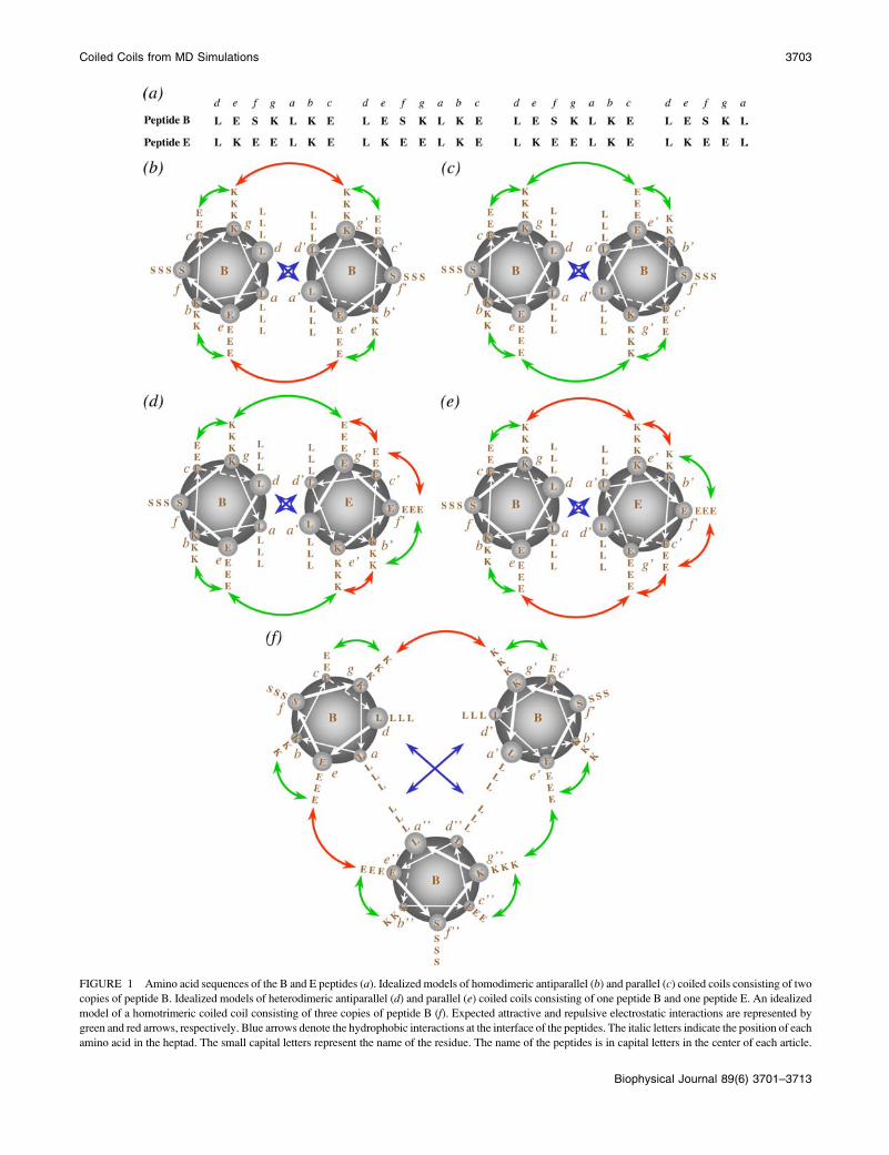
FIGURE 1 Amino acid sequences of the B and E peptides (a). Idealized models of homodimeric antiparallel (b) and parallel (c) coiled coils consisting of two
copies of peptide B. Idealized models of heterodimeric antiparallel (d) and parallel (e) coiled coils consisting of one peptide B and one peptide E. An idealized
model of a homotrimeric coiled coil consisting of three copies of peptide B (f). Expected attractive and repulsive electrostatic interactions are represented by
green and red arrows, respectively. Blue arrows denote the hydrophobic interactions at the interface of the peptides. The italic letters indicate the position of each
amino acid in the heptad. The small capital letters represent the name of the residue. The name of the peptides is in capital letters in the center of each article.
Biophysical Journal 89(6) 3701–3713
Coiled Coils from MD Simulations 3703

sequence has no net charge. The initial velocities of the atoms were taken
from a Maxwell distribution at 298 K. Different random number seeds were
used for each simulation. Before carrying out the MD simulations, a steepest
descent minimization was performed. Three independent simulations were
carried out for certain of the initial configurations, giving 24 simulations in
total. In Table 1 the distances and orientations of the helices together with
the number of water molecules used for each simulation are listed.
Configurations were stored every 20 ps during 10 ns for analysis. For each
configuration, the distance to the nearest periodic image of each peptide was
calculated and found to be in most cases .2 nm and never ,1.6 nm, i.e.,
always larger than the cutoff used for the long-range interactions.
Stability of dimers
The simulations of the B peptides that successfully formed coiled coils were
used to investigate the interactions stabilizing the dimers. In addition, to study
the effect of changes in the electrostatic and/or hydrophobic interactions on the
stability of a coiled coil, a second peptide (peptide E) was also investigated.
The amino acid sequence of peptide E is also listed in Fig. 1 a. Three sim-
ulations of dimers formed by combining E 1 E and E 1 B starting from an
antiparallel and a parallel orientation were performed (12 simulations in total).
Fig. 1, d and e, shows models of the antiparallel and parallel heterodimeric
coiled coils. For the simulations of E 1 E, a distance of 9 nm between centers
of adjacent unit cells was used because peptide E was not expected to be stable
as an a-helix due to repulsion between charged groups. For the E 1 B dimers,
boxes with three different sizes (7, 8, and 9 nm) were used. The distances, the
orientations of the helices, and the number of water molecules used to solvate
the peptides are listed in Table 1. The initial structure of peptide E in all
simulations was an ideal helix generated with the program WHATIF.
The protonation state of the residues and N- and C-termini was the same
as for peptide B. The net charge of peptide E was �4 e. The question of
whether counterions should be added to balance the overall charge in
simulations is a matter of continuing debate. In this regard it should be noted
that due to its high dielectric constant, explicit water very effectively screens
charge-charge interactions at distance. Furthermore, due to the small box
size, adding ions to balance the charge in this system would lead to very high
effective salt concentration, which could affect the stability of the coiled
coils. Thus, so that a direct comparison could be made with the simulations
of peptide B, again no counterions were added. This also avoided difficulty
associated with the very slow equilibration of the ion distribution.
Oligomerization state
The stability of trimers and tetramers consisting of monomers of peptide
B was studied in a similar manner. A total of six simulations, three with
antiparallel and three with parallel conformations, were performed to study
the trimers and eight simulations, four antiparallel and four parallel, to
investigate the stability of different tetramers. In all cases, the initial structure
was a model coiled coil consisting of three or four a-helices with the leucine
residues oriented to the core of the structure. The antiparallel trimeric models
consisted of two parallel helices and one antiparallel helix, whereas the
antiparallel tetrameric structure consisted of a bundle of four a-helices, each
one antiparallel to the two adjacent helices and parallel to the diagonal helix.
In Fig. 1 f a representation of an antiparallel trimeric coiled coil is shown.
Note, each of the initial configurations differed slightly in respect to the
distance or the orientation of the leucines to reduce systematic bias. The
distance between the geometrical centers of adjacent unit cells was 8 or 9 nm
FIGURE 2 Representation of the parameters used to define the initial
conformation of the peptides in the dimer. (d) The distance between the
centers of both helices. (a) The relative orientation of the helices; 0�corresponds to a parallel orientation. (b) The relative orientation of the
leucine residues; 0� means that the leucines of both helices are oriented
toward the interface of the dimer.
TABLE 1 List of MD simulations performed for dimers
Name of
trajectory*
Starting structurey
No. water
moleculesd (nm) a (deg) b (deg) Coiled coilz
aB1–aB3 1.43 180 0 6145 O (3)
aB4–aB6 1.69 180 180 7063
aB7 2.02 180 0 7752
aB8 1.98 180 180 7735
pB1–pB3 1.42 0 0 6137 O (1)
pB4–pB6 1.68 0 180 6738
pB7 2.02 0 0 7745
pB8 1.98 0 180 7735
xB1–xB3 1.42 90 0 6138
xB4– xB6 1.68 90 180 6147
xB7 2.02 90 0 7754
xB8 1.98 90 180 7744
aE1 1.98 180 0 16751
aE2 1.11 180 0 16765
aE3 1.22 180 0 16748
pE1 1.95 0 0 16749
pE2 1.06 0 0 16767
pE3 1.43 0 0 16746
aBE1 1.97 180 0 16754
aBE2 1.07 180 0 11739 OaBE3 0.81 180 0 7776 OpBE1 1.98 0 0 16754
pBE2 1.06 0 0 11744
pBE3 0.80 0 0 7761
Lines between rows separate groups of simulations of the same peptides
starting from the same relative orientation of the helices.
*a, p, and x denote antiparallel, parallel, and 90�, respectively, between the
axis of the helices in the initial conformation. B and E indicate homodimers
consisting of peptide B or E, and BE indicates a heterodimer consisting of
one peptide B and another peptide E. The last number in the name of the
trajectories is an index to distinguish different trajectories. The simulation
time was 10 ns for all the trajectories except for aB2, aB4, pB1, and xB8,
for which it was 110 ns.ya is the relative orientation of the helices, 0� corresponds to a parallel
orientation, and b is the relative orientation of the leucine residues; 0�means that the leucines of both helices are oriented toward the interface
of the dimer. d is the distance between the centers of both helices. The
meaning of a, b, and d are also illustrated in Fig. 2.zMarks only appear when coiled coils were observed after the correspond-
ing simulation time, and the number on their right is the number of simula-
tions providing coiled coils given one starting structure.
3704 Pineiro et al.
Biophysical Journal 89(6) 3701–3713

and the boxes solvated with water molecules. No template structure was
used to generate the initial configurations. The individual peptides were
simply placed in close proximity in the proposed orientation with the leucine
residues oriented toward the core of the oligomer.
The total length of the simulations presented in this work is 0.9 ms.
Analysis of the trajectories was performed with tools from the GROMACS
package, using VMD version 1.8 and RASMOL version 2.7 (55).
RESULTS AND DISCUSSION
Spontaneous dimerization
A classic coiled coil structure is formed from two peptides
that are predominately a-helical and interact in a parallel or
antiparallel orientation by means of a closely packed hy-
drophobic interface. Longer peptides also show a degree of
supercoiling. According to this definition, only 4 of the 24
simulations of peptide B show the formation of a coiled coil
dimer from two separated monomers. This is despite the fact
that coiled coil formation is believed to be highly cooperative
and the initial configurations consisted of two preformed
ideal a-helices in close proximity, a configuration specifi-
cally chosen to facilitate the formation of coiled coils. From
this it is already clear that to simulate the formation of coiled
coils from peptides placed randomly in an arbitrary confor-
mation would not be possible on the timescales investigated
in this study.
The relative orientation of the peptides forming coiled
coils was antiparallel in three trajectories (aB1–aB3) and
parallel in the fourth (pB1). The peptides are too short for
supercoiling to be observed. In each of these cases the initial
separation between the two monomers was small. The initial
conformation of the peptides in trajectories aB1–aB3 is shown
in Fig. 3 a with the structures after 10 ns from trajectories
aB2 and aB3 shown in Fig. 3, b and c. The initial confor-
mation for the trajectory pB1, Fig. 3 d, was similar to aB1–
aB3 except the helices were initially arranged parallel. The
conformation at 10 ns for this trajectory is shown in Fig. 3 e.
Starting from the same initial conformation two other sim-
ulations (pB2 and pB3) did not form an antiparallel coiled
coil. The 20 simulations which did not form coiled coils
resulted in structures consisting of partially folded a-helices,
either separated or interacting with each other in an irregular
fashion. An example is shown in Fig. 3 f, the conformation at
10 ns of trajectory pB2.
The variation of the solvent accessible surface (SAS) of
the hydrophobic residues for these 24 trajectories was cal-
culated (56). For the trajectories that formed classic coiled
coil dimers, a sharp reduction in the SAS was observed
during the first nanosecond, which then remained almost
constant during the rest of the simulation. A slow, more
continuous decrease was observed in the trajectories which
did not lead to coiled coils. The root mean square positional
deviation (RMSD) for the same 24 simulations was also
calculated taking as reference the corresponding initial
conformation in each case. The trajectories leading to coiled
coils are the most stable. They also remain closer to the initial
structure. The results suggest that on this timescale the final
structure is highly dependent on the initial conformation.
Coiled coils could only be obtained starting from structures
with 0� or 180� between the axis of the helices and very short
distances between hydrophobic residues. However, a variety
of other apparently stable structures was formed after a few
nanoseconds in other trajectories. Typically these were
characterized by low SAS values which in some cases were
comparable to the values of the classic coiled coil structures.
Simulations corresponding to two of the most unfavorable
initial conformations, aB4 and xB8, were extended for an-
other 100 ns. These trajectories show that increasing the
timescale of the simulations by an order of magnitude does
not significantly alter the results. A more or less stable struc-
FIGURE 3 Initial configuration of the peptides in trajectories aB1–aB3
(a). Configurations at 10 ns obtained from trajectories aB2 (b) and aB3 (c).
The initial configuration of the peptides in trajectories pB1-pB3 (d).
Configurations at 10 ns obtained from trajectories pB1 (e) and pB2 (f). In
a and d, the side chains of the leucine residues are highlighted in red. In b, c,e, and f, the leucines at positions a, d, a9, and d9 are highlighted in green,
yellow, orange, and red, respectively, to show the packing of the leucines in
different antiparallel and parallel coiled coils. Figures generated using VMD.
Coiled Coils from MD Simulations 3705
Biophysical Journal 89(6) 3701–3713

ture rapidly forms which slowly evolves to minimize the
hydrophobic SAS (data not shown).
Stability of dimers
The SAS and RMSD of the trajectories aB1–aB3 and pB1
suggest that the dimeric coiled coils obtained are very stable.
Calculations of the root mean square positional fluctuation
show that just the first and last side chains are mobile. The
coiled coil structures as represented by Fig. 3, b, c, and e, are
extremely rigid in the simulations, especially in the central
regions, whereas alternate structures such as the one shown
in Fig. 3 f are more mobile. Trajectories aB2 and pB1 were
extended by 100 ns to test whether the antiparallel and
parallel coiled coils maintained their respective conforma-
tions if the timescale was increased by an order of magnitude.
No significant differences between the 10 ns trajectories and
the 100 ns trajectories were evident.
In the idealized schematics of coiled coils presented in
Fig. 1, the red and green arrows represent electrostatic in-
teractions between charges of the same and different signs,
respectively, and the blue arrows represent hydrophobic in-
teractions. As it is shown in Fig. 1 c, peptide B was designed
to optimize the intermolecular interactions in a hypothetical
parallel coiled coil. However in three of the four simulations
in which a stable coiled coil was obtained, the orientation of
the helices was antiparallel. To analyze how the interactions
stabilizing the structures obtained from trajectories aB1–aB3
and pB1 compare with the idealized model, the minimal
distances between the charged groups of glutamate and
lysine, COO� and NH13 ; respectively, and between leucine-
leucine residues of different peptides were calculated. In
Figs. 4 and 5, the distributions of some of these distances
obtained from the last 5 ns of the trajectories aB2 and pB1
(antiparallel and parallel coiled coils, respectively) are shown.
Although only the results from the analysis of aB2 are
discussed, the nature of the interactions within the interface
was similar in all antiparallel cases. To generate these plots,
the six central residues of one of the peptides in each of these
trajectories, from lysine 11 at position g to glutamate 16 at
position e, were taken as a reference. From Figs. 4 and 5, it is
clear that the closest contacts between the hydrophobic
residues show relatively narrow distributions compared with
the charged residues. Note, the distances in Figs. 4 and 5
correspond to the centers of the interaction sites, which for
leucines are the aliphatic carbon atoms given that the non-
polar hydrogen atoms are not treated explicitly.
In the antiparallel coiled coil, the leucine at position ais juxtaposed with one leucine at position d9 (red dashed linein Fig. 4 b), the distance over the 5 ns being 0.4 6 0.1 nm
(where the error indicates the width of the distribution at
one-half height). The distance to the two closest leucines at
position a9 (red and green solid lines in Fig. 4 b) is larger, 0.6
6 0.2 nm, but the distributions are still narrow. The leucine
at position d behaves slightly differently since there are three
leucines in the second helix, two at position a9 and one at
position d9 (red and blue dashed lines and red solid line in
Fig. 4 e) at similar distances (0.3 6 0.2 nm in one case and
0.4 6 0.1 nm in the other two cases). In contrast, in the par-
allel coiled coil more regular interactions with the leucines of
FIGURE 4 Distributions of minimum distances
from the six central residues of the first helix (11–16)
to the residues of the second helix with which they are
expected to interact, calculated from the last 5 ns of
trajectory aB2. The label in each plot specifies the
name and position of the residue taken as the reference
in the first helix and the residues of the second helix
(primed) to which the minimum distances are calcu-
lated. Black, blue, red, and green curves represent
residues from the first, second, third, and fourth turns,
respectively, of the second peptide. Solid lines
represent glutamates at position e9, leucines at position
d9, or lysines at position g9, and dashed lines represent
glutamates at position c9, leucines at position a9, or
lysines at position b9, depending on the case. For
glutamate and lysine residues, only the charged groups
(COO� and NH13 ) were considered. Minimum dis-
tances between atoms in the aliphatic chains should
be reduced by ;0.1 nm due to the treatment of the
nonpolar hydrogens as united atoms.
3706 Pineiro et al.
Biophysical Journal 89(6) 3701–3713

the second peptide are observed. The distributions of the
distances to the three closest leucines at positions a9 and d9(Fig. 5, b and e) overlap almost exactly, the peak being at
0.4 6 0.2 for all of them.
In regard to the charged groups, in the antiparallel coiled
coil the distance between the lysine at position g and the two
closest glutamates of the second peptide at position c9 (blueand red dashed lines in Fig. 4 a) is 0.9 6 0.4 nm, within the
cutoff used in the simulations for the electrostatic inter-
actions. Note, any given lysine interacts with glutamates in
two repeats and any given glutamate interacts with lysines in
two repeats. This suggests attractive interactions which could
contribute to the stability of the dimer. Since both helices
have the same sequence of amino acids, the distributions of
the distances between residues placed at symmetrical posi-
tions, glutamate at c and lysines at g9 (red and blue solid linesin Fig. 4 d), are very similar. The distance between the same
lysine at position g and the glutamates at position e9 (red and
green solid lines in Fig. 4 a) is also within the cutoff during
a significant part of the trajectory (1.4 6 0.3 nm), indicating
a weak interaction. The symmetrical interaction between the
glutamate at position e and lysines at position g9 appears to
be even weaker, the distance being 1.7 6 0.3 nm. These
residues are almost always separated by more than the cutoff.
The distances between all the remaining charged groups for
the antiparallel coiled coil are beyond the cutoff over the 5
ns. This means that both lysine at position b (Fig. 4 c) and
glutamate at position e (Fig. 4 f) do not have direct attractive
electrostatic interactions with any residue of the second
helix. The lack of significant attractive interactions involving
these two residues in the antiparallel coiled coil was already
expected from the model presented in Fig. 1 b. In the parallel
coiled coil the distance between the lysine at position g and
the glutamates at position e9 (blue and red solid lines in Fig.
5 a) is within the cutoff over almost the 5 ns (0.9 6 0.4 nm).
The distributions of the distances between glutamate at
position e and lysines at position g9 (blue and red solid linesin Fig. 5 f) are very similar, showing the symmetrical
interaction since both helices have the same sequence of
amino acids. As was also expected from the model shown in
Fig. 1 c, the residues at positions c and b do not interact
significantly with the second helix.
By comparing the distributions of the leucine-leucine dis-
tances, it is evident that the arrangement of the hydrophobic
residues at the interface between the peptides depends on the
orientation of the helices in the dimer. The packing of the
leucines in the antiparallel and parallel coiled coils can be
appreciated in detail in Fig. 3, b and e, where the side chains
of the leucine residues at positions a and d of both peptides
are represented with different colors. In the parallel coiled
coil all of the leucines are oriented to the core of the dimer,
forming a hydrophobic interface with a type of knobs into
holes packing. However, in the antiparallel coiled coil formed
in the simulations, the leucines at positions a and d9 are ori-
ented perpendicularly to the plane containing the axis of both
helices. Only the leucines at positions d and a9 are clearly
interacting with each other. It is important to note, however,
that the interfaces in both the antiparallel and parallel coiled
coils are tightly packed. As discussed in detail later a range
of residues, in particular the nonpolar regions of the lysine
FIGURE 5 The same as Fig. 4 but for trajectory
pB1.
Coiled Coils from MD Simulations 3707
Biophysical Journal 89(6) 3701–3713

side chains, form extensive hydrophobic interactions in the
antiparallel case.
According to the idealized model presented in Fig. 1 b,
interactions between the lysine at position g and the
glutamate at position c9 in the antiparallel coiled coil as
well as interactions between the glutamate at position c and
the lysine at position g9 were not expected. Also no
difference in the packing of the hydrophobic core between
the parallel and antiparallel orientations was expected. To
better understand the role of the lysine residues in the
stability of the antiparallel dimer, the minimum distances
between the lysine and leucine residues and between the
lysine and lysine residues of different peptides along the last
5 ns of the trajectories aB1–aB3 were calculated. In these
calculations all of the atoms that comprise the lysine residues
were taken into account. In Fig. 6 the distributions of these
distances for the lysines 11 and 18 at position g for the
trajectory aB2 are plotted. Very narrow distributions for the
distances to the leucines were observed (0.4 6 0.1 nm),
suggesting hydrophobic interactions between the side chain
of lysines and the hydrophobic core of the dimer (Fig. 6,
a and b). The distances from the lysines at position g to the
lysines at position g9 have very similar distributions,
indicating that the side chains of these residues also
participate in the packing at the interface of the dimer (Fig.
6, c and d). Fig. 7 shows the arrangement of the lysine
residues at positions g and g9 of both peptides together with
the leucines at position d9 of the second peptide. The relative
orientation of the lysines in the different helices highlighted
in Fig. 7 also suggests hydrophobic interactions between
these side chains. Stable lysine-lysine interfaces have been
found previously in other designed coiled coils (57) and may
also play a role in the unexpected stability of the antiparallel
trimer Coil-Ser (33).
The intramolecular distances between the charged groups
of the glutamate and lysine residue within each peptide were
also calculated (data not shown). The distributions corre-
sponding to the individual glutamate-lysine pairs have a
maximum at ;0.4 nm. This suggests that the intramolecular
electrostatic interactions are more significant than intermo-
lecular ones. The proximity between the glutamate and lysine
residues within one peptide might also screen unfavorable
charge-charge interactions between the lysines residues
which lie in close proximity in the antiparallel orientation.
In light of the findings above, a modified model for the
interaction of the residues in the antiparallel B 1 B coiled
coil can be proposed. The electrostatic and the hydrophobic
interactions suggested by the MD simulations are illustrated
in Fig. 8. These differ significantly from those proposed in
Fig. 1 b and on which the design was based. Specifically, we
find that in addition to the leucine residues at the interface,
FIGURE 6 Distributions of minimum distances from the lysine 11 and
lysine 18, both at position g, of the first helix to the leucines and lysines of
the second helix, calculated from the last 5 ns of trajectory aB2. The label in
each plot specifies the name and position of the lysine taken as the reference
in the first helix and the residues of the second helix (primed) to which the
minimum distances are calculated. Black, blue, red, and green curves repre-
sent residues from the first, second, third, and fourth turns, respectively, of
the second peptide. Solid lines represent leucines at position d9 or lysines at
position g9, and dashed lines represent leucines at position a9, or lysines at
position b9, depending on the case. Minimum distances between the atoms in
the aliphatic chains should be reduced by ;0.1 nm due to the treatment of
the nonpolar hydrogens as united atoms.
FIGURE 7 View of the lysine interface in an antiparallel coiled coil
(trajectory aB2). Lysines at position g and g9 are highlighted in red and
orange, respectively. The side chains of the leucines at position d9 are shown
in yellow. The rest of the leucines are not shown for clarity. Figure generated
using VMD.
3708 Pineiro et al.
Biophysical Journal 89(6) 3701–3713

lysine-lysine interactions play a central role in stabilizing the
structure. Weak hydrophobic interactions between the side
chains of glutamate and leucine and/or hydrogen bonds
between the serines and glutamates may also contribute to
stability but are only of secondary importance.
Another factor which could favor an antiparallel orienta-
tion of any coiled coil is the dipole moment of the helices
which arises from the peptide backbone (58,59). For ex-
ample, this has been proposed to explain the stability of the
antiparallel trimer Coil-Ser (33). However, the stability of
the parallel trimer Coil-VaLd (34,35), a mutant of Coil-Ser in
which the leucines at position a have been changed by
valine, suggests that the packing of the hydrophobic residues
at the interface of the dimer can be sufficient to determine the
orientation of the helices. It should also be noted that
although the helix dipole favors an antiparallel orientation in
vacuum or in a nonpolarizable implicit solvent, in a highly
polarizable medium such as water, the helix dipole will be in
part compensated by an induced dipole in the environment.
In addition, in simulations performed under periodic bound-
ary conditions it is possible that this effect could be enhanced
and parallel orientations stabilized artificially due to the in-
teraction between neighboring periodic images.
Peptide E was designed such that it could not form com-
plementary electrostatic interactions with itself in either a
parallel or antiparallel orientation but would form comple-
mentary electrostatic interactions with peptide B in an anti-
parallel orientation (see Fig. 1 d). In the simulations performed
with homodimers of peptide E, it was not possible to obtain
a stable coiled coil. In all the trajectories, regardless of the
initial orientation of the helices both monomers start to unfold
within picoseconds. These simulations strongly suggest that
in this case the effect of the intramolecular electrostatic forces
dominate. It should be noted in this regard that although the
peptide E carries a net charge of �4 e no counterions were
included in the simulation. The reasons for this are listed in
the Methods section. Certainly, counterions might moderate
the electrostatic interactions. However, at the concentrations
at which these peptides are studied experimentally (10 mM
NaCl), the volume of the simulation box would contain on
average only between 1 and 2 Na1 ions. In addition, these
ions would not necessarily be directly associated with either
of the peptides.
Experimental investigations by CD spectroscopy clearly
demonstrate that at pH 7.4 peptide E does not form a coiled
coil (triangles, Fig. 9 a). Although peptide E does not form
a coiled coil in a 250 mM solution at pH 7.4, the CD curve of
FIGURE 8 Proposed model for the interactions in the homodimeric
antiparallel coiled coil of peptide B. Attractive and repulsive electrostatic
interactions are represented by green and red arrows, respectively. Hydro-
phobic interactions are represented by blue arrows. Dashed arrows represent
the new interactions added to the original model of Fig. 1 b. The italic letters
indicate the position of each amino acid in the heptad, and the small capital
letters represent the name of the residue.
FIGURE 9 (a) CD spectra measured in 10 mM Tris-HCl buffer, pH 7.4;
250 mM peptide B (circles), 250 mM peptide E (triangles); a mixture of
125 mM peptide B and 125 mM peptide E (squares). Diamonds correspond
to the sum of the curves for peptide B (circles) and peptide E (triangles)
curves corrected to a concentration of 125 mM for comparison to the mea-
sured curve of the mixture. All spectra were recorded at 298 K. (b) Thermal
unfolding profiles of 125 mM peptide B (solid squares; melting temperature
60.3�C) and a mixture of 125 mM peptide B and 125 mM peptide E
(triangles; melting temperature 58.3�C). Melting curves were recorded by
observing the CD signal at 222 nm at pH 7.4 in 2 M guanidinium chloride.
The thermal melting profiles were fitted by using a 5 parameter sigmoidal
curve.
Coiled Coils from MD Simulations 3709
Biophysical Journal 89(6) 3701–3713

peptide B shows two minima at 208 nm and 222 nm,
respectively, which are characteristic of an a-helical coiled
coil fold (circles, Fig. 9 a). The mixture of peptide E and
peptide B in a ratio of 1:1 suggests some formation of a
heterodimeric a-helical coiled coil (solid squares, Fig. 9 a).
The CD spectrum of the mixture is not simply the sum of the
spectra of the B and E peptides in isolation. The diamonds in
Fig. 9 a correspond to the sum of the experimental curves for
the isolated B and E peptides corrected for concentration.
Although the curves are similar, they deviate sharply at low
wavelengths. The measured and the calculated spectra also
differ in the ratio of the local minima at 208 nm and 222 nm
([u]222/[u]208 ¼ 0.72 for addition of single spectra, [u]222/
[u]208 ¼ 0.76 for the measured spectra of the B 1 E mixture),
indicating an increase in helical content. In addition, thermal
unfolding profiles of the B peptide and the BE mixture were
recorded (Fig. 9 b). Different curves and different melting
temperatures of TM ¼ 58.3�C (BE mixture) and TM ¼ 60.3�C(B peptide) show that the BB homodimer is not the sole
a-helical structure in the BE mixture. Rather peptide B as
either a monomer or higher aggregate is able to act as a tem-
plate for peptide E and possibly induce a transformation from
random coil to a helical structure.
To test this and the basic design hypothesis, six sim-
ulations of heterodimeric B 1 E coiled coils were performed.
The starting configurations varied slightly between the
simulations as can be appreciated from Table 1 and Fig.
10. Two of the antiparallel heterodimeric B 1 E coiled coils
maintained their initial structure during 10 ns, demonstrating
that although a helical peptide E is not stable in isolation the
heterodimeric B 1 E coiled coil is stable in the simulations
and might account for the experimental results. In Fig. 10 the
initial and final structures of the trajectories corresponding to
an antiparallel orientation of the helices are shown. In all
cases where the starting orientation was parallel, no coiled
coils were obtained. After 10 ns the structure of peptide E
was effectively random. These results suggest that anti-
parallel B 1 E heterodimers are more stable than parallel
dimers. It should be noted, however, that in general a wide
variety of structures could give rise to the CD signal ob-
served experimentally. These include structures such as that
shown in Fig. 3 f, which have significant a-helical content as
well as the possibility of trimers or higher order oligomers.
Oligomerization state
Trimers
To investigate the possible stability of trimers, conformations
consisting of bundles of three B peptides in a parallel and an
antiparallel orientation were constructed and simulated for 10
ns. The trajectories starting from antiparallel and parallel
arrangements were labeled 3aB1–3aB3 and 3pB1–3pB3,
respectively. Three simulations were performed starting from
a parallel orientation. In all cases the trimer disassociated,
leaving a coiled coil consisting of no more than two helices. In
contrast, in two of the three antiparallel cases the trimeric
coiled coil remained stable. Although it was not possible to
obtain a stable parallel trimer,a-helical parallel dimers similar
to that seen in pB1 (Fig. 3 e) were observed in 3pB1 and 3pB3.
Nevertheless, the results still strongly suggest a preference for
an antiparallel arrangement. Fig. 11, a and b, shows two views
of the trimer formed in trajectory 3aB3. The side chains of the
leucines of each helix are shown in different colors to
highlight the packing of the hydrophobic core.
Tetramers
Simulations were also performed with bundles of four helices.
The trajectories starting from antiparallel and parallel
arrangements were labeled 4aB1–4aB4 and 4pB1–4pB4,
respectively. In Fig. 11, c–e, the last structures corresponding
to trajectories 4aB1, 4aB4, and 4pB4 are shown. For each
helix the side chains of the leucines are highlighted in
different colors. Only in trajectory 4aB4 did an antiparallel
tetrameric coiled coil form and remain stable. No parallel
tetrameric coiled coils were observed. Some dimeric coiled
coils were obtained starting from the parallel tetramer, as for
FIGURE 10 Initial and last structures (after 10 ns) of MD for the three
simulations of antiparallel heterodimers consisting of one peptide B (black)
and one peptide E (gray); trajectories aBE1 (a), aBE2 (b), and aBE3 (c).
Figures generated using VMD.
3710 Pineiro et al.
Biophysical Journal 89(6) 3701–3713

instance the ones shown in Fig. 11 e, and one antiparallel
trimer interacting loosely with the final monomer was
obtained from 4aB1. The antiparallel tetramer obtained
from trajectory 4aB4 was very stable during the 10 ns the
RMSD remaining almost constant over the whole trajectory
(data not shown). This suggests that coiled coils consisting of
four a-helices in an antiparallel orientation may exist in
equilibrium with other structures, including antiparallel
trimers and parallel or antiparallel dimers. The interaction
between the dipole moments of the helices appears to prevent
the formation of parallel coiled coils consisting of more than
two helices for these peptides. As noted earlier, there was
a danger that interactions between the total dipole of the
systems due to the imposition of periodic boundary conditions
could have artificially favored parallel orientations. Although
this clearly proved not to be the case, as this effect was
potentially larger in the case of the tetrameric systems, larger
box dimensions were used in this case as a precautionary
measure.
CONCLUSIONS
This study had three aims: i), to simulate the spontaneous
formation of coiled coils, ii), to characterize the arrangement
of the residues in stable dimeric parallel and antiparallel
coiled coils, and iii), to determine if it is possible to dis-
criminate between different stoichiometries/orientations.
i. The classic coiled coil configuration could only be
obtained using 10 ns simulations if the initial structure
was very close to the expected final configuration.
Alternative starting configurations led to a wide variety
of alternative dimer metastable conformations. These
nevertheless contained a high degree of a-helix. The
work suggests either that the coiled coils form by a two-
state process forming an initial complex which only
slowly rearranges to form the classic coiled coil or that
a high helical content as inferred from CD spectra does
not necessarily imply the formation of a classic coiled
coil structure.
ii. Although peptide B had been designed to form a parallel
coiled coil in the simulations, an antiparallel configura-
tion was clearly favored. This was associated with the
formation of an asymmetric lysine interface. Factors
which may stabilize the antiparallel dimer include the
favorable interactions between the helix dipoles and
the effect of the packing of the lysines and leucines at
the hydrophobic interface.
FIGURE 11 Two views of conformation of the
trimer of a-helices at the end of trajectory 3aB3 with
the side chain of the leucines highlighted with
a different color for each peptide (a and b). Configu-
ration at 10 ns from trajectories 4aB1 (c), 4aB4 (d), and
4pB4 (e). In the antiparallel structures, the helices with
different orientation are in dark blue. Figures generated
using VMD.
Coiled Coils from MD Simulations 3711
Biophysical Journal 89(6) 3701–3713

iii. It did prove possible to distinguish between different
stoichiometries and/or orientations. In agreement with
experiment, it was found that B 1 B or B 1 E did form
stable coiled coils, whereas E 1 E did not. In the case of
peptide B, the simulations suggest that parallel and
antiparallel dimers as well as antiparallel trimers and
tetramers are potentially stable and may even be in
equilibrium in solution. Parallel trimers and tetramers
were not stable.
In summary, despite the apparent strong tendency of the B
peptide to form a coiled coil in solution it was not possible to
simulate the spontaneous formation of a coiled coil on
a nanosecond timescale unless the starting structure was very
close to the target structure. Nevertheless, it was possible to
distinguish between alternative orientations and stoichiome-
tries using relatively short simulation times. This suggests
MD simulations could have an important role to play in
elucidating the properties of this widespread structural motif.
We thank Prof. Stephan Berger from the University of Leipzig for
stimulating discussions.
Financial support from the VolkswagenStiftung (project No. I/77 986) and
European Community Training and Mobility of Researchers (project No.
HRPN-CT-2002-00241) is gratefully acknowledged.
REFERENCES
1. Gruber, M., and A. N. Lupas. 2003. Historical review: another 50th
anniversary—new periodicities in coiled coils. Trends Biochem. Sci.28:679–685.
2. Lupas, A. 1996. Coiled coils: new structures and new functions. TrendsBiochem. Sci. 21:375–382.
3. Mason, J. M., and K. M. Arndt. 2004. Coiled coil domains: stability,specificity, and biological implications. ChemBioChem. 5:170–176.
4. Lupas, A. 1997. Predicting coiled coils regions in proteins. Curr. Opin.Struct. Biol. 7:388–393.
5. Lupas, A., M. Van Dyke, and J. Stock. 1991. Predicting coiled coilsfrom protein sequences. Science. 252:1162–1164.
6. Berger, B., D. B. Wilson, E. Wolf, T. Tonchev, M. Milla, and P. S.Kim. 1995. Predicting coiled coils by use of pairwise residue cor-relations. Proc. Natl. Acad. Sci. USA. 92:8259–8263.
7. Hirst, J. D., M. Vieth, J. Skolnich, and C. L. Brooks 3rd. 1996. Predictingleucine zippers structures from sequence. Protein Eng. 9:657–662.
8. Woolfson, D. N., and T. Alber. 1995. Predicting oligomerization statesof coiled coils. Protein Sci. 4:1596–1607.
9. Wolf, E., P. S. Kim, and B. Berger. 1997. Multicoil: a program forpredicting two- and three-stranded coiled coils. Protein Sci. 6:1179–1189.
10. Walshaw, J., and D. J. Woolfson. 2001. SOCKET: a program foridentifying and analysing coiled coil motifs within protein structures. J.Mol. Biol. 307:1427–1450.
11. Walshaw, J., and D. J. Woolfson. 2003. Extended knobs-into-holespacking in classical and complex coiled coil assemblies. J. Struct. Biol.144:349–361.
12. Walshaw, J., and D. J. Woolfson. 2001. Open-and-shut cases in coiledcoil assembly: a-sheets and a-cylinders. Protein Sci. 10:668–673.
13. Landschulz, W. H., P. F. Johnson, and S. L. McKnight. 1988. Theleucine zipper: a hypothetical structure common to a new class ofDNA-binding proteins. Science. 240:1759–1764.
14. Harbury, P. A. B. 1998. Springs and zippers: coiled coils in SNARE-mediated membrane fusion. Structure. 6:1487–1491.
15. Weis, W. I., and R. H. Scheller. 1998. SNARE the rod, coil thecomplex. Nature. 395:328–329.
16. Yu, Y., O. D. Monera, R. S. Hodges, and P. L. Privalov. 1996.Investigation of electrostatic interactions in two-stranded coiled coilsthrough residue shuffling. Biophys. Chem. 59:299–314.
17. Zitzewitz, J. A., O. Bilsel, J. Luo, B. E. Jones, and C. R. Matthews.1995. Probing the folding mechanism of a leucine zipper peptide bystopped-flow circular dichroism spectroscopy. Biochemistry. 34:12812–12819.
18. Wendt, H., L. Leder, H. Harma, I. Jelesarov, A. Baici, and H. R.Bosshard. 1997. Very rapid, ionic strength-dependent association andfolding of a heterodimeric leucine zipper. Biochemistry. 36:204–213.
19. Zhu, H., S. A. Celinski, J. M. Scholtz, and J. C. Hu. 2001. Anengineered leucine zipper a position mutant with an unusual three-stateunfolding pathway. Protein Sci. 10:24–33.
20. Dragan, A. I., and P. L. Privalov. 2002. Unfolding of a leucine zipper isnot a simple two-state transition. J. Mol. Biol. 321:891–908.
21. Doerr, A. J., M. A. Case, I. Pelczer, and G. L. McLendon. 2004.Design of a functional protein for molecular recognition: specificity ofligand binding in a metal-assembled protein cavity probed by 19FNMR. J. Am. Chem. Soc. 126:4192–4198.
22. Moll, J. R., S. B. Ruvinov, I. Pastan, and C. Vinson. 2001. Designedheterodimerizing leucine zippers with a range of pIs and stabilities upto 10�15 M. Protein Sci. 10:649–655.
23. Junius, F. K., S. I. O’Donoghue, M. Nilges, A. S. Weiss, and G. F.King. 1996. High resolution NMR solution structure of the leucinezipper domain of the c-Jun homodimer. J. Biol. Chem. 271:13663–13667.
24. Rasmussen, R., D. Benvegnu, E. K. O’Shea, P. S. Kim, and T. Alber.1991. X-ray scattering indicates that the leucine zipper is a coiled coil.Proc. Natl. Acad. Sci. USA. 88:561–564.
25. Suzuki, K., H. Hiroaki, D. Kohda, and T. Tanaka. 1998. An isoleucinezipper peptide forms a native-like triple stranded coiled coil in solution.Protein Eng. 11:1051–1055.
26. Wendt, H., C. Berger, A. Baici, R. M. Thomas, and H. R. Bosshard.1995. Kinetics of folding of leucine zipper domains. Biochemistry. 34:4097–4107.
27. Potekhin, S. A., T. N. Melnik, V. Popov, N. F. Lanina, A. A. Vazina,P. Rigler, A. S. Verdini, G. Corradin, and A. V. Kajava. 2001. De novodesign of fibrils made of short a-helical coiled coil peptides. Chem.Biol. 8:1025–1032.
28. Vu, C., J. Robblee, K. M. Werner, and R. Fairman. 2001. Effects ofcharged amino acids at b and c heptad positions on specificity andstability of four-chain coiled coils. Protein Sci. 10:631–637.
29. Howard, K. P., J. D. Lear, and W. F. DeGrado. 2002. Sequencedeterminants of the energetics of folding of a transmembrane four-helix-bundle protein. Proc. Natl. Acad. Sci. USA. 99:8568–8572.
30. Jelesarov, L., and H. R. Bosshard. 1996. Thermodynamic character-ization of the coupled folding and association of heterodimeric coiledcoils (leucine zippers). J. Mol. Biol. 263:344–358.
31. Mohanty, D., A. Kolinski, and J. Skolnick. 1999. De novo simulationsof the folding thermodynamics of the GCN4 leucine zipper. Biophys. J.77:54–69.
32. Gorfe, A. A., P. Ferrara, A. Caflisch, D. N. Marti, and H. R. Bosshard.2002. Calculation of protein ionization equilibria with conformationalsampling: pKa of a model leucine zipper, GCN4 and barnase. Proteins.46:41–60.
33. Lovejoy, B., S. Choe, D. Cascio, D. K. McRorie, W. F. DeGrado, andD. Eisenberg. 1993. Crystal structure of a synthetic triple-strandeda-helical bundle. Science. 259:1288–1293.
34. Betz, S., R. Fairman, K. O’Neill, J. Lear, and W. DeGrado. 1995.Design of two-stranded and three-stranded coiled coil peptides. Philos.Trans. R. Soc. Lond. B Biol. Sci. 348:81–88.
3712 Pineiro et al.
Biophysical Journal 89(6) 3701–3713

35. Ogihara, N. L., M. S. Weiss, W. F. DeGrado, and D. Eisenberg. 1997.The crystal structure of the designed trimeric coiled coil coil-VaLd:implications for engineering crystals and supramolecular assemblies.Protein Sci. 6:80–88.
36. Oakley, M. G., and J. J. Hollenbech. 2001. The design of antiparallelcoiled coils. Curr. Opin. Struct. Biol. 11:450–457.
37. Sajot, N., and M. Genest. 2000. Structure prediction of the dimeric neu/ErbB-2 transmembrane domain from multi-nanosecond moleculardynamics simulations. Eur. Biophys. J. 28:648–662.
38. Briki, F., J. Doucet, and C. Etchebest. 2002. A procedure for refininga coiled coil protein structure using x-ray fiber diffraction andmodeling. Biophys. J. 83:1774–1783.
39. Caballero-Herrera, A., and L. Nilsson. 2003. Molecular dynamicssimulations of the E1/E2 transmembrane domain of the Semliki Forestvirus. Biophys. J. 85:3646–3658.
40. Yang, P. K., W.-S. Tzou, and M.-J. Hwang. 1999. Restraint-drivenformation of a-helical coiled coils in molecular dynamics simulations.Biopolymers. 50:667–677.
41. Magana, S., A. M. Rubio, and A. Rey. 2002. Influence of thehydrophobic face width on the degree of association of coiled coilproteins. J. Chem. Phys. 117:10321–10328.
42. Tieleman, D. P., H. J. C. Berendsen, and M. S. P. Sansom. 1999. Analamethicin channel in a lipid bilayer: molecular dynamics simulations.Biophys. J. 76:1757–1769.
43. Law, R. J., D. P. Tieleman, and M. S. P. Sansom. 2003. Pores formedby the nicotinic receptor M2d peptide: a molecular dynamics simu-lation study. Biophys. J. 84:14–27.
44. Berendsen, H. J. C., D. van der Spoel, and R. van Drunen. 1995.GROMACS: a message-passing parallel molecular dynamics imple-mentation. Comput. Phys. Comm. 95:43–56.
45. Lindahl, E., B. Hess, and D. van der Spoel. 2001. GROMACS 3.0:a package for molecular simulation and trajectory analysis. J. Mol.Model. (Online). 7:306–317.
46. http://www.gromacs.org
47. van Gunsteren, W. F., S. R. Billeter, A. A. Eising, P. H. Hunenberger,P. Kruger, A. E. Mark, W. R. P. Scott, and I. G. Tironi. 1996.
Biomolecular Simulation: GROMOS96 Manual and User Guide.
Hochschulverlag AG an der ETH Zurich, Zurich, Switzerland.
48. Schuler, L. D., and W. F. van Gunsteren. 2000. On the choice of
dihedral angle potential energy functions for n-alkanes. Mol. Simulat.25:301–319.
49. Berendsen, H. J. C., J. P. M. Postma, W. F. van Gunsteren, and J.
Hermans. 1981. Interaction models for water in relation to protein
hydration. In Intermolecular Forces. B. Pullman, editor. Reidel D.
Publishing Company, Dordrecht, The Netherlands. 331–342.
50. Berendsen, H. J. C., J. P. M. Postma, W. F. van Gunsteren, A. DiNola,
and J. R. Haak. 1984. Molecular dynamics with coupling to an external
bath. J. Chem. Phys. 81:3684–3690.
51. Miyamoto, S., and P. A. Kollman. 1992. SETTLE: an analytical
version of the SHAKE and RATTLE algorithms for rigid water
models. J. Comput. Chem. 13:952–962.
52. Hess, B., H. Bekker, H. J. C. Berendsen, and J. G. E. M. Fraaije. 1997.
LINCS: a linear constraint solver for molecular simulations. J. Comput.Chem. 18:1463–1472.
53. Humphrey, W., A. Dalke, and K. Schulten. 1996. VMD: visual molec-
ular dynamics. J. Mol. Graph. 14:33–38.
54. Vriend, G. 1990. WHAT IF: a molecular modeling and drug design
program. J. Mol. Graph. 8:52–56.
55. Sayle, R. A., and E. J. Milner-White. 1995. RASMOL: biomolecular
graphics for all. Trends Biochem. Sci. 20:374–376.
56. Eisenhaber, F., P. Lijnzaad, P. Argos, C. Sander, and M. Scharf. 1995.
The double cubic lattice method: efficient approaches to numerical
integration of surface area and volume and to dot surface contouring of
molecular assemblies. J. Comput. Chem. 16:273–284.
57. Schnarr, N. A., and A. J. Kennan. 2003. Specific control of peptide
assembly with combined hydrophilic and hydrophobic interfaces.
J. Am. Chem. Soc. 125:667–671.
58. Hol, W. G. J., P. T. van Duijnen, and H. J. C. Berendsen. 1978. The
a-helix dipole and the properties of proteins. Nature. 273:443–446.
59. Hol, W. G. J. 1985. The role of the a-helix dipole in protein function
and structure. Prog. Biophys. Mol. Biol. 45:149–195.
Coiled Coils from MD Simulations 3713
Biophysical Journal 89(6) 3701–3713
Copyright © 2022 FDOKUMEN