Solenoidal coils made from monofilamentary and multifilamentary MgB2 strands
22
Solenoidal Coils Made from Monofilamentary and Multifilamentary MgB 2 strands M.D.Sumption 1 , M. Bhatia 1 , F. Buta 1 , S. Bohnenstiehl 1 , M. Tomsic 2 , M. Rindfleisch 2 , J. Yue 2 , J. Phillips 2 , S. Kawabata 1,3 , and E.W. Collings 1 1 LASM, Materials Science and Engineering Department, OSU, Columbus, OH 43210, USA 2 Hyper Tech Research, Inc. Columbus, OH 43210, USA 3 Kagoshima University, Kagoshima, Japan Abstract Three solenoids have been wound and with MgB 2 strand and tested for transport properties. One of the coils was wound with Cu-sheathed monofilamentary strand and the other two with a seven filament strand with Nb-reaction barriers, Cu stabilization, and an outer monel sheath. The wires were first S-glass insulated, then wound onto an OFHC Cu former. The coils were then heat treated at 675°C/30 min (monofilamentary strand) and 700°C/20 min (multifilamentary strand). Smaller (1 m) segments of representative strand were also wound into barrel-form samples and HT along with the coils. After HT the coils were epoxy impregnated. Transport J c measurements were performed at various taps along the coil lengths. Measurements were made initially in liquid helium, and then as a function of temperature up to 30 K. Homogeneity of response along the coils was investigated and a comparison to the short sample results was made. Each coil contained more than 100 m of 0.84-1.01 mm OD strand. One of the 7 strand coils reached 222 A at 4.2 K, self field, with a J c of 300 kA/cm 2 in the SC and a winding pack J e of 23 kA/cm 2 . At 20 K these values were 175 kA/cm 2 and 13.4 kA/cm 2 . Magnet bore fields of 1.5 T and 0.87 T were achieved at 4.2 K and 20 K, respectively. The other multifilamentary coil gave similar results. Keywords: MgB 2 , coil, solenoid, stabilization, transport current
-
Upload
independent -
Category
Documents
-
view
0 -
download
0
Transcript of Solenoidal coils made from monofilamentary and multifilamentary MgB2 strands
Solenoidal Coils Made from Monofilamentary and
Multifilamentary MgB2 strands
M.D.Sumption1, M. Bhatia1, F. Buta1, S. Bohnenstiehl1, M. Tomsic2, M. Rindfleisch2, J. Yue2, J. Phillips2, S. Kawabata1,3, and E.W. Collings1
1LASM, Materials Science and Engineering Department, OSU, Columbus, OH 43210, USA
2Hyper Tech Research, Inc. Columbus, OH 43210, USA 3Kagoshima University, Kagoshima, Japan
Abstract
Three solenoids have been wound and with MgB2 strand and tested for transport
properties. One of the coils was wound with Cu-sheathed monofilamentary strand and the
other two with a seven filament strand with Nb-reaction barriers, Cu stabilization, and an
outer monel sheath. The wires were first S-glass insulated, then wound onto an OFHC Cu
former. The coils were then heat treated at 675°C/30 min (monofilamentary strand) and
700°C/20 min (multifilamentary strand). Smaller (1 m) segments of representative strand
were also wound into barrel-form samples and HT along with the coils. After HT the
coils were epoxy impregnated. Transport Jc measurements were performed at various
taps along the coil lengths. Measurements were made initially in liquid helium, and then
as a function of temperature up to 30 K. Homogeneity of response along the coils was
investigated and a comparison to the short sample results was made. Each coil contained
more than 100 m of 0.84-1.01 mm OD strand. One of the 7 strand coils reached 222 A at
4.2 K, self field, with a Jc of 300 kA/cm2 in the SC and a winding pack Je of 23 kA/cm2.
At 20 K these values were 175 kA/cm2 and 13.4 kA/cm2. Magnet bore fields of 1.5 T and
0.87 T were achieved at 4.2 K and 20 K, respectively. The other multifilamentary coil
gave similar results.
Keywords: MgB2, coil, solenoid, stabilization, transport current
Introduction
Many groups now fabricate MgB2 wires [1-13], powder-in-tube-processed (PIT)
strands being favored for long length applications. In some cases the MgB2 is in direct
contact with Cu, in other cases Fe, Nb, or other chemical barriers are used. Typical outer
sheath materials are stainless steel, monel, Cu-Ni, and Cu. There are two main variants of
PIT MgB2 fabrication: ex-situ [1-4], and in-situ [6,10-13]. Numerous efforts to develop
MgB2 strand are ongoing, and significant progress is being made in improving its basic
properties such as transport Jc, upper critical field, and irreversibility field. MgB2 has the
potential to fill an important niche as an inexpensive, lightweight conductor usable for
coils operating at temperatures of up to about 30K.
An important application of MgB2 is for the windings of MRI magnets. Here two
classes of magnet are of interest -- 0.5 T systems (competing with resistive and
permanent magnet systems) and higher field (2-4 T) systems. MgB2 conductors are
expected to operate at temperatures of 20-30 K, and be available at a lower cost per meter
as well as a lower specific ($/kAm) cost than the Bi- or Y- based high Tc conductors
currently being considered. Persistent joints, while only now in development, are not
expected to be as difficult as those for Bi- or YBCO-based conductors. Finally, MgB2
conductors will offer a good balance between stability and protect-ability for coil
applications.

Background
Soltanian, Dou, et al., [14] have made small solenoids from monofilamentary, 1
mm OD, in-situ based MgB2/Cu wires. The strand, of total length 3 m, reached a
transport critical current, Ic, of 72 A (1.3 x 10⁵ A/cm2) at self field and 4 K. Bhatia et al.
have measured 1 m lengths of MgB2/Cu and MgB2/Fe/monel strands wound into helical
samples (ITER barrels) [15], reaching 104 and 105 A/cm2 at 4.2 K and 4 T, respectively.
A somewhat larger solenoid coil was made by Tanaka, Togano, et al. (Hitachi) [16] using
a monocore, ex-situ powder-based, MgB2/Ni tape. The coil required 10 m of wire (80
turns), was wax impregnated, and reached an Ic of 105 A at 4.2 K. Machi and Murakami
[17] fabricated a solenoidal coil using 3.5 m of monofilamentary, 0.5 mm OD, in-situ
based MgB2/Cu which gave 76 A at 4.2 K in self field (4.4 x 10⁵ A/cm2). Fang, Salama,
et al [18] fabricated a squat solenoid with a total wire length of 4 m wound from 1 mm
square, monofilamentary, in-situ powder-based MgB2/Fe. The coil had an Ic of 185 A at
4.2 K and 1 T. A solenoid fabricated by Hyper Tech Research (reported by Hascicek et al
[19]) required 20 m of wire. The round strand, 1 mm OD, of in-situ powder-based
MgB2/Cu achieved 278 A at 4.2 K and self field. Its 170 turns were sol-gel insulated.
Serquis, Civale, et al. [20] fabricated a solenoid using 25 m of 1 mm OD wire of ex-situ
MgB2 powder in a stainless steel sheath; it achieved an Ic of 350 A in self field at 4.2 K.
Musenich et al [21] reported on pancake coils wound from tape which carried 347 A at
4.2 K in the coil and generated 0.75 T.
Previously, we have reported results on racetrack coils, where 120 A was
achieved at 4.2 K in a coil with 80 turns of monofilamentary wire [22, 23]. In this work,
we describe the fabrication and testing of three solenoids, each wound with 100+ m of
strand. The strand type used for these coils includes both monofilamentary Cu-based wire
and a seven filament MF conductor with Cu stabilization. Below we detail the strand
manufacture, coil winding, HT, epoxy impregnation, testing, and analysis For two of these
coils, the Ic reached 220+ A, at 4.2 K and 126 A at 20 K, representing 100% of the short
sample value. Fields of 1.5-1.57 T at 4.2 K and 0.87-0.97 T at 20 K were achieved.
Strand Fabrication
The continuous tube forming/filling (CTFF) process was used to produce
MgB2/Cu composite strands. This process, as developed at Hyper Tech Research (HTR),
begins with the dispensing of powder onto a metal strip as it is being continuously
formed into a tube. The starting 99.9% Mg powders were -325 mesh (but had an
approximate top size of 20 µm), and the 99.9% B powders were amorphous, at a typical
size of 1–2 µm. The powders were V-mixed and then run in a planetary mill. Two
powder types were made: stoichiometric binary powder and Mg rich powders. For the
Mg rich powders, Mg was added to the initial Mg and B mixture forming the ratio Mg1.1
B2. During the forming/filling process, either Cu or Nb strip was used to encapsulate the
powders. After exiting the mill at a diameter of 5.9 mm the filled overlap-closed tube was
inserted into a full hard 101 Cu tube. For the Cu-monofilamentary strand this was then
drawn to final size. For multifilament construction, this Nb-plus-Cu clad monofilament
was drawn to the proper size and then restack as a 6 around 1 (Cu) in a monel outer can
and drawn to final size. Strand specifications are given in Table 1. For further details on
these multifilamentary strands, see [24].
Coil Winding, Heat Treatment, Epoxy Impregnation
The former was solenoidal and made from OFHC Cu. The strands for all three
coils were insulated with S-glass insulation. The coils had from 364 to 538 turns of
strand, see Table 2. Cu-1 was HT for 675°C/30 min, while NbCu-7A and B were HT for
700°C/20 min. The ramp up time was 2.5 h and the ramp-down time was approximately
5-6 h, and all HT were performed under flowing Ar. Coils Cu-1 and NbCu-7A were
vacuum impregnated with mixed Stycast 1266 epoxy heated to 40°C. NbCu-7B was
merely dipped into degassed epoxy (40°C). After removal from the epoxy bath the coil
curing was performed in air (at room temperature). Total curing time was estimated at 6-
12 h.
Coil Measurement and Results
Transport properties of the coils were measured in a LHe cryostat (Figure 1 shows
Cu-1 mounted and ready for insertion). The 4.2 K measurements were performed in
liquid He, while higher temperature measurements were made as the coil warmed up.
Two Cernox temperature sensors were mounted on the coil, one on the top and one on the
bottom. The temperature difference across the coil was never greater than 0.3 K. Voltage
taps were placed an various places along the winding. The typical distance between
successive taps was about 14-20 m. The field was measured with a cryogenic hall probe
and a Bell gaussmeter calibrated to achieve a 2% or better accuracy. The probe was
inserted in the center of the bore during measurement.
The transport current testing results for various segments of Cu-1 at 4.2 K are
displayed in Figure 2. There were 14 layers and voltage taps were placed at layer 2, 4, 6,

8, 10, and 12. Critical current, Ic, defined using the 1 µV/cm criterion, is 99 A for the
overall coil (C-F). The inner taps reached similar values before quenching partway up
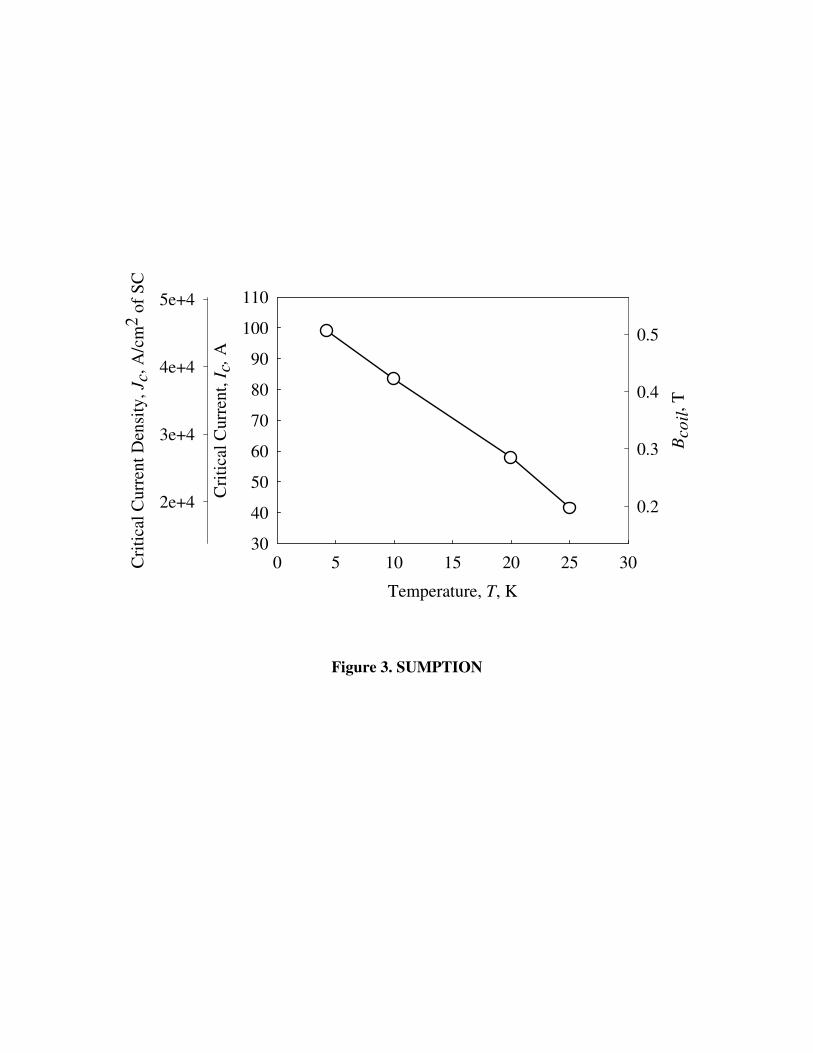
their transitions. Figure 3 displays Jc, Ic, and Bcoil vs temperature for Cu-1. Jc values of
54.5 kA/cm2 and 31.9 kA/cm2 in self field of the magnet are about a factor of 7 down
from the strands with a Nb-chemical barrier (Table 2), as might be expected. Strand and
coil Je values at 4.2 K and 20 K are also given in Table 2.
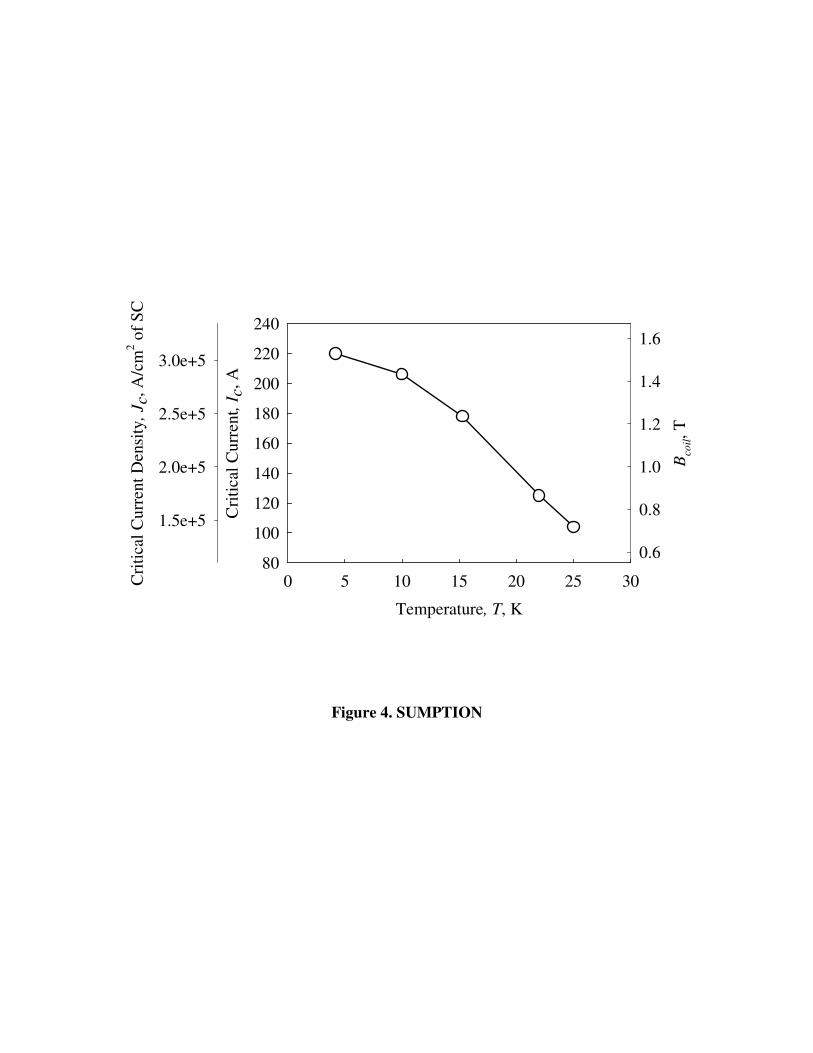
Figure 4 shows the Jc, Ic, and Bcoil vs temperature for NbCu-7A. Strand and coil Je
values at 4.2 K and 20 K are given in Table 2. Here the Jcs reach 308 kA/cm2 at 4.2 K
and 175 kA/cm2 at 20 K (self field of magnet). Similar analysis is given for NbCu-7B in
Figure 5 and Table 2. The Jc values are somewhat lower for this particular strand,
however, a slightly larger number of turns on the magnet lead to a higher Bcoil, which
reaches 1.57 T at 4.2 K and 0.97 T at 20 K. In order to see how close to the short sample
results that the strands in these coils have reached, we will need to first have an accurate
calculation of the magnetic field throughout these coils.
Field Distributions and Load Line for an MgB2 Coil
Figure 6 shows the schematic of the coil and the winding geometry used to
calculate the coil fields. Figure 7 shows the field distribution calculated from numerical
methods within coil NbCu-7A. Figure 7 (a) gives a calculation of Bz vs. z at r = 0. The
calculation gives 1.45 T in the center of the solenoid bore, in reasonable agreement with
the 1.5 T measured, and 2.3 T near the innermost winding. Figure 7(b) gives Bz Br, and
Bθ, vs. r at the midplane (z=0). In order to perform these calculations, we used a
numerical method, where the current was assumed uniformly distributed within the
strand. For convenience, we chose to work with a strand containing 91 filamentary
elements as an approximation to this continuum (Figure 6).
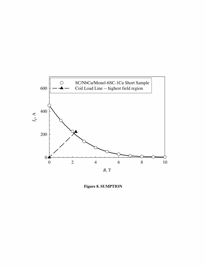
We note that the at Ic = 222 A, the bore field is calculated as 1.45 T (close to the
1.5 T measured) while the calculated maximum field on the windings is about 2.3 T. This
enables us to superpose a “calculated” load line for Coil NbCu-7A on the results of an
short sample (1 m of strand wrapped helically onto an ITER barrel [25]) measurement of
a sample strand from which it was wound, Figure 8.
Summary
Three solenoids were wound, one from a monofilamentary MgB2/Cu strand, the
other two from seven filament multifilamentary strands with internal Cu-stabilization.
Coils NbCu-7A and NbCu-7B were the best performers, reaching short sample
performance, and generating 1.5-1.57 T in zero background field at 4.2 K. At 20 K a field
of 0.87-0.97 T was generated. Jc values for the strand used in NbCu-7A were 308 kA/cm2
and 175 kA/cm2 at 4.2 K and 20 K respectively. At 20 K the strand Je for NbCu-7A was
22.7 kA/cm2 and the coil winding pack Je,w was 13.4 kA/cm2. Coil NbCu-7B had overall
similar performance, generating 1.57 T at 4.2 K and 0.97 T at 20 K. These coil results
show that in-situ route, Cu-stabilized, multifilamentary strands can be made on the 100
m+ length with good performance characteristics and consistent properties.
Acknowledgements
This work has been funded by an NIH SBIR No. 5710001628 and
1R43EB003752-01, a State of Ohio Technology Action fund, and by DOE HEP grant
No. DE-FG02-95ER40900.
References
[1] G. Grasso, A. Malagoli, M. Modica, et al., Supercond. Sci. Technol. 16, 271–275
(2003).
[2] G. Grasso, A. Malagoli, D. Marre, et al., Physica C 378–381, 899–902 (2002).
[3] R Flükiger, P Lezza, C Beneduce, et al., Supercond. Sci. Technol. 16, 264–270
(2003)
[4] R Flükiger, H.L. Suo, N. Musolino, et al., Physica C 385, 286–305 (2003).
[5] D. Eyidi, O. Eibl, T. Wenzel, et al., Supercond. Sci. Technol. 16, 778–788 (2003).
[6] A. Matsumoto, H. Kumakura, H. Kitaguchi, and H. Hatakeyama, Supercond. Sci.
Technol. 16, 926–930 (2003).
[7] Y. Ma, H. Kumakura, A. Matsumoto, et al., Supercond. Sci. Technol. 16, 852–856
(2003).
[8] B A Glowacki, M Majoros, M Vickers, et al., Supercond. Sci. Technol. 16, 297–
305 (2003).
[9] B.A. Glowacki, M. Majoros, M. Eisterer, et al., Physica C 387, 153–161 (2003).
[10] E.W. Collings, E. Lee, M.D. Sumption, et al., Rare Metal Mat. Eng. 31, 406-409
(2002).

[11] E.W. Collings, E. Lee, M.D. Sumption, et al., Physica C 386 555-559 (2003). See
also (for the CTFF process itself) V. Selvamanickam et al., Supercond. Sci.
Technol. 8 587-590 (1995).
[12] S. Soltanian, X.L. Wang, I. Kusevic, et al., Physica C 361, 84-90 (2001).
[13] M.D. Sumption, M. Bhatia, S.X. Dou, et al. Supercond. Sci. Technol. 17 (2004)
1180-1184.
[14] S. Soltanian, J. Horvat, X.L. Wang, et al., Supercond. Sci. Technol. 16 (2003) L4-
L6.
[15] M. Bhatia, M.D. Sumption, M. Tomsic, and E.W. Collings, Physica C 407 (2004)
153-159.
[16] K. Tanaka, M. Okada, H. Kumakura, et al., Physica C 382 (2002) 203-206.
[17] T. Machi, S. Shimura, N. Koshizuka, and M. Murakami, Physica C 392-396 (2003)
1039-1042.
[18] H. Fang, P.T Putman, S. Padmanaghan, et al., Supercon. Sic. Technol. 17 (2004)
717-720.
[19] Y.S. Hascicek, Z. Aslanoglu, L. Arda, et al., Adv. Cryo. Eng. 50 (2004) 541.
[20] A. Serquis, L. Civale, J.Y. Coulter, et al., Supercond. Sci. Technol. 17 (2004) L35-
L37.
[21] R. Musenich, P. Fabbricatore and S.Farinon. et. al, “Behavior of MgB2 react and
wind coils above 10 K”, presentation 4LS01 at the Applied Superconductivity
Conference Jacksonville, FL 2004.
[22] M.D. Sumption, M. Bhatia, M. Rindfleisch, J. Phillips, M. Tomsic, and E.W.
Collings, to be published in IEEE Trans. Supercond. 2005.
[23] M.D. Sumption, M. Bhatia, M. Rindfleisch, J. Phillips, M. Tomsic, and E.W.
Collings, “ MgB2/Cu Racetrack Coil Winding, Insulating, and Testing”, to be
published in Supercond. Sci. Tech. 2005.
[24] M.D. Sumption, M. Bhatia, X. Wu, M. Rindfleisch, M. Tomsic, and E.W. Collings
“Multifilamentary, in-situ Route, Cu-stabilized MgB2 Strands:”, to be published in
Supercond. Sci. Tech. 2005.
[25] L.F. Goodrich and A.N. Srinavasta, in Critical Currents in Superconductors, Proc.
7th. Int. Workshop, H.W. Weber ed. (World Scientific Publishing, Singapore, 1994)
p. 609.
List of Tables
Table 1. Strand Parameters.
Table 2. Coil Parameters and Performance Specifications.

Table 1. Strand Parameters.
Coil Name
Strand Trace
ID
SC Fil No.
Strand Construction/Name
Powder add
Strand OD, mm
SC %
Cu%
Cu-1 566 1 SC/Cu-mono -- 1.01 23 77 NbCu-7A 573 6 SC/Nb/Cu/monel-6SC-1Cu Mga 0.84 13 32 NbCu-7B 600 6 SC/Nb/Cu/monel-6SC-1Cu Mga 0.84 16 28
a Mg was added to form the ratio Mg1.1B2
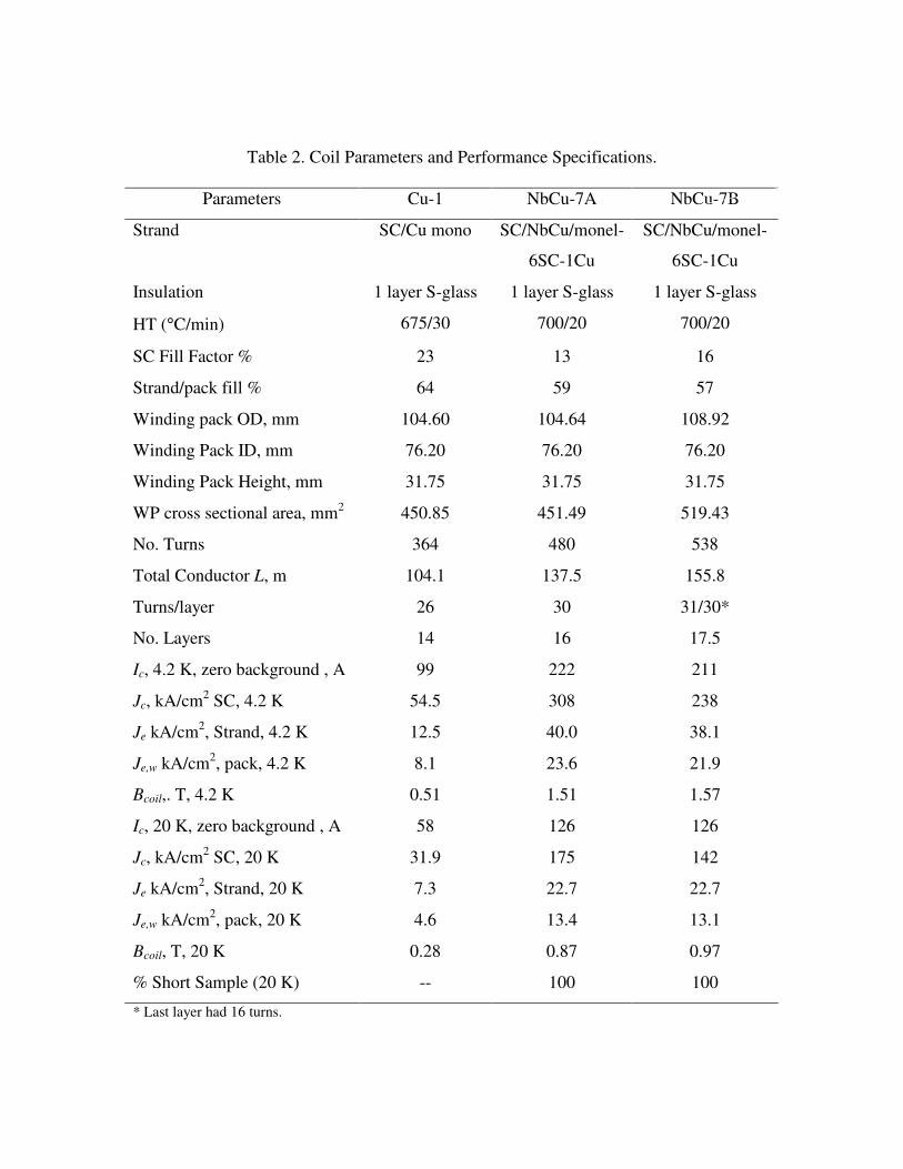
Table 2. Coil Parameters and Performance Specifications.
Parameters Cu-1 NbCu-7A NbCu-7B
Strand SC/Cu mono SC/NbCu/monel-
6SC-1Cu
SC/NbCu/monel-
6SC-1Cu
Insulation 1 layer S-glass 1 layer S-glass 1 layer S-glass
HT (°C/min) 675/30 700/20 700/20
SC Fill Factor % 23 13 16
Strand/pack fill % 64 59 57
Winding pack OD, mm 104.60 104.64 108.92
Winding Pack ID, mm 76.20 76.20 76.20
Winding Pack Height, mm 31.75 31.75 31.75
WP cross sectional area, mm2 450.85 451.49 519.43
No. Turns 364 480 538
Total Conductor L, m 104.1 137.5 155.8
Turns/layer 26 30 31/30*
No. Layers 14 16 17.5
Ic, 4.2 K, zero background , A 99 222 211
Jc, kA/cm2 SC, 4.2 K 54.5 308 238
Je kA/cm2, Strand, 4.2 K 12.5 40.0 38.1
Je,w kA/cm2, pack, 4.2 K 8.1 23.6 21.9
Bcoil,. T, 4.2 K 0.51 1.51 1.57
Ic, 20 K, zero background , A 58 126 126
Jc, kA/cm2 SC, 20 K 31.9 175 142
Je kA/cm2, Strand, 20 K 7.3 22.7 22.7
Je,w kA/cm2, pack, 20 K 4.6 13.4 13.1
Bcoil, T, 20 K 0.28 0.87 0.97
% Short Sample (20 K) -- 100 100
* Last layer had 16 turns.
List of Figures
Figure 1. Photograph of Solenoid Coil Cu-1.
Figure 2. I-V curves at 4.2 K for various voltage taps for coil Cu-1.
Figure 3. Ic, Jc, and Bcoil vs. T f or Cu-1.
Figure 4. Ic, Jc, and Bcoil vs. T f or NbCu-7A
Figure 5. Ic, Jc, and Bcoil vs. T f or NbCu-7B.
Figure 6. Schematic of coil and calculation scheme.
Figure 7. Calculation of (a) Bz vs. z at r = 0 and (b) Br, Bθ, and Bz vs. r at z = 0.
Figure 8. Coil load line and short sample (1 m barrel) Jc vs B curve for NbCu-7A.

Figure 1. SUMPTION

Current, I, A
0 20 40 60 80 100 120
Vol
ts, V
, mV
0
2
4
6
8
10
12
D-E (layers 2-4)E-F (layers 6-8)F-G (layers 10-12)C-H (layers 2-12)
1 µV/cm criterion
Figure 2. SUMPTION
Temperature, T, K
0 5 10 15 20 25 30
Cri
tical
Cur
rent
, Ic,
A
30
40
50
60
70
80
90
100
110
Bco
il, T
0.2
0.3
0.4
0.5
Cri
tical
Cur
rent
Den
sity
, Jc,
A/c
m2
of S
C
2e+4
3e+4
4e+4
5e+4
Figure 3. SUMPTION
Temperature, T, K
0 5 10 15 20 25 30
Cri
tical
Cur
rent
, Ic,
A
80
100
120
140
160
180
200
220
240
Bco
il, T
0.6
0.8
1.0
1.2
1.4
1.6
Cri
tical
Cur
rent
Den
sity
, Jc,
A/c
m2 o
f SC
1.5e+5
2.0e+5
2.5e+5
3.0e+5
Figure 4. SUMPTION

Temperature, T, K
0 5 10 15 20 25 30
Cri
tical
Cur
rent
, Ic,
A
80
100
120
140
160
180
200
220
Cri
tical
Cur
rent
Den
sity
, Jc,
A/c
m2
of S
C
1.0e+5
1.2e+5
1.4e+5
1.6e+5
1.8e+5
2.0e+5
2.2e+5
2.4e+5
Bco
il, T
0.6
0.8
1.0
1.2
1.4
1.6
Figure 5. SUMPTION
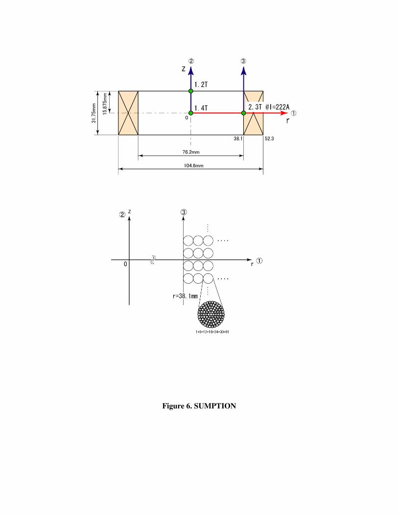
Figure 6. SUMPTION

Axial Distance, z, mm
0 5 10 15 20
Bz,
coil
1.10
1.15
1.20
1.25
1.30
1.35
1.40
1.45
Radius, r, mm
0 10 20 30 40 50 60 70
B, T
-1
0
1
2
3BrBzBθ
Coil ID
Coil OD
Figure 7. SUMPTION
B, T
0 2 4 6 8 10
I c, A
0
200
400
600SC/NbCu/Monel-6SC-1Cu Short SampleCoil Load Line -- highest field region
Figure 8. SUMPTION