Two-loop euler-heisenberg lagrangian in dimensional regularization
Upload
khangminh22Category
view
2download
0
The Cryosphere, 15, 5423–5445, 2021https://doi.org/10.5194/tc-15-5423-2021© Author(s) 2021. This work is distributed underthe Creative Commons Attribution 4.0 License.
Elements of future snowpack modeling – Part 2: A modularand extendable Eulerian–Lagrangian numerical scheme forcoupled transport, phase changes and settling processesAnna Simson1,4, Henning Löwe2, and Julia Kowalski3,4
1AICES Graduate School, RWTH Aachen University, Schinkelstr. 2a, 52062 Aachen, Germany2WSL Institute for Snow and Avalanche Research SLF, Flüelastr. 11, 7260 Davos, Switzerland3Computational Geoscience, University of Göttingen, Goldschmidtstr. 1, 37077 Göttingen, Germany4Methods for Model-based Development in Computational Engineering, RWTH Aachen University,Eilfschornsteinstraße 18, 52062 Aachen, Germany
Correspondence: Anna Simson ([email protected])
Received: 25 February 2021 – Discussion started: 25 March 2021Revised: 8 October 2021 – Accepted: 11 October 2021 – Published: 7 December 2021
Abstract. A coupled treatment of transport processes, phasechanges and mechanical settling is the core of any detailedsnowpack model. A key concept underlying the majority ofthese models is the notion of layers as deforming materialelements that carry the information on their physical state.Thereby an explicit numerical solution of the ice mass conti-nuity equation can be circumvented, although with the down-side of virtual no flexibility in implementing different cou-pling schemes for densification, phase changes and transport.As a remedy we consistently recast the numerical core ofa snowpack model into an extendable Eulerian–Lagrangianframework for solving the coupled non-linear processes. Inthe proposed scheme, we explicitly solve the most generalform of the ice mass balance using the method of charac-teristics, a Lagrangian method. The underlying coordinatetransformation is employed to state a finite-difference formu-lation for the superimposed (vapor and heat) transport equa-tions which are treated in their Eulerian form on a moving,spatially non-uniform grid that includes the snow surface asa free upper boundary. This formulation allows us to unifythe different existing viewpoints of densification in snow orfirn models in a flexible way and yields a stable couplingof the advection-dominated mechanical settling with the re-maining equations. The flexibility of the scheme is demon-strated within several numerical experiments using a modu-lar solver strategy. We focus on emerging heterogeneities in(two-layer) snowpacks, the coupling of (solid–vapor) phase
changes with settling at layer interfaces and the impact ofswitching to a non-linear mechanical constitutive law. Lastly,we discuss the potential of the scheme for extensions like adynamical equation for the surface mass balance or the cou-pling to liquid water flow.
1 Introduction
The snow density is probably the most important prognosticvariable of any snowpack model as, e.g., reflected by a focuson snow water equivalent in past snow model intercompar-ison projects (Krinner et al., 2018, and references therein).That said, it actually comes as a surprise when not even thedetailed snowpack models, e.g., Crocus and SNOWPACK,explicitly state an ice mass conservation equation in theirtechnical documentation (Brun et al., 1989, 1992; Lehninget al., 2002; Bartelt and Lehning, 2002). Only a more de-tailed inspection reveals how mass conservation is accountedfor, namely rather indirectly by stating a settling law for indi-vidual layers and resorting to a “Lagrangian coordinate sys-tem that moves with the ice matrix” (Bartelt and Lehning,2002) to translate the ice-phase deformation into a thick-ness evolution of the layers (Brun et al., 1989; Vionnet et al.,2012). While this procedure has been well established for along time, it is without numerical ambiguities only in the ab-sence of phase changes. In addition, this non-explicit nature
Published by Copernicus Publications on behalf of the European Geosciences Union.

5424 A. Simson et al.: Mixed Eulerian–Lagrangian approach for snow modeling – Part 2
of the most important conservation law in snow makes it vir-tually impossible to isolate and advance the numerical coreof a snowpack model as an encapsulated numerical schemecomprising all involved coupled non-linear partial differen-tial equations.
This non-explicit treatment of snow density or ice masscontinuity in snowpack models, e.g., SNOWPACK and Cro-cus, has to be contrasted to other existing work on densi-fication, comprising both stand-alone numerical snow stud-ies (Meyer et al., 2020) and the vast body of work on firndensification (Lundin et al., 2017). All of the latter modelsare built around an explicit formulation of the ice mass con-tinuity equation. This conceptual difference renders a gen-eral comparison of firn and snow densification mechanisms(Lundin et al., 2017) difficult. For model intercomparisonsin the future it is thus desirable to have a numerical core thatis able to digest arbitrary snow or firn densification physicswith a flexible but rigorous coupling to superimposed non-linear transport and phase change processes.
Any holistic snowpack model has to account for transportof heat, vapor and liquid water and its induced phase changeprocesses, as well as mechanical settling and apparent meta-morphic processes acting on the snow’s microstructure. Awidespread body of literature exists that proposes differentmodeling approaches and computational tools for the variousflavors and perspectives of this multi-physics coupled situa-tion, e.g., Krinner et al. (2018, and references therein). Forthe general timescales of interest (diurnal up to seasonal), itis common practice to employ a continuum assumption andto model the snowpack’s state as a mixture of ice, vapor, wa-ter and air, as initially described in Bader and Weilenmann(1992). Detailed snowpack models, such as SNOWPACK(Lehning et al., 2002) and Crocus (Vionnet et al., 2012), arebuilt upon this type of mixture theory approach and used fora wide range of purposes.
While heat transport, mechanical settling and processesdue to the presence of liquid water have been incorporatedinto SNOWPACK (Bartelt and Lehning, 2002) and Crocus(Vionnet et al., 2012) for a long time, effects due to vaportransport have mostly recently been investigated in separatestudies. Temperature gradients between the ground and at-mosphere imply upward vapor fluxes in snowpacks. Strongertemperature gradients (due to either a smaller snowpackheight or colder surface temperature) in arctic conditionsyield higher vapor fluxes (Domine et al., 2019) comparedwith alpine snowpacks. Depth hoar layers with reduced den-sity and thermal conductivity form at the snowpack’s bottom.In alpine snowpacks similar hoar layers develop within thesnowpack that may cause avalanches due to their low me-chanical stability (Schweizer et al., 2003). Upscaled and ho-mogenized continuum mechanical process models that ac-count for vapor transport have been put forward, for instanceby Hansen and Foslien (2015) and Calonne et al. (2014).Both couple the snowpack’s evolving temperature profilesto a non-linear reaction–diffusion type of equation for va-
por transport and phase change. While they provide differentflavors of how to set up the underlying mathematical model,both approaches are formulated for idealized conditions andinvestigate vapor diffusion in the absence of settling andtherefore neglect its feedback on the apparent snow density.These model-based investigations and also field-based obser-vations in arctic snowpacks on top of permafrost (Domineet al., 2016, 2019) have demonstrated the significance ofvapor-related processes in snow. Hence, it is of great inter-est to investigate further how vapor interacts with apparentmechanical processes within the snowpack.
Incorporating vapor transport directly into a fully coupledsnowpack model is however challenging, e.g., due to the factthat the associated characteristic timescales are small, andexpected effects on the snowpack are localized (Schürholtet al., 2021). To resolve these processes on small timescalesand at specific locations requires a much higher spatio-temporal resolution than is typically provided by existing op-erational schemes. In its original version, SNOWPACK forinstance uses time steps on the order of 15 min or longer(Bartelt and Lehning, 2002) to facilitate seasonal simula-tion times. For Crocus time steps are on the order of 15 min(Viallon-Galinier et al., 2020) to 1 h (Vionnet et al., 2012).The recent work of Jafari et al. (2020) provides a first at-tempt to account for vapor transport within a coupled snow-pack model. In their paper, they accounted for diffusive va-por transport and phase change following Hansen and Fos-lien (2015) and analyzed its feedback on the snow density. Inorder to resolve diffusive processes, simulations were con-ducted at much shorter time steps of 1 min and a finer spatialresolution of approximately 0.1 cm. For comparison, a typ-ical layer thickness in SNOWPACK is 2 cm (Wever et al.,2016) and the minimum layer thickness in Crocus is 0.5 cm(Brun et al., 1989). While the work of Jafari et al. (2020)demonstrates the general feasibility of vapor-coupled snow-pack models, the exact nature of how vapor transport andphase changes interfere with stress-induced settling remainsto be investigated in depth.
It is well known that any numerical strategy that aimsat simulating simultaneous settling-induced deformation ofthe snowpack and (arbitrary) diffusive transport requires aspecial computational treatment to couple both. Diffusivetransport and reactive phase change are best modeled bytaking an Eulerian perspective, hence on a static mesh. Incontrast there exist a number of different techniques to in-corporate the settling-induced deformation. One option isto use a time-dependent coordinate transformation by Mor-land (1982), who developed a fixed domain transformation tosolve one-phase diffusion problems with a moving free sur-face on a finite, time-invariant computational domain. An al-ternative approach was put forward by Wingham (2000), whoused a different spatio-temporal coordinate transformationfor firn densification. Both transformation strategies effec-tively eliminate the vertical motion (or gradients of it) fromthe computational update procedure. And exactly the same is
The Cryosphere, 15, 5423–5445, 2021 https://doi.org/10.5194/tc-15-5423-2021

A. Simson et al.: Mixed Eulerian–Lagrangian approach for snow modeling – Part 2 5425
(implicitly) performed in the present treatment of densifica-tion in snowpack models (Bartelt and Lehning, 2002; Vion-net et al., 2012), where the coordinate transformation em-bodied in the deformation of the underlying computationalgrid through the update of layer positions and/or thicknessesis (implicitly) exploited for the ice mass conservation. How-ever, the present descriptions do not take full advantage of aclear and explicit separation into a Lagrangian deformationmodule that accounts for mechanical settling and an Eule-rian transport and phase change module. The benefit of thishybrid computational strategy is that it is easy to understand,computationally feasible, provides a modular error controland increases the interpretability by disentangling numericalartifacts from features of the underlying non-linear processmodels. Hybrid numerical schemes that combine an Eulerianprocess model with a Lagrangian-type spatio-temporal meshadaptation are not new. These schemes have been used inother disciplines, e.g., for phase change problems (Lacroixand Garon, 1992); as σ coordinates in oceanography, wherethe ocean’s surface and bottom are projected onto coordi-nates σ = 0 and σ =−1 that follow the ocean floor’s topogra-phy (Mellor and Blumberg, 1985); or for shallow-flow mod-els (Kowalski and Torrilhon, 2019).
The aim of our work is twofold: first, we will describe ournumerical strategy for a phase-changing snowpack. The nu-merical scheme is hybrid, in the sense that it clearly discrim-inates between a solution of the mechanical settling opera-tor by means of a Lagrangian approach and a solution to thetransport and phase change operator by means of an Eule-rian approach. To some degree, the numerical model descrip-tion must be understood as a rigorous re-formulation of thenumerical schemes from existing computational snowpackmodels. Yet, in addition to existing schemes we (a) explic-itly separate the Eulerian and Lagrangian part of the solverto facilitate a later modular adaption, (b) provide a full finite-difference formulation including correction terms due to thedeforming (non-uniform) mesh that are typically omitted,and (c) discuss options to increase the approximation accu-racy of the various parts of the numerical scheme. Second,we demonstrate the computational potential by applying andanalyzing simulation results for an idealized two-layer, dry-snow situation. We consider a model cascade of differentprocess building blocks, which in their most comprehensiveversion, correspond to fully coupled heat and vapor transportalongside phase changes and settling.
With this work we seek to contribute to anticipated fu-ture developments of snow or firn models or likewise ex-tensions of existing ones that aim at flexibility and modu-larity while providing a simple, mathematically rigorous nu-merical approximation for a stable and robust integration ofgeneric multi-physics process equations. By modularity andextendability we understand the possibility of considering orneglecting specific process modules and parametrizations ina straightforward way. This modularity would enable us to(a) investigate competing non-linear effects systematically
Table 1. Terminology of state variables, model parameters and con-stants.
Symbol Name Equation/value Unit
State variables
φi Ice volume fraction Eq. (1) –ρv Vapor density Eq. (A1) kgm−3
T Temperature Eq. (11) K
Model parameters of snow
v Vertical velocity Eq. (7) ms−1
c Ice deposition rate Eq. (9) kg m−3 s−1
ε̇ Strain rate Eq. (3) s−1
η Viscosity Eq. (4) Pasσ Stress Eq. (5) Pam−2
ρsnow Density Eq. (5) kgm−3
Deff Vapor diffusion coefficient Eq. (A2) m2 s−1
(ρC)eff Heat capacity Eq. (A4) Jm−3 K−1
keff Thermal conductivity Eq. (A3) Wm−1 K−1
Parameters assumed to be constant (Calonne et al., 2014)
ρi Ice density φi= 1 917 kgm−3
L Ice latent heat of sublimation 2 835 333 Jkg−1
Ci Ice heat capacity φi= 1 2000 J kg−1 K−1
ρa Air density φi= 0 1.335 kgm−3
Ca Air heat capacity φi= 0 1005 J kg−1 K−1
from a cascade of process models, (b) assess the quality ofthe numerical approximation independently and (c) conducta standardized model selection based on well-defined bench-marks.
The paper is structured as follows. In Sect. 2, we recallthe dry-snow model equations comprising the relevant trans-port, phase change and mechanical aspects. In Sect. 3, weintroduce the Eulerian–Lagrangian numerical scheme and itssolution using the method of characteristics. In Sect. 4, wepresent and discuss results from a number of simulation sce-narios, including verification scenarios that consider trans-port, phase changes and mechanics in the absence of any in-teraction, as well as coupled scenarios that focus on theirinterplay. We furthermore investigate the impact of differ-ent viscosity parametrizations and assess the behavior whenswitching to a Glen type of non-linear constitutive closure.Finally, we compare our results to a conventional layer-basedtreatment. In Sect. 5, we summarize and discuss our findings,and in Sect. 6 we draw conclusions regarding future snow-pack modeling.
2 Physical model
2.1 General situation
As a common starting point, snow models take a macroscaleperspective that volume averages (Bartelt and Lehning, 2002;Bader and Weilenmann, 1992; Hansen and Foslien, 2015)or homogenizes (Calonne et al., 2014) the snowpack’s mi-crostructural state into macroscale variables. If not stated
https://doi.org/10.5194/tc-15-5423-2021 The Cryosphere, 15, 5423–5445, 2021

5426 A. Simson et al.: Mixed Eulerian–Lagrangian approach for snow modeling – Part 2
otherwise, we implicitly assume all state variables to bemacroscale variables. State variables, model parameters andconstants used in this paper are summarized in Table 1.
In the most general case, snow is a mixture of ice, air,vapor and water, and the snow density is given as a mix-ture of the respective pure densities (Bader and Weilenmann,1992; Morland et al., 1990). The amount of ice in one ref-erence volume of snow is φiρiV , in which φi denotes theice’s volume fraction, ρi its pure density and V the volumeof the reference volume. For dry snow, further contributionsdue to water vapor can be neglected, and the snow densitycan be approximated as φi ρi. The structure and volume frac-tion of the ice can change over time either due to strain-induced settling processes or due to transient phase changes,such as sublimation and deposition or melting and freezing.Our paper focuses on the derivation of a hybrid Eulerian–Lagrangian framework to solve settling, transport and phasechanges with an assessment of the computational buildingblocks. To this end we restrict ourselves to dry snow and al-low for one secondary phase (vapor) in an Eulerian treatmentcoupled to the Lagrangian treatment of the ice phase. Withrespect to computational model development, we regard thedry-snow situation as the more challenging (yet less investi-gated) one compared to the wet-snow situation, mostly dueto a broader spectrum of characteristic spatial and temporalscales involved (see more detailed discussion in Sect. 6).
Note, that water transport and solid–liquid phase changecan in principle be integrated following a similar strategyto that presented in this paper. The following section intro-duces the (macroscale) snowpack model where the subsec-tion structure reflects the later-described modular structureof the numerical core.
2.2 Ice mass balance
The ice volume fraction φi = φi(z, t) within a spatio-temporally evolving snowpack of varying snow height H(t)is governed by the ice mass balance and reads
∂tφi+∇ · (v φi)=c
ρi, (1)
with velocity field v, source term c and ice density ρi (Hansenand Foslien, 2015; Bader and Weilenmann, 1992). Note thatmechanical settling is neglected in Part 1 of this companionpaper. The corresponding ice mass balance (Eq. 7 in Part 1)does thus not include the velocity field v.
In a 1D situation that focuses on an evolving vertical snowcolumn, we have the vertical position z as the only relevantspatial coordinate (z ∈ [0,H(t)]). The velocity field v re-duces to vertical velocity v = v(z, t), which depends on timeand the position within the column. It is negative for snowheight decrease and positive for snow height increase. Ver-tical motion results either from mechanical settling, hencea consolidation or compaction of the snowpack, or alterna-tively as a continuity response to changes in ice volume from
sublimation, deposition, melting and freezing via the sourceterm c. The continuity response leads to a minor vertical de-crease/increase in snow height. Though effects due to consol-idation of snow may be significantly more pronounced thanthose due to phase change processes in the pore space, thelatter needs to be accounted for to acknowledge mass con-servation of the complete system. At this point in time, wedo not consider any additional increases in snow height dueto precipitation, yet we discuss how this can be included inthe future in Sect. 5.
The source term c = c(z, t) varies with time and positionin the column and stands for a gain or loss of ice mass fromphase change (Bader and Weilenmann, 1992) per unit vol-ume and unit time. As we constrain this paper to the dry sit-uation we will henceforth refer to c as the deposition rate.c is positive (production) if new ice is built, namely vapordeposits, and it is negative (loss) if ice is lost, namely subli-mates. Finally, ρi denotes the constant pure density of ice andserves as a scaling factor. The ice mass balance (Eq. 1) cou-ples mechanical settling and phase change processes. Con-sidering the equation in its full form is essential for our goalto model and eventually analyze the interplay between theseprocesses. The structure of the ice mass balance resembles anadvection–reaction equation that can conveniently be solvedby means of Lagrangian-type computational methods, suchas the method of characteristics (see Sect. 3). Yet in order todo so, we need to provide a closure for both vertical veloc-ity v and deposition rate c.
2.3 A closure for the velocity field
Velocity v represents mechanical deformation in the snow-pack. Its idealized relation to the strain rate is given by
∇v = ε̇. (2)
Note that this is simplified with respect to more general,tensorial formulations of 1D consolidation theories; see forinstance Audet and Fowler (1992). Yet even the idealized for-mulation Eq. (2) will be sufficient for our purposes, as it re-sembles the approach implicitly chosen in snowpack models(Bartelt and Lehning, 2002; Vionnet et al., 2012).
In general one would expect that porous snow inherits thenon-linear constitutive behavior of ice (Kirchner et al., 2001),which leads to
ε̇ =1ησm, (3)
which is a variant of Glen’s law. Here, η denotes the com-pactive viscosity of snow and σ denotes the stress. Thechoice of the Glen exponent m in earlier work depends onboth the physical regime and the computational feasibility.The linear form of Glen’s law (m= 1) is chosen in Vionnetet al. (2012) and Bartelt and Lehning (2002). For the sake ofcomparability we thus mainly use a linear version of Glen’slaw; hence m= 1. Our framework, however, also copes with
The Cryosphere, 15, 5423–5445, 2021 https://doi.org/10.5194/tc-15-5423-2021

A. Simson et al.: Mixed Eulerian–Lagrangian approach for snow modeling – Part 2 5427
the non-linear relation, such as m= 3, and we later include acomparative example.
The compactive viscosity η depends on the snow’s mi-crostructure and is challenging to determine from experi-ments (Wiese and Schneebeli, 2017). It is typically providedas a parametrized closure for a specific physical situationand strongly correlates with the choice for the Glen expo-nent m. This fact clearly constrains its universal applicabil-ity and makes any transfer of a validated snowpack modelto other physical situations challenging. In this article, wewill consider both constant-viscosity scenarios, as well as anadditional scenario with a varying viscosity assuming an em-pirical viscosity closure from Vionnet et al. (2012)
η(φi,T )= f η0ρiφi
cηexp(aη(Tph− T )+ bηρiφi), (4)
with the state variables temperature T and ice vol-ume fraction φi; the constants ice density ρi andphase change temperature Tph= 273 K; and furtherconstants η0= 7.62237× 10⁶ kgs−1, aη= 0.1 K−1,bη= 0.023 m3 kg−1 and cη= 250 kgm−2. Finally, f re-flects properties of the snow microstructure, i.e., theangularity and the size of the grains, and it is assumed tobe 1 in our case. The constant-viscosity value applied toa linear Glen’s law ηconst,m=1 is derived with intermediatevalues for the ice volume fraction and temperature of therespective initial conditions. These values are plugged intothe empirical closure Eq. (4) to solve for viscosity. The sameprocedure cannot be applied to derive a constant-viscosityvalue for the non-linear version of Glen’s law ηconst,m=3since the viscosity closure (Eq. 4) was initially calibrated tothe linear form of Glen’s law (m= 1). Instead we choosea snow deformation rate from the literature (ε̇= 10−6 s−1;Johnson, 2011) and determine the maximum stress valuefrom the initial snow density. These strain rate and stressvalues are then inserted into the constitutive relation (Eq. 3),which is finally solved for viscosity. To avoid infinite icevolume growth above physical values (φi> 1), the viscositymust tend to infinity for φi→ 1. Therefore, the constant-viscosity values are restricted to ice volumes below 0.95by multiplication with an ice-volume-fraction-dependentpower law (Appendix Eq. A6). This power law yields ∼ 1for φi ≤ 0.95 and exponentially increases for higher icevolumes. Multiplied with the constant-viscosity values, vis-cosity remains constant below φi< 0.95 and exponentiallyincreases above it, which stops further densification andsettling. This procedure does not intend to reproduce the cor-rect physics for low-porosity ice, although it mathematicallyleads to a similar crossover behavior.
In the absence of strong horizontal deformation and devi-atoric stress components, it is reasonable to assume a stress-free condition at the snow’s surface and a hydrostatic stresscondition in its interior:
∇σ = gρsnow . (5)
g is the gravitational acceleration, and ρsnow refers to thesnow’s density, which is clearly dominated by the ice fractionvia ρsnow ≈ φi(z)ρi. It varies with the position z in the snowcolumn due to a vertically varying ice volume fraction φi(z).Integration of Eq. (5) and combination with Eqs. (2) and (3)yields an expression for the velocity gradient:
∂zv =1η
g H(t)∫z
φi(ζ )ρidζ
m. (6)
ζ is the integration variable. A second integration alongthe vertical axis finally yields an expression for the velocityat position z in the snow column:
v(z)=
z∫0
1η
g H(t)∫z̃
φi(ζ )ρidζ
m
dz̃ , (7)
in terms of total height H(t) and the ice volume fractionφi(z, t) and with v(z= 0, t)≡ 0. This definition of the ver-tical velocity yields a process that complies with the obviousphysical constraints: (a) the velocity vanishes at the bottomof the snow column, hence preventing artificial penetrationinto the ground. This is similar to displacement requirementsin SNOWPACK (Bartelt and Lehning, 2002). (b) The ver-tical velocity accumulates with height, which prevents anyartificial disaggregation of the snowpack. (c) The vertical ve-locity relaxes towards zero as the ice volume fraction tendstowards its maximum volume fraction φi < φi,max < 1. In theremainder of this paper, we will use Eq. (7) to account for themechanical settling of the snowpack.
2.4 Transport and phase changes
The ice deposition rate c as relevant to solve Eq. (1) typicallydepends on a cascade of coupled heat and mass transport forthe involved phases of ice, water and vapor. In this article, wewill consider a process model proposed by Hansen and Fos-lien (2015) that reflects a dry-snow condition in which voidspace is filled by vapor only. Note, however, that this cou-pled process model could readily be substituted or extendedby another one, e.g., from Calonne et al. (2014), Jafari et al.(2020) or Schürholt et al. (2021).
Next, we state the essential aspects and process equationsof the model proposed in Hansen and Foslien (2015) and de-scribe how it can be used to recover the ice deposition rate.
Assuming a dry-snow condition, the ice production issolely determined by mass transport between vapor and ice.The vapor mass balance reads
∂t (ρv(1−φi))−∇ · (Deff∇ρv)= −c, (8)
in which ρv denotes the vapor density and Deff the effectivevapor diffusion coefficient. Vapor production corresponds toa negative ice deposition rate −c that represents sublima-tion. Following Hansen and Foslien (2015), vapor density in
https://doi.org/10.5194/tc-15-5423-2021 The Cryosphere, 15, 5423–5445, 2021

5428 A. Simson et al.: Mixed Eulerian–Lagrangian approach for snow modeling – Part 2
the pore space can be assumed to be at saturation densityρ
eqv , so ρv ≡ ρ
eqv . The latter is well investigated, and empir-
ical relations exist that specify its temperature dependencyρ
eqv (T ). In this work, we will employ an empirical relation
from Libbrecht (1999). The full expression can be read inAppendix A1. Due to the closure for vapor density ρeq
v , thevapor mass balance (Eq. 8) can be rewritten using the tem-perature dependence of the equilibrium vapor density:
(1−φi)dρeq
v
dT∂tT −∇ ·
(Deff
dρeqv
dT∇T
)= −c. (9)
Assuming the snow to be in thermal equilibrium at the mi-croscale, we can likewise write the energy balance in termsof the temperature, which reads
(ρC)eff∂tT −∇ · (keff∇T )= cL. (10)
The parameters (ρC)eff and keff stand for the effective heatcapacity of snow and effective thermal conductivity, respec-tively. Both parameters depend on the ice volume fraction,and their definition is stated in Appendix A2. The right-handside of the heat equation (Eq. 10) accounts for latent heatrelease, which is coupled to phase change processes.
The system of the two equations, Eqs. (9) and (10), andthe two unknowns, temperature T and deposition rate c, issolved by replacing c in Eq. (10) with Eq. (9), which yieldsa non-linear equation for temperature:((ρC)eff +(1−φi)
dρeqv (T )
dTL
)∂tT
=∇ ·
((LDeff
dρeqv (T )
dT+ keff
)∇T
). (11)
The spatio-temporal temperature evolution is then usedto recover the ice deposition rate c from either Eq. (9) orEq. (10).
3 Computational approach
The complete process model is now given by the ice massbalance Eq. (1), its mechanically induced vertical velocityEq. (7), and the coupled system for temperature Eq. (11) andice deposition rate determined by either Eq. (9) or Eq. (10).Each of the equations will be solved in a separate module.The ice mass balance in conjunction with the vertical veloc-ity has the form of a non-linear advection equation, whereasthe remaining equations are of parabolic nature, which is re-flected in our general approach to solve the system.
3.1 General approach to the computational strategy
Based on the distinction into diffusion- and advection-dominated processes, we propose a two-step solutionscheme:
Step 1. This step accounts for the mesh deformation andsolves the advection-dominated mechanical settling, i.e., theice mass balance Eq. (1), by means of a Lagrangian ap-proach that tracks the movement of the coordinates includingchanges from metamorphism.
Step 2. This step determines the spatio-temporal evo-lution of temperature and deposition rate fields as intro-duced in Sect. 2.4 based on an Eulerian approach that solvesthe diffusion-dominated transport and phase changes viaa finite-difference implementation on a deformed (unstruc-tured) mesh.
Note that here we employed a finite-difference method be-cause it provides a feasible algorithm that is applicable to thescenarios considered in the paper using a 1D snow column.It also naturally integrates with the Lagrangian part of thesolution (Step 1), as we can re-use the same mesh. In princi-ple, it is also possible to couple the two-step approach witha finite-element solution for the temperature and depositionrate, for instance when aiming for a 2D or 3D model in acomplex geometry that incorporates realistic mountain slopetopographies. When using a finite-element solver, however,we have to keep in mind that the deposition rate and tem-perature fields need to be reconstructed from the solution ateach time step. Especially when wanting to use higher-orderelements, this might limit computational feasibility.
Our solution scheme alternates both steps via straightfor-ward first-order operator splitting. This is found to work wellfor our simulation scenarios yet could be readily exchangedwith a higher-order splitting scheme, e.g., a second-orderStrang splitting (LeVeque, 2002), if required.
The computational model is implemented in Python, and itis modular and extendable, in the sense that each module canbe separately activated and deactivated. This not only simpli-fies the verification of individual process building blocks butalso allows an in-depth investigation of the various couplingeffects and the model’s non-linear feedback. Alternative for-mulations e.g., of the parametrized velocity field are imple-mented and can easily be exchanged. Finally, the modularstructure facilitates the implementation of additional closurerelations or the integration of entire new process modules.
3.2 Computational grid
In this paper, we consider a 1D snow column, which is dis-cretized into nz+1 spatial mesh nodes denoted by zk with k ∈{0,1, . . .,nz}. We applied 101 computational nodes (nz=100) except for some simulations that required a higher res-olution of 251 nodes (nz= 250). The mesh is non-uniformin general, meaning that the distance between neighboringnodes zk+1−zk varies throughout the snow column and withtime. Note that the z axis is oriented opposing gravitationalacceleration, such that z0 denotes the position of the groundand znz the position of the snowpack’s free surface. Timeincrements are denoted by tn with n ∈ {0,1, . . .,nt} and ntbeing the maximum number of time steps in a complete sim-
The Cryosphere, 15, 5423–5445, 2021 https://doi.org/10.5194/tc-15-5423-2021

A. Simson et al.: Mixed Eulerian–Lagrangian approach for snow modeling – Part 2 5429
ulation run. For each of the field variables subscript k de-notes the vertical coordinate and superscript n denotes thetime step; hence T (zk, tn)= T nk .
3.3 Lagrangian solution of the ice mass balance
When the snowpack is subject to vertical motion, e.g., set-tling, its physical height decreases; hence its vertical extentshrinks. One option to reflect this in a computational methodis to adjust the spatial node coordinates accordingly. Thechallenging fact in our situation is that the vertical motionwithin the snow column (non-linear advection) is coupled tophase changes, i.e., a change in the ice volume fraction viathe source term in the ice mass balance (Eq. 1). The methodof characteristics is a suitable method to solve such a non-linear advection equation with source terms. It can be inter-preted as a simultaneous motion tracking of snow referencevolumes, referred to as the integration along so-called char-acteristics, while also accounting for its metamorphism alongthe trajectory. By construction, the method correctly tracksthe snowpack’s moving free surface. Due to the fact that thesnow column’s evolution is determined with respect to a ref-erence volume that moves vertically at speed v in the snow-pack, the method of characteristics is called a Lagrangian ap-proach.
In order to derive the specific update rule for the ice massbalance Eq. (1), we first apply the product rule to its initialEulerian version
∂tφi+ v∂zφi =1ρic−φi∂zv (12)
and then re-formulate the equation in a Lagrangian referenceframe, hence with respect to nodes moving at the vertical ve-locity v. Changing to the moving reference frame effectivelycompensates for the advection term in Eq. (12) and yields
∂tφi =1ρic−φi∂zv, (13)
∂tz= v. (14)
Equation (14) accounts for the settling of material parti-cles within the snowpack. We will use it to update the coor-dinates of the mesh nodes directly, which results in a contin-uous mesh deformation as illustrated in Fig. 1. Equation (13)captures the evolution of the ice volume fraction along thetrajectory of a moving ice volume within the snowpack. Itaccounts for volume changes due to (a) mass production andloss in response to phase changes and (b) vertical variationin the vertical velocity. Further details and generalizations ofthe method of characteristics can be found in Farlow (1993).
Equations (13) and (14) can be solved analytically for aconstant vertical velocity and deposition rate. In our casehowever, the velocity closure is provided by Eq. (7) andthe deposition rate results from solving yet another process
Figure 1. Computational mesh. The snowpack height varies withtime, e.g., shrinks due to settling of the snow. This has to be in-corporated into the computational mesh, which undergoes defor-mation due to the downward movement of the free surface. Theinitially equidistant mesh does not uniformly change, which resultsin a mesh of varying node distances, so in general 1z0
k6=1zn
kand
1znk6=1zn
k+1.
model (Eqs. 10 and 11), which requires a numerical solution.Since we expect the response of the ice volume fraction to beslow (with respect to other processes in the system), we willrely on a first-order explicit Euler time integration scheme:
φn+1i,k = φ
ni,k +1t
n
(1ρicnk −φ
ni,k∂zv
nk
), (15)
zn+1k = znk +1t
nvnk . (16)
In order to update the mesh coordinates according toEq. (16) for the vertical velocity closure derived before, weneed to numerically approximate Eq. (7) at each node zk ,which results in
v(zk)=
k∑j=0
(1ησmj
)1znj , (17)
with 1znj := znj+1− z
nj where j ∈ [0,nz), m being the Glen
exponent, η being viscosity and σj denoting the stress ex-erted by the overburdened snow mass
σj =
nz∑l=j
gφni,lρi1znl , (18)
where g is gravitational acceleration. Note that the stress atthe uppermost node k = nz is zero, so velocity v(znz) is onlycontrolled by the movement below and is thus equivalent tothe velocity at the next lower node (v(znz−1)). The forwardEuler scheme of Eqs. (15) and (16) via the method of char-acteristics combined with the velocity update (Eq. 17) essen-tially resembles the treatment of mass conservation as it is,for instance, presently carried out in SNOWPACK. However,the explicit formulation and numerical treatment of Eqs. (15)and (16) allows us to also employ other (e.g., higher-order,implicit) solution schemes for both equations if this is re-quired to capture detailed aspects of the spatio-temporal cou-pling of phase changes (c) and settling (via ∂zv) (cf. also
https://doi.org/10.5194/tc-15-5423-2021 The Cryosphere, 15, 5423–5445, 2021

5430 A. Simson et al.: Mixed Eulerian–Lagrangian approach for snow modeling – Part 2
the discussion in Sect. 5). To solve Eq. (15), we directlydiscretize the velocity’s spatial derivative ∂zv, which corre-sponds to the strain rate ε̇nk =
1ησmk given via Eq. (3). This
is beneficial, as it avoids numerically approximating the ve-locity gradient. The complete numerical update of ice vol-ume fraction φi and mesh coordinates z can now conciselybe written as
φn+1i,k = φ
ni,k +1t
n
(1ρicnk −
1η
(nz∑l=k
gφni,lρi1znl
)mφni,k
), (19)
zn+1k = znk +1t
n
(k∑j=0
1η
(nz∑l=j
gφni,lρi1znl
)m1znj
). (20)
Similarly to existing layer-based schemes (see for instanceSect. 3.4. in Bartelt and Lehning, 2002, or its recent exten-sion in Jafari et al., 2020), the method of characteristics pro-vides information on the settling of layers within the snow-pack. Yet, in addition, it serves as a basis for a fully modularand flexible computational strategy that (a) by constructionaccounts for the two-way feedback between the ice volumefraction and mass production or decay rates resulting fromphase changes as a response to transport processes withinthe snowpack and (b) allows for a flexible adoption and ex-tension of the process model (used to determine c) and thevelocity closure. The latter could for instance serve as a path-way to integrate a data-driven velocity closure (or assimila-tion) from measurements. Such flexibility in numerical toolswill be important in the future to conduct model compar-isons, such as presented in Schürholt et al. (2021) withinholistic snowpack models, or even a formalized Bayesianmodel selection that allows for inferring the most plausibleprocess model out of a pool of candidate models given cer-tain data. A remaining difficulty now is to provide a (Eule-rian) numerical scheme for diffusive processes that can oper-ate on a spatially varying unstructured mesh.
3.4 Eulerian solution of transport and phase changeson a moving mesh
The process model accounting for vapor transport and heattransport (Eqs. 9 and 11) has to be solved with respect toa moving computational mesh according to Eq. (16). Bothequations have the same generic structure; namely
α∂tT − ∂z(β∂zT )= γ, (21)
with α = αT = (ρC)eff+ (1−φi)dρeq
v (T )dT L, β = βT = keff+
LDeffdρeq
v (T )dT and γ = γT = 0 for the heat equation (Eq. 11)
and α = αc = (1−φi)dρeq
v (T )dT , β = βc =Deff
dρeqv (T )dT and γ =
γc = −c for the vapor transport equation (Eq. 9).An implicit first-order finite-difference approximation of
Eqs. (9) and (11) for a spatially varying mesh of increments
1znk results in
αnT ,kT n+1k − T nk
1tn
=
2βnT ,k((T n+1k+1 − T
n+1k
)−
(T n+1k − T n+1
k−1
))(1znk
)2+(1znk−1
)2+βnT ,k+1−β
nT ,k−1
1znk +1znk−1
T n+1k+1 − T
n+1k−1
1znk +1znk−1
+ET
(T n+1k+1 ,T
n+1k−1
), (22)
αnc,kT n+1k − T nk
1tn
=
2βnc,k((T n+1k+1 − T
n+1k
)−
(T n+1k − T n+1
k−1
))(1znk
)2+(1znk−1
)2− cn+1
k +βnc,k+1−β
nc,k−1
1znk +1znk−1
T n+1k+1 − T
n+1k−1
1znk +1znk−1
+Ec
(T n+1k+1 ,T
n+1k−1
). (23)
Note that parameters αf and βf for f ∈ {T ,c} also varyin space and time and will be (explicitly) evaluated basedon the snowpack’s state at time n. The terms Ec and ETare higher-order mesh errors for the vapor and temperatureequations. These higher-order mesh errors account for thenecessary correction due to non-uniformity of the mesh andare controlled by the temperature gradient; they vanish forequidistant meshes or constant temperatures. The completeform of the higher-order mesh errors is given in Appendix B,and their effect on the accuracy of the simulation is discussedin Sect. 4.3.
The complete numerical update can be concisely written inmatrix form, which matches with the way it is implementedin the software:
T n+1= (AT+ET)
−1 (BTTn), (24)
cn+1= (Ac+Ec)T
n+1+BcT
n. (25)
First, Eq. (24) is solved for temperature T n+1. Next, theupdated temperature is used to solve Eq. (25) for the deposi-tion rate cn+1. The complete matrix definitions are given inAppendix C. Note that, formally, it would be possible to addup matrices AT and ET as well as Ac and Ec. We decided tokeep them in this particular form to stress the similarity ofthis formulation with a standard finite-difference approxima-tion on an equidistant mesh, in which we are left with BT andBc and ET and Ec vanish.
3.5 Iterative coupling of Eulerian and Lagrangiansolutions
The derived numerical update routines for temperature, de-position rate, vertical velocity and ice volume fraction com-
The Cryosphere, 15, 5423–5445, 2021 https://doi.org/10.5194/tc-15-5423-2021

A. Simson et al.: Mixed Eulerian–Lagrangian approach for snow modeling – Part 2 5431
Figure 2. The computational workflow of one iteration. The state variables at time tn, depicted on the left-hand side, are updated throughthe modules annotated as dashed-outline boxes that are ordered diagonally in the center of the figure. After each update the state variablesat time tn+1 are retrieved. The equations of the modules are implemented into the computational model through the respective solutiontechnique stated in the solid-outline boxes in the top row. The computational steps are carried out from top to bottom. The iterative approachcan be summarized as (1) determine time step size 1t according to Eq. (26), (2) update the temperature field based on Eq. (22), (3) computethe deposition rate with the temperature field based on Eq. (23), (4) determine the vertical velocity with Eqs. (17) and (18), and (5) updatethe ice volume fraction and the mesh coordinates simultaneously based on Eqs. (19) and (20). While (2) and (3) are a re-implementation ofan existing approach previously published by Hansen and Foslien (2015) and Calonne et al. (2014), their coupling to (4) and (5) constitutesthe novelties of our work. Note that (4) is computed as part of (5) in the code.
prise the four main modules that are sequentially called toupdate the respective state variables for one time step. Aschematic illustration is given in Fig. 2. The equations forheat and vapor transport have already been implemented byCalonne et al. (2014) and Hansen and Foslien (2015). A feed-back on the ice volume fraction in the absence of a verticalvelocity has been investigated in Part 1 of the companion pa-per (Schürholt et al., 2021). The modules for vertical velocityand the coupled update of ice volume fraction and mesh co-ordinates, through the method of characteristics, are novel inour approach. Our implementation is modular in the sensethat it allows for a coupling with other process models thatcomply with a non-uniform mesh.
The time step size for the next time step n+ 1 is dynam-ically updated in the computational scheme. Since diffusiveprocesses are dominant, we utilize the mesh Fourier numberbased on the diffusivity βT
αTof heat of the current time step n:
1tn+1=min
k
0.5αnT ,k(1znk
)2βnT ,k
. (26)
Since this choice for the time step computation did notyield instabilities, we excluded the vapor’s diffusivity for thetime step computation. Note that in response to settling pro-cesses, the mesh sizes vary and decrease (see Fig. 1) withtime, and so does the time step.
In the following, we describe how the modularity of themodel is applied and used to assess the individual effect of
the different process building blocks by a strategical activa-tion and deactivation of the modules.
3.6 Application of the model
We applied the developed numerical scheme to perform sev-eral simulations with varying combinations of activated anddeactivated advection- and diffusion-type process buildingblocks, e.g., transport and phase changes, such as those alsoconsidered in Schürholt et al. (2021), vs. transport and phasechanges in the presence of settling and their correspondingcoupled scenarios. Furthermore, this scheme allowed the nu-merical verification of separate building blocks. While thescenarios are still idealized, they demonstrate the robustnessof the Eulerian–Lagrangian scheme against the selection ofvarying sub-sets of model components. Table 2 provides anoverview of the various combinations we considered as theyhave been introduced in Sect. 3. Note that we use the termsvertical velocity and settling velocity interchangeably.
Firstly, we focus on the effects due to pure mechanical set-tling on the snowpack (Case 1). Next, we consider isolatedheat transport (Case 2) as well as its interplay with settlingprocesses (Case 3). Similarly, we consider coupled heat andvapor transport first in the absence of settling (Case 4) andlater with settling (Case 5). For Case 5, we evaluate the ef-fect of included or excluded higher-order mesh errors ET andEc (see Sect. 3.4) on the temperature profiles. Case 1, Case 3and Case 5 consider the constant viscosity for a linear Glen’slaw (m= 1) ηconst,m=1, as introduced in Sect. 2.3. Further-
https://doi.org/10.5194/tc-15-5423-2021 The Cryosphere, 15, 5423–5445, 2021

5432 A. Simson et al.: Mixed Eulerian–Lagrangian approach for snow modeling – Part 2
Table 2. List of the various simulation scenarios, referred to as cases, in which we activate different combinations of process building blocksand consider constant-viscosity and non-constant-viscosity closures. Heat transport induces vapor transport and triggers phase changes.Cases 5, 7 and 8 are also referred to as fully coupled processes.
Case Heat Vapor Mechanics (Eqs. 19 and 20)
transport transport Viscosity (Sect. 2.3) Glen’s law (Eq. 17)
(Eq. 22) (Eq. 23) η = const η(φi,T ) m= 1 m= 3
Case 1 X XCase 2 XCase 3 X X XCase 4 X XCase 5 X X X XCase 6 X XCase 7 X X X XCase 8 X X X X
Figure 3. The initial condition of the snowpack regarding snow den-sity on the left-hand side and profile plots of the initial ice volumefraction (φ0
i ) and temperature (T 0) on the right-hand side. There aretwo snow layers with equal thickness of 25 cm, yielding a snow-pack of 50 cm height. The bottom layer has a higher density of150 kgm−3, and the upper layer’s density is 75 kgm−3. The z axisof the 1D model increases in an upward direction, so z= 0 denotesthe ground. Downward-directed movements are thus described bynegative velocities. The vicinity of the interface between the twolayers is referred to as the transition area. The initial ice volumefraction is derived from the initial snow density. Its profile (φ0
i )shows the linear decrease over 2 cm of the ice volume fraction inthe transition area from the lower to the upper layer. The initial tem-perature profile (T 0) is constant at 263 K. The black dots mark theconstant temperature boundary conditions: 273 K at the bottom and253 K at the top.
more, we investigate the impact of an empirical, temperature-controlled and ice-volume-fraction-controlled viscosity clo-sure (Eq. 4), first on settling only (Case 6) and then on thefully coupled processes (Case 7). Next, we show that ourgeneral approach can be combined with the non-linear Glen’slaw (Eq. 3) by using m= 3 (Case 8) and an accordinglyadjusted constant viscosity ηconst,m=3. For a detailed expla-nation of the general derivation of the viscosity values seeSect. 2.3. Lastly, we compare our new modeling approach tothat of layer-based schemes (cf. Sect. 1).
3.7 Computational setup, initial and boundaryconditions
Initial condition. The initial ice volume fraction φi reflectsa layered situation as depicted in Fig. 3, with two snowlayers of equal thickness. The bottom layer has an initialsnow density of 150 kgm−3, and the upper layer’s density is75 kgm−3. The transition from the upper layer to the lowerlayer is linearly smoothed out over 2 cm, which for a griddefined according to Sect. 3.2 corresponds to 5 computa-tional nodes for the coarser and 11 computational nodes forthe finer discretization. The snow densities are in the rangeof “damped new snow” and “new snow”, respectively (Pa-terson, 1994). Snow densities in this range are expected,e.g., for new snow in the European Alps (Helfricht et al.,2018) or in the Rocky Mountains (Judson and Doesken,2000). We choose this layered snowpack to ensure an ex-treme and very active snow regime with a strong dynamicalcoupling of the processes. Temperature is initially constant at263 K throughout the whole snowpack. The deposition rateis directly deduced from temperature (see Eq. 23) and there-fore requires neither initial nor boundary conditions. Fromthe initial condition we derived the constant-viscosity valuesηconst,m=1 ≈ 9.1× 10⁷ Pas and ηconst,m=3 ≈ 16× 1012 Pas;see also Appendix A3.
Boundary condition. We consider a constant temperatureof 273 K at the bottom boundary and a constant temperatureof 253 K at the free surface.
Simulation time. We simulate 2 d (48 h), 3 d (62 h) and 4 d(96 h) scenarios.
4 Results and discussion
4.1 Settling (Case 1)
First, we investigate the effects of mechanical settling on thesnowpack (Case 1 in Table 2) and in particular the evolution
The Cryosphere, 15, 5423–5445, 2021 https://doi.org/10.5194/tc-15-5423-2021
A. Simson et al.: Mixed Eulerian–Lagrangian approach for snow modeling – Part 2 5433
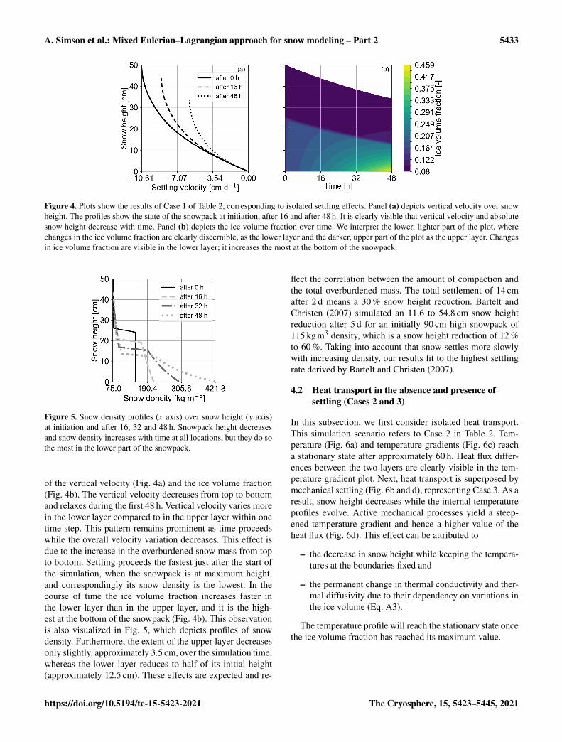
Figure 4. Plots show the results of Case 1 of Table 2, corresponding to isolated settling effects. Panel (a) depicts vertical velocity over snowheight. The profiles show the state of the snowpack at initiation, after 16 and after 48 h. It is clearly visible that vertical velocity and absolutesnow height decrease with time. Panel (b) depicts the ice volume fraction over time. We interpret the lower, lighter part of the plot, wherechanges in the ice volume fraction are clearly discernible, as the lower layer and the darker, upper part of the plot as the upper layer. Changesin ice volume fraction are visible in the lower layer; it increases the most at the bottom of the snowpack.
Figure 5. Snow density profiles (x axis) over snow height (y axis)at initiation and after 16, 32 and 48 h. Snowpack height decreasesand snow density increases with time at all locations, but they do sothe most in the lower part of the snowpack.
of the vertical velocity (Fig. 4a) and the ice volume fraction(Fig. 4b). The vertical velocity decreases from top to bottomand relaxes during the first 48 h. Vertical velocity varies morein the lower layer compared to in the upper layer within onetime step. This pattern remains prominent as time proceedswhile the overall velocity variation decreases. This effect isdue to the increase in the overburdened snow mass from topto bottom. Settling proceeds the fastest just after the start ofthe simulation, when the snowpack is at maximum height,and correspondingly its snow density is the lowest. In thecourse of time the ice volume fraction increases faster inthe lower layer than in the upper layer, and it is the high-est at the bottom of the snowpack (Fig. 4b). This observationis also visualized in Fig. 5, which depicts profiles of snowdensity. Furthermore, the extent of the upper layer decreasesonly slightly, approximately 3.5 cm, over the simulation time,whereas the lower layer reduces to half of its initial height(approximately 12.5 cm). These effects are expected and re-
flect the correlation between the amount of compaction andthe total overburdened mass. The total settlement of 14 cmafter 2 d means a 30 % snow height reduction. Bartelt andChristen (2007) simulated an 11.6 to 54.8 cm snow heightreduction after 5 d for an initially 90 cm high snowpack of115 kgm3 density, which is a snow height reduction of 12 %to 60 %. Taking into account that snow settles more slowlywith increasing density, our results fit to the highest settlingrate derived by Bartelt and Christen (2007).
4.2 Heat transport in the absence and presence ofsettling (Cases 2 and 3)
In this subsection, we first consider isolated heat transport.This simulation scenario refers to Case 2 in Table 2. Tem-perature (Fig. 6a) and temperature gradients (Fig. 6c) reacha stationary state after approximately 60 h. Heat flux differ-ences between the two layers are clearly visible in the tem-perature gradient plot. Next, heat transport is superposed bymechanical settling (Fig. 6b and d), representing Case 3. As aresult, snow height decreases while the internal temperatureprofiles evolve. Active mechanical processes yield a steep-ened temperature gradient and hence a higher value of theheat flux (Fig. 6d). This effect can be attributed to
– the decrease in snow height while keeping the tempera-tures at the boundaries fixed and
– the permanent change in thermal conductivity and ther-mal diffusivity due to their dependency on variations inthe ice volume (Eq. A3).
The temperature profile will reach the stationary state oncethe ice volume fraction has reached its maximum value.
https://doi.org/10.5194/tc-15-5423-2021 The Cryosphere, 15, 5423–5445, 2021

5434 A. Simson et al.: Mixed Eulerian–Lagrangian approach for snow modeling – Part 2
Figure 6. Panels (a) and (c) show the results for Case 2 of Table 2 corresponding to heat transport being solely active. Panels (b) and (d) showthe results for Case 3 of Table 2 corresponding to active heat transport and mechanical settling. For each plot the y axis represents snowheight and x axis time. The plots in the top row (a, b) show the temperature evolution, and the plots in the bottom row (c, d) show therespective temperature gradients. In (a) and (c) settling is inactive, so the boundary of upper layer and lower layer is at the snowpack center.In (b) and (d), we interpret the upper, darker part, which is characterized by higher gradients, as the upper layer and the lower, lighter areawith lower gradients as the lower layer. The initial conditions for both cases are equivalent (see Fig. 3). In Case 2 the temperature profile (a)has reaches the stationary, piecewise linear profile after approximately 60 h. In Case 3 the temperature profile (b) is not yet stationary at theend of the simulation (96 h) as mechanical processes are still yielding a change in the ice volume fraction. The temperature gradient (c) willbecome constant only when the maximum ice volume fraction has been reached.
4.3 Heat and vapor transport in the absence andpresence of settling (Cases 4 and 5)
By using the vapor formulation from Hansen and Foslien(2015), transport of vapor through and phase changes inthe snowpack both require an apparent temperature gradientsuch that the evolution of vapor transport can only be consid-ered in conjunction with heat transport. In Fig. 7a, we com-pare the deposition rate (negative for sublimation) due to heatand vapor transport only (Case 4 in Table 2) with the depo-sition rate obtained when considering additional settling pro-cesses, representing the fully coupled processes (Case 5 inTable 2). Both profiles are characterized by moderate depo-sition rates throughout the snow column with a pronouncednegative (sublimation) peak at the center of the snow column,which is located in the transition area of the layers. The pro-file for the fully coupled processes shows a higher sublima-tion peak (approximately 4 times higher). Figure 7b showsthe time evolution of the fully coupled processes (Case 5). Inthe first hours, sublimation is low in the transition area. Afterapproximately 6 h, the pronounced sublimation rate peak, asalready described for (Fig. 7a), develops and increases until
the end of the simulation (48 h). The increased sublimation inthe layer transition area may be driven by strong vapor den-sity gradients (Fig. 7c) above the transition area that can beinferred from a strong, local temperature gradient (Fig. 7d).This temperature gradient is further enhanced (Fig. 6d) bycompaction due to settling for Case 5, which yields evenstronger variations in the material properties in the transi-tion area than without compaction and explains the strongersublimation rates for the fully coupled processes.
Furthermore, both profiles in Fig. 7a show a small peak inthe deposition rate (positive x direction) just above the afore-mentioned sublimation rate peak. This peak is very weak forCase 4 and more prominent for Case 5. This deposition ratepeak is highly interesting as it is interpreted as the onset ofspatio-temporal oscillations as observed and investigated ingreater detail in the companion paper (Schürholt et al., 2021).Schürholt et al. (2021) describe these wiggles as “smooth os-cillations” that are “intrinsic features” of the equations. Theresults in Fig. 7a nicely demonstrate that (a) our Eulerian–Lagrangian scheme can capture this behavior and (b) the in-stability prevails and even increases in the presence of set-tling processes. The results suggest that mechanics likely in-
The Cryosphere, 15, 5423–5445, 2021 https://doi.org/10.5194/tc-15-5423-2021

A. Simson et al.: Mixed Eulerian–Lagrangian approach for snow modeling – Part 2 5435
Figure 7. Panel (a) shows two deposition rate profiles over the normalized snow height after 2 d. The solid line represents the results of heatand vapor transport in the absence of settling for Case 4 of Table 2. The dashed line refers to Case 5 of Table 2, which additionally accountsfor settling. Sublimation rates (negative deposition rates) for Case 5 (fully coupled processes) are increased by approximately a factor of 4with respect to Case 4 without settling. At the top of the sublimation peak for both cases, a slight peak in the deposition rate is visible.Panel (b) shows the deposition rate profile evolution for Case 5. A pronounced sublimation rate peak in the transition area is first visible afterapproximately 6 h and increases with time. We interpret this area of increased sublimation (red line in the center) as the boundary of the upperand lower layer. Panel (c) shows the evolution of the vapor density gradient. The gradient at the bottom of the upper layer (at approximately20 and 15 cm height after 16 and 48 h) increases with time. Panel (d) shows the evolution of the temperature gradient with time. Overall thetemperature gradient is higher in the upper compared to in the lower layer. The lobes at the top and bottom at the start of the simulation in(b–d) are due to the strong phase change activity and heat flux triggered by the initial and boundary conditions.
crease local phase change activity in the vicinity of layerboundaries, which potentially has a large effect on weaklayer formation.
The deposition rates obtained with our model are between−2 and 2 kgm−3 d−1, which fits to the range of −1.728 to1.728 kgm−3 d−1 presented in Jafari et al. (2020). Sublima-tion rate peaks on the order of 0.1 to 1.2 kgm−3 d−1 havealso been computed with the numerical test cases by Hansenand Foslien (2015). For comparison with experiments, de-position rates can be derived via SSA · vn · ρi, with vn be-ing the ice crystal’s interface growth velocities and SSA theice’s specific surface area (see Calonne et al., 2014, Eq. 21therein). For a simple characteristic scale analysis, we con-sidered SSA in the range of 0.6× 10⁴ to 1×10⁴ m−1 (Schleefet al., 2014) and an interface growth velocity on the orderof 1× 10⁻⁹ms−1 (Krol and Löwe, 2016; Calonne et al.,2014). Combining these literature values yields depositionrates on the order of 0.5× 10⁴ kgm−3 d−1, which is signif-icantly larger than our simulation results. Interface growthvelocities on the order of 10−13 or 10−14 ms−1 would matchwith the simulated magnitudes for the deposition rate.
Lastly, we evaluate the impact of included higher-ordermesh errorsET andEc (see Sect. 3.4) on the temperature dis-tribution. We determine the error by computing the temper-ature deviation between the solution that considers higher-order mesh errors and the solution that does not. The devi-ation is then quantified in an L1 norm. The error increaseswith simulation time and is 0.13 K after 24 h, 0.23 K after36 h and 0.28 K after 48 h. After 48 h the deviation is highestfor the computational nodes just above the layer transition,where high temperature gradients are present (see Fig. 6).Note that the error for the deposition rate could be derivedsimilarly. From the temperature error, the deposition rate er-ror can be derived as the deposition rate is directly derivedfrom temperature via the vapor transport equation; we con-sider one error measure as sufficient to emphasize the impactof mesh errors.
https://doi.org/10.5194/tc-15-5423-2021 The Cryosphere, 15, 5423–5445, 2021

5436 A. Simson et al.: Mixed Eulerian–Lagrangian approach for snow modeling – Part 2
Figure 8. The plots show ice volume fraction profiles over the normalized snow height after 2 d. (a) Case 1 (Table 2) depicts the ice volumefraction corresponding to solely active settling, and Case 5 refers to the fully coupled processes. Panel (b) zooms in to the density transitionarea of (a). The kink in the profile of Case 5 shows the effect of the increased sublimation in Fig. 7 that yields a local decrease in the icevolume fraction. In order to better resolve the kink of Case 5, we increased the number of grid nodes to 251.
Figure 9. The plots show the evolution of the ice volume fraction (a) and viscosity (b) for 4 d for Case 7 of Table 2, which refers to the fullycoupled processes combined with a dynamically varying viscosity. Snow height is depicted on the y axis. The upper and lower layers areinterpreted in both plots as the darker areas in the upper part and the lighter areas in the lower part. In (a) ice volume fraction increases mostat the bottom of the upper layer. The lower layer consolidates less than the upper layer. In (b) viscosity increases more slowly in the upperlayer and increases faster (by up to 1 order of magnitude) in the lower layer.
4.4 Settling-induced evolution of the ice volumefraction in the absence and presence of transport(Cases 1 and 5)
In this section, we compare isolated settling (Case 1 in Ta-ble 2) and the fully coupled processes (Case 5 in Table 2)with respect to their impact on the evolving ice volume frac-tion. Figure 8 shows the corresponding ice volume fractionprofiles after 2 d. Both profiles are very similar (Fig. 8a),which suggests that the density evolution is dominated bysettling processes and coupled heat and vapor transport playa minor role. When focusing on the upper boundary of thetransition area (Fig. 8b), we find however a locally decreasedice volume fraction for the fully coupled processes (Case 5).This suggests a local ice volume decay for active vapor trans-port and implies phase changes. This observation is consis-tent with the enhanced sublimation rate observed in Fig. 7and indicates the formation of a density heterogeneity.
4.5 Heat and vapor transport coupled to settling with adynamic viscosity (Cases 4, 6, and 7)
Figure 9 shows the evolution of the ice volume fraction andviscosity over 4 d for Case 7 (Table 2), which is the fully cou-pled processes coupled to dynamic viscosity. The ice volumefraction increases gradually throughout the snow column(Fig. 9a). In Fig. 9b, we see that the viscosity of the upperlayer has smaller values, and they also increase more slowlycompared to viscosity values in the lower layer. In contrast,viscosity increases by approximately 1 order of magnitude inthe lower layer. This derives from the applied viscosity for-mula that is controlled by the variables of temperature and icevolume fraction. Based on the formula, viscosity varies morewith respect to ice volume fraction changes than to temper-ature changes. The ice volume fraction varies more in thelower layer, which then also yields more variation in viscos-ity. Additionally, the height of the lower layer decreases lessthan that of the upper layer. This outcome may be related to
The Cryosphere, 15, 5423–5445, 2021 https://doi.org/10.5194/tc-15-5423-2021

A. Simson et al.: Mixed Eulerian–Lagrangian approach for snow modeling – Part 2 5437
Figure 10. Panel (a) shows the ice volume fraction over the normalized snow height after a 3 d simulation time obtained with a dynamicviscosity. Case 6 (Table 2) corresponds to mechanical settling solely, and Case 7 represents the fully coupled processes. Panel (b) showsthe deposition rate over the normalized snow height for Case 7 and Case 4 after a 3 d simulation time. Case 4 represents heat and vaportransport in the absence of settling. For the fully coupled processes (Case 7) the sublimation rate peak at the layer transition is slightly lowercompared with inactive settling (Case 4). Both peaks are approximately at the same location of the normalized snow height. Case 7 showsreduced deposition rates in the area above the peak compared with Case 4. Case 7 also has a small peak in the deposition rate just above thesublimation rate peak.
the lower layer’s higher viscosity (higher resistance to defor-mation).
Figure 10a compares the ice volume fraction profiles af-ter a 3 d simulation time of Case 7 to those of Case 6 (fullycoupled processes, non-dynamic viscosity). For the dynamicviscosity, the ice volume fraction is higher in the lower layerand lower in the upper layer compared to that of constant vis-cosity. This is due to the dynamic viscosity’s temperature de-pendence. Temperatures at the bottom are close to the melt-ing point and yield lower viscosities. Thus, settling proceedsfaster and compaction is stronger in the lower part. The oppo-site is true for the upper layer. Since we used an intermediatevalue of 263 K to derive the constant viscosity, variations inthe center of the snowpack are less pronounced. Figure 10bshows the deposition rate of Case 7 compared with Case 4,which refers to deactivated settling. Similarly to Fig. 7 bothdeposition rate profiles have a sublimation rate peak in thetransition area. Dissimilar to Fig. 7b is that the peaks are ap-proximately at the same normalized snow height and that thepeak of the fully coupled processes is not higher than the oneof deactivated settling. Instead Case 7 shows less depositionin the vicinity of the transition area above the sublimationrate peak compared to Case 4. This suggests that the subli-mation rate peak is less pronounced when coupled to the pro-posed dynamic viscosity, but settling still has an effect on thedeposition rate. Additionally, Case 7 shows the small peak indeposition rate just above the sublimation rate peak, which issimilar to Case 4 and discussed in Sect. 4.3.
4.6 Non-linear Glen’s law in a fully coupleddry-snowpack model of constant viscosity (Case 8)
In this simulation scenario, we present the results of the fullycoupled processes for the non-linear Glen’s law (Eq. 3 withm= 3, Case 8). As discussed before (Sect. 2.3), the viscos-ity closure (whether it is a constant value or an empiricalclosure) strongly depends on the choice of the Glen parame-ter m. This requires us to adjust the constant-viscosity valueaccordingly; see Sect. 2.3 for details.
Figure 11a (Case 8 in Table 2) shows vertical velocity pro-files and the evolution of the ice volume fraction with time.The vertical velocity is almost constant in the upper layerand then decreases in the lower layer. This effect is similarto the vertical velocity profiles as presented and explainedfor the linear version of Glen’s law (Fig. 4a), but it is morepronounced due to the non-linearity in the constitutive law.Compared with previous scenarios, the overall vertical ve-locity is lower. This is probably related to the magnitude ofthe constant viscosity and cannot be directly related to thenon-linear constitutive law. A further sensitivity study in thefuture would be most informative.
In Fig. 11b the upper layer’s ice volume fraction and thick-ness remain almost constant with time. In contrast, the lowerlayer decreases 9 cm in height while the ice volume fractionincreases with time from top to bottom.
As shown for Case 7 (Fig. 7a) the deposition rate profileshows a sublimation peak in the layer transition area (Ap-pendix D1) that increases with time. Overall, however, depo-sition rates tend to be lower compared to those of precedingcomputations. The reduced phase change activity in the layertransition area can be directly related to smaller vertical vari-ations in the temperature profile. This effect may be due to
https://doi.org/10.5194/tc-15-5423-2021 The Cryosphere, 15, 5423–5445, 2021

5438 A. Simson et al.: Mixed Eulerian–Lagrangian approach for snow modeling – Part 2
Figure 11. The plots show vertical velocity profiles over snow height (a) and the evolution of the ice volume fraction (b) for Case 8 ofTable 2, which refers to the fully coupled processes combined with a non-linear Glen’s law. Velocity (a) varies less compared with a linearversion of Glen’s law, which yields a more uniform evolution of the snowpack’s ice volume fraction (b). In (b) we interpret the locations ofthe upper layer as the darker area with an almost constant extent in the upper part and that of the lower layer as the slightly lighter area below.
less variation in the vertical velocities that yield a more uni-form deformation and a less pronounced variation in the icevolume fraction across the layer transition area.
4.7 Comparison against layer-based schemes (based onCase 6)
In this section, we compare results of our proposed Eulerian–Lagrangian scheme with conventional layer-based models.We would like to emphasize that a two-layer snowpackmodel certainly constitutes an extremely simplified case, aslayer-based schemes are usually operated with a significantlyhigher number of snow layers. Yet it is informative to con-duct this analysis to point out differences, as these can cer-tainly accumulate during long simulation times.
In layer-based snowpack models state variables are as-signed layerwise, and the two-layer snowpack (Fig. 3) wouldhave three computational nodes at the following locations:at the bottom of the lower layer, at the top of the lower layerand at the top of the upper layer. The two nodes located at thetop of the lower and upper layers would then represent thephysical state of the lower and the upper layer, respectively.Velocity is again derived from stress exerted by the overbur-den snow mass. Since the upper layer is represented by thecomputational node at the top, it is unloaded and requires aspecial treatment for stress. We adopt the approach by Vion-net et al. (2012) and apply a “non-physical stress” equivalentto half of the layer’s own weight, yet we apply it to the upper-most computational node (Sect. 3.4 in Vionnet et al., 2012).Next, vertical velocity is computed likewise with Eq. (7) andviscosity with Eq. (4). We compare both approaches based onCase 6 of Table 2, hence in the presence of mechanical set-tling and for a dynamic viscosity closure. Since we neglectheat and vapor transport, the viscosity changes over time aresolely due to the evolution of the ice volume fraction alone.
In Fig. 12, we see that the layer-based scheme sustains alayerwise vertical velocity (Fig. 12a) and ice volume fraction
evolution (Fig. 12c): one value for the velocity and one valuefor the ice volume fraction describe an entire layer. In con-trast, using the generalized Lagrangian approach described inSect. 3, we yield a sublayer resolution of the vertical veloci-ties (Fig. 12b) and ice volume fractions (Fig. 12d). For bothapproaches (layer-based and Eulerian–Lagrangian) the verti-cal velocity is higher in the top part of the snowpack and zeroat the bottom. For early times, the layer-based scheme deter-mines a vertical velocity that is 1 order of magnitude higherthan values computed with the Eulerian–Lagrangian scheme.This may be related to the comparably high (non-physical)stress at the top of the upper layer. At the end of the simu-lation, the snowpack has settled almost twice as much withthe layer-based scheme, which highlights the impact of thisconceptual difference. This effect may result from an over-estimation of velocity with layer-based schemes. Followingour proposed method, the ice volume fraction is higher inthe lower part of the snowpack and reaches higher values(Fig. 12d). Furthermore, the ice volume fraction at the topof the snowpack does not change during the simulation sincethere is no stress from overburden mass. In contrast, for thelayer-based scheme ice volume fraction grows at this location(Fig. 12c). This is again due to the chosen stress condition atthe top. Of course this discrepancy becomes smaller as weincrease the number of layers, and this effect may reduce.However this slight offset in the stress condition will alwaysbe present and lead to uncertainties. In the proposed compu-tational approach the spatial resolution of processes can beeasily changed to assess its impact on snowpack evolution. Ina future study, it might be interesting to quantitatively com-pare results against Jafari et al. (2020), who also rely on arather fine spatial resolution.
The Cryosphere, 15, 5423–5445, 2021 https://doi.org/10.5194/tc-15-5423-2021

A. Simson et al.: Mixed Eulerian–Lagrangian approach for snow modeling – Part 2 5439
Figure 12. The plots show the temporal evolution of vertical velocity (top row) and the ice volume fraction (bottom row) for Case 6 ofTable 2 corresponding to solely active mechanical settling. The y axis depicts snow height. For (b) and (d), we applied our highly discretizedsettling scheme, and for (a) and (c), we mimicked the layerwise discretization of layer-based schemes. Snow viscosity is controlled by theice volume fraction alone, since heat transport is inactive. In (a) and (c) the lower and upper layer are resolved as the darker upper andbrighter lower parts of the snowpack. Their respective values refer to the computational nodes at the top and between the two layers. Thevalues retrieved for the lowest node do not represent an entire layer and are depicted at height zero. For the layer-based scheme, one velocityor ice volume fraction value represents the movement or density of the entire layer. In contrast, with our approach vertical velocity variesthroughout each layer in (b) so that the ice volume fraction increases within layers and develops a gradual pattern (d). For (b) and (d), weinterpret the locations of the upper and lower layers as the darker upper and brighter lower areas, respectively, in (d).
4.8 Thin layers at the top and bottom of the snowpack(Case 5)
For the final scenario we implement a thin layer at the topand at the bottom of the two-layer snowpack. With this testcase we want to show our model’s feasibility for a potentialfuture comparison with operational snowpack models suchas Crocus that sustain layers at the top and bottom of thesnowpack (Vionnet et al., 2012).
The initial condition for snow density is in principle equiv-alent to Fig. 3 except that the upper and lower 2 cm nowform a new layer each, of 50 and 200 kgm−3, respectively.The transition to the neighboring layer is linearly smoothedout over 1 cm for both thin layers. Figure 13a shows the icevolume fraction profiles for three times. The profile for 0 hreflects the initial condition for the ice volume fraction. Thethree layer transitions are discernible as steps in the profiles.Figure 13b depicts the deposition rate evolution. Sublimationis stronger at the layer transitions but shows a different evo-lution at all transitions. While the uppermost layer transitionremains at a constant sublimation rate with time, sublimation
at the lowermost layer transition is very strong in the begin-ning and then decreases. The central layer transition showsthat sublimation continuously increases until the end of thesimulation time. This is consistent with our observations inFig. 7b. Figure 7a and b show that after 48 h the lowermostthin layer has been reduced to less than half its initial heightwhile the upper thin layer’s thickness has remained almostconstant. We suggest that the initially strong sublimation forthe lowermost transition area is related to high temperaturegradients at the lower boundary at the start of the simulation.Sublimation then reduces due to effects from consolidation.The effects of settling are very small in the vicinity of theuppermost layer transition, and the density difference in thelayers is only 25 kgm−3, which explains the constant and in-termediate sublimation rate.
5 Summary and conclusions
In this paper, we described in detail a hybrid Eulerian–Lagrangian computational approach to model the evolution
https://doi.org/10.5194/tc-15-5423-2021 The Cryosphere, 15, 5423–5445, 2021

5440 A. Simson et al.: Mixed Eulerian–Lagrangian approach for snow modeling – Part 2
Figure 13. The simulations were carried out based on Case 5 of Table 2, which is the fully coupled processes with constant viscosity.Panel (a) shows the profiles for the ice volume fraction (x axis) over snow height (y axis) for a test case that has a thin layer at the top andbottom of the snowpack. The line corresponding to 0 h shows the initial condition for the ice volume fraction. The thin layers at the top andbottom each have a thickness of 2 cm. Panel (b) depicts the evolution of the deposition rate. The three transition areas of the four layers arecharacterized by increased sublimation rates (after 16 h at snow heights 42, 20 and 2 cm). The lobes at the top and bottom at the start of thesimulation are due to the strong phase change activity triggered by the initial and boundary conditions.
of a dry snowpack. The model accounts for transport of heatand vapor, phase changes (sublimation and deposition), andmechanical settling processes. The ice mass balance is ex-plicitly accounted for in the model formulation. It capturesthe evolution of the ice volume fraction in response to settlingand phase changes. It constitutes an advection-dominatedpartial differential equation of hyperbolic type and is there-fore conveniently solved with the method of characteristics,a popular Lagrangian-type scheme for such processes. Here,Lagrangian refers to the fact that the scheme tracks the mo-tion of small reference volumes within the snow column byadjusting the node positions while at the same time account-ing for phase changes within the moving snow. Solving theice mass balance requires us to specify the vertical velocity aswell as the mass production rate (sublimation rate/depositionrate). A closure for the velocity is derived by combining acommon mechanical stress–strain relation with Glen’s lawand numerically approximating the resulting integrals. Thedeposition rate is due to vapor transport through a varyingtemperature field and can be determined from a diffusive-type process model that accounts for simultaneous heat andvapor transport. Due to its diffusive type (parabolic), a fixed-grid approach is most appropriate, referred to as an Eulerianapproach. More specifically, we solved coupled heat and va-por transport by means of a first-order implicit-in-time finite-difference approximation. The Eulerian scheme for the pro-cess model’s diffusive part complies with the non-uniformmesh that results from the Lagrangian scheme for the icevolume fraction evolution. In order to solve the completedry-snow process model for the coupled evolution of the icevolume fraction, temperature field, vapor field and settlingprocesses, the Eulerian and Lagrangian parts are iterativelyapplied following a straightforward operator split approach.
We have implemented our proposed numerical scheme as aseries of sequential updates within one simulation time step.The implementation follows a modular, extendable approach,such that each process building block can easily be consid-ered or neglected for verification or validation purposes. Weapplied our numerical core to conduct a series of simulationscenarios comprising isolated processes (pure settling, pureheat transport), two-process coupling scenarios (heat trans-port in the presence of settling, coupled heat and vapor trans-port) and fully coupled processes (heat and vapor transportin the presence of settling). We furthermore investigated dif-ferent viscosity closures as well as a linear and a non-linearversion of Glen’s law. A two-layer snowpack, consisting ofa lower layer of higher density and an upper layer of lowerdensity, served as a test case to demonstrate the feasibility ofour approach. We simulated fields and profiles for the tem-perature, deposition rate, ice volume fraction and vertical ve-locity with a high spatial (∼mm to cm) and temporal (∼ sto min) resolution.
We showed that our model implementation facilitates thecomparison of various parametrizations and processes. Thisis enabled by the following:
– Our Eulerian–Lagrangian scheme along with its vector-ized implementation is flexible and extendable. Alterna-tive model closures, e.g., for the viscosity and the ver-tical velocity, can easily be integrated. To close for thevelocity, we have successfully tested a non-linear strainrate closure commonly used in firn models (Lundinet al., 2017). The Lagrangian part of the solver (thataccounts for the evolution of the ice volume fraction)can be singled out and coupled to an alternative processmodel, e.g., when accounting for firn conditions insteadof dry snow.
The Cryosphere, 15, 5423–5445, 2021 https://doi.org/10.5194/tc-15-5423-2021

A. Simson et al.: Mixed Eulerian–Lagrangian approach for snow modeling – Part 2 5441
– The combination of an implicit Eulerian routine for thediffusion-dominated operators (that controls the timestepping) and a Lagrangian routine for the advection-dominated operators ran stably and robustly for all con-sidered simulation cases (different viscosity closures,different versions of Glen’s law).
– The numerical scheme allows for a high spatial reso-lution that resolves processes on the sublayer level. Byconstruction, it relies on a mechanically consistent ver-tical velocity. This improves the accuracy since it makesthe ad hoc specification of an artificial stress value forthe uppermost layer (e.g., Vionnet et al., 2012), as re-quired for conventional layer-based schemes, obsolete.
– The modular setup of the software allows a systematicstudy of various model formulations, in which we se-lectively considered different combinations of processbuilding blocks without fine-tuning the stability of thesolver. This is important to enable empirical–numericalinvestigations of the relevance of different process cou-plings.
– The incorporation of the higher-order mesh errors intothe vapor and heat transport equations that account fordeviations due to the non-uniform mesh increases accu-racy especially in areas of large variations in node dis-tance and of high temperature gradients.
In this paper, we mostly relied on numerical approxima-tions that are of either first order (time integration and oper-ator splitting) or second order (diffusion operator); the cor-responding numerical solvers can be extended without con-ceptual difficulty, e.g., changing from a first-order time inte-gration to a higher-order-in-time integrator. We commentedon this in the relevant section (Sect. 3). Our simulation con-sistently showed that vapor transport and phase change inthe presence of strong temperature gradients can induce astronger phase change activity and in particular a localizedsublimation rate peak above the transition area between twolayers. We furthermore showed that this has the potentialto result in a localized ice volume fraction reduction abovethe transition area. This in itself is not new, as a similar be-havior has been deduced in Hansen and Foslien (2015) andanalyzed in detail in our companion paper (Schürholt et al.,2021). In addition to the existing results, we have shown thatthe increased phase change activity persists in the presenceof settling (even more pronounced), for a constant-viscosityclosure in combination with a linear as well as a non-linearversion of Glen’s law.
6 Future work and challenges
In our paper, we deliberately focused on discussing modu-larity and extendability in the context of snowpack model-ing, e.g., by assessing a whole process cascade for one rela-tively simplified physical setting. In order to discuss theseaspects in depth, we restricted ourselves to one relativelysimple physical setting. We are well aware that as of today,our proposed numerical approach is not ready for operationaluse, and that was not our intention. At this point in time, werather would like to contribute to the discussion on how fu-ture snowpack modeling can benefit from a consistently for-mulated, hybrid Eulerian–Lagrangian solver. Nevertheless,it is important to discuss whether the suggested scheme isamenable to further extensions required for an operationalsnowpack model.
Most importantly, the proposed scheme would needa generalization for surface mass gain (precipitation) orlosses (sublimation). This bears two technical challenges.First, concurrent settling and precipitation result in a non-monotonic vertical motion of the snowpack’s upper surface,for which several techniques have been proposed in the past,e.g., based on a regularization approach (Wingham, 2000) orvia kinetic boundary conditions as applied to sedimentationon ocean floors in Audet and Fowler (1992). A straightfor-ward approach based on appending the computational gridsequentially during precipitation events likewise seems com-putationally feasible. A second challenge associated with theincorporation of precipitation events is the question of howto initialize the complete state (temperature, vapor and de-position rate) in the new snow layers. The latter is less crit-ical in conventional layer-based schemes, as the necessaryinformation reduces to “one value per layer”. While the firstchallenge mostly consists in overcoming technical subtletiesin the actual implementation, the second requires a thought-ful formulation of physically consistent boundary conditions.Neither of the two challenges seems to pose a severe risk.
Another important addition to our proposed snowpackmodel is the presence of liquid water in the snow. Concep-tually, similar modeling approaches could be used to derive amodel for wet snow. While including potential phase changesfrom melting and freezing could be straightforwardly im-plemented via the source term c, it is the advective trans-port of liquid water that is more demanding. Liquid watertransport is commonly modeled via the Richards equation(Wever et al., 2014) which would benefit from existing hy-brid Eulerian–Lagrangian solution strategies, as shown forsaturated media without mechanical settling (Huang et al.,1994). Furthermore, a model for wet snow requires a sec-ond energy balance to account for the liquid water tempera-ture. Once set up, it can be integrated into our computationalworkflow (Fig. 2).
Finally, operational models generally include the capabil-ity to account for topological change within the snow col-umn, to capture either layer coalescence if two initially sep-
https://doi.org/10.5194/tc-15-5423-2021 The Cryosphere, 15, 5423–5445, 2021

5442 A. Simson et al.: Mixed Eulerian–Lagrangian approach for snow modeling – Part 2
arated snow layers merge into one or layer separation if aninitially homogeneous layer splits into two. By construction,our computational approach does not require a dedicatedtreatment for layer coalescence or separation. Both are im-plicitly accounted for in the continuous description of stratig-raphy as long as the feature that is to be resolved is larger thanthe chosen spatial resolution of the computational grid. Inthe current version of our model we use a dynamic time stepadaptation based on the mesh Fourier number, which leads toa decreasing time step size from 40 s at initiation to 3 s after48 h. Layer coalescence, e.g., after certain time intervals orwhenever a specific time step size is undercut, could facili-tate longer simulations runs. Otherwise the resolution can beincreased to avoid layer split-ups for regions with high gra-dients. Furthermore, our approach prevents the complete de-generation of layers as the ice volume fraction is constrainedby the snow’s maximum apparent density per constructionof the scheme. Yet, while the theory suggests that layer coa-lescence and separation are not problematic, there might stillbe troublesome realistic test cases, especially when thinkingabout long simulation times. In order to address these andverify robustness, a series of benchmark tests have to be con-ducted. If necessary, the Eulerian–Lagrangian scheme in itscurrent version can be equipped with occasional re-meshing(along with a re-sampling of field variables) triggered by thedegeneration of well-defined mesh quality criteria.
We believe that a flexible and extendable computationalapproach, such as the one described in this paper, will bekey for future snowpack modeling to facilitate the use ofstandardized benchmark problems (potentially used during acontinuous integration) and allow us to systematically assessthe model’s predictive power, including uncertainty quantifi-cation, parameter estimation and model selection.
Appendix A: Formulas required for the process model
A1 Vapor saturation density
An empirical expression for the vapor saturation densityρ
eqv (T ) in terms of temperature T is formulated based on
the empirical formulation for vapor saturation pressure fromLibbrecht (1999) and reads
ρeqv (T )=
exp(−TrefT
)f T
(a0+ a1(T − Tm)+ a2(T − Tm)
2), (A1)
with coefficients a0= 3.6636× 10¹² kgm−1 s−2,a1=−1.3086× 10⁸ kgm−1 s−2 K−1,a2=−3.3793× 10⁶ kgm−1 s−2 K−2,f = 461.31 Jkg−1 K−1, Tm= 273.15 K and Tref= 6150 K.f is the specific gas constant for water vapor. Note thatdivision by f T accounts for the conversion from pressure(Pa) (as used in Part 1) to density (kgm−3).
A2 Model parameters in the transport and phasechange equations
The effective vapor mass diffusion coefficient Deff(φi) interms of the ice volume fraction φi is taken from Calonneet al. (2014) but is extended by the heaviside function 2 tohinder vapor diffusion for ice volumes above two-thirds:
Deff(φi)=D0
(1−
32φi
)2
(23−φi
), (A2)
with D0= 2.036× 10⁻⁵ m2 s−1 being the vapor diffusionconstant in air.
The effective thermal conductivity keff(φi) in terms of theice volume fraction φi is taken from Calonne et al. (2011)and reads
keff(φi)= a0+ a1(φiρi)+ a2(ρiφi)2, (A3)
with coefficients a0= 0.024, a1=−1.23× 10⁻⁴ anda2= 2.5× 10⁻⁶ and ice density ρi.
The effective heat capacity (ρC)eff(φi) in terms of the icevolume fraction φi is taken from Calonne et al. (2014) andHansen and Foslien (2015) and reads
(ρC)eff(φi)= φiρiCi+ (1−φi)ρa,Ca , (A4)
with Ci being ice heat capacity, Ca air heat capacity, ρi icedensity and ρa air density.
A3 Constant viscosity for the two-layer case
A3.1 Linear Glen’s law, ηconst,m=1
We derived intermediate ice volume fractionφi,const= 0.1125 and temperature Tconst= 263 K valuesfrom the initial condition of the two-layer case and insertthem as constants into Eq. (4).
A3.2 Non-linear Glen’s law ηconst,m=3
Equation (4) does not hold for the Glen exponent m= 3;therefore we derive an adjusted constant viscosity ηconst,m=3via the constitutive equation (Eq. 3)
ε̇lit =1
ηconst,m=3σmax , (A5)
with ε̇lit ≡ 10−6 s−1 being a strain rate value from the liter-ature (Johnson, 2011) and σmax ≡ 547.71 Pa the maximumstress value obtained from the initial snow density profile ofthe two-layer case. Equation (A5) is then solved for the con-stant viscosity ηconst,m=3.
A3.3 Restrict infinite ice volume growth
To hinder infinite ice volume growth, the constant viscos-ity ηconst,m is combined with a power law that yields expo-nential growth of viscosity for cells with φi > 0.95:
PL(φi)= exp(pl1φi−pl2)+ 1, (A6)
The Cryosphere, 15, 5423–5445, 2021 https://doi.org/10.5194/tc-15-5423-2021

A. Simson et al.: Mixed Eulerian–Lagrangian approach for snow modeling – Part 2 5443
with pl1= 690 and pl2= 650. The constant viscosity isthen multiplied with the power law (ηconst,mPL(φi)) so thatcomputational nodes with φi > 0.95 are assigned and viscos-ity grows exponentially. Note that for better readability themultiplication with the power law is omitted in the equationsof this paper.
Appendix B: Higher-order mesh errors to correct fornon-uniform mesh
For the temperature equation (Eq. 22) the higher-order mesherror is
ET
(T n+1k+1 ,T
n+1k−1
)=
2βT ,k(1znk
)2+(1znk−1
)2 1znk −1znk−1
1znk +1znk−1
·
(T n+1k+1 − T
n+1k−1
), (B1)
and for the vapor transport equation (Eq. 23) it is
Ec
(T n+1k+1 ,T
n+1k−1
)=
2βc,k(1znk
)2+(1znk−1
)2 1znk −1znk−1
1znk +1znk−1
·
(T n+1k+1 − T
n+1k−1
). (B2)
For the matrix equations Eqs. (25) and (24) the higher-order mesh errors are defined as ET and Ec.
Appendix C: Matrices from temperature and vaportransport equations
Matrix A is defined as follows:
A=
Anm,0 0 0 · · · 0 0 0Anl,1 Anm,1 Anu,1 · · · 0 0 0
0 Anl,2 Anm,2 · · · 0 0 0...
.
.
....
. . ....
.
.
....
0 0 0 · · · Anm,nz−2 Anu,nz−2 00 0 0 · · · Anl,nz−1 Anm,nz−1 Anu,nz−10 0 0 · · · 0 0 Anm,nz
. (C1)
For the heat equation (Eq. 24) (AT) the entries are
Anl,k =1tn
(βnT ,k+1−β
nT ,k−1(
1znk +1znk−1
)2 −DnT ,k), (C2)
Anu,k =−1tn
(βnT ,k+1−β
nT ,k−1(
1znk +1znk−1
)2 +DnT ,k), (C3)
Anm,k= αnT ,k + 21tnDnT ,k , with Anm,0 = 1 and Anm,nz = 1, (C4)
and for the vapor transport (Eq. 25) (Ac) the entries are
Anl,k =−βnc,k+1−β
nc,k−1
(1znk +1znk−1)
2 +Dnc,k , (C5)
Anu,k =βnc,k+1−β
nc,k−1
(1znk +1znk−1)
2 +Dnc,k, (C6)
Anm,k =−αnc,k
1tn− 2Dnc,k , with Anm,0 =−
αnc,0
1tnand Anm,nz
=−αnc,nz
1tn,
(C7)
with
Dnf,k =2βnf,k
(1znk )2+ (1znk−1)
2 forf ∈ {T ,c}. (C8)
Matrix B is defined as follows:
B=
αnm,0 0 0 · · · 0 0 00 αnm,1 0 · · · 0 0 00 0 αnm,2 · · · 0 0 0...
.
.
....
. . ....
.
.
....
0 0 0 · · · αnm,nz−2 0 00 0 0 · · · 0 αnm,nz−1 00 0 0 · · · 0 0 αnm,nz
. (C9)
For Eq. (24) (BT) the entries are
αnm,k = αnT ,k , (C10)
and for Eq. (25) (Bc) they are
αnm,k =αnc,k
1tn. (C11)
Matrix E is defined as follows:
E=
0 0 0 · · · 0 0 0Enl,0 0 Enu,1 · · · 0 0 0
0 Enl,1 0 · · · 0 0 0...
.
.
....
. . ....
.
.
....
0 0 0 · · · 0 Enu,nz−2 00 0 0 · · · Enl,nz−1 0 Enu,nz−10 0 0 · · · 0 0 0
, (C12)
consisting of the terms for the heat equation (ET) (Eq. 24)
Enl,k =−1tnDnT ,k
1znk −1znk−1
1znk +1znk−1
and (C13)
Enu,k =1tnDnT ,k
1znk −1znk−1
1znk +1znk−1
(C14)
and for the vapor equation (Ec) (Eq. 25)
Enl,k =Dnc,k1znk −1z
nk−1
1znk +1znk−1
and (C15)
Enu,k =−Dnc,k1znk −1z
nk−1
1znk +1znk−1
. (C16)
https://doi.org/10.5194/tc-15-5423-2021 The Cryosphere, 15, 5423–5445, 2021

5444 A. Simson et al.: Mixed Eulerian–Lagrangian approach for snow modeling – Part 2
Appendix D: Additional figures
D1 Non-linear Glen’s law
Figure D1. The plot shows the deposition rate profiles for 16, 32and 48 h simulation times for Case 8 (Table 2), which is the fullycoupled processes combined with the non-linear version of Glen’slaw. The y axis depicts snow height.
Code availability. The model code is available viahttps://doi.org/10.5281/zenodo.5588308 (Simson and Kowal-ski, 2021).
Author contributions. The study concept, underlying model andmethodology were devised by AS, HL and JK. Model analysis, soft-ware implementation and simulation runs were performed by ASsupervised by JK. Test case analysis and discussion, data visual-ization, and manuscript preparation were carried out by AS withcontributions from JK and HL.
Competing interests. The authors declare that they have no conflictof interest.
Disclaimer. Publisher’s note: Copernicus Publications remainsneutral with regard to jurisdictional claims in published maps andinstitutional affiliations.
Acknowledgements. We thank the two anonymous reviewers fortheir helpful suggestions on the manuscript. The authors were sup-ported by the Helmholtz School for Data Science in Life, Earth andEnergy (HDS-LEE). The work was furthermore supported by theFederal Ministry of Economic Affairs and Energy, on the basis of adecision by the German Bundestag (50 NA 1908).
Review statement. This paper was edited by Mark Flanner and re-viewed by two anonymous referees.
References
Audet, D. and Fowler, A.: A mathematical model for com-paction in sedimentary basins, Geophys. J. Int., 110, 577–590,https://doi.org/10.1111/j.1365-246x.1992.tb02093.x, 1992.
Bader, H.-P. and Weilenmann, P.: Modeling temperature distribu-tion, energy and mass flow in a (phase-changing) snowpack.I. Model and case studies, Cold Reg. Sci. Technol., 20, 157–181,https://doi.org/10.1016/0165-232x(92)90015-m, 1992.
Bartelt, P. and Christen, M.: A computational procedure for insta-tionary temperature-dependent snow creep, Springer Berlin Hei-delberg, https://doi.org/10.1007/BFb0104195, 2007.
Bartelt, P. and Lehning, M.: A physical SNOWPACK model forthe Swiss avalanche warning: Part I: numerical model, ColdReg. Sci. Technol., 35, 123–145, https://doi.org/10.1016/s0165-232x(02)00074-5, 2002.
Brun, E., Martin, E., Simon, V., Gendre, C., and Coleou, C.:An Energy and Mass Model of Snow Cover Suitable forOperational Avalanche Forecasting, J. Glaciol., 35, 333–342,https://doi.org/10.3189/s0022143000009254, 1989.
Brun, E., David, P., Sudul, M., and Brunot, G.: A numer-ical model to simulate snow-cover stratigraphy for op-erational avalanche forecasting, J. Glaciol., 38, 13–22,https://doi.org/10.1017/s0022143000009552, 1992.
Calonne, N., Flin, F., Morin, S., Lesaffre, B., du Roscoat, S. R., andGeindreau, C.: Numerical and experimental investigations of theeffective thermal conductivity of snow, Geophys. Res. Lett., 38,L23501, https://doi.org/10.1029/2011GL049234, 2011.
Calonne, N., Geindreau, C., and Flin, F.: Macroscopic Mod-eling for Heat and Water Vapor Transfer in Dry Snowby Homogenization, J. Phys. Chem. B, 118, 13393–13403,https://doi.org/10.1021/jp5052535, 2014.
Domine, F., Barrere, M., and Sarrazin, D.: Seasonal evolution of theeffective thermal conductivity of the snow and the soil in highArctic herb tundra at Bylot Island, Canada, The Cryosphere, 10,2573–2588, https://doi.org/10.5194/tc-10-2573-2016, 2016.
Domine, F., Picard, G., Morin, S., Barrere, M., Madore, J.-B.,and Langlois, A.: Major Issues in Simulating Some ArcticSnowpack Properties Using Current Detailed Snow PhysicsModels: Consequences for the Thermal Regime and WaterBudget of Permafrost, J. Adv. Model. Earth Sy., 11, 34–44,https://doi.org/10.1029/2018ms001445, 2019.
Farlow, S. J.: Partial Differential Equations for Scientists and Engi-neers, Dover Publications, Mineola, New York, USA, reprint ofthe John Wiley & Sons, New York, USA, 1982 edition, 1993.
Hansen, A. C. and Foslien, W. E.: A macroscale mixture the-ory analysis of deposition and sublimation rates during heatand mass transfer in dry snow, The Cryosphere, 9, 1857–1878,https://doi.org/10.5194/tc-9-1857-2015, 2015.
Helfricht, K., Hartl, L., Koch, R., Marty, C., and Olefs, M.: Obtain-ing sub-daily new snow density from automated measurements inhigh mountain regions, Hydrol. Earth Syst. Sci., 22, 2655–2668,https://doi.org/10.5194/hess-22-2655-2018, 2018.
Huang, K., Zhang, R., and van Genuchten, M. T.: An Eulerian-Lagrangian approach with an adaptively corrected method ofcharacteristics to simulate variably saturated water flow, WaterResour. Res., 30, 499–507, https://doi.org/10.1029/93WR02881,1994.
Jafari, M., Gouttevin, I., Couttet, M., Wever, N., Michel, A.,Sharma, V., Rossmann, L., Maass, N., Nicolaus, M., and Lehn-
The Cryosphere, 15, 5423–5445, 2021 https://doi.org/10.5194/tc-15-5423-2021

A. Simson et al.: Mixed Eulerian–Lagrangian approach for snow modeling – Part 2 5445
ing, M.: The Impact of Diffusive Water Vapor Transport on SnowProfiles in Deep and Shallow Snow Covers and on Sea Ice, Front.Earth Sci., 8, 249, https://doi.org/10.3389/feart.2020.00249,2020.
Johnson, J. B.: Snow Deformation, in: Encyclopedia of Snow, Iceand Glaciers, 2011 edition, edited by: Singh, V. P., Singh, P., andHaritashya, UK, Springer, Dordrecht, the Netherlands, 1041–1045, https://doi.org/10.1007/978-90-481-2642-2_501, 2011.
Judson, A. and Doesken, N.: Density of Freshly FallenSnow in the Central Rocky Mountains, B. Am. Me-teorol. Soc., 81, 1577–1587, https://doi.org/10.1175/1520-0477(2000)081<1577:DOFFSI>2.3.CO;2, 2000.
Kirchner, H. K., Michot, G., Narita, H., and Suzuki, T.:Snow as a foam of ice: Plasticity, fracture and the brittle-to-ductile transition, Philos. Mag. A, 81, 2161–2181,https://doi.org/10.1080/01418610108217141, 2001.
Kowalski, J. and Torrilhon, M.: Moment Approximations andModel Cascades for Shallow Flow, Commun. Comput. Phys., 25,669–702, https://doi.org/10.4208/cicp.oa-2017-0263, 2019.
Krinner, G., Derksen, C., Essery, R., Flanner, M., Hagemann, S.,Clark, M., Hall, A., Rott, H., Brutel-Vuilmet, C., Kim, H., Mé-nard, C. B., Mudryk, L., Thackeray, C., Wang, L., Arduini, G.,Balsamo, G., Bartlett, P., Boike, J., Boone, A., Chéruy, F., Colin,J., Cuntz, M., Dai, Y., Decharme, B., Derry, J., Ducharne, A.,Dutra, E., Fang, X., Fierz, C., Ghattas, J., Gusev, Y., Haverd, V.,Kontu, A., Lafaysse, M., Law, R., Lawrence, D., Li, W., Marke,T., Marks, D., Ménégoz, M., Nasonova, O., Nitta, T., Niwano,M., Pomeroy, J., Raleigh, M. S., Schaedler, G., Semenov, V.,Smirnova, T. G., Stacke, T., Strasser, U., Svenson, S., Turkov,D., Wang, T., Wever, N., Yuan, H., Zhou, W., and Zhu, D.:ESM-SnowMIP: assessing snow models and quantifying snow-related climate feedbacks, Geosci. Model Dev., 11, 5027–5049,https://doi.org/10.5194/gmd-11-5027-2018, 2018.
Krol, Q. and Löwe, H.: Analysis of local ice crystal growth in snow,J. Glaciol., 62, 378–390, https://doi.org/10.1017/jog.2016.32,2016.
Lacroix, M. and Garon, A.: Numerical Solution of phase changeproblems: an Eulerian-Lagrangian approach, Numer. Heat Tr. B-Fund., 19, 57–78, https://doi.org/10.1080/10407799208944922,1992.
Lehning, M., Bartelt, P., Brown, B., Fierz, C., and Satyawali, P.: Aphysical SNOWPACK model for the Swiss avalanche warning:Part II. Snow microstructure, Cold Reg. Sci. Technol., 35, 147–167, https://doi.org/10.1016/s0165-232x(02)00073-3, 2002.
LeVeque, R. J.: Finite Volume Methods for Hyper-bolic Problems, Cambridge Texts in Applied Math-ematics, Cambridge University Press, Cambridge,https://doi.org/10.1017/CBO9780511791253, 2002.
Libbrecht, K. G.: Physical properties of ice, available at: http://www.cco.caltech.edu/~atomic/snowcrystals/ice/ice.htm (last ac-cess: 29 July 2021), 1999.
Lundin, J. M., Stevens, C. M., Arthern, R., Buizert, C., Orsi, A.,Ligtenberg, S. R., Simonsen, S. B., Cummings, E., Essery, R.,Leahy, W., Harris, P., Helsen, M. M., and Waddington, E. D.: FirnModel Intercomparison Experiment (FirnMICE), J. Glaciol., 63,401–422, https://doi.org/10.1017/jog.2016.114, 2017.
Mellor, G. L. and Blumberg, A. F.: Modeling Vertical and Hor-izontal Diffusivities with the Sigma Coordinate System, Mon.
Weather Rev., 113, 1379–1383, https://doi.org/10.1175/1520-0493(1985)113<1379:mvahdw>2.0.co;2, 1985.
Meyer, C. R., Keegan, K. M., Baker, I., and Hawley, R. L.: Amodel for French-press experiments of dry snow compaction,The Cryosphere, 14, 1449–1458, https://doi.org/10.5194/tc-14-1449-2020, 2020.
Morland, L., Kelly, R., and Morris, E.: A mixture theory for aphase-changing snowpack, Cold Reg. Sci. Technol., 17, 271–285, https://doi.org/10.1016/s0165-232x(05)80006-0, 1990.
Morland, L. W.: A fixed domain method for diffusionwith a moving boundary, J. Eng. Math., 16, 259–269,https://doi.org/10.1007/bf00042720, 1982.
Paterson, W.: The Physics of Glaciers, third edition, Elsevier, Ox-ford, England, https://doi.org/10.1016/C2009-0-14802-X, 1994.
Schleef, S., Löwe, H., and Schneebeli, M.: Influence of stress, tem-perature and crystal morphology on isothermal densification andspecific surface area decrease of new snow, The Cryosphere, 8,1825–1838, https://doi.org/10.5194/tc-8-1825-2014, 2014.
Schürholt, K., Kowalski, J., and Löwe, H.: Elements of futuresnowpack modeling – part 1: A physical instability arising fromthe non-linear coupling of transport and phase changes, TheCryosphere Discuss. [preprint], https://doi.org/10.5194/tc-2021-72, in review, 2021.
Schweizer, J., Jamieson, J. B., and Schneebeli, M.:Snow avalanche formation, Rev. Geophys., 41, 1016,https://doi.org/10.1029/2002rg000123, 2003.
Simson, A. and Kowalski, J.: Eulerian_Lagrangian_snow_solver:final paper submission TC, Zenodo [code],https://doi.org/10.5281/zenodo.5588308, 2021.
Viallon-Galinier, L., Hagenmuller, P., and Lafaysse, M.: Forc-ing and evaluating detailed snow cover models with stratig-raphy observations, Cold Reg. Sci. Technol., 180, 103163,https://doi.org/10.1016/j.coldregions.2020.103163, 2020.
Vionnet, V., Brun, E., Morin, S., Boone, A., Faroux, S., LeMoigne, P., Martin, E., and Willemet, J.-M.: The detailed snow-pack scheme Crocus and its implementation in SURFEX v7.2,Geosci. Model Dev., 5, 773–791, https://doi.org/10.5194/gmd-5-773-2012, 2012.
Wever, N., Fierz, C., Mitterer, C., Hirashima, H., and Lehning, M.:Solving Richards Equation for snow improves snowpack melt-water runoff estimations in detailed multi-layer snowpack model,The Cryosphere, 8, 257–274, https://doi.org/10.5194/tc-8-257-2014, 2014.
Wever, N., Valero, C. V., and Fierz, C.: Assessing wetsnow avalanche activity using detailed physics based snow-pack simulations, Geophys. Res. Lett., 43, 5732–5740,https://doi.org/10.1002/2016GL068428, 2016.
Wiese, M. and Schneebeli, M.: Early-stage interaction between set-tlement and temperature-gradient metamorphism, J. Glaciol., 63,652–662, https://doi.org/10.1017/jog.2017.31, 2017.
Wingham, D. J.: Small fluctuations in the density and thick-ness of a dry firn column, J. Glaciol., 46, 399–411,https://doi.org/10.3189/172756500781833089, 2000.
https://doi.org/10.5194/tc-15-5423-2021 The Cryosphere, 15, 5423–5445, 2021
Copyright © 2022 FDOKUMEN