n EXTENDABLE UNDERRUN BAR - Terberg Techniek
25
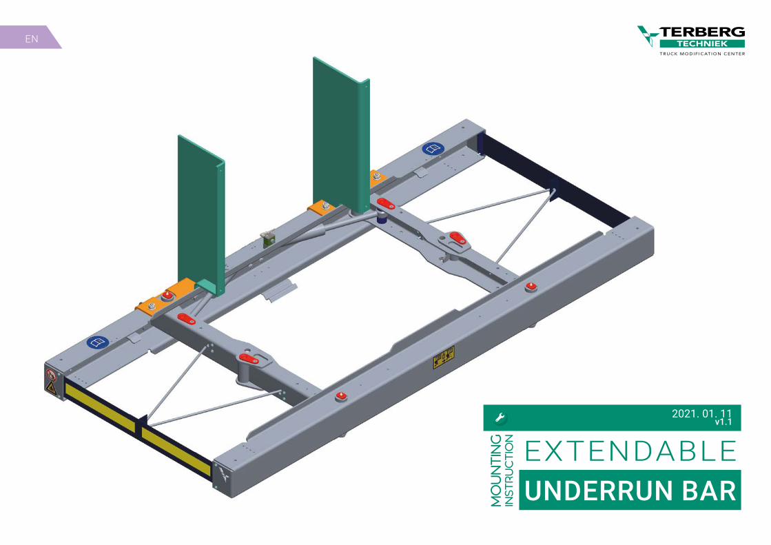
EN mounting instruction EXTENDABLE UNDERRUN BAR 2021. 01. 11 v1.1
-
Upload
khangminh22 -
Category
Documents
-
view
0 -
download
0
Transcript of n EXTENDABLE UNDERRUN BAR - Terberg Techniek
EN
mounting
inst
ructio
n EXTENDABLEUNDERRUN BAR
2021. 01. 11v1.1
Industrieweg 9–103401 MA IJsselstein
P.O.Box 233400 AA IJsselstein
T (+31) 030-6006260E [email protected]
I www.terbergtechniek.nl
Please consider the environment before printing this document.
© Terberg Techniek IJsselstein, NederlandAll rights reserved. No part of this book may be reproduced, stored in database or retrieval system, or published, in any form or in any way, electronically, mechanically, by print, photoprint, microfilm or any other means without prior written permission from the publisher.
Terberg Techniek B.V. is registered by: � Lloyds Register – Quality Assurance; ISO9001 & ISO14001 � RDW registered manufacturer of vehicles, Terberg Techniek B.V.
Revision Page(s) Remark1.1 15, 16, 18 the quantity of the bolts and nuts has been changed
REVISION HISTORY
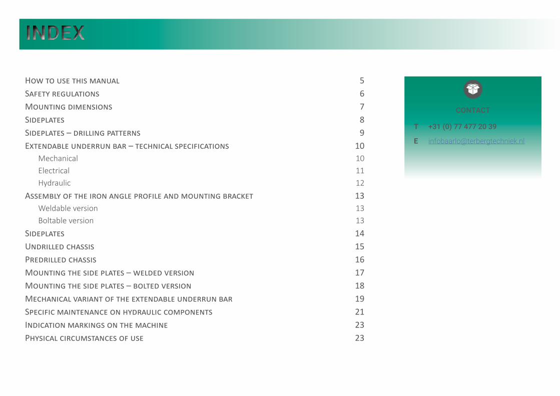
How to use this manual 5Safety regulations 6Mounting dimensions 7Sideplates 8Sideplates – drilling patterns 9Extendable underrun bar – technical specifications 10
Mechanical 10Electrical 11Hydraulic 12
Assembly of the iron angle profile and mounting bracket 13Weldable version 13Boltable version 13
Sideplates 14Undrilled chassis 15Predrilled chassis 16Mounting the side plates – welded version 17Mounting the side plates – bolted version 18Mechanical variant of the extendable underrun bar 19Specific maintenance on hydraulic components 21Indication markings on the machine 23Physical circumstances of use 23
CONTACT
T +31 (0) 77 477 20 39
INDEX
EXTENDABLE UNDERRUN BAR | Mounting instruction v1.1 | 2021.01.11. 4
EXTENDABLE UNDERRUN BARMOUNTING INSTRUCTION
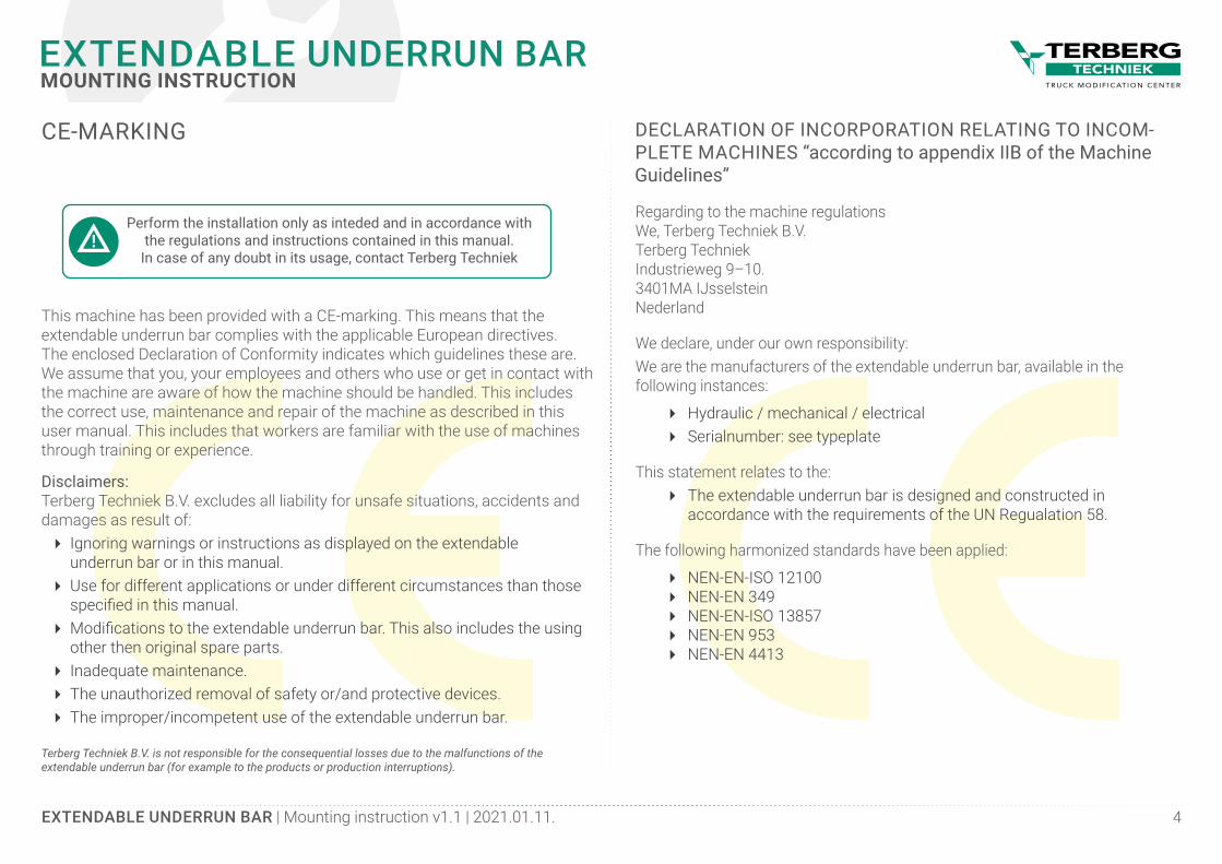
CE-MARKING
This machine has been provided with a CE-marking. This means that the extendable underrun bar complies with the applicable European directives. The enclosed Declaration of Conformity indicates which guidelines these are.We assume that you, your employees and others who use or get in contact with the machine are aware of how the machine should be handled. This includes the correct use, maintenance and repair of the machine as described in this user manual. This includes that workers are familiar with the use of machines through training or experience.
Disclaimers:Terberg Techniek B.V. excludes all liability for unsafe situations, accidents and damages as result of:
� Ignoring warnings or instructions as displayed on the extendable underrun bar or in this manual.
� Use for different applications or under different circumstances than those specified in this manual.
� Modifications to the extendable underrun bar. This also includes the using other then original spare parts.
� Inadequate maintenance. � The unauthorized removal of safety or/and protective devices. � The improper/incompetent use of the extendable underrun bar.
Terberg Techniek B.V. is not responsible for the consequential losses due to the malfunctions of the extendable underrun bar (for example to the products or production interruptions).
Perform the installation only as inteded and in accordance with the regulations and instructions contained in this manual.
In case of any doubt in its usage, contact Terberg Techniek
Regarding to the machine regulationsWe, Terberg Techniek B.V.Terberg TechniekIndustrieweg 9–10.3401MA IJsselsteinNederland
We declare, under our own responsibility:We are the manufacturers of the extendable underrun bar, available in the following instances:
� Hydraulic / mechanical / electrical � Serialnumber: see typeplate
This statement relates to the: � The extendable underrun bar is designed and constructed in accordance with the requirements of the UN Regualation 58.
The following harmonized standards have been applied:
� NEN-EN-ISO 12100 � NEN-EN 349 � NEN-EN-ISO 13857 � NEN-EN 953 � NEN-EN 4413
DECLARATION OF INCORPORATION RELATING TO INCOM-PLETE MACHINES “according to appendix IIB of the Machine Guidelines”
EXTENDABLE UNDERRUN BAR | Mounting instruction v1.1 | 2021.01.11. 5
EXTENDABLE UNDERRUN BARMOUNTING INSTRUCTION
Prior to assembly all parts must be identified and inspected. Carry out installation and service carefully and professionally. Follow the instructions. Please note that the vehicle manufacturer’s instructions and any frame reinforcements must be taken into account.
Have the customer keep all directions and instructions in the vehicle so they are available for future service and maintenance.
For more information, visit our website www.terbergtechniek.nl.
Assembly must be mounted in accordance with the instructions of Terberg Techniek B.V. All parts must be identified prior to assembly. Carry out the installation and service carefully and professionally. Follow the instructions.
Please note that the vehicle manufacturer’s instructions and any frame reinforcements must be taken into account. Have the customer keep all directions and instructions in the vehicle so that they are available for future service and maintenance. Category “G” has different mounting positions than those listed in the table on page 7.
Terberg Techniek B.V. reserves the right to make construction changes. No rights, nor a claim can be derived in any way from printing and/or typing errors are made on the content.
HOW TO USE THIS MANUAL
Install the extendable underrun bar according to this document!
The extendable underrun bar is intended for use outdoor.
The extendable underrun bar is not suitable for explosion sensitive environments.
EXTENDABLE UNDERRUN BAR | Mounting instruction v1.1 | 2021.01.11. 6
EXTENDABLE UNDERRUN BARMOUNTING INSTRUCTION
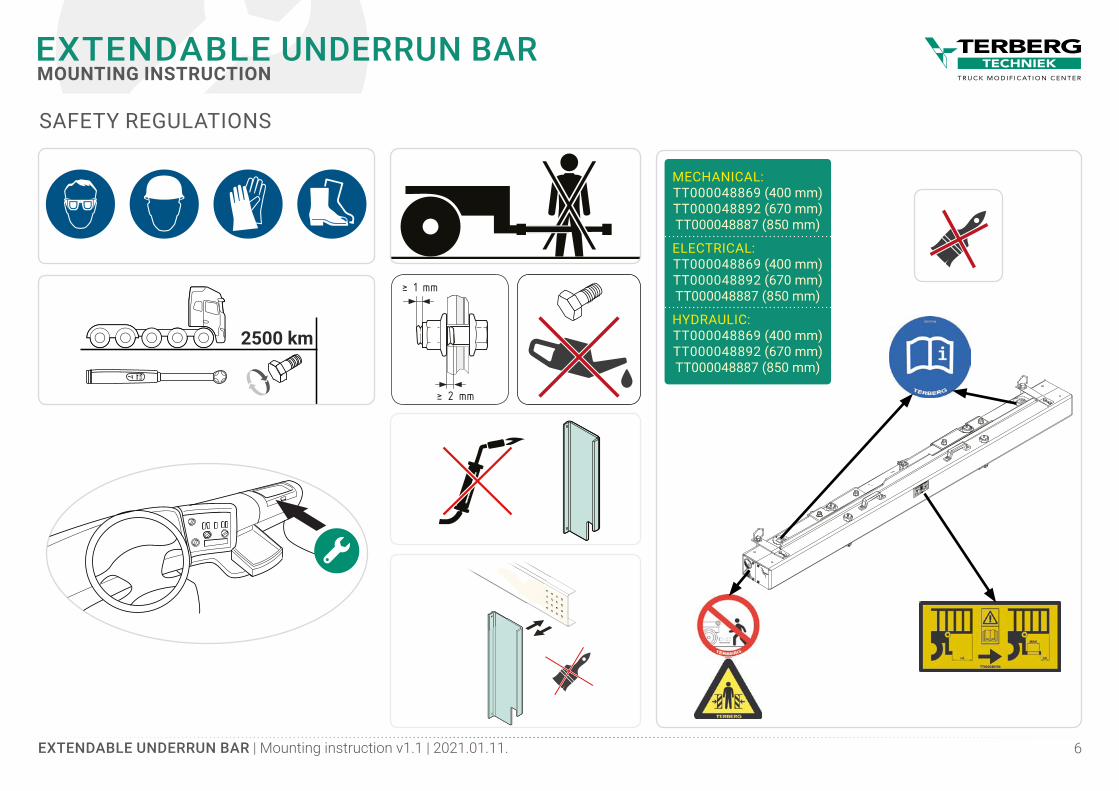
2500 km
NmƬ
MECHANICAL:TT000048869 (400 mm)TT000048892 (670 mm)TT000048887 (850 mm)
ELECTRICAL:TT000048869 (400 mm)TT000048892 (670 mm)TT000048887 (850 mm)
HYDRAULIC:TT000048869 (400 mm)TT000048892 (670 mm)TT000048887 (850 mm)
SAFETY REGULATIONS
EXTENDABLE UNDERRUN BAR | Mounting instruction v1.1 | 2021.01.11. 7
EXTENDABLE UNDERRUN BARMOUNTING INSTRUCTION
RH
l
A
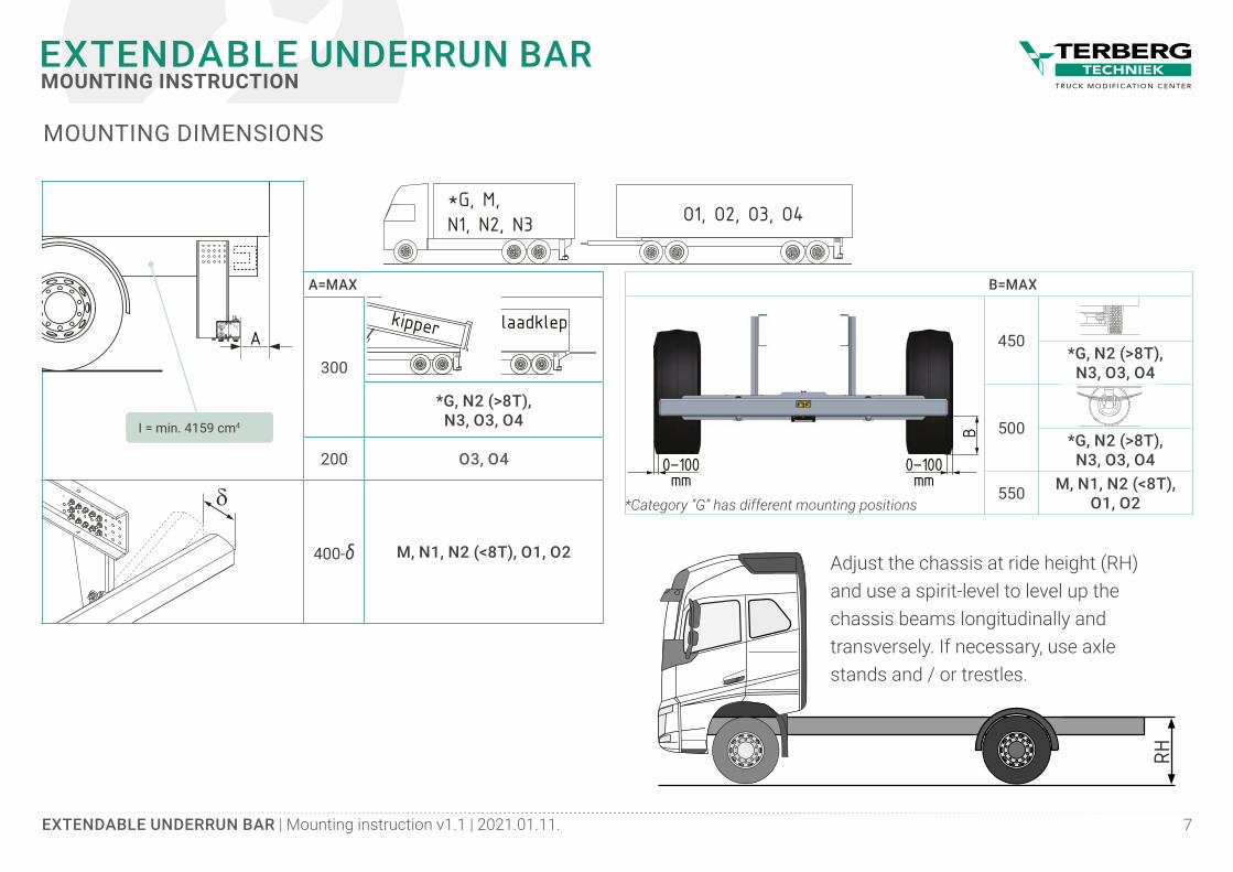
A=MAX
300
N1, N2, N3 O1, O2, O3, O4*G, M,
kipper laadklep
*G, N2 (>8T), N3, O3, O4
200 O3, O4
l
A
400-δ M, N1, N2 (<8T), O1, O2
MOUNTING DIMENSIONS
N1, N2, N3 O1, O2, O3, O4*G, M,
kipper laadklep
B=MAX
0–100mm
0–100mm
B
450*G, N2 (>8T),
N3, O3, O4
500*G, N2 (>8T),
N3, O3, O4
550 M, N1, N2 (<8T), O1, O2*Category “G” has different mounting positions
I = min. 4159 cm4
Adjust the chassis at ride height (RH) and use a spirit-level to level up the chassis beams longitudinally and transversely. If necessary, use axle stands and / or trestles.
EXTENDABLE UNDERRUN BAR | Mounting instruction v1.1 | 2021.01.11. 8
EXTENDABLE UNDERRUN BARMOUNTING INSTRUCTION
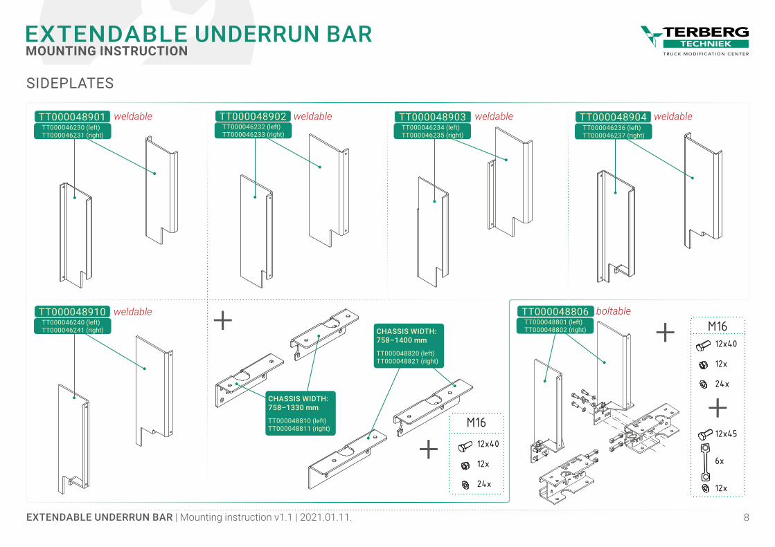
SIDEPLATES
+
+CHASSIS WIDTH:758–1330 mm
TT000048810 (left)TT000048811 (right)
TT000048901 weldableTT000046230 (left)TT000046231 (right)
TT000048902 weldableTT000046232 (left)TT000046233 (right)
TT000048903 weldableTT000046234 (left)TT000046235 (right)
TT000048904 weldableTT000046236 (left)TT000046237 (right)
TT000048910 weldableTT000046240 (left)TT000046241 (right)
TT000048806 boltableTT000048801 (left)TT000048802 (right)CHASSIS WIDTH:
758–1400 mm
TT000048820 (left)TT000048821 (right)
+
M16
12x
12x40
24x
M16
12x
12x40
24x
+6x
12x45
12x
EXTENDABLE UNDERRUN BAR | Mounting instruction v1.1 | 2021.01.11. 9
EXTENDABLE UNDERRUN BARMOUNTING INSTRUCTION
MIN
. 45
MIN
. 45
MIN
. 45
MIN
. 40
MAX. 71
5
M IN. 45 (OPTIONAL)MIN. 45MIN. 45MIN. 45MIN. 35
MIN
. 45
MIN
. 45
MIN
. 45
MIN
. 40
MAX. 71
5
M IN. 45 (OPTIONAL)MIN. 45MIN. 45MIN. 45MIN. 35
MIN
. 45
MIN
. 45
MIN
. 45
MIN
. 40
MAX. 61
5
M IN. 45 (OPTIONAL)MIN. 45MIN. 45MIN. 45MIN. 35
MIN
. 45
MIN
. 45
MIN
. 45
MIN
. 40
MAX. 71
5
M IN. 45 (OPTIONAL)MIN. 45MIN. 45MIN. 45MIN. 35
MIN
. 45
MIN
. 45
MIN
. 45
MIN
. 40
MAX. 71
5
M IN. 45 (OPTIONAL)MIN. 45MIN. 45MIN. 45MIN. 35
MIN
. 45
MIN
. 45
MIN
. 45
MIN
. 40
MAX. 71
5
M IN. 45 (OPTIONAL)MIN. 45MIN. 45MIN. 45MIN. 35
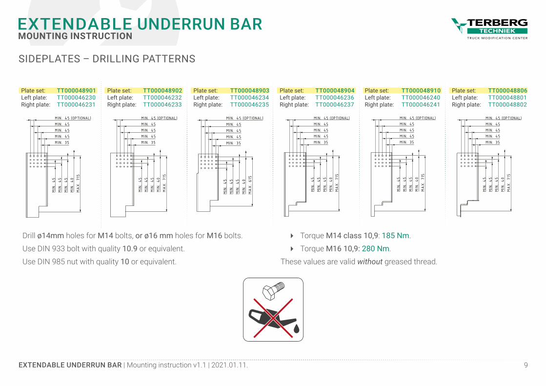
SIDEPLATES – DRILLING PATTERNS
Plate set:Left plate:Right plate:
TT000048902TT000046232TT000046233
Plate set:Left plate:Right plate:
TT000048903TT000046234TT000046235
Plate set:Left plate:Right plate:
TT000048904TT000046236TT000046237
Plate set:Left plate:Right plate:
TT000048910TT000046240TT000046241
Plate set:Left plate:Right plate:
TT000048806TT000048801TT000048802
Plate set:Left plate:Right plate:
TT000048901TT000046230TT000046231
Drill ø14mm holes for M14 bolts, or ø16 mm holes for M16 bolts.
Use DIN 933 bolt with quality 10.9 or equivalent.
Use DIN 985 nut with quality 10 or equivalent.
� Torque M14 class 10,9: 185 Nm.
� Torque M16 10,9: 280 Nm.
These values are valid without greased thread.

EXTENDABLE UNDERRUN BAR | Mounting instruction v1.1 | 2021.01.11. 10
EXTENDABLE UNDERRUN BARMOUNTING INSTRUCTION
TT000048867 (400 mm)TT000048890 (670 mm)TT000048885 (850 mm)
MECHANICALExtension (mm) 400 670 850
Dimensions (closed) LxWxH (mm)
2408×222×144/204
Dimensions (open) LxWxH (mm)
2408×622×144/204 2408×1072×144/204 2408×892×144/204
Chassis width (mm) minimum-maximum 758–1400
Chassis width (mm) in combination with different side plates:
TT000048806 758–930
TT000048901 758–1400
TT000048902 758–1400
TT000048903 758–1400
TT000048904 758–1400
TT000048910 758–1400
Weight (kg) bumper only 132 137 141
Weight (kg) of the bumper, equipped with different side plates:
TT000048806 204 178 213
TT000048901 173 178 182
TT000048902 182 187 191
TT000048903 166 171 175
TT000048904 173 178 182
TT000048910 166 171 175
Side-band yes
Certification (bumper+side plates) E4 R58.03-0899
EXTENDABLE UNDERRUN BAR – TECHNICAL SPECIFICATIONS
Weight can deviate +/- 5% incl. the CC (Cataphoresic coating) treatment, but excl. the bolt connections required to mount the bumper to the chassis. No rights can be derived from the information in the table.Modificatons and typing errors reserved.
EXTENDABLE UNDERRUN BAR | Mounting instruction v1.1 | 2021.01.11. 11
EXTENDABLE UNDERRUN BARMOUNTING INSTRUCTION
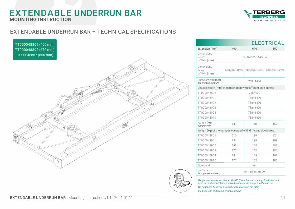
TT000048869 (400 mm)TT000048892 (670 mm)TT000048887 (850 mm)
ELECTRICALExtension (mm) 400 670 850
Dimensions (closed) LxWxH (mm)
2408×222×144/204
Dimensions (open) LxWxH (mm)
2408×622×144/204 2408×1072×144/204 2408×892×144/204
Chassis width (mm) minimum-maximum 758–1400
Chassis width (mm) in combination with different side plates:
TT000048806 758–930
TT000048901 758–1400
TT000048902 758–1400
TT000048903 758–1400
TT000048904 758–1400
TT000048910 758–1400
Weight (kg) bumper only 143 148 152
Weight (kg) of the bumper, equipped with different side plates:
TT000048806 215 189 224
TT000048901 184 189 193
TT000048902 193 198 202
TT000048903 177 182 186
TT000048904 184 189 193
TT000048910 177 182 186
Side-band yes
Certification (bumper+side plates) E4 R58.03-0899
EXTENDABLE UNDERRUN BAR – TECHNICAL SPECIFICATIONS
Weight can deviate +/- 5% incl. the CC (Cataphoresic coating) treatment, but excl. the bolt connections required to mount the bumper to the chassis. No rights can be derived from the information in the table.Modificatons and typing errors reserved.
EXTENDABLE UNDERRUN BAR | Mounting instruction v1.1 | 2021.01.11. 12
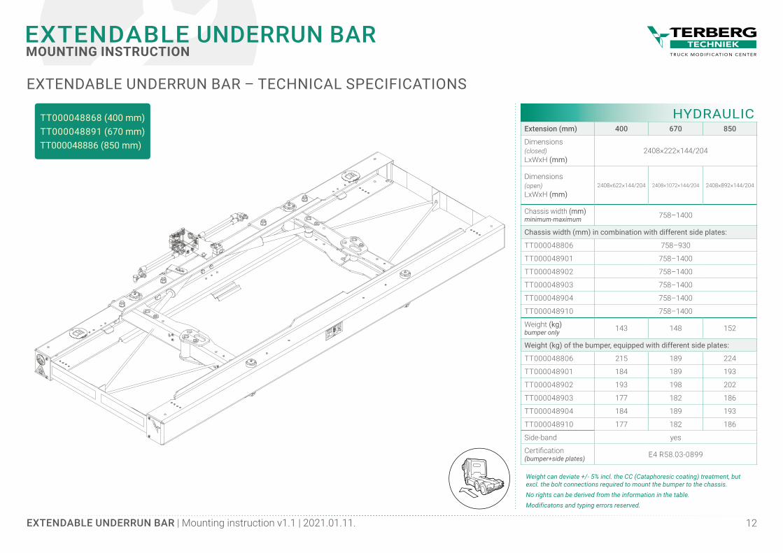
EXTENDABLE UNDERRUN BARMOUNTING INSTRUCTION
TT000048868 (400 mm)TT000048891 (670 mm)TT000048886 (850 mm)
HYDRAULICExtension (mm) 400 670 850
Dimensions (closed) LxWxH (mm)
2408×222×144/204
Dimensions (open) LxWxH (mm)
2408×622×144/204 2408×1072×144/204 2408×892×144/204
Chassis width (mm) minimum-maximum 758–1400
Chassis width (mm) in combination with different side plates:
TT000048806 758–930
TT000048901 758–1400
TT000048902 758–1400
TT000048903 758–1400
TT000048904 758–1400
TT000048910 758–1400
Weight (kg) bumper only 143 148 152
Weight (kg) of the bumper, equipped with different side plates:
TT000048806 215 189 224
TT000048901 184 189 193
TT000048902 193 198 202
TT000048903 177 182 186
TT000048904 184 189 193
TT000048910 177 182 186
Side-band yes
Certification (bumper+side plates) E4 R58.03-0899
EXTENDABLE UNDERRUN BAR – TECHNICAL SPECIFICATIONS
Weight can deviate +/- 5% incl. the CC (Cataphoresic coating) treatment, but excl. the bolt connections required to mount the bumper to the chassis. No rights can be derived from the information in the table.Modificatons and typing errors reserved.
EXTENDABLE UNDERRUN BAR | Mounting instruction v1.1 | 2021.01.11. 13
EXTENDABLE UNDERRUN BARMOUNTING INSTRUCTION
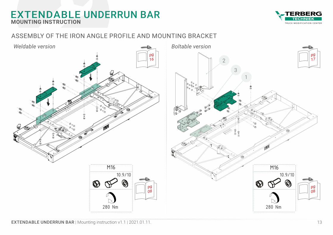
Boltable versionWeldable version
ASSEMBLY OF THE IRON ANGLE PROFILE AND MOUNTING BRACKET
pg16
pg172
13
280 Nm
M1610.9/10
pg08
280 Nm
10.9/10
pg08
M16
EXTENDABLE UNDERRUN BAR | Mounting instruction v1.1 | 2021.01.11. 14
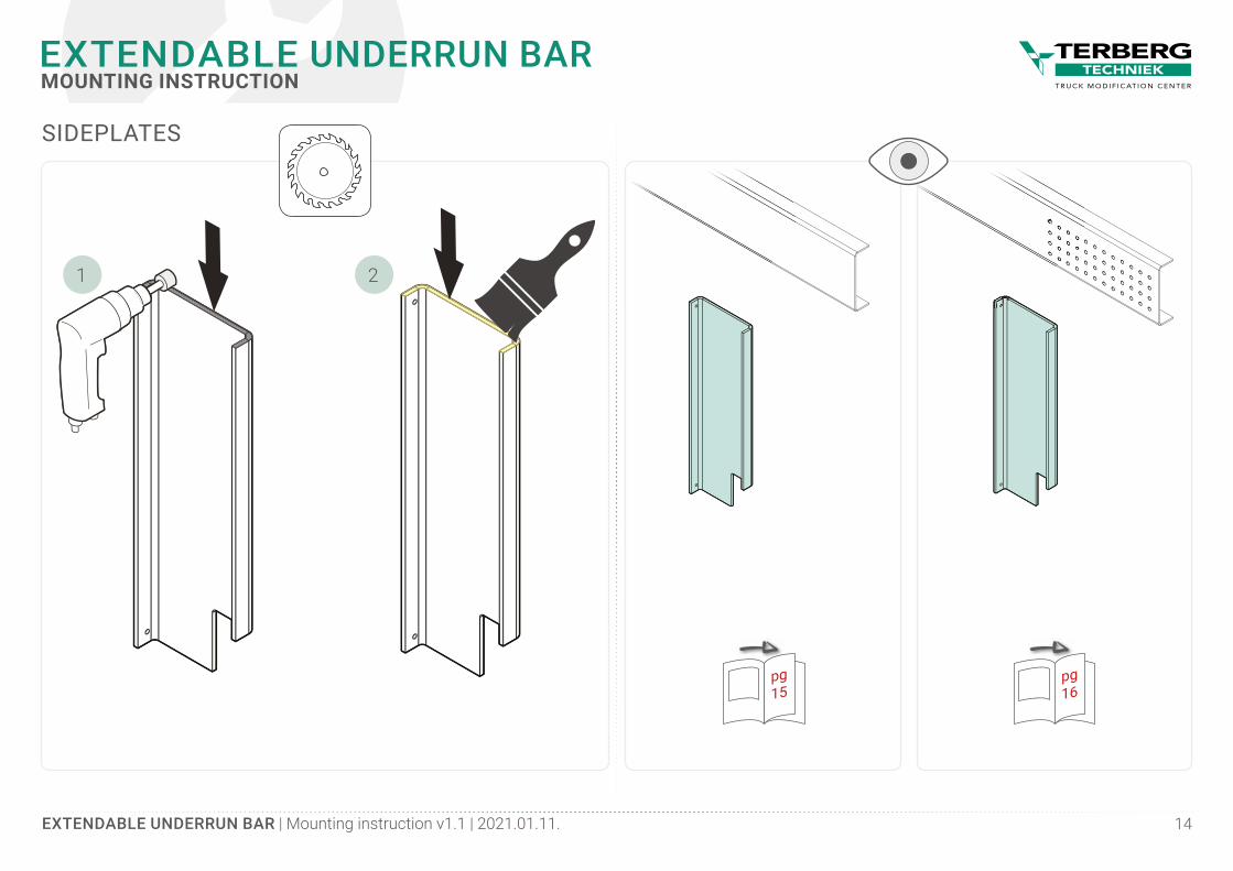
EXTENDABLE UNDERRUN BARMOUNTING INSTRUCTION
21
SIDEPLATES
pg15
pg16
EXTENDABLE UNDERRUN BAR | Mounting instruction v1.1 | 2021.01.11. 15
EXTENDABLE UNDERRUN BARMOUNTING INSTRUCTION
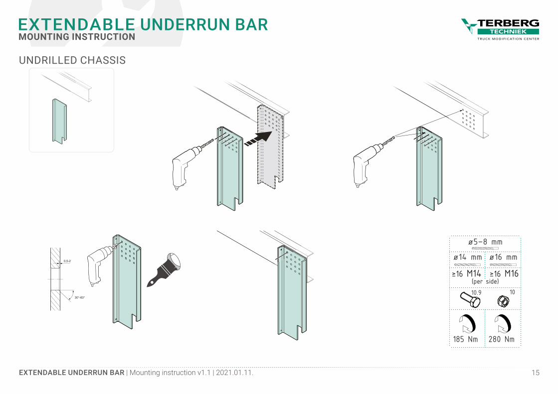
0,5-2
30°-60°
UNDRILLED CHASSIS
185 Nm 280 Nm
≥16 M14 ≥16 M16
ø16 mm
ø5–8 mm
ø14 mm
10.9 10(per side)
EXTENDABLE UNDERRUN BAR | Mounting instruction v1.1 | 2021.01.11. 16
EXTENDABLE UNDERRUN BARMOUNTING INSTRUCTION
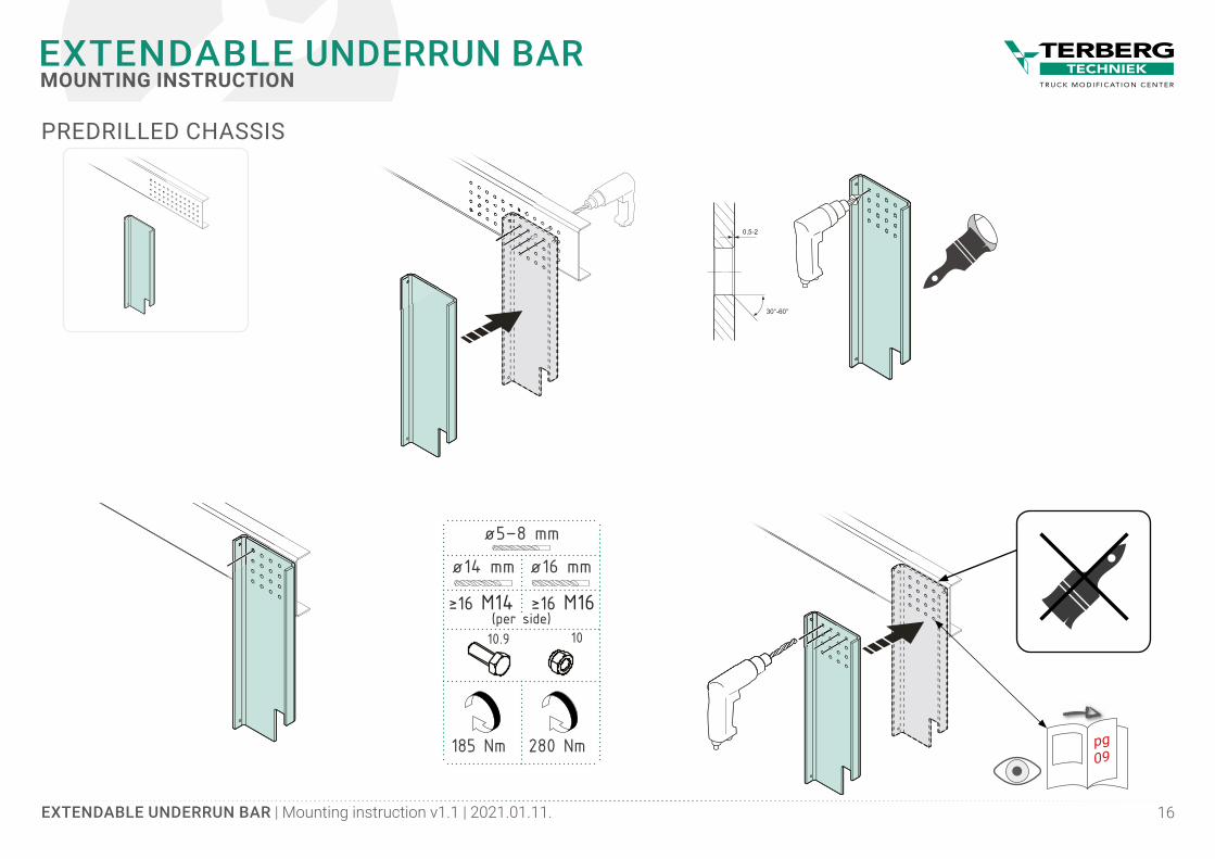
0,5-2
30°-60°
PREDRILLED CHASSIS
pg09
185 Nm 280 Nm
≥16 M14 ≥16 M16
ø16 mm
ø5–8 mm
ø14 mm
10.9 10(per side)
EXTENDABLE UNDERRUN BAR | Mounting instruction v1.1 | 2021.01.11. 17
EXTENDABLE UNDERRUN BARMOUNTING INSTRUCTION
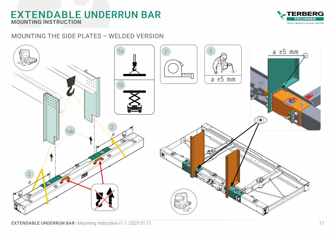
MOUNTING THE SIDE PLATES – WELDED VERSION
a ≥5 mm2
a ≥5 mm
3
=
=2
1b
1a
2
1ab
1b
1a
EXTENDABLE UNDERRUN BAR | Mounting instruction v1.1 | 2021.01.11. 18
EXTENDABLE UNDERRUN BARMOUNTING INSTRUCTION
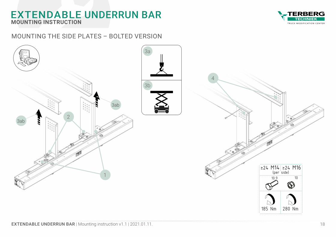
185 Nm 280 Nm
≥24 M14 ≥24 M16
3b
3a
10.9 10(per side)
MOUNTING THE SIDE PLATES – BOLTED VERSION
4
2
1
3ab
3ab
EXTENDABLE UNDERRUN BAR | Mounting instruction v1.1 | 2021.01.11. 19
EXTENDABLE UNDERRUN BARMOUNTING INSTRUCTION
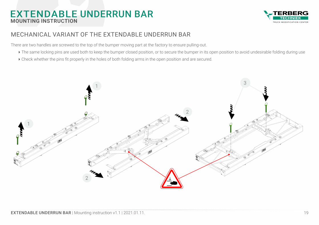
MECHANICAL VARIANT OF THE EXTENDABLE UNDERRUN BARThere are two handles are screwed to the top of the bumper moving part at the factory to ensure pulling-out.
� The same locking pins are used both to keep the bumper closed position, or to secure the bumper in its open position to avoid undesirable folding during use
� Check whether the pins fit properly in the holes of both folding arms in the open position and are secured.
2
2
1
1
3
EXTENDABLE UNDERRUN BAR | Mounting instruction v1.1 | 2021.01.11. 20
EXTENDABLE UNDERRUN BARMOUNTING INSTRUCTION
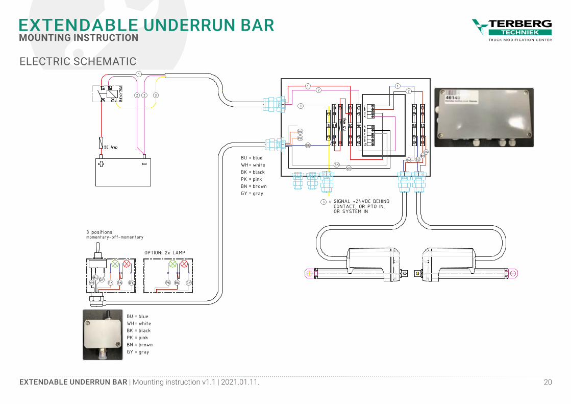
OPTION: 2x LAMP
BUWHBKPKBNGY
bluewhiteblackpinkbrowngray
======
BUWHBKPKBNGY
bluewhiteblackpinkbrowngray
======
= SIGNAL +24VDC BEHINDCONTACT, OR PTO IN,
OR SYSTEM IN
3 positionsmomentary-off-momentary
WHGY
GY GYPK PK
BU BUBN
BN
WH
1
3
21
2
1
32 2
3
PK
BN
BU
BK
BN BNBU
ELECTRIC SCHEMATIC
EXTENDABLE UNDERRUN BAR | Mounting instruction v1.1 | 2021.01.11. 21
EXTENDABLE UNDERRUN BARMOUNTING INSTRUCTION
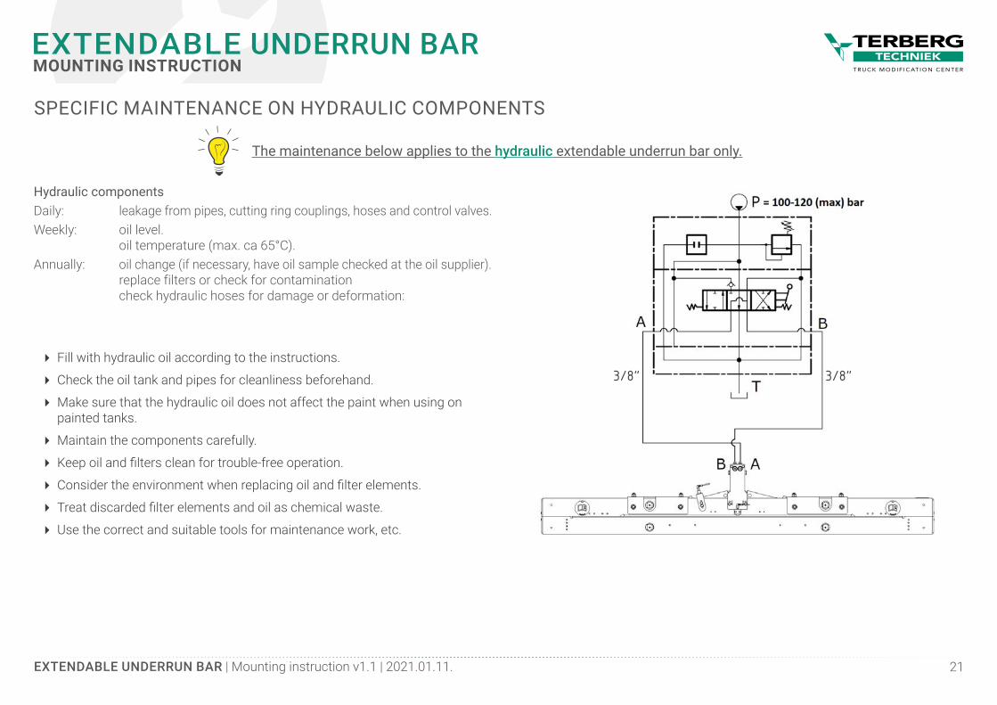
SPECIFIC MAINTENANCE ON HYDRAULIC COMPONENTS
The maintenance below applies to the hydraulic extendable underrun bar only.
Hydraulic componentsDaily: leakage from pipes, cutting ring couplings, hoses and control valves.Weekly: oil level. oil temperature (max. ca 65°C).Annually: oil change (if necessary, have oil sample checked at the oil supplier). replace filters or check for contamination check hydraulic hoses for damage or deformation:
� Fill with hydraulic oil according to the instructions.
� Check the oil tank and pipes for cleanliness beforehand.
� Make sure that the hydraulic oil does not affect the paint when using on painted tanks.
� Maintain the components carefully.
� Keep oil and filters clean for trouble-free operation.
� Consider the environment when replacing oil and filter elements.
� Treat discarded filter elements and oil as chemical waste.
� Use the correct and suitable tools for maintenance work, etc.
3/8”3/8”
EXTENDABLE UNDERRUN BAR | Mounting instruction v1.1 | 2021.01.11. 22
EXTENDABLE UNDERRUN BARMOUNTING INSTRUCTION
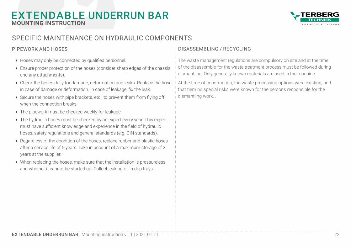
DISASSEMBLING / RECYCLING
The waste management regulations are compulsory on site and at the time of the disassemble for the waste treatment process must be followed during dismantling. Only generally known materials are used in the machine.
At the time of construction, the waste processing options were existing, and that tiem no special risks were known for the persons responsible for the dismantling work. .
PIPEWORK AND HOSES
� Hoses may only be connected by qualified personnel.
� Ensure proper protection of the hoses (consider sharp edges of the chassis and any attachments).
� Check the hoses daily for damage, deformation and leaks. Replace the hose in case of damage or deformation. In case of leakage, fix the leak.
� Secure the hoses with pipe brackets, etc., to prevent them from flying off when the connection breaks.
� The pipework must be checked weekly for leakage.
� The hydraulic hoses must be checked by an expert every year. This expert must have sufficient knowledge and experience in the field of hydraulic hoses, safety regulations and general standards (e.g. DIN standards).
� Regardless of the condition of the hoses, replace rubber and plastic hoses after a service life of 6 years. Take in account of a maximum storage of 2 years at the supplier.
� When replacing the hoses, make sure that the installation is pressureless and whether it cannot be started up. Collect leaking oil in drip trays.
SPECIFIC MAINTENANCE ON HYDRAULIC COMPONENTS
EXTENDABLE UNDERRUN BAR | Mounting instruction v1.1 | 2021.01.11. 23
EXTENDABLE UNDERRUN BARMOUNTING INSTRUCTION
PHYSICAL CIRCUMSTANCES OF USEThe following physical conditions are necessary:
During transport/storage: 0 to 55 degrees Celsius
Environmental temperature, working: -15 to 40 degrees Celsius
Relative humidity (RH): 30% to 100% non condensing
Lighting normal environmental lighting
Height airpressure to 1000m above the sea-level
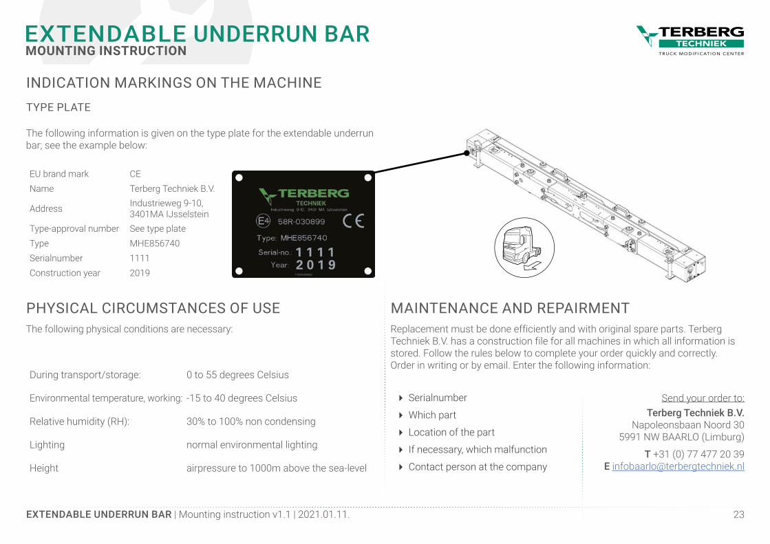
INDICATION MARKINGS ON THE MACHINE
The following information is given on the type plate for the extendable underrun bar; see the example below:
TYPE PLATE
EU brand mark CEName Terberg Techniek B.V.
Address Industrieweg 9-10,3401MA IJsselstein
Type-approval number See type plateType MHE856740Serialnumber 1111Construction year 2019
MAINTENANCE AND REPAIRMENTReplacement must be done efficiently and with original spare parts. Terberg Techniek B.V. has a construction file for all machines in which all information is stored. Follow the rules below to complete your order quickly and correctly.Order in writing or by email. Enter the following information:
Send your order to:Terberg Techniek B.V.
Napoleonsbaan Noord 305991 NW BAARLO (Limburg)
T +31 (0) 77 477 20 39E [email protected]
� Serialnumber
� Which part
� Location of the part
� If necessary, which malfunction
� Contact person at the company
COMMENTS
FEEDBACK
Our goal is to constantly improve our products and its documentation. Therefore the opinion and experiences of the users of our products and documentation is always more than welcome and will be greatly appreciated.
Please notify us if you have any suggestions and/or comments on this document. Please send your comments by mail, telefax, or hard-copy to the address listed to the right.
Terberg Techniek BVDept. EngineeringP.O. Box 23 3400AA IJsselstein The Netherlands
F +31 30 688 55 23 E [email protected]
Industrieweg 9–103401 MA IJsselstein
T +31 (0)30 600 62 60E [email protected]
I www.terbergtechniek.nlP.O.Box 233400 AA IJsselstein