Intuitive Theories of Information: Beliefs about the Value of Redundancy
Upload
independentCategory
view
3download
0
P1: KCU/JHR P2: VTL
JOURNAL OF ELECTRONIC TESTING: Theory and Applications KL440-04-Bushnell May 15, 1997 14:17
JOURNAL OF ELECTRONIC TESTING: Theory and Applications 10, 175–195 (1997)c© 1997 Kluwer Academic Publishers. Manufactured in The Netherlands.
A Functional Decomposition Method for Redundancy Identificationand Test Generation
MICHAEL L. BUSHNELLElectrical and Computer Eng. Dept., Rutgers University, P.O. Box 909, Piscataway, N.J. 08855-0909
JOHN GIRALDIJXG Consulting, 25 Bedell Rd., Poughkeepsie, NY 12603
Received February 10, 1994; Revised October 8, 1996 and November 11, 1996
Editor: J.A. Abraham
Abstract. We present a new combinational circuitautomatic test-pattern generation(ATPG) acceleration methodcalledEST that detects equivalentsearch states, which are saved for later use. Thesearch spaceis learned andcharacterized usingE-frontiers, which are circuit cut-sets induced by the implication stack contents. The searchspace is reduced by matching the current search state against previously-encountered search states (possibly fromprior faults), and this reduces the length of the search. A second contribution is acalculus of redundant faults, whichenablesEST to make many more mandatory assignments before search than is possible by prior algorithms, byeffectively using its knowledge of prior faults proven to be redundant. This accelerates ATPG for subsequent faults.These methods accelerate theTOPSalgorithm 33.3 times for the hard-to-test faults in the ISCAS ’85 benchmarks,and theSOCRATESalgorithm 5.6 times for the same hard-to-test faults, with little memory overhead.
Keywords: automatic test generation, redundancy identification, backtracing, logic testing
1. Introduction
We are entering the era ofUltra Large Scale Inte-gratedcircuits (ULSI), which are expected to have asmany as 10 million transistors on a single chip by theend of the century. Future mainframe computers mayhave as many as one million logic gates. Because ofthese dramatic increases in circuit size and the decreas-ing controllability and observability of internal circuitnodes, testing costs now exceed 50 per cent of the totalchip manufacturing cost.Design for testabilitytech-niques,scan design[1] andbuilt-in self-testing(BIST)[2] techniques have been developed to alleviate theseproblems. Scan design reduces the general sequential
circuit test generation problem to a combinational cir-cuit testing problem. BIST techniques replace externalautomatic test equipmentand test-patterns with inter-nal circuitry that generates a pseudo-random sequenceof test-patterns, exercises the circuit and compressesthe output response to determine whether the circuitis faulty. Regrettably, BIST requires that the circuit-under-test have no redundant logic or faults, which, inturn, requires a very fast combinational circuitredun-dancy identification(RI ) algorithm.
The EST [3] automatic test-pattern generation(ATPG) acceleration algorithm and combinationalredundancy identificationmethod provides thesecontributions:
P1: KCU/JHR P2: VTL
JOURNAL OF ELECTRONIC TESTING: Theory and Applications KL440-04-Bushnell May 15, 1997 14:17
176 Bushnell and Giraldi
1. We characterize thesearch stateof the ATPG algo-rithm using theE-frontier, a circuit cut-set inducedby a set ofprimary input (PI ) assignments. Thefrontier is a partition between the circuit part labeledwith 0, 1,D andD̄ signals and the part labeled withX signals.
2. We show that matching of E-frontiers can be usedto cause early backup from infeasible searches orearly search termination with a test-pattern.
3. EST uses knowledge about the search space for aprior fault to accelerate search for a test of the cur-rent fault.
4. EST is the first ATPG algorithm to use its knowl-edge of opportunistically-discovered redundantfaults in the circuit to further reduce the search spacefor later faults.
5. EST accelerates theTOPS [4] ATPG algo-rithm 33.3 times on the hard-to-test faults in theISCAS ’85 [5] benchmarks, and enables it to handleall faults in the circuits with no aborted faults.ESTaccelerates theSOCRATES [6] ATPG algorithm5.6 times on the same hard-to-test faults, while us-ing only 1.37 times as much memory. In both cases,EST generates a test-pattern or a redundancy prooffor all faults in the ISCAS ’85 benchmarks.ESTdramatically acceleratesTOPS andSOCRATES,even when using random-pattern generation andfault dropping. However, since theEST algo-rithm is orthogonal to all existing ATPG algo-rithms, it may be used to accelerate any test-patterngenerator.
EST characterizes and learns its search space, op-portunistically discovers equivalent search states anduses this knowledge to backup earlier than other algo-rithms can to avoid previously-traversed areas of thesearch space. Theimplication stackcontents definethe search space traversed by the ATPG algorithm. Apartial simulation [7] of the implication stack contentsdefines theATPG search state[3], which is representedas an E-frontier. When fault simulation fails to identifythe current fault as tested,EST uses E-frontiers to findtest-patterns for the current fault using test-patterns forprevious faults. Specifically, at each decision point ofthe ATPG algorithm,EST learns the circuit decom-position (an E-frontier) induced by the contents of theimplication stack. WheneverEST reaches a decisionpoint, it hashes the circuit decomposition correspond-ing to the present search state. If the decompositionwas previously generated (i.e., it matches an E-frontier
learned during ATPG for another fault), the hashingwill detect this equivalence. In most cases this meansthat all subsequent ATPG decisions will be identicalto those previously made for the matched decomposi-tion. EST annotates each remembered decompositionwith the fault for which the decomposition was gen-erated. If the matched decomposition led to a test forthe prior fault,EST can immediately fill in unknownprimary input values andprimary output(PO) circuitresponse values for the current fault, using informationstored with the decomposition for the prior fault. If thematched decomposition instead corresponds to a searchstate that ultimately led to a conflict during ATPG, thenEST can also use this knowledge to back up in the cur-rent fault search space much earlier than it otherwisewould have. When given sufficient memory,EST willsearch each region of the circuit search space only once.EST is based on the observation that when the faultsite is moved in the circuit, the ATPG search spacechanges but not very much. Vast regions of the spaceare identical for different failing machines, which rep-resent different faults.EST avoids repeating a searchof a previously-explored space wherever possible.
The second contribution ofEST is that, at the be-ginning of search for each fault, it analyzes the rela-tionships of all known redundant faults in the circuitto the current fault. In many cases, this allowsEST toimmediately label many nodes in the circuit whose la-belings would otherwise have to be discovered throughsearch.EST uses Muth’s nine-valued algebra [8], soeach such labeling reduces the search space to one ninthof its former size. Naturally, this method becomes in-creasingly more effective over time asEST completesmore redundancy proofs.
First, we briefly survey the prior work on combina-tional test-pattern generation. Then, we introduce theconcept ofATPG search state. Following that, we dis-cuss search state equivalence, search path termination,theEST algorithm and an example. Subsequently, wedescribe our calculus of redundant faults, which col-lapses the search space, and we present an example.Next, we show the results ofEST running with bothTOPSandSOCRATES. Finally, we conclude.
2. Prior Work
Roth first formulated the ATPG problem using hisD-algorithm [9], which divided ATPG into faultsensitization, fault propagationand line justificationoperations. Goel developedPODEM [10], which

P1: KCU/JHR P2: VTL
JOURNAL OF ELECTRONIC TESTING: Theory and Applications KL440-04-Bushnell May 15, 1997 14:17
A Functional Decomposition Method for Redundancy Identification and Test Generation 177
reduced the search space from the Shannon expan-sion around all internal circuit nodes to the expan-sion around circuit primary inputs. Fujiwara developedFAN [11], which accelerated ATPG by use ofuniquesensitizationandmultiple backtraceoperations. Kirk-land and Mercer developedTOPS [4], which accel-erated fault propagation by the use of Tarjan’s dom-inator theory [12] to analyze fault propagation paths.Schulz [6, 13] dramatically accelerated ATPG throughSOCRATES, which integrated random-pattern gener-ation, fault simulation and ATPG. He further collapsedthe search space through static and dynamic learningmethods, which accelerate fault propagation and back-tracing. Larrabee [14] has proposed a conjunctive nor-mal form representation of the Boolean difference thatshe solves by partitioning the equations and addingclauses to the Boolean difference as she traverses thecircuit during ATPG. A small partition is solved di-rectly and the remaining equations are used to checkthe solution for validity. Chakradhar et al. [15, 16]have proposed an ATPG method based on neural net-work modeling, usingquadratic0–1programmingandtransitive closure[17] algorithms.
CATAPULT [18] was the first gate-level ATPG al-gorithm to useBinary Decision Diagrams(BDD’s) andruns with algorithms that use random-patterns and/orheuristics. A BDD is a labeled, directed, acyclic graphrepresenting a combinational circuit [19] and is de-rived from a Boolean equation, truth table,binary de-cision treeor logic circuit. The more compact BDDis derived from the binary decision tree by removingequivalent subtrees and reconnecting the tree edges asgraph edges.CATAPULT computes controllabilityand observability BDD’s relative to the fault site by us-ing internal circuit signal stem variables and PI’s. Thetwo BDD’s are composed using Shannon’s composi-tion theorem to obtain a test of the fault. TheCOSMOSATPG algorithm [20] identifies test-patterns for faultsin sequential switch or gate level circuits. A BDD isgenerated from Boolean expressions for the circuit anda novel fault injector. Circuit stem and PI values areused in the BDD. The circuit is symbolically simulatedas a function of the variables that are outputs of thefault injector. The BDD is traversed until a differencethat results in a test-pattern is found. Although the ap-proach is feasible, the memory and CPU time require-ments are substantially greater than for other meth-ods.TSUNAMI [21], developed by Stanion and Bhat-tacharya, incrementally constructs a BDD, as it pro-ceeds along a circuit fault propagation path, to represent
the testing problem for the current fault in the circuit.The method was extremely successful on all ISCAS ’85circuits except c6288, the parallel multiplier, which itwas unable to complete.
Waicukauski [22] has further accelerated Schulz’smethod with an industrial implementation, but he didnot change the basic algorithm. More recent work byRajski and Cox [23] uses a 16-valued algebra basedon power sets of the five-valued algebra pioneered byRoth. The method is interesting, but was unable to gen-erate tests for all faults in the 1985 ISCAS BenchmarkCircuits.
3. Search States
We define new representations for ATPG search, searchstates and search state equivalence. We then presenttheEST algorithm and an example of the algorithm’sbehavior for a specific circuit.
3.1. ATPG Search State
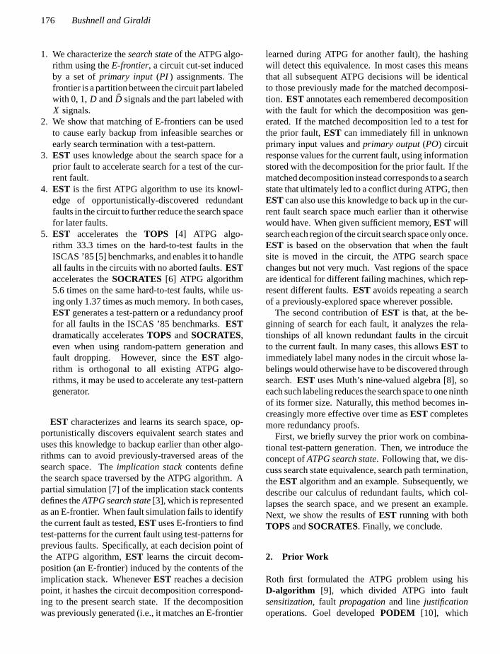
We view theATPG-Decision Tree(ATPG-DT) in Fig. 1as representing the test-pattern search steps for a faultas performed by the ATPG algorithm of Fig. 2, ratherthan as representing the entire search space for the fault.The tree represents a history of the search at any givenstep (shown by the numbered boxes) of the algorithm.Generation of the tree stops when the algorithm exitswith a test-pattern (Step 7) or when the search space isexhausted (Step 8). The ATPG-DT size is potentiallyexponential in the number of PI’s [10], since testing is,in general,NP-complete[24].
Fig. 1. ATPG decision tree and binary decision diagram.
P1: KCU/JHR P2: VTL
JOURNAL OF ELECTRONIC TESTING: Theory and Applications KL440-04-Bushnell May 15, 1997 14:17
178 Bushnell and Giraldi
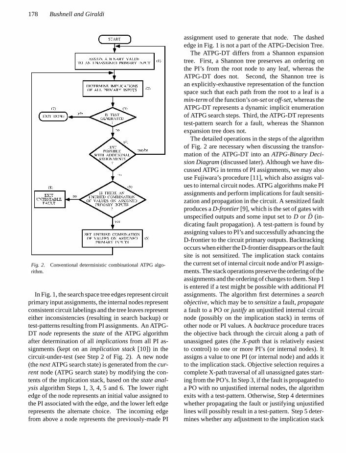
Fig. 2. Conventional deterministic combinational ATPG algo-rithm.
In Fig. 1, the search space tree edges represent circuitprimary input assignments, the internal nodes representconsistent circuit labelings and the tree leaves representeither inconsistencies (resulting in search backup) ortest-patterns resulting from PI assignments. An ATPG-DT noderepresents thestateof the ATPG algorithmafter determination of allimplicationsfrom all PI as-signments (kept on animplication stack[10]) in thecircuit-under-test (see Step 2 of Fig. 2). A new node(thenextATPG search state) is generated from thecur-rent node (ATPG search state) by modifying the con-tents of the implication stack, based on thestate anal-ysisalgorithm Steps 1, 3, 4, 5 and 6. The lower rightedge of the node represents an initial value assigned tothe PI associated with the edge, and the lower left edgerepresents the alternate choice. The incoming edgefrom above a node represents the previously-made PI
assignment used to generate that node. The dashededge in Fig. 1 is not a part of the ATPG-Decision Tree.
The ATPG-DT differs from a Shannon expansiontree. First, a Shannon tree preserves an ordering onthe PI’s from the root node to any leaf, whereas theATPG-DT does not. Second, the Shannon tree isan explicitly-exhaustive representation of the functionspace such that each path from the root to a leaf is amin-termof the function’son-setoroff-set, whereas theATPG-DT represents a dynamic implicit enumerationof ATPG search steps. Third, the ATPG-DT representstest-pattern search for a fault, whereas the Shannonexpansion tree does not.
The detailed operations in the steps of the algorithmof Fig. 2 are necessary when discussing the transfor-mation of the ATPG-DT into anATPG-Binary Deci-sion Diagram(discussed later). Although we have dis-cussed ATPG in terms of PI assignments, we may alsouse Fujiwara’s procedure [11], which also assigns val-ues to internal circuit nodes. ATPG algorithms make PIassignments and perform implications for fault sensiti-zation and propagation in the circuit. A sensitized faultproduces aD-frontier [9], which is the set of gates withunspecified outputs and some input set toD or D̄ (in-dicating fault propagation). A test-pattern is found byassigning values to PI’s and successfully advancing theD-frontier to the circuit primary outputs. Backtrackingoccurs when either the D-frontier disappears or the faultsite is not sensitized. The implication stack containsthe current set of internal circuit node and/or PI assign-ments. The stack operations preserve the ordering of theassignments and the ordering of changes to them. Step 1is entered if a test might be possible with additional PIassignments. The algorithm first determines asearchobjective, which may be tosensitizea fault,propagatea fault to a PO orjustify an unjustified internal circuitnode (possibly on the implication stack) in terms ofother node or PI values. Abacktraceprocedure tracesthe objective back through the circuit along a path ofunassigned gates (theX-path that is relatively easiestto control) to one or more PI’s (or internal nodes). Itassigns a value to one PI (or internal node) and adds itto the implication stack. Objective selection requires acomplete X-path traversal of all unassigned gates start-ing from the PO’s. In Step 3, if the fault is propagated toa PO with no unjustified internal nodes, the algorithmexits with a test-pattern. Otherwise, Step 4 determineswhether propagating the fault or justifying unjustifiedlines will possibly result in a test-pattern. Step 5 deter-mines whether any adjustment to the implication stack
P1: KCU/JHR P2: VTL
JOURNAL OF ELECTRONIC TESTING: Theory and Applications KL440-04-Bushnell May 15, 1997 14:17
A Functional Decomposition Method for Redundancy Identification and Test Generation 179
will result in an untried combination of assignments. Ifno more assignments are possible, then the algorithmhas proven the fault redundant. If an untried assign-ment exists, then Step 6backs upthe implication stackby removing each PI on the stack (in stack order) ifthe algorithm has already made the alternate assign-ment for the PI. We traverse the tree of Fig. 1 upwardfrom the current node through an incoming edge em-anating from the lower left of the above node. Whena PI on the stack is encountered with an untried alter-nate assignment, the alternate assignment is made forthe PI and the backup ends. These heuristic decisionsare deterministic and involve a complete examinationof all gates, possibly affecting the selection of the nextobjective, PI assignment, implication stack adjustmentand consequently the generation of the next state.
The generation of the next state in Step 2 of the al-gorithm results from the state analysis steps. Step 2finds logical implications of all assignments on the im-plication stack to determine the gate labeling set inthe circuit-under-test, which is called theATPG searchstate. The specific set of gates depends on the partic-ular ATPG algorithm. For algorithms that only searchthe PI space, such asPODEM [10] andTOPS [4], theATPG search state includes all gates and their labelingsthat are connected by an X-path to the PO’s. For al-gorithms that search the entire circuit node space, suchasFAN [11] andSOCRATES [6], the search state in-cludes, in addition, all gates that are on X-paths to theinternal unjustified gates.
3.2. ATPG Binary Decision Diagram
EST may be visualized as using a dynamically discov-ered, incompletebinary decision diagramto reducethe search space further than other algorithms can [4,9–11, 18]. The fragments are learned from the ATPGsearch state. Unlike BDD-based methods,EST neverprecomputes any part of the BDD, but instead matchescircuit decompositions to discover the cross-edges ina BDD. We use the ATPG search state to transforman ATPG Decision Tree into anATPG Binary Deci-sion Diagram(ATPG-BDD). Search states at PI or in-ternal node decision points are saved and comparedto subsequently-generated search states. Equivalentsearch states are connected by non-tree (dashed) edgesto form the ATPG-BDD of Fig. 1.
The algorithm of Fig. 2 analyzes the circuit labelingsto generate the next search state. Since the algorithm
steps are deterministic, if they are presented with iden-tical current statesat different times, they will makeidentical decisions and subsequently generate identi-cal next states, which is the basis of this equivalentsearch state recognition approach.
Two nodes (states)C andC′, in the ATPG-DT ofFig. 1, are identical if the subtrees below each node areisomorphic in labeling and structure. The ATPG-DTnodes represent the sequence of ATPG states generatedduring search, implying that all algorithm decisionsmade at nodeC′will be identical to those made for nodeC until the set of PI assignments causes the generationof a node not common to the subtrees. Since no test-pattern exists at any leaf below nodeC of the ATPG-DT,we avoid repeating those ATPG algorithm steps asso-ciated with nodes below equivalent nodeC′ that leadto known inconsistencies. We combineC andC′ intoa single node using a cross link, and represent ATPGsearch having equivalent states by the ATPG BinaryDecision Diagram of Fig. 1. We replace unproductivebacktracks with additional, more productive steps togenerate and recognize equivalent states. Search statesare saved at every search decision point. Equivalentsearch states from thecurrentandprior faults (detectedusing hashing) are used to prune the ATPG search spacevastly more effectively than before.
Since only one leaf in the ATPG-BDD represents thegenerated test-pattern, the other leaves are the result ofwrong or unproductive decisions. The total number ofwrong decisions equals the number of edges that are onthe paths from the root node to the leaves representingbackups and is of size complexityO(2n), wheren isdependent on the algorithm and the circuit-under-test.We minimize the number of backups and the numberof steps performed between backups.
The incomplete ATPG-BDD of Fig. 3 represents thesearch space for faulti . Node letters represent searchstates at each decision point. Edge labels represent pri-mary inputs assigned values during test-pattern search.Curved arrows represent equivalent search states. Thesearch state is computed at each BDD node. Searchstarts at the root nodeA and proceeds in depth-firstsearch order up to nodeG with implications result-ing in inconsistent assignments at nodesD, E andF .At node G, x2 is set to 1 with implication resultingin search stateC′. EST determines that stateC′ isequivalent toC (which led to inconsistent labelings) bymatching both states, and backs up earlier than otheralgorithms, which waste time exploring implicationsfrom C′.

P1: KCU/JHR P2: VTL
JOURNAL OF ELECTRONIC TESTING: Theory and Applications KL440-04-Bushnell May 15, 1997 14:17
180 Bushnell and Giraldi
Fig. 3. Equivalent states for current and prior faults.
Figure 3 also shows another early search termina-tion example. Test-pattern search for faultk uses theincomplete BDD of the search for the previous fault,i .Whenx2 is set to 0 in stateb for fault k, search stateI ′ is created and found to be equivalent to nodeI forfault i . If the fault has been sensitized (a D-frontierexists), all subsequent PI assignments for faultk willbe identical to those previously made for faulti . SincenodeI for fault i is on a path to a test-pattern, the unas-signed PI’s for faultk are set to corresponding valuesfor fault i and search terminates immediately with atest-pattern for faultk. We justify this by observingthat circuit decompositions represented by equivalentstates are identical and ATPG search produces iden-tical results for the decompositions. While the circuitlabelings and fault model for the circuit region from thePI’s to the matched decompositions differ for the twofaults, the decompositions are identical for both faultsand, therefore, all labelings from the decompositionsto the PO’s are identical for both faults.
EST does not precompute ATPG-BDD’s and solvethem but instead dynamically detects ATPG-BDDcross-links (representing equivalent search spaces) toavoid repeating earlier searches. We avoid exponentialcomplexity algorithms for precomputing and compos-ing BDD’s [18, 20] that are more compute intensivethan ATPG. To our knowledge, this is the first use ofsearch space information generated during ATPG for afault to accelerate ATPG for subsequent faults. Implicitdynamic generation of the ATPG-BDD is superior toa priori generation of BDD’s for other reasons, too.BDD generation preserves a PI ordering that may beless optimal than selecting PI’s based on dynamic anal-ysis of fault sensitization, propagation and line justifi-cationsubgoalsor objectives. The many possible PIorderings for the BDD may require a different good
machine BDD for each failing machine BDD. Precom-puted BDD’s cannot use the known static and dynamicanalysis methods [4, 6, 11], which dramatically reducethe redundancy identification search space. Precom-putation of BDD’s characterizes the complete func-tion/search space for good and failing machines sep-arately, whereas ATPG is concerned with the searchspace of the combination of both machines. The CPUtime [25, 26] required to generate BDD’s for only thegood machine representation of the ISCAS ’85 bench-mark circuits [5] far exceeds the test generation timesof other methods [4, 6, 11].
3.3. The E-Frontier
First we discuss the use of the ATPG Decompositionas a search state, and then we introduce the E-frontier,a more efficient search state representation.
3.3.1. ATPG Decomposition as Search State.TheATPG Decompositionof a function during ATPG canrepresent the ATPG search state, and is an extension toWei’s network reductionoperation [7] based on simu-lating partially-specified PI assignments using a three-valued algebra (0, 1 andX). He uses this networkreduction to obtain a partial circuit simulation for deter-mining cube splitting and expected outcomes for veri-fication of a primitive. The ATPG Decomposition is thereduced circuit resulting from partial simulation. Theimplications of Step 2 in Fig. 2 decompose the circuit-under-test by partial simulation of all internal circuitnode and PI assignments on the implication stack. Im-plications use a five-valued algebra (0/1/X/D/D̄) or anine-valued algebra (0/1/X/D/D̄/G0/G1/F0/F1)[8]. The decomposition contains all gates (and theirlabels) connected by an X-path, either to a PO orto any unjustified internal circuit node on the impli-cation stack, or that are unjustified internal circuitnodes. ATPG Decompositions consist of the same gatesand labels as ATPG search states. Since circuit inter-connections do not change during ATPG and any gatelabel change in the Decomposition results in the samechange to the Search State, we can represent the SearchState as a canonically-ordered list of all gates and labelsin the Decomposition.
Figure 4 is an example of ATPG Decompositionsfrom a partial simulation of PI values. The zebra-striped gates of Fig. 4(a), (Figs. 4 (b) and (c)) representdecompositions for sensitized (unsensitized) faults.The decompositions are generated by traversing the cir-cuit in breadth-first order from the PO’s and unjustified

P1: KCU/JHR P2: VTL
JOURNAL OF ELECTRONIC TESTING: Theory and Applications KL440-04-Bushnell May 15, 1997 14:17
A Functional Decomposition Method for Redundancy Identification and Test Generation 181
(a)
(b)
(c)
(d)
Fig. 4. E-frontiers for sensitized (a) and unsensitized (b, c) faultsand unjustified gates (d).
Fig. 5. PODEM ATPG decomposition.
internal circuit nodes. In Fig. 4(c),x2 is not of interest,since its assignment does not alter the ATPG Decom-position or the ATPG search state because it does notaffect the propagation of the fault signal atg8 since theeffect ofx2 is blocked by the value atg5.
Figure 5 shows a decomposition resulting fromthe PODEM algorithm using a five-valued algebra(0/1/X/D/D̄). The decomposition includes the gatesg1 = D̄, g3 = D, {g0, g2, g4, g5, g6} = X X X X Xandthe PI’s that are connected to them.PODEM makesno internal circuit node assignments and therefore hasno X-paths to unjustified internal circuit nodes.
Fig. 6. FAN ATPG decomposition.
ATPG Decompositions forFAN resulting from par-tial simulation of PI and internal node assignmentsare similar to those forPODEM. FAN makes unjus-tified internal node assignments during fault sensiti-zation and propagation. The current set of unjusti-fied lines is treated as objectives and backtraced. TheDecomposition includes all gates satisfying an X-pathcriterion relative to all PO’s and unjustified lines. Fig-ure 6 shows implications from the internal node as-signmentg2= 0. Since gatesg0= 1 andg1= 1 are un-justified, they are included in the Decomposition withgatesg3, g5, g6 and the X-labeled PI’s connected tothese gates (x1, x2, x3, x4).
3.3.2. E-Frontiers as Search State.We now intro-duce the Evaluation frontier(E-frontier), which is amore effective ATPG search state representation thanthe ATPG Decomposition. E-frontier equivalence canbe detected by hashing. Whereas the D-frontier in-cludes only fault propagation signal values, the E-frontier represents a complete circuit cut-set labelingand uniquely identifies a circuit decomposition. Ina five-valued (0, 1, X, D, D̄) Boolean algebra, the E-frontier divides the portion of the circuit with knownlabels (induced by the PI assignments on theimplica-tion stack) from the circuit portion with unknown la-bels. The E-frontier consists of all internal nets labeledwith values other thanX that are connected to the cir-cuit PO’s by an X-path (a path of gates with unassignedvalues). PI’s appearing asX values are not included. E-frontiers based on a nine-valued algebra do not includepartially-specified values (G0,G1, F0, F1) lying be-tween the frontier and the PO’s.
We show the equivalence between an E-frontierand an ATPG Decomposition.F1(x1, x2, . . . , xn) is alogic function of the input variablesx1, . . . , xn that isrepresented by the output of the circuit of Fig. 4(a).Figure 4(c) is the result of partial simulationof the logic circuit of Fig. 4(a) with partially-specified input assignments ofx3= 1 and x4=1, asrepresented byF1(X, X, 1, 1, . . . , xn). Let ATPG-STATE(F1(X, X, 1, 1, . . . , xn)) represent the ATPG
P1: KCU/JHR P2: VTL
JOURNAL OF ELECTRONIC TESTING: Theory and Applications KL440-04-Bushnell May 15, 1997 14:17
182 Bushnell and Giraldi
search state consisting of the set{g5/1, g6/0,g7/1, . . . , x3/1, x4/1}, which is derived from theATPG Decomposition shown in Fig. 4(c). The SearchState includes the gatesg5= 1 andg7= 1 that are con-nected to the outputs by an X-path, and the gates andPI’s g8, g9, . . . , x2, which are labeled asX.
The output of the above combinational logic cir-cuit can also be represented as a function of the in-put variables and the internal signals calledF2(x1, x2,
. . . , xn, gn+1, gn+2, . . . , gn+k). F2 has the same onand off sets asF1. Figure 4(d) shows the partialsimulation of the logic circuit of Fig. 4(a) withinternal signal assignments ofg6= 1 and g7= 1,which are currently unjustified. Let this be representedby F2(x1, x2, . . . , x4, g5, 1, 1, . . . , g9). Let ATPG-STATE(F2(x1, x2, . . . , x4,g5, 1, 1, . . . , g9)) representthe ATPG search state consisting of the set{g6/1,g7/1, g8/X, g9/X, . . . , x4/X}, which is derived fromthe decomposition shown in Fig. 4(d). The ATPGsearch states of each partial simulation are identical andrepresented by:
ATPGSTATE(F1(x1, x2, . . . , x4))
= ATPGSTATE(F2(x1, x2, . . . , x4, g5, 1,
1, . . . , g9)). (1)
E-frontiers can be generated in agateor netorientedmanner. A gate-based E-frontier identifies each gateand value satisfying the cut-set criterion. Net-basedE-frontiers must uniquely identify each fanout branchand value satisfying the criterion. We use gate-basedfrontiers to conserve memory and we handle fanoutbranches with different values from the fanout stemas a special case by including the branch value in theE-frontier only for the faulty branch that differs fromthe fanout stem value. There will never be more thanone such fanout branch in a frontier. The E-frontiersof Fig. 4 represent a gate-based cut-set using a five-valued algebra. Note that Figs. 4(b) and 4(c) representequivalent E-frontiers generated from the partial simu-lation of different PI assignments and therefore implyequivalent ATPG search states.
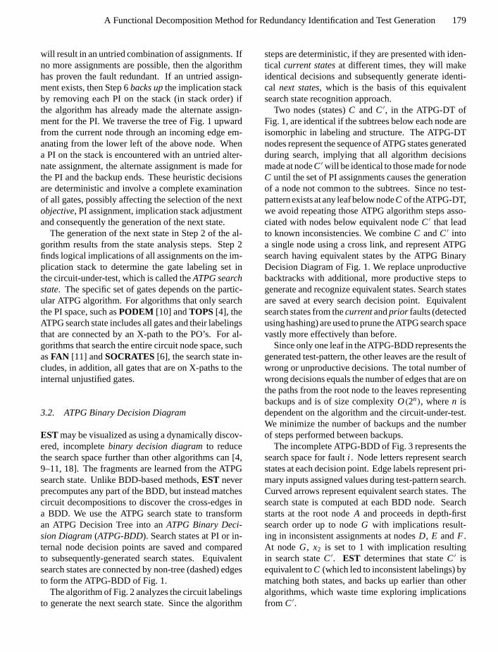
Since the ATPG-BDD represents the steps of anATPG algorithm on a circuit, we can introduce ad-ditional steps into the deterministic ATPG searchalgorithm of Fig. 2 to use the ATPG-BDD. AfterStep 2, we introduce Step 9 (see Fig. 7) which extractsthe current E-frontier from the circuit-under-test andStep 10 (see Fig. 7) which compares it with previously-generated E-frontiers to determine search state equiv-alence, backup and avoid unnecessary ATPG steps.
Fig. 7. Equivalent state hashing algorithm.
We now examine the time and storage complexity ofusing ATPG Decompositions and E-frontiers to repre-sent the ATPG search state. We assume that the ATPGalgorithm performs implication and decomposition op-erations in Step 2 of Fig. 2 an average ofk times perfault. For each pass through Step 2 an ATPG Decom-position of(N − i ) gates is produced, whereN is thenumber of circuit gates andi ranges from 1 to(N−1).Results in Table 1 for selected redundant faults in theISCAS ’85 benchmark circuits [5] show that(N − i )averages toN
3.5. We use theTOPS[4] algorithm to pre-dict upper bounds on CPU time, memory and compu-tational complexity. TheTimecolumns in the table arethe times forTOPS to identify the faults as redundant,using either ATPG Decompositions or E-frontiers. Thetotal number of gates in all ATPG search states and thetotal number of operations in generating hash keys fora single fault is proportional tok × N
3.5 for ATPG De-compositions. The space and time complexity of main-taining ATPG Decompositions for a circuit ofN gatesthat typically has 2× N faults isO( k
1.75N2). A is thenumber of gates per search state representation for bothmethods. The columns labeledA of Table 1 show thatgate-based E-frontiers have significantly lower values

P1: KCU/JHR P2: VTL
JOURNAL OF ELECTRONIC TESTING: Theory and Applications KL440-04-Bushnell May 15, 1997 14:17
A Functional Decomposition Method for Redundancy Identification and Test Generation 183
Table 1. Relative compactness of ATPG decompositions and E-frontiers.
Circuit ATPG decomposition E-frontier
ATPG search Memory Time Memory TimeCkt # GatesG # Faults statesS (Meg.) A G
A (CPU secs.) (Meg.) A GA (CPU secs.)
c432 203 3 40764 5.736 61 3.3 169.14 2.655 23 8.8 135.38
c2670 1426 1 7104 5.635 387 3.7 117.6 1.132 70 20.4 75.36
of A than ATPG Decompositions.GA is the ratio ofthe number of circuit gates to the number of ATPGDecomposition or E-frontier gates. CPU time is re-duced by factors of 1.25 and 1.56 for circuitsc432 andc2670, respectively. Additionally, memory usage hasbeen reduced by 54% and 80%, respectively.
The state analysis steps of the ATPG algorithm ofFig. 7 analyze the same E-frontiers at different timesduring ATPG search. We learn these frontiers and storethem in an open hash table, using the cut-set gate namesand labelings as the hash key. The ATPG search stateis generated in Step 9 of the algorithm of Fig. 7 andhashed in Step 10. The PI assignments producing theE-frontier are the data associated with the hash key.A hash hit in Step 10 forces a decision to be madeabout continuing search (selecting an unassigned PI orinternal circuit node) or backing up. Additional datais stored with the E-frontier and used to distinguishwhen to continue, backup or choose other operationswhen equivalent frontiers are matched. EquivalentATPG search states may be generated during test-pattern search for different faults. Therefore, we storethecurrent faultnumber with the E-frontier hash key.Additional flags indicate whether the fault site has beensensitized and whether the node in the ATPG-BDD as-sociated with the E-frontier is on a path from the rootto a valid test-pattern leaf. The number of hash ta-ble entries is equal to a prime number. We combineeach gate name and its labeling into a single integer.The hash key is generated byexclusive-oringall suchintegers in the E-frontier cut-set and taking the mod-ulus with respect to the prime number. Storage foreach hash table entry is maintained by a routine thatdivides up larger amounts of storage into several sizecategories. E-frontiers falling within the size range ofa category use an element of that category for stor-age in lieu of calling the system memory allocator.E-frontiers larger than any available category require asystem memory allocation call. A large amount of stor-age is obtained and divided to create a new E-frontiercategory for the required size. Although hashing is a
constant time operation, the CPU time and storage re-quirements of E-frontiers still grow with complexityO(N2) where N is the number of circuit gates. Wediscuss memory relief strategies later to manage thisproblem.
E-frontiers are generated duringX-path check, a pro-cedure which identifies the current D-frontier and vi-able fault propagation paths to the circuit PO’s fromthe fault site after all implications resulting from a PIsetting are determined.X-path checkonly examinesX-paths and stops at those gates whose output is a con-stant or part of the D-frontier. E-frontiers for sensitizedfaults include D-frontiers as subsets. For algorithmssuch asFAN andSOCRATES, the E-frontier must in-clude an X-path analysis of the internal unjustified linesadded to the frontiers.
3.4. The EST Algorithm
The ATPG Steps 9 and 10 introduced in Fig. 7 corre-spond to the generation and identification of equivalentE-frontiers representing ATPG search states. We de-scribe in more detail the decisions made when equiva-lent ATPG Search States are generated and discovered.
E-frontiers uniquely represent circuit decomposi-tions and allow for early identification of searchpath termination conditions. Subsequent operationson equivalent circuit decompositions correspondingto equivalent E-frontiers produce equivalent results.These repeated operations in ATPG search can beeliminated. We can immediately discover whether apreviously-explored search state leads to a valid test-pattern or an inconsistent labeling.
Figure 7 is a flowchart of decisions made when thecurrent E-frontier is found to be equivalent to one pre-viously generated. Steps 3, 5 and 7 referred to belowcorrespond to steps in Fig. 2. Figure 8 represents theEST algorithm, which uses an open hash-table to de-termine state equivalence. The E-frontier is the hashkey. EST is orthogonal to the operations of the base

P1: KCU/JHR P2: VTL
JOURNAL OF ELECTRONIC TESTING: Theory and Applications KL440-04-Bushnell May 15, 1997 14:17
184 Bushnell and Giraldi
Fig. 8. Detailed equivalent state hashing algorithm.
ATPG algorithm and therefore works with any otherATPG search algorithm [4, 6, 10, 11].
PI assignments are determined by backtracing [10]from subgoals[4] resulting from those mandatory as-signments required for fault sensitization and propa-gation. The algorithm attempts to solve all manda-tory assignment subgoals first and then propagates theD-frontier subgoals to the circuit PO’s. A D-frontiersubgoal is selected from candidate D-frontiers based onease of propagation, which is estimated as the numberof logic levels between the D-frontier and the clos-est output. For D-frontiers at the same level, the rel-ative ease is the number of logic levels between theD-frontier and the closest unassigned PI. The back-trace procedure detects circuit node assignments con-flicting with mandatory assignments identified duringa priori circuit and redundancy analysis. After back-trace and implication, each new E-frontier is hashedinto the search state table. A hash hit places all statesequivalent to the current state on thestate stack. If thecurrent fault is sensitized (unsensitized) at this point inthe search, then all faults associated with the equiva-lent E-frontiers are sensitized (unsensitized), since theD-frontier is a subset of the E-frontier. If the statestack is empty, the ATPG algorithm continues nor-mally. Associated with equivalent search states are
the PI assignments which produced sensitized (unsen-sitized) E-frontiers and test-patterns. Each state stackentry is examined. In Step 10b of Fig. 7, if the entry isfor the same fault (meaning that it led to an inconsis-tency since that search path was abandoned), the algo-rithm backs-up via Step 5, remakes PI assignments andre-implies. Backing up occurs regardless of whetherthe fault has been sensitized. If the E-frontier is for adifferent fault, then a flag indicates whether that faultwas sensitized (Step 10c). If the fault was not sensi-tized, we go to Step 3. If the E-frontier for that fault wassensitized, we examine a flag stored with its hash keyto determine whether it represents a valid test-patternfor the previous fault (Step 10d). If so, we immediatelyform the test-pattern for the current fault (Step 10e) andexit search via Step 7. The unassigned PI’s of the cur-rent fault are set equal to those corresponding PI’s fromthe previous fault’s test-pattern, since those choices ofPI assignments would be made if the search were tocontinue. This operation was justified earlier. We canbackup (via Step 5) if the E-frontier is not on a path to atest-pattern for the prior fault, since only one path canlead to the single valid test-pattern leaf (since searchstops after the first test-pattern for a fault is found). It isimpossible to match a frontier for a prior fault that wasunsensitized with a sensitized frontier for the currentfault, because the latter will contain a D-frontier whilethe former will not.
If the current fault is not sensitized, the algorithm ex-amines the topological relationships [12] between thecurrent and prior faults. For unrelated faults, the algo-rithm pops the stack and continues the stack loop. Gatei dominates faultj if all paths from the faultj to thePO’s pass throughi . If the current fault’s dominator listis a subset of the prior fault’s dominator list, implica-tions are tried using the prior fault’s test-pattern. If notest results, the stack loop continues. If a test results,search exits with a test-pattern and ATPG continues fora new fault.
3.5. Circuit Example
A fault’s test-pattern derived from equivalent E-frontierdetection is not necessarily identical to that of the priorfault. In Fig. 9(a), each ATPG step for faulti choosesPI assignments until a test is implied at the PO la-beledF . The E-frontier nets and values computed ateach step are shown in the table. The ATPG algorithmuses controllability/observability measures, dominatortrees and backtracing to choose PI values that are most

P1: KCU/JHR P2: VTL
JOURNAL OF ELECTRONIC TESTING: Theory and Applications KL440-04-Bushnell May 15, 1997 14:17
A Functional Decomposition Method for Redundancy Identification and Test Generation 185
Fig. 9. Example test generation steps for faulti (a) and faultj (b).
likely to sensitize and propagate the fault effect. Linesthrough the circuit represent the E-frontier cut-sets ateach search step.
Consider the subsequent search for a test of faultjin Fig. 9(b). ATPG proceeds as indicated in Steps 1,2 and 3. At Step 3 the computed E-frontier is iden-tical to the E-frontier in Step 3 of the ATPG searchfor fault i (Fig. 9(a)). The E-frontier also contains aD-frontier, so the fault is sensitized and propagating.Since the E-frontier of Step 3 for faulti is on a pathto a test-pattern, the unassigned PI’s of faultj are setto the corresponding PI’s of faulti to derive a test-pattern for j without further search. Labelings for thefilled-in values from the test-pattern of faulti are shown
in parentheses. The test-pattern for faulti ( j ) is not atest-pattern for faultj (i ) and therefore would not befound by fault simulation.
4. Using Redundancy to Reduce Search
We now present a new theory of redundant fault anal-ysis to identify additional mandatory assignments dy-namically during ATPG forsubsequentfaults, based ontheir topological and functional relationships to knownredundant faults. Each assignment reduces the searchspace to one ninth of its former size. Previous ATPGalgorithms use ana priori circuit analysis to discovermany redundancies.FAN [11] andTOPS [4] identifycircuit nodes that must be uniquely set to sensitize andpropagate the fault, andSOCRATES [6] learns cir-cuit signal value implications over many circuit levelsthat are not otherwise discovered. These unique sensi-tizations and learned implications identifymandatoryassignments[4] for fault sensitization and propagationthrough topological and functional analyses of the sen-sitization function and fault propagation paths of thecurrent fault. Implications from theseclampedinter-nal signal values can result in line justification conflictsthat indicate that thecurrentfault is redundant.
Prior work on redundancy identification in logic cir-cuits discusses methods for identifying multiple redun-dant faults and suitable test-sets for circuits with mul-tiple redundant faults [27–32]. These methods workwell on circuits with tens of gates, but are impracti-cal for VLSI circuits. Redundant faults are manifestedas eitherunsensitizableor unpropagatableduring test-pattern search or static learning. Faults may also beredundant due to an empty intersection of the fault sen-sitizing and propagating conditions. Unsensitizableredundant faults are ones whose fault site can neverbe set and justified to the fault sensitizing value. InFig. 10(b), gate outputg1 cannot be set and justifiedto the fault sensitizing value for thestuck-at-zero(sa0)fault on gateg1’s output. Consider the combinationalcircuit of Fig. 11 with stuck-at faultsj at gate outputFj and PI’s(x1, . . . , xn)whereFj = f(Fj , x1, . . . , xn).Faultsj is unsensitizable, for astuck-at-one(sa1) faultwhen
Fj = f (x1, . . . , xn)= 1 (2)
or, for asa0 fault when
Fj = f (x1, . . . , xn)= 0. (3)

P1: KCU/JHR P2: VTL
JOURNAL OF ELECTRONIC TESTING: Theory and Applications KL440-04-Bushnell May 15, 1997 14:17
186 Bushnell and Giraldi
Fig. 10. Redundant faults.
Fig. 11. Unsensitizable redundant fault analysis.
Since the solution sets are empty, the fault sites cannotbe set to the fault sensitizing values and, therefore,the faults are classified as unsensitizable redundant.An unpropagatable redundant fault is one whose faulteffect cannot be propagated from the fault site along afault-path to the PO’s and whose sensitization statusis unknown. In the example of Fig. 10(a), we cannotobserve the effect of thesa1 fault on inputx1 at Fbecause of conflicting fault propagation requirementson input signalx2.
The classification process is sensitive to the algo-rithm used to determine redundant faults.PODEM [10]first tries tosensitizeand thenpropagatethe fault tothe PO’s. If sensitization fails, we classify the fault asunsensitizableredundant. Conversely, if the fault be-comes sensitized and fault propagation fails, we clas-sify the fault asunpropagatableredundant.FAN [11]may try to simultaneously sensitize and propagate thefault. If this combined procedure fails, we may be un-able to determine whether the fault was sensitized;therefore, we classify such faults asunpropagatable
redundant. Some faults are independently sensitiz-able and propagatable, but have an empty intersectionbetween the two conditions. We classify such faultsasunpropagatableredundant. Wherever possible wetry to distinguish between these types of redundancies,since implications from the uniquely-determined sig-nal values differ for each class.
4.1. Unsensitizable Redundancies
Known unsensitizable gate output redundant faults leadto additional mandatory assignments during ATPG forsubsequent faults. The signal values are derived byapplying the following theorem:
Theorem 4.1. When an unsensitizable redundantfault on si at the output of gate Fi in Fig. 11 is noton the current fault-path, one may set gate output Fi
to the value of its stuck-at redundancy, 0 for sa0 or 1for sa1, and use all implications from F′i s value duringATPG for the current fault.
Proof: SinceFi is not on the current fault-path andthe current fault does not affectFi , it assumes a value of0 or 1. From Eqs. (2) and (3),Fi ’s value can never beopposite from its stuck-at redundant value. Therefore,all implications fromFi ’s value are consistent. ¥
In Fig. 11, when we recognize that faultsi is unsen-sitizable redundant, we setFi to a constant 1 (0) for aredundantsa1 (sa0) fault during subsequent faultsj ’stest-pattern search, sinceEST has proven thatFi canonly have this good machine value. Since no PI assign-ment sensitizes faultsi at Fi and no fault-path (a faultpropagation path) fromsj to Fi exists, both good andfailing machine values atFi are uniquely determinedto be equal toFi ’s stuck-at redundant value.
We also identify uniquely-determined signal valuesfor the current fault when the previously-discovered un-sensitizable redundant gate output fault is on the cur-rent fault-path. We can useG0 (0/X) or G1 (1/X)to represent good/failing machine signal values, whereX means that the failing machine value is unknown.The uniquely-determined signal values are derived byapplying the following theorem:
Theorem 4.2. When an unsensitizable redundantfault on sk at the output of gate Fk in Fig. 11 is onthe current fault-path, set gate output Fk to the goodmachine value of its stuck-at redundancy, either G0 for

P1: KCU/JHR P2: VTL
JOURNAL OF ELECTRONIC TESTING: Theory and Applications KL440-04-Bushnell May 15, 1997 14:17
A Functional Decomposition Method for Redundancy Identification and Test Generation 187
sa0 or G1 for sa1, and use all implications from thevalue at Fk during test-pattern search for the currentfault.
Proof: Fk is redundantsa1 (sa0) and from Eq. 2(3)it can take on a good machine value of 1(0). Also, Fk ison the current fault-path and can assume either a faultpropagation(faulty machine) value of 0 or 1. There-fore, the good/faulty machine value atFk is representedby G1 (G0) for asa1 (sa0) redundant fault. ¥
Consider an unsensitizable redundant fault at the out-put of gateFk on sj ’s fault-path, as in Fig. 11. Sincethe fault onsk is unsensitizable, any PI assignment forthe test-pattern search for the fault onsj will producea good machine value atFk equal to its stuck-at redun-dancy value. Any subsequent fault propagation paththroughFk must exhibit a good machine value equalto its stuck-at redundant value. We can therefore ini-tially set Fk to G0 (0/X) or G1 (1/X) to represent itsgood/failing machine values forsa0 orsa1 redundan-cies, respectively.
The values atFi andFk are propagated both forwardand backward through the circuit duringa priori circuitanalysis [4, 6] and identify unique sensitizing condi-tions and redundancies without search. In Fig. 11, thisleads to four additional mandatory assignments on theinputs to gatesFi and Fk. We also propagateFi andFk values forward and backward through the circuit,by implications, during normal test-pattern search forfault sj .
4.2. Unpropagatable Redundancies
A fault on si at the output of gateFi in Fig. 12 is un-propagatable redundant if theBoolean difference[33]
Fig. 12. Unpropagatable redundant fault on fault-path of subse-quent fault.
Bk of each outputGk with respect toFi and the PI’s iszero.
Fi = f (x1, . . . , xn) (4)
Gk= gk(Fi , x1, . . . , xn) (5)
Bk= gk(1, x1, . . . , xn)⊕ gk(0, x1, . . . , xn) = 0 (6)
Since the Boolean difference is zero and nothing isdetermined about sensitization, the fault is classifiedas unpropagatable redundant, because all outputs areinsensitive to signal changes atFi .
We identify uniquely-determined signal values fromunpropagatable gate output redundancies on the currentfault-path. Consider Fig. 12 where redundant fault siteFi is on the propagation path of the fault onsj . Fi isanabsolute dominator[4] of Fj when all fault-paths ofsj to the PO’s pass throughFi . Uniquely-determinedsignal values are identified by applying this theorem:
Theorem 4.3. As an absolute dominator of the cur-rent fault on sj , Fi can only exhibit a good machinevalue equal to its stuck-at redundancy value(i.e., G0for sa0 or G1 for sa1).
Proof: Apply the Boolean differencechain-rule[33]at the primary outputG, for Fi and Fj , whereG= g(Fi ,x1, . . . , xn) andFi = f (Fj ,x1, . . . , xn) suchthat
B= [ f (1, x1, . . . , xn)⊕ f (0, x1, . . . , xn)]
· [g(1, x1, . . . , xn)⊕ g(0, x1, . . . , xn)] = 0. (7)
The first Boolean difference is not necessarily zero,but the second is identically zero based upon the re-dundancy analysis of the fault onsi . ¥
Good machine values forFi are propagated forwardand used duringa priori circuit analysis and branch-and-bound test-pattern search. Good machine valuescannot be propagated backward from the fault site sinceproofs about this redundant fault site only involve itspropagation forward through the network to the PO’s.
Use of unpropagatable redundant faultsnot on thecurrent fault-path is infeasible. “Clamping” the unprop-agatable redundant fault site for the current fault canonly occur if we know the extent of allD-frontiersofthe redundant fault. This, unfortunately, requires an ex-haustive explicit search rather than the implicit search

P1: KCU/JHR P2: VTL
JOURNAL OF ELECTRONIC TESTING: Theory and Applications KL440-04-Bushnell May 15, 1997 14:17
188 Bushnell and Giraldi
of most ATPG algorithms. Explicit search enlargesthe search space to its full extent (exponential in thenumber of inputs), which is not productive.
4.3. EST Algorithm with the Redundancy Calculus
First we determine as many redundant faults as pos-sible usinga priori circuit analysis and static learn-ing techniques [4, 6]. Next, we apply the new staticand dynamic redundancy techniques described aboveto each new fault. We record each fault’s redundancycharacteristics. After all faults have been processedduring a priori analysis, we iteratively select eachremaining fault.EST-TOPS clamps the previously-discovered unsensitizable and unpropagatable redun-dant fault values that apply to the selected fault in addi-tion to clamping mandatory assignment values.EST-TOPS examines all forward and backward implica-tions of the mandatory assignments and redundancyclampings to determine whether the fault is redundantbecause of conflicts on any internal signal. TheX-pathcheckoperation determines whether any viable faultpropagation path from the fault site to the PO’s exists.If no test is possible, then the search loop exits and weclassify the fault using the above redundancy classifi-cation criteria. As more redundancies are discoveredwe record them and clamp their circuit nodes for ATPGsearch for subsequent faults.
4.4. Redundancy Analysis Example
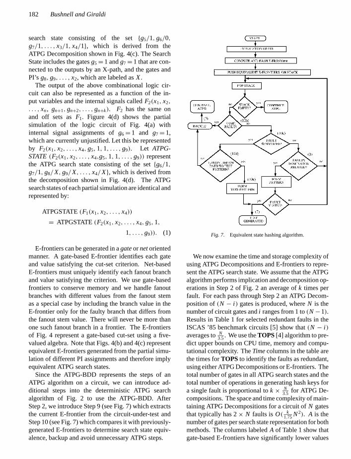
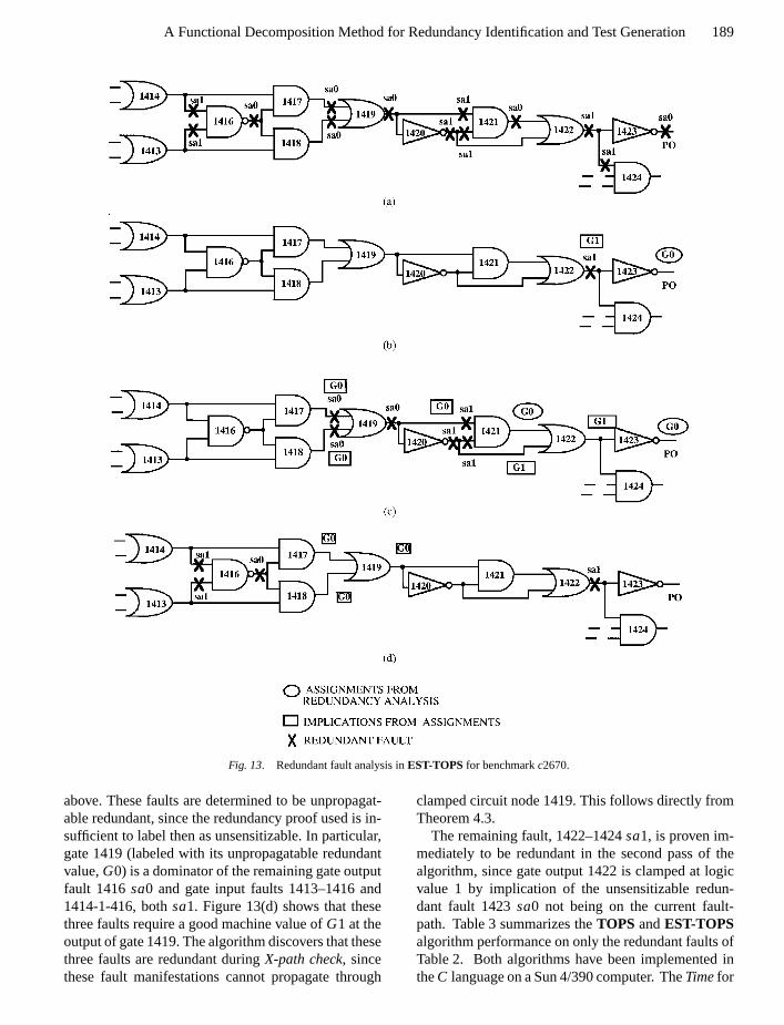
Figure 13 and Tables 2 and 3 show the effective-ness of redundant fault analysis byEST-TOPSfor theISCAS ’85 circuitc2670 [5]. We have selected a list oftwenty-seven faults, as shown in Table 2 in the portionof the circuit given in Fig. 13(a). The faults markedX in the figure are redundant faults that are hard-to-detect for the basicTOPSalgorithm. Fault site 1419–1421 has asa1 fault marked in Fig. 13(a) and listed inTable 2. Asa0 fault at this site is also redundant, but isnot included in the analysis, since this fault (and othermissing faults) has been eliminated from the fault listby fault collapsing. Some faults may appear out of log-ical sequence in the table, such as fault 1423sa0 and1423sa1, because we sort the fault list in level orderfrom output to input, independent of gate numbering, toimprove performance of the redundancy analysis fea-ture. Level numbers for gates are generated startingwith number 1 for PI’s to the maximum gate depth for
PO’s. Levels of fanout branch faults are based on thelevel of the destination gate.
A “two pass” feature allows us to identify and clas-sify as many redundancies as possible and to applyredundancy analysis during the second pass to anyhard-to-testfault that may have exceeded the first passbackup limit. We also may increase the backup limit inthe second pass. Frequently, faults that are cut off dur-ing the first pass are successfully processed during thesecond because of additional mandatory assignmentslearned from analyzing other redundant faults.
In Table 2,From is the source gate for a stem faultwhen the correspondingTo field is present; otherwise,From is a gate output fault.Stuck-At-Valueis the faulton the gate or net andFault Analysis and Classifi-cation shows the disposition of each fault in the ta-ble. Fault 1422–1424sa1 appears twice in the table,since it was appended to the end of the fault list afterexceeding the backup limit in the first pass. Redun-dancy analysis does not improve performance for theeasily-testable faults, but it dramatically speeds up re-dundancy identification.
We consider only those faults not listed asTestedinTable 2. We set the backup limit for the first pass to10,000. First, gate input fault 1422–1424sa1 exceededthe backup limit and was appended to the end of thefault list. Next, gate output fault 1423sa0 is identi-fied as unsensitizable redundant using E-frontiers andbranch-and-bound search. This unsensitizable redun-dancy is on the fault-path of each remaining “first pass”fault and its implications are reflected in Fig. 13(b).Fault 1422sa1 is immediately identified as redundantfrom implications of the mandatory assignmentG0(circle) on net 1423 in Fig. 13(b). Next, gate outputfault 1421sa0 is identified as unsensitizable redun-dant because of the conflicting implications for faultsensitization on gate output 1419 caused by the pres-ence of the inverter numbered 1420. This fault doesnot require the redundancy analysis of faults 1423sa0and 1422sa1.
All subsequent faults use all forward and backwardimplications of the two known unsensitizable redun-dant faults, which results in the set of labelings inFig. 13(c). Implications from the good machine value(G0) for each are propagated forward and backwardthrough the circuit and labeled with boxes in the fig-ure. Subsequently, faults 1420–1421sa1, 1420sa1,1419–1421sa1, 1419sa0, 1418sa0 and 1417sa0 areall found to be redundant because their sensitizationand propagation labelings conflict with those learned
P1: KCU/JHR P2: VTL
JOURNAL OF ELECTRONIC TESTING: Theory and Applications KL440-04-Bushnell May 15, 1997 14:17
A Functional Decomposition Method for Redundancy Identification and Test Generation 189
Fig. 13. Redundant fault analysis inEST-TOPSfor benchmarkc2670.
above. These faults are determined to be unpropagat-able redundant, since the redundancy proof used is in-sufficient to label then as unsensitizable. In particular,gate 1419 (labeled with its unpropagatable redundantvalue,G0) is a dominator of the remaining gate outputfault 1416sa0 and gate input faults 1413–1416 and1414-1-416, bothsa1. Figure 13(d) shows that thesethree faults require a good machine value ofG1 at theoutput of gate 1419. The algorithm discovers that thesethree faults are redundant duringX-path check, sincethese fault manifestations cannot propagate through
clamped circuit node 1419. This follows directly fromTheorem 4.3.
The remaining fault, 1422–1424sa1, is proven im-mediately to be redundant in the second pass of thealgorithm, since gate output 1422 is clamped at logicvalue 1 by implication of the unsensitizable redun-dant fault 1423sa0 not being on the current fault-path. Table 3 summarizes theTOPS andEST-TOPSalgorithm performance on only the redundant faults ofTable 2. Both algorithms have been implemented intheC language on a Sun 4/390 computer. TheTimefor

P1: KCU/JHR P2: VTL
JOURNAL OF ELECTRONIC TESTING: Theory and Applications KL440-04-Bushnell May 15, 1997 14:17
190 Bushnell and Giraldi
Table 2. Faults forTOPSversusEST-TOPScomparison.
Fault Stuck-At- Fault Analysisorder Level # From gate # To gate # value and classification
1 31 1423 sa1 Tested
2 31 1422 1424 sa1 Exceeded the backup limit
3 31 1423 sa0 Unsensitizable redundant
4 30 1422 sa1 Unpropagatable redundant
5 30 1422 sa0 Tested
6 30 1420 1422 sa0 Tested
7 29 1421 sa0 Unsensitizable redundant
8 29 1420 1421 sa1 Unpropagatable redundant
9 29 1419 1421 sa1 Unpropagatable redundant
10 28 1420 sa1 Unpropagatable redundant
11 28 1420 sa0 Tested
14 27 1419 sa1 Tested
15 27 1419 sa0 Unpropagatable redundant
12 26 1418 sa0 Unpropagatable redundant
13 26 1417 sa0 Unpropagatable redundant
16 26 1416 1417 sa1 Tested
17 26 1416 1418 sa1 Tested
18 26 1413 1418 sa1 Tested
19 26 1414 1417 sa1 Tested
20 25 1416 sa1 Tested
21 25 1416 sa0 Unpropagatable redundant
22 25 1413 1416 sa1 Unpropagatable redundant
23 25 1414 1416 sa1 Unpropagatable redundant
24 24 1413 sa0 Tested
25 24 1413 sa1 Tested
26 24 1414 sa1 Tested
27 24 1414 sa0 Tested
28 31 1422 1424 sa1 Unpropagatable redundant
Table 3. TOPSandEST-TOPSperformance.
TOPS EST-TOPS
Time TimeCkt # Redundant Cutoff (CPU min.) Backups Redundant Cutoff (CPU min.) Backups
c2670 2 11 4042 > 22× 106 13 0 3.2 17105
each algorithm reflects only the CPU time spent in theportion ofc2670 shown in Fig. 13. Processing time forcomputingdominators, absolute dominatorsandbasisnodes[4] is excluded.
TOPSexceeded a backup limit of 2×10⁶ on elevenof the thirteen redundant faults and wasted 4042 CPUminutes, whileEST-TOPS used two passes and 3.2
CPU minutes to identify all thirteen faults as redun-dant. This is a performance improvement of 1263 : 1overTOPSwithout redundancy analysis.EST-TOPSsaved all E-frontiers in the hash table using 2.39 Meg.of memory, whileTOPSused 1.20 Meg. of memory.
The EST-TOPS algorithm does not immediatelydeduce additional redundant faults by examining

P1: KCU/JHR P2: VTL
JOURNAL OF ELECTRONIC TESTING: Theory and Applications KL440-04-Bushnell May 15, 1997 14:17
A Functional Decomposition Method for Redundancy Identification and Test Generation 191
implications from the currently discovered redundantfault. Instead, it selects each subsequent fault forATPG, determines its mandatory assignments fromdominator relationships, determines the relationship ofthe selected fault to previously-discovered redundantfaults and finally clamps appropriate circuit nodes totheir redundant fault values. These clampings are prop-agated forward and backward in the circuit to determineadditional node clampings. It would also be possible,after an unsensitizable redundant fault is discovered, topropagate its redundant value forward and backward inthe circuit and immediately deduce additional redun-dant fault sites. In the prior example, once fault 1421sa0 is identified as unsensitizable redundant, all re-dundant faults shown in Fig. 13(c) can be immediatelyidentified by forward and backward implications. Thisrevised procedure could avoid the minor overhead ofmandatory assignment analysis for these additional re-dundant faults. Clamped values from unpropagatableredundant faults could also be propagated as soon asthey are discovered.
5. Results
TheEST algorithm has been implemented withTOPS[4] andSOCRATES [6], based on the literature. TheE-frontier is formed using a five-valued algebra al-though other computations inTOPSuse a nine-valuedalgebra. We use no additional heuristics other than theEquivalent State Hashing algorithm and the redundantfault analysis. EST processes the fault list in twopasses. The first pass identifies many redundancies andtest-patterns for easy-to-test faults using a low backup
Table 5. EST algorithm performance vs.TOPS for all faults.
TOPS EST
CKT Time Cut-off Cov. # Time Mem Cut-off Backup Hash Cov. ## (min.) faults Backups % Test patt. (min.) (Meg.) Redundant faults count test % Test patt.
c432 56.5 0 1411311 99.22 221 4.2 4.0 4 0 70893 80 99.22 221
c499 1.3 0 94 98.73 256 .94 2.32 8 0 92 284 98.73 256
c880 .9 0 0 100 437 .87 1.52 0 0 0 231 100 440
c1355 7.1 0 882 99.49 563 4.05 5.21 8 0 694 754 99.49 563
c1908 2610 0 24138301 99.62 889 70.31 10.49 7 0 346082 673 99.62 890
c2670 >172 10 >20× 106 12.39 6.71 115 0 18050 930 95.8 1017
c3540 55.3 0 135197 96.91 1402 17.89 10.3 105 0 6918 708 96.91 13196
c5315 42.8 0 2288 98.86 2316 37.42 8.41 59 0 2280 2372 98.86 2351
c6288 142.6 0 2365 99.57 3840 125.6 25.9 33 0 2330 2525 99.57 3840
c7552 76.98 23.18 131 0 26991 4854 98.24 3350
Table 4. 1985 ISCAS circuitdescriptions.
CKT
# # Gates # PI’s # Flts.
c432 160 36 510
c499 202 41 630
c880 383 60 942
c1355 546 41 1574
c1908 880 33 1829
c2670 1193 233 2735
c3540 1669 50 3394
c5315 2307 178 5163
c6288 2406 32 7680
c7552 3512 207 7448
limit of 10000. The second pass processes the cut-offfaults with a higher backup limit of 2×10⁶. Faults thatcut off during the first pass are processed much morerapidly during the second because the algorithm haslearned many E-frontiers and signal node values fromthe other faults.EST was written in theC language ona Sun-4/280 computer and was benchmarked using theISCAS ’85 benchmarks [5] described in Table 4.
Table 5 comparesEST with TOPS without anyrandom-pattern generation, fault simulation or faultdropping, and shows thatEST runs at least 47 timesfaster on the benchmarks [5] with no cut-off faults.Each algorithm had a backup limit of 2× 10⁶. A faultsimulator validated all test-patterns produced by EST.In Table 5Cut-offis the number of faults where ATPGexceeded the backup limit.Hash Testis the number

P1: KCU/JHR P2: VTL
JOURNAL OF ELECTRONIC TESTING: Theory and Applications KL440-04-Bushnell May 15, 1997 14:17
192 Bushnell and Giraldi
of test-patterns found by equivalent state hashing. TheBackup Countsfor each test case show thatEST canquickly derive a test-pattern, using fewer implicationsthanTOPS. EST fails to significantly accelerate ATPGfor the easy-to-test faults of circuitsc499,c880,c1355,c5315 andc6288, becauseTOPS rarely backtrackson these benchmarks. However,EST still acceler-ated ATPG for these benchmarks and demonstratedthe low overhead of E-frontier generation and statehashing. Since random-pattern testing and fault sim-ulation are used in practice to generate tests for thesefaults,ESTshould be reserved for circuits with hard-to-test faults or functionally symmetric sub-circuits (e.g.,c432, c1908, c2670 andc7552). Forc2670, TOPSwastes 4042 minutes on 11 faults for which it stillcuts off. The redundancy analysis algorithm inESTdiscovers that these faults are redundant in three min-utes for a speedup of 1347 : 1 overTOPS. An indi-vidual fault in this group is proven redundant in 0.1seconds byEST while TOPScuts off after 20713 sec-onds, reflecting a speedup of 200, 000 : 1 overTOPS.TOPSuses at most two megabytes of memory.EST ismore memory intensive than prior algorithms; how-ever, the relative cost of memory to CPU time hasdramatically declined so this tradeoff is acceptable.Table 5 also shows the fault coverage (including re-dundancies) and the number of test-patterns gener-ated. EST does not produce significantly more test-patterns thanTOPS but determines them much morequickly.
Table 6 compares the performance ofEST andSOCRATES when usingrandom pattern generation(RPG),fault simulation(FSIM) using a single-patternsingle-fault fault simulator andfault droppingwith abackup limit of 200. The version ofSOCRATESwasdeveloped at Rutgers, and includes all features of the al-gorithm except dynamic learning. However, this com-bined version ofEST-SOCRATESuses two additionalstate hashing techniques that are described elsewhere[34, 35] so the added speedup is not solely attributableto the techniques described in this paper. The RPG stageends when 64 consecutive patterns do not produce atest pattern for the remaining faults. BothEST andSOCRATESwere able to identify all redundant faultsin the simplistically-reduced fault lists for the bench-marks. All terminology in the table is the same as be-fore. ATPG Faultsis the number of faults processed bythe ATPG search algorithm. The discrepancies in theATPG Faultscolumns betweenEST andSOCRATESarise because the two algorithms compute different test
patterns for the same faults, and therefore fault drop-ping causes theEST search algorithm to process fewerfaults thanSOCRATES. This experiment proved ex-actly the same numbers of faults redundant as reportedfor SOCRATES [6]. EST performed 54.5 % fewertotal implications thanSOCRATES, and backed up64.5 % less often. No test pattern search for a faultwas aborted by either algorithm.EST ran, on average,5.81 times faster thanSOCRATES with the greatestspeedup of 22.87 on benchmarkc1355. EST used atmost 5.64 Megabytes of memory, only 1.04 times asmuch asSOCRATES. EST produced 1.5 % fewer testpatterns thanSOCRATES. The absolute numbers ofpatterns are higher here than for Schulz’s experiments[6], because we do not fault simulate the entire testpattern set in the reverse order of pattern generationafter ATPG is completed. This operation would dropadditional, unnecessary patterns.
6. Conclusion
We have presentedEST, a new combinational ATPGbranch-and-bound search algorithm that is based on thedetection of equivalent logic decompositions (searchstates) at each search step. The E-frontier is an effi-cient representation of search state and is used witha hashing algorithm to detect equivalent search states.WhenEST matches an equivalent search state from aprior fault, where both faults are sensitized,EST com-pletes the current fault test-pattern with values from theprior fault test-pattern and terminates search immedi-ately. We have also introduced a new method of re-dundant fault analysis that uniquely determines signalvalues for subsequent test-pattern search. Results showthat thisEST algorithm accelerates the base ATPG al-gorithm by a factor of 1.03 to 328 when consideringall faults, a factor of 33.3 for hard-to-test faults, anda factor of 200,000 for certain redundancy proofs forthe 1985 ISCAS Benchmarks. To our knowledge, thisis the first test-pattern generator that learns from thesearch spaces of all prior faults in order to accelerateATPG for the current fault.
Since this work was completed, the method has beenextended to sequential circuits, and implemented in aprogram calledSEST[36]. This program can now han-dle both stuck faults and path delay faults in sequentialcircuits. The state equivalence method involves cubecovering of the illegal states of the good and failingmachines during test generation.

P1: KCU/JHR P2: VTL
JOURNAL OF ELECTRONIC TESTING: Theory and Applications KL440-04-Bushnell May 15, 1997 14:17
A Functional Decomposition Method for Redundancy Identification and Test Generation 193
Tabl
e6.
EST
perf
orm
ance
vs.
SOC
RA
TE
Sw
ithra
ndom
patte
rnte
stin
gan
dfa
ults
imul
atio
n.
CK
TSO
CR
AT
ES
EST
CPU
Tim
e(s
ec.)
AT
PGfa
ults
CPU
Tim
e(s
ec.)
#St
atic
lear
ning
time
(sec
.)
Tota
lAT
PGfa
ults
Impl
icat
ions
Bac
kups
RPG
-FSI
MA
TPG
Mem
.
(meg
.)
#Te
stpa
ttern
sTo
tal
Has
hte
stIm
plic
atio
nsB
acku
psR
PG-F
SIM
AT
PGM
em.
(meg
.)
#Te
stpa
ttern
s
c432
.43
624
650
1214
12.
810
8.6
0.67
796
054
022
12.
84.
31.
0479
c499
1.1
1110
70
4.7
0.8
1.04
6711
023
04.
70.
21.
2767
c880
1.4
1513
71
6.4
1.2
0.83
120
151
661
6.4
0.8
1.07
120
c135
55.
229
695
012
.734
.31.
8610
929
086
012
.71.
52.
1010
9
c190
89.
131
221
143
.26.
92.
2518
732
121
43
43.1
3.5
2.49
188
c267
014
.722
527
818
44.8
71.6
1.66
211
212
3636
05
44.0
7.7
1.93
198
c354
026
.716
927
52
68.0
6.3
2.51
259
168
020
82
67.2
4.9
2.78
258
c531
542
.080
559
4280
.823
.23.
3722
380
1030
928
80.8
6.0
3.60
223
c628
852
.634
340
73.3
1.0
5.42
6334
017
073
.10.
55.
6463
c755
288
.928
556
5352
417
7.1
622.
54.
1838
127
494
3472
164
176.
011
2.6
4.56
370

P1: KCU/JHR P2: VTL
JOURNAL OF ELECTRONIC TESTING: Theory and Applications KL440-04-Bushnell May 15, 1997 14:17
194 Bushnell and Giraldi
Acknowledgements
We thank the IBM Corporation for support from theResident Study Program. The research reported herewas partially supported by the Center for ComputerAids for Industrial Productivity (CAIP), an AdvancedTechnology Center of the New Jersey Commission onScience and Technology, at Rutgers University. Wethank the ACM SIGDA and the Micro-ElectronicsCenter of North Carolina for providing the ISCAS ’85benchmarks. We thank Kwang-Ting Cheng andVishwani D. Agrawal of AT&T Bell Laboratories forthe use of a fault simulator. We thank Jim Sienicki ofRutgers U. for writing the random-pattern generator forEST. Finally, we thank Jim Sienicki and Joe Williamsof Rutgers U. for upgrading our fault simulator to bean efficient, parallel-pattern-single-fault simulator.
References
1. E.B. Eichelberger and T.W. Williams, “A Logic Design Structurefor LSI Testability,” Journal of Design Automation and FaultTolerant Computing, Vol. 2, pp. 165–178, May 1978.
2. B. Konemann, J. Mucha, and G. Zweihoff, “Built-In Test forComplex Digital Integrated Circuits,”IEEE Journal of Sold-State Circuits, Vol. SC-15, pp. 315–319, June 1980.
3. J. Giraldi and M.L. Bushnell, “EST: The New Frontier in Au-tomatic Test-Pattern Generation,”Proc. of the 27th ACM/IEEEDesign Automation Conf., June 1990, pp. 667–672.
4. T. Kirkland and M.R. Mercer, “A Topological Search Algorithmfor ATPG,” Proc. of the 24th ACM/IEEE Design AutomationConf., 1987, pp. 502–508.
5. F. Brglez and H. Fujiwara, “A Neutral Netlist of 10 Combina-tional Benchmark Circuits,”Proc. of the International Sympo-sium on Circuits and Systems; Special Session on ATPG andFault Simulation, June 1985, pp. 151–158.
6. M. Schulz and E. Auth, “Improved Deterministic Test PatternGeneration with Applications to Redundancy Identification,”IEEE Transactions on Computer-Aided Design, Vol. 8, pp. 811–816, July 1989.
7. R.S. Wei and A. Sangiovanni-Vincentelli, “PROTEUS: A LogicVerification System for Combinational Circuits,”Proc. of theIEEE International Test Conf., Oct. 1986, pp. 350–359.
8. P. Muth, “A Nine-Valued Circuit Model for Test Generation,”IEEE Transactions on Computers, Vol. C-25, pp. 630–636,June 1976.
9. J.P. Roth, “Diagnosis of Automata Failures: A Calculus and aMethod,” IBM Journal of Research and Development, Vol. 10,pp. 278–291, July 1966.
10. P. Goel, “An Implicit Enumeration Algorithm to Generate Testsfor Combinational Logic Circuits,”IEEE Transactions on Com-puters, Vol. C-30, pp. 215–222, March 1981.
11. H. Fujiwara and T. Shimono, “On the Acceleration ofTest Generation Algorithms,”Proc. of the 13th InternationalFault Tolerant Computing Symposium, June 1983, pp. 98–105.
12. R.E. Tarjan, “Finding Dominators in Directed Graphs,”SIAMJournal of Computing, Vol. 3, pp. 62–89, 1974.
13. M. Schulz, E. Trischler, and T.M. Sarfert, “SOCRATES: AHighly Efficient Automatic Test Pattern Generation System,”IEEE Transactions on Computer-Aided Design, Vol. 7, pp. 126–137, Jan. 1988.
14. T. Larrabee, “Efficient Generation of Test Patterns UsingBoolean Difference,”Proc. of the IEEE International Test Conf.,Aug. 1989, pp. 795–801.
15. S.T. Chakradhar, V.D. Agrawal, and M.L. Bushnell, “AutomaticTest Generation Using Quadratic 0–1 Programming,”Proc.of the 27th ACM/IEEE Design Automation Conf., June 1990,pp. 654–659.
16. S.T. Chakradhar, M.L. Bushnell, and V.D. Agrawal, “TowardMassively Parallel Automatic Test Generation,”IEEE Trans-actions on Computer-Aided Design, Vol. 9, pp. 981–994, Sept.1990.
17. S.T. Chakradhar, V.D. Agrawal, and S.G. Rothweiler, “A Transi-tive Closure Algorithm for Test Generation,”IEEE Transactionson Computer-Aided Design, Vol. 12, pp. 1015–1028, July 1993.
18. R.K. Gaede, M.R. Mercer, K.M. Butler, and D.E. Ross, “CATA-PULT: Concurrent Automatic Testing Allowing Parallelizationand Using Limited Topology,”Proc. of the 25th ACM/IEEE De-sign Automation Conf., June 1988, pp. 597–600.
19. S.B. Akers, “Functional Testing with Binary Decision Dia-grams,”Proc. of the 8th International Fault Tolerant ComputingSymposium, June 1978, pp. 82–92.
20. K. Cho and R.E. Bryant, “Test Pattern Generation for Sequen-tial MOS Circuits by Symbolic Fault Simulation,”Proc. of the26th ACM/IEEE Design Automation Conf., June 1989, pp. 418–423.
21. T. Stanion and D. Bhattacharya, “TSUNAMI: A Path OrientedScheme for Algebraic Test Generation,”Proceedings of the FaultTolerant Computing Symposium, June 1991, pp. 36–43.
22. J.A. Waicukauski, P.A. Shupe, D.J. Giramma, and A. Matin,“ATPG for Ultra-Large Structured Designs,”Proc. of the IEEEInternational Test Conf., Sept. 1990, pp. 44–51.
23. J. Rajski and H. Cox, “A Method to Calculate Necessary Assign-ments in Algorithmic Test Pattern Generation,”Proceedings ofthe 1990 International Test Conference, Sept. 1990, pp. 25–34.
24. O.H. Ibarra and S.K. Sahni, “Polynomially Complete Fault De-tection Problems,”IEEE Transactions on Computers, Vol. C-24,pp. 242–249, March 1985.
25. M. Fujita, H. Fujisawa, and N. Kawato, “Evaluation and Im-provements of Boolean Comparison Method Based on BinaryDecision Diagrams,”Proc. of the IEEE International Conf. onComputer-Aided Design, Nov. 1988, pp. 2–5.
26. S. Malik, A. Wang, R. Brayton, and A. Sangiovanni-Vincentelli,“Logic Verification using Binary Decision Diagrams in a LogicSynthesis Environment,”Proc. of the IEEE International Conf.on Computer-Aided Design, Nov. 1988, pp. 6–9.
27. R. Dandapani and S.M. Reddy, “On the Design of LogicNetworks with Redundancy and Testability Considerations,”IEEE Transactions on Computers, Vol. C-23, pp. 1139–1149,Nov. 1974.
28. M. Fridrich and W.A. Davis, “Minimal Fault Tests for RedundantCombinational Networks,”IEEE Transactions on Computers,Vol. C-26, pp. 1057–1060, Oct. 1977.
29. A. Friedman, “Fault Detection in Redundant Circuits,”IEEETransactions on Electronic Computers, Vol. EC16, pp. 99–100,Feb. 1967.
P1: KCU/JHR P2: VTL
JOURNAL OF ELECTRONIC TESTING: Theory and Applications KL440-04-Bushnell May 15, 1997 14:17
A Functional Decomposition Method for Redundancy Identification and Test Generation 195
30. H.P.S. Lee and E.S. Davidson, “Redundancy Testing inCombinational Networks,”IEEE Transactions on Computers,Vol. C-23, pp. 1029–1047, Oct. 1974.
31. S. Li, “Dynamic Testing of Redundant Logic Networks,”IEEETransactions on Computers, Vol. C-27, pp. 828–832, Sept. 1978.
32. J. Smith, “On the Existence of Combinational Logic CircuitsExhibiting Multiple Redundancy,”IEEE Transactions on Com-puters, Vol. C-27, pp. 1221–1225, Dec. 1978.
33. E.F. Sellers, M.Y. Hsiao, and L.W. Bearnson, “Analyzing Errorswith the Boolean Difference,”IEEE Transactions on Computers,Vol. C-17, No. 7, pp. 676–683, 1968.
34. J. Giraldi,Search Space Equivalence for Combinational Redun-dancy Identification and Test-Pattern Generation, Ph.D. thesis,ECE Dept., U. Rutgers, Oct. 1990.
35. J. Giraldi and M.L. Bushnell, “Search State Equivalence forRedundancy Identification and Test Generation,”Proc. of the1991 International Test Conference, Oct. 1991, pp. 184–193.
36. X. Chen and M.L. Bushnell,Efficient Branch and Bound Searchwith Application to Computer Aided Design, Kluwer AcademicPublishers, Boston, 1996.
Michael Bushnell received his Ph.D. degree in 1986 and his M.S.degree in 1983, both from Carnegie Mellon University. His un-dergraduate work was done at MIT. He was selected in 1983 forthe American Electronics Association Faculty Development Pro-gram, he received the Outstanding Graduate Student Teaching Awardfrom Carnegie Mellon, and he was a Presidential Young Investiga-tor of the National Science Foundation of the United States. Hiscurrent VLSI CAD research interests are automatic digital, analog,and mixed-signal circuit test-pattern generation on serial and dis-tributed computers, delay-fault built-in self-testing, fault simulation,synthesis for testability, and automatic full-custom layout technologymapping.
John Giraldi received his Ph.D. degree in 1990 from Rutgers Uni-versity under the IBM Resident Study Program. His Bachelors andMasters work was also done at Rutgers. He was a member of thedesign team for the IBM 3090 mainframe processor. His current re-search interest is formal verification using binary decision diagramsand search state equivalence.
Copyright © 2022 FDOKUMEN