CONTINUOUS CATALYTIC DECOMPOSITION OF METHANE
66
I NASACONTRACTOR REPORT CONTINUOUS CATALYTIC DECOMPOSITION OF METHANE Prepared by BATTELLE MEMORIAL INSTITUTE Columbus, Ohio 43201 for AmesResearchCenter NATIONAL AERONAUTICS AND SPACE ADMINISTRATION WASHINGTON, D. C. OCTOBER 1970
-
Upload
khangminh22 -
Category
Documents
-
view
2 -
download
0
Transcript of CONTINUOUS CATALYTIC DECOMPOSITION OF METHANE

I
N A S A C O N T R A C T O R
R E P O R T
CONTINUOUS CATALYTIC DECOMPOSITION OF METHANE
Prepared by BATTELLE MEMORIAL I N S T I T U T E Columbus, Ohio 43201
for Ames Research Center
NATIONAL AERONAUTICS AND SPACE ADMINISTRATION WASHINGTON, D. C. OCTOBER 1970

r TECH LIBRARY KAFB, NM
I 2. Government Accession No. I 3. Recipient's Catalog No.
4. T i t l e and Subtitle
Continuous Catalytic Decomposition of Methane
5. Report Date -ochbe-~1970
~
7. Author(.) B. C. Kim, J. Zupan, L. Hillenbrand , 8. Performing Organization Report No.
and J, E. Clifford 9. Performing Organization Name and Address IO. Work Uni t No.
1/' Battelle Memorial Inst$tute Columbus , Ohio 43201
11. Contract or Grant No.
NAS 2-5051 13. Type of Report and Period Covered
12. Sponsoring Agency Name and Address
National Aeronautics & Space Administration Contractor Report
14. Sponsoring.Agency Code
15. Supplementary Notes
16. Abstroct
Experimental studies of catalysts for decomposition of methane and process design studies were directed to the problems of carbon produc- tion in a high-temperature reaction required for one subsystem of the Closed Sabatier system as applied to space life support. The basis for a new reactor design for continuous carbon removal in a gravity- independent manner was demonstrated using a rotating magnetic field to support the catalyst in the flowing methane stream and to confine the catalyst bed within the high-temperature reaction zone until a high catalyst utilization is achieved. For this purpose, the preferred catalyst was cobalt powder which maintains magnetic properties above the desired reaction temperature of 850 C. On the basis of the experimental data obtained, a methane-decomposition reactor having a catalyst-bed volume of about 1 liter was designed for a nominal 3-man
17. Key Words (Selected by Author(s)) 18. Distribution Statement I
methane methane cracking continuous methane decomposition
carbon separation catalytic methane decomposition
UNCLASSIFIED-UNLIMITED
. .
19. Security Classif. (of this report) 22. Pr ice* 21. No. of Pages 20. Security Classif. (of this page)
Unclassified $3.00 63 Unclassified
*For sale by the Clearinghouse for Federal Scientific and Technical Information Springfield, Virginia 22151
- . - - ". "" -~ . ~~ - - "

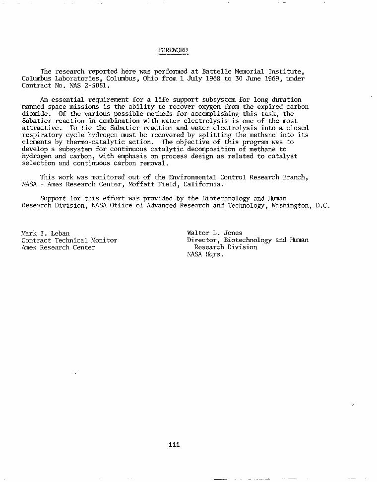
FOREWORD
The Columbus Contract
research reported here was performed at Battelle Memorial Institute, Laboratories, Columbus, Ohio from 1 July 1968 to 30 June 1969, under NO. NAS 2-5051.
An essential requirement for a life support subsystem for long duration manned space missions is the ability to recover oxygen from the expired carbon dioxide. Of the various possible methods for accomplishing this task, the Sabatier reaction in combination with water electrolysis is one of the most attractive. To tie the Sabatier reaction and water electrolysis into a closed respiratory cycle hydrogen must be recovered by splitting the methane into its elements by thenno-catalytic action. The objective of this program was to develop a subsystem for continuous catalytic decomposition of methane to hydrogen and carbon, with emphasis on process design as related to catalyst selection and continuous carbon removal.
This work was monitored out of the Environmental Control Research Branch, NASA - Ames Research Center, Moffett Field, California.
Support for this effort was provided by the Biotechnology and m a n Research Division, NASA Office of Advanced Research and Technology, Washington, D.C.
Mark I. Leban Contract Technical Monitor Ames Research Center
Waltor L. Jones Director, Biotechnology and Man
NASA Hqrs . Research Division
i ii

1

.
TABLE OF CONTENTS
Page
SECTION 1 . INTRODUCTION . . . . . . . . . . . . . . . . . 1
SECTION 2 . CATALYST STUDY . . . . . . . . . . . . . . . . 4
Introduction . . . . . . . . . . . . . . . . . . . . . Determination of Methane Conversion . . . . . . . . . . . . Survey of Catalysis . . . . . . . . . . . . . . . . . . Effect of Surface Activation on Metal Foils . . . . . . . . . . Effect of Activation on Metal Powder . . . . . . . . . . . . . Effect of Feed Composition on Methane Decomposition on Extended
Surfaces . . . . . . . . . . . . . . . . . . . . . Methane Decomposition in a Vibrating Bed of Catalyst Particles . . . Discussion . . . . . . . . . . . . . . . . . . . . . Summary of Experimental Results . . . . . . . . . . . . . .
4 4 6 9
10
13 16 19 26
SECTION 3 . PROCESS DESIGN STUDY . . . . . . . . . . . . . . 28
Methane-Decomposition Unit Design . . . . . . . . . . . . . 28
Heat Balance for Methane-Decomposition Unit . . . . . . . . . . 33 Summary of Methane-Decomposition Unit Weight and Power Estimates . 33 Discussion of Process-Design Results . . . . . . . . . . . . 33
Reactor Design . . . . . . . . . . . . . . . . . . . . 30
SECTION 4 . CONCLUSIONS . . . . . . . . . . . . . . . . . 41
SECTION 5 . RECOMMENDATIONS FOR FUTURE WORK . . . . . . . . 42
SECTION 6 . REFERENCES . . . . . . . . . . . . . . . . . 43
APPENDIX A
PROCESS-DESIGN AND MATERIAL-BALANCE CALCULATIONS . . . . . A- 1
APPENDIX B
CARBON-SEPARATION UNIT . . . . . . . . . . . . . . . . . B- I
LIST OF FIGURES
Figure Page
1 . Arrangement and Methods Used for Determination of Methane Conversion . . . . . . . . . . . . . . . . . . . . . 5
2 . Effect of Hydrogen Reduction Only on Extended Activity of Cobalt Powder (50-Mesh) Catalyst for Methane Decomposition . . . . . . . . . 11
V
. . "

LIST O F FIGURES (Continued)
Page . 3 . Effect of Oxidation-Reduction on Extended Activity of Cobalt Powder
(50-Mesh) Catalyst for Methane Decomposition . . . . . . . . . 4 . Catalytic Decomposition of CH4 and Simulated Sabatier Product
Mixture on Nickel . . . . . . . . . . . . . . . . . . 5 . Catalytic Decomposition of CH4 and Simulated Sabatier Product
Mixture on Iron . . . . . . . . . . . . . . . . . . . 6 . Vertical Vibrating Bed for Methane Pyrolysis . . . . . . . . . 7 . Nickel Particles After the Run 2P-Ni . . . . . . . . . . . . 8 . As-Received Nickel Particles (Not Etched) . . . . . . . . . . 9 . As-Received Nickel Particles (Etched) . . . . . . . . . . .
10 . As-Received Cobalt Particles . . . . . . . . . . . . . . . 11 . Product-Powder Particles A f t e r Run 4P-co . . . . . . . . . . 12 . Product-Powder Particles A f t e r Run 7P-co . . . . . . . . . . 13 . Activity of the Cobalt Catalyst Powder as a Function of the Total
Carbon Formed per Unit Weight. g. of the Catalyst Powder . . . . . 14 . Catalyst Activity Versus Carbon Content . . . . . . . . . . . 15. Curie Temperature of Cobalt-Nickel Alloys . . . . . . . . . . 16 . Proposed Design for Experimental Methane-Decomposition Reactor . . 17 . Endothermic Heat of Methane Decomposition . . . . . . . . . . . . . . . . . . . 18 Sensible Heat of Methane. Hydrogen. and Carbon
19 . Weight Estimates of Methane-Decomposition Unit a s a Function of Product Carbon/Catalyst Ratio . . . . . . . . . . . . .
20 . Rate of Methane Decomposition as Function of Temperature for Cobalt-Powder and Steel-Wool Catalysts . . . . . . . . . . .
A.1 . Closed Sabatier System . . . . . . . . . . . . . . . . . A.2 . Stored Water at Launch as Function of Percent Decomposition of
Methane . . . . . . . . . . . . . . . . . . . . . . A.3 . Closed Sabatier System Instrumentation and Controls . . . . . . .
12
15
15
17
20
20
21
21
22
22
23
23
29
31
34
35
38
40
A-2
A-3
A-5
vi

LIST OF FIGURES (Continued)
Page
A- a
B-2
B-4
Figure
A-4. Flowsheet of Methane Decomposition Process . . . . . . . . . B-1. Carbon-Separation Unit . . . . . . . . . . . . . . . . B-2. Maximum Pressure Drop Through Carbon Filter . . . . . . . .
LIST OF TABLES
Table
Correlation of Carbon Formed W i t h Estimates Based on the Reaction: CH4=C t 2H2. . . . . . . . . . . . . . . . 1.
5
7
14
18
24
Activity Determinations for Methane-Decomposition Catalysts. . . 2.
3.
4.
5.
6.
Catalytic Decomposition of Methane . . . . . . . . . . . Methane Decomposition in a Vibrating Bed of Catalyst Particles . . Activity of Cobalt Catalyst Powder . . . . . . . . . . . . Experimental Data on Decomposition of Methane Using Cobalt Powder Catalyst . . . . . . . . . . . . . . . . . . 29
7. Design and Operating Parameters for a Methane-Decomposition Reactor (3-Man System) . . . . . . . . . . . . . . . 30
Preliminary Design and Estimated Weight and Power Penalties for Methane-Decomposition Unit (3-Man System) . . . . . . . . 8.
32
Summary of Preliminary Weight Estimates for Methane- Decomposition Unit . . . . . . . . . . . . . . . . . 9.
36
A-7 A-1.
A - 2 .
Material Balance Around Reactor. . . . . . . . . . . . Material Balance Around Methane Decomposition Reactor in a 3-Man System . . . . . . . . . . . . . . . . . . P. - 3
Design and Operating Characteristics of Carbon-Separation Unit . . . . . . . . . . . . . . . . . . . . . B- 1.
B-3
vii
.- ~ ."

CONTINUOUS CATALYTIC DECOMPOSITION O F METHANE
by
B. C. K i m , J. Zupan, L. Hillenbrand, and J. E. Clifford
SECTION 1. INTRODUC TION
The following discussion which views catalytic methane decomposition as an alter- native to stored water is believed to provide the proper perspective for evaluating a methane decomposition process. A t the present stage of development of regenerative space life-support systems, water electrolysis is considered the most reliable method of producingoxygen on board a spacecraft for missions in the 1970's. To provide the water for electrolysis indirectly, one could consider on-board storage of a portion of the drinking water requirements at launch. Consider further that this amount of water i s consumed, evaporated into the cabin air, and subsequently electrolyzed to produce oxygen (e. g. , by water-vapor electrolysis according to material-balance calculations covered in Appendix A ) .
However, to minimize the launch weight of s tored water it is desirable to recover water by catalytic reduction of carbon dioxide to the extent that hydrogen is available as a by-product of water electrolysis. The Sabatier reaction which produces methane as a disposable product provides the most reliable method of recovering a portion of the stored water (about 60 percent). To eliminate the remaining need for water storage at launch by reacting all the carbon dioxide available, it is necessary to recover a portion of the hydrogen combined in the methane. One method i s by catalytic decomposition of methane which produces a final product of carbon to be stored on board. Unused meth- ane can be vented to space. The exact amount depends on several factors such as cabin leak rate, but preliminary estimates indicate that it i s unlikely that greater than 75 per- cent of the methane needs to be decomposed (Figure A-2 , Appendix A ) . Thus, of the several approaches utilizing waste carbon dioxide that result in a carbon product, the Closed Sabatier system with methane decomposition results in the least carbon produc- tion. The 25 percent reduction in carbon volume is desirable in view of the carbon- handling and -storage problems anticipated on board a space vehicle.
A s mission duration is extended, significant weight savings in stored water are potentially possible by the development of an operationally reliable method of methane decomposition. While methane decomposition is the primary objective, new approaches to catalytic carbon production and carbon handling could be applicable to the Bosch system and the "solid electrolyte" system.
The objective of this program is to perform the necessary research and develop- ment of a subsystem for continuous catalytic decomposition of methane to hydrogen and carbon, with emphasis on process design as related to catalyst selection and continuous carbon removal. The primary emphasis on th i s research program i s in th ree in te r - related areas that include:
(1 ) A fundamental study of methane-decomposition catalysts as related to process design

2
(2) A fundamental study of resultant carbon properties as related to evaluation of carbon-removal methods applicable to process design
(3) A process-design study including review of prior studies, con- ceptual design of new methods, and analysis of integration with other components of the subsystem (i. e., Sabatier reactor, methane/hydrogen separation unit) based on state-of-the-art knowledge of a Closed Sabatier system* in relation to overall EC/LS system.
At the beginning of the program the available published literature pertinent to methane decomposition was reviewed. A bibliography of 3 1 l i terature references was included in the first report on this contract.(1)"" There appear to have been only two prior contracts that resulted in published reports relating to methane decomposition. The most extensive experimental studies were performed by Isomet Corporation during the period from 1959 to 1962. The latter work was reviewed during a subsequent study by AiResearch in 1965. ( 2 ) The most significant experimental results relate to catalyst activity as function of carbon-to-catalyst ratio for the following catalysts: unsupported iron and nickel powder (Isomet data), and cobalt, nickel, and palladium powders sup- ported on asbestos (AiResearch data). The experimental results from both programs are reproduced in Figure 14 shown later in this report and essentially summarize the most pertinent published information on catalytic decomposition of methane that was available prior to this program.
Pyrolytic decomposition of methane at elevated temperatures (above 1000 C) to avoid using an expendable catalyst was the subject of an in-house investigation at the NASA Ames Research Center. At the beginning of the present program pyrolytic de- composition of methane at temperatures below 1000 C was investigated in limited exper iments ( l ,3 )
The pyrolytic carbon-deposition study was concerned with decomposition of methane on defined substrates of graphite and quartz. Results from the experiments involving the graphite substrate indicate that decomposition of methane at 950 C occurs predominantly by the mechanism of a homogeneous, as opposed to heterogeneous, reaction in the gas phase followed by gas-phase nucleation of solid particles with sub- sequent accretion of the particles on available solid surfaces. Deposition of carbon on a quartz substrate was investigated as a method to achieve deposition and removal of carbon (without resorting to scraping) by thermal cycling. Experimental results sup- ported by theoretical calculations indicate that a temperature cycling of 600 C o r higher would be required for the carbon deposit to flake off the quartz substrate, and this approach was abandoned.
The principal disadvantage of pyrolytic methane decomposition is that, with the temperatures sufficient for homogeneous gas-phase reactions, it is .difficult to control the deposition and prevent carbon accumulation on reactor walls and in gas feed lines. Thus, in subsequent catalytic studies, temperatures below 950 C were desired for practical reasons of preventing carbon deposition in undesirable areas of the reactor unit.
' A related study jointly sponsored by the Air Force (AMRL) and NASA begun in March, 1969, on Contract F 33615-69-C-1455, "Closed Sabatier Oxygen Reclamation System".
-Numbers refer to references listed in Section 6 of this report.

3
The experimental studies on catalysts during the first three quarters of this pro- g r a m ( 1 , 3 , 4, were summarized in the Third Quarterly Report(4) in the section on catalyst study which has been reproduced with an introduction as Section 2 of this report . Pro- cess design studies relating to the methane decomposition unit carried out concurrently with the experimental program (1,3) were concluded in the fourth quarter and are summarized in Section 3 of this report.
Additional details of process-design and material-balance calculations are in- cluded as Appendix A of this report to show the interrelation of the methane decomposi- tion unit in the overall Closed Sabatier system.
Appendix B contains some preliminary design estimates for a carbon-separation unit. The function of the latter unit is to separate the solid product from the product gases. This is a significant component for the overall methane-decomposition unit and the weight must be considered in tradeoffs versus the Open Sabatier system (no carbon product). At the present state of the art , i t is difficult to make estimates for the car- bon separation unit because of the various options for carbon storage. However, a similar or greater weight penalty is required for other carbon-producing processes (Bosch process or disproportionation process in the solid-electrolyte system) i f the same assumptions are used regarding ultimate carbon storage.
I.
4
SECTION 2. CATALYST STUDY
Introduction
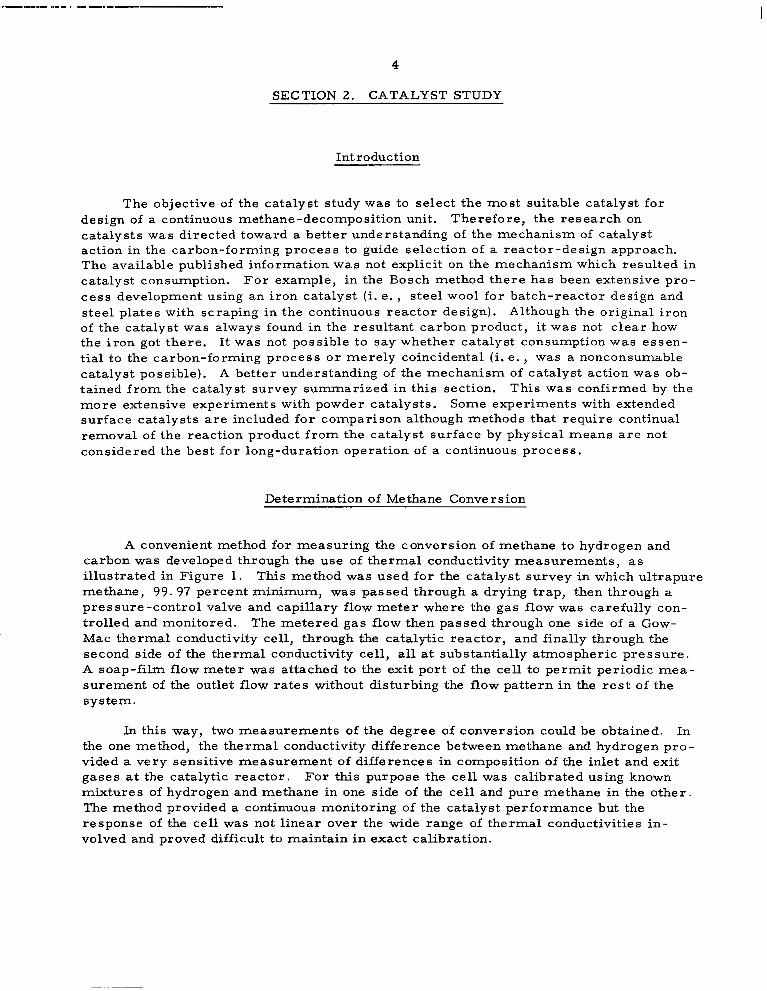
The objective of the catalyst study was to select the most suitable catalyst for design of a continuous methane-decomposition unit. Therefore, the research on catalysts was directed toward a better understanding of the mechanism of catalyst action in the carbon-forming process to guide selection of a reactor-design approach. The available published information w a s not explicit on the mechanism which resulted in catalyst consumption. For example, in the Bosch method there has been extensive pro- cess development using an iron catalyst (i. e. , steel wool for batch-reactor design and steel plates with scraping in the continuous reactor design). Although the original iron of the catalyst was always found in the resultant carbon product, it was not c lear how the iron got there. It was not possible to say whether catalyst consumption was essen- tial to the carbon-forming process or merely coincidental (i. e . , was a nonconsumable catalyst possible). A better understanding of the mechanism of catalyst action was ob- tained from the catalyst survey summarized in this section. This was confirmed by the more extensive experiments with powder catalysts. Some experiments with extended surface catalysts are included for comparison although methods that require continual removal of the reaction product from the catalyst surface by physical means are not considered the best for long-duration operation of a continuous process.
Determination of Me thane Conve r s ion ~~
A convenient method for measuring the conversion of methane to hydrogen and carbon was developed through the use of thermal conductivity measurements, as illustrated in Figure 1. This method was used for the catalyst survey in which ultrapure methane, 99 .97 percent minimum, was passed through a drying trap, then through a pressure-control valve and capillary flow meter where the gas flow was carefully con- trolled and monitored. The metered gas flow then passed through one side of a Gow- Mac thermal conductivity cell, through the catalytic reactor, and finally through the second side of the thermal conductivity cell, all at substantially atmospheric pressure. A soap-film flow meter was attached to the exit port of the cell to permit periodic mea- surement of the outlet flow rates without disturbing the flow pattern in the rest of the system.
In this way, two measurements of the degree of conversion could be obtained. In the one method, the thermal conductivity difference between methane and hydrogen pro- vided a very sensitive measurement of differences in composition of the inlet and exit gases a t the catalytic reactor. For this purpose the cell was calibrated using known mixtures of hydrogen and methane in one side of the cell and pure methane in the other. The method provided a continuous monitoring of the catalyst performance but the response of the cell was not linear over the wide range of thermal conductivities in- volved and proved difficult to maintain in exact calibration.

5
- C H4
control - trap
-" supply
Flow Drying'
- c f
Thermal t Soap- Catalytic film conductivity reactor flowmeter cel I + - fl -
FIGURE 1. ARRANGEMENT AND METHODS USED FOR DETERMINATION O F m T H A N E CONVERSION
The other method for measuring the conversion w a s based on the change in gas flow accompanying the decomposition. In the range of reaction temperatures below 950 C, where the reaction was seen to be substantially confined to the catalytic surface, the assumption that 2 . 0 moles of hydrogen were formed for each mole of methane de- composed proved to be a very accurate basis for estimating the degree of conversion. This accuracy was determined by comparison with the conversion estimates obtained from the thermal conductivity differences at low conversions and by comparison with the total amount of carbon collected in the reactor at the end of an experiment as shown by the data in Table 1.
TABLE 1. C0RRF:LATION OF CARBON FORMED WITH ESTIMATES BASED ON THE REACTION: CHq=C+2H2
Carbon Formed, g Catalyst(b) Experiment(a) Estimated Found Weight, g C/Co Ratio
1 3 .88 3 . 91 0 .863 4 .54
2 3. 08 3. 07 0 .862 3 .56
3 5 . 5 1 5 . 5 5 1 .000
Totals 12.47 12 .53
5 . 5 5
- (a) Other aspects of Experiments 1 and 2 are covered in Table 2 and Figures 2 and 3. (b) Cobalt powder, 50 mesh.
-

I
6
Both methods of estimating the conversion were used; the thermal conductivity was recorded continuously and provided detailed information concerning the changes in conversion that accompanied changes in conditions at the catalytic reactor. The flowmeter results were used at frequent intervals to provide accurate calibration points for the conversion being obtained.
Survev of Catalvsts
The planned screening program of various types and forms of catalyst was con- cluded during this quarter. All of the data obtained with essentially the same experi- mental apparatus are shown in Table 2 for comparison (including data for the first 14 catalysts previously reported in Table 1 of the Second Quarterly Report. (3)
The experimental catalytic reactor described in a previous report was a quartz U-tube with an enlarged section at the bottom of the U where the catalyst was con- tained. ( l ) The side tubes of the U were filled with quartz rod to remove most of the dead-space volume except for a short length which was provided as a preheat zone for the gas. In the flow range of 6 to 25 cc (STP) methane per minute used for this study, the distribution of the carbon deposit on the catalyst indicated that this arrangement for preheating was entirely sufficient. The entire U-tube was immersed in an electric furnace controlled by a Foxboro temperature controller. The experiments with cobalt powder and magnetic agitation listed in Table 2 used a la rger Vycor reactor (37 cm3 for carbon accumulation) [ see Figure 16, Reference (5) for design] .
It should be noted that all activities reported in Table 2 are based on ultrapure methane (99. 97 percent), predried before feeding to the reactor. Other experiments discussed later in this report utilized technical-grade methane with and without additions of carbon dioxide and water vapor to simulate a typical Sabatier reaction product which would be the practical feed to a methane decomposition reactor. In general, the addi- tives contributed to increased and sustained catalytic activity.
Supported Catalysts
The commercially available supported catalysts studied during this quarter were vanadium pentoxide, copper, silver, and nickel-tungsten. The support was not always identified but it is assumed to be alumina or an alumina-containing material in most cases . The commercial identifications are listed in Table 2 along with the results ob- tained for each catalyst. The lack of significant activity indicated for copper and silver is of interest for future engineering consideration in selection of mater ia ls of construc- tion for high-temperature reactors and associated equipment.
Following the initial experiments with steel wool catalysts, a ser ies of supported metal catalysts, metal foils, and a few miscellaneous materials were evaluated to determine more exactly the contributions of metal identity and form to the activities being obtained. The supported catalysts were included because they provided a ready opportunity to examine some metals in submicron crystallite form so that large catalyst surface areas were available. By comparing the initial reaction rates and the falloff in activity with carbon accumulation for the various forms, it was possible to

7
TABLE 2. ACTIVITY DETERMINATIONS FOR METHANE-DECOMPOSITION CATALYSTS .~ . - - . - ." . ~ -~ ~ , . . " _______._" ____..
Catalyst(b) - ."
0-gage steel WOOI(C)
Pt (5%) on carbon powder (Baker)
Pd (10%) on charcoal (Matheson, Coleman & Bell)
Pd on alumina (Girdler G-68-1/8 inch)
Fe on alumina (Harshaw LA-40-4-3/16 inch)
Cracking catalyst (TCC bead catalyst Grade 34)
Co on alumina (Harshaw Co-0102-T 1/8 inch)
Co-Mo alumina (Girdler G-51)
Chromia-alumina dehydro- genation catalyst (Davison)
N i (high) on alumina (Girdler T-324-1/8 inch)
Pd (0.5%) on alumina (Baker 1/8 inch)
Pd (0.2%) on silica gel (Davison 6-12 mesh)
" .
Activity, (a) percent decomposition CH4 at temperature (C) shown
IO0 150 800 85 0 900 950 Remarks ~
" 4 8 23 " >62 Second day of testing used here
" Slight 5 5 " 5 Activity falling, reactor not
" Nil 45 50 " " Activity falling, reactor
for more stable activity.
plugged.
palrially plugged.
" " 13 22 36 56 Activity falling with time.
" " 18 53 " Very high Pellets swelled, reactor plugged.
" " 68 83 (max) -- " Pellets swelled, reactor par- tially plugged.
33 " 44 (max) -- " " Activity falling, reactor not
" " 4 8 16 28 Short-term activity.
plugged.
65 86 (max) - - " " " Pellets swelled, reactor partially plugged.
7 (max) -- " " " " Activity falling, reactor not plugged.
" " 13 18 (max) -- " Activity falling, reactor not plugged.
Mn on alumina (Harshaw Slight " Slight Mn-0201-T 1/8 inch)
Chrome1 A wire, 32 gage, -- " Slight 0.020-cm diameter
V205/Alundum (Harshaw " " I L1345-20)
Cu/support (Harshaw Nil " "
Cu-2501 G4-10)
Ag/support (Harshaw N i l "
Ag-0101 G6-8) "
Ni-W/support (Harshaw 2 6 " 63 Ni 4301E)
Ni foil(e) N i l -- Slight
N i foil(e) activated (air/ 75 (rnax) -- "
950 C then H2/800 C)
Cobalt foil(d) N i l " Slight ~ ~~~~ "
6 12 " Short term, activity holding.
Slight 5 8(d) Short term, activity holding.
Small 26 " Re-test poor. falling
" Nil " Catalyst not visibly carbonized.
" Nil " Slight carbon deposit.
62 63 " Re-test 800 C poor.
4 5 " Slight darkening.
" " " Final, 43% after 10 hrs.

8
TABLE 2. (Continued)
- ~
Activity,(a) percent decomposition CH4 a t temDerature (C) shown
Catalyst(') IO0 150 800 85 0 900 950 Remarks ~" ~. .~
Co foil(e) activated (air/ 3 -- 25 (rising) - - " " Total 8.5 hrs at 800 C 1.16 g 950 C then H2/800 C) 4 " 36 (rising) -- " " C accum.
Fe foil(e) (high purity) N i l " 29 (falling) 14 (max) 16 (max) -- Fe foil(e) activated (air/ 2 " I " 9
500 C then H2/800 C) "
Re-test N i l " " 9 13 (max) -- 0.29 g C after 8 hrs.
Co powder(f) " 31 >5 0 >5 0 " -- For detailed description see Figure 2.
"
Co powddf) act ivated 28 41 " 86 " " For detailed description see (air/500 C then H2/500 C) Figure 3.
(a ) CH4 flow 15.2 cmS/min (STP). inlet, in all runs. Catalyst usually occupied 3.0 cm3 reactor-tube volume and corres- ponded to residence times of about 0.04-0.05 min; GHSV = 300 (approx.). Activities are determined as +10-20 percent of value listed. Predried, ultrapure methane (99.97 percent).
(b) Al l catalysts reduced in 50:50 mixture H2 in He for 1 hr, the first 9 listed in the table at 450 C. the rest at 800 C except as noted for special activation.
(c) Calculated surface area of 154 cm2 and 0. I1 g based on 0.001-inch diameter. (d) Corresponds to 3 x 10⁻⁶ moles CHq decomposed per cm2 per hr for calculated wire-surface area of 107 cm2. (e) Total surface area of foil was 103 cm2. (f) Magnetic agitation used to suspend and retain powder in reaction zone.
9
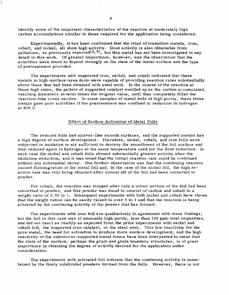
identify some of the important characteristics of the reaction at moderately high carbon accumulations similar to those required for the application being considered.
Experimentally, it has been confirmed that the triad of transition metals, iron, cobalt, and nickel, all show high activity. Good activity is also obtainable from palladium, as previously reported(2, 5), but this metal has not been investigated in any detail in this work. Of greater importance, however, was the observation that the activities were found to depend strongly on the state of the metal surface and the type of pretreatment provided.
The experiments with supported iron, nickel, and cobalt indicated that these metals in high-surface-area form were capable of providing reaction rates substantially above those that had been obtained with steel wool. In the course of the reaction at these high rates, the pellets of supported catalyst swelled up as the carbon accumulated, reaching diameters several times the original value, until they completely filled the reaction-tube cross section. In some samples of metal foils of high purity, these three metals gave poor activities if the pretreatment was confined to reduction in hydrogen a t 800 C.
Effect of Surface Activation of Metal Foils
supported metals had and iron foils were
The reduced foils had mirror-like smooth surfaces, and the a high degree of surface development. Therefore, nickel, cobalt, subjected to oxidation in air 'sufficient to destroy the smoothness of the foil surface and then reduced again in hydrogen at the same temperature used for the first reduction. In each case the nickel and cobalt foils showed substantially greater activity after the oxidation-reduction, and it w a s noted that the initial reaction rate could be continued without any substantial decay. One further observation was that the continuing reaction caused disintegration of the metal foil and, in the case of the nickel foil, the high re- action rate was still being obtained after almost all of the foil had been converted to powder .
For cobalt, the reaction was stopped after only a minor portion of the foil had been converted to powder, and this powder was found to consist of carbon and cobalt in a weight ratio of 3 . 05 to 1. Subsequent experiments with both nickel and cobalt have shown that the weight ratios can be easily raised to over 5 to 1 and that the reaction is being achieved by the continuing activity of the powder that has formed.
The experiments with iron foil are qualitatively in agreement with these findings, but the foil in this case was of unusually high purity, less than 100 ppm total impurities, and did not react as readily as expected from the prior experiments with nickel and cobalt foil, the supported iron catalyst, or the steel wool. This low reactivity for the pure metal, the need for activation to produce more surface development, and the high reactivity of the submicron-supported metal forms have been interpreted to mean that the state of the surface, perhaps the grain and grain boundary structures, is of great importance in obtaining the degree of activity desired for the application under consideration.
The experiments with activated foil indicate that the continuing activity is main- tained by the finely subdivided powders formed from the foils. However, there is not

10
sufficient information to say at this time whether that activity is due to regenerated fresh metal surface, o r due to a reaction product of the methane and the metal during the decomposition.
Photomicrographs (appearing later in this report) made on catalyst-metal powders i l lustrate the process of subdivision of the metal by the reaction. This phenomenon has been a c o m o n characterist ic of all experiments in which high continuing levels of activity were obtained, regardless of the metal choice.
Effect of Activation on Metal Powder
In a further examination of the reactivity provided by powders, several experi- ments were made using cobalt metal in the form of 50 mesh powder. Since beds of powder provide poor transport properties for the reactant and products, the arrange- ment of apparatus was changed so that the powder could be agitated and confined in the reactor .
To accomplish this, a magnetic field w a s employed, and, since cobalt is the only metal that remains ferromagnetic at the reaction temperatures employed, the experi- ments were confined to that metal. The catalyst chamber was located over a magnet that could be rotated at various speeds so as to provide agitation of the powder and, at the same time, another magnet was placed over the sample tube to partially levitate the powder and confine it in the reactor. Vibrational agitation seemed to serve equally as well a s the magnetic agitation provided by the first magnet.
As with cobalt foil, the cobalt-powder catalyst was found to be substantially im- proved by the redox activation procedure, and in these cases nearly equilibrium con- versions were obtained under the same flow and temperature conditions used for catalyst- survey resul ts as shown in Table 2 .
The results for experiments with cobalt powder are a lso summarized in Figures 2 and 3 . Comparison of Figures 2 and 3 shows the higher activities with cobalt powder that was activated by oxidation and reduction with that which was reduced only. Later figures show the experimental data in recalculated form in which the activity is plotted for increments in carbon accumulation in the reactor. The actual peak activity found for the activated sample was 88 percent conversion at 15-cc-methane-per-minute inlet flow at 850 C (at about 0 . 2 grams carbodgram cobal t in F igure 3 ) . The subsequent change in flow to 25 cc/minute produced almost no change in conversion, expressed in percent, so that the specific reaction rate was increased from 0.039 to 0.064 g-mole carbon per hour per gram of catalyst. A s the experimental apparatus was limited to a feed of 25 cc/minute, higher flows could not be investigated in this experiment. How- ever, equilibrium conversion at 850 C has been estimated to be about 95 percent s o the activities being obtained (82 to 88 percent) are only slightly below equilibrium values. A s shown in Figure 3, high activity was maintained up to a carbon/catalyst ratio of 3 a t a level above 75 percent methane decomposition that would be required for a one-pass system (no recycle).
In another experiment with activated cobalt powder and magnetic agitation a carbon to catalyst ratio of 5.55 was attained. The three experiments were summarized in Table 1 to show the correlation of carbon found with the reaction CHq=CtZH2. In

Stored in CH, .25 C over weekend
Stored in CH4, 25 C overnight
I I 1 I I I I I I I I I I I I I I I 1.0 2.0 3 .O 4.0
Estimoted Grams Carbon per Gram Cobalt
FIGURE 2. EFFECTOFHYDROGENREDUCTIONONLYONEXTENDEDACTIVITYOFCOBALTPOWDER (50"ESH) CATALYST FOR METHANE DECOMPOSITION

I I I I I I I I I I I I I I I I I I I
0 I .o 2.0 3 .O Grams Carbon per Gram Cabolt
.O
FIGURE 3 . EFFECT OF OXIDATION-REDUCTION ON EXTENDED ACTIVITY O F COBALT POWDER (50-MESH) CATALYST FOR METHANE DECOMPOSITION

13
addition to confirming predominant formation of hydrogen, practically all of the carbon was associated with the catalyst with little or no deposition of products on the reactor wall at 850 C.
Additional experiments with powders are discussed in a later section using a different experimental apparatus which permitted study of powders other than cobalt.
Effect of Feed Composition on Methane Decomposition on Extended Surfaces
-. ~
" ~~
The ser ies of experiments initiated in the second quarter on the decomposition of methane over a defined surface of iron and nickel foils was completed. The addition of small quantities of carbon dioxide and water vapor to the methane feed was made in an attempt to solve the problem of catalyst inactivation observed in the initial runs, when 97. 0 percent minimum purity methane (the technical grade product of the Matheson Co. ) was decomposed over iron and nickel foils. Moreover, methane feed containing traces of carbon dioxide and water vapor simulates the composition of a Sabatier effluent, the feed to the methane cracking unit in the actual life-support system.
The apparatus descr ibed ear l ier( l1 was used ( i .e . , a quar tz tube and two cylindri- cal resistance-wire furnaces for heating the decomposition zone and a preheater section). The operating procedure also remained unchanged. Nickel sheet was 0.023 to 0. 024-in. (0 . 053-0. 061 cm) thick, iron (shim steel) used was a 0. 006-in. (0. 015 cm) thick foil. Both catalysts were 5 in. (12.7 cm) wide and 6 in. (15.2 cm) long. Nickel catalyst was cleaned with concentrated hydrochloric acid, rinsed successively with distilled water and acetone, then dried in air. Iron foil was wiped with a clean towel and degreased in chlorol. Catalyst foil was rolled up so that it fitted into the quartz reactor tube. The spacings between layers of the roll were 0. 1 to 0 . 4 cm. After the catalyst was rolled up and before the run, it was degreased in chlorol, dried in air, rinsed with acetone and dried again in air. The catalyst surface area of 386 cm2 in these experiments was the same as that reported previously, but the methane flow used was increased from 50 to 250 cm3/min.
In Runs c-6 to C-8, crushed graphite was replaced by Alcoa T-61 alumina, mesh size minus 8 plus 14. The preheater temperature in al l experiments was 700 C. The degree of methane conversion was determined from the pressure measurements of the gaseous reaction mixture at room and at liquid-nitrogen temperature. Small amounts of carbon dioxide and water vapor in the reaction mixture lowered its methane content and resulted in slightly higher values of the degree of methane decomposition than those calculated for only methane-hydrogen mixture. The resulting differences were esti- mated to be in the error range of the analytical method used. Therefore, the uncorrected values are given in Table 3 and plotted in Figures 4 and 5. In Runs C-6 and C-7, wet carbon dioxide was fed into the reactor, in Run C-8 methane was allowed to bubble through water upstream of the reactor.
No maximum in the methane-decomposition rate was observed with the methane flow of 250 cm3/min. Considering the results obtained with the methane flow of 50 cm3/min, a maximum in the degree of methane decomposition with the methane flow of 250 cm3/min should have occurred during the initial 10 to 20 minutes of the experi- ment. The degree of methane decomposition at 750 C was lower at higher methane flow

.. . . . .. ..._ "_ -
14
TABLE 3 . CATALYTIC DECOMPOSITION OF METHANE@)
- Decamp. H z Content in the Degree of CH4
Temp, Product, volume Decomposition, Reaction Rate, g-mole Run Catalyst C Time, hr percent percent CH4/hr cm2 x lo5
C d b ) Nickel
C-8(d) Nickel
750 750 800 800 800 85 0 850 850 900 900 9 00 800 800
750 750 800 800 800 850 85 0 850
750 800 800 850 850 85 0 9 00 900 900 900 800 800
750 800 800 850 85 0 85 0 900 900 950 950 800 800
0 .25 1 1 . 2 1 . 7 2 .45 2 . 8 3 .3 4 .05 4 . 3 4 . 9 5.65 5.9 6 .6
0.25 1 1 . 2 1 . 7 2 . 4 5 2 .75 3 . 3 4 . 05
0.25 0.51 1.07 1 .51 2.07 4 . 3 4 .51 5.08 5 .83 6.58 6.9 7 . 4
0.25 0.58 1.07 1.58 2 .07 5.07 5.58 6.08 6.62 7 7 . 5 7 . 8
3 . 7 2 .8 "
9 . 7 4 . 6
5 .6 5 . 6
"
12.9 12 .8
"
1.7
4 . 2 2 . 8
"
5.5 5 . 9
"
15.1 1 5 . 1
2.7
"
4.9 "
10.8 12.6
"
"
26.1 25.2 24 .8 "
11. 7
7.7
10.4 "
1 3 . 1 14 .9
"
"
26. i "
26.1 "
17.3
1.9 1.4 "
5.1 2 .3 "
2.9 2.9 "
6.9 6.8 "
0.9
2 . 1 1 . 4
2.9 3 . 1
"
"
8.2 8.2
1 . 4 "
2 .6 "
5.7 6. 7 "
15.0 1 4 . 4 1 4 . 1
6.3
4 . 1
"
5 . 5
"
"
7 . 0 8.1 "
15.0 "
15 .0
9 . 3 "
3 . 1 2 .3 "
8 . 3 3.7
4. 7 4.7
"
11.2 11 .0
"
1.5
3 . 4 2 . 3
"
"
4. 7 5 . 0
1 3 . 3 13 .3
2 . 3
"
4.2 "
"
9.2 10.9 "
24 ,3 23.3 22.8 "
10.2
6.6 "
8.9
11 .3 13 .1
"
"
24.3 "
24.3 "
15.1
(a) Preheater temperature: 700 C; catalyst surface area: 386 cm2. (b) CH4 flow rate: 250 cm3/min at 21 C. 14.7 psia. (c) CH4 flow rate: 250 crn3/min at 21 C. 14.7 psia; C02 flow rate: 10 cm3/min at 0 C, 14.7 psia; carbon
(dl CH4 flow rate: 250 crn3/rnin at 21 C, 14.7 psia; COS flow rate: 10 cm3/min at 0 C, 14.7 psis; methane dioxide was bubbled through water.
was bubbled through water.

I
15
( Experiment C-6 1 A C b - CO2(4%) - H@ vapor
( Experiment C-8) ( 1.8 %) mixture
Temperature , C
FIGURE 4. CATALYTIC DECOMPOSITION O F CH4 AND SIMULATED SABATIER PRODUCT MIXTURE ON NICKEL
3c
2C
IC
s
." 1 I I I I
d 0 High purity CH4(99.97' and 0- gage steel wool
Saba t ier product ( Table 2 1 mixture ..
P x CH4-C02(4%) Hfl vaF
/ o (Experiment C-7) (0.07%) mixture
1 - Values obtained at the x- .. end of the experiment
I I I -~ ~~~ ~~ . . ~
800 900 IO00 I loo
Temperature, C K)
FIGURE 5. CATALYTIC DECOMPOSITION O F CH4 AND SIMULATED SABATIER PRODUCT MIXTURE ON IRON
I

16
(Run C-5) than that observed with the methane flow of 50 cm3/min (Run C-l)(3) , but the ra tes of the methane decomposition per unit area of catalyst in these runs were similar. The same conclusion can be drawn for methane decomposition at 800 C (Runs C-3 and C-5). (3)
Comparing the results obtained when technical-grade methane was used (Run C-5) with those of Run C-6, a higher degree of methane decomposition with a wet carbon dioxide-methane reaction mixture was observed only at higher temperature, i. e , a t 850 C. With a carbon dioxide-wet methane reaction mixture, a higher degree of methane decomposition was measured from 750 C on up. The presence of about 4 per - cent carbon dioxide and 1. 8 percent water vapor in methane approximately doubled the degree of methane decomposition at these temperatures . The highest degree of methane decomposition using this carbon dioxide-water vapor mixture was 15 percent a t 900 C for a methane flow rate of 250 cm3/min and a catalyst-surface area of 386 cm2. Im- proved catalyst activity with the carbon dioxide and water addition to the methane w a s also maintained in extended runs (compare results of Experiments C-5 and C-8 at 800 C).
Methane Decomposition in a Vibrating Bed of Catalyst Particles ~~
Experiments on methane decomposition using higher methane flow of 250 cm3/min were carried out in a vibrating bed of catalyst (nickel or cobalt) particles. The reactor shown in Figure 6 consisted of a 2.5-cm-ID quartz tube with a conical bed support. The methane was fed into the reactor through a 0. 125-cm capillary at the center of the bed-support cone, the angle of the cone being about 37 degrees. The preheater section of the reactor, a 3.0-cm-ID quartz tube was filled with 8 x 16-mesh alumina in the first three experiments. Later, quartz wool was used instead. The reaction zone and the preheater zone were heated with two cylindrical, resistance-wire furnaces. As in the previous work(l), the reaction-zone thermocouple (Chromel-Alumel) was positioned inside the quartz tube and the thermocouple used with the preheater was located in con- tact with the outer quartz-tube wall. The reactor was mechanically vibrated in vertical position by a Syntron electric vibrator. The assembled system was purged with helium before and during the charging of the catalyst powder into the reactor and while the heater zone was heated to the reaction temperature. Helium purge was used also after the methane-decomposition experiment, when the reactor was cooled off.
Initial experiments were carried out with spherical nickel powder, minus 270 mesh f rom Welded Carbide Co., Inc. Cobalt powder, minus 50 mesh, m2N8, was obtained f rom Alfa Inorganics, Inc. A summary of the experimental conditions used and results obtained is given in Table 4. Nickel powder used in Run 1P-Ni contained many particles in the micron-size range. Only about one quarter of this powder was 270 x 325-mesh particles, as observed after screening it through a 325-mesh screen. Nickel powder in Run 2 P - N i was of better defined size. The smaller quantity of catalyst powder and the absence of small micron-size particles explain the observed lower degree of methane decomposition in this experiment. Decrease in the amount of catalyst particles and in the catalytic surface in Run 3P-Ni as compared to that of 2P-Ni resulted in additional decrease in degree of methane decomposition.
Methane decomposition experiments on cobalt powder were carried out mostly at 850 C. The data demonstrated significant effect of the amount of cobalt-catalyst powder

17
Reaction mixture
Thermocouple - and quartz protection tube
VI bra tor clamp 7
- Rubber stopper - Clamp for loose support - Quartz tube
Decomposition - zone furnace
Pre hea ter
i Thermocouple
Rubber stopper
FIGURE 6 . VERTICAL VIBRATING BED FOR METHANE PYROLYSIS
I

18
TABLE 4 . METHANE DECOMPOSITION IN A VIBRATING BED OF CATALYST PARTICLE&)
~ _ . "" ~- ~ ~ ~"
Decomp. H2 Content in the Degree of CH4 Volume of the Amount of Temp. Product, volume Decomposition, Reaction Product Carbon
Run Catalyst C Time, hr percent percent Powder. cm3 Formed, g
1P-Ni
2P-Ni
3P-Ni
4P-C0(e)
5P-CO
6P-Co
7P-Co(f)
Ni-Powder - 270 mesh 6.9 cm3 42.37 g
Ni-Powder 270 x 325 mesh 4 cm3 21.99 g
Reaction Product Powder of 2P-Ni 4 cm3 10.4 g
Co-Powder -50 mesh 4 cm3 12.52 g
Reaction Product Powder of
4 cm3 3.26 g
Co-Powder -50 mesh 1.05 cm3 3.36 g
4P-CO
Co-Powder -50 mesh 1.02 cm3 3.13 g
750
750
750
750 850 850 850 850 850
850
850
850
0.5 35 1.5 44.8 2 . 5 . 49.6 3.5 58.4
0.5 17.5 1.5 25.4 2 .5 27 .6 3.5 24.4 4.5 27.6 5.5 29.6
0.5 14.2 1 .5 12 (dl
0 .5 2 1.5 77.4 2 .5 es. 5 3.5 85.4 4.5 85.7 5.5 79.2
0.5 27.9 1.5 28.7 2 .5 25 .8 3.5 21.5 4 .5 19 .2 5 . 5 1 5 . 1
0 . 5 9 . 4 1.5 33.2 2 . 5 4 0 . 4 3.5 44.2 4 .5 45 .4 5 . 5 44.2 6 .5 38 .4 8.5 31.6
0.5 46.4 1.5 67.7 2.5 75.7 3 .5 71 .8 4.5 64.4 5.5 64.8
9 . 4 14.5 16 13.9 16 17.4
7 .6 6.4
1
63 12 74.5 75 65.6
16.3 16.8 14.8 12.1 10.6 8.2
5 19.9 25.3 28.4 29.4 28.4 23.8 18.8
30.2 51 60.9 55.9 47.4 47.8
6.2
45
22
37
53
1.15
21.87
4.55
13.6
19.89
(a) CH4 flow rate: 250 cm3/min at 2 1 C, 14.7 psia; preheater temperature: 700 C. (b) Bed was plugged at the beginning of the experiment. The developed pressure burst the bed. Since nickel powder
(c) Values reported in these two columns were obtained at the end of the experiment. Runs 2P-Ni, 4P-Co and
(d) Run was discontinued after a short reaction time (-2 hr), due to a leak in the system. (e) Reactor was at 750 C for the initial 40 minutes. ( f ) Prior to the methane-decomposition experiment, the cobalt powder was oxidized in air at 800 C for 1 hr
and reduced in hydrogen at 500 C for 1 hr.
was carried out of the reactor by the spurt no reliable measurements were possible.
7P-Co were run for 6 hours. Runs 5P-Co and 6P-Co were run for 6.5 and 9 hours, respectively.
" . . - . . .._ .. . - . . - " . . . . ..._ .....

' I
on the degree of methane decomposition. A s when nickel powder was used, the catalytic activity of cobalt powder passed through a maximum during the decomposition experiment. The initial catalytic activity of cobalt powder was lower than that of nickel powder. However, a valuable comparison could be made only on nickel and cobalt particles of the same size and shape. The effect of activating the cobalt prior to the methane -decomposition experiment was outstanding. The most important observation was the high catalytic activity of the product powder at the end of Run i'p-co when the carbon to catalyst ratio was higher than 6.3.
Microscopic examination of product particles (Run 2P-Ni ) did not reveal any separate carbon. Only spherical particles in the product powder were observed under the microscope. Examination of sectioned product particles indicated a coating on all particles (Figure 7) and an extensive attack of the whole particle in most cases. The as-received nickel particles were dense and sound (Figure 8). All particles appeared to be polygrained, but they showed some difference in their network of voids (Figure 9 ) . The cobalt powder consisted of agglomerates of smaller particles (Figure 10) . This powder, too, was disintegrated in the methane-decomposition process. The extent of the disintegration varied with the ratio of the total carbon formed to the amount of catalyst used as shown in Figures 11 and 12, which are sectioned product-powder particles of Runs 4P-Co and ~ P - C O , r e s p e c t i v e l y . The final carbon-to-catalyst ratio in Run 4P-Co was 1.75 and that in Run 7P-Co was 6.35.
Methane-decomposition Runs ~ P - C O , ~ P - C O , and ~ P - C O , on cobalt-catalyst powder are analyzed from a different viewpoint in Table 5 and Figure 13. In this repre- sentation a direct comparison with the results of the work at AiResearch (Figure 14) is possible. The "cumulative carbon produced" reported in Table 5 is higher than the "amount of carbon formed" given in Table 4 . The difference in these two values comes mainly from the uncertainty in the "cumulative carbon produced" at the beginning of the experiment in the initial 1.5 hr. Some carbon was formed also on the quartz wool and on the quartz wall of the upper part of the preheater, and w a s not included in the values reported in Table 4 .
As already noted, the degree of methane decomposition and the rate of carbon production on preactivated cobalt powder was high. The best improvement is indicated for the observed rates of carbon production per unit weight of the catalyst powder for the ratio of the cumulative carbon formed per unit weight of the catalyst greater than 5. Additional overall improvement is realized in considering that the 75 percent of the catalyst-support weight was left out in the AiResearch evaluation.
Discussion
It is character is t ic of the reaction process under study that the catalyst becomes intimately mixed with the carbon powder-reaction product. Thus, since the catalyst ultimately would be removed with the carbon accumulated in the reactor, the ability of the catalyst to maintain the reaction at high weight ratios of carbon to catalyst is of cri t ical importance. The meaning of this to the engineering of a stable reactor is better understood if it is realized that one square meter of catalyst surface can form only about 10-4 grams of carbon unless that monolayer of reaction product can be dis- placed or new catalyst surface can be generated to replace it. A weight ratio of 5 grams of carbon per gram of catalyst would consist of 40 ,000 to 50, 000 layers of carbon atoms

20
5 O O X FIGURE 7. NICKEL PARTICLES AFTER THE RUN 2P-Ni
500X N o t Etched FIGURE 8. AS-RECEIVED NICKEL PARTICLES

21
500X Etched
FIGURE 9. AS-RECEIVED NICKEL PARTICLES
200x FIGURE 10. AS-RECEIVED COBALT PARTICLES

2 2
ZOOX
FIGURE 11. PRODUCT-POWDER PARTICLES AFTER RUN ~ P - C O
200x
FIGURE 12. PRODUCT-POWDER PARTICLES AFTER RUN 7P-CO

I . ..
23
04 cm3 Co powder (as received) Experiment
0 I cm3 Co powder(as received) 14 Experiment
c m 3 Co oowder(activated)
4P- C O
I I I I
E 0 0 2 4 6 8 IO 1 z
Cumulative Carbon Formed, g Wt of Catalyst Powder,g
FIGURE 13. ACTIVITY OF THE COBALT CATALYST POWDER A S A FUNCTION OF THE TOTAL CARBON FORMED P E R UNIT WEIGHT, G, OF THE CATALYST POWDER
(u ~ . . - 2 5 % Co on Asbestos -" 2 5 % Ni on Asbestos . " 25 O/O Pd on Asbestos } $741
A Fe powder(reduced iron oxalate)
14 \\ B Ni powder(reduced oxalate)
01 I I \
0 2 4 6 8 IO I I I I
Curnula tive Carbon Formed. a ~
Wt of Catalyst Powder,g
z
FIGURE 14. CATALYST ACTIVITY VERSUS CARBON CONTENT
Based on AiResearch and Isomet data. (2 )

24
TABLE 5. ACTIVITY OF COBALT CATALYST POWDER(^)
Rate of Carbon Degree of CH4 Rate of Carbon Production/Wt Average Rate of Cumulative Decomposition, Production, of Catalyst Carbon Prod. , Carbon Prod.,
Run Time, hr percent g/hdb) Powder, hr g/hdc) g ... ." -. 1 ~~
4P-CO 0 .5 1 0.075 0.006 0.03 0.015 12.52g 1.5 63 4.73 0 .38 2 .36 2 .38
2 . 5 72 5.4 0 .43 5 .05 7 .43 3.5 74.5 5 .59 0 .45 5 .48 12.91 4.5 75 5 .63 0 .45 5 .62 18.53 5.5 65.6 4 .93 0 .39 5 .53 24. 06
5.88 27.00
6P-Co 0 . 5 3.36 g 1 . 5
2 . 5 3 . 5 4 . 5 5 . 5 6 .5 8 . 5
5 19.9 25.3 28.4 29 .4 28.4 23 .8 1 8 . 8
0.38 1.49 1 .9 2.13 2 .2 2.13 1.79 1.41
0.113 0.44 0.57 0.63 0.65 0. 63 0.53 0.42
0.2 0.93 1 . 7 2 . 0 2 .16 2.16 1.95 1 .6 1.38
0 . 1 1. 03 2.73 4.73 6.89 9. 05
1 1 . 0 0 14.2 14.89
7P-co 0.5 30.2 2.26 0. 67 1 . 2 0. 6 3 .13 g 1.5 51 3 .82 1 .14 3 .05 3 .65
2 .5 60 .9 4 .56 1 .36 4 .2 7 .85 3.5 55.9 4.19 1.25 4.38 12.23 4.5 47.4 3 .56 1. 06 3.87 16.10 5 .5 47. a 3.58 1.07 3.57 19.67
3.57 21.45 " " " "
Cumulative Carbon Prod. / W t of
Catalyst Powder
"
0.19 0.59 1. 03 1 .48 1.92 2.16
0.03 0.33 0.81 1 .41 2. 05 2.69 3.28 4 .23 4.43
0.19 1.17 2.51 3 . 9 1 5.15 6.29 6.86
" . ~~
~ . . . -
(a) CH4 flow rate: 250 cm3/min at 21 C, 760 mm Hg; 6 .25 x lo-' g mole/hr. (b) The rate of carbon production is 7 5 g/hr. when degree of methane decomposition is 100 percent. ( c ) Obtained graphically.

25
on the catalyst surface if the 1 gram of catalyst were spread out so as to provide 1 square meter of active surface, and if layerwise deposition of carbon occurred. In the summary table of catalysts tried, those metals which provided only an initial surge of activity may be regarded as ones for which the deposited layer of carbon rapidly inundated and poisoned the reactive surface. On the other hand, those catalysts that provided good continuing activity all were pulverized during the reaction and this effect of the reaction process is believed to be responsible for the continuing activity obtained. The above considerations of the number of carbon layers involved in a suitable reactor, and the experimental observations of the formation of a powder containing both catalyst and carbon seem to indicate that it is unrealistic to view the high-reaction-rate process as occurring through any substantial thickness of carbon product. The diffusion rate for methane or catalyst through the carbon layer would depend strongly upon the cracks and other defects formed in the layer, and the critical thickness for reaction rates of the order seen in this work would be difficult to estimate.
Alternatively, the diffusion thickness can be viewed as being maintained small by the destructive action on the metal s t ructure of the catalyst, but the nature of the catalyst surface being maintained by this process is not known. In the catalytic process, the activation of the methane molecule is achieved by chemical-bond formation between the catalyst and the molecule during which carbon-hydrogen bonds are broken. Ulti- mately, the hydrogen is desorbed leaving behind the carbon residues which may remain chemically attached to the catalyst or which may be desorbed as the carbon product. From the experimental results and particularly the effect of the oxidation-reduction pro- cedure, it can be assumed that chemisorption of the methane and carbon deposition along intergranular cracks or f issures in the metal surface produces a wedging action which causes the metal to become pulverized, and this process generates additional catalytic surface. If the carbon residues formed by the surface process are readily desorbed or displaced from the surface, reaction can continue on all surfaces at a ra te that is enhanced by the increasing amount of surface area, and decreased by the accumu- lation of carbon residue which gradually inundates the catalyst.
It is also possible that carbides or similar reaction products persist at the surface and prevent regeneration of a t least par t of the original surface. In that event the con- tinuing reaction depends on the activity, if any, of the reaction product thus formed, the amount of original metal surface regenerated, and the amount of fresh surface formed. The balance that is achieved among these several processes depends not only on the elemental composition of the catalyst but upon the metallurgical structure of the sample t r ied. In this respect, the low activity of the high-purity iron sample may be of interest in demonstration of the role of metallurgical factors present in the commercial steel wool and other forms of i ron mater ia ls .
The results indicate that the reaction occurs to a considerable extent in the powdery mixture of catalyst and carbon that forms. This accumulated product o f r e - action is a loose material that readily falls off the metal surface and does not appear to adhere as a succession of layers forming a gradient of catalyst concentration between the original catalyst surface and the outer layer of the product. For such a product, good kinetics of reaction can be maintained only if the powdery bed of mater ia l is kept agitated and loosely formed so that methane can stream through it. The experiments with cobalt powder have shown that high levels of reactivity can be maintained by use of a powder that has been oxidized and reduced to activate the surface, and agitated to prevent transport l imitations. The cobalt powder, furthermore, is ferromagnetic at reaction temperatures s o that this metal or its alloys may be confined effectively in the
I
26
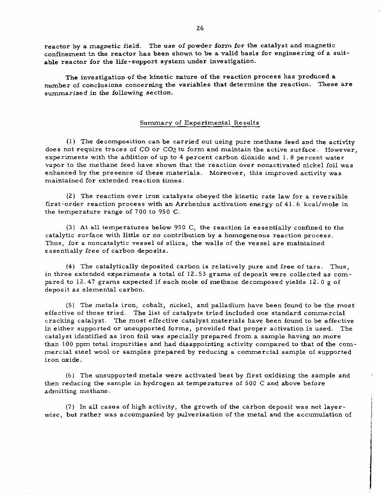
reactor by a magnetic field. The use of powder form for the catalyst and magnetic confinement in the reactor has been shown to be a valid basis for engineering of a suit- able reactor for the life-support system under investigation.
The investigation of the kinetic nature of the reaction process has produced a number of conclusions concerning the variables that determine the reaction. These are summarized in the following section.
Summarv of ExDerimental Results
(1) The decomposition can be carried out using pure methane feed and the activity does not require traces of CO or C02 to form and maintain the active surface. However, experiments with the addition of up to 4 percent carbon dioxide and 1.8 percent water vapor to the methane feed have shown that the reaction over nonactivated nickel foil was enhanced by the presence of these materials. Moreover, this improved activity was maintained for extended reaction times.
( 2 ) The reaction over iron catalysts obeyed the kinetic rate law for a reversible first-order reaction process with an Arrhenius activation energy of 41.6 kcal/mole in the temperature range of 700 to 950 C.
( 3 ) At all temperatures below 950 C, the reaction is essentially confined to the catalytic surface with little or no contribution by a homogeneous reaction process. Thus, for a noncatalytic vessel of silica, the walls of the vessel are maintained essent ia l ly f ree of carbon deposits.
(4) The catalytically deposited carbon is relatively pure and free of tars. Thus, in three extended experiments a total of 12.53 grams of deposit were collected as com- pared to 12.47 grams expected if each mole of methane decomposed yields 12. 0 g of deposit as elemental carbon.
(5) The metals iron, cobalt, nickel, and palladium have been found to be the most effective of those tr ied. The l i s t of catalysts tried included one standard commercial cracking catalyst. The most effective catalyst materials have been found to be effective in either supported or unsupported forms, provided that proper activation is used. The catalyst identified as iron foil was specially prepared from a sample having no more than 100 ppm total impurities and had disappointing activity compared to that of the com- merc ia l s tee l wool or samples prepared by reducing a commercial sample of supported iron oxide.
(6) The unsupported metals were activated best by first oxidizing the sample and then reducing the sample in hydrogen at temperatures of 500 C and above before admitting methane.
(7) In a l l cases of high activity, the growth of the carbon deposit was not layer- wise, but rather was accompanied by pulverization of the metal and the accumulation of

t
27
an intimate mixture of active metal and carbon residue. The prior oxidation and reduc- tion of the sample apparently promoted this tendency for the metal to pulverize during methane decomposition. In some of these cases the reaction exceeded 80 percent con- version at flows of nearly 2 l i t e rs of methane (STP) per hour for 1 gram of metal-powder catalyst. Under these conditions recycle of unconverted methane probably would not be necessary.
(8) The large dependence of high, continuing activity upon the pulverizing action of the reaction on the metal catalyst indicates that a suitable reactor would probably need to be capable of retaining the powder formed until a sufficient carbon-to-metal ratio has been produced. This has been suitably accomplished with work described here by use of vibratory o r magnetic agitation, and magnetic confinement of the catalyst powder in the reactor. The only metal with suitable magnetic characteristics for this purpose appears to be cobalt.

28
SECTION 3. PROCESS DESIGN STUDY
Methane-DecomDosition Unit Design
The major task in the design study was concerned with the methane-decomposition reactor, which involved selection and configuration of a catalyst, reactor geometry, and operating mode that would permit continuous deposition and removal of carbon pro- duced from methane decomposition. The design concept evolved from this program is the combination of a magnetic field coupled with a particulate catalyst which is ferro- magnetic at the reaction temperature of interest. Thus, the active catalyst requires no physical support within the reactor or inert support structure (e. g . , asbestos) thatwould add to the expendable catalyst weight.
The magnetic field is used as a means to contain the catalyst in the hot reaction zone in a gravity-independent manner. A, rotating magnetic field or rapid polarity re- versal can create magnetic-field-strength fluctuations which impart agitation to the catalyst bed. A state of gas-solid fluidization exists while carbon is formed on the cata- lyst . The catalyst/carbon mixture maintains posit ion against gas flow up to high carbon/ catalyst ratio as long as an adequate magnetic field exists. Partial reduction or removal of the magnetic field permits the product carbon/catalyst particles to be entrained by the gas for removal from the hot reaction zone. Final gas/solid separation occurs in a low- temperature carbon separator which collects the solid product powder for either a con- tinuous o r batch operation. The carbon separator is discussed in Appendix B.
Experimental results in this program indicate that a mixture of a cobalt catalyst and carbon deposited around cobalt particles remains ferromagnetic at a reaction tem- perature up to at least 900 C. Hence, the carbon-cobalt mixture in the catalyst bed could be confined inside the working volume of the reactor by a magnetic field until sufficient catalyst utilization had been achieved.
Two of the best catalysts having good catalytic activities toward methane decom- position are nickel and cobalt. Nickel appears to be somewhat superior to cobalt in t e rms of catalytic activity. However, the Curie points of nickel and cobalt are 358 and 1130 C , respectively. ( 6 ) Since the reaction temperature of interest l ies in the range of 700 to 900 C, cobalt is the choice of catalyst for magnetic application. Of all the metal- lic elements, cobalt is unique in having the highest Curie point. Alloys of nickel and cobalt might be considered in future experiments for improved catalytic activity while retaining ade uate magnetic properties. Curie points of cobalt-nickel alloys are shown in Figure 15.q6) The data suggest that alloys containing up to 40 percent by weight of nickel have sufficiently high Curie temperatures for methane decomposition.
Parameters that determine reactor sizing include the quantity of the catalyst, the carbon/catalyst ratio in the catalyst bed, and the packing density of the catalyst bed dur- ing steady-state operation. These parameters were determined from the results on this program in some laboratory-scale experiments at nearly 1-man capacity. Since the reactor size is relatively small , a 3-man experimental reactor was designed for future study rather than the 1-man reactor originally considered at the beginning of the program.

29
I h t.
20 40 60 80 Percent Nlckel 1-57995
FIGURE 15. CURIE TEMPERATURE OF COBALT-NICKEL A L L O Y S ( ~ )
The catalyst study conducted on this program and covered in Section 2 includes experimental results with cobalt powder. Two of the experiments showed that acti- vated cobalt powder has sufficiently high activity for methane decomposition to per- mit designing an efficient and compact reactor. It was desired that preliminary design of the experimental reactor and extrapolated estimates for a 3-man, 1000-day mission be based on demonstrated catalyst activity. The choices of experimental data to use were: (1) demonstration of 75 percent decomposition up to a carbon/catalyst ratio of 3 using a magnetic field (one-pass system), or ( 2 ) demonstration of attainment of a t least a carbon/catalyst ratio of 6. 35 with a degree of methane decomposition of 45 percent averaged over a 6-hour run in a vibrating catalyst bed. The latter choice was made be- cause the added penalties for larger reactor size and recycle were sufficiently small to provide favorable weight estimates.
The pertinent experimental data are reproduced in Table 6 in a slightly different form for design purposes.
TABLE 6. EXPERIMENTAL DATA ON DECOMPOSITION O F METHANE USING COBALT POWDER CATALYST(^)
Activated Cobalt Catalyst Powder, -50 mesh
Amount of Catalyst Used, g 3 . 13 Methane Feed, g-mole/hr 0.615 Carbon Formation Rate (Average) , g-mole/hr 0.276 Rate of Methane Decomposition, g-mole/hr/g catalyst 0 .088 Degree of Methane Decomposition (Average), percent 45. Carbon/Catalyst Ratio Attained, g/g 6.35 Operating Bulk Density, g/cm3 0. 175(b)
(a) Data given in this rable are based on experimental data reported for Run 'Ip-Co, Table 4. In producing
(b) Value estimated on the low (conservative) side from observation during Run lp-Co (Table 4). The
d
19.89 g carbon in 6 -hr run.
final product density corresponding to a packing density was 0.435 g/cm3 (Table 4).

30
Results of reactor-design calculations are summarized in Table 7. The catalyst consumption estimated for a final carbon/catalyst ratio of 6 . 3 5 in the present design is considered adequate, and there were evidences in the catalyst studies that this ratio could be increased without reducing the reaction rate significantly.
TABLE 7. DESIGN AND OPERATING PARAMETERS FOR A METHANE-DECOMPOSITION REACT'OR ( 3 -MAN SYSTEM)
Catalyst Cobalt powder,
" ~ -~ " -50 mesh ~- . " -
Rate of methane Decomposition, Catalyst in the Reactor, g Carbon in the Reactor, g Reactor Working Volume, cm3 Catalyst Consumption, g/day
(kg/lOOO-day mission) Reactor Temperature, C Reactor Pressure, mm Hg Reactor Feed(b):
Total Flow, g-mole/hr Methane, percent
Total Flow, g-mole/hr Methane, percent
Reactor Effluent(b1:
g-mole/hr 2. 08(") 23. 5
149. 2
94 .0 (94.0) 850. 760
1000.
5. 1 97 .
7 . 2 40.
(a ) Based on data given in Figure A-4, Appendix A for a waste carbon product formation rate of 1 6 . 6 g-moles/man-day (73.5 percent net overall decomposition of methane with recycle).
(b) Based on data given in Table 6.
Reactor Design
To obtain a uniform and strong magnetic field throughout the working volume of the reactor, a flat, disk-shape design is proposed. A cross sect ion of the proposed reactor design is shown in Figure 16. The reactor consists of a hollow disk with re- sistance heaters on both sides of the disk. Vacuum insulation is recommended, using radiation shields and a gas-tight jacket around the reactor-heater assembly. A radia- tion shield, made of a gold-plated high-temperature alloy, surrounds the heater unit. The outer surface of the heater unit and the inside surface of the jacket would be gold plated to serve as additional radiation shields. Confinement and agitation of the cobalt- catalyst bed would be accomplished with a stationary permanent magnet mounted on one side of the disk and a rotating permanent magnet mounted on the opposite side. A ro- tating magnetic field with local polarity reversal would be set up between the stationary permanent magnet and the rotating magnet.
m
The cobalt catalyst would be t ransferred f rom a storage-feed hopper into the reactor through an inlet tube, which extends into the center of the reactor, by feed gas as gas-solid suspension.

Cobalt- powder
catalystkarbon mixture to carbon separator
Reactor scale: 112
Vacuum A-57996
W c
FIGURE 16. PROPOSED DESIGN FOR EXPERIMENTAL METHANE-DECOMPOSITION REACTOR
32
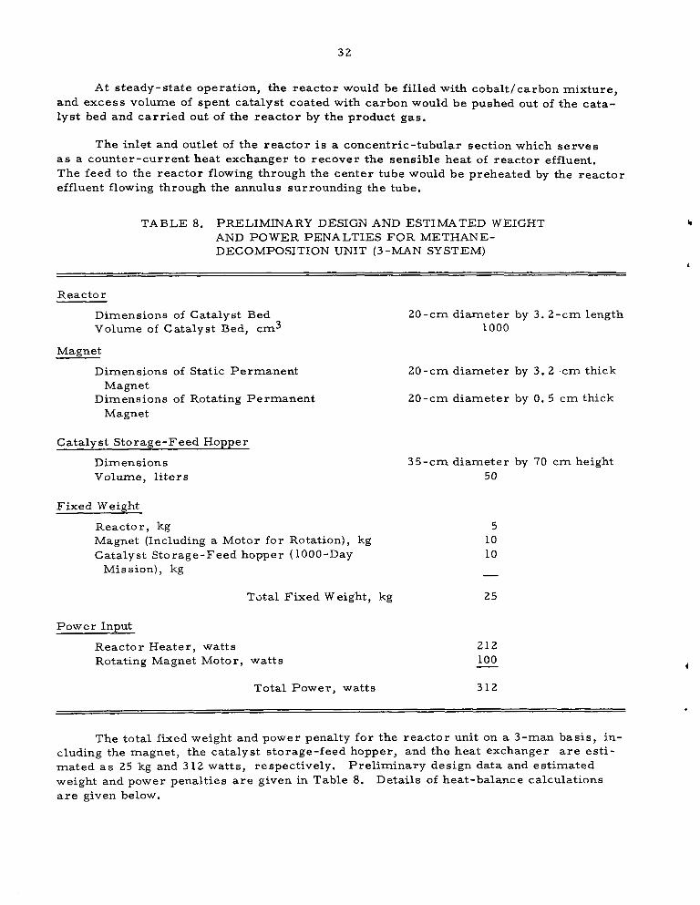
At steady-state operation, the reactor would be filled with cobalt/carbon mixture, and excess volume of spent catalyst coated with carbon would be pushed out of the cata- lyst bed and carr ied out of the reactor by the product gas.
The inlet and outlet of the reac tor i s a concentric-tubular section which serves as a counter-current heat exchanger to recover the sensible heat of reactor effluent. The feed to the reactor flowing through the center tube would be preheated by the reactor effluent flowing through the annulus surrounding the tube.
TABLE 8. PRELIMINARY DESIGN AND ESTIMATED WEIGHT AND POWER PENALTIES FOR METHANE- DECOMPOSITION UNIT (3-MAN SYSTEM)
Reactor
Dimensions of Catalyst Bed Volume of Catalyst Bed, cm3
Magnet
Dimensions of Static Permanent Magnet
Magnet Dimensions of Rotating Permanent
Catalyst Storage-Feed Hopper
Dimensions Volume, liters
Fixed Weight
Reactor, kg Magnet (Including a Motor for Rotation), kg Catalyst Storage-Feed hopper (1000-Day
Mis sion), kg
Total Fixed Weight, kg
Pow e r InDut
Reactor Heater, watts Rotating Magnet Motor, watts
Total Power, watts
20-cm diameter by 3. 2-cm length 1000
20-cm diameter by 3. 2 .cm thick
20-cm diameter by 0. 5 cm thick
35-cm diameter by 70 cm height 50
5 10 10
25
212 100 - 312
The total fixed weight and power penalty for the reactor unit on a 3-man basis, in- cluding the magnet, the catalyst storage-feed hopper, and the heat exchanger are esti- m a t e d a s 25 kg and 312 watts, respectively. Preliminary design data and estimated weight and power penalties are given in Table 8. Details of heat-balance calculations a r e given below.

33
Heat Balance for Methane-Decomposition Unit
I
Decomposition of methane to carbon and hydrogen is an endothermic reaction. Heat of reaction data are shown in Figure 17. ( 7 ) The endothermic heat of reaction at 850 C i s 21. 5 kcal/mole of methane, which corresponds to a power input at a level of 52 watts for the 3-man system. The process would require much additional power to make up for heat loss from the high-temperature reactor through reactor insulation and to compensate for heat-exchange inefficiency.
The heat loss through the vacuum-jacketed reactor primarily by radiation can be estimated from the reactor design shown in Figure 16. The heat loss by radiant heat t ransmiss ion f rom the reactor was estimated as 120 watts for the 3-man system for the following conditions :
Outside-surface temperature of heater unit = 850 C
Outside-surface temperature of vacuum jacket = 25 C
Emissivity of gold surface = 0. 05
The heat loss due to heat-exchanger inefficiency can be estimated from the flow rates, the sensible heat of the reactants, and the products around the reactor-heat ex- changer assembly. Flow rates of the reactants and the products are given in Table A-2 , Appendix A. Sensible-heat data for methane, hydrogen, and carbon are shown in Figure 18. ( 7 ) The reactor effluent consists of 69 g-moles/day of methane and 104 g-moles/day of hydrogen. Assuming the reactants enter the heat exchanger at 25 C and the products leave the heat exchanger at 500 C, the enthalpy loss for the 3-man system was estimated to be 40 watts.
The total power input to the reactor heater would be the sum of the three values calculated, which i s 212 watts for the 3-man system.
Surnmary of Methane-Decomposition-Unit Weight and Power Estimates
Table 9 provides a summary of the preliminary weight estimates for the total methane-decomposition unit that would be added to an Open Sabatier System to achieve a Closed Sabatier System. The weight-and-power penalties of Table 9 can be considered relative to the alternative of carrying s tored water of 900 kg for a 3-man, 1000-day mission (the small added tankage weight of approximately 5 percent for stored water i s not included).
Discussion of Process-Design Results
To i l lustrate the significance of the experimental results obtained on this program, a comparison can be made with prior published information relating to catalysts for methane decomposition and to the various approaches that have been considered to resolve the "carbon-handling problem" for reduced-gravity operation.

34
21
20
19
/
/ /
/
300 400 500 600 700 800 900 IO00 I
Temperature, C
FIGURE 17. ENDOTHERMIC HEAT O F METHANE DECOMPOSITION

Temperature, C
/
/
/
FIGURE 18. SENSIBLE HEAT O F METHANE, HYDROGEN, AND CARBON

36
TABLE 9. SUMMARY O F PRELIMINARY WEIGHT ESTIMATES FOR METHANE-DECOMPOSITION UNIT
3 -Man 1000-Day Equipment Expendable Power Penalty
Weight, Weight, Powe r, at 136 kg/kw, It e m kg kg watts kg
Reactor
Recycle Pump
25
1
312 42
50 7
Hydrogen Separator 6 50 7
Catalyst
Carbon Separator 10
94
3 2(a)
(a) This value is based on an assumed carbon packing density of 0.25 g/cm3 (Table B-1 , Appendix B ) and might be reduced significantly by demonstration of a packing density of about 0.45 g/crn3 indicated for the carbon/cobalt product a t R = 6.35 (Table 4).
In the earliest work by Isomet the use of unsupported powder-metal catalyst was evaluated (at least iron and nickel but not cobalt). A s shown by the data in Figure 14, the decrease in catalyst activity with increase in carbon formation was considered a serious limitation (at that time the assumed goal was a carbon-to-catalyst ratio of 100). The powder bed plugged in the exploratory experiments because there was no agitation of the powder. The major effort in the Isomet studies was directed toward supported catalysts and development of a mechanical method of moving catalyst canisters through a high-temperature reactor.
Subsequent studies by AiResearch showed that higher activity could be obtained for an equivalent amount of metal catalyst by use of an asbestos support structure (e. g. , compare 25 percent N i on asbestos and N i powder in Figure 14). Supported cobalt and supported palladium powder were also shown to have high initial activity but sustained activity to sufficiently high carbon-to-catalyst ratio did not appear possible. The inert support material (asbestos) results in a large expendable weight. It should be noted that while reasonably high catalyst activity is indicated in Figure 14 up to about a carbon-to- metal-catalyst ratio of 4, the ratio would be only 1 for carbon to metal powder plus asbestos. Thus, the use of an inert material for catalyst support does not appear to be an attractive approach. Most of the subsequent AiResearch investigation was directed to the use of cleanable cobalt shot (with limited catalyst surface area). The latter approach has many of the limitations of the "scraping" techniques (i. e. , the need for providing mechanical movement within a high-temperature reactor to separate the carbon/catalyst product from unused catalyst).
(
The use of an expendable catalyst without added support structure is a desirable approach. In a batch operation fine metal wire (i. e. , steel wool) can be used to provide its own physical support initially. Batch processes accomplish carbon separation from the product gas within the high-temperature reactor and require expendable canisters o r a large reactor with resultant heat losses. A continuous methane-decomposition process leads to a smaller reactor volume but requires a means of continuous product removal from the high-temperature reactor. This can be conveniently accomplished by

37
entrainment in the gas stream. Thus, the ideal system provides that a large-surface- area catalyst be used without any expendable inert mechanical support. The problem resolves to one of containing the catalyst/carbon mixture within the high-temperature zone of the reactor in a dispersed manner while controlling entrainment by the gas stream. A magnetic field satisfies the requirements in an ideal manner that avoids sealing problems that would be associated with penetration of the hot reactor to provide mechanical motion. The above reasoning which leads to the use of a magnetic field also limits the choice of catalysts to cobalt (or cobalt alloys).
The important principles of operation of a methane-decomposition reactor with a magnetic field have been shown to be feasible. Further study is indicated to optimize design of the magnetic field and to demonstrate continuous carbon removal. This is con- sidered to be the most important goal for future research on the new concept. While further improvement of activity of the cobalt-powder catalyst can be expected (i. e . , use of smaller mesh powder, improved initial activation, and use of Sabatier products rather than pure methane), the catalytic activity already demonstrated is considered ade- quate to achieve a small reactor size.
The carbon-to-cobalt ratio of about 6 already demonstrated in the experimental work is considered adequate catalyst utilization at the present time.
The reasoning behind the acceptance of a relatively low carbon-to-catalyst ratio is evident from the weight estimates for the total subsystem as a function of carbon- to-catalyst ratio shown in Figure 19. Firs t , in Figure 19, i t is evident that about the same expendable weight can be achieved for a "suspended" catalyst at a ratio of about 6 a s could be obtained with a "supported" catalyst at a ratio of over 20. Admittedly, the magnets and power for rotation are an added weight to provide catalyst "suspension" but this is a small fixed weight independent of mission duration whereas an asbestos support (or special expendable canisters in a batch process) is a mission-duration-dependent item.
The second consideration shown in Figure 19 is that the greater portion of the weight saving versus the alternative of stored water is achieved within a carbon-to- catalyst ratio of about 6 for the assumed fixed weight of the system. Actually, the fixed-weight estimates are conservatively low because no allowance was made for spare components to achieve mission-reliability goals. Assumption of a 1000-day mission makes the expendable-catalyst weight appear significant but the related assumption that the original reactor unit will operate for 1000 days should not be overlooked.
The important point illustrated by Figure 19 is that the maximum utilization of catalyst (or the highest carbon-to-catalyst ratio) does not result in the minimum total- system weight. The reason for this is that the higher the carbon-to-catalyst ratio, the larger the volume of reactor and, the larger the volume of the reactor, the greater the fixed weight and power penalty associated with heat loss. This can be shown by the fol- lowing simplified equation for estimating reactor volume:
V = K ( l t R) kPB

I
Supported catalyst weight (e.g. 25% metal on asbestos)
Total weight (flxed weight + suspended.powder catalyst 1 - 2 - - - ””””
“- ““-.- ”< ””- L
-\ ” ” - ””1
” -- Fixed weight (equlpment + power penalty)
2 4 6 8 IO 12 14 16 I8 20 Carbon/Catalyst Ratio ( R ) , g /g A-57997
FIGURE 19. WEIGHT ESTIMATES O F METHANE-DECOMPOSITION UNIT AS A FUNCTION O F PRODUCT CARBON/CATALYST RATIO
Basis: 3-man system, 1000-day mission for which stored water alternative is 900 kg.
.

39
where
V = design-reactor volume, cm3
K = constant for a particular carbon-producing capability, g-mole carbon/hr
k = specific design-reaction rate, g-mole carbon/hr-g catalyst
R = carbon/catalyst weight ratio
pB = operating bulk density of carbon/catalyst mixture.
In general, it has been observed that reactivity of the catalyst, (k), decreases with in- crease in R. (Thus, an increase in design volume, V , required for lower k. ) At best, there is the possibility that some minimum value of k can be sustained beyond a value of R = 5 as suggested by the data in Figure 13. However, it is obvious that, if one as- sumes a certain operational void volume for the catalyst bed, the bulk-density term also decreases as R increases (i. e . , densi ty of cobalt is 8.9 g/cm3 corresponding to R = 0 and density of carbon is 2 g/cm3 at R = cc). Taking the latter factor into account indi- cates that the reactor volume increases approximately as ( 1 t 4. 5 R). Thus, reactor weight and power penalty for heat loss both increase significantly i f one provides suf- ficient reactor volume to contain the carbon.
For use of a magnetic field in the reactor design, a vacuum-jacket type insulation was preferred to the thicker felt-type insulation. Therefore, heat losses, as related to reactor volume, were estimated as radiation heat losses which vary as the fourth power of absolute temperature of the reactor. Thus, there will be a trade-off between higher operating temperature to favor increased reaction rate, and lower operating temperature to reduce the heat loss and power. No detailed optimization has been made to determine the optimum reaction temperature. However, some data have been obtained during the experimental work to indicate the effect of temperature on reactivn rate as shown in Figure 20. The data shown for steel wire are reproduced from an earlier report. ( 3 ) The data for cobalt powder were obtained at a carbon-to-catalyst ratio of 3 (Figure 3 of this report). The cobalt powder after activation had a la rger t rue sur face a rea of 8 0 0 0 cm2/g (compared to about 1800 cm2/g for as-received powder). The high reaction rate for cobalt powder is probably related to the larger active surface area (compared to steel wool),
It is often difficult to determine which metal is the best catalyst unless all other factors are identical . Fortunately, the proposed l imitation to cobalt (or cobalt al loy) reduces the scope of any future catalyst study. The apparent absence of any immediate need to achieve higher carbon-to-catalyst ratio than already demonstrated is also im- portant. Other properties of the catalyst that might affect continuous catalyst feed to the reactor, operating bulk density, continuous removal of solid product from the reactor, and packing density of the separated carbon now appear to be more important than maxi- mizing reaction rate or increasing catalyst utilization. Catalyst study as related to demonstrating continuous, reliable system operation and ease of process control appears to be the important direction for future research. Since, in the final analysis, the use of any carbon-producing process in space applications depends on resolving the opera- tional problems.

0. I
0.01
0.001 0.8
Temperature, C 950 900 850 800 750 700 650 600
Cobalt powder: (-50 mesh 1 ___ Inltlal surface area: 8500 crn2/g
\,
Steel wool (0 gage) Surface area : 217 crn2/g C
I I ' i
I
I I I i 0 9 I O
I /T , K"
1 . 1
A-57998
FIGURE 20. RATE O F METHANE DECOMPOSITION AS FUNCTION O F TEMPERATURE FOR COBALT-POWDER AND STEEL-WOOL CATALYSTS

41
SECTION 4. CONCLUSIONS
The following conclusions may be drawn from the results obtained in this program:
(1) The use of cobalt powder as an expendable catalyst looks promising a s a means for designing an efficient reactor for methane de- composition and for resolving the problem of carbon handling.
(2) A disk-shaped reactor with a rotating magnetic field set up uniformly through the catalyst bed by a stationary permanent magnet coupled with a rotating magnet is recommended. The total fixed weight and power penalty for the reactor unit are esti- mated as 25 kg and 312 watts, respectively, for a 3-man system.
(3) One feasible method for collection and disposal of carbon produced from methane decomposition as waste is the use of disposable bag filters. The fixed weight of the filter unit for a 3-man, 1000-day mission is es t imated as 43 kg, of which the weight of the disposable bags accounts for 80 percent.
(4) The metals-iron, cobalt, nickel, and palladium- have been found to be the most effective catalysts of those tried for methane decom- position. The most effective catalyst materials have been found to be effective in either supported or unsupported forms provided that proper activation is used. The unsupported metals were activated best by first oxidizing the metals and then reducing them in hydro- gen at temperatures of 500 C and above before admitting methane.
(5) In a l l cases of high activity, the growth of the carbon deposit was not layerwise, but, rather, was accompanied by disintegration of the metal catalyst and the accumulation of an intimate mixture of active metal and carbon residue.
(6) The large dependence of high, continuing activity upon the pulver- izing action of the reaction on the metal catalyst indicates that a suitable reactor would probably need to be capable of retaining the powder formed until a sufficient carbon-to-metal ratio has been achieved. This has been suitably accomplished with work de- scribed here by use of vibratory or magnetic agitation, and mag- netic confinement of the catalyst powder in the reactor. The only metal with suitable magnetic characteristics for this purpose ap- pears to be cobalt.

4 2
SECTION 5. RECOMMENDATIONS FOR FUTURE WORK
Future work recommended for implementing the findings of this program would be construction and evaluation of an experimental methane-decomposition unit. The unit would be designed for a nominal 3-man capacity based on the design data and specifica- tions developed in this program. The overall unit would consist of (1) a methane- decomposition reactor, including the rotating-magnet and catalyst-feed mechanisms, ( 2 ) a carbon-separation unit, (3) a recycle pump, (4) a hydrogen-separation unit, and (5) instrumentation and controls.
Evaluation of the experimental unit would be directed to accomplish the following tasks:
(1 ) Continuous feeding of fresh catalyst and removal of spent catalyst/ carbon mixture from the reactor
( 2 ) Improving the design of the carbon-separation unit
(3) Investigating the process dynamics of reactor operation as i t relates to automatic control of the overall Closed Sabatier system operation
.
(4) Further evaluation of catalysts as related to obtaining satisfactory steady-state operation of an experimental methane-decomposition unit with continuous carbon removal.

43 and 44
SECTION 6. REFERENCES
(1) Shandle, J. D., "Evaluation of Life-support Chemical Techniques, Volume 3, Part 3 : Investigation of Catalytic Decomposition of Methane", Final Report SS-3507, NASA Manned Spacecraft Center Contract NAS 9-1043 (August 1, 1965).
(2) Clifford, J. E., et al., "Investigation of an Integrated Carbon Dioxide-Reduction and Water-Electrolysis System", AMFKL-TDR-66-166 (April , 1967).
(3) Bozorth, R. M., Ferromagnetism, D. Van Nostrand (1951), pp. 277, 723.
( 4 ) JANAF Thermochemical Data, Volumes 2 and 4.
( 5 ) Perry, J . H., ed., Chemical Engineers Handbook, Fourth Edition, McGraw-Hill (1963) , pp 20-75 to 20-77.

4
APPENDIX A
PROCESS-DESIGN AND hL4TEFUAL-BALANCE CALCULATIONS "" ~~ ~

A- 1
APPENDIX A
PROCESS-DESIGN AND MATERIAL-BALANCE CALCULATIONS - .~ - .~~ ~ ~ ~- ~ ~~
Closed Sabatier System - Material Balance -~ ~ ~~
A flowsheet of a Closed Sabatier system for oxygen recovery from carbon dioxide and water vapor is shown in Figure A-1. Indicated flows are based on metabolic oxygen consumption at a rate of 910 g/man-day, carbon dioxide production at a rate of 1000 g/man-day, and water-vapor generation by respiration and perspiration at a minimum rate of 11 13 g/man-day. '' Carbon dioxide is first reacted with hydrogen by the Sabatier reaction at 200 C to produce water and methane:
After water vapor is removed, methane is decomposed to hydrogen and carbon, the latter being the primary waste product from the overall process. Hydrogen containing unreacted unreacted methane is separated from the decomposition products and is returned to the Sabatier reactor.
The Sabatier reaction produces 818 g/man-day of water by complete reduction of all of the available carbon dioxide. To provide enough hydrogen for the reduction pro- cess, about three quarters of the total methane produced by the Sabatier reaction must be decomposed, and the remainder discarded as waste. When hydrogen recovery from methane is less than the indicated level, either part of the carbon dioxide must be wasted or make-up hydrogen must be provided from another source. In the lat ter event, the preferred approach is to carry stored water at launch and supply the make-up hydrogen by electrolysis. The stored water at launch as a function of the extent of con- version of methane to hydrogen is shown in Figure A - 2 . When the conversion is nilin the situation where all of the methane produced is dumped overboard, the Sabatier reac- tion produces only 508 g/man-day of water. The difference between 818 glman-day and 508 g/man-day is the deficiency to be made up from stored water. The storage require- ment amounts to 113 kg/man-year (249 lblman-year), which indicates a trade-off for long missions which favors recovery of hydrogen from methane.
Integrated Process Control
Optimal performance of a Closed Sabatier carbon dioxide reduction system is at- tained when all of the available carbon dioxide is utilized as efficiently as possible to maximize recovery of contained oxygen as water, Therefore, the system must be operated in such a manner that, given a prescribed feed of carbon dioxide to be pro- cessed, minimum quantity of carbon dioxide is wasted. To accomplish this task, the instrumentation and control system should be designed accordingly.
*The fact that the water-vapor production might be higher is not pertinent, since only the humidity condensate (90 g/day-man) would be increased.

A - 2
90 H,O (g)(excess) - 910 0, Water -Vapor 1023 H20 (g) I I I3 H,O (9)
< * " Electrolysis 4
1000 CO,
Concentration
Sabatier
Methane ' Decomposition and - 88 CH, (waste)
818 H,O (1) 207 C (waste)
FIGURE A-1. CLOSED SABATIER SYSTEM
Numerals: g/man-day.

A - 3
4a
L
c aJ
s -0
0 0
L c
I O(
\
\ I €
O v e r a l I Conversion of CH,to C + 2 H,, percent
FIGURE A - 2 . STORED WATER AT LAUNCH AS FUNCTION O F PERCENT DECOMPOSITION O F M E T H A N E
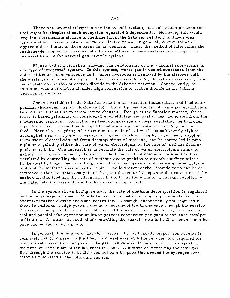
A-4
There are several subsystems in the overal l system, and subsystem process con- trol might be simpler i f each subsystem operated independently. However, this would require intermediate storage of methane (from the Sabatier reaction) and hydrogen (from methane decomposition and water electrolysis) . In general , accumulation of appreciable volumes of these gases is not desired, Thus, the method of integrating the methane-decomposition reactor into the overall system was analyzed with respect to material balance for several gas-recycle options.
Figure A - 3 i s a flowsheet showing the relationship of the principal subsystems in one type of integrated system. In this system, waste gas is vented overboard from the outlet of the hydrogen-stripper cell. After hydrogen is removed by the str ipper cell , the waste gas consists of mostly methane and carbon dioxide, the latter originating from incomplete conversion of carbon dioxide in the Sabatier reaction. Consequently, to minimize waste of carbon dioxide, high conversion of carbon dioxide in the Sabatier reaction is required.
Control variables in the Sabatier reaction are reaction temperature and feed com- position (hydrogenlcarbon dioxide ratio). Since the reaction is both rate and equilibrium limited, i t is sensitive to temperature changes. Design of the Sabatier reactor, there- fore , i s based pr imar i ly on consideration of efficient removal of heat generated from the exothermic reaction. Control of the feed composition involves regulating the hydrogen input for a fixed carbon dioxide input to maintain a preset ratio of the two gases in the feed. Normally, a hydrogen/carbon dioxide ratio of 4. 1 would be sufficiently high to accomplish near-complete conversion of carbon dioxide. The hydrogen feed, supplied from water electrolysis and from decomposition of methane, can be controlled in prin- ciple by regulating either the rate of water e lectrolysis or the ra te of methane decom- posi t ion or both. One approach is to regulate the rate of water electrolysis solely to satisfy the oxygen demand by the crew. The Sabatier feed composition would be then regulated by controlling the rate of methane decomposition to smooth out fluctuations in the total hydrogen feed resulting from off-normal operation of the water-electrolysis unit and the methane-decomposition unit. The hydrogenlcarbon dioxide ratio can be de- termined either by direct analysis of the gas mixture or by separate determination of the carbon dioxide feed and the hydrogen feed, the latter from the total current supplied to the water-electrolysis cell and the hydrogen-stripper cell .
In the system shown in Figure A - 3 , the rate of methane decomposition is regulated by the recycle-pump speed. The latter is controlled in turn by output signals from a hydrogenlcarbon dioxide analyzer-controller. Although, theoretically not required if there is sufficiently high percent methane decomposition in one pass through the reactor, the recycle pump would be a desirable part of the system for redundancy, process con- trol and possibly for operation at lower percent conversion per pass to increase catalyst utilization. An alternate method of controlling the recycle rate is by flow control on a by- pass around the recycle pump.
In general, the volume of gas flow through the methane-decomposition reactor is relatively low (compared to the Bosch process) even with the recycle flow required for low percent conversion per pass. The gas flow rate could be a factor in transporting the product carbon out of the hot reaction zone. A method of increasing the total gas flow through the reactor is by flow control on a by-pass line around the hydrogen sepa- rator as discussed in the following section.

Power - p, decompostion
@ I
control
I Recycle
H2 i
H, stripper I Sa ba t ier cell
5 H2O H 2 0 Makeup I
I E= reactor separator electrolysis
cel I H2O -
1 @ Temperature-indicator controller
t
0 2
Product
Legend
BPR Back-pressure regulator A/C Analyzer-controller
@ Set-point station
A-57999
FIGURE A-3. CLOSED SABATIER SYSTEM INSTRUMENTATION AND CONTROLS

A-6
MATERIAL-BALANCE CALCULATIONS - METHANE-DECOMPOSITION UNIT
A flow sheet of a methane-decomposition unit i s shown in Figure A-4. The unit consists of a high-temperature reactor, a heat exchanger for heat recovery, a carbon separator , a hydrogen separator, and a recycle-gas pump. This unit receives as i t s feed a gas mixture leaving the water separator following the Sabatier reactor and pro- duces pure hydrogen at a suitable pressure to be returned to the Sabatier reactor. The feed gas consists of methane and small quantities of unreacted hydrogen and carbon dioxide. The feed-gas composition shown is based on: (1) hydrogen/carbon dioxide ratio of 4. 1 moles/mole in the Sabatier feed, ( 2 ) 99 percent conversion of carbon diox- ide feed to methane in the Sabatier reaction, (3) complete removal of water vapor from the Sabatier-reactor effluent, and (4) removal of excess hydrogen by the hydrogen sep- arator until about 1 percent hydrogen remains in the gas mixture.
The flow sheet shows two recycle streams at the reactor outlet; one passes through the hydrogen separator, and the other by-passes the hydrogen separator. The recycle stream by-passing the hydrogen separator is included in the flow sheet to con- sider the option of high gas flow through the reactor while passing a portion of the total recycle through the hydrogen separator. The methane flows in the recycle streams are designated as R1 and R2.
A small quantity of carbon dioxide present in the feed is removed from the pro- cess with the excess methane and is vented from the process as waste. Assuming the carbon dioxide does not undergo reaction in the process, its concentration would build up to a maximum level of about 3 percent in the waste-gas stream and less than 3 pe r - cent elsewhere in the process.
The equations shown in Figure A - 4 were solved to examine the effect of recycle on the compositions of the gas mixture at the inlet and the outlet of the methane- decomposition reactor. Calculated results are summarized in Table A - 1 . The results show that the gas compositions at the reactor outlet are independent of R2 (the rate of methane recycle by-passing the hydrogen separator) and dependent only on R1 (the rate of methane recycle through the hydrogen separator). As R1 is increased, the concen- tration of methane at the reactor inlet and outlet increases, thus favoring the methane decomposition reaction. Increasing R2 on the other hand produces the reverse effect - reducing the concentration of methane at the reactor inlet . The latter recycle, there- fore, should be minimized and considered only as a means to provide a high gas flow through the reactor, i f needed, to aid in carbon removal from the reactor.
Material-balance calculations around the methane-decomposition reactor for R2 = 0 in a 3-man system are summarized in Table A-2. When the degree of methane decomposition reaches 73.9 percent on the basis of methane feed to the reactor, no recycle would be required (R1 = 0) . F o r a lesser degree of decomposition, the un- reacted methane from the reactor must be partially recycled to close the system. As the recycle rate is increased, the total gas flow through the reactor increases, and the degree of methane decomposition needed to produce hydrogen at a prescribed rate de- creases . A l s o , with increasing recycle rate, the concentration of methane is reduced only slightly at the reactor inlet; but it increases substantially at the reactor outlet, thus favoring the decomposition reaction. At the lowest level of methane decomposition

A - 7
TABLE A-1. MATERIAL BALANCE AROUND REACTOR
- . . .. .~ ... . . - . .. "~ . . - ~ . .. ~ ~ . . . . . - . . -. . I - . "~ . I
Recycles, Reactor Inlet Reactor Outlet g-mole/ Flow Rate, Flow Rate,
day/rnada) g-mole/day/man Composition, percent g-mole/day/man Composition, percent
R1 R2 CHq H2 COP CH4 H2 - C02 cH4 H2 C02 CH4 H2 CO2 .~ ." . ~. , . . .~ . .
0 0 22.5 0.2 0.2 98.2 0.9 0.9 5.9 33.4 0.2 14.9 84.6 0.5
0 100 122.5 567.2 3.6 17.7 81.8 0.5 105.9 600.4 3.6 14..9 84.6 0.5
0 1000 1022.5 5670.2 34.1 15.2 84.3 0.5 1005.9 5703.4 34.1 14.9 84.6 0.5
10 0 32.5 0.3 0.5 97.6 0.9 1.5 15.9 33.5 0.5 31.8 67.2 1.0
10 100 132.5 211.3 3.9 38.1 60.8 1.1 115.9 244.5 3.9 31.5 67.1 1.1
10 1000 1032.5 2110.3 34.4 32.5 66.4 1.1 1015.9 2143.5 34.4 31.8 67.1 1.1
100 0 122.5 1.2 3.6 96.3 0.9 2.8 105.9 34.4 3.6 73.6 23.9 2.5
100 100 222.5 33.7 7.0 84.5 12.8 2.7 205.9 66.9 7.0 73.5 23.9 2.6
100 1000 1122.5 326.2 37.6 75.5 21.9 2.5 1105.9 359.4 37.6 73.6 23.9 2.5
( a ) 1 g-mole/day/man = 0.0155 l /min/man (STP) = 0.000550 cfm/man (STP). "" ~ . _ - " I _ _ i "~ =kL--,:~-..-":-;L" i I"l"=-i"z
"

A- 8
Reactor
~
Exchanger
I
I
! C H 4 = 22.5 + R, + R, 1 1 C = 16.6
C H 4 = 5.9 + R, + R,
H, = 33.4 + 0.01 R, + R2 ( 33.45$ y l )
CO2 = 0.2 + 0.034 R, + R, ( "';,,"y;R,) 1
H,=0.2 + 0.01RI + R2 33.4 + 0.01 R,
( 5.9 + R, Carbon
Separator Waste Solid
C = 16.6
Recycle - Gas Pump
- -
Hydrogen Separator -- Product to Sabatier
H, = 33.3 L
C H 4 = R,
2- .( 33.4 + 0.01 R,) -
5.9 + R,
I
co 2- - ,(0.2 5.9 +O.034Rl) + R, - - Waste Gas
CH4 = 5.9 He= 0.06 c02 = 0.2 C H 4 = R,
HZ = 0.01 R, C 0 2 0.034 RI
- - Feed From Sabotier CH4 = 22.5 H2 = 0.2 cop 0.2
A-58000 1
T i
FIGURE A-4. FLOWSHEET O F METHANE DECOMPOSITION PROCESS
Numerals: g-moles/man-day.

TABLE A-2. MATERIAL BALANCE AROUND METHANE DECOMPOSITION REACTOR IN A 3-MAN SYSTEM
Recycle(a), Reactor Inlet Reactor Outlet g-mole/day(b) Flow Rate, g-molelday Composition, percent Flow Rate. n-mole/dav Composition, percent m4 Decomposition,
- R1 CH4 H2 C02 Total CH4 H2 C02 CH4 H2 CO2 Total CH4 Hz C02 percent of input
I
0 67.5
30 97.5
60 127.5
90 157.5
120 187.5
150 217.5
180 247.5
210 277.5
240 307.5
27 0 337.5
300 367.5
0.60 0.60
0.90 1.62
1.20 2.64
1.50 3.66
1.80 4.68
2.10 5.76
2.40 6.72
2.70 7 .74
3.00 8.76
3.30 9.78
3.60 10.80
68.7
100.0
131.3
162.7
194.0
225.3
256.6
287.9
319.3
350.6
381.9
98.3 0.87 0.87
97.5 0.90 1.62
97.1 0.92 2.01
96.8 0.92 2.25
96.7 0.93 2.41
96.5 0.93 2.53
96.4 0.94 2.62
96.4 0.94 2.69
96.3 0.94 2.74
96.3 0.94 2.79
96.2 0.94 2.83
17.7
47. 7
77.7
107.7
137.7
167.7
197.7
227.7
257.7
287.7
317.7
100.2
100.5
100.8
101.1
101.4
101.7
102.0
102.3
102.6
102.9
103.2
0.60
1.62
2.64
3.66
4.68
5.70
6.72
7.74
8.76
9.78
10.80
118.5
149.8
181.1
212.5
243.8
275.1
306.4
337.7
369.1
400.4
431.7
14.9 84.6 0.51
31.9 67.0 1.08
42.9 55.6 1.46
50.7 47.6 1.72
56.5 41.6 1.92
61 .0 36.9 2.07
64.5 33.3 2.19
67.4 30.3 2.29
69.8 27.8 2.37
71.9 25.7 2.44
73.6 23.9 2.50
73.9
51.2
39.2
31.7
26.6
22.9
20.2
18.0
16.2
14.8
13.6
(a) A portion of output (essentially methane) from the hydrogen separator recycled to decomposition reactor. (b) 100 g-mole/day = 1.55 liter/min (STP) = 0. 0550 cfm (STP).

I
Q
APPENDIX I3
CARBON-SEPARATION UNIT "

B- 1
APPENDIX B
CARBON-SEPARATION UNIT
Requirements
Some of the requirements for a carbon-separation device are (1) a high collection efficiency for small particles of spent catalyst and carbon, (2) operation with low gas flow, ( 3 ) ease of handling collected carbon (from the standpoint of permanent storage and disposal), (4 ) reliability, and (5) low fixed weight.
Bag Filter Design
A bag fi l ter satisfies some of the requirements better than any other types of gas/ solid separation devices. A bag-filter unit was used in the Bosch subsystem in the ILSS at NASA Langley Research Center. Typical collection efficiencies of bag filters on small particles in the micron range are above 99 percent on woven fabrics and above 99 . 9 percent on felt fabrics. (8 ) A filter unit for removing carbon from the effluent of methane decomposition is shown schematically in Figure B- 1. The proposed design is based on a batch-mode operation in which two identical filters are used to permit periodic removal and replacement of disposable bag filters. The bags filled with sarbon will be removed from the unit and transferred manually to a food locker for storage and future disposal.
For the present design, a commercial Teflon felt(8) was selected as the filter medium. Teflon was chosen for its strength, abrasion resistance, heat resistance, and nonflammability. Design and operating data are given in Table B-1 for a 3-man unit to be used on a 1000-day mission. In the design given, the dimensions of the filter, the basis weight of the filter fabric, and the packing density of carbon in the f i l ter were as- sumed. A large proportion of the total-weight penalty of the unit is due to the disposable fi l ter bags. Since commercial f i l ter bags are designed for a long-term usage involving repeated cleaning, the basis weight assumed for the felt might be higher than would be needed for disposable bags for use on a short-term basis. Hence, the fixed weight of the filter bags could be reduced substantially by improved design of the felt for present application.
Pressure drop through the f i l ter occurs in most par t through the layer of carbon dust, the pressure drop through the felt itself being comparatively negligible. The pres- sure drop increases in proportion to the thickness of the dust layer as shown by the fol- lowing equation(81,
P = KpmV ,

B- 2
Carbon-laden gas
Clean gas
FIGURE B- 1. CARBON-SEPARATION UNIT
A-58001

B-3
where
P = pressure drop through dust layer, mrn Hg
K = cake-resistance factor, mm H g / (centipoise)(grains/ft'/rnin)
1-1 = viscosity of gas, centipoise
m = m a s s of dust accumulated per unit area of f i l t e r , g ra ins / f t 2
v = superficial velocity of gas through filter, ft/min.
The cake resistance factor ( K ) depends mainly on the particle size of dust and void fraction of cake. The resistance factor increases with decrease in particle size and void fraction. For sizes under 10 microns, the value of the resistance factor levels off to a maximum of 0. 75, increased voids compensating for the reduction in size. From the maximum value of the cake-resistance factor, pressure-drop data were calculated as funcion of the rate of gas flow through the 3-man unit. The pressure-drop data shown in Figure B-2 refer to the maximum values reached at the end of collection cycles. For the 3-man integrated system, the minimum gas f low through the f i l ter is 118. 5 g-molelday (Table A - 2 ) . The maximum pressure drop for this flow is estimated a s 1 . 0 mm Hg from Figure B-2.
TABLE B-1. DESIGN AND OPERATING CHARACTERISTICS O F CARBON-SEPARATION UNIT
(3-Man Unit for 1000-Day Mission)
~ ~~
Filter Medium
Material Basis Weight, oz/sq yd Dimensions
Fi l ter Area, f t 2 Carbon-Collection Capacity, ft3 Carbon-Collection Efficiency, percent
Filter Housing
Material Dimensions
ODeratine Conditions
Rate of Carbon Collection, kg/day Carbon Packing Density, g/cm3 Carbon Loading/Bag, kg Time Between Filter Replacement, days
Fixed Weight - Fil ter bags
Number Required/ 1000 days Total Weight of Bags, kg
Filter Housing, kg/2 units
Total Fixed Weight, kg
Teflon felt 15. 6(8) 12-inch diameter by 12 inch length
4. 71 0. 785 above 9 9 . 9
Aluminum 13-inch diameter by 13-inch length
by l/di-inch thickness
0. 598 0. 25 5. 55 9 . 3
108 32.4
9. 6
42. 0

B-4 5
4
I
0 0 50 IO0 I 50 200 250 300 350 400 450 500
Total Gas Flow Through Filter, g-moles/doy A - h O Z
FIGURE B-2. MAXIMUM PRESSURE DROP THROUGH CARBON FILTER
( 3 -Man Unit)
Other Carbon-Separation Concepts
The following methods of carbon separation are suggested as al ternative approaches to the problem:
(1 ) Filtration using one bag filter with the capacity to hold and store all the carbon produced in the mission. The volume of the filter unit, based on a packing density of 0. 2 g/cm3 of carbon is esti- mated as 2 , 9 9 0 l i t e r s o r 106 ft3. The advantage of this approach is that carbon would be permanently contained by the system without being exposed to the outside cabin atmosphere. The dis- advantage is that the large quantity of methane and hydrogen con- tained in the filter unit presents a f i re hazard.
( 2 ) Filtration using the proposed dual-filter unit with repeated use of filter bags by transferring carbon into one large storage bag. Carbon transfer would be accomplished by a blow-back technique using cabin air as the transfer medium. This approach eliminates the need for the large number of disposable bags and manual transfer of carbon to storage but would require added equipment for auto- mat ic t ransfer of carbon into the permanent storage bag.
(3) Separation of carbon using an electromagnet as a substitute for the f i l t e r bag in method (2 ) . This approach obviates the need for re- placement of filter bags due to plugging and degradation.
(4) Separation of carbon using a cyclone and a screw feeder. A screw feeder attached to the bottom of a cyclone separator would transfer carbon into a storage container. The main advantage of this method would be possible compaction of powdery carbon in the screw feeder to obtain more densely packed carbon.
NASA-Langley, 1970 - 5