Dual Redundancy Module with Load Sharing - 24…28V, 20 A
24
Dual Redundancy Module with Load Sharing - 24…28V, 20 A Catalog Number 1606-XLERED20Y Reference Manual Original Instructions
-
Upload
khangminh22 -
Category
Documents
-
view
0 -
download
0
Transcript of Dual Redundancy Module with Load Sharing - 24…28V, 20 A
Dual Redundancy Module with Load Sharing - 24…28V, 20 ACatalog Number 1606-XLERED20Y
Reference Manual Original Instructions
2 Rockwell Automation Publication 1606-RM107A-EN-P - July 2020
Dual Redundancy Module with Load Sharing - 24…28V, 20 A Reference Manual
Important User InformationRead this document and the documents listed in the additional resources section about installation, configuration, and operation of this equipment before you install, configure, operate, or maintain this product. Users are required to familiarize themselves with installation and wiring instructions in addition to requirements of all applicable codes, laws, and standards.
Activities including installation, adjustments, putting into service, use, assembly, disassembly, and maintenance are required to be carried out by suitably trained personnel in accordance with applicable code of practice.
If this equipment is used in a manner not specified by the manufacturer, the protection provided by the equipment may be impaired.
In no event will Rockwell Automation, Inc. be responsible or liable for indirect or consequential damages resulting from the use or application of this equipment.
The examples and diagrams in this manual are included solely for illustrative purposes. Because of the many variables and requirements associated with any particular installation, Rockwell Automation, Inc. cannot assume responsibility or liability for actual use based on the examples and diagrams.
No patent liability is assumed by Rockwell Automation, Inc. with respect to use of information, circuits, equipment, or software described in this manual.
Reproduction of the contents of this manual, in whole or in part, without written permission of Rockwell Automation, Inc., is prohibited.
Throughout this manual, when necessary, we use notes to make you aware of safety considerations.
Labels may also be on or inside the equipment to provide specific precautions.
WARNING: Identifies information about practices or circumstances that can cause an explosion in a hazardous environment, which may lead to personal injury or death, property damage, or economic loss.
ATTENTION: Identifies information about practices or circumstances that can lead to personal injury or death, property damage, or economic loss. Attentions help you identify a hazard, avoid a hazard, and recognize the consequence.
IMPORTANT Identifies information that is critical for successful application and understanding of the product.
SHOCK HAZARD: Labels may be on or inside the equipment, for example, a drive or motor, to alert people that dangerous voltage may be present.
BURN HAZARD: Labels may be on or inside the equipment, for example, a drive or motor, to alert people that surfaces may reach dangerous temperatures.
ARC FLASH HAZARD: Labels may be on or inside the equipment, for example, a motor control center, to alert people to potential Arc Flash. Arc Flash will cause severe injury or death. Wear proper Personal Protective Equipment (PPE). Follow ALL Regulatory requirements for safe work practices and for Personal Protective Equipment (PPE).
Table of ContentsTerminology and Abbreviations . . . . . . . . . . . . . . . . . . . . . . . . . . . . . . . . . . . 5Product Overview . . . . . . . . . . . . . . . . . . . . . . . . . . . . . . . . . . . . . . . . . . . . . . . . 5Specifications . . . . . . . . . . . . . . . . . . . . . . . . . . . . . . . . . . . . . . . . . . . . . . . . . . . 6Catalog Numbers . . . . . . . . . . . . . . . . . . . . . . . . . . . . . . . . . . . . . . . . . . . . . . . . 6Input and Output Characteristics. . . . . . . . . . . . . . . . . . . . . . . . . . . . . . . . . . 7Power Losses . . . . . . . . . . . . . . . . . . . . . . . . . . . . . . . . . . . . . . . . . . . . . . . . . . . . 8Lifetime Expectancy and Meant Time Between Failure . . . . . . . . . . . . . . 9Terminals and Wiring . . . . . . . . . . . . . . . . . . . . . . . . . . . . . . . . . . . . . . . . . . . 10Functional Diagram . . . . . . . . . . . . . . . . . . . . . . . . . . . . . . . . . . . . . . . . . . . . . 10Front Side and User Elements . . . . . . . . . . . . . . . . . . . . . . . . . . . . . . . . . . . . 11Redundancy OK Relay Contact . . . . . . . . . . . . . . . . . . . . . . . . . . . . . . . . . . . 11Load Share OK Relay Contact . . . . . . . . . . . . . . . . . . . . . . . . . . . . . . . . . . . . 12Automated Load Sharing . . . . . . . . . . . . . . . . . . . . . . . . . . . . . . . . . . . . . . . . 12Electromagnetic Compatibility . . . . . . . . . . . . . . . . . . . . . . . . . . . . . . . . . . . 13Environment . . . . . . . . . . . . . . . . . . . . . . . . . . . . . . . . . . . . . . . . . . . . . . . . . . . 14Protection Features . . . . . . . . . . . . . . . . . . . . . . . . . . . . . . . . . . . . . . . . . . . . . 15Safety Features . . . . . . . . . . . . . . . . . . . . . . . . . . . . . . . . . . . . . . . . . . . . . . . . . 15Dielectric Strength . . . . . . . . . . . . . . . . . . . . . . . . . . . . . . . . . . . . . . . . . . . . . . 15Approvals . . . . . . . . . . . . . . . . . . . . . . . . . . . . . . . . . . . . . . . . . . . . . . . . . . . . . . 16Standards Compliance . . . . . . . . . . . . . . . . . . . . . . . . . . . . . . . . . . . . . . . . . . 16Approximate Dimensions and Weight . . . . . . . . . . . . . . . . . . . . . . . . . . . . 17JulySide Mounting Bracket. . . . . . . . . . . . . . . . . . . . . . . . . . . . . . . . . . . . . . . 18Using Only One Input Instead of Both Channels . . . . . . . . . . . . . . . . . . . 19Recommendations for Redundancy. . . . . . . . . . . . . . . . . . . . . . . . . . . . . . . 20Inductive and Capacitive Loads . . . . . . . . . . . . . . . . . . . . . . . . . . . . . . . . . . 20Applications that Allow Reduced Side Clearances . . . . . . . . . . . . . . . . . . 201+1 Redundancy Up to 10 A . . . . . . . . . . . . . . . . . . . . . . . . . . . . . . . . . . . . . . . 21Mounting Orientations . . . . . . . . . . . . . . . . . . . . . . . . . . . . . . . . . . . . . . . . . . 22Additional Resources . . . . . . . . . . . . . . . . . . . . . . . . . . . . . . . . . . . . . . . . . . . . 23
Rockwell Automation Publication 1606-RM107A-EN-P - July 2020 3
Notes:
4 Rockwell Automation Publication 1606-RM107A-EN-P - July 2020
Terminology and Abbreviations
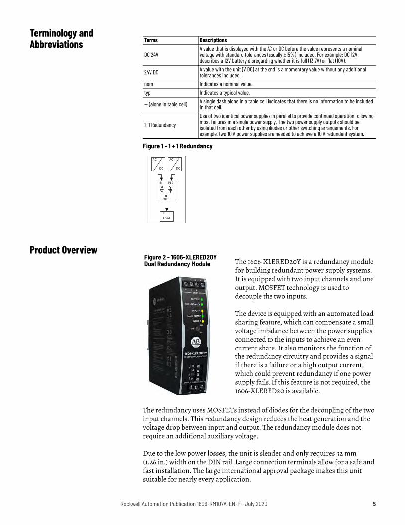
Figure 1 - 1 + 1 Redundancy
Product Overview
The redundancy uses MOSFETs instead of diodes for the decoupling of the two input channels. This redundancy design reduces the heat generation and the voltage drop between input and output. The redundancy module does not require an additional auxiliary voltage.
Due to the low power losses, the unit is slender and only requires 32 mm (1.26 in.) width on the DIN rail. Large connection terminals allow for a safe and fast installation. The large international approval package makes this unit suitable for nearly every application.
Terms Descriptions
DC 24V A value that is displayed with the AC or DC before the value represents a nominal voltage with standard tolerances (usually ±15%) included. For example: DC 12V describes a 12V battery disregarding whether it is full (13.7V) or flat (10V).
24V DC A value with the unit (V DC) at the end is a momentary value without any additional tolerances included.
nom Indicates a nominal value.typ Indicates a typical value.
— (alone in table cell) A single dash alone in a table cell indicates that there is no information to be included in that cell.
1+1 Redundancy Use of two identical power supplies in parallel to provide continued operation following most failures in a single power supply. The two power supply outputs should be isolated from each other by using diodes or other switching arrangements. For example, two 10 A power supplies are needed to achieve a 10 A redundant system.
AC
DC
AC
DC
Load
+ -
IN 1
OUT
IN 2
Figure 2 - 1606-XLERED20Y Dual Redundancy Module The 1606-XLERED20Y is a redundancy module
for building redundant power supply systems. It is equipped with two input channels and one output. MOSFET technology is used to decouple the two inputs.
The device is equipped with an automated load sharing feature, which can compensate a small voltage imbalance between the power supplies connected to the inputs to achieve an even current share. It also monitors the function of the redundancy circuitry and provides a signal if there is a failure or a high output current, which could prevent redundancy if one power supply fails. If this feature is not required, the 1606-XLERED20 is available.
Rockwell Automation Publication 1606-RM107A-EN-P - July 2020 5
Product features include:• Design for 1+1 redundancy with automated load sharing• Dual-input with single output• Redundancy OK Signal, which reports the loss of redundancy• 160% (32.5 A) peak load capability• Reverse input polarity protection• Full power at temperatures -40…+70 °C (-40…+158 °F)• Width only 32 mm (1.26 in.)• Rugged metal housing• Easy wiring, with distribution terminal for negative pole
Specifications
Catalog Numbers
Attributes Values NotesInput voltage DC 24…28V ±25% Input voltage range 18…35V DC —
Input current 2 x 0…12 A ambient < 45 °C (113 °F)2 x 0…10 A ambient < 70 °C (158 °F)
Output current 0…24 A ambient < 45 °C (113 °F)0…20 A ambient < 70 °C (158 °F)26 A max in overload(1) or short circuit mode
(1) Currents at voltages below 6V.
Input to output voltage drop 0.1…0.5V(2)
(2) Depending on load share function.
input: 2 x 5 A
0.2…0.5V(2) input: 2 x 10 A
Power losses
1.7 W at no load
2.6…4.7 W(2) input: 2 x 5 A
5.6…8.7 W(2) input: 2 x 10 A
Temperature range -40…+70 °C (-40…+158 °F) operational
Dimensions 32 x 124 x 117 mm(1.26 x 4.88 x 4.61 in.) W x H x D
Weight 310 g (0.69 lb) —
Catalog Numbers Descriptions1606-XLERED20Y Redundancy module1606-XLA-S37 Side mount bracket
6 Rockwell Automation Publication 1606-RM107A-EN-P - July 2020

Input and Output Characteristics
Attributes Values NotesNumber of inputs — 2 —Number of outputs — 1 —Input voltage Nom DC 24…28V ±25% —Input voltage range — 18…35V DC —
Voltage drop, input to outputTyp 0.1…0.5V at 2 x 5 A, load share dependent on function, see Figure 3Typ 0.2…0.5V at 2 x 10 A, load share dependent on function, see Figure 3Typ 0.24…0.5V at 2 x 12 A, load share dependent on function, see Figure 3
Input current
Nom 2 x 0…12 A continuous, ambient temperature < 45 °C (113 °F) Nom 2 x 0…10 A continuous, ambient temperature < 70 °C (158 °F)
Nom 2 x 17 A(1) for 5 s max
Max 2 x 700 A for 1 ms max
Output current
Nom 24 A continuous, ambient temperature < 45 °C (113 °F) Nom 20 A continuous, ambient temperature < 70 °C (158 °F) Nom 32.5 A for 5 s max
Max 26 A in overload /short-circuit (voltage < 6V). Ensure that the sum of input currents does not exceed this value.
Reverse current Max 1 mA at 24V, per input, -40…+70 °C (-40…+158°F) Reverse voltage Max 40V DC voltage applied to the output, continuously allowedOutput capacitance Typ 320 μF —
(1) The average value (R.M.S. value) of the output current must not exceed the values of the continuous output current.
Figure 3 - Input to Output Voltage Drop Figure 4 - Test Setup for Voltage Drop Measurements
Voltage Drop, typ
0 mV5 A 15 A
100 mV
200 mV
300 mV
400 mV
500 mV
20 A10 AOutput:2 x 5 A2 x 2.5 AInput: 2 x 10 A2 x 7.5 A
00
600 mV
25 A2 x 12.5 A
Input / Output Current
Depending onLoad ShareRegulation 25 °C
60 °C
V
A
PowerSupply24V, 12 A +
-
V
A
I 1
I 2
U1
U2
I 1 I2= U2U1 = Voltage Drop U1= UOUT-
Output
A
V
IOUT
UOUT
VariableLoad,0...24 A
1606-XLERED20Y
Input 1
Input 2
Output
PowerSupply24V, 12 A +
-
Rockwell Automation Publication 1606-RM107A-EN-P - July 2020 7
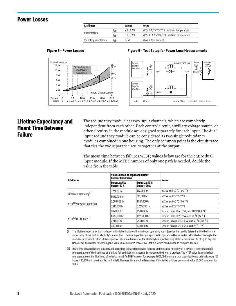
Power Losses
Lifetime Expectancy and Meant Time Between Failure
The redundancy module has two input channels, which are completely independent from each other. Each control circuit, auxiliary voltage source, or other circuitry in the module are designed separately for each input. The dual-input redundancy module can be considered as two single redundancy modules combined in one housing. The only common point is the circuit trace that ties the two separate circuits together at the output.
The mean time between failure (MTBF) values below are for the entire dual-input module. If the MTBF number of only one path is needed, double the value from the table.
Attributes Values Notes
Power lossesTyp 2.6…4.7 W at 2 x 5 A, 25 °C (77 °F) ambient temperatureTyp 5.6…8.7 W at 2 x 10 A, 25 °C (77 °F) ambient temperature
Standby power losses Typ 1.7 W at no output current
Figure 5 - Power Losses Figure 6 - Test Setup for Power Loss Measurements
Power Losses, typ
05 A 15 A
2 W
4 W
6 W
8 W
10 W
20 A10 AOutput:2 x 5 A2 x 2.5 AInput: 2 x 10 A2 x 7.5 A
00
12 W
25 A2 x 12.5 A
Input / Output Current
Depending onLoad ShareRegulation
25 °C
60 °C
25/60 °C
Output
V
A
PowerSupply24V, 12 A +
-
V
A
I 1
I 2
U1
U2
A
V
I OUT
UOUT
I 1 I2= U2U1 L= osses U1= UOUT-* I 1 + )( *U2 * I2 I OUT
VariableLoad,0...24 A
1606-XLERED20Y
Input 1
Input 2
Output
PowerSupply24V, 12 A +
-
Attributes
Values Based on Input and OutputCurrent Conditions
NotesInput: 2 x 5 A Output: 10 A
Input: 2 x 10 A Output: 20 A
Lifetime expectancy(1) 372,000 hr 182,000 hr at 24V and 40 °C (104 °F)
1,053,000 hr 516,000 hr at 24V and 25 °C (77 °F)
MTBF(2) SN 29500, IEC 617092,306,000 hr 1,954,000 hr at 24V and 40 °C (104 °F)3,913,000 hr 3,359,000 hr at 24V and 25 °C (77 °F)
MTBF(2) MIL HDBK 217F
964,000 hr 858,000 hr Ground Fixed GF40: 24V, and 40 °C (104 °F) 1,379,000 hr 1,226,000 hr Ground Fixed GF25: 24V, and 25 °C (77 °F) 278,000 hr 243,000 hr Ground Benign GB40: 24V, and 40 °C (104 °F) 381,000 hr 330,000 hr Ground Benign GB25: 24V, and 25 °C (77 °F)
(1) The lifetime expectancy that is shown in the table indicates the minimum operating hours (service life) and is determined by the lifetime expectancy of the built-in electrolytic capacitors. Lifetime expectancy is specified in operational hours and is calculated according to the manufacturer specification of the capacitor. The manufacturer of the electrolytic capacitors only states a maximum life of up to 15 years (131,400 hr). Any number exceeding this value is a calculated theoretical lifetime, which can be used to compare devices.
(2) Mean time between failure is calculated according to statistical device failures, and indicates reliability of a device. It is the statistical representation of the likelihood of a unit to fail and does not necessarily represent the life of a product. The MTBF value is a statistical representation of the likelihood of a device to fail. An MTBF value of for example 1,000,000 hr means that statistically one unit fails every 100 hours if 10,000 units are installed in the field. However, it cannot be determined if the failed unit has been running for 50,000 hr or only for 100 hr.
8 Rockwell Automation Publication 1606-RM107A-EN-P - July 2020
Terminals and Wiring
When wiring, be aware of the following:
• Use appropriate copper cables that are designed for minimum operating temperatures of:- 60 °C (140 °F) for ambient up to 45 °C (113 °F)- 75 °C (167 °F) for ambient up to 60 °C (140 °F)- 90 °C (194 °F) for ambient up to 70 °C (158 °F)
• Follow national installation codes and installation regulations.• Ensure that all strands of a stranded wire enter the terminal
connection.• Securely tighten screws of unused terminal compartments.• Ferrules are allowed.
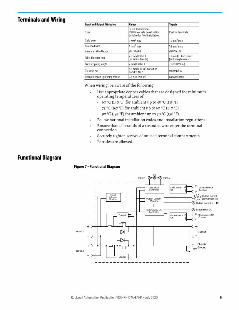
Functional Diagram
Input and Output Attributes Values Signals
TypeScrew terminationIP20 fingersafe construction.Suitable for field installation.
Push-in terminals
Solid wire 6 mm2 max 1.5 mm2 maxStranded wire 4 mm2 max 1.5 mm2 maxAmerican Wire Gauge 20…10 AWG AWG 24…16
Wire diameter max 2.8 mm (0.11 in.) (including ferrule)
1.6 mm (0.06 in.) max (including ferrules)
Wire stripping length 7 mm (0.28 in.) 7 mm (0.28 in.)
Screwdriver 3.5 mm (0.14 in.) slotted orPozidriv No 2 not required
Recommended tightening torque 0.8 N•m (7 lb•in) not applicable
Figure 7 - Functional Diagram
+
-
+
-
Input 1
Control
Control
Input 2
Redundancy OKContact
RedundancyOK
+
-
ChassisGround
Output
Load ShareOK
13
14
23
24
Load Share OKContact
Load ShareController
5 A10 A Output current
alarm threshold20 A
Input 2Input 1OK
Output current < IN
Redundancy OKController
Redundancy OK
InputVoltagesMonitor Output Current
Monitor
Rockwell Automation Publication 1606-RM107A-EN-P - July 2020 9
Front Side and User Elements
Redundancy OK Relay Contact
This feature reports the loss of redundancy by opening the relay contact (pin 23 and 24).
Figure 8 - Front Side User Elements1 Input Terminals for Input 1 (screw terminals)2 Input Terminals for Input 2 (screw terminals)3 Output Current < IN Status Indicator The LED is in a solid on state when the
output current is smaller than the output current alarm threshold. See Output Current Alarm Threshold Selector (user element 6).
4 Redundancy OK Status Indicator The LED is in a solid on state when no errors are detected. Errors include:• One or both input voltages are out of range (below 22V or above 30V).• Output current is higher than the adjusted value of the output current
threshold setting.• Internal anomaly is detected.
5 Load Share Status Indicators The three LEDs indicate the status of the load sharing between the two power supplies. See Automated Load Sharing on page 11 for detailed description.
6 Output Current Alarm Threshold Selector If the output current increases, for example due to additional loads, and exceeds the nominal current of one power supply unit, redundancy is no longer guaranteed. To avoid the loss in redundancy, the output current is monitored and is reported through LEDs and relay contacts when exceeding the predefined value.• Set the selector to 5 A in combination with two 5 A power supplies (1+1 red.) • Set the selector to 10 A in combination with two 10 A power supplies (1+1 red.)• Set the selector to 20 A for n+1 redundant systems. With this setting, the
redundancy module cannot check redundancy.Exceeding the current by less than 2 seconds is ignored.
7 Output Terminals (screw terminals)8 Chassis-Ground Terminal Connection of the chassis is optional and not
required since the unit fulfills the requirements according to protection class III.9 Relay Contact Redundancy OK (push-in terminals) The relay contact is closed
when no redundancy errors are detected. The relay contact is also synchronized with the Redundancy OK LED. See Redundancy OK Relay Contact on page 10 for contact ratings.
10 Relay Contact Load Share OK (push-in terminals) The relay contact is closed when the output voltage of the two power supplies is sufficiently adjusted. Deviations less than 2 s are ignored. See Automated Load Sharing on page 11 for detailed description. See Load Share OK Relay Contact on page 11 for contact ratings.
2
1 3
4
6
78
9
10
5
Attributes Values Notes
Contact ratings Max 60V DC 0.3 A, 30V DC 1 A, 30V AC 0.5 A resistive load Min 1 mA at 5V DC permissible load min
Isolation voltage See Dielectric Strength on page 14.Contact is closed When no errors are detected.
Contact is open
When:One or both input voltages are below 22V DC or above 30V DC.The output current is higher than the adjusted value of the output current threshold setting.An internal anomaly of the redundancy module is detected (decoupling measures and several internal test routines).Input voltage errors less than 2 s are ignored.Overcurrent errors (less than 150% of the adjusted value) less than 4 s are ignored.Overcurrent errors (above 150% of the adjusted value) less than 30 ms are ignored.Internal errors less than 10 s are ignored.
10 Rockwell Automation Publication 1606-RM107A-EN-P - July 2020
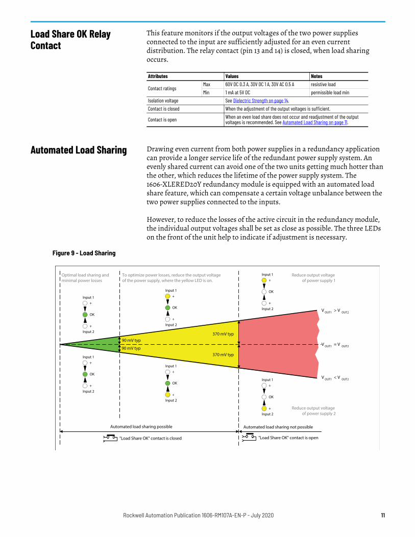
Load Share OK Relay Contact
This feature monitors if the output voltages of the two power supplies connected to the input are sufficiently adjusted for an even current distribution. The relay contact (pin 13 and 14) is closed, when load sharing occurs.
Automated Load Sharing Drawing even current from both power supplies in a redundancy application can provide a longer service life of the redundant power supply system. An evenly shared current can avoid one of the two units getting much hotter than the other, which reduces the lifetime of the power supply system. The 1606-XLERED20Y redundancy module is equipped with an automated load share feature, which can compensate a certain voltage unbalance between the two power supplies connected to the inputs.
However, to reduce the losses of the active circuit in the redundancy module, the individual output voltages shall be set as close as possible. The three LEDs on the front of the unit help to indicate if adjustment is necessary.
Attributes Values Notes
Contact ratings Max 60V DC 0.3 A, 30V DC 1 A, 30V AC 0.5 A resistive load Min 1 mA at 5V DC permissible load min
Isolation voltage See Dielectric Strength on page 14.Contact is closed When the adjustment of the output voltages is sufficient.
Contact is open When an even load share does not occur and readjustment of the output voltages is recommended. See Automated Load Sharing on page 11.
Figure 9 - Load Sharing
90 mV typ370 mV typ
Input 1
Input 2
OK
+
+
Input 1
Input 2
OK
+
+
Input 1
Input 2
OK
+
+
Input 1
Input 2
OK
+
+
Input 1
Input 2
OK
+
+
Automated load sharing possible Automated load sharing not possible
"Load Share OK" contact is closed "Load Share OK" contact is open
To optimize power losses, reduce the output voltageof the power supply, where the yellow LED is on.
V OUT1 > V OUT2
V OUT1 < V OUT2
V OUT1 = V OUT2
370 mV typ90 mV typ
Input 1
Input 2
OK
+
+
Reduce output voltageof power supply 1
Reduce output voltageof power supply 2
Optimal load sharing andminimal power losses
Rockwell Automation Publication 1606-RM107A-EN-P - July 2020 11
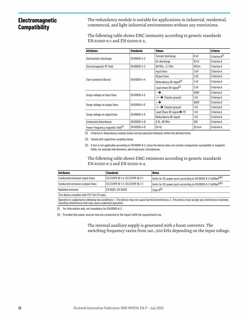
Electromagnetic Compatibility
The redundancy module is suitable for applications in industrial, residential, commercial, and light industrial environments without any restrictions.
The following table shows EMC immunity according to generic standards EN 61000-6-1 and EN 61000-6-2.
The following table shows EMC emissions according to generic standards EN 61000-6-3 and EN 61000-6-4.
The internal auxiliary supply is generated with a boost converter. The switching frequency varies from 140…500 kHz depending on the input voltage.
Attributes Standards Values Criteria
Electrostatic discharge EN 61000-4-2Contact discharge 8 kV Criterion A(1)
(1) Criterion A: Redundancy module shows normal operation behavior within the defined limits.
Air discharge 15 kV Criterion AElectromagnetic RF field EN 61000-4-3 80 MHz…2.7 GHz 10V/m Criterion A
Fast transients (Burst) EN 61000-4-4
Input lines 2 kV Criterion AOutput lines 2 kV Criterion A
Redundancy OK signal(2)
(2) Tested with capacitive coupling clamp.
2 kV Criterion A
Load share OK signal(2) 2 kV Criterion A
Surge voltage on input lines EN 61000-4-5+ - 500V Criterion A+/- Chassis ground 1 kV Criterion A
Surge voltage on output lines EN 61000-4-5+ - 500V Criterion A+/- Chassis ground 1 kV Criterion A
Surge voltage on signal lines EN 61000-4-5Load Share OK signal PE 1 kV Criterion ARedundancy OK signal 1 kV Criterion A
Conducted disturbance EN 61000-4-6 0.15…80 MHz 20V Criterion A
Power-frequency magnetic field(3)
(3) A test is not applicable according to EN 61000-6-2, since the device does not contain components susceptible to magnetic fields, for example hall elements, electrodynamic microphones.
EN 61000-4-8 50 Hz 30 A/m Criterion A
Attributes Standards Notes
Conducted emission input lines IEC/CISPR 16-1-2, IEC/CISPR 16-2-1 limits for DC power ports according to EN 61000-6-3 fulfilled(1)(2)
Conducted emission output lines IEC/CISPR 16-1-2, IEC/CISPR 16-2-1 limits for DC power ports according to EN 61000-6-3 fulfilled(1)(2)
Radiated emission EN 55011, EN 55022 Class B(2)
This device complies with FCC Part 15 rules.Operation is subjected to following two conditions: 1. This device may not cause harmful interference. 2. This device must accept any interference received, including interference that may cause undesired operation.
(1) For information only, not mandatory for EN 61000-6-3.
(2) Provided that power sources that are connected on the inputs fulfill the requirements too.
12 Rockwell Automation Publication 1606-RM107A-EN-P - July 2020
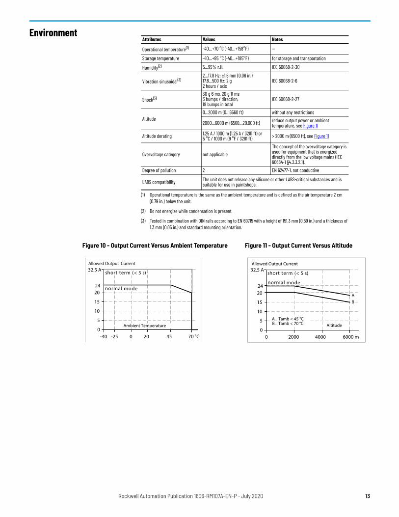
EnvironmentAttributes Values Notes
Operational temperature(1)
(1) Operational temperature is the same as the ambient temperature and is defined as the air temperature 2 cm (0.79 in.) below the unit.
-40…+70 °C (-40…+158°F) —
Storage temperature -40…+85 °C (-40…+185°F) for storage and transportation
Humidity(2)
(2) Do not energize while condensation is present.
5…95% r.H. IEC 60068-2-30
Vibration sinusoidal(3)
(3) Tested in combination with DIN rails according to EN 60715 with a height of 151.3 mm (0.59 in.) and a thickness of 1.3 mm (0.05 in.) and standard mounting orientation.
2…17.8 Hz: ±1.6 mm (0.06 in.);17.8…500 Hz: 2 g 2 hours / axis
IEC 60068-2-6
Shock(3)30 g 6 ms, 20 g 11 ms 3 bumps / direction, 18 bumps in total
IEC 60068-2-27
Altitude0…2000 m (0…6560 ft) without any restrictions
2000…6000 m (6560…20,000 ft) reduce output power or ambient temperature, see Figure 11
Altitude derating 1.25 A / 1000 m (1.25 A / 3281 ft) or 5 °C / 1000 m (9 °F / 3281 ft) > 2000 m (6500 ft), see Figure 11
Overvoltage category not applicableThe concept of the overvoltage category is used for equipment that is energized directly from the low voltage mains (IEC 60664-1 §4.3.3.2.1).
Degree of pollution 2 EN 62477-1, not conductive
LABS compatibility The unit does not release any silicone or other LABS-critical substances and is suitable for use in paint shops.
Figure 10 - Output Current Versus Ambient Temperature Figure 11 - Output Current Versus Altitude
Allowed Output Current
0-40 0 20 45 70 °C
5
10
15
2024
32.5 A
-25
normal mode
Ambient Temperature
short term (< 5 s)
Allowed Output Current
00 2000 4000 6000 m
5
10
15
2024
32.5 A
normal mode
AltitudeA... Tamb < 45 °CB... Tamb < 70 °C
AB
short term (< 5 s)
Rockwell Automation Publication 1606-RM107A-EN-P - July 2020 13
Protection Features
Safety Features
Dielectric Strength The input and output voltages have the same reference, are floating and have no ohmic connection to ground. The manufacturer conducts type and factory tests. Field tests may be conducted in the field using the appropriate test equipment, which applies the voltage with a slow ramp (2 s up and 2 s down). Connect input/output and signal terminals together before conducting the test. When testing, set the cutoff current settings to the value in the table below.
Attributes Values NotesOutput overcurrent protection not included —
Reverse input polarity protection included unit does not start when input voltage is reversed
Degree of protection IP 20 EN/IEC 60529Penetration protection > 3.6 mm (0.14 in.) for example, screws, and small partsOver-temperature protection not included —Input transient protection included see Electromagnetic Compatibility on page 12Output transient protection included see Electromagnetic Compatibility on page 12Internal input fuse not included —
Attributes Values NotesInput / output separation no galvanic separation MOSFET between input and output
Safety level of output voltage The output voltage is regarded to be SELV (EN 60950-1) or PELV (EN 60204-1, EN62477-1, IEC 60364-4-41) if the input voltage fulfills the requirements for a SELV source or PELV source.
Class of protection III PE (Protective Earth) or chassis connection not required
PE resistance < 0.1 Ω between housing and chassis-ground terminal
Figure 12 - Dielectric Strength Tests/Settings Times A in Figure 12 B in Figure 12Type test 60 s 500V AC 500V AC Factory test 5 s 500V AC 500V AC Field test 5 s 500V AC 500V AC Cutoff current setting
— > 2 mA > 2 mA
B
A
Load Share OK,Redundancy OK
ChassisIn- / Output
-
+
B
14 Rockwell Automation Publication 1606-RM107A-EN-P - July 2020
Approvals
Standards Compliance
Approval Name Approval Symbol Notes
EU Declaration of Conformity The CE marking indicates conformance with the following:- EMC Directive- ATEX directive
IEC 60950-1 CB Scheme, Information Technology Equipment
UL 508 Listed for use as Industrial Control Equipment; U.S.A. (UL 508) and Canada (C22.2 No. 107-1-01); E-File: NMTR(7).E56639
UL 60950-1 Recognized for use as Information Technology Equipment, Level 5; U.S.A. (UL 60950-1) and Canada (C22.2 No. 60950); E-File: QQGQ(2,8). E168663
ANSI / ISA 12.12.01-2007Class I Div 2, planned
LISTED for use in Hazardous Location Class I Div 2 T4 Groups A,B,C,D systems; U.S.A. (ANSI / ISA 12.12.01-2007) and Canada (C22.2 No. 213-M1987)
ATEXEN 60079-0, EN 60079-7
Suitable for use in Category 3 Zone 2 locations. Number of ATEX certificate: EPS 11 ATEX 1 312 X The redundancy module must be built in, in an IP54 enclosure.
IECExIEC 60079-0, IEC 60079-7
Suitable for use in Category 3 Zone 2 locations. Number of IECEx certificate: IECEx EPS 12.0032X
Marine, planned GL (Germanischer Lloyd) classified Environmental category: C, EMC1 Marine and offshore applications
EAC TR Registration Registration for the Eurasian Customs Union market (Russia, Kazakhstan, Belarus)
IND. CONT. EQ.
II 3G Ex ec IIC T4 Gc
IECExEx ec IIC T4 Gc
Standard Name Standard Symbol Notes
RoHS DirectiveDirective 2011/65/EU of the European Parliament and the Council of June 8, 2011 on the restriction of the use of certain hazardous substances in electrical and electronic equipment.
REACH DirectiveDirective 1907/2006/EU of the European Parliament and the Council of June 1, 2007 regarding the Registration, Evaluation, Authorization, and Restriction of Chemicals (REACH)
Rockwell Automation Publication 1606-RM107A-EN-P - July 2020 15
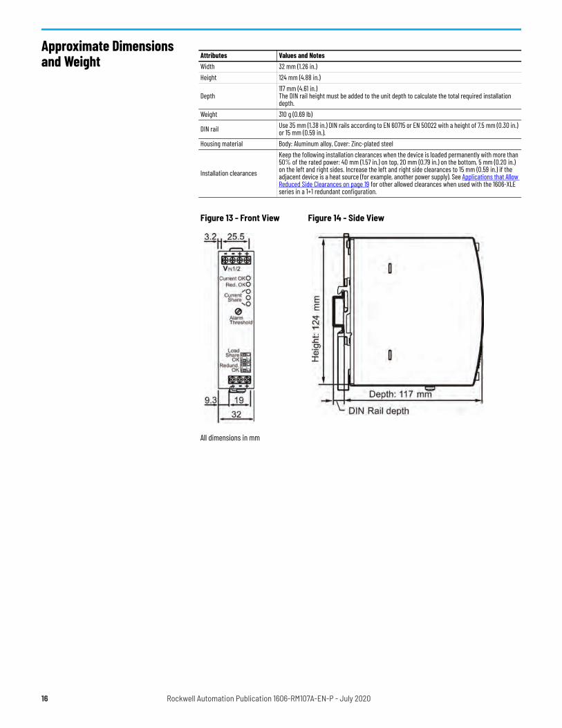
Approximate Dimensions and Weight Attributes Values and Notes
Width 32 mm (1.26 in.) Height 124 mm (4.88 in.)
Depth 117 mm (4.61 in.) The DIN rail height must be added to the unit depth to calculate the total required installation depth.
Weight 310 g (0.69 lb)
DIN rail Use 35 mm (1.38 in.) DIN rails according to EN 60715 or EN 50022 with a height of 7.5 mm (0.30 in.) or 15 mm (0.59 in.).
Housing material Body: Aluminum alloy, Cover: Zinc-plated steel
Installation clearances
Keep the following installation clearances when the device is loaded permanently with more than 50% of the rated power: 40 mm (1.57 in.) on top, 20 mm (0.79 in.) on the bottom, 5 mm (0.20 in.) on the left and right sides. Increase the left and right side clearances to 15 mm (0.59 in.) if the adjacent device is a heat source (for example, another power supply). See Applications that Allow Reduced Side Clearances on page 19 for other allowed clearances when used with the 1606-XLE series in a 1+1 redundant configuration.
Figure 13 - Front View Figure 14 - Side View
All dimensions in mm
16 Rockwell Automation Publication 1606-RM107A-EN-P - July 2020
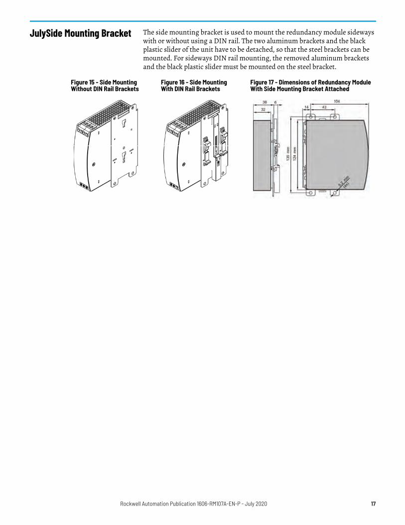
JulySide Mounting Bracket The side mounting bracket is used to mount the redundancy module sideways with or without using a DIN rail. The two aluminum brackets and the black plastic slider of the unit have to be detached, so that the steel brackets can be mounted. For sideways DIN rail mounting, the removed aluminum brackets and the black plastic slider must be mounted on the steel bracket.
Figure 15 - Side Mounting Without DIN Rail Brackets
Figure 16 - Side MountingWith DIN Rail Brackets
Figure 17 - Dimensions of Redundancy Module With Side Mounting Bracket Attached
Rockwell Automation Publication 1606-RM107A-EN-P - July 2020 17
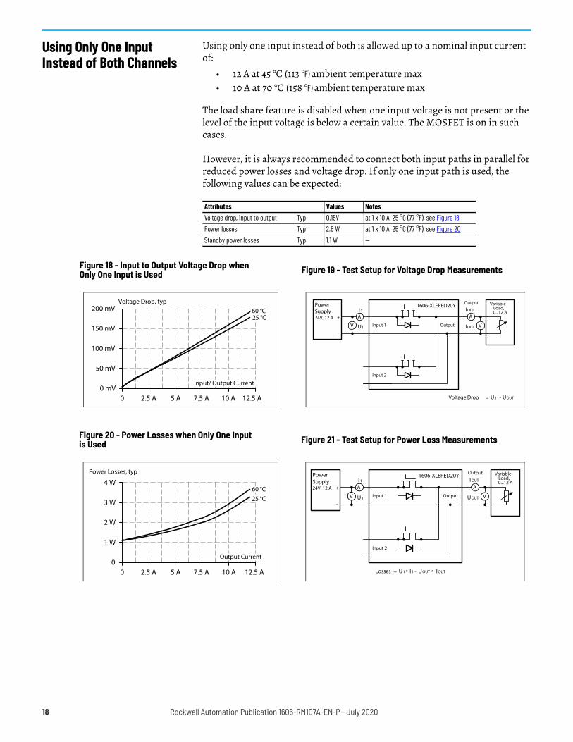
Using Only One Input Instead of Both Channels
Using only one input instead of both is allowed up to a nominal input current of:
• 12 A at 45 °C (113 °F) ambient temperature max• 10 A at 70 °C (158 °F) ambient temperature max
The load share feature is disabled when one input voltage is not present or the level of the input voltage is below a certain value. The MOSFET is on in such cases.
However, it is always recommended to connect both input paths in parallel for reduced power losses and voltage drop. If only one input path is used, the following values can be expected:
Attributes Values NotesVoltage drop, input to output Typ 0.15V at 1 x 10 A, 25 °C (77 °F), see Figure 18Power losses Typ 2.6 W at 1 x 10 A, 25 °C (77 °F), see Figure 20Standby power losses Typ 1.1 W —
Figure 18 - Input to Output Voltage Drop when Only One Input is Used Figure 19 - Test Setup for Voltage Drop Measurements
Voltage Drop, typ
0 mV2.5 A 7.5 A
50 mV
100 mV
150 mV
10 A5 A0
200 mV
12.5 A
Input/ Output Current
25 °C60 °C
Voltage Drop U1= UOUT-
V
A
PowerSupply24V, 12 A +
-
I1
U1
Output
A
V
IOUT
UOUT
VariableLoad,0...12 A
1606-XLERED20Y
Input 1
Input 2
Output
Figure 20 - Power Losses when Only One Input is Used Figure 21 - Test Setup for Power Loss Measurements
Power Losses, typ
02.5 A 7.5 A
1 W
2 W
3 W
10 A5 A0
4 W
12.5 A
Output Current
25 °C60 °C
Losses U1= UOUT-* I 1 * I OUT
Output
V
AI 1
U1
A
V
I OUT
UOUT
1606-XLERED20Y
Input 1
Input 2
Output
VariableLoad,0...12 A
PowerSupply24V, 12 A +
-
18 Rockwell Automation Publication 1606-RM107A-EN-P - July 2020
Recommendations for Redundancy
Recommendations for the configuration of redundant power systems:• Use separate input fuses for each power supply.• Use three-phase power supplies to gain functional safety if one phase
fails.• When single-phase power supplies are used, connect them to different
phases or mains circuits if possible.• Set the power supply in “Parallel-Use” mode if this feature is available.• It is desirable to set the output voltages of all power supplies to the
same value.
Inductive and Capacitive Loads
The unit is designed to supply any kind of loads, including unlimited capacitive and inductive loads.
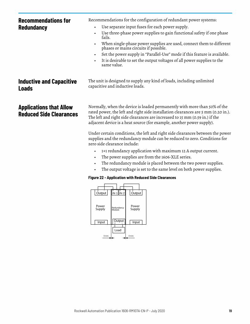
Applications that Allow Reduced Side Clearances
Normally, when the device is loaded permanently with more than 50% of the rated power, the left and right side installation clearances are 5 mm (0.20 in.). The left and right side clearances are increased to 15 mm (0.59 in.) if the adjacent device is a heat source (for example, another power supply).
Under certain conditions, the left and right side clearances between the power supplies and the redundancy module can be reduced to zero. Conditions for zero side clearance include:
• 1+1 redundancy application with maximum 12 A output current. • The power supplies are from the 1606-XLE series. • The redundancy module is placed between the two power supplies. • The output voltage is set to the same level on both power supplies.
Figure 22 - Application with Reduced Side Clearances
0 mm0 mm
Load
PowerSupply
Input
Output+ -
RedundancyModule
Output+ -
IN 2+ -
IN 1+ -
PowerSupply
Input
Output+ -
Rockwell Automation Publication 1606-RM107A-EN-P - July 2020 19
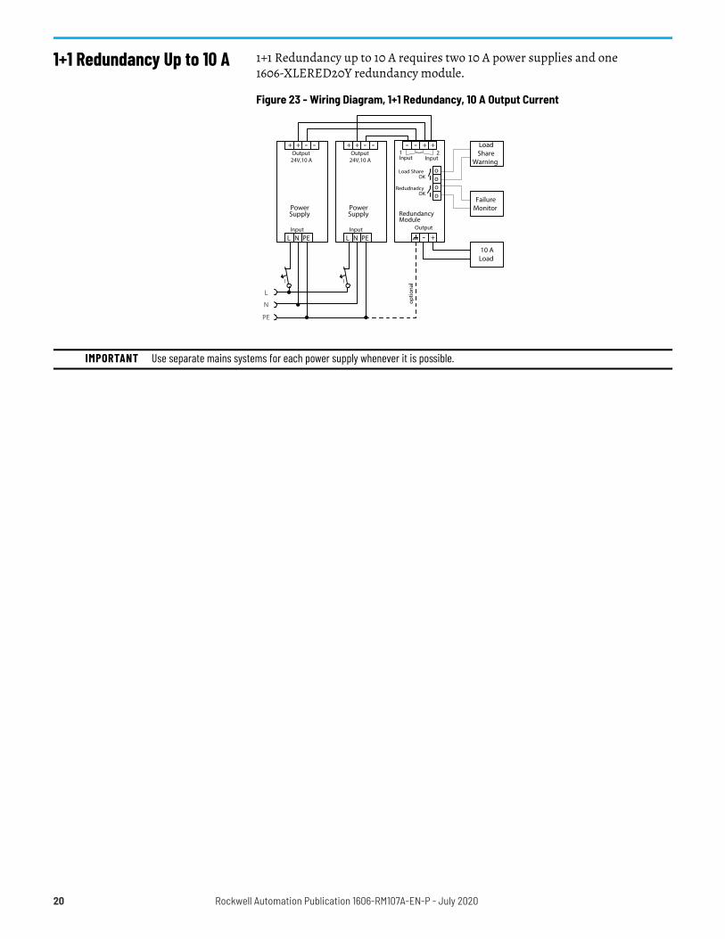
1+1 Redundancy Up to 10 A 1+1 Redundancy up to 10 A requires two 10 A power supplies and one 1606-XLERED20Y redundancy module.
Figure 23 - Wiring Diagram, 1+1 Redundancy, 10 A Output Current
L
N
PE
10 ALoad
LoadShare
Warning
I
optio
nal
PowerSupply
24V,10 A
+ + - -
L N PE
Output
Input
I
RedundancyModule
Output
1Input
2Input
++--
+-
Load ShareOK o
o
RedudnadcyOK o
o
FailureMonitorPower
Supply
24V,10 A
+ + - -
L N PE
Output
Input
IMPORTANT Use separate mains systems for each power supply whenever it is possible.
20 Rockwell Automation Publication 1606-RM107A-EN-P - July 2020
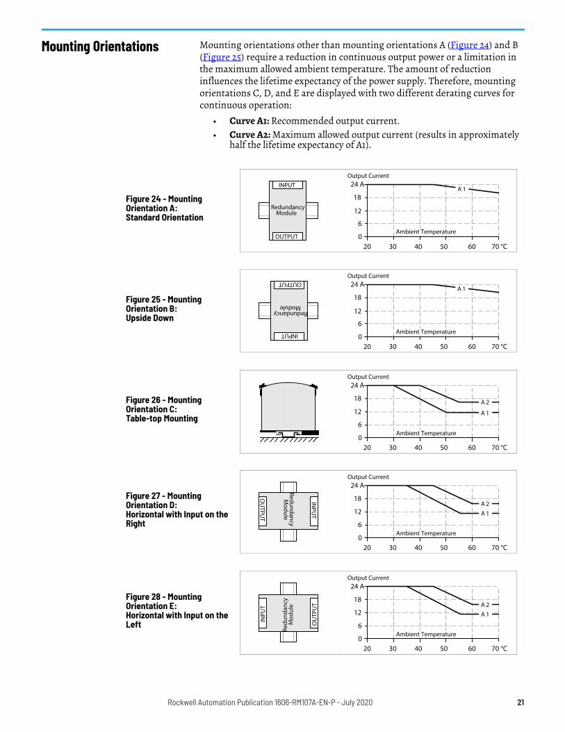
Mounting Orientations Mounting orientations other than mounting orientations A (Figure 24) and B (Figure 25) require a reduction in continuous output power or a limitation in the maximum allowed ambient temperature. The amount of reduction influences the lifetime expectancy of the power supply. Therefore, mounting orientations C, D, and E are displayed with two different derating curves for continuous operation:
• Curve A1: Recommended output current.• Curve A2: Maximum allowed output current (results in approximately
half the lifetime expectancy of A1).
Figure 24 - Mounting Orientation A: Standard Orientation
Figure 25 - Mounting Orientation B: Upside Down
Figure 26 - Mounting Orientation C: Table-top Mounting
Figure 27 - Mounting Orientation D: Horizontal with Input on the Right
Figure 28 - Mounting Orientation E: Horizontal with Input on the Left
RedundancyModule
INPUT
OUTPUT
Output Current
020 30 40 50 70 °C
6
12
18
24 A
60
A 1
Ambient Temperature
RedundancyModule
INPUT
OUTPUT
Output Current
020 30 40 50 70 °C
6
12
18
24 A
60
A 1
Ambient Temperature
Output Current
020 30 40 50 70 °C
6
18
24 A
60
12 A 1
A 2
Ambient Temperature
RedundancyM
odule
INPU
T
OU
TPUT
Output Current
020 30 40 50 70 °C
6
18
24 A
60
12 A 1A 2
Ambient Temperature
Redu
ndan
cyM
odul
e
INPU
T
OU
TPU
T
Output Current
020 30 40 50 70 °C
6
18
24 A
60
12 A 1A 2
Ambient Temperature
Rockwell Automation Publication 1606-RM107A-EN-P - July 2020 21

22 Rockwell Automation Publication 1606-RM107A-EN-P - July 2020
Rockwell Automation Publication 1606-RM107A-EN-P - July 2020 23
Dual Redundancy Module with Load Sharing - 24…28V, 20 A Reference Manual
Additional ResourcesThese documents contain additional information concerning related products from Rockwell Automation.
You can view or download publications at rok.auto/literature.
Resource DescriptionSwitched Mode Power Supply Specifications Technical Data, publication 1606-TD002 Provides specifications for Bulletin 1606-XL, -XLE, -XLP, and -XLS products and applications.
Industrial Components Preventive Maintenance, Enclosures, and Contact Ratings Specifications, publication IC-TD002
Provides a quick reference tool for Allen-Bradley industrial automation controls and assemblies.
Safety Guidelines for the Application, Installation, and Maintenance of Solid-State Control, publication SGI-1.1
Designed to harmonize with NEMA Standards Publication No. ICS 1.1-1987 and provides general guidelines for the application, installation, and maintenance of solid-state control in the form of individual devices or packaged assemblies incorporating solid-state components.
Industrial Automation Wiring and Grounding Guidelines, publication 1770-4.1 Provides general guidelines for installing a Rockwell Automation industrial system.Product Certifications website, rok.auto/certifications. Provides declarations of conformity, certificates, and other certification details.
Publication 1606-RM107A-EN-P - July 2020Copyright © 2020 Rockwell Automation, Inc. All rights reserved. Printed in the U.S.A.
Rockwell Automation SupportUse these resources to access support information.
Documentation FeedbackYour comments help us serve your documentation needs better. If you have any suggestions on how to improve our content, complete the form at rok.auto/docfeedback.
Waste Electrical and Electronic Equipment (WEEE)
Rockwell Automation maintains current product environmental information on its website at rok.auto/pec.
Technical Support Center Find help with how-to videos, FAQs, chat, user forums, and product notification updates. rok.auto/support
Knowledgebase Access Knowledgebase articles. rok.auto/knowledgebase
Local Technical Support Phone Numbers Locate the telephone number for your country. rok.auto/phonesupport
Literature Library Find installation instructions, manuals, brochures, and technical data publications. rok.auto/literature
Product Compatibility and Download Center (PCDC)
Get help determining how products interact, check features and capabilities, and find associated firmware. rok.auto/pcdc
At the end of life, this equipment should be collected separately from any unsorted municipal waste.
Rockwell Otomasyon Ticaret A.Ş. Kar Plaza İş Merkezi E Blok Kat:6 34752, İçerenkÖy, İstanbul, Tel: +90 (216) 5698400 EEE YÖnetmeliğine Uygundur
Allen-Bradley, expanding human possibility, and Rockwell Automation are trademarks of Rockwell Automation, Inc.Trademarks not belonging to Rockwell Automation are property of their respective companies.