Stability Analysis of Load Sharing Control for Distributed Generation Systems
9
IEEE TRANSACTIONS ON ENERGY CONVERSION, VOL. 22, NO. 3, SEPTEMBER 2007 737 Stability Analysis of Load Sharing Control for Distributed Generation Systems Mohammad N. Marwali, Member, IEEE, Jin-Woo Jung, Member, IEEE, and Ali Keyhani, Fellow, IEEE Abstract—This paper discusses the small-signal stability anal- ysis of the combined droop and average power method for load sharing control of multiple distributed generation systems (DGS) in a stand-alone ac supply mode. The small-signal model is devel- oped and its accuracy is verified from simulations of the original nonlinear model. It is shown that the small-signal model accurately predicts the stability of the parallel systems. Index Terms—Distributed generation systems (DGS), paral- lel operation, small-signal model, stability analysis, stand-alone, three-phase pulse width modulation (PWM) inverter. I. INTRODUCTION A T present, the distributed generation system (DGS) tech- nology is increasingly being used for power generation plants around the world because large central power plants are economically unviable in many areas due to diminishing fossil fuels, increasing fuel costs, and stricter environmental regulations about acid deposition and green house gas emission [1]–[10]. Moreover, technological advances in small genera- tors, power electronics, and energy storage devices for transient backup have accelerated the penetration of DGS into electric power generation plants. First of all, statutory incentives for us- ing renewable energy resources are pushing the electric utility companies to construct higher numbers of distributed genera- tion units on their distribution networks for a more decentralized power delivery. Additionally, the DGS technology can offer im- proved service reliability, better economics, and a reduced de- pendency on local utility. In fact, advanced power electronic technology that includes power converters, pulse width modulation (PWM) techniques, control algorithm, and electronic control units is definitely re- quired for the DGS technology. This is the reason why electric power generated by all DGS units is first converted into the dc power, which is then fed into the dc distribution bus to be again converted by the dc-to-ac inverters into the ac power. Of the many applications that use the DGS technology, an important research area for multiple DSG units in a stand-alone ac power supply is the proper load sharing of each unit because it is difficult for each generation unit to share loads uniformly according to its size under different conditions. Therefore, each Manuscript received October 13, 2005; revised February 8, 2006. This work was supported in part by the National Science Foundation under Grant NSF ECE 0501349. Paper No. TEC-00372-2005. M. N. Marwali is with the Liebert Corporation, Delaware, OH 43015 USA (e-mail: [email protected]). J. W. Jung is with the Samsung SDI Company, Seoul 121-885, South Korea (e-mail: [email protected]). A. Keyhani is with the Department of Electrical and Computer Engineering, Ohio State University, Columbus, OH 43210 USA (e-mail: [email protected]). Digital Object Identifier 10.1109/TEC.2006.881397 unit should operate in an autonomous power system, and control real power (P ) and reactive power (Q) independently. Also, it should enable paralleled inverters to share linear or even non- linear loads uniformly according to their capacities, including the real power sharing, reactive power sharing, and harmonic power sharing, such as the parallel operation of multiple UPS systems [11]–[17]. First of all, good load sharing should be guar- anteed under both locally measurable voltages/currents and the wire impedance mismatches, and voltage/current measurement error mismatches that considerably downgrade the performance of load sharing. In [2], the droop control and average power control methods have been proposed to ensure good load sharing. In these meth- ods, the sharing of active and reactive powers between each DGS unit is executed by two independent control variables: power an- gle and inverter output voltage amplitude. Particularly, the aver- age power method is used to remarkably reduce the sensitivity about voltage and current measurement error mismatches. In this paper, the stability of paralleled DGS in a stand-alone ac supply mode is investigated in great detail based on the original nonlinear model. Stability analysis of paralleled UPS with only the frequency and voltage droop method has been discussed [19], [20]. In these papers, the small-signal analysis models were developed to study the stability of the paralleled inverters network around the state of equilibrium. The droop technique analyzed in [18] uses total three-phase instantaneous active and reactive power, and therefore, cannot be directly ex- tended to analyze the control method proposed in this paper, since here the paralleling problem is viewed as three separate single-phase circuits (Fig. 1). However, in [19] and [20], the analysis for two interconnected single-phase inverters using fre- quency and voltage droop methods is given. Hence, the stability analysis provided in this section follows [19] and [20] with the exception that the analysis is performed for the phase and volt- age droop method combined with the average power control method. Additionally, the analysis provided here is performed in a discrete time domain, as opposed to the continuous time domain in [19] and [20]. This paper is organized as follows. Section II provides a description of the combined droop method and average power control for load sharing. Section III addresses the small-signal stability analysis. Simulation results of the proposed method are given in Section IV. II. COMBINED DROOP METHOD AND A VERAGE POWER CONTROL FOR LOAD SHARING Fig. 2 shows a circuit model of two DGS units in a stand-alone ac power supply. In [2], a combination of the droop method and 0885-8969/$25.00 © 2007 IEEE
-
Upload
independent -
Category
Documents
-
view
4 -
download
0
Transcript of Stability Analysis of Load Sharing Control for Distributed Generation Systems

IEEE TRANSACTIONS ON ENERGY CONVERSION, VOL. 22, NO. 3, SEPTEMBER 2007 737
Stability Analysis of Load Sharing Control forDistributed Generation Systems
Mohammad N. Marwali, Member, IEEE, Jin-Woo Jung, Member, IEEE, and Ali Keyhani, Fellow, IEEE
Abstract—This paper discusses the small-signal stability anal-ysis of the combined droop and average power method for loadsharing control of multiple distributed generation systems (DGS)in a stand-alone ac supply mode. The small-signal model is devel-oped and its accuracy is verified from simulations of the originalnonlinear model. It is shown that the small-signal model accuratelypredicts the stability of the parallel systems.
Index Terms—Distributed generation systems (DGS), paral-lel operation, small-signal model, stability analysis, stand-alone,three-phase pulse width modulation (PWM) inverter.
I. INTRODUCTION
A T present, the distributed generation system (DGS) tech-nology is increasingly being used for power generation
plants around the world because large central power plantsare economically unviable in many areas due to diminishingfossil fuels, increasing fuel costs, and stricter environmentalregulations about acid deposition and green house gas emission[1]–[10]. Moreover, technological advances in small genera-tors, power electronics, and energy storage devices for transientbackup have accelerated the penetration of DGS into electricpower generation plants. First of all, statutory incentives for us-ing renewable energy resources are pushing the electric utilitycompanies to construct higher numbers of distributed genera-tion units on their distribution networks for a more decentralizedpower delivery. Additionally, the DGS technology can offer im-proved service reliability, better economics, and a reduced de-pendency on local utility.
In fact, advanced power electronic technology that includespower converters, pulse width modulation (PWM) techniques,control algorithm, and electronic control units is definitely re-quired for the DGS technology. This is the reason why electricpower generated by all DGS units is first converted into the dcpower, which is then fed into the dc distribution bus to be againconverted by the dc-to-ac inverters into the ac power.
Of the many applications that use the DGS technology, animportant research area for multiple DSG units in a stand-aloneac power supply is the proper load sharing of each unit becauseit is difficult for each generation unit to share loads uniformlyaccording to its size under different conditions. Therefore, each
Manuscript received October 13, 2005; revised February 8, 2006. This workwas supported in part by the National Science Foundation under Grant NSFECE 0501349. Paper No. TEC-00372-2005.
M. N. Marwali is with the Liebert Corporation, Delaware, OH 43015 USA(e-mail: [email protected]).
J. W. Jung is with the Samsung SDI Company, Seoul 121-885, South Korea(e-mail: [email protected]).
A. Keyhani is with the Department of Electrical and Computer Engineering,Ohio State University, Columbus, OH 43210 USA (e-mail: [email protected]).
Digital Object Identifier 10.1109/TEC.2006.881397
unit should operate in an autonomous power system, and controlreal power (P ) and reactive power (Q) independently. Also, itshould enable paralleled inverters to share linear or even non-linear loads uniformly according to their capacities, includingthe real power sharing, reactive power sharing, and harmonicpower sharing, such as the parallel operation of multiple UPSsystems [11]–[17]. First of all, good load sharing should be guar-anteed under both locally measurable voltages/currents and thewire impedance mismatches, and voltage/current measurementerror mismatches that considerably downgrade the performanceof load sharing.
In [2], the droop control and average power control methodshave been proposed to ensure good load sharing. In these meth-ods, the sharing of active and reactive powers between each DGSunit is executed by two independent control variables: power an-gle and inverter output voltage amplitude. Particularly, the aver-age power method is used to remarkably reduce the sensitivityabout voltage and current measurement error mismatches.
In this paper, the stability of paralleled DGS in a stand-aloneac supply mode is investigated in great detail based on theoriginal nonlinear model. Stability analysis of paralleled UPSwith only the frequency and voltage droop method has beendiscussed [19], [20]. In these papers, the small-signal analysismodels were developed to study the stability of the paralleledinverters network around the state of equilibrium. The drooptechnique analyzed in [18] uses total three-phase instantaneousactive and reactive power, and therefore, cannot be directly ex-tended to analyze the control method proposed in this paper,since here the paralleling problem is viewed as three separatesingle-phase circuits (Fig. 1). However, in [19] and [20], theanalysis for two interconnected single-phase inverters using fre-quency and voltage droop methods is given. Hence, the stabilityanalysis provided in this section follows [19] and [20] with theexception that the analysis is performed for the phase and volt-age droop method combined with the average power controlmethod. Additionally, the analysis provided here is performedin a discrete time domain, as opposed to the continuous timedomain in [19] and [20].
This paper is organized as follows. Section II provides adescription of the combined droop method and average powercontrol for load sharing. Section III addresses the small-signalstability analysis. Simulation results of the proposed method aregiven in Section IV.
II. COMBINED DROOP METHOD AND AVERAGE POWER
CONTROL FOR LOAD SHARING
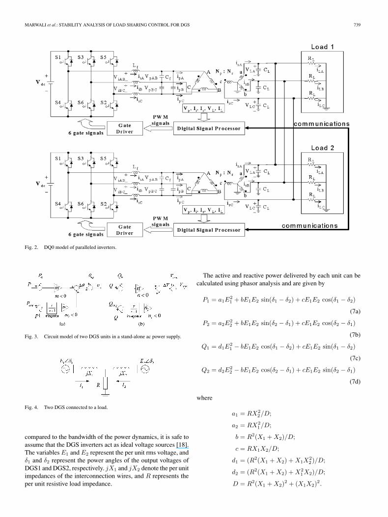
Fig. 2 shows a circuit model of two DGS units in a stand-aloneac power supply. In [2], a combination of the droop method and
0885-8969/$25.00 © 2007 IEEE

738 IEEE TRANSACTIONS ON ENERGY CONVERSION, VOL. 22, NO. 3, SEPTEMBER 2007
Fig. 1. Combined droop and average power methods for load sharing control.(a) Active power control. (b) Reactive power control.
average power control is proposed for load sharing of paral-leled inverters in DGS, as shown in Fig. 3. The average powermethod is used to overcome the sensitivity of the droop methodtoward measurements errors and wiring impedance mismatches.Choosing phase angle (instead of frequency) as the controllingvariable for the real power control has the advantage that theaverage power control can be deactivated by setting the input tothe integrator to zero if communication error is detected. Thismakes the load sharing control less dependent on the existenceof the intercommunication signals between units. Another wayof looking at this is that the average power control fine-tunes thedroop method to achieve proper load sharing when measurementerrors or other nonidealities exist.
An issue to be addressed is what power quantities should beused for the method proposed. Most previous works in paral-leled three-phase inverters have used total three-phase real andreactive power for this purpose. However, using total powerdoes not guarantee load sharing of individual phase in the caseof unbalanced load or wire impedances. To answer this ques-tion, the load sharing control shall be applied to the individualDQ-axis circuit, i.e., the method shall be applied to the realand reactive power on each D- and Q-axis. The reasoning forthis can be justified if one examines the DQ0 model of theparalleled inverters, as shown in Fig. 1. The problem of paral-leling three-phase inverters can be broken down into paralleling
three-independent single-phase circuits. Since the 0-componentis not controllable and the filter has suppressed its quantities, theload sharing shall only be accomplished for the D- and Q-axissingle-phase circuitry.
Applying the proposed load sharing control to the individualD- and Q-axis, we obtain the following equations for updatingthe phases and amplitudes of the D and Q voltages references.
A. D-Axis
Phase angle:
φd(k + 1) = φd(k) + miePdePd
=
Pq avg − Pd, if activated0, if deactivated
∆θd(k) = φd(k) + m(Pd − Pd0)
θd(k) = θref(k) + ∆θd(k). (1)
Amplitude:
υd(k + 1) = υd(k) + nieQdeQq
=
Qd avg − Qd, if activated0, if deactivated
Vmax d(k) = Vnom + υd(k) + n(Qd − Qd0). (2)
Voltage reference:
Vref d(k) = Vmax d(k) cos[θd(k)]. (3)
B. Q-Axis
Phase angle:
φd(k + 1) = φq(k) + miePqePq
=
Pq avg − Pq, if activated0, if deactivated
∆θq(k) = φq(k) + m(Pq − Pq0)
θq(k) = θref(k) + ∆θq(k). (4)
Amplitude:
υq(k + 1) = υq(k) + nieQqeQq
=
Qq avg − Qq, if activated0, if deactivated
Vmax q(k) = Vnom + υq(k) + n(Qq − Qq0). (5)
Voltage reference:
Vref q(k) = Vmax q(k) sin[θq(k)]. (6)
III. SMALL-SIGNAL STABILITY ANALYSIS
Fig. 4 shows an equivalent circuit of two paralleled invertersfor one of the dq phases in Fig. 1 with a resistive load (R)and interconnection impedances modeled as inductors (X1 andX2). Due to the high bandwidth of the voltage control loop as
MARWALI et al.: STABILITY ANALYSIS OF LOAD SHARING CONTROL FOR DGS 739
Fig. 2. DQ0 model of paralleled inverters.
Fig. 3. Circuit model of two DGS units in a stand-alone ac power supply.
Fig. 4. Two DGS connected to a load.
compared to the bandwidth of the power dynamics, it is safe toassume that the DGS inverters act as ideal voltage sources [18].The variables E1 and E2 represent the per unit rms voltage, andδ1 and δ2 represent the power angles of the output voltages ofDGS1 and DGS2, respectively. jX1 and jX2 denote the per unitimpedances of the interconnection wires, and R represents theper unit resistive load impedance.
The active and reactive power delivered by each unit can becalculated using phasor analysis and are given by
P1 = a1E21 + bE1E2 sin(δ1 − δ2) + cE1E2 cos(δ1 − δ2)
(7a)
P2 = a2E22 + bE1E2 sin(δ2 − δ1) + cE1E2 cos(δ2 − δ1)
(7b)
Q1 = d1E21 − bE1E2 cos(δ1 − δ2) + cE1E2 sin(δ1 − δ2)
(7c)
Q2 = d2E22 − bE1E2 cos(δ2 − δ1) + cE1E2 sin(δ2 − δ1)
(7d)
where
a1 = RX22/D;
a2 = RX21/D;
b = R2(X1 + X2)/D;
c = RX1X2/D;
d1 = (R2(X1 + X2) + X1X22 )/D;
d2 = (R2(X1 + X2) + X21X2)/D;
D = R2(X1 + X2)2 + (X1X2)2.

740 IEEE TRANSACTIONS ON ENERGY CONVERSION, VOL. 22, NO. 3, SEPTEMBER 2007
Considering small deviations around the equilibrium point(δ1e, δ2e, E1e, E2e), (7) can be linearized as follows:
∆P1
∆P2
∆Q1
∆Q2
= S
∆δ1
∆δ2
∆E1
∆E2
, S = [sij ], i, j = 1, . . . , 4 (8)
where each sij is given as
s11 = bE1eE2e cos(δ1e − δ2e) − cE1eE2e sin(δ1e − δ2e)s12 = −bE1eE2e cos(δ1e − δ2e) + cE1eE2e sin(δ1e − δ2e)s13 = 2a1E1e + bE2e sin(δ1e − δ2e) + cE2e cos(δ1e − δ2e)s14 = bE1e sin(δ1e − δ2e) + cE1e cos(δ1e − δ2e)
s21 = −bE1eE2e cos(δ2e − δ1e) + cE1eE2e sin(δ2e − δ1e)s22 = bE1eE2e cos(δ2e − δ1e) − cE1eE2e sin(δ2e − δ1e)s23 = bE2e sin(δ2e − δ1e) + cE2e cos(δ2e − δ1e)s24 = 2a2E2e + bE1e sin(δ2e − δ1e) + cE1e cos(δ2e − δ1e)
s31 = bE1eE2e sin(δ1e − δ2e) + cE1eE2e cos(δ1e − δ2e)s32 = −bE1eE2e sin(δ1e − δ2e) − cE1eE2e cos(δ1e − δ2e)s33 = 2d1E1e − bE2e cos(δ1e − δ2e) + cE2e sin(δ1e − δ2e)s34 = −bE1e cos(δ1e − δ2e) + cE1e sin(δ1e − δ2e)
s41 = −bE1eE2e sin (δ2e − δ1e) − cE1eE2e cos (δ2e − δ1e)s42 = bE1eE2e sin (δ2e − δ1e) + cE1eE2e cos (δ2e − δ1e)s43 = −bE2e cos (δ2e − δ1e) + cE2e sin (δ2e − δ1e)s44 = 2d2E2e−bE1e cos (δ2e−δ1e) + cE1e sin (δ2e − δ1e) .
In this paper, each of the active and reactive powers are com-puted once every one-line cycle and digital low-pass filtering isapplied to each power computation for the purpose of removingthe measurement noise. The digital filters used are given as
p1m(k + 1) = (1 − γ)p1m(k) + γP1(k) (9a)
p2m(k + 1) = (1 − γ)p2m(k) + γP2(k) (9b)
q1m(k + 1) = (1 − γ)q1m(k) + γQ1(k) (9c)
q2m(k + 1) = (1 − γ)q2m(k) + γQ2(k). (9d)
Using the filtered power quantities in (9), the combined aver-age power control and droop methods from the previous sectioncan be written in per unit notation as follows:
δ1(k) = φ1(k) + mp1m (10a)
δ2(k) = φ2(k) + mp2m (10b)
E1(k) = 1 + υ1(k) + nq1m (10c)
E2(k) = 1 + υ2(k) + nq2m. (10d)
Also, the integrator states can be updated as
φ1(k + 1) = φ1(k) +mi
2(p1m − p2m) (11a)
φ2(k + 1) = φ2(k) +mi
2(p2m − p1m) (11b)
υ1(k + 1) = υ1(k) +ni
2(q1m − q2m) (11c)
υ2(k + 1) = υ2(k) +ni
2(q2m − q1m). (11d)
Using the small-signal analysis, (9)–(11) can be linearized asLinearized power filter:
∆p1m(k + 1) = (1 − γ)∆p1m(k) + γ∆P1(k) (12a)
∆p2m(k + 1) = (1 − γ)∆p2m(k) + γ∆P2(k) (12b)
∆q1m(k + 1) = (1 − γ)∆q1m(k) + γ∆Q1(k) (12c)
∆q2m(k + 1) = (1 − γ)∆q2m(k) + γ∆Q2(k). (12d)
Linearized combined average and droop control:
∆δ1(k) = ∆φ1(k) + m ∆p1m (13a)
∆δ2(k) = ∆φ2(k) + m ∆p2m (13b)
∆E1(k) = ∆υ1(k) + n∆q1m (13c)
∆E2(k) = ∆υ2(k) + n∆q2m. (13d)
Linearized integrator equations:
∆φ1(k + 1) = ∆φ1(k) +mi
2(∆p1m − ∆p2m) (14a)
∆φ2(k + 1) = ∆φ2(k) +mi
2(∆p2m − ∆p1m) (14b)
∆υ1(k + 1) = ∆υ1(k) +ni
2(∆q1m − ∆q2m) (14c)
∆υ2(k + 1) = ∆υ2(k) +ni
2(∆q2m − ∆q1m). (14d)
Substituting (13) into the linearized power equations in (8),we obtain linearized equations in terms of the integrator statesand power filter states perturbations as
∆P1
∆P2
∆Q1
∆Q2
= S
∆φ1
∆φ2
∆υ1
∆υ2
+ S
m∆p1m
m∆p2m
n∆q1m
n∆q2m
. (15)
If we define the following states vector
∆x=[∆p1m ∆p2m ∆q1m ∆q2m ∆φ1 ∆φ2 ∆υ1 ∆υ2]T
then from (11), (12), and (14), we can obtain
∆x(k + 1) = A∆∆x(k) (16)
for an explanation of A∆ in (16), refer to the equation at thebottom of the next page.
Equation (16) describes the system dynamics around the equi-librium point. The eigenvalues of matrix A∆ can be used todetermine the stability of the system around the state of equi-librium and the type of dynamic response expected. For exam-ple, we assume the following parameters: X1 = 0.001 per unit(p.u.), X2 = 0.002 p.u., and R = 1 p.u. The filter time constantis chosen to be γ = 0.5. Let us consider three cases of droopcoefficients and integrator gains.
Case 1:
m = n = −0.001;mi = ni = −0.0003.
Case 2:
m = n = −0.001; mi = ni = −0.0008.
Case 3:
m = n = −0.005; mi = ni = −0.0008.

MARWALI et al.: STABILITY ANALYSIS OF LOAD SHARING CONTROL FOR DGS 741
Fig. 5. System response for Case 1 (per unit power versus time in seconds).
The state of equilibrium for each case needs to be calculatedusing the power flow analysis. However, since the amplitude andphase adjustments made by each DGS are very small comparedto the nominal value of the voltages, and the phases are alwaysinitially in synchronization with respect to a reference voltage,we can choose (δ1e, δ2e, E1e, E2e) = (0, 0, 1, 1) for the calcula-tion of each term in matrix S in (8). As a result, the eigenvaluesof matrix A∆ for each case are obtained as follows.
Case 1:
0.3118, 0.3122, 0.8547, 0.8546, 0.5000, 0.5000, 1.0000,1.0000.
Case 2:
0.3120, 0.8546, 0.5833 ± 0.305 1i, 0.5000, 0.5000, 1.0000,1.0000.
Case 3:
− 1.0369, − 1.0344, 0.8690, 0.8690, 0.5000, 0.5000, 1.0000,1.0000.
In Cases 1 and 2, all the eigenvalues are located within theunit circle; therefore, both the systems are stable. In Case 1, allthe eigenvalues are real, and therefore the system has a dampedresponse. Case 2 presents eigenvalues with imaginary compo-nents, so the system response can be expected to be oscillatory.In Case 3, two of the eigenvalues lie outside of the unit circle;hence, the system is unstable.
To verify these findings, simulations of the circuit of Fig. 1with the proposed control have been performed using Mat-lab/Simulink with Power System Blockset. Figs. 5–7 show the
Fig. 6. System response for Case 2 (per unit power versus time in seconds).
Fig. 7. System response for Case 3 (per unit power versus time in seconds).
system responses (P1, P2, Q1, and Q2) for Cases 1, 2, and 3,respectively. As expected earlier, it can be seen that Cases 1 and2 are stable, as shown in Figs. 5 and 6, while Case 3 is unstable,as depicted in Fig. 7.
IV. SIMULATION RESULTS
Based on the stability analysis described in the previous sec-tion, two DGS units operating in parallel are simulated. Asshown in Fig. 8, this configuration consists of two DGS unitsand two loads. In real circuit model, wire impedances (Z1 and
A∆ =
(1 − γ) + mγs11 mγs12 nγs13 nγs14 γs11 γs12 γs13 γs14
mγs21 (1 − γ) + mγs22 nγs23 nγs24 γs21 γs22 γs23 γs24
mγs31 mγs32 (1 − γ) + nγs33 nγs34 γs31 γs32 γs33 γs34
mγs41 mγs42 nγs43 (1 − γ) + nγs44 γs41 γs42 γs43 γs44mi
2 −mi
2 0 0 1 0 0 0−mi
2mi
2 0 0 0 1 0 00 0 ni
2 −ni
2 0 0 1 00 0 −ni
2ni
2 0 0 0 1
.

742 IEEE TRANSACTIONS ON ENERGY CONVERSION, VOL. 22, NO. 3, SEPTEMBER 2007
Fig. 8. Configuration of the system simulated for two DGS units.
Fig. 9. Simulink model of two DGS units connected to two loads.
Z2) are modeled because these can significantly affect loadsharing between the DGS units.
To simulate Fig. 8 with Matlab/Simulink, the configurationis modeled as in Fig. 9. This model is also composed of twoDGS units, two loads, and wire impedances (Z1 and Z2). Inparticular, the power information (PQdq1 and PQdq2) such asthe real power (P ) and the reactive power (Q) is exchangedbetween two DGS systems to ensure proper load sharing.
To enhance the speed of simulations, each PWM inverter hasbeen modeled as an ideal voltage controlled source with a delayof half the sampling time of the actual PWM signal. Two lineartransformers are used as the isolation transformers, and a seriesinductance and resistance representing the leakage impedanceand losses of each transformer are respectively 3% p.u. Notethat the series inductance and resistance of the transformers aredenoted as LT and RT , respectively. The circuit parameters forsimulations are given in Table I.
As explained in [2], each PWM inverter’s output voltageand current are controlled using dual loop control system, withouter loop (RSC) controlling the output voltage, and the innerloop (DSMC) controlling the inverter current. To demonstratethe stability analysis proposed for load sharing control, wireimpedances mismatches and voltage/current sensor measure-ment error mismatches are considered, and the following casesare simulated.
All cases:
DGS unit 1. Z1 = R1 + jX1(R1 = 0.01Ω/L1 = 0.2) mH).Voltage measurement error. Vp[−0.1%,+0.1%,−0.1%];
VL[+0.1%,+0.1%,−0.1%].
TABLE ISYSTEM PARAMETERS FOR TWO DGS UNITS
Current measurement error. Ii[+0.1%,−0.1%,−0.1%];IL[+0.1%,−0.1%,−0.1%].
DGS unit 2. Z2 = R2 + jX2(R2 = 0.02Ω/L2 = 0.4 mH).Voltage measurement error. Vp[+0.1%,−0.1%,+0.1%];
VL[−0.1%,−0.1%,+0.1%].Current measurement error. Ii[−0.1%,+0.1%,+0.1%];
IL[−0.1%,+0.1%,+0.1%].Case: 1
Power ratings of DGS units 1 and 2. 50 kVA.Load 1. Pload1 = 40 kW; Qload1 = 30 kvar (p.f. = 0.8).Load 2. Pload2 = 40 kW; Qload2 = 30 kvar (p.f. = 0.8).
Case 2:
Power ratings of DGS units 1 and 2. 50 kVA.Load 1. Pload1 = 40 kW; Qload1 = 30 kvar (p.f. = 0.8).Load 2. Pload2 = 20 kW ⇒ 40 kW; Qload2 = 15 kvar ⇒ 30
kvar (at 3 s).
Case 3:
Power ratings of DGS units 1 and 2. 50 kVA.Load 1 . Pload1 = 40 kW; Qload1 = 30 kvar (p.f. = 0.8).Load 2. Pload2 = 40 kW ⇒ 20 kW; Qload2 = 30 kvar ⇒ 15
kvar (at 3 s).
Case 4:
Power ratings of DGS units 1 and 2. 50 and 25 kVA.Load 1. Pload1 = 20 kW; Qload1 = 15 kvar (p.f. = 0.8).Load 2. Pload2 = 40 kW; Qload2 = 30 kvar (p.f. = 0.8).
Case 5:
Power ratings of DGS units 1 and 2. 50 and 25 kVA.Load 1. Pload1 = 20 kW; Qload1 = 15 kvar (p.f. = 0.8).Load 2. Pload2 = 20 kW ⇒ 40 kW; Qload2 = 15 kvar ⇒ 30
kvar (at 3 s).
Case 6:
Power ratings of DGS units 1 and 2. 50 and 25 kVA.Load 1. Pload1 = 20 kW; Qload1 = 15 kvar (p.f. = 0.8).Load 2. Pload2 = 40 kW ⇒ 20 kW; Qload2 = 30 kvar ⇒ 15
kvar (at 3 s).
Case 7:
Power ratings of DGS units 1 and 2. 50 kVA.Load 1. Three-phase bridge diode (CDC1 = 3000 µF; RL1 =
1.6 Ω).

MARWALI et al.: STABILITY ANALYSIS OF LOAD SHARING CONTROL FOR DGS 743
Fig. 10. Simulation results for Case 1.
Fig. 11. Simulation results for Case 2.
Load 2. Three-phase bridge diode (CDC2 = 3000 µF; RL2 =1.6 Ω).
Case 8:
Power ratings of DGS units 1 and 2. 50 and 25 kVA.Load 1. Three-phase bridge diode (CDC1 = 3000 µF; RL1 =
3.2 Ω).Load 2. Three-phase bridge diode (CDC2 = 3000 µF; RL2 =
1.6 Ω).
In all the cases, it is assumed that Z2 is twice Z1, the signsof voltage/current sensor errors of DGS unit 1 are opposite tothose of DGS unit 2. In Cases 1, 2, 3, and 7, the power ratingof DGS unit 1 is equal to that of DGS unit 2. In Cases 4, 5, 6,and 8, it is assumed that the power rating of DGS unit 1 is twicethat of DGS unit 2. In Cases 2 and 5, it is assumed that load 2doubles after 3 s, while in Cases 3 and 6, it is assumed that load2 reduces to half after 3 s. Finally, Cases 7 and 8 are simulatedunder nonlinear loads with a three-phase bridge diode.
Fig. 12. Simulation results for Case 3.
Fig. 13. Simulation results for Case 4.
The first six cases (Figs. 10–15) were simulated for linearloads, while the last two cases (Figs. 16 and 17) were simulatedunder nonlinear loads. Fig. 10 shows very good load sharing ofthe real and the reactive powers under the conditions of identicalunits and loads. Fig. 14 shows the results under different powerratings and loads, and these results also show that the loads areproperly shared according to the power capability of each unit.
As shown in Figs. 11, 12, 14, and 15, even when load 2 is dou-bled or halved after 3 s, respectively, the results definitely show agood power sharing. Two nonlinear loads that consist of a three-phase bridge, a large capacitor, and a small resistor are imple-mented, and the results demonstrate good load sharing depend-ing on the power rating of each unit, as shown in Figs. 16 and 17.
V. COMPARISON WITH DROOP-ONLY TECHNIQUE
It is instructive to compare the control strategy discussed inthis paper with the well-known voltage and frequency droop

744 IEEE TRANSACTIONS ON ENERGY CONVERSION, VOL. 22, NO. 3, SEPTEMBER 2007
Fig. 14. Simulation results for Case 5.
Fig. 15. Simulation results for Case 6.
Fig. 16. Simulation results for Case 7.
Fig. 17. Simulation results for Case 8.
Fig. 18. Simulation results for Case 1 with the droop-only technique.
Fig. 19. Simulation results for Case 7 with the droop-only technique.

MARWALI et al.: STABILITY ANALYSIS OF LOAD SHARING CONTROL FOR DGS 745
techniques [15]–[20]. As mentioned earlier, the control strategyin this paper reduces the effect of line impedances mismatchesand the occurrence of measurement errors. The benefits offeredare the results of having closed feedback loop of the power quan-tities. Once a proper load sharing is established, the closed-loopfeedback can be deactivated, and the droop mechanism can stillmaintain the proper load sharing. This in turn reduces the depen-dency on the communication between units. These features canbe contrasted to the approach of wireless load sharing [15]–[20],which lacks the closed-loop feedback of the power quantities.For a comparison, Figs. 18 and 19 show the performance of thedroop-only technique for the same cases as in Cases 1 and 7of the previous section. It can be seen that load sharing cannotbe properly achieved due to the gross mismatches in the lineimpedances and the presence of measurement errors.
VI. CONCLUSION
In this paper, the small-signal model has been developed toinvestigate the stability of paralleled distributed generation sys-tems in a stand-alone ac supply mode, using the combined droopand average power method for load sharing control. Simulationresults have been used to verify the accuracy of the small-signalmodel. It was shown that the small-signal model accurately pre-dicted the stability of the control system.
REFERENCES
[1] M. N. Marwali and A. Keyhani, “Control of distributed generation sys-tems, Part I: Voltages and currents control,” IEEE Trans. Power Electron.,vol. 19, no. 6, pp. 1541–1550, Nov. 2004.
[2] M. N. Marwali, J.-W. Jung, and A. Keyhani, “Control of distributed genera-tion systems, Part II: Load sharing control,” IEEE Trans. Power Electron.,vol. 19, no. 6, pp. 1551–1561, Nov. 2004.
[3] A. A. Chowdhury, S. K. Agarwal, and D. O. Koval, “Reliability modelingof distributed generation in conventional distribution systems planningand analysis,” IEEE Trans. Ind. Appl., vol. 39, no. 5, pp. 1493–1498,Sep.–Oct. 2003.
[4] J. L. Del Monaco, “The role of distributed generation in the critical electricpower infrastructure,” in Proc. IEEE Power Eng. Soc. Winter Meet., Jan.28–Feb. 1, 2001, vol. 1, pp. 144–145.
[5] L. Philipson, “Distributed and dispersed generation: Addressing the spec-trum of consumer needs,” in Proc. IEEE Power Eng. Soc. Summer Meet.Jul. 16–20, 2000, vol. 3, pp. 1663–1665.
[6] S. Barsali, M. Ceraolo, P. Pelacchi, and D. Poli, “Control techniques ofdispersed generators to improve the continuity of electricity supply,” inProc. IEEE Power Eng. Soc. Winter Meet., Jan. 27–31, 2002, vol. 2,pp. 789–794.
[7] S. Sivakumar, T. Parsons, and S. C. Sivakumar, “Modeling, analysis andcontrol of bidirectional power flow in grid connected inverter systems,” inProc. Power Conversion Conf., 2002, vol. 3, pp. 1015–1019.
[8] R. Kyoungsoo and S. Rahman, “Two-loop controller for maximizing per-formance of a grid-connected photovoltaic-fuel cell hybrid power plant,”IEEE Trans. Energy Convers., vol. 13, no. 3, pp. 276–281, Sep. 1998.
[9] K. Sedghisigarchi and A. Feliachi, “Control of grid-connected fuel cellpower plant for transient stability enhancement,” in Proc. IEEE PowerEng. Soc. Winter Meet., Jan. 27–31, 2002, vol. 1, pp. 383–388.
[10] S. Stevandic and J. Jiang, “Standalone, reduced-order model and controlof a grid-connected fuel cell power plant,” in Proc. IEEE Power Eng. Soc.Gen. Meet., Jul. 13–17, 2003, vol. 2, pp. 679–686.
[11] M. C. Chandorkar, D. M. Divan, and R. Adapa, “Control of parallelconnected inverters in standalone ac supply systems,” IEEE Trans. Ind.Appl., vol. 29, no. 1, pp. 136–143, Jan.–Feb. 1993.
[12] M. C. Chandorkar, D. M. Divan, Y. Hu, and B. Banerjee, “Novel archi-tectures and control for distributed UPS systems,” in Proc. Appl. PowerElectron. Conf. Expo., 1994, vol. 2, pp. 683–689.
[13] M. C. Chandorkar, D. M. Divan, and B. Banerjee, “Control of distributedUPS systems,” in Proc. Power Electron. Spec. Conf., 1994, vol. 1, pp. 197–204.
[14] M. C. Chandorkar and D. M. Divan, “Decentralized operation of dis-tributed UPS systems,” in Proc. 1996 Int. Conf. Power Electronics, Drivesand Energy Syst. Ind. Growth, vol. 1, pp. 565–571.
[15] A. Tuladhar, H. Jin, T. Unger, and K. Mauch, “Parallel operation of singlephase inverters with no control interconnections,” in Proc. Appl. PowerElectron. Conf. Expo., 1997, vol. 1, pp. 94–100.
[16] , “Control of parallel inverters in distributed ac power systems withconsideration of line impedance effect,” IEEE Trans. Ind. Appl., vol. 36,no. 1, pp. 131–138, Jan.–Feb. 2000.
[17] Y. B. Byun, T. G. Koo, K. Y. Joe, E. S. Kim, J. I. Seo, and D. H. Kim,“Parallel operation of three-phase UPS inverters by wireless load shar-ing control,” in Proc. 22nd Int. Telecommun Energy Conf., 2000, vol. 1,pp. 526–532.
[18] E. A. A. Coelho, P. Cortizo, and P. F. D. Garcia, “Small-signal stabilityfor parallel-connected inverters in stand-alone ac supply systems,” IEEETrans. Ind. Appl., vol. 38, no. 2, pp. 533–542, Mar.–Apr. 2002.
[19] L. Xinchun, F. Feng, D. Shanxu, K. Yong, and C. Jian, “Modeling andstability analysis for two paralleled UPS with no control interconnection,”in Proc. Int. Electric Machines and Drives Conf., Madison, WI, Jun. 2003,pp. 1772–1776.
[20] , “The droop characteristic decoupling of parallel connected UPSwith no control interconnection,” in Proc. Int. Electric Machines andDrives Conf., Madison, WI, Jun. 2003, pp. 1777–1780.
Mohammad N. Marwali (S’96–M’98) received theB.S.E.E. degree from the Institut Teknologi Bandung,Bandung, Indonesia, in 1993, and the M.S.E.E. andthe Ph.D. degrees, both in electrical engineering fromthe Ohio State University, Columbus, in 1997 and2004, respectively.
Currently, he is with the Liebert Corporation,Delaware, OH. His current research interests includecontrol of uninterruptible power supplies, distributedgeneration systems, electric motor drives, and powerconverters.
Jin-Woo Jung (S’97–M’06) received the B.S. andthe M.S. degrees, both in electrical engineering, fromthe Hanyang University, Seoul, South Korea, in 1991and 1997, respectively. He received the Ph.D. degreein electrical engineering from the Ohio State Univer-sity, Columbus, in 2005.
From 1997 to 2000, he was with the Digital Appli-ance Research Laboratory, LG Electronics Company,Seoul. Currently, he is with the CTO Display Re-search and Development Center, Samsung SDI Com-pany, Seoul. His current research interests include
distributed generation systems using renewable energy resources, driving cir-cuits and driving waveforms of ac plasma display panel, fuel cell systems,electric machines, ac motor drives, power converters, and control.
Ali Keyhani (S’69–M’72–SM’89–F’98) was withHewlett-Packard Company and TRW Control, from1967 to 1972. Currently, he is a Professor of Electri-cal Engineering at the Ohio State University (OSU),Columbus. He is also the Director of the OSU Elec-tromechanical and Mechatronic Systems Laboratory.His current research interests include control of thedistributed energy systems, design and modeling ofelectric machine, control and design of˜power elec-tronic systems, digital signal processor (DSP)-basedvirtual test bed for design, control of power˜systems,
automotive systems, modeling, parameter estimation, and failure detection sys-tems.
Dr. Keyhani was the Chairman of the Electric Machinery Committee, IEEEPower Engineering Society, and was an Editor of the IEEE TRANSACTIONS ON
ENERGY CONVERSION. He was the recipient of the Ohio State University Col-lege of Engineering Research Award for 1989, 1999, and 2003.