Load sharing behavior in epicyclic gears: Physical explanation and generalized formulation
20
Load sharing behavior in epicyclic gears: Physical explanation and generalized formulation Avinash Singh * Global Transmission Advanced Engineering, GM Powertrain, General Motors Company, 895 Joslyn Road, Bldg. C, Pontiac, MI 48340, United States article info Article history: Received 29 October 2008 Received in revised form 6 August 2009 Accepted 19 October 2009 Available online 24 November 2009 Keywords: Epicyclic Planetary Load sharing abstract In an n planet epicyclic gear set, under ideal conditions, each path will carry an equal amount of torque and therefore can be designed to transmit only 1/n of the input torque. However, earlier works have shown that such equal sharing of the input torque between the parallel paths is not realized in practical applications, due to the presence of manufac- turing errors. While various aspects of the load sharing behaviors have been shown both through computational models and experiments, a physical understanding of the true nat- ure of the load sharing behavior is still lacking. In this paper, a physical explanation will be provided for the basic mechanism causing the unequal load sharing phenomenon. Both floating (system with clearances) and non-floating systems will be treated. On the basis of the physical explanation, closed form non-dimensional equations that predict the planet to planet load sharing behavior in the presence of positional errors will be derived. Epicy- clic systems having 3–6 planets will be specifically treated and generalized equations for systems having an arbitrary number of planets will be presented. The developed expres- sions will be validated by comparing their predictions with previously published predic- tions from a computational model and experimental data. Ó 2009 Elsevier Ltd. All rights reserved. 1. Introduction One of the main advantages of epicyclic transmissions is that the input torque is split into a number of parallel paths. Therefore, in an n planet epicyclic system, each sun–planet–ring path is designed to transmit 1/n of the input torque. How- ever, this is only true in the ideal case when there is equal load sharing between all the planets in the epicyclic system. In the presence of manufacturing errors, equal load sharing is not realized [1–14], and the degree of inequality in load sharing has major implications for gear system sizing, tolerancing schemes, and torque ratings [14]. It is important to first understand the fundamental cause of the unequal load sharing behavior experienced in epicyclic gear sets. It has been previously reported, through experimental [1–6] and numerical studies [6–13] of varying complexities, that the load sharing behavior is associated with positional errors causing one or more planets to lead or lag the other plan- ets. There are several manufacturing errors that can introduce positional errors on the planets. Some of the common contrib- utors are carrier pinhole position error, planet size variation, and runout of the gears [11]. It has also been previously shown, through models and experiments, that: The load sharing behavior is sensitive to the tangential pinhole position errors and insensitive to radial pinhole position errors [12]. Floating systems experience better load sharing than non-floating systems [1–3,12]. 0094-114X/$ - see front matter Ó 2009 Elsevier Ltd. All rights reserved. doi:10.1016/j.mechmachtheory.2009.10.009 * Tel.: +1 734 891 0323; fax: +1 248 857 6565. E-mail address: [email protected] Mechanism and Machine Theory 45 (2010) 511–530 Contents lists available at ScienceDirect Mechanism and Machine Theory journal homepage: www.elsevier.com/locate/mechmt
-
Upload
independent -
Category
Documents
-
view
0 -
download
0
Transcript of Load sharing behavior in epicyclic gears: Physical explanation and generalized formulation

Mechanism and Machine Theory 45 (2010) 511–530
Contents lists available at ScienceDirect
Mechanism and Machine Theory
journal homepage: www.elsevier .com/ locate/mechmt
Load sharing behavior in epicyclic gears: Physical explanationand generalized formulation
Avinash Singh *
Global Transmission Advanced Engineering, GM Powertrain, General Motors Company, 895 Joslyn Road, Bldg. C, Pontiac, MI 48340, United States
a r t i c l e i n f o
Article history:Received 29 October 2008Received in revised form 6 August 2009Accepted 19 October 2009Available online 24 November 2009
Keywords:EpicyclicPlanetaryLoad sharing
0094-114X/$ - see front matter � 2009 Elsevier Ltddoi:10.1016/j.mechmachtheory.2009.10.009
* Tel.: +1 734 891 0323; fax: +1 248 857 6565.E-mail address: [email protected]
a b s t r a c t
In an n planet epicyclic gear set, under ideal conditions, each path will carry an equalamount of torque and therefore can be designed to transmit only 1/n of the input torque.However, earlier works have shown that such equal sharing of the input torque betweenthe parallel paths is not realized in practical applications, due to the presence of manufac-turing errors. While various aspects of the load sharing behaviors have been shown boththrough computational models and experiments, a physical understanding of the true nat-ure of the load sharing behavior is still lacking. In this paper, a physical explanation will beprovided for the basic mechanism causing the unequal load sharing phenomenon. Bothfloating (system with clearances) and non-floating systems will be treated. On the basisof the physical explanation, closed form non-dimensional equations that predict the planetto planet load sharing behavior in the presence of positional errors will be derived. Epicy-clic systems having 3–6 planets will be specifically treated and generalized equations forsystems having an arbitrary number of planets will be presented. The developed expres-sions will be validated by comparing their predictions with previously published predic-tions from a computational model and experimental data.
� 2009 Elsevier Ltd. All rights reserved.
1. Introduction
One of the main advantages of epicyclic transmissions is that the input torque is split into a number of parallel paths.Therefore, in an n planet epicyclic system, each sun–planet–ring path is designed to transmit 1/n of the input torque. How-ever, this is only true in the ideal case when there is equal load sharing between all the planets in the epicyclic system. In thepresence of manufacturing errors, equal load sharing is not realized [1–14], and the degree of inequality in load sharing hasmajor implications for gear system sizing, tolerancing schemes, and torque ratings [14].
It is important to first understand the fundamental cause of the unequal load sharing behavior experienced in epicyclicgear sets. It has been previously reported, through experimental [1–6] and numerical studies [6–13] of varying complexities,that the load sharing behavior is associated with positional errors causing one or more planets to lead or lag the other plan-ets. There are several manufacturing errors that can introduce positional errors on the planets. Some of the common contrib-utors are carrier pinhole position error, planet size variation, and runout of the gears [11].
It has also been previously shown, through models and experiments, that:
� The load sharing behavior is sensitive to the tangential pinhole position errors and insensitive to radial pinhole positionerrors [12].
� Floating systems experience better load sharing than non-floating systems [1–3,12].
. All rights reserved.

512 A. Singh / Mechanism and Machine Theory 45 (2010) 511–530
� 3 planet systems experience equal load sharing under floating conditions [1–4,7].� Under floating conditions, 4 planet systems have equal loads on diagonally opposed planets [5,6,12,13]� As the number of planets in the system increases, the sensitivity to positional errors also increases [5,10–13]� Load sharing improves as the load is increased [4,5]
Although these behaviors have been documented through experiments, and matched by computational models, a phys-ical understanding is lacking. The objective of this paper is to provide a physical explanation for the observed behavior. Anerror in the position of one planet will be introduced, and the response of the epicyclic system to the introduced error will beexplained in physical terms. Both floating and non-floating systems will be treated. The response of the epicyclic system topositive (planet with error leads the other planets) and negative (planet with error lags the other planets) errors will beexplained.
Next, closed form expressions that completely define the load sharing behavior (in the presence of the introduced error)in epicyclic systems with 3–6 planets will be derived. The expressions will be formulated in terms of a non-dimensionalparameter, and will be valid for any error and torque combination. Also, generalized expressions for load sharing in epicyclicsystems with arbitrary number of planets will be presented.
Finally, the load sharing behavior predicted by the closed form expressions will be validated by comparing their predic-tions to those of a deformable body computational model and experimental data. In a companion paper, the closed formequations will be used to develop the concept of an Epicyclic Load Sharing Map (ELSM) that can be used to describe the loadsharing behavior of any epicyclic system under any operating conditions.
2. Basic framework
It has been widely reported that the presence of positional error results in the phenomenon of unequal load sharing be-tween the planets. Several recent publications [5,12] have also shown that the epicyclic system is sensitive to errors in thetangential direction and insensitive to errors in the radial direction. In this section, a physical explanation of this behaviorwill be provided and a framework will be established for investigating the load sharing phenomenon.
2.1. Influence of tangential and radial errors
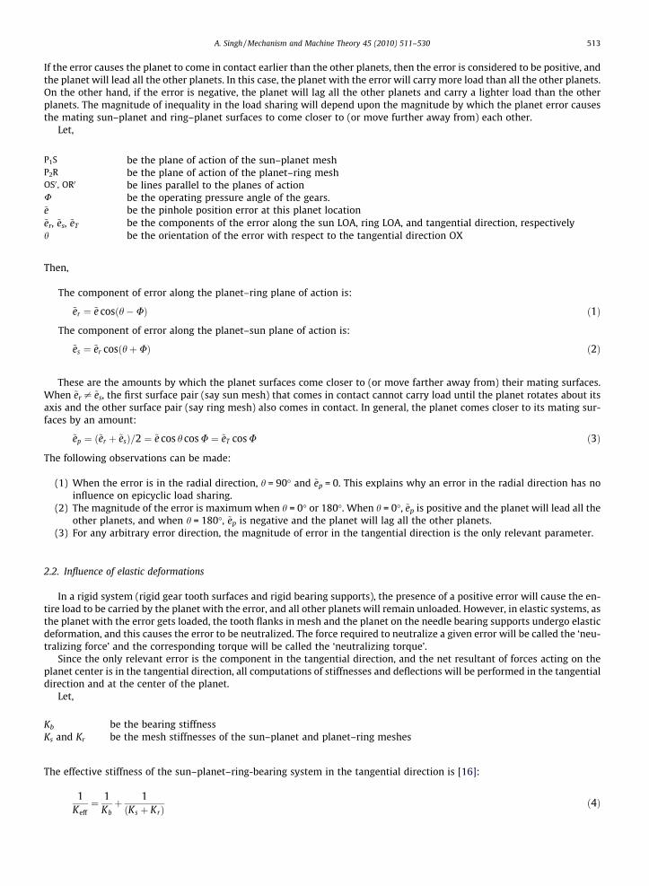
Position error is defined as the error in the location of the center of the planets. In epicyclic gear systems, this is a con-sequence of the manufacturing tolerances on dimensions such as the location of the planet pinhole in the carriers. Consideran epicyclic system with an error ~e on the location of one of the planets, while all the other planets are at their ideal location.Fig. 1 shows a schematic of the planet with the error.
Under unloaded conditions, the error will cause the planet contacting surfaces to come closer to or move farther awayfrom their mating surfaces. This will result in that planet coming in contact either earlier or later than all the other planets.
Fig. 1. Pinhole position error.
A. Singh / Mechanism and Machine Theory 45 (2010) 511–530 513
If the error causes the planet to come in contact earlier than the other planets, then the error is considered to be positive, andthe planet will lead all the other planets. In this case, the planet with the error will carry more load than all the other planets.On the other hand, if the error is negative, the planet will lag all the other planets and carry a lighter load than the otherplanets. The magnitude of inequality in the load sharing will depend upon the magnitude by which the planet error causesthe mating sun–planet and ring–planet surfaces to come closer to (or move further away from) each other.
Let,
P1S be the plane of action of the sun–planet meshP2R be the plane of action of the planet–ring meshOS0 , OR0 be lines parallel to the planes of actionU be the operating pressure angle of the gears.~e be the pinhole position error at this planet location~er, ~es, ~eT be the components of the error along the sun LOA, ring LOA, and tangential direction, respectivelyh be the orientation of the error with respect to the tangential direction OX
Then,
The component of error along the planet–ring plane of action is:
~er ¼ ~e cosðh�UÞ ð1Þ
The component of error along the planet–sun plane of action is:
~es ¼ ~er cosðhþUÞ ð2Þ
These are the amounts by which the planet surfaces come closer to (or move farther away from) their mating surfaces.When ~er – ~es, the first surface pair (say sun mesh) that comes in contact cannot carry load until the planet rotates about itsaxis and the other surface pair (say ring mesh) also comes in contact. In general, the planet comes closer to its mating sur-faces by an amount:
Kb
Ks and
~ep ¼ ð~er þ ~esÞ=2 ¼ ~e cos h cos U ¼ ~eT cos U ð3Þ
The following observations can be made:
(1) When the error is in the radial direction, h = 90� and ~ep = 0. This explains why an error in the radial direction has noinfluence on epicyclic load sharing.
(2) The magnitude of the error is maximum when h = 0� or 180�. When h = 0�, ~ep is positive and the planet will lead all theother planets, and when h = 180�, ~ep is negative and the planet will lag all the other planets.
(3) For any arbitrary error direction, the magnitude of error in the tangential direction is the only relevant parameter.
2.2. Influence of elastic deformations
In a rigid system (rigid gear tooth surfaces and rigid bearing supports), the presence of a positive error will cause the en-tire load to be carried by the planet with the error, and all other planets will remain unloaded. However, in elastic systems, asthe planet with the error gets loaded, the tooth flanks in mesh and the planet on the needle bearing supports undergo elasticdeformation, and this causes the error to be neutralized. The force required to neutralize a given error will be called the ‘neu-tralizing force’ and the corresponding torque will be called the ‘neutralizing torque’.
Since the only relevant error is the component in the tangential direction, and the net resultant of forces acting on theplanet center is in the tangential direction, all computations of stiffnesses and deflections will be performed in the tangentialdirection and at the center of the planet.
Let,
be the bearing stiffnessKr be the mesh stiffnesses of the sun–planet and planet–ring meshes
The effective stiffness of the sun–planet–ring-bearing system in the tangential direction is [16]:
1Keff¼ 1
Kbþ 1ðKs þ KrÞ
ð4Þ
514 A. Singh / Mechanism and Machine Theory 45 (2010) 511–530
Keff is the cumulative stiffness due to Hertzian contact at the sun–planet and planet–ring meshes, the tooth bending deflec-tions, the tooth base rotation, and the planet bearing stiffness. Keff can be considered to be lumped at the center of the planet,and the rest of the system can be considered to be rigid. Keff is a property of the sun–planet–ring-needle bearing system andis generally invariant with the number of planets in the system.
In the rest of this paper, we will focus on the tangential error ~eT (simply called error) and the tangential neutralizing forceor torque required to neutralize this error. Also, all the stiffnesses will be lumped in the Keff term, and the rest of the systemwill be assumed to be rigid.
2.3. Non-dimensional neutralizing ratio
If an n planet epicyclic gear set has an error e on the position of one of its planets, and all other planets are at their ideallocation, then the neutralizing force is given by:
Fig. 2.represe
Fe ¼ Keff � e ð5Þ
The corresponding non-dimensional neutralizing ratio is the ratio of the neutralizing force to the total input force, or theneutralizing torque to the total input torque:
Xe ¼Keff � e
FI¼ Fe
FI¼ Te
TIð6Þ
The neutralizing ratio captures the influence of the system flexibility, the amount of error, and the loading on the gear set. Inthis paper, we will express the load sharing behavior in terms of the neutralizing ratio. The developed expressions will beapplicable for any epicyclic gear set, regardless of its error level, loading level, system stiffnesses or number of planets.
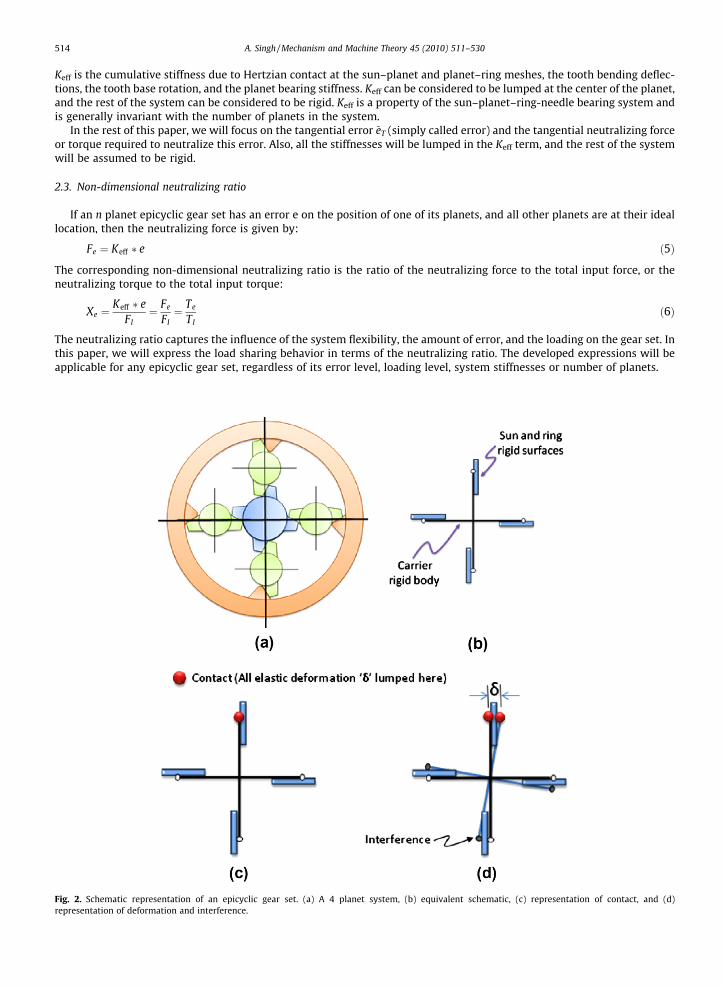
Schematic representation of an epicyclic gear set. (a) A 4 planet system, (b) equivalent schematic, (c) representation of contact, and (d)ntation of deformation and interference.
A. Singh / Mechanism and Machine Theory 45 (2010) 511–530 515
2.4. Equal load sharing in the absence of errors
Consider an n planet epicyclic gear set and assume the meshes to be in-phase (phasing has a transient secondary effect onmesh load sharing). Under ideal conditions, all n mesh paths are simultaneously in contact. Under this condition, all mesheswill share the load equally, and 1/n of the load will pass through each sun–planet–ring path. Equally spaced planets, in theabsence of location errors, always share the load equally amongst all the planets. Even slightly unequally spaced planets(small deviations from equally spaced due to assembly considerations) share the load approximately equally. This behavioris well established and epicyclic gear sets are designed around this principle. Previous works [10–13] using various compu-tational models confirms this behavior. This argument can also be based on symmetry considerations. Since all planets seeidentical geometric configurations and relative mesh phases of the surrounding planets, the mesh forces at all meshes mustbe the same (with the exception of a time lag captured by the phase differences) [15].
2.5. Schematic representation
Fig. 2a shows an example of a 4 planet epicyclic gear set with no position errors and Fig. 2b shows its equivalent sche-matic. In the schematic, the centers of the planets are connected to the center of the carrier by rigid arms and the sun–ringbodies are represented by another rigid body. The combined stiffness, Keff, of all the elastic bodies (sun, planet, ring, bearings,and carrier) is lumped at the interface between the planet and the sun–ring bodies. Though this stiffness is not explicitlyshown in the schematics, it is assumed to always be present and is located at the planet centers. The regions of contactare represented by as shown in Fig. 2c, and all loaded elastic deformations (d) take place in these regions. Interferenceconditions will be represented as shown in Fig. 2d, and such material penetration will not be allowed.
3. Non-floating systems
In a non-floating system, the centers of the sun, ring, and carrier are fixed and no relative motion is possible between theirreference frames. The only unconstrained movement is rotation about their axis. The positional errors can only be neutral-ized by system deformations under load. The load needed to neutralize the error is the root cause of the load sharinginequalities.
3.1. Approach
We will assume that only one planet has a positional error. The approach that will be used to explain the load sharingbehavior and derive the planet load sharing expressions is as follows:
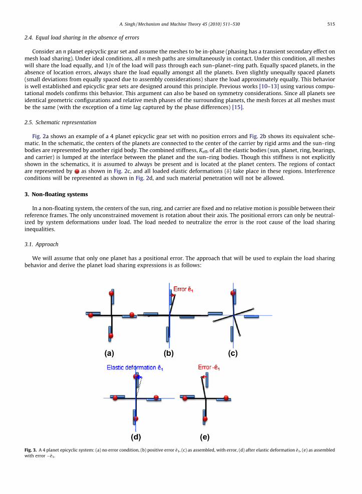
Fig. 3. A 4 planet epicyclic system: (a) no error condition, (b) positive error ~e1, (c) as assembled, with error, (d) after elastic deformation ~e1, (e) as assembledwith error �~e1.
516 A. Singh / Mechanism and Machine Theory 45 (2010) 511–530
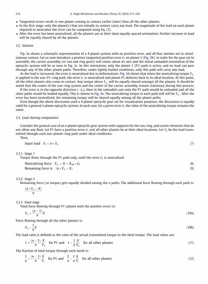
� Tangential errors result in one planet coming in contact earlier (later) than all the other planets.� In the first stage, only the planet(s) that are initially in contact carry any load. The magnitude of the load on each planet
required to neutralize the error can be computed using Eq. (5).� After the error has been neutralized, all the planets are at their ideal equally spaced orientation. Further increase in load
will be equally shared by all the planets.
3.2. Solution
Fig. 3a shows a schematic representation of a 4 planet system with no position error, and all four meshes are in simul-taneous contact. Let us now introduce a positive tangential position error ~e1 on planet 1 (Fig. 3b). In order for the gear set toassemble, the carrier assembly (or sun and ring gears) will rotate about its axis and the initial unloaded orientation of theepicyclic system will be as seen in Fig. 3c. In this orientation, only the planet 1 (P1) path is active, and no load can passthrough any of the other planet paths. Therefore, under lightly loaded conditions, only this path will carry any load.
As the load is increased, the error is neutralized due to deformations. Fig. 3d shows that when the neutralizing torque T~e1
is applied to the sun–P1–ring path, the error ~e1 is neutralized and planet P1 deforms back to its ideal location. At this point,all the other planets also come in contact. Any torque above T~e1 will be equally shared amongst all the planets. It should benoted that the center of the sun–ring system and the center of the carrier assembly remain stationary during this process.
If the error is in the opposite direction (�~e1), then in the unloaded case only the P1 path would be unloaded and all theother paths would be loaded equally. This is shown in Fig. 3e. The neutralizing torque in each path will still be T~e1 . After theerror has been neutralized, the remaining torque will be shared equally among all the planet paths.
Even though the above discussion used a 4 planet epicyclic gear set for visualization purposes, the discussion is equallyvalid for a general n planet epicyclic system. In each case, for a given error ~e1 the value of the neutralizing torque remains thesame.
3.3. Load sharing computation
Consider the general case of an n planet epicyclic gear system with supports for the sun, ring, and carrier elements that donot allow any float. Let P1 have a position error ~e1 and all other planets be at their ideal locations. Let Yn be the load trans-mitted through each sun–planet–ring path under ideal conditions.
Then,
Input load FI ¼ n � Yn ð7Þ
3.3.1. Stage 1Torque flows through the P1 path only, until the error ~e1 is neutralized
Neutralizing force F~e1 ¼ X ¼ Keff � ~e1 ð8ÞRemaining force is ðn � Yn � XÞ ð9Þ
3.3.2. Stage 2Remaining force (or torque) gets equally divided among the n paths. The additional force flowing through each path is:
ðn � Yn � XÞn
3.3.3. Final stageTotal force flowing through P1 (planet with the positive error) is:
Yn þðn� 1Þ
nX ð10aÞ
Force flowing through all the other planets is:
Yn �1n
X ð10bÞ
The load ratio is defined as the ratio of the actual transmitted torque to the ideal torque. The load ratios are:
1þ ðn� 1Þn
XYn
for P1 and 1� 1n
XYn
for all other planets ð11Þ
The fraction of total torque through each mesh is:
1nþ ðn� 1Þ
nXTi
for P1 and1n� 1
nXTi
for all other planets ð12Þ

Table 1Load sharing calculation – n planet non-floating system.
Error = +~e1 Error = �~e1
P1 P2� � �Pn P1 P2� � �Pn
Ideal condition Yn Yn Yn Yn
Stage 1 X 0 0 XRemaining torque n � Yn � X n � Yn � (n � 1)XStage 2 n�Yn�X
nn�Yn�X
nn�Yn�ðn�1ÞX
nn�Yn�ðn�1ÞX
n
Total torque Yn þ ðn�1Þn X Yn � 1
n X Yn � ðn�1Þn X Yn þ 1
n X
Load ratio 1 + (n � 1)Xe 1�Xe 1 � (n � 1)Xe 1+Xe
Fraction of total torque (Ti) 1nþ
ðn�1Þn Xe
1n � 1
n Xe 1n �
ðn�1Þn Xe
1nþ 1
n Xe
Table 2Load ratio and load fraction for 3, 4, 5, and 6 Planet gear sets.
Error + ~e1 Error � ~e1
P1 P2, . . . , Pn P1 P2, . . . , Pn
Load ratio for a given input torque Ti
3 P 1 + 2Xe 1 � Xe 1 � 2Xe 1 + Xe
4 P 1 + 3Xe 1 � Xe 1 � 3Xe 1 + Xe
5 P 1 + 4Xe 1 � Xe 1 � 4Xe 1 + Xe
6 P 1 + 5Xe 1 � Xe 1 � 5Xe 1 + Xe
Fraction of total torque for a given Ti
3 P 1/3 + (2/3)Xe 1/3 � (1/3)Xe 1/3 � (2/3)Xe 1/3 + (1/3)Xe
4 P 1/4 + (3/4)Xe 1/4 � (1/4)Xe 1/4 � (3/4)Xe 1/4 + (1/4)Xe
5 P 1/5 + (4/5)Xe 1/5 � (1/5)Xe 1/5 � (4/5)Xe 1/5 + (1/5)Xe
6 P 1/6 + (5/6)Xe 1/6 � (1/6)Xe 1/6 � (5/6)Xe 1/6 + (1/6)Xe
A. Singh / Mechanism and Machine Theory 45 (2010) 511–530 517
Using Eq. (6), the load ratio through each mesh can be expressed in terms of the neutralizing ratio as:
1þ ðn� 1ÞXe for P1 and 1� Xe for all other planets ð13Þ
The fraction of total torque is:
1nþ ðn� 1Þ
nXe for P1 and
1n� 1
nXe for all other planets ð14Þ
Table 1 captures the calculation steps for an n planet epicyclic gear set. If the error is in the opposite direction ð�~e1Þ the pla-net loading can be similarly calculated and is also shown in Table 1. The equations in Table 1 are valid for any arbitrary num-ber of planets in the epicyclic gear set. Table 2 captures the load ratios and fraction of total torque relationships for 3–6planet epicyclic systems and can be obtained by substituting the corresponding values of n in Table 1.
It is obvious from Tables 1 and 2 that a positive error results in worse load sharing and is therefore more detrimental thana similar negative error. Also as seen in Table 2, even though the neutralizing torque is the same regardless of the number ofplanets, the effect on the final load sharing is different. For a positive error, the net extra torque through the most heavilyloaded planet path is 2
3 Xe in a 3 planet system, 34 Xe in a 4 planet system, 4
5 Xe in a 5 planet system and 56 Xe in a 6 planet system.
This shows that the sensitivity of the system to location error increases as the number of planet in the system increases. For anegative error, the trend is opposite, but again that is a less detrimental condition.
4. Floating systems
In floating systems, the center of at least one of the coaxial members (the sun, ring, and carrier) is free to move radiallyand thus relative motion between the coaxial members is possible. It is well established that floating one or more of thesebodies leads to significantly better load sharing characteristics. In this section, a physical explanation will be provided for theload sharing mechanism in floating systems. The major advantage of floating systems over non-floating systems is that aportion of the positional error is neutralized by system float. The remaining error is neutralized by system deflections.The portion of the error that is neutralized by system deflection is the cause of the load sharing inequality.
4.1. Approach
� Tangential errors result in one planet coming in contact earlier (later) than all the other planets.� The system then ‘floats’ until two or three planets come in contact (two – if number of planets is even and diagonally
opposed planets are present, three – if odd)

518 A. Singh / Mechanism and Machine Theory 45 (2010) 511–530
� In the first stage, only the planets that are in contact after the floating stage carry any load. The magnitude of the load oneach planet required to neutralize a portion of the error can be calculated by using Eq. (5).
� After a portion of the error has been neutralized, more planets come in contact. The amount of initial error, the magnitudeof input torque, and the kinematics of the floating system has to be considered in order to calculate the amount of loadthat needs to be applied so that additional planets come in contact.
� The last step is repeated until all the planets come in contact. At that moment, all the planets are at their ideal equallyspaced orientation. Further increase in load will be equally shared by all the planets.
4.2. Simulating system float
In this paper, the floating behavior will be modeled by allowing the carrier assembly to float with respect to the sun andring gear centers. In reality, the system float may be the result of the motions of one or more of the coaxial members – car-rier, sun, and ring gear. It can be shown that regardless of the motion of the individual bodies, it is their relative motion thatis important. The load sharing calculations and results will be the same, regardless of the individual bodies that float, as longas the system has the minimum amount of float needed to realize a fully floating condition.
A few simple equations, based on geometry considerations, will be used to simulate the floating behavior. In Fig. 4, thecircle represents the bounding circle of the planet centers for an epicyclic gear set with center distance ‘R’. Let ‘O’ be the cen-ter of the gear set and ‘A’ be a point on the bounding circle. Let ‘I’ be a point on the bounding circle at an angle b1 from OA,and let Ri be distance IA.
Then,
Ri ¼ffiffiffiffiffiffiffiffiffiffiffiffiffiffiffiffiffiffiffiffiffiffiffiffiffiffiffi2ð1� cos biÞ2
p� R ð15Þ
Let the bounding circle rotate by an amount h about A. Then, point I rotates to the point I0 and its projection in the tangentialdirection is I00. The change in the position of the point I along the tangential direction is given by the distance I–I00 and rep-resented by di.
di ¼ Rih cos 90� bi
2
� �¼
ffiffiffiffiffiffiffiffiffiffiffiffiffiffiffiffiffiffiffiffiffiffiffiffiffiffiffi2ð1� cos biÞ2
pcos 90� bi
2
� �Rh ð16Þ
If there is a planet Pi at position I, and the effective error at Pi is yi, then the error after float will be:
y0i ¼ yi þ di ð17Þ
Also, the center of the carrier moves from point O to point O0. The distance O–O0 is the amount of carrier float needed to real-ize a fully floating condition during this stage, and is given by:
cstage1float ¼ Rh ð18Þ
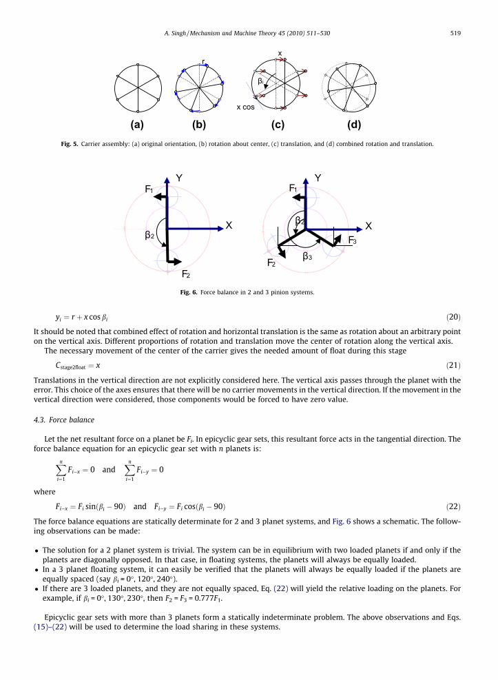
Next, consider rotational and radial movements of the carrier assembly. Fig. 5a depicts a carrier assembly with several arbi-trarily located planets. Fig. 5b shows the carrier assembly after it undergoes pure rotation about its center. In this case, everypoint on the circumference moves by the same amount in the tangential direction. Let the magnitude of tangential move-ment due to rotation about the center be represented by r. If the carrier assembly translates in the horizontal directionby an amount x, then every point on the carrier moves the same amount in the horizontal direction. However, the componentalong the tangential direction, xi, will be different at each point and depends upon the angular position of the given pointfrom the vertical axis. This is shown in Fig. 5c
xi ¼ x cos bi ð19Þ
If both rotation and translation is present (Fig. 5d), then the total movement in the tangential direction, at any circumferen-tial location, is given by:
R
R
Ri
βi
I
B
A
O R
Ri
βi
I I'
I"
θ
B B
O'O
A
Fig. 4. Rigid body rotation about a circumferential point.
βi
x cos
rx
(a) (b) (c) (d)Fig. 5. Carrier assembly: (a) original orientation, (b) rotation about center, (c) translation, and (d) combined rotation and translation.
β2
F1
F2
X
Y
β2
β3
F1
F2
F3
X
Y
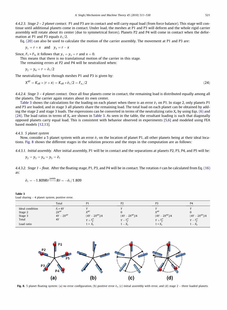
Fig. 6. Force balance in 2 and 3 pinion systems.
A. Singh / Mechanism and Machine Theory 45 (2010) 511–530 519
yi ¼ r þ x cos bi ð20Þ
It should be noted that combined effect of rotation and horizontal translation is the same as rotation about an arbitrary pointon the vertical axis. Different proportions of rotation and translation move the center of rotation along the vertical axis.
The necessary movement of the center of the carrier gives the needed amount of float during this stage
Cstage2float ¼ x ð21Þ
Translations in the vertical direction are not explicitly considered here. The vertical axis passes through the planet with theerror. This choice of the axes ensures that there will be no carrier movements in the vertical direction. If the movement in thevertical direction were considered, those components would be forced to have zero value.
4.3. Force balance
Let the net resultant force on a planet be Fi. In epicyclic gear sets, this resultant force acts in the tangential direction. Theforce balance equation for an epicyclic gear set with n planets is:
Xn
i¼1
Fi�x ¼ 0 andXn
i¼1
Fi�y ¼ 0
where
Fi�x ¼ Fi sinðbi � 90Þ and Fi�y ¼ Fi cosðbi � 90Þ ð22Þ
The force balance equations are statically determinate for 2 and 3 planet systems, and Fig. 6 shows a schematic. The follow-ing observations can be made:
� The solution for a 2 planet system is trivial. The system can be in equilibrium with two loaded planets if and only if theplanets are diagonally opposed. In that case, in floating systems, the planets will always be equally loaded.
� In a 3 planet floating system, it can easily be verified that the planets will always be equally loaded if the planets areequally spaced (say bi = 0�, 120�, 240�).
� If there are 3 loaded planets, and they are not equally spaced, Eq. (22) will yield the relative loading on the planets. Forexample, if bi = 0�, 130�, 230�, then F2 = F3 = 0.777F1.
Epicyclic gear sets with more than 3 planets form a statically indeterminate problem. The above observations and Eqs.(15)–(22) will be used to determine the load sharing in these systems.

520 A. Singh / Mechanism and Machine Theory 45 (2010) 511–530
4.4. Solution – positive error
Fig. 7a shows a 4 planet system with no position error and all four meshes simultaneously in contact. Let us now intro-duce a positive tangential position error ~e1 on planet 1 (Fig. 7b). In order for the gear set to assemble, the carrier (or sun andring gears) will rotate and the initial unloaded orientation of the gears will be as shown in Fig. 7c with contact at P1 only. Ifthe system is free to float, the sun, ring and/or carrier members will rotate about P1 and come to rest at a position wherethere are two diagonally opposed planets in contact. This is seen in Fig. 7d where the carrier is assumed to be the floatingmember. As seen in the figure, a portion of the error is neutralized by the system float. This can be seen by the smaller gapbetween the remaining planets (P2 and P4) and the corresponding mating surfaces in Fig. 7d.
As the system load is increased, the remaining error is neutralized due to elastic deformations at the loaded planets.When enough torque has been applied, the remaining planets will also come in contact. Any further increase in load is thenshared equally between all the planets.
Even though the above discussion used a 4 planet epicyclic gear set for visualization purposes, the discussion is equallyvalid for a general n planet epicyclic system. There are, however, differences in how the system floats, the load shared by theplanets, and the number of stages in the solution process. Epicyclic gear sets with an even number of equally (or almostequally) spaced planets (4, 6) have diagonally opposed planets. At the end of the floating phase, they will always havetwo diagonally opposed planets that are loaded. In epicyclic gear sets with an odd number of planets (3, 5, 7), at the endof the floating phase, there will always be three loaded planets.
4.4.1. 3 planet systemThe solution for the 3 planet system is trivial. In the floating stage, the carrier center will float until all three planets come
in contact. The amount of carrier movement needed is obtained from Eqs. (16) and (18) and using d ¼ ~e1 and is given by:
Fig. 7.
C3pfloat ¼ �2~e1=3
From static force balance, for equally spaced planets, it can be seen that all planets will share the load equally, regardless ofthe magnitude of the error. The amount of error merely influences the amount of float needed to achieve the fully floatingcondition.
4.4.2. 4 planet systemConsider the 4 planet case shown in Fig. 7 with an error ~e1 on the location of P1, all other planets being at their ideal loca-
tions. The steps in the computation are as follows:
4.4.2.1. Initial assembly. After initial assembly, P1 will be in contact and the separations at planets P2, P3, and P4 will be:
y2 ¼ y3 ¼ y4 ¼ ~e1
4.4.2.2. Stage 1 – float. After the floating stage, P1 and P3 will be in contact. The rotation h can be calculated from Eq. (16) as:
~e1 ¼ �2:0Rh ��!yieldsRh ¼ �~e1=2
Using Eqs. (16) and (17) and b2 = 90�, the gap at P2 and P4 will be given by:
y02 ¼ ~e1 þ d2 ¼ ~e1 þ 1:0Rh ¼ ~e1=2
Similarly, y04 ¼ ~e1=2.This shows that half the error in a 4 planet epicyclic gear set is neutralized by system float. Also, the amount of carrier
float needed in this stage in order to realize the fully floating condition is given by:
c4pfloat ¼ �~e1=2 ð23Þ
4 planet floating system: (a) no error condition, (b) positive error ~e1, (c) initial assembly with error, and (d) after floating stage – two loaded planets.
A. Singh / Mechanism and Machine Theory 45 (2010) 511–530 521
4.4.2.3. Stage 2 – 2 planet contact. P1 and P3 are in contact and will carry equal load (from force balance). This stage will con-tinue until additional planets come in contact. Under load, the meshes at P1 and P3 will deform and the whole rigid carrierassembly will rotate about its center (due to symmetrical forces). Planets P2 and P4 will come in contact when the defor-mation at P1 and P3 equals ~e1=2.
Eq. (20) can also be used to calculate the motion of the carrier assembly. The movement at P1 and P3 are:
Table 3Load sh
IdeaStagStagTota
Load
Fig. 8
y1 ¼ r þ x and y3 ¼ r � x
Since, F1 = F3, it follows that y1 ¼ y3 ¼ r and x ¼ 0.This means that there is no translational motion of the carrier in this stage.The remaining errors at P2 and P4 will be neutralized when:
y2 ¼ y4 ¼ r ¼ ~e1=2
The neutralizing force through meshes P1 and P3 is given by:
X4P ¼ Keff � ðr þ xÞ ¼ Keff � ~e1=2 ¼ Fe1=2 ð24Þ
4.4.2.4. Stage 3 – 4 planet contact. Once all four planets come in contact, the remaining load is distributed equally among allthe planets. The carrier again rotates about its own center.
Table 3 shows the calculations for the loading on each planet when there is an error ~e1 on P1. In stage 2, only planets P1and P3 are loaded, and in stage 3 all planets share the remaining load. The total load on each planet can be obtained by add-ing the stage 2 and stage 3 loads. The expressions can be converted in terms of the neutralizing ratio Xe by using Eqs. (6) and(24). The load ratios in terms of Xe are shown in Table 3. As seen in the table, the resultant loading is such that diagonallyopposed planets carry equal load. This is consistent with behavior observed in experiments [5,6] and modeled using FEAbased models [12,13].
4.4.3. 5 planet systemNow, consider a 5 planet system with an error ~e1 on the location of planet P1, all other planets being at their ideal loca-
tions. Fig. 8 shows the different stages in the solution process and the steps in the computation are as follows:
4.4.3.1. Initial assembly. After initial assembly, P1 will be in contact and the separations at planets P2, P3, P4, and P5 will be:
y2 ¼ y3 ¼ y4 ¼ y5 ¼ ~e1
4.4.3.2. Stage 1 – float. After the floating stage, P1, P3, and P4 will be in contact. The rotation h can be calculated from Eq. (16)as:
~e1 ¼ �1:809Rh ��!yieldsRh ¼ �~e1=1:809
aring – 4 planet system, positive error.
Total P1 P2 P3 P4
l condition FI = 4Y Y Y Y Ye 2 2X4P X4P 0 X4P 0e 3 4Y � 2X4P (4Y � 2X4P)/4 (4Y � 2X4P)/4 (4Y � 2X4P)/4 (4Y � 2X4P)/4l 4Y Y þ X4P
2 Y � X4P
2 Y þ X4P
2 Y � X4P
2
ratio 1 + Xe 1 � Xe 1 + Xe 1 � Xe
. 5 planet floating system: (a) no error configuration, (b) positive error ~e1, (c) initial assembly with error, and (d) stage 2 – three loaded planets.

522 A. Singh / Mechanism and Machine Theory 45 (2010) 511–530
The gap at P2 and P5 will be given by Eqs. (16) and (17) as:
Table 4Load sh
IdeaStagStagTotaLoad
y02 ¼ ~e1 þ d2 ¼ ~e1 þ 0:691Rh ¼ 0:618~e1
Similarly, y05 ¼ 0:618~e1.The amount of carrier float needed in this stage in order to realize the fully floating condition is:
C5ps1 ¼ �~e1=1:809 ¼ �0:5527~e1 ð25Þ
4.4.3.3. Stage 2 – 3 planet contact. Forces on P1, P3, and P4 can be computed from the force balance Eq. (22).
b1 ¼ 0�; b2 ¼ 144�; b4 ¼ 216�
F3 ¼ F4 and F3 þ F4 ¼ 1:236F1
Therefore, F3 = F4 = 0.618F1.This stage will continue until additional planets come in contact.Using Eq. (20), the motion at P1, P3, and P4 is given by:
y1 ¼ r þ x; y3 ¼ r � 0:809x and y4 ¼ r � 0:809x
The forces at each planet mesh are proportional to the displacements at that mesh.Therefore,
r � 0:809x ¼ 0:618ðr þ xÞ ��!yieldsr ¼ 3:7361x
Additional planets come in contact when the separation at P2 and P5 are neutralized, i.e. y2 ¼ y02
r þ 0:309x ¼ 0:618~e1
x ¼ 0:1528~e1 and r ¼ 0:5708~e1
The neutralizing torque is given by:
X5P ¼ Keff � ðr þ xÞ ¼ Keff � ðr þ xÞ ¼ Keff � 0:7236~e1 ¼ 0:7236Fe1 ð26Þ
The carrier motion needed in this stage is back towards its original center and the magnitude is given by:
c5Ps2 ¼ 0:1528~e1 ð27Þ
4.4.3.4. Stage 3 – 5 planet contact. Once all five planets come in contact, the remaining load is distributed equally among allthe planets. In this stage the carrier rotates about its own center.
The steps in the calculation are shown in Table 4. Using Eqs. (6) and (26), the load ratios can again be expressed in termsof the non-dimensional parameter Xe.
4.4.4. 6 planet systemThe solution process for a 6 planet epicyclic gear set is similar, but there are more stages in the solution process. Fig. 9a
shows a 6 planet system with all the planets in contact in the absence of positional errors. Fig. 9b–e shows various stages inthe solution process when there is an error ~e1 on the location of planet P1 (all other planets are at their ideal locations). Thesteps in the computation are as follows:
4.4.4.1. Initial assembly. After initial assembly, P1 will be in contact and the separations at planets P2, P3, P4, P5, and P6 are:
y2 ¼ y3 ¼ y4 ¼ y5 ¼ y6 ¼ ~e1
4.4.4.2. Stage 1 – float. After the floating stage, diagonally opposed planets P1 and P4 will be in contact. The rotation h can becalculated from Eq. (16):
~e1 ¼ �2:0Rh ��!yieldsRh ¼ �~e1=2
aring – 5 planet system, positive error.
Total P1 P2, P5 P3, P4
l condition FI = 5Y Y Y Ye 2 2.236X5P X5P 0 0.618X5P
e 3 5Y � 2.236X5P Y � 0.4472X5P Y � 0.4472X5P Y � 0.4472X5P
l 5Y Y + 0.5528X5P Y � 0.4472X5P Y + 0.1708X5P
ratio 1 + 2Xe 1 � 1.618Xe 1 + 0.618Xe

A. Singh / Mechanism and Machine Theory 45 (2010) 511–530 523
The gap at P3 and P5 will be given by Eqs. (16) and (17) as:
Fig. 9.3 – fou
y03 ¼ ~e1 þ d3 ¼ ~e1 þ 1:50Rh ¼ ~e1=4 and y05 ¼ ~e1=4
The gap at P2 and P6 is:
y02 ¼ ~e1 þ d2 ¼ ~e1 þ 0:50Rh ¼ 3~e1=4 and y06 ¼ 3~e1=4
The amount of carrier float needed in this stage in order to realize the fully floating condition is:
C6Ps1 ¼ �0:50~e1 ð28Þ
4.4.4.3. Stage 2 – 2 planet loading. As in the 4 planet case, opposing planets (P1 and P4) are in contact and the individual loadscan be computed by force balance equations as F1 ¼ F4 ¼ X6P
s1 .This stage will continue until additional planets come in contact.Also, the loading is such that there will be equal deformation at the diagonally opposed meshes P1 and P4. This condition
will be satisfied by pure rotation of the carrier assembly about its axis, and therefore
c6Ps2 ¼ 0 ð29Þ
The next planets that come in contact are P3 and P5. These planets will come in contact when the carrier assembly has ro-tated by an amount equal to ~e1=4. The corresponding neutralizing force is given by:
X6Ps1 ¼ Keff � ~e1=4 ¼ 0:25Fe1 ð30Þ
At this point the gap at P2 and P6 is given by:
y002 ¼ y006 ¼ 3~e1=4� ~e1=4 ¼ ~e1=2
4.4.4.4. Stage 3 – 4 planet loading. At this stage planets P1, P3, P4, and P5 are in contact and carrying load. This is a staticallyindeterminate system. From the force balance equations, we get:
F3 ¼ F5 and F1 ¼ F3 þ F4
The degree of static indeterminacy is 1. Therefore, the solution of this problem requires one additional equation. This can beobtained by noting that the displacements at each mesh should be proportional to the loading and that the new orientationof the carrier should be obtained by rigid body rotations and translations.
Using Eq. (20) for the displacements at each mesh, the forces are:
6 planet floating system: (a) no error configuration, (b) positive error ~e1, (c) initial assembly with error, (d) stage 2 – two loaded planets, and (e) stager loaded planets.
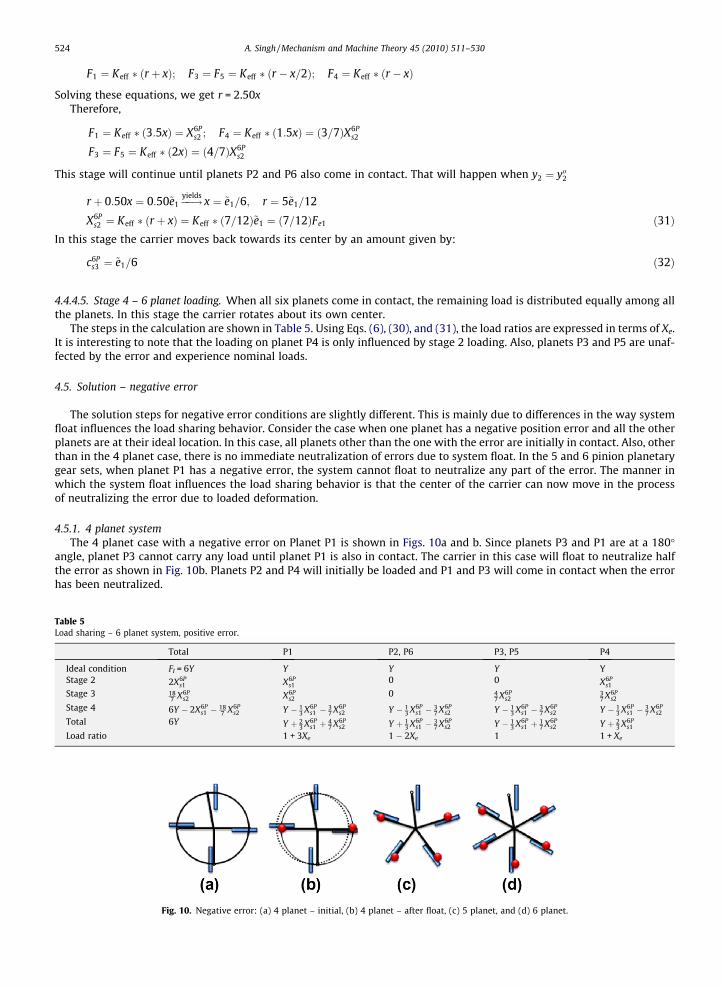
Table 5Load sh
IdeaStag
Stag
Stag
Tota
Load
524 A. Singh / Mechanism and Machine Theory 45 (2010) 511–530
F1 ¼ Keff � ðr þ xÞ; F3 ¼ F5 ¼ Keff � ðr � x=2Þ; F4 ¼ Keff � ðr � xÞ
Solving these equations, we get r = 2.50xTherefore,
F1 ¼ Keff � ð3:5xÞ ¼ X6Ps2 ; F4 ¼ Keff � ð1:5xÞ ¼ ð3=7ÞX6P
s2
F3 ¼ F5 ¼ Keff � ð2xÞ ¼ ð4=7ÞX6Ps2
This stage will continue until planets P2 and P6 also come in contact. That will happen when y2 ¼ y002
r þ 0:50x ¼ 0:50~e1 ��!yieldsx ¼ ~e1=6; r ¼ 5~e1=12
X6Ps2 ¼ Keff � ðr þ xÞ ¼ Keff � ð7=12Þ~e1 ¼ ð7=12ÞFe1 ð31Þ
In this stage the carrier moves back towards its center by an amount given by:
c6Ps3 ¼ ~e1=6 ð32Þ
4.4.4.5. Stage 4 – 6 planet loading. When all six planets come in contact, the remaining load is distributed equally among allthe planets. In this stage the carrier rotates about its own center.
The steps in the calculation are shown in Table 5. Using Eqs. (6), (30), and (31), the load ratios are expressed in terms of Xe.It is interesting to note that the loading on planet P4 is only influenced by stage 2 loading. Also, planets P3 and P5 are unaf-fected by the error and experience nominal loads.
4.5. Solution – negative error
The solution steps for negative error conditions are slightly different. This is mainly due to differences in the way systemfloat influences the load sharing behavior. Consider the case when one planet has a negative position error and all the otherplanets are at their ideal location. In this case, all planets other than the one with the error are initially in contact. Also, otherthan in the 4 planet case, there is no immediate neutralization of errors due to system float. In the 5 and 6 pinion planetarygear sets, when planet P1 has a negative error, the system cannot float to neutralize any part of the error. The manner inwhich the system float influences the load sharing behavior is that the center of the carrier can now move in the processof neutralizing the error due to loaded deformation.
4.5.1. 4 planet systemThe 4 planet case with a negative error on Planet P1 is shown in Figs. 10a and b. Since planets P3 and P1 are at a 180�
angle, planet P3 cannot carry any load until planet P1 is also in contact. The carrier in this case will float to neutralize halfthe error as shown in Fig. 10b. Planets P2 and P4 will initially be loaded and P1 and P3 will come in contact when the errorhas been neutralized.
aring – 6 planet system, positive error.
Total P1 P2, P6 P3, P5 P4
l condition FI = 6Y Y Y Y Ye 2 2X6P
s1 X6Ps1
0 0 X6Ps1
e 3 187 X6P
s2 X6Ps2
0 47 X6P
s237 X6P
s2
e 4 6Y � 2X6Ps1 � 18
7 X6Ps2 Y � 1
3 X6Ps1 � 3
7 X6Ps2 Y � 1
3 X6Ps1 � 3
7 X6Ps2 Y � 1
3 X6Ps1 � 3
7 X6Ps2 Y � 1
3 X6Ps1 � 3
7 X6Ps2
l 6Y Y þ 23 X6P
s1 þ 47 X6P
s2 Y þ 13 X6P
s1 � 37 X6P
s2 Y � 13 X6P
s1 þ 17 X6P
s2 Y þ 23 X6P
s1
ratio 1 + 3Xe 1 � 2Xe 1 1 + Xe
Fig. 10. Negative error: (a) 4 planet – initial, (b) 4 planet – after float, (c) 5 planet, and (d) 6 planet.
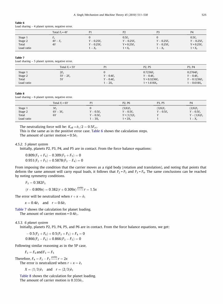
Table 6Load sharing – 4 planet system, negative error.
Total FI = 4Y P1 P2 P3 P4
Stage 1 Fe 0 0.5Fe 0 0.5Fe
Stage 2 4Y � Fe Y � 0.25Fe Y � 0.25Fe Y � 0.25Fe Y � 0.25Fe
Total 4Y Y � 0.25Fe Y + 0.25Fe Y � 0.25Fe Y + 0.25Fe
Load ratio 1 � Xe 1 + Xe 1 � Xe 1 + Xe
Table 7Load sharing – 5 planet system, negative error.
Total FI = 5Y P1 P2, P5 P3, P4
Stage 1 2Fe 0 0.7236Fe 0.2764Fe
Stage 2 5Y � 2Fe Y � 0.4Fe Y � 0.4Fe Y � 0.4Fe
Total 5Y Y � 0.4Fe Y + 0.3236Fe Y � 0.1236Fe
Load ratio 1 � 2Xe 1 + 1.618Xe 1 � 0.618Xe
Table 8Load sharing – 6 planet system, negative error.
Total FI = 6Y P1 P2, P6 P3, P5 P4
Stage 1 3Fe 0 (5/6)Fe (3/6)Fe (2/6)Fe
Stage 2 6Y � 3Fe Y � 0.5Fe Y � 0.5Fe Y � 0.5Fe Y � 0.5Fe
Total 6Y Y � 0.5Fe Y + (1/3)Fe Y Y � (1/6)Fe
Load ratio 1 � 3Xe 1 + 2Xe 1 1 � Xe
A. Singh / Mechanism and Machine Theory 45 (2010) 511–530 525
The neutralizing force will be: Keff � ~e1=2 ¼ 0:5Fe1.This is the same as in the positive error case. Table 6 shows the calculation steps.The amount of carrier motion = 0:5~e1
4.5.2. 5 planet systemInitially, planets P2, P3, P4, and P5 are in contact. From the force balance equations:
0:809ðF3 þ F4Þ � 0:309ðF2 þ F5Þ ¼ 00:951ðF2 þ F5Þ þ 0:5878ðF3 � F4Þ ¼ 0
From imposing the condition that the carrier moves as a rigid body (rotation and translation), and noting that points thatdeform the same amount will carry equal loads, it follows that F2 = F5 and F3 = F4. The same conclusions can be reachedby noting symmetry conditions.
F3 ¼ 0:382F5
ðr � 0:809xÞ ¼ 0:382ðr þ 0:309xÞ ��!yieldsr ¼ 1:5x
The error will be neutralized when r þ x ¼ ~e1
x ¼ 0:4~e1 and r ¼ 0:6~e1
Table 7 shows the calculation for planet loading.The amount of carrier motion = 0:4~e1.
4.5.3. 6 planet systemInitially, planets P2, P3, P4, P5, and P6 are in contact. From the force balance equations, we get:
� 0:5ðF2 þ F6Þ þ 0:5ðF3 þ F5Þ þ F4 ¼ 00:866ðF2 � F6Þ þ 0:866ðF3 � F5Þ ¼ 0
Following similar reasoning as in the 5P case,
F2 ¼ F6 andF3 ¼ F5
Therefore, F4 ¼ F2 � F3 ��!yieldsr ¼ 2x
The error is neutralized when r þ x ¼ ~e1
X ¼ ð1=3Þ~e1 and r ¼ ð2=3Þ~e1
Table 8 shows the calculation for planet loading.The amount of carrier motion is 0:333~e1.
526 A. Singh / Mechanism and Machine Theory 45 (2010) 511–530
5. Discussion
From the load sharing calculations shown in Tables 2–8, several significant observations can be noted about the load shar-ing behavior in epicyclic gear sets.
5.1. Positive and negative error
From the expressions in Tables 3–8, it is obvious that the load sharing expressions in terms of the non-dimensionalparameter Xe is similar in the positive and negative error cases. It should be noted that the final load ratio expressions inthese tables are valid for operating conditions in which all the planets are in contact and are loaded. In these cases, the loadratio expressions for the positive error case yields the expressions for the negative error case if we stipulate that Xe is neg-ative when the error ~e is negative.
When the error is positive, the planet with the error is the most heavily loaded planet, and the adjacent planets are themost lightly loaded planets. On the other hand, when the error is negative, the planet with the error is most lightly loaded,and the two adjacent planets are most heavily loaded. It can also be noted that for epicyclic gear sets with more than fourplanets, the positive error condition is more detrimental than the negative error condition. In a 4 planet system, positive andnegative errors result in equivalent load sharing behavior. Therefore, from a design standpoint, it is sufficient to consider thepositive error case.
Also, at high values of Xe (large error and/or low input torque) individual planets may lose contact. In these cases, if theerror is negative then stage 2 (in Tables 6–8) is not reached and:
� In a 4 planet gear set, there are 2 loaded planets.� In a 5 planet gear set, there are 4 loaded planets.� In a 6 planet gear set, there are 5 loaded planets.� In an n planet gear set, if n > 4, there are n � 1 loaded planets.
If the error is positive:
� In a 4 planet gear set, there are 2 loaded planets (stage 2 in Table 3).� In a 5 planet gear set, there are 3 loaded planets (stage 2 in Table 4).� In a 6 planet gear set, there are either 4 loaded planets, or two loaded planets (depending on stage 2 or 3 in Table 5).� In general, in the worst case there are three loaded planets if n is odd, and two loaded planets if n is even.
5.2. Load sharing pattern
The load sharing patterns can also be observed from Tables 3–5. In a 4 planet epicyclic gear set, diagonally opposing plan-ets (P1, P3, and P2, P4) are equally loaded. One pair experiences an increase in its load and the other pair experiences a cor-responding reduction in its load. In a 5 planet system, the planet with the error, P1, experiences the maximum increase in itsload. Planets P3 and P4 experience a moderate increase in their load, while planets P2 and P5 experience significant reduc-tions in their load. The ratio of the coefficients of Xe gives the relative amplitude of the loading increase or decrease. In thiscase, the increase in loading on P3 and P4 is only 31% of the increase on P1, and the decrease in loading on P2 and P5 is 81% ofthe increase on P1. In a 6 planet system, P1 again experiences the maximum increase in loading. Adjacent planets P2 and P6experience the maximum reduction in loading (magnitude is 2/3 of the increase on P1), and opposing planet P4 experiencesa moderate increase in loading (1/3 of the increase on P1). Planets P3 and P5 carry nominal loads and see no effect of theerror.
These load sharing patterns match previously published experimental and computational results [5,6,12,13]. It should benoted that these relative magnitudes of loading increase or decrease is independent of the amplitude of Xe, and thus valid forevery epicyclic gear set regardless of the details of the geometry and support conditions, error level, and torque level (as longas all planets are loaded).
5.3. General n planet epicyclic gear set
Table 2 contains the general expressions for the non-floating case. The expressions in Tables 3–8 can be used to explainthe load sharing behavior for a floating epicyclic system with any number of planets. It can also be observed that symmet-rically loaded planets carry equal load. The axis of symmetry is the axis joining the planet with the error to the center of thecarrier. In the 4 planet case, planets P2 and P4 are symmetric about this axis. Similarly, planets P2 and P5, and P3 and P4 aresymmetric about this axis in the 5 planet case. In the 6 planet case, planets P2 and P6, and P3 and P5 are also symmetric. Thissymmetry can be noted and utilized in the explicit solution process for epicyclic gear sets with more than six planets. Here,based on the form of the equation, we will formulate a general expression for the n planet epicyclic gear set.
A. Singh / Mechanism and Machine Theory 45 (2010) 511–530 527
From Tables 3–5, it can be seen that the planet with the error is the most heavily loaded planet. For the same amount oferror on planet P1, the load ratio for P1 is given by the expression:
Table 9Carrier
3 Pla4 Pla5 Pla6 Plan Pla
Load ratio ¼ 1þ 0Xe 3 Planet gear set1þ 1Xe 4 Planet gear set1þ 2Xe 5 Planet gear set1þ 3Xe 6 Planet gear set
In the general case of n planet floating epicyclic gear set,
LRfloat ¼ 1þ ðn� 3ÞXe ð33Þ
The corresponding equation for the non-floating case is:
LRnon-float ¼ 1þ ðn� 1ÞXe ð34Þ
These equations are valid for any epicyclic gear set, with positive or negative errors. From the equation it can be seen that:
� As the number of planets in the epicyclic gear set increases, so does its sensitivity to errors. For the same amount of error(constant Xe) the load ratio increases as n increases.
� The load ratio also increases as Xe increases. Xe depends upon the system stiffness, error level, and input torque.- As the error increases, load sharing gets worse.- As the input torque increases, load sharing improves.- As the system stiffness increases, load sharing gets worse.
5.4. Floating and non-floating systems
It has been shown that there is a beneficial effect on load sharing if one or more central members in an epicyclic gear setare allowed to float. In the freely floating condition, there is perfect load sharing in 3 planet systems. In systems having morethan 3 planets, system float still has a beneficial effect, but the error is not completely neutralized and the system experi-ences varying levels of unequal load sharing.
The load increments in the floating and non-floating cases follow the following relationship (as long as all pinions areloaded):
Load Incrementfloat ¼ðn� 3Þðn� 1Þ Load Incrementnon-floating
The amount of float necessary to achieve a fully floating condition varies with the number of planets in the planetary system.This float can be achieved by the combined motion of one or more of the three coaxial members – carrier, sun, and ring gear.The calculations so far have assumed that the carrier is the floating member, but it can be shown that floating of the othercoaxial members would lead to the same load sharing results.
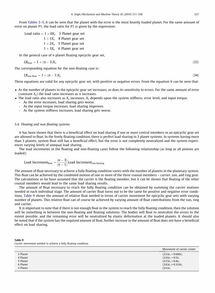
The amount of float necessary to reach the fully floating condition can be obtained by summing the carrier motionsneeded in each individual stage. The amount of carrier float turns out to be the same for positive and negative error condi-tions. Table 9 shows the amount of relative float needed in terms of carrier movement for epicyclic gear sets with varyingnumber of planets. This relative float can of course be achieved by varying amount of float contributions from the sun, ringand carrier.
It is important to note that if there is not enough float in the system to reach the fully floating condition, then the solutionwill be something in between the non-floating and floating solutions. The bodies will float to neutralize the errors to theextent possible, and the remaining error will be neutralized by elastic deformation at the loaded planets. It should alsobe noted that if the system has the required amount of float, further increase in the amount of float does not have a beneficialeffect on load sharing.
movement needed to achieve a fully floating condition.
Movement of carrier center
net (2/3)~e1 = 0.666~e1
net (2/4)~e1 = 0.5~e1
net (2/5)~e1 = 0.4~e1
net (2/6)~e1 = 0.333~e1
net (2/n)~e1

528 A. Singh / Mechanism and Machine Theory 45 (2010) 511–530
5.5. Comparison to computational model and experiments
Extensive experiments were previously conducted to determine the load sharing characteristics of 3–6 planet variants ofan epicyclic gear set. Carriers were fabricated with intentional errors of �70 lm, �35 lm, 0 lm, +35 lm, and +70 lm on thelocation of planet P1, and all planets were at their ideal location. The results of the experimental study have been publishedin detail [5].
A system level computational model was used to simulate the effects of planet location errors. The model used, Gear Sys-tem Analysis Modules (GSAM), has been described in detail in earlier publications [12,17]. The results from the GSAM modelwere found to bear good qualitative and quantitative correlation to the experimental data [13].
Fig. 11 shows some graphical results of the GSAM load sharing simulations for the experimental 4, 5, and 6 planet gearsets. The load sharing pattern can be visualized by noting the relative planet loadings. In each case, the planet at the top deadcenter is the planet P1 with the error. It can be seen that the load sharing pattern is the same as obtained from the formu-lations in this paper (the color gradient changes with increasing loading in the order blue–green–yellow–red).
The load ratio expressions presented in this paper are in terms of the non-dimensional Neutralizing Ratio Xe. For a givenhardware (sun, pinion, ring gear, needle bearing), the value of Xe is constant, and does not vary with the number of planets inthe epicyclic gear set. The expressions for the load ratio are the same for every epicyclic gear set, although the value of Xe willvary from gear set to gear set. For a given load and error level, the value of Xe depends only upon the value of the effectivestiffness Keff. Therefore, the load sharing characteristics of a given epicyclic gear set can be completely mapped if the value ofKeff can be estimated. This can be done either computationally or experimentally.
For the epicyclic gear set used in the experiments, GSAM analyses were performed at various load and error levels. For a 7planet carrier, at 1000 N m input torque on the sun gear and a +70 lm error on P1, GSAM predicts a load ratio of 2.05 on P1[13]. This can be used to estimate the value of Xe (and hence Keff).
From Eq. (33),
Table 1Load ra
P1P2P3P4P5P6
LRfloat ¼ 1þ ð7� 3ÞXe ¼ 2:05Xe ¼ 0:2625
This means that 262.5 N m of torque is needed to deform the test sun–planet–ring-needle bearing combination by anamount of 70 lm. Also, if the value of Xe is known at a given error and torque level, the value at any other error and torquelevel can be calculated by:
X1e � T1
e1¼ X2
e � T2
e2ð35Þ
The estimated value of Xe can be used to calculate the planet load sharing using the formulae developed in this paper. Thecorresponding GSAM predicted load ratios for the 4–6 planet variants of the test epicyclic gear set are obtained from [13].
Fig. 11. GSAM predicted load sharing patterns.
0tio – GSAM predictions and proposed formulae.
GSAM Proposed formulae
4P 5P 6P 4P 5P 6P
1.25 1.53 1.81 1.26 1.53 1.790.75 0.58 0.45 0.74 0.58 0.481.24 1.16 1.02 1.26 1.16 1.000.76 1.15 1.23 0.74 1.16 1.26
0.58 1.02 0.58 1.000.47 0.48
0%
5%
10%
15%
20%
25%
30%
35%
-70 -35 0 35 70
Pin hole position error (micrometers)
Load
P1
P2, P5
P3, P4
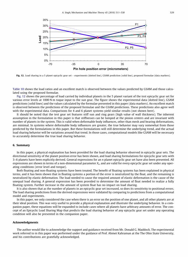
Fig. 12. Load sharing in a 5 planet epicyclic gear set – experiments (dotted line), GSAM prediction (solid line), proposed formulae (data markers).
A. Singh / Mechanism and Machine Theory 45 (2010) 511–530 529
Table 10 shows the load ratios and an excellent match is observed between the values predicted by GSAM and those calcu-lated using the proposed formulae.
Fig. 12 shows the percentage of load carried by individual planets in the 5 planet variant of the test epicyclic gear set forvarious error levels at 1000 N m toque input to the sun gear. The figure shows the experimental data (dotted line), GSAMpredictions (solid lines) and the values calculated by the formulae presented in this paper (data markers). An excellent matchis observed between the predictions of the proposed formulae and the GSAM predictions. These predictions also agree wellwith the experimental data. Comparisons for 4 and 6 planet systems yield similar results (not shown here).
It should be noted that the test gear set features stiff sun and ring gears (high value of wall thickness). The inherentassumption in the formulation in this paper is that stiffnesses can be lumped at the pinion centers and are invariant withnumber of planets in the system. This is valid when deformable body influences, other than mesh and bearing deformations,are minimal. In systems where deformable body influences are greater, the true behavior may vary somewhat from thosepredicted by the formulations in this paper. But these formulations will still determine the underlying trend, and the actualload sharing behavior will be variations around that trend. In those cases, computational models like GSAM will be necessaryto accurately determine the true load sharing behavior.
6. Summary
In this paper, a physical explanation has been provided for the load sharing behavior observed in epicyclic gear sets. Thedirectional sensitivity of the planet position error has been shown, and load sharing formulations for epicyclic gear sets with3–6 planets have been explicitly derived. General expressions for an n planet epicyclic gear set have also been presented. Allexpressions are shown in terms of a non-dimensional parameter Xe, and are valid for every epicyclic gear set under any oper-ating conditions (error level and torque).
Both floating and non-floating systems have been treated. The benefit of floating systems has been explained in physicalterms, and it has been shown that in floating systems a portion of the error is neutralized by the float, and the remaining isneutralized by elastic deformation. The load needed to cause the required amount of elastic deformation is the cause of theunequal load sharing. A general expression has been provided to determine the amount of float needed to realize a fullyfloating system. Further increase in the amount of system float has no impact on load sharing.
It is also shown that as the number of planets in an epicyclic gear set increased, so does its sensitivity to positional errors.The load sharing predictions from the derived expressions were validated by comparing to predictions from a computationalmodel and experiments.
In this paper, we only considered the case when there is an error on the position of one planet, and all other planets are attheir ideal position. This was very useful to provide a physical explanation and illustrate the underlying behavior. In a com-panion paper, these equations will be expanded to include cases where all planets have arbitrary amounts of error. The con-cept of an Epicyclic Load Sharing Map that predicts the load sharing behavior of any epicyclic gear set under any operatingcondition will also be presented in the companion paper.
Acknowledgments
The author would like to acknowledge the support and guidance received from Mr. Donald G. Maddock. The experimentalwork referred to in this paper was performed under the guidance of Prof. Ahmet Kahraman at the The Ohio State University,and his contributions are gratefully acknowledged.
530 A. Singh / Mechanism and Machine Theory 45 (2010) 511–530
References
[1] T. Hidaka, Y. Terauchi, Dynamic behavior of planetary gear – 1st report, load distribution in planetary Gear, Bulletin of the JSME 19 (1976) 690–698.[2] T. Hidaka, Y. Terauchi, K. Dohi, On the relation between the run out errors and the motion of the center of sun gear in a Stoeckicht planetary gear,
Bulletin of the JSME 22 (1979) 748–754.[3] T. Hidaka, Y. Terauchi, K. Nagamura, Dynamic behavior of planetary gear—7th report, influence of the thickness of ring gear, Bulletin of the JSME 22
(1979) 1142–1149.[4] T. Hayashi, Y. Li, I. Hayashi, K. Endou, W. Watanabe, Measurement and some discussions on dynamic load sharing in planetary gears, Bulletin of the
JSME 29 (1986) 2290–2297.[5] H. Ligata, A. Kahraman, A. Singh, An experimental study of the influence of manufacturing errors on planetary gear stresses and load sharing, Journal of
Mechanical Design 130 (2008) 041701.[6] A. Kahraman, Static Load Sharing Characteristics of Transmission Planetary Gear Sets: Model and Experiment, SAE Paper No. 1999-01-1050, 1999.[7] H.W. Muller, Epicyclic Drive Trains, Wayne State University Press, Detroit, 1982.[8] D.L. Seager, Load Sharing Among Planet Gears, SAE Paper No. 700178, 1970.[9] A. Kahraman, Load sharing characteristics of planetary transmissions, Mechanism and Machine Theory 29 (8) (1994) 1151–1165.
[10] A. Kahraman, S. Vijayakar, Effect of internal gear flexibility on the quasi-static behavior of a planetary gear set, Journal of Mechanical Design 123 (2001)408–415.
[11] A. Bodas, A. Kahraman, Influence of carrier and gear manufacturing errors on the static load sharing behavior of planetary gear sets, JSME InternationalJournal Series C 47 (2004) 908–915.
[12] A. Singh, Application of a system level model to study the planetary load sharing behavior, Journal of Mechanical Design 127 (2005) 469–476.[13] A. Singh, A. Kahraman, H. Ligata, Internal gear strains and load sharing in planetary transmissions—model and experiments, Journal of Mechanical
Design 130 (2008) 072602.[14] A. Singh, Implications of planetary load sharing on transmission torque capacity, in: 6th International CTI Symposium ‘‘Innovative Automotive
Transmissions”, Berlin, Germany, December, 2007.[15] R.G. Parker, A physical explanation for the effectiveness of planet phasing to suppress planetary gear vibration, Journal of Sound and Vibration 236 (4)
(2000) 561–573.[16] H. Ligata, A. Kahraman, A. Singh, A closed-form planet load sharing formulation for planetary gear sets using a translational analogy, Journal of
Mechanical Design 131 (2009) 021007.[17] A. Singh, Influence of planetary needle bearings on the performance of single and double pinion planetary systems, Journal of Mechanical Design 129
(2007) 85–94.