Through-Hardening Gears - ASM International
10
CHAPTER 4 Through-Hardening Gears THE THROUGH-HARDENUING PROCESS is generally used for gears that do not require high surface hardness. Typical gear tooth hardness after through hardening ranges from 32 to 48 HRC. Most steels that are used for through-hardened gears have medium carbon (0.3–0.6%) and a relatively low alloy content (up to 3%). The purpose of alloy content is to increase hardenability. The higher the hardenability, the deeper is through hardening of gear teeth. Since strength increases directly with hardness, high hardenability is essential for through hard- ening steels. High hardenability, again, has some adverse effect on material ductility and impact resistance. The other drawback of through- hardened gears is lower allowable contact stresses than those of surface- hardened gears. This tends to increase the size of through-hardened gears for the same torque capacity compared with those with surface hardened. In through hardening, gears are first heated to a required temperature and then cooled either in the furnace or quenched in air, gas, or liquid. The process may be used before or after the gear teeth are cut. If applied before cutting the teeth, the hardness usually is governed and limited by the most feasible machining process. Since these gear teeth are cut after heat treatment, no further finishing operation is needed. On the other hand, gears that are designed for hardness above the machining limit are first cut to semifinish dimensions and then through hardened. In case of some minor heat treat distortion, a finishing operation such as lapping or grinding is very often used to improve the quality of these gears (AGMA class 10 and above); for quality up to class 9, gears are finished cut at least one AGMA class above the requirement prior to heat treatment. Four different methods of heat treatment are primarily used for through-hardened gears. In ascending order of achievable hardness, these methods are annealing, normalizing and annealing, normalizing and tempering, and quenching and tempering. Sometimes, hardnesses of through-hardened gears are specified and measured in other scales besides © 2000 ASM International. All Rights Reserved. Heat Treatment of Gears: A Practical Guide for Engineers (#06732G) www.asminternational.org
-
Upload
khangminh22 -
Category
Documents
-
view
0 -
download
0
Transcript of Through-Hardening Gears - ASM International

CHAPTER 4Through-Hardening
Gears
THE THROUGH-HARDENUING PROCESS is generally used forgears that do not require high surface hardness. Typical gear toothhardness after through hardening ranges from 32 to 48 HRC. Most steelsthat are used for through-hardened gears have medium carbon (0.3–0.6%)and a relatively low alloy content (up to 3%). The purpose of alloycontent is to increase hardenability. The higher the hardenability, thedeeper is through hardening of gear teeth. Since strength increasesdirectly with hardness, high hardenability is essential for through hard-ening steels. High hardenability, again, has some adverse effect onmaterial ductility and impact resistance. The other drawback of through-hardened gears is lower allowable contact stresses than those of surface-hardened gears. This tends to increase the size of through-hardened gearsfor the same torque capacity compared with those with surface hardened.
In through hardening, gears are first heated to a required temperatureand then cooled either in the furnace or quenched in air, gas, or liquid. Theprocess may be used before or after the gear teeth are cut. If appliedbefore cutting the teeth, the hardness usually is governed and limited bythe most feasible machining process. Since these gear teeth are cut afterheat treatment, no further finishing operation is needed. On the otherhand, gears that are designed for hardness above the machining limit arefirst cut to semifinish dimensions and then through hardened. In case ofsome minor heat treat distortion, a finishing operation such as lapping orgrinding is very often used to improve the quality of these gears (AGMAclass 10 and above); for quality up to class 9, gears are finished cut at leastone AGMA class above the requirement prior to heat treatment.
Four different methods of heat treatment are primarily used forthrough-hardened gears. In ascending order of achievable hardness, thesemethods are annealing, normalizing and annealing, normalizing andtempering, and quenching and tempering. Sometimes, hardnesses ofthrough-hardened gears are specified and measured in other scales besides
© 2000 ASM International. All Rights Reserved.Heat Treatment of Gears: A Practical Guide for Engineers (#06732G)
www.asminternational.org

Rockwell, such as Vickers and Brinell. Table 4.1 shows an approximaterelationship among the various commonly used hardness scales.
Through-Hardening Processes
Annealing refers to any heating and cooling operation that is usuallyapplied to induce softening. There are two types of annealing—full andprocess. In full annealing, the steel is heated usually to approximately38 °C (100 °F) above the upper critical temperature and held for thedesired length of time, followed by very slow cooling as in the furnace.The purposes of full annealing are to:
O Soften the steel and improve ductility and machinabilityO Relieve internal stresses caused by previous treatment and improve
dimensional stabilityO Refine the grain structure
In process annealing, the steel is heated to a temperature below or closeto the lower critical temperature followed by the desired rate of cooling.The purpose here is to soften the steel partially and to release the internalstresses. In this treatment, grain refinement by phase transformation is notaccomplished as it is in full annealing. Process annealing uses tempera-tures between 550 and 650 °C (1020 and 1200 °F).
Table 4.1 Approximate relation between various hardness-test scalesRockwell
Brinell(a) C A 30-N 15-N B 30-T 15-T Vickers pyramid Tukon (Knoop)
. . . 70 86.5 86.0 94.0 . . . . . . . . . 1076 . . .
. . . 65 84.0 82.0 92.0 . . . . . . . . . 820 840
. . . 63 83.0 80.0 91.5 . . . . . . . . . 763 790614 60 81.0 77.5 90.0 . . . . . . . . . 695 725587 58 80.0 75.5 89.3 . . . . . . . . . 655 680547 55 78.5 73.0 88.0 . . . . . . . . . 598 620522 54 77.5 71.0 87.0 . . . . . . . . . 562 580484 50 76.0 68.5 85.5 . . . . . . . . . 513 530460 48 74.5 66.5 84.5 . . . . . . . . . 485 500426 45 73.0 64.0 83.0 . . . . . . . . . 446 460393 52 71.5 61.5 81.5 . . . . . . . . . 413 425352 38 69.5 57.5 79.5 . . . . . . . . . 373 390301 33 67.0 53.0 76.5 . . . . . . . . . 323 355250 24 62.5 45.0 71.5 . . . . . . . . . 257 . . .230 20 60.5 41.5 69.5 . . . . . . . . . 236 . . .200 . . . . . . . . . . . . 93 78.0 91.0 210 . . .180 . . . . . . . . . . . . 89 75.5 89.5 189 . . .150 . . . . . . . . . . . . 80 70.0 86.5 158 . . .100 . . . . . . . . . . . . 56 54.0 79.0 105 . . .80 . . . . . . . . . . . . 47 47.7 75.7 . . . . . .70 . . . . . . . . . . . . 34 38.5 71.5 . . . . . .
(a) Load, 3000 kgf; diam, 10 mm (0.4 in.)
22 / Heat Treatment of Gears
© 2000 ASM International. All Rights Reserved.Heat Treatment of Gears: A Practical Guide for Engineers (#06732G)
www.asminternational.org

Gears with hardness up to 34 HRC are fully annealed by heating to 800to 900 °C (1475 to 1650 °F) and then furnace cooled to a prescribedtemperature, generally below 315 °C (600 °F). Typical hardnessesobtained after full annealing gears of different materials are shown inTable 4.2.
Normalizing and Annealing. In general, the termnormalizingrefersto the heating of steel to approximately 38 °C (100 °F) above the uppercritical temperature, followed by cooling in still air. The normalizing andannealing process is used, either singularly or in a combination, as a grainstructure homogenizing for alloy steel gears. The process also is used toreduce metallurgical nonuniformity such as segregated alloy microstruc-tures from previous mechanical working. A hypoeutectoid steel consistingof a structure of ferrite and coarse pearlite may be made easier to machineif the ferrite and cementite are more finely distributed. A very soft steelhas a tendency to tear in machining; therefore, some increase in hardeningobtained by normalizing leads to a more brittle chip and thus improvesmachinability. Some through-hardened gears may just require hardnessobtained with normalizing and annealing.
Normalizing and Tempering. Normalizing consists of heating gears to870 to 980 °C (1600 to 1800 °F) and then furnace cooling in still or circu-lated air. This process results in higher hardness than annealing, with hard-ness being a function of the grade of steel and gear tooth size. However,normalizing does not increase hardness significantly more than annealingdoes, regardless of tooth size for plain carbon steels containing up to 0.4%carbon. But it definitely helps to ensure homogeneous microstructure ofsteels. After normalizing, alloy steel gears are tempered at 540 to 680 °C(1000 to 1250 °F) for uniform hardness and dimensional stability.
Quench and Temper. The quench and temper process involvesheating the gears to form austenite at 800 to 900 °C (1475 to 1650 °F),followed by quenching in a suitable media such as oil. The rapid coolingcauses the gears to become harder and stronger by the formation ofmartensite. Hardened gears then are tempered at a temperature, generallybelow 690 °C (1275 °F), to achieve the desired mechanical properties.This process is the most commonly used for through-hardened gears.
Tempering lowers both the hardness and strength of quenched steels butimproves materials properties such as ductility, toughness, and impact
Table 4.2 Typical Brinell hardness ranges of gears after through hardeningBrinell hardness (HB) Brinell hardness (HB)
MaterialAnnealed;normalized Normalized and
MaximumBrinell hardness, Material
Annealed;normalized Normalized and
MaximumBrinell hardness,
(AISI steel) and annealed tempered quench and tempered (AISI steel) and annealed tempered quench and tempered4130 155–200 170–215 350 4145 195–240 285–330 4508630 155–200 170–215 350 4150 195–240 285–330 4504140 185–230 260–300 425 4340 210–255 300–340 4804142 185–230 260–300 425 HP 9-4-30 200–240 (a) 5208640 185–230 260–300 425 Maraging steel 200–240 (a) 485(a) Process generally is not used with these types of materials.
Through-Hardening Gears / 23
© 2000 ASM International. All Rights Reserved.Heat Treatment of Gears: A Practical Guide for Engineers (#06732G)
www.asminternational.org

resistance. The tempering temperature must be carefully selected basedon the specified hardness range, the quenched hardness of the part, andthe material. Normally, the optimum tempering temperature is the highesttemperature possible while maintaining the specified hardness range. It isto be remembered that hardness after tempering varies inversely with thetempering temperature used. After tempering, parts usually are air cooledat room temperature.
Some steels can become brittle and unsuitable for service if tempered inthe temperature range of 430 to 650 °C (800 to 1200 °F). Thisphenomenon is called temper brittleness and generally is considered to becaused by segregation of alloying elements or precipitation of compoundsat ferrite and austenite grain boundaries. If the gear materials underconsideration must be tempered in this range, investigation to determinetheir susceptibility to temper brittleness is needed. Molybdenum contentof 0.25 to 0.50% has been shown to eliminate temper brittleness in moststeels. (Note: Temper brittleness should not be confused with thetempering embrittlement phenomenon that sometimes results from tem-pering at a lower temperature range, such as 260 to 320 °C, or 500 to600 °F.)
The major factors of the quench and temper process that influencehardness and material strength are:
O Material chemistry and hardenabilityO Quench severityO Section sizeO Time at temper temperature
Of the four commonly used through-hardening processes, the quenchand temper method is used widely, particularly when:
O The hardness and mechanical properties required for a given applica-tion cannot be achieved by any of the other three processes.
O It is necessary to develop mechanical properties (core properties) ingears that will not be altered by any subsequent heat treatment such asnitriding or induction hardening.
Typical hardness ranges achieved for different materials after throughhardening by different processes are illustrated in Table 4.2.
Some Hints on Through-Hardened Gear Design
After finalizing a design, a gear designer needs to specify the followinginformation on a through-hardened gear drawing. This information will
24 / Heat Treatment of Gears
© 2000 ASM International. All Rights Reserved.Heat Treatment of Gears: A Practical Guide for Engineers (#06732G)
www.asminternational.org

help to minimize confusion for all involved with gear manufacturing andmaterial procurement:
O Grade of steel with Aerospace Material Specification (AMS), ifapplicable
O AMS specification for material cleanliness, if requiredO Hardnesses on tooth surface and at the coreO Gear quality level
Each hardness callout should have at least a range of 4 points in HRC scaleor 40 points in Brinell hardness (HB). Also, specify a tempering tempera-ture range on the drawing. This allows gear manufacturing engineers to se-lect a particular tempering temperature for a specified hardness.
Hardness Measurement
The hardness of through-hardened gears generally is measured either onthe gear tooth end face or rim section. This is the hardness that is used forgear rating purposes. Sometimes, achieving specified hardness on toothend face may not necessarily assure the desired hardness at the roots ofteeth because of grade of steel, tooth size, and heat treat practice. If geartooth root hardness is critical to a design, then it should be specified andmeasured on a sample (coupon) processed with the gears. However,needless increase of material cost by selecting a higher grade of steelshould be avoided.
Heat Treat Distortion of Through-Hardened Gears
All steel gears experience distortion during a heat treat process. It is aphysical phenomenon and cannot be eliminated from any heat treatoperation, although distortion of through-hardened gears is not as severeas in other processes discussed in Chapters 5, 6, and 7. Still, through-hardened gears, particularly quench and tempered class, experienceenough distortion that will eventually lower the quality level of gears afterheat treatment. This necessitates a finishing operation for higher quality.In general, some materials expand after a through-hardening operationwhile others contract. This requires a suitable stock allowance to beprovided on teeth for finish machining before heat treatment of gears thatare likely to distort. The allowance needs to include expansion orcontraction of material and also distortion of tooth geometry. Formaterials with predictable and uniform distortion, gears could be cut toinclude the distortion so that no finishing operation is required, possiblyup to AGMA class 10 gear tooth quality. A great majority of materials
Through-Hardening Gears / 25
© 2000 ASM International. All Rights Reserved.Heat Treatment of Gears: A Practical Guide for Engineers (#06732G)
www.asminternational.org

listed in Table 4.2 seem to expand during the through-hardening process,whereas a few materials such as maraging steel are found to contract. Theamount of expansion or contraction depends on alloy content, quality ofsteel, and configuration of gears. In this regard, knowledge of distortioncharacteristics is helpful in optimizing the manufacturing process ofgears. When gears are made from a material without any previous heattreat distortion data, an experimental investigation is beneficial toestablish the distortion characteristics of the material. With such data,cost-effective manufacturing methods can be established. An investiga-tion of this nature carried out by an aerospace company to determine theheat treat distortion characteristics of a through-hardened gear rack for anaerospace application is discussed at the end of this chapter. Table 4.3shows a comparative distortion rating of some preferred through-harden-ing materials for gears.
Applications
Of the four different through-hardening processes described, those gearshardened by quenching and tempering have some limited use in powertransmission applications. The other three processes are only employed toeither improve machinability or to enhance homogeneous grain structure ofthe gear steel. Use of through-hardened gears is limited because of the lowsurface hardness that results in low gear pitting life and low power densitygearbox compared with the one made with case-hardened gears. Also, forsimilar torque capacity, through-hardened gears are larger with higher pitchline velocity. This increases dynamic problems substantially in a gearbox.However, in a bending strength limited design, through-hardened gearssometimes are successfully used, particularly for large gears (over 508 mm,or 20 in., OD) that normally exhibit high distortion if a case hardening pro-cess is used. An example for such an application is the internal ring gear ofan epicyclic gearbox. These gears are usually designed with hardness in therange of 32 to 34 HRC that can be finish cut after hardening, thus eliminat-ing costly finishing operations. Through-hardened gears also are found tobe effective in applications susceptible to gear scuffing. It is claimed thatprofile conformance of through-hardened gears, because of their low sur-face hardness, reduces sliding friction and thereby helps to increase scuff-ing resistance.
Table 4.3 Distortion ratings of through-hardened gearsMaterial AMS specification AMS quality Hardness (HRC) Distortion rating
AISI 4340 6414 2300 48/50 Good(a)Maraging 250 6520 2300 49/52 Predictable and good(a)Maraging 300 6521/6514 2300 52/56 Predictable and good(a)AISI 4140 6382 2300 48/50 Good(a)(a) Within one AGMA class of gear quality.
26 / Heat Treatment of Gears
© 2000 ASM International. All Rights Reserved.Heat Treatment of Gears: A Practical Guide for Engineers (#06732G)
www.asminternational.org
Overall, through-hardened gears are used in gearboxes that requirelarge gears that cannot be economically case hardened, such as largemarine propulsion gears and railway power transmission gears.
Case History: Design and Manufacture of a Rack
As explained in this chapter, all steel gears distort after any type of heattreat process. Carburizing imparts the highest distortion, while throughhardening imparts the least distortion. Even then, distorted gears requirea finishing operation for higher tooth quality. Sometimes, for through-hardened gears, the knowledge of distortion characteristics may beincluded in the design of gear cutting tools such that gears after heattreatment meet the desired quality. Such a case history is presented here.
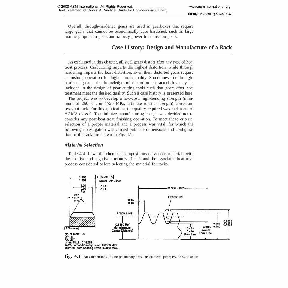
The project was to develop a low-cost, high-bending strength (mini-mum of 250 ksi, or 1720 MPa, ultimate tensile strength) corrosion-resistant rack. For this application, the quality required was rack teeth ofAGMA class 9. To minimize manufacturing cost, it was decided not toconsider any post-heat-treat finishing operation. To meet these criteria,selection of a proper material and a process was vital, for which thefollowing investigation was carried out. The dimensions and configura-tion of the rack are shown in Fig. 4.1.
Material Selection
Table 4.4 shows the chemical compositions of various materials withthe positive and negative attributes of each and the associated heat treatprocess considered before selecting the material for racks.
Fig. 4.1 Rack dimensions (in.) for preliminary tests. DP, diametral pitch; PA, pressure angle
Through-Hardening Gears / 27
© 2000 ASM International. All Rights Reserved.Heat Treatment of Gears: A Practical Guide for Engineers (#06732G)
www.asminternational.org

Option 1: Use of Quench-Hardening Steels. The following steelswere considered:
O AISI 4340O 300MO HP 9-4-30O H-11
An excellent survey was made from published literature to determine thevarious properties of each, with the following results and conclusion:
Results.High heat treat distortion:
O Grinding of rack is necessary after heat treatment to attain the requiredaccuracy of teeth.
O High cost of materialO Poor corrosion resistance; additional process needed to make racks
corrosion resistant
Conclusion. None of these materials was found suitable for the applica-tion.
Option 2: Use a Precipitation Hardening Steel. Steels considered:
O 17-4 PHO 13-8 Mo
Resultswere as follows:
O Attainable mechanical properties were not at specified strength level.O Heat treat distortion was not predictable.O Sensitive to grind burnsO Problems with alloy segregation for any post-heat treat finishing, in
section size needed
Conclusion.Materials were not suitable.
Table 4.4 Chemical composition of steels considered for racksMaterial C Mn Si P S Ni Cr Mo V Co W Cu
Quench-hardening steelsAISI 4340 . . . 0.60/0.80 0.20/0.35 . . . . . . 1.65/2.00 0.70/0.90 0.20/0.30 . . . . . . . . . . . .HP 9-4-30(a) 0.30 0.20 0.01 0.005 0.0007 7.50 1.00 1.00 0.08 4.0H-11 0.35 . . . . . . . . . . . . . . . 5.00 2.50 0.40 . . . . . . . . .300M 0.42 0.68 1.61 0.005 0.006 1.77 0.85 0.40 0.09 . . . . . . . . .
Precipitation-hardening steels17-4 PH . . . . . . . . . . . . . . . 4.00 16.50 . . . . . . . . . . . . 4.0013-8 Mo . . . . . . . . . . . . . . . 8.00 12.80 2.30 . . . . . . . . . . . .
Age-hardening steelsMaraging C-250 0.026 0.10 0.11 . . . . . . 18.5 . . . 4.30 . . . 7.0 . . . . . .(a) Courtesy Republic Steel Corporation, Cleveland, Ohio
28 / Heat Treatment of Gears
© 2000 ASM International. All Rights Reserved.Heat Treatment of Gears: A Practical Guide for Engineers (#06732G)
www.asminternational.org

Option 3: Use an Age-Hardening Steel (Maraging C-250). Thismaraging steel has high nickel (18% or more), very low carbon (under0.03%), and is capable of developing very high tensile and yield strengthsby means of an aging process. It is sold in the martensitic state, which,because of the low carbon, is soft enough to be readily machinable.Heating to approximately 480 °C (900 °F ) for aging, and cooling in thefurnace, causes a change in material microstructure that increases thehardness up to 52 HRC. This meets the required tensile strength.
Resultswere as follows:
O Published literature indicated distortion of maraging C-250 steel ispredictable.
O The material is available as forged, as well as in bar form, to AMS6412. Sheet or plate stock available to AMS 6420 was not acceptabledue to nonuniform distribution of mechanical properties.
Conclusion.Maraging C-250 forgings met the design requirements andwere selected for this application.
Process Selection
Heat Treat Distortion of Racks Made of C-250. Although publishedliterature indicated distortion of maraging C-250 material is predictable,it was still necessary to find out how much the distortion would be for arack tooth used in this application. To determine these characteristics, apreliminary investigation was undertaken with racks made from readilyavailable C-250 of shorter lengths (305 mm, or 12 in., long); longerlengths were not commercially available at the time of this investigation.To expedite the program further, a standard shaper cutter was used to cutthe teeth. The racks were then heat treated.
Heat Treatment of Racks. Some preliminary experiments were con-ducted to select a suitable heat treat furnace. The following furnaces wereconsidered:
O Partial vacuum furnaceO Full vacuum furnaceO Air furnace
Heat treatment in the air furnace was not acceptable due to:
O Oxidation of racksO Scale removal resulted in size change.
Both full and partial vacuum furnaces produced oxidation-free racks.Conclusion.Full vacuum furnace that ensures oxidation-free parts was
selected to determine heat distortion.
Through-Hardening Gears / 29
© 2000 ASM International. All Rights Reserved.Heat Treatment of Gears: A Practical Guide for Engineers (#06732G)
www.asminternational.org

Twelve racks were selected for heat treatment. All critical dimensionsof the racks were inspected and recorded before heat treatment.
The heat treat procedure consisted of the following steps:
O Vapor degrease racksO Wipe racks with a cleaning chemical such as acetoneO Select any two racksO Hold the racks together back to back with nickel-plated bolts—
processed horizontally on a flat base in the furnaceO Heat treat racks along with one tensile test bar in each production lot,
at 4806 6 °C (9006 10 °F) for 4.5 h at this temperatureO Furnace cool racks
Inspectionconsisted of:
O Critical rack dimensions after heat treatmentO Mechanical properties of material such as hardness and tensile strength
Results.From the experimental results and inspection, the followingconclusions were made:
O Contraction rate of maraging steel was between 0.0005 and 0.0007mm/mm (in./in.) and found to be linear and consistent in each lot.
O Parts remained flat after the hardening process.O Pitch and accumulative pitch errors were within acceptable limit.O Teeth perpendicularity (lead errors) were between 0.013 and 0.025 mm
(0.0005 and 0.001 in.).O Pitch dimensions measured over a pin were held to 0.038 to 0.076 mm
(0.0015 to 0.003 in.).
Recommendationsincluded:
O Design of rack to include 0.076 mm (0.003 in.) tolerance for pitchdimension over the pin
O Tooth perpendicularity (lead) error to 0.025 mm (0.001 in.)O A shaper cutter to be developed to include 0.0006 mm/mm (in./in.)
contraction rate of rack tooth geometry with the expectation that thismight eliminate finish processing of racks after heat treatment.
New Shaper Cutter. With the proposed contraction rate, a shapercutter was designed and manufactured by a cutter manufacturing com-pany. Figure 4.2 shows the dimensions of this special cutter. Aninvestigation was then carried out with full-length racks.
30 / Heat Treatment of Gears
© 2000 ASM International. All Rights Reserved.Heat Treatment of Gears: A Practical Guide for Engineers (#06732G)
www.asminternational.org