Contact fatigue failure analysis of shot-peened gears
12
Contact fatigue failure analysis of shot-peened gears M. Guagliano a, *, E. Riva b , M. Guidetti c a Dipartimento di Meccanica, Politecnico di Milano, Via la Masa 34, 20158 Milano, Italy b Dipartimento di Ingegneria Industriale, Universita ` degli Studi di Parma, Parco delle Scienze, Area 181/A, 43100 Parma, Italy c Casappa SpA, Via Balestrieri 1, 43044 Cavalli di Collecchio, Parma, Italy Received 6 November 2000; accepted 28 December 2000 Abstract The paper includes the results of experimental investigations and numerical analysis performed with the aim of studying contact fatigue damage in carburized and shot-peened gearwheels used in gearpumps. On the basis of SEM observations, a model for the evolution of the damage was developed, supposing that the residual stresses induced by shot-peening are mainly effective in stopping microcrack propagation but not in preventing microcrack initiation. In the light of this hypothesis, and following experimental measurements of residual stress, an approach is proposed to evaluate the effect of shot-peening parameters on the performance. The development of this approach required the execution of a numerical analysis of the engagement cycle taking into account the presence of residual stress and microcracks: the results allow one to determine, at least in comparative terms, the parameters that give the best strength improvement against contact fatigue. # 2002 Elsevier Science Ltd. All rights reserved. Keywords: Gear-tooth failures; Fatigue crack growth; Residual stress; Shot-peening; Carburization 1. Introduction Among the surface processes employed to improve the performance of mechanical components, shot- peening is one of the most versatile and useful, because it can be applied on very general geometries and produces no toxic residues. This latter feature is, nowadays, ever more important because of the laws aiming at reducing the impact of industrial processes on the environment. Even if the first applications of shot-peening go back 80 years, this treatment is today still considered more as an art than as a science. In fact in just a few cases have analyses been made to quantitatively predict the effectiveness of the process in practical applications; in addition, the parameters (shot size, material, velocity versus the target component) are chosen according to the experience and sensitivity of the operator rather than following methods and preliminary standards developed on an analytical basis. In connection with this, it is important to say that shot-peening intensity is expressed by Almen degrees [1]; this unit adapts well to industrial applications but cannot allow one to get a direct relation with the 1350-6307/02/$ - see front matter # 2002 Elsevier Science Ltd. All rights reserved. PII: S1350-6307(01)00002-4 Engineering Failure Analysis 9 (2002) 147–158 * Corresponding author. Tel.: +39-02-23998206; fax: +39-02-23998202. E-mail address: [email protected] (M. Guagliano).
Transcript of Contact fatigue failure analysis of shot-peened gears

Contact fatigue failure analysis of shot-peened gears
M. Guagliano a,*, E. Riva b, M. Guidetti c
aDipartimento di Meccanica, Politecnico di Milano, Via la Masa 34, 20158 Milano, ItalybDipartimento di Ingegneria Industriale, Universita degli Studi di Parma, Parco delle Scienze, Area 181/A, 43100 Parma, Italy
cCasappa SpA, Via Balestrieri 1, 43044 Cavalli di Collecchio, Parma, Italy
Received 6 November 2000; accepted 28 December 2000
Abstract
The paper includes the results of experimental investigations and numerical analysis performed with the aim ofstudying contact fatigue damage in carburized and shot-peened gearwheels used in gearpumps. On the basis of SEMobservations, a model for the evolution of the damage was developed, supposing that the residual stresses induced by
shot-peening are mainly effective in stopping microcrack propagation but not in preventing microcrack initiation. In thelight of this hypothesis, and following experimental measurements of residual stress, an approach is proposed to evaluatethe effect of shot-peening parameters on the performance. The development of this approach required the execution of a
numerical analysis of the engagement cycle taking into account the presence of residual stress and microcracks: theresults allow one to determine, at least in comparative terms, the parameters that give the best strength improvementagainst contact fatigue. # 2002 Elsevier Science Ltd. All rights reserved.
Keywords: Gear-tooth failures; Fatigue crack growth; Residual stress; Shot-peening; Carburization
1. Introduction
Among the surface processes employed to improve the performance of mechanical components, shot-peening is one of the most versatile and useful, because it can be applied on very general geometries andproduces no toxic residues. This latter feature is, nowadays, ever more important because of the lawsaiming at reducing the impact of industrial processes on the environment.Even if the first applications of shot-peening go back 80 years, this treatment is today still considered
more as an art than as a science. In fact in just a few cases have analyses been made to quantitativelypredict the effectiveness of the process in practical applications; in addition, the parameters (shot size,material, velocity versus the target component) are chosen according to the experience and sensitivity ofthe operator rather than following methods and preliminary standards developed on an analytical basis.In connection with this, it is important to say that shot-peening intensity is expressed by Almen degrees
[1]; this unit adapts well to industrial applications but cannot allow one to get a direct relation with the
1350-6307/02/$ - see front matter # 2002 Elsevier Science Ltd. All rights reserved.
PI I : S1350-6307(01 )00002-4
Engineering Failure Analysis 9 (2002) 147–158
* Corresponding author. Tel.: +39-02-23998206; fax: +39-02-23998202.
E-mail address: [email protected] (M. Guagliano).
induced range of residual stress, which produces changes in the mechanical performance of the piecesunder treatment [1,2].Recently, thanks to the ever bigger capabilities of automatic computing and of the development of
accurate experimental tests, it has been possible to investigate the relation between treatment parameters,residual stresses and the fatigue resistance of processed components (often carburized gears).This is particularly true in the case of bending fatigue of gears, on which subject most studies have been
carried out. On the contrary, there are very few specific references on the damage caused by contact fatigue,probably due to the major complexity of the problem. Most of the studies just describe tests results withoutlooking for causes or explanations of the effect produced by shot-peening [3–5]. Such results sometimescontradict each other, thus showing that the shot-peening effect varies following the changing of contactconditions and particularly of contact pressure. Besides, these studies do not consider the changes of thecontact fatigue strength that can be obtained by varying the peening parameters. Only recently has a sys-tematic study been published regarding shot-peening effects on contact fatigue [6], although this does notexplain how to predict the improvements produced by the treatment, following different parameters.This paper studies carburized gearwheels, which work under severe contact conditions, created during
the working process by unusual geometrical features, which were particularly subject to early damage bypitting due to the high contact pressure.Starting from an analysis of wheel decay by carrying out computations on finite parts performed with the
aim of determining the real meshing conditions of the wheels [7], and using SEM observations, the authorssuggest shot-peening as a possible remedy, using parameters chosen according to previous experience.Since the damage has not been completely eliminated, experimental investigation of the damaged sur-
faces was necessary, together with the development of a method to foresee the effectiveness of the treat-ment following parameter changes.Such an approach assumes that residual stresses induced by shot-peening are mainly effective in stopping
microcrack propagation but not in preventing microcrack initiation and requires a numerical analysis ofthe meshing cycle in the presence of residual stress induced by shot-peening, and of microcracks along thetoothflanks.On the basis of the analysis and the consequent observations, it was proposed to modify the treatment
parameters, which has to date avoided premature damage to the teeth.
2. Description of the case
The gearwheels in this study are parts of an oleodynamic plant and are of carburized and hardened steel16CrNi4 (according to Italian code UNI 7846) (UTS=1050 MPa, yield stress=850 MPa), with a surfacehardness of about 63 HRC and a core of 35 HRC. The gears have spur teeth with a modified involute profile;the module is 2.65 mm, there are 12 teeth with a pitch diameter of 32.8 mm. The pressure angle is 20� and thestandard pitch is 7.72 mm. Gears of the same dimensions create both the pinion and the driven gear.The loading conditions require the transmission of the torque Mt and the application of inter-axial forces
Fx and Fy, directed along axes X and Y, as shown in Fig. 1. Such forces make the load on the tooth heavier,particularly as far as contact pressure and stress in the contact area are concerned. Besides, the presence ofthese loads alters the contact conditions, since it causes, at least partially during the cycle, a contact onboth flanks of the tooth.These forces are responsible for the early damage of carburized and hardened toothflanks. To solve this
problem, shot-peening was applied, since it induces inside the surface layers of the material a compressiveresidual stress field, able to stop, or at least to delay, the damage process, caused by the repetition of con-tact cycles. On the basis of previous experience, the treatment intensity (measured by the Almen scale) was8 A, with a sphere diameter of 0.4 mm (S170 type). Even if this treatment improved the surface resistance
148 M. Guagliano et al. / Engineering Failure Analysis 9 (2002) 147–158

to fatigue, nevertheless it did not completely eliminate the damage: Fig. 2 shows the profile of a shot-peenedtooth, damaged after a number of cycles less than the one required by the engineers.It is in fact well known that the effect of shot-peening may vary considerably, following a change of the
treatment conditions: a more accurate analysis of the damage morphology was necessary to improve andoptimize the toothflank resistance to contact damage. It is necessary to know the origin and the develop-ment of the damage to choose the best treatment conditions (shot diameter, Almen intensity, shot velocityand material, angle of impact) and to develop a procedure able to predict the damage evolution. Exper-imental investigations and numerical analyses were performed with this aim.
3. Experimental analysis
The experimental analysis included SEM observations of the flanks of macroscopically damaged andundamaged teeth, fractographic analysis on sections of damaged wheels and measurements of residualstress on new shot-peened and non shot-peened gears, using an X-ray diffractometer.
3.1. Analysis of the flanks of damaged teeth
SEM analysis showed that the damaged area is located in the tooth dedendum, near the pitch diameter.Taking into account the meshing between two teeth and the damage location on the toothflank, it ispossible to state that the surface damage occurs when the tooth is subject to rolling and sliding in opposite
Fig. 1. Schematic drawing of gears, with the applied loads.
M. Guagliano et al. / Engineering Failure Analysis 9 (2002) 147–158 149

directions: under such conditions, microcracks originate on the surface, propagate subsurface and come to thesurface again, causing a detachment of material and subsequent flank damage. In other words, it was provedthat the damage is caused by pitting and does not involve other damage processes, which have a different originand evolution (subsurface nucleation and interface nucleation between carburized layer and core).Figs. 2 and 3 show pictures of damaged flanks: as one can see, the macroscopic damage is almost the
same on the whole flank, indicating good uniformity of mesh conditions and a very slight effect caused bymisalignment or elastic deformation of the gear. From the pictures it is apparent that the detached layer isvery thin, indicating that the damage developed just on the surface.
Fig. 2. Damaged flank of a shot-peened gear with intensity 8 A.
Fig. 3. SEM pictures of the surface (dedendum area) of a carburized, shot-peened (8 A) and damaged (1000� and 250�) toothflank.
150 M. Guagliano et al. / Engineering Failure Analysis 9 (2002) 147–158

Fig. 4 shows the top area of the tooth, with no macroscopic damage, but microscopic traces of damagetogether with machining marks. This may be caused by a too low shot-peening intensity, not able toremove machining marks, as usually happens.This hypothesis is supported by the appearance of a carburized and shot-peened (8 A) gear, as is shown
in Fig. 5. In fact, the observation of the micrographs indicates the presence of sphere indentations, createdduring the impact with the tooth, together with machining marks. This indicates a low intensity of treat-ment and the indentations can be considered to be preferred sites of crack initiation. It is possible to notemicroscopic damage marks which did not promote detachment of material along the flanks.The observation of SEM images of gearwheels which were only carburized (see Fig. 6) supports such a
hypothesis: in fact marks produced by the machining process were far more evident and the macroscopicdamage far more usual.
3.2. Analysis of sections of damaged, shot-peened gears
Some gearwheels were cut and polished on the median section, and then observed by SEM. These investi-gations were aimed at determining the damage morphology, not only on the surface but also further in.
Fig. 4. Surface (addendum area) of a carburized and shot-peened (8 A) (1000� and 250�) toothflank.
Fig. 5. Surface of a carburized and shot-peened (8 A) toothflank, with no macroscopic damage (1000� and 250�).
M. Guagliano et al. / Engineering Failure Analysis 9 (2002) 147–158 151

Fig. 7 shows some images of typical damage by pitting: in particular, Fig. 7(a) illustrates a typical pit,created by the detachment of material, due to damage accumulation. As can be seen, the pit is 0.03 mmdeep and shows the typical geometry of this kind of fatigue.Fig. 7(b) shows a crack propagating in from the surface which was not big enough to cause macroscopic
damage by detachment of material. The crack shows an inclination of about 30� against the tooth surfaceand it is about 0.03 mm deep. After reaching this dimension, the crack appears to deviate and propagateparallel to the surface. Thereafter it generally returns to the surface, producing final detachment of material.This kind of crack is very common in the gears under study and it may be well taken as a reference
during the analysis of the damage and in defining a procedure which allows one to foresee and, if possible,to prevent pitting.
3.3. Measurement of residual stress
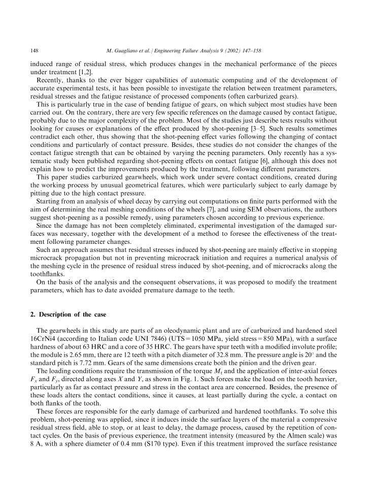
Measurement of residual stress was carried out by using an Italstructures X-ray diffractometer (methodof sin2 c, linear detector, Cr radiation, Vn filter, 2�=156.5�). The residual stress profile with depth wasmeasured by detaching layers of material by electrolytic dissolution over small areas. The measurementswere carried out on three teeth of a new shot-peened gear (8 A, spheres S170). Fig. 8 shows the measuredresidual stress profile and the comparison with typical residual stresses of a carburized gear.It is evident that, although compressive stresses larger than those produced by carburizing are generated,
the surface value and maximun value of residual stress are relatively low, at least according to existing data[3–5] and relative to the mechanical characteristics of the material. It is also important to observe that thepeak of residual stress is not very deep, being only about 0.03 mm under the surface. In such a depthresidual stresses, caused by shot-peening, are likely to suffer from contact (sliding and rolling) between theteeth, which can decrease the residual stress. In fact, due to the contact stress distribution, large strains occurlocally, which can change the value obtained through shot-peening. Generally, shot-peening conditions, formaterial and pieces like those under study, produce residual stress profiles with peaks of 900–1000 MPa, 0.05mm under the surface [1,6].
3.4. Remarks
On the basis of the observations above, it is possible to state that cracks propagate in a straight way withan inclination of about 30� to the surface and after reaching a critical depth, they abruptly change direction.
Fig. 6. Surface of a carburized (1000� and 250�) toothflank.
152 M. Guagliano et al. / Engineering Failure Analysis 9 (2002) 147–158

Such behaviour has already been observed [8–10]: its quantitative features (length and depth of propagationmodification) depend on the loads applied, the material and the state of residual stress, whose measurementis thus necessary.In the light of these remarks, it is possible to suppose that the conditions, under which microscopic
damage of toothflanks causes macroscopic damage with subsequent detachment of material from the toothsurface and consequent breaking of the damaged gears, depend upon the ability to prevent microcrackpropagation and thus the creation of pits usually caused by damage.
Fig. 7. Typical ‘‘pit’’ caused by pitting (a) (650�) and crackpath, during propagation, due to contact loads (b) (1900�).
M. Guagliano et al. / Engineering Failure Analysis 9 (2002) 147–158 153
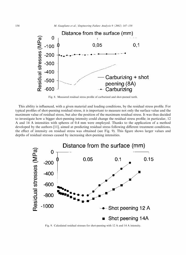
This ability is influenced, with a given material and loading conditions, by the residual stress profile. Fortypical profiles of shot-peening residual stress, it is important to measure not only the surface value and themaximum value of residual stress, but also the position of the maximum residual stress. It was thus decidedto investigate how a bigger shot-peening intensity could change the residual stress profile; in particular, 12A and 14 A intensities with spheres of 0.4 mm were employed. Thanks to the application of a methoddeveloped by the authors [11], aimed at predicting residual stress following different treatment conditions,the effect of intensity on residual stress was obtained (see Fig. 9). This figure shows larger values anddepths of residual stresses caused by increasing shot-peening intensities.
Fig. 8. Measured residual stress profile of carburized and shot-peened teeth.
Fig. 9. Calculated residual stresses for shot-peening with 12 A and 14 A intensity.
154 M. Guagliano et al. / Engineering Failure Analysis 9 (2002) 147–158

4. Numerical analysis
The improved performance of shot-peened gears with increased shot-peening intensity was analysed byfinite element analyses, which simulated a meshing cycle of the gears.Starting from the hypothesis that shot-peening has a beneficial effect in stopping microcrack growth but
not in preventing initiation [12], the models considered cracked gears, including residual stress profilescaused by different treatment conditions.Fig. 10 shows the computation model, with the dark band indicating the site of the crack and the
residual stress field. The elements employed are of ‘‘plane strain’’ type with four nodes and first ordershape functions. The total number of elements is 10,224 with 11,226 nodes. The contact was modelled byusing the elements provided by the computing program library.The loads of the model are those required by the project, with a torque Mt and inter-axial forces of Fx
and Fy (see Fig. 1). The analysis investigated the whole meshing cycle; this allowed one to evaluate thedistribution of the forces between the teeth in moving contact.The crack modelled considers the maximum depth before which the crack changes its path: the crack under
study thus has an inclination of 30� relative to the surface and is 0.03 mm long. Element dimensions in themicrocrack area do not exceed 1/40 of the crack length.The literature considers hydrostatic pressure of crack lubricant to be the main cause of propagation of
surface cracks caused by contact fatigue. Thus the computation took this mechanism into account, withvariations during the meshing cycle, as in [8].The analysis allowed one to compute the value of the stress intensity factor K, specifically modes I and II
and to determine the real �K (variation of the stress intensity factor in a load cycle), caused by the appliedloads and by the state of residual stress, by varying the shot-peening conditions.Computation was based on the values of nodal displacements on the opposite faces of the crack
(� ¼ 180�, see Fig. 11). By considering displacements of nodes, located on the opposite faces of the crack,both parallel (ux) and perpendicular (uy) to the direction of propagation we obtain:
Fig. 10. Finite elements and detail of contact area.
M. Guagliano et al. / Engineering Failure Analysis 9 (2002) 147–158 155

KI ¼ limr ! 02E
ð1þ �Þ
ffiffiffiffiffiffi2�
r
r�uy
KII ¼ limr ! 02E
ð1þ �Þ
ffiffiffiffiffiffi2�
r
r�ux ð1Þ
These equations allow one to find an ‘‘equivalent stress intensity factor’’, which considers both kinds ofpropagation, defined as:
Keq ¼
ffiffiffiffiffiffiffiffiffiffiffiffiffiffiffiffiffiffiK2
I þ K2II
qð2Þ
The equations above consider cases with no residual stress and with residual stress caused by shot-peening with 8 A, 12 A and 14 A intensities.
5. Results
The first analysis considered models of intact gears and verified that numerical computation createdcontact pressures similar to those described by Hertzian theory. To make the comparison easier, theanalysis took into account just the torque and the contact at the pitch diameter: the gap between numericalresults and analytical ones, for maximum contact pressure, did not exceed 2%, which is small enough tovalidate the model.Fig. 12 shows the von Mises stresses at the contact point considering the crack and the action of both
inter-axial forces and torque: it may be seen that the contact shares itself between three pairs of teeth. Thehigh values of the picture backscale are produced by the stresses of the parts around the crack and areclearly influenced by the particular stress range created by the crack.
Fig. 11. Coordinate system used for the computation of KI and KII.
156 M. Guagliano et al. / Engineering Failure Analysis 9 (2002) 147–158

Table 1 shows K values for modes I and II, found for the length of crack under study by investigating theresidual stress created by the different treatments. Residual stresses are mainly effective in diminishing the modeI stress intensity factor.This means that residual stresses, caused by shot-peening, help to decrease the crack growth rate.It can be observed that for 14 A shot-peening the�Keq is much smaller with respect to the other conditions
considered due to the more effective action of the residual stress and is near to the threshold value ofmaterials similar to that employed. It may thus be supposed that, in this case, propagation becomes muchslower and crack growth could stop.One objection to this approach is that it is not correct to use LEMF to study cracks of such dimensions,
since it does not consider the interaction with the microstructure of the material, which is a very importantfactor in analysing ‘‘short crack’’ propagation; nevertheless, many equations, employed to describe shortcrack propagation, can be expressed according to the stress intensity factor (see for example [13]).In the light of the above results, it may be stated that, among all possible solutions, shot-peening with 14
A intensity and spheres diameter of 0.4 mm guarantees the strongest resistance to damage caused bycontact fatigue and this was sucessfully adopted to avoid premature damage.
6. Conclusions
The analysis of the damage produced on toothflanks of carburized gears, which were shot-peened with agiven intensity, allowed one to observe pitting development and crack propagation. The measurement ofresidual stress and the observation of performance, following different shot-peening intensity, gave indicationson how to choose the best shot-peening parameters. To support this theory, finite element analyses were carriedout simulating the whole meshing cycle in the presence of microcracks and shot-peening stresses, so as to
Fig. 12. Map of von Mises stresses and detail of the damaged area.
Table 1
Stress intensity factor values, according to numerical computation
With no residual stresses 8 A shot-peening 12 A shot-peening 14 A shot-peening
�KI 10.1 MPa @m 7.5 MPa @m 5.8 MPa @m 3.4 MPa @m
�KII 4.1 MPa @m 3.6 MPa @m 3.2 MPa @m 2.9 MPa @m
�Keq 10.8 MPa @m 8.3 MPa @m 6.6 MPa @m 4.4 MPa @m
M. Guagliano et al. / Engineering Failure Analysis 9 (2002) 147–158 157

determine how residual stress influences microcrack propagation and to suggest a change in shot-peeningintensity, to prevent premature damage. Such an approach may be considered as a starting point to abetter understanding of the subject and for verifying and predicting the resistance to pitting of shot-peenedgears.
References
[1] Marsh KJ, editor. Shot peening: techniques and applications. EMAS, 1993.
[2] Herzog R, Zinn W, Sholtes B, Wohlfahrt H. The significance of Almen intensity for the generation of shot peening residual
stresses. In: Proceedings of the VI International Conference on Shot Peening, San Francisco, 1996. p. 270–81.
[3] Jia-Xiang C, Bing-ju A. Effect of shot peening on contact fatigue behavior life of carburized steel. In: Proceedings of the I
International Conference on Shot Peening, Garmish, 1981. p. 333–40.
[4] Kobayashi M, Hasegawa K. Effect of shot peening on the pitting fatigue strength of carburized gears. In: Proceedings of the IV
International Conference on Shot Peening, 1990. p. 465–76.
[5] Jingpu Z. Effect of shot peening on contact fatigue behavior of 40Cr steel after compound heat treatment. In: Proceedings of the
II International Conference on Shot Peening, 1984. p. 215–24.
[6] Widmark M, Melander A. Effect of material, heat treatment, grinding and shot peening on contact fatigue life of carburised
steels. Int J Fatigue 1999;21:310–27.
[7] Internal Report CASAPPA Studio dell’influenza della pallinatura sulla resistenza al pitting di ruote dentate di pompe ad ingra-
naggi. 1999 (in Italian).
[8] Glodez S, Ren Z, Simulation of the surface fatigue growth under contact loading. In: Proceedings of the Conference. Fracture
and Damage Mechanics, London, 1999. p. 121–30.
[9] Glodez S, Winter H, Stuwe HP. A fracture mechanics model for the wear of gear flanks by pitting. Wear 1997;208:177–83.
[10] Wulpi DJ. Understanding how components fail. Materials Park (OH): ASM, 1991.
[11] Guagliano M, Vergani L, Bandini M, Gili F. An approach to relate the shot peening parameters to the induced residual stresses.
In: Proceedings of the VII International Conference on Shot Peening, Warsaw, 1999. p. 274–82.
[12] Navarro A, de los Rios ER. Short and long fatigue crack growth — a unified model. Philosiphical Magazine A 1988;57:15–36.
[13] Miller KJ. Materials science perspective of metal fatigue resistance. Mater Sci Technol 1993;9:453–62.
158 M. Guagliano et al. / Engineering Failure Analysis 9 (2002) 147–158