
Manufacturing of Forged and Extruded Gears
8
B Manutacturlnq of Forqed and Extruded Gears Introduction Traditional. methods of manufacturing precision gears usually ,employ either hobbing or shaper cutting. Both of these processes rely upon generating the con- jugate tooth form by moving the work- piece in a precise relation to the tool, Recently, attention has been given to .forming gear teeth in a single step. Advantages to such a process include reduced pro- duction time, material savings, and improved performance characteristics. Drawbacks in- elude complicated tool designs, nan-uniformity of gears pro- duced throughout the life ofthe tooling, and lengthy develop- ment times, Through projects funded by the U.S. Army Tank Automotive Command, Bat- telle's Columbus Division developed a method for design- ing spiral bevel, spur, and helical gear forming dies. This article discusses this method and summarizes the current state of the art regarding the manufac- turing of farged and extruded gears. Traditi.onal 'Gear .Fornting Methodology Design/test/modify. The traditional method of forging and extrusion die design and manufacture is based on exper- 36 Gear Technology David J. Kuhlmann P.S. Raghupathi Battelle Columbus Division. Columbus, OH ience and trial and error. A preliminary die is made, and a few parts are formed, Measurements are taken of the finished part, and the die is modified accord- ingly, A second series of trials is con- ducted, and so on, until the final die geometry is obtained. Such a develop- En.!ml-. Fo;rm~na , lood. lDAlStr ...... I I!I'Id f-onn!"I [ntlty Fig. 1- Methodology for designing gear Forming dies. ment program is required for every new design, which makes the precision fanning process economically less at- tractive, especially when complex and precise geometries are involved, as with gears. Therefore. methods need to be developed to apply advancedeompu- ter-aided design and manufac- turing (CAD/CAM) technologies (analysis of loads, stresses, and temperatures us- ing finite element method based approaches, etc.) to gear form- ing die design and manufacture. This approach benefits hom the capabilities of the computer in performing complex mathe- matical analysis and mforma- tion storage, and allows the die designer to examine the effects of various changes .0.£ process variables on the die design, without trying out each new change on the shop floor, CAD/CAM Applied To Forging and Extrusion In recent years, CAD/CM1i techniques have been. applied to various forging processes. The experience gained in all of these applications implies. a certain overall methodology for CAD I CANt of dies for precision and/ or near-net shape forming. This computerized approach is also applicable to precision cold and hot forming of spiral bevel,
-
Upload
khangminh22 -
Category
Documents
-
view
1 -
download
0
Transcript of Manufacturing of Forged and Extruded Gears

BManutacturlnq of Forqed
and Extruded Gears
IntroductionTraditional. methods of manufacturingprecision gears usually ,employ eitherhobbing or shaper cutting. Both of theseprocesses rely upon generating the con-jugate tooth form by moving the work-piece in a precise relation to the tool,Recently, attention has beengiven to .forming gear teeth in asingle step. Advantages to sucha process include reduced pro-duction time, material savings,and improved performancecharacteristics. Drawbacks in-elude complicated tool designs,nan-uniformity of gears pro-duced throughout the life ofthetooling, and lengthy develop-ment times,
Through projects funded bythe U.S. Army TankAutomotive Command, Bat-telle's Columbus Divisiondeveloped a method for design-ing spiral bevel, spur, andhelical gear forming dies. Thisarticle discusses this method andsummarizes the current state ofthe art regarding the manufac-turing of farged and extrudedgears.
Traditi.onal 'Gear.Fornting Methodology
Design/test/modify. Thetraditional method of forgingand extrusion die design andmanufacture is based on exper-36 Gear Technology
David J. KuhlmannP.S.Raghupathi
Battelle Columbus Division. Columbus, OH
ience and trial and error. A preliminarydie is made, and a few parts are formed,Measurements are taken of the finishedpart, and the die is modified accord-ingly, A second series of trials is con-ducted, and so on, until the final diegeometry is obtained. Such a develop-
En.!ml-. Fo;rm~na, lood. lDAlStr ......I I!I'Id f-onn!"I [ntlty
Fig. 1- Methodology for designing gear Forming dies.
ment program is required for every newdesign, which makes the precisionfanning process economically less at-tractive, especially when complex andprecise geometries are involved, as withgears. Therefore. methods need to bedeveloped to apply advancedeompu-
ter-aided design and manufac-turing (CAD/CAM)technologies (analysis of loads,stresses, and temperatures us-ing finite element method basedapproaches, etc.) to gear form-ing die design and manufacture.This approach benefits hom thecapabilities of the computer inperforming complex mathe-matical analysis and mforma-tion storage, and allows the diedesigner to examine the effectsof various changes .0.£ processvariables on the die design,without trying out each newchange on the shop floor,
CAD/CAM Applied ToForging and Extrusion
In recent years, CAD/CM1itechniques have been. applied tovarious forging processes. Theexperience gained in all of theseapplications implies. a certainoverall methodology for CAD ICANt of dies for precision and/or near-net shape forming. Thiscomputerized approach is alsoapplicable to precision cold andhot forming of spiral bevel,

spur, and helical gears, as seen inFig, 1,The procedure uses as input; the processvariables and the part: (gear) geometry,The former consist of:
(1) data on billet material underforming conditions (billet and die pro-perties, such as flow stress as a functionof strain, strain-rate, temperatures, andheat transfer coefficients),
(2) the friction coefficient to quantifythe friction shear stress at the materialand die interface, and
(3) forming conditions, such as tem-peratures, deformation rates, and sug-gested number of forming operations.
Using the process variables and thepart geometry, a preliminary design ofthe finish forming die can be made.Next, stresses necessary to finish formthe part and temperatures in the mater-ial and the dies are calculated. The elas-tic die deflections due to temperaturesand stresses can be estimated and usedto predict the small corrections neces-sary on the finish die geometry. Knowl-edge of the forming stresses also allowsthe prediction of forming load and en-ergy. The estimation of die geometrycorrections is necessary for obtainingclose tolerance formed parts and formachining the finish dies to exact di-mensions. The corrected finish die ge-ometry is used to estimate the necessaryvolume, and the volume distribution inthe billet or the preform. Ideally, asimulation of the metal flow should beconducted for each die design. This is acomputerized prediction of metal flowat each instant during forming. Thissimulation allows the determination ofthe cavity filling without excessiveloading of the dies and prediction ofdefects.
Process VariablesBillet Material Characterization. (l)
For a given materialcomposition anddeformation Iheat treatment history(microstructure), the flow stress, andthe workability (or formability) invarious directions (anisotropy), are themost important material variables in
analysis of a metal forming process. Fora given microstructure, the flow stress,a, is expressed as a function of strain, E,
strain rate, t and temperature, T:
a = f(e,tT)
To formulate the constitutive equa-tion (Equation 1) it is necessary to con-duct torsion, plane-strain compression,and uniform axisymmetric-compres-sion tests. During anyone of these tests,plastic work creates a certain increase intemperature of the billet material, whichmust be considered in evaluation anduse of the test results.
Tooling and Eguipment. Theselec-tion of a machine for a given process isinfluenced by the time, accuracy, andload / energy characteristics of thatmachine. Optimum equipmentselec-tion requires consideration of the entireforming system, including lot size, con-ditions at the plant, environmental ef-fects, and maintenance requirements, aswell as the requirements of the specificpart and process under consideration.
The tooling variables include designand geometry, surface finish, stiffnessand mechanical and thermal propertiesunder conditions of use.
Friction and Lubrication aithe T0011Workpiece Interface. The mechanics ofinterface friction are very complex. Oneway of expressing friction quantita-tively is through a friction coefficient, p"
or at friction shear factor. m. Thus, thefrictional shear stress, 7, is
T = anop,or
where an is the normal stress at the in-terface, a is the flow stress of the de-forming material, and f is the frictionfactor.
Friction estimation. The friction be-tween the workpiece and the tooling isdependant upon the die surface, thetemperature.and the type of lubricant.A standard testcalled the ring test, is
(1)
used to determine the friction shear fac-tors of various lubricants. This test in-volves taking a ring of known dimen-sions and temperature and upsett-ing it(thickness reduction) between Hat dies,Measurement of the final imide andoutside diameters plus thickness enableone Itocalculate the friction shear factorof the lubricant. Thus, to accuratelypredict the loads when forming gears, itis important that data be obtainedregarding the friction associated withthe lubricant to be used.
Estimation of Die Corrections, Tem~perature Effects. Temperatureaifects allforgings in two ways. First, when theworkpiece is heated to be able to formthe part, it expands .. In addition, thematerial will always increase intemperature due to deformationheating. After the part is formed, itshrinks during cooling, Thus, the finalpart size will.always be smaller than thedie in which it was formed. The secondtemperature effect comes from the tool-ing. The 'tooling will always be slightlyheated due to the transfer of heat fromthe workpiece. Inaddition, the die maybe intentionally heated if the part is tobe formed at elevated temperatures.This prevents premature toe 1failure ordefect formation in the final part. As at
result, the part formed will always belarger than the size of the die manufac-tured at "room temperature". Both of
(2)
-------------~. -------AUTHOR:DAVID J. KUHLMANN, is manager of
the Net Shape Manufacturing Section of Bat-telle Columbus Division. For the past sevenyears he has been developing interactiVe.graphics- oriented computer programs formetal forming processes and luis authoredseveral papers.
DR. P.!;. RAGHUPATHI, former.lywithBattelle Columbus Division, is an expert inthe area of cold extrusion, dosed die forging.deep drawing, metal forming machine tools,and computer aided design and manufactur-ing. In addition to being the author/co-author of more than 30 publications, he .isalso a co-editor of the Metal Forming Hand-book (Springer- Verlag. 7985).
July/Augustl990 37
these temperature effects must be com-pensated for when designing toolingwhich one expects to use to form near-net parts.
Shrink fitting. Shrink fitnngrefers tothe tedmiqueof pladng the forming die,which contains the cavity in which thepart is formed, under a residual com-pressive stress to permit higher formingloads. This compressive stress isgenerated by using an interference be-tween the die and one or more outerrings. As a result of this shrink fitting,the dimensions of the die cavity wiU besmaller than when it was machined.This dimensional shrinkage must alsobe accounted for when designing theforming dies for near-net shape manu-facturing.
E1asHc Deflection. (Mechanics ofPlastic Deformation I Slab Method).During forming, pressure on the work-piece causes the die to expand, and thematerial moves out to meet this ex-panded. surface. To compensate for thisgeometry change, the die must be cor-rected, depending on the estimatedpr,essure. To calculate this pressure, anelementary plasticity theory developedby Sachs(2)and SiebeP), known as slabtheory, can be applied to practical metalforming problems, The following rea-sonable assumptions are madeCll:
• The defomUng material is isotropicand incompressible.
• The elastic deformations of thedeforming material and of the toolare neglected.
'. The inertial forces are small and areneglected.
• The friction shear stress is constantat the die! material interface and isdefined as in Equation 3 above.
• The material flow criterion isdefined by TRESCA's maximumshear stress criterion:
where 0'1 and 0'3 are the maximum andminimum principal stresses respec-tively.38 Gear technology
(4)
• The flow stress, D', and the temper-ature are constant within theanalyzed portion of the deformingmaterial.
The basic approach for using the slabmethod is as follows.
1..The region of materia] undergoingplastic deformation is identified.Thus, the boundary between theelastic and plastic regions of theworkpiece material is identified.
2. One of the three principal stresses(assuming TRESCA's yield condi-tion will be used) should be deter-mined. Inmost cases it will be easyto determine certain points whereone of the principal stresses mustbe zero. Por example, on at simpleforward extrusion process, the ax-ial.stress should be zero at the exitof the die. Itwill also be necessaryto determine the nature of thisstress in the deformation zone(tensile or compressive).
3. In order to apply the TRESCAyield criterion, the maximum andminimum principal stresses mustbe ascertained.
4. The equilibrium equations ofstresses in the deformation zoneare then formulated assuming thedeformation zone is completelyfilled .. Knowing the friction andflow stress of the material. in thedeformation zone, the load re-quired for the operation can becomputed.
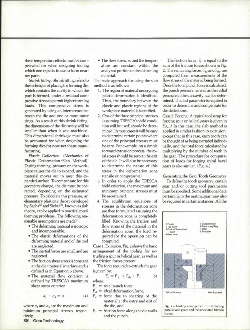
Case 1: Extrusion, Fig. 2 shows the basicarrangement of the tooling for ex-truding a spur or helical gear, as weU asthe friction forces present.
The force required to extrude the gearis given by.
Fp = F i.d + F", + Ff (5)where:Fp = total punch force,Fid = ideal deformation force,FsIJ. = forte due to shearing of the
material. at the entry andexit ofthe die, and
Ff = friction force along the die wallsand the punch.
The friction force, FE, is equal to thesum of the friction forces shown in rig.2. The remaining forces, Fid and fs]"arecomputed from measurements of theflow stress of the material being formed.Once the total punch force is calculated,the punch pressure, as well as the radialpressure in the die cavity, can be deter-mined. This last parameter is required inorder to determine and compensate fordie deflections.Case 2: Forging. A typical too] setup forforging spuror helical gears is given inFig. 3 In this case, the slab method isapplied in similar fashion to extrusion,except that in this case, each tooth canbe thought of as being extrudedindivid-uaUy, and the total force calculated bymultiplying by the number of teeth inthe gear. The procedure for computa-tion of loads for forging spiral bevelgears is also similar. (Fig. 4.)
Generating I:heGear Tooth W!ometryTo define the tooth geometry, certain
gear and/or cutting tool parameters.be: oedfied S· ..J.J·,..·at d-tmust spec... '.omeaUUltion u oara
pertaining to the mating gear may alsobe required in certain instances. All the
, Punch2 Top I","",3Conical/Streamline<!
Insert4 Gear I.,...,
5~hoB<16 Reirlforang Ring7_ . -8 ExtruSlOfl
fig . .2- Tooling arrangement for extrudingparallel axis gears and the associated frlction I
forces.

data required for the computations andthe geometry of the cutting tool can beobtained from a "summary sheet"developed by gear designers. With thisdata, standard gear equations are usedto calculate the X and Y coordinates ofthe points describing the gear toothprofile.
Cutti.t)g the Die. A common methodof die manufacture is called Electrical
Discharge Machining (EDM). The pro-cess uses an. electrode, usually made ofgraphite or brass, which is the negativeof the die geometry, The electrode isbrought dose to, but not in contactwith, the die material. An electrical cur-rent is allowed to arc across the gapwhich "burns" away the die material.Another form of this method of manu-facture is called wire EDM. Current is
1 Inner Punch2 Outer Punch3 Top Insert'* Helical Insert
5 Support lnsert6 Stationa!)' Ring7 Reinlorcing Ring8 Ejector
9 Billel10 Forging
Before Forging Alter Forging
Fig. J - Tooling arrangement for forging parallel axis gears.
BEFORE FORGING4
AFTE.R FORGING
t R.ngGear2 Die BonDm (W~h Teeth)'* Punch6 Doe HolderB Kick Out RII19
fig ..4 - Tooling arrangement for forging spiral bevel gears.
.2-6 Die Assembly3 Inner Die Bottom5 Die Rir>g7 Preform
passed through a straight wire thatmoves in two dimensions, burning thedie geometry as it moves .. Spur andstraight bevel gear rues are the only oneswhich can be cut using the wir-e EDMprocess. In all cases, a corrected set ofgear tooth profile coordinates is needed.Under contract from the United StatesArmy Tank-Automotive Command,Battelle Columbus Division engineersdeveloped two computer programswhich calculate corrected gear toothgeometries and assist in :theoverall diedesign pr-ocess. These programs, called.SPBEVL and GeARDt are used forspiral bevel gear forging and spur/hel-ical gear extrustion I forging respec-tively.
Computer Program "GEARDl" ..Themain functions of GEARDI are
• Define the exact tooth form of aspur or helical gear,
• Compute the forming load re-quired to produce the current geardesign,
• Compute the coordinates of thecorrected gear geometry necessaryfor machini.ng LheEDM electrodesby taking into account the changein the die geometry due to temper-ature differentials, load stresses,and shrink fitting, ..and,
• Determine the specifieatiorts ofatool which can cut the.altered toothgeometry on a conventional hob-bing or shaper cutter machine.
This program enables the user to,de-sign spur and helical gears, predict tool-ing loads and pressures.estimate metalflow for forming the gear, and definethe geometry required to manufacturethe tooling using conventionalor wireEDM. Several examples of gears cur-rently being forged in industry weretested in the GEARDI computer pro-gram. The predicted forging loads werewithin acceptable limits of the actualloads measured during productionruns.
GEARDI is an interactive, graphics-oriented program which was developedon a Digitial Equipment Corporation
July/August1990 39

VAX 1 VMS 11/750 computer. It is amenu-driven program that allows theuser to 'select various options from a.pre-defined list. The GEARDI programhas powerful application possibilities,not only in the area of metal forming,but also in the area of gear and geartrain design, with its ability to designhobs and shaper cutters and to modifythe fillet from a trochoidal shape to acircular shape.
Computer Program ·'SPBEVI.:'..Themain functions of the computer pro-gram "SPBEVL" are
'. Determiae the tooth geometry forspiral bevel gears and pinionsnormally machined on Gleasongenerators. The full irnplementa-tion in the program is for FOR-MA JElM gears only. This is ac-complished by an analysis of thekinematics of the machine, blankand cutter dimensions, and initialsettings proposed from the Gleasonsummary charts.
• Correct the tooth geometry for theforgirng process parameters, such astemperature of forging, initial. dietemperatures, etc. The correctionsare made for temperature dilieren-tials, loading of the dies, diemanufacturing techniques (elec-trode overbum, shrink-fitting,etc.)
• Give new machine settings, blank,and tool geometries determinedfrem the modified tooth geometry.These are used to machine theEDM graphite electrodes on thesame Gleason machines that areused to cut the gears.
SPBEVL is an interactive gra-phics program operational onVAX/V1v1S systems.
EXtrusion TrialsSpur 1Hel..ica1 Gears.. Tooling de-
signed using 'theGEARDI program wasused to conduct spur and helical gearextrusion trials at Battelle's ColumbusDivision using a 700-ton hydraulicpress. These trials were intended tovalidate the capabilities of the GEARDIprogram and demonstrate the prac-40 Gear Technology
ticality of extruding parallel axis gears.The spur gear was a 15 tooth, 5 DPgear. The gears were extruded using a"push-through" concept. Each gear isfirst partially formed and left in the diewhile the punch is retracted. A secondbillet is placed on top of the partiallyformed gear and the press is cycledagain. During this cycle, the partiallyformed gear is finished formed andpushed through the die, dropping outthe bottom of the die. Fig. 5 shows thesequence of parts in the tooling. Onceformed, the teeth on the gear are notmachined further. A fixture whichholds the gear on the pitch line of theteeth is used to finish-machine the insideand ends of the gear. The spur gear
PARTIALLYFORl'IEDGEAR
FINISHEDGEAR
Fig. 5 - Sequence of steps in extrudingparallel axis gears.
formed in these trials is intended to bean AGMA quality class B gear. Mea-surements taken on the extruded gearsindicated a gear of between AGMAquality 7 and 8.
The helical gear chosen for the extru-sion trials was a 32 tooth 10 DP gearwith a helix angle of 30°. During theforming trials, several dies were clam-aged from internal tooth breakage. Thiswas due largely to the relatively highhelix angle and the fine pitch of the part ..Several die designs were used beforeparts were finally extruded sucoessfully.Yet even these gears were observed tohave poor surface finish and were lessaccurate than desired ..
Spiral Bevel Gear. Refer to Fig. 4 fora schematic of some initial forging tool-ing. The preform geometry is given inFig. 6 ..Hot work steel.H-13 was used asthe die material. Six electrodes wereneeded for the spark erosion of the die.The gear forging trials were conductedat Eaton Corporation's Forging Divisionin Marion, Ohio. A 3,(X)ij).ton,mechan-ical forging press was used for the trials,based upon a forging load estimate of2,500 tons. The preforms were ma-chined for these trials, though theycould be made by forming methods.The preforms were heated in an induc-tion coil that was specifically designedfor this purpose. The preform washeated for 200 seconds under a protec-tive atmosphere to the required forgingtemperature of 2,OOO°F(1,093°C). Theforging loads were monitored using
1------ 7.280 -------1(184:912 i'nm)
1.001 (25~ mm) 6.0lI0 -:- ---1(l54."32mm)
I---------~ 9.920 ----------l(25196a """)
INOTE: RADII .375 UNLESS OTHERWISE NOTEDPreform Material: 8620 Steel
Fig. 6 - Preform geometry for spiral bevel gear forgillg.

For' pour .to,uglJest gear cutf-n:g Jobs,
t-llelJardest steel Isthe easiest IclJolce' •.. CPM RBX 76
For hobs, shaper cutters and other ,gear ·cuttingtools that are more than a cut above the rest, specifyCrucib'le CPM- iREX- 7,6. With 33% total alloy con-tent and an attainable hardness of HRC 68-70, thish'igh speed steel prov,ides the highest avai:lablecombination of red hardness, wear resistance andtoughness, either coated or uncoated.
A 8ig,-Three US. auto maker recently realized a300%· improvement in gear cuttingl toot Hfe byswitching from M3 HSS- to CPM REX 76. Withgreat,e.rtool life and excellent grindability. CPM REX76 means less downtime because resharpeninq iseasier and less frequent.
CPM REX 76 is just one of 10 high speed steelsproduced by the Crucible Particle' Metallurgy pro-cess. With the industry's widest material selection,Crucible can meet your specific needs at any pro-ductivity level, You can selectively upgrade to thebest OPM material for the right application ..
On your next order, specilfy a high speed steelthat's hard to beat . .. CPM REX 76 or anothermember of the CPM FlEXfamil.~To learn more, con-tact your nearest Crucible Service Center, or write'Crucible Service Centers. 5639 West GeneseeStreet, Camillus, NY 130.31.
c:Cruci:bleService Center's,A Division of Crucible Maferlals Corporation
CIROlE A-1S ONI REAOER REPLY CARD

BougLt & Sold:* BRIDLES* Bl'CKLES* CLOTHING* BITS'* BOOKS
* BELT* BOLOS* CHAP'* SPURS'* SADDLES
HIGH NO'ONW,est,ern CoJlectiLtes
(211) 202-9,01,0 by appoinunent onl»(2/3) 2,02·134,0 (fax)
CIRCtE A-19 ON READER RiEPLYCARD
trs true, our Consumer Information Catalog is tilled with booklets thatcan answer the questions American consumers ask. most.
To satisfy every appetite, the Consumer Information Center puts togetherthis helpful Catalog quarterly containing more than 200 federalpublications you can order. It's free, and so are almost half of thebooklets it lists. Subjects like nutrition, money management, health andfederal benefits help you make the right choices and decisions.
So get a slice of American opportunity. Write today for your free Catalog:
11.~.f:Co...~.-u...m..er.. lo.ro. f.mat..i.on.'.Center, Department APPueblo, Colorado 81009
"'public service of this pubhcanon and the Consumer Information Centeror the US General Services Adrmrusrraucn
42 Gear Technolog:y
load transducers attached to the framesof the press.
Die lubrica~ion, used during the forg~Lng trials, consisted primarily of awater-base graphite material sprayedwith pressurized air ..After forging, thegears wer placed teeth down in a sand-grapite mixture to reduce oxidation ofthe teeth during cooling. The back sur-faces were still left exposed to the air sothat the cooling rates would not be ex-cessively slow. Gears were forged witha machining allowance of O.OO7~(0.178mm) on both tooth surfaces. A speciallydesigned nest located the teeth so thatthe back surfaces are machined to bereference surfaces. This reference sur-face was used in the finish machining ofthe teeth in a conventional gear cuttingmachine.
The forged and machined gear waschecked! ina Zeiss coordinate measuringmachine ..Fig ..'J shows the relative devi-ation of the forged tooth profile as com-pared to a "master gear tooth" producedby conventional machining. Note thatthe relative error at the center of the pro-file is zero; i.e., the variations were mea-sured relative to 'the center of the coastand' drive surface of the master gear.The maximum variation was 0.003"(0.0762 mm), This difference can beeasily compensated for in the machiningof the pinion.
The above procedure was repeated toforge a 16~ ring gear. These trialsshowed the applicability of the aboveapproach in designing dies fOI" spiralbevel gear forging.
Conclusions & Future WorkParallel Axis Gearing. The GEARDI
program has demonstrated the feasibil-ity of extruding and forging spur andhelical gears ..Several U.S. gear manu-facturers are currently using this pro-gram to design their dies on an ongoingbasis. Still, there is much to be deter-mined concerning the l:imitsof this pro-cess in terms of part geometry and pro-cess conditions. Those companies whichcurrently are forming gears using this

..'
!I.1.'IIiNMENT MOOE - 0
C? .'It_.".....~. - ~.
OPERAT.: r .H ... ole
fig. i-Zeiss gear tooth plots comparing the tooth Iorrn variation of a forged gear versus the cutmaster gear.
technology have gamed considerableexperience to date. There is a definitelearning curve which 'one must travel inorder to get into the business of forminggears. Research is still needed in manyareas in order to generally quantify theprocess, including the following:
• gear materials which are formable,• lubrication,• tool life,• variance in part dimensions be-
tween the first and last pieces fromOJ given tool set, and
• limitations on part geometry.The GEARDI program should also
be improved to run on other computers,11. ef ied i bil" t odihaswei asrm t iruts a lty om _uy
the fill.et Iormand to more accuratelyestimate forming loads and generate diecorrections.
Bevel Gearing. One of the majorproblems in spiral bevel gear forgi.ng isthe extension of the above approach toother types of spiral bevel gears (gen-erated tooth, [or example). Though themodifications of the tooth surface canperhaps be determined by a rigorousmathematical treatment of the problem,the cost factor for making dies with anelectrode to be machined in a five-axismachine is still unknown. Further, thecomputer-aided methods should con-
sider the distortion of the gear toothduring cooling ..Tool life is another un-known factor. The fact that spiral bevelgears are forged around the world (withor without using the above method) isan indication that the method suggestedin this article will be a good first step forthe initial design of the dies withoutmuch trial and error. The future workis currently directed towards extendingthe above concept to gears that are cutwith both modified roll and tilt mecha-nisms using Gleason machines.
References:
1. AtTAN, T., OH, 5., and GEGEL.H.Metal Farming Fundamentals and Ap-plications. ASM, Metals Park. Ohio.1983, pp. 6-8,132.
2. SACHS. G. "On the Theory of theDrawing Process". (in German). Z.angew. Math. tI. Mech., 7, 1927, pp.235-236.
3. SlEBEL. E. Metal Forming in PlasticCondition (i.n German), Dusseldorf.Verlag Stahleisen, 1932.
Acknowledgements: Reprinted with permis-sioll of the American Gear Ma1ll4actl.!rersAssociation. Tile opi71;oll5. silltemellts. and COI1-
elusions presented in this paperar/i! those of tileauthors and in no way represent the positiol1 oropinion of AGMA.
Special thanks to William L. /anninck for hlshelp witll tile technicalediting of this article.
CALENDAR
PROFILE MEASlJIUNG, RING GEAR
SEPTEMBER 5-13, 1990.IMTS-90, McC'ormickPlace, Ctd,eago,. It.Largest trade show in 'theWestern hemisphere withexhibitors from aroundthe world ..A new featurethis year will be the120,000 sq. fL Formingand Fabricating Pavilion ..For more inlormation,contact: [MTS ..90, 7901Westpark Drive, McLean,VA 22102-4269. Ph:(703)893-2900. Fax: (703)898-1151 .
SEPTEMBER 11-1.3,1990.Short Course on GearNoise. The Ohio StateUniversity, Columbas,OH. Discussions willcover gear noise cause andreduction, measurementand analysis. transmissionerror methods. dynamicmodeling, gear noisesignal analysis, and shaftand housing dynamics.Case history workshopsand laboratory demon-strations. Featured speak-ers include Profs. D. R.Houser and R. Si.ngh ofOSU and Dr. RobertMunro of Huddersfield In-stitute of Technology,England. For more infor-mation contact: Mr.Richard D, Frasher, Direc-tor, Continuing Educa-tion, College of Engineer-ing, 2070 NeH Ave., Col-umbus, OH4!3210. (614)292-8143.
OCTOBER 29-31, 1990.AGMA FaU T,echnicalMeeting. Hilton Interna-tional Hotel, Toronto.Canada, Papers andseminars on gear design,analysis, manufacturing,applications, gea.r drives,and related products.Contact AGMA. :1500King St., Suite 2101, Alex-andria. VA, 22314. (703)684-0211.
July/Augus11990 43,