Indigenous PAH-degrading bacteria from oil-polluted sediments in Caleta Cordova, Patagonia Argentina

Engineering Structures 60 (2014) 235–240
Contents lists available at ScienceDirect
Engineering Structures
journal homepage: www.elsevier .com/ locate /engstruct
Short communication
A consistent degrading Bouc–Wen model
0141-0296/$ - see front matter � 2013 Elsevier Ltd. All rights reserved.http://dx.doi.org/10.1016/j.engstruct.2013.12.025
⇑ Corresponding author. Address: School of Civil Engineering, Institute ofStructural Analysis and Aseismic Research, National Technical University of Athens,Zografou Campus, 15780 Athens, Greece. Tel.: +30 210 7721657; fax: +30 2107721651.
E-mail addresses: [email protected] (A.K. Kottari), [email protected](A.E. Charalampakis), [email protected] (V.K. Koumousis).
A.K. Kottari a, A.E. Charalampakis b, V.K. Koumousis b,⇑a University of California at San Diego, Civil Engineering, United Statesb School of Civil Engineering, National Technical University of Athens, Greece
a r t i c l e i n f o
Article history:Received 30 March 2013Revised 10 November 2013Accepted 17 December 2013
Keywords:Bouc–WenStiffness degradationStrength deteriorationPlasticity postulates
a b s t r a c t
In this work, a consistent smooth Bouc–Wen-type degrading hysteretic model is presented whichincorporates stiffness degradation, strength deterioration, pinching, asymmetric hysteresis and strain-hardening characteristics. The smooth rate-independent model originally proposed by Bouc [1] and laterextended by Wen [2] was further developed by Sivaselvan and Reinhorn [3] to incorporate degradationphenomena. This is extended herein to incorporate two specific modifications; one accounting for theloading history effect in stiffness degradation, pointed out by Wang and Foliente [4], and another relatedto compatibility with plasticity postulates. The latter is independently enforced based on the methoddeveloped by Charalampakis and Koumousis [5], eliminating the model’s displacement drift, forcerelaxation and non-closure of hysteretic loops when subjected to short unloading–reloading paths.Numerical examples are presented for a single-degree-of-freedom system demonstrating the effect ofthe modifications, particularly for seismic excitations.
� 2013 Elsevier Ltd. All rights reserved.
1. Introduction
The inelastic response of structures in seismic-prone regions isof major importance and it is based on the individual hystereticbehavior of the constituent members. Several smooth hystereticmodels have been proposed in the literature to account for thatbehavior. In contrast to multi-linear segmental hysteretic models,smooth models constantly change their stiffness due to plastifica-tion, allowing for a more realistic representation of a system’sbehavior. This drastically facilitates computation especially forcyclic loading where degradation phenomena are present, byavoiding massive bookkeeping of various auxiliary variables.Among these models, the one originally proposed by Bouc [1]and later extended by Wen [2] is widely used. It has been shownthat the Bouc–Wen model can successfully express the inelasticbehavior of many materials and structural elements. For this rea-son it has been incorporated in software programs such as IDARC[6], OpenSees [7] and Ruaumoko [8].
The fact that the Bouc–Wen model exhibits force relaxation,displacement drift and nonclosure of hysteretic loops whensubjected to short unloading–reloading paths [9–13] constitutesa major concern. This is due to the fact that the model predictsreduced reloading stiffness as compared to the unloading stiffness
at the same state. As a consequence, negative total work is pro-duced, which violates Drucker’s [14] and Illiushin’s [15] postulatesthat require nonnegative work in a closed stress, or strain loop,respectively. Although these postulates are not mandatory from athermodynamical perspective [16], they should be adhered towhen dealing with a wide range of materials, such as metals. Thisis not though the case for granular and other soil materials [17]. Tocope with the aforementioned violation, Casciati [10] introduced a‘‘counterclockwise’’ hysteretic parameter that gives rise to negativeinelastic displacements at reloading. This method alleviates, butdoes not eliminate the problem. Charalampakis and Koumousis[5] proposed a method successfully treating the problem, basedon a stiffening factor inserted within the hysteretic equationswhich guides the reloading response directly on the unloadingpath up to an appropriate reversal point. This has the same effectas the correction proposed by Ridell and Newmark [18] for theClough and Johnston model [19].
The Bouc–Wen modeling has been proven fully aligned withclassical theory of associative plasticity [20,21] and can be appliedequally in uniaxial and multiaxial problems, where as a constitu-tive model can be directly incorporated in classical finite elementsformulation [21–23]. What is of interest is that it can be equallyintroduced at the level of stresses and strains, or at a level of stressresultants-generalized displacements. Moreover, the additionalhysteretic variables can be casted in various different forms i.e.as hysteretic strains, hysteretic generalized displacements, orhysteretic stresses and hysteretic stress-resultants leading toequivalent systems with different mathematical descriptions. Notethat Erlicher and Point [24] and Erlicher and Bursi [25] proposed
236 A.K. Kottari et al. / Engineering Structures 60 (2014) 235–240
certain restrictions in the model parameters in order to achieve athermodynamically admissible formulation.
Sivaselvan and Reinhorn, in a synthetic attempt, proposed asmooth Bouc–Wen type model to account for degrading factorsappropriate for modeling inelastic structural engineering behavior[3]. However, this model displays some minor mathematical andphysical deficiencies that call for modifications to improve its con-sistency. In case of stiffness degradation, the system’s response ap-pears to be independent of the loading history and thus unable toaccount for cumulative deterioration [4], while in strength degra-dation and pinching, the existing mathematical relations containinconsistencies [4,26]. Local violation of Drucker’s stability postu-late is another limitation of the original model [5,26].
In this work, a degrading Bouc–Wen type model is proposed alongthe lines of the formulation by Sivaselvan and Reinhorn [3], incorpo-rating modifications that account for the mathematical and physicaldeficiencies, and optionally restore compatibility with Drucker’s andIlliushin’s postulates based on the previous work by Charalampakisand Koumousis [5].
2. Model description
2.1. Base model
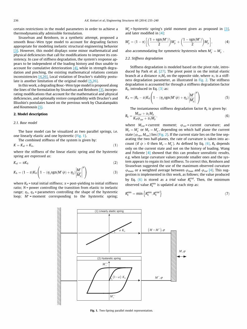
The base model can be visualized as two parallel springs, i.e.one linearly elastic and one hysteretic (Fig. 1).
The combined stiffness of the system is given by:K ¼ Kel þ Kh; ð1Þ
where the stiffness of the linear elastic spring and the hystereticspring are expressed as:
Kel ¼ aK0 ð2Þ
Kh ¼ ð1� aÞK0 1� g1sgnðM� _uÞ þ g2ð Þ M�
M�y
����������
N0@
1A ð3Þ
where K0 = total initial stiffness; a = post-yielding to initial stiffnessratio; N = power controlling the transition from elastic to inelasticrange; g1, g2 = parameters controlling the shape of the hystereticloop; M� = moment corresponding to the hysteretic spring;
0a K
yM ∗+
(2) Hysteretic spring
(1) Linearly elastic spring
yM ∗−
( )1 a K−
Fig. 1. Two-Spring parallel
M�y = hysteretic spring’s yield moment given as proposed in [3],
and later modified in [4]:
M�y ¼ ð1� aÞ 1þ sgnðM�Þ
2
� �Mþ
y þ1� sgnðM�Þ
2
� �M�
y
� �; ð4Þ
also accommodating for symmetric hysteresis when Mþy ¼ M�
y .
2.2. Stiffness degradation
Stiffness degradation is modeled based on the pivot rule, intro-duced by Park et al. [27]. The pivot point is on the initial elasticbranch at a distance a1My on the opposite side, where a1 is a stiff-ness degradation parameter, as illustrated in Fig. 2. The stiffnessdegradation is accounted for through a stiffness degradation factorRk, introduced in Eq. (3) as:
Kh ¼ ðRk � aÞK0 1� g1sgnðM� _uÞ þ g2ð Þ M�
M�y
����������
N0@
1A ð5Þ
The instantaneous stiffness degradation factor Rk is given by:
Rk ¼Mcur þ a1My
K0ucur þ a1My; ð6Þ
where Mcur = current moment; ucur = current curvature; andMy ¼ Mþ
y or My ¼ M�y , depending on which half plane the current
state (ucur, Mcur) lies (Fig. 2). If the current state lies on the line sep-arating the two half-planes, the rate of curvature is taken into ac-count (if _u > 0 then My ¼ Mþ
y ). As defined by Eq. (6), Rk dependsonly on the current state and not on the history of loading. Wangand Foliente [4] showed that this can produce unrealistic results,e.g. when large curvature values precede smaller ones and the sys-tem appears to regain its lost stiffness. To correct this, Reinhorn andSivaselvan suggested the use of the maximum observed curvatureumax, or a weighted average between umax and ucur [4]. This sug-gestion is implemented in this work, as follows; the value produced
by Eq. (6) is stored as a trial value Rtrialk . Then, the minimum
observed value Rmink is updated at each step as:
Rmink ¼min Rmin
k ;Rtrialk
n oð7Þ
0
,M ϕ
( ) ,M M ϕ∗−
,M ϕ∗
model representation.

yM
M
ϕ
1 ya M−
0kR K0K1ϕ
curϕ
curM
yyM M +=
yM
M
1ϕ
curM
yyM M −=
Fig. 2. Park et al. pivoting rule [27].
A.K. Kottari et al. / Engineering Structures 60 (2014) 235–240 237
Finally, the suggested degradation parameter Rk is an interpo-lated value between Rmin
k and Rtrialk :
Rk ¼ Rtrialk þ ð1� a2ÞðRmin
k � Rtrialk Þ; ð8Þ
where a2 is a stiffness recovery parameter. If a2 = 1, then Rk ¼ Rtrialk
at all steps and the degradation rule is identical to the initial one(with full stiffness recovery). If a2 = 0, then Rk ¼ Rmin
k at all times,and the stiffness diminishes continuously. To demonstrate the dif-ferences in behavior, consider a system with N = 1, K0 = 50,Mþ
y ¼ �M�y ¼ 400, g1 = g2 = 0.5, a1 = 5 subjected to the inverse-
saw-tooth cyclic history of Fig. 3a, as in [4]. When a2 = 0, the re-duced stiffness obtained in the first cycle of intense curvature ismaintained for the remainder of the event, whereas when a2 = 1 fullstiffness recovery is observed, as in the initial model (Fig. 3b).
2.3. Strength deterioration
Strength deterioration, which occurs due to dissipation of en-ergy and/or increase of maximum deformation, is modeled byreducing Mþ=�
y . Sivaselvan and Reinhorn [3] proposed the followingrelation:
Mþ=�y ¼ Mþ=�
y0 1� uþ=�max
uþ=�ult
!1=b10@
1A 1� b2
1� b2
HHult
� �; ð9Þ
where Mþ=�y0 = initial positive or negative yield moment;
uþ=�max = maximum positive or negative curvatures; uþ=�ult = ultimatepositive or negative curvatures, H = hysteretic energy dissipated;
Fig. 3. (a) Inverse-saw-tooth imposed curvature h
Hult = hysteretic energy dissipated when loaded monotonically tothe ultimate curvature without any degradation; b1 = ductility-based strength degradation parameter; and b2 = energy-basedstrength degradation parameter. Note that in Eq. (9) negative curva-tures with non-integer exponents occur when differentiating. Theseminor discrepancies were recently addressed in Ray and Reinhorn[30]. The strength deterioration rule adopted herein is the oneproposed by Mostaghel [28]:
Mþ=�y ¼ Mþ=�
y01
1þ bm1H
� �; ð10Þ
where Mþ=�y0 = initial value of yield moment; bm1 = strength deterio-
ration parameter, and H = dissipated energy. Differentiating Eq. (10)with respect to time the following relation is obtained:
ddt
Mþ=�y ¼ Mþ=�
y01
ð1þ bm1HÞ2
!_H ð11Þ
where _H = rate of the dissipated energy, for which the equationproposed by Sivaselvan and Reinhorn [3] can be used:
_H ¼ M _u 1� Kel þ RkKh
RkK0
� �ð12Þ
The above equation expresses the rate of dissipated energy interms of the evolution of curvature. Consider a system withN = 1, K0 = 50, Mþ
y ¼ �M�y ¼ 400, g1 = g2 = 0.5, a1 = inf, bm1 ¼ 10�6
subjected to the saw-tooth cyclic history of Fig. 4a. The strengthdeterioration effect is presented in Fig. 4b.
2.4. Pinching
Pinching usually results from losing bonding in reinforced con-crete, cracking, bolt slip in steel connections, etc. It can be modeledas an additional slip-lock spring connected in series to the hyster-etic spring [3]. The stiffness of the slip-lock element can be distrib-uted following a Gaussian or any other distribution satisfying:Z 1
�1
1Ks
dM ¼ s ð13Þ
where s = slip length. The expression for the slip-lock spring usedherein is:
Ks ¼1ffiffiffiffiffiffiffi2pp s
M�r
�� �� exp �12
M� � jM�jsgnð _uÞjM�
rj
!20@
1A
8<:
9=;�1
ð14Þ
In the above equation, s ¼ Rs uþmax �u�max
� = total slip length;
M�r ¼ rM�
y = a measure of the moment range over which slip occurs;M� ¼ kM�
y = mean moment on either side about which slip occurs;
istory and (b) hysteretic response for a1 = 5.

Fig. 4. (a) Saw-tooth imposed curvature history and (b) hysteretic response for bm1 = 10�6.
Fig. 5. Pinching effect with (a) Rs = 0.25, r = 0.05, k = 0.10 and (b) Rs = 0.40, r = 0.10, k = 0.
238 A.K. Kottari et al. / Engineering Structures 60 (2014) 235–240
Rs, r, k = model parameters. Eq. (14) is practically identical to theone proposed by Wang and Wen [29] and Wang and Foliente [4].The only difference is the normalizing factor in order to conformto the standard form of the Gaussian distribution, although this isnot directly related to the pinching analysis. Note that in the pro-posed formulation, Rs is constant. Another approach which allowsfor varying Rs can be found in Ray and Reinhorn [30].
The system’s combined stiffness is expressed as:
K ¼ Kel þKhKs
Kh þ Ksð15Þ
Consider a system with N = 1, K0 = 50, Mþy ¼ �M�
y ¼ 400,g1 = g2 = 0.5 subjected to the cyclic history of Fig. 4a. Two casesof pinching are demonstrated in Fig. 5.
2.5. Strain hardening
Many systems exhibit strain hardening when subjected to in-tense deformations. To include this phenomenon in the model,an independent gap-closing spring can be connected in parallelto the elastic and hysteretic springs as proposed by Sivaselvanand Reinhorn [3]. The internal moment of the gap-closing springis given by:
M�� ¼ Kgapu ¼ jK0Ngapðjuj �ugapÞNgap�1Uðjuj �ugapÞ
�u; ð16Þ
where Kgap = stiffness of the gap-closing spring; U() = Heaviside stepfunction; ugap = curvature corresponding to the initiation of the
effect; j and Ngap = parameters. Note that there is typographical er-ror in the corresponding equation of [3].
3. Compatibility with plasticity postulates
In cases when it is desirable to eliminate a behavior related todisplacement drifts, force relaxation and non-closure of hystereticloops when the model is subjected to short unloading–reloadingpaths, and thus restore compatibility with plasticity postulates, itis possible to apply a modification along the lines of [5]. This isachieved by inserting a stiffening factor in the differential equa-tion, so that when reloading follows unloading, the response isguided along the unloading path up to the corresponding reversalpoint. Eq. (3) is written as:
Kh ¼ ð1� aÞK0 1� g1 sgnð _uM�Þ�2Hð _uM�ÞRsmðu;M�;M�yÞ
�þ g2
� M�
M�y
����������N
24
35;ð17Þ
where the underlined expression is the modification;
Rsm u;M�;M�y
�= a stiffening factor; and H() = Heaviside function
with H(0) = 0. The Heaviside function is equal to zero along theunloading branches, where Eq. (17) reduces to Eq. (3), and unityalong the reloading branches. During reloading, Rsm controls thestiffness between two extremes; for Rsm = 0 Eq. (17) once again re-duces to Eq. (3), whereas for Rsm = 1 the loading stiffness becomesequal to the one of unloading at the same point. The stiffening fac-tor Rsm is defined as illustrated in Fig. 6. For the purposes of this

+P
C
Pϕ +
*PM +
*yM +
*M
CϕF
A
ϕ
as csHys
tere
tic m
omen
t
curvature
Fig. 6. Formulation of the stiffening factor Rsm [5].
Fig. 7. Model Response under the Northridge Tarzana 090 excitation.
A.K. Kottari et al. / Engineering Structures 60 (2014) 235–240 239
example, the reversal point Pþ uþP ;M�þP
� is set in the upper half
plane of the M⁄ - u space. Symmetric formulation with respect tothe origin of the reference axes is assumed for the lower half-plane.When unloading occurs, the system’s current state is representedby point A(u, M�), with 0 6 M�
6 M�þP . Point CðuC ;M
�CÞ is the corre-
sponding point of the unloading path, i.e. M�C ¼ M�. The unloading
path from the reversal point P+ is known in analytical form [31],as proposed by Charalampakis and Koumousis [32], and thus thecurvature uC can be evaluated by:
uC �uþPuy
¼ M�
M�þy 2
F1 1;1N;1þ 1
N; ðg2 � g1Þ
M�
M�þy
����������
N0@
1A������M�C
M�þP
; ð18Þ
where 2F1(a, b, c; w) = Gauss’s hypergeometric function. Wheng1 = g2, Eq. (18) is simplified as:
uC �uþPuy
¼ M�C �M�þ
P
M�þy
; ð19Þ
as the unloading branch is a straight line.The proposed expression for Rsm is based on the ratio of the
slopes sa/sc (Fig. 6), as follows:
Rsm ¼ H M�þP �M�� uþP �uC
uþP �u
� �p
; ð20Þ
where p = parameter controlling the intensity of stiffening to theleft of the unloading path. For increased values of p, stiffening isconcentrated close to the unloading path and it is diminished every-where else. In general, values of p between 1.0 and 2.0 result into
realistic hysteretic behavior [5]. Note that Eq. (20) differs from thecorresponding equation in [5], since the term H(uC – u), which can-cels the stiffening effect to the right of the unloading path, has beenproven to be unnecessary and it is omitted herein. The new formu-lation, i.e. Eq. (20), is simpler and also numerically more stable,since values of Rsm slightly greater than unity only guide the re-sponse back to the unloading path. Further details on the formula-tion of equations and the selection of the appropriate reversalpoints can be found in [5,31,32].
To demonstrate the effect of the proposed modification, asingle-degree-of-freedom system with unit stiffness was subjectedto a number of seismic excitations. In Fig. 7 the response of thesystem to Northridge Tarzana 090 excitation is presented, bothfor the original and the modified model. The system consideredhas the following properties: N = 2, K0 = 50, Mþ
y ¼ �M�y ¼ 0:5,
g1 = g2 = 0.5, a1 = 1. The overall response is affected considerably.Note e.g. the short reversals in the lower left part of the picture,which are eliminated in the modified model.
4. Conclusions
Bouc–Wen type hysteretic models are phenomenological rate-independent plasticity models controlled by a number of easilyidentifiable parameters. They are capable of expressing effectivelythe inelastic-hysteretic response of a wide range of materials andstructural components. Degrading models of Bouc–Wen type aremore realistic at the expense of some additional parameters. In thiswork, certain modifications are suggested for the model proposedby Sivaselvan and Reinhorn [3] regarding the stiffness degradation.Furthermore, an alternative strength deterioration rule is adoptedand a stiffening factor is introduced within the hysteretic differen-tial equation in the spirit of [5], capable of correcting violations ofplasticity postulates that raised considerable criticism on Bouc–Wen models. Implementation of the proposed modificationstowards a consistent degrading hysteretic model of Bouc–Wentype is straightforward and can be easily introduced into existingcodes.
References
[1] Bouc R. Forced vibration of mechanical systems with hysteresis. In: Proc 4thconf on nonlinear oscillations, Prague, Czechoslovakia; 1967.
[2] Wen Y-K. Method for random vibration of hysteretic systems. J Eng MechDiv-ASCE 1976;102(2):249–63.
[3] Sivaselvan MV, Reinhorn AM. Hysteretic models for deteriorating inelasticstructures. J Eng Mech ASCE 2000;126(6):633–40.
[4] Wang C-H, Foliente GC. Discussion on ‘‘hysteretic models for deterioratinginelastic structures’’. J Eng Mech-ASCE 2001;127(11):1200–2.
[5] Charalampakis AE, Koumousis VK. A Bouc–Wen model compatible withplasticity postulates. J Sound Vib 2009;322:954–68.
[6] Reinhorn AM, Roh H, Sivaselvan M, Kunnath SK, Valles RE, Madan A, et al.MCEER-09-0006. IDARC 2D Version 7.0: A program for the inelastic damageanalysis of structures. MCEER Technical Report, University at Buffalo – theState University of New York; 2009.
[7] Open system for earthquake engineering simulation (Opensees). <http://opensees.berkeley.edu> [accessed 17.02.13].
[8] Carr A. 3D Ruaumoko: inelastic three-dimensional dynamic analysis program,Christchurch, NZ: University of Canterbury-Department of StructuralEngineering; 2007.
[9] Sandler IS. On the uniqueness and stability of endochronic theories of materialbehaviour. J Appl Mech 1987;45:263–6.
[10] Casciati F. Non-linear stochastic dynamics of large structural system byequivalent linearization. In: Proc ICASP5, Vancouver; 1987. p. 1165–72.
[11] Thyagarajan RS. Modeling and analysis of hysteretic structuralbehaviour. Pasadena, California: EERL-89-03, Earthquake EngineeringResearch Lab, California Institute of Technology; 1989.
[12] Spacone E, Ciampi V, Filippou FC. A beam element for seismic damageanalysis. Berkeley: UCB/EERC-92/07, Earthquake Engineering Research Center,University of California; 1992.
[13] Wong CW, Ni YQ, Ko JM. Steady-state oscillation of hysteretic differentialmodel II: performance analysis. J Eng Mech 1994;120(11):2299–325.
[14] Drucker DC. Some implications of work hardening and ideal plasticity. QuartAppl Math 1950;7:411–8.

240 A.K. Kottari et al. / Engineering Structures 60 (2014) 235–240
[15] Iliushin AA. On the postulate of plasticity. Prikl Math Mekh 1961;25:503–7.[16] Green AE, Naghdi PM. A comment on Drucker’s postulate in the theory of
plasticity. Acta Mech 1965;1(4):334–8.[17] Prevost J-H, Hoeg K. Soil mechanics and plasticity analysis of strain softening.
Geotechnique 1975;25(2):279–97.[18] Ridell R, Newmark NM. Force-deformation models for non-linear analysis. J
Struct Div 1979;105(ST12):2773–8.[19] Clough RW, Johnston SB. Effect of stiffness degradation and earthquake
ductility requirements. In: Proc of the Japan earthquake engineeringsymposium, Tokyo, Japan; 1966.
[20] Sivaselvan MV, Reinhorn AM. Hysteretic models for cyclic behaviour ofdeteriorating inelastic structures. MCEER-99-0018, Multidisciplinary Centerfor Earthquake Engineering Research. Buffalo, NY: State University of NewYork at Buffalo; 1999.
[21] Triantafyllou SP, Koumousis VK. Bouc–Wen type hysteretic plane stresselement. J Eng Mech-ASCE 2012;138(3):235–46.
[22] Triantafyllou SP, Koumousis VK. Hysteretic quadrilateral plane stress element.Arch Appl Mech 2012;82(10–11):1675–87.
[23] Triantafyllou SP, Koumousis VK. Hysteretic finite elements for the nonlinearstatic and dynamic analysis of structures. J Eng Mech-ASCE 2013. http://dx.doi.org/10.1061/(ASCE)EM.1943-7889.0000699.
[24] Erlicher S, Point N. Thermodynamic admissibility of Bouc–Wen type hysteresismodels. CR Mecanique 2004;332:51–7.
[25] Erlicher S, Bursi OS. Bouc–Wen-type models with stiffness degradation:thermodynamic analysis and applications. J Eng Mech 2008;134(10):843–55.
[26] Charalampakis AE. Inelastic dynamic analysis of structures using Bouc–Wenhysteretic models. PhD Thesis, National Technical University of Athens; 2009.
[27] Park YJ, Reinhorn AM, Kunnath SK. IDARC: Inelastic damage analysis ofreinforced concrete frame-shear wall structures. NCEER-87-0008, NationalCentre for Earthquake Engineering Research. Buffalo, NY: State University ofNew York; 1987.
[28] Mostaghel N. Analytical description of pinching, degrading hysteretic systems.J Eng Mech-ASCE 1999;125(2):216–24.
[29] Wang C-H, Wen YK. Evaluation of pre-Northridge low-rise steel buildings – I,modeling. J Struct Eng-ASCE 2000;126(10):1160–8.
[30] Ray T, Reinhorn AM. Enhanced smooth hysteretic model with degradingproperties. J Struct Eng-ASCE 2012. doi:10.1061/(ASCE)ST.1943-541X.0000798[in press].
[31] Kottari AK. Inelastic analysis of structures with generalized Bouc–Wen models.Diploma Thesis, National Technical University of Athens; 2009.
[32] Charalampakis AE, Koumousis VK. On the response and dissipated energy ofBouc–Wen hysteretic models. J Sound Vib 2008;309:887–95.
Copyright © 2022 FDOKUMEN