A Bicriteria Optimisation Approach for Waste Management of ...
24
HAL Id: hal-01895648 https://hal.archives-ouvertes.fr/hal-01895648 Submitted on 15 Oct 2018 HAL is a multi-disciplinary open access archive for the deposit and dissemination of sci- entific research documents, whether they are pub- lished or not. The documents may come from teaching and research institutions in France or abroad, or from public or private research centers. L’archive ouverte pluridisciplinaire HAL, est destinée au dépôt et à la diffusion de documents scientifiques de niveau recherche, publiés ou non, émanant des établissements d’enseignement et de recherche français ou étrangers, des laboratoires publics ou privés. A Bicriteria Optimisation Approach for Waste Management of Carbon Fibre Reinforced Polymers Used in Aerospace Applications: Application to the Case Study of France Phuong Anh Vo Dong, Catherine Azzaro-Pantel, Marianne Boix, Leslie Jacquemin, Anne-Laure Cadène To cite this version: Phuong Anh Vo Dong, Catherine Azzaro-Pantel, Marianne Boix, Leslie Jacquemin, Anne-Laure Cadène. A Bicriteria Optimisation Approach for Waste Management of Carbon Fibre Reinforced Poly- mers Used in Aerospace Applications: Application to the Case Study of France. Waste and Biomass Valorization, Springer, 2017, 8 (6), pp.2187-2208. 10.1007/s12649-016-9669-z. hal-01895648
-
Upload
khangminh22 -
Category
Documents
-
view
2 -
download
0
Transcript of A Bicriteria Optimisation Approach for Waste Management of ...

HAL Id: hal-01895648https://hal.archives-ouvertes.fr/hal-01895648
Submitted on 15 Oct 2018
HAL is a multi-disciplinary open accessarchive for the deposit and dissemination of sci-entific research documents, whether they are pub-lished or not. The documents may come fromteaching and research institutions in France orabroad, or from public or private research centers.
L’archive ouverte pluridisciplinaire HAL, estdestinée au dépôt et à la diffusion de documentsscientifiques de niveau recherche, publiés ou non,émanant des établissements d’enseignement et derecherche français ou étrangers, des laboratoirespublics ou privés.
A Bicriteria Optimisation Approach for WasteManagement of Carbon Fibre Reinforced Polymers Used
in Aerospace Applications: Application to the CaseStudy of France
Phuong Anh Vo Dong, Catherine Azzaro-Pantel, Marianne Boix, LeslieJacquemin, Anne-Laure Cadène
To cite this version:Phuong Anh Vo Dong, Catherine Azzaro-Pantel, Marianne Boix, Leslie Jacquemin, Anne-LaureCadène. A Bicriteria Optimisation Approach for Waste Management of Carbon Fibre Reinforced Poly-mers Used in Aerospace Applications: Application to the Case Study of France. Waste and BiomassValorization, Springer, 2017, 8 (6), pp.2187-2208. �10.1007/s12649-016-9669-z�. �hal-01895648�

an author's http://oatao.univ-toulouse.fr/20419
http://doi.org/10.1007/s12649-016-9669-z
Vo Dong, Phuong Anh and Azzaro-Pantel, Catherine and Boix, Marianne and Jacquemin, Leslie and Cadène, Anne-Laure A Bicriteria Optimisation Approach for Waste Management of Carbon Fibre Reinforced Polymers Used inAerospace Applications: Application to the Case Study of France. (2017) Waste and Biomass Valorization, 8 (6).2187-2208. ISSN 1877-2641
A Bicriteria Optimisation Approach for Waste Managementof Carbon Fibre Reinforced Polymers Used in AerospaceApplications: Application to the Case Study of France
Phuong Anh Vo Dong1 • Catherine Azzaro-Pantel1 • Marianne Boix1 •
Leslie Jacquemin2 • Anne-Laure Cadene2
Abstract The increased use of carbon fibre reinforced
polymers (CFRP) has raised the environmental concerns on
waste disposal and consumption of non-renewable resources
as well as economic awareness for the need to recycle CFRP
wastes stemming from aircraft. This study develops an
optimisation approach of CFRP waste management with the
simultaneous objective of minimising cost and global
warming potential impacts along the the entire network.
Various CFRP waste types are involved with multiple
available techniques of fibre/no-fibre recovery techniques.
The scenarios that are investigated are based on the current
situation in France. The large inventory of the existing sites
concerning aerospace CFRP industry is carried out to predict
the waste quantity that is likely to be generated in the future.
The objective is to developwaste allocation strategies, which
are both good for economic and environmental aspects. The
results obtained show that the economic interest and the
environmental effect are conflicting. Transportation turns
out to be an important factor of waste management.
Keywords Carbon fibre reinforced polymers � Waste
management � Multiobjective optimization � Recovery �Recycling
List of symbols
Indices/Sets
c 2 C Market of recovered
product
e 2 E No-fibre recovery
pathways
f 2 {Carbon fibre
production, prepreg
production, CFRP component
production}
Manufacturer type
i 2 I Intermediate product
j Variant in each aircraft
model
l; l0 2 L Location/region
m Aircraft model
p 2 P Recovered product from
fibre recycling technique
r 2 R Fibre recycling technique
s 2 {Small, medium, large} Plant scale
t Year of the study
w 2 W Waste type
Parameters
am Number of variants in aircraft model m
CAPDl Maximum dismantling capacity at region
l in 1 year (airplanes)
CAPELel Capacity of no-fibre recovery technique
e at region l, (tons/year)
CAPPfs Annual capacity of one plant of type f at
scale s in 1 year (tons/plant)
CAPRLrl Recycling capacity of fibre recovery
technique r at region l, (tons/year)
& Catherine Azzaro-Pantel
1 Laboratoire de Genie Chimique, Universite de Toulouse,
UMR CNRS 5503, INP ENSIACET, UPS,
31432 Toulouse Cedex 4, France
2 Altran RESEARCH, 4 Avenue Didier Daurat, Parc Centreda
- Batiment Synapse, 31700 Blagnac, France
CQLcp Minimum quality of product p accepted
by sector c (%)
DISMl Dismantling productivity, (2 [0 1])
DISTll’ Distance between region l and region l0
(km)
ECOM Energy for compression (kWh/ton)
EPRw Energy used for pre-treatment of waste
w (kWh/ton)
GWPE GWP impacts of electricity (tons CO2
eq./MJ)
GWPIRri GWP impacts of treatment of
intermediate product i by recycling
technique r (tons CO2 eq./ton of waste)
GWPNRAUwe Avoided GWP impact of no-fibre
recovery pathway e from waste w (tons
CO2 eq./ton of waste)
GWPNRUe GWP impacts of treatment by no-fibre
recovery pathway e (tons CO2 eq./ton of
waste)
GWPPp GWP impacts of conventional production
of product p (tons CO2 eq./ton)
GWPTRU GWP impacts of transport (tons CO2
eq./tkm)
GWPWRrw GWP impacts of treatment of waste w by
fibre recycling technique r (tons CO2
eq./ton of waste)
Mmj Operating empty weight of variant j in
aircraft model m (tons/aircraft)
NOMfsl Number of plants of type f at scale s in
region l (plants)
ntm Number of aircraft model m delivered in
year t (aircraft)
pcm Proportion of CFRP weight in airframe in
model m, (2[0;1])PCOM Cost of compression (€/ton)
PE Unit cost of electricity (€/kWh)
PIRri Cost of treatment of recycling technique
r for intermediate product i (€/ton)
PNRew Cost of no-fibre recovery technique e for
waste w (€/ton)
PPp Price of recovered product p (€/ton)
PRODfs Productivity of plant type f at scale
s (2[0;1])
psm Proportion of airframe weight in
operating empty weight in model
m (2[0;1])
PTR0 Cost of normal transport for recovered
product (same for all type product p)
(€/ton.km)
PTRw Cost of transport for waste w (€/ton.km)
PWMwf Generation rate of waste w from
fabrication plant of type f (%)
PWRrw Cost of treatment of recycling technique
r for waste w (€/ton)
QLPRPwp Quality of recovered product p from
waste w by pretreatment (%)
QLRPIirp Quality of recovered product p from
intermediate i by recycling technique r (%)
QLRPWwrp Quality of recovered product p from
waste w by recycling technique r (%)
QWwl Waste quantity w at region l (tons/year)
RECMl Rate of CFRP waste separation from
aircraft, (2[0;1])
RIRPrpi Conversion ratio from intermediate
product i to final product p by fibre
recycling technique r (%)
RNRe Revenue from no-fibre recovery pathway
e (€/ton)
RWRPrpw Conversion ratio from waste w to final
productpbyfibre recycling technique r (%)
umt Average CFRP weight per retired aircraft
in year t (tons)
XDPcpl Index of existence of sector c for product
p at region l
XIRir Acceptance index of fibre recycling
technique r for intermediate product i, 1
if the technique r can treat the
intermediate product i, 0 otherwise
XPRPwp Index of conversion w to product p after
pretreatment
XPRw Index for waste w which does not need
recycling process after pretreatment step
for recovery, 1 if the waste w does not go
to the recycling process for recovery, 0
otherwise
XTRll’ Factor of transport, 1 if two regions (l and
l’) are different 0 otherwise
XWIwi Index of conversion waste w to
intermediate product i after pretreatment
XWNRwe Acceptance index of no-fibre recovery
technique e for waste w, 1 if the
technique e can treat the waste w, 0
otherwise
XWPRw Index for waste w which can go to pre-
treatment step separately from recycling
process, 1 if the separated pretreatment
step is opened for the waste w, 0 otherwise
XWRwr Acceptance index of fibre recycling
technique r for waste w, 1 if the technique
r can treat the waste w, 0 otherwise
Continuous Variables
FIRirll0 Flow of intermediate product i transported
from l to recycling site r at l’, (tons)
FPDRwrpcll0 Flow of product p recovered from waste
w by direct recycling technique r at location
l and then distributed to market c at l0, (tons)
FPIRirpcll0 Flow of product p recovered from i by
recycling technique r at location l and then
distributed to market c at l0, (tons)
FPPRwpcll0 Flow of product p obtained from pretreated
waste w at l directly transported to market
c at l0, (tons)
FWDRwrll0 Flow of waste w from waste source
l transported directly to recycling site r at l0,
(tons)
FWNRwell0 Flow of waste w to no-fibre recovery
technique e at region l, (tons)
FWPRwll0 Flow of waste w transported from waste
source at l to pretreatment site at l’, (tons)
Introduction
Air traffic has been expanding at nearly two and half
average economic growth rates since 1960 [22]. In the
20 year forecast of Airbus [3], passenger air traffic is
expected to continue this tendency with an average annual
growth rate of 4.6 %. However, regarding the impacts of
energy crisis through its history, this industry is one of the
most vulnerable ones to oil price variation. While elec-
tricity can be produced from various sources, liquid fuels
used for aviation have yet no other economically viable
alternatives than from fossil ones for the scale of current
consumption. The energy crisis has induced the demand for
fuel efficiency as a characteristic of aircraft [6]. Beside this
economic reason, the improvement of fuel efficiency can
reduce the emission of greenhouse gases from burning of
fuels. Indeed, with 16,000 commercial jet aircraft in the
world, aviation generates more than 600 million tons of
CO2 per year which is nearly equivalent to all human
activities in Africa [22]. The effects of aviation on climate
change has been extensively studied by Brasseur et al. [8],
Dessens et al. [14], Lee et al. [26], Penner et al. [37],
Prather et al. [43], Rothengatter [45], Wuebbles et al. [59].
The aviation industry has made diverse efforts in design
and materials in aircraft and different practices in order to
reduce airplane fuel consumption since the past three
decades. These efforts allow a dramatic reduction in fuel
consumption of 70 % in new aircraft compared to those of
40 years ago. By the middle of the century, 40–50 %
improvement is projected [29]. One of the strategies for
fuel savings is the reduction of aircraft weight by using
lighter materials, i.e. aluminium and composite. This latter
has exclusively high technique properties such as high
strength, relatively low weight and corrosion resistance.
Composites have been used originally in military aircraft
and have then been adopted progressively in civil airplane
from secondary part to primary structure in the latest
models of Boeing and Airbus, e.g. B787 with 50 % in
composite, A350 with 53 % in composite.
These two models have marked the revolution of carbon
fibre reinforced polymer (CFRP) composite utilisation in
airframe with CFRP fuselage. Adopted since 1970s, CFRP
is increasingly used in structural applications of aircraft to
replace more conventional materials (steel, aluminium,
alloys…) in order to design lighter products due to their
low density and high performance of chemical and physical
properties and become the major composite in recent
models among the other composites (GFRP, GLARE,
Carbon/Caron Composite…). This material is constituted
of two main components: carbon fibre and polymer matrix.
In aerospace applications, carbon fibre exhibits the high
mechanical properties and polymer matrix is principally
thermoset.
In contrast to metal, glass, thermoplastics and many
other engineering materials for which a solid recycling
industry has been established, CFRP and composite mate-
rials in general have not yet been properly recycled and
landfill still constitutes the main option used. The main
difficulty of recycling is related to the heterogeneous nature
of the matrix and the reinforcement, especially in the case
of thermoset composite [38]. This one cannot be remoulded
after curing/hardening process like thermoplastics. At this
time, the lack of markets, the high recycling cost associated
with the lower quality of the recyclates versus virgin
materials constitute major commercialisation barriers for
composites recycling [60].
Moreover, carbon fibre production needs high energy in
production, approximately 183–286 MJ/kg [52]. This pro-
cess generates environment and human health impacts due
to emissions from the oxidation and carbonization furnaces
such as hydrogen cyanide (HCN), ammonia (NH3), nitro-
gen oxide (NOx), volatile organic compounds (VOCS),
carbon monoxide (CO) and carbon dioxide (CO2) [17].
Therefore, instead of being landfilled or burned for energy
recovery, carbon fibre can be recycled from composite like
CFRP for several interests. First, it is necessary to limit the
accumulation of waste that is likely to be generated; sec-
ond, recycling could be a fibre supply solution in order to
meet future demand in different applications [7]. Finally,
recycling could be expected as a less-energy-intensive
operation with lower environmental impact than the tra-
ditional way to produce CFRP, by-passing some produc-
tion steps.
CFRP composite recycling is receiving a lot of attention
from academics and industries [35] as highlighted by an
increasing number of recent publications on the subject.
Because of the technical difficulties to separate thermoset
matrix from the reinforcement materials [60], the devel-
opment of recycling technologies has been mainly focused
on this type of composite materials. Several recycling

construction etc. which can give more environmental
benefits than the disposal solutions, e.g. landfill,
incineration.
Considering these challenges, this study aims to develop
an optimisation approach of CFRP waste management in
aerospace with two objectives, i.e. minimising both cost
and global warming potential (GWP) impacts, in order to
assess both economic and environmental factors in the
entire network. A linear programming model has been
developed to determine the optimal material flow of CFRP
waste going into different routes under each strategy. This
framework is applied in France where the aviation industry
is strong with Airbus and important suppliers in global
aviation.
This paper is organised as follows. Section 2 presents
the general concept of the network and its mathematical
model with the associated constraints and objective func-
tion. The data and assumptions used in the case of France
can be found in detail in Sect. 3. Section 4 presents the
results of the network design under different strategies,
following first a mono-objective optimisation strategy with
economic cost and GWP impacts as separate criteria; sec-
ond the criteria are associated in a bi-criteria optimisation
formulation. This assessment is extended by a sensitivity
study relative to the influence of recycling capacity.
Finally, conclusions and perspectives are highlighted in
Sect. 5 focusing on the extension of the model.
Problem Formulation
System Definition and Assumptions
The waste management model is developed through three
main layers: waste types, waste treatment techniques and
recovered products. The economic and environmental
assessments are evaluated by all the activities concerning
these three layers: transportation of waste from source to
plant for treatment, waste treatment process and recovered
products output from waste treatment (Fig. 1).
The model is formulated here as a static problem in
which there is no variation of waste quantity and waste
treatment capacity during the considered horizon time. All
the wastes produced at the various sources have to follow
the treatment system completely and cannot be stored at
source. The waste treatment techniques are assumed to be
available with a fixed capacity and the problem of
deployment is not considered in this study.
According to Potter andWard [42], waste in the aerospace
composites industry can be defined generally as either end-
of-life or manufacturing waste. The latter is constituted of
different scrap types including woven prepreg, unidirec-
tional prepreg, compositemanufacturing part, clean fibre and
technologies have been developed and proposed over the past decades in order to improve the recycling yield and the properties of the recovered fibre involving three main types of techniques, i.e., mechanical (grinding and electrody-namic fragmentation), thermal (pyrolysis, fluidised bed and microwave), and chemical (low temperature–pressure and high temperature–pressure in supercritical conditions). Beside these three main techniques, other recycling solu-tions can be found like electrochemical [51] and biotech-nological [20]. The recent review of Oliveux et al. [35] is recommended for the current recycling techniques of Fibre Reinforced Polymer (FRP) composite in general including those of CFRP type and other fibre reinforced polymer composites such as GFRP (glass fibre reinforced polymer).
Aerospace sector has to face up with the problem of increasing CFRP waste. Regarding the long lifespan of airplane (20–30 years), the main stream of current CFRP waste may come from manufacturing of recent aircraft, which use high quantity of CFRP material. Otherwise, the flow of end-of-life CFRP waste from retired aircraft will be more important in the next decades when the high CFRP-content aircraft will be dismantled. In aviation, there is no legislation or regulation imposed on aircraft owners or aircraft manufacturers about how to design or deal an air-craft that meets proper and due end-of-life requirements like end-of-life vehicle directive and WEEE (waste elec-trical and electronic equipment) legislation in Europe [54]. However, recent programs of Boeing and Airbus like AFRA, TARMAC have motivated valorisation and reuse of reclaimed materials including CFRP and other com-
posites in aviation on developing the best practices and processes with concerned stakeholders.
This context motivates the essential of modelling for CFRP waste management in aerospace sector in order to reduce the increasing flow of waste and to regain economic and environmental benefits from recycling. However, this model is complex with multiple possible routes for CFRP waste treatment. Each waste type has different character-istics and needs its own operation conditions. The market of recovered fibre is not still mature as the utilisation of recycled carbon fibres in industry generates some chal-lenges which come from their lower quality than that of virgin carbon fibres [31] and their variability affecting many factors such as length, length distribution, surface quality (adhesion of fibre and matrix), as well as their origin (different grades of fibres are found at composite scraps from different manufacturers) [35]. In aerospace, the closed loop of carbon fibre material is limited because of high requirements in structural components and the degradation of fibre through recycling process. Recycled carbon fibre can be used in the applications in aerospace or other sectors which do not demand high quality in mechanical properties such as interior, automotive,

End-of-life
Waste
Cured
Production
Waste
Uncured
Production
Waste
Dry Fibre
Waste
Curing
Cutting
Grinding
Pyrolysis
SCW
Fibre
Oligomers
Powder
Fibrous
Market 1
Market 2
Market 3
Market 4
Landfill
Incineration
Co-
incineration
Heat Electricity
Ash Landfill
Heat
Ash Clinker
Coal’s
substitution
Fibre recovery/
Non-fibre recovery
No-Fibre
Recovery
Pathways
Recycling
techniques
Curing/Non-
Curing
Cured
Production
Waste
Hazardous
waste
Non-hazardous
waste
Product
Process
Market
Decision
Flow of EOL
waste
Flow of Cured
Production
Waste
Flow of Uncured
Production
Waste
Flow of Dry
Fibre Waste
Flow of All
waste types
Flow of Powder
Flow of Fibrous
Flow of Fibre
Flow of
Oligomer
Flow of Ash
Flow of Heat
Fibre recovery
pathways
Transportation
(Compression-
Transport)
Fig. 1 System of CFRP waste management

fraction can be obtained by grinding, its quality is assumed to
be too low for high-value carbon fibremarket and can be used
in lower value market considering the degradation of fibre
and the impurity of matrix in this fraction.
For transportation, the geographic unit of the model is
based on a regional grid. The distance between the regions
corresponds to the average distance between their two
prefectures. The model does not consider the intra-mobility
in each region. Although each waste type is generated by
specific plants, e.g. end-of-life waste from aircraft dis-
mantling site, uncured waste from prepreg/composite pro-
duction plants, etc., the collection of all waste type in each
region is not considered in the model and all of waste in
each region is assumed to be available at the same location,
i.e. its prefecture. In the same way, the transportation of
waste from source to treatment plant and the distribution of
the recovered product to market at the same region are not
considered in the model.
There is no storage of waste at source and all the waste
generated at each region has to be treated completely
through either no-fibre recycling or fibre recycling path-
ways until there is no waste left in the static model. Two
quantitative constraints are formulated at upstream: con-
servation of waste quantity allocated according to different
techniques and to the capacity of waste treatment plants.
As the aerospace industry has not been clearly regulated for
the waste problem yet, there is no constraint on the recy-
cling rate in the model. This variable factor is kept track of
in order to study carbon fibre recyclability in the system in
function of different criteria.
The economic criterion taken into account includes all the
costs of the entire system, i.e., transportation, waste treat-
ment, products distribution activities. The environmental
impact is based on GWP impacts and is evaluated through
both impacts from the activities of the whole system and the
avoided impacts gained by the replacement of conventional
products by the recovered products, which are assumed to
have the same nature. An equivalent amount of the recovered
product replaces the virgin product.
Position of the Proposed Model
The majority of current works about CFRP waste are
related to the recycling process itself and do not embed the
whole recycling chain. Along with the use of composite
materials in various applications like aerospace, automo-
tive and leisure activities, studies on life cycle assessment
of composite in general and CFRP in particular have
received a lot of attention to study the environmental
benefits of composite utilisation that can be gained com-
pared to the conventional materials [12, 49, 52, 53, 56, 57].
However, these studies focused mostly on production and
utilisation phases of such materials. The phase of waste
fabric selvedge [31]. In this study, the composition of the input waste flow only considers the status of polymeric matrix via its curing level in scrap since the thermosetting polymer is principal resin used in aerospace application. The form of carbon fibre, e.g. fabric, or unidirectional form is not applied to classify the waste type. Based on carbon fibre chain in aerospace industry, the model considers four waste types: dry fibre waste, uncured production waste, cured production waste and cured end-of-life waste.
As carbon fibre is the most value component in CFRP, we focus on how the recycling rate of carbon fibre varies in the system under different scenarios. There are two main routes for waste treatment, i.e., no-fibre recovery and fibre recovery. The techniques considered in the first group are landfill, incineration and co-incineration. Heat or heat/material couple valorisation can be obtained through incineration or co-incineration respectively. Otherwise, fibre recovery pathways allow the recovery of carbon fibre through pre-treatment steps and recycling process. Due to the nature of waste types and technical constraints of recycling process, each waste type has to go into firstly pre-treatment step and then recycling process. Pre-treatment activities encompass shredding and curing. The techniques of recycling process considered are grinding, pyrolysis and recycling using supercritical water. Beside recovery of carbon fibre, by-products can be obtained. The modelling of these techniques is based on literature. Data collection is mainly obtained from a literature analysis based on an experimental approach for CFRP recycling.
Due to its nature, each waste type has its own constraints for the selection of the possible routes (Fig. 1). All waste types are required to go through shredding before going to recycling process. However, dry fibre waste can be recovered only by this step and does not need to go into any further process. The curing activity is applied on uncured waste due to the hazardous classification of this waste for transportation and to the requirements of some processes which cannot operate the uncured waste. Pre-treatment activities are assumed to be available at all recycling plants. All waste types are free to choose either direct recycling way, which means the pre-treatment step and recycling process at the same location or the indirect recycling way by which waste is pre-treated at one location and then transported to other locations for recycling. Considering the presence of flame retardant, end-of-life waste cannot go to the thermal process, i.e. incineration, co-incineration and pyrolysis.
The quality of recovered fibre is also considered in the model and may vary according to the selected process. The retention of tensile strength in comparison with virgin fibre is used to quantify the quality of recycled fibre. This parameter can help to distinguish pyrolysis from supercritical water to separate the recovered fibres from. Although a fibrous

treatment is poorly studied and limited on one technique,
e.g. recycling by microwave [12, 52] or recovery energy by
incineration [57].
The analysis of the works dedicated to the CFRP waste
management shows that the scope is limited by the lack of
data and the heterogeneous sources used since composite
recycling is still not mature and is currently on the phase of
process development for some processes with heteroge-
neous technology readiness levels (TRL) for the identified
recycling processes [46].
Hedlund-Astrom [19] applied life cycle cost (LCC) and
life cycle assessment (LCA) in order to study waste treat-
ment routes of CFRP and other composites. The curing
level of matrix in CFRP waste is considered in this study
with two types of waste: uncured and cured CFRP. The
cost-benefit analysis and the environmental load unit are
assessed through the scenarios of three waste treatment
pathways, i.e. incineration for energy recovery, mechanical
recycling for material recovery and fluidised bed for
material/energy recovery, applied in each waste type.
Witik et al. [58] developed a quantitative model for the
determination of equivalent quantities of virgin carbon
fibre and virgin glass fibre, which are replaced by recov-
ered carbon fibre to achieve mechanical performance
equivalent to virgin material in a short fibre composite
beam, i.e. sheet moulding compound (SMC). This study
assessed environmental impacts (climate change, resour-
ces, ecosystem quality and human health) of three waste
treatment options: landfilling, energy recovery with incin-
eration and carbon fibre recovery with pyrolysis.
Li et al. [27] carried out the study on LCC and envi-
ronmental assessment (GWP, energy use, final disposal
waste) for end-of-life CFRP in the automotive sector with
three options (landfilling, incineration and mechanical
recycling) within regulations of UK and EU. In this
hypothetic case, between the two conventional disposal
techniques (landfill, incineration), landfill tax can be
viewed as a useful tool to shift CFRP waste from landfill to
incineration because of the low GWP impacts and energy
use in landfilling. Benefits of recycling depend on dis-
placement factors of virgin carbon fibre by recycled fibre
and on the recycling rate in order to balance the energy-
intensive recycling process.
The decision support frameworks developed in waste
management study waste allocation and compare the existing
waste management options to guide decision-makers in the
selection of the best available and applicable option(s) [33].
The currentwastemanagementmodels can be categorized into
three main categories: cost benefit analysis, life cycle analysis
and use of amulticriteria technique. The principal applications
of waste management modelling are planning of municipal
solid waste management (MSWM) in order to optimise plant
locations, collection network under various criteria such as
environmental impacts (e.g. global warming, human health
risks, resource depletion, ecosystem damage), associated
economic costs and benefits and regional characteristics (e.g.
waste generation rate, political and social factors) [48]. The
increasing interest on materials recovery (environmental
consciousness, legislation, security of raw materials…) has
motivated the integration of waste management in reverse
supply chain for efficientmaterialsmanagement, especially for
industrialwaste, e.g. electronicwaste (e.g. [2, 34]), battery (e.g.
[23]) end-of-life vehicles (e.g. [10]).
Instead of analysing individually each waste treatment
pathway, the proposed study focuses on the economic and
environmental assessment of the entire system in which
diverse CFRP waste type inputs are involved with mul-
tiple available techniques of fibre/no-fibre recovery
techniques. Waste distributions can be varied under dif-
ferent strategies in this flexible model of CFRP waste
management. Furthermore, the consideration of the mar-
ket presence for recovered products allows the control of
outputs.
Mathematical Model
The CFRP waste management system in this study is for-
mulated as a single-period linear problem which predicts
the distribution of wastes in multiple pathways of waste
treatment techniques under two objectives: minimisation of
the cost and minimisation of the GWP impacts. Four types
of constraints are included in this model, i.e. mass con-
servation, treatment capacities, non-negative flows, and
acceptability characteristics of techniques.
Constraints
Waste Quantity Conservation All the wastes generated at
source l cannot be stored at source and have to be treated
completely through either no-fibre recovery or fibre
recovery pathways. There are two options for the sec-
ondary routes: pretreatment step and recycling process are
separated for flow FWPRwll’; direct recycling in which
pretreatement can be integrated in function of the adapt-
ability of process r with waste w. Therefore, each output
flow of each waste type w at source l has to be equal to
the waste quantity of that waste type at the same location
(1).
X
e2E
X
l02L
FWNRwell0 þX
l02L
FWPRwll0þX
r2R
X
l02L
FWDRwrll0
¼ QWwl; 8w 2 W; 8l 2 L ð1Þ
Capacity Constraints The waste treatment capacity at
each plant is applied for all waste inputs. The total waste
streams which go into No-Fibre recovery techniques are
under constraints (2). The flow of waste that pre-treated
separately is lower than the capacity of pre-treatment
which is equal to the total of capacity of all recycling
techniques at the same location (3). All stream inputs of
each recycling plant are inferior to its capacity (4).
X
w2W
X
l2L
FWNRwell0 �CAPELel0 ; 8e 2 E; 8l0 2 L ð2Þ
X
w2W
X
l2L
FWPRwll0 �X
r2R
CAPRLrl0 ; 8l0 2 L ð3Þ
X
i2I
X
l2L
FIRirll0 þX
w2W
X
l2L
FWDRwrll0 �CAPRLrl0 ;
8r 2 R; 8l0 2 L
ð4Þ
Non Negativity Constraints All streams of waste, inter-
mediate product and recovered final product cannot take
negative values according to constraints (5)–(11).
FWNRwell0 � 0; 8w 2 W; 8e 2 E; 8l; l0 2 L ð5Þ
FWPRwll0 � 0; 8w 2 W; 8l; l0 2 L ð6Þ
FWDRwrll0 � 0; 8w 2 W; 8r 2 R; 8l; l0 2 L ð7Þ
FIRirll0 � 0; 8i 2 I; 8r 2 R; 8l; l0 2 L ð8Þ
FPPRwpcll0 � 0; 8w 2 W; 8p 2 P; 8c 2 C;8l; l0 2 L
ð9Þ
FPDRwrpcll0 � 0; 8w 2 W; 8r 2 R; 8p 2 P;8c 2 C; 8l; l0 2 L
ð10Þ
FPIRirpcll0 � 0; 8i 2 I; 8r 2 R; 8p 2 P; 8c 2 C;8l; l0 2 L
ð11Þ
Acceptability Constraints According to their type, the
wastes can be accepted or not in a waste treatment path-
ways due to the difficulty of treatment. The waste streams
to each route are restricted by the constraints (12)–(14).
The adaptability of intermediate products after pretreat-
ment step in recycling technique is under constraint (15).
The constraints (16)–(18) show the acceptability of
recovered product streams in the corresponding market.
Besides the types of recovered products, each market
requires a minimum quality of products so that they can be
accepted by that market. These constraints are expressed in
(19)–(21).X
l02L
FWNRwell0 �XWNRwe � QWwl; 8w 2 W; 8e 2 E;
8l 2 L
ð12Þ
X
l02L
FWDRwrll0 �QWwl � XWRwr; 8w 2 W; 8r 2 R;
8l 2 L
ð13Þ
FWPRwrll0 �XWPRw � QWwl; 8w 2 W; 8r 2 R;8l; l0 2 L
ð14ÞX
l02L
FIRirll0 �QWIRil � XIRir; 8i 2 I; 8r 2 R;
8l 2 L
with
QWIRil ¼X
w2W
X
l0
FWPRwl0l � ð1� XPRwÞ
" #
� XWIwi;
8i 2 I; 8l 2 L
ð15ÞX
w2W
X
l2L
FPPRwpcll0 �XDPcpl0 �M; 8c 2 C; 8p 2 P;
8l0 2 L
with
X
c2C
X
l02L
FPPRwpcll0 ¼X
l00
FWPRwl00l � XPRw
!
� XPRPwp;
8w 2 W; 8p 2 P; 8l 2 L
ð16ÞX
w2W
X
r2R
X
l2L
FPDRwrpcll0 �XDPcpl0 �M; 8c 2 C;
8p 2 P; 8l0 2 L
withX
c2C
X
l02L
FPDRwrpcll0 ¼X
l002L
FWDRwrl00l � RWRPrpw=100;
8w 2 W; 8r 2 R; 8p 2 P; 8l 2 L
ð17ÞX
i2I
X
r2R
X
l2L
FPIRirpcll0 �XDPcpl0 �M; 8c 2 C; 8p 2 P;
8l0 2 L
withX
c2C
X
l02L
FPIRirpcll0 ¼X
l002L
FIRwrl00l � RIRPrpi=100; 8i 2 I;
8r 2 R; 8p 2 P; 8l 2 L
ð18Þ
FPDRwrpcll0 � QLRPWwrp �FPDRwrpcll0 � CQLcp=100
8w 2 W; 8r 2 R; 8p 2 P; 8c 2 C; 8l; l0 2 L
ð19Þ
FPIRirpcll0 � QLRPIirp=100�FPIRirpcll0 � CQLcp=100
8i 2 I; 8r 2 R; 8p 2 P; 8c 2 C; 8l; l0 2 L
ð20Þ
FPPRwpcll0 � QLPRPwp �FPPRwpcll0 � CQLcp=100;8w 2 W; 8p 2 P; 8c 2 C; 8l; l0 2 L
ð21Þ
M is a big number that is used to impose the qualitative
constraints in the mathematical model. In this case, it is
applied to the restrictions of markets for recovered
products.
Objective Functions
The bi-criteria optimisation approach in the model is car-
ried out through all activities in the system boundary
(Fig. 1) from transportation, waste treatment process to
distribution of recovered product with two indicators, i.e.
the economic cost and the GWP impacts. The objective
functions are the minimisation of the cost and the min-
imisation of the GWP impacts. These objectives functions
consist of variable costs (22–27) and variable GWP
impacts (28–34) that depend on flows of wastes and
products in the network. The input data are collected from
literature in general and evaluated from Simapro v7.3 with
ReCiPe Midpoint (H) v.1.06 assessment method for unit
GWP impacts.
Cost Minimisation
Cost ¼X
w2W
X
i2I
X
e2E
X
r2R
X
l2L
X
l02L
FWNRwell0 þ FWPRwll0 þ FWDRwrll0ð Þ � PTRwþ
þ FIRirll0 � PTR0ð Þ
" #
� DISTll0þ
ð22Þ
Transport costð Þ
þX
w2W
X
e2E
X
l2L
X
l02L
FWNRwell0 � PNRew
!
þð23Þ
Cost of No-Fibre recovery pathwaysð Þ
þX
w2W
X
i2I
X
e2E
X
r2R
X
l2L
X
l02L
FWNRwell0 þ FWPRwll0ð
þFWDRwrll0 þ FIRirll0Þ � XTRll0 � PCOMÞþ
ð24Þ
Compression costð Þ
þX
w2W
X
l2L
X
l02L
FWPRwll0 � EPRw � PE
!
þð25Þ
Pretreatment costð Þ
þX
w2W
X
r2R
X
l2L
X
l02L
FWDRwrll0 � PWRrw
þX
i2I
X
r2R
X
l2L
X
l02L
FIRirll0 � PIRri
!
þ
ð26Þ
Cost of recycling processð Þ
þX
w2W
X
i2I
X
r2R
X
p2P
X
c2C
X
l2L
X
l02L
FPPRwpcll0ÿ
þFPDRwrpcll0 þ FPIRirpcll0�
� DISTll0 � PTR0�
Cost of distribution of recovered productð Þ
ð27Þ
Minimisation of the GWP Impacts The GWP is expressed
as follows:
GWP =X
w2W
X
e2E
X
l2L
X
l02L
FWNRwell0 � GWPNRUe
!
þ
ð28Þ
No-fibre recovery activities impactsð Þ
þX
w2W
X
i2I
X
e2E
X
r2R
X
l2L
X
l02L
FWNRwell0 þ FWPRwll0þ
FWDRwrll0 þ FIRirll0
!
� DISTll0 � GWPTRUð ÞÞþ
ð29Þ
Transport impactsð Þ
þX
w2W
X
i2I
X
e2E
X
r2R
X
l2L
X
l02L
FWNRwell0 þ FWPRwll0ð þFWDRwrll0
þFIRirll0Þ � XTRll0 � ECOM � 3:6 � GWPEÞþ
ð30Þ
Compression impactsð Þ
þX
w2W
X
l2L
X
l02L
FWPRwll0 � EPRw � 3:6 � GWPE
!
þ
ð31Þ
Pretreatment activity impactsð Þ
þX
w2W
X
r2R
X
l2L
X
l02L
FWDRwrll0 � GWPWRrw
þX
i2I
X
r2R
X
l2L
X
l02L
FIRirll0 � GWPIRri
!
þ
ð32Þ
Recycling activity impactsð Þ
þX
w2W
X
i2I
X
r2R
X
p2P
X
c2C
X
l2L
X
l02L
FPPRwpcll0 þ FPDRwrpcll0ÿ
þFPIRirpcll0�
� DISTll0 � GWPTRU�
ð33Þ

been selected to rank the Pareto optimal solutions.
TOPSIS is based upon the concept that the chosen
alternative should have the shortest distance from the
Positive Ideal Solution (PIS) (the lowest GWP impacts
and the lowest cost in the studied case) and the furthest
from the Negative Ideal Solution (NIS). The final ranking
is obtained by means of the closeness index [44].
TOPSIS has been selected mainly for four the fol-
lowing reasons: TOPSIS logic is rational and under-
standable, the computation process is straightforward, the
selection of the best alternatives for each criterion is
carried out by a simple mathematical form, and the
importance of weights is incorporated into the comparison
procedures. In this study, the two criteria are considered
to have the same importance weight; there is no prefer-
ence of one criterion over the other. M-TOPSIS is
therefore the appropriate decision aid method to rank the
alternatives in Pareto front and determine the compromise
solution for the two objectives. It must be yet emphasized
that MCDM techniques are not the panacea for all deci-
sion problems and the TOPSIS methods present certain
drawbacks such as the phenomenon known as rank
reversal [44].
Case Study
The case study refers to the situation of France in 2016 for
carbon fibre wastes from aerospace industry. The horizon
time of this study is 1 year. The data input and the
assumptions for the modelling of the case study, i.e. waste
quantity, waste treatment pathways, transport, will be
detailed in this section.
Waste Types
Apart from dry fibre scrap, the other waste types consid-
ered in the model are constituted of both carbon fibre and
polymeric matrix. In the aerospace sector, CFRP are
assumed to have 65 wt% of carbon fibre, and 35 wt% of
thermoset matrix in average. The additives are considered
to be negligible.
Distribution impactsð Þ
�
P
w2W
P
e2E
P
l2L
P
l02L
FWNRwell0 � GWPNRAUweþ
P
w2W
P
i2I
P
e2E
P
r2R
P
p2P
P
c2C
P
l2L
P
l02L
FPPRwpcll0 þ FPDRwrpcll0 þ FPIRirpcll0ÿ �
� GWPPp
2
6
4
3
7
5
ð34Þ
(Avoided impacts from recovered products of No-Fibre recovery and Fibre recovery pathways).
Coupling Multi-Objective Optimisation
with MCDM Strategy
The CFRP waste management is modelled as a linear problem with a deterministic approach fixing the waste quantity input of system. Two objective functions are considered in the model, i.e. minimising the cost and minimising the GWP impacts either separately or simul-
taneously. In this study, from a multiobjective point of view, the lexicographic method and the e-constraint method have been combined to build the so-called the Pareto front which represents in the objective function space the non-dominated vectors of Pareto optimal solu-tions (so-called non-inferior, admissible or efficient solu-tions) which cannot be improved in one objective function without declining the performance in at least one of the remaining objectives [55].
Both lexicographic and e-constraints are categorised as a priori preference methods, in which multiobjective optimisation is transformed into a single objective opti-misation problem by optimising one objective function after the other (lexicographic), or by optimising one objective by transforming all other objectives function into inequality constraints (e-constraints). As two distinct lexicographic optimisations with distinct sequences of objective functions do not produce the same solution [11], the solutions of the lexicographic method in this bi-criteria optimisation problem correspond to two extremities of Pareto front. Between the two extreme solutions, the other alternatives in Pareto front are obtained by e-constraints method. The GWP impact function is minimised while the cost is limited under successive intervals till the lowest cost.
The multiobjective optimisation step is then followed by the use of a multiple criteria decision making (MCDM) procedure that consists in finding the best alternative among a set of feasible alternatives. Among the many approaches of MCDM, a variant of the Tech-nique for Order Performance by Similarity to Ideal Solution (TOPSIS) method [44], called M-TOPSIS has

Carbon fibre in all waste types considered in this model
is PAN (Polyacrycolonitrile)-based, which due to high
carbon yield, competitive process cost and superior phys-
ical properties, has been dominating the global market with
90 %, the remaining 10 % are made from rayon or pitch
(Zoltek). This type of carbon fibre is therefore employed
extensively in aerospace and industrial field and sporting/
recreational goods (The Japan Carbon Fiber Manufacturers
Association).
Through carbon fibre chain in aerospace (Fig. 2), only
wastes containing carbon fibre are considered in the
boundary of system, i.e. dry fibre, uncured productionCFRP,
cured production CFRP and end-of-life CFRP, the other
wastes such as PAN fibre and resin are excluded. Based on
input–output relations of each step in carbon fibre chain, we
determine the potential carbon fibre wastes of the system
(Fig. 2). Dry fibre comes from production of carbon fibre as
production scrap, from production of prepreg and finished
composite component as raw material scrap. Uncured pro-
duction waste is generated during manufacturing prepreg as
production scrap and finished composite component as raw
material scrap. Cured production waste is produced from
fabrication of finished CFRP component and end-of-life
CFRP waste comes from retired aircraft after dismantling.
End-of-Life Waste from Aircraft Dismantling
End-of-life (EoL) CFRP waste is extracted from CFRP
components of retired airplanes through their dismantling.
In France, two sites are identified at Tarbes and Chateau-
roux, with a respective dismantling capacity estimated at
50 and 30 airplanes per year at full capacity. The rate of
CFRP separation is assumed to reach 95 %. There is no
consideration of reuse for CFRP waste, right after
dismantling.
The rate of generation of CFRP waste per aircraft at a
dismantling site is assumed to be equal to the average of all
aircraft retired in 2006. Due to the variety in aircraft types
and their CFRP content, the average weight of CFRP per
aircraft at their retirement age [see expression (35)] is used
to estimate the quantity of end-of-life waste according to
expression (36).
Even if the retirement time of an aircraft depends on
several factors such as the number of pressurisation and
depressurisation cycles, greater efficiency, financial rea-
sons, an average 25-year life span of aircraft (tr) is gen-
erally considered. The aircraft weight depends on its load,
e.g. operating empty weight, maximum take-off weight.
However, the weight of airframe structure is not well
described by aircraft manufacturers. This parameter is
therefore based on the operating empty weight with an
index of proportion of airframe structure in this weight
(psm). The operating empty weight, which includes
structure, systems, engines, equipment, non-usable fuel,
crew, is the nearest well-documented weight to the air-
frame structure weight. The index psm is assumed to be
0.9 for all aircraft types. Considering the light variation
between the different variants in each aircraft model, the
operating empty weight considered is the average of all
the variants.
The CFRP content in structure of each aircraft model
has been evaluated from literature review. This case study
is applied for the commercial jets from McDonnell Dou-
glas/Boeing and Airbus, which have CFRP content, the
other aircraft from these manufacturers, which have no
CFRP are not considered. Due to the lack of data, the
assumptions are applied for the aircraft models, for which
only the general information on composite proportion with
yet no detail on CFRP content: the first models which adopt
CFRP in secondary structure and the recent models which
use CFRP in primary structure have respectively 50 and
85 wt% of CFRP in the total composite content. Data
concerning aircraft models, i.e. operating empty weight,
proportion of CFRP, and the number of deliveries can be
found in online Appendices 1 and 2 respectively.
umt ¼
P
m
nmt�tr�
P
j
Mmj
am� psm � pcm
!" #
P
m
nmt�tr
ð35Þ
QW lw¼EOL ¼ umt0 � CAPDl � DISMl � RECMl ð36Þ
Manufacturing Waste
The quantity of each type of production waste is calculated
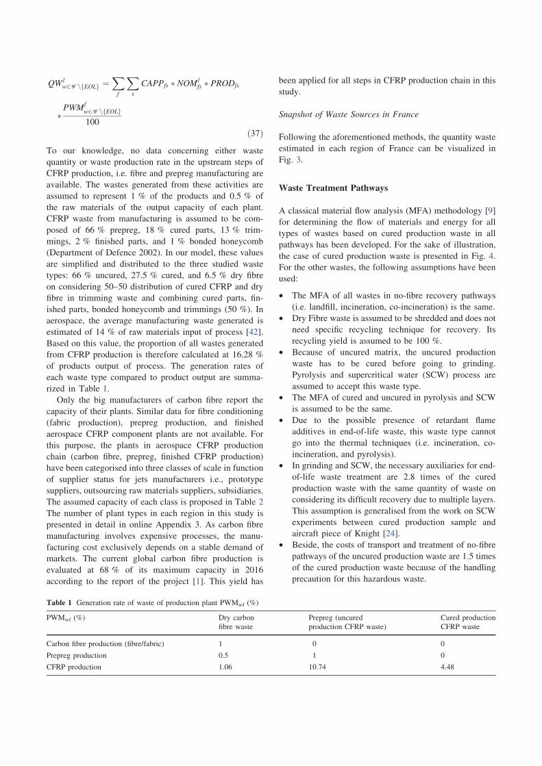
by the following formula (37):
Fig. 2 Waste generation in Aerospace carbon fibre chain
QW lw2Wn EOLf g ¼
X
f
X
s
CAPPfs � NOMlfs � PRODfs
�PWM
f
w2Wn EOLf g
100
ð37Þ
To our knowledge, no data concerning either waste
quantity or waste production rate in the upstream steps of
CFRP production, i.e. fibre and prepreg manufacturing are
available. The wastes generated from these activities are
assumed to represent 1 % of the products and 0.5 % of
the raw materials of the output capacity of each plant.
CFRP waste from manufacturing is assumed to be com-
posed of 66 % prepreg, 18 % cured parts, 13 % trim-
mings, 2 % finished parts, and 1 % bonded honeycomb
(Department of Defence 2002). In our model, these values
are simplified and distributed to the three studied waste
types: 66 % uncured, 27.5 % cured, and 6.5 % dry fibre
on considering 50–50 distribution of cured CFRP and dry
fibre in trimming waste and combining cured parts, fin-
ished parts, bonded honeycomb and trimmings (50 %). In
aerospace, the average manufacturing waste generated is
estimated of 14 % of raw materials input of process [42].
Based on this value, the proportion of all wastes generated
from CFRP production is therefore calculated at 16.28 %
of products output of process. The generation rates of
each waste type compared to product output are summa-
rized in Table 1.
Only the big manufacturers of carbon fibre report the
capacity of their plants. Similar data for fibre conditioning
(fabric production), prepreg production, and finished
aerospace CFRP component plants are not available. For
this purpose, the plants in aerospace CFRP production
chain (carbon fibre, prepreg, finished CFRP production)
have been categorised into three classes of scale in function
of supplier status for jets manufacturers i.e., prototype
suppliers, outsourcing raw materials suppliers, subsidiaries.
The assumed capacity of each class is proposed in Table 2
The number of plant types in each region in this study is
presented in detail in online Appendix 3. As carbon fibre
manufacturing involves expensive processes, the manu-
facturing cost exclusively depends on a stable demand of
markets. The current global carbon fibre production is
evaluated at 68 % of its maximum capacity in 2016
according to the report of the project [1]. This yield has
been applied for all steps in CFRP production chain in this
study.
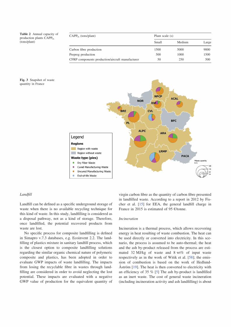
Snapshot of Waste Sources in France
Following the aforementioned methods, the quantity waste
estimated in each region of France can be visualized in
Fig. 3.
Waste Treatment Pathways
A classical material flow analysis (MFA) methodology [9]
for determining the flow of materials and energy for all
types of wastes based on cured production waste in all
pathways has been developed. For the sake of illustration,
the case of cured production waste is presented in Fig. 4.
For the other wastes, the following assumptions have been
used:
• The MFA of all wastes in no-fibre recovery pathways
(i.e. landfill, incineration, co-incineration) is the same.
• Dry Fibre waste is assumed to be shredded and does not
need specific recycling technique for recovery. Its
recycling yield is assumed to be 100 %.
• Because of uncured matrix, the uncured production
waste has to be cured before going to grinding.
Pyrolysis and supercritical water (SCW) process are
assumed to accept this waste type.
• The MFA of cured and uncured in pyrolysis and SCW
is assumed to be the same.
• Due to the possible presence of retardant flame
additives in end-of-life waste, this waste type cannot
go into the thermal techniques (i.e. incineration, co-
incineration, and pyrolysis).
• In grinding and SCW, the necessary auxiliaries for end-
of-life waste treatment are 2.8 times of the cured
production waste with the same quantity of waste on
considering its difficult recovery due to multiple layers.
This assumption is generalised from the work on SCW
experiments between cured production sample and
aircraft piece of Knight [24].
• Beside, the costs of transport and treatment of no-fibre
pathways of the uncured production waste are 1.5 times
of the cured production waste because of the handling
precaution for this hazardous waste.
Table 1 Generation rate of waste of production plant PWMwf (%)
PWMwf (%) Dry carbon
fibre waste
Prepreg (uncured
production CFRP waste)
Cured production
CFRP waste
Carbon fibre production (fibre/fabric) 1 0 0
Prepreg production 0.5 1 0
CFRP production 1.06 10.74 4.48
Landfill
Landfill can be defined as a specific underground storage of
waste when there is no available recycling technique for
this kind of waste. In this study, landfilling is considered as
a disposal pathway, not as a kind of storage. Therefore,
once landfilled, the potential recovered products from
waste are lost.
No specific process for composite landfilling is defined
in Simapro v.7.3 databases, e.g. Ecoinvent 2.2. The land-
filling of plastics mixture in sanitary landfill process, which
is the closest option to composite landfilling solutions
regarding the similar organic chemical nature of polymeric
composite and plastics, has been adopted in order to
evaluate GWP impacts of waste landfilling. The impacts
from losing the recyclable fibre in wastes through land-
filling are considered in order to avoid neglecting the lost
potential. These impacts are evaluated with a negative
GWP value of production for the equivalent quantity of
virgin carbon fibre as the quantity of carbon fibre presented
in landfilled waste. According to a report in 2012 by Fis-
cher et al. [15] for EEA, the general landfill charge in
France in 2015 is estimated of 95 €/tonne.
Incineration
Incineration is a thermal process, which allows recovering
energy in heat resulting of waste combustion. The heat can
be used directly or converted into electricity. In this sce-
nario, the process is assumed to be auto-thermal; the heat
and the ash by-product released from the process are esti-
mated 32 MJ/kg of waste and 8 wt% of input waste
respectively as in the work of Witik et al. [58]; the emis-
sion of combustion is based on the work of Hedlund-
Astrom [19]. The heat is then converted to electricity with
an efficiency of 35 % [5] The ash by-product is landfilled
as an inert waste. The cost of general waste incineration
(including incineration activity and ash landfilling) is about
Table 2 Annual capacity of
production plants CAPPfs(tons/plant)
CAPPfs (tons/plant) Plant scale (s)
Small Medium Large
Carbon fibre production 1500 5000 9000
Prepreg production 500 1000 1500
CFRP components production/aircraft manufacturer 50 250 500
Fig. 3 Snapshot of waste
quantity in France

Grinding
The principle of this technique is to separate fibres from
matrix by a grinding process. After mechanical process and
sieving, the obtained products are a mixture of matrix and
fibre. They are separated into different fractions in function
of the proportion and the length of fibre [25, 36].
From Palmer et al. [36], two products are assumed to be
recovered from the composite waste, i.e., a powder product
(29 wt%), which is rich in matrix and used as filler, and a
fibrous fraction (71 wt%), which is rich in fibre. The pro-
cess energy of this technique is estimated at 0.27 MJ/kg by
Hedlund-Astrom [19] which is in agreement with the value
proposed in Howarth et al. [21] in a test with industrial
equipment.
Pyrolysis
Pyrolysis is a thermal recycling process of FRP that
decomposes the matrix at around 400–750 �C [35]
depending on the thermal properties of resin in order to
CFRP
Waste
(1kg)
Landfill
Incineration
Co-incineration
Mechanical
recycling
Pyrolysis
Landfill
Heat
(32 MJ)
Powder
(0.21 kg)
Fibrous
(0.79 kg)
Fibre
(0.65 kg)
SCW
Oligomers
(0.35 kg)
Fibre
(0.65 kg)
Ash
(0.08 kg)
Input (Waste)
Process
Output (Products)
Limestone
(0.21 kg)
Glass fibre
(0.79 kg)
Carbon
fibre
(0.65 kg)
Carbon
fibre
(0.65 kg)
Replaced Materials
Electricity
(3.11
kWh)
Heat
(32 MJ)
Ash
(0.08 kg)
Heat (32 MJ)
from Coal
(1.16 kg)
Clinker
(0.08 kg)
35 %
conversion
0.075 kWh
(0.27 MJ) of
Electricity
8.33 kWh
(30 MJ) of
Electricity
3.39 kg CO2
3.39 kg CO2
Electricity
(3.11 kWh)
Combustion
of 0.35 kg
matrix
2.61 kWh
(9.40 MJ) of
Electricity
1.64 m3
of
Natural Gas
3.5 kg of
Pure Water 72.07 tons of
Cooling Water
Phenol
(0.35 kg)
Fig. 4 Material flows of cured production waste in the studied system [19, 21, 24, 36, 52, 58]
92 €/tonne in France in 2015 according to Fischer et al.[15].
Co-Incineration
As incineration and co-incineration are both based on combustion of waste, we assume that there is no change in the quantity of heat and ash produced in co-incineration compared with incineration technique. However, co-
incineration allows material recovery in addition to energy recovery. Indeed, in co-incineration technique, waste is used as a substituted fuel involved in clinker fabrication where coal is normally used as fuel and the products of waste combustion, i.e. heat and ash, are completely val-orised in co-incineration. Heat released from combustion of waste can substitute the same amount of heat from coal combustion in furnace and ash is mixed with the raw materials of clinker in its manufacturing. According to Halliwell [18], the cost of treatment of co-incineration of composite waste charged by the cement industry is around 1 € per kg.
recover fibres. The main characteristic of this process is the
thermal decomposition in an inert environment or in a
controlled atmosphere with a low proportion of oxygen to
avoid the oxidation of fibres. A rapid gasification might be
needed after the main process step to clean the fibres from
char of resin decomposition [13, 32] The gas fraction
produced from the decomposition of matrix can be con-
densed to be reused as a fuel or burned to recover heat.
In this study, the pyrolysis is modelled as a combustion
process of the matrix (35 wt% of CFRP waste) for
assessment of environmental impacts. No energy recovery
from thermal decomposition of matrix has been assumed.
The total energy used in pyrolysis has been estimated at
about 30 MJ/kg composite [58].
Supercritical Water (SCW)
In supercritical condition (temperature above 374 �C and
pressure superior to 221 bar), ‘‘the properties of water
change considerably: the hydrogen bonds disappear and
water becomes similar to a moderately polar solvent;
oxygen and all hydrocarbons becomes completely miscible
with water; mass transfer occurs almost instantaneously;
and solubility of inorganic salts drops to ppm range’’ [28].
Due to these properties, the polymer matrix is decomposed
into different oligomers and the carbon fibre is recovered in
supercritical water. Other supercritical solvents such as
acetone, methanol, ethanol and propanol are also used for
CFRP recycling because of their lower critical temperature
and pressure compared to water [41].
This technique has been industrialised for hazardous
waste treatment since 1980s [30]. For composite applica-
tion, although it has received a lot of attention from aca-
demics and industry [35], supercritical water for CFRP
waste is still at pilot scale. Only scarce information is
available for this process. From Knight [24], for 1 kg of
CFRP (35 wt% matrix) waste, the process requires
2.61 kWh of electricity, 1.64 m3 of natural gas, 3.5 kg of
pure water for solvent and 72.07 tonnes of cooling water.
CFRP waste is assumed to lead to 100 % recovery yield of
carbon fibre and matrix (in the form of oligomers).
Distribution of Waste Treatment Echelon
The non-fibre recovery techniques are assumed to be
available in all regions with a capacity at each region
exceeding to the total wastes in the system. Currently, fibre
recovery techniques have a limited presence in France with
only three sites: (1) Bretagne (BRE), (2) Auvergne-Rhone-
Alpes (ARA) and Pays de la Loire (PL). BRE site has a
capacity of over 1000 tons of chopped carbon fibre for the
grinding technique (Procotex). In another source [31], this
site is reported to involve pyrolysis. Therefore, in this
model, a capacity of 1000 tons of waste input with 50 % in
grinding and 50 % in pyrolysis is assumed. The ARA site
uses grinding technique with a 3000 ton-capacity [18]. This
site also works with other composites in reality, but we
assume that its full capacity is available for carbon fibre
waste in this study. SCW at pilot scale applied for carbon
fibre recycling is found in the site in PL region [35] and is
assumed to have a capacity of 200 ton-input per year. The
location and the capacity of waste treatment techniques are
summarised in Table 3.
Transport Echelon
In order to simplify the system, the CFRP waste manage-
ment in this study uses the road mode of transport. All
wastes have to be compressed at source before being
transported to other regions for treatment. If the waste is
treated at the origin region, the compression step is not
necessary.
The lorry of 16–32 tonnes certified EURO5 is used to
transport all wastes and recovered products in this model.
The evaluation of GWP impacts from this activity is based
on this type of vehicle. The transport price is a variable cost
depending on waste/recovered products quantity and dis-
tance. This cost is estimated at 0.14 €/(ton.km) [47] for all
normal goods including non-hazardous wastes and recov-
ered products. Considering the specific configuration for
uncured waste which is classified as a hazardous waste, its
transport cost is assumed to be 1.5 times than the standard
cost.
Table 3 Location and capacity of waste treatment techniques
Waste treatment techniques Availability Capacity (tonnes/year)
Non-fibre recovery techniques (landfill, incineration, co-incineration) All regions Unlimited
Grinding BRE 500
ARA 3000
Pyrolysis BRE 500
Supercritical water (SCW) PL 200

Quality of Recovered Products and Markets
The products recovered from the fibre recovery pathways
have diverse qualities depending on the process. Moreover,
the requirement of each market is different from the type of
product and quality of products. In this study, the ratio of
quality of recovered products over standard conventional
products replaced by the equivalent recovered products, are
used to represent the quality of products output and the so-
called acceptability index of market. This assumed index is
the minimum quality that recovered products must have to
go into the corresponding market. There is no weight
compensation to satisfy the quality requirement of replaced
materials in market.
The retention of tensile strength in comparison with
virgin fibre is used to quantify the quality of recycled fibre.
Its values are the average of the best qualities of recycled
fibre from the experiments of Akonda et al. [4], Greco et al.
[16], Meyer et al. [32], Pimenta and Pinho [39], Pinero-
Hernanz et al. [40], Stoeffler et al. [50]. The dry fibre is
considered to conserve its quality after shredding. The
other recovered products are assumed to have 100 % of
quality of the replaced materials. The quality of all
recovered products from the Fibre Recovery Pathways and
the characterisation of markets are resumed in online
Appendix 4.
Results and Discussions
Pareto Optimal Solutions
The Pareto front (Fig. 5) is constituted of 11 alternatives.
Alternatives 1 and 11 refer to cost minimisation and GWP
minimisation respectively. The convex form of Pareto front
indicates that the two objective functions are conflicting,
resulting from the effect of the avoided impacts included in
the GWP function though both the cost and the GWP
impacts of process activities (without the avoided impacts)
have linear relationship with materials flows.
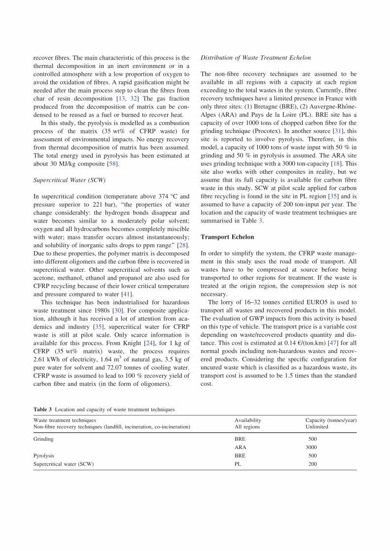
Figure 6 shows the evolution of waste treatment tech-
niques used through the alternatives of Pareto front. Min-
imising the GWP impacts promotes the recovery pathways
in general and the techniques with high value recovered
products. From alternatives 1–11, the utilisation of landfill
is reduced and replaced by incineration (2–3); this latter is
also substituted more and more by grinding which loses
gradually its part then favouring pyrolysis and SCW in the
alternatives 5–11. This evolution corresponds to an
increase in the avoided impacts released from incineration
to grinding then to pyrolysis and SCW.
Instead of losing recoverable materials in landfill, waste
can be valorised to electricity in incineration. The avoided
impacts from substitution of energy produced in France are
too low to compensate all impacts from the emissions of
process. Although co-incineration is modelled with a
similar process as for incineration, the reuse of its outputs
in clinker production covers all GWP impacts from the
process. However, due to its high cost, co-incineration
which has negative GWP impacts cannot win over the
other techniques. With the high values of recovered prod-
ucts, all fibre-recovery techniques have negative GWP
impacts. The conventional production of carbon fibre emits
very high GWP impacts. The avoided impacts from the
replacement of carbon fibre in pyrolysis and SCW are
much more important than limestone-glass fibre from
grinding. Besides, as matrix is also valorised as a by-pro-
duct in SCW, and this technique offers the lowest GWP
impacts.
The Non-Fibre recovery pathways have an advantage in
accessibility for waste treatment. They are assumed to be
available at all regions with unlimited capacity. The Fibre
recovery techniques are currently located in some regions
and are limited in capacity. However, this advantage of the
Non-Fibre recovery techniques has a low economic interest
in the system. With the slight increase of unit cost per 1 kg
of waste (0.0025 €/kg) in alternative 1 which has more than
50 % of waste in No-Fibre recovery technique (i.e. land-
fill), the GWP impacts of the system become negative in
alternative 4 which recovers 99.6 % of waste with the
reinforcement of grinding dominance. This technique has
the lowest operation cost in Fibre recovery pathways.
Furthermore, all wastes can be operated with grinding.
SCW can treat all wastes but suffers from a high operation
cost. In this case study, the use of a simple recycling
technique like grinding, leads to 2.7 % increase in the
minimum cost with avoiding the loss of 52.5 % of wastes
in landfill. Grinding is therefore helpful to increase the
recycling yield under the cost minimisation strategy.
However, this technique suffers from a low value added of
its recovered products on the market.
The capacity also influences on the distribution of
techniques of Fibre recovery techniques. The total capacity
-20
-15
-10
-5
0
5
10
0 0.2 0.4 0.6 0.8 1
GW
P (
kg
CO
2 e
q./
kg
of
wa
ste
)
Cost (€/kg of waste)
1
2
4
5
6
7
8 9
10 11
3
Fig. 5 Pareto front of the case study
of grinding is higher than the total waste quantity. How-
ever, pyrolysis and SCW have limited capacities. Although
SCW has the lowest GWP impacts, this technique cannot
yet dominate in the alternative 11 due to its capacity lim-
itation. This alternative is also highlighted by by the sat-
uration of capacity for pyrolysis and SCW plants.
In this case study, all the recovered products are directly
reused on the recycling plant sites for all the solutions
found by the optimisation strategy. There is no distribution
of products from plant to market because all markets pre-
sent at the region of recycling plants. Without the limited
demand constraints, the markets have no impacts on
decision of waste distribution in upstream. This latter
depends therefore on the characterisation of the waste
treatment techniques.
The alternatives are ranked into this following order by
the decision aid method M-TOPSIS with two objectives,
i.e. cost minimisation and GWP minimisation:
6[ 7[ 5[ 8[ 4[ 9[ 10[ 3[ 11[ 2[ 1. The
M-TOPSIS solution found is alternative 6.
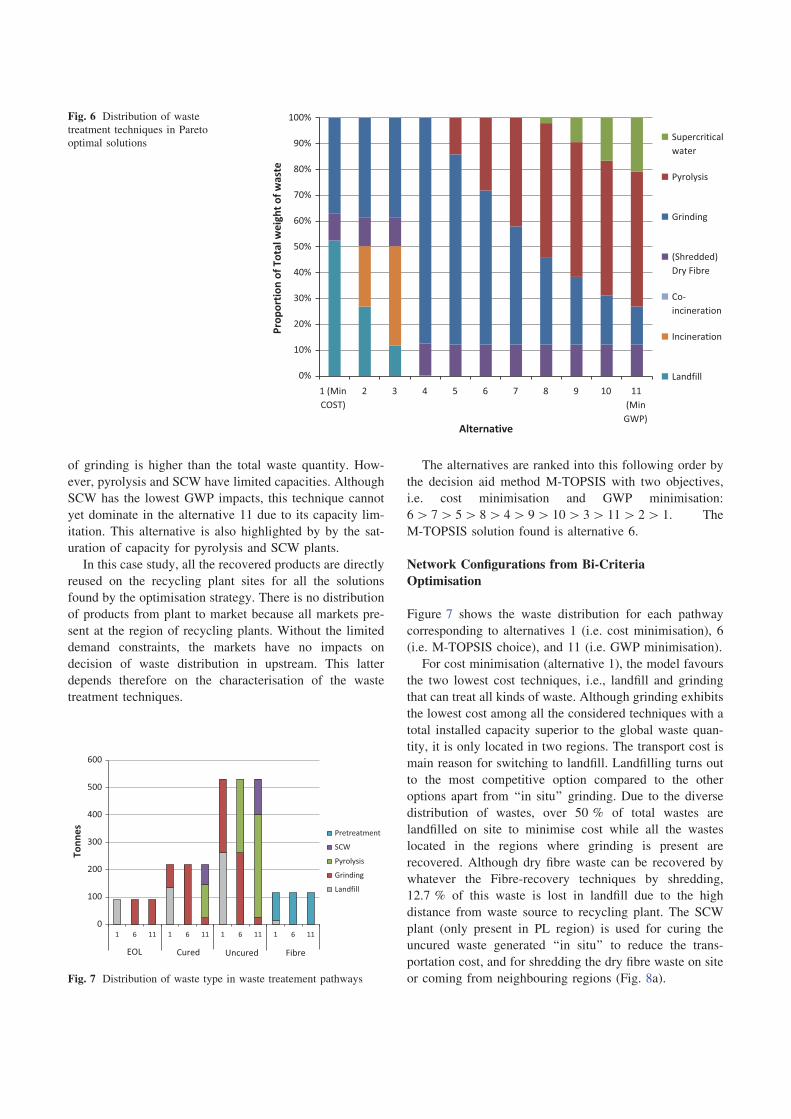
Network Configurations from Bi-Criteria
Optimisation
Figure 7 shows the waste distribution for each pathway
corresponding to alternatives 1 (i.e. cost minimisation), 6
(i.e. M-TOPSIS choice), and 11 (i.e. GWP minimisation).
For cost minimisation (alternative 1), the model favours
the two lowest cost techniques, i.e., landfill and grinding
that can treat all kinds of waste. Although grinding exhibits
the lowest cost among all the considered techniques with a
total installed capacity superior to the global waste quan-
tity, it is only located in two regions. The transport cost is
main reason for switching to landfill. Landfilling turns out
to the most competitive option compared to the other
options apart from ‘‘in situ’’ grinding. Due to the diverse
distribution of wastes, over 50 % of total wastes are
landfilled on site to minimise cost while all the wastes
located in the regions where grinding is present are
recovered. Although dry fibre waste can be recovered by
whatever the Fibre-recovery techniques by shredding,
12.7 % of this waste is lost in landfill due to the high
distance from waste source to recycling plant. The SCW
plant (only present in PL region) is used for curing the
uncured waste generated ‘‘in situ’’ to reduce the trans-
portation cost, and for shredding the dry fibre waste on site
or coming from neighbouring regions (Fig. 8a).
0%
10%
20%
30%
40%
50%
60%
70%
80%
90%
100%
1 (Min
COST)
2 3 4 5 6 7 8 9 10 11
(Min
GWP)
Pro
po
rtio
n o
f T
ota
l w
eig
ht
of
wa
ste
Alternative
Supercritical
water
Pyrolysis
Grinding
(Shredded)
Dry Fibre
Co-
incineration
Incineration
Landfill
Fig. 6 Distribution of waste
treatment techniques in Pareto
optimal solutions
0
100
200
300
400
500
600
1 6 11 1 6 11 1 6 11 1 6 11
To
nn
es
Pretreatment
SCW
Pyrolysis
Grinding
Landfill
EOL Fibre Cured Uncured
Fig. 7 Distribution of waste type in waste treatement pathways

alternative due to the high operational cost of SCW com-
pared to grinding and pyrolysis. The avoided GWP impacts
from the reuse of oligomers as phenol are not high enough to
balance the GWP impacts and the high cost from recycling
operation so that SCW can compete with pyrolysis. In this
context, curing the uncured waste at SCW plant (PL region)
before grinding this waste at BRE region is needed to reduce
the transportation cost in alternative 6 as the network in
alternative 1 with a lower quantity of uncured waste. This
SCW is also used for shredding the dry fibre on site or from
the neighbouring regions (Fig. 8b).
In this case study considered, all the markets exist at the
regions where recycling is implemented. Therefore, all the
recovered products generated from the recycling plants
depend on upstream. Yet, the distribution of products can
help developing potential markets where the accumulation
of products is generated, so that the upstream waste man-
agement can be developed in order to solve the treatment
of all wastes on the one hand and the valorisation of
recovered products from waste on the other hand.
The snapshots of the amount of recovered products from
fibre-recovery pathways are shown in Fig. 9 for (a) alterna-
tive 1, (b) alternative 6, and (c) alternative 11. It can be seen
that the distribution of recovered products, which results
from upstream waste distribution varies with the strategy of
the system. The fibre market is not well developed in alter-
native 1 because of a high contribution of landfilling,
whereas pyrolysis and SCW are strongly involved in alter-
native 11 with strong fibre market. The markets for products
of grinding, i.e. powder and fibrous fractions are well rep-
resented in alternatives 1 and 6, but poorly contribute in
alternative 11. Beside fibremarket, the use of SCWneeds the
existence of market for its by-product, i.e., oligomers.
Extension of Recycling Capacity
Not surprisingly, the results obtained show the importance
of recycling capacity in waste distribution, e.g. the
Fig. 8 Waste flows and waste distribution in each region of, a alternative 1, b alternative 6, c alternative 11
However, in order to minimise GWP impacts, the con-figuration of network found by the optimisation strategy is balanced by the GWP impacts from operation activities, the avoided GWP impacts from recovered products and the capacity of techniques. Since the impacts of the recovered products from fibre-recovery pathways are much more important than both the impacts of activities and the impacts from no-fibre recovery pathways, the first options are favoured so as to avoid the maximum GWP as possible. This explains why this situation leads to a saturation of both pyrolysis and SCW plants. But the total capacity of these two plants cannot take into account all the wastes apart from dry fibre which does not depend on recycling capacity but on pre-treatment capacity at recycling plant. Grinding is mainly used for EOL waste treatment. Besides grinding, this waste can be recovered by only SCW (pyrolysis is not allowed). In each process, the treatment of EOL waste needs more aux-iliaries input than of the other wastes. This waste also con-tributes to the lowest part in the total wastes quantity in the system. Therefore, EOL grinding allows saving capacity of pyrolysis and SCW for cured and uncured production wastes on reducing the GWP impacts produced from EOL treat-ment. As the GWP criterion does not consider the difference in transport between non-hazardous waste and hazardous waste transport like the cost. The uncured waste is directly transported to recycling plant without pre-treatment at source before transportation in alternative 11 (Fig. 8c).
Alternative 6 is the top-ranked solution obtained by M-TOPSIS. As mentioned before, there is slightly small gap in cost between the cheapest No-Fibre recovery technique, i.e. landfill and the cheapest Fibre recovery technique, i.e. grinding; however, the difference in GWP impacts between the two pathways is very high due to the value of recovered products. Although all wastes go to fibre-recovery pathways like the alternative 11, there are fewer flows of waste trans-ported to recycling sites in the alternative 6. The wastes which are not at the regions of recycling plant are transported to the closest region. However, SCW is not applied in this

saturation of pyrolysis and SCW in the solution for GWP
impacts minimisation. In this section, the recycling
capacity constraint is relaxed by the extension of recycling
capacity in order to determine the necessary capacity of
each plant, i.e. so that the total waste amount of the system
can be treated.
The same formulation as the one used for the base case
study with e-constraint method and lexicographic
technique, is involved: in this case, the Pareto front
(Fig. 10) is constituted of 18 alternatives (numbered from 1
to 18 with decreasing GWP impact). Alternatives 1 and 18
are the solutions of lexicographic technique with priority of
cost minimisation and GWP minimisation respectively.
Figure 11 shows the waste distributions for the solutions of
the Pareto front. Alternative 7 is the M-TOPSIS solution
for the bi-criteria optimisation problem in the case of the
extension of recycling capacity.
The evolution of waste distribution exhibits the same
trend for the solution of cost minimisation and of GWP
minimisation respectively as in the base case study. The
low cost option with low value of recovered products is
substituted by the higher cost option with higher value of
recovered products. The effect of extension of recycling
capacity can be clearly seen by the total dominance of
SCW in the system for GWP minimisation. In the base case
study, the system is trapped by the limitation of capacity
for both pyrolysis and SCW. The GWP impacts are
reduced of 20 % while the cost is doubled in the case of
extension of recycling capacity in comparison with the
Fig. 9 Snapshot of recovered products from fibre-recovery pathways of, a alternative 1, b alternative 6, c alternative 11
-25
-20
-15
-10
-5
0
5
10
0 0.5 1 1.5 2
GW
P (
kg
CO
2 e
q./
kg
of
wa
ste
)
Cost (€/kg of waste)
1
2
3 4
5 6
7 8
9 10 11 12 13 14 15 16 17 18
Fig. 10 Pareto front of the case extended recycling capacity
0%
10%
20%
30%
40%
50%
60%
70%
80%
90%
100%
1 (
Min
CO
ST
) 2 3 4 5 6 7 8 9
10
11
12
13
14
15
16
17
18
(M
in G
WP
)
Pro
po
rtio
n o
f T
ota
l w
eig
ht
of
wa
ste
Alternative
Supercritical water
Pyrolysis
Grinding
(Shredded) Dry Fibre
Co-incineration
Incineration
Landfill
Fig. 11 Distribution of waste
treatment techniques in Pareto
optimal solutions of the case
extended recycling capacity

reason. However, with the progress in studies of recycling
processes, carbon fibre recycling techniques have become
new options for CFRP waste treatment with the conven-
tional disposal paths. It is thus important to develop an
optimised network for CFRP waste management dealing
with the range of waste types and waste treatment
techniques.
In this work, a linear model based on mathematical
programming for aerospace CFRP waste management from
upstream source to treatment and to downstream market is
developed. A bi-criteria optimisation approach is proposed
based on simultaneous cost and GWP impact minimisation.
Cost evaluation includes all activities in the network, i.e.
waste collection, pre-treatment, recycling process, product
distribution. Beside the impacts from activities, the value
of recovered products is taken into account in GWP
impacts via the avoided impacts. The model is applied to a
case study for determining the distribution of wastes in the
aerospace carbon fibre chain in France.
The results of the case study show the conflicting aspect
between cost and GWP impacts. The decrease in GWP
impacts can lead to an increase in the cost in the system.
The waste distribution among the different treatment
options depends on waste type, treatment technique (input,
output, capacity, and operation conditions), and transport.
The fibre-recovery pathways are favoured for minimising
GWP impacts to obtain higher avoided impacts than those
obtained with the no-fibre recovery pathways. Furthermore,
these options do not have an economic advantage with the
current cost in comparison with the operation cost of fibre-
recovery pathways. However, due to the centralisation of
recycling plants, the wastes in the regions that are far from
recycling plants are landfilled instead of being recovered
by grinding technique, though grinding cost is lower than
landfill fees in this case study in order to minimise the cost
of system. An additional pre-treatment capacity besides
recycling capacity is an essential strategy to save recycling
capacity from recovery of dry fibre scrap for other wastes
and to reduce the transportation cost of uncured waste by
curing on site before transportation to other techniques.
The combination of different techniques allows obtaining
the compromise values of cost and GWP impacts in the
system. Moreover, in system downstream, with the lack of
quantitative data of markets for recovered products, this
model allows flexible control under the qualitative data of
Table 4 Waste distribution of
fibre-recovery pathways in each
region (the number of the
alternative is in bold characters)
Amount of waste
(Ton)
Pre-treatment Grinding Pyrolysis SCW
1 7 18 1 7 18 1 7 18 1 7 18
BRE 13 18 18 264 38 0 0 522 0 0 0 0
PL 176 59 59 0 0 0 0 0 0 0 0 841
ARA 30 39 39 90 281 0 0 0 0 0 0 0
base case for the same strategy of GWP minimisation. This situation can be explained by the high operation cost, and by-product recovery of SCW. The impacts of SCW can be confirmed by the deviation of the slope from alternatives 4–9 which do not use SCW to alternatives 10–18 which include SCW in the system. The capacity of grinding in this base case study is high enough to treat all waste input flows in order to achieve the lowest cost in the system. The configuration for cost minimisation strategy with capacity extension is therefore the same as the base case study.
The total waste flows input in recycling plant for alterna-tives 1, 7 and 18 are shown in Table 4. The wastes volume in pre-treatment of all recycling plant is not changed between the alternatives 7 and 18 because of the optimal distribution of dry fibre waste and no pre-treatment for uncured waste before transportation to recycling site. However, under the objective of cost minimisation (alternative 1), pre-treatment part of PL plant has to treat additionally the uncured waste of the region for curing before grinding this waste at BRE in order to reduce the transportation cost. In this alternative, only grinding plants operate, mainly in BRE and for a small quantity of ARA. However, in alternative 7, the waste flows to ARA are tripled, and a small quantity of waste goes into grinding in BRE; more than half of total wastes are treated by pyrolysis in BRE. Otherwise, all wastes apart from dry fibre are recovered by SCW in PL in alternative 18. This plant has to recycle over 800 tons of wastes though there is no waste treated by SCW technique in the alternatives 1 and 7. With the 3 centres of recycling in BRE, PL and ARA regions, a high concentration of recycling activities in BRE and PL is observed due to the high quantity of wastes around these regions and the multiple recycling techniques in BRE and PL. Grinding in ARA region may be interesting in a solution in which both economic and environmental criteria are taken into account like alternative 7 or in the case with a solid market position for recovered products of grinding around this region.
Conclusion
The increasing use of CFRP in aerospace leads to diverse and high quantity of wastes that will continue to grow in the future. Although the production of carbon fibre is expensive and polluting, the majority of wastes go to dis-posal routes like landfill or incineration for economic

markets presence in order to determine volume of products
revalorised by recycling routes and to then develop
potential markets where the accumulation of products is
generated.
Acknowledgments This research was financially supported by the
French National Research Agency for Project titled ‘‘Sustainability
Engineering Assessment Research for Recycled Composite with High
value’’ (SEARRCH).
References
1. ?Composites. Composite: Materials of the Future—Part 2:
Market and Market Developments. http://www.pluscomposites.
eu/sites/default/files/Technical%20series%20-%20Part%202%20-%
20Market%20and%20market%20developments_0.pdf (2014)
2. Achillas, Ch., Vlachokostas, Ch., Moussiopoulos, M., Banias, G.:
Decision support system for the optimal location of electrical and
electronic waste treatment plants: a case study in Greece. Waste
Manag. 30(5), 870–879 (2010). doi:10.1016/j.wasman.2009.11.
029
3. Airbus. Airbus Global Market Forecast 2015–2034 ‘‘Flying by
Numbers.’’ (2015)
4. Akonda, M.H., Lawrence, C.A., Weager, B.M.: Recycled carbon
fibre-reinforced polypropylene thermoplastic composites. Com-
pos. Part Appl. Sci. Manuf. 43, 79–86 (2012). doi:10.1016/j.
compositesa.2011.09.014
5. Antonini, G.: Traitements thermiques des dechets Procedes et
technologies associees. Tech. Ing. Gest. Dechets base documen-
taire: TIB437DUO (2005)
6. Archibald, R.B., Reece, W.S.: The impact of the energy crisis on
the demand for fuel efficiency: the case of general aviation.
Transp. Res. 11, 161–165 (1977). doi:10.1016/0041-
1647(77)90014-4
7. Black, S.: Carbon fiber market: gathering momentum. High-
Perform. Compos. http://www.compositesworld.com/articles/car
bon-fiber-market-gathering-momentum (2012)
8. Brasseur, G.P., Cox, R.A., Hauglustaine, D., Isaksen, I., Lelieveld,
J., Lister, D.H., Sausen, R., Schumann, U.,Wahner, A.,Wiesen, P.:
European scientific assessment of the atmospheric effects of air-
craft emissions. Atmos. Environ. 32, 2329–2418 (1998)
9. Bringezu, S., Moriguchi, Y.: Material flow analysis. In: Ayres,
R.U., Ayres, L.W. (eds.) A Handbook of Industrial Ecology.
Edward Elgar Publishing Inc, Cheltenham (2002)
10. Chan, F.T.S., Chan, H.K., Jain, V.: A framework of reverse
logistics for the automobile industry. Int. J. Prod. Res. 50,
1318–1331 (2012). doi:10.1080/00207543.2011.571929
11. Collette, Y., Siarry, P.: Multiobjective Optimization: Principles
and Case Studies, Decision Engineering. Springer, Berlin (2004)
12. Das, S.: Life cycle assessment of carbon fiber-reinforced polymer
composites. Int. J. Life Cycle Assess. 16, 268–282 (2011)
13. Davidson, J., Price, R.: WO/2009/090264 European Patent
Application, 19 Jan 2009. Process. (2009)
14. Dessens, O., Kohler, M.O., Rogers, H.L., Jones, R.L., Pyle, J.A.:
Aviation and climate change. Transp. Policy Air Transp. Environ.
34, 14–20 (2014). doi:10.1016/j.tranpol.2014.02.014
15. Fischer, C., Lehner, M., McKinnon, D.: Overview of the use of
landfill taxes in Europe. ETC/SCP 96 (2012)
16. Greco, A., Maffezzoli, A., Buccoliero, G., Caretto, F., Cornac-
chia, G.: Thermal and chemical treatments of recycled carbon
fibres for improved adhesion to polymeric matrix. J. Compos.
Mater. 47, 369–377 (2013). doi:10.1177/0021998312440133
17. Grzanka, R.: The greening of carbon fibre. Reinf. Plast. 58, 44–46
(2014). doi:10.1016/S0034-3617(14)70143-2
18. Halliwell, S.: End of Life Options for Composite Waste: Recycle,
Reuse or Disposal? National Composites Network Best Practice
Guide. National Composites Network, Chesterfield, UK (2006)
19. Hedlund-Astrom, A.: Model for End of Life Treatment of Poly-
mer Composite Materials. KTH, Stockholm (2005)
20. Hohenstein Institute. Biotechnology innovation helps with recy-
cling carbon fibres. https://www.hohenstein.de/en/inline/press
release_101440.xhtml (2015)
21. Howarth, J., Mareddy, S.S.R., Mativenga, P.T.: Energy intensity
and environmental analysis of mechanical recycling of carbon
fibre composite. J. Clean. Prod. 81, 46–50 (2014). doi:10.1016/j.
jclepro.2014.06.023
22. IPCC: In: Penner, J.E., Lister, D.H., Griggs, D.J., Dokken, D.J.,
McFarland M. (eds.) Prepared in collaboration with the Scientific
Assessment Panel to the Montreal Protocol on Substances that
Deplete the Ozone Layer, pp. 373. Cambridge University Press,
UK (1999)
23. Kannan, G., Sasikumar, P., Devika, K.: A genetic algorithm
approach for solving a closed loop supply chain model: a case of
battery recycling. Appl. Math. Model. 34, 655–670 (2010).
doi:10.1016/j.apm.2009.06.021
24. Knight, C.C.: Recycling high-performance carbon fiber rein-
forced polymer composites using sub-critical and supercritical
water. PhD dissertation, The Florida State University (2013)
25. Kouparitsas, C.E., Kartalis, C.N., Varelidis, P.C., Tsenoglou,
C.J., Papaspyrides, C.D.: Recycling of the fibrous fraction of
reinforced thermoset composites. Polym. Compos. 23, 682–689
(2002). doi:10.1002/pc.10468
26. Lee, D.S., Fahey, D.W., Forster, P.M., Newton, P.J., Wit, R.C.N.,
Lim, L.L., Owen, B., Sausen, R.: Aviation and global climate
change in the twenty-first century. Atmos. Environ. 43,
3520–3537 (2009). doi:10.1016/j.atmosenv.2009.04.024
27. Li, X., Bai, R., McKechnie, J.: Environmental and financial per-
formance of mechanical recycling of carbon fibre reinforced poly-
mers and comparison with conventional disposal routes. J. Clean.
Prod. 127, 451–460 (2016). doi:10.1016/j.jclepro.2016.03.139
28. Liu, D.H.F., Liptak, B.G.: Hazardous Waste and Solid. CRC
Press, Boca raton (1999)
29. Luft, G.: The oil crisis and its impact on the air cargo industry.
Inst. Anal. Glob. Secur. 22. http://www.iags.org/ (2006)
30. Marrone, P.A.: Supercritical water oxidation—current status of
full-scale commercial activity for waste destruction. J. Supercrit.
Fluids, Special Issue—10th International Symposium on Super-
critical Fluids Special Issue—10th International Symposium on
Supercritical Fluids 79, 283–288 (2013). doi:10.1016/j.supflu.
2012.12.020
31. McConnell, V.P.: Launching the carbon fibre recycling industry.
Reinf. Plast. 54, 33–37 (2010). doi:10.1016/S0034-
3617(10)70063-1
32. Meyer, L.O., Schulte, K., Grove-Nielsen, E.: CFRP-recycling
following a pyrolysis route: process optimization and potentials.
J. Compos. Mater. 43, 1121–1132 (2009). doi:10.1177/
0021998308097737
33. Morrissey, A.J., Browne, J.: Waste management models and their
application to sustainable waste management. Waste Manag.
Landfill. Process. Model. 24, 297–308 (2004). doi:10.1016/j.
wasman.2003.09.005
34. Nagurney, A., Toyasaki, F.: Reverse supply chain management
and electronic waste recycling: a multitiered network equilibrium
framework for e-cycling. Transp. Res. Part E Logist. Transp. Rev.
41, 1–28 (2005). doi:10.1016/j.tre.2003.12.001
35. Oliveux, G., Dandy, L.O., Leeke, G.A.: Current status of recy-
cling of fibre reinforced polymers: review of technologies, reuse
and resulting properties. Prog. Mater Sci. 72, 61–99 (2015).
doi:10.1016/j.pmatsci.2015.01.004
36. Palmer, J., Savage, L., Ghita, O.R., Evans, K.E.: Sheet moulding
compound (SMC) from carbon fibre recyclate. Composite of Part
Application Science Manufacture. Special Issue on 10th Defor-
mation & Fracture of Composites Conference: Interfacial inter-
actions in composites and other applications 41, 1232–1237
(2010). doi:10.1016/j.compositesa.2010.05.005
37. Penner, J.E., Lister, D.H., Griggs, D.J., Dokken, D.J., McFarland,
M.: Aviation and the Global Atmosphere—A Special Report of
IPCC Working Groups I and III. Intergovernmental Panel on
Climate Change. Cambridge University Press, Cambridge (1999)
38. Pickering, S.J.: Recycling technologies for thermoset composite
materials—current status. Composite of Part Applied Science and
Manufacturing. The 2nd International Conference: Advanced
Polymer Composites for Structural Applications in Construction
37, 1206–1215 (2006). doi:10.1016/j.compositesa.2005.05.030
39. Pimenta, S., Pinho, S.T.: The effect of recycling on the
mechanical response of carbon fibres and their composites.
Compos. Struct. 94, 3669–3684 (2012). doi:10.1016/j.comp
struct.2012.05.024
40. Pinero-Hernanz, R., Dodds, C., Hyde, J., Garcıa-Serna, J., Poli-
akoff, M., Lester, E., Cocero, M.J., Kingman, S., Pickering, S.,
Wong, K.H.: Chemical recycling of carbon fibre reinforced
composites in nearcritical and supercritical water. Compos. Part
Appl. Sci. Manuf. 39, 454–461 (2008)
41. Pinero-Hernanz, R., Garcıa-Serna, J., Dodds, C., Hyde, J., Poli-
akoff, M., Cocero, M.J., Kingman, S., Pickering, S., Lester, E.:
Chemical recycling of carbon fibre composites using alcohols
under subcritical and supercritical conditions. J. Supercrit. Fluids
46, 83–92 (2008)
42. Potter, K., Ward, C.: In-process composite recycling in the
aerospace industry. In: Goodship, V. (ed.) Management, Recy-
cling and Reuse of Waste Composites. Woodhead Publishing,
Cambridge (2010)
43. Prather, M., Sausen, R., Grossman, A.S., Haywood, J.M., Rind,
D., Subbaraya, B.H.: Potential climate change from aviation.
Aviatation and the Global Atmosphere. A Special Report of IPCC
Work. Groups III Cambridge University Press, Cambridge,
185–215 (1999)
44. Ren, L., Zhang, Y., Wang, Y., Sun, Z.: Comparative analysis of a
novel M-TOPSIS method and TOPSIS. Appl. Math. Res. Express
2007 (2007). doi:10.1093/amrx/abm005
45. Rothengatter, W.: Climate change and the contribution of trans-
port: basic facts and the role of aviation. Transp. Res. Part
Transp. Environ Air Transp. Glob. Warm. Environ. Select. Pap.
Air Transp. Res. Soc. Meet. Berkeley 15, 5–13 (2010). doi:10.
1016/j.trd.2009.07.005
46. Rybicka, J., Tiwari, A., Leeke, G.A.: Technology readiness level
assessment of composites recycling technologies. J. Clean. Prod.
112(1), 1001–1012 (2016). doi:10.1016/j.jclepro.2015.08.104
47. Schade, W., Doll, C., Maibach, M., Peter, M., Crespo, F., Car-
valho, D., Caiado, G., Conti, M., Lilico, A., Afraz, N.:
COMPETE Final Report: Analysis of the Contribution of
Transport Policies to the Competitiveness of the EU Economy
and Comparison with the United States. Funded by European
Commission – DG TREN, Karlsruhe, Germany (2006)
48. Soltani, A., Hewage, K., Reza, B., Sadiq, R.: Multiple stake-
holders in multi-criteria decision-making in the context of
municipal solid waste management: a review. Waste Manag. 35,
318–328 (2015). doi:10.1016/j.wasman.2014.09.010
49. Song, Y.S., Youn, J.R., Gutowski, T.G.: Life cycle energy anal-
ysis of fiber-reinforced composites. Compos. Part Appl. Sci.
Manuf. 40, 1257–1265 (2009)
50. Stoeffler, K., Andjelic, S., Legros, N., Roberge, J., Schougaard,
S.B.: Polyphenylene sulfide (PPS) composites reinforced with
recycled carbon fiber. Compos. Sci. Technol. 84, 65–71 (2013).
doi:10.1016/j.compscitech.2013.05.005
51. Sun, H., Guo, G., Memon, S.A., Xu, W., Zhang, Q., Zhu, J.-H.,
Xing, F.: Recycling of carbon fibers from carbon fiber reinforced
polymer using electrochemical method. Compos. Part Appl. Sci.
Manuf. 78, 10–17 (2015). doi:10.1016/j.compositesa.2015.07.015
52. Suzuki, T., Takahashi, J.: Prediction of energy intensity of carbon
fiber reinforced plastics for mass-produced passenger cars. Pre-
sented at the Proceedings of 9th Japan International SAMPE
Symposium, pp. 14–19 (2005)
53. Takahashi, J., Zushi, H., Suzuki, T., Nagai, H., Kageyama, K.,
Yoshinari, H.: Life cycle assessment of ultra lightweight vehicles
using CFRP, in: 5th International Conference on EcoBalance
(7–9 th of Nov 2002). Tsukuba (Japan). pp. 1–4 (2002)
54. van Heerden, D.-J., Curran, R.: Value Extraction from End-of-
Life Aircraft. Encyclopedia of Aerospace Engineering. Wiley,
NewYork (2011). 12
55. Van Veldhuizen, D.A.: Multiobjective evolutionary algorithms:
classifications, analyses and new innovations, Ph.D., Graduate
School of Engineering. Air Force Institute of Technology, Wright
Patterson AFB, Ohio, USA (1999)
56. Witik, R.A., Gaille, F., Teuscher, R., Ringwald, H., Michaud, V.,
Maanson, J.A.E.: Economic and environmental assessment of
alternative production methods for composite aircraft compo-
nents. J. Clean. Prod. 29, 91–102 (2012)
57. Witik, R.A., Payet, J., Michaud, V., Ludwig, C., Maanson, J.A.E.:
Assessing the life cycle costs and environmental performance of
lightweight materials in automobile applications. Compos. Part
Appl. Sci. Manuf. 42, 1694–1709 (2011)
58. Witik, R.A., Teuscher, R., Michaud, V., Ludwig, C., Ma anson,
J.A.E.: Carbon fibre reinforced composite waste: an environ-
mental assessment of recycling, energy recovery and landfilling.
Compos. Part Appl. Sci. Manuf. 49, 89–99 (2013)
59. Wuebbles, D., Gupta, M., Ko, M.: Evaluating the impacts of
aviation on climate change. Eos 88, 157–160 (2007)
60. Yang, Y., Boom, R., Irion, B., van Heerden, D.-J., Kuiper, P., de
Wit, H.: Recycling of composite materials. Chem. Eng. Process.
Process. Intensif Delft Skyline DebateDelft Skyline Debate 51,
53–68 (2012). doi:10.1016/j.cep.2011.09.007