Astrophysical hydrodynamics with a high order discontinuous ...
DOI: 10.1002/prep.201400244
A 3D Smoothed Particle Hydrodynamics Method withReactive Flow Model for the Simulation of ANFOGuangyu Wang,*[a] Guirong Liu,[a] Qing Peng,[b] Suvranu De,[b] Dianlei Feng,[c] and Moubin Liu[c]
1 Introduction
ANFO is an explosive mixture of ammonium nitrate (AN,94 wt-%) and fuel oil (FO, 6 wt-%) with a density of 800 to1000 kg m�3. It is known as highly non-ideal, high-porosityand low-density explosive, where the fuel and oxidizer arenot mixed at the molecular level [1, 2] . Differing from otherexplosives such as TNT, it exhibits special characteristicssuch as low detonation velocity, long reaction zones, lowdetonation energies, and large failure diameters.
The characteristics of ANFO have been studied a lot bymany researchers through experiments [3, 4] and theoreti-cal studies [5] . Catanach, Hill, and Davis conducted series ofexperiments on diameter effect of ANFO, and measuredthe curvature of detonation front using ANFO cylinders[3, 4] . Bdzil and Aslam proposed Detonation Shock Dynam-ics (DSD) theory that the velocity of detonation normal tothe shock is solely a function of the shock curvature, andincorporated the model in their code [5]. For the numericalmodelling of non-ideal explosives, Borg and Jones investi-gated projectile impact experiments using a fire reactionrate model [6] . Kapila, Schwendeman, and Bdzil describedthe Ignition-and-Growth model in a finite-volume methodand applied the model in simulation of LX-17 [7, 8]. Souersdescribed a simplified reactive flow model (JWL + + model)and applied the model in the study of size effect of ANFOK1 [9]. Tarver and McGuire applied Ignition-and-Growthmodel in the investigation of detonation waves of confinedhigh explosive LX-17, PBX 9502, and EDC-35 [10]. Garciaand Tarver further described a 3D Ignition-and-Growth reac-tive flow model of PBX 9502 and compared simulation withexperiment [11]. Guilkey, Harman et al. described a 3D Eu-lerian-Lagrangian approach and applied it in the simulationof size effect and copper-confined explosion of ANFO [12].
Kim and Yoh [13] investigated size effect and copper-con-fined ANFO using an Eulerian method. Besides these con-tinuum models for the mixtures, the pure ammonium ni-trate is also an interest in atomistic-level studies, includingmechanical properties [14] and equations of state [15, 16] .
The SPH method was first proposed by Gingold, Mona-ghan, and Lucy [17, 18] to study astrophysics. Afterwards,due to the advantages of SPH method in tracking movinginterfaces and dealing with large deformation, it has beenapplied to solve fluid dynamic problems and beyond, ex-plosion, and hypervelocity impact problems. Liu, Liu et al.[19–23] investigated the feasibility of using SPH to simulateexplosion of high explosive, underwater explosion, shapedcharge detonation, and so on. In this paper, the SPHmethod has been applied in the simulation of detonationof 3D ANFO cylinders, where heterogeneous materials andtheir interaction, phase transformation, large deformation
[a] G. Wang, G. LiuSchool of Aerospace SystemsUniversity of CincinnatiCincinnati, OH 45221-0070, USA*e-mail : [email protected]
[b] Q. Peng, S. DeDepartment of Mechanical, Aerospace and Nuclear EngineeringRensselaer Polytechnic InstituteTroy, NY 12180, USA
[c] D. Feng, M. LiuKey Laboratory for Mechanics in Fluid-Solid Coupling SystemsInstitute of MechanicsChinese Academy of SciencesBeijing, 100190, P. R. China
Abstract : ANFO (ammonium nitrate/fuel oil) is a widelyused bulk industrial explosive mixture that is considered tobe highly “non-ideal” with long reaction zones, low detona-tion energies, and large failure diameters. Thus, its detona-tion poses great challenge for accurate numerical model-ing. Herein, we present a numerical model to simulateANFO based on improved smoothed particle hydrodynam-ics (SPH) method, which is a mesh-free Lagrangian method
performing well in simulating situations consist of movinginterface and large deformation, as happened in high-ve-locity impact and explosion. The improved three-dimen-sional SPH method incorporated with JWL + + model isused to simulate the detonation of ANFO. Good agreementis observed between simulation and experiment, which in-dicates that the proposed method performs well in predic-tion of behavior of ANFO.
Keywords: ANFO · Smoothed particle hydrodynamics (SPH) · Size effect · Detonation · Numerical simulation
Propellants Explos. Pyrotech. 2010, 35, 1 – 11 � 2010 Wiley-VCH Verlag GmbH & Co. KGaA, Weinheim &1&
These are not the final page numbers! ��
Full Paper
and high strain rate are involved, to which the SPH methodcan be of advantageous.
In this paper, an improved SPH method incorporatedwith JWL + + model is proposed to simulate detonation ofseries of ANFO cylinders. Then, the simulation is comparedwith experiment and good agreement is observed, whichindicates that the proposed method can well predict thebehavior of ANFO in detonation.
2 Theoretical Formulation of SPH
2.1 Function Approximation in SPH
SPH was formulated to solve hydrodynamics problems thatare governed in form of partial differential equations (PDEs)with primary field variables of density, velocity, and energy[19]. It was also extended to solve problems such as solidmechanics [18]. In SPH method, the entire domain is discred-ited by a finite number of particles that carry individual massand occupy individual space. Any field function f(x) in theproblem domain can be approximated in SPH as follow [19]:
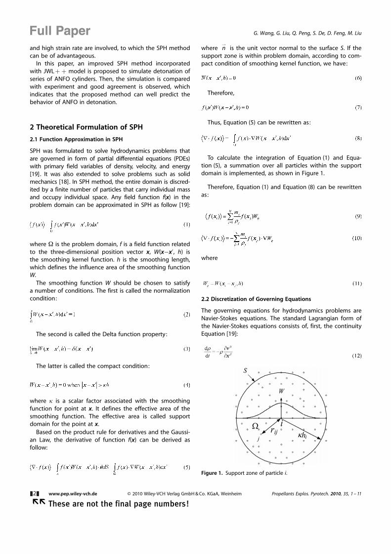
where W is the problem domain, f is a field function relatedto the three-dimensional position vector x, W(x�x’, h) isthe smoothing kernel function. h is the smoothing length,which defines the influence area of the smoothing functionW.
The smoothing function W should be chosen to satisfya number of conditions. The first is called the normalizationcondition:
The second is called the Delta function property:
The latter is called the compact condition:
where k is a scalar factor associated with the smoothingfunction for point at x. It defines the effective area of thesmoothing function. The effective area is called supportdomain for the point at x.
Based on the product rule for derivatives and the Gaussi-an Law, the derivative of function f(x) can be derived asfollow:
where n!
is the unit vector normal to the surface S. If thesupport zone is within problem domain, according to com-pact condition of smoothing kernel function, we have:
Therefore,
Thus, Equation (5) can be rewritten as:
To calculate the integration of Equation (1) and Equa-tion (5), a summation over all particles within the supportdomain is implemented, as shown in Figure 1.
Therefore, Equation (1) and Equation (8) can be rewrittenas:
where
2.2 Discretization of Governing Equations
The governing equations for hydrodynamics problems areNavier-Stokes equations. The standard Lagrangian form ofthe Navier-Stokes equations consists of, first, the continuityEquation [19]:
Figure 1. Support zone of particle i.
&2& www.pep.wiley-vch.de � 2010 Wiley-VCH Verlag GmbH & Co. KGaA, Weinheim Propellants Explos. Pyrotech. 2010, 35, 1 – 11
�� These are not the final page numbers!
Full Paper G. Wang, G. Liu, Q. Peng, S. De, D. Feng, M. Liu
Second, the momentum equation:
Third, the energy equation:
where 1 is the density, e is the internal energy, va is the ve-locity, and sa,b is the total stress tensor, which are all de-pendent variables. xa is the spatial coordinate and t is thetime, which are both independent variables. The totalstress tensor sa,b consists of two parts, one is the isotropicpressure p and the other is shear stress ta,b :
For the explosive gas, the viscous shear stress can be ne-glected compared with the isotropic pressure. For solid ma-terials, shear stress can be obtained from constitutive equa-tions of material.
By implementing the SPH method to approximate densi-ty of particle, an approach called continuity density is em-ployed. After manipulation, Equation (12) can be rewrittenas:
Similarly, Equation (13) and Equation (14) can be rewrit-ten as follows:
where ea,b is the strain rate tensor and P is the artificial vis-cosity.
2.3 Artificial Viscosity
In order to simulate the transformation of kinetic energy toheat energy across the shock wave front, Monaghan typeartificial viscosity Pij is introduced in the implementation ofSPH [19, 24–26], which can be written as:
where
where a and b are constants. f is used to prevent numeri-cal divergences between two particles, c and v representthe speed of sound and velocity of particle, respectively.The viscosity term associated with a produces a bulk vis-cosity, while the second term associated with b is intendedto suppress particle interpenetration at high Mach number.a, b, f is set to be 1, 1, and 0.1, respectively, in all our simu-lation.
2.4 Kernel Gradient Correction
To reduce particle inconsistency and improve SPH approxi-mation accuracy, a Kernel Gradient Correction (KGC)method is applied. It has been demonstrated that undercircumstances such as irregular particle distribution, varia-ble smoothing length, truncated boundary areas, the SPHmethod with KGC is of second-order accuracy [27].
The implementation of KGC method can be described asfollow: first, a local reversible matrix L(ri) is calculated usingTaylor series, then, the original kernel gradient is multipliedby L(ri) to obtain modified kernel gradient.
In the condition of three-dimensional simulation, themodified kernel gradient of smoothing function ri
CVij canbe calculated as follow:
where
Vj is the volume of particle j. xij, yij, and zij is given by:
Propellants Explos. Pyrotech. 2010, 35, 1 – 11 � 2010 Wiley-VCH Verlag GmbH & Co. KGaA, Weinheim www.pep.wiley-vch.de &3&
These are not the final page numbers! ��
3D Smoothed Particle Hydrodynamics Method for the Simulation of ANFO
2.5 Smoothing Length Update
The following method is used to update the smoothinglength of each particle during the implementation of SPHsimulation [28]:
where hin 1i
n are smoothing length and density of particlei at time step n. For convenience, Equation (21) can be fur-ther written in the form:
where vin and ri
nWij are velocity and kernel gradient of par-ticle i at time step n.
Thus, the smoothing length at the next step becomes:
3 Equations of State and ConstitutiveModeling
3.1 JWL + + Model
The JWL + + model is incorporated with our improved SPHcode to simulate ANFO. Compared with the standardJones-Wilkins-Lee (JWL) that uses a single Equation of state(EoS), JWL + + model introduces an extra EoS for unreact-ed explosive. It also allows the simulation of ignition, whichmeans that the explosive can be detonated by impact. Be-sides the extra EoS for unreacted explosive, JWL + + modelkeeps the standard JWL EoS for explosive products. TheJWL EoS is an empirical mathematical expression written interms of specific internal energy, pressure and specificvolume of explosive products [29–31]. It is used to calcu-late the pressure of explosive products as they expandfrom a certain high-pressure, high-density state after deto-nation to terminal state at normal pressure, and gaseousdensity. The JWL EoS works well for ideal explosive like TNT.JWL + + model is a simplified model that includes time-de-pendent chemical reaction, allowing the ignition as well asthe reaction process to be modeled. The JWL + + modelcan reproduce the size effect and detonation front curva-ture [9] . It mainly consists of the following parts:
First, the unreacted explosive is modelled using the Mur-nahan EoS:
where punreacted is the pressure of unreacted explosive, n andk are constants determined by experiment, u is the relativevolume, which is given by
The speed of sound for the Murnahan EoS is given by:
Second, the modified JWL EoS is used to describe explo-sive products:
where A, B, C, R1, R2, w are constants derived from experi-ments.
The speed of sound used in the JWL EoS is given by:
Third, a rule of mixture is used to combine these twoEoSs for intermediate stages of ANFO:
where F is the burn fraction, m is usually 1. Similarly, thespeed of sound is estimated using the same rule of mix-ture.
Finally, the reaction rate can be described using the fol-lowing formula,
where G is the rate constant, b is the power of the pressureand Q is the artificial viscosity, which is set to be 0 in allcases.
In the implementation of JWL + + model, the state of ex-plosive can be described by reaction progress that is be-tween 0 and 1. 0 represents unreacted solid explosive,1 represents the fully reacted explosive gas, and the
&4& www.pep.wiley-vch.de � 2010 Wiley-VCH Verlag GmbH & Co. KGaA, Weinheim Propellants Explos. Pyrotech. 2010, 35, 1 – 11
�� These are not the final page numbers!
Full Paper G. Wang, G. Liu, Q. Peng, S. De, D. Feng, M. Liu
number between 0 and 1 represents explosion products inthe mixing state.
4 Numerical Examples
In this section, a 3D simulation of detonation of ANFO cyl-inders, which is used to reproduce size effect, is implement-ed using our improved SPH code, and the results are com-pared with experiment.
4.1 Study on Size Effect
ANSYS� is used to generate the initial particles for our SPHcode. The process can be described as follow:
First, the 3D geometric domain is meshed using tetrahe-dron elements. Tetrahedron element is preferred becausethey can be automatically generated for any complex ge-ometry. Then, at the geometric center of each tetrahedron,a particle is generated, as shown in Figure 2. The elementedge length l of tetrahedron is used to control the totalnumber of particles used in the model.
Size effect is a typical characteristic of ANFO, whichrefers to the phenomenon that the detonation velocityvaries considerably with the diameter of ANFO cylinder. Inthis section, the detonation of six ANFO cylinders with di-ameters ranging from 77 mm to 153 mm is simulated, aslisted in Table 1. The density values of all ANFO are identi-cally set to be 880 kg m�3. The length-to-diameter (LD) ratioin all cases is 10.
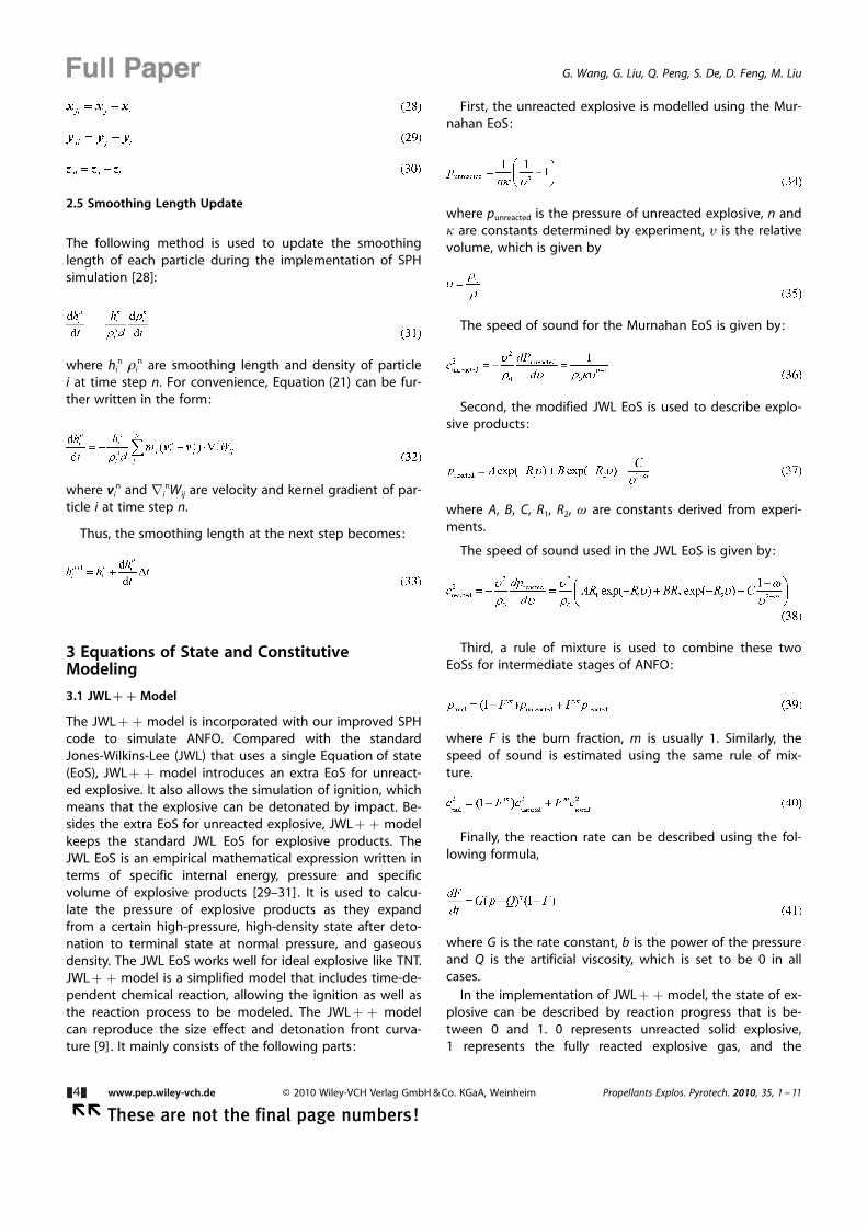
All cylinders are detonated by impacting from one end,as shown in Figure 3, where the vz of red particles is set tobe 500 m s�1. The instant detonation velocity is calculatedat each time step based on the location of detonationfront.
The unreacted explosive is described by the MurnahanEoS with parameters n = 7.4, k= 3.9 � 10�11 Pa�1 and 10 =1160.0 kg m�3. The explosive products is described bymodified JWL EoS with parameter A = 2.9867 � 1011 Pa, B =4.11706 � 109 Pa, C = 7.206147 � 108 Pa, R1 = 4.95, R2 = 1.15,w= 0.35, and 10 = 1160.0 kg m�3. The reaction rate is de-scribed by an Equation of reaction rate with parametersG = 3.5083 � 10�7 Pa�b, Q is 0, b = 1.3, and 10 =1160.0 kg m�3.
4.1.1 Influence of Element Edge Length
As mentioned in the previous section, the particles of the3D SPH models are generated through ANSYS. Elementedge length, which is used to control the average edgelength of tetrahedron element, is a fundamental parameterto determine the total number of ANFO models and fur-thermore, the accuracy of the SPH method.
According to Souers et al. [32], for JWL + + model, atleast 4 zones per mm are required for the simulation ofANFO. However, similar research has not been done for thesimulation of ANFO based on SPH method. Thus, in thissection, the influence of element edge length on simula-tion has been investigated.
Series of length are used to investigate the influence ofelement edge length, as shown in Table 2.
In SPH method, smoothing length is a vital parameterwhich determines the influence domain of each particle, asdescribed in the theoretical part in the previous section.Thus, it significantly influences the accuracy of SPH algo-rithm. An ill smoothing length can even cause failure of themethod. Thus, a tuned smoothing length is necessitated
Table 1. Detonation velocity of ANFO cylinders obtained from experiment [3].
Charge diameter Ø [mm] 77 90 102 115 128 153
Detonation velocity (experiment) D0 [m s�1] 1570.51 2467.95 2852.56 3108.97 3317.31 3621.79
Figure 2. Tetrahedron element and SPH particle. l is the elementedge length of the tetrahedron. The red dot is the SPH particle tobe generated.
Figure 3. 3D model of ANFO. The diameter is 77 mm. LD ratiois10. The initial vz of red particles is set to be 500 m s�1.
Propellants Explos. Pyrotech. 2010, 35, 1 – 11 � 2010 Wiley-VCH Verlag GmbH & Co. KGaA, Weinheim www.pep.wiley-vch.de &5&
These are not the final page numbers! ��
3D Smoothed Particle Hydrodynamics Method for the Simulation of ANFO
for each simulation based on SPH method. Herein, a param-eter called smoothing length coefficient is introduced, asshown in
where L is the initial smoothing length (since smoothinglength is updated at each time step, initial smoothinglength is only used at the beginning), l is the element edgelength, and a is the smoothing length coefficient.
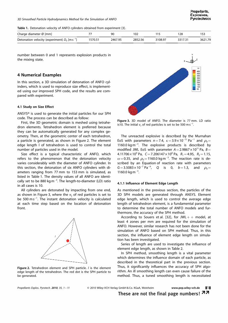
The simulation result is presented in Figure 4, where thediameter is 77 mm, length-to-diameter ratio is 10, elementedge length is 0.0109 mm, and smoothing length coeffi-cient is 1.065.
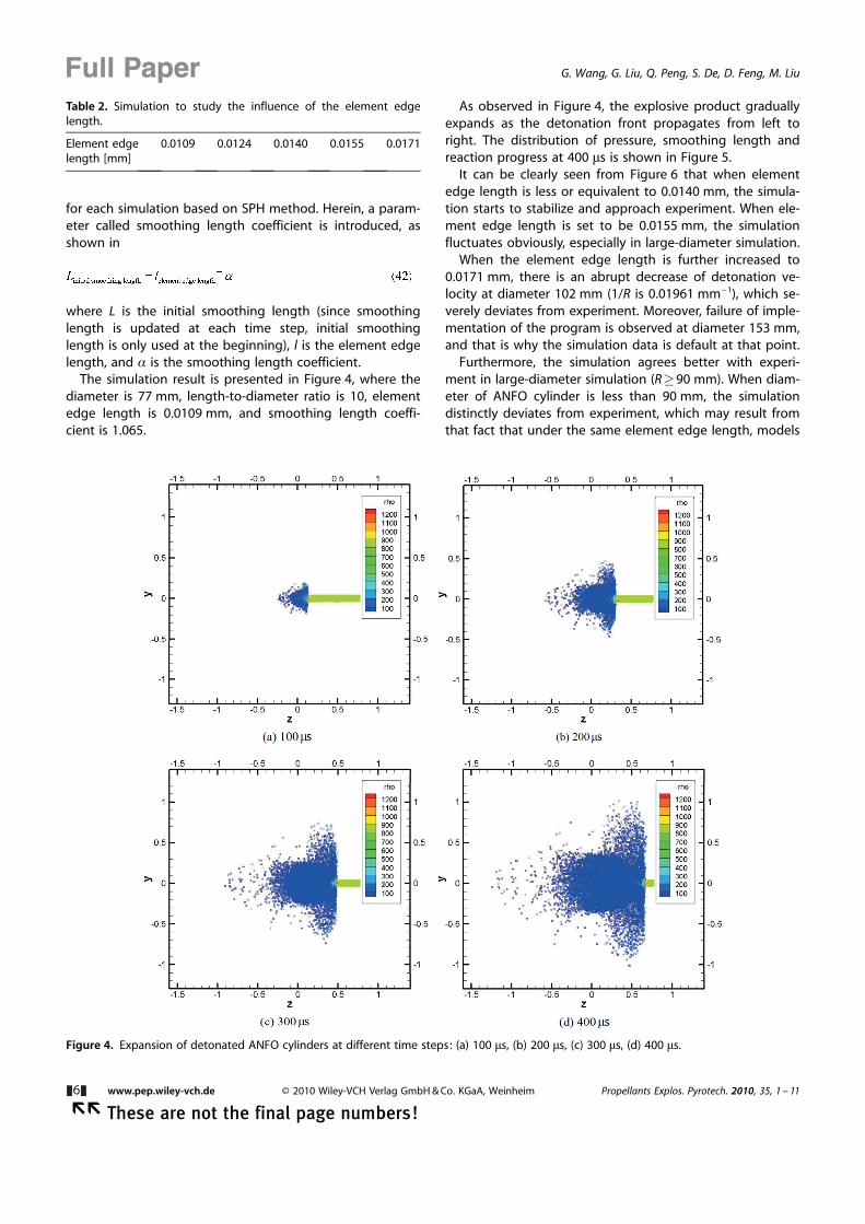
As observed in Figure 4, the explosive product graduallyexpands as the detonation front propagates from left toright. The distribution of pressure, smoothing length andreaction progress at 400 ms is shown in Figure 5.
It can be clearly seen from Figure 6 that when elementedge length is less or equivalent to 0.0140 mm, the simula-tion starts to stabilize and approach experiment. When ele-ment edge length is set to be 0.0155 mm, the simulationfluctuates obviously, especially in large-diameter simulation.
When the element edge length is further increased to0.0171 mm, there is an abrupt decrease of detonation ve-locity at diameter 102 mm (1/R is 0.01961 mm�1), which se-verely deviates from experiment. Moreover, failure of imple-mentation of the program is observed at diameter 153 mm,and that is why the simulation data is default at that point.
Furthermore, the simulation agrees better with experi-ment in large-diameter simulation (R�90 mm). When diam-eter of ANFO cylinder is less than 90 mm, the simulationdistinctly deviates from experiment, which may result fromthat fact that under the same element edge length, models
Figure 4. Expansion of detonated ANFO cylinders at different time steps: (a) 100 ms, (b) 200 ms, (c) 300 ms, (d) 400 ms.
Table 2. Simulation to study the influence of the element edgelength.
Element edgelength [mm]
0.0109 0.0124 0.0140 0.0155 0.0171
&6& www.pep.wiley-vch.de � 2010 Wiley-VCH Verlag GmbH & Co. KGaA, Weinheim Propellants Explos. Pyrotech. 2010, 35, 1 – 11
�� These are not the final page numbers!
Full Paper G. Wang, G. Liu, Q. Peng, S. De, D. Feng, M. Liu
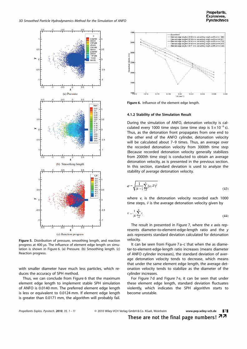
with smaller diameter have much less particles, which re-duces the accuracy of SPH method.
Thus, we can conclude from Figure 6 that the maximumelement edge length to implement stable SPH simulationof ANFO is 0.0140 mm. The preferred element edge lengthis less or equivalent to 0.0124 mm. If element edge lengthis greater than 0.0171 mm, the algorithm will probably fail.
4.1.2 Stability of the Simulation Result
During the simulation of ANFO, detonation velocity is cal-culated every 1000 time steps (one time step is 5 � 10�8 s).Thus, as the detonation front propagates from one end tothe other end of the ANFO cylinder, detonation velocitywill be calculated about 7–9 times. Thus, an average overthe recorded detonation velocity from 3000th time step(Because recorded detonation velocity generally stabilizesfrom 2000th time step) is conducted to obtain an averagedetonation velocity, as is presented in the previous section.In this section, standard deviation is used to analyze thestability of average detonation velocity.
where vi is the detonation velocity recorded each 1000time steps, n is the average detonation velocity given by
The result in presented in Figure 7, where the x axis rep-resents diameter-to-element-edge-length ratio and the yaxis represents standard deviation calculated for detonationvelocity.
It can be seen from Figure 7 a–c that when the as diame-ter-to-element-edge-length ratio increases (means diameterof ANFO cylinder increases), the standard deviation of aver-age detonation velocity tends to decrease, which meansthat under the same element edge length, the average det-onation velocity tends to stabilize as the diameter of thecylinder increases.
For Figure 7 d and Figure 7 e, it can be seen that underthese element edge length, standard deviation fluctuatesviolently, which indicates the SPH algorithm starts tobecome unstable.
Figure 5. Distribution of pressure, smoothing length, and reactionprogress at 400 ms. The influence of element edge length on simu-lation is shown in Figure 6. (a) Pressure. (b) Smoothing length. (c)Reaction progress.
Figure 6. Influence of the element edge length.
Propellants Explos. Pyrotech. 2010, 35, 1 – 11 � 2010 Wiley-VCH Verlag GmbH & Co. KGaA, Weinheim www.pep.wiley-vch.de &7&
These are not the final page numbers! ��
3D Smoothed Particle Hydrodynamics Method for the Simulation of ANFO
4.1.3 Influence of Smoothing Length on Simulation
In SPH method, smoothing length is a vital parameter todetermine the accuracy and performance of the algorithm.To investigate the influence of smoothing length, twosmoothing length is applied for each simulation, as shownin Table 3.
The simulation result is illustrated in Figure 8, where thex axis represents reverse of radius of ANFO cylinder and they axis represents detonation velocity.
According to Figure 8 a, b, c, when the smoothing lengthcoefficient increases, the detonation velocity decreases. ForFigure 8 d and e, since the algorithm starts to become un-stable, the influence of smoothing length coefficient onaverage detonation velocity is not clearly observed.
The influence of smoothing length coefficient on detona-tion velocity is shown in Table 4.
5 Conclusions
An improved SPH method incorporated with JWL + +model for 3D simulation of non-ideal ANFO is proposed. Aninnovative numerical technique, kernel gradient correction(KGC) method, is also applied to improve computational ac-curacy of the algorithm.
To validate the model, series of ANFO cylinders with di-ameters ranging from 77 mm to 153 mm are detonated.The detonation velocity is obtained and compared with ex-periment. The influence of element edge length on simula-tion was investigated and it is found that when elementedge length is less or equivalent to 0.0140 mm, the SPHmodel starts to stabilize and approach experiment. Other-wise, the SPH will fluctuate and become unstable. Theagreement between simulation and experiment is betterfor ANFO cylinders with larger diameter. We concluded that
Figure 7. Influence of the element edge length on stability ofANFO model. (a) Standard deviation of average detonation velocityfor element edge length 0.0109 mm. (b) Standard deviation ofaverage detonation velocity for element edge length 0.0124 mm.(c) Standard deviation of average detonation velocity for elementedge length 0.0140 mm. (d) Standard deviation of average detona-tion velocity for element edge length 0.0155 mm. (e) Standard de-viation of average detonation velocity for element edge length0.0171 mm.
Table 3. Simulation to study the influence of the smoothinglength coefficient.
Element edge length [mm] 0.0109 0.0124 0.0140 0.0155 0.0171
Smoothing length coeffi-cient a
1.18 0.968 0.837 0.636 0.514
1.065 0.871 0.753 0.572 0.463
&8& www.pep.wiley-vch.de � 2010 Wiley-VCH Verlag GmbH & Co. KGaA, Weinheim Propellants Explos. Pyrotech. 2010, 35, 1 – 11
�� These are not the final page numbers!
Full Paper G. Wang, G. Liu, Q. Peng, S. De, D. Feng, M. Liu
the proposed SPH model is sufficiently accurate and relia-ble to study the detonation of non-ideal high-explosiveANFO.
Acknowledgments
The work is mainly supported by the United States DoD (DTRA):Grant # HDTRA1-13-1-0025.The Ohio Supercomputer Center isgratefully acknowledged for providing the computation source.
References
[1] M. Short, T. R. Salyer, T. D. Aslam, C. B. Kiyanda, J. S. Morris, T.Zimmerly, Detonation Shock Dynamics Calibration for Noni-deal HE:ANFO, AIP Conf. Proc. 2009, 1195, 189–192.
[2] S. I. Jackson, C. B. Kiyanda, Experimental Observations of De-toantion in Ammonium-Nitrate-Fueloil (ANFO) Surrounded bya High-Sound-Speed, Shockless, Aluminum Confiner, Proc.Combust. Inst. 2011, 33, 2219 – 2226.
[3] J. B. Bdzil, T. D. Catanach, R. A. Hill, M. Short, R. A. Catanach,L. G. Hill, DSD Front Models: Non-Ideal Explosive Detonationin ANFO, 12th Symposium (International) on Detonation, SanDiego, CA, USA, August 11–16, 2002.
[4] L. L. Davis, L. G. Hill, ANFO Cylinder Test, 2002, 620, 165–168.[5] J. B. Bdzil, T. D. Aslam, R. A. Catanach, DSD Front Models: Non-
ideal Explosive Detonation in ANFO, 12th Symposium (Interna-tional) on Detonation, San Diego, CA, USA, August 11–16,2002.
[6] R. A. Borg, D. A. Jones, Numerical Simulation of ProjectileImpact Experiments Using the Forest Fire Reaction Rate Model,DSTO Publications, Canberra 1996.
Table 4. Influence of smoothing length coefficient on average det-onation velocity.
Diameter [mm]
77 90 102 115 128 153
Element edgelength [mm]0.0109 1.18 1605.5 1955.9 2335.1 2616.5 2879.6 3063
1.065 1764.5 2256.8 2541.9 2847.5 3088.7 3400.80.0124 0.968 1549.5 2057.6 2466.9 2770.3 3026.4 3354.5
0.871 1768.8 2353.3 2690.2 2984.8 3208.8 3529.60.0140 0.837 1585.2 2115.7 2534.2 2809.2 3031.9 3388.5
0.753 2020.9 2453.0 2716.0 3007.1 3220.6 3505.10.0155 0.636 1739.6 2308.8 2774.7 2983.8 3237.7 3521.5
0.572 1896.4 2413.9 2828.6 3216.5 3032.8 3655.40.0171 0.514 1844.0 2315.0 2422.2 1632.9 2682.8 3425.9
0.463 1894.9 2306.1 1424.6 2668.9 2950.2 defaultExperimentaldetonationvelocity[m s�1]
1570.5 2468.0 2852.6 3109.0 3317.3 3621.8
Figure 8. Influence of smoothing length coefficient on the averagedetonation velocity. (a) Element edge length 0.0109 mm. (b) Ele-ment edge length 0.0124 mm. (c) Element edge length 0.0140 mm.(d) Element edge length 0.0155 mm. (e) Element edge length0.0171 mm.
Propellants Explos. Pyrotech. 2010, 35, 1 – 11 � 2010 Wiley-VCH Verlag GmbH & Co. KGaA, Weinheim www.pep.wiley-vch.de &9&
These are not the final page numbers! ��
3D Smoothed Particle Hydrodynamics Method for the Simulation of ANFO
[7] A. K. Kapila, D. W. Schwendeman, J. B. Bdzil, W. D. Henshaw, AStudy of Detonation Diffraction in the Ignition-and-GrowthModel, Combust. Theor. Model. 2007, 11, 781 – 822.
[8] A. K. Kapila, D. W. Schwendeman. Numerical Studies of Deto-nation Diffraction Using the Ignition-and-Growth Model. 20thInternational Colloquium on Dynamics of Explosions and Reac-tive Systems, Montreal, Canada, October 20–22, 2005.
[9] P. C. Souers, S. Anderson, J. Mercer, E. McGuire, P. Vitello,JWL + + : A Simple Reactive Flow Code Package for Detona-tion, Propellants Explos. Pyrotech. 2000, 25, 54–58.
[10] C. M. Tarver, E. M. McGuire, Reactive Flow Modeling of the In-teraction of TATB Detonation Waves with Inert Materials, 12thSymposium (International) on Detonation, San Diego, CA, USA,August 11–16, 2002.
[11] M. L. Garcia, C. M. Tarver, Three Dimensional Ignition andGrowth Reactive Flow Modeling of Prism Faliure Tests on PBX9502, 13th Symposium (International) on Detonation, Norfolk,VA, USA, July 23–28, 2006.
[12] J. E. Guilkey, T. B. Harman, B. Banerjee, An Eulerian-LagrangianApproach for Simulating Explosions of Energetic Devices,Comput. Struct. 2007, 85, 660 – 674.
[13] K. H. Kim, J. J. Yoh, A Particle Level-Set Based Eulerian Methodfor Multi-material Detonation Simualtion of High Explosiveand Metal Confinements, Proc. Combust. Inst. 2013, 34, 2025 –2033.
[14] D. C. Sorescu, D. L. Thompson. Classical and Quantum Me-chanical Studies of Crystalline Ammonium Nitrate, J. Phys.Chem. A 2001, 105, 720 – 733.
[15] D. L. Robbins, S. A. Sheffield, D M Dattelbaum, N. Velisavljevic,D. B. Stahl, Equation of State of Ammonium Nitrate, ShockCompress. Condens. Matter 2009, 1195, 552 – 555.
[16] R. S. Chellappa, D. M. Dattelbaum, N. Velisavljevic, S. Sheffield,The Phase Diagram of Ammonium Nitrate, J. Chem. Phys.2012, 137, 064504.
[17] R. A. Gingold, J. J. Monaghan, Smoothed Particle Hydrodynam-ics – Theory and Application to Non-Spherical Stars, Mon. Not.R. Astron. Soc. 1977, 181, 375 – 389.
[18] L. B. Lucy, A Numerical Approach to the Testing of the FissionHypothesis, Astronomical J. 1977, 82, 1013 – 1024.
[19] G. R. Liu, M. B. Liu, Smoothed Particle Hydrodynamics: A Mesh-free Particle Method, World Scientific, Singapore, 2003.
[20] M. B. Liu, G. R. Liu, Z. Zong, K. Y. Lam, Computer Simulation ofHigh Explosive Explosion Using Smoothed Particle Hydrody-namics Methodology, Computer Fluids 2003, 32, 305 – 322.
[21] M. B. Liu, G. R. Liu, K. Y. Lam, Z. Zong, Smoothed Particle Hy-drodynamics for Numerical Simulation of Underwater Explo-sion, Comput. Mechanics 2003, 30, 106 – 118.
[22] M. B. Liu, G. R. Liu, K. Y. Lam, Z. Zong, Meshfree Particle Simu-lation of the Detonation Process for High Explosives inShaped Charge Unlined Cavity Configurations, Shock Waves2003, 12, 509 – 520.
[23] D. Feng, M. B. Liu, H. Li, G. R. Liu, Smoothed Particle Hydrody-namics Modeling of Linear Shaped Charge with Jet Formationand Penetration Effects, Computers Fluids 2013, 86, 77 – 85.
[24] J. J. Monaghan, R. A. Gingold, Shock Simualtion by the ParticleMethod SPH, J. Comput. Phys. 1983, 52, 374 – 389.
[25] J. J. Monaghan, J. Poinracic, Artificial Viscosity for ParticleMethods, Appl. Numer. Math. 1985, 1, 187 – 194.
[26] J. J. Monaghan, SPH Meets the Shocks of Noh, Monash Univer-sity, Monash, Western Australia, 1987.
[27] J. R. Shao, H. Q. Li, G. R. Liu, M. B. Liu, An Improved SPHMethod for Modeling Liquid Sloshing Dynamics, Comput.Struct. 2012, 100–101, 18 – 26.
[28] W. Benz, Smooth Particle Hydrodynamics: A Review, NATO ASISer. 1990, 302, 269–288.
[29] E. L. Lee, H. C. Hornig, J. W. Kury, Adiabatic Expansion of HighExplosive Detonation Products, University of California Liver-more, Lawrence Livermore Radiation Laboratory, Livermore,CA, USA, 1968.
[30] J. W. Kury, H. C. Hornig, E. L. Lee, Metal Acceleration by Chemi-cal Explosives, 4th Symposium (International) on Detonation,Silver Spring, MD, USA, October 12–15, 1965, p. 3–13.
[31] E. L. Lee, H. C. Hornig, Equation of State of Detoantion ProductGases, 12th International Symposium on Combustion, Poitiers,France, July 14–20, 1968, p. 493–499.
[32] P. C. Souers, R. Garza, P. Vitello, Ignition and Growth andJWL + + Detonation Models in Coarse Zones, PropellantsExplos. Pyrotech. 2002, 27, 62 – 71.
Received: October 12, 2014Revised: November 21, 2014
Published online: && &&, 0000
&10& www.pep.wiley-vch.de � 2010 Wiley-VCH Verlag GmbH & Co. KGaA, Weinheim Propellants Explos. Pyrotech. 2010, 35, 1 – 11
�� These are not the final page numbers!
Full Paper G. Wang, G. Liu, Q. Peng, S. De, D. Feng, M. Liu

FULL PAPERS
G. Wang,* G. Liu, Q. Peng, S. De,D. Feng, M. Liu
&& –&&
A 3D Smoothed ParticleHydrodynamics Method withReactive Flow Model for theSimulation of ANFO
Propellants Explos. Pyrotech. 2010, 35, 1 – 11 � 2010 Wiley-VCH Verlag GmbH & Co. KGaA, Weinheim www.pep.wiley-vch.de &11&
These are not the final page numbers! ��
3D Smoothed Particle Hydrodynamics Method for the Simulation of ANFO
Copyright © 2022 FDOKUMEN