780 User Guide - Quantum Data
338
780E Video Generator / Protocol Analyzer – User Guide Page 1 November 21, 2021 Revision B3 780E Video Generator / Protocol Analyzer for HDMI, DisplayPort & HDBaseT Testing User Guide Rev: B3
-
Upload
khangminh22 -
Category
Documents
-
view
0 -
download
0
Transcript of 780 User Guide - Quantum Data

780E Video Generator / Protocol Analyzer – User Guide Page 1
November 21, 2021 Revision B3
780E Video Generator / Protocol Analyzer
for HDMI, DisplayPort & HDBaseT Testing
User Guide
Rev: B3
780E Video Generator / Protocol Analyzer – User Guide Page 2
November 21, 2021 Revision B3
Table of Contents 1 Overview of the 780E Multi-Protocol Analyzer / Generator ............................................................................... 7
1.1 Scope of this User Guide ............................................................................................................................................. 7
1.2 Changes to this User Guide ......................................................................................................................................... 7
1.3 Introducing the 780E Multi-Protocol Analyzer / Generator for HDMI, DisplayPort and HDBaseT ............................... 7
1.4 Overview of 780E features ........................................................................................................................................... 9
1.4.1 Standard features ........................................................................................................................................................ 9
1.4.2 Network Analyzer features .......................................................................................................................................... 9
1.4.3 Cable and Repeater test features ............................................................................................................................. 10
1.4.4 Report File Creation feature ...................................................................................................................................... 10
1.4.5 Auto EDID Test ......................................................................................................................................................... 10
1.4.6 Auxiliary Channel Analyzer for HDMI/HDBaseT DDC (and DP Aux Chan) monitoring features ............................... 10
1.4.7 What is in the 780E shipping box .............................................................................................................................. 11
2 Physical Interfaces of the 780E Multi-Protocol Analyzer / Generator ............................................................ 12
2.1 Video Interfaces ......................................................................................................................................................... 12
2.2 Audio interfaces ......................................................................................................................................................... 13
2.3 Administrative Interface ............................................................................................................................................. 13
3 General Operation .............................................................................................................................................. 15
3.1 Power Considerations ................................................................................................................................................ 15
3.2 Tilt Bail ....................................................................................................................................................................... 15
3.3 Navigating through the 780E User Interface .............................................................................................................. 16
3.3.1 Home Menu items ..................................................................................................................................................... 16
3.3.2 Back Navigation ........................................................................................................................................................ 18
3.3.3 Status Bar .................................................................................................................................................................. 19
3.4 Calibrating the LCD .................................................................................................................................................... 21
4 Using the 780E Test Instrument to Video and Audio Pattern Tests on Sink Devices .................................. 23
4.1 Making Physical Connections .................................................................................................................................... 23
4.1.1 Connecting the 780E to the Display Device - HDMI .................................................................................................. 23
4.1.2 Connecting the 780E to the Display Device - HDBaseT ........................................................................................... 24
4.1.3 Connecting the 780E to the Display Device - DisplayPort ........................................................................................ 24
4.2 Selecting a Signal Type and Resolution .................................................................................................................... 25
4.2.1 Procedures for Selecting a Signal Type .................................................................................................................... 25
4.2.2 Procedures for Selecting an Resolution and Frame Rate ......................................................................................... 27
4.2.3 Procedures for Enabling AVMute .............................................................................................................................. 30
4.3 Rendering Test Patterns on an HDTV ....................................................................................................................... 31
4.3.1 Procedures for Outputting Test Patterns ................................................................................................................... 31
4.4 High Dynamic Range (HDR) Test Pattern Packs....................................................................................................... 42
4.4.1 Testing UHD Displays with HDR Lab Test Patterns .................................................................................................. 42
4.4.2 Testing With the Dolby Vision Test Pattern ............................................................................................................... 69
4.5 Using Custom Test Image Packs ............................................................................................................................... 73
4.6 Outputting 3D Test Patterns through HDMI or HDBaseT .......................................................................................... 79
4.6.1 Configurations for Rendering 3D Bitmaps on an HDMI or HDBaseT Sink Device .................................................... 79
4.6.2 Procedures for Obtaining 3D Bitmaps on HDMI or HDBaseT Sink Device ............................................................... 80
4.6.3 Procedures for Rendering 3D Bitmaps or 3D Test Patterns on HDMI or HDBaseT Sink Device ............................. 80
4.7 How to Scroll or Pan a Bitmap Pattern ...................................................................................................................... 83
4.7.1 Guidelines for Scrolling Bitmaps ............................................................................................................................... 83
4.7.2 Procedures for Scrolling Bitmaps .............................................................................................................................. 83

780E Video Generator / Protocol Analyzer – User Guide Page 3
November 21, 2021 Revision B3
4.7.3 Procedures for Panning Bitmaps ............................................................................................................................... 84
4.8 Testing Digital Audio on an HDTV or A/V Receiver ................................................................................................... 87
4.8.1 Connecting the 780E to an Audio Rendering Device ................................................................................................ 87
4.8.2 Procedures for Testing a Sink with Dolby Digital or DTS Audio Test Patterns ......................................................... 89
4.8.3 Procedures for Testing a Display with Dolby Digital or DTS Sine Wave Clips .......................................................... 93
4.8.4 Procedures for Testing with Programmable Sine Waves .......................................................................................... 95
5 Using the 780E Test Instrument to Test HDMI and HDBaseT Protocols on Sink Devices ........................... 99
5.1 Testing HDCP on an HDMI, HDBaseT or DisplayPort HDTV, Projector or Repeater Device ................................... 99
5.1.1 Configurations for Testing HDCP on an HDMI Sink Device ...................................................................................... 99
5.1.2 Configurations for Testing HDCP on an HDBaseT Sink Device ............................................................................. 100
5.1.3 Configurations for Testing HDCP on a DisplayPort Monitor .................................................................................... 100
5.1.4 Procedures for Testing HDCP on an HDMI, HDBaseT or DisplayPort Sink Device ............................................... 100
5.2 Verifying the EDID on an HDMI, HDTV, HDBaseT Projector or HDMI Repeater Device ....................................... 104
5.2.1 Configurations for Verifying and Viewing the EDID on an HDMI Sink Device ......................................................... 104
5.2.2 Configurations for Verifying and Viewing the EDID on an HDBaseT Sink Device or Input of an HDBaseT Distribution Device .............................................................................................................................................................. 105
5.2.3 Configurations for Verifying and Viewing the EDID on a DisplayPort Monitor ........................................................ 105
5.2.4 Procedures for Testing and Viewing the EDID on an HDMI, HDBaseT or DisplayPort Sink Device ...................... 106
5.2.5 Workflow for Comparing EDIDs .............................................................................................................................. 110
5.2.6 Procedures for Comparing EDIDs ........................................................................................................................... 111
5.3 Verifying the EDID of a High Dynamic Range (HDR)-Capable HDMI UHDTV ........................................................ 114
5.3.1 Configurations for Verifying HDR EDID on an HDMI UHD TV ................................................................................ 114
5.3.2 Procedures for Verifying HDR EDID on an HDMI UHD TV ..................................................................................... 114
5.4 Viewing the CEC devices on an HDMI/HDBaseT network ...................................................................................... 117
5.4.1 Configurations for Testing CEC on an HDMI/HDBaseT Sink Device ...................................................................... 117
5.4.2 Procedures for Testing CEC on an HDMI/HDBaseT Sink Device ........................................................................... 118
5.5 DisplayPort Link Training Testing on a DisplayPort Sink ......................................................................................... 119
5.5.1 Configurations for running Link Training tests on a DisplayPort Sink Device ......................................................... 119
5.5.2 Procedures for running Link Training tests on a DisplayPort Sink Device .............................................................. 120
5.6 Multi-protocol (HDCP, EDID and CEC) testing on an HDMI or HDBaseT HDTV, Projector or Monitor ................... 125
5.6.1 Configurations for running multi-protocol tests on an HDMI Sink Device ................................................................ 125
5.6.2 Configurations for running multi-protocol tests on an HDBaseT Sink Device ......................................................... 125
5.6.3 Procedures for running multi-protocol tests on an HDMI or HDBaseT Sink Device ................................................ 125
6 Using the 780E Test Instrument to Test HDMI or HDBaseT Source Devices .............................................. 129
6.1 Testing Video from an HDMI, HDBaseT or DisplayPort Source Device .................................................................. 129
6.1.1 Connection Configurations for Testing HDMI Source Devices ................................................................................ 129
6.1.2 Connection Configurations for Testing HDBaseT Outputs on Repeater and Distribution Devices ......................... 130
6.1.3 Connection Configurations for Testing DisplayPort Source Devices ...................................................................... 131
6.1.4 Procedures for Viewing Video on an HDMI, HDBaseT or DisplayPort Source Device ........................................... 131
6.1.5 Viewing Video Metadata from an HDMI, HDBaseT or DisplayPort Source Device ................................................. 138
6.2 Viewing Source Data Island Packets on HDMI and HDBaseT ................................................................................ 145
6.2.1 Configurations for Viewing the Data Island Packets from an HDMI or HDBaseT Source Device ........................... 145
6.2.2 Procedures for Viewing the HDMI/HDBaseT Data Island Packets from a Source Device ...................................... 145
6.3 Testing HDCP Max Devices on an HDMI Source Devices and Outputs of HDBaseT distribution Devices ............. 149
6.3.1 Configurations for Testing Max Devices an HDMI Source Device Supports ........................................................... 149
6.3.2 Procedures for disabling HDCP on the 780E HDMI/HDBaseT Out Port - GUI ....................................................... 153
6.3.3 Procedures for disabling HDCP on the 780E out port – Command Line ................................................................ 154

780E Video Generator / Protocol Analyzer – User Guide Page 4
November 21, 2021 Revision B3
6.4 Testing Audio of an HDMI or DisplayPort Source Device or at the Output of an HDBaseT Distribution Device ..... 154
6.4.1 Configurations for Testing Audio on an HDMI Source Device ................................................................................ 154
6.4.2 Configurations for Testing Audio on the Output of an HDBaseT Distribution Device .............................................. 155
6.4.3 Configurations for Testing Audio on the Output of a DisplayPort Source Device ................................................... 156
6.4.4 Procedures for Testing Audio from an HDMI, HDBaseT DisplayPort Source Device ............................................. 157
6.4.5 Procedures for Audible Monitoring of LPCM Audio from an Digital Video Source Device ...................................... 164
6.5 Testing an HDMI, HDBaseT or DisplayPort Source’s Response to EDIDs ............................................................. 170
6.5.1 Configurations for Testing an HDMI Source Devices Response to an EDID .......................................................... 170
6.5.2 Configurations for Testing an HDBaseT Device’s Output Response to an EDID ................................................... 170
6.5.3 Configurations for Testing DisplayPort Device’s Output Response to an EDID ...................................................... 171
6.5.4 Procedures for Testing an HDMI, HDBaseT or DisplayPort Source Devices Response to an EDID ...................... 171
7 Using the 780E Test Instrument Installer Test Utility .................................................................................... 180
7.1 Diagnosing HDMI and HDBaseT Interoperability Problems toward the Source - Upstream ................................... 181
7.1.1 Connection Configurations for Testing HDMI Source Devices ................................................................................ 181
7.1.2 Connection Configurations for Testing HDBaseT Source Devices ......................................................................... 182
7.1.3 Procedures for Testing Upstream (Source Test) with the Installer Utility ................................................................ 182
7.2 Diagnosing HDMI and HDBaseT Interoperability Problems at the Sink - Downstream ........................................... 186
7.2.1 Connection Configurations for Testing HDMI Sink Devices .................................................................................... 186
7.2.2 Connection Configurations for Testing HDBaseT Sink Devices .............................................................................. 186
7.2.3 Connection Configurations for Testing DisplayPort Sink Devices ........................................................................... 187
7.2.4 Procedures for Testing Downstream (Sink Test) with the Installer Utility ................................................................ 187
7.3 Diagnosing HDMI/HDBaseT Interoperability Problems with a Repeater ................................................................. 190
7.3.1 Connection Configurations for Testing HDMI Repeater Devices ............................................................................ 190
7.3.2 Connection Configurations for Testing HDBaseT Repeater Devices ...................................................................... 191
7.3.3 Procedures for Testing Repeaters (Repeater Test) with the Installer Utility ........................................................... 191
7.4 Diagnosing HDMI/HDBaseT Interoperability Problems in an HDMI/HDBaseT Network .......................................... 194
7.4.1 Connection Configurations for Testing HDMI Links ................................................................................................ 195
7.4.2 Connection Configurations for Testing HDBaseT Links .......................................................................................... 195
7.4.3 Procedures for Testing HDMI Networks (Links) with the Installer Utility ................................................................. 195
8 Using the 780E to Monitor the HDMI/HDBaseT DDC, CEC and DisplayPort Aux Channel ......................... 199
8.1 Auxiliary Channel Analyzer (ACA) Transactions ...................................................................................................... 199
8.2 Auxiliary Channel Analyzer – Emulation Monitoring of DDC on an HDMI or HDBaseT Sink ................................... 201
8.2.1 Configurations for Monitoring DDC Transactions with ACA on HDMI Sink Devices ............................................... 201
8.2.2 Configurations for Monitoring DDC Transactions with ACA on HDBaseT Sink Devices ......................................... 202
8.2.3 Monitoring DDC Transactions with ACA on HDMI or HDBaseT Sink Devices ........................................................ 203
8.2.4 Configurations for Monitoring DDC Transactions with ACA on HDMI Source Devices ........................................... 207
8.2.5 Configurations for Monitoring DDC Transactions with ACA on HDBaseT Source Devices .................................... 207
8.2.6 Procedures for Monitoring the DDC Transactions using the Auxiliary Channel Analyzer on HDMI or HDBaseT Source Devices .................................................................................................................................................................. 208
8.3 Configuration for Monitoring DDC Transactions with the ACA on an HDMI or HDBaseT Repeater or distribution device ............................................................................................................................................................................ 212
8.3.1 Procedures for Running an Auxiliary Channel Analyzer Test on HDMI/HDBaseT Repeater or Distribution Devices .................................................................................................................................................................... 213
8.4 Auxiliary Channel Analyzer – Passive Monitoring HDMI.......................................................................................... 219
8.4.1 Configurations for Passively Monitoring CEC and or DDC Transactions with ACA on an HDMI System ............... 219
8.4.2 Procedures for Passive Monitoring DDC transactions and hot plug events with the Auxiliary Channel Analyzer on HDMI Devices .................................................................................................................................................... 219
8.5 Auxiliary Channel Analyzer – Monitoring of CEC Messages ................................................................................... 225

780E Video Generator / Protocol Analyzer – User Guide Page 5
November 21, 2021 Revision B3
8.5.1 Procedures for Passive Monitoring HDMI CEC messages with the Auxiliary Channel Analyzer ............................ 225
8.6 Auxiliary Channel Analyzer – Emulation Monitoring of Aux Channel on a DisplayPort Sink ................................... 229
8.6.1 Configurations for Monitoring Aux Chan Transactions with ACA on DisplayPort Sink Devices .............................. 229
8.6.2 Monitoring Aux Chan Transactions with ACA on DisplayPort Sink Devices ........................................................... 229
8.6.3 Configurations for Monitoring Aux Chan Transactions with ACA on DisplayPort Source Devices ......................... 234
8.6.4 Procedures for Monitoring the Aux Chan Transactions using the Auxiliary Channel Analyzer on DisplayPort Source Devices ....................................................................................................................................................... 234
8.7 Auxiliary Channel Analyzer – Passive Monitoring DisplayPort ................................................................................ 240
8.7.1 Configurations for Passively Monitoring Aux Channel Transactions with ACA on DisplayPort Devices ................. 240
8.7.2 Procedures for Passive Monitoring Aux Channel transactions and hot plug events with the Auxiliary Channel Analyzer on DisplayPort Devices ............................................................................................................................ 240
9 Using the 780E Test Instrument to Test Cable or Repeaters ........................................................................ 247
9.1 HDMI/HDBaseT Cable or Repeater Test ................................................................................................................. 247
9.1.1 Configurations for Running an HDMI/HDBaseT Cable or Repeater Test ............................................................... 247
9.1.2 Procedures for Running an HDMI/HDBaseT Cable or Network (“Repeater”) Test ................................................. 249
9.2 DisplayPort Cable or Repeater Test ........................................................................................................................ 252
9.2.1 Configurations for Running an DisplayPort Cable or Repeater Test ....................................................................... 252
9.2.2 Procedures for Running a DisplayPort Cable or Network (“Repeater”) Test ........................................................... 253
9.3 Frame Compare Test ............................................................................................................................................... 255
9.3.1 Configuration for Running a Frame Compare Test ................................................................................................. 255
9.3.2 Procedures for Running the Frame Compare Test ................................................................................................. 255
9.3.3 Procedures for Running the Remote PRN Test ...................................................................................................... 257
9.4 HDBaseT Remote Cable Test ................................................................................................................................. 259
9.4.1 Configuration for Running an HDBaseT Remote Cable Test .................................................................................. 259
9.4.2 Procedures for Running the HDBaseT Remote Cable Test .................................................................................... 259
10 Generating Reports with the Reports File Creation Feature ......................................................................... 263
10.1 Report File Creation Feature Description ................................................................................................................ 263
10.2 Procedures for creating reports ............................................................................................................................... 263
10.2.1 Creating a report for source testing ......................................................................................................................... 263
10.3 Procedures for Accessing Reports .......................................................................................................................... 270
11 Running the Automated EDID Tests on HDMI Source Devices .................................................................... 276
11.1 HDMI Auto EDID Test .............................................................................................................................................. 276
11.1.1 Procedures for Configuring a Set of EDIDs for the Auto EDID Test ....................................................................... 276
11.1.2 Configurations for Running an Auto EDID Test ....................................................................................................... 278
11.1.3 Procedures for Running the Auto EDID Test .......................................................................................................... 279
11.1.4 Viewing the Auto-EDID Test report. ........................................................................................................................ 283
12 Creating and Using Custom Formats, EDIDs, Bitmaps and Menus ............................................................. 285
12.1 Creating and Using Custom Formats ....................................................................................................................... 285
12.1.1 Workflow for Using Custom Formats ....................................................................................................................... 285
12.1.2 Procedures for Creating and Loading Custom Formats .......................................................................................... 285
12.2 Adding Reference EDIDs for Use in Testing HDMI Devices .................................................................................... 289
12.2.1 Workflow for Importing EDIDs into the 780E ........................................................................................................... 289
12.2.2 Procedures for Importing EDIDs into the 780E ....................................................................................................... 289
12.2.3 Procedures for Saving an EDID into the 780E ........................................................................................................ 291
12.3 Using Custom Bitmaps ............................................................................................................................................ 294
12.3.1 Workflow for Importing Bitmaps .............................................................................................................................. 294
12.3.2 Workflow for loading bitmaps from the SD card ...................................................................................................... 294

780E Video Generator / Protocol Analyzer – User Guide Page 6
November 21, 2021 Revision B3
12.3.3 Procedures for Importing Bitmaps ........................................................................................................................... 294
12.3.4 Procedures for Loading Bitmaps from SD Card ...................................................................................................... 297
12.4 Creating Custom Menus .......................................................................................................................................... 298
12.4.1 To create a custom menu: ....................................................................................................................................... 299
12.4.2 To access custom menus: ....................................................................................................................................... 299
13 Command Interface .......................................................................................................................................... 302
13.1 Guidelines for Using the Command Line ................................................................................................................. 302
13.2 Procedures for Enabling the Command Line Interface through USB Port ............................................................... 302
13.3 Procedures for using the Command Line Interface through RS-232 Port (780E only) ......................................... 304
13.4 Procedures for Entering Commands ........................................................................................................................ 305
14 Using the Keypad ............................................................................................................................................. 327
14.1 Connecting a Keypad ............................................................................................................................................... 327
14.2 Enabling and Configuring an RS-232 Keypad ......................................................................................................... 327
14.3 Keypad Functionality ................................................................................................................................................ 328
14.4 Selecting a Format (Timing) ..................................................................................................................................... 329
14.5 Selecting a Test Pattern (Image) ............................................................................................................................. 331
14.6 Programming a Test Sequence using the keypad ................................................................................................... 332
14.7 Programming a Test Sequence in the UserKeys file ............................................................................................... 333
15 Upgrading the 780E .......................................................................................................................................... 335
15.1 Upgrading the Firmware and Gateware on your 780E Handheld Test Instrument for HDMI ................................ 335
780E Video Generator / Protocol Analyzer – User Guide Page 7
November 21, 2021 Revision B3
1 Overview of the 780E Video Generator / Protocol Analyzer
This section provides an overview of the 780E Multi-Protocol Analyzer / Generator. The 780E is equipped with the following digital video test interfaces:
• HDMI Tx and Rx ports operating up to 600MHz pixel and TMDS rate.
• HDBaseT Tx and Rx ports operating up to 300MHz pixel rate.
• DisplayPort Tx and Rx ports operating at link rates up to 5.4Gb/s.
• HDMI Tx and Rx auxiliary monitoring ports for passive monitoring the DDC channel, CEC bus and the connection detection leads.
• DisplayPort Tx and Rx auxiliary monitoring ports for passive monitoring the Aux Channel including link training.
The 780E instrument also offers SPDIF and optical digital audio interfaces.
Important Note: The 780E model name has been changed to: 780E Video Generator / Protocol Analyzer for HDMI, DisplayPort & Testing
1.1 Scope of this User Guide
This User Guide documents the complete operation of the 780E Video Generator / Protocol Analyzer.
Note: Please be sure to check the quantumdata website for updates to this User Guide.
1.2 Changes to this User Guide
This User Guide has been updated to include information related to the following features:
• HDBaseT Remote Cable test feature.
• Support for HDMI deep color on formats with pixel rates above: 300MHz for 10bit, 12 bit and 16bit (up to 300MHz).
• Additional information on the HDCP 2.2 sink test screen.
• Additional timings for 21:9 formats.
• New command TMAX:NBPC to read incoming bits per component.
• New command DIDQ? to view the list of EDIDs stored in the 780E.
• Added support for spread spectrum clock control on DisplayPort Link Training control screen.
• Additional information on the DisplayPort Rx selection menu.
• Added HLG EDID and InfoFrame support
• New command FMTL VIC to set the format using the VIC code.
• Added frame count selection on the Frame Compare test
• New command DPRX:DPCD to query the DisplayPort DPCD and DPTX:LPQM.
1.3 Introducing the 780E Video Generator / Protocol Analyzer
for HDMI, DisplayPort and HDBaseT
The 780E Video Generator / Protocol Analyzer is a portable multimedia pattern generator that enables you to conduct quick, on-site verification testing of your HDMI, DisplayPort and HDBaseT sources, displays and distribution networks. The 780E is equipped with both reference source and reference sink HDMI, DisplayPort and HDBaseT interfaces allowing you to test audio, video and protocols—HDCP, EDID, Aux Channel link training (DisplayPort) CEC & infoframes—of any type of HDMI, DisplayPort or HDBaseT device: sources, repeaters and sinks. Because the 780E has both a digital video outputs and inputs, you can test cables and

780E Video Generator / Protocol Analyzer – User Guide Page 8
November 21, 2021 Revision B3
systems with splitters, extenders and switches as well with the optional pixel error test feature. You can also test hybrid digital video systems comprised of HDMI, DisplayPort and HDBaseT devices.
A color touch display makes the 780E easy and convenient to use. When testing a digital video source device you can toggle between operating the unit through the touch screen and viewing the incoming video from the source.
Note: 780E Image above shows the front edge with the SD card slot which is used for storing and loading bitmaps, reports and for recovery in the event of a failed upgrade.

780E Video Generator / Protocol Analyzer – User Guide Page 9
November 21, 2021 Revision B3
1.4 Overview of 780E features
The 780E Multi-Protocol Analyzer / Generator provides a rich set of features. The following is a list of available options and the key features and benefits of each:
1.4.1 Standard features
The following features are standard with the 780E:
• Pattern testing for HDTVs - Enables you to conduct pattern testing for an HDTV through the digital video and analog component outputs. Provides dozens of patterns with variation options on most.
• Custom bitmaps and pattern scrolling – The 780E enables you to import bitmaps for use in pattern testing. You can initiate a scroll of these bitmaps with user control over the rate and extent of horizontal movement.
• Create custom formats using the standalone Format Editor.
• 3D bitmap pattern testing – The 780E enables you to import 3D bitmaps for use in pattern testing. You can create your own bitmaps from any stereoscopic images you have using the Quantum Data Bitmap Conversion Tool available from the quantumdata website: http://www.quantumdata.com/apps/3D/BMP_conv.asp. There are some sample 3D bitmaps on this webpage as well.
• Video confidence test of an HDMI, DisplayPort or HDBaseT source device – The 780E enables you to view the incoming video on the 780E’s LCD screen.
• 780E also enables scrolling to view an entire unscaled 4K image received on the HDMI, DisplayPort and HDBaseT input ports.
• Audio confidence test of an HDMI, DisplayPort and HDBaseT source device – The 780E enables you to listen to the incoming LPCM audio through the 780E’s headphone jack on the front edge or through an embedded speaker. There will be no sound when compressed audio is received on the incoming stream.
• Audio testing for AVRs and HDTVs – The 780E provides multi-channel digital audio test patterns through the HDMI, HDBaseT, DisplayPort, SPDIF and optical outputs. A variety of audio patterns and formats are provided at sampling rates from 32kHz up to 192kHz and bit depths of 16, 20 and 24. Format supported are Dolby Digital and DTS compressed formats and lossless compressed or high bit rate HDMI formats.
• Installer Utility – Provides simplified diagnostics of HDMI, DisplayPort (Sink Test only) and HDBaseT interoperability problems in an installation. The Installer utility enables installers to connect the 780E into an HDMI/HDBaseT network and quickly conduct diagnostics without required detailed knowledge of protocols.
• Command line interface for automated testing.
1.4.2 Network Analyzer features
The following Network Analyzer features are available:
• HDCP test of an HDMI, DisplayPort or HDBaseT sink or input to a repeater device – The 780E enables you to run an HDCP (1.x or 2.2) functional test on an HDMI, DisplayPort or HDBaseT sink device directly or through a repeater device.
• EDID test of an HDMI, DisplayPort or HDBaseT HDTV, monitor, projector or input to a repeater device – The 780E enables you to run an EDID functional test on an HDMI, DisplayPort or HDBaseT sink device directly or through a repeater device. You can view the entire EDID in human readable text. You can also run a portion of EDID compliance test.
• DisplayPort Link Training test on sink – Run a link training test on a DisplayPort sink device. Use link training values from sink or force link train with specific values for link rate, number of lanes, pre-emphasis, voltage swing.
• Video test of an HDMI, DisplayPort or HDBaseT source device – The 780E provides HDMI, DisplayPort and HDBaseT inputs for testing HDMI, DisplayPort or HDBaseT source devices and entire upstream networks. You can run a verification test of a video source which includes timing and format information and an indication of whether the video is HDCP content protected.

780E Video Generator / Protocol Analyzer – User Guide Page 10
November 21, 2021 Revision B3
• Data Island test of an HDMI or HDBaseT source device – The 780E provides an HDMI/HDBaseT input for testing HDMI or HDBaseT source devices. You can view the infoframes and other data islands.
• Audio test of an HDMI, DisplayPort or HDBaseT source device – The 780E provides HDMI, DisplayPort or HDBaseT inputs for testing source devices. You can run a verification test of an audio source which includes decoding of the audio IEC headers, audio infoframes and audio sample packet headers (for HDMI and HDBaseT and parsing out of the channel status bits as well.
• EDID test of HDMI, DisplayPort or HDBaseT source device or outputs – The 780E’s HDMI, DisplayPort or HDBaseT input ports can be provisioned with any EDID you have access to. You can verify that a source device responds properly to the provisioned EDID. The EDID could be a known-good EDID or an EDID that you have created specifically for testing.
• HDCP test of an HDMI, DisplayPort or HDBaseT source device – The 780E enables you to run a test to determine how many HDCP devices an HDMI, DisplayPort or HDBaseT source can support during HDCP authentication. The HDMI and DisplayPort interfaces emulate 1.x and 2.2 HDCP capable displays.
• CEC ping test of any HDMI device – The 780E enables you to run a CEC ping test on an HDMI device.
1.4.3 Cable and Repeater test features
The following features are available with the Cable and Repeater test option:
• Cable & Repeater test – Because the 780E has both digital video inputs and outputs, you can loop a cable or entire distribution networks comprised of splitters, extenders, repeaters, switches, even hybrid networks with HDMI, DisplayPort or HDBaseT components, from the 780E’s output to input and run a pseudo-random noise pattern test to determine pixel errors on the TMDS lines. The feature also runs a continuity test on the HDMI, DisplayPort or HDBaseT DDC, Aux Chan (DP) test pair, CEC bus, the +5V line and the hot plug lead. The Repeater test also shows you the hot plug delay between the downstream side and the upstream side and the pulse width. The Cable & Repeater Test enable you to test a cable, repeater or distribution network if the source and sink ends are collocated. If the source and sink ends are not collocated then you need to use the Frame Compare test.
1.4.4 Report File Creation feature
The following features are available with the Report File Creation option:
• Enables residential installers, proAV integrators and test engineers in R&D to produce a record of the tests they perform. Reports can be run on HDCP, Format Analyzer, Audio Analyzer, Cable tests, auxiliary channel analyzer tests for any interface (HDMI, HDBaseT or DisplayPort). The reports can be provided to customers, colleagues or to the contracting agent to verify and demonstrate project completion. The reports can be run on a single test or aggregated for a series of tests. The reports can be transferred by SD card or the USB interface and viewed in a standard browser or any text editor.
1.4.5 Auto EDID Test
The following features are available with the Auto EDID test option:
• Select a series of EDIDs to test a source’s handling of them.
• Emulate the EDIDs on the 780E HDMI, DisplayPort or HDBaseT Input port.
• Test runs automatically and flags improper handling. Checks for proper VIC, timing, video type, color depth and sampling mode.
1.4.6 Auxiliary Channel Analyzer for HDMI/HDBaseT DDC (and DP Aux Chan) monitoring features
The following features are available with the Auxiliary Channel Analyzer test options:
• DDC (and DP Aux Chan) monitoring with Auxiliary Channel Analyzer (ACA) – The 780E ACA enables you to monitor HDMI or HDBaseT CEC message and DDC transactions such as HDCP and EDID as well as hot plug related events while emulating an HDMI or HDBaseT source and/or an HDMI or HDBaseT sink device(s) in a system. You can also monitor passively between two HDMI/HDBaseT devices. When
780E Video Generator / Protocol Analyzer – User Guide Page 11
November 21, 2021 Revision B3
monitoring passively you can also view the +5V status. The ACA feature also enables you to monitor the DP Aux Channel transactions such as the Link Training exchanges.
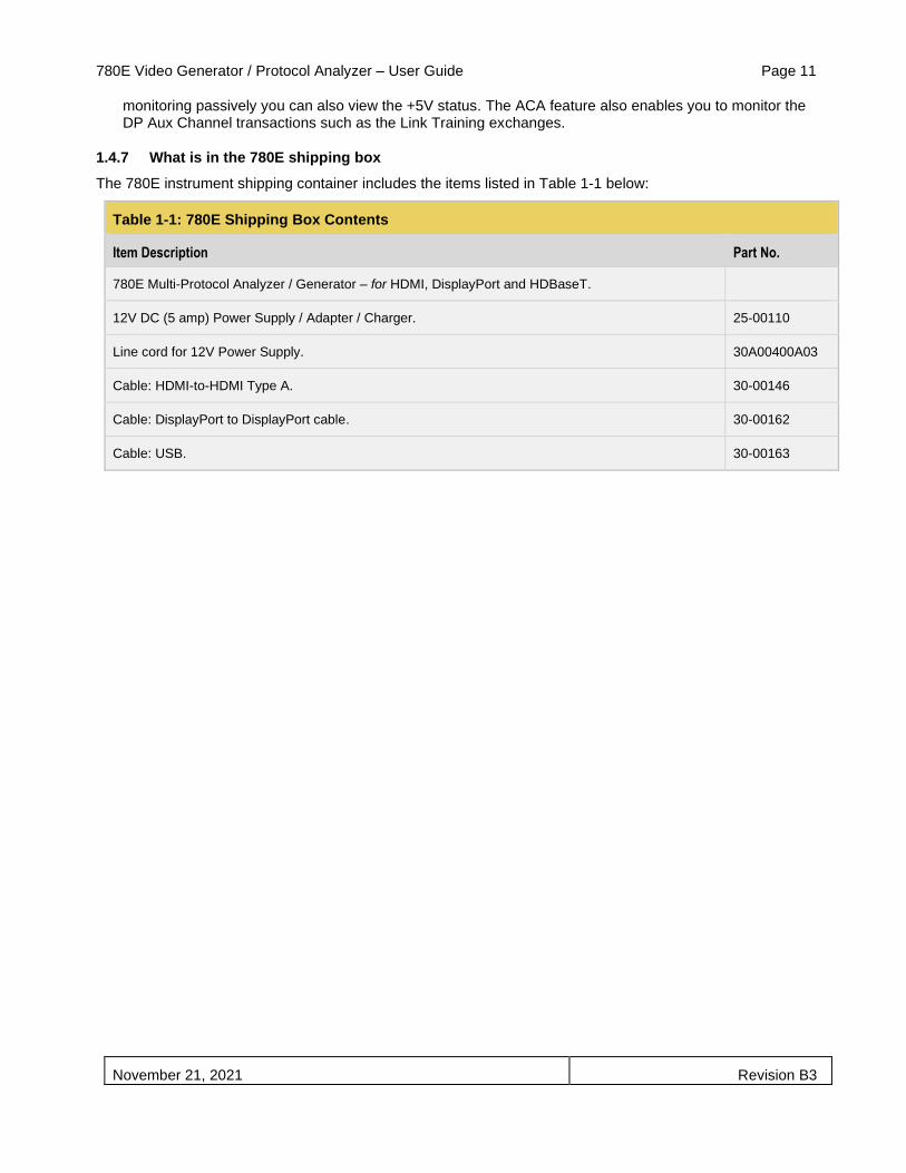
1.4.7 What is in the 780E shipping box
The 780E instrument shipping container includes the items listed in Table 1-1 below:
Table 1-1: 780E Shipping Box Contents
Item Description Part No.
780E Multi-Protocol Analyzer / Generator – for HDMI, DisplayPort and HDBaseT.
12V DC (5 amp) Power Supply / Adapter / Charger. 25-00110
Line cord for 12V Power Supply. 30A00400A03
Cable: HDMI-to-HDMI Type A. 30-00146
Cable: DisplayPort to DisplayPort cable. 30-00162
Cable: USB. 30-00163

780E Video Generator / Protocol Analyzer – User Guide Page 12
November 21, 2021 Revision B3
2 Physical Interfaces of the 780E Multi-Protocol Analyzer / Generator
This section describes the administration, video and audio interfaces on the 780E test instrument:
2.1 Video Interfaces
Table 2-1 below describes the video interfaces on the 780E test instrument, these interfaces are used to render test patterns for testing consumer electronic HDTVs and computer displays.
Table 2-1: 780E Video Interfaces
Video Interface Description
HDMI (1) Output Type A Single HDMI output connector. Supports HDMI 1.4x and HDMI 2.0x:
▪ Bit Depth: 24/30/36/48 bit.
▪ Colorimetry: RGB, YCbCr.
▪ Sampling: 4:4:4, 4:2:2, 4:2:0.
▪ Pixel rate: Timings up to 600MHz for 4K x 2K resolutions.
▪ DVI support through HDMI to DVI adapter cable (RGB, 4:4:4, 24 bit).
▪ Audio: LPCM, Dolby Digital and DTS (more details below).
DP (1) Output Standard Single DisplayPort output connector. Supports DP 1.2a:
▪ Bit Depth: 18/24/30/36/48 bit.
▪ Colorimetry: RGB, YCbCr.
▪ Sampling: 4:4:4, 4:2:2.
▪ Link Rates: 1.62Gb/s, 2.70Gb/s, 5.40Gb/s.
▪ Lanes: 1, 2, 4
▪ Audio: LPCM (more details below)
HDBaseT (1) Output RJ-45 Single HDBaseT output connector. Supports HDBaseT 1.x:
▪ Bit Depth: 24/30/36 bit.
▪ Colorimetry: RGB, YCbCr.
▪ Sampling: 4:4:4, 4:2:2, 4:2:0.
▪ Pixel rate: Timings up to 300MHz for 4K x 2K resolutions.
▪ DVI support through HDMI to DVI adapter cable (RGB, 4:4:4, 24 bit).
▪ Audio: LPCM, Dolby Digital and DTS (more details below).
HDMI (1) Input Type A Single link HDMI input connector. Supports HDMI 1.4x:
▪ Colorimetry: RGB, YCbCr.
▪ Sampling: 4:4:4, 4:2:2, 4:2:0.
▪ Pixel rate: Timings up to 600MHz for 4K x 2K resolutions.
DP (1) Input Standard Single DisplayPort output connector. Supports DP 1.2a:
▪ Bit Depth: 18/24/30/36/48 bit.
▪ Colorimetry: RGB, YCbCr.
▪ Sampling: 4:4:4, 4:2:2.
▪ Link Rates: 1.62Gb/s, 2.70Gb/s, 5.40Gb/s.
▪ Lanes: 1, 2, 4.
▪ Audio: LPCM (more details below).
HDBaseT (1) Input RJ-45 Single link HDBaseT input connector. Supports HDBaseT 1.x:
▪ Colorimetry: RGB, YCbCr.
▪ Sampling: 4:4:4, 4:2:2, 4:2:0.
▪ Pixel rate: Timings up to 300MHz for 4K x 2K resolutions.

780E Video Generator / Protocol Analyzer – User Guide Page 13
November 21, 2021 Revision B3
2.2 Audio interfaces
Table 2-2 below describes the audio interfaces supported on the 780E test instrument.
Table 2-2: 780E Audio Interfaces
Interface Description
HDMI (1) Output Type A Single HDMI output connector. Single HDMI output connector. Supports HDMI 1.4x and HDMI 2.0x:
▪ Channels: 8.
▪ Bits per sample: 16, 20, 24.
▪ Sampling rates (kHz): 32.0, 44.1, 48.0, 88.2, 96.0, 176.4, 192.0.
▪ Formats: LPCM, Dolby Digital (clips), DTS (clips).
HDBaseT (1) RJ-45 Single HDBaseT output connector. Supports HDBaseT 1.x:
▪ Channels: 8.
▪ Bits per sample: 16, 20, 24.
▪ Sampling rates (kHz): 32.0, 44.1, 48.0, 88.2, 96.0, 176.4, 192.0.
▪ Formats: LPCM, Dolby Digital (clips), DTS (clips).
DisplayPort (1) Output Standard Single DisplayPort output connector. Supports DP 1.2a:
▪ Channels: 8.
▪ Bits per sample: 16, 20, 24.
▪ Sampling rates (kHz): 32.0, 44.1, 48.0, 88.2, 96.0, 176.4, 192.0.
▪ Formats: LPCM.
SPDIF - RCA SPDIF RCA audio connector:
▪ Channels: 8 (clips).
▪ Bits per sample: 16, 20, 24.
▪ Sampling rates (kHz): 32.0, 44.1, 48.0, 96.0
▪ Formats: LPCM, Dolby Digital (clips), DTS (clips).
Optical – JIS FOS Optical audio connector:
▪ Channels: 8 (clips).
▪ Bits per sample: 16, 20, 24.
▪ Sampling rates (kHz): 32.0, 44.1, 48.0
▪ Formats: LPCM, Dolby Digital (clips), DTS (clips).
2.3 Administrative Interface
The 780E is equipped with a USB interface and an RS-232 interface. The USB interface is used to download custom bitmaps and to upgrade firmware and issue commands. The USB interface is a peripheral device. There are two modes:
• COM - Command Mode. Used for sending commands to set the interface, select formats and patterns.
• Disk - Mass Storage Mode. Used for downloading bitmaps, audio clips and upgrading firmware or gateware.
The RS-232 interface is used for command line control through a terminal emulation program such as Putty or Hyperterminal.
780E Video Generator / Protocol Analyzer – User Guide Page 14
November 21, 2021 Revision B3
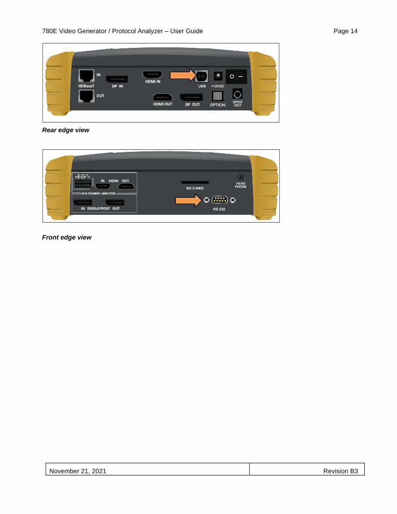
Rear edge view
Front edge view

780E Video Generator / Protocol Analyzer – User Guide Page 15
November 21, 2021 Revision B3
3 General Operation
This section describes power up, power usage and general operation.
3.1 Power Considerations
The 780E has a rocker style power switch on the back panel. Refer to the photo below.
Rear edge view
The 780E is supplied with the Part No 25-00110 12V DC power supply adapter as well as a part number 30A00400A03 line cord.
3.2 Tilt Bail
The 780E has support bail for convenience in viewing. This is depicted in the illustration below. (The illustration shows the 780; however, the 780E tilt bail operates in the same manner.)
780E Video Generator / Protocol Analyzer – User Guide Page 16
November 21, 2021 Revision B3
3.3 Navigating through the 780E User Interface
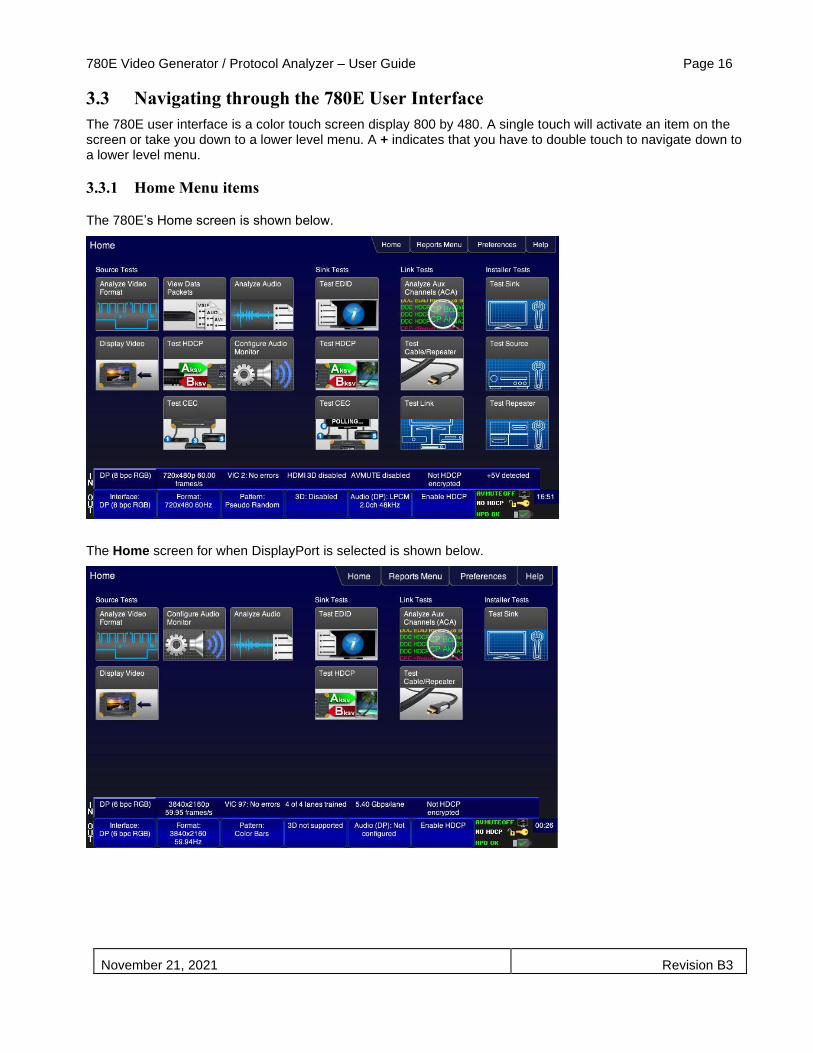
The 780E user interface is a color touch screen display 800 by 480. A single touch will activate an item on the screen or take you down to a lower level menu. A + indicates that you have to double touch to navigate down to a lower level menu.
3.3.1 Home Menu items
The 780E’s Home screen is shown below.
The Home screen for when DisplayPort is selected is shown below.

780E Video Generator / Protocol Analyzer – User Guide Page 17
November 21, 2021 Revision B3
Table 3-1 below shows functions available from the Home screen.
Table 3-1: Top Level Menu
Item Submenu - Pattern Third Level Menu Value
Top Menu Bar Home / Back navigation
See Below Enables you to navigate back to the previous screen.
Reports Menu
Note: Changes to Add a Report when a test is run.
Report File Format ▪ Text Only ▪ HTML
Enables you to specify the format of a report.
Start Report Initiates a report
Add Comment Grayed out until Start Report is activated
Set Save Dir Enables you to create and name a directory on the SD card or the 780 file system.
Save to SD Enables you to create and name a report on the SD card to save a report to. Unavailable without an SD card in the slot.
Save to Unit Enables you to create and name a report in the 780 file system to save a report to.
Preferences
Page 1
Audible Touch ▪ Off ▪ On
Screen Brightness ▪ Min ▪ 25% ▪ 50% ▪ 75% ▪ Max
USB Mode ▪ COM for commands ▪ Disk for downloading files and upgrades
Startup Mode ▪ Set the 780’s menu configuration to the default
menu (shown throughout this User Guide). ▪ Custom Menu – Utilize a configuration that you
have created.
Custom Menu ▪ Enter to navigate to custom menu screen.
Preferences
Page 2
Hot Plug Formats ▪ On – 780E automatically select the formats in
the EDID of the connected HDTV. ▪ Off – 780E will not automatically select the
formats in the EDID of the connected HDTV.
AVMute on Format Change
▪ On – AVMute will occur when the resolution is changed on the 780E HDMI output.
▪ Off – AVMute will occur when the resolution is changed on the 780E HDMI output.
RS-232 Baud Rate ▪ Configure the baud rate of the RS-232 interface
on the 780E (N/A to 780).
RS-232 Keypad Mode ▪ Off – Keypad connected to RS-232 is disabled. ▪ On – Keypad connected to RS-232 is enabled.
Help Upgrades ▪ USB Storage Flash
▪ Application Flash ▪ FPGA Flash
Touchscreen ▪ Calibrate the touch screen display
Source Tests Buttons Analyze Video Format
Viewing Source Data Island Packet

780E Video Generator / Protocol Analyzer – User Guide Page 18
November 21, 2021 Revision B3
Display Video Testing Video from an HDMI Source Device
View Data Packets (not available with DisplayPort)
Viewing Source Data Island Packet
Test HDCP (not available with DisplayPort)
Testing HDCP Max Devices on an HDMI Source Device
Test CEC (not available with DisplayPort)
Viewing the CEC devices on an HDMI network
Analyze Audio Testing Audio of an HDMI Source Device
Configure Audio Monitor
Procedures for Monitoring LPCM Audio from a Source Device (780E only)
Sink Tests Buttons Test EDID Verifying the EDID on an HDMI HDTV or HDMI Repeater Device
Test HDCP Testing HDCP on an HDMI HDTV or HDMI Repeater Device
Test CEC (not available with DisplayPort)
Viewing the CEC devices on an HDMI network
Link Tests Buttons Analyze Aux Channel Procedures for Monitoring Auxiliary Channel events and transactions
Test Cable/Repeater Using the 780E Test Instrument to Test HDMI Cable or Repeaters
Test Link (not available with DisplayPort)
Procedures for Installer Utility
Installer Tests Buttons Test Sink Using the 780E Test Instrument Installer Utility
Test Source (not available with DisplayPort)
Using the 780E Test Instrument Installer Utility
Test Repeater (not available with DisplayPort)
Using the 780E Test Instrument Installer Utility
3.3.2 Back Navigation
When you navigate away from the Home screen a white arrow will appear in the upper left next to the name of the of the screen you are on. You can navigate to the previous screen by touch selecting this arrow. In the example below, touch selecting the upper left area on or near the white, left facing arrow next to Signal Type will take you to the previous screen.

780E Video Generator / Protocol Analyzer – User Guide Page 19
November 21, 2021 Revision B3
3.3.3 Status Bar
The 780E has a status bar on the bottom of the screen.
Status bar when HDMI or HDBaseT is selected:
Status bar when DP is selected:
The items in the status bar are described in the Table 3-2.
Table 3-2: Status Bar
Type Status Item Function
HDMI/HDBaseT/DisplayPort Input (from left to right)
Video Type Status Indicates the status of video on the HDMI/HDBaseT Rx ports. This includes: ▪ Video interface: HDMI or DVI, HDBaseT,
DisplayPort ▪ Color depth ▪ Video type. ▪ Sampling mode.

780E Video Generator / Protocol Analyzer – User Guide Page 20
November 21, 2021 Revision B3
Video Resolution Status Indicates the video resolution on the HDMI, HDBaseT or DisplayPort Rx port. This includes: ▪ Horizontal Active in pixels ▪ Vertical Active in pixels ▪ Frame rate
Video Identification Status Indicates the video resolution on the HDMI, HDBaseT or DisplayPort Rx port. This includes: ▪ Horizontal Active in pixels ▪ Vertical Active in pixels ▪ Frame rate
For HDMI and HDBaseT: 3D Status
For DisplayPort: Number of Lanes
Indicates the status of 3D video for HDMI or HDBaseT. This includes: ▪ 3D enabled or disabled ▪ 3D format
▪ Indicates the link rate: 1.62, 2.70, 5.40Gbps
For HDMI and HDBaseT: AVMute status
For DisplayPort: Link Rate
Indicates the AVmute status, enabled or disabled. Applies only to HDMI and HDBaseT.
Indicates the link rate: 1.62, 2.70, 5.40Gbps.
HDCP Status Indicates whether the incoming video is encrypted with HDCP.
+5V Status (not applicable to DisplayPort)
Indicates whether +5V is detected from the HDMI or HDBaseT source.
HDMI/HDBaseT/DisplayPort Output (from left to right)
Video Type Status/Selection
Indicates the video on the HDMI, HDBaseT or DisplayPort Tx ports. This includes: ▪ Video interface ▪ Color depth ▪ Video type ▪ Sampling mode
Provides access to the Video Signal Type screen.
Video Resolution Status/Selection
Indicates the video resolution on the HDMI, HDBaseT or DisplayPort Tx port. This includes: ▪ Horizontal Active in pixels ▪ Vertical Active in pixels ▪ Frame rate
Provides access to the Video Format selection screen.
Video Pattern Status/Selection
Indicates the video pattern on the HDMI, HDBaseT or DisplayPort Tx port.
Provides access to Video Pattern selection screen.
3D Format Status/Configuration
Indicates the status of 3D video. This includes: ▪ 3D enabled or disabled ▪ 3D format
780E Video Generator / Protocol Analyzer – User Guide Page 21
November 21, 2021 Revision B3
Provides access to the 3D video configuration screen.
Audio Status Indicates the Audio status: ▪ Audio format ▪ Audio channels ▪ Audio sampling rate
Provides access to the audio format selection screen.
HDCP Status Indicates whether the outgoing video on the active output port is encrypted with HDCP.
AVMute HDCP Status +5V Status
Indicates the status of the following for HDMI or HDBaseT (not used for DisplayPort): ▪ AVMute active/inactive status ▪ HDCP active/inactive status ▪ +5V present/not present status
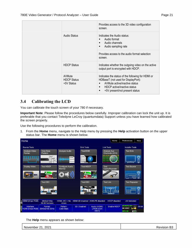
3.4 Calibrating the LCD
You can calibrate the touch screen of your 780 if necessary.
Important Note: Please follow the procedures below carefully. Improper calibration can lock the unit up. It is preferable that you contact Teledyne LeCroy (quantumdata) Support unless you have learned how calibrated the screen properly.
Use the following procedures to perform the calibration.
1. From the Home menu, navigate to the Help menu by pressing the Help activation button on the upper status bar. The Home menu is shown below.
The Help menu appears as shown below:

780E Video Generator / Protocol Analyzer – User Guide Page 22
November 21, 2021 Revision B3
2. Touch select the Calibrate activation button. A screen appears instructing you to press each of four red squares.
When you finish touch selecting the fourth box, the calibration is completed and you will return to the Home menu.
3. If the calibration fails and you cannot access the menus, establish a command line session and enter the calibration command:
TCAL
This will cause the screen to display the calibration screen again.

780E Video Generator / Protocol Analyzer – User Guide Page 23
November 21, 2021 Revision B3
4 Using the 780E Test Instrument to Video and Audio Pattern Tests on
Sink Devices
This chapter provides procedures for running audio and video pattern tests on high definition sink devices such as HDTVs and projectors. The features and functions described in this chapter are provided with the standard 780E; no options are required. The following signal types are supported.
▪ HDMI (via the HDMI physical connector)
▪ DVI (via the HDMI physical connector)
▪ HDBaseT (via the HDBaseT physical connector)
▪ DisplayPort (via DisplayPort physical connector)
4.1 Making Physical Connections
The first step in testing a sink device is to make the HDMI physical connections between the 780E and the device(s) under test.
4.1.1 Connecting the 780E to the Display Device - HDMI
Use the following procedures to make the physical connections from the 780E to the display device under test.
1. Make the cable connection between the appropriate the 780E video output connector (e.g. HDMI OUT) connector and the input connector of the HDTV using the cables supplied.
2. Alternatively you may connect from the 780E video output connector to an HDTV through an HDMI repeater device such as an A/V receiver. In this case make the HDMI connection between the HDMI OUT connector on the 780E and the HDMI input of the HDMI repeater device using an HDMI-to-HDMI cable. Then connect the HDTV to an active output on the repeater. The following illustrations depict the typical test configurations.

780E Video Generator / Protocol Analyzer – User Guide Page 24
November 21, 2021 Revision B3
4.1.2 Connecting the 780E to the Display Device - HDBaseT
Use the following procedures to make the physical connections from the 780E to the display device under test.
1. Make the cable connection between the appropriate the 780E video HDBaseT output connector and the input connector of the HDBaseT device.
The following illustrations depict the typical test configurations.
4.1.3 Connecting the 780E to the Display Device - DisplayPort
Use the following procedures to make the physical connections from the 780E to the display device under test.
1. Make the cable connection between the appropriate the 780E video DisplayPort output connector and the input connector of the HDTV or computer monitor using the cables supplied.

780E Video Generator / Protocol Analyzer – User Guide Page 25
November 21, 2021 Revision B3
4.2 Selecting a Signal Type and Resolution
After making the physical connections between the 780E and the display device under test you will need to select the signal type, Resolution and Frame Rate for the sink device under test.
4.2.1 Procedures for Selecting a Signal Type
The procedures below describe how to select the active signal type.
1. Power up the 780E using the rocker switch on the back panel.
2. Touch select the Signal Type activation button on the OUT Status Bar (see screen example below).
The Signal Type menu appears as shown below.
3. Touch select the desired signal type using the associated activation button (examples below).

780E Video Generator / Protocol Analyzer – User Guide Page 26
November 21, 2021 Revision B3
HDBaseT Selection:
DisplayPort selection:
4. Touch select the options for the Signal Type. Use the information in Table 4-1 below as a guide:
Table 4-1: Signal Type
Signal Type Name Physical Connector Option Option Values
HDMI Color Space ▪ YCbCr 4:4:4, 4:2:2, 4:2:0 ▪ RGB
780E Video Generator / Protocol Analyzer – User Guide Page 27
November 21, 2021 Revision B3
HDMI OUT via HDMI to HDMI cable (provided)
Bit Depth ▪ 8 ▪ 10 ▪ 12 ▪ 16
Format Type ▪ TV – Uses limited color range ▪ PC – Uses full color range ▪ User
DVI HDMI OUT via HDMI to DVI cable (not provided)
Format Type ▪ TV – Uses limited color range ▪ PC – Uses full color range ▪ User
HDBaseT HDBaseT OUT via HDBaseT to HDBaseT cable (not provided)
Color Space ▪ YCbCr 4:4:4 4:2:2, 4:2:0 ▪ RGB
Bit Depth ▪ 8 ▪ 10 ▪ 12
Format Type ▪ TV – Uses limited color range ▪ PC – Uses full color range ▪ User
DisplayPort DisplayPort OUT via DisplayPort Standard cable
Color Space ▪ YCbCr 4:4:4 4:2:2 ▪ RGB
Bit Depth ▪ 6 ▪ 8 ▪ 10 ▪ 12 ▪ 16
Format Type ▪ TV – Uses limited color range ▪ PC – Uses full color range ▪ User
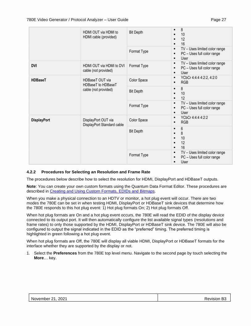
4.2.2 Procedures for Selecting an Resolution and Frame Rate
The procedures below describe how to select the resolution for HDMI, DisplayPort and HDBaseT outputs.
Note: You can create your own custom formats using the Quantum Data Format Editor. These procedures are described in Creating and Using Custom Formats, EDIDs and Bitmaps.
When you make a physical connection to an HDTV or monitor, a hot plug event will occur. There are two modes the 780E can be set in when testing HDMI, DisplayPort or HDBaseT sink devices that determine how the 780E responds to this hot plug event: 1) Hot plug formats On; 2) Hot plug formats Off.
When hot plug formats are On and a hot plug event occurs, the 780E will read the EDID of the display device connected to its output port. It will then automatically configure the list available signal types (resolutions and frame rates) to only those supported by the HDMI, DisplayPort or HDBaseT sink device. The 780E will also be configured to output the signal indicated in the EDID as the “preferred” timing. The preferred timing is highlighted in green following a hot plug event.
When hot plug formats are Off, the 780E will display all viable HDMI, DisplayPort or HDBaseT formats for the interface whether they are supported by the display or not.
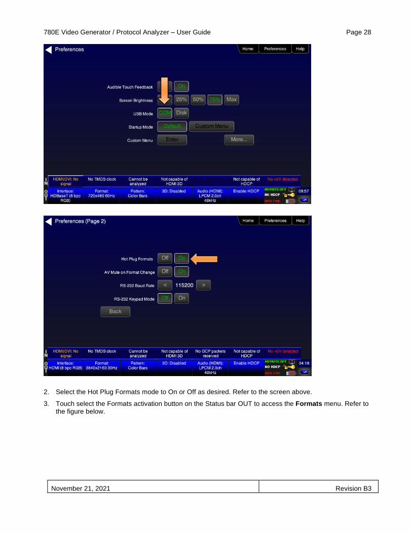
1. Select the Preferences from the 780E top level menu. Navigate to the second page by touch selecting the More… key.
780E Video Generator / Protocol Analyzer – User Guide Page 28
November 21, 2021 Revision B3
2. Select the Hot Plug Formats mode to On or Off as desired. Refer to the screen above.
3. Touch select the Formats activation button on the Status bar OUT to access the Formats menu. Refer to the figure below.

780E Video Generator / Protocol Analyzer – User Guide Page 29
November 21, 2021 Revision B3
The Formats menu appears as shown below (example HDMI):
4. Touch select the desired format and Frame Rate (example 2160p at 30Hz above).
For the HDMI formats, there are color codes that are applied to the Resolution and Frame Rate selections. The following is a summary of their meaning:
▪ A Resolution or Frame Rate with white lettering but with no outline – a Resolution or Frame Rate that appears in the EDID and has a short video descriptor associated with it.
▪ A Frame Rate with green lettering and with white outline – The Frame Rate that is currently selected.
▪ A Frame Rate with red lettering but with no outline – The Frame Rate is not supported by the EDID for that Resolution.

780E Video Generator / Protocol Analyzer – User Guide Page 30
November 21, 2021 Revision B3
▪ A Frame Rate(s) with green lettering and with white outline – The Frame Rate along with the currently selected Resolution that is the “preferred” timing.
▪ A Frame Rate with black lettering but with no outline – The Frame Rate is not supported by the standard for the selected resolution.
Note: When you make a physical connection to an HDMI or HDBaseT HDTV or sink device, a hot plug event will occur. If Hot Plug Formats is enabled on the Preference menu, when the hot plug event occurs, the 780E will read the EDID of the display device connected to its output port. The output is automatically set to the preferred timing which is highlighted in green following a hot plug.
4.2.3 Procedures for Enabling AVMute
The procedures below describe how to enable AVMute on the HDMI or HDBaseT output ports. AVMute is an optional feature in HDMI or HDBaseT that enables a source to signal a sink to extinguish its audio and video. The source, in this case the 780E emulating a source sets the AVMute Set flag in the general control packet. The purpose of AVMute is to avoid audio artifacts when switching resolutions.
1. Select the Preferences from the 780E top level menu. Navigate to the second page by touch selecting the More… key.
2. Touch select the On activation button next to AVMute on the screen below.

780E Video Generator / Protocol Analyzer – User Guide Page 31
November 21, 2021 Revision B3
4.3 Rendering Test Patterns on an HDTV
This subsection describes how to render test patterns on an HDTV. You will first have to complete the previous procedures:
▪ Making the physical connections ▪ Selecting the Signal Type and Resolution
4.3.1 Procedures for Outputting Test Patterns
The procedures below cover cases where there is a direct connection between the 780E and the HDTV and also where the 780E is connected to an HDTV through a repeater device.
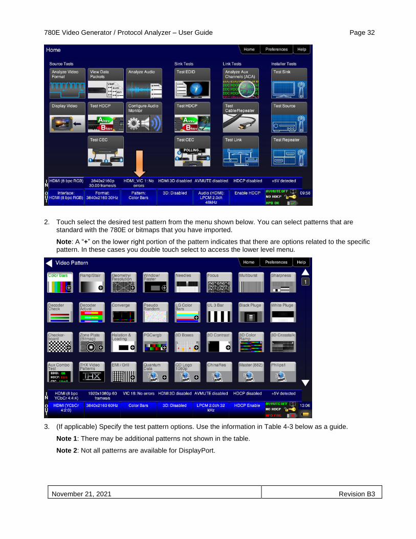
1. From the Home screen on the 780E display, touch select the Video Pattern status and activation button on the Status Bar as shown below.
780E Video Generator / Protocol Analyzer – User Guide Page 32
November 21, 2021 Revision B3
2. Touch select the desired test pattern from the menu shown below. You can select patterns that are standard with the 780E or bitmaps that you have imported.
Note: A “+” on the lower right portion of the pattern indicates that there are options related to the specific pattern. In these cases you double touch select to access the lower level menu.
3. (If applicable) Specify the test pattern options. Use the information in Table 4-3 below as a guide.
Note 1: There may be additional patterns not shown in the table.
Note 2: Not all patterns are available for DisplayPort.

780E Video Generator / Protocol Analyzer – User Guide Page 33
November 21, 2021 Revision B3
Table 4-3: Test Patterns
Pattern Name Variant Options Range of Values
ColorBar patterns
Applications:
SMPTEBars - To adjust color and hue.
Colorbars - To test a display’s ability to product fully saturated primary and secondary color.
SMPTE
Orientation - Vertical Direction:
▪ Left to Right
▪ Right to Left
Orientation - Horizontal Direction:
▪ Top / Bottom ▪ Bottom / Top
Pixel values in RGB, 8bit with TV (limited range) mode. Note 1: Deep color values for 10-bit or 12-bit are different from those shown. Note 2: When using PC Format type the range will go from 0 to 255 for 8-bit color mode.
From left to right; top to bottom: Top bars: R=180 G=180 B=180 R=180 G=180 B=16 R=16 G=180 B=180 R=16 G=180 B=16 R=180 G=16 B=180 R=180 G=16 B=16 R=16 G=16 B=180 Middle short bars: R=16 G=16 B=180 R=16 G=16 B=16 R=180 G=16 B=180 R=16 G=16 B=16 R=16 G=180 B=180 R=16 G=16 B=16 R=180 G=180 B=180 Lower bars: R=18 G=70 B=107 R=235 G=235 B=235 R=86 G=31 B=134 R=16 G=16 B=16 R=9 G=9 B=9 R=16 G=16 B=16 R=23 G=23 B=23
Full
Orientation - Vertical Direction:
▪ Left to Right
▪ Right to Left
Orientation - Horizontal Direction:
▪ Top / Bottom
▪ Bottom / Top
Split
Orientation - Vertical Direction:
▪ Left to Right
▪ Right to Left
Orientation - Horizontal Direction:
▪ Top / Bottom ▪ Bottom / Top

780E Video Generator / Protocol Analyzer – User Guide Page 34
November 21, 2021 Revision B3
Table 4-3: Test Patterns
Pattern Name Variant Options Range of Values
Ramp/Stair Patterns
Applications:
Stair - To visually check grayscale tracking performance of a rear projection display.
Ramp – To check the digitizing linearity of video signal processors.
Stair - Full
Orientation - Vertical Direction:
▪ Left to Right
▪ Right to Left
Orientation - Horizontal Direction:
▪ Top / Bottom ▪ Bottom / Top
Bars ▪ 5 ▪ 11 ▪ 21
Color ▪ R ▪ G ▪ B ▪ C ▪ M ▪ Y ▪ W
Stair – Split
Orientation - Vertical Direction:
▪ Left to Right ▪ Right to Left
Orientation - Horizontal Direction:
▪ Top / Bottom ▪ Bottom / Top
Bars ▪ 5 ▪ 11 ▪ 21
Color ▪ R ▪ G ▪ B ▪ C ▪ M ▪ Y ▪ W
Ramp Color ▪ R ▪ G ▪ B ▪ C ▪ M ▪ Y ▪ W

780E Video Generator / Protocol Analyzer – User Guide Page 35
November 21, 2021 Revision B3
Table 4-3: Test Patterns
Pattern Name Variant Options Range of Values
Pixel values in RGB, 8bit with TV (limited range) mode. Note 1: When using PC Format type the range will go from 0 to 255 for 8-bit color mode.
In 8-bit color mode (24) the ramp displays all 256 shades of gray.
In 10-bit color mode (30) the ramp displays 256 shades of gray throughout a range of 64 – 940 skipping interim shades at each increment.
In 12-bit color mode (36) the ramp displays 256 shades of gray throughout a range of 256 – 3760 skipping interim shades at each increment.
3D Box Pattern
Application: This is a 3D pattern used to test 3D displays. The pattern enables you to set the offset between the left and right image components.
No variants
Box 1 Offset -64 to +64
Box 2 Offset -64 to +64
Background Brightness 0 to 63
3D Color Ramp
Application: This is a 3D pattern used to test 3D color uniformity and crosstalk or extinction ratio.
No variants
Description: There are 4 pairs of horizontal color bars. Each bar
depicts a color gradation from red to purple; two from left to right
and one from right to left.
Method – Color uniformity:
1. Close left eye to view image from right eye.
2. Assess the color gradation on each bar.
3. Close right eye to view image from left eye.
4. Subjectively compare the images to assess color
uniformity.
Method – Crosstalk (extinction ratio):
1. Close left eye to view image from right eye.
2. Verify that the bottom bar is extinguished. The extent to
which the bar is not extinguished represents the amount
of crosstalk.
3. Repeat for a test of the left eye

780E Video Generator / Protocol Analyzer – User Guide Page 36
November 21, 2021 Revision B3
Table 4-3: Test Patterns
Pattern Name Variant Options Range of Values
3D Cross Talk
Application: This is a 3D pattern used to measure the crosstalk (extinction ratio) for frame packing, top and bottom and side by side 3D format structures.
No variants
Description: This image is divided in two sections with four rows of 16 white boxes each. The top section is for testing with the left eye open. The bottom section is for testing with the right eye open. The background area surrounding the boxes is a series of grayscale ramps. The ramps begin at 100 IRE and transitions to 50 IRE at the left end of the fourth row of each series. Method – Calculating percent crosstalk:
1. Close right eye to test the left eye using the top section.
2. Check the visibility of the boxes. Any deviation from
black indicates crosstalk.
3. Assess where the box and its background blend such
that they are not distinguishable.
4. Calculate the degree of crosstalk as a percent by
counting the number of boxes (from the beginning of the
series to the box identified in step 3) and divide that by
127. Example if the 20th box blends with its background,
the crosstalk would be 20/127 * 100 = 15.7%
5. Repeat with the left eye closed to test the right eye.
PGCWRGB Pattern
Application: This is a scrolling pattern used to test for noise on analog displays and motion artifacts.
No variants
Show Text On / Off
Show Center Cross On / Off
Show Video On / Off
Show Overscan On / Off
Grid Type • 10x50
• 5% H/V
Geometry/Resolution Patterns
Applications:
Grid – To check and adjust convergence of red, green and blue pictures.
Linearity – for testing deflection linearity testing and alignment.
Overscan – To check and adjust for the proper geometry of display including picture centering, size, pincushion and linearity.
Grid
Color Mode ▪ White on Black ▪ Black on White
Linearity
Color Mode ▪ White on Black ▪ Black on White

780E Video Generator / Protocol Analyzer – User Guide Page 37
November 21, 2021 Revision B3
Table 4-3: Test Patterns
Pattern Name Variant Options Range of Values
Overscan
N/A
EMI/Grill
Applications:
EMI – Show grid of “H” characters to check for EMI effects on image. Each “H” character should be clear and distinct.
EMI
H Type
Grill On/Off
Scroll – Scrolls the “H” characters vertically.
Grill – for verifying monitor resolution.
EMI - Grill
Grill On/Off
Grill Mode
Color Bars – To test a display’s ability to produce fully saturated primary and secondary color.
EMI - ColorBars
Scroll – color bars scroll horizontally.
Needles Pattern
Application: To detect whether scan velocity modulation is enabled on display.
No variants
Window/Raster Pattern
Applications:
Window IRE Level ▪ -5 ▪ -1 ▪ 100 ▪ +1 ▪ +5

780E Video Generator / Protocol Analyzer – User Guide Page 38
November 21, 2021 Revision B3
Table 4-3: Test Patterns
Pattern Name Variant Options Range of Values
Window1 - To calibrate display drive chromaticity.
Window2 - To calibrate display cutoff chromaticity.
Raster – To check color purity and display chrominance uniformity.
IRE Label ▪ Off ▪ On
Color ▪ R ▪ G ▪ B ▪ C ▪ M ▪ Y ▪ W
Raster
IRE Level ▪ -5 ▪ -1 ▪ 100 ▪ +1 ▪ +5
IRE Label ▪ Off ▪ On
Color ▪ R ▪ G ▪ B ▪ C ▪ M ▪ Y ▪ W
Needles Pattern
Application: To detect whether scan velocity modulation is enabled on display.
N/A
Focus Pattern
Application: To detect whether scan velocity modulation is enabled on display.
N/A
Multi-burst Pattern
Application: To check a display’s ability to produce sharply defined stripes at equal brightness up to full resolution.
N/A

780E Video Generator / Protocol Analyzer – User Guide Page 39
November 21, 2021 Revision B3
Table 4-3: Test Patterns
Pattern Name Variant Options Range of Values
Sharpness
Application: To align display sharpness, picture, aperture and scan velocity modulation adjustments.
No Variants
Decoder Check
Application: To check the color decoder performance to determine if the decoder over-emphasizes red or green colors.
No Variants
Decoder Adjust Pattern
Application: To adjust a display’s color decoder/matrix circuit for most accurate color reproduction.
No Variants
Converge Pattern
Application: To color converge a display throughout the entire picture area.
No Variants
Pseudo Random Pattern
Application: To test for pixel errors on an HDMI cable.
No Variants
LG Color Pattern No Variants Horizontal
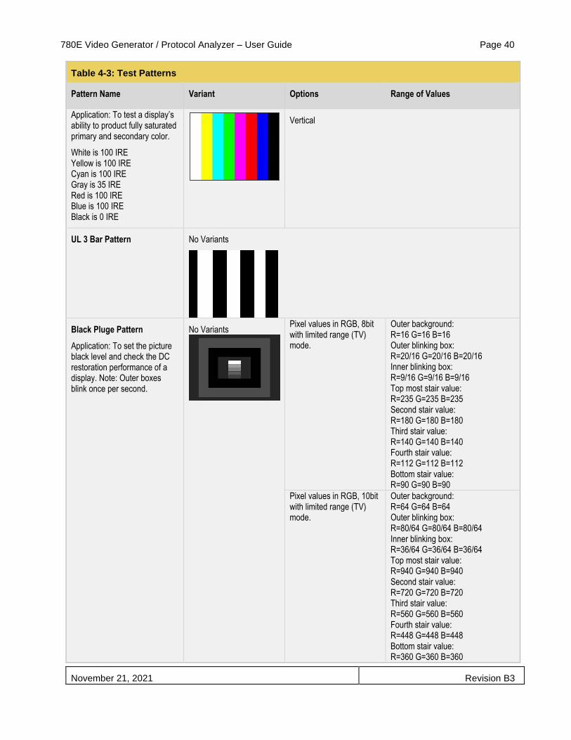
780E Video Generator / Protocol Analyzer – User Guide Page 40
November 21, 2021 Revision B3
Table 4-3: Test Patterns
Pattern Name Variant Options Range of Values
Application: To test a display’s ability to product fully saturated primary and secondary color.
White is 100 IRE Yellow is 100 IRE Cyan is 100 IRE Gray is 35 IRE Red is 100 IRE Blue is 100 IRE Black is 0 IRE
Vertical
UL 3 Bar Pattern No Variants
Black Pluge Pattern
Application: To set the picture black level and check the DC restoration performance of a display. Note: Outer boxes blink once per second.
No Variants
Pixel values in RGB, 8bit with limited range (TV) mode.
Outer background: R=16 G=16 B=16 Outer blinking box: R=20/16 G=20/16 B=20/16 Inner blinking box: R=9/16 G=9/16 B=9/16 Top most stair value: R=235 G=235 B=235 Second stair value: R=180 G=180 B=180 Third stair value: R=140 G=140 B=140 Fourth stair value: R=112 G=112 B=112 Bottom stair value: R=90 G=90 B=90
Pixel values in RGB, 10bit with limited range (TV) mode.
Outer background: R=64 G=64 B=64 Outer blinking box: R=80/64 G=80/64 B=80/64 Inner blinking box: R=36/64 G=36/64 B=36/64 Top most stair value: R=940 G=940 B=940 Second stair value: R=720 G=720 B=720 Third stair value: R=560 G=560 B=560 Fourth stair value: R=448 G=448 B=448 Bottom stair value: R=360 G=360 B=360
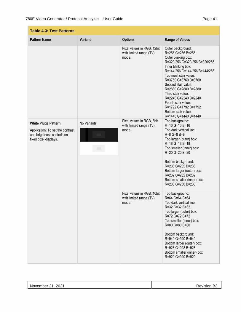
780E Video Generator / Protocol Analyzer – User Guide Page 41
November 21, 2021 Revision B3
Table 4-3: Test Patterns
Pattern Name Variant Options Range of Values
Pixel values in RGB, 12bit with limited range (TV) mode.
Outer background: R=256 G=256 B=256 Outer blinking box: R=320/256 G=320/256 B=320/256 Inner blinking box: R=144/256 G=144/256 B=144/256 Top most stair value: R=3760 G=3760 B=3760 Second stair value: R=2880 G=2880 B=2880 Third stair value: R=2240 G=2240 B=2240 Fourth stair value: R=1792 G=1792 B=1792 Bottom stair value: R=1440 G=1440 B=1440
White Pluge Pattern
Application: To set the contrast and brightness controls on fixed pixel displays.
No Variants
Pixel values in RGB, 8bit with limited range (TV) mode.
Top background: R=16 G=16 B=16 Top dark vertical line: R=8 G=8 B=8 Top larger (outer) box: R=18 G=18 B=18 Top smaller (inner) box: R=20 G=20 B=20 Bottom background: R=235 G=235 B=235 Bottom larger (outer) box: R=232 G=232 B=232 Bottom smaller (inner) box: R=230 G=230 B=230
Pixel values in RGB, 10bit with limited range (TV) mode.
Top background: R=64 G=64 B=64 Top dark vertical line: R=32 G=32 B=32 Top larger (outer) box: R=72 G=72 B=72 Top smaller (inner) box: R=80 G=80 B=80 Bottom background: R=940 G=940 B=940 Bottom larger (outer) box: R=928 G=928 B=928 Bottom smaller (inner) box: R=920 G=920 B=920

780E Video Generator / Protocol Analyzer – User Guide Page 42
November 21, 2021 Revision B3
Table 4-3: Test Patterns
Pattern Name Variant Options Range of Values
Pixel values in RGB, 12bit with limited range (TV) mode.
Top background: R=256 G=256 B=256 Top dark vertical line: R=128 G=128 B=128 Top larger (outer) box: R=288 G=288 B=288 Top smaller (inner) box: R=320 G=320 B=320 Bottom background: R=3760 G=3760 B=3760 Bottom larger (outer) box: R=3712 G=3712 B=3712 Bottom smaller (inner) box: R=3680 G=3680 B=3680
Checkboard Pattern
Application: To check the regulation of CRT video drive power supply circuits.
No Variants
Rows
▪ 2 ▪ 3 ▪ 4 ▪ 5 ▪ 6
• Columns ▪ 2 ▪ 3 ▪ 4 ▪ 5 ▪ 6
Zone Plate Pattern
This is a bitmap that can be scrolled to test motion artifacts. You can replace particular bitmap with any other bitmap image to allow scrolling. You just need to ensure that you assign it the same name.
Vertical
• Vertical Movement ▪ Stop ▪ Slow ▪ Medium ▪ Fast
Horizontal Movement ▪ Stop ▪ Slow ▪ Medium ▪ Fast
4.4 High Dynamic Range (HDR) Test Pattern Packs
The 780E provides licensed image packs for certain sets of test images. You need to have a license key to use these custom test image packs. You can arrange to get access to them by contacting Quantum Data customer support at: http://www.quantumdata.com/support.
When you purchase an image pack it appears as an icon at the end of the list of Test Patterns. A sample screen is shown below (Philips1, ChinaRes, Master). You simply select one of the test patterns (e.g. ChinaRes in the screen example below). They will take a few seconds to load. They will load at the resolution of the format that you have selected.
4.4.1 Testing UHD Displays with HDR Lab Test Patterns
780E Video Generator / Protocol Analyzer – User Guide Page 43
November 21, 2021 Revision B3
The HDR Lab utility is an optional test pattern pack that requires a license to use.
In order to address the HDR needs of the industry from Device Manufacturers to HDR content Post-Production, Teledyne LeCroy has worked together with industry experts Joe Kane of Joe Kane Productions and Florian Friedrich to develop this new test option “HDR Lab.” There are two test applications:
• HDR Display Test Suite – Verifies various HDR attributes such as: peak brightness, native contrast,
color decoding, signal clipping, and color gamut on an HDR-capable UHD TV using a variety of test
patterns (below) while enabling the user to change important signal parameters to test the response of
any given HDR display.
• HDR End-to-End Validation in Post Production – Verifies HDR metadata, signal levels and many more
relevant parameters throughout the post production process. Reference images can be compared with
HDR workflow outputs.
The HDR Lab utility is an optional test pattern pack that requires a license to use.

780E Video Generator / Protocol Analyzer – User Guide Page 44
November 21, 2021 Revision B3
The following table describes just some of the Test Patterns and Reference Images that comprise the HDR Lab utility. Additional test patterns and test images are included and will be described in subsequent versions of this application note.
HDR Lab Test Patterns
Test Pattern Name Function, Pattern Layout and Use
Combination Test Pattern
Function The Combination Test Pattern’s top and bottom portion provide a quick overview of display conditions for black level, white level, HDR on (status information) in the display, color, gray scale with bit depth, resolution, overscan, color decoding, and a 50% gray level. The three images in the center provide example of images color graded for HDR-10, P3 color in a BT.2020 container, mastered at 1,000 nits.
A
B B C
D
E
F F F
G H I J
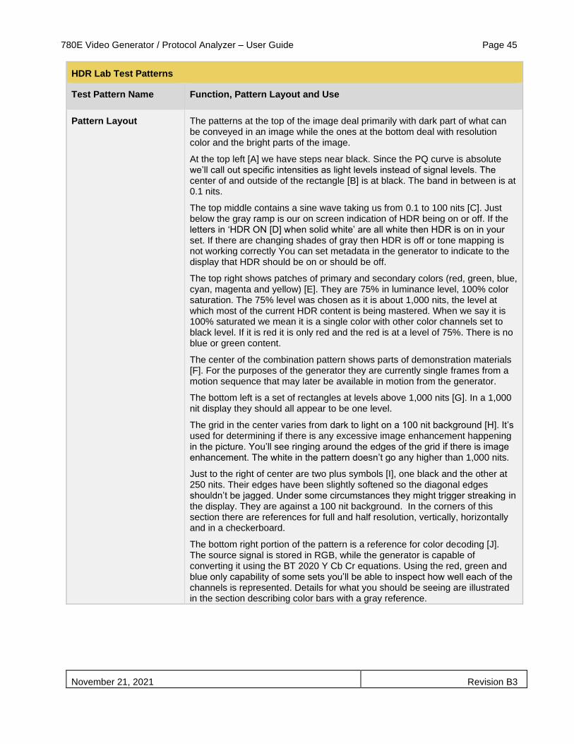
780E Video Generator / Protocol Analyzer – User Guide Page 45
November 21, 2021 Revision B3
HDR Lab Test Patterns
Test Pattern Name Function, Pattern Layout and Use
Pattern Layout The patterns at the top of the image deal primarily with dark part of what can be conveyed in an image while the ones at the bottom deal with resolution color and the bright parts of the image.
At the top left [A] we have steps near black. Since the PQ curve is absolute we’ll call out specific intensities as light levels instead of signal levels. The center of and outside of the rectangle [B] is at black. The band in between is at 0.1 nits.
The top middle contains a sine wave taking us from 0.1 to 100 nits [C]. Just below the gray ramp is our on screen indication of HDR being on or off. If the letters in ‘HDR ON [D] when solid white’ are all white then HDR is on in your set. If there are changing shades of gray then HDR is off or tone mapping is not working correctly You can set metadata in the generator to indicate to the display that HDR should be on or should be off.
The top right shows patches of primary and secondary colors (red, green, blue, cyan, magenta and yellow) [E]. They are 75% in luminance level, 100% color saturation. The 75% level was chosen as it is about 1,000 nits, the level at which most of the current HDR content is being mastered. When we say it is 100% saturated we mean it is a single color with other color channels set to black level. If it is red it is only red and the red is at a level of 75%. There is no blue or green content.
The center of the combination pattern shows parts of demonstration materials [F]. For the purposes of the generator they are currently single frames from a motion sequence that may later be available in motion from the generator.
The bottom left is a set of rectangles at levels above 1,000 nits [G]. In a 1,000 nit display they should all appear to be one level.
The grid in the center varies from dark to light on a 100 nit background [H]. It’s used for determining if there is any excessive image enhancement happening in the picture. You’ll see ringing around the edges of the grid if there is image enhancement. The white in the pattern doesn’t go any higher than 1,000 nits.
Just to the right of center are two plus symbols [I], one black and the other at 250 nits. Their edges have been slightly softened so the diagonal edges shouldn’t be jagged. Under some circumstances they might trigger streaking in the display. They are against a 100 nit background. In the corners of this section there are references for full and half resolution, vertically, horizontally and in a checkerboard.
The bottom right portion of the pattern is a reference for color decoding [J]. The source signal is stored in RGB, while the generator is capable of converting it using the BT 2020 Y Cb Cr equations. Using the red, green and blue only capability of some sets you’ll be able to inspect how well each of the channels is represented. Details for what you should be seeing are illustrated in the section describing color bars with a gray reference.

780E Video Generator / Protocol Analyzer – User Guide Page 46
November 21, 2021 Revision B3
HDR Lab Test Patterns
Test Pattern Name Function, Pattern Layout and Use
Description of Use This pattern is designed to be fully functional in the HDR mode of a UHD set as levels in it are specific to the PQ based HDR-10. It serves as a quick reference for black and white levels,, BT 2020 Y Cr Cb color decoding, sharpness, resolution and overall image quality. Primary color measurements can be made on the patches in the upper right corner and peak light output capability can be measured in the bottom left of the pattern as long as there are no image uniformity issues or significant APL limitations.
Clipping Test Pattern
Function The Clipping pattern is designed to be a quick human inspection pattern to subjectively test for clipping, tone mapping, peak luminance and adherence to the PQ curve. The clipping and tone mapping can be assessed subjectively by inspection. The measuring and calibration of the luminance can be assessed objectively using a measurement sensor or a professional camera with descent manual exposure. The UHD TV under test should be set in the HDR mode for all tests.
A B
E
D C
F
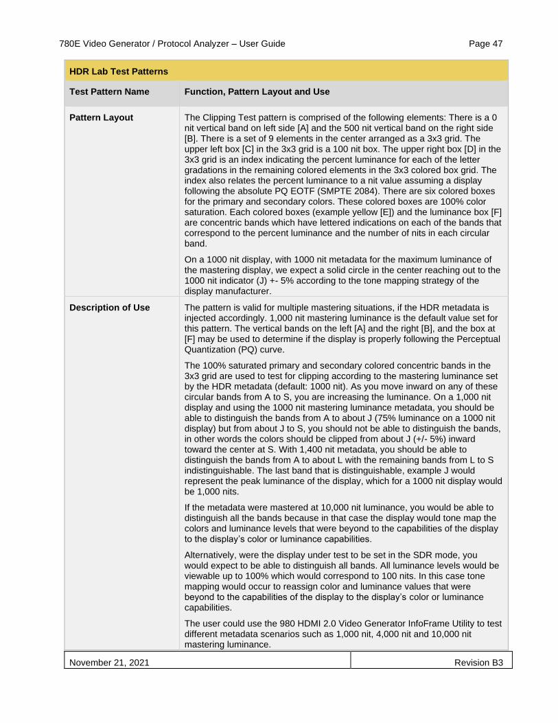
780E Video Generator / Protocol Analyzer – User Guide Page 47
November 21, 2021 Revision B3
HDR Lab Test Patterns
Test Pattern Name Function, Pattern Layout and Use
Pattern Layout The Clipping Test pattern is comprised of the following elements: There is a 0 nit vertical band on left side [A] and the 500 nit vertical band on the right side [B]. There is a set of 9 elements in the center arranged as a 3x3 grid. The upper left box [C] in the 3x3 grid is a 100 nit box. The upper right box [D] in the 3x3 grid is an index indicating the percent luminance for each of the letter gradations in the remaining colored elements in the 3x3 colored box grid. The index also relates the percent luminance to a nit value assuming a display following the absolute PQ EOTF (SMPTE 2084). There are six colored boxes for the primary and secondary colors. These colored boxes are 100% color saturation. Each colored boxes (example yellow [E]) and the luminance box [F] are concentric bands which have lettered indications on each of the bands that correspond to the percent luminance and the number of nits in each circular band.
On a 1000 nit display, with 1000 nit metadata for the maximum luminance of the mastering display, we expect a solid circle in the center reaching out to the 1000 nit indicator (J) +- 5% according to the tone mapping strategy of the display manufacturer.
Description of Use The pattern is valid for multiple mastering situations, if the HDR metadata is injected accordingly. 1,000 nit mastering luminance is the default value set for this pattern. The vertical bands on the left [A] and the right [B], and the box at [F] may be used to determine if the display is properly following the Perceptual Quantization (PQ) curve.
The 100% saturated primary and secondary colored concentric bands in the 3x3 grid are used to test for clipping according to the mastering luminance set by the HDR metadata (default: 1000 nit). As you move inward on any of these circular bands from A to S, you are increasing the luminance. On a 1,000 nit display and using the 1000 nit mastering luminance metadata, you should be able to distinguish the bands from A to about J (75% luminance on a 1000 nit display) but from about J to S, you should not be able to distinguish the bands, in other words the colors should be clipped from about J (+/- 5%) inward toward the center at S. With 1,400 nit metadata, you should be able to distinguish the bands from A to about L with the remaining bands from L to S indistinguishable. The last band that is distinguishable, example J would represent the peak luminance of the display, which for a 1000 nit display would be 1,000 nits.
If the metadata were mastered at 10,000 nit luminance, you would be able to distinguish all the bands because in that case the display would tone map the colors and luminance levels that were beyond to the capabilities of the display to the display’s color or luminance capabilities.
Alternatively, were the display under test to be set in the SDR mode, you would expect to be able to distinguish all bands. All luminance levels would be viewable up to 100% which would correspond to 100 nits. In this case tone mapping would occur to reassign color and luminance values that were beyond to the capabilities of the display to the display’s color or luminance capabilities.
The user could use the 980 HDMI 2.0 Video Generator InfoFrame Utility to test different metadata scenarios such as 1,000 nit, 4,000 nit and 10,000 nit mastering luminance.

780E Video Generator / Protocol Analyzer – User Guide Page 48
November 21, 2021 Revision B3
HDR Lab Test Patterns
Test Pattern Name Function, Pattern Layout and Use
Luma Resolution Test Pattern
Function This Luma Resolution pattern is designed to be a quick human inspection pattern to subjectively test for proper handling of resolution without color being involved. It uses 1 to 100 nits in HDR mode to ensure that there should never be any clipping
Pattern Layout The Luma Resolution Test pattern is comprised of the following elements: A luma sine wave resolution vertical sweep on the top [A] to [B] and a luma sine wave resolution horizontal sweep on the bottom [C] to [D]. The sine waves vary from a luminance of 1 to 100 nits for each cycle and at a frequency that ranges from 2% to 50% of the Nyquist frequency from start to end of each sweep. Both frequency sweeps are linear.
Description of Use Check the pattern in both RGB and YCbCr in all sampling modes: 4:4:4, 4:2:2 and 4:2:0. Also check for different bit depths. In none of these colorimetry or sampling modes should the observer see any chroma. There should be no loss of resolution; the waves should all be distinguishable. Interferences (ringing) are indicating edge enhancement, masking some of the original information.
A
D
C D

780E Video Generator / Protocol Analyzer – User Guide Page 49
November 21, 2021 Revision B3
HDR Lab Test Patterns
Test Pattern Name Function, Pattern Layout and Use
Chroma Resolution Test Pattern
Function The Chroma Resolution pattern is designed to be a quick human inspection pattern to subjectively test for proper handling of chroma resolution and chroma subsampling.
Pattern Layout The Chroma Resolution pattern is comprised of the following elements: A chroma sine wave resolution vertical sweep on the top [A] to [B] and a chroma sine wave resolution horizontal sweep on the bottom [C] to [D]. The sine wave’s green and magenta colors are fully saturated at their peaks at each frequency but vary in dynamic range only up to 50% throughout each sine wave cycle at their peak. The frequency of the sine wave sweep ranges from 2% to 25% of the Nyquist frequency from start to end of each sweep. Both frequency sweeps are linear.
Description of Use Check the pattern in both RGB and YCbCr in all sampling modes: 4:4:4, 4:2:2 and 4:2:0. Also check for different bit depths. In none of these colorimetry or sampling modes should the observer see any chroma other than magenta or green or something in between. The green and magenta at their peaks should look equally saturated. There should be no gray, black or highlighted color between the colors nor should there be any blue or red chroma even in 4:2:2 or 4:2:0. The edges should not be desaturated, i.e. the area between the peaks should not look grayish or black. There should be no loss of resolution; the waves should all be distinguishable. Interferences (ringing) are indicating edge enhancement, masking some of the original information.
A
D
C D

780E Video Generator / Protocol Analyzer – User Guide Page 50
November 21, 2021 Revision B3
HDR Lab Test Patterns
Test Pattern Name Function, Pattern Layout and Use
HDR Pluge Test Pattern
Function To assess/adjust the brightness of a display in HDR
Pattern Layout The pattern consists of a background at video black [A] with a symmetrical PLUGE on the left and right sides [B] & [C] of the log gray scale in the middle of the pattern [D]. It is based on a pattern used for adjusting the Brightness control in SDR displays. It has been adapted to meet the needs of adjusting the Brightness control in the HDR mode of a UHD TV display. The outer part of the PLUGE contains three bars: a below black bar -0.1 nit [E], 0.05 nit bar [F], 0.1 nit bar [G] on the video black background. The gray scale in the middle represents steps of 100 nit [H], 50 nit [ I], 25 nit [J] and 12.5 nit [K]. These values were chosen based on the Perceptual Quantization (PQ) Electro-Optical Transfer Function (EOTF) of an HDR display. There are 10 rectangles on the top and bottom which range from 0.01 nits [L] to 0.1 nits [M] in 0.01 nit steps.
D B A C
E E F G G F H
I
J
K
L
L M
M

780E Video Generator / Protocol Analyzer – User Guide Page 51
November 21, 2021 Revision B3
HDR Lab Test Patterns
Test Pattern Name Function, Pattern Layout and Use
Description of Use The levels in this PLUGE pattern are specific to the 1,000 nit master using the PQ version of HDR. The pattern has been designed to function the same way as the SDR version of PLUGE but at levels specific to 1,000 nit PQ curve. This particular pattern is not correct for use in the SDR mode of a display.
The PLUGE is on both sides of the center to provide a greater opportunity to set black taking image uniformity and viewing angle into account when setting the brightness control. There are two above black steps [F] [G] in the PLUGE, one really close to black and the other a little further above it. The step below black may or may not be visible depending on where the individual set clips black.
The HDR-10 system we are using assumes nothing useful in picture information will go below black. Some sets will accommodate the below black portion of this signal just to make it easier to properly set the Brightness control. Others won’t and there will be nothing lost in the picture if the set clips everything below black.
Turn the brightness control up far enough so the strip just above black [G] is clearly visible. Turn the control down to the point where the just above black stripe disappears into the black background. Raise the Brightness control just enough for the strip to reappear. This is the correct setting for black.
If the below black stripe is visible when the Brightness control is turned up, turn the control back down to the point where the below black [E] stripe disappears into the background with the just above black strip still being visible.
The pattern has a low average picture level (APL). As much as white levels may change in the HDR mode depending on APL black level should remain fixed.
In some displays you’ll never actually reach black, an absence of light. What you reach is a digital cut-off, a point where information in the video signal is no longer displayed. Any information in the signal above black will be displayed, even if it looks slightly washed out because the set can’t make an absence of light.
The center grayscale [D] allows for a quick determination of the color of gray. Many calibrators use this pattern as a reference for quickly adjusting a grayscale as it allows one to see what is happening to the entire gray scale as adjustments are being made.

780E Video Generator / Protocol Analyzer – User Guide Page 52
November 21, 2021 Revision B3
HDR Lab Test Patterns
Test Pattern Name Function, Pattern Layout and Use
Reverse Ramp Test Pattern
Function The Reverse Dither Ramps test pattern provides a look at how well the display is doing at producing a smooth gray scale with no apparent steps. It helps assess color bit depth handling and gray tracking. Through visual inspection an assessment can be made as to whether the display is handling 10 bit color properly. Also the bidirectional nature of the ramps enables an assessment as to whether improper bit depth handling or setting is related to a problem at a specific luminance level or a region of the display.
Pattern Layout The Reverse Dither Ramp test pattern is comprised of two luminance ramps running in the opposite directions [A] and [B]. The top and bottom horizontal bands [C] are at black. There has been some low level static dither noise added across the entire image to make it easier to discern banding. The ramps are in the center of the image. The top ramp goes from 25% luminance on the left to 75% luminance on the right. The lower ramp goes from 75% luminance on the left to 25% luminance on the right. There are indicators on the ramp to show the luminance level.
Description of Use The ramps in this pattern should be smooth with no visible stepping (banding) from one level to another which would indicate improper rendering of 10 bit content. The amplitude is limited to 75% reflecting the 1,000 nit mastering level. There should be no chroma artifacts—no color detectable. If color is observed this means that the gray tracking on the display is improper. Switch between 8 bit mode and 10 bit mode on the video generator and verify that there is a difference on the display.
C
C
B
A

780E Video Generator / Protocol Analyzer – User Guide Page 53
November 21, 2021 Revision B3
ColorBars Test Pattern
Function To assess color decoding and or assist in determining the best operating positions of the Color and or Tint control.
Pattern Layout This pattern is specific to HDR-10 and the PQ EOTF, but also works for SDR. It consists of a 50 % gray background with yellow, cyan, green, magenta, red, and blue rectangles on the top and bottom rows in the image. The colors are 50% in level and are reversed in direction from the top to the bottom. The original signal in the generator is stored as a RGB signal gets converted according to the requirements (for example the ITU 2020 specifications for YCrCb).

780E Video Generator / Protocol Analyzer – User Guide Page 54
November 21, 2021 Revision B3
HDR Lab Reference Images
Reference Image Name Function, Pattern Layout and Use
Castle Reference Image
Function The Castle image is a natural image shot with a Nikon D800E still picture camera. The image offers rich dynamic range and detail that usually is not produced by a motion picture camera. The image is used to gain a subjective assessment of the display’s ability to render details in a high dynamic range setting and also the ability to maintain detail within highly saturated colors.
Pattern Layout The Castle image offers high dynamic range and color saturation and a high level of detail with maximum resolution where there are single pixel transitions between image elements. The image contains details in the highlights (example on the left side wall of the castle at [A]) and in the shadows (example on the windows in the roof at [B]). The image also has a lot of highly saturated colors in the greens on the trees in the foreground at [C].
Description of Use Visually inspect the image for sharpness. The details of the bricks on the left side of the castle wall [A] should be discernable despite the highlights of the wall; in some cases you should be able to see each individual brick. The wall should not look washed out.
The details in the shadows should be discernable as well, for example on the windows of the roof at [B]. You should be able to see the details of the grid on these windows.
Check for resolution artifacts such as double edges or loss of chromatic details in the leaves on the trees in the foreground example [C]. The individual leaves should be distinguishable and not desaturated. You should not see a uniformly colored patch of green.
A
B
C

780E Video Generator / Protocol Analyzer – User Guide Page 55
November 21, 2021 Revision B3
HDR Lab Reference Images
Reference Image Name Function, Pattern Layout and Use
Flowers Reference Image
Function The Montage Flower image is a natural image used to gain a subjective assessment of the displays rendering capabilities with respect to color saturation and maintaining differentiated colors throughout the highly saturated natural flowers.
Pattern Layout The Montage Flower image contains an arrangement of fully chroma saturated flowers of various hues. The image was shot with a 4K Red ONE Mx digital motion picture camera in a warm ambience light environment ~3000 degrees Kelvin. The warm nature of the image was maintained throughout the color grading process. The image was mastered such that is appears naturally on a P3 color gamut display, while using BT.2020 as a container.
Description of Use Upon visual inspection the colors in the flowers should be differentiated without any patches of uniform color. The lighter parts of the image especially should not be uniform in color which would indicate that the colors were clipped.

780E Video Generator / Protocol Analyzer – User Guide Page 56
November 21, 2021 Revision B3
HDR Lab Reference Images
Reference Image Name Function, Pattern Layout and Use
Cruise Ship Reference Image
Function The Cruise Ship image is a natural image shot in time lapse with a Canon 5D Mark 2 camera. The image is used to gain a subjective assessment of a display’s ability to render details in a high dynamic range setting.
Pattern Layout The Cruise Ship image offers high dynamic range image. The image depicts a sunset with the sun behind a cruise ship at dock. The clouds contain nearly white elements. The sun is behind the ship and the image is graded in such a way that you see the transition from the violet bluish sky a yellowish sunset.
Description of Use Visually inspect the image for details in the carrier vessels beside. A high level of details in these vessels should be discernable. The lights on these smaller vessels [A] aiming toward the viewer, should appear considerably brighter than the diffuse white parts of the image.
Inspect the windows on the navigator’s deck on the front of the ship; notice the reflections on the glass [B] which should exhibit some color and should be brighter than the windows adjacent to them.
Overall the image should reveal a dramatic effect exhibiting stark dynamic range transition from the sun light clouds at [C] to the shadows aside the ship [D]. The impression that the sun is behind the ship should be pronounced. This dramatic level of high dynamic range will not be visible when the display is in the SDR mode.
There should be a significant difference in the brightness between the outer and inner portions of the cloud nearest the sun at [C]. The yellows in the clouds should be highly saturated.
A
B
C
D

780E Video Generator / Protocol Analyzer – User Guide Page 57
November 21, 2021 Revision B3
HDR Lab Reference Images
Reference Image Name Function, Pattern Layout and Use
OktoberFest Reference Image
Function The Oktoberfest Reference Image was shot from atop a Ferris wheel. The image has some challenging elements for an HDR display to test for details in the dark portions against a bright light and also for wide color gamut.
Pattern Layout The main elements to examine are the LED lights in the background [A], the bright white 1000 nit light in the foreground [B] and the people walking in the shadows [C]. Note that the sky in the background should be uniformly black.
Description of Use The bright 1,000 nit light in the foreground is pointing directly at toward the camera. Ideally, it should appear like a real light. The LED red, green and blue lights in the background are great examples of why a modern HDR display needs to have a wider color gamut than the current BT.709. There are elements of these LEDs that extend into coordinates of the P3 and BT.2020 color space. They are highly saturated and radiate though a very narrow color spectrum.. They should appear as modern LED lights.
Another challenging element of this image is the amount of details in the people walking in the shadows. These elements are near black but a viewer should be able to discern the individuals and differentiate their clothing. Their shadows should also be clearly visible.
A
A
B
C

780E Video Generator / Protocol Analyzer – User Guide Page 58
November 21, 2021 Revision B3
HDR Lab Reference Images
Reference Image Name Function, Pattern Layout and Use
Forest and Waterfall Reference Image
Function The Forest and Waterfall reference image contains many elements that are ideal for evaluating HDR displays. This is a good representation of what HDR should be able to do. It can show bright highlights differentiation in bright colors and subtle differentiation in the dark portion of the images.
Pattern Layout The image offers several challenging visual elements with varying levels of bright and highly saturated greens as well as greens in the shadow. The image should show this differentiation in the greens. To accurately represent these colors it would be necessary to have a display that is capable of producing bright colors without losing color information. In a poorly engineered HDR display, the greens would tend to appear the same color.
C
B
A
D

780E Video Generator / Protocol Analyzer – User Guide Page 59
November 21, 2021 Revision B3
HDR Lab Reference Images
Reference Image Name Function, Pattern Layout and Use
Description of Use The leaves should not appear to be the same color throughout the area at [A]. Some are reflecting the sunlight and some are in the shadows. Some of the leaves are younger and in the sunlight and so they should appear with a vivid green. Some are older and should appear less saturation.
The same sort of differentiation in the greens should also be apparent in the water [B]. Examination of the water elements should show a variety of blue, cyan and green colors.
One particular element that is challenging is the sun peeking through the leaves [C] and reflecting off the leaves. A well-engineered HDR display should be able to reproduce that these highlights. On a ideal HDR display, it should actually look like the sun is hitting your eyes.
The image also contains some details in the dark elements. Close examination of these elements should reveal some details and differentiation even in the darkest areas [D]. This is what makes a good HDR TV; it should be possible for a viewer to distinguish between the darks. If you see a uniform black area in the picture this means that the HDR display is not properly representing the visual elements.
Bottles and Glasses Reference Image
Function The Bottles and Glasses Reference Image is an excellent image for evaluating bit depth artifacts, proper color space, average picture level and tone mapping on HDR displays.
A
B C
C
D
E
F G

780E Video Generator / Protocol Analyzer – User Guide Page 60
November 21, 2021 Revision B3
HDR Lab Reference Images
Reference Image Name Function, Pattern Layout and Use
Pattern Layout This reference image provides some visual elements that are very useful for evaluating HDR displays. The white background offers a fine high luminance gradation for evaluating bit depth and proper color space.
The colors in the bottles also provide some visual elements which along with the background are useful for assessing how well an HDR display can produce an image with a high average picture level while still maintaining vivid, high saturated colors.
Description of Use Examine the light background behind the bottles and glasses in the foreground. The background should be a smooth gradation from the brightest portion in the center [A] to the slightly darker areas on the edges [B]. There should be no discernable steps or banding. If there is any banding that is an indication that the display is not handling the color depth properly. Also there should be no chromatic elements apparent in the background. An appearance of greenish or reddish chroma elements in the background would be an indication that the wrong color space standard is being used. For example: If the display would decode YCbCr following the BT.709 matrix coefficients, while the generator created it with BT.2020 matrix coefficients.
Examine the bottles. The green [C] on the bottle should pop out; some of the elements should be vivid, highly saturated green. The transitions in the color should look natural with no stark changes. If the colors do not appear highly saturated this would be indication that the HDR display cannot produce an image with a high average picture level and still produce saturated colors.
The brightness of the specular highlight on the bottle [D] should be significantly brighter than the white background [A]. The reflections should not appear as diffuse light. If there is not a significant difference between the reflections and the diffuse background, then this is a sign that the display is doing aggressive tone mapping.
The round label on the green bottle at [E] has some structural elements. These structural elements should be readily discernable.
The bottom of the glasses at [F] and the bottom of the bottle at [G] are near dark but they should not appear as being completely black. They should appear as a gradation.
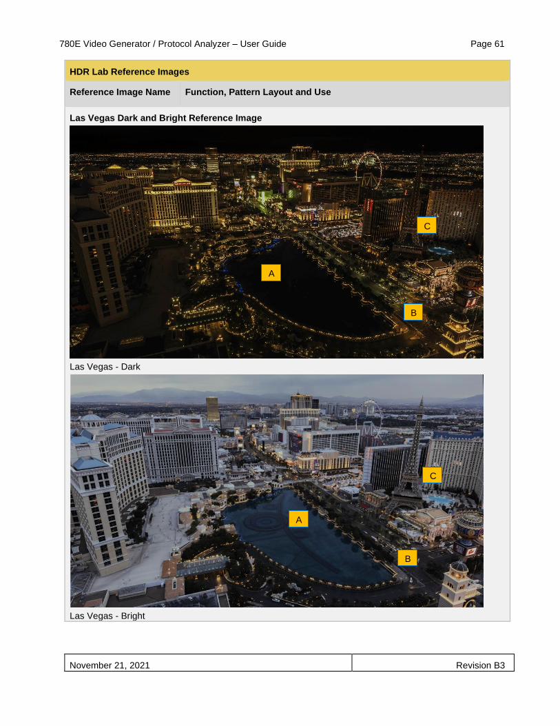
780E Video Generator / Protocol Analyzer – User Guide Page 61
November 21, 2021 Revision B3
HDR Lab Reference Images
Reference Image Name Function, Pattern Layout and Use
Las Vegas Dark and Bright Reference Image
Las Vegas - Dark
Las Vegas - Bright
A
A
B
B
C
C

780E Video Generator / Protocol Analyzer – User Guide Page 62
November 21, 2021 Revision B3
HDR Lab Reference Images
Reference Image Name Function, Pattern Layout and Use
Function This pair of images is good for evaluating how OLEDs and LCDs handle highlights in differing Average Picture Levels of brightness. The set of image is also useful for testing projection system’s ability to reproduce black levels or contrast. The pair of images presents different challenges for OLED HDR TVs vs LCD HDR TVs because the highlights remain the same intensity of light but the ambient light changes dramatically. The Las Vegas Dark image starts off with a very low Average Picture Level (APL) and the Las Vegas Bright Image has a much higher APL which is challenging an APL dependent TV. Some HDR TVs can produce bright highlights when the whole scene is dark but they cannot produce these bright highlights when the scene is getting brighter. As a result some TVs would look less rich in contrast.
Pattern Layout There are two images of the Las Vegas Strip taking from the Cosmopolitan hotel using time lapse photography. The Las Vegas Dark image was taken in the middle of the night. The Las Vegas Bright image was taken in the early morning hours.
Description of Use Images with high Average Picture Level are sometimes difficult to reproduce with current OLED TVs. This technology will result in a loss of contrast where an image has highlights with a high APL. Therefore the Las Vegas Bright image is challenging for OLEDs.
Images with a low Average Picture Level are sometimes difficult to reproduce with LCD TVs.
When subjectively evaluating these images, you should look out for good differentiation in the darkest parts of the image, like the underlying structure in the water in the center of the image [A]. Cars on the street [B] should be individually distinguishable while still providing texture.
The individual letters of the Eiffel tower restaurant [C] advertising should be perfectly sharp and separated. In some of these letters, you should be able to see single pixel transitions, where one pixel is white and the next is nearly black.
The street lights and hotel lighting should appear like realistic lights, adding depth to the scene.
The image with the higher APL should reveal many more details of the area, while maintaining the intensity of lights in a realistic way, still reasonably differentiated from the background.

780E Video Generator / Protocol Analyzer – User Guide Page 63
November 21, 2021 Revision B3
HDR Lab Reference Images
Reference Image Name Function, Pattern Layout and Use
Mountain Lake Reference Image
Function The Mountain Lake reference image German Alps in the early morning contains several useful elements for evaluating HDR displays.
Pattern Layout There is a low hanging cloud in the foreground floating just above the lake. The cloud should really pop out on good HDR display. The lake gives off a reflection that should appear bright silver almost a metallic surface [B].
The image overall should have a warm appearance and should not look bluish in the clouds or sky. If the color temperature on the display is not adjusted correctly, then the mountains in the background would show a intense blue.
Description of Use There should be a lot of detail visible in the trees. There is a path [C] that should be discernable. The fresh younger trees on the left of the path [D] are in the sunlight and should show a lot of detail and there should be some differentiation in the green colors. They should really pop out from the duller greens in the shade in front and older trees behind them.
An examination of the cloud area just above the horizon [E] where the mountains forming the valley occur should not show banding, nor should they look uniform in color at any point. There should not be any chroma elements in the clouds.
A
B
C
D
E

780E Video Generator / Protocol Analyzer – User Guide Page 64
November 21, 2021 Revision B3
HDR Lab Reference Images
Reference Image Name Function, Pattern Layout and Use
Faces Reference Image
Function The woman’s face was shot with a RED Epic Dragon camera. The lighting that was used had a warm color temperature slightly below 3000K to match the candles in the background. The pattern is designed to reveal the TV’s capability to reproduce warm skin tones, soft highlights and clear differentiation in the darkest parts of HDR images.
It also shows potential viewing angle issues and halos around bright objects if the display has such issues.
Pattern Layout The skin tones should look natural and well differentiated in the lights as well as the shadow part below her chin. Hairs should show good structure with no ringing or other artificial edges.
The candles in the background [A] should appear with a soft bouquet, while being noticeably brighter than the face itself.
Description of Use The image should look soft in the background and sharp in the foreground, while the scene light should provide an ambience like in a dinner situation with a lot of near black details.
Hair and skin should show shadow details [B]. The system is not set up properly when there are larger areas of uniform black in the image.
In order to test for viewing angle dependencies, you may choose a specific angle like 30 degree or 45 degree relative to the screen and look for luminance and color changes especially in the dark part of the image.
A B

780E Video Generator / Protocol Analyzer – User Guide Page 65
November 21, 2021 Revision B3
To test your UHD display with HDR Lab:
1. Make the physical connections from the 780E HDMI output port to the UHD TV under test. The illustration
below depicts the test setup.
2. Select the HDMI interface Touch select the desired signal type using the associated activation button
(examples below).
3. Select the format resolution, frame rate using the procedures in Selecting a Signal Type and Resolution.
Format tab menu and select 4K at 30Hz format. Typically you will use a 4K format as indicated below.

780E Video Generator / Protocol Analyzer – User Guide Page 66
November 21, 2021 Revision B3
4. Return to the Main menu to access the Test HDR using the Test HDR button indicated below.
5. Read the EDID of the UHD TV under test by touch selecting the EDID Test button as indicated below. The
example below indicates the presence of the HDR Static Metadata Data block.
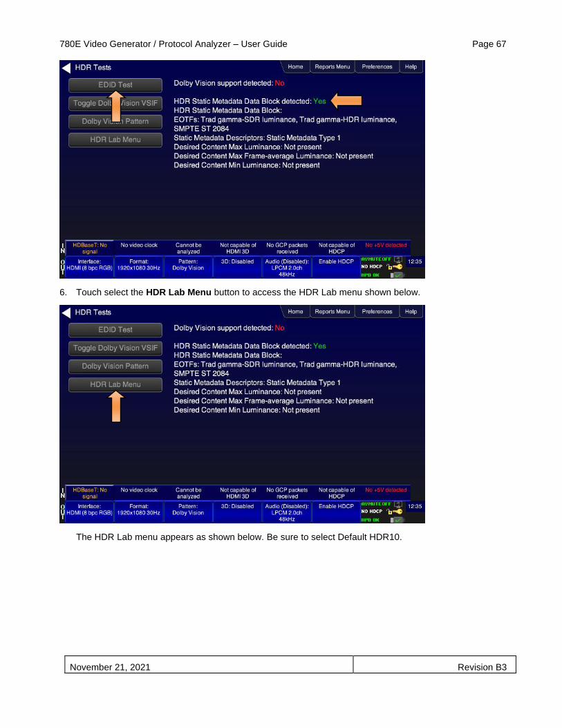
780E Video Generator / Protocol Analyzer – User Guide Page 67
November 21, 2021 Revision B3
6. Touch select the HDR Lab Menu button to access the HDR Lab menu shown below.
The HDR Lab menu appears as shown below. Be sure to select Default HDR10.

780E Video Generator / Protocol Analyzer – User Guide Page 68
November 21, 2021 Revision B3
7. Select a Reference Image or Test Pattern and examine how it is rendered on your HDR display to assess
proper rendering in accordance with your requirements.
8. Choose the settings for color depth, colorimetry, sampling and chroma sampling in accordance with your
requirements.
9. Touch select the Apply Settings activation button.
10. Repeat with different HDR lab test patterns.
11. Repeat with different format resolutions, bit depths, colorimetry settings.
12. Use the Clear button to zero out the transmitted EOTF in the HDR infoframe when done testing HDR. Use
the Disable button to stop sending the HDR infoframe altogether.
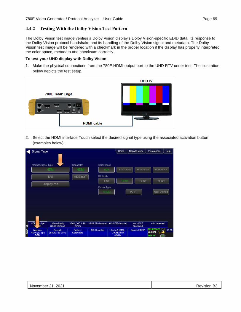
780E Video Generator / Protocol Analyzer – User Guide Page 69
November 21, 2021 Revision B3
4.4.2 Testing With the Dolby Vision Test Pattern
The Dolby Vision test image verifies a Dolby Vision display’s Dolby Vision-specific EDID data, its response to the Dolby Vision protocol handshake and its handling of the Dolby Vision signal and metadata. The Dolby Vision test image will be rendered with a checkmark in the proper location if the display has properly interpreted the color space, metadata and checksum correctly.
To test your UHD display with Dolby Vision:
1. Make the physical connections from the 780E HDMI output port to the UHD RTV under test. The illustration
below depicts the test setup.
2. Select the HDMI interface Touch select the desired signal type using the associated activation button
(examples below).

780E Video Generator / Protocol Analyzer – User Guide Page 70
November 21, 2021 Revision B3
3. Select the format resolution, frame rate using the procedures in Selecting a Signal Type and Resolution.
You will typically use a 4k format. The following example shows 30 Hz frame rate, though this can be used
with any frame rate.
4. The Color Space and Bit Depth for Dolby Vision will be set to RGB 8 bpc. Choose the settings for sampling
and chroma sampling in accordance with your requirements. Access the format settings screen from the
TV Formats page to make these settings as shown below.

780E Video Generator / Protocol Analyzer – User Guide Page 71
November 21, 2021 Revision B3
5. Return to the Main menu to access the Test HDR using the Test HDR button indicated below.
6. Read the EDID of the UHD TV under test by touch selecting the EDID Test button as indicated below. The
example below indicates support for Dolby Vision in the EDID.
7. Enable Dolby Vision using the Toggle Dolby Vision VSIF as indicated below (the result is shown as well).
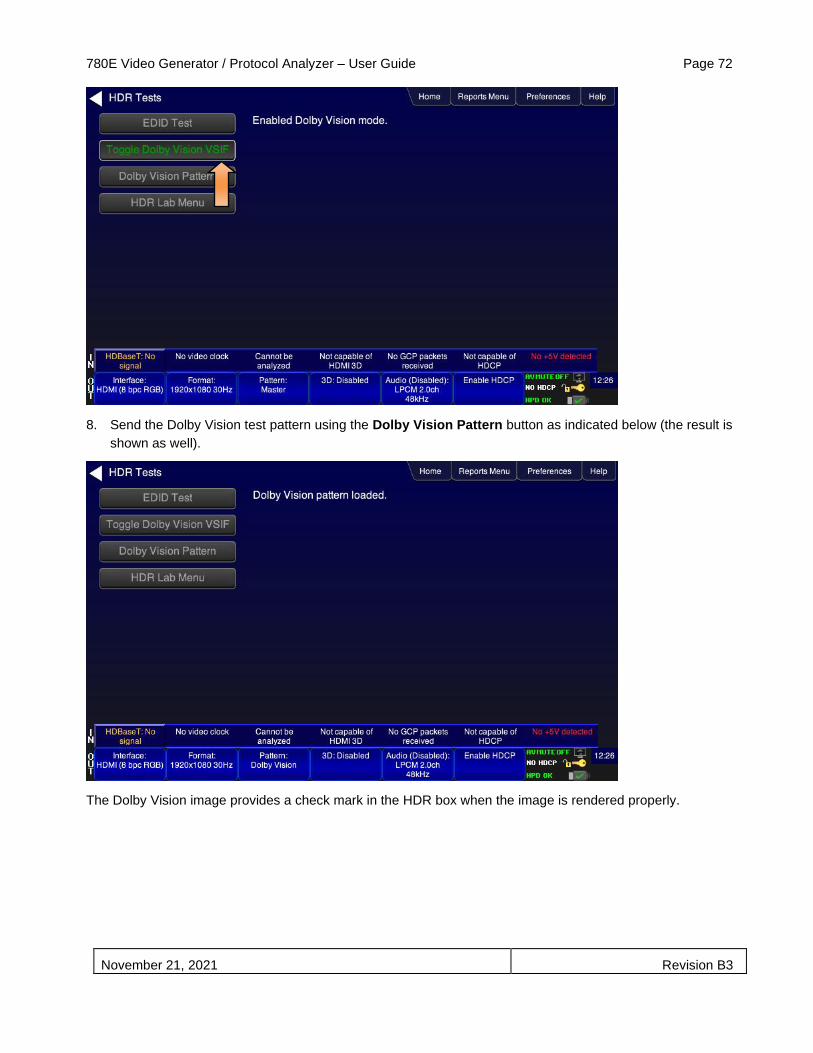
780E Video Generator / Protocol Analyzer – User Guide Page 72
November 21, 2021 Revision B3
8. Send the Dolby Vision test pattern using the Dolby Vision Pattern button as indicated below (the result is
shown as well).
The Dolby Vision image provides a check mark in the HDR box when the image is rendered properly.
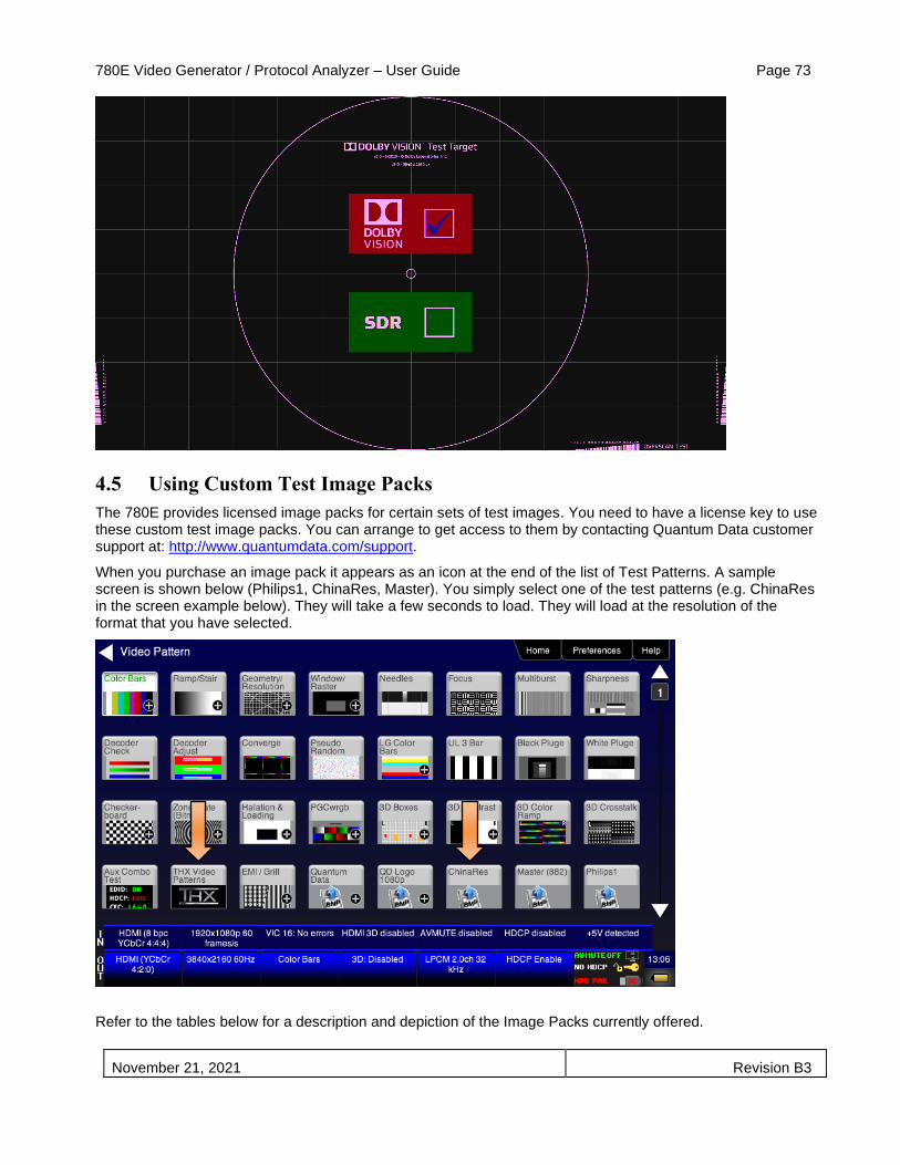
780E Video Generator / Protocol Analyzer – User Guide Page 73
November 21, 2021 Revision B3
4.5 Using Custom Test Image Packs
The 780E provides licensed image packs for certain sets of test images. You need to have a license key to use these custom test image packs. You can arrange to get access to them by contacting Quantum Data customer support at: http://www.quantumdata.com/support.
When you purchase an image pack it appears as an icon at the end of the list of Test Patterns. A sample screen is shown below (Philips1, ChinaRes, Master). You simply select one of the test patterns (e.g. ChinaRes in the screen example below). They will take a few seconds to load. They will load at the resolution of the format that you have selected.
Refer to the tables below for a description and depiction of the Image Packs currently offered.

780E Video Generator / Protocol Analyzer – User Guide Page 74
November 21, 2021 Revision B3

780E Video Generator / Protocol Analyzer – User Guide Page 75
November 21, 2021 Revision B3
Table 4-4: Custom Test Image Packs – ChinaRes Pattern
ChinaRes Pattern Pack
This is a bitmap that is available through the Image Packs option. The ChinaRes test pattern is specified by the National Testing and Inspection Center for Radio and TV Products of China.
The image pack includes both a standard definition aspect ratio (shown right) and a high definition aspect ratio. This test pattern is supported at: 1920x1080, 1280x720, 720x576 and 720x480 resolutions.
The following is a description of the elements in this test image 1. Overscan gauges to determine percentage of
overscan.
2. Centered cross, centered circles, and centered grid to test centering and concentricity.
3. White grid to test convergence.
4. Central resolution wedge gauges for vertical, horizontal, and diagonal resolutions.
5. Corner resolution wedge gauges for vertical and horizontal resolutions.
6. 4-quadrant horizontal and vertical test areas to judge resolution and display artifacts.
7. Color bar for testing color purity and chroma delay.
8. 10-step grayscale to test brightness, contrast, and luminance.
9. Split (left and right) grayscales for testing dark-field and bright-field gray levels.
• Average picture level is approximately 50%.
1
2
3
4
5
6
7
8
9

780E Video Generator / Protocol Analyzer – User Guide Page 76
November 21, 2021 Revision B3
Table 4-5: Custom Test Image Packs – THX Test Patterns

780E Video Generator / Protocol Analyzer – User Guide Page 77
November 21, 2021 Revision B3
THX Test Patterns
The THX Pattern Pack offers a variety of test patterns for calibrating the luminance and chrominance of high end 3D-capable HDTVs. The following is a list of test patterns provided in this optional test pattern package.
3D Convergence - test patterns to align pixels for proper convergence.
3D Crosstalk – test patterns to determine level of 3D crosstalk.
Color Gamut – 2D/3D primary and secondary color patterns to fine-tune colors and gamma.
Picture performance – pattern within THX Optimizer to verify accuracy of skin tones.
THX Optimizer - test patterns to easily adjust brightness, contrast, color, tint, etc.

780E Video Generator / Protocol Analyzer – User Guide Page 78
November 21, 2021 Revision B3
Table 4-5: Custom Test Image Packs – THX Test Patterns
1. Uniformity - 2D/3D circle patterns to determine luminance and chrominance screen uniformity.
THX box - 2D/3D grayscale test patterns to accurately adjust white point and gamma.

780E Video Generator / Protocol Analyzer – User Guide Page 79
November 21, 2021 Revision B3
Table 4-6: Custom Test Image Packs – ISF® Test Patterns
ISF Test Patterns
The ISF Pattern Pack offers patterns for verifying white and black levels as well as geometry and resolution for calibrating high end HDTVs
Black Pluge - for calibrating black level for dynamic range.
White Pluge - for calibrating white level for dynamic range.
Geometry/Resolution – test pattern to verify geometry and resolution.
Red-Blue Color Multiburst – test pattern for verifying chroma resolution for red and blue transitions.
4.6 Outputting 3D Test Patterns through HDMI or HDBaseT
This subsection describes how to render 3D test patterns on an HDTV. The 780E supports Side-by-Side, Top-and-Bottom and Frame Packing (for both interlaced and progressive timings) 3D format structures.
4.6.1 Configurations for Rendering 3D Bitmaps on an HDMI or HDBaseT Sink Device
Typically you will render 3D bitmap images with the 780E directly connected to an HDTV or projector. This configuration is shown below:
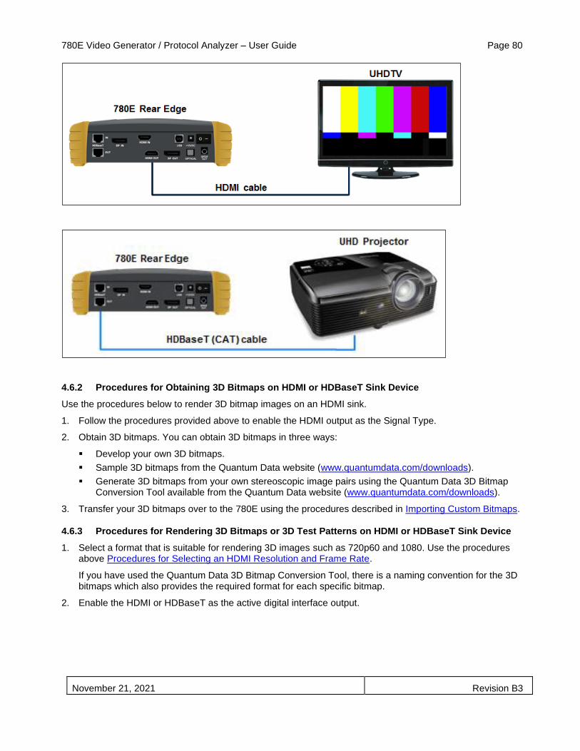
780E Video Generator / Protocol Analyzer – User Guide Page 80
November 21, 2021 Revision B3
4.6.2 Procedures for Obtaining 3D Bitmaps on HDMI or HDBaseT Sink Device
Use the procedures below to render 3D bitmap images on an HDMI sink.
1. Follow the procedures provided above to enable the HDMI output as the Signal Type.
2. Obtain 3D bitmaps. You can obtain 3D bitmaps in three ways:
▪ Develop your own 3D bitmaps.
▪ Sample 3D bitmaps from the Quantum Data website (www.quantumdata.com/downloads).
▪ Generate 3D bitmaps from your own stereoscopic image pairs using the Quantum Data 3D Bitmap Conversion Tool available from the Quantum Data website (www.quantumdata.com/downloads).
3. Transfer your 3D bitmaps over to the 780E using the procedures described in Importing Custom Bitmaps.
4.6.3 Procedures for Rendering 3D Bitmaps or 3D Test Patterns on HDMI or HDBaseT Sink Device
1. Select a format that is suitable for rendering 3D images such as 720p60 and 1080. Use the procedures above Procedures for Selecting an HDMI Resolution and Frame Rate.
If you have used the Quantum Data 3D Bitmap Conversion Tool, there is a naming convention for the 3D bitmaps which also provides the required format for each specific bitmap.
2. Enable the HDMI or HDBaseT as the active digital interface output.

780E Video Generator / Protocol Analyzer – User Guide Page 81
November 21, 2021 Revision B3
3. Touch select 3D Output option from the top level menu shown below.
The following screen will appear:
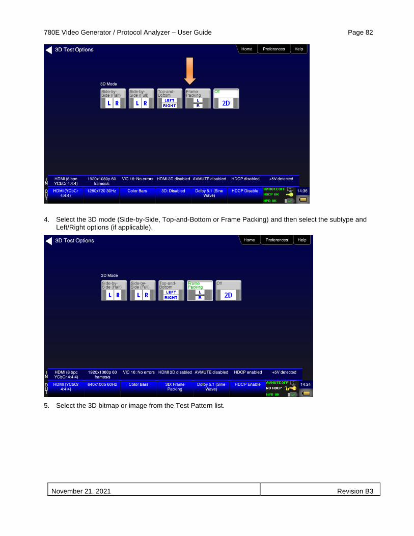
780E Video Generator / Protocol Analyzer – User Guide Page 82
November 21, 2021 Revision B3
4. Select the 3D mode (Side-by-Side, Top-and-Bottom or Frame Packing) and then select the subtype and Left/Right options (if applicable).
5. Select the 3D bitmap or image from the Test Pattern list.

780E Video Generator / Protocol Analyzer – User Guide Page 83
November 21, 2021 Revision B3
Note: If you are using one of the 3D bitmaps (as opposed to a standard 3D test pattern) you will have to make sure that the 3D bitmap you use matches your selection of 3D formats and timing (resolution). In the example above, a 3D Frame Packing bitmap is selected for 1280 x 720. Therefore you have to make sure that you select that specific timing (i.e. 1280 x 720) and that specific 3D format structure (Frame Packing).
4.7 How to Scroll or Pan a Bitmap Pattern
This subsection describes how to scroll bitmaps on your 780E.
4.7.1 Guidelines for Scrolling Bitmaps
There are two ways you can animate (move) a bitmap image: 1) image shifting (scrolling); 2) panning. You can shift or scroll a bitmap image that you have imported into the 780E by modifying the X and Y parameters or by dragging and panning. When you use the X and Y parameters, you are limited to linear scrolling. With panning you can move the image in non-linear motions.
You can only scroll bitmaps whose overall pixel resolution is smaller than the resolution of the active format and you can only scroll them within the bounds of the resolution of the active format. You cannot scroll the standard test patterns in the 780E.
In order to scroll a bitmap the name of the bitmap has to be “zp.bmp.” But you can scroll any bitmap. You just have to make sure that you have named it “zp.bmp” (without the quotes). The zone plate bitmap is the only bitmap that comes standard with the 780E.
4.7.2 Procedures for Scrolling Bitmaps
Use the following procedure to scroll your bitmaps.
1. Touch select the desired bitmap image, e.g. Zone Plate image from the list of video patterns.

780E Video Generator / Protocol Analyzer – User Guide Page 84
November 21, 2021 Revision B3
2. Double touch select on the Zone Plate bitmap to access its options.
The Zone Plate Options menu appears:
3. Specify the Horizontal Movement by touch selecting the appropriate setting Slow, Medium, Fast.
4. Specify the Vertical Movement by touch selecting the appropriate setting Slow, Medium, Fast.
The pattern will begin to move around the raster of the display in accordance with the horizontal and vertical settings. To halt the motion, touch Stop for either or both of the Horizontal Movement and Vertical Movement.
4.7.3 Procedures for Panning Bitmaps
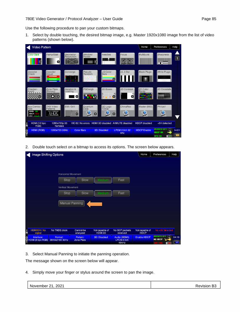
780E Video Generator / Protocol Analyzer – User Guide Page 85
November 21, 2021 Revision B3
Use the following procedure to pan your custom bitmaps.
1. Select by double touching, the desired bitmap image, e.g. Master 1920x1080 image from the list of video patterns (shown below).
2. Double touch select on a bitmap to access its options. The screen below appears.
3. Select Manual Panning to initiate the panning operation.
The message shown on the screen below will appear.
4. Simply move your finger or stylus around the screen to pan the image.

780E Video Generator / Protocol Analyzer – User Guide Page 86
November 21, 2021 Revision B3

780E Video Generator / Protocol Analyzer – User Guide Page 87
November 21, 2021 Revision B3
4.8 Testing Digital Audio on an HDTV or A/V Receiver
This section provides procedures for testing digital audio on an HDTV or A/V Receiver.
Note: It is recommended not to select bitmap images when outputting compressed audio clips.
Table 4-5 below summarizes the 780E support for digital audio.
Table 4-5: Summary of Audio Signal Types
Audio Signal Type Interfaces Description
Dolby 5.1
▪ HDMI ▪ HDBaseT ▪ Optical ▪ SPDIF
Provides a set of Dolby Digital 5.1 noise patterns:
▪ 500-2kHz Pink ▪ 20-20kHz Pink ▪ Sine Wave ▪ Impulse ▪ Polarity ▪ Auto Time Delay
Dolby Digital Plus 7.1
▪ HDMI ▪ HDBaseT
Provides a set of Dolby Digital Plus 7.1 sine wave clips:
▪ 2.0 192kHz – 2 channel @ 192kHz sampling rate ▪ 5.1 192kHz – 6 channel @ 192kHz sampling rate ▪ 7.1 192kHz – 8 channel @ 192kHz sampling rate
DTS-ES 6.1
▪ HDMI ▪ HDBaseT ▪ Optical ▪ SPDIF
Provides a set of DTS ES 6.1 noise pattern clips:
▪ 500-2kHz Pink ▪ 20-20kHz Pink ▪ Sine Wave ▪ Impulse ▪ Polarity ▪ Auto Time Delay
Dolby TrueHD
▪ HDMI ▪ HDBaseT
Provides a set of Dolby TrueHD Hi Bit Rate sine wave clips:
▪ 192kHz 7.1 1kHz TrueHD – 8 channel @ 192kHz sampling rate ▪ 192kHz 7.1 2kHz TrueHD – 2 channel @ 192kHz sampling rate
DTS HD Master Audio
▪ HDMI ▪ HDBaseT
Provides a set of DTS-HD Hi Bit Rate sine wave clips:
▪ 192kHz 7.1 HDMA – 8 channel @ 192kHz sampling rate ▪ 192kHz 5.1 HDMA – 6 channel @ 192kHz sampling rate
PCM Sine Wave (programmable)
▪ HDMI ▪ HDBaseT ▪ DisplayPort ▪ Optical ▪ SPDIF
Provides programmable sine waves:
▪ Bits per sample – 16, 20, 24 ▪ Sampling rate (kHz) – 32, 44.2, 48, 88.2, 96, 176.4, 192 ▪ Channels – 2.0, 2.1, 5.1, 6.1, 7.1 ▪ Level – 0dB to -99dB in 1dB or 3dB increments (per channel) ▪ Frequency – 0.01kHz to 20kHz in 1Hz, 10Hz, 100Hz or 1000Hz
increments (per channel) ▪ Mute – On/Off (per channel)
4.8.1 Connecting the 780E to an Audio Rendering Device
Use the following procedures to make the physical connections from the 780E to the audio rendering device under test.
1. Make the cable connection between the appropriate the 780E video output connector (e.g. HDMI OUT, HDBaseT OUT, DisplayPort OUT, SPDIF or OPTICAL) and the input connector of the audio rendering device using the cables supplied.

780E Video Generator / Protocol Analyzer – User Guide Page 88
November 21, 2021 Revision B3
Alternatively you may connect from the 780E video output connector to an HDTV through an HDMI repeater device such as an A/V receiver. In this case make the HDMI connection between the HDMI OUT connector on the 780E and the HDMI input of the HDMI repeater device using an HDMI-to-HDMI cable. Then connect the HDTV to an active output on the repeater. The following illustrations depict the typical test configurations.
The following illustrations depict the test setups for the HDMI audio, SPDIF audio and optical (TOSLink). Note also that you can test directly into an HDTV without going through an A/V receiver.
The following illustration depicts the test setups for the HDBaseT audio to an HDBaseT/HDMI switch then to an A/V Receiver.

780E Video Generator / Protocol Analyzer – User Guide Page 89
November 21, 2021 Revision B3
The following illustration depicts the test setups for the DisplayPort audio to DisplayPort monitor.
4.8.2 Procedures for Testing a Sink with Dolby Digital or DTS Audio Test Patterns
Use the following procedures to run audio tests using Dolby Digital and or DTS audio test patterns. These test patterns are useful for calibrating the room acoustics in a home theatre system.
1. Make the physical connections between the 780E and the audio rendering device as described in the procedures above.
2. Select the digital interfaces—HDMI or HDBaseT—output as shown below.
Note for testing SPDIF of TOSLink this is not necessary.
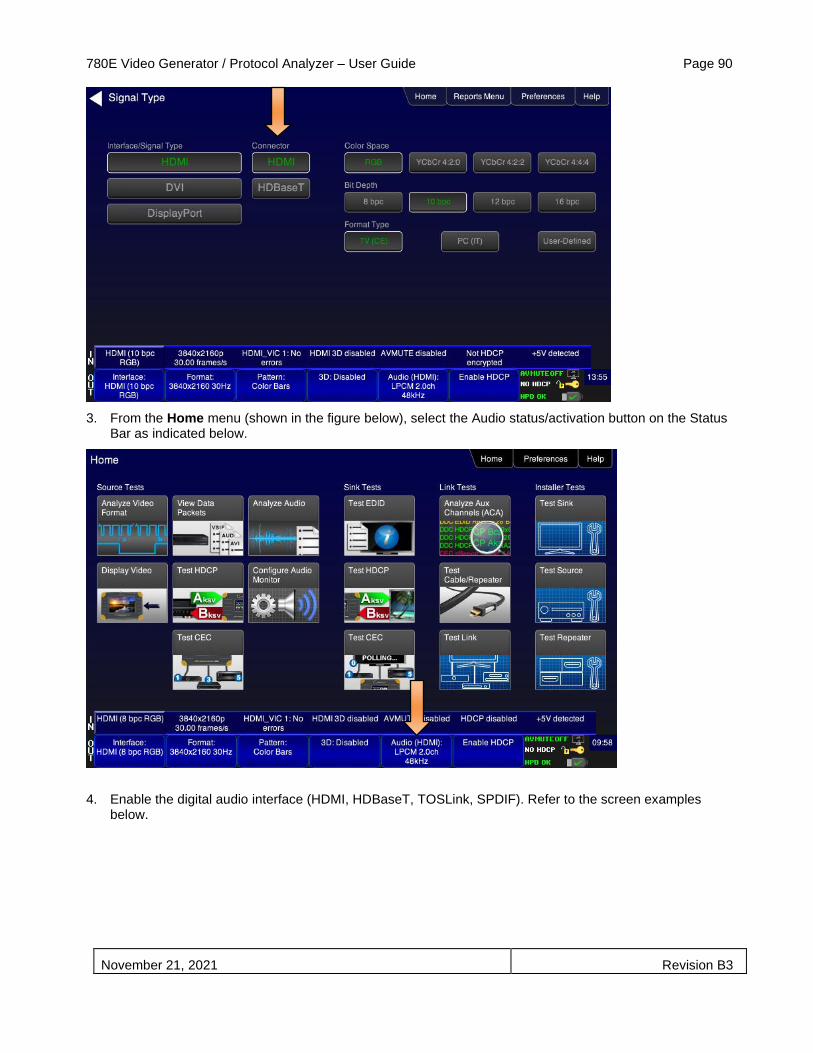
780E Video Generator / Protocol Analyzer – User Guide Page 90
November 21, 2021 Revision B3
3. From the Home menu (shown in the figure below), select the Audio status/activation button on the Status Bar as indicated below.
4. Enable the digital audio interface (HDMI, HDBaseT, TOSLink, SPDIF). Refer to the screen examples below.

780E Video Generator / Protocol Analyzer – User Guide Page 91
November 21, 2021 Revision B3
5. Touch select the desired Interface from the Audio Pattern menu (refer to the screen shot above which shows HDMI). The options are Optical, SPDIF or HDMI.
6. Double touch select the Dolby Digital 5.1 or DTS-ES 6.1 item on the Audio Pattern menu (refer to the screen shot above).
The following screen appears (DTS-ES shown):
7. Touch select the desired audio test pattern. (500-2kHz Pink is shown selected in the sample screen shot above and Sine Wave shown in the screen shot below.) Use the information in Table 4-6 below to understand the application of each audio test pattern.

780E Video Generator / Protocol Analyzer – User Guide Page 92
November 21, 2021 Revision B3
Note: When selecting Sine Wave at 1kHz or 4kHz the 780 will output 5.0 audio. This is because the subwoofer frequency response is 20Hz to 200Hz.
Table 4-6: Audio Pattern Tests
Pattern Format Interfaces Range of Values
Pink Noise Patterns:
▪ 500-2kHz Pink noise ▪ 20-20kHz Pink noise
Application:
▪ Tests sound pressure level ▪ Main speaker frequency
response
Dolby Digital 5.1
HDMI
HDBASET
SPDIF
Optical
▪ Individually selectable channels
▪ Cycle – cycling through each channel; 8 seconds per channel
DTS-ES 6.1
HDMI
HDBASET
SPDIF
Optical
Sine Wave Pattern:
▪ 63Hz ▪ 125Hz ▪ 1kHz (5.0 only - no subwoofer) ▪ 4kHz (5.0 only - no subwoofer)
Application:
▪ Speaker distortion
Dolby Digital 5.1
HDMI
HDBASET
SPDIF
Optical
Channel selection:
▪ Select All channels or…
▪ Cycle – cycling through each channel; 8 seconds per channel
DTS-ES 6.1
HDMI
HDBASET
SPDIF
Optical
Impulse Pattern
Application:
▪ Early reflections
Dolby Digital 5.1
HDMI
HDBASET
SPDIF
Optical
▪ Individually selectable channels
▪ Cycle – cycling through each channel; 8 seconds per channel
DTS-ES 6.1 HDMI
HDBASET
SPDIF
Optical

780E Video Generator / Protocol Analyzer – User Guide Page 93
November 21, 2021 Revision B3
Table 4-6: Audio Pattern Tests
Pattern Format Interfaces Range of Values
Polarity Pattern
Application:
▪ Polarity of the speaker wires
Dolby Digital 5.1
HDMI
HDBASET
SPDIF
Optical
▪ Individually selectable channels
▪ Cycle – cycling through each channel; 8 seconds per channel
DTS-ES 6.1 HDMI
HDBASET
SPDIF
Optical
Auto Time Delay
Application:
▪ Fine tunes sound convergence using the distance setting in an AVR
Dolby Digital 5.1
HDMI
HDBASET
SPDIF
Optical
▪ Individually selectable channels
▪ Cycle – cycling through each channel; 8 seconds per channel
DTS-ES 6.1 HDMI
HDBASET
SPDIF
Optical
4.8.3 Procedures for Testing a Display with Dolby Digital or DTS Sine Wave Clips
Table 4-7 below summarizes the 780E support for digital audio.
Table 4-7: Summary of Audio Sine Wave Clips
Sine Wave Audio Clips Interfaces Description
Dolby Digital Plus 7.1
HDMI
HDBASET
Provides a set of Dolby Digital Plus 7.1 sine wave clips:
▪ 2.0 192kHz – 2 channel @ 192kHz sampling rate ▪ 5.1 192kHz – 6 channel @ 192kHz sampling rate ▪ 7.1 192kHz – 8 channel @ 192kHz sampling rate
Dolby TrueHD
HDMI
HDBASET
Provides a set of Dolby TrueHD Hi Bit Rate sine wave clips:
▪ 192kHz 7.1 1kHz TrueHD – 8 channel @ 192kHz sampling rate ▪ 192kHz 7.1 2kHz TrueHD – 2 channel @ 192kHz sampling rate
DTS HD HRA
HDMI
HDBASET
Provides a set of DTS-HD Hi Bit Rate sine wave clips:
▪ 192kHz 7.1 5376kb HDHRA – 8 channel @ 192kHz sampling rate ▪ 192kHz 5.1 3840kb HDHRA – 6 channel @ 192kHz sampling rate ▪ 192kHz 7.1 5760kb HDHRA – 8 channel @ 192kHz sampling rate
DTS HD Master Audio
HDMI
HDBASET
Provides a set of DTS-HD Hi Bit Rate sine wave clips:
▪ 192kHz 7.1 HDMA – 8 channel @ 192kHz sampling rate ▪ 192kHz 5.1 HDMA – 6 channel @ 192kHz sampling rate
Use the procedures below for testing multi-channel Dolby or DTS sine wave using clips.
1. Make the cable connection between the appropriate the 780E video output connector (e.g. HDMI, HDBaseT OUT, SPDIF or OPTICAL) and the input connector of the audio rendering device using the cables supplied.
2. From the top level menu (shown in the figure below), select Audio Test Tone.

780E Video Generator / Protocol Analyzer – User Guide Page 94
November 21, 2021 Revision B3
The Audio Pattern (Test Tone) menu appears as shown below:
Note: ARC is not currently supported on the 780E
3. Touch select the desired Interface from the Audio Pattern (Test Tone) menu (refer to the screen shot above which shows HDMI). The options are Optical, SPDIF or HDMI.
4. Double touch select the Dolby Digital Plus 7.1/TrueHD or DTS-HD item on the Audio Pattern (Test Tone) menu (refer to the screen shot above).
One of the following screens will appear:

780E Video Generator / Protocol Analyzer – User Guide Page 95
November 21, 2021 Revision B3
5. Touch select the desired clip.
4.8.4 Procedures for Testing with Programmable Sine Waves
Use the procedures below for testing with programmable sine waves. Table 4-8 below describes the audio sine wave parameters that can be configured.

780E Video Generator / Protocol Analyzer – User Guide Page 96
November 21, 2021 Revision B3
Table 4-8: Sine Wave Audio Pattern
Pattern Interface Description
PCM Sine Wave (programmable)
▪ HDMI ▪ HDBaseT ▪ DisplayPort ▪ Optical ▪ SPDIF
Provides programmable sine waves:
▪ Bits per sample – 16, 20, 24 ▪ Sampling rate (kHz) – 32, 44.2, 48, 88.2, 96, 176.4, 192 ▪ Channels – 2.0, 2.1, 5.1, 6.1, 7.1 ▪ Level – 0dB to -99dB in 1dB and 3dB increments (per
channel) ▪ Frequency – 0.01kHz to 20kHz (per channel) in 1Hz, 10Hz,
100Hz and 1000Hz increments ▪ Mute – On/Off (per channel)
1. Make the cable connection between the appropriate the 780E video output connector (e.g. HDMI OUT, HDBaseT OUT, DisplayPort OUT, SPDIF or OPTICAL) and the input connector of the audio rendering device using the cables supplied.
2. Select the digital interfaces—HDMI, DisplayPort or HDBaseT—output as shown below. The examples used in this subsection are for HDMI but the procedure applies to HDBaseT and DisplayPort as well.
Note for testing SPDIF of TOSLink this is not necessary.
3. From the Home menu (shown in the figure below), select the Audio status/activation button on the Status Bar as indicated below.

780E Video Generator / Protocol Analyzer – User Guide Page 97
November 21, 2021 Revision B3
The Audio Pattern (Test Tone) menu appears as shown below:
Note: ARC is not currently supported on the 780E.
4. Touch select the desired Interface (shown in the screen above) to select the active digital audio output. (Optical selected in the example screen shot above.)
5. Double touch select the PCM Sine Wave item (shown in the screen above).
The PCM Sine Wave Options menu appears as shown below:

780E Video Generator / Protocol Analyzer – User Guide Page 98
November 21, 2021 Revision B3
6. Touch select the values for the Bits per Sample using the three buttons provided. (24 bits is selected in the example above.)
7. Touch select the Sampling Rate by incrementing the associated arrows adjacent to the current value. (Refer to the screen shot above which shows 96 kHz selected.)
8. Touch select the Channels by incrementing the associated arrows adjacent to the current value. (Refer to the screen shot above which shows 7.1 selected.)
9. Specify the Level by touch selecting the associated increment or decrement buttons showing +3dB and -3dB. (Refer to the screen shot above which shows the level at 0dB.) Repeat for each channel. You can specify the level for each channel individually.
10. Specify the Frequency of the sine wave by touch selecting the associated increment or decrement buttons. There are four buttons on the left of the current value. (1.00 kHz is shown selected in the screen shot above) The four buttons provide a variety of increment and decrement values for convenience. Repeat for each channel. You can specify the frequency for each channel individually in 1 Hz increments
11. Specify which channels you want to mute by touch selecting a channel and then touch selecting the Mute activation button. You can only select one channel at a time. Note that only the active channels (the ones specified in Channels will be selectable. (Refer to the screen shot above.)
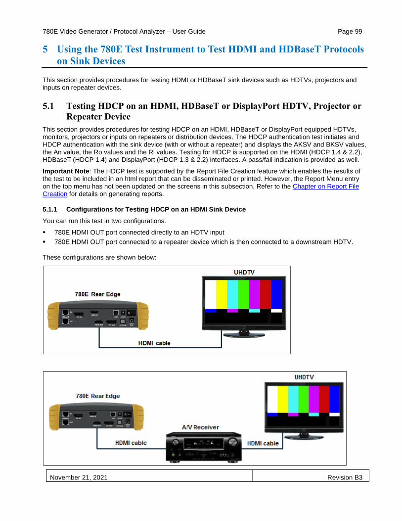
780E Video Generator / Protocol Analyzer – User Guide Page 99
November 21, 2021 Revision B3
5 Using the 780E Test Instrument to Test HDMI and HDBaseT Protocols
on Sink Devices
This section provides procedures for testing HDMI or HDBaseT sink devices such as HDTVs, projectors and inputs on repeater devices.
5.1 Testing HDCP on an HDMI, HDBaseT or DisplayPort HDTV, Projector or
Repeater Device
This section provides procedures for testing HDCP on an HDMI, HDBaseT or DisplayPort equipped HDTVs, monitors, projectors or inputs on repeaters or distribution devices. The HDCP authentication test initiates and HDCP authentication with the sink device (with or without a repeater) and displays the AKSV and BKSV values, the An value, the Ro values and the Ri values. Testing for HDCP is supported on the HDMI (HDCP 1.4 & 2.2), HDBaseT (HDCP 1.4) and DisplayPort (HDCP 1.3 & 2.2) interfaces. A pass/fail indication is provided as well.
Important Note: The HDCP test is supported by the Report File Creation feature which enables the results of the test to be included in an html report that can be disseminated or printed. However, the Report Menu entry on the top menu has not been updated on the screens in this subsection. Refer to the Chapter on Report File Creation for details on generating reports.
5.1.1 Configurations for Testing HDCP on an HDMI Sink Device
You can run this test in two configurations.
▪ 780E HDMI OUT port connected directly to an HDTV input
▪ 780E HDMI OUT port connected to a repeater device which is then connected to a downstream HDTV.
These configurations are shown below:

780E Video Generator / Protocol Analyzer – User Guide Page 100
November 21, 2021 Revision B3
5.1.2 Configurations for Testing HDCP on an HDBaseT Sink Device
You can run this test in two configurations.
▪ 780E HDBaseT OUT port connected directly to a projector’s input
These configurations are shown below:
5.1.3 Configurations for Testing HDCP on a DisplayPort Monitor
You can run this test in the following configuration.
▪ 780E DisplayPort OUT port connected directly to a projector’s input
These configurations are shown below:
5.1.4 Procedures for Testing HDCP on an HDMI, HDBaseT or DisplayPort Sink Device
Use the procedures below to run an HDCP test on an HDMI, HDBaseT or DisplayPort sink.
1. Make the physical connections between the 780E HDMI, HDBaseT or DisplayPort OUT connector and the sink device under test.
2. Enable the HDMI, HDBaseT or DisplayPort interface. If the interface output type you are using is not selected, then access the Signal Type screen (first screen below); then select the output interface (second screen below). The screen selection used in the example below is HDMI but the procedure applies to HDBaseT and DisplayPort as well.

780E Video Generator / Protocol Analyzer – User Guide Page 101
November 21, 2021 Revision B3
3. Touch select Test HDCP from the Home menu shown below.

780E Video Generator / Protocol Analyzer – User Guide Page 102
November 21, 2021 Revision B3
4. Touch select Enable from the HDCP Output Tests menu shown below.
The Pass/Fail results for HDCP 2.2 for HDMI are presented on the display as shown below:
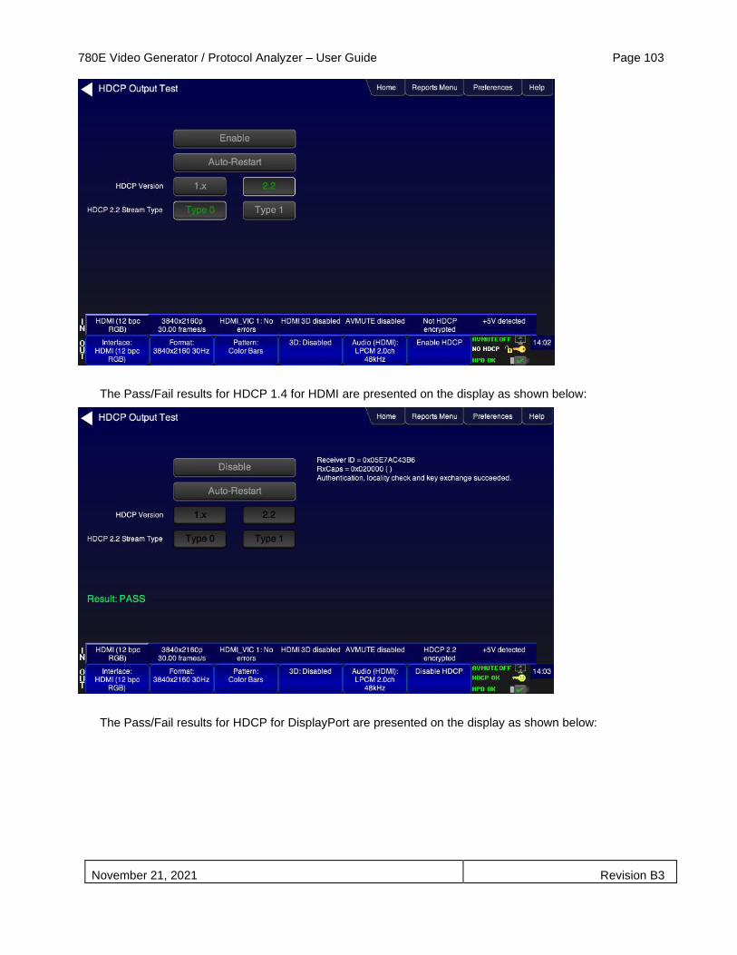
780E Video Generator / Protocol Analyzer – User Guide Page 103
November 21, 2021 Revision B3
The Pass/Fail results for HDCP 1.4 for HDMI are presented on the display as shown below:
The Pass/Fail results for HDCP for DisplayPort are presented on the display as shown below:

780E Video Generator / Protocol Analyzer – User Guide Page 104
November 21, 2021 Revision B3
5. Touch select Auto-Restart to restart HDCP authentication.
Alternatively you can run this test from the command line as follows:
HDCP?
0 // indicates pass (1 indicates a failure)
5.2 Verifying the EDID on an HDMI, HDTV, HDBaseT Projector or HDMI
Repeater Device
This section provides procedures for verifying and viewing the EDID of an HDMI, HDBaseT or DisplayPort HDTV, monitor, projector or a repeater device such as an A/V receiver. You can also compare two EDIDs.
Important Note: The EDID test is supported by the Report File Creation feature which enables the results of the test to be included in an html report that can be disseminated or printed. However, the Report Menu entry on the top menu has not been updated on the screens in this subsection. Refer to the Chapter on Report File Creation for details on generating reports.
5.2.1 Configurations for Verifying and Viewing the EDID on an HDMI Sink Device
The following illustrations depict the typical test setups. You can either connect directly to an HDTV or to a repeater device connected to an HDTV.

780E Video Generator / Protocol Analyzer – User Guide Page 105
November 21, 2021 Revision B3
5.2.2 Configurations for Verifying and Viewing the EDID on an HDBaseT Sink Device or Input of an HDBaseT Distribution Device
The following illustrations depict the typical test setups. You can either connect directly to an HDBaseT projector or input of an HDBaseT distribution device.
5.2.3 Configurations for Verifying and Viewing the EDID on a DisplayPort Monitor
The following illustration depicts the typical test setup for testing a DisplayPort monitor.
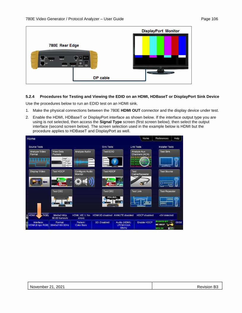
780E Video Generator / Protocol Analyzer – User Guide Page 106
November 21, 2021 Revision B3
5.2.4 Procedures for Testing and Viewing the EDID on an HDMI, HDBaseT or DisplayPort Sink Device
Use the procedures below to run an EDID test on an HDMI sink.
1. Make the physical connections between the 780E HDMI OUT connector and the display device under test.
2. Enable the HDMI, HDBaseT or DisplayPort interface as shown below. If the interface output type you are using is not selected, then access the Signal Type screen (first screen below); then select the output interface (second screen below). The screen selection used in the example below is HDMI but the procedure applies to HDBaseT and DisplayPort as well.

780E Video Generator / Protocol Analyzer – User Guide Page 107
November 21, 2021 Revision B3
3. Touch select EDID from the Home menu shown below.
4. Touch select the Read activation button from the EDID Test menu shown below.
The EDID information is presented on multiple pages on the display. An example of a few of the pages of an EDID listing is shown below. You scroll through all the pages using the scroll bar at the right side of the listing. In addition, the EDID test runs a check on the EDID header and checksum to determine if the EDID is valid and runs a portion of the EDID compliance test of the HDMI Compliance Test Specification.

780E Video Generator / Protocol Analyzer – User Guide Page 108
November 21, 2021 Revision B3
The following screen shows an example of the summary page of a DisplayPort EDID.

780E Video Generator / Protocol Analyzer – User Guide Page 109
November 21, 2021 Revision B3
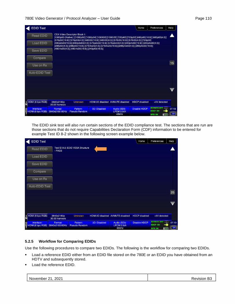
780E Video Generator / Protocol Analyzer – User Guide Page 110
November 21, 2021 Revision B3
The EDID sink test will also run certain sections of the EDID compliance test. The sections that are run are those sections that do not require Capabilities Declaration Form (CDF) information to be entered for example Test ID 8-2 shown in the following screen example below.
5.2.5 Workflow for Comparing EDIDs
Use the following procedures to compare two EDIDs. The following is the workflow for comparing two EDIDs.
▪ Load a reference EDID either from an EDID file stored on the 780E or an EDID you have obtained from an HDTV and subsequently stored.
▪ Load the reference EDID.

780E Video Generator / Protocol Analyzer – User Guide Page 111
November 21, 2021 Revision B3
▪ Connect the 780E HDMI OUT, HDBaseT or DisplayPort OUT port to the sink device whose EDID you wish to compare with your reference EDID.
▪ Compare the two EDIDs.
Note: To load an EDID use the procedures described in Adding Reference EDIDs for Use in Testing HDMI Devices.
5.2.6 Procedures for Comparing EDIDs
Use the following procedures to compare two EDIDs.
1. Follow the procedures above for Selecting a Signal Type and Resolution to enable the desired output (HDMI, HDBaseT, or DisplayPort).
2. Touch select Test EDID from the Home menu shown below.
3. Touch select Load from the EDID Tests menu. The following screen results.

780E Video Generator / Protocol Analyzer – User Guide Page 112
November 21, 2021 Revision B3
4. Touch select the Load File option from the EDID Test menu shown above that you want to use as a reference EDID. The options:
▪ Load File – Loads from an EDID file stored on the 780E file system
▪ Load TV Default – Loads the standard reference EDID for a TV from the 780E file system
▪ Load AVR Default - Loads the standard reference EDID for a AVR from the 780E file system
5. If you have selected the Load File option, the following screen results. Select the file that you wish to use as the reference EDID. In the example below there is only one file.
The EDID is loaded and displayed on the screen.

780E Video Generator / Protocol Analyzer – User Guide Page 113
November 21, 2021 Revision B3
6. Connect the 780E HDMI OUT, HDBaseT OUT or DisplayPort OUT port to a sink device (e.g. HDTV, display, projector or A/V receiver) and touch select Compare. The results will show PASS or FAIL with an explanation as in the following two screen examples.
When a failure occurs the following message is displayed.

780E Video Generator / Protocol Analyzer – User Guide Page 114
November 21, 2021 Revision B3
5.3 Verifying the EDID of a High Dynamic Range (HDR)-Capable HDMI
UHDTV
This section describes how to verify a UHDTV’s HDR-capable EDID.
Important Note: The EDID test is supported by the Report File Creation feature which enables the results of the test to be included in an html report that can be disseminated or printed. However, the Report Menu entry on the top menu has not been updated on the screens in this subsection. Refer to the Chapter on Report File Creation for details on generating reports.
5.3.1 Configurations for Verifying HDR EDID on an HDMI UHD TV
Typically this test is run by directly connecting the 780E to the UHD TV.
5.3.2 Procedures for Verifying HDR EDID on an HDMI UHD TV
Use the following procedures to verify HDR EDID on UHD TV.
1. Connect the 780E HDMI OUT port to an HDMI UHD TV using the configuration guidelines provided above.

780E Video Generator / Protocol Analyzer – User Guide Page 115
November 21, 2021 Revision B3
2. Enable the HDMI interface as shown below. If the interface output type you are using is not selected, then access the Signal Type screen (first screen below); then select the output interface (second screen below). The screen selection used in the example below is HDMI but the procedure applies to HDBaseT and DisplayPort as well.
3. Touch select EDID from the Home menu shown below.

780E Video Generator / Protocol Analyzer – User Guide Page 116
November 21, 2021 Revision B3
4. Touch select the Read activation button from the EDID Test menu shown below.
The EDID information is presented on multiple pages on the display. An example of the first summary page is shown below in the first screen example. The second screen example shows the Video Capability Block Data where the HDR information resides.

780E Video Generator / Protocol Analyzer – User Guide Page 117
November 21, 2021 Revision B3
5.4 Viewing the CEC devices on an HDMI/HDBaseT network
This section describes how to view the CEC devices on an HDMI/HDBaseT network.
Important Note: The CEC test is supported by the Report File Creation feature which enables the results of the test to be included in an html report that can be disseminated or printed. However, the Report Menu entry on the top menu has not been updated on the screens in this subsection. Refer to the Chapter on Report File Creation for details on generating reports.
5.4.1 Configurations for Testing CEC on an HDMI/HDBaseT Sink Device
You can run this test in two configurations.
▪ 780E HDMI/HDBaseT OUT port connected directly to an HDTV or projector input
▪ 780E HDMI/HDBaseT OUT port connected to a repeater device which is then connected to a downstream HDTV.
These configurations are shown below:

780E Video Generator / Protocol Analyzer – User Guide Page 118
November 21, 2021 Revision B3
5.4.2 Procedures for Testing CEC on an HDMI/HDBaseT Sink Device
Use the following procedures to test CEC on an HDMI/HDBaseT sink device.
1. Connect the 780E HDMI/HDBaseT OUT port to an HDMI/HDBaseT sink device (e.g. HDTV or A/V receiver) using the configuration guidelines provided above.
2. Follow the procedures above for Selecting a Signal Type and Resolution to enable the HDMI/HDBaseT output.
3. Touch select CEC Test from the Home menu shown below.

780E Video Generator / Protocol Analyzer – User Guide Page 119
November 21, 2021 Revision B3
The CEC devices on the HDMI network are presented on the display as shown below:
5.5 DisplayPort Link Training Testing on a DisplayPort Sink
This section provides procedures for testing DisplayPort link training on DisplayPort sink devices (e.g. monitors, displays).
Important Note: The Link Training test is supported by the Report File Creation feature which enables the results of the test to be included in an html report that can be disseminated or printed. However, the Report Menu entry on the top menu has not been updated on the screens in this subsection. Refer to the Chapter on Report File Creation for details on generating reports.
5.5.1 Configurations for running Link Training tests on a DisplayPort Sink Device
You run this test with the 780E DisplayPort OUT port connected directly to the DisplayPort monitor’s input
This configuration is shown below:

780E Video Generator / Protocol Analyzer – User Guide Page 120
November 21, 2021 Revision B3
5.5.2 Procedures for running Link Training tests on a DisplayPort Sink Device
Use the procedures below to run a Link Training test on a DisplayPort sink. There are two modes you can run the Link Training test in: 1) Forced Link Training, 2) Unforced Link Training. A sample screen of the Link Training screen is shown below. Table 5-1 further below describes the modes for Link Training testing.
Table 5-1: Link Training Functions
Forced Training State Selections/Display Activation Buttons Result
Forced Training Off Link Training Actions
Link Train Initiates Link Training.
Use Sink Max Values Forces Link Training to use the Max Link Rate and Max Lane Count detected on the Sink for the subsequent Link Training process.
Max Link Rate Sets and Indicates the Max Link Rate that will be used when Link Training is initiated.
Use Sink Max Values Sets and Indicates the Max Lane Count that will be used when Link Training is initiated.
Forced Training On Link Train Initiates Link Training.

780E Video Generator / Protocol Analyzer – User Guide Page 121
November 21, 2021 Revision B3
Link Training Actions
Use Sink Max Values Forces Link Training to use the Max Link Rate and Max Lane Count detected on the Sink when Link Training is initiated.
Max Link Rate Sets and Indicates the Max Link Rate that will be used when Link Training is initiated.
Use Sink Max Values Sets and Indicates the Max Lane Count that will be used when Link Training is initiated.
Voltage Swing/Pre-Emphasis (only displayed when Forced Training is Enabled)
Sets and Indicates the Voltage Swing and Pre-Emphasis values that will be used when Link Training is initiated.
Link Training Results (Displayed Results Left Side of Screen)
Link Training Info HPD Detected Sets and Indicates the Voltage Swing and Pre-Emphasis values that will be used when Link Training is initiated.
Summary Indicates number of Lanes and Link Rate per Lane
Lane 0 Swing level, pre-emphasis level
Clock Recover value Symbol Lock value Channel EQ value
Lane 1 Swing level, pre-emphasis level
Clock Recover value Symbol Lock value Channel EQ value
Lane 2 Swing level, pre-emphasis level
Clock Recover value Symbol Lock value Channel EQ value
Lane 3 Swing level, pre-emphasis level
Clock Recover value Symbol Lock value Channel EQ value
Spread Spectrum Clock Sets Spread Spectrum for EMI reduction.
1. Make the physical connections between the 780E DisplayPort OUT connector and the display device under test.
2. Enable the DisplayPort interface as shown below.
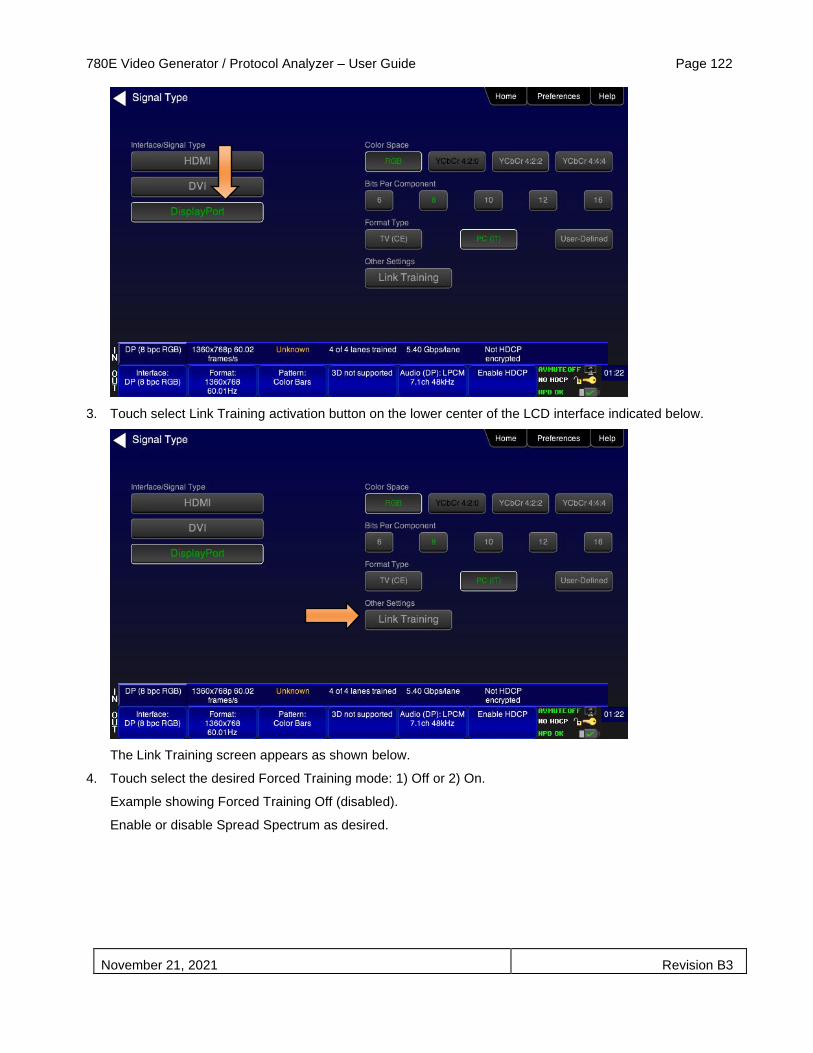
780E Video Generator / Protocol Analyzer – User Guide Page 122
November 21, 2021 Revision B3
3. Touch select Link Training activation button on the lower center of the LCD interface indicated below.
The Link Training screen appears as shown below.
4. Touch select the desired Forced Training mode: 1) Off or 2) On.
Example showing Forced Training Off (disabled).
Enable or disable Spread Spectrum as desired.

780E Video Generator / Protocol Analyzer – User Guide Page 123
November 21, 2021 Revision B3
Example showing Forced Training On (enabled).
5. (With Forced Link Training Off) Touch select either the Use Sink Max Values activation button or use the Max Link Rate and Max Lane Count activation buttons to set these values specifically for your application.
In the screen example below, the 780E will link train with a Max Link Rate of 5.4Gpbs and with a Max Lane Count of 4 Lanes.

780E Video Generator / Protocol Analyzer – User Guide Page 124
November 21, 2021 Revision B3
6. (With Forced Link Training On) Touch select the desired Max Link Rate and Max Lane Count values using the activation buttons provided. Alternatively you can force the link training to use the values detected from the sink using the Use Sink Max Values activation button.
7. (With Forced Link Training On) Touch select the Voltage Swing/Pre-Emphasis values using the activation buttons provided.
In the screen example below, the 780E will link train with a Max Link Rate of 5.4Gpbs and with a Max Lane Count of 2 Lanes. The Link Training test will use a Voltage Swing value of 1 and a Pre-Emphasis value of 2. The results are shown on the Link Training Info on the right of the screen. Notice that the Symbol Lock and Channel EQ are shown as 0 (N) indicating that Lanes 3 and 4 were not involved in Link Training per the selection of Max Lane Count (2 Lanes) in this example.

780E Video Generator / Protocol Analyzer – User Guide Page 125
November 21, 2021 Revision B3
5.6 Multi-protocol (HDCP, EDID and CEC) testing on an HDMI or HDBaseT
HDTV, Projector or Monitor
This section provides procedures for testing HDCP, EDID and CEC (HDMI and HDBaseT only) using the Aux Combo Test image. The Aux Combo Test image runs tests similar to the individual HDCP, EDID and CEC tests except that the results are displayed on the HDTV or projector that the 780E HDMI or HDBaseT output is connected to.
5.6.1 Configurations for running multi-protocol tests on an HDMI Sink Device
You run this test with the 780E HDMI OUT port connected directly to an HDTV input
This configuration is shown below:
5.6.2 Configurations for running multi-protocol tests on an HDBaseT Sink Device
You run this test with the 780E HDBaseT OUT port connected directly to a projector or HDBaseT input on a distribution device.
This configuration is shown below:
5.6.3 Procedures for running multi-protocol tests on an HDMI or HDBaseT Sink Device
Use the procedures below to run a multi-protocol test on an HDMI or HDBaseT sink.
1. Make the physical connections between the 780E HDMI or HDBaseT OUT connector and the display device under test.
2. Enable the HDMI or HDBaseT interface as shown below.

780E Video Generator / Protocol Analyzer – User Guide Page 126
November 21, 2021 Revision B3
Example screen for HDBaseT
3. Touch select video pattern status and activation button on the lower right of the LCD interface.

780E Video Generator / Protocol Analyzer – User Guide Page 127
November 21, 2021 Revision B3
4. Touch select the Aux Combo Test pattern from the second page of the Video Pattern menu shown below.
The results will appear on the connected display. An example of the results is shown below:

780E Video Generator / Protocol Analyzer – User Guide Page 128
November 21, 2021 Revision B3
Note: DisplayPort results will not show CEC Test
4. Alternatively you can run the AuxComboTest from the command line as follows:
IMGL AuxTest
IMGU
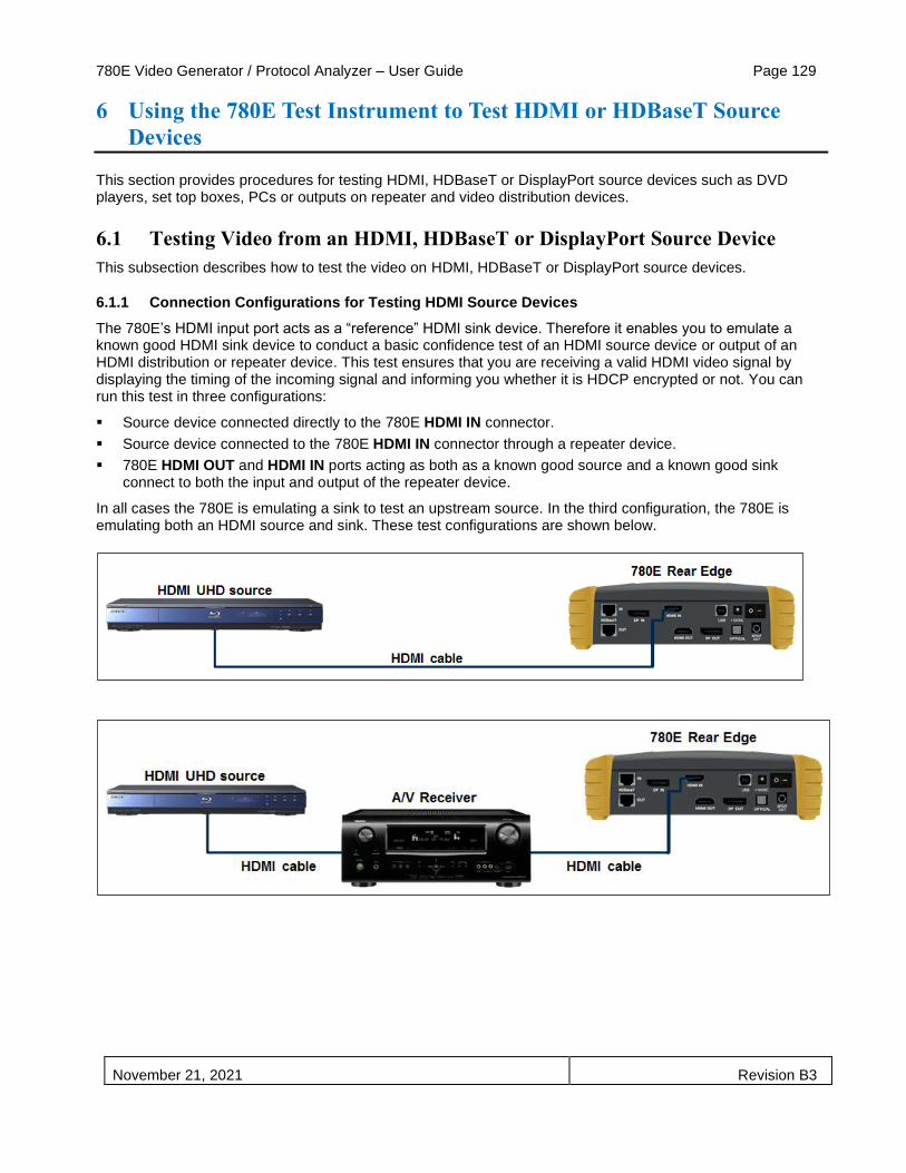
780E Video Generator / Protocol Analyzer – User Guide Page 129
November 21, 2021 Revision B3
6 Using the 780E Test Instrument to Test HDMI or HDBaseT Source
Devices
This section provides procedures for testing HDMI, HDBaseT or DisplayPort source devices such as DVD players, set top boxes, PCs or outputs on repeater and video distribution devices.
6.1 Testing Video from an HDMI, HDBaseT or DisplayPort Source Device
This subsection describes how to test the video on HDMI, HDBaseT or DisplayPort source devices.
6.1.1 Connection Configurations for Testing HDMI Source Devices
The 780E’s HDMI input port acts as a “reference” HDMI sink device. Therefore it enables you to emulate a known good HDMI sink device to conduct a basic confidence test of an HDMI source device or output of an HDMI distribution or repeater device. This test ensures that you are receiving a valid HDMI video signal by displaying the timing of the incoming signal and informing you whether it is HDCP encrypted or not. You can run this test in three configurations:
▪ Source device connected directly to the 780E HDMI IN connector.
▪ Source device connected to the 780E HDMI IN connector through a repeater device.
▪ 780E HDMI OUT and HDMI IN ports acting as both as a known good source and a known good sink connect to both the input and output of the repeater device.
In all cases the 780E is emulating a sink to test an upstream source. In the third configuration, the 780E is emulating both an HDMI source and sink. These test configurations are shown below.
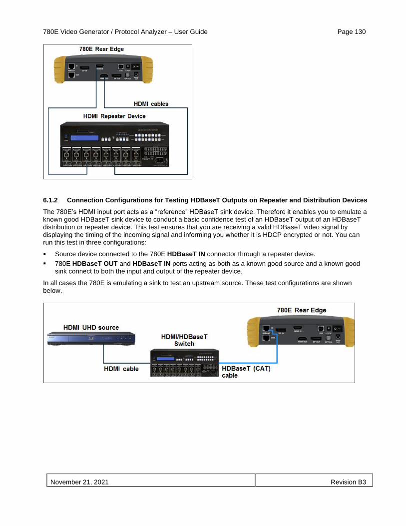
780E Video Generator / Protocol Analyzer – User Guide Page 130
November 21, 2021 Revision B3
6.1.2 Connection Configurations for Testing HDBaseT Outputs on Repeater and Distribution Devices
The 780E’s HDMI input port acts as a “reference” HDBaseT sink device. Therefore it enables you to emulate a known good HDBaseT sink device to conduct a basic confidence test of an HDBaseT output of an HDBaseT distribution or repeater device. This test ensures that you are receiving a valid HDBaseT video signal by displaying the timing of the incoming signal and informing you whether it is HDCP encrypted or not. You can run this test in three configurations:
▪ Source device connected to the 780E HDBaseT IN connector through a repeater device.
▪ 780E HDBaseT OUT and HDBaseT IN ports acting as both as a known good source and a known good sink connect to both the input and output of the repeater device.
In all cases the 780E is emulating a sink to test an upstream source. These test configurations are shown below.

780E Video Generator / Protocol Analyzer – User Guide Page 131
November 21, 2021 Revision B3
6.1.3 Connection Configurations for Testing DisplayPort Source Devices
The 780E’s DisplayPort IN port acts as a “reference” DisplayPort sink device. Therefore it enables you to emulate a known good DisplayPort sink device to conduct a basic confidence test of an DisplayPort source device such as a PC. This test ensures that you are receiving a valid DisplayPort video signal by displaying the timing of the incoming signal and informing you whether it is HDCP encrypted or not. Typically this test is run with a DisplayPort source device, such as a PC, connected directly to the 780E DisplayPort input port. This configuration is shown below.
6.1.4 Procedures for Viewing Video on an HDMI, HDBaseT or DisplayPort Source Device
Use the following procedures to test the video from an HDMI, HDBaseT or DisplayPort source device. You can view the incoming video and check the video and timing parameters of the incoming video.
1. Make the physical connection between the 780E HDMI, HDBaseT or DisplayPort IN port and the source device under test using the configuration instructions above.
2. Enable the HDMI, HDBaseT or DisplayPort Input port.
Activate HDMI Rx (Input) port. First you will have to access the Rx Interface Selection screen through the lower left button on the status bar as indicated below. Then you select the desired digital video interface shown in the subsequent screen examples.
3.
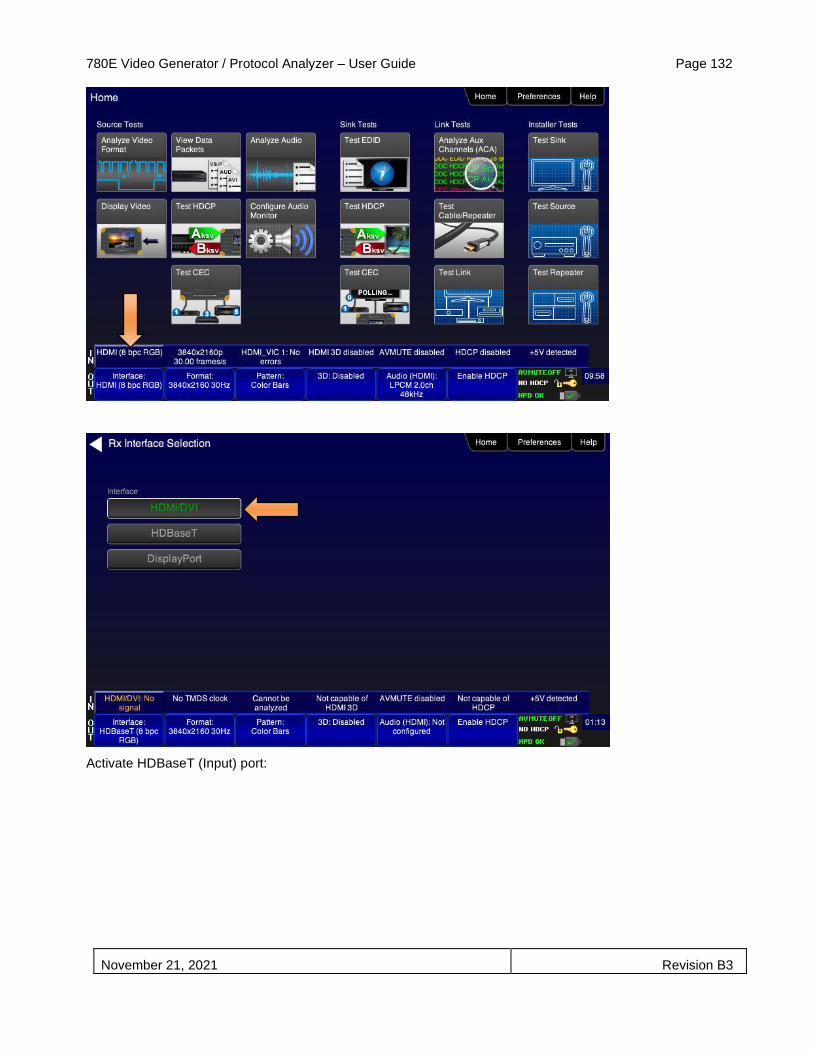
780E Video Generator / Protocol Analyzer – User Guide Page 132
November 21, 2021 Revision B3
Activate HDBaseT (Input) port:
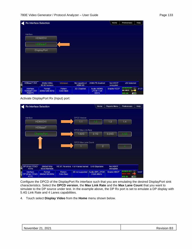
780E Video Generator / Protocol Analyzer – User Guide Page 133
November 21, 2021 Revision B3
Activate DisplayPort Rx (Input) port:
Configure the DPCD of the DisplayPort Rx interface such that you are emulating the desired DisplayPort sink characteristics. Select the DPCD version, the Max Link Rate and the Max Lane Count that you want to simulate to the DP source under test. In the example above, the DP Rx port is set to emulate a DP display with 5.4G Link Rate and 4 Lanes capabilities.
4. Touch select Display Video from the Home menu shown below.
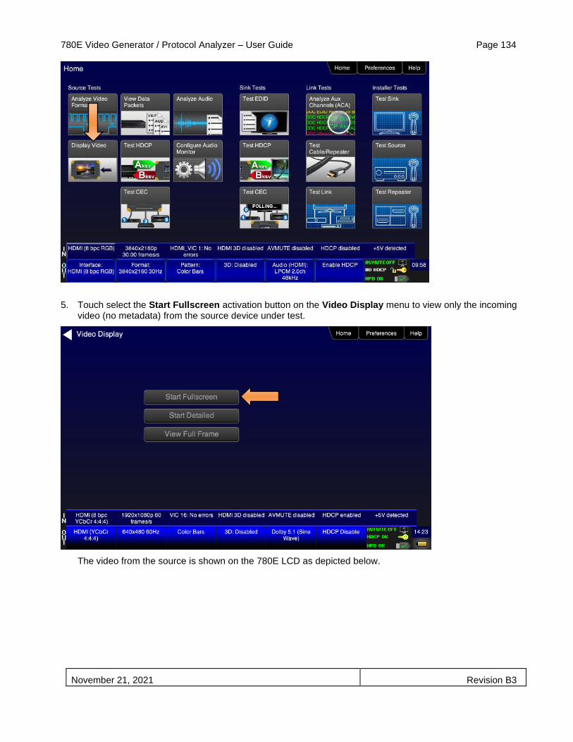
780E Video Generator / Protocol Analyzer – User Guide Page 134
November 21, 2021 Revision B3
5. Touch select the Start Fullscreen activation button on the Video Display menu to view only the incoming video (no metadata) from the source device under test.
The video from the source is shown on the 780E LCD as depicted below.
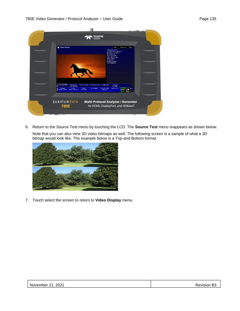
780E Video Generator / Protocol Analyzer – User Guide Page 135
November 21, 2021 Revision B3
6. Return to the Source Test menu by touching the LCD. The Source Test menu reappears as shown below.
Note that you can also view 3D video bitmaps as well. The following screen is a sample of what a 3D bitmap would look like. The example below is a Top-and-Bottom format.
7. Touch select the screen to return to Video Display menu.

780E Video Generator / Protocol Analyzer – User Guide Page 136
November 21, 2021 Revision B3
8. Touch select the Start Detailed activation button on the Video Display menu to view the incoming video along with the metadata from the source device under test. In this example a test pattern is shown.
Note that the HDCP encryption status and AVmute status are also shown.
Example showing HDMI source.
Example showing DisplayPort source.

780E Video Generator / Protocol Analyzer – User Guide Page 137
November 21, 2021 Revision B3
8. For the 780E you have the additional option of capturing and viewing a captured bitmap of the entire resolution of the incoming video View Full Frame.
Use the arrows to move about the video frame. Note that in the example below the 780 is receiving a test pattern; typically this screen would show video from a source device.

780E Video Generator / Protocol Analyzer – User Guide Page 138
November 21, 2021 Revision B3
9. Return to the Home menu by touching the LCD then the Home menu.
6.1.5 Viewing Video Metadata from an HDMI, HDBaseT or DisplayPort Source Device
Use the following procedures to verify the video metadata and video timing data from an HDMI, HDBaseT or DisplayPort source device.
Important Note: The Format Analyzer test is supported by the Report File Creation feature which enables the results of the test to be included in an html report that can be disseminated or printed. However, the Report Menu entry on the top menu has not been updated on the screens in this subsection. Refer to the Chapter on Report File Creation for details on generating reports.
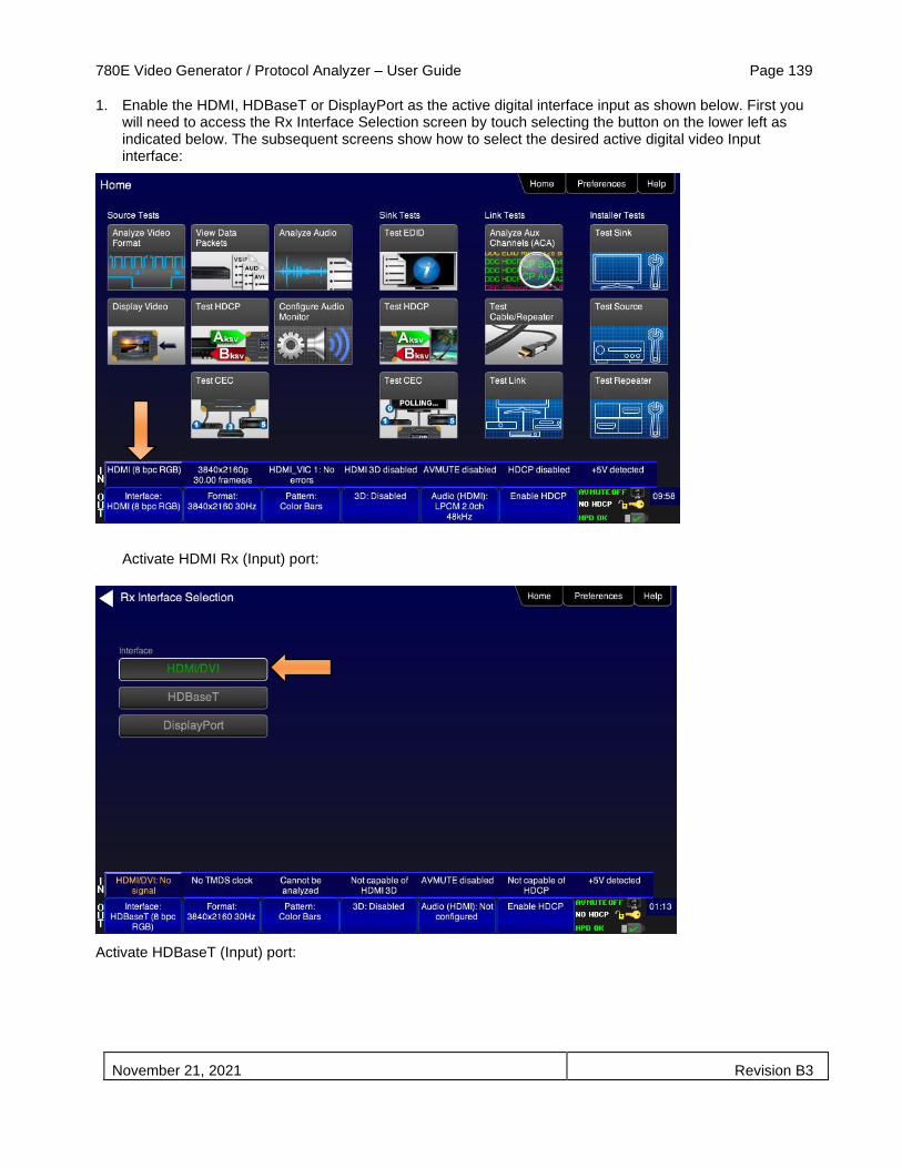
780E Video Generator / Protocol Analyzer – User Guide Page 139
November 21, 2021 Revision B3
1. Enable the HDMI, HDBaseT or DisplayPort as the active digital interface input as shown below. First you will need to access the Rx Interface Selection screen by touch selecting the button on the lower left as indicated below. The subsequent screens show how to select the desired active digital video Input interface:
Activate HDMI Rx (Input) port: 10.
Activate HDBaseT (Input) port:
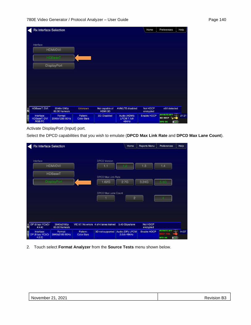
780E Video Generator / Protocol Analyzer – User Guide Page 140
November 21, 2021 Revision B3
Activate DisplayPort (Input) port.
Select the DPCD capabilities that you wish to emulate (DPCD Max Link Rate and DPCD Max Lane Count).
2. Touch select Format Analyzer from the Source Tests menu shown below.

780E Video Generator / Protocol Analyzer – User Guide Page 141
November 21, 2021 Revision B3
3. Touch select the Read activation button (shown on the screen below) to initiate the test. The results are shown in the screen shots below. The first three screens show example of a test on HDMI; the fourth screen shows an example of a DisplayPort source test. The first screen shows a typical pass results, the second screen shows a failure condition and the third screen shows a case where the incoming format was unknown.
If one of the timing parameters does not match the value of the parameters in the associated standard timing in the 780E format library, an indication of the error is shown as can be seen below.

780E Video Generator / Protocol Analyzer – User Guide Page 142
November 21, 2021 Revision B3
If the timing does not match a standard timing in the 780E format library, a message is shown: “Unknown format” as can be seen below.
DisplayPort example:

780E Video Generator / Protocol Analyzer – User Guide Page 143
November 21, 2021 Revision B3
Table 6-2 below describes each field in the Format Analyzer on-screen report. The basic timing information is shown on the left of the resulting screen and the AVI infoframes received are displayed on the right. Also displayed on the right side is an indication of the status of HDCP encryption.
Note: The results differ between HDMI and HDBaseT on the one hand and DisplayPort on the other.
Table 6-2: Format Analyzer
Timing Parameters (left side) Description
Video Type Indicates whether the source is HDMI or DVI.
Total Total horizontal and vertical resolution including blanking.
Active Total active horizontal and vertical resolution excluding blanking.
Frames/sec The frame rate of the HDMI/DVI input source.
Scan Type Indicates whether the HDMI/DVI input source is progressive or interlaced.
HSYNC delay The horizontal sync pulse delay in pixels.
HSYNC width The horizontal sync pulse width in pixels.
VSYNC delay The vertical sync pulse delay in lines.
VSYNC delay The vertical sync pulse width in lines.
HSYNC polarity The polarity of the horizontal sync pulse; either positive (+) or negative (-).
VSYNC polarity The polarity of the vertical sync pulse; either positive (+) or negative (-).
Note: For DisplayPort the timing data is derived from the main stream attribute metadata; it is not measured data.

780E Video Generator / Protocol Analyzer – User Guide Page 144
November 21, 2021 Revision B3
Table 6-2: Format Analyzer
AVI Infoframe Parameters (HDMI and HDBaseT only) (right side)
Description
Bits per comp The number of bits per component color. Can be 6, 8, 10, 12, 16.
Color space Color space and sampling
Color space:
▪ YCbCr ▪ RGB ▪ xvColor
Sampling:
▪ 4:4:4 ▪ 4:2:2 ▪ 4:2:0
Basic colorimetry The ITU colorimetry standard.
Pixels repeated Indicates whether pixel repetition is active.
Video ID code (VIC) The CEA video identification code number.
Resolution Shows the horizontal and vertical resolution as well as the frame rate and the aspect ratio.
AVmute status The current setting of the AVmute parameter in the General Control Packet.
HDCP Indicates the HDCP encryption status either: 1) Encrypted or 2) Unencrypted.
Main Stream Attribute Metadata (DisplayPort only) (right side)
Description
Bits per comp The number of bits per component color. Can be 6, 8, 10, 12, 16.
Color space Color space and sampling
Color space:
▪ YCbCr ▪ RGB
Sampling:
▪ 4:4:4 ▪ 4:2:2
Dynamic Range The standard used for dynamic range, e.g. CEA.
Total (H & V resolution) Indicates the Total horizontal and vertical resolution.
Active (H & V resolution) Indicates the Active horizontal and vertical resolution.
Mvid/Nvid The Mvid value is used for stream clock recover. This is determined from the main stream
attributes. The Nvid value is used for stream clock recover. This is determined from the main stream attributes
Clock Type Indicates if the Link Clock and Main Video Stream clock are asynchronous or synchronous. A value of N means async; a value of Y means synchronous. This value is determined by the main stream attributes.
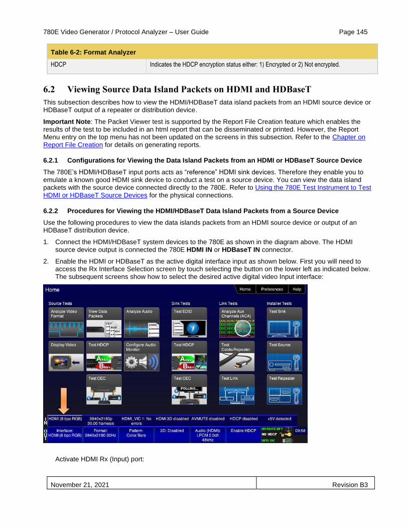
780E Video Generator / Protocol Analyzer – User Guide Page 145
November 21, 2021 Revision B3
Table 6-2: Format Analyzer
HDCP Indicates the HDCP encryption status either: 1) Encrypted or 2) Not encrypted.
6.2 Viewing Source Data Island Packets on HDMI and HDBaseT
This subsection describes how to view the HDMI/HDBaseT data island packets from an HDMI source device or HDBaseT output of a repeater or distribution device.
Important Note: The Packet Viewer test is supported by the Report File Creation feature which enables the results of the test to be included in an html report that can be disseminated or printed. However, the Report Menu entry on the top menu has not been updated on the screens in this subsection. Refer to the Chapter on Report File Creation for details on generating reports.
6.2.1 Configurations for Viewing the Data Island Packets from an HDMI or HDBaseT Source Device
The 780E’s HDMI/HDBaseT input ports acts as “reference” HDMI sink devices. Therefore they enable you to emulate a known good HDMI sink device to conduct a test on a source device. You can view the data island packets with the source device connected directly to the 780E. Refer to Using the 780E Test Instrument to Test HDMI or HDBaseT Source Devices for the physical connections.
6.2.2 Procedures for Viewing the HDMI/HDBaseT Data Island Packets from a Source Device
Use the following procedures to view the data islands packets from an HDMI source device or output of an HDBaseT distribution device.
1. Connect the HDMI/HDBaseT system devices to the 780E as shown in the diagram above. The HDMI source device output is connected the 780E HDMI IN or HDBaseT IN connector.
2. Enable the HDMI or HDBaseT as the active digital interface input as shown below. First you will need to access the Rx Interface Selection screen by touch selecting the button on the lower left as indicated below. The subsequent screens show how to select the desired active digital video Input interface:
Activate HDMI Rx (Input) port: 11.
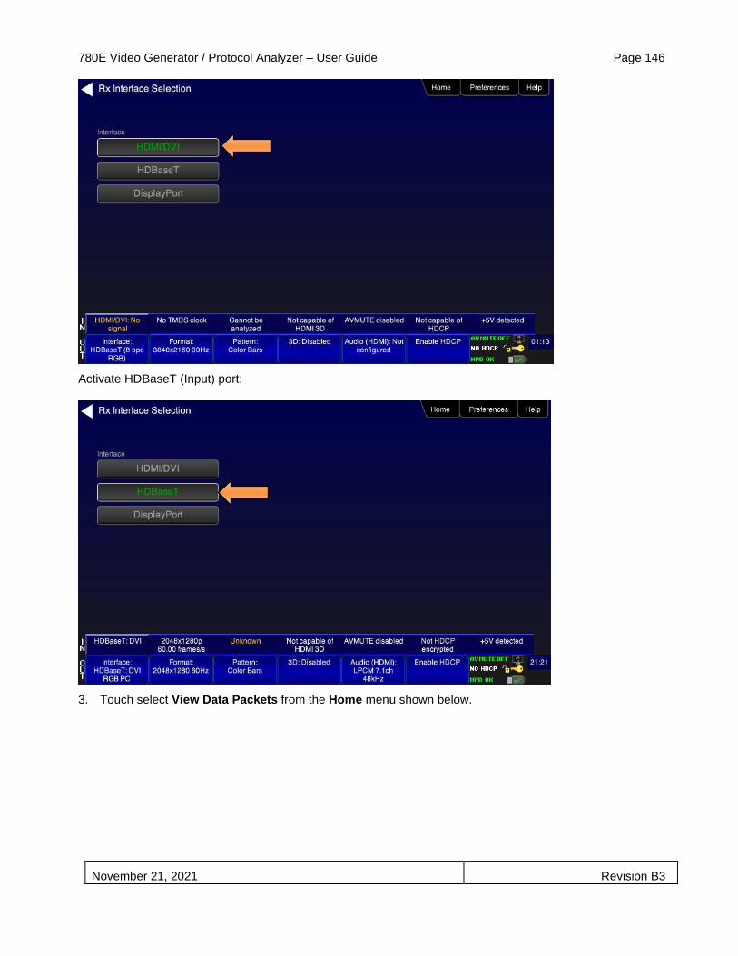
780E Video Generator / Protocol Analyzer – User Guide Page 146
November 21, 2021 Revision B3
Activate HDBaseT (Input) port:
3. Touch select View Data Packets from the Home menu shown below.
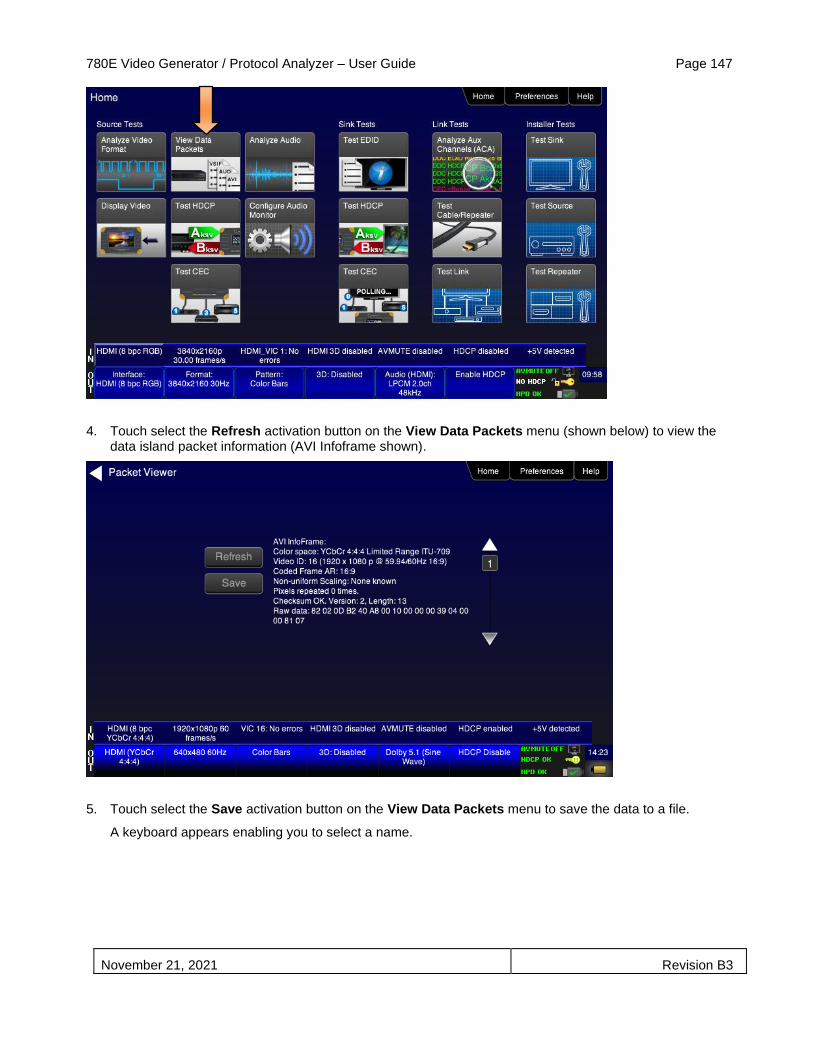
780E Video Generator / Protocol Analyzer – User Guide Page 147
November 21, 2021 Revision B3
4. Touch select the Refresh activation button on the View Data Packets menu (shown below) to view the data island packet information (AVI Infoframe shown).
5. Touch select the Save activation button on the View Data Packets menu to save the data to a file.
A keyboard appears enabling you to select a name.

780E Video Generator / Protocol Analyzer – User Guide Page 148
November 21, 2021 Revision B3
6. View the rest of the packet data using the scroll bar on the right as shown below.
There are two additional screen examples below. The first example shows the HDMI Vendor Specific Infoframe packet. The second example shows the Dynamic Range and Mastering Infoframe used for High Dynamic Range.

780E Video Generator / Protocol Analyzer – User Guide Page 149
November 21, 2021 Revision B3
6.3 Testing HDCP Max Devices on an HDMI Source Devices and Outputs of
HDBaseT distribution Devices
This subsection describes how to run a test of the number of HDCP devices an HDMI or HDBaseT source device supports. The Max HDCP devices test runs a test on the source device (such as a DVD or STB) to determine how many downstream devices are supported during an HDCP authentication with a repeater device.
Important Note: The HDCP source test is supported by the Report File Creation feature which enables the results of the test to be included in an html report that can be disseminated or printed. However, the Report Menu entry on the top menu has not been updated on the screens in this subsection. Refer to the Chapter on Report File Creation for details on generating reports.
6.3.1 Configurations for Testing Max Devices an HDMI Source Device Supports
The 780E’s HDMI input port acts as a “reference” HDMI sink device. Therefore it enables you to emulate a known good HDMI sink device to conduct a test on a source device. You can run this source device connected directly to the 780E. Refer to Using the 780E Test Instrument to Test HDMI or HDBaseT Source Devices for procedures on how to make the physical connections.
1. Enable the HDMI, HDBaseT or DisplayPort as the active digital interface input as shown below. First you will need to access the Rx Interface Selection screen by touch selecting the button on the lower left as indicated below. The subsequent screens show how to select the desired active digital video Input interface:

780E Video Generator / Protocol Analyzer – User Guide Page 150
November 21, 2021 Revision B3
Activate HDMI Rx (Input) port: 12.
Activate HDBaseT (Input) port:
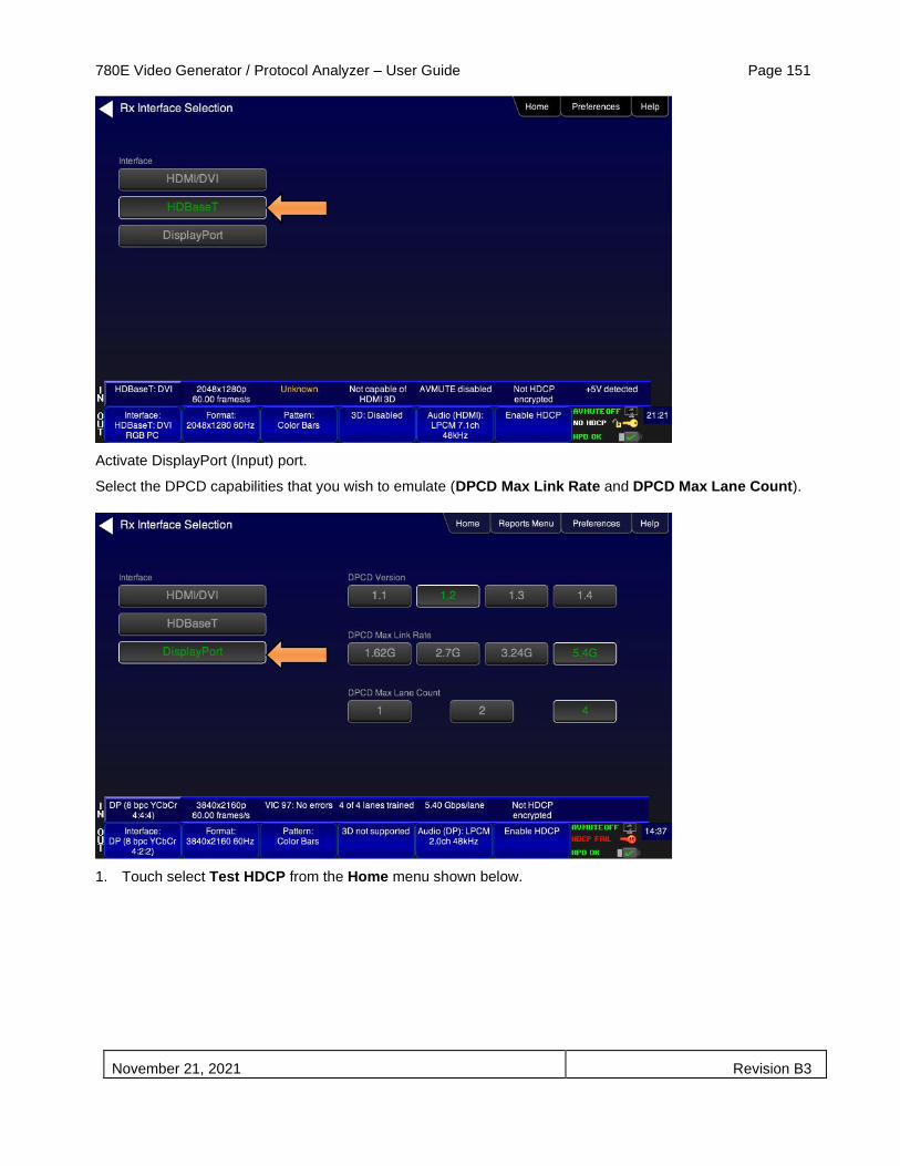
780E Video Generator / Protocol Analyzer – User Guide Page 151
November 21, 2021 Revision B3
Activate DisplayPort (Input) port.
Select the DPCD capabilities that you wish to emulate (DPCD Max Link Rate and DPCD Max Lane Count).
1. Touch select Test HDCP from the Home menu shown below.
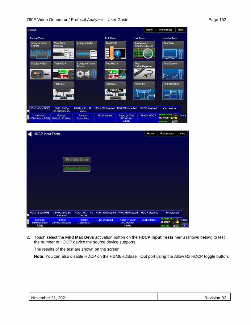
780E Video Generator / Protocol Analyzer – User Guide Page 152
November 21, 2021 Revision B3
2. Touch select the Find Max Devs activation button on the HDCP Input Tests menu (shown below) to test the number of HDCP device the source device supports.
The results of the test are shown on the screen.
Note: You can also disable HDCP on the HDMI/HDBaseT Out port using the Allow Rx HDCP toggle button.
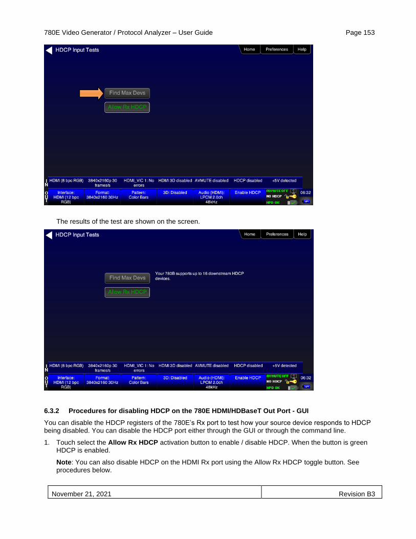
780E Video Generator / Protocol Analyzer – User Guide Page 153
November 21, 2021 Revision B3
The results of the test are shown on the screen.
6.3.2 Procedures for disabling HDCP on the 780E HDMI/HDBaseT Out Port - GUI
You can disable the HDCP registers of the 780E’s Rx port to test how your source device responds to HDCP being disabled. You can disable the HDCP port either through the GUI or through the command line.
1. Touch select the Allow Rx HDCP activation button to enable / disable HDCP. When the button is green HDCP is enabled.
Note: You can also disable HDCP on the HDMI Rx port using the Allow Rx HDCP toggle button. See procedures below.
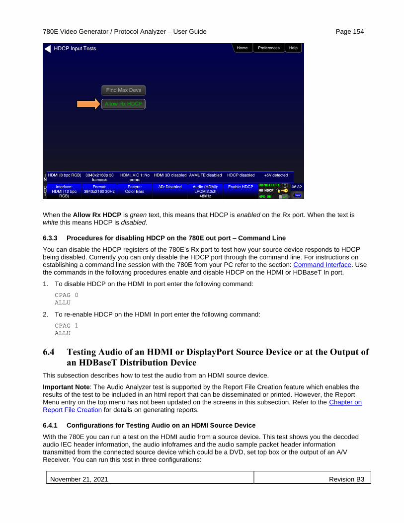
780E Video Generator / Protocol Analyzer – User Guide Page 154
November 21, 2021 Revision B3
When the Allow Rx HDCP is green text, this means that HDCP is enabled on the Rx port. When the text is white this means HDCP is disabled.
6.3.3 Procedures for disabling HDCP on the 780E out port – Command Line
You can disable the HDCP registers of the 780E’s Rx port to test how your source device responds to HDCP being disabled. Currently you can only disable the HDCP port through the command line. For instructions on establishing a command line session with the 780E from your PC refer to the section: Command Interface. Use the commands in the following procedures enable and disable HDCP on the HDMI or HDBaseT In port.
1. To disable HDCP on the HDMI In port enter the following command:
CPAG 0
ALLU
2. To re-enable HDCP on the HDMI In port enter the following command:
CPAG 1
ALLU
6.4 Testing Audio of an HDMI or DisplayPort Source Device or at the Output of
an HDBaseT Distribution Device
This subsection describes how to test the audio from an HDMI source device.
Important Note: The Audio Analyzer test is supported by the Report File Creation feature which enables the results of the test to be included in an html report that can be disseminated or printed. However, the Report Menu entry on the top menu has not been updated on the screens in this subsection. Refer to the Chapter on Report File Creation for details on generating reports.
6.4.1 Configurations for Testing Audio on an HDMI Source Device
With the 780E you can run a test on the HDMI audio from a source device. This test shows you the decoded audio IEC header information, the audio infoframes and the audio sample packet header information transmitted from the connected source device which could be a DVD, set top box or the output of an A/V Receiver. You can run this test in three configurations:

780E Video Generator / Protocol Analyzer – User Guide Page 155
November 21, 2021 Revision B3
▪ Source device connected directly to the 780E.
▪ Source device connected to the 780E through a repeater device such as an A/V receiver.
▪ 780E OUT and IN ports acting as both as a known good source and a known good sink connect to both the input and output of the repeater device.
In all cases the 780E is emulating a sink to test an upstream source. In the third configuration, the 780E is emulating both an HDMI source and sink. These test configurations are shown below.
6.4.2 Configurations for Testing Audio on the Output of an HDBaseT Distribution Device
With the 780E you can run a test on the HDMI audio from a source device. This test shows you the decoded audio IEC header information, the audio infoframes and the audio sample packet header information

780E Video Generator / Protocol Analyzer – User Guide Page 156
November 21, 2021 Revision B3
transmitted from the connected source device which could be a DVD, set top box or the output of an A/V Receiver. You can run this test in three configurations:
▪ Source device connected to the 780E through an HDBaseT distribution device.
▪ 780E HDBaseT OUT and HDBaseT IN ports acting as both as a known good source and a known good sink connect to both the input and output of the repeater device.
In all cases the 780E is emulating a sink to test an upstream source. In the third configuration, the 780E is emulating both an HDBaseT source and sink. These test configurations are shown below.
6.4.3 Configurations for Testing Audio on the Output of a DisplayPort Source Device
With the 780E you can run a test on the DisplayPort audio from a source device. This test shows you the decoded audio IEC header information, the audio infoframes and the audio sample packet header information transmitted from the connected source device such as a PC. Typically you will run this test with the DisplayPort source device connected to the 780E.
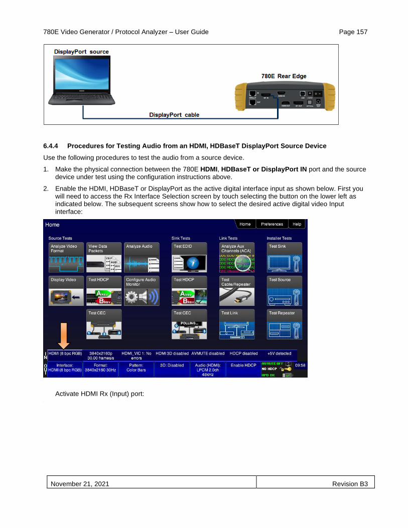
780E Video Generator / Protocol Analyzer – User Guide Page 157
November 21, 2021 Revision B3
6.4.4 Procedures for Testing Audio from an HDMI, HDBaseT DisplayPort Source Device
Use the following procedures to test the audio from a source device.
1. Make the physical connection between the 780E HDMI, HDBaseT or DisplayPort IN port and the source device under test using the configuration instructions above.
2. Enable the HDMI, HDBaseT or DisplayPort as the active digital interface input as shown below. First you will need to access the Rx Interface Selection screen by touch selecting the button on the lower left as indicated below. The subsequent screens show how to select the desired active digital video Input interface:
Activate HDMI Rx (Input) port: 13.

780E Video Generator / Protocol Analyzer – User Guide Page 158
November 21, 2021 Revision B3
Activate HDBaseT (Input) port:
Activate DisplayPort (Input) port.
Select the DPCD capabilities that you wish to emulate (DPCD Max Link Rate and DPCD Max Lane Count).

780E Video Generator / Protocol Analyzer – User Guide Page 159
November 21, 2021 Revision B3
3. Select Audio Analyzer from the Home menu shown below.
The Audio Analysis screen appears as shown below. The first screen example shows HDMI. The second example shows a test on DisplayPort source.
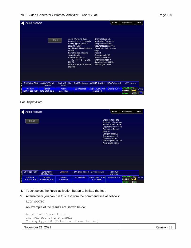
780E Video Generator / Protocol Analyzer – User Guide Page 160
November 21, 2021 Revision B3
For DisplayPort:
4. Touch select the Read activation button to initiate the test.
5. Alternatively you can run this test from the command line as follows:
AUDA:RPTP?
An example of the results are shown below:
Audio InfoFrame data:
Channel count: 2 channels
Coding type: 0 (Refer to stream header)

780E Video Generator / Protocol Analyzer – User Guide Page 161
November 21, 2021 Revision B3
Word length: Refer to stream header
Sampling freq.: Refer to stream header
Channel allocation:
--- --- --- --- --- --- FR FL
Channel status bits:
Application: Consumer
Sample words: LPCM
Copyright asserted: Yes
Format info: Default
Mode: 0
Category code: 00
Source number: 0
Channel number: 0
Sampling freq.: 48 KHz
Word length: 24 bits)

780E Video Generator / Protocol Analyzer – User Guide Page 162
November 21, 2021 Revision B3
Table 6-2 below describes each field in the Audio Analyzer on-screen report. The audio infoframe information is shown on the left of the resulting screen and the channel status data from the audio sample packets received are displayed on the right.
Table 6-2: Audio Analyzer
Audio IEC Header decoded data (left side) Description
Audio Format Indicates the audio format type. Typically one of:
▪ LPCM ▪ Dolby ▪ DTS
Sampling rate The sampling frequency. One of:
▪ Refer to Stream Header ▪ 32kHz ▪ 44.1kHz ▪ 48kHz ▪ 88.2kHz ▪ 96kHz ▪ 176.4kHz ▪ 192kHz
Audio Infoframe Data (middle – HDMI and HDBaseT only)
Description
Channel count Indicates the number of active channels. One of:
▪ Refer to Stream Header ▪ 2ch ▪ 3ch ▪ 4ch ▪ 5ch ▪ 6ch ▪ 7ch ▪ 8ch
Coding type Indicates the audio format. One of:
▪ Refer to stream header ▪ LPCM (IEC 60958) ▪ AC-3 ▪ MPEG1 ▪ MPEG2 ▪ AAC ▪ DTS ▪ ATRAC ▪ One Bit Audio ▪ Dolby Digital Plus ▪ DTS-HD ▪ MAT ▪ DST ▪ WMA Pro
Sample Size The sample size or bit depth. One of:
▪ Refer to Stream Header ▪ 16 bit ▪ 20 bit ▪ 24 bit

780E Video Generator / Protocol Analyzer – User Guide Page 163
November 21, 2021 Revision B3
Table 6-2: Audio Analyzer
Audio IEC Header decoded data (left side) Description
Sampling Frequency The sampling frequency. One of:
▪ Refer to Stream Header ▪ 32kHz ▪ 44.1kHz ▪ 48kHz ▪ 88.2kHz ▪ 96kHz ▪ 176.4kHz ▪ 192kHz
Channel Allocation The speaker mapping and allocation. One or more of the following:
▪ FL ▪ FC ▪ FR ▪ RLC ▪ FRC ▪ RL ▪ RC ▪ RR ▪ RLC ▪ RRC ▪ LFE
Audio Clock Regeneration N/ CTS values ▪ N ▪ CTS
Channel Status Bit Data (right side) Description
Application Application format. One of: Consumer or Professional.
Sample words Sample word encoding. One of: LPCM or Encoded (non linear compressed).
Copyright asserted Copyright assertion. One of: Yes or No.
Format info Format. Typically Default.
Mode Channel mode. Typically 0 for Mode 0.
Category code Category code. Typically 00 for general.
Source number Source number. Typically 0 for Unspecified.
Channel number Channel number. Typically 0 for Unspecified
Sampling freq Sampling rate. One of:
▪ 32kHz
▪ 44.1kHz
▪ 48kHz
▪ 88.2kHz
▪ 96kHz
▪ 176.4kHz
▪ 192kHz
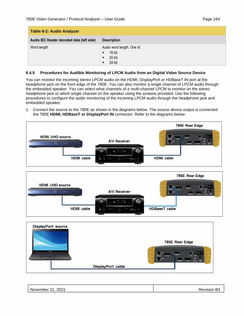
780E Video Generator / Protocol Analyzer – User Guide Page 164
November 21, 2021 Revision B3
Table 6-2: Audio Analyzer
Audio IEC Header decoded data (left side) Description
Word length Audio word length. One of:
▪ 16 bit
▪ 20 bit
▪ 24 bit
6.4.5 Procedures for Audible Monitoring of LPCM Audio from an Digital Video Source Device
You can monitor the incoming stereo LPCM audio on the HDMI, DisplayPort or HDBaseT IN port at the headphone jack on the front edge of the 780E. You can also monitor a single channel of LPCM audio through the embedded speaker. You can select what channels of a multi-channel LPCM to monitor on the stereo headphone jack or which single channel on the speaker using the screens provided. Use the following procedures to configure the audio monitoring of the incoming LPCM audio through the headphone jack and embedded speaker.
1. Connect the source to the 780E as shown in the diagrams below. The source device output is connected the 780E HDMI, HDBaseT or DisplayPort IN connector. Refer to the diagrams below:

780E Video Generator / Protocol Analyzer – User Guide Page 165
November 21, 2021 Revision B3
2. Touch select Audio Monitor Settings from the Home menu shown below (for HDMI or HDBaseT).
DisplayPort Main screen:
The following screen appears:
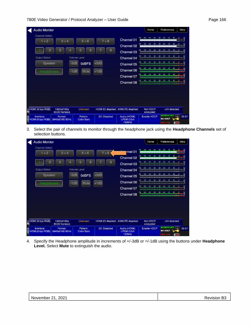
780E Video Generator / Protocol Analyzer – User Guide Page 166
November 21, 2021 Revision B3
3. Select the pair of channels to monitor through the headphone jack using the Headphone Channels set of selection buttons.
4. Specify the Headphone amplitude in increments of +/-3dB or =/-1dB using the buttons under Headphone Level. Select Mute to extinguish the audio.

780E Video Generator / Protocol Analyzer – User Guide Page 167
November 21, 2021 Revision B3
5. Select the single channel to monitor through the embedded speaker using the Speaker Channel set of selection buttons.
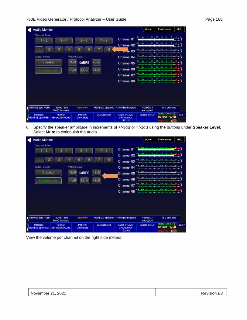
780E Video Generator / Protocol Analyzer – User Guide Page 168
November 21, 2021 Revision B3
6. Specify the speaker amplitude in increments of +/-3dB or =/-1dB using the buttons under Speaker Level. Select Mute to extinguish the audio.
View the volume per channel on the right side meters.
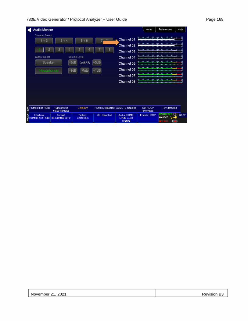
780E Video Generator / Protocol Analyzer – User Guide Page 169
November 21, 2021 Revision B3

780E Video Generator / Protocol Analyzer – User Guide Page 170
November 21, 2021 Revision B3
6.5 Testing an HDMI, HDBaseT or DisplayPort Source’s Response to EDIDs
The 780E HDMI, HDBaseT and DisplayPort IN ports emulate an HDMI, HDBaseT or DisplayPort sink device. Part of that emulation function is presenting an EDID to a source when a sink device is powered and hot plug is asserted. The 780E is provisioned with a default EDID from the factory. There are two standard EDIDs available with the 780E as provided: 1) Standard HDTV EDID, 2) Standard A/V Receiver EDID.
However you can reprovision the EDID by connecting it to a sink device whose EDID you would like to use for testing. The 780E can store multiple EDIDs. These EDIDs can be obtained either by extracting them from an HDMI or HDBaseT sink device (e.g. HDTV, Projector, AVR, repeater or distribution device input) or by importing EDID .xml files created using Quantum Data EDID Editor tools. For procedures on importing EDIDs refer to Adding Reference EDIDs for Use in Testing HDMI Devices.
The EDID test of an HDMI, HDBaseT or DisplayPort source device enables you to see how a source device responds to a specific EDID or a series of EDIDs. The EDID could be a known good EDID or an EDID you have chosen specifically for testing purposes.
6.5.1 Configurations for Testing an HDMI Source Devices Response to an EDID
You can run this test in two configurations: 1) with your source device connected directly to the 780E, 2) with your source device connected to the 780E through a repeater device. In both cases the 780E is emulating an HDMI sink to test an upstream source. These configurations are shown below.
6.5.2 Configurations for Testing an HDBaseT Device’s Output Response to an EDID
Typically you run this test with the 780E connected to an HDMI source through an HDBaseT distribution device. This configuration is shown below.
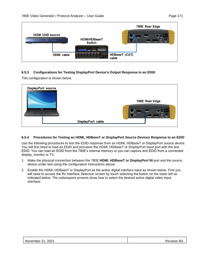
780E Video Generator / Protocol Analyzer – User Guide Page 171
November 21, 2021 Revision B3
6.5.3 Configurations for Testing DisplayPort Device’s Output Response to an EDID
This configuration is shown below.
6.5.4 Procedures for Testing an HDMI, HDBaseT or DisplayPort Source Devices Response to an EDID
Use the following procedures to test the EDID response from an HDMI, HDBaseT or DisplayPort source device. You will first need to load an EDID and provision the HDMI, HDBaseT or DisplayPort Input port with the test EDID. You can load an EDID from the 780E’s internal memory or you can capture and EDID from a connected display, monitor or TV.
1. Make the physical connection between the 780E HDMI, HDBaseT or DisplayPort IN port and the source device under test using the configuration instructions above.
2. Enable the HDMI, HDBaseT or DisplayPort as the active digital interface input as shown below. First you will need to access the Rx Interface Selection screen by touch selecting the button on the lower left as indicated below. The subsequent screens show how to select the desired active digital video Input interface:

780E Video Generator / Protocol Analyzer – User Guide Page 172
November 21, 2021 Revision B3
Activate HDMI Rx (Input) port: 14.
Activate HDBaseT (Input) port:
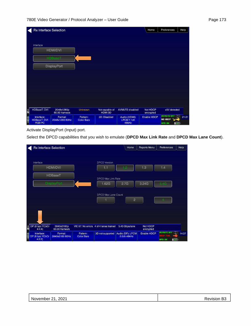
780E Video Generator / Protocol Analyzer – User Guide Page 173
November 21, 2021 Revision B3
Activate DisplayPort (Input) port.
Select the DPCD capabilities that you wish to emulate (DPCD Max Link Rate and DPCD Max Lane Count).

780E Video Generator / Protocol Analyzer – User Guide Page 174
November 21, 2021 Revision B3
3. Touch select Test EDID from the Home menu (shown below).
The following menu appears.

780E Video Generator / Protocol Analyzer – User Guide Page 175
November 21, 2021 Revision B3
4. Touch select Load from the EDID Tests menu. The following screen results.
The options:
▪ Load File – Loads from an EDID file stored on the 780E file system
▪ Load TV Default – Loads the standard reference EDID for a TV from the 780E file system
▪ Load AVR Default - Loads the standard reference EDID for a AVR from the 780E file system
5. If you have selected the Load File option, the following screen results. Select the file that you wish to use as the reference EDID. In the example below there is only one file.

780E Video Generator / Protocol Analyzer – User Guide Page 176
November 21, 2021 Revision B3
The EDID is loaded and displayed on the screen.
6. If you wish to obtain an EDID from an HDMI, HDBaseT, DisplayPort sink device that you have on hand, connect the 780E HDMI, HDBaseT, DisplayPort OUT port to the HDMI, HDBaseT, DisplayPort input of that sink device. This configuration is depicted below.
Skip to Step 8 if you do not want to use an EDID from an HDMI, HDBaseT, DisplayPort sink device you have on hand.

780E Video Generator / Protocol Analyzer – User Guide Page 177
November 21, 2021 Revision B3
7. Navigate to the EDID Test from the Sink Tests menu shown below.
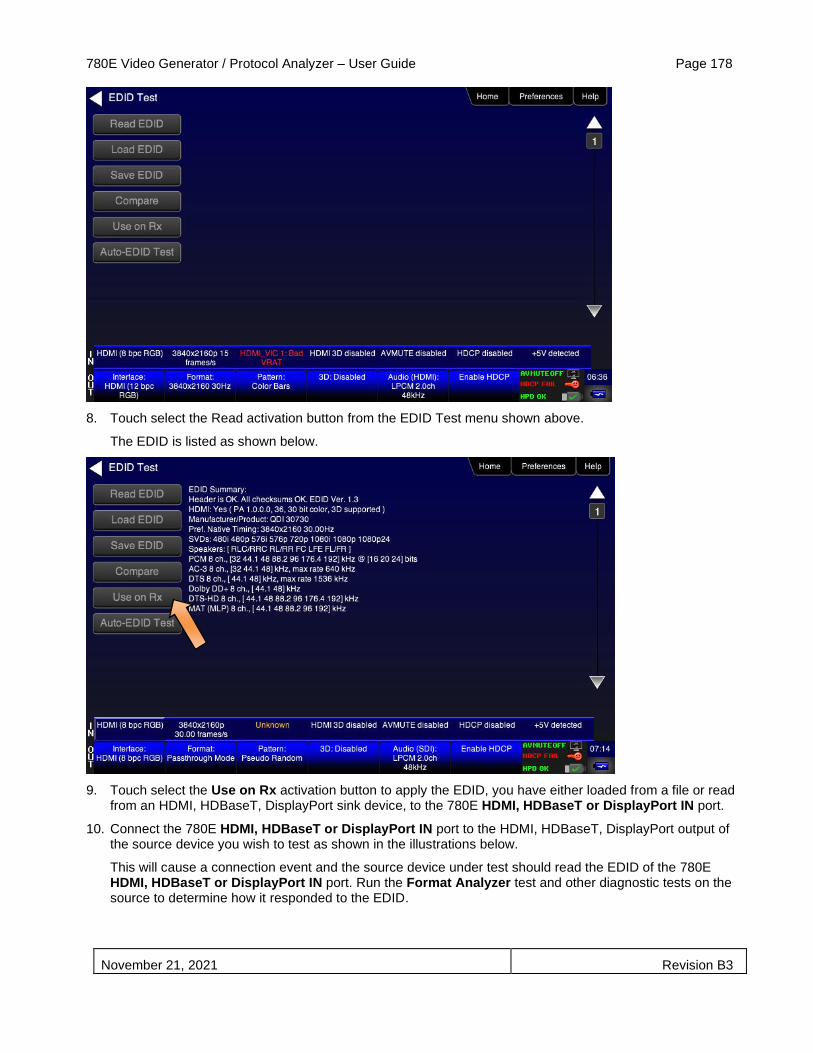
780E Video Generator / Protocol Analyzer – User Guide Page 178
November 21, 2021 Revision B3
8. Touch select the Read activation button from the EDID Test menu shown above.
The EDID is listed as shown below.
9. Touch select the Use on Rx activation button to apply the EDID, you have either loaded from a file or read from an HDMI, HDBaseT, DisplayPort sink device, to the 780E HDMI, HDBaseT or DisplayPort IN port.
10. Connect the 780E HDMI, HDBaseT or DisplayPort IN port to the HDMI, HDBaseT, DisplayPort output of the source device you wish to test as shown in the illustrations below.
This will cause a connection event and the source device under test should read the EDID of the 780E HDMI, HDBaseT or DisplayPort IN port. Run the Format Analyzer test and other diagnostic tests on the source to determine how it responded to the EDID.
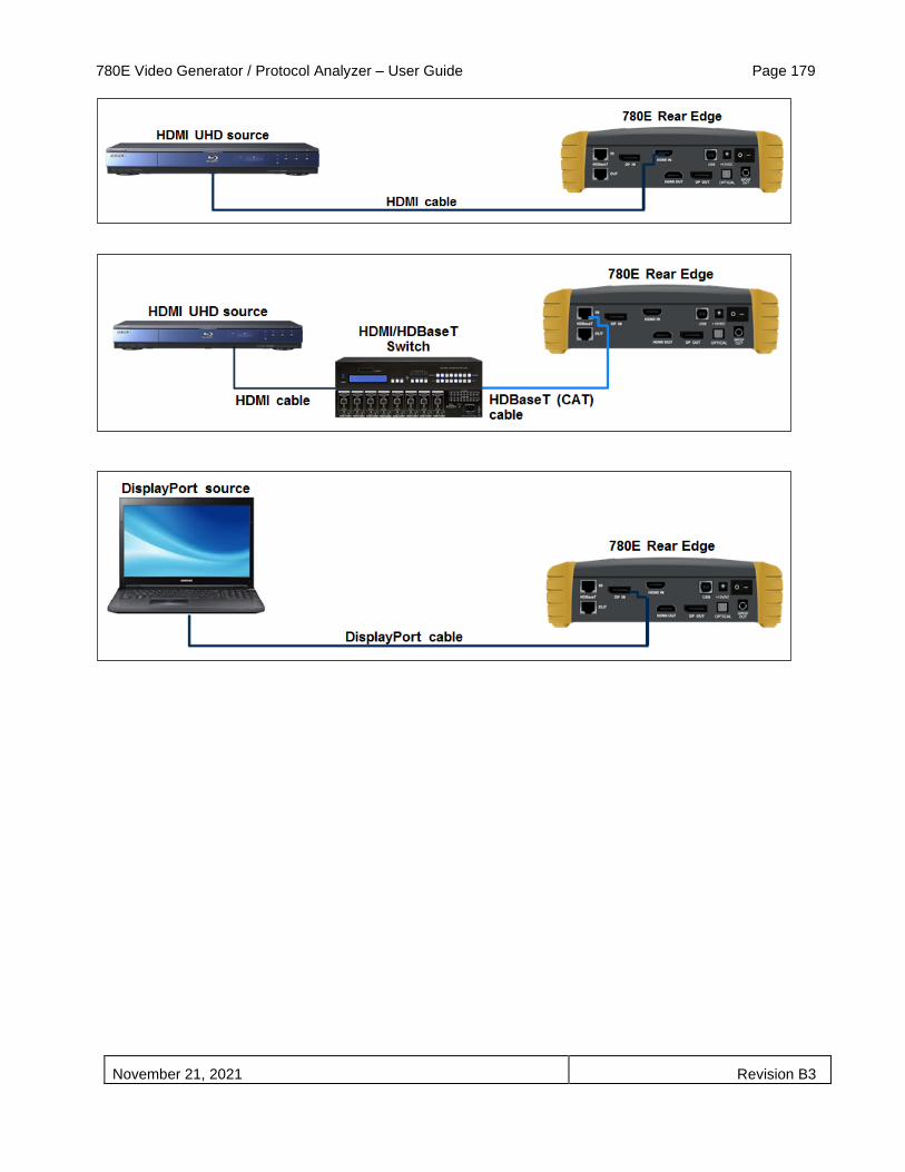
780E Video Generator / Protocol Analyzer – User Guide Page 179
November 21, 2021 Revision B3

780E Video Generator / Protocol Analyzer – User Guide Page 180
November 21, 2021 Revision B3
7 Using the 780E Test Instrument Installer Test Utility
This section provides procedures for diagnosing HDMI and HDBaseT (and DisplayPort for sink testing) networks using the automated Installer Test. The features and functions described in this section are included as a standard feature. The Installer Test enables you to quickly and simply identify common interoperability problems. The Installer Test enables you to conduct step by step diagnostics toward the source—upstream (Source Test), toward the sink—downstream (Sink Test), or in a looped configuration around a repeater device (Repeater Test). You can also conduct both and upstream and a downstream diagnostic test at the same time using the Link Test.
Table 7-1 below describes what items are tested with each test in the Installer Test.
Table 7-1: Installer Test
Sink Test Description
▪ Verifies hot plug detect is high
▪ Verifies EDID (bad header, bad checksum, pass/fail on compliance)
▪ Runs an HDCP test
▪ Runs a video test at EDID preferred timing, with HDCP enabled
▪ Test EDID video at 1080p(24/50/60), 1080i(25/30), 720p(50/60)
▪ YCbCr 4:2:0 4:2:2 and 4:4:4 video tests
▪ Tests deep color parameters
▪ Test port switch on HDTV with HDCP re-authentication
Source Test Description
▪ Tests the maximum number of HDCP keys supported by the
source device during HDCP authentication.
▪ Verifies the incoming video at various timings
▪ Verifies video timing parameters.
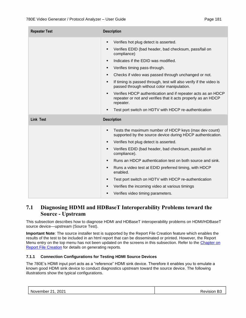
780E Video Generator / Protocol Analyzer – User Guide Page 181
November 21, 2021 Revision B3
Repeater Test Description
▪ Verifies hot plug detect is asserted.
▪ Verifies EDID (bad header, bad checksum, pass/fail on compliance)
▪ Indicates if the EDID was modified.
▪ Verifies timing pass-through.
▪ Checks if video was passed through unchanged or not.
▪ If timing is passed through, test will also verify if the video is passed through without color manipulation.
▪ Verifies HDCP authentication and if repeater acts as an HDCP repeater or not and verifies that it acts properly as an HDCP repeater.
▪ Test port switch on HDTV with HDCP re-authentication
Link Test Description
▪ Tests the maximum number of HDCP keys (max dev count)
supported by the source device during HDCP authentication.
▪ Verifies hot plug detect is asserted.
▪ Verifies EDID (bad header, bad checksum, pass/fail on compliance).
▪ Runs an HDCP authentication test on both source and sink.
▪ Runs a video test at EDID preferred timing, with HDCP enabled.
▪ Test port switch on HDTV with HDCP re-authentication
▪ Verifies the incoming video at various timings
▪ Verifies video timing parameters.
7.1 Diagnosing HDMI and HDBaseT Interoperability Problems toward the
Source - Upstream
This subsection describes how to diagnose HDMI and HDBaseT interoperability problems on HDMI/HDBaseT source device—upstream (Source Test).
Important Note: The source installer test is supported by the Report File Creation feature which enables the results of the test to be included in an html report that can be disseminated or printed. However, the Report Menu entry on the top menu has not been updated on the screens in this subsection. Refer to the Chapter on Report File Creation for details on generating reports.
7.1.1 Connection Configurations for Testing HDMI Source Devices
The 780E’s HDMI input port acts as a “reference” HDMI sink device. Therefore it enables you to emulate a known good HDMI sink device to conduct diagnostics upstream toward the source device. The following illustrations show the typical configurations.
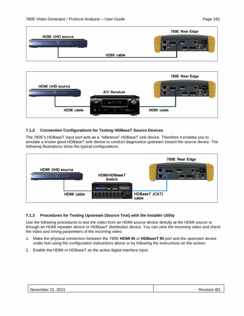
780E Video Generator / Protocol Analyzer – User Guide Page 182
November 21, 2021 Revision B3
7.1.2 Connection Configurations for Testing HDBaseT Source Devices
The 780E’s HDBaseT input port acts as a “reference” HDBaseT sink device. Therefore it enables you to emulate a known good HDBaseT sink device to conduct diagnostics upstream toward the source device. The following illustrations show the typical configurations.
7.1.3 Procedures for Testing Upstream (Source Test) with the Installer Utility
Use the following procedures to test the video from an HDMI source device directly at the HDMI source or through an HDMI repeater device or HDBaseT distribution device. You can view the incoming video and check the video and timing parameters of the incoming video.
1. Make the physical connection between the 780E HDMI IN or HDBaseT IN port and the upstream device under test using the configuration instructions above or by following the instructions on the screen.
2. Enable the HDMI or HDBaseT as the active digital interface input.

780E Video Generator / Protocol Analyzer – User Guide Page 183
November 21, 2021 Revision B3
3. Touch select Source Test under Installer Tests from the Home menu shown below.
4. Touch select the OK activation button to initiate the test.
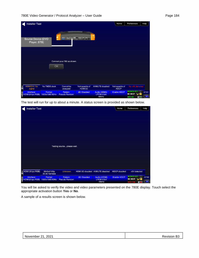
780E Video Generator / Protocol Analyzer – User Guide Page 184
November 21, 2021 Revision B3
The test will run for up to about a minute. A status screen is provided as shown below.
You will be asked to verify the video and video parameters presented on the 780E display. Touch select the appropriate activation button Yes or No.
A sample of a results screen is shown below.

780E Video Generator / Protocol Analyzer – User Guide Page 185
November 21, 2021 Revision B3
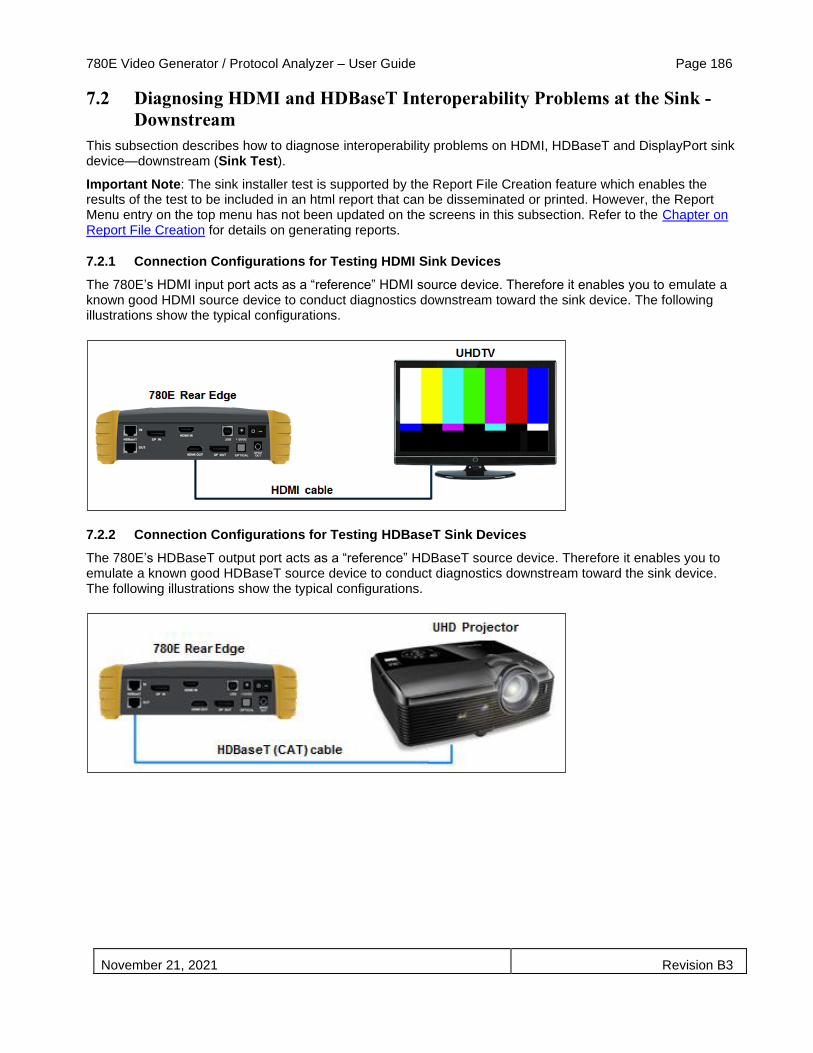
780E Video Generator / Protocol Analyzer – User Guide Page 186
November 21, 2021 Revision B3
7.2 Diagnosing HDMI and HDBaseT Interoperability Problems at the Sink -
Downstream
This subsection describes how to diagnose interoperability problems on HDMI, HDBaseT and DisplayPort sink device—downstream (Sink Test).
Important Note: The sink installer test is supported by the Report File Creation feature which enables the results of the test to be included in an html report that can be disseminated or printed. However, the Report Menu entry on the top menu has not been updated on the screens in this subsection. Refer to the Chapter on Report File Creation for details on generating reports.
7.2.1 Connection Configurations for Testing HDMI Sink Devices
The 780E’s HDMI input port acts as a “reference” HDMI source device. Therefore it enables you to emulate a known good HDMI source device to conduct diagnostics downstream toward the sink device. The following illustrations show the typical configurations.
7.2.2 Connection Configurations for Testing HDBaseT Sink Devices
The 780E’s HDBaseT output port acts as a “reference” HDBaseT source device. Therefore it enables you to emulate a known good HDBaseT source device to conduct diagnostics downstream toward the sink device. The following illustrations show the typical configurations.

780E Video Generator / Protocol Analyzer – User Guide Page 187
November 21, 2021 Revision B3
7.2.3 Connection Configurations for Testing DisplayPort Sink Devices
The 780E’s DisplayPort output port acts as a “reference” DisplayPort source device. Therefore it enables you to emulate a known good DisplayPort source device to conduct diagnostics downstream toward the sink device. The following illustrations show the typical configurations.
7.2.4 Procedures for Testing Downstream (Sink Test) with the Installer Utility
Use the following procedures to test the video from an HDMI sink device.
1. Make the physical connection between the 780E HDMI, HDBaseT or DisplayPort OUT port and the sink device under test using the configuration instructions above or by following the instructions on the screen.
2. Enable the HDMI, HDBaseT or DisplayPort as the active digital interface input. (HDMI shown in example.)

780E Video Generator / Protocol Analyzer – User Guide Page 188
November 21, 2021 Revision B3
3. Touch select Test Sink under the Installer Tests from the Home menu shown below.
4. Touch select the OK activation button to initiate the test.

780E Video Generator / Protocol Analyzer – User Guide Page 189
November 21, 2021 Revision B3
The test will run for up to about a minute. You will be asked to verify the video and video parameters presented on the display device under test. Touch select the appropriate activation button Yes or No.
The results are presented for each timing (video resolution) tested. The following two screens are samples of these results screens.
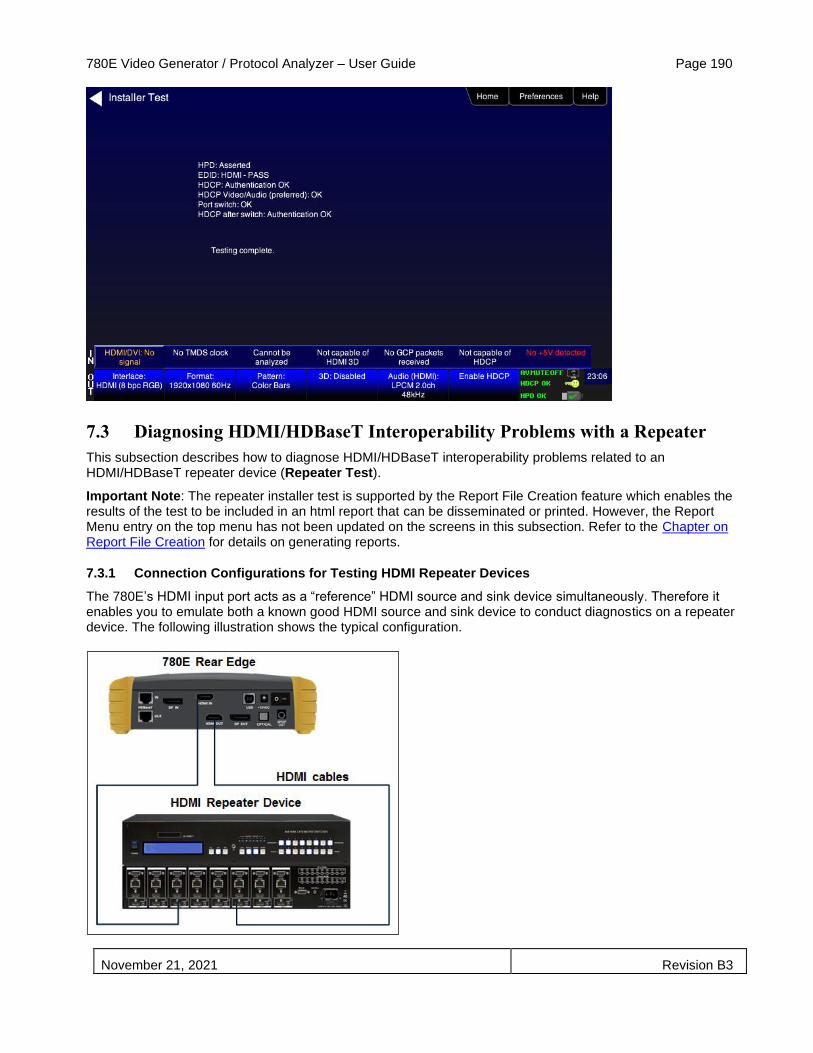
780E Video Generator / Protocol Analyzer – User Guide Page 190
November 21, 2021 Revision B3
7.3 Diagnosing HDMI/HDBaseT Interoperability Problems with a Repeater
This subsection describes how to diagnose HDMI/HDBaseT interoperability problems related to an HDMI/HDBaseT repeater device (Repeater Test).
Important Note: The repeater installer test is supported by the Report File Creation feature which enables the results of the test to be included in an html report that can be disseminated or printed. However, the Report Menu entry on the top menu has not been updated on the screens in this subsection. Refer to the Chapter on Report File Creation for details on generating reports.
7.3.1 Connection Configurations for Testing HDMI Repeater Devices
The 780E’s HDMI input port acts as a “reference” HDMI source and sink device simultaneously. Therefore it enables you to emulate both a known good HDMI source and sink device to conduct diagnostics on a repeater device. The following illustration shows the typical configuration.
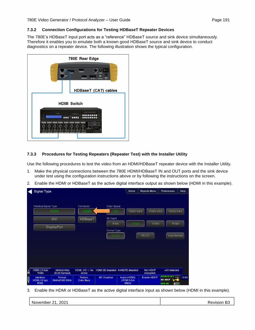
780E Video Generator / Protocol Analyzer – User Guide Page 191
November 21, 2021 Revision B3
7.3.2 Connection Configurations for Testing HDBaseT Repeater Devices
The 780E’s HDBaseT input port acts as a “reference” HDBaseT source and sink device simultaneously. Therefore it enables you to emulate both a known good HDBaseT source and sink device to conduct diagnostics on a repeater device. The following illustration shows the typical configuration.
7.3.3 Procedures for Testing Repeaters (Repeater Test) with the Installer Utility
Use the following procedures to test the video from an HDMI/HDBaseT repeater device with the Installer Utility.
1. Make the physical connections between the 780E HDMI/HDBaseT IN and OUT ports and the sink device under test using the configuration instructions above or by following the instructions on the screen.
2. Enable the HDMI or HDBaseT as the active digital interface output as shown below (HDMI in this example).
3. Enable the HDMI or HDBaseT as the active digital interface input as shown below (HDMI in this example).

780E Video Generator / Protocol Analyzer – User Guide Page 192
November 21, 2021 Revision B3
4. Touch select Test Repeater from Installer Tests from the Home menu shown below.
The Repeater Test screen will appear as shown below.

780E Video Generator / Protocol Analyzer – User Guide Page 193
November 21, 2021 Revision B3
5. Touch select the OK activation button to initiate the test.
The test will run for up to about a minute. You will be instructed to switch to different timings and verify that the video displayed on the 780E screen looks correct.
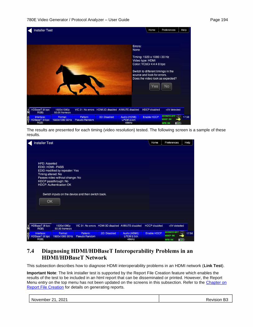
780E Video Generator / Protocol Analyzer – User Guide Page 194
November 21, 2021 Revision B3
The results are presented for each timing (video resolution) tested. The following screen is a sample of these results.
7.4 Diagnosing HDMI/HDBaseT Interoperability Problems in an
HDMI/HDBaseT Network
This subsection describes how to diagnose HDMI interoperability problems in an HDMI network (Link Test).
Important Note: The link installer test is supported by the Report File Creation feature which enables the results of the test to be included in an html report that can be disseminated or printed. However, the Report Menu entry on the top menu has not been updated on the screens in this subsection. Refer to the Chapter on Report File Creation for details on generating reports.
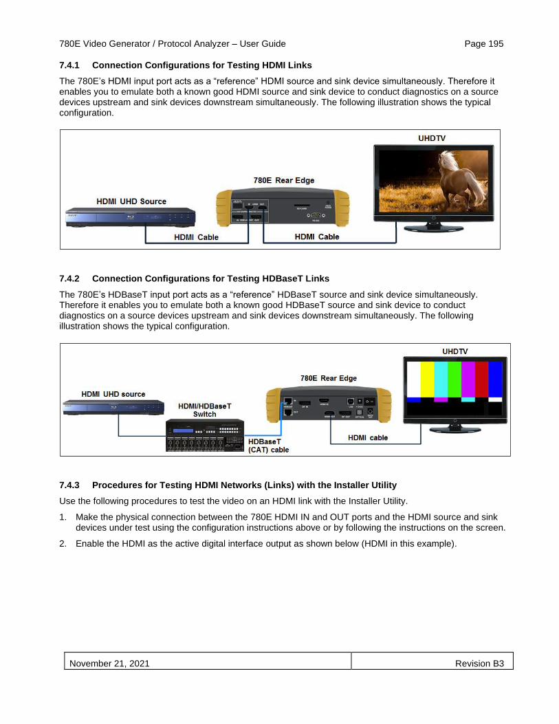
780E Video Generator / Protocol Analyzer – User Guide Page 195
November 21, 2021 Revision B3
7.4.1 Connection Configurations for Testing HDMI Links
The 780E’s HDMI input port acts as a “reference” HDMI source and sink device simultaneously. Therefore it enables you to emulate both a known good HDMI source and sink device to conduct diagnostics on a source devices upstream and sink devices downstream simultaneously. The following illustration shows the typical configuration.
7.4.2 Connection Configurations for Testing HDBaseT Links
The 780E’s HDBaseT input port acts as a “reference” HDBaseT source and sink device simultaneously. Therefore it enables you to emulate both a known good HDBaseT source and sink device to conduct diagnostics on a source devices upstream and sink devices downstream simultaneously. The following illustration shows the typical configuration.
7.4.3 Procedures for Testing HDMI Networks (Links) with the Installer Utility
Use the following procedures to test the video on an HDMI link with the Installer Utility.
1. Make the physical connection between the 780E HDMI IN and OUT ports and the HDMI source and sink devices under test using the configuration instructions above or by following the instructions on the screen.
2. Enable the HDMI as the active digital interface output as shown below (HDMI in this example).
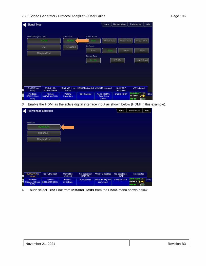
780E Video Generator / Protocol Analyzer – User Guide Page 196
November 21, 2021 Revision B3
3. Enable the HDMI as the active digital interface input as shown below (HDMI in this example).
4. Touch select Test Link from Installer Tests from the Home menu shown below.

780E Video Generator / Protocol Analyzer – User Guide Page 197
November 21, 2021 Revision B3
A diagram will appear on the 780E display depicting the proper setup for the Link Test.
5. Touch select the OK activation button to initiate the test.
The test will run for up to about a minute. A status screen is provided as shown below.
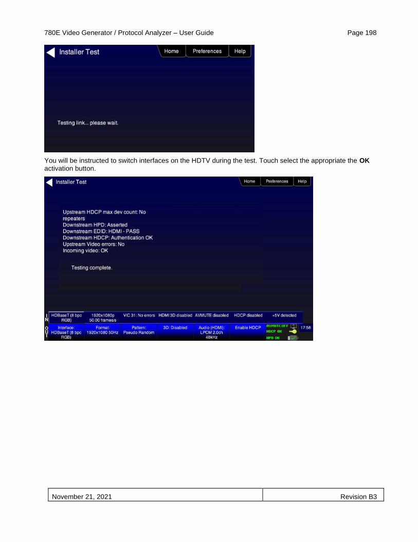
780E Video Generator / Protocol Analyzer – User Guide Page 198
November 21, 2021 Revision B3
You will be instructed to switch interfaces on the HDTV during the test. Touch select the appropriate the OK activation button.

780E Video Generator / Protocol Analyzer – User Guide Page 199
November 21, 2021 Revision B3
8 Using the 780E to Monitor the HDMI/HDBaseT DDC, CEC and
DisplayPort Aux Channel
This section provides procedures for using the optional Auxiliary Channel Analyzer (ACA) feature. This option enables you to monitor the following:
• HDMI/HDBaseT DDC and CEC emulation monitoring with Auxiliary Channel Analyzer (ACA) – The 780E ACA enables you to monitor DDC transactions such as HDCP and EDID as well as hot plug related events while emulating an HDMI/HDBaseT source and/or sink device(s) in an HDMI/HDBaseT system.
• DisplayPort emulation monitoring with Auxiliary Channel Analyzer (ACA) – The 780E ACA enables you to monitor the HDCP and EDID as well as link training transactions while emulating a DisplayPort source and/or sink device(s).
• DDC and CEC passive monitoring with Auxiliary Channel Analyzer (ACA) – The 780E ACA enables you to passively monitor HDMI CEC and DDC transactions between an HDMI source and sink. You can monitor +5V, hot plug events as well as the HDCP and EDID transactions and CEC messages.
• DisplayPort Aux Channel passive monitoring with Auxiliary Channel Analyzer (ACA) – The 780E ACA enables you to passively monitor DisplayPort Aux Chan transactions between a DisplayPort source and sink. You can monitor the HDCP and EDID transactions and link training transactions.
These ACA features require a license key and can be enabled remotely. The features and functions described in this section are included only if you have purchased the Auxiliary Channel Analyzer option.
8.1 Auxiliary Channel Analyzer (ACA) Transactions
This subsection describes the ACA transaction screens. The screen shot and tables below describes the Auxiliary Channel Analyzer control buttons and on-screen transactions.
HDMI example:
DisplayPort example:

780E Video Generator / Protocol Analyzer – User Guide Page 200
November 21, 2021 Revision B3
Note: You can scroll through the transactions up or down (older to more recent) by sliding your finger or stylus up or down on the touch screen.
The following table describes the control buttons on the top of the ACA screen.
Table 8-2: Auxiliary Channel Analyzer activation button description
Button Description
Start/Stop A toggle button to initiate and then halt the collection of ACA transactions. You must stop the collection if you want to save the transactions or view the details. Once stopped you can scroll through the transactions by moving your finger or stylus up or down.
Save Enables you to name and save an ACA trace for later examination and exporting to other colleagues. Once exported the saved traces can be viewed either through another 780 or through the ACA viewer application available from the Quantum Data website.
Clear Clears out the trace transactions shown on the 780 display.
Details Enables you to view the details of the transaction that is highlighted. Also enable you to return to the main screen with the transactions.
Auto Scroll Automatically moves the viewer to the most recently collected transactions.
Table 8-2: Auxiliary Channel Analyzer record description
Data type Description Color coding
Hot Plug indication An indication from the HDMI/HDBaseT or DisplayPort sink to the source that there is a device connected. The Hot Plug voltage is a steady. In the case of a repeater, it is a 100ms pulse.
Blue
+5V A voltage from an HDMI/HDBaseT source to the HDMI/HDBaseT sink to power the hot plug voltage. The +5V is a steady voltage nominally 5 volts.
Cyan

780E Video Generator / Protocol Analyzer – User Guide Page 201
November 21, 2021 Revision B3
Table 8-2: Auxiliary Channel Analyzer record description
Data type Description Color coding
EDID Exchange A data set in the HDMI, HDBaseT sink that describes its capabilities to a connected source device. This data is transmitted over the DDC channel.
Gold
HDCP Transactions HDMI and HDBaseT content protection authentication and encryption transactions. The source initiates HDCP for protected content. Various values and registers are exchanged over the DDC.
Green
CEC messages HDMI CEC messages are transmitted over a one wire CEC bus. These messages are monitored through the ACA
Magenta
Aux Chan DisplayPort Aux Chan transactions such as HDCP, EDID and link training transactions.
Yellow
Errors The DDC channel uses the I2C protocol. Errors in the I2C protocol are shown in the ACA transactions.
Red
Notes:
1. For each transaction there is a timestamp. The timestamps are: HH:MM:SS:MSEC format. They are best used for comparing between transactions.
2. Each transaction has a type indicate which can be: DDC, Hot Plug, CEC or 5V.
3. Each transaction there is a directional indicator, U – Upstream, D – Downstream. This pertains to the location of the 780 relative to the network it is exchanging information with. Upstream means that the 780 is upstream and communicating downstream and Downstream means that the 780 is downstream and communicating upstream.
You can save these transactions and then view them on the Quantum Data external ACA viewer which is available for free on the Quantum Data website.
8.2 Auxiliary Channel Analyzer – Emulation Monitoring of DDC on an HDMI
or HDBaseT Sink
The Aux Channel Analyzer test monitors the DDC channel transactions and hot plug events while emulating HDMI devices. The features and functions described in this section are included only if you have purchased the Auxiliary Channel Analyzer option.
You can view the details of each transaction and save the traces for viewing on the external ACA application available from the Quantum Data website.
8.2.1 Configurations for Monitoring DDC Transactions with ACA on HDMI Sink Devices
This subsection provides configuration diagrams that depict ACA monitoring of HDMI sink devices, with or without a repeater while the 780E is emulating an HDMI source device.
1. Connect the HDMI or HDBaseT sink devices to the 780E in either of the ways shown in the diagrams below and described as follows:
a. The HDMI sink device input is connected the 780E HDMI OUT connector.
OR
b. The HDMI repeater device input is connected to the 780E HDMI OUT connector.

780E Video Generator / Protocol Analyzer – User Guide Page 202
November 21, 2021 Revision B3
8.2.2 Configurations for Monitoring DDC Transactions with ACA on HDBaseT Sink Devices
This subsection provides configuration diagrams that depict ACA monitoring on HDBaseT sink devices, with or without a repeater while the 780E is emulating an HDBaseT source device.
1. Connect the HDBaseT system devices to the 780E in either of the ways shown in the diagrams above and described as follows:
a. The HDBaseT sink device input is connected the 780E HDBaseT OUT connector.
OR
b. The HDBaseT repeater device input is connected to the 780E HDBaseT OUT connector.

780E Video Generator / Protocol Analyzer – User Guide Page 203
November 21, 2021 Revision B3
8.2.3 Monitoring DDC Transactions with ACA on HDMI or HDBaseT Sink Devices
This subsection provides procedures for ACA monitoring of HDMI or HDBaseT sink devices, with or without a repeater while the 780E is emulating an HDMI or HDBaseT source device.
1. Enable the HDMI or HDBaseT as the active digital interface output as shown below. First access the Signal Type screen (first screen); then select the HDMI or HDBaseT output interface (second screen).
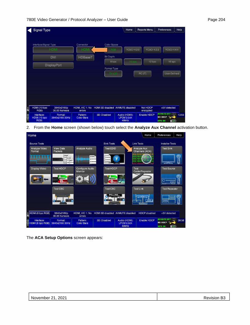
780E Video Generator / Protocol Analyzer – User Guide Page 204
November 21, 2021 Revision B3
2. From the Home screen (shown below) touch select the Analyze Aux Channel activation button.
The ACA Setup Options screen appears:

780E Video Generator / Protocol Analyzer – User Guide Page 205
November 21, 2021 Revision B3
6. Select the data types that you wish to monitor. In this application you would select data types from the Tx Port side.
7. Determine what data types you wish to monitor. Typically you will want to monitor the DDC and hot plug (+5V only available with passive monitoring option).
Note: By default the two activation buttons labeled 780E Tx Port and 780E Rx port are enabled. You cannot disable them. Transactions will be shown based on which ports (HDMI/HDBaseT OUT and/or HDMI/HDBaseT IN) are connected to HDMI/HDBaseT devices and which set of transactions you have enabled (i.e. DDC, HPD on Tx or Rx side).
8. Enable HDCP on the 780E HDMI or HDBaseT OUT port. Use the procedures in the section entitled: Testing HDCP on an HDMI HDTV or HDMI Repeater Device.
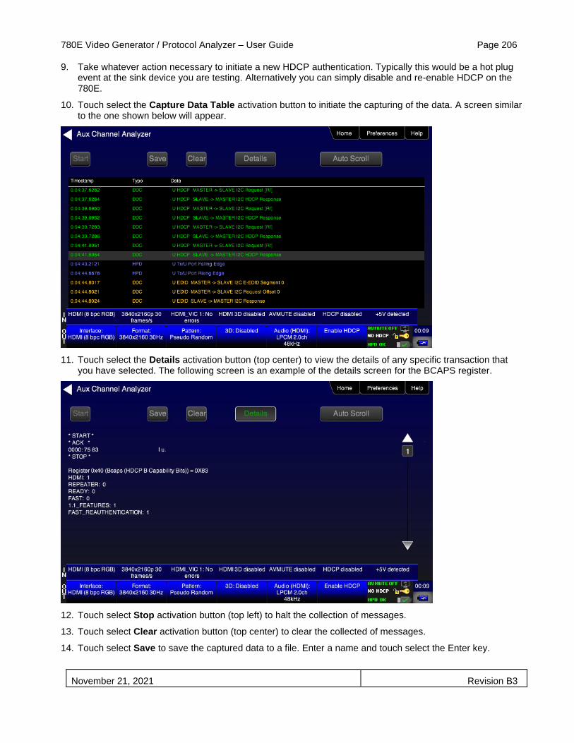
780E Video Generator / Protocol Analyzer – User Guide Page 206
November 21, 2021 Revision B3
9. Take whatever action necessary to initiate a new HDCP authentication. Typically this would be a hot plug event at the sink device you are testing. Alternatively you can simply disable and re-enable HDCP on the 780E.
10. Touch select the Capture Data Table activation button to initiate the capturing of the data. A screen similar to the one shown below will appear.
11. Touch select the Details activation button (top center) to view the details of any specific transaction that you have selected. The following screen is an example of the details screen for the BCAPS register.
12. Touch select Stop activation button (top left) to halt the collection of messages.
13. Touch select Clear activation button (top center) to clear the collected of messages.
14. Touch select Save to save the captured data to a file. Enter a name and touch select the Enter key.

780E Video Generator / Protocol Analyzer – User Guide Page 207
November 21, 2021 Revision B3
8.2.4 Configurations for Monitoring DDC Transactions with ACA on HDMI Source Devices
This subsection provides configuration diagrams that depict ACA monitoring of HDMI source devices, with or without a repeater, while the 780E is emulating an HDMI sink device.
8.2.5 Configurations for Monitoring DDC Transactions with ACA on HDBaseT Source Devices
This subsection provides configuration diagrams that depict ACA monitoring of HDBaseT source devices, with or without a repeater, while the 780E is emulating an HDBaseT sink device.

780E Video Generator / Protocol Analyzer – User Guide Page 208
November 21, 2021 Revision B3
8.2.6 Procedures for Monitoring the DDC Transactions using the Auxiliary Channel Analyzer on HDMI or HDBaseT Source Devices
This subsection provides procedures for ACA monitoring of HDMI and HDBaseT source devices, with or without a repeater while the 780E is emulating an HDMI or HDBaseT sink device with HDCP capabilities.
Note: You will have to obtain a license key for the ACA option to use the feature.
1. Connect the HDMI or HDBaseT source devices to the 780E in either of the ways shown in the diagrams above and described as follows:
a. The HDMI source device output is connected the 780E HDMI IN connector.
OR
b. The HDMI/HDBaseT repeater device output is connected to the 780E HDMI/HDBaseT IN connector.
c. The HDMI source device output is connected to the HDMI/HDBaseT repeater device input.
d. Enable the HDMI or HDBaseT as the active digital interface output as shown below.
2. First access the Rx Interface Selection screen (first screen); then select the HDMI or HDBaseT input interface (second screen).
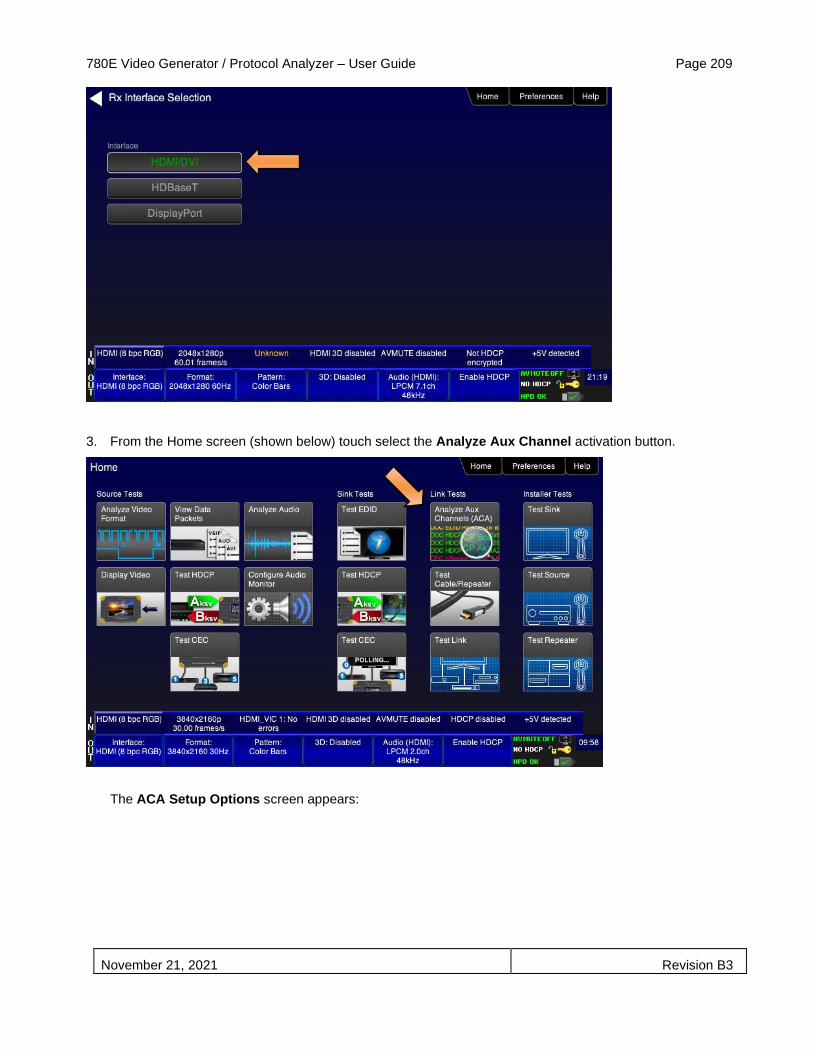
780E Video Generator / Protocol Analyzer – User Guide Page 209
November 21, 2021 Revision B3
3. From the Home screen (shown below) touch select the Analyze Aux Channel activation button.
The ACA Setup Options screen appears:
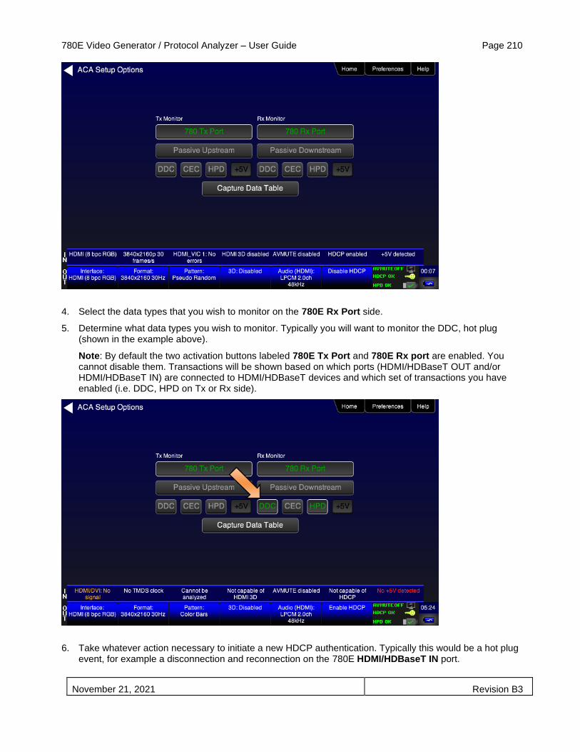
780E Video Generator / Protocol Analyzer – User Guide Page 210
November 21, 2021 Revision B3
4. Select the data types that you wish to monitor on the 780E Rx Port side.
5. Determine what data types you wish to monitor. Typically you will want to monitor the DDC, hot plug (shown in the example above).
Note: By default the two activation buttons labeled 780E Tx Port and 780E Rx port are enabled. You cannot disable them. Transactions will be shown based on which ports (HDMI/HDBaseT OUT and/or HDMI/HDBaseT IN) are connected to HDMI/HDBaseT devices and which set of transactions you have enabled (i.e. DDC, HPD on Tx or Rx side).
6. Take whatever action necessary to initiate a new HDCP authentication. Typically this would be a hot plug event, for example a disconnection and reconnection on the 780E HDMI/HDBaseT IN port.

780E Video Generator / Protocol Analyzer – User Guide Page 211
November 21, 2021 Revision B3
7. Touch select the Capture Data Table activation button to access the Auxiliary Channel Analyzer screen.
8. Touch select Start to initiate the capturing of the data. A screen similar to the one shown below will appear.
9. Touch select the Details activation button (top center) to view the details of any specific transaction that you have selected. The following screen is an example of the details screen. The screen below shows a detailed view of the BCAPS register.
10. Touch select Stop activation button (top left) to halt the collection of messages.
11. Touch select Clear activation button (top center) to clear the collected of messages.
12. Touch select Save to save the captured data to a file. Enter a name and touch select the Enter key.
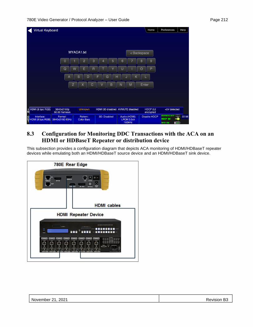
780E Video Generator / Protocol Analyzer – User Guide Page 212
November 21, 2021 Revision B3
8.3 Configuration for Monitoring DDC Transactions with the ACA on an
HDMI or HDBaseT Repeater or distribution device
This subsection provides a configuration diagram that depicts ACA monitoring of HDMI/HDBaseT repeater devices while emulating both an HDMI/HDBaseT source device and an HDMI/HDBaseT sink device.

780E Video Generator / Protocol Analyzer – User Guide Page 213
November 21, 2021 Revision B3
8.3.1 Procedures for Running an Auxiliary Channel Analyzer Test on HDMI/HDBaseT Repeater or Distribution Devices
This subsection provides procedures for ACA monitoring of HDMI/HDBaseT repeater devices while the 780E is emulating both an HDMI/HDBaseT sink device and an HDMI/HDBaseT source device.
1. Connect the HDMI system devices to the 780E as shown in the diagrams above and described as follows:
a. The HDMI/HDBaseT repeater device input is connected the 780E HDMI/HDBaseT OUT connector.
b. The HDMI/HDBaseT repeater device output is connected to the 780E HDMI/HDBaseT IN connector.
2. Enable the HDMI or HDBaseT interface as the active digital interface output as shown below. First access the Signal Type screen (first screen below); then select the HDMI or HDBaseT interface (second screen below).

780E Video Generator / Protocol Analyzer – User Guide Page 214
November 21, 2021 Revision B3
3. Enable the HDMI or HDBaseT interface as the active digital interface input as shown below. First access the Rx Interface Selection screen (first screen below); then select the HDMI or HDBaseT interface (second screen below).

780E Video Generator / Protocol Analyzer – User Guide Page 215
November 21, 2021 Revision B3
4. Enable the HDMI or HDBaseT interface as the active digital interface input as shown below.
5. From the Home screen (shown below) touch select the Aux Channel Analyzer activation button.

780E Video Generator / Protocol Analyzer – User Guide Page 216
November 21, 2021 Revision B3
The ACA Setup Options screen appears:
6. Determine what data types you wish to monitor. Typically you will want to monitor the DDC and hot plug (+5V is only available for monitoring with the passive monitoring option). Select the data types that you wish to monitor.
Note: By default the two activation buttons labeled 780E Tx Port and 780E Rx Port are enabled. You cannot disable them. Transactions will be shown based on which ports (HDMI OUT and/or HDMI IN) are connected to HDMI devices and which transaction types (i.e. DDC and HPD) you have enabled.
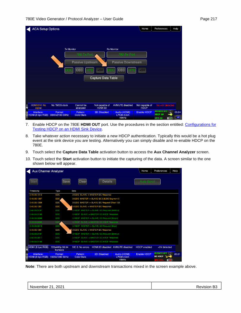
780E Video Generator / Protocol Analyzer – User Guide Page 217
November 21, 2021 Revision B3
7. Enable HDCP on the 780E HDMI OUT port. Use the procedures in the section entitled: Configurations for Testing HDCP on an HDMI Sink Device.
8. Take whatever action necessary to initiate a new HDCP authentication. Typically this would be a hot plug event at the sink device you are testing. Alternatively you can simply disable and re-enable HDCP on the 780E.
9. Touch select the Capture Data Table activation button to access the Aux Channel Analyzer screen.
10. Touch select the Start activation button to initiate the capturing of the data. A screen similar to the one shown below will appear.
Note: There are both upstream and downstream transactions mixed in the screen example above.

780E Video Generator / Protocol Analyzer – User Guide Page 218
November 21, 2021 Revision B3
11. Touch select the Details activation button (top center) to view the details of any specific transaction that you have touch selected. The following screen is an example of the details screen. A detailed view of the BCAPS register is shown. Touch Details again to return to the ACA transaction screen.
9. Touch select Stop activation button (top left) to halt the collection of messages.
10. Touch select Clear activation button (top center) to clear the collected of messages.
11. Touch select Save to save the captured data to a file. Enter a name and touch select the Enter key.

780E Video Generator / Protocol Analyzer – User Guide Page 219
November 21, 2021 Revision B3
8.4 Auxiliary Channel Analyzer – Passive Monitoring HDMI
The Aux Channel Analyzer test monitors the CEC and DDC channel transactions and hot plug events. You can monitor the events while emulating either an HDMI source or sink device or you can passively monitor the transactions. This subsection provides procedures on passive monitoring. The features and functions described in this section are included only if you have purchased the Auxiliary Channel Analyzer – Passive Monitoring option.
You can view the details of each transaction and save the traces for viewing on the external ACA application available from the Quantum Data website.
8.4.1 Configurations for Passively Monitoring CEC and or DDC Transactions with ACA on an HDMI System
This subsection provides configuration diagrams that depict ACA passive monitoring of an HDMI system.
1. Connect the HDMI system devices to the 780E as shown in the diagram below and described as follows:
a. The HDMI source is connected to the 780E ACA IN connector.
b. The HDMI sink device (e.g. HDTV) is connected to the 780E ACA OUT connector.
8.4.2 Procedures for Passive Monitoring DDC transactions and hot plug events with the Auxiliary Channel Analyzer on HDMI Devices
This subsection provides procedures for ACA passive monitoring of HDMI devices.
1. Enable the HDMI interface as the active digital interface output as shown below. First access the Signal Type screen (first screen below); then select the HDMI interface (second screen below).
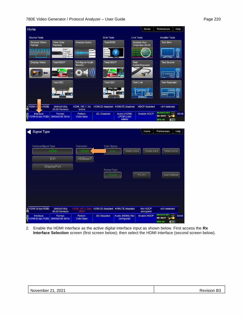
780E Video Generator / Protocol Analyzer – User Guide Page 220
November 21, 2021 Revision B3
2. Enable the HDMI interface as the active digital interface input as shown below. First access the Rx Interface Selection screen (first screen below); then select the HDMI interface (second screen below).
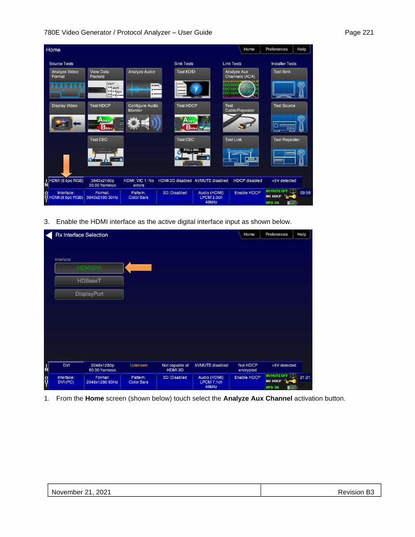
780E Video Generator / Protocol Analyzer – User Guide Page 221
November 21, 2021 Revision B3
3. Enable the HDMI interface as the active digital interface input as shown below.
1. From the Home screen (shown below) touch select the Analyze Aux Channel activation button.
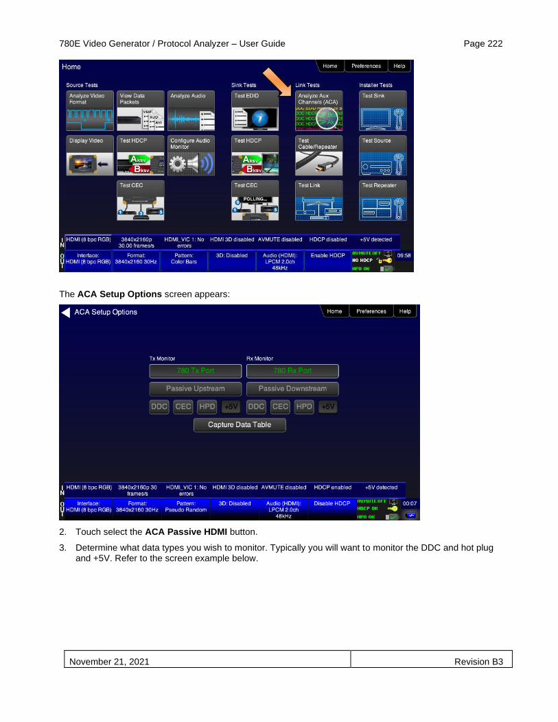
780E Video Generator / Protocol Analyzer – User Guide Page 222
November 21, 2021 Revision B3
The ACA Setup Options screen appears:
2. Touch select the ACA Passive HDMI button.
3. Determine what data types you wish to monitor. Typically you will want to monitor the DDC and hot plug and +5V. Refer to the screen example below.
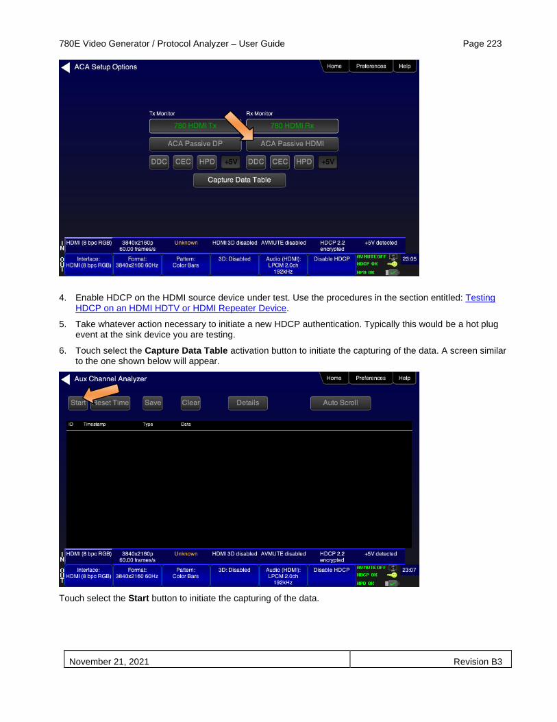
780E Video Generator / Protocol Analyzer – User Guide Page 223
November 21, 2021 Revision B3
4. Enable HDCP on the HDMI source device under test. Use the procedures in the section entitled: Testing HDCP on an HDMI HDTV or HDMI Repeater Device.
5. Take whatever action necessary to initiate a new HDCP authentication. Typically this would be a hot plug event at the sink device you are testing.
6. Touch select the Capture Data Table activation button to initiate the capturing of the data. A screen similar to the one shown below will appear.
Touch select the Start button to initiate the capturing of the data.

780E Video Generator / Protocol Analyzer – User Guide Page 224
November 21, 2021 Revision B3
7. Touch select the Details activation button (top center) to view the details of any specific transaction that you have selected. The following screen is an example of the details screen. This example shows the BCAPS register details. Touch select the Details activation button again to return to the trace view.
10. Touch select Stop activation button (top left) to halt the collection of messages.
11. Touch select Clear activation button (top center) to clear the collected of messages.
12. Touch select Save to save the captured data to a file. Enter a name and touch select the Enter key.

780E Video Generator / Protocol Analyzer – User Guide Page 225
November 21, 2021 Revision B3
8.5 Auxiliary Channel Analyzer – Monitoring of CEC Messages
The Aux Channel Analyzer test monitors the CEC channel message while emulating HDMI/HDBaseT devices. The features and functions described in this section are included only if you have purchased the Auxiliary Channel Analyzer option.
You can view the details of each transaction and save the traces for viewing on the external ACA application available from the Quantum Data website.
8.5.1 Procedures for Passive Monitoring HDMI CEC messages with the Auxiliary Channel Analyzer
This subsection provides procedures for ACA passive monitoring of CEC messages on HDMI devices.
Note: You will have to obtain a license key for the ACA passive monitoring option to use the feature.
1. Connect the HDMI system devices to the 780E as shown in the diagram above and described as follows:
a. The HDMI source is connected to the 780E ACA IN connector.
b. The HDMI sink device (e.g. HDTV) is connected to the 780E ACA OUT connector.
8. From the Home screen (shown below) touch select the Analyze Aux Channel activation button.

780E Video Generator / Protocol Analyzer – User Guide Page 226
November 21, 2021 Revision B3
The ACA Setup Options screen appears:
2. Select the CEC to monitor. In this application you would select Passive Upstream. Note that you need only set either the Passive Upstream or Passive Downstream.

780E Video Generator / Protocol Analyzer – User Guide Page 227
November 21, 2021 Revision B3
3. Enable HDCP on the HDMI source device under test. Use the procedures in the section entitled: Testing HDCP on an HDMI HDTV or HDMI Repeater Device.
4. Take whatever action necessary to initiate CEC messages.
5. Touch select the Capture Data Table activation button to initiate the capturing of the data. A screen similar to the one shown below will appear.
Touch select the Details activation button (top center) to view the details of any specific transaction that you have selected. The following screen is an example of the details screen. These screen examples show polling example.

780E Video Generator / Protocol Analyzer – User Guide Page 228
November 21, 2021 Revision B3
6. Touch select Stop activation button (top left) to halt the collection of messages.
7. Touch select Clear activation button (top center) to clear the collected of messages.
8. Touch select Save to save the captured data to a file. Enter a name and touch select the Enter key.

780E Video Generator / Protocol Analyzer – User Guide Page 229
November 21, 2021 Revision B3
8.6 Auxiliary Channel Analyzer – Emulation Monitoring of Aux Channel on a
DisplayPort Sink
The Aux Channel Analyzer test monitors the DisplayPort Aux Chan transactions and hot plug events while emulating DisplayPort devices. The features and functions described in this section are included only if you have purchased the Auxiliary Channel Analyzer option.
You can view the details of each transaction and save the traces for viewing on the external ACA application available from the Quantum Data website.
8.6.1 Configurations for Monitoring Aux Chan Transactions with ACA on DisplayPort Sink Devices
This subsection provides configuration diagrams that depict ACA monitoring of DisplayPort sink devices, with or without a repeater while the 780E is emulating a DisplayPort source device.
1. Connect the DisplayPort sink device to the 780E DisplayPort output.
8.6.2 Monitoring Aux Chan Transactions with ACA on DisplayPort Sink Devices
This subsection provides procedures for ACA monitoring of DisplayPort sink devices while the 780E is emulating a DisplayPort source device.
1. Enable the DisplayPort as the active digital interface output as shown below.

780E Video Generator / Protocol Analyzer – User Guide Page 230
November 21, 2021 Revision B3
2. From the Home screen (shown below) touch select the Analyze Aux Channel activation button.
The ACA Setup Options screen appears:

780E Video Generator / Protocol Analyzer – User Guide Page 231
November 21, 2021 Revision B3
3. Select the data types that you wish to monitor. In this application you would select data types from the Tx Port side.
4. Determine what data types you wish to monitor. Typically you will want to monitor the Aux Chan (AUX) and hot plug (HPD).
Note: By default the two activation buttons labeled 780E Tx Port and 780E Rx port are enabled. You cannot disable them. Transactions will be shown based on which ports (DisplayPort OUT and/or DisplayPort IN) are connected to DisplayPort devices and which set of transactions you have enabled (i.e. Aux, HPD on Tx or Rx side).
5. Optionally, enable HDCP on the 780E HDMI or DisplayPort OUT port by touch selection the Enable/Disable button the status bar indicated below.
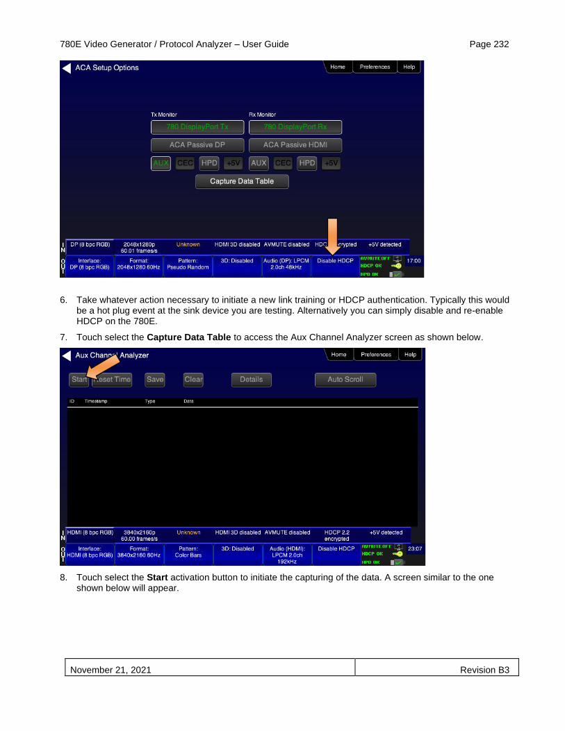
780E Video Generator / Protocol Analyzer – User Guide Page 232
November 21, 2021 Revision B3
6. Take whatever action necessary to initiate a new link training or HDCP authentication. Typically this would be a hot plug event at the sink device you are testing. Alternatively you can simply disable and re-enable HDCP on the 780E.
7. Touch select the Capture Data Table to access the Aux Channel Analyzer screen as shown below.
8. Touch select the Start activation button to initiate the capturing of the data. A screen similar to the one shown below will appear.

780E Video Generator / Protocol Analyzer – User Guide Page 233
November 21, 2021 Revision B3
9. Touch select the Details activation button (top center) to view the details of any specific transaction that you have selected. The following screen is an example of the details screen for the BCAPS register.
10. Touch select Stop activation button (top left) to halt the collection of messages.
11. Touch select Clear activation button (top center) to clear the collected of messages.
12. Touch select Save to save the captured data to a file. Enter a name and touch select the Enter key.

780E Video Generator / Protocol Analyzer – User Guide Page 234
November 21, 2021 Revision B3
8.6.3 Configurations for Monitoring Aux Chan Transactions with ACA on DisplayPort Source Devices
This subsection provides configuration diagrams that depict ACA monitoring of DisplayPort source devices while the 780E is emulating a DisplayPort sink device.
8.6.4 Procedures for Monitoring the Aux Chan Transactions using the Auxiliary Channel Analyzer on DisplayPort Source Devices
This subsection provides procedures for ACA monitoring of DisplayPort source devices while the 780E is emulating a DisplayPort sink device.
Note: You will have to obtain a license key for the ACA option to use the feature.
1. Connect the DisplayPort source devices to the 780E DisplayPort Input port.
2. Enable the DisplayPort interface as the active digital interface input as shown below. First access the Rx Interface Selection screen from the Home screen (first screen); then enable DisplayPort (second screen).
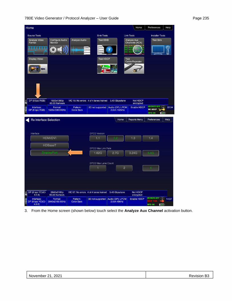
780E Video Generator / Protocol Analyzer – User Guide Page 235
November 21, 2021 Revision B3
3. From the Home screen (shown below) touch select the Analyze Aux Channel activation button.
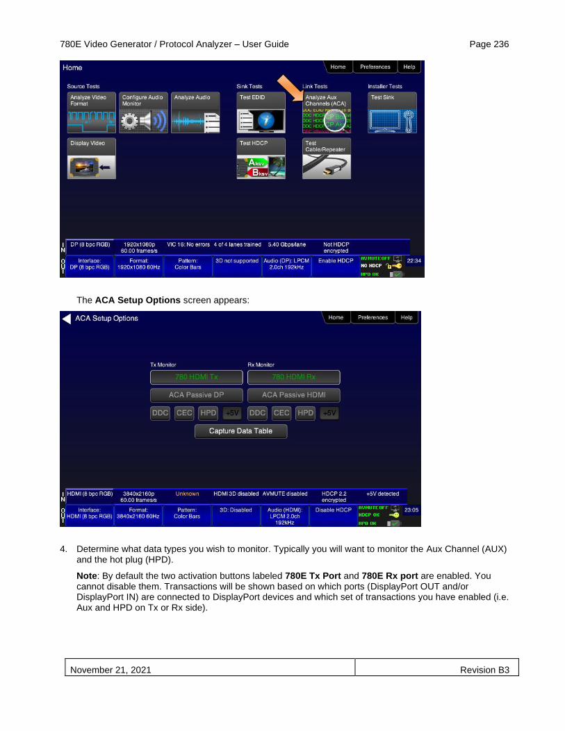
780E Video Generator / Protocol Analyzer – User Guide Page 236
November 21, 2021 Revision B3
The ACA Setup Options screen appears:
4. Determine what data types you wish to monitor. Typically you will want to monitor the Aux Channel (AUX) and the hot plug (HPD).
Note: By default the two activation buttons labeled 780E Tx Port and 780E Rx port are enabled. You cannot disable them. Transactions will be shown based on which ports (DisplayPort OUT and/or DisplayPort IN) are connected to DisplayPort devices and which set of transactions you have enabled (i.e. Aux and HPD on Tx or Rx side).

780E Video Generator / Protocol Analyzer – User Guide Page 237
November 21, 2021 Revision B3
5. Touch select the Capture Data Table to access the Aux Channel Analyzer screen as shown below.
6. Take whatever action necessary to initiate a new Link training or HDCP authentication. Typically this would be a hot plug event, for example a disconnection and reconnection on the 780E DisplayPort IN port.
7. Touch select the Start activation button to initiate the capturing of the data. A screen similar to the one shown below will appear.

780E Video Generator / Protocol Analyzer – User Guide Page 238
November 21, 2021 Revision B3
8. Touch select the Details activation button (top center) to view the details of any specific transaction that you have selected. The following screen is an example of the details screen. The screen below shows a detailed view of the link training transaction values.
9. Touch select Stop activation button (top left) to halt the collection of messages.
10. Touch select Clear activation button (top center) to clear the collected of messages.
11. Touch select Save to save the captured data to a file. Enter a name and touch select the Enter key.

780E Video Generator / Protocol Analyzer – User Guide Page 239
November 21, 2021 Revision B3

780E Video Generator / Protocol Analyzer – User Guide Page 240
November 21, 2021 Revision B3
8.7 Auxiliary Channel Analyzer – Passive Monitoring DisplayPort
The Aux Channel Analyzer test monitors the Aux channel transactions and hot plug events. You can monitor the events while emulating either a DisplayPort source or sink device or you can passively monitor the transactions. This subsection provides procedures on passive monitoring. The features and functions described in this section are included only if you have purchased the Auxiliary Channel Analyzer – Passive Monitoring option.
You can view the details of each transaction and save the traces for viewing on the external ACA application available from the Quantum Data website.
8.7.1 Configurations for Passively Monitoring Aux Channel Transactions with ACA on DisplayPort Devices
This subsection provides configuration diagrams that depict ACA passive monitoring of a DisplayPort system.
1. Connect the DisplayPort devices to the 780E as shown in the diagram below and described as follows:
a. The DisplayPort source is connected to the 780E DP ACA IN connector.
b. The DisplayPort sink device is connected to the 780E DP ACA OUT connector.
8.7.2 Procedures for Passive Monitoring Aux Channel transactions and hot plug events with the Auxiliary Channel Analyzer on DisplayPort Devices
This subsection provides procedures for ACA passive monitoring of DisplayPort devices.
1. Enable the DisplayPort interfaces for Tx and Rx as the active digital interface output as shown below.
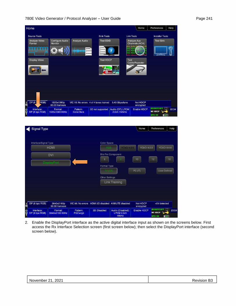
780E Video Generator / Protocol Analyzer – User Guide Page 241
November 21, 2021 Revision B3
2. Enable the DisplayPort interface as the active digital interface input as shown on the screens below. First access the Rx Interface Selection screen (first screen below); then select the DisplayPort interface (second screen below).

780E Video Generator / Protocol Analyzer – User Guide Page 242
November 21, 2021 Revision B3
3. From the Home screen (shown below) touch select the Analyze Aux Channel activation button.

780E Video Generator / Protocol Analyzer – User Guide Page 243
November 21, 2021 Revision B3
The ACA Setup Options screen appears:
4. Select the data types that you wish to monitor. In this application you would select ACA Passive DP. Typically you will want to monitor the Aux Channel (AUX) and hot plug (HPD). Refer to the screen example below.
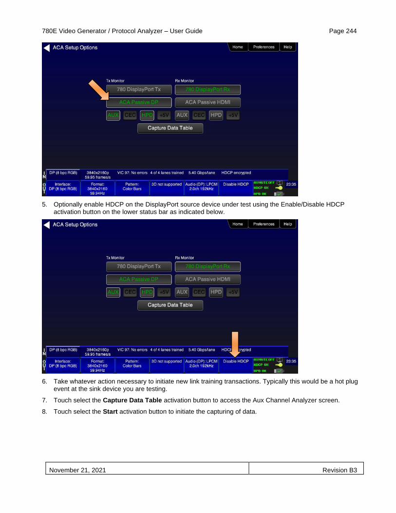
780E Video Generator / Protocol Analyzer – User Guide Page 244
November 21, 2021 Revision B3
5. Optionally enable HDCP on the DisplayPort source device under test using the Enable/Disable HDCP
activation button on the lower status bar as indicated below.
6. Take whatever action necessary to initiate new link training transactions. Typically this would be a hot plug
event at the sink device you are testing.
7. Touch select the Capture Data Table activation button to access the Aux Channel Analyzer screen.
8. Touch select the Start activation button to initiate the capturing of data.
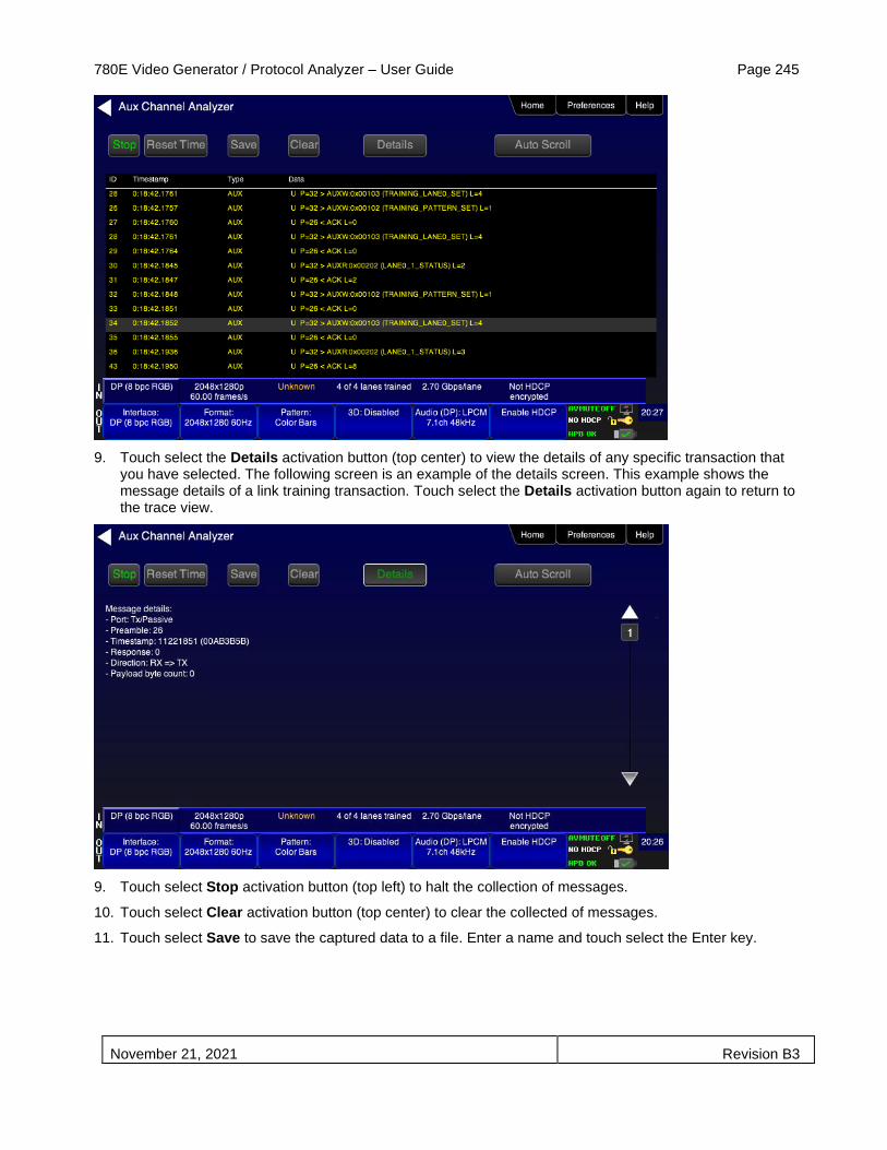
780E Video Generator / Protocol Analyzer – User Guide Page 245
November 21, 2021 Revision B3
9. Touch select the Details activation button (top center) to view the details of any specific transaction that you have selected. The following screen is an example of the details screen. This example shows the message details of a link training transaction. Touch select the Details activation button again to return to the trace view.
9. Touch select Stop activation button (top left) to halt the collection of messages.
10. Touch select Clear activation button (top center) to clear the collected of messages.
11. Touch select Save to save the captured data to a file. Enter a name and touch select the Enter key.

780E Video Generator / Protocol Analyzer – User Guide Page 246
November 21, 2021 Revision B3

780E Video Generator / Protocol Analyzer – User Guide Page 247
November 21, 2021 Revision B3
9 Using the 780E Test Instrument to Test Cable or Repeaters
This section provides procedures for testing HDMI and HDBaseT cables, cable extenders, splitters, repeaters, etc. The HDMI and HDBaseT Cable Test runs a pixel error test on the TMDS leads and a continuity check on the 5V & hot plug leads and the DDC leads. The Repeater test runs a pixel error test on the TMDS leads and a continuity check on the 5V & hot plug leads and the DDC leads but additionally tests the hot plug delay and the hot plug width.
The cable test and repeater test can be used when the source and sink ends are collocated, in other words can be connected to the 780E Tx and Rx ports. For a cable or distribution system that is installed and where the source and sink ends cannot be connected to the 780E, you can use the Frame Compare feature. The Frame Compare feature captures a reference frame and then compares a series of captured frames pixel by pixel to the reference frame.
The features and functions described in this section are included only if you have purchased the HDMI Cable and Link Test option.
Important Note: The cable test is supported by the Report File Creation feature which enables the results of the test to be included in an html report that can be disseminated or printed. However, the Report Menu entry on the top menu has not been updated on the screens in this subsection. Refer to the Chapter on Report File Creation for details on generating reports.
9.1 HDMI/HDBaseT Cable or Repeater Test
The HDMI/DVI/HDBaseT Cable Test runs a test on all the leads in the HDMI/HDBaseT (CAT) cable and HDMI or HDBaseT networks (when extenders, splitters, switchers and repeaters are used) except the power bus as follows:
▪ Pixel error test using a pseudo-noise pattern on the TMDS lines using three separate timings:
o 480p60 using 8 bit/component color
o 720p60 using 8 bit/component color
o 1080p60 using 8 bit/component color
o 1080p60 using 12 bit/component (deep color)
o 2160p30 using 8 bit/component color
▪ Read/write test on the DDC leads and the CEC bus. It reads an EDID at the output from the input.
▪ Continuity test on the 5V/Hot plug leads.
▪ Hot plug delay and hot plug pulse width. The hot plug delay is the time that elapses between the falling edge of the hot plug line on the on the sink side of a repeater and the falling edge of the hot plug line on the source side. The hot plug pulse width is the time that the hot plug pulse goes low as detected on the HDMI Tx side.
9.1.1 Configurations for Running an HDMI/HDBaseT Cable or Repeater Test
This subsection provides configurations supported when performing an HDMI/HDBaseT cable test or a test of an HDMI network comprised of repeaters, splitters, extenders, switches, etc.
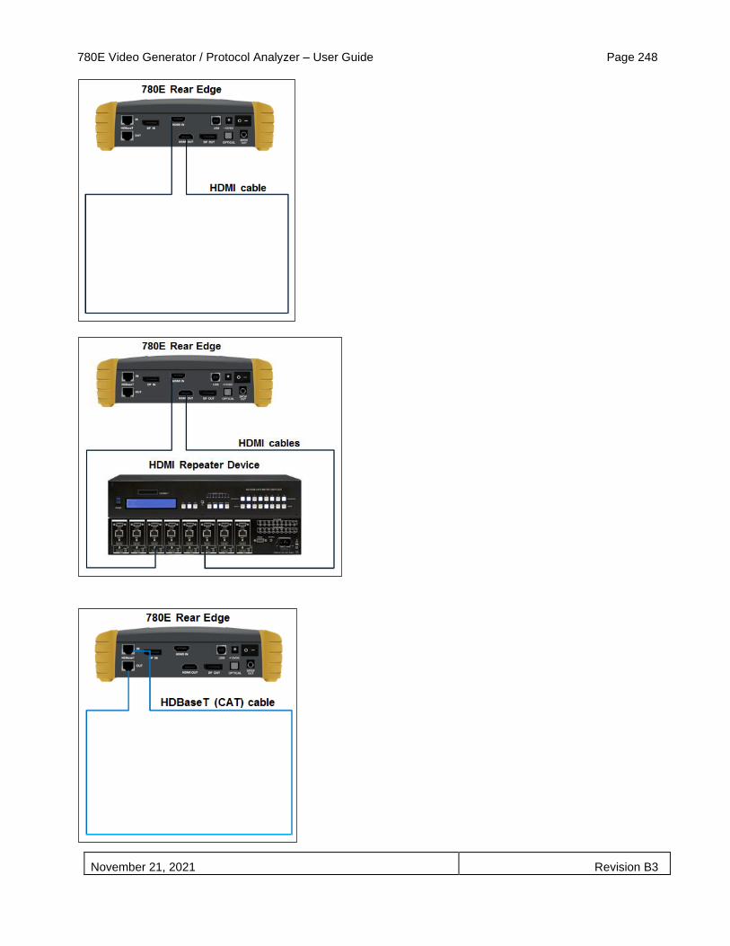
780E Video Generator / Protocol Analyzer – User Guide Page 248
November 21, 2021 Revision B3

780E Video Generator / Protocol Analyzer – User Guide Page 249
November 21, 2021 Revision B3
9.1.2 Procedures for Running an HDMI/HDBaseT Cable or Network (“Repeater”) Test
This subsection provides procedures for performing an HDMI cable test or a test of an HDMI network comprised of repeaters, splitters, extenders, switches, etc.
1. For testing an HDMI cable, connect one end of the HDMI cable to the 780E HDMI OUT connect and the other end to the 780E HDMI IN connector.
For testing an HDBaseT cable, connect one end of the HDBaseT CAT cable to the 780E HDBaseT OUT connect and the other end to the 780E HDBaseT IN connector.
For testing an HDMI repeater device such as a repeater, video or audio processor, extender, switch, etc, connect the 780E HDMI OUT connector to the repeater device input and connect the 780E HDMI IN connector to the repeater device output.
2. Touch select Cable/Repeater Test from the Home menu shown below.

780E Video Generator / Protocol Analyzer – User Guide Page 250
November 21, 2021 Revision B3
3. For testing an HDMI cable touch select Test Wire to initiate the test.
The pixel errors are displayed for each timing on the screen as shown below. The +5V, Hot Plug and DDC test results are shown as Pass/Fail.
For testing an HDMI repeater device touch select Test Repeater to initiate the test.

780E Video Generator / Protocol Analyzer – User Guide Page 251
November 21, 2021 Revision B3
When a repeater device is tested using the Test Repeater function, the hot plug pulse delay and the hot plug pulse with are shown in addition to the information and results displayed for the Cable Test. In the Test Repeater function, the 780E initiates a hot plug event on its sink (HDMI IN) port. The hot plug delay is the time that elapses between the falling edge of the hot plug line on the on the sink side of a repeater and the falling edge of the hot plug line on the source side. The hot plug pulse width is the time that the hot plug pulse goes low as detected on the HDMI OUT side.
The following is an example of test on an HDBaseT CAT cable.
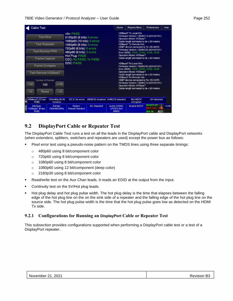
780E Video Generator / Protocol Analyzer – User Guide Page 252
November 21, 2021 Revision B3
9.2 DisplayPort Cable or Repeater Test
The DisplayPort Cable Test runs a test on all the leads in the DisplayPort cable and DisplayPort networks (when extenders, splitters, switchers and repeaters are used) except the power bus as follows:
▪ Pixel error test using a pseudo-noise pattern on the TMDS lines using three separate timings:
o 480p60 using 8 bit/component color
o 720p60 using 8 bit/component color
o 1080p60 using 8 bit/component color
o 1080p60 using 12 bit/component (deep color)
o 2160p30 using 8 bit/component color
▪ Read/write test on the Aux Chan leads. It reads an EDID at the output from the input.
▪ Continuity test on the 5V/Hot plug leads.
▪ Hot plug delay and hot plug pulse width. The hot plug delay is the time that elapses between the falling edge of the hot plug line on the on the sink side of a repeater and the falling edge of the hot plug line on the source side. The hot plug pulse width is the time that the hot plug pulse goes low as detected on the HDMI Tx side.
9.2.1 Configurations for Running an DisplayPort Cable or Repeater Test
This subsection provides configurations supported when performing a DisplayPort cable test or a test of a DisplayPort repeater.
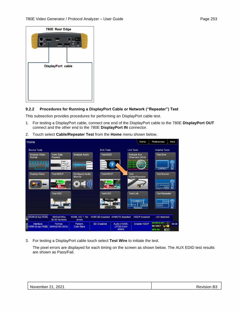
780E Video Generator / Protocol Analyzer – User Guide Page 253
November 21, 2021 Revision B3
9.2.2 Procedures for Running a DisplayPort Cable or Network (“Repeater”) Test
This subsection provides procedures for performing an DisplayPort cable test.
1. For testing a DisplayPort cable, connect one end of the DisplayPort cable to the 780E DisplayPort OUT connect and the other end to the 780E DisplayPort IN connector.
2. Touch select Cable/Repeater Test from the Home menu shown below.
3. For testing a DisplayPort cable touch select Test Wire to initiate the test.
The pixel errors are displayed for each timing on the screen as shown below. The AUX EDID test results are shown as Pass/Fail.

780E Video Generator / Protocol Analyzer – User Guide Page 254
November 21, 2021 Revision B3
For testing an HDMI repeater device touch select Test Repeater to initiate the test.
A screen sample of the cable test (Test Wire) results is shown below.

780E Video Generator / Protocol Analyzer – User Guide Page 255
November 21, 2021 Revision B3
9.3 Frame Compare Test
The cable test and repeater test can be used when the source and sink ends are collocated, in other words can be connected to the 780E Tx and Rx ports. For a cable or distribution system that is installed and where the source and sink ends cannot be connected to the 780E, you can use the Frame Compare feature. The Frame Compare feature captures a reference frame and then compares a series of captured frames pixel by pixel to the reference frame.
Important Note: The Frame Compare test is supported by the Report File Creation feature which enables the results of the test to be included in an html report that can be disseminated or printed. However, the Report Menu entry on the top menu has not been updated on the screens in this subsection. Refer to the Chapter on Report File Creation for details on generating reports.
9.3.1 Configuration for Running a Frame Compare Test
This subsection shows a typical configuration when performing an Frame Compare test for a network comprised of repeaters, splitters, extenders, switches, etc.
9.3.2 Procedures for Running the Frame Compare Test
This subsection provides procedures for performing an Frame Compare test on a network comprised of repeaters, splitters, extenders, switches, etc. The examples used in this section depict and HDMI network but HDBaseT and DisplayPort frame compare tests are also supported.

780E Video Generator / Protocol Analyzer – User Guide Page 256
November 21, 2021 Revision B3
1. Connect the far end of the HDMI cable (at the display or HDTV) to the 780E HDMI IN connect as shown in the diagram above.
2. Touch select Cable/Repeater Test from the Home menu shown below.
The following screen appears:
3. Select Frame Capture to capture a reference frame.
Important Note: The source device has to be putting out a static image.
A message will appear indicating that the reference frame has been captured.
4. Select Frame Compare to compare a series of frames to the reference frame.

780E Video Generator / Protocol Analyzer – User Guide Page 257
November 21, 2021 Revision B3
The following screen example shows the results of the Frame Compare test. Note that the incoming resolution is shown with the number of pixel errors detected.
The 780E will capture a frame and indicate that the +5V was detected properly or not. The screen below shows these results. You will need (or you can) specify a different number of frames than the default of 50 frames. You can select up to 16 million frames but we do not recommend that. Generally it is good to run the test multiple times at a lower number of frames and at a variety of resolutions starting at 480p as shown in the example below.
9.3.3 Procedures for Running the Remote PRN Test
This subsection provides procedures for performing an HDMI Remote PRN test on an HDMI network comprised of repeaters, splitters, extenders, switches, etc. This test differs in that there is a 780 at both ends of the network—source and sink ends.
1. Follow the procedures above for rendering a Test Pattern on an HDMI HDTV Rendering Test Patterns on an HDMI HDTV.
2. Disconnect the source device at the near end of an HDMI distribution network and connect the HDMI cable to the first 780’s HDMI output connector.
3. Disconnect the sink device at the far end of an HDMI distribution network and connect the HDMI cable to the second 780’s HDMI input connector.
4. Touch select Cable/Repeater Test from the Home menu shown below.

780E Video Generator / Protocol Analyzer – User Guide Page 258
November 21, 2021 Revision B3
The following screen appears:
5. Select Test Remote PRN to capture a reference frame.
The 780E will run the PRN test at the format resolution set for the 780 at the source end. Repeat the test at other resolutions and bit depths.

780E Video Generator / Protocol Analyzer – User Guide Page 259
November 21, 2021 Revision B3
9.4 HDBaseT Remote Cable Test
The HDBaseT Remote Cable test is an optional feature requiring the 780 Remote Terminal device. You also need the Cable test option to run this test. The HDBaseT Remote Cable test feature enables you to run tests on installed HDBaseT Cat networking cable. The test requires that the 780E be at the near end (transmitting) to a far-end HDBaseT Remote Terminal. The results appear on the 780E screen and they show the cable quality. You can acquire results of the test using the Reports File Creation feature and distribute them to colleagues and other subject matter experts.
9.4.1 Configuration for Running an HDBaseT Remote Cable Test
This subsection shows a typical configuration when performing an HDBaseT Remote Cable Test for an HDBaseT Cat network cable run.
9.4.2 Procedures for Running the HDBaseT Remote Cable Test
This subsection provides procedures for performing an HDBaseT Remote Cable Test on an HDBaseT Cat network cable.
1. Connect the 780E HDBaseT Out (Tx) port at the near end of the HDBaseT Cat networking cable.
2. Connect the 780 HDBaseT Remote Terminal to the HDBaseT Cat networking cable at the far end. Use the HDBaseT input receptacle.
3. Touch select Cable/Repeater Test from the Home menu shown below.
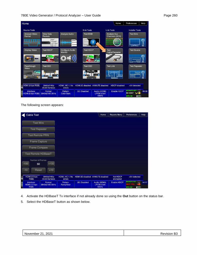
780E Video Generator / Protocol Analyzer – User Guide Page 260
November 21, 2021 Revision B3
The following screen appears:
4. Activate the HDBaseT Tx interface if not already done so using the Out button on the status bar.
5. Select the HDBaseT button as shown below.

780E Video Generator / Protocol Analyzer – User Guide Page 261
November 21, 2021 Revision B3
6. Select Test Remote HDBaseT to initiate the test.
Note that you can optionally specify the number of frames to run the test for from the default of 50 frames. You can select up to 16 million frames but we recommend selecting fewer number of frames and running the test multiple times.
The 780E will retrieve the information from the far end HDBaseT Remote Terminal device and display them on the screen.
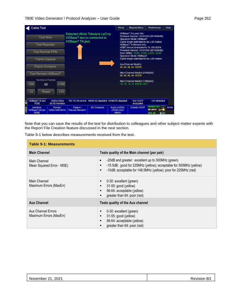
780E Video Generator / Protocol Analyzer – User Guide Page 262
November 21, 2021 Revision B3
Note that you can save the results of the test for distribution to colleagues and other subject matter experts with the Report File Creation feature discussed in the next section.
Table 9-1 below describes measurements received from the test.
Table 9-1: Measurements
Main Channel Tests quality of the Main channel (per pair)
Main Channel Mean Squared Error - MSE)
• -20dB and greater: excellent up to 300MHz (green)
▪ -15.5dB: good for 225MHz (yellow); acceptable for 300MHz (yellow)
▪ -10dB: acceptable for 148.5MHz (yellow); poor for 225MHz (red)
Main Channel Maximum Errors (MaxErr)
▪ 0-30: excellent (green)
▪ 31-55: good (yellow)
▪ 56-64: acceptable (yellow)
▪ greater than 64: poor (red)
Aux Channel Tests quality of the Aux channel
Aux Channel Errors Maximum Errors (MaxErr)
▪ 0-30: excellent (green)
▪ 31-55: good (yellow)
▪ 56-64: acceptable (yellow)
▪ greater than 64: poor (red)

780E Video Generator / Protocol Analyzer – User Guide Page 263
November 21, 2021 Revision B3
10 Generating Reports with the Reports File Creation Feature
This section provides procedures for running the optional Reports File Creation feature.
The Report File Creation feature is included only if you have purchased the license for this option.
10.1 Report File Creation Feature Description
Enables residential installers, professional A/V integrators and test engineers in R&D to produce a record of the tests they perform. Reports can be run on HDCP, Format Analyzer, Audio Analyzer, Cable tests, auxiliary channel analyzer tests for any interface type. The reports can be provided to customers, colleagues or to the contracting agent to verify and demonstrate project completion. The reports can be run on a single test or aggregated for a series of tests. The reports can be transferred by SD card or the USB interface and viewed in a standard browser or any text editor.
The following test are supported by the Reports File Creation feature:
Source Tests supported:
• Format Analyzer
• Audio Analyzer
• Packet Viewer
• Frame Compare
• HDCP
• Source Installer test.
Sink Tests supported:
• EDID
• HDCP
• Sink Installer test.
• Link Training (DP only)
Repeater Tests supported:
• Cable Test
• Repeater Installer test.
10.2 Procedures for creating reports
This subsection provides procedures for generating reports. You can aggregate any set of tests, source, sink or repeater into any report you wish. The example below depicts a scenario where you run a series of source tests. The examples given in this subsection will use the tests for the HDMI interface but the reports can be run on any interface (HDBaseT and DisplayPort).
10.2.1 Creating a report for source testing
Use the procedure below to run a report on a series source tests. This procedure assumes that you have powered up the source device(s) and connected it (them) to the 780E HDMI In port.
1. From the Main screen, touch select the Reports Menu item from the top menu. Refer to the screen example below.
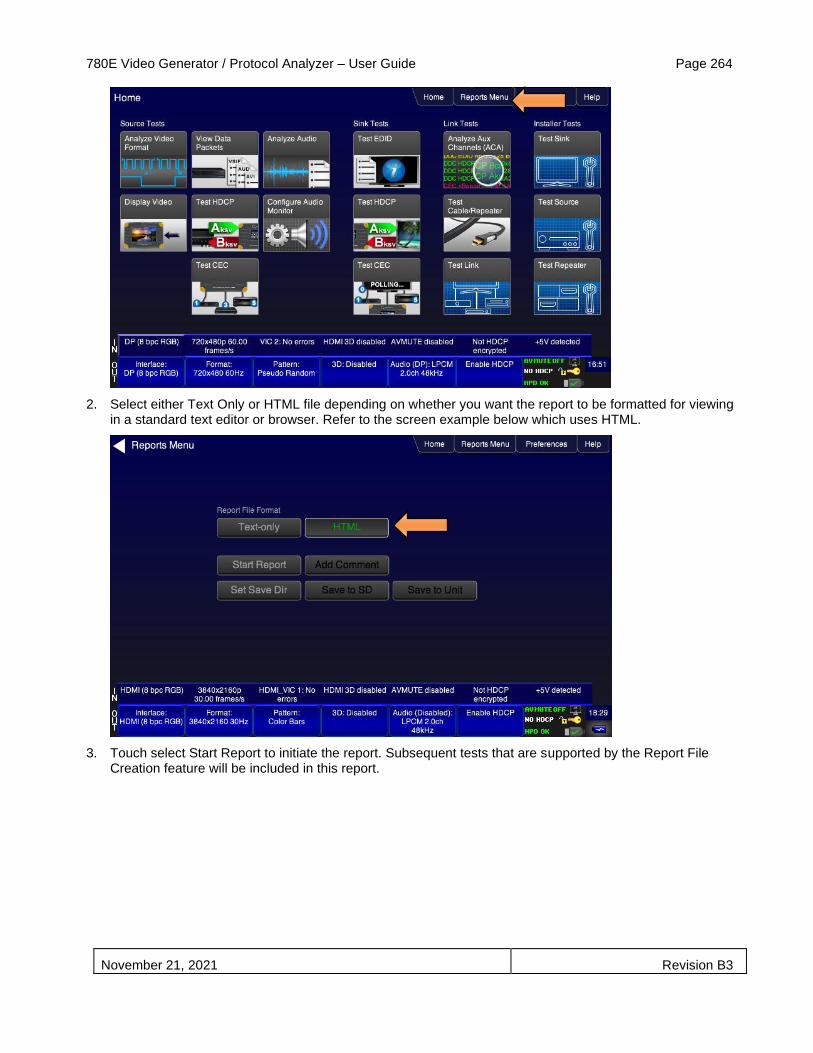
780E Video Generator / Protocol Analyzer – User Guide Page 264
November 21, 2021 Revision B3
2. Select either Text Only or HTML file depending on whether you want the report to be formatted for viewing in a standard text editor or browser. Refer to the screen example below which uses HTML.
3. Touch select Start Report to initiate the report. Subsequent tests that are supported by the Report File Creation feature will be included in this report.
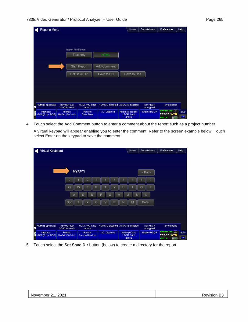
780E Video Generator / Protocol Analyzer – User Guide Page 265
November 21, 2021 Revision B3
4. Touch select the Add Comment button to enter a comment about the report such as a project number.
A virtual keypad will appear enabling you to enter the comment. Refer to the screen example below. Touch select Enter on the keypad to save the comment.
5. Touch select the Set Save Dir button (below) to create a directory for the report.
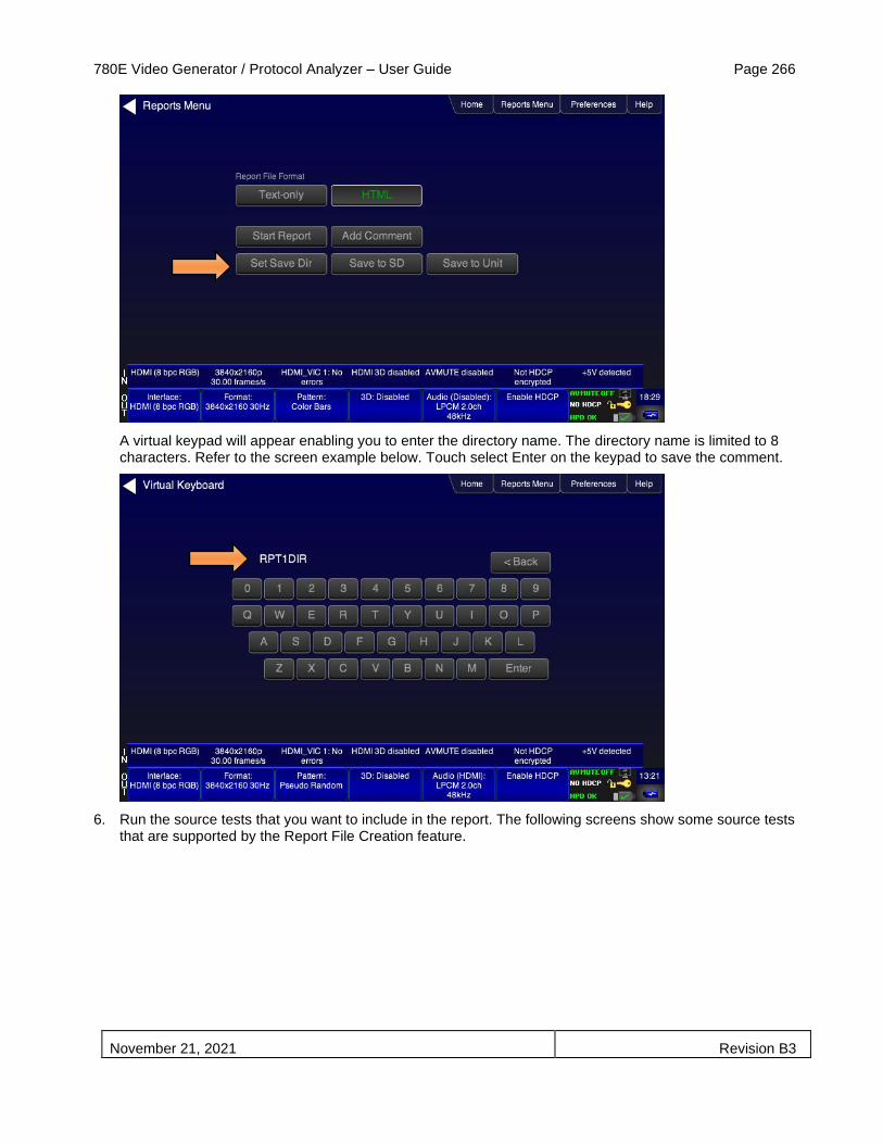
780E Video Generator / Protocol Analyzer – User Guide Page 266
November 21, 2021 Revision B3
A virtual keypad will appear enabling you to enter the directory name. The directory name is limited to 8 characters. Refer to the screen example below. Touch select Enter on the keypad to save the comment.
6. Run the source tests that you want to include in the report. The following screens show some source tests that are supported by the Report File Creation feature.

780E Video Generator / Protocol Analyzer – User Guide Page 267
November 21, 2021 Revision B3
Format Analyzer test
After each test, add the test results to the report by touch selecting the Add to Report button on the top menu bar as shown above. Note that the button will indicated Report Added in green as shown below.

780E Video Generator / Protocol Analyzer – User Guide Page 268
November 21, 2021 Revision B3
Audio Analyzer
7. Run the source tests that you want to include in the report. The following screens show some source tests that are supported by the Report File Creation feature.
Packet Viewer

780E Video Generator / Protocol Analyzer – User Guide Page 269
November 21, 2021 Revision B3
Source Installer Tests
8. When you are done running the tests that will comprise the report, you will need to save it either to the 780 file system or the SDcard if you have one installed. Refer to the screen below.
When you select Save to SD or Save to Unit you will be prompted with a virtual keypad to enter the name of the report. Refer to the screen example below.

780E Video Generator / Protocol Analyzer – User Guide Page 270
November 21, 2021 Revision B3
The report will be saved in the RPT1DIR directory under the name SRCTEST.html.
10.3 Procedures for Accessing Reports
Once you have run the tests and added them to a report you can access the report either from the SDcard or the 780 file system depending on where you saved them. This procedure describes how to access the reports from the 780 file system. The 780 USB interface is a standard USB peripheral; therefore you can access the files on the 780 as you would access files on a USD drive from a PC acting as a USB host. The image below shows the rear edge of the 780E indicating the location of the USB connector.
Use the following procedures to access the report files.
1. Connect the USB cable from your PC’s USB slots to the 780’s USB interface (refer to the image above).
2. Configure the 780E’s USB interface to emulate a USB peripheral by specifying Disk on the screen below.
Note: You will have to recycle power on the 780 if you have changed the USB from COM to Disk.
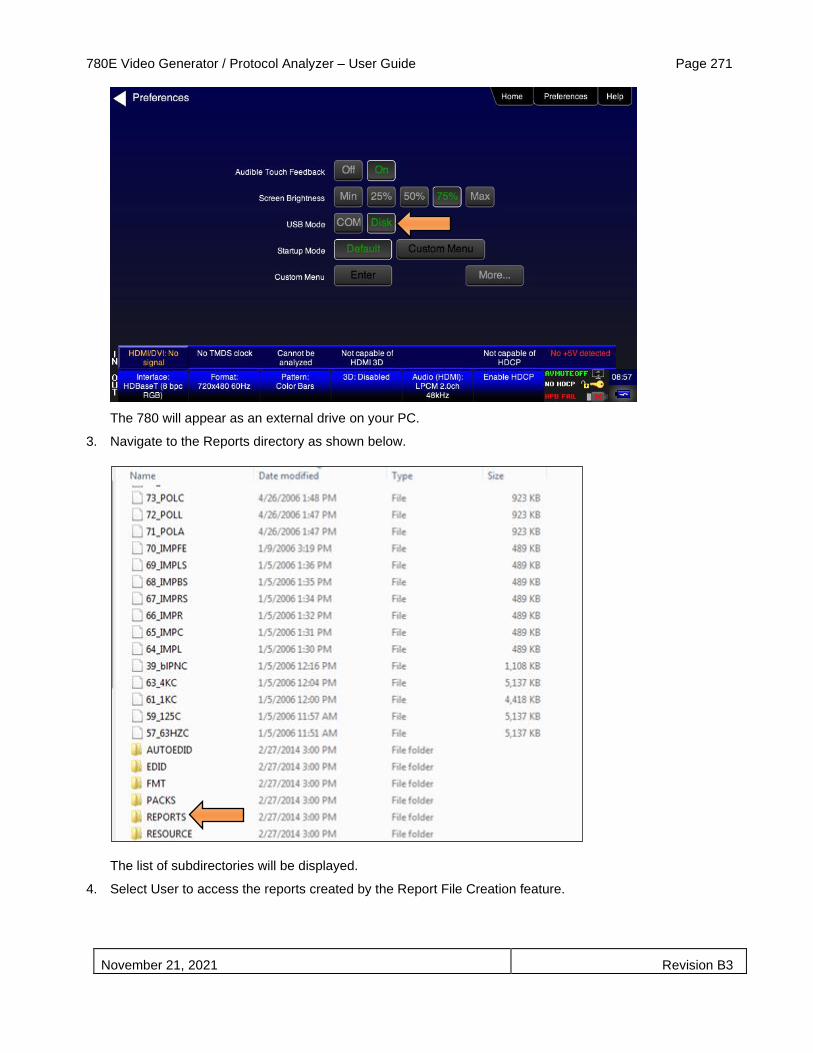
780E Video Generator / Protocol Analyzer – User Guide Page 271
November 21, 2021 Revision B3
The 780 will appear as an external drive on your PC.
3. Navigate to the Reports directory as shown below.
The list of subdirectories will be displayed.
4. Select User to access the reports created by the Report File Creation feature.

780E Video Generator / Protocol Analyzer – User Guide Page 272
November 21, 2021 Revision B3
The subdirectories will be displayed as shown below.
5. Copy the report directories over to your PC.
You can now access the report, source report in the example below.
Note: You can add your logo to the HTML report by including a png logo file in the directory as shown below.
6. Open the report in a standard browser.
An example of the composite source report is shown below.

780E Video Generator / Protocol Analyzer – User Guide Page 273
November 21, 2021 Revision B3

780E Video Generator / Protocol Analyzer – User Guide Page 274
November 21, 2021 Revision B3

780E Video Generator / Protocol Analyzer – User Guide Page 275
November 21, 2021 Revision B3
You can print the reports or disseminated them as a series of files to your customer or contracting agency.
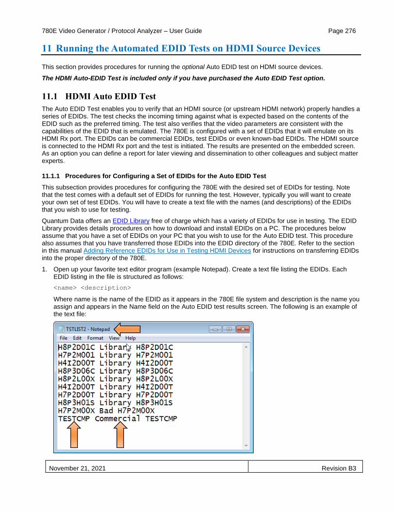
780E Video Generator / Protocol Analyzer – User Guide Page 276
November 21, 2021 Revision B3
11 Running the Automated EDID Tests on HDMI Source Devices
This section provides procedures for running the optional Auto EDID test on HDMI source devices.
The HDMI Auto-EDID Test is included only if you have purchased the Auto EDID Test option.
11.1 HDMI Auto EDID Test
The Auto EDID Test enables you to verify that an HDMI source (or upstream HDMI network) properly handles a series of EDIDs. The test checks the incoming timing against what is expected based on the contents of the EDID such as the preferred timing. The test also verifies that the video parameters are consistent with the capabilities of the EDID that is emulated. The 780E is configured with a set of EDIDs that it will emulate on its HDMI Rx port. The EDIDs can be commercial EDIDs, test EDIDs or even known-bad EDIDs. The HDMI source is connected to the HDMI Rx port and the test is initiated. The results are presented on the embedded screen. As an option you can define a report for later viewing and dissemination to other colleagues and subject matter experts.
11.1.1 Procedures for Configuring a Set of EDIDs for the Auto EDID Test
This subsection provides procedures for configuring the 780E with the desired set of EDIDs for testing. Note that the test comes with a default set of EDIDs for running the test. However, typically you will want to create your own set of test EDIDs. You will have to create a text file with the names (and descriptions) of the EDIDs that you wish to use for testing.
Quantum Data offers an EDID Library free of charge which has a variety of EDIDs for use in testing. The EDID Library provides details procedures on how to download and install EDIDs on a PC. The procedures below assume that you have a set of EDIDs on your PC that you wish to use for the Auto EDID test. This procedure also assumes that you have transferred those EDIDs into the EDID directory of the 780E. Refer to the section in this manual Adding Reference EDIDs for Use in Testing HDMI Devices for instructions on transferring EDIDs into the proper directory of the 780E.
1. Open up your favorite text editor program (example Notepad). Create a text file listing the EDIDs. Each EDID listing in the file is structured as follows:
<name> <description>
Where name is the name of the EDID as it appears in the 780E file system and description is the name you assign and appears in the Name field on the Auto EDID test results screen. The following is an example of the text file:

780E Video Generator / Protocol Analyzer – User Guide Page 277
November 21, 2021 Revision B3
Note: In the example above the first white space separates the name of the EDID which matches the EDID file in the 780E for testing and the description that appears on the AutoEDID test screen. The second white space is part of the description.
2. Transfer this text file to the AutoEDID directory of the 780E. Use the procedures in Procedures for Importing EDIDs into the 780E to transfer the this text file to the 780E. Refer to the figure below for reference on the AutoEDID directory.
The AutoEDID directory should now include your EDID list file:
The EDID directory would look similar to the following:
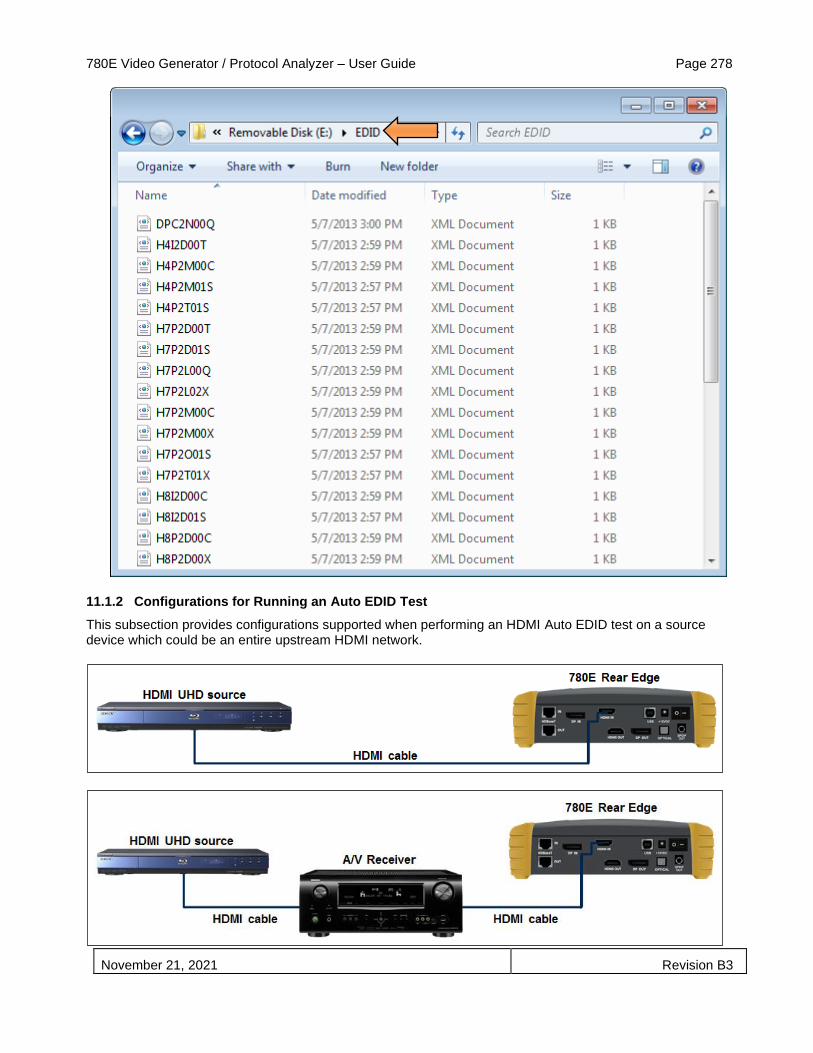
780E Video Generator / Protocol Analyzer – User Guide Page 278
November 21, 2021 Revision B3
11.1.2 Configurations for Running an Auto EDID Test
This subsection provides configurations supported when performing an HDMI Auto EDID test on a source device which could be an entire upstream HDMI network.

780E Video Generator / Protocol Analyzer – User Guide Page 279
November 21, 2021 Revision B3
11.1.3 Procedures for Running the Auto EDID Test
This subsection provides procedures for running the optional Auto EDID Test on an HDMI source or upstream network. The procedure assumes that you have the EDIDs saved on the 780E and also the AutoEDID test list file using the procedures above. The procedures also assume that you have the source device connected to the 780E’s HDMI Rx port.
Important Note: If you wish to run the optional text report, you will have to have installed a suitable SDCard into the 780E at the SDCard input on the front edge. You will have to install the SDCard before you boot up the 780E and run the test.
1. From the Home screen touch select the Test EDID application on the Sink Test region.
The EDID Test screen appears.
2. From the EDID Test screen, touch select Auto-EDID Test as shown below.

780E Video Generator / Protocol Analyzer – User Guide Page 280
November 21, 2021 Revision B3
The Auto-EDID Test screen appears.
3. From the Auto-EDID Test screen optionally select Set Report Name as shown below.
A Virtual Keyboard screen appears enabling you enter a name for the report. This screen is shown in the next step in this procedure.
Important Note: You will have to have installed a suitable SDCard into the 780E at the SDCard input on the front edge. Refer to the image below. You will have to install the SDCard before you boot up the 780E and run the test. If you have not installed the SDCard. Install the SDCard now, power cycle the 780E and repeat the previous steps.
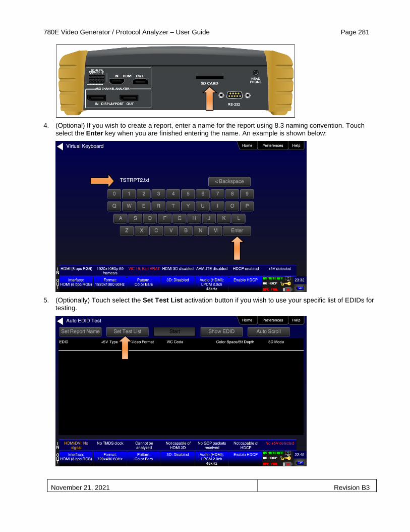
780E Video Generator / Protocol Analyzer – User Guide Page 281
November 21, 2021 Revision B3
4. (Optional) If you wish to create a report, enter a name for the report using 8.3 naming convention. Touch select the Enter key when you are finished entering the name. An example is shown below:
5. (Optionally) Touch select the Set Test List activation button if you wish to use your specific list of EDIDs for testing.
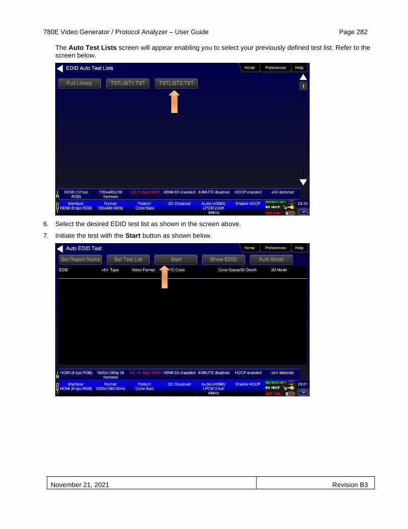
780E Video Generator / Protocol Analyzer – User Guide Page 282
November 21, 2021 Revision B3
The Auto Test Lists screen will appear enabling you to select your previously defined test list. Refer to the screen below.
6. Select the desired EDID test list as shown in the screen above.
7. Initiate the test with the Start button as shown below.
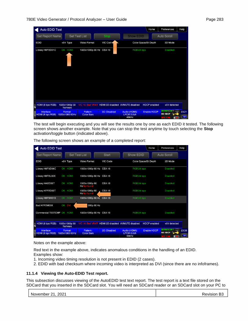
780E Video Generator / Protocol Analyzer – User Guide Page 283
November 21, 2021 Revision B3
The test will begin executing and you will see the results one by one as each EDID it tested. The following screen shows another example. Note that you can stop the test anytime by touch selecting the Stop activation/toggle button (indicated above).
The following screen shows an example of a completed report:
Notes on the example above:
Red text in the example above, indicates anomalous conditions in the handling of an EDID. Examples show: 1. Incoming video timing resolution is not present in EDID (2 cases). 2. EDID with bad checksum where incoming video is interpreted as DVI (since there are no infoframes).
11.1.4 Viewing the Auto-EDID Test report.
This subsection discusses viewing of the AutoEDID test text report. The test report is a text file stored on the SDCard that you inserted in the SDCard slot. You will need an SDCard reader or an SDCard slot on your PC to

780E Video Generator / Protocol Analyzer – User Guide Page 284
November 21, 2021 Revision B3
view the text report. You can view the Auto-EDID test report directly from the SDCard or transfer it to your PC. An example of the report is shown below.
You can disseminate the test report to subject matter experts or colleagues.

780E Video Generator / Protocol Analyzer – User Guide Page 285
November 21, 2021 Revision B3
12 Creating and Using Custom Formats, EDIDs, Bitmaps and Menus
This chapter provides procedures on creating and using custom formats, EDIDs, bitmaps and Menus.
12.1 Creating and Using Custom Formats
You can also create your own formats using the Quantum Data Format Editor available at: www.quantumdata.com/downloads. The Format Editor will create an .xml format file that you can store in the 780E. The instructions for using the Format Editor are included with the 882 User Guide also available on at: www.quantumdata.com/downloads. Once created you can load your custom formats either through the command line or by selecting them through the User buttons on the Signal Type menu.
12.1.1 Workflow for Using Custom Formats
In order to import and use custom formats in the 780E you must take the following high level steps (detailed procedures are provided further below):
▪ Create custom formats with the Quantum Data Format Editor available from www.quantumdata/com/downloads page. The instructions for using the Format Editor are provided in the 882 User Guide also available from www.quantumdata/com/downloads page.
▪ Store the .xml format files on your PC.
▪ Place the 780E’s USB interface in the Disk mode. This is not the default mode for the USB interface.
▪ Transfer the .xml format file(s) to the FMT directory of 780E over the USB interface.
▪ Establish a command line session with the 780E from your PC over the USB port.
▪ Select the custom format through the User Signal Type menu.
▪ Apply the custom formats using the FMTL and FMTU commands.
12.1.2 Procedures for Creating and Loading Custom Formats
Use the following procedures to add custom formats to your 780E.
1. Create a new custom format or modify an existing formats with the Quantum Data Format Editor. You can use some of the sample formats available from the Quantum Data website as a starting point for creating a new format. Be sure to save the file. The format files will be saved as .xml files by the Format Editor.
2. Select the Preferences from the 780E top level menu.
The following screen will appear:

780E Video Generator / Protocol Analyzer – User Guide Page 286
November 21, 2021 Revision B3
3. Choose Disk mode.
The Disk selection for USB Mode in the above screen will be highlighted in green.
4. Power cycle the 780E using the rocker switch on the back panel.
The 780E will appear as a mass storage device on your PC like any other USB drive.
Note: If this is the first time you have used the 780E in the Disk mode you will have to reformat the disk. The system will prompt you through the format process.
5. Connect the 780E to a PC host via the USB cable provided.
The 780E should appear as a USB storage device.
6. Transfer your custom format .xml files from your PC to the FMT directory of the 780E using standard Windows methods for transferring files to a USB drive, i.e. by dragging and dropping or copying and pasting.
Note: Your formats are limited to 8 characters with an extension (.xml).
7. Touch select the Preferences from the 780E top level menu. Refer to the screen below.
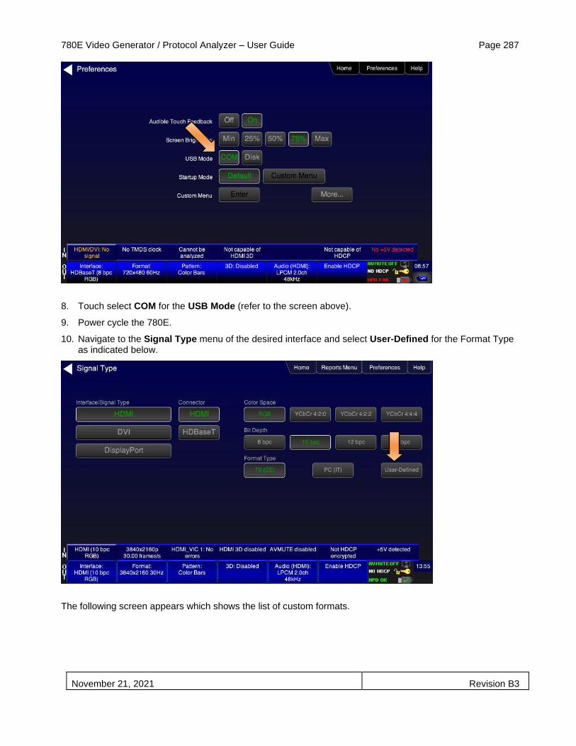
780E Video Generator / Protocol Analyzer – User Guide Page 287
November 21, 2021 Revision B3
8. Touch select COM for the USB Mode (refer to the screen above).
9. Power cycle the 780E.
10. Navigate to the Signal Type menu of the desired interface and select User-Defined for the Format Type as indicated below.
The following screen appears which shows the list of custom formats.

780E Video Generator / Protocol Analyzer – User Guide Page 288
November 21, 2021 Revision B3
11. (Alternatively) Establish a command line session with the 780E from your PC using the procedures described in Procedures for Enabling the Command Line Interface.
12. Load a custom format using the following commands:
FMTL <formatName> // where formatName is the name of the custom format
FMTU
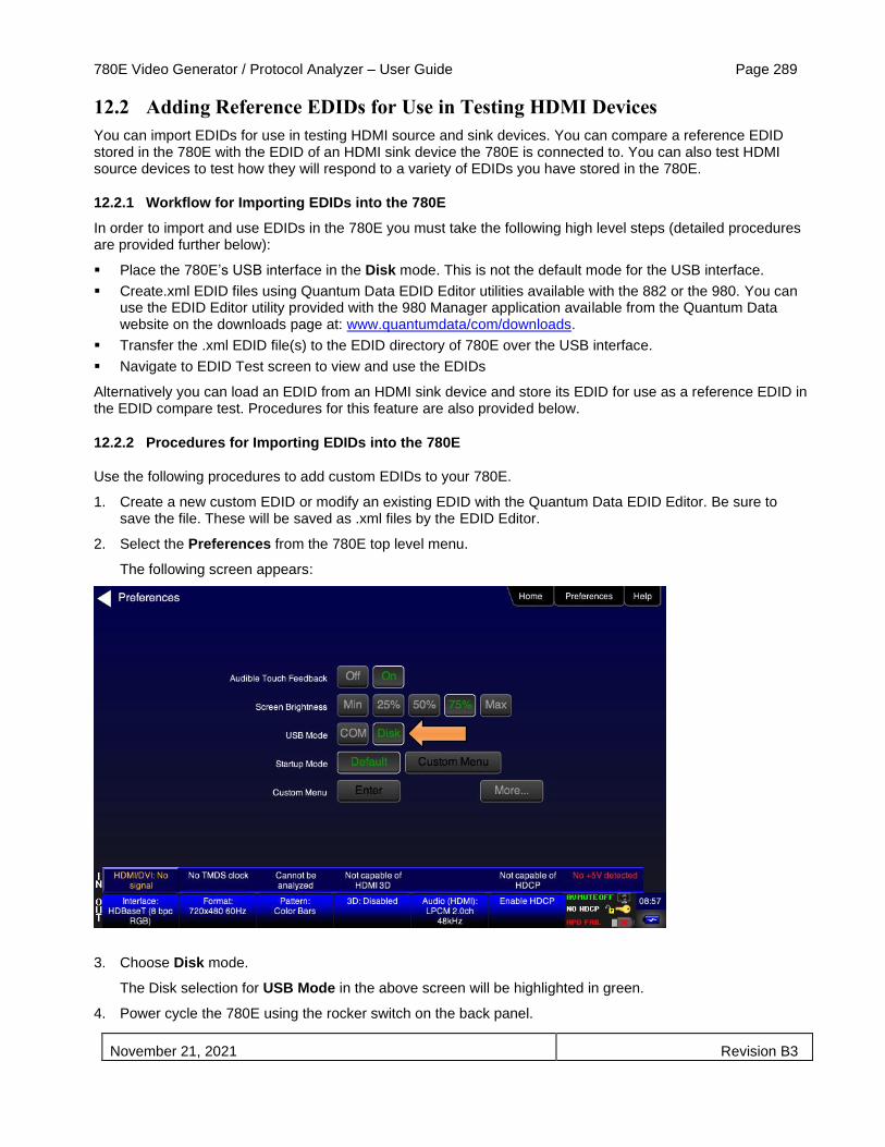
780E Video Generator / Protocol Analyzer – User Guide Page 289
November 21, 2021 Revision B3
12.2 Adding Reference EDIDs for Use in Testing HDMI Devices
You can import EDIDs for use in testing HDMI source and sink devices. You can compare a reference EDID stored in the 780E with the EDID of an HDMI sink device the 780E is connected to. You can also test HDMI source devices to test how they will respond to a variety of EDIDs you have stored in the 780E.
12.2.1 Workflow for Importing EDIDs into the 780E
In order to import and use EDIDs in the 780E you must take the following high level steps (detailed procedures are provided further below):
▪ Place the 780E’s USB interface in the Disk mode. This is not the default mode for the USB interface.
▪ Create.xml EDID files using Quantum Data EDID Editor utilities available with the 882 or the 980. You can use the EDID Editor utility provided with the 980 Manager application available from the Quantum Data website on the downloads page at: www.quantumdata/com/downloads.
▪ Transfer the .xml EDID file(s) to the EDID directory of 780E over the USB interface.
▪ Navigate to EDID Test screen to view and use the EDIDs
Alternatively you can load an EDID from an HDMI sink device and store its EDID for use as a reference EDID in the EDID compare test. Procedures for this feature are also provided below.
12.2.2 Procedures for Importing EDIDs into the 780E
Use the following procedures to add custom EDIDs to your 780E.
1. Create a new custom EDID or modify an existing EDID with the Quantum Data EDID Editor. Be sure to save the file. These will be saved as .xml files by the EDID Editor.
2. Select the Preferences from the 780E top level menu.
The following screen appears:
3. Choose Disk mode.
The Disk selection for USB Mode in the above screen will be highlighted in green.
4. Power cycle the 780E using the rocker switch on the back panel.
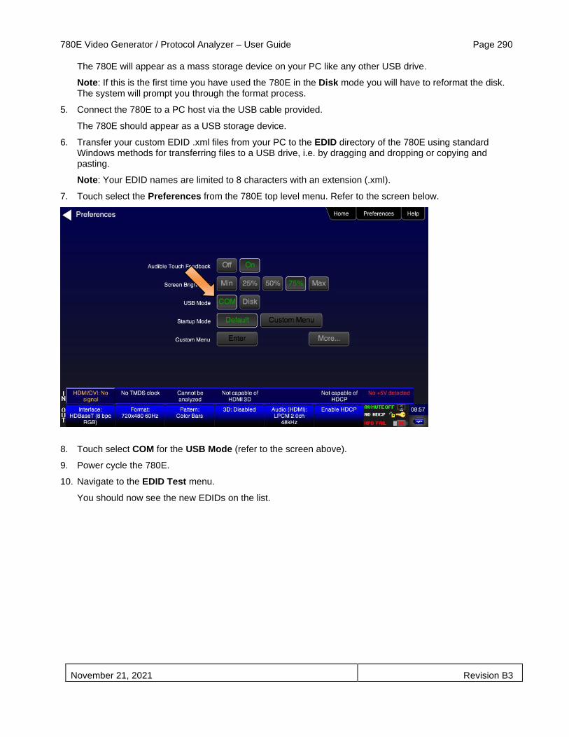
780E Video Generator / Protocol Analyzer – User Guide Page 290
November 21, 2021 Revision B3
The 780E will appear as a mass storage device on your PC like any other USB drive.
Note: If this is the first time you have used the 780E in the Disk mode you will have to reformat the disk. The system will prompt you through the format process.
5. Connect the 780E to a PC host via the USB cable provided.
The 780E should appear as a USB storage device.
6. Transfer your custom EDID .xml files from your PC to the EDID directory of the 780E using standard Windows methods for transferring files to a USB drive, i.e. by dragging and dropping or copying and pasting.
Note: Your EDID names are limited to 8 characters with an extension (.xml).
7. Touch select the Preferences from the 780E top level menu. Refer to the screen below.
8. Touch select COM for the USB Mode (refer to the screen above).
9. Power cycle the 780E.
10. Navigate to the EDID Test menu.
You should now see the new EDIDs on the list.

780E Video Generator / Protocol Analyzer – User Guide Page 291
November 21, 2021 Revision B3
12.2.3 Procedures for Saving an EDID into the 780E
Use the following procedures to add an EDID to your 780E from a connected HDMI sink device.
1. Make the physical connections between the 780E HDMI or HDBaseT OUT connector and the display device whose EDID you wish to store.
2. Enable the HDMI output using the procedures at Selecting a Signal Type and Resolution.
3. Touch select Test EDID from the Home menu shown below.
4. Touch select the Read activation button from the Test EDID menu shown below.
The EDID information is presented on multiple pages on the display. An example of a page of the EDID listing is shown below. You scroll through all the pages using the scroll bar at the right side of the listing.

780E Video Generator / Protocol Analyzer – User Guide Page 292
November 21, 2021 Revision B3
5. Touch select the Save activation button from the EDID Test menu shown below.
A keypad appears as shown below allowing you to save the EDID to a file.
6. Spell out a name for the EDID (limit 8 characters) by touch selecting the virtual keys (e.g. above “MYEDID”. Then touch select the Enter key.
7. Power cycle the 780E.
8. Navigate to the EDID Test screen and touch select Load from the EDID Tests menu. The following screen results.

780E Video Generator / Protocol Analyzer – User Guide Page 293
November 21, 2021 Revision B3
9. Touch select the Load File option to view your new EDID.

780E Video Generator / Protocol Analyzer – User Guide Page 294
November 21, 2021 Revision B3
12.3 Using Custom Bitmaps
You can import your own bitmaps into the 780E through the USB interface or load them from an SD card. Note that when bitmaps are imported into the 780E, they are rendered at their native resolution, i.e. they do not scale to the resolution of the video format you have selected as the standard test patterns do. Therefore, if you want to test with a specific bitmap pattern for each resolution and you want the bitmap to fill the entire display, you would need to import a separate bitmap of that image for each resolution you wish to test.
The 780E can accommodate up to 40 custom bitmap images in its internal memory and additional bitmaps stored on the SD card.
Important Note: It is highly recommended that you not select bitmap images when outputting compressed audio clips.
12.3.1 Workflow for Importing Bitmaps
In order to import and use bitmaps in the 780E you must take the following high level steps (detailed procedures are provided further below):
▪ Place the 780E’s USB interface in the Disk mode. This is not the default mode for the USB interface.
▪ Create a text file called “UserPats.txt” that lists each bitmap stored for use. The name in the file has to match the name of the bitmap. The procedures below provide an example of this text file.
▪ Transfer the UserPats.txt file to the 780E over the USB interface.
▪ Transfer the bitmap(s) over to the 780E flash memory through the USB interface.
12.3.2 Workflow for loading bitmaps from the SD card
In order to load bitmaps from the 780E’s SD card you must take the following high level steps (detailed procedures are provided further below):
▪ Create a text file called “UserPats.txt” that lists each bitmap stored for use. The name in the file has to match the name of the bitmap. The procedures below provide an example of this text file.
▪ Transfer the UserPats.txt file to the 780E to an SC card using a card reader.
▪ Insert the SD card into the 780E SD slot on the front.
Important notes about SD card use and formatting:
1. The SD card (not an SDHC and not an SDXC).
2. The SD card should be a 1GB or less.
3. The SD card should be formatted using an SD format program available from www.sdcard.org.
4. The SD card must be formatted FAT16.
12.3.3 Procedures for Importing Bitmaps

780E Video Generator / Protocol Analyzer – User Guide Page 295
November 21, 2021 Revision B3
Use the procedures below to import bitmaps.
1. Connect the 780E to a PC host via the USB cable provided.
2. Select the Preferences from the 780E top level menu.
3. Choose Disk mode.
The Disk selection for USB Mode in the above screen will be highlighted in green.
4. Power cycle the 780E using the rocker switch on the back panel.
The 780E will appear as a mass storage device on your PC like any other USB drive.
5. If this is the first time you have used the 780E in the Disk mode you will have to reformat the disk. The system will prompt you through the format process.
6. Create the userpats.txt text file listing your bitmaps. Use the information in Table 11-1 below to construct your text file:
Table 12-1: Importing Bitmaps – UserPats.txt file
Bitmap Name (use 8.3 naming convention) Bitmap Resolution UserPats.txt Text File Structure
Mast480.bmp 720x480 The structure of the UserPats file is:
<Bitmap Name> space <Description>
The contents of the UserPats.txt text file would be:
Mast480.bmp Master 720x480 Mast720.bmp Master 1280x720 Mast1080.bmp Master 1920x1080
Note 1: The bitmap name has to match the name of the stored bitmap.
Note 2: The description is limited to 20 characters.
Mast720.bmp 128x720
Mast1080.bmp 1920x1080

780E Video Generator / Protocol Analyzer – User Guide Page 296
November 21, 2021 Revision B3
Important Note: It is very important to ensure that the names in the userpats.txt file match the names of the bitmaps.
Example: Given the following bitmap file names:
Mast720.bmp
Mast1080.bmp
MYPLG07.bmp
MYPLG10.bmp
MYGEO07.bmp
MYGEO10.bmp
MYBRTS07.bmp
MYBRTS 10.bmp
Your userpats.txt file would be something like the following:
Note: Must use 8.3 naming system. Eight (8) characters. The names in the name field (first field) must match the bitmap names.
Mast720.bmp Master 720
Mast1080.bmp Master 1080
MYPLG07.bmp BlkPlug 720
MYPLG10.bmp BlkPlug 1080
MYGEO07.bmp Geom178 720
MYGEO10.bmp Geom178 1080
MYBRTS07.bmp RGMultBurst 720
MYBRTS10.bmp RGMultBurst 1080
7. Transfer your userpats.txt file from your PC to the 780E using standard Windows methods for transferring files to a USB drive, i.e. by dragging and dropping or copying and pasting.
Note: Your bitmaps are limited to 8 characters with an extension (.bmp).
8. Transfer your bitmap(s) from your PC to the 780E using standard windows procedures for transferring files to a USB drive, i.e. dragging and dropping or copying and pasting.
9. Touch select the Preferences from the 780E top level menu. Refer to the screen below.

780E Video Generator / Protocol Analyzer – User Guide Page 297
November 21, 2021 Revision B3
10. Touch select COM for the USB Mode (refer to the screen above).
11. Power cycle the 780E.
12. Navigate to the Video Pattern menu.
You should now see the new bitmap image(s) on the pattern list (below).
12.3.4 Procedures for Loading Bitmaps from SD Card
Use the procedures below to load bitmaps from an SD card.
1. Load your bitmaps on to the SD card from your PC using a USB SD card reader.
2. Create the UserPats.txt text file listing your bitmaps. Use the information in Table 10-2 below to construct your text file:
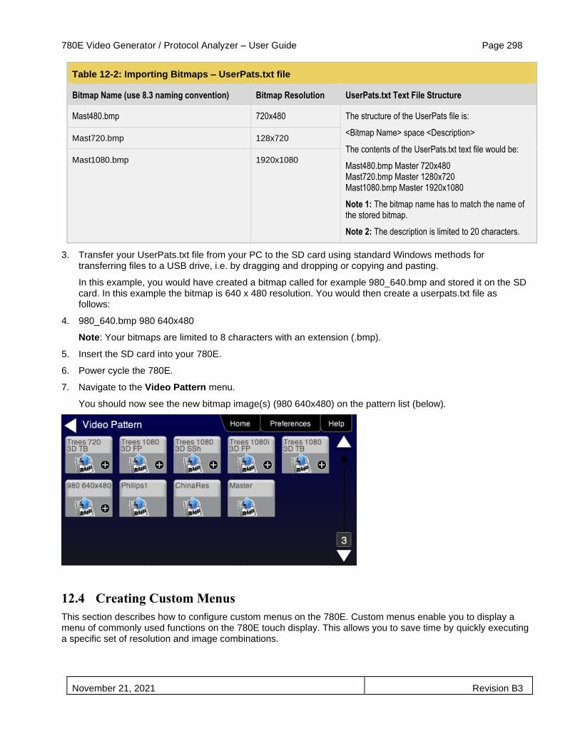
780E Video Generator / Protocol Analyzer – User Guide Page 298
November 21, 2021 Revision B3
Table 12-2: Importing Bitmaps – UserPats.txt file
Bitmap Name (use 8.3 naming convention) Bitmap Resolution UserPats.txt Text File Structure
Mast480.bmp 720x480 The structure of the UserPats file is:
<Bitmap Name> space <Description>
The contents of the UserPats.txt text file would be:
Mast480.bmp Master 720x480 Mast720.bmp Master 1280x720 Mast1080.bmp Master 1920x1080
Note 1: The bitmap name has to match the name of the stored bitmap.
Note 2: The description is limited to 20 characters.
Mast720.bmp 128x720
Mast1080.bmp 1920x1080
3. Transfer your UserPats.txt file from your PC to the SD card using standard Windows methods for transferring files to a USB drive, i.e. by dragging and dropping or copying and pasting.
In this example, you would have created a bitmap called for example 980_640.bmp and stored it on the SD card. In this example the bitmap is 640 x 480 resolution. You would then create a userpats.txt file as follows:
4. 980_640.bmp 980 640x480
Note: Your bitmaps are limited to 8 characters with an extension (.bmp).
5. Insert the SD card into your 780E.
6. Power cycle the 780E.
7. Navigate to the Video Pattern menu.
You should now see the new bitmap image(s) (980 640x480) on the pattern list (below).
12.4 Creating Custom Menus
This section describes how to configure custom menus on the 780E. Custom menus enable you to display a menu of commonly used functions on the 780E touch display. This allows you to save time by quickly executing a specific set of resolution and image combinations.

780E Video Generator / Protocol Analyzer – User Guide Page 299
November 21, 2021 Revision B3
The custom menus are setup using two text files that you create on your PC and transfer over to the 780E. The two files are: 1) UserKeys.txt and 2) SeqMap.txt. The UserKeys.txt is a set of commands with menu key codes. Each set of commands is a line in the text file.
12.4.1 To create a custom menu:
Use the following procedure to create a custom menu on your 780E.
1. Create a UserKeys.txt file or edit an existing file. An example of a UserKeys.txt file is shown below.
#F0 fmtl 720p60;imgl user01;fmtu
#F1 fmtl 1080p60;imgl pgcwrgb;fmtu
#F2 fmtl 480p60;imgl smptebar;fmtu
#F3 fmtl dmt0660;imgl ramp;fmtu
#F4 fmtl 1080i30;imgl focus;fmtu
#FF mfgm 0
Note that the commands are separated by a semicolon. In the example above in the first line there is a custom bitmap image “user01” that is used.
2. Create a SeqMap.txt file or edit an existing file. An example of a SeqMap.txt file is shown below.
The SeqMap.txt then maps the commands listed in the UserKeys.txt file to a name and a location on the custom menu. The following is an example of a SeqMap.txt file.
#F0 720p Master
#F1 1080p PGCWrgb
#F2 480p SMPTEbar
#F3 DMT0660 Ramp
#F4 1080i Focus
#FF Go Home
The result of these two files would be the following custom menu:
Touch selecting the key labeled “1080p PGCWrgb” would cause the following command sequence to execute:
#F1 fmtl 1080p60;imgl pgcwrgb;fmtu // loads 1080p60 format,
displays pgcwrgb test pattern
12.4.2 To access custom menus:
Use the following procedure access the custom menu on your 780E.
1. Navigate to the Preference menu by selecting the Preferences tab from the Home menu.

780E Video Generator / Protocol Analyzer – User Guide Page 300
November 21, 2021 Revision B3
2. Navigate Touch select Custom Menu from the Preference screen as shown below.
The following screen appears.

780E Video Generator / Protocol Analyzer – User Guide Page 301
November 21, 2021 Revision B3

780E Video Generator / Protocol Analyzer – User Guide Page 302
November 21, 2021 Revision B3
13 Command Interface
This chapter describes how to use the command line to control the 780E. The command line is useful for automated control applications.
13.1 Guidelines for Using the Command Line
The command line is available through the 780E USB port and additionally through an RS-232 connector on the 780E. In order to use the command line through the USB port you need to set the 780E USB port in COM mode. You may need to download an .INF file from the Quantum Data website on the downloads page.
13.2 Procedures for Enabling the Command Line Interface through USB Port
Use the following procedures for command line control of the 780E via the USB port.
Please note if you experience a different behavior on your PC, refer to the 780E release notes on the Quantum Data website at: http://www.quantumdata.com/downloads/index.asp.
1. Download the .INF file from the Quantum Data website http://www.quantumdata.com/downloads/index.asp to your PC and unzip the file. Store it in a convenient location on your PC.
2. Power up the 780E and touch select Preferences from the 780E top level menu.
3. Choose COM for the USB Mode (refer to the screen below).
4. Connect the 780E to your host PC via the USB cable provided.
The first time you connect 780E to your PC in COM mode, the Found New Hardware Wizard will appear.

780E Video Generator / Protocol Analyzer – User Guide Page 303
November 21, 2021 Revision B3
5. Follow the instructions provided on the dialog box to browse to the location of the .INF file.
Once you locate the .INF file the required software will load as shown below.
6. Power cycle the 780E.
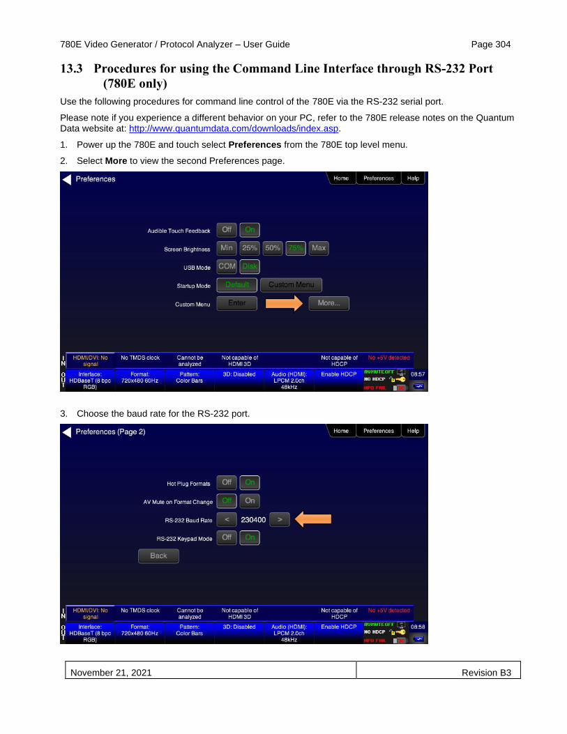
780E Video Generator / Protocol Analyzer – User Guide Page 304
November 21, 2021 Revision B3
13.3 Procedures for using the Command Line Interface through RS-232 Port
(780E only)
Use the following procedures for command line control of the 780E via the RS-232 serial port.
Please note if you experience a different behavior on your PC, refer to the 780E release notes on the Quantum Data website at: http://www.quantumdata.com/downloads/index.asp.
1. Power up the 780E and touch select Preferences from the 780E top level menu.
2. Select More to view the second Preferences page.
3. Choose the baud rate for the RS-232 port.

780E Video Generator / Protocol Analyzer – User Guide Page 305
November 21, 2021 Revision B3
4. Connect the 780E to your host PC via an RS-232 cable.
You will have to use a standard RS-232 cable.
13.4 Procedures for Entering Commands
Use the following procedure to connect to the 780E through the USB port.
1. Open up a terminal program such as Hyperterm on your Windows PC. Configure the terminal session with the following settings:
▪ Bits per second = 2400, 4800 or 9600
▪ Data bits = 8
▪ Parity = none
▪ Stop bits = 1
▪ Flow control = Hardware
2. Press the Return key on your PC and you should receive the R:\> prompt.
Now you are ready to enter commands.
3. Use the following tables as a guideline for enter commands.
Note: Changes you make through the command line will not be reflected on the 780E touch panel. For example if you make a selection through the touch panel for the signal type, format and pattern and then override these changes through the command line, the 780E touch screen will still show the selections you made through the touch screen but the interface, format and pattern selections you made through the command line will be active.
Table 13-1 below provides the list of commands supported or testing HDMI sink devices:
Note: The commands are not case sensitive.
Table 13-1: List of Commands (alphabetical) – For Testing HDMI Sink Devices
Command Description Syntax Parameters Command Example
TIME Sets the system time. TIME YY MM DD HH MM SS
Where YY is the last two digits of the year (e.g. 16).
Where MM is the two digits of the month (e.g. 11).
Where DD is the two digits of for the day of the month (e.g. 18).
Where HH is the two digits of the current hour in 24 hour clock (e.g. 23).
Where MM is the two digits of the current minutes (e.g. 32).
Where MM is the two digits of the current seconds (e.g. 57).
To set the time to October 11th 2016 at on second after 8:35 PM TIME 16 10 11 20 35 01
ACRG Enables or disables (“Gates” on or off) the ACR packets sent to a sink.
ACRG 0, 1
ASSG? <0, 1>
Where 1, 0 are one of:
0 – disable
1 - enable
To disable ACR packets:
ACRG 0
ALLU

780E Video Generator / Protocol Analyzer – User Guide Page 306
November 21, 2021 Revision B3
Table 13-1: List of Commands (alphabetical) – For Testing HDMI Sink Devices
Command Description Syntax Parameters Command Example
ALLU Activates a change to the video output.
ALLU Not applicable To load and invoke a format load command:
FMTL 1080i60
ALLU
ASCT Sets or queries the analog sync composite type. It sets the analog sync type properly for TV vs PC formats for HDMI, DVI, HDBaseT and RGB analog.
ASCT <type>
ASCT?
Where type is one of:
2 = American ORed. Used for HDMI, DVI, HDBaseT when PC formats are used. Used with RGB Analog when PC formats are used.
4 = American with Serrations and equalization pulses. Used for Component Analog. Used for RGB Analog with TV formats.
10 = American HDTV with Serrations and equalization pulses. Used for HDMI, DVI, HDBaseT with TV formats.
To set the analog sync composite type on the RGB Analog interface for TV formats:
ASCT 4
ALLU
To set the analog sync composite type on the HDMI format for PC formats:
ASCT 2
ALLU
ASSG Enables or disables adding composite sync to all three analog components.
ASSG R, G, B
ASSG? <R, G, B>
Where R, G, B are one of:
0 – disable
1 - enable
To enable composite sync on green:
ASSG 0, 1, 0
FMTU
ASSS Sets or queries the analog sync signal swing.
ASSS <swing>
ASSS?
Where swing is between the range of:
min = 0.000 volts
max = 0.500 volts
To set the analog sync signal swing:
ASSS 0.286
ALLU
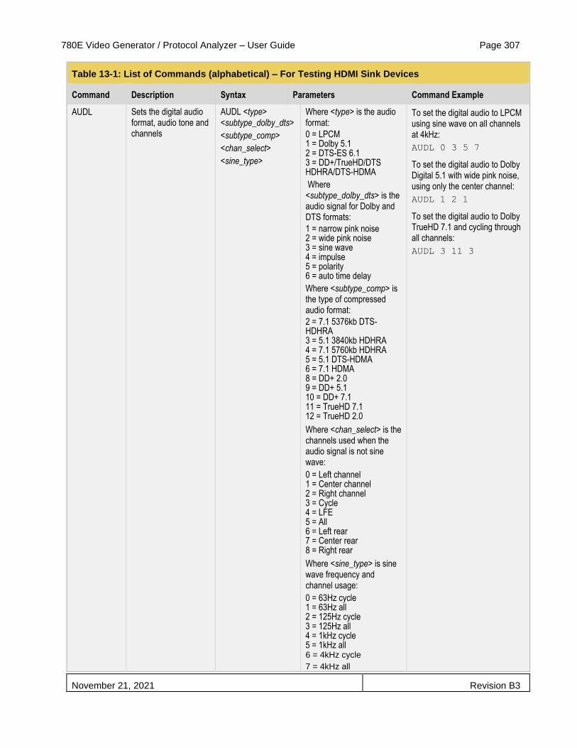
780E Video Generator / Protocol Analyzer – User Guide Page 307
November 21, 2021 Revision B3
Table 13-1: List of Commands (alphabetical) – For Testing HDMI Sink Devices
Command Description Syntax Parameters Command Example
AUDL Sets the digital audio format, audio tone and channels
AUDL <type> <subtype_dolby_dts>
<subtype_comp>
<chan_select>
<sine_type>
Where <type> is the audio format:
0 = LPCM 1 = Dolby 5.1 2 = DTS-ES 6.1 3 = DD+/TrueHD/DTS HDHRA/DTS-HDMA
Where <subtype_dolby_dts> is the audio signal for Dolby and DTS formats:
1 = narrow pink noise 2 = wide pink noise 3 = sine wave 4 = impulse 5 = polarity 6 = auto time delay
Where <subtype_comp> is the type of compressed audio format:
2 = 7.1 5376kb DTS-HDHRA 3 = 5.1 3840kb HDHRA 4 = 7.1 5760kb HDHRA 5 = 5.1 DTS-HDMA 6 = 7.1 HDMA 8 = DD+ 2.0 9 = DD+ 5.1 10 = DD+ 7.1 11 = TrueHD 7.1 12 = TrueHD 2.0
Where <chan_select> is the channels used when the audio signal is not sine wave:
0 = Left channel 1 = Center channel 2 = Right channel 3 = Cycle 4 = LFE 5 = All 6 = Left rear 7 = Center rear 8 = Right rear
Where <sine_type> is sine wave frequency and channel usage:
0 = 63Hz cycle 1 = 63Hz all 2 = 125Hz cycle 3 = 125Hz all 4 = 1kHz cycle 5 = 1kHz all 6 = 4kHz cycle
7 = 4kHz all
To set the digital audio to LPCM using sine wave on all channels at 4kHz:
AUDL 0 3 5 7
To set the digital audio to Dolby Digital 5.1 with wide pink noise, using only the center channel:
AUDL 1 2 1
To set the digital audio to Dolby TrueHD 7.1 and cycling through all channels:
AUDL 3 11 3
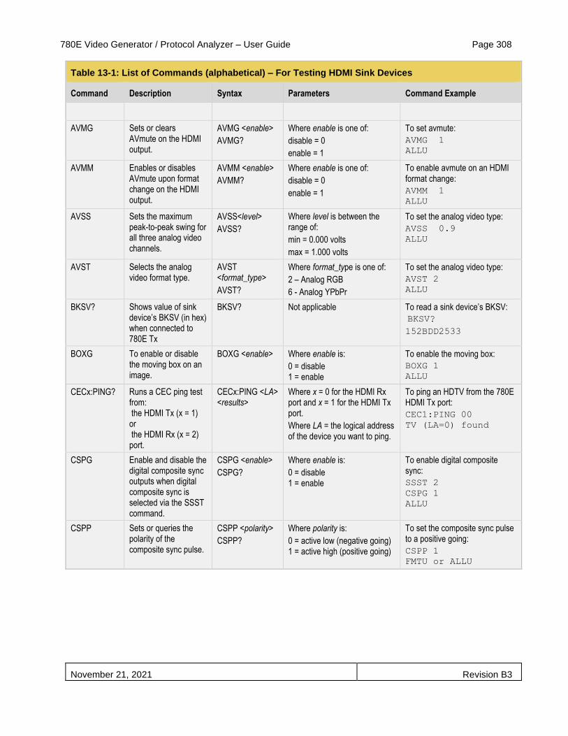
780E Video Generator / Protocol Analyzer – User Guide Page 308
November 21, 2021 Revision B3
Table 13-1: List of Commands (alphabetical) – For Testing HDMI Sink Devices
Command Description Syntax Parameters Command Example
AVMG Sets or clears AVmute on the HDMI output.
AVMG <enable>
AVMG?
Where enable is one of:
disable = 0
enable = 1
To set avmute:
AVMG 1
ALLU
AVMM Enables or disables AVmute upon format change on the HDMI output.
AVMM <enable>
AVMM?
Where enable is one of:
disable = 0
enable = 1
To enable avmute on an HDMI format change:
AVMM 1
ALLU
AVSS Sets the maximum peak-to-peak swing for all three analog video channels.
AVSS<level>
AVSS?
Where level is between the range of:
min = 0.000 volts
max = 1.000 volts
To set the analog video type:
AVSS 0.9
ALLU
AVST Selects the analog video format type.
AVST <format_type>
AVST?
Where format_type is one of:
2 – Analog RGB
6 - Analog YPbPr
To set the analog video type:
AVST 2
ALLU
BKSV? Shows value of sink device’s BKSV (in hex) when connected to 780E Tx
BKSV? Not applicable To read a sink device’s BKSV:
BKSV?
152BDD2533
BOXG To enable or disable the moving box on an image.
BOXG <enable> Where enable is:
0 = disable 1 = enable
To enable the moving box:
BOXG 1
ALLU
CECx:PING? Runs a CEC ping test from: the HDMI Tx (x = 1) or the HDMI Rx (x = 2) port.
CECx:PING <LA> <results>
Where x = 0 for the HDMI Rx port and x = 1 for the HDMI Tx port.
Where LA = the logical address of the device you want to ping.
To ping an HDTV from the 780E HDMI Tx port:
CEC1:PING 00
TV (LA=0) found
CSPG Enable and disable the digital composite sync outputs when digital composite sync is selected via the SSST command.
CSPG <enable>
CSPG?
Where enable is:
0 = disable 1 = enable
To enable digital composite sync:
SSST 2
CSPG 1
ALLU
CSPP Sets or queries the polarity of the composite sync pulse.
CSPP <polarity>
CSPP?
Where polarity is:
0 = active low (negative going) 1 = active high (positive going)
To set the composite sync pulse to a positive going:
CSPP 1
FMTU or ALLU

780E Video Generator / Protocol Analyzer – User Guide Page 309
November 21, 2021 Revision B3
Table 13-1: List of Commands (alphabetical) – For Testing HDMI Sink Devices
Command Description Syntax Parameters Command Example
DACG Specifies which audio channels are activated (gated on) for LPCM audio.
DACG <mask> Where mask is an 8 bit value. Each bit corresponds to a channel with the first bit (bit 0) associated with channel 1, bit 1 for channel 2 and so on to bit 7 corresponding to channel 8. The bit position values are:
Bit 0 – Ch 1 = 1
Bit 1 – Ch 2 = 2
Bit 2 – Ch 3 = 4
Bit 3 – Ch 4 = 8
Bit 4 – Ch 5 = 16
Bit 5 – Ch 6 = 32
Bit 6 – Ch 7 = 64
Bit 7 – Ch 8 = 128
You can enable multiple channels.
To enable channel 1 only:
DACG 1
ALLU
To disable all channels:
DACG 0
ALLU
To enable all channels:
DACG 255
ALLU
To enable channel 8 only:
DACG 128
ALLU
To enable channels 1-6:
DACG 127
ALLU
DSCT Sets or queries the digital sync composite type. It sets the digital sync type properly for TV vs PC formats for HDMI, DVI, HDBaseT and RGB analog.
DSCT <type>
DSCT?
Where type is one of:
0 = None Used for HDMI, DVI, HDBaseT when TV formats are used.
2 = American HDTV w/ Serrations and equalization pulses Used for HDMI, DVI & RGB Analog with PC formats.
4 = American HDTV w/double serrations
Used for Component Analog all formats. Used for RGB Analog when TV formats are selected.
To set the digital sync composite type for the RGB Analog interface for TV formats:
DSCT 4
ALLU
To set the digital sync composite type for the HDMI interface for PC formats:
DSCT 2
ALLU

780E Video Generator / Protocol Analyzer – User Guide Page 310
November 21, 2021 Revision B3
Table 13-1: List of Commands (alphabetical) – For Testing HDMI Sink Devices
Command Description Syntax Parameters Command Example
DSST Sets or queries the digital separate sync type. It sets the sync type properly for TV vs PC formats for HDMI, DVI, HDBaseT and RGB Analog.
DSST <type>
DSST?
Where type is one of:
1 = American ORed. Used for HDMI, DVI, HDBaseT when PC formats are used. Used with RGB Analog when PC formats are used.
4 = American with Serrations and equalization pulses. Used for Component Analog interface. Used for RGB Analog with TV formats.
10 = American HDTV with Serrations and equalization pulses. Used for HDMI, DVI, HDBaseT with TV formats.
To set the digital separate sync type on the RGB Analog interface for PC formats:
DSST 1
ALLU
To set the digital separate sync composite type for the HDMI interface for TV formats:
DSST 10
ALLU
DVSM Sets or queries the digital video sampling mode. Applies only for HDMI.
DVSM <sampling>
DVSM?
Where sampling is one of:
0 – RGB (4:4:4) 2 – YCbCr (4:2:2) 4 - YCbCr (4:4:4)
To set the HDMI sampling mode to RGB (4:4:4):
DVST 10
DVSM 0
ALLU
DVST Sets or queries the digital video type. Applies only for HDMI.
DVST<type>
DVST?
Where type is one of:
10 – RGB 14 – YCbCr
To set the HDMI sampling mode to YCbCr (4:4:4):
DVST 14
DVSM 4
ALLU
DVQM Sets or queries the digital video quantizing range. Applies only for HDMI.
DVQM <mode>
DVQM?
Where range is one of:
0 – 0-255 (8 bit) 1 – 1-254 (8 bit) 2 – 16-235 (8 bit RGB 16-240 (8 bit YCbCr)
To set the HDMI quantizing range to 0-255: to RGB:
DVQM 0
ALLU
EDID? Shows the EDID (in hex) of the sink device connected to the 780E Tx port.
EDID? Not applicable To read a sink device’s EDID:
EDID?
01FFFFFFF01…
FMTL Loads a format. FMTL <format> Where format is one of the formats listed in Table 7-2 and Table 7-3
See example below for FMTU
FMTU Activates a format that has been loaded and queries for the currently active format.
FMTU
FMTU?
Not applicable To load and invoke a format load command:
FMTL 1080i60
FMTU

780E Video Generator / Protocol Analyzer – User Guide Page 311
November 21, 2021 Revision B3
Table 13-1: List of Commands (alphabetical) – For Testing HDMI Sink Devices
Command Description Syntax Parameters Command Example
FRAT? Queries the frame rate of the outgoing HDMI format.
FRAT?
Not Applicable To read the frame rate of the outgoing HDMI signal:
FRAT?
+60.000E+00
HDBG Sets the active video output interface to HDBaseT. Used with XVSI.
HDBG 1 <interface>
HDBG?
Where interface is one of:
0 – HDMI
1 – HDBaseT (Note)
Note: XVSI must be set to 4.
To set the active video output interface to HDBaseT:
XVSI 4
HDBG 1
HDBG?
1
HDCP? Runs an HDCP authentication test on an HDMI sink device
HDCP? <frames> Number of frames:
Where frames is number of frames rounded to the nearest 128 frames.
Results:
where results are:
0 = pass
1 = fail
To run an HDCP authentication test on an HDMI sink device or repeater device:
To run an HDCP test for 128 frames: (pass reported)
HDCP? 255
To run an HDCP test for 256 frames:
HDCP? 257
0
To run an HDCP test for 512 frames (with a failure reported):
HDCP?
1
HPAG? Query the incoming sink for hot plug pin status.
HPAG? <hotplug>
Where hotplug can be 0 (no hot plug detected) or 1 (hot plug deteted)
To check for hot plug on the HDMI Out port:
HPAG?
HRAT Sets the horizontal rate of the video timing.
HRAT <rate>
HRAT?
<rate>
Where rate can be within the range of:
1000Hz to 130000Hz
To set the horizontal rate to 15000Hz:
HRAT 15000
ALLU or FMTU
HRES Sets the horizontal resolution of the video timing.
HRES <pixels>
HRES?
< pixels >
Where pixels can be within the range of:
100 to 4000 pixels
To set the horizontal resolution to 1282 pixels:
HRES 1282
ALLU
HTOT Sets the horizontal total number of pixels of the video timing.
HTOT <pixels>
HTOT?
< pixels >
Where pixels can be within the range of:
100 to 4000 pixels
To set the horizontal total to 1376 pixels:
HTOT 1376
ALLU or FMTU

780E Video Generator / Protocol Analyzer – User Guide Page 312
November 21, 2021 Revision B3
Table 13-1: List of Commands (alphabetical) – For Testing HDMI Sink Devices
Command Description Syntax Parameters Command Example
HSPP Sets of the polarity of the horizontal sync pulse.
HSPP <polarity>
HSPP?
<polarity>
Where polarity can be within the range of:
0 = high to low transition 1 = low to high transition
To set the horizontal sync pulse polarity to low to high transition:
HSPP 1
ALLU or FMTU
HSPW Sets the horizontal sync pulse width of the video timing in pixels.
HSPW <pixels>
HSPW?
< pixels >
Where pixels can be within the range of:
1 to HTOT-HRES-HSPD
To set the horizontal sync pulse width to 32 pixels:
HSPW 32
ALLU or FMTU
HSPG Sets enable gate of the horizontal sync pulse.
HSPG <enable>
HSPG?
< enable >
Where enable is:
0 = disable 1 = enable
To enable the horizontal sync pulse:
HSPG 1
ALLU or FMTU
IMGL Loads an image (pattern).
IMGL <image> Where image is one of the images listed in Table 7-4
See example below for IMGU
IMGU Activates an image that has been loaded and queries for the currently active image.
IMGU
IMGU?
Not applicable To load and invoke a image load command:
IMGL SMPTEbar
IMGU
NBPC Sets or queries the number of bits per component. Applies only to HDMI
NBPC <bit_depth>
NBPC?
Where bit_depth is one of:
8 – 8 bits per component
10 – 10 bit per component
12 – 12 bits per component
To set the HDMI bit depth to 10:
NBPC 10
ALLU or FMTU
PRAT? Queries the pixel rate of the outgoing HDMI format.
PRAT?
Not Applicable To read the pixel rate of the outgoing HDMI signal:
PRAT?
+74.2500E+06
RGBW Sets RGB values on with Raster and Window test patterns
RGBW <pattern> <R> <G> <B>
RGBW? <pattern> <R> <G> <B>
Where pattern is either 4 for Window pattern or 33 for raster pattern.
Where R G B are the respective values for the RGB color components
To set the Window pattern to dark brown: imgl window
imgu
rgbw 4 115 82 68
or
rgbw 4 115 87 74
SCAN Defines whether the active timing is progressive or interlaced or queries the state of the active timing.
SCAN <scan>
SCAN?
< scan >
Where scan is:
1 = progressive 2 = interlaced
To set the scan to interlaced:
SCAN 2
ALLU or FMTU
SIRE Sets IRE levels for certain images: Window1/2, Raster, Flat_Wht/Grn/ Red/Blu/Cyn/Mag/Blk
SIRE <range> Where range is a value from 0 to 100.
To set the IRE range for any of the images listed:
SIRE 50
ALLU

780E Video Generator / Protocol Analyzer – User Guide Page 313
November 21, 2021 Revision B3
Table 13-1: List of Commands (alphabetical) – For Testing HDMI Sink Devices
Command Description Syntax Parameters Command Example
SSST Sets or queries the sync signal type. It sets the sync type properly for the RGB Analog interface and the Component Analog interface.
SSST <type>
SSST?
Where type is one of:
1 = digital separate horizontal and vertical sync. Used for the HDMI, DVI, HDBaseT interfaces.
Used with RGB Analog and Component Analog interface when separate sync is selected.
3 = digital separate composite sync. Used for Component Analog and RGB Analog interface when sync on Y or sync on green are used.
To set the sync signal type on the Component Analog interface for separate sync:
SSST 1
ALLU
To set the sync signal type on the RGB Analog interface for sync on green:
SSST 3
ALLU
TOGG Enables or disables hot plug formats.
TOGG <enable>
TOGG?
<enable/disable>
Where enable is one of:
0 = disable
1 = enable
To enable hot plug formats on the active Tx interface:
TOGG 1
ALLU
To read the current setting:
TOGG?
1
VRES Sets or queries the vertical resolution of the active timing. Express in number of lines.
VRES <lines>
VRES?
< lines >
Where lines can be within the range of:
Min = 1 (if scan = 1) = 2 (if scan = 2) Max = VTOT – 1 (if scan = 1) = VTOT – 3 (if scan = 2)
To set the horizontal resolution:
VRES 480
ALLU
VRAT? Queries the vertical rate (field rate for interlaced formats) of the outgoing video format.
VRAT?
Not Applicable To read the vertical rate of the outgoing HDMI signal of 1080i30:
VRAT?
+60.000E+00
VSPD Sets or queries the vertical sync pulse delay of the active timing. Express in number of lines.
VSPD <lines>
VSPD?
< lines >
Where lines can be within the range of:
Min = 1 (if scan = 1) = 2 (if scan = 2) Max = VTOT – 1 (if scan = 1) = VTOT – 3 (if scan = 2)
To set the horizontal sync pulse delay:
VSPD 11
ALLU
VSPW Sets or queries the vertical sync pulse width of the active timing. Express in number of lines.
VSPW <lines>
VSPW?
< lines >
Where lines are the number of lines for the vertical pulse width
To set the horizontal sync pulse width:
VSPW 3
ALLU
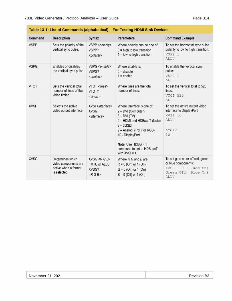
780E Video Generator / Protocol Analyzer – User Guide Page 314
November 21, 2021 Revision B3
Table 13-1: List of Commands (alphabetical) – For Testing HDMI Sink Devices
Command Description Syntax Parameters Command Example
VSPP Sets the polarity of the vertical sync pulse.
VSPP <polarity>
VSPP?
<polarity>
Where polarity can be one of:
0 = high to low transition 1 = low to high transition
To set the horizontal sync pulse polarity to low to high transition:
VSPP 1
ALLU
VSPG Enables or disables the vertical sync pulse.
VSPG <enable>
VSPG?
<enable>
Where enable is:
0 = disable 1 = enable
To enable the vertical sync pulse:
VSPG 1
ALLU
VTOT Sets the vertical total number of lines of the video timing.
VTOT <lines>
VTOT?
< lines >
Where lines are the total number of lines.
To set the vertical total to 525 lines:
VTOT 525
ALLU
XVSI Selects the active video output interface.
XVSI <interface>
XVSI?
<interface>
Where interface is one of:
2 – DVI (Computer)
3 – DVI (TV)
4 – HDMI and HDBaseT (Note)
8 – 3GSDI
9 – Analog YPbPr or RGB)
10 - DisplayPort
Note: Use HDBG = 1 command to set to HDBaseT with XVSI = 4.
To set the active output video interface to DisplayPort:
XVSI 10
ALLU
XVSI?
10
XVSG Determines which video components are active when a format is selected.
XVSG <R G B>
FMTU or ALLU
XVSG?
<R G B>
Where R G and B are:
R = 0 (Off) or 1 (On)
G = 0 (Off) or 1 (On)
B = 0 (Off) or 1 (On)
To set gate on or off red, green or blue components:
XVSG 1 0 1 (Red On;
Green Off; Blue On)
ALLU
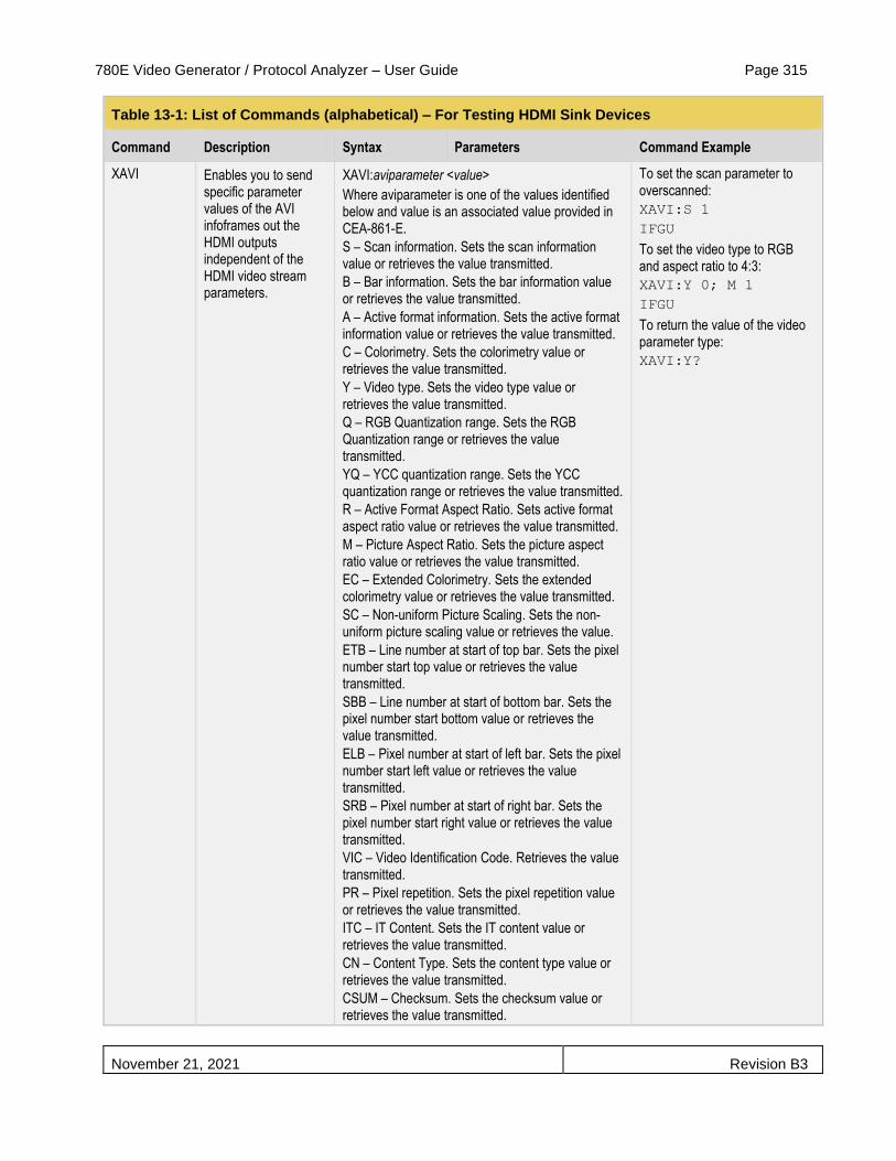
780E Video Generator / Protocol Analyzer – User Guide Page 315
November 21, 2021 Revision B3
Table 13-1: List of Commands (alphabetical) – For Testing HDMI Sink Devices
Command Description Syntax Parameters Command Example
XAVI Enables you to send specific parameter values of the AVI infoframes out the HDMI outputs independent of the HDMI video stream parameters.
XAVI:aviparameter <value>
Where aviparameter is one of the values identified below and value is an associated value provided in CEA-861-E.
S – Scan information. Sets the scan information value or retrieves the value transmitted.
B – Bar information. Sets the bar information value or retrieves the value transmitted.
A – Active format information. Sets the active format information value or retrieves the value transmitted.
C – Colorimetry. Sets the colorimetry value or retrieves the value transmitted.
Y – Video type. Sets the video type value or retrieves the value transmitted.
Q – RGB Quantization range. Sets the RGB Quantization range or retrieves the value transmitted.
YQ – YCC quantization range. Sets the YCC quantization range or retrieves the value transmitted.
R – Active Format Aspect Ratio. Sets active format aspect ratio value or retrieves the value transmitted.
M – Picture Aspect Ratio. Sets the picture aspect ratio value or retrieves the value transmitted.
EC – Extended Colorimetry. Sets the extended colorimetry value or retrieves the value transmitted.
SC – Non-uniform Picture Scaling. Sets the non-uniform picture scaling value or retrieves the value.
ETB – Line number at start of top bar. Sets the pixel number start top value or retrieves the value transmitted.
SBB – Line number at start of bottom bar. Sets the pixel number start bottom value or retrieves the value transmitted.
ELB – Pixel number at start of left bar. Sets the pixel number start left value or retrieves the value transmitted.
SRB – Pixel number at start of right bar. Sets the pixel number start right value or retrieves the value transmitted.
VIC – Video Identification Code. Retrieves the value transmitted.
PR – Pixel repetition. Sets the pixel repetition value or retrieves the value transmitted.
ITC – IT Content. Sets the IT content value or retrieves the value transmitted.
CN – Content Type. Sets the content type value or retrieves the value transmitted.
CSUM – Checksum. Sets the checksum value or retrieves the value transmitted.
To set the scan parameter to overscanned:
XAVI:S 1
IFGU
To set the video type to RGB and aspect ratio to 4:3:
XAVI:Y 0; M 1
IFGU
To return the value of the video parameter type:
XAVI:Y?

780E Video Generator / Protocol Analyzer – User Guide Page 316
November 21, 2021 Revision B3
Table 13-1: List of Commands (alphabetical) – For Testing HDMI Sink Devices
Command Description Syntax Parameters Command Example
XAUD Enables you to send specific parameter values of the AUD infoframes out the HDMI output independent of the HDMI audio stream.
XAUD:audparameter <value>
Where audparameter is one of the values identified below and value is an allowed value associated with the parameter provided in CEA-861-E.
CA – Channel assignment. Sets the channel assignment value or retrieves the value transmitted.
CC – Channel count. Sets the channel count value or retrieves the value transmitted.
CT – Audio coding type. Sets the audio coding type value or retrieves the value transmitted.
SS – Sample size. Sets the sample size value or retrieves the value transmitted.
SF – Sampling frequency. Sets the sampling frequency value or retrieves the value transmitted.
DMI – Down-mix inhibit. Sets the down-mix inhibit value or retrieves the value transmitted.
LSV – Level shift value. Sets the level shift value or retrieves the value transmitted.
PBL – LFE playback level. Sets the LFE playback level or retrieves the level transmitted.
CSUM – Checksum. Sets or gets the checksum value for the corresponding InfoFrame.
To set the channel count to 3:
XAUD:CC 2
IFGU
To set the sampling size to 24:
XAUD:SS 3
IFGU
To return the value of the channel count parameter type:
XAUD:CC?
XHVI Enables you to send specific parameter values of the Vendor Specific infoframe out the HDMI output independent of the HDMI stream.
XHVI:hviparameter <value>
Where hviparameter is one of the values identified below and value is an allowed value associated with the parameter provided in CEA-861-E.
HVF – HDMI Video Format field. Values: 0 = no info, i.e. 2D; 1 = 4Kx2K; 2 = 3D.
HVIC – HDMI Video Identification Code (VIC). Sets VIC for 4Kx2K use.
H3DS– HDMI 3D structure. Sets the 3D structure indication.
3DMG – 3D metadata present gate. Indicates whether 3D metadata is present or not present.
3DED – 3D External data.
LEN – HDMI VSIF length in bytes.
CSUM – Checksum. Sets or gets the checksum value for the corresponding InfoFrame.
To enable 3D:
XHVI:HVF 2
IFGU
To indicate that 3D metadata is present:
XHVI:3DMG 2
IFGU
To query if 3D metadata is present:
XHVI:3DMG?

780E Video Generator / Protocol Analyzer – User Guide Page 317
November 21, 2021 Revision B3
Table 13-1: List of Commands (alphabetical) – For Testing HDMI Sink Devices
Command Description Syntax Parameters Command Example
XSPD Enables you to send specific parameter values of the Source Product Descriptor infoframe out the HDMI output independent of the HDMI stream.
XSPD:spdparameter <value>
Where spdparameter is one of the values identified below and value is an allowed value associated with the parameter provided in CEA-861-E.
XSPD [VNS [PDS [SDI]]
Where:
XSPD – Vendor string name.
PDS – Product description string.
SDI – Source device information (see EIA/CEA-861-E standard)
To assign a vendor string name: XSPD QDI HDMI-Analyzer
IFGU
To query the vendor string name:
XSPD?
Note: The commands are not case sensitive.
Table 13-2 below provides the list of commands supported or testing HDMI sink devices:
Note: The commands are not case sensitive.
Table 13-2: List of Commands (alphabetical) – For Testing HDMI Audio in Sink Devices
Command Description Syntax Parameters Command Example
ARAT Sets the audio rate on Optical, SPDIF and HDMI LPCM audio.
ARAT rate
ARAT? <rate>
Where rate is one of:
32000, 44100, 48000, 88200, 96000, 176400, 192000.
To set the audio sampling rate to 48kHz:
ARAT 48000
FMTU
SAMP Sets the amplitude on either a specific channel or channels.
SAMP <amp> <ch>
SAMP? <amp> <ch>
Where amp is between the range of:
min = -99 dB
max = 0 dB
Where ch is in one of:
0 - 7
To set the amplitude of the audio signal on channel 1 (FR) to -3dB:
SAMP -3 1
FMTU
To set the amplitude of the audio signal on all channels to -6dB:
SAMP -6
FMTU
SRAT Sets the sine wave frequency on either a specific channel or all channels.
SRAT <rate> <ch>
SRAT? <rate> <ch>
Where rate is between the range of:
min = 8Hz
max = 20000Hz
Where ch is in one of:
0 - 7
To set the sinewave frequency of the audio signal on channel 1 (FL) to 2000 Hz:
SRAT 2000 0
FMTU
To set the sinewave frequency of the audio signal on all channels to 4000Hz:
SRAT 4000
FMTU
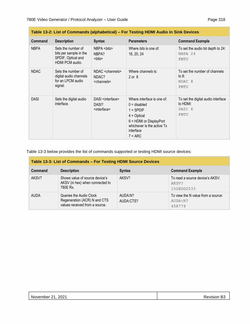
780E Video Generator / Protocol Analyzer – User Guide Page 318
November 21, 2021 Revision B3
Table 13-2: List of Commands (alphabetical) – For Testing HDMI Audio in Sink Devices
Command Description Syntax Parameters Command Example
NBPA Sets the number of bits per sample in the SPDIF, Optical and HDMI PCM audio.
NBPA <bits>
NBPA? <bits>
Where bits is one of:
16, 20, 24
To set the audio bit depth to 24:
NBPA 24
FMTU
NDAC Sets the number of digital audio channels for an LPCM audio signal.
NDAC <channels>
NDAC? <channels>
Where channels is:
2 or 8
To set the number of channels to 8:
NDAC 8
FMTU
DASI Sets the digital audio interface.
DASI <interface>
DASI? <interface>
Where interface is one of:
0 = disabled
1 = SPDIF
4 = Optical
6 = HDMI or DisplayPort whichever is the active Tx interface
7 = ARC
To set the digital audio interface to HDMI:
DASI 6
FMTU
Table 13-3 below provides the list of commands supported or testing HDMI source devices:
Table 13-3: List of Commands – For Testing HDMI Source Devices
Command Description Syntax Command Example
AKSV? Shows value of source device’s AKSV (in hex) when connected to 780E Rx.
AKSV? To read a source device’s AKSV:
AKSV?
152BDD2533
AUDA Queries the Audio Clock Regeneration (ACR) N and CTS values received from a source.
AUDA:N?
AUDA:CTS?
To view the N value from a source:
AUDA:N?
458779

780E Video Generator / Protocol Analyzer – User Guide Page 319
November 21, 2021 Revision B3
Table 13-3: List of Commands – For Testing HDMI Source Devices
Command Description Syntax Command Example
AUDA:RPTP? Queries the audio infoframe and channel status bits and issues a text report.
AUDA:RPTP?
To view the audio infoframe and channel status bits:
AUDA:RPTP?
Audio InfoFrame data:
Channel count: 2 channels
Coding type: 0 (Refer to stream header)
Word length: Refer to stream header
Sampling freq.: Refer to stream header
Channel allocation:
--- --- --- --- --- --- FR FL
Channel status bits:
Application: Consumer
Sample words: LPCM
Copyright asserted: Yes
Format info: Default
Mode: 0
Category code: 00
Source number: 0
Channel number: 0
Sampling freq.: 48 KHz
Word length: 24 bits
CECx:PING? Runs a CEC ping test from: the HDMI Tx (x = 1) or the HDMI Rx (x = 2) port.
CECx:PING <LA> <results>
Where x = 0 for the HDMI Rx port and x = 1 for the HDMI Tx port.
Where LA = the logical address of the device you want to ping.
To ping an HDTV from the 780E HDMI Tx port:
CEC1:PING 00
TV (LA=0) found
CPAG Enables or disables HDCP on the HDMI Rx port.
CPAG <enable>
CPAG?
Where enable is:
0 = disable 1 = enable
To disable HDCP on the HDMI Rx port: CPAG 0
ALLU
DIDL Loads an EDID file into memory in preparation to apply it to the Rx port with the DIDU command.
DIDL <file.xml>
Where file.xml is an EDID file stored in the 780E memory.
To load an EDID file and apply it to the Rx port:
DIDL my720p.xml
DIDU
DIDU Applies an EDID file loaded with DIDL to the Rx and issues a hot plug pulse.
Note: can be used in conjunction with the HPPW command to produce hot plug pulses of varying widths.
DIDU To load an EDID file, apply it to the Rx port and issue a hot plug pulse:
DIDL my720p.xml
DIDU

780E Video Generator / Protocol Analyzer – User Guide Page 320
November 21, 2021 Revision B3
Table 13-3: List of Commands – For Testing HDMI Source Devices
Command Description Syntax Command Example
HPPW Sets the hot plug pulse width. HPPW <pulse>
HPPW?
<pulse>
Where pulse can be within the range of:
100 to 4000 milliseconds
IFAU Reads infoframes. IFAU Not applicable
IFAD? Displays the contents of a specific type of infoframe.
IFAU
IFAD? <infoframe packet>
Where infoframe packet is the header number assigned to the infoframe type in the HDMI specification:
- VSIF = 81 - AVI = 82
- SPD = 83
- AUD = 84
- MPEG = 85
TMAU
Invokes timing analyzer. TMAU To initiate a timing test:
TMAU
Note: Then use one or more of the TMAX commands below.
TMAX:HTOT? Reads horizontal total pixels. TMAX:HTOT? To read horizontal total pixels:
TMAX:HTOT?
TMAX:HRES? Reads horizontal active pixels. TMAX:HRES? To read horizontal active pixels:
TMAX:HRES?
TMAX:HSPD? Reads horizontal sync pulse delay in pixels.
TMAX:HSPD? To read horizontal sync pulse delay:
TMAX:HSPD?
TMAX:HSPP Reads horizontal sync pulse polarity.
TMAX:HSPP? To read horizontal sync pulse polarity:
TMAX:HSPP?
Returns:
1 = Plus (positive)
2 = Minus (negative)
TMAX:HSPW? Reads horizontal sync pulse width in pixels.
TMAX:HSPW? To read horizontal sync pulse width:
TMAX:HSPW?
TMAX:HSPP? Reads horizontal sync pulse polarity TMAX:HSPP?
1 = positive
2 = negative
To read horizontal sync pulse polarity:
TMAX:HSPP?
TMAX:NBPC? Reads number of bits per color TMAX:NBPC? To read number of bits per color:
TMAX:NBPC?
TMAX:SCAN Reads the Scan parameter of the incoming video on the active interface.
TMAX:SCAN? To read scan parameter:
TMAX:SCAN?
Returns:
1 = Progressive
2 = Interlaced
TMAX:VRAT? Reads vertical frame rate TMAX:VRAT? To read vertical frame rate:
TMAX:VRAT?
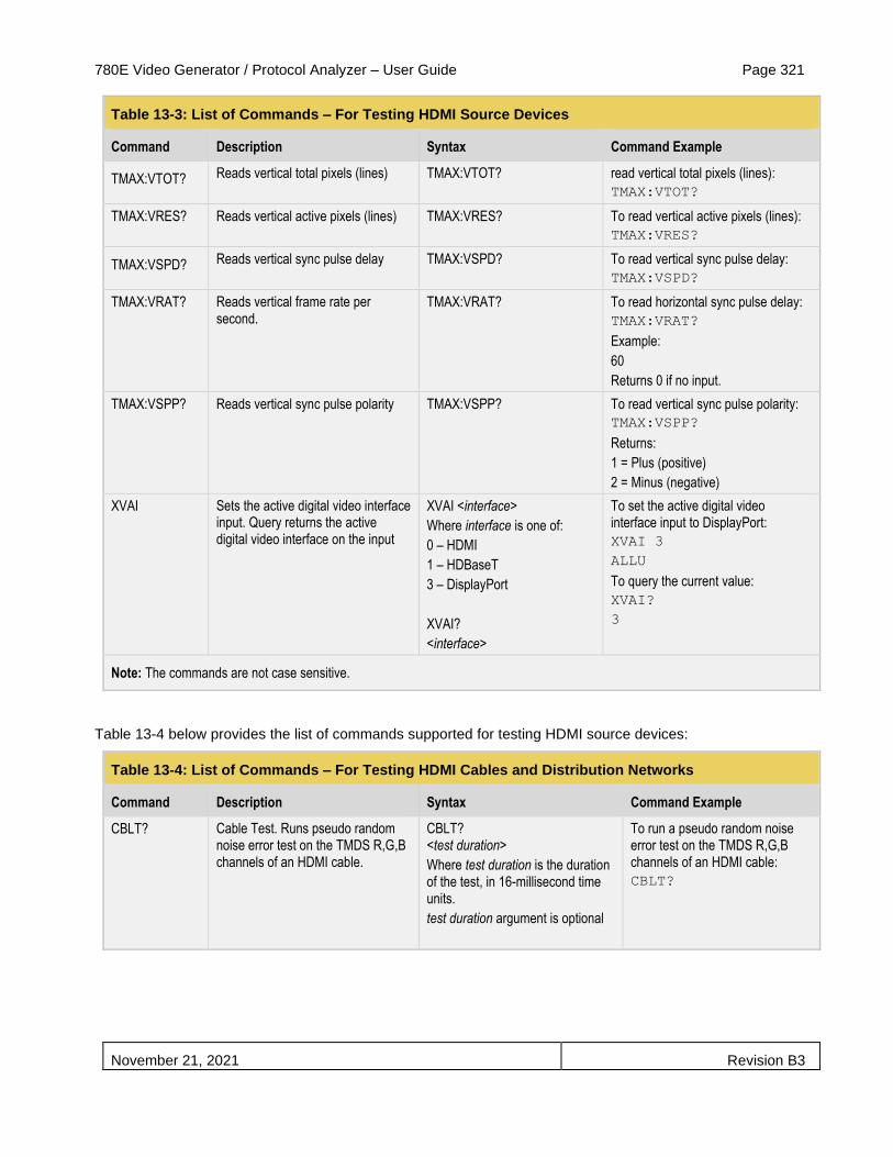
780E Video Generator / Protocol Analyzer – User Guide Page 321
November 21, 2021 Revision B3
Table 13-3: List of Commands – For Testing HDMI Source Devices
Command Description Syntax Command Example
TMAX:VTOT? Reads vertical total pixels (lines)
TMAX:VTOT? read vertical total pixels (lines):
TMAX:VTOT?
TMAX:VRES? Reads vertical active pixels (lines) TMAX:VRES? To read vertical active pixels (lines):
TMAX:VRES?
TMAX:VSPD? Reads vertical sync pulse delay
TMAX:VSPD? To read vertical sync pulse delay:
TMAX:VSPD?
TMAX:VRAT? Reads vertical frame rate per second.
TMAX:VRAT? To read horizontal sync pulse delay:
TMAX:VRAT?
Example:
60
Returns 0 if no input.
TMAX:VSPP? Reads vertical sync pulse polarity TMAX:VSPP? To read vertical sync pulse polarity:
TMAX:VSPP?
Returns:
1 = Plus (positive)
2 = Minus (negative)
XVAI Sets the active digital video interface input. Query returns the active digital video interface on the input
XVAI <interface>
Where interface is one of:
0 – HDMI
1 – HDBaseT
3 – DisplayPort
XVAI?
<interface>
To set the active digital video interface input to DisplayPort:
XVAI 3
ALLU
To query the current value:
XVAI?
3
Note: The commands are not case sensitive.
Table 13-4 below provides the list of commands supported for testing HDMI source devices:
Table 13-4: List of Commands – For Testing HDMI Cables and Distribution Networks
Command Description Syntax Command Example
CBLT? Cable Test. Runs pseudo random noise error test on the TMDS R,G,B channels of an HDMI cable.
CBLT? <test duration>
Where test duration is the duration of the test, in 16-millisecond time units.
test duration argument is optional
To run a pseudo random noise error test on the TMDS R,G,B channels of an HDMI cable:
CBLT?
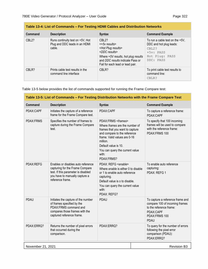
780E Video Generator / Protocol Analyzer – User Guide Page 322
November 21, 2021 Revision B3
Table 13-4: List of Commands – For Testing HDMI Cables and Distribution Networks
Command Description Syntax Command Example
CBL2? Runs continuity test on +5V, Hot Plug and DDC leads in an HDMI cable.
CBL2? <+5v results> <Hot Plug results> <DDC results>
Where +5V results, hot plug results and DDC results indicate Pass or Fail for each lead or lead pair.
To run a cable test on the +5V, DDC and hot plug leads:
CBL2?
+5v: PASS
Hot Plug: PASS
DDC: PASS
CBLR? Prints cable test results in the command line interface
CBLR? To print cable test results to command line:
CBLR?
Table 13-5 below provides the list of commands supported for running the Frame Compare test:
Table 13-5: List of Commands – For Testing Distribution Networks with the Frame Compare Test
Command Description Syntax Command Example
PDAX:CAPF Initiates the capture of a reference frame for the Frame Compare test.
PDAX:CAPF To capture a reference frame:
PDAX:CAPF
PDAX:FRMS Specifies the number of frames to capture during the Frame Compare test.
PDAX:FRMS <frames>
Where frames are the number of frames that you want to capture and compare to the reference frame. Valid values are 0-16 million.
Default value is 10.
You can query the current value with:
PDAX:FRMS?
To specify that 100 incoming frames will be used to compare with the reference frame:
PDAX:FRMS 100
PDAX:REFG Enables or disables auto reference capturing for the Frame Compare test. If this parameter is disabled you have to manually capture a reference frame.
PDAX: REFG <enable>
Where enable is either 0 to disable or 1 to enable auto reference capturing.
Default value is o to disable.
You can query the current value with:
PDAX: REFG?
To enable auto reference capturing:
PDAX: REFG 1
PDAU Initiates the capture of the number of frames specified by the PDAX:FRMS command and compares those frames with the captured reference frame.
PDAU To capture a reference frame and compare 100 of incoming frames to the reference frame:
PDAX:CAPF PDAX:FRMS 100
PDAU
PDAX:ERRQ? Returns the number of pixel errors that occurred during the comparison.
PDAX:ERRQ? To query for the number of errors following the pixel error comparison (PDAU):
PDAX:ERRQ?

780E Video Generator / Protocol Analyzer – User Guide Page 323
November 21, 2021 Revision B3

780E Video Generator / Protocol Analyzer – User Guide Page 324
November 21, 2021 Revision B3
Table 13-6 below lists the format names, their resolutions and frame rates for television formats. For command line control you would use the format name as the argument for the FMTL command.
Table 13-6: List of HDTV Format Names for Command Line Applies to: HDMI, DVI (TV), Analog YPbPr Video Signal Types
Syntax for Format Name Resolution Frame Rates (Hz) Command example
480i[frame rate] e.g.: 480i29 H: 720; V: 480 29.97, 30, 59.94, 60, 119.88, 120 FMTL 480i60
FMTU
480p[frameRate] e.g.: 480p59 H: 720; V: 480 59.94, 60, 119.88, 120 FMTL 480p60
FMTU
576i[frame rate] e.g.: 576i25 H: 720; V: 576 25, 50, 100 FMTL 576i25
FMTL
576p[frameRate] e.g.: 576p50 H: 720; V: 576 50, 100 FMTL 576p50
FMTU
720p[frameRate] e.g.: 720p25 H: 1280; V: 720 24, 25, 29.97, 30, 59.94, 60, 100, 119.88, 120
FMTL 720p60
FMTU
1080i[frameRate] e.g.: 1080i25 H: 1920; V: 1080 25, 29.97, 30, 50, 59.94, 60 FMTL 1080i59
FMTU
1080p[frameRate] e.g.: 1080p30 H: 1920; V: 1080 25, 29.97, 30, 50, 59.94, 60 FMTL 1080p60
FMTU

780E Video Generator / Protocol Analyzer – User Guide Page 325
November 21, 2021 Revision B3
Table 13-7 lists some of the format names for computer formats. For command line control you would use the format name as the argument for the FMTL command as shown in the example
Note: The following table only shows a sample of some of the more common formats. The other names can be obtained from the list on the 780E itself.
Table 13-7: Partial List of Computer Format Names for Command Line Applies to: DVI (Computer) Analog RGB Video Signal Types
Format Name Command example
640x480_72Hz FMTL 640x480_72Hz
FMTU
800x600_56Hz FMTL 800x600_56Hz
FMTU
1024x768_60Hz FMTL 1024x768_60Hz
FMTU
1280x768_60Hz FMTL 1280x768_60Hz
FMTU
1280x1024_60Hz FMTL 1280x1024_60Hz
FMTU
1600x1024_60Hz FMTL 1600x1024_60Hz
FMTU
1920x1440_60Hz FMTL 1920x1440_60Hz
FMTU
Table 13-8 below lists the image names. For command line control you would use the image name as the argument for the IMGU command.
Table 13-8: List of Image parameter names for command line
Image Name Example Image Name Example Image Name Example
SMPTEBar IMGL SMPTEBar IMGU
Regulate IMGL Regulate IMGU
Flat_Yel IMGL Flat_Yel
IMGU
H_Stair (Horizontal)
IMGL H_Stair IMGU
Checker (6x6)
IMGL Checker IMGU
Flat_Blk IMGL Flat_Blk
IMGU
Pluge IMGL Pluge IMGU
Focus IMGL Focus IMGU
Crosshtch (Grid) IMGL Crosshtch
IMGU
Needle IMGL Needle IMGU
Multibrst IMGL Multibrst IMGU
Anmorphic IMGL Anmorphic
IMGU
HiLoTrk (White Pluge)
IMGL HiLoTrk IMGU
SplitGray (11 vertical bars)
IMGL SplitGray IMGU
GrayBar IMGL GrayBar
IMGU
Overscan IMGL Overscan IMGU
LG_V_CBAR (Vertical bars)
IMGL LG_V_CBAR IMGU
Staircase IMGL Staircase
IMGU
Window1 (30 IRE)
IMGL Window1 IMGU
LG_H_CBAR (Horiz bars)
IMGL LG_H_CBAR IMGU
PulseBar IMGL PulseBar
IMGU
Window2 (80 IRE)
IMGL Window2 IMGU
V_3BARS (UL 3 bar pattern)
IMGL V_3BARS IMGU
Rev_Grid IMGL Rev_Grid
IMGU
Raster IMGL Raster IMGU
Flat_Wht IMGL Flat_Wht IMGU
Linearity IMGL Linearity
IMGU
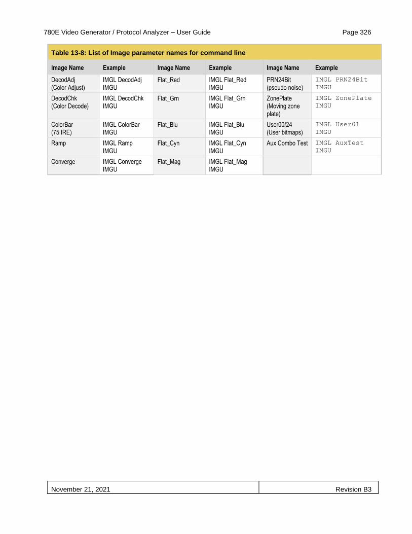
780E Video Generator / Protocol Analyzer – User Guide Page 326
November 21, 2021 Revision B3
Table 13-8: List of Image parameter names for command line
Image Name Example Image Name Example Image Name Example
DecodAdj (Color Adjust)
IMGL DecodAdj IMGU
Flat_Red IMGL Flat_Red IMGU
PRN24Bit (pseudo noise)
IMGL PRN24Bit
IMGU
DecodChk (Color Decode)
IMGL DecodChk IMGU
Flat_Grn IMGL Flat_Grn IMGU
ZonePlate (Moving zone plate)
IMGL ZonePlate
IMGU
ColorBar (75 IRE)
IMGL ColorBar IMGU
Flat_Blu IMGL Flat_Blu IMGU
User00/24 (User bitmaps)
IMGL User01
IMGU
Ramp IMGL Ramp IMGU
Flat_Cyn IMGL Flat_Cyn IMGU
Aux Combo Test IMGL AuxTest
IMGU
Converge IMGL Converge IMGU
Flat_Mag IMGL Flat_Mag IMGU
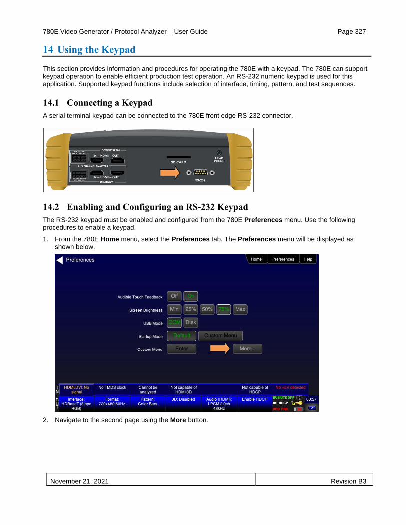
780E Video Generator / Protocol Analyzer – User Guide Page 327
November 21, 2021 Revision B3
14 Using the Keypad
This section provides information and procedures for operating the 780E with a keypad. The 780E can support keypad operation to enable efficient production test operation. An RS-232 numeric keypad is used for this application. Supported keypad functions include selection of interface, timing, pattern, and test sequences.
14.1 Connecting a Keypad
A serial terminal keypad can be connected to the 780E front edge RS-232 connector.
14.2 Enabling and Configuring an RS-232 Keypad
The RS-232 keypad must be enabled and configured from the 780E Preferences menu. Use the following procedures to enable a keypad.
1. From the 780E Home menu, select the Preferences tab. The Preferences menu will be displayed as shown below.
2. Navigate to the second page using the More button.

780E Video Generator / Protocol Analyzer – User Guide Page 328
November 21, 2021 Revision B3
3. For the RS-232 Keypad Mode menu item, select the ON button.
When selected, the ON button will be highlighted green.
4. Under RS-232 Baud Rate, use the arrow keys to select the correct baud rate for the keypad to be used. For the Genovation keypad supplied by Quantum Data, choose 1200 baud. After selecting the correct baud rate, power-cycle the 780E so that the changes take effect.
14.3 Keypad Functionality
For keypad support, the 780E uses four configuration files stored in the root directory of the internal flash. Here are the names and functions of the four files:
▪ UserKeys.txt: This file provides mappings of key codes so that the 780E knows which key has been pressed. This file may be different for each model of keypad that is used. This file should be configured by Quantum Data Engineering, and should not be changed by the customer unless you wish to create a specific test sequence. Procedures for creating a test sequence in the UserKeys.txt file are provided further below. Please contact Quantum Data Applications Engineering if you need this file changed, or if you want to use a different model of keypad.
▪ fmtmap.txt: This file provides mapping of format numbers to specific formats on specific interfaces. Each interface has a range of format numbers associated with it, and these ranges are specified in file intmap.txt. An example of the mapping for this file is depicted in Table 14-2.
▪ intmap.txt: This file specifies the ranges of format numbers assigned to each video interface. An example of the mapping for this file is depicted in Table 14-3.
▪ imgmap.txt: This file provides a mapping of test pattern numbers to the actual test patterns. An example of the mapping for this file is depicted in Table 14-4.
Keypad functions are assigned as shown in Table 14-1 below:
Table 14-1 – Keypad Functions
Key Function
Num Lock Timing - Select a format
/ Pattern - Select an image
* Program – Create a sequence

780E Video Generator / Protocol Analyzer – User Guide Page 329
November 21, 2021 Revision B3
. or Del Out or End
- Go to Previous item
+ Go to Next item
14.4 Selecting a Format (Timing)
A format can be selected by pressing the TIMING key followed by the number that represents the desired timing and interface. The following is an example of how you would select a format using the Format Map file shown in Table 14-2 below. Table 14-3 further below shows a sample mapping between formats (timings) and interfaces.
TIMING
352
ENTER
This will change the timing format to 1080p60 on the HDMI interface. Then the “Previous” and “Next” keys can be pressed to sequence through the format list. The following table is an example of a map between formats and keypad numbers that you would select.
Table 14-2 – Example Format Map File
Format Number Format Name Interface-Specific
301 NTSC44
TV
302 NTSC-J
303 NTSC-M
304 PAL-BDGH
305 PAL-N
306 PAL-NC
307 PAL-M
308 PAL-60
310 480i30
BNC
(YPbPr)
311 576i25
312 480p59
313 576p50
314 720p60
315 720p59
316 720p50
317 1035i30
318 1035i24
319 1152i25
320 1080i25
321 1080i24
322 1080i29

780E Video Generator / Protocol Analyzer – User Guide Page 330
November 21, 2021 Revision B3
323 1080i30
324 1080p24
325 1080p24
326 1080p25
327 1080p29
BNC (YPbPr)
328 1080p30
329 1080p50
330 1080p59
331 1080p60
332 480i24
DVI
333 480p60
334 1080i30
335 720p60
336 1080p59
341 480i24
HDMI
342 480i24
343 576i25
344 480p60
345 480p59
346 576p50
347 720p60
348 720p50
349 1080i30
350 1080i25
351 1080p50
352 1080p60
353 DMT0659
354 DMT0860
355 DMT1060
368 1080p59
370 720p59
371 1080p50
372 1080i25
373 1080i24
374 576i25

780E Video Generator / Protocol Analyzer – User Guide Page 331
November 21, 2021 Revision B3
375 480i30
396 720p59
397 DMT0660
398 480p60
Table 14-3 – Format Range per Interface Map
Interface Number Interface Name
301 - 309 TV
310 - 331 BNC + S-Video + CVBS (ED/HD)
332 - 336 DVI
341 - 398 HDMI
400 - 499 VGA(HD15) Analog RGB
500 - 599 VGA(HD15) Analog YPbPr
14.5 Selecting a Test Pattern (Image)
A test pattern (image) can be selected by pressing the PATTERN key followed by the number that represents the desired pattern. The following is an example of how you would select a test pattern using the Image Map file shown in Table 14-4 below.
PATTERN
001
ENTER
This will display the SMPTEBar pattern at the current format and on the current interface. Then the “Previous” and “Next” keys can be pressed to sequence through the pattern list.
Table 14-4 – Example Image Map File
Image Number Image Name
001 SmpteBar
002 TVBar100
003 TVBar_75
004 H_Stair
005 Pluge
100 Ramp
101 SplitGray
200 LG_V_CBAR
300 EcoFlower
301 Halation
302 Loading
400 Flat

780E Video Generator / Protocol Analyzer – User Guide Page 332
November 21, 2021 Revision B3
401 Flat93
402 Flat87
403 Flat80
404 Flat73
405 Flat67
406 Flat60
407 Flat53
500 PRN24Bit
14.6 Programming a Test Sequence using the keypad
You can create and run test sequences in one of two ways.
▪ You can program a test sequence through the keypad using the procedures below.
▪ You can create a sequence by adding a set of commands to the UserKeys.txt file using the procedures below.
Keypad functions are assigned as shown in Table 14-5 below:
Table 14-5 – Keypad Functions
Key Function
Num Lock TIMING - Select a format
/ PATTERN - Select an image
* Program PROG – Create a sequence
. or Del OUT or END
- Go to Previous item
+ Go to NEXT item
1. Define a sequence as follows:
Note: Information after “//” are comments to help you understand.
OUT // press the OUT key to start the creation of the sequence
001 // enter the sequence number
PROG // press the PROG key to begin programming
TIMING
344 // 480p60 HDMI
PATTERN
001 // SmpteBar pattern
NEXT
TIMING
347 // 720p60 HDMI
PATTERN
004 // horizontal stair
NEXT
TIMING

780E Video Generator / Protocol Analyzer – User Guide Page 333
November 21, 2021 Revision B3
352 // 1080p60 HDMI
PATTERN
100 // ramp
END // press the END key to halt the of sequence programming
2. Play back a sequence as follows.
OUT
001
NEXT
NEXT
(repeat NEXT or PREVIOUS)
14.7 Programming a Test Sequence in the UserKeys file
You can also create a test sequence by including a set of commands in the UserKeys.txt file. The UserKeys.txt file is primarily used internally for mapping the keypad keys to a set of commands for general keypad use. However you can also use the UserKeys.txt file to store programming test sequences similar to macros.
The following is an example of a UserKeys.txt file which shows the keypad mapping and more importantly a test sequence instruction set (#F0, #F1 and #FF). Note that there are two macro test sequences defined #F0 and #F1. The #FF definition is a macro that simply disables manufacturing mode in the 804 test instrument. The #F0 macro also shows a special use case for the kbrd command. In this case the kbrd f0 command will cause the macro to loop back on itself such that the #F0 macro continuously loops.
Note: Do not change any of the keypad mapping commands. These are the commands such as xkpm, xkpkj, xkpu, xkpi. Modifying these commands will affect the general functions of the keypad.
S xkpm 2
T xkpm 1
U xkpm 4
V xkpj 1
W xkpj -1
X xkpu
Y xkpi 1
Z xkpi 2
[ xkpi 3
\ xkpi 4
] xkpi 5
^ xkpi 6
_ xkpi 7
` xkpi 8
a xkpi 9
b xkpi 0
c xkpm 3
#F0 xvsi 4;fmtl 720p60;imgl smptebar;fmtu;dlay 5000;fmtl 480p60;imgl
h_stair;fmtu;dlay 5000;fmtl 1080i30;imgl needle;fmtu;dlay 5000;fmtl
1080p60;imgl decodchk;fmtu;dlay 5000;fmtl 480i30;imgl v_3bars;fmtu;dlay 5000
#F1 xvsi 4;fmtl cvt1460d;imgl checkby6;fmtu;dlay 5000;fmtl dmt1170_;fmtu;dlay
5000;fmtl dmt0660;fmtu;dlay 5000
#FF mfgm 0
To run a test sequence macro stored in the UserKeys.txt file you use the kbrd command on the command line as follows.

780E Video Generator / Protocol Analyzer – User Guide Page 334
November 21, 2021 Revision B3
KBRD F0 // This command would run the F0 macro in the UserKeys.txt file (case is not important)

780E Video Generator / Protocol Analyzer – User Guide Page 335
November 21, 2021 Revision B3
15 Upgrading the 780E
15.1 Upgrading the Firmware and Gateware on your 780E Handheld Test
Instrument for HDMI
You can upgrade the firmware and gateware on your 780E through the USB interface. In order to upgrade the 780E firmware and gateware you have to put the 780E in the “Disk” mode. This is not the default mode.
Important Note: Be sure to check the Release Notes on the Quantum Data website for additional information on upgrading for a particular release. The instructions below may not apply in all upgrade scenarios. If you have any questions or encounter a problem with the upgrade, contact Quantum Data customer support.
Use the following procedure to upgrade the firmware and gateware for your 780E. Note that the files will also come with a bootstrp.bin file.
1. Download the 780E firmware and gateware (if necessary) files from the Quantum Data website http://www.quantumdata.com/downloads/index.asp to your PC and unzip the file.
2. Connect the 780E to a PC host via the USB cable provided.
3. Touch select the Preferences from the 780E top menu.
4. Choose Disk for the USB Mode (refer to the screen below).
5. Power cycle the 780E.
The 780E appears as a mass storage device like any other USB drive.
6. Transfer the bootstrp.bin from your PC to the 780E using standard Windows drag and drop techniques.
7. Transfer the new firmware (VP500app.bin) from your PC to the 780E using standard Windows drag and drop techniques.
8. (if necessary) Transfer the new gateware file (for 780: Xilinx.bin; for 780E: 780afpga.bin ) from your PC to the 780E using standard Windows drag and drop techniques.
9. Use Windows Eject function on the 780E USB device then physically disconnect the 780E from your PC.
10. Reboot the 780E.
11. Navigate to the Help window.

780E Video Generator / Protocol Analyzer – User Guide Page 336
November 21, 2021 Revision B3
12. Activate the gateware (if you are updating the FPGA Flash) by touching the associated Update button.
A confirmation prompt is displayed. Touch select Confirm to initiate the firmware upgrade. (Note: The screen on your unit may appear slightly different.)
The screen will show several messsages indicating the progress of the update. Once the gateware update has completed the following screen appears.
13. Reboot the 780E by power cycling.
14. Navigate back to the Help menu to access the upgrade screen.
15. Activate the firmware (Application Flash) by touch selecting the associated Update button.
A confirmation prompt is displayed as shown below. Touch select Confirm to initiate the firmware upgrade.

780E Video Generator / Protocol Analyzer – User Guide Page 337
November 21, 2021 Revision B3
The screen will show several messsages indicating the progress of the update. Once the firmware update has completed the following screen appears.
16. Reboot the 780E by power cycling.
17. Touch select the Preferences from the 780E top menu.
18. Choose COM for the USB Mode (refer to the screen below).
19. Power cycle the 780E.
20. Navigate back to the Help menu to verify the upgraded versions.

780E Video Generator / Protocol Analyzer – User Guide Page 338
November 21, 2021 Revision B3
END OF USER GUIDE