Impurity effects on semiconductor quantum bits in coupled quantum dots
24
arXiv:1103.0767v2 [cond-mat.mes-hall] 10 Jul 2011 Impurity effects on semiconductor quantum bits in coupled quantum dots Nga T. T. Nguyen and S. Das Sarma Condensed Matter Theory Center, Department of Physics, University of Maryland, College Park, Maryland 20742-4111, USA We theoretically consider the effects of having unintentional charged impurities in laterally coupled two-dimensional double (GaAs) quantum dot systems, where each dot contains one or two electrons and a single charged impurity. Using molecular orbital and configuration interaction method, we calculate the effect of the impurity on the 2-electron energy spectrum of each individual dot as well as on the spectrum of the coupled-double-dot 2-electron system. We find that the singlet-triplet exchange splitting between the two lowest energy states, both for the individual dots and the coupled dot system, depends sensitively on the location of the impurity and its coupling strength (i.e. the effective charge). A strong electron-impurity coupling breaks down equality of the two doubly- occupied singlets in the left and the right dot leading to a mixing between different spin singlets. As a result, the maximally entangled qubit states are no longer fully obtained in zero magnetic field case. Moreover, a repulsive impurity results in a triplet-singlet transition as the impurity effective charge increases or/and the impurity position changes. We comment on the impurity effect in spin qubit operations in the double dot system based on our numerical results. PACS numbers: 73.21.La, 03.67.Lx, 73.23.Hk I. INTRODUCTION The goal of this work is the calculation of the low- lying energy spectra of 2-electron semiconductor quan- tum dots (QDs) (both single dots and coupled double- dots) in the presence of nearby static charged impurity centers within a minimal model. The purpose is to quan- tify the effects of quenched random charged impurities on the singlet-triplet splitting in QDs in order to assess the importance of background unintentional impurities, which are invariably present in the environment, in ad- versely affecting the operations of exchange-coupled dots as elementary spin qubits for solid state quantum com- putation. Since the positions and the strengths of the background unintentional impurities are unknown and random, we study the impurity effects as functions of impurity position and coupling strength (defined as the effective impurity charge Z ) assuming the impurities to be Coulombic charge centers so that their effective po- tential falls off slowly as a 1/r potential away from the impurity location where ‘r’ is the distance from the im- purity. Since the main background impurities in GaAs and Si, the two most relevant semiconductors of interest for solid state spin quantum computation, are random charge centers, our consideration of Coulombic impurities with a long-range impurity potential is reasonable. The theoretical results presented herein, while being com- pletely microscopic and fully quantum mechanical, are phenomenological in nature since the impurity position and charge are treated as unknown parameters. While our results show clearly the strong effect of local back- ground charged impurities on the low-lying QD spectra, its usefulness is limited in comparing with experiment since no direct information about impurity locations is currently available experimentally. On the other hand, our results establish the manifest importance of using the highest quality background materials for semiconductor spin qubit operations since the presence of even a sin- gle charged impurity in the vicinity of the QDs seems to completely ruin the operational logistics of coupled QD systems. The exchange coupling (or equivalently, the singlet-triplet splitting) depends strongly and sensitively on the location and the strength of the charged impurity, which means that (1) a single charged impurity located nearby could destroy the qubit, and (2) even a remote charged impurity could have a strong adverse effect in- ducing substantial qubit decoherence if the impurity is dynamic and has a fluctuation timescale comparable to gate operations timescales– in fact, the impurity fluctua- tion timescale will become a dominant decoherence time since the exchange energy will vary substantially over this timescale. The motivation of our work is a clear un- derstanding of the energetics of QD systems in the few electron situation in the presence of charged impurities so that some rudimentary quantitative magnitudes of the impurity effects are available for qubit operation consid- erations. Coupled QDs for quantum computation 1–5 have been extensively studied due to the prospect of using QDs as ideal environment to confine and manipulate the QD electron spins. The quantum bit, or qubit, of infor- mation is encoded and stored in these localized single electron spins which exploit a spin relaxation time of the order of milliseconds 6–8 , sufficiently long to allow the performance of coherent spin operations. The pro- posed quantum computer 3 in solid states operates based on the exchange coupling J between the two electron spin qubits manipulated by an external magnetic field. This exchange energy can be envisioned as the effective coupling between the two spins in the double dots 3 via the Heisenberg spin Hamiltonian, H = J s 1 · s 2 , which takes into account possible contributions from different hybridzation between singlet and triplet states. Hence, J is determined through the gate voltage control over
-
Upload
independent -
Category
Documents
-
view
0 -
download
0
Transcript of Impurity effects on semiconductor quantum bits in coupled quantum dots

arX
iv:1
103.
0767
v2 [
cond
-mat
.mes
-hal
l] 1
0 Ju
l 201
1
Impurity effects on semiconductor quantum bits in coupled quantum dots
Nga T. T. Nguyen and S. Das SarmaCondensed Matter Theory Center, Department of Physics,
University of Maryland, College Park, Maryland 20742-4111, USA
We theoretically consider the effects of having unintentional charged impurities in laterally coupledtwo-dimensional double (GaAs) quantum dot systems, where each dot contains one or two electronsand a single charged impurity. Using molecular orbital and configuration interaction method, wecalculate the effect of the impurity on the 2-electron energy spectrum of each individual dot as wellas on the spectrum of the coupled-double-dot 2-electron system. We find that the singlet-tripletexchange splitting between the two lowest energy states, both for the individual dots and the coupleddot system, depends sensitively on the location of the impurity and its coupling strength (i.e. theeffective charge). A strong electron-impurity coupling breaks down equality of the two doubly-occupied singlets in the left and the right dot leading to a mixing between different spin singlets.As a result, the maximally entangled qubit states are no longer fully obtained in zero magnetic fieldcase. Moreover, a repulsive impurity results in a triplet-singlet transition as the impurity effectivecharge increases or/and the impurity position changes. We comment on the impurity effect in spinqubit operations in the double dot system based on our numerical results.
PACS numbers: 73.21.La, 03.67.Lx, 73.23.Hk
I. INTRODUCTION
The goal of this work is the calculation of the low-lying energy spectra of 2-electron semiconductor quan-tum dots (QDs) (both single dots and coupled double-dots) in the presence of nearby static charged impuritycenters within a minimal model. The purpose is to quan-tify the effects of quenched random charged impuritieson the singlet-triplet splitting in QDs in order to assessthe importance of background unintentional impurities,which are invariably present in the environment, in ad-versely affecting the operations of exchange-coupled dotsas elementary spin qubits for solid state quantum com-putation. Since the positions and the strengths of thebackground unintentional impurities are unknown andrandom, we study the impurity effects as functions ofimpurity position and coupling strength (defined as theeffective impurity charge Z) assuming the impurities tobe Coulombic charge centers so that their effective po-tential falls off slowly as a 1/r potential away from theimpurity location where ‘r’ is the distance from the im-purity. Since the main background impurities in GaAsand Si, the two most relevant semiconductors of interestfor solid state spin quantum computation, are randomcharge centers, our consideration of Coulombic impuritieswith a long-range impurity potential is reasonable. Thetheoretical results presented herein, while being com-pletely microscopic and fully quantum mechanical, arephenomenological in nature since the impurity positionand charge are treated as unknown parameters. Whileour results show clearly the strong effect of local back-ground charged impurities on the low-lying QD spectra,its usefulness is limited in comparing with experimentsince no direct information about impurity locations iscurrently available experimentally. On the other hand,our results establish the manifest importance of using thehighest quality background materials for semiconductor
spin qubit operations since the presence of even a sin-gle charged impurity in the vicinity of the QDs seemsto completely ruin the operational logistics of coupledQD systems. The exchange coupling (or equivalently, thesinglet-triplet splitting) depends strongly and sensitivelyon the location and the strength of the charged impurity,which means that (1) a single charged impurity locatednearby could destroy the qubit, and (2) even a remotecharged impurity could have a strong adverse effect in-ducing substantial qubit decoherence if the impurity isdynamic and has a fluctuation timescale comparable togate operations timescales– in fact, the impurity fluctua-tion timescale will become a dominant decoherence timesince the exchange energy will vary substantially overthis timescale. The motivation of our work is a clear un-derstanding of the energetics of QD systems in the fewelectron situation in the presence of charged impuritiesso that some rudimentary quantitative magnitudes of theimpurity effects are available for qubit operation consid-erations.
Coupled QDs for quantum computation1–5 have beenextensively studied due to the prospect of using QDs asideal environment to confine and manipulate the QDelectron spins. The quantum bit, or qubit, of infor-mation is encoded and stored in these localized singleelectron spins which exploit a spin relaxation time ofthe order of milliseconds6–8, sufficiently long to allowthe performance of coherent spin operations. The pro-posed quantum computer3 in solid states operates basedon the exchange coupling J between the two electronspin qubits manipulated by an external magnetic field.This exchange energy can be envisioned as the effectivecoupling between the two spins in the double dots3 via
the Heisenberg spin Hamiltonian, H = Js1 · s2, whichtakes into account possible contributions from differenthybridzation between singlet and triplet states. Hence,J is determined through the gate voltage control over

2
the tunneling coupling between the coupled two QDs. Acomplete understanding of J is important because it di-rectly determines the
√SWAP operator which describes
the exchange information between the two qubits in thedouble dots. The fast solid-state two-qubit operation3,9,generated as a consequence of the electron spin exchangeunder electrical control, and the single-qubit operation10
suffice to assemble a standard quantum computing sys-tem. The number of electrons in such a QD system canbe controlled precisely11–14 to 0, and the electron ex-change interaction is tunable by the applied gate volt-ages. Thereby, the coupling between the dots can also becontrolled.
Established quantum regimes such as quantum entan-glement between individual electrons in one dot with theother electrons in the other dots and superposition ofelectron spin qubits are the major objects3,4,9,15–25 insuch exchange coupled QD system. Prerequisite crite-ria for realization of a quantum computation system3
(including initialization, manipulation of spin qubits,and readout) have been demonstrated for single dot26
and coupled QD system27, provided the long relaxationtime6,14 of the spins, by using charge sensing and fastspin-to-charge conversion techniques. One of the per-ceived advantages of solid-state quantum computing isthe scalability with existing semiconductors. In ad-dition, integrating multi coupled dots into a quantumcircuit is made possible by adding more suitable gateelectrodes.5,12
QDs in versatile GaAs semiconductors not only havebeen considered the most widely-studied objects in theQD science but also their well-understood physics are ap-plicable to a variety of materials.5 Often, unintentionalimpurities found in the dot sample are used in the fabrica-tion process to adjust the potential well height betweendifferent heterostructure semiconductors (such as Si ingated GaAs/AlGaAs QDs - see e.g. Ref.5) allowing thecharge flow of electrons. Statistically, such QD systemcontaining impurities can be studied for one, two, ... im-purities. On the other hand, when integrating multiplecoupled 2-dot systems utilized as a multi-qubit gate, inthe non-overlapping regime between different 2-dot sys-tems, a single spin qubit in one coupled 2-dot system canbe affected28 by the other coupled 2-dot systems. Eachcoupled 2-dot system acts as a source of electrostatic fieldto the others and can be treated as “charged impurities”.
Theoretical studies of impurities in coupled QDs havebeen rarely found in the literature. In fact, the impuritiesare practically found randomly in/outside the dot sam-ple and their positions cannot be specified precisely. In acoupled triple-dot system, a relatively large collection ofimpurities was considered29. These statistical impuritieswere theoretically assumed to induce a weak perturba-tion to the coupled triple QDs. The authors29 found thatthe Coulomb exchange energy of the impurities with theQD electrons in this study resulted in decoherence of thecoded qubit states. Thus, any information processing us-ing electron charge degree of freedom needs to take into
account the decoherence channel due to charge fluctua-tions.In the present paper, we study the influence of charged
impurities on the singlet-triplet splitting of the two lowestenergy levels as well as the energy spectrum as a functionof the impurity position, the impurity effective charge,and the number of impurities for a coupled two-dot sys-tem in zero magnetic field. We also examine the impurityeffect on the coupled electron qubits by tuning the po-tential well height to different values and obtain differenttriplet-singlet transitions for the repulsive impurity case.To accomplish, we discuss the singlet-triplet splitting inthe presence of two impurities with similar charge locatedin the two separate dots of the system.The paper is organized as follows. In Sec. II we in-
troduce the model and methodology. Impurity effect onenergy spectrum of a two-electron single QD containing asingle charged impurity is first discussed in detail in Sec.III. Sect. IV is spent to present our studies on a cou-pled 2-dot system in the presence of one or two chargedimpurities. We examine the impurity position and impu-rity effective charge dependence of the singlet-triplet spinsplitting energy. Influence of the confining potential bar-rier height on the electron-impurity (e-I) and electron-electron (e-e) coupling is also explored. All the resultspresented in this paper are obtained at zero magneticfield, B=0. Summary of our results and conclusion arefound in Sec. V.
II. THEORETICAL MODEL
Horizontally-coupled QDs are grown by the depletionof the two-dimensional electron gas (2DEG) using typ-ically the gated mechanism30,31. Such gated QDs havetypical size of about few tens of nm. Consequently, thelowest excitation energy in such a QD system is foundof the order of few meV. When the inter-dot couplingstrength is substantial, the electrons in the coupled dotsstrongly quantum mechanically couple with each other.As long as the phase is coherent, the electrons can “tun-nel” between the adjacent dots forming different entan-gled qubits. Using single-conduction-band effective-massapproximation which was justified in Ref.22, the Hamilto-nian describing a two-electron coupled double QD systemcontaining unintentional charged impurities (charge sizeZe) in zero magnetic field reads:
H = h1 + h2 + VC + Ve-Imp + VI-I. (1)
Here, the first two terms hi,j are the single-particleHamiltonian of the two quantum-dot electrons (coordi-nates ri)
hi =(i~∇i + eAi)
2
2m∗ + V (ri) (2)
confined by a potential well V (r). In the present pa-per, this confining potential is constructed as a linear
3
combination of the three different Gaussians and can beseparated into two parts:
V (r) = V0(e−[ (x−a)2
l2x+ y2
l2y]+ e
−[ (x+a)2
l2x+ y2
l2y]) (3)
+Vbe−( x2
l2bx
+ y2
l2by
).
The first part acts as a double-well confining potentialfor the coupled double dot system and the second part isused to control the electrostatic barrier height betweenthe two dots independently. The set of varying param-eters V0, Vb, lx, ly, lbx, lby characterizes the potential welldepth and barrier height. A nonvanishing overlap be-tween the wave functions of the two quantum dots signi-fies the electron virtual tunneling between the two dots,i.e. the exchange energy is nonzero. Because this prop-erty can be tuned by the applied gate voltage this ex-change energy thereby can be controlled. It is worthnoting that Vb can independently modulate the barrierheight resulting in concomitant change in the inter-dotseparation without modifying the single-particle energyspectrum of the individual QDs in the system. The last
-30 -20 -10 0 10 20 30
-60
-50
-40
-30
V (
r) (
me
V)
x (nm)
Vb = 35 (meV) a
m=17.52 (nm)
Vb = 30 a
m=16.41
Vb = 25 a
m=15
Vb = 20 a
m=13.09
Vb = 15 a
m=10.11
Vb = 11.4 a
m=6.1
Em
FIG. 1: (Color online) Confinement potential double well ofcoupled double QDs modeled along the x-direction plotted fordifferent barrier depth Vb (from 35 down to 11.4 meV) (leftcolumn). The corresponding double well minima (±am, 0)are indicated in the same line in the right column of the ref-erence. The confinement energy at the two well bottoms Em
is enclosed as the magenta open circles for various values ofVb.
three terms in Eq. (1) are the Coulomb interaction be-tween, respectively, the two electrons
VC =e2
4πǫǫ0|rij|, (4)
the electron and the impurities
Ve-Imp =
NI=2∑
k=1
Ne=2∑
i=1
Zke2
4πǫǫ0|Rk − ri|(5)
where NI and Ne denote the number of impurities andelectrons, respectively, and the impurities
VI-I =Z1Z2
4πǫǫ0|R1 −R2|. (6)
The solution of a single particle confined by a parabolicpotential is well known as the Fock-Darwin basis:
ϕnl (r) =1
l0
√n!
π (n+ |l|)!
(r
l0
)|l|e−ilθe
− r2
2l20 L|l|
n
(r2
l20
)
(7)with corresponding energy
En,l = ~ω0(2n+ |l|+ 1) (8)
where (n, l) stand for radial and azimuthal quantumnumber, respectively. l0 is the confinement length whichis defined via the confinement frequency ω0: l0 =√
~
m∗eω0
. Using this basis as the radial part we can con-
struct the many-body wave function for the consideredsystem.We introduce a dimensionless parameter,
λ =l0a∗B
(9)
with a∗B = 4πǫ0ǫ~2
m∗ee
2 the effective Bohr radius, which is used
to describe the relation between the effective Rydberg
energy R∗y = m∗e4
2~2(4πǫ0ǫ)2and the confinement energy ~ω0
R∗y = ~ω0 ·
λ2
2. (10)
Both e-e and e-I Coulomb interaction are evaluated interms of matrix elements as
〈Ψ|Ve-e|Ψ〉 = V C0 〈Ψ| 1
ri − rj||Ψ〉 (11)
〈Ψ|Ve-Imp|Ψ〉 = V C0 〈Ψ| 1
|r− R||Ψ〉
where Ψ denotes the wave function of the system, ri,j =
r/l0, R = R/l0, and V C0 = e2/4πǫǫ0l0 is the Coulombenergy unit. V C0 relates to the confinement energy viathe relation:
V C0 =e2
4πǫǫ0l0= λ · ~ω0. (12)
The numerical results are implemented for e.g. a GaAsQD with m∗ = 0.067m0, ǫ = 13.1, ge = −0.44, R∗
y = 5.31meV (corresponding to a∗B = 10.3 nm). λ is changedby changing the confinement energy ~ω0. λ = 1 gives~ω0 = 2R∗
y = 10.62 meV and corresponding confinementlength l0 = a∗B = 10.3 nm.For Si/SiGe (ǫ=13) and Si/SiO2 (ǫ=6.8) quantum dots
with a heavier effective mass m∗ = 0.19m0, effective

4
Bohr radius and effective Rydberg energy are, respec-tively, a∗B = 4 nm and R∗
y = 15 meV, and a∗B = 2.11
nm and R∗y = 44.76 meV (see e.g. Ref.40). λ = 1 gives
~ω0 = 2R∗y = 30 meV (l0 = 4 nm) for a Si/SiGe QD and
~ω0 = 2R∗y ≈ 90 meV (l0 = 2.11 nm) for a Si/SiO2 QD
system. Even though our numerical results are applica-ble to GaAs QD systems, singlet-triplet splitting energiesfor Si QD systems are also provided in Appendix D forcomparison purposes.Reducing λ means that the effective length, l0, of the
QD decreases while the energy spacing, ~ω0, between the2D shells, i.e. the s-, p-, d- levels, will increase. In thesmall λ limit, the problem at hand converts to the prob-lem of independent particles. In the opposite case, verylarge λ, the problem approaches the classical situation.In the coupled double QD system, the single-particle
solutions in each dot are obtained approximately basedon an assumption that around the center of the eachdot (±am, 0) the single-electron problem can be treatedas a 2D harmonic oscillator. This means that the con-fining potential well V (r) performs a quadratic formV (r) − Em ≈ V0
l2x[(x ± am)2 + y2], with Em the bottom
energy of the potential well, around (±am, 0). Changesin Em when Vb varies can be obtained as the open cir-cles in Fig. 1 The single-particle wave functions now areidentical to the Fock-Darwin levels centered at (±am, 0)and the single-particle energy spectrum is shifted by anamount of Em.
ϕL(R) (r) =1
l0
√n!
π (n+ |l|)!
(rL(R)
l0
)|l|e−ilθ (13)
e−
r2L(R)
2l20 L|l|
n
(r2L(R)
l20
)
where rL,R = (x ± am, y) and ω0 =√
2V0
m∗l2xis the
quadratic confining frequency which defines a new lengthl20 = ~
m∗ω0called the confinement length. The single-
particle ground-state wave function is
ϕL,R =1√πl0
e− [(x±am)2+y2]
2l20 . (14)
To quantitatively evaluate the advantage of using theabove confining potential present in Eq. (3), we plotin Fig. 1 the confining potential well where its barrierheight and the QD centers are modified by changing Vb.Here, Vb is reduced from 35 meV to 30, 25, 20, 15, and11.4 meV. As a result, the barrier height will decreasemaking the electron exchange energy increased. For ex-ample, the system with Vb = 35 meV has the corre-sponding am ≈ 17.52 nm (≈ 1.75l0), and barrier height∆Vb = 13.26 meV. For Vb = 30meV, these parametersare am ≈ 16.41 nm (≈ 1.64l0) and ∆Vb = 9.65 meV.Decreasing Vb leads to a shortened inter-dot separation2am and a smaller ∆Vb. Details can be obtained in Fig. 1.In our numerical results, we use Vb = 30 meV for most
of our calculations except when we examine the barrierheight dependence of the exchange energy J where Vbcan vary. The center region of each QD, however, hasunchanged effective length, namely l0, regardless to thechange in the barrier height. The other parameters takenafter Refs.9,22,23 are lx = ly = 30 nm, a = lbx = lx/2 = 15nm, lby = 80 nm.We assume that the impurities are located arbitrarily
in or outside the coupled QDs. Their coordinates areRk = (xk, yk, zk), {k=1,2}. Theoretically, the effectivecoupling between electron and the localized impuritiesas well as the coupling between the impurities with eachother can be tuned by engineering the impurity chargeZ.Configuration interaction (CI) and molecular orbital
(MO) method are used to numerically solve the Hamilto-nian Eq. (1). Both construct the total wave functionof the system as a superposition of different possiblequantum configurations (CI) or molecule states (MO) ex-tended in the basis of single-particle wave functions:
Ψ(r1, r2) =
Nc∑
i
ψi(r1, r2) (15)
where ψi(r1, r2) represents one many-electron configura-tion as a Slater determinant. Each term of this Slaterdeterminant is a single-electron wave function consistedof the radial part, the Fock-Darwin state ϕ(r1,r2) definedin Eq. (13), and the electron spin part (detailed justifi-cations are referred to Ref.22).The singlet-triplet spin splitting energy of the electrons
J in such a coupled 2-dot system is defined as the energydifference between the two lowest singlet (ΨS) and triplet(ΨT ) states:
J = 〈ΨT |H |ΨT 〉 − 〈ΨS |H|ΨS〉. (16)
A. Hund-Mulliken
In Hund-Mulliken model, the energy spectrum consistsof four levels which are four possible superpositions of thefour basis (three singlets and one triplet) wave functions
ψS1 (r1, r2) =1√2[ϕL(r1)ϕR(r2) + ϕL(r1)ϕR(r2)](17)
ψS2 (r1, r2) = ϕL(r1)ϕL(r2)
ψS3 (r1, r2) = ϕR(r1)ϕR(r2)
ψT (r1, r2) =1√2[ϕL(r1)ϕR(r2)− ϕL(r1)ϕR(r2)].
In the coupled QD system without an impurity, thesethree singlets do not couple with the maximally entangledtriplet state ψT therefore they can be treated separately.The entire Hamiltonian matrix represents these singletsand triplets as independent blocks.
5
B. Configuration Interaction
The most difficult task in finding the eigenvalues ofa coupled 2-dot system lies in the basis choice amongwhich Fock-Darwin basis and Gaussian basis are the mostwidely used. However, in both cases a closed analyticalform for the Hamiltonian matrix elements, essentially thee-e Coulomb matrix elements, has not yet been obtained.The reason is that the single-particle solutions of differ-ent dots i) have distinct zero-points shifted to the twobottoms of the confining potential well and ii) thus arenot orthogonal with each other. Consequently, the num-ber of distinguishable single-particle quantum states forthe double-dot system will be doubled. Effectively, thesize of the entire Hamiltonian increases in comparison tothe single dot case. Quantitatively, for Sz = 0 subspace,such a number is 4 times larger than that of the singledot problem (2NX2N). Specifically, if only the s-wavesare taken into account, the number of configurations inthe subspace Sz = 0 is 1 for single QD and 4 for coupled2-dot system and if the s- and p-waves are included thosenumbers are 9 and 36, respectively.The above fact poses much difficulty to solving the
eigenvalues of the coupled QD Hamiltonian. The mosttime consuming part is spent to calculate the Coulombmatrix elements. In the problem at hand, the numberof Coulomb elements increases due to the e-I exchangeinteraction. However, based on the following facts onecan take out nonphysical excited single-particle quantumstates: i) the form of the confining potential, which istuned electrostatically by metal top gates, is not exactlyknown and ii) the barrier potential height is finite. Thelatter factor validates the harmonic approximation forthe confinement potential double well resulting in only alimited number of Fock-Darwin states involved.
III. IMPURITY EFFECTS IN SINGLEQUANTUM DOTS
In the single QD case, we assume that there is onlyone impurity and the impurity is located along z-axis,i.e. R = (0, 0, d). The addition Coulomb interaction ofthe electrons with the impurity is obtained analytically(see Appendix A):
V n2l2n1l1
(R) = δl1,l22√π
Γ (n1 + l+ + 1)Γ (n2 + l+ + 1)√n1!n2!(n1 + l+)!(n2 + l+ + 1)!
× (18)
n1∑
j=0
n2∑
k=0
(−n1)j(−n2)kΓ(l+ + j + k + 1)Γ(l+ + 1)
j!k!Γ(l+ + j + 1)Γ(l+ + k + 1)Im(R)
where l+ = |l1| = |l2| and
Im(R) =
∫ ∞
0
e−R2u2
(1 + u2)m+1du. (19)
Integral (19) can be obtained through the recurrence:
I0(R) =π
2eR
2
erfc(R), (20)
I1(R) =1
2[(1 − 2R2)I0R+
√πR],
Im(R) = (− R2
m+ 1− 1
2m)Im−1(R) +
R2
mIm−2(R)
where erfc(x) is the complementary error function,
erfc(x) =
∫ ∞
x
e−x2t2
1 + t2dt, (21)
which rapidly decreases in x. (x)n = x(x + 1)(x +2)...(x + n − 1) is the Pochhammer function. Severalvalues of the complementary error function which canbe obtained in any numerical library are: erfc(0) = 1,erfc(0.01) ≈ 0.98872, erfc(0.1) ≈ 0.88754, erfc(0.5) ≈0.47950, erfc(1)≈ 0.1573, erfc(2)≈ 0.00468, etc.
A. Perturbative and exact calculations
Following the e-I interaction whose matrix elements areexpressed in Eq. (18), there is mixture between differ-ent states with different total radial quantum numbers.Consequently, the ground-state wave function e.g. forNe = 1 electron is no longer the only one s- (n=0,l=0)quantum state. Instead, it consists of several quantumstates whose contributions Ci are different
Ψ =∑
i=1
Ciψi. (22)
For Ne = 2 electrons without impurity, by increasingλ results in the ground state mixing of different config-urations. The two electrons will occupy higher Fock-Darwin states with decreasing energy spacing to lowertheir Coulomb repulsion. The easiest way to check theaccuracy of the numerical results when the impurity ispresent is to consider the limitation when weak pertur-bation works perfectly. The first-order perturbation ap-
6
proximation:
E = E0 + Z
Ne∑
i=1
< Ψ0|V (|ri −R|)|Ψ0 > +O(Z2) (23)
where E0 is the GS energy of the QD with the ground-state wave function Ψ0 in case without impurity is a goodone when Z < 1. For the sake of simplicity in evaluatingthe perturbative part in Eq. (23) for both Ne = 1 and2 electrons, we assume that Ψ0 in case Z = 0 is a singleterm: the s-state. For Ne = 1 electron, this is alwayssatisfied and its radial part is
Ψ0(r) =1
l0√πe− r2
2l20 . (24)
0.0 0.5 1.0 1.5 2.0
-6
-4
-2
0
0.0 0.5 1.0 1.5 2.0-1.5
-1.0
-0.5
∆E (
R* y)
d (a*
B)
numeric
theoryλ=0.1
Ne=2
Ne=1
d (a*
B)
∆E (
R* y)
λ=0.5N
e=2
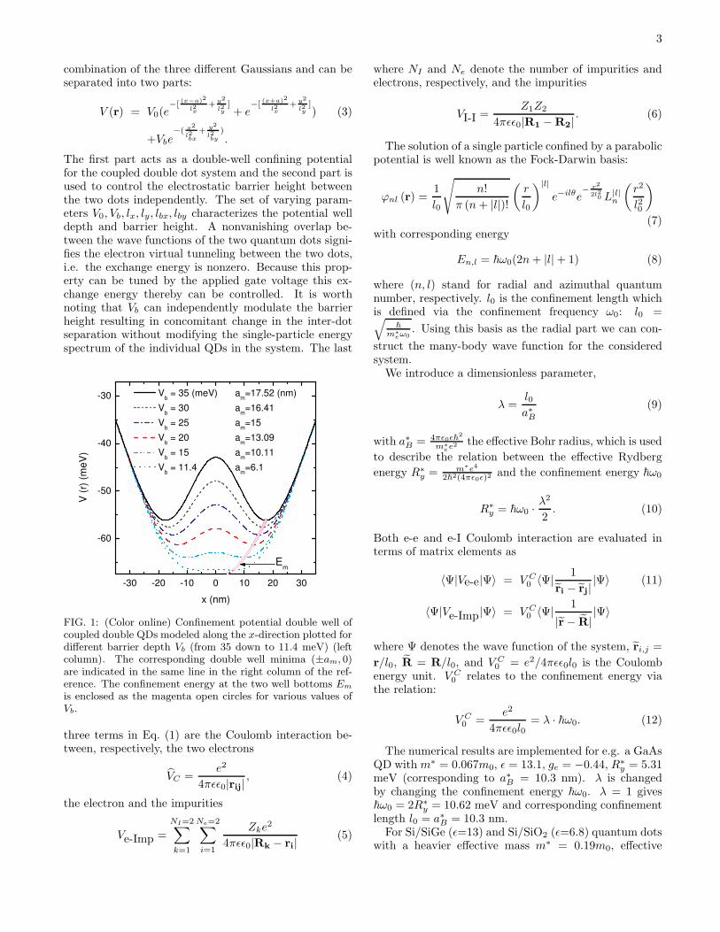
FIG. 2: (Color online) Agreement between theoretically per-turbative (red dash-dotted) and exact diagonalization (blacksolid) calculations in the shift of the ground-state energy dueto the presence of the impurity in single-electron (two uppercurves) and two-electron (two lower curves) QDs for λ = 0.1.The impurity effective charge is Z = −0.1. The inset showsaddition data for the case that λ is increased to 0.5 to exam-ine whether the perturbative calculations hold reliable. Thisenergy shift is identical to the binding energy of the systemand scaled to the Rydberg energy R∗
y = 5.31 meV for GaAsQDs.
The situation changes forNe = 2. The above conditionfor Ψ0 to be a single term is only satisfied when λ < 1.If so, the two electrons obeying Pauli exclusion principlewith spins antiparallel will mainly stay in the s-orbitalin case no impurity is present because their Coulombrepulsion is small as compared to the confining energy.The ground-state wave function is
|Ψ0 >= c†s↑c†s↓|0 > . (25)
Using this assumption, the total energy is estimated
theoretically for the single-electron QD:
E(Ne=1) = E0(Ne=1)+ 2
√πZλ~ω0e
R2
erfc(R)+O(Z2)
(26)and the two-electron QD:
E(Ne=2) = E0(Ne=2)+ 4
√πZλ~ω0e
R2
erfc(R)+O(Z2).
(27)We plotted in Fig. 2 the energy shift due to the pres-
ence of the impurity as a function of d using the abovetheoretical estimations (red dash-dotted) and the nu-merical results (black solid) for Z = 0.1 and λ = 0.1(l0 = 1.03nm and ~ω0 = 200R∗
y = 1.062eV) for Ne = 1(upper curves) and 2 (lower curves) electrons. Both the-oretical and numerical results are in good agreement.A small comment is made in case d is large. As seen
from Fig. 2, the e-I interaction goes to zero slowly whend increases to a relatively large value, say d > a∗B. The
answer lies in the product[eR
2 ·erfc(R) ]
where the ex-
ponential function increases in d competitively with thecomplementary error function which decreases in d.The first-order perturbation theory works very well as
long as Z < 1 and λ is small enough. Because if λ in-creases different e-I couplings of different configurationswill occur which result in the presence of a substantialnumber of nonzero off-diagonal terms. This fact leadsto an increasing difference between the first-order cal-culations and the numerical results. For example, inthe two-electron QD as plotted in the inset of Fig. 2,
this difference for R = 0, which is also the largestvalue, is about 6% when λ increases to 0.5. This 6%come from the configurations with minor contributions(n1 = 1, l1 = 0;n2 = 1, l2 = 0), (0,1;0,-1), etc. n1, l1 andn2, l2 are the radial and azimuthal quantum numbers ofthe two electrons.Practically, one often has GaAs QDs with λ > 1 i.e.
larger QDs need to be considered. To describe such QDs,numerical calculations are used for different values of λ.Here, we examine the case of λ = 2 which has l0 = 2a∗B =20.6 nm and the corresponding ~ω0 = R∗
y/2 = 2.655
meV. The Coulomb interaction unit (V C0 = 5.31 meV) insuch a QD system is (2 times) larger than the confiningenergy ~ω0.
B. Singlet-triplet splitting energy
The Coulomb interaction between the QD electronsstrongly competes with the confining energy and withthe e-I interaction as Z and/or λ increase. Increasing λmeans that the confining energy becomes smaller withrespect to the Coulomb interaction. As a result, elec-trons start to occupy higher Fock-Darwin levels. At zeroB-field and in the absence of impurity, the ground stateconsists of several Fock-Darwin states where the dom-inant component is the s-wave term. In the presenceof a charged impurity, those electron configurations that

7
1.0 1.2 1.4 1.6 1.8 2.0
0.2
0.4
0.6
0.8
1.0
1.2
-1.0 -0.5 0.0 0.5 1.0
0.2
0.4
0.6
0.8
split
ting (
R* y)
λ
Z=-0.1
Z= 0
Z= 0.1
d=0
(a)
split
ting (
R* y)
Z
d=0
λ=2
(b)
FIG. 3: Splitting energy of the two lowest singlet and tripletenergy levels as a function of (a) Coulomb interaction strengthλ for three different Z=-0.1 (blue dashed-dot), 0 (black solid),and 0.1 (dash-dotted dot) and (b) impurity effective chargeZ within the range (-1,1) for the case λ = 2. The impurity islocated at the origin of the single two-electron QD: d=0.
fulfill L=const form different L-subgroups with nonzerocontributions to the total wave function of the system.Increasing the effective charge Z results in a strong mix-ing between those subgroups. Consequently, there aremore than 1 state which play as dominant components tothe total wave function. We plot in Figs. 3(a) and (b), re-spectively, the splitting energy between the ground state(singlet) and the first excited state (triplet) as a func-tion of λ and Z in case the impurity is located at thecenter of the single QD. As λ increases [see Fig. 3(a)],the splitting becomes smaller for both with and withoutimpurity cases. It is because the singlet and the tripletstates have many similar nonzero configurations. Detailsare found below from the discussion for particular val-ues of Z. From Fig. 3(a) we also notice that the energysplitting shift due to the presence of the impurity remainsalmost unchanged by changing λ for both cases Z = −0.1(blue dashed dot) and Z = 0.1 (red dash-dotted-dot). Itis because the impurity location is examined at the cen-ter of the QD d=0. Such splitting shift will change ifthe impurity is displaced to any other off-center positiond 6= 0.The Z-dependence of the splitting energy in Fig. 3(b)
for λ = 2 shows a continuous decrease as Z changes itssign from negative (-1,0) to positive (0,1). The decrease issignificant around Z=-1 which coincides with the physicsdiscussed above for the negative Z=-0.1 and -1 cases.It is found that for Z = −0.1 and −1 the ground state
and the first-excited state in the two-electron QD con-taining a single charged impurity are the singlet and thetriplet, respectively. Their major components are, re-spectively, the s-s and the s-p configuration, i.e. oneelectron is in the s- and the other in the s-(p-)orbital.Note that the s-s overlap has only one maximum at theorigin. In opposite, the s-p overlap exhibits a minimumat the origin.With changing the position of the impurity, the energy
spin splitting of the singlet-triplet states is obtained in
0 1 2 3 4 5
0.21
0.22
0.23
0.24
0 1 2 3 4 5
0.3
0.6
0.9
0 1 2 3 4 5
0.18
0.19
0.20
0.21
0 1 2 3 4 5
0.1
0.2
sp
littin
g (
R* y)
d (a*
B)
Z=-0.1
(a)
sp
littin
g (
R* y)
d (a*
B)
Z=-1
(b)
sp
littin
g (
R* y)
d (a*
B)
Z=0.1
(c)
sp
littin
g (
R* y)
d (a*
B)
Z=1
(d)
FIG. 4: Splitting of the two lowest singlet and triplet statesas a function of the impurity position in a two-electron singleQD for four different effective charges of the impurity (a) Z =−0.1, (b) -1, (c) 0.1, and (d) 1 in case λ = 2 (~ω0 = 2R∗
y/4 =2.655 meV). Dotted lines are the data obtained for the zeroeffective charge case (Z = 0) for reference.
Fig. 4(a) for Z=-0.1 and Fig. 4(b) for Z=-1. The pres-ence of the impurity results in an increase in the splittingwhich is largest when the impurity is located at the cen-ter of the dot [as illustrated in Fig. 4(a) and Fig. 4(b) forZ = 0 (dot lines) and for Z < 0 (solid lines)].
The magnitude of the splitting over an impurity charge
unit[ (EI1 − EI0
)≡ splitting
]/Z, with EI0,1 the energy of
the ground state and the first excited state in the dopedQD, is found smaller for the larger Z case [see Figs. 4(a)and (b)] for a certain d value. This means that the e-Iattraction becomes dominant over the e-e Coulomb inter-action. As a result, each state consists of different config-urations with compatible contributions to the total wavefunction. For example, by increasing the e-I effectivestrength from Z = −0.1 [Fig. 4(a)] to Z = −1 [Fig. 4(b)]the contribution of the singlet s-configuration decreasesfrom C2
0 ≈ 0.83 to respectively C20 ≈ 0.64. The com-
pensatory parts come from other configurations whichalso have L = 0 such as (n1 = 0, l1 = 0;n2 = 1, l2 = 0),(0,0;2,0), (0,0;3,0), etc. Those states stay closer in energywith increasing λ (= 2 in this case).
Above we discussed the impurity effect for an attrac-tive impurity (positively charged Z <0). A negativelycharged impurity which induces a repulsive coupling withelectron is examined in Figs. 4(c) and (d) for two effectivecharges Z=0.1 and Z=1. The splitting energy betweenthe ground state singlet and the first excited triplet isplotted as a function of the impurity position d. Ap-parently, when the impurity is found at the origin d=0,it repels the two electrons most. The probability of theelectrons to be found at the origin (s-orbital) reducessignificantly. In this case, the electrons can be found
8
at other higher Fock-Darwin states. This means thatthe ground state energy becomes closer in energy to thefirst excited state. That explains a smaller splitting en-ergy we obtain for Z=0.1 [see Fig. 4(c)] and Z=1 [seeFig. 4(d)] as compared to, respectively, the cases Z=-0.1[see Fig. 4(a)] and Z=-1 [see Fig. 4(b)]. Moreover, wesee from Figs. 4(c) and (d) that when the impurity ismoved away from the center of the QD, the splitting en-ergy starts to increase. In other words, the probabilityof finding the electrons in the s-orbital increases.
C. Impurity effect on the energy spectrum
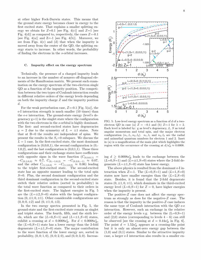
Technically, the presence of a charged impurity leadsto an increase in the number of nonzero off-diagonal ele-ments of the Hamiltonian matrix. We present such exam-ination on the energy spectrum of the two-electron singleQD as a function of the impurity position. The competi-tion between the two types of Coulomb interaction resultsin different relative orders of the energy levels dependingon both the impurity charge Z and the impurity positiond.For the weak perturbation case, Z=-0.1 [Fig. 5(a)], the
e-I interaction strength is much smaller (10 times) thanthe e-e interaction. The ground-state energy (level’s de-generacy g=1) is the singlet state where the configurationwith the two electrons in the s-orbital is highly dominant.The first- and second-excited states have degeneraciesg = 2 due to the symmetry of L = ±1 states. Notethat at B=0 the results are independent of spins. Wepresent the results in the Sz=0 subspace. We discuss theL = 1 case. In the first-excited state, the most dominantconfiguration is (0,0;0,1), the second configuration is (0,-1;0,2), and the last configuration is (0,0;1,1). These threeconfigurations and their exchange states have coefficientswith opposite signs in the wave function (C(0,0;0,1) =−C(0,1;0,0) ≈ 0.7, C(0,−1;0,2) = −C(0,2;0,−1) ≈ 0.07,and the other C(1,1;0,0) = −C(1,1;0,0) ≈ 0.06) leadingto the triplet first-excited state. The second-excitedstate has an opposite manner leading to the total spinS=0. Plus, the second dominant configuration and thethird dominant configuration in the second-excited stateswitch their relative orders (sorted in probability) inthe total wave function as compared to their orders inthe first-excited state. The highest energies in Fig. 5are the (L=±2,S=0) states with the largest configura-tion (0,±1; 0,±1). Other considerable configurations are(0, 0; 0,±2) and (0,∓1; 0,±3).In the two energy spectra presented in Fig. 5, the
ground-state and the first-excited state remain as singletand triplet states. The fourth, fifth, and the sixth lev-els, which are the (L=0,S=1) and (L=±1,S=0) states,exhibit a crossing at d = 0.0008a∗B. For d < 0.0008a∗B,the (L=0,S=1) state has a lower energy than the 2-folddegenerate (L=±1,S=0) state. The major contributionto the wave function of the lower energy are, sorted inprobability, (0, 0; 1, 0), (0, 0; 2, 0), and (0, 0; 3, 0). Increas-
0 1 2 3 4 5
-2
-1
0
1
0.0000 0.0005 0.0010
-1.026
-1.023
0 1 2 3 4 5
1.5
2.0
2.5
Energ
y (
R* y)
d (a*
B)
L=0,S=0; (0,0;0,0)
L=|1|,S=1; (0,0;0,|1|)
g=1
g=2
L=|1|,S=0; (0,0;0,|1|)
L=0,S=1; (0,0;1,0)
g=2
g=1
(b) Z=-1
L=0,S=1; g=1
L=1,S=0g=2
L=0,S=1
L=1,S=0
g=1
g=2
Energ
y (
R* y)
d (a*
B)
L=0,S=0; (0,0;0,0)
L=|1|,S=1; (0,0;0,|1|)
g=1
g=2
g=2
g=2
L=|1|,S=0; (0,0;0,|1|)
L=|2|,S=0; (0,|1|;0,|1|)
(a) Z=-0.1
FIG. 5: Low-level energy spectrum as a function of d of a two-electron QD in case (a) Z = −0.1 and (b) Z=-1 for λ = 2.Each level is labeled by: g as level’s degeneracy, L, S as totalangular momentum and total spin, and the major electronconfiguration (n1, l1, n2, l2). n1, l1 and n2, l2 are the radialand azimuthal quantum numbers for electron 1 and 2. Insetin (a) is a magnification of the main plot which highlights theregion with the occurrence of the crossing at d/a∗B ≈ 0.0008.
ing d ≥ 0.0008a∗B leads to the exchange between the(L=0,S=1) and (L=±1,S=0) states where the 2-fold de-generate (L=±1,S=0) state has lower energy.The above physics is resulted from the dominant e-I in-
teraction when Z=-1. The (L=0,S=1) and (L=1,S=0)states now have smaller energies than the (L=2,S=0)state. Besides, it is found that the 2-fold degeneratestates (0,±1, 0,∓1), which dominate in the third-excitedenergy level (L=0,S=1) for Z = 0, have higher energieswhen the impurity is present.The positive-Z case does not affect the energy spec-
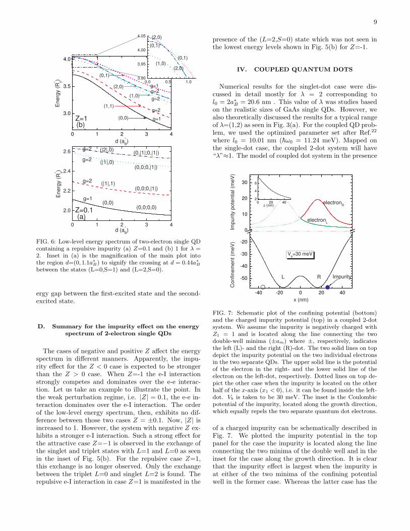
trum as strongly as does for the negative-Z case. Thereason is that the impurity in the positive-Z case inducesthe same type of Coulomb interaction with the QD e-einteraction. However, such an exchange in the relativeorder of the energy levels e.g. between the (L=0,S=1)and (2,0) states (corresponding to levels 4 − 6) can stillbe observed [see the crossing at d = 0.44a∗B in Fig. 6].The point d = 1.52a∗B appears as a crossing-like pointbut it is only an almost-zero energy gap between the(1,0) and (0,1) states. Similar to the attractive impuritycase, a larger e-I interaction also results in a smaller en-
9
0 1 2 3 4
3.0
3.5
4.0
0.0 0.5 1.03.90
3.95
4.00
4.05
0 1 2 3 4
2.0
2.2
2.4
2.6
d (a*
B)
En
erg
y (
R* y)
g=2
g=1
g=2
g=2g=1
(0,0)
(1,1)
(1,0)
(0,1)
(2,0)
(b)Z=1
(1,0)
(0,1)
(2,0)
(0,1)
(2,0)
En
erg
y (
R* y)
d (a*
B)
Z=0.1(0,0)
(|1|,1)
(|1|,0)
(|2|,0)
g=2
g=2
g=2
g=1
(0,0;0,0)
(0,0;0,|1|)
(0,0;0,|1|)
(0,|1|;0,|1|)
(a)
FIG. 6: Low-level energy spectrum of two-electron single QDcontaining a repulsive impurity (a) Z=0.1 and (b) 1 for λ =2. Inset in (a) is the magnification of the main plot intothe region d=(0, 1.1a∗B) to signify the crossing at d = 0.44a∗Bbetween the states (L=0,S=1) and (L=2,S=0).
ergy gap between the first-excited state and the second-excited state.
D. Summary for the impurity effect on the energyspectrum of 2-electron single QDs
The cases of negative and positive Z affect the energyspectrum in different manners. Apparently, the impu-rity effect for the Z < 0 case is expected to be strongerthan the Z > 0 case. When Z=-1 the e-I interactionstrongly competes and dominates over the e-e interac-tion. Let us take an example to illustrate the point. Inthe weak perturbation regime, i.e. |Z| = 0.1, the e-e in-teraction dominates over the e-I interaction. The orderof the low-level energy spectrum, then, exhibits no dif-ference between those two cases Z = ±0.1. Now, |Z| isincreased to 1. However, the system with negative Z ex-hibits a stronger e-I interaction. Such a strong effect forthe attractive case Z=−1 is observed in the exchange ofthe singlet and triplet states with L=1 and L=0 as seenin the inset of Fig. 5(b). For the repulsive case Z=1,this exchange is no longer observed. Only the exchangebetween the triplet L=0 and singlet L=2 is found. Therepulsive e-I interaction in case Z=1 is manifested in the
presence of the (L=2,S=0) state which was not seen inthe lowest energy levels shown in Fig. 5(b) for Z=-1.
IV. COUPLED QUANTUM DOTS
Numerical results for the singlet-dot case were dis-cussed in detail mostly for λ = 2 corresponding tol0 = 2a∗B = 20.6 nm . This value of λ was studies basedon the realistic sizes of GaAs single QDs. However, wealso theoretically discussed the results for a typical rangeof λ=(1,2) as seen in Fig. 3(a). For the coupled QD prob-lem, we used the optimized parameter set after Ref.22
where l0 = 10.01 nm (~ω0 = 11.24 meV). Mapped onthe single-dot case, the coupled 2-dot system will have“λ”≈1. The model of coupled dot system in the presence
-40 -20 0 20 40
-50
-40
-30
-20
0
10
20
30
0 20 402
4
6
C
on
fin
em
en
t (m
eV
) Im
pu
rity
po
ten
tia
l (m
eV
)
x (nm)
electronR
electronL
L R Impurity
Vb=30 meV
z (nm)
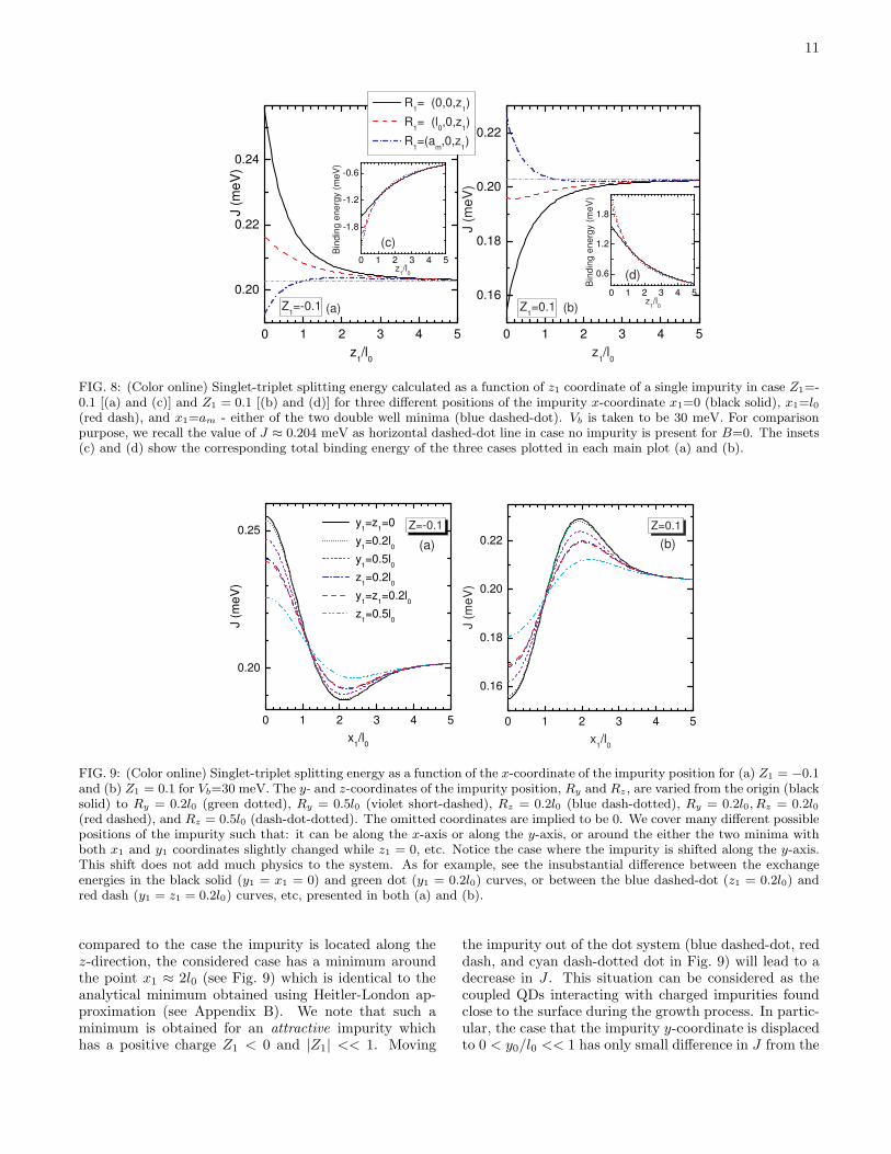
FIG. 7: Schematic plot of the confining potential (bottom)and the charged impurity potential (top) in a coupled 2-dotsystem. We assume the impurity is negatively charged withZ1 = 1 and is located along the line connecting the twodouble-well minima (±am) where ±, respectively, indicatesthe left (L)- and the right (R)-dot. The two solid lines on topdepict the impurity potential on the two individual electronsin the two separate QDs. The upper solid line is the potentialof the electron in the right- and the lower solid line of theelectron on the left-dot, respectively. Dotted lines on top de-pict the other case when the impurity is located on the otherhalf of the x-axis (x1 < 0), i.e. it can be found inside the left-dot. Vb is taken to be 30 meV. The inset is the Coulombicpotential of the impurity, located along the growth direction,which equally repels the two separate quantum dot electrons.
of a charged impurity can be schematically described inFig. 7. We plotted the impurity potential in the toppanel for the case the impurity is located along the lineconnecting the two minima of the double well and in theinset for the case along the growth direction. It is clearthat the impurity effect is largest when the impurity isat either of the two minima of the confining potentialwell in the former case. Whereas the latter case has the

10
largest impurity effect when the impurity is found at cen-ter of the system, i.e. R=0. We label the two impuritycoordinates as R1(2)=(x1(2), y1(2), z1(2)).
A. Singlet-triplet splitting
1. Impurity position dependence
In the coupled QD system without impurity and with-out magnetic field (B=0), the two lowest energy levelsare the maximally entangled exchange spin states, re-spectively, the singlet ΨS1 and the triplet ΨT . The nexthigher excited states are the linear combination of thetwo doubly-occupied singlets which result in “bonding”
(ψS
2 +ψS3√
2) and “anti-bonding” (
ψS2 −ψS
3√2
) states.
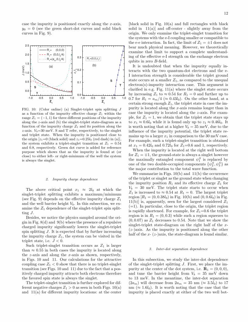
Let us first consider the simplest case when the systemcontains only a single charged impurity R1 = (x1, y1, z1)(effective charge Z1) and the impurity plays only as aweak perturbation to the coupled dot system. However,there will be no restriction to the impurity location in oroutside the system. Such a system allows us to provide adirect comparison to the single-dot case discussed earlier.In case the e-I interaction is attractive coupling, i.e.
Z1 < 0, the singlet-triplet exchange energy J is shownin Fig. 8(a). When the impurity is located along the z-axis [see the black solid curve in Fig. 8(a)], the presenceof the impurity increases the singlet-triplet spin split-ting J between the two electrons as compared to thecase when no impurity is present [see horizontal grey dotcurve in Fig. 8(a)]. This is understood as both electronsare attracted toward the impurity. Because the impurityequally couples to the electrons, the system favors theantiparallel electron spin state. This type of e-I couplingreduces the total energy of the system [negative bindingenergy presented as black solid in Fig. 8(c)]. As the im-purity is moved away from the origin [z1 6= 0 - still theblack solid curve in Fig. 8(a)], J will decrease. Such a de-crease can be evaluated via Eq. (A4) (see Appendix A) asthe product of an exponential and complementary errorfunction.When the impurity is located along the ‘z’-direction
of either the two separate dots, e.g. of the right-dot i.e.R1 = (am, 0, z1) [see red dash curve in Fig. 8(a)], J re-mains larger than the J for the case without impurityZ1 = 0. However, J behaves very differently from theabove two cases x1 = 0 and x1 = l0. The impuritynot only no longer attracts equally the two QD electrons(similar to the x1 = l0 case) but also affects the doubly-occupied states most. J in this case intersects the split-ting energy of the Z1 = 0 case at z1 ≈ l0. Close tothe QD sample, i.e. z1 << l0, J is always smaller thanthe splitting energy for the without impurity case, about10%. We reserve the detailed physical discussion around(±am, 0) for a later discussion when we examine the casethe impurity is located along the x-axis.We expect that a repulsive impurity induces an oppo-
site spin order of the two electron spin orientations: theparallel spin state. This is illustrated in Fig. 8(b). Aweakly repulsive impurity (Z1 = 0.1), located along thez-axis (black solid curve), has the smallest exchange en-ergy (≈ 0.17 meV) when it is, apparently, at the origin:z1 = 0. The reason is the impurity now repels both elec-trons. The e-I addition energy lifts up, ≈ few meV, thetotal energy of the coupled 2-dot system [see the posi-tive binding energy presented in Fig. 8(d)]. J rapidlyincreases and reaches the value of the non-impurity caseas the impurity is engineered relatively far from the ori-gin, say 3l0.
The ground state consists of all three Hund-Mullikensinglets, i.e. the total wave function ΨGS ={ψS1 , ψS2 , ψS3 }. However, two doubly occupied states playa small part, which are ≈ 2%, to the total wave function.
The binding energy of the impurity, which is definedas the energy difference of the system with and withouta charged impurity, shown in Figs. 8(c) and (d) was par-tially discussed above. In both cases Z1 = ∓0.1, aroundz1 = 0, the absolute value of the binding energy is foundlargest in case the impurity is placed closer to either ofthe two minima of the well (x1 = am): 2.2 meV as com-pared to 2 meV and 1.53 meV of the x1 = l0 and x1 = 0case, respectively. Beyond a critical z1, say z1 > 2l0the most dominant binding energy case (x1 = am - blacksolid curve) becomes less dominant and compatible to theother cases x1 = 0 and l0. All three curves in Figs. 8(c)and (d) convert to the situation without impurity at thelarge z1 limit.
Now, we consider the case when the impurity is foundinside the QD. In particular, we discuss the impurity ef-fect when the impurity is found on the x- or y-axis, alongwhich the confining potential is constructed.
Because the Z1 = ∓0.1 case was found to weakly affectthe quantum dot qubits and that the doubly-occupiedstates have very small contributions to the singlet-tripletsplitting, we can now use Heitler-London model to an-alytically check our numerical results. We found qual-itative agreement between the results presented in e.g.Fig. 9 and the analytical results shown in Eq. (B1),in particular the minimum (maximum) in J for Z=-0.1(0.1). Details are collected in Appendix B.
As signified in the top plot in Fig. 1, the absolute valueof the effective e-I coupling exhibits a maximum at the ei-ther of the two well minima and decreases rapidly as theimpurity position is out of the minima [analytical ma-trix elements are presented in Eq. (A5) in Appendix A].However, the overlap between the two coupled QDs hasa maximum at the origin (see e.g. Ref.23). In the weakimpurity perturbation, i.e. Z1 << 1, these two termscompete with each other. As a result, the singlet-tripletspin splitting J for Z1 = −0.1 has the impurity posi-tion dependence as shown in Fig. 9. J has a maximumat the origin where the overlap between the two coupleddots is largest and the binding energy exhibits a maxi-mum around x1 = 1.6l0 which is identical to the quasi-bottom positions of the left and the right dots ±a. As
11
0 1 2 3 4 5
0.20
0.22
0.24
0 1 2 3 4 5
0.16
0.18
0.20
0.22
0 1 2 3 4 5
-1.8
-1.2
-0.6
0 1 2 3 4 5
0.6
1.2
1.8
J (
me
V)
z1/l
0
Z1=-0.1
R1= (0,0,z
1)
R1= (l
0,0,z
1)
R1=(a
m,0,z
1)
(a)
J (
me
V)
z1/l
0
Z1=0.1 (b)
Bin
din
g e
nerg
y (
meV
)
z1/l
0
(c)
Bin
din
g e
nerg
y (
meV
)
z1/l
0
(d)
FIG. 8: (Color online) Singlet-triplet splitting energy calculated as a function of z1 coordinate of a single impurity in case Z1=-0.1 [(a) and (c)] and Z1 = 0.1 [(b) and (d)] for three different positions of the impurity x-coordinate x1=0 (black solid), x1=l0(red dash), and x1=am - either of the two double well minima (blue dashed-dot). Vb is taken to be 30 meV. For comparisonpurpose, we recall the value of J ≈ 0.204 meV as horizontal dashed-dot line in case no impurity is present for B=0. The insets(c) and (d) show the corresponding total binding energy of the three cases plotted in each main plot (a) and (b).
0 1 2 3 4 5
0.20
0.25
0 1 2 3 4 5
0.16
0.18
0.20
0.22
J (
me
V)
x1/l
0
y1=z
1=0
y1=0.2l
0
y1=0.5l
0
z1=0.2l
0
y1=z
1=0.2l
0
z1=0.5l
0
Z=-0.1
(a)
J (
me
V)
x1/l
0
Z=0.1
(b)
FIG. 9: (Color online) Singlet-triplet splitting energy as a function of the x-coordinate of the impurity position for (a) Z1 = −0.1and (b) Z1 = 0.1 for Vb=30 meV. The y- and z-coordinates of the impurity position, Ry and Rz, are varied from the origin (blacksolid) to Ry = 0.2l0 (green dotted), Ry = 0.5l0 (violet short-dashed), Rz = 0.2l0 (blue dash-dotted), Ry = 0.2l0, Rz = 0.2l0(red dashed), and Rz = 0.5l0 (dash-dot-dotted). The omitted coordinates are implied to be 0. We cover many different possiblepositions of the impurity such that: it can be along the x-axis or along the y-axis, or around the either the two minima withboth x1 and y1 coordinates slightly changed while z1 = 0, etc. Notice the case where the impurity is shifted along the y-axis.This shift does not add much physics to the system. As for example, see the insubstantial difference between the exchangeenergies in the black solid (y1 = x1 = 0) and green dot (y1 = 0.2l0) curves, or between the blue dashed-dot (z1 = 0.2l0) andred dash (y1 = z1 = 0.2l0) curves, etc, presented in both (a) and (b).
compared to the case the impurity is located along thez-direction, the considered case has a minimum aroundthe point x1 ≈ 2l0 (see Fig. 9) which is identical to theanalytical minimum obtained using Heitler-London ap-proximation (see Appendix B). We note that such aminimum is obtained for an attractive impurity whichhas a positive charge Z1 < 0 and |Z1| << 1. Moving
the impurity out of the dot system (blue dashed-dot, reddash, and cyan dash-dotted dot in Fig. 9) will lead to adecrease in J . This situation can be considered as thecoupled QDs interacting with charged impurities foundclose to the surface during the growth process. In partic-ular, the case that the impurity y-coordinate is displacedto 0 < y0/l0 << 1 has only small difference in J from the
12
case the impurity is positioned exactly along the x-axis,y0 = 0 (see the green short-dot curves and solid blackcurves in Fig. 9).
-1.0 -0.5 0.0 0.5 1.0
0.0
0.5
1.0
1.5
2.0
2.5
-1.0 -0.5 0.0 0.5 1.00.0
0.1
0.2
0.3
R1= (0,0,0)
R1= (0,0,l
0/4)
R1=(a
m,0,l
0/4)
J (
me
V)
Z1
T
S
(a)
z1/l
0
Z1
S
T
(b)
R1=(0,0,z
1)
FIG. 10: (Color online) (a) Singlet-triplet spin splitting Jas a function of the impurity effective charge Z1 within therange Z1 = (−1, 1) for three different positions of the impurityalong the z-axis and (b) the singlet-triplet state-diagram as afunction of the impurity charge Z1 and its position along thez-axis. Vb=30 meV. S and T refer, respectively, to the singletand triplet state. When the impurity is positioned close tothe origin [z1=0 (black solid) and z1=0.25l0 (red dash) in (a)],the system exhibits a triplet-singlet transition at Z1 = 0.54and 0.8, respectively. Green dot curve is added for referencepurpose which shows that as the impurity is found at (orclose) to either left- or right-minimum of the well the systemis always the singlet.
2. Impurity charge dependence
The above critical point x1 ≈ 2l0 at which thesinglet-triplet splitting exhibits a maximum/minimum(see Fig. 9) depends on the effective impurity charge Z1
and the well barrier height Vb. In this subsection, we ex-amine the Z1 dependence of the singlet-triplet spin split-ting J .Besides, we notice the physics sampled around the ori-
gin in Fig. 8(d) and 9(b) where the presence of a repulsivecharged impurity significantly lowers the singlet-tripletspin splitting J . It is expected that by further increasingthe impurity charge Z1, the system can be visited in thetriplet state, i.e. J < 0.Such triplet-singlet transition occurs as Z1 is larger
than ≈ 0.55 in both cases the impurity is located alongthe z-axis and along the x-axis as shown, respectively,in Figs. 10 and 11. Our calculations for the attractivecoupling case Z1 < 0 show that there is no triplet-singlettransition (see Figs. 10 and 11) due to the fact that a pos-itively charged impurity attracts both electrons thereforethe favored spin state is always the singlet.The triplet-singlet transition is further explored for dif-
ferent negative charges Z1 > 0 as seen in both Figs. 10(a)and 11(a) for different impurity locations: at the center
[black solid in Fig. 10(a) and full rectangles with blacksolid in 11(a)] and off-center - slightly away from theorigin. We only examine the triplet-singlet transition forthe systems with the e-I coupling smaller or compatible tothe e-e interaction. In fact, the limit of Z1 = ±1 does notbear much physical meaning. However, we theoreticallyexamine that limit to support a complete understand-ing of the effective e-I strength on the exchange electronqubits in zero B-field.It is undoubted that when the impurity equally in-
teracts with the two quantum-dot electrons and the e-I interaction strength is considerable the triplet groundstate occurs at a smaller Z1, as compared to the unequalelectron(s)-impurity interaction case. This argument isclarified in e.g. Fig. 11(a) where the singlet state occursby increasing Z1 to ≈ 0.54 for R1 = 0 and further up to0.7 for R1 = am/4 (≈ 0.43l0). On the other hand, at acertain strong enough Z1, the triplet state in case the im-purity is located along the x-axis remains longer than incase the impurity is located along the z-axis. For exam-ple, for Z1 = 1, we obtain that the triplet state stays upto x1 ≈ 0.6l0 while it is found only up to z1 ≈ 0.46l0. Itis worth noting that at a higher Vb = 35 meV, due to theinfluence of the impurity potential, the triplet state re-mains up to a larger x1 in comparison to the 30 meV case.For example, such a triplet-singlet transition is obtainedat x1 = 0.42l0 and 0.72l0 for Z1=0.6 and 1, respectively.When the impurity is located at the right well bottom
for Z1 = ∓1, the ground-state is always a singlet howeverthe maximally entangled component ψS1 is replaced byone of the two double-occupied components {ψS2 , ψS3 } asthe major contribution to the total wave function.We summarize in Figs. 10(b) and 11(b) the occurrence
of the triplet or singlet as the ground state when changingthe impurity position R1 and its effective charge Z1 forVb = 30 meV. The triplet state starts to occur whenZ1 is increased to ≈ 0.54 at R1 = 0. The largest tripletregion [R1 = (0, 0.38l0) in Fig. 10(b) and (0, 0.6l0) in Fig.11(b)] is, apparently, seen for the largest considered Z1
(=1). In particular, close to the origin, the triplet regionis rapidly shortened. For example, for Z1=0.6 the tripletregion is in R1 = (0, 0.3) while such a region squeezes to(0, 0.07) as Z1 decreases to 0.54. Note that we show thesinglet-triplet state-diagram on the right half of the x-(z-)axis. As the impurity is positioned along the otherhalf of the x- (z-)axis, the state-diagram is found similar.
3. Inter-dot separation dependence
In this subsection, we study the inter-dot dependenceof the singlet-triplet splitting J . First, we place the im-purity at the center of the dot system, i.e. R1 = (0, 0, 0),and tune the barrier height from Vb = 35 meV downto 13 meV. In the meantime, the inter-dot separation(2am) will decrease from 2am = 35 nm (≈ 3.5l0) to 17nm (≈ 1.6l0). It is worth noting that the case that theimpurity is placed exactly at either of the two well bot-

13
-1.0 -0.5 0.0 0.5 1.0
0.0
0.2
0.4
0.6
0.8
-1.0 -0.5 0.0 0.5 1.00.0
0.1
0.2
0.3
0.4
0.5
J (
me
V)
Z1
R1= (0,0,0)
R1=(a
m/4,0,0)
(a)
T
S
x1/l
0
Z1
(b)
S T
FIG. 11: (Color online) (a) Singlet-triplet spin splitting of a coupled 2-dot system as a function of the effective charge Z1 withinthe range −1 < Z1 < 1 for x1 = 0 (full squares with black solid) and x1 = am/4 (full circles with red solid). (b) Singlet-tripletstate-diagram plotted in the impurity-position−effective-charge R1−Z1 plane. Vb is taken to be 30 meV. Horizontal dot line in(a) is used to clarify the triplet-singlet transition. In the region close to the center of the system, at ≈ 0.07l0 (about 0.04am), arelatively large repulsive impurity potential, say Z1 = 0.54, is enough to induce a triplet-singlet transition [see the state-diagram(b)]. The stronger the effective charge, the broader the triplet region. Consequently, when moving the impurity close to theright bottom it requires a larger Z1 to observe the triplet-singlet transition occur. S and T stands, respectively, for the singletand triplet state.
2.0 2.5 3.0 3.5
0.5
1.0
1.5
2.0
3.2 3.4
0.1
0.2
0.3
no impurity R1=(0,0,0)
R1=(0.5l
0,0,0)
R1=(0.7l
0,0,0)
R1=(l
0,0,0)
R1=(1.5l
0,0,0)
R1=(2l
0,0,0)
R1=(2.5l
0,0,0)
R1=(3l
0,0,0)J
(m
eV
)
2am/l
0
high Vb
FIG. 12: (Color online) Singlet-triplet splitting energy J cal-culated as a function of the inter-dot separation 2am for dif-ferent positions of the impurity when it is located along thex-axis for Z1=-0.1, Z2=0. We added data in case no impu-rity is present as the open squares with magenta dash line.Because Vb changes (from 35 meV down to 13 meV) effec-tively controlling the inter-dot separation, i.e. am, while theimpurity position should be fixed during the Vb modification,we examine different locations of the impurity. Several ex-amples of corresponding (Vb, 2am) are (35 meV, 3.5l0), (30meV, 3.3l0), and (25 meV, 2l0). Inset is the magnification ofthe region sampled by the big open circle for high-Vb-limit.
toms does not have any physical meaning in this casebecause the bottoms of the double-well change concomi-tantly with Vb changing (see Fig. 1). In fact, the im-
2.0 2.5 3.0 3.5
0.5
1.0
1.5
3.2 3.4
0.1
0.2
0.3
no impurity R1=(0,0,0)
R1=(0.5l
0,0,0)
R1=(0.7l
0,0,0)
R1=(l
0,0,0)
R1=(1.5l
0,0,0)
R1=(2l
0,0,0)
R1=(2.5l
0,0,0)
R1=(3l
0,0,0)J
(m
eV
)
2am/l
0
high Vb
FIG. 13: (Color online) The same plot as Fig. 12 for Z1 =0.1. As the impurity position is engineered further away fromthe origin, the double-dot system reveals crossings betweendifferent J for different R1.
purity position should be fixed thus its position onlyvaries relatively with respect to the double-well minimaof different-Vb systems. Consequently, different-Vb 2-dotsystems exhibit various impurity effect on J . We obtainthe inter-dot separation dependence of the singlet-tripletspin splitting J for Z1 = −0.1 in Fig. 12 and Z1=0.1 inFig. 13.
For Z1 = −0.1, the splitting energy J becomes smalleras the inter-dot separation increases (see Fig. 12). How-ever, J is found larger than that of the case withoutcharged impurity as illustrated in e.g. the full rectan-
14
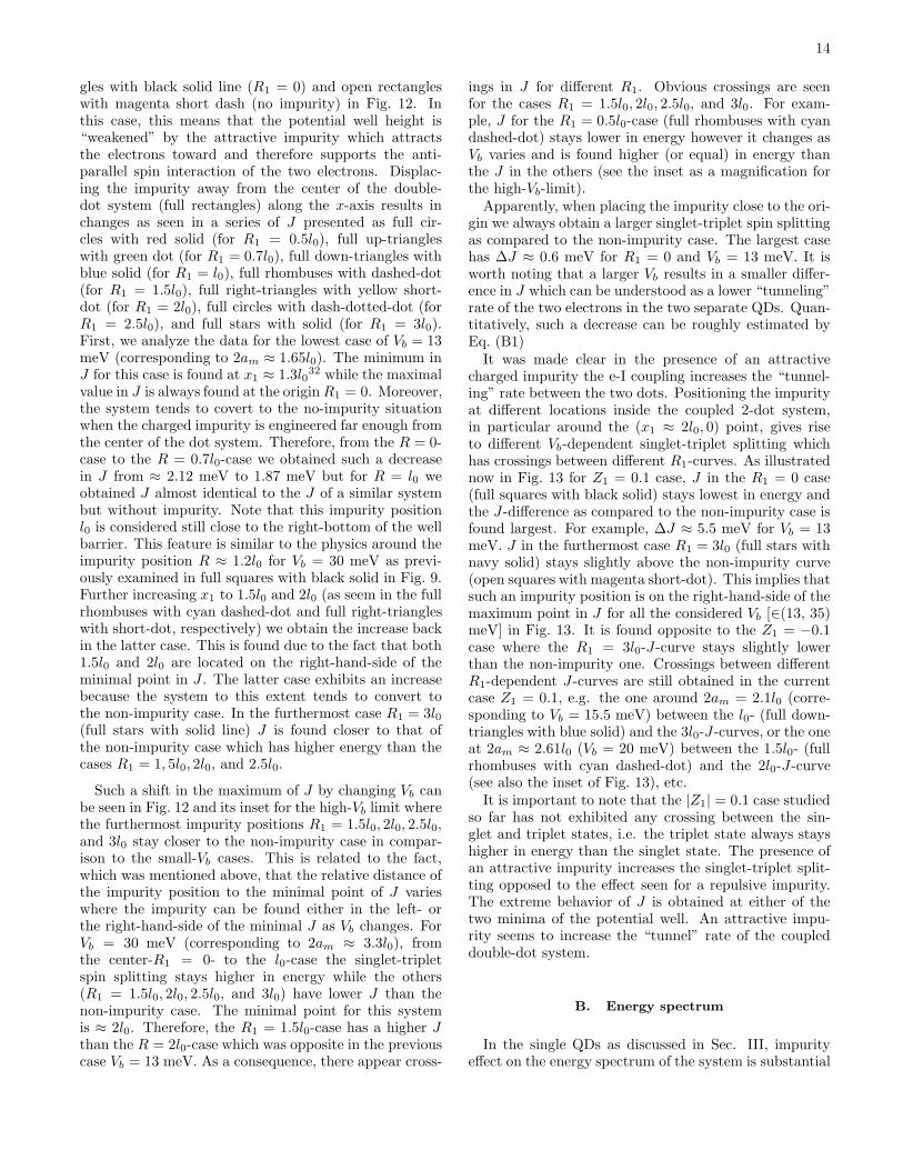
gles with black solid line (R1 = 0) and open rectangleswith magenta short dash (no impurity) in Fig. 12. Inthis case, this means that the potential well height is“weakened” by the attractive impurity which attractsthe electrons toward and therefore supports the anti-parallel spin interaction of the two electrons. Displac-ing the impurity away from the center of the double-dot system (full rectangles) along the x-axis results inchanges as seen in a series of J presented as full cir-cles with red solid (for R1 = 0.5l0), full up-triangleswith green dot (for R1 = 0.7l0), full down-triangles withblue solid (for R1 = l0), full rhombuses with dashed-dot(for R1 = 1.5l0), full right-triangles with yellow short-dot (for R1 = 2l0), full circles with dash-dotted-dot (forR1 = 2.5l0), and full stars with solid (for R1 = 3l0).First, we analyze the data for the lowest case of Vb = 13meV (corresponding to 2am ≈ 1.65l0). The minimum inJ for this case is found at x1 ≈ 1.3l0
32 while the maximalvalue in J is always found at the originR1 = 0. Moreover,the system tends to covert to the no-impurity situationwhen the charged impurity is engineered far enough fromthe center of the dot system. Therefore, from the R = 0-case to the R = 0.7l0-case we obtained such a decreasein J from ≈ 2.12 meV to 1.87 meV but for R = l0 weobtained J almost identical to the J of a similar systembut without impurity. Note that this impurity positionl0 is considered still close to the right-bottom of the wellbarrier. This feature is similar to the physics around theimpurity position R ≈ 1.2l0 for Vb = 30 meV as previ-ously examined in full squares with black solid in Fig. 9.Further increasing x1 to 1.5l0 and 2l0 (as seem in the fullrhombuses with cyan dashed-dot and full right-triangleswith short-dot, respectively) we obtain the increase backin the latter case. This is found due to the fact that both1.5l0 and 2l0 are located on the right-hand-side of theminimal point in J . The latter case exhibits an increasebecause the system to this extent tends to convert tothe non-impurity case. In the furthermost case R1 = 3l0(full stars with solid line) J is found closer to that ofthe non-impurity case which has higher energy than thecases R1 = 1, 5l0, 2l0, and 2.5l0.
Such a shift in the maximum of J by changing Vb canbe seen in Fig. 12 and its inset for the high-Vb limit wherethe furthermost impurity positions R1 = 1.5l0, 2l0, 2.5l0,and 3l0 stay closer to the non-impurity case in compar-ison to the small-Vb cases. This is related to the fact,which was mentioned above, that the relative distance ofthe impurity position to the minimal point of J varieswhere the impurity can be found either in the left- orthe right-hand-side of the minimal J as Vb changes. ForVb = 30 meV (corresponding to 2am ≈ 3.3l0), fromthe center-R1 = 0- to the l0-case the singlet-tripletspin splitting stays higher in energy while the others(R1 = 1.5l0, 2l0, 2.5l0, and 3l0) have lower J than thenon-impurity case. The minimal point for this systemis ≈ 2l0. Therefore, the R1 = 1.5l0-case has a higher Jthan the R = 2l0-case which was opposite in the previouscase Vb = 13 meV. As a consequence, there appear cross-
ings in J for different R1. Obvious crossings are seenfor the cases R1 = 1.5l0, 2l0, 2.5l0, and 3l0. For exam-ple, J for the R1 = 0.5l0-case (full rhombuses with cyandashed-dot) stays lower in energy however it changes asVb varies and is found higher (or equal) in energy thanthe J in the others (see the inset as a magnification forthe high-Vb-limit).Apparently, when placing the impurity close to the ori-
gin we always obtain a larger singlet-triplet spin splittingas compared to the non-impurity case. The largest casehas ∆J ≈ 0.6 meV for R1 = 0 and Vb = 13 meV. It isworth noting that a larger Vb results in a smaller differ-ence in J which can be understood as a lower “tunneling”rate of the two electrons in the two separate QDs. Quan-titatively, such a decrease can be roughly estimated byEq. (B1)It was made clear in the presence of an attractive
charged impurity the e-I coupling increases the “tunnel-ing” rate between the two dots. Positioning the impurityat different locations inside the coupled 2-dot system,in particular around the (x1 ≈ 2l0, 0) point, gives riseto different Vb-dependent singlet-triplet splitting whichhas crossings between different R1-curves. As illustratednow in Fig. 13 for Z1 = 0.1 case, J in the R1 = 0 case(full squares with black solid) stays lowest in energy andthe J-difference as compared to the non-impurity case isfound largest. For example, ∆J ≈ 5.5 meV for Vb = 13meV. J in the furthermost case R1 = 3l0 (full stars withnavy solid) stays slightly above the non-impurity curve(open squares with magenta short-dot). This implies thatsuch an impurity position is on the right-hand-side of themaximum point in J for all the considered Vb [∈(13, 35)meV] in Fig. 13. It is found opposite to the Z1 = −0.1case where the R1 = 3l0-J-curve stays slightly lowerthan the non-impurity one. Crossings between differentR1-dependent J-curves are still obtained in the currentcase Z1 = 0.1, e.g. the one around 2am = 2.1l0 (corre-sponding to Vb = 15.5 meV) between the l0- (full down-triangles with blue solid) and the 3l0-J-curves, or the oneat 2am ≈ 2.61l0 (Vb = 20 meV) between the 1.5l0- (fullrhombuses with cyan dashed-dot) and the 2l0-J-curve(see also the inset of Fig. 13), etc.It is important to note that the |Z1| = 0.1 case studied
so far has not exhibited any crossing between the sin-glet and triplet states, i.e. the triplet state always stayshigher in energy than the singlet state. The presence ofan attractive impurity increases the singlet-triplet split-ting opposed to the effect seen for a repulsive impurity.The extreme behavior of J is obtained at either of thetwo minima of the potential well. An attractive impu-rity seems to increase the “tunnel” rate of the coupleddouble-dot system.
B. Energy spectrum
In the single QDs as discussed in Sec. III, impurityeffect on the energy spectrum of the system is substantial
15
0.0 0.5 1.0 1.5 2.0 2.5 3.0
-88
-86
-78
0.0 0.5 1.0 1.5 2.0 2.5 3.0-90
-88
-86
-80
-78
En
erg
y (
me
V)
z1/l
0
R1= (0,0,z
1)
R1= (0.5l
0,0,z
1)
(a)
(b)
Z1= -0.1; Z
2=0
En
erg
y (
me
V)
x1/l
0
R1= (x
1,0,0)
R1= (x
1,0,0.5l
0)
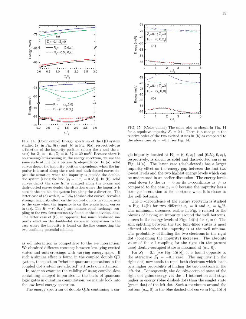
FIG. 14: (Color online) Energy spectrum of the QD systemstudied (a) in Fig. 8(a) and (b) in Fig. 9(a), respectively, asa function of the impurity position (along the z and the x-axis) for Z1 = −0.1, Z2 = 0. Vb = 30 meV. Because there isno crossing/anti-crossing in the energy spectrum, we use thesame style of line for a certain R1-dependence. In (a), solidcurves depict the impurity-position dependence when the im-purity is located along the z-axis and dash-dotted curves de-pict the situation when the impurity is outside the double-dot system [along the line (y1 = 0; x1 = 0.5l0)]. In (b), solidcurves depict the case R1 is changed along the x-axis anddash-dotted curves depict the situation where the impurity isoutside the double-dot system but along the x-direction. Thelatter case of (a) with x1 = 0.5l0 (dashed-dot curves) reveals astronger impurity effect on the coupled qubits in comparisonto the case when the impurity is on the z-axis [solid curvesin (a)]. The R1 = (0, 0, z1)-case induces equal exchange cou-pling to the two electrons mostly found on the individual dots.The latter case of (b), in opposite, has much weakened im-purity effect on the double-dot system in comparison to thecase where the impurity is found on the line connecting thetwo confining potential minima.
as e-I interaction is competitive to the e-e interaction.We obtained different crossings between low-lying excitedstates and anti-crossings with varying energy gaps. Ifsuch a similar effect is found in the coupled double QDsystem, the question “whether quantum operations in thecoupled dot system are affected” attracts our attention.In order to examine the validity of using coupled dots
containing charged impurities as the basis of quantumlogic gates in quantum computation, we mainly look intothe low-level energy spectrum.The energy spectrum of double QDs containing a sin-
0 1 2 3 4 5
-86
-84
-82
-80
-78
-76
-74
0 1 2 3 4 5
-86
-84
-82
-80
-78
-76
-74
En
erg
y (
me
V)
z1/l
0
Z1=0.1; Z
2=0
R1= (0,0,z
1)
(a)
Z1=0.1; Z
2=0
R1= (x
1,0,0)
En
erg
y (
me
V)
x1/l
0
(b)
FIG. 15: (Color online) The same plot as shown in Fig. 14for a repulsive impurity Z1 = 0.1. There is a change in therelative order of the two excited states in (b) as compared tothe above case Z1 = −0.1 (see Fig. 14).
gle impurity located at R1 = (0, 0, z1) and (0.5l0, 0, z1),respectively, is shown as solid and dash-dotted curve inFig. 14(a). The latter case (dash-dotted) has a largerimpurity effect on the energy gap between the first twolowest levels and the two highest energy levels which canbe understood in an earlier discussion. The energy levelsbend down to the z1 = 0 as its x-coordinate x1 6= ascompared to the case x1 = 0 because the impurity has astronger interaction to the electrons when it is closer tothe well bottoms.
The x1-dependence of the energy spectrum is studiedin Fig. 14(b) for two different z1 = 0 and z1 = l0/2.The minimum, discussed earlier in Fig. 9 related to thephysics of having an impurity around the well bottoms,is seen in the energy levels of Figs. 14(b) for z1 = 0. Thespin splitting between the two fully-filled states is mostaffected also when the impurity is at the well minima.The probability of finding the two electrons in the rightdot (containing the impurity) increases. The absolutevalue of the e-I coupling for the right (in the presentcase) doubly-occupied state is maximal at (am, 0).
For Z1 = 0.1 [see Fig. 15(b)], it is found opposite tothe attractive Z1 = −0.1 case. The impurity (in theright-dot) now tends to repel both electrons which leadsto a higher probability of finding the two electrons in theleft-dot. Consequently, the doubly-occupied state of theright-dot gains energy via the e-I interaction and stayshigher in energy (blue dashed-dot) than the singlet state(green dot) of the left-dot. Such a maximum around thebottom (am, 0) in the blue dashed-dot curve in Fig. 15(b)

16
has similar physics discussed earlier for Z1 = −0.1. Re-member that in the attractive case, the singlet-tripletspin splitting has a minimum around 2l0 (see Fig. 9)which is resulted due to i) the competition between thewave function overlap of the coupled 2-dots and the impu-rity potential on the right-dot electron and ii) the doubly-occupied states have relatively small contribution to thetotal singlet state (the ground state). Now, the effectivecharge changes its sign (0.1) and we obtain a maximum[see the inset of Fig. 15(b)]. The other left-dot fully occu-pied state [green dot in Fig. 15(b)] only shows a decreasein x1.
Even though the presence of the impurity changes thesinglet-triplet splitting as discussed above, the energy gap∆ǫ between the highest spin state that stores informationand the lowest unwanted state, in this case the first andthe second excited states, remains much larger than thesinglet-triplet splitting energy J . In case Vb = 30 meV,J/∆ǫ is typically ≤ 0.07. This means that adiabaticcondition is satisfied so that higher excited states are notinvolved when the system is evolved to its desired state.
C. Strong electron-impurity coupling destroyscoupled qubits
1. Strong perturbation
In the following, we discuss in detail the influence ofa strongly perturbative impurity on the energy spectrumfor Z1 = ∓1. Results for other intermediate Z1 (e.g.∓0.6, ∓0.8) are collected in Appendix C.
We plot in Fig. 16 the impurity-position dependence ofthe singlet-triplet spin splitting J when the impurity islocated along the z-axis for (a) Z1 = −1 and (b) Z1 = 1.The former case has a similarly qualitative curve to thecase Z1 = 0.1 with a much larger exchange energy J . Thelatter case has a triplet-singlet transition which occursat z1 = 0.38l0 as obtained already in the singlet-tripletstate-diagram Fig. 10(b). This property is resulted fromthe strong e-I interaction as Z1 is increased to 1.
For the case the impurity is located along the x-axisand Z1 = 1, we obtain in Fig. 17 and its inset the entiretriplet state for the case the impurity is engineered at theorigin or very close to the origin, say R1 < 0.6l0 (see theinset). The R1 = 0-case has the impurity that equallyrepels the two electrons in the two individual QDs andthe impurity is kept distant from the two well minima.As a result, the favored state becomes the triplet withtwo electron spins aligned parallel to each other. Movingthe impurity off-center means that there appears a biasin the impurity-electron coupling with the two electrons.Such a triplet state becomes weakened and disappearedwhen the bias increases to its maximum for the case theimpurity is found around the bottoms of the confiningpotential.
0 1 2 3 4
0.2
0.4
0.6
0.8
0 1 2 3 4-0.1
0.0
0.1
0.2
J (
meV
)
z1/l
0
(a)
Z1=-1
J (
meV
)
z1/l
0
(b)
Z1=1
T
S
FIG. 16: (Color online) Singlet-triplet spin splitting J calcu-lated as a function of the impurity position along the z-axisfor Z1=-1 (a) and 1 (b). Vb = 30 meV. S and T stand for,respectively, singlet and triplet. The horizontal dotted linein (b) is used to clarify the triplet and singlet states. Such atriplet-singlet transition is obtained at z1 = 0.3l0 for Z1=1.
0.0 0.5 1.0 1.5 2.0 2.5 3.0 3.5
0
1
2
3
4
5
6
0.0 0.5 1.0
0.0
0.5
1.0
J (
me
V)
x1/l
0
Z1=1
R1=(x
1,0,0)
T
S
FIG. 17: (Color online) Singlet-triplet spin splitting J of asingly-doped charged impurity coupled double-dot system asa function of the impurity position when it is located along thex-axis for Z1 = 1. Vb = 30 meV. Inset is the magnificationof the circled region in the main plot which highlights thetriplet-singlet transition in the small x1 region.
2. Destroy of coupled qubits
Impurity effect of small effective charges shown inFigs. 9 and 15 as discussed above for Z1 = ∓0.1 resultsin a relatively small coupling between the three Hund-Mulliken singlets in ground-state singlet. Quantitatively,the major (≈ 98%) component is the ψS1 therefore themixing of ψS1 with the other two singlets ψS2,3, with theprobability about 1% each, can be neglected. The consid-erable impurity effect is observed in the excited singletswhere such full bonding- and anti-bonding states are nolonger found at B=0 when the impurity is found in eitherof the two individual QDs. Plus, the probability of find-ing the electrons in a fully-occupied state is increased.In the next examination, we study the case when the
coupling between the electron and the impurity is com-
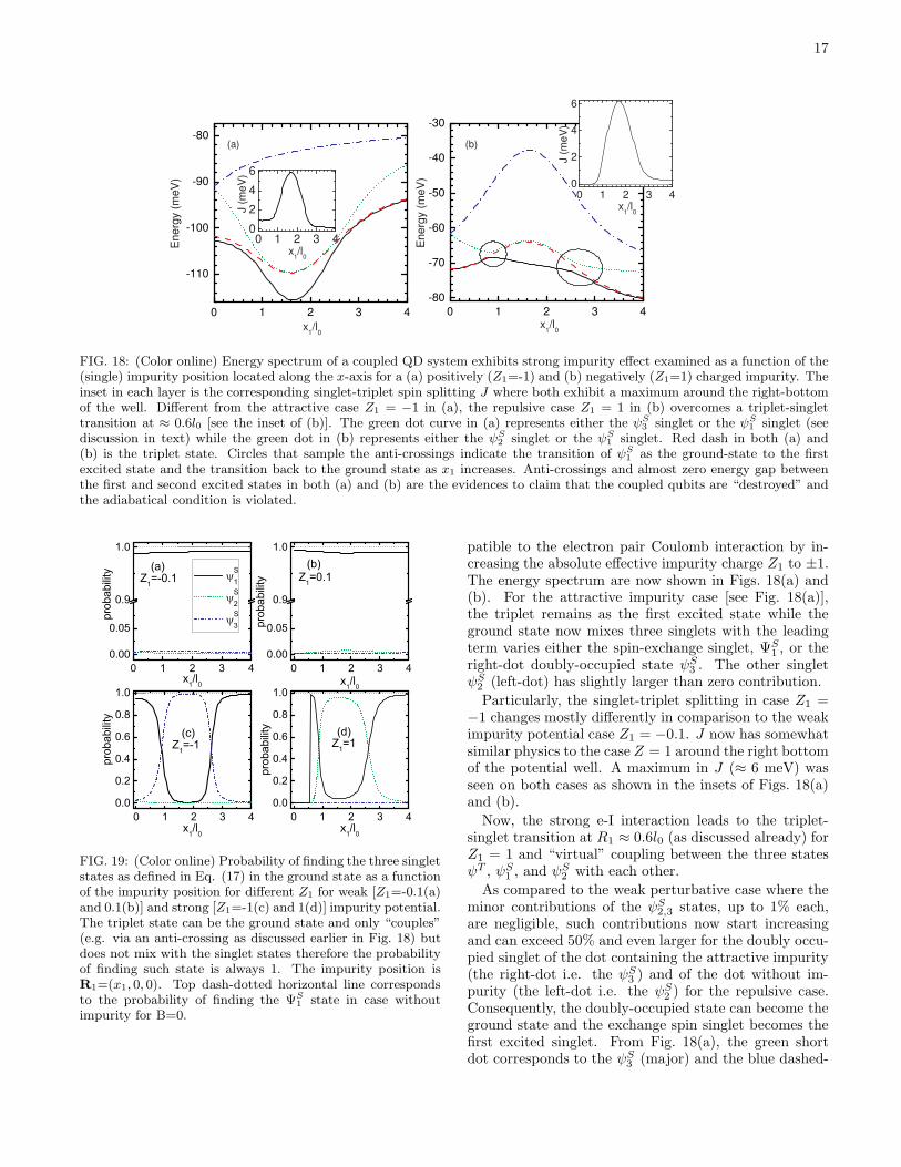
17
0 1 2 3 4
-110
-100
-90
-80
0 1 2 3 4
-80
-70
-60
-50
-40
-30
0 1 2 3 40
2
4
6
0 1 2 3 40
2
4
6
Energ
y (
meV
)
x1/l
0
(a)
Energ
y (
meV
)
x1/l
0
(b)
x1/l
0
J (
meV
)
J (
meV
)
x1/l
0
FIG. 18: (Color online) Energy spectrum of a coupled QD system exhibits strong impurity effect examined as a function of the(single) impurity position located along the x-axis for a (a) positively (Z1=-1) and (b) negatively (Z1=1) charged impurity. Theinset in each layer is the corresponding singlet-triplet spin splitting J where both exhibit a maximum around the right-bottomof the well. Different from the attractive case Z1 = −1 in (a), the repulsive case Z1 = 1 in (b) overcomes a triplet-singlettransition at ≈ 0.6l0 [see the inset of (b)]. The green dot curve in (a) represents either the ψS
3 singlet or the ψS1 singlet (see
discussion in text) while the green dot in (b) represents either the ψS2 singlet or the ψS
1 singlet. Red dash in both (a) and(b) is the triplet state. Circles that sample the anti-crossings indicate the transition of ψS
1 as the ground-state to the firstexcited state and the transition back to the ground state as x1 increases. Anti-crossings and almost zero energy gap betweenthe first and second excited states in both (a) and (b) are the evidences to claim that the coupled qubits are “destroyed” andthe adiabatical condition is violated.
0 1 2 3 40.0
0.2
0.4
0.6
0.8
1.0
0 1 2 3 40.00
0.05
0.9
1.0
0 1 2 3 40.00
0.05
0.9
1.0
0 1 2 3 40.0
0.2
0.4
0.6
0.8
1.0
prob
abilit
y
x1/l0
Z1=1(d)
prob
abilit
y
x1/l0
Z1=0.1(b)
prob
abilit
y
x1/l0
S1
S2
S3
Z1=-0.1(a)
prob
abilit
y
x1/l0
Z1=-1(c)
FIG. 19: (Color online) Probability of finding the three singletstates as defined in Eq. (17) in the ground state as a functionof the impurity position for different Z1 for weak [Z1=-0.1(a)and 0.1(b)] and strong [Z1=-1(c) and 1(d)] impurity potential.The triplet state can be the ground state and only “couples”(e.g. via an anti-crossing as discussed earlier in Fig. 18) butdoes not mix with the singlet states therefore the probabilityof finding such state is always 1. The impurity position isR1=(x1, 0, 0). Top dash-dotted horizontal line correspondsto the probability of finding the ΨS
1 state in case withoutimpurity for B=0.
patible to the electron pair Coulomb interaction by in-creasing the absolute effective impurity charge Z1 to ±1.The energy spectrum are now shown in Figs. 18(a) and(b). For the attractive impurity case [see Fig. 18(a)],the triplet remains as the first excited state while theground state now mixes three singlets with the leadingterm varies either the spin-exchange singlet, ΨS1 , or theright-dot doubly-occupied state ψS3 . The other singletψS2 (left-dot) has slightly larger than zero contribution.
Particularly, the singlet-triplet splitting in case Z1 =−1 changes mostly differently in comparison to the weakimpurity potential case Z1 = −0.1. J now has somewhatsimilar physics to the case Z = 1 around the right bottomof the potential well. A maximum in J (≈ 6 meV) wasseen on both cases as shown in the insets of Figs. 18(a)and (b).
Now, the strong e-I interaction leads to the triplet-singlet transition at R1 ≈ 0.6l0 (as discussed already) forZ1 = 1 and “virtual” coupling between the three statesψT , ψS1 , and ψ
S2 with each other.
As compared to the weak perturbative case where theminor contributions of the ψS2,3 states, up to 1% each,are negligible, such contributions now start increasingand can exceed 50% and even larger for the doubly occu-pied singlet of the dot containing the attractive impurity(the right-dot i.e. the ψS3 ) and of the dot without im-purity (the left-dot i.e. the ψS2 ) for the repulsive case.Consequently, the doubly-occupied state can become theground state and the exchange spin singlet becomes thefirst excited singlet. From Fig. 18(a), the green shortdot corresponds to the ψS3 (major) and the blue dashed-
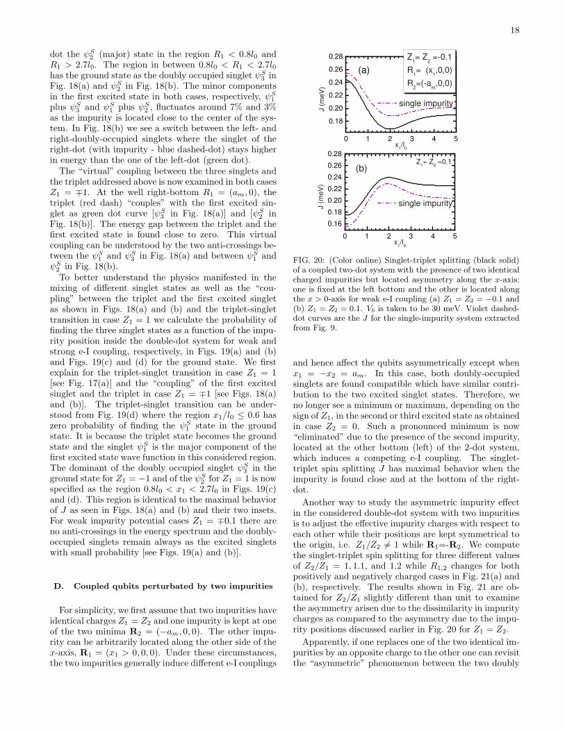
18
dot the ψS2 (major) state in the region R1 < 0.8l0 andR1 > 2.7l0. The region in between 0.8l0 < R1 < 2.7l0has the ground state as the doubly occupied singlet ψS3 inFig. 18(a) and ψS2 in Fig. 18(b). The minor componentsin the first excited state in both cases, respectively, ψS1plus ψS3 and ψS1 plus ψS2 , fluctuates around 7% and 3%as the impurity is located close to the center of the sys-tem. In Fig. 18(b) we see a switch between the left- andright-doubly-occupied singlets where the singlet of theright-dot (with impurity - blue dashed-dot) stays higherin energy than the one of the left-dot (green dot).The “virtual” coupling between the three singlets and
the triplet addressed above is now examined in both casesZ1 = ∓1. At the well right-bottom R1 = (am, 0), thetriplet (red dash) “couples” with the first excited sin-glet as green dot curve [ψS3 in Fig. 18(a)] and [ψS2 inFig. 18(b)]. The energy gap between the triplet and thefirst excited state is found close to zero. This virtualcoupling can be understood by the two anti-crossings be-tween the ψS1 and ψS3 in Fig. 18(a) and between ψS1 andψS2 in Fig. 18(b).To better understand the physics manifested in the
mixing of different singlet states as well as the “cou-pling” between the triplet and the first excited singletas shown in Figs. 18(a) and (b) and the triplet-singlettransition in case Z1 = 1 we calculate the probability offinding the three singlet states as a function of the impu-rity position inside the double-dot system for weak andstrong e-I coupling, respectively, in Figs. 19(a) and (b)and Figs. 19(c) and (d) for the ground state. We firstexplain for the triplet-singlet transition in case Z1 = 1[see Fig. 17(a)] and the “coupling” of the first excitedsinglet and the triplet in case Z1 = ∓1 [see Figs. 18(a)and (b)]. The triplet-singlet transition can be under-stood from Fig. 19(d) where the region x1/l0 ≤ 0.6 haszero probability of finding the ψS1 state in the groundstate. It is because the triplet state becomes the groundstate and the singlet ψS1 is the major component of thefirst excited state wave function in this considered region.The dominant of the doubly occupied singlet ψS3 in theground state for Z1 = −1 and of the ψS2 for Z1 = 1 is nowspecified as the region 0.8l0 < x1 < 2.7l0 in Figs. 19(c)and (d). This region is identical to the maximal behaviorof J as seen in Figs. 18(a) and (b) and their two insets.For weak impurity potential cases Z1 = ∓0.1 there areno anti-crossings in the energy spectrum and the doubly-occupied singlets remain always as the excited singletswith small probability [see Figs. 19(a) and (b)].
D. Coupled qubits perturbated by two impurities
For simplicity, we first assume that two impurities haveidentical charges Z1 = Z2 and one impurity is kept at oneof the two minima R2 = (−am, 0, 0). The other impu-rity can be arbitrarily located along the other side of thex-axis, R1 = (x1 > 0, 0, 0). Under these circumstances,the two impurities generally induce different e-I couplings
0 1 2 3 4 5
0.18
0.20
0.22
0.24
0.26
0.28
0 1 2 3 4 5
0.16
0.18
0.20
0.22
0.24
0.26
0.28
(a)
Z1= Z
2 =-0.1
R1= (x
1,0,0)
R2=(-a
m,0,0)
J (
meV
)
x1/l
0
single impurity
Z1= Z
2 =0.1
J (
meV
)
x1/l
0
single impurity
(b)
FIG. 20: (Color online) Singlet-triplet splitting (black solid)of a coupled two-dot system with the presence of two identicalcharged impurities but located asymmetry along the x-axis:one is fixed at the left bottom and the other is located alongthe x > 0-axis for weak e-I coupling (a) Z1 = Z2 = −0.1 and(b) Z1 = Z2 = 0.1. Vb is taken to be 30 meV. Violet dashed-dot curves are the J for the single-impurity system extractedfrom Fig. 9.
and hence affect the qubits asymmetrically except whenx1 = −x2 = am. In this case, both doubly-occupiedsinglets are found compatible which have similar contri-bution to the two excited singlet states. Therefore, weno longer see a minimum or maximum, depending on thesign of Z1, in the second or third excited state as obtainedin case Z2 = 0. Such a pronounced minimum is now“eliminated” due to the presence of the second impurity,located at the other bottom (left) of the 2-dot system,which induces a competing e-I coupling. The singlet-triplet spin splitting J has maximal behavior when theimpurity is found close and at the bottom of the right-dot.
Another way to study the asymmetric impurity effectin the considered double-dot system with two impuritiesis to adjust the effective impurity charges with respect toeach other while their positions are kept symmetrical tothe origin, i.e. Z1/Z2 6= 1 while R1=-R2. We computethe singlet-triplet spin splitting for three different valuesof Z2/Z1 = 1, 1.1, and 1.2 while R1,2 changes for bothpositively and negatively charged cases in Fig. 21(a) and(b), respectively. The results shown in Fig. 21 are ob-tained for Z2/Z1 slightly different than unit to examinethe asymmetry arisen due to the dissimilarity in impuritycharges as compared to the asymmetry due to the impu-rity positions discussed earlier in Fig. 20 for Z1 = Z2.
Apparently, if one replaces one of the two identical im-purities by an opposite charge to the other one can revisitthe “asymmetric” phenomenon between the two doubly

19
1 2 3 4
0.20
0.25
1 2 3 4
0.20
0.25
Z2=Z
1=-0.1
Z2=1.1Z
1
Z2=1.2Z
1
R1=-R
2
J (
me
V)
x1/l
0
(a)
Z2=Z
1=0.1
Z2=1.1Z
1
Z2=1.2Z
1
R1=-R
2
J (
me
V)
x1/l
0
(b)
FIG. 21: (Color online) Singlet-triplet spin splitting J as afunction of the impurity position in case the two impurities aresymmetrically located, R1=-R2, but they are charged slightlydifferently (a) both impurities are positively charged and (b)both impurities are negatively charged with Z1 = ±0.1 andZ2 = Z1 (black solid), 1.1Z1 (red dash), and 1.2Z1 (blue dash-dotted). Vb is taken to be 30 meV. Vb is fixed at 30 meV whichcorresponds to am ≈ 1.64l0. Note that the system converts tothe situation without impurity at a much larger x1 than thesingly-doped impurity case (previously seen around 3.5l0). Inthis plot, at x1 = 4l0 the system does not convert to the casewithout impurity (e.g. ∆J ≈0.01 meV) and the total bindingenergy ∆E ≈0.8 meV for Z1 = −0.1 [black solid in (a)].
occupied singlets in the two dots which now can be en-hanced as a double. Our further calculations show thatif Z1=-Z2=-0.1 and R1 = −R2 = (−am, 0, 0), for Vb=30meV the two doubly-occupied states have a significantlylarge energy gap and the higher level, which is the rightoccupied state in this case, exhibits a maximum around(am, 0) - one of the two potential well minima. Gen-erally, this considered situation can be extended to thecase that the charged impurities are different types andobey a specified charge distribution. By examining theenergy spectrum of the coupled dot, as illustrated in theabove discussion, one can detect the impurity effect onthe singlets of the double-dot system. This can be madepossible due to the distinguishability between the totalpositive and the total negative charge cases. It is alsopossible that both impurities are found either in the left-or right-dot, however, not much different physics fromthe case with only a single impurity will be added.
The last part of this section is reserved to examineone special case described in what follows. The cou-pled 2-dot system interacts with two negatively charged
impurities Z1 = Z2 = 1, equal to the electron charge.Now, the two impurities are engineered such that theyare far enough from the target (A) coupled 2-dot sam-ple and only induces electrostatic interaction to the twoelectrons of the target system. We examine the casethat the two impurities have varied positions but theircenter-of-mass coordinates are kept unchanged, in thiscase R
c12 = (R1 + R2)/2 = (5am, 0, 0). This center-of-
mass location can be imagined as another “center” ofanother coupled 2-dot system (B) where the two impuri-ties are mostly found at the well bottoms of the systemB. That the relative positions of individual impuritiesvary with respect to their center-of-mass position can beimagined as the well barrier height is tuned resulting invarying inter-dot separation in system B. A and B onlyinteract via the e-I Coulomb interaction. Now, we studythe influence of the presence of system B on the qubits ofthe system A. We plot in Fig. 22 the singlet-triplet spinsplitting as a function of one impurity position for sys-tem A. We find that J decreases as the impurity whichstays closer to the system A is positioned further fromthe system A. This effect is expected to be significantlyenhanced if one applies an external field to engineer theimpurities in and out the active region of the target sys-tem A. As a result, one can see such anti-crossings asseen earlier for Z = ∓1 where the triplet state stays in-between the two lowest singlets.
3.5 4.0 4.5
0.212
0.214
0.216
0.218
J (
me
V)
x1/a
m
R1+R
2=10a
m
R12
2am
QD1 QD2
FIG. 22: (Color online) Singlet-triplet spin splitting J as afunction of the impurity position in case the two impurities(blue circles) are located relatively far from the two potentialminima, R1+R2/2=5am and the closest impurity to the ac-tive coupled 2-dot system (the grey box) starts atR1 = 3.5am.By fixing the center-of-mass coordinate of the two impuritiesat Rc = 5am, we imply such two impurities can be consideredas another coupled 2-dot system which has no tunneling cou-pling with the considered 2-dot system in the grey box. Thatthe relative positions of each impurity R1,2 vary with respectto the origin (0,0) of the active system can be mapped tothe problem of other 2-dot system (in open dotted box) withvarying potential barrier height. Vb of the active system istaken to be 30 meV. J is slightly different from that of thesystem without impurity.

20
V. DISCUSSION AND CONCLUSION
The coupling of two qubits is sensitively affected bythe presence of a charged impurity. A charged impuritywhich is found inside the right- or the left-dot “breaksdown” the equality between the right and the left doublyoccupied singlet states. In case the impurity weakly cou-ples with the electrons, the maximally doubly-occupiedsinglet of the dot containing the impurity has a smallerenergy due to the e-I coupling. This can be considered asa tool to distinguish the doped and un-doped QD com-ponents in the coupled QD system.A relatively strongly repulsive impurity which almost
equally couples to the two individual QD electrons willresult in an entire triplet state at B=0 due to the smallcompetition between the two e-I couplings. This can beobserved by positioning the impurity around the originof the double-dot system. When the impurity is foundclose to the bottoms of the confining potential well thesystem will stay in the singlet state where the two elec-trons perform the favored singlet state with spins anti-parallel to each other. Due to this fact, the influenceof the inter-dot separation in the presence of impuritycan be examined by modulating the well barrier Vb with-out changing the single-particle properties in individualQDs. The reason is that the relative position of the im-purity with respect to the minima of the 2-dot system iseffectively controlled by changing Vb. We found that anattractive impurity serves to increase the “tunnel” ratebetween the two coupled dots.In general, charged impurities “destroy” the maximally
entangled singlet state by mixing the different singletshaving varying contributions to the total wave function.A strongly perturbative impurity really “messes up” thequantum information obtained from this coupled QDsbecause the triplet state “couples” to the second excitedstate by the presence of anti-crossings with a slightlylarger than zero energy gap. The ground state now canfavor a doubly occupied state. Because the triplet is al-ways obtained with probability 1, it occurs in betweenthe two lowest singlets: the exchange singlet ψS1 and thedoubly-occupied ψS2 or ψS3 depending on the sign of theeffective charge Z1. The energy spectrum appears withanti-crossings as seen in our results.In the presence of two identical charged impurities, the
breakdown between the two doubly-occupied singlets ofthe left and the right dots is “mended” if the impuritiesare located exactly symmetrically along the line connect-ing the two confining potential minima, i.e. the x-axis.As a result, one no longer obtains such a bias between thetwo doubly-occupied singlets in the left- or the right-dotas seen in the energy spectrum.The mixing of different singlet states and anti-crossing
coupling of the singlet and triplet states due to the im-purity presence results in significant affect on the qubitoperations, e.g. exchange and C-NOT, in the consideredcoupled 2-quantum-dot system.Finally, we discuss the implications of our results for
the operation of semiconductor spin qubits. Obviously,without some quantitative knowledge of impurity loca-tions near the qubits, no real comparison between ourresults and experiments would be possible. But we canmake some general remarks based on statistical consid-erations.
First, semiconductor qubits are typically fabricated bylithographic techniques creating QDs from parent 2DEGsystems. The low-temperature mobility of the 2DEG iscontrolled entirely by the background charged impuritydensity both in Si34 and in GaAs35 systems. Theoreticalcalculations34,35 can provide quantitatively accurate in-formation about the ensemble averaged impurity densityin the 2DEG from the mobility measurements. This in-formation about the background impurity density can beconverted to a statistical probability of finding impuritieslocated in specific QD structures since the effective activeareas of the dots would be known from the lithographicstructures. For example, typical GaAs 2DEG would have1010 to 1011 charged impurities per sq. cm. whereas Sisystems are typically dirtier with 1011 to 1012 chargedimpurities per sq. cm. This crudely translates to onecharged impurity every 10 to 100 nm in linear distancestatistically. Typical lithographic qubits are 20-100 nmsquares, indicating the presence of 1-5 charged impuri-ties per qubit statistically with GaAs (Si) being near thelower (higher number) number. Of course, the details ofimpurity locations matter very much, and the statisti-cal considerations could be improved and combined withour exchange splitting calculations to obtain the effectivesample “yield” for a given 2DEG mobility, i.e. estimatethe fraction of samples that would statistically have theimpurities far enough for spin qubit operations to work.But even these elementary considerations show that theeffective yield is likely to be very low with probably onlyabout 1-5% of QD systems being “lucky enough” to havethe impurities located far enough from the dots for themto work as spin qubits. The rest, even before taking intoaccount extraneous experimental factors (e.g. leakage,noise), simply would not work because there is no effec-tive singlet-triplet coupling providing the necessary en-tanglement in the system. A possible way of circumvent-ing this problem may perhaps be having several electronsper dot so that the external charged impurity potential iseffectively screened by the QD electrons, but this raisesthe problem of having rather weak exchange coupling inmultielectron dots22. The complex interplay of multielec-tron dots in the presence of random charged impuritiesin the background is left as an important future openproblem in this subject, which may very well be the nextimportant step in this direction.
Second, an important effect of background charged im-purities is their fluctuations which produce various chargenoise signals in semiconductor devices. This charge noisemay very well be the limiting decoherence mechanism incurrently existing semiconductor QD spin qubits36. Nor-mally, of course, charge noise would not adversely affectspin configurations, but semiconductor spin qubits de-

21
pend on the electrostatic exchange coupling which is af-fected by external charged impurities as discussed exten-sively in this paper. Therefore, any impurity fluctuationswould lead to spin qubit decoherence through the chargenoise mechanism37,38. Our current work provides quan-titative estimate of the strength of such charge noise ifthe fluctuation spectrum (or the fluctuation timescale) isknown. Deriving microscopic information about chargenoise from our results could be another future interestingdirection of research.
Third, the inevitable presence of static charged impu-rities in the background makes every semiconductor dotspin qubit, whether in GaAs or in Si (or some other mate-rial), unique since the microscopic electrostatic potentialenvironment for each qubit will necessarily differ in a ran-dom manner from qubit to qubit due to background im-purities as shown in this paper. In particular, the singlet-triplet energy separation and the consequent exchangecoupling will thus be somewhat random in a collectionof many qubits. This would in turn necessitate charac-terization of each qubit in the eventual quantum com-puter rather precisely since the gate operations dependvery strongly on the knowledge of the exchange couplingbetween the dots. Such a characterization will adverselyaffect the scalability of semiconductor spin quantum com-puter architectures. Our work shows the importanceof having ultraclean impurity-free environment even forsolid state quantum computation, similar to the require-ments for topological quantum computation using non-Abelian fractional quantum Hall states39, not becausespin quantum computation needs ultra-high mobilities34,but because it requires stable values of exchange cou-pling without large qubit-to-qubit variations. Our cur-rent work indicates that an order of magnitude reduc-tion in the background impurity concentration in GaAs,bringing it down to around 1012 per cubic cm, whichis also the goal for topological quantum computation39,should lead to the production of 100-1000 spin qubitswith impurity-free environment rather easily. Unfortu-nately, for Si-SiO2 systems this is a very stringent con-dition because of the invariable presence of large oxidecharges near the interface35, but for GaAs34,36 and Si-Gebased quantum dot systems,38,40,41 low-impurity materi-als may become available for quantum computer archi-tectures in the near future.
Fourth, most of the spin qubit manipulation experi-ments in semiconductor quantum dots are carried outunder transport situations using an external dc voltagebias. Such external voltage affects the two dots differen-tially somewhat similar to the impurity effects discussedin the current work since the confinement potentials forthe two dots are affected differently by the external volt-age. Our technique can be used to study this effect.Another possible future direction of study could be im-purity effects on the full coupled quantum dot energyspectra (i.e. in addition to just the double-dot exchangeenergy mainly considered in the current work) since insome experiments42 higher energy levels come into play.
It will, in fact, be interesting also to consider multielec-tron quantum dot systems with more than one electronper dot and ask how impurity disorder affects the en-ergy spectra. This would necessitate a calculation of thequantum dot electronic structure using many orbitals perdot (e.g. s, p, d, f, ...), which is beyond the scope of thecurrent work.
VI. ACKNOWLEDGMENTS
This work is supported by LPS-NSA and IARPA.
Appendix A: Coulomb matrix elements
1. Single QDs
To evaluate the e-I Coulomb matrix element, we cal-culate the integral:
V n2l2n1l1
(R)=
∫ϕ∗n1l1
(r)1
|r− R|ϕn2l2 (r) dr (A1)
where ϕn,l(r) is defined in Eq. (7). The denominator inthe right hand side of Eq. (A1) is eliminated using theGaussian identity:
1
r=
2
π
∫ ∞
0
e−u2r2du. (A2)
Integrating integral (A1) over θ and set r2 = t, we arriveat:
V n2l2n1l1
(R)
= δl1,l2
√n1!n2!
(n1 + l+)!(n2 + l+)!(A3)
∫ ∞
0
tl+
e−(1+u2)tLl+
n1(t)Ll
+
n2(t) e−u
2R2
dtdu.
Next, we use one of the properties of the Laguerrepolynomials33:
∫ ∞
0
tα−1e−ptLλm (at)Lβn (bt)dt =
Γ (α) (λ+ 1)m(β + 1)np−α
m!n!
m∑
j=0
(−m)j(α)j(λ + 1)jj!
(a
p
)j
n∑
k=0
(−n)k(j + α)k(β + 1)kk!
(b
p
)k
and the gamma functions for integers to calculate theintegral in the right hand side of (A3). Finally, we arriveat the formula presented in Eq. (18)
2. Coupled QDs
In general, the Coulomb matrix elements between theelectrons and impurity are obtained numerically. Except

22
for few cases with applied constraint conditions to theimpurity position, it is impossible to obtain a closed al-gebraic form for this type of Coulomb interaction. Usinga similar method as before to calculate the e-I coupling
elements, i.e. 〈Ψ|Ve-Imp|Ψ〉, we obtain:
〈ϕL(R)|Ve-Imp|ϕL(R)〉 = ZV C0√π
∫∞0
e−vz20− v
v+1√v(v+1)
dv (A4)
〈ϕL(R)|Ve-Imp|ϕR(L)〉 = ZV C0√πez
20−a20erfc(z0)
for R = (0, 0, z) and
〈ϕL(R)|Ve-Imp|ϕL(R)〉 = ZV C0√πe−
[(x0±a0)2+y20]
2 (A5)
I0[(x0±a0)2+y20
2 ]
〈ϕL(R)|Ve-Imp|ϕR(L)〉 = ZV C0√πe−[a20−
(x20+y200
2 ]
I0[(x2
0+y20)
2 ]
for R = (x0, y0, 0) where a0 = am/l0, x0 = x/l0, y0 =y/l0, and z0 = z/l0.
It is of interest to consider the special situation whenthe impurity is located along the line connecting the twopotential well minima, i.e. along the x-axis in this case.In the above sections, we discussed this case in depth.The Coulomb matrix elements for the left and the rightQD electron are as follows:
〈ϕL(R)|Ve-Imp|ϕL(R)〉 = ZV C0√πe−
(x0±a0)2
2
I0[(x0 ± a0)
2
2] (A6)
〈ϕL(R)|Ve-Imp|ϕR(L)〉 = ZV C0√πe−(a20+
x202 )I0[
x202].
Appendix B: Heitler-London approximation
The closed analytical form of the exchange energy be-tween the two coupled QDs for a single charged impuritylocated arbitrarily in the xy-plane [R = (x0, y0, 0)l0] isobtained by solving a basic two-level problem:
JHL = − ea20
1− e4a20
{2~ω0a
20ea20 +
4V0(ea20−2a0a2
0xa8−a20xa2
81+a2
0x + ea20+2a0a2
0xa8−a20xa2
81+a2
0x − 2ea20−
a20xa2
81+a2
0x )√(1 + a20x)(1 + a20y)
(B1)
+4Vb(e
a20
1+a20bx − ea
20)√
(1 + a20bx)(1 + a20by)+√πV C0
[−√2ea
20 +
√2I0(a
20)− 4Zea
20−
x20+y202 I0(
x20 + y202
)
+2ea20+2a0x0−x2
0−y202 ZI0(
a20 − 2a0x0 + x20 + y202
) + 2ea20−2a0x0−x2
0−y202 ZI0(
a20 + 2a0x0 + x20 + y202
)]}.
Here, a8 = a/l0, a0x = l0/lx, a0y = l0/ly, a0bx = l0/lbx,and a0by = l0/lby are dimensionless parameters asso-ciated with a series of lengths such as a, lx, ly, lbx, lby.These parameters together with depths V0 and Vb definethe size and the shape of the confinement double well.
Heitler-London approximation does not allow one toexamine the impurity effect on the coupled qubit oper-ations manifested in the mixing of the different singletsand “coupling” between the singlet-triplet states as al-ready observed and discussed in e.g. Fig. 18(b) Theimpurity-position dependence of JHL, as obtained an-alytically in the last three terms in Eq. (B1), now can bestudied in Fig. 23 as a function of x0. We see that thepresence of the charged impurity only plays a role as aweak perturbative interaction to the total energy even incase the effective e-I coupling is found relatively large (thecase Z1 = −1). Such a property like the triplet-singlettransition for weak repulsive e-I exchange interaction isnot found in this case.
Appendix C: Singlet-triplet splitting J forintermediate impurity effective charges
We show the results obtained for several different inter-mediate Z1 for both the negatively and positively chargedimpurity cases in Figs. 24, 25, and 26. These plotsprovide a clearer and deeper look into the triplet-singlettransition (Figs. 25 and 26) for a strongly repulsive im-purity as well as the physics of anti-crossings found inthe energy spectrum of the coupled 2-dot system. Forthe Z1 < 0 case, Fig. 24 serves to explain in detail thetransition from having a minimum to a maximum in thesinglet-triplet splitting J between the two lowest energylevels.

23
0 1 2 3 4
0.05
0.10
0.15
0.20
0.25
0 1 2 3 4
0.05
0.10
0.15
0.20
0.25
J (
meV
)
x1/l
0
Heitler-London
Z1=-0.1
(a)
Heitler-London
Z1=0.1
J (
meV
)
x1/l
0
(b)
FIG. 23: (Color online) Singlet-triplet spin splitting J asa function of the impurity position along the x-axis for (a)Z1=-0.1 and (b) 0.1. Black solid curves are extracted fromFig. 9 and blue dashed curves are obtained from Eq. (B1).We receive qualitative agreement between our numerical cal-culations and analytical results where the singlet-triplet split-ting energy calculated using these two methods exhibits a (a)minimum for Z1=-0.1 and (b) maximum for Z1 = 0.1 aroundx1 ≈ 2l0.
0 1 2 3 4 50
1
2
J (
me
V)
x1/l
0
Z1=-0.2
Z1=-0.4
Z1=-0.5
Z1=-0.6
Z1=-0.8
FIG. 24: (Color online) Singlet-triplet spin splitting J as afunction of the impurity position along the x-axis for differentZ1 < 0. In this plot one can see the gradual change in J fromhaving a minimum around x1 ≈ 2l0 to having a maximumat different x1 depending on Z1 as Z1 is increases from -0.1(black solid) to -0.8 (cyan dash-dotted-dot).
0 1 2 3 4 5
0
1
2
3
J (
me
V)
x1/l
0
Z1=0.4
Z1=0.6
Z1=0.8
FIG. 25: (Color online) Singlet-triplet spin splitting J as afunction of the impurity position along the x-axis for differentZ1 > 0. The maximum in J is found at different x1 as Z1
changes.
0 1 2 3 4 5
0.0
0.5
1.0
0 1 2 3 4 5
-80
-70
-60
J (
me
V)
x1/l
0
Z1=0.6
T
S
En
erg
y (
me
V)
x1/l
0
FIG. 26: (Color online) Singlet-triplet spin splitting J as afunction of the impurity position along the x-axis for a specificcase of Z1 > 0: 0.6. Inset is the low-level energy spectrumof the system. As compared to the pronounced anti-crossingseen in Fig. 18(b), the Z1 = 0.6 case has the spectrum whichis close to having pronounced anti-crossings as obtained forZ1 = 1 in Fig. 18(b).
Appendix D: Spin splitting energy of Si/SiGecoupled quantum dots
Si QDs have a relatively large effective mass m∗Si ≈
2.8m∗GaAs. Plus, the effective Rydberg energy in Si QDs,
as discussed in Sec. II, is higher than the effective Ryd-berg energy of GaAs QDs. These bring into the fact thatthe Si QDs have a smaller electron kinetic energy, whichmeans that the electrons tend to be more localized ascompared to the case of GaAs. Thus the tunnel rate is ex-pected to be smaller. Our calculations show that for thesame model of a coupled 2-dot system in which the shapeand the size and the barrier height are kept unchanged:e.g. V0 = −50 meV and Vb = 30 meV (correspond-

24
ing to ∆Vb = 9.65 meV), Si/SiGe double-dot systemhas ~ω0 ≈ 6.67 meV (l0 ≈ 8.48 nm). The spin singlet-triplet splitting J between the two lowest energy levelsin Si/SiGe double dots is found J ≈ 0.003 meV, muchsmaller than the J ≈ 0.204 meV of the GaAs/AlGaAsdouble dots. In experiments, the electron tunneling ratein Si/SiGe coupled double QDs is indeed found much
lower than the tunneling rate in GaAs/AlGaAs coupledQDs (see e.g. Ref.41). In the presence of a charged im-purity, e.g. Z1 = −0.1 located at the origin, we obtainedJ increased to J ≈ 0.008 meV for Si/SiGe double QDsas compared to J ≈ 0.26 meV for GaAs/AlGaAs doubleQDs.
1 C.H. Bennett and D.P. DiVincenzo, Nature (London) 404,247 (2000).
2 B. E. Kane, Nature (London) 393, 133 (1998).3 D. Loss and D.P. DiVincenzo, Phys. Rev. A 57, 120 (1998).4 R. Vrijen, E. Yablonovitch, K. Wang, H.W. Jiang, A. Ba-landin, V. Roychowdhury, Tal Mor, and D.P. DiVincenzo,Phys. Rev. A 62, 012306 (2000).
5 R. Hanson, L. Kouwenhoven, J. Petta, S. Tarucha, and L.Vandersypen, Rev. Mod. Phys. 79, 1217 (2007).
6 J. M. Elzerman, R. Hanson, L. H. Willems van Beveren, B.Witkamp, L. M. K. Vandersypen, and L. P. Kouwenhoven,Nature (London) 430, 431 (2004).
7 D. Rugar, R. Budakian, H. J. Mamin, and B. W. Chui,Nature (London) 430, 329 (2004).
8 J. R. Petta, A. C. Johnson, A. Yacoby, C. M. Marcus, M.P. Hanson, and A. C. Gossard, Phys. Rev. B 72, 161301R(2005).
9 X. Hu and S. Das Sarma, Phys. Rev. A 64, 042312 (2001).10 F. H. L. Koppens, C. Buizert, K. J. Tielrooij, I. T. Vink,
K. C. Nowack, T. Meunier, L. P. Kouwenhoven, and L. M.K. Vandersypen, Nature (London) 442, 766 (2006).
11 M. Ciorga, A. S. Sachrajda, P. Hawrylak, C. Gould, P.Zawadzki, S. Jullian, Y. Feng, and Z. Wasilewski, Phys.Rev. B 61, R16315 (2000).
12 J. M. Elzerman, R. Hanson, J. S. Greidanus, L. H. Willemsvan Beveren, S. De Franceschi, L. M. K. Vandersypen,S. Tarucha, and L. P. Kouwenhoven, Phys. Rev. B 67,161308(R) (2003).
13 M. Poiro-Ladriere, Phys. Rev. Lett. 91, 026803 (2003).14 J. R. Petta, A. C. Johnson, C. M. Marcus, M. P. Hanson,
and A. C. Gossard, Phys. Rev. Lett. 93, 186802 (2004).15 W. Tittel, J. Brendel, H. Zbinden, and N. Gisin, Phys.
Rev. Lett. 81, 3563 (1998).16 G. Weihs, T. Jennewein, C. Simon, H. Weinfurter, and A.
Zeilinger, Phys. Rev. Lett. 81, 5039 (1998).17 G. Burkard, D. Loss, and D.P. DiVincenzo, Phys. Rev. B
59, 2070 (1999).18 D. Loss and E.V. Sukhorukov, Phys. Rev. Lett. 84, 1035
(2000).19 M.A. Rowe, D. Kielpinski, V. Meyer, C.A. Sackett, W.M.
Itano, C. Monroe, and D.J. Wineland, Nature (London)409, 791 (2001).
20 X. Hu and S. Das Sarma, Phys. Rev. B 69, 115312 (2004).21 G. Burkard, J. Phys. Cond. Matt. 19, 233202 (2007).22 X. Hu and S. Das Sarma, Phys. Rev. A 61, 062301 (2000).23 R. de Sousa, X. Hu, and S. Das Sarma, Phys. Rev. A 64,
042307 (2001).24 J. Levy, Phys. Rev. Lett. 89, 147902 (2002).25 A. Harju, S. Siljamaki, and R. M. Nieminen, Phys. Rev.
Lett. 88, 226804 (2002).26 R. Hanson, L. H. Willems van Beveren, I. T. Vink, J.
M. Elzerman, W. J. M. Naber, F. H. L. Koppens, L. P.Kouwenhoven, and L. M. K. Vandersypen, Phys. Rev. Lett.94, 196802 (2005).
27 J. R. Petta, A. C. Johnson, J. Taylor, E. A. Laird, A.Yacoby, M. D. Lukin, C. M. Marcus, M. P. Hanson, andA. C. Gossard, Science 309, 2180 (2005).
28 I. van Weperen, B. D. Armstrong, E. A. Laird, J. Med-ford, C. M. Marcus, M. P. Hanson, and A. C. Gossard(unpublished); arXiv:1101.5654v3.
29 I. Puerto Gimenez, C.Y Hsieh, M. Korkusinski, and P.Hawrylak, Phys. Rev. B 79 205311 (2009).
30 W. G. van der Wiel, S. De Franceschi, J. M. Elzerman, T.Fujisawa, S. Tarucha, and L. P. Kouwenhoven, Rev. Mod.Phys. 75, 1 (2002).
31 J. R. Petta, J. M. Taylor, A. C. Johnson, A. Yacoby, M. D.Lukin, C. M. Marcus, M. P. Hanson, and A. C. Gossard,Phys. Rev. Lett. 100, 067601 (2008).
32 The minimum in J varies when Vb changes. Therefore, theminimal splitting energy for Vb = 13 meV is found at a dif-ferent position of the impurity as compared to the “stan-dard” ≈ 2l0 for the case Vb = 30 meV
33 I. S. Gradshteyn, I. M. Ryzhik, A. Jeffrey, and D. Zwill-inger, Tables of Integrals, Series, and Products, 6th ed.(Academic, San Diego, 2000).
34 E. H. Hwang and S. Das Sarma, Phys Rev B 77, 235437(2008).
35 L. A. Tracy, E. H. Hwang, K. Eng, G. A. Ten Eyck, E. P.Nordberg, K. Childs, M. S. Carroll, M. P. Lilly, and S. DasSarma, Phys. Rev. B 79, 235307 (2009).
36 C. Marcus and A. Yacoby, private communications andunpublished.
37 X. Hu and S. Das Sarma, Phys. Rev. Lett. 96, 100501(2006); M. Stopa and C. M. Marcus, Nanoletters 8, 1778(2008).
38 D. Culcer, X. Hu, and S. Das Sarma, Appl. Phys. Lett. 95,073102 (2009).
39 C. Nayak, S. H. Simon, A. Stern, M. Freedman, and S. DasSarma, Rev. Mod. Phys. 80, 1083 (2008).
40 Q. Li, L. Cywinski, D. Culcer, X. Hu, and S. Das Sarma,Phys. Rev. B 81, 085313 (2010).
41 Madhu Thalakulam, C. B. Simmons, B. M. Rosemeyer,D. E. Savage, M. G. Lagally, Mark Friesen, S. N. Copper-smith, and M. A. Eriksson, Appl. Phys. Lett. 96, 183104(2010).
42 K. Ono and S. Tarucha, Phys. Rev. Lett. 92, 256803(2004).