
7. ADDITIONAL STUDIES - Environmental Clearance
46
Environmental Impact Assessment Report for Development Drilling of 3 (Nos.) Wells and Establishment of Early Production System (one) at Nagayalanka in the onland NELP-V Block KG-ONN-2003/1, At Nagayalanka Block, Krishna District, Andhra Pradesh for M/s Oil & Natural Gas Corporation Chapter 7 :Additional Studies 7. ADDITIONAL STUDIES 7.1. Risk Assessment Oil & Natural Gas Corporation (ONGC) of Rajahmundry, India, plans to establish an Early Production System (EPS) NAG-1Z-ST and carry out drilling of one additional development drilling of 3 wells in KG-ONN-2003/1 block (Nagaylanka Block), awarded under NELP-V. As part of the procedure for clearance by the MOEF&CC, ONGC need to submit a rapid risk assessment of the operations. ONGC has commissioned Bhagavathi Ana Labs Private Limited (BALPL) to conduct a rapid risk assessment of the proposed EPS and drilling operation and to establish the Risk Criteria and based on it provide recommendations and Mitigation measures to bring the level of risk to as low as reasonably practicable (ALARP). ONGC intends EPS with a capacity of 40,000m 3 /day of gas and for drilling of Development well to a depth of 4600 m. 7.1.1. Block Description Location One EPS and three development well is located in 55.446 sq. km in Krishna District of Andhra 7.1.2. Rapid Risk Assessment Approach Study Assumptions The quantified risk assessment (QRA) approach used in this rapid risk assessment is necessarily generic in nature as the drilling rig type has yet to be selected. However, a credible QRA can be achieved by the careful setting of assumptions and generally by taking a conservative view of the event frequency, equipment performance and consequence modelling. This will be the approach that has been followed in this study. The principal study assumptions regarding: drilling & testing lifecycle, study scope, well data, legislative compliance, support services, operating practices are contained in Table 51. These assumptions have been applied to all generic QRA’s. In addition, modelling assumptions specific to Drilling are provided below. ALARP Risk Principles The ONGC definition of risk tolerability, against which all the QRA results have been assessed, below The definition of what level of risk is tolerable, difficult and necessarily subjective. For safety risks ONGC has adopted the ALARP principle (as low as reasonably practical) outlined in Figure 26 below. In general terms, the risk should be considered to be ALARP if the cost of reducing the risk further cannot be justified by the reduction in risk which would occur. For many risks these ALARP considerations may be addressed qualitatively. For high risk situations numerical risk tolerability performance standards are required. If the risk is not considered to be ALARP even following the correct development and application of control measures, then alternative ways of achieving the operational objective shall be identified and considered. Bhagavathi Ana Labs Pvt. Ltd. (a Bureau Veritas Group Company) Project Reference: IND.BH.41.17.0273/HSR Rev. 02, Draft 114
-
Upload
khangminh22 -
Category
Documents
-
view
3 -
download
0
Transcript of 7. ADDITIONAL STUDIES - Environmental Clearance

Environmental Impact Assessment Report for Development Drilling of 3 (Nos.) Wells and Establishment of Early Production System (one) at Nagayalanka in the onland NELP-V Block KG-ONN-2003/1, At Nagayalanka Block, Krishna District, Andhra Pradesh for M/s Oil & Natural Gas Corporation
Chapter 7 :Additional Studies
7. ADDITIONAL STUDIES 7.1. Risk Assessment
Oil & Natural Gas Corporation (ONGC) of Rajahmundry, India, plans to establish an Early Production System (EPS) NAG-1Z-ST and carry out drilling of one additional development drilling of 3 wells in KG-ONN-2003/1 block (Nagaylanka Block), awarded under NELP-V. As part of the procedure for clearance by the MOEF&CC, ONGC need to submit a rapid risk assessment of the operations. ONGC has commissioned Bhagavathi Ana Labs Private Limited (BALPL) to conduct a rapid risk assessment of the proposed EPS and drilling operation and to establish the Risk Criteria and based on it provide recommendations and Mitigation measures to bring the level of risk to as low as reasonably practicable (ALARP). ONGC intends EPS with a capacity of 40,000m
3/day of gas and for drilling of Development well to a depth of 4600 m.
7.1.1. Block Description
Location One EPS and three development well is located in 55.446 sq. km in Krishna District of Andhra
7.1.2. Rapid Risk Assessment Approach
Study Assumptions The quantified risk assessment (QRA) approach used in this rapid risk assessment is necessarily generic in nature as the drilling rig type has yet to be selected. However, a credible QRA can be achieved by the careful setting of assumptions and generally by taking a conservative view of the event frequency, equipment performance and consequence modelling. This will be the approach that has been followed in this study.
The principal study assumptions regarding: drilling & testing lifecycle, study scope, well data, legislative compliance, support services, operating practices are contained in Table 51. These assumptions have been applied to all generic QRA’s. In addition, modelling assumptions specific to Drilling are provided below.
ALARP Risk Principles The ONGC definition of risk tolerability, against which all the QRA results have been assessed, below The definition of what level of risk is tolerable, difficult and necessarily subjective. For safety risks ONGC has adopted the ALARP principle (as low as reasonably practical) outlined in Figure 26 below.
In general terms, the risk should be considered to be ALARP if the cost of reducing the risk further cannot be justified by the reduction in risk which would occur. For many risks these ALARP considerations may be addressed qualitatively. For high risk situations numerical risk tolerability performance standards are required.
If the risk is not considered to be ALARP even following the correct development and application of control measures, then alternative ways of achieving the operational objective shall be identified and considered.
Bhagavathi Ana Labs Pvt. Ltd. (a Bureau Veritas Group Company) Project Reference: IND.BH.41.17.0273/HSR Rev. 02, Draft 114

Environmental Impact Assessment Report for Development Drilling of 3 (Nos.) Wells and Establishment of Early Production System (one) at Nagayalanka in the onland NELP-V Block KG-ONN-2003/1, At Nagayalanka Block, Krishna District, Andhra Pradesh for M/s Oil & Natural Gas Corporation
Chapter 7 :Additional Studies
Figure 25 shows the methodology adopted for the rapid risk assessment of the drilling operation.
FIGURE 25 : RAPID RISK ASSESSMENT METHODOLOGY
Qualitative demonstration of ALARP In relatively low risk situations when the ALARP justification is being made qualitatively some or all of the following can be applied where appropriate: demonstration of the application of best practice including technology and
management techniques, reference to trends in accident and incident statistics,
Bhagavathi Ana Labs Pvt. Ltd. (a Bureau Veritas Group Company) Project Reference: IND.BH.41.17.0273/HSR Rev. 02, Draft 115

Environmental Impact Assessment Report for Development Drilling of 3 (Nos.) Wells and Establishment of Early Production System (one) at Nagayalanka in the onland NELP-V Block KG-ONN-2003/1, At Nagayalanka Block, Krishna District, Andhra Pradesh for M/s Oil & Natural Gas Corporation
Chapter 7 :Additional Studies
discussion /comparison of risk levels before and after possible change, i.e. identification of practicable options for reduction of risks following the preferred hierarchy as follows, elimination or minimisation of hazard, engineering design, suitable systems of working, and then personal protective equipment
Quantitative demonstration of ALARP Where the consequences of a hazard being realised are very high, i.e. where multiple fatalities, severe environmental damage or damage to installations, and/or major loss of production would result, then quantitative risk assessment (QRA) techniques must be used to demonstrate ALARP. It needs to be understood that QRA is not an exact science; it relies on the use of historical data which may be inaccurate or not directly relevant. Nevertheless, it is valuable in comparing risks to identify priorities and can be used with caution to establish absolute levels of risk. These absolute levels can then be compared with criteria which establish the way in which risks are to be treated.
ONGC has determined that, on the basis of generally accepted international risk acceptance criteria: No offshore installation shall pose an individual risk per annum (IRPA) of
death to those involved in operating or maintaining the installation from major accidents greater than a 1 in 1,000 chance a year. If this risk can be shown to be less than 1 in 100,000 a year, then it will be accepted;
Where the risk lies between these levels, then potential design improvements will be assessed to ensure that risks are reduced to an ALARP level.
In other words: an IRPA greater than 1 in 1,000 a year cannot be accepted as
ALARP; an IRPA less than 1 in 100,000 a year is automatically accepted; IRPA's between these levels may be accepted but additional safeguards should be examined to ensure that an ALARP level is reached.
FIGURE 26 : ALARP CRITERIA
Bhagavathi Ana Labs Pvt. Ltd. (a Bureau Veritas Group Company) Project Reference: IND.BH.41.17.0273/HSR Rev. 02, Draft 116

Environmental Impact Assessment Report for Development Drilling of 3 (Nos.) Wells and Establishment of Early Production System (one) at Nagayalanka in the onland NELP-V Block KG-ONN-2003/1, At Nagayalanka Block, Krishna District, Andhra Pradesh for M/s Oil & Natural Gas Corporation
Chapter 7 :Additional Studies
Control Measures to Reduce Risks Once it has been decided that a risk needs further control, the means of doing so should be evaluated in the following order of preference: Eliminate the hazard. Occasionally this may prove practicable, for example, by
changing the material used, the process or the equipment. An example would be cleaning using a detergent instead of a flammable, toxic solvent;
Technical solutions. Engineered control measures, for example enclosures, ventilation systems, alarms, trips and guards. These are relatively independent of the human factor, and generally can be made reliable;
Procedural solutions. Doing things in a different way to improve safety relies on individuals complying with procedures. Training and communication are important to ensure that operators recognise the risks and know how to avoid them;
Protective equipment (PPE). This is the least satisfactory form of control, and should only be considered after all others have been rejected.
It should be noted that introducing controls can produce further risks which may need to be assessed in turn.
Risk cannot be justified save in extraordinary circumstances
Finally, each QRA requires: The identification of major hazards specific to the unit being assessed The
construction of an event tree for each major hazard to derive a set of credible sub – events Numerical values for major hazard occurrence frequencies and event probabilities are derived from international accident databases of historical incidents and are combined in the event tree to derive occurrence frequencies for these sub events. BALPL have consistently adopted a conservative modelling approach in defining these frequencies and probabilities. All such modelling assumptions are listed;
The modelling of the consequences in terms of potential fatalities from each credible sub event. As these are ’rapid’, generic risk assessments, this modelling does not take the form of detailed physical modelling but rather reflects typical outcomes based on historical data. BALPL have consistently adopted a conservative approach in deriving such outcomes and all such modelling assumptions are listed
It is ONGC intention to use the latest generation of drilling unit and EPS for this work. Hence the use of historical records which reflect the performance of potentially lower design and operational standards, may introduce an additional element of conservatism into the approach over and above that inherent in BALPL’s selection and application of data.
TABLE 51 : PRINCIPAL STUDY ASSUMPTIONS AssumptionAssumption
Description Number Title
The risk analysis will assume that the EPS and drilling rig are securely on location and will cover a typical ‘whole lifecycle’ of the well operation including:
1 Lifecycle a. Drilling / Casing / Cementing b. Well testing c. EPS / Production d. Decommission
Bhagavathi Ana Labs Pvt. Ltd. (a Bureau Veritas Group Company) Project Reference: IND.BH.41.17.0273/HSR Rev. 02, Draft 117

Environmental Impact Assessment Report for Development Drilling of 3 (Nos.) Wells and Establishment of Early Production System (one) at Nagayalanka in the onland NELP-V Block KG-ONN-2003/1, At Nagayalanka Block, Krishna District, Andhra Pradesh for M/s Oil & Natural Gas Corporation
Chapter 7 :Additional Studies
AssumptionAssumption Description
Number Title
a. The QRA will address those hazards with the potential to cause a “major incident” (e.g. multiple fatalities)
2 Study b. The study is confined to events occurring on the rig & Scope EPS and the impact of any releases on the
environment. c. In the event of rig abandonment The well has the potential to flow either oil or gas a. The well may be High Pressure / High Temperature b. H2S or significant CO2 may be present in the well
3 Well c. Drilling will be likely to take place at any time during the Information year
d. The rig will be on station for 30-45 days. For analysis purposes a conservative approach, assuming a 45 day well (40 days drilling & 5 days testing) will be used
The EPS plant capacities are
4 EPS Crude Oil 2385BPD
Gas 0.145 MMSCMD Information
Produced Water
a. The drilling rig will fully comply with all relevant Indian
5 Drilling Rig and international legislation and safety standards and
the Operator has certified it as fit for purpose at the Certification commencement of drilling
6
Site a. Prior to rig, BALPL identified all potential environmental
sensitivities and an appropriate site survey for debris Information etc in earlier chapters.
a. Operator has and will apply a modern Safety
Operator Management System
7 b. All drilling and other related operations carried out Information on the rig reflect best Industry practices and comply
with all relevant Indian and international legislation
8 Acceptable The individual risk per annum (IRPA) will be assessedRisk Levels against the ALARP risk level
Industry acceptable data sources will be substantially Supporting utilised in the assessments. These include but are not
9 Study limited to: a.
UK Health and Safety Executive (HSE) Hydrocarbon Data
Ignition Database b. Purple Book
a. Test equipment skid mounted, typically consisting of heater, test separator, surge drum, holding tank,
Well metering runs, associated pipework
10 b. Each test lasts for 5 days Testing
c. Ten (10) men in the immediate vicinity of the
equipment during testing
Bhagavathi Ana Labs Pvt. Ltd. (a Bureau Veritas Group Company) Project Reference: IND.BH.41.17.0273/HSR Rev. 02, Draft 118

Environmental Impact Assessment Report for Development Drilling of 3 (Nos.) Wells and Establishment of Early Production System (one) at Nagayalanka in the onland NELP-V Block KG-ONN-2003/1, At Nagayalanka Block, Krishna District, Andhra Pradesh for M/s Oil & Natural Gas Corporation
Chapter 7 :Additional Studies
7.1.3. Drilling Rig
This section summarises the rapid risk assessment for the exploration wells in Block KG-ONN-2003// using electrical drilling rig.
7.1.3.1. Risk Analysis Results for Drilling Rig
Major Accident Hazards The major hazards identified for the Drilling rig are shown in Table 52
TABLE 52 : MAJOR ACCIDENT HAZARDS FOR DRILLING RIG
Hazard Major Accident Including No Hazard
1 Well Blowout Drill Rig blowouts During Drilling
2 Dropped Objects Offloading & back loading: Movement of material on rig: Dropped drill pipe
It is assumed that the unit has been chosen to be fit
3 Structural Failure for purpose for its area of operation and that failure occurs as a result of extreme events such as
earthquakes, extreme winds etc.
Non Process
Cellulosic or electrical fires in accommodation: Diesel 4 fuel tank or pipe leaks leading to fires & explosions in
Fires machinery spaces: etc.
Hydrocarbon 5 Leaks During Well Leaks, fires and explosions
Testing
Modelling Assumptions The frequency to be assigned to the likelihood of occurrence of each major hazard is derived from industry reference sources and has been used to facilitate this frequency derivation and to support consequence modelling.
Bhagavathi Ana Labs Pvt. Ltd. (a Bureau Veritas Group Company) Project Reference: IND.BH.41.17.0273/HSR Rev. 02, Draft 119

Environmental Impact Assessment Report for Development Drilling of 3 (Nos.) Wells and Establishment of Early Production System (one) at Nagayalanka in the onland NELP-V Block KG-ONN-2003/1, At Nagayalanka Block, Krishna District, Andhra Pradesh for M/s Oil & Natural Gas Corporation
Chapter 7 :Additional Studies
TABLE 53 : ASSUMPTIONS FOR WELL BLOWOUT DURING DRILLING IN RIG S.No Assumption Comments Blowout Probability Assume that a rig drills 7 wells per year made up of: Probability of blowout per well is taken as 0.0063 45 days drill & test
1 Frequency of Blowout is derived as 0.044 per year 5 days move 15 days WOW per year Hence annual frequency becomes 0.0063*7 = 0.044
2 Ignition probability of gas escaping from either a top drive 20 year historical data set and takes account of a trend to lower ignition blowout is taken as 0.1 probabilities in recent wells. Note blowout ignition probability of 0.3
For blowouts, when ignition occurs: In the event of ignition of hydrocarbons the following may occur . 50% of the time it occurs immediately and results in a pool fire: a burning pool of liquid (oil or well fluid) jet fire jet fire: a burning jet of gas which if ignited soon after it occurs results 50% of the time it will be delayed and result in an in an intense stabilised jet which is very destructive to anything explosion within it or close to it Flash fire: delayed (say after 15 minutes) ignition of a gas release. In this time the release may have formed an extensive plume and the ensuing fire will kill everyone within it who is unprotected but not damage structures
3 Confined explosion: delayed ignition of a gas release within a confined space, the delay (usually in excess of 5 minutes) giving
time for an explosive mixture to build up. It has the potential for considerable fatalities and damage. It is assumed that the necessary degree of confinement does not exist on a jack up Vapour cloud explosion: an ignited gas plume which burns in such a way that it generates overpressures characteristic of and explosion. A simple but conservative approach has been taken that all immediate ignition events result in a jet fire while the results of all delayed ignition events (whether they are from a flash fire or a vapour cloud explosion) are equally severe For blowouts on rig resulting in immediate ignition: A blowout on the Drilling Rig with immediate ignition would be expected
4 10% probability of fatality for all personnel on Drilling to lead to a gas jet. An ignited gas jet from a blowout would result in a Rig large flame which has the potential to impact structural members of the
0% probability of fatality for all other personnel who drilling, leading to their failure. A prolonged fire (say one to 2 hours)
Bhagavathi Ana Labs Pvt. Ltd. (a Bureau Veritas Group Company) Project Reference: IND.BH.41.17.0273/HSR Rev. 02, Draft 120
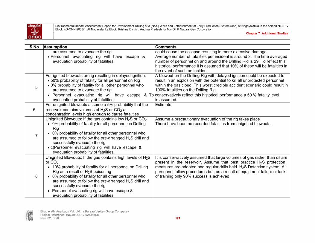
Environmental Impact Assessment Report for Development Drilling of 3 (Nos.) Wells and Establishment of Early Production System (one) at Nagayalanka in the onland NELP-V Block KG-ONN-2003/1, At Nagayalanka Block, Krishna District, Andhra Pradesh for M/s Oil & Natural Gas Corporation
Chapter 7 :Additional Studies
S.No Assumption Comments
are assumed to evacuate the rig could cause the collapse resulting in more extensive damage. Personnel evacuating rig will have escape & Average number of fatalities per incident is around 3. The time averaged evacuation probability of fatalities number of personnel on and around the Drilling Rig is 29. To reflect this historical performance it is assumed that 10% of these will be fatalities in the event of such an incident. For ignited blowouts on rig resulting in delayed ignition: A blowout on the Drilling Rig with delayed ignition could be expected to 50% probability of fatality for all personnel on Rig result in an explosion with the potential to kill all unprotected personnel
5 0% probability of fatality for all other personnel who within the gas cloud. This worst credible accident scenario could result in
are assumed to evacuate the rig 100% fatalities on the Drilling Rig. Personnel evacuating rig will have escape & To conservatively reflect this historical performance a 50 % fatality level
evacuation probability of fatalities is assumed. For unignited blowouts assume a 5% probability that the Estimate
6 reservoir contains volumes of H2S or CO2 at concentration levels high enough to cause fatalities
Unignited Blowouts: If the gas contains low H2S or CO2 Assume a precautionary evacuation of the rig takes place 0% probability of fatality for all personnel on Drilling There have been no recorded fatalities from unignited blowouts. Rig
7 0% probability of fatality for all other personnel who
are assumed to follow the pre-arranged H2S drill and
successfully evacuate the rig c)Personnel evacuating rig will have escape & evacuation probability of fatalities
Unignited Blowouts: If the gas contains high levels of H2S It is conservatively assumed that large volumes of gas rather than oil are or CO2 present in the reservoir. Assume that best practice H2S protection 10% probability of fatality for all personnel on Drilling measures are adopted and regular drills held. H2S Detection system. All
Rig as a result of H2S poisoning personnel follow procedures but, as a result of equipment failure or lack
8 0% probability of fatality for all other personnel who of training only 90% success is achieved are assumed to follow the pre-arranged H2S drill and successfully evacuate the rig
Personnel evacuating rig will have escape & evacuation probability of fatalities
Bhagavathi Ana Labs Pvt. Ltd. (a Bureau Veritas Group Company) Project Reference: IND.BH.41.17.0273/HSR Rev. 02, Draft 121

Environmental Impact Assessment Report for Development Drilling of 3 (Nos.) Wells and Establishment of Early Production System (one) at Nagayalanka in the onland NELP-V Block KG-ONN-2003/1, At Nagayalanka Block, Krishna District, Andhra Pradesh for M/s Oil & Natural Gas Corporation
Chapter 7 :Additional Studies
TABLE 54 : EVENT TREE FOR WELL BLOWOUT DURING DRILLING
Blowout Sub Event
Ignition of
High H2S or
occurs Ignition of Delayed wellhead CO2
Frequency
under blowout ignition
Description
blowout concentration per year water
Probability 0.17 0.1 0.1 0.5 0.05
7.5E-04 1 Explosion around rig 7.5E-04
7.5E-03 3.4E-04
2 Gas cloud around rig with high concentration 3.4E-04
6.7E-03 of H2S or CO2
6.4E-03
3 Gas cloud around rig with low concentration6.4E-03
1.8E-03
Blowout of H2S or CO2 4.4E-02 per year 3.7E-03 4 Explosion at wellhead with delayed ignition 1.8E-03 1.8E-03
5 Gas jet flame at wellhead instantaneous 1.8E-03
3.7E-02
ignition
1.6E-03
6 Gas leak at wellhead with high concentration 1.6E-03
3.3E-02 of H2S or CO2
3.1E-02 7 Gas leak at wellhead with low concentration 3.1E-02
of H2S or CO2
Bhagavathi Ana Labs Pvt. Ltd. (a Bureau Veritas Group Company) Project Reference: IND.BH.41.17.0273/HSR Rev. 02, Draft 122

Environmental Impact Assessment Report for Development Drilling of 3 (Nos.) Wells and Establishment of Early Production System (one) at Nagayalanka in the onland NELP-V Block KG-ONN-2003/1, At Nagayalanka Block, Krishna District, Andhra Pradesh for M/s Oil & Natural Gas Corporation
Chapter 7 :Additional Studies
TABLE 55 : CONSEQUENCE CALCULATIONS FOR WELL BLOWOUT DURING DRILLING
Men in Prob of Estm. Men
Means of Estm.
Frequency
needing Prob of Escape/ Total
Sub Event immediate immediate Immediate escape/ AFR per year
area fatality fatalities escape/
evacuation fatality evac fatalities
evacuation fatalities
1 Explosion around rig 7.5E-04 26 0.5 13 101 TR (note 1) 1.3E-05 1.3E-03 13 9.7E-03
2 Gas cloud around rig 3.4E-04 26 0.1 3 111 TR (note 1) 1.3E-05 1.4E-03 3 8.8E-04
with high H2S or CO2
3 Gas cloud around rig with low concentration 6.4E-03 26 0 0 114 TR (note 1) 1.3E-05 1.5E-03 0 9.5E-06 of H2S or CO2 4 Explosion at wellhead 1.8E-03 26 0.5 13 101 TR (note 1) 1.3E-05 1.3E-03 13 2.4E-02 with delayed ignition 1.8E-03 26 0.1 3 111 TR (note 1) 1.3E-05 1.4E-03 3 4.8E-03
5 Gas jet flame at wellhead instantaneous 1.8E-03 26 0.1 3 111 TR (note 1) 1.3E-05 1.4E-03 3 4.8E-03 ignition
6 Gas leak at wellhead with high concentration 1.6E-03 26 0.1 3 111 TR (note 1) 1.3E-05 1.4E-03 3 4.3E-03 of H2S or CO2 7 Gas leak at wellhead H2S or CO2 with low 3.1E-02 26 0 0 114 TR (note 1) 1.3E-05 1.5E-03 0 4.6E-05 concentration
TOTAL4.3E-02 AFR IRPA 1.9E-04
Evacuation methods Notes TR - muster in TR (no evacuation required) 1 Controlled evacuation H - Muster in TR and evacuation
Bhagavathi Ana Labs Pvt. Ltd. (a Bureau Veritas Group Company) Project Reference: IND.BH.41.17.0273/HSR Rev. 02, Draft 123

Environmental Impact Assessment Report for Development Drilling of 3 (Nos.) Wells and Establishment of Early Production System (one) at Nagayalanka in the onland NELP-V Block KG-ONN-2003/1, At Nagayalanka Block, Krishna District, Andhra Pradesh for M/s Oil & Natural Gas Corporation
Chapter 7 :Additional Studies
TABLE 56 : ASSUMPTIONS FOR PASSING VEHICLE COLLISION TO DRILLING RIG S.No Assumption Comments 1 Frequency of passing Vehicle collision is 0.0008 per year As per above references
In 90% of such cases there is sufficient prior warning to No data has been found. This estimate is based on the assumed existence 2 allow for precautionary evacuation of the following controls to provide for early warning: Rig has radar which is
regularly monitored, Control of Vehicle Movement Of the remaining 10% of impacts, it is assumed that the Based on a conservative interpretation of data reference. Collision energy following apply: of 35 – 70 MJ is required for column collapse in rigs. Estimate taking
3 75% do not impair the structural stability of the Rig; account fires and explosions can occur when the rig is in the reservoir (a
only 25% do small % - around 10% - of the time that the rig is on station) coupled with the
Of these 25%, one tenth also result in ignition leading fact that, when hydrocarbons are present controls exist to shut down flow to jet fires / explosion (e.g. sub surface safety valves) these would have had to be impaired Ignore the possible impacts of a live well at the same time Assume that the well is likely to be live (assuming that all wells drilled are as this incident occurs successful) for 5 days out of 45, i.e. a probability of 0.11. In addition the live 4 well will have a number of barriers to prevent flow including the BOP and
possibly safety valves. Assume a typical reliability of 0.01 per demand for these 2 safety barriers. When the rig is toppled Estimate based on calculations using data from reference, assume 5 25% of the personnel on rig are immediate fatalities moderate weather conditions
Remaining 75% escape. Probability of rescuing is 0.8
TABLE 57 : EVENT TREE FOR VEHICLE COLLISION TO DRILLING RIG Men on rig capsizes Sub Event Description Frequency per year Probability 0.1 0.25
2.0E-05 1 Capsizes 2.0E-05 Passing Vehicle impacts 8.0E-05
2 Impact
6.0E-05 6.0E-05
8.E-04 per year 3 Collision when unoccupied 7.2E-04
7.2E-04
Bhagavathi Ana Labs Pvt. Ltd. (a Bureau Veritas Group Company) Project Reference: IND.BH.41.17.0273/HSR Rev. 02, Draft 124

Environmental Impact Assessment Report for Development Drilling of 3 (Nos.) Wells and Establishment of Early Production System (one) at Nagayalanka in the onland NELP-V Block KG-ONN-2003/1, At Nagayalanka Block, Krishna District, Andhra Pradesh for M/s Oil & Natural Gas Corporation
Chapter 7 :Additional Studies
TABLE 58 : CONSEQUENCE CALCULATIONS FOR VEHICLE COLLISION TO DRILLING RIG
Men in Prob of Estm.
Men Means of
Estm.
Frequency needing Prob of Escape/ Total
Sub Event immediate immediate Immediate escape/ AFR per year
area fatality
fatalities escape/
evacuation fatality evac fatalities
evacuation fatalities
1 Capsizes 2.0E-05 114 0.25 29 86 R 2.E-01 17 46 9.1E-
04
2 Impact 6.0E-05 114 0 0 114 H 1.3E-051.5E-03 0 8.9E-
08
3 Collision when unoccupied 7.2E-04 114 0 0 114 H 1.3E-051.5E-03 0 1.1E-
06 TOTAL AFR 9.1E-04 IRPA 4.0E-06 Evacuation methods TR - muster in TR (no evacuation required) H - musters in TR and evacuation
TABLE 59 : ASSUMPTIONS FOR DROPPED OBJECTS ON DRILLING RIG S.No Assumption Comments 1 Frequency of dropped loads per year is 0.55 “falling objects” (defined as all falling loads / dropped objects from crane, drill , or any other lifting equipment. Crane fall accidentally dropped to land and man overboard are also included) of 1.1 per year. However many of the contributions to this figure will not have a “major hazard” contribution and it is inappropriate to include all of them in a QRA modelling approach. Reference allows a figure for crane related dropped objects to be derived as 0.18 per year. Assuming that there are 2 cranes on the rig this equates to a frequency of “crane related” dropped objects of 0.36 per year. These incidents are all likely to be major hazard related and are (in theory) included in the 1.1 per year figure. There may however be additional contributions to major hazards. We shall assume that 50% of the contributions in reference are major hazard related. Hence an annual frequency of 0.55 is taken for dropped loads. 2 The probability of a dropped load landing on a vulnerable Operational experience suggests that there are few vulnerable areas over area is taken as 10% which crane loads are permitted to travel, hence this should reflect a conservative approach 3 The probability of such a dropped load resulting in loss of Relatively few heavy lifts should be carried out. In addition, it is assumed
Bhagavathi Ana Labs Pvt. Ltd. (a Bureau Veritas Group Company)

Project Reference: IND.BH.41.17.0273/HSR Rev. 02, Draft 125

Environmental Impact Assessment Report for Development Drilling of 3 (Nos.) Wells and Establishment of Early Production System (one) at Nagayalanka in the onland NELP-V Block KG-ONN-2003/1, At Nagayalanka Block, Krishna District, Andhra Pradesh for M/s Oil & Natural Gas Corporation
Chapter 7 :Additional Studies
S.No Assumption Comments
hydrocarbons is taken as 10% that the rig is managed to meet best operational practice such that very heavy lifts which have the potential to cause a major hazard are planned in advance. Where necessary, additional controls should be provided to minimise the chances and consequences of dropped loads 4 If hydrocarbons were released their probability of ignition A very conservative interpretation of data for ignition following a small gas
is taken as 0.1 leak 5 For unignited hydrocarbon releases assume a 5% Estimate
probability that the reservoir contains volumes of H2S or CO2 at concentration levels high enough to cause fatalities
6 When the dropped object does not fall on a vulnerable BALPL assumption area, there is no fatality
7 Unignited hydrocarbon releases: If the gas contains high Estimate levels of H2S or CO2
0.1 probability of fatality for all personnel (10) around laydown area
0% probability of fatality for all other personnel who are assumed to follow the pre-arranged H2S drill and successfully evacuate the rig
Release is quickly brought under control and no further fatalities arise.
8 If a fire occurs as a result of a dropped load the Reflective of a typical industry approach probability of immediate fatality is taken to be 0.1 Fire is quickly brought under control and no further fatalities ensue
9 For gas leak with low H2S, no fatalities BALPL assumption
Bhagavathi Ana Labs Pvt. Ltd. (a Bureau Veritas Group Company) Project Reference: IND.BH.41.17.0273/HSR Rev. 02, Draft 126
Environmental Impact Assessment Report for Development Drilling of 3 (Nos.) Wells and Establishment of Early Production System (one) at Nagayalanka in the onland NELP-V Block KG-ONN-2003/1, At Nagayalanka Block, Krishna District, Andhra Pradesh for M/s Oil & Natural Gas Corporation
Chapter 7 :Additional Studies
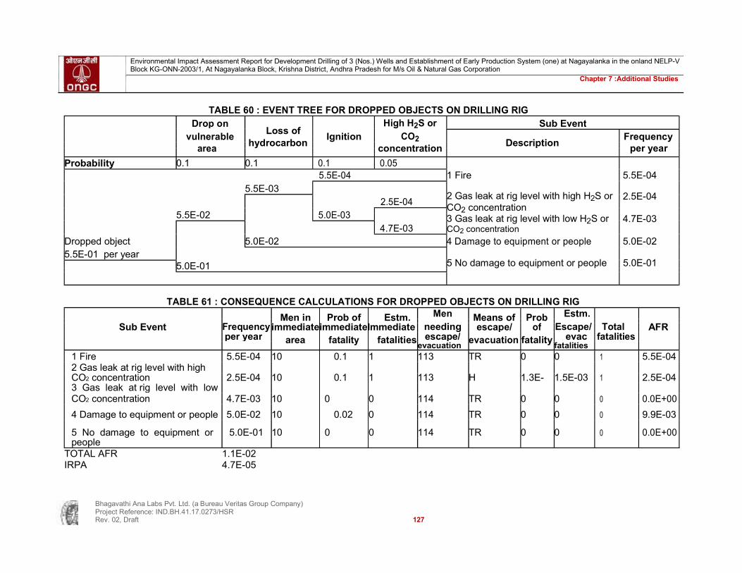
TABLE 60 : EVENT TREE FOR DROPPED OBJECTS ON DRILLING RIG Drop on
Loss of High H2S or Sub Event
vulnerable Ignition CO2 Frequency
hydrocarbon Description area concentration per year
Probability 0.1 0.1 0.1 0.05 1 Fire
5.5E-04
5.5E-04 5.5E-03
2 Gas leak at rig level with high H2S or 2.5E-04
2.5E-04 CO2 concentration
5.5E-02
5.0E-03
3 Gas leak at rig level with low H2S or 4.7E-03
4.7E-03
CO2 concentration
Dropped object 5.0E-02 4 Damage to equipment or people 5.0E-02 5.5E-01 per year
5 No damage to equipment or people 5.0E-01
5.0E-01
TABLE 61 : CONSEQUENCE CALCULATIONS FOR DROPPED OBJECTS ON DRILLING RIG
Frequency Men in Prob of Estm. Men Means of Prob Estm.
Total
needing Escape/
Sub Event immediateimmediateImmediate escape/ of AFR per year area fatality fatalities escape/ evacuation fatality evac fatalities evacuation fatalities
1 Fire 5.5E-04 10 0.1 1 113 TR 0 0 1 5.5E-04 2 Gas leak at rig level with high CO2 concentration 2.5E-04 10 0.1 1 113 H 1.3E- 1.5E-03 1 2.5E-04 3 Gas leak at rig level with low CO2 concentration 4.7E-03 10 0 0 114 TR 0 0 0 0.0E+00
4 Damage to equipment or people 5.0E-02 10 0.02 0 114 TR 0 0 0 9.9E-03
5 No damage to equipment or 5.0E-01 10 0 0 114 TR 0 0 0 0.0E+00 people
TOTAL AFR 1.1E-02 IRPA 4.7E-05
Bhagavathi Ana Labs Pvt. Ltd. (a Bureau Veritas Group Company) Project Reference: IND.BH.41.17.0273/HSR Rev. 02, Draft 127

Environmental Impact Assessment Report for Development Drilling of 3 (Nos.) Wells and Establishment of Early Production System (one) at Nagayalanka in the onland NELP-V Block KG-ONN-2003/1, At Nagayalanka Block, Krishna District, Andhra Pradesh for M/s Oil & Natural Gas Corporation
Chapter 7 :Additional Studies
Evacuation methods TR - muster in TR (no evacuation required) H - muster in TR and evacuation
TABLE 62 : ASSUMPTION FOR STRUCTURAL FAILURE OF DRILLING RIG S.No Assumption Comments 1 Probability of a structural failure in any year is Structural failure includes: design error, fatigue failure, modification error, operating
assumed to be 0.0028 outside design parameters (e.g. extreme weather / earthquakes in excess of design conditions). It is assumed that the rig has been correctly specified for the anticipated environmental conditions It is assumed that only the 2 most severe categories will contribute to major structural failure. These are: total loss of the unit severe damage to one or more modules of the unit / major damage to essential equipment These 2 categories comprise 12.8% and 22.8% of all structural failure contributions (35.6% in total) Hence the annual rig failure rate is 0.0077*0.36 = 0.0028. 2 90% of failures are assumed to give some Estimate
warning and hence allow time for precautionary evacuation 3 The remaining 10% of failures are split as follows: Estimate
10% of them result in sudden collapse The remaining 90% are the result of a progressive failure 4 When escaping from the rig sudden collapse A potentially conservative interpretation which assumes that the collapse is so
scenario, personnel will have a 50 % survival sudden that many escape routes become unusable probability 5 When escaping from the rig progressive collapse Based on a conservative interpretation of reference assuming that all such events
scenario, personnel will have a 90 % survival will occur during severe weather. Reference gives a probability of failure to survive probability as 0.06.
Bhagavathi Ana Labs Pvt. Ltd. (a Bureau Veritas Group Company) Project Reference: IND.BH.41.17.0273/HSR Rev. 02, Draft 128

Environmental Impact Assessment Report for Development Drilling of 3 (Nos.) Wells and Establishment of Early Production System (one) at Nagayalanka in the onland NELP-V Block KG-ONN-2003/1, At Nagayalanka Block, Krishna District, Andhra Pradesh for M/s Oil & Natural Gas Corporation
Chapter 7 :Additional Studies
TABLE 63 : EVENT TREE FOR STRUCTURAL FAILURE STRUCTURAL FAILURE OF DRILLING RIG Sub Event
No precautionary Progressive failure
Description
Frequency per evacuation year
Probability 0.1 0.1
1 Loss of rig, personnel have time to
2.8E-05
2.8E-05
2.8E-04
evacuate
Structural failure 2.5E-04 2 Catastrophic loss
2.5E-04
2.8E-03 per year
2.5E-03 3 Loss of rig with no personnel on rig 2.5E-03
TABLE 64 : CONSEQUENCE CALCULATIONS FOR STRUCTURAL FAILURE OF DRILLING RIG
Men in Prob of
Men Means of Prob
Estm. Frequency Estm.Immediate needing Escape/ Total
Sub Event per year immediate immediate fatalities escape/ escape/ of evac fatalities AFR area fatality evacuation evacuation fatality fatalities
1 Loss of rig, personnel have 2.8E-05 114 0 0 114 H 1.3E- 1.5E-03 0 4.1E- time o 05 08 evacuate 2 Catastrophic loss 2.5E-04 114 0.5 57 114 L/R 1.E-01 11.4 68 1.7E- 3 Loss of rig with no 2.5E-03 114 0 0 114 H 1.3E- 1.5E-03 0 3.7E- personnel on board 05 06 TOTAL 1.7E-02 AFR 7.6E-05 IRPA Evacuation methods TR - muster in TR (no evacuation required) H - Muster in TR and evacuation
Bhagavathi Ana Labs Pvt. Ltd. (a Bureau Veritas Group Company) Project Reference: IND.BH.41.17.0273/HSR Rev. 02, Draft 129
Environmental Impact Assessment Report for Development Drilling of 3 (Nos.) Wells and Establishment of Early Production System (one) at Nagayalanka in the onland NELP-V Block KG-ONN-2003/1, At Nagayalanka Block, Krishna District, Andhra Pradesh for M/s Oil & Natural Gas Corporation
Chapter 7 :Additional Studies
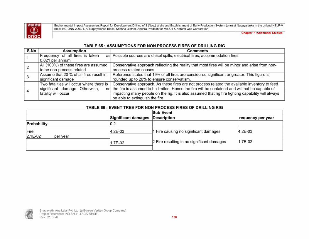
TABLE 65 : ASSUMPTIONS FOR NON PROCESS FIRES OF DRILLING RIG S.No Assumption Comments
1 Frequency of all fires is taken as Possible sources are diesel spills, electrical fires, accommodation fires. 0.021 per annum
2 All (100%) of these fires are assumed Conservative approach reflecting the reality that most fires will be minor and arise from non- to be non-process related process related causes
3 Assume that 20 % of all fires result in Reference states that 19% of all fires are considered significant or greater. This figure is significant damage rounded up to 20% to ensure conservatism.
Two fatalities will occur where there is Conservative approach. As these fires are not process related the available inventory to feed
4 significant damage. Otherwise, no the fire is assumed to be limited. Hence the fire will be contained and will not be capable of fatality will occur impacting many people on the rig. It is also assumed that rig fire fighting capability will always
be able to extinguish the fire
TABLE 66 : EVENT TREE FOR NON PROCESS FIRES OF DRILLING RIG Sub Event Significant damages Description requency per year
Probability 0.2
Fire 4.2E-03 1 Fire causing no significant damages 4.2E-03 2.1E-02 per year 1.7E-02 2 Fire resulting in no significant damages 1.7E-02
Bhagavathi Ana Labs Pvt. Ltd. (a Bureau Veritas Group Company) Project Reference: IND.BH.41.17.0273/HSR Rev. 02, Draft 130

Environmental Impact Assessment Report for Development Drilling of 3 (Nos.) Wells and Establishment of Early Production System (one) at Nagayalanka in the onland NELP-V Block KG-ONN-2003/1, At Nagayalanka Block, Krishna District, Andhra Pradesh for M/s Oil & Natural Gas Corporation
Chapter 7 :Additional Studies
TABLE 67 : CONSEQUENCE CALCULATIONS FOR NON PROCESS FIRES OF DRILLING RIG
Men in Prob of
Estm. Men
Means of Estm.
Frequency needing Prob of Escape/ Total
Sub Event immediate immediate
Immediate escape/ AFR
per year escape/
fatalityevac
fatalities area fatality fatalities evacuation evacuation fatalities
1 Fire causing4.2E-03 N/A N/A 2 112 TR 0 0 2 8.4E-03 no significant damages 1.7E-02 N/A N/A 0 114 TR 0 0 0 0.0E+00 2 Fire resulting in no significant damages TOTAL 8.4E-03 AFR 3.7E-05 IRPA
Evacuation methods TR - muster in TR (no evacuation required) H - muster in TR and evacuation
TABLE 68 : ASSUMPTIONS FOR HYDROCARBON LEAKS DURING WELL TESTING / EARLY PRODUCTION SYSTEM S.No Assumption Comments Assume annual gas leakage frequency of 0.00027 Derived from reference assuming: 1
Test equipment skid mounted, typically consisting of; heater, test separator, surge drum, holding tank, metering runs, and associated pipework. This
equates to 4 pressure vessels, 2 flanges, 2 valves (assume inlet and outlet to isolate skid) and an assumed 40 metres of pipework reference gives the following annual failure frequencies: pressure vessel (0.00015), valve (0.00023), flange (0.000088), piping (4” to 11” – 0.000036 per metre) This produces an annual leak frequency of (4*0.00015)+(2*0.000088)+ (0.00023*2) +(40*0.000036) = 0.0027 Each test lasts for 5 days, there are 7 tests per year hence the equipment is at risk for 35/365 of a year = 0.1 Thus annual leak frequency is 0.0027*0.1 =0.00027
Bhagavathi Ana Labs Pvt. Ltd. (a Bureau Veritas Group Company) Project Reference: IND.BH.41.17.0273/HSR Rev. 02, Draft 131

Environmental Impact Assessment Report for Development Drilling of 3 (Nos.) Wells and Establishment of Early Production System (one) at Nagayalanka in the onland NELP-V Block KG-ONN-2003/1, At Nagayalanka Block, Krishna District, Andhra Pradesh for M/s Oil & Natural Gas Corporation
Chapter 7 :Additional Studies
S.No Assumption Comments testing equipment pressurized at all times Assume that 95% of leaks can be isolated Typical value used in risk assessments. Detection can be by personnel or 2
automatic equipment and relates to the probability of a single valve not closing. As isolation is possible via the wellhead master control valve, the BOP or and ESD
valve within the test equipment this can be considered a conservative approach 3
If the gas release is not isolated all workers in the Conservative approach immediate vicinity will be assumed to be exposed Assume 10 men in the immediate vicinity during testing
If the release is isolated no fatalities occur If the release is isolated only a short lived jet fire or small flash fire is possible in 4
the event of ignition or a small volume of potentially poisonous gas in the event that the gas contains H2S. In all these scenarios the threat is limited and
contained and hence they do not result in any fatalities Assume probability of ignition of 0.1 Reference suggests that the probability of ignition for small and large gas leaks is 0.005 and 0.3 respectively. Reference indicates that this upper value may be too 5
conservative by recommending a probability of ignition for blowouts of 0.1. Most leaks from process equipment are small and hence a figure towards the lower
end of the scale will be most appropriate. Although a lower figure may be justifiable the figure of 0.1 is considered suitably conservative When ignition occurs: In the event of ignition of hydrocarbons the following may occur 50% of the time it occurs immediately and pool fire: a burning pool of liquid (oil or well fluid) on the rig results in a jet fire jet fire: a burning jet of gas which if ignited soon after it occurs results in an 50% of the time it will be delayed and result in intense stabilised jet which is very destructive to anything within it or close to an explosion it Flash fire: delayed (say after 15 minutes) ignition of a gas release. In this 6
time the release may have formed an extensive plume and the ensuing fire will kill everyone within it who is unprotected but not damage structures
Confined explosion: delayed ignition of a gas release within a confined space, the delay (usually in excess of 5 minutes) giving time for an explosive mixture to build up. It has the potential for considerable fatalities and damage. It is assumed that the necessary degree of confinement does not exist on a jack up Vapour cloud explosion: an ignited gas plume which burns in such a way
Bhagavathi Ana Labs Pvt. Ltd. (a Bureau Veritas Group Company) Project Reference: IND.BH.41.17.0273/HSR Rev. 02, Draft 132
Environmental Impact Assessment Report for Development Drilling of 3 (Nos.) Wells and Establishment of Early Production System (one) at Nagayalanka in the onland NELP-V Block KG-ONN-2003/1, At Nagayalanka Block, Krishna District, Andhra Pradesh for M/s Oil & Natural Gas Corporation
Chapter 7 :Additional Studies
S.No Assumption Comments that it generates overpressures characteristic of an explosion. A simple but conservative approach has been taken that all immediate ignition events result in a jet fire while the results of all delayed ignition events (whether they are from a flash fire or a vapour cloud explosion) are equally severe
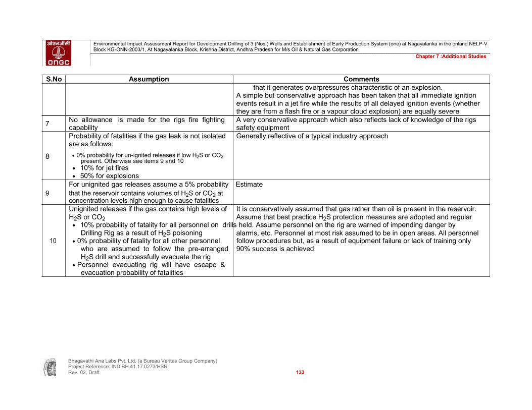
7 No allowance is made for the rigs fire fighting A very conservative approach which also reflects lack of knowledge of the rigs capability safety equipment
Probability of fatalities if the gas leak is not isolated Generally reflective of a typical industry approach are as follows:
8 0% probability for un-ignited releases if low H2S or CO2 present. Otherwise see items 9 and 10
10% for jet fires 50% for explosions
For unignited gas releases assume a 5% probability Estimate 9 that the reservoir contains volumes of H2S or CO2 at
concentration levels high enough to cause fatalities Unignited releases if the gas contains high levels of It is conservatively assumed that gas rather than oil is present in the reservoir. H2S or CO2 Assume that best practice H2S protection measures are adopted and regular 10% probability of fatality for all personnel on drills held. Assume personnel on the rig are warned of impending danger by
Drilling Rig as a result of H2S poisoning alarms, etc. Personnel at most risk assumed to be in open areas. All personnel 10 0% probability of fatality for all other personnel follow procedures but, as a result of equipment failure or lack of training only
who are assumed to follow the pre-arranged 90% success is achieved H2S drill and successfully evacuate the rig Personnel evacuating rig will have escape & evacuation probability of fatalities
Bhagavathi Ana Labs Pvt. Ltd. (a Bureau Veritas Group Company) Project Reference: IND.BH.41.17.0273/HSR Rev. 02, Draft 133

Environmental Impact Assessment Report for Development Drilling of 3 (Nos.) Wells and Establishment of Early Production System (one) at Nagayalanka in the onland NELP-V Block KG-ONN-2003/1, At Nagayalanka Block, Krishna District, Andhra Pradesh for M/s Oil & Natural Gas Corporation
Chapter 7 :Additional Studies
TABLE 69 : EVENT TREE FOR HYDROCARBON LEAKS DURING WELL TESTING / EARLY PRODUCTION SYSTEM
Release is High H2S or Sub Event
Frequency
Ignition Delayed ignition CO2
Description
isolated concentration per year
Probability 0.95 0.1 0.5 0.05
1.3E-05 1 Small flash fire 1.3E-05
2.6E-05
2.6E-04 1.3E-05 2 Short-lived jet flame 1.3E-05
1.2E-05
Hydrocarbon leak
2.3E-04
3 Small gas cloud with high H2S or CO2 1.2E-05
concentration
2.7E-04 per year
2.2E-04
4 Small gas cloud with low H2S or CO2 2.2E-04
6.8E-07
concentration 5 Explosion 6.8E-07
1.4E-06
1.4E-05 6.8E-07 6.1E-07 6 Jet flame 6.8E-07 1.2E-05 7 Gas cloud with high H2S or CO2 concentration 6.1E-07 1.2E-05
8 Gas cloud with low H2S or CO2 concentration 1.2E-05
Bhagavathi Ana Labs Pvt. Ltd. (a Bureau Veritas Group Company) Project Reference: IND.BH.41.17.0273/HSR Rev. 02, Draft 134

Environmental Impact Assessment Report for Development Drilling of 3 (Nos.) Wells and Establishment of Early Production System (one) at Nagayalanka in the onland NELP-V Block KG-ONN-2003/1, At Nagayalanka Block, Krishna District, Andhra Pradesh for M/s Oil & Natural Gas Corporation
Chapter 7 :Additional Studies TABLE 70 : CONSEQUENCE CALCULATIONS FOR HYDROCARBON LEAKS DURING WELL TESTING / EARLY PRODUCTION SYSTEM
Frequency Men in Prob of Estm. Men needing Means of
Prob of Estm.
Total
escape/ Escape/
Sub Event immediate immediate Immediate escape/ AFR per year evacuation fatality evac fatalities area fatality fatalities evacuation
fatalities
1 Small flash 1.3E-05 10 0 0 114 TR 0 0 0 0.0E+00 fire
2 Short-lived 1.3E-05 10 0 0 114 TR 0 0 0 0.0E+00 jet flame
3 Small gas 1.2E-05 10 0 0 114 TR 0 0 0 0.0E+00 cloud with high H2S or CO2 concentration
4 Small gas 2.2E-04 10 0 0 114 TR 0 0 0 0.0E+00 cloud with low H2S or CO2
concentration
5 Explosion 6.8E-07 10 0.5 5 109 H 1.3E-05 1.4E-03 5 3.4E-06
6 Jet flame 6.8E-07 10 0.1 1 113 H 1.3E-05 1.5E-03 1 6.8E-07
7 Gas cloud with high H2S 6.1E-07 10 0.1 1 113 H 1.3E-05 1.5E-03 1 6.1E-07 or CO2 8 Gas cloud 1.2E-05 10 0 0 114 H 1.3E-05 1.5E-03 0 1.7E-08 with low H2S or CO2 concentration
TOTAL AFR 4.7E-06 IRPA 2.1E-08
Evacuation methods TR - muster in TR (no evacuation required) H - muster in TR and evacuation
Bhagavathi Ana Labs Pvt. Ltd. (a Bureau Veritas Group Company) Project Reference: IND.BH.41.17.0273/HSR Rev. 02, Draft 135

Environmental Impact Assessment Report for Development Drilling of 3 (Nos.) Wells and Establishment of Early Production System (one) at Nagayalanka in the onland NELP-V Block KG-ONN-2003/1, At Nagayalanka Block, Krishna District, Andhra Pradesh for M/s Oil & Natural Gas Corporation
Chapter 7 :Additional Studies
7.1.3.2. Calculation of Individual Risk Per Annum (IRPA)
Event trees and consequence analysis will be used to evaluate the Annual Fatality Rate (AFR) for each major hazard
By their method of calculation these AFR’s provide a measure of the average risk between the drilling, maintenance and support populations on the rig. They essentially weight each groups contribution to fatalities by exposure
All major hazard AFR’s will then be summed to derive a total AFR for the rig This figure is the average risk faced in one year by all personnel on the rig and
has been calculated assuming that the rig always contains 30 personnel However, workforce of 30*2 = 60 to maintain a constant 30 man workforce on the
rig for the whole year. Hence the IRPA can be simplistically assumed to be (Total AFR / 60)
7.1.3.3. Analysis Results
The results of the risk analysis for the drilling in Block KG-ONN-2003/1 which are shown in Table 71.
TABLE 71 : RISK RESULTS
Hazard No Major Accident Hazard Individual Risk Per Annum (IRPA)
1 Blowout During Drilling 1.9E-04
2 Passing Vehicle collision 4.0E-06 3 Dropped Objects 4.7E-05 4 Structural Failure 7.6E-05 5 Non Process Fires 3.7E-05
6 Hydrocarbon Leaks During Well
2.1E-08 Testing / Early Production System
TOTAL 3.54E-04 7.1.3.4. Comparison with ALARP Criteria
The total individual risk (IRPA) for the drilling operation in Block KG -ONN-2004/1 has been estimated to be 3.54E-04 fatalities per annum. This is within the ALARP region of less than 1.00E-03 but greater than 1.00E-05. The calculated fatality frequency for each individual hazard is also within the ALARP region with the exception of Vehic le Collision (4.0E-06) and Hydrocarbon Leaks during Well Testing (2.1E-08). Which are both in the ‘broadly acceptable’ region. IRPA's in the ALARP Region are tolerable but additional safeguards should be examined to ensure that an ALARP level is reached in practice and the risk further reduced using cost effective solutions.
7.1.3.5. Oil Spill Frequency
The event trees have identified a number of contributions to the release of hydrocarbons from the drilling unit. The safety impacts of these releases have been modelled in the consequence analyses; this section addresses their potential environmental impact taking account of the relative remoteness of block KG-ONN-2003/1 from the coastline.
Bhagavathi Ana Labs Pvt. Ltd. (a Bureau Veritas Group Company) Project Reference: IND.BH.41.17.0273/HSR Rev. 02, Draft 136

Environmental Impact Assessment Report for Development Drilling of 3 (Nos.) Wells and Establishment of Early Production System (one) at Nagayalanka in the onland NELP-V Block KG-ONN-2003/1, At Nagayalanka Block, Krishna District, Andhra Pradesh for M/s Oil & Natural Gas Corporation
Chapter 7 :Additional Studies
Hydrocarbon releases may arise from the drilling unit’s own equipment / tank s, equipment / tanks or from the hydrocarbon reservoir itself. The releases are categorised as follows:
Tier 1 – spills <10 tonnes: These releases are assumed to have only a small, local to the unit, impact and to be capable of being managed solely by the unit. Most spills in this category are likely to be sufficiently small to be dispersed naturally; the remainder assumed to have a limited oil spill response capability. Such incidents can arise from: spills of oils /lubricants; diesel spillages etc. Events resulting in such minor spillages are not conducive to QRA and therefore have not been modelled as part of this QRA.
Tier 2 – spills >10 to 100 tonnes: These incidents may not be capable of being managed entirely by the drilling unit and may require some limited outside support.
TABLE 72 : INITIATING EVENTS LEADING TO TIER 2 OIL SPILL
Initiating Event (Major Accident Hazard) Hazard No. Annual Frequency
Dropped Objects 2 5.5E-03
Tier 3 – spills >100 tonnes These incidents, resulting from hydrocarbon releases from the reservoir, have the potential to impact a wider area and, particularly at the upper end of the range, to impact the coast no matter how remote from the shore the unit may be.
TABLE 73 : INITIATING EVENTS LEADING TO TIER 3 OIL SPILL
Initiating Event (Major Accident Hazard) Hazard No Annual Frequency Well Blowout
1 1 4 . 4E - 02
Leak During Well Testing2 / Early Production System 8 1 . 4E - 05
NOTES: 1: Maximum volume = Open hole flow rate x days to plug well 2: Maximum volume assumes that downhole and top drive safety equipment fail to isolate the reservoir
This gives a total spill frequency for Tier 2 and Tier 3 for a drilling operation of 5.0E-02.
7.1.3.6. Recommendations
Recommendations are given in Table 74 for each of the risks within the ALARP region. Implementing these recommendations will ensure that the assumptions in the risk assessment are valid and potentially provide cost effective risk reduction measures. These constitute ‘best practice’ for operational control and would form part of an effective Safety Management System.
In addition recommendations have been made relating to preparedness for dealing with the risk of an oil spill during the drilling operation.
Bhagavathi Ana Labs Pvt. Ltd. (a Bureau Veritas Group Company) Project Reference: IND.BH.41.17.0273/HSR Rev. 02, Draft 137

Environmental Impact Assessment Report for Development Drilling of 3 (Nos.) Wells and Establishment of Early Production System (one) at Nagayalanka in the onland NELP-V Block KG-ONN-2003/1, At Nagayalanka Block, Krishna District, Andhra Pradesh for M/s Oil & Natural Gas Corporation
Chapter 7 :Additional Studies
TABLE 74 : RECOMMENDATIONS FOR DRILLING
Hazard Hazard
Recommendation
No
Through control of the Drilling Contract including the use of Audit ensure that: Blowout The rig is fit for purpose and fully certified 1 During Properly certified equipment is used e.g. BOP etc. Drilling The Drilling Contractor will be competent and will provide qualified staff and supervision Emergency response and training is adequate
Passing Ensure that there is adequate monitoring by Transporting team.
2 Vehicle Emergency exercises to include dealing with errant Vehicles Collision
Through control of the Drilling Contract including the use of Audit
Dropped ensure that:
3 cranes are fully certified Objects crane operators and banks men are competent
hazardous areas are outside areas used for lifting
Through control of the Drilling Contract including the use of Audit
Structural ensure that:
4 the Rig / EPS is fully certified Failure the Rig / EPS maintenance is adequate
the Rig / EPS is operated within its design criteria
Non- Maintain awareness of crew of fire risks within accommodation and
5 Process engine spaces Fires
All oil The drilling oil spill planning requires: spills
Response capability at the drill site. Some pollution control resulting ALL capability
from the
back-up resources identified major adequate training in Emergency Response hazards
Proper zoning of the area is to be done to avoid cumulative fire scenarios. MSDS should be provided in the storage areas and clear demarcation of hazards is to be provided. Proper cementing and casing practices should be taken up. Diesel tanks of 2* 6KL are proposed in each drilling site & EPS, if the tanks are caught with fire the heat radiation will reach a
distance of 100mts which will be well within the site premises. Automatic H2S gas detection system is to be made available near the well site to avoid fatality due to toxic gases. Heat radiation due to crude oil fire scenario will reach a distance of 326mts but immediate utilisation of BOP will decrease the distances of heat radiation. The proximity of DG sets as per the below Figure 27 & 28 may be an ignition source in case of any spillages. So safe distance should be maintained in between well and DG Sets
Bhagavathi Ana Labs Pvt. Ltd. (a Bureau Veritas Group Company) Project Reference: IND.BH.41.17.0273/HSR Rev. 02, Draft 138

Environmental Impact Assessment Report for Development Drilling of 3 (Nos.) Wells and Establishment of Early Production System (one) at Nagayalanka in the onland NELP-V Block KG-ONN-2003/1, At Nagayalanka Block, Krishna District, Andhra Pradesh for M/s Oil & Natural Gas Corporation
Chapter 7 :Additional Studies
FIGURE 27 : DRILLING SITE PLAN
FIGURE 28 : EPS LAYOUT
Bhagavathi Ana Labs Pvt. Ltd. (a Bureau Veritas Group Company) Project Reference: IND.BH.41.17.0273/HSR Rev. 02, Draft 139

Environmental Impact Assessment Report for Development Drilling of 3 (Nos.) Wells and Establishment of Early Production System (one) at Nagayalanka in the onland NELP-V Block KG-ONN-2003/1, At Nagayalanka Block, Krishna District, Andhra Pradesh for M/s Oil & Natural Gas Corporation
Chapter 7 :Additional Studies
7.2. Emergency Response Plan
7.2.1. Objectives And Scope
The key objective of this Emergency Response Plan (ERP) is to outline the management, organisational arrangements and available facilities that will be utilised by ONGC, in the event of an emergency situation arising during the proposed drilling activity in Block KG-ONN-2003/1. The plan identifies the philosophy and approach for managing an emergency and provides an outline of the roles and responsibilities of key ONGC and contractor staff for potential emergency scenarios identified as part of the rapid risk assessment conducted for the proposed drilling activity.
The plan should not include specific action items for controlling emergencies but provides a basis on which specific detailed emergency response procedures may be developed.
This section outlines the key elements of an Emergency Response Plan to support the drilling activity.
7.2.1.1. Emergency Response Organisation And Communication
Initial response to any incident will be managed on site. The overall level of response will depend on the nature and scale of the emergency.
Emergency incidents have the potential to impact both ONGC (staff / reputation / schedule/ etc.) and the Drilling Contractor (staff / equipment / rig / reputatio n / etc.) and require the involvement both ONGC and the Drilling Contractors management. Hence there should be one ERP for the drilling operation that reflect the integration of both the ONGC and Drilling Contractor’s response plans. Where necessary, bridg ing documents may be required to fully integrate aspects of the two companies response plans.
The initial response to all incidents should be managed by the drilling unit. The Drilling Contractor having most personnel at risk and most knowledge of the drilling unit should take the lead in managing the immediate response to the incident.
The specific structure and organisation of the ERP will be dependent on the location and capability of the Drilling Contractor but will typically consist of On Site Response Team (managed by Drilling Contractor with ONGC support);
7.2.1.2. Identified Emergency Scenarios
The Emergency Response Plan (ERP) must be capable of managing the response to the major hazards, identified and any associated environmental risks. In addition the ERP must also address “occupational” hazards including incidents such as Single and multiple accidents requiring medical evacuation).
Bhagavathi Ana Labs Pvt. Ltd. (a Bureau Veritas Group Company) Project Reference: IND.BH.41.17.0273/HSR Rev. 02, Draft 140

Environmental Impact Assessment Report for Development Drilling of 3 (Nos.) Wells and Establishment of Early Production System (one) at Nagayalanka in the onland NELP-V Block KG-ONN-2003/1, At Nagayalanka Block, Krishna District, Andhra Pradesh for M/s Oil & Natural Gas Corporation
Chapter 7 :Additional Studies
7.2.1.3. Emergency Classification
The required response will depend on the scale of the incident. Emergency scenarios are categorised into three levels, typically:
Tier 1 Incident (Local Alert) Tier 1 incidents require no external assistance and can be managed by the Emergency Co-ordinator using on site resources. Typical incidents may include: Single casualty (medevac); Oil spills <10 tonnes; ONGC equipment damage;
Tier 2 Incident (Site Alert) Tier 2 incidents cannot be managed entirely on site. ONGC response is typically activated, Incidents may include: Substantial security incident; Multiple casualty (medevac); Oil spill 10-100 tonnes ; Substantial fire; Cyclone/flooding; Cultural conflict.
Tier 3 Incident (External Alert) Tier 3 incidents are major emergencies beyond site resources with the potential to impact beyond the site limit. External assistance is required and there is immediate mobilisation of ONGC. Typical incidents may include: Major fire / explosion; Oil spill >100 tonnes; Fatality.
It should be noted that for any tier incident, when determining tiers for oil spills, the quantity of oil spilt is not the only factor. The environment potentially threatened by the oil is also considered in determining the tier of spill.
7.2.1.4. Emergency Response Activation
The level of callout to deal with an emergency needs to be defined and co-ordinated by ONGC. The Emergency Response Contact directory will be updated before the actual commencement of drilling activity.
7.2.2. Disaster Prevention Methods
Effective emergency management should include both detailed emergency response measures and appropriate prevention measures. ONGC will assure that the process for assessing potential contractors includes an assessment of each Company's safety record and arrangements for emergency prevention and response.
It may be necessary for the Contractor to demonstrate inter alia:
Bhagavathi Ana Labs Pvt. Ltd. (a Bureau Veritas Group Company) Project Reference: IND.BH.41.17.0273/HSR Rev. 02, Draft 141

Environmental Impact Assessment Report for Development Drilling of 3 (Nos.) Wells and Establishment of Early Production System (one) at Nagayalanka in the onland NELP-V Block KG-ONN-2003/1, At Nagayalanka Block, Krishna District, Andhra Pradesh for M/s Oil & Natural Gas Corporation
Chapter 7 :Additional Studies
Properly documented EHS Management System Competent personnel trained in disaster response duties Appropriate detection equipment (gas detection including H2S, smoke detection,
radar) Suitable fire fighting equipment available and personnel properly trained in its use
Operational emergency alarm and PA system Effective communication equipment including VHF Radio, V-SAT / INMARSAT,
mobile VHF radios All equipment required for emergency response undergoes routine maintenance
and is regularly tested / calibrated Detailed evacuation procedures including appropriate muster areas, escape
routes including clear signs where appropriate. Personnel should be made aware of evacuation procedures through appropriate training.
Regular drills/exercises to test ERP’s Regular review of Emergency Response Plans with modifications as required. ONGC is also having Operational Risk Management Committee BOP of 10000 to 15000 PSI are utilised based on rig capacity
Decommissioning Phase and Well Abandonment Management At the conclusion of the exploration-drilling program at each drilling site, an orderly withdrawal of all personnel and the removal of all drilling and testing equipment and non-fixed items from the drilling site will be undertaken.
Broadly, there are two such scenarios:
In case that the well is completed when economic quantities of hydrocarbons are found, the well will be left with a wellhead in place, but all other equipment and materials will be removed from the site.
In any other case the site will be cleared and refurbished to permit recovery to as near as
possible the pre-existing local environment.
Temporary Suspension of Activities In the event that economic quantities of hydrocarbons are found, all empty drums, wastes, used and unused drilling fluids, fuel and lubricants will be removed from the drilling site. Water supply and effluent discharge hoses and associated equipment will be removed.
Decommissioning Upon Abandonment In the event that no economic quantities of hydrocarbons are found, a full abandonment plan will be implemented for the drilling sites in accordance with the applicable Oil Mines Regulation, 1984. The activities mentioned in the above section would apply to decommissioning upon abandonment as well, but abandonment would be more permanent. The overriding principle being that the environment should, with time, be reinstated to broadly its original condition. Until such time as this is achieved, SOGL would actively manage the reinstatement process. All concrete or steel installations would be removed to at least 1 m below ground level, so as to ensure that there are no protruding surface structures. In the unlikely event if soil is found to be contaminated, measures would be taken to remove or treat appropriately all contaminated topsoil to promote its remediation.
Bhagavathi Ana Labs Pvt. Ltd. (a Bureau Veritas Group Company) Project Reference: IND.BH.41.17.0273/HSR Rev. 02, Draft 142

Environmental Impact Assessment Report for Development Drilling of 3 (Nos.) Wells and Establishment of Early Production System (one) at Nagayalanka in the onland NELP-V Block KG-ONN-2003/1, At Nagayalanka Block, Krishna District, Andhra Pradesh for M/s Oil & Natural Gas Corporation
Chapter 7 :Additional Studies
ONGC has accorded top priority to safety and protection of environment in the operational areas. The activities are oriented towards prevention rather than cure and conducted in such a way as to ensure: Health and safety of its employees Protect the environment Optimal utilization of oil field equipment, instruments without leading to any health
hazards. Health, safety and environment (HSE) matters have given equal status with all
other primary business objectives. 7.3. Health and Safety
The field Development project proposes drilling of three development wells and establishment of one EPS with the required process facilities for producing from these wells and the existing well. The impact of drilling the development wells and operating the production facilities have been considered during site preparation, drilling, well testing and demobilization stages. A robust HSE Management Plan is proposed to be put in place so as to mitigate the negative impacts and the entire project is implemented in a sustainable way.
7.3.1. Occupational Health
An Occupational Health Management System is proposed to be kept in place aimed at promoting and maintaining physical, mental and social wellbeing to the highest degree among the personnel by monitoring their health and the state of the workplace. Occupational Health monitoring shall be made applicable to all the workers at all installations and work centers.
Scope of activities The scope of activities include the following –
Personnel Surveillance: Periodic Medical Examination, Pre-Employment Medical Examination and Pre- Placement Medical Examination. Investigations will be carried out at authorized laboratories.
Workplace Surveillance: Monitoring of all workplaces for Hazards Ergonomic Assessment of the Workplace Sanitation Evaluation will be carried out including potability of Water
Educative Function:– By imparting training in: Occupational Health Preventive Medicine First Aid Training
Occupational Health Surveillance Program- Onshore operations comes under Mines Act, 1952 and as per Mines Act every person employed in a mine must undergo PME (Periodical Medical Examination) by an approved physician / Hospital at a reasonable periodic interval i.e.
Bhagavathi Ana Labs Pvt. Ltd. (a Bureau Veritas Group Company) Project Reference: IND.BH.41.17.0273/HSR Rev. 02, Draft 143

Environmental Impact Assessment Report for Development Drilling of 3 (Nos.) Wells and Establishment of Early Production System (one) at Nagayalanka in the onland NELP-V Block KG-ONN-2003/1, At Nagayalanka Block, Krishna District, Andhra Pradesh for M/s Oil & Natural Gas Corporation
Chapter 7 :Additional Studies
For age up to 45 yrs - Once in 5 years For age from 46 to 55 yrs - Once in 3 years For ages above 55 yrs - Once every year
The operator herewith ensures that he will adopt all measures to safeguard the health of the employees.
7.3.2. Safety
An effective Safety Management System will be put in place to prevent accidents, hazardous incidents and eliminate or minimise their consequences.
Enforcement of Safety Safety shall be ensured through repeatedly highlighting its utility in preventing loss of life and property and providing training to employees on safe working. Following modes will be followed for this:
Work Permit System Job safety analysis Training of employees and contractors Surprise checks Drills Operating manuals / Safety manuals
HSE Information & Corporate EHS Policy of ONGC is provided as Annexure IV. Monitoring of Systems Following systems will be monitored regularly for effective implementation:
Checking of safety interlocks Internal audits of facilities in line with OISD-STD-145 Management of change Testing / Inspection of equipment Checking of fire detection and protection system
Safety Promotion Visuals play an important role in reminding personnel of safety information. Therefore, display of following information will be done in the premises:
Safety precautions for critical operations at strategic locations Safety posters and slogans Safety records Do's and Don'ts at chemicals handling/storage/operation areas Need for Wearing helmet and other Personal Protective Equipment (PPEs) Labeling of chemicals Material Safety Data Sheet (MSDS) Safety manuals, Rules and Regulations Safety News Letters & bulletins Dissipation of incident information
Bhagavathi Ana Labs Pvt. Ltd. (a Bureau Veritas Group Company) Project Reference: IND.BH.41.17.0273/HSR Rev. 02, Draft 144
Environmental Impact Assessment Report for Development Drilling of 3 (Nos.) Wells and Establishment of Early Production System (one) at Nagayalanka in the onland NELP-V Block KG-ONN-2003/1, At Nagayalanka Block, Krishna District, Andhra Pradesh for M/s Oil & Natural Gas Corporation
Chapter 7 :Additional Studies
Work Permit In case, work is required to be performed in the plant / facility by any person other than the operating personnel of that area, a duly authorized written permit will be obtained by the person / agency executing the work before commencement of the work.
Based on the nature, the work would be undertaken under different types of permits. For example, following jobs will be undertaken with the duly issued hot work permit:
Cutting, Welding, Excavation, Road/Dyke cutting, Electrical lock out / Energising, Confined space entry, Boxing up of a vessel, Working on fragile roof structures, Radiography, Material Handling in operational areas, Crane operation etc. OISD-STD- 105 on Work Permit System will be adhered to regarding issuance of work permits.
Safe Work Practices Safe Work Practices will be followed during drilling and production operations as given below:
Drilling Operations Safety precautions during drilling operations involve
Safety during Rig Building / Dismantling Systems Rig building operations involve dismantling of the structures in old location, transportation and erection of the same at new location. The job involves handling of heavy loads upto 20-30 tons using various heavy material handling operations, transportation from location to location involves accidental risk and such transportation to be handled with extreme care. In rig building the risks of accident are therefore involved in:
Use of heavy material handling equipment. Transportation of heavy equipment from one location to another location. Rigging
up operations involve risks associated with work at height, handling tools in awkward positions, danger of falling object on workers on the ground.
The recommendations listed below serve as a guide for minimizing hazards during rigging up and dismantling operations.
Rig Dismantling
All sheaves and shafts of the hoisting system will be checked (zin poles, hoisting sheaves, equalizer sheave, crown block sheaves, traveling block sheaves). All the sheaves, bearings and bushings to be greased.
All the lifting ropes, casing lines and clamps fitted on lifting ropes will be checked. Lifting rope / bull line will be lubricated prior to lowering mast, drawworks and sub-structure.
Draw works brake, eddy current brake, hydromatic brake will be checked. Counter pre-loading tanks will be filled completely with water. Required power availability to drawworks will be checked. Required normal working air pressure to hoisting clutch to be checked. Zin poles or Mole trucks for dragging tanks and heavy equipment in slushy areas
will be used. All the threaded joints will be greased and the threaded ends will be covered by
thread protectors to protect joints during transportation
Bhagavathi Ana Labs Pvt. Ltd. (a Bureau Veritas Group Company) Project Reference: IND.BH.41.17.0273/HSR Rev. 02, Draft 145

Environmental Impact Assessment Report for Development Drilling of 3 (Nos.) Wells and Establishment of Early Production System (one) at Nagayalanka in the onland NELP-V Block KG-ONN-2003/1, At Nagayalanka Block, Krishna District, Andhra Pradesh for M/s Oil & Natural Gas Corporation
Chapter 7 :Additional Studies
Lifting hooks will be checked for any cracks or damage during lifting and loading.
Rigging Up All sheaves and shafts of the hoisting system will be checked (zin poles, hoisting
sheaves, equalizer sheave, crown block sheaves, traveling block sheaves). All the sheaves, bearings and bushings to be greased.
All the lifting ropes, casing lines and clamps fitted on lifting ropes will be checked. Lifting rope / bull line will be lubricated prior to raising mast, drawworks and sub-structure.
Check required power to drawworks motor is available. Check required normal working air pressure to hoisting clutch is available. Safety pins will be used, check nuts on fastening devices. Unauthorized personnel without safety kits on raised structures or platforms shall
not be allowed. Lifting rope shall be checked for kinks, damage due to any falling objects on wire
rope. Check spelter sockets, clamps and wedge blocks for any damage or cracks before fixing the lifting ropes.
Quick release valves of draw works will be checked before hoisting the mast. Proper load on the ammeters, load meter will be checked before raising the mast. Persons not connected directly with the job shall be moved by at least 10 mts from
the raising mast. Everyone involved would know how to stop draw works in case of emergency. Test rig pneumatic system will be kept at a pressure 1.5 times more than working
pressure. Crown end of the derrick will be kept at level with the substructure to minimize
strain on derrick/mast at the time of initial lift. Workers will be told to always wait until the mast comes to a complete rest before
going near a frame/ pedestal for fixing of stay bolts/pins. No loose tools/ bolts or any other materials shall be left on the mast members while
raising mast. Mast will be raised to about 30 cms above the saddle, condition of the foundation
bolts will be checked for any cracks, or any sinking of foundation itself. Lower back the mast, rest on the saddle and rise again.
Rising of mast shall be done in a slow speed in the lowest gear. Derrick designed with guy ropes will be fastened with steel guy ropes. Each guy
rope will have a separate dead end for anchoring. It will be ensured that guy rope is free of kinks, cuts or any other damage before using it and replace when such observations occurred.
Well Control Equipment General Considerations: The following consideration will be made when selecting well control equipment-
The equipment shall be selected to withstand the maximum anticipated surface pressure.
The blowout preventer stack shall consist of remotely controlled equipment capable of closing the well with or without the pipe in the hole.
Welded flange or hub connections are mandatory on all pressure systems as approved for threaded connections. In some areas, well control equipment suitable
Bhagavathi Ana Labs Pvt. Ltd. (a Bureau Veritas Group Company) Project Reference: IND.BH.41.17.0273/HSR Rev. 02, Draft 146

Environmental Impact Assessment Report for Development Drilling of 3 (Nos.) Wells and Establishment of Early Production System (one) at Nagayalanka in the onland NELP-V Block KG-ONN-2003/1, At Nagayalanka Block, Krishna District, Andhra Pradesh for M/s Oil & Natural Gas Corporation
Chapter 7 :Additional Studies
for sour service may be required, in such cases the complete high pressure BOP system shall consist of metallic materials resistant to sulphide stress cracking.
Kill lines will not be smaller than 2" nominal dia and shall be fitted with two valves and an NRV. Choke lines will not be smaller than 3" through bore and are to be connected with two valves to the BOP stack of which the outer valve shall be hydraulically operated. When kill and choke lines are employed, both lines willt not be smaller than 2" through bore and the outer valve of each line shall be hydraulically operated.
In the BOP stack, blind/shear rams shall be provided during drilling and work over operations. The blind/shear rams shall always be capable of shearing the drill pipe/tubing in use under No load conditions and subsequently providing a proper seal.
In the stack, the blind ram will be upper and pipe ram will be lower. This will facilitate to changing the blind ram to pipe ram in case of need and using lower ram as Master ram preventer.
Closing systems of surface BOPs will be capable of closing each ram preventer within 30 seconds, the closing time will not exceed 45 seconds for annular preventers of 20” and larger.
Closing systems of subsea BOPs will be capable of closing each ram preventer within 45 seconds. Closing time will not exceed 60 seconds for annular preventers.
All master and remote operating panel handles will be kept in the full open or closed position, and be free to move into either position, i. e. the shear ram operating handles will not be locked.
All spare operating lines and connections, which are not used in the system, will be properly blocked off with blind plugs at the hydraulic operating unit.
All 3 positions 4 way valves will be either in the open or close position, as required, they will not be left in the locked or neutral position.
Drill pipe safety valve (FOSV/ Kelly cock) shall be kept available at rig floor, which can be conventionally fitted on drill pipe in case kick occurs during tripping Operations.
In case of other tubular in the hole, change over sub from Drill Pipe to that tubular will be available at Derrick Floor.
Casing and Cementation of Wells
Casing of wells As drilling progresses, the well is lowered with casings of different length and diameter. The work of lowering the casing in a well will be carried out in accordance with the GTO/ plan.
Casing lowering operations will be done very carefully. The following recommendations provide guidance in this respect:
The rig I/C Tool pusher will familiarize himself with the inspection practices specified in the standards by the manufacturer.
Casing will be handled at all times on racks or wooden/metal surfaces free of sand, dirt etc.
Cleaning and visual inspection of casing threads will be done on rack and all casing pipes will be provided with thread protectors on the rack.
Bhagavathi Ana Labs Pvt. Ltd. (a Bureau Veritas Group Company) Project Reference: IND.BH.41.17.0273/HSR Rev. 02, Draft 147
Environmental Impact Assessment Report for Development Drilling of 3 (Nos.) Wells and Establishment of Early Production System (one) at Nagayalanka in the onland NELP-V Block KG-ONN-2003/1, At Nagayalanka Block, Krishna District, Andhra Pradesh for M/s Oil & Natural Gas Corporation
Chapter 7 :Additional Studies
Floating equipments (float shoe, float collar) will be properly checked before installation.
Every joint will be drifted with a proper go-gauge. Locking compound will be used for float shoe, float collar and bottom 3-4 singles. In stabbing, casing will be lowered carefully to avoid damaging the threads. Stabbing will be done vertically preferably with assistance of a man on the stabbing
board. Mast will be centered. Slip and tong marks are injurious. Every possible effort should be made to keep
such damage at minimum by using proper up to date equipments. The length of the backup line of tong will be such as to cause minimum bending
stresses on the casing. Proper torque practices will be followed. Hydraulic tong will be used for proper
make up/ torquing of joint. The tong will be provided with a reliable torque gauge. In the initial stages of makeup, any irregularities of make up or speed of makeup
will be observed, since these may be indicative of cross threads or damaged threads.
To prevent galling while making up, the connections will be made up at a speed not exceeding 25 rpm.
Filling of casing during running in will be closely monitored. Casing will be lowered in the well smoothly to avoid surge pressures. Mechanical aids will be placed on casing in accordance with the plan. Circulating sub with kelly and casing connections will be available at the rig floor
prior to start casing. Spiders are recommended for long casing strings and for heavier loads (preferably
load more than 150 tons). Last casing pipe on which BOP and safety equipment is to be installed will be
lowered with matching nipple having good threads in order to avoid any gas or oil leakage.
Lowering of the last two pipes with mud circulation will be ensured with low speed. During cementation, if any sign of activity in the well is noticed; appropriate
protective measures will be taken to keep the well under control. A safety clamp will be used when running the first joint of casing. During running of casing, intermediate circulation needs to be made and minimum
gelation will be ensured. To get a good cement sheath, cement slurry will be kept heavier than mud by 0 .2
to 0.5 gm/cc. Casing string will be rotated during cementation for perfect uniform cement
bonding.
Cementation of wells General safety instruction for cementing discipline:
Cement mixers will not be moved with more than 12 MT of cement. Bunkers loaded with 20 MT of cement at site will be kept on jack.
All the persons not engaged in the cementing work will be kept away from cementing operational are a mud/water supply line and main high – pressure line
Smoking and light match in the premises of drill site will be prohibited.
Bhagavathi Ana Labs Pvt. Ltd. (a Bureau Veritas Group Company) Project Reference: IND.BH.41.17.0273/HSR Rev. 02, Draft 148

Environmental Impact Assessment Report for Development Drilling of 3 (Nos.) Wells and Establishment of Early Production System (one) at Nagayalanka in the onland NELP-V Block KG-ONN-2003/1, At Nagayalanka Block, Krishna District, Andhra Pradesh for M/s Oil & Natural Gas Corporation
Chapter 7 :Additional Studies
While lifting the cabin of cementing vehicles for chassis engine repair, no person will be allowed to stand underneath the charging pump till the cabin is locked and properly clamped in position.
Drilling Equipment
Derrick and masts
Every derrick or mast will be of sound construction and adequate strength, be maintained in safe working order and will be adequately secured to prevent it from overturning because of wind velocity. Wherever required, guy ropes will be used and anchored properly as per the recommendations of the manufacturer.
Hoisting of the load must be done at a speed of less than 1 meter/sec. Departure and arrival of the load must be slow and gradual with no jerk.
No welding jobs on derrick member are allowed normally. All bolt connections of derrick or mast will have lock nuts or split pins and spring
washers. Derrick /mast bolted type will be inspected at least once in a fortnight by the top
man and he will particularly see whether the bolts are properly tightened and lock nuts or split pins and spring washers are secured in position. Similar checks on pin type derrick/mast will be made before spudding of well.
Once in every year, the welded joints of derrick/mast will be cleaned and examined for any defect. Such checks will also be made immediately after any untoward incident in the derrick that might affect its strength and rig will carry test certificate from competent authority to this effect.
Draw works
The draw works on a rotary drilling rig serves to either lift pipe and casing out of the well or lower into it. It is important that the draw works controls are designed, installed and maintained in such a manner as to provide a driller at his control panel complete visibility, rapid control of hoisting operations and adequate protection against moving equipment.
The drum shafts and keys of the draw works will be provided with suitable guards. At the Driller’s control panel a suitable device will be provided to stop the draw
works in case of an emergency.
Guards and covers During rigging up, guards and covers will be placed at least on moving shafts,
engines and transmissions. Open holes on floor must be covered to avoid accident. When work is to be carried out at height exceeding 1.8 mts. for installation of rotary
hose, BOP well head etc. a portable working platform with non-skid surface and hand rails will be used.
Guards and cover must be secured properly. Proper size of nuts and bolts with lock pin/check nuts will be used when guard or cover is at height.
Guards/Covers will be of proper size and shape. A safety monitor system, which signals the potentially dangerous loss of control of
brake excitation, shall be available.
Bhagavathi Ana Labs Pvt. Ltd. (a Bureau Veritas Group Company) Project Reference: IND.BH.41.17.0273/HSR Rev. 02, Draft 149

Environmental Impact Assessment Report for Development Drilling of 3 (Nos.) Wells and Establishment of Early Production System (one) at Nagayalanka in the onland NELP-V Block KG-ONN-2003/1, At Nagayalanka Block, Krishna District, Andhra Pradesh for M/s Oil & Natural Gas Corporation
Chapter 7 :Additional Studies
Air Gap If there is corrosion in the air gap between the rotor assembly and the pole faces of the magnet assemblies due to the use of poor quality cooling water, this gap distance may gradually increase to a point where peak torque will be reduced. In making any field check of this gap distance, it is necessary to allow for any pitting and for any scale buildup to determine the effective gap distance. Any scale present does not provide an effective magnetic path so it must be deducted from the measurement. This air gap will be checked monthly.
Overflow
In normal operations, water should never be coming out of this over flow. This overflow needs to be checked daily.
If the brake cooling water is shared with other remote machines, fresh water will be added to prevent acquiring too much acid content. Also add corrosion resistant chemicals as recommended by a water treatment specialist.
If iron oxide flakes off the magnet and rotor, the air gap is increased. This decreases the brake torque capacity. The air gap will be as listed in the specifications .If the air gap increases beyond 0.100 inch, brake will be returned to Baylor for rebuilding. Rust and scale will be removed before measuring the air gap.
Rotary Table The rotary table operating through drive bushings rotates the kelly and through it the drill string and the bit. It also serves as supporting table for the string and to screw and unscrew tool joints, connections of drill string, casing and tubing’s.
The rotary table gear, driving chains and sprockets will be securely guarded. The Driller will not engage the rotary clutch without watching the rotary table. He
must satisfy himself that persons are at a safe distance from the moving parts. The lock of the rotary table will not be used to arrest its motion.
Drilling crew must not put their foot on a moving rotary table. Periodical inspection and maintenance will be carried out as per operational procedure and be recorded.
Crown Block
Crown block assembly will be securely bolted. The sheaves will be provided with metal guards where the clearance between the
sheaves and its guards will not be more than half the diameter of the ropes so as to prevent the wire rope from jumping out of the sheaves.
The crown block will be inspected regularly and preventive maintenance carried out as per schedule and recorded.
It will not be lubricated while in motion.
Traveling Block The traveling block sheaves will be provided with suitable guards to prevent fingers
of drilling crew being drawn into it during operations. When any load is attached to the traveling block, it will not be left unattended. When not in use, the traveling block will be kept as near as possible to the rotary
table and the brake lever of the draw works will be securely locked to prevent any inadvertent movement of the traveling block.
Bhagavathi Ana Labs Pvt. Ltd. (a Bureau Veritas Group Company) Project Reference: IND.BH.41.17.0273/HSR Rev. 02, Draft 150

Environmental Impact Assessment Report for Development Drilling of 3 (Nos.) Wells and Establishment of Early Production System (one) at Nagayalanka in the onland NELP-V Block KG-ONN-2003/1, At Nagayalanka Block, Krishna District, Andhra Pradesh for M/s Oil & Natural Gas Corporation
Chapter 7 :Additional Studies
Hook
Every drilling hook will be equipped with locking device, which will prevent the load from being accidentally disconnected from the hook.
The hook will be securely guarded during the round trip. Elevator links will be securely latched with the hook by lock nuts or suitable pins.
Kelly
The Kelly will be provided with Kelly cocks at its upper and lower ends. Kelly cocks are valves installed between swivel and kelly and also between kelly and drill pipes to control pressure, will a high pressure back flow of fluid occur, thus keeping the pressure off the swivel and rotary hose. The pressure rating of Kelly cocks will be greater than the expected bottom hole pressure in the well being drilled. The kelly cocks will be pressure tested before installation .The Kelly will not be lifted from its rat hole until the swivel bail is securely latched to the hook. The rat hole casing will be about 50 centimeters above the derrick floor.
The upper left hand threads of Kelly will be checked at regular intervals. Any repairs to the swivel gooseneck or rotary hose will preferably be done when
the Kelly is in the rat hole. When drilling is in progress or string is in open hole, any repair of swivel or wash
pipe will be done after pulling out the string in cased hole to avoid stuck up and keep the hole full with mud all the times to avoid the kick situation.
Rotary Hose
The ends of rotary hose will be fitted with safety chains or safety clamps will be of proper size, will be placed 18 " or less from the hose end. Hose will not be intentionally back twisted as it reduces the resistance of the hose to bursting and kinking or steel wire ropes to provide support in the event of failure of normal connection. The pump end of the hose will be secured with the derrick by a chain at least 1/2 " thick. Swivel end of the hose will be secured with a similar chain fastened to the body of the swivel. In no case will the chain be fastened to the swivel gooseneck because the gooseneck may break.
When circulating mud at high pressure, the drilling crew will remain at a safe distance from the rotary hose.
Tongs In drilling work, some of the most serious accidents are caused by the tongs used for making up or breaking out the pipes, drill collars and casings. Some of the recommendations for safe use of the tongs are as follows:
Make up and break out tongs will be used in pairs for tightening and loosening of pipe joints.
Tongs will be fitted with safety line of sufficient length to gain full benefit of pull from the break out cathead, but will be short enough to prevent complete rotation of the tongs.
The ends of tongs safety line will be secured with at least three wire line clamps. Tong counter balance weight and lines will be adequately guarded to prevent
accidental contact. The tong latches will be kept clean and lubricated; its dies will be checked for wear.
If tong dies are worn out, they will be immediately replaced.
Bhagavathi Ana Labs Pvt. Ltd. (a Bureau Veritas Group Company) Project Reference: IND.BH.41.17.0273/HSR Rev. 02, Draft 151
Environmental Impact Assessment Report for Development Drilling of 3 (Nos.) Wells and Establishment of Early Production System (one) at Nagayalanka in the onland NELP-V Block KG-ONN-2003/1, At Nagayalanka Block, Krishna District, Andhra Pradesh for M/s Oil & Natural Gas Corporation
Chapter 7 :Additional Studies
Welded tongs will not be used. When not in use tongs will be hooked back in the derrick corner. The backup tongs will be snubbed either to the substructure or to anchor posts
attached to it; it will not be snubbed to derrick leg. The strength of safety line of tongs will be more than the pull or break out line
strength of both the tongs.
Slips Slips will be greased on its tapered side to facilitate its removal. Since a stuck slip
handle can cause injury to hand or fingers Slip handles will be lubricated. To grasp the slips, the palms of the hands will face the drill pipes. Slips of correct size will only be used. In no case welded slips will be put into operation. The slips will be inspected regularly using a straight edge to detect uneven wear or
damage. Downward motion of the pipe must be arrested with the draw work brakes and not
with the slips.
Elevator Elevators will be securely latched to the pipe as otherwise a pipe dropped may
cause serious injuries to the drilling crew working at the derrick floor. When latching an elevator in motion, the rig crew will place their hand around the
pipe only when the elevator has come to complete stop as otherwise it may result in injury to the hands.
The elevator hinge pin, hinge and latch mechanism will be lubricated for ease of operation.
When latching an elevator to a joint of pipe or casing lying in the “Vee” door, the rig man will ensure that the elevator door is on the upper side of the pipe and it is securely latched to the pipe or casing.
Cat Heads and Cat Lines
If the shaft on which a cat head is mounted, projects beyond the guard or other moving parts of machinery, the shaft end or the key for securing the shaft, will be covered with a smooth thimble.
Cat head operated manually will be provided with a guide divider to ensure separation of the first wrap of cat line form subsequent wraps. Cat heads will have reasonably smooth surface.
When the cathead is in use, the driller will remain at the controls, carefully watching the lifting operations; he will be assisted by a signal man. In the event of any emergency, the driller will immediately stop the rotation of the cat head.
Damaged cat lines or jerk lines would not be used on a cathead and will be replaced.
The cathead operator will keep his operating area clear and will ensure that the portion of the catline not being used is kept neatly coiled or spooled.
When not in use, the catline will be neatly coiled and kept in a dry place.
Bhagavathi Ana Labs Pvt. Ltd. (a Bureau Veritas Group Company) Project Reference: IND.BH.41.17.0273/HSR Rev. 02, Draft 152

Environmental Impact Assessment Report for Development Drilling of 3 (Nos.) Wells and Establishment of Early Production System (one) at Nagayalanka in the onland NELP-V Block KG-ONN-2003/1, At Nagayalanka Block, Krishna District, Andhra Pradesh for M/s Oil & Natural Gas Corporation
Chapter 7 :Additional Studies
Spinning Chains
Spinning chains used for screwing and unscrewing of pipes will be of adequate strength, of proper length and be maintained in good condition.
It will be normalized and inspected periodically as per the recommendations of the manufacturer.
For smooth operation of spinning chains, roller guards mounted on bearings and fitted with grease nipples will be provided at the derrick floor and will be so positioned that the Driller, while at the controls, is not endangered due to the operations.
The roller guards will be regularly lubricated.
Engines Internal combustion engines of over 30 HP will be provided with means, other than
manual, for starting them. It will also be provided with a lock out device to ensure that the external source of
power, if started in advertently when the engine is under repairs, does not result in any danger to persons undertaking the repairs.
All moving parts of the engine, which may pose danger to persons working in the vicinity eg. cooling fan, shaft ends, flexible drives etc will be provided with suitable guards.
The various compressed air cylinders shall be purged daily or even more often if necessary.
The exhaust system of the engine will be fitted with silencer and spark arrestors to prevent discharge of open flame and sparks from the exhausts unless the exhaust gases are otherwise cooled and conditioned.
The engine will be provided with emergency stop device and also fitted with a control at driller's control panel, so that the engine can be stopped manually during emergency.
Mud Pumps
The mud pumps provide fluids under high pressure to the drilling equipment and will be fitted with safety pressure relief valve and pressure gauge.
The relief valve will be set to discharge if the pressure exceeds 10% above the working pressure.
The discharge line from the pressure relief valve will be anchored and piped to a place where it will not endanger persons.
No valve will be installed between the pump and its safety pressure relief valve. The safety valves must be frequently checked and cleaned, principally after the pumps have been used for cementing.
The pump will also be provided with bleeder valve, so that if it is necessary to release pressure in the mud system during drilling operations, it could be released through the bleeder valve. For example, with the line under pressure if the kelly is to be opened, mud will splash on the derrick floor, unless the pressure is first released through the bleeder valve.
Prior to spudding of well mud pump manifold system must be tested at 1.5 times the working pressure of the system.
Bhagavathi Ana Labs Pvt. Ltd. (a Bureau Veritas Group Company) Project Reference: IND.BH.41.17.0273/HSR Rev. 02, Draft 153

Environmental Impact Assessment Report for Development Drilling of 3 (Nos.) Wells and Establishment of Early Production System (one) at Nagayalanka in the onland NELP-V Block KG-ONN-2003/1, At Nagayalanka Block, Krishna District, Andhra Pradesh for M/s Oil & Natural Gas Corporation
Chapter 7 :Additional Studies
Production Operations In the Production facilities, separators and pipelines under pressure, storage tanks and heater-treaters, are the basic facilities. Leakage from flow lines inside Early Production System (EPS) and also incoming and outgoing lines can result into oil spills/gas leakage. This can lead to fires. Therefore any oil spill/gas leakage is to be rectified on priority. The safety hazards common to installation are as follows:
Pressurized Vessels & Pipelines The safety valves, pressure gauges and liquid level controls of separators need frequent checks. The separator and its safety valves unless tested and maintained properly can result in bursting of separator with serious consequences. The safety valve will be tested once in six months Back flow of fluids from separator to wellhead can also be hazardous. Hydrate formation in production systems and well heads needs special attention by taking suitable remedial measures.
Fire Hazards Flammable matter like oil and gas are constantly present and unless sources of ignition like naked lights, frictional sparks, electrical sparks, static electric charges, lightning, Overheated surfaces, are carefully controlled, fire could be a major hazard. In some cases, even auto ignition takes place.
Accumulation of Oil Vapor Oil vapor which is heavier than air tends to settle down and accumulate near loading and unloading point for road tankers, open pits containing accumulation of oil and around storage tanks, particularly during winter. The accumulated oil vapour can be easily ignited and may even explode. In a confined space, they tend to make the atmosphere leaner in oxygen content-confined to difficulty in normal breathing (asphyxiation) and/or adverse physiological effects (with more than 0.1% concentration of hydrocarbons).
Explosion Hazard Large quantities of gas released from separators is generally piped away from the installation and flared, but in case the flare is extinguished, large quantities of unburnt gas is discharged into the atmosphere, which may lead to an explosion. Pyrophoric iron sulphide in lines and vessels can also cause an explosion when coming in contact with air.
Safe practices Recommendations listed below will provide guidance for safety in the light of hazards mentioned above.
Separators and Pipelines
Separators, connecting lines, valves, flow lines and collector lines will be hydraulically tested to one and half times the maximum working pressure and the installation will not be commissioned unless the test results are satisfactory.
Separators, heater treater, bath heaters and other pressure vessels will be periodically hydraulically tested once in 3 years at 1.5 times the max permissible working pressure and a record will also be maintained thereof.
Thickness measurements of all pressure vessels will be done at least once in 3 year.
Bhagavathi Ana Labs Pvt. Ltd. (a Bureau Veritas Group Company) Project Reference: IND.BH.41.17.0273/HSR Rev. 02, Draft 154

Environmental Impact Assessment Report for Development Drilling of 3 (Nos.) Wells and Establishment of Early Production System (one) at Nagayalanka in the onland NELP-V Block KG-ONN-2003/1, At Nagayalanka Block, Krishna District, Andhra Pradesh for M/s Oil & Natural Gas Corporation
Chapter 7 :Additional Studies
Every separator will be provided with a safety valve. The pressure leaving safety device shall be set to open at a pressure not exceeding 10% of the maximum allowable working pressure.
The safety valve will be installed directly on the separator and no valves will be fitted between the vessel and the line connecting the safety valve. Every safety valve will be provided with an arrangement for testing its efficiency.
Suitable working platforms with stair cases and hand rails will be provided for maintenance of separators and its safety valves. The discharge line of every safety valve will be connected to the flare line for safe disposal of gas released from it.
Safety valves of the pressure vessels like separators, scrubbers, heater treaters etc. will be tested at least once in six months and record thereof.
At the header manifold, a non-return valve will be provided in each flow line connected to well.
In each flow line, an emergency shut-off valve will be installed on the upstream side of the non- return valve, which can be closed manually in case emergency.
At the overhead crossing of a steam pipeline, a condensate trap will be provided just before such crossing, otherwise the condensate may cause severe hammer in the pipeline.
A steam trap will also be provided in the pipeline immediately before it enters the storage tank.
Thermal insulation with asbestos rope will be provided in the exhaust pipes of bath heater and heater treater at least up to a height of 1.8 meters from ground level.
Process areas like separators platform, heater treater area, pump house, tank farm etc. will have free passage for safe working of operators. In case of interference by pipelines, in the free movement of operator, suitable walk ways will be made.
Approach road for fire tenders inside EPS will be in good condition and there will not be any interference from any flow lines, overgrowth of grass etc.
Precautions against Fire
The protected area surrounding the EPS will be enclosed by boundary walls or barbed wire fencing, not less than 1.8 meters in height, with gates which can be duly locked. Guards will be posted at the gates when so required, to prevent entry of unauthorized persons.
Smoking is strictly prohibited inside the production installation. Prohibitory sign for these precautions will be displayed at the gate on the panel board. Anybody entering the EPS and if carrying any smoking apparatus like cigarettes, matches and lighters etc. must deposit the same at the gate.
Emergency exit : In an enclosed area, before undertaking any operation, it will be ensured that there are at least two escape ways, unobstructed and easily accessible,
Hand tools used for loosening or tightening etc. It will be of non-sparking type. The following precautions will be taken to prevent electrical spark: In every zone-1 hazardous area, only intrinsically safe flame-proof electrical
apparatus and equipment(s) will be used, whereas in every zone-2 hazardous area, only flame-proof or increased safety or pressurized electrical apparatus and equipment will be used.
EPS will be protected against lightning by suitable lightning arresters which will be installed as per I.S. standards. (IS: 4850-1968)
Bhagavathi Ana Labs Pvt. Ltd. (a Bureau Veritas Group Company) Project Reference: IND.BH.41.17.0273/HSR Rev. 02, Draft 155

Environmental Impact Assessment Report for Development Drilling of 3 (Nos.) Wells and Establishment of Early Production System (one) at Nagayalanka in the onland NELP-V Block KG-ONN-2003/1, At Nagayalanka Block, Krishna District, Andhra Pradesh for M/s Oil & Natural Gas Corporation
Chapter 7 :Additional Studies
- Lightning arresters will not be installed directly on storage tanks. While loading and unloading oil in road tankers, its engine will be stopped and
battery isolated from the electric circuit. The engine will not be re-started and the battery will not be connected to the electric until all tanks and valves have been securely closed.
At the loading arm, all oil pipelines, filling and delivery hoses, metallic loading arm, swivel joints, tank and chassis of tank vehicle will be electrically continuous and be efficiently earthed.
Overheated surfaces can cause fire. The probable sources are, the discharge line of compressed air at high pressure, exhaust pipe of diesel and gas engines, chimneys of the emulsion heater treater, water bath heater and steam lines going to storage tanks.
- The chimneys will be adequately insulated. The compressed air discharge lines will be connected to inter-coolers with automatic temperature recorder alarm, which will sound a warning if the temperature exceeds the prescribed limit.
- In case of diesel engine, the exhaust gas will be conditioned so as to reduce its temperature.
Hot work permit will be issued to the concerned persons by shift In-charge with approval from area In-charge, prior to commencement of any hot job inside the installations.
Efficient earthing of all vessels and equipments will be done to take care of static charges. Earthing connections will be checked every year and measured values will be recorded in a register. Earthing pits will be clearly marked for inspection.
Spillage of flammable liquids will be minimized to mitigate risk of fire and will be immediately cleaned.
All firefighting equipments will be maintained in good condition. Electrical control room, switch gear room, computer room etc. will be maintained in
good condition. There will be rubber mats in electrical control room and switch gear room and cables will be properly led in trenches. Lighting fixtures will be permanent and no hanging wires or naked bulbs are permitted. There will not be-any leakage of water from ceiling in electrical control room and switch gear room. Starter panels of all equipments will be in good condition and rear doors will be closed when equipments are in operation.
Use of electrical equipment including lighting fitting is prohibited in zone-0 hazardous area. Flame proof and intrinsically safe lighting fitting/equipments will be used in Zone- I and Zone- 2 hazardous area as per IS - 2148 - 1968 and IS - 8289 - 1976 and IS - 2206 - 1976.
Vessel entry permit is to be issued by area in-charge with due approval of mines manager prior to taking up cleaning / maintenance jobs in any vessel.
Fire hydrants, water sprinkler system, foam lines of storage tanks will be inspected regularly to ensure their smooth functioning.
Regular inspection of well head fittings is to be carried out for any leakage of gas/oil. To prevent unauthorized entry to the wells, periodical inspection of fencing is to be done.
Flammable material will be kept away from source of heat and stored in suitable cans and at proper place.
All electrical equipments and fittings will be maintained properly.
Bhagavathi Ana Labs Pvt. Ltd. (a Bureau Veritas Group Company) Project Reference: IND.BH.41.17.0273/HSR Rev. 02, Draft 156

Environmental Impact Assessment Report for Development Drilling of 3 (Nos.) Wells and Establishment of Early Production System (one) at Nagayalanka in the onland NELP-V Block KG-ONN-2003/1, At Nagayalanka Block, Krishna District, Andhra Pradesh for M/s Oil & Natural Gas Corporation
Chapter 7 :Additional Studies
First aid items will be maintained properly. Regularly removal of accumulated waste material like dry vegetation is to be
ensured. Routine maintenance of all machinery will be ensured. Close supervision of premises at all times is to be ensured. There will be proper drainage system in process areas. Necessary sumps will be
available in all critical areas like pump house, storage tanks, separator platforms etc. to collect and recover spilled oil.
Water supplies will be adequate. Prohibitory caution signs will be displayed at all critical places. All the wells will be clearly marked for easy identification.
Precautions against Accumulation of Oil Vapor Loading and unloading points and open pits into which oil is discharged are the possible locations where oil vapors may accumulate. It may also accumulate near the storage tank. Regular checks with explosive meter will be made for presence of flammable vapors, particularly in the night hours and in winter months. Whenever any dangerous accumulation of flammable vapors is observed, immediate steps will be taken to remove such accumulation by arranging adequate ventilation in the area. Suitable air blowers may be used for the purpose.
Disposal of Gas through Flare System
A flare line shall be sited to a flare stack not less than 90 meters from any part of the EPS or petroleum storage tanks.
As far as practicable, the flare line will be laid below ground. It will be provided with a bleeding valve and a knock-out drum to drain condensate from the line. In case of any overhead crossing, the bleeding valve will be located immediately before such crossing on the upstream side. Regular draining of the flare line is essential, as otherwise accumulation of liquid in the line may restrict passage and create a back pressure at the separators which may in turn lead to failure of the system.
The flare line will terminate with a vertical riser pipe of not less than 9 meters in height.
When the gas flow is intermittent, the flare line will be provided with a pilot burner with remote control electrical ignition device to ensure that the pilot burner is continuously lighted.
At the flare stack, a water seal drum will be provided to prevent ingress of air into the flare line.
Leakage of gas if any in flare line and in flare stack will be attended on priority. There will not be any seepage of effluent from effluent evaporation pit located in
gas flare area. Effluent evaporation pit will be prepared with suitable masonry boundary wall and
asbestos enclosure to prevent seepage and transmission of heat respectively. Passage to flare area will be kept accessible and free from dry vegetation.
Safe distances Smoking is strictly prohibited within 30 meters of any well, separator, petroleum
storage tank or other sources of flammable gases.
Bhagavathi Ana Labs Pvt. Ltd. (a Bureau Veritas Group Company) Project Reference: IND.BH.41.17.0273/HSR Rev. 02, Draft 157

Environmental Impact Assessment Report for Development Drilling of 3 (Nos.) Wells and Establishment of Early Production System (one) at Nagayalanka in the onland NELP-V Block KG-ONN-2003/1, At Nagayalanka Block, Krishna District, Andhra Pradesh for M/s Oil & Natural Gas Corporation
Chapter 7 :Additional Studies
No naked light or open flame or spark will be permitted within 30 meters of any well or any place where petroleum is stored.
No flame type, crude oil treater or other flame type equipment will be placed within 30 meters of any well, separator, petroleum storage tank except where such flame type equipment is fitted with a flame arrester.
Flare will be sited not less than 90 meters from any part of EPS or petroleum storage tanks
Bhagavathi Ana Labs Pvt. Ltd. (a Bureau Veritas Group Company) Project Reference: IND.BH.41.17.0273/HSR Rev. 02, Draft 158