FEASIBILITY REPORT - Environmental Clearance
63
FEASIBILITY REPORT FOR DHENKANAL STEEL PLANT AT VILLAGE JHARBANDH, GALPADA AND TARKABEDA DISTRICT DHENKANAL, ODISHA (EXTENT : 674.765 ACRES) PRODUCTION – 2.85 MTPA STEEL Submitted by: RUNGTA MINES LIMITED RUNGTA HOUSE, CHAIBASA, JHARKHAND-833201
-
Upload
khangminh22 -
Category
Documents
-
view
7 -
download
0
Transcript of FEASIBILITY REPORT - Environmental Clearance
FEASIBILITY REPORT
FOR
DHENKANAL STEEL PLANT
AT
VILLAGE JHARBANDH, GALPADA ANDTARKABEDA
DISTRICT DHENKANAL, ODISHA
(EXTENT : 674.765 ACRES)
PRODUCTION – 2.85 MTPA STEEL
Submitted by:
RUNGTA MINES LIMITEDRUNGTA HOUSE, CHAIBASA,
JHARKHAND-833201

Feasibility Report for Dhenkanal Steel Plant of M/s Rungta Mines Ltd. i
CONTENTS
Sl. No. Description Page No.
1.0 Executive summary 1
2.0 Introduction 1
2.1 Identification of project and project proponent 1
2.2 Brief description of nature of the project 1
2.3 Need for the project and its importance to the country and orregion
2
2.4 Demand-supply gap 3
2.5 Imports vs. indigenous production 3
2.6 Export possibility 3
2.7 Domestic / export markets 4
2.8 Employment generation (direct and indirect) 4
3.0 Project description 4
3.1 Type of project including interlinked and interdependentprojects
4
3.2 Location with coordinates 4
3.3 Details of alternate sites & environmental considerations 4
3.4 Size or magnitude of operation 4
3.5 Project description with process details 8
3.6 Raw material required along with estimated quantity, likelysource, marketing area of final product’s mode of transport ofraw material and finished product
46
3.7 Resource optimization/recycling and reuse envisaged in theproject
50
3.8 Availability of water its source, energy/ power requirement andsource
50
3.9 Quantity of wastes to be generated (liquid and solid) andscheme for their management /disposal
50
3.10 Schematic representations of the feasibility drawing which giveinformation of EIA purpose
52
4.0 Site analysis 52
4.1 Connectivity 52
4.2 Land form, land use and land ownership 52
4.3 Topography 52
4.4 Existing land use pattern 52

Feasibility Report for Dhenkanal Steel Plant of M/s Rungta Mines Ltd. ii
Sl. No. Description Page No.
4.5 Existing infrastructure 52
4.6 Soil classification 53
4.7 Climatic data from secondary sources 53
4.8 Social infrastructure available 53
5.0 Planning brief 53
5.1 Planning concept 53
5.2 Population projection 53
5.3 Land use planning (break up along with green belt etc.) 54
5.4 Assessment of infrastructure demand (physical & social) 54
5.5 Amenities / facilities 55
6.0 Proposed infrastructure 55
6.1 Industrial area (processing area) 56
6.2 Residential area (non processing area) 56
6.3 Green belt 56
6.4 Social infrastructure 56
6.5 Connectivity 57
6.6 Drinking water management (source & supply of water) 57
6.7 Sewarage system & Industrial waste management 57
6.8 Solid waste management 59
6.9 Power requirement & supply / source 59
7.0 Rehabilitation and resettlement plan 59
8.0 Project schedule & cost estimates 59
8.1 Project schedule 59
8.2 Cost of the project 59
9.0 Analysis of proposal (final recommendations) 59

Feasibility Report for Dhenkanal Steel Plant of M/s Rungta Mines Ltd. 1
1.0 EXECUTIVE SUMMARY
Project name Dhenkanal Steel Plant
Project proponent Rungta Mines Limited
LocationJharbandh, Galpada and Tarkabeda, DistrictDhenkanal, Odisha
Latitude 85° 17' 12" to 85° 18' 45" E
Longitude 20° 45' 14" to 20° 46' 24" N
Total Area 674.765 acres
Present Land usebreak up
LAND USE IN CORE ZONE (IN ACRES)
Sl.Sl.
No.No.NameName ofof thethe
VillageVillagePrivatePrivate
LandLand (In(In
Acres)Acres)
GovernmentGovernment LandsLands (In(In Acres)Acres) GrandGrand
TotalTotal
(In(In
Acres)Acres)LeasableLeasable GocharGochar CommunalCommunal ForestForest TotalTotal
11 JhadabandhaJhadabandha 261.565261.565 44.03044.030 17.39017.390 12.33012.330 7.5407.540 81.29081.290 342.855342.855
22 TarkabedaTarkabeda 175.870175.870 9.8409.840 0.3800.380 15.17015.170 0.2600.260 25.65025.650 201.520201.520
33 GalapadaGalapada 103.270103.270 1.8001.800 16.71016.710 8.6108.610 0.0000.000 27.12027.120 130.390130.390
GrandGrand TotalTotal 540.705540.705 55.67055.670 34.48034.480 36.11036.110 7.8007.800 134.060134.060 674.765674.765
PossessionTaken
540.705540.705 40.04040.040 19.95019.950 0.0000.000 7.8007.800 67.79067.790 608.495608.495
BalanceBalance 0.0000.000 15.63015.630 14.53014.530 36.11036.110 0.0000.000 66.27066.270 66.27066.270
ProductDRI, Power, Steel, Pig Iron, Ductile Pipe, Pellets,Coke, Cement
Rated CapacityPhase-I 1.45 MTPA Steel ;
Phase-II 1.4 MTPA Steel
Working Days 350
ManpowerPhase-I 1300 ;
Phase-II 1300
ImplementationSchedule
84 Months
Phase-I 48 Months; Phase-II 36 Months
Expected cost of theproject
Phase-I Rs.3888. 63 Crores
Phase-II Rs. 3948.27 Crores
ElevationApproximate 90 m (Core zone)
60 to 312 m ( Buffer zone)
Topography Flat
Water Requirement 2950 Cum/ Hour
Feasibility Report for Dhenkanal Steel Plant of M/s Rungta Mines Ltd. 2
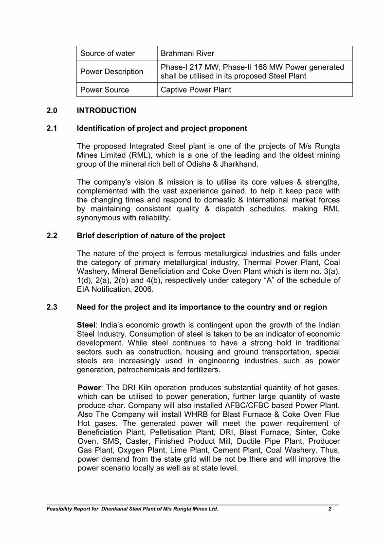
Source of water Brahmani River
Power DescriptionPhase-I 217 MW; Phase-II 168 MW Power generatedshall be utilised in its proposed Steel Plant
Power Source Captive Power Plant
2.0 INTRODUCTION
2.1 Identification of project and project proponent
The proposed Integrated Steel plant is one of the projects of M/s RungtaMines Limited (RML), which is a one of the leading and the oldest mininggroup of the mineral rich belt of Odisha & Jharkhand.
The company's vision & mission is to utilise its core values & strengths,complemented with the vast experience gained, to help it keep pace withthe changing times and respond to domestic & international market forcesby maintaining consistent quality & dispatch schedules, making RMLsynonymous with reliability.
2.2 Brief description of nature of the project
The nature of the project is ferrous metallurgical industries and falls underthe category of primary metallurgical industry, Thermal Power Plant, CoalWashery, Mineral Beneficiation and Coke Oven Plant which is item no. 3(a),1(d), 2(a), 2(b) and 4(b), respectively under category “A” of the schedule ofEIA Notification, 2006.
2.3 Need for the project and its importance to the country and or region
Steel: India’s economic growth is contingent upon the growth of the IndianSteel Industry. Consumption of steel is taken to be an indicator of economicdevelopment. While steel continues to have a strong hold in traditionalsectors such as construction, housing and ground transportation, specialsteels are increasingly used in engineering industries such as powergeneration, petrochemicals and fertilizers.
Power: The DRI Kiln operation produces substantial quantity of hot gases,which can be utilised to power generation, further large quantity of wasteproduce char. Company will also installed AFBC/CFBC based Power Plant.Also The Company will install WHRB for Blast Furnace & Coke Oven FlueHot gases. The generated power will meet the power requirement ofBeneficiation Plant, Pelletisation Plant, DRI, Blast Furnace, Sinter, CokeOven, SMS, Caster, Finished Product Mill, Ductile Pipe Plant, ProducerGas Plant, Oxygen Plant, Lime Plant, Cement Plant, Coal Washery. Thus,power demand from the state grid will be not be there and will improve thepower scenario locally as well as at state level.
Feasibility Report for Dhenkanal Steel Plant of M/s Rungta Mines Ltd. 3
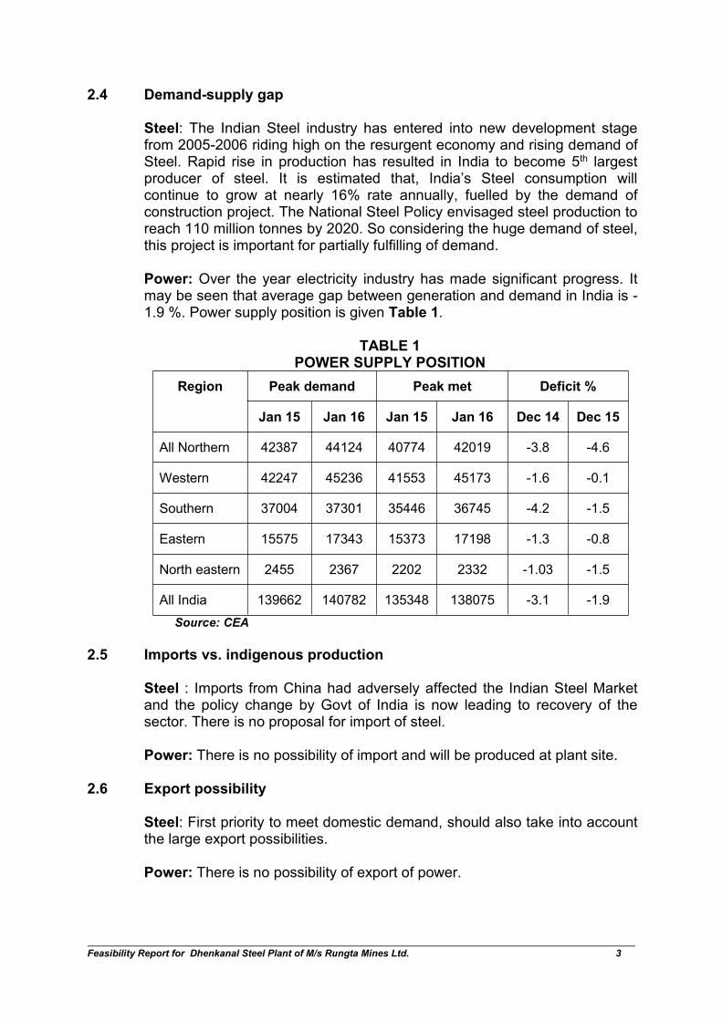
2.4 Demand-supply gap
Steel: The Indian Steel industry has entered into new development stagefrom 2005-2006 riding high on the resurgent economy and rising demand ofSteel. Rapid rise in production has resulted in India to become 5th largestproducer of steel. It is estimated that, India’s Steel consumption willcontinue to grow at nearly 16% rate annually, fuelled by the demand ofconstruction project. The National Steel Policy envisaged steel production toreach 110 million tonnes by 2020. So considering the huge demand of steel,this project is important for partially fulfilling of demand.
Power: Over the year electricity industry has made significant progress. Itmay be seen that average gap between generation and demand in India is -1.9 %. Power supply position is given Table 1.
TABLE 1POWER SUPPLY POSITION
Region Peak demand Peak met Deficit %
Jan 15 Jan 16 Jan 15 Jan 16 Dec 14 Dec 15
All Northern 42387 44124 40774 42019 -3.8 -4.6
Western 42247 45236 41553 45173 -1.6 -0.1
Southern 37004 37301 35446 36745 -4.2 -1.5
Eastern 15575 17343 15373 17198 -1.3 -0.8
North eastern 2455 2367 2202 2332 -1.03 -1.5
All India 139662 140782 135348 138075 -3.1 -1.9
Source: CEA
2.5 Imports vs. indigenous production
Steel : Imports from China had adversely affected the Indian Steel Marketand the policy change by Govt of India is now leading to recovery of thesector. There is no proposal for import of steel.
Power: There is no possibility of import and will be produced at plant site.
2.6 Export possibility
Steel: First priority to meet domestic demand, should also take into accountthe large export possibilities.
Power: There is no possibility of export of power.

Feasibility Report for Dhenkanal Steel Plant of M/s Rungta Mines Ltd. 4
2.7 Domestic/ Export markets
Sponge Iron shall be used as raw material from within house for producingsteel. The steel shall sell in domestic market. Total power generated fromthe 385 MW will be utilised in the Beneficiation Plant, Pelletisation Plant,DRI, Blast Furnace, Sinter, Coke Oven, SMS, Caster, Finished Product Mill,Ductile Pipe Plant, Producer Gas Plant, Oxygen Plant, Lime Plant, CementPlant, Coal Washery, etc.
2.8 Employment generation (Direct and Indirect)
The manpower requirement for steel plant is 1300 people in each phaseand an equal number in indirect employment.
Many more persons will also get employment in the ancillary & otherservices connected with this project.
3.0 PROJECT DESCRIPTION
3.1 Type of project including interlinked and interdependent projects
No
3.2 Location with Coordinates
District & State : Dhenkanal & Odisha
Village : Jharbandh, Galpada and Tarkabeda
Latitudes : 20° 45’ 14’’ to 20° 46’ 24’’ E
Longitudes : 85° 17’ 12’’ to 85° 18’ 45’’ N
3.3 Details of Alternate Sites & Environmental Considerations
No alternatives under consideration since the project has already beengranted environmental clearance as well as several other clearances are inadvanced stage of processing. Majority of the land has been acquired. Theproposed project will be incorporated within the 674.765 acres.
3.4 Size/ Magnitude of operation
Plant area: 674.765 acres
Feasibility Report for Dhenkanal Steel Plant of M/s Rungta Mines Ltd. 5
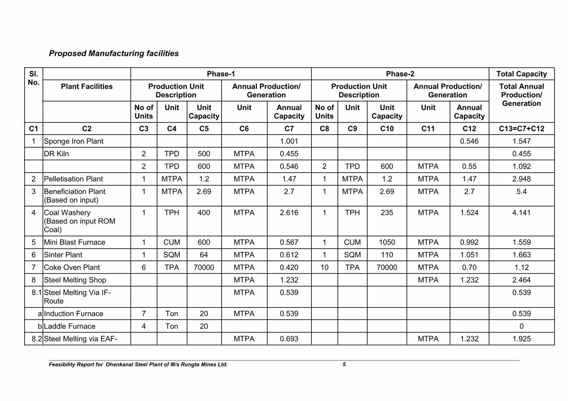
Proposed Manufacturing facilities
Sl.No.
Phase-1 Phase-2 Total Capacity
Plant Facilities Production UnitDescription
Annual Production/Generation
Production UnitDescription
Annual Production/Generation
Total AnnualProduction/Generation
No ofUnits
Unit UnitCapacity
Unit AnnualCapacity
No ofUnits
Unit UnitCapacity
Unit AnnualCapacity
C1 C2 C3 C4 C5 C6 C7 C8 C9 C10 C11 C12 C13=C7+C12
1 Sponge Iron Plant 1.001 0.546 1.547
DR Kiln 2 TPD 500 MTPA 0.455 0.455
2 TPD 600 MTPA 0.546 2 TPD 600 MTPA 0.55 1.092
2 Pelletisation Plant 1 MTPA 1.2 MTPA 1.47 1 MTPA 1.2 MTPA 1.47 2.948
3 Beneficiation Plant(Based on input)
1 MTPA 2.69 MTPA 2.7 1 MTPA 2.69 MTPA 2.7 5.4
4 Coal Washery(Based on input ROMCoal)
1 TPH 400 MTPA 2.616 1 TPH 235 MTPA 1.524 4.141
5 Mini Blast Furnace 1 CUM 600 MTPA 0.567 1 CUM 1050 MTPA 0.992 1.559
6 Sinter Plant 1 SQM 64 MTPA 0.612 1 SQM 110 MTPA 1.051 1.663
7 Coke Oven Plant 6 TPA 70000 MTPA 0.420 10 TPA 70000 MTPA 0.70 1.12
8 Steel Melting Shop MTPA 1.232 MTPA 1.232 2.464
8.1 Steel Melting Via IF-Route
MTPA 0.539 0.539
a Induction Furnace 7 Ton 20 MTPA 0.539 0.539
b Laddle Furnace 4 Ton 20 0
8.2 Steel Melting via EAF- MTPA 0.693 MTPA 1.232 1.925

Feasibility Report for Dhenkanal Steel Plant of M/s Rungta Mines Ltd. 6
Sl.No.
Phase-1 Phase-2 Total Capacity
Plant Facilities Production UnitDescription
Annual Production/Generation
Production UnitDescription
Annual Production/Generation
Total AnnualProduction/Generation
No ofUnits
Unit UnitCapacity
Unit AnnualCapacity
No ofUnits
Unit UnitCapacity
Unit AnnualCapacity
C1 C2 C3 C4 C5 C6 C7 C8 C9 C10 C11 C12 C13=C7+C12
VD-AOF Route
a Electric Arc Furnace 1 Ton 90 MTPA 0.693 1 Ton 160 MTPA 1.232 1.925
b Laddle Furnace 1 Ton 90 1 Ton 160 0
c Vacuum degassing plant 1 Ton 90 1 Ton 160
8.3 Continuous CastingMachine
MTPA 1.207 MTPA 1.207 2.415
a Billets/ BloomCaster/Slab Caster
2 Strands 3 MTPA 1.207 1 Strands 3 MTPA 1.207 2.415
9 Finished ProductFacilities
MTPA 1.450 MTPA 1.400 2.850
9.1 Rolling Mill (TMT/ Flat/Round/ Wire Rod/Structural Mill/ others)
MTPA 0.800 0.800 1.600
a Rolling Mill-1 4 TPA 200000 MTPA 0.800 2 TPA 300,000.00 MTPA 0.600 1.400
b Rolling Mill-2 1 TPA 200,000.00 MTPA 0.200 0.200
9.2 Strip Mill/Sheet/Coil/ Wire& Bar Mill/Wire Rope
1 TPA 450000 MTPA 0.450 1 TPA 400,000.00 MTPA 0.400 0.8500
9.3 Ductile Pipe Plant 1 TPA 200000 MTPA 0.200 1 TPA 200,000.00 MTPA 0.200 0.400
10 Producer Gas Plant Nm3/Annum 240000000 Nm3/Annum 240000000 480000000
Producer Gas Plant 10 Nm3/Hr 3000 Nm3/Annum 240000000 10 Nm3/Hr 3000 Nm3/Annum 240000000 480000000
Feasibility Report for Dhenkanal Steel Plant of M/s Rungta Mines Ltd. 7
Sl.No.
Phase-1 Phase-2 Total Capacity
Plant Facilities Production UnitDescription
Annual Production/Generation
Production UnitDescription
Annual Production/Generation
Total AnnualProduction/Generation
No ofUnits
Unit UnitCapacity
Unit AnnualCapacity
No ofUnits
Unit UnitCapacity
Unit AnnualCapacity
C1 C2 C3 C4 C5 C6 C7 C8 C9 C10 C11 C12 C13=C7+C12
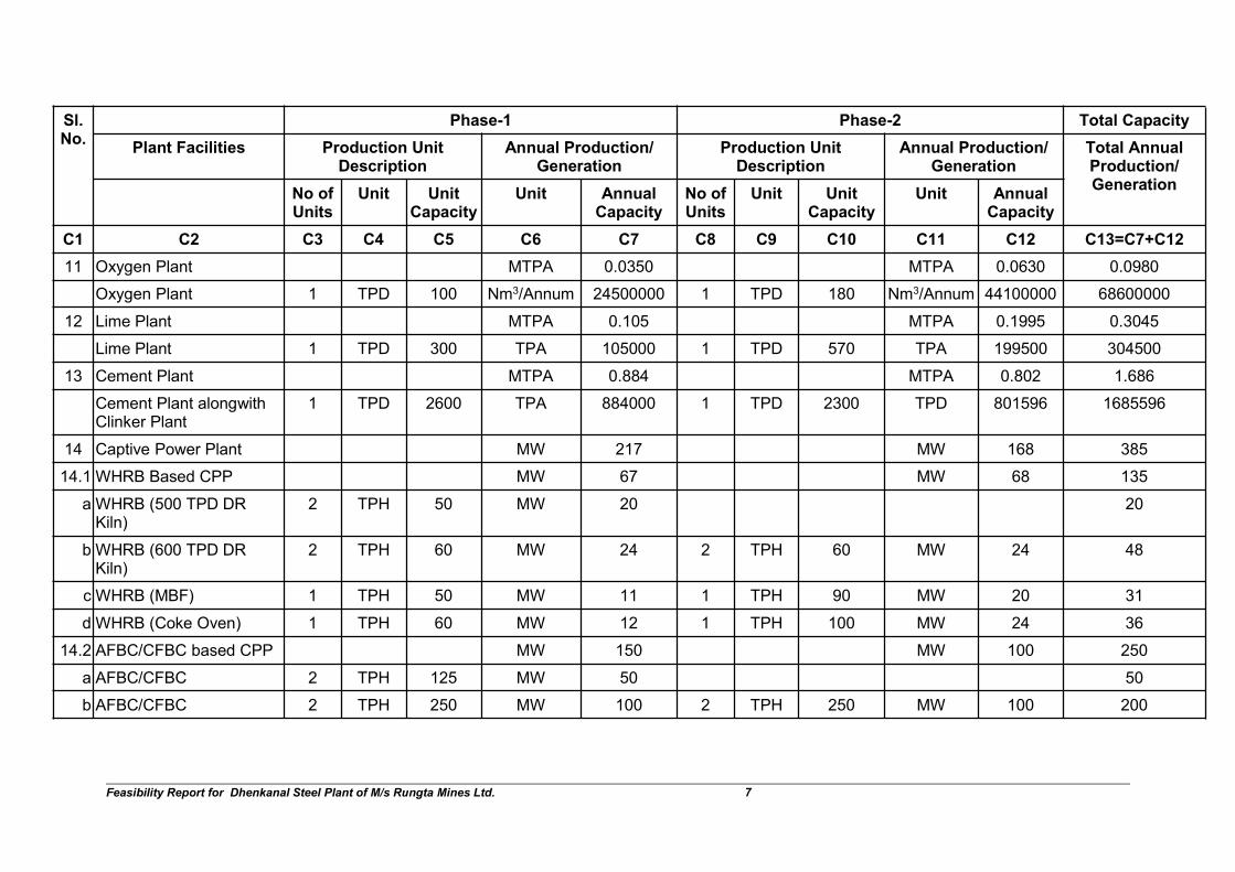
11 Oxygen Plant MTPA 0.0350 MTPA 0.0630 0.0980
Oxygen Plant 1 TPD 100 Nm3/Annum 24500000 1 TPD 180 Nm3/Annum 44100000 68600000
12 Lime Plant MTPA 0.105 MTPA 0.1995 0.3045
Lime Plant 1 TPD 300 TPA 105000 1 TPD 570 TPA 199500 304500
13 Cement Plant MTPA 0.884 MTPA 0.802 1.686
Cement Plant alongwithClinker Plant
1 TPD 2600 TPA 884000 1 TPD 2300 TPD 801596 1685596
14 Captive Power Plant MW 217 MW 168 385
14.1 WHRB Based CPP MW 67 MW 68 135
a WHRB (500 TPD DRKiln)
2 TPH 50 MW 20 20
b WHRB (600 TPD DRKiln)
2 TPH 60 MW 24 2 TPH 60 MW 24 48
c WHRB (MBF) 1 TPH 50 MW 11 1 TPH 90 MW 20 31
d WHRB (Coke Oven) 1 TPH 60 MW 12 1 TPH 100 MW 24 36
14.2 AFBC/CFBC based CPP MW 150 MW 100 250
a AFBC/CFBC 2 TPH 125 MW 50 50
b AFBC/CFBC 2 TPH 250 MW 100 2 TPH 250 MW 100 200
Feasibility Report for Dhenkanal Steel Plant of M/s Rungta Mines Ltd. 8
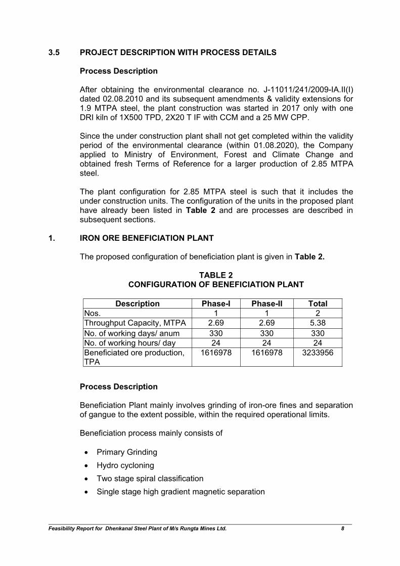
3.5 PROJECT DESCRIPTION WITH PROCESS DETAILS
Process Description
After obtaining the environmental clearance no. J-11011/241/2009-IA.II(I)dated 02.08.2010 and its subsequent amendments & validity extensions for1.9 MTPA steel, the plant construction was started in 2017 only with oneDRI kiln of 1X500 TPD, 2X20 T IF with CCM and a 25 MW CPP.
Since the under construction plant shall not get completed within the validityperiod of the environmental clearance (within 01.08.2020), the Companyapplied to Ministry of Environment, Forest and Climate Change andobtained fresh Terms of Reference for a larger production of 2.85 MTPAsteel.
The plant configuration for 2.85 MTPA steel is such that it includes theunder construction units. The configuration of the units in the proposed planthave already been listed in Table 2 and are processes are described insubsequent sections.
1. IRON ORE BENEFICIATION PLANT
The proposed configuration of beneficiation plant is given in Table 2.
TABLE 2CONFIGURATION OF BENEFICIATION PLANT
Process Description
Beneficiation Plant mainly involves grinding of iron-ore fines and separationof gangue to the extent possible, within the required operational limits.
Beneficiation process mainly consists of
Primary Grinding
Hydro cycloning
Two stage spiral classification
Single stage high gradient magnetic separation
Description Phase-I Phase-II Total
Nos. 1 1 2
Throughput Capacity, MTPA 2.69 2.69 5.38
No. of working days/ anum 330 330 330
No. of working hours/ day 24 24 24
Beneficiated ore production,TPA
1616978 1616978 3233956

Feasibility Report for Dhenkanal Steel Plant of M/s Rungta Mines Ltd. 9
Regrinding & thickening of concentrate received from both spirals &magnetic separators
Iron-ore fines will be brought from the mine. The fines will be stockpiled inthe raw material yard. Iron-ore fines will be reclaimed through pay-loadersand tippers and transported to silos through shuttle conveyor. Vibratingfeeders are provided below each of the silo. The output from the vibrofeeder will feed the grinding mill feed conveyors.
Thereafter, primary grinding in wet grinding mill shall be carried out.
The mill feed conveyors will feed primary ball mill. The primary ball mill’sdischarge is collected in pump sump for pumping to hydro cyclone clusters.The overflow from the cyclone is sent to slime thickener. The cyclone underflow is fed to a bank of rougher spirals. The concentrate from the rougherspirals will be processed in cleaner spirals. The tailings from the rougher &cleaner spirals are fed to intermediate slime thickener. The concentratefrom cleaner spiral are pumped to secondary hydro cyclone. The under flowfrom cyclone are fed to regrinding mills for further grinding to requiredproduct size. The overflow from the cyclone is fed to concentrate thickener.The under flow from the concentrate thickener is pumped to slurry storagetanks. The thickened concentrate at approximately 65-66% solids by weightwill be pumped into the pellet plant by single stage pumping to the slurrystorage tank fitted with agitation mechanism.
The under size from the screens is fed to High Gradient Magnetic Separator(HGMS) for recovery of concentrate from slimes. The concentrate fromHGMS is further ground in the same regrinding mill, which is closecirculated with secondary hydro cyclone. The concentrate over flow fromhydro cyclone is thickened in concentrate thickener before pumping to slurrystorage tanks provided with agitators. The tailing from HGMS is fed to atailing thickener. The tailing thickener underflow is pumped to a tailing damin the beneficiation plant site. The overflow from the tailing thickener is sentto process water tank for re-circulation in the process. The major quantity ofwater of tailing dam shall be lost in evaporation and seepage.
The slurry from this storage tank is fed to pressure filters to obtain filtercakes. When wet grinding process is adopted, the preparation of fluxmaterials and binders (if bentonite is used) is done in dry state and separategrinding equipment is to be installed.
Material balance for the iron ore beneficiation plant is given in Table 3

Feasibility Report for Dhenkanal Steel Plant of M/s Rungta Mines Ltd. 10
TABLE 3MATERIAL BALANCE FOR IRON ORE BENEFICIATION PLANT
Raw MaterialInputs
SpecificConsumptionor generationT/T of Product
Phase-I
Quantity(TPA)
Phase-I
%
Phase-IIQuantity(TPA)
Phase-II
%
TotalQuantity(TPA)
Total
%
Low Grade IronOre Fines (0 to 5mm)
1.00 2694963 99.995% 2694963 99.995% 5389927 99.995%
Flocculant 0.00005 135 0.005% 135 0.005% 269 0.005%
Total 1.00005 2695098 100% 2695098 100% 5390196 100%
Outputs
Beneficiated IronOre (product)
0.60000 1616978 60% 1616978 60% 3233956 60%
Tailing (0.4) &emission losses(0.00005)
0.40005 1078120 40% 1078120 40% 2156240 40%
Total 1.00005 2695098 100% 2695098 100% 5390196 100%
100% of the beneficiated iron ore will be used in pellet plant. Likelycomposition of beneficiated iron ore will be :
Fe content - 63 - 64 %
Al2O3 - 2.5 - 3% max
SiO2 - 2.5 - 3% max
L.O.I. - 2% max
2.0 PELLETISATION PLANT
The proposed pellet plant is designed to produce iron oxide pellets suitablefor use in DRI and Blast Furnace. The configuration of the pellet plant isgiven in Table 4.
TABLE 4CONFIGURATION OF PELLETISATION PLANT
Description Phase I Phase II Total
No. of Units 1 No. 1 No. 2 Nos.
Unit Capacity (Based on output)1,200,000
TPA1,200,000
TPA1,200,000 TPA
Production capacity per day@300 days/annum
4000 Tonnes 4000 Tonnes 2 X 4000Tonnes
10% productivity improved byusing high grade iron-ore fines
4000 + (4000X 10%)
4000 + (4000X 10%)
8000 + (8000 X10%)
Actual number of days per yearlikely to be operated
335 335 335
No. of working hours/day 24 24 24
Total Capacity (Based onoutput), TPA
1,474,000 1,474,000 2,948,000
Feasibility Report for Dhenkanal Steel Plant of M/s Rungta Mines Ltd. 11
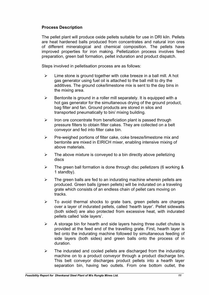
Process Description
The pellet plant will produce oxide pellets suitable for use in DRI kiln. Pelletsare heat hardened balls produced from concentrates and natural iron oresof different mineralogical and chemical composition. The pellets haveimproved properties for iron making. Pelletization process involves feedpreparation, green ball formation, pellet induration and product dispatch.
Steps involved in pelletisation process are as follows:
Lime stone is ground together with coke breeze in a ball mill. A hotgas generator using fuel oil is attached to the ball mill to dry theadditives. The ground coke/limestone mix is sent to the day bins inthe mixing area.
Bentonite is ground in a roller mill separately. It is equipped with ahot gas generator for the simultaneous drying of the ground product,bag filter and fan. Ground products are stored in silos andtransported pneumatically to bin/ mixing building.
Iron ore concentrate from beneficiation plant is passed throughpressure filters to obtain filter cakes. They are collected on a beltconveyor and fed into filter cake bin.
Pre-weighed portions of filter cake, coke breeze/limestone mix andbentonite are mixed in EIRICH mixer, enabling intensive mixing ofabove materials.
The above mixture is conveyed to a bin directly above pelletizingdiscs
The green ball formation is done through disc pelletizers (6 working &1 standby).
The green balls are fed to an indurating machine wherein pellets areproduced. Green balls (green pellets) will be indurated on a travelinggrate which consists of an endless chain of pellet cars moving ontracks.
To avoid thermal shocks to grate bars, green pellets are chargesover a layer of indurated pellets, called ‘hearth layer’. Pellet sidewalls(both sided) are also protected from excessive heat, with induratedpellets called ‘side layers’.
A storage bin for hearth and side layers having three outlet chutes isprovided at the feed end of the travelling grate. First, hearth layer isfed onto the indurating machine followed by simultaneous feeding ofside layers (both sides) and green balls onto the process of induration.
The indurated and cooled pellets are discharged from the induratingmachine on to a product conveyor through a product discharge bin.This belt conveyor discharges product pellets into a hearth layerseparation bin, having two outlets. From one bottom outlet, the

Feasibility Report for Dhenkanal Steel Plant of M/s Rungta Mines Ltd. 12
amount of pellets required as hearth & side layer are discharged,controlled by the level of hearth layer bin mentioned above. Hearthlayer shall be transported by a series of belt conveyors to hearthlayer bin while product pellets are discharged for transportation to thepellet stock pile. Material balance of the pelletisation plant is given inTable 5. Process flow sheet is given in Fig 1.
TABLE 5MATERIAL BALANCE OF PELLETISATION PLANT
Raw Material & FuelInputs
SpecificConsumptionor generationT/T of Product
Phase-IQuantity(TPA)
Phase-I%
Phase-IIQuantity
(TPA)
Phase-II%
TotalQuantity
(TPA)
Total%
Iron Ore/ Fines/concentrate
1.097 1616978 93.25% 1616978 93.25% 3233956 93.25%
Dolomite (Flux) 0.014 20636 1.19% 20636 1.19% 41272 1.19%
Bentonite 0.015 22110 1.28% 22110 1.28% 44220 1.28%
Coke Breeze 0.017 25058 1.45% 25058 1.45% 50116 1.45%
Coal >= 5500 Kcal/kg (emergency use)
0.033 49232 2.84% 49232 2.84% 98463 2.84%
Sub-Total (solids) 1.176 1734014 100.00% 1734014 1.00 3468027 100.00%
Producer Gas(Nm3)/year
162.5 239525000 239525000 479050000
Sub-Total (gas) 162.500 239525000 239525000 479050000
Outputs
Pellets 1.000 1474000 85.01% 1474000 85.01% 2948000 85.01%
Dust (Iron Ore,Coke, Coal Fines)
0.082 120386 6.94% 120386 6.94% 240772 6.94%
Losses 0.095 139628 8.05% 139628 8.05% 279255 8.05%
Sub-Total (Solids) 1.176 1734014 100.00% 1734014 100.00% 3468027 100.00%
Combustion Gases(Nm3)
162.5 239525000 239525000 479050000
Sub-Total (gas) 162.500 239525000 239525000 479050000
The pellets generated in first phase will not be sufficient to meet thedemand for the DRI kilns. Of the total demand of 1,501,500 TPA of ironoxide in DRI kilns in phase I, pellet plat will be able to meet 1,474,000 TPA.There will be a shortfall of 27,500 TPA which will be brought fromcompany’s own plant at Kamanda Steel Plant or Dudhaposi PelletisationPlant. Both these plants are located in Odisha. In second phase, against arequirement of 819,000 TPA, the pellets generated will be 1,474,000 TPA.After compensating for the deficit of Phase-I, there will be 6,27,500 TPAexcess pellets available which will be sold in the open market.

Feasibility Report for Dhenkanal Steel Plant of M/s Rungta Mines Ltd. 13
FIG 1: PROCESS FLOW OF PELLETISATION PROCESS
Quality of pellets DR Grade
The expected chemical composition of DR grade pellets and their chemical,physical & metallurgical properties are given in Table 6. The properties ofthe finished pellets will vary depending on actual physical and chemicalcharacteristics of input raw materials.
TABLE 6CHEMICAL, PHYSICAL & METALLURGICAL PROPERTIES OF DR PELLETS
Chemical Properties Specification Chemical Properties Specification
Fe (t) 66.50% min Mn 0.10% max
SiO2 + Al2O3 3.10% max P 0.04% max
Na2O 0.05% max S 0.02% max
K2O 0.05% max V ----
TiO2 0.10% max Basicity (CaO/SiO2) 0.5
Moisture (free moistureloss at 105 degreecentigrade) :
4% max (fairseason), 6%max (monsoon)
MetallurgicalProperties
Specification Physical Properties Specification
Swelling (JIS) 20% max +19mm 5% max
Compression strength 250 kg/pellet min -16 mm, +9mm 85% max
Porosity 18-25% min -9mm, +5mm 5% min
Reducibility (JIS) 70% min -5mm 3% max
Tumbler test (ASTM)
Tumble Index (+6.35mm) 94% minSource:- IS : 11092-2001
Feasibility Report for Dhenkanal Steel Plant of M/s Rungta Mines Ltd. 14
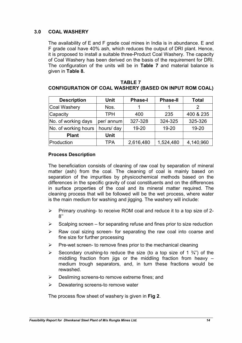
3.0 COAL WASHERY
The availability of E and F grade coal mines in India is in abundance. E andF grade coal have 40% ash, which reduces the output of DRI plant. Hence,it is proposed to install a suitable three-Product Coal Washery. The capacityof Coal Washery has been derived on the basis of the requirement for DRI.The configuration of the units will be in Table 7 and material balance isgiven in Table 8.
TABLE 7CONFIGURATION OF COAL WASHERY (BASED ON INPUT ROM COAL)
Description Unit Phase-I Phase-II Total
Coal Washery Nos. 1 1 2
Capacity TPH 400 235 400 & 235
No. of working days per/ annum 327-328 324-325 325-326
No. of working hours hours/ day 19-20 19-20 19-20
Plant Unit
Production TPA 2,616,480 1,524,480 4,140,960
Process Description
The beneficiation consists of cleaning of raw coal by separation of mineralmatter (ash) from the coal. The cleaning of coal is mainly based onseparation of the impurities by physicochemical methods based on thedifferences in the specific gravity of coal constituents and on the differencesin surface properties of the coal and its mineral matter required. Thecleaning process that will be followed will be the wet process, where wateris the main medium for washing and jigging. The washery will include:
Primary crushing- to receive ROM coal and reduce it to a top size of 2-8’’
Scalping screen – for separating refuse and fines prior to size reduction
Raw coal sizing screen- for separating the raw coal into coarse andfine size for further processing
Pre-wet screen- to remove fines prior to the mechanical cleaning
Secondary crushing-to reduce the size (to a top size of 1 ¾”) of themiddling fraction from jigs or the middling fraction from heavy –medium trough separators, and, in turn these fractions would berewashed.
Desliming screens-to remove extreme fines; and
Dewatering screens-to remove water
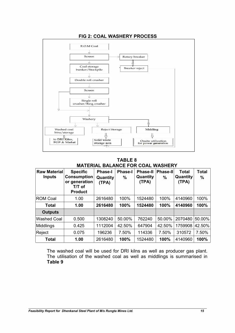
The process flow sheet of washery is given in Fig 2.
Feasibility Report for Dhenkanal Steel Plant of M/s Rungta Mines Ltd. 15
FIG 2: COAL WASHERY PROCESS
TABLE 8MATERIAL BALANCE FOR COAL WASHERY
Raw MaterialInputs
SpecificConsumptionor generation
T/T ofProduct
Phase-I
Quantity(TPA)
Phase-I
%
Phase-IIQuantity(TPA)
Phase-II
%
TotalQuantity(TPA)
Total
%
ROM Coal 1.00 2616480 100% 1524480 100% 4140960 100%
Total 1.00 2616480 100% 1524480 100% 4140960 100%
Outputs
Washed Coal 0.500 1308240 50.00% 762240 50.00% 2070480 50.00%
Middlings 0.425 1112004 42.50% 647904 42.50% 1759908 42.50%
Reject 0.075 196236 7.50% 114336 7.50% 310572 7.50%
Total 1.00 2616480 100% 1524480 100% 4140960 100%
The washed coal will be used for DRI kilns as well as producer gas plant.The utilisation of the washed coal as well as middlings is summarised inTable 9

Feasibility Report for Dhenkanal Steel Plant of M/s Rungta Mines Ltd. 16
TABLE 9UTILISATION OF WASHED COAL & MIDDLINGS
Use of washed coaland middlings
Quantity(TPA)
% Quantity(TPA)
% Quantity(TPA)
%
Washed Coal Used inDRI kilns
880880 67.33% 480480 63.04% 1361360 65.18%
Washed Coal Used inProducer Gas Plant
107040 8.18% 107040 14.04% 214080 11.11%
Washed Coal sold inmarket
320320 24.48% 174719.89
22.92% 495040 23.91%
Middlings in CaptivePower Plant
1112004 100.00% 647904 100.00% 1759908
4.0 DRI PLANT
The proposed capacity is given in Table 10.
TABLE 10CONFIGURATION OF DRI PLANT
Description Unit Phase-I Phase-II Total
DRI Kilns 2 X 500 TPD +2 X 600 TPD
2 X 600TPD
2 X 500 TPD +4 X 600 TPD
No. of working days Days/Annum 350 350 350
No. of working hours Hours /Day 24 24 24
% Production increase % 30% 30% 30%
Total Production TPA 1001000 546000 1547000
With respect to the 30% production increase mentioned in the above table,the following may be noted:
Increased production will be achieved by using superior quality of Non-Coking Coal.
When the input coal quality is improved by washing or by using SouthAfrican coal, the specific consumption of coal reduces to 0.879 T/T ofDRI as compared to 1.5 T/T in conventional kilns under operation in thecountry.
This will result in increase of production of DRI because of increase infeed rate of Iron Ore with the same fill factor.
Although specific iron ore consumption will remain 1.5 T/T of DRI, butthe feed rate will increase.
Due to using superior quality of coal, accretion is minimized andnumber of working days increased.

Feasibility Report for Dhenkanal Steel Plant of M/s Rungta Mines Ltd. 17
With use of superior quality of coal, the char generation will alsodecrease from conventionally 25% to 18%.
Process Description
Iron ore (lumps or pellets) is reduced by heating with solid carbonaceousmaterial, such as coal, in a rotary kiln to temperature of about 1000°C. Afterreduction, products are cooled in a drum type rotary cooler and thenseparated into sponge iron and char by magnetic separation. The magneticand non-magnetic material are stored in fully closed hoppers. The producthouse consists of silo for sponge iron lumps, sponge iron fines and char.The char shall be used as fuel in the proposed power plant.The basicreactions in this process are as given below:
C + O2 = CO2
CO2 + C = 2CO
Fe2O3 + CO = Fe3O4 + CO2
Fe3O4 + CO = FeO + CO2
FeO + CO = Fe + CO2
Raw Material Handling System
Main raw materials- iron ore pellets, coal & dolomite are being fed to theground hoppers with the help of pay loaders and tippers and carried by beltconveyors to the crusher house. Screened and crushed material will becarried out by belt conveyers to the stock house, having 5 days storage bins.Crushers for coal & limestone, will be provisioned.
Raw Material Feed System
The stored raw material are weighed individually and fed to the kiln througha rotary airlock feeder. The injection coal system injects coal at thedischarge end of rotary kiln to avoid coal starvation with 1 bar pressure atwhich leakages are not possible. There will be a burner system, which is
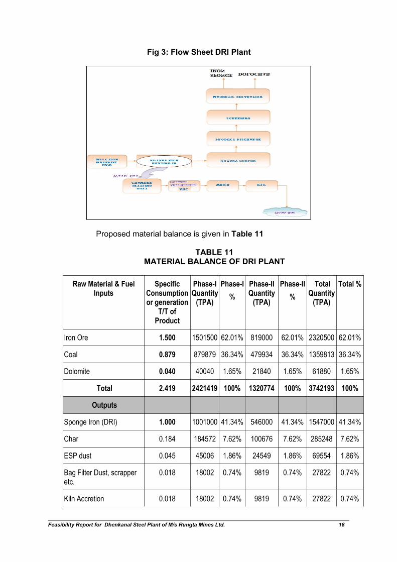
used for initial heating of the kiln up to 400 C. The calibrated quantity ofcombustion air is also fed through the same opening. Process flow sheet forproposed DRI plant is shown in Fig 3.
Feasibility Report for Dhenkanal Steel Plant of M/s Rungta Mines Ltd. 18
Fig 3: Flow Sheet DRI Plant
Proposed material balance is given in Table 11
TABLE 11MATERIAL BALANCE OF DRI PLANT
Raw Material & FuelInputs
SpecificConsumptionor generation
T/T ofProduct
Phase-IQuantity
(TPA)
Phase-I
%
Phase-IIQuantity
(TPA)
Phase-II
%
TotalQuantity
(TPA)
Total %
Iron Ore 1.500 1501500 62.01% 819000 62.01% 2320500 62.01%
Coal 0.879 879879 36.34% 479934 36.34% 1359813 36.34%
Dolomite 0.040 40040 1.65% 21840 1.65% 61880 1.65%
Total 2.419 2421419 100% 1320774 100% 3742193 100%
Outputs
Sponge Iron (DRI) 1.000 1001000 41.34% 546000 41.34% 1547000 41.34%
Char 0.184 184572 7.62% 100676 7.62% 285248 7.62%
ESP dust 0.045 45006 1.86% 24549 1.86% 69554 1.86%
Bag Filter Dust, scrapperetc.
0.018 18002 0.74% 9819 0.74% 27822 0.74%
Kiln Accretion 0.018 18002 0.74% 9819 0.74% 27822 0.74%
Feasibility Report for Dhenkanal Steel Plant of M/s Rungta Mines Ltd. 19
Losses 1.154 1154841 47.69% 629913 47.69% 1784754 47.69%
Total 2.419 2421419 100% 1320774 100% 3742193 100%
5.0 MINI BLAST FURNACE
The proposed configuration of Mini Blast Furnaces will be as shown inTable 12.
TABLE 12CONFIGURATION OF MINI BLAST FURNACE
Description Unit Phase-I Phase-II Total
MBF Nos. 1 1 2
Capacity CUM 600 1050 600 & 1050
Working days days/Annum 350 350 350
Working hours Hours /Day 24 24 24
Productivity T/Cum/day 2.7 2.7 2.7
Production TPA 567,000 992,250 1,559,250
By using superior quality raw material, the blast furnace charge mix willbecome 71-72 % Sinter along with other inputs & 28-29% Blast FurnaceGrade Iron-Ore. Furthermore, use of coke with low ash content and byusing best operation & maintenance practice, the productivity of BlastFurnace will increase from traditionally around 2.1 to 2.7 T/cum/day in theproposed MBF.
Manufacturing Process and Facilities
The purpose of a blast furnace is to chemically reduce and physicallyconvert iron oxides into liquid iron called "hot metal". The blast furnace is ahuge, steel lined with refractory brick, where iron ore, coke and limestoneare dumped into the top, and preheated air is blown into the bottom.
The raw materials require 6 to 8 hours to descend to the bottom of thefurnace where they become the final product of liquid iron and reject ofliquid slag. Both of these are drained from the furnace at regular intervals.
The hot air that was blown into the bottom of the furnace ascends to the topin 6 to 8 seconds after going through numerous chemical reactions. The airis blown through tuyers in the bottom portion and liquid iron is tapped fromthe tap hole.
Feasibility Report for Dhenkanal Steel Plant of M/s Rungta Mines Ltd. 20
The blast furnace complex will consist of two blast furnaces and two pigcasting machines along with the requisite support facilities, namely thestock house, coal injection system, cast house, gas cleaning plant, de-dusting facilities, slag granulation unit, etc.
The blast furnace flue gas will be passed through Waste Heat RecoveryBoiler and power generated from heat recovery. Thereafter, gas is cleanedin Gas Cleaning Plant and utilized for stove of blast furnace and other plantuses such as reheating furnaces. Unutilised gas shall be flared.
Stock House
The sized ore, fluxes, coke, etc., from the raw material storage yard, aretransferred to the stock house and placed in respective bins by shuttleconveyors. The raw material will be screened before charging into the blastfurnace. The stock house will be provided with a dedusting system (bagfilters) for collection of dust arising from all material transfer points, vibratoryfeeder screens, weigh hoppers, etc.
Furnace
The blast furnace will be self-supporting free standing design complete withshell, refractory, cooling system, top charging equipment, bustle main,tuyeres/tuyere stocks etc. The blast furnace top equipment and the platformat various levels around the furnace are supported by an independent towerstructure.
Hot Blast Stoves
The furnaces will be provided with stoves for supply of hot blast up to amaximum of 1100oC. The stoves will be of regenerative type and fired withblast furnace gas. Two fans, one working and one stand by will be providedfor supply of combustion air to the stove burners. A chimney will beprovided for the stoves.
The different zones of the stoves will be lined with suitable quality ofAlumina/Fireclay refractories depending on the temperature prevailing in therespective zones. The stove valves will be electrically/hydraulically actuated,and the stove-changing operations will be automatic and remotely controlledfrom the control room.
Cast House
The furnace will have one tap hole. A cast house will be provided forhandling the tapping operations and the hot metal/ slag. The main hot metaltrough will be fixed type fabricated steel construction. The hot metal runnerfrom each trough will discharge the metal into hot metal ladle kept on casthouse floor. For opening and closing of the tap-hole, a hydraulically
Feasibility Report for Dhenkanal Steel Plant of M/s Rungta Mines Ltd. 21
operated mud gun and a pneumatically operated tap-hole drilling machinewill be provided.The skimmed slag from the main trough will normally be led to the slaggranulation trough. Under emergency conditions, the slag can also bediverted to the dry slag pit. The cast house will be served by an EOT cranein the hot metal bay, for transferring the filled up hot metal ladle on to a ladlecar for transfer to the steel melt shop. The crane will be used also forhandling hot metal ladles to and from Pig Casting Machine (PCM) and ladlemaintenance.
Slag granulation
The cast house will be served by a slag granulation unit. The slag / waterslurry after granulation will be led to storage area and the water will beallowed to drain off. The granulated slag will be reclaimed by a pay loaderand sent to the storage yard. From the storage yard, trucks will transport thegranulated slag.
The water for granulation will be routed through a water re-circulationsystem. The granulation units will be designed to granulate 100% of slagproduction. The granulated slag will be use in the cement plant proposed inthe project.
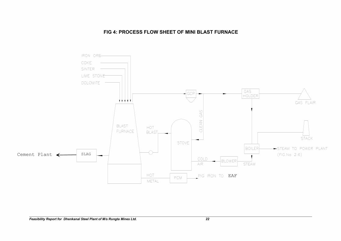
Process flow sheet of the blast furnaces is given in Fig 4
Feasibility Report for Dhenkanal Steel Plant of M/s Rungta Mines Ltd. 22
FIG 4: PROCESS FLOW SHEET OF MINI BLAST FURNACE
Cement Plant SLAG
EAF

Feasibility Report for Dhenkanal Steel Plant of M/s Rungta Mines Ltd. 23
The material balance of the MBF is given in Table 13.
TABLE 13MATERIAL BALANCE OF BLAST FURNACE
Raw Material Inputs SpecificConsumptionor generationT/T of Product
Phase-I
Quantity(TPA)
Phase-I
%
Phase-IIQuantity
(TPA)
Phase-II
%
TotalQuantity
(TPA)
Total
%
Iron Ore 0.421 238980 17.92% 418215 18.07% 657195 18.01%
Sinter 1.066 611520 45.86% 1051050 45.41% 1662570 45.57%
Coke 0.610 345870 25.94% 605273 26.15% 951143 26.07%
Coal dust 0.050 28350 2.13% 49613 2.14% 77963 2.14%
Dolomite 0.140 79380 5.95% 138915 6.00% 218295 5.98%
Quartz 0.052 29484 2.21% 51597 2.23% 81081 2.22%
Total 2.340 1333584 100% 2314662 100% 3648246 100%
Outputs
Hot Metal/ Pig Iron 1 567000 42.74% 992250 42.74% 1559250 42.74%
BF Slag 0.3 170100 12.82% 297675 12.82% 467775 12.82%
Dust (Iron Ore,Coke, Sinter Fines)
0.05 283502.14%
496132.14%
779632.14%
Sludge from GCP 0.005 2835 0.21% 4961 0.21% 7796 0.21%
Losses 0.985 558350 42.09% 977112 42.09% 1535462 42.09%
Total 2.340 1934184 100.00% 3384822 100.00% 5319006 100.00%
6.0 SINTER PLANT
Sinter Plant plays a very important role in increasing the productivity of BlastFurnace and also in utilizing huge reserves of iron ore fines generated fromcrushing of ROM. Two Sinter machine of about 64 SQM (Phase-I) and 110SQM (Phase-II) will be installed to produce 1.663 MTPA charge sinter,which will be adequate for feeding the blast furnace. The configuration ofsinter plant is as given in Table 14.
TABLE 14CONFIGURATION OF SINTER PLANT
Description Unit Phase-Iquantity
Phase-II
quantity
Total quantity
Sinter Plant Nos. 1 1 2
Capacity SQM 64 110 64 &110
working days days/Annum 325 325 325
working hours Hours /Day 21 21 21
Productivity Ton/SQM 1.4 1.4 1.4
Production TPA 611520 1051050 1662570
Feasibility Report for Dhenkanal Steel Plant of M/s Rungta Mines Ltd. 24
Process description
Flux and Fuel Crushing & Screening Section
Limestone, dolomite, coke will be stored in storage bins of adequatecapacity. The materials will be crushed in crushing and grinding section andwill be screened and transported by conveyor to proportioning bins.
Proportioning System
For various types of input materials, adequate number of proportioning binsmounted on load cells to ascertain material level in each bin and electronicweigh feeders under each bin shall be provided to draw materials ofrequired proportions.
Mixing & Nodulising Drum
A combined mixing and nodulising drum with water proportioning systemand calcined lime addition facilities will be provided for the sinter machine.
The drum will facilitate stage-wise intimate mixing and rolling of sinter mixwhere approximate amount of water and required calcined lime will beadded.
Sinter Machine Section
Sinter machine will be complete with hearth layer feeding system, raw mixfeeding system comprising anti segregation filling method at the top of rawmix feed bin and drum feeder, ignition furnace, sinter breaker, crash deck,segregation chute and the sinter strand proper comprising lifting wheelassembly, support structure, sliding bars, thermal compensation device,wind boxes with compensators, spillage chute, SG iron pallet assembly withspring loaded sealing and high chrome grate bar, lubrication system etc.Sintering will be performed during the movement of the bed from ignitionfurnace to the discharge end.
Suitable sinter breaker will break hot sinter cake to about 200 mm size. Oneelevator will be provided in sinter machine building.
Sinter Cooler Section
A suitable forced draft type circular cooler comprising of adequate numberof fans, drives, cooler troughs, sealing etc will be installed so thattemperature of the sinter at discharge point is 1000°C (maximum). Thecooler discharge hopper shall be load cell mounted. One magnet shall beprovided on the product sinter conveyor after cooler to remove iron bearingmaterial.
Waste heat recovery system from cooler for ignition furnace combustionsystem will be optional for sinter machine.
Feasibility Report for Dhenkanal Steel Plant of M/s Rungta Mines Ltd. 25
Sinter Stabilizing Section
Cooled sinter from sinter machine will be fed to a double roll crusher via asuitably designed separation chute. Crushed sinter of minus 50 mm size willbe screened for separation of hearth layer material and plant return fines.
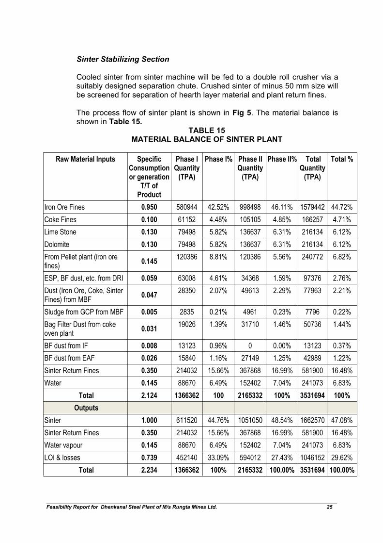
The process flow of sinter plant is shown in Fig 5. The material balance isshown in Table 15.
TABLE 15MATERIAL BALANCE OF SINTER PLANT
Raw Material Inputs SpecificConsumptionor generation
T/T ofProduct
Phase IQuantity
(TPA)
Phase I% Phase IIQuantity
(TPA)
Phase II% TotalQuantity
(TPA)
Total %
Iron Ore Fines 0.950 580944 42.52% 998498 46.11% 1579442 44.72%
Coke Fines 0.100 61152 4.48% 105105 4.85% 166257 4.71%
Lime Stone 0.130 79498 5.82% 136637 6.31% 216134 6.12%
Dolomite 0.130 79498 5.82% 136637 6.31% 216134 6.12%
From Pellet plant (iron orefines)
0.145120386 8.81% 120386 5.56% 240772 6.82%
ESP, BF dust, etc. from DRI 0.059 63008 4.61% 34368 1.59% 97376 2.76%
Dust (Iron Ore, Coke, SinterFines) from MBF
0.04728350 2.07% 49613 2.29% 77963 2.21%
Sludge from GCP from MBF 0.005 2835 0.21% 4961 0.23% 7796 0.22%
Bag Filter Dust from cokeoven plant
0.03119026 1.39% 31710 1.46% 50736 1.44%
BF dust from IF 0.008 13123 0.96% 0 0.00% 13123 0.37%
BF dust from EAF 0.026 15840 1.16% 27149 1.25% 42989 1.22%
Sinter Return Fines 0.350 214032 15.66% 367868 16.99% 581900 16.48%
Water 0.145 88670 6.49% 152402 7.04% 241073 6.83%
Total 2.124 1366362 100 2165332 100% 3531694 100%
Outputs
Sinter 1.000 611520 44.76% 1051050 48.54% 1662570 47.08%
Sinter Return Fines 0.350 214032 15.66% 367868 16.99% 581900 16.48%
Water vapour 0.145 88670 6.49% 152402 7.04% 241073 6.83%
LOI & losses 0.739 452140 33.09% 594012 27.43% 1046152 29.62%
Total 2.234 1366362 100% 2165332 100.00% 3531694 100.00%

Feasibility Report for Dhenkanal Steel Plant of M/s Rungta Mines Ltd. 26
7.0 COKE OVEN PLANT
The Coke requirements in MBF & Sinter Plant are about 0.610 T/T of hotmetal and 0.065 T/T of sinter respectively. Based on the requirement,Rungta Mines Ltd proposes to install 6 batteries of 70,000 TPA in Phase-I &10 batteries of 70,000 TPA in Phase-II. The configuration of coke oven plantis given in Table 16.
TABLE 16CONFIGURATION OF COKE OVEN PLANT
Description Unit Phase-I
Quantity
Phase-II
Quantity
TotalQuantity
Coke Oven Batteries Nos. 6 10 16
Working days days/Annum 350 350 350
Working hours Hours /Day 24 24 24
Production TPA 420000 700000 1120000
Manufacturing Process
Raw coal will be crushed in a crusher into powdered form and charged inthe oven for carbonisation. The volatile matter in raw coal gets released inthe form of gas and gets burnt in the oven as well as in the flues. After thecompletion of the carbonization process, raw coal get converted to cokewithin 36 to 38 hours. The coke is then pushed out from the oven andquenched by water. Coke will be utilised in MBF and sinter plant.The hot quenching water is continuously collected into a settling tank & thecoke particles are also being carried out upto the settling tank with water.
FIG 5: PROCESS FLOW OF SINTER PLANT
ProportioningUnits
Mixing &nodulising
Unit
Sinter Machine
Sinter CoolerScreening
Iron Ore Fines
Lime
Dolomite
Cokefines
WaterMixed gas
fuel
Screenedsinter
Under sizedsinter returns
Sinter Bin andthen to MBF
Dust & sludgesfrom pelletplant, DRI,MBF, coke
oven, IF & EAF
Feasibility Report for Dhenkanal Steel Plant of M/s Rungta Mines Ltd. 27
These particles are allowed to be settled below the settling tank and thenthe water almost free from suspended is allowed to be again used for thepurpose of quenching of hot coke mass. Time to time the settled particlesare reclaimed and these have the large demand in mini cement plants,briquetting plants etc.
Non-Recovery Type Coke Ovens
The proposed non-recovery coke ovens have been specially developedbased on the imported coking coal with a volatile matter content in therange of 20%-24%. Moisture control of coal is important as it has directbearing on the carbonization rate & bulk density of coal.
Non-recovery coke ovens are capable of producing coke of large size,strong, dense & abrasion resistant. The coarse mosaic micro-structure, lowporosity during carbonization and development of minor crack result in lowreactivity, strength in high temperature, stability and superior post reactionstrength.
The ovens are unique in that, no external heat source is required. All theenergy in carbonization is supplied by burning the gaseous volatile productsreleased from the coal charge during carbonization.
Raw Material For Coke Oven Plant
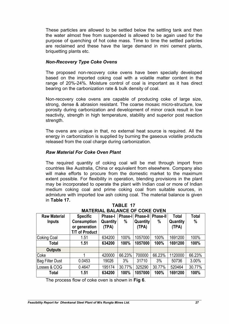
The required quantity of coking coal will be met through import fromcountries like Australia, China or equivalent from elsewhere. Company alsowill make efforts to procure from the domestic market to the maximumextent possible. For flexibility in operation, blending provisions in the plantmay be incorporated to operate the plant with Indian coal or more of Indianmedium coking coal and prime coking coal from suitable sources, inadmixture with imported low ash coking coal. The material balance is givenin Table 17.
TABLE 17MATERIAL BALANCE OF COKE OVEN
Raw MaterialInputs
SpecificConsumptionor generationT/T of Product
Phase-IQuantity(TPA)
Phase-I%
Phase-IIQuantity
(TPA)
Phase-II%
TotalQuantity
(TPA)
Total%
Coking Coal 1.51 634200 100% 1057000 100% 1691200 100%
Total 1.51 634200 100% 1057000 100% 1691200 100%
Outputs
Coke 1 420000 66.23% 700000 66.23% 1120000 66.23%
Bag Filter Dust 0.0453 19026 3% 31710 3% 50736 3.00%
Losses & COG 0.4647 195174 30.77% 325290 30.77% 520464 30.77%
Total 1.51 634200 100% 1057000 100% 1691200 100%
The process flow of coke oven is shown in Fig 6.

Feasibility Report for Dhenkanal Steel Plant of M/s Rungta Mines Ltd. 28
FIG 6: COKE OVEN PLANT
8.0 STEEL MELTING SHOP
The Steel Melt Shop will comprise of Induction Furnaces and Electric Arcfurnace. Details are described in subsequent paragraph
Induction Furnace- LRF-CCM Route
The configuration for various phases is given in Table 18. A briefdescription of the manufacturing process is given in subsequent paragraphs.
TABLE 18CONFIGURATION OF SMS VIA IF ROUTE
Description Unit Phase-I Quantity
Induction Furnace Nos. 7
Capacity Ton 20
Laddle Furnace Nos. 4
Capacity Ton 20
CCM Nos. 1
Strands Nos. 3
Working days Days/Annum 350
Working hours Hours /Day 24
No. of Heats Heats 11
Production Plant TPA 539000
Feasibility Report for Dhenkanal Steel Plant of M/s Rungta Mines Ltd. 29
Induction furnace works on the principle of induction melting of scrap/sponge iron with the help of electric power. An alternating electromagneticfield induces eddy current in the metal so that the electrical energy convertsinto heat, whose quantity depends on the resistivity of the charge. Inductionfurnaces operate on current of commercial frequencies (50Hz) or on currentof higher frequencies from 500 to 2000 Hz. These furnaces are beneficial insteel making for low melting loss.
An induction furnace constitutes a single larger primary coil made of water-cooled copper tube. The working voltage is impressed across the terminalsof the coil. The furnace has a rammed lining. The ramming material silicamass contains should more than 96% silica and minimum of Al2O3 & Fe2O3.Before ramming the material, a steel template is kept inside the furnace andthe material is rammed between the template and the insulated coil of theinduction heater. To minimize the consumption of electric power and cutdown the melting period, the crucible wall must be as thin as possible. Theinside of crucible lining is in contact with liquid metal while it’s outsidesurface contacts the water-cooled induction.
The LF will be complete with the transformer, ladle stirring system,aluminum wire feeder, carbon injecting device, additives storage andaddition system, sampling and temperature measuring device. A fumeextraction and cleaning system consisting of bag filters, ID fan and chimneywith the related duct work will be provided.
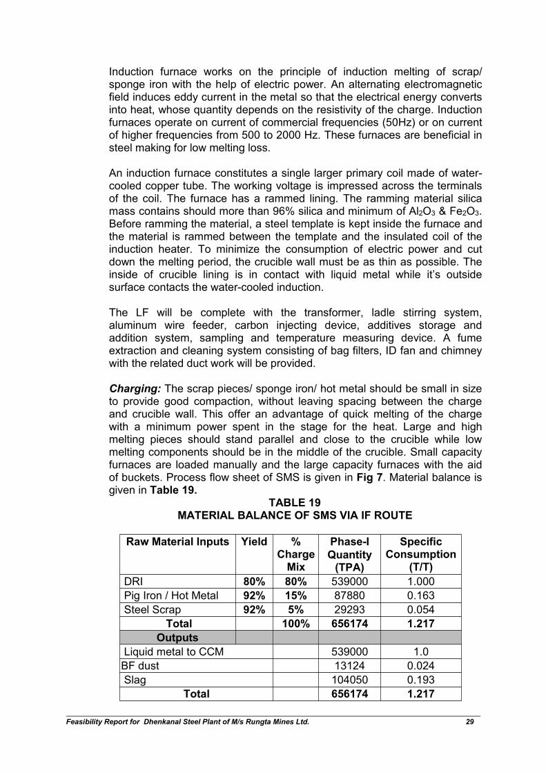
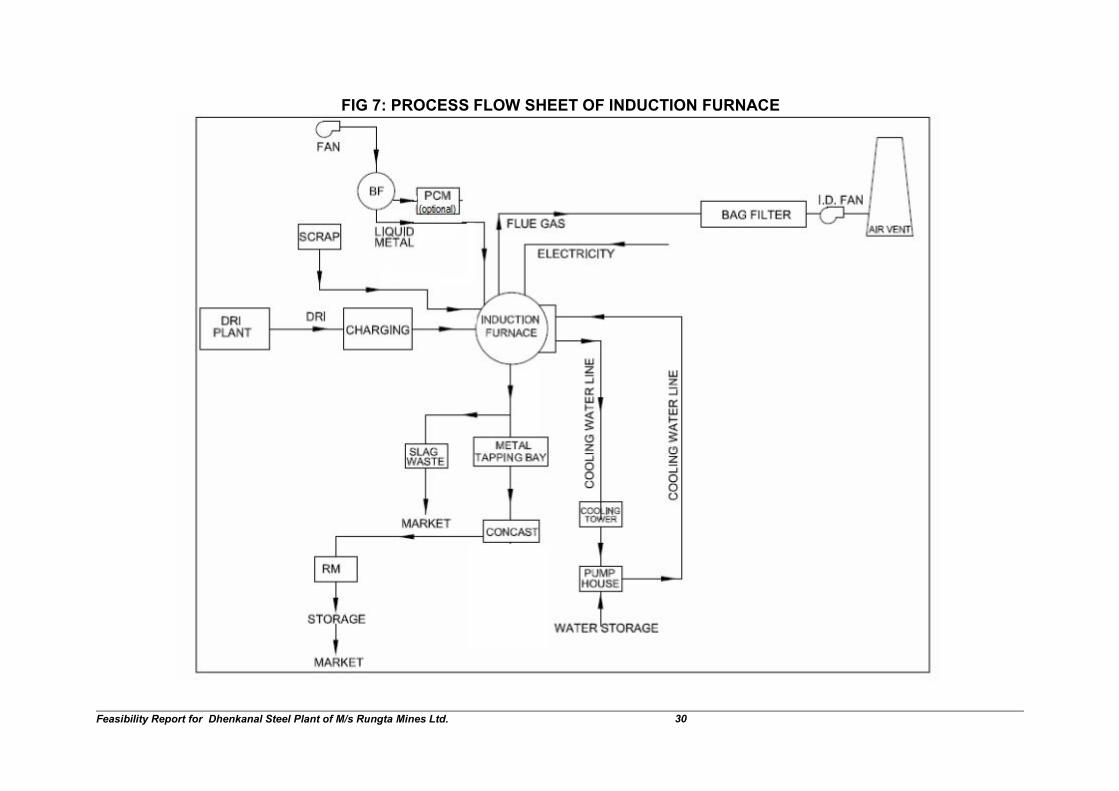
Charging: The scrap pieces/ sponge iron/ hot metal should be small in sizeto provide good compaction, without leaving spacing between the chargeand crucible wall. This offer an advantage of quick melting of the chargewith a minimum power spent in the stage for the heat. Large and highmelting pieces should stand parallel and close to the crucible while lowmelting components should be in the middle of the crucible. Small capacityfurnaces are loaded manually and the large capacity furnaces with the aidof buckets. Process flow sheet of SMS is given in Fig 7. Material balance isgiven in Table 19.
TABLE 19MATERIAL BALANCE OF SMS VIA IF ROUTE
Raw Material Inputs Yield %ChargeMix
Phase-I
Quantity(TPA)
SpecificConsumption
(T/T)
DRI 80% 80% 539000 1.000
Pig Iron / Hot Metal 92% 15% 87880 0.163
Steel Scrap 92% 5% 29293 0.054
Total 100% 656174 1.217
Outputs
Liquid metal to CCM 539000 1.0
BF dust 13124 0.024
Slag 104050 0.193
Total 656174 1.217
Feasibility Report for Dhenkanal Steel Plant of M/s Rungta Mines Ltd. 30
FIG 7: PROCESS FLOW SHEET OF INDUCTION FURNACE
Feasibility Report for Dhenkanal Steel Plant of M/s Rungta Mines Ltd. 31
9.0 ELECTRIC ARC FURNACE-LRF-CCM ROUTE
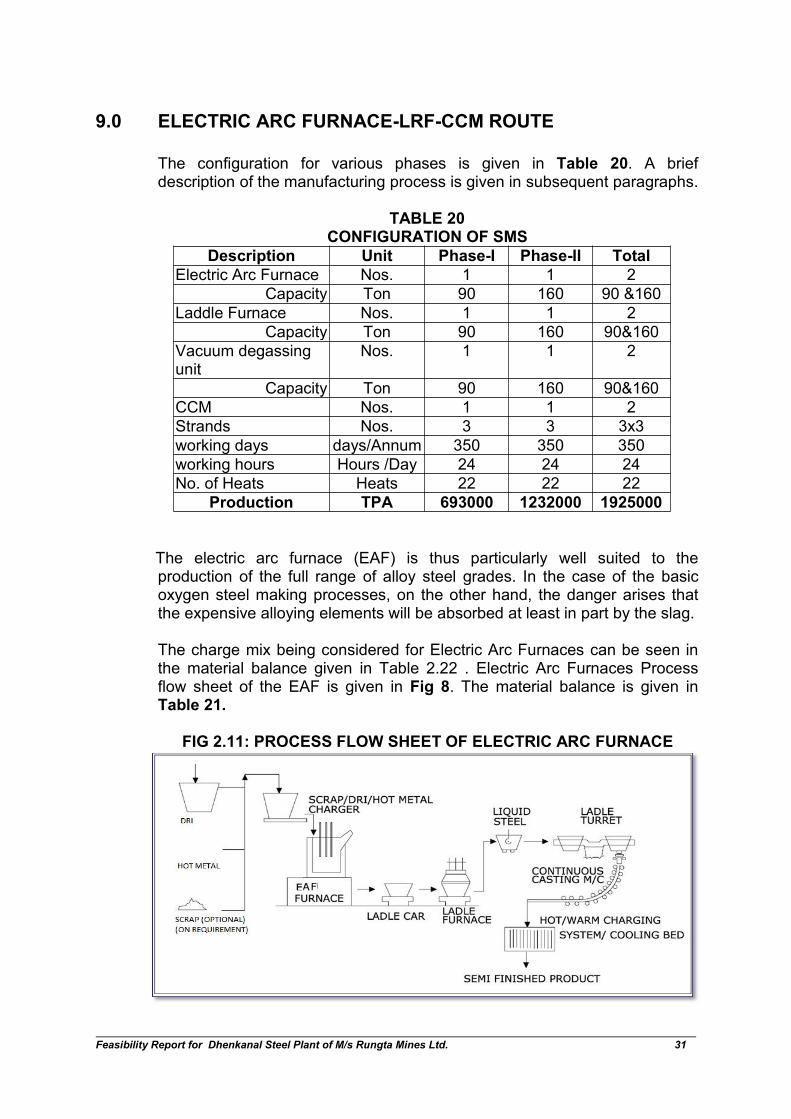
The configuration for various phases is given in Table 20. A briefdescription of the manufacturing process is given in subsequent paragraphs.
TABLE 20CONFIGURATION OF SMS
Description Unit Phase-I Phase-II Total
Electric Arc Furnace Nos. 1 1 2
Capacity Ton 90 160 90 &160
Laddle Furnace Nos. 1 1 2
Capacity Ton 90 160 90&160
Vacuum degassingunit
Nos. 1 1 2
Capacity Ton 90 160 90&160
CCM Nos. 1 1 2
Strands Nos. 3 3 3x3
working days days/Annum 350 350 350
working hours Hours /Day 24 24 24
No. of Heats Heats 22 22 22
Production TPA 693000 1232000 1925000
The electric arc furnace (EAF) is thus particularly well suited to theproduction of the full range of alloy steel grades. In the case of the basicoxygen steel making processes, on the other hand, the danger arises thatthe expensive alloying elements will be absorbed at least in part by the slag.
The charge mix being considered for Electric Arc Furnaces can be seen inthe material balance given in Table 2.22 . Electric Arc Furnaces Processflow sheet of the EAF is given in Fig 8. The material balance is given inTable 21.
FIG 2.11: PROCESS FLOW SHEET OF ELECTRIC ARC FURNACE
Feasibility Report for Dhenkanal Steel Plant of M/s Rungta Mines Ltd. 32
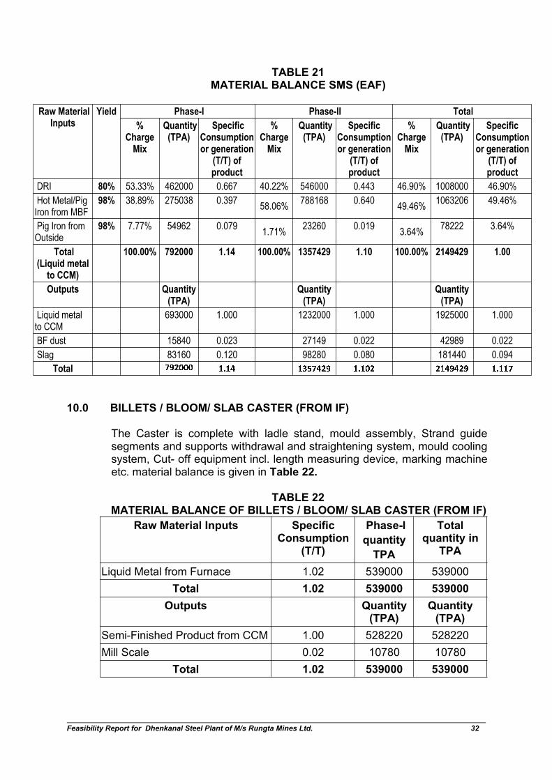
TABLE 21MATERIAL BALANCE SMS (EAF)
Raw MaterialInputs
Yield Phase-I Phase-II Total
%Charge
Mix
Quantity(TPA)
SpecificConsumptionor generation
(T/T) ofproduct
%Charge
Mix
Quantity(TPA)
SpecificConsumptionor generation
(T/T) ofproduct
%Charge
Mix
Quantity(TPA)
SpecificConsumptionor generation
(T/T) ofproduct
DRI 80% 53.33% 462000 0.667 40.22% 546000 0.443 46.90% 1008000 46.90%
Hot Metal/PigIron from MBF
98% 38.89% 275038 0.39758.06%
788168 0.64049.46%
1063206 49.46%
Pig Iron fromOutside
98% 7.77% 54962 0.0791.71%
23260 0.0193.64%
78222 3.64%
Total(Liquid metal
to CCM)
100.00% 792000 1.14 100.00% 1357429 1.10 100.00% 2149429 1.00
Outputs Quantity(TPA)
Quantity(TPA)
Quantity(TPA)
Liquid metalto CCM
693000 1.000 1232000 1.000 1925000 1.000
BF dust 15840 0.023 27149 0.022 42989 0.022
Slag 83160 0.120 98280 0.080 181440 0.094
Total������ ���� ������� ����� ������� �����
10.0 BILLETS / BLOOM/ SLAB CASTER (FROM IF)
The Caster is complete with ladle stand, mould assembly, Strand guidesegments and supports withdrawal and straightening system, mould coolingsystem, Cut- off equipment incl. length measuring device, marking machineetc. material balance is given in Table 22.
TABLE 22MATERIAL BALANCE OF BILLETS / BLOOM/ SLAB CASTER (FROM IF)
Raw Material Inputs SpecificConsumption
(T/T)
Phase-I
quantity
TPA
Totalquantity in
TPA
Liquid Metal from Furnace 1.02 539000 539000
Total 1.02 539000 539000
Outputs Quantity(TPA)
Quantity(TPA)
Semi-Finished Product from CCM 1.00 528220 528220
Mill Scale 0.02 10780 10780
Total 1.02 539000 539000
Feasibility Report for Dhenkanal Steel Plant of M/s Rungta Mines Ltd. 33
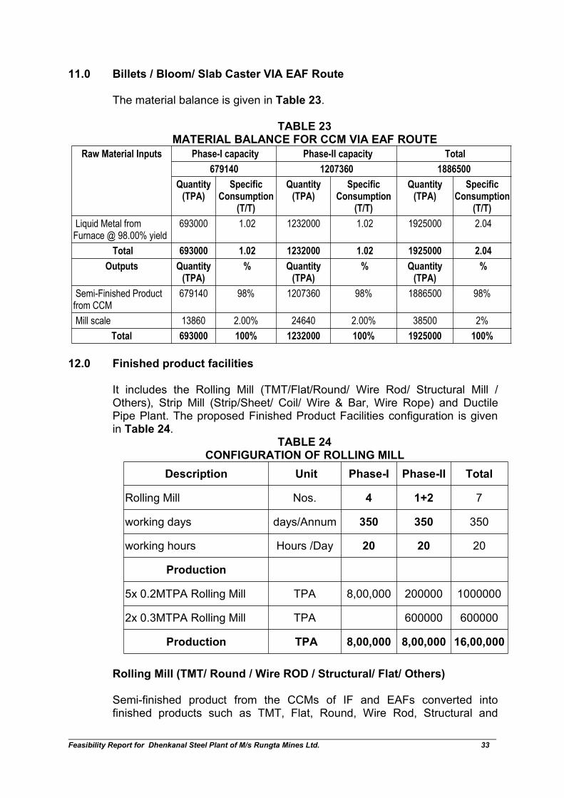
11.0 Billets / Bloom/ Slab Caster VIA EAF Route
The material balance is given in Table 23.
TABLE 23MATERIAL BALANCE FOR CCM VIA EAF ROUTE
Raw Material Inputs Phase-I capacity Phase-II capacity Total
679140 1207360 1886500
Quantity(TPA)
SpecificConsumption
(T/T)
Quantity(TPA)
SpecificConsumption
(T/T)
Quantity(TPA)
SpecificConsumption
(T/T)
Liquid Metal fromFurnace @ 98.00% yield
693000 1.02 1232000 1.02 1925000 2.04
Total 693000 1.02 1232000 1.02 1925000 2.04
Outputs Quantity(TPA)
% Quantity(TPA)
% Quantity(TPA)
%
Semi-Finished Productfrom CCM
679140 98% 1207360 98% 1886500 98%
Mill scale 13860 2.00% 24640 2.00% 38500 2%
Total 693000 100% 1232000 100% 1925000 100%
12.0 Finished product facilities
It includes the Rolling Mill (TMT/Flat/Round/ Wire Rod/ Structural Mill /Others), Strip Mill (Strip/Sheet/ Coil/ Wire & Bar, Wire Rope) and DuctilePipe Plant. The proposed Finished Product Facilities configuration is givenin Table 24.
TABLE 24CONFIGURATION OF ROLLING MILL
Description Unit Phase-I Phase-II Total
Rolling Mill Nos. 4 1+2 7
working days days/Annum 350 350 350
working hours Hours /Day 20 20 20
Production
5x 0.2MTPA Rolling Mill TPA 8,00,000 200000 1000000
2x 0.3MTPA Rolling Mill TPA 600000 600000
Production TPA 8,00,000 8,00,000 16,00,000
Rolling Mill (TMT/ Round / Wire ROD / Structural/ Flat/ Others)
Semi-finished product from the CCMs of IF and EAFs converted intofinished products such as TMT, Flat, Round, Wire Rod, Structural and
Feasibility Report for Dhenkanal Steel Plant of M/s Rungta Mines Ltd. 34
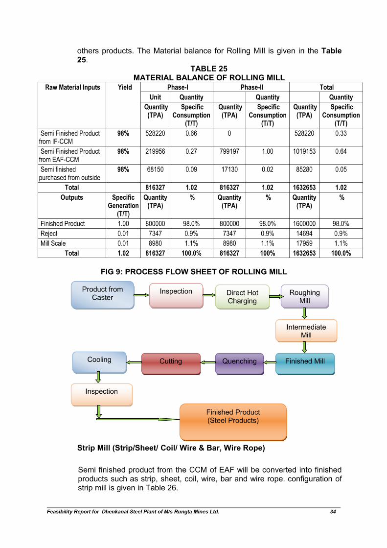
others products. The Material balance for Rolling Mill is given in the Table25.
TABLE 25MATERIAL BALANCE OF ROLLING MILL
Raw Material Inputs Yield Phase-I Phase-II Total
Unit Quantity Quantity Quantity
Quantity(TPA)
SpecificConsumption
(T/T)
Quantity(TPA)
SpecificConsumption
(T/T)
Quantity(TPA)
SpecificConsumption
(T/T)
Semi Finished Productfrom IF-CCM
98% 528220 0.66 0 528220 0.33
Semi Finished Productfrom EAF-CCM
98% 219956 0.27 799197 1.00 1019153 0.64
Semi finishedpurchased from outside
98% 68150 0.09 17130 0.02 85280 0.05
Total 816327 1.02 816327 1.02 1632653 1.02
Outputs SpecificGeneration
(T/T)
Quantity(TPA)
% Quantity(TPA)
% Quantity(TPA)
%
Finished Product 1.00 800000 98.0% 800000 98.0% 1600000 98.0%
Reject 0.01 7347 0.9% 7347 0.9% 14694 0.9%
Mill Scale 0.01 8980 1.1% 8980 1.1% 17959 1.1%
Total 1.02 816327 100.0% 816327 100% 1632653 100.0%
FIG 9: PROCESS FLOW SHEET OF ROLLING MILL
Strip Mill (Strip/Sheet/ Coil/ Wire & Bar, Wire Rope)
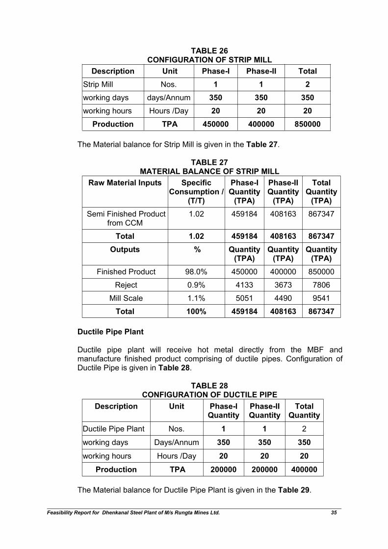
Semi finished product from the CCM of EAF will be converted into finishedproducts such as strip, sheet, coil, wire, bar and wire rope. configuration ofstrip mill is given in Table 26.
Product fromCaster
Inspection Direct HotCharging
RoughingMill
IntermediateMill
Finished Product(Steel Products)
Finished MillQuenchingCuttingCooling
Inspection
Feasibility Report for Dhenkanal Steel Plant of M/s Rungta Mines Ltd. 35
TABLE 26CONFIGURATION OF STRIP MILL
Description Unit Phase-I Phase-II Total
Strip Mill Nos. 1 1 2
working days days/Annum 350 350 350
working hours Hours /Day 20 20 20
Production TPA 450000 400000 850000
The Material balance for Strip Mill is given in the Table 27.
TABLE 27MATERIAL BALANCE OF STRIP MILL
Raw Material Inputs SpecificConsumption /
(T/T)
Phase-IQuantity(TPA)
Phase-IIQuantity(TPA)
TotalQuantity(TPA)
Semi Finished Productfrom CCM
1.02 459184 408163 867347
Total 1.02 459184 408163 867347
Outputs % Quantity(TPA)
Quantity(TPA)
Quantity(TPA)
Finished Product 98.0% 450000 400000 850000
Reject 0.9% 4133 3673 7806
Mill Scale 1.1% 5051 4490 9541
Total 100% 459184 408163 867347
Ductile Pipe Plant
Ductile pipe plant will receive hot metal directly from the MBF andmanufacture finished product comprising of ductile pipes. Configuration ofDuctile Pipe is given in Table 28.
TABLE 28CONFIGURATION OF DUCTILE PIPE
Description Unit Phase-IQuantity
Phase-IIQuantity
TotalQuantity
Ductile Pipe Plant Nos. 1 1 2
working days Days/Annum 350 350 350
working hours Hours /Day 20 20 20
Production TPA 200000 200000 400000
The Material balance for Ductile Pipe Plant is given in the Table 29.

Feasibility Report for Dhenkanal Steel Plant of M/s Rungta Mines Ltd. 36
TABLE 29MATERIAL BALANCE OF DUCTILE PIPE PLANT
Raw Material Inputs SpecificConsumption/
(T/T )
Phase-IQuantity(TPA)
Phase-IIQuantity(TPA)
TotalQuantity(TPA)
Hot Metal from BlastFurnace
1.02 204082 204082 408163
Total 1.02 204082 204082 408163
Outputs %
Finished Product 98.0% 200000 200000 400000
Reject 0.9% 1837 1837 3673
Mill Scale 1.1% 2245 2245 4490
Total 100% 204082 204082 408163
13.0 PRODUCER GAS PLANT
The proposed Producer Gas Plant Facilities configuration is given in Table30
TABLE 30CONFIGURATION OF PRODUCER GAS PLANT FACILITIES
Description Unit Parameters
Phase I Phase II
Heat required for one ton of Pellet KCal/Ton 220,000 220,000
Total Pellet Production TPA 1,474,000 1,474,000
Total Heat Required KCal/Year 32.428X 10¹⁰ 32.428X 10¹⁰
CV of Producer Gas KCal/Nm3 1250-1375 1250-1375
Design CV of Producer Gas KCal/Nm3 1353.78 1353.78
Producer Gas Requirement Nm3/Year 24.00 X 10⁷ 24.00 X 10⁷
Operational Day per Annum Days 335 335
Operational Hours per Day Hours 24 24
Per Hour Requirement Nm3/Hr 29788.55 29788.55
Per Unit Capacity Nm3/Hr 3000 3000
No. of Units Nos. 9.92 9.92
Say Nos. 10 10
Feasibility Report for Dhenkanal Steel Plant of M/s Rungta Mines Ltd. 37
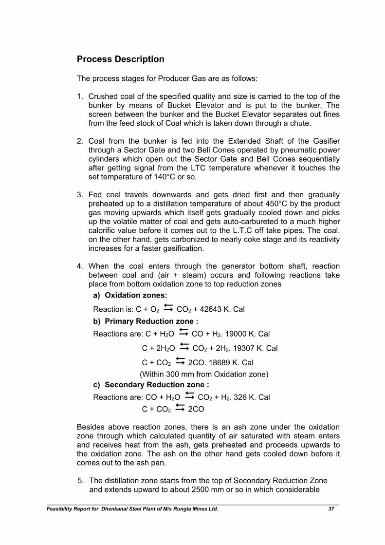
Process Description
The process stages for Producer Gas are as follows:
1. Crushed coal of the specified quality and size is carried to the top of thebunker by means of Bucket Elevator and is put to the bunker. Thescreen between the bunker and the Bucket Elevator separates out finesfrom the feed stock of Coal which is taken down through a chute.
2. Coal from the bunker is fed into the Extended Shaft of the Gasifierthrough a Sector Gate and two Bell Cones operated by pneumatic powercylinders which open out the Sector Gate and Bell Cones sequentiallyafter getting signal from the LTC temperature whenever it touches theset temperature of 140°C or so.
3. Fed coal travels downwards and gets dried first and then graduallypreheated up to a distillation temperature of about 450°C by the productgas moving upwards which itself gets gradually cooled down and picksup the volatile matter of coal and gets auto-carbureted to a much highercalorific value before it comes out to the L.T.C off take pipes. The coal,on the other hand, gets carbonized to nearly coke stage and its reactivityincreases for a faster gasification.
4. When the coal enters through the generator bottom shaft, reactionbetween coal and (air + steam) occurs and following reactions takeplace from bottom oxidation zone to top reduction zones
a) Oxidation zones:
Reaction is: C + O2 CO2 + 42643 K. Cal
b) Primary Reduction zone :
Reactions are: C + H2O CO + H2. 19000 K. Cal
C + 2H2O CO2 + 2H2. 19307 K. Cal
C + CO2 2CO. 18689 K. Cal
(Within 300 mm from Oxidation zone)
c) Secondary Reduction zone :
Reactions are: CO + H2O CO2 + H2. 326 K. Cal
C + CO2 2CO
Besides above reaction zones, there is an ash zone under the oxidationzone through which calculated quantity of air saturated with steam entersand receives heat from the ash, gets preheated and proceeds upwards tothe oxidation zone. The ash on the other hand gets cooled down before itcomes out to the ash pan.
5. The distillation zone starts from the top of Secondary Reduction Zoneand extends upward to about 2500 mm or so in which considerable
Feasibility Report for Dhenkanal Steel Plant of M/s Rungta Mines Ltd. 38
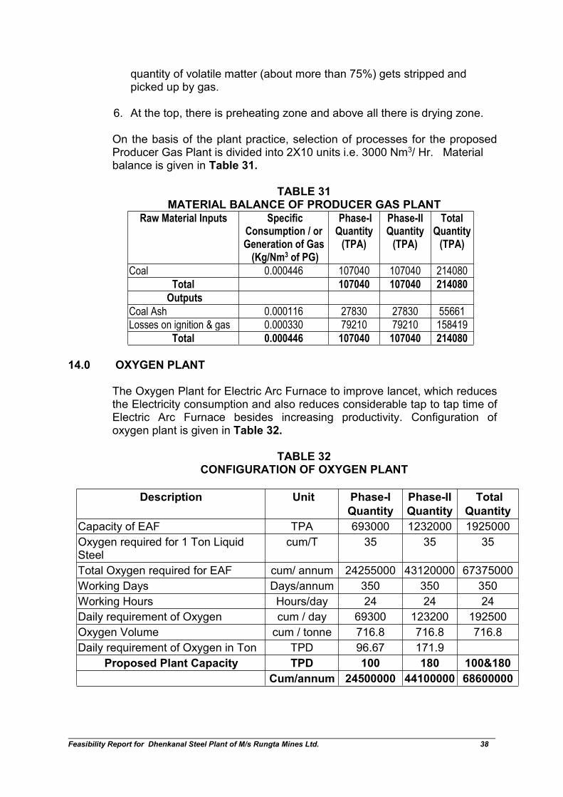
quantity of volatile matter (about more than 75%) gets stripped andpicked up by gas.
6. At the top, there is preheating zone and above all there is drying zone.
On the basis of the plant practice, selection of processes for the proposedProducer Gas Plant is divided into 2X10 units i.e. 3000 Nm3/ Hr. Materialbalance is given in Table 31.
TABLE 31MATERIAL BALANCE OF PRODUCER GAS PLANT
Raw Material Inputs SpecificConsumption / orGeneration of Gas
(Kg/Nm3 of PG)
Phase-IQuantity
(TPA)
Phase-IIQuantity
(TPA)
TotalQuantity
(TPA)
Coal 0.000446 107040 107040 214080
Total 107040 107040 214080
Outputs
Coal Ash 0.000116 27830 27830 55661
Losses on ignition & gas 0.000330 79210 79210 158419
Total 0.000446 107040 107040 214080
14.0 OXYGEN PLANT
The Oxygen Plant for Electric Arc Furnace to improve lancet, which reducesthe Electricity consumption and also reduces considerable tap to tap time ofElectric Arc Furnace besides increasing productivity. Configuration ofoxygen plant is given in Table 32.
TABLE 32CONFIGURATION OF OXYGEN PLANT
Description Unit Phase-I
Quantity
Phase-II
Quantity
Total
Quantity
Capacity of EAF TPA 693000 1232000 1925000
Oxygen required for 1 Ton LiquidSteel
cum/T 35 35 35
Total Oxygen required for EAF cum/ annum 24255000 43120000 67375000
Working Days Days/annum 350 350 350
Working Hours Hours/day 24 24 24
Daily requirement of Oxygen cum / day 69300 123200 192500
Oxygen Volume cum / tonne 716.8 716.8 716.8
Daily requirement of Oxygen in Ton TPD 96.67 171.9
Proposed Plant Capacity TPD 100 180 100&180
Cum/annum 24500000 44100000 68600000
Feasibility Report for Dhenkanal Steel Plant of M/s Rungta Mines Ltd. 39
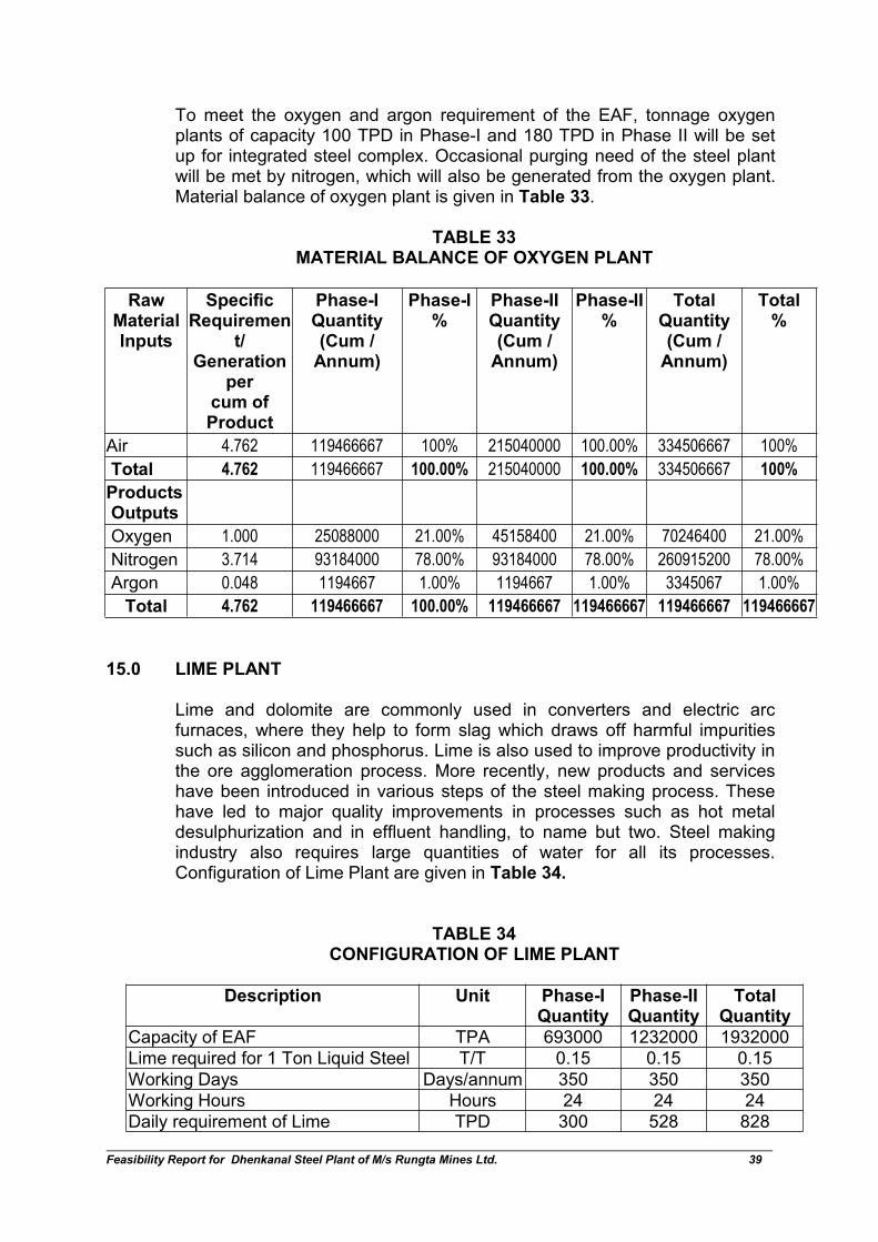
To meet the oxygen and argon requirement of the EAF, tonnage oxygenplants of capacity 100 TPD in Phase-I and 180 TPD in Phase II will be setup for integrated steel complex. Occasional purging need of the steel plantwill be met by nitrogen, which will also be generated from the oxygen plant.Material balance of oxygen plant is given in Table 33.
TABLE 33MATERIAL BALANCE OF OXYGEN PLANT
RawMaterialInputs
SpecificRequiremen
t/Generation
percum ofProduct
Phase-IQuantity(Cum /Annum)
Phase-I%
Phase-IIQuantity(Cum /Annum)
Phase-II%
TotalQuantity(Cum /Annum)
Total%
Air 4.762 119466667 100% 215040000 100.00% 334506667 100%
Total 4.762 119466667 100.00% 215040000 100.00% 334506667 100%
ProductsOutputs
Oxygen 1.000 25088000 21.00% 45158400 21.00% 70246400 21.00%
Nitrogen 3.714 93184000 78.00% 93184000 78.00% 260915200 78.00%
Argon 0.048 1194667 1.00% 1194667 1.00% 3345067 1.00%
Total 4.762 119466667 100.00% 119466667 119466667 119466667 119466667
15.0 LIME PLANT
Lime and dolomite are commonly used in converters and electric arcfurnaces, where they help to form slag which draws off harmful impuritiessuch as silicon and phosphorus. Lime is also used to improve productivity inthe ore agglomeration process. More recently, new products and serviceshave been introduced in various steps of the steel making process. Thesehave led to major quality improvements in processes such as hot metaldesulphurization and in effluent handling, to name but two. Steel makingindustry also requires large quantities of water for all its processes.Configuration of Lime Plant are given in Table 34.
TABLE 34CONFIGURATION OF LIME PLANT
Description Unit Phase-IQuantity
Phase-IIQuantity
TotalQuantity
Capacity of EAF TPA 693000 1232000 1932000
Lime required for 1 Ton Liquid Steel T/T 0.15 0.15 0.15
Working Days Days/annum 350 350 350
Working Hours Hours 24 24 24
Daily requirement of Lime TPD 300 528 828
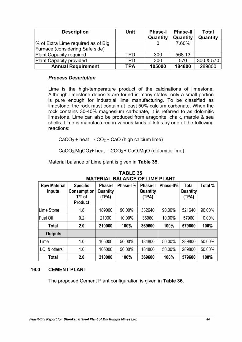
Feasibility Report for Dhenkanal Steel Plant of M/s Rungta Mines Ltd. 40
Description Unit Phase-IQuantity
Phase-IIQuantity
TotalQuantity
% of Extra Lime required as of BigFurnace (considering Safe side)
0 7.60%
Plant Capacity required TPD 300 568.13
Plant Capacity provided TPD 300 570 300 & 570
Annual Requirement TPA 105000 184800 289800
Process Description
Lime is the high-temperature product of the calcinations of limestone.Although limestone deposits are found in many states, only a small portionis pure enough for industrial lime manufacturing. To be classified aslimestone, the rock must contain at least 50% calcium carbonate. When therock contains 30-40% magnesium carbonate, it is referred to as dolomiticlimestone. Lime can also be produced from aragonite, chalk, marble & seashells. Lime is manufactured in various kinds of kilns by one of the followingreactions:
CaCO3 + heat → CO2 + CaO (high calcium lime)
CaCO3.MgCO3+ heat →2CO2 + CaO.MgO (dolomitic lime)
Material balance of Lime plant is given in Table 35.
TABLE 35MATERIAL BALANCE OF LIME PLANT
Raw MaterialInputs
SpecificConsumption
T/T ofProduct
Phase-IQuantity
(TPA)
Phase-I % Phase-IIQuantity
(TPA)
Phase-II% TotalQuantity
(TPA)
Total %
Lime Stone 1.8 189000 90.00% 332640 90.00% 521640 90.00%
Fuel Oil 0.2 21000 10.00% 36960 10.00% 57960 10.00%
Total 2.0 210000 100% 369600 100% 579600 100%
Outputs
Lime 1.0 105000 50.00% 184800 50.00% 289800 50.00%
LOI & others 1.0 105000 50.00% 184800 50.00% 289800 50.00%
Total 2.0 210000 100% 369600 100% 579600 100%
16.0 CEMENT PLANT
The proposed Cement Plant configuration is given in Table 36.

Feasibility Report for Dhenkanal Steel Plant of M/s Rungta Mines Ltd. 41
TABLE 36CONFIGURATION OF CEMENT PLANT
Description Unit Phase-IQuantity
Phase-IIQuantity
Total Quantity
(1) Cement Plant Nos. 1 1 2
Capacity TPD 2600 2300 2600 & 2300
Working days per/Annum 340 348.5 340,348.5
Working hours Hours /Day 24 24 24
Total TPA 884000 801550 1685550
Process Description
Limestone will be the primary raw material for clinker making. Along withcoal, it will be fed into the clinker kiln and the manufactured clinker will besent to cement mill. Company will installed cement plant, PortlandPozzolana Cement (PPC) using fly ash and Portland Blast Furnace SlagCement (PBFS) using blast furnace slag Dry process of cementmanufacturing offers more advantages, particularly in fuel consumption andis the most rational and logical choice. In the proposed plant, dry processhas been selected to manufacture clinker, which comprises of rotary kiln,preheater and pre-calciner. The typical process diagram for cementmanufacturing is depicted in the Fig 10.
FIG 10: MANUFACTURING PROCESS
In dry process, the raw materials are dried in a combined drying-cum-grinding installation to reduce the moisture content to below 1%. The dryingin the grinding unit is achieved by using kiln exhaust gases for normalmoisture. The ground raw mix is then homogenized in silos and fed into the
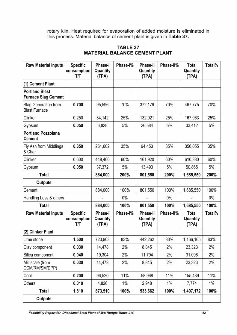
Feasibility Report for Dhenkanal Steel Plant of M/s Rungta Mines Ltd. 42
rotary kiln. Heat required for evaporation of added moisture is eliminated inthis process. Material balance of cement plant is given in Table 37.
TABLE 37MATERIAL BALANCE CEMENT PLANT
Raw Material Inputs Specificconsumption
T/T
Phase-IQuantity
(TPA)
Phase-I% Phase-IIQuantity
(TPA)
Phase-II% TotalQuantity
(TPA)
Total%
(1) Cement Plant
Portland BlastFurnace Slag Cement
Slag Generation fromBlast Furnace
0.700 95,596 70% 372,179 70% 467,775 70%
Clinker 0.250 34,142 25% 132,921 25% 167,063 25%
Gypsum 0.050 6,828 5% 26,584 5% 33,412 5%
Portland PozzolanaCement
Fly Ash from Middlings& Char
0.350 261,602 35% 94,453 35% 356,055 35%
Clinker 0.600 448,460 60% 161,920 60% 610,380 60%
Gypsum 0.050 37,372 5% 13,493 5% 50,865 5%
Total 884,000 200% 801,550 200% 1,685,550 200%
Outputs
Cement 884,000 100% 801,550 100% 1,685,550 100%
Handling Loss & others - 0% - 0% - 0%
Total 884,000 100% 801,550 100% 1,685,550 100%
Raw Material Inputs Specificconsumption
T/T
Phase-IQuantity
(TPA)
Phase-I% Phase-IIQuantity
(TPA)
Phase-II% TotalQuantity
(TPA)
Total%
(2) Clinker Plant
Lime stone 1.500 723,903 83% 442,262 83% 1,166,165 83%
Clay component 0.030 14,478 2% 8,845 2% 23,323 2%
Silica component 0.040 19,304 2% 11,794 2% 31,098 2%
Mill scale (fromCCM/RM/SM/DPP)
0.030 14,478 2% 8,845 2% 23,323 2%
Coal 0.200 96,520 11% 58,968 11% 155,489 11%
Others 0.010 4,826 1% 2,948 1% 7,774 1%
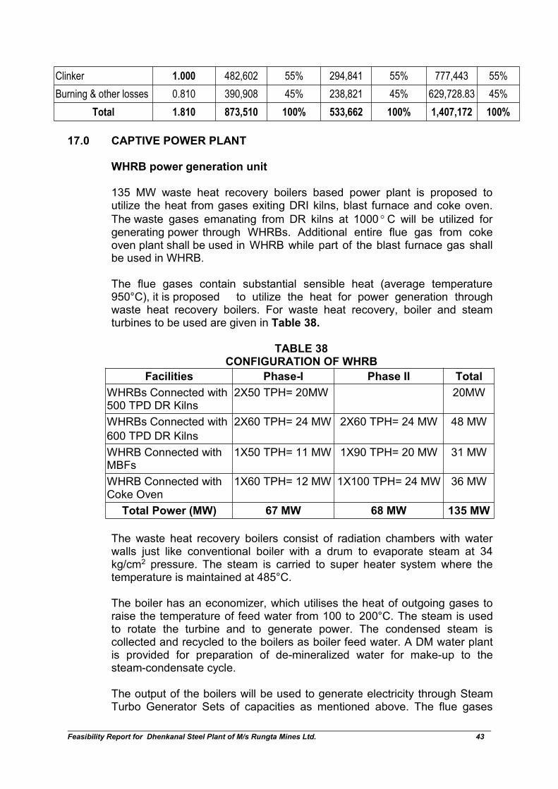
Total 1.810 873,510 100% 533,662 100% 1,407,172 100%
Outputs
Feasibility Report for Dhenkanal Steel Plant of M/s Rungta Mines Ltd. 43
Clinker 1.000 482,602 55% 294,841 55% 777,443 55%
Burning & other losses 0.810 390,908 45% 238,821 45% 629,728.83 45%
Total 1.810 873,510 100% 533,662 100% 1,407,172 100%
17.0 CAPTIVE POWER PLANT
WHRB power generation unit
135 MW waste heat recovery boilers based power plant is proposed toutilize the heat from gases exiting DRI kilns, blast furnace and coke oven.
The waste gases emanating from DR kilns at 1000 C will be utilized forgenerating power through WHRBs. Additional entire flue gas from cokeoven plant shall be used in WHRB while part of the blast furnace gas shallbe used in WHRB.
The flue gases contain substantial sensible heat (average temperature950°C), it is proposed to utilize the heat for power generation throughwaste heat recovery boilers. For waste heat recovery, boiler and steamturbines to be used are given in Table 38.
TABLE 38CONFIGURATION OF WHRB
Facilities Phase-I Phase II Total
WHRBs Connected with500 TPD DR Kilns
2X50 TPH= 20MW 20MW
WHRBs Connected with
600 TPD DR Kilns
2X60 TPH= 24 MW 2X60 TPH= 24 MW 48 MW
WHRB Connected withMBFs
1X50 TPH= 11 MW 1X90 TPH= 20 MW 31 MW
WHRB Connected withCoke Oven
1X60 TPH= 12 MW 1X100 TPH= 24 MW 36 MW
Total Power (MW) 67 MW 68 MW 135 MW
The waste heat recovery boilers consist of radiation chambers with waterwalls just like conventional boiler with a drum to evaporate steam at 34kg/cm2 pressure. The steam is carried to super heater system where thetemperature is maintained at 485°C.
The boiler has an economizer, which utilises the heat of outgoing gases toraise the temperature of feed water from 100 to 200°C. The steam is usedto rotate the turbine and to generate power. The condensed steam iscollected and recycled to the boilers as boiler feed water. A DM water plantis provided for preparation of de-mineralized water for make-up to thesteam-condensate cycle.
The output of the boilers will be used to generate electricity through SteamTurbo Generator Sets of capacities as mentioned above. The flue gases
Feasibility Report for Dhenkanal Steel Plant of M/s Rungta Mines Ltd. 44
leave the economizer zone at about 150°C. The gases are passed throughESPs, where the dust concentration is brought down to below 50 mg/m3.
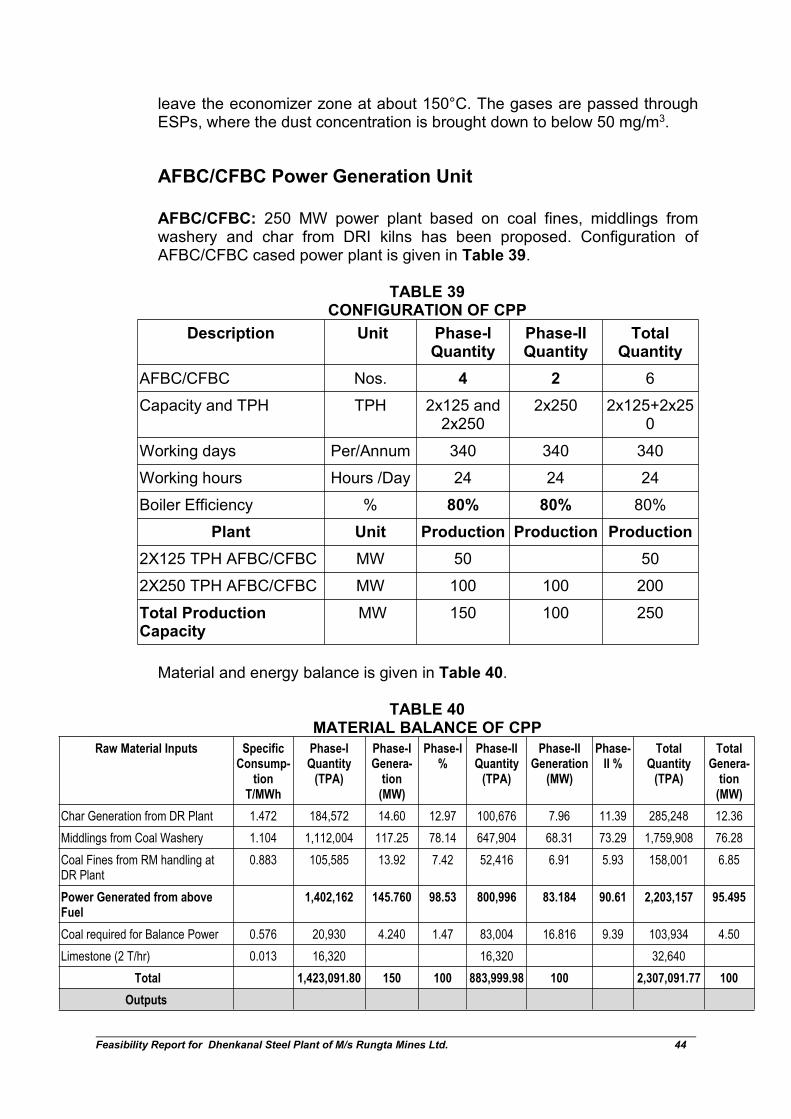
AFBC/CFBC Power Generation Unit
AFBC/CFBC: 250 MW power plant based on coal fines, middlings fromwashery and char from DRI kilns has been proposed. Configuration ofAFBC/CFBC cased power plant is given in Table 39.
TABLE 39CONFIGURATION OF CPP
Description Unit Phase-IQuantity
Phase-IIQuantity
TotalQuantity
AFBC/CFBC Nos. 4 2 6
Capacity and TPH TPH 2x125 and2x250
2x250 2x125+2x250
Working days Per/Annum 340 340 340
Working hours Hours /Day 24 24 24
Boiler Efficiency % 80% 80% 80%
Plant Unit Production Production Production
2X125 TPH AFBC/CFBC MW 50 50
2X250 TPH AFBC/CFBC MW 100 100 200
Total ProductionCapacity
MW 150 100 250
Material and energy balance is given in Table 40.
TABLE 40MATERIAL BALANCE OF CPP
Raw Material Inputs SpecificConsump-
tionT/MWh
Phase-IQuantity
(TPA)
Phase-IGenera-
tion(MW)
Phase-I%
Phase-IIQuantity
(TPA)
Phase-IIGeneration
(MW)
Phase-II %
TotalQuantity
(TPA)
TotalGenera-
tion(MW)
Char Generation from DR Plant 1.472 184,572 14.60 12.97 100,676 7.96 11.39 285,248 12.36
Middlings from Coal Washery 1.104 1,112,004 117.25 78.14 647,904 68.31 73.29 1,759,908 76.28
Coal Fines from RM handling atDR Plant
0.883 105,585 13.92 7.42 52,416 6.91 5.93 158,001 6.85
Power Generated from aboveFuel
1,402,162 145.760 98.53 800,996 83.184 90.61 2,203,157 95.495
Coal required for Balance Power 0.576 20,930 4.240 1.47 83,004 16.816 9.39 103,934 4.50
Limestone (2 T/hr) 0.013 16,320 16,320 32,640
Total 1,423,091.80 150 100 883,999.98 100 2,307,091.77 100
Outputs
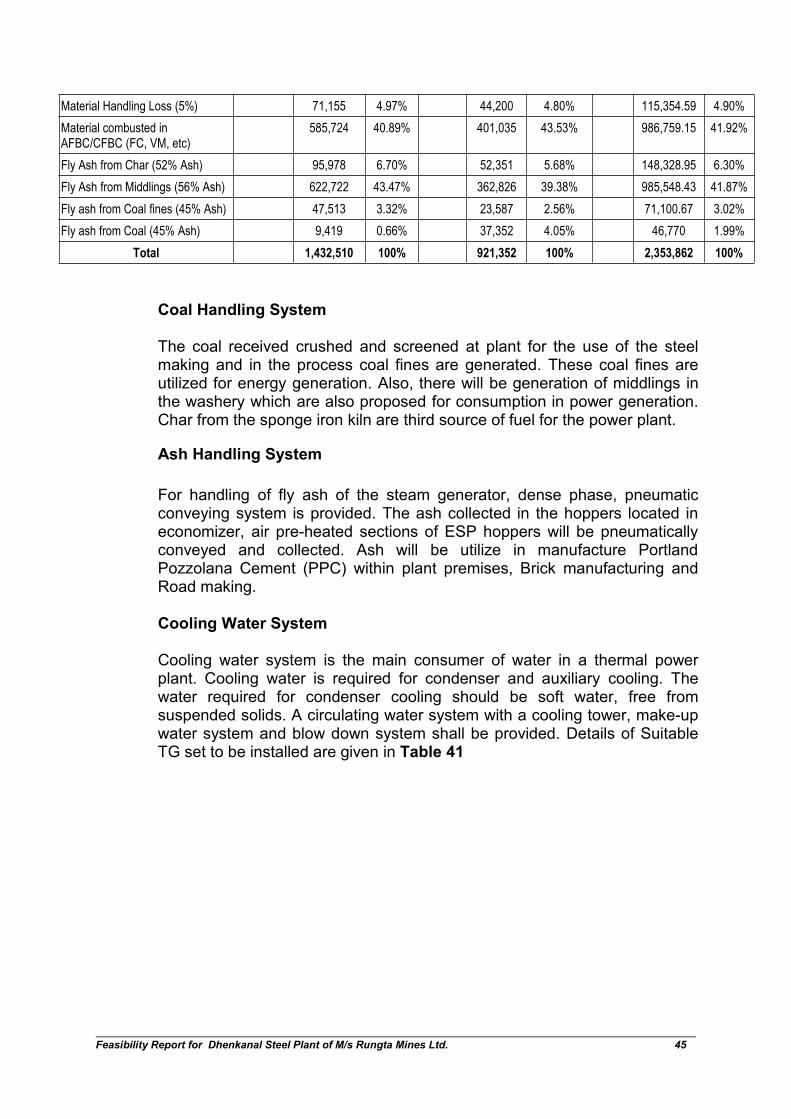
Feasibility Report for Dhenkanal Steel Plant of M/s Rungta Mines Ltd. 45
Material Handling Loss (5%) 71,155 4.97% 44,200 4.80% 115,354.59 4.90%
Material combusted inAFBC/CFBC (FC, VM, etc)
585,724 40.89% 401,035 43.53% 986,759.15 41.92%
Fly Ash from Char (52% Ash) 95,978 6.70% 52,351 5.68% 148,328.95 6.30%
Fly Ash from Middlings (56% Ash) 622,722 43.47% 362,826 39.38% 985,548.43 41.87%
Fly ash from Coal fines (45% Ash) 47,513 3.32% 23,587 2.56% 71,100.67 3.02%
Fly ash from Coal (45% Ash) 9,419 0.66% 37,352 4.05% 46,770 1.99%
Total 1,432,510 100% 921,352 100% 2,353,862 100%
Coal Handling System
The coal received crushed and screened at plant for the use of the steelmaking and in the process coal fines are generated. These coal fines areutilized for energy generation. Also, there will be generation of middlings inthe washery which are also proposed for consumption in power generation.Char from the sponge iron kiln are third source of fuel for the power plant.
Ash Handling System
For handling of fly ash of the steam generator, dense phase, pneumaticconveying system is provided. The ash collected in the hoppers located ineconomizer, air pre-heated sections of ESP hoppers will be pneumaticallyconveyed and collected. Ash will be utilize in manufacture PortlandPozzolana Cement (PPC) within plant premises, Brick manufacturing andRoad making.
Cooling Water System
Cooling water system is the main consumer of water in a thermal powerplant. Cooling water is required for condenser and auxiliary cooling. Thewater required for condenser cooling should be soft water, free fromsuspended solids. A circulating water system with a cooling tower, make-upwater system and blow down system shall be provided. Details of SuitableTG set to be installed are given in Table 41

Feasibility Report for Dhenkanal Steel Plant of M/s Rungta Mines Ltd. 46
TABLE 41SUITABLE TG SET TO BE INSTALLED
Facilities Units GenerationCapacity(in MW)
TotalPower(in MW)
PowerGeneration(in MW)
Phase I
TG Sets(WHRB 3 Nos. 25 75 67
TG Sets (AFBC/ CFBC) 3 Nos. 50 150 150
Total Power 225 217
Phase II
TG Sets(WHRB) 3 Nos. 25 75 68
TG Sets(AFBC/CFBC) 2 Nos. 50 100 100
Sub total 168
Total 385
3.6 Raw material required along with estimated quantity, likely source,marketing area of final product and mode of transport of raw materialand Finished product
The detail of raw material and their sources is given below in Table 42. It isplanned to have own railway siding within the plant to eliminate roadmovement for raw materials as well as finished products.
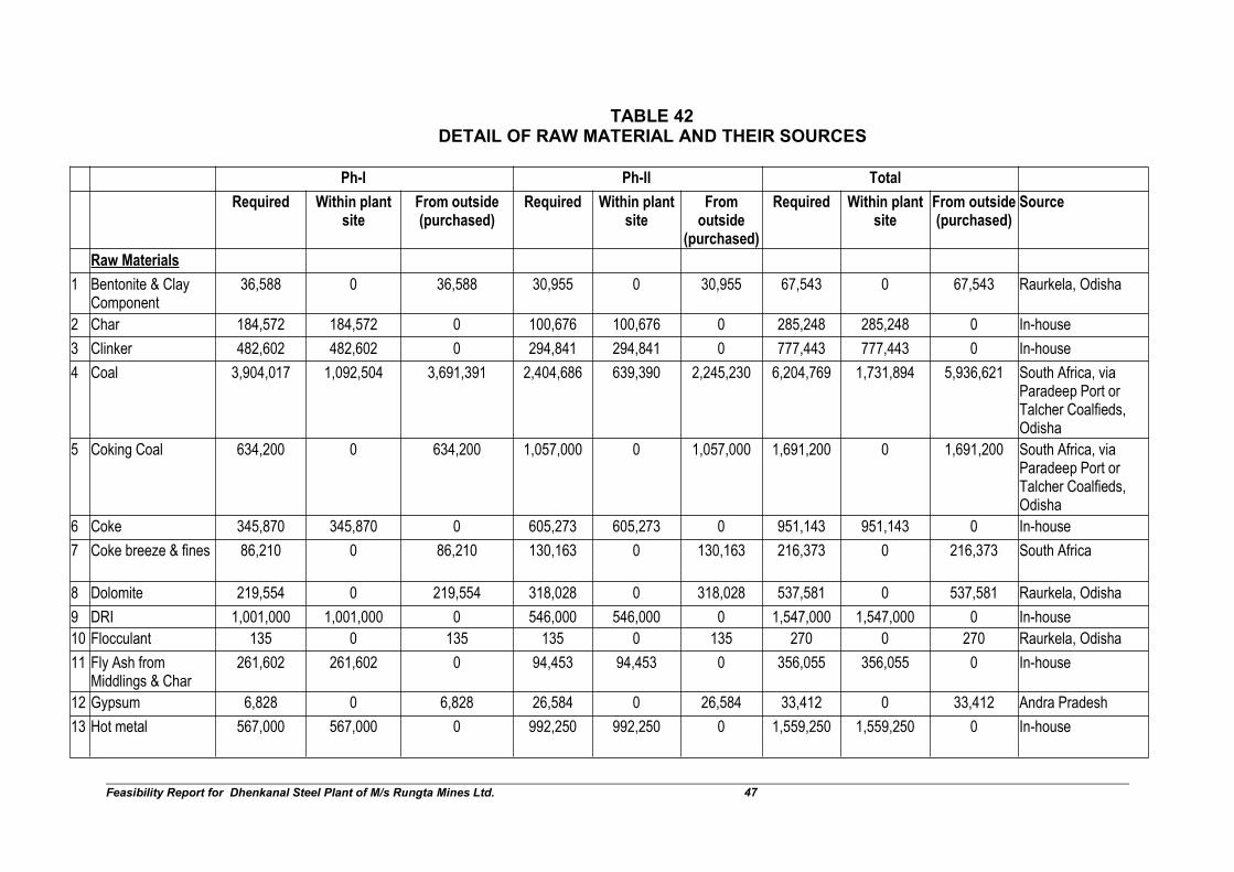
Feasibility Report for Dhenkanal Steel Plant of M/s Rungta Mines Ltd. 47
TABLE 42DETAIL OF RAW MATERIAL AND THEIR SOURCES
Ph-I Ph-II Total
Required Within plantsite
From outside(purchased)
Required Within plantsite
Fromoutside
(purchased)
Required Within plantsite
From outside(purchased)
Source
Raw Materials
1 Bentonite & ClayComponent
36,588 0 36,588 30,955 0 30,955 67,543 0 67,543 Raurkela, Odisha
2 Char 184,572 184,572 0 100,676 100,676 0 285,248 285,248 0 In-house
3 Clinker 482,602 482,602 0 294,841 294,841 0 777,443 777,443 0 In-house
4 Coal 3,904,017 1,092,504 3,691,391 2,404,686 639,390 2,245,230 6,204,769 1,731,894 5,936,621 South Africa, viaParadeep Port orTalcher Coalfieds,Odisha
5 Coking Coal 634,200 0 634,200 1,057,000 0 1,057,000 1,691,200 0 1,691,200 South Africa, viaParadeep Port orTalcher Coalfieds,Odisha
6 Coke 345,870 345,870 0 605,273 605,273 0 951,143 951,143 0 In-house
7 Coke breeze & fines 86,210 0 86,210 130,163 0 130,163 216,373 0 216,373 South Africa
8 Dolomite 219,554 0 219,554 318,028 0 318,028 537,581 0 537,581 Raurkela, Odisha
9 DRI 1,001,000 1,001,000 0 546,000 546,000 0 1,547,000 1,547,000 0 In-house
10 Flocculant 135 0 135 135 0 135 270 0 270 Raurkela, Odisha
11 Fly Ash fromMiddlings & Char
261,602 261,602 0 94,453 94,453 0 356,055 356,055 0 In-house
12 Gypsum 6,828 0 6,828 26,584 0 26,584 33,412 0 33,412 Andra Pradesh
13 Hot metal 567,000 567,000 0 992,250 992,250 0 1,559,250 1,559,250 0 In-house
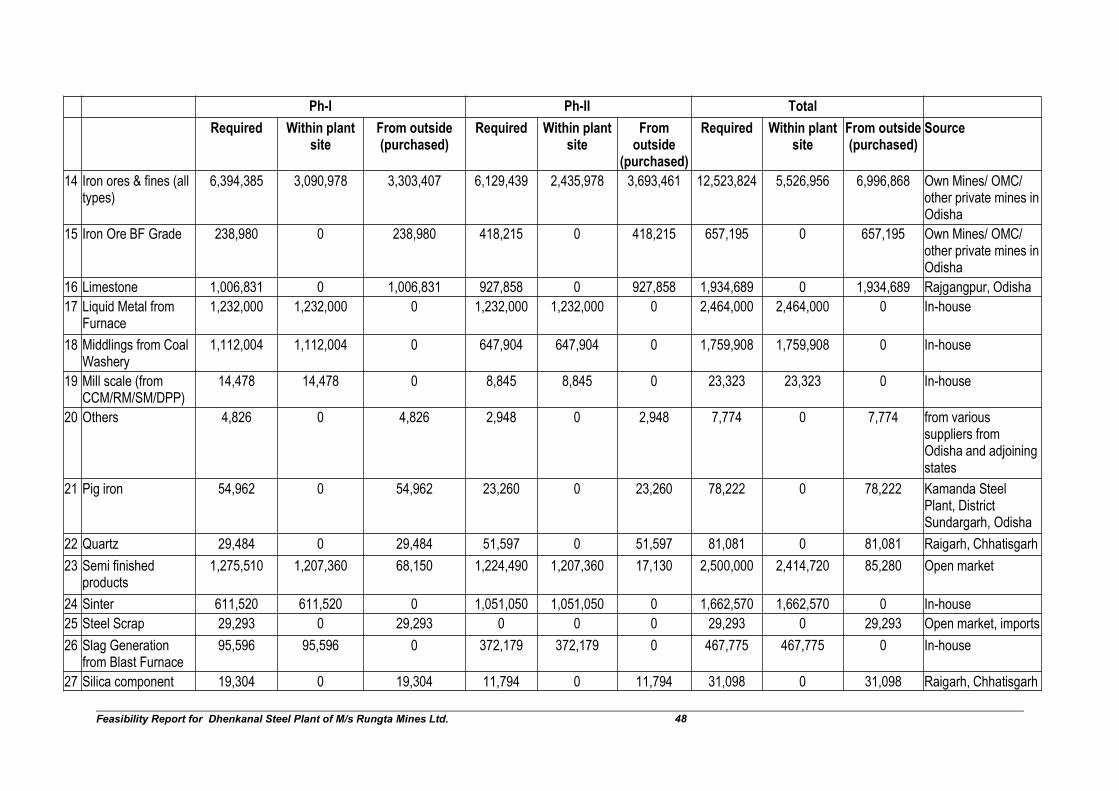
Feasibility Report for Dhenkanal Steel Plant of M/s Rungta Mines Ltd. 48
Ph-I Ph-II Total
Required Within plantsite
From outside(purchased)
Required Within plantsite
Fromoutside
(purchased)
Required Within plantsite
From outside(purchased)
Source
14 Iron ores & fines (alltypes)
6,394,385 3,090,978 3,303,407 6,129,439 2,435,978 3,693,461 12,523,824 5,526,956 6,996,868 Own Mines/ OMC/other private mines inOdisha
15 Iron Ore BF Grade 238,980 0 238,980 418,215 0 418,215 657,195 0 657,195 Own Mines/ OMC/other private mines inOdisha
16 Limestone 1,006,831 0 1,006,831 927,858 0 927,858 1,934,689 0 1,934,689 Rajgangpur, Odisha
17 Liquid Metal fromFurnace
1,232,000 1,232,000 0 1,232,000 1,232,000 0 2,464,000 2,464,000 0 In-house
18 Middlings from CoalWashery
1,112,004 1,112,004 0 647,904 647,904 0 1,759,908 1,759,908 0 In-house
19 Mill scale (fromCCM/RM/SM/DPP)
14,478 14,478 0 8,845 8,845 0 23,323 23,323 0 In-house
20 Others 4,826 0 4,826 2,948 0 2,948 7,774 0 7,774 from varioussuppliers fromOdisha and adjoiningstates
21 Pig iron 54,962 0 54,962 23,260 0 23,260 78,222 0 78,222 Kamanda SteelPlant, DistrictSundargarh, Odisha
22 Quartz 29,484 0 29,484 51,597 0 51,597 81,081 0 81,081 Raigarh, Chhatisgarh
23 Semi finishedproducts
1,275,510 1,207,360 68,150 1,224,490 1,207,360 17,130 2,500,000 2,414,720 85,280 Open market
24 Sinter 611,520 611,520 0 1,051,050 1,051,050 0 1,662,570 1,662,570 0 In-house
25 Steel Scrap 29,293 0 29,293 0 0 0 29,293 0 29,293 Open market, imports
26 Slag Generationfrom Blast Furnace
95,596 95,596 0 372,179 372,179 0 467,775 467,775 0 In-house
27 Silica component 19,304 0 19,304 11,794 0 11,794 31,098 0 31,098 Raigarh, Chhatisgarh

Feasibility Report for Dhenkanal Steel Plant of M/s Rungta Mines Ltd. 49
Ph-I Ph-II Total
Required Within plantsite
From outside(purchased)
Required Within plantsite
Fromoutside
(purchased)
Required Within plantsite
From outside(purchased)
Source
Total Raw Material 19,849,351 11,299,087 9,430,143 18,702,622 10,228,199 8,954,358 38,448,039 21,527,285 18,384,501
Ph-I Ph-II Total Ph-I Ph-I Total
Products Manu-factured for
sale
Incomingtrucks being
used forproduct
evacuation
Balance left forwhich additionaltrucks required
Manu-factured for
sale Solid waste
Reusedoutside
project site
Reusedoutside
project site
Reused outsideproject site
1 Pellets 0 0 627,500 627,500 Ash 489637 378159 867796
2 Washed Coal 320,320 320,320 0 174,720 495,040 Mill Scale 24805 31509 56314
3 Coke 12,978 12,978 0 -10,377 2,601 Total 514442 409668 924110
4 Finished Product 800,000 800,000 800,000 1,600,000
5 Finished Product 450,000 450,000 400,000 850,000
6 Finished Product 200,000 200,000 200,000 400,000
7 Portland BlastFurnace SlagCement
136,566 136,566 0 531,684 668,250
8Portland PozzolanaCement
747,434 747,434 0 269,866 1,017,300
Total 2,667,298 1,217,298 1,450,000 2,993,393 5,660,691
Feasibility Report for Dhenkanal Steel Plant of M/s Rungta Mines Ltd. 50
3.6.1 Mode of transport of raw material
Raw material will be transport through Rail/ Road.
3.7 Resource optimization/ recycling and reuse envisaged in the project
Recirculating cooling water system shall be provided in the plant. Therecirculating cooling water pumps to the various consumers in the plant willpump cold water from the cooling tower basin. The hot water return from theconsumers will return to the cooling tower for cooling and recirculation.
To meet the requirement of demineralization water as make-up water forboiler, de-mineralization plant of suitable capacity will be provided. Waterquality shall meet the Turbine and Boiler Manufacturers’ recommendation.
Entire waste water from the SMS and CPP complex shall be treated andreused for afforestation, green belt watering, sprinkling and dustsuppression. There is no liquid waste discharge from the Plant premisesexcept during monsoon when the sprinkling and watering demand will bealmost negligible.
Fly ash shall be utilised in brick making, road embankments, filling the lowlying area, etc.
3.8 Availability of water its source, energy / power requirement and source
The estimated make-up water requirement for the Complete Steel Plant is2950 cum per hour. Water allocation committee (WAC) has advised forprovisional allotment of 2950 cum/hr. Final allotment is awaited. The plantshall be generate 385 MW energy in form of electricity from its captivepower plant and shall be utilized in DRI, SMS, IF LR, EAF Beneficiationplant and coal washery, etc.
3.9 Quantity of wastes likely to be generated (liquid and solid) andscheme for their management /disposal
The main solid waste will be fly ash generated from power plant. Fly ashshall be utilised in brick making, road embankments, filling the low lyingarea and cement plant, etc.
Electrostatic Precipitator and Bag Filters Systems will be installed forpollution control of air emissions. Dust particles collected in the hoppers(below ESP) and conveyed pneumatically. This shall be disposed by trucks.Wastes like slag, runners & raiser from IF and scales and return scrap, etc.from Bar and Rod Mill will be recycled and reused in the process. Domesticwaste shall be generated from the plant office, organic component of whichshall be composted/ vermi composted. Quantity of waste generation isgiven in Table 43.

Feasibility Report for Dhenkanal Steel Plant of M/s Rungta Mines Ltd. 51
TABLE 43SOLID WASTE GENERATION (TPA)
Sl. Facility Solid Waste Phase-I Phase-II Total
1 Beneficiation Plant Tailing 1078120 1078120 2156240
2 Pellet PlantDust (Iron Ore, Coke, CoalFines)
120386 120386 240772
3 Coal Washery Middlings 1112004 647904 1759908
Reject from washery 196236 114336 310572
4 DRI Kilns Char 184572 100676 285248
ESP dust 45006 24549 69554
Bag Filter Dust, scrapper etc 18002 9819 27822
Kiln Accretion 18002 9819 27822
5 MBFBF Slag 74504 TPA shall besold in Ph-I only
170100 297675 467775
Dust (Iron Ore, Coke, SinterFines)
170100 49613 219713
Sludge from GCP 28350 4961 33311
6 Sinter Plant Sinter Return Fines 214032 367868 581900
7 Coke Oven Plant Bag Filter Dust 19026 31710 50736
8 Induction Furnace Slag 104050 - 104050
BF dust 13123 - 13123
SMS (Caster) Mill Scale 10780 - 10780
9Electric ArcFurnace
Slag 83160 125429 208589
BF dust 15840 27149 42989
SMS (Caster) Mill scale 13860 24640 38500
10 Rolling Mill Reject from RMS/SM/DPP 7347 7347 14694
Mill Scale 7347 8980 16327
11 Strip Mill Reject 4133 3673 7806
Mill Scale 5051 4490 9541
12 Ductile Pipe Plant Reject 1837 1837 3673
Mill Scale 2245 2245 4490
13 Producer Gas PlantCoal Ash 27830 27830 55661
14 Captive Power Fly Ash from Char (52% Ash) 95978 52351 148329
Plant Fly Ash from Middlings (56%Ash)
622722 362826 985548
Fly ash from Coal fines (45%Ash)
47513 23587 71101
Fly ash from Coal (45% Ash) 9419 37352 46770
Total 4446172 3567171 8013343
Feasibility Report for Dhenkanal Steel Plant of M/s Rungta Mines Ltd. 52
3.10 Schematic Representations of the Feasibility Drawing which giveInformation of EIA Purpose
Project feasibility report has been prepared by M/s Predominant EngineersPvt. Ltd., Gurugram
4.0 SITE ANALYSIS
4.1 Connectivity
Road link
The proposed plant is accessible by all weather road from the districtheadquarter Dhenkanal and town Angul, which are located at distances of36 km and 22 km, respectively. The site is located on NH-42, at a distanceof 4.1 km, which connects Bhubaneswar to Angul.
Rail link
The nearest railway station is Meramandali at a distance of 3.6 km.Air link
The nearest airport is at Bhubaneswar, which is approximately 150 km fromthe site.
4.2 Land form, land use and land ownership
Total land required for the project is 674.765 acres. Company has acquired608.495 acres (comprising 540.705 acres private land + 67.790 acresGovernment land). Balance is pending with Tehsildar, Hindol. This willchange to industrial use.
4.3 Topography
The ground elevation in the study area varies from approximately 60 m to312 m. Change in topography is envisaged due to construction of buildings,making raw material and finished good yards.
4.4 Existing land use pattern
As given in section 4.2 above.
4.5 Existing infrastructure
Infrastructure like office building, canteen, strengthening of roads, waste orwaste water treatment is proposed. Temporary sheds for workers will beestablished at the site. Jharbandh village has a primary school, powersupply for domestic use. Besides this the village also have bank, post andtelegraph office and cultural facilities.
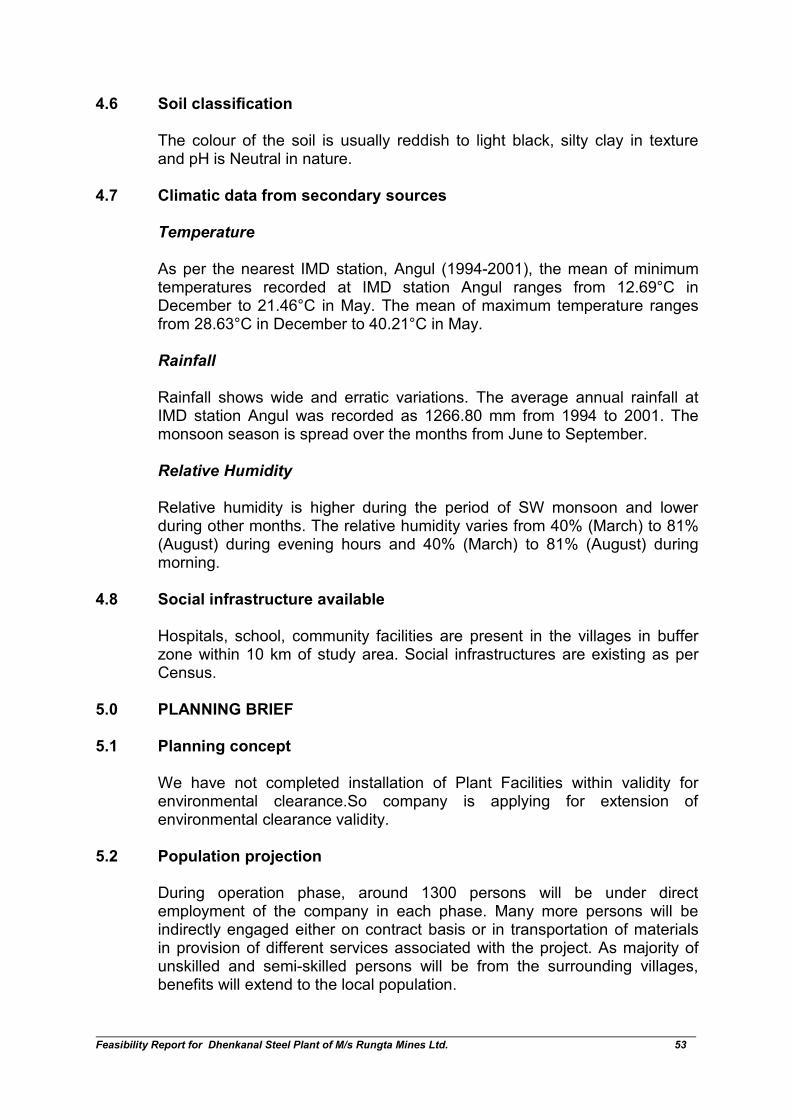
Feasibility Report for Dhenkanal Steel Plant of M/s Rungta Mines Ltd. 53
4.6 Soil classification
The colour of the soil is usually reddish to light black, silty clay in textureand pH is Neutral in nature.
4.7 Climatic data from secondary sources
Temperature
As per the nearest IMD station, Angul (1994-2001), the mean of minimumtemperatures recorded at IMD station Angul ranges from 12.69°C inDecember to 21.46°C in May. The mean of maximum temperature rangesfrom 28.63°C in December to 40.21°C in May.
Rainfall
Rainfall shows wide and erratic variations. The average annual rainfall atIMD station Angul was recorded as 1266.80 mm from 1994 to 2001. Themonsoon season is spread over the months from June to September.
Relative Humidity
Relative humidity is higher during the period of SW monsoon and lowerduring other months. The relative humidity varies from 40% (March) to 81%(August) during evening hours and 40% (March) to 81% (August) duringmorning.
4.8 Social infrastructure available
Hospitals, school, community facilities are present in the villages in bufferzone within 10 km of study area. Social infrastructures are existing as perCensus.
5.0 PLANNING BRIEF
5.1 Planning concept
We have not completed installation of Plant Facilities within validity forenvironmental clearance.So company is applying for extension ofenvironmental clearance validity.
5.2 Population projection
During operation phase, around 1300 persons will be under directemployment of the company in each phase. Many more persons will beindirectly engaged either on contract basis or in transportation of materialsin provision of different services associated with the project. As majority ofunskilled and semi-skilled persons will be from the surrounding villages,benefits will extend to the local population.
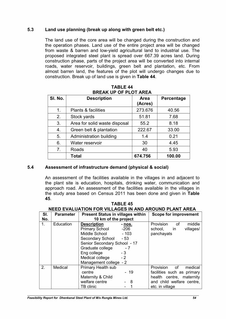
Feasibility Report for Dhenkanal Steel Plant of M/s Rungta Mines Ltd. 54
5.3 Land use planning (break up along with green belt etc.)
The land use of the core area will be changed during the construction andthe operation phases. Land use of the entire project area will be changedfrom waste & barren and low-yield agricultural land to industrial use. Theproposed integrated steel plant is spread over 667.39 acres land. Duringconstruction phase, parts of the project area will be converted into internalroads, water reservoir, buildings, green belt and plantation, etc. Fromalmost barren land, the features of the plot will undergo changes due toconstruction. Break up of land use is given in Table 44.
TABLE 44BREAK UP OF PLOT AREA
Sl. No. Description Area(Acres)
Percentage
1. Plants & facilities 273.676 40.56
2. Stock yards 51.81 7.68
3. Area for solid waste disposal 55.2 8.18
4. Green belt & plantation 222.67 33.00
5. Administration building 1.4 0.21
6. Water reservoir 30 4.45
7. Roads 40 5.93
Total 674.756 100.00
5.4 Assessment of infrastructure demand (physical & social)
An assessment of the facilities available in the villages in and adjacent tothe plant site is education, hospitals, drinking water, communication andapproach road. An assessment of the facilities available in the villages inthe study area based on Census 2011 has been done and given in Table45.
TABLE 45NEED EVALUATION FOR VILLAGES IN AND AROUND PLANT AREA
Sl.No.
Parameter Present Status in villages within10 km of the project
Scope for improvement
1. Education Description - nos.Primary School -206Middle School - 103Secondary School - 53Senior Secondary School - 17Graduate college - 7Eng college - 3Medical college - 2Management college - 2
Provision of middleschool, in villages/panchayats
2. Medical Primary Health subcentre - 19Maternity & Childwelfare centre - 8TB clinic - 1
Provision of medicalfacilities such as primaryhealth centre, maternityand child welfare centre,etc. in village
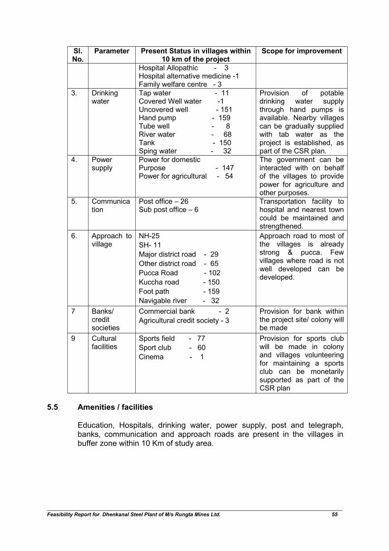
Feasibility Report for Dhenkanal Steel Plant of M/s Rungta Mines Ltd. 55
Sl.No.
Parameter Present Status in villages within10 km of the project
Scope for improvement
Hospital Allopathic - 3Hospital alternative medicine -1Family welfare centre - 3
3. Drinkingwater
Tap water - 11Covered Well water -1Uncovered well - 151Hand pump - 159Tube well - 8River water - 68Tank - 150Sping water - 32
Provision of potabledrinking water supplythrough hand pumps isavailable. Nearby villagescan be gradually suppliedwith tab water as theproject is established, aspart of the CSR plan.
4. Powersupply
Power for domesticPurpose - 147Power for agricultural - 54
The government can beinteracted with on behalfof the villages to providepower for agriculture andother purposes.
5. Communication
Post office – 26Sub post office – 6
Transportation facility tohospital and nearest towncould be maintained andstrengthened.
6. Approach tovillage
NH-25
SH- 11
Major district road - 29
Other district road - 65
Pucca Road - 102
Kuccha road - 150
Foot path - 159
Navigable river - 32
Approach road to most ofthe villages is alreadystrong & pucca. Fewvillages where road is notwell developed can bedeveloped.
7 Banks/creditsocieties
Commercial bank - 2
Agricultural credit society - 3
Provision for bank withinthe project site/ colony willbe made
9 Culturalfacilities
Sports field - 77
Sport club - 60
Cinema - 1
Provision for sports clubwill be made in colonyand villages volunteeringfor maintaining a sportsclub can be monetarilysupported as part of theCSR plan
5.5 Amenities / facilities
Education, Hospitals, drinking water, power supply, post and telegraph,banks, communication and approach roads are present in the villages inbuffer zone within 10 Km of study area.
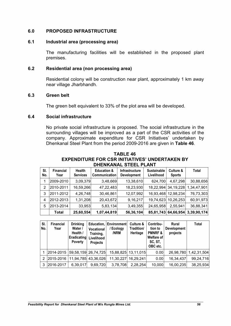
Feasibility Report for Dhenkanal Steel Plant of M/s Rungta Mines Ltd. 56
6.0 PROPOSED INFRASTRUCTURE
6.1 Industrial area (processing area)
The manufacturing facilities will be established in the proposed plantpremises.
6.2 Residential area (non processing area)
Residential colony will be construction near plant, approximately 1 km awaynear village Jharbhandh.
6.3 Green belt
The green belt equivalent to 33% of the plot area will be developed.
6.4 Social infrastructure
No private social infrastructure is proposed. The social infrastructure in thesurrounding villages will be improved as a part of the CSR activities of thecompany. Approximate expenditure for CSR Initiatives’ undertaken byDhenkanal Steel Plant from the period 2009-2016 are given in Table 46.
TABLE 46EXPENDITURE FOR CSR INITIATIVES’ UNDERTAKEN BY
DHENKANAL STEEL PLANT
Sl.No.
FinancialYear
HealthServices
Education &Communication
InfrastructureDevelopment
SustainableLivelihood
Culture &Sports
Total
1 2009-2010 3,09,379 3,48,669 13,38,610 624,700 4,67,298 30,88,656
2 2010-2011 16,59,266 47,22,483 18,23,930 18,22,994 34,19,228 1,34,47,901
3 2011-2012 4,26,748 30,46,861 12,07,992 16,93,468 12,98,234 76,73,303
4 2012-2013 1,31,208 20,43,672 9,16,217 19,74,623 10,26,253 60,91,973
5 2013-2014 33,953 5,83,134 3,49,355 24,65,958 2,55,941 36,88,341
Total 25,60,554 1,07,44,819 56,36,104 85,81,743 64,66,954 3,39,90,174
Sl.No.
FinancialYear
DrinkingWater /Health /
EradicatingPoverty
Education,
VocationalTraining,
LivelihoodProjects
Environment/ Ecology
/NRM
Culture &Tradition/Heritage
Contribu-tion to
PMNRF &Welfare ofSC, ST,
OBC etc.
RuralDevelopment
projects
Total
1 2014-2015 59,58,159 26,74,725 15,88,825 13,11,015 0.00 26,98,780 1,42,31,504
2 2015-2016 11,94,785 43,36,026 11,30,227 16,29,241 0.00 16,34,437 99,24,716
3 2016-2017 6,39,017 9,69,720 3,78,708 2,28,254 10,000 16,00,235 38,25,934
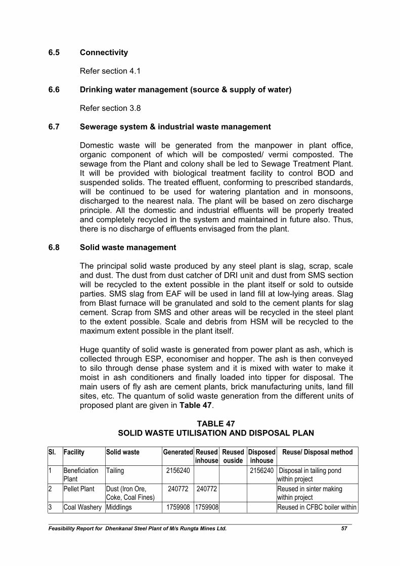
Feasibility Report for Dhenkanal Steel Plant of M/s Rungta Mines Ltd. 57
6.5 Connectivity
Refer section 4.1
6.6 Drinking water management (source & supply of water)
Refer section 3.8
6.7 Sewerage system & industrial waste management
Domestic waste will be generated from the manpower in plant office,organic component of which will be composted/ vermi composted. Thesewage from the Plant and colony shall be led to Sewage Treatment Plant.It will be provided with biological treatment facility to control BOD andsuspended solids. The treated effluent, conforming to prescribed standards,will be continued to be used for watering plantation and in monsoons,discharged to the nearest nala. The plant will be based on zero dischargeprinciple. All the domestic and industrial effluents will be properly treatedand completely recycled in the system and maintained in future also. Thus,there is no discharge of effluents envisaged from the plant.
6.8 Solid waste management
The principal solid waste produced by any steel plant is slag, scrap, scaleand dust. The dust from dust catcher of DRI unit and dust from SMS sectionwill be recycled to the extent possible in the plant itself or sold to outsideparties. SMS slag from EAF will be used in land fill at low-lying areas. Slagfrom Blast furnace will be granulated and sold to the cement plants for slagcement. Scrap from SMS and other areas will be recycled in the steel plantto the extent possible. Scale and debris from HSM will be recycled to themaximum extent possible in the plant itself.
Huge quantity of solid waste is generated from power plant as ash, which iscollected through ESP, economiser and hopper. The ash is then conveyedto silo through dense phase system and it is mixed with water to make itmoist in ash conditioners and finally loaded into tipper for disposal. Themain users of fly ash are cement plants, brick manufacturing units, land fillsites, etc. The quantum of solid waste generation from the different units ofproposed plant are given in Table 47.
TABLE 47SOLID WASTE UTILISATION AND DISPOSAL PLAN
Sl. Facility Solid waste Generated Reusedinhouse
Reusedouside
Disposedinhouse
Reuse/ Disposal method
1 BeneficiationPlant
Tailing 2156240 2156240 Disposal in tailing pondwithin project
2 Pellet Plant Dust (Iron Ore,Coke, Coal Fines)
240772 240772 Reused in sinter makingwithin project
3 Coal Washery Middlings 1759908 1759908 Reused in CFBC boiler within

Feasibility Report for Dhenkanal Steel Plant of M/s Rungta Mines Ltd. 58
Sl. Facility Solid waste Generated Reusedinhouse
Reusedouside
Disposedinhouse
Reuse/ Disposal method
project
Reject fromwashery
310572 310572 Disposed in solid wastedisposal area within projectsite
4 DRI Kilns Char 285248 285248 Reused in CFBC boiler withinproject
ESP dust 69554 69554 Reused in sinter makingwithin project
Bag Filter Dust,scrapper etc
27822 27822 Reused in sinter makingwithin project
Kiln Accretion 27822 27822 Disposed in solid wastedisposal area within projectsit
5 MBF BF Slag 467775 467775 * 74504 TPA shall be sold inPh-I only* By Ph-II, 100% reutilised inmaking PBS cement withinproject
Dust (Iron Ore,Coke, Sinter Fines)
219713 219713 Reused in sinter makingwithin project
Sludge from GCP 33311 33311 Reused in sinter makingwithin project
6 Sinter Plant Sinter Return Fines 581900 581900 Reused in sinter makingwithin project
7 Coke OvenPlant
Bag Filter Dust 50736 50736 Reused in sinter makingwithin project
8 InductionFurnace
Slag 104050 104050 Given for metal recovery,converted to aggregates(special balls) and used inroad making
Bag Filter dust 13123 13123 Reused in sinter makingwithin project
SMS (Caster) Mill Scale 10780 10780 Reused in cement makingwithin project
9 Electric ArcFurnace
Slag 208589 208589 Given for metal recovery,converted to aggregates(special balls) and used inroad making
Bag Filter dust 42989 42989 Reused in sinter makingwithin project
SMS (Caster) Mill scale 38500 12543 25957 Reused in cement makingwithin & outside project
10 Rolling Mill Reject fromRMS/SM/DPP
14694 14694 Reused in steel making withinproject
Mill Scale 16327 16327 Sold to cement othermanufacturers
11 Strip Mill Reject 7806 7806 Reused in steel making withinproject
Mill Scale 9541 9541 Sold to cement other
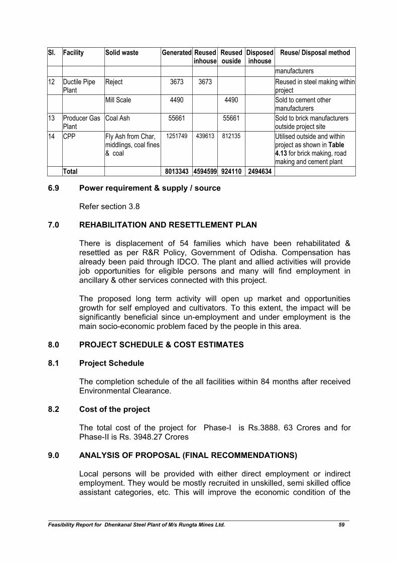
Feasibility Report for Dhenkanal Steel Plant of M/s Rungta Mines Ltd. 59
Sl. Facility Solid waste Generated Reusedinhouse
Reusedouside
Disposedinhouse
Reuse/ Disposal method
manufacturers
12 Ductile PipePlant
Reject 3673 3673 Reused in steel making withinproject
Mill Scale 4490 4490 Sold to cement othermanufacturers
13 Producer GasPlant
Coal Ash 55661 55661 Sold to brick manufacturersoutside project site
14 CPP Fly Ash from Char,middlings, coal fines& coal
1251749 439613 812135 Utilised outside and withinproject as shown in Table4.13 for brick making, roadmaking and cement plant
Total 8013343 4594599 924110 2494634
6.9 Power requirement & supply / source
Refer section 3.8
7.0 REHABILITATION AND RESETTLEMENT PLAN
There is displacement of 54 families which have been rehabilitated &resettled as per R&R Policy, Government of Odisha. Compensation hasalready been paid through IDCO. The plant and allied activities will providejob opportunities for eligible persons and many will find employment inancillary & other services connected with this project.
The proposed long term activity will open up market and opportunitiesgrowth for self employed and cultivators. To this extent, the impact will besignificantly beneficial since un-employment and under employment is themain socio-economic problem faced by the people in this area.
8.0 PROJECT SCHEDULE & COST ESTIMATES
8.1 Project Schedule
The completion schedule of the all facilities within 84 months after receivedEnvironmental Clearance.
8.2 Cost of the project
The total cost of the project for Phase-I is Rs.3888. 63 Crores and forPhase-II is Rs. 3948.27 Crores
9.0 ANALYSIS OF PROPOSAL (FINAL RECOMMENDATIONS)
Local persons will be provided with either direct employment or indirectemployment. They would be mostly recruited in unskilled, semi skilled officeassistant categories, etc. This will improve the economic condition of the
Feasibility Report for Dhenkanal Steel Plant of M/s Rungta Mines Ltd. 60
local people. The employment of local people in primary and secondarysectors of project will upgrade the prosperity of the region.
With the advancement in technology and the stringency in permissible limitsof emission along with regular monitoring, it is possible to operate plants ofthis type by having minimal impact on the environment.