Computed tomographic cholangiography using spiral scanning and 3D image processing

17th International Symposium on Applications of Laser Techniques to Fluid Mechanics Lisbon, Portugal, 07-10 July, 2014
- 1 -
3D Flow Dynamics in a Turbulent Slot Jet: Time-resolved Tomographic
PIV Measurements
Maxim V. Shestakov1,*, Mikhail P. Tokarev1, Dmitri M. Markovich1,2
1: Kutateladze Institute of Thermophysics, Siberian Branch of Russian Academy of Sciences, Novosibirsk, Russia
2: Novosibirsk State University, Novosibirsk, Russia * correspondent author: [email protected]
Abstract We experimentally investigated 3D structure and evolution of a quasi-two-dimensional turbulent jet in a narrow channel. This work focuses on characteristics of 3D vortex structures in the flow. We investigated development of the secondary flows downstream, their interaction with each other and evolution into large-scale quasi-2D vortices. The time-resolved tomographic PIV technique (with repetition rate up to 25 kHz for 1 Mpx CMOS cameras) was used to measure subsequent 3D velocity distributions. We analyzed two different nozzle width (d) to depth (h) ratios 1 and 2.5. The analysis showed that the secondary flows existed up to 7.5h from the nozzle exit. The 3D structures were generated near the corners of the nozzle and grew downstream under a stretch. Then, decelerated vortexes united into bigger agglomerates. The analyzed behavior of the secondary structures in the slot jet configuration are useful for understanding development of large-scale quasi-2D vortex structures in other shear flows in confined spaces. 1. Introduction Quasi-2D turbulent jet flows are widely spread in nature and industry. Many practical applications and developing devices assume the jets to be spreading in narrow gaps: geothermal engineering, modern mini-channel chemical processors, cooling systems, etc. Modeling of filtration processes and development of optimal methods for raw oil extraction also require comprehensive information on structure of such flows. Presently, many researchers are interested in micro and mini jets in a confined space. Small-scale technical systems are of an interest because they are more efficient and economical than large-scale devices. Jet in a slot channel has a number of features, which significantly distinguish it from free jets and flows in channels. The presence of the bounding surfaces leads to different characteristic scales. Development of Kelvin-Helmholtz vortices is accompanied with a strong influence of wall friction, which leads to the existence of a variety of fundamentally different regimes: from classical Hele-Shaw regimes up to developed turbulent flows that manifest some features of 2D turbulence. The jet included small-scale 3D turbulence, with a maximum scale of the order of a channel depth, and quasi-2D large-scale flow with the characteristic scales greater than the channel depth (Bilsky et al. 2007, Bilsky et al. 2012). The features of such flows allow us to investigate the properties of quasi-2D turbulence and the mechanisms of dynamical interaction between large-scale 2D structures and small-scale 3D turbulence in a laboratory. Heskestad (1965) showed that the jets in confined channels cannot be described by 2D flow equations. Secondary flows, which lead to a significant three-dimensional flow, are formed near the bounding planes inside the jet shear layer. Foss and Jones (1968) studied features of the bounded two-dimensional jets. They showed that the flat bounded jet is not a superposition of two flows: a boundary layer and a two-dimensional jet. Based on measured velocity distributions in a cross section, Foss and Jones (1968) proposed a model for secondary flows. Later, Holdeman and Foss (1975) provided support for this model by hot-wire velocity measurements and via direct vorticity strength measurements by a small mechanical turbine. The model assumes that the secondary flows arise from the curvature of the wall-normal vortex tube, which is formed after the edge of the nozzle. The vortex tube is similar to that formed at the onset of the free rectangular jets, but the presence of bounding surfaces leads to the generation of longitudinal vorticity since the tube bends near the bounding surfaces. The bending of the vortex tube is directly related to its curvature that arises due to the zero velocity at the wall and strong velocity gradient near the wall. Thus, the secondary flows are caused by the longitudinal vorticity. However, data obtained by local methods do not give a complete picture of the flow and do not provide

17th International Symposium on Applications of Laser Techniques to Fluid Mechanics Lisbon, Portugal, 07-10 July, 2014
- 2 -
comprehensive information on the three-dimensional structures. Thus, it is necessary to use modern 3D velocimetry techniques, for example, tomographic PIV (Scarano 2013). Our previous research (Bilsky et al. 2012) was done using a 2D PIV measurement system with the repetition rate at 1 kHz. It allowed us to obtain dynamics and the temporal spectra of streamwise velocity fluctuations at a far zone of the slot jet. However, we were unable to resolve the near field due to limitations of the spatial and temporal resolution. Several recent papers (Violato and Scarano, 2011; Violato et al., 2012; Ianiro et al., 2012) describe high-speed tomographic PIV measurements in circular and chevron jets. Currently, no such experimental data for confined jets are available. The present paper investigates the dynamics of three-dimensional vortices in a turbulent slot jet using time-resolved tomographic PIV. The repetition rate up to 25 kHz allows us to analyze the flow behavior in the near field of the jet, where the secondary flows are developed. The aim of this work is to combine the benefits of time-resolved and volumetric measurements to analyze the complex behavior and structure of turbulent jets in bounded geometry. 2. Experimental setup The experimental setup consisted of a closed hydrodynamic contour, including a tank, a pump, flow meter, and measurement section. The measurement section was a narrow channel formed by two plates made of organic glass (size: 307x270 mm2, thickness: 20 mm), located at a distance h = 4 mm from each other. The data were acquired for the Reynolds numbers of Re = hU0/ν = 18 000, where U0 is the bulk flow velocity. The flow was seeded with 50 µm polyamide particles. The rectangular/square nozzle without contraction was formed by two flat inserts placed between the glass plates (see figure 1). The nozzle widths were d = 4, 10 mm. Two thousands of 3D velocity snapshots were obtained for each regime and were further used to calculate statistical flow characteristics. Measurements were carried out in three slightly overlapped zones at tree distances from the edge of the nozzle 4h, 12h and 20h.
Fig. 1. Experimental setup for time-resolved Tomo-PIV measurements in a turbulent slot jet The measurement system consisted of a high-repetition Nd: YAG laser (Photonix DM-532-100 with 10 mJ at 10 kHz), four high speed CMOS cameras (Photron FASTCAM SA5 with resolution of 1024×1024 px of 12 bit images at 7 kHz), and synchronizing device Berkeley Nucleonics BNC 575. The thickness of the laser sheet was 4 mm. We used SIGMA AF 105 mm f/2.8 EX DG MACRO lenses for the optical setup. The size of the measurement area was 60×60 mm2. We used two overlapped areas to cover the near, middle zones of the jet.

17th International Symposium on Applications of Laser Techniques to Fluid Mechanics Lisbon, Portugal, 07-10 July, 2014
- 3 -
A precise Edmund Optics 50×50 mm2 plane calibration target with reference circles on the Cartesian grid with a 1 mm step between the circles was used. A precise traverse system was used to shift the cameras relative to the calibration target (fixed inside the slot) for the volumetric calibration. The cameras were equipped with 3D printed Scheimpflug adapters to align the focal plane to the sensor plane. We arranged the cameras in corners of a square with viewing angles equal to 30 degrees in the horizontal and vertical planes. 2. Data processing We used home-made “ActualFlow” software to process the acquired data. A self-calibration procedure was done prior to the tomographic reconstruction. It was performed in three steps. The final average disparity was below 0.05 px and the maximum corrected disparity was equal to 4 px. Also before the reconstruction step, the recorded projections were preprocessed by subtracting the minimum statistical intensity (for each pixel). The reconstructed 3D object was of 1024×1024×128 voxels. The physical size of a voxel was approximately equal to 0.065×0.065×0.065 mm3. The volume particle concentration was close to 8.5 parts/mm3. The image density at this concentration upon the registered projections was 0.04 ppp. The tomographic reconstruction was done by the implementation of the SMART and MENT (Bilsky et al. 2013) algorithms. Correlation analysis was performed using the iterative multigrid algorithm with continuous interrogation box shifting. The total number of iterations was four: two steps were performed with a resolution of 32×64×32 voxels and two extra iterations with a final resolution of 16×32×16 voxels. The grid-overlapping factor was set to 75%; therefore, the final correlation domain size for the calculation of a single velocity vector was 1×2×1 mm3 with a half size distance between neighbor vectors. 3. Results Figure 2 demonstrates a complex 3D pattern of the instantaneous velocity field. Large-scale quasi-two dimensional vortex structures, formed in the mixing layers, produce flows across the channel.
Fig. 2. Distribution of the instantaneous wall-normal velocity component and the velocity vector field at the central plane of the jet at z = 0. Note, that the scalar field is partially transparent and vectors with negative vz are slightly
shaded. Left and right pictures correspond to the square nozzle and the rectangular nozzle cases.
Figure 2 shows these flows in the distribution of the wall-normal component of the instantaneous velocity. It can be seen that the flows across the channel correlate with the large-scale vortex motion shown with the velocity vector field.
17th International Symposium on Applications of Laser Techniques to Fluid Mechanics Lisbon, Portugal, 07-10 July, 2014
- 4 -
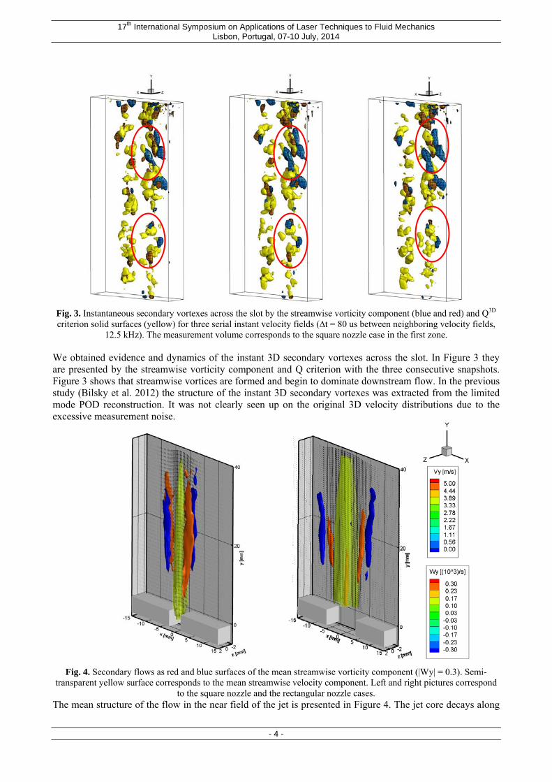
Fig. 3. Instantaneous secondary vortexes across the slot by the streamwise vorticity component (blue and red) and Q3D criterion solid surfaces (yellow) for three serial instant velocity fields (∆t = 80 us between neighboring velocity fields,
12.5 kHz). The measurement volume corresponds to the square nozzle case in the first zone. We obtained evidence and dynamics of the instant 3D secondary vortexes across the slot. In Figure 3 they are presented by the streamwise vorticity component and Q criterion with the three consecutive snapshots. Figure 3 shows that streamwise vortices are formed and begin to dominate downstream flow. In the previous study (Bilsky et al. 2012) the structure of the instant 3D secondary vortexes was extracted from the limited mode POD reconstruction. It was not clearly seen up on the original 3D velocity distributions due to the excessive measurement noise.
Fig. 4. Secondary flows as red and blue surfaces of the mean streamwise vorticity component (|Wy| = 0.3). Semi-
transparent yellow surface corresponds to the mean streamwise velocity component. Left and right pictures correspond to the square nozzle and the rectangular nozzle cases.
The mean structure of the flow in the near field of the jet is presented in Figure 4. The jet core decays along

17th International Symposium on Applications of Laser Techniques to Fluid Mechanics Lisbon, Portugal, 07-10 July, 2014
- 5 -
the vertical coordinate velocity gradients near the walls can be seen on the cross-stream plane. Four counter rotating vortex structures, originating from the rectangular nozzle corners, are also clearly visible. In Figure 3 they are showed with the isosurfaces of the streamwise vorticity component calculated for the mean velocity field. They vanish at 7.5h for the considered Reynolds number.
1 10 100 1000i
-0
0.05
0.1
0.15
0.2
0.25
a 2i /(
22)0.
5
Fig 5. Normalized eigenvalues versus the POD mode number for the third zone and the rectangular nozzle (a) and the scatter plot of POD correlation coefficients of two the most energetic modes for the obtained 3D velocity distributions.
Fig 6. Two most energetic POD modes (47.1% of total TKE energy) downstream of the jet with the square nozzle. Solid surfaces and color maps at z = 0 present y and x component of 3D basis functions. Every third vector is plotted. Additionally we analyzed behavior of the jet flow downstream from 15h to 28h. In this region the effect of jet meandering was observed. The result of the POD decomposition from 1000 snapshots with the two 3D basis functions corresponded to the two most energetic modes is presented in the Figure 5 and 6. They look like a quasi-2D large-scale vortex structure spatially shifted in y direction between two modes. First mode had 24.9% of total TKE and second mode corresponded to the 22.2% of total energy. Below in the Figure 7 the real instantaneous 3D velocity fields are presented with the maximum correlation between them and first POD mode on the left and second POD mode on the right hand side.
i = 330
i = 999

17th International Symposium on Applications of Laser Techniques to Fluid Mechanics Lisbon, Portugal, 07-10 July, 2014
- 6 -
Fig. 7. An example of real 3D velocity fields with the maximum impact from the first POD mode (left) and the second POD mode (right) for the jet with the square nozzle. Solid surfaces and color maps at z = 0 present 3D distribution of
the streamwise velocity component. Time distance between two snapshots is 33 ms.
10 100 1000 10000f (Hz)
1E-007
1E-006
1E-005
0.0001
0.001
0.01
0.1Eii
EwwEvvEuu
-5/3
10 100 1000 10000f (Hz)
1E-007
1E-006
1E-005
0.0001
0.001
0.01
0.1Eii
EwwEvv Euu
-3
-5/3
Fig. 8. Temporal spectra of velocity fluctuations in the shear layer (x = h/2, y = 4h) at the central plane (z = 0) for the
first (x = h/2, y = 4h) (left ) and the third (x = h, y = 20h) (right) zone from the edge of the nozzle Re = 18 000. The temporal spectra of velocity fluctuations for each of the three components of velocity are presented in Figure 8. The temporal spectra for vx and vy – components of velocity had the slope «-3» indicating large – scale velocity fluctuations. However the spectrum for vz – component of velocity fluctuations had the typical 3D turbulent slope «-5/3» . 4. Conclusions We used a high speed tomographic PIV system in order to investigate the spatial-temporal 3D structure of a quasi-2D turbulent jet. Experiments were carried out for the turbulent jet flowing into a slot channel. The study was done for Reynolds number 18 000 and two different rectangular nozzles with the square and rectangular cross section. Three dimensional instantaneous velocity fields and Q – criterion value distribution showed that in the jet shear layer Kelvin-Helmholtz instability is formed. These structures are influenced by the transversal and longitudinal velocity gradient. They form streamwise vortices in consequence of three dimensional interactions with each other. The streamwise vortices formed by Kelvin-Helmholtz vortex structures have which was shown by the wall-

17th International Symposium on Applications of Laser Techniques to Fluid Mechanics Lisbon, Portugal, 07-10 July, 2014
- 7 -
normal velocity component distribution. The streamwise vortices make a contribution to secondary flows formation. Region of existence and influence of secondary flows ends where streamwise vortices break and large-scale vortex structures are formed and develop. The main mechanism of quasi-2D large-scale vortex structures formation is a development of a jet sinusoidal instability. With the growth of the linear size of quasi-2D vortex structures the maximum of the turbulent kinetic energy spectrum shifts to the long-wave area. The main contribution to the long-wave area of the turbulent kinetic energy spectrum is made with the wall-parallel velocity components. We used POD decomposition for analysis of the measured 3D velocity snapshots in the measurement volume at the distance 20h from the nozzle edge. Results of analysis showed strong domination of sinusoidal instability in this region. Acknowledgements The authors acknowledge support by President of Russian Federation via Leading Schools grant (NS-5984.2014.8), RFBR (grant No 13-08-01356) and RFBR (grant No 14-08-31504 mol-a). References Bilsky A.V., Dulin V.M., Markovich D.M., Shestakov M.V. Turbulence measurements in a quasi-two dimensional jet in a slot channel // Proc. of the 5th International Symposium on Turbulence and Shear Flow Phenomena, TU Munich, Germany, 27-29 August 2007, 1067-1072 Bilsky A.V., Markovich D.M., Shestakov M.V., Tokarev M.P. Tomographic PIV and planar Time-resolved PIV measurements in a turbulent slot jet // Proc. of the 16th international symposium on applications of laser techniques to fluid mechanics, Lisbon, pp 09–12 July, 2012 Bilsky A.V., Lozhkin V.A., Markovich D.M., Tokarev M.P. A maximum entropy reconstruction technique for tomographic particle image velocimetry // Meas. Sci. Technol. 2013. 24. 045301 Foss J. F., Jones J. B. Secondary flow effects in a bounded rectangular jet // Trans ASME, J. Basic Eng. 1968. Vol. 90(2). P. 241 – 248 Heskestad G. Hot-wire measurements in a plane turbulent jet // Trans ASME, J Appl. Mech. 1965. Vol. 32. P. 721 – 734 Holdeman J. D., Foss J. F. The initiation, development and decay of the secondary flow in а bounded jet // Trans. ASME, J. Fluid Eng. 1975. Vol. 97. P. 342 – 352. Ianiro A., Violato D., Scarano F., Cardone G. Three dimensional features in swirling impinging jets // Proc. of the 15th International Symposium on Flow Visualization June 25-28, 2012, Minsk, Belarus Scarano F. Tomographic PIV: principles and practice // Measurement Science and Technology. 2013. 24. 012001 Violato D., Ianiro A., Cardone G., Scarano F. Three-dimensional vortex dynamics and convective heat transfer in circular and chevron impinging jets // Int. J. Heat Fluid Flow. 2012. 37. 22–36 Violato D., Scarano F. Three-dimensional evolution of flow structures in transitional circular and chevron jets // Phys. Fluids 2011. 23, 124104
Copyright © 2022 FDOKUMEN