Torque analysis and slot regions assignment of a DC-excited ...
14
AIMS Electronics and Electrical Engineering 1(1): 4-17 DOI: 10.3934/ElectrEng.2017.1.4 Received: 7 July 2017 Accepted: 23 October 2017 Published: 23 November 2017 http://www.aimspress.com/journal/ElectronEng Research article Torque analysis and slot regions assignment of a DC-excited flux-modulated machine with two stator windings Jing Ou 1, *, Yingzhen Liu 2 , Martin Doppelbauer 1 1 Institute of Electrical Engineering, Karlsruhe Institute of Technology, 76131, Karlsruhe, Germany 2 Institute of Technical Physics, Karlsruhe Institute of Technology, 76131, Karlsruhe, Germany * Correspondence: Email: [email protected]; Tel: +49 721 608-41783; Fax: +49 721 608-42921. Abstract: This paper presents a DC-excited flux-modulated (DCEFM) machine. It has one rotor with p r poles and two sets of windings on one stator. One of the windings has p f pole-pairs and is excited with DC current. The second winding has p a pole-pairs and is excited with AC sinusoidal current. The relationship between p r , p f and p a is p r = p f + p a . The purpose of this paper is to analyze the torque of the machine in order to optimize the slot regions assigned to the two stator windings for generating the highest torque at the admissible copper losses. Firstly, the torque equation of the machine is derived. The methods described in this paper are also feasible for other machine types such as variable flux reluctance machine, field excited flux-switching machine. By using the finite element analysis (FEA) the analytical results are verified. The results show that the magneto motive forces (MMFs) of the two windings need to be approximately equal to obtain optimal torque. Keywords: torque; DC-excited; flux-modulated; synchronous machine; reluctance machine 1. Introduction Because of supply security and price fluctuations of rare-earth materials, some countries such as the USA, UK, Germany and Japan are making efforts on developing non-rare earth material and even non-permanent magnet machines for electric vehicles [1]. Over the past decades, due to its
-
Upload
khangminh22 -
Category
Documents
-
view
0 -
download
0
Transcript of Torque analysis and slot regions assignment of a DC-excited ...
AIMS Electronics and Electrical Engineering 1(1): 4-17
DOI: 10.3934/ElectrEng.2017.1.4
Received: 7 July 2017
Accepted: 23 October 2017
Published: 23 November 2017
http://www.aimspress.com/journal/ElectronEng
Research article
Torque analysis and slot regions assignment of a DC-excited
flux-modulated machine with two stator windings
Jing Ou1,*, Yingzhen Liu2, Martin Doppelbauer1
1 Institute of Electrical Engineering, Karlsruhe Institute of Technology, 76131, Karlsruhe, Germany
2 Institute of Technical Physics, Karlsruhe Institute of Technology, 76131, Karlsruhe, Germany
* Correspondence: Email: [email protected]; Tel: +49 721 608-41783; Fax: +49 721 608-42921.
Abstract: This paper presents a DC-excited flux-modulated (DCEFM) machine. It has one rotor with pr poles and two sets of windings on one stator. One of the windings has pf pole-pairs and is excited with DC current. The second winding has pa pole-pairs and is excited with AC sinusoidal current. The relationship between pr, pf and pa is pr = pf + pa. The purpose of this paper is to analyze the torque of the machine in order to optimize the slot regions assigned to the two stator windings for generating the highest torque at the admissible copper losses. Firstly, the torque equation of the machine is derived. The methods described in this paper are also feasible for other machine types such as variable flux reluctance machine, field excited flux-switching machine. By using the finite element analysis (FEA) the analytical results are verified. The results show that the magneto motive forces (MMFs) of the two windings need to be approximately equal to obtain optimal torque.
Keywords: torque; DC-excited; flux-modulated; synchronous machine; reluctance machine
1. Introduction
Because of supply security and price fluctuations of rare-earth materials, some countries such as the USA, UK, Germany and Japan are making efforts on developing non-rare earth material and even non-permanent magnet machines for electric vehicles [1]. Over the past decades, due to its
5
AIMS Electronics and Electrical Engineering Volume 1, Issue 1, 4-17.
simple and robust structure and low cost, switched reluctance machines (SRMs) have received some attention [2]. However, vibration, noise and torque ripples of SRMs are potential disadvantages [3]. Furthermore, switched reluctance machines need unconventional drives and complex control strategies. In [4] a new type of synchronous machine (SM), with doubly salient structure, named “flux-modulating SM” was proposed. It also does not need permanent magnets but promises fewer technical problems than SRMs. This machine has two sets of stator windings: one field winding and an armature winding. Both are non-overlapped concentrated windings. Since there are neither permanent magnets nor field windings on the rotor, the new machine is well suited for high-speed operation. By regulating the field current, the machine can operate at a wider constant power region. In [4] the working principle of this machine was introduced, and in [5] the core losses were assessed. In [6] the effect of changing the rotor pole shape was investigated. The machine was also considered as variable flux reluctance machine and has been studied intensively [7-11]. In [10] the stator/rotor pole combinations such as 12/8, 12/10, 12/11, 12/12 and 12/14 are compared. It is found that 12/10 and 12/14 combinations can eliminate the inherent unbalanced magnetic force and exhibit more sinusoidal back-EMF. Compared with switched reluctance machine, variable flux reluctance machine can significantly reduce torque ripple and acoustic noise and vibration [11]. In [12] the torque variations along DC and AC currents were investigated through FEA and experiment methods. However, the slot assignment strategy for this type of machines with more than one set of winding is still missing. Since the two sets of windings are installed together in the same stator, the slot space allocation will influence the torque and the copper losses of the machine. Hence, this paper presents a detail derivation of torque equation through analytical methods. The methods described in this paper are also applicative for other machine types, which has more excitation sources on the stator.
This paper focuses on the slot space allocation and is organized as follows: Firstly, the structure and operation principle of DC-excited flux-modulated (DCEFM) are introduced in Section 2. Then, the methods and detailed derivation of torque equation are illustrated in Section 3. To verify the analysis, FEA method is used and the comparison of FEA and analytical results are shown in Section 4. Finally, the conclusion is drawn in Section 5.
2. Structure and principle
2.1 Structure evolution
The structure of a basic flux-modulated machine with 12 slots and 10 poles is shown in Figure 1(a). Based on the equation pr = pf + pa, this machine has pa = 4, pf = 6, pr = 10. Of course, there are still many other slots/poles combinations following this rule, such as 12 slots 8 poles (pr = 8, pf = 6, pa = 2), 12 slots 11 poles (pr =11, pf = 6, pa = 5), 12 slots 13 poles (pr = 13, pf = 6, pa = 7), 12 slots 14 poles (pr = 14, pf = 6, pa = 8). For this special configuration, the stator slots number is equal to the pole number of the outer rotor. If the permanent magnets (PMs) on the outer rotor were replaced by the field excitation, the structure of the machine is changed to Figure 1(b). Further on, by keeping the outer rotor stationary and combining the outer rotor with the inner stator, a new DCEFM machine is created as shown in Figure 1(c).

6
AIMS Electronics and Electrical Engineering Volume 1, Issue 1, 4-17.
Figure 1. (a) Basic flux-modulated machine. (b) Using the DC winding to replace the
PMs on the outer rotor. (c) DC-excited flux-modulated machine.
Since the DC winding and the armature winding are both installed on the stator, the machine does not need brushes. This arrangement also improves heat dissipation. A drawback is the additional DC winding. It decreases the fill factor of the armature winding and adds additional copper losses. Moreover, as the machine contains high harmonic field due to its working principle, it also causes high core losses.
2.2 DC field
In this paper, a 12 slots 10 poles motor is analyzed. For this motor, the pr = 10, pf = 6 and pa = 4. When only DC winding is excited and the DC current is equal to 10 A, the air gap flux consists high 6th because pf is equal to 6 as shown in Figure 2(b). In addition, the air gap flux consists high 4th and 16th components due to the interaction of rotor pole number 10 and pole-pair number of DC field winding which is equal to 6.
(a) (b)
Figure 2. Air-gap flux generated by DC winding with DC current equal to 10 A. (a) The flux density radial component along the air-gap. (b) The amplitude of each harmonics.
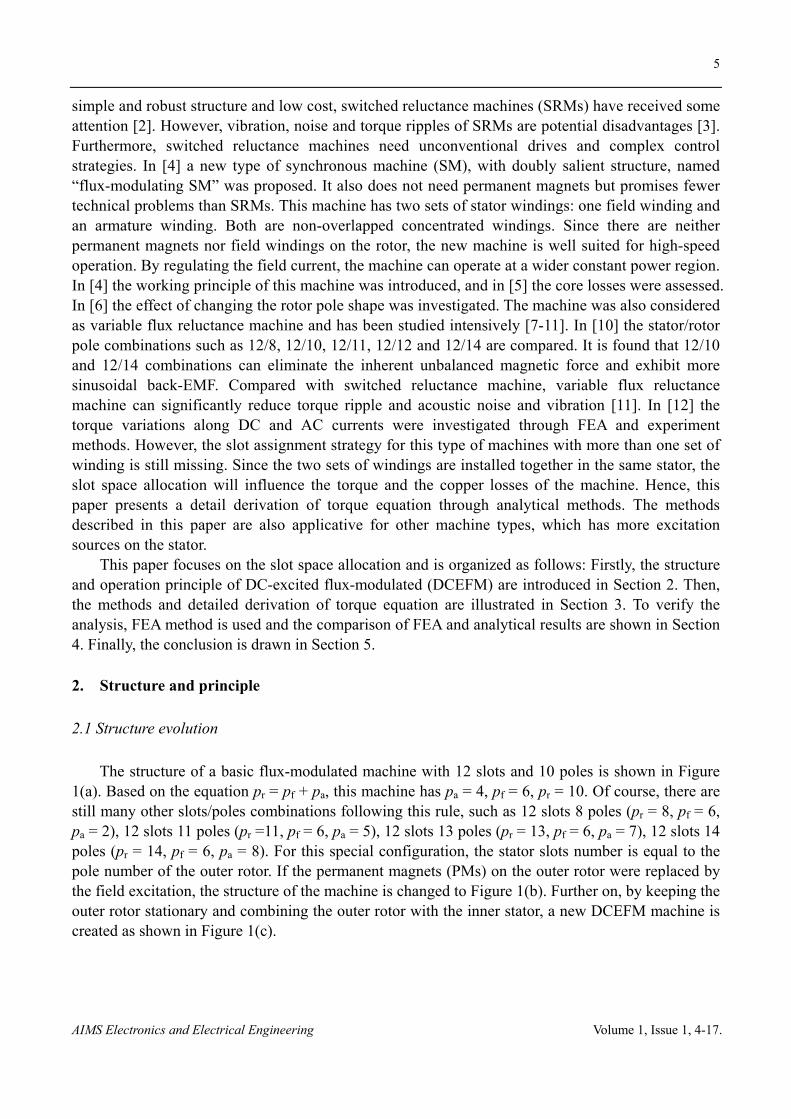
2.3 Armature field
The air-gap flux density excited by armature winding is shown in Figure 3(a). To generate effective torque in the machine, the armature field must contain 4th order harmonic, which interacts
7
AIMS Electronics and Electrical Engineering Volume 1, Issue 1, 4-17.
with the DC field to yield the torque. Due to the modulating rotor, the armature field also contains high frequencies harmonic field, which causes core losses.
(a) (b)
Figure 3. Air-gap flux generated by armature winding with 3-phases currents equal to 10A-RMS. (a) The flux density radial component along the air-gap. (b) The amplitude of each harmonics.
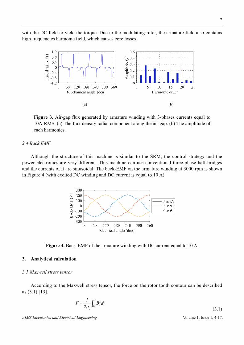
2.4 Back EMF
Although the structure of this machine is similar to the SRM, the control strategy and the power electronics are very different. This machine can use conventional three-phase half-bridges and the currents of it are sinusoidal. The back-EMF on the armature winding at 3000 rpm is shown in Figure 4 (with excited DC winding and DC current is equal to 10 A).
Figure 4. Back-EMF of the armature winding with DC current equal to 10 A.
3. Analytical calculation
3.1 Maxwell stress tensor
According to the Maxwell stress tensor, the force on the rotor tooth contour can be described as (3.1) [13].
200
02
dlF B dy
(3.1)

8
AIMS Electronics and Electrical Engineering Volume 1, Issue 1, 4-17.
where, F is the force on the rotor tooth contour, µ0 is the permeability of the air, d is the integral depth of the rotor tooth, l is the axial length of the rotor tooth, and B0 is the flux density on the contour of the rotor tooth. This formula disregards the saturation of the iron.
It can be seen from (3.1) that in order to calculate the forces on the rotor teeth, the flux densities along the rotor teeth contours must be calculated firstly.
3.2 Schwarz-Christoffel mapping
The following assumptions are made: The permeability of the iron core is infinitely large; rotor and the stator slots are infinitely deep and the teeth of the stator and rotor are infinitely wide. In order to eliminate the influence of adjacent teeth and slots, the slot opening of the stator and rotor are assumed to be infinitely wide. The equivalent model of a stator and a rotor tooth of the DCEFM are shown in Figure 5 [13-15].
Figure 5. Schwarz-Christoffel mapping. (a) Plane z. (b) Plane w. (c) Plane t.
Based on the Schwarz-Christoffel mapping, the relationship between Figure 5(a) and (b) can be expressed as (3.2), and the relationship between Figure 5(b) and (c) is expressed as (3.3) [13,14].
1 1wdz dw
w w s
(3.2)
1
( )idt
dw w w s
(3.3)
where, s = (δ/b)2, δ is the air-gap length and b is the distance between the rotor and stator tooth as shown in Figure 5(a).
The flux density and the force on the contour CD are expressed as (3.4) and (3.5), respectively [13,14].
0 0 0 0 1
dt dt dw Ni wB
dz dw dz w
(3.4)
22 00
0
1arcsin
2 2 1 2i ll s
F B dys
(3.5)

9
AIMS Electronics and Electrical Engineering Volume 1, Issue 1, 4-17.
where, φi is the magnetic potential on the contour BA, and the magnetic potential on the contour CDA is assumed to be 0.
3.3 Active belts
According to (3.5), if the magnetic potential φi on each stator tooth contour is known, the force on each rotor tooth can be easily calculated, and then the torque equation can be derived. By using the magnetic circuit method, the magnetic potential can be calculated. However, the air-gap permeance for the magnetic circuit is still unknown. Thus, a method named “active belts” is used to solve the air-gap permeance [16]. In this method, the air-gap region under each stator slot pitch can be divided into many belts. For example, the air-gap shown in Figure 6 is divided into 10 belts.
Figure 6. An example of air-gap belts division.
By using active belts method, the division of the air-gap under a module machine with 5-poles and 6-slots is shown in Figure 7. At this moment, it can be considered as rotor displacement α = 0. When the rotor displacement 0 ≤ α ≤ 0.1wst, the width of each belt under G1 region can be described as (3.6). The permeance of each belt can be expressed in (3.7). Then the air-gap permeance G1 is equal to (3.8).
Figure 7. Magnetic circuit of a module machine with 5-poles and 6-slots.
1 st4 st
2 st5 st
3 st
0.40.1
0.10.5
0.9
ww
ww
w
(3.6)

10
AIMS Electronics and Electrical Engineering Volume 1, Issue 1, 4-17.
0 111
2 0 414
0 212
0 515
40 313
2ln(1 )
2ln(1 )
ln(1 )2
ln(1 )2
lG
lG
lG
lG
lG
(3.7)
1 11 12 13 14 15G G G G G G (3.8)
where, β is a coefficient. When wst/δ ≤ 10, β = 1; when wst/δ > 10, β = 1.1 [16]. By following this method, the air-gap permeance of each stator slot pitch region along with the
rotor rotation can be calculated and drawn as shown in Figure 8.
Figure 8. Air-gap permeance variation along with rotor rotation.
3.4 Magnetic circuit
The equivalent magnetic circuit of the module machine in Figure 7 is shown in Figure 9. In the circuit, Un1 to Un6 are the magnetic potential of each stator tooth contour, respectively. Vi1 to Vi6 are the MMF of the coil on each tooth. They can be expressed as given in (3.9).
Figure 9. Equivalent magnetic circuit of the module machine.
i1 dc dc ac B i4 dc dc ac B
i2 dc dc ac C i5 dc dc ac C
i3 dc dc ac A i6 dc dc ac A
V N i N i V N i N i
V N i N i V N i N i
V N i N i V N i N i
(3.9)

11
AIMS Electronics and Electrical Engineering Volume 1, Issue 1, 4-17.
where, Ndc and Nac are the turns number of the DC winding and armature winding on each tooth, respectively; idc is the DC current, iA, iB and iC are the three-phase AC current, and they can be written as (3.10).
stA sp
st
stB sp
st
stC sp
st
0.7( ) 2 sin( 2 )
2.4
0.7 2( ) 2 sin( 2 )
2.4 3
0.7 2( ) 2 sin( 2 )
2.4 3
wi I
w
wi I
w
wi I
w
(3.10)
where, Isp is the phase RMS current. As a result, the magnetic potential Un1 to Un6 can be expressed in (3.11).
n1 n0 i1 n2 n0 i2 n3 n0 i3
n4 n0 i4 n5 n0 i5 n6 n0 i6
U U V U U V U U V
U U V U U V U U V
(3.11)
With
1 i1 2 i2 3 i3 4 i4 5 i5 6 i6n0
1 2 3 4 5 6
0GV G V G V G V G V G V
UG G G G G G
(3.12)
3.5 Force and torque equations
By substituting (3.11) and (3.12) to (3.5), the forces variation with the rotor rotation can be expressed. For example, when the rotor displacement is: 0 ≤ α ≤ 0.1wst, the forces on the rotor tooth 1 shown in Figure 7 can be expressed as (3.13) and (3.14).
20 n1
1
1arcsin
2 1 2
U l sF
s
(3.13)
20 n6 11
111 11
1arcsin
2 1 2
U l sF
s
(3.14)
where, 2 211 st+( +0.9 )w ,
211 11 st( )s w and
2st( 0.1 )s w .
When the rotor displacement is: 0.1wst ≤ α ≤ 1.1wst, the forces on the rotor tooth 1 shown in Figure 7 can be obtained as (3.15) and (3.16).
20 n2 12
112 12
1arcsin
2 1 2
U l sF
s
(3.15)
20 n1
1
1arcsin
2 1 2
U l sF
s
(3.16)
where, 2 212 st+(1.1 )w
and 2
12 12 st( )s w .
By analogy, all the forces can be expressed in the similar form. Because the force on a rotor tooth

12
AIMS Electronics and Electrical Engineering Volume 1, Issue 1, 4-17.
can be considered to be on the top of it, the torque equation of the machine can be expressed as (3.17).
1 1 2 2 3 3 4 4 5 52( )T F F F F F F F F F F R (3.17)
where, R is the radius of the rotor.
4. Verification by finite element analysis
To verify the analyses above, FEA method is used. The main parameters and size of the FEA model are listed in Table 1.
Tabel 1. Main parameters and sizes of the FEA model.
Parameter Value
Outer radius 132 mm
Stack length 50 mm
Air-gap length 0.73 mm
Width of rotor tooth 22.64 mm
Depth of rotor tooth 15 mm
Width of stator tooth 22.64~32 mm
Slot depth of stator 30 mm
DC winding turns number per slot 44
AC winding turns number per slot 44
4.1 DC excitation only
In the analyzed machine, Ndc is equal to Nac. When there is only DC excitation on the stator and idc = 10 A, based on (3.11) the magnetic potential Un1 to Un6 are illustrated in Figure 10(a). The forces variation with the rotor rotation is shown in Figure 10(b).
To verify the results, a FEA model was built. The comparison between FEA and analytical result is shown in Figure 11. Obviously, the analytical method has a high accuracy. If there is only DC excitation, the magnetic potential of the stator teeth contours is almost flat along with the rotor rotation. Under this circumstance, the effective torque is equal to 0.
For
ces
(N)
Mag
neti
c po
tent
ial (
A)
Figure 10. idc = 10 A and Isp = 0 A. (a) Magnetic potential. (b) Forces.

13
AIMS Electronics and Electrical Engineering Volume 1, Issue 1, 4-17.
-1
-0,5
0
0,5
1
0 90 180 270 360
Tor
que
(Nm
)
Electrical angle (deg)
FEA Analytical
Figure 11. Torque comparison when idc = 10 A and Isp = 0 A.
4.2 Armature current only
When the armature winding is excited with three-phase sinusoidal current and Isp = 10 A, while the DC current is 0, according to the principle of the flux-modulated machine, the effective torque is also 0. The magnetic potential on the stator teeth contours is shown in Figure 12(a). The forces variation and the torque comparison are illustrated in Figure 12(b) and Figure 13, respectively.
Figure 12. idc = 0 A and Isp = 10 A. (a) Magnetic potential. (b) Forces.
-0,2
-0,1
0
0,1
0,2
0 90 180 270 360
Tor
que
(Nm
)
Electrical angle (deg)
FEA Analytical
Figure 13. Torque comparison when idc = 0 A and Isp = 10 A.
4.3 Optimal currents
To maximize the torque, both DC and AC windings on each tooth must have the same current density. If the effective slot area is As, the areas for DC winding Asdc and AC winding Asac have a relationship as expressed in (4.1).
14
AIMS Electronics and Electrical Engineering Volume 1, Issue 1, 4-17.
dc dcsdc s
dc dc ac sp
ac spsac s
dc dc ac sp
N iA A
N i N I
N IA A
N i N I
(4.1)
Then the resistances of DC and AC windings on each tooth are equal to (4.2). 2dc dc
dc dc dc ac spsdc dc s
2ac ac
ac dc dc ac spsac sp s
2 2 ( )
2 2 ( )
N l N lR k k N i N I
A i A
N l N lR k k N i N I
A I A
(4.2)
where, ρ is the resistivity of copper, k is the coefficient considering the end-winding. As both windings are single-tooth concentrated, they have the same coefficient.
The copper losses of each tooth Pcopper are equal to (4.3).
2 2 2copper sp ac dc dc dc dc ac sp
s
2( )
k lP I R i R N i N I
A
(4.3)
It can be seen from (4.3) that for a certain stator, the slot area and the effective length of the stator are constant. If the MMFs of the two windings on each tooth are constant, the copper losses is constant.
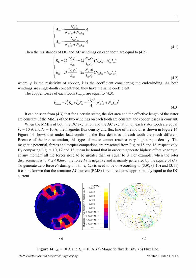
When the MMFs of both the DC excitation and the AC excitation on each stator tooth are equal: idc = 10 A and Isp = 10 A, the magnetic flux density and flux line of the motor is shown in Figure 14. Figure 14 shows that under load condition, the flux densities of each tooth are much different. Because of the iron saturation, this type of motor cannot reach a very high torque density. The magnetic potential, forces and torques comparison are presented from Figure 15 and 16, respectively. By comparing Figure 10, 12 and 15, it can be found that in order to generate highest effective torque, at any moment all the forces need to be greater than or equal to 0. For example, when the rotor displacement is: 0 ≤ α ≤ 0.6wst, the force F2 is negative and is mainly generated by the square of Un2. To generate zero force F2 during this time, Un2 is need to be 0. According to (3.9), (3.10) and (3.11) it can be known that the armature AC current (RMS) is required to be approximately equal to the DC current.
(a) (b)
Figure 14. idc = 10 A and Isp = 10 A. (a) Magnetic flux density. (b) Flux line.
15
AIMS Electronics and Electrical Engineering Volume 1, Issue 1, 4-17.
Figure 15. idc = 10 A and Isp = 10 A. (a) Magnetic potential. (b) Forces.
0
5
10
15
20
0 60 120 180 240 300 360
Tor
que
(Nm
)
Electrical angle (deg)
FEAAnalytical
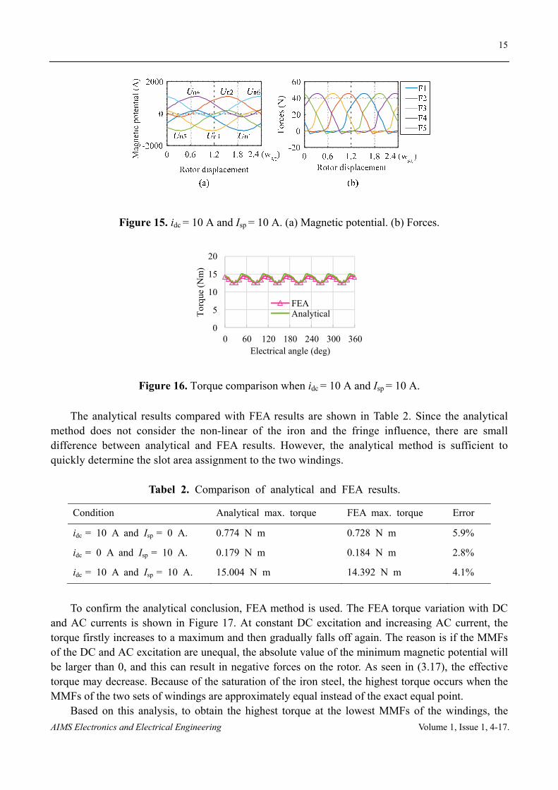
Figure 16. Torque comparison when idc = 10 A and Isp = 10 A.
The analytical results compared with FEA results are shown in Table 2. Since the analytical method does not consider the non-linear of the iron and the fringe influence, there are small difference between analytical and FEA results. However, the analytical method is sufficient to quickly determine the slot area assignment to the two windings.
Tabel 2. Comparison of analytical and FEA results.
Condition Analytical max. torque FEA max. torque Error
idc = 10 A and Isp = 0 A. 0.774 N m 0.728 N m 5.9%
idc = 0 A and Isp = 10 A. 0.179 N m 0.184 N m 2.8%
idc = 10 A and Isp = 10 A. 15.004 N m 14.392 N m 4.1%
To confirm the analytical conclusion, FEA method is used. The FEA torque variation with DC and AC currents is shown in Figure 17. At constant DC excitation and increasing AC current, the torque firstly increases to a maximum and then gradually falls off again. The reason is if the MMFs of the DC and AC excitation are unequal, the absolute value of the minimum magnetic potential will be larger than 0, and this can result in negative forces on the rotor. As seen in (3.17), the effective torque may decrease. Because of the saturation of the iron steel, the highest torque occurs when the MMFs of the two sets of windings are approximately equal instead of the exact equal point.
Based on this analysis, to obtain the highest torque at the lowest MMFs of the windings, the

16
AIMS Electronics and Electrical Engineering Volume 1, Issue 1, 4-17.
MMFs of the two sets of windings need to be approximately equal.
0
100
200
300
0 50 100 150 200T
orqu
e (N
m)
Armature RMS current (A)
DC current(A)
105090130170200
Figure 17. Torque variation along with DC and AC currents.
5. Conclusion
A detail analysis of the torque calculation of a DC-excited flux-modulated machine has been performed. By using the FEA method, the validity of the analytical result was validated. The analysis shows that in order to obtain the highest torque at the admissible copper losses, the MMFs of the two sets of stator windings need to be approximately equal. Since the three-phase winding is excited with sinusoidal current, the armature AC current (RMS) is required to be approximately equal to the DC current. In other words, the slot space is required to be equally assigned to the two windings. The analytical methods and progress described in this paper can also be referred to analyze other machines with salient stators and rotors such as variable flux reluctance machine, field excited flux-switching machine.
Acknowledgments
This work was supported in part by the China Scholarship Council under Grant 201608080024.
Conflict of Interest
The authors declare no conflict of interests in this paper.
References
1. Raminosoa T, Torrey DA, El-Refaie AM, et al. (2016) Sinusoidal reluctance machine with DC winding : An attractive non-permanent-magnet option. IEEE T Ind Appl 52: 2129-2137.
2. Shi JT, Zhu ZQ (2015) Analysis of novel multi-tooth variable flux reluctance machines with different stator and rotor pole combinations. IEEE T Magn 51: 1-11.
3. Liu X, Zhu ZQ, Hasegawa M, et al. (2012) Vibration and noise in novel variable flux reluctance machine with DC-field coil in stator. Proceedings of the 7th International Power Electronics and Motion Control Conference 2: 1100-1107.
4. Fukami T, Matsuura Y, Shima K, et al. (2010) Development of a low-speed multi-pole synchronous machine with a field winding on the stator side. The XIX International Conference on Electrical Machines - ICEM 2010 Rome: 1-6.

17
AIMS Electronics and Electrical Engineering Volume 1, Issue 1, 4-17.
5. Fukami T, Aoki H, Shima H, et al. (2012) Assessment of core losses in a flux-modulating synchronous machine. IEEE T Ind Appl 48: 603-611.
6. Fukami T, Matsuura Y, Shima K, et al. (2012) A multipole synchronous machine with nonoverlapping concentrated armature and field windings on the stator. IEEE T Ind Electron 59: 2583-2591.
7. Fukami T, Ueno Y, Shima K (2015) Magnet arrangement in novel flux-modulating synchronous machines with permanent magnet excitation. IEEE T Magn 51: 1-4.
8. Liu X, Zhu ZQ (2013) Electromagnetic performance of novel variable flux reluctance machines with DC-field coil in stator. IEEE T Magn 49: 3020-3028.
9. Shi JT, Liu X, Wu D, et al. (2014) Influence of stator and rotor pole arcs on electromagnetic torque of variable flux reluctance machines. IEEE T Magn 50: 1-4.
10. Liu X, Zhu ZQ (2014) Stator/rotor pole combinations and winding configurations of variable flux reluctance machines. IEEE T Ind Appl 50: 3675-3684.
11. Zhu ZQ, Liu X (2015) Novel stator electrically field excited synchronous machines without rare-earth magnet. IEEE T Magn 51: 8103609.
12. Azar Z, Zhu ZQ (2014) Performance analysis of synchronous reluctance machines having nonoverlapping concentrated winding and sinusoidal bipolar with DC bias excitation. IEEE T Ind Appl 50: 3346-3356.
13. Tang YQ (1998) In: Electromagnetic fields in Electrical machines-Second edition. Beijing, CN: Science Press, 341-355.
14. Ou J, Doppelbauer M (2016) Torque analysis and comparison of the switched reluctance machine and the doubly-salient permanent magnet machine, 2016 18th European Conference on Power Electronics and Applications (EPE'16 ECCE Europe) Karlsruhe: 1-11.
15. Williams FC, Mamak RS (1962) Electromagnetic forces in slotted structures. Proceeding of the IET-Part C: Monographs 109: 11-17.
16. Robert Pohl (1946) Theory of pulsating-field machines. Journal of the Institution of Electrical Engineers-Part II: Power Engineering 93: 37-47.
© 2017 the Author(s), licensee AIMS Press. This is an open access
article distributed under the terms of the Creative Commons Attribution
License (http://creativecommons.org/licenses/by/4.0)