18BK CdrnSCKiOT Xfi 0m»i3IGff.. f® EKs» - DTIC
91
MM saessaasesBasssss^eBgssassWss^^s^^^ 18BK CdrnSCKiOT Xfi 0m»i3IGff.. f® btt: W s UJ A S K EKs»lNfcteKiN<?> DELAWARE
-
Upload
khangminh22 -
Category
Documents
-
view
3 -
download
0
Transcript of 18BK CdrnSCKiOT Xfi 0m»i3IGff.. f® EKs» - DTIC

MM saessaasesBasssss^eBgssassWss^^s^^^
18BK CdrnSCKiOT Xfi 0m»i3IGff.. f®
btt:
W s UJ A S K
EKs»lNfcteKiN<?>
DELAWARE

THIS REPORT HAS BEEN DELIMITED
AND CLEARED FOR PUBLIC RELEASE
UNDER DOD DIRECTIVE 5200.20 AND
NO RESTRICTIONS ARE IMPOSED UPON
ITS USE AND DISCLOSURE,
DISTRIBUTION STATEMENT A
APPROVED FOR PUBLIC RELEASE;
DISTRIBUTION UNLIMITED,
••-=-*-—««
LOCAL HEAT PLUX IN A VERTICAL DUCT WITH
FREE CONVECTION IN OPPOSITION TO
FORCED FLOW
Contract #N-onr-622(01)
«
Sponsored by Office of Naval Research
FINAL REPORT
31 December, 19$2
Submitted by: S. A. Ouerrieri, * aistent Professor of C;..« aical Engineering-
Russell J. Hcrna, Research Fellow in Chemical Engineering
Department of fhenriAti engineering CJrsiv ?r«.i «y of Delaware
Newark, Delaware
u^wuM\!iwmwn**«*2#,v*mtmmi*m'v><)imi&r~->-1 ••i*ismtx#eii&!&ir^s^'^'-MSW**"" •

•HC23
-.'••
x ..J. i — vi V.,
I. O'I.J" ;i~RY
III. «&&j:.US DKSC3.IPTIP?: ftKD PROCEDURE IV. DISC fSSIO]
rl. Outline of the problem '•. lix&ct theoretics;;! equations '. - C. iVpi-rOXlraatc theoretical e^uati *rs D. Previous experir.ient 1 r/ork 2. Sxperln:ont31 approach to 'the probleja.
?a?e
eat ci-ansic-r iroc Urave4?s<»E tnor;:ocouple cieasurerionts'
transfer from visual raeasureneitfc
VI.
II. Heat transfer ns c: lculuted 'by average inlet and outlet terap.era-tures
I. ".Consideration of data for analysis J. Ban^e of InvestftfTtlpg -;>.• TT>C 1 V- * ._> . .• —i— o
A. Comparison of the three netheds • -- - —
I'. *'oehanisu analys is C. do^pafisoh and analysis •
vii. i?ii3i.ioc:h'.h;:Y
vni. ire: SIJC'LAS-UTW:
IX. ^Piv'hDlX .-• •i. SaiqVle calculations' 15, Data see 1 oiov; Tor list or tables
C. Figures* — see below far list of figures
3 4
11 11 11
13 /• 15 16
13 24
30
33 35 3o 36 36 39 41
43
.
*r
• •*»««.=* sag*** <9h« V^-.rf*^- • .VI
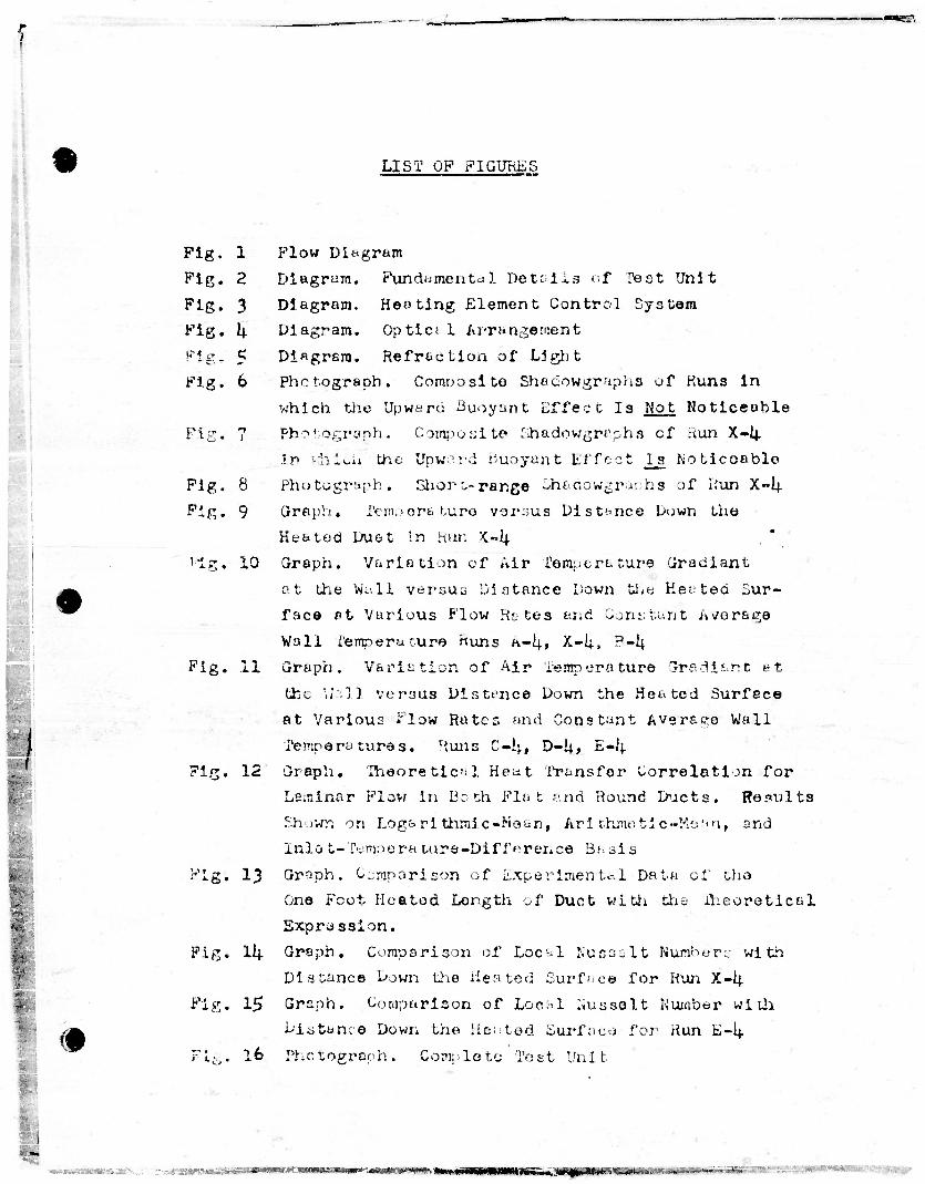
LIST OP FIGURES
Pig. 1 Fig. 2
Fig. 3 Fig. k Pig, 5
Fig. 6
Fig. 7
Fig. 8 Fig. 9
Mg. 10
Fig. 11
Fig. 12
(•
Fig. 13
Fig. Ill-
Fix. 15
FU-. 16
Flow Diagram Diagram. Fundamental Detoils of Teat Unit Diagram. Heating Element Control System Diagram. Optic; 1 Arrangement Diagram. Refraction of Li gh t Photograph. Composite Shadowgraphs of Runs in which the Upward Buoyant Effect Is Not Noticeable Photograph. Composite Shadowgraphs cf Run X-lj. in kjii-oi* the Upward Buoyant Effect l_s ftoticoable Photograph, Short-range Shadowgr&nhs of Run X-I+ Graph. femoorature vor:;us Distance Down the Heated Duet in Run K-I4. Graph. Variation of Air Temperature Gradient at the W^-.li versus Distance Down the Heated Sur- face ft Vurious Flow Ra tes and Constant Ai/orage
Wall rempera cure Runs K-I4., X-l;t ?-ij Graph. Variation of Air Temperature CJradiant at
the Walj versus Distance Down the Heated Surface at Various Flow Rates and Constant Average Wall
Temperatures. Runs C-i^# D-U> E-«; Graph. Theoretical Heat Transfer Correlation for Laminar Flow in Both Flat and Round Ducts. Results
Shown on Logarithmic-Mean, Arithmetic-Me.'m, and Inlo t-Temporature-Difference Basis
Graph. Comparison of Experimental Data of the One Foot Heated Length of Duct with the iheoretical Expression. Graph. Comparison of Local Nussslt Numbers with Distance Down the Hen ted Surface for Run X-lj. Graph. Comparison of Loc-.l Imsselt Number with Distance Down the Heated Surface for Run E-I4. Photograph. Complete Tost Unit
Er„-ir'--. .'C^cfll-...
Pig. 17 Photograph. Heated Section cf Tost Unit Showing
Heating Elements rig. 18 Photograph. Heated Section of Teat Unit Without
Heating Ll^menty. Fig. 19 Photograph. Window Frame Showing Plush Nature
of Glass with the End Wall
Fig. 20 Photograph. Top Praversc Mechanism
Fig. 21 Photograph. Control Board
•
i
« »i—xa IIIWHII'IBIMMI **m*<se*enm,j>m, mn •naBPgfpW! •^«r-^»ft5ii«^--r;'^g'^' "^ ^' "*—*
?
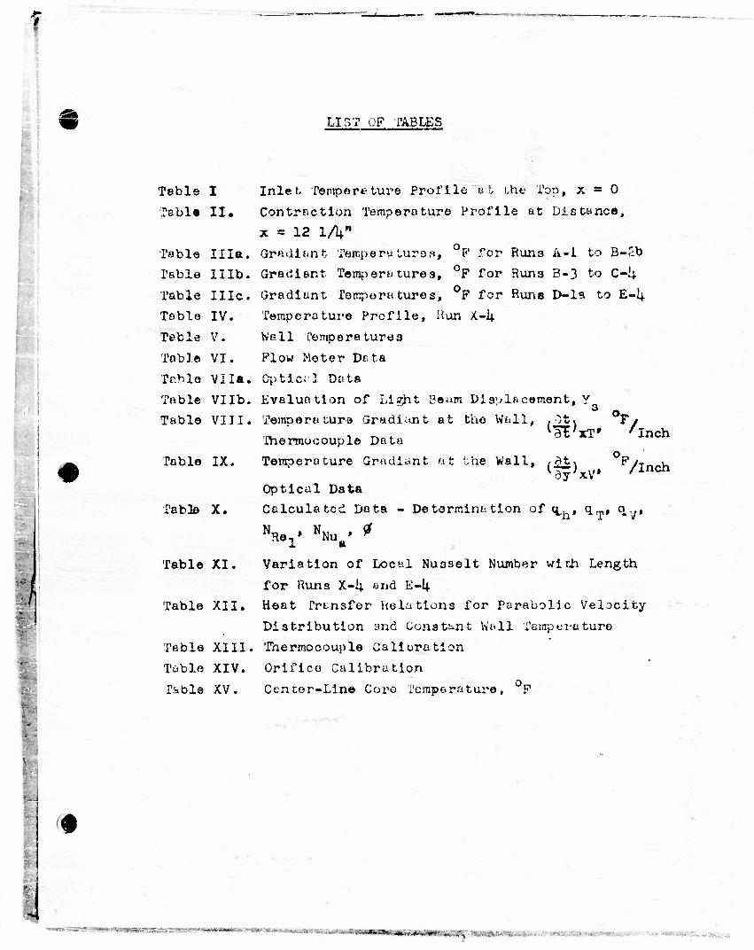
LIST OF TABLES
Table I
Tabla II.
Table Ilia.
Table IIlb.
Table I He.
Table IV.
Table V.
Table VI.
Table Vila.
Table VIlb.
Table VIII.
Table IX.
Table X.
Table XI.
Table XII.
Table XIII,
Table XIV.
Table XV.
Inlet Temper* ture Profile ut the Top, x = 0
Contraction Temperature Profile at Distance,
x = 12 lA" Gradient Temperatures, P for Rune A-l to B~£b
Gradient Tempera tures, °F for Runs 3-3 to C-1+
Gradient fompora tures, °F for Runs D-la to E-I4.
Temperature Profile, Hun X.—14.
Wall Temperatures
Flow Meter Dtta
Optic;'] Data
Evaluation of Light Baum Displacement, V
Temp era ture Gradiant at the Wall, , ;t<
Ihermocouple Data dE'xT' 7 Inch
Temoerature Gradiant at the Wall, ,^k\ p/r~~u (dy}xV* /Inch
Optical Data
Calculated Data - Determination of <^. . q_,, q.,,,
>W NNu • * a. m
Variation of Local Nu3selt Number with Length
for Runs X-U and E-lj.
Heat Transfer Relations for Parabolic Velocity
Distribution and Constant Wall femperuture
Thermocouple Caliuration
Orifice Calibration
Cencer-Line Core Temperature, F
'•
,,.^r,-r". „ ;'

SUMMARY
Heat transfer rates acconpanying simultaneous natural con-
vection and forced flow of air in a vertioal channel* using an
optical method, were studied experimentally, under conditions such th»t •"•he two types of flow tended to oppose eaoh other*
Thus the light, heated air tended to flow upward near the *
vertical surfaces of the channel while the air stream as a
whole was forced to flow downward. These conditions are quali-
tatively similar to those occurring in cooling passages inside
blades of gas turbines.
Optloal measurements showed that natural oonveotive flow
predominated at low forced-flow velocities and high temperature
differences while at high mean velocities the flow was downward
even at the wall. Under Intermediate conditions a maximum rate
of heat transfer occurred about half-way up the channel, owing
to instability of the laminar flow associated with the opposing
forces. At the highest mean velocities the local heat transfer
coefficients agreed closely with values expected from laminar-
flow theory neglecting natural convection.
-ii w i •IMMWMmun.iiMiMW • 3 •»'"~~**iSciyn. ..
'
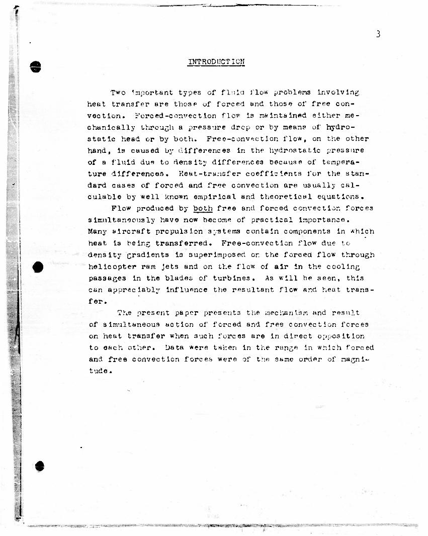
INTRODUCTION
Two Important types of fluid Mow problems Involving
heat transfer are those of forced and those of free con-
vection. Forced-convection flc* is maintained either me-
chanically through a pressure drcp or by means of hydro-
static head or by both. Free-conviction flow, on the other
hand, is caused by dlfferences in the hydrostatic pressure
of a fluid due to density differences becuuse of tempera-
ture differences. Ksat-tra.usfer coefficients for the stan-
dard cases of forced and free convection are usually cal-
culable by well known empirical and theoretical equations.
Plow produced by both free and forced convection forces
simultaneously have now become of practical importance.
Many aircraft propulsion systems contain components in which
heat is being; transferred. Free-convection flow due to
density gradients is superimposed or. the forced flow through
helicopter ram Jets and on the flow of air in the cooling
passages in the blades of turbines. As will be seen, this
can appreciably influence the resultant flow and heat trans-
fer.
The present paper presents the mechanism and result
of simultaneous action of forced and free convection forces
on heat transfer when such forces are in direct opposition
to each other. Data were taken in the rung* in wnich forced
and free convection force.s were of trie same order of magni-
tude.
•' *-v ,r,- "..4 ..**
•^
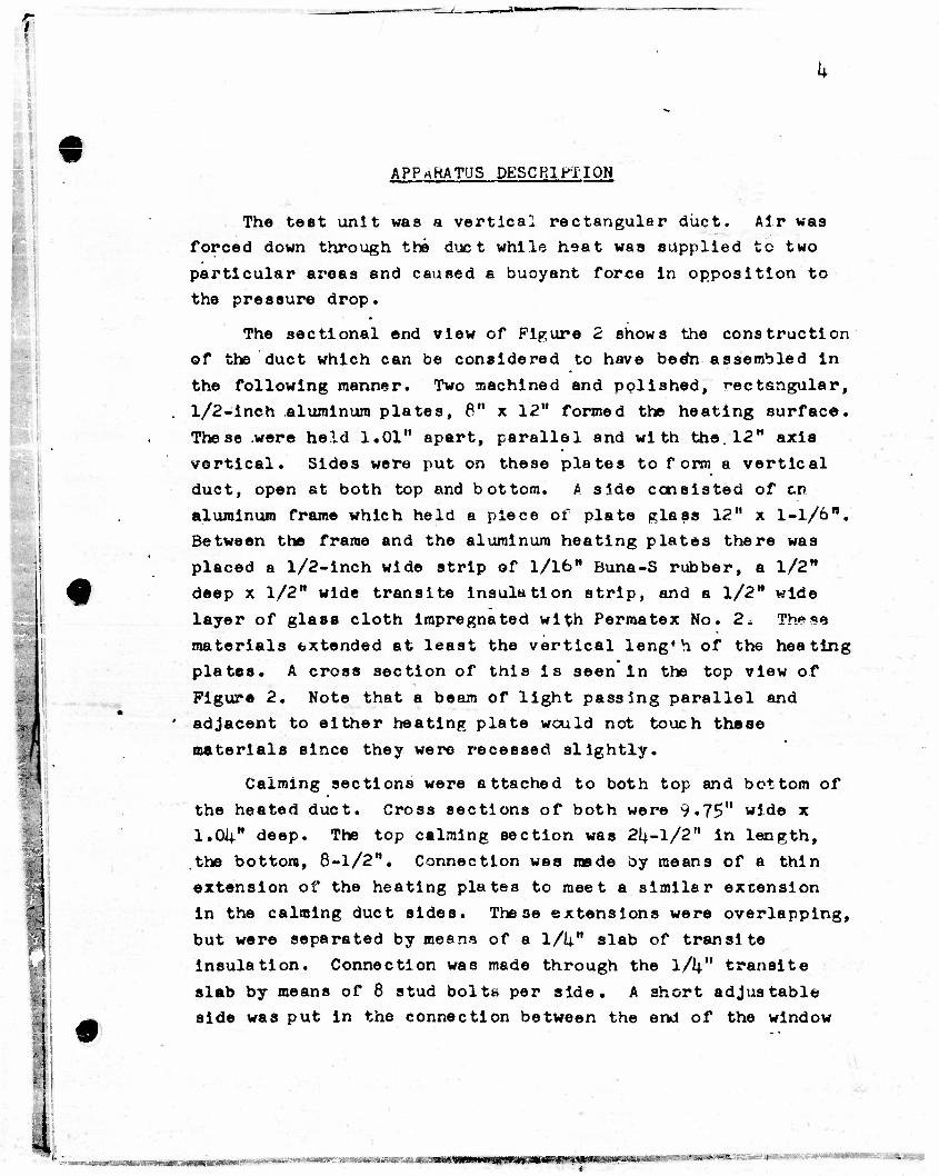
APPARATUS DESCRIPTION
The teat unit was a vertical rectangular duct. Air was forced down through the due t while heat was supplied to two
particular areas and caused a buoyant force in opposition to
the pressure drop.
The sectional end view of Figure 2 shows the construction of the duct which can be considered to have becfn assembled In
the following manner. Two machined and polished, rectangular,
. l/2-inch aluminum plates, 8" x 12" formed the heating surface.
These were held 1.01" apart, parallel and with the. 12" axis
vertical. Sides were put on these plates to form a vertical duct, open at both top and bottom. A side consisted of en
aluminum frame which held a piece of plate glass 12" x l-l/6B. Between the frame and the aluminum heating plates there was
placed a l/2-inch wide strip of 1/16" Buna-S rubber, a 1/2" A deep x 1/2" wide transite insulation strip, and a l/2M wide
layer of glass cloth Impregnated with Permatex No. 2. These
materials extended at least the vertical length of the heating plates. A cross section of this is seen in the top view of
Figure 2. Note that a beam of light passing parallel and ' adjacent to either heating plate would not touch these
materials since they were recessed slightly.
Calming sections were attached to both top and bottom of
the heated duct. Cross sections of both were 9.75" wide x 1.0i|" deep. The top calming section was 2U-1/2" in length,
the bottom, 8-1/2". Connection was made by means of a thin
extension of the heating plates to meet a similar extension
in the calming duct sides. These extensions were overlapping,
but were separated by means of a 1/U" slab of transite
insulation. Connection was made through the l/V' transite
slab by means of 8 stud bolts per side. A short adjustable ^ side was put in the connection between the end of the window
:.
MM— iMI—11 • • ' ' ww—WT ' ••"•"•• —www i »]WiW»W~ll'»"W»«

.
frame and the top calming section, A 1/\" foam rubber gaskofc plus the movable nature of this piece made possible a
correction for differences in thermal expansion. Design of
the entire duct was such that the inside dimensions were the
same at any point down the duct, with the exception that the distance between the heating plates wan 1.01" while the distance between the corresponding faces of the calming
sections was I.OI4." wide.
Wall temperatures in the haafcing plates were measured
by means of L * N No. 30 B&S glass insulated iron-constantan Duplex thermocouples. These couples were located in horizontal
holes which were drilled parallel to and 1/V from the heat
transfer interface. 'This gave the junction and wire leading to it a I4." isothermal zone in the plate. iheso thermocouples
were located at a distance, x, from the top of the heated
plate of 1, 3, 5, 7# 9, and 11 inches.
At the top and bottom of the duety mechanisms supported a travelling thermocouple which could move anywhere In a
plane perpendicular to the heated surface and passing through the axis of the duct. The mechanism of movement could
determine horizontal changes in position of the junction within 0,0005" and vertical changes within 1/16". Figure 2 shows the
construction.
The travelling thermocouple itself was m«de by butt silver
soldering IAN No, i+0 B&S (.0031'-) copper-constantan bare
thermocouple wire. The couple was gold plated for 1" on the
copper side of the junction and 3/8" on the constantan side of the junction. This plating and subsequent polishing were
done in order to minimize radiation error.
!
t
All thermocouple wires led into insulated switch boxes. Separate boxes were used for the copper-constantun and iron- constantan connections. Leads to the potentiometer were
;•:•>. #r:»—*-.il«»>w*v..i<tMI&s>TSi'<%*;..
*
I
I
r!
«
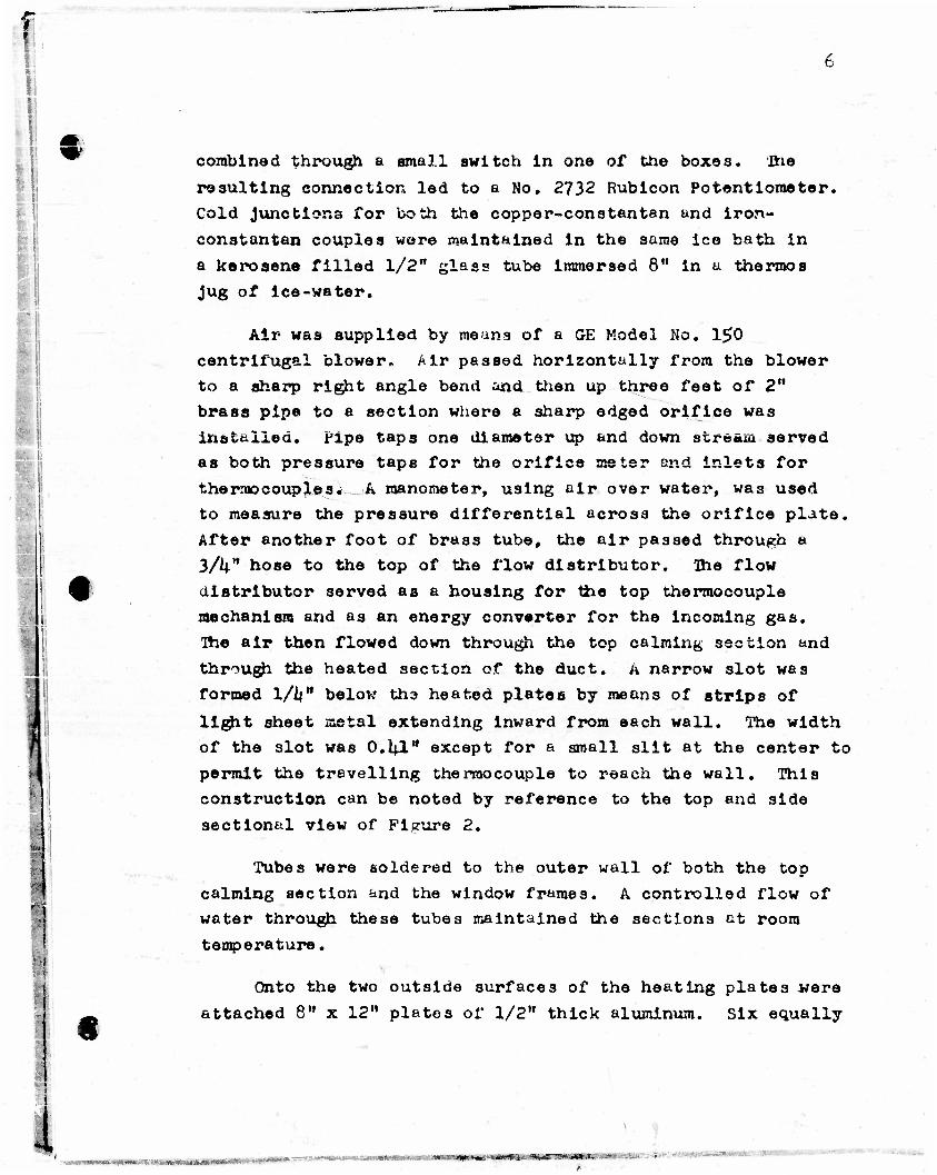
combined through a email switch In one of the boxes. The
resulting connection led to a No. 2732 Rubicon Potentiometer.
Cold Junctions for both the copper-constantan and iron-
constantan couples were maintained in the same ice bath in
a kerosene filled 1/2" glass tube immersed 8" in u thermos
Jug of ice-water.
Air was supplied by means of a GE Model No. 15>0
centrifugal blower- Air passed horizontally from the blower
to a sharp right angle bend and then up three feet of 2"
brass pipe to e section where a sharp edged orifice was
installed. Pipe taps one diameter up and down stream served
as both pressure taps for the orifice meter and inlets for
thermocouples. A manometer, using air over water, was used
to measure the pressure differential across the orifice plate.
After another foot of brass tube, the air passed through «
3/1*" hose to the top of the flow distributor. The flow
distributor served as a housing for the top thermocouple
mechanism and as an energy converter for the incoming gas.
Ihe air then flowed down through the top calming section and
through the heated section of the duct. A narrow slot was
formed 1/Un below tho heated plates by means of strips of
light sheet metal extending inward from each wall. The width
of the slot was 0.1*1" except for a small slit at the center to
permit the travelling thermocouple to reach the wall. This
construction can be noted by reference to the top and side
sectional view of Fieure 2.
Tubes were soldered to the outer wall of both the top
calming section and the window frames. A controlled flow of
water through these tubes maintained the sections at room
temperature.
Onto the two outside surfaces of the heating plate3 were
attached 8" x 12" plates of 1/2" thick aluminum. Six equally
t ^"".*i|h***v-*J«wS;J*—
! C
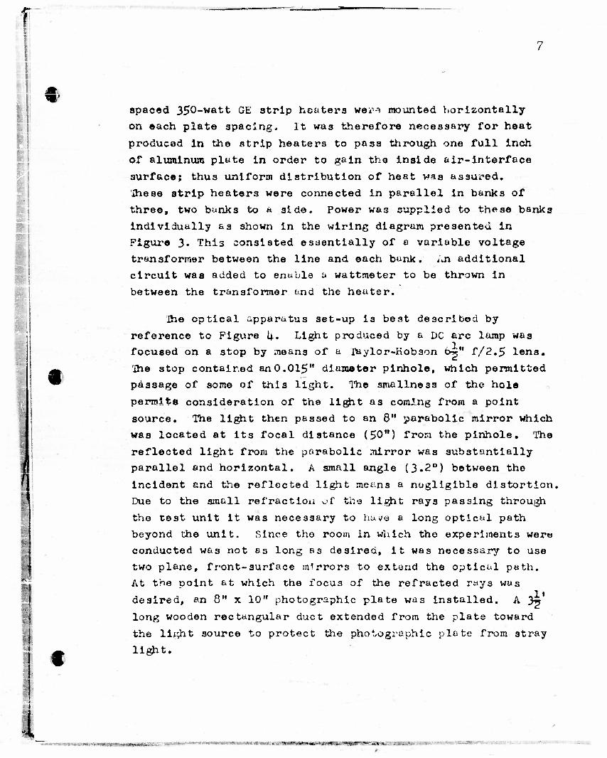
spaced 350-watt G£ atrip heaters wei-i mounted horizontally on each plate spacing. It was therefore necessary for heat
produced In the strip heaters to pass through one full inch
of aluminum plate in order to gain the inside air-interface
surface; thus uniform distribution of heat was assured,
ihese strip heaters were connected in parallel in banks of
three, two bunks to a side. Power was supplied to these banks
individually as shown in the wiring diagram presented in Figure 3. This consisted essentially of a variable voltage
transformer between the line and each bunk, .nji additional circuit was added to enable a wattmeter to be thrown in
between the transformer and the heater.
Jhe optical apparatus set-up is best described by
reference to Figure I4.. Light produced by a DC arc lamp was focused on a stop by means of a raylor-Hobson 6V* f/2.5 lens.
Ihe stop contained an 0.015" diameter pinhole, which permitted passage of some of this light. The smallne3s of the hole
permits consideration of the light as coming from a point
source. The light then passed to an 8" parabolic mirror which
was located at its focal distance (50") from the pinhole. The
reflected light from the parabolic mirror was substantially parallel and horizontal. A small angle (3.2°) between the
incident and the reflected light means a negligible distortion,
Due to the small refraction of the light rays passing through
the test unit it was necessary to have a long optical path
beyond the unit. Since the room in which the experiments were conducted was not es long as desired, it was necessary to use
two plane, front-surface mirrors to extend the optical path.
At the point at which the focus of the refracted rays was
desired, an 8" x 10" photographic plate was installed. A yJ
long wooden rectangular duct extended from the plate toward
the light source to protect the photographic plate from stray
light.
f-
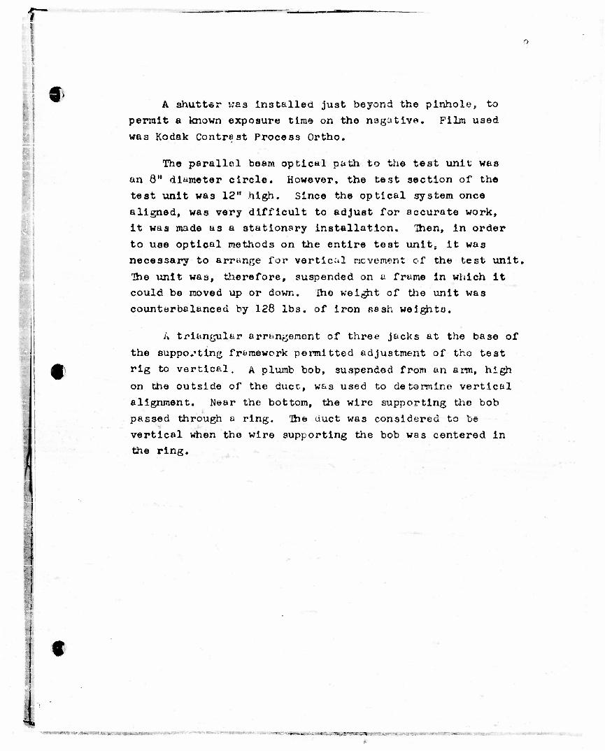
A shutter was installed just beyond the pinhole, to
permit a known exposure time on the negative. Film used
was Kodak Contrast Process Ortho.
The parallel beam optical path to the test unit was
an 8" diameter circle. However, the test section of the
test unit was 12" high. Since the optical system once
aligned, was very difficult to adjust for accurate work,
it was made as a stationary installation. Then, in order
to use optical methods on the entire test unit, it was
necessary to arrange for vertical movement of the test unit.
'Ihe unit was, therefore, suspended on a frame in which it
could be moved up or down. Ihe weight of the unit was
counterbalanced by 128 lbs. of iron sash weights.
k triangular arrt>ngenont of three jacks at the base of
the supporting framework permitted adjustment of the test
rig to vertical, A plumb bob, suspended from an arm, high
on the outside of the duct, was used to determine vertical
alignment. Near the bottom, the wire supporting the bob
passed through a ring. Ihe duct was considered to be
vertical when the wire supporting the bob was centered in
the ring.
C
^•awwuBtawmwuMiipiwiii'' •+-- -«---•-••*»—-.•- mm
.
t
I PROCEDURE
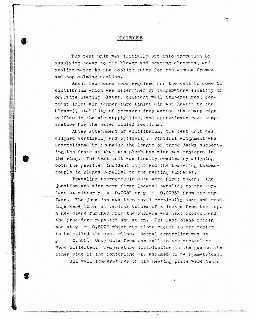
The test ur.it was Initially put into operation by
supplying power to the blower and heating elements, and
cooling water to the cooling tubes for the window frames
and top calming section.
About two hours were required for the unit to come to
equilibrium which was determined by temperature equality of
opposite heating plates, constant wall temperatures, con-
stant inlet air temperature (inlet air was heated by the
blower), stability of pressure drop across the sharp edge
orifice in the air supply line. «nd approximate room temp-
erature for the water cooled sections.
After attainment of equilibrium, the test unit was
aliened vertically and optically. Vertical alignment was
accomplished by changing the length of three jacks, support-
ing the frame so that the plumb bob wire was centered in
the ring. The test unit was finally readied by aligning
both the parallel incident light end the traveling thermo-
couple in plan«s parallel to the heating surfaces.
Traveling thermocouple data were first taken. i'he
junction and wire were first located parallel to the sur-
face at either y = 0.005" or y - 0.0075" from the sur-
face. The .'unction wa3 then moved "ertically ao*n and read-
ings were taken at various values of x Inches from the top.
A new plane further from the surface was next chosen, and
the procedure repeated and so on. The last plane chesen
was at y = 0.500" which was close er.cugh tu the center
to be called trie centerllne. Actual centerline was at
y = 0.505*. Only data from one wall to the cer.terline
•sere collected. Temperature distr ibut ion in the ^as on the
other 3ido of the centerllne was assumed to be symmetrical.
All wall temperatures of the heating plate were taken
f
-.- - .- '>:^-.*»««0»«iw«^'*B2;'<MaaM-:•>•.: - *. ,. •••**&** W*a W0&3B$*X9W? ''••> T,*"*aWr»i'"'--•:•-

r 10
on the 3id« which was used as the da tun plane for the traveling thermocouple. As a check on the opposite side,
one wall temperature was taken there for comparison.
Pressure readings wore taken across the orifice and
between atmosphere and the downstream orifice top. Thermo-
couples installed at the pipe taps gave temperatures at these points. Finally barometric pressure was recorded.
With lights out, the arc lamp was turned on and
pictures were ta'.en of refraction occuring in the loy/er
half of the test section. The test unit was then lowered
and similar pictures were ta:en of the upper half of the
test section. Usually two pictures, of 1/5 and 1/2 second
exposure time, were taken of each section. Standard
procedure was used in development of the negatives.
r
t
I DISCUSSION
11
•
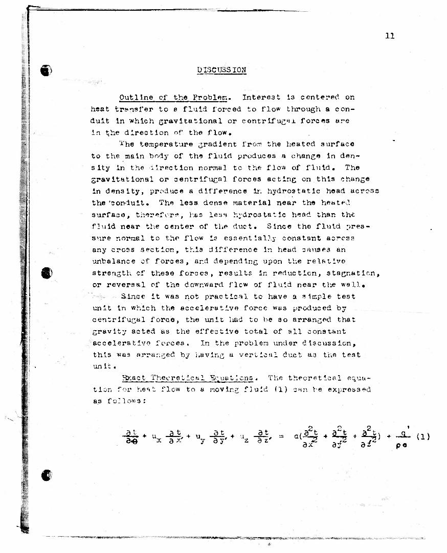
Outline cf the Problem. Interest 13 centered on
heat transfer to a fluid forced to flow through a con-
duit in which gravitational or centrifugal forces are
in t"e direction of the flow. The temperature gradient from the heated surface
to the main body of the fluid produces a change in den-
sity in the direction normal tc the flow of fluid. The
gravitational or centrifugal forces acting on this change
in density, produce a difference in hydrostatic head across
the 'conduit. The le33 dense material near the heated
surface, therefore, has leas hydrostatic head than the
fluid near the center of the duct. Since the fluid pres-
sure normel to the flow is essentially constant across
any crocs section, this difference in head causes an
unbalance of forces, ar.ci depending upon the relative
strength cf these forces, results in reduction, stagnation,
or reversal of the downward flow of fluid near the wall.
Since it was not practical to have a simple test
unit in which the accelerative force wus produced by
centrifugal force, the unit liad to be so arranged that
gravity acted as the effective total of all constant
acceleration forces. In the problem under discussion,
this was arranged by leaving a vertical duct as the test
tin i t«
Hxact Theoretical Equations. The theoretical equa-
tion for heat flow to a moving fluid (1) can be expressed as follows:
SI * U* -Bf * u7 •& * \ dt
ax hi2. (l) P«
.••• i
~ IV* ••£,%•-,rv ,*,. tc- • -- it n-ipi niriTTW*Hi>lfcimiM*mll» «l i »«-,-— -. . **
p 12
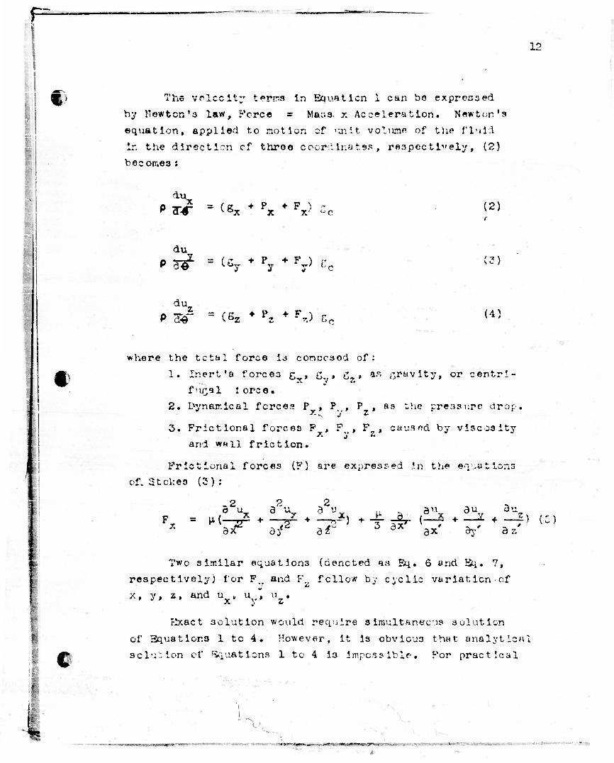
% The velocity terns In Equation i can bo expressed
by ITewtcn's law, Fcrce = Mass. x Acceleration. Newton's
equation, applied to notion of unit volumfl of the fluid
ir. the direction cf throe coordinates, respectively, (2)
beeorr.es :
lu. P TT^ = (g * P • P ) r (2)
du
V a-© ^*»y y y' (3)
du. «-~— = <- r • P *• F ^ P de Ctz * *s - - ,.; (4)
where the tctal force i3 concraod of:
1. Inert'a forces g , g , g , a.s gravity, or centri- x y z f ur;al 1 orce.
2. Lvynair.ical forces P , P. , P , aa the ;;re.ri3ure drop *• w, y z
3. Frictional forces P , F , F , caused by viscosity x and wall friction.
Frictional forces (F) are expressed in the equations
of. Stokes (3) :
2 a u^ ,2. 2 „ „ A u a u 3 u
af a? 3 dx ax' ay' az' ax
£
Two similar equations (denoted a.s Eq. 6 and Sq,. 7,
respectively) for P; and F_ fellow by cyclic variation of
x, y, z, and u , u .., u
Hxact solution would require alraultaneous solution
of Equations 1 to 4. However, it is obvious that analytical
solution of Equations 1 to 4 is impossible• For practical
v~ |QHHBMMMVt'*'T1'^M<'-'
*

13
:."
C purposes, considerable simplification of these equations can be attained without great loss of accuracy. Such simplifications, however, must include laminar flow.
Approximate Theoretical Squat ions. For the heat conduction equation, Equation 1, such simplifications include the assumption of :
1. Steady state unidirectional laminar flow. 2. Constant physical properties of the fluid in, c, p,
and k)• 3. Negligible conduction in the direction of flow,
i.e. in direction x. 4. Temperature independent of time. 5. Ccnstant duct wail temperature
Application of these assumptions give:
• -
x ** df* a*2 (£)
I
For the hydrodynamic equations, Equations 2 to 7, ?uch simplifications are:
1. P and F are negligible in the direction y and z, 2. Physical properties of fir id are constant with the
exception of the density in relation to g, the acceleration due to gravity.
3. Flo* is constant and unidirectional 4. Gravitational or centrifugal force lies in the x
direction only.
Application of these assumptions to Equations 2 to 7 give:
and
a • P ••• F aX X X = 0
= H( a2
3y T7r) (10)
, \
-

M .
14
Since P = --§-?, and x ax'
equation becomes:
*x 6^ •p, the hydrodynarr.ic
A « ST d U_ au
GC ay a^ (ID
t
Chances in density are manifest by a change in velo- cities due to expansion of the fluid and by ft change in the gravitational or1 centrifugal force on a unit volume. Since the former effect has been held constant and the lat- ter has been regarded as a function of temperature, we find that Equations 8 and 11 offer practically the furthest theoretical simplification of the actual case as stated under "Outline of the Problem*. Some additional simplification results i'or the case of flow through a cylindrical tube cr between flat parallel plates of Infinite extent. Buz, nevertheless, simultaneous analytical solution of Equations 8 and 11 does not appear possible.
For analytical solution of Equations 3 and 11, it is necessary to regard the density as constant also.
In this case then -|4L - 'T^-p = Prictional Pressure Drop.
3o aquation 11 can be expressed as:
" Friction
a~u
ay "
*2
(12)
C
Solution of Equation 12 for flew in cylindrical tubes or between fat parallel plates of infinite extent results in a parabolic velocity distribution (4)* Substitution of the parabolic velocity distribution in the heat con- duction equation, Equation 8, results in equations amerable to solution.
imm — - - act*
!!!• !•••• ' *"~ - -——
J 15
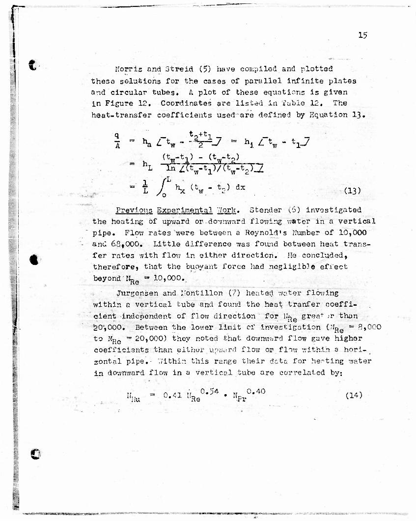
Norris and 3treid (5) have compiled and plotted these solutions for the cases of parallel infinite plates and circular tubes* A. plot of these equations is given in Figure 12. Coordinates are listed In Table 12. The heat-transfer coefficients used are defined by Equation 13.
* J - t2+tl - A
t
m h <yy VfrV; s j
" L Jf' S (tw - ?2> 4* . (13)
Previous Experimental V/orlc. Stencler (6) investigated the heating of upward or do-vnward flowing water in a vertical pipe. Flow rates were between a Reynold's Number of 10,000
'- and 63tOOO. Little difference was found between heat trans- fer rates with flow in either direction. He concluded, therefore, that the buoyant force had negligible effect beyond H^e «"? 10,000.
Jurgensen and I'ontillon (?) heated water flowing within a vertical tube and found the heat tranfer coeffi- cient independent of flow direction for lfe»,6 grea+ >r than 20',000. Between the lower limit of investigation (MRe =* 8*000 to NR *? 20,000) they noted that downward flow gave higher coefficients than either upward flow or flow within a hori-_ zontal pipe. V/ithin this range their data for he-ting water in downward flow in a vertical tube are correlated by:
IL 0.54 . „ 0.40 ~ 0.41 I.U "•<" • N "'+W (14) Nu ' "Re -Pr
£
&w:<cv^v*v«rew«"«VMMWt •BW*C«*mwn«*-«- ;VU«M«W«»»>.H,„ .»....,•.kju„rw*nitr.>t-*ft JBW - • •".* •••»• • ••,-.-
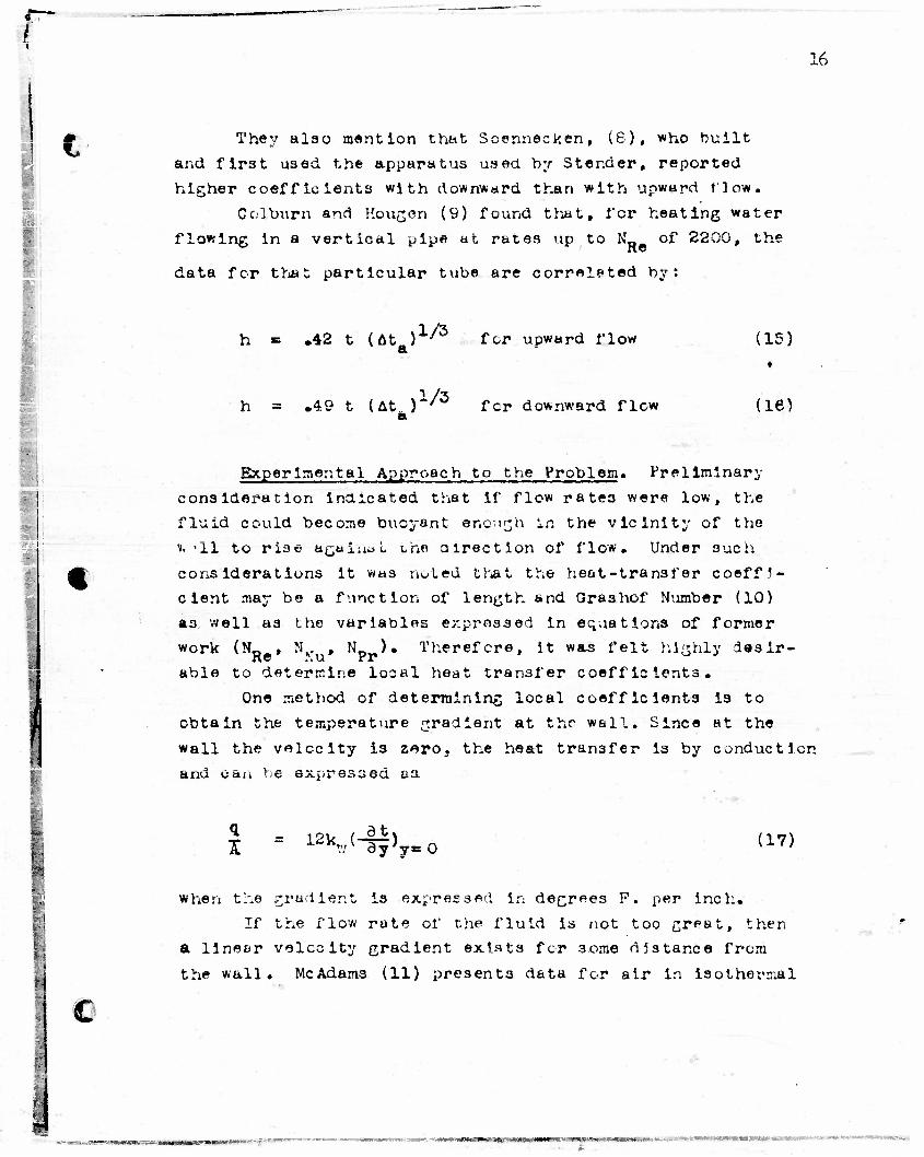
They also mention that Scennecken, (6), who built and first used the apparatus used by Stender, reported higher coefficients with downward than with upward flow.
Col/burn and Hougon (9) found that, for heating water flowing in a vertical pipe at rates up to N„ of 2200, the
data for that particular tube are correlated by:
16
h = .42 t (At )
h = .49 t (At. )
1/3
1/3
for upward flow
fcr downward flow
(15) •
(ie)
Experimental Approach to the Problem. Preliminary consideration inaicated that if flow rates were low, the fluid could become buoyant enough in the vicinity of the n. '11 to rise againol uhe direction of flow. Under such- cons lderations it was noted that the heat-transfer coeffi- cient may be a function of length and Grashof Number (10) a3 well as the variables expressed in equations of former work (NRe, NTu, N ). Therefore, it was felt highly desir- able to determine looal heat transfer coefficients.
One method of determining local coefficients is to obtain the temperature gradient at thr wall. Since at the wall the velocity is z^ro, the heat transfer is by conduction and can be expressed as.
1 - 12V-tf>y.O (17)
C
when the gradient is expressed In degrees F. per inch. If the flow rate of the fluid is not too great, then
a linear velocity gradient exists fcr some distance from the wall. McAdams (11) presents data for air in isothermal
- • ' www »iMLmu..)ii«miw"»'IPM *>•*•-• *.i
r .
i, a
«
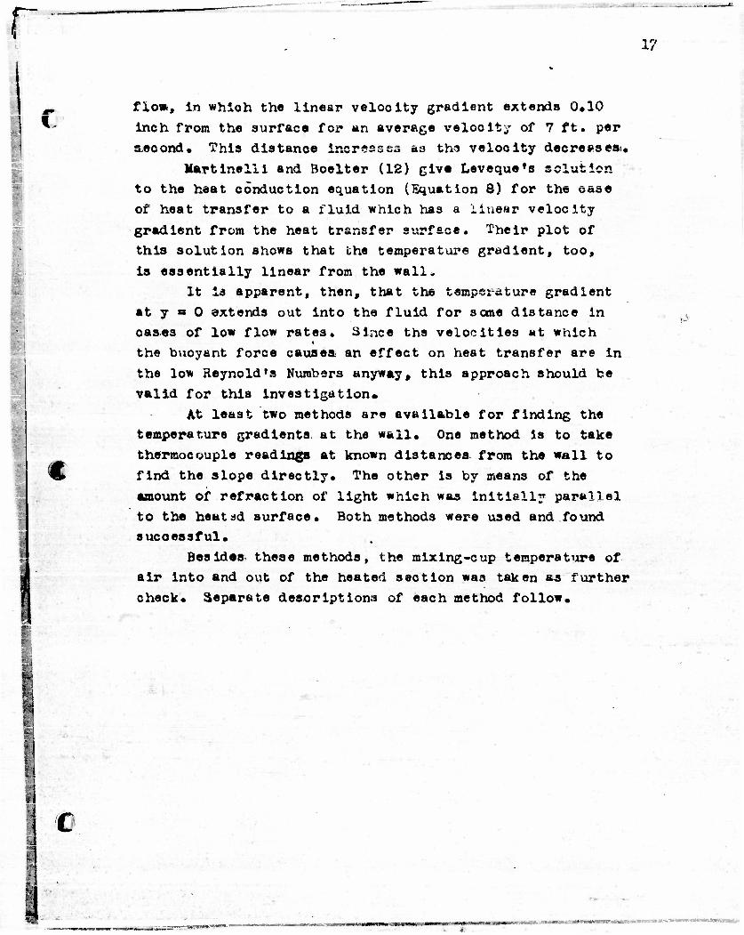
flow, in which the linear velooity gradient extends 0.10 inch from the surface for an average velocity of 7 ft. per s.econd. This distance increases as tha velooity decreesesi.
Martinelii and Boelter (12) give Leveque»s solution to the heat conduction equation (Equation 8) for the oa3e of heat transfer to a fluid which has a iiuear velocity gradient from the heat transfer svjrface. Their plot of this solution shows that the temperature gradient, too, • is essentially linear from the wall*
It i3 apparent, then, that the temperature gradient at y « 0 extends out into the fluid for some distance in oases of low flow rates. Since the velocities at which the buoyant force causea an effect on heat transfer are in the low Reynold's Numbers anyway, this approach should be valid for this investigation.
At least two methods are available for finding the temperature gradients at the wall. One method Is to take thermocouple readings at known distances from the wall to find the slope directly. The other is by means of the amount of refraction of light which was initially parallel to the heatad surface. Both methods were used and found successful.
Besides these methods, the mixing-cup temperature of air into and out of the heated section was taken as further check. Separate descriptions of each method follow.
j
a
€
*l C
•-•
1?

13
Heat Transfer from ITAvollap: Thermocouple Measurements
Ihe hot Junction of the traveling thermocouple la adjacent to air at one temperature and essentially surrounded by a heated duct at another* these tevperature differences can become appreciable, and the heat transferred to the wire by radiation will cause the wire to be at a higher temperature than the surrounding gas. Since the wire measures its own temperature, this error is introduced in gas temperature measurement.
The radiation error can be calculated by setting up a heat balance around the wire. Heat to the wire by radiation will be equal to heat leaving by convection if the wire is in an isothermal plane. Since the couple is inclosed by a virtual black body, we have:
eradiation • ^convection
0.173 Cl£««*^ - J^P)^ ) - VL^i~ " *«••> <18)
Original calculations were made for:
Tw » 1060 °R (600°F)
^ire* 66° ** t200^) a" • 0.8k. to* oxidised const ant an h^ • 60 (see Ref. 13)
and resulted in
t _, - t » 26 °P wire gas
; • •
! •
:»;' . . . . tsjasaaaamamssess*!u»wwpw
c i
19 i
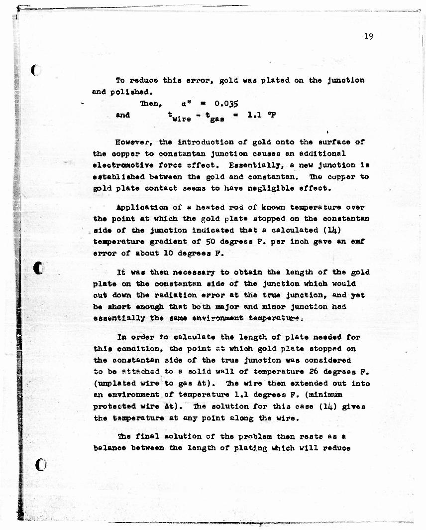
To reduce this error, gold was plated on the Junction
and polished.
Then, a" • 0.035
wxre gas
*
However, the Introduction of gold onto the surfaoe of
the copper to constantan junction causes an additional
electromotive force effect. Essentially, a new Junction Is
established between the gold and constantan. Oho copper to
gold plate contaot seems to have negligible effect.
Application of a heated rod of known temperature over
the point at which the gold plate stopped on the constantan
side of the junction indicated that a calculated (Uj.)
temperature gradient of $0 degrees F. per inch gave an emf
error of about 10 degrees P.
It was then necessary to obtain the length of the gold
plate on the constantan side of the junction which would
cut down the radiation error at the true junction, and yet
be short enough that both major and minor junction had
essentially the same environment temperature?
In order to calculate the length of plate needed for
this condition, the point at which gold plate stopped on
the constantan side of the true junction was considered
to be attached to a solid wall of temperature 26 degrees F.
(unplated wire to gas At), ihe wire then extended out into
an environment of temperature 1.1 degrees F. (minimum
protected wire At). Ihe solution for this case (li|) gives
the temperature at any point along the wire.
Ihe final solution of the problem then rests as a
balance between the length of plating which will reduoe
MMM9MMKS *•
u ». 1
20
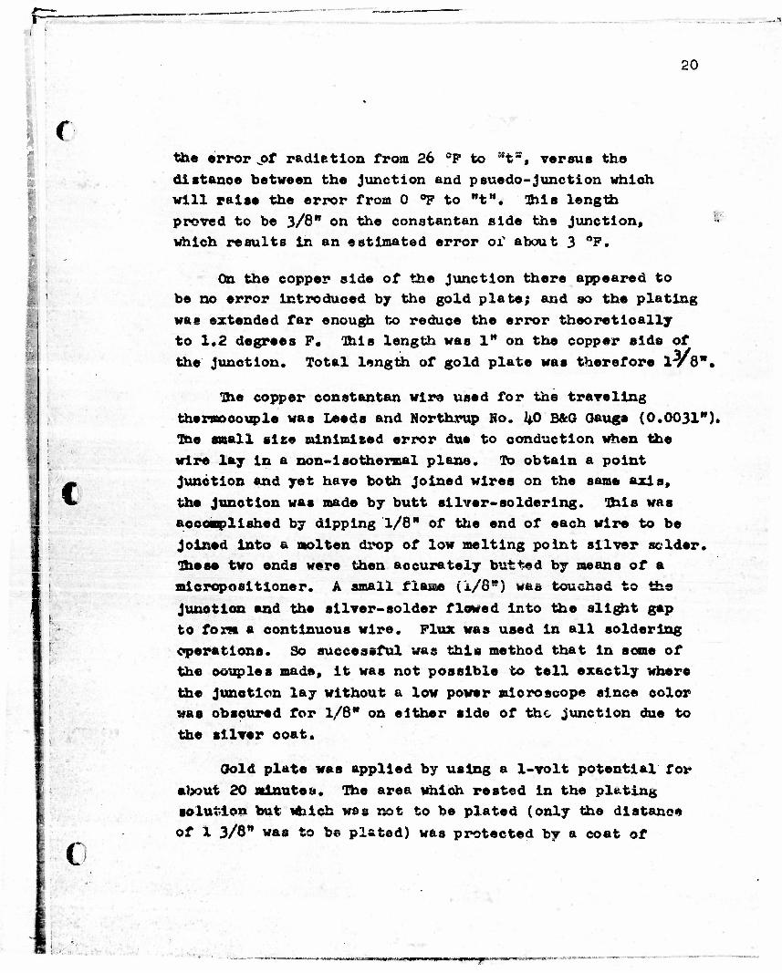
the error „of radietion from 26 °F to Mt°, versus the
distance between the junction and psuedo-junction which will raise the error from 0 °P to "t". !Ihls length
proved to be 3/8" on the constantan side the junction, which results in an estimated error or about 3 °P.
S
i
On the copper side of the junction there appeared to be no error introduced by the gold plate; and so the plating
was extended far enough to reduce the error theoretically to 1.2 degrees F. "Oils length was 1" on the copper side of
the junction. Total length of gold plate was therefore ly6",
3he copper constantan wire used for the traveling
thermocouple was Leeds and Northrup No. /j.0 BAG Gauge (0.0031").
T&e small else minimised error due to conduction when the
wire lay in a non-isothermal plane. To obtain a point junction and yet have both joined wires on the same axis,
the junction was made by butt silver-soldering. This was
accomplished by dipping 1/8" of the end of each wire to be
joined into a molten drop of low melting point silver solder. These two ends were then accurately butted by means of a
micropositloner. A small flaae (1/8") was touched to the
Junction and the silver-solder flowed into the slight gap
to font a continuous wire. Flux was used in all soldering
operations. So successful was this method that in some of the couples made, it was not possible to tell exactly where
the Junction lay without a low power microscope since color was obscured for 1/8" on either side of the junction due to
the silver ooat.
Gold plate was applied by using a 1-volt potential for
about 20 minutes. The area which rested in the pitting solution but which wss not to be plated (only the distance
of X 3/8" w«s to be plated) was protected by a coat of
:
>
i • •
• . • ' , * ••.... XVAWM1 ,. Mi —* '«ju^pnPMW irr

F=-
21
f Wonder-Lee stop-off lacquer.
Two different traveling thermocouples were used in~ the course of all runs. One had a small bead (estimated
thickness of O.OOii") which identified the junction. The
position of the junction of the other could be Identified
only because Its distance from the end of the gold plate
on the constantan side of the junction was known.
Slight differences In temperature between the two
heated plates or between opposite sides of the top calming
section ehlfted the calming sections slightly from vertical
parallel to the heating surfaces. If the traveling
thermocouple was flush with the heating surface at one set
of conditions, it was found that it might have been
displaced 0.020" in the next. Such variation made it
desirable to zero the traveling thermocouple before each
run.
Tb zero the thermocouple was not difficult. If the thermocouple wire was close to the heating surface and
light was dirsvjisd at a small angle to the heating surface, then the shadow of the wire on the surface as well as the
wire itself could be seen. It oan be shown geometrically
that the distance between the images as seen is twite the
actual distance from wire to plate. Under these conditions
the wire can bs located with reference to the surface* within
sereral thousandths of an inch.
In operation it was found that the wire, although
originally parallel to the surfaoe, would not neoessarily be parallel when the junction was moved vertically.
Fortunately, however, the junotion stayed a fixed distance
from the wall.
*»*^.n.M '*• | tm>" ....»-> .;
• .
22
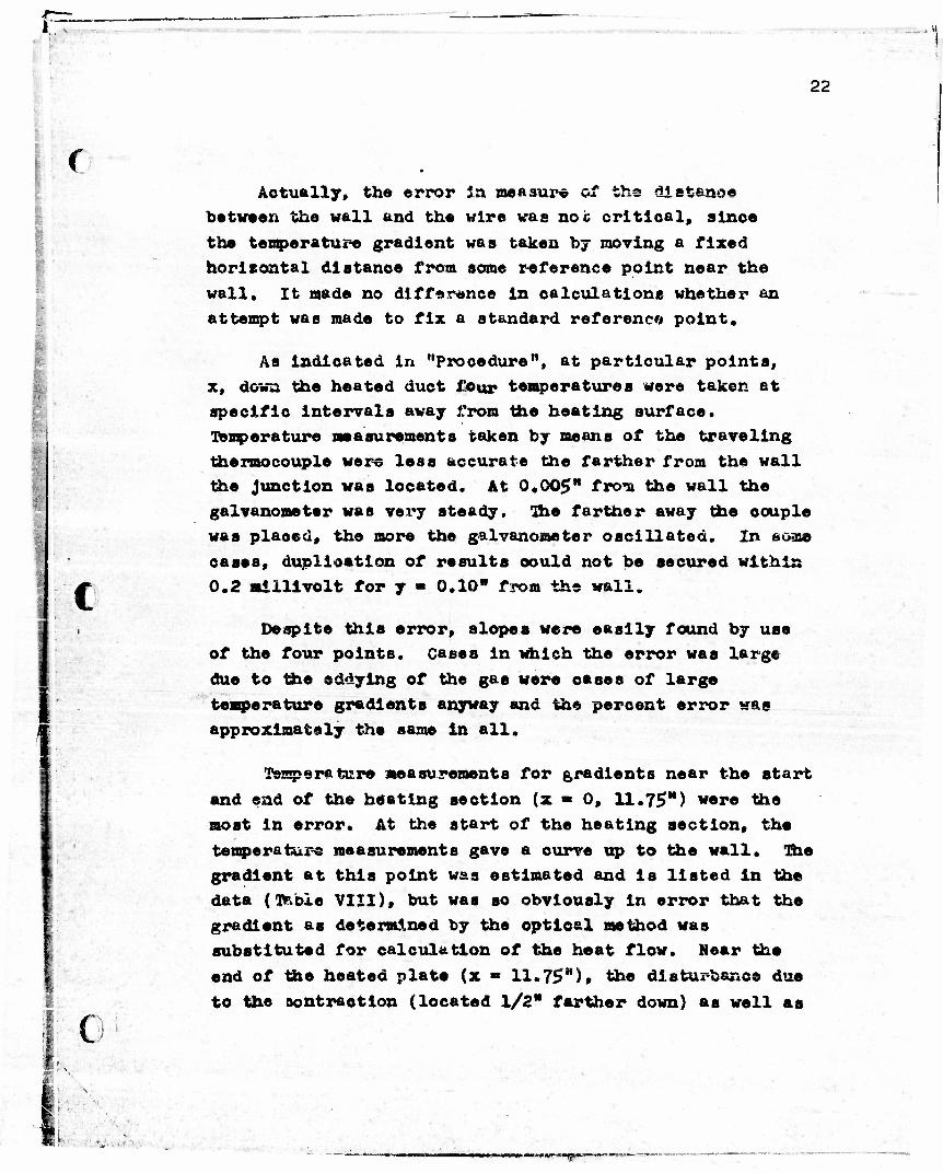
:' f Actually, the error in measure of ths distance
between the wall and the wire was not critical, since
the temperature gradient was taken by moving a fixed horizontal distance from some reference point near the
wall, it made no difference in calculations whether an
attempt was made to fix a standard reference point.
As indicated in "Procedure11, at particular points,
x, down the heated duct four temperatures were taken at specific intervals away from the heating surface. Temperature measurements taken by means of the traveling
thermocouple were less accurate the farther from the wall
the junction was located. At 0,005" from the wall the galvanometer was very steady. The farther away the couple was plaoed, the more the galvanometer oscillated. In acme
cases, duplication of results could not be secured within
0.2 millivolt for y » 0.10" from the wall.
Despite this error, slopes were easily found by use of the four points. Cases in which the error was large
due to the eddying of the gas were cases of large
temperature gradients anyway and the percent error was approximately the same in all.
I 0 i
I! s
j »
Temperature measurements for gradients near the start
and end of the heating section (x « 0, 11.75") were the
most in error. At the start of the heating section, the
temperature measurements gave a curve up to the wall. The gradient at this point was estimated and is listed in the
data (TRbxe VIII), but was so obviously in error that the gradient as determined by the optical method was
substituted for calculation of the heat flow. Near the
end of the hoated plate (x «* 11.75"), the disturbance due
to the contraction (located 1/2" farther down) as well as
- «-Tp~
"** • .
! .
:
! •
:
23
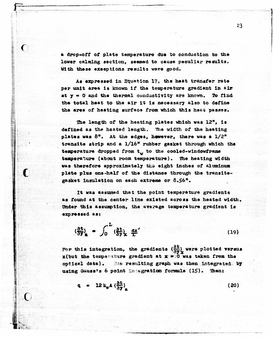
r a drop-off of plate temperature due to conduction to the lower calming section, seemed to cause peculiar results. With these exceptions results were good.
As expressed in Equation 17. the heat transfer rate per unit area is known if the temperature gradient in air at y « 0 and the thermal conductivity are known. ID find the total heat to the air it is necessary also to define the area of heating surface from which this hetit passes.
The length of the heating plates which was 12", is defined as the heated length. The width of the heating plates was 8". At the edges, hevever, there was a 1/2" transits strip and a 1/16" rubber gasket through which the temperature dropped from t to the cooled-windowframe temperature (about room temperature). The heating width was therefore approximately tha eight inches of aluminum plate plus one-half of the distance through the transite- gasket insulation on each extreme or 8.56".
It was assumed that the point temperature gradients as found at the center line existed across the heated width. Under ttxta assumption, the average temperature gradient is expressed as:
For this integration, the gradients (ir) were plotted versus x(but the temps-: afcure gradient at x •» 0 was taken from the optical data). ilae resulting graph was then integrated by using Gauss*s 6 point SJO, ':«^ration formula (15)* Then:
•
q m l2kyA(§&) (20)
. ,
24
I •
( where (fyL iB oxProssed ia Agrees per Inch. A in this
cast la 2 x 8.56 x 12.00/lkk% - 1.1*25 sq. ft.
rl
Values of- the temperaturea from which temperature
gradients were calculated, temperature gradients, and q^
calculated from theam gradienta, are listed In Tables
III, VIII, and X, respectively.
Heat Transfer from Visual Measurementa
Jakob (16) points out that If a heated, plate In air
has a oonatant temperature gradient from the surface for
a short distance, then the refraction of a grafting beam
of light over this surface can be used to measure the
temperature gradient. We have already noted, in the flow
range to be studied, that a linear temperature gradient
exi at a for some distance from the wall into the fluid.
The method then appears Ideal for the pres<vnt study.
Martineiii et al. (17) ©«tllna the mathematical
derivation of the equation for calculation of the
temperature gradient from amount of refraction:
dyxV
Y T " a w o.u&p Jb? •i cpt
(21)
where jJ is a correction factor whioh effectively replaces
T by an average temperature through which the light passes
in the course of refraction, and ia expressed by the
equation:
m <e>* w x**i8n opt
(22)
. • lajw—g— -
•
25
, The teat unit as described under "apparatus* comprised a flat duot with two parallel, opposite heating surfaces la
the elder sides, and glass windows as the narrower* With
two parallel plates, the obvious me hod of obtaining grazing
light is with parallel light. Figure 4 shows the equipment
arrangement to obtain parallel light*
• • •.
y> ,
Idealized operation of the test unit for visual purposes i« best noted by reference to the lower right hand view on
Figure 5* This view presents the test duct as if looking
down from above* Air is passing into the plane of the paper* Light which is originally grasing and parallel to the heated
surface la refracted from the heated surface* After leaving
the d«tct the light resumes a linear path, but with the de-
viation it had upon leaving the test unit* A screen la set
up beyond the test unit to intercept the refracted light* . The distance is measured between the point at which this light
falls upon the screen after passing by the heated plate# and
the point at which it falls if no heat is applied to the unit
(no deviation)* Slnoe the distance of the screen from the test unit is known, the temperature gradient througntwhloh ,
this grazing lighjb passes oan be oaioulated from aquation (21)*
The main graph of Figure 5 shows the amount of refraction
of tho light in relation t the temperature through whiqh it
Passes* The solid, arrow marked lines indicate light whioh
has Just l*»ft the test unit ("Bmergeno© of Light fptm Test Unit1*), after having paseed perpendicular to the dotted temp-
erature prof lie shown under the main diagram* '*•..'"•
:. '•!# <-$
.t- •-*'•',
1 A. "1 ' .V ',
•X
; *' »,v«; * •*•
f ' '-N. ,.•-• •,••>*
•a*
' '••>'.
v,.
k ••
W.r-
'^•<$
'#
i'&JC;
"'"?'; <---'i
'*:'-•• 4 •* . *
• - • • . fo^K*^ • '• "•• •
• /•#-,, • •
'•• • . >?\, ,
t , •. ..- *' * .•r ..
V »*rV--'S•••»',;••- >• V .n!'•,••''• .-.'f V
26
( The refraction of the light beam, su*h as beam AA,
which Just grazes tha heated surface is of Interest. Its
distance of refraction on the screen is measured from a
linear extension of the heated surface to the indicated
point, total distance of refraction is Ya. Note however-,
that beam BB which initially was parallel but not adjacent
to the heated surface was refracted even more than beam AA.
Ibis was caused by the fact that beam BB has passed through
the same temperature gradient, but at a lower absolute
temperature than team AA. Review of Equation 21 will show
that this condition is expected to give a larger refraction.
Beam CC, which is typical of light passing through the center of the duct, is refracted little because of the low temperature gradient. These beams form a bright center line
on the screen.
C Example of these patterns of refraction can be noted by
reference to Figure 6, Run E-k» •
If the screen is brought to within 2 to 5 feet of the
test unit, the convergence of rays BB and CC indicate
closely the point of actual penetration of heat to the gas.
In some oases also it is a measure of a laminar film. In
all oases, the refraction is so slight at this distance,
that the image as seen gives essentially the actual distance
between heated films. Figure 6 shows rull sise pictures of
such K#lose-up" for the upper and lower section of the test
unit*
Due to the lack of linear length beyond the test unit.
It was necessary to install two plane front-surf ace mirrors.
Since the standard front-surface mirrors are not optloally
plane, it was necessary to correct for deviations*
( * •
•
|i _. • _ • •' I, -"•••-••j'itt.,- » wrrrr -
I
27
(
Alter exhaustlye tests, It was found that horizontal deviations were negligible. Vertical deviations, however,
resulted in a l/k" contraction of the image. Correction of this problem rested on placement of a "ladder" in front
of the test unit window. This ladder had rungs which cut
cff the entering light at known intervals down the heated
length. The resulting photographs then had these markings
which located' exactly where the light had come from. This procedure also helped correct for vertical refraction.
In some cases, it was desirable to put * stop in the
light path to cut out all of the light which would other-
wise have passed through the center of the duct, (such beams as CC In Figure 5)• Only a vertical slab of light
0.07" thick and adjacent to each heated surface was permitted to pass across the duct. Figure 7 shows photo-
graphs taken with and without the stop.
As noted In the section headed "Apparatus", it was
necessary to move the test unit up and down since the unit was greater in vertical length than the height of the
optical path; the parabolic mirror was only 8" in diameter whereas the length of the test unit used for pictures was
from x « 0 to 11.75. Therefor©, it was necessary to readjust the position of the unit for each run. and to
realign the heating surfaces parallel to the parallel
light. However, such alignment was not difficult. If
parallel light was passing between the two polished
parallel plates in the test unit, and the plates were turned slightly, then some light would strike one of the
plates and be refleoted. If a screen was set up about 3* from the exit of the IIght rays from the test unit, a
sharp line was found to be superimposed upon the usual
•• • ... .i

(
f
I
29
light through the unit. This line approached coincidence
with the boundary of light only when the plates approached
being parallel with this parallel light. If the unit was
twisted past the point of being parallel, then the same
phenomena occurred although propagated from the opposite
plate* In short, alignment at the point at which no
reflected lines appeared on the screen was assurance of
the parallel nature of both light and plates. Addition
of heat, which refracted the light causing slightly non-
parallel beams, caused no apparent effect on this procedure.
As already brought out, the measurement of the
deflection of the refracted beam of light which grazes the
heating surface (Beam AA in Figure 5) is necessary to find
the temperature gradient. As can be seen by reference to
Figure k or 5» the grafting beam starts from one side,
crosses the horizontal oenterline and appears on the screen.
The distanoe deviated (Y8) then is:
M
Y * Distanoe between Inner boundaries on screen"• 12D (23) 2
where, in this flit, D = 1.01/12 feet.
The wall temperature of the heated plate was oonstant
across the aluminum plate but dropped off linearly through
the transite-gasket strip to the window frame. As discussed
previously, one-'ialf of the thickness of the strip on either
side is considered to be a part of cae heating section.
Equation 21, however, contains an absolute wall temperature
term. It therefore becomes necessary to correct for the
faot that over this section a different (dt/dy) and T
exist.
3vo assumptions are made:
1. That the average temperature (Tj ) of the transite-
•
•
29
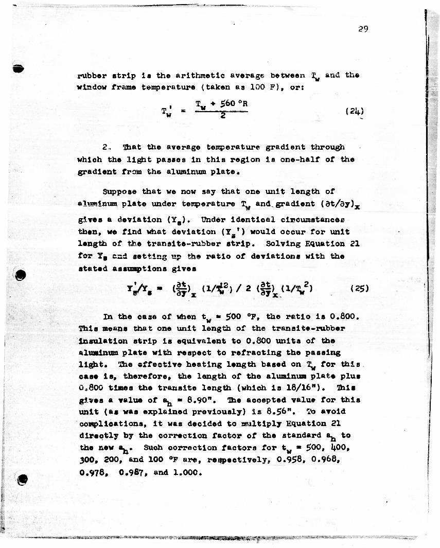
rubber strip ia the arithmetic average between T^ and the window frame temperature (taken as 100 F), or:
Tj = -H g (21+)
2. Ohat the average temperature gradient through which the light passes in this region is one-half of the gradient from thG aluminum plate.
Suppose that we now say that one unit length of elvminura plate under temperature Tw and. gradient (dt/dy)x
gives a deviation (Yfl). Under identical circumstances then, we find what deviation (Y ') would occur for unit length of tiie transits-rubber strip. Solving Equation 21
for Y8 end setting up the ratio of deviations with the
mk stated assumptions gives
TA - (H>X (i/,t2>/ 2 (Hku/^2) (25)
In the ease of when tw » 500 °F, the ratio is 0.800. This means that one unit length of the transits-rubber
Insulation strip is equivalent to 0.800 units of the aluminum plate with respect to refracting the passing light* The effective heating length bassd on T^ for this cess is, therefore, the length of the aluminum plate plus 0,800 times the transits length (which is 18/16"). This gives a value of a^ » 8.90". The accepted value for this unit (as was explained previously) is 8.56". To avoid complications, it was dscided to multiply Equation 21 directly by the correction factor of the standard a^ to the new a. . Such correction factors for tv * 500, 1+00, 300, 200, and 100 °F are, respectively. 0.958, 0.966,
0.978* 0.987, and 1.000.
•• Jh u, «*o^»^*»»ww»<»s«r*«!>*.->** iiuwraaw in»-> *.T-**^-*isawisj,'»»t<5^i#i^9ki«-)_~' .
30
m
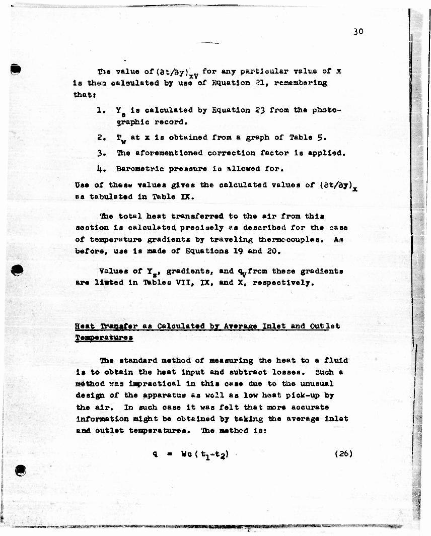
Bie value of (dt/3y) v ror any particular value of x is the;a calculated by uao of Equation 21, remembering
thatt
1. Y is calculated by Equation 23 from the photo-
graphic record.
2. T at x is obtained from a graph of Table 5*
3* The aforementioned correction factor is applied.
k» Barometric pressure is allowed for*
Use of these values gives the calculated values of (dt/dy), 4
as tabulated in Table IX.
The total heat transferred to the air from this section is calculated precisely es described for the case of temperature gradients by traveling the mo couples. Ail before, use is made of Equations 19 and 20.
Values of Y , gradients, and q.frcm these gradients are listed in Tables VII, IX, and X, respectively.
Heat Transfer as Calculated by Average Inlet and Outlet Temperatures
The standard method of measuring the heat to a fluid is to obtain the heat input and subtract losses. Such a method was impractical in this oase due to the unusual design of the apparatus as well as low heat pick-up by the air. In such oase it was felt that more accurate Information might be obtained by taking the average inlet and outlet temperatures. The method Is:
q • WoC^-t^) (26) II
•
. irr-n i IIII rrn- m>rr - r i<iinrii~fmUiwm-tmrit'm')ir:m»itSti0K flrv"rTf»iiryMVi •' -ft--"' • ""-•- www ' "fm^m°^rmtm$w

•• .
31
She flow rate ranged up to £ aaxlafeaa Reynold* number of J|900. under these conditions the velocity profile at the start of the heated section was very closely parabolic (18). With the temperature profile also at the start of the heating section, it was possible to find the average temperature (t,) at 2 * o, based on the assumption that there was a two dimensional Telocity and temperature field.
Die average velocity is given by the equation:
*aT« *'/ S (PoVV (27)
and the point velooity is given by
(28)
The point density is related to the main body density by the equation
(29)
(30)
P * Po T0 / T
and the mass flow rate is given by
W • a f updy' ->0
where D is In reet. ,
Equation 27 Is substituted into Equation 28. Equations
28 and 29 *re substituted into Equation 30. Solution TQT
the average temperature (T,) gives
D lAa - r~ f (Dr'-y*) d// T (3D
..
. -
I
... «!•->—i*.:&;--i:"*-*— ' ="^«MiMRW««*S*aW«S«.'S l^)Mg«MMM4RNMMRINKll 2
SSSW'
m
32
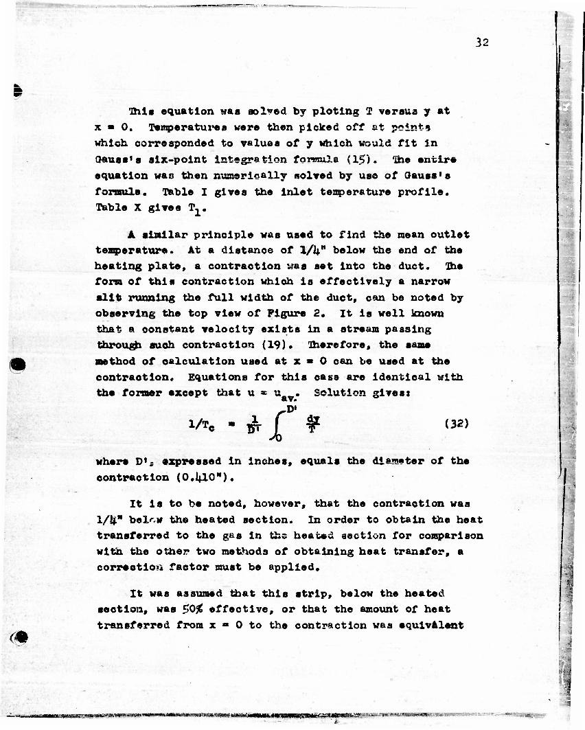
This equation was solved by plotlng T versus y at
x » 0. Tempera tux's a were then picked off at points
which corresponded to values of y which would fit in
3auss*s six-point integration forwula (15)• 'Ihe entire
equation was then numerically solved by use of Gauss's
formula. Table I gives the inlet temperature profile* Table X gives T^.
A similar principle was used to find the mean outlet temperature. At a distance of 1/1+w below the end of the
heating plate, a contraction was set into the duct, Dhe form of this contraction which is effectively a narrow
slit running the full width of the duct, can be noted by
observing the top view of Figure 2. It is well known
that a constant velocity exists in a stream passing
through such contraction (19). Therefore, the same
method of calculation used at x * 0 can be used at the
contraction^ Equations for this oass are identical with the former except that u * u._. Solution gives:
1/Te - ^r f ¥ (32) H * where D»; expressed in inches, equals the diameter of the
contraction (O.I4.IO").
It is to be noted, however, that the contraction was
l/k" belr,w the heated section. In order to obtain the heat transferred to the gas in the heated section for comparison
with the other two methods of obtaining heat transfer, a correction factor must be applied.
It was assumed that this strip, below the heated
section, was $0% effective, or that the amount of heat transferred from x • 0 to the contraction was equivalent
iu in • in HI 11 1» ii«iMiiMiiii*iijiwiiiiirrT*iir,,r*iiT*r"'~' ' ••'-*»-•»-•«•*——IT1—«—••»
1

33
to the amount transferred if the heating plate had been 12-1/8" long. Ihereforo:
12 "« Wfi W° < V*o> (33)
m
The flow rate was roetered by means of sharp edge orlfioes which had been calibrated with calibrated gasometer. Orifice coefficients were as expected. Calibration error was estimated to be 1%, but, due zo slight variations in the input voltage to the blower, usage error was advanced to 2%.
Ihe specific heat at constant pressure was taken as 0.240 plus .003 correction for humidity.
The values of q. calculated from the mean temperature change are listed in Table X.
Consideration of Data for Analysis
In geometrical configuration, the test unit is a narrow rectangular duct. Nevertheless, it cannot be considered to be a true heated duct, since only two of the sides are heated. In a case such as this, it can be assumed that the two parallel heated plates are a slice cut from the classical case of air flowing between two heated planes of infinite extent.
We will choose the breadth of the section out from the infinite plates as equal to the heated breadth (a. ) of the unit. Formerly, then, the cross sectional area was 9.75" % 1.01", now an imaginary piece has been takes*
- 11 mtw<±vLMmm>uT*saf&fm'£*i»x*#»<'»*!'* t'OWMi»«utr^>MMIaWII* »
34
I
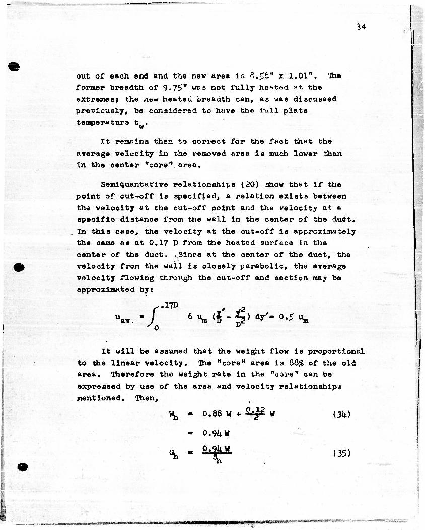
out of each end and the new urea it 8.56" x 1.01". The
former breadth of 9.75" was not fully heated at the extremes; the new heated breadth can, as was discussed
previously, be considered to have the full plate
temperature t .
It remains then to correct for the fact that the
average velocity in the removed area is much lower than in the center "core" area.
Semiquantatlve relationships (20) show that if the
point of cut-off is specified, a relation exists between
the velocity at the cut-off point and the velocity at a specific distance from the wall in the center of the duct. In this case, the velocity at the cut-off is approximately the seme as at 0.17 D from the heated surface in the
center of the duct, .Since at the center of the duct, the
velocity from the wall is closely parabolic, the average
velocity flowing through the cut-off end section may be
approximated by:
.17D u av. I %( ?'- *5> <»' 0.5 %
It will be assumed that the weight flow is proportional
to the linear velocity. The "core" area is 88# of the old area. Therefore the weight rate in the "core" can be
expressed by use of the area and velocity relationships
mentioned. Then,
0.88 W + £4£ w
•
*h
°h
o.skv
*
(3k)
(35)
mnwtMK£Hw»
•
. — _-.. . . .
35
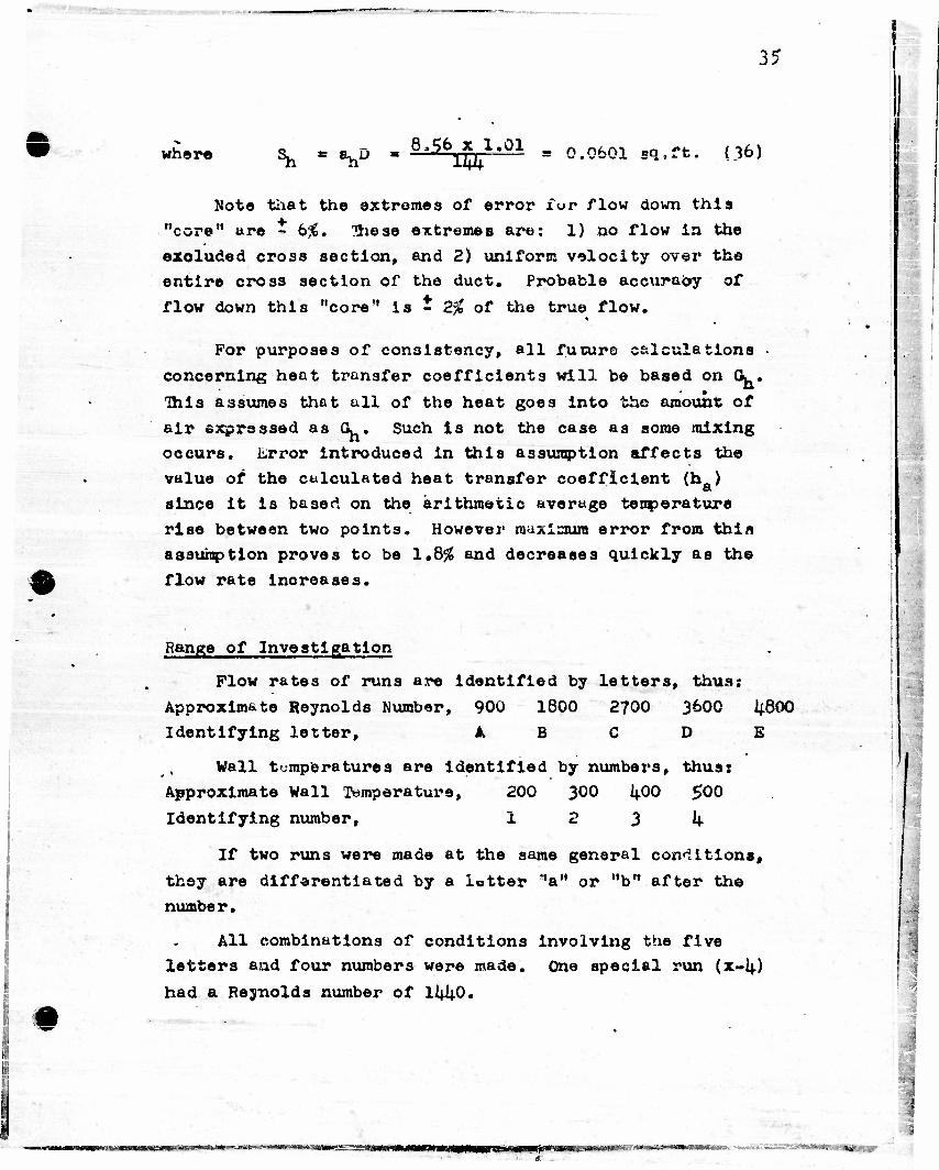
where ^ = V* * 8'*feur1,01 = 0.0601 sq,ft. (36)
Note that the extremes of error ivr flow down this
"core" are - 6$. These extremes are: 1) no flow in the
excluded cross section, and 2) uniform velocity over the
entire cross section of the duct. Probable accuracy of
flow down this "core" is - 2# of the true flow.
For purposes of consistency, all future calculations •
concerning heat transfer coefficients will be based on Q. .
This assumes that all of the heat goes into the amount of
air expressed as G. . Such is not the case as some mixing
occurs. Lrror Introduced in this assumption affects the
value of the calculated heat transfer coefficient (h_) fit
since it is based on the arithmetic average tenperature rise between two points. However maximum error from thin assumption proves to be 1.8$ and decreases quickly as the flow rate increases.
Range of Investigation
Flow rates of runs are identified by letters, thus: Approximate Reynolds Number, 900 1800 2700 3600 i|800 Identifying letter, ABODE
Wall temperatures are identified by numbers, thus: Approximate Wall Temperature, 200 300 lj.00 500 Identifying number, 1 2 3 h
If two runs were made at the same general conditions, they are differentiated by a letter "a" or "b" after the number.
All combinations of conditions involving the five letters and four numbers were made. One special run (X-I4.) had a Reynolds number of 11+40.
•
'-««*«T««»<<l«»WJi^i«nMia«<4iOMB««S=',,»«^
36
RESULTS
Comparison of the Three Methods
The optical method of determining temperature
gradients in the air adjacent to the wall agrees very
well with thermocouple measurements. Based on the total heat transfer from the heated section as calculated by
temperature gradients, Equation 20, q. was found to agree with <j within an absolute error of 3.8% and an average error of l.l£. Despite the good agreement, optical
measurements were found to be more consistent.
The heat to the section as calculated from the air
Inlet and outlet mean temperatures, Equation 33» gave an
absolute difference of 21,$% and an average of +7.0£ from q^; Results obtained from the inlet and outlet air
temperatures were not consistent. For instance in runs
C-lf, D-k> &~'d E-k» optical pictures showed the usual pattern for forced flow with no apparent buoyant effects;
nevertheless, as the flow rate Increased in these runs
q. decreased. This is contrary to all previous evidence.
Due then to the greater consistency and more likely
accuracy, it was decided to use q * q for all future
calculations.
Mechanism Analysis
Variation in the local heat transfer as the flow rate
decreases (E to A) can be noted by reference to Figures 10
and 11. These plot variation In temperature gradients
(which are proportional to q/a) versus x for a particular wall temperature (500 °F). The D and E runs follow the
M^ftAiawIwi iiiiiuiM.il iMMMn.i.iwiMiiimiiiiii—iiwiiiw'W^—MIHIMJUHI'II " (Win •.^w.,T-:^yrtfc^»--*w«-w---- ""'TO.1.!1'
37
»
•
expected variation in that q/A decreases approximately
by (1/x) '* (noto Figure 15). As the flow velocity
decreased, however, a "hump" appeared in the curve. The
exact description of this phenomena can be boat Illustrated
by reference to Run X-I4..
A plot of the approximate theoretical variation of the
heat transfer coefficient with the actual local coefficient
In Run X-k is given In Figure 11;. With the entering Reynolds
number at IkkO the flow was essentially laminar. As the gas
passed into th<* heated section, heat flowed from the wall
into the gas In accordance with Equation 8. With the low
flow rate, the gas near the wall became buoyant and its
velocity became slower than isothermal flow calculations
would indicate. This stagnation of flow near the wall
caused a decrease of the heat transfer below what would be
expected.
Before the gas near the wall flowed much farther, it*
density-change was sufficient to cause upward flow at the
*fail. Such upward flow created a semi-turbulent condition.
The heated layers near the wall are thrown into the core
of the gas stream. This, therefore, effectively brought the
core temperature much nearer to the wall and a sharper
temperature drop occurred per unit distance from the wall.
As can be seen,a sharp increase In the heat transfer resulted. * *
The semi-turbulent condition and rapid heat transfer
rate raised the core temperature quickly. Since the buoyant
effect depended upon the density difference between the core
and the gas adjacent to the wall, a decrease in the velocity
of the gas near the wall resulted. This stagnation again
reduced the heat transfer. At some point then the
temperature of the core had become close enough to that of
the wall so that the flow shear again reverted the wall film
to downward flow. Run k-k$ Figure 10 shows the beginning of this condition.
• II
1
••
—w»——X BB«IB>MBWg»—WrWfcgWI—I—M TTWTttt-f III I , ,M».«..«i«m»rai.— « " '•"'•'•"'-iHr'it

;Jar<w»i
38
>
Reference to Figure 9 shows th* temperature profiles
at different values of x In Run X-i*. At x « 1" and V i*
is obvious that laminar flow was still controlling the heat
flew. By x • 7* it can be seen that the semi-turbulent condition oaused by upward flow at the walls had greatly
increased the oore temperature and the temperature gradient at the wall. Further evidence of this phenomena can be
noted by attention to Figure 8.
As discussed previously, Figure 8 shows ' ,«: ntially
the exact boundary of the heated film. Note that che upward flowing film seems to tear off into the main oore.
ibis variation of the film thlokneas causes fluctuations in the local heat transfer eoeffioient with time. Hote the
wariness of the outer boundary of light. Xhis light had
passed adjacent to the heated surface. Indentations
indicate where the temperature gradient was momentarily
steeper. Variations in gradient with time made it necessary
to average a number of photographs! however, variation
between views was not excessive as can be noted by observing
Figure 7.
It is of interest to note that even under these turbulent conditions the gradient was approximately a
straight line to y • .1". Maximum deviation (Run E-k.) of initially gracing light was 0.05" from the heated surface
when leaving the unit.
If the Runs A-l, A-2, A«3» and A-lj. are examined they
are found to increase in temperature and to have approximately equal Reynolds numbers. Ihe buoyant oounterflow is seen to
become more apparent as the temperature increases. Increase
in temperature or decrease in flow rate thus are, as expected,
variables which increase the tendency for the upward flow.
M
•IIMW *»icn.'.iw.-ra*****'- * »M8aM»m«m« xa:

39
9
«
Comparison and Analysis
Norria and Streid^' have collected and plotted
some of the complex analytical solutions for heat transfer
to a fluid flowing in steady state laminar flow. These
equations assume constant physical properties and constant wall temperature. A plot of tnese equations is given in
Figure 12. Coordinates are tabulated in Table XII. Heat
transfer coefficients as expressed in these aquations are
defined by Equation 13.
Using q over the 12 inoh long heated section (Table Xi
we found the temperature rise of the air flow 0. from t, to
tp. Combining D , Equation -13* and 20 , we obtained the
average Nusselt number (notice that for infinite plates
Dtt =* 2b).
The data are plotted against the coordinates of
Figure 12. The line for the average Nusselt number for
flat ducts (infinite plates) from Figure 12 is also plotted on the same graph. .These results are presented in Figure 13.
Since 1^ does not vary much with air, the decrease of the function 0 is largely due to the drop of G^ in value.
It is notioed then that as Gv decreases, the data fall under the theoretical curve. Jhis could be caused by tvo effects:
1. The resulting slowing down of the film due to the increased buoyant effect on the slower fluid.
2. Emergence from the lower transition into the fully laminar region of flow. No mattor which effect predominates,
the data are no less than 2$% under the theoretloal equation.
As soon as the flow rate becomes low enough to cause a
reversal of flow near the we.ll, the Nusselt number climbs
again to values over the theoretical. However, when the
buoyant forces are of the saron order of magnitude as the forced flow forces (as the data are), the upward flow will
again approach the theoretical- !
vmma) m HniHBKsi ••ft m—mmm
1
40
I
Therfore In the fange investigated, it oth bo said that the average Nuaselt tfuinber will be within ±25% of the values predicted by the plfcts.•offF'igpra 12*
**... 1 »$?, •• i
1 •• •. »*
it ' . * " v
1 !»/-• Lf fc, • •. • - - •• yv •* "' ' 4 *
if' ' y- .' • ' W" '>.'«• . p "~— * j '» '
j»>' tv '
m • • •:..-.:" • '
g . . .' ,
& -*';' '• • ¥ •' '*•
# %4;-'
*}* *• x' *** h
'A:**- '
,"•** . <
•:,<.-.•• .' :
.,-1. t \j, 'v 1 *?*•"
:v*fe •'. ••)
In the oaee of small L/D ratios aa say 1*5 in Bun X-4*
(Pig. 14) suoh statements may not b« true; however suoh a
small L/t> would rarely be found.
In the range in which the buoyant foroe is much greater
than the forced flow forces, it appears that the Nuaaelt
number would approach values given by heat transfer to a
oooler fluid in a vertical tube, the lower end of whioh is
closed.
>»;'
.:•"
•V - ,
>. i-i; '.• •
• l-'A.
, - . -'(, - :• • w ' ; .
T c :. • - •• '*-V • •'..«.• ;
^w'-
•v..it
MS--»•• ,
{0V ;,^"'
-1.
S.V; hM,
'>- ,••••
; • • J 'f
•i • v
•,!,'
_.. - i ii nn'-i 1 i II Itl-tfcj, j
€^_
. 41
%
BIBLIOGRAPHY
m
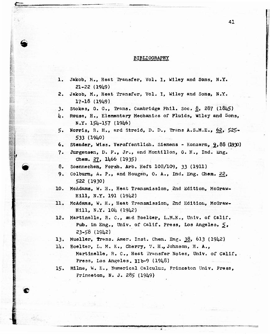
1. Jakob, M., Heat Transfer, Vol. I, Wiley and Sons, N.Y.
21-22 (19^9) 2. Jakob, M., Heat Transfer, Vol. I, Wiley and Sons, N.Y.
17-18 (19i+9) 3. Stokes, G. G., Trans. Cambridge Phil. Soc. 8, 287 (l81i-5) If. Rouse, H., Elementary Mechanics of Fluids, Wiley and Sons,
N.Y. 151+-157 (191*6) 5. Norris, R. H., and Streid, D. D., Trans A.S.MoE., 62, 525-
533 (191+0) 6. Stender, Wiss. Veroffentlich. Siemens - Konzern, 9.,88 (1930)
7. Jurgensen, D. F., Jr., and Montillon, G. H., Ind. Eng.
Chem. 22, 11*66 (1935)
8. Soennechen, Forsh. Arb. Heft 108/109, 33 (1911) 9. Colbumi A. P., and Hougen, 0. A., Ind. Eng. Chem. 22,
522 (1930) 10. McAdaras, W. H., Heat Transmission, 2nd Edition, McGraw-
Hill, N.Y. 191 (19U2)
11. McAdams, W. H., Heat Transmission, 2nd Edition, McGraw- Hill, N.Y. 10U (191+2)
12. Martinelle, R. C, aid Eoelfcer, L.M.K., Univ. of Calif. Pub. in Eng., Univ. of Calif. Press, Los Angeles. £,
23-58 (19^2) 13. Mueller, Trans. Amer. Inst. Chem. Eng. ^Q, 613 (191+2) ll|.. Boelter, L. M. K., Cherry, V. H., Johnson, H. A.,
Martinelle, R. C, Hoat Transfer Notes, Univ. of Calif. Press, Los Angeles. Hb-9 (191+8)
15. Milne, W. E., Numerical Calculus, Princeton Univ. Press,
Princeton, N. J. 285 (191+9)
C
.
minnHm-smsxam • • » n—li

C=.
42
*
16.
17.
13.
19. 20.
Jakob, M., Heat Transfer, Vol, I., Wiley and Sons, N.Y.
568-577 (19U9) Bcelter, L. M. K,, Cherry, V. H,( Johnson, H, A.,
Martinelle, R. C, Heat Transfer Notes, Univ. of Calif.
Press, Los nngeles. XII 21 - 28 (19^8) Goldstein, S., Modern Development in Fluid Dynamics, Vol.
I, The Clarendon Press, Oxford. 310 (1938) Powell, Mechanics of Liquids, MacMillen, N. Y. 123 (1940)
Rouse, H., Elementary Mechanics of Fluids, Wiley and Sons,
N.Y. 215 (191*6)
m
—n» BW
43
NOKSNCfLAXURE
m
A
a
ah b C
crt o c D
°P
P
g,
ha
h,
h. x
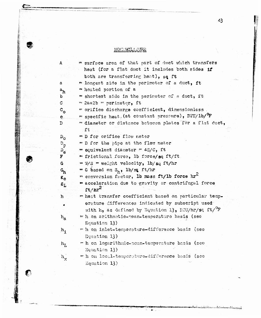
*• surface area of that part of duct which transfers heat (for a flat duct it includes both sides if both are transferring heat), sq ft
"= longest side in the perimeter of a duct, ft •* heated portion of a = shortest side in the perimeter of « duct, ft *• 2a+2b «• porln:etQr, ft ~ orifice discharge coefficient, dimensionless • specific heat.(at constant pressure), BTU/lb/°F — diameter or distance between plates for a flat duct,
ft *" D for orifice flow meter ~ D for the pipe at the flow meter "• equivelent diameter ~ 4S/C, ft *• frictional force, lb force/sq ft/ft » W/S • weight velocity, lb/sq ft/hr - G based on 3h, lb/sq ft/hr •• conversion f.ictor, lb mass ft/lb force hr «• acceleration due to gravity or centrifugal force
ft/hr2
*=* heat transfer coefficient bssed on particular temp- erature differences indicated by subscript used with h, as defined by Equation 13, BTU/hr/sq ft/°F
- h on arithmetic-mean-temperature basis (see Equation 13)
— h on inlet-teir.perattire-difference basis (see Equation 13)
~ h on logarithuic-ncnn-te.mper^ture basis (see Equation 13)
•* h on local~tetnpe.rature-diff erence basis (sec Equation 13)
©
" -"••' •>••-" • -..-.
s e
r>.
"Sr
L
Jopt
N. N Pr Re
N, Rec
Nne3
MKu P £
P
V
u
*h
44
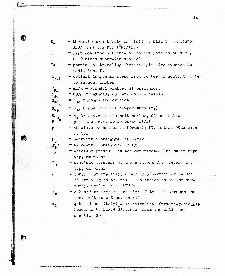
thermal conductivity of fluid at wall tei -orotu^e. BTU/ (hr) (so ft) (°F)/(ft) distance from enU-ance of heated portion of duct*
ft (unless otherwise stated)
portion of traveling thermocouple wire exposed to
radiation, ft optical length measured from center of heating plate
to screen, inches
om/k •» Prandtl number, dimensionless
GD/yU " Reynolds number, dimensionless
No through the orifice
- 14- Re based on Inlet, temperature (t-,)
h D/k, ever..-? 1,'usselt number, dimensionless
pressure drop, lb force/s- ft/ft
absolute pressure, lb force's.; ft, unl: ss otherwise
staled barometric pressure, cm water
barometric pressure, mm Hg absolute : ressure at the downstream flow me^er pine tap, cm water absolute -ressure at the upstream id ov: meter ripe tap, cm water total heat transfer, based on a particular method of arriving at the result as indicated by the sub- script used with *;, £;.TU/hr q based on temper; ture rise of the air through the test unit (see Equation 33) q based on "dt/3y)ar-, as calculated from thermocouple readings at fixed distances from the wall (see Equation 20)
ye:-; WpBUBi »>• wwmpm

oww
45 9
I
e
s
T
t t m
rf-t. ft u
u_
Wi
q based on (dt/dy)ay as calculated from visual measurements (see Equation 20)
heat energy developed in unit volume and time,
BTU/hr/cu ft cross sectional area for fluid flow, sq ft S for the area a, b, sq ft
absolute temperature designation of t, deg R
fluid temperature, dog F traverse mean (mixing cup) temperature of the fluid, deg F
t at entrance of heated portion of duct, (x=T0, (see Equation 31)
t at any distance (x) dovm heated portion of m duct
t at contraction (sec Equation 32)
refercr.ee fluid temperature, or average temper-
ature at the flow meter, deg F wall temperature, deg F
tw - (t1+t2)/2, deg F velocity, ft/hr
u avcrr.ee for the entire cross section of duct \\ in x direction
U in y dI root ion
U in z direction total macs flow rate of r^^id, lb/hr
W through the "core" cros.s section (a/b) (see
Equation 3^)
a;cial distance from the entrance of heated portion of duct, inches
x in dimensions of feet
measured screen deviation of refracted light,
inches (see ?i.rure 5)
©
yrvrjrwmn 4t-mmi%sH*?£*jm~mt: «••»<•. a WBWtW»T*qMMM*»Mf»
46
€
*
©
y z
2'
a
a« '
P
(•2t) ay
oy •
<f§>
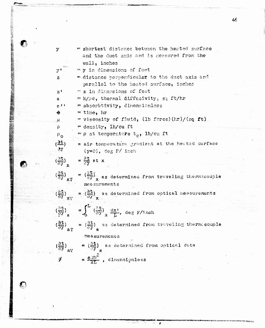
- shortest distance betvjeen the heated surface
and the duct axis and is measured fron i'.he
wall» inches
~ y in dimensions of feet
•= distance ncrperdicular to the duct axis and
parallel to the heated snrface, inchcc
- z in dinensions of feot
- k/pc, thermal diffusivity, sq ft/hr
~ absorbtivity, dimensionless = time, hr -viscosity of fluid, (lb force) (hr)/(sq ft)
" density, lb/cu ft
-p at temperature t0, lb/cu ft
= air temperature gradient at the he; tod surface
(y=0), dog F/ inch
.- 9t dj
8t X
it
XT
{ —) 3y XV
,?t* (ay;,
'oy as determines from traveling thermocouple '* x measursmer.ts
= (HJE) as determined from optical measurements •Oy
•Jf (3y) ^T~» d©8 F/inch
(|i) v8y' aT = (|i) as determined from traveling thenticcouple
cy a
(I*) • av
measurement:
5y' = (4^) ss determined from optical data
a
= c/y • , dimensionless
* Mmmmmnmmmma m
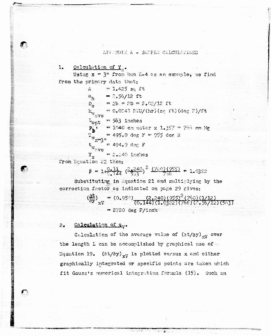
r. uvi'. .inn;: A - SAIJPIE CALCULATIONS
I
©
1. Calculation of Y.. Using x =* 3" from Run E-4 as an example, we find
from the primary data that: A := 1.425 sq ft a.
e
a /e Lopt
V Se-3"
o.56/12 ft 2b » 2D » 2.02/12 ft 0.0243 BTU/(hr)(sq ft)(dec P)/ft
v/„ ve
from Equation
= 563 inches •» 1040 em water x 1#357 ~
* 495.0 dog F *• 955 den R
** 494.9 dor F
« 2.240 Inches I then:
766 nn Hff
fl . njilj (2*240/- XZ60Ki^ « 1#0322
Substituting in Equation 21 and multiplying by the correction factor as indicated on pane 29 gives:
(0) = (0.953). xv
'"(2?2^°U^?r(760)(l/12)
» 2720 deg F/inch
2. Calculation of qy.
Calculation of the average value of (at/ay)^,v over
the length L can be accomplished by graphical use of
Equation 19. (3t/dy) „ is plotted versus x and either
graphically Integrated or specific points are taken which
fit Gauss's numerical integration formula (15). Such an
•MMMMU uPVMMUM
*"
i"
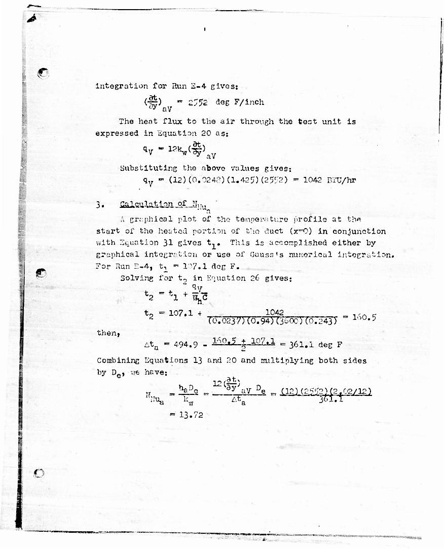
integration for Run E-4 gives:
(~) - 2;5£ <*eg F/inch °«y aV
The heat flux to the air through the toot unit is
expressed in Equation 20 as:
*v - 1?Vf} aV
Substituting the above values gives:
qv - (12) (0.0242) (1.42?) (25</2) - 1042 BTU/hP
•
i I «>
3. ^salaJU^iUpv, ' A graphical plot of the temperature profile at th«
start of the heated portion of the duct (x°0) in conjunction with Equation 31 gives t,. This is accomplished either by- graphical integration or use of Gauss's numerical integration. For Run E-4, t, - 107.1 dog F.
Solving for t0 in Equation 26 gives:
t0 - 107.1 + _ 1042 ,,n - 2 To:02y;5(0.94W3iOc) (0.243) lop*5
At_ « 494.9 - ^^ j .10.7,t.l =361.1 deg F then,
Combining Equations 13 ^nd 20 and multiplying both sides by De, we have:
IT. %2P
- 13.72
12 (|& dy aV Pe _ (12) (25'T2) (2.02/12) ^ta • 301.1

TABLE II
CONTRACTION THKPERATTTKB* PROF ILK
AT DISTANC8. x, = 12 1/4" FROM THE TOP
RUN NO.
Distance from Aall, y, Inches .300 .350 .400 .450 .500
A-l 152.0 146.8 142.0 137.5 137.6 A~2 207.2 200.4 189.5 182,5 181.1 A-3 200.5 269.0 263.7 249.3 248.0 A-4 355.9 339.2 329.6 319.4 311.1
X-4 295.1 200.7 259.9 240.1 235.3
n 1 - D*»JUCI 139 s 3 130.6 114.7 107.9 105.6 B-lb 146.4 137.0 123.1 112.5 111.6 B-2a 170.2 158.5 148.4 133*1 127.7 B-2b 194.8 174.6 154.1 137.3 131.0 B-3 205.4 189.7 100.8 172.5 168.5 B-4 256.7 241.6 229.0 218.7 212.6
C-xa 132.3 120.6 109.7 1C1.C 101.5 C-lb 14 3-0 126*6 118.2 111.5 112.4 C-2a 159.7 140.9 121.C 1C8.5 107.9 C-2b 170,0 153.3 132*3 119.9 119.8 C-3a 206.4 180.9 155.3 137.3 129.5 C-3b 204.2 179.4 155*3 136.3 131.0 C-4 252.4 207.2 181.2 162.6 149.8
D-la 126.0 113.6 103.6 101.4 102.6 D-lb 136.0 124.1 116.5 112.9 113.1 D-2 162.2 138*9 119.7 110.6 110.7 D-3 196.7 174.8 135.2 123.4 121.2 D-4 243.9 194.8 159.3 141.8 142.4
E-l 132,7 121.4 114.6 112.4 112.6 1S«*<; 157.7 132.4 123.9 117,5 118.8 S-3 176.8 145.5 126.8 118.8 121.1 B-4 212.4 166.3 136.1 127.6 127.7
r
* All Temporatures are In F
* n>*->t+*+*l*tfMe

i
c
e
< E-<
O
• X
o
g E-i <
M &, O K IX,
1a
a.
fH <*
6 o
•p » •ri
o
I
in
O O to
O o CM ,
O tn
•P% r-i
O O
m D- O
o m o
in CM o
m c- o o .
m o o
to
m co c- co c- en m *• rH o> CM m m CM co rH to nowio-f co^fOa> IO <u Ci C- co co o> o
rH CO
tO O CO tOrH tO o> O CO oo> o>
rH »H
in IT- rH in io ^ to OOOiOfiOO
rH fH rH H
c~ C> o CO r—; 0> OOO rH
rHrH r-i
CO m •* w OOOO rHrH rH rH
^CftfflC- in O C* iO JO r-4 CM. to IO O IO *• CO tO tO O •«*• tO iH <* to o> o>
lOtOHO CD CO O rH
fH fH CO
lOOCDiOH^ O) O CO O Cft o>
rH »H
m it/ CM m to •* to o o o> o o> o O
r J rH rH H
rH COOCOfH OOOOH
#HrH rH
0> CO tO CM O O O O rH rH rH rH
rH m to to o> rj< 0> ITJ O CO O <o *t» m o> o> to co CJ> £" o to <ft tO «H OS r-l
in ^ to co CO CJ> r-i r-i o>
CM O CO tO rH uO O 3 CO O C"» Q>
5|« tO rH *£ lO \* CM o o o> o o c o
tocoot*o 0> CO to tO CDOOCOH oooo
r-frH rH rH rH rH rH
o> to c^ m O CM co o in •*•» m »J» r-i tO tO tO C- rH COrH tO COO <# lO rH tO
CM «*• C- t- r-i fH in 0> rH H rH rH
C- CM rH
tO CM CM C* O fc- Cft o c> o o o
rH rH rH rH
tO tO tO to £> tC '£> o o o> o a> o o
r-i r-i r-ir-i
i»0 CO 0> J> CM OlOOOlrl
H rH
CO CO •* ^f oooo rHrH rH rH
116.
3 14
5.1
185.
8 22
0,8 CO •
fH 107.
9
115.
8
107.
4
110.
5
113.
7 11
6.3 CM fr*
|§1!5 rH rl
co m t- w e » • •
t- Oi to c- oooo rHrH rH rH
INI CM • to m CM
O CO o •*
O 1 rH 1 tOtO rH | «0 I l> r-i r-i rH fH CM 10
0.7
115,
3
142.
S
97.9
106.
7 12
2.7
INI
135.
3 17
9.3
256.
0 29
8.8
1 129.
0
155.
7
121.
1
143.
0
165.
4 1S
4.8
117.
9
167.
0
113.
C
126.
4 13
1.4
145.
1
rlHCOt- CM to co CM co to m c- m to a> to o o r-i to torn c- rH tO tO CO
0> CO rH CM *»• CO CO **• rH fH CM tO
to r-i tO
to o o o en to to •<*• in co to o> rH r-i r-i r-i CM CM
CM 05 C- CM CM CM tO CM tO in to r-i O lO rH rH rH rH CM CM CM
m t~ o Oi co rH CM ^ 0> rH HHHHCM
*r i- in rH CM ^ tO O rH rH rH CM
^f to o tO to o> to rH o •«»• t- O «r> t*- CM ^ > CO lO If J tO Oi rH rH rH tO C- tO
c •H
0)
C8
(0
3
0> IO O rH in iH o fc- r-i 01 tO lO
CO
3 CM «** CM CT> tO tO in m cfi o> t- to rH rH rH rH CM tO
c- co CM ©J m to <r> tO ^ CO 0> u"S tO CJ> rH rH rH fH CM CM CM
CM tO tO C« rH tO •«* tOtO CO r-i r-i r-i CM CM
to m o co •* CO CM t- rHrH CM CM
fill t
1 CM . -«*C0
in j m o CM to to 15
3.5
£09.
6
284.
7
148.
2
198.
0 29
7.0
MM
171.
2 23
6.3
313.
0 39
6.9 •
CO o> to 17
4.6
167.
9
224.
6
163.
6
226.
8
342.
1
157.
3
328.
1
161.
8 22
3.4
267.
3 34
7.7
41
B
fH CM tO Tji 1 1 1 1 1
ap op H r-i CJ 03 tO ««
1 i 1 1 t 1 cu en m to ta en
a) £j as XJ cri ,o HH CM CM tO tO ^f
1 1 1 1 1 1 1 o oooooo
08 ,a fH r-4 M tO «rJ«
1 1 1 1 1 a n a a a r-i CM tO ^
1 1 . 1 «K « W
r-> rH <

£=-
TABLE Ilt-a
GRADIENT TEMPERATURES. °F
Run No. from Wall * .
X. lnche s 0
Distance from Top, x, lnchaa
11 TI^
(I,
.
A-l
A-2
A-T
A-4
X-4
B-la
B-lb
B-2a
B-2b
0.005 0.025 0.050 0.075 0.005 0.025 0.050 0.075 0.005 0.025 0.050 0.075 0.005 0.025 0.050 0.075 0.005 0.025 0.050 0.100 0.005 0.025 0.050 0.100 0.005 0.025 0.050 0.075 0,0075 0.025 0.050 0.100 0.005 0.025 0.050 0.075
171.2 159 .If 149.1 135.3 236.3 213.6 188.1 179.3 318.0 3OO.O 281.8 256.0 396.? 371.3 342.7 298.8
398.9 348.6 316.2 256.2 174.6 152.9 136.6 110.0
167.9 154.3 140.8 129.0 215.2 192.1 156.2 131.8 224.6 199.0 180.8 155.7
199.5 188.k 179.6 166.6 273.9 254.7 234.6 210.2 376.8 360.0
316.8
468.7 447.3 417.8 391.3 467.9 433.4 399.8 324.6
195.1 180.0 163.9 135.8
200.5 186.3 170.6 156.9 274.8 255.1 211.2 179.6
283.4 261.7 236.1 211.9
205.0 196.9 185.4 177.2 282.7 269.8 255.1 244.3 387.9 365,9 334.2 306.1
481.0 445.2 397.2 360.9
487.4 459.9 427.0 367.0 201.0 189.2 177.1 152.9 206.1 195.8 183.2 172.1 285.2 269.4 237.1 207.9
295.5 278.9 260.4 239.0
207.0 198.0 187.7 177.2 282.0 260.8 240.5 215*9 398.0 377.5 344.2 311.8
494.9 464.6 430.9 392.4
Sea Table
IV
205.9 196.1 186.0 162.3 209.5 200.5 191.3 180.9 293.3 281.7 249.3 230.9
303.5 288.7 272.2 254.1
203.9 192.7 179.2 167.4 284.7 271.5 253.3 237.7 397.1 380.7 362.2 339.2
496.2 476.7 451.4 426.3 486.3 448.4 404.3 320.8 204.6 197.2 186.1 I69.O
208.3 201.9 193.4 183.4 291.5 278.8 250.6 225.2 302.2 290.3 275.1 259.6
200.9 194.2 186.4 171.0
205.5 198.9 191.3 184.2
283.7 266.8 233.2 204.4 295.2 283.9 271.5 255.6
196.1 190.3 I8O.3 173.8 273.1 265.5 255.4 246.4 378,5 366.4 -»«"•» if
344.0
476.9 464*2 446.3 433.2
440.8 418.4 369.4 I83.8 181.4 179.5 170.2 201.7 196.8 191.8 185,8 273.2 262.5 230.3 209.8
286.7 277.5 265.6 251.9
Q
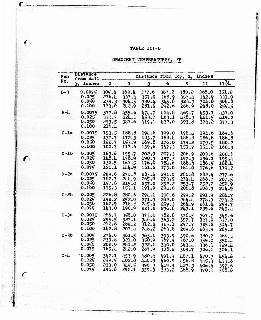
.0 TABLE Ill-b
GRADIENT !TEMPRRATORES, °P
Run Diatanca from Wall _ j, lnchas
Distance from Top, x, inches No. 0 1 3 6 9 11 113A
1
•
B-3
B-4
C-la
C-lb
C-2a
C-2b
C-3R
C-3b
C-4
I s i c
0.0075 0.025 0.050 0.100
0.0075 0.025 0.050 0.100 0,007? 0.025 0.050 0.100 0.005 0.025 0.050 0.075 0.0075 0.025 0.050 0.100
0.005 0.025 0.050 0.075 0.0075 0.025 0.050 0.100
0.005 0.025 0.050 0.075 0.005 0.025 0.050 0.075
305.1* 276.4 239.3 173.0 377.8 333.7 293.5 216.1+
153.5 137.7 122.7 100.7 163.6 148.4 132.5 121.1 209.6 182.7 157.6 115.3 226.8 192.2 162.9 11*3.0
28k. 7 255.5 212.6 11*2.8 274.0 233.8 202.0 165. 4 342.1 299.5 233.0 194.8
363.1* 337. 4 30U.5 21*2,9 455.6 1*21*. 1 381.6
188.8 172.3 153.9 117.6
195.7 178.9 161.5 11*U.9 270.6 21*4.9 215.0 153.1 280.6 252.0 218.6 190.9 358.0 327.1 284.2 201.4 361.5 321.0 281.2 242.0
453.9 402.8 345.5 298.1
377.6 387.2 357.0 368.9 330.4 345.8 281.5 292.6
474.7 484.8 453.7 463.1 419*1 432.0
194.6 199.0 183.7 188.4 169.8 176.0 139.6 147.3
202.9 207.3 190.3 197.3 176.0 184.6 161.6 173.0 233.4 291.0 265.0 273.5 237.0 2S2.2 191.9 204.0 294.1 30C,8 271.9 282.0 245.4 259.3 221.2 236.6 373.6 382.8 348.6 363.2 312.4 325.I 248.2 263.8
383.1 393.9 350.9 367.9 322.1 340.0 287.9 308.2 480.4 491.9 440.9 460.5 396,3 419.9 359.3 383.2
380.2 357.4 323.3 266.9
469.7 438.3 393.8
196.4 188.8 179.2 151.7 206.9 197.3 188.3 161.0 286.6 274.4 253.7 206.8
299.2 284-4 264.9 243.1 378.5 357.7 297.7 269.6 390.6 367.0 343.4 309.7 487.1 456.8
388.9
368.0
304.8 248.0
453.7 421.5 374.2
194.6 186.8 179.5 154.2 203.6 196.1 186.5 176.6
282.4 268.7 252.2 208.3 291.9 278.9 261 .k 239.6
367.7 347.9 325.2 263.9 380.7 359.0 336.1 306.1
470.3 1*45.3 406.4 370.1
351.2 331.0 304.8
437.0 419.2 377.3
189.6 186.8 180.2 160.3 200.6 195.4 188.4 179.2 277.6 267.5 250.9 214.9 284.7 274.2 259.7 245.4 345.6 337.0 314.7 265.2 366.4 350.4 329.4 306.1
454.6 433.6 397.6 368,6

r TABLE III-o
GRADIENT TEMPERATURES, °P
Run No.
Distance from Wall j9 Inches 0^
Distance from Top, ** Inches
2. 11
c
D-la
D-lb
D-2
D-3
D»4
E-l
E-2
E-3
E-4
0.0075 0.02* 0.050 0.100 0.005 0.025 0.05c 0.075 0.0075 0.025 0.050 0.100
0.0075 0.025 0.050 0.100 0.005 0.025 0.050 0.075 0.005 0.025 0.050 0.075 0.005 0.025 0.050 0.075 0.005 0.025 0.050 0.075 0.005 0.025 0.050 0.075
148.2 132.5 115.1 97.9
157.3 11*5.6 127.3 117.9 198.0 166.9 11*0.3 106.7 297.0 239.1 192.5 122,7 328.1 281.1 218.7 I67.O 161.8 1^3.1 121+.1 113.0 223. k 185.6 11*7.3 126.4
267.3 220.7 I65.6 131.1* 31+7.7 278.3 201.6 11*5.1
168.8 11*6.9 110. 4
191.3 17^.8 15U.7 136.3 267.3 237-0 201.0 133.6 356.7 319.9 271.3 169. 4 1*1*9.2 398.8 339.1* 264.8 200.7 180.4 152.6 130.6
283.5 248.8 201.9 161.3 361.6 311.6 250.0 189.7 460.7 397.0 317.6 223.1
1?1*.3 161.5 161.8 I69.I
199.3 186.1 169.6 153.2
280.3 258.1 228.1 168.4 375.6 31*6.3 307.2 218.0
1*75.5 436.7 38I.6 327.5 209.2 192.2 170.6 148.0 297.6 268.7 231.3 192.9 380.2 3U.1 288.9 231*. 9 483.0 1*31*. 1 365.2 291.6
c
198.4 186.8 171.6 137.9 203.8 192.9 178.8 163.5 289.5 269.5 245.9 I86.7 381.4 357.1 321.2 242.2
487.6 1*55.5 1*13.5 351*.2 212.3 197.0 177.9 158.6 300.9 277.9 243.8 208.3 387.9 3*6.4 312.6 259.0
1*93.5 1*51.9 391* ,7 317.5
199*1 190.7 176.3 141*. 8
203.7 193.2 182.1 166*9 287,8 271.5 250.2 195.9 380.5 358.3 323.4 247.3 483.0 452.4 412.8 361.6 210.4 197.5 181.0 I6I.7
299.4 279.1 249.0 210.8
381.3 353.3 315.2 265.4 484.1
394.6 333.0
266. £ 248.5 194.0 376.6 31*7.6 317.1* 242.4 469.6 41*0.6 1*07.7 364.3 206.5 196.0 180.9 164. 2 292.7 271*.8 247.9 214.3 372.8 31*8.6 313.0 265.3 470.6 1*36.0 390.9 331*. 0
2±ML 194.7 193.0 186.2 187.3 173.5 178.0 11*5.3 153.9 199.7 196.3 191.9 190.0 181.8 182.8 168.6 3L71.4
281.4 278.3 Cfw . c
249.7 202.3 352.3 338.9 310.7 257.8
1*52.4 1*30.9 404.0 368.7 204.3 196.0 184.4 170.0 286.8 273.5 252.4 220.4 361.6 243.6 315.5 278.2
1*51*. 1 1*29.7 396,4 31*5.5
*
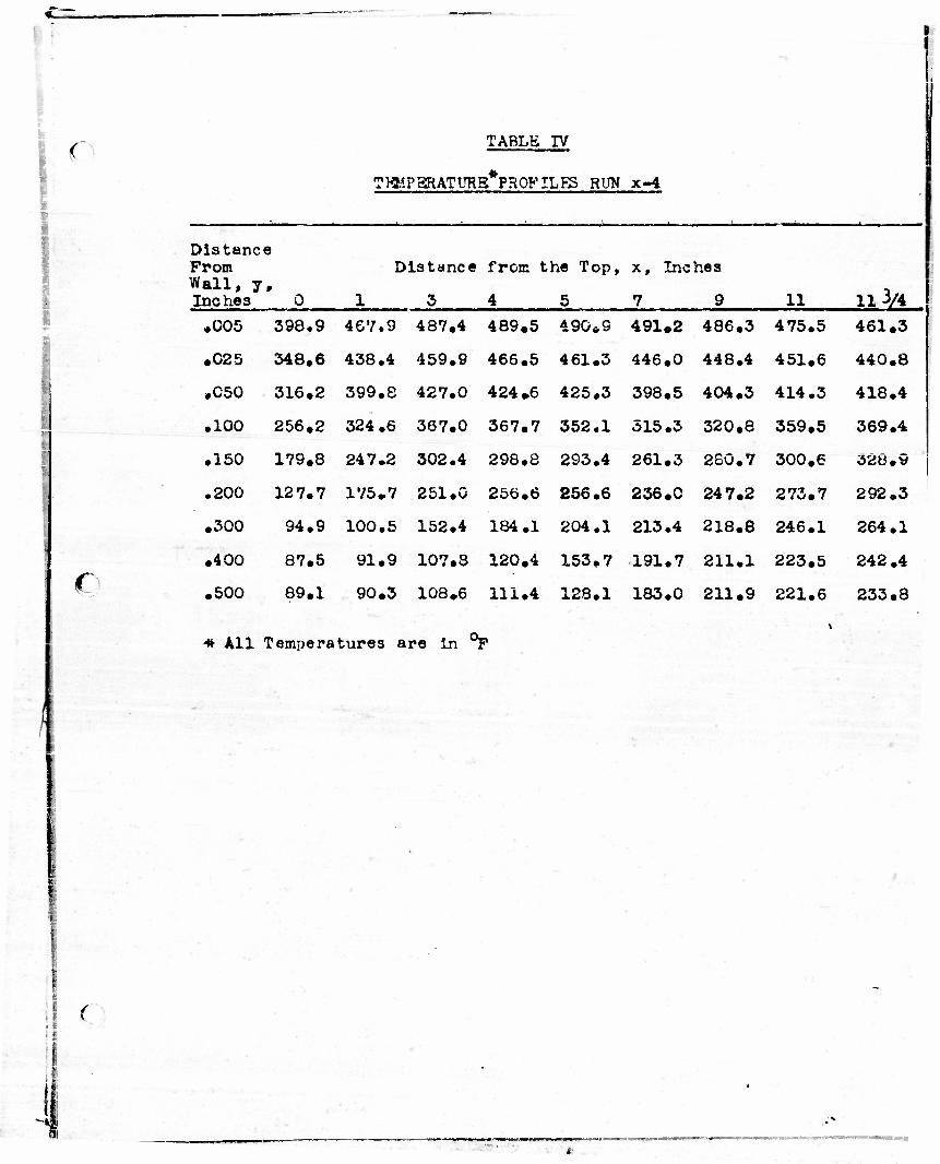
(
€
TABLE rv
TRHPSRATURB*PH0PILES RUN x-4
Distance Prom Wall, y. Inches 0
Distance
1 3
from the Top,
4 5
x, Inches
7 9 11 11 3/4 •005 398.9 467.9 487.4 489.5 490*9 491*2 486.3 475.5 461.3
•025 348.6 438.4 459.9 466.5 461.3 446.0 448.4 451.6 440.8
.050 316.2 399.8 427.0 424.6 425.3 398.5 404.3 414.3 418.4
.100 256.2 324.6 367.0 367.7 352.1 315.3 320.8 359.5 369.4
.150 179.8 247.2 302.4 298.8 293.4 261.3 260.7 300.6 328.9
.200 127.7 175.7 251.G 256.6 256.6 236.0 247.2 273.7 292.3
.300 94.9 100.5 152.4 184.1 204.1 213.4 218.8 246.1 264.1
•400 87.5 91.9 107.3 120.4 153.7 191.7 211.1 223.5 242.4
.500 89.1 90.3 108*6 111.4 128.1 183.0 211.9 221.6 233.8
* All Temperatures are In °P
(
i
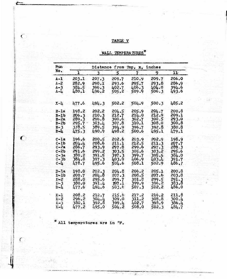
Run No.
TABIE V
WALL TEMPERATURES
Distance from Top, x, inches
JL 11
f
A-l 203.1 207.3 209.7 210.9 209.7 206.0 A-2 282.9 290.1 293.6 295.7 293.8 286.9 A"? A«4
384-5 IJ.80.1
396.3 496.2
402.7 406.3 40L.0 506.3
394.6 493.6 505.2 509.9 •
x-4 477.6 494-3 502.2 504.9 500.3 485.2
13-la 198.2 202.2 204.5 205.9 204.7 200.6 B-lb 206.3 210.3 212.7
300.6 214.0 212.9 209.1
B-2a 289.3 296.8 302.7 300.5 293.0 B-2b 295.7 • 303.4 307.8 310.1 308,0 300.8 B-3 378.5 389.5 394.9
498.2 396.7 392.8 380.8
B-4 1*75.3 490.9 500.6 495.1 479.1
C-la 196.6 200.5 202.6 203.9 202.9 198.9 C-lb 204.4
286.7 208.6 211.1 212.5 211.3 207.7
C-2a 293.9 297.8 299.6 297.3 289.3 C-2b 291.6 299.2 303.5 305.6 303.2 295.6 C-3& 380.2 391.5 397.3 399.7
406.9 395.5 403.4
384-0 C-3b 384.8 397.3 403.9 391.7 c-k 478.7 495.6 504.6 508.1 502.9 486.7
D-la 198.0 202.3 204.8 206.2 205.1 200.8 D-lb 200.7 204.8 207.3 208.5 207.6 203.8 D-2 288.0 295.6 299.7 301.8 299.5 291.3
383.8 n 38O.O 477.6 llk'.t
397.1 399.9 396.2 1
503.6 507.3 502.2 486.0
E-i 208.2 212.7 215.6 217.2 216.2 211.8 E-2 296.2 304.4
392.8 309.0 311.2 308.8 300.4
E-3 380.1 399.4 402.7 398.9 386.4 E-4 477.2 495.0 504.2 508.0 502.3 484.7
All tsmpei'atiires are in °P.
I (
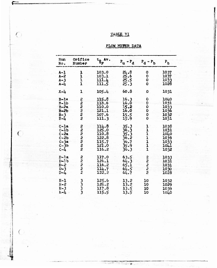
f=.
C TABLE VI
FLOW METER DATA
1
I
\
'
II I
(
( ii
Run Orifice t0 Av. pu-pd pd-pb Pb No. Number
A-l 1 103.0 24.8 0 1037 A-2 1 103.1 25.6 0 1037 A-3 N * 111.1; 2$.$ 0 1033 A4 1 111.5 25.3 0 1028
x-4 1 105*1* 60.8 0 1031
B-la 2 115.8 16.3 0 1040 B-lb 2 116.6 lO.U %0 ion B»2a 2 110.0 15.2 0 1033 B-2b 2 121.1 16.0 0 1036
E-U 2 107.6 15.5 0 1032 2 111.3 15.9 0 1031
C-la 2 114.8 35.3 1 1038 C-lb 2 125.0 36.3 1 1031
1040 C-2a 2 110.8 35.3 1 C-2b 2 122.8 36.2 1 1039 C-3a 2 115.7 36.7 1 1033
1041 C-3b 2 121.0 35.9 1 c4 2 116.2 36.3 1 1032
D~la 2 117.0 63.5 2 1033 D-lb 2 126.1 64.3 2 1031 D~2 2 116.2 65.1 2 1031 D-3 2 114.7 64.5 2 1030 D-4 122.2 64.7 2 1028
E-l 3 125.6 13.2 10 1032 E-2 3 125.2 13.2 10 1029 E-3 3 117.8 13.5 10 1039 E-k 3 115.5 13.5 10 IOUO
- *
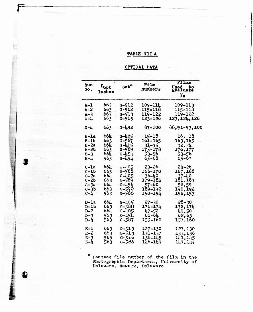
r-
*
TABLE VII A
OPTICAL DATA ••
Run No. Inches
Set* Film Numbers
Films Used to Evaluate
*6
A-l 663 0-512 109- .118
109- •113 A-2 663 G-512 115* 115= •118
M *-** 663 0-513 119- .122 119- 122 AM w "• ,• 0-513 123- •126 123.124,126
x-4 663 0-492 87- •100 88,91- •93,100
B-la 664 G-405 15- •18 16, 18 B-Ic 663
6^ G-587 161- •165 163,165
B-2a G-I4.05 31- •35 32f 34 B-2b 663 G-589 175-178 176. 177 B-3 6614. G-454 53-56 53-56 B4 563 G-454 65- .68 65-67
C-la 66I4. 0-^05 23- •26 24- .26 C-lb 663 G-588 166- -170 167, 168 C-2a 664 o-4o5 36-40 V7 . .40 C-2b 663 G-5'89 179- .184 181, 183 C-3* 661+ G-l+54 57- -60 58,59
SF 663 G-590 189- -192 190, ,192 563 G-586 150-154 152, .153
D-la 664 G-405 27- -30 28- -30 D-lb 663 G-588 171- -174 172,174 D-2 66i> G-i+05 hi- -$z 49,50 D-3 563 G-454 61. .64
-160 62, ,63
D-1+ 563 G-587 155- 1 f-> ,160
E-l 663 0-513 127- -130 127, 130 E-2 663 0-513 131- -137 133, ,136 E-3 E-4
563 G-5I6 138. 146.
-1U$ 141 ,145 563 a~586 -149 147, ,149
it Denotes file number of the film in the Photographic Department, University of Delaware, Newark, Delaware
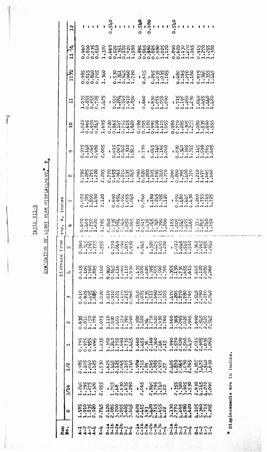
i
r
*4 SH
a
H
CO 1 s:
l-l < t-t ui > 03
to 5 ~< M e -4
2: o H
>
oj
•#
J4
CT-
a. c
co
r-
o
VA
OJ
OJ
o
u turn
i i i i
O © O O .d- 3-co -=f
I VA I 6 I t I )AIO<l I I I VA I I I I I I I I
OOVAO O OOHOOO OVAOVAOlAO ©OOOVAVAOVAO <OOfiH OJ >0 OJ VACO (\l CO ONOCOOJCO AjOJ OOJ »^l«-%0 H f-VACO OCOOCQ »A O VA«AO<? VA GO VAOCO OOH 0)vOH'.MH OAJAJC,
OOOO H OOHOHH OOOOOHH OOHHri OriHri
VAU\OVA o OcocO l> <A
OHVAO O <Ald--:±o OJ
(VAfAooc^-
VA o
I O
VAVAVAVA O <AfAO
ICUOOH
O VAO O VAO'LAVA coo r-co c--d-VA—f
OOOO H
VAVAVAVA VA fA VAVA0O OJ OOCON .d
OHOHH
VA-dVAO O VACOO H VA
I VAOJCO OCO
O H H H
O OVAOO sO «At«-VAO
I' O 10*0 O O
OHrHH OHHH
VAVAO O OVAOO H 000 ^i -dOA-dXO
I O-H oj oj o-d-d-_-;i-
H O O O H O rl O H H O C • H H i OHHH HHHH
OlAOU\ VA OVAC-'AVAO O VAOVAO VAVr\ OOVAUV-A OVAO'iA ojoiA-d o c\isOJ-(>H(\j COOCOOOHV\ cor>-cooi-A CO*ACTVA OtMMD ^O r-VAHl^OCO O^NHOHHO ©»l*-OJfAAI O VA-dVA
rHOOO i-( O O H O H H O O H O H H H OOHHH HriHH
VAOVAO VA r--JNOOO O OH O O O
VA^O O O H O O H -i.L
IsOOCO *AVA
C VAO VAO t-- -d-dNO vO
I r~- I O H H O
OOVAVA VAO'vAlA <^i_d-^) H -dOOO
ICOnnn HVAVAO
OHHO CVJ OHOHrt Hr-lr-li-l OHHH HHHH
VAVAVAO VA OXAHOVAVA OOOVAVAOO OOVAOO OO^O oco r~oj o MAvo i>-nj- oojcooo-dr- oooor- HC—oo f- OJ OJ Oj OJ C—O OCO H Ol O CO OJ H r-t OJ O O CO fA-d C\ OJ v0 >0 vO
OHHH OJ O O O O H H i-i O t-i i-i i-t r-l r-\ H O H H H HHHH
OVAQO O r—co u\o» oj O OVA-d H
O-dOVAO CMAOV\-*
I O O O O O
O O
I CO
OVA VAO cO-dO 03
I H OJ o^rH
OOL"iO O VAVAVA IACO -d fA ^o VA -d CXJ 0-J-4J- ojr—r-r-
O H H H OJ O O O H H HHHH O H H -d HHHH
O VA O O IA O VA-d iA O VA r--ovr\oj co vj3 rAco.dVA--o o-do-o t^- cor-oooo
lAVAIAVAOOO VA VAVA VAVA .^tfvOO (OHn440>0 oOO-dOO H-d-crVA H o^Ai ^fAOj i-tovA-cr-o- rAcocoa>
OHHH H OOOO <-! O HOHHHHH HHHr-iH r-l H H H
O IAVAVA VA O -j Ch 0- VA vr\ n r-- r- u\
O CM3 1AO
i r-o <>o o~>
VA O;AO O OJ f J 000
i fn_d-j-cj
O U\\T\ O VAVrvO 'A
C vfl LAVA «t>0>0<
O H rH H H
VAVAOVA O H X> sO CO -J5 vO H r-CO H
O H <i H O
O VAO O O O •^--d-H-O H <•"". f>CO H O H O
r-t t-i r-i r-i r4 ,-i l-*,
1AOOVAVAOO VAOO LAVA VAO O O <A0C OJ OVAOO VA^^VAH ^Tj OJ CO sO HOvOnuMr,n r^Hr-J3vO -3 H O O
OHHH H OOHHHO HHHHHHH HHHHH HOJOJOJ
O IAVAVA O OOHOVAVA O VAVAVAO VAVA O VAO OVA VAO O O H OJ fT'OO OJ HHOJ^HsO ^COfAHOHO NOr-30>0 4(M^4 >C f>..Cj->0 O OCMMHWO OJ O f^-VA^O (-VA -4CVI0D t>-r~ ^AAJ OJ OJ
OOHH H HOHHHO t-i r-t r^ r-f r-i i-i rH H t-i H H t-i HOJOJOJ
VA O O Q VA O o H O O O *AHVAC~ r~ Hojor-ocr vO co H «*> o Hojnno
OO OOOO OOOJ J-r-'OJ «A>0 POOJ (J* t—0s C^ f>-
OXAVApVA OVAOVA NONOOAIVO O-d-AJj- sO «AO OO1 -fl VfkVAVA
OOHH H HHHHHH HHHHHHH HHOJOJH HAiOJOJ
VAVr,VA.m VA OO VAO VAVA OVA OO OOQOO VAVAVAO 0-. t>-VA3,> <A Vr._tfiA<7>CA-3- O VAO vO J) >0 VA «T»r>-CVj^fA HCO rao> f-OO^O C\i CAOJ t>-JD t^-^ vO-^«AH'A^-H CMAVfVA^- OOOO
OOOH H HHHHHH HHOJOJOJOJOJ HHCJOJOJ OJOJrAfA
VAVAOVA O VT»VJ\VAVAVr»0 OVf\ VAVAO VAOVT,OVA V:\O0O coo-d-oj «A oj_:foj J3 o-d- co H oo co r--1>- or-ocoo cot>—d*^ OHOH VA vO— J-HOHC- C'C-COVACO OVA >dXO.COoCO <A.dVAO
OHHH rH HH AJOJOJH HH OjOjOJOJOJ OjHOJ <noj OJ «AtA e^
O VAVAO VA -dOt-AJ \A oj kv^nj <A o
• • « • • H H rH H OJ
VA OVAO OCO <A^O
I f-O J3JJW
H OJ OJ CJ 0J
VA
to OVAO -^O-d/OJ
i oc-r-oj
OJ OJ CA f ^ <A
VAOVAQ OVAOO \AOJO f^ fA-dr-O
I f^fAOVA OHOJO • ii • • ••••
OJ fACAfA OJ^t_dVA
VAOtAO IA OtAOVAVAVA OVA OVAlA COH<AOJ ^ OJCOOVAO-d- OJH <A<\JH«A<M VAO0DO f- HOWOsOsO JJ^C>4N-J> OJ
OOVAQO VAO VAVA
HHHOf OJ OJOJfAfA«AfA OJOJ rA«A-d-4-d fAOJ-d^-d- ^* VAVAO
<a j2 as ,o <a JO c8. XJ « j.'a « fi H OJ JA^t J" H H OJ OJ «A^J- H H A! OJ <A f\_d H H OJ «»V* H OJ tA.-d I 8 I I I I I I I I I I I I I I I 1 • t I I » I I I Ii i < <3«««< x « cq CQ no « m o o o t > o o o Q o o a a a w w w
m O
o C
to h aJ
to +> a
o u 0) H a n
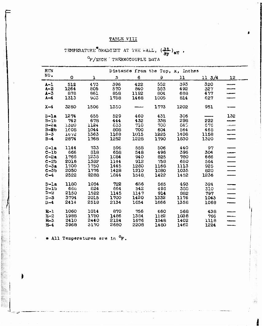
r TABLR VIII
TEMPERATUP.E*aRADISNT AT THK WALL, (At-) , dy »*
°F/INCH ' THERMOCOUPLE DATA
RUN Dl3taric 9 from the Top, x, Inches NO. 0 1 3 6 9 11 11 3/4 12
A.-1 512 473 396 422 552 393 320 . A-2 1264 eo5 570 340 583 492 327 A-3 87e 861 858 1192 804 688 4 77 A-4 1313 903 1758 1468 1005 814 627 • -' —
X-4 3280 1506 1 *» c r\ 1773 1202 951
5-la 1274 655 529 460 431 306 —— 132 B-lb 742 678 444 432 338 298 222 B-2a 16x0 1124 555 710 ,.^^= B-8b 1608 1044 808 700 604 564 468 3-3 1072 1363 1168 1015 1225 1408 1158 —— B-4 2874 1768 1252 1228 1790 1830 1320 "
C-la 1144 733 596 558 506 440 97 ___ C-lb 666 818 658 548 496 396 304 C-2a 1768 1235 1084 940 825 780 666 C-2b 2016 1382 1144 912 758 680 564 C~3a 1700 1750 1445 1280 1168 1113 925 __ C-3b 2050 1776 1428 1210 1080 1035 820 ___ C-4 2522 2288 1844 1548. 1422 1452 1236
D-la 1180 1054 722 656 565 493 324 ——— D-lb 66b 824 654 542 33G • ...
D-2 2150 1522 1145 114 7 914 882 797 D-3 3794 2015 1700 1420 1332 1176 1043 - D-4 2414 2518 2134 1654 1666 1358 1068 ——
B-l 1060 1014 870 756 660 568 438 i,M
B-2 1988 1750 1486 1364 1182 1038 766 ••..
tt-3 2410 2440 2124 1676 1548 1402 1118 . B-4 3968 3170 2680 2208 1480 1462 1224 -
• AH Temperatures are In °P.

< E-
o H
ft, o
> eg
CM
to
CM
to to co m O CM O 3« m in c- co
CO 1> tn lO m H tO rH tO r- in in C- CO to
o
tO
><! r*
IT'
r-f.
i->
H
tt,
c
a.
CO u O c
a o EH
•W £
6 o
01 o r*
n -\
I
LO
4
to
CM
SO #55
© w o » to to O O) to Ci to in
<-< r-4
o o o o to co rJ in to o> in r-
i-H r-l
a> a> to m Cl 01 to rH CM a to c>
Ol •*»« tO lO OJ « rl O tO^-KlO
,«-! CM
mm o H CM rH ac en to to o; c-
tO to CT> O to tO C~ to to m ci •#
co o r- en rH tO OICM »jt (0 C- ^-l
tO t- * c- HH CC CM in t- co H
rH
<o CM cr> o **oi *• to
r-4 tO IO O CM rH > H CO CM •«* O
HrHCM
m
co to >n to <t o to rt m in c- oo
o CM co c- •* Tf CVJ rH m to co m
O W H > CM <o to o m t- ai o
to t- CM o CM tO CM fO «3« CO f-< to
rH rH
rH CO
CM
tO to tn to -D rvj CO *<• T* c- o> m in to to io OJ a o .n oo
^< O Cft CD tO co a> ^ <T> «# CM CO iO '0 O
--HCM
C-TJ< O o o 01 E- OS tO rH CM co m m ..M
rH (M
W W O) O tO o c~ o c- n *• CM tO tO C- S) tO CM
rH iM
fr~ O 01 Tr> iO to en IOHH tO tC lO rH 05
tO CD to CO CM tO o m to o > c- TJ« ;0 tO tOOn
r-i
t> tO O rj« to t- m to o CM tctr> ooto
«H i-r)Cf<lO •J) O C- tO 01 CM ** ^ to *x> co o:
tn O •3"
tO
O :M
CM
O ifl tO CM
O tfj C* M
o
o to '0
CO iO CM r-i
CO to m r-i
O to o CM
o 0> tO CM
o co o> o TJI rH fj CO CM t- TJ« I- tO C7> r-i
oi a> c- i-i to to o -t CD iO '*> ^f« •* C~ CM <« -J« > O (31 rH
o inoi en co c- to CO M CO M OOO o in ^« co co o CM
*t* in to to r-i to t> tn •»!• to to to lO lO 01 CT> rH rt
tO tO E~ O OCR 01 tO iO IO CM 0) CO O rl H If >
r-ir^r-it-i
r-i Q> CM CM rHO to to o t- o in 00 c- to to <D o
r-i r-i rH CM
ifiOOOO O JO N O to 0> rH tO
r-i r-i CM 05
01 CM o co o o (> o» to <o o> o o o o o> »> o H r< CM r-i CM *
HHCJ Oi i0^f I I I I II
CQ fQCO CQrQtO
i • :•
to 01 a) to CM to
rw CM ca CM m eQ oi o o «p in o in m »f to <o m co co r*
8 CM
o cn n CM it to CM **• to o iS to t> CM if
«0 i CM uo in m o tn c- to CM o m tC' to tO £~ cO ^i to 1 to co co to tO t-CM-*
iO to
o co m to to 01 00 to tO CC CO to
in oi o> oi •* sc in CM co ai t- to in rH •^ to > to ci oi to
o rH
c- m co oi H>O* C- Ol o to
r-ir-i
m to cn CT> co CM o t- ^ to 1.0 CM CC i> <f * CO t- o o to
rH rH rH
m CM Ol »J« tO ri C* tO tO CD O rH ^
sr tO r-i t> C- r-i :~ o; 35 t- m n r-> o •J j TJ« 01 CCi rH cv n
HrtH
o I in o o CM r-f J O CM Cl CM in i oi CJ CM to
I r-i r-i r-i
»J« rH CO rH tO CM O o> tn co m CM tc •* m in o oi to to t*
r-i r-i r-l r-i
* o C- o <o :?- co •^ cc o to M a to to m r-i o «*• ^ o>
HHH -4 rH
rf CO 1> O -<^ CM O rH T!< t> ^ CO r-i »J< C-- tO CM rH IO tO rH
rH r-l rH rH CM
CM o o co c»- m o ^ C- CM r-i r-i rH M< co t~- m ^r oi o in
H rH r-i CM 0J
CM IO rH if) 00 O tO Oi tO CD CM tO
O O CM CM CO lOHSO to in *i< co ^3 m
IO CM CM rH Tl< r-i I- to r}» C> lO tO
CO to to •<* » c^ i> in CM -* m ^ o> •<!< o
rHr-l
o» o o CO O t-ifr-r-i in o «* JD
t~ Ol O"- CM 5 CM o n rH to BJTOJ: CO
rH rH rH
r-t C~ 'O tO ^ CM in oi lO rH iO CO
HHH
HOt-NO rH O C- tO rH C^- tO r-i tO O
rH rH CM
in o o to o tO TJI to to CO C- tO CM C- r-i
t-» rH CM
tO Ol ^ TJ< O m rH CJ1 tO CO CO O tO Ol to
H rH CM
O C-C0OO CJ H to to in O CO tO -4« CO H rHCMO-J
O H CM <-H Ci to rH tO TJ< CO r>j to
rH Cl tO O >M r-i r-i CM in ft to r-
rH rH
r-iO O CO tO O rH O m c <«i« r-
HrHH
Ol lO Ol l> oo to e- r-i icio^ a
r-i r-i r-i
tO tO rH lO Oi r-i -X) O tl> r-A lO O
rH rH CM
(OOOO to > CO CO tO rH o o
r-i rH CM
oo>o Ol rO T> CO to r\) C— r-H
HHOJ
>•"• tO X' rH 01 lO > CM CO
rH r-i
(OCOOO TJI tO rf rH E- tO Ol »a<
rH ci CM
ifl CM O O CO !> tO CM l> •«}• o in
rH CM CM
CMC tO O S> tO CM
in CM f- rH C- CM
tn co o o O H t> CO Cl t- tO 01
rH CM CM
C-CM O O tO l> CM O o oi oo m rHH CM tO
•c« i> to co m o o in oi CM o o omoo o o 4 ^ 6 >to cMtO'djjnto lomoiio OOlTOtOtOtOOl CMCftCOCOcJ CMCMHOl
o H
I CM 0J >l
CM OO O 0>*HH CD Cft 01 tO HCMCMW
HCM lO rHCM tO tO
oeoogooo CM >0 CM CO to o H to CM ** H in m m rH rHCM CM «0 lO •*
H H 01 CM «0 «0 <+ • I I I I J 1 ooooooo
rM
Hoobch oooo CM to CM m intO l> r-i
H
OZrMlfGi to HCMtOlO rHCM »0 iO ©
U •p
Ot-OQO c- o in oo <# m ^» oo o> co
OOOO CO
CO to -* to OCM to CO
0 n,
r-i r-i 09 >0 5jt CM «o -«i« »n a r_j
< !C2 ' H rH
*
•
i
.

•QL
9
5S
d* W
I 03
X
CD «< EH
0 S3
H © PC
>
« EH
o*
.c O'
o '.Z o M H •< in M
W
EH
1 a1 »
o
3 55
• fa +> 5
r-i - •P . H
OJ^M
U
>i to
A3 C
•P "N.
5 ?•
-P cr
EH CQ
H .c
jt > fa -P «o
* e 03
O fa 43 o
fa o
O o
a H
r-XAXAH • * • • -=JvO v0 O OCO r-^-o
•AfAOvO OOCOcO
O-d-fvJ O XAXAXA-d" CMCM ojcg
t*- eAt-CO (%_ f^CD CA
o o
o°OvO r-XA-4^ H HHH HH
O OOOOO t^o <ACM CM cj co coco CO co co HI Hr-lrH HrH
P-OJ «^H N-CM o OOO OO XA -d-d-XA-dXA
o -d_d-_d--sO vO o OcoXAXAfACvi o CM c\j c\r c\j <\t CM c\j
ooo o o oo ©HN^r-M <A c-- r- r— t*- p~ t*- r-- c\j c\j CM r\j CM rvj rvj
CMO- CO CO- CA <A I
fco O j-oco S<A<M
OOOOO O <ACMC0H r—vO ^NO VQ (A n-\ rA <A < A
t—XACO OOO^i CJGO f\OCO _d--d--dXAXA-d-XA O O H O O c- t— r-1*- r-1*- P~ ooooo
co -3-iAfAr*-<A_d' co r-oj fAO-=roj co <Ar-x> r>-H^
o r— <AOO XA _d«3 NUMA
o-d/o r-
ooo o r- r- co co -d-d-d-d
C\J CVJ cr d-
HHAJfn <*\ <A fA CA
-df-H CJ oo_3-o r-
0O OOO o r-i
o ooco oo H
H H H O O O O HHHH H
J-CM CM <MH rH r-4 r-l H H
XAXA-=T<A r-l r-ir-i H
CO aoco-d"
vO r-»CO-^-
r-r~-d-o f'va- o^^xrs^iri-dNO r-r--o o r-i h-onn
OIAON c\jrg
O sO c—CM r-r^f^ C\J O O^CO t^-XA'^ OOCO r-^0s0tf\
rH rH OvlCXJ <^
p~OOCO O OCOOOvOlA
iH CJ <*\
C*-r-l (*- rH OCOvU X)
rHCM r*\
xO vO OCO O
VA03CO r^» O H
O ^-=JNO O <^ir\no o ri CM -=J-VT\ h-
CVJ^tnjH IA
HH H
r^XAr-XA XA _rf^r-f\j XA H eg CMA sO
H .^--X) CVJ -oco r-.j- -^%0 CM'vj
H
eg oj r»-o COOMJ H CJ f\J C\J o o o o
CM o c^cvj 0s r—
O OOvO H H c\i HJ-nvO o
ONOOIAC>(V IA'^OVO J-C- H HOJ (^4<0
IA<0-^0 HO co i^?n^o r-o -^-.:^CO C- r-l \A
OOO <nCj H lA'^O-O f—^ H rH OJ OJ _JvO
^r_d-oj_cf-j-0-J3 cwiMvOJoo vOJ-04
Cj VA O c^ rH CO o"i \f\
<no rr, ON -4- c— -o -d- rvj O f> r-~ Hrlnftl 3-3-sO H H OJ . J-lA
r- .oct'-j-cvj ru o -ct iflnntr\ f*>H m _3--:7CO r- CO IT, H H H
cu o
O OJ C^IJM/VL) coa)oo(M4 H H CJ OJ C\| CJ O O O O O O
CO O o"\c^o fM^ r—co so oj o H *""* Hr-t ro cn-^-lA t—
sO XA (M r- O O sO r-CjU\Oj r-<M c\j IAXAO OOJ '^if—
H H H H
co O CO CA H O VA
HH ro^XAXAt-
0j f- JO O-fAlH r- r— o r^-<o H «^ IAXAO O^^h-
H HHH
O C\J e^, ^j-sO CO CO CO CO O O CM CM _-* H H CV CJ CM CM CM O O O O O O O
-O t^^tOH HM> COXA .run f^voco
r~H r—o^t or— cOxO o
-•O XA H sO o HHCJ
H O- O r-l OJ CJ H -3-xO CO
r~ r< -O r- Oj or-u\o c^» O lAr-l O O
i-iH H
H H fOsOCO CO GO O OJ _4^ H H OJ CM CM OOOOO
OxOvO CM _3-CO>JN_d- oj-^-r-o
•«0 o^ r- XA r-^.oxA
HH OJ
OXA-4-C0 -j-OCJ co oj_^-r-o
.^ro r- 7^ O H 'X> iM :.N-_tuO r^
H H CM
C**\LJ"\SO ^O CO<\J4 H CM CM CM O O O O
O O O O
sO HXAH
O OOOOO OOOOOOO OOOOO OOOO
-3-CD O O Xi XA xO OJ o XA rrico r- NQ *^ao O O XACO H O
r-o c— co fv^ o o o o o CJ CM fO^t -CT
vo xr»r~'jc CO VAOH H ro^j-tx.. O
CM C) C— r^cG 0s
O H O O X) CO CM OJ CM fA <A_j.
^t O- O O C- O^ C--UN O »A O H HH CACAXAO
O 0<^iOH C^XA O O OOOOO CM C\J CM CM »n CA^J-
SOXAOCOCO r-r- r---^ fA rH ^-J-UA H H CA r^isO XACO
CVJXAXAHXA r"\-J-fA_j- QOOO^O HOOO ftj CM CM <A^J- CMfAfA^f
CO.^CO_*H xr>/3 XAO OJ H H CAr-CO
XAONOO I—OJ^tOJ H CAXACO
Xi-\XAOj-d- -d- cou\HvOr-r- ^m^nj-voo cooOsOH CMXO<AH
H CAO O OJ -a-OvO CM vo H HCM CA CM
r--f -o UN H o H CM ^XACO CM H r-l H H H OJ
HO XA>OC0 r-XA H CM CM CAXAXACO t-i t-t H i-i i-i r-1 r-i
C-CO-dvO O OH CM-d-sO i-i r-i t-i r-t r-1
COO *Ar- HOJ r-\^j- HH HH
O O f-cO CO XAv£i XACO «A0J O NO t»0 OO XAXAO^O XAf« XAr-l
CACM OH <A OO CM-d" H
r-tt-ir-i H
-4H r«-»A O
ooo o o oooo o
XA<A-d-CO mo OO OO O H
r-l r-i r-i rH
H~rXAO <AH o t»- r-ooo o oco co CO co co o o o o o o o © o o o o
sO f-XOCO CM OO r-OHH\0 OOOOOOH OOOOH
H H H H H H t-^l rH r-i
OCO O OJsO O f- Cj CM CA rA -d CA »A «A *A rA rr, e\ tr\ rA H H H H H H H OOOOOOO
O^OCM O t-NO OO r- r-co f«- f»_ i-^ r-4 rH r-i r-i OOOOO
ooo r«- o H o o rMr-i r-it-i
fACAO C- CA'fnJAO'V CM iM CM CM OOOO
OOOO OCOOOO OOOOOOO OOOOO OOOO
«J: ** HCM <AJ" -d- r4 r-i Ol CM «A J- lilt i 1 1 1 1 1 1
* W 03 K 03 03 03 03
of /l ro is aj xx H H CVJ CM <A C^^t
I I I I I I I OOOOOOO
CD JO H H CM <A-d" HCM CA-d
I I I I w w w m
J
•
dm*.
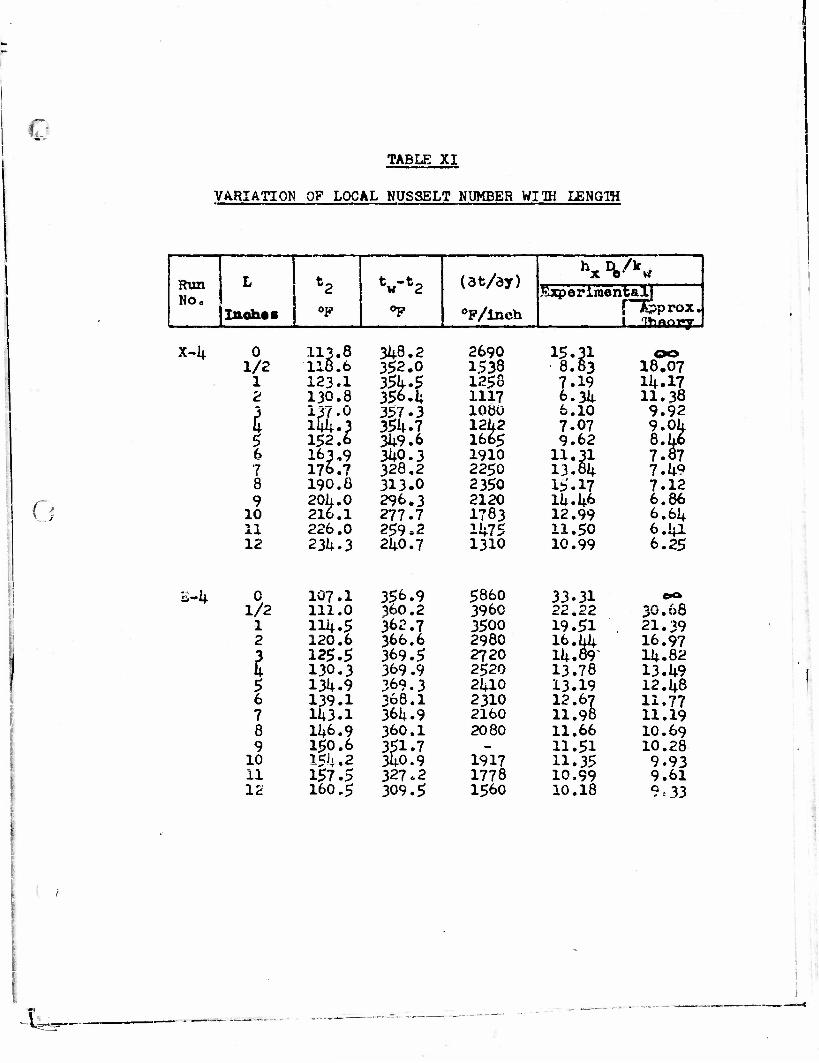
c
CJL
TABLE : XI
VARIATIOh OP LOCAL NUSSELT NUMBER Wlffl LENG1H
Run No,
L *2 w 2 (3t/dy) hx Vk«
Experimental!
Inoh«s °F op °P/lnch 5 Appro*. 1 1^r\ftnfj •
X-k 0 U3.8 118.6
3k8.2 2690 15.31 8.83 1/2 352.0 1538 18.07
1 123.1 35k.5 356. k
1258 7.19 ik.17 2 130.8 1117 6.3k 11.38
| 13Y.0 1^.3 152.6
357.3 1000 6.10 9.92 35k.7 12k2
1665 7.07 9.0k
8.k6 7.87
5 349.6 9.62 6 163.9
176.7 3k0.3 1910 11.31
13.8k 7 328.2 2250 7.k9 8 190.8 313.0 2350 15.17 7.12 9 20k. 0
216.1 296.3 2120 lk.k6 6.86
10 277.7 1783 12.99 6.6k 11 226.0 259.2 147S 11.50 6.kl 12 23k. 3 2k0.7 1310 10.99 6.25
s-U q 107.I 356.9 5860 33.31 e** 1/2 111.0 360.2 3960 22.22
21.39 i ilk.5 362.7 3500 19.51 2 120.6 366.6 2980 16.kk
Ik.89~ 16.97
2 125.5 369.5 2720 lk.82 130.3 369.9 2520 13.78 13.k9 f
5 13k.9 369.3 2kl0 13.19 12. k8 6 139.1 368.1 2310 12.67 11.77 7 lk3.1 36k. 9 2160 11.98 11.19 8 1M>.9 360.1 2080 11.66 10.69 9 150.6 351.7 - 11.51 10.28
10 15)|.2 3k0.9 1917 11.35 9.93 11 157.5 327.2 1778 10.99 9.61 12 160.5 309.5 1560 10.18 9 = 33

c
i
TABL3 YT T Ail
HEAT -TRANSFER RKLATIONS
FOR PARABOLIC VELOCITY DISTRIBUTION
AND CONSTANT *ALL TEMPERAT JRB •
Round Duct a Flat Ducts
at _ cOD2 hlD V W h.D le V>. W 9 ~ EC" T" HF k k T IT
I 0.50 3.68 0.25 0.50 7.60 2 C.50 0.99 3.76 0.50 1.00 7.60 >-> 0,75 1.48 3.81 0.75 1.50 7.60 4 0.90 1.92 3.86 1.00 2.00 7.60 a 1.20 2e29 3.91 1.24 2.48 7.62 « ^ -» **» r\ r* *-\ *» t~\r* •% A r\ r. r\n r» *? c u ± .JV i&.UU 0»VX3 i. .1 O fj • S7U 1 • \>*J
7 1.57 2.86 4.01 1.73 3.42 7.69 0 1.74 3.07 4.06 1.96 3.85 7.74 9 1.89 3.25 4.11 2.18 4.23 7.80
10 2.03 3.41 4.16 2.39 4.58 7.06 12 2.27 3.66 4.26 2.78 5.18 7.92 15 2.60 3.95 4.41 3.30 5.39 7.98 20 3.05 4.38 4.70 4.00 6.67 8.05 25 3.43 4.72 4.97 4.55 7.16 8.15 30 3e76 So 02 5.22 5.00 7.50 8.24 40 4.33 5.67 5.74 0.04 0,52 60 5.22 6.32 6.48 6.73 8.67 0.93 .0 6.23 7.24 7.30 '.'.87 9.54 9.67
130 7.27 G.18 8.23 8.97 10.4 10.5 200 3. 63 9.45 9«45 10s4 11.6 11.6 300 10.1 1C.S 10.8 12lo 13.1 13.1 400 11.2 11.9 11.9 13.4 14.4 14.4 eoo 13.0 13.6 13.6 15.4 16.2 16.2
1000 15.6 16.1 16.1 is. e 19.5 19.5 2C00 19.9 20.3 20.3 23.3 23.9 23.9 30CQ 22.9 23.3 23.3 2C.4 26.9 26.9 4000 25.3 25.6 25.6 2e.9 29.3 29.3 6000 29.0 ?9.3 29.3 33.3 33.5 33.5
10000 34.6 54.8 34.8 39.6 39.9 39.9 20000 43.6 43.8 43.8 50.0 50.2 50.2 300 00 50.0 50.2 50.2 57.0 57.2 57.2 40000 55.1 55.2 55.2 62.6 62,8 62.8
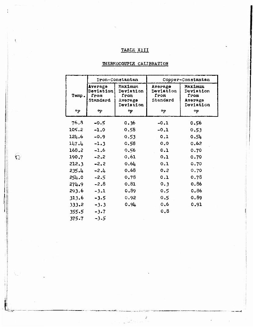
TABLE XIII
THERMOCOUPLE CALIBRATION
Temp.
op
Iron-Conatantan Copper-Constantan
Average Deviation from Standard
Op
Maximum Deviation from
Average Deviation
op
Average Deviation from Standard
Op
Maximum Deviation from
Average Deviation
op
?6,a -0.5 0.36 -0.1 0.56
105.2 -1.0 0.56 -0.1 0.53 12^.6 -0.9 0.53 0.1 0.5k iUT.q- -1.3 0.58 0.0 0.62
168.2 -1.6 0.56 0.1 0.70
190.7 -2.2 0.61 0.1 0.70
212.3 -2.2 0.61+ 0.1 0.70
235.1+ -2.^ 0.68 0.2 0.70
25U.0 -2.5 0.73 0.1 O.78
27U.9 -2.8 0.81 0.3 0.86
293.6 -3.1 0.39 0.5 0.86
313.6 -3.5 0.92 0.5 0.89
333.2 -3.3 0.94 0.6 0.91
355.5 -3.7 0.8
375.7 -3.5
'

c
TABIE XIV
ORIFICE CALIBRATION
Orifice Do ft i NR
'O Co
i 0.021+75 8.200 0.621 • 11,590 O.6I3
15,220 0.607 13,100 0.614 oo nAn 0,60^ 25,900 6.604 30,150 0.606 33*100 0.605 36,150 0.603
2 0.03935 18,700 O.6I3 23,800 0.609 29,550 0.606 34,130 40,100
0.601 0.60]+
45,400 0.601+ 51,650 0.60ij. 55,150 0.603
3 0.0656 30,660 0.625 40,90c 0.628 1+9,200 0.625 59,500 0.625 69,400 0.625
i
I
4 -
D * 0.1600 ft.
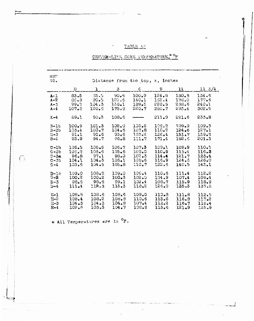
p=.
r
fl
L
TABLE M
CEKTEH- -LINK C ORK T EM P BR ATURB * °F
RUT' NO. Distance from tiio top, x, lnchea
0 1 3 6 9 11 11 3/4
A-l 83.5 83.5 90.5 100.9 124.8 130.3 134.6 A-2 8C.3 9C.5 122 .5 140.1 ' 153.4 176.0 177.5 A-3 99.7 104.3 133.1 139.5 220.3 238.6 240.1 A-4 107.3 120.5 175.3 220.7 230.7 2 93.4 302.5
X-4
B-lb
69.1
100.9
90.3
101.3
108.5
102.0
211.9
i it; o
221.6
109.9
233.8
109.3 103.6 B-2To 103.4 103.7 104.5 107.8 lic'.i 124.6 12 7.1 B-3 91.1 91.5 93.6 103.2 126.4 lbl. 7 159.2 B-4 93.9 94.7 96.8 111.7 171.4 192.6 201.3
C-lb 106.5 106.6 106.7 107.3 109.1 109.9 110.5 C-2b 105.2 105.6 105. S 103.0 110.9 115.4 116.3 C-3a 96.3 97.1 98.0 102. 3 114.4 121.7 123.4 C-3b 104.1 104.3 105.1 103.6 116.9 124.5 126.0
103.5 104 . 5 105.8 110.7 122.6 140.5 143.1
D-lb 109.0 10S.S 109.0 109.4 110.5 111.4 112.2 D-2 100.2 100.2 10Q.3 102.0 104.9 107.4 109.4 D-3 98.5 98.5 99.1 102.4 ioo.,7 115.9 118.9 L>-4 111.4 ua.3 113.3 113.2 126.0 125.3 137.5
B-l 108,8 103.6 108.6 109.0 110.3 111.3 112.5 5-8 108.4 108.2 103.3 110.6 113.6 116.3 117.2 2-3 104.3 104.3 104.3 107.4 112.2 116.7 118.4 B-4 102.6 103.3 104.7 100.2 115.5 121.9 125.9
•«• All Temperatures are In F.

m i
\
-•—*
COOLING WATER
THERMOCOUPLE -1
COOLING WATER
-THERMOCOUPLE
TRAVELING kv THERMOCOUPLE -fx f O
THERMOCOUPLE
X
THERMOCOUPLE
-THERMOCOUPLE
-ORIFICE METER
STRIP HEATERS
-JUO ^—CENTRIFUGAL
BLOWER
-INSULATION OUTLINE
THERMOCOUPLE
L
DEPARTMENT OF CHEMICAL ENGINEERTNGI UNIVERSITY OF DELAWARE
FLOW DIAGRAM
DATE 8-1-52 IY R.J.H. Rfl. NO . I
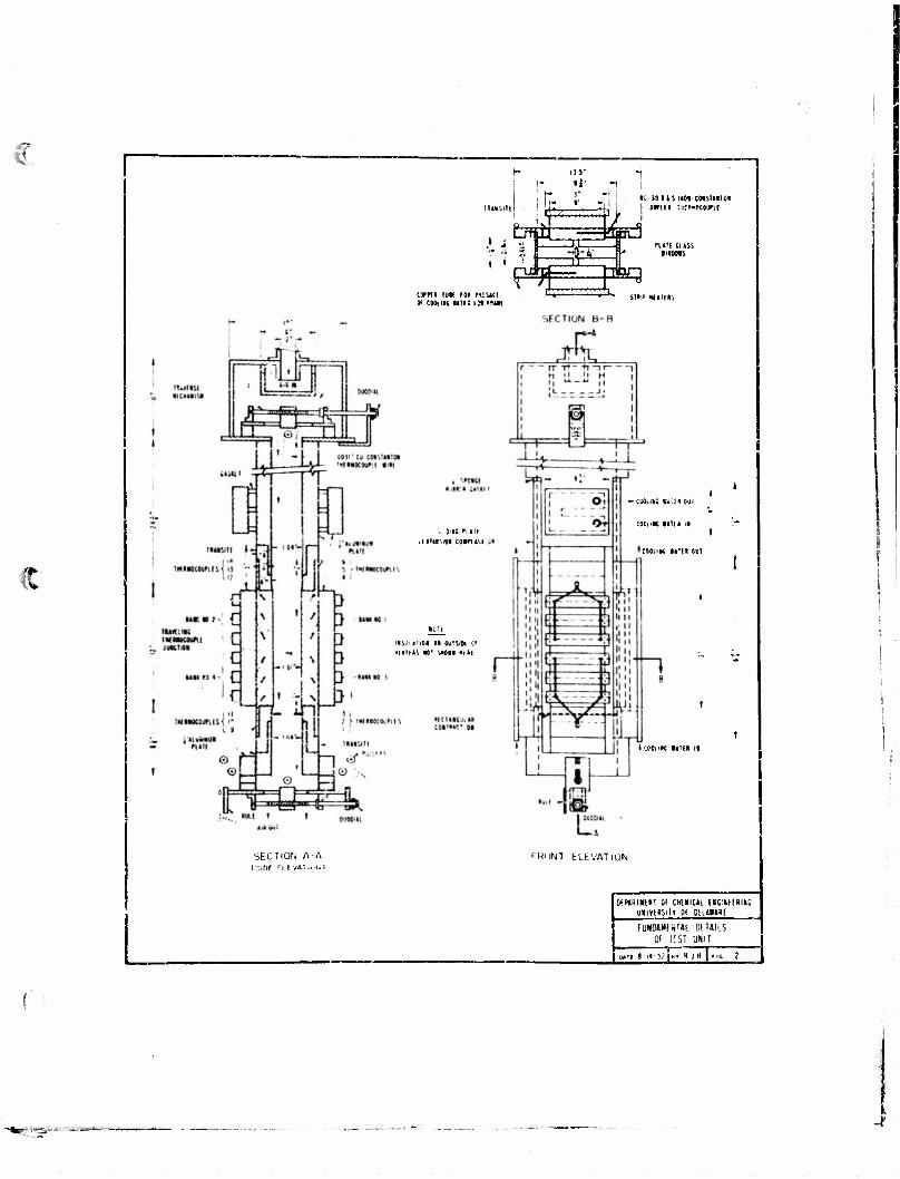
S.V
I
•: H IIS KOI CMSIU1M I JUflll inttMCMM
i^T^ MM CHS', •noon
COfftl lull 101 MiSKI Of COOklHC lllfQ 1^ "Wi
..'in: mti tirtr.iot coimsi
-;«.i; i.." om
COCuK ••III il
COOilK IHII OKI
HSii'.l'iOl III fajlS> n •tUMS «' Si*M Mll|
• count mil ii
SECTION A-A f.iDC ''I I VAi M+|}
f'HUNI ELEVATION
0<HKT«l»; 01 CHOICAi ISC.Uf Kim uaivtmii of Diunai
FUNDUKMUI MUILS Of iCSi UNI I
4"
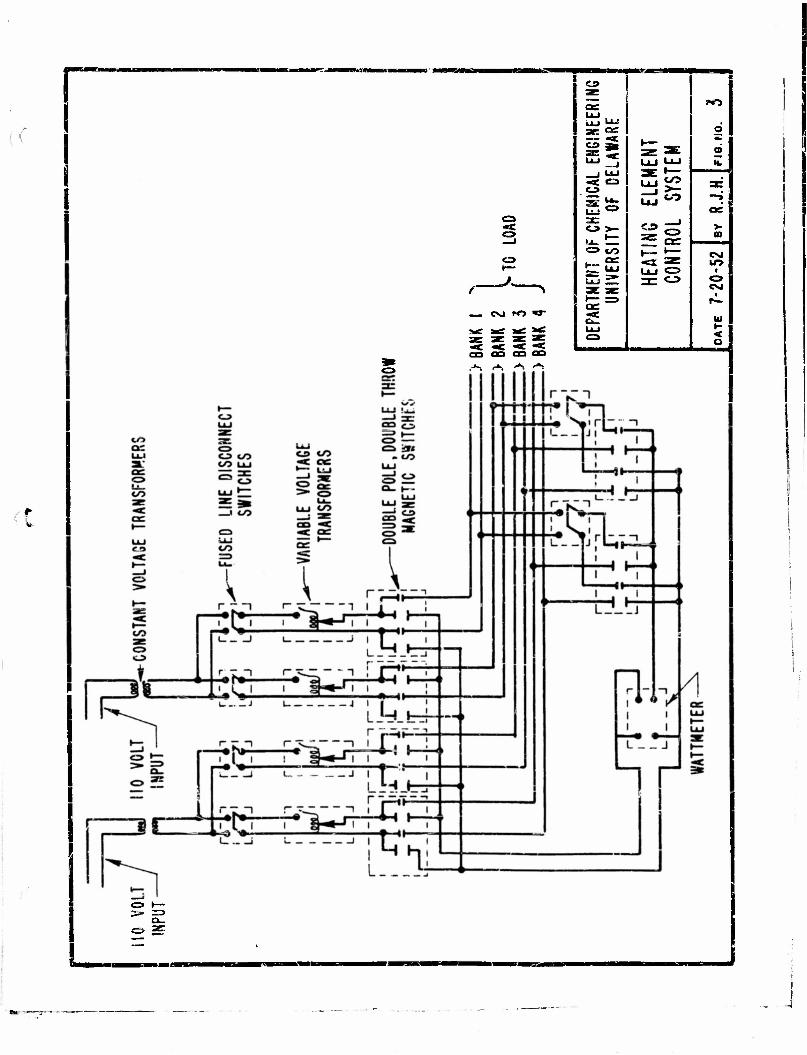
«« O
<s>
f— N
— e>j ro w
,-N i*i A **>
C»
5E «=
o
o >-
CO
CO
ct=
w>
- it
CM lO
CM
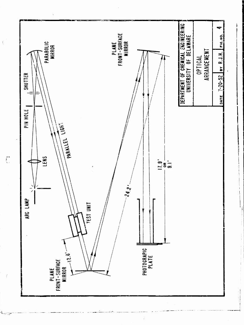
III " <J» 9B
t4J "^
<J>
co
CJ> UJ CD I— 3S
C5 or or
2 u.
CM
i
w •- < a
-U--^

——-- ————
<3> c»
IJ2E •* co
c*
ae as co
££ 2 IXJ u -•*» ,* ' <=>£ 1—
u.', 0 3* 0 0
a: a: i-- a. C5 35; ae
t.LJ
*c u. 1 =3
a:
or _j «-> <«: at: UJ a.
INAL
Di
ARAL
LE
UJ ex.
U-l LI U_ OL. c_ •-
'
J v • .
. ..
tu»_ s>
C9 => <o 0 ae a: 1— »—
ac u_ as
—_? tw
t— 06
to UJ c»
CO
t_2
CO
»~

IHttfe*! ! RUN B-IB
Figure 6. Composite Shadowgraphs of runs in which the upward'buoyant effect is not noticeable,

*
^
RUN X-4
Figure 7. Composite shadowgraphs of Rim X-4 in which the p-.vr.rd buoyant effect is noticatle.
9'

e
Firure 8. Short-ranre snarl ovjgraphs of inn M-4. Lowest horizontal b.^r on the u.",Ner hea! section photo (left) is at the name
if
unit as the !:i;:her»t her lov;er he-?, tin;; sect.loo photo
jositi r>n • n t he
4- \
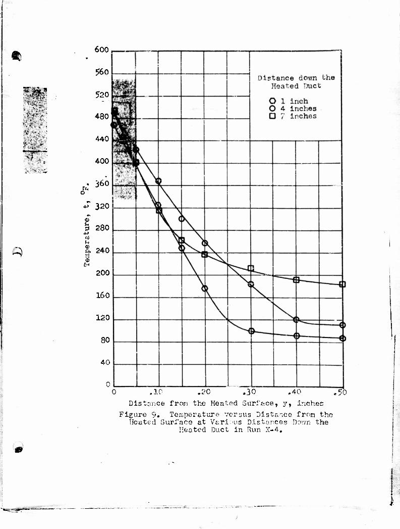
ft
•ww*
^
600,
560
520
480
440
400
• o
360
4J 320
280
0) a. s ©
EH
240
200
16 o
120
80
40
0 .10 .20 ,30 .40 .50
Distance frori the Heated Surface, y, inches Figure 9. Temperature versus Distance from the
Heated Surface at Various Distances Down the Heated Duct in Run X-4.
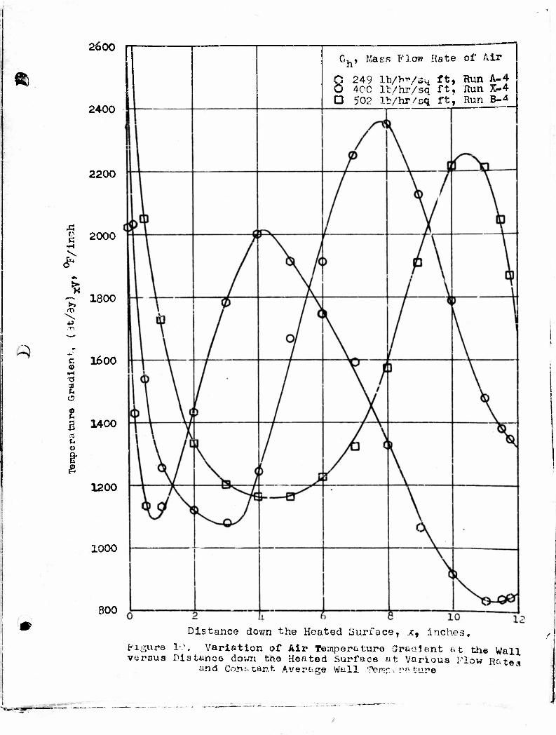
2600
ft
Q
m
c
*•
•tl
r, <D
•d 31
o
g B <U
£
2400
2200
2000
- 1800
1600
1400
1200
1000
aoo
Ch, Maes Flow Rate of Air
Q 249 Ib/hVsm f*> Run A-4
O 4CC lt/hr/sa ft, Run X-4 D 502 It/hr/sq ft, Run B-4
Distance down the Heated Surfacet .*, inches* Figure 10. Variation of Air Temperaturo CJraalent at the Wall versus Distance dovm the Heated Surface at Various Klow Ratea
and Corti tar.t Average Wall TQ7ti>- >. p«ture

i
1
o
>
a v> «-* a)
2 <3 U <D
EH
3000
2800
2600
2400
2200
2000
1800
1600
1400
1200 2 4 6 8 1C
Distance dovm the Heated ourfrce, x, inches
Fi^nr^ 11. Variation cf Air Temperature Gradient at the Wall versus Distance down the Heated Surface at Various Flow Rates and Constant Average 'Jail Temperatures.
I.
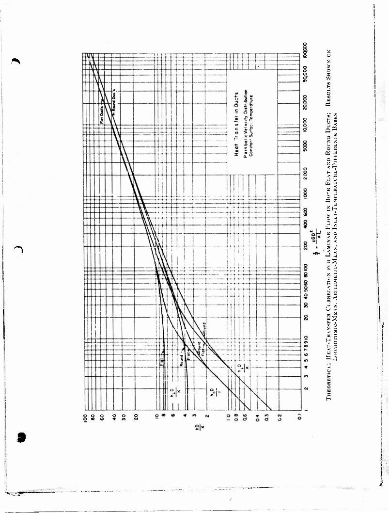
")
« i z o 0
y. o * o o o X s •/J
09 (- J y
o a
< •—• i
•< K - Li
•< X «
y. »
6 I a: «•« « ; ^ <
X o
X X
a O u
o o o o o • 3 * (O w
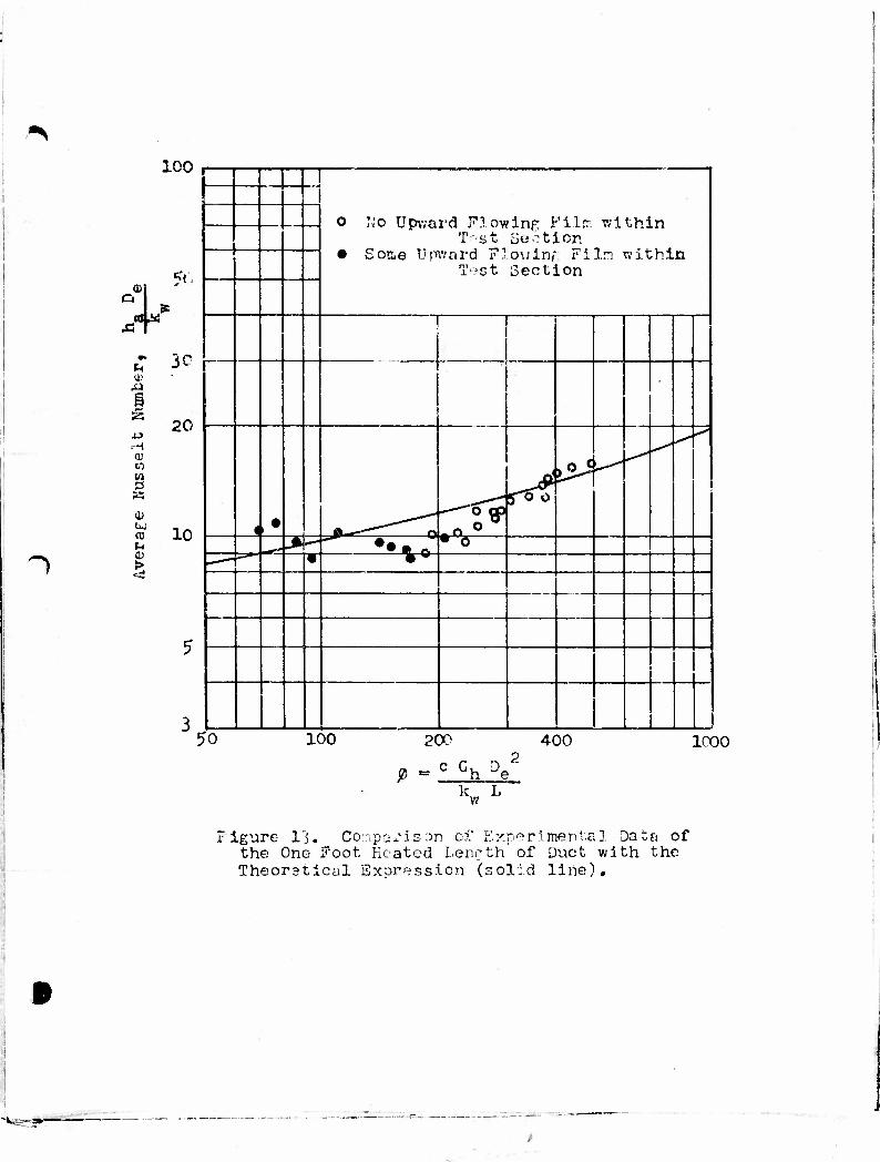
~)
%'
g
4->
H en
m t-,
o Mo Upward Flowing Film within T st Section
• Son,e Tjpv.'nrd Plowinf Filn within Test Section •Cf" ?l
3c
20
10
1
4 • J!1—*""""' o i?* f6o
i^5 >-<-
^" u* r* 'Ho • 6 • *®
5
3 ! 50 100 200
_ c G
400 1000
h e k L w
.figure l'j. Co'npa*3son of Experimental Data of the One- Foot Heated Lenrth of Duct with the Theoretical Expression (solid line).

~)
2 4 6 8 10
Distance down the Heated Place, x, Inches.
Figure 14. Comparison !~>f Local Nusselt ff-juiter with Distance dov.n the Heated Surface for Run X-4.

1
Distance down the Heated Plate, x, inches. Figure 1$, Comparison of Local Nusselt Number with
Distance down the Heated Surface for Run 13-4.
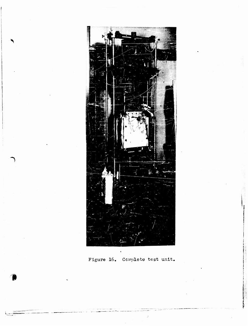
1
Figure 16. Complete test unit,
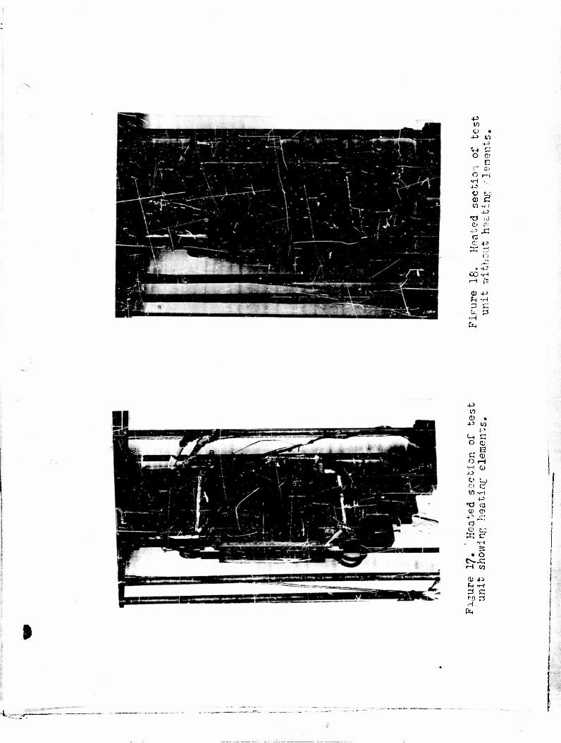
• ^
-p to o •
4-> crt 4-3
Vl r—
o c- E
r~*
o r—i •H 4- o 0)
• -
ST (.1 •c 1
•4-3
TJ '••.)
c< n; .;.") .c IS r- 4^
• -I- U_/ •H H t-
<D 4-> rH •H —' c •u* 3
•H En
4-> w o •
4-3 t)
Cn C o c;
R Li n> O t-i •H GJ JJ
o L? w •H
P TJ «j (1) P>
r3 ^L> f.n w c
TH
% O tN-Xj rH W
0) +a tn •H 3 C Ml 3 ,H
EK
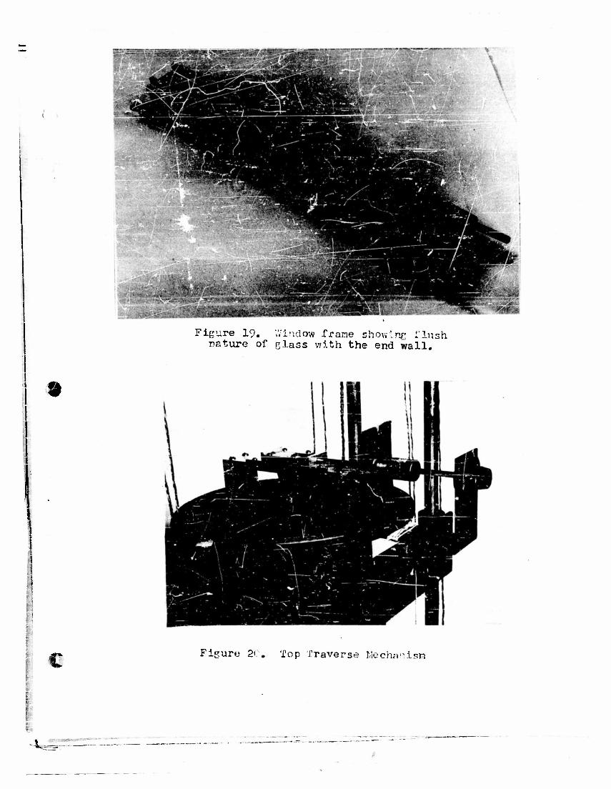
I
Figure 19. Window frame showing flush nature of class with the end wall.
1
c Figure 20. Top Traverse Mechanism
"W
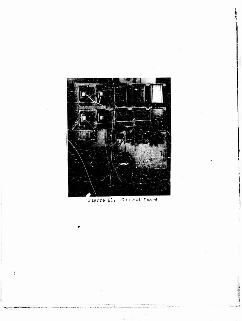
Figure 21. Control Board