15K 4-POST ALIGNMENT LIFT - Snap-on Equipment
41
Rev. 10/14/2021 15K 4-POST ALIGNMENT LIFT Installation, Operation & Maintenance Manual Four Post Surface Mounted Lift Models EELR504A, EELR504LL, EELR506A, EELR506LL, EELR706A, EELR706LL, EELR708A, & EELR708LL Snap-on Equipment 309 Exchange Avenue, Conway, Arkansas, 72032 Tel: 501-450-1500 Fax: 501-450-1585 IMPORTANT: READ THIS MANUAL COMPLETELY BEFORE INSTALLING or OPERATING LIFT
-
Upload
khangminh22 -
Category
Documents
-
view
2 -
download
0
Transcript of 15K 4-POST ALIGNMENT LIFT - Snap-on Equipment
Rev. 10/14/2021
15K 4-POST ALIGNMENT LIFT
Installation, Operation & Maintenance Manual
Four Post
Surface Mounted Lift
Models EELR504A, EELR504LL,
EELR506A, EELR506LL, EELR706A,
EELR706LL, EELR708A, & EELR708LL
Snap-on Equipment 309 Exchange Avenue, Conway, Arkansas, 72032
Tel: 501-450-1500 Fax: 501-450-1585
IMPORTANT: READ THIS MANUAL COMPLETELY BEFORE
INSTALLING or OPERATING LIFT
Installation, Operation and Maintenance
2 Rev. 10/14/2021 EAZ0080V62A.doc
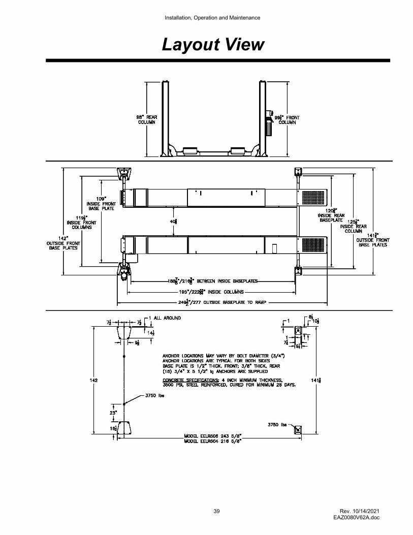
LIFT SPECIFICATIONS
SPECIFICATIONS EELR504A/ EELR504LL EELR706A/ EELR706LL
EELR506A/ EELR506LL EELR708A/ EELR708LL
Lift Style Open Front
A Length Overall 250.75" (6370mm) 277” (7036mm)
B Width Overall 142" Front (3607mm) - 141.75” Rear (3600mm)
C Inside Columns 120.75" Front (3067mm) - 125.5" Rear (3188mm)
D Between Columns 195” (4953mm) 222.5” (5651mm)
E Height of Columns 99 1/4” front (2521mm) - 98” rear (2489mm)
F Height of Runways 8" (203mm)
G Width of Runways 26” (660mm)
H Width Between Runways 40.625" (1032mm)
I Max/Min Wheelbase * 183” (4648mm)/ 89.5” (2273mm) 210.5" (5347mm)/ 113” (2870mm)
J Max. 2 Wheel Alignment 167.75” (4261mm) 195.25" (4959mm)
K 4 Wheel Alignment 68" (1727mm) - 158" (4013mm)
L Rise Height 78" (1981mm)
Lifting Capacity (Hydraulic Pressure at Cap.)
15,000 lbs. (6804kg) (2190 psi) (151bar)
Air Supply Required 90-120 psi Clean & Dry (6.2-8.23bar)
Motor 3HP
Voltage (Single Phase Std.) ** 208v-230V, 60Hz
Rise Time 85 Seconds (approximate)
Min. Recommended Bay Size 14' x 24' (4267mm) x (7315mm) 14' (4267mm) x 26' (7925mm)
Approximate Shipping Weight 4350~4550 lbs. (1973~2046kg)
* Wheelbase is based on a tire diameter of 30” ** Optional 3 phase, 50/60Hz, 208, 230 or 460V available.
Fig 1 – General Specifications and Service Bay Layout
Installation, Operation and Maintenance
3 Rev. 10/14/2021 EAZ0080V62A.doc
VERTICAL CLEARANCE Check the height of the area where the lift is to be installed. Clearance should be calculated based on the full raised height of the lift.
Failure by purchaser to provide adequate clearance could result in unsatisfactory
lift performance, property damage, or personal injury.
FLOORING
Be certain you have the proper concrete floor to properly handle the loaded lift. Floor should be in generally good condition with no large cracks, spalling or deterioration.
Minimum requirements for concrete are 4 inches minimum depth, with steel reinforcement, 3500 psi, cured for 28 days per local commercial practice. This lift is designed to accommodate a 3 inch total variation in elevation at the base of the four posts. Floor should be level within 1/2 inch from side-to-side and 2 1/2 front-to-rear to avoid special shimming. No anchors should be installed within 8 inches of any crack, edge, or expansion joint. If these conditions cannot be met, a pad may be poured to accommodate the lift.
Check with local building inspectors and/or permits office for any special instructions or approvals required for your installation.
A qualified person should be consulted to address seismic loads and other local or state requirements.
Failure by purchaser to provide the recommended mounting surface could
result in unsatisfactory lift performance, property damage, or personal injury.
LOCATION This lift has been evaluated for indoor use only with an operating ambient temp. range of 5–40°C (41-104°F). Outdoor Installation is Prohibited.
ELECTRICAL REQUIREMENTS
For lift installation and operation it is necessary to have a dedicated circuit with circuit breaker or time delay fuse. Refer to wiring diagram for circuit sizing.
AIR REQUIREMENTS
This lift is equipped with an air operated lock release system. The air supplied to the lift must be clean, dry, lubricated, and regulated to 90-120 psi, FRL (Filter/Regulator/Lubricator). The FRL must be within 30 feet of lift. Failure to provide clean, dry, lubricated, and pressure regulated air will void warranty on pneumatic components.
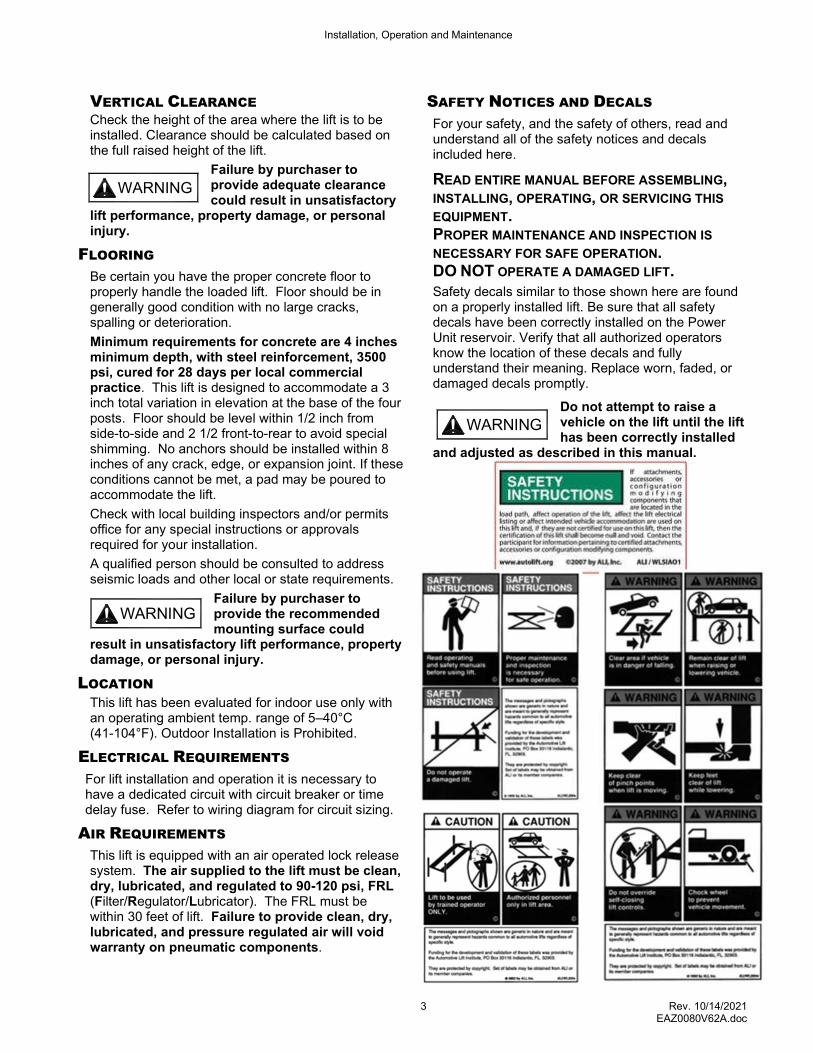
SAFETY NOTICES AND DECALS
For your safety, and the safety of others, read and understand all of the safety notices and decals included here.
READ ENTIRE MANUAL BEFORE ASSEMBLING, INSTALLING, OPERATING, OR SERVICING THIS
EQUIPMENT. PROPER MAINTENANCE AND INSPECTION IS
NECESSARY FOR SAFE OPERATION. DO NOT OPERATE A DAMAGED LIFT. Safety decals similar to those shown here are found on a properly installed lift. Be sure that all safety decals have been correctly installed on the Power Unit reservoir. Verify that all authorized operators know the location of these decals and fully understand their meaning. Replace worn, faded, or damaged decals promptly.
Do not attempt to raise a vehicle on the lift until the lift has been correctly installed
and adjusted as described in this manual.
WARNING
WARNING
WARNING
Installation, Operation and Maintenance
4 Rev. 10/14/2021 EAZ0080V62A.doc
RECEIVING
The shipment should be thoroughly inspected as soon as it is received. The signed bill of lading is acknowledgement by the carrier of receipt in good condition of shipment covered by our invoice.
If any of the goods called for on this bill of lading are shorted or damaged, do not accept them until the carrier makes a notation on the freight bill of the shorted or damaged goods. Do this for your own protection.
NOTIFY Customer Service AT ONCE if any hidden loss or damage is discovered after receipt.
IT IS DIFFICULT TO COLLECT FOR LOSS OR DAMAGE AFTER YOU HAVE GIVEN THE CARRIER A CLEAR RECEIPT.
File your claim with Customer Service promptly. Support your claim with copies of the bill of lading, freight bill, and photographs, if available.
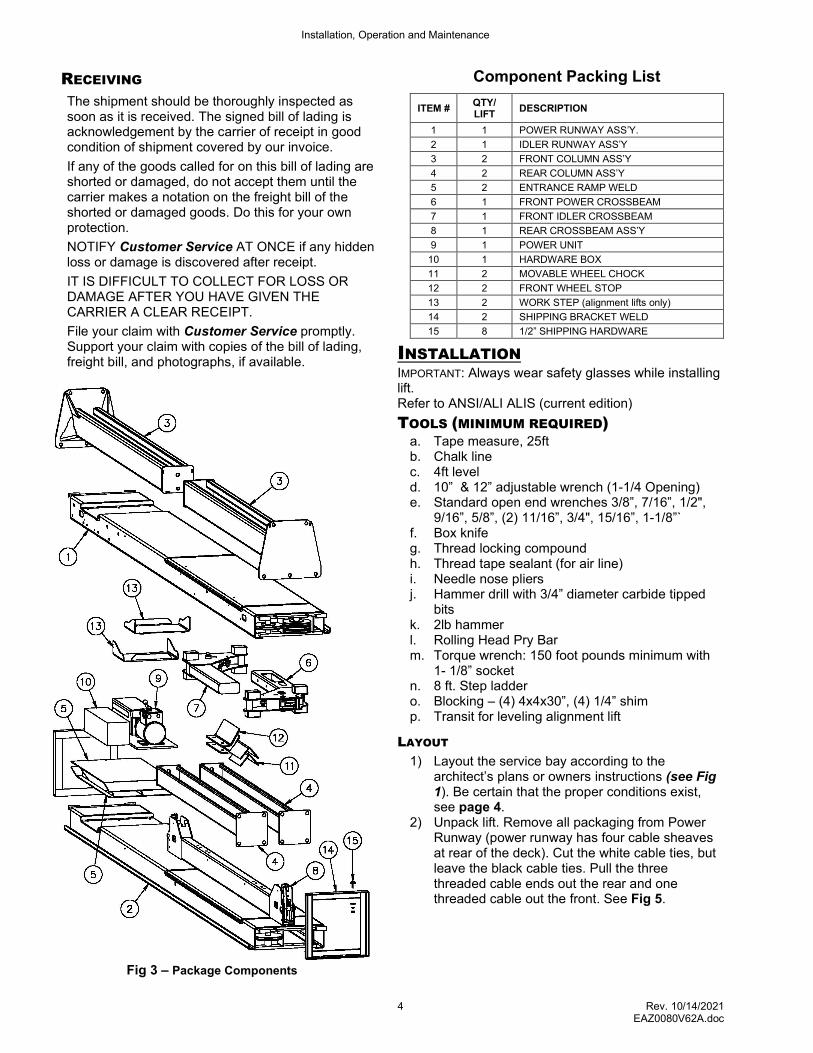
Fig 3 – Package Components
Component Packing List
ITEM # QTY/ LIFT
DESCRIPTION
1 1 POWER RUNWAY ASS’Y.
2 1 IDLER RUNWAY ASS’Y
3 2 FRONT COLUMN ASS’Y
4 2 REAR COLUMN ASS’Y
5 2 ENTRANCE RAMP WELD
6 1 FRONT POWER CROSSBEAM
7 1 FRONT IDLER CROSSBEAM
8 1 REAR CROSSBEAM ASS’Y
9 1 POWER UNIT
10 1 HARDWARE BOX
11 2 MOVABLE WHEEL CHOCK
12 2 FRONT WHEEL STOP
13 2 WORK STEP (alignment lifts only)
14 2 SHIPPING BRACKET WELD
15 8 1/2” SHIPPING HARDWARE
INSTALLATION IMPORTANT: Always wear safety glasses while installing lift. Refer to ANSI/ALI ALIS (current edition)
TOOLS (MINIMUM REQUIRED) a. Tape measure, 25ft b. Chalk line c. 4ft level d. 10” & 12” adjustable wrench (1-1/4 Opening) e. Standard open end wrenches 3/8”, 7/16”, 1/2",
9/16”, 5/8”, (2) 11/16”, 3/4", 15/16”, 1-1/8”` f. Box knife g. Thread locking compound h. Thread tape sealant (for air line) i. Needle nose pliers j. Hammer drill with 3/4” diameter carbide tipped
bits k. 2lb hammer l. Rolling Head Pry Bar m. Torque wrench: 150 foot pounds minimum with
1- 1/8” socket n. 8 ft. Step ladder o. Blocking – (4) 4x4x30”, (4) 1/4” shim p. Transit for leveling alignment lift
LAYOUT
1) Layout the service bay according to the architect’s plans or owners instructions (see Fig 1). Be certain that the proper conditions exist, see page 4.
2) Unpack lift. Remove all packaging from Power Runway (power runway has four cable sheaves at rear of the deck). Cut the white cable ties, but leave the black cable ties. Pull the three threaded cable ends out the rear and one threaded cable out the front. See Fig 5.
Installation, Operation and Maintenance
5 Rev. 10/14/2021 EAZ0080V62A.doc
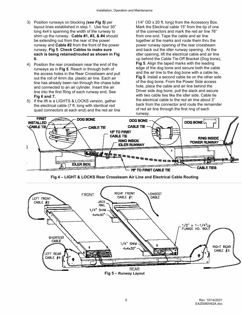
3) Position runways on blocking (see Fig 5) per layout lines established in step 1. Use four 30” long 4x4’s spanning the width of the runway to shim up the runway. Cable #1, #3, & #4 should be extending out from the rear of the power runway and Cable #2 from the front of the power runway, Fig 5. Check Cables to make sure each is being retained/routed as shown in Fig 6.
4) Position the rear crossbeam near the end of the runways as in Fig 5. Reach in through both of the access holes in the Rear Crossbeam and pull out the roll of 4mm dia. plastic air line. Each air line has already been ran through the chase tube and connected to an air cylinder. Insert the air line into the first Ring of each runway end. See Fig 6 and 7.
5) If the lift is a LIGHTS & LOCKS version, gather the electrical cable (7 ft. long with identical red quad connectors at each end) and the red air line
(1/4” OD x 20 ft. long) from the Accessory Box. Mark the Electrical cable 15” from the tip of one of the connectors and mark the red air line 76” from one end. Tape the cable and air line together at the marks and route them thru the power runway opening of the rear crossbeam and back out the idler runway opening. At the idler opening, lift the electrical cable and air line up behind the Cable Tie-Off Bracket (Dog bone), Fig 5. Align the taped marks with the leading edge of the dog bone and secure both the cable and the air line to the dog bone with a cable tie, Fig 5. Install a second cable tie on the other side of the dog bone. From the Power Side access hole, place the cable and air line behind the Driver side dog bone, pull the slack and secure with two cable ties like the idler side. Cable tie the electrical cable to the red air line about 3” back from the connector and route the remainder of red air line through the first ring of each runway.
Fig 4 – LIGHT & LOCKS Rear Crossbeam Air Line and Electrical Cable Routing
Fig 5 – Runway Layout
Installation, Operation and Maintenance
6 Rev. 10/14/2021 EAZ0080V62A.doc
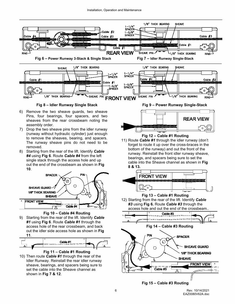
Fig 6 – Power Runway 3-Stack & Single Stack Fig 7 – Idler Runway Single-Stack
Fig 8 – Idler Runway Single Stack Fig 9 – Power Runway Single-Stack
6) Remove the two sheave guards, two sheave Pins, four bearings, four spacers, and two sheaves from the rear crossbeam noting the assembly order.
7) Drop the two sheave pins from the idler runway (runway without hydraulic cylinder) just enough to remove the sheaves, bearing, and spacers. The runway sheave pins do not need to be removed.
8) Starting from the rear of the lift. Identify Cable #4 using Fig 6. Route Cable #4 from the left single stack through the access hole and up out the end of the crossbeam as shown in Fig 10.
Fig 10 – Cable #4 Routing
9) Starting from the rear of the lift. Identify Cable #1 using Fig 6. Route Cable #1 through the access hole of the rear crossbeam, and back out the idler side access hole as shown in Fig 11.
Fig 11 – Cable #1 Routing
10) Then route Cable #1 through the rear of the Idler Runway. Reinstall the rear idler runway sheave, bearings, and spacers being sure to set the cable into the Sheave channel as shown in Fig 7 & 12.
Fig 12 – Cable #1 Routing 11) Route Cable #1 through the idler runway (don’t
forget to route it up over the cross-braces in the bottom of the runway) and out the front of the runway. Reinstall the front idler runway sheave, bearings, and spacers being sure to set the cable into the Sheave channel as shown in Fig 8 & 13.
Fig 13 – Cable #1 Routing
12) Starting from the rear of the lift. Identify Cable #3 using Fig 6. Route Cable #3 through the access hole and out the end of the crossbeam..
Fig 14 – Cable #3 Routing
Fig 15 – Cable #3 Routing
Installation, Operation and Maintenance
7 Rev. 10/14/2021 EAZ0080V62A.doc
NOTE: Look through the idler end of the crossbeam and ensure that cable #1 and #3 have not crossed. Cable #3 should be above Cable #1. 13) Double check to make sure Cable #3 is above
Cable #1 and not crossed. See Fig 6 and 7. 14) Reinstall the crossbeam sheave for Cable #3
and Cable #4. Slide the sheave pin through the hole, slide one sheave spacer onto the pin followed by one 1/8” plastic bearing washer, and the sheave. Set the cable into the Sheave channel and proceed to adding a 1/8” plastic washer and sheave spacer to the pin. Install the 5/16 x 3/4 bolt to retain the sheave. Reinstall the sheave guards. See Fig 10 & 15.
15) Remove slack and route each 4mm air line through the first ring in the runway for both sides, see Fig 6 and 7. Bring the crossbeam up to the runways being careful to not pinch the air line, cables, and sheaves.
16) The runways to crossbeam positioning can be located using a tapered punch to pry on the locating holes in the runway and crossbeam NOTE: The locating holes are not threaded. See Fig 20.
17) Attach the rear crossbeam to the runways (Fig. 5) with 1/2 x 1-1/4” lg. flange head bolts. (Leave the air lines hanging out the bottom of the runway at this time. They will be fed in through the runway after the lift is raised.) The outermost runway holes should be in line with the outermost holes in the top of the crossbeam, see Fig. 5. Do not torque bolts yet.
18) Check the layout of the lift in the bay. (This is the last opportunity to reposition the lift. Take a moment to determine the position of the front column anchors to ensure proper clearance from any crack, edge, or expansion joint. Ensure proper clearance for the lift operator at the Power Unit Controls). Adjust the position of the runways so the distance from power side jack rail to idler side jack rail is the same at the front and rear and the diagonal measurements from the front tip of one rail to the rear tip of the opposite rail are within 1/8”, Fig 16.
Fig 16 – Final Runway Positioning
19) Tighten rear crossbeam bolts to 60-80ft-lb.
REAR COLUMNS
20) Stand up both rear (small base) column assemblies near the rear corners of the lift Thread the locking ladder jam nut (located under the column top plate) down approximately 9.5” to allow the ladder to be lifted freely.
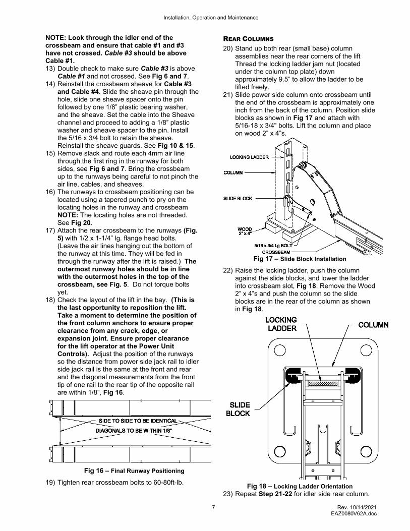
21) Slide power side column onto crossbeam until the end of the crossbeam is approximately one inch from the back of the column. Position slide blocks as shown in Fig 17 and attach with 5/16-18 x 3/4" bolts. Lift the column and place on wood 2” x 4”s.
Fig 17 – Slide Block Installation
22) Raise the locking ladder, push the column against the slide blocks, and lower the ladder into crossbeam slot, Fig 18. Remove the Wood 2” x 4”s and push the column so the slide blocks are in the rear of the column as shown in Fig 18.
Fig 18 – Locking Ladder Orientation 23) Repeat Step 21-22 for idler side rear column.
Installation, Operation and Maintenance
8 Rev. 10/14/2021 EAZ0080V62A.doc
ANCHORING (Rear Columns Only At This Time)
24) The anchor bolts must be installed at least 8” from any crack, edge, or expansion joint.
25) Use a concrete hammer drill with a 3/4 inch carbide bit. Tip diameter should conform to ANSI Standard B94.12-1977 (.775 to .787). Do not use excessively worn bits or bits which have been incorrectly sharpened. A core bit may be necessary if an obstruction is encountered. Never substitute with shorter anchor.
26) Drill the anchor holes using the base plate as a template. Drill through the floor if possible or to a depth of 5 inches minimum.
27) Vacuum dust from the hole for proper holding power.
28) Shim columns to plumb using the shims provided or steel washers. DO NOT shim more than 1/2" at any given point. Use a level no less than 24” in length to plumb columns.
29) Assemble each washer and nut to each anchor with the nut just below impact section of bolt. Drive the outer anchors into the other holes until nut and washer contact the base. Align the spacer over the two inside anchor holes on top of the baseplate and drive the anchors assembly in both inside holes, See Fig 18. The spacer is used to space the crossbeam off the floor. Tighten each anchor bolt to 150 foot-pounds and recheck column for plumb. Re-shim as required. Note the Front Spacer is wider than the Rear.
NOTE: Level bubble should not only be between the lines, the bubble should be centered between the lines. If the provided shims do not allow sufficient centering of the bubble, it is best to lean the rear columns in the direction toward each other and the open front columns in the direction away from each other.
OPEN FRONT COLUMNS/CROSSBEAMS
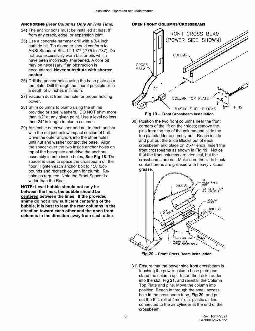
Fig 19 – Front Crossbeam Installation
30) Position the two front columns near the front corners of the lift on their sides; remove the pins from the top of the column and slide the top plate/ladder assembly out. Reach inside and pull out the Slide Blocks out of each crossbeam and place on 2”x4” ends. Insert the front crossbeams as shown in Fig 19. Notice that the front columns are identical, but the crossbeams are not. Make sure the slide block contact areas are greased with heavy viscous grease.
Fig 20 – Front Cross Beam Installation
31) Ensure that the power side front crossbeam is
touching the power column base plate and stand the column up. Insert the Lock Ladder into the slot, Fig 21, and reinstall the Column Top Plate and pins. Move the column into position. Reach in through the small access hole in the crossbeam tube, Fig 20, and pull out the 6 ft. roll of 4mm” dia. plastic air line connected to the air cylinder at the end of the crossbeam.
Installation, Operation and Maintenance
9 Rev. 10/14/2021 EAZ0080V62A.doc
32) Remove the crossbeam sheave guard, sheave, Pin etc. Feed Cable #2 into the crossbeam’s large access hole and back out the top, Fig 20. Insert the air line into the first Ring in the runway end. See Fig 8 and 9 for ring location.
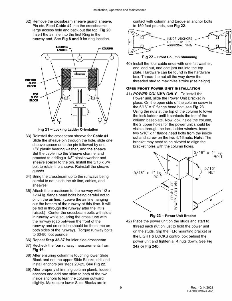
Fig 21 – Locking Ladder Orientation
33) Reinstall the crossbeam sheave for Cable #1. Slide the sheave pin through the hole, slide one sheave spacer onto the pin followed by one 1/8” plastic bearing washer, and the sheave. Set the cable into the Sheave channel and proceed to adding a 1/8” plastic washer and sheave spacer to the pin. Install the 5/16 x 3/4 bolt to retain the sheave. Reinstall the sheave guards
34) Bring the crossbeam up to the runways being careful to not pinch the air line, cables, and sheaves
35) Attach the crossbeam to the runway with 1/2 x 1-1/4 lg. flange head bolts being careful not to pinch the air line. (Leave the air line hanging out the bottom of the runway at this time. It will be fed in through the runway after the lift is raised.) Center the crossbeam bolts with slots in runway while squaring the cross tube with the runway (gap between the front of the runway and cross tube should be the same on both sides of the runway). Torque runway bolts to 60-80 foot pounds.
36) Repeat Step 32-37 for idler side crossbeam.
37) Recheck the four runway measurements from Fig 16.
38) After ensuring column is touching lower Slide Block and not the upper Slide Blocks, drill and install anchors per steps 20-25, See Fig 22.
39) After properly shimming column plumb, loosen anchors and add one shim to both of the two inside anchors to lean the column outward slightly. Make sure lower Slide Blocks are in
contact with column and torque all anchor bolts to 150 foot-pounds, see Fig 22.
Fig 22 – Front Column Shimming
40) Install the four cable ends with one flat washer, one load nut, and one jam nut into the top plate. Hardware can be found in the hardware box. Thread the nut all the way down the threaded stud to maximize stroke (rise height).
OPEN FRONT POWER UNIT INSTALLATION
41) POWER COLUMN ONLY – To install the Power unit, slide the Power Unit Bracket in place. On the open side of the column screw in the 5/16” x 1” flange head bolt, see Fig 23. Using the nuts at the top of the column to lower the lock ladder until it contacts the top of the column baseplate. Now look inside the column, the 2 upper holes for the power unit should be visible through the lock ladder window. Insert two 5/16” x 1” flange head bolts from the inside out and screw on the two 5/16 nuts. Note: The bracket may need to be pivoted to align the bracket holes with the column holes.
Fig 23 – Power Unit Bracket
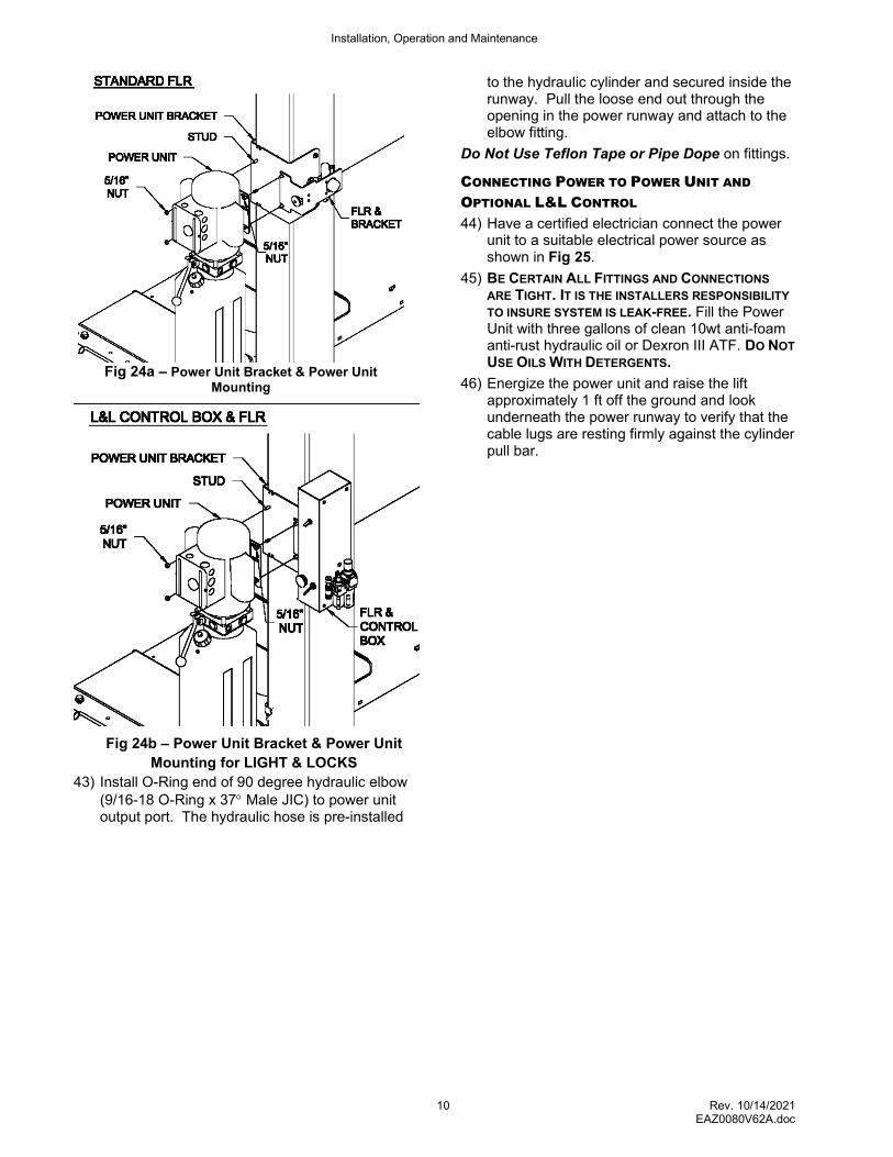
42) Place the power unit on the studs and start to
thread each nut on just to hold the power unit
on the studs. Slip the FLR mounting bracket or
the LIGHT & LOCKS control box behind the
power unit and tighten all 4 nuts down. See Fig
24a or Fig 24b.
Installation, Operation and Maintenance
10 Rev. 10/14/2021 EAZ0080V62A.doc
Fig 24a – Power Unit Bracket & Power Unit Mounting
Fig 24b – Power Unit Bracket & Power Unit
Mounting for LIGHT & LOCKS
43) Install O-Ring end of 90 degree hydraulic elbow (9/16-18 O-Ring x 37 Male JIC) to power unit output port. The hydraulic hose is pre-installed
to the hydraulic cylinder and secured inside the runway. Pull the loose end out through the opening in the power runway and attach to the elbow fitting.
Do Not Use Teflon Tape or Pipe Dope on fittings.
CONNECTING POWER TO POWER UNIT AND
OPTIONAL L&L CONTROL
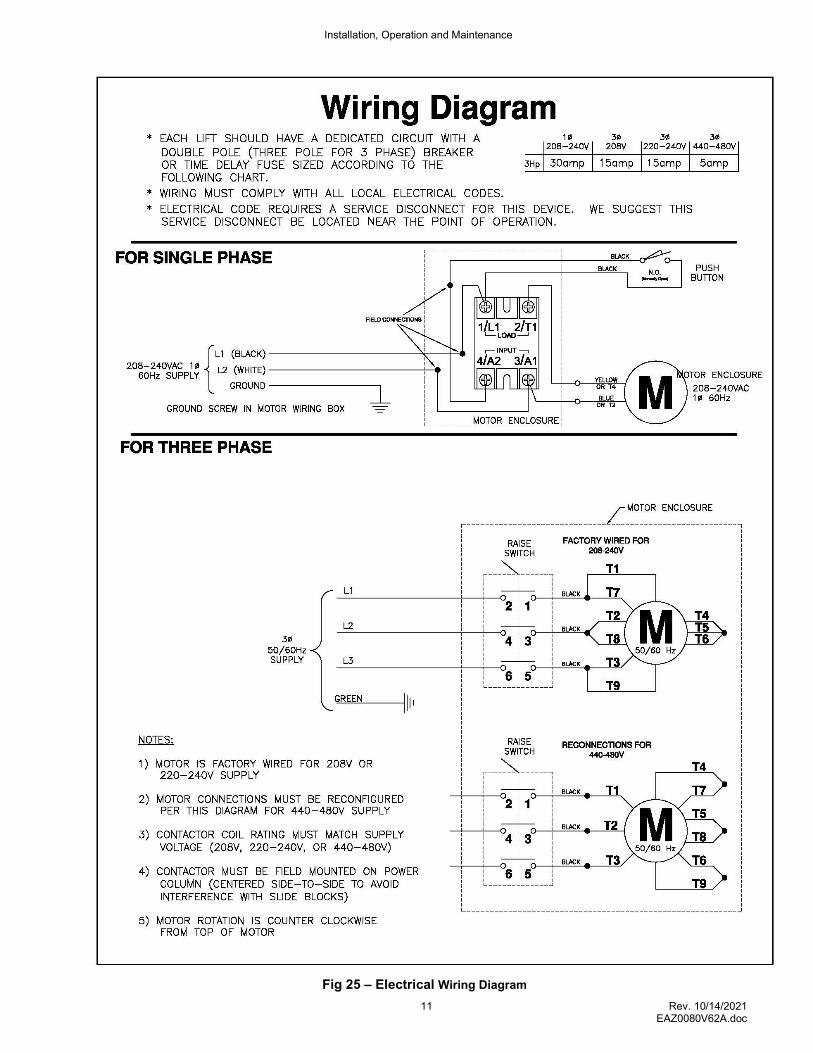
44) Have a certified electrician connect the power unit to a suitable electrical power source as shown in Fig 25.
45) BE CERTAIN ALL FITTINGS AND CONNECTIONS
ARE TIGHT. IT IS THE INSTALLERS RESPONSIBILITY
TO INSURE SYSTEM IS LEAK-FREE. Fill the Power Unit with three gallons of clean 10wt anti-foam anti-rust hydraulic oil or Dexron III ATF. DO NOT
USE OILS WITH DETERGENTS.
46) Energize the power unit and raise the lift approximately 1 ft off the ground and look underneath the power runway to verify that the cable lugs are resting firmly against the cylinder pull bar.
Installation, Operation and Maintenance
11 Rev. 10/14/2021 EAZ0080V62A.doc
Fig 25 – Electrical Wiring Diagram
Installation, Operation and Maintenance
12 Rev. 10/14/2021 EAZ0080V62A.doc
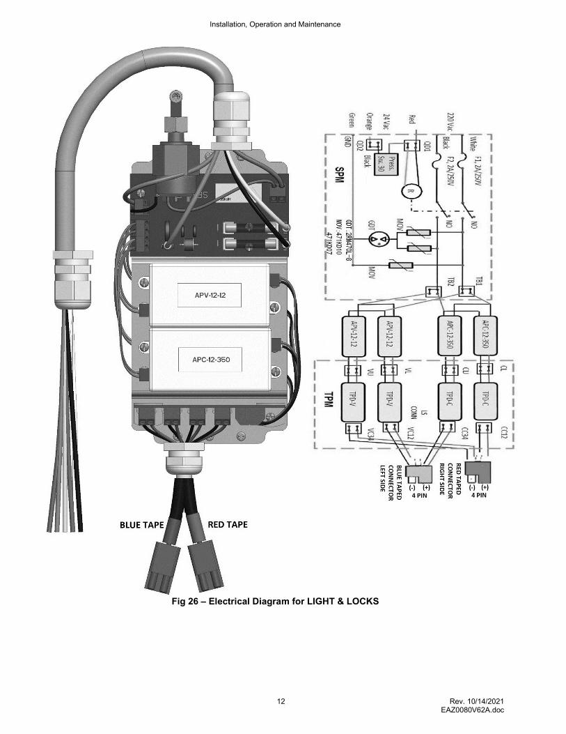
Fig 26 – Electrical Diagram for LIGHT & LOCKS
Installation, Operation and Maintenance
13 Rev. 10/14/2021 EAZ0080V62A.doc
LOCK RELEASE AIR LINE INSTALLATION
47) For the L&L, install the 4mm air line into the 4mm union shown in Fig 37. For all other lifts install 4mm air line into the air valve assembly. For all lifts, route the airline thru opening in runway to Tee. See Fig 27
Fig 27 – Lock Release Air Line Routing
48) Route power side front and rear crossbeam air lines through power runway rings to Tee. Route idler side front and rear crossbeam air lines through idler runway rings and connect together with 4mm air line spice provided.
49) Using a suitable air source, connect the air source to the Female 1/4” NPT ball valve fitting.
50) Shutoff the ball valve and using a screwdriver remove the filler cap on the top of the FRL. Fill FRL to the max line. Re-install the oil filler cap. Adjust the drips to 2-3 per minute. Once adjusted turn the ball valve back on.
51) Pull up on the regulator knob and adjust the pressure to 100psi (allowable range 90-120 psi).
52) Press the lock release air valve button and ensure that all air cylinders are working properly.
53) Raise and lower lift several times to bleed hydraulic cylinder. Hydraulic cylinder is self-bleeding. Lower lift and check fluid level in reservoir. Add fluid as needed.
54) Pressure test hydraulic system. Energize power unit, raise lift to full rise and continue to run motor for additional 10 seconds. (NOTE: pressure relief will make a high pitch squeal sound for these 10 seconds.) Check hydraulic system for leaks
Place the two provided wheel chocks on top of the drivers side runway one wheel chocks on each runway
LIFT LEVELING
55) Adjust all four column lock ladders so the bottom of the ladder is floating just above the
column base plate. Lower the lift into a lock position.
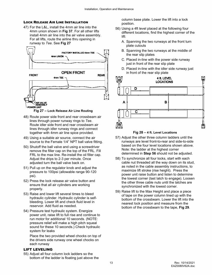
56) Using a 4ft level placed at the following four different locations, find the highest corner of the lift:
A. Spanning the two runways at the front turn plate cutouts
B. Spanning the two runways at the middle of the rear slip plates
C. Placed in-line with the power side runway just in front of the rear slip plate
D. Placed in-line with the idler side runway just in front of the rear slip plate
Fig 28 – 4 ft. Level Locations
57) Adjust the other three column ladders until the runways are level front-to-rear and side-to-side based on the four level locations shown above. Note: the ladder at the highest corner determined in Step 56 should not be adjusted.
58) To synchronize all four locks, start with each cable nut threaded all the way down on its stud, as noted in the cable assembly instructions, to maximize lift stroke (rise height). Press the power unit raise button and listen to determine the lowest corner (last latch to engage). Loosen the other three cable nuts until the latches are synchronized with the lowest corner.
59) Raise lift to the Max Height and place a piece of tape on the power column lined up with the bottom of the crossbeam. Lower the lift into the nearest lock position and measure from the bottom of the crossbeam to the tape, Fig 29.

Installation, Operation and Maintenance
14 Rev. 10/14/2021 EAZ0080V62A.doc
Fig 29 – Lock Clearance Measurement
60) If this distance is less than 1”, adjust all four column ladders up by 12 revolutions (approx. 1-1/4”) to ensure proper lock engagement in the highest position.
FRONT TURNPLATE LEVELING 61) Place the level in a front turn plate cutout,
Fig 30. Place three 1/16” thick column shims (3/16” total thickness) under the level at the outside edge of the cutout and adjust the runway pitch leveling screws until the bubble is centered between the lines. Make sure all leveling screws are touching the crossbeam. Torque runway bolts to 60-80 foot pounds and recheck the level. Repeat for other side. (The rear of the runway usually does not require pitch adjustment as this is a closed rear crossbeam.)
Fig 30 – Runway Pitch Adjustment
LEVELING WITH A TRANSIT
62) Use a transit to fine-tune the lift leveling while the lift is resting in its locks. Place the target on the center of the turn plate and the center of the rear slip plate. Adjust the column ladders as needed so all 4 target locations are on the same level plane.
63) Re-adjust cables until all four locks are synchronized when lift is raised.
FINALIZING LIFT LEVELING
64) Tighten lock ladder jam nut against bottom side of each column top plate.
65) Tighten cable jam nuts against adjustment nuts.
66) For the lifts that don’t have the LIGHT & LOCKS option proceed to the Jack Installation section Step 82.
LOCKING FRONT TURN PLATES & REAR
SLIP PLATES
Caution: Avoid inserting fingers in the front alignment pan cut-out, if position of the turn plate assembly exposes such openings. Caution: Ensure that air supply to the lift is turned off and no person is operating on the console during maintenance of clamping elements of the locking system. Caution: During normal use, the front turn plates and rear slip plates may move rapidly, when locking system is activated. This creates pinch points for your fingers or hands. Keep hands clear of these pinch points when lift air supply is connected. No person shall operate console while maintenance or inspection of the slip plates is in process. 67) Lower lift to a comfort height. 68) Place each front turn plate assembly, one by
one, on the front alignment pan on runway. Moving handles of the turn plates should be oriented to the outside of lift, Fig 31.
Installation, Operation and Maintenance
15 Rev. 10/14/2021 EAZ0080V62A.doc
NOTE: Ensure that the locking system components on the bottom of the turn plate (air cylinder, fittings, and plastic clamping parts) are not hitting against the runway during placement.
Fig 31- Turn plate Installation
69) Verify that the turn plate assembly is completely seated in the front alignment pan. Gently slide each turn plate in the alignment pan, left and right, to verify that they can be positioned for different car widths. Do not hit plastic locking ring forcefully against the edges of the cut-out in the front alignment pan.
70) Connect free ends of front air lines to the turn plate locking cylinder: red air line to the top cylinder port Fig 32. Remove and discard the bottom air fitting and replace it with the provided breather. Repeat for the idler side.
Fig 32- Turn Plate Installation
71) Plug the Four Pin Electrical Connector on the turn plate light cord into the Blue Four Pin Electrical Connector on the cable at the front for both the idler and power side. See Fig 34.
Note: The Power side Blue 4 Pin connector has only ONE Lead as the TWO Lead Blue 4 Pin connector will be plugged in at the L&L control box.
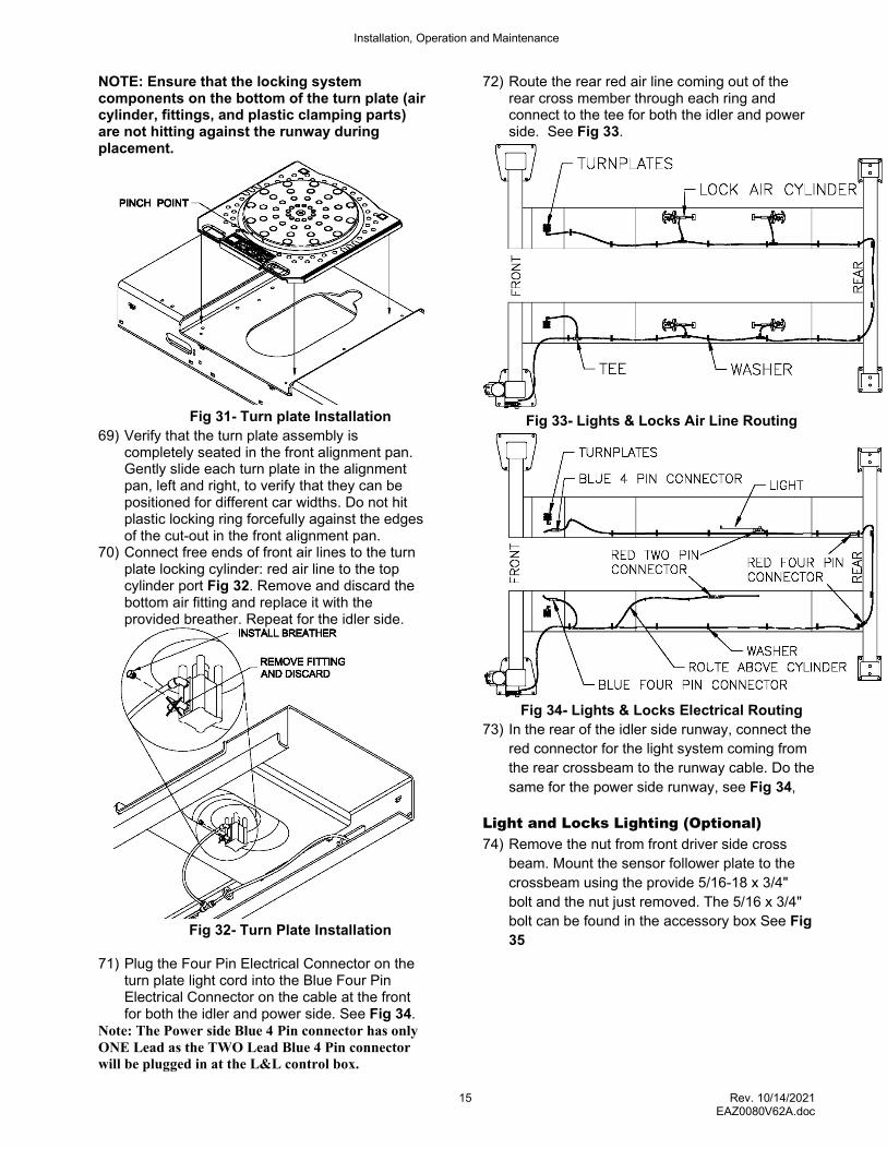
72) Route the rear red air line coming out of the rear cross member through each ring and connect to the tee for both the idler and power side. See Fig 33.
Fig 33- Lights & Locks Air Line Routing
Fig 34- Lights & Locks Electrical Routing
73) In the rear of the idler side runway, connect the
red connector for the light system coming from
the rear crossbeam to the runway cable. Do the
same for the power side runway, see Fig 34,
Light and Locks Lighting (Optional)
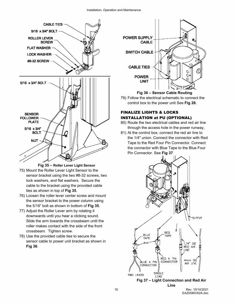
74) Remove the nut from front driver side cross
beam. Mount the sensor follower plate to the
crossbeam using the provide 5/16-18 x 3/4"
bolt and the nut just removed. The 5/16 x 3/4"
bolt can be found in the accessory box See Fig
35
Installation, Operation and Maintenance
16 Rev. 10/14/2021 EAZ0080V62A.doc
Fig 35 – Roller Lever Light Sensor
75) Mount the Roller Lever Light Sensor to the
sensor bracket using the two #8-32 screws, two
lock washers, and flat washers. Secure the
cable to the bracket using the provided cable
ties as shown in top of Fig 35.
76) Loosen the roller lever center screw and mount
the sensor bracket to the power column using
the 5/16” bolt as shown in bottom of Fig 35.
77) Adjust the Roller Lever arm by rotating it
downwards until you hear a clicking sound.
Slide the arm towards the crossbeam until the
roller makes contact with the side of the front
crossbeam. Tighten screw.
78) Use the provided cable ties to secure the
sensor cable to power unit bracket as shown in
Fig 36.
Fig 36 – Sensor Cable Routing
79) Follow the electrical schematic to connect the
control box to the power unit See Fig 26.
FINALIZE LIGHTS & LOCKS
INSTALLATION at PU (OPTIONAL)
80) Route the two electrical cables and red air line
through the access hole in the power runway,
81) At the control box, connect the red air line to
the 1/4" union. Connect the connector with Red
Tape to the Red Four Pin Connector. Connect
the connector with Blue Tape to the Blue Four
Pin Connector. See Fig 37
Fig 37 – Light Connection and Red Air
Line

Installation, Operation and Maintenance
17 Rev. 10/14/2021 EAZ0080V62A.doc
Jack Installation 82) Install Jacks per Jack Manual.
Air Accessories Installation TEE FITTING INSTALLATION
83) Move lift to comfortable working height and rest in locks.
Note: Refer to Fig 40 for Location A, Location B, Location C, etc. 84) Locate Ø13/16” hole on the vertical wall of the
power runway. As shown in Fig 40 Location A
Fig 40 – Overall Detail View for Air Accessories
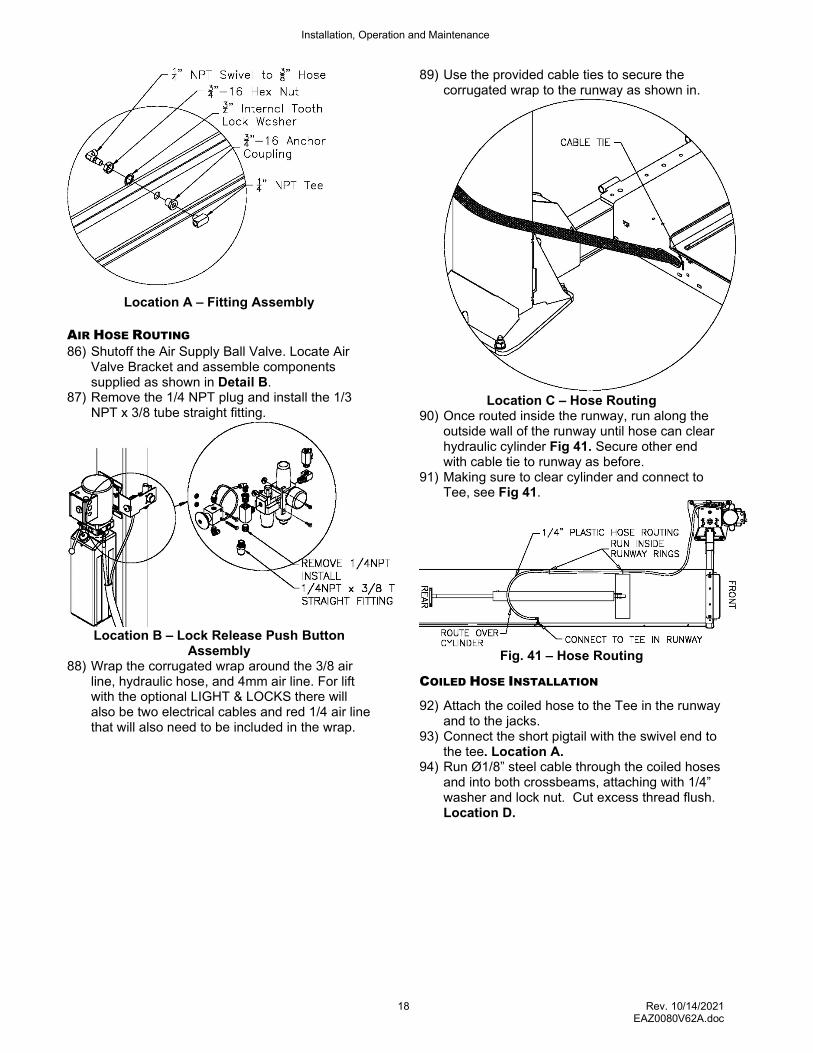
85) Assemble fittings as show in Location A
Installation, Operation and Maintenance
18 Rev. 10/14/2021 EAZ0080V62A.doc
Location A – Fitting Assembly
AIR HOSE ROUTING
86) Shutoff the Air Supply Ball Valve. Locate Air Valve Bracket and assemble components supplied as shown in Detail B.
87) Remove the 1/4 NPT plug and install the 1/3 NPT x 3/8 tube straight fitting.
Location B – Lock Release Push Button Assembly
88) Wrap the corrugated wrap around the 3/8 air line, hydraulic hose, and 4mm air line. For lift with the optional LIGHT & LOCKS there will also be two electrical cables and red 1/4 air line that will also need to be included in the wrap.
89) Use the provided cable ties to secure the corrugated wrap to the runway as shown in.
Location C – Hose Routing
90) Once routed inside the runway, run along the outside wall of the runway until hose can clear hydraulic cylinder Fig 41. Secure other end with cable tie to runway as before.
91) Making sure to clear cylinder and connect to Tee, see Fig 41.
Fig. 41 – Hose Routing
COILED HOSE INSTALLATION
92) Attach the coiled hose to the Tee in the runway and to the jacks.
93) Connect the short pigtail with the swivel end to the tee. Location A.
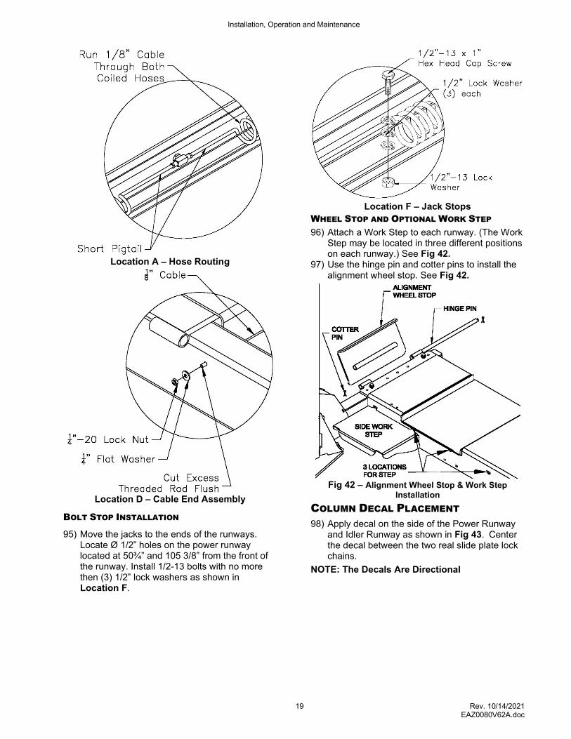
94) Run Ø1/8” steel cable through the coiled hoses and into both crossbeams, attaching with 1/4” washer and lock nut. Cut excess thread flush. Location D.
Installation, Operation and Maintenance
19 Rev. 10/14/2021 EAZ0080V62A.doc
Location A – Hose Routing
Location D – Cable End Assembly
BOLT STOP INSTALLATION
95) Move the jacks to the ends of the runways. Locate Ø 1/2” holes on the power runway located at 50¾” and 105 3/8” from the front of the runway. Install 1/2-13 bolts with no more then (3) 1/2” lock washers as shown in Location F.
Location F – Jack Stops
WHEEL STOP AND OPTIONAL WORK STEP 96) Attach a Work Step to each runway. (The Work
Step may be located in three different positions on each runway.) See Fig 42.
97) Use the hinge pin and cotter pins to install the alignment wheel stop. See Fig 42.
Fig 42 – Alignment Wheel Stop & Work Step Installation
COLUMN DECAL PLACEMENT
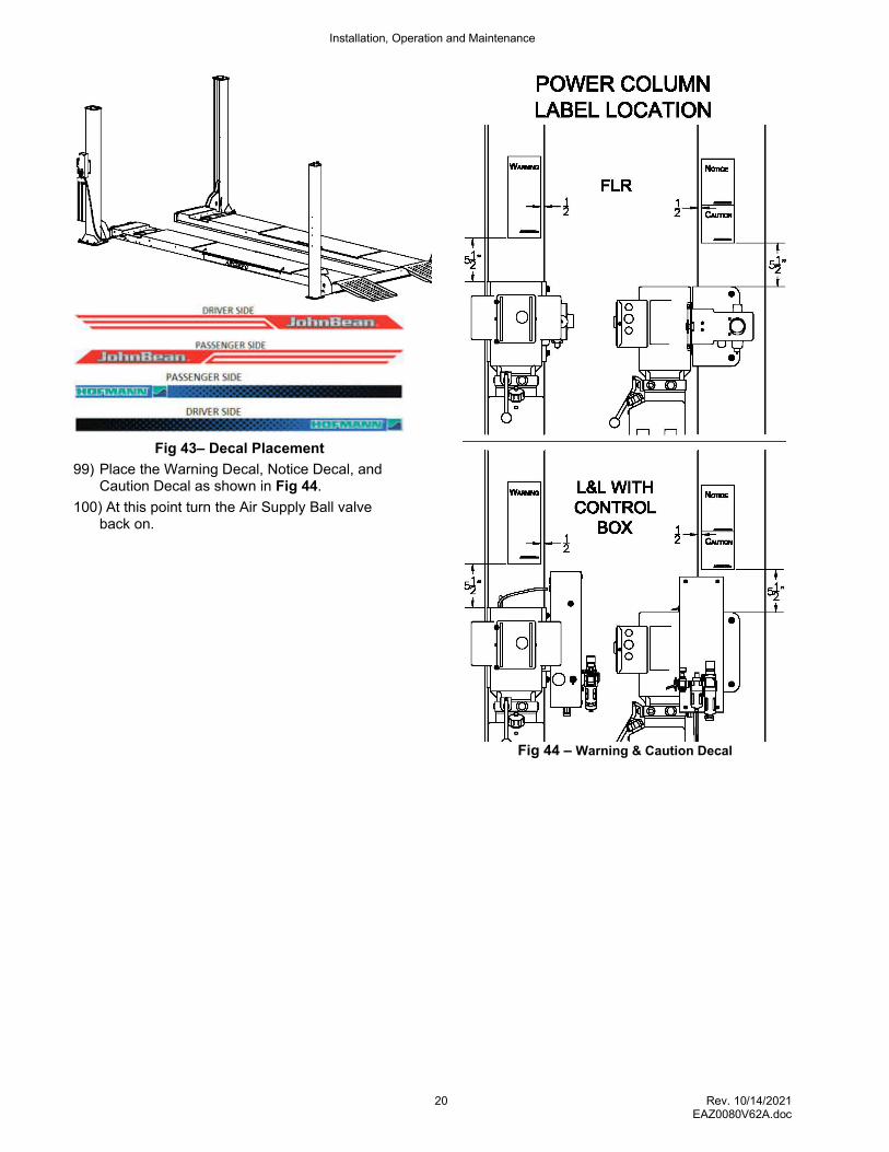
98) Apply decal on the side of the Power Runway and Idler Runway as shown in Fig 43. Center the decal between the two real slide plate lock chains.
NOTE: The Decals Are Directional
Installation, Operation and Maintenance
20 Rev. 10/14/2021 EAZ0080V62A.doc
Fig 43– Decal Placement
99) Place the Warning Decal, Notice Decal, and Caution Decal as shown in Fig 44.
100) At this point turn the Air Supply Ball valve back on.
Fig 44 – Warning & Caution Decal
Installation, Operation and Maintenance
21 Rev. 10/14/2021 EAZ0080V62A.doc
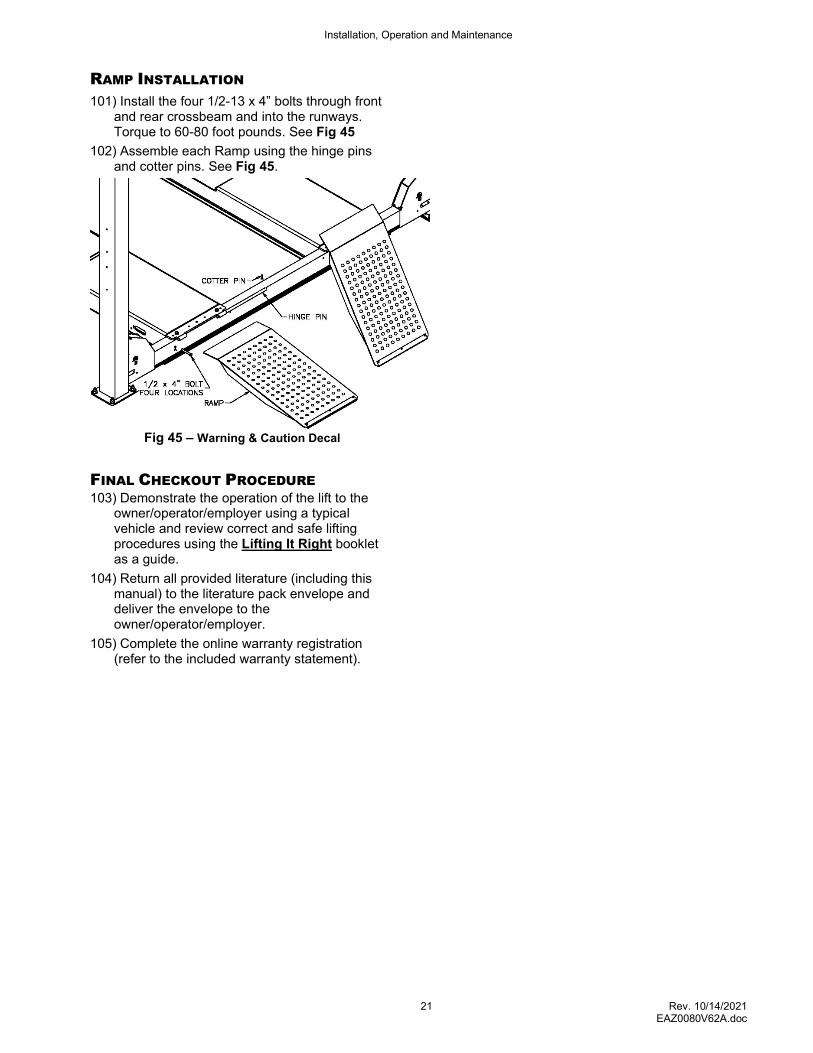
RAMP INSTALLATION
101) Install the four 1/2-13 x 4” bolts through front and rear crossbeam and into the runways. Torque to 60-80 foot pounds. See Fig 45
102) Assemble each Ramp using the hinge pins and cotter pins. See Fig 45.
Fig 45 – Warning & Caution Decal
FINAL CHECKOUT PROCEDURE 103) Demonstrate the operation of the lift to the
owner/operator/employer using a typical vehicle and review correct and safe lifting procedures using the Lifting It Right booklet as a guide.
104) Return all provided literature (including this manual) to the literature pack envelope and deliver the envelope to the owner/operator/employer.
105) Complete the online warranty registration (refer to the included warranty statement).
Installation, Operation and Maintenance
22 Rev. 10/14/2021 EAZ0080V62A.doc
OPERATION PROCEDURE
SAFETY NOTICES AND DECALS
This product is furnished with graphic safety warning labels, which are reproduced on page 3 of these instructions. Do not remove or deface these warning labels, or allow them to be removed or defaced. For your safety, and the safety of others, read and understand all of the safety notices and decals included.
OWNER/EMPLOYER RESPONSIBILITIES
This lift has been designed and constructed according to ANSI/ALI ALCTV standard. The standard applies to lift manufactures, as well as to owners and employers. The owner/employer’s responsibilities as prescribed by ANSI/ALI ALOIM, are summarized below. For exact wording refer to the actual standard provided with this manual in the literature pack.
The Owner/Employer shall insure that lift operators are qualified and that they are trained in the safe use and operation of the lift using the manufacturer’s operating instructions; ALI/SM 93 -1, ALI Lifting it Right safety manual; ALI/ST-90 ALI Safety Tips card; ANSI/ALI ALOIM, American National Standard for Automotive Lifts-Safety Requirements for Operation, Inspection and Maintenance; ALI/WL Series, ALI Uniform Warning Label Decals/Placards; and in case of frame engaging lifts, ALI/LP-GUIDE, Vehicle Lifting Points/Quick Reference Guide for Frame Engaging Lifts.
The Owner/Employer shall establish procedures to periodically inspect the lift in accordance with the lift manufacturer’s instructions or ANSI/ALI ALOIM, American National Standard for Automotive Lifts-Safety Requirements for Operation, Inspection and Maintenance; and the employer shall insure that the lift inspectors are qualified and that they are adequately trained in the inspection of the lift.
The Owner/Employer shall establish procedures to periodically maintain the lift in accordance with the lift manufacturer’s instructions or ANSI/ALIOIM, American National Standard for Automotive Lifts-Safety Requirements for Operation, Inspection and Maintenance; and the employer shall insure that the lift maintenance personnel are qualified and that they are adequately trained in the maintenance of the lift.
The Owner/Employer shall maintain the periodic inspection and maintenance records recommended by the manufacturer or ANSI/ALI ALOIM, American National Standard for Automotive Lifts-Safety Requirements for Operation, Inspection and Maintenance.
The Owner/Employer shall display the lift manufacturer’s operating instructions; ALI/SM 93 -
1, ALI Lifting it Right safety manual; ALI/ST-90 ALI Safety Tips card; ANSI/ALI ALOIM, American National Standard for Automotive Lifts-Safety Requirements for Operation, Inspection and Maintenance; and in the case of frame engaging lift, ALI/LP-GUIDE, Vehicle Lifting Points/Quick Reference Guide for Frame Engaging Lifts; in a conspicuous location in the lift area convenient to the operator.
IMPORTANT SAFETY
INSTRUCTIONS When using your garage equipment, basic safety precautions should always be followed, including the following:
1. Read all instructions.
2. Care must be taken as burns can occur from touching hot parts.
3. To reduce the risk of fire, do not operate equipment in the vicinity of open containers of flammable liquids (gasoline).
4. Keep hair, loose clothing, fingers, and all parts of body away from moving parts.
5. Use only as described in this manual. Use only manufacturer’s recommended attachments.
6. ALWAYS WEAR SAFETY GLASSES. Everyday eyeglasses only have impact resistant lenses, they are not safety glasses.
SAVE THESE INSTRUCTION
Installation, Operation and Maintenance
23 Rev. 10/14/2021 EAZ0080V62A.doc
LIFTING A VEHICLE Drive vehicle onto lift. Set parking brake and use wheel chocks that are provided with lift. Wheel chocks should be used at the front and back of the same wheel.
When the vehicle has reached the desired working height, release the power unit button, and lower the vehicle until the locks are engaged. The vehicle should remain level when all locks are engaged. If one side engages and the other continues to descend, stop lowering the vehicle, raise it several inches, and try again to engage locks.
IMPORTANT: Before walking under the lift insure that all locks are properly engaged.
It is not safe to work under the vehicle unless all locks are engaged, and the vehicle is level.
JACKING A VEHICLE
Note: Before lifting a vehicle, operate the jack through a couple of cycles to become familiar with the controls. Roll jack forward before moving vehicle on lift
rack. Be sure vehicle is centered on rack, apply parking brake and chock wheels.
Roll jack(s) to the vehicle manufacturer’s recommended pick-up points. Extend lift pad arms to proper lift points. Use lift pad spacers if necessary.
Raise jack by pushing on foot pedal on pump.
Raise vehicle to desired height.
Lower jack onto lock.
To lower jack completely, raise off of lock and while holding lock release handle open lower jack. Push lift pad arms in, remove lift pad spacers (if used). Roll jack forward before moving vehicle off rack
LOWERING LIFT WITH A VEHICLE
Insure that the area under the vehicle is clear of personnel and tools.
Raise the vehicle until locks are free.
Disengage the locks by depressing and holding the palm button.
Lower the vehicle by depressing the lowering valve handle. Watch lift to insure that the lift is lowering evenly. If not, raise lift and check all locks to insure they are disengaged before trying to lower lift again.
Continue to lower the vehicle until the crossbeams stop against the base plate. It is important to fully lower the lift to release hydraulic pressure on the system.
LOSS OF POWER
If for any reason, the lift will not raise off the locks or the locks will not retract, consult factory authorized personnel.
DO NOT OVERRIDE ANY SAFETY FEATURE IN AN ATTEMPT TO LOWER THE LIFT.
IMPORTANT!
Failure to keep lift free of corrosive agents and solvents will lead to reduced service life, which could result in property damage and/or personal injury. If any problems are encountered, contact your local service representative
Installation, Operation and Maintenance
24 Rev. 10/14/2021 EAZ0080V62A.doc
LIFT MAINTENANCE
To avoid personal injury, permit only qualified personnel to perform maintenance on this equipment. Maintenance personnel should follow lockout/tag out instructions per ANSI Z244.1.
The following maintenance points are suggested as the basis of a routine maintenance program. The actual maintenance program should be tailored to the installation. See ANSI/ALI ALOIM booklet for periodic inspection checklist and maintenance log sheet.
If lift stops short of full rise or chatters, check fluid level.
Replace all Safety, Warning or Caution Labels if missing or damaged. (See Installation instructions page 3.)
Daily
Keep lift components clean. To keep alignment lifts with rear slip plates working properly use compressed air to blow out any debris from the bearing area.
Check for loose or broken parts.
Check hydraulic system for fluid leaks.
Check lock release activation.
Weekly
Check cables and sheaves for wear or damage. Replace as required with parts approved by Snap-on Equipment.
Inspect lock mechanism for proper function.
Monthly
Lubricate Open Front slide tracks with heavy viscous grease. (Grease all four slide block contact areas on Open Front Columns.)
Torque concrete anchor bolts to 80 ft-lbs.
Clean and inspect cables and sheaves for wear or damage. Lubricate cables and sheaves with light oil.
NOTE: The Open-Front crossbeam rollers require traction to roll along the column surface. Do not lubricate roller surface. Lubrication will cause skidding and wear flat spots into the roller.
Visually inspect concrete floor for cracks and/or spalls within 12” of base plate
IMPORTANT! Failure to keep lift free of corrosive agents and solvents will lead to reduced service life, which could result in property damage and/or personal injury.
If any problems are encountered, contact your local service representative.
Jack Maintenance
Daily
Inspect jack and it’s components for damage or excessive wear. Replace parts as required. See parts list. Check for loose or broken parts.
Annually
Check hydraulic pump fluid level. When jack is completely lowered remove breather plug and check oil level. Oil should be at top of filler plug hole.
Installation, Operation and Maintenance
25 Rev. 10/14/2021 EAZ0080V62A.doc
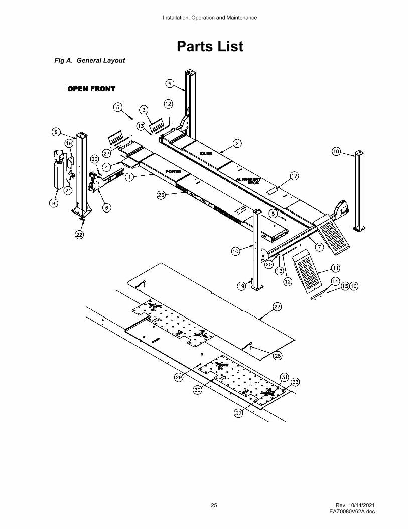
Parts List Fig A. General Layout
Installation, Operation and Maintenance
26 Rev. 10/14/2021 EAZ0080V62A.doc
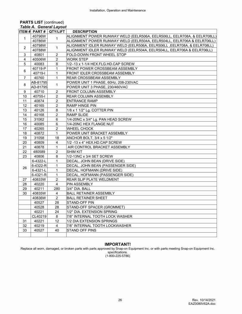
PARTS LIST (continued) Table A. General Layout ITEM # PART # QTY/LIFT DESCRIPTION
1 40796W
1 ALIGNMENT POWER RUNWAY WELD (EELR506A, EELR506LL, EELR708A, & EELR708LL)
40786W ALIGNMENT POWER RUNWAY WELD (EELR504A, EELR504LL, EELR706A & EELR706LL)
2 40798W
1 ALIGNMENT IDLER RUNWAY WELD (EELR506A, EELR506LL ,EELR708A, & EELR708LL)
40788W ALIGNMENT IDLER RUNWAY WELD (EELR504A, EELR504LL, EELR706A & EELR706LL)
3 40801 2 FOLD-DOWN FRONT WHEEL STOP
4 40506W 2 WORK STEP
5 40083 8 1/2–13 x 1-1/4 HEX.FLG.HD.CAP SCREW
6 40719-P 1 FRONT POWER CROSSBEAM ASSEMBLY
40719-I 1 FRONT IDLER CROSSBEAM ASSEMBLY
7 40760 1 REAR CROSSBEAM ASSEMBLY
8 AB-81795
1 POWER UNIT 1 PHASE, 60Hz, 208-230VAC
AD-81795 POWER UNIT 3 PHASE, 230/460VAC
9 40710 2 FRONT COLUMN ASSEMBLY
10 40755-I 2 REAR COLUMN ASSEMBLY
11 40874 2 ENTRANCE RAMP
12 40165 2 RAMP HINGE PIN
13 40126 8 1/8 x 1 1/2" Lg. COTTER PIN
14 40168 2 RAMP SLIDE
15 31062 6 1/4-20NC x 3/4" Lg. PAN HEAD SCREW
16 40085 6 1/4-20NC HEX FLANGE NUT
17 40265 2 WHEEL CHOCK
18 40872 1 POWER UNIT BRACKET ASSEMBLY
19 31058 18 ANCHOR BOLT, 3/4 x 5 1/2"
20 40809 4 1/2 -13 x 4” HEX.HD.CAP SCREW
21 40878 1 AIR CONTROL BRACKET ASSEMBLY
22 480589 2 SHIM KIT
23 40806 8 1/2-13NC x 3/4 SET SCREW
26
6-4322-L 1 DECAL, JOHN BEAN (DRIVE SIDE)
6-4322-R 1 DECAL, JOHN BEAN (PASSENGER SIDE)
6-4321-L 1 DECAL, HOFMANN (DRIVE SIDE)
6-4321-R 1 DECAL, HOFMANN (PASSENGER SIDE)
27 40833W 2 REAR SLIP PLATE WELDMENT
28 40220 4 PIN ASSEMBLY
29 40211 280 3/4" DIA. BALL
30 40835W 4 BALL RETAINER ASSEMBLY
40836W 2 BALL RETAINER SHEET
40527 28 STAND-OFF PIN
40528 28 STAND-OFF SPACER (GROMMET)
40221 24 1/2" DIA. EXTENSION SPRING
CL40219 8 7/8” INTERNAL TOOTH LOCK WASHER
31 40221 12 1/2 DIA EXTENSION SPRINGS
32 40219 4 7/8” INTERNAL TOOTH LOCKWASHER
33 40527 40 STAND OFF PINS
IMPORTANT!
Replace all worn, damaged, or broken parts with parts approved by Snap-on Equipment Inc. or with parts meeting Snap-on Equipment Inc. specifications.
(1-800-225-5786)
Installation, Operation and Maintenance
27 Rev. 10/14/2021 EAZ0080V62A.doc
PARTS LIST (continued)
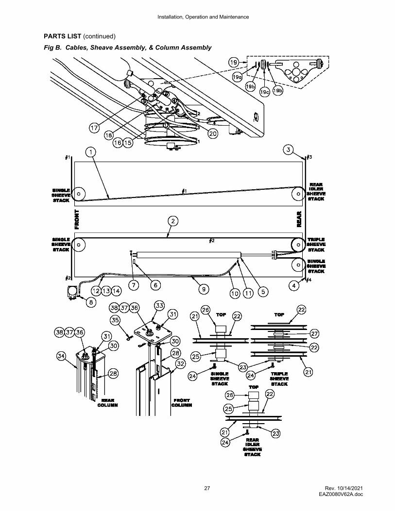
Fig B. Cables, Sheave Assembly, & Column Assembly

Installation, Operation and Maintenance
28 Rev. 10/14/2021 EAZ0080V62A.doc
PARTS LIST (continued) Table B. Cables, Sheave Assembly, & Column Assembly
ITEM # PART # QTY/LIFT DESCRIPTION
1 40703-X1
1 RIGHT FRONT CABLE #1 (EELR506A, EELR708A) (36’ 7”)
40703-E1 RIGHT FRONT CABLE #1 (EELR504A, EELR706A) (34’ 3-1/2”)
2 40703-X2
1 LEFT FRONT CABLE #2 (EELR506, EELR708) (32’ 2”)
40703-E2 LEFT FRONT CABLE #2 ((EELR504A, EELR706A) (29’ 10-1/2”)
3 40703-3 1 RIGHT REAR CABLE #3 (17’)
4 40703-4 1 LEFT REAR CABLE #4 (11’ 8-1/2”)
5 40611 1 HYDRAULIC CYLINDER
6 40082 1 CLEVIS PIN
7 40126 1 1/8 x 1 1/2" Lg. COTTER PIN
8 16167 1 90 DEGREE ADAPTER ELBOW – MALE #6 O-RING x MALE #6 J.I.C.
9 40349 1 HYDRAULIC HOSE – FEMALE #6 J.I.C. BOTH ENDS 13 ft
10 39101-024
1 HYDRAULIC HOSE EXTENSION – 2 ft (EELR504A, EELR706A)
39101-048 HYDRAULIC HOSE EXTENSION – 4 ft (EELR506A, EELR708A)
11 A2128 1 45 DEG ELBOW - #6 O-RING x #6 JIC 37 DEG
12 A1122-12 1 HOSE CLAMP
13 A1153 1 3/8-16NC x 3/4 HEX. FLG. HD. CAP SCREW
14 A1154 1 3/8-16NC HEX FLANGE NUT
15 44207 2 5/16-18NC x 2 HEX HD CAP SCREW
16 6-0295 2 5/16 SAE FLAT WASHER
17 4100237 2 5/16-18NC FLANGE HD LOCKING HEX NUT
18 40770 1 CABLE PULL BAR
19 40995 1 CABLE RETAINER ASSEMBLY
19a 40999 2 ROLLER
19b 31036 4 3/8 FLAT WASHER
19c CL6-0267 2 COTTER PIN 1/8 x 1
20 44015 2 1 3/8-12NF JAM NUT
21 B40650 11 SHEAVES
22 40053 22 1/8” THICK BEARING
23 B40055 4 SHEAVE PIN WELD (RUNWAY)
24 40807 10 5/16 – 18NC x 3/4 HEX. SER. FLG. HD. CAP SCREW
25 40774-B 4 SHEAVE SPACER, BOTTOM 1-5/8
26 40774-T 4 SHEAVE SPACER, TOP 1-1/4
27 40774-S 2 SHEAVE SPACER, 3-STACK 3/8
28 40750 4 LADDER WELD
30 CL40130 4 3/4-10NC HEX JAM NUT
31 40129 4 3/4-10NC HEX NUT
32 40712 2 O OPEN FRONT COLUMN WELD
33 40711 2 O OPEN FRONT COLUMN TOP PLATE
34 40756 2 IDLER COLUMN WELD
35 40126 4 1/8 x 1-1/2” Lg. COTTER PIN
36 40147 4 7/8-9NC HEX NUT
37 40148 4 7/8-9NC HEX JAM NUT
38 CL40149 4 7/8 FLAT WASHER
39 1-3762 2 PLASTIC INSERT
IMPORTANT!
Replace all worn, damaged, or broken parts with parts approved by Snap-on Equipment Inc. or with parts meeting Snap-on Equipment Inc. specifications.
(1-800-225-5786)

Installation, Operation and Maintenance
29 Rev. 10/14/2021 EAZ0080V62A.doc
PARTS LIST (continued)
Fig C. Front and Rear Crossbeam Assembly
Installation, Operation and Maintenance
30 Rev. 10/14/2021 EAZ0080V62A.doc
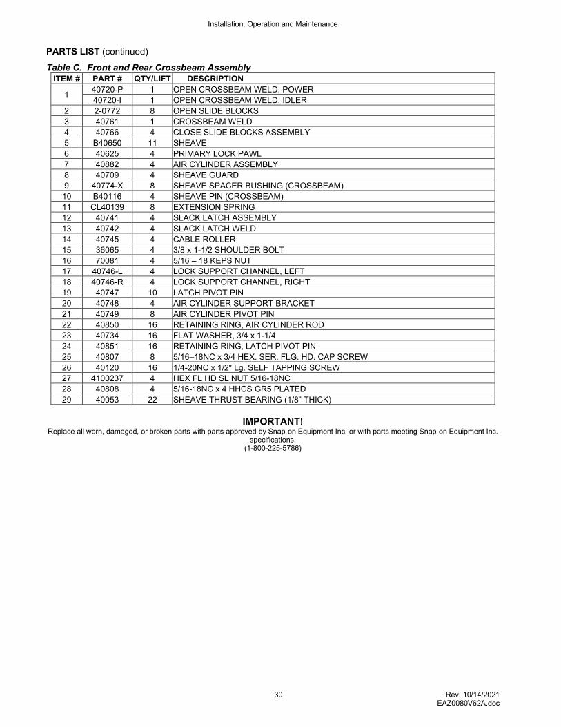
PARTS LIST (continued)
Table C. Front and Rear Crossbeam Assembly ITEM # PART # QTY/LIFT DESCRIPTION
1 40720-P 1 OPEN CROSSBEAM WELD, POWER
40720-I 1 OPEN CROSSBEAM WELD, IDLER
2 2-0772 8 OPEN SLIDE BLOCKS
3 40761 1 CROSSBEAM WELD
4 40766 4 CLOSE SLIDE BLOCKS ASSEMBLY
5 B40650 11 SHEAVE
6 40625 4 PRIMARY LOCK PAWL
7 40882 4 AIR CYLINDER ASSEMBLY
8 40709 4 SHEAVE GUARD
9 40774-X 8 SHEAVE SPACER BUSHING (CROSSBEAM)
10 B40116 4 SHEAVE PIN (CROSSBEAM)
11 CL40139 8 EXTENSION SPRING
12 40741 4 SLACK LATCH ASSEMBLY
13 40742 4 SLACK LATCH WELD
14 40745 4 CABLE ROLLER
15 36065 4 3/8 x 1-1/2 SHOULDER BOLT
16 70081 4 5/16 – 18 KEPS NUT
17 40746-L 4 LOCK SUPPORT CHANNEL, LEFT
18 40746-R 4 LOCK SUPPORT CHANNEL, RIGHT
19 40747 10 LATCH PIVOT PIN
20 40748 4 AIR CYLINDER SUPPORT BRACKET
21 40749 8 AIR CYLINDER PIVOT PIN
22 40850 16 RETAINING RING, AIR CYLINDER ROD
23 40734 16 FLAT WASHER, 3/4 x 1-1/4
24 40851 16 RETAINING RING, LATCH PIVOT PIN
25 40807 8 5/16–18NC x 3/4 HEX. SER. FLG. HD. CAP SCREW
26 40120 16 1/4-20NC x 1/2" Lg. SELF TAPPING SCREW
27 4100237 4 HEX FL HD SL NUT 5/16-18NC
28 40808 4 5/16-18NC x 4 HHCS GR5 PLATED
29 40053 22 SHEAVE THRUST BEARING (1/8” THICK)
IMPORTANT!
Replace all worn, damaged, or broken parts with parts approved by Snap-on Equipment Inc. or with parts meeting Snap-on Equipment Inc. specifications.
(1-800-225-5786)
Installation, Operation and Maintenance
31 Rev. 10/14/2021 EAZ0080V62A.doc
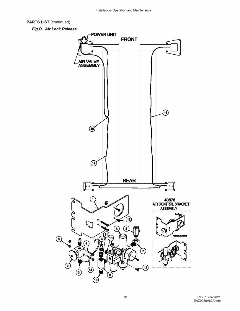
PARTS LIST (continued)
Fig D. Air Lock Release
Installation, Operation and Maintenance
32 Rev. 10/14/2021 EAZ0080V62A.doc
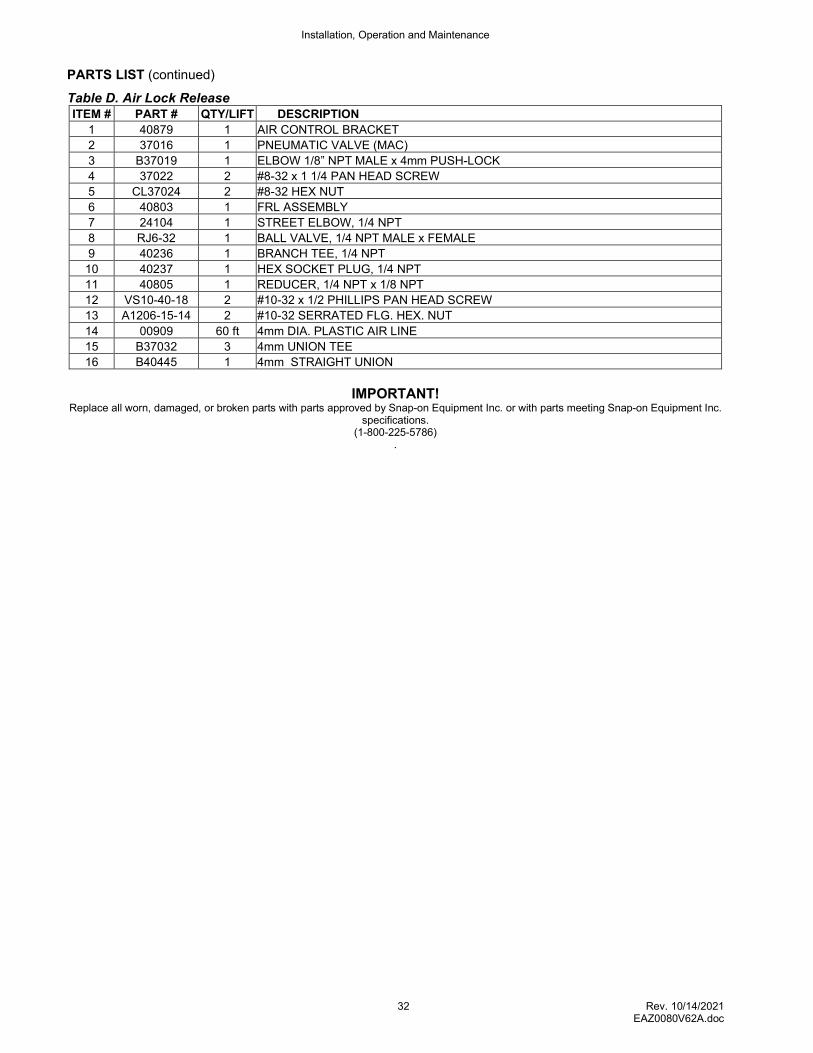
PARTS LIST (continued)
Table D. Air Lock Release ITEM # PART # QTY/LIFT DESCRIPTION
1 40879 1 AIR CONTROL BRACKET
2 37016 1 PNEUMATIC VALVE (MAC)
3 B37019 1 ELBOW 1/8” NPT MALE x 4mm PUSH-LOCK
4 37022 2 #8-32 x 1 1/4 PAN HEAD SCREW
5 CL37024 2 #8-32 HEX NUT
6 40803 1 FRL ASSEMBLY
7 24104 1 STREET ELBOW, 1/4 NPT
8 RJ6-32 1 BALL VALVE, 1/4 NPT MALE x FEMALE
9 40236 1 BRANCH TEE, 1/4 NPT
10 40237 1 HEX SOCKET PLUG, 1/4 NPT
11 40805 1 REDUCER, 1/4 NPT x 1/8 NPT
12 VS10-40-18 2 #10-32 x 1/2 PHILLIPS PAN HEAD SCREW
13 A1206-15-14 2 #10-32 SERRATED FLG. HEX. NUT
14 00909 60 ft 4mm DIA. PLASTIC AIR LINE
15 B37032 3 4mm UNION TEE
16 B40445 1 4mm STRAIGHT UNION
IMPORTANT!
Replace all worn, damaged, or broken parts with parts approved by Snap-on Equipment Inc. or with parts meeting Snap-on Equipment Inc. specifications.
(1-800-225-5786) .
Installation, Operation and Maintenance
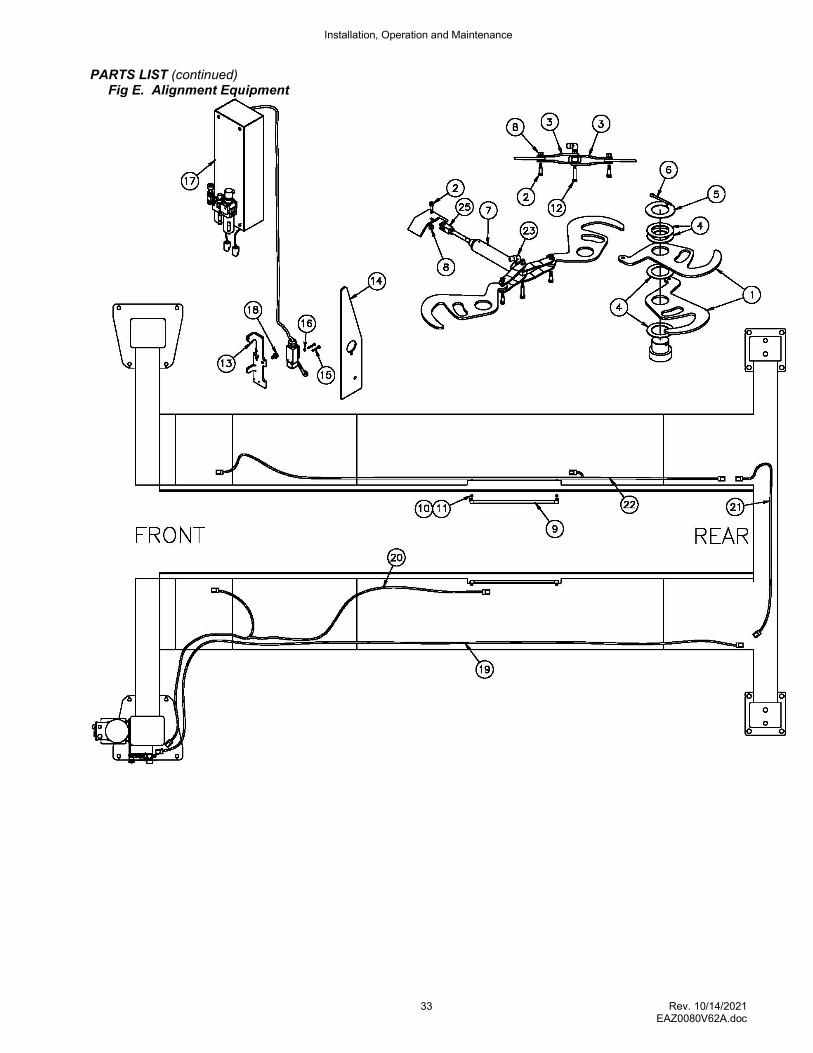
33 Rev. 10/14/2021 EAZ0080V62A.doc
PARTS LIST (continued) Fig E. Alignment Equipment
Installation, Operation and Maintenance
34 Rev. 10/14/2021 EAZ0080V62A.doc
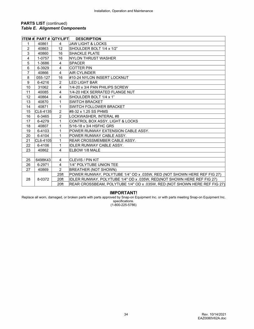
PARTS LIST (continued) Table E. Alignment Components
ITEM # PART # QTY/LIFT DESCRIPTION
1 40861 4 JAW LIGHT & LOCKS
2 40863 12 SHOULDER BOLT 1/4 x 1/2”
3 40860 16 SHACKLE PLATE
4 1-0757 16 NYLON THRUST WASHER
5 1-3686 4 SPACER
6 6-3929 4 COTTER PIN
7 40866 4 AIR CYLINDER
8 055-127 16 #10-24 NYLON INSERT LOCKNUT
9 6-4216 2 LED LIGHT BAR
10 31062 4 1/4-20 x 3/4 PAN PHILIPS SCREW
11 40085 4 1/4-20 HEX SERRATED FLANGE NUT
12 40864 4 SHOULDER BOLT 1/4 x 1”
13 40870 1 SWITCH BRACKET
14 40871 1 SWITCH FOLLOWER BRACKET
15 CL6-4135 2 #8-32 x 1.25 SS PHMS
16 6-3465 2 LOCKWASHER, INTERAL #8
17 6-4279 1 CONTROL BOX ASSY, LIGHT & LOCKS
18 40807 1 5/16-18 x 3/4 HSFHC GR5
19 6-4103 1 POWER RUNWAY EXTENSION CABLE ASSY.
20 6-4104 1 POWER RUNWAY CABLE ASSY.
21 CL6-4105 1 REAR CROSSMEMBER CABLE ASSY.
22 6-4106 1 IDLER RUNWAY CABLE ASSY.
23 40862 4 ELBOW 1/8 MALE
25 6498K43 4 CLEVIS / PIN KIT
26 6-2971 4 1/4” POLYTUBE UNION TEE
27 40869 2 BREATHER (NOT SHOWN)
28 8-0372
25ft POWER RUNWAY, POLYTUBE 1/4” OD x .035W, RED (NOT SHOWN HERE REF FIG 27)
20ft IDLER RUNWAY, POLYTUBE 1/4" OD x .035W, RED(NOT SHOWN HERE REF FIG 27)
20ft REAR CROSSBEAM, POLYTUBE 1/4" OD x .035W, RED (NOT SHOWN HERE REF FIG 27)
IMPORTANT! Replace all worn, damaged, or broken parts with parts approved by Snap-on Equipment Inc. or with parts meeting Snap-on Equipment Inc.
specifications. (1-800-225-5786)
Installation, Operation and Maintenance
35 Rev. 10/14/2021 EAZ0080V62A.doc
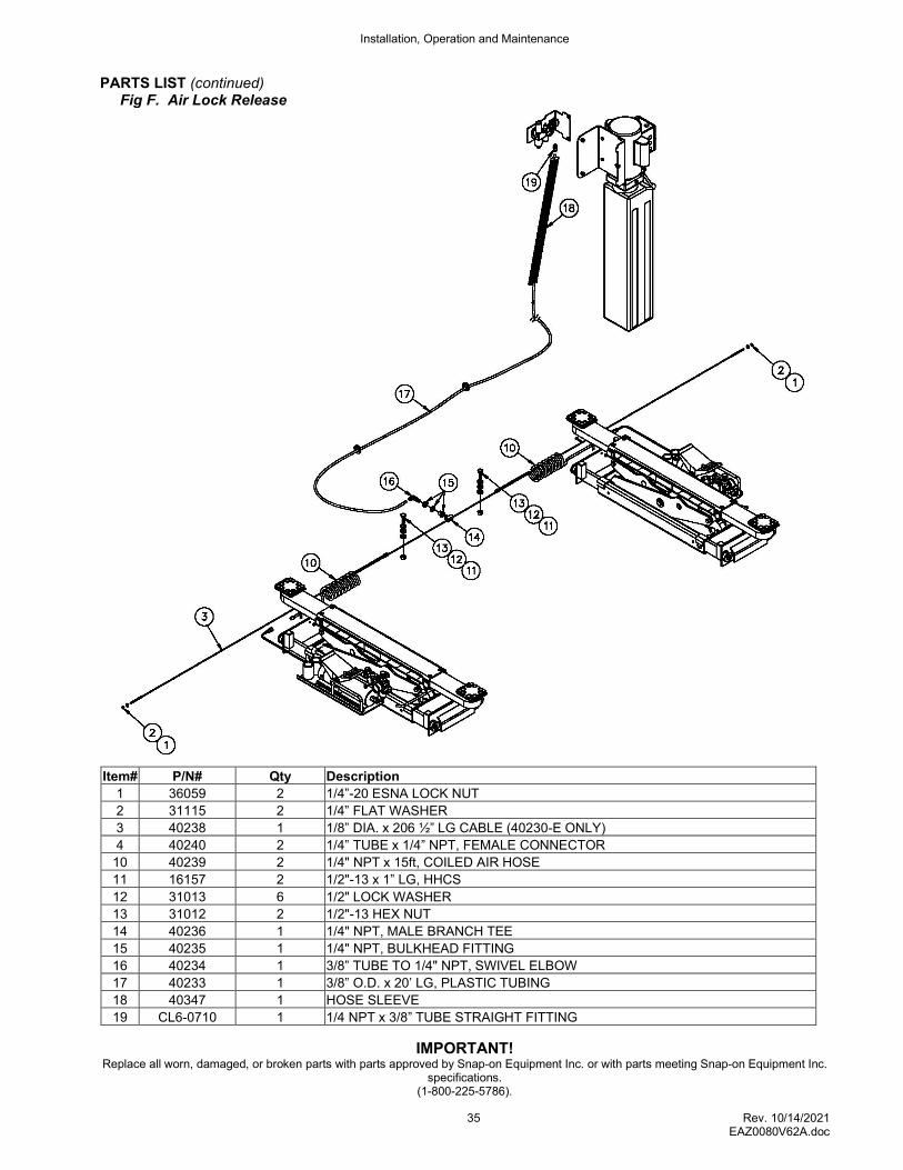
PARTS LIST (continued) Fig F. Air Lock Release
Item# P/N# Qty Description
1 36059 2 1/4”-20 ESNA LOCK NUT
2 31115 2 1/4” FLAT WASHER
3 40238 1 1/8” DIA. x 206 ½” LG CABLE (40230-E ONLY)
4 40240 2 1/4” TUBE x 1/4” NPT, FEMALE CONNECTOR
10 40239 2 1/4" NPT x 15ft, COILED AIR HOSE
11 16157 2 1/2"-13 x 1” LG, HHCS
12 31013 6 1/2" LOCK WASHER
13 31012 2 1/2"-13 HEX NUT
14 40236 1 1/4" NPT, MALE BRANCH TEE
15 40235 1 1/4" NPT, BULKHEAD FITTING
16 40234 1 3/8” TUBE TO 1/4" NPT, SWIVEL ELBOW
17 40233 1 3/8” O.D. x 20’ LG, PLASTIC TUBING
18 40347 1 HOSE SLEEVE
19 CL6-0710 1 1/4 NPT x 3/8” TUBE STRAIGHT FITTING
IMPORTANT! Replace all worn, damaged, or broken parts with parts approved by Snap-on Equipment Inc. or with parts meeting Snap-on Equipment Inc.
specifications. (1-800-225-5786).
Installation, Operation and Maintenance
36 Rev. 10/14/2021 EAZ0080V62A.doc
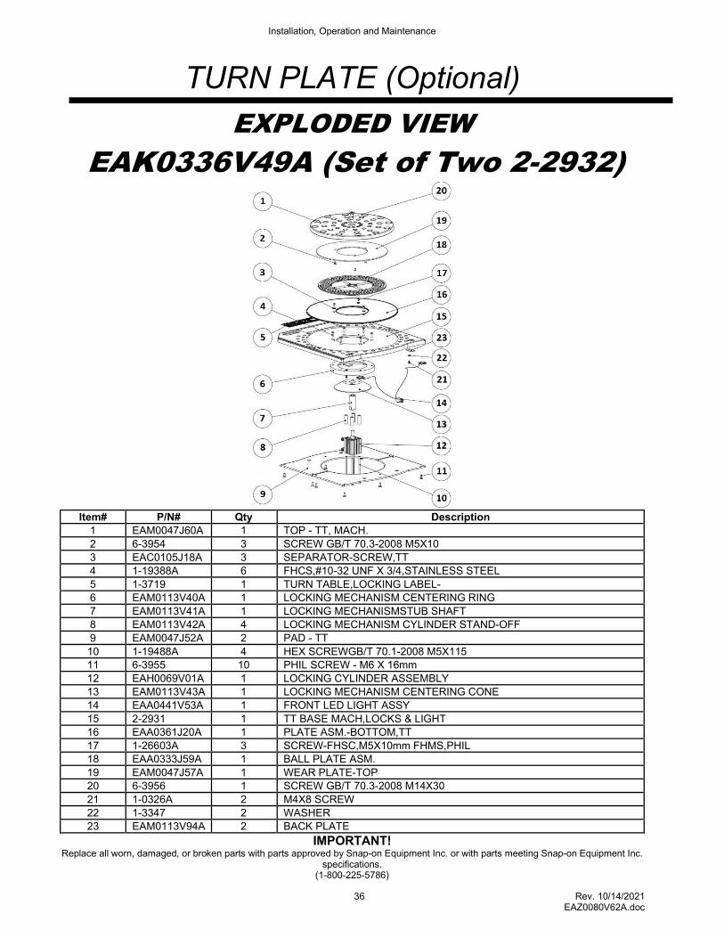
TURN PLATE (Optional)
EXPLODED VIEW
EAK0336V49A (Set of Two 2-2932)
Item# P/N# Qty Description
1 EAM0047J60A 1 TOP - TT, MACH.
2 6-3954 3 SCREW GB/T 70.3-2008 M5X10
3 EAC0105J18A 3 SEPARATOR-SCREW,TT
4 1-19388A 6 FHCS,#10-32 UNF X 3/4,STAINLESS STEEL
5 1-3719 1 TURN TABLE,LOCKING LABEL-
6 EAM0113V40A 1 LOCKING MECHANISM CENTERING RING
7 EAM0113V41A 1 LOCKING MECHANISMSTUB SHAFT
8 EAM0113V42A 4 LOCKING MECHANISM CYLINDER STAND-OFF
9 EAM0047J52A 2 PAD - TT
10 1-19488A 4 HEX SCREWGB/T 70.1-2008 M5X115
11 6-3955 10 PHIL SCREW - M6 X 16mm
12 EAH0069V01A 1 LOCKING CYLINDER ASSEMBLY
13 EAM0113V43A 1 LOCKING MECHANISM CENTERING CONE
14 EAA0441V53A 1 FRONT LED LIGHT ASSY
15 2-2931 1 TT BASE MACH,LOCKS & LIGHT
16 EAA0361J20A 1 PLATE ASM.-BOTTOM,TT
17 1-26603A 3 SCREW-FHSC,M5X10mm FHMS,PHIL
18 EAA0333J59A 1 BALL PLATE ASM.
19 EAM0047J57A 1 WEAR PLATE-TOP
20 6-3956 1 SCREW GB/T 70.3-2008 M14X30
21 1-0326A 2 M4X8 SCREW
22 1-3347 2 WASHER
23 EAM0113V94A 2 BACK PLATE
IMPORTANT! Replace all worn, damaged, or broken parts with parts approved by Snap-on Equipment Inc. or with parts meeting Snap-on Equipment Inc.
specifications. (1-800-225-5786)
Installation, Operation and Maintenance
37 Rev. 10/14/2021 EAZ0080V62A.doc
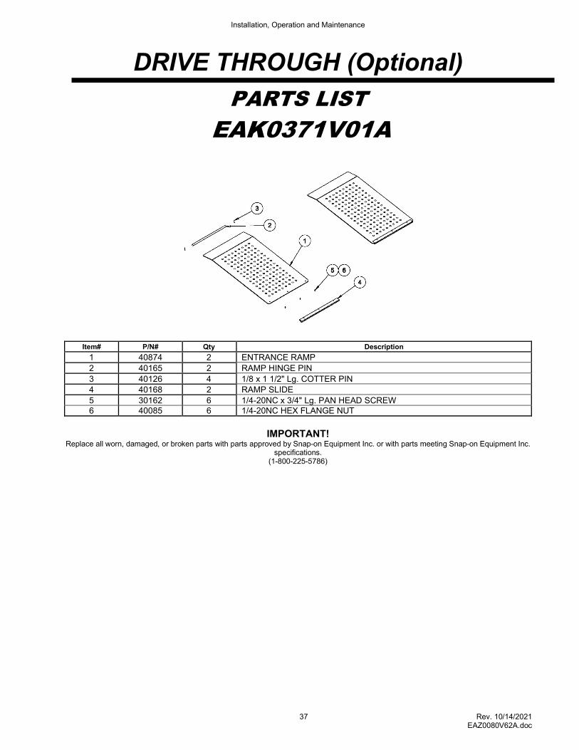
DRIVE THROUGH (Optional)
PARTS LIST
EAK0371V01A
Item# P/N# Qty Description
1 40874 2 ENTRANCE RAMP
2 40165 2 RAMP HINGE PIN
3 40126 4 1/8 x 1 1/2" Lg. COTTER PIN
4 40168 2 RAMP SLIDE
5 30162 6 1/4-20NC x 3/4" Lg. PAN HEAD SCREW 6 40085 6 1/4-20NC HEX FLANGE NUT
IMPORTANT!
Replace all worn, damaged, or broken parts with parts approved by Snap-on Equipment Inc. or with parts meeting Snap-on Equipment Inc. specifications.
(1-800-225-5786)
Installation, Operation and Maintenance
38 Rev. 10/14/2021 EAZ0080V62A.doc
Maintenance .
Date Maintenance
Installation, Operation and Maintenance
39 Rev. 10/14/2021 EAZ0080V62A.doc
Layout View
Installation, Operation and Maintenance
40 Rev. 10/14/2021 EAZ0080V62A.doc
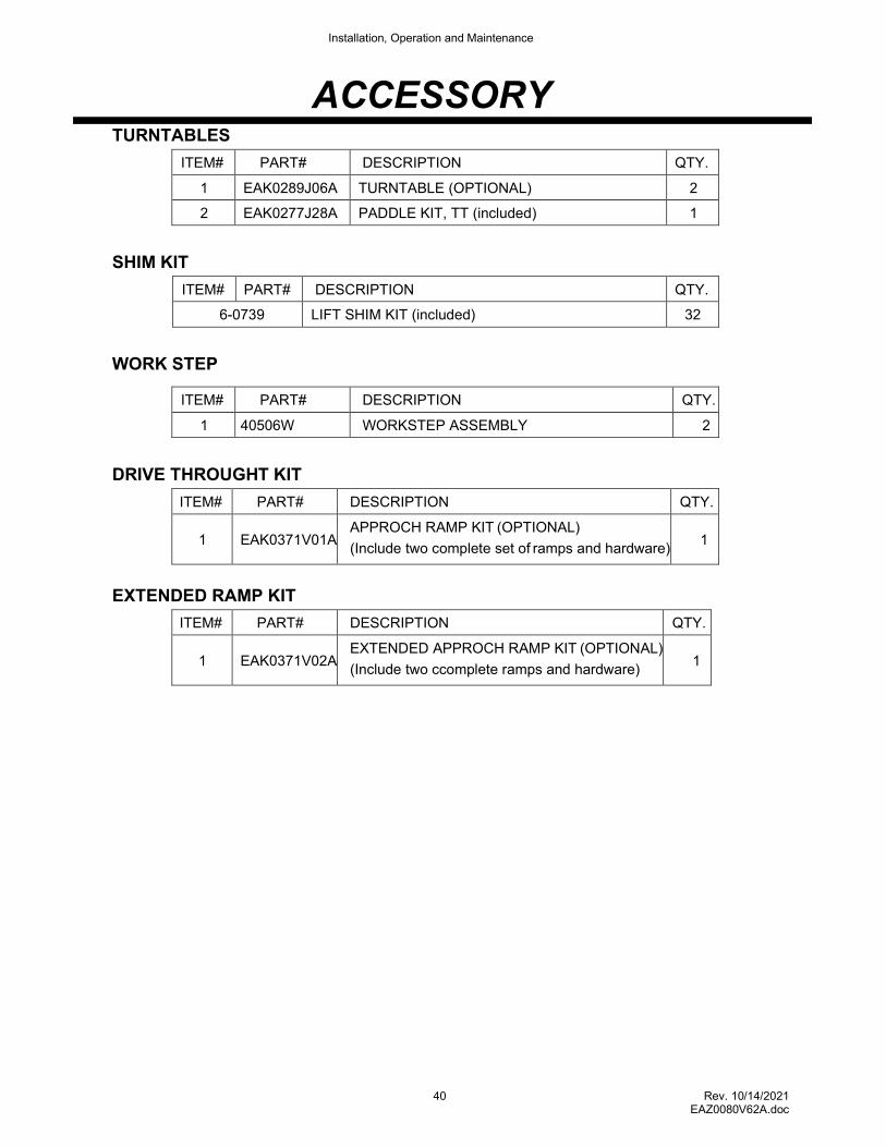
ACCESSORY TURNTABLES
ITEM# PART# DESCRIPTION QTY.
1 EAK0289J06A TURNTABLE (OPTIONAL) 2
2 EAK0277J28A PADDLE KIT, TT (included) 1
SHIM KIT
ITEM# PART# DESCRIPTION QTY.
6-0739 LIFT SHIM KIT (included) 32
WORK STEP
ITEM# PART# DESCRIPTION QTY.
1 40506W WORKSTEP ASSEMBLY 2
DRIVE THROUGHT KIT
ITEM# PART# DESCRIPTION QTY.
1
EAK0371V01A
APPROCH RAMP KIT (OPTIONAL)
(Include two complete set of ramps and hardware)
1
EXTENDED RAMP KIT
ITEM# PART# DESCRIPTION QTY.
1
EAK0371V02A
EXTENDED APPROCH RAMP KIT (OPTIONAL)
(Include two ccomplete ramps and hardware)
1
Installation, Operation and Maintenance
41 Rev. 10/14/2021 EAZ0080V62A.doc
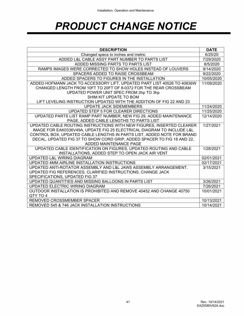
PRODUCT CHANGE NOTICE
DESCRIPTION DATE Changed specs to inches and metric 6/25/20
ADDED L&L CABLE ASSY PART NUMBER TO PARTS LIST 7/29/2020 ADDED MISSING PARTS TO PARTS LIST 8/5/2020
RAMPS IMAGES WERE CORRECTED TO SHOW HOLES INSTEAD OF LOUVERS 9/14/2020 SPACERS ADDED TO RAISE CROSSBEAM 9/22/2020
ADDED SPACERS TO FIGURES IN THE INSTALLATION 10/05/2020 ADDED HOFMANN JACK TO ACCESSORY LIFT, UPDATED PART LIST 40526 TO 40836W
CHANGED LENGTH FROM 10FT TO 20FT OF 8-0372 FOR THE REAR CROSSBEAM UPDATED POWER UNIT SPEC FROM 2hp TO 3hp
SHIM KIT UPDATE TO BOM LIFT LEVELING INSTRUCTION UPDATED WITH THE ADDITION OF FIG 22 AND 23
11/09/2020
UPDATE JACK SIDEMEMBERS 11/24/2020 UPDATED STEP 5 FOR CLEARER DIRECTIONS 11/25/2020
UPDATED PARTS LIST RAMP PART NUMBER, NEW FIG 29, ADDED MAINTENANCE PAGE, ADDED CABLE LENGTHS TO PARTS LIST
12/14/2020
UPDATED CABLE ROUTING INSTRUCTIONS WITH NEW FIGURES, INSERTED CLEARER IMAGE FOR EAK0336V49A, UPDATE FIG 25 ELECTRICAL DIAGRAM TO INCLUDE L&L
CONTROL BOX, UPDATED CABLE LENGTHS IN PARTS LIST, ADDED NOTE FOR BRAND DECAL, UPDATED FIG 37 TO SHOW CORD GRIP, ADDED SPACER TO FIG 18 AND 22,
ADDED MAINTENANCE PAGE
1/27/2021
UPDATED CABLE IDENTIFICATION ON FIGURES, UPDATED ROUTING AND CABLE INSTALLATIONS, ADDED STEP TO OPEN JACK AIR VENT
1/28/2021
UPDATED L&L WIRING DIAGRAM 02/01/2021 UPDATED 4MM AIRLINE INSTALLATION INSTRUCTIONS 02/17/2021 UPDATED ANTI-ROTATOR ASSEMBLY AND L&L JAWS ASSEMBLY ARRANGEMENT. UPDATED FIG REFERENCES, CLARIFIED INSTRUCTIONS, CHANGE JACK SPECIFICATIONS, UPDATED FIG 37
3/15/2021
UPDATED QUANTITIES AND MISSING BALLOONS IN PARTS LIST 3/26/2021 UPDATED ELECTRIC WIRING DIAGRAM 7/26/2021 OUTDOOR INSTALLATION IS PROHIBITED AND REMOVE 40452 AND CHANGE 40750 QTY TO 4
10/01/2021
REMOVED CROSSMEMBER SPACER 10/13/2021 REMOVED 545 & 746 JACK INSTALLATION INSTRUCTIONS 10/14/2021