ODU-MINI-SNAP - Mouser Electronics Ecuador
35
ODU-MINI-SNAP Series L - IP 50 LP-Locking Concept Keying with Pin and Groove Series L
-
Upload
khangminh22 -
Category
Documents
-
view
0 -
download
0
Transcript of ODU-MINI-SNAP - Mouser Electronics Ecuador

ODU-MINI-SNAPSeries L - IP 50
LP-Locking ConceptKeying with Pin and Groove
Seri
es L

Page 12 ODU-Steckverbindungssysteme GmbH & Co. KG, Pregelstr. 11, D-84453 Mühldorf/Inn, Tel. +49/86 31/61 56-0, Fax +49/86 31/61 56 49, www.odu.de
ODU-MINI-SNAP Series L
The Push-Pull Locking Principle: LP
Locking Groove
Grounding RingLocking Fingers
("Jaws") Back Nut
Outer Housing
ODU-MINI-SNAP connector in unmatedcondition.
ODU-MINI-SNAP connector in matedcondition.
Pulling on the cable or on the back nut causesthe “jaws” to grip harder into the groove in thereceptacle. A separation is virtually impossible.
Pulling on the outer plug housing disengages the “jaws” from the receptacle groove and theconnector separates easily.
Receptacle Plug

ODU-Steckverbindungssysteme GmbH & Co. KG, Pregelstr. 11, D-84453 Mühldorf/Inn, Tel. +49/86 31/61 56-0, Fax +49/86 31/61 56 49, www.odu.de Page 13
Collet Nut
Cable
Shield
Single Conductor
Back Nut
Half Shells
Inner Housing withLocking Fingers("Jaws")
Hex Nut
Insulator
Outer Housing
Housing
Insulator
Grounding Ring
Contacts
Contacts
ODU-MINI-SNAPPlug
ODU-MINI-SNAPReceptacle
ODU-MINI-SNAPwith LP-Locking Scheme in Cross Section
Series L ODU-MINI-SNAP

Page 14 ODU-Steckverbindungssysteme GmbH & Co. KG, Pregelstr. 11, D-84453 Mühldorf/Inn, Tel. +49/86 31/61 56-0, Fax +49/86 31/61 56 49, www.odu.de
Available Housing Sizes(Scale 1 : 1)
OD = Outside Diameter (Plug)S = Size
00 0 1 2
3 6
6,5 9,512 15
18
42
4
24
OD:
S:
OD:
S:
ODU-MINI-SNAP Series L

ODU-Steckverbindungssysteme GmbH & Co. KG, Pregelstr. 11, D-84453 Mühldorf/Inn, Tel. +49/86 31/61 56-0, Fax +49/86 31/61 56 49, www.odu.de Page 15
Part Number Key
Example:
Receptacle - Style 5 - Size 2 - Series L - Coding 60˚ - Brass matt chromate Housing -PBT Insulator - 16pos. - Socket(crimp) 0,75 µm Au -Term. Cross Section AWG22
Plug - Style 2 - Size 2 - Series L - Coding 60˚ - Brass matt chromate Housing - PEEK Insulator - 16pos. - Pin (solder) 0,75 µm Au - Term. Cross Section AWG22 - Cable Diameter 6.0-7.2 mm
The Part Number Key1 2 3 4 5 6 7 8 9 10 11 12 13 14 15 16 17 18 19
L 0 0
1. Type G = Receptacle
K = In-Line Receptacle
S = Straight Plug
W = Right-Angle Plug
2. Style 1 - 9 and A - Z
X = Special
3. Size 0 - 6 and C
C = 00
4. Series L
5. Coding (Page 36)
6. Material/Surface - Housing (Page 37)
7. empty
8. Material - Insulator Page 37)
9. + 10. Contact Insert (Page 27 to 34)
e.g. 18-way = 18
11. Contact Type/Surface (Page 38)
12. Contact Diameter (Page 38)
M = mixed arrangement
13. + 14. Term. Cross Section (Page 39)
14. for special Contact Configurations 9
15. empty
16. + 17. Collet System (Page 41)
1 2 3 4 5 6 7 8 9 10 11 12 13 14 15 16 17 18 19
G 5 2 L F C T 1 6 N F G 0 0 0 0 0
1 2 3 4 5 6 7 8 9 10 11 12 13 14 15 16 17 18 19
S 2 2 L F C P 1 6 M F G 0 7 2 0 0
Series L ODU-MINI-SNAP
Page 16 ODU-Steckverbindungssysteme GmbH & Co. KG, Pregelstr. 11, D-84453 Mühldorf/Inn, Tel. +49/86 31/61 56-0, Fax +49/86 31/61 56 49, www.odu.de
1 2 3 4 5 6 7 8 9 10 11 12 13 14 15 16 17 18 19
L 0 0
Part Number Key
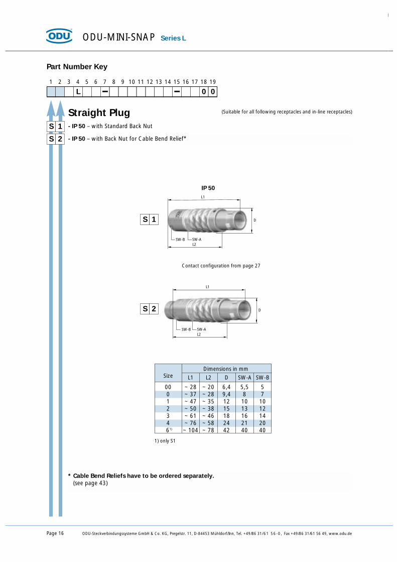
S - IP 50 – with Standard Back Nut
S 2
1
S 1
S 2
- IP 50 – with Back Nut for Cable Bend Relief*
* Cable Bend Reliefs have to be ordered separately.(see page 43)
IP 50
Straight Plug (Suitable for all following receptacles and in-line receptacles)
D
SW-B
L1
L2SW-A
Contact configuration from page 27
D
SW-B
L1
L2SW-A
Dimensions in mmSize L1 L2 D SW-A SW-B
00 ~ 28 ~ 20 6,4 5,5 50 ~ 37 ~ 28 9,4 8 71 ~ 47 ~ 35 12 10 102 ~ 50 ~ 38 15 13 123 ~ 61 ~ 46 18 16 144 ~ 76 ~ 58 24 21 2061) ~ 104 ~ 78 42 40 40
ODU-MINI-SNAP Series L
1) only S1

D
SW-B
L1
L2SW-A
D
SW-B
L1
L2SW-A
ODU-Steckverbindungssysteme GmbH & Co. KG, Pregelstr. 11, D-84453 Mühldorf/Inn, Tel. +49/86 31/61 56-0, Fax +49/86 31/61 56 49, www.odu.de Page 17
Series L ODU-MINI-SNAP
1 2 3 4 5 6 7 8 9 10 11 12 13 14 15 16 17 18 19
L 0 0
Part Number Key
S - IP 50 – with Standard Back Nut
S 8
7
S 7
S 8
- IP 50 – with Back Nut for Cable Bend Relief*
* Cable Bend Reliefs have to be ordered separately.(see page 43)
IP 50
Straight Plug(Suitable for all following receptacles and in-line receptacles)
Contact configuration from page 27
Dimensions in mmSize L1 L2 D SW-A SW-B
1 ~ 47 ~ 35 19 10 104 ~ 76 ~ 58 32 21 20

Page 18 ODU-Steckverbindungssysteme GmbH & Co. KG, Pregelstr. 11, D-84453 Mühldorf/Inn, Tel. +49/86 31/61 56-0, Fax +49/86 31/61 56 49, www.odu.de
W 2C
B
A
D
C
B
A
D
(Suitable for all following receptacles and in-line receptacles)
1 2 3 4 5 6 7 8 9 10 11 12 13 14 15 16 17 18 19
L 0 0
Part Number Key
W - IP 50 – with Standard Back Nut1
W 2
W 1
- IP 50 – with Back Nut for Cable Bend Relief*
Contact configuration from page 27
Dimensions in mmSize A B C D
00 ~24 ~18,5 7,7 6,40 ~30 ~22,5 11 91 ~36 ~28,5 13,5 112 ~41,5 ~33 16,5 144 ~65 48 25 23
Right-Angle Plug
IP 50
* Cable Bend Reliefs have to be ordered separately.(see page 43)
ODU-MINI-SNAP Series L

ODU-Steckverbindungssysteme GmbH & Co. KG, Pregelstr. 11, D-84453 Mühldorf/Inn, Tel. +49/86 31/61 56-0, Fax +49/86 31/61 56 49, www.odu.de Page 19
Series L ODU-MINI-SNAP
1 2 3 4 5 6 7 8 9 10 11 12 13 14 15 16 17 18 19
L 0 0
Part Number Key
A - IP 50 – with Standard Back Nut
A 6
5
A 5
A 6
- IP 50 – with Back Nut for Cable Bend Relief*
* Cable Bend Reliefs have to be ordered separately.(see page 43)
IP 50
Break-Apart-Plug (Suitable for all following receptacles and in-line receptacles)
D
SW-B
L1
L2SW-A
Contact configuration from page 27
D
SW-B
L1
L2SW-A
Dimensions in mmSize L1 L2 D SW-A SW-B
00 ~ 28 ~ 20 6,4 5,5 53 ~ 61 ~ 46 18 16 14

Page 20 ODU-Steckverbindungssysteme GmbH & Co. KG, Pregelstr. 11, D-84453 Mühldorf/Inn, Tel. +49/86 31/61 56-0, Fax +49/86 31/61 56 49, www.odu.de
1 2 3 4 5 6 7 8 9 10 11 12 13 14 15 16 17 18 19
L 0 0
Part Number Key
A - IP 50 – with hex nut, non-latchingA
A A
Panel-Mounted Plug (Suitable for all following receptacles and in-line receptacles)
D
SW-A
SW-B
L2
L3
L1
Contact configuration from page 27
ODU-MINI-SNAP Series L
SW
ØDimensions in mm PanelSize L1 L2 L3 D SW-A SW-B Cut-Out
0 17 5,8 24,5 10 8,2 11 SW 8,3 / Ø 9,11 22,3 10 29,5 14 10,5 14 SW 10,6 / Ø 12,12 23,5 9,7 31,5 18 13,5 17 SW 13,6 / Ø 15,13 29 12 33 22 16,5 22 SW 16,6 / Ø 18,1

ODU-Steckverbindungssysteme GmbH & Co. KG, Pregelstr. 11, D-84453 Mühldorf/Inn, Tel. +49/86 31/61 56-0, Fax +49/86 31/61 56 49, www.odu.de Page 21
1 2 3 4 5 6 7 8 9 10 11 12 13 14 15 16 17 18 19
L 0 0
Part Number Key
K - IP 50 – with Standard Back Nut
K 2
1
K 1
K 2
- IP 50 – with Back Nut for Cable Bend Relief*
In-Line Receptacle
D
SW-B
L1
SW-A
D
SW-B
L1
SW-A
Contact configuration from page 27
ODU-MINI-SNAP In-line Receptacle connect to plug for cable-to-cable connection.
IP 50
* Cable Bend Reliefs have to be ordered separately.(see page 43)
00 ~ 27 6,4 5,5 50 ~ 34,5 9,4 8 71 ~ 41 11,5 10 102 ~ 47 14,5 13 123 ~ 56 18 16 154 ~ 74 23,5 21 20
Dimensions in mmSize L1 D SW-A SW-B
Series L ODU-MINI-SNAP

Page 22 ODU-Steckverbindungssysteme GmbH & Co. KG, Pregelstr. 11, D-84453 Mühldorf/Inn, Tel. +49/86 31/61 56-0, Fax +49/86 31/61 56 49, www.odu.de
1 2 3 4 5 6 7 8 9 10 11 12 13 14 15 16 17 18 19
L 0 0
Part Number Key
G Style 1 – ODU-MINI-SNAP RECEPTACLE IP 50, installation from front of panel1
Dimensions in mm PanelSize 1) L1 L2 2) L3 M D SW-A SW-B C Cut-Out
00 ~16,0 ~ 7,0 12,0 7x0,5 8,0 9,0 6,3 1,0 SW 6,4 / Ø 7,10 ~19,5 ~ 9,0 14,5 9x0,5 10,0 11,0 8,2 1,5 SW 8,3 / Ø 9,11 ~24,0 ~ 8,0 16,5 12x1 14,0 14,0 10,0 1,5 SW 10,1 / Ø 12,12 ~27,5 ~10,0 18,5 15x1 18,0 17,0 13,5 2,0 SW 13,6 / Ø 15,13 ~33,0 ~13,0 22,5 18x1 22,0 22,0 16,5 2,0 SW 16,6 / Ø 18,14 ~36,0 ~13,0 27,5 25x1 28,0 30,0 23,5 2,5 SW 23,6 / Ø 25,16 ~46,0 ~18,0 33,0 42x1,5 48,0 48,0 40,0 3,5 SW 40,1 / Ø 42,1
SW
Ø
1) L1 = Maximum Length incl. Contact Insert2) L3 =Length of Housing
Technical Data
IP 50 anti-rotation feature contact configuration from page 27
D
SW-B
M
SW-A
L2 C
L3
L1
G 5
Receptacle
ODU-MINI-SNAP Series L
00 ~16,0 ~ 6,0 12,0 7x0,5 9,0 9,0 6,3 8,0 2,0 SW 6,4 / Ø 7,10 ~19,5 ~ 8,0 14,5 9x0,5 11,5 11,0 8,2 10,0 2,5 SW 8,3 / Ø 9,11 ~24,0 ~ 8,0 16,5 12x1 15,0 14,0 10,0 13,0 4,0 SW 10,1 / Ø 12,12 ~27,5 ~10,0 18,5 15x1 20,0 17,0 13,5 17,0 4,0 SW 13,6 / Ø 15,13 ~33,0 ~14,0 22,5 18x1 23,0 22,0 16,5 20,0 5,0 SW 16,3 / Ø 18,1
Dimensions in mm PanelSize 1) L1 L2 2) L3 M D SW-A SW-B SW-C C Cut-OutSW
Ø
Style 5 – ODU-MINI-SNAP RECEPTACLE IP 50, CONTINUOUS THREAD, installation from rear or front of panel. Front extension adjustable
Technical Data
IP 50 anti-rotation feature contact configuration from page 27
D
SW-B
C
L3
L2
SW-A SW-C
L1
M
G 8 Style 8 – ODU-MINI-SNAP WATERTIGHT RECEPTACLE IP 68*, with slotted nut, installation from rearof panel
Technical Data
IP 68 anti-rotation feature contact configuration from page 27 nutdriver for slotted mounting nut see page 168
D2D1
C
L3
L2
SW-A
L1
M
1 ~26,0 6 22,5 12x1 15,0 17,9 10,5 4,0 SW 10,6 / Ø 12,1
SW
ØDimensions in mm PanelSize 1) L1 L2 2) L3 M D1 D2 SW-A C Cut-Out
* Reference: Potted Receptacle please see page 183 III

ODU-Steckverbindungssysteme GmbH & Co. KG, Pregelstr. 11, D-84453 Mühldorf/Inn, Tel. +49/86 31/61 56-0, Fax +49/86 31/61 56 49, www.odu.de Page 23
1 2 3 4 5 6 7 8 9 10 11 12 13 14 15 16 17 18 19
L 0 0
Part Number Key
G Style F* – ODU-MINI-SNAP RIGHT-ANGLE RECEPTACLE (without thread)F
1) L1 = Maximum Length incl. Contact Insert2) L3 =Length of Housing
Technical Data
IP 50 contact configuration from page 27
24,8 (26,8)
7,625,08
3,81
7,0
2,54
(8-polig nur bei Größe 1)
12,7
(14,
0)
7,62
2,54
3,0
6,9
(8,0
)
11,6 (13,6)7,5
13,22,81
Ø 0,7Ø 0,7
1,27
Receptacle
PCB LayoutSize 0 / (1)
Series L ODU-MINI-SNAP
* Maximum positions in size 0: 7-wayMaximum positions in size 1: 8-wayInserts with more positions on request
G A Style A – ODU-MINI-SNAP RECEPTACLE IP 50, with round nut, installation from rear of panel
Technical Data
IP 50 anti-rotation feature contact configuration from page 27
D
SW-B
MSW-A
L2
C
L3
L1
1 ~26,0 ~ 2,0 16,5 14x1 19,0 17,0 12,0 5,0 SW 12,1 / Ø 14,12 ~29,0 ~ 2,0 18,5 16x1 21,9 19,0 15,0 5,0 SW 15,1 / Ø 16,13 ~33,0 ~ 2,0 25,0 20x1 26,9 24,0 18,0 6,0 SW 18,1 / Ø 20,16 ~46,0 ~ 5,0 33,0 42x1,5 50 45 40 11 SW 40,1 / Ø 42,1
SW
ØDimensions in mm PanelSize 1) L1 L2 2) L3 M D SW-A SW-B C Cut-Out

Page 24 ODU-Steckverbindungssysteme GmbH & Co. KG, Pregelstr. 11, D-84453 Mühldorf/Inn, Tel. +49/86 31/61 56-0, Fax +49/86 31/61 56 49, www.odu.de
1 2 3 4 5 6 7 8 9 10 11 12 13 14 15 16 17 18 19
L 0 0
Part Number Key
G Style H – ODU-MINI-SNAP PROTRUDENTPROTRUDENT RECEPTACLE IP 50, with low rear profileH
1) L1 = Maximum Length incl. Contact Insert2) L3 =Length of Housing
Technical Data
IP 50 anti-rotation feature contact configuration from page 55
D
SW-A
M
L3
L1
CL2
SW-B
00 ~16,0 ~ 2,5 12,5 7x0,5 9,0 9,0 6,3 8,0 SW 6,4 / Ø 7,10 ~21,5 ~ 3,5 15,0 9x0,5 11,5 11,0 8,2 9,0 SW 8,3 / Ø 9,11 ~24,0 ~ 4,5 17,5 12x1 14,0 14,0 10,0 10,0 SW 10,6 / Ø 12,12 ~26,0 ~ 6,0 19,5 15x1 18,0 17,0 13,5 11,0 SW 13,6 / Ø 15,1
SW
ØDimensions in mm PanelSize 1) L1 L2 2) L3 M D SW-A SW-B C Cut-Out
Receptacle
ODU-MINI-SNAP Series L
G Style G* – ODU-MINI-SNAP RIGHT-ANGLE RECEPTACLE (with thread)G
Technical Data
IP 50 contact configuration from page 27
Size 0 / (1)24,8 (26,8)
7,625,08
3,81
7,0
2,54
Ø 2,5
12,7
(14,
0)
7,62
M9
x 0,
5(M
11 x
0,5
)Ø
11,5
(Ø15
)
2,54
3,0
6,9
(8,0
)
11,6 (13,6)7,5
13,22,81
Ø 0,7Ø 0,7 (8-polig nur bei Größe 1)
1,27
SW 1
0(S
W 1
3)
PCB Layout
* Maximum positions in size 0: 7-wayMaximum positions in size 1: 8-wayInserts with more positions on request
ODU-Steckverbindungssysteme GmbH & Co. KG, Pregelstr. 11, D-84453 Mühldorf/Inn, Tel. +49/86 31/61 56-0, Fax +49/86 31/61 56 49, www.odu.de Page 25
1 2 3 4 5 6 7 8 9 10 11 12 13 14 15 16 17 18 19
L 0 0
Part Number Key
1) L1 = Maximum Length incl. Contact Insert2) L3 =Length of Housing
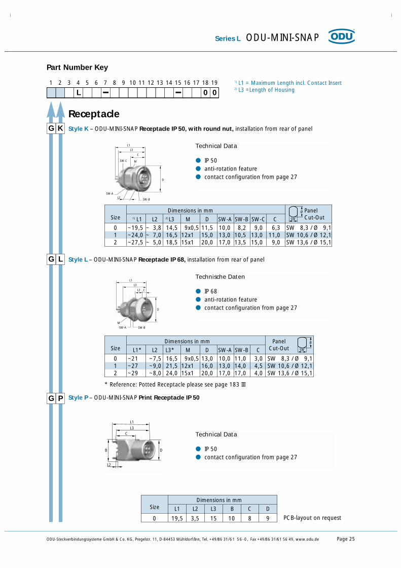
G Style P – ODU-MINI-SNAP Print Receptacle IP 50P
Technical Data
IP 50 contact configuration from page 27
DB
L3C
L1
L2
G Style K – ODU-MINI-SNAP Receptacle IP 50, with round nut, installation from rear of panelK
Technical Data
IP 50 anti-rotation feature contact configuration from page 27
D
SW-A
M
L3
L1
C
L2 SW-B
SW-C
SW
ØDimensions in mm PanelSize 1) L1 L2 2) L3 M D SW-A SW-B SW-C C Cut-Out
Receptacle
0 ~19,5 ~ 3,8 14,5 9x0,5 11,5 10,0 8,2 9,0 6,3 SW 8,3 / Ø 9,11 ~24,0 ~ 7,0 16,5 12x1 15,0 13,0 10,5 13,0 11,0 SW 10,6 / Ø 12,12 ~27,5 ~ 5,0 18,5 15x1 20,0 17,0 13,5 15,0 9,0 SW 13,6 / Ø 15,1
PCB-layout on request
Series L ODU-MINI-SNAP
G Style L – ODU-MINI-SNAP Receptacle IP 68, installation from rear of panelL
Technische Daten
IP 68 anti-rotation feature contact configuration from page 27D
SW-B
M
SW-A
L2 C
L3
L1
SW
ØDimensions in mm PanelSize L1* L2 L3* M D SW-A SW-B C Cut-Out
0 ~21 ~7,5 16,5 9x0,5 13,0 10,0 11,0 3,0 SW 8,3 / Ø 9,11 ~27 ~9,0 21,5 12x1 16,0 13,0 14,0 4,5 SW 10,6 / Ø 12,12 ~29 ~8,0 24,0 15x1 20,0 17,0 17,0 4,0 SW 13,6 / Ø 15,1
* Reference: Potted Receptacle please see page 183 III
Dimensions in mmSize L1 L2 L3 B C D
0 19,5 3,5 15 10 8 9
Page 26 ODU-Steckverbindungssysteme GmbH & Co. KG, Pregelstr. 11, D-84453 Mühldorf/Inn, Tel. +49/86 31/61 56-0, Fax +49/86 31/61 56 49, www.odu.de
ODU-MINI-SNAP For your notes

ODU-Steckverbindungssysteme GmbH & Co. KG, Pregelstr. 11, D-84453 Mühldorf/Inn, Tel. +49/86 31/61 56-0, Fax +49/86 31/61 56 49, www.odu.de Seite 27
Contact ConfigurationSeries L
PCB and solder contacts are factory-installed in the insulation body.Crimp contacts are shipped separately.

Page 28 ODU-Steckverbindungssysteme GmbH & Co. KG, Pregelstr. 11, D-84453 Mühldorf/Inn, Tel. +49/86 31/61 56-0, Fax +49/86 31/61 56 49, www.odu.de
0,5 5 750VAC
0,5 5 750VAC
Serie
s
Size
C L
ODU-MINI-SNAP Series L
Posi
tions
Posi
tions
1 2 3 4 5 6 7 8 9 10 11 12 13 14 15 16 17 18 19
L 0 0
Part Number Key
0 2 0,5 5 750VAC
Con
tact
2)
Ø m
m
Nom
inal
Sig
nal
Con
tact
Cur
rent
Load
in A
*Te
st V
olta
geac
c.V
DE
0627
1)
Sold
er
Crim
p
PCB
4)
Terminations3)
Pin Part Socket
View on termination side
C L 0 3
C L 0 4
1) In most cases the operating voltageaccording to MIL-STD-1344, Method 3001 is twice as high as according to VDE.
2) Termination cross section see page 39 and 403) Termination and surface see page 384) PCB Layout and pin length on requestCoaxial and triaxial connectors please see on page 146
* Derating Factor see page 186
A) Standard Contact Configuration(compatible with other manufacturers)
Stan
dard
Con
tact
Con
figu
rati
onA
)
Size 00

ODU-Steckverbindungssysteme GmbH & Co. KG, Pregelstr. 11, D-84453 Mühldorf/Inn, Tel. +49/86 31/61 56-0, Fax +49/86 31/61 56 49, www.odu.de Page 29
0,9 10 875VAC
0,7 7 875VAC
0,7 7 750VAC
0,5 5 750VAC
0,5 5 750VAC
Series L ODU-MINI-SNAP
Serie
s
size
0 L
Posi
tions
Posi
tions
1 2 3 4 5 6 7 8 9 10 11 12 13 14 15 16 17 18 19
L 0 0
Part Number Key
0 2 0,9 10 875VAC
Con
tact
2)
Ø m
m
Nom
inal
Sig
nal
Con
tact
Cur
rent
Load
in A
*Te
st V
olta
geac
c.V
DE
0627
1)
Sold
er
Crim
p7)
PCB
4)
Terminations3)
Pin Part Socket
View on termination side
1
2
1
2
0 L 0 312
3
12
3
0 L 0 41
2
3
4
1
2
3
4
1) In most cases the operating voltageaccording to MIL-STD-1344, Method 3001 is twice as high as according to VDE.
2) Termination cross section see page 39 and 403) Termination and surface see page 384) PCB Layout and pin length on request7) Tools for assembly see page 165 to 168Coaxial and triaxial connectors please see on page 146
0 L 0 55
24
32
1 122
34
5
0 L 0 61 1
0 L 0 71
7
1
7
* Derating Factor see page 186
A) Standard Contact Configuration(compatible with other manufacturers)
Size 0
Stan
dard
Con
tact
Con
figu
rati
on A
)

Page 30 ODU-Steckverbindungssysteme GmbH & Co. KG, Pregelstr. 11, D-84453 Mühldorf/Inn, Tel. +49/86 31/61 56-0, Fax +49/86 31/61 56 49, www.odu.de
0,5 5 750VAC
ODU-MINI-SNAP Series L
0,9 10 875VAC
0,7 7 875VAC
0,7 7 875VAC
0,7 7 750VAC
0,5 5 750VAC
Serie
s
Size
1 L
Posi
tions
Posi
tions
1 2 3 4 5 6 7 8 9 10 11 12 13 14 15 16 17 18 19
L 0 0
Part Number Key
0 4 0,9 10 875VAC
Con
tact
2)
Ø m
m
Nom
inal
Sig
nal
Con
tact
Cur
rent
Load
in A
*Te
st V
olta
geac
c.V
DE
0627
1)
Sold
er
Crim
p7)
PCB
4)
Terminations3)
Pin Part Socket
View on termination side
1
4
3
2
1
2
3
4
1 L 0 5 1
23
4
5
1 2
3
4
5
1 L 0 6
1 L 0 3 1,3 14 1000VAC
12
3
12
3
1 L 0 2 1,3 14 1000VAC
1
2
1
2
12
34
5
61
6
54
3
2
1 L 0 72
34
5
67
12
34
5
67
1
1 L 0 8 1
7
6
54
3
2
81
45
6
78
2
3
1 L 1 0
1 L 1 4
1) In most cases the operating voltageaccording to MIL-STD-1344, Method 3001 is twice as high as according to VDE.
2) Termination cross section see page 39 and 403) Termination and surface see page 384) PCB Layout and pin length on request7) Tools for assembly see page 165 to 168Coaxial and triaxial connectors please see on page 146
Size 1
Stan
dard
Con
tact
Con
figu
rati
on A
)
* Derating Factor see page 154
A) Standard Contact Configuration(compatible with other manufacturers)
ODU-Steckverbindungssysteme GmbH & Co. KG, Pregelstr. 11, D-84453 Mühldorf/Inn, Tel. +49/86 31/61 56-0, Fax +49/86 31/61 56 49, www.odu.de Page 31
Series L ODU-MINI-SNAP
Serie
s
Size
Posi
tions
Posi
tions
1 2 3 4 5 6 7 8 9 10 11 12 13 14 15 16 17 18 19
L 0 0
Part Number Key
Con
tact
2)
Ø m
m
Nom
inal
Sig
nal
Con
tact
Cur
rent
Load
in A
*Te
st V
olta
geac
c.V
DE
0627
1)
Sold
er
Crim
p7)
PCB
4)
Terminations3)
Pin Part Socket
View on termination side
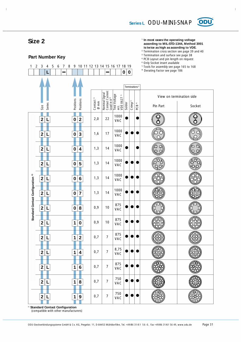
Size 2
2,02 L 0 2 1000VAC22
1) In most cases the operating voltageaccording to MIL-STD-1344, Method 3001 is twice as high as according to VDE.
2) Termination cross section see page 39 and 403) Termination and surface see page 384) PCB Layout and pin length on request6) Only Socket insert available7) Tools for assembly see page 165 to 168* Derating Factor see page 186
A) Standard Contact Configuration(compatible with other manufacturers)
1,62 L 0 3 1000VAC17
1
2
3
1
2
3
1,32 L 0 4 1000VAC14
1,32 L 0 5 1000VAC14
1,32 L 0 6 1000VAC14
1
23
4
5
6
1
2
34
5 6
1,32 L 0 7 1000VAC14
0,92 L 0 8 875VAC10 2
3
4 5
6
7
81
7
6
5 4
3
2
18
0,92 L 1 0 875VAC10
1
2
34
5
6
78
910
7
6
54
3
2
18
910
0,72 L 1 2 875VAC7
1
12
1
12
0,72 L 1 4 8,75VAC7
0,72 L 1 6 875VAC7
1
16
1
16
0,72 L 1 8 750VAC7
0,72 L 1 9 750VAC7
Stan
dard
Con
tact
Con
figu
rati
onA
)

Page 32 ODU-Steckverbindungssysteme GmbH & Co. KG, Pregelstr. 11, D-84453 Mühldorf/Inn, Tel. +49/86 31/61 56-0, Fax +49/86 31/61 56 49, www.odu.de
14
ODU-MINI-SNAP Series L
1,3 14 1000VAC
0,9 10 875VAC
Serie
s
Size
3 L
Posi
tions
Posi
tions
1 2 3 4 5 6 7 8 9 10 11 12 13 14 15 16 17 18 19
L 0 0
Part Number Key
0 7 17 1000VAC
Con
tact
2)
Ø m
m
Nom
inal
Sig
nal
Con
tact
Cur
rent
Load
in A
*Te
st V
olta
geac
c.V
DE
0627
1)
Sold
er
Crim
p7)
PCB
4)
Terminations3)
Pin Part Socket
View on termination side
1
7
3 L 0 8
3 L 1 4
1
14
3 L 1 8
1
18
1
18
1) In most cases the operating voltageaccording to MIL-STD-1344, Method 3001 is twice as high as according to VDE.
2) Termination cross section see page 39 and 403) Termination and surface see page 384) PCB Layout and pin length on request7) Tools for assembly see page 165 to 168* Derating Factor see page 186
1,6
100,9875VAC
3 L 2 0 70,7875VAC
3 L 2 2 70,7875VAC
3 L 2 6 70,7750VAC
3 L 3 0 70,7750VAC
Size 3
Stan
dard
Con
tact
Con
figu
rati
onA
)
1
7
A) Standard Contact Configuration(compatible with other manufacturers)
3 L 0 4 222,01000VAC
1,3 1000VAC3 L 1 0
1
14

ODU-Steckverbindungssysteme GmbH & Co. KG, Pregelstr. 11, D-84453 Mühldorf/Inn, Tel. +49/86 31/61 56-0, Fax +49/86 31/61 56 49, www.odu.de Page 33
Series L ODU-MINI-SNAP
0,7 7
875VAC
Serie
s
Size
Posi
tions
Posi
tions
1 2 3 4 5 6 7 8 9 10 11 12 13 14 15 16 17 18 19
L 0 0
Part Number Key
4 L 4 0
1) In most cases the operating voltageaccording to MIL-STD-1344, Method 3001 is twice as high as according to VDE.
2) Termination cross section see page 39 and 403) Termination and surface see page 384) PCB Layout and pin length on request7) Tools for assembly see page 165 to 168
* Derating Factor see page 186
A) Standard Contact Configuration(compatible with other manufacturers)
Size 4
Stan
dard
Con
tact
Conf
igur
atio
nA)
Con
tact
2)
Ø m
m
Nom
inal
Sig
nal
Con
tact
Cur
rent
Load
in A
*Te
st V
olta
geac
c.V
DE
0627
1)
Sold
er
Crim
p7)
Prin
t 4)
Terminations3)
Pin Part Socket
View on termination side

Page 34 ODU-Steckverbindungssysteme GmbH & Co. KG, Pregelstr. 11, D-84453 Mühldorf/Inn, Tel. +49/86 31/61 56-0, Fax +49/86 31/61 56 49, www.odu.de
ODU-MINI-SNAP Series L
Coax 75 Ω0,7 7
Serie
s
Size
6 L
Posi
tions
Posi
tions
1 2 3 4 5 6 7 8 9 10 11 12 13 14 15 16 17 18 19
L 0 0
Part Number Key
0 2 4,0 50 8
KVAC
onrequest6 L 0 5
1) In most cases the operating voltageaccording to MIL-STD-1344, Method 3001 is twice as high as according to VDE.
2) Termination cross section see page 39 and 403) Termination and surface see page 384) PCB Layout and pin length on request7) Tools for assembly see page 165 to 168
* Derating Factor see page 186
Size 6
Con
tact
2)
Ø m
m
Nom
inal
Sig
nal
Con
tact
Cur
rent
Load
in A
*Te
st V
olta
geac
c.V
DE
0627
1)
Sold
er
Crim
p7)
PCB
4)
Terminations3)
Pin Part Socket
View on termination side
14x0,93x1,63x2,5
2xCoax 75 ΩØ 0,7
101724
6 L 2 2 onrequest
Spec
ial C
onta
ctCo
nfig
urat
ion
Details for thePart Number Key:
Keyings Housing Materials / Surfaces
Insulation Body MaterialContacts
Contact Termination Cross Section (AWG)Collet System
Bend Protection Sleeves

Page 36 ODU-Steckverbindungssysteme GmbH & Co. KG, Pregelstr. 11, D-84453 Mühldorf/Inn, Tel. +49/86 31/61 56-0, Fax +49/86 31/61 56 49, www.odu.de
Coding
1 2 3 4 5 6 7 8 9 10 11 12 13 14 15 16 17 18 19
L 0 0
Part Number Key
ODU-MINI-SNAP Details for the Part Number Key
0
0
A
B
C
C
F
J
K
Q
V
W
Angle
0°
0°
30°
37,5°
45°
- 45°
60°
90°
95°
120°
135°
145°
155°
ReceptacleFront View
Size
00 0 1
Y
2 3 4 6
Standard
On request

ODU-Steckverbindungssysteme GmbH & Co. KG, Pregelstr. 11, D-84453 Mühldorf/Inn, Tel. +49/86 31/61 56-0, Fax +49/86 31/61 56 49, www.odu.de Page 37
C
N
S
Standard
Cu-alloy / matt chromate
Special materials and surfaces on request.
Cu-alloy / nickel
Cu-alloy / black chromate
Additional materials on request.
T PBT
P PEEK
Insulation Body Material
Details for the Part Number Key ODU-MINI-SNAP
Housing Materials / Surfaces
Part Number Key
1 2 3 4 5 6 7 8 9 10 11 12 13 14 15 16 17 18 19
L 0 0
Part Number Key
1 2 3 4 5 6 7 8 9 10 11 12 13 14 15 16 17 18 19
L 0 0
Turned Contact
Article Number PBT PEEK
Solder TerminationCrimp TerminationPCB Termination
-
= available

Page 38 ODU-Steckverbindungssysteme GmbH & Co. KG, Pregelstr. 11, D-84453 Mühldorf/Inn, Tel. +49/86 31/61 56-0, Fax +49/86 31/61 56 49, www.odu.de
ODU-MINI-SNAP Details for the Part Number Key
Contact Type / Contact Surface - Contact Diameter
Part Number Key
1 2 3 4 5 6 7 8 9 10 11 12 13 14 15 16 17 18 19
L 0 0
L
M
N
P
Q
R
ContactØ
in mmType Surface
Socket
Pin
Socket
Pin
Socket
Pin
L - 0,75 µm Au (min.)
L - 0,75 µm Au (min.)
C- 0,75 µm Au (min.)
C - 0,75 µm Au (min.)
P - 0,75 µm Au (min.)
P - 0,75 µm Au (min.)
0,50
0,70
0,90
mixed
1,30
1,50
1,60
2,00
3,00
4,00L = Solder termination
C = Crimp termination
P = PCB termination
C
F
J
M
P
Q
S
T
V
W
Has
to
mat
ch w
ith s
elec
ted
cont
act
inse
rts

ODU-Steckverbindungssysteme GmbH & Co. KG, Pregelstr. 11, D-84453 Mühldorf/Inn, Tel. +49/86 31/61 56-0, Fax +49/86 31/61 56 49, www.odu.de Page 39
Details for the Part Number Key ODU-MINI-SNAP
Contact Termination Cross Sections
Part Number Key
1 2 3 4 5 6 7 8 9 10 11 12 13 14 15 16 17 18 19
L 0 0
0D0G0D0G0D0G0D0H0L0D0G0D0G0H0L0D0G0C0D0H0L0N
0,7 0 24/26 0,25/0,15
0,7 0 22 0,38
0,9 0 24/26 0,25/0,15
0,9 0 22 0,38
0,7 1 24/26 0,25/0,15
0,7 1 22 0,38
0,9 1 24/26 0,25/0,15
0,9 1 20/22 0,50/0,38
1,3 1 18 1,0
0,7 2 24/26 0,25/0,15
0,7 2 22 0,38
0,9 2 24/26 0,25/0,15
0,9 2 22 0,38
0,9 2 20/22 0,50/0,38
1,3 2 18 1,0
0,7 3 24/26 0,25/0,15
0,7 3 22 0,38
0,7 3 28/30 0,08/0,05
0,9 3 24/26 0,25/0,15
0,9 3 20/22 0,50/0,38
1,3 3 18 1,0
1,6 3 16 -
ContactØ Size AWG mm2
Tools for crimping and their adjustmentssee Page 166.
Crimp Contact

Page 40 ODU-Steckverbindungssysteme GmbH & Co. KG, Pregelstr. 11, D-84453 Mühldorf/Inn, Tel. +49/86 31/61 56-0, Fax +49/86 31/61 56 49, www.odu.de
ODU-MINI-SNAP Details for the Part Number Key
Contact Termination Cross Sections
Part Number Key
1 2 3 4 5 6 7 8 9 10 11 12 13 14 15 16 17 18 19
L 0 0
0C0D0G0G0H0N0Q0S
000000000000
00
0,5 0,4 28 0,08
0,7 0,6 26 0,15
0,7 0,85 22 0,38
0,9 0,85 22 0,38
1,3 1,1 20 0,50
1,6 1,4 18 1,00
2,0 1,85 14 1,5
2,0 2,4 - 2,5
ContactØ
Term.Ø AWG
Term. Cross
mm2
0,5 0,5
0,7 0,5
0,9 0,7
1,3 0,7
1,6 0,7
2,0 0,7
ContactØ
Term.Ø
(Please provide details of termination cross section!)
Solder Contact
PCB Contact
For mixed inserts

ODU-Steckverbindungssysteme GmbH & Co. KG, Pregelstr. 11, D-84453 Mühldorf/Inn, Tel. +49/86 31/61 56-0, Fax +49/86 31/61 56 49, www.odu.de Page 41
1
Cable diameterin mm
Size
00 0 1 2
> 0,5 - 1,0
> 1,0 - 1,5
> 1,5 - 2,0
> 1,5 - 2,2
> 2,0 - 2,5
> 2,5 - 3,0
> 2,0 - 3,2
> 3,0 - 3,5
> 3,0 - 4,2
> 4,0 - 5,2
> 5,0 - 6,2
> 6,0 - 7,2
> 7,0 - 7,7
> 7,0 - 8,0
> 7,0 - 8,2
> 8,0 - 9,2
> 9,0 - 9,9
> 9,0 - 10,2
> 9,1 - 10,5
> 10,0 - 11,0
> 10,0 - 11,2
> 11,0 - 11,9
> 12,0 - 13,0
> 14,0 - 15,0
Collet System
Insert: for all Plugs and In-Line Receptacles.
Application: Collet nut for strain relief.
Collet Nut
Cable-Ø
Anti Rotation Pin
without collet system
Part Number Key
1 2 3 4 5 6 7 8 9 10 11 12 13 14 15 16 17 18 19
L 0
3 4 6
Details for the Part Number Key ODU-MINI-SNAP
0
01 52 02 22 53 03 23 54 25 26 27 27 78 08 29 29 90 20 21 11 21 91 31 50 0

Page 42 ODU-Steckverbindungssysteme GmbH & Co. KG, Pregelstr. 11, D-84453 Mühldorf/Inn, Tel. +49/86 31/61 56-0, Fax +49/86 31/61 56 49, www.odu.de
ODU-MINI-SNAP Details for the Part Number Key
Right-Angled Print Contacts in the Receptacle
Right-Angled Print Contact
Part Number Key
21 3 4 5 6 7 8 9 10 11 12 13 14 15 16 17 18 19
L 0
A
0
PCB-Layout on request

Cable O.DSize Part Number * Dim. L
min. max.
000000000011111112222222333333334444
713 022 ... 960 020713 022 ... 960 030700 022 ... 960 020700 022 ... 960 025700 022 ... 960 030700 022 ... 960 035700 022 ... 960 040700 022 ... 960 045701 022 ... 960 025701 022 ... 960 030701 022 ... 960 035701 022 ... 960 040701 022 ... 960 050701 022 ... 960 060701 022 ... 960 070702 022 ... 960 030702 022 ... 960 035702 022 ... 960 040702 022 ... 960 050702 022 ... 960 060702 022 ... 960 070702 022 ... 960 080703 022 ... 960 040703 022 ... 960 050703 022 ... 960 060703 022 ... 960 070703 022 ... 960 080703 022 ... 960 090703 022 ... 960 100703 022 ... 960 110704 022 ... 960 080704 022 ... 960 090704 022 ... 960 100704 022 ... 960 015
19192727272727273030303030303036363636363636424242424242424260606060
> 2,0> 3,0> 2,0> 2,5> 3,0> 3,5> 4,0> 4,5> 2,5> 3,0> 3,5> 4,0> 5,0> 6,0> 6,5> 3,0> 3,5> 4,0> 5,0> 6,0> 7,0> 8,0> 4,0> 5,0> 6,0> 7,0> 8,0> 9,0> 10,0> 11,0> 8,0> 9,0> 10,0> 11,5
2,53,52,53,03,54,04,55,03,03,54,05,06,06,57,53,54,05,06,07,08,09,05,06,07,08,09,010,011,012,09,010,011,011,5
ODU-Steckverbindungssysteme GmbH & Co. KG, Pregelstr. 11, D-84453 Mühldorf/Inn, Tel. +49/86 31/61 56-0, Fax +49/86 31/61 56 49, www.odu.de Page 43
Details for the Part Number Key ODU-MINI-SNAP
Color Code
202203204205206207208209210212215216
Color
redwhiteyellowgreenbluegreyblackorangevioletbrownlight greenlight blue
RAL-Nr.
302090101016602950027005900520044005801660185012
L
Cable Bend Relief
(similar)
* = In ... please indicate color code
Temperature rangePUR -40 ºC up to +80 ºC
Short-term up to +120 ºC
On request:Silicone -50 ºC up to +200 ºC
Short-term up to +230 ºC
(Has to be ordered separately)

Page 44 ODU-Steckverbindungssysteme GmbH & Co. KG, Pregelstr. 11, D-84453 Mühldorf/Inn, Tel. +49/86 31/61 56-0, Fax +49/86 31/61 56 49, www.odu.de
ODU-MINI-SNAP For your notes

Mouser Electronics
Authorized Distributor
Click to View Pricing, Inventory, Delivery & Lifecycle Information: ODU USA:
GF0L0C-P06QC00-0000