14 Separations in Food Processing
83
James G. Brennan, Alistair S. Grandison and Michael J. Lewis 14.1 Introduction Alistair S. Grandison Separations are vital to all areas of the food processing industry. Separations usually aim to remove specific components in order to increase the added value of the products, which may be the extracted component, the residue or both. Purposes include cleaning, sorting and grading operations (see Chapter 1), ex- traction and purification of fractions such as sugar solutions or vegetable oils, recovery of valuable components such as enzymes or flavour compounds, or re- moval of undesirable components such as microorganisms, agricultural residues or radionuclides. Operations range from separation of large food units, such as fruits and vegetables measuring many centimetres, down to separation of mole- cules or ions measured in nanometres. Separation processes always make use of some physical or chemical differ- ence between the separated fractions; examples are size, shape, colour, density, solubility, electrical charge and volatility. The separation rate is dependent on the magnitude of the driving force and may be governed by a number of physical principles involving concepts of mass transfer and heat transfer. Rates of chemical reaction and physical processes are virtually always temperature-dependent, such that separation rate will increase with temperature. However, high temperatures give rise to degradation reac- tions in foods, producing changes in colour, flavour and texture, loss of nutri- tional quality, protein degradation, etc. Thus a balance must be struck between rate of separation and quality of the product. Separations may be classified according to the nature of the materials being separated, and a brief overview is given below. 429 Food Processing Handbook. Edited by James G. Brennan Copyright © 2006 WILEY-VCH Verlag GmbH & Co. KGaA, Weinheim ISBN: 3-527-30719-2 14 Separations in Food Processing
-
Upload
khangminh22 -
Category
Documents
-
view
2 -
download
0
Transcript of 14 Separations in Food Processing

James G. Brennan, Alistair S. Grandison and Michael J. Lewis
14.1Introduction
Alistair S. Grandison
Separations are vital to all areas of the food processing industry. Separationsusually aim to remove specific components in order to increase the added valueof the products, which may be the extracted component, the residue or both.Purposes include cleaning, sorting and grading operations (see Chapter 1), ex-traction and purification of fractions such as sugar solutions or vegetable oils,recovery of valuable components such as enzymes or flavour compounds, or re-moval of undesirable components such as microorganisms, agricultural residuesor radionuclides. Operations range from separation of large food units, such asfruits and vegetables measuring many centimetres, down to separation of mole-cules or ions measured in nanometres.
Separation processes always make use of some physical or chemical differ-ence between the separated fractions; examples are size, shape, colour, density,solubility, electrical charge and volatility.
The separation rate is dependent on the magnitude of the driving force andmay be governed by a number of physical principles involving concepts of masstransfer and heat transfer. Rates of chemical reaction and physical processes arevirtually always temperature-dependent, such that separation rate will increasewith temperature. However, high temperatures give rise to degradation reac-tions in foods, producing changes in colour, flavour and texture, loss of nutri-tional quality, protein degradation, etc. Thus a balance must be struck betweenrate of separation and quality of the product.
Separations may be classified according to the nature of the materials beingseparated, and a brief overview is given below.
429
Food Processing Handbook. Edited by James G. BrennanCopyright © 2006 WILEY-VCH Verlag GmbH & Co. KGaA, WeinheimISBN: 3-527-30719-2
14Separations in Food Processing

14.1.1Separations from Solids
Solid foods include fruits, vegetables, cereals, legumes, animal products (car-casses, joints, minced meat, fish fillets, shellfish) and various powders and gran-ules. Their separation has been reviewed by Lewis [1] and can be subdivided asfollows.
14.1.1.1 Solid-Solid SeparationsParticle size may be exploited to separate powders or larger units using sievesor other screen designs, examples of which are given in Chapter 1.
Air classification can be achieved using differences in aerodynamic propertiesto clean or fractionate particulate materials in the dry state. Controlled airstreams will cause some particles to be fluidised in an air stream depending onthe terminal velocity, which in turn is related primarily to size, but also to shapeand density. Also in the dry state, particles can be separated on the basis ofphotometric (colour), magnetic or electrostatic properties.
By suspending particles in a liquid, particles may be separated by settlementon the basis of a combination of size and density differences. Buoyancy differ-ences can be exploited to separate products from heavy materials such as stonesor rotten fruit in flotation washing, while surface properties can be used to sep-arate peas from weed seeds in froth flotation.
14.1.1.2 Separation From a Solid MatrixPlant materials often contain valuable components within their structure. In thecase of oils or juices, these may be separated from the bulk structure by expres-sion, which involves the application of pressure. Alternatively, components maybe removed from solids by extraction (see Section 14.4), which utilises the dif-ferential solubilities of extracted components in a second medium. Water maybe used to extract sugar, coffee, fruit and vegetable juices, etc. Organic solventsare necessary in some cases, e.g. hexane for oil extraction. Supercritical CO2
may be used to extract volatile materials such as in the decaffeination of coffee.A combination of expression and extraction is used to remove 99% of the oilfrom oilseeds.
Water removal from solids plays an important role in food processing (seeChapter 3).
14.1.2Separations From Liquids
Liquid foods include aqueous or oil based materials, and frequently contain sol-ids either in true solution or dispersed as colloids or emulsions.
14 Separations in Food Processing430

14.1.2.1 Liquid-Solid SeparationsDiscrete solids may be removed from liquids using a number of principles.Conventional filtration (see Section 14.2) is the removal of suspended particleson the basis of particle size using a porous membrane or septum, composed ofwire mesh, ceramics or textiles. A variety of pore sizes and geometric shapesare available and the driving force can be gravity, upstream pressure (pumping),downstream pressure (vacuum) or centrifugal force. Using smaller pore sizes,microfiltration, ultrafiltration and related membrane processes can be used tofractionate solids in true solution (see Section 14.7).
Density and particle size determine the rate of settlement of dispersed solidsin a liquid, according to Stokes Law. Settlement due to gravity is very slow, butis widely used in water and effluent treatment. Centrifugation subjects the dis-persed particles to forces greatly exceeding gravity which dramatically increasesthe rate of separation and is widely used for clarifying liquid food products. Arange of geometries for batch and continuous processing are available (see Sec-tion 14.3).
14.1.2.2 Immiscible LiquidsCentrifugation is again used to separate immiscible liquids of different densi-ties. The major applications are cream separation and the dewatering of oilsduring refining.
14.1.2.3 General Liquid SeparationsDifferences in solubility can be exploited by contacting a liquid with a solventwhich preferentially extracts the component(s) of interest from a mixture. Forexample, organic solvents could be used to extract oil soluble components, suchas flavour compounds, from an aqueous medium.
An alternative approach is to induce a phase change within the liquid, suchthat components are separated on the basis of their freezing or boiling points.Crystallisation is the conversion of a liquid into a solid plus liquid state by cool-ing or evaporation (see Section 14.6). The desired fraction, solid or liquid, canthen be collected by filtration or centrifugation. Alternatively, evaporation (seeChapter 3) is used to remove solvent or other volatile materials by vapourisation.In heat-sensitive foods, this is usually carried out at reduced operating pressuresand hence reduced temperature, frequently in the range 40–90 �C. Reverse os-mosis (see Section 14.7) is an alternative to evaporation in which pressurerather than heat is the driving force.
Ion exchange and electrodialysis (see Sections 14.8 and 14.9) are used to sepa-rate dissolved components in liquids, depending on their electrostatic charge.
14.1 Introduction 431

14.1.3Separations From Gases and Vapours
These separations are not common in food processing. Removal of solids sus-pended in gases is required in spray drying and pneumatic conveying and isachieved by filter cloths, bag filters or cyclones. Another possibility is wet scrub-bing to remove suspended solids on the basis of solubility in a solvent (see Chap-ter 3).
14.2Solid-Liquid Filtration
James G. Brennan
14.2.1General Principles
In this method of separation the insoluble solid component of a solid-liquidsuspension is separated from the liquid component by causing the latter to flowthrough a porous membrane, known as the filter medium, which retains the sol-id particles within its structure and/or as a layer on its upstream face. If a layerof solid particles does form on the upstream face of the medium it is known asthe filter cake. The clear liquid passing through the medium is known as the fil-trate. The flow of the liquid through the medium and cake may be broughtabout by means of gravity alone (gravity filtration), by pumping it through underpressure (pressure filtration), by creating a partial vacuum downstream of themedium (vacuum filtration) or by centrifugal force (centrifugal filtration). Oncethe filtration stage is complete, it is common practice to wash the cake free offiltrate. This is done to recover valuable filtrate and/or to obtain a cake of ade-quate purity. When filtering oil, the cake may be blown free of filtrate by meansof steam. After washing, the cake may be dried with heated air.
In the early stages of a filtration cycle, solid particles in the feed becomeenmeshed in the filter medium. As filtration proceeds, a layer of solids beginsto build up on the upstream face of the medium. The thickness of this layerand so the resistance to the flow of filtrate increases with time. The pressuredrop, –�pc, across the cake at any point in time may be expressed as:
��pc � ��wVA2
dVdt
� ��14�1�
Where � is the viscosity of the filtrate, w is the mass of solids deposited onthe medium per unit volume of filtrate, V is the volume of filtrate delivered intime t, A is the filter area normal to the direction of flow of the filtrate and � is
14 Separations in Food Processing432

the specific cake resistance. � characterises the resistance to flow offered by thecake and physically represents the pressure drop necessary to give unit super-ficial velocity of filtrate of unit viscosity through a cake containing unit mass ofsolid per unit filter area.
If a cake is composed of rigid nondeformable solid particles, then � is inde-pendent of the pressure drop across the cake and is constant throughout thedepth of the cake. Such a cake is known as incompressible. In the case of incom-pressible cakes, it is possible to calculate the value of �. In contrast, a compress-ible cake is made up of nonrigid deformable solid particles or agglomerates ofparticles. In such cakes, the value of � increases with increase in pressure andalso varies throughout the depth of the cake, being highest near the filter medi-um. The relationship between � and –�pc is often expressed as:
� � �0���pc�s �14�2�
Where �0 and s are empirical constants. s is known as the compressibility coeffi-cient of the cake and is zero for an incompressible cake rising towards 1.0 asthe compressibility increases. In the case of compressible cakes, values of �
must be obtained by experiment.The filter medium also offers resistance to the flow of the filtrate and a pres-
sure drop, –�pm, develops across it. This pressure drop may be expressed as:
��pm � Rm�
AdVdt
� �� � � �14�3�
Where Rm is known as the filter medium resistance. Values of Rm are deter-mined experimentally. It is usual to assume that Rm is constant throughout anyfiltration cycle.
The total pressure drop across the cake and medium, –�p, is obtained by add-ing the two pressure drops together, thus:
��p � ��pc � �pm � �
AdVdt
� ��wV
A� Rm
� ��14�4�
or:
dVdt
� A���p�� �wV
A � Rm� � �14�5�
A filter cycle may be carried out by maintaining a constant total pressure dropacross the cake and medium. This is known as constant pressure filtration. As thecake builds up during the cycle, the rate of flow of filtrate decreases. Alterna-tively, the rate of flow of filtrate may be maintained constant throughout the cy-cle, in which case the pressure increases as the cake builds up. This is knownas constant rate filtration. A combination of constant rate and constant pressure
14.2 Solid-Liquid Filtration 433

filtration may also be employed by building up the pressure in the early stagesof the cycle and maintaining it constant throughout the remainder of the cycle.Equation (14.5) may be applied to both constant pressure and constant rate fil-tration. In the case of a compressible cake, a relationship such as Eq. (14.2)needs to be used to account for the change in � with increase in pressure dur-ing constant rate filtration [2–10].
14.2.2Filter Media
The main functions of the filter medium are to promote the formation of thefilter cake and to support the cake once it is formed. Once the filter cake isformed, it becomes the primary filter medium. The medium must be strongenough to support the cake under the pressure and temperature conditions thatprevail during the filtering cycle. It must be nontoxic and chemically inert withrespect to the material being filtered. Filter media may be flexible or rigid. Themost common type of flexible medium is a woven cloth, which may be made ofcotton, wool, silk or synthetic material. The synthetic materials used include Ny-lon, polyester, polyacrylonitrile, polyvinylchloride, polyvinylidenechloride, poly-ethylene and polytetrafluoroethylene. Such woven materials are available withdifferent mesh counts, mesh openings, thread sizes and weaves. Woven glassfibre and flexible metal meshes are also used as filter media. Nonwoven, flexiblemedia are fabricated in the form of belts, sheets or pads of various shapes.These tend to be used for filtering liquids with relatively low solids content.Most of the solids remain enmeshed within the depth of the media rather thanforming a cake on the surface. Rigid media may be fixed or loose. Fixed rigidmedia are made in the forms of disks, pads and cartridges. They consist of rigidparticles set in permanent contact with one another. They include ceramic anddiatomaceous materials and foamed plastics made from polyvinylchloride, poly-ethylene, polypropylene and other polymer materials. Perforated metal platesand rigid wire meshes are used for filtering relatively large particles. Loose rigidmedia consist of rigid particles that are merely in contact with each other butremain in bulk, loose form. They include sand, gravel, charcoal and diatomac-eous material arranged in the form of beds. All types of media are availablewith different pore sizes to suit particular filtration duties. Practical trials arethe most reliable methods for selecting media for particular tasks [7–11].
14.2.3Filter Aids
Filter aids are employed to improve the filtration characteristics of highly com-pressible filter cakes or when small amounts of finely divided solids are beingfiltered. They consist of hard, strong, inert incompressible particles of irregularshape. They form a porous, permeable rigid lattice structure which allows liquidto pass through but retains solid particles. They are usually applied in small
14 Separations in Food Processing434

amounts in the range 0.01–4.00% of the weight of the suspension. They maybe applied in one of two ways. The filter medium may be precoated with a layerof filter aid prior to introducing the suspension to be filtered. This precoat,which is usually 1.5–3.0 mm thick, prevents the suspension particles from be-coming enmeshed in the filter medium and reducing the flow of liquid. It mayalso facilitate the removal of the cake when filtration and washing are complete.Alternatively, the filter aid may be added to the suspension before it is intro-duced into the filter unit. It increases the porosity of the cake and reduces itscompressibility. Sometimes a combination of precoating and premixing is used.The materials most commonly used as filter aids include: diatomaceous materi-al (which is made from the siliceous remains of tiny marine plants known asdiatoms, known as diatomite and kieselguhr), expanded perlite (made from vol-canic rock), charcoal, cellulose fibres and paper pulp. These materials are avail-able in a range of grades. Experimental methods are used to select the correctgrade, amount and method of application for a particular duty [7–10].
14.2.4Filtration Equipment
Gravity filtration is not widely applied to food slurries, but is used in the treat-ment of water and waste disposal. These applications are covered in Chapter 13.
14.2.4.1 Pressure FiltersIn pressure filters the feed is pumped through the cake and medium and thefiltrate exits at atmospheric pressure. The following are examples of pressure fil-ters used in processing of foods.
Plate-and-Frame Filter Press In this type of press grooved plates, covered onboth sides with filter medium, alternate with hollow frames in a rack (seeFig. 14.1). The assembly of plates and frames is squeezed tightly together toform a liquid-tight unit. The feed is pumped into the hollow frames throughopenings in one corner of the frames (see Fig. 14.2). The cake builds up in theframes and the filtrate passes through the filter medium onto the grooved sur-face of the plates, from where it exits via an outlet channel in each plate. Whenfiltering is complete, wash liquid may be pumped through the press followingthe same path as the filtrate. Some presses are equipped with special washplates (see Fig. 14.2). Every second plate in the frame is a wash plate. During fil-tration, these act as filter plates. During washing, the outlets from the washplates are closed and the wash liquid is pumped onto their surfaces via an inletchannel (see Fig. 14.2). The wash liquid then passes through the full thicknessof the cake and two layers of filter medium before exiting from the filter plates.This is said to achieve more effective washing than that attainable without thewash plates. After washing, the press is opened, the cake is removed from theframes, the filter medium is cleaned and the press is reassembled ready for the
14.2 Solid-Liquid Filtration 435

next run. This and other types of vertical plate filters are compact, flexible andhave a relatively low capital cost. However, labour costs and filter cloth con-sumption can be high.
Horizontal Plate Filter In this type of filter, the medium is supported on top ofhorizontal drainage plates which are stacked inside a pressure vessel. The feedis pumped in through a central duct, entering above the filter medium. The fil-trate passes down through the medium onto the drainage plates and exits fromthem through an annular outlet. The cake builds up on top of the filter medi-
14 Separations in Food Processing436
Fig. 14.1 Schematic drawing of assembled plate-and-framefilter press; from [2] with permission of the authors.
Fig. 14.2 Schematic drawings of plates and frames; from [2] with permission of the authors.

um. After filtration, the feed is replaced by wash liquid which is pumpedthrough the filter. After washing, the assembly of plates is lifted out of the pres-sure vessel and the cake removed manually. This type of filter is compact. Theunits are readily cleaned and can be sterilised if required. Labour costs can behigh. They are used mainly for removing small quantities of solids and areknown as polishing filters.
Shell-and-Leaf Filters A filter leaf consists of a wire mesh screen or groovedplate over which the filter medium is stretched. Leaves may be rectangular orcircular in shape. They are located inside a pressure vessel or shell. They areeither supported from the bottom or centre or suspended from the top, insidethe shell. The supporting member is usually hollow and acts as a takeaway forthe filtrate. In horizontal shell-and-leaf filters, the leaves are mounted verticallyinside horizontal pressure vessels (see Fig. 14.3).
As the feed slurry is pumped through the vessel, the cake builds up on thefilter medium covering the leaves while the filtrate passes through the mediuminto the hollow leaf and then out through the leaf supports. Leaves may be sta-tionary or they may rotate about a horizontal axis. When filtering is stopped,washing is carried out by pumping wash liquid through the cake and leaves.The cake may be removed by withdrawing the leaf assembly from the shell andcleaning the leaves manually. In some designs, the bottom half of the shell maybe opened and the cake sluiced down with water jets. In vertical shell-and-leaffilters, rectangular leaves are mounted vertically inside a vertical pressure vessel.Shell-and-leaf filters are generally not as labour intensive as plate-and-framepresses but have higher capital costs. They are mainly used for relatively longfiltration runs with slurries of low or moderate solids content.
Edge Filters In this type of filter a number of stacks of rings or discs, knownas filter piles or packs, are fixed to a header plate inside a vertical pressure ves-
14.2 Solid-Liquid Filtration 437
Fig. 14.3 Schematic drawing of a shell-and-leaf filter; adaptedfrom [2] with permission of the authors.
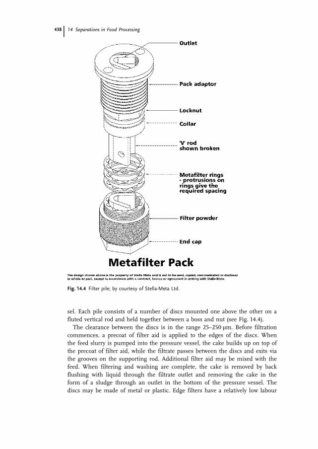
sel. Each pile consists of a number of discs mounted one above the other on afluted vertical rod and held together between a boss and nut (see Fig. 14.4).
The clearance between the discs is in the range 25–250 �m. Before filtrationcommences, a precoat of filter aid is applied to the edges of the discs. Whenthe feed slurry is pumped into the pressure vessel, the cake builds up on top ofthe precoat of filter aid, while the filtrate passes between the discs and exits viathe grooves on the supporting rod. Additional filter aid may be mixed with thefeed. When filtering and washing are complete, the cake is removed by backflushing with liquid through the filtrate outlet and removing the cake in theform of a sludge through an outlet in the bottom of the pressure vessel. Thediscs may be made of metal or plastic. Edge filters have a relatively low labour
14 Separations in Food Processing438
Fig. 14.4 Filter pile; by courtesy of Stella-Meta Ltd.

requirement and use no filter cloth. They are used mainly for removing smallquantities of fine solids from liquids.
14.2.4.2 Vacuum FiltersIn vacuum filters a partial vacuum is created downstream of the medium andatmospheric pressure is maintained upstream. Most vacuum filters are operatedcontinuously, as it is relatively easy to arrange continuous cake discharge underatmospheric pressure.
Rotary Drum Vacuum Filters There are a number of different designs of thistype of filter, one of which is depicted in Fig. 14.5.
A cylindrical drum rotates about a horizontal axis partially immersed in atank of the feed slurry. The surface of the drum is divided into a number ofshallow compartments by means of wooden or metal strips running the lengthof the drum. Filter medium is stretched over the drum surface, supported onperforated plates or wire mesh. A pipeline runs from each compartment to a ro-tary valve located centrally at one end of the drum. Consider one of the com-partments on the surface of the drum (shown shaded in Fig. 14.5). As the drumrotates, this compartment becomes submerged in the slurry. A vacuum is ap-plied to the compartment through the rotary valve. Filtrate is drawn throughthe medium and flows through the pipe to the rotary valve, from where it is di-rected to a filtrate receiver. The solids form a layer of cake on the outer surfaceof the medium. The cake increases in thickness as long as the compartment re-mains submerged in the slurry. As it emerges from the slurry, residual filtrateis sucked from the cake. Next the compartment passes beneath sprays of wash
14.2 Solid-Liquid Filtration 439
Fig. 14.5 Principle of operation of a rotary drum vacuumfilter; from [2] with permission of the authors.

liquid. The washings are directed to a different receiver by means of the rotaryvalve. As the compartment passes from beneath the sprays, residual wash liquidis sucked from the cake. Next, by means of the rotary valve, the compartment isdisconnected from the vacuum source and compressed air introduced beneaththe medium for a short period of time. This loosens the cake from the surfaceof the medium and facilitates its removal by means of a scraper knife.
Many other designs of rotary drum filters are available featuring differentmethods of feeding the slurry onto the drum surface removing the cake fromthe medium.
Rotary drum vacuum filters incur relatively low labour costs and have largecapacities for the space occupied. However, capital costs are high and they canonly handle relatively free-draining solids. In common with all vacuum filters,they are not used to process hot and/or volatile liquids.
For removing small quantities of fine solids from a liquid, a relatively thicklayer (up to 7.5 cm) of filter aid may be precoated onto the medium. A thinlayer of this precoat is removed together with the cake by the scraper knife.
Rotary Vacuum Disc Filters In a disc filter, instead of a drum, a number of cir-cular filter leaves, mounted on a horizontal shaft, rotate partially submerged ina tank of slurry. Each disc is divided into sections. Each section is covered withfilter medium and is connected to a rotary valve, which controls the applicationof vacuum and compressed air to the section. Scraper knives remove the cakefrom each disc. Such disc filters have a larger filtering surface per unit floorarea, compared to drum filters. However, cake removal can be difficult anddamage to filter cloth excessive.
Other designs of continuous vacuum filters are available featuring moving belts,rotating tables and other supports for the filter medium. These are used mainlyfor waste treatment rather than in direct food applications [2, 5–7, 9, 10].
14.2.4.3 Centrifugal Filters (Filtering Centrifugals, Basket Centrifuges)In this type of filter, the flow of filtrate through the cake and medium is in-duced by centrifugal force. The slurry is fed into a rotating cylindrical bowl witha perforated wall. The bowl wall is lined on the inside with a suitable filter me-dium. Under the action of centrifugal force, the solids are thrown to the bowlwall where they form a filter cake on the medium. The filtrate passes throughthe cake and medium and leaves the bowl through the perforations in the wall.
Batch Centrifugal Filters The principle of this type of filter is shown in Fig. 14.6.The cylindrical metal bowl in suspended from the end of a vertical shaft within astationary casing. With the bowl rotating at moderate speed, slurry is fed into thebowl. A cake forms on the medium lining the inside of the perforated bowl walland the filtrate passes through the perforations into the casing and out through aliquid outlet. The speed of the bowl is increased to recover most of the filtrate.Wash liquid may be sprayed onto the cake and spun off at high speed. The bowl
14 Separations in Food Processing440

is then slowed down, the cake cut out with an unloader knife or plough and re-moved through an opening in the bottom of the bowl. Cycle times vary over 3–30 min.
Fully automated versions of these batch filters operate at a constant speed,about horizontal axes, throughout a shorter cycle of 0.5–1.5 min. The feed andwash liquid are introduced automatically and the cake is cut out by a hydrauli-cally operated knife.
Continuous Centrifugal Filters The principle of one type of continuous centrifu-gal filter is shown in Fig. 14.7.
A conical perforated bowl (basket) rotates about a vertical axis inside a station-ary casing. The incline of the bowl causes the separation force to be split be-
14.2 Solid-Liquid Filtration 441
Fig. 14.6 Batch centrifugal filter; from [2] with permission of the authors.
Fig. 14.7 A continuous centrifugal filter; by courtesy of Broadbent Customer Services Ltd.
tween vertical and horizontal elements resulting in the product moving up-wards. The vertical force pushes the product up over the basket lip into the cas-ing from where it is discharged. The horizontal element ensures that purgingof the liquid phase takes place. This type of centrifuge is used for separating su-gar crystals from syrup. Sliding of the product upwards and its discharge formthe lip of the bowl, usually at high speed, is a relatively violent process and maydamage the product, i.e. fracture of crystals. Washing the solid phase while it ismoving may limit its effectiveness.
Other types of continuous centrifugal filters feature reciprocating pushingdevices, screw conveyors or vibrating mechanisms to facilitate removal of thecake [2, 5, 6, 11].
14.2.5Applications of Filtration in Food Processing
14.2.5.1 Edible Oil RefiningFiltration is applied at a number of stages in refining of edible oils. After extrac-tion or expression, crude oil may be filtered to remove insoluble impurities suchas fragments of seeds, nuts, cell tissue, etc. For large-scale applications rotaryfilters are used. Plate-and-frame filters are used for smaller operations. Bleach-ing earths used in decolourising oils are filtered off using rotary or plate filters.The catalysts used in hydrogenating fats and oils are recovered by filtration.Since hydrogenated fats have relatively high melting points, heated plate filtersmay be used. During winterisation and fractionation of fats, after cooling, thehigher melting point fractions are filtered off using plate-and-frame or belt fil-ters [12–15].
14.2.5.2 Sugar RefiningThe juice produced by extraction from sugar cane or sugar beet contains insol-uble impurities. The juice is treated with lime to form a flocculent precipitatewhich settles to the bottom of the vessel. The supernatant liquid is filtered toproduce a clear juice for further processing. Plate-and-frame presses, shell-and-leaf and rotary drum vacuum filters are used. The settled ‘mud’ is also filteredto recover more juice. Plate-and-frame presses or rotary drum vacuum filtersare used for this duty. Filtration is also used at a later stage in the refining pro-cess to further clarify sugar juice. In the production of granulated sugar, puri-fied sugar juice is concentrated up to 50–60% solids content by vacuum eva-poration and seeded with finely ground sugar crystals to initiate crystallisation.When the crystals have grown to the appropriate size, they are separated fromthe juice in batch or continuous centrifugal filters (see Section 3.1.4.2) [16, 17].
14 Separations in Food Processing442

14.2.5.3 Beer ProductionDuring maturation of beer, a deposit of yeast and trub forms on the bottom ofthe maturation tank. Beer may be recovered from this by filtration using plate-and-frame presses, shell-and-leaf or rotary drum vacuum filters. The beer is clar-ified by treatment with isinglass finings, centrifugation or filtration. If filtrationis used, the beer is first chilled and then filtered through plate-and-frame, hori-zontal plate or edge filters. In the case of plate filters, the filter medium consistsof sheets of cellulose, aluminium oxide or zirconium oxide fibres, with addedkieselguhr. Insoluble polyvinyl pyrrolidone may also be incorporated into themedium to absorb phenolic materials associated with beer haze. Edge filters areprecoated with filter aid and more filter aid is usually added to the beer prior tofiltration. Yeasts and bacteria may also be removed from beer by filtration.Although the pore sizes in the media are much larger than the microorgan-isms, the fibres hold the negatively charged microorganisms electrostatically.The pressure drop across these filters needs to be limited to avoid the microor-ganisms being forced off the media fibres. When a sterile product is desired,the sealed filter must be presterilised before use [18, 19].
14.2.5.4 Wine MakingWine is filtered at different stages of production: after racking, after decolouris-ing and finally just before bottling. Plate-and-frame presses, shell-and-leaf fil-ters, edge filters and precoated rotary drum vacuum filters have been used. Fil-ter media are mainly sheets made of cellulose incorporating filter aid material(mainly diatomaceous earth) which is bound into the cellulose sheets with bitu-men. With edge and precoated drum filters, loose filter aid material is used.Sterile wine may be produced by filtration in presterilised equipment [20–22].
There are many other applications for filtration in the food industry, includ-ing the filtration of starch and gluten suspensions and the clarification ofbrines, sugar syrups, fruit juices, yeast and meat extracts.
14.2 Solid-Liquid Filtration 443

14.3Centrifugation
James G. Brennan
14.3.1General Principles
Centrifugation involves the application of centrifugal force to bring about theseparation of materials. It may be applied to the separation of immiscible liq-uids and the separation of insoluble solids from liquids.
14.3.1.1 Separation of Immiscible LiquidsIf two immiscible liquids, A and B, with different densities, are introduced intoa cylindrical bowl rotating about a vertical axis, under the influence of centrifu-gal force, the more dense liquid A moves towards the wall of the bowl where itforms an annular ring (see Fig. 14.8). The less dense liquid B is displaced to-wards the centre of the bowl where it forms an inner annular ring.
If the feed is introduced continuously into the bottom of the bowl through avertical feed pipe, the liquids may be removed separately from each layer by aweir system, as shown in Fig. 14.9. The more dense liquid A flows out over acircular weir of radius RA and the less dense liquid B over a weir of radius RB.
The interface between the two layers is known as the neutral zone. The posi-tion of this interface can influence the performance of the centrifuge. In theouter zone (A), light liquid is effectively stripped from a mass of dense liquidwhile, in the inner zone (B), dense liquid is more effectively stripped from amass of light liquid. Thus, if the centrifuge is being used to strip a mass ofdense liquid free of light liquid so that the dense phase leaves in as pure a state
14 Separations in Food Processing444
Fig. 14.8 Separation of immiscible liquids in a cylindrical bowl(plan view); from [2] with permission of the authors.

as possible, then the dwell time in zone A should be greater than that in zoneB. For such a duty, the interface is best moved towards the centre of rotation sothat the volume of zone A exceeds that of zone B. In this situation, the lightcomponent is exposed to a relatively small centrifugal force for a short time,while the heavy component is exposed to a large force for a longer time. An ex-ample of such a duty is the separation of cream from milk, where the objectiveis to produce skim milk with as little fat in it as possible. In contrast, if the dutyis to strip a mass of light liquid free of dense liquid, i.e. to produce a pure lightphase, the interface is best moved out towards the bowl wall so that the volumeoccupied by zone B exceeds that of zone A. An example of such a duty wouldbe the removal of small amounts of water from an oil. The actual change in po-sition of the interface is quite small, in the order of 25–50 �m. However, it doesaffect the performance of the separator. The position of the interface can bechanged by altering the radii of the liquid outlets. For example, if the radius ofthe light liquid outlet RB is fixed, decreasing the radius of the dense liquid out-let RA will move the interface towards the centre of rotation. In practice, the ra-dius of either liquid outlet and hence the position of the interface, is deter-mined by fitting a ring with an appropriate internal diameter to the outlet. Suchrings are known as ring dams or gravity discs. It has also been established thatthe best separation is achieved by introducing the feed to the bowl at a pointnear the interface. The density difference between the liquids needs to be 3% ormore for successful separation. Other factors which influence the performanceof liquid-liquid centrifugal separators are bowl speed and the rate of flow of theliquids through them. In general, the higher the speed of the bowl, the betterthe separation. However, at very high speeds the viscosity of the oil phase mayimpede its flow through the centrifuge. The higher the rate of flow of the liq-uids through the bowl, the shorter the dwell time in the action zone; and so theless effective the separation is likely to be. For each duty a compromise needsto be struck between throughput and efficiency of separation.
14.3 Centrifugation 445
Fig. 14.9 Separation of immiscible liquids in a cy-lindrical bowl with submerged weir (sectionalview); from [2] with permission of the authors.

14.3.1.2 Separation of Insoluble Solids from LiquidsIf a liquid containing insoluble solid particles is fed into the bottom of a cylin-drical bowl rotating about a vertical axis, under the influence of centrifugalforce, the solid particles move towards to the bowl wall. If a particular solid par-ticle reaches the bowl wall before being swept out by the liquid leaving througha central outlet in the top of the bowl (see Fig. 14.10), it remains in the bowland thus is separated from the liquid. If it does not reach the bowl wall, it iscarried out by the liquid. The fraction of the solid particles remaining in thebowl and the fraction passing out in the liquid depend on the rate of feed, i.e.the dwell time in the bowl.
The following expression relates the throughput of liquid through a cylindri-cal bowl centrifuge to the characteristics of the feed and the dimensions andspeed of the bowl:
q � 2g��s � �l�D2
p
18�
� ��2V
2g ln R2
��R21�R2
2��2�1�2
� ����
��� �14�6�
where q is the volumetric flow rate of liquid through the bowl, g is accelerationdue to gravity, �s is the density of the solid, �l is the density of the liquid, Dp isthe minimum diameter of a particle that will be removed from the liquid, � isthe viscosity of the liquid, � is the angular velocity of the bowl, V is the volumeof liquid held in the bowl at any time, R1 is the radius of the liquid outlet andR2 is the inner radius of the bowl. Note the quantities contained within the firstset of square brackets relate to the feed material, while those within the secondset refer to the centrifuge. This expression can be used to calculate the through-put of a specified feed material through a cylindrical bowl centrifuge of knowndimensions and speed. It can also be used for scaling-up calculations. Alterna-tive expressions for different types of bowl (see Section 14.3.2) can be found inthe literature [2, 5, 6, 23].
14 Separations in Food Processing446
Fig. 14.10 Principle of simple cylindrical centrifugal clarifier;from [2] with permission of the authors.

14.3.2Centrifugal Equipment
14.3.2.1 Liquid-Liquid Centrifugal Separators
Tubular Bowl Centrifuge This type of centrifuge consists of a tall, narrow bowlrotating about a vertical axis inside a stationary casing. Bowl diameters rangefrom 10 cm to 15 cm with length:diameter ratios of 4–8. The feed enters intothe bottom of the bowl through a stationary pipe and is accelerated to bowlspeed by vanes or baffles. The light and dense phases leave via a weir system atthe top of the bowl and flow into stationary discharge covers. Depending on theduty it has to perform, a gravity disc of appropriate size is fitted to the dense phaseoutlet, as explained in Section 14.3.1.1. Bowl speeds range from 15000 rpm (large)to 50 000 rpm (small).
14.3 Centrifugation 447
Fig. 14.11 Principle of disc bowl centrifuge; from [2] with permission of the authors.

Disc Bowl Centrifuge In this type of centrifuge a relatively shallow, wide bowlrotates within a stationary casing. The bowl usually has a cylindrical body, witha diameter in the range 20–100 cm and a conical top (see Fig. 14.11). The bowlcontains a stack of truncated metal cones, known as discs, which rotate withthe bowl. The clearance between the discs is of the order of 50–130 �m. Thediscs have one or more sets of matching holes which form vertical channels inthe stack. The feed is introduced to the bottom of the bowl, flows through thesechannels and enters the spaces between the discs. Under the influence of cen-trifugal force, the dense phase travels in a thin layer down the underside of thediscs towards the bowl wall while the light phase, displaced towards the centreof rotation, flows over the top of the discs. Thus the space between each pair ofdiscs is a minicentrifuge. The distance any drop of one liquid must travel to getinto the appropriate stream is small compared to that in a tubular bowl ma-chine or indeed an empty bowl of any design. In addition, in a disc machinethere is considerable shearing at the interface between the two countercurrentstreams of liquid which contributes to the breakdown of emulsions. The phasesleave the bowl through a weir system fitted with an appropriate gravity disc andflow into stationary discharge covers.
14.3.2.2 Solid-Liquid Centrifugal SeparatorsBoth tubular bowl and disc bowl centrifuges can be used for solid-liquid separa-tion, within certain limitations. For this type of duty, the dense phase outlet isclosed off and the clear liquid exits the bowl through the central, light phaseoutlet. The solid particles which are separated from the liquid remain in thebowl, building up as a deposit on the wall of the bowl. Consequently, the centri-fuges are operated on a batch principle and have to be stopped and cleaned atintervals. The tubular bowl machines have a relatively small solids capacity andare only suitable for handling feeds with low solids content, less than 0.5%.However, because of the high speeds they operate at, they are particularly suitedto removing very fine solids. Disc bowl machines have up to five times the ca-pacity for solids, compared to tubular bowl centrifuges. However, to avoid fre-quent cleaning, they are also used mainly with feeds containing relatively lowsolids content, less than 1.0%.
Solid Bowl Centrifuge (Clarifier) For separating solid particles which settle rela-tively easily, a bowl similar in shape to that shown in Fig. 14.7 may be used.However, the bowl wall is not perforated and no filter medium is used. The sol-ids build up on the inside of the bowl wall and the clear liquid spills out overthe top rim of the bowl into the outer casing. At intervals, the feed is stoppedand the solids removed by means of a knife or plough and discharged throughan opening in the bottom of the bowl. This type of clarifier can handle feedswith up to 2.0% solids content.
14 Separations in Food Processing448

Nozzle-discharge Centrifuge In this type of centrifuge there is provision for thecontinuous discharge of solids, in the form of a sludge, as well as the clear liq-uid. There are many different designs available. One design consists of a disc-bowl machine with two to twenty four nozzles spaced around the bowl. The sizeof the nozzles is in the range 0.75 to 2.00 mm, depending on the size of thesolid particles in the feed. From 5 to 50% of the feed is continuously dischargedin the form of a slurry through these nozzles. The slurry may contain up to25% v/v solids. By recycling some of the slurry the solids content may be in-creased. Up to 75% of the slurry may be recycled, depending on its flowability,and the solids content increased up to 40%.
Self-opening Centrifuge In this type of centrifuge the ports discharging the slur-ry open at intervals and the solids are discharged under a pressure of up to3500 kN m–2. The opening of the ports may be controlled by timers. Self-trig-gering ports are also available. The build-up of solids in the bowl is monitoredand a signal is generated which triggers the opening of the ports. An exampleof one such centrifuge, used in the brewing industry, is shown in Fig. 14.12.The slurry discharged from these self-opening centrifuges usually has a highersolids content compared to that continuously discharged through open nozzles.
Decanting Centrifuge Nozzle and valve discharge centrifuges can only handlefeeds containing a few percent or less of solids. For feeds containing a higherpercent of solids, decanting or conveyor bowl centrifuges may be used. Theprinciple of operation of one such centrifuge is shown in Fig. 14.13. A solid
14.3 Centrifugation 449
Fig. 14.12 A self-triggering solids-ejecting clarifier centrifuge; by courtesy of Alfa Laval Ltd.

bowl containing a screw conveyor rotates about a horizontal axis. The bowl andconveyor rotate in the same direction but at different speeds. The feed entersthe bowl through the conveyor axis. The solids are thrown to the bowl wall andare conveyed to one end of the bowl, up a conical section, from where they aredischarged. The clear liquid is discharged through an adjustable weir at theother end of the bowl. Such machines can handle feeds containing up to 90%(v/v) of relatively large solid particles. Particles 2 �m or less in diameter are nor-mally not removed from the liquid. Where necessary, the liquid discharged fromdecanting centrifuges may be further clarified in tubular or disc bowl centri-fuges [2, 5, 6, 10].
14.3.3Applications for Centrifugation in Food Processing
14.3.3.1 Milk ProductsCentrifugation is used in the separation of milk to produce cream and/or skimmilk. Disc bowl centrifuges are generally used for this duty. They may be her-metically sealed and fitted with centripetal pumps. Milk is usually heated to be-tween 40 �C and 50 �C prior to separation, to reduce its viscosity and optimisethe density difference between the fat and aqueous phases. The fat content ofthe skim milk may be reduced to less than 0.05%. Although the process is con-tinuous, insoluble solids present in the milk (dirt particles, casein micelles, mi-croorganisms) build up as sludge in the centrifuge bowl. The bowl has to becleaned out at intervals. Alternatively, nozzle or self-opening centrifuges may beused, but with outlets for the cream and skim milk as well as the sludge.
Fat may be recovered from whey and buttermilk by centrifugation [24].
14 Separations in Food Processing450
Fig. 14.13 Cut away view – Alfa Leval Decanter, by courtesy ofAlfa Laval Ltd.

14.3.3.2 Edible Oil RefiningIn the early stages of oil refining, the crude oil is treated with water, dilute acidor alkali to remove phosphatides and mucilaginous material. This process isknown as degumming. Nozzle or self-opening centrifuges are used to removethe gums after these treatments. In the case of acid-degumming, the de-gummed oil may be washed with hot water and the washings removed by cen-trifugation. The next step in oil refining is neutralisation. The free fatty acids,phosphatides and some of the pigments are treated with caustic soda to formsoapstock which is then separated from the oil by centrifugation, using nozzleor self-opening centrifuges. The oil is then washed with hot water and thewashings removed by centrifugation [13].
14.3.3.3 Beer ProductionCentrifugation may be used as an alternative to filtration at various stages inthe production of beer. Nozzle discharge centrifuges may be used for clarifyingrough beer from fermenting vessels and racking tanks. Self-opening centrifugesmay be used for wort and beer clarification. Centrifuges used for the treatmentof beer may be hermetically sealed to prevent the loss of carbon dioxide and thetake-up of oxygen by the beer. Self-opening centrifuges may also be used for therecovery of beer from fermenters and tank bottoms. Decanting centrifuges maybe used for clarifying worts and beers containing relatively high contents ofyeast or trub. They may also be used as an alternative to self-opening machinesto recover beer from fermenters and tank bottoms [18].
14.3.3.4 Wine MakingCentrifugation may be used instead of or in combination with filtration at var-ious stages in the production of wine. Nozzle or self-opening centrifuges aregenerally used. Applications include: the clarification of must after pressing,provided that the solids content is relatively low, the clarification of wine duringfermentation to stabilise it by gradual elimination of yeast, the clarification ofnew wines after fermentation and before filtration, the clarification of new redwines before filling into barrels and the facilitation of tartrate precipitation forthe removal of tartrate crystals [20, 21, 22].
14.3.3.5 Fruit Juice ProcessingCentrifugation may be used for a variety of tasks in fruit juice processing. Self-opening centrifuges are used to remove pulp and control the level of pulp re-maining in pineapple and citrus juices. Centrifuged apple juice is cloudy butfree from visible pulp particles. Tubular bowl centrifuges were originally used toclarify apple juice but more recently nozzle and self-opening machine are used.The use of hermetically sealed centrifuges prevents excessive aeration of thejuice. In the production of oils from citrus fruits centrifugation is applied in
14.3 Centrifugation 451

two stages. The product from the extractor contains an emulsion of 0.5–3.0%oil. This is concentrated up to 50–70% oil in a nozzle or self-opening centrifuge.The concentrated emulsion is then separated in a second centrifuge to producethe citrus oil [25, 26].
There are many other applications for centrifugation in food processing, e.g.tubular bowl machines for clarifying cider and sugar syrups and separating ani-mal blood into plasma and haemoglobin, nozzle and self-opening machines fordewatering starches and decanting centrifuges for recovering animal and vege-table protein, separating fat from comminuted meat and separating coffee andtea slurries.
14.4Solid-Liquid Extraction (Leaching)
James G. Brennan
14.4.1General Principles
This is a separation operation in which the desired component, the solute, in asolid phase is separated by contacting the solid with a liquid, the solvent, inwhich the desired component is soluble. The desired component leaches fromthe solid into the solvent. Thus the compositions of both the solid and liquidphases change. The solid and liquid phases are subsequently separated and thedesired component recovered from the liquid phase.
Solid-liquid extraction is carried out in single or multiple stages. A stage is anitem of equipment in which the solid and liquid phases are brought into con-tact, maintained in contact for a period of time and then physically separatedfrom each other. During the period of contact, mass transfer of components be-tween the phases takes place and they approach a state of equilibrium. In anequilibrium or theoretical stage, complete thermodynamic equilibrium is attainedbetween the phases before they are separated. In such a stage, the composi-tional changes in both phases are the maximum which are theoretically possibleunder the operating conditions. In practice, complete equilibrium is not reachedand the compositional changes in a real stage is less than that attainable in anequilibrium stage. The efficiency of a real stage may be defined as the ratio ofthe compositional change attained in the real stage to that which would havebeen reached in an equilibrium stage under the same operating conditions.When estimating the number of stages required to carry out a particular task ina multistage system, the number of equilibrium stages is first estimated andthe number of real stages calculated by dividing the number of equilibriumstages by the stage efficiency. Graphical and numerical methods are used to es-timate the number of equilibrium stages required for a particular duty [2, 4–6].
14 Separations in Food Processing452

After the period of contact, the solid-liquid mixture is separated into twostreams: a ‘clear’ liquid stream or overflow consisting of a solution of the solutein the solvent and a ‘residue’ stream or underflow consisting of the insoluble sol-id component with some solution adhering to it. In an equilibrium stage, thecomposition of the overflow is the same as that of the solution leaving with theinsoluble solid in the underflow. In a real stage, the concentration of solute inthe overflow is less than that in the solution leaving with the insoluble solid inthe underflow.
The extraction of the solute from a particle of solid takes place in threestages. The solute dissolves in the solvent. The solute in solution then diffusesto the surface of the particle. Finally, the solute transfers from the surface ofthe particle into the bulk of the solution. One or more of these steps can limitthe rate of extraction. If the correct choice of solvent has been made, the solu-tion of the solute in solvent is rapid and is unlikely to influence the overall rateof extraction. The rate of movement of the solute to the surface of the solid par-ticle depends on the size, shape and internal structure of the particle and is dif-ficult to quantify. The rate of transfer of the solute from the surface of the solidparticle to the bulk of the solution may be represented by the expression:
dwdt
� KA�Cs � C� �14�7�
Here, dwdt is the rate of mass transfer of the solute, A is the area of the solid-
liquid interface, Cs and C are the concentration of the solute at the surface ofthe solid particle and in the bulk of the solution, respectively, and K is the masstransfer coefficient.
In a single stage extraction unit where V is the total volume of the solutionand is constant, then:
dwdt
� VdC
and so:
dCdt
� KA�Cs � C�V
�14�8�
The main factors which influence the rate of extraction include:
1. The solid-liquid interface area. The rate of mass transfer from the surface ofthe particle to the bulk of the solution increases with increase in this area.Reducing the size of the solid particles increases this area and so increasesthe rate of mass transfer. In addition, the smaller the particle the shorter thedistance the solute has to travel to reach the surface. This is likely to furtherspeed up the extraction. However, very small particles may impede the flowof solvent through the bed of solid in an extractor and some particles may
14.4 Solid-Liquid Extraction (Leaching) 453

not come in contact with the solvent. In the case of cellular material, such assugar beet (see Section 14.4.3.2), the cell wall acts as a semipermeable mem-brane releasing sugar but retaining larger nonsugar molecules. Therefore, thebeet is sliced rather than comminuted to increase the surface area for extrac-tion but to limit cell wall damage.
2. Concentration gradient. To ensure as complete extraction as possible, a gradi-ent must be maintained between the concentration of solute at the surface ofthe solid particles and that in the bulk of the solution. In a single stage ex-tractor, as the phases approach equilibrium, this gradient decreases and sodoes the rate of extraction until it ceases. When this occurs, the solid may stillcontain a significant amount of solute and the solution may be relatively di-lute, depending on the equilibrium conditions. This solution could be drainedoff and replaced with fresh solvent resulting in further extraction of thesolute. This could be repeated until the solute content of the solid reached asuitably low level. However, this would result in the production of a large vol-ume of relatively dilute solution. The cost of recovering the solute from thissolution increases as its solute content decreases. For example, the lower theconcentration of sugar in the solution obtained after extraction of sugar beet,the more water has to be evaporated off before crystallisation occurs. Multi-stage countercurrent extraction systems enable a concentration gradient to bemaintained even when the concentration of solute in the solid is low (seeFig. 14.14b). This results in more complete extraction as compared with thatattainable in single-stage or multistage concurrent systems (see Fig. 14.14a).
3. Mass transfer coefficient. An increase in temperature increases the rate of so-lution of the solute in the solvent and also the rate of diffusion of solutethrough the solution. This is reflected in a higher value of K in Eq. (14.7) andEq. (14.8). Thus, the solvent is usually heated prior to and/or during extrac-tion. The upper limit in temperature depends on the nature of the solids. Forexample, in the extraction of sugar from beet, too high a temperature can re-sult in peptisation of the beet cells and the release of nonsugar compoundsinto the solution (see Section 14.4.3.2). In the case of the extraction of solu-bles from ground roasted coffee beans, too high a temperature can result inthe dried coffee powder having an undesirable flavour (see Section 14.4.3.3).
Increasing the velocity and turbulence of the liquid as it flows over the sol-id particles can result in an increase in the value of K in Eq. (14.7) andEq. (14.8) and hence an increase in the rate of extraction. In some industries,when fine particles are being extracted, they are mechanically stirred. How-ever, in most food applications, this is not the case as agitation of the solidcan result in undesirable breakdown of the particles. In most food applica-tions, the solvent is made to flow through a static bed of solids under the in-fluence of gravity or with the aid of a pump. Alternatively, the solids are con-veyed slowly, usually countercurrent to the flow of solvent [2, 4–6, 27].
14 Separations in Food Processing454

14.4.2Extraction Equipment
14.4.2.1 Single-Stage ExtractorsA simple extraction cell consists of a tank fitted with a false bottom which sup-ports a bed of the solids to be extracted. The tank may be open or closed. If ex-traction is to be carried under pressure, as in the case with extraction of groundroasted coffee (see Section 14.4.3.3), or if volatile solvents are used, as in thecase of edible oil extraction (see Section 14.4.3.1), the tank is enclosed (seeFig. 14.15). The solvent is sprayed over the top surface of the bed of solids, per-colates down through the bed and exits via an outlet beneath the false bottom.The tank may be jacketed and/or a heater incorporated into the solvent feed lineto maintain the temperature of the solution at the optimum level. Usually apump is provided for recirculating the solution. The spent solid is removedmanually or dumped through an opening in the bottom of the tank. In largecells, additional supports may be provided for the bed of solids to prevent con-solidation at the bottom of the cell.
Single extraction cells are used for laboratory trials and for small-scale indus-trial applications. As discussed in Section 14.4.1, the bulked solution from suchunits is relatively dilute. If a volatile solvent is used, the overflow from the cellmay be heated to vapourise the solvent, which is then condensed and recycledthrough the cell. In this way, a more concentrated solution of the solute may beobtained.
14.4 Solid-Liquid Extraction (Leaching) 455
Fig. 14.14 Graphical representation of concur-rent and countercurrent extraction systems.(a) Concurrent system, (b) countercurrentsystem. Solid lines indicates solution, dashedlines indicate solid matter; from [2] with per-mission of the authors.

14.4.2.2 Multistage Static Bed ExtractorsOne method of applying multistage countercurrent extraction is to use a num-ber of single cells arranged in a circuit. Each cell contains a charge of solids.The solution from the preceding cell is sprayed over the surface of the bed ofsolids and percolates down through the bed, becoming more concentrated as itdoes so. The solution leaving from the bottom of the cell is introduced into thetop of the next cell. A typical battery, as used for the extraction of sugar beet,contains 14 cells, as shown in Fig. 14.16. At the time depicted in this figure,three of the cells are excluded from the circuit. Cells 10, 11 and 12 are beingfilled, washed and emptied, respectively. The fresh water enters cell 13 and theconcentrated sugar solution, or overflow, leaves from cell 9. When the beet incell 9 is fully extracted, this cell is taken out of the circuit and cell 10 broughtin to take its place. Fresh water then enters cell 14 and the concentrated sugarsolution leaves from cell 10. By isolating cells in turn around the circuit, theprinciple of countercurrent extraction may be achieved without physically mov-ing the beet from one cell to the next. The number of cells in such a circuitmay vary from three to 14.
14 Separations in Food Processing456
Fig. 14.15 Single-stage, enclosed extraction cell; from [2] with permission of the authors.

14.4.2.3 Multistage Moving Bed ExtractorsThere are many different designs of moving bed extractors available. Theyusually involve moving the solid gently from one stage to the next, countercur-rent to the flow of the solution. One type of continuous extractor consists of atrough set at a small angle to the horizontal containing two screw conveyorswith intermeshing flights. The solvent is introduced at the elevated end of thetrough. The solid is fed in at the other end and is carried up the slope by con-veyors countercurrent to the flow of the solution. The trough is enclosed andcapable of withstanding high pressure. Extractors of this type are used for sugarbeet and ground roasted coffee. Another type, known as the Bonotto extractor isshown in Fig. 14.17. It consists of a vertical tower divided into sections by hori-zontal plates. Each plate has an opening through which the solid can passdownwards from plate to plate; and each plate is fitted with a wiper blade whichmoves the solid to the opening. The holes are positioned 180� from each otherin successive plates. The solid is fed onto the top plate. The wiper blade movesit to the opening and it falls onto the plate below and so on down the towerfrom plate to plate. Fresh solvent is introduced at the bottom of the tower andis pumped upwards countercurrent to the solid. The rich solution leaves at thetop of the tower and the spent solid is discharged from the bottom. This type ofextractor is used for oil extraction from nuts and seeds.
Many other designs of continuous moving bed extractors are in use in indus-try. One design features moving perforated baskets which carry the solidthrough a stream of the solvent. In another design, the solid is conveyed byscrew conveyors, with perforated blades, through vertical towers, countercurrentto the flow of solvent [2, 4–6, 27].
14.4 Solid-Liquid Extraction (Leaching) 457
Fig. 14.16 Mulistage, countercurrent extraction battery show-ing flow of solution at one particular point in time; from [2]with permission of the authors.

14 Separations in Food Processing458
Fig. 14.17 Bonotto extractor.

14.4.3Applications for Solid-Liquid Extraction in Food Processing
14.4.3.1 Edible Oil ExtractionSolvent extraction may be used as an alternative to or in combination with ex-pression to obtain oil from nuts, seeds and beans. The most commonly usedsolvent is hexane. This is a clear hydrocarbon, derived from petroleum that boilsat 68.9 �C. It is miscible with oil, immiscible with water and does not impartany objectionable odour or taste to the oil or spent solid. Hexane is highly flam-mable and so the plant must be vapour-tight and care must be taken to avoidthe generation of sparks that might ignite the solvent. Other solvents have beeninvestigated, including heptane and cyclohexane. Nonflammable solvents, suchas trichloroethylene and carbon disulphide, have been studied but are toxic anddifficult to handle. Various alcohols and supercritical carbon dioxide (see Sec-tion 14.4.5) have also been investigated. Various designs of moving bed extrac-tors are used in large scale-oil extraction, including those described in Sec-tion 14.4.3. After extraction, the solution of oil in solvent is filtered, the solventremoved by vacuum evaporation followed by distillation and the solvent reused.Residual solvent may be removed from the spent solid by direct or indirect heat-ing with steam and the resulting meal used for animal feed. Batch extractorsfeaturing solvent recovery and reuse can be used for small-scale operations. Cot-tonseed, linseed, rapeseed, sesame, sunflower, peanuts, soybean and corn germmay be solvent-extracted [2, 28].
14.4.3.2 Extraction of Sugar from Sugar BeetSugar is extracted from sugar beet using heated water as solvent. The beets arewashed and cut into slices, known as cossettes. This increases the surface areafor extraction and limits cell wall damage (see Section 14.4.1). Water tempera-ture ranges from 55 �C in the early stages of extraction to 85 �C towards theend. Higher temperatures can cause peptisation of the beet cells and releasenonsugar compounds into the extract. Multistage static bed batteries, as de-picted in Fig. 14.17, are widely used. So also are various designs of moving bedextractors, including those described in Section 14.4.2.3. The solution leavingthe extractor contains about 15% of dissolved solids. This is clarified by settlingand filtration, concentrated by vacuum evaporation, seeded and cooled to crystal-lise the sugar. The crystals are separated from the syrup by centrifugation,washed and air dried (see Section 3.1.5.2) [2, 29].
14.4.3.3 Manufacture of Instant CoffeeA blend of coffee beans is roasted to the required degree, ground to the appro-priate particle size range and extracted with heated water. Extraction may be car-ried out in a multistage, countercurrent static bed system consisting of 5–8 cells. Each cell consists of a tall cylindrical pressure vessel as temperatures
14.4 Solid-Liquid Extraction (Leaching) 459

above 100 �C are used. Heat exchangers are located between the cells. Water atabout 100 �C is introduced into the cell containing the beans that are almostfully extracted and then passes through the other cells, until the rich solutionexits from the cell containing the freshly ground beans. The temperature of thesolution increases up to a maximum of 180 �C as it passes through the batteryof cells. In the later stages of extraction, some hydrolysis of insoluble carbohy-drate material occurs, resulting in an increase in the yield of soluble solids.Higher temperatures may impart an undesirable flavour to the product due toexcessive hydrolysis. Continuous, countercurrent extractors featuring screw con-veyors within pressurised chambers (see Section 14.4.2.3) may be used insteadof the static bed system. The rich solution leaving the extractor usually contains15–28% solids. This may be fed directly to a spray drier. Alternatively, the solu-tion may be concentrated up to 60% solids by vacuum evaporation (see Sec-tion 3.1.5.2). The volatiles may be stripped from the extract before or duringevaporation and added back to the concentrated extract prior to dehydrationeither by spray drying or freeze drying [2, 30, 31].
14.4.3.4 Manufacture of Instant TeaDried, blended tea leaves may be extracted with heated water in a static bed sys-tem consisting of 3–5 cells. Water temperature ranges from 70 �C in the earlystages of extraction to 90 �C in the later stages. The cells may be evacuated afterfilling with the dry leaves and the pressure brought back to atmospheric levelby introducing gaseous carbon dioxide. This facilitates the flow of the waterthrough the cells. Continuous tower or other moving-bed extractors are alsoused to extract tea leaves. The rich solution coming from the extractor usuallycontains 2.5–5.0% solids. This is concentrated by vacuum evaporation to 25–50% solids. The volatile aroma compounds are stripped from the extract priorto or during evaporation and added back before dehydration by spray drying,vacuum drying or freeze drying.
14.4.3.5 Fruit and Vegetable Juice ExtractionIn recent years there has been considerable interest in using extraction insteadof expression for recovering juices from fruits and vegetables. Countercurrentscrew extractors, some operated intermittently, have been used to extract juicewith water. In some cases this results in higher yields of good quality comparedto that obtained by expression [32].
14.4.4The Use of Supercritical Carbon Dioxide as a Solvent
The critical pressure and temperature for carbon dioxide are 73.8 kPa and31.06 �C, respectively. At pressures and temperatures above these values carbondioxide exists in the form of a supercritical fluid (supercritical carbon dioxide;
14 Separations in Food Processing460

SC-CO2). In this state it has the characteristics of both a gas and a liquid. It hasthe density of a liquid and can be used as a liquid solvent, but it diffuses easilylike a gas. It is highly volatile, has a low viscosity, a high diffusivity, is nontoxicand nonflammable. These properties make it a very useful solvent for extrac-tion. However, the fact that SC-CO2 has to be used at high pressure means thatrelatively expensive pressure resistant equipment is required and running costsare also high. The solvent power of SC-CO2 increases with increase in tempera-ture and pressure. For the extraction of highly soluble compounds or for deo-dorisation, pressures and temperatures close to the critical values may be used.When a single component is to be extracted from an insoluble matrix, so calledsimple extraction, the highest pressure and temperature possible for each appli-cation should be used. The upper limit on temperature will depend on the heat-sensitivity of the material. The limit on pressure will be determined by the costof the operation. When all soluble matter is to be extracted, so called total ex-traction, high pressures and temperatures are again necessary.
The following are examples of the industrial application of SC-CO2 extraction.
Hop Extract A good quality hop extract, for use in brewing, may be obtainedby extraction with SC-CO2. A multistage, countercurrent, static bed system, con-sisting of four extraction cells, is normally used. The SC-CO2 percolates downthrough the hop pellets in each cell in turn. The solution of the extract in theSC-CO2 leaving the battery is heated and the carbon dioxide evaporates, precipi-tating out the extract. The carbon dioxide is recompressed and cooled and con-denses back to SC-CO2 which is chilled to 7 �C and recycled through the extrac-tion battery.
Decaffeination of Coffee Beans SC-CO2 may be used as an alternative to wateror methylene chloride for the extraction of caffeine from coffee beans. Thebeans are moistened before being loaded into the extractor. SC-CO2 is circulatedthrough the bed of beans extracting the caffeine. The caffeine-laden SC-CO2
passes to a scrubbing vessel where the caffeine is washed out with water. Alter-natively, the caffeine may be removed by passing the caffeine-laden SC-CO2
through a bed of activated charcoal.
Removal of Cholesterol from Dairy Fats SC-CO2 at 40 �C and 175 kPa has beenused to remove cholesterol from butter oil in a packed column extractor. Theaddition of methanol as an entrainer increases the solubility of cholesterol inthe fluid phase. The methanol is introduced with the oil into the column.Many other potential applications for SC-CO2 extraction have been investigatedincluding: extraction of oils from nuts and seeds, extraction of essential oilsfrom roots, flowers, herbs and leaves, extraction of flavour compounds fromspices and concentration of flavour compounds in citrus oils [2, 28, 33–37].
14.4 Solid-Liquid Extraction (Leaching) 461

14.5Distillation
James G. Brennan
14.5.1General Principles
Distillation is a method of separation which depends on there being a differ-ence in composition between a liquid mixture and the vapour formed from it.This difference in composition develops if the different components of the mix-ture have different vapour pressures or volatilities. In batch distillation, a givenvolume of liquid is heated and the vapours formed are separated and condensedto form a product. In batch distillation, the compositions of the liquid remain-ing in the still and the vapour collected change with time. Batch distillation isstill used in some whisky distilleries. However, continuous distillation columnsare used in most industrial applications of distillation.
Consider a liquid mixture consisting of two components with different volatilities.If such a mixture is heated under constant pressure conditions, it does not boil at asingle temperature. The more volatile component starts to vaporise first. The tem-perature at which this commences is known as the bubble point. If a vapour con-sisting of two components with different volatilities is cooled, the less volatile com-ponent starts to condense first. The temperature at which this commences is knownas the dew point. A diagram of the temperature composition for liquid- vapour equi-librium of a two-component mixture is presented in Fig. 14.18.
The bottom ‘L’ line in the phase envelope represents liquid at its bubble pointand the top ‘V’ line represents vapour at its dew point. The 0–1.0 compositionaxis refers to the more volatile component ‘a’, xa and ya are the mole fractionsof ‘a’ in the liquid and vapour phases, respectively, and xb and yb are the molefractions of component ‘b’, the less volatile component, in the liquid and vapourphases, respectively. The region below the bubble point curve represents sub-cooled liquid. The region above the dew point curve represents superheatedvapour. Within the envelope, between the L and V lines, two phases exist. Satu-rated liquid and saturated vapour exist in equilibrium with each other.
If a liquid mixture at temperature �1 is heated until it reaches temperature�2, its bubble point, it will start to vaporise. The vapour produced at this tem-perature will contain mole fraction y2 of component ‘a’. Note that the vapour isricher in ‘a’ than the liquid. As a result of the evaporation the liquid becomesless rich in component ‘a’ and richer in ‘b’ so its temperature rises further. Attemperature �3 the liquid phase contains mole fraction x3 of ‘a’ and vapourphase y3 of ‘a’. Note that, at this temperature, the vapour is less rich in ‘a’ thanit was at its bubble point. When temperature �4 is reached, all of the liquid isevaporated and the composition of the vapour is the same as the original liquid,y4 = x1. A similar sequence of events occurs if we start with a superheated va-
14 Separations in Food Processing462
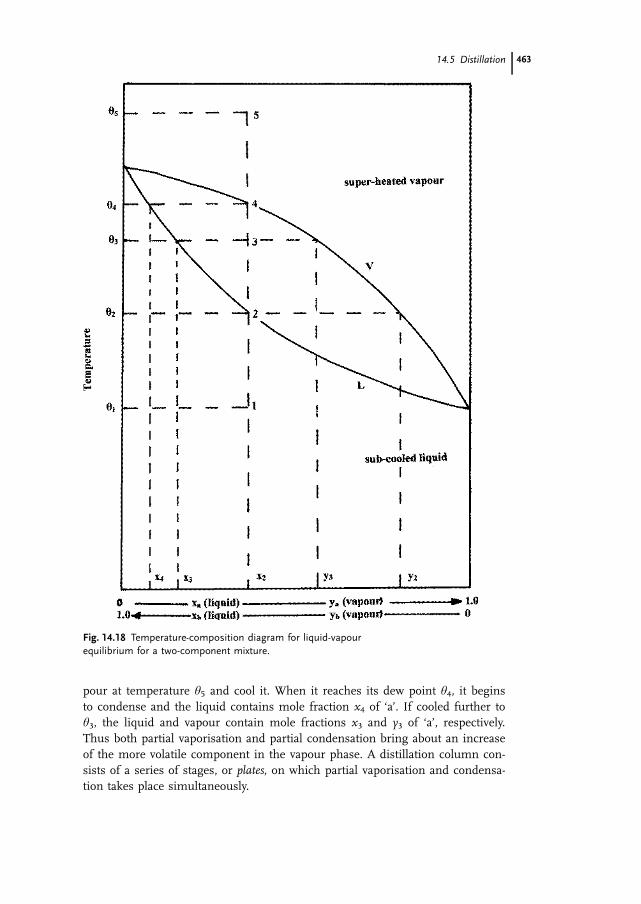
pour at temperature �5 and cool it. When it reaches its dew point �4, it beginsto condense and the liquid contains mole fraction x4 of ‘a’. If cooled further to�3, the liquid and vapour contain mole fractions x3 and y3 of ‘a’, respectively.Thus both partial vaporisation and partial condensation bring about an increaseof the more volatile component in the vapour phase. A distillation column con-sists of a series of stages, or plates, on which partial vaporisation and condensa-tion takes place simultaneously.
14.5 Distillation 463
Fig. 14.18 Temperature-composition diagram for liquid-vapourequilibrium for a two-component mixture.

The principle of a continuous distillation column, also known as a fraction-ation or fractionating column, is shown in Fig. 14.19.
The column contains a number of plates which are perforated to allow vapourrising from below to pass through them. Each plate is equipped with a weirover which the liquid flows and then through a downtake onto the plate below.The liquid contained in the reboiler at the bottom of the column is heated.When the liquid reaches its bubble point temperature, vapour is formed andthis vapour bubbles through the liquid on the bottom plate. The vapour fromthe reboiler has a composition richer in the more volatile components than theliquid remaining in the reboiler. This vapour is at a higher temperature thanthe liquid on the bottom plate. Some of that vapour condenses and causes someof the liquid on the bottom plate to evaporate. This new vapour is richer in themore volatile components than the liquid on the bottom plate. This vapour inturn bubbles through the liquid on the plate above the bottom plate, causingsome of it to evaporate and so on up the column. Thus, partial condensationand partial vaporisation takes place on each plate. The vapour rising up the col-umn becomes increasingly rich in the more volatile components while the liq-uid flowing down from plate to plate becomes richer in the less volatile compo-nents. If all the vapour leaving the top of the column is condensed and re-moved, then the liquid in the column becomes progressively less rich in the vol-atile components as does the vapour being removed at the top of the column.This is the equivalent of batch distillation. However, if some of the condensedvapour is returned to the column and allowed to flow down from plate to plate,the concentration of the volatile components in the column is maintained at ahigher level. The condensed vapour returned to the column is known as reflux.If feed material is introduced continuously into the column, then a product richin volatile components can be withdrawn continuously from the top of the col-umn and one rich in the less-volatile components from the reboiler at the bot-tom of the column. The feed is usually introduced onto a plate partway up thecolumn.
Each plate represents a stage in the separation process. As is the case in sol-id-liquid extraction (see Section 14.4.1), the terms equilibrium or theoretical plateand plate efficiency may be applied to distillation. Graphical and numerical meth-ods are used to estimate the number of equilibrium plates required to performa particular duty and the number of real plates is calculated by dividing thenumber of equilibrium plates by the plate efficiency.
Steam distillation is applicable to mixtures which have relatively high boilingpoints and which are immiscible with water. If steam is bubbled through theliquid in the still, some of it will condense and heat the liquid to boiling point.Two liquid layers will form in the still. The vapour will consist of steam and thevolatile vapour, each exerting its own vapour pressure. The mixture will boilwhen the sum of these pressures equals atmospheric pressure. Thus, the distil-lation temperature will always be lower than 100 �C at atmospheric pressure. Byreducing the operating pressure, the distillation temperature will be reducedfurther and less steam will be used. Steam distillation may be used to separate
14 Separations in Food Processing464

temperature-sensitive, high boiling point materials from volatile impurities, orfor removing volatile impurities with high boiling points from even less volatilecompounds. The separation of essential oils from nonvolatile compounds dis-solved or dispersed in water is an example of its application [5, 6, 38, 39].
14.5 Distillation 465
Fig. 14.19 Principle of a continuous distillation (fractionating) column.

14.5.2Distillation Equipment
14.5.2.1 Pot StillsPot stills, used in the manufacture of good quality whiskey, are usually madefrom arsenic-free copper. Apparently the copper has an influence on the flavourof the product. The still consists of a pot which holds the liquor to be distilledand which is fitted with a swan neck. Because of their shape, pot stills aresometimes known as onion stills. A lyne arm, a continuation of the swan neck,tapers towards the condenser. The condenser is usually a shell and tube heat ex-changer also made of copper. Heat is applied to the pot by means of steampassing through coils or a jacket. There is very limited use of direct heating bymeans of a solid fuel furnace beneath the pot. Such stills operate on a batchprinciple and two or three may operate in series (see Section 14.5.3.1).
14.5.2.2 Continuous Distillation (Fractionating) ColumnsA distillation column consists of a tall cylindrical shell fitted with a number ofplates or trays. The shell may be made of stainless steel, monel metal or tita-nium. As described in Section 14.5.1, the vapour passes upwards through theplates while the refluxed liquid flows across each plate, over a weir and onto theplate below via a downtake. There are many different designs of plate includingthe following examples.
Sieve plates consist of perforated plates with apertures of the order of 5 mm di-ameter, spaced at about 10 mm centres. The vapour moving up through the per-forations prevents the liquid from draining through the holes. Each plate isfitted with a weir and downtake for the liquid.
Bubble cap plates are also perforated but each hole is fitted with a riser or‘chimney’ through which the vapour from the plate below passes. Each riser iscovered by a bell-shaped cap, which is fastened to the riser by means of a spideror other suitable mounting. There is sufficient space between the top of theriser and the cap to permit the passage of the vapour. The skirt of the cap maybe slotted or the edge of the cap may be serrated. The vapour rises through thechimney, is diverted downwards by the cap and discharged as small bubblesthrough the slots or from the serrated edge of the cap beneath the liquid. Theliquid level is maintained at some 5–6 cm above the top of the slots in the capby means of the weir. The bubbles of vapour pass through the layer of liquid,heat and mass transfer occur and vapour, now richer in the more volatile com-ponents, leaves the surface of the liquid and passes to the plate above.
Valve plates are also perforated but the perforations are covered by liftable capsor valves. The caps are lifted as the vapour flows upwards through the perfora-tions, but they fall and seal the holes when the vapour flow rate decreases. Liq-uid is prevented from falling down through the perforations when the vapourflow rate drops. The caps direct the vapour horizontally into the liquid thus pro-moting good mixing.
14 Separations in Food Processing466

Packed columns may be used instead of plate columns. The cylindrical column ispacked with an inert material. The liquid flows down the column in the form of athin film over the surface of the packing material providing a large area of contactwith the vapour rising up the column. The packing may consist of hollow cylin-drical rings or half rings, which may be fitted with internal cross pieces or baffles.These rings may be made of metal, various plastics or ceramic materials. Thepacking is supported on perforated plates or grids. Alternatively, the columnmay be packed with metal mesh. The liquid flows through the packing in a zigzagpattern providing a large area of contact with the vapour [5, 38–40].
The spinning cone column consists of a vertical cylinder with a rotating shaft atits centre. A set of inverted cones are fixed to the shaft and rotate with it. Alter-nately between the rotating cones is a set of stationary cones fixed to the inter-nal wall of the cylinder. The feed material, which may be in the form of a liq-uid, puree or slurry, is introduced into the top of the column. It flows by gravitydown the upper surface of a fixed cone and drops onto the next rotating cone.Under the influence of centrifugal force, it is spun into a thin film whichmoves outwards to the rim of the spinning cone and onto the next stationarycone below. The liquid, puree or slurry moves from cone to cone to the bottomof the column. The stripping gas, usually nitrogen or steam, is introduced intothe bottom of the column and flows upwards, countercurrent to the feed mate-rial. The thin film provides a large area of contact and the volatiles are strippedfrom the feed material by the gas or steam. Fins on the underside of the rotat-ing cones create a high degree of turbulence in the rising gas or steam whichimproves mass transfer. They also provide a pumping action which reduces thepressure drop across the column. The gas or steam flows out of the top of thecolumn and passes through a condensing system, where the volatile aromacompounds are condensed and collected in a concentrated form. This equip-ment is used to recover aroma compounds from fruits, vegetables and their by-products, tea, coffee, meat extracts and some dairy products [41].
14.5.3Applications of Distillation in Food Processing
14.5.3.1 Manufacture of WhiskyWhisky is a spirit produced by the distillation of a mash of cereals, which mayinclude barley, corn, rye and wheat, and is matured in wooden casks. There arethree types of Scotch and Irish whisky: malt whisky produced from 100%malted (germinated) barley, grain whisky produced from unmalted cereal grainsand blended whisky which contains 60–70% grain whisky and 30–40% maltwhisky.
Malting of barley is carried out by steeping the grain in water for 2–3 daysand allowing it to germinate. The purpose of malting is the production of amy-lases which later convert grain starch to sugar. Malting is stopped by drying thegrain down to a moisture content of 5% in a kiln. In traditional Scotch whiskyproduction, the grain is dried over a peat fire which contributes to the character-
14.5 Distillation 467

istic flavour of the end product. Alternatively, the kiln may be heated indirectlyby gas or oil or directly by natural gas. The dried grain is milled by means ofcorrugated roller mills, hammer mills or attrition mills (see Section 15.3.2), inorder to break open the bran layer without creating much fines. The milledgrain is mashed. In the case of malted barley, the grain is mixed with water at63–68 �C for 0.5–1.5 h before filtering off the liquid, known as wort. In the pro-duction of grain whisky, the milled grain is cooked for 1.5 h at 120 �C to gelati-nise the starch in the nonbarley cereals. It is cooled to 60–65 �C and 10–15%freshly malted barley is added to provide a source of enzymes for the conversionof the starch to the sugar maltose. The wort is filtered, transferred to a fermen-tation vessel, cooled to 20–25 �C, inoculated with one or more strains of theyeast Saccharomyces cerevisiae and allowed to ferment for 48–72 h. This producesa wash containing about 7% ethanol and many flavour compounds. The fer-mented wash is then distilled. In the batch process for the production of Scotchwhisky, two pot stills are used. In the first, known as the wash still, the fer-mented mash is boiled for 5–6 h to produce a distillate, known as low wines,containing 20–25% (v/v) ethanol. This is condensed and transferred to a smallerpot still, known as the low wines still, and distilled to produce a spirit containingabout 70% (v/v) ethanol. A crude fractionation is carried out in this second still.The distillate first produced, known as the foreshots, contains aldehydes, furfur-ols and many other compounds which are not used directly in the product. Theforeshots are returned to the second still. The distillation continues and the dis-tillate collected as product until a specified distillate strength is reached. Distilla-tion continues beyond that point but the distillate, known as feints, is returnedto the second still. A similar process, but incorporating three pot stills, is usedin the production of Irish whiskey.
The continuous distillation of fermented mash to produce whisky is usuallycarried out using two distillation columns. The fermented wash is fed towardsthe top of the first column, known as the beer column. Alcohol-free stillage iswithdrawn from the bottom of this column. The vapour from the top of the firstcolumn is introduced at the base of the second column, known as the rectifiercolumn. The vapour from the top of this column is condensed and collected asproduct. The bottom product is returned as reflux to top of the first column.The rectifier column contains mainly sieve plates but with some bubble capplates near the top. If the columns are fabricated from stainless steel, a flat discof copper mesh may be fitted near the top of the rectifier column to improvethe flavour of the product.
Whiskies produced by batch or continuous distillation are matured in woodenbarrels, usually oak, for periods ranging from 1 year to more than 18 years, de-pending on the type and quality of the whisky. The type of barrel used has apronounced effect on the flavour of the matured product. The matured productsare usually blended before bottling.
The following are examples of other distilled beverage spirits. Brandy is a dis-tillate from the fermented juice, mash or wine of fruit, rum is a distillate fromthe fermented juice of sugar cane, sugar cane syrup, sugar cane molasses or
14 Separations in Food Processing468

other sugar cane products and gin is obtained by distillation from mash or byredistillation of distilled spirits, or by mixing neutral spirits, with or over juni-per berries and other aromatics, or extracts from such materials. It derives itsmain characteristic flavour from juniper berries. Tequila is a distillate producedin Mexico from the fermented juice of the heads of Agave tequilana Weber, withor without other fermentable substances [42–45].
14.5.3.2 Manufacture of Neutral SpiritsA multicolumn distillation plant is used for producing neutral spirits from fer-mented mash. A typical system would be comprised of five columns: a whisky-se-parating column, an aldehyde column, a product-concentrating column, an alde-hyde-concentrating column and a fusel oils concentrating column (see Fig. 14.20).The whisky-separating column is fitted with sieve plates, with some bubble capplates near the top of the column. The other four columns are fitted with bubblecap plates. The fermented mash containing 7% (v/v) of alcohol is fed to near thetop of the whisky-separating column. The overhead distillate from this column isfed to the aldehyde column. The bottom product from this column is pumped tothe middle of the product-concentrating column. The end product, neutral spirit,is withdrawn from near the top of this column. The top product from the aldehydecolumn is rich in aldehydes and esters and is fed to the aldehyde-concentratingcolumn. The top product from this column is rich in aldehydes and is removedwhile the bottom product is recycled to the aldehyde column. Fusel oils concen-trate near the bottom of the aldehyde column and from there are fed to the fuseloil-concentrating column. The bottom product from this column is rich in fuseloils and is removed. The top product is recycled to the aldehyde column. The prod-uct from the very top of the product-concentrating column is condensed and re-turned as reflux to the aldehyde column [42, 45].
There are many other applications for distillation including the following ex-amples.
Recovery of solvents from oil after extraction Most of the solvent can be recov-ered by evaporation using a film evaporator (see Section 3.1.2.3). However, whenthe solution becomes very concentrated, its temperature rises and the oil maybe heat-damaged. The last traces of solvent in the oil may be removed by steamdistillation or stripping with nitrogen.
Concentration of Aroma Compounds from Juices and Extracts By evaporating10–30% of the juice in a vacuum evaporator, most of the volatile aroma com-pounds leave in the vapour. This vapour can be fed to a distillation column.The bottom product from the column is almost pure water and the aroma con-centrate leaves from the top of the column. This is condensed and may beadded back to the juice or extract prior to drying. Fruit juices and extract of cof-fee may be treated in this way (see Sections 3.1.5.2, 3.1.5.3). A spinning coneevaporator (see Section 14.5.2.2) may be used for this duty.
14.5 Distillation 469

14 Separations in Food Processing470
Fig.
14.2
0M
ater
ial
proc
ess
flow
,m
oder
nbe
vera
gesp
irits
plan
t;fr
om[4
2]w
ithpe
rmis
sion
.1
cere
algr
ains
;2
mal
t;3
mal
tbi
n;4
cere
algr
ain
bin;
5un
load
ing
elev
ator
;6
dust
filte
r;7
colle
ctor
;8
scal
pera
tor;
9m
iller
ator
;10
recl
aim
ing
exha
uste
r;11
mal
tre
ceiv
er;
12ce
real
grai
nre
ceiv
er;
13au
tom
atic
scal
e;14
mill
feed
er;
15ro
ller
mill
s;16
prec
ooke
r;17
mal
tin
fusi
on;
18co
oker
;19
baro
met
ric
cond
ense
r;20
conv
erte
r;21
mas
hco
oler
s;22
ferm
ente
r;23
final
yeas
tpr
opag
ator
;24
yeas
tcu
lture
and
inte
rmed
iate
yeas
tpr
opag
ator
;25
ferm
ente
d-m
ash
hold
ing
vess
el;
26st
illag
ere
turn
syst
em;
27st
illag
eflo
wto
reco
very
syst
em;
28w
hisk
yse
para
ting
colu
mn;
29he
atex
chan
ger;
30de
phle
gam
tor;
31ve
ntco
nden
ser;
32pr
oduc
tco
oler
;33
sele
ctiv
edi
still
atio
nco
lum
n;34
prod
uct
conc
entr
atin
gco
lum
n;35
alde
hyde
conc
entr
atin
gco
lum
n;36
fuse
loi
lco
ncen
trat
ing
colu
mn;
37fu
sel
oil
deca
nter
.

Extraction of Essential Oils from Leaves, Seeds, etc. This may be achieved bysteam distillation. The material in a suitable state of subdivision is placed on agrid or perforated plate above heated water. In some cases the material is in di-rect contact with the water or superheated steam may be used. If the oil is veryheat sensitive distillation may be carried out under vacuum [6].
14.6Crystallisation
Alistair S. Grandison
14.6.1General Principles
Many foods and food ingredients consist of, or contain crystals. Crystallisationhas two types of purpose in food processing: (a) the separation of solid materialfrom a liquid in order to obtain either a pure solid, e.g. salt or sugar, or a puri-fied liquid, e.g. winterised salad oil and (b) the production of crystals within afood such as in butter, chocolate or ice cream.
In either case, it is desirable to control the process such that the optimumyield of crystals of the required purity, size and shape is obtained. It is also im-portant to understand crystallisation when considering frozen food (see Chap-ter 4) or where undesirable crystals are produced, e.g. lactose crystals in dairyproducts, or precipitated fat crystals in salad oils.
14.6.1.1 Crystal StructureCrystals are solids with a three-dimensional periodic arrangement of units intoa spatial lattice. They differ from amorphous solids in having highly organisedstructures of flat faces and corners. A limited number of elementary crystal cellsare possible with accurately defined angles; and any crystalline material has oneof 14 possible lattice structures. Some examples of these structures are shownin Fig. 14.21.
It is important to note that the final macroscopic shape of a crystal is usuallynot the same as its elementary lattice structure, as growth conditions canchange the final ‘habit’. The units involved in lattice structures may be metallicnuclei or atoms, but most food crystals are formed of molecular units bondedby van der Waals forces, or in a limited number of cases, ions bonded by ionicbonds. Detailed information on crystal structure and the crystallisation processmay be found elsewhere [46–48].
14.6.1.2 The Crystallisation ProcessCrystallisation is the conversion of one or more substances from an amorphoussolid or the gaseous or liquid state to the crystalline state. In practice, we are
14.6 Crystallisation 471
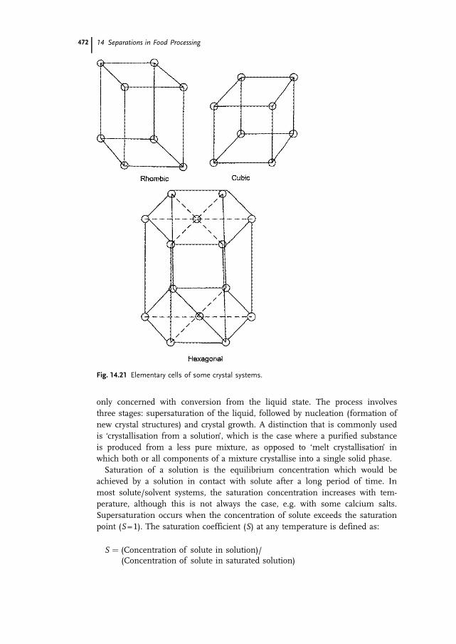
only concerned with conversion from the liquid state. The process involvesthree stages: supersaturation of the liquid, followed by nucleation (formation ofnew crystal structures) and crystal growth. A distinction that is commonly usedis ‘crystallisation from a solution’, which is the case where a purified substanceis produced from a less pure mixture, as opposed to ‘melt crystallisation’ inwhich both or all components of a mixture crystallise into a single solid phase.
Saturation of a solution is the equilibrium concentration which would beachieved by a solution in contact with solute after a long period of time. Inmost solute/solvent systems, the saturation concentration increases with tem-perature, although this is not always the case, e.g. with some calcium salts.Supersaturation occurs when the concentration of solute exceeds the saturationpoint (S = 1). The saturation coefficient (S) at any temperature is defined as:
S � (Concentration of solute in solution)/(Concentration of solute in saturated solution)
14 Separations in Food Processing472
Fig. 14.21 Elementary cells of some crystal systems.

Solutes differ in their ability to withstand supersaturation without crystallisa-tion – for example sucrose can remain in solution when S = 1.5–2.0, whereas so-dium chloride solutions crystallise with only a very small degree of supersatura-tion. Crystals cannot form or grow in a solution at or below its saturation con-centration (S�1) at any given temperature; and thus supersaturation must beachieved in two main ways: cooling or evaporation. Cooling moves the systemalong the solubility curve such that a saturated solution becomes supersaturatedat the same solute concentration, while evaporation increases the concentrationinto the supersaturated zone. It is also possible to produce supersaturation bychemical reaction or by addition of a third substance which reduces solubility,e.g. addition of ethanol to an aqueous solution, but these are not commerciallyimportant in food processing.
Supersaturation does not necessarily result in spontaneous crystallisation be-cause, although the crystalline state is more thermodynamically stable than thesupersaturated solution and there is a net gain in free energy on crystallisation,the activation energy required to form a surface in a bulk solution may be quitehigh. In other words, the probability of aligning the units correctly to form a vi-able crystal nucleus is low and is dependent on a number of factors. Viscosity isone such factor; and crystallisation occurs less readily as viscosity increases.This can readily be seen in sugar confectionery which frequently consists ofsupercooled viscous liquids. Miers’ theory (Fig. 14.22) defines three regions fora solute/solvent mixture. Below the saturation curve (in the undersaturatedzone) there is no nucleation or crystal growth; and in fact crystals dissolve. Inthe metastable zone, crystal growth occurs, but nucleation does not occur spon-taneously. In the labile zone, both nucleation and crystal growth occur and, thehigher the degree of supersaturation, the more rapidly these occur. While thesolubility curve is fixed, the supersolubility curve is not only a property of the
14.6 Crystallisation 473
Fig. 14.22 Crystallisation equilibria.

system, but also depends on other factors such as presence of impurities, cool-ing rate or agitation of the system, in other words factors which affect the acti-vation energy of the system as mentioned above.
In practice, crystals can be produced by several methods:1. Homogeneous nucleation is the spontaneous production of crystals in the
labile zone.2. Heterogeneous nucleation occurs in the presence of other surfaces, such as
foreign particles, gas bubbles, stirrers, which form sites for crystallisation inthe metastable zone.
3. Secondary nucleation requires the presence of crystals of the crystallising spe-cies itself and also occurs in the upper regions of the metastable zone. Thereason for this phenomenon is not clear but may be due to fragments break-ing off existing crystals by agitation or viscous drag and forming new nuclei.
4. Nucleation is also stimulated by outside effects such as agitation or ultra-sound.
Alternatively, crystalline materials can be produced by ‘seeding’ solutions in themetastable zone. In this case, very finely divided crystals are added to a super-saturated solution and allowed to grow to the finished size without furthernucleation.
Control of crystal growth following nucleation or seeding is essential to obtainthe correct size and shape of crystals. The rate of growth depends on the rate oftransport of material to the surface and the mechanism of deposition. The rateof deposition is approximately proportional to S, while diffusion to the crystalsurface can be accelerated by stirring. Impurities generally reduce the rate.
The final shapes or ‘habits’ of crystals are distinguished into classes such asplatelike, prismatic, dendritic and acicular. Habits are determined by conditionsof growth. Invariant crystals maintain the same shape during growth, as deposi-tion in all directions is the same (see Fig. 14.23a). Much more commonly, theshape changes and overlapping of smaller faces occurs (see Fig. 14.23b).
Crystals grown rapidly from highly supersaturated solutions tend to developextreme habits, such as needle-shaped or dendritic, with a high specific surface,due to the need to dissipate heat rapidly. The final shape is also affected by im-purities which act as habit modifiers, interacting with growing crystals andcausing selective growth of some surfaces, or dislocations in the structure.
Some substances can crystallise out into chemically identical, but structurallydifferent forms. This is known as polymorphism; and perhaps the best recog-nised examples are diamond and graphite. Polymorphism is particularly impor-tant in fats, which can often crystallise out into different polymorphs with dif-ferent melting points [48, 49]. In some cases, polymorphs can be converted toother, higher melting point crystal forms, which is the basis of tempering somefat-based foods.
14 Separations in Food Processing474

14.6.2Equipment Used in Crystallisation Operations
Industrial crystallisers are classified according to the method of achieving super-saturation, i.e. by cooling, evaporation or mixed operations [50], as well as fac-tors such as mode of operation (continuous or batch), desired crystal size distri-bution and purity. Detailed descriptions of design and operation are given byMersmann and Rennie [51]. The crystallising suspension is often known as‘magma’, while the liquid remaining after crystallisation is the ‘mother liquor’.Fluidised beds are common with either cooling or evaporative crystallisation, inwhich the solution is desupersaturated as it flows through a bed of growingcrystals (see Figs. 14.24, 14.25).
14.6 Crystallisation 475
Fig. 14.23 Crystal growth: (a) invariant crystal growth, (b) overlapping crystal growth.
Fig. 14.24 Fluidised bed coolingcrystalliser; from [51] with permission.

Yield from a crystalliser (Y) can be calculated from:
Y � W�C1 � C2�1 � V�� �14�9�
Where W is the initial mass of water, C1 and C2 are the concentrations ofsolute before and after crystallisation and V is the fraction of water evaporated.
Cooling crystallisers may incorporate continuous circulation through a coolingheat exchanger (e.g. Fig. 14.24) or for viscous materials, may incorporate ascraped surface heat exchanger (see Chapter 2).
Evaporative crystallisers are similar to forced circulation evaporators with a crys-tallisation vessel below the vapour/liquid separator (see Fig. 14.25). Simultaneousevaporation and cooling can be carried out without heat exchangers, the coolingeffect being produced by vacuum evaporation of the saturated solution.
14.6.3Food Industry Applications
14.6.3.1 Production of SugarCrystallisation is a major operation in sugar manufacture. Beet or cane sugarconsist essentially of sucrose; and different grades of product require uniformcrystals of different sizes. Supersaturation is effected by evaporation, but thetemperature range is limited by the fact that sugar solutions are sensitive to car-amelisation above 85 �C, while high viscosities limit the rate of crystallisationbelow 55 �C, so all operations are carried out within a fairly narrow temperaturerange. The supersaturated sugar solution is seeded with very fine sugar crystalsand the ‘massecuite’, i.e. syrup/crystal mixture, is evaporated with further syrupaddition. When the correct crystal size has been achieved, the crystals are re-moved and the syrup is passed to a second evaporator. Up to four evaporationstages may be used, with the syrup becoming less pure each time.
14 Separations in Food Processing476
Fig. 14.25 Fluidised bed evaporativecrystalliser; from [51] with permission.

14.6.3.2 Production of SaltSalt is much less of a problem then sugar, in that it is not temperature-sensitiveand forms crystals more easily than sugar. Evaporation of seawater in lagoons isstill carried out, but factory methods are more common. Continuous systemsbased on multiple effect evaporators (see Chapter 3) are widespread. Sodiumchloride normally forms cubic crystals, but it is common to add potassium fer-rocyanide as a habit-modifier, producing dendritic crystals which have betterflow properties.
A number of other food materials are produced in pure form by crystallisa-tion, including lactose, citric acid, monosodium glutamate and aspartame.
14.6.3.3 Salad Dressings and MayonnaiseIn some cases, crystallisation is carried out to remove unwanted components.Salad oils, such as cottonseed and soybean oil, are widely used in salad dress-ings and mayonnaise. They contain high melting point triglycerides which crys-tallise out on storage. This is not especially serious in pure oil, but would breakan emulsion and hence lead to product deterioration. Winterisation is fractionalcrystallisation to remove higher melting point triglycerides. It is essential toremove this fraction while retaining the maximum yield of oil, which requiresextremely slow cooling to produce a small number of large crystals, i.e. crystalgrowth with little nucleation. Crystallisation is carried out over 2–3 days withslow cooling to approximately 7 �C, followed by very gentle filtration. Agitationis avoided after the initial nucleation to prevent the formation of further nuclei.The winterised oil should then pass the standard test of remaining clear for5.5 h at 0 �C.
14.6.3.4 Margarine and Pastry FatsFractional crystallisation of fats into high (stearin) and low (olein) melting pointproducts is used to improve the quality of fats for specific purposes, e.g. mar-garine, pastry fats. Crystallisation may be accelerated by reducing the viscosityin the presence of solvents such as hexane. Adding detergents also improvesthe recovery of high melting point crystals from the olein phase.
14.6.3.5 Freeze ConcentrationIce crystallisation from liquid foods is a method of concentrating liquids suchas fruit juices or vinegar without heating, or adjusting the alcohol content ofbeverages. Its use is limited as only a modest level of concentration is possible;and there is an inevitable loss of yield with the ice phase.
There are many applications of crystallisation in the manufacture of foodswhere a separation is not involved and will therefore not be dealt with here.These include ice cream, butter, margarine, chocolate and sugar confectionery.
14.6 Crystallisation 477

14.7Membrane Processes
Michael J. Lewis
14.7.1Introduction
Over the last 50 years, a number of membrane processes have evolved whichmake use of a pressure driving force and a semipermeable membrane in orderto effect a separation of components in a solution or colloidal dispersion. Theseparation is based mainly on molecular size, but to a lesser extent on shapeand charge. The four main processes are reverse osmosis (hyperfiltration), na-nofiltration, ultrafiltration and microfiltration. The dimensions of the compo-nents involved in these separations are typically in the range from < 1 nm to> 1000 nm. In fact, they can be considered to be a continuous spectrum of pro-cesses, with no clearcut boundaries between them. Most suppliers of mem-branes now offer a selection of membranes which cover this entire spectrum.Figure 14.26 illustrates these processes and how they also relate to traditionalparticle filtration.
14 Separations in Food Processing478
Fig. 14.26 Comparison of the different membrane processeswith particle filtration; courtesy of GE Infrastructure – Waterand Process Technologies.

14.7.2Terminology
The feed material is applied to one side of a membrane and subjected to a pres-sure. In most cases, the feed flows in a direction parallel to the membrane sur-face and the term crossflow filtration is used to describe such applications.Dead-end systems are also used, but mainly for laboratory-scale separations.The stream which passes through the membrane under the influence of thispressure is termed the permeate (filtrate). The stream left after the requiredamount of permeate is removed is termed the concentrate or retentate.
If the membrane has a very small pore diameter (tight pores), the permeatewill be predominantly water and the process is known as reverse osmosis (RO),similar in its effects to evaporation or freeze-concentration. In some cases, thepermeate is the required material; for example in the production of ‘potable’water from seawater or polluted waters or in the production of ultrapure water.In RO, the pressure applied needs to be in excess of the osmotic pressure ofthe solution. Osmotic pressures are highest for low molecular weight solutes,such as salt and sugar solutions; and large increases in their osmotic pressureoccur during RO. The osmotic pressure, �, of a dilute solution can be predictedfrom the Van t’Hoff equation:
� � iRTc
M
� ��14�10�
where i is the degree of ionisation, R is the ideal gas constant, T is the absolutetemperature, M is the molecular weight and c is the concentration (kg m–3).
As the membrane pore size increases, the membrane becomes permeable tolow molecular weight solutes in the feed. Lower pressure driving forces are re-quired. However, larger molecular weight molecules, e.g. proteins, are still re-jected by the membrane. It is this fractionation which makes ultrafiltration amore interesting process than RO. Membranes with even larger pore sizes allowsmaller macromolecules to pass through, but retain particulate matter and fatglobules; and this is termed microfiltration.
Concentration factor and rejection are two important processing parameters forall pressure activated processes. The concentration factor (f ) is defined as follows:
f �VF
VC�14�11�
where VF is the feed volume and VC is the final concentrate volume.As soon as the concentration factor exceeds 2.0, the volume of permeate will
exceed that of the concentrate. Concentration factors may be as low as 1.5 forsome viscous materials and 5.0–50 for some dilute protein solutions. Generallyhigher concentration factors are used for ultrafiltration than for RO: over 50.0can be achieved for UF treatment of cheese whey, compared to about to 5 forRO treatment of cheese whey.
14.7 Membrane Processes 479

The rejection or retention factor (R) of any component is defined as:
R �cF � cP
cF�14�12�
where cF is the the concentration of component in the feed and cp is the concen-tration in the permeate. It can easily be measured and is very important, as itinfluences the extent (quality) of the separation that can be achieved.
Rejection values normally range between 0 and 1.0; and sometimes they areexpressed as percentages (0–100%). Occasionally negative rejections are foundfor some charged ions (Donnan effect).1. When cp = 0, R = 1, all the component is retained in the feed.2. When cp = cF, R = 0, the component is freely permeating.
If the concentration factor and rejection value are known, the yield of any com-ponent, which is defined as the fraction of that component present in the feed,which is recovered in the concentrate, can be estimated. Obviously for reverseosmosis, the yield for an ideal membrane is 1.0.
The yield (Y) can be calculated from:
Y � f R�1 �14�13�
The derivation of this equation is provided in Lewis [52]. Thus for a compo-nent where R = 0.95, at a concentration factor of 20, the yield is 0.86; i.e. 86% isretained in the concentrate and 14% is lost in the permeate.
14.7.3Membrane Characteristics
The membrane itself is crucial to the process. The first commercial membraneswere made of cellulose acetate and these are termed first generation mem-branes. However, temperatures had to be maintained below 30 �C and the pHrange was 3–6. These constraints limited their use, as they could not be disin-fected by heat or cleaned with acid or alkali detergents. These were followed inthe mid-1970s by other polymeric membranes (second generation membranes),with polyamides (with a low tolerance to chlorine) and, in particular, polysul-phones being widely used for foods. It is estimated that over 150 organic poly-mers have now been investigated for membrane applications. Inorganic mem-branes based on sintered and ceramic materials are also now available and theseare much more resistant to heat and cleaning and disinfecting fluids.
The main terms used to describe membranes are microporous or asymmetric.Microporous membranes have a uniform porous structure throughout, althoughthe pore size may not be uniform across the thickness of the membrane. They areusually characterised by a nominal pore size and no particle larger than this willpass through the membrane. In contrast to this, most membranes used for ultra-
14 Separations in Food Processing480

filtration are of the asymmetric type, having a dense active layer or skin of 0.5–1.0 micron in thickness, with a further support layer which is much more porousand of greater thickness. The membrane also has a chemical nature; and manymaterials have been evaluated. It may be hydrophilic or hydrophobic in nature.The hydrophobic nature can be characterised by measuring its contact angle, �.The higher the contact angle, the more hydrophobic is the surface. Polysulphonesare generally much more hydrophobic than cellulosic membranes. The surfacemay also be charged. All these factors give rise to interactions between the mem-brane and the components in the feed and influence the components passingthrough the membrane, as well as the fouling of the membrane.
14.7.4Flux Rate
Permeate flux and power consumption are two important operating characteristics.The permeate flux is usually expressed in terms of l m–2 h–1. This permits a
ready comparison of different membrane configurations of different surfaceareas. Flux values may be from < 5 l m–2 h–1 to > 500 l m–2 h–1. Factors affectingthe flux rate are the applied pressure, the volumetric flow rate of feed acrossthe membrane surface, its temperature and its viscosity. The flux is also influ-enced by concentration polarization and fouling, which in turn are influencedby the flow conditions across the membrane. Inducing turbulence increases thewall shear stress and promotes higher flux rates [52].
The main energy consumption for membrane techniques is the power utilisa-tion of the pumps. The power used, W, is related to the pressure (head) devel-oped and the mass flow rate as follows:
W � m�hg �14�14�
where m� is the mass flow rate (kg s–1), h is the head developed by the pump(m) and g is the acceleration due to gravity (9.81 m s–2).
This energy is largely dissipated within the fluid as heat and results in a tem-perature rise. Cooling may be necessary if a constant processing temperature isrequired.
14.7.5Transport Phenomena and Concentration Polarisation
A very important consideration for pressure driven membrane processes is thatthe separation takes place not in the bulk of solution, but in a very small regionclose to the membrane, known as the boundary layer, as well as over the mem-brane itself. This gives rise to the phenomenon of concentration polarisationover the boundary layer. It is manifested by a quick and significant reduction(2- to 10-fold) in flux when water is replaced by the feed solution, for examplein a dynamic start.
14.7 Membrane Processes 481

Concentration polarisation occurs whenever a component is rejected by themembrane. As a result, there is an increase in the concentration of that compo-nent at the membrane surface, together with a concentration gradient over theboundary layer (see Fig. 14.27).
Eventually a dynamic equilibrium is established, where the convective flow ofthe component to the membrane surface equals the flow of material away fromthe surface, either in the permeate or back into the bulk of the solution by dif-fusion, due to the concentration gradient established. This increase in concen-tration, especially of large molecular weight components, offers a very signifi-cant additional resistance. It may also give rise to the formation of a gelled orfouling layer on the surface of the membrane. Whether this occurs will dependupon the initial concentration of the component and the physical properties ofthe solution. It could be very important, as it may affect the subsequent separa-tion performance. Concentration polarisation itself is a reversible phenomenon,i.e. if the solution is then replaced by water, the original water flux should be re-stored. However, this rarely occurs in practice due to the occurrence of fouling,which is detected by a decline in flux rate at constant composition. Fouling iscaused by the deposition of material on the surface of the membrane or withinthe pores of the membrane. Fouling is irreversible and the flux needs to berestored by cleaning. Therefore, during any membrane process, flux declinesdue to a combination of these two phenomena. More recently, it has been recog-nised that fouling can be minimised by operating at conditions at or below thecritical flux. When operating below this value, fouling is minimised, but whenoperating above it, fouling deposits accumulate. This can be determined experi-mentally for different practical situations [53].
14 Separations in Food Processing482
Fig. 14.27 (a) Concentration polarisation inthe boundary layer, (b) concentrationpolarisation with a gel layer from [52] withpermission.

14.7.6Membrane Equipment
Membrane suppliers now provide a range of membranes, each with different re-jection characteristics. For ultrafiltration, different molecular weight cutoffs areavailable in the range 1000 Da to 500000 Da. Tight ultrafiltration membraneshave a molecular weight cutoff value of around 1000–5000 Da, whereas themore ‘open’ or ‘loose’ membranes will have a value in excess of 100000 Da.However, because there are many other factors that affect rejection, molecularweight cutoff should only be regarded as giving a relative guide to its pore sizeand true rejection behaviour. Experimental determinations should always bemade on the system to be validated, at the operating conditions to be used.Other desirable features of membranes to ensure commercial viability are:� reproducible pore size, offering uniformity both in terms of their permeate
rate and their rejection characteristics� high flux rates and sharp rejection characteristics� compatible with processing, cleaning and sanitising fluids� resistance to fouling� an ability to withstand temperatures required for disinfecting and sterilising
surfaces, which is an important part of the safety and hygiene considerations.
Extra demands placed upon membranes used for food processing include: theability to withstand hot acid and alkali detergents (low and high pH), tempera-tures of 90 �C for disinfecting or 120 �C for sterilising and/or widely used chem-ical disinfectants, such as sodium hypochlorite, hydrogen peroxide or sodiummetabisulphite. The membrane should be designed to allow cleaning both onthe feed/concentrate side and the permeate side.
Membrane processing operations can range in their scale of operation, fromlaboratory benchtop units, with samples less than 10 ml through to large com-mercial-scale operations, processing at rates greater than 50 m3 h–1. Further-more, the process can be performed at ambient temperatures, which allows con-centration without any thermal damage to the feed components.
14.7.7Membrane Configuration
The membranes themselves are thin and require a porous support against thehigh pressure. The membrane and its support, together are normally known asthe module. This should provide a large surface area in a compact volume andmust allow suitable conditions to be established, with respect to turbulence,high wall shear stresses, pressure losses, volumetric flow rates and energy re-quirements, thereby minimising concentration polarisation. Hygienic considera-tions are also important: there should be no dead spaces and the module shouldbe capable of being cleaned in-place on both the concentrate and the permeateside. The membranes should be readily accessible, both for cleaning and re-
14.7 Membrane Processes 483

placement. It may also be an advantage to be able to collect permeate from indi-vidual membranes in the module to be able to assess the performance of eachindividually.
The three major designs are the tubular, flat plate and spiral wound config-urations (see Figs. 14.28, 14.29).
Sintered or ceramic membranes can also be configured in the form of tubes.Tubular membranes come in range of diameters. In general tubes offer no deadspaces, do not block easily and are easy to clean. However, as the tube diameterincreases, they occupy a larger space, have a higher hold-up volume and incurhigher pumping costs. The two major types are the hollow fibre, with a fibre di-ameter of 0.001–1.2 mm and the wider tube with diameters up to 25 mm,although about 12 mm is a popular size.
For the hollow fibre system, the membrane wall thickness is about 250 �mand the tubes are self-supporting. The number of fibres in a module can be asfew as 50 but sometimes > 1000. The fibres are attached at each end to a tubesheet, to ensure that the feed is properly distributed to all the tubes. This maygive rise to pore plugging at the tube entry point. Prefiltration is recommendedto reduce this. They are widely used for desalination and in these RO applica-
14 Separations in Food Processing484
Fig. 14.28 This shows the tubular, hollow fibre, plate and frameand spiral wound configurations; courtesy of ITT Aquious.

tions are capable of withstanding high pressures. It is the ratio of the externalto internal diameter, rather than the membrane wall thickness which deter-mines the pressure that can be tolerated. Hollow fibre systems usually operatein the streamline flow regime. However the wall shear rates are high. They tendto be expensive, because if one or several fibres burst, the whole cartridge needsto be replaced.
For wider tubes, the feed is normally pumped through the tube, which maybe up to 25 mm in diameter, although a popular size is about 12 mm diameter.There may be up to 20 tubes in one module, tube lengths may be 1.2–3.8 mand tubes within the module may be connected in series or parallel. The mem-brane is cast or inserted into a porous tube which provides support against theapplied pressure. Therefore they are capable of handling higher viscosity fluidsand even materials with small suspended particles, up to one-tenth the tube di-ameter. They normally operate under turbulent flow conditions with flow veloci-ties greater than 2 m s–1. The corresponding flux rates are high, but pumpingcosts are also high, in order to generate the high volumetric flow rate requiredand the operating pressure.
The flat plate module can take the form of a plate-and-frame type geometryor a spirally wound geometry. The plate-and-frame system employs membranesstacked together, with appropriate spacers and collection plates for permeate re-moval, somewhat analogous to plate heat exchangers. The channel height canbe 0.4–2.5 mm. Flow may be either streamline or turbulent and the feed maybe directed over the plates in a parallel or series configuration. This design per-mits a large surface area to be incorporated into a compact unit. Membranesare easily replaced and it is easy to isolate any damaged membrane sandwich.Considerable attention has been devoted to the design of the plate to improveperformance. This has been achieved by ensuring a more uniform distributionof fluid over the plate, by increasing the width of the longer channels and by re-ducing the ratio of the longest to the shortest channel length.
14.7 Membrane Processes 485
Fig. 14.29 Tubular, hollow fibre and spiral wound configurations; courtesy of ITT Aquious.

The spiral wound system is now widely used and costs for membranes arerelatively low. In this case, a sandwich is made from two sheet membraneswhich enclose a permeate spacer mesh. This is attached at on end to a perme-ate removal tube and the other three sides of the sandwich are sealed. Next tothis is placed a feed spacer mesh and the two together are rolled round thepermeate collection tube in the form of a Swiss roll. The channel height is dic-tated by the thickness of the feed spacer. Wider channel heights will reduce thesurface area to volume ratio, but reduce the pressure drop.
The typical dimensions of one spiral membrane unit would be about 12 cmin diameter and about 1 m in length. Up to three units may be placed in onehousing, with appropriate spacers to prevent telescoping, which may occur inthe direction of flow and could damage the sandwich. This configuration is be-coming very popular and is relatively cheap. Again, the flow may be streamlineor turbulent. Pressure drop/flow rate relationships suggest that flow conditionsare usually turbulent.
Each system does and will continue to have its devotees. An alternative, muchused, unit for simple laboratory separations is the stirred cell with agitation fa-cilities. In contrast to the systems described earlier, this is a dead-end ratherthan a flow-through system.
As well as the membrane module, there will be pumps, pipeline, valves andfittings, gauges, tanks, heat exchangers, instrumentation and control and per-haps in-place cleaning facilities. For small installations, the cost of the mem-brane modules may only be a relatively small component of the total cost of thefinished plant, once these other items have been accounted for. This may alsoapply to some large installations such as water treatment plants, where otherseparation processes are numerous and the civil engineering costs may also behigh.
The simplest system is a batch process. The feed is usually recycled, as suffi-cient concentration is rarely achieved in one pass. Flux rates are initially highbut decrease with time. Energy costs are high because the pressure is releasedafter each pass. Residence times are long. Batch processes are usually restrictedto small-scale operations. Batch processing with top-up is used in situationswhen the entire feed volume will not fit into the feed tank. Continuous pro-cesses may be single-stage (feed and bleed), or multistage processes, dependingupon the processing capacity required. Figure 14.30 illustrates these differentsystems.
14.7.8Safety and Hygiene Considerations
It is important that safety and hygiene are considered at any early stage whendeveloping membrane processes. These revolve round cleaning and disinfectingprocedures for the membranes and ancillary equipment, as well as the monitor-ing and controlling the microbial quality of the feed material. For many pro-cesses, thermisation or pasteurisation are recommended for feed pretreatment
14 Separations in Food Processing486

(see Chapter 2). Microfiltration may also be considered for heat-labile compo-nents. Relatively little has been reported about the microbiological hazards asso-ciated with membrane processing. All microorganisms will be rejected by themembrane and will therefore increase in number in the concentrate, by the
14.7 Membrane Processes 487
Fig. 14.30 Different plant layouts: (a) batch operation,(b) continuous with internal recycle (feed and bleed),(c) commercial scale with three stages; courtesy of ITT Aquious.

concentration factor. There may also be some microbial growth during the pro-cess, so the residence time and residence time distribution should be known, aswell as the operating temperature. If residence times are long, it may be advisa-ble to operate either below 5 �C or above 50 �C, to prevent further microbialgrowth.
14.7.9Applications for Reverse Osmosis
The main applications of RO are for concentrating fluids, by removal of water.RO permits the use of relatively low temperatures, even lower than vacuum eva-poration. It reduces volatile loss caused by the phase change in evaporation andis very competitive from an energy viewpoint. RO uses much higher pressuresthan other membrane processes, in the range 2–8 MPa, and incurs greater en-ergy costs and requires special pumps. Products of RO may be subtly differentto those produced by evaporation, particularly with respect to low molecularweight solutes, which might not be completely rejected, and to volatile compo-nents, which are not completely lost.
Thin-film composite membranes, based on combinations of polymers havenow largely replaced cellulose acetate, allowing higher temperatures, up to80 �C and greater extremes of pH (3–11) to be used, thereby facilitating cleaningand disinfection. Therefore, the main applications of RO are for concentratingliquids, recovering solids and treatment of water.
14.7.9.1 Milk ProcessingRO can be used for concentrating full cream milk up to a factor of 2–3 times.Flux rates for skimmed milk are only marginally higher than those for fullcream milk. The product concentration attainable is nowhere near as high asthat for evaporation, due to increasing osmotic pressure and fouling, duemainly to the increase in calcium phosphate, which precipitates out in the poresof the membrane. Therefore, most of the commercial applications have beenfor increasing the capacity of evaporation plant. Other possible applications thathave been investigated and discussed include: (a) the concentration of milk onthe farm for reducing transportation costs, (b) for yoghurt production at a con-centration factor of about 1.5, to avoid the addition of skimmed milk powder,(c) for ice cream making, also to reduce the use of expensive skimmed milkpowder, (d) for cheesemaking to increase the capacity of the cheese vats and (e)for recovering rinse water. Cheese whey can also be concentrated, to reducetransportation costs or prior to drying. Flux values for sweet whey are higherthan for acid whey, which in turn are higher than for milk, for all systemstested [54]. Reviews of the use of RO and UF in dairying applications includeEl-Gazzar and Marth [55] and Renner [56].
14 Separations in Food Processing488
14.7.9.2 Other FoodsReverse osmosis has found application in the processing of fruit and vegetablejuices, sometimes in combination with ultrafiltration and microfiltration. The os-motic pressure of juices is considerably higher than that of milk. It is advanta-geous to minimise thermal reactions, such as browning, and to reduce loss of vol-atiles. From a practical viewpoint, the flux rate and rejection of volatiles is impor-tant. RO modules can cope with single strength clear or cloudy juices and alsofruit pulp. RO can be used to produce a final product, as in the case of tomatopaste and fruit purees, or to partially concentrate, prior to evaporation. RO is a wellestablished process for concentrating tomato juice from about 4.5 � Brix, to 8–12 �
Brix. Other fruit juices which have been successfully concentrated are apple, pear,peach and apricot. Where juices have been clarified, osmotic pressure limits theextent of concentration and up to 25 � Brix can be achieved. Unclarified juicesmay be susceptible to fouling. With purees and pulps, the viscosity may be thelimiting factor and these can be concentrated to a maximum of 1.5 times. It is pos-sible to concentrate coffee extract from about 13–36% total solids at 70 �C, withlittle loss of solids. Tea extracts can also be similarly concentrated.
Reverse osmosis is also used for waste recovery and more efficient use of pro-cessing water in corn wet-milling processes. Commercial plant is available forconcentrating egg white to about 20% solids. In one particular application, eggwhite is concentrated and dried, after lysozyme has been extracted.
Dealcoholisation is an interesting application, using membranes which arepermeable to alcohol and water. In a process akin to diafiltration, water is addedback to the concentrated product, to replace the water and alcohol removed inthe permeate. Such technology has been used for the production of low or re-duced alcohol, beers, ciders and wine. Leeper [57] reported ethanol rejectionsfor cellulose acetate ranged between 1.5% and 40.0%, for polyamides between32.8% and 60.9% and, for other hybrid membranes, as high as 91.8%.
Reverse osmosis is used in many areas worldwide for water treatment, wherethere are shortages of fresh water, although it is still well exceeded by multi-stage fractional distillation. Potable water should contain less than 500 ppm ofdissolved solids. Brackish water, e.g. bore-hole or river water, typically containsfrom 1000 ppm up to about 10 000 ppm of dissolved solids, whereas seawatercontains upwards of 35 000 ppm of dissolved solids. If lower total solids arerequired, the permeate can be subjected to a second process, known as doublereverse osmosis water.
14.7.10Applications for Nanofiltration
Nanofiltration (NF) has been used for partially reducing calcium and other saltsin milk and whey, with typical retention values of 95% for lactose and less than50% for salts. Guu and Zall [58] have reported that permeate subject to NF gaveimproved lactose crystallisation. NF provides potential for improving the heatstability of the milk.
14.7 Membrane Processes 489
NF has also been investigated for removing pesticides and components re-sponsible for the colour from ground water, as well as for purifying water forcarbonation and soft drinks. For water production of high-grade purity, for ana-lytical purposes, it may be double RO treated, as mentioned earlier.
NF is currently being investigated for fractionating oligosaccharides with pre-biotic potential, produced by the enzymatic breakdown of different complex car-bohydrates.
14.7.11Applications for Ultrafiltration
14.7.11.1 Milk ProductsMilk will be taken as an example to show the potentialities of ultrafiltration(UF). Milk is chemically complex, containing components of a wide range ofmolecular weights, such as protein, fat, lactose, minerals and vitamins. It alsocontains microorganisms, enzymes and perhaps antibiotics and other contami-nants. Whole milk contains about 30–35% protein and about the same amountof fat (dry weight). Therefore, it is an ideal fluid for membrane separation pro-cesses, in order to manipulate its composition, thereby providing a variety ofproducts or improving the stability of the colloidal system. The same principlesapply to skimmed milk, standardised milk and some of its byproducts, such ascheese whey. Skimmed milk can be concentrated up to seven times and fullcream milk up to about five times Kosikowski [59]. An IDF publication [60]gives a summary of the rejection values obtained during the ultrafiltration ofsweet whey, acid whey, skimmed milk and whole milk, using a series of indus-trial membranes.
Bastian et al. [61] compared the rejection values during UF and diafiltrationof whole milk. They found that the rejection of lactose, riboflavin, calcium, so-dium and phosphorus was higher during diafiltration than UF. Diafiltration ofacidified milk gave rise to lower rejections of calcium, phosphorus and sodium.Premaratne and Cousin [62] reported a detailed study on the rejection of vita-mins and minerals during UF of skimmed milk. During a five-fold concentra-tion, the following minerals were concentrated by the following factors: Zn(4.9), Fe (4.9), Cu (4.7), Ca (4.3), Mg (4.0) and Mn (3.0), indicating high rejec-tion values. In contrast, most of the B vitamins examined were almost freelypermeating.
Ultrafiltration has been used to concentrate cheese whey (�6.5% TS), whichcontains about 10–12% protein (dry weight), to produce concentrates whichcould then be dried to produce high protein powders (concentrates and isolates)which retain the functional properties of the proteins. Some typical concentra-tion factors, f, used are as follows:f = 5: protein content (dry weight) about 35% (similar to skimmed milk)f = 20: protein content about 65%f = 20 plus diafiltration: protein content about 80%.
14 Separations in Food Processing490
The product starts to become very viscous at a concentration factor of about20, so diafiltration is required to further increase the protein in the final prod-uct.
The permeate from ultrafiltration of whey contains about 5% total solids, thepredominant component being lactose. Since this is produced in substantialquantities, the economics of the process are dependent upon its utilisation. Itcan be concentrated by reverse osmosis and hydrolysed to glucose and galactoseto produce sweeteners or fermented to produce alcohol or microbial protein.Skimmed milk has been investigated also but protein concentrates based onskimmed milk have not received the same amount of commercial interest asthose based on whey proteins.
However, yoghurt and other fermented products have been made fromskimmed milk and whole milk concentrated by ultrafiltration [55]. Whey proteinconcentrates have also been incorporated [63]. Production of labneh, which is astrained or concentrated yoghurt at about 21% total solids, has been describedby Tamime et at. [64], by preconcentrating milk to 21% TS. Inorganic mem-branes have also been used for skimmed milk; and Daufin et al. [65] have inves-tigated the cleanability of these membranes using different detergents and se-questering agents.
As well as exploiting the functional properties of whey proteins, full creammilk has been concentrated by UF prior to cheesemaking. The UF concentratehas been incorporated directly into the cheese vats. Some advantages of thisprocess include: increased yield (particularly of whey protein), lower rennet andstarter utilisation, smaller vats or even complete elimination of vats, little or nowhey drainage and better control of cheese weights. Lawrence [66] suggests thatconcentration below a factor of 2.0 gives protein standardisation, reduced rennetand vat space, but no increased yield. Concentration factors greater than 2.0 re-sult in an increased yield.
Some problems result from considerable differences in the way the cheesematures and hence its final texture and flavour. The types of cheese that can bemade in this way include: Camembert type cheese, mozzarella, feta and manysoft cheeses. Those which are difficult include the hard cheeses, such as Ched-dar and also cottage cheese; and the problems are mainly concerned with poortexture. More discussion is given by Kosikowski [59]. Further reviews on thetechnological problems arising during the conversion of retentate into cheesesare discussed by Lelievre and Lawrence [67]. Quarg is also produced from ultra-filtered milk.
Ultrafiltration is an extremely valuable method of concentrating and recover-ing many the minor components, particularly enzymes from raw milk, many ofwhich would be inactivated by pasteurisation. Such enzymes are discussed inmore detail by Kosikowski [68]. Further reviews on membrane processing of milkare provided by Glover [53], El-Gazzar and Marth [54], Renner and El-Salam [55]and the International Dairy Federation [69].
14.7 Membrane Processes 491

14.7.11.2 Oilseed and Vegetable ProteinsThere have been many laboratory investigations into the use of ultrafiltrationfor extracting proteins from oil seed residues, or for removing any toxic compo-nents. Lewis [70] and Cheryan [71] have reviewed the more important of these.The investigations include: for soya, the separation of low molecular weightpeptides from soy hydrolysates (with the aim of improving quality), the dissocia-tion of phytate from protein (followed by its removal by UF), the removal of oli-gosaccharides, the removal of trypsin inhibitor and performance of differentmembrane configurations. For cottonseed, the use of different extraction condi-tions has been evaluated, as have the functional properties of the isolates pro-duced by UF. Investigations were performed with sunflower and alfalfa to re-move the phenolic compounds responsible for the colour and bitter flavour andglucosinolates from rapeseed.
Many have been successful in terms of producing good quality concentratesand isolates, particularly with soyabean. However, few have come to commercialfruition, mainly because of the economics of the process, dictated by the rela-tively low value of products and the fact that acceptable food products can beobtained by more simple technology, such as isoelectric precipitation. A furtherproblem arises from the fact that the starting residue is in the solid form, there-by imparting an additional extraction procedure. Extraction conditions may needto be optimised, with respect to time; temperature, pH and antinutritional fac-tors. Another problem arises from the complexity of oil seed and vegetable pro-teins, compared to milk products, evidenced by electrophoretic measurement. Itis likely that many of these proteins are near their solubility limits after extrac-tion and further concentration will cause them to come out of solution and pro-mote further fouling. Fouling and cleaning of membranes was found to be aserious problem during ultrafiltration of rapeseed meal extracts [72].
A further important area is the use of enzyme reactors. The earliest exampleswere to breakdown polysaccharides to simpler sugars in a continuous reactorand to use a membrane to continuously remove the breakdown products.
14.7.11.3 Animal ProductsSlaughterhouse wastes contain substantial amounts of protein. Two importantstreams that could be concentrated by ultrafiltration are blood and waste water.
Blood contains about 17% protein. It can be easily separated by centrifugationinto plasma (70%) and the heavier erythrocytes (red blood corpuscles or cells,ca. 30%). Plasma contains about 7% protein, whereas the blood corpuscles con-tain 28–38% protein. The proteins in plasma possess useful functional proper-ties, particularly gelation, emulsification and foaming. They have been incorpo-rated into meat products and have shown potential for bakery products, as re-placers for egg white.
Whole blood, plasma and erythrocytes have all been subjected to UF processes[71, 73]. The process is concentration polarisation controlled and flux rates are low.High flow rate and low pressure regimes are best. Gel concentrations were ap-
14 Separations in Food Processing492
proximately 45% for plasma protein and 35% for red blood cells. The fouling char-acteristics of different blood fractions have been investigated [74]. Whole bloodwas found to be the worst foulant, when compared to lysed blood and blood plas-ma.
Another important material is gelatin, which can be concentrated from verydilute solutions by UF. As well as concentration, ash is removed, which im-proves its gelling characteristics. This is one example where there have beensome high negative rejections recorded for calcium, when ultrafiltered at lowpH.
Eggs have also been processed by UF. Egg white contains 11–13% total solids(about 10% protein, 0.5% salts, 0.5% glucose). Large amounts of egg white areused in the baking industry. The glucose can cause problems during storageand causes excessive browning during baking. Whole egg contains about 25%solids and about 11% fat, whereas egg yolk contains about 50% solids. It is un-usual to evaporate eggs prior to drying, because of the damage caused. Com-pared to RO, UF also results in the partial removal of glucose; and further re-moval can be achieved by diafiltration. Flux values during UF are much lowerthan for many other food materials, most probably due to the very high initialprotein concentration; and rates are also highly velocity- and temperature-depen-dent [71].
Membrane-based bioreactors appear to be a very promising application for theproduction of ethanol, lactic acid, acetone, butanol, starch hydrolysates and pro-tein hydrolysates.
14.7.12Applications for Microfiltration
Microfiltration (MF) is generally used to separate particles suspended in liquidmedia and may frequently be considered as an alternative to conventional filtra-tion or centrifugation. For industrial use, the aim is usually to obtain either aclear permeate or the concentrate. Therefore most applications are either clarifi-cation, or the recovery of suspended particles such as cells or colloids, or theconcentration of slurries.
One application in the food industry has been in the treatment of juices andbeverages. As MF is a purely physical process, it can have advantages over tradi-tional methods, which may involve chemical additives, in terms of the quality ofthe product as well as the costs of processing.
Finnigan and Skudder [75] report that very good quality, clear permeate wasfound when MF processing cider and beer, with high flux rates and no rejectionof essential components.
Clarification and biological stabilisation of wine musts and unprocessed winehave also been described for MF. This avoids the requirement for fining and,possibly, pasteurisation. Another section of the industry with several applica-tions is dairy processing. Piot et al. [76] and Merin [77] have clarified sweetcheese whey using crossflow MF. This has the dual benefit of removing fat and
14.7 Membrane Processes 493

reducing the bacterial population and could eliminate the need for fat separa-tion and heat treatment in the production of whey protein powders prior to UF.The former authors reported that a 5-log reduction of microorganisms could beobtained in the microfiltrate compared to the whey, although some loss of wheyprotein was observed. Hanemaaijer [78] described a scheme for whey treatmentincorporating MF and UF to produce ‘tailor-made’ whey products with specificproperties for specific applications. The products include whey protein concen-trates which are rich in whey lipids, as well as highly purified protein.
Bacterial removal from whole milk by MF is a problem because the size rangeof the bacteria overlaps with the fat globules and, to a lesser extent, with thecasein micelles. However, some success has been achieved with skim milk. The‘Bactocatch’ system can remove 99.6% of the bacteria from skimmed milk usingceramic membranes on a commercial scale [79]. The retentate (approximately10% of the feed) can then be sterilised by a UHT process, mixed with thepermeate and the mixture pasteurised, to give a product with 50% longer shelflife but no deterioration in organoleptic properties compared to milk that hasonly been pasteurised. One such product on the market in the UK is Craven-dale milk [80]. The combination of MF and heat reduces the bacterial numbersby 99.99%.
Alternatively, the permeate could be used for cheesemaking, or the productionof low-heat milk powder [81]. Piot et al. [82] described the use of membranes ofpore diameter 1.8 �m to produce skimmed milk of low bacterial content. Recov-ery of fat from buttermilk has also been described [83].
Membranes have been used to concentrate milk prior to the manufacture ofmany cheese types. This results in improved yields and other associated benefitssuch as reduced requirement for rennet and starter and the ability to producemuch more cheese per vat [84]. However, the use of MF is an attractive alterna-tive. Rios et al. [83] have carried out extensive trials on this application and con-cluded that the use of 0.2 �m pore diameter membranes gave a product withbetter texture and yield than with centrifugation. The choice of ceramic mem-branes allowed the curd to be contacted directly with the membrane.
Other food applications have been reported with meat and vegetable productsincluding the following. Devereux and Hoare [85] described the use of MF to re-cover precipitated soya protein. This could have advantages over recovery of thedissolved protein using UF. Gelatin is a proteinaceous material derived by hy-drolysis of collagen. This is purified by filtration incorporating diatomaceousearth. The latter process can be replaced by crossflow microfiltration (CMF),which effectively removes dirt, coagulated proteins, fats and other particulatematerials from the feed. Again, CMF gives higher yields of high quality producton a continuous basis. Short [86] calculated that incorporating plants for gelatinwould have a payback time of 3 years for a capacity of 30 t h–1.
Overall, MF has made significant advances in new applications in the foodand biotechnology industries. However, it has not yet realised its full potential,largely due to the severe problems of flux decline due to fouling. It is believedthat further developments in membrane design and a greater knowledge of
14 Separations in Food Processing494

fouling mechanisms will result in greater application in the future, especially inthe field of downstream processing.
14.8Ion Exchange
Alistair S. Grandison
14.8.1General Principles
Ion exchange can be used for separations of many types of molecules, such asmetal ions, proteins, amino acids or sugars. The technology is utilised in manysensitive analytical chromatography and laboratory separation procedures, fre-quently on a very small scale. However, industrial-scale production operations,such as demineralisation or protein recovery, are possible. More detailed infor-mation on the theory of ion exchange can be found elsewhere [87–89].
Ion exchange is the selective removal of a single, or group of, charged speciesfrom one liquid phase followed by transfer to a second liquid phase by meansof a solid ion exchange material. This involves the process of adsorption – thetransfer of specific solute(s) from a feed solution on to a solid ion exchanger.The mechanism of adsorption is electrostatic involving opposite charges on thesolute(s) and the ion exchanger. After washing off the feed solution, the sol-ute(s) is desorbed back into solution in a much purified form.
Ion exchange solids have fixed ions covalently attached to a solid matrix.There are two basic types of ion exchanger:(a) Cation exchangers bear fixed negative charges (e.g. -SO3
–H+, -PO32–(H+)2,
-COOH) and therefore retain cations.(b) Anion exchangers bear fixed positive charges (amines or imines, such as
quaternary amine or diethylaminoethyl groups) and thus retain anions.
Ion exchangers can be used to retain simple ionised species such as metal ions,but may also be used in the separation of polyelectrolytes, such as proteins,which carry both positive and negative charges, as long as the overall charge onthe polyelectrolyte is opposite to the fixed charges on the ion exchanger. Thisoverall charge depends on the isoelectric point (IEP) of the polyelectrolyte andthe pH of the solution. At pH values lower than the IEP, the net overall chargewill be positive and vice versa. The main interaction is via electrostatic forcesand, in the case of polyelectrolytes, the affinity is governed by the number ofelectrostatic bonds between the solute molecule and the ion exchanger. How-ever, with large molecules such as proteins, size, shape and the degree of hydra-tion of the ions may affect these interactions and hence the selectivity of theion exchanger for different solutes. Figure 14.31 gives a generalised anion ex-changer – i.e. bearing fixed positive charges.
14.8 Ion Exchange 495

To maintain electrical neutrality, these fixed ions must be balanced by anequal number of mobile ions of the opposite charge, i.e. anions, held by electro-static forces. These mobile ions can move into and out of the porous molecularframework of the solid matrix and may be exchanged stoichiometrically withother dissolved ions of the same charge and are termed counterions. As the dis-tribution of ions between the internal phase of the ion exchanger and the exter-nal phase is determined by the Donnan equilibrium, some co-ions (mobile ionshaving the same sign – positive in this example – as the fixed ions) will be pres-ent even in the internal phase. Therefore, if an anion exchanger, as inFig. 14.31, is in equilibrium with a solution of NaCl, the internal phase containssome Na+ ions, although the concentration is less than in the external phase be-cause the internal concentration of Cl– ions is much larger.
When an ion exchanger is contacted with an ionised solution, equilibrationbetween the two phases rapidly occurs. Water moves into or out of the internalphase so that osmotic balance is achieved. Counter ions also move in and outbetween the phases on an equivalent basis. If two or more species of counterion are present in the solution, they are distributed between the phases accord-ing to the proportions of the different ions present and the relative selectivity ofthe ion exchanger for the different ions. It is this differential distribution of dif-ferent counter ions which forms the basis of separation by ion exchange. Therelative selectivity for different ionised species results from a range of factors.The overall charge on the ion and the molecular or ionic mass are the primarydetermining factors, but selectivity is also related to degree of hydration, stericeffects and environmental factors such as pH or salt content.
In the adsorption stage, a negatively charged solute molecule (e.g. a protein, P–)is attracted to a charged site on the ion exchanger (R+), displacing a counterion (X–):
R�X� � P� � R�P� � X�
This is shown schematically in Fig. 14.32a.In the desorption stage, the anion is displaced from the ion-exchanger by a
competing salt ion (S–) and hence is eluted:
14 Separations in Food Processing496
Fig. 14.31 Schematic diagram of a general-ised anion exchanger.

R�P� � S� � R�S� � P�
This is shown schematically in Fig. 14.32b.Alternatively, desorption can be achieved by the addition of H+ or OH– ions.
Ion exchangers are further classified, in terms of how their charges vary withchanges in pH, into weak and strong exchangers. Strong ion exchangers areionised over a wide range of pH and have a constant capacity within the range,whereas weak exchangers are only ionised over a limited pH range, e.g. weakcation exchangers may lose their charge below pH 6 and weak anion exchangersabove pH 9. Thus, weak exchangers may be preferable to strong ones in somesituations, for example where desorption may be achieved by a relatively smallchange in pH of the buffer in the region of the pKa of the exchange group. Re-generation of weak ion exchange groups is easier than with strong groups andtherefore has a lower requirement of costly chemicals.
14.8.2Ion Exchange Equipment
All ion exchangers consist of a solid insoluble matrix (termed the resin, adsor-bent, medium, or just ion exchanger) to which the active, charged groups are at-tached covalently. The solid support must have an open molecular frameworkwhich allows the mobile ions to move freely in and out and must be completelyinsoluble throughout the process. Most commercial ion exchangers are basedon an organic polymer network, e.g. polystyrene and dextran, although inorgan-ic materials such as porous silica may be used. The latter are much more rigidand incompressible. The support material does not directly determine the ionicdistribution between the two phases, but it does influence the capacity, the flowrate through a column, the diffusion rate of counterions into and out of the ma-trix, the degree of swelling and the durability of the material.
As the adsorption is a surface effect, the available surface area is a key param-eter. For industrial processing, the maximum surface area to volume should beused to minimise plant size and product dilution. It is possible for a 1-ml bedof ion exchanger to have a total surface area > 100 m2. The ion exchange materi-al is normally deployed in packed beds and involves a compromise betweenlarge particles (to minimise pressure drop) and small particles to maximisemass transfer rates. Porous particles are employed to increase surface area/vol-ume.
The capacity of an ion exchanger is defined as the number of equivalents (eq)of exchangeable ions per kilogram of exchanger, but is frequently expressed asx meq g–1 (usually in the dry form). Most commercially available materials havecapacities in the range 1–10 eq kg–1 of dry material, but this may decline withage due to blinding or fouling, i.e. nonspecific adsorption of unwanted materi-als, such as lipids, onto the surface, or within the pores.
14.8 Ion Exchange 497

14 Separations in Food Processing498
Fig. 14.32 Process of anion exchange: (a) adsorption stage, (b) desorption stage.

The choice of method of elution depends on the specific separation required.In some cases the process is used to remove impurities from a feedstock, whilethe required compound(s) remains unadsorbed. No specific elution method isrequired in such cases, although it is necessary to regenerate the ion exchangerwith strong acid or alkali. In other cases the material of interest is adsorbed bythe ion exchanger, while impurities are washed out of the bed. This is followedby elution and recovery of the desired solute(s). In the latter case, the methodof elution is much more critical – for example, care must be taken to avoid de-naturation of adsorbed proteins.
The adsorbed solute is eluted from the ion exchanger by changing the pH orthe ionic strength of the buffer, followed by washing away the desorbed solutewith a flow of buffer. Increasing the ionic strength of the buffer increases thecompetition for the charged sites on the ion exchanger. Small buffer ions with ahigh charge density displace polyelectrolytes, which can subsequently be eluted.Altering the buffer pH, so that the charge on an adsorbed polyelectrolyte is neu-tralised or made the same as the charges on the ion exchanger, results in de-sorption.
Fixed bed operations consisting of one or two columns connected in series(depending on the type of ions which are to be adsorbed) are used in most ionexchange separations. Liquids should penetrate the bed in plug flow, in eitherdownward or upward direction. The major problems with columns arise fromclogging of flow and the formation of channels within the bed. Problems mayalso arise from swelling of organic matrices when the pH changes. These prob-lems may be minimised by the use of stirred tanks. However, these batch sys-tems are less efficient and expose the ion exchangers to mechanical damage, asthere is a need for mechanical agitation. The system involves mixing the feedsolution with the ion exchanger and stirring until equilibration has been
14.8 Ion Exchange 499
Fig. 14.33 Commercial stirred tank reactors; by courtesy of Bio-Isolates plc.
achieved (typically 30–90 min in the case of proteins). After draining and wash-ing the ion exchanger, the eluant solution is then contacted with the bed for asimilar equilibration time before draining and further processing. Commercialstirred tank reactors for recovering protein from whey are shown in Fig. 14.33.
Mixed bed systems, containing both anion and cation exchangers, may beused to avoid prolonged exposure of the solutions to both high and low pH en-vironments, as are frequently encountered when using anion and cation ex-change columns in series, e.g. during demineralisation of sugar cane juice toprevent hydrolysis of sucrose, as described below.
14.8.3Applications of Ion Exchange in the Food Industry
The main areas of the food industry where the process is currently used or isbeing developed are sugar, dairy and water purification. Ion exchange is alsowidely employed in the recovery, separation and purification of biochemicalsand enzymes.
The main functions of ion exchange are:(a) removal of minor components, e.g. de-ashing or decolourising(b) enrichment of fractions, e.g. recovery of proteins from whey or blood(c) isolating valuable compounds, e.g. production of purified enzymes.
Applications can be classified as follows.
14.8.3.1 Softening and DemineralisationSoftening of water and other liquids involves the exchange of calcium and mag-nesium ions for sodium ions attached to a cation exchange resin, e.g.:
R� �Na��2 � Ca�HCO3�2 � R� Ca�� � 2NaHCO3
The sodium form of the cation exchanger is produced by regenerating withNaCl solution. Apart from the production of softened water for boiler feeds andcleaning of food and processing equipment, softening may be employed to re-move calcium from sucrose solutions prior to evaporation (which reduces scal-ing of heat exchanger surfaces in sugar manufacture) and from wine (whichimproves stability).
Demineralisation using ion exchange is an established process for water treat-ment, but over the last 20 years it has been applied to other food streams. Typi-cally the process employs a strong acid cation exchanger followed by a weak orstrong base anion exchanger. The cations are exchanged with H+ ions, e.g.:
2R�H� � CaSO4 � �R��2Ca�� �H2SO4
R�H� �NaCl � R�Na� �HCl
14 Separations in Food Processing500

and the acids thus produced are fixed with an anion exchanger, e.g.:
R�OH��HCl � R�Cl� �H2O
Demineralised cheese whey is desirable for use mainly in infant formulations,but also in many other products such as ice cream, bakery products, confection-ery, animal feeds etc. The major ions removed from whey are Na+, K+, Ca++,Mg++, Cl–, HPO4
–, citrate and lactate. Ion exchange demineralisation of cheesewhey generally employs a strong cation exchanger followed by a weak anion ex-changer. This can produce more than 90% reduction in salt content, which isnecessary for infant formulae.
Demineralisation by ion exchange resins is used at various stages during themanufacture of sugar from either beet or cane, as well as for sugar solutions pro-duced by hydrolysis of starch. In the production of sugar from beet, the beet juiceis purified by liming and carbonatation and then may be demineralised by ion ex-change. The carbonated juice is then evaporated to a thick juice prior to sugar crys-tallisation. Demineralisation may, alternatively, be carried out on the thick juicewhich has the advantage that the quantities handled are much smaller. To producehigh quality sugar the juice should have a purity of about 95%. Ash removal orcomplete demineralisation of cane sugar liquors is carried out on liquors that havealready been clarified and decolourised, so the ash load is at minimum. The use ofa mixed bed of weak cation and strong anion exchangers in the hydrogen and hy-droxide forms, respectively, reduces the prolonged exposure of the sugar tostrongly acid or alkali conditions which would be necessary if two separate col-umns were used. Destruction of sucrose is thus minimised.
The cation and anion resins are sometimes used in their own right for deal-kalisation or deacidification, respectively. Weak cation exchangers may be usedto reduce the alkalinity of water used in the manufacture of soft drinks andbeer, while anion exchangers can be used for deacidification of fruit and vegeta-ble juices. In addition to deacidification, anion exchangers may also be used toremove bitter flavour compounds (such as naringin or limonin) from citrusjuices. Anion or cation exchange resins are used in some countries to controlthe pH or titratable acidity of wine although this process is not permitted byother traditional wine-producing countries. Acidification of milk to pH 2.2,using ion exchange during casein manufacture by the Bridel process, has alsobeen described.
Ion exchange processes can be used to remove specific metals or anions fromdrinking water and food fluids, which has potential application for detoxificationor radioactive decontamination. Procedures have been described for the reten-tion of lead, barium, radium, aluminium, uranium, arsenic and nitrates fromdrinking water. Removal of a variety of radionuclides from milk has been dem-onstrated. Radiostrontium and radiocaesium can be removed using a stronglyacidic cation exchanger, while iodine 131 can be adsorbed on to a variety ofanion exchangers. The production of low-sodium milk, with potential dieteticapplication, has been demonstrated.
14.8 Ion Exchange 501

14.8.3.2 DecolourisationSugar liquors from either cane or beet contain colourants such as caramels,melanoidins, melanins or polyphenols combined with iron. Many of these areformed during the earlier refining stages and it is necessary to remove them inthe production of a marketable white sugar. The use of ion exchangers just be-fore the crystallisation stage results in a significant improvement in productquality. It is necessary to use materials with an open, porous structure to allowthe large colourant molecules access to the adsorption sites. A new approach tothe use of ion exchange for decolourisation of sugar solutions is the applicationof powdered resin technology. Finely powdered resins (0.005–0.2 mm diameter)have a very high capacity for sugar colourants due to the ready availability of ad-sorption sites. The use of such materials on a disposable basis eliminates theneed for chemical regenerants, but is quite expensive.
Colour reduction of fermentation products such as wine uses a strongly basicanion exchanger to remove colouring matter, followed by a strong cation ex-changer to restore the pH. It is claimed that colour reduction can be achievedwithout substantially deleteriously affecting the other wine qualities.
14.8.3.3 Protein PurificationHigh purity protein isolates can be produced in a single step from dilute solu-tions containing other contaminating materials by ion exchange. The ampho-teric nature of protein molecules permits the use of either anion or cation ex-changers, depending on the pH of the environment. Elution takes place eitherby altering the pH or increasing the ionic strength. The eluate can be a singlebulk, or a series of fractions produced by stepwise or linear gradients, althoughfractionation may be too complex for large-scale industrial production. Separa-tion of a single protein may take place on the basis that it has a higher affinityto the charged sites on the ion exchanger compared to other contaminating spe-cies, including other proteins present in the feed. In such cases, if excess quan-tities of the feed are used, the protein of interest can be adsorbed exclusively,despite initial adsorption of all the proteins in the feed. Alternatively, it may bepossible to purify a protein on the basis that it has a much lower affinity for theion exchanger than other proteins present in the feed; and thus the other pro-teins are removed leaving the desired protein in solution. One limitation of theprocess for protein treatment is that extreme conditions of pH, ionic strengthand temperature must be avoided to prevent denaturation of the protein.
An area of great potential is the recovery of proteins from whey, which is abyproduct of the manufacture of cheese and related products such as casein.Typically whey contains 0.6–0.8% protein which is both highly nutritious anddisplays excellent physical properties, yet the vast majority of this is wasted orunder-utilised. Anion exchange materials can produce high purity functionalprotein from cheese whey, using a stirred tank reactor into which the whey isintroduced at low pH. Following rinsing of nonadsorbed material, the proteinfraction is eluted at high pH and further purified by ultrafiltration, so that the
14 Separations in Food Processing502

final protein content is approximately 97% (dry weight). It is further possible tofractionate the whey proteins into their separate components or groups of com-ponents. This approach has the potential of producing protein fractions with arange of functional properties which could be extremely valuable for use in thefood industry. Lactoperoxidase and lactoferrin are valuable proteins with poten-tial pharmaceutical applications which are present in small quantities in cheesewhey. They may be purified from whey on the basis that these proteins are posi-tively charged at neutral pH, whereas the major whey proteins are negativelycharged. Another application of adsorption of whey protein by ion exchangerscould be to improve the heat stability of milk. The use of ion exchange to re-cover or separate the caseins in milk is not carried out commercially, althoughit has been shown to be feasible.
This system has also been demonstrated for recovery of food proteins fromwaste streams resulting from the processing of soya, fish, vegetables and gela-tine production, plus abattoir waste streams. Such protein fractions could beused as functional proteins in the food industry or for animal feeds. A varietyof other food proteins have been purified or fractionated by ion-exchangers, in-cluding pea globulins, gliadin from wheat flour, egg, groundnut and soya pro-tein.
Purification of proteins from fermentation broths usually involves a series ofseparation steps and frequently includes ion exchange. Large-scale purificationof a variety of enzymes with applications in the food industry has been de-scribed, e.g. �-amylase, �-galactosidase.
14.8.3.4 Other SeparationsIon exchange has been used for various other separations in the food industrywhich do not fit into the above categories.
Fructose is sweeter than sucrose and glucose and can be used as a naturalsweetener at reduced caloric intake. Although present in many natural sources,it is produced commercially from corn starch by hydrolysis to dextrose, which isthen partially converted to fructose using the enzyme isomerase. The resultinghigh fructose corn syrup may be deionised by ion exchange and then a purefructose fraction can be recovered with a sulphonic cation exchanger. Anotherapplication is the production of lactose-free milk. A process using sulphonatedcation exchangers has been used to reduce the lactose level of skim milk to< 10% of that in the feed, while retaining > 90% of protein, minerals and citrate.
The purification of phenylalanine, which may be used in aspartame sweet-ener production, from fermentation broths using cationic zeolite material hasbeen demonstrated. Ion exchange may also be used to purify enzymic reactionproducts such as flavour constituents from the enzymic degradation of fruitwastes.
14.8 Ion Exchange 503

14.8.4Conclusion
There are many potential applications for ion exchange in the food industry, butfew have been fully exploited in commercial practice. This is because of thecomplexity of the process and problems of scale-up. New applications are mostlikely to be developed in the food related aspects of biotechnology and in theproduction of high value protein fractions.
14.9Electrodialysis
Alistair S. Grandison
14.9.1General Principles and Equipment
Electrodialysis (ED) is a separations process in which membranes are used toseparate ionic species from nonionic species. More detailed information on thetheory and applications can be found elsewhere [88, 90, 91]. The process permitsthe separation of electrolytes from nonelectrolytes, concentration or depletion ofelectrolytes in solutions and the exchange of ions between solutions. Separationdepends on ion-selective membranes, which are essentially ion exchange resinscast in sheet form, and electromigration of ions through ion-selective mem-branes depends on the electrical charge on the molecules, combined with theirrelative permeability through membranes. The membranes are composed ofpolymer chains which are crosslinked and intertwined into a network and beareither fixed positive or fixed negative charges. These may be heterogeneousmembranes which consist of ion exchange resins dispersed in a polymer filmor, more commonly, homogeneous membranes in which the ionic groups (-NH3
+ or -SO3–) are attached directly to the polymer. Counter ions (see Sec-
tion 14.8) are freely exchanged by the fixed charges on the membranes and thuscarry the electric current through the membranes, while co-ions are repelled bythe fixed charges and cannot pass through the membrane. Therefore cationmembranes (with -SO3
– groups) allow the passage of positively charged ions,while anion membranes (with -NH3
+ groups) allow the passage of negativelycharged ions.
In practice, the cation and anion membranes are usually arranged alternatelywith plastic spacers to form thin solution compartments, as shown in Fig. 14.34.
In commercial practice 100–200 membranes may be assembled to form amembrane stack (Fig. 14.35) and an ED system may be composed of one ormore stacks. Commercial ED membranes may be as large as 1–2 m2.
The basic unit of a membrane stack is called a cell pair and comprises a pairof membranes and spacers, as illustrated in Figs. 14.34, 14.36.
14 Separations in Food Processing504

A positive electrode at one end and a negative electrode at the other permitthe passage of a DC current. The electrical potential causes the anions to movetowards the anode and the cations to move towards the cathode. However, theion-selective membranes act as barriers to either anions or cations. Hence, an-ions migrating towards the anode will pass through anion membranes, but willbe rejected by cation membranes, and vice versa. The membranes, therefore,form alternating compartments of ion-diluting (even-numbered compartmentsin Fig. 14.36) and ion-concentrating (odd-numbered) cells. If a feed stream con-taining dissolved salts, e.g. cheese whey, is circulated through the ion-dilutingcells and a brine solution through the ion-concentrating cells, free mineral ionswill leave the feed and be concentrated in the brine solution. Demineralisationof the feed is therefore achieved. Note that any charged macromolecules in thefeed, such as proteins, will attempt to migrate in the electrical field, but will notpass through either anion or cation membranes, due to their molecular size.The efficiency of electrolyte transfer is determined by the current density andthe residence time of the solutions within the membrane cells; and in practiceefficiency this is limited to about 90% removal of minerals. The membranes aresubject to concentration polarisation and fouling, as described in Section 14.7.
14.9 Electrodialysis 505
Fig. 14.34 Electrodialysis membranesand spacers; with permission of IonicsInc.
Fig. 14.35 Electrodialysis membranestacks; with permission of Ionics Inc.

Alternative membrane configurations are possible, such as the use of cationmembranes only for ion replacement. In Fig. 14.37, X+ ions are replaced withY+ ions.
14.9.2Applications for Electrodialysis
The largest application of ED has been in the desalination of brackish water toproduce potable water. In Japan, all the table salt consumed is produced by EDof sea water. The major application of ED in the food industry is probably fordesalting of cheese whey. Following ED, the demineralised whey is usually con-centrated further and spray dried. ED could potentially be employed in the re-fining of sugar from either cane or beet but, in fact, commercial applications inthese industries are limited by severe membrane fouling problems.
Other potential applications of ED in food processing include:� demineralisation of ultrafiltration permeate to improve lactose crystallisation� separation of lactic acid from whey or soybean stock� removal of Ca from milk, either to improve protein stability during freezing,
or to simulate human milk
14 Separations in Food Processing506
Fig. 14.36 Schematic diagram of electrodialysis process.

� removal of radioactive metal ions from milk� demineralisation of fermented milk products to improve flavour and textural
quality� extraction of salts from grape musts and wine to improve their stability� controlling the sugar/acid ratio in wine either by deacidification of the grape
musts by ion substitution ED using anionic membranes, or acidificationusing cationic membranes
� deacidification of fruit juices, either to reduce the sourness of the naturaljuices, or for the health food market
� desalination of spent pickling brine.
In addition, the process can be integrated into continuous fermentation or reac-tor designs.
References 507
Fig. 14.37 Ion replacement using cation membranes.
References
1 Lewis, M.J. 1996, Solids separation pro-cesses, in Separation Processes in the Foodand Biotechnology Industries, ed. A. S.Grandison, M.J. Lewis, Woodhead, Cam-bridge, pp 245–286.
2 Brennan, J. G., Butters, J. R., Cowell,N.D., Lilly, A. E. V. 1990, Food Engineer-ing Operations, 3rd edn, Elsevier AppliedScience, London.
3 Fellows, P. 2000, Food Processing Technol-ogy, 2nd edn, Woodhead Publishing,Cambridge.
4 Toledo, R. T.B 1991, Fundamentals ofFood Process Engineering, 2nd edn, VanNostrand Reinhold, New York.
5 McCabe, W.L., Smith, J. C., Harriott, P.1985, Unit Operations of Chemical Engi-neering, 4th edn, McGraw-Hill, New York.

14 Separations in Food Processing508
6 Leniger, H.A., Beverloo, W. A. 1975, Foodprocess Engineering, Reidel Publishing,Dordrecht.
7 Purchas, D. B. 1971, Industrial Filtrationof Liquids, 2nd edn, Leonard Hill Books,London.
8 Akers, R. J., Ward, A. S. 1977, Liquid Fil-tration Theory and Filtration Pre-Treat-ment, in Filtration Principles and Practice,Part 1, ed. C. Orr, Marcel Dekker, NewYork, pp 159–250.
9 Cheremisinoff, N.P., Azbel, D.S. 1983,Liquid Filtration, Ann Arbor, Woburn.
10 Cheremisinoff, P.N. 1995, Solids/LiquidsSeparation, Technomic Publishing, Lan-caster, Penn.
11 Rushton, A., Griffiths, P.V. R. 1977, Fil-ter Media, in Filtration Principles andPractice, Part 1, ed. C. Orr, Marcel Dek-ker, New York, pp 251–308.
12 Lawson, H. 1994, Food Oils and Fats,Chapman and Hall, New York.
13 De Greyt, W., Kellens, M. 2000, RefiningPractice, in Edible Oil Processsing, ed. W.Hamm, R. J. Hamilton, Sheffield Aca-demic Press, Sheffield, pp 79–128.
14 Kellens, M. 2000, Oil Modification Pro-cesses, in Edible Oil Processing, ed. W.Hamm, R. J. Hamilton, Sheffield Aca-demic Press, Sheffield, pp 129–173.
15 O’Brien, R. D. 2004, Fats and Oils, For-mulating and Processing for Applications,2nd edn, CRC Press, New York.
16 Hugot, E. 1986, Handbook of Cane SugarEngineering, 3rd edn, Elsevier, Amster-dam.
17 McGinnis, R. A. 1971, Juice preparationIII, in Beet-Sugar Technology, 2nd edn, ed.R. A. McGinnis, Beet Sugar Develop-ment Foundation, Fort Collins, Colo.,pp 259–295.
18 Hough, J.S., Briggs, D.E., Stevens, R.,Yound, T.W. 1982, Malting and BrewingScience, vol. II, 2nd edn, Chapman andHall, London.
19 Posada, J. 1987, Filtration of Beer, inBrewing Science, vol. 3, ed. J. R. A Pol-lock, Academic Press, London, pp 379–439.
20 Farkas, J. 1988, Technology and Biochemis-try of Wine, vol. 2, Gordon and BreachScience Publishers, New York.
21 Amerine, M.A., Kunkee, R. E., Ough,C.S., Singleton, V.L., Webb, A.D. 1980,The Technology of Winemaking, 4th edn,AVI Publishing, Westport.
22 Ribereau-Gayon, P., Glories, Y., Maujean,A., Dubourdieu, D. 2000, The Chemistryof Wine Stabilization and Treatments(Handbook of Eonology, vol. 2), John Wiley& Sons, Chichester.
23 Ambler, C.M. 1952, The Evaluation ofCentrifugal Performance, Chem. Eng.Prog., 48, 150–158.
24 Walstra, P., Geirts, T. J., Noomen, A., Jel-lema, A., van Boekel, M.A. J. S. 1999,Dairy Technology, Principles of Milk Proper-ties and Processes, Marcel Dekker, NewYork.
25 Braddock, R. J. 1999, Handbook of CitrusBy-Products and Processing Technology,John Wiley & Sons, New York.
26 Nelson, P.E., Tressler, D. K. 1980, Fruitand Vegetable Juice Processing Technology,3rd edn, AVI Publishing, Westport.
27 Schwartzberg, H.G. 1987, Leaching-Or-ganic Materials, in Handbook of Separa-tion Process Technology, ed. R. W. Rous-seau, John Wiley & Sons, New York,pp 540–577.
28 Williams, M.A. 1997, Extraction of lipidsfrom natural sources, in Lipid Technolo-gies and Applications, ed. F.D. Gunstone,F.B. Padley, Marcel Dekker, New York,pp 113–135.
29 Ebell, A., Storz, M. 1971, Diffusion, inBeet-Sugar Technology, 2nd edn, ed. R. A.McGinnis, Beet Sugar DevelopmentFoundation, Fort Collins, pp 125–160.
30 Masters, K. 1991, Spray Drying Hand-book, 5th edn, Longman Scientific &Technical, Harlow.
31 Clarke, R. J. 1987, Extraction, in Coffee,vol. 2, ed. R. J. Clarke, R. Macrae, Else-vier Applied Science, London, pp 109–145.
32 McPherson, A. 1987, It was Squeeze orG, Now it’s CCE, Food Technol. Austral.39, 56–60.
33 Gardner, D.D. 1982, Industrial ScaleHop Extraction with Liquid CO2, Chem.Ind. 12, 402- 405.
34 Rizvi, S. S.H., Daniels, J.A., Benado,E.L., Zollweg, J. A. 1986, SupercriticalFluid Extraction: Operating Principles

References 509
and Food Applications, Food Technology,40, 56–64.
35 Brunner, G. 2005, Supercritical Fluids:Technology and Application to Food Pro-cessing, J. Food Eng. 67, 21–33.
36 Temelli, F., Chen, C.S., Braddock, R. J.1988, Supercritical Fluid Extraction inCitrus Oil Processing, Food Technol. 46,145–150.
37 Reverchon, E. 2003, Supercritical FluidExtraction, in Encyclopedia of Food Scienceand Nutrition, 2nd edn, ed. B. Caballero,L.C. Trugo, P.M. Finglas, AcademicPress, London, pp 5680–5687.
38 Fair, J. R. 1987, Distillation, in Handbookof Separation Processes, ed. R.W. Rous-seau, John Wiley & Sons, New York,pp 229–339.
39 Foust, A. S., Wenzel, L.A., Clump, C.W.,Maus, L., Andersen, L.B. 1980, Principlesof Unit Operations, 2nd edn, John Wiley& Sons, New York.
40 Anon. 2000, Distillation: Technology andEngineering, in Encyclopedia of FoodScience and Technology, 2nd edn, ed. F. J.Francis, John Wiley & Sons, New York,pp 509–518.
41 Schofield, T. 1995, Natural Aroma Im-provement by Means of the SpinningCone, in Food Technology InternationalEurope, ed. A. Turner, Sterling Publica-tions, London, pp 137–139.
42 Owades, J. L. 2000, Distilled BeverageSpirits, in Encyclopedia of Food Scienceand Technology, 2nd edn, ed. F. J. Francis,John Wiley & Sons, New York, pp 519–540.
43 Piggott, J. R., Connor, J. M. 2003, Whisky,Whiskey and Bourbon, Products andManufacture, in Encyclopedia of FoodScience and Nutrition,2nd edn, ed.B. Caballero, L.C. Trugo, P. M. Finglas,Academic Press, London, pp 6171–6177.
44 Nicol, D. 1989, Batch Distillation, in TheScience and Technologies of Whiskies, ed.J. R. Piggott, R. Sharp, R. E. Duncan,Longman Scientific & Technical, Harlow,pp 118–149.
45 Panek, R. J., Boucher, A. R. 1989, Contin-uous Distillation, in The Science andTechnologies of Whiskies, ed. J. R. Piggott,R. Sharp, R.E. Duncan, Longman Scien-tific & Technical, Harlow, pp 150–181.
46 Mersmann, A. (ed.) 1994, CrystallisationTechnology Handbook, Marcel Dekker,New York.
47 Hartel, R.W. 2001, Crystallisation inFoods, Aspen, Gaithersburg.
48 Singh, G. 1988, Crystallisation from So-lutions, in Separation Techniques forChemical Engineers, 2nd edn, ed. P.A.Schweitzer, McGraw-Hill, London,pp 151–182.
49 Rajah, K. K. 1996, Fractionation of Fat, inSeparation Processes in the Food and Bio-technology Industries, ed. A.S. Grandison,M.J. Lewis, Woodhead Publishing, Cam-bridge, pp 207–241.
50 Saravacos, G. D., Kostaropoulos, A. E.2002, Handbook of Food Processing Equip-ment, Kluwer Academic, London.
51 Mersmann, A., Rennie, F.W. 1994, De-sign of Crystallizers and CrystallizationProcesses, in Crystallisation TechnologyHandbook, ed. A. Mersmann, MarcelDekker, New York, pp 215–325.
52 Lewis, M.J. 1996, Ultrafiltration, in Sepa-ration Processes in the Food and Biotech-nology Industries, ed. A.S. Grandison,M.J. Lewis, Woodhead Publishing, Cam-bridge, pp 97–154.
53 Youravong, W., Lewis M.J., Grandison,A. S. 2003, Critical Flux in Ultrafiltrationof Skim Milk, Trans. Inst. Chem. Eng. 81,303–308.
54 Glover, F. 1985, Ultrafiltration and Re-verse Osmosis for the Dairy Industry(NIRD Technical Bulletin No. 5), Na-tional Institute for Research in Dairying,Reading.
55 El-Gazzar, F.E., Marth, E.H. 1991, Ultra-filtration and Reverse Osmosis in DairyTechnology – a Review, J. Food Prot. 54,801–809.
56 Renner, E., El-Salam, M.H.A. 1991, Ap-plication of Ultrafiltration in the Dairy In-dustry, Elsevier Applied Science, London.
57 Leeper, S. A. 1987, Membrane Separa-tions in the Production of Alcohol Fuelsby Fermentation, in Membrane Separa-tions in Biotechnology, ed. W. C. McGre-gor, Marcel Dekker, New York.
58 Guu, Y. K., Zall, R.R. 1992, Nanofiltra-tion Concentration on the Efficiency ofLactose Crystallisation, J. Food Sci. 57,735–739.

14 Separations in Food Processing510
59 Kosikowski, F.V. 1986, Membrane Se-parations in Food Processing, in Mem-brane Separations in Biotechnology, ed.W. C. MeGregor, Marcel Dekker, NewYork.
60 International Dairy Federation 1979,Equipment available for membrane pro-cessing, Int. Dairy Fed. Bull. 115.
61 Bastian, E.D., Collinge, S. K., Ernstrom,C.A. 1991, Ultrafiltraton: Partitioning ofMilk Constituents into Permeate and Re-tentate, J. Dairy Sci. 74, 2423–2434.
62 Premaratne, R. J., Cousin, M.A. 1991,Changes in the Chemical CompositionDuring Ultrafiltration of Skim Milk, J.Dairy Sci. 74, 788–795.
63 de Boer, R., Koenraads, J. P. J. M. 1991,Incorporation of Liquid Ultrafiltration –Whey Retentates in Dairy Desserts andYoghurts, in New Applications in Mem-brane Processes (International Dairy Fed-eration Special Issue 9201), InternationalDairy Federation, Brussels.
64 Tamime, A.Y., Davies, G., Chekade,A. S., Mahdi, H.A. 1991, The effect ofprocessing temperatures on the qualityof labneh made by ultrafiltration, J. Soc.Dairy Technol. 44, 99–103.
65 Daufin, G., Merin, U., Kerherve, F.L.,Labbe, J. P., Quemerais, A., Bousser, C.1992, Efficiency of Cleaning Agents foran Inorganic Membrane after Milk Ul-trafiltration, J. Dairy Res. 59, 29–38.
66 Lawrence, R. C. 1989, The Use of Ultra-filtration Technology in Cheese Making,Int. Dairy Fed. Bull. 240.
67 Lelievre, J., Lawrence, R.C. 1988, Manu-facture of Cheese from Milk Concen-trated by Ultrafiltration, J. Dairy Sci. 55,465–470.
68 Kosikowski, F.V. 1988, Enzyme Behav-iour and Utilisation in Dairy Technology,J. Dairy Sci. 71, 557–573.
69 International Dairy Federation 1991,New Applications of Membrane Processes(Special Issue No. 9201), InternationalDairy Federation, Brussels.
70 Lewis, M.J. 1982, Ultrafiltration of pro-teins, in Developments in Food Proteins,vol. 1, ed. B. J. F. Hudson, AppliedScience Publishers, London, pp 91–130.
71 Cheryan M. 1986, Ultrafiltration Hand-book, Technomic Publishing, Lancaster.
72 Lewis, M.J., Finnigan, T. J.A. 1989, Re-moval of Toxic Components Using Ultra-filtration, in Process Engineering in theFood Industry, ed. R. W. Field, J. A. Ho-well, Elsevier Applied Science, London,pp 291–306.
73 Ockerman, H.W., Hansen, C.L. 1988,Animal By-Product Processing, Ellis Hor-wood, Chichester.
74 Wong, W., Jelen, P., Chang, R. 1984, Ul-trafiltration of Bovine Blood, in Engineer-ing and Food, vol. 1, ed. B. McKenna,Elsevier Applied Science, London,pp 551–558.
75 Finnigan, T. J.A., Skudder, P. J. 1989,The Application of Ceramic Microfiltra-tion in the Brewing Industry, in Proces-sing Engineering in the Food Industry, ed.R. W. Field, J. A. Howell, Elsevier AppliedScience, London, pp 259–272.
76 Piot, M., Maubois, J.L., Schaegis, P.,Veyre, R. 1984, Microfiltration en FluxTangential des Lactoserums de Froma-gerie et al., Le Lait 64, 102–120.
77 Merin, U. 1986, Bacteriological Aspectsof Microfiltration of Cheese Whey,J. Dairy Sci. 69, 326–328.
78 Hanemaaijer, J.H. 1985, Microfiltrationin Whey Processing, Desalination 53,143–155.
79 Malmbert, R., Holm, S. 1988, Producinglow-bacteria milk by ultrafiltration, N.Eur. Food Dairy J. 1, 1–4.
80 Cravendale Milk, available at: www.arla-foods.com.
81 Hansen R. 1988, Better Market Milk,Better Cheese Milk and Better Low-HeatMilk Powder with Bactocatch TreatedMilk, N. Eur. Food Dairy J. 1, 5–7
82 Piot, M., Vachot, J. C, Veaux, M., Mau-bois, J. L., Brinkman, G. E. 1987, Ecre-mage et Epuration Bacterienne du LaitEntire Cru par Microfiltration sur Mem-brane en Flux Tangential, Tech. Lait.Market. 1016, 42–46.
83 Rios, G. M., Taraodo de la Fuente, B.,Bennasar, M., Guidard, C. 1989, Cross-Flowfiltration of Biological Fluids in In-organic Membranes: A First State of theArt, in Developments in Food Preserva-tion 5, ed. S. Thorne, Elsevier AppliedScience, London, pp 131–175.

References 511
84 Grandison, A.S., Glover, F. A. 1994,Membrane Processing of Milk, in Mod-ern Dairy Technology, vol. 1, ed. R. K. Ro-binson, Elsevier Applied Science, Lon-don, pp 73–311.
85 Devereux, N., Hoare, M. 1986, Mem-brane Separation of Proteins and Pre-cipitates: Studies with Cross Flow inHollow Fibres, Biotechnol. Bioeng. 28,422–431.
86 Short, J.L. 1988, Newer Applications forCrossflow Membrane Filtration, Desalina-tion 70, 341–352.
87 Anderson, R.E. 1988, Ion-Exchange Se-parations, in Handbook of SeparationTechniques for Chemical Engineers, 2ndedn, ed. P.A. Schweitzer, McGraw-Hill,London, pp (1)387–(1)444.
88 Grandison, A.S. 1996, Ion-Exchange andElectrodialysis, in Separation Processes in
the Food and Biotechnology Industries, ed.A. S. Grandison, M. J. Lewis, WoodheadPublishing, Cambridge, pp 155–177.
89 Walton, H.F. 1983, Ion-Exchange Chro-matography, in Chromatography, Funda-mentals and Applications of Chromato-graphic Methods, Part A – Fundamentalsand Techniques (Journal of Chromatogra-phy Library, vol. 22A), ed. E. Heftmann,Elsevier Scientific, Amsterdam,pp A225–A255.
90 Lopez Leiva, M.H. 1988, The Use ofElectrodialysis in Food Processing Part 1:Some Theoretical Concepts, Lebensm.Wiss. Technol. 21, 119–125.
91 Lopez Leiva, M.H. 1988, The Use ofElectrodialysis in Food Processing Part 2:Review of Practical Applications,Lebensm. Wiss. Technol. 21, 177–182.