Generic Modeling Framework for Gas Separations Using Multibed Pressure Swing Adsorption Processes
35
1 A generic modeling framework for gas separations using multibed Pressure Swing Adsorption processes Dragan Nikolic 1 , Apostolos Giovanoglou 2 , Michael C. Georgiadis 3 , Eustathios S. Kikkinides 1,* 1 University of Western Macedonia, Department of Engineering and Management of Energy Resources, Sialvera & Bakola Str., 50100 Kozani, Greece 2 Process Systems Enterprise Ltd, Thermi Business Incubator, 9th Km Thessaloniki-Thermi, 57001 Thessaloniki-Thermi, Greece 3 Imperial College London, Centre for Process Systems Engineering, Department of Chemical Engineering, London SW7 2AZ, UK This is the accepted version of the following article: Nikolic D., Giovanoglou A., Georgiadis M.C., Kikkinides E.S. A generic modeling framework for gas separations using multibed Pressure Swing Adsorption processes, Ind. Eng. Chem. Res. 47 (9), 2008, 3156–3169. The final publication is available at: http://doi.org/10.1021/ie0712582 Abstract This work presents a generic modeling framework for the separation of gas mixtures using multibed Pressure Swing Adsorption (PSA) processes. Salient features of the model include various mass, heat and momentum transport mechanisms, gas valve models, complex boundary conditions, and realistic operating procedures. All models have been implemented in the gPROMS modeling environment and a formal and user-friendly automatic procedure for generating multibed configurations of arbitrary complexity has been developed. The predictive power of the developed modeling framework for various PSA multibed configurations has been validated against literature and experimental data. The effect of various operating conditions on the product purity and recovery is systematically analyzed. Typical trade offs between capital and operating costs are revealed. Keywords: Pressure swing adsorption; gas separations; process modeling; flowsheets;
-
Upload
independent -
Category
Documents
-
view
2 -
download
0
Transcript of Generic Modeling Framework for Gas Separations Using Multibed Pressure Swing Adsorption Processes

1
A generic modeling framework for gas separations using
multibed Pressure Swing Adsorption processes
Dragan Nikolic1 Apostolos Giovanoglou
2 Michael C Georgiadis
3 Eustathios S Kikkinides
1
1 University of Western Macedonia Department of Engineering and Management of Energy Resources
Sialvera amp Bakola Str 50100 Kozani Greece
2 Process Systems Enterprise Ltd Thermi Business Incubator 9th Km Thessaloniki-Thermi 57001
Thessaloniki-Thermi Greece
3 Imperial College London Centre for Process Systems Engineering Department of Chemical
Engineering London SW7 2AZ UK
This is the accepted version of the following article
Nikolic D Giovanoglou A Georgiadis MC Kikkinides ES A generic modeling framework for gas separations
using multibed Pressure Swing Adsorption processes Ind Eng Chem Res 47 (9) 2008 3156ndash3169
The final publication is available at
httpdoiorg101021ie0712582
Abstract
This work presents a generic modeling framework for the separation of gas mixtures using multibed
Pressure Swing Adsorption (PSA) processes Salient features of the model include various mass heat
and momentum transport mechanisms gas valve models complex boundary conditions and realistic
operating procedures All models have been implemented in the gPROMS modeling environment and a
formal and user-friendly automatic procedure for generating multibed configurations of arbitrary
complexity has been developed The predictive power of the developed modeling framework for various
PSA multibed configurations has been validated against literature and experimental data The effect of
various operating conditions on the product purity and recovery is systematically analyzed Typical trade
offs between capital and operating costs are revealed
Keywords Pressure swing adsorption gas separations process modeling flowsheets
2
1 Introduction
Pressure swing adsorption (PSA) is a gas separation process which has attracted increasing interest
because of its low energy requirements as well as low capital investment costs in comparison to the
traditional separation processes12
The major industrial applications of PSA include small to
intermediate scale oxygen and nitrogen production from air small to large-scale gas drying hydrogen
recovery from different petrochemical processes (steam-methane reforming off gas or coke oven gas)
and trace impurity removal from contaminated gases
From an operational point of view PSA is an intrinsic dynamic process operating in a cyclic manner
with each bed undergoing the same sequence of steps The typical operating steps include pressurization
with feed or pure product high-pressure adsorption pressure equalization(s) blowdown and purge
Over the last three decades several PSA studies have appeared in the literature An overview of single-
bed PSA studies is presented in Table 1 Industrial practice indicates that difficult gas separations under
high product quality requirements (ie purity andor recovery) rely on complex PSA flowsheets with
several interconnected beds and complicated operating procedures The key literature contributions
involving two and multibed configurations under certain assumptions are summarized in Tables 2 and 3
One of the earliest attempts to realistically describe bed interactions is presented by Chou and Huang3
and is based on incorporating a gas valve equation into the PSA model to control flowrate The results
obtained are in good agreement with experimental data The proposed approach was followed to study
the dynamic behavior of two and four bed PSA processes in a subsequent work4
Warmuzinski and Tanczyk5 developed a generic multibed PSA model The main features of their
approach include support for multicomponent mixtures LDF approximation one or two adsorbent
layers and linear pressure changes The model was used to study the separation of coke oven gas in a
five-bed eight-step PSA process In a subsequent publication6 the same authors presented an
experimental verification of the model using a case study concerning hydrogen recovery from a
H2N2CH4CO mixture In both cases satisfactory agreement between theoretical predictions and
experimental data was achieved
Nilchan and Pantelides7 proposed a rigorous mathematical programming approach for the simulation
and optimization of PSA Their work is the first key contribution towards a formal framework for
optimizing a PSA process
Cho and co-workers8 developed a mathematical model for the separation of H2 from steam methane
reformer off gas They investigated the effects of carbon-to-zeolite ratio on adsorber dynamics In a
3
subsequent study9 they investigated the purification of hydrogen from cracked gas mixture
(H2CH4COCO2) using a double-layered four-bed eight-step PSA configuration
Secchi and co-workers10
studied the modeling and optimization of an industrial PSA unit for hydrogen
purification involving six beds and twelve steps The effects of step durations on process performance
were systematically analyzed
Sircar and Golden11 presented an overview of industrial PSA processes for the simultaneous
production of hydrogen and carbon dioxide and for the production of ammonia synthesis gas The
selection of adsorbents for hydrogen purification was also investigated Configurations of four nine
(two series of adsorbents six + three) and ten beds have been analyzed in detail The same authors12
carried out a parametric study of multibed PSA systems for the separation of hydrogen from a H2CH4
mixture Three different PSA configurations were employed and the effect of numerous process
variables on the separation quality was evaluated
Biegler and co-workers131415
developed a robust simulation and optimization framework for multibed
PSA processes They investigated the effect of different operating parameters on process performance
using a five-bed eleven-step PSA configuration for the separation of hydrogen from H2CH4N2COCO2
mixture Bed interactions have been described using gas valve equation To simulate the behavior of a
five-bed PSA configuration two different approaches were employed the ldquoUnibedrdquo and the ldquoMultibedrdquo
13 The ldquoUnibedrdquo approach assumes that all beds undergo identical steps so only one bed is needed to
simulate the multibed cycle Information about the effluent streams are stored in data buffers and linear
interpolation is used to obtain information between two time points The ldquoMultibedrdquo approach considers
a multibed process as a sequence of repetitive stages within the cycle
In most of the previous studies either complex mathematical models and simple bed arrangements or
simple mathematical models and complex bed arrangements have been presented Mass balance is
usually represented by the LDF approximation and heat balance by the typical bulk gas equation
Detailed mass and heat transfer mechanisms at the particle level are often neglected Transport
properties such as mass and heat transfer coefficients gas diffusivities (molecular Knudsen surface)
and mass and heat axial dispersion coefficients are often assigned to constant values Furthermore most
of the previous contributions focus on a relatively small number of units with simple bed interactions
(frozen solid model the linear pressure change or the information about streams are stored in data
buffers for later use) Moreover simulations of multibed PSA processes are usually carried out by
simulating only one bed with the exception of the works of Sircar and Golden11
and Jiang et al14
4
This work presents a generic modeling framework for multibed PSA flowsheets The framework is
general enough to support an arbitrary number of beds a customized complexity of the adsorbent bed
model one or more adsorbent layers automatic generation of operating procedures all feasible PSA
cycle step configurations and inter-bed connectivities The gPROMS16
modeling and optimization
environment has been served as the development platform
2 Mathematical modeling
The proposed framework consists of several mathematical models operating procedures and auxiliary
applications presented in Appendix A
21 Adsorbent bed models
The mathematical modeling of a PSA column has to take into account the simultaneous mass heat
and momentum balances at both bed and adsorbent particle level adsorption isotherm transport and
thermo-physical properties of the fluids and boundary conditions for each operating step The
architecture of the developed adsorbent bed model sets a foundation for the problem solution Internal
model organization defines the general equations for the mass heat and momentum balances adsorption
isotherm and transport and thermo-physical properties Phenomena that occur within the particles could
be described by using many different transport mechanisms However only the mass and heat transfer
rates through a particle surface in the bulk flow mass and heat balance equations have to be calculated
Hence the same adsorbent bed model could be used for implementing any transport mechanism as long
as it follows the defined interface that calculates transfers through the particle surface This way
different models describing mass and heat transfer within the particle can be plugged-in into the
adsorbent column model Systems where the mass transfer in the particles is fast enough can be
described by the local equilibrium model thus avoiding the generation of thousands of unnecessary
equations On the other hand more complex systems may demand mathematical models taking into
account detailed heat and mass transfer mechanisms at the adsorbent particle level They may even
employ equations for the phenomena occurring at the molecular level without any changes in the macro
level model This is also the case for other variables such as pressure drop transport and thermo-
physical properties of gases that can be calculated by using any available equation The result of such
architecture is the fully customizable adsorbent bed model that can be adapted for the underlying
application to the desired level of complexity
The following general assumptions have been adopted in this work (i) the flow pattern in the bed is
described by the axially dispersed plug flow (no variations in radial direction across the adsorber) (ii)
5
the adsorbent is represented by uniform micro-porous spheres and at the particle level only changes in
the radial direction occur
The following generic features have been implemented mass transfer in particles is described by four
different diffusion mechanisms (i) local equilibrium (LEQ) (ii) linear driving force (LDF) (iii) surface
diffusion (SD) (iv) pore diffusion (PD) three different thermal operating modes of the adsorber have
been implemented isothermal nonisothermal and adiabatic momentum balance is described by Blake-
Kozenyrsquos or Ergunrsquos equation multicomponent adsorption equilibrium is described by Henryrsquos law
extended Langmuir type isotherm or by using Ideal Adsorbed Solution theory thermo-physical
properties are calculated using the ideal gas equation or an equation of state transport properties are
assigned constant values or predicted using appropriate correlations In this work the Langmuir
isotherm has been applied as a pure component adsorption isotherm to calculate the spreading pressure
in the IAS theory However any isotherm equation having expression for spreading pressure which is
explicit in the pressure can be used Finally proper boundary conditions for the various operating steps
have been developed in accordance with previous studies on multibed configurations The overall
modeling framework is summarized in Appendix A
22 Gas valve model
The gas valve model describes a one-way valve The purpose of the one-way valve is to force the flow
only to desired directions and to avoid any unwanted flows Gas valve equations are also included in
Appendix A
23 The multibed PSA model
The single bed PSA model provides the basis for the automatic generation of the flowsheet via a
network-superstructure of single adsorbent beds The main building block of the multibed PSA model is
illustrated in Figure 1 The central part of the building block is the adsorbent bed model Feed purge
gas and strong adsorptive component streams are connected to the corresponding bed ends via gas
valves This is also the case for light and waste product sinks The bed is properly connected to all other
beds in the system at both ends via gas valves Such a configuration makes the flowsheet sufficiently
general to support all feasible bed interconnections This way all possible operating steps in every
known PSA process can be supported The main building block can be replicated accordingly through an
input parameter representing the number of beds in the flowsheet A typical four-bed PSA flowsheet is
shown in Figure 2
24 Operating procedures
6
Procedures for controlling the operation of multibed PSA processes are highly complex due to the
large number of interactions Hence an auxiliary program for automatic generation of operating
procedures has been developed This program generates operating procedures for the whole network of
beds according to the given number of beds and sequence of operating steps in one bed Operating
procedures govern the network by opening or closing the appropriate valves at the desired level and
changing the state of each bed This auxiliary development allows the automatic generation of a
gPROMS source code for a given number of beds and sequence of operating steps in one bed It also
generates gPROMS tasks ensuring feasible connectivities between the units according to the given
sequence A simplified algorithm illustrating the generation of operating procedures is presented in
Figure 3 The program is not limited only to PSA configurations where beds undergo the same sequence
of steps but it can also handle more complex configurations such as those concerning the production of
two valuable components11
3 Model validation
The single-bed pore diffusion model is validated against the results of Shin and Knaebel1718
The first
part of their work presents a pore diffusion model for a single column17 They developed a dimen-
sionless representation of the overall and component mass balance for the bulk gas and the particles and
applied Danckwertrsquos boundary conditions In this work the effective diffusivity axial dispersion
coefficient and mass transfer coefficient are taken by Shin and Knaebel Phase equilibrium is given as a
linear function of gas phase concentration (Henryrsquos law) The design characteristics of the adsorbent and
packed bed are also adopted from the work of Shin and Knaebel The axial domain is discretized using
orthogonal collocation on finite elements of third order with 20 elements The radial domain within the
particles is discretized using the same method of third order with five elements Shin and Knaebel used
six collocation points for discretization of the axial domain and eight collocation points for the radial
domain The bed is considered to be clean initially The target is to separate nitrogen from an air stream
using molecular sieve RS-10 Here oxygen is the preferably adsorbed component due to higher
diffusivity The PSA configuration consists of one bed and four operating steps (pressurization with
feed high-pressure adsorption counter-current blowdown and counter-current purge)
The effect of the following operational variables on the N2 purity and recovery is systematically ana-
lyzed duration of adsorption step for a constant feed velocity feed velocity (for a fixed duration of ad-
sorption step) duration of adsorption step for a fixed amount of feed duration of blowdown step purge
gas velocity for a fixed duration of purge step duration of purge step for a constant purge gas velocity
duration of purge step for a fixed amount of purge gas duration of pressurization step feedpurge step
pressure ratio and column geometry (lengthdiameter ratio)
7
The pore diffusion model presented in Section 2 and Appendix A has been used for comparison
purposes Gas valve constants and corresponding stem positions have been properly selected to produce
the same flow rates as in the work of Shin and Knaebel18
Since during the simulations several
parameters have been changed corresponding modifications in stem positions of the gas valves have
been made The stem positions of the gas valves for the base case are 015 for feed inlet 0002 for feed
outlet 07 for blowdown and 03 for purge All the other cases have been modified according to the
base case This was necessary since the flow rate through the gas valve depends linearly on the valve
pressure difference for a given stem position (eg in order to increase the flowrate through the gas valve
the stem position should be linearly increased)
Table 4 presents a comparison of experimental and simulation results of this work and the work of
Shin and Knaebel18
The modeling approach presented in this work predicts satisfactorily the behavior
of the process and the overall average absolute deviation from experimental data is limited to 197 in
purity and 223 in recovery while the deviations between Shin and Knaebelrsquos18
theoretical and
experimental results were 181 and 252 respectively These small differences can be attributed to
the use of a gas valve equation employed to calculate the flowrate and pressure at the end of the column
as opposed to linear pressure histories during pressure changing steps used in the original work of Shin
and Knaebel18 It should be emphasized that the gas valve equation results in exponential pressure
histories during the pressure changing steps Moreover different number of discretization points and
different package for thermo-physical property calculations have been used compared to the work of
Shin and Knaebel18
4 Case studies
The developed modeling framework has been applied in a PSA process concerning the separation of
hydrogen from steam-methane reforming off gas (SMR) using activated carbon as an adsorbent In this
case the nonisothermal linear driving force model has been used for simulation purposes The
geometrical data of a column adsorbent and adsorption isotherm parameters for activated carbon have
been adopted from the work of Park et al8 and are given in Tables 5 and 6 The effective diffusivity
axial dispersion coefficients and heat transfer coefficient are assumed constant in accordance with the
work of Park et al8 Two different cycle configurations have been used The sequence of the steps differs
only in the first step In the first configuration (configuration A) pressurization has been carried out by
using the feed stream whereas in the second (configuration B) by using the light product stream (pure
H2) Flowsheets of one four eight and twelve beds have been simulated These configurations differ
only in the number of pressure equalization steps introduced Thus the one-bed configuration contains
no pressure equalization steps the four-bed involves one the eight-bed configuration two and the
8
twelve-bed flowsheet involves three pressure equalization steps The following sequence of steps has
been used pressurization adsorption pressure equalization (depressurization to other beds) blowdown
purge and pressure equalization (repressurization from other beds) The sequence of steps for the one-
bed configuration is Ads Blow Purge CoCP and an overview of operating steps employed in the other
configurations is presented in Tables 7 to 9 where CoCP stands for co-current pressurization Ads for
adsorption EQD1 EQD2 and EQD3 are the pressure equalization steps (depressurization to the other
bed) Blow represents counter-current blowdown Purge is the counter-counter purge step and EQR3
EQR2 and EQR1 are the pressure equalization steps (repressurization from the other bed)
Configurations using pressurization by the light product (H2) are the same apart from the first step All
configurations have been generated using the auxiliary program described in section 2 The bed is
initially assumed clean
For simulation purposes the axial domain is discretized using orthogonal collocation on finite ele-
ments of third order with 20 elements In terms of numerical stability and accuracy other superior
discretization methods exist (eg adaptive multiresolution approach19
) which overcome problems of
non-physical oscillations or the divergence of the numerical method in the computed solution in the
presence of steep fast moving fronts These methods are capable of locally refining the grid in the
regions where the solution exhibits sharp features and this way allowing nearly constant discretization
error throughout the computational domain This approach has been successfully applied in the
simulation and optimization of cyclic adsorption processes2021 However in all case studies considered
in this work the contribution of diffusivedispersive terms is significant and all numerical simulations
did not reveal any non-physical oscillations Thus the orthogonal collocation on fixed elements was
considered as an adequate discretization scheme in terms of accuracy and stability
Three different sets of simulations have been carried out
Simulation Run I
In this case configuration A has been employed (pressurization with feed) The effect of number of
beds and cycle time (due to introduction of pressure equalization steps) on the separation quality has
been investigated The following operating conditions have been selected constant duration of ad-
sorption and purge steps and constant feed and purge gas flowrates The input parameters of the
simulation are given in Table 10 and the simulation results are summarized in Table 11 and Figure 4
The results clearly illustrate that as the number of beds increases an improved product purity (~3)
and product recovery (~38) are achieved The improved purity can be attributed to the fact that
flowsheets with lower number of beds process more feed per cycle (feed flowrate is constant but more
9
feed is needed to repressurize beds from the lower pressure) The noticeable increase in product
recovery is the direct result of the pressure equalization steps On the other hand power requirements
and adsorbent productivity decrease due to the lower amount of feed processed per unit time (the power
and productivity of the eight-bed configuration are lower than the power and productivity of the twelve-
bed configuration due to higher cycle time) The purity of the twelve-bed configuration is lower than the
purity of the four and eight-bed ones This interesting trend can be attributed to the fact that during the
third pressure equalization a small breakthrough takes place thus contaminating the pressurized bed
Simulation Run II
In simulation Run II configuration A has been employed (pressurization with feed) The effect of
number of beds for constant power requirements and constant adsorbent productivity on the separation
quality has been analyzed The following operating conditions have been selected constant adsorbent
productivity constant cycle time and constant amount of feed processed per cycle The input parameters
are given in Table 12 and the simulation results are summarized in Table 13 and Figure 5
The results show that increasing the number of beds a slight increase in the product purity (~1) and
a significant increase in product recovery (~52) are achieved In this run the amount of feed processed
per cycle is constant and improve in the purity cannot be attributed to the PSA design characteristics and
operating procedure Due to the same reasons described in Run I the purity of the twelve-bed
configuration is lower than the purity of the eight-bed one The power requirements and adsorbent
productivity remain constant due to the constant amount of feed processed per cycle
Simulation Run III
In this case configuration B (pressurization with light product) is used The effect of number of beds
for constant power requirements and constant adsorbent productivity on separation quality has been
investigated The following operating conditions have been selected constant adsorbent productivity
constant duration of adsorption and purge steps constant feed and purge gas flowrates constant cycle
time and constant amount of feed processed per cycle The input parameters are given in Table 14 and
the simulation results are presented in Figure 6 and Table 15
The results illustrate that the number of beds does not affect the product purity productivity and
power requirements (since the amount of feed per cycle is constant) However a huge improvement in
the product recovery (~64) is achieved due to three pressure equalization steps Similar to the results
in Run I and II the purity of the twelve-bed con-figuration is lower than the purity of the eight-bed one
10
The above analysis reveals typical trade-offs between capital and operating costs and separation
quality Thus by increasing the number of beds a higher product purityrecovery is achieved while
higher capital costs are required (due to a larger number of beds) On the other hand energy demands
are lower due to energy conservation imposed by the existence of pressure equalization steps
5 Conclusions
A generic modeling framework for the separation of gas mixtures using multibed PSA flowsheets is
presented in this work The core of the framework represents a detailed adsorbent bed model relying on
a coupled set of mixed algebraic and partial differential equations for mass heat and momentum balance
at both bulk gas and particle level equilibrium isotherm equations and boundary conditions according to
the operating steps The adsorbent bed model provides the basis for building a PSA flowsheet with all
feasible inter-bed connectivities PSA operating procedures are automatically generated thus facilitating
the development of complex PSA flowsheet for an arbitrary number of beds The modeling framework
provides a comprehensive qualitative and quantitative insight into the key phenomena taking place in
the process All models have been implemented in the gPROMS modeling environment and successfully
validated against experimental and simulation data available from the literature An application study
concerning the separation of hydrogen from the steam methane reformer off gas illustrates the predictive
power of the developed framework Simulation results illustrate the typical trade-offs between operating
and capital costs
Current work concentrates on the development of a mathematical programming framework for the
optimization of PSA flowsheets Recent advances in mixed-integer dynamic optimization techniques
will be employed for the solution of the underlying problems Future work will also consider the
detailed modeling and optimization of hybrid PSA-membrane processes
Acknowledgements
Financial support from PRISM EC-funded RTN (Contract number MRTN-CT-2004-512233) is
gratefully acknowledged The authors thank Professor Costas Pantelides from Process Systems
Enterprise Ltd for his valuable comments and suggestions
Nomenclature
a1 = Langmuir isotherm parameter molkg
a2 = Langmuir isotherm parameter K
b1 = Langmuir isotherm parameter 1Pa
11
b2 = Langmuir isotherm parameter K
b = Langmuir isotherm parameter m3mol
C = molar concentrations of gas phase in bulk gas molm3
Cp = molar concentrations of gas phase in particles molm
3
cp = heat capacity of bulk gas J(kgK)
cppg = heat capacity of gas within pellets J(kgK)
cpp = heat capacity of the particles J(kgK)
Cv = valve constant
Dz = axial dispersion coefficient m2s
Dm = molecular diffusion coefficient m2s
Ds = surface diffusion coefficient m2s
De = effective diffusivity coefficient m2s
εbed = porosity of the bed -
εp = porosity of the pellet -
F = molar flowrate mols
∆Hads = heat of adsorption Jmol
H = Henryrsquos parameter m3kg
kf = mass transfer coefficient m2s
kh = heat transfer coefficient J(m2Ks)
khwall = heat transfer coefficient for the column wall J(m2Ks)
L = bed length m
Q = adsorbed amount molkg
Q = adsorbed amount in equilibrium state with gas phase (in the mixture) molkg
12
Q
pure = adsorbed amount in equilibrium state with gas phase (pure component) molkg
Qtotal = total adsorbed amount molkg
Qm = Langmuir isotherm parameter molkg
Rbed = bed radius m
Rp = pellet radius m
T = temperature of bulk gas K
Tp = temperature of particles K
P = pressure Pa
P0 = pressure that gives the same spreading pressure in the multicomponent equilibrium Pa
u = interstitial velocity ms
X = molar fraction in gas phase -
X = molar fraction in adsorbed phase -
Z = compressibility factor -
ρ = density of bulk gas kgm3
micro = viscosity of bulk gas Pas
λ = thermal conductivity of bulk gas J(mK)
π = reduced spreading pressure -
ρpg = density of gas within pellets kgm3
ρp = density of the particles kgm
3
λp = thermal conductivity of the particles J(mK)
sp = stem position of a gas valve
spPressCoC = stem position of a gas valve during co-current pressurization -
spPressCC = stem position of a gas valve during counter-current pressurization -
13
spAdsIn = stem position of a gas valve during adsorption (inlet valve) -
spAdsOut = stem position of a gas valve during adsorption (outlet valve) -
spBlow = stem position of a gas valve during blowdown -
spPurgeIn = stem position of a gas valve during purge (inlet valve) -
spPurgeOut = stem position of a gas valve during purge (outlet valve) -
spPEQ1 = stem position of a gas valve during pressure equalization -
spPEQ2 = stem position of a gas valve during pressure equalization -
spPEQ3 = stem position of a gas valve during pressure equalization -
References
(1) Ruthven D M Principles of adsorption and adsorption processes Wiley New York 1984
(2) Yang R T Gas separation by adsorption processes Butterworths Boston 1987
(3) Chou CT Huang WC Incorporation of a valve equation into the simulation of a pressure swing
adsorption process Chem Eng Sci 1994 49 75
(4) Chou CT Huang WC Simulation of a four-bed pressure swing adsorption process for oxygen
enrichment Ind Eng Chem Res 1994 33 1250
(5) Warmuzinski K Tanczyk M Multicomponent pressure swing adsorption Part I Modelling of
large-scale PSA installations Chem Eng Process 1997 36 89
(6) Warmuzinski K Tanczyk M Multicomponent pressure swing adsorption Part II Experimental
verification of the model Chem Eng Process 1998 37 301
(7) Nilchan S Pantelides CC On the optimisation of periodic adsorption processes Adsorption
1998 4 113
(8) Park JH Kim JN Cho SH Kim JD Yang RT Adsorber dynamics and optimal design of
layered beds for multicomponent gas adsorption Chem Eng Sci 1998 53 3951
14
(9) Park JH Kim JN Cho SH Performance analysis of four-bed H2 PSA process using layered
beds AIChE J 2000 46 790
(10) Barg C Fereira JMP Trierweiler JO Secchi AR Simulation and optimization of an
industrial PSA unit Braz J Chem Eng 2000 17
(11) Sircar S Golden TC Purification of hydrogen by pressure swing adsorption Sep Sci Technol
2000 35 667
(12) Waldron WE Sircar S Parametric Study of a Pressure Swing Adsorption Process Adsorption
2000 6 179
(13) Jiang L Biegler L T Fox V G Simulation and optimization of pressure-swing adsorption
systems for air separation AIChE J 2003 49 1140
(14) Jiang L Biegler LT Fox VG Simulation and optimal design of multiple-bed pressure swing
adsorption systems AIChE J 2004 50 2904
(15) Jiang L Biegler LT Fox VG Design and optimization of pressure swing adsorption systems
with parallel implementation Comput Chem Eng 2005 29 393
(16) Process Systems Enterprise Ltd httpwwwpsenterprisecom 2006
(17) Shin HS Knaebel KS Pressure swing adsorption A theoretical study of diffusion-induced
separation AIChE J 1987 33 654
(18) Shin HS Knaebel KS Pressure swing adsorption An experimental study of diffusion-induced
separation AIChE J 1988 34 1409
(19) Cruz P Alves MB Magalhaes FD Mendes A Solution of hyperbolic PDEs using a stable
adaptive multiresolution method Chem Eng Sci 2003 58 1777
(20) Cruz P Alves MB Magalhaes FD Mendes A Cyclic adsorption separation processes
analysis strategy and optimization procedure Chem Eng Sci 2003 58 3143
(21) Cruz P Magalhaes FD Mendes A On the optimization of cyclic adsorption separation
processes AIChE J 2005 51 1377
(22) Kawazoe K Takeuchi Y Mass transfer in adsorption on bidisperse porous materials Macro and
micro-pore series diffusion model J Chem Eng Jpn 1974 7
15
(23) Wakao N Funazkri T Effect of fluid dispersion coefficients on particle-to-fluid mass transfer
coefficients in packed beds Correlation of Sherwood numbers Chem Eng Sci 1978 33 1375
(24) Wakao N Kaguei S Funazkri T Effect of fluid dispersion coefficients on particle-to-fluid heat
transfer coefficients in packed beds Correlation of Nusselt numbers Chem Eng Sci 1979 34
325
(25) Raghavan N Ruthven D Pressure swing adsorption Part III numerical simulation of a
kinetically controlled bulk gas separation AIChE J 1985 31 2017
(26) Raghavan N Hassan M Ruthven DM Numerical simulation of a PSA system using a pore
diffusion model Chem Eng Sci 1986 41 2787
(27) Doong SJ Yang RT Bulk separation of multicomponent gas mixtures by pressure swing
adsorption Poresurface diffusion and equilibrium models AIChE J 1986 32 397
(28) Yang RT Doong SJ Parametric study of the pressure swing adsorption process for gas
separation A criterion for pore diffusion limitation Chem Eng Commun 1986 41 163
(29) Doong SJ Yang RT Bidisperse pore diffusion model for zeolite pressure swing adsorption
AIChE J 1987 33 1045
(30) Hassan MM Raghavan NS Ruthven DM Numerical simulation of a pressure swing air
separation system a comparative study of finite difference and collocation methods Can J Chem
Eng 1987 65 512
(31) Raghavan NS Hassan MM Ruthven DM Pressure swing air separation on a carbon
molecular sieve- II Investigation of a modified cycle with pressure equalization and no purge
Chem Eng Sci 1987 42 2037
(32) Farooq S Ruthven DM Numerical simulation of a pressure swing adsorption oxygen unit
Chem Eng Sci 1989 44 2809
(33) Kapoor A Yang RT Kinetic separation of methane-carbon mixture by adsorption on molecular
sieve carbon Chem Eng Sci 1989 44 1723
(34) Suh SS Wankat PC A new pressure adsorption process for high enrichment and recovery
Chem Eng Sci 1989 44 567
16
(35) Alpay E Scot DM The linear driving force model for the fast-cycle adsorption and desorption
in a spherical particle Chem Eng Sci 1992 47 499
(36) Ruthven DM Farooq S Air separation by pressure swing adsorption Gas Sep Purif 1990 4
141
(37) Ackley MW Yang RT Kinetic separation by pressure swing adsorption Method of
characteristics model AIChE J 1990 36 1229
(38) Kikkinides ES Yang RT Effects of bed pressure drop on isothermal and adiabatic adsorber
dynamics Chem Eng Sci 1993 48 1545
(39) Ruthven DM Diffusion of Oxygen and Nitrogen in Carbon Molecular Sieve Chem Eng Sci
1992 47 4305
(40) Kikkinides ES Yang RT Concentration and recovery of CO2 from flue gas by pressure swing
adsorption Ind Eng Chem Res 1993 32 2714
(41) Lu ZP Loureiro JM Le Van MD Rodrigues AE Pressure swing adsorption processes -
Intraparticle diffusionconvection models Ind Eng Chem Res 1993 32 2740
(42) Lu ZP Rodrigues AE Pressure swing adsorption reactors simulation of three-step one-bed
process AIChE J 1994 40 1118
(43) Ruthven DM Farooq S Knaebel KS Pressure swing adsorption VCH Publishers New
York 1994
(44) Le Van MD Pressure swing adsorption Equilibrium theory for purification and enrichment Ind
Eng Chem Res 1995 34 2655
(45) Hartzog DG Sircar S Sensitivity of PSA process performance to input variables Air Products
and Chemicals Inc 1994
(46) Yang J Han S Cho C Lee CH Lee H Bulk separation of hydrogen mixtures by a one-
column PSA process Separations Technology 1995 5 239
(47) Serbezov A Sotirchos SV Mathematical modelling of multicomponent nonisothermal
adsorption in sorbent particles under pressure swing conditions Adsorption 1998 4 93
(48) Yang J Lee CH Adsorption dynamics of a layered bed PSA for H2 recovery from coke oven
gas AIChE J 1998 44 1325
17
(49) Lee CH Yang J Ahn H Effects of carbon-to-zeolite ratio on layered bed H2 PSA for coke
oven gas AIChE J 1999 45 535
(50) Pantelides CC The mathematical modelling of the dynamic behaviour of process systems
Imperial College of Science Technology and Medicine London 2000
(51) Chou CT Chen CY Carbon dioxide recovery by vacuum swing adsorption Sep Purif
Technol 2000 39 51
(52) Chahbani MH Tondeur D Mass transfer kinetics in pressure swing adsorption Sep Purif
Technol 2000 20 185
(53) Rajasree R Moharir AS Simulation based synthesis design and optimization of pressure swing
adsorption (PSA) processes Comput Chem Eng 2000 24 2493
(54) Mendes AMM Costa CAV Rodrigues AE PSA simulation using particle complex models
Sep Purif Technol 2001 24 1
(55) Botte GG Zhang RY Ritter JA On the use of different parabolic concentration profiles for
nonlinear adsorption and diffusion in a single particle Chem Eng Sci 1998 24 4135
(56) Ko D Siriwardane R Biegler L T Optimization of a pressure-swing adsorption process using
zeolite 13X for CO2 sequestration Ind Eng Chem Res 2003 42 339
(57) Cruz P Santos JC Magalhaes FD Mendes A Cyclic adsorption separation processes
analysis strategy and optimization procedure Chem Eng Sci 2003 58 3143
(58) Jain S Moharir AS Li P Wozny G Heuristic design of pressure swing adsorption a
preliminary study Sep Purif Technol 2003 33 25
(59) Kim MB Jee JG Bae YS Lee CH Parametric study of pressure swing adsorption process
to purify oxygen using carbon molecular sieve AIChE J 2004
(60) Chang D Min J Moon K Park Y K Jeon JK Ihm SK Robust numerical simulation of
pressure swing adsorption process with strong adsorbate CO2 Chem Eng Sci 2004 59 2715
(61) Ko D Siriwardane R Biegler LT Optimization of pressure swing adsorption and fractionated
vacuum pressure swing adsorption processes for CO2 capture Ind Eng Chem Res 2005 44
8084
18
(62) Jee J Kim M Lee C Pressure Swing Adsorption Processes to Purify Oxygen Using a Carbon
Molecular Sieve Chem Eng Sci 2005 60 869
(63) Knaebel SP Ko D Biegler LT Simulation and optimization of a pressure swing adsorption
system Recovering hydrogen from methane Adsorption 2005 11 615
(64) Kim MB Jee JG Bae YS Lee CH Parametric study of pressure swing adsorption process
to purify oxygen using carbon molecular sieve Ind Eng Chem Res 2005 44 7208
(65) Grande CA Rodrigues AE Propanepropylene separation by pressure swing adsorption using
zeolite 4A Ind Eng Chem Res 2005 44 8815
(66) Reynolds SP Ebner AD Ritter JA Stripping PSA cycles for CO2 recovery from flue gas at
high temperature using a hydrotalcite-like adsorbent Ind Eng Chem Res 2006 45 4278
(67) Reynolds SP Ebner AD Ritter JA Enriching PSA cycle for the production of nitrogen from
air Ind Eng Chem Res 2006 45 3256
(68) OrsquoBrien JA Myers AL A comprehensive technique for equilibrium calculations in adsorbed
mixtures The generalized FastIAS method Ind Eng Chem Res 1988 27 2085
(69) Ahn H Brandani S A new numerical method for accurate simulation of fast cyclic adsorption
processes Adsorption 2005 11 113
19
Table1 Overview of single-bed PSA studies
Ref Mass
balance
Heat
balance
Momentum
balance
Isotherm
adsorbent
No of
steps
No of
layers Application
(3) LDF - - Linear CMS 4 1 Air separation
(8) LDF Bulk gas Ergun Langmuir AC+5A - 2 H2 CO2 CH4 CO
(26) PD - - Langmuir alumina 4 1 Air separation
(27) LEQ SD PD Bulk gas - IASLRC AC 5 1 H2 CO2 CH4
(29) BDPD Bulk gas - Langmuir 5A 5 1 H2 CH4
(17) PD - - Linear MS RS-10 4 1 Air separation theoretical
study
(18) PD - - Linear MS RS-10 4 1 Air separation
experimental study
(38) 4 different LDF Bulk gas Ergun Linear 13X - 1 Air separation
(43) LDF Bulk gas
solids -
Langmuir Freundlich 5A
5 1 H2 CO H2 CO2
(47) DG Bulk gas - Langmuir 5A - 1 Air separation
(48) LDF Bulk gas Ergun Langmuir AC+5A - 2 H2 CO2 CH4 CO
(54) DG LDF -DG
LDF-DGSD
LDF-DGSD
- - Langmuir 4A 5A
CMS 4 1 Air separation
(56) LDF Bulk gas Darcy Langmuir 13X 4 1 CO2 sequestr
(61) LDF Bulk gas - Langmuir AC 4 1 H2 CH4
(63) LDF Bulk gas Ergun Dual-site Langmuir
13X 4 1 CO2 capture
(65) Bi-LDF Bulk gas
solid Ergun Langmuir 4A 5 1 Propane propylene
LEQ ndash local equilibrium model LDF ndash linear driving force model SD ndash solid diffusion model PD ndash pore diffusion model
DG ndash dusty gas model
Table 2 Overview of two-bed PSA studies
Ref Mass
balance
Heat
balance
Momentum
balance
Isotherm
adsorbent
No of
beds
No of
steps
Bed
interactions
No of
layers Application
(3) LDF - - Langmuir
CMS5A 2 4 Valve eq 1 Air separation
(7) LDF PD - Darcy Linear-
Langmuir 5A 1 2 2 6 Valve eq 1 Air separation
(13) LDF Bulk gas Ergun
Dual-site
Langmuir
13X
1 2 3 6 Valve eq Inert +
ads Air separation
(28) LDF PD Bulk gas - LRC AC 2 4 - 1 H2 CH4
(31) LDF - - Linear CMS 2 6 Frozen solid 1 Air separation
(49) LDF Bulk gas Ergun Langmuir Freundlich
AC+5A
2 7 - 2 H2 CH4 CO
N2 CO2
(57) LDF DG Bulk gas Darcy Langmuir 2 4 - 1 Air separation
(64) LDF Bulk gas Ergun LRC AC+5A 2 6 - 1 Air separation
20
Table 3 Overview of multibed PSA studies
Ref Mass
balance Heat
balance
Momentum
balance
Isotherm adsorbent
No of beds
No of steps
Bed interactions
No of layers
Application
(4) LEQ - - Langmuir 5A 4 6 Valve eq 1 Air separation
(5) LDF Bulk gas - LRC AC+5A 5 8 Linear change 1 or 2 H2 CH4 CO
N2
(6) LDF Bulk gas - LRC AC5A 2 4 5 7 - 1 H2 CH4 N2
(9) LDF Bulk gas Ergun Langmuir
AC+5A 4 8
Only one bed is simulated
information
stored in data buffer
2 H2 CO2 CH4
CO
(10) LDF Bulk gas Darcy
Langmuir
Alumina+ AC+zeolite
6 12
Information
stored in data buffer
inert +
2 ads H2 CH4 CO
(11) - - - AC zeolite silica
gel 9 10
9 11 6+7
- -
Overview of
commercial PSA processes
(12) LDF Bulk gas Darcy Langmuir AC 4 5 7 9 12 - 1 H2 CH4
(14) LDF Bulk gas Ergun
Dual-site
Langmuir APHP+5A
5 11 Valve eq 2 N2 CH4 CO2
CO H2
(51) LEQ Bulk gas - Ext Langmuir
13X 2 3 4 6 - 1
CO2 from flue
gases
(66) LDF Bulk gas - Langmuir 13X 4 5 4 5 5 Linear change 1 CO2 N2 H2O
21
Table 4 Comparison of the experimental and the simulation results
Recovery Purity
No Exp18
Model18
This
work Exp
18 Model
18
This
work
1 644 638 696 9975 10000 9931
2 816 864 850 9955 9989 9892
3 1065 1092 994 9900 9909 9855
4 1239 1215 1130 9835 9859 9815
5 707 825 852 9960 9988 9895
6 941 985 995 9885 9941 9854
7 1167 1172 1072 9830 9877 9833
8 1299 1213 1141 9780 9849 9811
9 2584 1702 2123 9080 9539 9447
10 2136 1609 2121 9070 9623 9475
11 2274 1550 2120 9140 9618 9478
12 2218 2274 2108 9120 9602 9477
13 939 835 845 9825 9970 9974
14 740 632 785 9890 9982 9991
15 510 500 738 9900 9988 9997
16 919 859 982 9845 9963 9960
17 707 762 856 9850 9976 9979
18 643 699 742 9870 9983 9989
19 541 613 612 9880 9993 9996
20 1151 1244 1128 9795 9871 9825
21 972 967 943 9850 9942 9940
22 674 659 726 9885 9979 9991
23 337 408 546 9900 9996 9999
24 1663 1433 1086 9585 9747 9869
25 1076 1155 962 9680 9872 9957
26 857 847 881 9730 9915 9984
27 826 721 844 9765 9910 9991
28 735 856 1135 9875 9987 9822
29 1195 1427 1117 9770 9792 9831
30 1330 1607 1120 9700 9657 9824
31 4156 3764 2638 8230 8227 8923
32 2246 1607 1511 9370 9497 9670
33 1254 800 899 9820 10000 9906
34 1383 1309 986 9380 9445 9606
35 2305 1673 1425 9370 9758 9775
42 2240 1646 2051 8900 9440 9496
43 2237 1615 2006 8230 8972 9012
22
Table 5 Geometrical and transport characteristics of PSA process
Parameter Value Units
Temperature of the feed 297 K
Temperature of the purge gas 297 K
Temperature of the wall 297 K
Feed pressure 263e5 Pa
Purge pressure 1e5 Pa
Gas valve constant 1e-5 -
Particle density 850 kgm3
Particle radius 3e-3 m
Bed void fraction 036 -
Bed inner diameter 01 m
Bed length 10 m
Molar fraction of H2 in feed 0755 -
Molar fraction of CO in feed 0040 -
Molar fraction of CH4 in feed 0035 -
Molar fraction of CO2 in feed 0170 -
Overall mass transfer
coefficient of H2 10 1s
Overall mass transfer
coefficient of CO 03 1s
Overall mass transfer
coefficient of CH4 04 1s
Overall mass transfer
coefficient of CO2 01 1s
Heat capacity of the particles 87864 J(kgK)
Heat transfer coefficient
(wall) 13807 W(m
2K)
Heat axial dispersion
coefficient 1e-3 m
2s
Mass axial dispersion
coefficient 1e-3 m
2s
Table 6 Langmuir parameters and heat of adsorption for activated carbon
Comp a1 x10
3
(molg) a2
(K) b1 x10
9
(Pa-1
) b2
(K) -∆Hads (Jmol)
H2 432 000 5040 8505 786173
CO 092 052 5896 17309 1667742
CH4 -170 198 19952 14467 1875269
CO2 -1420 663 24775 14966 2557261
Table 7 A four-bed six-step PSA configuration (pressurization with feed one pressure equalization
step purge from tank) Bed 1 CoCP Ads Ads EQD1 Blow Purge Purge EQR1
Bed 2 Purge EQR1 CoCP Ads Ads EQD1 Blow Purge
Bed 3 Blow Purge Purge EQR1 CoCP Ads Ads EQD1
Bed 4 Ads EQD1 Blow Purge Purge EQR1 CoCP Ads
23
Table 8 A eight-bed eight-step PSA configuration (pressurization with feed two pressure equalization
steps purge from tank) Bed 1 CoCP Ads EQD1 EQD2 Blow Purge EQR2 EQR1
Bed 2 EQR1 CoCP Ads EQD1 EQD2 Blow Purge EQR2
Bed 3 EQR2 EQR1 CoCP Ads EQD1 EQD2 Blow Purge
Bed 4 Purge EQR2 EQR1 CoCP Ads EQD1 EQD2 Blow
Bed 5 Blow Purge EQR2 EQR1 CoCP Ads EQD1 EQD2
Bed 6 EQD2 Blow Purge EQR2 EQR1 CoCP Ads EQD1
Bed 7 EQD1 EQD2 Blow Purge EQR2 EQR1 CoCP Ads
Bed 8 Ads EQD1 EQD2 Blow Purge EQR2 EQR1 CoCP
Table 9 A twelve-bed ten-step PSA configuration (pressurization with feed three pressure equalization
steps purge from tank) Bed 1 CoCP Ads Ads EQD1 EQD2 EQD3 Blow Purge Purge EQR3 EQR2 EQR1
Bed 2 EQR1 CoCP Ads Ads EQD1 EQD2 EQD3 Blow Purge Purge EQR3 EQR2
Bed 3 EQR2 EQR1 CoCP Ads Ads EQD1 EQD2 EQD3 Blow Purge Purge EQR3
Bed 4 EQR3 EQR2 EQR1 CoCP Ads Ads EQD1 EQD2 EQD3 Blow Purge Purge
Bed 5 Purge EQR3 EQR2 EQR1 CoCP Ads Ads EQD1 EQD2 EQD3 Blow Purge
Bed 6 Purge Purge EQR3 EQR2 EQR1 CoCP Ads Ads EQD1 EQD2 EQD3 Blow
Bed 7 Blow Purge Purge EQR3 EQR2 EQR1 CoCP Ads Ads EQD1 EQD2 EQD3
Bed 8 EQD3 Blow Purge Purge EQR3 EQR2 EQR1 CoCP Ads Ads EQD1 EQD2
Bed 9 EQD2 EQD3 Blow Purge Purge EQR3 EQR2 EQR1 CoCP Ads Ads EQD1
Bed 10 EQD1 EQD2 EQD3 Blow Purge Purge EQR3 EQR2 EQR1 CoCP Ads Ads
Bed 11 Ads EQD1 EQD2 EQD3 Blow Purge Purge EQR3 EQR2 EQR1 CoCP Ads
Bed 12 Ads Ads EQD1 EQD2 EQD3 Blow Purge Purge EQR3 EQR2 EQR1 CoCP
24
Table 10 Input parameters of Run 1
Number of beds Parameter
1 4 8 12
spPressCoC 01000 0060 0030 00500
spAdsIn 03600 03600 03600 03600
spAdsOut 00035 00015 00015 00015
spBlow 08000 05000 02500 04000
spPurgeIn 02250 02250 02250 02250
spPurgeOut 00300 00300 0030 00300
spPEQ1 - 00040 00025 00030
spPEQ2 - - 00050 00040
spPEQ3 - - - 00080
Feed
flowrate m3s
360e-6 360e-6 360e-6 360e-6
Purge
flowrate m3s
225e-6 225e-6 225e-6 225e-6
τPress s 10 10 20 10
τAds s 20 20 20 20
τBlow s 10 10 20 10
τPurge s 20 20 20 20
τPEQ1 s - 10 20 10
τPEQ2 s - - 20 10
τPEQ3 s - - - 10
τcycle s 60 80 160 120
Table 11 Simulation results of Run I
No
beds
O2 purity
()
O2 recovery
()
Power
(W)
Productivity
(molkgs)
1 9687 3440 52902 918e-2
4 9950 5806 27949 485e-2
8 9958 6887 11987 208e-2
12 9936 7250 13936 242e-2
25
Table 12 Runtime parameters for Run II
Number of beds Parameter
1 4 8 12
spPressCoC 00300 00450 00500 00500
spAdsIn 01200 01300 03300 03600
spAdsOut 00004 000035 00014 00015
spBlow 02000 02200 03000 04000
spPurgeIn 05625 01500 03000 02250
spPurgeOut 00075 00200 00400 00300
spPEQ1 - 00025 00020 00300
spPEQ2 - - 00040 00040
spPEQ3 - - - 00080
Feed flowrate m
3s
120e-6 130e-6 330e-6 360e-6
Purge
flowrate m3s
075e-6 115e-6 300e-6 225e-6
τPress s 20 15 15 10
τAds s 40 30 15 20
τBlow s 20 15 15 10
τPurge s 40 30 15 20
τPEQ1 s - 15 15 10
τPEQ2 s - - 15 10
τPEQ3 s - - - 10
τcycle s 120 120 120 120
Table 13 Simulation results for Run II
No
beds
O2 purity
()
O2 recovery
()
Power
(W)
Productivity
(molkgs)
1 9811 2021 14420 250e-2
4 9929 3840 14069 244e-2
8 9979 6525 14092 245e-2
12 9936 7250 13936 242e-2
26
Table 14 Runtime parameters for Run III
Number of beds Parameter
1 4 8 12
spPressCC 00030 00030 00500 00040
spAdsIn 04000 03333 03450 05000
spAdsOut 000088 000085 00015 00014
spBlow 02500 04000 03000 04000
spPurgeIn 00900 01333 03000 02000
spPurgeOut 00140 00200 00400 00300
spPEQ1 - 00050 00020 00030
spPEQ2 - - 00040 00040
spPEQ3 - - - 00080
Feed flowrate m
3s
400e-6 333e-6 345e-6 500e-6
Purge
flowrate m3s
090e-6 133e-6 300e-6 200e-6
τPress s 20 15 15 10
τAds s 40 30 15 20
τBlow s 20 15 15 10
τPurge s 40 30 15 20
τPEQ1 s - 15 15 10
τPEQ2 s - - 15 10
τPEQ3 s - - - 10
τcycle s 120 120 120 120
Table 15 Simulation results for Run III
No beds
O2 purity ()
O2 recovery ()
Power (W)
Productivity (molkgs)
1 9987 141 18878 203e-2
4 9997 2847 11808 205e-2
8 9997 5058 11938 207e-2
12 9983 6516 11909 207e-2
27
APPENDIX A Table A1 Basic adsorbent bed model
Feature General equation
Bulk flow mass balance
( )( )
( )
1
0 1
i i ibed bed bed i bed z i
comp
uC C CN D
z t z z
z L i N
part part partpart ε + ε + minus ε = ε
part part part part
forall isin = hellip
(A1)
The generation term in bulk flow mass balance (transfer through a
particle surface)
( ) ( ) 0 1 i i compN f T P C Adsorbent type z L i N= forall isin = hellip (A2)
Bulk flow heat balance
( ) ( )( ) ( )
( )
31
0
bed pbed p h wallbed g wall
bed
bed z
c Tc uT kq T T
z t R
Tz L
z z
part ε ρpart ε ρ+ + minus ε + minus =
part part
part part = ε λ forall isin
part part
(A3)
The generation term in bulk flow
heat balance (transfer through a particle surface)
( ) ( ) 0 1 g i compq f T P C Adsorbent type z L i N= forall isin = hellip (A4)
Momentum balance ( ) ( ) 0 bed p
Pf u R z L
z
partminus = ε forall isin
part (A5)
Overall mass transfer
coefficient ( )
0 1 f i p
compm i
k RSh f Sc Re z L i N
D= = forall isin = hellip (A6)
Overall heat transfer coefficient ( ) 0
h pk RNu f PrRe z L= = forall isin
λ (A7)
Mass axial dispersion coefficient
( )
0 1 z i bed
compm i
Df Sc Re z L i N
D
ε= forall isin = hellip (A8)
Heat axial dispersion coefficient
( ) 0 z f Pr Re z Lλ
= forall isin λ
(A9)
Equation of state ( ) 0 1 i Ncomp compP f T C C z L i N= forall isin = hellip (A10)
Thermo-physical properties ( ) [ ] 0 1 p i Ncomp compc f T P C C z L i Nρ λ micro = forall isin = hellip (A11)
( ) 0 or 1 in ii i z i comp
Cu C C D z z L i N
z
partminus = = = =
parthellip (A12)
0 or inT T z z L= = = (A13)
Boundary conditions for stream inlet into the bed
0 0 and u
z z Lz
part= = =
part (A14)
0 0 or 1 icomp
Cz z L i N
z
part= = = =
parthellip (A15) Boundary conditions for stream
outlet from the bed closed bed
end 0 0 or
Tz z L
z
part= = =
part (A16)
28
Table A2 Mass transport mechanisms
Model Equation
Mass transfer between a bulk gas and particles is assumed instantaneous and concentration of the gas
within the particles is equal to the concentration in the bulk flow
[ ] 0 0 1 p
i p compiC C r R z L i N = forall isin forall isin = hellip (A17)
The gas phase is in equilibrium with the solid phase
[ ] 0 0 1 i i p compQ Q r R z L i N = forall isin forall isin = hellip (A18) LEQ
The generation term is sum of accumulation in gas phase in particles and amount adsorbed
( )
0 1 p i ii p comp
Q CN z L i N
t t
part part= ρ + ε forall isin =
part parthellip
(A19)
Mass transfer between a bulk gas and particles is assumed instantaneous
[ ] 0 1 pi p compiC C r R z L i N= = forall isin = hellip
(A20)
Concentration profile within the particle is assumed parabolic
( ) [ ]
2
15 0 0 1
e iii i p comp
p
DQQ Q r R z L i N
t R
part = minus forall isin forall isin = part
hellip (A21) LDF
The generation term is sum of accumulation in gas phase in particles and amount adsorbed
( ) 0 1 p i i
i p comp
Q CN z L i N
t t
part part= ρ + ε forall isin =
part parthellip
(A22)
Gas phase within particles is neglected
) [ ]0 0 0 1 p
p compiC r R z L i N= forall isin forall isin = hellip (A23)
All adsorption happens at the particle surface Adsorbed phase is then transported towards particle
centre by surface diffusion (Fickrsquos first law of diffusion)
( ) [ ]22
1 0 0 1 i i
p s i p comp
p
Q QR D r R z L i N
t r rR
part partpart= forall isin forall isin =
part part part hellip
(A24)
Mass transfer between bulk gas and particles is carried out through the gas film around particles
( ) ( )3
0 1 p
f pi i r R compi
p
kN C C z L i N
R== minus forall isin = hellip
(A25)
Boundary conditions ( ) 1 p p
p if i i r R s i r R p compi
Qk C C D r R i N
r= =
partminus = = =
part (A26)
SD
0 0 0 1 icomp
Qr z L i N
r
part= = forall isin =
parthellip (A27)
Within the pores gas is transported by combined molecular and Knudsen diffusion
( ) ( ) [ ]
22
11 0 0 1
p ppi i i
p p p p e i p comp
p
C CQR D r R z L i N
t t r rR
part partpart part ε + minus ε ρ = ε forall isin forall isin =
part part part part hellip
(A28)
The gas phase in micro-pores is in equilibrium with the adsorbed phase
[ ] 0 0 1 i i p compQ Q r R z L i N = forall isin forall isin = hellip (A29)
Mass transfer between bulk gas and particles is carried out through the gas film around particles
( ) ( )3
0 1 p
f pi i r R compi
p
kN C C z L i N
R== minus forall isin = hellip
(A30)
Boundary conditions ( ) 1 p p
p if i i r R e i r R p compi
Qk C C D r R i N
r= =
partminus = = =
part (A31)
PD
0 0 0 1 p
icomp
Cr z L i N
r
part= = forall isin =
parthellip (A32)
29
Table A3 Thermal operating modes
Mode Equation
( )0 0 T
z Lz
part= forall isin
part (A33)
Isothermal Temperature within the particles are constant and equal to the temperature of bulk flow
(no heat transfer between bulk flow and particles occurs)
0 0 ppT T r R z L = forall isin forall isin
(A34)
Bulk flow heat balance
( ) ( )( ) ( )3
0 bed pbed p h wall
g wall bed zbed
c Tc uT k Tq T T z L
z t R z z
part ε ρpart ε ρ part part + + + minus = ε λ forall isin
part part part part
(A35)
Heat transfer between bulk gas and particles is assumed instantaneous and the
temperature of particles is equal to the temperature of the bulk flow
0 0 ppT T r R z L = forall isin forall isin
(A36)
LEQ
model The generation term qg is given by the sum of accumulations in gas and solid
phase within the particles and heat of adsorptiondesorption
( )( ) ( )
0 comp
p p Np p pg p pg
p ig ads i
i
c c TQ
q H z Lt t
part ρ + ε ρpart = + ρ ∆ forall isin
part partsum
(A37)
Heat transfer between bulk gas and particles is assumed instantaneous and the
temperature of particles is equal to the temperature of the bulk flow
0 0 ppT T r R z L = forall isin forall isin
(A38)
LDF
model The generation term qg is given by the sum of accumulations in gas and solid
phase within the particles and heat of adsorptiondesorption
( )( ) ( )
0 comp
p p Np p pg p pg
p ig ads i
i
c c TQ
q H z Lt t
part ρ + ε ρpart = + ρ ∆ forall isin
part partsum
(A39)
Heat transfer between bulk gas and particles is assumed instantaneous and the
temperature of particles is equal to the temperature of the bulk flow
0 0 p
pT T r R z L = forall isin forall isin
(A40)
SD
model The generation term qg is given by the sum of accumulation in solid phase within
the particles and heat of adsorptiondesorption
( )( ) ( ) 0
compp p N
p i Rppg ads i
i
c T Qq H z L
t t
part ρ part= + ρ ∆ forall isin
part partsum
(A41)
Heat transfer is carried out through the gas film around particles
( ) ( )3
0 p
phg R
p
kq T T z L
R= minus forall isin
(A42)
Particle heat balance
( )( ) ( )
2
2
1 0 0
p p ppp p pg p pg
p pg p p
p
c c TT
q R r R z Lt r rR
part ρ + ε ρ part part + = λ forall isin forall isin part part part
(A43)
The generation term qgp is given by the heat of adsorptiondesorption
( ) ( )
0 compN
p p ig ads i p
i
Qq H r R
t
part= ρ ∆ forall isin
partsum
(A44)
( ) p p
pp p
h r R r R p
Tk T T r R
r= =
partminus = λ =
part
(A45)
Nonisothermal
PD
model
Boundary conditions
0 0p
Tr
r
part= =
part (A46)
Adiabatic The same as in the Nonisothermal mode except the term
( )3 h wallwall
bed
kT T
Rminus
is neglected
30
Table A4 Momentum balance and equilibrium isotherms Feature Equation
Blake-Kozeny equation
( )
( )( )
2
2 3
180 1 0
2
bg bed
bedp
uPz L
z R
micro minus εpartminus = forall isin
part ε (A47)
Momentum balance Ergunrsquos equation
( )
( )( )
2
2 3
180 1 0
2
bg bed
bedp
uPz L
z R
micro minus εpartminus = forall isin
part ε (A48)
Linear (Henry type)
( ) 0 1 pi i comp iiQ H C z L i N H f T P= forall isin = = hellip
(A49)
Extended Langmuir
2 2 1 1 exp 0 1
1
i ii ii m i m i i i i comp
j j
j
a bb PQ Q Q a b b z L i j N
b P T T
= = + = forall isin =
+ sumhellip (A50)
Ideal Adsorbed Solution theory (IAS)268
( )0
0
0
1 0 1 iP
pure i Langmuiri i m i i i compisotherm
QdP Q b P z L i N
Pπ = rarrπ = + forall isin = int hellip
(A51a)
1 0 1 1i i compz L i N+π = π forall isin = minus hellip
(A51b
)
2 2 1 1 exp 0 1
1
i ii ipure i m i m i i i i comp
i i
a bb PQ Q Q a b b z L i N
b P T T
= = + = forall isin = +
hellip (A51c)
0 0 1 i i i compX P X P z L i N= forall isin = hellip (A51d
)
1 0 1 i compX z L i N= forall isin = sum hellip (A51e)
1 0 1 i
comp
itotal pure i
Xz L i N
Q Q= forall isin = sum hellip (A51f)
Equilibrium isotherms
0 1 i i total compQ X Q z L i N= forall isin = hellip (A51g)
31
Table A5 Calculation of transport properties
Variable Equation
Overall mass transfer coefficient
Wakao correlation23
( ) 033 06 20 11 0 1
m if i comp
p
Dk Sc Re z L i N
R= + forall isin = hellip (A52)
Overall heat transfer
coefficient
Wakao correlation24
( )033 0620 11 Re 0 hp
k Pr z LR
λ= + forall isin
(A53)
Mass axial dispersion
coefficient
Wakao correlation23
( ) 20 05 0 1
m iz i comp
bed
DD ScRe z L i N= + forall isin =
εhellip
(A54)
Heat axial dispersion
coefficient
Wakao correlation24
( )7 05 0 z bg PrRe z Lλ = λ + forall isin (A55)
Chapman-Enskog equation2
3
3 2
12 12
1
18583 10 0 0 1 2im i p
TMW
D z L r R iP
minus = times forall isin forall isin = σ Ω
(A56)
Molecular diffusivity Fuller correlation
2
7 175 2
12
1
1013 10 0 0 1 2im i p
MWD T z L r R i
PX
minus = times forall isin forall isin = (A57)
Knudsen diffusivity
Kauzmann2 correlation
3 97 10 0 0 1 k i pore p comp
i
TD R z L r R i N
MW = times forall isin forall isin = hellip
(A58)
Effective diffusivity
0 0 1 p m i k i
e i p compp m i k i
D DD z L r R i N
D D
ε = forall isin forall isin = τ +
hellip (A59)
Table A6 Gas valve equation Variable Equation
If Pout gt Pcrit Pin
2
1
1
out
inv in comp
i i
P
PF C SP P i N
x MW T
minus = = hellip
sum (A60)
Molar flowrate
Otherwise ( )
21
1
critv in comp
i i
PF C SP P i N
x MW T
minus= = hellip
sum (A61)
Critical pressure 12
1critP
κ
minusκ =
+ κ (A62)
Power
1
11
feed feedfeed
low cycle
P NPower RT
P
κminus
κ κ
= minus κ minus τ
(A63)
32
Figure 1 Single bed PSA arrangement with all possible interconnections
33
Figure 2 Four-bed PSA flowsheet
34
Figure 3 A simplified algorithm of the operating procedure generator
Figure 4 Simulation results of Run I
35
Figure 5 Simulation results of Run II
Figure 6 Simulation results of Run III

2
1 Introduction
Pressure swing adsorption (PSA) is a gas separation process which has attracted increasing interest
because of its low energy requirements as well as low capital investment costs in comparison to the
traditional separation processes12
The major industrial applications of PSA include small to
intermediate scale oxygen and nitrogen production from air small to large-scale gas drying hydrogen
recovery from different petrochemical processes (steam-methane reforming off gas or coke oven gas)
and trace impurity removal from contaminated gases
From an operational point of view PSA is an intrinsic dynamic process operating in a cyclic manner
with each bed undergoing the same sequence of steps The typical operating steps include pressurization
with feed or pure product high-pressure adsorption pressure equalization(s) blowdown and purge
Over the last three decades several PSA studies have appeared in the literature An overview of single-
bed PSA studies is presented in Table 1 Industrial practice indicates that difficult gas separations under
high product quality requirements (ie purity andor recovery) rely on complex PSA flowsheets with
several interconnected beds and complicated operating procedures The key literature contributions
involving two and multibed configurations under certain assumptions are summarized in Tables 2 and 3
One of the earliest attempts to realistically describe bed interactions is presented by Chou and Huang3
and is based on incorporating a gas valve equation into the PSA model to control flowrate The results
obtained are in good agreement with experimental data The proposed approach was followed to study
the dynamic behavior of two and four bed PSA processes in a subsequent work4
Warmuzinski and Tanczyk5 developed a generic multibed PSA model The main features of their
approach include support for multicomponent mixtures LDF approximation one or two adsorbent
layers and linear pressure changes The model was used to study the separation of coke oven gas in a
five-bed eight-step PSA process In a subsequent publication6 the same authors presented an
experimental verification of the model using a case study concerning hydrogen recovery from a
H2N2CH4CO mixture In both cases satisfactory agreement between theoretical predictions and
experimental data was achieved
Nilchan and Pantelides7 proposed a rigorous mathematical programming approach for the simulation
and optimization of PSA Their work is the first key contribution towards a formal framework for
optimizing a PSA process
Cho and co-workers8 developed a mathematical model for the separation of H2 from steam methane
reformer off gas They investigated the effects of carbon-to-zeolite ratio on adsorber dynamics In a
3
subsequent study9 they investigated the purification of hydrogen from cracked gas mixture
(H2CH4COCO2) using a double-layered four-bed eight-step PSA configuration
Secchi and co-workers10
studied the modeling and optimization of an industrial PSA unit for hydrogen
purification involving six beds and twelve steps The effects of step durations on process performance
were systematically analyzed
Sircar and Golden11 presented an overview of industrial PSA processes for the simultaneous
production of hydrogen and carbon dioxide and for the production of ammonia synthesis gas The
selection of adsorbents for hydrogen purification was also investigated Configurations of four nine
(two series of adsorbents six + three) and ten beds have been analyzed in detail The same authors12
carried out a parametric study of multibed PSA systems for the separation of hydrogen from a H2CH4
mixture Three different PSA configurations were employed and the effect of numerous process
variables on the separation quality was evaluated
Biegler and co-workers131415
developed a robust simulation and optimization framework for multibed
PSA processes They investigated the effect of different operating parameters on process performance
using a five-bed eleven-step PSA configuration for the separation of hydrogen from H2CH4N2COCO2
mixture Bed interactions have been described using gas valve equation To simulate the behavior of a
five-bed PSA configuration two different approaches were employed the ldquoUnibedrdquo and the ldquoMultibedrdquo
13 The ldquoUnibedrdquo approach assumes that all beds undergo identical steps so only one bed is needed to
simulate the multibed cycle Information about the effluent streams are stored in data buffers and linear
interpolation is used to obtain information between two time points The ldquoMultibedrdquo approach considers
a multibed process as a sequence of repetitive stages within the cycle
In most of the previous studies either complex mathematical models and simple bed arrangements or
simple mathematical models and complex bed arrangements have been presented Mass balance is
usually represented by the LDF approximation and heat balance by the typical bulk gas equation
Detailed mass and heat transfer mechanisms at the particle level are often neglected Transport
properties such as mass and heat transfer coefficients gas diffusivities (molecular Knudsen surface)
and mass and heat axial dispersion coefficients are often assigned to constant values Furthermore most
of the previous contributions focus on a relatively small number of units with simple bed interactions
(frozen solid model the linear pressure change or the information about streams are stored in data
buffers for later use) Moreover simulations of multibed PSA processes are usually carried out by
simulating only one bed with the exception of the works of Sircar and Golden11
and Jiang et al14
4
This work presents a generic modeling framework for multibed PSA flowsheets The framework is
general enough to support an arbitrary number of beds a customized complexity of the adsorbent bed
model one or more adsorbent layers automatic generation of operating procedures all feasible PSA
cycle step configurations and inter-bed connectivities The gPROMS16
modeling and optimization
environment has been served as the development platform
2 Mathematical modeling
The proposed framework consists of several mathematical models operating procedures and auxiliary
applications presented in Appendix A
21 Adsorbent bed models
The mathematical modeling of a PSA column has to take into account the simultaneous mass heat
and momentum balances at both bed and adsorbent particle level adsorption isotherm transport and
thermo-physical properties of the fluids and boundary conditions for each operating step The
architecture of the developed adsorbent bed model sets a foundation for the problem solution Internal
model organization defines the general equations for the mass heat and momentum balances adsorption
isotherm and transport and thermo-physical properties Phenomena that occur within the particles could
be described by using many different transport mechanisms However only the mass and heat transfer
rates through a particle surface in the bulk flow mass and heat balance equations have to be calculated
Hence the same adsorbent bed model could be used for implementing any transport mechanism as long
as it follows the defined interface that calculates transfers through the particle surface This way
different models describing mass and heat transfer within the particle can be plugged-in into the
adsorbent column model Systems where the mass transfer in the particles is fast enough can be
described by the local equilibrium model thus avoiding the generation of thousands of unnecessary
equations On the other hand more complex systems may demand mathematical models taking into
account detailed heat and mass transfer mechanisms at the adsorbent particle level They may even
employ equations for the phenomena occurring at the molecular level without any changes in the macro
level model This is also the case for other variables such as pressure drop transport and thermo-
physical properties of gases that can be calculated by using any available equation The result of such
architecture is the fully customizable adsorbent bed model that can be adapted for the underlying
application to the desired level of complexity
The following general assumptions have been adopted in this work (i) the flow pattern in the bed is
described by the axially dispersed plug flow (no variations in radial direction across the adsorber) (ii)
5
the adsorbent is represented by uniform micro-porous spheres and at the particle level only changes in
the radial direction occur
The following generic features have been implemented mass transfer in particles is described by four
different diffusion mechanisms (i) local equilibrium (LEQ) (ii) linear driving force (LDF) (iii) surface
diffusion (SD) (iv) pore diffusion (PD) three different thermal operating modes of the adsorber have
been implemented isothermal nonisothermal and adiabatic momentum balance is described by Blake-
Kozenyrsquos or Ergunrsquos equation multicomponent adsorption equilibrium is described by Henryrsquos law
extended Langmuir type isotherm or by using Ideal Adsorbed Solution theory thermo-physical
properties are calculated using the ideal gas equation or an equation of state transport properties are
assigned constant values or predicted using appropriate correlations In this work the Langmuir
isotherm has been applied as a pure component adsorption isotherm to calculate the spreading pressure
in the IAS theory However any isotherm equation having expression for spreading pressure which is
explicit in the pressure can be used Finally proper boundary conditions for the various operating steps
have been developed in accordance with previous studies on multibed configurations The overall
modeling framework is summarized in Appendix A
22 Gas valve model
The gas valve model describes a one-way valve The purpose of the one-way valve is to force the flow
only to desired directions and to avoid any unwanted flows Gas valve equations are also included in
Appendix A
23 The multibed PSA model
The single bed PSA model provides the basis for the automatic generation of the flowsheet via a
network-superstructure of single adsorbent beds The main building block of the multibed PSA model is
illustrated in Figure 1 The central part of the building block is the adsorbent bed model Feed purge
gas and strong adsorptive component streams are connected to the corresponding bed ends via gas
valves This is also the case for light and waste product sinks The bed is properly connected to all other
beds in the system at both ends via gas valves Such a configuration makes the flowsheet sufficiently
general to support all feasible bed interconnections This way all possible operating steps in every
known PSA process can be supported The main building block can be replicated accordingly through an
input parameter representing the number of beds in the flowsheet A typical four-bed PSA flowsheet is
shown in Figure 2
24 Operating procedures
6
Procedures for controlling the operation of multibed PSA processes are highly complex due to the
large number of interactions Hence an auxiliary program for automatic generation of operating
procedures has been developed This program generates operating procedures for the whole network of
beds according to the given number of beds and sequence of operating steps in one bed Operating
procedures govern the network by opening or closing the appropriate valves at the desired level and
changing the state of each bed This auxiliary development allows the automatic generation of a
gPROMS source code for a given number of beds and sequence of operating steps in one bed It also
generates gPROMS tasks ensuring feasible connectivities between the units according to the given
sequence A simplified algorithm illustrating the generation of operating procedures is presented in
Figure 3 The program is not limited only to PSA configurations where beds undergo the same sequence
of steps but it can also handle more complex configurations such as those concerning the production of
two valuable components11
3 Model validation
The single-bed pore diffusion model is validated against the results of Shin and Knaebel1718
The first
part of their work presents a pore diffusion model for a single column17 They developed a dimen-
sionless representation of the overall and component mass balance for the bulk gas and the particles and
applied Danckwertrsquos boundary conditions In this work the effective diffusivity axial dispersion
coefficient and mass transfer coefficient are taken by Shin and Knaebel Phase equilibrium is given as a
linear function of gas phase concentration (Henryrsquos law) The design characteristics of the adsorbent and
packed bed are also adopted from the work of Shin and Knaebel The axial domain is discretized using
orthogonal collocation on finite elements of third order with 20 elements The radial domain within the
particles is discretized using the same method of third order with five elements Shin and Knaebel used
six collocation points for discretization of the axial domain and eight collocation points for the radial
domain The bed is considered to be clean initially The target is to separate nitrogen from an air stream
using molecular sieve RS-10 Here oxygen is the preferably adsorbed component due to higher
diffusivity The PSA configuration consists of one bed and four operating steps (pressurization with
feed high-pressure adsorption counter-current blowdown and counter-current purge)
The effect of the following operational variables on the N2 purity and recovery is systematically ana-
lyzed duration of adsorption step for a constant feed velocity feed velocity (for a fixed duration of ad-
sorption step) duration of adsorption step for a fixed amount of feed duration of blowdown step purge
gas velocity for a fixed duration of purge step duration of purge step for a constant purge gas velocity
duration of purge step for a fixed amount of purge gas duration of pressurization step feedpurge step
pressure ratio and column geometry (lengthdiameter ratio)
7
The pore diffusion model presented in Section 2 and Appendix A has been used for comparison
purposes Gas valve constants and corresponding stem positions have been properly selected to produce
the same flow rates as in the work of Shin and Knaebel18
Since during the simulations several
parameters have been changed corresponding modifications in stem positions of the gas valves have
been made The stem positions of the gas valves for the base case are 015 for feed inlet 0002 for feed
outlet 07 for blowdown and 03 for purge All the other cases have been modified according to the
base case This was necessary since the flow rate through the gas valve depends linearly on the valve
pressure difference for a given stem position (eg in order to increase the flowrate through the gas valve
the stem position should be linearly increased)
Table 4 presents a comparison of experimental and simulation results of this work and the work of
Shin and Knaebel18
The modeling approach presented in this work predicts satisfactorily the behavior
of the process and the overall average absolute deviation from experimental data is limited to 197 in
purity and 223 in recovery while the deviations between Shin and Knaebelrsquos18
theoretical and
experimental results were 181 and 252 respectively These small differences can be attributed to
the use of a gas valve equation employed to calculate the flowrate and pressure at the end of the column
as opposed to linear pressure histories during pressure changing steps used in the original work of Shin
and Knaebel18 It should be emphasized that the gas valve equation results in exponential pressure
histories during the pressure changing steps Moreover different number of discretization points and
different package for thermo-physical property calculations have been used compared to the work of
Shin and Knaebel18
4 Case studies
The developed modeling framework has been applied in a PSA process concerning the separation of
hydrogen from steam-methane reforming off gas (SMR) using activated carbon as an adsorbent In this
case the nonisothermal linear driving force model has been used for simulation purposes The
geometrical data of a column adsorbent and adsorption isotherm parameters for activated carbon have
been adopted from the work of Park et al8 and are given in Tables 5 and 6 The effective diffusivity
axial dispersion coefficients and heat transfer coefficient are assumed constant in accordance with the
work of Park et al8 Two different cycle configurations have been used The sequence of the steps differs
only in the first step In the first configuration (configuration A) pressurization has been carried out by
using the feed stream whereas in the second (configuration B) by using the light product stream (pure
H2) Flowsheets of one four eight and twelve beds have been simulated These configurations differ
only in the number of pressure equalization steps introduced Thus the one-bed configuration contains
no pressure equalization steps the four-bed involves one the eight-bed configuration two and the
8
twelve-bed flowsheet involves three pressure equalization steps The following sequence of steps has
been used pressurization adsorption pressure equalization (depressurization to other beds) blowdown
purge and pressure equalization (repressurization from other beds) The sequence of steps for the one-
bed configuration is Ads Blow Purge CoCP and an overview of operating steps employed in the other
configurations is presented in Tables 7 to 9 where CoCP stands for co-current pressurization Ads for
adsorption EQD1 EQD2 and EQD3 are the pressure equalization steps (depressurization to the other
bed) Blow represents counter-current blowdown Purge is the counter-counter purge step and EQR3
EQR2 and EQR1 are the pressure equalization steps (repressurization from the other bed)
Configurations using pressurization by the light product (H2) are the same apart from the first step All
configurations have been generated using the auxiliary program described in section 2 The bed is
initially assumed clean
For simulation purposes the axial domain is discretized using orthogonal collocation on finite ele-
ments of third order with 20 elements In terms of numerical stability and accuracy other superior
discretization methods exist (eg adaptive multiresolution approach19
) which overcome problems of
non-physical oscillations or the divergence of the numerical method in the computed solution in the
presence of steep fast moving fronts These methods are capable of locally refining the grid in the
regions where the solution exhibits sharp features and this way allowing nearly constant discretization
error throughout the computational domain This approach has been successfully applied in the
simulation and optimization of cyclic adsorption processes2021 However in all case studies considered
in this work the contribution of diffusivedispersive terms is significant and all numerical simulations
did not reveal any non-physical oscillations Thus the orthogonal collocation on fixed elements was
considered as an adequate discretization scheme in terms of accuracy and stability
Three different sets of simulations have been carried out
Simulation Run I
In this case configuration A has been employed (pressurization with feed) The effect of number of
beds and cycle time (due to introduction of pressure equalization steps) on the separation quality has
been investigated The following operating conditions have been selected constant duration of ad-
sorption and purge steps and constant feed and purge gas flowrates The input parameters of the
simulation are given in Table 10 and the simulation results are summarized in Table 11 and Figure 4
The results clearly illustrate that as the number of beds increases an improved product purity (~3)
and product recovery (~38) are achieved The improved purity can be attributed to the fact that
flowsheets with lower number of beds process more feed per cycle (feed flowrate is constant but more
9
feed is needed to repressurize beds from the lower pressure) The noticeable increase in product
recovery is the direct result of the pressure equalization steps On the other hand power requirements
and adsorbent productivity decrease due to the lower amount of feed processed per unit time (the power
and productivity of the eight-bed configuration are lower than the power and productivity of the twelve-
bed configuration due to higher cycle time) The purity of the twelve-bed configuration is lower than the
purity of the four and eight-bed ones This interesting trend can be attributed to the fact that during the
third pressure equalization a small breakthrough takes place thus contaminating the pressurized bed
Simulation Run II
In simulation Run II configuration A has been employed (pressurization with feed) The effect of
number of beds for constant power requirements and constant adsorbent productivity on the separation
quality has been analyzed The following operating conditions have been selected constant adsorbent
productivity constant cycle time and constant amount of feed processed per cycle The input parameters
are given in Table 12 and the simulation results are summarized in Table 13 and Figure 5
The results show that increasing the number of beds a slight increase in the product purity (~1) and
a significant increase in product recovery (~52) are achieved In this run the amount of feed processed
per cycle is constant and improve in the purity cannot be attributed to the PSA design characteristics and
operating procedure Due to the same reasons described in Run I the purity of the twelve-bed
configuration is lower than the purity of the eight-bed one The power requirements and adsorbent
productivity remain constant due to the constant amount of feed processed per cycle
Simulation Run III
In this case configuration B (pressurization with light product) is used The effect of number of beds
for constant power requirements and constant adsorbent productivity on separation quality has been
investigated The following operating conditions have been selected constant adsorbent productivity
constant duration of adsorption and purge steps constant feed and purge gas flowrates constant cycle
time and constant amount of feed processed per cycle The input parameters are given in Table 14 and
the simulation results are presented in Figure 6 and Table 15
The results illustrate that the number of beds does not affect the product purity productivity and
power requirements (since the amount of feed per cycle is constant) However a huge improvement in
the product recovery (~64) is achieved due to three pressure equalization steps Similar to the results
in Run I and II the purity of the twelve-bed con-figuration is lower than the purity of the eight-bed one
10
The above analysis reveals typical trade-offs between capital and operating costs and separation
quality Thus by increasing the number of beds a higher product purityrecovery is achieved while
higher capital costs are required (due to a larger number of beds) On the other hand energy demands
are lower due to energy conservation imposed by the existence of pressure equalization steps
5 Conclusions
A generic modeling framework for the separation of gas mixtures using multibed PSA flowsheets is
presented in this work The core of the framework represents a detailed adsorbent bed model relying on
a coupled set of mixed algebraic and partial differential equations for mass heat and momentum balance
at both bulk gas and particle level equilibrium isotherm equations and boundary conditions according to
the operating steps The adsorbent bed model provides the basis for building a PSA flowsheet with all
feasible inter-bed connectivities PSA operating procedures are automatically generated thus facilitating
the development of complex PSA flowsheet for an arbitrary number of beds The modeling framework
provides a comprehensive qualitative and quantitative insight into the key phenomena taking place in
the process All models have been implemented in the gPROMS modeling environment and successfully
validated against experimental and simulation data available from the literature An application study
concerning the separation of hydrogen from the steam methane reformer off gas illustrates the predictive
power of the developed framework Simulation results illustrate the typical trade-offs between operating
and capital costs
Current work concentrates on the development of a mathematical programming framework for the
optimization of PSA flowsheets Recent advances in mixed-integer dynamic optimization techniques
will be employed for the solution of the underlying problems Future work will also consider the
detailed modeling and optimization of hybrid PSA-membrane processes
Acknowledgements
Financial support from PRISM EC-funded RTN (Contract number MRTN-CT-2004-512233) is
gratefully acknowledged The authors thank Professor Costas Pantelides from Process Systems
Enterprise Ltd for his valuable comments and suggestions
Nomenclature
a1 = Langmuir isotherm parameter molkg
a2 = Langmuir isotherm parameter K
b1 = Langmuir isotherm parameter 1Pa
11
b2 = Langmuir isotherm parameter K
b = Langmuir isotherm parameter m3mol
C = molar concentrations of gas phase in bulk gas molm3
Cp = molar concentrations of gas phase in particles molm
3
cp = heat capacity of bulk gas J(kgK)
cppg = heat capacity of gas within pellets J(kgK)
cpp = heat capacity of the particles J(kgK)
Cv = valve constant
Dz = axial dispersion coefficient m2s
Dm = molecular diffusion coefficient m2s
Ds = surface diffusion coefficient m2s
De = effective diffusivity coefficient m2s
εbed = porosity of the bed -
εp = porosity of the pellet -
F = molar flowrate mols
∆Hads = heat of adsorption Jmol
H = Henryrsquos parameter m3kg
kf = mass transfer coefficient m2s
kh = heat transfer coefficient J(m2Ks)
khwall = heat transfer coefficient for the column wall J(m2Ks)
L = bed length m
Q = adsorbed amount molkg
Q = adsorbed amount in equilibrium state with gas phase (in the mixture) molkg
12
Q
pure = adsorbed amount in equilibrium state with gas phase (pure component) molkg
Qtotal = total adsorbed amount molkg
Qm = Langmuir isotherm parameter molkg
Rbed = bed radius m
Rp = pellet radius m
T = temperature of bulk gas K
Tp = temperature of particles K
P = pressure Pa
P0 = pressure that gives the same spreading pressure in the multicomponent equilibrium Pa
u = interstitial velocity ms
X = molar fraction in gas phase -
X = molar fraction in adsorbed phase -
Z = compressibility factor -
ρ = density of bulk gas kgm3
micro = viscosity of bulk gas Pas
λ = thermal conductivity of bulk gas J(mK)
π = reduced spreading pressure -
ρpg = density of gas within pellets kgm3
ρp = density of the particles kgm
3
λp = thermal conductivity of the particles J(mK)
sp = stem position of a gas valve
spPressCoC = stem position of a gas valve during co-current pressurization -
spPressCC = stem position of a gas valve during counter-current pressurization -
13
spAdsIn = stem position of a gas valve during adsorption (inlet valve) -
spAdsOut = stem position of a gas valve during adsorption (outlet valve) -
spBlow = stem position of a gas valve during blowdown -
spPurgeIn = stem position of a gas valve during purge (inlet valve) -
spPurgeOut = stem position of a gas valve during purge (outlet valve) -
spPEQ1 = stem position of a gas valve during pressure equalization -
spPEQ2 = stem position of a gas valve during pressure equalization -
spPEQ3 = stem position of a gas valve during pressure equalization -
References
(1) Ruthven D M Principles of adsorption and adsorption processes Wiley New York 1984
(2) Yang R T Gas separation by adsorption processes Butterworths Boston 1987
(3) Chou CT Huang WC Incorporation of a valve equation into the simulation of a pressure swing
adsorption process Chem Eng Sci 1994 49 75
(4) Chou CT Huang WC Simulation of a four-bed pressure swing adsorption process for oxygen
enrichment Ind Eng Chem Res 1994 33 1250
(5) Warmuzinski K Tanczyk M Multicomponent pressure swing adsorption Part I Modelling of
large-scale PSA installations Chem Eng Process 1997 36 89
(6) Warmuzinski K Tanczyk M Multicomponent pressure swing adsorption Part II Experimental
verification of the model Chem Eng Process 1998 37 301
(7) Nilchan S Pantelides CC On the optimisation of periodic adsorption processes Adsorption
1998 4 113
(8) Park JH Kim JN Cho SH Kim JD Yang RT Adsorber dynamics and optimal design of
layered beds for multicomponent gas adsorption Chem Eng Sci 1998 53 3951
14
(9) Park JH Kim JN Cho SH Performance analysis of four-bed H2 PSA process using layered
beds AIChE J 2000 46 790
(10) Barg C Fereira JMP Trierweiler JO Secchi AR Simulation and optimization of an
industrial PSA unit Braz J Chem Eng 2000 17
(11) Sircar S Golden TC Purification of hydrogen by pressure swing adsorption Sep Sci Technol
2000 35 667
(12) Waldron WE Sircar S Parametric Study of a Pressure Swing Adsorption Process Adsorption
2000 6 179
(13) Jiang L Biegler L T Fox V G Simulation and optimization of pressure-swing adsorption
systems for air separation AIChE J 2003 49 1140
(14) Jiang L Biegler LT Fox VG Simulation and optimal design of multiple-bed pressure swing
adsorption systems AIChE J 2004 50 2904
(15) Jiang L Biegler LT Fox VG Design and optimization of pressure swing adsorption systems
with parallel implementation Comput Chem Eng 2005 29 393
(16) Process Systems Enterprise Ltd httpwwwpsenterprisecom 2006
(17) Shin HS Knaebel KS Pressure swing adsorption A theoretical study of diffusion-induced
separation AIChE J 1987 33 654
(18) Shin HS Knaebel KS Pressure swing adsorption An experimental study of diffusion-induced
separation AIChE J 1988 34 1409
(19) Cruz P Alves MB Magalhaes FD Mendes A Solution of hyperbolic PDEs using a stable
adaptive multiresolution method Chem Eng Sci 2003 58 1777
(20) Cruz P Alves MB Magalhaes FD Mendes A Cyclic adsorption separation processes
analysis strategy and optimization procedure Chem Eng Sci 2003 58 3143
(21) Cruz P Magalhaes FD Mendes A On the optimization of cyclic adsorption separation
processes AIChE J 2005 51 1377
(22) Kawazoe K Takeuchi Y Mass transfer in adsorption on bidisperse porous materials Macro and
micro-pore series diffusion model J Chem Eng Jpn 1974 7
15
(23) Wakao N Funazkri T Effect of fluid dispersion coefficients on particle-to-fluid mass transfer
coefficients in packed beds Correlation of Sherwood numbers Chem Eng Sci 1978 33 1375
(24) Wakao N Kaguei S Funazkri T Effect of fluid dispersion coefficients on particle-to-fluid heat
transfer coefficients in packed beds Correlation of Nusselt numbers Chem Eng Sci 1979 34
325
(25) Raghavan N Ruthven D Pressure swing adsorption Part III numerical simulation of a
kinetically controlled bulk gas separation AIChE J 1985 31 2017
(26) Raghavan N Hassan M Ruthven DM Numerical simulation of a PSA system using a pore
diffusion model Chem Eng Sci 1986 41 2787
(27) Doong SJ Yang RT Bulk separation of multicomponent gas mixtures by pressure swing
adsorption Poresurface diffusion and equilibrium models AIChE J 1986 32 397
(28) Yang RT Doong SJ Parametric study of the pressure swing adsorption process for gas
separation A criterion for pore diffusion limitation Chem Eng Commun 1986 41 163
(29) Doong SJ Yang RT Bidisperse pore diffusion model for zeolite pressure swing adsorption
AIChE J 1987 33 1045
(30) Hassan MM Raghavan NS Ruthven DM Numerical simulation of a pressure swing air
separation system a comparative study of finite difference and collocation methods Can J Chem
Eng 1987 65 512
(31) Raghavan NS Hassan MM Ruthven DM Pressure swing air separation on a carbon
molecular sieve- II Investigation of a modified cycle with pressure equalization and no purge
Chem Eng Sci 1987 42 2037
(32) Farooq S Ruthven DM Numerical simulation of a pressure swing adsorption oxygen unit
Chem Eng Sci 1989 44 2809
(33) Kapoor A Yang RT Kinetic separation of methane-carbon mixture by adsorption on molecular
sieve carbon Chem Eng Sci 1989 44 1723
(34) Suh SS Wankat PC A new pressure adsorption process for high enrichment and recovery
Chem Eng Sci 1989 44 567
16
(35) Alpay E Scot DM The linear driving force model for the fast-cycle adsorption and desorption
in a spherical particle Chem Eng Sci 1992 47 499
(36) Ruthven DM Farooq S Air separation by pressure swing adsorption Gas Sep Purif 1990 4
141
(37) Ackley MW Yang RT Kinetic separation by pressure swing adsorption Method of
characteristics model AIChE J 1990 36 1229
(38) Kikkinides ES Yang RT Effects of bed pressure drop on isothermal and adiabatic adsorber
dynamics Chem Eng Sci 1993 48 1545
(39) Ruthven DM Diffusion of Oxygen and Nitrogen in Carbon Molecular Sieve Chem Eng Sci
1992 47 4305
(40) Kikkinides ES Yang RT Concentration and recovery of CO2 from flue gas by pressure swing
adsorption Ind Eng Chem Res 1993 32 2714
(41) Lu ZP Loureiro JM Le Van MD Rodrigues AE Pressure swing adsorption processes -
Intraparticle diffusionconvection models Ind Eng Chem Res 1993 32 2740
(42) Lu ZP Rodrigues AE Pressure swing adsorption reactors simulation of three-step one-bed
process AIChE J 1994 40 1118
(43) Ruthven DM Farooq S Knaebel KS Pressure swing adsorption VCH Publishers New
York 1994
(44) Le Van MD Pressure swing adsorption Equilibrium theory for purification and enrichment Ind
Eng Chem Res 1995 34 2655
(45) Hartzog DG Sircar S Sensitivity of PSA process performance to input variables Air Products
and Chemicals Inc 1994
(46) Yang J Han S Cho C Lee CH Lee H Bulk separation of hydrogen mixtures by a one-
column PSA process Separations Technology 1995 5 239
(47) Serbezov A Sotirchos SV Mathematical modelling of multicomponent nonisothermal
adsorption in sorbent particles under pressure swing conditions Adsorption 1998 4 93
(48) Yang J Lee CH Adsorption dynamics of a layered bed PSA for H2 recovery from coke oven
gas AIChE J 1998 44 1325
17
(49) Lee CH Yang J Ahn H Effects of carbon-to-zeolite ratio on layered bed H2 PSA for coke
oven gas AIChE J 1999 45 535
(50) Pantelides CC The mathematical modelling of the dynamic behaviour of process systems
Imperial College of Science Technology and Medicine London 2000
(51) Chou CT Chen CY Carbon dioxide recovery by vacuum swing adsorption Sep Purif
Technol 2000 39 51
(52) Chahbani MH Tondeur D Mass transfer kinetics in pressure swing adsorption Sep Purif
Technol 2000 20 185
(53) Rajasree R Moharir AS Simulation based synthesis design and optimization of pressure swing
adsorption (PSA) processes Comput Chem Eng 2000 24 2493
(54) Mendes AMM Costa CAV Rodrigues AE PSA simulation using particle complex models
Sep Purif Technol 2001 24 1
(55) Botte GG Zhang RY Ritter JA On the use of different parabolic concentration profiles for
nonlinear adsorption and diffusion in a single particle Chem Eng Sci 1998 24 4135
(56) Ko D Siriwardane R Biegler L T Optimization of a pressure-swing adsorption process using
zeolite 13X for CO2 sequestration Ind Eng Chem Res 2003 42 339
(57) Cruz P Santos JC Magalhaes FD Mendes A Cyclic adsorption separation processes
analysis strategy and optimization procedure Chem Eng Sci 2003 58 3143
(58) Jain S Moharir AS Li P Wozny G Heuristic design of pressure swing adsorption a
preliminary study Sep Purif Technol 2003 33 25
(59) Kim MB Jee JG Bae YS Lee CH Parametric study of pressure swing adsorption process
to purify oxygen using carbon molecular sieve AIChE J 2004
(60) Chang D Min J Moon K Park Y K Jeon JK Ihm SK Robust numerical simulation of
pressure swing adsorption process with strong adsorbate CO2 Chem Eng Sci 2004 59 2715
(61) Ko D Siriwardane R Biegler LT Optimization of pressure swing adsorption and fractionated
vacuum pressure swing adsorption processes for CO2 capture Ind Eng Chem Res 2005 44
8084
18
(62) Jee J Kim M Lee C Pressure Swing Adsorption Processes to Purify Oxygen Using a Carbon
Molecular Sieve Chem Eng Sci 2005 60 869
(63) Knaebel SP Ko D Biegler LT Simulation and optimization of a pressure swing adsorption
system Recovering hydrogen from methane Adsorption 2005 11 615
(64) Kim MB Jee JG Bae YS Lee CH Parametric study of pressure swing adsorption process
to purify oxygen using carbon molecular sieve Ind Eng Chem Res 2005 44 7208
(65) Grande CA Rodrigues AE Propanepropylene separation by pressure swing adsorption using
zeolite 4A Ind Eng Chem Res 2005 44 8815
(66) Reynolds SP Ebner AD Ritter JA Stripping PSA cycles for CO2 recovery from flue gas at
high temperature using a hydrotalcite-like adsorbent Ind Eng Chem Res 2006 45 4278
(67) Reynolds SP Ebner AD Ritter JA Enriching PSA cycle for the production of nitrogen from
air Ind Eng Chem Res 2006 45 3256
(68) OrsquoBrien JA Myers AL A comprehensive technique for equilibrium calculations in adsorbed
mixtures The generalized FastIAS method Ind Eng Chem Res 1988 27 2085
(69) Ahn H Brandani S A new numerical method for accurate simulation of fast cyclic adsorption
processes Adsorption 2005 11 113
19
Table1 Overview of single-bed PSA studies
Ref Mass
balance
Heat
balance
Momentum
balance
Isotherm
adsorbent
No of
steps
No of
layers Application
(3) LDF - - Linear CMS 4 1 Air separation
(8) LDF Bulk gas Ergun Langmuir AC+5A - 2 H2 CO2 CH4 CO
(26) PD - - Langmuir alumina 4 1 Air separation
(27) LEQ SD PD Bulk gas - IASLRC AC 5 1 H2 CO2 CH4
(29) BDPD Bulk gas - Langmuir 5A 5 1 H2 CH4
(17) PD - - Linear MS RS-10 4 1 Air separation theoretical
study
(18) PD - - Linear MS RS-10 4 1 Air separation
experimental study
(38) 4 different LDF Bulk gas Ergun Linear 13X - 1 Air separation
(43) LDF Bulk gas
solids -
Langmuir Freundlich 5A
5 1 H2 CO H2 CO2
(47) DG Bulk gas - Langmuir 5A - 1 Air separation
(48) LDF Bulk gas Ergun Langmuir AC+5A - 2 H2 CO2 CH4 CO
(54) DG LDF -DG
LDF-DGSD
LDF-DGSD
- - Langmuir 4A 5A
CMS 4 1 Air separation
(56) LDF Bulk gas Darcy Langmuir 13X 4 1 CO2 sequestr
(61) LDF Bulk gas - Langmuir AC 4 1 H2 CH4
(63) LDF Bulk gas Ergun Dual-site Langmuir
13X 4 1 CO2 capture
(65) Bi-LDF Bulk gas
solid Ergun Langmuir 4A 5 1 Propane propylene
LEQ ndash local equilibrium model LDF ndash linear driving force model SD ndash solid diffusion model PD ndash pore diffusion model
DG ndash dusty gas model
Table 2 Overview of two-bed PSA studies
Ref Mass
balance
Heat
balance
Momentum
balance
Isotherm
adsorbent
No of
beds
No of
steps
Bed
interactions
No of
layers Application
(3) LDF - - Langmuir
CMS5A 2 4 Valve eq 1 Air separation
(7) LDF PD - Darcy Linear-
Langmuir 5A 1 2 2 6 Valve eq 1 Air separation
(13) LDF Bulk gas Ergun
Dual-site
Langmuir
13X
1 2 3 6 Valve eq Inert +
ads Air separation
(28) LDF PD Bulk gas - LRC AC 2 4 - 1 H2 CH4
(31) LDF - - Linear CMS 2 6 Frozen solid 1 Air separation
(49) LDF Bulk gas Ergun Langmuir Freundlich
AC+5A
2 7 - 2 H2 CH4 CO
N2 CO2
(57) LDF DG Bulk gas Darcy Langmuir 2 4 - 1 Air separation
(64) LDF Bulk gas Ergun LRC AC+5A 2 6 - 1 Air separation
20
Table 3 Overview of multibed PSA studies
Ref Mass
balance Heat
balance
Momentum
balance
Isotherm adsorbent
No of beds
No of steps
Bed interactions
No of layers
Application
(4) LEQ - - Langmuir 5A 4 6 Valve eq 1 Air separation
(5) LDF Bulk gas - LRC AC+5A 5 8 Linear change 1 or 2 H2 CH4 CO
N2
(6) LDF Bulk gas - LRC AC5A 2 4 5 7 - 1 H2 CH4 N2
(9) LDF Bulk gas Ergun Langmuir
AC+5A 4 8
Only one bed is simulated
information
stored in data buffer
2 H2 CO2 CH4
CO
(10) LDF Bulk gas Darcy
Langmuir
Alumina+ AC+zeolite
6 12
Information
stored in data buffer
inert +
2 ads H2 CH4 CO
(11) - - - AC zeolite silica
gel 9 10
9 11 6+7
- -
Overview of
commercial PSA processes
(12) LDF Bulk gas Darcy Langmuir AC 4 5 7 9 12 - 1 H2 CH4
(14) LDF Bulk gas Ergun
Dual-site
Langmuir APHP+5A
5 11 Valve eq 2 N2 CH4 CO2
CO H2
(51) LEQ Bulk gas - Ext Langmuir
13X 2 3 4 6 - 1
CO2 from flue
gases
(66) LDF Bulk gas - Langmuir 13X 4 5 4 5 5 Linear change 1 CO2 N2 H2O
21
Table 4 Comparison of the experimental and the simulation results
Recovery Purity
No Exp18
Model18
This
work Exp
18 Model
18
This
work
1 644 638 696 9975 10000 9931
2 816 864 850 9955 9989 9892
3 1065 1092 994 9900 9909 9855
4 1239 1215 1130 9835 9859 9815
5 707 825 852 9960 9988 9895
6 941 985 995 9885 9941 9854
7 1167 1172 1072 9830 9877 9833
8 1299 1213 1141 9780 9849 9811
9 2584 1702 2123 9080 9539 9447
10 2136 1609 2121 9070 9623 9475
11 2274 1550 2120 9140 9618 9478
12 2218 2274 2108 9120 9602 9477
13 939 835 845 9825 9970 9974
14 740 632 785 9890 9982 9991
15 510 500 738 9900 9988 9997
16 919 859 982 9845 9963 9960
17 707 762 856 9850 9976 9979
18 643 699 742 9870 9983 9989
19 541 613 612 9880 9993 9996
20 1151 1244 1128 9795 9871 9825
21 972 967 943 9850 9942 9940
22 674 659 726 9885 9979 9991
23 337 408 546 9900 9996 9999
24 1663 1433 1086 9585 9747 9869
25 1076 1155 962 9680 9872 9957
26 857 847 881 9730 9915 9984
27 826 721 844 9765 9910 9991
28 735 856 1135 9875 9987 9822
29 1195 1427 1117 9770 9792 9831
30 1330 1607 1120 9700 9657 9824
31 4156 3764 2638 8230 8227 8923
32 2246 1607 1511 9370 9497 9670
33 1254 800 899 9820 10000 9906
34 1383 1309 986 9380 9445 9606
35 2305 1673 1425 9370 9758 9775
42 2240 1646 2051 8900 9440 9496
43 2237 1615 2006 8230 8972 9012
22
Table 5 Geometrical and transport characteristics of PSA process
Parameter Value Units
Temperature of the feed 297 K
Temperature of the purge gas 297 K
Temperature of the wall 297 K
Feed pressure 263e5 Pa
Purge pressure 1e5 Pa
Gas valve constant 1e-5 -
Particle density 850 kgm3
Particle radius 3e-3 m
Bed void fraction 036 -
Bed inner diameter 01 m
Bed length 10 m
Molar fraction of H2 in feed 0755 -
Molar fraction of CO in feed 0040 -
Molar fraction of CH4 in feed 0035 -
Molar fraction of CO2 in feed 0170 -
Overall mass transfer
coefficient of H2 10 1s
Overall mass transfer
coefficient of CO 03 1s
Overall mass transfer
coefficient of CH4 04 1s
Overall mass transfer
coefficient of CO2 01 1s
Heat capacity of the particles 87864 J(kgK)
Heat transfer coefficient
(wall) 13807 W(m
2K)
Heat axial dispersion
coefficient 1e-3 m
2s
Mass axial dispersion
coefficient 1e-3 m
2s
Table 6 Langmuir parameters and heat of adsorption for activated carbon
Comp a1 x10
3
(molg) a2
(K) b1 x10
9
(Pa-1
) b2
(K) -∆Hads (Jmol)
H2 432 000 5040 8505 786173
CO 092 052 5896 17309 1667742
CH4 -170 198 19952 14467 1875269
CO2 -1420 663 24775 14966 2557261
Table 7 A four-bed six-step PSA configuration (pressurization with feed one pressure equalization
step purge from tank) Bed 1 CoCP Ads Ads EQD1 Blow Purge Purge EQR1
Bed 2 Purge EQR1 CoCP Ads Ads EQD1 Blow Purge
Bed 3 Blow Purge Purge EQR1 CoCP Ads Ads EQD1
Bed 4 Ads EQD1 Blow Purge Purge EQR1 CoCP Ads
23
Table 8 A eight-bed eight-step PSA configuration (pressurization with feed two pressure equalization
steps purge from tank) Bed 1 CoCP Ads EQD1 EQD2 Blow Purge EQR2 EQR1
Bed 2 EQR1 CoCP Ads EQD1 EQD2 Blow Purge EQR2
Bed 3 EQR2 EQR1 CoCP Ads EQD1 EQD2 Blow Purge
Bed 4 Purge EQR2 EQR1 CoCP Ads EQD1 EQD2 Blow
Bed 5 Blow Purge EQR2 EQR1 CoCP Ads EQD1 EQD2
Bed 6 EQD2 Blow Purge EQR2 EQR1 CoCP Ads EQD1
Bed 7 EQD1 EQD2 Blow Purge EQR2 EQR1 CoCP Ads
Bed 8 Ads EQD1 EQD2 Blow Purge EQR2 EQR1 CoCP
Table 9 A twelve-bed ten-step PSA configuration (pressurization with feed three pressure equalization
steps purge from tank) Bed 1 CoCP Ads Ads EQD1 EQD2 EQD3 Blow Purge Purge EQR3 EQR2 EQR1
Bed 2 EQR1 CoCP Ads Ads EQD1 EQD2 EQD3 Blow Purge Purge EQR3 EQR2
Bed 3 EQR2 EQR1 CoCP Ads Ads EQD1 EQD2 EQD3 Blow Purge Purge EQR3
Bed 4 EQR3 EQR2 EQR1 CoCP Ads Ads EQD1 EQD2 EQD3 Blow Purge Purge
Bed 5 Purge EQR3 EQR2 EQR1 CoCP Ads Ads EQD1 EQD2 EQD3 Blow Purge
Bed 6 Purge Purge EQR3 EQR2 EQR1 CoCP Ads Ads EQD1 EQD2 EQD3 Blow
Bed 7 Blow Purge Purge EQR3 EQR2 EQR1 CoCP Ads Ads EQD1 EQD2 EQD3
Bed 8 EQD3 Blow Purge Purge EQR3 EQR2 EQR1 CoCP Ads Ads EQD1 EQD2
Bed 9 EQD2 EQD3 Blow Purge Purge EQR3 EQR2 EQR1 CoCP Ads Ads EQD1
Bed 10 EQD1 EQD2 EQD3 Blow Purge Purge EQR3 EQR2 EQR1 CoCP Ads Ads
Bed 11 Ads EQD1 EQD2 EQD3 Blow Purge Purge EQR3 EQR2 EQR1 CoCP Ads
Bed 12 Ads Ads EQD1 EQD2 EQD3 Blow Purge Purge EQR3 EQR2 EQR1 CoCP
24
Table 10 Input parameters of Run 1
Number of beds Parameter
1 4 8 12
spPressCoC 01000 0060 0030 00500
spAdsIn 03600 03600 03600 03600
spAdsOut 00035 00015 00015 00015
spBlow 08000 05000 02500 04000
spPurgeIn 02250 02250 02250 02250
spPurgeOut 00300 00300 0030 00300
spPEQ1 - 00040 00025 00030
spPEQ2 - - 00050 00040
spPEQ3 - - - 00080
Feed
flowrate m3s
360e-6 360e-6 360e-6 360e-6
Purge
flowrate m3s
225e-6 225e-6 225e-6 225e-6
τPress s 10 10 20 10
τAds s 20 20 20 20
τBlow s 10 10 20 10
τPurge s 20 20 20 20
τPEQ1 s - 10 20 10
τPEQ2 s - - 20 10
τPEQ3 s - - - 10
τcycle s 60 80 160 120
Table 11 Simulation results of Run I
No
beds
O2 purity
()
O2 recovery
()
Power
(W)
Productivity
(molkgs)
1 9687 3440 52902 918e-2
4 9950 5806 27949 485e-2
8 9958 6887 11987 208e-2
12 9936 7250 13936 242e-2
25
Table 12 Runtime parameters for Run II
Number of beds Parameter
1 4 8 12
spPressCoC 00300 00450 00500 00500
spAdsIn 01200 01300 03300 03600
spAdsOut 00004 000035 00014 00015
spBlow 02000 02200 03000 04000
spPurgeIn 05625 01500 03000 02250
spPurgeOut 00075 00200 00400 00300
spPEQ1 - 00025 00020 00300
spPEQ2 - - 00040 00040
spPEQ3 - - - 00080
Feed flowrate m
3s
120e-6 130e-6 330e-6 360e-6
Purge
flowrate m3s
075e-6 115e-6 300e-6 225e-6
τPress s 20 15 15 10
τAds s 40 30 15 20
τBlow s 20 15 15 10
τPurge s 40 30 15 20
τPEQ1 s - 15 15 10
τPEQ2 s - - 15 10
τPEQ3 s - - - 10
τcycle s 120 120 120 120
Table 13 Simulation results for Run II
No
beds
O2 purity
()
O2 recovery
()
Power
(W)
Productivity
(molkgs)
1 9811 2021 14420 250e-2
4 9929 3840 14069 244e-2
8 9979 6525 14092 245e-2
12 9936 7250 13936 242e-2
26
Table 14 Runtime parameters for Run III
Number of beds Parameter
1 4 8 12
spPressCC 00030 00030 00500 00040
spAdsIn 04000 03333 03450 05000
spAdsOut 000088 000085 00015 00014
spBlow 02500 04000 03000 04000
spPurgeIn 00900 01333 03000 02000
spPurgeOut 00140 00200 00400 00300
spPEQ1 - 00050 00020 00030
spPEQ2 - - 00040 00040
spPEQ3 - - - 00080
Feed flowrate m
3s
400e-6 333e-6 345e-6 500e-6
Purge
flowrate m3s
090e-6 133e-6 300e-6 200e-6
τPress s 20 15 15 10
τAds s 40 30 15 20
τBlow s 20 15 15 10
τPurge s 40 30 15 20
τPEQ1 s - 15 15 10
τPEQ2 s - - 15 10
τPEQ3 s - - - 10
τcycle s 120 120 120 120
Table 15 Simulation results for Run III
No beds
O2 purity ()
O2 recovery ()
Power (W)
Productivity (molkgs)
1 9987 141 18878 203e-2
4 9997 2847 11808 205e-2
8 9997 5058 11938 207e-2
12 9983 6516 11909 207e-2
27
APPENDIX A Table A1 Basic adsorbent bed model
Feature General equation
Bulk flow mass balance
( )( )
( )
1
0 1
i i ibed bed bed i bed z i
comp
uC C CN D
z t z z
z L i N
part part partpart ε + ε + minus ε = ε
part part part part
forall isin = hellip
(A1)
The generation term in bulk flow mass balance (transfer through a
particle surface)
( ) ( ) 0 1 i i compN f T P C Adsorbent type z L i N= forall isin = hellip (A2)
Bulk flow heat balance
( ) ( )( ) ( )
( )
31
0
bed pbed p h wallbed g wall
bed
bed z
c Tc uT kq T T
z t R
Tz L
z z
part ε ρpart ε ρ+ + minus ε + minus =
part part
part part = ε λ forall isin
part part
(A3)
The generation term in bulk flow
heat balance (transfer through a particle surface)
( ) ( ) 0 1 g i compq f T P C Adsorbent type z L i N= forall isin = hellip (A4)
Momentum balance ( ) ( ) 0 bed p
Pf u R z L
z
partminus = ε forall isin
part (A5)
Overall mass transfer
coefficient ( )
0 1 f i p
compm i
k RSh f Sc Re z L i N
D= = forall isin = hellip (A6)
Overall heat transfer coefficient ( ) 0
h pk RNu f PrRe z L= = forall isin
λ (A7)
Mass axial dispersion coefficient
( )
0 1 z i bed
compm i
Df Sc Re z L i N
D
ε= forall isin = hellip (A8)
Heat axial dispersion coefficient
( ) 0 z f Pr Re z Lλ
= forall isin λ
(A9)
Equation of state ( ) 0 1 i Ncomp compP f T C C z L i N= forall isin = hellip (A10)
Thermo-physical properties ( ) [ ] 0 1 p i Ncomp compc f T P C C z L i Nρ λ micro = forall isin = hellip (A11)
( ) 0 or 1 in ii i z i comp
Cu C C D z z L i N
z
partminus = = = =
parthellip (A12)
0 or inT T z z L= = = (A13)
Boundary conditions for stream inlet into the bed
0 0 and u
z z Lz
part= = =
part (A14)
0 0 or 1 icomp
Cz z L i N
z
part= = = =
parthellip (A15) Boundary conditions for stream
outlet from the bed closed bed
end 0 0 or
Tz z L
z
part= = =
part (A16)
28
Table A2 Mass transport mechanisms
Model Equation
Mass transfer between a bulk gas and particles is assumed instantaneous and concentration of the gas
within the particles is equal to the concentration in the bulk flow
[ ] 0 0 1 p
i p compiC C r R z L i N = forall isin forall isin = hellip (A17)
The gas phase is in equilibrium with the solid phase
[ ] 0 0 1 i i p compQ Q r R z L i N = forall isin forall isin = hellip (A18) LEQ
The generation term is sum of accumulation in gas phase in particles and amount adsorbed
( )
0 1 p i ii p comp
Q CN z L i N
t t
part part= ρ + ε forall isin =
part parthellip
(A19)
Mass transfer between a bulk gas and particles is assumed instantaneous
[ ] 0 1 pi p compiC C r R z L i N= = forall isin = hellip
(A20)
Concentration profile within the particle is assumed parabolic
( ) [ ]
2
15 0 0 1
e iii i p comp
p
DQQ Q r R z L i N
t R
part = minus forall isin forall isin = part
hellip (A21) LDF
The generation term is sum of accumulation in gas phase in particles and amount adsorbed
( ) 0 1 p i i
i p comp
Q CN z L i N
t t
part part= ρ + ε forall isin =
part parthellip
(A22)
Gas phase within particles is neglected
) [ ]0 0 0 1 p
p compiC r R z L i N= forall isin forall isin = hellip (A23)
All adsorption happens at the particle surface Adsorbed phase is then transported towards particle
centre by surface diffusion (Fickrsquos first law of diffusion)
( ) [ ]22
1 0 0 1 i i
p s i p comp
p
Q QR D r R z L i N
t r rR
part partpart= forall isin forall isin =
part part part hellip
(A24)
Mass transfer between bulk gas and particles is carried out through the gas film around particles
( ) ( )3
0 1 p
f pi i r R compi
p
kN C C z L i N
R== minus forall isin = hellip
(A25)
Boundary conditions ( ) 1 p p
p if i i r R s i r R p compi
Qk C C D r R i N
r= =
partminus = = =
part (A26)
SD
0 0 0 1 icomp
Qr z L i N
r
part= = forall isin =
parthellip (A27)
Within the pores gas is transported by combined molecular and Knudsen diffusion
( ) ( ) [ ]
22
11 0 0 1
p ppi i i
p p p p e i p comp
p
C CQR D r R z L i N
t t r rR
part partpart part ε + minus ε ρ = ε forall isin forall isin =
part part part part hellip
(A28)
The gas phase in micro-pores is in equilibrium with the adsorbed phase
[ ] 0 0 1 i i p compQ Q r R z L i N = forall isin forall isin = hellip (A29)
Mass transfer between bulk gas and particles is carried out through the gas film around particles
( ) ( )3
0 1 p
f pi i r R compi
p
kN C C z L i N
R== minus forall isin = hellip
(A30)
Boundary conditions ( ) 1 p p
p if i i r R e i r R p compi
Qk C C D r R i N
r= =
partminus = = =
part (A31)
PD
0 0 0 1 p
icomp
Cr z L i N
r
part= = forall isin =
parthellip (A32)
29
Table A3 Thermal operating modes
Mode Equation
( )0 0 T
z Lz
part= forall isin
part (A33)
Isothermal Temperature within the particles are constant and equal to the temperature of bulk flow
(no heat transfer between bulk flow and particles occurs)
0 0 ppT T r R z L = forall isin forall isin
(A34)
Bulk flow heat balance
( ) ( )( ) ( )3
0 bed pbed p h wall
g wall bed zbed
c Tc uT k Tq T T z L
z t R z z
part ε ρpart ε ρ part part + + + minus = ε λ forall isin
part part part part
(A35)
Heat transfer between bulk gas and particles is assumed instantaneous and the
temperature of particles is equal to the temperature of the bulk flow
0 0 ppT T r R z L = forall isin forall isin
(A36)
LEQ
model The generation term qg is given by the sum of accumulations in gas and solid
phase within the particles and heat of adsorptiondesorption
( )( ) ( )
0 comp
p p Np p pg p pg
p ig ads i
i
c c TQ
q H z Lt t
part ρ + ε ρpart = + ρ ∆ forall isin
part partsum
(A37)
Heat transfer between bulk gas and particles is assumed instantaneous and the
temperature of particles is equal to the temperature of the bulk flow
0 0 ppT T r R z L = forall isin forall isin
(A38)
LDF
model The generation term qg is given by the sum of accumulations in gas and solid
phase within the particles and heat of adsorptiondesorption
( )( ) ( )
0 comp
p p Np p pg p pg
p ig ads i
i
c c TQ
q H z Lt t
part ρ + ε ρpart = + ρ ∆ forall isin
part partsum
(A39)
Heat transfer between bulk gas and particles is assumed instantaneous and the
temperature of particles is equal to the temperature of the bulk flow
0 0 p
pT T r R z L = forall isin forall isin
(A40)
SD
model The generation term qg is given by the sum of accumulation in solid phase within
the particles and heat of adsorptiondesorption
( )( ) ( ) 0
compp p N
p i Rppg ads i
i
c T Qq H z L
t t
part ρ part= + ρ ∆ forall isin
part partsum
(A41)
Heat transfer is carried out through the gas film around particles
( ) ( )3
0 p
phg R
p
kq T T z L
R= minus forall isin
(A42)
Particle heat balance
( )( ) ( )
2
2
1 0 0
p p ppp p pg p pg
p pg p p
p
c c TT
q R r R z Lt r rR
part ρ + ε ρ part part + = λ forall isin forall isin part part part
(A43)
The generation term qgp is given by the heat of adsorptiondesorption
( ) ( )
0 compN
p p ig ads i p
i
Qq H r R
t
part= ρ ∆ forall isin
partsum
(A44)
( ) p p
pp p
h r R r R p
Tk T T r R
r= =
partminus = λ =
part
(A45)
Nonisothermal
PD
model
Boundary conditions
0 0p
Tr
r
part= =
part (A46)
Adiabatic The same as in the Nonisothermal mode except the term
( )3 h wallwall
bed
kT T
Rminus
is neglected
30
Table A4 Momentum balance and equilibrium isotherms Feature Equation
Blake-Kozeny equation
( )
( )( )
2
2 3
180 1 0
2
bg bed
bedp
uPz L
z R
micro minus εpartminus = forall isin
part ε (A47)
Momentum balance Ergunrsquos equation
( )
( )( )
2
2 3
180 1 0
2
bg bed
bedp
uPz L
z R
micro minus εpartminus = forall isin
part ε (A48)
Linear (Henry type)
( ) 0 1 pi i comp iiQ H C z L i N H f T P= forall isin = = hellip
(A49)
Extended Langmuir
2 2 1 1 exp 0 1
1
i ii ii m i m i i i i comp
j j
j
a bb PQ Q Q a b b z L i j N
b P T T
= = + = forall isin =
+ sumhellip (A50)
Ideal Adsorbed Solution theory (IAS)268
( )0
0
0
1 0 1 iP
pure i Langmuiri i m i i i compisotherm
QdP Q b P z L i N
Pπ = rarrπ = + forall isin = int hellip
(A51a)
1 0 1 1i i compz L i N+π = π forall isin = minus hellip
(A51b
)
2 2 1 1 exp 0 1
1
i ii ipure i m i m i i i i comp
i i
a bb PQ Q Q a b b z L i N
b P T T
= = + = forall isin = +
hellip (A51c)
0 0 1 i i i compX P X P z L i N= forall isin = hellip (A51d
)
1 0 1 i compX z L i N= forall isin = sum hellip (A51e)
1 0 1 i
comp
itotal pure i
Xz L i N
Q Q= forall isin = sum hellip (A51f)
Equilibrium isotherms
0 1 i i total compQ X Q z L i N= forall isin = hellip (A51g)
31
Table A5 Calculation of transport properties
Variable Equation
Overall mass transfer coefficient
Wakao correlation23
( ) 033 06 20 11 0 1
m if i comp
p
Dk Sc Re z L i N
R= + forall isin = hellip (A52)
Overall heat transfer
coefficient
Wakao correlation24
( )033 0620 11 Re 0 hp
k Pr z LR
λ= + forall isin
(A53)
Mass axial dispersion
coefficient
Wakao correlation23
( ) 20 05 0 1
m iz i comp
bed
DD ScRe z L i N= + forall isin =
εhellip
(A54)
Heat axial dispersion
coefficient
Wakao correlation24
( )7 05 0 z bg PrRe z Lλ = λ + forall isin (A55)
Chapman-Enskog equation2
3
3 2
12 12
1
18583 10 0 0 1 2im i p
TMW
D z L r R iP
minus = times forall isin forall isin = σ Ω
(A56)
Molecular diffusivity Fuller correlation
2
7 175 2
12
1
1013 10 0 0 1 2im i p
MWD T z L r R i
PX
minus = times forall isin forall isin = (A57)
Knudsen diffusivity
Kauzmann2 correlation
3 97 10 0 0 1 k i pore p comp
i
TD R z L r R i N
MW = times forall isin forall isin = hellip
(A58)
Effective diffusivity
0 0 1 p m i k i
e i p compp m i k i
D DD z L r R i N
D D
ε = forall isin forall isin = τ +
hellip (A59)
Table A6 Gas valve equation Variable Equation
If Pout gt Pcrit Pin
2
1
1
out
inv in comp
i i
P
PF C SP P i N
x MW T
minus = = hellip
sum (A60)
Molar flowrate
Otherwise ( )
21
1
critv in comp
i i
PF C SP P i N
x MW T
minus= = hellip
sum (A61)
Critical pressure 12
1critP
κ
minusκ =
+ κ (A62)
Power
1
11
feed feedfeed
low cycle
P NPower RT
P
κminus
κ κ
= minus κ minus τ
(A63)
32
Figure 1 Single bed PSA arrangement with all possible interconnections
33
Figure 2 Four-bed PSA flowsheet
34
Figure 3 A simplified algorithm of the operating procedure generator
Figure 4 Simulation results of Run I
35
Figure 5 Simulation results of Run II
Figure 6 Simulation results of Run III

3
subsequent study9 they investigated the purification of hydrogen from cracked gas mixture
(H2CH4COCO2) using a double-layered four-bed eight-step PSA configuration
Secchi and co-workers10
studied the modeling and optimization of an industrial PSA unit for hydrogen
purification involving six beds and twelve steps The effects of step durations on process performance
were systematically analyzed
Sircar and Golden11 presented an overview of industrial PSA processes for the simultaneous
production of hydrogen and carbon dioxide and for the production of ammonia synthesis gas The
selection of adsorbents for hydrogen purification was also investigated Configurations of four nine
(two series of adsorbents six + three) and ten beds have been analyzed in detail The same authors12
carried out a parametric study of multibed PSA systems for the separation of hydrogen from a H2CH4
mixture Three different PSA configurations were employed and the effect of numerous process
variables on the separation quality was evaluated
Biegler and co-workers131415
developed a robust simulation and optimization framework for multibed
PSA processes They investigated the effect of different operating parameters on process performance
using a five-bed eleven-step PSA configuration for the separation of hydrogen from H2CH4N2COCO2
mixture Bed interactions have been described using gas valve equation To simulate the behavior of a
five-bed PSA configuration two different approaches were employed the ldquoUnibedrdquo and the ldquoMultibedrdquo
13 The ldquoUnibedrdquo approach assumes that all beds undergo identical steps so only one bed is needed to
simulate the multibed cycle Information about the effluent streams are stored in data buffers and linear
interpolation is used to obtain information between two time points The ldquoMultibedrdquo approach considers
a multibed process as a sequence of repetitive stages within the cycle
In most of the previous studies either complex mathematical models and simple bed arrangements or
simple mathematical models and complex bed arrangements have been presented Mass balance is
usually represented by the LDF approximation and heat balance by the typical bulk gas equation
Detailed mass and heat transfer mechanisms at the particle level are often neglected Transport
properties such as mass and heat transfer coefficients gas diffusivities (molecular Knudsen surface)
and mass and heat axial dispersion coefficients are often assigned to constant values Furthermore most
of the previous contributions focus on a relatively small number of units with simple bed interactions
(frozen solid model the linear pressure change or the information about streams are stored in data
buffers for later use) Moreover simulations of multibed PSA processes are usually carried out by
simulating only one bed with the exception of the works of Sircar and Golden11
and Jiang et al14
4
This work presents a generic modeling framework for multibed PSA flowsheets The framework is
general enough to support an arbitrary number of beds a customized complexity of the adsorbent bed
model one or more adsorbent layers automatic generation of operating procedures all feasible PSA
cycle step configurations and inter-bed connectivities The gPROMS16
modeling and optimization
environment has been served as the development platform
2 Mathematical modeling
The proposed framework consists of several mathematical models operating procedures and auxiliary
applications presented in Appendix A
21 Adsorbent bed models
The mathematical modeling of a PSA column has to take into account the simultaneous mass heat
and momentum balances at both bed and adsorbent particle level adsorption isotherm transport and
thermo-physical properties of the fluids and boundary conditions for each operating step The
architecture of the developed adsorbent bed model sets a foundation for the problem solution Internal
model organization defines the general equations for the mass heat and momentum balances adsorption
isotherm and transport and thermo-physical properties Phenomena that occur within the particles could
be described by using many different transport mechanisms However only the mass and heat transfer
rates through a particle surface in the bulk flow mass and heat balance equations have to be calculated
Hence the same adsorbent bed model could be used for implementing any transport mechanism as long
as it follows the defined interface that calculates transfers through the particle surface This way
different models describing mass and heat transfer within the particle can be plugged-in into the
adsorbent column model Systems where the mass transfer in the particles is fast enough can be
described by the local equilibrium model thus avoiding the generation of thousands of unnecessary
equations On the other hand more complex systems may demand mathematical models taking into
account detailed heat and mass transfer mechanisms at the adsorbent particle level They may even
employ equations for the phenomena occurring at the molecular level without any changes in the macro
level model This is also the case for other variables such as pressure drop transport and thermo-
physical properties of gases that can be calculated by using any available equation The result of such
architecture is the fully customizable adsorbent bed model that can be adapted for the underlying
application to the desired level of complexity
The following general assumptions have been adopted in this work (i) the flow pattern in the bed is
described by the axially dispersed plug flow (no variations in radial direction across the adsorber) (ii)
5
the adsorbent is represented by uniform micro-porous spheres and at the particle level only changes in
the radial direction occur
The following generic features have been implemented mass transfer in particles is described by four
different diffusion mechanisms (i) local equilibrium (LEQ) (ii) linear driving force (LDF) (iii) surface
diffusion (SD) (iv) pore diffusion (PD) three different thermal operating modes of the adsorber have
been implemented isothermal nonisothermal and adiabatic momentum balance is described by Blake-
Kozenyrsquos or Ergunrsquos equation multicomponent adsorption equilibrium is described by Henryrsquos law
extended Langmuir type isotherm or by using Ideal Adsorbed Solution theory thermo-physical
properties are calculated using the ideal gas equation or an equation of state transport properties are
assigned constant values or predicted using appropriate correlations In this work the Langmuir
isotherm has been applied as a pure component adsorption isotherm to calculate the spreading pressure
in the IAS theory However any isotherm equation having expression for spreading pressure which is
explicit in the pressure can be used Finally proper boundary conditions for the various operating steps
have been developed in accordance with previous studies on multibed configurations The overall
modeling framework is summarized in Appendix A
22 Gas valve model
The gas valve model describes a one-way valve The purpose of the one-way valve is to force the flow
only to desired directions and to avoid any unwanted flows Gas valve equations are also included in
Appendix A
23 The multibed PSA model
The single bed PSA model provides the basis for the automatic generation of the flowsheet via a
network-superstructure of single adsorbent beds The main building block of the multibed PSA model is
illustrated in Figure 1 The central part of the building block is the adsorbent bed model Feed purge
gas and strong adsorptive component streams are connected to the corresponding bed ends via gas
valves This is also the case for light and waste product sinks The bed is properly connected to all other
beds in the system at both ends via gas valves Such a configuration makes the flowsheet sufficiently
general to support all feasible bed interconnections This way all possible operating steps in every
known PSA process can be supported The main building block can be replicated accordingly through an
input parameter representing the number of beds in the flowsheet A typical four-bed PSA flowsheet is
shown in Figure 2
24 Operating procedures
6
Procedures for controlling the operation of multibed PSA processes are highly complex due to the
large number of interactions Hence an auxiliary program for automatic generation of operating
procedures has been developed This program generates operating procedures for the whole network of
beds according to the given number of beds and sequence of operating steps in one bed Operating
procedures govern the network by opening or closing the appropriate valves at the desired level and
changing the state of each bed This auxiliary development allows the automatic generation of a
gPROMS source code for a given number of beds and sequence of operating steps in one bed It also
generates gPROMS tasks ensuring feasible connectivities between the units according to the given
sequence A simplified algorithm illustrating the generation of operating procedures is presented in
Figure 3 The program is not limited only to PSA configurations where beds undergo the same sequence
of steps but it can also handle more complex configurations such as those concerning the production of
two valuable components11
3 Model validation
The single-bed pore diffusion model is validated against the results of Shin and Knaebel1718
The first
part of their work presents a pore diffusion model for a single column17 They developed a dimen-
sionless representation of the overall and component mass balance for the bulk gas and the particles and
applied Danckwertrsquos boundary conditions In this work the effective diffusivity axial dispersion
coefficient and mass transfer coefficient are taken by Shin and Knaebel Phase equilibrium is given as a
linear function of gas phase concentration (Henryrsquos law) The design characteristics of the adsorbent and
packed bed are also adopted from the work of Shin and Knaebel The axial domain is discretized using
orthogonal collocation on finite elements of third order with 20 elements The radial domain within the
particles is discretized using the same method of third order with five elements Shin and Knaebel used
six collocation points for discretization of the axial domain and eight collocation points for the radial
domain The bed is considered to be clean initially The target is to separate nitrogen from an air stream
using molecular sieve RS-10 Here oxygen is the preferably adsorbed component due to higher
diffusivity The PSA configuration consists of one bed and four operating steps (pressurization with
feed high-pressure adsorption counter-current blowdown and counter-current purge)
The effect of the following operational variables on the N2 purity and recovery is systematically ana-
lyzed duration of adsorption step for a constant feed velocity feed velocity (for a fixed duration of ad-
sorption step) duration of adsorption step for a fixed amount of feed duration of blowdown step purge
gas velocity for a fixed duration of purge step duration of purge step for a constant purge gas velocity
duration of purge step for a fixed amount of purge gas duration of pressurization step feedpurge step
pressure ratio and column geometry (lengthdiameter ratio)
7
The pore diffusion model presented in Section 2 and Appendix A has been used for comparison
purposes Gas valve constants and corresponding stem positions have been properly selected to produce
the same flow rates as in the work of Shin and Knaebel18
Since during the simulations several
parameters have been changed corresponding modifications in stem positions of the gas valves have
been made The stem positions of the gas valves for the base case are 015 for feed inlet 0002 for feed
outlet 07 for blowdown and 03 for purge All the other cases have been modified according to the
base case This was necessary since the flow rate through the gas valve depends linearly on the valve
pressure difference for a given stem position (eg in order to increase the flowrate through the gas valve
the stem position should be linearly increased)
Table 4 presents a comparison of experimental and simulation results of this work and the work of
Shin and Knaebel18
The modeling approach presented in this work predicts satisfactorily the behavior
of the process and the overall average absolute deviation from experimental data is limited to 197 in
purity and 223 in recovery while the deviations between Shin and Knaebelrsquos18
theoretical and
experimental results were 181 and 252 respectively These small differences can be attributed to
the use of a gas valve equation employed to calculate the flowrate and pressure at the end of the column
as opposed to linear pressure histories during pressure changing steps used in the original work of Shin
and Knaebel18 It should be emphasized that the gas valve equation results in exponential pressure
histories during the pressure changing steps Moreover different number of discretization points and
different package for thermo-physical property calculations have been used compared to the work of
Shin and Knaebel18
4 Case studies
The developed modeling framework has been applied in a PSA process concerning the separation of
hydrogen from steam-methane reforming off gas (SMR) using activated carbon as an adsorbent In this
case the nonisothermal linear driving force model has been used for simulation purposes The
geometrical data of a column adsorbent and adsorption isotherm parameters for activated carbon have
been adopted from the work of Park et al8 and are given in Tables 5 and 6 The effective diffusivity
axial dispersion coefficients and heat transfer coefficient are assumed constant in accordance with the
work of Park et al8 Two different cycle configurations have been used The sequence of the steps differs
only in the first step In the first configuration (configuration A) pressurization has been carried out by
using the feed stream whereas in the second (configuration B) by using the light product stream (pure
H2) Flowsheets of one four eight and twelve beds have been simulated These configurations differ
only in the number of pressure equalization steps introduced Thus the one-bed configuration contains
no pressure equalization steps the four-bed involves one the eight-bed configuration two and the
8
twelve-bed flowsheet involves three pressure equalization steps The following sequence of steps has
been used pressurization adsorption pressure equalization (depressurization to other beds) blowdown
purge and pressure equalization (repressurization from other beds) The sequence of steps for the one-
bed configuration is Ads Blow Purge CoCP and an overview of operating steps employed in the other
configurations is presented in Tables 7 to 9 where CoCP stands for co-current pressurization Ads for
adsorption EQD1 EQD2 and EQD3 are the pressure equalization steps (depressurization to the other
bed) Blow represents counter-current blowdown Purge is the counter-counter purge step and EQR3
EQR2 and EQR1 are the pressure equalization steps (repressurization from the other bed)
Configurations using pressurization by the light product (H2) are the same apart from the first step All
configurations have been generated using the auxiliary program described in section 2 The bed is
initially assumed clean
For simulation purposes the axial domain is discretized using orthogonal collocation on finite ele-
ments of third order with 20 elements In terms of numerical stability and accuracy other superior
discretization methods exist (eg adaptive multiresolution approach19
) which overcome problems of
non-physical oscillations or the divergence of the numerical method in the computed solution in the
presence of steep fast moving fronts These methods are capable of locally refining the grid in the
regions where the solution exhibits sharp features and this way allowing nearly constant discretization
error throughout the computational domain This approach has been successfully applied in the
simulation and optimization of cyclic adsorption processes2021 However in all case studies considered
in this work the contribution of diffusivedispersive terms is significant and all numerical simulations
did not reveal any non-physical oscillations Thus the orthogonal collocation on fixed elements was
considered as an adequate discretization scheme in terms of accuracy and stability
Three different sets of simulations have been carried out
Simulation Run I
In this case configuration A has been employed (pressurization with feed) The effect of number of
beds and cycle time (due to introduction of pressure equalization steps) on the separation quality has
been investigated The following operating conditions have been selected constant duration of ad-
sorption and purge steps and constant feed and purge gas flowrates The input parameters of the
simulation are given in Table 10 and the simulation results are summarized in Table 11 and Figure 4
The results clearly illustrate that as the number of beds increases an improved product purity (~3)
and product recovery (~38) are achieved The improved purity can be attributed to the fact that
flowsheets with lower number of beds process more feed per cycle (feed flowrate is constant but more
9
feed is needed to repressurize beds from the lower pressure) The noticeable increase in product
recovery is the direct result of the pressure equalization steps On the other hand power requirements
and adsorbent productivity decrease due to the lower amount of feed processed per unit time (the power
and productivity of the eight-bed configuration are lower than the power and productivity of the twelve-
bed configuration due to higher cycle time) The purity of the twelve-bed configuration is lower than the
purity of the four and eight-bed ones This interesting trend can be attributed to the fact that during the
third pressure equalization a small breakthrough takes place thus contaminating the pressurized bed
Simulation Run II
In simulation Run II configuration A has been employed (pressurization with feed) The effect of
number of beds for constant power requirements and constant adsorbent productivity on the separation
quality has been analyzed The following operating conditions have been selected constant adsorbent
productivity constant cycle time and constant amount of feed processed per cycle The input parameters
are given in Table 12 and the simulation results are summarized in Table 13 and Figure 5
The results show that increasing the number of beds a slight increase in the product purity (~1) and
a significant increase in product recovery (~52) are achieved In this run the amount of feed processed
per cycle is constant and improve in the purity cannot be attributed to the PSA design characteristics and
operating procedure Due to the same reasons described in Run I the purity of the twelve-bed
configuration is lower than the purity of the eight-bed one The power requirements and adsorbent
productivity remain constant due to the constant amount of feed processed per cycle
Simulation Run III
In this case configuration B (pressurization with light product) is used The effect of number of beds
for constant power requirements and constant adsorbent productivity on separation quality has been
investigated The following operating conditions have been selected constant adsorbent productivity
constant duration of adsorption and purge steps constant feed and purge gas flowrates constant cycle
time and constant amount of feed processed per cycle The input parameters are given in Table 14 and
the simulation results are presented in Figure 6 and Table 15
The results illustrate that the number of beds does not affect the product purity productivity and
power requirements (since the amount of feed per cycle is constant) However a huge improvement in
the product recovery (~64) is achieved due to three pressure equalization steps Similar to the results
in Run I and II the purity of the twelve-bed con-figuration is lower than the purity of the eight-bed one
10
The above analysis reveals typical trade-offs between capital and operating costs and separation
quality Thus by increasing the number of beds a higher product purityrecovery is achieved while
higher capital costs are required (due to a larger number of beds) On the other hand energy demands
are lower due to energy conservation imposed by the existence of pressure equalization steps
5 Conclusions
A generic modeling framework for the separation of gas mixtures using multibed PSA flowsheets is
presented in this work The core of the framework represents a detailed adsorbent bed model relying on
a coupled set of mixed algebraic and partial differential equations for mass heat and momentum balance
at both bulk gas and particle level equilibrium isotherm equations and boundary conditions according to
the operating steps The adsorbent bed model provides the basis for building a PSA flowsheet with all
feasible inter-bed connectivities PSA operating procedures are automatically generated thus facilitating
the development of complex PSA flowsheet for an arbitrary number of beds The modeling framework
provides a comprehensive qualitative and quantitative insight into the key phenomena taking place in
the process All models have been implemented in the gPROMS modeling environment and successfully
validated against experimental and simulation data available from the literature An application study
concerning the separation of hydrogen from the steam methane reformer off gas illustrates the predictive
power of the developed framework Simulation results illustrate the typical trade-offs between operating
and capital costs
Current work concentrates on the development of a mathematical programming framework for the
optimization of PSA flowsheets Recent advances in mixed-integer dynamic optimization techniques
will be employed for the solution of the underlying problems Future work will also consider the
detailed modeling and optimization of hybrid PSA-membrane processes
Acknowledgements
Financial support from PRISM EC-funded RTN (Contract number MRTN-CT-2004-512233) is
gratefully acknowledged The authors thank Professor Costas Pantelides from Process Systems
Enterprise Ltd for his valuable comments and suggestions
Nomenclature
a1 = Langmuir isotherm parameter molkg
a2 = Langmuir isotherm parameter K
b1 = Langmuir isotherm parameter 1Pa
11
b2 = Langmuir isotherm parameter K
b = Langmuir isotherm parameter m3mol
C = molar concentrations of gas phase in bulk gas molm3
Cp = molar concentrations of gas phase in particles molm
3
cp = heat capacity of bulk gas J(kgK)
cppg = heat capacity of gas within pellets J(kgK)
cpp = heat capacity of the particles J(kgK)
Cv = valve constant
Dz = axial dispersion coefficient m2s
Dm = molecular diffusion coefficient m2s
Ds = surface diffusion coefficient m2s
De = effective diffusivity coefficient m2s
εbed = porosity of the bed -
εp = porosity of the pellet -
F = molar flowrate mols
∆Hads = heat of adsorption Jmol
H = Henryrsquos parameter m3kg
kf = mass transfer coefficient m2s
kh = heat transfer coefficient J(m2Ks)
khwall = heat transfer coefficient for the column wall J(m2Ks)
L = bed length m
Q = adsorbed amount molkg
Q = adsorbed amount in equilibrium state with gas phase (in the mixture) molkg
12
Q
pure = adsorbed amount in equilibrium state with gas phase (pure component) molkg
Qtotal = total adsorbed amount molkg
Qm = Langmuir isotherm parameter molkg
Rbed = bed radius m
Rp = pellet radius m
T = temperature of bulk gas K
Tp = temperature of particles K
P = pressure Pa
P0 = pressure that gives the same spreading pressure in the multicomponent equilibrium Pa
u = interstitial velocity ms
X = molar fraction in gas phase -
X = molar fraction in adsorbed phase -
Z = compressibility factor -
ρ = density of bulk gas kgm3
micro = viscosity of bulk gas Pas
λ = thermal conductivity of bulk gas J(mK)
π = reduced spreading pressure -
ρpg = density of gas within pellets kgm3
ρp = density of the particles kgm
3
λp = thermal conductivity of the particles J(mK)
sp = stem position of a gas valve
spPressCoC = stem position of a gas valve during co-current pressurization -
spPressCC = stem position of a gas valve during counter-current pressurization -
13
spAdsIn = stem position of a gas valve during adsorption (inlet valve) -
spAdsOut = stem position of a gas valve during adsorption (outlet valve) -
spBlow = stem position of a gas valve during blowdown -
spPurgeIn = stem position of a gas valve during purge (inlet valve) -
spPurgeOut = stem position of a gas valve during purge (outlet valve) -
spPEQ1 = stem position of a gas valve during pressure equalization -
spPEQ2 = stem position of a gas valve during pressure equalization -
spPEQ3 = stem position of a gas valve during pressure equalization -
References
(1) Ruthven D M Principles of adsorption and adsorption processes Wiley New York 1984
(2) Yang R T Gas separation by adsorption processes Butterworths Boston 1987
(3) Chou CT Huang WC Incorporation of a valve equation into the simulation of a pressure swing
adsorption process Chem Eng Sci 1994 49 75
(4) Chou CT Huang WC Simulation of a four-bed pressure swing adsorption process for oxygen
enrichment Ind Eng Chem Res 1994 33 1250
(5) Warmuzinski K Tanczyk M Multicomponent pressure swing adsorption Part I Modelling of
large-scale PSA installations Chem Eng Process 1997 36 89
(6) Warmuzinski K Tanczyk M Multicomponent pressure swing adsorption Part II Experimental
verification of the model Chem Eng Process 1998 37 301
(7) Nilchan S Pantelides CC On the optimisation of periodic adsorption processes Adsorption
1998 4 113
(8) Park JH Kim JN Cho SH Kim JD Yang RT Adsorber dynamics and optimal design of
layered beds for multicomponent gas adsorption Chem Eng Sci 1998 53 3951
14
(9) Park JH Kim JN Cho SH Performance analysis of four-bed H2 PSA process using layered
beds AIChE J 2000 46 790
(10) Barg C Fereira JMP Trierweiler JO Secchi AR Simulation and optimization of an
industrial PSA unit Braz J Chem Eng 2000 17
(11) Sircar S Golden TC Purification of hydrogen by pressure swing adsorption Sep Sci Technol
2000 35 667
(12) Waldron WE Sircar S Parametric Study of a Pressure Swing Adsorption Process Adsorption
2000 6 179
(13) Jiang L Biegler L T Fox V G Simulation and optimization of pressure-swing adsorption
systems for air separation AIChE J 2003 49 1140
(14) Jiang L Biegler LT Fox VG Simulation and optimal design of multiple-bed pressure swing
adsorption systems AIChE J 2004 50 2904
(15) Jiang L Biegler LT Fox VG Design and optimization of pressure swing adsorption systems
with parallel implementation Comput Chem Eng 2005 29 393
(16) Process Systems Enterprise Ltd httpwwwpsenterprisecom 2006
(17) Shin HS Knaebel KS Pressure swing adsorption A theoretical study of diffusion-induced
separation AIChE J 1987 33 654
(18) Shin HS Knaebel KS Pressure swing adsorption An experimental study of diffusion-induced
separation AIChE J 1988 34 1409
(19) Cruz P Alves MB Magalhaes FD Mendes A Solution of hyperbolic PDEs using a stable
adaptive multiresolution method Chem Eng Sci 2003 58 1777
(20) Cruz P Alves MB Magalhaes FD Mendes A Cyclic adsorption separation processes
analysis strategy and optimization procedure Chem Eng Sci 2003 58 3143
(21) Cruz P Magalhaes FD Mendes A On the optimization of cyclic adsorption separation
processes AIChE J 2005 51 1377
(22) Kawazoe K Takeuchi Y Mass transfer in adsorption on bidisperse porous materials Macro and
micro-pore series diffusion model J Chem Eng Jpn 1974 7
15
(23) Wakao N Funazkri T Effect of fluid dispersion coefficients on particle-to-fluid mass transfer
coefficients in packed beds Correlation of Sherwood numbers Chem Eng Sci 1978 33 1375
(24) Wakao N Kaguei S Funazkri T Effect of fluid dispersion coefficients on particle-to-fluid heat
transfer coefficients in packed beds Correlation of Nusselt numbers Chem Eng Sci 1979 34
325
(25) Raghavan N Ruthven D Pressure swing adsorption Part III numerical simulation of a
kinetically controlled bulk gas separation AIChE J 1985 31 2017
(26) Raghavan N Hassan M Ruthven DM Numerical simulation of a PSA system using a pore
diffusion model Chem Eng Sci 1986 41 2787
(27) Doong SJ Yang RT Bulk separation of multicomponent gas mixtures by pressure swing
adsorption Poresurface diffusion and equilibrium models AIChE J 1986 32 397
(28) Yang RT Doong SJ Parametric study of the pressure swing adsorption process for gas
separation A criterion for pore diffusion limitation Chem Eng Commun 1986 41 163
(29) Doong SJ Yang RT Bidisperse pore diffusion model for zeolite pressure swing adsorption
AIChE J 1987 33 1045
(30) Hassan MM Raghavan NS Ruthven DM Numerical simulation of a pressure swing air
separation system a comparative study of finite difference and collocation methods Can J Chem
Eng 1987 65 512
(31) Raghavan NS Hassan MM Ruthven DM Pressure swing air separation on a carbon
molecular sieve- II Investigation of a modified cycle with pressure equalization and no purge
Chem Eng Sci 1987 42 2037
(32) Farooq S Ruthven DM Numerical simulation of a pressure swing adsorption oxygen unit
Chem Eng Sci 1989 44 2809
(33) Kapoor A Yang RT Kinetic separation of methane-carbon mixture by adsorption on molecular
sieve carbon Chem Eng Sci 1989 44 1723
(34) Suh SS Wankat PC A new pressure adsorption process for high enrichment and recovery
Chem Eng Sci 1989 44 567
16
(35) Alpay E Scot DM The linear driving force model for the fast-cycle adsorption and desorption
in a spherical particle Chem Eng Sci 1992 47 499
(36) Ruthven DM Farooq S Air separation by pressure swing adsorption Gas Sep Purif 1990 4
141
(37) Ackley MW Yang RT Kinetic separation by pressure swing adsorption Method of
characteristics model AIChE J 1990 36 1229
(38) Kikkinides ES Yang RT Effects of bed pressure drop on isothermal and adiabatic adsorber
dynamics Chem Eng Sci 1993 48 1545
(39) Ruthven DM Diffusion of Oxygen and Nitrogen in Carbon Molecular Sieve Chem Eng Sci
1992 47 4305
(40) Kikkinides ES Yang RT Concentration and recovery of CO2 from flue gas by pressure swing
adsorption Ind Eng Chem Res 1993 32 2714
(41) Lu ZP Loureiro JM Le Van MD Rodrigues AE Pressure swing adsorption processes -
Intraparticle diffusionconvection models Ind Eng Chem Res 1993 32 2740
(42) Lu ZP Rodrigues AE Pressure swing adsorption reactors simulation of three-step one-bed
process AIChE J 1994 40 1118
(43) Ruthven DM Farooq S Knaebel KS Pressure swing adsorption VCH Publishers New
York 1994
(44) Le Van MD Pressure swing adsorption Equilibrium theory for purification and enrichment Ind
Eng Chem Res 1995 34 2655
(45) Hartzog DG Sircar S Sensitivity of PSA process performance to input variables Air Products
and Chemicals Inc 1994
(46) Yang J Han S Cho C Lee CH Lee H Bulk separation of hydrogen mixtures by a one-
column PSA process Separations Technology 1995 5 239
(47) Serbezov A Sotirchos SV Mathematical modelling of multicomponent nonisothermal
adsorption in sorbent particles under pressure swing conditions Adsorption 1998 4 93
(48) Yang J Lee CH Adsorption dynamics of a layered bed PSA for H2 recovery from coke oven
gas AIChE J 1998 44 1325
17
(49) Lee CH Yang J Ahn H Effects of carbon-to-zeolite ratio on layered bed H2 PSA for coke
oven gas AIChE J 1999 45 535
(50) Pantelides CC The mathematical modelling of the dynamic behaviour of process systems
Imperial College of Science Technology and Medicine London 2000
(51) Chou CT Chen CY Carbon dioxide recovery by vacuum swing adsorption Sep Purif
Technol 2000 39 51
(52) Chahbani MH Tondeur D Mass transfer kinetics in pressure swing adsorption Sep Purif
Technol 2000 20 185
(53) Rajasree R Moharir AS Simulation based synthesis design and optimization of pressure swing
adsorption (PSA) processes Comput Chem Eng 2000 24 2493
(54) Mendes AMM Costa CAV Rodrigues AE PSA simulation using particle complex models
Sep Purif Technol 2001 24 1
(55) Botte GG Zhang RY Ritter JA On the use of different parabolic concentration profiles for
nonlinear adsorption and diffusion in a single particle Chem Eng Sci 1998 24 4135
(56) Ko D Siriwardane R Biegler L T Optimization of a pressure-swing adsorption process using
zeolite 13X for CO2 sequestration Ind Eng Chem Res 2003 42 339
(57) Cruz P Santos JC Magalhaes FD Mendes A Cyclic adsorption separation processes
analysis strategy and optimization procedure Chem Eng Sci 2003 58 3143
(58) Jain S Moharir AS Li P Wozny G Heuristic design of pressure swing adsorption a
preliminary study Sep Purif Technol 2003 33 25
(59) Kim MB Jee JG Bae YS Lee CH Parametric study of pressure swing adsorption process
to purify oxygen using carbon molecular sieve AIChE J 2004
(60) Chang D Min J Moon K Park Y K Jeon JK Ihm SK Robust numerical simulation of
pressure swing adsorption process with strong adsorbate CO2 Chem Eng Sci 2004 59 2715
(61) Ko D Siriwardane R Biegler LT Optimization of pressure swing adsorption and fractionated
vacuum pressure swing adsorption processes for CO2 capture Ind Eng Chem Res 2005 44
8084
18
(62) Jee J Kim M Lee C Pressure Swing Adsorption Processes to Purify Oxygen Using a Carbon
Molecular Sieve Chem Eng Sci 2005 60 869
(63) Knaebel SP Ko D Biegler LT Simulation and optimization of a pressure swing adsorption
system Recovering hydrogen from methane Adsorption 2005 11 615
(64) Kim MB Jee JG Bae YS Lee CH Parametric study of pressure swing adsorption process
to purify oxygen using carbon molecular sieve Ind Eng Chem Res 2005 44 7208
(65) Grande CA Rodrigues AE Propanepropylene separation by pressure swing adsorption using
zeolite 4A Ind Eng Chem Res 2005 44 8815
(66) Reynolds SP Ebner AD Ritter JA Stripping PSA cycles for CO2 recovery from flue gas at
high temperature using a hydrotalcite-like adsorbent Ind Eng Chem Res 2006 45 4278
(67) Reynolds SP Ebner AD Ritter JA Enriching PSA cycle for the production of nitrogen from
air Ind Eng Chem Res 2006 45 3256
(68) OrsquoBrien JA Myers AL A comprehensive technique for equilibrium calculations in adsorbed
mixtures The generalized FastIAS method Ind Eng Chem Res 1988 27 2085
(69) Ahn H Brandani S A new numerical method for accurate simulation of fast cyclic adsorption
processes Adsorption 2005 11 113
19
Table1 Overview of single-bed PSA studies
Ref Mass
balance
Heat
balance
Momentum
balance
Isotherm
adsorbent
No of
steps
No of
layers Application
(3) LDF - - Linear CMS 4 1 Air separation
(8) LDF Bulk gas Ergun Langmuir AC+5A - 2 H2 CO2 CH4 CO
(26) PD - - Langmuir alumina 4 1 Air separation
(27) LEQ SD PD Bulk gas - IASLRC AC 5 1 H2 CO2 CH4
(29) BDPD Bulk gas - Langmuir 5A 5 1 H2 CH4
(17) PD - - Linear MS RS-10 4 1 Air separation theoretical
study
(18) PD - - Linear MS RS-10 4 1 Air separation
experimental study
(38) 4 different LDF Bulk gas Ergun Linear 13X - 1 Air separation
(43) LDF Bulk gas
solids -
Langmuir Freundlich 5A
5 1 H2 CO H2 CO2
(47) DG Bulk gas - Langmuir 5A - 1 Air separation
(48) LDF Bulk gas Ergun Langmuir AC+5A - 2 H2 CO2 CH4 CO
(54) DG LDF -DG
LDF-DGSD
LDF-DGSD
- - Langmuir 4A 5A
CMS 4 1 Air separation
(56) LDF Bulk gas Darcy Langmuir 13X 4 1 CO2 sequestr
(61) LDF Bulk gas - Langmuir AC 4 1 H2 CH4
(63) LDF Bulk gas Ergun Dual-site Langmuir
13X 4 1 CO2 capture
(65) Bi-LDF Bulk gas
solid Ergun Langmuir 4A 5 1 Propane propylene
LEQ ndash local equilibrium model LDF ndash linear driving force model SD ndash solid diffusion model PD ndash pore diffusion model
DG ndash dusty gas model
Table 2 Overview of two-bed PSA studies
Ref Mass
balance
Heat
balance
Momentum
balance
Isotherm
adsorbent
No of
beds
No of
steps
Bed
interactions
No of
layers Application
(3) LDF - - Langmuir
CMS5A 2 4 Valve eq 1 Air separation
(7) LDF PD - Darcy Linear-
Langmuir 5A 1 2 2 6 Valve eq 1 Air separation
(13) LDF Bulk gas Ergun
Dual-site
Langmuir
13X
1 2 3 6 Valve eq Inert +
ads Air separation
(28) LDF PD Bulk gas - LRC AC 2 4 - 1 H2 CH4
(31) LDF - - Linear CMS 2 6 Frozen solid 1 Air separation
(49) LDF Bulk gas Ergun Langmuir Freundlich
AC+5A
2 7 - 2 H2 CH4 CO
N2 CO2
(57) LDF DG Bulk gas Darcy Langmuir 2 4 - 1 Air separation
(64) LDF Bulk gas Ergun LRC AC+5A 2 6 - 1 Air separation
20
Table 3 Overview of multibed PSA studies
Ref Mass
balance Heat
balance
Momentum
balance
Isotherm adsorbent
No of beds
No of steps
Bed interactions
No of layers
Application
(4) LEQ - - Langmuir 5A 4 6 Valve eq 1 Air separation
(5) LDF Bulk gas - LRC AC+5A 5 8 Linear change 1 or 2 H2 CH4 CO
N2
(6) LDF Bulk gas - LRC AC5A 2 4 5 7 - 1 H2 CH4 N2
(9) LDF Bulk gas Ergun Langmuir
AC+5A 4 8
Only one bed is simulated
information
stored in data buffer
2 H2 CO2 CH4
CO
(10) LDF Bulk gas Darcy
Langmuir
Alumina+ AC+zeolite
6 12
Information
stored in data buffer
inert +
2 ads H2 CH4 CO
(11) - - - AC zeolite silica
gel 9 10
9 11 6+7
- -
Overview of
commercial PSA processes
(12) LDF Bulk gas Darcy Langmuir AC 4 5 7 9 12 - 1 H2 CH4
(14) LDF Bulk gas Ergun
Dual-site
Langmuir APHP+5A
5 11 Valve eq 2 N2 CH4 CO2
CO H2
(51) LEQ Bulk gas - Ext Langmuir
13X 2 3 4 6 - 1
CO2 from flue
gases
(66) LDF Bulk gas - Langmuir 13X 4 5 4 5 5 Linear change 1 CO2 N2 H2O
21
Table 4 Comparison of the experimental and the simulation results
Recovery Purity
No Exp18
Model18
This
work Exp
18 Model
18
This
work
1 644 638 696 9975 10000 9931
2 816 864 850 9955 9989 9892
3 1065 1092 994 9900 9909 9855
4 1239 1215 1130 9835 9859 9815
5 707 825 852 9960 9988 9895
6 941 985 995 9885 9941 9854
7 1167 1172 1072 9830 9877 9833
8 1299 1213 1141 9780 9849 9811
9 2584 1702 2123 9080 9539 9447
10 2136 1609 2121 9070 9623 9475
11 2274 1550 2120 9140 9618 9478
12 2218 2274 2108 9120 9602 9477
13 939 835 845 9825 9970 9974
14 740 632 785 9890 9982 9991
15 510 500 738 9900 9988 9997
16 919 859 982 9845 9963 9960
17 707 762 856 9850 9976 9979
18 643 699 742 9870 9983 9989
19 541 613 612 9880 9993 9996
20 1151 1244 1128 9795 9871 9825
21 972 967 943 9850 9942 9940
22 674 659 726 9885 9979 9991
23 337 408 546 9900 9996 9999
24 1663 1433 1086 9585 9747 9869
25 1076 1155 962 9680 9872 9957
26 857 847 881 9730 9915 9984
27 826 721 844 9765 9910 9991
28 735 856 1135 9875 9987 9822
29 1195 1427 1117 9770 9792 9831
30 1330 1607 1120 9700 9657 9824
31 4156 3764 2638 8230 8227 8923
32 2246 1607 1511 9370 9497 9670
33 1254 800 899 9820 10000 9906
34 1383 1309 986 9380 9445 9606
35 2305 1673 1425 9370 9758 9775
42 2240 1646 2051 8900 9440 9496
43 2237 1615 2006 8230 8972 9012
22
Table 5 Geometrical and transport characteristics of PSA process
Parameter Value Units
Temperature of the feed 297 K
Temperature of the purge gas 297 K
Temperature of the wall 297 K
Feed pressure 263e5 Pa
Purge pressure 1e5 Pa
Gas valve constant 1e-5 -
Particle density 850 kgm3
Particle radius 3e-3 m
Bed void fraction 036 -
Bed inner diameter 01 m
Bed length 10 m
Molar fraction of H2 in feed 0755 -
Molar fraction of CO in feed 0040 -
Molar fraction of CH4 in feed 0035 -
Molar fraction of CO2 in feed 0170 -
Overall mass transfer
coefficient of H2 10 1s
Overall mass transfer
coefficient of CO 03 1s
Overall mass transfer
coefficient of CH4 04 1s
Overall mass transfer
coefficient of CO2 01 1s
Heat capacity of the particles 87864 J(kgK)
Heat transfer coefficient
(wall) 13807 W(m
2K)
Heat axial dispersion
coefficient 1e-3 m
2s
Mass axial dispersion
coefficient 1e-3 m
2s
Table 6 Langmuir parameters and heat of adsorption for activated carbon
Comp a1 x10
3
(molg) a2
(K) b1 x10
9
(Pa-1
) b2
(K) -∆Hads (Jmol)
H2 432 000 5040 8505 786173
CO 092 052 5896 17309 1667742
CH4 -170 198 19952 14467 1875269
CO2 -1420 663 24775 14966 2557261
Table 7 A four-bed six-step PSA configuration (pressurization with feed one pressure equalization
step purge from tank) Bed 1 CoCP Ads Ads EQD1 Blow Purge Purge EQR1
Bed 2 Purge EQR1 CoCP Ads Ads EQD1 Blow Purge
Bed 3 Blow Purge Purge EQR1 CoCP Ads Ads EQD1
Bed 4 Ads EQD1 Blow Purge Purge EQR1 CoCP Ads
23
Table 8 A eight-bed eight-step PSA configuration (pressurization with feed two pressure equalization
steps purge from tank) Bed 1 CoCP Ads EQD1 EQD2 Blow Purge EQR2 EQR1
Bed 2 EQR1 CoCP Ads EQD1 EQD2 Blow Purge EQR2
Bed 3 EQR2 EQR1 CoCP Ads EQD1 EQD2 Blow Purge
Bed 4 Purge EQR2 EQR1 CoCP Ads EQD1 EQD2 Blow
Bed 5 Blow Purge EQR2 EQR1 CoCP Ads EQD1 EQD2
Bed 6 EQD2 Blow Purge EQR2 EQR1 CoCP Ads EQD1
Bed 7 EQD1 EQD2 Blow Purge EQR2 EQR1 CoCP Ads
Bed 8 Ads EQD1 EQD2 Blow Purge EQR2 EQR1 CoCP
Table 9 A twelve-bed ten-step PSA configuration (pressurization with feed three pressure equalization
steps purge from tank) Bed 1 CoCP Ads Ads EQD1 EQD2 EQD3 Blow Purge Purge EQR3 EQR2 EQR1
Bed 2 EQR1 CoCP Ads Ads EQD1 EQD2 EQD3 Blow Purge Purge EQR3 EQR2
Bed 3 EQR2 EQR1 CoCP Ads Ads EQD1 EQD2 EQD3 Blow Purge Purge EQR3
Bed 4 EQR3 EQR2 EQR1 CoCP Ads Ads EQD1 EQD2 EQD3 Blow Purge Purge
Bed 5 Purge EQR3 EQR2 EQR1 CoCP Ads Ads EQD1 EQD2 EQD3 Blow Purge
Bed 6 Purge Purge EQR3 EQR2 EQR1 CoCP Ads Ads EQD1 EQD2 EQD3 Blow
Bed 7 Blow Purge Purge EQR3 EQR2 EQR1 CoCP Ads Ads EQD1 EQD2 EQD3
Bed 8 EQD3 Blow Purge Purge EQR3 EQR2 EQR1 CoCP Ads Ads EQD1 EQD2
Bed 9 EQD2 EQD3 Blow Purge Purge EQR3 EQR2 EQR1 CoCP Ads Ads EQD1
Bed 10 EQD1 EQD2 EQD3 Blow Purge Purge EQR3 EQR2 EQR1 CoCP Ads Ads
Bed 11 Ads EQD1 EQD2 EQD3 Blow Purge Purge EQR3 EQR2 EQR1 CoCP Ads
Bed 12 Ads Ads EQD1 EQD2 EQD3 Blow Purge Purge EQR3 EQR2 EQR1 CoCP
24
Table 10 Input parameters of Run 1
Number of beds Parameter
1 4 8 12
spPressCoC 01000 0060 0030 00500
spAdsIn 03600 03600 03600 03600
spAdsOut 00035 00015 00015 00015
spBlow 08000 05000 02500 04000
spPurgeIn 02250 02250 02250 02250
spPurgeOut 00300 00300 0030 00300
spPEQ1 - 00040 00025 00030
spPEQ2 - - 00050 00040
spPEQ3 - - - 00080
Feed
flowrate m3s
360e-6 360e-6 360e-6 360e-6
Purge
flowrate m3s
225e-6 225e-6 225e-6 225e-6
τPress s 10 10 20 10
τAds s 20 20 20 20
τBlow s 10 10 20 10
τPurge s 20 20 20 20
τPEQ1 s - 10 20 10
τPEQ2 s - - 20 10
τPEQ3 s - - - 10
τcycle s 60 80 160 120
Table 11 Simulation results of Run I
No
beds
O2 purity
()
O2 recovery
()
Power
(W)
Productivity
(molkgs)
1 9687 3440 52902 918e-2
4 9950 5806 27949 485e-2
8 9958 6887 11987 208e-2
12 9936 7250 13936 242e-2
25
Table 12 Runtime parameters for Run II
Number of beds Parameter
1 4 8 12
spPressCoC 00300 00450 00500 00500
spAdsIn 01200 01300 03300 03600
spAdsOut 00004 000035 00014 00015
spBlow 02000 02200 03000 04000
spPurgeIn 05625 01500 03000 02250
spPurgeOut 00075 00200 00400 00300
spPEQ1 - 00025 00020 00300
spPEQ2 - - 00040 00040
spPEQ3 - - - 00080
Feed flowrate m
3s
120e-6 130e-6 330e-6 360e-6
Purge
flowrate m3s
075e-6 115e-6 300e-6 225e-6
τPress s 20 15 15 10
τAds s 40 30 15 20
τBlow s 20 15 15 10
τPurge s 40 30 15 20
τPEQ1 s - 15 15 10
τPEQ2 s - - 15 10
τPEQ3 s - - - 10
τcycle s 120 120 120 120
Table 13 Simulation results for Run II
No
beds
O2 purity
()
O2 recovery
()
Power
(W)
Productivity
(molkgs)
1 9811 2021 14420 250e-2
4 9929 3840 14069 244e-2
8 9979 6525 14092 245e-2
12 9936 7250 13936 242e-2
26
Table 14 Runtime parameters for Run III
Number of beds Parameter
1 4 8 12
spPressCC 00030 00030 00500 00040
spAdsIn 04000 03333 03450 05000
spAdsOut 000088 000085 00015 00014
spBlow 02500 04000 03000 04000
spPurgeIn 00900 01333 03000 02000
spPurgeOut 00140 00200 00400 00300
spPEQ1 - 00050 00020 00030
spPEQ2 - - 00040 00040
spPEQ3 - - - 00080
Feed flowrate m
3s
400e-6 333e-6 345e-6 500e-6
Purge
flowrate m3s
090e-6 133e-6 300e-6 200e-6
τPress s 20 15 15 10
τAds s 40 30 15 20
τBlow s 20 15 15 10
τPurge s 40 30 15 20
τPEQ1 s - 15 15 10
τPEQ2 s - - 15 10
τPEQ3 s - - - 10
τcycle s 120 120 120 120
Table 15 Simulation results for Run III
No beds
O2 purity ()
O2 recovery ()
Power (W)
Productivity (molkgs)
1 9987 141 18878 203e-2
4 9997 2847 11808 205e-2
8 9997 5058 11938 207e-2
12 9983 6516 11909 207e-2
27
APPENDIX A Table A1 Basic adsorbent bed model
Feature General equation
Bulk flow mass balance
( )( )
( )
1
0 1
i i ibed bed bed i bed z i
comp
uC C CN D
z t z z
z L i N
part part partpart ε + ε + minus ε = ε
part part part part
forall isin = hellip
(A1)
The generation term in bulk flow mass balance (transfer through a
particle surface)
( ) ( ) 0 1 i i compN f T P C Adsorbent type z L i N= forall isin = hellip (A2)
Bulk flow heat balance
( ) ( )( ) ( )
( )
31
0
bed pbed p h wallbed g wall
bed
bed z
c Tc uT kq T T
z t R
Tz L
z z
part ε ρpart ε ρ+ + minus ε + minus =
part part
part part = ε λ forall isin
part part
(A3)
The generation term in bulk flow
heat balance (transfer through a particle surface)
( ) ( ) 0 1 g i compq f T P C Adsorbent type z L i N= forall isin = hellip (A4)
Momentum balance ( ) ( ) 0 bed p
Pf u R z L
z
partminus = ε forall isin
part (A5)
Overall mass transfer
coefficient ( )
0 1 f i p
compm i
k RSh f Sc Re z L i N
D= = forall isin = hellip (A6)
Overall heat transfer coefficient ( ) 0
h pk RNu f PrRe z L= = forall isin
λ (A7)
Mass axial dispersion coefficient
( )
0 1 z i bed
compm i
Df Sc Re z L i N
D
ε= forall isin = hellip (A8)
Heat axial dispersion coefficient
( ) 0 z f Pr Re z Lλ
= forall isin λ
(A9)
Equation of state ( ) 0 1 i Ncomp compP f T C C z L i N= forall isin = hellip (A10)
Thermo-physical properties ( ) [ ] 0 1 p i Ncomp compc f T P C C z L i Nρ λ micro = forall isin = hellip (A11)
( ) 0 or 1 in ii i z i comp
Cu C C D z z L i N
z
partminus = = = =
parthellip (A12)
0 or inT T z z L= = = (A13)
Boundary conditions for stream inlet into the bed
0 0 and u
z z Lz
part= = =
part (A14)
0 0 or 1 icomp
Cz z L i N
z
part= = = =
parthellip (A15) Boundary conditions for stream
outlet from the bed closed bed
end 0 0 or
Tz z L
z
part= = =
part (A16)
28
Table A2 Mass transport mechanisms
Model Equation
Mass transfer between a bulk gas and particles is assumed instantaneous and concentration of the gas
within the particles is equal to the concentration in the bulk flow
[ ] 0 0 1 p
i p compiC C r R z L i N = forall isin forall isin = hellip (A17)
The gas phase is in equilibrium with the solid phase
[ ] 0 0 1 i i p compQ Q r R z L i N = forall isin forall isin = hellip (A18) LEQ
The generation term is sum of accumulation in gas phase in particles and amount adsorbed
( )
0 1 p i ii p comp
Q CN z L i N
t t
part part= ρ + ε forall isin =
part parthellip
(A19)
Mass transfer between a bulk gas and particles is assumed instantaneous
[ ] 0 1 pi p compiC C r R z L i N= = forall isin = hellip
(A20)
Concentration profile within the particle is assumed parabolic
( ) [ ]
2
15 0 0 1
e iii i p comp
p
DQQ Q r R z L i N
t R
part = minus forall isin forall isin = part
hellip (A21) LDF
The generation term is sum of accumulation in gas phase in particles and amount adsorbed
( ) 0 1 p i i
i p comp
Q CN z L i N
t t
part part= ρ + ε forall isin =
part parthellip
(A22)
Gas phase within particles is neglected
) [ ]0 0 0 1 p
p compiC r R z L i N= forall isin forall isin = hellip (A23)
All adsorption happens at the particle surface Adsorbed phase is then transported towards particle
centre by surface diffusion (Fickrsquos first law of diffusion)
( ) [ ]22
1 0 0 1 i i
p s i p comp
p
Q QR D r R z L i N
t r rR
part partpart= forall isin forall isin =
part part part hellip
(A24)
Mass transfer between bulk gas and particles is carried out through the gas film around particles
( ) ( )3
0 1 p
f pi i r R compi
p
kN C C z L i N
R== minus forall isin = hellip
(A25)
Boundary conditions ( ) 1 p p
p if i i r R s i r R p compi
Qk C C D r R i N
r= =
partminus = = =
part (A26)
SD
0 0 0 1 icomp
Qr z L i N
r
part= = forall isin =
parthellip (A27)
Within the pores gas is transported by combined molecular and Knudsen diffusion
( ) ( ) [ ]
22
11 0 0 1
p ppi i i
p p p p e i p comp
p
C CQR D r R z L i N
t t r rR
part partpart part ε + minus ε ρ = ε forall isin forall isin =
part part part part hellip
(A28)
The gas phase in micro-pores is in equilibrium with the adsorbed phase
[ ] 0 0 1 i i p compQ Q r R z L i N = forall isin forall isin = hellip (A29)
Mass transfer between bulk gas and particles is carried out through the gas film around particles
( ) ( )3
0 1 p
f pi i r R compi
p
kN C C z L i N
R== minus forall isin = hellip
(A30)
Boundary conditions ( ) 1 p p
p if i i r R e i r R p compi
Qk C C D r R i N
r= =
partminus = = =
part (A31)
PD
0 0 0 1 p
icomp
Cr z L i N
r
part= = forall isin =
parthellip (A32)
29
Table A3 Thermal operating modes
Mode Equation
( )0 0 T
z Lz
part= forall isin
part (A33)
Isothermal Temperature within the particles are constant and equal to the temperature of bulk flow
(no heat transfer between bulk flow and particles occurs)
0 0 ppT T r R z L = forall isin forall isin
(A34)
Bulk flow heat balance
( ) ( )( ) ( )3
0 bed pbed p h wall
g wall bed zbed
c Tc uT k Tq T T z L
z t R z z
part ε ρpart ε ρ part part + + + minus = ε λ forall isin
part part part part
(A35)
Heat transfer between bulk gas and particles is assumed instantaneous and the
temperature of particles is equal to the temperature of the bulk flow
0 0 ppT T r R z L = forall isin forall isin
(A36)
LEQ
model The generation term qg is given by the sum of accumulations in gas and solid
phase within the particles and heat of adsorptiondesorption
( )( ) ( )
0 comp
p p Np p pg p pg
p ig ads i
i
c c TQ
q H z Lt t
part ρ + ε ρpart = + ρ ∆ forall isin
part partsum
(A37)
Heat transfer between bulk gas and particles is assumed instantaneous and the
temperature of particles is equal to the temperature of the bulk flow
0 0 ppT T r R z L = forall isin forall isin
(A38)
LDF
model The generation term qg is given by the sum of accumulations in gas and solid
phase within the particles and heat of adsorptiondesorption
( )( ) ( )
0 comp
p p Np p pg p pg
p ig ads i
i
c c TQ
q H z Lt t
part ρ + ε ρpart = + ρ ∆ forall isin
part partsum
(A39)
Heat transfer between bulk gas and particles is assumed instantaneous and the
temperature of particles is equal to the temperature of the bulk flow
0 0 p
pT T r R z L = forall isin forall isin
(A40)
SD
model The generation term qg is given by the sum of accumulation in solid phase within
the particles and heat of adsorptiondesorption
( )( ) ( ) 0
compp p N
p i Rppg ads i
i
c T Qq H z L
t t
part ρ part= + ρ ∆ forall isin
part partsum
(A41)
Heat transfer is carried out through the gas film around particles
( ) ( )3
0 p
phg R
p
kq T T z L
R= minus forall isin
(A42)
Particle heat balance
( )( ) ( )
2
2
1 0 0
p p ppp p pg p pg
p pg p p
p
c c TT
q R r R z Lt r rR
part ρ + ε ρ part part + = λ forall isin forall isin part part part
(A43)
The generation term qgp is given by the heat of adsorptiondesorption
( ) ( )
0 compN
p p ig ads i p
i
Qq H r R
t
part= ρ ∆ forall isin
partsum
(A44)
( ) p p
pp p
h r R r R p
Tk T T r R
r= =
partminus = λ =
part
(A45)
Nonisothermal
PD
model
Boundary conditions
0 0p
Tr
r
part= =
part (A46)
Adiabatic The same as in the Nonisothermal mode except the term
( )3 h wallwall
bed
kT T
Rminus
is neglected
30
Table A4 Momentum balance and equilibrium isotherms Feature Equation
Blake-Kozeny equation
( )
( )( )
2
2 3
180 1 0
2
bg bed
bedp
uPz L
z R
micro minus εpartminus = forall isin
part ε (A47)
Momentum balance Ergunrsquos equation
( )
( )( )
2
2 3
180 1 0
2
bg bed
bedp
uPz L
z R
micro minus εpartminus = forall isin
part ε (A48)
Linear (Henry type)
( ) 0 1 pi i comp iiQ H C z L i N H f T P= forall isin = = hellip
(A49)
Extended Langmuir
2 2 1 1 exp 0 1
1
i ii ii m i m i i i i comp
j j
j
a bb PQ Q Q a b b z L i j N
b P T T
= = + = forall isin =
+ sumhellip (A50)
Ideal Adsorbed Solution theory (IAS)268
( )0
0
0
1 0 1 iP
pure i Langmuiri i m i i i compisotherm
QdP Q b P z L i N
Pπ = rarrπ = + forall isin = int hellip
(A51a)
1 0 1 1i i compz L i N+π = π forall isin = minus hellip
(A51b
)
2 2 1 1 exp 0 1
1
i ii ipure i m i m i i i i comp
i i
a bb PQ Q Q a b b z L i N
b P T T
= = + = forall isin = +
hellip (A51c)
0 0 1 i i i compX P X P z L i N= forall isin = hellip (A51d
)
1 0 1 i compX z L i N= forall isin = sum hellip (A51e)
1 0 1 i
comp
itotal pure i
Xz L i N
Q Q= forall isin = sum hellip (A51f)
Equilibrium isotherms
0 1 i i total compQ X Q z L i N= forall isin = hellip (A51g)
31
Table A5 Calculation of transport properties
Variable Equation
Overall mass transfer coefficient
Wakao correlation23
( ) 033 06 20 11 0 1
m if i comp
p
Dk Sc Re z L i N
R= + forall isin = hellip (A52)
Overall heat transfer
coefficient
Wakao correlation24
( )033 0620 11 Re 0 hp
k Pr z LR
λ= + forall isin
(A53)
Mass axial dispersion
coefficient
Wakao correlation23
( ) 20 05 0 1
m iz i comp
bed
DD ScRe z L i N= + forall isin =
εhellip
(A54)
Heat axial dispersion
coefficient
Wakao correlation24
( )7 05 0 z bg PrRe z Lλ = λ + forall isin (A55)
Chapman-Enskog equation2
3
3 2
12 12
1
18583 10 0 0 1 2im i p
TMW
D z L r R iP
minus = times forall isin forall isin = σ Ω
(A56)
Molecular diffusivity Fuller correlation
2
7 175 2
12
1
1013 10 0 0 1 2im i p
MWD T z L r R i
PX
minus = times forall isin forall isin = (A57)
Knudsen diffusivity
Kauzmann2 correlation
3 97 10 0 0 1 k i pore p comp
i
TD R z L r R i N
MW = times forall isin forall isin = hellip
(A58)
Effective diffusivity
0 0 1 p m i k i
e i p compp m i k i
D DD z L r R i N
D D
ε = forall isin forall isin = τ +
hellip (A59)
Table A6 Gas valve equation Variable Equation
If Pout gt Pcrit Pin
2
1
1
out
inv in comp
i i
P
PF C SP P i N
x MW T
minus = = hellip
sum (A60)
Molar flowrate
Otherwise ( )
21
1
critv in comp
i i
PF C SP P i N
x MW T
minus= = hellip
sum (A61)
Critical pressure 12
1critP
κ
minusκ =
+ κ (A62)
Power
1
11
feed feedfeed
low cycle
P NPower RT
P
κminus
κ κ
= minus κ minus τ
(A63)
32
Figure 1 Single bed PSA arrangement with all possible interconnections
33
Figure 2 Four-bed PSA flowsheet
34
Figure 3 A simplified algorithm of the operating procedure generator
Figure 4 Simulation results of Run I
35
Figure 5 Simulation results of Run II
Figure 6 Simulation results of Run III
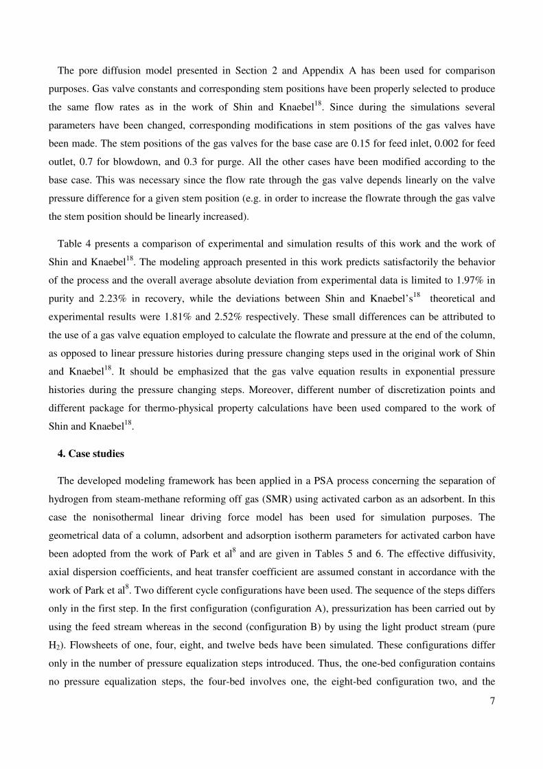

9
feed is needed to repressurize beds from the lower pressure) The noticeable increase in product
recovery is the direct result of the pressure equalization steps On the other hand power requirements
and adsorbent productivity decrease due to the lower amount of feed processed per unit time (the power
and productivity of the eight-bed configuration are lower than the power and productivity of the twelve-
bed configuration due to higher cycle time) The purity of the twelve-bed configuration is lower than the
purity of the four and eight-bed ones This interesting trend can be attributed to the fact that during the
third pressure equalization a small breakthrough takes place thus contaminating the pressurized bed
Simulation Run II
In simulation Run II configuration A has been employed (pressurization with feed) The effect of
number of beds for constant power requirements and constant adsorbent productivity on the separation
quality has been analyzed The following operating conditions have been selected constant adsorbent
productivity constant cycle time and constant amount of feed processed per cycle The input parameters
are given in Table 12 and the simulation results are summarized in Table 13 and Figure 5
The results show that increasing the number of beds a slight increase in the product purity (~1) and
a significant increase in product recovery (~52) are achieved In this run the amount of feed processed
per cycle is constant and improve in the purity cannot be attributed to the PSA design characteristics and
operating procedure Due to the same reasons described in Run I the purity of the twelve-bed
configuration is lower than the purity of the eight-bed one The power requirements and adsorbent
productivity remain constant due to the constant amount of feed processed per cycle
Simulation Run III
In this case configuration B (pressurization with light product) is used The effect of number of beds
for constant power requirements and constant adsorbent productivity on separation quality has been
investigated The following operating conditions have been selected constant adsorbent productivity
constant duration of adsorption and purge steps constant feed and purge gas flowrates constant cycle
time and constant amount of feed processed per cycle The input parameters are given in Table 14 and
the simulation results are presented in Figure 6 and Table 15
The results illustrate that the number of beds does not affect the product purity productivity and
power requirements (since the amount of feed per cycle is constant) However a huge improvement in
the product recovery (~64) is achieved due to three pressure equalization steps Similar to the results
in Run I and II the purity of the twelve-bed con-figuration is lower than the purity of the eight-bed one
10
The above analysis reveals typical trade-offs between capital and operating costs and separation
quality Thus by increasing the number of beds a higher product purityrecovery is achieved while
higher capital costs are required (due to a larger number of beds) On the other hand energy demands
are lower due to energy conservation imposed by the existence of pressure equalization steps
5 Conclusions
A generic modeling framework for the separation of gas mixtures using multibed PSA flowsheets is
presented in this work The core of the framework represents a detailed adsorbent bed model relying on
a coupled set of mixed algebraic and partial differential equations for mass heat and momentum balance
at both bulk gas and particle level equilibrium isotherm equations and boundary conditions according to
the operating steps The adsorbent bed model provides the basis for building a PSA flowsheet with all
feasible inter-bed connectivities PSA operating procedures are automatically generated thus facilitating
the development of complex PSA flowsheet for an arbitrary number of beds The modeling framework
provides a comprehensive qualitative and quantitative insight into the key phenomena taking place in
the process All models have been implemented in the gPROMS modeling environment and successfully
validated against experimental and simulation data available from the literature An application study
concerning the separation of hydrogen from the steam methane reformer off gas illustrates the predictive
power of the developed framework Simulation results illustrate the typical trade-offs between operating
and capital costs
Current work concentrates on the development of a mathematical programming framework for the
optimization of PSA flowsheets Recent advances in mixed-integer dynamic optimization techniques
will be employed for the solution of the underlying problems Future work will also consider the
detailed modeling and optimization of hybrid PSA-membrane processes
Acknowledgements
Financial support from PRISM EC-funded RTN (Contract number MRTN-CT-2004-512233) is
gratefully acknowledged The authors thank Professor Costas Pantelides from Process Systems
Enterprise Ltd for his valuable comments and suggestions
Nomenclature
a1 = Langmuir isotherm parameter molkg
a2 = Langmuir isotherm parameter K
b1 = Langmuir isotherm parameter 1Pa
11
b2 = Langmuir isotherm parameter K
b = Langmuir isotherm parameter m3mol
C = molar concentrations of gas phase in bulk gas molm3
Cp = molar concentrations of gas phase in particles molm
3
cp = heat capacity of bulk gas J(kgK)
cppg = heat capacity of gas within pellets J(kgK)
cpp = heat capacity of the particles J(kgK)
Cv = valve constant
Dz = axial dispersion coefficient m2s
Dm = molecular diffusion coefficient m2s
Ds = surface diffusion coefficient m2s
De = effective diffusivity coefficient m2s
εbed = porosity of the bed -
εp = porosity of the pellet -
F = molar flowrate mols
∆Hads = heat of adsorption Jmol
H = Henryrsquos parameter m3kg
kf = mass transfer coefficient m2s
kh = heat transfer coefficient J(m2Ks)
khwall = heat transfer coefficient for the column wall J(m2Ks)
L = bed length m
Q = adsorbed amount molkg
Q = adsorbed amount in equilibrium state with gas phase (in the mixture) molkg
12
Q
pure = adsorbed amount in equilibrium state with gas phase (pure component) molkg
Qtotal = total adsorbed amount molkg
Qm = Langmuir isotherm parameter molkg
Rbed = bed radius m
Rp = pellet radius m
T = temperature of bulk gas K
Tp = temperature of particles K
P = pressure Pa
P0 = pressure that gives the same spreading pressure in the multicomponent equilibrium Pa
u = interstitial velocity ms
X = molar fraction in gas phase -
X = molar fraction in adsorbed phase -
Z = compressibility factor -
ρ = density of bulk gas kgm3
micro = viscosity of bulk gas Pas
λ = thermal conductivity of bulk gas J(mK)
π = reduced spreading pressure -
ρpg = density of gas within pellets kgm3
ρp = density of the particles kgm
3
λp = thermal conductivity of the particles J(mK)
sp = stem position of a gas valve
spPressCoC = stem position of a gas valve during co-current pressurization -
spPressCC = stem position of a gas valve during counter-current pressurization -
13
spAdsIn = stem position of a gas valve during adsorption (inlet valve) -
spAdsOut = stem position of a gas valve during adsorption (outlet valve) -
spBlow = stem position of a gas valve during blowdown -
spPurgeIn = stem position of a gas valve during purge (inlet valve) -
spPurgeOut = stem position of a gas valve during purge (outlet valve) -
spPEQ1 = stem position of a gas valve during pressure equalization -
spPEQ2 = stem position of a gas valve during pressure equalization -
spPEQ3 = stem position of a gas valve during pressure equalization -
References
(1) Ruthven D M Principles of adsorption and adsorption processes Wiley New York 1984
(2) Yang R T Gas separation by adsorption processes Butterworths Boston 1987
(3) Chou CT Huang WC Incorporation of a valve equation into the simulation of a pressure swing
adsorption process Chem Eng Sci 1994 49 75
(4) Chou CT Huang WC Simulation of a four-bed pressure swing adsorption process for oxygen
enrichment Ind Eng Chem Res 1994 33 1250
(5) Warmuzinski K Tanczyk M Multicomponent pressure swing adsorption Part I Modelling of
large-scale PSA installations Chem Eng Process 1997 36 89
(6) Warmuzinski K Tanczyk M Multicomponent pressure swing adsorption Part II Experimental
verification of the model Chem Eng Process 1998 37 301
(7) Nilchan S Pantelides CC On the optimisation of periodic adsorption processes Adsorption
1998 4 113
(8) Park JH Kim JN Cho SH Kim JD Yang RT Adsorber dynamics and optimal design of
layered beds for multicomponent gas adsorption Chem Eng Sci 1998 53 3951
14
(9) Park JH Kim JN Cho SH Performance analysis of four-bed H2 PSA process using layered
beds AIChE J 2000 46 790
(10) Barg C Fereira JMP Trierweiler JO Secchi AR Simulation and optimization of an
industrial PSA unit Braz J Chem Eng 2000 17
(11) Sircar S Golden TC Purification of hydrogen by pressure swing adsorption Sep Sci Technol
2000 35 667
(12) Waldron WE Sircar S Parametric Study of a Pressure Swing Adsorption Process Adsorption
2000 6 179
(13) Jiang L Biegler L T Fox V G Simulation and optimization of pressure-swing adsorption
systems for air separation AIChE J 2003 49 1140
(14) Jiang L Biegler LT Fox VG Simulation and optimal design of multiple-bed pressure swing
adsorption systems AIChE J 2004 50 2904
(15) Jiang L Biegler LT Fox VG Design and optimization of pressure swing adsorption systems
with parallel implementation Comput Chem Eng 2005 29 393
(16) Process Systems Enterprise Ltd httpwwwpsenterprisecom 2006
(17) Shin HS Knaebel KS Pressure swing adsorption A theoretical study of diffusion-induced
separation AIChE J 1987 33 654
(18) Shin HS Knaebel KS Pressure swing adsorption An experimental study of diffusion-induced
separation AIChE J 1988 34 1409
(19) Cruz P Alves MB Magalhaes FD Mendes A Solution of hyperbolic PDEs using a stable
adaptive multiresolution method Chem Eng Sci 2003 58 1777
(20) Cruz P Alves MB Magalhaes FD Mendes A Cyclic adsorption separation processes
analysis strategy and optimization procedure Chem Eng Sci 2003 58 3143
(21) Cruz P Magalhaes FD Mendes A On the optimization of cyclic adsorption separation
processes AIChE J 2005 51 1377
(22) Kawazoe K Takeuchi Y Mass transfer in adsorption on bidisperse porous materials Macro and
micro-pore series diffusion model J Chem Eng Jpn 1974 7
15
(23) Wakao N Funazkri T Effect of fluid dispersion coefficients on particle-to-fluid mass transfer
coefficients in packed beds Correlation of Sherwood numbers Chem Eng Sci 1978 33 1375
(24) Wakao N Kaguei S Funazkri T Effect of fluid dispersion coefficients on particle-to-fluid heat
transfer coefficients in packed beds Correlation of Nusselt numbers Chem Eng Sci 1979 34
325
(25) Raghavan N Ruthven D Pressure swing adsorption Part III numerical simulation of a
kinetically controlled bulk gas separation AIChE J 1985 31 2017
(26) Raghavan N Hassan M Ruthven DM Numerical simulation of a PSA system using a pore
diffusion model Chem Eng Sci 1986 41 2787
(27) Doong SJ Yang RT Bulk separation of multicomponent gas mixtures by pressure swing
adsorption Poresurface diffusion and equilibrium models AIChE J 1986 32 397
(28) Yang RT Doong SJ Parametric study of the pressure swing adsorption process for gas
separation A criterion for pore diffusion limitation Chem Eng Commun 1986 41 163
(29) Doong SJ Yang RT Bidisperse pore diffusion model for zeolite pressure swing adsorption
AIChE J 1987 33 1045
(30) Hassan MM Raghavan NS Ruthven DM Numerical simulation of a pressure swing air
separation system a comparative study of finite difference and collocation methods Can J Chem
Eng 1987 65 512
(31) Raghavan NS Hassan MM Ruthven DM Pressure swing air separation on a carbon
molecular sieve- II Investigation of a modified cycle with pressure equalization and no purge
Chem Eng Sci 1987 42 2037
(32) Farooq S Ruthven DM Numerical simulation of a pressure swing adsorption oxygen unit
Chem Eng Sci 1989 44 2809
(33) Kapoor A Yang RT Kinetic separation of methane-carbon mixture by adsorption on molecular
sieve carbon Chem Eng Sci 1989 44 1723
(34) Suh SS Wankat PC A new pressure adsorption process for high enrichment and recovery
Chem Eng Sci 1989 44 567
16
(35) Alpay E Scot DM The linear driving force model for the fast-cycle adsorption and desorption
in a spherical particle Chem Eng Sci 1992 47 499
(36) Ruthven DM Farooq S Air separation by pressure swing adsorption Gas Sep Purif 1990 4
141
(37) Ackley MW Yang RT Kinetic separation by pressure swing adsorption Method of
characteristics model AIChE J 1990 36 1229
(38) Kikkinides ES Yang RT Effects of bed pressure drop on isothermal and adiabatic adsorber
dynamics Chem Eng Sci 1993 48 1545
(39) Ruthven DM Diffusion of Oxygen and Nitrogen in Carbon Molecular Sieve Chem Eng Sci
1992 47 4305
(40) Kikkinides ES Yang RT Concentration and recovery of CO2 from flue gas by pressure swing
adsorption Ind Eng Chem Res 1993 32 2714
(41) Lu ZP Loureiro JM Le Van MD Rodrigues AE Pressure swing adsorption processes -
Intraparticle diffusionconvection models Ind Eng Chem Res 1993 32 2740
(42) Lu ZP Rodrigues AE Pressure swing adsorption reactors simulation of three-step one-bed
process AIChE J 1994 40 1118
(43) Ruthven DM Farooq S Knaebel KS Pressure swing adsorption VCH Publishers New
York 1994
(44) Le Van MD Pressure swing adsorption Equilibrium theory for purification and enrichment Ind
Eng Chem Res 1995 34 2655
(45) Hartzog DG Sircar S Sensitivity of PSA process performance to input variables Air Products
and Chemicals Inc 1994
(46) Yang J Han S Cho C Lee CH Lee H Bulk separation of hydrogen mixtures by a one-
column PSA process Separations Technology 1995 5 239
(47) Serbezov A Sotirchos SV Mathematical modelling of multicomponent nonisothermal
adsorption in sorbent particles under pressure swing conditions Adsorption 1998 4 93
(48) Yang J Lee CH Adsorption dynamics of a layered bed PSA for H2 recovery from coke oven
gas AIChE J 1998 44 1325
17
(49) Lee CH Yang J Ahn H Effects of carbon-to-zeolite ratio on layered bed H2 PSA for coke
oven gas AIChE J 1999 45 535
(50) Pantelides CC The mathematical modelling of the dynamic behaviour of process systems
Imperial College of Science Technology and Medicine London 2000
(51) Chou CT Chen CY Carbon dioxide recovery by vacuum swing adsorption Sep Purif
Technol 2000 39 51
(52) Chahbani MH Tondeur D Mass transfer kinetics in pressure swing adsorption Sep Purif
Technol 2000 20 185
(53) Rajasree R Moharir AS Simulation based synthesis design and optimization of pressure swing
adsorption (PSA) processes Comput Chem Eng 2000 24 2493
(54) Mendes AMM Costa CAV Rodrigues AE PSA simulation using particle complex models
Sep Purif Technol 2001 24 1
(55) Botte GG Zhang RY Ritter JA On the use of different parabolic concentration profiles for
nonlinear adsorption and diffusion in a single particle Chem Eng Sci 1998 24 4135
(56) Ko D Siriwardane R Biegler L T Optimization of a pressure-swing adsorption process using
zeolite 13X for CO2 sequestration Ind Eng Chem Res 2003 42 339
(57) Cruz P Santos JC Magalhaes FD Mendes A Cyclic adsorption separation processes
analysis strategy and optimization procedure Chem Eng Sci 2003 58 3143
(58) Jain S Moharir AS Li P Wozny G Heuristic design of pressure swing adsorption a
preliminary study Sep Purif Technol 2003 33 25
(59) Kim MB Jee JG Bae YS Lee CH Parametric study of pressure swing adsorption process
to purify oxygen using carbon molecular sieve AIChE J 2004
(60) Chang D Min J Moon K Park Y K Jeon JK Ihm SK Robust numerical simulation of
pressure swing adsorption process with strong adsorbate CO2 Chem Eng Sci 2004 59 2715
(61) Ko D Siriwardane R Biegler LT Optimization of pressure swing adsorption and fractionated
vacuum pressure swing adsorption processes for CO2 capture Ind Eng Chem Res 2005 44
8084
18
(62) Jee J Kim M Lee C Pressure Swing Adsorption Processes to Purify Oxygen Using a Carbon
Molecular Sieve Chem Eng Sci 2005 60 869
(63) Knaebel SP Ko D Biegler LT Simulation and optimization of a pressure swing adsorption
system Recovering hydrogen from methane Adsorption 2005 11 615
(64) Kim MB Jee JG Bae YS Lee CH Parametric study of pressure swing adsorption process
to purify oxygen using carbon molecular sieve Ind Eng Chem Res 2005 44 7208
(65) Grande CA Rodrigues AE Propanepropylene separation by pressure swing adsorption using
zeolite 4A Ind Eng Chem Res 2005 44 8815
(66) Reynolds SP Ebner AD Ritter JA Stripping PSA cycles for CO2 recovery from flue gas at
high temperature using a hydrotalcite-like adsorbent Ind Eng Chem Res 2006 45 4278
(67) Reynolds SP Ebner AD Ritter JA Enriching PSA cycle for the production of nitrogen from
air Ind Eng Chem Res 2006 45 3256
(68) OrsquoBrien JA Myers AL A comprehensive technique for equilibrium calculations in adsorbed
mixtures The generalized FastIAS method Ind Eng Chem Res 1988 27 2085
(69) Ahn H Brandani S A new numerical method for accurate simulation of fast cyclic adsorption
processes Adsorption 2005 11 113
19
Table1 Overview of single-bed PSA studies
Ref Mass
balance
Heat
balance
Momentum
balance
Isotherm
adsorbent
No of
steps
No of
layers Application
(3) LDF - - Linear CMS 4 1 Air separation
(8) LDF Bulk gas Ergun Langmuir AC+5A - 2 H2 CO2 CH4 CO
(26) PD - - Langmuir alumina 4 1 Air separation
(27) LEQ SD PD Bulk gas - IASLRC AC 5 1 H2 CO2 CH4
(29) BDPD Bulk gas - Langmuir 5A 5 1 H2 CH4
(17) PD - - Linear MS RS-10 4 1 Air separation theoretical
study
(18) PD - - Linear MS RS-10 4 1 Air separation
experimental study
(38) 4 different LDF Bulk gas Ergun Linear 13X - 1 Air separation
(43) LDF Bulk gas
solids -
Langmuir Freundlich 5A
5 1 H2 CO H2 CO2
(47) DG Bulk gas - Langmuir 5A - 1 Air separation
(48) LDF Bulk gas Ergun Langmuir AC+5A - 2 H2 CO2 CH4 CO
(54) DG LDF -DG
LDF-DGSD
LDF-DGSD
- - Langmuir 4A 5A
CMS 4 1 Air separation
(56) LDF Bulk gas Darcy Langmuir 13X 4 1 CO2 sequestr
(61) LDF Bulk gas - Langmuir AC 4 1 H2 CH4
(63) LDF Bulk gas Ergun Dual-site Langmuir
13X 4 1 CO2 capture
(65) Bi-LDF Bulk gas
solid Ergun Langmuir 4A 5 1 Propane propylene
LEQ ndash local equilibrium model LDF ndash linear driving force model SD ndash solid diffusion model PD ndash pore diffusion model
DG ndash dusty gas model
Table 2 Overview of two-bed PSA studies
Ref Mass
balance
Heat
balance
Momentum
balance
Isotherm
adsorbent
No of
beds
No of
steps
Bed
interactions
No of
layers Application
(3) LDF - - Langmuir
CMS5A 2 4 Valve eq 1 Air separation
(7) LDF PD - Darcy Linear-
Langmuir 5A 1 2 2 6 Valve eq 1 Air separation
(13) LDF Bulk gas Ergun
Dual-site
Langmuir
13X
1 2 3 6 Valve eq Inert +
ads Air separation
(28) LDF PD Bulk gas - LRC AC 2 4 - 1 H2 CH4
(31) LDF - - Linear CMS 2 6 Frozen solid 1 Air separation
(49) LDF Bulk gas Ergun Langmuir Freundlich
AC+5A
2 7 - 2 H2 CH4 CO
N2 CO2
(57) LDF DG Bulk gas Darcy Langmuir 2 4 - 1 Air separation
(64) LDF Bulk gas Ergun LRC AC+5A 2 6 - 1 Air separation
20
Table 3 Overview of multibed PSA studies
Ref Mass
balance Heat
balance
Momentum
balance
Isotherm adsorbent
No of beds
No of steps
Bed interactions
No of layers
Application
(4) LEQ - - Langmuir 5A 4 6 Valve eq 1 Air separation
(5) LDF Bulk gas - LRC AC+5A 5 8 Linear change 1 or 2 H2 CH4 CO
N2
(6) LDF Bulk gas - LRC AC5A 2 4 5 7 - 1 H2 CH4 N2
(9) LDF Bulk gas Ergun Langmuir
AC+5A 4 8
Only one bed is simulated
information
stored in data buffer
2 H2 CO2 CH4
CO
(10) LDF Bulk gas Darcy
Langmuir
Alumina+ AC+zeolite
6 12
Information
stored in data buffer
inert +
2 ads H2 CH4 CO
(11) - - - AC zeolite silica
gel 9 10
9 11 6+7
- -
Overview of
commercial PSA processes
(12) LDF Bulk gas Darcy Langmuir AC 4 5 7 9 12 - 1 H2 CH4
(14) LDF Bulk gas Ergun
Dual-site
Langmuir APHP+5A
5 11 Valve eq 2 N2 CH4 CO2
CO H2
(51) LEQ Bulk gas - Ext Langmuir
13X 2 3 4 6 - 1
CO2 from flue
gases
(66) LDF Bulk gas - Langmuir 13X 4 5 4 5 5 Linear change 1 CO2 N2 H2O
21
Table 4 Comparison of the experimental and the simulation results
Recovery Purity
No Exp18
Model18
This
work Exp
18 Model
18
This
work
1 644 638 696 9975 10000 9931
2 816 864 850 9955 9989 9892
3 1065 1092 994 9900 9909 9855
4 1239 1215 1130 9835 9859 9815
5 707 825 852 9960 9988 9895
6 941 985 995 9885 9941 9854
7 1167 1172 1072 9830 9877 9833
8 1299 1213 1141 9780 9849 9811
9 2584 1702 2123 9080 9539 9447
10 2136 1609 2121 9070 9623 9475
11 2274 1550 2120 9140 9618 9478
12 2218 2274 2108 9120 9602 9477
13 939 835 845 9825 9970 9974
14 740 632 785 9890 9982 9991
15 510 500 738 9900 9988 9997
16 919 859 982 9845 9963 9960
17 707 762 856 9850 9976 9979
18 643 699 742 9870 9983 9989
19 541 613 612 9880 9993 9996
20 1151 1244 1128 9795 9871 9825
21 972 967 943 9850 9942 9940
22 674 659 726 9885 9979 9991
23 337 408 546 9900 9996 9999
24 1663 1433 1086 9585 9747 9869
25 1076 1155 962 9680 9872 9957
26 857 847 881 9730 9915 9984
27 826 721 844 9765 9910 9991
28 735 856 1135 9875 9987 9822
29 1195 1427 1117 9770 9792 9831
30 1330 1607 1120 9700 9657 9824
31 4156 3764 2638 8230 8227 8923
32 2246 1607 1511 9370 9497 9670
33 1254 800 899 9820 10000 9906
34 1383 1309 986 9380 9445 9606
35 2305 1673 1425 9370 9758 9775
42 2240 1646 2051 8900 9440 9496
43 2237 1615 2006 8230 8972 9012
22
Table 5 Geometrical and transport characteristics of PSA process
Parameter Value Units
Temperature of the feed 297 K
Temperature of the purge gas 297 K
Temperature of the wall 297 K
Feed pressure 263e5 Pa
Purge pressure 1e5 Pa
Gas valve constant 1e-5 -
Particle density 850 kgm3
Particle radius 3e-3 m
Bed void fraction 036 -
Bed inner diameter 01 m
Bed length 10 m
Molar fraction of H2 in feed 0755 -
Molar fraction of CO in feed 0040 -
Molar fraction of CH4 in feed 0035 -
Molar fraction of CO2 in feed 0170 -
Overall mass transfer
coefficient of H2 10 1s
Overall mass transfer
coefficient of CO 03 1s
Overall mass transfer
coefficient of CH4 04 1s
Overall mass transfer
coefficient of CO2 01 1s
Heat capacity of the particles 87864 J(kgK)
Heat transfer coefficient
(wall) 13807 W(m
2K)
Heat axial dispersion
coefficient 1e-3 m
2s
Mass axial dispersion
coefficient 1e-3 m
2s
Table 6 Langmuir parameters and heat of adsorption for activated carbon
Comp a1 x10
3
(molg) a2
(K) b1 x10
9
(Pa-1
) b2
(K) -∆Hads (Jmol)
H2 432 000 5040 8505 786173
CO 092 052 5896 17309 1667742
CH4 -170 198 19952 14467 1875269
CO2 -1420 663 24775 14966 2557261
Table 7 A four-bed six-step PSA configuration (pressurization with feed one pressure equalization
step purge from tank) Bed 1 CoCP Ads Ads EQD1 Blow Purge Purge EQR1
Bed 2 Purge EQR1 CoCP Ads Ads EQD1 Blow Purge
Bed 3 Blow Purge Purge EQR1 CoCP Ads Ads EQD1
Bed 4 Ads EQD1 Blow Purge Purge EQR1 CoCP Ads
23
Table 8 A eight-bed eight-step PSA configuration (pressurization with feed two pressure equalization
steps purge from tank) Bed 1 CoCP Ads EQD1 EQD2 Blow Purge EQR2 EQR1
Bed 2 EQR1 CoCP Ads EQD1 EQD2 Blow Purge EQR2
Bed 3 EQR2 EQR1 CoCP Ads EQD1 EQD2 Blow Purge
Bed 4 Purge EQR2 EQR1 CoCP Ads EQD1 EQD2 Blow
Bed 5 Blow Purge EQR2 EQR1 CoCP Ads EQD1 EQD2
Bed 6 EQD2 Blow Purge EQR2 EQR1 CoCP Ads EQD1
Bed 7 EQD1 EQD2 Blow Purge EQR2 EQR1 CoCP Ads
Bed 8 Ads EQD1 EQD2 Blow Purge EQR2 EQR1 CoCP
Table 9 A twelve-bed ten-step PSA configuration (pressurization with feed three pressure equalization
steps purge from tank) Bed 1 CoCP Ads Ads EQD1 EQD2 EQD3 Blow Purge Purge EQR3 EQR2 EQR1
Bed 2 EQR1 CoCP Ads Ads EQD1 EQD2 EQD3 Blow Purge Purge EQR3 EQR2
Bed 3 EQR2 EQR1 CoCP Ads Ads EQD1 EQD2 EQD3 Blow Purge Purge EQR3
Bed 4 EQR3 EQR2 EQR1 CoCP Ads Ads EQD1 EQD2 EQD3 Blow Purge Purge
Bed 5 Purge EQR3 EQR2 EQR1 CoCP Ads Ads EQD1 EQD2 EQD3 Blow Purge
Bed 6 Purge Purge EQR3 EQR2 EQR1 CoCP Ads Ads EQD1 EQD2 EQD3 Blow
Bed 7 Blow Purge Purge EQR3 EQR2 EQR1 CoCP Ads Ads EQD1 EQD2 EQD3
Bed 8 EQD3 Blow Purge Purge EQR3 EQR2 EQR1 CoCP Ads Ads EQD1 EQD2
Bed 9 EQD2 EQD3 Blow Purge Purge EQR3 EQR2 EQR1 CoCP Ads Ads EQD1
Bed 10 EQD1 EQD2 EQD3 Blow Purge Purge EQR3 EQR2 EQR1 CoCP Ads Ads
Bed 11 Ads EQD1 EQD2 EQD3 Blow Purge Purge EQR3 EQR2 EQR1 CoCP Ads
Bed 12 Ads Ads EQD1 EQD2 EQD3 Blow Purge Purge EQR3 EQR2 EQR1 CoCP
24
Table 10 Input parameters of Run 1
Number of beds Parameter
1 4 8 12
spPressCoC 01000 0060 0030 00500
spAdsIn 03600 03600 03600 03600
spAdsOut 00035 00015 00015 00015
spBlow 08000 05000 02500 04000
spPurgeIn 02250 02250 02250 02250
spPurgeOut 00300 00300 0030 00300
spPEQ1 - 00040 00025 00030
spPEQ2 - - 00050 00040
spPEQ3 - - - 00080
Feed
flowrate m3s
360e-6 360e-6 360e-6 360e-6
Purge
flowrate m3s
225e-6 225e-6 225e-6 225e-6
τPress s 10 10 20 10
τAds s 20 20 20 20
τBlow s 10 10 20 10
τPurge s 20 20 20 20
τPEQ1 s - 10 20 10
τPEQ2 s - - 20 10
τPEQ3 s - - - 10
τcycle s 60 80 160 120
Table 11 Simulation results of Run I
No
beds
O2 purity
()
O2 recovery
()
Power
(W)
Productivity
(molkgs)
1 9687 3440 52902 918e-2
4 9950 5806 27949 485e-2
8 9958 6887 11987 208e-2
12 9936 7250 13936 242e-2
25
Table 12 Runtime parameters for Run II
Number of beds Parameter
1 4 8 12
spPressCoC 00300 00450 00500 00500
spAdsIn 01200 01300 03300 03600
spAdsOut 00004 000035 00014 00015
spBlow 02000 02200 03000 04000
spPurgeIn 05625 01500 03000 02250
spPurgeOut 00075 00200 00400 00300
spPEQ1 - 00025 00020 00300
spPEQ2 - - 00040 00040
spPEQ3 - - - 00080
Feed flowrate m
3s
120e-6 130e-6 330e-6 360e-6
Purge
flowrate m3s
075e-6 115e-6 300e-6 225e-6
τPress s 20 15 15 10
τAds s 40 30 15 20
τBlow s 20 15 15 10
τPurge s 40 30 15 20
τPEQ1 s - 15 15 10
τPEQ2 s - - 15 10
τPEQ3 s - - - 10
τcycle s 120 120 120 120
Table 13 Simulation results for Run II
No
beds
O2 purity
()
O2 recovery
()
Power
(W)
Productivity
(molkgs)
1 9811 2021 14420 250e-2
4 9929 3840 14069 244e-2
8 9979 6525 14092 245e-2
12 9936 7250 13936 242e-2
26
Table 14 Runtime parameters for Run III
Number of beds Parameter
1 4 8 12
spPressCC 00030 00030 00500 00040
spAdsIn 04000 03333 03450 05000
spAdsOut 000088 000085 00015 00014
spBlow 02500 04000 03000 04000
spPurgeIn 00900 01333 03000 02000
spPurgeOut 00140 00200 00400 00300
spPEQ1 - 00050 00020 00030
spPEQ2 - - 00040 00040
spPEQ3 - - - 00080
Feed flowrate m
3s
400e-6 333e-6 345e-6 500e-6
Purge
flowrate m3s
090e-6 133e-6 300e-6 200e-6
τPress s 20 15 15 10
τAds s 40 30 15 20
τBlow s 20 15 15 10
τPurge s 40 30 15 20
τPEQ1 s - 15 15 10
τPEQ2 s - - 15 10
τPEQ3 s - - - 10
τcycle s 120 120 120 120
Table 15 Simulation results for Run III
No beds
O2 purity ()
O2 recovery ()
Power (W)
Productivity (molkgs)
1 9987 141 18878 203e-2
4 9997 2847 11808 205e-2
8 9997 5058 11938 207e-2
12 9983 6516 11909 207e-2
27
APPENDIX A Table A1 Basic adsorbent bed model
Feature General equation
Bulk flow mass balance
( )( )
( )
1
0 1
i i ibed bed bed i bed z i
comp
uC C CN D
z t z z
z L i N
part part partpart ε + ε + minus ε = ε
part part part part
forall isin = hellip
(A1)
The generation term in bulk flow mass balance (transfer through a
particle surface)
( ) ( ) 0 1 i i compN f T P C Adsorbent type z L i N= forall isin = hellip (A2)
Bulk flow heat balance
( ) ( )( ) ( )
( )
31
0
bed pbed p h wallbed g wall
bed
bed z
c Tc uT kq T T
z t R
Tz L
z z
part ε ρpart ε ρ+ + minus ε + minus =
part part
part part = ε λ forall isin
part part
(A3)
The generation term in bulk flow
heat balance (transfer through a particle surface)
( ) ( ) 0 1 g i compq f T P C Adsorbent type z L i N= forall isin = hellip (A4)
Momentum balance ( ) ( ) 0 bed p
Pf u R z L
z
partminus = ε forall isin
part (A5)
Overall mass transfer
coefficient ( )
0 1 f i p
compm i
k RSh f Sc Re z L i N
D= = forall isin = hellip (A6)
Overall heat transfer coefficient ( ) 0
h pk RNu f PrRe z L= = forall isin
λ (A7)
Mass axial dispersion coefficient
( )
0 1 z i bed
compm i
Df Sc Re z L i N
D
ε= forall isin = hellip (A8)
Heat axial dispersion coefficient
( ) 0 z f Pr Re z Lλ
= forall isin λ
(A9)
Equation of state ( ) 0 1 i Ncomp compP f T C C z L i N= forall isin = hellip (A10)
Thermo-physical properties ( ) [ ] 0 1 p i Ncomp compc f T P C C z L i Nρ λ micro = forall isin = hellip (A11)
( ) 0 or 1 in ii i z i comp
Cu C C D z z L i N
z
partminus = = = =
parthellip (A12)
0 or inT T z z L= = = (A13)
Boundary conditions for stream inlet into the bed
0 0 and u
z z Lz
part= = =
part (A14)
0 0 or 1 icomp
Cz z L i N
z
part= = = =
parthellip (A15) Boundary conditions for stream
outlet from the bed closed bed
end 0 0 or
Tz z L
z
part= = =
part (A16)
28
Table A2 Mass transport mechanisms
Model Equation
Mass transfer between a bulk gas and particles is assumed instantaneous and concentration of the gas
within the particles is equal to the concentration in the bulk flow
[ ] 0 0 1 p
i p compiC C r R z L i N = forall isin forall isin = hellip (A17)
The gas phase is in equilibrium with the solid phase
[ ] 0 0 1 i i p compQ Q r R z L i N = forall isin forall isin = hellip (A18) LEQ
The generation term is sum of accumulation in gas phase in particles and amount adsorbed
( )
0 1 p i ii p comp
Q CN z L i N
t t
part part= ρ + ε forall isin =
part parthellip
(A19)
Mass transfer between a bulk gas and particles is assumed instantaneous
[ ] 0 1 pi p compiC C r R z L i N= = forall isin = hellip
(A20)
Concentration profile within the particle is assumed parabolic
( ) [ ]
2
15 0 0 1
e iii i p comp
p
DQQ Q r R z L i N
t R
part = minus forall isin forall isin = part
hellip (A21) LDF
The generation term is sum of accumulation in gas phase in particles and amount adsorbed
( ) 0 1 p i i
i p comp
Q CN z L i N
t t
part part= ρ + ε forall isin =
part parthellip
(A22)
Gas phase within particles is neglected
) [ ]0 0 0 1 p
p compiC r R z L i N= forall isin forall isin = hellip (A23)
All adsorption happens at the particle surface Adsorbed phase is then transported towards particle
centre by surface diffusion (Fickrsquos first law of diffusion)
( ) [ ]22
1 0 0 1 i i
p s i p comp
p
Q QR D r R z L i N
t r rR
part partpart= forall isin forall isin =
part part part hellip
(A24)
Mass transfer between bulk gas and particles is carried out through the gas film around particles
( ) ( )3
0 1 p
f pi i r R compi
p
kN C C z L i N
R== minus forall isin = hellip
(A25)
Boundary conditions ( ) 1 p p
p if i i r R s i r R p compi
Qk C C D r R i N
r= =
partminus = = =
part (A26)
SD
0 0 0 1 icomp
Qr z L i N
r
part= = forall isin =
parthellip (A27)
Within the pores gas is transported by combined molecular and Knudsen diffusion
( ) ( ) [ ]
22
11 0 0 1
p ppi i i
p p p p e i p comp
p
C CQR D r R z L i N
t t r rR
part partpart part ε + minus ε ρ = ε forall isin forall isin =
part part part part hellip
(A28)
The gas phase in micro-pores is in equilibrium with the adsorbed phase
[ ] 0 0 1 i i p compQ Q r R z L i N = forall isin forall isin = hellip (A29)
Mass transfer between bulk gas and particles is carried out through the gas film around particles
( ) ( )3
0 1 p
f pi i r R compi
p
kN C C z L i N
R== minus forall isin = hellip
(A30)
Boundary conditions ( ) 1 p p
p if i i r R e i r R p compi
Qk C C D r R i N
r= =
partminus = = =
part (A31)
PD
0 0 0 1 p
icomp
Cr z L i N
r
part= = forall isin =
parthellip (A32)
29
Table A3 Thermal operating modes
Mode Equation
( )0 0 T
z Lz
part= forall isin
part (A33)
Isothermal Temperature within the particles are constant and equal to the temperature of bulk flow
(no heat transfer between bulk flow and particles occurs)
0 0 ppT T r R z L = forall isin forall isin
(A34)
Bulk flow heat balance
( ) ( )( ) ( )3
0 bed pbed p h wall
g wall bed zbed
c Tc uT k Tq T T z L
z t R z z
part ε ρpart ε ρ part part + + + minus = ε λ forall isin
part part part part
(A35)
Heat transfer between bulk gas and particles is assumed instantaneous and the
temperature of particles is equal to the temperature of the bulk flow
0 0 ppT T r R z L = forall isin forall isin
(A36)
LEQ
model The generation term qg is given by the sum of accumulations in gas and solid
phase within the particles and heat of adsorptiondesorption
( )( ) ( )
0 comp
p p Np p pg p pg
p ig ads i
i
c c TQ
q H z Lt t
part ρ + ε ρpart = + ρ ∆ forall isin
part partsum
(A37)
Heat transfer between bulk gas and particles is assumed instantaneous and the
temperature of particles is equal to the temperature of the bulk flow
0 0 ppT T r R z L = forall isin forall isin
(A38)
LDF
model The generation term qg is given by the sum of accumulations in gas and solid
phase within the particles and heat of adsorptiondesorption
( )( ) ( )
0 comp
p p Np p pg p pg
p ig ads i
i
c c TQ
q H z Lt t
part ρ + ε ρpart = + ρ ∆ forall isin
part partsum
(A39)
Heat transfer between bulk gas and particles is assumed instantaneous and the
temperature of particles is equal to the temperature of the bulk flow
0 0 p
pT T r R z L = forall isin forall isin
(A40)
SD
model The generation term qg is given by the sum of accumulation in solid phase within
the particles and heat of adsorptiondesorption
( )( ) ( ) 0
compp p N
p i Rppg ads i
i
c T Qq H z L
t t
part ρ part= + ρ ∆ forall isin
part partsum
(A41)
Heat transfer is carried out through the gas film around particles
( ) ( )3
0 p
phg R
p
kq T T z L
R= minus forall isin
(A42)
Particle heat balance
( )( ) ( )
2
2
1 0 0
p p ppp p pg p pg
p pg p p
p
c c TT
q R r R z Lt r rR
part ρ + ε ρ part part + = λ forall isin forall isin part part part
(A43)
The generation term qgp is given by the heat of adsorptiondesorption
( ) ( )
0 compN
p p ig ads i p
i
Qq H r R
t
part= ρ ∆ forall isin
partsum
(A44)
( ) p p
pp p
h r R r R p
Tk T T r R
r= =
partminus = λ =
part
(A45)
Nonisothermal
PD
model
Boundary conditions
0 0p
Tr
r
part= =
part (A46)
Adiabatic The same as in the Nonisothermal mode except the term
( )3 h wallwall
bed
kT T
Rminus
is neglected
30
Table A4 Momentum balance and equilibrium isotherms Feature Equation
Blake-Kozeny equation
( )
( )( )
2
2 3
180 1 0
2
bg bed
bedp
uPz L
z R
micro minus εpartminus = forall isin
part ε (A47)
Momentum balance Ergunrsquos equation
( )
( )( )
2
2 3
180 1 0
2
bg bed
bedp
uPz L
z R
micro minus εpartminus = forall isin
part ε (A48)
Linear (Henry type)
( ) 0 1 pi i comp iiQ H C z L i N H f T P= forall isin = = hellip
(A49)
Extended Langmuir
2 2 1 1 exp 0 1
1
i ii ii m i m i i i i comp
j j
j
a bb PQ Q Q a b b z L i j N
b P T T
= = + = forall isin =
+ sumhellip (A50)
Ideal Adsorbed Solution theory (IAS)268
( )0
0
0
1 0 1 iP
pure i Langmuiri i m i i i compisotherm
QdP Q b P z L i N
Pπ = rarrπ = + forall isin = int hellip
(A51a)
1 0 1 1i i compz L i N+π = π forall isin = minus hellip
(A51b
)
2 2 1 1 exp 0 1
1
i ii ipure i m i m i i i i comp
i i
a bb PQ Q Q a b b z L i N
b P T T
= = + = forall isin = +
hellip (A51c)
0 0 1 i i i compX P X P z L i N= forall isin = hellip (A51d
)
1 0 1 i compX z L i N= forall isin = sum hellip (A51e)
1 0 1 i
comp
itotal pure i
Xz L i N
Q Q= forall isin = sum hellip (A51f)
Equilibrium isotherms
0 1 i i total compQ X Q z L i N= forall isin = hellip (A51g)
31
Table A5 Calculation of transport properties
Variable Equation
Overall mass transfer coefficient
Wakao correlation23
( ) 033 06 20 11 0 1
m if i comp
p
Dk Sc Re z L i N
R= + forall isin = hellip (A52)
Overall heat transfer
coefficient
Wakao correlation24
( )033 0620 11 Re 0 hp
k Pr z LR
λ= + forall isin
(A53)
Mass axial dispersion
coefficient
Wakao correlation23
( ) 20 05 0 1
m iz i comp
bed
DD ScRe z L i N= + forall isin =
εhellip
(A54)
Heat axial dispersion
coefficient
Wakao correlation24
( )7 05 0 z bg PrRe z Lλ = λ + forall isin (A55)
Chapman-Enskog equation2
3
3 2
12 12
1
18583 10 0 0 1 2im i p
TMW
D z L r R iP
minus = times forall isin forall isin = σ Ω
(A56)
Molecular diffusivity Fuller correlation
2
7 175 2
12
1
1013 10 0 0 1 2im i p
MWD T z L r R i
PX
minus = times forall isin forall isin = (A57)
Knudsen diffusivity
Kauzmann2 correlation
3 97 10 0 0 1 k i pore p comp
i
TD R z L r R i N
MW = times forall isin forall isin = hellip
(A58)
Effective diffusivity
0 0 1 p m i k i
e i p compp m i k i
D DD z L r R i N
D D
ε = forall isin forall isin = τ +
hellip (A59)
Table A6 Gas valve equation Variable Equation
If Pout gt Pcrit Pin
2
1
1
out
inv in comp
i i
P
PF C SP P i N
x MW T
minus = = hellip
sum (A60)
Molar flowrate
Otherwise ( )
21
1
critv in comp
i i
PF C SP P i N
x MW T
minus= = hellip
sum (A61)
Critical pressure 12
1critP
κ
minusκ =
+ κ (A62)
Power
1
11
feed feedfeed
low cycle
P NPower RT
P
κminus
κ κ
= minus κ minus τ
(A63)
32
Figure 1 Single bed PSA arrangement with all possible interconnections
33
Figure 2 Four-bed PSA flowsheet
34
Figure 3 A simplified algorithm of the operating procedure generator
Figure 4 Simulation results of Run I
35
Figure 5 Simulation results of Run II
Figure 6 Simulation results of Run III

11
b2 = Langmuir isotherm parameter K
b = Langmuir isotherm parameter m3mol
C = molar concentrations of gas phase in bulk gas molm3
Cp = molar concentrations of gas phase in particles molm
3
cp = heat capacity of bulk gas J(kgK)
cppg = heat capacity of gas within pellets J(kgK)
cpp = heat capacity of the particles J(kgK)
Cv = valve constant
Dz = axial dispersion coefficient m2s
Dm = molecular diffusion coefficient m2s
Ds = surface diffusion coefficient m2s
De = effective diffusivity coefficient m2s
εbed = porosity of the bed -
εp = porosity of the pellet -
F = molar flowrate mols
∆Hads = heat of adsorption Jmol
H = Henryrsquos parameter m3kg
kf = mass transfer coefficient m2s
kh = heat transfer coefficient J(m2Ks)
khwall = heat transfer coefficient for the column wall J(m2Ks)
L = bed length m
Q = adsorbed amount molkg
Q = adsorbed amount in equilibrium state with gas phase (in the mixture) molkg
12
Q
pure = adsorbed amount in equilibrium state with gas phase (pure component) molkg
Qtotal = total adsorbed amount molkg
Qm = Langmuir isotherm parameter molkg
Rbed = bed radius m
Rp = pellet radius m
T = temperature of bulk gas K
Tp = temperature of particles K
P = pressure Pa
P0 = pressure that gives the same spreading pressure in the multicomponent equilibrium Pa
u = interstitial velocity ms
X = molar fraction in gas phase -
X = molar fraction in adsorbed phase -
Z = compressibility factor -
ρ = density of bulk gas kgm3
micro = viscosity of bulk gas Pas
λ = thermal conductivity of bulk gas J(mK)
π = reduced spreading pressure -
ρpg = density of gas within pellets kgm3
ρp = density of the particles kgm
3
λp = thermal conductivity of the particles J(mK)
sp = stem position of a gas valve
spPressCoC = stem position of a gas valve during co-current pressurization -
spPressCC = stem position of a gas valve during counter-current pressurization -
13
spAdsIn = stem position of a gas valve during adsorption (inlet valve) -
spAdsOut = stem position of a gas valve during adsorption (outlet valve) -
spBlow = stem position of a gas valve during blowdown -
spPurgeIn = stem position of a gas valve during purge (inlet valve) -
spPurgeOut = stem position of a gas valve during purge (outlet valve) -
spPEQ1 = stem position of a gas valve during pressure equalization -
spPEQ2 = stem position of a gas valve during pressure equalization -
spPEQ3 = stem position of a gas valve during pressure equalization -
References
(1) Ruthven D M Principles of adsorption and adsorption processes Wiley New York 1984
(2) Yang R T Gas separation by adsorption processes Butterworths Boston 1987
(3) Chou CT Huang WC Incorporation of a valve equation into the simulation of a pressure swing
adsorption process Chem Eng Sci 1994 49 75
(4) Chou CT Huang WC Simulation of a four-bed pressure swing adsorption process for oxygen
enrichment Ind Eng Chem Res 1994 33 1250
(5) Warmuzinski K Tanczyk M Multicomponent pressure swing adsorption Part I Modelling of
large-scale PSA installations Chem Eng Process 1997 36 89
(6) Warmuzinski K Tanczyk M Multicomponent pressure swing adsorption Part II Experimental
verification of the model Chem Eng Process 1998 37 301
(7) Nilchan S Pantelides CC On the optimisation of periodic adsorption processes Adsorption
1998 4 113
(8) Park JH Kim JN Cho SH Kim JD Yang RT Adsorber dynamics and optimal design of
layered beds for multicomponent gas adsorption Chem Eng Sci 1998 53 3951
14
(9) Park JH Kim JN Cho SH Performance analysis of four-bed H2 PSA process using layered
beds AIChE J 2000 46 790
(10) Barg C Fereira JMP Trierweiler JO Secchi AR Simulation and optimization of an
industrial PSA unit Braz J Chem Eng 2000 17
(11) Sircar S Golden TC Purification of hydrogen by pressure swing adsorption Sep Sci Technol
2000 35 667
(12) Waldron WE Sircar S Parametric Study of a Pressure Swing Adsorption Process Adsorption
2000 6 179
(13) Jiang L Biegler L T Fox V G Simulation and optimization of pressure-swing adsorption
systems for air separation AIChE J 2003 49 1140
(14) Jiang L Biegler LT Fox VG Simulation and optimal design of multiple-bed pressure swing
adsorption systems AIChE J 2004 50 2904
(15) Jiang L Biegler LT Fox VG Design and optimization of pressure swing adsorption systems
with parallel implementation Comput Chem Eng 2005 29 393
(16) Process Systems Enterprise Ltd httpwwwpsenterprisecom 2006
(17) Shin HS Knaebel KS Pressure swing adsorption A theoretical study of diffusion-induced
separation AIChE J 1987 33 654
(18) Shin HS Knaebel KS Pressure swing adsorption An experimental study of diffusion-induced
separation AIChE J 1988 34 1409
(19) Cruz P Alves MB Magalhaes FD Mendes A Solution of hyperbolic PDEs using a stable
adaptive multiresolution method Chem Eng Sci 2003 58 1777
(20) Cruz P Alves MB Magalhaes FD Mendes A Cyclic adsorption separation processes
analysis strategy and optimization procedure Chem Eng Sci 2003 58 3143
(21) Cruz P Magalhaes FD Mendes A On the optimization of cyclic adsorption separation
processes AIChE J 2005 51 1377
(22) Kawazoe K Takeuchi Y Mass transfer in adsorption on bidisperse porous materials Macro and
micro-pore series diffusion model J Chem Eng Jpn 1974 7
15
(23) Wakao N Funazkri T Effect of fluid dispersion coefficients on particle-to-fluid mass transfer
coefficients in packed beds Correlation of Sherwood numbers Chem Eng Sci 1978 33 1375
(24) Wakao N Kaguei S Funazkri T Effect of fluid dispersion coefficients on particle-to-fluid heat
transfer coefficients in packed beds Correlation of Nusselt numbers Chem Eng Sci 1979 34
325
(25) Raghavan N Ruthven D Pressure swing adsorption Part III numerical simulation of a
kinetically controlled bulk gas separation AIChE J 1985 31 2017
(26) Raghavan N Hassan M Ruthven DM Numerical simulation of a PSA system using a pore
diffusion model Chem Eng Sci 1986 41 2787
(27) Doong SJ Yang RT Bulk separation of multicomponent gas mixtures by pressure swing
adsorption Poresurface diffusion and equilibrium models AIChE J 1986 32 397
(28) Yang RT Doong SJ Parametric study of the pressure swing adsorption process for gas
separation A criterion for pore diffusion limitation Chem Eng Commun 1986 41 163
(29) Doong SJ Yang RT Bidisperse pore diffusion model for zeolite pressure swing adsorption
AIChE J 1987 33 1045
(30) Hassan MM Raghavan NS Ruthven DM Numerical simulation of a pressure swing air
separation system a comparative study of finite difference and collocation methods Can J Chem
Eng 1987 65 512
(31) Raghavan NS Hassan MM Ruthven DM Pressure swing air separation on a carbon
molecular sieve- II Investigation of a modified cycle with pressure equalization and no purge
Chem Eng Sci 1987 42 2037
(32) Farooq S Ruthven DM Numerical simulation of a pressure swing adsorption oxygen unit
Chem Eng Sci 1989 44 2809
(33) Kapoor A Yang RT Kinetic separation of methane-carbon mixture by adsorption on molecular
sieve carbon Chem Eng Sci 1989 44 1723
(34) Suh SS Wankat PC A new pressure adsorption process for high enrichment and recovery
Chem Eng Sci 1989 44 567
16
(35) Alpay E Scot DM The linear driving force model for the fast-cycle adsorption and desorption
in a spherical particle Chem Eng Sci 1992 47 499
(36) Ruthven DM Farooq S Air separation by pressure swing adsorption Gas Sep Purif 1990 4
141
(37) Ackley MW Yang RT Kinetic separation by pressure swing adsorption Method of
characteristics model AIChE J 1990 36 1229
(38) Kikkinides ES Yang RT Effects of bed pressure drop on isothermal and adiabatic adsorber
dynamics Chem Eng Sci 1993 48 1545
(39) Ruthven DM Diffusion of Oxygen and Nitrogen in Carbon Molecular Sieve Chem Eng Sci
1992 47 4305
(40) Kikkinides ES Yang RT Concentration and recovery of CO2 from flue gas by pressure swing
adsorption Ind Eng Chem Res 1993 32 2714
(41) Lu ZP Loureiro JM Le Van MD Rodrigues AE Pressure swing adsorption processes -
Intraparticle diffusionconvection models Ind Eng Chem Res 1993 32 2740
(42) Lu ZP Rodrigues AE Pressure swing adsorption reactors simulation of three-step one-bed
process AIChE J 1994 40 1118
(43) Ruthven DM Farooq S Knaebel KS Pressure swing adsorption VCH Publishers New
York 1994
(44) Le Van MD Pressure swing adsorption Equilibrium theory for purification and enrichment Ind
Eng Chem Res 1995 34 2655
(45) Hartzog DG Sircar S Sensitivity of PSA process performance to input variables Air Products
and Chemicals Inc 1994
(46) Yang J Han S Cho C Lee CH Lee H Bulk separation of hydrogen mixtures by a one-
column PSA process Separations Technology 1995 5 239
(47) Serbezov A Sotirchos SV Mathematical modelling of multicomponent nonisothermal
adsorption in sorbent particles under pressure swing conditions Adsorption 1998 4 93
(48) Yang J Lee CH Adsorption dynamics of a layered bed PSA for H2 recovery from coke oven
gas AIChE J 1998 44 1325
17
(49) Lee CH Yang J Ahn H Effects of carbon-to-zeolite ratio on layered bed H2 PSA for coke
oven gas AIChE J 1999 45 535
(50) Pantelides CC The mathematical modelling of the dynamic behaviour of process systems
Imperial College of Science Technology and Medicine London 2000
(51) Chou CT Chen CY Carbon dioxide recovery by vacuum swing adsorption Sep Purif
Technol 2000 39 51
(52) Chahbani MH Tondeur D Mass transfer kinetics in pressure swing adsorption Sep Purif
Technol 2000 20 185
(53) Rajasree R Moharir AS Simulation based synthesis design and optimization of pressure swing
adsorption (PSA) processes Comput Chem Eng 2000 24 2493
(54) Mendes AMM Costa CAV Rodrigues AE PSA simulation using particle complex models
Sep Purif Technol 2001 24 1
(55) Botte GG Zhang RY Ritter JA On the use of different parabolic concentration profiles for
nonlinear adsorption and diffusion in a single particle Chem Eng Sci 1998 24 4135
(56) Ko D Siriwardane R Biegler L T Optimization of a pressure-swing adsorption process using
zeolite 13X for CO2 sequestration Ind Eng Chem Res 2003 42 339
(57) Cruz P Santos JC Magalhaes FD Mendes A Cyclic adsorption separation processes
analysis strategy and optimization procedure Chem Eng Sci 2003 58 3143
(58) Jain S Moharir AS Li P Wozny G Heuristic design of pressure swing adsorption a
preliminary study Sep Purif Technol 2003 33 25
(59) Kim MB Jee JG Bae YS Lee CH Parametric study of pressure swing adsorption process
to purify oxygen using carbon molecular sieve AIChE J 2004
(60) Chang D Min J Moon K Park Y K Jeon JK Ihm SK Robust numerical simulation of
pressure swing adsorption process with strong adsorbate CO2 Chem Eng Sci 2004 59 2715
(61) Ko D Siriwardane R Biegler LT Optimization of pressure swing adsorption and fractionated
vacuum pressure swing adsorption processes for CO2 capture Ind Eng Chem Res 2005 44
8084
18
(62) Jee J Kim M Lee C Pressure Swing Adsorption Processes to Purify Oxygen Using a Carbon
Molecular Sieve Chem Eng Sci 2005 60 869
(63) Knaebel SP Ko D Biegler LT Simulation and optimization of a pressure swing adsorption
system Recovering hydrogen from methane Adsorption 2005 11 615
(64) Kim MB Jee JG Bae YS Lee CH Parametric study of pressure swing adsorption process
to purify oxygen using carbon molecular sieve Ind Eng Chem Res 2005 44 7208
(65) Grande CA Rodrigues AE Propanepropylene separation by pressure swing adsorption using
zeolite 4A Ind Eng Chem Res 2005 44 8815
(66) Reynolds SP Ebner AD Ritter JA Stripping PSA cycles for CO2 recovery from flue gas at
high temperature using a hydrotalcite-like adsorbent Ind Eng Chem Res 2006 45 4278
(67) Reynolds SP Ebner AD Ritter JA Enriching PSA cycle for the production of nitrogen from
air Ind Eng Chem Res 2006 45 3256
(68) OrsquoBrien JA Myers AL A comprehensive technique for equilibrium calculations in adsorbed
mixtures The generalized FastIAS method Ind Eng Chem Res 1988 27 2085
(69) Ahn H Brandani S A new numerical method for accurate simulation of fast cyclic adsorption
processes Adsorption 2005 11 113
19
Table1 Overview of single-bed PSA studies
Ref Mass
balance
Heat
balance
Momentum
balance
Isotherm
adsorbent
No of
steps
No of
layers Application
(3) LDF - - Linear CMS 4 1 Air separation
(8) LDF Bulk gas Ergun Langmuir AC+5A - 2 H2 CO2 CH4 CO
(26) PD - - Langmuir alumina 4 1 Air separation
(27) LEQ SD PD Bulk gas - IASLRC AC 5 1 H2 CO2 CH4
(29) BDPD Bulk gas - Langmuir 5A 5 1 H2 CH4
(17) PD - - Linear MS RS-10 4 1 Air separation theoretical
study
(18) PD - - Linear MS RS-10 4 1 Air separation
experimental study
(38) 4 different LDF Bulk gas Ergun Linear 13X - 1 Air separation
(43) LDF Bulk gas
solids -
Langmuir Freundlich 5A
5 1 H2 CO H2 CO2
(47) DG Bulk gas - Langmuir 5A - 1 Air separation
(48) LDF Bulk gas Ergun Langmuir AC+5A - 2 H2 CO2 CH4 CO
(54) DG LDF -DG
LDF-DGSD
LDF-DGSD
- - Langmuir 4A 5A
CMS 4 1 Air separation
(56) LDF Bulk gas Darcy Langmuir 13X 4 1 CO2 sequestr
(61) LDF Bulk gas - Langmuir AC 4 1 H2 CH4
(63) LDF Bulk gas Ergun Dual-site Langmuir
13X 4 1 CO2 capture
(65) Bi-LDF Bulk gas
solid Ergun Langmuir 4A 5 1 Propane propylene
LEQ ndash local equilibrium model LDF ndash linear driving force model SD ndash solid diffusion model PD ndash pore diffusion model
DG ndash dusty gas model
Table 2 Overview of two-bed PSA studies
Ref Mass
balance
Heat
balance
Momentum
balance
Isotherm
adsorbent
No of
beds
No of
steps
Bed
interactions
No of
layers Application
(3) LDF - - Langmuir
CMS5A 2 4 Valve eq 1 Air separation
(7) LDF PD - Darcy Linear-
Langmuir 5A 1 2 2 6 Valve eq 1 Air separation
(13) LDF Bulk gas Ergun
Dual-site
Langmuir
13X
1 2 3 6 Valve eq Inert +
ads Air separation
(28) LDF PD Bulk gas - LRC AC 2 4 - 1 H2 CH4
(31) LDF - - Linear CMS 2 6 Frozen solid 1 Air separation
(49) LDF Bulk gas Ergun Langmuir Freundlich
AC+5A
2 7 - 2 H2 CH4 CO
N2 CO2
(57) LDF DG Bulk gas Darcy Langmuir 2 4 - 1 Air separation
(64) LDF Bulk gas Ergun LRC AC+5A 2 6 - 1 Air separation
20
Table 3 Overview of multibed PSA studies
Ref Mass
balance Heat
balance
Momentum
balance
Isotherm adsorbent
No of beds
No of steps
Bed interactions
No of layers
Application
(4) LEQ - - Langmuir 5A 4 6 Valve eq 1 Air separation
(5) LDF Bulk gas - LRC AC+5A 5 8 Linear change 1 or 2 H2 CH4 CO
N2
(6) LDF Bulk gas - LRC AC5A 2 4 5 7 - 1 H2 CH4 N2
(9) LDF Bulk gas Ergun Langmuir
AC+5A 4 8
Only one bed is simulated
information
stored in data buffer
2 H2 CO2 CH4
CO
(10) LDF Bulk gas Darcy
Langmuir
Alumina+ AC+zeolite
6 12
Information
stored in data buffer
inert +
2 ads H2 CH4 CO
(11) - - - AC zeolite silica
gel 9 10
9 11 6+7
- -
Overview of
commercial PSA processes
(12) LDF Bulk gas Darcy Langmuir AC 4 5 7 9 12 - 1 H2 CH4
(14) LDF Bulk gas Ergun
Dual-site
Langmuir APHP+5A
5 11 Valve eq 2 N2 CH4 CO2
CO H2
(51) LEQ Bulk gas - Ext Langmuir
13X 2 3 4 6 - 1
CO2 from flue
gases
(66) LDF Bulk gas - Langmuir 13X 4 5 4 5 5 Linear change 1 CO2 N2 H2O
21
Table 4 Comparison of the experimental and the simulation results
Recovery Purity
No Exp18
Model18
This
work Exp
18 Model
18
This
work
1 644 638 696 9975 10000 9931
2 816 864 850 9955 9989 9892
3 1065 1092 994 9900 9909 9855
4 1239 1215 1130 9835 9859 9815
5 707 825 852 9960 9988 9895
6 941 985 995 9885 9941 9854
7 1167 1172 1072 9830 9877 9833
8 1299 1213 1141 9780 9849 9811
9 2584 1702 2123 9080 9539 9447
10 2136 1609 2121 9070 9623 9475
11 2274 1550 2120 9140 9618 9478
12 2218 2274 2108 9120 9602 9477
13 939 835 845 9825 9970 9974
14 740 632 785 9890 9982 9991
15 510 500 738 9900 9988 9997
16 919 859 982 9845 9963 9960
17 707 762 856 9850 9976 9979
18 643 699 742 9870 9983 9989
19 541 613 612 9880 9993 9996
20 1151 1244 1128 9795 9871 9825
21 972 967 943 9850 9942 9940
22 674 659 726 9885 9979 9991
23 337 408 546 9900 9996 9999
24 1663 1433 1086 9585 9747 9869
25 1076 1155 962 9680 9872 9957
26 857 847 881 9730 9915 9984
27 826 721 844 9765 9910 9991
28 735 856 1135 9875 9987 9822
29 1195 1427 1117 9770 9792 9831
30 1330 1607 1120 9700 9657 9824
31 4156 3764 2638 8230 8227 8923
32 2246 1607 1511 9370 9497 9670
33 1254 800 899 9820 10000 9906
34 1383 1309 986 9380 9445 9606
35 2305 1673 1425 9370 9758 9775
42 2240 1646 2051 8900 9440 9496
43 2237 1615 2006 8230 8972 9012
22
Table 5 Geometrical and transport characteristics of PSA process
Parameter Value Units
Temperature of the feed 297 K
Temperature of the purge gas 297 K
Temperature of the wall 297 K
Feed pressure 263e5 Pa
Purge pressure 1e5 Pa
Gas valve constant 1e-5 -
Particle density 850 kgm3
Particle radius 3e-3 m
Bed void fraction 036 -
Bed inner diameter 01 m
Bed length 10 m
Molar fraction of H2 in feed 0755 -
Molar fraction of CO in feed 0040 -
Molar fraction of CH4 in feed 0035 -
Molar fraction of CO2 in feed 0170 -
Overall mass transfer
coefficient of H2 10 1s
Overall mass transfer
coefficient of CO 03 1s
Overall mass transfer
coefficient of CH4 04 1s
Overall mass transfer
coefficient of CO2 01 1s
Heat capacity of the particles 87864 J(kgK)
Heat transfer coefficient
(wall) 13807 W(m
2K)
Heat axial dispersion
coefficient 1e-3 m
2s
Mass axial dispersion
coefficient 1e-3 m
2s
Table 6 Langmuir parameters and heat of adsorption for activated carbon
Comp a1 x10
3
(molg) a2
(K) b1 x10
9
(Pa-1
) b2
(K) -∆Hads (Jmol)
H2 432 000 5040 8505 786173
CO 092 052 5896 17309 1667742
CH4 -170 198 19952 14467 1875269
CO2 -1420 663 24775 14966 2557261
Table 7 A four-bed six-step PSA configuration (pressurization with feed one pressure equalization
step purge from tank) Bed 1 CoCP Ads Ads EQD1 Blow Purge Purge EQR1
Bed 2 Purge EQR1 CoCP Ads Ads EQD1 Blow Purge
Bed 3 Blow Purge Purge EQR1 CoCP Ads Ads EQD1
Bed 4 Ads EQD1 Blow Purge Purge EQR1 CoCP Ads
23
Table 8 A eight-bed eight-step PSA configuration (pressurization with feed two pressure equalization
steps purge from tank) Bed 1 CoCP Ads EQD1 EQD2 Blow Purge EQR2 EQR1
Bed 2 EQR1 CoCP Ads EQD1 EQD2 Blow Purge EQR2
Bed 3 EQR2 EQR1 CoCP Ads EQD1 EQD2 Blow Purge
Bed 4 Purge EQR2 EQR1 CoCP Ads EQD1 EQD2 Blow
Bed 5 Blow Purge EQR2 EQR1 CoCP Ads EQD1 EQD2
Bed 6 EQD2 Blow Purge EQR2 EQR1 CoCP Ads EQD1
Bed 7 EQD1 EQD2 Blow Purge EQR2 EQR1 CoCP Ads
Bed 8 Ads EQD1 EQD2 Blow Purge EQR2 EQR1 CoCP
Table 9 A twelve-bed ten-step PSA configuration (pressurization with feed three pressure equalization
steps purge from tank) Bed 1 CoCP Ads Ads EQD1 EQD2 EQD3 Blow Purge Purge EQR3 EQR2 EQR1
Bed 2 EQR1 CoCP Ads Ads EQD1 EQD2 EQD3 Blow Purge Purge EQR3 EQR2
Bed 3 EQR2 EQR1 CoCP Ads Ads EQD1 EQD2 EQD3 Blow Purge Purge EQR3
Bed 4 EQR3 EQR2 EQR1 CoCP Ads Ads EQD1 EQD2 EQD3 Blow Purge Purge
Bed 5 Purge EQR3 EQR2 EQR1 CoCP Ads Ads EQD1 EQD2 EQD3 Blow Purge
Bed 6 Purge Purge EQR3 EQR2 EQR1 CoCP Ads Ads EQD1 EQD2 EQD3 Blow
Bed 7 Blow Purge Purge EQR3 EQR2 EQR1 CoCP Ads Ads EQD1 EQD2 EQD3
Bed 8 EQD3 Blow Purge Purge EQR3 EQR2 EQR1 CoCP Ads Ads EQD1 EQD2
Bed 9 EQD2 EQD3 Blow Purge Purge EQR3 EQR2 EQR1 CoCP Ads Ads EQD1
Bed 10 EQD1 EQD2 EQD3 Blow Purge Purge EQR3 EQR2 EQR1 CoCP Ads Ads
Bed 11 Ads EQD1 EQD2 EQD3 Blow Purge Purge EQR3 EQR2 EQR1 CoCP Ads
Bed 12 Ads Ads EQD1 EQD2 EQD3 Blow Purge Purge EQR3 EQR2 EQR1 CoCP
24
Table 10 Input parameters of Run 1
Number of beds Parameter
1 4 8 12
spPressCoC 01000 0060 0030 00500
spAdsIn 03600 03600 03600 03600
spAdsOut 00035 00015 00015 00015
spBlow 08000 05000 02500 04000
spPurgeIn 02250 02250 02250 02250
spPurgeOut 00300 00300 0030 00300
spPEQ1 - 00040 00025 00030
spPEQ2 - - 00050 00040
spPEQ3 - - - 00080
Feed
flowrate m3s
360e-6 360e-6 360e-6 360e-6
Purge
flowrate m3s
225e-6 225e-6 225e-6 225e-6
τPress s 10 10 20 10
τAds s 20 20 20 20
τBlow s 10 10 20 10
τPurge s 20 20 20 20
τPEQ1 s - 10 20 10
τPEQ2 s - - 20 10
τPEQ3 s - - - 10
τcycle s 60 80 160 120
Table 11 Simulation results of Run I
No
beds
O2 purity
()
O2 recovery
()
Power
(W)
Productivity
(molkgs)
1 9687 3440 52902 918e-2
4 9950 5806 27949 485e-2
8 9958 6887 11987 208e-2
12 9936 7250 13936 242e-2
25
Table 12 Runtime parameters for Run II
Number of beds Parameter
1 4 8 12
spPressCoC 00300 00450 00500 00500
spAdsIn 01200 01300 03300 03600
spAdsOut 00004 000035 00014 00015
spBlow 02000 02200 03000 04000
spPurgeIn 05625 01500 03000 02250
spPurgeOut 00075 00200 00400 00300
spPEQ1 - 00025 00020 00300
spPEQ2 - - 00040 00040
spPEQ3 - - - 00080
Feed flowrate m
3s
120e-6 130e-6 330e-6 360e-6
Purge
flowrate m3s
075e-6 115e-6 300e-6 225e-6
τPress s 20 15 15 10
τAds s 40 30 15 20
τBlow s 20 15 15 10
τPurge s 40 30 15 20
τPEQ1 s - 15 15 10
τPEQ2 s - - 15 10
τPEQ3 s - - - 10
τcycle s 120 120 120 120
Table 13 Simulation results for Run II
No
beds
O2 purity
()
O2 recovery
()
Power
(W)
Productivity
(molkgs)
1 9811 2021 14420 250e-2
4 9929 3840 14069 244e-2
8 9979 6525 14092 245e-2
12 9936 7250 13936 242e-2
26
Table 14 Runtime parameters for Run III
Number of beds Parameter
1 4 8 12
spPressCC 00030 00030 00500 00040
spAdsIn 04000 03333 03450 05000
spAdsOut 000088 000085 00015 00014
spBlow 02500 04000 03000 04000
spPurgeIn 00900 01333 03000 02000
spPurgeOut 00140 00200 00400 00300
spPEQ1 - 00050 00020 00030
spPEQ2 - - 00040 00040
spPEQ3 - - - 00080
Feed flowrate m
3s
400e-6 333e-6 345e-6 500e-6
Purge
flowrate m3s
090e-6 133e-6 300e-6 200e-6
τPress s 20 15 15 10
τAds s 40 30 15 20
τBlow s 20 15 15 10
τPurge s 40 30 15 20
τPEQ1 s - 15 15 10
τPEQ2 s - - 15 10
τPEQ3 s - - - 10
τcycle s 120 120 120 120
Table 15 Simulation results for Run III
No beds
O2 purity ()
O2 recovery ()
Power (W)
Productivity (molkgs)
1 9987 141 18878 203e-2
4 9997 2847 11808 205e-2
8 9997 5058 11938 207e-2
12 9983 6516 11909 207e-2
27
APPENDIX A Table A1 Basic adsorbent bed model
Feature General equation
Bulk flow mass balance
( )( )
( )
1
0 1
i i ibed bed bed i bed z i
comp
uC C CN D
z t z z
z L i N
part part partpart ε + ε + minus ε = ε
part part part part
forall isin = hellip
(A1)
The generation term in bulk flow mass balance (transfer through a
particle surface)
( ) ( ) 0 1 i i compN f T P C Adsorbent type z L i N= forall isin = hellip (A2)
Bulk flow heat balance
( ) ( )( ) ( )
( )
31
0
bed pbed p h wallbed g wall
bed
bed z
c Tc uT kq T T
z t R
Tz L
z z
part ε ρpart ε ρ+ + minus ε + minus =
part part
part part = ε λ forall isin
part part
(A3)
The generation term in bulk flow
heat balance (transfer through a particle surface)
( ) ( ) 0 1 g i compq f T P C Adsorbent type z L i N= forall isin = hellip (A4)
Momentum balance ( ) ( ) 0 bed p
Pf u R z L
z
partminus = ε forall isin
part (A5)
Overall mass transfer
coefficient ( )
0 1 f i p
compm i
k RSh f Sc Re z L i N
D= = forall isin = hellip (A6)
Overall heat transfer coefficient ( ) 0
h pk RNu f PrRe z L= = forall isin
λ (A7)
Mass axial dispersion coefficient
( )
0 1 z i bed
compm i
Df Sc Re z L i N
D
ε= forall isin = hellip (A8)
Heat axial dispersion coefficient
( ) 0 z f Pr Re z Lλ
= forall isin λ
(A9)
Equation of state ( ) 0 1 i Ncomp compP f T C C z L i N= forall isin = hellip (A10)
Thermo-physical properties ( ) [ ] 0 1 p i Ncomp compc f T P C C z L i Nρ λ micro = forall isin = hellip (A11)
( ) 0 or 1 in ii i z i comp
Cu C C D z z L i N
z
partminus = = = =
parthellip (A12)
0 or inT T z z L= = = (A13)
Boundary conditions for stream inlet into the bed
0 0 and u
z z Lz
part= = =
part (A14)
0 0 or 1 icomp
Cz z L i N
z
part= = = =
parthellip (A15) Boundary conditions for stream
outlet from the bed closed bed
end 0 0 or
Tz z L
z
part= = =
part (A16)
28
Table A2 Mass transport mechanisms
Model Equation
Mass transfer between a bulk gas and particles is assumed instantaneous and concentration of the gas
within the particles is equal to the concentration in the bulk flow
[ ] 0 0 1 p
i p compiC C r R z L i N = forall isin forall isin = hellip (A17)
The gas phase is in equilibrium with the solid phase
[ ] 0 0 1 i i p compQ Q r R z L i N = forall isin forall isin = hellip (A18) LEQ
The generation term is sum of accumulation in gas phase in particles and amount adsorbed
( )
0 1 p i ii p comp
Q CN z L i N
t t
part part= ρ + ε forall isin =
part parthellip
(A19)
Mass transfer between a bulk gas and particles is assumed instantaneous
[ ] 0 1 pi p compiC C r R z L i N= = forall isin = hellip
(A20)
Concentration profile within the particle is assumed parabolic
( ) [ ]
2
15 0 0 1
e iii i p comp
p
DQQ Q r R z L i N
t R
part = minus forall isin forall isin = part
hellip (A21) LDF
The generation term is sum of accumulation in gas phase in particles and amount adsorbed
( ) 0 1 p i i
i p comp
Q CN z L i N
t t
part part= ρ + ε forall isin =
part parthellip
(A22)
Gas phase within particles is neglected
) [ ]0 0 0 1 p
p compiC r R z L i N= forall isin forall isin = hellip (A23)
All adsorption happens at the particle surface Adsorbed phase is then transported towards particle
centre by surface diffusion (Fickrsquos first law of diffusion)
( ) [ ]22
1 0 0 1 i i
p s i p comp
p
Q QR D r R z L i N
t r rR
part partpart= forall isin forall isin =
part part part hellip
(A24)
Mass transfer between bulk gas and particles is carried out through the gas film around particles
( ) ( )3
0 1 p
f pi i r R compi
p
kN C C z L i N
R== minus forall isin = hellip
(A25)
Boundary conditions ( ) 1 p p
p if i i r R s i r R p compi
Qk C C D r R i N
r= =
partminus = = =
part (A26)
SD
0 0 0 1 icomp
Qr z L i N
r
part= = forall isin =
parthellip (A27)
Within the pores gas is transported by combined molecular and Knudsen diffusion
( ) ( ) [ ]
22
11 0 0 1
p ppi i i
p p p p e i p comp
p
C CQR D r R z L i N
t t r rR
part partpart part ε + minus ε ρ = ε forall isin forall isin =
part part part part hellip
(A28)
The gas phase in micro-pores is in equilibrium with the adsorbed phase
[ ] 0 0 1 i i p compQ Q r R z L i N = forall isin forall isin = hellip (A29)
Mass transfer between bulk gas and particles is carried out through the gas film around particles
( ) ( )3
0 1 p
f pi i r R compi
p
kN C C z L i N
R== minus forall isin = hellip
(A30)
Boundary conditions ( ) 1 p p
p if i i r R e i r R p compi
Qk C C D r R i N
r= =
partminus = = =
part (A31)
PD
0 0 0 1 p
icomp
Cr z L i N
r
part= = forall isin =
parthellip (A32)
29
Table A3 Thermal operating modes
Mode Equation
( )0 0 T
z Lz
part= forall isin
part (A33)
Isothermal Temperature within the particles are constant and equal to the temperature of bulk flow
(no heat transfer between bulk flow and particles occurs)
0 0 ppT T r R z L = forall isin forall isin
(A34)
Bulk flow heat balance
( ) ( )( ) ( )3
0 bed pbed p h wall
g wall bed zbed
c Tc uT k Tq T T z L
z t R z z
part ε ρpart ε ρ part part + + + minus = ε λ forall isin
part part part part
(A35)
Heat transfer between bulk gas and particles is assumed instantaneous and the
temperature of particles is equal to the temperature of the bulk flow
0 0 ppT T r R z L = forall isin forall isin
(A36)
LEQ
model The generation term qg is given by the sum of accumulations in gas and solid
phase within the particles and heat of adsorptiondesorption
( )( ) ( )
0 comp
p p Np p pg p pg
p ig ads i
i
c c TQ
q H z Lt t
part ρ + ε ρpart = + ρ ∆ forall isin
part partsum
(A37)
Heat transfer between bulk gas and particles is assumed instantaneous and the
temperature of particles is equal to the temperature of the bulk flow
0 0 ppT T r R z L = forall isin forall isin
(A38)
LDF
model The generation term qg is given by the sum of accumulations in gas and solid
phase within the particles and heat of adsorptiondesorption
( )( ) ( )
0 comp
p p Np p pg p pg
p ig ads i
i
c c TQ
q H z Lt t
part ρ + ε ρpart = + ρ ∆ forall isin
part partsum
(A39)
Heat transfer between bulk gas and particles is assumed instantaneous and the
temperature of particles is equal to the temperature of the bulk flow
0 0 p
pT T r R z L = forall isin forall isin
(A40)
SD
model The generation term qg is given by the sum of accumulation in solid phase within
the particles and heat of adsorptiondesorption
( )( ) ( ) 0
compp p N
p i Rppg ads i
i
c T Qq H z L
t t
part ρ part= + ρ ∆ forall isin
part partsum
(A41)
Heat transfer is carried out through the gas film around particles
( ) ( )3
0 p
phg R
p
kq T T z L
R= minus forall isin
(A42)
Particle heat balance
( )( ) ( )
2
2
1 0 0
p p ppp p pg p pg
p pg p p
p
c c TT
q R r R z Lt r rR
part ρ + ε ρ part part + = λ forall isin forall isin part part part
(A43)
The generation term qgp is given by the heat of adsorptiondesorption
( ) ( )
0 compN
p p ig ads i p
i
Qq H r R
t
part= ρ ∆ forall isin
partsum
(A44)
( ) p p
pp p
h r R r R p
Tk T T r R
r= =
partminus = λ =
part
(A45)
Nonisothermal
PD
model
Boundary conditions
0 0p
Tr
r
part= =
part (A46)
Adiabatic The same as in the Nonisothermal mode except the term
( )3 h wallwall
bed
kT T
Rminus
is neglected
30
Table A4 Momentum balance and equilibrium isotherms Feature Equation
Blake-Kozeny equation
( )
( )( )
2
2 3
180 1 0
2
bg bed
bedp
uPz L
z R
micro minus εpartminus = forall isin
part ε (A47)
Momentum balance Ergunrsquos equation
( )
( )( )
2
2 3
180 1 0
2
bg bed
bedp
uPz L
z R
micro minus εpartminus = forall isin
part ε (A48)
Linear (Henry type)
( ) 0 1 pi i comp iiQ H C z L i N H f T P= forall isin = = hellip
(A49)
Extended Langmuir
2 2 1 1 exp 0 1
1
i ii ii m i m i i i i comp
j j
j
a bb PQ Q Q a b b z L i j N
b P T T
= = + = forall isin =
+ sumhellip (A50)
Ideal Adsorbed Solution theory (IAS)268
( )0
0
0
1 0 1 iP
pure i Langmuiri i m i i i compisotherm
QdP Q b P z L i N
Pπ = rarrπ = + forall isin = int hellip
(A51a)
1 0 1 1i i compz L i N+π = π forall isin = minus hellip
(A51b
)
2 2 1 1 exp 0 1
1
i ii ipure i m i m i i i i comp
i i
a bb PQ Q Q a b b z L i N
b P T T
= = + = forall isin = +
hellip (A51c)
0 0 1 i i i compX P X P z L i N= forall isin = hellip (A51d
)
1 0 1 i compX z L i N= forall isin = sum hellip (A51e)
1 0 1 i
comp
itotal pure i
Xz L i N
Q Q= forall isin = sum hellip (A51f)
Equilibrium isotherms
0 1 i i total compQ X Q z L i N= forall isin = hellip (A51g)
31
Table A5 Calculation of transport properties
Variable Equation
Overall mass transfer coefficient
Wakao correlation23
( ) 033 06 20 11 0 1
m if i comp
p
Dk Sc Re z L i N
R= + forall isin = hellip (A52)
Overall heat transfer
coefficient
Wakao correlation24
( )033 0620 11 Re 0 hp
k Pr z LR
λ= + forall isin
(A53)
Mass axial dispersion
coefficient
Wakao correlation23
( ) 20 05 0 1
m iz i comp
bed
DD ScRe z L i N= + forall isin =
εhellip
(A54)
Heat axial dispersion
coefficient
Wakao correlation24
( )7 05 0 z bg PrRe z Lλ = λ + forall isin (A55)
Chapman-Enskog equation2
3
3 2
12 12
1
18583 10 0 0 1 2im i p
TMW
D z L r R iP
minus = times forall isin forall isin = σ Ω
(A56)
Molecular diffusivity Fuller correlation
2
7 175 2
12
1
1013 10 0 0 1 2im i p
MWD T z L r R i
PX
minus = times forall isin forall isin = (A57)
Knudsen diffusivity
Kauzmann2 correlation
3 97 10 0 0 1 k i pore p comp
i
TD R z L r R i N
MW = times forall isin forall isin = hellip
(A58)
Effective diffusivity
0 0 1 p m i k i
e i p compp m i k i
D DD z L r R i N
D D
ε = forall isin forall isin = τ +
hellip (A59)
Table A6 Gas valve equation Variable Equation
If Pout gt Pcrit Pin
2
1
1
out
inv in comp
i i
P
PF C SP P i N
x MW T
minus = = hellip
sum (A60)
Molar flowrate
Otherwise ( )
21
1
critv in comp
i i
PF C SP P i N
x MW T
minus= = hellip
sum (A61)
Critical pressure 12
1critP
κ
minusκ =
+ κ (A62)
Power
1
11
feed feedfeed
low cycle
P NPower RT
P
κminus
κ κ
= minus κ minus τ
(A63)
32
Figure 1 Single bed PSA arrangement with all possible interconnections
33
Figure 2 Four-bed PSA flowsheet
34
Figure 3 A simplified algorithm of the operating procedure generator
Figure 4 Simulation results of Run I
35
Figure 5 Simulation results of Run II
Figure 6 Simulation results of Run III
12
Q
pure = adsorbed amount in equilibrium state with gas phase (pure component) molkg
Qtotal = total adsorbed amount molkg
Qm = Langmuir isotherm parameter molkg
Rbed = bed radius m
Rp = pellet radius m
T = temperature of bulk gas K
Tp = temperature of particles K
P = pressure Pa
P0 = pressure that gives the same spreading pressure in the multicomponent equilibrium Pa
u = interstitial velocity ms
X = molar fraction in gas phase -
X = molar fraction in adsorbed phase -
Z = compressibility factor -
ρ = density of bulk gas kgm3
micro = viscosity of bulk gas Pas
λ = thermal conductivity of bulk gas J(mK)
π = reduced spreading pressure -
ρpg = density of gas within pellets kgm3
ρp = density of the particles kgm
3
λp = thermal conductivity of the particles J(mK)
sp = stem position of a gas valve
spPressCoC = stem position of a gas valve during co-current pressurization -
spPressCC = stem position of a gas valve during counter-current pressurization -
13
spAdsIn = stem position of a gas valve during adsorption (inlet valve) -
spAdsOut = stem position of a gas valve during adsorption (outlet valve) -
spBlow = stem position of a gas valve during blowdown -
spPurgeIn = stem position of a gas valve during purge (inlet valve) -
spPurgeOut = stem position of a gas valve during purge (outlet valve) -
spPEQ1 = stem position of a gas valve during pressure equalization -
spPEQ2 = stem position of a gas valve during pressure equalization -
spPEQ3 = stem position of a gas valve during pressure equalization -
References
(1) Ruthven D M Principles of adsorption and adsorption processes Wiley New York 1984
(2) Yang R T Gas separation by adsorption processes Butterworths Boston 1987
(3) Chou CT Huang WC Incorporation of a valve equation into the simulation of a pressure swing
adsorption process Chem Eng Sci 1994 49 75
(4) Chou CT Huang WC Simulation of a four-bed pressure swing adsorption process for oxygen
enrichment Ind Eng Chem Res 1994 33 1250
(5) Warmuzinski K Tanczyk M Multicomponent pressure swing adsorption Part I Modelling of
large-scale PSA installations Chem Eng Process 1997 36 89
(6) Warmuzinski K Tanczyk M Multicomponent pressure swing adsorption Part II Experimental
verification of the model Chem Eng Process 1998 37 301
(7) Nilchan S Pantelides CC On the optimisation of periodic adsorption processes Adsorption
1998 4 113
(8) Park JH Kim JN Cho SH Kim JD Yang RT Adsorber dynamics and optimal design of
layered beds for multicomponent gas adsorption Chem Eng Sci 1998 53 3951
14
(9) Park JH Kim JN Cho SH Performance analysis of four-bed H2 PSA process using layered
beds AIChE J 2000 46 790
(10) Barg C Fereira JMP Trierweiler JO Secchi AR Simulation and optimization of an
industrial PSA unit Braz J Chem Eng 2000 17
(11) Sircar S Golden TC Purification of hydrogen by pressure swing adsorption Sep Sci Technol
2000 35 667
(12) Waldron WE Sircar S Parametric Study of a Pressure Swing Adsorption Process Adsorption
2000 6 179
(13) Jiang L Biegler L T Fox V G Simulation and optimization of pressure-swing adsorption
systems for air separation AIChE J 2003 49 1140
(14) Jiang L Biegler LT Fox VG Simulation and optimal design of multiple-bed pressure swing
adsorption systems AIChE J 2004 50 2904
(15) Jiang L Biegler LT Fox VG Design and optimization of pressure swing adsorption systems
with parallel implementation Comput Chem Eng 2005 29 393
(16) Process Systems Enterprise Ltd httpwwwpsenterprisecom 2006
(17) Shin HS Knaebel KS Pressure swing adsorption A theoretical study of diffusion-induced
separation AIChE J 1987 33 654
(18) Shin HS Knaebel KS Pressure swing adsorption An experimental study of diffusion-induced
separation AIChE J 1988 34 1409
(19) Cruz P Alves MB Magalhaes FD Mendes A Solution of hyperbolic PDEs using a stable
adaptive multiresolution method Chem Eng Sci 2003 58 1777
(20) Cruz P Alves MB Magalhaes FD Mendes A Cyclic adsorption separation processes
analysis strategy and optimization procedure Chem Eng Sci 2003 58 3143
(21) Cruz P Magalhaes FD Mendes A On the optimization of cyclic adsorption separation
processes AIChE J 2005 51 1377
(22) Kawazoe K Takeuchi Y Mass transfer in adsorption on bidisperse porous materials Macro and
micro-pore series diffusion model J Chem Eng Jpn 1974 7
15
(23) Wakao N Funazkri T Effect of fluid dispersion coefficients on particle-to-fluid mass transfer
coefficients in packed beds Correlation of Sherwood numbers Chem Eng Sci 1978 33 1375
(24) Wakao N Kaguei S Funazkri T Effect of fluid dispersion coefficients on particle-to-fluid heat
transfer coefficients in packed beds Correlation of Nusselt numbers Chem Eng Sci 1979 34
325
(25) Raghavan N Ruthven D Pressure swing adsorption Part III numerical simulation of a
kinetically controlled bulk gas separation AIChE J 1985 31 2017
(26) Raghavan N Hassan M Ruthven DM Numerical simulation of a PSA system using a pore
diffusion model Chem Eng Sci 1986 41 2787
(27) Doong SJ Yang RT Bulk separation of multicomponent gas mixtures by pressure swing
adsorption Poresurface diffusion and equilibrium models AIChE J 1986 32 397
(28) Yang RT Doong SJ Parametric study of the pressure swing adsorption process for gas
separation A criterion for pore diffusion limitation Chem Eng Commun 1986 41 163
(29) Doong SJ Yang RT Bidisperse pore diffusion model for zeolite pressure swing adsorption
AIChE J 1987 33 1045
(30) Hassan MM Raghavan NS Ruthven DM Numerical simulation of a pressure swing air
separation system a comparative study of finite difference and collocation methods Can J Chem
Eng 1987 65 512
(31) Raghavan NS Hassan MM Ruthven DM Pressure swing air separation on a carbon
molecular sieve- II Investigation of a modified cycle with pressure equalization and no purge
Chem Eng Sci 1987 42 2037
(32) Farooq S Ruthven DM Numerical simulation of a pressure swing adsorption oxygen unit
Chem Eng Sci 1989 44 2809
(33) Kapoor A Yang RT Kinetic separation of methane-carbon mixture by adsorption on molecular
sieve carbon Chem Eng Sci 1989 44 1723
(34) Suh SS Wankat PC A new pressure adsorption process for high enrichment and recovery
Chem Eng Sci 1989 44 567
16
(35) Alpay E Scot DM The linear driving force model for the fast-cycle adsorption and desorption
in a spherical particle Chem Eng Sci 1992 47 499
(36) Ruthven DM Farooq S Air separation by pressure swing adsorption Gas Sep Purif 1990 4
141
(37) Ackley MW Yang RT Kinetic separation by pressure swing adsorption Method of
characteristics model AIChE J 1990 36 1229
(38) Kikkinides ES Yang RT Effects of bed pressure drop on isothermal and adiabatic adsorber
dynamics Chem Eng Sci 1993 48 1545
(39) Ruthven DM Diffusion of Oxygen and Nitrogen in Carbon Molecular Sieve Chem Eng Sci
1992 47 4305
(40) Kikkinides ES Yang RT Concentration and recovery of CO2 from flue gas by pressure swing
adsorption Ind Eng Chem Res 1993 32 2714
(41) Lu ZP Loureiro JM Le Van MD Rodrigues AE Pressure swing adsorption processes -
Intraparticle diffusionconvection models Ind Eng Chem Res 1993 32 2740
(42) Lu ZP Rodrigues AE Pressure swing adsorption reactors simulation of three-step one-bed
process AIChE J 1994 40 1118
(43) Ruthven DM Farooq S Knaebel KS Pressure swing adsorption VCH Publishers New
York 1994
(44) Le Van MD Pressure swing adsorption Equilibrium theory for purification and enrichment Ind
Eng Chem Res 1995 34 2655
(45) Hartzog DG Sircar S Sensitivity of PSA process performance to input variables Air Products
and Chemicals Inc 1994
(46) Yang J Han S Cho C Lee CH Lee H Bulk separation of hydrogen mixtures by a one-
column PSA process Separations Technology 1995 5 239
(47) Serbezov A Sotirchos SV Mathematical modelling of multicomponent nonisothermal
adsorption in sorbent particles under pressure swing conditions Adsorption 1998 4 93
(48) Yang J Lee CH Adsorption dynamics of a layered bed PSA for H2 recovery from coke oven
gas AIChE J 1998 44 1325
17
(49) Lee CH Yang J Ahn H Effects of carbon-to-zeolite ratio on layered bed H2 PSA for coke
oven gas AIChE J 1999 45 535
(50) Pantelides CC The mathematical modelling of the dynamic behaviour of process systems
Imperial College of Science Technology and Medicine London 2000
(51) Chou CT Chen CY Carbon dioxide recovery by vacuum swing adsorption Sep Purif
Technol 2000 39 51
(52) Chahbani MH Tondeur D Mass transfer kinetics in pressure swing adsorption Sep Purif
Technol 2000 20 185
(53) Rajasree R Moharir AS Simulation based synthesis design and optimization of pressure swing
adsorption (PSA) processes Comput Chem Eng 2000 24 2493
(54) Mendes AMM Costa CAV Rodrigues AE PSA simulation using particle complex models
Sep Purif Technol 2001 24 1
(55) Botte GG Zhang RY Ritter JA On the use of different parabolic concentration profiles for
nonlinear adsorption and diffusion in a single particle Chem Eng Sci 1998 24 4135
(56) Ko D Siriwardane R Biegler L T Optimization of a pressure-swing adsorption process using
zeolite 13X for CO2 sequestration Ind Eng Chem Res 2003 42 339
(57) Cruz P Santos JC Magalhaes FD Mendes A Cyclic adsorption separation processes
analysis strategy and optimization procedure Chem Eng Sci 2003 58 3143
(58) Jain S Moharir AS Li P Wozny G Heuristic design of pressure swing adsorption a
preliminary study Sep Purif Technol 2003 33 25
(59) Kim MB Jee JG Bae YS Lee CH Parametric study of pressure swing adsorption process
to purify oxygen using carbon molecular sieve AIChE J 2004
(60) Chang D Min J Moon K Park Y K Jeon JK Ihm SK Robust numerical simulation of
pressure swing adsorption process with strong adsorbate CO2 Chem Eng Sci 2004 59 2715
(61) Ko D Siriwardane R Biegler LT Optimization of pressure swing adsorption and fractionated
vacuum pressure swing adsorption processes for CO2 capture Ind Eng Chem Res 2005 44
8084
18
(62) Jee J Kim M Lee C Pressure Swing Adsorption Processes to Purify Oxygen Using a Carbon
Molecular Sieve Chem Eng Sci 2005 60 869
(63) Knaebel SP Ko D Biegler LT Simulation and optimization of a pressure swing adsorption
system Recovering hydrogen from methane Adsorption 2005 11 615
(64) Kim MB Jee JG Bae YS Lee CH Parametric study of pressure swing adsorption process
to purify oxygen using carbon molecular sieve Ind Eng Chem Res 2005 44 7208
(65) Grande CA Rodrigues AE Propanepropylene separation by pressure swing adsorption using
zeolite 4A Ind Eng Chem Res 2005 44 8815
(66) Reynolds SP Ebner AD Ritter JA Stripping PSA cycles for CO2 recovery from flue gas at
high temperature using a hydrotalcite-like adsorbent Ind Eng Chem Res 2006 45 4278
(67) Reynolds SP Ebner AD Ritter JA Enriching PSA cycle for the production of nitrogen from
air Ind Eng Chem Res 2006 45 3256
(68) OrsquoBrien JA Myers AL A comprehensive technique for equilibrium calculations in adsorbed
mixtures The generalized FastIAS method Ind Eng Chem Res 1988 27 2085
(69) Ahn H Brandani S A new numerical method for accurate simulation of fast cyclic adsorption
processes Adsorption 2005 11 113
19
Table1 Overview of single-bed PSA studies
Ref Mass
balance
Heat
balance
Momentum
balance
Isotherm
adsorbent
No of
steps
No of
layers Application
(3) LDF - - Linear CMS 4 1 Air separation
(8) LDF Bulk gas Ergun Langmuir AC+5A - 2 H2 CO2 CH4 CO
(26) PD - - Langmuir alumina 4 1 Air separation
(27) LEQ SD PD Bulk gas - IASLRC AC 5 1 H2 CO2 CH4
(29) BDPD Bulk gas - Langmuir 5A 5 1 H2 CH4
(17) PD - - Linear MS RS-10 4 1 Air separation theoretical
study
(18) PD - - Linear MS RS-10 4 1 Air separation
experimental study
(38) 4 different LDF Bulk gas Ergun Linear 13X - 1 Air separation
(43) LDF Bulk gas
solids -
Langmuir Freundlich 5A
5 1 H2 CO H2 CO2
(47) DG Bulk gas - Langmuir 5A - 1 Air separation
(48) LDF Bulk gas Ergun Langmuir AC+5A - 2 H2 CO2 CH4 CO
(54) DG LDF -DG
LDF-DGSD
LDF-DGSD
- - Langmuir 4A 5A
CMS 4 1 Air separation
(56) LDF Bulk gas Darcy Langmuir 13X 4 1 CO2 sequestr
(61) LDF Bulk gas - Langmuir AC 4 1 H2 CH4
(63) LDF Bulk gas Ergun Dual-site Langmuir
13X 4 1 CO2 capture
(65) Bi-LDF Bulk gas
solid Ergun Langmuir 4A 5 1 Propane propylene
LEQ ndash local equilibrium model LDF ndash linear driving force model SD ndash solid diffusion model PD ndash pore diffusion model
DG ndash dusty gas model
Table 2 Overview of two-bed PSA studies
Ref Mass
balance
Heat
balance
Momentum
balance
Isotherm
adsorbent
No of
beds
No of
steps
Bed
interactions
No of
layers Application
(3) LDF - - Langmuir
CMS5A 2 4 Valve eq 1 Air separation
(7) LDF PD - Darcy Linear-
Langmuir 5A 1 2 2 6 Valve eq 1 Air separation
(13) LDF Bulk gas Ergun
Dual-site
Langmuir
13X
1 2 3 6 Valve eq Inert +
ads Air separation
(28) LDF PD Bulk gas - LRC AC 2 4 - 1 H2 CH4
(31) LDF - - Linear CMS 2 6 Frozen solid 1 Air separation
(49) LDF Bulk gas Ergun Langmuir Freundlich
AC+5A
2 7 - 2 H2 CH4 CO
N2 CO2
(57) LDF DG Bulk gas Darcy Langmuir 2 4 - 1 Air separation
(64) LDF Bulk gas Ergun LRC AC+5A 2 6 - 1 Air separation
20
Table 3 Overview of multibed PSA studies
Ref Mass
balance Heat
balance
Momentum
balance
Isotherm adsorbent
No of beds
No of steps
Bed interactions
No of layers
Application
(4) LEQ - - Langmuir 5A 4 6 Valve eq 1 Air separation
(5) LDF Bulk gas - LRC AC+5A 5 8 Linear change 1 or 2 H2 CH4 CO
N2
(6) LDF Bulk gas - LRC AC5A 2 4 5 7 - 1 H2 CH4 N2
(9) LDF Bulk gas Ergun Langmuir
AC+5A 4 8
Only one bed is simulated
information
stored in data buffer
2 H2 CO2 CH4
CO
(10) LDF Bulk gas Darcy
Langmuir
Alumina+ AC+zeolite
6 12
Information
stored in data buffer
inert +
2 ads H2 CH4 CO
(11) - - - AC zeolite silica
gel 9 10
9 11 6+7
- -
Overview of
commercial PSA processes
(12) LDF Bulk gas Darcy Langmuir AC 4 5 7 9 12 - 1 H2 CH4
(14) LDF Bulk gas Ergun
Dual-site
Langmuir APHP+5A
5 11 Valve eq 2 N2 CH4 CO2
CO H2
(51) LEQ Bulk gas - Ext Langmuir
13X 2 3 4 6 - 1
CO2 from flue
gases
(66) LDF Bulk gas - Langmuir 13X 4 5 4 5 5 Linear change 1 CO2 N2 H2O
21
Table 4 Comparison of the experimental and the simulation results
Recovery Purity
No Exp18
Model18
This
work Exp
18 Model
18
This
work
1 644 638 696 9975 10000 9931
2 816 864 850 9955 9989 9892
3 1065 1092 994 9900 9909 9855
4 1239 1215 1130 9835 9859 9815
5 707 825 852 9960 9988 9895
6 941 985 995 9885 9941 9854
7 1167 1172 1072 9830 9877 9833
8 1299 1213 1141 9780 9849 9811
9 2584 1702 2123 9080 9539 9447
10 2136 1609 2121 9070 9623 9475
11 2274 1550 2120 9140 9618 9478
12 2218 2274 2108 9120 9602 9477
13 939 835 845 9825 9970 9974
14 740 632 785 9890 9982 9991
15 510 500 738 9900 9988 9997
16 919 859 982 9845 9963 9960
17 707 762 856 9850 9976 9979
18 643 699 742 9870 9983 9989
19 541 613 612 9880 9993 9996
20 1151 1244 1128 9795 9871 9825
21 972 967 943 9850 9942 9940
22 674 659 726 9885 9979 9991
23 337 408 546 9900 9996 9999
24 1663 1433 1086 9585 9747 9869
25 1076 1155 962 9680 9872 9957
26 857 847 881 9730 9915 9984
27 826 721 844 9765 9910 9991
28 735 856 1135 9875 9987 9822
29 1195 1427 1117 9770 9792 9831
30 1330 1607 1120 9700 9657 9824
31 4156 3764 2638 8230 8227 8923
32 2246 1607 1511 9370 9497 9670
33 1254 800 899 9820 10000 9906
34 1383 1309 986 9380 9445 9606
35 2305 1673 1425 9370 9758 9775
42 2240 1646 2051 8900 9440 9496
43 2237 1615 2006 8230 8972 9012
22
Table 5 Geometrical and transport characteristics of PSA process
Parameter Value Units
Temperature of the feed 297 K
Temperature of the purge gas 297 K
Temperature of the wall 297 K
Feed pressure 263e5 Pa
Purge pressure 1e5 Pa
Gas valve constant 1e-5 -
Particle density 850 kgm3
Particle radius 3e-3 m
Bed void fraction 036 -
Bed inner diameter 01 m
Bed length 10 m
Molar fraction of H2 in feed 0755 -
Molar fraction of CO in feed 0040 -
Molar fraction of CH4 in feed 0035 -
Molar fraction of CO2 in feed 0170 -
Overall mass transfer
coefficient of H2 10 1s
Overall mass transfer
coefficient of CO 03 1s
Overall mass transfer
coefficient of CH4 04 1s
Overall mass transfer
coefficient of CO2 01 1s
Heat capacity of the particles 87864 J(kgK)
Heat transfer coefficient
(wall) 13807 W(m
2K)
Heat axial dispersion
coefficient 1e-3 m
2s
Mass axial dispersion
coefficient 1e-3 m
2s
Table 6 Langmuir parameters and heat of adsorption for activated carbon
Comp a1 x10
3
(molg) a2
(K) b1 x10
9
(Pa-1
) b2
(K) -∆Hads (Jmol)
H2 432 000 5040 8505 786173
CO 092 052 5896 17309 1667742
CH4 -170 198 19952 14467 1875269
CO2 -1420 663 24775 14966 2557261
Table 7 A four-bed six-step PSA configuration (pressurization with feed one pressure equalization
step purge from tank) Bed 1 CoCP Ads Ads EQD1 Blow Purge Purge EQR1
Bed 2 Purge EQR1 CoCP Ads Ads EQD1 Blow Purge
Bed 3 Blow Purge Purge EQR1 CoCP Ads Ads EQD1
Bed 4 Ads EQD1 Blow Purge Purge EQR1 CoCP Ads
23
Table 8 A eight-bed eight-step PSA configuration (pressurization with feed two pressure equalization
steps purge from tank) Bed 1 CoCP Ads EQD1 EQD2 Blow Purge EQR2 EQR1
Bed 2 EQR1 CoCP Ads EQD1 EQD2 Blow Purge EQR2
Bed 3 EQR2 EQR1 CoCP Ads EQD1 EQD2 Blow Purge
Bed 4 Purge EQR2 EQR1 CoCP Ads EQD1 EQD2 Blow
Bed 5 Blow Purge EQR2 EQR1 CoCP Ads EQD1 EQD2
Bed 6 EQD2 Blow Purge EQR2 EQR1 CoCP Ads EQD1
Bed 7 EQD1 EQD2 Blow Purge EQR2 EQR1 CoCP Ads
Bed 8 Ads EQD1 EQD2 Blow Purge EQR2 EQR1 CoCP
Table 9 A twelve-bed ten-step PSA configuration (pressurization with feed three pressure equalization
steps purge from tank) Bed 1 CoCP Ads Ads EQD1 EQD2 EQD3 Blow Purge Purge EQR3 EQR2 EQR1
Bed 2 EQR1 CoCP Ads Ads EQD1 EQD2 EQD3 Blow Purge Purge EQR3 EQR2
Bed 3 EQR2 EQR1 CoCP Ads Ads EQD1 EQD2 EQD3 Blow Purge Purge EQR3
Bed 4 EQR3 EQR2 EQR1 CoCP Ads Ads EQD1 EQD2 EQD3 Blow Purge Purge
Bed 5 Purge EQR3 EQR2 EQR1 CoCP Ads Ads EQD1 EQD2 EQD3 Blow Purge
Bed 6 Purge Purge EQR3 EQR2 EQR1 CoCP Ads Ads EQD1 EQD2 EQD3 Blow
Bed 7 Blow Purge Purge EQR3 EQR2 EQR1 CoCP Ads Ads EQD1 EQD2 EQD3
Bed 8 EQD3 Blow Purge Purge EQR3 EQR2 EQR1 CoCP Ads Ads EQD1 EQD2
Bed 9 EQD2 EQD3 Blow Purge Purge EQR3 EQR2 EQR1 CoCP Ads Ads EQD1
Bed 10 EQD1 EQD2 EQD3 Blow Purge Purge EQR3 EQR2 EQR1 CoCP Ads Ads
Bed 11 Ads EQD1 EQD2 EQD3 Blow Purge Purge EQR3 EQR2 EQR1 CoCP Ads
Bed 12 Ads Ads EQD1 EQD2 EQD3 Blow Purge Purge EQR3 EQR2 EQR1 CoCP
24
Table 10 Input parameters of Run 1
Number of beds Parameter
1 4 8 12
spPressCoC 01000 0060 0030 00500
spAdsIn 03600 03600 03600 03600
spAdsOut 00035 00015 00015 00015
spBlow 08000 05000 02500 04000
spPurgeIn 02250 02250 02250 02250
spPurgeOut 00300 00300 0030 00300
spPEQ1 - 00040 00025 00030
spPEQ2 - - 00050 00040
spPEQ3 - - - 00080
Feed
flowrate m3s
360e-6 360e-6 360e-6 360e-6
Purge
flowrate m3s
225e-6 225e-6 225e-6 225e-6
τPress s 10 10 20 10
τAds s 20 20 20 20
τBlow s 10 10 20 10
τPurge s 20 20 20 20
τPEQ1 s - 10 20 10
τPEQ2 s - - 20 10
τPEQ3 s - - - 10
τcycle s 60 80 160 120
Table 11 Simulation results of Run I
No
beds
O2 purity
()
O2 recovery
()
Power
(W)
Productivity
(molkgs)
1 9687 3440 52902 918e-2
4 9950 5806 27949 485e-2
8 9958 6887 11987 208e-2
12 9936 7250 13936 242e-2
25
Table 12 Runtime parameters for Run II
Number of beds Parameter
1 4 8 12
spPressCoC 00300 00450 00500 00500
spAdsIn 01200 01300 03300 03600
spAdsOut 00004 000035 00014 00015
spBlow 02000 02200 03000 04000
spPurgeIn 05625 01500 03000 02250
spPurgeOut 00075 00200 00400 00300
spPEQ1 - 00025 00020 00300
spPEQ2 - - 00040 00040
spPEQ3 - - - 00080
Feed flowrate m
3s
120e-6 130e-6 330e-6 360e-6
Purge
flowrate m3s
075e-6 115e-6 300e-6 225e-6
τPress s 20 15 15 10
τAds s 40 30 15 20
τBlow s 20 15 15 10
τPurge s 40 30 15 20
τPEQ1 s - 15 15 10
τPEQ2 s - - 15 10
τPEQ3 s - - - 10
τcycle s 120 120 120 120
Table 13 Simulation results for Run II
No
beds
O2 purity
()
O2 recovery
()
Power
(W)
Productivity
(molkgs)
1 9811 2021 14420 250e-2
4 9929 3840 14069 244e-2
8 9979 6525 14092 245e-2
12 9936 7250 13936 242e-2
26
Table 14 Runtime parameters for Run III
Number of beds Parameter
1 4 8 12
spPressCC 00030 00030 00500 00040
spAdsIn 04000 03333 03450 05000
spAdsOut 000088 000085 00015 00014
spBlow 02500 04000 03000 04000
spPurgeIn 00900 01333 03000 02000
spPurgeOut 00140 00200 00400 00300
spPEQ1 - 00050 00020 00030
spPEQ2 - - 00040 00040
spPEQ3 - - - 00080
Feed flowrate m
3s
400e-6 333e-6 345e-6 500e-6
Purge
flowrate m3s
090e-6 133e-6 300e-6 200e-6
τPress s 20 15 15 10
τAds s 40 30 15 20
τBlow s 20 15 15 10
τPurge s 40 30 15 20
τPEQ1 s - 15 15 10
τPEQ2 s - - 15 10
τPEQ3 s - - - 10
τcycle s 120 120 120 120
Table 15 Simulation results for Run III
No beds
O2 purity ()
O2 recovery ()
Power (W)
Productivity (molkgs)
1 9987 141 18878 203e-2
4 9997 2847 11808 205e-2
8 9997 5058 11938 207e-2
12 9983 6516 11909 207e-2
27
APPENDIX A Table A1 Basic adsorbent bed model
Feature General equation
Bulk flow mass balance
( )( )
( )
1
0 1
i i ibed bed bed i bed z i
comp
uC C CN D
z t z z
z L i N
part part partpart ε + ε + minus ε = ε
part part part part
forall isin = hellip
(A1)
The generation term in bulk flow mass balance (transfer through a
particle surface)
( ) ( ) 0 1 i i compN f T P C Adsorbent type z L i N= forall isin = hellip (A2)
Bulk flow heat balance
( ) ( )( ) ( )
( )
31
0
bed pbed p h wallbed g wall
bed
bed z
c Tc uT kq T T
z t R
Tz L
z z
part ε ρpart ε ρ+ + minus ε + minus =
part part
part part = ε λ forall isin
part part
(A3)
The generation term in bulk flow
heat balance (transfer through a particle surface)
( ) ( ) 0 1 g i compq f T P C Adsorbent type z L i N= forall isin = hellip (A4)
Momentum balance ( ) ( ) 0 bed p
Pf u R z L
z
partminus = ε forall isin
part (A5)
Overall mass transfer
coefficient ( )
0 1 f i p
compm i
k RSh f Sc Re z L i N
D= = forall isin = hellip (A6)
Overall heat transfer coefficient ( ) 0
h pk RNu f PrRe z L= = forall isin
λ (A7)
Mass axial dispersion coefficient
( )
0 1 z i bed
compm i
Df Sc Re z L i N
D
ε= forall isin = hellip (A8)
Heat axial dispersion coefficient
( ) 0 z f Pr Re z Lλ
= forall isin λ
(A9)
Equation of state ( ) 0 1 i Ncomp compP f T C C z L i N= forall isin = hellip (A10)
Thermo-physical properties ( ) [ ] 0 1 p i Ncomp compc f T P C C z L i Nρ λ micro = forall isin = hellip (A11)
( ) 0 or 1 in ii i z i comp
Cu C C D z z L i N
z
partminus = = = =
parthellip (A12)
0 or inT T z z L= = = (A13)
Boundary conditions for stream inlet into the bed
0 0 and u
z z Lz
part= = =
part (A14)
0 0 or 1 icomp
Cz z L i N
z
part= = = =
parthellip (A15) Boundary conditions for stream
outlet from the bed closed bed
end 0 0 or
Tz z L
z
part= = =
part (A16)
28
Table A2 Mass transport mechanisms
Model Equation
Mass transfer between a bulk gas and particles is assumed instantaneous and concentration of the gas
within the particles is equal to the concentration in the bulk flow
[ ] 0 0 1 p
i p compiC C r R z L i N = forall isin forall isin = hellip (A17)
The gas phase is in equilibrium with the solid phase
[ ] 0 0 1 i i p compQ Q r R z L i N = forall isin forall isin = hellip (A18) LEQ
The generation term is sum of accumulation in gas phase in particles and amount adsorbed
( )
0 1 p i ii p comp
Q CN z L i N
t t
part part= ρ + ε forall isin =
part parthellip
(A19)
Mass transfer between a bulk gas and particles is assumed instantaneous
[ ] 0 1 pi p compiC C r R z L i N= = forall isin = hellip
(A20)
Concentration profile within the particle is assumed parabolic
( ) [ ]
2
15 0 0 1
e iii i p comp
p
DQQ Q r R z L i N
t R
part = minus forall isin forall isin = part
hellip (A21) LDF
The generation term is sum of accumulation in gas phase in particles and amount adsorbed
( ) 0 1 p i i
i p comp
Q CN z L i N
t t
part part= ρ + ε forall isin =
part parthellip
(A22)
Gas phase within particles is neglected
) [ ]0 0 0 1 p
p compiC r R z L i N= forall isin forall isin = hellip (A23)
All adsorption happens at the particle surface Adsorbed phase is then transported towards particle
centre by surface diffusion (Fickrsquos first law of diffusion)
( ) [ ]22
1 0 0 1 i i
p s i p comp
p
Q QR D r R z L i N
t r rR
part partpart= forall isin forall isin =
part part part hellip
(A24)
Mass transfer between bulk gas and particles is carried out through the gas film around particles
( ) ( )3
0 1 p
f pi i r R compi
p
kN C C z L i N
R== minus forall isin = hellip
(A25)
Boundary conditions ( ) 1 p p
p if i i r R s i r R p compi
Qk C C D r R i N
r= =
partminus = = =
part (A26)
SD
0 0 0 1 icomp
Qr z L i N
r
part= = forall isin =
parthellip (A27)
Within the pores gas is transported by combined molecular and Knudsen diffusion
( ) ( ) [ ]
22
11 0 0 1
p ppi i i
p p p p e i p comp
p
C CQR D r R z L i N
t t r rR
part partpart part ε + minus ε ρ = ε forall isin forall isin =
part part part part hellip
(A28)
The gas phase in micro-pores is in equilibrium with the adsorbed phase
[ ] 0 0 1 i i p compQ Q r R z L i N = forall isin forall isin = hellip (A29)
Mass transfer between bulk gas and particles is carried out through the gas film around particles
( ) ( )3
0 1 p
f pi i r R compi
p
kN C C z L i N
R== minus forall isin = hellip
(A30)
Boundary conditions ( ) 1 p p
p if i i r R e i r R p compi
Qk C C D r R i N
r= =
partminus = = =
part (A31)
PD
0 0 0 1 p
icomp
Cr z L i N
r
part= = forall isin =
parthellip (A32)
29
Table A3 Thermal operating modes
Mode Equation
( )0 0 T
z Lz
part= forall isin
part (A33)
Isothermal Temperature within the particles are constant and equal to the temperature of bulk flow
(no heat transfer between bulk flow and particles occurs)
0 0 ppT T r R z L = forall isin forall isin
(A34)
Bulk flow heat balance
( ) ( )( ) ( )3
0 bed pbed p h wall
g wall bed zbed
c Tc uT k Tq T T z L
z t R z z
part ε ρpart ε ρ part part + + + minus = ε λ forall isin
part part part part
(A35)
Heat transfer between bulk gas and particles is assumed instantaneous and the
temperature of particles is equal to the temperature of the bulk flow
0 0 ppT T r R z L = forall isin forall isin
(A36)
LEQ
model The generation term qg is given by the sum of accumulations in gas and solid
phase within the particles and heat of adsorptiondesorption
( )( ) ( )
0 comp
p p Np p pg p pg
p ig ads i
i
c c TQ
q H z Lt t
part ρ + ε ρpart = + ρ ∆ forall isin
part partsum
(A37)
Heat transfer between bulk gas and particles is assumed instantaneous and the
temperature of particles is equal to the temperature of the bulk flow
0 0 ppT T r R z L = forall isin forall isin
(A38)
LDF
model The generation term qg is given by the sum of accumulations in gas and solid
phase within the particles and heat of adsorptiondesorption
( )( ) ( )
0 comp
p p Np p pg p pg
p ig ads i
i
c c TQ
q H z Lt t
part ρ + ε ρpart = + ρ ∆ forall isin
part partsum
(A39)
Heat transfer between bulk gas and particles is assumed instantaneous and the
temperature of particles is equal to the temperature of the bulk flow
0 0 p
pT T r R z L = forall isin forall isin
(A40)
SD
model The generation term qg is given by the sum of accumulation in solid phase within
the particles and heat of adsorptiondesorption
( )( ) ( ) 0
compp p N
p i Rppg ads i
i
c T Qq H z L
t t
part ρ part= + ρ ∆ forall isin
part partsum
(A41)
Heat transfer is carried out through the gas film around particles
( ) ( )3
0 p
phg R
p
kq T T z L
R= minus forall isin
(A42)
Particle heat balance
( )( ) ( )
2
2
1 0 0
p p ppp p pg p pg
p pg p p
p
c c TT
q R r R z Lt r rR
part ρ + ε ρ part part + = λ forall isin forall isin part part part
(A43)
The generation term qgp is given by the heat of adsorptiondesorption
( ) ( )
0 compN
p p ig ads i p
i
Qq H r R
t
part= ρ ∆ forall isin
partsum
(A44)
( ) p p
pp p
h r R r R p
Tk T T r R
r= =
partminus = λ =
part
(A45)
Nonisothermal
PD
model
Boundary conditions
0 0p
Tr
r
part= =
part (A46)
Adiabatic The same as in the Nonisothermal mode except the term
( )3 h wallwall
bed
kT T
Rminus
is neglected
30
Table A4 Momentum balance and equilibrium isotherms Feature Equation
Blake-Kozeny equation
( )
( )( )
2
2 3
180 1 0
2
bg bed
bedp
uPz L
z R
micro minus εpartminus = forall isin
part ε (A47)
Momentum balance Ergunrsquos equation
( )
( )( )
2
2 3
180 1 0
2
bg bed
bedp
uPz L
z R
micro minus εpartminus = forall isin
part ε (A48)
Linear (Henry type)
( ) 0 1 pi i comp iiQ H C z L i N H f T P= forall isin = = hellip
(A49)
Extended Langmuir
2 2 1 1 exp 0 1
1
i ii ii m i m i i i i comp
j j
j
a bb PQ Q Q a b b z L i j N
b P T T
= = + = forall isin =
+ sumhellip (A50)
Ideal Adsorbed Solution theory (IAS)268
( )0
0
0
1 0 1 iP
pure i Langmuiri i m i i i compisotherm
QdP Q b P z L i N
Pπ = rarrπ = + forall isin = int hellip
(A51a)
1 0 1 1i i compz L i N+π = π forall isin = minus hellip
(A51b
)
2 2 1 1 exp 0 1
1
i ii ipure i m i m i i i i comp
i i
a bb PQ Q Q a b b z L i N
b P T T
= = + = forall isin = +
hellip (A51c)
0 0 1 i i i compX P X P z L i N= forall isin = hellip (A51d
)
1 0 1 i compX z L i N= forall isin = sum hellip (A51e)
1 0 1 i
comp
itotal pure i
Xz L i N
Q Q= forall isin = sum hellip (A51f)
Equilibrium isotherms
0 1 i i total compQ X Q z L i N= forall isin = hellip (A51g)
31
Table A5 Calculation of transport properties
Variable Equation
Overall mass transfer coefficient
Wakao correlation23
( ) 033 06 20 11 0 1
m if i comp
p
Dk Sc Re z L i N
R= + forall isin = hellip (A52)
Overall heat transfer
coefficient
Wakao correlation24
( )033 0620 11 Re 0 hp
k Pr z LR
λ= + forall isin
(A53)
Mass axial dispersion
coefficient
Wakao correlation23
( ) 20 05 0 1
m iz i comp
bed
DD ScRe z L i N= + forall isin =
εhellip
(A54)
Heat axial dispersion
coefficient
Wakao correlation24
( )7 05 0 z bg PrRe z Lλ = λ + forall isin (A55)
Chapman-Enskog equation2
3
3 2
12 12
1
18583 10 0 0 1 2im i p
TMW
D z L r R iP
minus = times forall isin forall isin = σ Ω
(A56)
Molecular diffusivity Fuller correlation
2
7 175 2
12
1
1013 10 0 0 1 2im i p
MWD T z L r R i
PX
minus = times forall isin forall isin = (A57)
Knudsen diffusivity
Kauzmann2 correlation
3 97 10 0 0 1 k i pore p comp
i
TD R z L r R i N
MW = times forall isin forall isin = hellip
(A58)
Effective diffusivity
0 0 1 p m i k i
e i p compp m i k i
D DD z L r R i N
D D
ε = forall isin forall isin = τ +
hellip (A59)
Table A6 Gas valve equation Variable Equation
If Pout gt Pcrit Pin
2
1
1
out
inv in comp
i i
P
PF C SP P i N
x MW T
minus = = hellip
sum (A60)
Molar flowrate
Otherwise ( )
21
1
critv in comp
i i
PF C SP P i N
x MW T
minus= = hellip
sum (A61)
Critical pressure 12
1critP
κ
minusκ =
+ κ (A62)
Power
1
11
feed feedfeed
low cycle
P NPower RT
P
κminus
κ κ
= minus κ minus τ
(A63)
32
Figure 1 Single bed PSA arrangement with all possible interconnections
33
Figure 2 Four-bed PSA flowsheet
34
Figure 3 A simplified algorithm of the operating procedure generator
Figure 4 Simulation results of Run I
35
Figure 5 Simulation results of Run II
Figure 6 Simulation results of Run III

18
(62) Jee J Kim M Lee C Pressure Swing Adsorption Processes to Purify Oxygen Using a Carbon
Molecular Sieve Chem Eng Sci 2005 60 869
(63) Knaebel SP Ko D Biegler LT Simulation and optimization of a pressure swing adsorption
system Recovering hydrogen from methane Adsorption 2005 11 615
(64) Kim MB Jee JG Bae YS Lee CH Parametric study of pressure swing adsorption process
to purify oxygen using carbon molecular sieve Ind Eng Chem Res 2005 44 7208
(65) Grande CA Rodrigues AE Propanepropylene separation by pressure swing adsorption using
zeolite 4A Ind Eng Chem Res 2005 44 8815
(66) Reynolds SP Ebner AD Ritter JA Stripping PSA cycles for CO2 recovery from flue gas at
high temperature using a hydrotalcite-like adsorbent Ind Eng Chem Res 2006 45 4278
(67) Reynolds SP Ebner AD Ritter JA Enriching PSA cycle for the production of nitrogen from
air Ind Eng Chem Res 2006 45 3256
(68) OrsquoBrien JA Myers AL A comprehensive technique for equilibrium calculations in adsorbed
mixtures The generalized FastIAS method Ind Eng Chem Res 1988 27 2085
(69) Ahn H Brandani S A new numerical method for accurate simulation of fast cyclic adsorption
processes Adsorption 2005 11 113
19
Table1 Overview of single-bed PSA studies
Ref Mass
balance
Heat
balance
Momentum
balance
Isotherm
adsorbent
No of
steps
No of
layers Application
(3) LDF - - Linear CMS 4 1 Air separation
(8) LDF Bulk gas Ergun Langmuir AC+5A - 2 H2 CO2 CH4 CO
(26) PD - - Langmuir alumina 4 1 Air separation
(27) LEQ SD PD Bulk gas - IASLRC AC 5 1 H2 CO2 CH4
(29) BDPD Bulk gas - Langmuir 5A 5 1 H2 CH4
(17) PD - - Linear MS RS-10 4 1 Air separation theoretical
study
(18) PD - - Linear MS RS-10 4 1 Air separation
experimental study
(38) 4 different LDF Bulk gas Ergun Linear 13X - 1 Air separation
(43) LDF Bulk gas
solids -
Langmuir Freundlich 5A
5 1 H2 CO H2 CO2
(47) DG Bulk gas - Langmuir 5A - 1 Air separation
(48) LDF Bulk gas Ergun Langmuir AC+5A - 2 H2 CO2 CH4 CO
(54) DG LDF -DG
LDF-DGSD
LDF-DGSD
- - Langmuir 4A 5A
CMS 4 1 Air separation
(56) LDF Bulk gas Darcy Langmuir 13X 4 1 CO2 sequestr
(61) LDF Bulk gas - Langmuir AC 4 1 H2 CH4
(63) LDF Bulk gas Ergun Dual-site Langmuir
13X 4 1 CO2 capture
(65) Bi-LDF Bulk gas
solid Ergun Langmuir 4A 5 1 Propane propylene
LEQ ndash local equilibrium model LDF ndash linear driving force model SD ndash solid diffusion model PD ndash pore diffusion model
DG ndash dusty gas model
Table 2 Overview of two-bed PSA studies
Ref Mass
balance
Heat
balance
Momentum
balance
Isotherm
adsorbent
No of
beds
No of
steps
Bed
interactions
No of
layers Application
(3) LDF - - Langmuir
CMS5A 2 4 Valve eq 1 Air separation
(7) LDF PD - Darcy Linear-
Langmuir 5A 1 2 2 6 Valve eq 1 Air separation
(13) LDF Bulk gas Ergun
Dual-site
Langmuir
13X
1 2 3 6 Valve eq Inert +
ads Air separation
(28) LDF PD Bulk gas - LRC AC 2 4 - 1 H2 CH4
(31) LDF - - Linear CMS 2 6 Frozen solid 1 Air separation
(49) LDF Bulk gas Ergun Langmuir Freundlich
AC+5A
2 7 - 2 H2 CH4 CO
N2 CO2
(57) LDF DG Bulk gas Darcy Langmuir 2 4 - 1 Air separation
(64) LDF Bulk gas Ergun LRC AC+5A 2 6 - 1 Air separation
20
Table 3 Overview of multibed PSA studies
Ref Mass
balance Heat
balance
Momentum
balance
Isotherm adsorbent
No of beds
No of steps
Bed interactions
No of layers
Application
(4) LEQ - - Langmuir 5A 4 6 Valve eq 1 Air separation
(5) LDF Bulk gas - LRC AC+5A 5 8 Linear change 1 or 2 H2 CH4 CO
N2
(6) LDF Bulk gas - LRC AC5A 2 4 5 7 - 1 H2 CH4 N2
(9) LDF Bulk gas Ergun Langmuir
AC+5A 4 8
Only one bed is simulated
information
stored in data buffer
2 H2 CO2 CH4
CO
(10) LDF Bulk gas Darcy
Langmuir
Alumina+ AC+zeolite
6 12
Information
stored in data buffer
inert +
2 ads H2 CH4 CO
(11) - - - AC zeolite silica
gel 9 10
9 11 6+7
- -
Overview of
commercial PSA processes
(12) LDF Bulk gas Darcy Langmuir AC 4 5 7 9 12 - 1 H2 CH4
(14) LDF Bulk gas Ergun
Dual-site
Langmuir APHP+5A
5 11 Valve eq 2 N2 CH4 CO2
CO H2
(51) LEQ Bulk gas - Ext Langmuir
13X 2 3 4 6 - 1
CO2 from flue
gases
(66) LDF Bulk gas - Langmuir 13X 4 5 4 5 5 Linear change 1 CO2 N2 H2O
21
Table 4 Comparison of the experimental and the simulation results
Recovery Purity
No Exp18
Model18
This
work Exp
18 Model
18
This
work
1 644 638 696 9975 10000 9931
2 816 864 850 9955 9989 9892
3 1065 1092 994 9900 9909 9855
4 1239 1215 1130 9835 9859 9815
5 707 825 852 9960 9988 9895
6 941 985 995 9885 9941 9854
7 1167 1172 1072 9830 9877 9833
8 1299 1213 1141 9780 9849 9811
9 2584 1702 2123 9080 9539 9447
10 2136 1609 2121 9070 9623 9475
11 2274 1550 2120 9140 9618 9478
12 2218 2274 2108 9120 9602 9477
13 939 835 845 9825 9970 9974
14 740 632 785 9890 9982 9991
15 510 500 738 9900 9988 9997
16 919 859 982 9845 9963 9960
17 707 762 856 9850 9976 9979
18 643 699 742 9870 9983 9989
19 541 613 612 9880 9993 9996
20 1151 1244 1128 9795 9871 9825
21 972 967 943 9850 9942 9940
22 674 659 726 9885 9979 9991
23 337 408 546 9900 9996 9999
24 1663 1433 1086 9585 9747 9869
25 1076 1155 962 9680 9872 9957
26 857 847 881 9730 9915 9984
27 826 721 844 9765 9910 9991
28 735 856 1135 9875 9987 9822
29 1195 1427 1117 9770 9792 9831
30 1330 1607 1120 9700 9657 9824
31 4156 3764 2638 8230 8227 8923
32 2246 1607 1511 9370 9497 9670
33 1254 800 899 9820 10000 9906
34 1383 1309 986 9380 9445 9606
35 2305 1673 1425 9370 9758 9775
42 2240 1646 2051 8900 9440 9496
43 2237 1615 2006 8230 8972 9012
22
Table 5 Geometrical and transport characteristics of PSA process
Parameter Value Units
Temperature of the feed 297 K
Temperature of the purge gas 297 K
Temperature of the wall 297 K
Feed pressure 263e5 Pa
Purge pressure 1e5 Pa
Gas valve constant 1e-5 -
Particle density 850 kgm3
Particle radius 3e-3 m
Bed void fraction 036 -
Bed inner diameter 01 m
Bed length 10 m
Molar fraction of H2 in feed 0755 -
Molar fraction of CO in feed 0040 -
Molar fraction of CH4 in feed 0035 -
Molar fraction of CO2 in feed 0170 -
Overall mass transfer
coefficient of H2 10 1s
Overall mass transfer
coefficient of CO 03 1s
Overall mass transfer
coefficient of CH4 04 1s
Overall mass transfer
coefficient of CO2 01 1s
Heat capacity of the particles 87864 J(kgK)
Heat transfer coefficient
(wall) 13807 W(m
2K)
Heat axial dispersion
coefficient 1e-3 m
2s
Mass axial dispersion
coefficient 1e-3 m
2s
Table 6 Langmuir parameters and heat of adsorption for activated carbon
Comp a1 x10
3
(molg) a2
(K) b1 x10
9
(Pa-1
) b2
(K) -∆Hads (Jmol)
H2 432 000 5040 8505 786173
CO 092 052 5896 17309 1667742
CH4 -170 198 19952 14467 1875269
CO2 -1420 663 24775 14966 2557261
Table 7 A four-bed six-step PSA configuration (pressurization with feed one pressure equalization
step purge from tank) Bed 1 CoCP Ads Ads EQD1 Blow Purge Purge EQR1
Bed 2 Purge EQR1 CoCP Ads Ads EQD1 Blow Purge
Bed 3 Blow Purge Purge EQR1 CoCP Ads Ads EQD1
Bed 4 Ads EQD1 Blow Purge Purge EQR1 CoCP Ads
23
Table 8 A eight-bed eight-step PSA configuration (pressurization with feed two pressure equalization
steps purge from tank) Bed 1 CoCP Ads EQD1 EQD2 Blow Purge EQR2 EQR1
Bed 2 EQR1 CoCP Ads EQD1 EQD2 Blow Purge EQR2
Bed 3 EQR2 EQR1 CoCP Ads EQD1 EQD2 Blow Purge
Bed 4 Purge EQR2 EQR1 CoCP Ads EQD1 EQD2 Blow
Bed 5 Blow Purge EQR2 EQR1 CoCP Ads EQD1 EQD2
Bed 6 EQD2 Blow Purge EQR2 EQR1 CoCP Ads EQD1
Bed 7 EQD1 EQD2 Blow Purge EQR2 EQR1 CoCP Ads
Bed 8 Ads EQD1 EQD2 Blow Purge EQR2 EQR1 CoCP
Table 9 A twelve-bed ten-step PSA configuration (pressurization with feed three pressure equalization
steps purge from tank) Bed 1 CoCP Ads Ads EQD1 EQD2 EQD3 Blow Purge Purge EQR3 EQR2 EQR1
Bed 2 EQR1 CoCP Ads Ads EQD1 EQD2 EQD3 Blow Purge Purge EQR3 EQR2
Bed 3 EQR2 EQR1 CoCP Ads Ads EQD1 EQD2 EQD3 Blow Purge Purge EQR3
Bed 4 EQR3 EQR2 EQR1 CoCP Ads Ads EQD1 EQD2 EQD3 Blow Purge Purge
Bed 5 Purge EQR3 EQR2 EQR1 CoCP Ads Ads EQD1 EQD2 EQD3 Blow Purge
Bed 6 Purge Purge EQR3 EQR2 EQR1 CoCP Ads Ads EQD1 EQD2 EQD3 Blow
Bed 7 Blow Purge Purge EQR3 EQR2 EQR1 CoCP Ads Ads EQD1 EQD2 EQD3
Bed 8 EQD3 Blow Purge Purge EQR3 EQR2 EQR1 CoCP Ads Ads EQD1 EQD2
Bed 9 EQD2 EQD3 Blow Purge Purge EQR3 EQR2 EQR1 CoCP Ads Ads EQD1
Bed 10 EQD1 EQD2 EQD3 Blow Purge Purge EQR3 EQR2 EQR1 CoCP Ads Ads
Bed 11 Ads EQD1 EQD2 EQD3 Blow Purge Purge EQR3 EQR2 EQR1 CoCP Ads
Bed 12 Ads Ads EQD1 EQD2 EQD3 Blow Purge Purge EQR3 EQR2 EQR1 CoCP
24
Table 10 Input parameters of Run 1
Number of beds Parameter
1 4 8 12
spPressCoC 01000 0060 0030 00500
spAdsIn 03600 03600 03600 03600
spAdsOut 00035 00015 00015 00015
spBlow 08000 05000 02500 04000
spPurgeIn 02250 02250 02250 02250
spPurgeOut 00300 00300 0030 00300
spPEQ1 - 00040 00025 00030
spPEQ2 - - 00050 00040
spPEQ3 - - - 00080
Feed
flowrate m3s
360e-6 360e-6 360e-6 360e-6
Purge
flowrate m3s
225e-6 225e-6 225e-6 225e-6
τPress s 10 10 20 10
τAds s 20 20 20 20
τBlow s 10 10 20 10
τPurge s 20 20 20 20
τPEQ1 s - 10 20 10
τPEQ2 s - - 20 10
τPEQ3 s - - - 10
τcycle s 60 80 160 120
Table 11 Simulation results of Run I
No
beds
O2 purity
()
O2 recovery
()
Power
(W)
Productivity
(molkgs)
1 9687 3440 52902 918e-2
4 9950 5806 27949 485e-2
8 9958 6887 11987 208e-2
12 9936 7250 13936 242e-2
25
Table 12 Runtime parameters for Run II
Number of beds Parameter
1 4 8 12
spPressCoC 00300 00450 00500 00500
spAdsIn 01200 01300 03300 03600
spAdsOut 00004 000035 00014 00015
spBlow 02000 02200 03000 04000
spPurgeIn 05625 01500 03000 02250
spPurgeOut 00075 00200 00400 00300
spPEQ1 - 00025 00020 00300
spPEQ2 - - 00040 00040
spPEQ3 - - - 00080
Feed flowrate m
3s
120e-6 130e-6 330e-6 360e-6
Purge
flowrate m3s
075e-6 115e-6 300e-6 225e-6
τPress s 20 15 15 10
τAds s 40 30 15 20
τBlow s 20 15 15 10
τPurge s 40 30 15 20
τPEQ1 s - 15 15 10
τPEQ2 s - - 15 10
τPEQ3 s - - - 10
τcycle s 120 120 120 120
Table 13 Simulation results for Run II
No
beds
O2 purity
()
O2 recovery
()
Power
(W)
Productivity
(molkgs)
1 9811 2021 14420 250e-2
4 9929 3840 14069 244e-2
8 9979 6525 14092 245e-2
12 9936 7250 13936 242e-2
26
Table 14 Runtime parameters for Run III
Number of beds Parameter
1 4 8 12
spPressCC 00030 00030 00500 00040
spAdsIn 04000 03333 03450 05000
spAdsOut 000088 000085 00015 00014
spBlow 02500 04000 03000 04000
spPurgeIn 00900 01333 03000 02000
spPurgeOut 00140 00200 00400 00300
spPEQ1 - 00050 00020 00030
spPEQ2 - - 00040 00040
spPEQ3 - - - 00080
Feed flowrate m
3s
400e-6 333e-6 345e-6 500e-6
Purge
flowrate m3s
090e-6 133e-6 300e-6 200e-6
τPress s 20 15 15 10
τAds s 40 30 15 20
τBlow s 20 15 15 10
τPurge s 40 30 15 20
τPEQ1 s - 15 15 10
τPEQ2 s - - 15 10
τPEQ3 s - - - 10
τcycle s 120 120 120 120
Table 15 Simulation results for Run III
No beds
O2 purity ()
O2 recovery ()
Power (W)
Productivity (molkgs)
1 9987 141 18878 203e-2
4 9997 2847 11808 205e-2
8 9997 5058 11938 207e-2
12 9983 6516 11909 207e-2
27
APPENDIX A Table A1 Basic adsorbent bed model
Feature General equation
Bulk flow mass balance
( )( )
( )
1
0 1
i i ibed bed bed i bed z i
comp
uC C CN D
z t z z
z L i N
part part partpart ε + ε + minus ε = ε
part part part part
forall isin = hellip
(A1)
The generation term in bulk flow mass balance (transfer through a
particle surface)
( ) ( ) 0 1 i i compN f T P C Adsorbent type z L i N= forall isin = hellip (A2)
Bulk flow heat balance
( ) ( )( ) ( )
( )
31
0
bed pbed p h wallbed g wall
bed
bed z
c Tc uT kq T T
z t R
Tz L
z z
part ε ρpart ε ρ+ + minus ε + minus =
part part
part part = ε λ forall isin
part part
(A3)
The generation term in bulk flow
heat balance (transfer through a particle surface)
( ) ( ) 0 1 g i compq f T P C Adsorbent type z L i N= forall isin = hellip (A4)
Momentum balance ( ) ( ) 0 bed p
Pf u R z L
z
partminus = ε forall isin
part (A5)
Overall mass transfer
coefficient ( )
0 1 f i p
compm i
k RSh f Sc Re z L i N
D= = forall isin = hellip (A6)
Overall heat transfer coefficient ( ) 0
h pk RNu f PrRe z L= = forall isin
λ (A7)
Mass axial dispersion coefficient
( )
0 1 z i bed
compm i
Df Sc Re z L i N
D
ε= forall isin = hellip (A8)
Heat axial dispersion coefficient
( ) 0 z f Pr Re z Lλ
= forall isin λ
(A9)
Equation of state ( ) 0 1 i Ncomp compP f T C C z L i N= forall isin = hellip (A10)
Thermo-physical properties ( ) [ ] 0 1 p i Ncomp compc f T P C C z L i Nρ λ micro = forall isin = hellip (A11)
( ) 0 or 1 in ii i z i comp
Cu C C D z z L i N
z
partminus = = = =
parthellip (A12)
0 or inT T z z L= = = (A13)
Boundary conditions for stream inlet into the bed
0 0 and u
z z Lz
part= = =
part (A14)
0 0 or 1 icomp
Cz z L i N
z
part= = = =
parthellip (A15) Boundary conditions for stream
outlet from the bed closed bed
end 0 0 or
Tz z L
z
part= = =
part (A16)
28
Table A2 Mass transport mechanisms
Model Equation
Mass transfer between a bulk gas and particles is assumed instantaneous and concentration of the gas
within the particles is equal to the concentration in the bulk flow
[ ] 0 0 1 p
i p compiC C r R z L i N = forall isin forall isin = hellip (A17)
The gas phase is in equilibrium with the solid phase
[ ] 0 0 1 i i p compQ Q r R z L i N = forall isin forall isin = hellip (A18) LEQ
The generation term is sum of accumulation in gas phase in particles and amount adsorbed
( )
0 1 p i ii p comp
Q CN z L i N
t t
part part= ρ + ε forall isin =
part parthellip
(A19)
Mass transfer between a bulk gas and particles is assumed instantaneous
[ ] 0 1 pi p compiC C r R z L i N= = forall isin = hellip
(A20)
Concentration profile within the particle is assumed parabolic
( ) [ ]
2
15 0 0 1
e iii i p comp
p
DQQ Q r R z L i N
t R
part = minus forall isin forall isin = part
hellip (A21) LDF
The generation term is sum of accumulation in gas phase in particles and amount adsorbed
( ) 0 1 p i i
i p comp
Q CN z L i N
t t
part part= ρ + ε forall isin =
part parthellip
(A22)
Gas phase within particles is neglected
) [ ]0 0 0 1 p
p compiC r R z L i N= forall isin forall isin = hellip (A23)
All adsorption happens at the particle surface Adsorbed phase is then transported towards particle
centre by surface diffusion (Fickrsquos first law of diffusion)
( ) [ ]22
1 0 0 1 i i
p s i p comp
p
Q QR D r R z L i N
t r rR
part partpart= forall isin forall isin =
part part part hellip
(A24)
Mass transfer between bulk gas and particles is carried out through the gas film around particles
( ) ( )3
0 1 p
f pi i r R compi
p
kN C C z L i N
R== minus forall isin = hellip
(A25)
Boundary conditions ( ) 1 p p
p if i i r R s i r R p compi
Qk C C D r R i N
r= =
partminus = = =
part (A26)
SD
0 0 0 1 icomp
Qr z L i N
r
part= = forall isin =
parthellip (A27)
Within the pores gas is transported by combined molecular and Knudsen diffusion
( ) ( ) [ ]
22
11 0 0 1
p ppi i i
p p p p e i p comp
p
C CQR D r R z L i N
t t r rR
part partpart part ε + minus ε ρ = ε forall isin forall isin =
part part part part hellip
(A28)
The gas phase in micro-pores is in equilibrium with the adsorbed phase
[ ] 0 0 1 i i p compQ Q r R z L i N = forall isin forall isin = hellip (A29)
Mass transfer between bulk gas and particles is carried out through the gas film around particles
( ) ( )3
0 1 p
f pi i r R compi
p
kN C C z L i N
R== minus forall isin = hellip
(A30)
Boundary conditions ( ) 1 p p
p if i i r R e i r R p compi
Qk C C D r R i N
r= =
partminus = = =
part (A31)
PD
0 0 0 1 p
icomp
Cr z L i N
r
part= = forall isin =
parthellip (A32)
29
Table A3 Thermal operating modes
Mode Equation
( )0 0 T
z Lz
part= forall isin
part (A33)
Isothermal Temperature within the particles are constant and equal to the temperature of bulk flow
(no heat transfer between bulk flow and particles occurs)
0 0 ppT T r R z L = forall isin forall isin
(A34)
Bulk flow heat balance
( ) ( )( ) ( )3
0 bed pbed p h wall
g wall bed zbed
c Tc uT k Tq T T z L
z t R z z
part ε ρpart ε ρ part part + + + minus = ε λ forall isin
part part part part
(A35)
Heat transfer between bulk gas and particles is assumed instantaneous and the
temperature of particles is equal to the temperature of the bulk flow
0 0 ppT T r R z L = forall isin forall isin
(A36)
LEQ
model The generation term qg is given by the sum of accumulations in gas and solid
phase within the particles and heat of adsorptiondesorption
( )( ) ( )
0 comp
p p Np p pg p pg
p ig ads i
i
c c TQ
q H z Lt t
part ρ + ε ρpart = + ρ ∆ forall isin
part partsum
(A37)
Heat transfer between bulk gas and particles is assumed instantaneous and the
temperature of particles is equal to the temperature of the bulk flow
0 0 ppT T r R z L = forall isin forall isin
(A38)
LDF
model The generation term qg is given by the sum of accumulations in gas and solid
phase within the particles and heat of adsorptiondesorption
( )( ) ( )
0 comp
p p Np p pg p pg
p ig ads i
i
c c TQ
q H z Lt t
part ρ + ε ρpart = + ρ ∆ forall isin
part partsum
(A39)
Heat transfer between bulk gas and particles is assumed instantaneous and the
temperature of particles is equal to the temperature of the bulk flow
0 0 p
pT T r R z L = forall isin forall isin
(A40)
SD
model The generation term qg is given by the sum of accumulation in solid phase within
the particles and heat of adsorptiondesorption
( )( ) ( ) 0
compp p N
p i Rppg ads i
i
c T Qq H z L
t t
part ρ part= + ρ ∆ forall isin
part partsum
(A41)
Heat transfer is carried out through the gas film around particles
( ) ( )3
0 p
phg R
p
kq T T z L
R= minus forall isin
(A42)
Particle heat balance
( )( ) ( )
2
2
1 0 0
p p ppp p pg p pg
p pg p p
p
c c TT
q R r R z Lt r rR
part ρ + ε ρ part part + = λ forall isin forall isin part part part
(A43)
The generation term qgp is given by the heat of adsorptiondesorption
( ) ( )
0 compN
p p ig ads i p
i
Qq H r R
t
part= ρ ∆ forall isin
partsum
(A44)
( ) p p
pp p
h r R r R p
Tk T T r R
r= =
partminus = λ =
part
(A45)
Nonisothermal
PD
model
Boundary conditions
0 0p
Tr
r
part= =
part (A46)
Adiabatic The same as in the Nonisothermal mode except the term
( )3 h wallwall
bed
kT T
Rminus
is neglected
30
Table A4 Momentum balance and equilibrium isotherms Feature Equation
Blake-Kozeny equation
( )
( )( )
2
2 3
180 1 0
2
bg bed
bedp
uPz L
z R
micro minus εpartminus = forall isin
part ε (A47)
Momentum balance Ergunrsquos equation
( )
( )( )
2
2 3
180 1 0
2
bg bed
bedp
uPz L
z R
micro minus εpartminus = forall isin
part ε (A48)
Linear (Henry type)
( ) 0 1 pi i comp iiQ H C z L i N H f T P= forall isin = = hellip
(A49)
Extended Langmuir
2 2 1 1 exp 0 1
1
i ii ii m i m i i i i comp
j j
j
a bb PQ Q Q a b b z L i j N
b P T T
= = + = forall isin =
+ sumhellip (A50)
Ideal Adsorbed Solution theory (IAS)268
( )0
0
0
1 0 1 iP
pure i Langmuiri i m i i i compisotherm
QdP Q b P z L i N
Pπ = rarrπ = + forall isin = int hellip
(A51a)
1 0 1 1i i compz L i N+π = π forall isin = minus hellip
(A51b
)
2 2 1 1 exp 0 1
1
i ii ipure i m i m i i i i comp
i i
a bb PQ Q Q a b b z L i N
b P T T
= = + = forall isin = +
hellip (A51c)
0 0 1 i i i compX P X P z L i N= forall isin = hellip (A51d
)
1 0 1 i compX z L i N= forall isin = sum hellip (A51e)
1 0 1 i
comp
itotal pure i
Xz L i N
Q Q= forall isin = sum hellip (A51f)
Equilibrium isotherms
0 1 i i total compQ X Q z L i N= forall isin = hellip (A51g)
31
Table A5 Calculation of transport properties
Variable Equation
Overall mass transfer coefficient
Wakao correlation23
( ) 033 06 20 11 0 1
m if i comp
p
Dk Sc Re z L i N
R= + forall isin = hellip (A52)
Overall heat transfer
coefficient
Wakao correlation24
( )033 0620 11 Re 0 hp
k Pr z LR
λ= + forall isin
(A53)
Mass axial dispersion
coefficient
Wakao correlation23
( ) 20 05 0 1
m iz i comp
bed
DD ScRe z L i N= + forall isin =
εhellip
(A54)
Heat axial dispersion
coefficient
Wakao correlation24
( )7 05 0 z bg PrRe z Lλ = λ + forall isin (A55)
Chapman-Enskog equation2
3
3 2
12 12
1
18583 10 0 0 1 2im i p
TMW
D z L r R iP
minus = times forall isin forall isin = σ Ω
(A56)
Molecular diffusivity Fuller correlation
2
7 175 2
12
1
1013 10 0 0 1 2im i p
MWD T z L r R i
PX
minus = times forall isin forall isin = (A57)
Knudsen diffusivity
Kauzmann2 correlation
3 97 10 0 0 1 k i pore p comp
i
TD R z L r R i N
MW = times forall isin forall isin = hellip
(A58)
Effective diffusivity
0 0 1 p m i k i
e i p compp m i k i
D DD z L r R i N
D D
ε = forall isin forall isin = τ +
hellip (A59)
Table A6 Gas valve equation Variable Equation
If Pout gt Pcrit Pin
2
1
1
out
inv in comp
i i
P
PF C SP P i N
x MW T
minus = = hellip
sum (A60)
Molar flowrate
Otherwise ( )
21
1
critv in comp
i i
PF C SP P i N
x MW T
minus= = hellip
sum (A61)
Critical pressure 12
1critP
κ
minusκ =
+ κ (A62)
Power
1
11
feed feedfeed
low cycle
P NPower RT
P
κminus
κ κ
= minus κ minus τ
(A63)
32
Figure 1 Single bed PSA arrangement with all possible interconnections
33
Figure 2 Four-bed PSA flowsheet
34
Figure 3 A simplified algorithm of the operating procedure generator
Figure 4 Simulation results of Run I
35
Figure 5 Simulation results of Run II
Figure 6 Simulation results of Run III
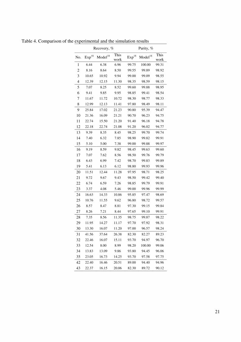
21
Table 4 Comparison of the experimental and the simulation results
Recovery Purity
No Exp18
Model18
This
work Exp
18 Model
18
This
work
1 644 638 696 9975 10000 9931
2 816 864 850 9955 9989 9892
3 1065 1092 994 9900 9909 9855
4 1239 1215 1130 9835 9859 9815
5 707 825 852 9960 9988 9895
6 941 985 995 9885 9941 9854
7 1167 1172 1072 9830 9877 9833
8 1299 1213 1141 9780 9849 9811
9 2584 1702 2123 9080 9539 9447
10 2136 1609 2121 9070 9623 9475
11 2274 1550 2120 9140 9618 9478
12 2218 2274 2108 9120 9602 9477
13 939 835 845 9825 9970 9974
14 740 632 785 9890 9982 9991
15 510 500 738 9900 9988 9997
16 919 859 982 9845 9963 9960
17 707 762 856 9850 9976 9979
18 643 699 742 9870 9983 9989
19 541 613 612 9880 9993 9996
20 1151 1244 1128 9795 9871 9825
21 972 967 943 9850 9942 9940
22 674 659 726 9885 9979 9991
23 337 408 546 9900 9996 9999
24 1663 1433 1086 9585 9747 9869
25 1076 1155 962 9680 9872 9957
26 857 847 881 9730 9915 9984
27 826 721 844 9765 9910 9991
28 735 856 1135 9875 9987 9822
29 1195 1427 1117 9770 9792 9831
30 1330 1607 1120 9700 9657 9824
31 4156 3764 2638 8230 8227 8923
32 2246 1607 1511 9370 9497 9670
33 1254 800 899 9820 10000 9906
34 1383 1309 986 9380 9445 9606
35 2305 1673 1425 9370 9758 9775
42 2240 1646 2051 8900 9440 9496
43 2237 1615 2006 8230 8972 9012
22
Table 5 Geometrical and transport characteristics of PSA process
Parameter Value Units
Temperature of the feed 297 K
Temperature of the purge gas 297 K
Temperature of the wall 297 K
Feed pressure 263e5 Pa
Purge pressure 1e5 Pa
Gas valve constant 1e-5 -
Particle density 850 kgm3
Particle radius 3e-3 m
Bed void fraction 036 -
Bed inner diameter 01 m
Bed length 10 m
Molar fraction of H2 in feed 0755 -
Molar fraction of CO in feed 0040 -
Molar fraction of CH4 in feed 0035 -
Molar fraction of CO2 in feed 0170 -
Overall mass transfer
coefficient of H2 10 1s
Overall mass transfer
coefficient of CO 03 1s
Overall mass transfer
coefficient of CH4 04 1s
Overall mass transfer
coefficient of CO2 01 1s
Heat capacity of the particles 87864 J(kgK)
Heat transfer coefficient
(wall) 13807 W(m
2K)
Heat axial dispersion
coefficient 1e-3 m
2s
Mass axial dispersion
coefficient 1e-3 m
2s
Table 6 Langmuir parameters and heat of adsorption for activated carbon
Comp a1 x10
3
(molg) a2
(K) b1 x10
9
(Pa-1
) b2
(K) -∆Hads (Jmol)
H2 432 000 5040 8505 786173
CO 092 052 5896 17309 1667742
CH4 -170 198 19952 14467 1875269
CO2 -1420 663 24775 14966 2557261
Table 7 A four-bed six-step PSA configuration (pressurization with feed one pressure equalization
step purge from tank) Bed 1 CoCP Ads Ads EQD1 Blow Purge Purge EQR1
Bed 2 Purge EQR1 CoCP Ads Ads EQD1 Blow Purge
Bed 3 Blow Purge Purge EQR1 CoCP Ads Ads EQD1
Bed 4 Ads EQD1 Blow Purge Purge EQR1 CoCP Ads
23
Table 8 A eight-bed eight-step PSA configuration (pressurization with feed two pressure equalization
steps purge from tank) Bed 1 CoCP Ads EQD1 EQD2 Blow Purge EQR2 EQR1
Bed 2 EQR1 CoCP Ads EQD1 EQD2 Blow Purge EQR2
Bed 3 EQR2 EQR1 CoCP Ads EQD1 EQD2 Blow Purge
Bed 4 Purge EQR2 EQR1 CoCP Ads EQD1 EQD2 Blow
Bed 5 Blow Purge EQR2 EQR1 CoCP Ads EQD1 EQD2
Bed 6 EQD2 Blow Purge EQR2 EQR1 CoCP Ads EQD1
Bed 7 EQD1 EQD2 Blow Purge EQR2 EQR1 CoCP Ads
Bed 8 Ads EQD1 EQD2 Blow Purge EQR2 EQR1 CoCP
Table 9 A twelve-bed ten-step PSA configuration (pressurization with feed three pressure equalization
steps purge from tank) Bed 1 CoCP Ads Ads EQD1 EQD2 EQD3 Blow Purge Purge EQR3 EQR2 EQR1
Bed 2 EQR1 CoCP Ads Ads EQD1 EQD2 EQD3 Blow Purge Purge EQR3 EQR2
Bed 3 EQR2 EQR1 CoCP Ads Ads EQD1 EQD2 EQD3 Blow Purge Purge EQR3
Bed 4 EQR3 EQR2 EQR1 CoCP Ads Ads EQD1 EQD2 EQD3 Blow Purge Purge
Bed 5 Purge EQR3 EQR2 EQR1 CoCP Ads Ads EQD1 EQD2 EQD3 Blow Purge
Bed 6 Purge Purge EQR3 EQR2 EQR1 CoCP Ads Ads EQD1 EQD2 EQD3 Blow
Bed 7 Blow Purge Purge EQR3 EQR2 EQR1 CoCP Ads Ads EQD1 EQD2 EQD3
Bed 8 EQD3 Blow Purge Purge EQR3 EQR2 EQR1 CoCP Ads Ads EQD1 EQD2
Bed 9 EQD2 EQD3 Blow Purge Purge EQR3 EQR2 EQR1 CoCP Ads Ads EQD1
Bed 10 EQD1 EQD2 EQD3 Blow Purge Purge EQR3 EQR2 EQR1 CoCP Ads Ads
Bed 11 Ads EQD1 EQD2 EQD3 Blow Purge Purge EQR3 EQR2 EQR1 CoCP Ads
Bed 12 Ads Ads EQD1 EQD2 EQD3 Blow Purge Purge EQR3 EQR2 EQR1 CoCP
24
Table 10 Input parameters of Run 1
Number of beds Parameter
1 4 8 12
spPressCoC 01000 0060 0030 00500
spAdsIn 03600 03600 03600 03600
spAdsOut 00035 00015 00015 00015
spBlow 08000 05000 02500 04000
spPurgeIn 02250 02250 02250 02250
spPurgeOut 00300 00300 0030 00300
spPEQ1 - 00040 00025 00030
spPEQ2 - - 00050 00040
spPEQ3 - - - 00080
Feed
flowrate m3s
360e-6 360e-6 360e-6 360e-6
Purge
flowrate m3s
225e-6 225e-6 225e-6 225e-6
τPress s 10 10 20 10
τAds s 20 20 20 20
τBlow s 10 10 20 10
τPurge s 20 20 20 20
τPEQ1 s - 10 20 10
τPEQ2 s - - 20 10
τPEQ3 s - - - 10
τcycle s 60 80 160 120
Table 11 Simulation results of Run I
No
beds
O2 purity
()
O2 recovery
()
Power
(W)
Productivity
(molkgs)
1 9687 3440 52902 918e-2
4 9950 5806 27949 485e-2
8 9958 6887 11987 208e-2
12 9936 7250 13936 242e-2
25
Table 12 Runtime parameters for Run II
Number of beds Parameter
1 4 8 12
spPressCoC 00300 00450 00500 00500
spAdsIn 01200 01300 03300 03600
spAdsOut 00004 000035 00014 00015
spBlow 02000 02200 03000 04000
spPurgeIn 05625 01500 03000 02250
spPurgeOut 00075 00200 00400 00300
spPEQ1 - 00025 00020 00300
spPEQ2 - - 00040 00040
spPEQ3 - - - 00080
Feed flowrate m
3s
120e-6 130e-6 330e-6 360e-6
Purge
flowrate m3s
075e-6 115e-6 300e-6 225e-6
τPress s 20 15 15 10
τAds s 40 30 15 20
τBlow s 20 15 15 10
τPurge s 40 30 15 20
τPEQ1 s - 15 15 10
τPEQ2 s - - 15 10
τPEQ3 s - - - 10
τcycle s 120 120 120 120
Table 13 Simulation results for Run II
No
beds
O2 purity
()
O2 recovery
()
Power
(W)
Productivity
(molkgs)
1 9811 2021 14420 250e-2
4 9929 3840 14069 244e-2
8 9979 6525 14092 245e-2
12 9936 7250 13936 242e-2
26
Table 14 Runtime parameters for Run III
Number of beds Parameter
1 4 8 12
spPressCC 00030 00030 00500 00040
spAdsIn 04000 03333 03450 05000
spAdsOut 000088 000085 00015 00014
spBlow 02500 04000 03000 04000
spPurgeIn 00900 01333 03000 02000
spPurgeOut 00140 00200 00400 00300
spPEQ1 - 00050 00020 00030
spPEQ2 - - 00040 00040
spPEQ3 - - - 00080
Feed flowrate m
3s
400e-6 333e-6 345e-6 500e-6
Purge
flowrate m3s
090e-6 133e-6 300e-6 200e-6
τPress s 20 15 15 10
τAds s 40 30 15 20
τBlow s 20 15 15 10
τPurge s 40 30 15 20
τPEQ1 s - 15 15 10
τPEQ2 s - - 15 10
τPEQ3 s - - - 10
τcycle s 120 120 120 120
Table 15 Simulation results for Run III
No beds
O2 purity ()
O2 recovery ()
Power (W)
Productivity (molkgs)
1 9987 141 18878 203e-2
4 9997 2847 11808 205e-2
8 9997 5058 11938 207e-2
12 9983 6516 11909 207e-2
27
APPENDIX A Table A1 Basic adsorbent bed model
Feature General equation
Bulk flow mass balance
( )( )
( )
1
0 1
i i ibed bed bed i bed z i
comp
uC C CN D
z t z z
z L i N
part part partpart ε + ε + minus ε = ε
part part part part
forall isin = hellip
(A1)
The generation term in bulk flow mass balance (transfer through a
particle surface)
( ) ( ) 0 1 i i compN f T P C Adsorbent type z L i N= forall isin = hellip (A2)
Bulk flow heat balance
( ) ( )( ) ( )
( )
31
0
bed pbed p h wallbed g wall
bed
bed z
c Tc uT kq T T
z t R
Tz L
z z
part ε ρpart ε ρ+ + minus ε + minus =
part part
part part = ε λ forall isin
part part
(A3)
The generation term in bulk flow
heat balance (transfer through a particle surface)
( ) ( ) 0 1 g i compq f T P C Adsorbent type z L i N= forall isin = hellip (A4)
Momentum balance ( ) ( ) 0 bed p
Pf u R z L
z
partminus = ε forall isin
part (A5)
Overall mass transfer
coefficient ( )
0 1 f i p
compm i
k RSh f Sc Re z L i N
D= = forall isin = hellip (A6)
Overall heat transfer coefficient ( ) 0
h pk RNu f PrRe z L= = forall isin
λ (A7)
Mass axial dispersion coefficient
( )
0 1 z i bed
compm i
Df Sc Re z L i N
D
ε= forall isin = hellip (A8)
Heat axial dispersion coefficient
( ) 0 z f Pr Re z Lλ
= forall isin λ
(A9)
Equation of state ( ) 0 1 i Ncomp compP f T C C z L i N= forall isin = hellip (A10)
Thermo-physical properties ( ) [ ] 0 1 p i Ncomp compc f T P C C z L i Nρ λ micro = forall isin = hellip (A11)
( ) 0 or 1 in ii i z i comp
Cu C C D z z L i N
z
partminus = = = =
parthellip (A12)
0 or inT T z z L= = = (A13)
Boundary conditions for stream inlet into the bed
0 0 and u
z z Lz
part= = =
part (A14)
0 0 or 1 icomp
Cz z L i N
z
part= = = =
parthellip (A15) Boundary conditions for stream
outlet from the bed closed bed
end 0 0 or
Tz z L
z
part= = =
part (A16)
28
Table A2 Mass transport mechanisms
Model Equation
Mass transfer between a bulk gas and particles is assumed instantaneous and concentration of the gas
within the particles is equal to the concentration in the bulk flow
[ ] 0 0 1 p
i p compiC C r R z L i N = forall isin forall isin = hellip (A17)
The gas phase is in equilibrium with the solid phase
[ ] 0 0 1 i i p compQ Q r R z L i N = forall isin forall isin = hellip (A18) LEQ
The generation term is sum of accumulation in gas phase in particles and amount adsorbed
( )
0 1 p i ii p comp
Q CN z L i N
t t
part part= ρ + ε forall isin =
part parthellip
(A19)
Mass transfer between a bulk gas and particles is assumed instantaneous
[ ] 0 1 pi p compiC C r R z L i N= = forall isin = hellip
(A20)
Concentration profile within the particle is assumed parabolic
( ) [ ]
2
15 0 0 1
e iii i p comp
p
DQQ Q r R z L i N
t R
part = minus forall isin forall isin = part
hellip (A21) LDF
The generation term is sum of accumulation in gas phase in particles and amount adsorbed
( ) 0 1 p i i
i p comp
Q CN z L i N
t t
part part= ρ + ε forall isin =
part parthellip
(A22)
Gas phase within particles is neglected
) [ ]0 0 0 1 p
p compiC r R z L i N= forall isin forall isin = hellip (A23)
All adsorption happens at the particle surface Adsorbed phase is then transported towards particle
centre by surface diffusion (Fickrsquos first law of diffusion)
( ) [ ]22
1 0 0 1 i i
p s i p comp
p
Q QR D r R z L i N
t r rR
part partpart= forall isin forall isin =
part part part hellip
(A24)
Mass transfer between bulk gas and particles is carried out through the gas film around particles
( ) ( )3
0 1 p
f pi i r R compi
p
kN C C z L i N
R== minus forall isin = hellip
(A25)
Boundary conditions ( ) 1 p p
p if i i r R s i r R p compi
Qk C C D r R i N
r= =
partminus = = =
part (A26)
SD
0 0 0 1 icomp
Qr z L i N
r
part= = forall isin =
parthellip (A27)
Within the pores gas is transported by combined molecular and Knudsen diffusion
( ) ( ) [ ]
22
11 0 0 1
p ppi i i
p p p p e i p comp
p
C CQR D r R z L i N
t t r rR
part partpart part ε + minus ε ρ = ε forall isin forall isin =
part part part part hellip
(A28)
The gas phase in micro-pores is in equilibrium with the adsorbed phase
[ ] 0 0 1 i i p compQ Q r R z L i N = forall isin forall isin = hellip (A29)
Mass transfer between bulk gas and particles is carried out through the gas film around particles
( ) ( )3
0 1 p
f pi i r R compi
p
kN C C z L i N
R== minus forall isin = hellip
(A30)
Boundary conditions ( ) 1 p p
p if i i r R e i r R p compi
Qk C C D r R i N
r= =
partminus = = =
part (A31)
PD
0 0 0 1 p
icomp
Cr z L i N
r
part= = forall isin =
parthellip (A32)
29
Table A3 Thermal operating modes
Mode Equation
( )0 0 T
z Lz
part= forall isin
part (A33)
Isothermal Temperature within the particles are constant and equal to the temperature of bulk flow
(no heat transfer between bulk flow and particles occurs)
0 0 ppT T r R z L = forall isin forall isin
(A34)
Bulk flow heat balance
( ) ( )( ) ( )3
0 bed pbed p h wall
g wall bed zbed
c Tc uT k Tq T T z L
z t R z z
part ε ρpart ε ρ part part + + + minus = ε λ forall isin
part part part part
(A35)
Heat transfer between bulk gas and particles is assumed instantaneous and the
temperature of particles is equal to the temperature of the bulk flow
0 0 ppT T r R z L = forall isin forall isin
(A36)
LEQ
model The generation term qg is given by the sum of accumulations in gas and solid
phase within the particles and heat of adsorptiondesorption
( )( ) ( )
0 comp
p p Np p pg p pg
p ig ads i
i
c c TQ
q H z Lt t
part ρ + ε ρpart = + ρ ∆ forall isin
part partsum
(A37)
Heat transfer between bulk gas and particles is assumed instantaneous and the
temperature of particles is equal to the temperature of the bulk flow
0 0 ppT T r R z L = forall isin forall isin
(A38)
LDF
model The generation term qg is given by the sum of accumulations in gas and solid
phase within the particles and heat of adsorptiondesorption
( )( ) ( )
0 comp
p p Np p pg p pg
p ig ads i
i
c c TQ
q H z Lt t
part ρ + ε ρpart = + ρ ∆ forall isin
part partsum
(A39)
Heat transfer between bulk gas and particles is assumed instantaneous and the
temperature of particles is equal to the temperature of the bulk flow
0 0 p
pT T r R z L = forall isin forall isin
(A40)
SD
model The generation term qg is given by the sum of accumulation in solid phase within
the particles and heat of adsorptiondesorption
( )( ) ( ) 0
compp p N
p i Rppg ads i
i
c T Qq H z L
t t
part ρ part= + ρ ∆ forall isin
part partsum
(A41)
Heat transfer is carried out through the gas film around particles
( ) ( )3
0 p
phg R
p
kq T T z L
R= minus forall isin
(A42)
Particle heat balance
( )( ) ( )
2
2
1 0 0
p p ppp p pg p pg
p pg p p
p
c c TT
q R r R z Lt r rR
part ρ + ε ρ part part + = λ forall isin forall isin part part part
(A43)
The generation term qgp is given by the heat of adsorptiondesorption
( ) ( )
0 compN
p p ig ads i p
i
Qq H r R
t
part= ρ ∆ forall isin
partsum
(A44)
( ) p p
pp p
h r R r R p
Tk T T r R
r= =
partminus = λ =
part
(A45)
Nonisothermal
PD
model
Boundary conditions
0 0p
Tr
r
part= =
part (A46)
Adiabatic The same as in the Nonisothermal mode except the term
( )3 h wallwall
bed
kT T
Rminus
is neglected
30
Table A4 Momentum balance and equilibrium isotherms Feature Equation
Blake-Kozeny equation
( )
( )( )
2
2 3
180 1 0
2
bg bed
bedp
uPz L
z R
micro minus εpartminus = forall isin
part ε (A47)
Momentum balance Ergunrsquos equation
( )
( )( )
2
2 3
180 1 0
2
bg bed
bedp
uPz L
z R
micro minus εpartminus = forall isin
part ε (A48)
Linear (Henry type)
( ) 0 1 pi i comp iiQ H C z L i N H f T P= forall isin = = hellip
(A49)
Extended Langmuir
2 2 1 1 exp 0 1
1
i ii ii m i m i i i i comp
j j
j
a bb PQ Q Q a b b z L i j N
b P T T
= = + = forall isin =
+ sumhellip (A50)
Ideal Adsorbed Solution theory (IAS)268
( )0
0
0
1 0 1 iP
pure i Langmuiri i m i i i compisotherm
QdP Q b P z L i N
Pπ = rarrπ = + forall isin = int hellip
(A51a)
1 0 1 1i i compz L i N+π = π forall isin = minus hellip
(A51b
)
2 2 1 1 exp 0 1
1
i ii ipure i m i m i i i i comp
i i
a bb PQ Q Q a b b z L i N
b P T T
= = + = forall isin = +
hellip (A51c)
0 0 1 i i i compX P X P z L i N= forall isin = hellip (A51d
)
1 0 1 i compX z L i N= forall isin = sum hellip (A51e)
1 0 1 i
comp
itotal pure i
Xz L i N
Q Q= forall isin = sum hellip (A51f)
Equilibrium isotherms
0 1 i i total compQ X Q z L i N= forall isin = hellip (A51g)
31
Table A5 Calculation of transport properties
Variable Equation
Overall mass transfer coefficient
Wakao correlation23
( ) 033 06 20 11 0 1
m if i comp
p
Dk Sc Re z L i N
R= + forall isin = hellip (A52)
Overall heat transfer
coefficient
Wakao correlation24
( )033 0620 11 Re 0 hp
k Pr z LR
λ= + forall isin
(A53)
Mass axial dispersion
coefficient
Wakao correlation23
( ) 20 05 0 1
m iz i comp
bed
DD ScRe z L i N= + forall isin =
εhellip
(A54)
Heat axial dispersion
coefficient
Wakao correlation24
( )7 05 0 z bg PrRe z Lλ = λ + forall isin (A55)
Chapman-Enskog equation2
3
3 2
12 12
1
18583 10 0 0 1 2im i p
TMW
D z L r R iP
minus = times forall isin forall isin = σ Ω
(A56)
Molecular diffusivity Fuller correlation
2
7 175 2
12
1
1013 10 0 0 1 2im i p
MWD T z L r R i
PX
minus = times forall isin forall isin = (A57)
Knudsen diffusivity
Kauzmann2 correlation
3 97 10 0 0 1 k i pore p comp
i
TD R z L r R i N
MW = times forall isin forall isin = hellip
(A58)
Effective diffusivity
0 0 1 p m i k i
e i p compp m i k i
D DD z L r R i N
D D
ε = forall isin forall isin = τ +
hellip (A59)
Table A6 Gas valve equation Variable Equation
If Pout gt Pcrit Pin
2
1
1
out
inv in comp
i i
P
PF C SP P i N
x MW T
minus = = hellip
sum (A60)
Molar flowrate
Otherwise ( )
21
1
critv in comp
i i
PF C SP P i N
x MW T
minus= = hellip
sum (A61)
Critical pressure 12
1critP
κ
minusκ =
+ κ (A62)
Power
1
11
feed feedfeed
low cycle
P NPower RT
P
κminus
κ κ
= minus κ minus τ
(A63)
32
Figure 1 Single bed PSA arrangement with all possible interconnections
33
Figure 2 Four-bed PSA flowsheet
34
Figure 3 A simplified algorithm of the operating procedure generator
Figure 4 Simulation results of Run I
35
Figure 5 Simulation results of Run II
Figure 6 Simulation results of Run III

22
Table 5 Geometrical and transport characteristics of PSA process
Parameter Value Units
Temperature of the feed 297 K
Temperature of the purge gas 297 K
Temperature of the wall 297 K
Feed pressure 263e5 Pa
Purge pressure 1e5 Pa
Gas valve constant 1e-5 -
Particle density 850 kgm3
Particle radius 3e-3 m
Bed void fraction 036 -
Bed inner diameter 01 m
Bed length 10 m
Molar fraction of H2 in feed 0755 -
Molar fraction of CO in feed 0040 -
Molar fraction of CH4 in feed 0035 -
Molar fraction of CO2 in feed 0170 -
Overall mass transfer
coefficient of H2 10 1s
Overall mass transfer
coefficient of CO 03 1s
Overall mass transfer
coefficient of CH4 04 1s
Overall mass transfer
coefficient of CO2 01 1s
Heat capacity of the particles 87864 J(kgK)
Heat transfer coefficient
(wall) 13807 W(m
2K)
Heat axial dispersion
coefficient 1e-3 m
2s
Mass axial dispersion
coefficient 1e-3 m
2s
Table 6 Langmuir parameters and heat of adsorption for activated carbon
Comp a1 x10
3
(molg) a2
(K) b1 x10
9
(Pa-1
) b2
(K) -∆Hads (Jmol)
H2 432 000 5040 8505 786173
CO 092 052 5896 17309 1667742
CH4 -170 198 19952 14467 1875269
CO2 -1420 663 24775 14966 2557261
Table 7 A four-bed six-step PSA configuration (pressurization with feed one pressure equalization
step purge from tank) Bed 1 CoCP Ads Ads EQD1 Blow Purge Purge EQR1
Bed 2 Purge EQR1 CoCP Ads Ads EQD1 Blow Purge
Bed 3 Blow Purge Purge EQR1 CoCP Ads Ads EQD1
Bed 4 Ads EQD1 Blow Purge Purge EQR1 CoCP Ads
23
Table 8 A eight-bed eight-step PSA configuration (pressurization with feed two pressure equalization
steps purge from tank) Bed 1 CoCP Ads EQD1 EQD2 Blow Purge EQR2 EQR1
Bed 2 EQR1 CoCP Ads EQD1 EQD2 Blow Purge EQR2
Bed 3 EQR2 EQR1 CoCP Ads EQD1 EQD2 Blow Purge
Bed 4 Purge EQR2 EQR1 CoCP Ads EQD1 EQD2 Blow
Bed 5 Blow Purge EQR2 EQR1 CoCP Ads EQD1 EQD2
Bed 6 EQD2 Blow Purge EQR2 EQR1 CoCP Ads EQD1
Bed 7 EQD1 EQD2 Blow Purge EQR2 EQR1 CoCP Ads
Bed 8 Ads EQD1 EQD2 Blow Purge EQR2 EQR1 CoCP
Table 9 A twelve-bed ten-step PSA configuration (pressurization with feed three pressure equalization
steps purge from tank) Bed 1 CoCP Ads Ads EQD1 EQD2 EQD3 Blow Purge Purge EQR3 EQR2 EQR1
Bed 2 EQR1 CoCP Ads Ads EQD1 EQD2 EQD3 Blow Purge Purge EQR3 EQR2
Bed 3 EQR2 EQR1 CoCP Ads Ads EQD1 EQD2 EQD3 Blow Purge Purge EQR3
Bed 4 EQR3 EQR2 EQR1 CoCP Ads Ads EQD1 EQD2 EQD3 Blow Purge Purge
Bed 5 Purge EQR3 EQR2 EQR1 CoCP Ads Ads EQD1 EQD2 EQD3 Blow Purge
Bed 6 Purge Purge EQR3 EQR2 EQR1 CoCP Ads Ads EQD1 EQD2 EQD3 Blow
Bed 7 Blow Purge Purge EQR3 EQR2 EQR1 CoCP Ads Ads EQD1 EQD2 EQD3
Bed 8 EQD3 Blow Purge Purge EQR3 EQR2 EQR1 CoCP Ads Ads EQD1 EQD2
Bed 9 EQD2 EQD3 Blow Purge Purge EQR3 EQR2 EQR1 CoCP Ads Ads EQD1
Bed 10 EQD1 EQD2 EQD3 Blow Purge Purge EQR3 EQR2 EQR1 CoCP Ads Ads
Bed 11 Ads EQD1 EQD2 EQD3 Blow Purge Purge EQR3 EQR2 EQR1 CoCP Ads
Bed 12 Ads Ads EQD1 EQD2 EQD3 Blow Purge Purge EQR3 EQR2 EQR1 CoCP
24
Table 10 Input parameters of Run 1
Number of beds Parameter
1 4 8 12
spPressCoC 01000 0060 0030 00500
spAdsIn 03600 03600 03600 03600
spAdsOut 00035 00015 00015 00015
spBlow 08000 05000 02500 04000
spPurgeIn 02250 02250 02250 02250
spPurgeOut 00300 00300 0030 00300
spPEQ1 - 00040 00025 00030
spPEQ2 - - 00050 00040
spPEQ3 - - - 00080
Feed
flowrate m3s
360e-6 360e-6 360e-6 360e-6
Purge
flowrate m3s
225e-6 225e-6 225e-6 225e-6
τPress s 10 10 20 10
τAds s 20 20 20 20
τBlow s 10 10 20 10
τPurge s 20 20 20 20
τPEQ1 s - 10 20 10
τPEQ2 s - - 20 10
τPEQ3 s - - - 10
τcycle s 60 80 160 120
Table 11 Simulation results of Run I
No
beds
O2 purity
()
O2 recovery
()
Power
(W)
Productivity
(molkgs)
1 9687 3440 52902 918e-2
4 9950 5806 27949 485e-2
8 9958 6887 11987 208e-2
12 9936 7250 13936 242e-2
25
Table 12 Runtime parameters for Run II
Number of beds Parameter
1 4 8 12
spPressCoC 00300 00450 00500 00500
spAdsIn 01200 01300 03300 03600
spAdsOut 00004 000035 00014 00015
spBlow 02000 02200 03000 04000
spPurgeIn 05625 01500 03000 02250
spPurgeOut 00075 00200 00400 00300
spPEQ1 - 00025 00020 00300
spPEQ2 - - 00040 00040
spPEQ3 - - - 00080
Feed flowrate m
3s
120e-6 130e-6 330e-6 360e-6
Purge
flowrate m3s
075e-6 115e-6 300e-6 225e-6
τPress s 20 15 15 10
τAds s 40 30 15 20
τBlow s 20 15 15 10
τPurge s 40 30 15 20
τPEQ1 s - 15 15 10
τPEQ2 s - - 15 10
τPEQ3 s - - - 10
τcycle s 120 120 120 120
Table 13 Simulation results for Run II
No
beds
O2 purity
()
O2 recovery
()
Power
(W)
Productivity
(molkgs)
1 9811 2021 14420 250e-2
4 9929 3840 14069 244e-2
8 9979 6525 14092 245e-2
12 9936 7250 13936 242e-2
26
Table 14 Runtime parameters for Run III
Number of beds Parameter
1 4 8 12
spPressCC 00030 00030 00500 00040
spAdsIn 04000 03333 03450 05000
spAdsOut 000088 000085 00015 00014
spBlow 02500 04000 03000 04000
spPurgeIn 00900 01333 03000 02000
spPurgeOut 00140 00200 00400 00300
spPEQ1 - 00050 00020 00030
spPEQ2 - - 00040 00040
spPEQ3 - - - 00080
Feed flowrate m
3s
400e-6 333e-6 345e-6 500e-6
Purge
flowrate m3s
090e-6 133e-6 300e-6 200e-6
τPress s 20 15 15 10
τAds s 40 30 15 20
τBlow s 20 15 15 10
τPurge s 40 30 15 20
τPEQ1 s - 15 15 10
τPEQ2 s - - 15 10
τPEQ3 s - - - 10
τcycle s 120 120 120 120
Table 15 Simulation results for Run III
No beds
O2 purity ()
O2 recovery ()
Power (W)
Productivity (molkgs)
1 9987 141 18878 203e-2
4 9997 2847 11808 205e-2
8 9997 5058 11938 207e-2
12 9983 6516 11909 207e-2
27
APPENDIX A Table A1 Basic adsorbent bed model
Feature General equation
Bulk flow mass balance
( )( )
( )
1
0 1
i i ibed bed bed i bed z i
comp
uC C CN D
z t z z
z L i N
part part partpart ε + ε + minus ε = ε
part part part part
forall isin = hellip
(A1)
The generation term in bulk flow mass balance (transfer through a
particle surface)
( ) ( ) 0 1 i i compN f T P C Adsorbent type z L i N= forall isin = hellip (A2)
Bulk flow heat balance
( ) ( )( ) ( )
( )
31
0
bed pbed p h wallbed g wall
bed
bed z
c Tc uT kq T T
z t R
Tz L
z z
part ε ρpart ε ρ+ + minus ε + minus =
part part
part part = ε λ forall isin
part part
(A3)
The generation term in bulk flow
heat balance (transfer through a particle surface)
( ) ( ) 0 1 g i compq f T P C Adsorbent type z L i N= forall isin = hellip (A4)
Momentum balance ( ) ( ) 0 bed p
Pf u R z L
z
partminus = ε forall isin
part (A5)
Overall mass transfer
coefficient ( )
0 1 f i p
compm i
k RSh f Sc Re z L i N
D= = forall isin = hellip (A6)
Overall heat transfer coefficient ( ) 0
h pk RNu f PrRe z L= = forall isin
λ (A7)
Mass axial dispersion coefficient
( )
0 1 z i bed
compm i
Df Sc Re z L i N
D
ε= forall isin = hellip (A8)
Heat axial dispersion coefficient
( ) 0 z f Pr Re z Lλ
= forall isin λ
(A9)
Equation of state ( ) 0 1 i Ncomp compP f T C C z L i N= forall isin = hellip (A10)
Thermo-physical properties ( ) [ ] 0 1 p i Ncomp compc f T P C C z L i Nρ λ micro = forall isin = hellip (A11)
( ) 0 or 1 in ii i z i comp
Cu C C D z z L i N
z
partminus = = = =
parthellip (A12)
0 or inT T z z L= = = (A13)
Boundary conditions for stream inlet into the bed
0 0 and u
z z Lz
part= = =
part (A14)
0 0 or 1 icomp
Cz z L i N
z
part= = = =
parthellip (A15) Boundary conditions for stream
outlet from the bed closed bed
end 0 0 or
Tz z L
z
part= = =
part (A16)
28
Table A2 Mass transport mechanisms
Model Equation
Mass transfer between a bulk gas and particles is assumed instantaneous and concentration of the gas
within the particles is equal to the concentration in the bulk flow
[ ] 0 0 1 p
i p compiC C r R z L i N = forall isin forall isin = hellip (A17)
The gas phase is in equilibrium with the solid phase
[ ] 0 0 1 i i p compQ Q r R z L i N = forall isin forall isin = hellip (A18) LEQ
The generation term is sum of accumulation in gas phase in particles and amount adsorbed
( )
0 1 p i ii p comp
Q CN z L i N
t t
part part= ρ + ε forall isin =
part parthellip
(A19)
Mass transfer between a bulk gas and particles is assumed instantaneous
[ ] 0 1 pi p compiC C r R z L i N= = forall isin = hellip
(A20)
Concentration profile within the particle is assumed parabolic
( ) [ ]
2
15 0 0 1
e iii i p comp
p
DQQ Q r R z L i N
t R
part = minus forall isin forall isin = part
hellip (A21) LDF
The generation term is sum of accumulation in gas phase in particles and amount adsorbed
( ) 0 1 p i i
i p comp
Q CN z L i N
t t
part part= ρ + ε forall isin =
part parthellip
(A22)
Gas phase within particles is neglected
) [ ]0 0 0 1 p
p compiC r R z L i N= forall isin forall isin = hellip (A23)
All adsorption happens at the particle surface Adsorbed phase is then transported towards particle
centre by surface diffusion (Fickrsquos first law of diffusion)
( ) [ ]22
1 0 0 1 i i
p s i p comp
p
Q QR D r R z L i N
t r rR
part partpart= forall isin forall isin =
part part part hellip
(A24)
Mass transfer between bulk gas and particles is carried out through the gas film around particles
( ) ( )3
0 1 p
f pi i r R compi
p
kN C C z L i N
R== minus forall isin = hellip
(A25)
Boundary conditions ( ) 1 p p
p if i i r R s i r R p compi
Qk C C D r R i N
r= =
partminus = = =
part (A26)
SD
0 0 0 1 icomp
Qr z L i N
r
part= = forall isin =
parthellip (A27)
Within the pores gas is transported by combined molecular and Knudsen diffusion
( ) ( ) [ ]
22
11 0 0 1
p ppi i i
p p p p e i p comp
p
C CQR D r R z L i N
t t r rR
part partpart part ε + minus ε ρ = ε forall isin forall isin =
part part part part hellip
(A28)
The gas phase in micro-pores is in equilibrium with the adsorbed phase
[ ] 0 0 1 i i p compQ Q r R z L i N = forall isin forall isin = hellip (A29)
Mass transfer between bulk gas and particles is carried out through the gas film around particles
( ) ( )3
0 1 p
f pi i r R compi
p
kN C C z L i N
R== minus forall isin = hellip
(A30)
Boundary conditions ( ) 1 p p
p if i i r R e i r R p compi
Qk C C D r R i N
r= =
partminus = = =
part (A31)
PD
0 0 0 1 p
icomp
Cr z L i N
r
part= = forall isin =
parthellip (A32)
29
Table A3 Thermal operating modes
Mode Equation
( )0 0 T
z Lz
part= forall isin
part (A33)
Isothermal Temperature within the particles are constant and equal to the temperature of bulk flow
(no heat transfer between bulk flow and particles occurs)
0 0 ppT T r R z L = forall isin forall isin
(A34)
Bulk flow heat balance
( ) ( )( ) ( )3
0 bed pbed p h wall
g wall bed zbed
c Tc uT k Tq T T z L
z t R z z
part ε ρpart ε ρ part part + + + minus = ε λ forall isin
part part part part
(A35)
Heat transfer between bulk gas and particles is assumed instantaneous and the
temperature of particles is equal to the temperature of the bulk flow
0 0 ppT T r R z L = forall isin forall isin
(A36)
LEQ
model The generation term qg is given by the sum of accumulations in gas and solid
phase within the particles and heat of adsorptiondesorption
( )( ) ( )
0 comp
p p Np p pg p pg
p ig ads i
i
c c TQ
q H z Lt t
part ρ + ε ρpart = + ρ ∆ forall isin
part partsum
(A37)
Heat transfer between bulk gas and particles is assumed instantaneous and the
temperature of particles is equal to the temperature of the bulk flow
0 0 ppT T r R z L = forall isin forall isin
(A38)
LDF
model The generation term qg is given by the sum of accumulations in gas and solid
phase within the particles and heat of adsorptiondesorption
( )( ) ( )
0 comp
p p Np p pg p pg
p ig ads i
i
c c TQ
q H z Lt t
part ρ + ε ρpart = + ρ ∆ forall isin
part partsum
(A39)
Heat transfer between bulk gas and particles is assumed instantaneous and the
temperature of particles is equal to the temperature of the bulk flow
0 0 p
pT T r R z L = forall isin forall isin
(A40)
SD
model The generation term qg is given by the sum of accumulation in solid phase within
the particles and heat of adsorptiondesorption
( )( ) ( ) 0
compp p N
p i Rppg ads i
i
c T Qq H z L
t t
part ρ part= + ρ ∆ forall isin
part partsum
(A41)
Heat transfer is carried out through the gas film around particles
( ) ( )3
0 p
phg R
p
kq T T z L
R= minus forall isin
(A42)
Particle heat balance
( )( ) ( )
2
2
1 0 0
p p ppp p pg p pg
p pg p p
p
c c TT
q R r R z Lt r rR
part ρ + ε ρ part part + = λ forall isin forall isin part part part
(A43)
The generation term qgp is given by the heat of adsorptiondesorption
( ) ( )
0 compN
p p ig ads i p
i
Qq H r R
t
part= ρ ∆ forall isin
partsum
(A44)
( ) p p
pp p
h r R r R p
Tk T T r R
r= =
partminus = λ =
part
(A45)
Nonisothermal
PD
model
Boundary conditions
0 0p
Tr
r
part= =
part (A46)
Adiabatic The same as in the Nonisothermal mode except the term
( )3 h wallwall
bed
kT T
Rminus
is neglected
30
Table A4 Momentum balance and equilibrium isotherms Feature Equation
Blake-Kozeny equation
( )
( )( )
2
2 3
180 1 0
2
bg bed
bedp
uPz L
z R
micro minus εpartminus = forall isin
part ε (A47)
Momentum balance Ergunrsquos equation
( )
( )( )
2
2 3
180 1 0
2
bg bed
bedp
uPz L
z R
micro minus εpartminus = forall isin
part ε (A48)
Linear (Henry type)
( ) 0 1 pi i comp iiQ H C z L i N H f T P= forall isin = = hellip
(A49)
Extended Langmuir
2 2 1 1 exp 0 1
1
i ii ii m i m i i i i comp
j j
j
a bb PQ Q Q a b b z L i j N
b P T T
= = + = forall isin =
+ sumhellip (A50)
Ideal Adsorbed Solution theory (IAS)268
( )0
0
0
1 0 1 iP
pure i Langmuiri i m i i i compisotherm
QdP Q b P z L i N
Pπ = rarrπ = + forall isin = int hellip
(A51a)
1 0 1 1i i compz L i N+π = π forall isin = minus hellip
(A51b
)
2 2 1 1 exp 0 1
1
i ii ipure i m i m i i i i comp
i i
a bb PQ Q Q a b b z L i N
b P T T
= = + = forall isin = +
hellip (A51c)
0 0 1 i i i compX P X P z L i N= forall isin = hellip (A51d
)
1 0 1 i compX z L i N= forall isin = sum hellip (A51e)
1 0 1 i
comp
itotal pure i
Xz L i N
Q Q= forall isin = sum hellip (A51f)
Equilibrium isotherms
0 1 i i total compQ X Q z L i N= forall isin = hellip (A51g)
31
Table A5 Calculation of transport properties
Variable Equation
Overall mass transfer coefficient
Wakao correlation23
( ) 033 06 20 11 0 1
m if i comp
p
Dk Sc Re z L i N
R= + forall isin = hellip (A52)
Overall heat transfer
coefficient
Wakao correlation24
( )033 0620 11 Re 0 hp
k Pr z LR
λ= + forall isin
(A53)
Mass axial dispersion
coefficient
Wakao correlation23
( ) 20 05 0 1
m iz i comp
bed
DD ScRe z L i N= + forall isin =
εhellip
(A54)
Heat axial dispersion
coefficient
Wakao correlation24
( )7 05 0 z bg PrRe z Lλ = λ + forall isin (A55)
Chapman-Enskog equation2
3
3 2
12 12
1
18583 10 0 0 1 2im i p
TMW
D z L r R iP
minus = times forall isin forall isin = σ Ω
(A56)
Molecular diffusivity Fuller correlation
2
7 175 2
12
1
1013 10 0 0 1 2im i p
MWD T z L r R i
PX
minus = times forall isin forall isin = (A57)
Knudsen diffusivity
Kauzmann2 correlation
3 97 10 0 0 1 k i pore p comp
i
TD R z L r R i N
MW = times forall isin forall isin = hellip
(A58)
Effective diffusivity
0 0 1 p m i k i
e i p compp m i k i
D DD z L r R i N
D D
ε = forall isin forall isin = τ +
hellip (A59)
Table A6 Gas valve equation Variable Equation
If Pout gt Pcrit Pin
2
1
1
out
inv in comp
i i
P
PF C SP P i N
x MW T
minus = = hellip
sum (A60)
Molar flowrate
Otherwise ( )
21
1
critv in comp
i i
PF C SP P i N
x MW T
minus= = hellip
sum (A61)
Critical pressure 12
1critP
κ
minusκ =
+ κ (A62)
Power
1
11
feed feedfeed
low cycle
P NPower RT
P
κminus
κ κ
= minus κ minus τ
(A63)
32
Figure 1 Single bed PSA arrangement with all possible interconnections
33
Figure 2 Four-bed PSA flowsheet
34
Figure 3 A simplified algorithm of the operating procedure generator
Figure 4 Simulation results of Run I
35
Figure 5 Simulation results of Run II
Figure 6 Simulation results of Run III
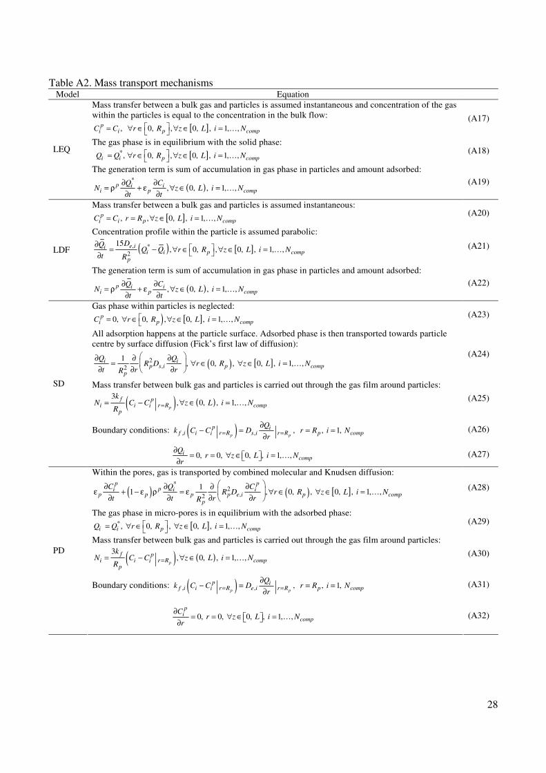

32
Figure 1 Single bed PSA arrangement with all possible interconnections
33
Figure 2 Four-bed PSA flowsheet
34
Figure 3 A simplified algorithm of the operating procedure generator
Figure 4 Simulation results of Run I
35
Figure 5 Simulation results of Run II
Figure 6 Simulation results of Run III

33
Figure 2 Four-bed PSA flowsheet
34
Figure 3 A simplified algorithm of the operating procedure generator
Figure 4 Simulation results of Run I
35
Figure 5 Simulation results of Run II
Figure 6 Simulation results of Run III

34
Figure 3 A simplified algorithm of the operating procedure generator
Figure 4 Simulation results of Run I
35
Figure 5 Simulation results of Run II
Figure 6 Simulation results of Run III
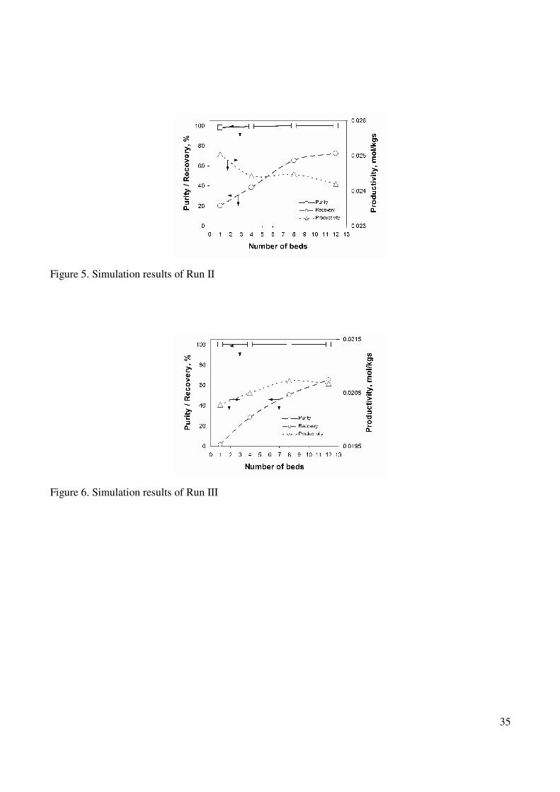
35
Figure 5 Simulation results of Run II
Figure 6 Simulation results of Run III