Leveraging temporal and spatial separations with the 24-hour knowledge factory paradigm
Upload
khangminh22Category
view
0download
0
ANL-6333 Chemical Separations P r o c e s s e s for Plutonium and Uranium (TID-4500, 16th Ed.) AEC Research and Development Report
ARGONNE NATIONAL LABORATORY 9700 South Cass Avenue
Argonne, Illinois
CHEMICAL ENGINEERING DIVISION SUMMARY REPORT
January , Feb rua ry , March, 1961
Stephen Lawroski , Division Director R. C. Vogel, Associate Division Director
V. H. Munnecke, Ass is tan t Division Director
June, 1961
Preceding Quar te r ly Repor t s : ANL-6287 October, November, December , I960 ANL-6231 July, August, September, I960 ANL-6183 April , May, June, I960
Operated by The Universi ty of Chicago under
Contract W-31-1 09-eng-38
DISCLAIMER
This report was prepared as an account of work sponsored by an agency of the United States Government. Neither the United States Government nor any agency Thereof, nor any of their employees, makes any warranty, express or implied, or assumes any legal liability or responsibility for the accuracy, completeness, or usefulness of any information, apparatus, product, or process disclosed, or represents that its use would not infringe privately owned rights. Reference herein to any specific commercial product, process, or service by trade name, trademark, manufacturer, or otherwise does not necessarily constitute or imply its endorsement, recommendation, or favoring by the United States Government or any agency thereof. The views and opinions of authors expressed herein do not necessarily state or reflect those of the United States Government or any agency thereof.

DISCLAIMER Portions of this document may be illegible in electronic image products. Images are produced from the best available original document.

TABLE OF CONTENTS
Page
SUMMARY 13
I, CHEMICAL-METALLURGICAL PROCESSING. . . . . . . . . . . . 29
A. Pyrometa l lu rg ica l Development . . . . . . . . . . . . . . . . . . 36 1. Melt Refining. . . . . . . . . . . . . . . . . . . . . . . . . . . . 36 2. Development of P r o c e s s e s Utilizing Liquid
Metal Solvents . . . . . . . . . . . . . . . . . . . . . . . . . . . 42 B. Fue l -p roces s ing Fac i l i t i es for EBR- I I . . . . . . . . . . . . . . 87
1. Design and Construct ion . . . . . . . . . . . . . . . . . . . . 87 2. EBR-II Fue l -p roces s ing Mockup . . . . . . . . . . . . . . . 96
C. Pyrometa l lu rg ica l R e s e a r c h . . . . . . . . . . . . . . . . . . . . . 100 1. Chemis t ry of Liquid Metal Systems . . . . . . . . . . . . . 100 2. Ca lo r ime t ry . . . . . . . . . . . . . . . . . . . . . . . . . . . . 120
11. F U E L CYCLE APPLICATIONS OF VOLATILITY AND FLUIDIZATION TECHNIQUES . . . . . . . . . . . . . . . . . . . . . . 129
A. Labora tory Investigations of Fluor ide Volatility P r o c e s s e s . . . . . . . . . . . . . . . . . . . . . . . . . . . . 133 1. The Kinetics and Mechanism of the Thermal
Decomposition of Plutonium Hexafluoride . . . . . . . . . 133 2. P r o c e s s Development: Plutonium Fluorinat ion
and Transpor t Studies . . . . . . . . . . . . . . . . . . . . . . 141 3. The Reaction of Plutonium Hexafluoride and Bromine . 152 4. Fluor inat ion of Uranium Dioxide - Ruthenium-106
and Uranium Dioxide -Niobium-95 Mixtures . . . . . . . 156 5. Kinetics of the Reaction of Uranium Trioxide and
Uranyl F luor ide with Sulfur Tet raf luor ide . . . . . . . . . 160 B. Engineer ing-sca le Investigations of Fluor ide
Volatility P r o c e s s e s . . . . . . . . . . . . . . . . . . . . . . . . . . 167 1. Direc t Fluor inat ion of Uranium Dioxide Fuels . . . . . . 167 2. Direct Halogenation P r o c e s s for Stainless Steel-
clad or Matr ix F u e l s . . . . . . . . . . . . . . . . . . . . . . . 185 3. Product ion of Uranium Hexafluoride by Reaction
of Uranium Trioxide with Sulfur Tetrafluoride in Fluidized Beds . . . . . . . = , . . . . . . . . . . . . . . . . . . 190
C. Conversion of Uranium Hexafluoride to Uranium Dioxide. . . . . . . . . . . . . . . . . . . . . . . . . . . . . . . . . . . 193 1. Steam Hydrolysis of Uranium Hexafluoride . . . . . . . . 193 2. Reduction of Uranyl F luor ide . . . . . . . . . . . . . . . . . 195
D. Fluid-bed Calcination Studies in Smal l -d iameter Columns . . . . . . . . . . . . . . . . . . . . . . . . . . . . . . . . . . 196
E. Multistage Fluidizat ion Studies . . . . . . . . . . . . . . . . . . . 197
TABLE OF CONTENTS
Page
III. REACTOR SAFETY 198
A. Metal Oxidation and Ignition Kinetics . . . . . . . . . . . . . 201 1 . Ignition Studies of Uranium Powder by the
Burning-curve Method. 201 2. Burning-propagat ion Studies. . . . . . . . . . . . . . . . 208
B. Metal-Water Reactions . . . . . . . . . . . . . . . . . . . . . . 212 1. Condenser -d i scharge Method . . . . . . . . . . . . . . . 212 2. P r e s s u r e - p u l s e Method. . . . . . . . . . . . . . . . . . . 220 3. Thermal Analysis of Uranium Oxide-Metal
Ce rme t s . . . . . . . . . . . . . . . . . . . . . . . . . . . . . 221 4. In-pile Testing in the TREAT Reactor . . . . . . . . . 226
IV. REACTOR CHEMISTRY. . . . . . . . . . . . . . . . . . . . . . . . . 239
A. Determinat ion of Nuclear Constants . . . . . . . . . . . . . . 239 1. Fas t Neutron Cross Sections . . . . . . . . . . . . . . . 239 2. Determinat ion of Capture- to- f i s s ion Ratios in
EBR-I , Mark III . . . . . . . . . . . . . . . . . . . . . . . . 240 B. Reactor Decontamination . . . . . . . . . . . . . . . . . . . . . 240
1 . Labora tory Investigations . . . . . . . . . . . . . . . . . 241 2. Loop Studies . . . . . . . . . . . . . . . . . . . . . . . . . . 244
V. ROUTINE OPERATIONS . . . . . . . . . . . . . . . . . . . . . . . . 249
A. Waste P r o c e s s i n g . . . . . . . . . . . . . . . . . . . . . . . . . . 249 B. High-level Gamma- i r r ad i a t i on Faci l i ty . . . . . . . . . . . 249

LIST OF TABLES
No. Title Page
1. High-act iv i ty- level Melt-refining Exper iments . . . . . . . . . . 37
2. Effect of Storage Conditions on Melt-refining Ingot Yield. . . . 40
3. Effect of Supplemental Pouring Techniques on Melt-refining Ingot Yield. . . . . . . . . . . . . . . . . . . . . . . . . . . . . 41
4. Surface Tempera tu re of a F i s s i u m Fuel Rod Under F r e e Convection . . . . . . . . . . . . . . . . . . . . . . . . . . . . . . . . . . 42
5. Composition of Skull Oxide Charge (From Skull Oxidation Run SO-50) 48
6. Compar ison of Uranium and F i s s i u m Product Concentrat ions
in Flux Before and After Reduction 49
7. P r o p e r t i e s of Salt F luxes . . . . . . . . . . . . . . . . . . . . . . . . . 50
8. Uranium Purif icat ion in Skul l - rec lamat ion P r o c e s s Runs . . . 52
9. Uranium Mater ia l Balances in Skull Demonstrat ion Runs . . . 53
10. Noble Metal Ext rac t ion: Distr ibution of Noble Metals Between Zinc and Flux Phases . . . . . . . . . . . . . . . . . . . . . 54
11. Sal t -skul l Oxide Transfer Runs. . . . . . . . . . . . . . . . . . . . . 56
12. Behavior of Uranium, Ruthenium, and Ceriuin on Decomposit ion of Uranium-Zinc In termeta l l ic Compound with Magnesium . . . . . . . . . . . . . . . . . . . . . . . . . . . . . . . . . . 58
13. Effect of Tempera tu re on the Reduction Rate of UsOg . . . . . . 62
14. Effect of Pa r t i c l e Size on the Reduction Rate of U3O3 . . . . . . 63
15. Reduction of UsOg by Liquid Magnes ium-Fused Salt Systems . 65
16. Reduction of Thorium Oxide by Zinc-Magnesium Alloy . . . . . 67
17. Effect of Agitation on Format ion of Uranium Agglomerates . . 69
18. Direct Reaction of Uranium Blanket Rods and Hydrided-Dehydrided Blanket Rods with Zinc to F o r m the Uranium-Zinc Inter ineta l l ic Compound . . . . . . . . . . . . . . . . . . . . . . 71
19. Uranium Dissolution in Zinc-14 Weight Pe rcen t Magnesium at 800 C . . . . . . . . . . . . . . . . . . . . . . . . . . . . 73
20. Cor ros ion of 1020 Steel by Cadmium Solutions Containing Zinc and Magnesium . . . . . . . . . . . . . . . . . . . . . . . . . . . . 79

LIST OF TABLES
No. Title Page
21. Stability of Uranium in a Z inc-Fused Salt System Contained
in Graphite at 800 C . . . . . . . . . . . . . . . . . . . . . . . . . . . • 81
22. Linear Expansion Coefficients of Selected Mate r i a l s . . . . . . . 84
23. Effect of I r rad ia t ion on Various Pa in t s . . 94
24. Ro l l e r -bea r ing Tests with I r r ad ia ted Greases . . . . . . . . . . . 95
25. Solubility of Terb ium in Liquid Cadmium . . . . . . . . . . . . . . 102
26. Solubility of Holmium in Liquid Cadmium . . . . . . . . . . . . . . 103
27. Solubility of Thulium in Liquid Cadmium . . . . . . . . . . . . . . 104
28. Solubility of Ytterbium in Liquid Cadmium . . . . . . . . . . . . . 104
29. Solubility of Lutet ium in Liquid Cadmium . . . . . . . . . . . . . . 106
30. Solubility of Cobalt in Liquid Cadmium. . . . . . . . . . . . . . . . 106
31 . Solubility of Chromium in Liquid C a d m i u m . . . . . . . . . . . . . 107
32. Solubility of Uranium in Liquid Zinc above 820 C . . . . . . . . . 109
33. Coprecipi tat ion Coefficients in Liquid Cadmium ( C a r r i e r : CeCdn) . . . . . . . . . . . . . . . . . . . . . . . . . . . . . 110
34. Distr ibut ion Data for Ce r ium and Pal ladium in the Lead-Zinc System . . . . . . . . . . . . . . . . . . . . . . . . . . . . . . . . . 113
35. Molar Magnetic Susceptibil i ty of NdCdn . . . . . . . . . . . . . . . 118
36. Resul ts of Uranium Combustions in F luor ine . . . . . . . . . . . . 125
37. Rate of Decomposit ion of Plutonium Hexafluoride Vapor . . . . 137
38. Rate Constants for the Thermal Decomposit ion of Plutonium Hexafluoride . . . . . . . . . . . . . . . . . . . . . . . . . . 138
39. Thermal Decomposit ion of Plutonium Hexafluoride: Compar ison of Observed with Calculated Resul ts . . . . . . . . . 139
40. Rate of Decomposit ion of Plutonium Hexafluoride Vapor at 161 C . . . . . . . . . . . . . . . . . . . . . . . . . . . 140
41 . Decomposit ion of Plutonium Hexafluoride in the Effluent S t ream from Fluorinat ion of Plutonium Tetraf luoride . . . . . . 144
42. Rate of Ther inal Decomposit ion of Plutonium Hexafluoride in a Nonpacked Vesse l . . . . . . . . . . . . . . . . . . . . . . . . . . . 146

LIST OF TABLES
No. Title Page
43 . Rate of Thermal Decomposit ion of Plutonium Hexafluoride in a Nickel Wool-packed Vessel . . . . . . . . . . . . . . . . . . . . 147
44. Compar ison of Physica l P r o p e r t i e s of Plutonium Te t ra fluoride Produced by Thermal and Radiation Decomposition of Plutonium Hexafluoride . . . . . . . . . . . . . . . . . . . . . . . . 149
45. Fluorinat ion and Recovery of Plutonium Previously Deposited on Nickel Wool by Thermal Decomposition of Plutonium Hexafluoride . . . . . . . . . . . . . . . . . . . . . . . . . . . . . . . . . 150
46. Extent of Reaction of Plutonium Hexafluoride and Bromine . . 153
47. Extent of Reaction of Plutonium Hexafluoride and Bromine at 78 C . . . . . . . . . . . . . . . . . . . . . . . . . . . . . . . . . . . . . 153
48. Analysis of the Gas Phase After Reaction of Plutonium Hexafluoride and Bromine . . . . . . . . . . . . . . . . . . . . . . . . . . . 155
49. Reaction of Mixtures of Plutonium Hexafluoride and Uranium Hexafluoride with Elementa l Bromine . . . . . . . . . . . . . . . . 155
50. Fluorinat ion of Uranium Dioxide - Ruthenium-1 06 and Uranium Dioxide "Niobium-95 Mixtures . . . . . . . . . . . . . . . . . . . . . . 159
51 . Reaction of Sulfur Tetraf luoride with Uranyl F luor ide : Effect of Pa r t i a l P r e s s u r e of Sulfur Tetrafluoride on the Rate Constant at 333 C . . . . . . . . . . . . . . . . . . . . . . . . . . . . . . . . 164
52. Reaction of Sulfur Tetraf luoride with Uranyl F luor ide : Effect of Gas Flow Rate on Rate Constant . . . . . . . . . . . . . . . . . . 165
53. Screen Analysis of Zi rconium Fluor ide Fluid Bed Mater ia l in Run UOF-27. . . . . . . . . . . . . . . . . . . . . . . . . . . . . . . . 1 73
54. Uranium Hexafluoride Collection Rates During Uraniura Dioxide Fluorinat ion Run UOF-27 . . . . . . . . . . . . . . . . . . . 174
55. Overal l P r o c e s s Conditions in Batch Fluorination of Uranium Dioxide Pe l le t s . . . . . . . . . . . . . . . . . . . . . . . . . . . . . . . 176
56. Calculation of Effective Thermal Conductivi ty. . . . . . . . . . . 178
57. Varia t ions of Effective Thermal Conductivity of a Packed
Fluid Bed for Different Thermocouple Arrangements . . . . . . 180
58. End Effect in Heat Transfe r T e s t s . . . . . . . . . . . . . . . . . . . 180
59. Per t inen t Conditions in Heat Transfer Tests . . . . . . . . . . . . 183
LIST OF TABLES
No. Title Page
60. Fluid-bed Reaction of Simulated Stainless Steel Cladding with Chlor ine . 187
61 . Chemical Analysis and Size Distr ibution of Uranium Trioxide Used in Sulfur Tetraf luoride Reaction Studies . . . . . 190
62. Product ion of Uranium Hexafluoride by Reaction of Uranium Trioxide with Sulfur Tetraf luoride in a Fluidized-bed Reactor 191
63. Pa r t i c l e Size Effects Noted as a Function of Starting Bed Pa r t i c l e Size 195
64. Ignition Behavior of Uranium Monocarbide Powders in Oxygen 204
65. Burn ing-curve Ignition Terapera tu res of Stacks of Uranium Foi ls in Ai r . 206
66. Resul ts of X- ray Diffraction Analysis of Uranium Oxide-Aluminum Cernaets . 224
67. Sumimary of In-pi le Data on Stainless Steel -Water React ions , Stainless S tee l -Uranium Dioxide Cermet Core Fuel Pins and P la tes in a Water Environment 226
68. Summary of In-pi le Data on Meta l -Water React ions , Oxide Core Fuel Pins and Uranium Wire Fuel Specimens in a Water Envi ronment . 227
69. Compatabil i ty of Low Alloy Steels in Ci t ra te and Oxalate Base Solutions 242
70. Stability of Po t a s s ium Oxalate-Hydrogen Peroxide Solution in the P r e s e n c e of Stainless Steel Type 304 244
71. Ces ium-137 Content of Liquid and Vapor During Loop Reproducibi l i ty Runs. 246
72. Argonne High-Level Gammia-Irradiat ion Faci l i ty Summary of I r rad ia t ions Pe r fo rmed in Racks M-1 and M-2 During January Through March, 1961 . 249
LIST OF FIGURES
No. Title Page
1 . Nitr idation of Uran ium-Five Pe rcen t F i s s ium Alloy Pins at 308 C for 24 Hours . . . . . . . . . . . . . . . . . . . . . . . . . . . . . 39
2. Liquid Metal P r o c e s s for Reclaixiation of Melt Refining
Skull Mater ia l 43
3. Oxidation Furnace for Radioactive Skulls . . . . . . . . . . . . . . 44
4. Flowsheet for Two Skul l - recovery Demonstrat ion Runs. . . . . 46
5. Modified Pour Furnace with P res su re -S iphon Attachment for Demionstration Runs. 47
6. Apparatus for Transfer of Molten Sa l t -F i s s ium Oxide Slur ry from Zinc 55
7. Settling of Uranium Oxide in Salt Flux . . . . . . . . . . . . . . . . 56
8. Uranium Solubilities in Various High Magnesium-Zinc Systenas . . . . . . . . . . . . . . . . . . . . . . . . . . . . . . . . . . . . 58
9. Reduction of F i s s i u m Oxide by Zinc-5 Percen t Magnesium . . 59
10. Behavior of Z i rconium Crucible F ragmen t s During the Reduction of Skull Oxide . . . . . . . . . . . . . . . . . . . . . . . . . 60
11. Metal Ingots Resulting from the Reduction of Uranium Oxide with Liquid Magnesium . . . . . . . . . . . . . . . . . . . . . . . . . . 64
12. Uranium Metal Produced by the Reduction of UsOg by Liquid Magnesium . . . . . . . . . . . . . . . . . . . . . . . . . . . . . . . . . . 66
13. Cor ros ion of Tantalum Agitator Blade . . . . . . . . . . . . . . . . 78
14. Auto radiograph of CS Graphite Penet ra t ion by Molten Salt Flux. . . . . . . . . . . . . . . . . . . . . . . . . . . . . . . . . . . . 83
15. Vapor-deposi ted Tungsten on Type 446 Stainless Steel Before Thermal Cycling (250 X, as polished). . . . . . . . . . . . 85
16. Vapor-deposi ted Tungsten on Type 446 Stainless Steel Before Thermal Cycling (300 X, etched) 86
17. Vapor-deposi ted Tungsten on Type 446 Stainless Steel After Thermal Cycling Between 800 and 100 C (400 X, etched) . 86
18. Effect of I r rad ia t ion on Transmi t tance of PPG No. 6788 Glass . . . . . . . . . . . . . . . . . . . . . . . . . . . . . . . . . . . . . . 90
LIST OF FIGURES
No. Title Page
19. Effect of Gamma Radiation f rom Mixed Fiss ion Products on Absorption Coefficient of PPG No. 6788 Glass 91
20. Fading of PPG No. 6788 Glass After 1 x lO' Rad Gamma Exposure 91
21. Oxidation Furnace for Melt Refining Crucible Skulls 99
22. Dri l l -changing Device 100
23. Solubility of Terbium, Holmium, Thulium, Ytterbium, and Lutet ium in Liquid Cadmiumi 102
24. Solubility of Cobalt in Liquid Cadmium IO6
25. Solubility of Chromium in Liquid Cadmium 108
26. Solubility of Uranium in Liquid Zinc 109
27. Coprecipi tat ion from Liquid Cadmiumi by In termeta l l ic Compounds I l l
28. Distribution of Pal ladium, Uranium, and Cer ium Between Lead and Zinc as a Function of T e m p e r a t u r e . 114
29. Variat ion of Sample Weight with Time in Uran ium-Cadmium System at 350 C . . . . . . . . . . . . . . 115
30. Vapor P r e s s u r e - C o m p o s i t i o n I so the rm at 350 C in Uran ium-Cadmium System 115
31 . Vapor P r e s s u r e - C o m p o s i t i o n I so the rms in Cer ium-Zinc System 117
32. Temiperature Variat ion in the Molar Susceptibil i ty of Neodymium in NdCdu 119
33. Apparatus for Plutonium Hexafluoride P repa ra t ion 134
34. Variat ion of Z e r o - o r d e r Rate Constant with Weight of Plutonium Tetraf luoride in Packed Reaction Vesse l 140
35. Apparatus Used in Fluor inat ion and Recovery of Plutonium Hexafluoride f rom Effluent S t r eam 143
36. Rate of Decomposit ion of Plutonium Hexafluoride Vapor as a Function of Tempera tu re 144
3 7. P r e s s u r e Change During Decomposit ion of Plutoniuin Hexafluoride 146

LIST OF FIGURES
No. Title Page
38. P r e s s u r e Change During Decomposition of Plutoniumi Hexafluoride Vapor. . . . . . . . . . . . . . . . . . . . . . . . . . . . . 147
39. Apparatus for Fluorinat ion of Uraniumi Dioxide-Fiss ion Product Mixtures . . . . . . . . . . . . . . . . . . . . . . . . . . . . . . 157
40. Kinetics of the Reaction of Uranyl Fluoride with Sulfur Tetrafluoride at 325 C. . . . . . . . . . . . . . . . . . . . . . . . . . • 163
41 . Rates of Fluorinat ion of Uranium Trioxide and Uranyl Fluoride with Sulfur Tet raf luor ide . . . . . . . . . . . . . . . . . . . 163
42. Arrhen ius Plot for Reactions of Sulfur Tetrafluoride with Uraniumi Trioxide and Uranyl F luor ide . . . . . . . . . . . . . . . . 164
43 . Effect of Bed Depth on Rate of Fluorinat ion of Uranyl Fluor ide with Sulfur Tet raf luor ide . 166
44. Fluorinat ion of Uranium Dioxide Pe l l e t s : Uranium Hexafluoride Product Collection (Run UOF-25). . . . . . . . . . . . . . 168
45. Fluorine-f low Control System for Tempera tu re Control in Uranium Dioxide Pel le t Fluor inat ions . . . . . . . . . . . . . . . . 169
46. Column Tempera tu r e s During Run UOF-29 . . . . . . . . . . . . . 171
47. Uranium Hexafluoride Collection and Fluorine Addition Rates During Fluorinat ion of Uranium Dioxide Pe l l e t s . . . . . . . . . . 172
48. Run UOF-30 Uranium Hexafluoride Production Rate, Fluor ine Efficiency, and Fluor ine Inlet Concent ra t ion . . . . . . 177
49. Various Thermocouple Ar rangemen t s Used in Thermial Conductivity Measu remen t s . . . . . . . . . . . . . . . . . . . . . . . 179
50. Tempera tu re Distr ibution in the Fluid Bed . . . . . . . . . . . . . 181
51 . Thermal Conductivity as a Function of Superficial Gas
Velocity . . . . . . . . . . . . . . . . . . . . . . . . . . . . . . . . . . . . 182
52. F i lm Coefficient h as a Function of Superficial Gas Velocity . 182
53. Mockup of Externa l F i l t e r Chamber Assembly . . . . . . . . . . . 184 54. Product ion of Uranium Hexafluoride by Reaction of Sulfur
Tetraf luoride with Uraniuin Trioxide in a Fluid-bed Reactor . 192
55. Effect of Pre -ox ida t ion on Ignition TemjDeratures of Uranium Powder in Oxygen. . . . . . . . . . . . . . . . . . . . . . . . . . . . . . 202

LIST OF FIGURES
No. Title Page
56. Effect of Pre -ox ida t ion at 150 C in Air on Nodule Format ion of -140 +170 Mesh Spherical Uranium Powder 203
57. Compar ison of Uranium Powder Oxidation Data with I so the rma l Oxidation of Uranium Cubes . 204
58. Ignition Behavior of Uranium and Uranium Monocarbide Powders in Oxygen 205
59. Schematic Diagram of P y r o m e t e r 210
60. Osci l loscope Record of Typical Burning Propagat ion of Uranium Foil Burning in Air 212
61 . Resul ts of Condense r -d i scharge Runs with Zi rconium in Water at 315 C. . . . . . . 213
62. P r e s s u r e Traces f rom Condense r -d i scharge Runs with Zi rconium. 214
63. Reaction Between Z i rca loy-2 and Water at 1750 C . 216
64. Effect of Tempera tu re on the Z i rcon ium-Water React ion. . . . 216
65. Computed and Exper imenta l Results of Zi rconium Runs in R o o m - t e m p e r a t u r e Water 218
66. Reaction Between Aluminum and Steam at 500 m m P r e s s u r e . 221
67. Selected Differential Thermal Analysis Exper iments 222
68. CEN-54 Osci l lograph Record . 228
69. In-pi le Run CEN-51 , 90 Weight P e r c e n t SS-304, 10 Weight P e r c e n t Uranium Dioxide (93 percent Enriched) C e r m e t Fuel Pin, Unclad 229
70. In-pi le Run CEN-53 , 90 Weight Pe rcen t SS-304, 10 Weight Pe rcen t Uranium Dioxide (93 P e r c e n t Enriched) Ce rme t Fuel P la te , Unclad 230
71 . Pa r t i c l e Size Dis t r ibut ions Determined by Sieve Screen Analyses of Meltdown Produc t s from SS-UOj C e r m e t Fuel P la tes 231
72. Photomicrographs of SS-UO2 Fuel Pins Before and After Trans ien t CEN-51 . 232
73. Run CEN-47, Ce ramic Core , Aluminum-Clad Fuel Pin 233

LIST OF FIGURES
No. Title Page
74. Run CEN-48, Ceramic Core , Stainless Steel-304-Clad Fuel Pin . . . . . . . . . . . . . . . . . . . . . . . . . . . . . . . . . . . . . . . 233
75. Run CEN-49, Ceramic Core , Z i rca loy-2-Clad Fuel Pin. . . . . 234
76. Photomicrographs of Por t ions of the Zirca loy-2 Jacket After Meta l -Water Meltdown Run CEN-49 with Oxide Core Fuel Pin . . . . . . . . . . . . . . . . . . . . . . . . . . . . . . . . . . . . 235
77. A Compar ison of the Resul ts of the Extent of Metal -Water Reaction Resulting f rom In-pile Tests of Various Ceramic and C e r a m i c - C o r e Fuel Pins . . . . . . . . . . . . . . . . . . . . . . 236
78. Uranium Wire Fuel Specimen After Meltdown CEN-27 . . . . . 237
79. In-pile Metal -Water React ions with 64-Mil Diameter
Uranium (93 P e r c e n t Enriched) Wires . . . . . . . . . . . . . . . . 238
80. Meta l -Water Exper iments in T R E A T . . . . . . . . . . . . . . . . . 238
81 . Deposition of Gamma Activi t ies on Stainless Steel . . . . . . . . 248
82. Gamma Spectra of Stainless Steel Type 304 Following Loop Run. Run U3C . . . . . . . . . . . . . . . . . . . . . . . . . . . . 248

ro
CHEMICAL ENGINEERING DIVISION SUMMARY REPORT
January , F e b r u a r y , March, 1961
SUMMARY
I. Chemica l -Meta l lu rg ica l P roces s ing (pages 29-128)
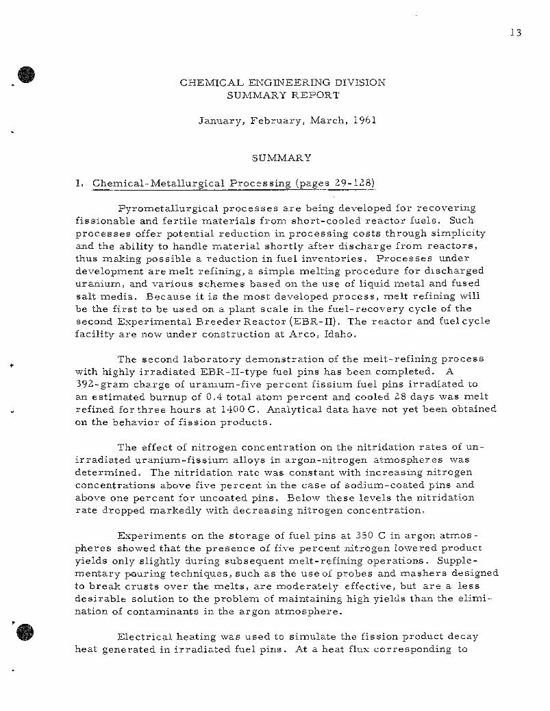
Pyrometa l lu rg ica l p r o c e s s e s a r e being developed for recover ing fissionable and fer t i le m a t e r i a l s from shor t -cooled r eac to r fuels. Such p r o c e s s e s offer potential reduction in p rocess ing costs through simplici ty and the ability to handle m a t e r i a l shor t ly after d ischarge from r e a c t o r s , thus making poss ible a reduction in fuel inventor ies . P r o c e s s e s under development a r e mel t refining, a s imple melt ing procedure for d ischarged uran ium, and var ious schemes based on the use of liquid meta l and fused salt media . Because it is the mos t developed p r o c e s s , mel t refining will be the f i rs t to be used on a plant sca le in the fue l - recovery cycle of the second Exper imenta l B r e e d e r Reactor (EBR-Il) . The reac to r and fuel cycle facility a re now under construct ion at Arco , Idaho.
The second l abora to ry demons t ra t ion of the mel t - ref in ing p roces s with highly i r r ad i a t ed EBR-II- type fuel pins has been completed. A 392-gram charge of uranium-f ive percen t f issium fuel pins i r r ad ia ted to an es t imated burnup of 0.4 total atom percent and cooled 28 days was mel t refined for th ree hours at 1400 C. Analytical data have not yet been obtained on the behavior of f ission p roduc t s .
The effect of n i t rogen concentrat ion on the ni t r idat ion r a t e s of uni r r ad ia t ed u ran ium-f i s s ium alloys in a rgon-n i t rogen a tmospheres was de te rmined . The ni t r idat ion ra t e was constant with increas ing ni t rogen concentra t ions above five percent in the case of sodium-coated pins and above one percent for uncoated p ins . Below these levels the ni t r idat ion ra te dropped marked ly with dec reas ing ni t rogen concentrat ion.
Exper iments on the s to rage of fuel pins at 350 C in argon a tmos phe res showed that the p r e sence of five percent ni t rogen lowered product yields only slightly during subsequent mel t - ref in ing opera t ions . Supplemen ta ry pouring techniques , such as the use of probes and m a s h e r s designed to b r e a k c rus t s over the m e l t s , a r e modera te ly effective, but a r e a l ess des i rab le solution to the problem of maintaining high yields than the e l imi nation of contaminants in the argon a tmosphe re .
E lec t r i ca l heating was used to s imulate the fission product decay heat generated in i r r ad i a t ed fuel p ins . At a heat flux corresponding to
two total atom percent burnup, the t empera tu re of the surface of a pin suspended in such a way that heat t ransfe r occur red p r ima r i l y by convection reached 128 C. The m e a s u r e d heat t ransfe r coefficients were considerably l a rge r than the theore t ica l values .
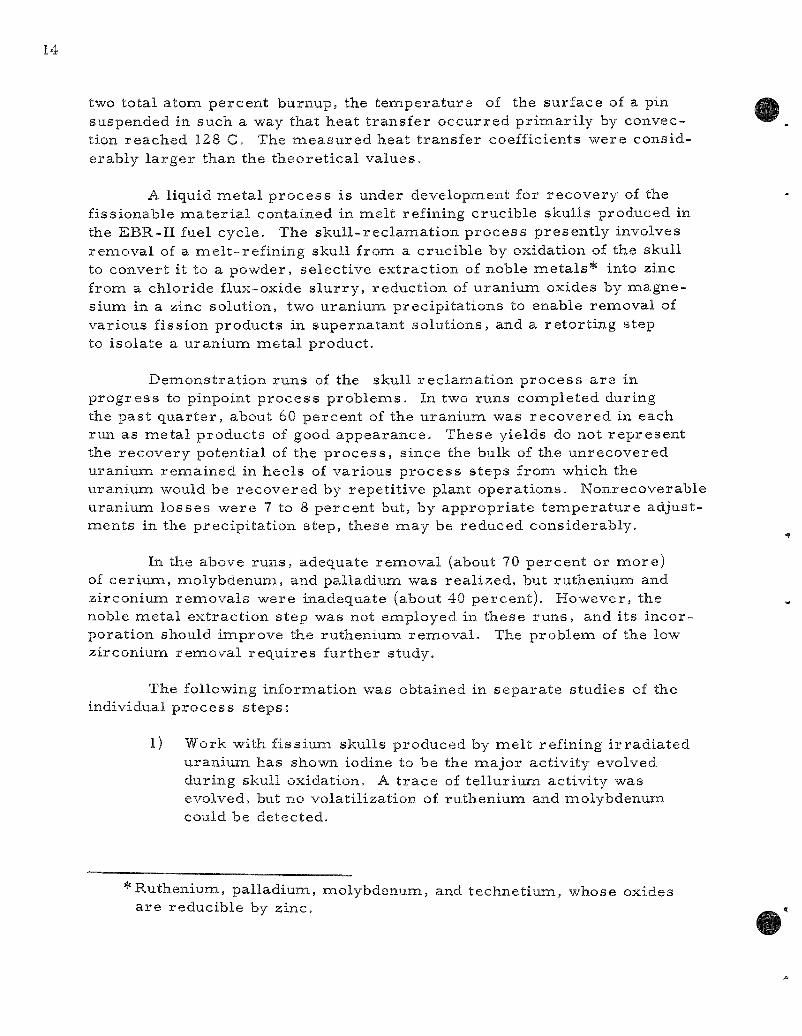
A liquid me ta l p r o c e s s is under development for r ecovery of the fissionable m a t e r i a l contained in mel t refining crucible skulls produced in the EBR-II fuel cycle . The sku l l - r ec lamat ion p r o c e s s presen t ly involves remova l of a mel t - re f in ing skull from a crucible by oxidation of the skull to convert it to a powder, se lect ive extract ion of noble m e t a l s * into zinc from a chloride flux-oxide s l u r ry , reduct ion of uran ium oxides by magnesium in a zinc solution, two uranium precipi ta t ions to enable removal of var ious fission products in supernatant solut ions, and a re to r t ing step to isolate a uranium meta l product .
Demonst ra t ion runs of the skull r ec lamat ion p r o c e s s a r e in p r o g r e s s to pinpoint p r o c e s s problemis. In two runs completed during the past qua r t e r , about 60 percen t of the uran ium was r ecove red in each run as me ta l products of good appearance . These yields do not r e p r e s e n t the r ecovery potential of the p r o c e s s , since the bulk of the unrecovered uranium remained in hee ls of var ious p rocess s teps from which the uranium would be r ecove red by repet i t ive plant opera t ions . Nonrecoverable uranium losses were 7 to 8 percen t but, by appropr ia te t empe ra tu r e adjustments in the precipi ta t ion s tep, these may be reduced considerably .
In the above runs , adequate r emova l (about 70 percen t or more ) of ce r ium, molybdenum, and palladium was rea l ized , but ruthenium and zirconium remova l s were inadequate (about 40 percent ) . However, the noble me ta l extract ion step was not employed in these r u n s , and i ts incorporat ion should improve the ruthenium remova l . The problem of the low zirconium remova l r equ i r e s further study.
The following information was obtained in sepa ra t e studies of the individual p r o c e s s s teps :
1) Work with f iss ium skulls produced by mel t refining i r r ad i a t ed uranium has shown iodine to be the major activi ty evolved during skull oxidation. A t r a c e of t e l lu r ium activity was evolved, but no volat i l izat ion of ruthenium and molybdenum could be detected.
* Ruthenium, pal ladium, molybdenum, and technet ium, whose oxides a r e reducible by zinc.

2) Over 80 percent of the ruthenium, palladium, and molybdenum was ex t rac ted into zinc from a f issium oxide-flux s lu r ry in one hour at 750 C. Separat ion of phases was readi ly accomplished by p re s su re - s iphon ing off the liquid zinc phase after solidification of the sal t . Ninety-two percent of the zinc was t r a n s f e r r e d Analysis showed that the zinc contained only 0.4 percent of the uranium charged. This procedure is considerably m o r e promis ing than t rans fe r of the flux-oxide s lu r ry away from the zinc phase because of the difficulty of keeping the oxide in s u s pension in the flux.
3) Fu r the r studies of reduction of uranium oxides by a dilute magnes ium-z inc sys tem in the p resence of flux show that m a g nesium chloride is an essen t ia l ingredient of the flux for rapid and quantitative reduct ions of U3O8 . Reduction r a t e s decreased with i nc rease in oxide par t ic le size and dec rease in t empera tu re , although quantitative reduct ions were achieved at t empera tu re s as low as 650 C.
4) Zirconium oxide crucible f ragments appearing in skull oxides r emained largely unreduced under the conditions employed for uranium oxide reduct ion and would be removed in the flux phase. However, fission product z i rconium may be m o r e susceptible to reduction than the highly re f rac tory crucible f ragments .
5) In the sku l l - r ec lamat ion p r o c e s s , advantage is taken of the low solubility of uran ium in sys t ems with high magnes ium concent ra t ions and of the contras t ing high solubility of r a r e ear ths in these sys t ems to effect a u r a n i u m - r a r e ear th separat ion. In the 46 percen t magnes ium-z inc eutectic sys tem, the uranium solubility may be reduced from around 0.5 percent at 800 to around 0.1 percent by lowering the t empera tu re to 400 C. Cer ium, at p r o c e s s concent ra t ions , will not be precipi ta ted by cooling to 400 C.
6) Agglomerat ion of uranium precipi ta ted from magnes ium- r i ch zinc sys t ems often occur s . This agglomerat ion is encouraged since it is cons idered advantageous in providing an easily handled r e to r t ed product . Under ce r ta in agitation and t empera tu re condit ions, the extent of agglomerat ion has been around 80 percent . The remaining 20 percent usually adheres firnaly to the tantalum re tor t ing c ruc ib le s .
The successful reduct ion of uranium oxides by z inc-magnes ium sys tems in the p resence of a halide flux has prompted application of the p rocedure to other compounds of in t e re s t . Quantitative reductions of uranium te t raf luor ide and plutonium dioxide have been achieved.
In scouting s tudies , significant reduction of thorium oxide (65 pe rcen t ) was also rea l ized .
P r e l i m i n a r y work has been c a r r i e d out on the prepara t ion of var ious compounds by precipi ta t ion from liquid meta l solut ions. Uranium monoca r bide and ce r ium sesquicarb ide (both identified by X- r ay diffraction) were prec ip i ta ted respec t ive ly from cadmium-uran ium and m a g n e s i u m - c e r i u m solutions by addition of finely divided carbon. This genera l p rocedure may have impor tant applications in the p repara t ion of f issionable or fert i le c e r a m i c r eac to r m a t e r i a l s of high puri ty and in the p rocess ing of such m a t e r i a l s .
In the c u r r e n t blanket p r o c e s s , the about 1 percen t plutonium-uranium alloy is dissolved in zinc containing 10 to 15 weight percent m a g nes ium. Additional magnes ium is then added after the dissolution to prec ip i ta te meta l l i c uranium. The plutonium dissolves in the magnes ium-r ich phase , thereby accomplishing the des i r ed separa t ion . The plutonium and uranium a r e r ecove red by re to r t ing . In two exper iments in which this d i rec t dissolution p rocedure was t r i ed , EBR-II blanket rods dissolved rapidly (within 2 hours ) . This p rocess is s imple r than those previously cons idered in that the u ran ium-z inc in te rmeta l l i c compound is nei ther prec ip i ta ted from the solution resul t ing from the dissolution of the blanket m a t e r i a l nor is the in te rmeta l l i c compound formed by d i rec t reac t ion of uranium and zinc at low t e m p e r a t u r e s . The la t t e r d i rec t react ion p r o cedure was a t tempted to el iminate the uranium dissolution and in te rmeta l l i c compound precipi ta t ion s teps . It was found that m a s s i v e uran ium reac t s very slowly with zinc. However, by hydriding and dehydriding the uranium to convert it to a powder of l a rge surface a r e a , a complete reac t ion was effected within a few h o u r s .
Mate r ia l s evaluation studies a r e in p r o g r e s s to evaluate the compatibili ty of var ious m a t e r i a l s with liquid me ta l sys t ems of the types contempla ted for r e p r o c e s s i n g r eac to r fuels. Cor ros ion studies in the cadmium-z inc -magnes ium sys tem indicate that 1020 s teel at 750 C is not appreciably co r roded by cadmium containing up to 15 percen t zinc. The p re sence of magnes ium appears beneficial in reducing any at tack. Testing of r e f r ac to ry me ta l s (tantalum, molybdenum, tungsten, and tanta lum-tungsten alloys) for containing z inc-based sys t ems is a lso in p r o g r e s s . Uranium in 5 pe rcen t magnes ium solution at 800 C r eac t s very slowly or not al l with grade CS graphi te . However, the sal t flux pene t ra tes to some extent this re la t ive ly porous grade of graphi te . Since grades of graphi te of g r ea t e r density a r e readi ly avai lable , flux penet ra t ion is not r ega rded as a se r ious problem.
A p i lo t -p lan t - sca le liquid me ta l dist i l lat ion unit having a design capacity of 100 kg of cadmium per hour has been cons t ruc ted and is being tes ted pr ior to operat ion. This unit will pe rmi t demonst ra t ion of a number of engineering opera t ions encountered in the liquid me ta l p r o c e s s e s .
A d i rec t -cyc le fue l - r ep rocess ing plant using pyrometa l lurgica l p rocedures is being designed and const ructed as par t of the Exper imenta l Breede r Reactor No. II (EBR-II) project . A Labora tory and Service Building is also included. Melt refining, liquid meta l extract ion, and p roces se s involving fractional c rys ta l l iza t ion from liquid meta l sys tems a r e methods being examined for the r ecovery and purification of EBR-II fuels. Based on these s tudies , p r o c e s s equipment is being designed and tested.
Fuel Cycle Faci l i ty building construct ion was about 80 percent complete on March 7, 1961, as compared to 70 percent on December 6,1960. The in ter ior of the Argon Cell has been meta l l ized with zinc and shot peened. Erec t ion of major cell equipment, such as manipula tors and c r anes , has begun. Work on e lec t r i ca l and piping se rv ices continues.
TWO mel t - re f in ing furnaces will be instal led as par t of the p rocess equipment in the Argon Cell . The instal lat ion ins t ruct ions for the furnace off-gas sys tem have been completed and components a r e being procured . Two panelboards for furnace operat ion and control have been designed and a r e on o rde r from a vendor. Pu rchase o rde r s for the furnaces themselves have been placed.
Work continues on other equipment i tems for the Fuel Cycle Faci l i ty . Design of the se rv ice plug feed throughs was completed and bids for their construct ion a r e being solicited. A purchase order has been placed for the interbuilding coffin which will t r anspo r t r eac to r fuel between the Fuel Cycle Faci l i ty and the Reac tor Building. A coffin for handling sc rap is also being procured . The x^ossibility of using a glass containing cer ium oxide as a gamma dos imeter is being explored. A versa t i l e dos imeter of this type would be useful in operat ion of Argon Cell equipment.
Several redes igned components have been instal led on the prototype manipula tor . As a r e su l t of exper ience with this new equipment, some changes have been made in the manipula tors being built by General Mil ls . The changes involved improvements in the br idge drive clutch mechan i sm, the c a r r i a g e b rush a s sembly , and the grip drive clutch mechanism.
A protect ive coating is r equ i r ed for Argon Cell equipment during the per iod of equipment instal la t ion. Based on the r e su l t s of lengthy gamma- i r r ad i a t i on t e s t s , a luminum paint appears to be a sat isfactory coating for this purpose . Test ing of other m a t e r i a l s , such as MI (mineral insulated) cable and s ea l s , and lubr ican t s , for cell use continues. Roller bear ings lubr ica ted with i r r ad i a t ed g r ea se s have run successfully under loads for 300 h o u r s .
Equipment for the oxidation of skulls from mel t refining is being developed. The powder which is formed on oxidation will be poured from the crucible and s tored .
Eight m o r e t en-k i logram batches of enr iched pin s c r ap were mel ted and cas t into ingots suitable for production of fuel pins for EBR-II .
Fundamental studies a r e being made in support of the var ious liquid meta l p r o c e s s e s . The solubil i t ies a r e being de termined of those e lements whose separa t ions a r e being at tempted. The solubil i t ies of the r a r e - e a r t h e lements t e rb ium, holmium, thulium, y t terbium, and lutetium in liquid cadmium may be r ep re sen t ed by the empi r ica l equations
te rb ium (321 to 535 C) : log (atom percent ) = 3.296 - 2425 T"^
holmium (324 to 628 C) : log (atom percent) = 3.409 - 2494 T"^
thulium (324 to 525 C) : log (atom percent ) = 3.488 - 2514 T"^
y t te rb ium (326 to 504 C ) : log (atom percent) = 2.992 - 1957 T"^
lutetium (324 to 557 C) : log (atom percent) = 7.328 - 7630 T"^ + 1.745 X 10^ T-^
The solubil i t ies of cobalt and chromium in liquid cadmium may be r ep re sen t ed by the empi r i ca l equations
cobalt (334 to 653 C): log (atom percent) = 3.594 - 6515 T"^ + 1.705X lO^T"^
chromium (450 to 650 C): log (atom percent) = 0.394 - 2605 T - 1
The c a d m i u m - r i c h in te rmeta l l i c phase in the t i t an ium-cadmium systemi has been found to have the composit ion TiCd and has te t ragonal sym m e t r y of the B-11 (7TiCu) s t ruc tu r a l type.
The solubili ty of uranium in liquid zinc above the per i tec t ic t e m pe ra tu r e (840 C) may be r e p r e s e n t e d by the empi r ica l equation
uranium (840 to 901 C): log (weight percent ) = 5.87 - 5550 T"^
Below the pe r i t ec t i c t empe ra tu r e the solubility may be r e p r e s e n t e d by the empi r i ca l equation
uranium (420 to 840 C): log (weight percent) = 6.946 - 6711 T"^
A sys temat ic study is underway to a sce r t a in the influence of atomic s ize , me ta l l i c valence, and e lect ronic configuration on the coprecipi ta t ion of var ious meta l l i c e lements with the cadmium-ce r ium in te rmeta l l i c phase CeCdn . The following values for the coprecipi ta t ion coefficient A., defined by the equation
/ t r a c e r in solution \ , , / log I ;; = ^ l o g l -
\ total t r a c e r / \
c a r r i e r in solution total c a r r i e r
have been determined: sodium, l i thium, potass ium, y t t r ium, bar ium, X = 0; lanthanum, X= 1.49; thor ium, X =: 1.08; praseodymium, X = 0.63; gadolinium, X= 0.23; s a m a r i u m , X= 0.17; uranium, X = 0.13; s t ront ium, X= Q.IO; europium, X= 0.099; scandium, X = 0.05; and zirconium, X= 0.04.
The t empe ra tu r e dependence of the distr ibution coefficient of cer ium and palladium when part i t ioned between the two part ia l ly immisc ib le liquids lead and zinc has been de termined. The value of the coefficient (weight percen t in zinc phase /weight percent in lead phase) for cer ium is 24 at 650 C, 11.7 at 700 C, and 5.7 at 730 C, whereas for palladium the coefficient is 1790 at 652 C, 473 at 703 C, and 178 at 740 C.
The vapor p r e s s u r e of solid u ran ium-cadmium alloys has been m e a s u r e d using the cont inuous- recording effusion appara tus . The vapor p r e s su re -compos i t i on pa t t e rns observed a r e in complete agreement with the r e su l t s previously obtained by conventional methods for phase s tudies .
The vapor p r e s s u r e of solid ce r ium-z inc alloys has been m e a s u r e d as a function of composit ion by means of the effusion method. The existence of the in te rmeta l l i c compounds CeZnn, CeZn, CejZn, and Ce4Zn was conf i rmed. The phase previously identified as CeZng was shown to be CezZuij. The exis tence of CeZnj appears highly probable . Two additional compounds CeZn^,7and a phase having a wide solid solution range between CeZn^^j^^and CeZn^g_^ were observed.
The magnet ic suscept ibi l i ty of the neodymium-cadmium in te rmeta l l ic phase NdCdu has been found to follow a Cur ie -Weiss re la t ion [x =C/ (T-A) ] with C - 1.667 ^i^d A = -8°K. The effective Bohr magneton number for this alloy is 3.67. This is in good ag reemen t with the theore t ica l value of 3.68 expected for a free t r iva lent neodymiumi ion in a ^la/2 ground s ta te .
A s e r i e s of combust ions of uranium mononitr ide in oxygen has been completed. The prec i s ion of the r e su l t s obtained was excellent. However, insufficient proof of the exact s ta te of some oxygen-containing impuri ty in the sample leaves a re la t ive ly l a rge uncer ta inty in any value of the heat of formation calculable from the r e s u l t s . Fu r the r analytical or p repara t ive work is n e c e s s a r y .
Combustions of boron n i t r ide in fluorine a r e being c a r r i e d out ca lo r -imet r ica l ly . These a r e the f i r s t combust ions of a compound in fluorine and the f i r s t combustions of a spontaneously react ing m a t e r i a l to be studied. Fo r these studies a special combustion bomb with an at tached fluorine tank is being used. This combustion bomb react ion sys tem has been ca l i bra ted and the energy of expansion of fluorine into the bomb has been determined.
Prev ious ly r epo r t ed values for the heats of formation of c rys ta l l ine zirconium te t raf luor ide and gaseous molybdenum hexafluoride have been
r ev i sed to A H | ( 2 5 C ) = -356.78 + O.Zg and -372.35 1 0.22 kca l /mo le , respect ively .
Resu l t s of the f i rs t c a lo r ime t r i c combustions of uranium in fluorine were uncer ta in because of complicat ions which a ro se in analyzing the combustion products However, the exper iments did lead to a p r e l i m i n a r y value of AHr (25 C) = -509 _ 3 kca l /mo le for uranium hexafluoride gas . Most of the l a rge uncer ta inty in the p re l imina ry value is due to analyt ical uncer ta in t ies which should be capable of being reso lved .
Techniques have been worked out for burning in fluorine some of the low melt ing m e t a l s , such as cadmium, zinc, magnes ium, and aluminum. Ca lo r ime t r i c m e a s u r e m e n t s have been s t a r t ed on cadmium.
Techniques somewhat s imi la r to those used in combustion of z i r conium in fluorine have been worked out for t i tanium, hafnium, niobium, and tantalum. Studies a r e being continued on thorium and vanadium.
II. Fuel Cycle Applications of Volatility and Fluidizat ion Techniques
(pages 129-197)
A d i rec t fluorination volati l i ty p roces s has been proposed for the r ecove ry of u ran ium and plutonium from i r r a d i a t e d nuc lear r e a c t o r fuels. In this p roces s advantage is taken of the volat i l i t ies of uranium and plutonium hexafluoride and of fluidization techniques. At tempts a r e being made to apply this p r o c e s s to uranium oxide and z i rconium m a t r i x fuels.
The proposed p roces s for r ecove ry of uran ium and plutonium from spent uran ium oxide involves decladding by an appropr ia te reac t ion in a fluidized bed. Plutonium and uran ium hexafluorides , which resu l t from the reac t ion of the declad oxide fuel with f luorine, m a y be separa ted using a combination of the var iabi l i ty of the r a t e s of fluorination of the plutonium and uranium compounds and chemica l reac t iv i t i es of the hexaf luorides .
The decladding step of the p roces s for uran ium dioxide fuels involves g a s - m e t a l reac t ions in the case of e lements clad ei ther with s ta inless s tee l or Zircaloy. The g a s - m e t a l reac t ions a r e c a r r i e d out with the fuel e lements submerged in an ine r t fluidized bed (calcium fluoride or alundum) which s e rves as a heat t r ans fe r medium Dilute mix tu re s of hydrogen chloride in hydrogen fluoride or the s epa ra t e gases have been successfully employed when z i rconium decladding is n e c e s s a r y . In recen t work, chlor ine has rep laced the hydrogen chlor ide . In the case of s ta inless s tee l cladding, chlorine appears to be a poss ib le decladding reagent , based on r e s u l t s from pi lot-plant s tudies .
The decladding reac t ions ( r e fe r r ed to as p r i m a r y ] a r e being c a r r ied out in a two-zone fluid-bed r e a c t o r . Volati l ization of the clad or alloying m a t e r i a l occurs in the lower zone during the chlorinat ion reac t ion .

The volati le m a t e r i a l s pass upward into the upper zone, where hydrogen fluoride is admitted, thereby effecting conversion to solid f luorides. Where solid chlor ides a r e formed, these will also be converted to solid f luor ides , s ince the re is solids mixing between zones. The two zones a r e separa ted by an inver ted conical baffle (other types may also be suitable) which reduces back-mixing of the gases and prevents the format ion of gas mix tu res that have been shown to affect these react ions adverse ly .
In pi lot-plant studies the reac t ion of 304 s ta inless s teel tube sections with chlorine has been invest igated in a Ij - inch-d iamete r two-zone fluid-bed r eac to r . The r a t e of chlorinat ion has been found to dec rease rapidly with t ime because of the formation of an adherent film compr ised p r imar i ly of nickel and chromium chloride on the surface of the cladding. An average penetra t ion r a t e of 4.6 m i l s / h r was obtained in a 4.7-hour run at 575 C using 87 percent chlorine (in ni t rogen) . At a higher t empera tu re of 625 C, using the same chlorine concentrat ion, a 35-mil tube completely reac ted in 3.8 hour s . The effect of chlor ine dilution at 625 C ^was noticeable at concentrat ions below 48 volume percent .
After decladding has been achieved, a subsequent fluorination step is expected to provide the n e c e s s a r y separat ion of the f issi le e lements . The d i rec t fluorination of dense uranium dioxide, pellets is being examined in fluid-bed pi lot-plant s tudies .
Substantial improvement in t empe ra tu r e control at higher react ion r a t e s has been achieved by regulat ion of fluorine inlet flow in place of coolant regulat ion previously employed. Four runs have been made in which pellet batches of approximately 4.5 kg have been completely reac ted at about 500 C; average uran ium hexafluoride production r a t e s of about 20 kg/ (hr) (sq ft r eac to r c r o s s section) were obtained with ine r t - f i r ed pel lets and approximately one-half this r a t e for hydrogen-f i red pel le ts . The hydrogen-f i red pellets (2" in. x ^ m.) a r e considered m o r e rep resen ta t ive of r e a c t o r fuel m a t e r i a l , and in these exper iments 10 to 12 hr was r equ i red for p rocess ing a complete batch.
Fluor inat ion runs have been made with iner t fluid beds of calcium fluoride or magnes ium fluoride to aid in the removal of h e a t . Additional runs were made to demons t ra t e the feasibil i ty of operating with a pure z i rconium te t raf luor ide fluid bed and without an iner t bed.
Since heat t r ans fe r l imi ts the max imum prac t i ca l reac t ion ra te in the d i rec t fluorination p r o c e s s , a heat t ransfe r study is being made in a mockup sys t em. In these t e s t s , m e a s u r e m e n t s a r e made of heat t r ans fe r coefficients for the sur faces of the inner hea te r and of the outer cooling wall, and for effective bed t h e r m a l conductivit ies for sys tems consist ing of pellet beds with a fluidized medium in the pellet voids. In seve ra l exper imenta l t e s t s , effective t h e r m a l conductivit ies along the radius of the
bed of about 0.8 Btu/(hr)(sq ft)(F/ft) were found for the nonfluidized case and of 5 to 10 for fluidization. Fo r the fluidized case , surface coefficients of about 80 Btu/ (hr) (sq ft)(F) were foxmd for the in ternal heating surface and 20 to 60 for the external cooling sur face .
A new fil ter sys tem with automatic blowback was demonst ra ted , in which the f i l ters a r e located in chambers separa ted from the reac tor by a length of one- inch pipe. This design p r o m i s e s to make fil ter rep lacement m o r e convenient in radioact ive s y s t e m s .
The r a t e of t h e r m a l decomposit ion of plutoniumi hexafluoride has been studied at t e m p e r a t u r e s from 140 to 173 C by a s ta t ic method and from 150 to 250 C by a flow method, A study of the kinet ics of decomposition has es tabl i shed the mechan i sm of the reaction- The ra t e of the r e action has been formulated as concur ren t f i r s t - and z e r o - o r d e r reac t ions with r e spec t to plutonium hexafluoride p r e s s u r e in the range between 50 and 1100 m m and of t e m p e r a t u r e from 140 to 170 C. It has been infer red that, within the aforementioned t e m p e r a t u r e and p r e s s u r e r a n g e s , the decomposit ion proceeds by both a homogenous and heterogeneous unimolec-ular decomposit ion and that the heterogeneous decomposit ion occurs on the surface of the deposited plutonium te t raf luor ide . Rates of decomposi tion of plutonium hexafluoride obtained in the flow sys tem approximate conditions which may be found in the fluorination r e a c t o r of the Direc t Fluor ide Volatili ty p r o c e s s for uranium oxide power r eac to r fuels. This information will be useful for plant design and future exper imenta l work.
The physical appearance of plutonium te t raf luor ide resul t ing from both t h e r m a l decomposit ion and a lpha-radia t ion decomposit ion has been observed and bulk densi t ies have been de te rmined . The bulk density of the product of t h e r m a l decomposit ion was 15 to 18 t imes g rea t e r than the bulk density of the product of radia t ion decomposit ion.
It has been demons t ra ted that a l a rge quantity (32 gm) of plutonium te t raf luor ide , which had been deposited in equipment by ther ina l decomposi tion of plutoniuin hexafluoride, could be ref luor inated to plutonium hexafluoride at about 450 C with a r ecove ry of 98 percent of the plutonium.
The reac t ion of e lemental b romine with plutonium hexafluoride has been invest igated. The s to ichiometry of the reac t ion has been es tabl i shed P r i m a r y products of the reac t ion a r e plutonium te t raf luor ide and bromine pentafluoride. The util i ty of the reac t ion for the separa t ion of uran ium and plutonium hexafluorides has been demons t ra ted .
In studies of f ission product behavior , m i x t u r e s of uranium dioxide-ruthenium-106 were reac ted with fluorine at 400 and 500 C. It was found that at both of these t e m p e r a t u r e s ruthenium was volat i l ized at a r a t e
equal to or faster than that of uranium volatil ization as uranium hexafluoride. However, it was found that ruthenium pentafluoride decomposed and was deposited on a colder portion of the walls of the fluorination vesse l . No a l t e ra t ion of the r e su l t s o c c u r r e d when calcium fluoride and zirconium fluoride were added to the or iginal mix tu re to be fluorinated. The fluorination of uranium dioxide-niobium-95 mix tu re s indicated that niobium is readi ly fluorinated out of uranium dioxide and that the re is no react ion between ni obium and calcium f luor ide-z i rconium fluoride bed m a t e r i a l s . Niobium differed from the ruthenium in that very lit t le (less than one percent) deposited on the reac t ion boat or furnace tube, indicating that niobium can be volat i l ized with l i t t le or no difficulty.
In studies of reac t ions which might be used to separa te uranium and plutonium, the react ions of gaseous sulfur te t raf luoride with uranium t r i oxide and uranyl fluoride to produce uranium hexafluoride were studied. Sulfur te t raf luor ide has the advantage that it will not r eac t with plutonium dioxide or plutonium te t raf luor ide to produce plutonium hexafluoride. It thus can se rve as a select ive fluorinating reagent in fluoride volatility p r o c e s s e s . Kinetics of the reac t ions of sulfur te t raf luoride with uranium dioxide and uranyl fluoride have been explored. This work se rves as a c l a s s i ca l example of the use of a thermobalance in the study of gas-sol id kinet ics in a reac t ion in which the final product is volat i le .
A combined chlorinat ion-f luorinat ion (Direct Chlorination P r o c e s s ) p roces s is being examiined as an a l t e rna te to the fluorination step of the Direc t Fluor inat ion Volatility P r o c e s s . The two-zone fluidized-bed concept has been employed successfully in the d i rec t chlorination of s in tered u r a nium dioxide pe l le t s . The volati le uranium chlorides produced in the lower zone of the r e a c t o r a r e conver ted to solid fluorides by reac t ion with hydrogen fluoride in the upper zone. A charge of 20 pellets (121 g to ta l ) was 92 p e r cent r eac ted at 550 C in only 2.5 hr by a gas s t r eam containing 69 mole percen t chlor ine in carbon t e t r ach lo r ide . An equimolar mix ture of carbon t e t r ach lo r ide and chlorine at 550 C has produced higher react ion ra t e s than seve ra l other gas mix tu r e s studied.
The reac t ion of sulfur te t raf luor ide with uranium tr ioxide to form volatile uran ium hexafluoride has been suggested as a bas i s for a possible fuel r ecove ry scheme (ANL-6145, page 93). This react ion might also be cons idered an a l te rna t ive for feed m a t e r i a l s production. The overa l l r e action is cons idered to be: UO3 + 3SF4-—^^ UF^ + 3SOF2 . One exploratory two-par t run was made in a 2 - in . -d i ame te r fluid-bed r eac to r to supplement the r e su l t s gained in the l abora to ry (ANL-6231. page 99).
The convers ion of uranium hexafluoride to uraniumi dioxide by a two-s tep fluid-bed p roces s is being studied in o rder to develop a s impler method for p repa ra t ion of c e r a m i c r e a c t o r fuel. The major problem in the f i rs t s tep, reac t ion of the hexafluoride with s team to form uranyl f luoride, continues to be fines formation. P r o p e r sizing of s tar t ing beds

a s s u r e s par t ic le growth (average par t ic le d iameter of 250/i or c o a r s e r ) ; however, continuous operat ion r equ i r e s a seed par t ic le feed s t r e a m to m.aintain bed fluidity. Regulation of the r a t e of seed par t i c le addition to offset growth without entering the region of fines formation (average bed d iameter l e s s than Z50 /i ) has not been successful due apparent ly to the continuous formation of smal l amounts of fines par t ia l ly offsetting seed par t ic le r e q u i r e m e n t s . Runs made at hexafluoride feed r a t e s of 100 g /min [174 lb u ran ium/ (h r ) ( sq ft)] have been extended to seven hours before interrupt ion by fines formation. The effect of s ta r t ing bed par t ic le s ize on fines formation was invest igated in a number of shor t runs .
The reduct ion of uranyl fluoride to uranium dioxide is being studied in a s e r i e s of batch fluidization runs in a 3 - in . -d iamete r fluid-bed r eac to r . A mixed gas of s team and hydrogen gave nauch fas ter conversion than hydrogen alone. A typical product from a run was 3 kg of powder containing ZIO ppm res idua l fluoride (specification grade) . This was p r e pared in 5 hr at 650 C using a gas s t r e a m of th ree pa r t s hydrogen to one par t s t eam.
Flu id-bed calcination studies have been init iated in s m a l l - d i a m e t e r columns in an at tempt to reduce the overa l l gas r equ i r emen t s for these units and thus reduce the off-gas handling problem.s. This technique employs the atomizing and feed decomposit ion gases as the p r i m a r y fluidizing medium by instal l ing the spray nozzles in the apex of the cone-bottom r e a c t o r s . The s m a l l - d i a m e t e r aspect has application to the calcination of plutonium solut ions, for which nuc lear c r i t i ca l i ty considera t ions a r e n e c e s s a r y .
A m a s s t ransfe r study using the s i l ica ge l -water sys tem has been completed in the 6 - in . -d iamete r mul t i s tage fluidization column designed to achieve control led downward t r anspo r t of solids without the use of in te rna l downcomers . Murphree efficiencies of nea r ly 100 pe rcen t were obtained.
III. Reac tor Safety (pages 198-238)
The oxidation, ignition, and combustion p r o c e s s e s of uranium, z i rconium, and plutonium a r e being studied to provide information to aid in minimiz ing the haza rds assoc ia ted with handling these m e t a l s .
Studies of the effect of pre-oxida t ion on the burn ing-curve ignition t e m p e r a t u r e s of uraniumi powders were continued. Ignition t e m p e r a t u r e , at f i r s t , dec reased with extent of pre-oxida t ion for both a fine and a c o a r s e powder fract ion. Ignition t e m p e r a t u r e s began to r i s e after m o r e than 50 percent pre-oxida t ion . Weight gain v e r s u s t ime measurerr ients at 150 C with both powder fract ions showed a two-s tage reac t ion ident ical with that found in previous s tudies of the i so the rma l oxidation of uranium cubes .

The dec reased ignition t e m p e r a t u r e of pre-oxidized powder may have been due to the fas ter reac t ion r a t e s that occur in the second-s tage react ion.
Ignition studies of uranium monocarbide powders a r e repor ted for powders from two s o u r c e s . The powders were composed of i r r egu la r pa r t i c les . An es t imate of the roughness factor was obtained by the Armour R e s e a r c h Foundation using a F i s c h e r Sub-Sieve Sizer . F r o m this information, it was possible to conapute the specific a r ea of a s e r i e s of powder f rac t ions . Ignition t e m p e r a t u r e s in oxygen var ied from 255 to 320 C for specific a r e a s from 314 to 20 sq c m / g . Ignition t empera tu re s of uranium monocarbide were 40 to 60 degrees higher than values previously repor ted with spher ica l uranium powders of corresponding specific a r ea .
A s e r i e s of m e a s u r e m e n t s of burn ing-curve ignition t empera tu re s in air were made with uran ium foil squares of two thicknesses (one-half and five mi l s ) . Studies were made with s tacks of one, two, four, and eight foil squa re s . Ignition t e m p e r a t u r e s dec reased 45 degrees in going from one to two 5-mil foils . Only a smal l additional dec rease occur red with four or eight foils . Studies a r e a imed at developing means to calculate ignition t e m p e r a t u r e d e c r e a s e s which a r e due to decreases heat loss by aggregat ion,
A brief study was made of uranium plates of the type used in ZPR-III blanket a s s e m b l i e s . Eighteen plates out of a total of 20,000 were found to be crumbl ing. Unaffected plates had a burn ing-curve ignition t e m p e r a t u r e of 480 C while de te r io ra t ed plates ignited at 115 C in ei ther a i r or oxygen. The affected plates were made by powder meta l lu rg ica l techniques . It appears that these plates a r e rever t ing to powder.
Studies of the r a t e of burning propagation along uranium and z i r conium foil s t r ips is continuing, A new ins t rument has been devised to m e a s u r e s imultaneously the propagat ion ra t e and the burning t e m p e r a t u r e . A new p r o g r a m was under taken to de te rmine the effects of halogenated hydrocarbons on propagat ion r a t e s and burning t e m p e r a t u r e s . It is p r o posed to study seve ra l homologous s e r i e s of hydrocarbons in which both R and X of a hydrocarbon RX a r e sys temat ica l ly var ied. It is anticipated that this new p r o g r a m will shed further light on the mechan ism by which the hydrocarbons inhibit burning.
The exper imenta l p r o g r a m to de te rmine ra t e s of reac t ion of mol ten r e a c t o r fuel and cladding me ta l s with water is continuing. One method involves the rap id mel t ing and d ispers ion of meta l wi res in a water environment by a surge c u r r e n t from a bank of condensers . The s e r i e s of runs with 60-mi l z i rconium wires at p r e s s u r e s up to 1500 psi is continuing. Runs made with water at 315 C (1500 psi) were identical in c h a r a c t e r to runs made in water from 90 to 200 C (10 to 225 psi) . Explosive r a t e s of p r e s s u r e r i s e occu r r ed at initial me ta l t empe ra tu r e s of 1900 C in heated water .
Resul t s of previous studies at Bat tel le and Westinghouse were r e examined and shown to be consis tent with r a t e data deduced from, condense r -d i scha rge studies of the z i rcon ium-wate r react ion. The following r a t e law was obtained:
Y,= 4 . 8 2 x l 0 M e x p ~ i ! ^ ) t ,
where V is cc of hydrogen at STP pe r sq cm of surface and t is t ime in min.
The lowered reac t iv i ty of z i rconium in roona- tempera tu re water could be explained by a lowered ra t e of diffusion of water vapor through the hydrogen-s t eam mant le surrounding reac t ing pa r t i c l e s , A diffusion ra t e of one-half of the value in heated water produced semiquanti tat ive ag reemen t with the exper imenta l data.
The explosive reac t ions r epor t ed previously for z i rconium at initial t e m p e r a t u r e s of 2600 C in r o o m - t e m p e r a t u r e water and those at 1900 C in heated water could be explained by a c r i t i ca l pa r t i c l e dianaeter (500 /i in r o o m - t e m p e r a t u r e water) below which rapid hydrogen evolution dr ives the pa r t i c l e s through the water at high velocity. The high-speed naotion r e su l t s in rapid r eac t ions . The reac t ions , however , a r e not complete because the i nc reased velocity also i n c r e a s e s the convective heat loss r a t e .
A second method involves the rapid contact of s t eam with heated me ta l . In this method, the me ta l r ece ives a " p r e s s u r e pulse" of water vapor. The appara tus is ent i re ly enclosed in a box heated to 105 C. Runs with one a tmosphere of water vapor reac t ing with mol ten aluminum at 1000 and 1200 C a r e r epor t ed . Contact t imes va r i ed from 0.1 to 1000 seconds . The data can be r e p r e s e n t e d approximate ly by the cubic r a t e law.
A brief study was made of the reac t ions occur r ing between a lumi num or s ta in less s tee l and uranium dioxide or UsOg in c e r m e t fuel pins . The method of differential t h e r m a l analysis (DTA) was used. A very mi ld exothermic reac t ion was found to occur between a luminum and uraniuna dioxide or U3O8 at about 900 C. React ion products included UAI2, UAI3, and UAI4, which were identified by X - r a y diffraction. It was concluded that the reac t ions were not violent or dangerous .
Two s e r i e s of in-p i le , m e t a l - w a t e r exper iments were completed. Meltdowns were conducted on stainle'ss s teel -urania c e r m e t s , u r a n i u m wi r e s , and on c e r a m i c co re , ine ta l -c lad fuel specinaens. C e r m e t s made of 90 weight pe rcen t s ta in less s teel with u ran ia showed s imi l a r behavior when submerged in water i r r e s p e c t i v e of whether the sample was in the form of pins or p la tes ; me ta l t e m p e r a t u r e s g r e a t e r than 1500 C were a t tained. The or iginal geomietry was changed into one or two l a rge globules

together with many fine pa r t i c l e s ; the m o r e energet ic t rans ien ts also produced some fine ( l - m i l d iameter ) powder. Chemical analyses indicated that a separa t ion of the urania from the s ta in less s teel took place during the mel t ing-quenching cycle of the r eac to r burs t . The l a rge r globules were depleted in uran ium (0.017 to 0.055 weight percent uranium) whereas the fine pa r t i c l e s were m o r e concentrated in uranium (30 to 64 weight percent uranium). The p la te- type ce rme t e lements gave only slightly m o r e m e t a l - w a t e r reac t ion than the cyl indrical e lements ; both r eac ted naore as the energy of the burs t was inc reased . The s ta in less s t ee l -u ran ia c e r m e t fuel pins gave 6.6 and 10.2 percent me ta l -wa te r reac t ion at r e a c t o r b u r s t s of 435 and 512 Mw-sec on a 50-ms period. The corresponding speci f ic -energy inputs to the fuel specimen, as de termined by the average from molybdenum-99 de terminat ions , a re 379 and 445 cal /gm, respec t ive ly ,
A Z i rca loy-2 clad, c e r a m i c core fuel pin subjected to a 648-Mw-sec pulse (606 cal/gna)on a 50 m s per iod gave near ly complete dest ruct ion of the specimen with 24.0 percent of the me ta l jacket reac t ing with the water . The data obtained to date from the var ious ce ramic and c e r m e t core fuel pins were c o r r e l a t e d as a function of the energy of the reac to r bu r s t . The following table s u m m a r i z e s the r e su l t s at two different energ ies :
P e r c e n t Metal -Water Reaction
Type of Fuel Pin
Z r - 2 clad, oxide co re
SS-UO2 c e r m e t
Al-UsOg c e r m e t
SS clad, oxide co re
Al clad, oxide co re
at 400 Mw-sec
8,0
5.0
3.2
0.0
0.4
at 500 Mw-sec
13.0
9.3
4.7
0.8
0.8
Reaction
Zr-HzO
SS-H2O
Al-HgO
SS-H2O
AI-H2O
The convers ion from reac to r to absorbed energy for the oxide core pins is 0.935 ( c a l / g m ) / M w - s e c and 0.87 ( c a l / g m ) / M W - s e c for the s ta in less s t ee l -urania c e r m e t s .
Trans ien t s conducted on 64 -mi l -d i ame te r uranium (93 percen t enriched) wires gave 33.2 and 50.2 percen t molten u ran ium-wate r react ion at r eac to r per iods of 440 and 152 nas, respec t ive ly . The average energy input to the wire was 554 c a l / g m from molybdenuna-99 ana lyses . The wires were conver ted into fine pa r t i c l e s and powder. It is planned to co r re l a t e these exper iments with condense r -d i scha rge exper iments which were a lso c a r r i e d out with w i r e s .
IV. Reac to r Chemis t ry (pages 239-248)
The neu t ron-cap tu re c ro s s sections of neptunium-237 a r e being dete rmined in the fas t -neut ron energy range . Work has also begun on the determinat ion of the total neutron c r o s s section of u ran ium-233 . The cap ture - to - f i s s ion ra t ios in the EBR-I , Mark III a r e being de termined for uraniumi isotopes 233, 235, and 238 and for plutonium isotopes 239 and 240.
The Reac tor Decontamination P r o g r a m is d i rec ted at determLining the s e r iousnes s of fuel-element rup tu re s in boiling water r e a c t o r s and the determinat ion of methods of decontamination of contaminated su r faces . Several runs have been made in a s ta in less s tee l loop which s imula tes the action of a boiling water r e a c t o r . Cur ren t l abora tory exper iments on the decontamiination of s t a in less s tee l 304 have been conducted with oxalic acid and c i t r ic acid-base solutions containing hydrogen peroxide,
V. Routine Operat ions (page 249)
The operat ion of the radioact ive was t e -p rocess ing facility and the gamma- i r r ad i a t i on facility continued without incident.
F o r the convenience of the r e a d e r , appropr ia te pa r t s of this summary a r e r epea ted at the beginning of each of the f i r s t four sect ions of this r epo r t .
L CHEMICAL-METALLURGICAL PROCESSING
Pyrometa l lu rg ica l p r o c e s s e s a r e being developed for recovering fissionable and fer t i le m a t e r i a l s from shor t -cooled reac tor fuels. Such p r o c e s s e s offer potential reduction in process ing costs through simplicity and the ability to handle m a t e r i a l short ly after discharge frona r e a c t o r s , thus naaking possible a reduction in fuel inventor ies . P r o c e s s e s under developnaent a r e mel t refining, a s imple melting procedure for discharged uranium, and var ious schemes based on the use of liquid meta l and fused salt media . Because it is the mos t developed p r o c e s s , mel t refining will be the f i r s t to be used on a plant scale in the fuel recovery cycle of the second Exper imenta l Breede r Reactor (EBR-II). The reac tor and fuel cycle facility a r e now under construct ion at Arco, Idaho.
The second labora tory demonst ra t ion of the mel t refining p rocess with highly i r r ad ia t ed EBR-II- type fuel pins has been completed. A 392-g ram charge of uraniuna-five percent fissiuna fuel pins i r rad ia ted to an es t imated burnup of 0.4 total atom percent and cooled 28 days was mel t refined for th ree hours at 1400 C. Analytical data have not yet been obtained on the behavior of f ission products .
The effect of ni t rogen concentrat ion on the ni tr idat ion ra tes of uni r rad ia ted u ran ium-f i s s ium alloys in a rgon-ni t rogen a tmospheres was deternained. The ni t r idat ion ra te was constant with increasing nitrogen concentrat ions above five percen t in the case of sodium-coated pins and above one percent for uncoated pins . Below these levels the nitr idation ra te dropped marked ly with decreas ing ni trogen concentrat ion.
Exper iments on the s torage of fuel pins at 350 C in argon a tmos pheres showed that the p r e sence of five percent ni t rogen lowered product yields only slightly during subsequent mel t refining opera t ions . Supplementary pouring techniques , such as the use of probes and m a s h e r s de signed to b reak c rus t s over the me l t s a r e modera te ly effective, but a r e a l e s s des i rab le solution to the problesaa of maintaining high yields than the el imination of contaminants in the argon a tmosphere .
E lec t r i ca l heating was used to simulate the fission product decay heat genera ted in i r r ad ia t ed fuel p ins . At a heat flux corresponding to two total atom percen t burnup, the t empera tu re of the surface of a pin suspended in such a way that heat t r ans fe r occur red p r imar i ly by convection reached 128 C. The m e a s u r e d heat t ransfe r coefficients were considerably l a r g e r than the theore t ica l values .
A liquid me ta l p r o c e s s is under development for recovery of the fissionable m a t e r i a l contained in mel t refining crucible skulls produced ill the EBR-II fuel cycle . The skull reclanaation p r o c e s s present ly involve

removal of a mel t - re f in ing skull f rom a crucible by oxidation of the skull to convert it to a powder, select ive extract ion of noble m e t a l s * into zinc from, a chloride flux-oxide s lu r ry , reduction of uranium, oxides by magnesium in a zinc solution, two uran ium precipi ta t ions to enable removal of various f ission products in supernatant solutions, and a re tor t ing step to isolate a u ran ium meta l product .
Demonst ra t ion runs of the skull rec lamat ion p r o c e s s a r e in p r o g r e s s to pinpoint p r o c e s s p r o b l e m s . In two runs completed during the past qua r te r , about 60 percen t of the u ran ium was recovered in each run as meta l products of good appearance . These yields do not r ep re sen t the recovery potential of the p r o c e s s , since the bulk of the unrecovered uran ium r e mained in heels of var ious p r o c e s s s teps from which the uran ium would be recovered by repet i t ive plant opera t ions . Nonrecoverable uran ium losses were 7 to 8 pe rcen t but, by appropr ia te t empe ra tu r e adjustments in the precipi ta t ion s tep, these may be reduced considerably.
In the above runs , adequate remova l (about 70 percen t or more) of ce r ium, molybdenum, and pal ladium was rea l ized , but ruthenium and z i r conium removals were inadequate (about 40 percent ) . However, the noble meta l ext ract ion step was not employed in these runs , and its incorpora tion should improve the ruthenium removal . The prob lem of the low z i r conium removal r equ i r e s fur ther study.
The following information was obtained in sepa ra t e studies of the individual p r o c e s s s t eps :
1) Work with fissiuna skulls produced by mel t refining i r r ad ia t ed uraniuna has shown iodine to be the major activity evolved during skull oxidation. A t r a c e of te l lur iura activity was evolved, but no volat i l izat ion of ruthenium and molybdenum could be detected.
2) Over 80 pe rcen t of the ruthenium, pal ladium, and molybdenum was ex t rac ted into zinc f rom a fissiuna oxide-flux s l u r r y in one hour at 750 C. Separat ion of phases was readi ly accomplished by p re s su re - s iphon ing off the liquid zinc phase after solidification of the sal t . Ninety-two pe rcen t of the zinc was t r a n s f e r r e d . Analysis showed that the zinc contained only 0.4 pe rcen t of the u ran ium charged. This p rocedure is cons iderably m o r e p romis ing than t r ans fe r of the flux-oxide s lu r ry away from the zinc phase because of the difficulty of keeping the oxide in suspension in the flux.
•Ruthenium, pal ladium, molybdenum, and technet ium, whose oxides a r e reducible by zinc.
3) F u r t h e r studies of reduction of uraniuna oxides by a dilute magna s lum-z inc sys tem in the p resence of flux show that magnes ium chloride is an essent ia l ingredient of the flux for rapid and quantitative reductions of U30g. Reduction ra tes dec reased with inc rease in oxide par t ic le size and decrease in t e m p e r a t u r e , although quantitative reductions were achieved at t e m p e r a t u r e s as low as 650 C.
4) Zirconium oxide crucible f ragments appearing in skull oxides remained largely unreduced under the conditions employed for u ran ium oxide reduction and would be removed in the flux phase . However, f ission product z i rconium may be more susceptible to reduction than the highly ref rac tory crucible f ragments .
5) In the skull rec lamat ion p r o c e s s , advantage is taken of the low solubility of uraniuna in sys tems with high naagnesium concent ra t ions and of the contras t ing high solubility of r a r e ear ths in these sys t ems to effect a u r a n i u m - r a r e ea r th separat ion. In the 46 percen t magnes ium-z inc eutectic sys tem, the u r a nium solubility may be reduced from around 0,5 percent at 800 to around 0,1 percent by lowering the t empera tu re to 400 C. Cer ium, at p r o c e s s concentra t ions , will not be p r e cipi tated by cooling to 400 C.
6) Agglomerat ion of uran ium precipi ta ted f rom magnes ium- r i ch zinc sys t ems often occu r s . This agglonaeration is encouraged since it is cons idered advantageous in providing an easily handled r e to r t ed product . Under cer ta in agitation and t e m p e r a ture condit ions, the extent of aggloiaieration has been around 80 percen t . The renaaining 20 percent usually adheres f irmly to the tantalum re tor t ing c ruc ib les .
The successful reduction of uran ium oxides by zinc-magna slum, s y s t ems in the p r e sence of a halide fltuc has prompted application of the p r o cedure to other compounds of in te res t . Quantitative reductions of uranium te t raf luor ide and plutonium dioxide have been achieved. In scouting s tudies , significant reduct ion of thor ium oxide (65 percent) was also real ized.
P r e l i m i n a r y work has been c a r r i e d out on the prepara t ion of v a r i ous compounds by precipi ta t ion f rom liquid meta l solutions. Uranium monocarbide and ce r i um sesquicarbide (both identified by X-ray diffraction) were prec ip i ta ted respec t ive ly frona cadiniuna-uranium and magnes ium-ce r ium solutions by addition of finely divided carbon This general p rocedure may have impor tant applications in the p repara t ion of fissionable or fer t i le c e r amic r eac to r m a t e r i a l s of high puri ty and m the process ing of such m a t e r i a l s .
32
In the cu r r en t blanket p r o c e s s , the about 1 percent plutonium-uranium alloy is dissolved in zinc containing 10 to 15 weight percent magnesium. Additional magnes ium is then added after the dissolution to precipi ta te meta l l ic uranium. The plutonium dissolves in the m a g n e s i u m - r i c h phase , thereby accomplishing the des i red separat ion. The plutonium and uraniuna a r e recovered by re tor t ing. In two expe r i ments in which this d i rec t dissolut ion procedure was t r ied , EBR-II blanket rods dissolved rapidly (within 2 hours) . This p r o c e s s is s i m pler than those previously cons idered in that the u ran ium-z inc in te r -meta l l ic compound is ne i ther prec ip i ta ted from the solution resul t ing from the dissolut ion of the blanket m a t e r i a l nor is the in te rmeta l l ic compound formed by d i rec t react ion of uran ium and zinc at low t e m p e r a t u r e s . The la t t e r d i rec t react ion p rocedure was attenapted to elinainate the uran ium dissolution and in te rmeta l l i c compound precipi ta t ion s teps . It was found that mass ive u ran ium reac t s very slowly with zinc. However , by hydriding and dehydriding the uran ium to convert it to a powder of la rge surface a r e a , a complete react ion was effected within a few hours .
Mate r ia l s evaluation studies a r e in p r o g r e s s to evaluate the compatibil i ty of var ious m a t e r i a l s with liquid meta l sy s t ems of the types contenaplated for r ep rocess ing r eac to r fuels. Cor ros ion studies in the cadmium-z inc -magnes ium sys tem indicate that 1020 steel at 750 C is not appreciably cor roded by cadmium containing up to 15 percent zinc. The p re sence of magnes ium appears beneficial in reducing any attack. Testing of re f rac tory naetals (tantalum., molybdenum, tungsten, and tanta lum-tungsten alloys) for containing z inc-based sys tems is also in p r o g r e s s . Uranium in 5 pe rcen t magnes ium solution at 800 C reac t s very slowly or not at all with grade CS graphi te . However, the salt flux pene t ra tes to sonae extent this re la t ively porous grade of graphi te . Since grades of graphite of g r e a t e r density a r e readi ly avai lable , flux pene t r a tion is not r egarded as a se r ious problem.
A p i lo t -p lan t - sca le liquid meta l dis t i l la t ion unit having a design capacity of 100 kg of cadmium per hour has been cons t ruc ted and is being tes ted p r io r to operat ion. This unit will pe rmi t demonst ra t ion of a number of engineering operat ions encountered in the liquid meta l p r o c e s s e s .
A d i r ec t - cyc le fue l - r ep rocess ing plant using pyrometa l lu rg ica l p rocedures is being designed and cons t ruc ted as pa r t of the Exper imenta l Breeder Reactor No. II (EBR-II) project . A Labora tory and Service Building is also included. Melt refining, liquid meta l ext ract ion, and p r o c e s s e s involving fract ional c rys ta l l i za t ion f rom liquid me ta l sys t ems a r e naethods being examined for the r ecove ry and purif icat ion of EBR-II fuels. Based on these s tudies , p r o c e s s equipnaent is being designed and tes ted.
Fuel Cycle Faci l i ty building construct ion was about 80 percent coiaiplete on March 7, 1961, as compared to 70 percent on December 6, i960. The in te r io r of the Argon Cell has been metal l ized with zinc and shot peened. Erec t ion of major cel l equipment, such as manipulators and c r a n e s , has begun. Work on e lec t r i ca l and piping se rv ices continues.
Two mel t - re f in ing furnaces will be instal led as pa r t of the p roces s equipment in the Argon Cell. The instal lat ion instruct ions for the furnace off-gas sys tem have bean completed and components a r e being procured . Two panelboards for furnace operat ion and control have been designed and a r e on o rde r from a vendor. Pu rchase o rde r s for the furnaces thena-selves have been placed.
Work continues on other equipment i tems for the Fuel Cycle F a c i l ity. Design of the se rv ice plug feed throughs was completed and bids for thei r construct ion a r e being solicited. A purchase order has been placed for the interbuilding coffin which will t r anspor t r eac to r fuel between the Fuel Cycle Faci l i ty and the Reactor Building, A coffin for handling sc rap is a lso being p rocured . The possibi l i ty of using a glass containing ce r ium oxide as a gamma dosinaeter is being explored. A versa t i l e dosinaeter of this type would be useful in operat ion of Argon Call equipment.
Several redes igned components have been instal led on the p ro to type manipula tor . As a resu l t of exper ience with this new equipnaent, some changes have been made in the manipula tors being built by General Mil ls . The changes involved improvenaents in the bridge drive clutch mechan i sm, the c a r r i a g e brush a s sembly , and the gr ip drive clutch mechan i sm.
A protec t ive coating is requ i red for Argon Cell equipment during the per iod of equipment instal lat ion. Based on the r e su l t s of lengthy ganama- i r rad ia t ion t e s t s , aluiaiinum paint appears to be a sat isfactory coating for this purpose . Testing of other m a t e r i a l s , such as MI (minera l insulated) cable and sea l s , and lubr ican t s , for cell use continues. Roller bear ings lubr ica ted with i r r ad ia t ed g r ea se s have run successfully under loads for 300 hou r s .
Equipment for the oxidation of skulls frona naelt refining is being developed. The po-wder which is formed on oxidation will be poured from the crucible and s tored.
Eight m o r e t en -k i log ram batches of enr iched pin sc rap were melted and cas t into ingots suitable for production of fuel pins for EBR-II .
Fundamenta l s tudies a r e being made in support of the var ious liquid laietal p r o c e s s e s . The solubil i t ies a r e being determined of those e lements whose separa t ions a r e being at tempted. The solubili t ies of the r a r e - e a r t h
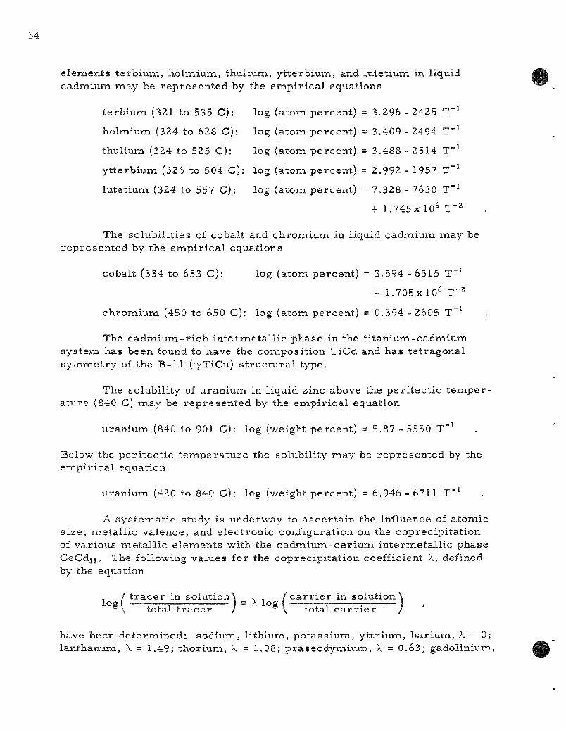
elements te rb ium, holmium, thulium, y t te rb ium, and lutet ium in liquid cadmium may be r ep re sen t ed by the empi r i ca l equations
t e rb ium (321 to 535 C): log (atom percent) = 3.296 -2425 T"^
holmium (324 to 628 C): log (atom percent) = 3.409 - 2494 T"^
thulium (324 to 525 C): log (atom percent) = 3.488 - 2514 T"^
y t te rb ium (326 to 504 C): log (atom percent) = 2.992 - 1957 T~^
lutet ium (324 to 557 C): log (atom percent) = 7.328 - 7630 T"^
+ 1.745x10^ T~2
The solubil i t ies of cobalt and chromium in liquid cadmium may be rep resen ted by the empi r i ca l equations
cobalt (334 to 653 C): log (atom percent) = 3,594 - 6515 T"^
+ 1.705x10^ T"^
chromium (450 to 650 C): log (atom percent) = 0.394 - 2605 T"^
The c a d m i u m - r i c h in te rmeta l l i c phase in the t i tanium-cadmiuna systena has been found to have the composit ion TiCd and has te t ragonal symmet ry of the B-11 (7TiCu) s t ruc tu ra l type.
The solubility of uraniuna in liquid zinc above the per i tec t ic t e m p e r a ture (840 C) naay be r ep re sen t ed by the empi r i ca l equation
uran ium (840 to 901 C): log (weight percent) = 5.87 - 5550 T"^
Below the per i tec t ic t e m p e r a t u r e the solubility naay be r ep resen ted by the empi r ica l equation
uran ium (420 to 840 C): log (weight percent) = 6.946 -6711 T"''
A sys temat ic study is underway to a sce r t a in the influence of atomic s ize , meta l l ic valence, and e lec t ronic configuration on the coprecipi ta t ion of var ious meta l l ic e lements with the cadnaium-cer ium in te rmeta l l ic phase CeCdii. The following values for the coprecipi ta t ion coefficient X, defined by the equation
/ t r a c e r in solutionX _ , / c a r r i e r in solution \ °\ total t r a c e r / °\ total c a r r i e r /
have been de te rmined : sodium, l i thium, po tass ium, y t t r ium, ba r ium, X = 0; lanthanum, X = 1,49; thor ium, X = 1.08; p raseodymium, X = 0.63; gadolinium.

X = 0.23; s a m a r i u m , X = 0,17; u ran ium, X = 0.13; s t ront ium, X = 0.10; europium, X = 0.099; scandium, X = 0.05; and zi rconium, X = 0.04.
The t empe ra tu r e dependence of the distr ibution coefficient of ce r ium and pal ladium when par t i t ioned betweenthe two par t ia l ly immiscible liquids lead and zinc has been determined. The value of the coefficient (weight percent in zinc phase /weight percen t in lead phase) for cer ium is 24 at 650 C, 11.7 at 700 C, and 5,7 at 730 C, whereas for palladium the coefficient is 1790 at 652 C, 473 at 703 C, and 178 at 740 C,
The vapor p r e s s u r e of solid u ran ium-cadmium alloys has been m e a s u r e d using the continuous recording effusion appara tus . The vapor p r e s s u r e - c o m p o s i t i o n pa t te rns observed a r e in complete agreement with the resu l t s previously obtained by conventional methods for phase s tudies .
The vapor p r e s s u r e of solid ce r ium-z inc alloys has been m e a s u r e d as a function of composi t ion by means of the effusion method. The existence of the in te rmeta l l i c compounds CeZnn, CeZn, CagZn, and Ce4Zn was conf i rmed. The phase previously identified as CeZng was shown to be CegZnj^. The exis tence of CeZnj appears highly probable . Two additional compounds, CeZn..„7 and a phase having a wide solid solution range between CeZn~3_7 and CeZn~6.4 were observed.
The naagnetic suscept ibi l i ty of the neodymium-cadmium in termeta l l ic phase NdCdijhas been found to follow a Cur ie -Weiss relat ion [X = C/(T-A)] with C = 1.667 3-"-^ ^ - -8°K. The effective Bohr naagneton nunaber for this alloy is 3.67. This is in good agreement with the theore t ica l value of 3,68 expected for a free t r iva lent neodymium ion in a I9/2 ground s ta te .
A s e r i e s of combustions of uran ium naononitride in oxygen has been completed. The p rec i s ion of the r e su l t s obtained was excellent. However, insufficient proof of the exact s tate of some oxygen containing impuri ty in the sample leaves a re la t ively l a rge uncer ta inty in any value of the heat of formation calculable frona the r e s u l t s . Fu r the r analytical or p repara t ive work is n e c e s s a r y .
Combustions of boron ni t r ide in fluorine a r e being c a r r i e d out ca l -or inaetr ical ly . These a re the f i r s t conabustions of a compound in fluorine and the f i r s t combustions of a spontaneously reacting ma te r i a l to be studied. F o r these studies a special combustion bomb with an attached fluorine tank is being used. This combustion bomb react ion sys tem has been cal ibra ted and the energy of expansion of fluorine into the bomb has been determined.
Prev ious ly repor ted values for the heats of formation of crys ta l l ine z i rconium te t raf luor ide and gaseous naolybdenum hexafluoride have been rev ised to AHf (25 C) = -356.7g + O.25 and -372.35 ± 0.22 kca l /mo le , respect ive ly .

Results of the f i rs t c a lo r ime t r i c combustions of uranium in fluorine were uncer ta in because of conaplications which a ro se in analyzing the combustion p roduc t s . However, the exper iments did lead to a p re l imina ry value of AHf (25 C) = -509 t 3 kca l /mo le for uranium hexafluoride gas . Most of the la rge uncer ta in ty in the p r e l i m i n a r y value is due to analytical uncer ta in t ies which should be capable of being resolved.
Techniques have been worked out for burning in fluorine some of the low melt ing m e t a l s , such as cadmium, zinc, magnes ium, and aluminum. Ca lo r ime t r i c measuren-ients have been s t a r t ed on cadmium.
Techniques somewhat s imi l a r to those used in combustion of z i r conium in fluorine have been worked out for t i tanium, hafnium, niobiuna and tanta lum. Studies a r e being continued on thor ium and vanadium.
A, Pyronaeta l lurgical Development
1. Melt Refining (R. K. Steunenberg, L, B u r r i s , J r . )
The f i rs t core loading of EBR-II , which cons is t s of 50 percent enr iched uran ium alloyed with noble me ta l f ission product e lements , will be recovered by mel t refining. After the s ta in less s tee l jackets have been removed mechanical ly , the fuel pins a re chopped and charged to a z i rconia c ruc ib le , where they a r e mel ted and held at a t e m p e r a t u r e of 1400 C for th ree to four h o u r s . Approximately two- th i rds of the fission products a re removed by this t r ea tmen t through the mechanisnas of volati l ization and se lect ive oxidation by the c ruc ib le . The purified product is collected in the form of an ingot by pouring the molten meta l into a graphite mold. (A separa te p r o c e s s is being developed to recover the unpoured naetal and oxide remaining in the crucible as a skull.) Exper imenta l work has been continued on (l) denaonstration runs using approximately 400 gm of highly i r r ad i a t ed EBR-II- type fuel alloy, (2) the effect of ni t rogen-containing atnaospheres on the mel t - re f in ing p r o c e s s , (3) possible modifications of the p r o c e s s , and (4) the anticipated self-heat ing of fuel pins resul t ing from fission product decay energy.
a. High-act ivi ty Level Melt-ref ining Exper iments JY. G . T r i c e , W. H. Spicer)
The second mel t - re f in ing exper iment with about 400 gm of highly i r r ad ia t ed , 10 percent enriched uranium-f ive percen t fissiuna alloy has been completed. The purposes of these s m a l l - s c a l e exper iments a r e to demons t r a t e the r ecove ry and decontaminat ion of i r r ad i a t ed EBR-II fuel and to observe the physical behavior of the fuel during var ious phases of the p r o c e s s . The experinaental conditions and pouring yields for the expe r imen t s that have been conapleted to date appear in Table 1. Complete analyt ical r esu l t s for the second exper iment a r e not yet avai lable .
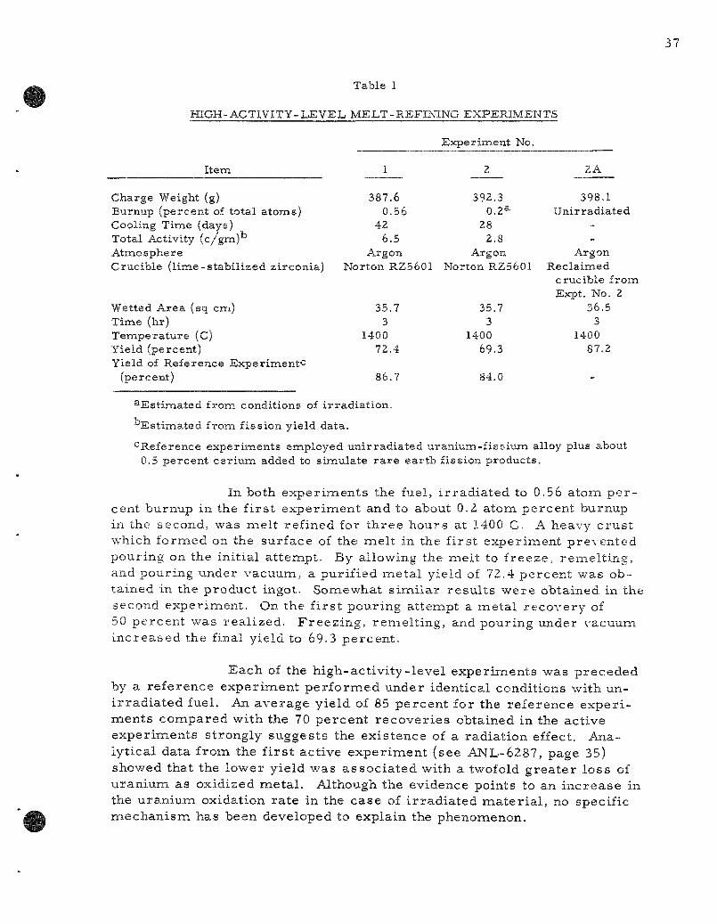
Table 1
HIGH-ACTIVITY-LEVEL MELT-REFINING EXPERIMENTS
I tem
Charge Weight (g) Burnup (percent of total a toms) Cooling Time (days) Total Activity ( c / g m ) ^ Atm.o sphere Crucible ( l ime-s t ab i l i zed z i rconia)
Wetted Area (sq cm) Time (hr) T e m p e r a t u r e (C) Yield (percent) Yield of Reference Expe r imen tc
(percent)
1
387.6 0.56
42 6.5
Argon Norton RZ5601
35.7 3
1400 72.4
86.7
Exper iment
2
392.3 0.2a
28 2.8
Argon
No.
Norton RZ5601
35.7 3
1400 69.3
84.0
2 A
398.1 Uni r rad ia ted
-_
Argon Recla imed
crucib le from Expt. No. 2
36.5 3
1400 87.2
-
^Estimated from conditions of irradiation.
Estimated from fission yield data.
•^Reference experiments employed unirradiated uranium-fissium alloy plus about 0.5 percent cerium added to simulate rare earth fission products.
In both exper iments the fuel, i r rad ia ted to 0.56 atom pe r cent burnup in the f i rs t exper iment and to about 0.2 atom percent burnup in the second, was melt refined for th ree hours at 1400 C. A heavy crus t which formed on the surface of the melt in the first experiment prevented pouring on the initial attempt. By allowing the melt to freeze, remel t ing, and pouring under vacuum, a purified metal yield of 72.4 percent was obtained in the product ingot. Somewhat s imi la r resu l t s were obtained in the second experiment. On the f i rs t pouring attenapt a metal recovery of 50 percent was real ized. Freez ing , remel t ing, and pouring under vacuum increased the final yield to 69-3 percent .
Each of the high-act ivi ty- level experiments was preceded by a reference experiment per formed under identical conditions with uni r rad ia ted fuel. An average yield of 85 percent for the reference exper i ments compared with the 70 percent recover ies obtained in the active exper iments strongly suggests the existence of a radiation effect. Analytical data from the f i r s t active exper iment (see ANL-6287, page 35) showed that the lower yield was assoc ia ted with a twofold grea te r loss of uranium as oxidized metal . Although the evidence points to an increase in the uranium oxidation rate in the case of i r rad ia ted mate r i a l , no specific mechanism has been developed to explain the phenomenon.
In Exper iment 2A, an attenapt was made to es tabl ish the effect of a high radiat ion field by naelt refining uni r rad ia ted fuel in the crucible used for the second active exper iment . As indicated by the data f rom the f i r s t active exper iment (ANL-6287, page 32), a substantial f r a c tion of the f ission product activity removed by mel t refining is not re ta ined in the skull. A smal l p a r t of this activity is volati l ized, but mos t of it, consist ing mainly of a port ion of the r a r e ea r ths and the bulk of the s t ron t ium-bar ium, is re ta ined in the z i rconia crucible . The gamma-activity levels of the crucible and the separa ted skull were of about the same magnitude (about 5 00 r at four feet).
Before the crucible was used, the skull from the active exper iment was renaoved by oxidation in a i r at 800 C, which also would be expected to r e s t o r e the oxygen depleted during mel t refining. In appearance the crucible closely r e sembled an unused crucible after degassing at high t e m p e r a t u r e . The crucible was heated to 1400 C for one hour at a p r e s sure l e s s than 25/i , p r io r to r e - u s e . A total of 400.1 gm of meta l , which consis ted of 398.1 gm of un i r rad ia ted u ran ium-f i s s ium fuel alloy and 2.0 gna of ce r ium meta l , was charged to the crucible . The other conditions were identical to those of the second active experiraent .
A meta l recovery of 87.2 percent was obtained, with no indication of a heavy surface c rus t . No c lear explanation for this phenomenon has been developed; however, it is possible that the type, leve ls , and locations of activity and f ission product decay heat were not sufficiently s imi la r to produce the inc reased oxidation. Pe rhaps the most likely cause for the lowered yields for the i r r ad ia t ion meta l is the enhanced rate of react ion of i r r ad ia t ed me ta l with impur i t i es in the furnace a tmosphere . It is anticipated that m o r e definitive information will be obtained as additional h igh-ac t iv i ty- level exper iments a r e completed.
b. Nitride Format ion on Sodium-coated and Uncoated Fuel Pins (J. P . LaPlante)
The declad sodium-coated fuel pins may be s tored for a per iod of t ime in the EBR-II Fuel Cycle Faci l i ty p r i o r to mel t refining. Inasmuch as the a tmosphere in the facility may contain up to five percen t ni trogen, an opportunity for ni t r idat ion may occur during s torage and handling opera t ions . It has been es t imated that during the handling of de-clad pins p r i o r to p rocess ing , the pin t e m p e r a t u r e s will be in the vicinity of 300 C as a r esu l t of f iss ion product decay heating.
Several measurenaents were made to de te rmine the effect of ni t rogen concentra t ion on the ni t r idat ion r a t e s of u ran ium-5 percen t fissiuna alloy pins with and without sodium coatings at 308 C. The sodium
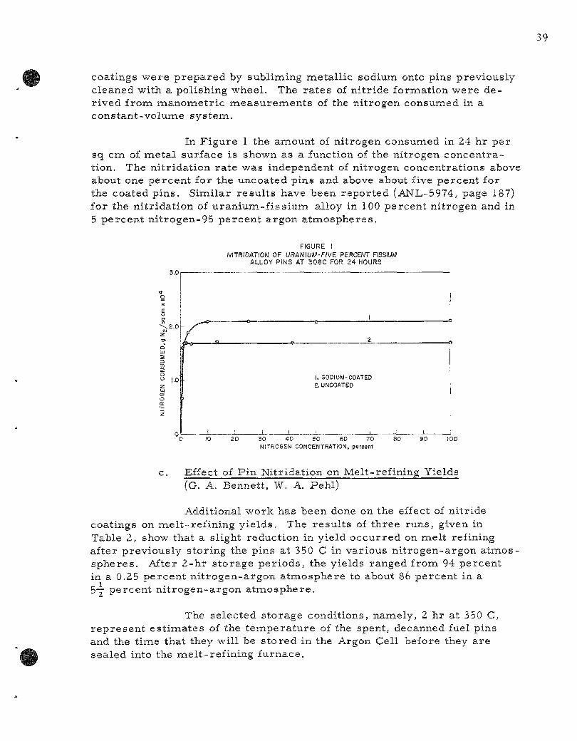
coatings were p r epa red by subliming metal l ic sodium onto pins previously cleaned with a polishing wheel. The ra tes of ni tr ide formation were der ived from manomet r i c jaieasurements of the nitrogen consunaed in a constant-volume sys tem.
In Figure 1 the amount of nitrogen consumed in 24 hr per sq cna of meta l surface is shown as a function of the nitrogen concentration. The ni tr idat ion ra te was independent of nitrogen concentrations above about one percent for the uncoated pins and above about five percent for the coated pins . Similar resu l t s have been repor ted (AN'L-5974, page 187) for the ni t r idat ion of u ran ium-f i s s ium alloy in 100 percent nitrogen and in 5 percen t ni t rogen-95 percen t argon atnaospheres.
3.0
S .2.0
S
1.0
FIGURE I NITRIDATION OF URANIUM-FIVE PERCENT FISSIUM
ALLOY PINS AT 308C FOR 24 HOURS
r*
I.. SODIUM-COATED 2. UNCOATED
20 30 40 50 60 70 lUITROGEN CONCENTRATION, percent
80 90 100
c. Effect of Pin Nitridation on Melt-refining Yields (G. A. Bennett, W. A. Pehl)
Additional work has been done on the effect of nitr ide coatings on mel t - ref in ing yie lds . The resu l t s of three runs, given in Table 2, show that a slight reduction in yield occurred on melt refining after previously storing the pins at 350 C in various ni t rogen-argon atmos-spheres . After 2-hr s torage per iods , the yields ranged from 94 percent in a 0.25 percent n i t rogen-argon a tmosphere to about 86 percent in a 5-7 percent n i t rogen-argon a tmosphere .
The selected s torage conditions, namely, 2 hr at 350 C, r ep re sen t es t imates of the t empera tu re of the spent, decanned fuel pins and the time that they will be s tored in the Argon Cell before they are sealed into the mel t - ref ining furnace.
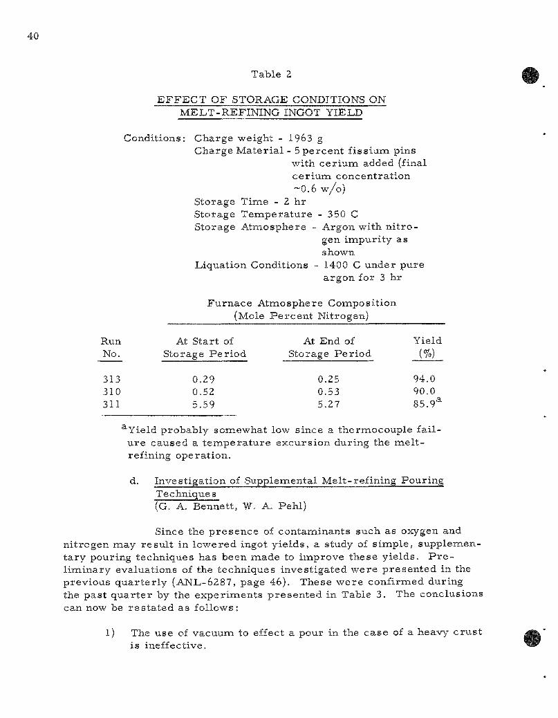
Table 2
E F F E C T OF STORAGE CONDITIONS ON MELT-REFINING INGOT YIELD
Conditions: Charge weight - 1963 g Charge Mater ia l - 5 percent f is slum pins
with ce r ium added (final ce r ium concentrat ion -0 .6 w/o)
Storage Time - 2 hr Storage Tempera tu re - 350 C Storage Atmosphere - Argon with n i t ro
gen impuri ty as shown
Liquation Conditions - 1400 C under pure argon for 3 hr
Furnace Atmosphere Composit ion (Mole P e r c e n t Nitrogen)
Run No.
313 310 311
At Start of Storage Pe r iod
0.29 0.52 5.59
At End of Storage Per iod
0.25 0.53 5,27
Yield (%)
94,0 90.0 85.9^
^Yield probably somewhat low since a thermocouple fai l u re caused a t empe ra tu r e excurs ion during the me l t -rafining operat ion.
d. Investigation of Suppleinental Melt-ref ining Pouring Techniques (G. A. Bennett, W. A. Pehl)
Since the p r e sence of contaminants such as oxygen and ni trogen may resu l t in lowered ingot y ie lds , a study of s imple , supplementa ry pouring techniques has been made to improve these yields . P r e l iminary evaluations of the techniques investigated were p resen ted in the previous quar t e r ly (ANL-6287, page 46). These were confirnaed during the pas t qua r t e r by the exper iments p resen ted in Table 3. The conclusions can now be r e s t a t ed as follows:
1) The use of vacuum to effect a pour in the case of a heavy c rus t is ineffective.
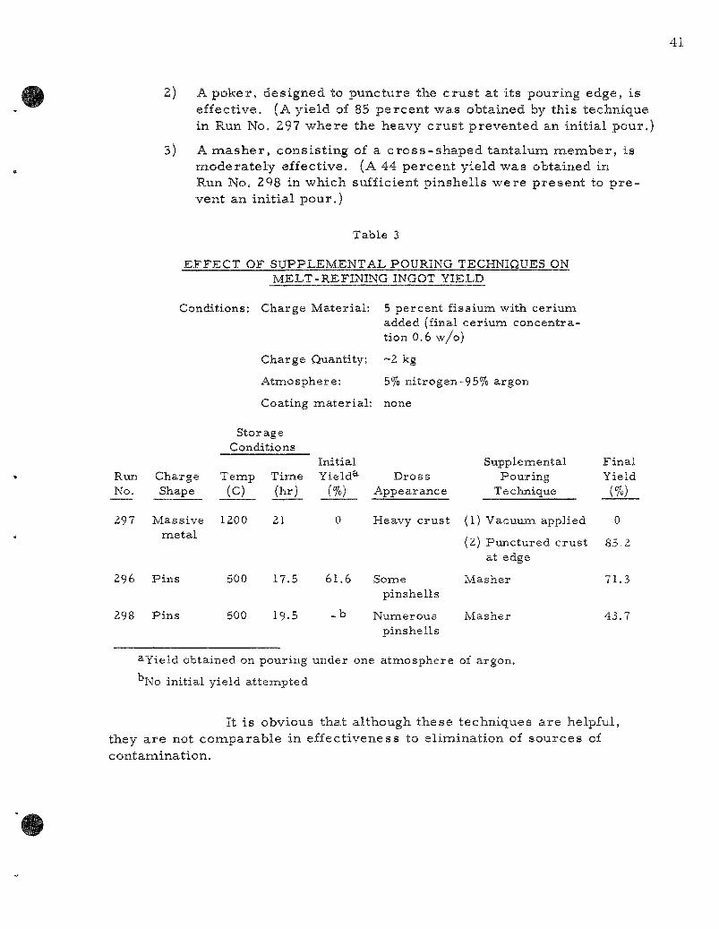
2) A poker, designed to puncture the c rus t at its pouring edge, is effective, (A yield of 85 percent was obtained by this technique in Run No. 297 where the heavy c rus t prevented an initial pour,
3) A m a s h e r , consist ing of a c ros s - shaped tantalum member , is modera te ly effective, (A 44 percent yield was obtained in Run No. 298 in which sufficient pinshells were present to p r e vent an initial pour.)
Table 3
EFFECT OF SUPPLEMENTAL POURING TECHNIQUES ON MELT-REFINING INGOT YIELD
Conditions; Charge Material : 5 percent fissium with cerium added (final cerium concentration 0.6 w/o)
Charge Quantity: ~2 kg
Atmosphere: 5% nitrogen-95% argon
Coating mater ia l : none
Run No.
297
296
298
Charge Shape
Massive metal
Pins
Pins
Stor age Conditions
Temp (c)
1200
500
500
Time (hr)
21
17.5
19.5
Initial Yield^-
(%)
0
61.6
- b
Dross Appearance
Heavy crust
Some pinshells
Numerous pinshells
Supplemental Pouring
Technique
(1) Vacuum applied
(2) Punctured crust at edge
Masher
Masher
Final Yield
(%)
0
85.2
71.3
43.7
3-Yield obtained on pouring under one atmosphere of argon.
No initial yield attempted
It is obvious that although these techniques a re helpful, they a re not comparable in effectiveness to elimination of sources of contamination.
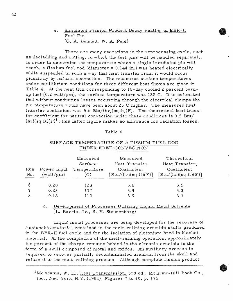
e. Simulated F i ss ion Produc t Decay Heating of EBR-II Fue l Pin (G. A. Bennett, W, A. Pehl)
There a r e many operat ions in the r ep rocess ing cycle, such as decladding and cutting, in which the fuel pins will be handled separa te ly . In o rde r to deternaine the t e m p e r a t u r e which a single i r r ad ia ted pin will reach, a f i ss ium fuel rod (diameter = 0.144 in.) was heated e lec t r ica l ly while suspended in such a way that heat t ransfe r from it would occur p r imar i l y by na tura l convection. The m e a s u r e d surface t empe ra tu r e s under equi l ibr ium conditions for th ree different heat fltixes a r e given in Table 4. At the heat flux corresponding to 15-day cooled 2 percent burn-up fuel (0.2 wa t t / gm) , the surface t empera tu re was 128 C. It is es t imated that without conduction l o s se s occurr ing through the e l ec t r i ca l c lamps the pin t empe ra tu r e would have been about 25 C higher . The m e a s u r e d heat t r ans fe r coefficient was 5.6 Btu/(hr)(sq ft)(F). The theore t ica l heat t r a n s fer coefficient for na tu ra l convection under these conditions is 3.5 B tu / (hr)(sq ft)(F) ; this l a t t e r figure makes no allowance for radiation l o s s e s .
Table 4
SURFACE TEMPERATURE OF A FISSIUM F U E L ROD UNDER FREE CONVECTION
Measured Measured Theore t ica l Surface Heat Transfe r Heat Trans fe r ,
Power Input Tempera tu re Coefficient Coefficient (watt /gm) (C) [Btu/(hr)(sq ft)(F)] [Btu/(hr)(sq ft)(F)]
0,20 128 5.6 3.5 0,23 137 5.9 3.3 0.18 112 5.9 3.3
2. Development of P r o c e s s e s Utilizing Liquid Metal Solvents (L. B u r r i s , J r . , R. K. Steunenberg)
Liquid me ta l p r o c e s s e s a r e being developed for the recovery of f issionable naater ia l contained in the mel t - re f in ing crucible skulls produced in the EBR-II fuel cycle and for the isolat ion of plutonium bred in blanket m a t e r i a l . At the completion of the mel t - re f in ing operat ion, approximately ten percent of the charge remains behind in the z i rconia crucible in the form of a skull composed of meta l and oxides. An auxi l iary p r o c e s s is requ i red to r ecover par t ia l ly decontaminated u ran ium from the skull and re tu rn it to the mel t - re f in ing p r o c e s s . Although complete f ission product
McAdams, W. H., Heat T ransmis s ion , 3rd ed., McGraw-Hil l Book Co., Inc. , New York, N.Y. (1954), F igu re s 7 to 10, p. 176.

removal is not neces sa ry , a substantial aiaiount of each fission product element must be removed in o rder to maintain the proper fission composition in the recycled fuel. The objective of the blanket p rocess is to upgrade the plutoniuna concentrat ion to a point sufficient for re -enr ichment of the EBR-II fuel ma te r i a l (from 1 percent to about 50 percent plutonium in uraniuna).
Work was continuedon the skul l - rec lamat ion p rocess presented in the previous quar te r ly repor t , the flowsheet for which is again given in Figure 2. Runs a re in p r o g r e s s for demonstrat ing the p rocess and for pinpointing engineering and chemical difficulties. Tests and evaluations of var ious possible naaterials for containing the liquid metal solutions of in te res t a re reported. In sup|5ort of the process work, laboratory studies were made on uranium oxide and f iss ium skull oxide reductions in the p resence of halide fluxes and on uranium and fission product behavior in var ious p roces s s teps .
MELT REFININfi
mam _ CONTilNINS
SKULL MTERI4L
PHASE
SEPiMTION
AT 525 C
FIGURE 2
LIQUID MITAl PROCESS FOR RECLAMATION OF MELT REFINING SKULLS
CHLORIDE FLUX J ^
OXIOEJ
-ZINC
0XI0H10N IN DILUTE 02-
mm MIXTURE (-700 C)
SEPARMION OF OXIDE POWER FROM CRyciBLE
BY POURING POWER
L
NOBLE METAL LEACHIII6
ZIRCONI* CRUCI8LE WASTE
mt SyPERNME PLUS FISSION PRODUCTS
COOLINS TO 525 C!
PPT. U-2« '"^
INTEBiETALLIC
NOBLE iETALS IN ZINC
DILUTE fe-Z. &LLOY -3
PHASE
SEPARATION
OXIDE REDUCTION
(750-800 C)
' I MgO IN
CHLORIDE FLUX
i INTERMETALLIC
DECOMPOSITION
«ITH io
PHASE
SEPARATION AT
- 5 2 5 C
RET0RTIN6
(600 TO 850 C)
luP L
URANIUM
lETAL PRODUCT
fe-ftlCH SUPERHATE PLUS FISSION PRODUCTS
^
CONDENSATE
OXIDE-BEARINO FLUX
Because of the potential application of the reduction procedures enaployed in the sku l l - rec lamat ion p roces s to other a r e a s of fuel p r o c e s sing, reductions of uranium te t raf luor ide , plutonium dioxide, and thorium oxide were demonst ra ted . P r e l im ina ry work has also shown that s to i chiometr ic uranium compounds, such as uranium monocarbide, can be p repa red in high puri ty by precipi ta t ion from liquid meta l solutions.
An al ternat ive z inc-dissolut ion procedure in which a snaall amount of magnesiuiai is p r e sen t has been applied to the process ing of blanket ma te r i a l for the separat ion of contained plutonium. This procedure avoids formation of the uranium-zinc intermetal l ic compound and
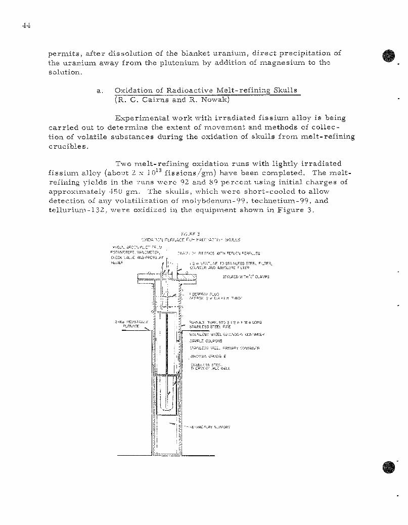
p e r m i t s , after dissolution of the blanket uranium, d i rec t precipi ta t ion of the uranium away from the plutoniuna by addition of inagnesiuna to the solution.
Oxidation of Radioactive Melt-refining Skulls ( R . C . Cai rns and R. Nowak)
Exper imenta l w'ork with i r rad ia ted f iss ium alloy is being c a r r i e d out to determine the extent of movement and methods of col lection of volatile substances during the oxidation of skulls from melt- ref ining cruc ib les .
Two mel t - ref in ing oxidation runs with lightly i r rad ia ted f iss ium alloy (about 2 x 10^^ f i ss ions /gm) have been completed. The mel t -refining yields in the runs were 92 and 89 percent using initial charges of approximately 450 gm. The skulls , which were shor t -cooled to allow detection of any volati l ization of molybdenuna-99, technetiuna-99, and te l lur ium-1 32, were oxidized in the equipment shoAvn in Figure 3.
F I G J ( ; F 3
••.•XIDA-iO'-j FURr .ACE F o ^ P A D i r - A C ' I V F SKULLS
XYGtr., ABCCN i'J-ET r ^ . M
P:iTAf.KTEPS, >,WfjC",1ETiK
CHECK VAL/E AND PPESSjRF
R E L I E P
2 - K » PES'SlAf / .E i='LRMAOE
;-. ' ,A:tL3>' ? i T i i ' K . s i s r n T E F L C - J = E R R L - E S
I 2 .n VE^~u.>.E Tj ST4,^LESS STEEL FILTER, COU'iilER A^-D ABSOLUTE i LTEP
SrCLRED WITH C CLAMPS
f L FBE^SCiAX PLUG (VFSOX 2 ir D A x l i n THICK
=URNACE TUBE, SID 2 1/2 n x 18 m LONG STAINLESS STEEL PIPE
S T A M L E S S S T E E L SEC0"«0APV C O N T A W E R
SAMPLE COUPOMS
STAI-CESS S T E E . . P R I M A R * C O ' J T A I ^ F R
ZIRCO'JIA CRUClBl E
SiAI,ijLF5S S'EEL T H E R W C - - J P L E WELL
hE^RACTCRY SUPPORT
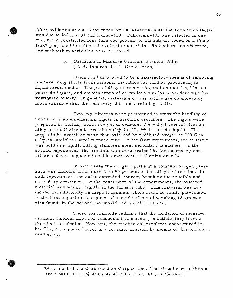
After oxidation at 800 C for th ree hours , essent ia l ly all the activity collected was due to iodine-131 and iodine-133. Tel lur ium-132 was detected in one run, but it consti tuted l e s s than one percent of the activity found on a F i b e r -frax* plug used to col lect the volati le m a t e r i a l s . Ruthenium, molybdenum, and technet ium act ivi t ies were not found.
b. Oxidation of Mass ive Uran ium-F i s s ium Alloy ( T . R . Johnson, R. L. Chris tensen)
Oxidation has proved to be a sat isfactory means of removing mel t - re f in ing skulls f rom z i rconia c ruc ib les for further process ing in liquid me ta l media . The possibi l i ty of recover ing molten meta l spi l ls , un-pourable ingots, and ce r ta in types of s c r ap by a s imi la r procedure was invest igated briefly. In genera l , m a t e r i a l s of this nature a r e considerably m o r e m a s s i v e than the re la t ively thin mel t - ref in ing skulls .
Two exper iments were performed to study the handling of unpoured u ran ium- f i s s ium ingots in z i rconia c ruc ib les . The ingots were p r e p a r e d by melt ing about 365 gm of u ran ium-7 .5 weight percent f iss ium alloy in snaall z i rconia c ruc ib les (1—-in. ID, Sy- in . inside depth). The ingots inthe c ruc ib les w e r e then oxidized by undiluted oxygen at 750 C in a 2Y-in.. s ta in less s tee l furnace tube. In the f i r s t exper iment , the crucible was held in a tightly fitting s ta in less s tee l secondary container . In the second exper iment , the crucible was un res t r a ined by the secondary conta iner and was supported upside down over an alumina crucible .
In both cases the oxygen uptake at a constant oxygen p r e s sure was uniforna until m o r e than 95 pe rcen t of the alloy had reacted. In both exper i inents the oxide expanded, thereby breaking the crucible and secondary container . At the conclusion of the exper iments , the oxidized m a t e r i a l was wedged tightly in the furnace tube. This m a t e r i a l was r e moved Avith difficulty as l a rge f ragments which could be easi ly pulverized. In the f i r s t exper iment , a piece of unoxidized meta l weighing 18 gm was also found; in the second, no unoxidized me ta l remained.
These exper imen t s indicate that the oxidation of mass ive u ran ium-f i s s ium alloy for subsequent p rocess ing is sat isfactory from a chemica l standpoint. However, the mechanica l problems encountered in handling an unpoured ingot in a c e r a m i c crucible by means of this technique need study.
•A product of the Carborunduiaa Corporatioia. The stated composit ion of the f ibers is 51.2% Al203,47.4% SiOa, 0.7% B2O3, 0.7% NazO.
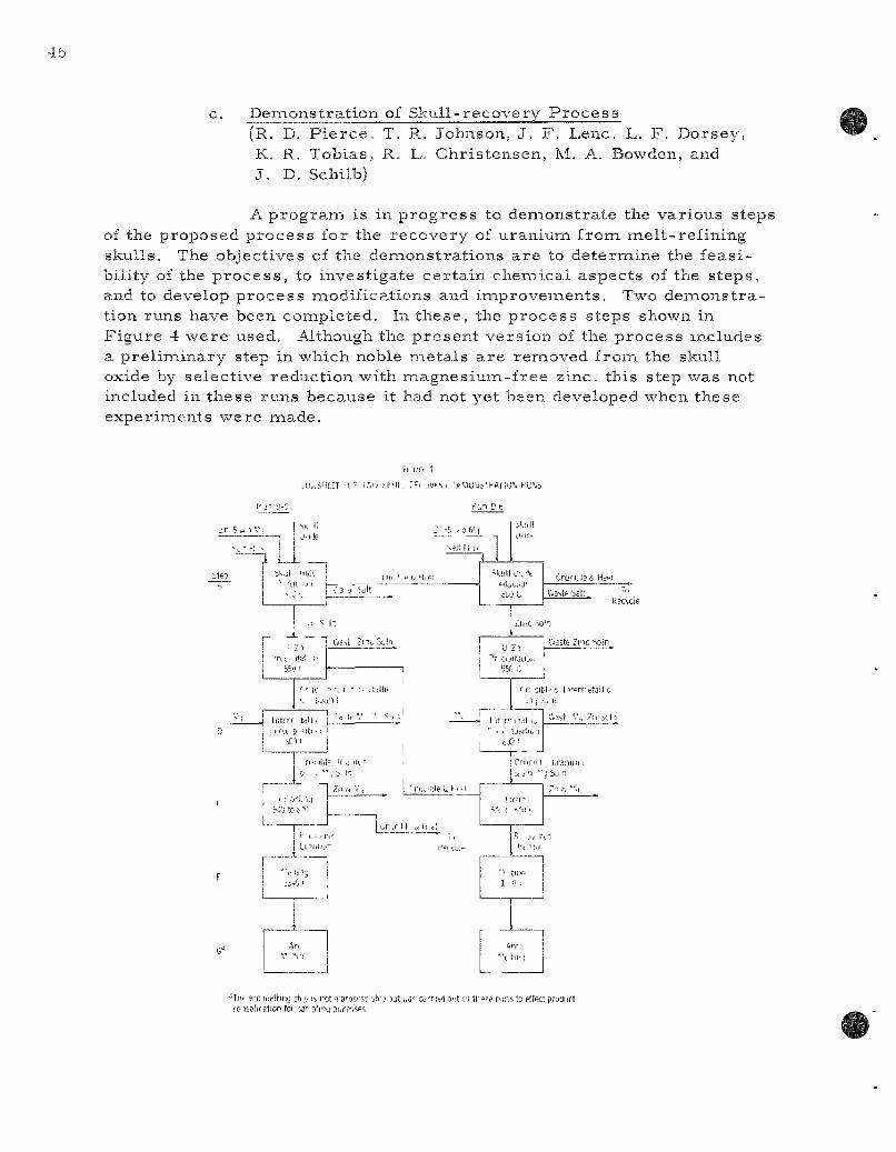
c. Demonstrat ion of Skul l - recovery P r o c e s s ( R . D . P i e r c e , T. R. Johnson, J . F . Lenc. L. F . Dorsey, K. R. Tobias, R. L. Chr is tensen, M. A. Bowden, and J . D. Schilb)
A p r o g r a m is in p r o g r e s s to denaonstrate the various step of the proposed p rocess for the recovery of uranium from melt- ref ining skulls. The objectives of the denaonstrations a re to determine the feas i bility of the p r o c e s s , to investigate cer ta in chenaical aspects of the s teps , and to develop p rocess modifications and inaprovem.ents. Two demons t ra tion runs have been completed. In these , the p rocess steps shown in Figure 4 were used. ALthoiigh the p resen t vers ion of the p rocess includes a p re l iminary step in which noble meta l s a r e removed from the skull oxide by selective reduction with naagnesium-free zinc, this step was not included in these runs because it had not yet been developed when these experinaents were naade.
F[ iir. t
HL.SHEET U ' T.'.i) iH j l L ri^UjyuJ, 'jl'.'lu'fcl-'AIIU\ PIJ>«S
P n D-5 pL.n [I 0
zn 5 .. 1 V)
G-*
u.] le -5 .ohM
sjit i 11«
b i j l l "«idi ' LR fjn [—- I nif •• e& Hi Pi
bKun
Skull ox-^t ' iLci i j" 5L0L
Cruride&HeHl
jAMLMil . To Recvcle
II Z l ' r i i itat n
550 i
1 ^ h
\'ia-'A Znc Solo _!_ U Z l
550 C
i I- ]C ^ 6, I * rr *-tilliL L Min I
Intcrr td l l ' I tfoi p <.iti I 1
iOi i
Waste Znc Soln
• a te V ' •: ,1 1 ^ —!—^ I It r-1
' n a!)i.'& l i 'orretall c
V.ast \\ 7n bch tai i„
bJ3'
ri'ublf II J l i e
In in *v% o'tnq
L.
' roublef. I n !
P t . 1 i-f-
CrunLI Uraniun & / n "^ SuIn
f i r t n
H.ivU-•? J, r f l Ifc lEIj
•1 tliw 1 0 '
'•( tirn
^IIH arc melting stip is not a process itf.) )ut v.a' Carritdoiit i i i th '" t ' runs to effect prudiict roisolifation for sa" phnq purposes

The reduction, in termeta l l ic precipi tat ion, and intermetal l ic decomposit ion steps were all conducted in the furnace shown in Figure 5. This furnace was modified to naake t ransfe r by p r e s s u r e possible , and it has functioned sat isfactor i ly when operated with ca re . Improved equipment has been designed and ordered , but delivery is not anticipated for severa l naonths.
FIGURE 5
MODIFIED POUR FURNACE WITH PRESSURE-SIPHON ATTACHMENT FOR DEMONSTRATION RUNS
THERMOCOUPLE • WELL
CONVECTION BAFFLE
ARGON
1®= a ^ ^ ^ A C U U M RADIATION SHIELD
PRESSURE-SIPHON TRANSFER T U B "
INDUCTION HEATING COILS
ARGON
V A C U L M ^ ^
VENT
The l iquid-phase t r ans fe r s were not quantitative in these runs ; however, the liquid heel result ing from the t rea tment of a skull (or batch of skulls) can be charged to a subsequent run. Therefore, crucible heels were interchanged in these two runs in order to limit the uranium los ses .
Oxidized ce r ium-f i s s ium-uran ium skulls were reduced (step B) with a five weight percent naagnesium-zinc solution in the presence of a salt flux (magnesium chlor ide, calcium chloride, and magnesium fluoride in the respect ive mole percentages of 47.5, 47.5, and 5.0). The conapo-sition and par t ic le size distr ibution of the skull oxide a re shown in Table 5. About half of the zirconium in the oxide consisted of par t ic les from the zirconia crucible . The reductions were conducted for 5 hr at 800 C in a graphite c ruc ib le , using tantalum baffles and agitator.
After the reduction (Step B, Figure 4) in Run D-5, the meta l phase was p re s su re - s iphoned into a mold through a tantalum tube, the inlet of which was located 3 nana above the bottona of the reduction crucible . The level of the liquid meta l was followed during the t ransfer
by means of an e lec t r i ca l p robe , and the t rans fe r was stopped when the m e t a l - s a l t interface was about 2 nana above the tube opening. After the meta l had frozen, the mold was removed and a different mold was inser ted to act as a r e ce ive r for the waste salt . The furnace was t i l ted slightly to bring the inlet of the t r ans fe r tube into the salt phase and the salt was t r ans fe r r ed . A heel of salt and me ta l was left in the react ion crucible . This crucible and the heel were used with a f resh charge for the r eduction step in Run D-6. In Run D-6, a plugged argon line caused the salt to be t r a n s f e r r e d along with the me ta l phase after the reduction. These phases were easi ly separa ted after solidification on cooling.
Table 5
COMPOSITION OF SKULL OXIDE CHARGE
( F r o m Skull Oxidation Run SO-50)
Skull Oxide Charge^- Weight: Run D-5, 225 g; Run D-6, 251 g
Element
Uranium Cer ium Zirconium Molybdenum
Weight P e r c e n t
76.0 + 0.4 2.67 ± 0.09 1.03 ± 0.06 1.87 1 0.09
Elenaent
Ruthenium Rhodium Pal ladium Oxygen
Wei
1.
ght Pe rcen t
.41 t 0.01 0.25^ 0.25^
16.52C
^ P a r t i c l e - s i z e dis t r ibut ion of skull oxide in both Run D-5 and Run D-6 was as follows (expressed in weight pe rcen t ) : -325 mesh , 5.2; -170 +325 mesh , 15.8; -80 +170 mesh , 11.6; -45 +80 mesh , 19.7; -25 +45 mesh , 24.0; -14 +25 mesh , 23.6; and + 14 mesh , none.
"Es t imate based on or iginal me ta l concentrat ion of 0.3 weight percen t .
^Obtained by difference.
The uran ium reductions (Step B), based on the amount of uran ium appearing in solution, were 93 and 96 pe rcen t complete in Runs D-5 and D-6, respec t ive ly . The sal t waste s t r e a m s on the other hand, contained only 0.2 and 0.4 percen t of the u ran ium charged. It is suspected that the 4 to 7 percent of unaccounted u ran ium was renaoved from the me ta l phase by react ion with the graphite crucible to forna uran ium carb ide . Quanti t ies of elenaents p r e sen t in the flux before and after reduction a r e given in Table 6. A la rge fract ion of the u ran ium in the D-6B (Run D-6, Step B) flux was probably contained in smal l amounts of zinc me ta l which were occluded by the sal t when the two phases were rapidly t r a n s f e r r e d and chilled.

Table 6
COMPARISON OF URANIUM AND FISSION PRODUCT CONCENTRATIONS IN FLUX BEFORE AND AFTER REDUCTION
Conditions: Reduction at 800 C for 5 hr in graphite crucible
Charges : 5 and 5.6 kg of 5 percent magnes ium-z inc alloy in Runs D-5 and D-6, respect ively, and 0.8 and 1.1 kg of flux in Runs D-5 and D-6, respect ively. Flux composit ion: 47.5, 47.5, and 5.0 mol p e r cent, respect ive ly of MgClj, CaCl^, and MgFj
Quantit ies in Flux (gra)
E lement
Uranium, total^-Ceriuin Zi rconium Molybdenum Ruthenium, Rhodium,
Pal ladium Zinc Uraniuna, as me ta l
Charged
171 6.0 2.3 4 .2
4 .3 0 0
Run D-5
After Reduction
0.4 0.3 0.07^ 0.2
_t> Not determine Not determiine
id
:d
Charged
191 6.7 2.6 4 .7
4 .8 0 0
Run D-6
After Reduction
0.9 0.3 0.07^ 0.5
_t) 17
0.6
^Includes u ran ium p re sen t both as me ta l and as oxide.
"Resul t is low or unavailable since the element was not completely dissolved on leaching the flux with aqua regia . Qualitative X- ray emiss ion data show significant amounts of z i rconium, ruthenium, rhodium, and tantalum (from the equipment) in the undissolved res idue .
In connection with the development work on the skull r e c l a mat ion p r o c e s s , rough de te rmina t ions were made of the melting points and densi t ies of per t inent mol ten salt irxixtures used as fluxes. The resu l t s a r e shown in Table 7.
The in te rmeta l l i c compound precipi ta t ion (Step C), in te r -meta l l ic compound decomposit ion (Step D), and re tor t ing (Step E) operat ions for both runs were made in the same tantalum crucible . These steps for Run D-6 were completed before they were begun in Run D-5, and the r e tort ing heel remaining in the crucible after Step D-6E was recharged in the crucible to the precipi ta t ion step of Run D-5 (Step C).

Table 7
PROPERTIES OF SALT FLUXES
Flux Connposition Freez ing Density (g/cc) Point
Constituent Mole % (C) 600 C 700 C 800 C
MgCl2 CaClz 47.5 V 602 2.12 2.01 1.92 MgF 2
MgCIz LiCl 47.5 )- 565 _ - I.9 MgF, 2
MgCla NaCl 54.0 > 432 - - 1.9 MgF2
F o r the precipi ta t ion s tep, the ingots from Step B were reheated to 800 C and cooled to about 550 C to c rys ta l l i ze the epsilon z inc-uranium in te rmeta l l i c phase . Most of the u ran ium-z inc solution was p r e s s u r e - t r a n s f e r r e d f rom the c r y s t a l s . The t r a n s f e r r e d meta l was r e -mel ted and sampled to p e r m i t u ran ium ana lyses . The uran ium concen t ra tion was only slightly higher than the solubility at the t r ans fe r t e m p e r a t u r e , as is indicated by the following data:
Uraniuna Cone (w/o)
Step
D-5C D-6C
Trans fe r Temp (C)
- 5 6 0 - 5 5 0
F i l t e r ed Sam.ple
Jus t before Trans fe r
0.17 0.10
T: r ans fe r r ed Ingot
0.19 0,11
Samples of the zinc solution in Step D-5C ( in termeta l l ic compound p rec ip i tation step) taken at 800 C before cooling indicated that about 80 percen t of the re tor t ing heel left f rom D-6E had redissolved.
Magnesium was added to the in te rmeta l l ic compound heel from Step C to form an equal weight ra t io of magnes ium to zinc. The m a t e r i a l was heated to 800 C and s t i r r e d to decompose the epsilon phase . After four hours the bulk of the magnes ium-z inc was t r a n s f e r r e d f rom the uranium. After the t r ans fe r in Step D-5D, f i l tered samples were
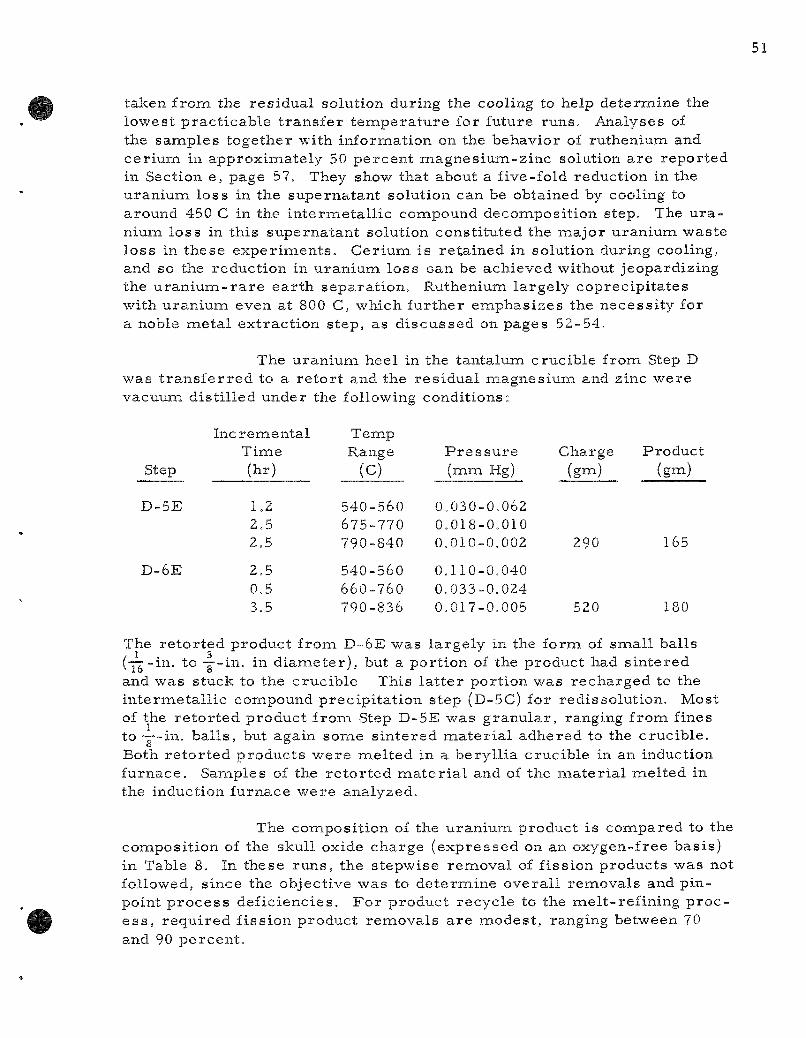
taken f rom the res idual solution during the cooling to help determine the lowest p rac t icab le t r ans fe r t e m p e r a t u r e for future runs . Analyses of the samples together with information on the behavior of ruthenium and ce r ium in approximately 50 percen t magnes ium-z inc solution a r e repor ted in Section e, page 57. They show that about a five-fold reduction in the u ran ium loss in the supernatant solution can be obtained by cooling to around 450 C in the in te rmeta l l i c compound decomposit ion step. The u r a nium loss in this supernatant solution consti tuted the major uranium waste loss in these exper imen t s . Cer ium is re ta ined in solution during cooling, and so the reduction in u ran ium loss can be achieved without jeopardizing the u r a n i u m - r a r e ea r th separa t ion . Ruthenium largely coprecipi ta tes with u ran ium even at 800 C, which fur ther emphas izes the necess i ty for a noble me ta l ext rac t ion s tep, as d i scussed on pages 52-54.
The uran ium heel in the tantalum crucible from Step D was t r a n s f e r r e d to a r e t o r t and the res idua l magnes ium and zinc were vacuum dis t i l led under the following condit ions:
Step
D-5E
D-6E
Incrementa l Time (hr)
1.2 2.5 2.5
2.5 0.5 3.5
Temp Range
(C)
540-560 675-770 790-840
540-560 660-760 790-836
P r e s s u r e (mm Hg)
0.030-0.062 0.018-0.010 0.010-0.002
0.110-0.040 0.033-0.024 0.017-0.005
Charge (gm)
290
520
Product (gm)
165
180
The re to r t ed product from D-6E was la rgely in the form of smal l balls (-77-in. to ™-in. in d i amete r ) , but a port ion of the product had s in tered and was stuck to the crucible This l a t t e r port ion was recharged to the in te rmeta l l i c compound precipi ta t ion step (D-5C) for redissolut ion. Most of the r e to r t ed product f rom Step D-5E was granular , ranging frona fines to—-in . ba l l s , but again somie s in te red m a t e r i a l adhered to the crucible . Both re to r t ed products were naelted in a beryl l ia crucible in an induction furnace. Samples of the r e to r t ed m a t e r i a l and of the ma te r i a l mel ted in the induction furnace were analyzed.
The composit ion of the uran ium product is conapared to the composit ion of the skull oxide charge (expressed on an oxygen-free basis) in Table 8. In these runs , the stepwise removal of fission products was not followed, since the objective was to de te rmine overa l l removals and pinpoint p r o c e s s deficiencies . Fo r product recycle to the mel t - ref ining p r o c e s s , r equ i red f iss ion product removals a r e modest , ranging between 70 and 90 percen t .

T a b l e 8
URANIUM P U R I F I C A T I O N IN S K U L L - R E C L A M A T I O N P R O C E S S RUNS
P r o d u c t C o n c e n t r a t i o n and D e c o n t a m i n a t i o n
C o n c e n t r a t i o n in Run D - 5 Run D-6 S t a r t i n g M a t e r i a l
C o n s t i t u e n t
U r a n i u m C e r i u m M o l v b d e n u m R u t h e n i u m Z i r c o n i u n i
P a l l a d i u m Magnes ium. Oxygen
(oxyg: e n - f r e e b a s i s ) (w/o)
91.0 3.2 2.2 1.7 1.2
0.3 0 -
Cone (w/o)
9 4 . 3 ^ 0 . 5 ^ O.Q^
1.2b 0.6h
X 0.001 0.4a
0.1 to 0.
a
3 a
P e r c e Ren^o\
85 5^ 30 ^0
--
nt .-al
Cone (w/o)
^ 5 . 6 ^ l b 0 .6a .b
1.3^^-b 0.4^ 1.0^ 0 . 0 0 1 ^ 0.3a O.ia-0.6l '
P e r c Remo
6Q 73 23 67 17 qq
--
^ B a s e d on a n a l y s i s of r e t o r t e d m a t e r i a l .
" B a s e d on a n a l y s e s of m a t e r i a l a f t e r m e l t i n g in a beryl l ic t c r u c i b l e .
No q u a n t i t a t i v e r e m o v a l s w e r e a n t i c i p a t e d , s i n c e t h e p h a s e s e p a r a t i o n s w e r e d e l i b e r a t e l y i n c o n a p l e t e . T h e c e r i u n a r e n a o v a l c o r r e s p o n d s c l o s e l y to t h e p e r c e n t r e m o v a l of t h e m a g n e s i u i n - r i c h s u p e r n a t a n t s o l u t i o n f o l l o w ing t h e d e c o m p o s i t i o n of t h e u r a n i u m - z i n c i n t e r m e t a l l i c c o m p o u n d . If d e s i r e d , t h e r e f o r e , i t c o u l d b e i n c r e a s e d b y b e t t e r p h a s e s e p a r a t i o n o r b y a n a a g n e s i u i T i w a s h . B e c a u s e of i t s i n s o l u b i l i t y i n z i n c , m o l y b d e n u m p r o b a b l y r e m a i n e d a s a p r e c i p i t a t e i n t h e n a e t a l h e e l of t h e r e d u c t i o n s t e p . T h e r e m o v a l of r u t h e n i u m i s i n a d e q u a t e f o r p r o c e s s p u r p o s e s ; i t i s a n t i c i p a t e d , h o w e v e r , t h a t r u t h e n i u m , a s w e l l a s t h e o t h e r n o b l e m e t a l s , w i l l b e r e m o v e d e f f e c t i v e l y i n s u b s e q u e n t r u n s w h e n t h e i n i t i a l n o b l e m e t a l e x t r a c t i o n s t e p i s a d d e d t o t h e p r o c e s s . Z i r c o n i u m w a s a l s o i n a d e q u a t e l y r e m o v e d . T h e r e a s o n s f o r t h i s w i l l b e e x p l o r e d . T h e v e r y g o o d p a l l a d i u n a r e m o v a l r e s u l t s f roia i i t s l o w c o n c e n t r a t i o n i n t h e c h a r g e m a t e r i a l a n d i t s h i g h s o l u b i l i t y in b o t h s u p e r n a t a n t s o l u t i o n s . W i t h a d d i t i o n a l e x p e r i e n c e . i t i s t h o u g h t t h a t t h e n a a g n e s i u n a a n d o x y g e n c o n t e n t s of t h e r e t o r t e d p r o d u c t s c a n b e r e d u c e d .
A u r a n i u n a m a t e r i a l b a l a n c e i s p r e s e n t e d i n T a b l e 9. As i n d i c a t e d p r e v i o u s l y , t h e h i g h i i r a n i u m l o s s in t h e m a g n e s i u n a w a s t e s t r e a m f r o n a t h e i n t e r i a i e t a l l i c d e c o n a p o s i t i o n s t e p c o u l d h a v e b e e n r e d u c e d s i g n i f i c a n t l y b y l o w e r i n g t h e t e n a p e r a t u r e p r i o r t o t h e t r a n s f e r . T h e h e e l s s h o u l d n o t b e r e g a r d e d a s l o s s e s b e c a u s e t h e y w o u l d n o r m a l l y b e r e c y c l e d i n t h e p r o c e s s . O t h e r r e s i d u a l u r a n i u m a d h e r i n g to p a r t s of t h e e q u i p n a e n t , s u c h

as s t i r r e r s and ba f f l e s , wou ld not o r d i n a r i l y c o n s t i t u t e a p r o c e s s l o s s , but w a s d i s s o l v e d in t h e s e e x p e r i m e n t s fo r m a t e r i a l b a l a n c e p u r p o s e s . Mos t of the u ran iuna l o s s e s cou ld be avo ided o r r e d u c e d s u b s t a n t i a l l y in e q u i p m e n t b e t t e r a d a p t e d for t h i s p u r p o s e .
Table 9
URANIUM MATERIAL BALANCES IN SKULL DEMONSTRATION RUNS
(See Flowsheet in Figure 4, page 46)
Designation
Uranium Charge Skull Oxide Heel from Step D-6E Heel from Step D-5B
Waste Streams Reduction Step FLix (Step B) Zinc-r ich Supernatant (Step C) Magnesium-rich Supernatant (Step D)
Heels and Residues Available for Recycle
Reduction Step Metal Heel Retorting Heel (Step E) Other Residiies^-
Retorted Product
Run D
Uranium Content
(gm)
171 46
_
0.4 5.4
11.9
-5
Percent of Charge
79 21 _
100
0.2 2.5 5.5
Run D
Uranium Content
(gm)
191 -
19
0.4 4.1
10.3
-6
Percent of Charge
91 -9
100
0.2 2.0 4.9
Unaccountable Losses
19 35 9
122
14
8.8 16
4.1
56
6.4
11 46
6
125
7
5.2 22
2.8
60
3.3
^•Metal on par ts of the equipment such as s t i r r e r s and thermocouple walls. This metal was dissolved for mater ia l balance purposes.
The m e t a l l i c u r a n i u m p r o d u c t w a s suff ic ient ly p u r e &o t ha t it cou ld be m e l t e d s a t i s f a c t o r i l y u n d e r n o r m a l m e l t - r e f i n i n g c o n d i t i o n s , thus ind ica t ing tha t it c a n be r e c y c l e d to the m e l t - r e f i n i n g o p e r a t i o n in the E B R - I I fuel c y c l e .
d. Noble M e t a l E x t r a c t i o n f r o m F i s s i u m Skull Oxides
A s t e p c u r r e n t l y e n v i s i o n e d for the m e l t - r e f i n i n g - s k u l l -r e c l a m a t i o n p r o c e s s is the s e l e c t i v e e x t r a c t i o n into z inc of the noble m e t a l s p r e s e n t in f i s s i u m ox ide . To f a c i l i t a t e th i s e x t r a c t i o n and the s u b s e q u e n t p h a s e s e p a r a t i o n , t he f i s s i u m oxide i s s u s p e n d e d in a m o l t e n s a l t flux. The noble f i s s i o n p r o d u c t s w h o s e o x i d e s a r e r e d u c e d by z inc ( such as m o l y b d e n u m , r u t h e n i u m , r h o d i u m , and p a l l a d i u m ) a r e e x p e c t e d to be r e d u c e d by

and dissolved or suspended in the zinc. Uranium oxide and other stable oxides (such as the oxides of plutonium, r a r e ea r th s , and zirconium) r e main suspended in the flux phase . P r e l i m i n a r y work (ANL-6287, page 58) demons t ra ted that ruthenium could be t r a n s f e r r e d to a molten zinc phase from a f i ss ium oxide-flux s lu r ry .
In the pas t qua r t e r , work on noble naetal extract ion with zinc was pe r fo rmed in two a r e a s : (1) a fur ther study of the extract ion of noble elenaents, and (2) the study of the separa t ion of the phases after the extract ion. P r e l i m i n a r y r e su l t s indicate near ly complete ext ract ion of ruthenium, molybdenum, and pal ladium. The phase separa t ion work has shown that separa t ion by remova l of the sal t s lu r ry is imprac t ica l . An al ternat ive p rocedure , r emova l of the zinc phase after solidification of the sal t , has worked well .
(1) Demonst ra t ion of Noble Metal Extrac t ion (J. B. Knighton, J . W. Walsh)
A run was made to study the ext rac t ion of molybdenum, rutheniuna, and pal ladium into zinc. The conditions of this run and the dis t r ibut ion of the noble me ta l s and uranium between the flux and zinc phases a r e shown in Table 10.
Table 10
NOBLE METAL EXTRACTION; DISTRIBUTION OF NOBLE METALS BETWEEN ZINC AND
FLUX PHASES
Charge : 400 g of zinc, 21,9 g of -325 m e s h f iss ium oxide f rom batch "S054," 200 g of fliox (47.5 m / o CaCl2, 47.5 m / o MgClz, 5 m / o MgFa)
Condit ions: P h a s e s contacted as 750 C for one hour in a lumina crucible under an air a tmosphere . The mixing ra te was 400 rpm.
Element
U rani una Ruthenium Molybdenum Pal ladium
P e rcen t of Total in Flux
100 9
16 7
P e rcent of Total in Zinc
0.001 91 84 93
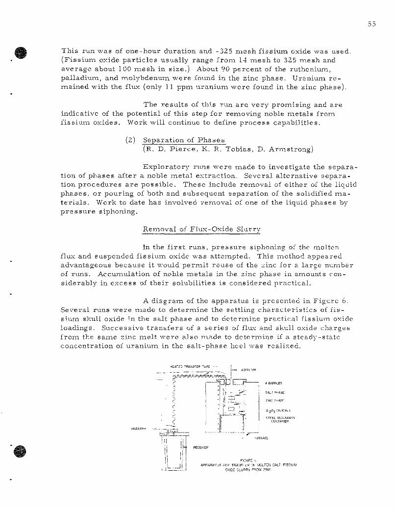
This run was of one-hour duration and -325 mesh f issium oxide was used. (F iss ium oxide pa r t i c l e s usually range from 14 mesh to 325 mesh and average about 100 naesh in size.) About 90 percent of the rutheniuna, palladium, and naolybdenum were found in the zinc phase. Uraniuna r e mained with the flux (only 11 ppm uranium were found in the zinc phase).
The resu l t s of this run a re very promising and are indicative of the potential of this step for removing noble meta ls frona fissiuiai oxides. Work will continue to define p rocess capabil i t ies .
(2) Separation of Phases (R. D. P i e r c e , K. R. Tobias, D. Armstrong)
Exploratory runs were made to investigate the separa tion of phases after a noble meta l extraction. Several al ternat ive separa tion procedures a r e poss ible . These include removal of ei ther of the liquid phases , or pouring of both and subsequent separat ion of the solidified m a t e r i a l s . Work to date has involved removal of one of the liquid phases by p r e s s u r e siphoning.
Removal of Flux-Oxide Slurry
In the f i r s t runs, p r e s s u r e siphoning of the naolten flux and suspended f iss ium oxide was attempted. This method appeared advantageous because it would pernait reuse of the zinc for a large number of runs. Accunaulation of noble meta l s in the zinc phase in amounts considerably in excess of their solubili t ies is considered pract ical .
A diagram of the apparatus is presented in Figure 6. Several runs were naade to determine the settling cha rac te r i s t i c s of f issium skull oxide in the salt phase and to determine prac t ica l fissiuna oxide loadings. Successive t r ans fe r s of a s e r i e s of flux and skull oxide charges from the same zinc mel t were also made to determine if a s teady-sta te concentrat ion of uraniuiai in the sa l t -phase heel was real ized.
SALT PHASE
ZiNC PHASE
At^Oj CRJC Bi.E
STEEL SECONDARY CONTAINER
FICURE t APPARATUS FOR TRAMSrER OF MOLTEN SALT~F!SSIUM
OXIDE SLURRY FROM ZINC

It w a s p o s s 12 we igh t p e r c e n t sku l l oxide in
FIGURE 7 SETTLING OF URANIUM OXIDE IN SALT FLUX
FLUX COMPOSITION 47 5 MOLE PERCENT MgCl2 4 7 5 MOLE PERCENT CaCip 5 MOLE PERCENT MgFj
CHARGE 6 0 0 g ZIHJC 400g SALT FLUX 20g SKULL OXIOE (-170 + 325 MESH)
UNFILTERED SALT PHASE SAMPLES TAKEN. NEAR BOTTOM OF FLUX - D
NEAR TOP OF F L U X - O ABOUT I-INCH FROM TOP OF FLUX - X
ABOUT 2-!NCHES FROM TOP OF FLUX - A
b 10 15 20 25 T!»JE AFTER AGITATOR TURNED OFF.n.nu'es
ib le to a c h i e v e a u n i f o r m d i s p e r s i o n of naol ten s a l t wi th fine f i s s i u m oxide (-170
- 3 2 5 i n e s h ) . H o w e v e r , it s e e m s c e r t a i n t ha t r a p i d se t t l ing of t h i s fine oxide s l u r r y w i l l o c c u r . Exper i i a ien ta l i n f o r m a t i o n on th i s point i s shown in F i g u r e 7 for a 5 p e r c e n t sku l l oxide s l u r r y . The e x p e r i m e n t a l r e s u l t s show t h a t in 15 m i n the u r a n i u m c o n c e n t r a t i o n n e a r the b o t t o m of the flux w a s laiore than tw ice the n e a r l y u n i f o r m c o n c e n t r a t i o n of the r e m a i n d e r of the f lux. C o n s i d e r a b l y g r e a t e r diff iculty w a s e n c o u n t e r e d in s u s p e n d i n g l a r g e r p a r t i c l e s of sku l l oxide ( -14 +25 m e s h ) . Al though w e t t e d wi th flux, t h e s e c o a r s e p a r t i c l e s s e t t l ed t h r o u g h the z inc p h a s e and accunau la ted on the s ide and bottona of the c r u c i b l e . H o w e v e r , none of the p a r t i c l e s could be found Vv'ithin the z inc p h a s e .
The s u s p e n s i o n b e c a m e th ick and no t i ceab ly naore diff icul t to t r a n s f e r at oxide c o n c e n t r a t i o n s of about t h r e e p e r c e n t for the -14 T 25 naesh p a r t i c l e s and a t about t e n p e r c e n t for the -170 - 3 2 5 m e s h p a r t i c l e s . T h e s e c o n c e n t r a t i o n s a r e both l o w e r tha,n the u r a n i u m oxide load ings of aboLit 15 p e r c e n t , wh ich a r e c o n s i d e r e d a t t r a c t i \ e f r om a \ o l u n i e s tandpoin t for the s u b s e q u e n t r e d u c t i o n s t e p .
^llthough t h e s e s t u d i e s i l l u s t r a t e d tha,t q u a n t i t a t i v e s u s p e n s i o n of skul l oxide in flux is diff icul t , a few r u n s ( s ee Tab le 11) w e r e m a d e to s e e w h e t h e r s u c c e s s i v e c o n t a c t s of s a l t - o x i d e wi th z inc would resLilt in a c o n s t a n t h e e l of oxide a f t e r e a c h sa l t t r a n s f e r .
J 1 Mil i f I I ' ,
r i I! I 1 ar I" 1 I J I
•lollo II l lL-0 3 rj T f *^ ft
i f H t l
bni I f r
iffttrd) t r
1
. '1
M "ir t ran ^ r
IP tia Tir 111 r j t a i f r
h r t ra f r ~ tr 1 ' r
i i ir i l 5 a f * HI t 1 1 ^ J d a I
as MI ak , 1 1
This heel might then be r ecove red by washing the zinc with additional flux. The g rea t e r difficulty with the c o a r s e r m a t e r i a l is evident in Run KT-9, but all runs resu l ted in a fair ly l a rge loss of uranium, even after two flux washes . Removal of the flux s lu r ry is therefore regarded as an una t t r ac tive p rocedure for the skull r ecovery p r o c e s s .
Removal of Zinc Phase
Because of the difficulty in making quantitative t r a n s fe rs of flux-oxide s l u r r i e s , s tudies were di rec ted to the removal of the zinc phase , thereby leaving the oxide and flux to be subsequently reduced with magnes ium-z inc in the saiaie c ruc ib le . This separa t ion has been successfully pe r fo rmed by p re s su re - s iphon ing away the zinc phase after cooling to f reeze the sal t . An opening was maintained in the salt by running the agi ta tor while the sal t was freezing. Analysis of the t r ans f e r r ed zinc showed only 0.4 percen t t r ans fe r of uraniuna with the zinc. Since this method of t r ans fe r appea r s sa t is factory , it will be exploited fur ther .
e. Uraniuna and F i s s ion Product Solubilities in High Magnes ium-Zinc Systems (I. O. Winsch, R. D. P i e r c e , T. Johnson, T. Cannon, and K. Tobias)
The changes in u ran ium, fission product , and plutonium solubil i t ies as magnes ium is added to zinc systenas a re uti l ized in both the blanket- and skul l - reclanaat ion p r o c e s s e s . For example, uranium solubility at 800 C f i r s t d e c r e a s e s as magnes ium is added to zinc (to a min i mum of about 5 percen t at a naagnesiuna concentrat ion of about 5 percent ) , then i n c r e a s e s to about 20 percent at a naagnesiuna concentrat ion of 12 p e r cent, and thereaf te r d e c r e a s e s sharply as further magnes ium is added. The insolubility of uraniuna in the systeiais of high naagnesium concent ra tions is exploited in the blanket p r o c e s s to effect a plutonium-uraniuna separa t ion and in the sku l l - r ec lamat ion p r o c e s s to effect a u r a n i u m - r a r e e a r t h separa t ion .
Uranium solubility data at severa l high naagnesiuna concentra t ions have been obtained (see F igure 8). Both naagnesiuna concent ra t ion and t e m p e r a t u r e have pronounced effects on the uraniuna solubility and can be va r i ed to provide low uran ium solubil i t ies (e.g., 0.1 percent at 405 C in the 46 weight percen t magnes ium-z inc eutectic) . In the exper iment at a 50 pe rcen t magnes ium concentrat ion, the ceriuna concent ra tion remained unchanged at 0.2 pe rcen t as the t empera tu re was lowered from 800 C to 405 C.
The behavior of ruthenium and ce r ium on the decomposi tion by magnesiuna of an in te rmeta l l i c u ran ium-z inc compound formed by d i rec t in terac t ion of a u ran ium-ru then ium-ce r iuna alloy with the zinc is shown in Table 12.
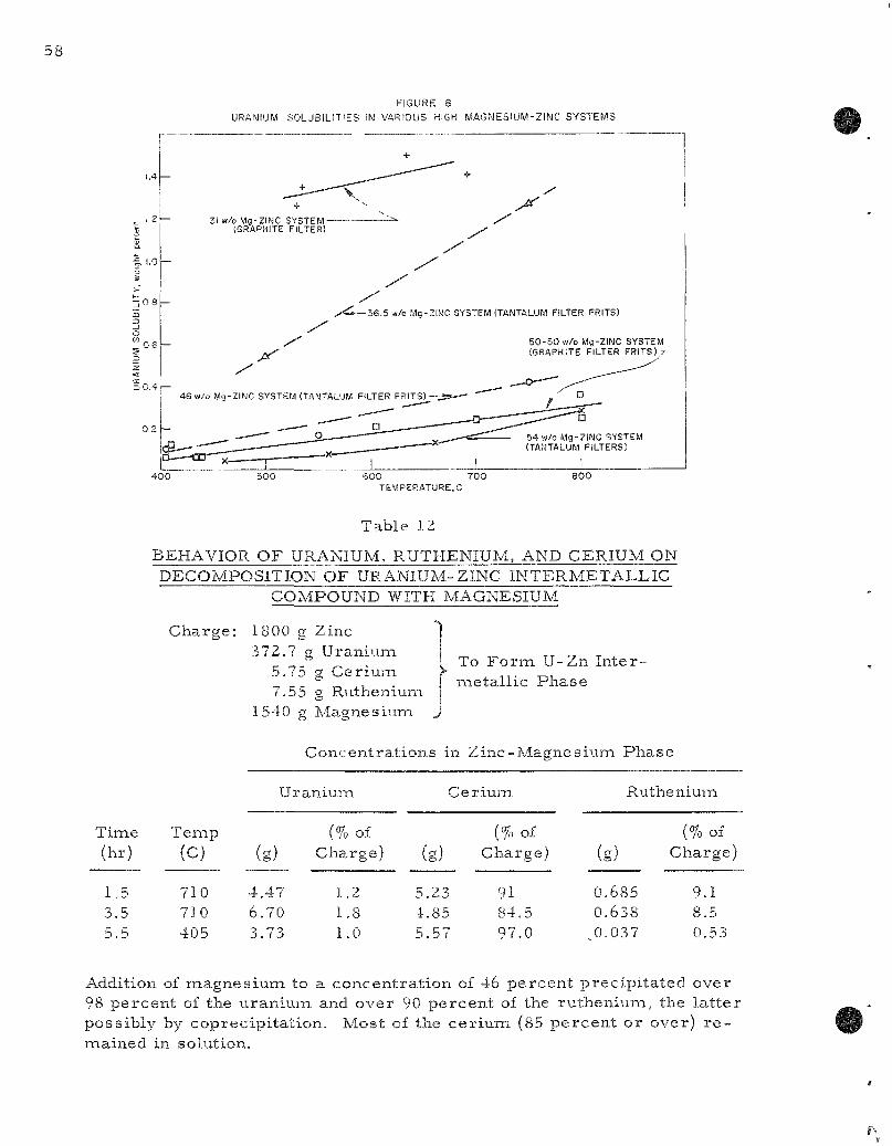
FIGURE 8
URANIUM SOLUBIL IT IES IN VARIOUS HIGH MAGMESIUM-Z INC SYSTEMS
; 0 8
. 0 6
X 31 w/o Mg-ZINC SYSTEM-
{GRAPHITE FILTER)
J^
-36 .5 w/o Mg-ZINC SYSTEM (TANTALUM FILTER FRITS)
5 0 - 5 0 w/o Mg-ZINC SYSTEM (GRAPHITE FILTER FRITS) ;
4 0 0 5 0 0 6 0 0 7 0 0 TEMPERATURE, C
8 0 0
Table 12
BEHAVIOR OF URANIUM, RUTHENIUM, AND CERIUM ON DECOMPOSITION OF URANIUM-ZINC INTERMETALLIC
COMPOUND WITH MAGNESIUM
Charge: 1800 g Zinc 372.7 g Uraniuna
5.75 g Ceriuna 7.55 g Rutheniuna
1540 g Magnesium ^
To F o r m U-Zn Inter-naetallic Phase
Concentrat ions in Zinc-Magnesium Phase
Time (hr)
1.5 3.5 5.5
Tenap
(c)
710 710 405
U
(g)
4.47 6.70 3.73
raniuna
(% of Charge)
1.2 1.8 1.0
c
(g)
5.23 4.85 5.57
eriuiaa
(% of Charge)
91 84.5 97.0
Rutheniuna
(g)
0.685 0.638
^0.037
(%of Charge)
9.1 8.5 0.53
Addition of magnesiuna to a concentrat ion of 46 percent precipi ta ted over 98 percent of the uranium and over 90 percent of the rutheniLina, the la t te r possibly by coprecipitat ion. Most of the ce r ium (85 percent or over) r e -naained in solution.
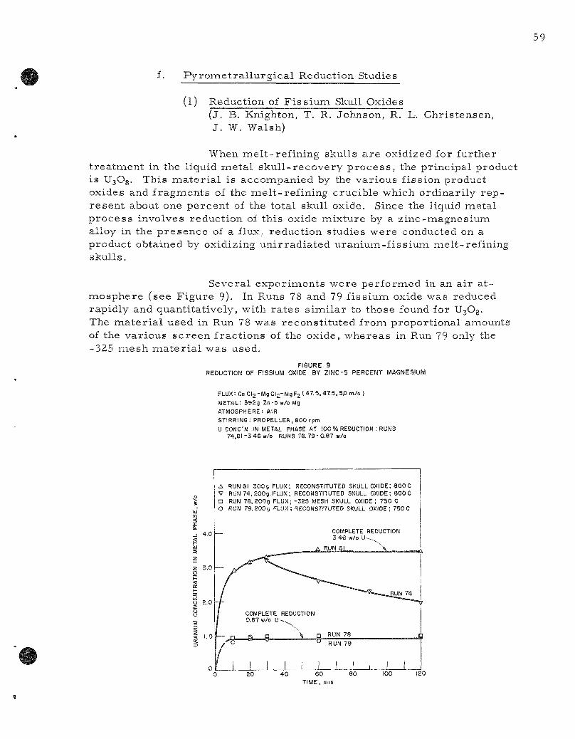
f. Py rome t r a l l u rg i ca l Reduction Studies
(l) Reduction of Fissiuna Skull Oxides ( j . B. Knighton, T. R. Johnson, R. L. Chris tensen, J . W. Walsh)
When mel t - ref in ing skulls a re oxidized for further t rea tment in the liquid meta l sku l l - recovery p r o c e s s , the principal product is U3O8. This m a t e r i a l is accompanied by the various fission product oxides and fragiaients of the me It-refining crucible which ordinar i ly r e p resen t about one percent of the total skull oxide. Since the liquid naetal p roces s involves reduction of this oxide mixture by a zinc-magnesium alloy in the p resence of a flux, reduction studies were conducted on a product obtained by oxidizing uni r rad ia ted uraniuna-fissium melt-refining skulls .
Several exper iments were performed in an air a t -laiosphere (see Figure 9). In Runs 78 and 79 fissium oxide was reduced rapidly and quantitatively, with ra tes s imi la r to those found for U3O8. The naaterial used in Run 78 was reconst i tuted from proport ional anaounts of the var ious sc reen fra.ctions of the oxide, whereas in Run 79 only the -325 mesh m a t e r i a l was used.
FIGURE 9 REDUCTION OF FISSIUM OXIDE BY Z I N C - 5 PERCENT MAGNESIUM
F L U X : C a C l 2 - M g C l 2 - M g F 2 ( 4 7 5 , 4 7 5 , 5 . 0 m/o)
METAL: 39£g Z n - 5 w / o M g
ATMOSPHERE: AIR
STIRRING: PROPELLER, 800 rpm
U CONC'N IN METAL PHASE AT 100 % REDUCTION : RUNS 74,81-3 46 w/o RUNS 7 8 , 7 9 - 0 . 8 7 w/o
4.0
3.0
o 2.0
A RUN 81 3 0 0 g FLUX; RECONSTITUTED SKULL OXIDE; 8 0 0 C V RUN 74 ,200g . FLUX; RECONSTITUTED SKULL OXIDE; 800 C D RUN 78, 200g FLUX; - 3 2 5 MESH SKULL OXIDE; 730 C O RUN 79 , 200g FLUX; RECONSTITUTED SKULL OXIDE; 750 C
COMPLETE REDUCTION 3 4 6 w/o U -
A RUN 61

In Run 74 an atteiaipt was made to inc rease the final uraniuna concentrat ion in the meta l phase by initially adding more u ran ium-fissiuna skull oxide to the sys tem. As indicated in F igure 9, the sys tem was unstable, the uran ium concentrat ion in the meta l phase decreas ing with t ime. When the amount of flux was increased from 200 gm in Run 74 to 300 gin in Run 81, but with the same amounts of skull oxide charged, the reaction proceeded to completion and no instability was evident. This effect is believed to resu l t from an inc reased viscosi ty of the flux caused by the higher concentrat ion of suspended magnes ium oxide when less flux is used. This , in turn , a l t e r s the ability of the flux to protec t the meta l phase from oxidation by the a i r a tmosphere .
It is expected that z i rconium will be p resen t in the skull oxide in two f o r m s : as finely divided fission product z i rconium oxide and as z i rconia f ragments produced by degradation of the crucible during the skull oxidation. The mel t - ref ining crucibles also contain about five percent calc ium oxide as a stabilizing agent and smal l amounts of other impur i t i es , chiefly sil icon and iron oxides. Several exper iments were conducted to investigate the behavior of zirconium, oxide frona these two sources during the reduction of f iss ium oxide.
The crucible f ragments do not appear to be reduced readily, possibly because they a re a ref rac tory , high-fired type of m a t e r ia l . With a sodium chlor ide-magnes ium chlor ide-magnes ium fluoride flux (54.2, 41 .1 , 4.7 naole percent , respect ively) , a zinc-6 weight percent magnesium solution, c rushed z i rconium oxide (<60 mesh) from the r e a c tion zone of a used mel t - ref in ing crucible was reduced relat ively slowly at 800 C and there appeared to be an induction per iod (see Figure 10).
FIGURE ID BEHAVIOR OF Z IRCONIA CRUCIBLE FRAGMENTS
DURING THE REDUCTION OF SKULL OXIDE
METAL PHASE:
427g Zn-6 w/o Kg FLUX: 82gNaCI -MgCl2 -MgF2(54 .2 ,4 l . l , 4 .7m/o)
TEMP: 8 0 0 C STIRRING;
FLAT PADDLE,SOOrpm ZIRCONIUM OXIDE!
I 7 5 g CRUCIBLE FRAGMENTS(95% 2r Oa)
rr
1.0
9,0 ul •=£ X Q.
< t?^ •*s fe" ^ N
2 " ^ h l ^ H-r o H "R 3
8,11
7 0
fi,0
«in
4 .0
3,0
2.0
0 I 2 3 4 5 6 7 8 9 0 TIME,hours
In Run 81 a wate r - inso lub le flux res idue from a skull oxide reduction showed a strong Ka line upon examination by X-ray f luorescence, which indicated retent ion of z i rconium in the flux. Chemical analysis of the res idue showed 1.47 weight percent zirconium,- this cor responds to 87 percen t of the total z i rconium original ly p re sen t in the oxide mix ture .
It is believed that the fission product z irconium may be p re sen t in the skull oxide in a form sonaewhat sinailar to reagent z i r conium oxide powder. The reduction of this powder by z inc-magnes ium in the p re sence of the ca lc ium ch lor ide-magnes ium chloride-naagnesium fluoride flux was near ly 60 percen t complete after 120 min. Complete reduction was not anticipated, since solution instabili ty has been observed with zirconiuna s y s t e m s . It appea r s , therefore , that the f ission product z i rconium oxide in a skull oxide naixture may undergo significant reduction, but that the crucible f ragments may be expected to renaain largely in the flux phase .
In another exper iment , the z i rconium concentration in the naetal phase was followed as a skull oxide (which contained both forms of z i rconium oxide) was being reduced by zinc-five weight percent naagnesium in the p r e sence of a calc ium ch lor ide-magnes ium chlor ide-magnes ium fluoride flux (47.5, 47.5, 5.0 mole percent , respect ively) in an air a tmosphe re . The z i rconium concentrat ion in the meta l phase was 0.01 weight percen t , compared to a theore t ica l value of 0.167 weight p e r cent based on conaplete reduct ion of z i rconium oxide. The flux contained 0.287 weight pe rcen t z i rconium, which accounts for 94.4 percent of the total z i rconium p resen t in the sys tem as the oxide.
(2) Reduction of Uraniuna Oxide by a Magnesium-Zinc Systena (jTB^^KnTghton, J. W. Walsh)
Effect of Flux Conaposition
Prev ious ly repor ted work (ANL-6287, page 51) has shown that group II cations (Mg"^" , Ca"''"'', Ba"'"+, and Sr++) a re beneficial in promoting rapid and quantitat ive reduction of UsOg by z inc-magnes ium-naolten halide s y s t e m s . An additional survey exper iment was perfornaed, in which the conditions of the previous study were used, to determine the effect of a mol ten salt containing only Ca++ on the ra te and extent of U^Og reduction. A eutect ic sal t , 80 mole percen t calcium chloride-20 mole percen t calciuna fluoride (mp 650 C), was used. After 120 min at 800 C, only 17 percen t reduction had taken place , thus indicating that this flux perfornaed poorly compared with those containing significant amounts of Mg" "*". Based on the r e su l t s of this and previous exper iments , it has been concluded that Mg"*"" is an essen t i a l ingredient of the flux for rapid and quantitative reduct ions of UsOg by zinc-low magnes ium alloys.

62
T e m p e r a t u r e Effect
Studies were made to de termine the effect of t empe ra ture on the reduction ra te of U30g by zinc-5 weight percent magnesiuna in the p r e sence of two different fluxes (calcium ch lor ide-magnes ium chlor ide-naagnesium fluoride, 47.5, 47.5, 5.0 mole percen t , respect ive ly , and l i thium ch lor ide-magnes ium ch lo r ide -magnes ium fluoride, 47.5, 47.5, 5.0 mole pe r cent, respect ively) . The r e su l t s a r e indicated in Table 13. As would be expected, the reduction ra t e dec reased as the t empera tu re was lowered. These data also indicate that quantitative reduction of UjOg can be achieved at t e m p e r a t u r e s as low as 650 C.
Table 13
E F F E C T OF TEMPERATURE ON THE REDUCTION RATE OF UgOg
Oxide: UsOg, -325 mesh Flux: 200 g, composit ion as indicated Metal: 400 g zinc-5 w/o magnes ium St i r r ing: 800 rpna Atmosphere : Air U Concentrat ion in Metal at 100% Reduction: 1.00 w/o
Pe rcen t Reduction Temp
(C)
Flux:
600 650 700 750
Flux:
650 700 750
(10 min) (20 min)
47.5 m / o LiCl - 47.5 m / o
80 95 79 90 97 99 + 99+ 99+
47.5 m / o CaCl2 - 47.5 m / o
77 94 94 97 97 99 +
P a r t i c l e Size Effect
(30 min) (60 min)
MgClj - 5.0 m / o MgFa
MgCl2
95 96 94 99 + 99+ 99+ 99+ 99+
- 5.0 m / o MgF2
99 99 99 99 99+ 99 +
The effect of pa r t i c l e size on the reduction ra t e of UsOg by zinc-5 weight pe rcen t magnes ium was invest igated. Aca l c ium chlor ide-magnesium chlor ide-magnesiuna fluoride flux (47.5, 47.5, 5.0 mole percent ) was used. The re su l t s of this study, shown in Table 14, indicate that the r e duction ra te dec r ea se s as the pa r t i c l e size is increased .
Status of Systematic Reduction Studies
The overa l l objectives of this p r o g r a m have b e e n ( l ) to define flux sys tems that produce rapid and complete reduction of u ran ium oxide by z inc-magnes ium solutions, (2) to define the effects of p r o c e s s v a r i ables on the reduction, and (3) to apply the findings of these studies to the fissiuna oxide reduct ion step of the nae I t-refining sku l l - r ecovery p r o c e s s .

Table 14
E F F E C T OF PARTICLE SIZE ON THE REDUCTION RATE OF UgOg
Oxide: UjOg Flux: 47.5 m / o CaClg - 47.5 m / o MgClz - 5.0 m / o MgFz,
200 g Metal : 400 g z inc-5 w/o magnes ium St i r r ing : 800 rpm T e m p e r a t u r e : 750 C Atnaosphere: Air U Concentrat ion in Metal at 100% Reduction: 1.00 w/o
Pe rcen t Reduction
Pa r t i c l e Size (Mesh No.)
-12, +25 -25 , +45 -80, +170
-325
follows:
(10 min)
55 75 87 97
The p re sen t
(20 min)
76 81 97 99+
status of this
(30 min)
79 79 97+ 99+
(60 min)
80 84 99 99+
work is summar ized as
(1) Flux sys tems which promote rapid, conaplete reduction of U30g have been defined. Magnesium chloride is an essent ia l component of fli-ixes for this purpose .
(2) The effect of tenaperature has been investigated. Complete reduct ions have been achieved at t e m p e r a t u r e s as low as 650 C, the ra te increas ing as the t empera tu re is ra i sed .
(3) The effect of par t ic le size has been studied. As expected, sma l l e r pa r t i c l e s of the oxide a re reduced more rapidly than la rge ones .
Work on the following aspec t s of uranium oxide reductions in the p resence of fluxes is in p r o g r e s s :
(1) The concentra t ion of Mg" in the flux requ i red for sat isfactory reduction.
(2) The effect of MgFz in the flux.
(3) The magnes ium concentrat ion in the naetal phase .
(4) The effect of f lux- to-meta l ra t io .
(5) Chemical studies of the species and naechanisms involved in the reduction.

(3) Reduction of U30g by Liquid Magnesium (A. Schneider, G. L. Rogers)
In e a r l i e r studies of the reduction of uranium oxides by liquid magnesium (ANL-6183, pages 46 to 51), it was shown that this react ion can be c a r r i e d to conapletion. The uranium product was found to be associa ted with the magnes ium oxide fornaed during this reaction, and any p rac t i ca l use of this p rocedure would require the separat ion of the uranium meta l from magnes ium oxide as well as unreacted magnesium. In the preceding repor t (ANL-6287, page 65) it was shown that this separat ion can be accomplished by contacting the magnes ium naelt with molten chlor ides following the reduction step. It was found that the magnesium oxide t r ans f e r r ed to the flux, while two separa te meta l ingots were presen t , one near the top and one at the bottom of the flux phase (Figure 11). The upper naetal phase consisted of pure magnesium meta l , whereas the heavier meta l ingot contained the bulk of the reduced uranium naetal and was surrounded by a thin naagnesium envelope.
FIGURE 11
METAL INGOTS RESULTING FROM THE REDUCTION OF URANIUM OXIDE WITH
LIQUID MAGNESIUM
Magnesium Ingot
Uraniuna Ingot before Retorting
«
Uranium Ingot after Retorting

Several additional experiiaients were performed to deternaine whether the reduction of uranium oxides by liquid naagnesium proceeds sat isfactor i ly in the p resence of a fltix. If so, this would enable the t ransfer of magnesiuna oxide to the flux to proceed simultaneously with the reduction. The exper imenta l conditions and resu l t s a re shown in Table 15. It was found that the p resence of the flux great ly enhanced the rate and yield of the reductions. Moreover , the extraction of magnesiuna oxide into the flux was fair ly complete, thus permit t ing the separat ion of a uraniuna-r ich naetal product . A metal lographic examination of this ingot (Figure 12) revealed a highly porous network of small uraniuna p a r t ic les embedded in magnes ium.
Table 15
REDUCTION OF U30g BY LIQUID f/.AGNESIUM-FUSED SALT SYSTEft'iS
All reductions performed at 725 to 730 C; alumina (Morganitf) crucibles; tantalum accessories.
U30g; 100% throuah 200 niesfi
Uranium '"} of Charge)
Expt. No.
12-7-0 12-15-0 12-27-0 1-3-1 l ' 5 - l 1-9-1
Flux [ype^
A B C B B B
Duration (Inr)
d 4 3 d> 4 0.5
Recovered as Metal
103 97 87
Not recovered 93
Not recovered
InHux Phase
2.7 6.6
10.1 17.1 8.5 6.7
aplux types: A: MCI - 69.3; fflgCl2 - 26.8; NaT - 3.9 w-'O; freezing temp, 700 C. B: NaCI - 56.7; MgCl2 - 39.5: NaF - 3.8 w/o; freezing temp. 600 C. C: KCI - 57.1: CaCl2 - 38.0; MgTj - 4.9 w/O; freezing temp, 625 C.
^Baffles not used in this experiment.
CfMerial balances for metal and flux phases are referred to the quantities calculated for complete reduction, in accordance ivith the equation
UsOg + Sf f lg -—3U + 8MgO.
Although the reduction of uraniuiai oxide with liquid laaagnesium appears to be a feasible p rocedure , zinc-maguesixina solutions a re p re fe r r ed for the skul l - recovery p r o c e s s . The naetailic uraniuna product is soluble in the zinc-magnesiuna solution, and the higher density of the liquid meta l phase pe rmi t s an eas ie r separat ion of the meta l and salt .
(4) Reduction of Uranium Tetrafluoride (J. B. Knighton, J. W. Walsh)
The reduction of uranium tetrafluoride by zinc-5 weight percent magnes ium in the p resence of a halide flux was demonstrated. The flux consisted of calcium chloride, naagnesium chloride, and laiagnesiuna fluoride (47.5, 47.5, and 5.0 laiole percent , respectively) . The zinc, mag-nesiuiai, flux, and uraniuna tetraf luoride were charged to an alunduna c ruc i ble p r io r to heating. Upon heating rapidly to 750 C, the naetal phase was
Overall K:)
99.2 99.5 9Q.4
99.6 lOO.O 97.3
Material Balances
Total yetal iUplusMq)*^
r-j
102.0 100.3 99.0
100.1 100,0 95.1
Flux and f.'acinesiiim
Oxide'-i^,i
97.0 97.5 96 7 95.8
100.0 99.5
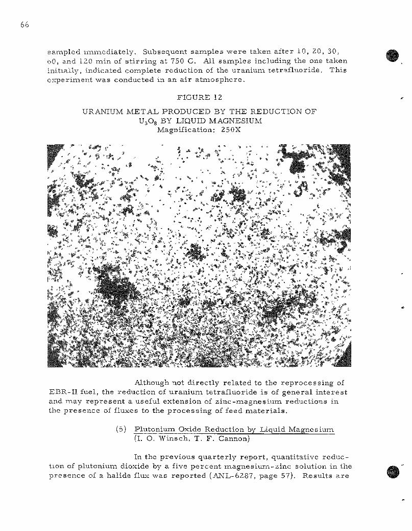
saiaipled maiaaediately. Subsequent samples were taken after 10, 20, 30, oO, and 120 laain of s t i r r ing at 750 C. All samples including the one taken initially, indicated conaplete reduction of the uranium te t raf luor ide. This experinaent was conducted in an a i r atnaosphere.
Although not di rect ly related to the reprocess ing of EBR-II fuel, the reduction of uran ium tetraf luoride is of genera l in te res t and may rep resen t a useful extension of zinc-magnesiuna reductions in the p resence of fluxes to the process ing of feed naater ia ls .
(5) Plutoniuna Oxide Reduction by Liquid Magnesium (I. O. Winsch, T. F . Cannon)
In the previous quar te r ly repor t , quantitative reduction of plutonium dioxide by a five percent magnes ium-z inc solution in the presence of a halide flxix was repor ted (ANL-6287, page 57). Results a re
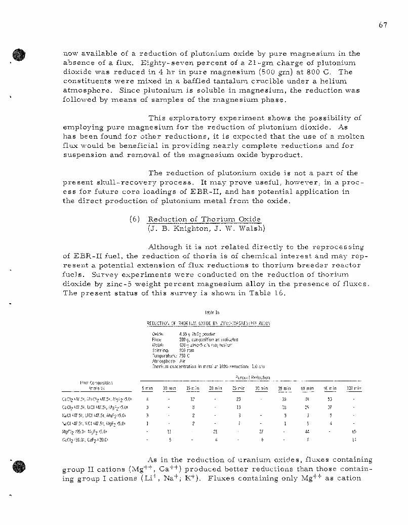
now available of a reduction of plutonium oxide by pure magnesium in the absence of a flux. Eighty-seven percent of a 21-gm charge of plutonium dioxide was reduced in 4 hr in pure magnesium (500 gjaa) at 800 C. The consti tuents were mixed in a baffled tantalum crucible under a heliuna atnaosphere. Since plutonium is soluble in magnesiuna, the reduction was followed by naeans of samples of the magnesium phase.
This exploratory experinaent shows the possibil i ty of employing pure naagnesiuna for the reduction of plutonium dioxide. As has been found for other reduct ions, it is expected that the use of a laiolten flux would be beneficial in providing near ly complete reductions and for suspension and removal of the magnes ium oxide byproduct.
The reduction of plutoniuna oxide is not a par t of the p resen t sku l l - recovery p r o c e s s . It naay prove useful, however, in a p roc ess for future core loadings of EBR-II , and has potential application in the d i rec t production of plutoniuna meta l from the oxide.
(6) Reduction of Thorium Oxide (J. B. Knighton, J. W. Walsh)
Although it is not re lated directly to the reprocess ing of EBR-II fuel, the reduction of thoria is of cheixiical in teres t and laiay represen t a potential extension of flux reductions to thoriuna breeder reactor fuels. Survey exper iments were conducted on the reduction of thoriuna dioxide by zinc-5 weight percent magnesium alloy in the presence of fluxes. The p resen t status of this survey is shown in Table 16.
Table 16
REDUCTIOK or THORIbM OXIDE B'. Z|t>!C-f,'.AGN[SI Mf.'- ALLO\
Oxide: 4.55 g rh02 powder
Flux; 200 9, composition as indicated Metal: 400 g zinc-5 v/o naqnesiuP" Stirring: 800 rpm Temperature: 750 C Atmosphere: Air Thorium concentration in metal at lOOS reduction: 1.0 {Jo
Flux Composition 'mole?o)
CaCl2 '47.51, M0CI2 ' * - 5 ' . f>\!F2 <5.Q'
CaCl2 147.51, LiCl (47.5!. WgF2 iS.O)
NaCI (47 5), LiCl (47.5), MqFj t5.0i
\aCI 147.5!. KCI (47.51, .''.1gF2 '5.0i
MgCl2 195.01 f.VjF2 '5.0)
CaCl2i80.0!, CaF2 120.01
5 mm
4
3
3
1
-~
10 mm
--
U
5
15 min
12
8
2
2
-
20 min
21
6
Percent Reduction
25 min
23
13
3
7
30 min
-
27
6
35 Riin
30
18
3
1
-
60 min
49
29
3
5
44
8
90 min
53
37
5
4
120 min
-
65
14
As in the reduction of uraniuiaa oxides, fluxes containing group II cations (Mg^"*", Ca++) produced bet ter reductions than those containing group I cations (Li"*", Na"^; K"^). Fluxes containing only Mg'*'"'" as cation
(95 mole percen t magnes ium chlor ide-5 naole percent magnes ium fluoride) gave be t te r reductions than those containing only Ca+''" as cation (80 mole percen t calcium chlor ide-20 naole pe rcen t calc ium fluoride). Magnesium chloride appears to be e s sen t i a l for significant reduction of thoriuna oxide.
Complete reduct ions of thorium oxide in this sys tem have not yet been achieved. It is believed, however, that with magnes ium chloride p r e sen t and with the p roper choice of va r iab les (such as s t i r r ing , t e m p e r a t u r e , magnesiuna concentrat ion, f lux- to-meta l ra t io , and time) complete reductions may be poss ib le .
(7) Poss ib le P roces s ing of Uranium Carbide Fuels (T. R. Johnson, R. L. Chr is tensen)
Uranium carbide has been suggested as a potential fuel for future loadings of EBR-II as well as other fast b r eede r r e a c t o r s . It is possible to conver t u ran ium carbide to the oxide by t r ea tmen t with oxygen and to reduce the oxide to the meta l with a z inc-magnes ium solution. This sequence of r eac t ions , which has been denaonstrated in a labora to ry exper iment , suggests the possibi l i ty of applying to these fuels a liquid meta l separa t ion p rocedure s imi l a r to the skull ox ide- recovery p r o c e s s .
g. Retort ing of Uraniuna Concentra tes ( j . F . Lenc, M. A. Bowden)
In the c u r r e n t sku l l - r ec l ama t ion p r o c e s s (see F igure 3, page 44), a final re tor t ing step is requ i red to isolate the prec ip i ta ted u r a nium solid phase f rom the zinc-naagnesium liquid me ta l phase . The r e tor ted uraniuna mus t be r ecove red in high yield from a suitable crucible in a form adaptable to r emote handling. In addition, it mus t be sufficiently free of impur i t i e s that would inhibit its incorporat ion with other fuel naater ia l upon recycle to laaelt refining. P a r t i a l success in obtaining a u ran ium product naeeting the above r equ i r emen t s has been achieved in exper iments in which the r e to r t ed product was readi ly r ecovered in the form of compact , i r r e g u l a r - s h a p e d naasses (see F igure 13, ANL-6287, page 68). The yield of these sphe re - shaped products (about 70 to 80 percen t ) , however, has been lower than des i red . In an effort to improve this yield, re tor t ing studies have been d i rec ted toward the de terminat ion of the mechan i sm responsible for the format ion of the sphe re - shaped m a s s e s .
In these s tudies , 200-gm batches of u ran ium were p r o c essed through the las t t h ree s teps of the skul l - reclanaat ion p r o c e s s , namely, (1) prec ip i ta t ion of the u ran ium-z inc in te rmeta l l i c compound, (2) decomposi t ion of this conapound with magnes ium, and (3) re tor t ing
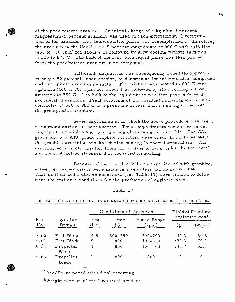
of the p r e c i p i t a t e d u r a n i u m . An in i t i a l c h a r g e of 4 kg z i n c - 5 p e r c e n t m a g n e s i u m - 5 p e r c e n t u r a n i u m w a s u s e d in e a c h e x p e r i m e n t . P r e c i p i t a t ion of the u r a n i u m - z i n c i n t e r m e t a l l i c p h a s e w a s acconap l i shed by d i s s o l v i n g the u ran iuna in the l iqu id z i n c - 5 p e r c e n t m a g n e s i u m a t 800 C wi th a g i t a t i o n (400 to 700 r p m ) for abou t 4 h r fo l lowed by slow cool ing wi thou t ag i t a t i on to 525 to 575 C. The bulk of the z i n c - r i c h l iqu id p h a s e w a s then p o u r e d f r o m the p r e c i p i t a t e d u r a n i u m - z i n c conapound.
Suff icient m a g n e s i u m w a s s u b s e q u e n t l y added (to a p p r o x i m a t e l y a 50 p e r c e n t c o n c e n t r a t i o n ) to d e c o m p o s e the i n t e r m e t a l l i c conapound and p r e c i p i t a t e u r a n i u m a s m e t a l . The m i x t u r e w a s h e a t e d to 800 C wi th a g i t a t i o n (400 to 700 r p m ) for abou t 4 h r fo l lowed by slow cool ing wi thout a g i t a t i o n to 550 C. The bulk of the l i qu id p h a s e w a s then p o u r e d f r o m the p r e c i p i t a t e d u r a n i u m . F i n a l r e t o r t i n g of the r e s i d u a l z i n c - m a g n e s i u m w a s c o n d u c t e d a t 550 to 850 C at a p r e s s u r e of l e s s t han 1 m m Hg to r e c o v e r the p r e c i p i t a t e d u r a n i u m .
Seven e x p e r i m e n t s , in w h i c h the above p r o c e d u r e w a s u s e d , w e r e naade d u r i n g the p a s t q u a r t e r . T h r e e e x p e r i m e n t s w e r e c a r r i e d out in g r a p h i t e c r u c i b l e s and fou r in a s e a m l e s s t a n t a l u m c r u c i b l e . One C S -g r a d e and two A T J - g r a d e g r a p h i t e c r u c i b l e s w e r e u s e d . In a l l t h r e e t e s t s the g r a p h i t e c r u c i b l e s c r a c k e d d u r i n g cool ing to r o o m t e m p e r a t u r e . The c r a c k i n g v e r y l i ke ly r e s u l t e d f r o m the we t t i ng of the g r a p h i t e by the m e t a l and the c o n t r a c t i o n s t r e s s e s t ha t o c c u r r e d on coo l ing .
B e c a u s e of the c r u c i b l e f a i l u r e s e x p e r i e n c e d wi th g r a p h i t e , s u b s e q u e n t e x p e r i m e n t s w e r e i n a d e in a s e a m l e s s t a n t a l u m c r u c i b l e . V a r i o u s t i m e and a g i t a t i o n c o n d i t i o n s ( s e e Table 17) w e r e s tud i ed to d e t e r naine the o p t i m u m c o n d i t i o n s fo r the p r o d u c t i o n of a g g l o m e r a t e s .
T a b l e 17
E F F E C T O F AGITATION O N F O R M A T I O N O F URANIUM A G G L O M E R A T E S
Run No.
A-60 A-62 A==64
A-66
A g i t a t o r D e s i g n
F l a t B lade F l a t B lade P r o p e l l e r
B lade P r o p e l l e r
B lade
Cond i t i ons of
T i m e T e m p (hr ) (C)
4 .5 800-750 5 800 4 800
1 800
Agi ta t ion
Speed Range ( r p m )
300-700 4 0 0 - 6 0 0 4 0 0 - 6 0 0
600
Yie ldo f Agglonr
(g) .
140.8 126.3 143.7
0
U r a n i u m l e r a t e s ^
(w /o )b
80.8 70.5 82.3
0
Read i ly r enaoved a f t e r f ina l r e t o r t i n g .
'^Weight p e r c e n t of t o t a l r e t o r t e d p r o d u c t .
In Table 17 it naay be seen that the best yield obtained was about 80 percent . The rem.i inder of the uranium adhered to the tantalum crucible and could not be removed by mechanica l m e a n s . In one run (A-66) in which the t ime was reduced from 4 or 5 hr to 1 h r , the ent i re re tor ted product adhered to the crucible in a porous , spongelike form.
F u r t h e r work on this problem is required . Additional exper iments a r e planned to invest igate the effects of t ime , t e m p e r a t u r e , and various agitation va r iab les (such as type of s t i r r e r and speed) on the formation in high yield of we l l -coa lesced m a s s e s of uran ium during the in te rmeta l l ic decomposit ion s tep of the sku l l - rec lamat ion p r o c e s s . The effect of other var iab les (such as the p resence of f ission products , the method of naagnesium addition, the nature of the internaetallic compound pr io r to deco3aaposition, and the crucible mate r ia l ) will also be evaluated.
h. Development of P r o c e s s for Recovery of Plutonium from EBR-II Blanket Mater ia l — • — (I. O. Winsch, T. F . Cannon)
In the EBR-II r eac to r , plutonium will be allowed to build up in the depleted uran ium blanket m a t e r i a l to a concentrat ion of about one percen t before d ischarge of the blanket ma te r i a l . The liquid meta l p roces s under considerat ion for separa t ion of the plutonium from uranium is based on the re la t ively high solubility of plutonium in m a g n e s i u m - r i c h zinc alloys and the contras t ing low solubili t ies of uraniuna in these al loys. P r o c e s s e s investigated previously have involved formation of a u ran ium-zmc in termeta l l ic compound (approxinaately UZn^j^s, designated as the epsilon phase) and subsequent decomposit ion of this compound by addition of magnes ium to prec ip i ta te the uran ium while retaining the plutonium in solution. After removal of the plutonium solution, the plutonium may be recovered by the vaporizat ion of the magnes ium and zinc.
In the previous work, the u ran ium-z inc in te rmeta l l ic compound was formed and isolated by dissolution of the uran ium in zinc, precipi ta t ion of the in te rmeta l l ic compound by cooling, and withdrawal of the zinc supernatant . Two simplifications of this p rocedure were inves t igated during the pas t q u a r t e r : (1) react ion of uran ium and zinc in approximately a s to ichiometr ic ra t io to form the in te rmeta l l ic compound direct ly , and (2) dissolution of the u ran ium to a concentrat ion of about 14 percent in a 12 percent magnes ium-z inc solution. In this la t te r d i rec t dissolution p rocedure , a further addition of magnes ium to a concentrat ion of about 50 percent p rec ip i ta tes the uran ium as me ta l , thus avoiding the formation of the in te rmeta l l ic compound. This dissolution procedure is based on infornaation obtained in the Division which shows remarkab ly high solubili t ies of uran ium in zinc sys tems containing around 12 percent magnes ium (up to 20 percent at 800 C as compared to about 6 pe rcen t in pure zinc).
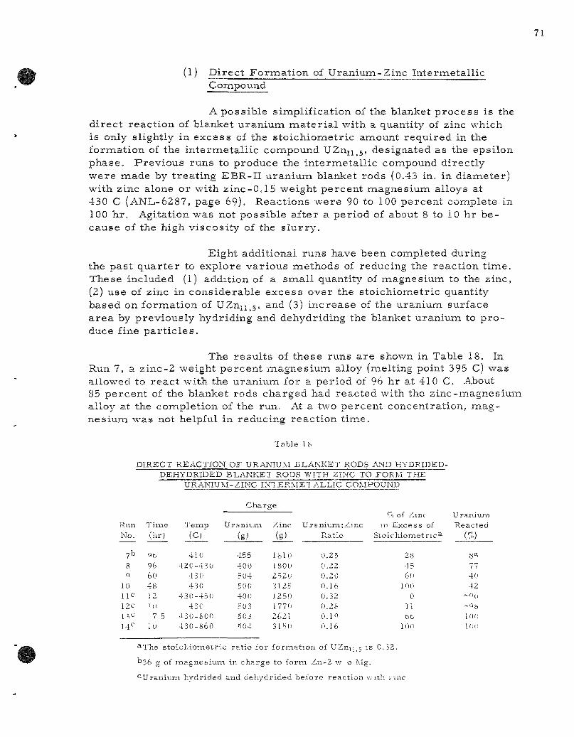
(1) Direct Format ion of Uranium-Zinc Internaetallic Conapound
A possible sinaplification of the blanket p rocess is the di rect react ion of blanket uraniuna ma.terial with a quantity of zinc which is only slightly in excess of the s toichiometr ic amount required in the formation of the in termeta l l ic compound UZn^^s, designated as the epsilon phase . Previous runs to produce the in termetal l ic compound directly were naade by t reat ing EBR-II uranium blanket rods (0.43 in. in diameter) with zinc alone or with zinc-0.1 5 weight percent magnesium alloys at 430 C (ANL-6287, page 69). Reactions were 90 to 100 percent complete in 100 hr. Agitation was not possible after a period of about 8 to 1 0 hr because of the high viscosi ty of the s lu r ry .
Eight additional runs have been conapleted during the past qua r t e r to explore var ious methods of reducing the reaction tinae. These included (1) addition of a smal l quantity of naagnesium to the zinc, (2) use of zinc in considerable excess over the s toichiometric quantity based on formation of UZnjj^g, and (3) increase of the uranium surface a r ea by previously hydriding and dehydriding the blanket uranium to p r o duce fine pa r t i c l e s .
The resu l t s of these runs a re shown in Table 18. In Run 7, a zinc-2 weight percent naagnesiuna alloy (naelting point 395 C) was allowed to reac t with the uranium for a period of 96 hr at 410 C. About 85 percent of the blanket rods charged had reacted with the zinc-naagnesium alloy at the conapletion of the run. At a two percent concentration, laiag-nesium was not helpful in reducing react ion tinae.
l a b l e KS
D I R E C T R E A C T I O N O F U R A N I U M B L A N K E T R O D S AND H Y D R I D E D -D E H Y D R I D E D B L A N K E T R O D S W I T H Z I N C T O F O R M T H E
U R A N I U M - Z I N C I N T E R M E T A L L I C C O M P O U N D
C h a r g e
R u n N o .
7b
8 9
10 l i e 12C
1 3 ^ 14'"
T i m e ( h r )
96 60 4 8 12 111
7 5 U)
T e m p
(C)
4 1 0 4 2 0 - 4 3 0
43(1 430
430-45(1 4 3 0
•430-800 4 3 0 - 8 6 0
U r a n i u m
is) 455 4 0 0 304 500 400 50 3 503 504
Z i n c
(g)
IfclO 1800 252u 3125 1250 177f! 2621 31 5(1
U r a n i u m : Z i n c R a t i o
0 .25 0 .22 0 .20 0 .16 0 .32 0.2fc O.IQ 0 .16
'-,n of Z m c m E x c e s s of
S t o i c h i o m e t r i c ^
28 45 60
100 0
11 66
100
U' R
-
r a n i u m e a c l e d
(%)
8=; 77 40 42
~ 0 ( ,
~ Q b
ion 1(10
^ T h e s t o i c h i o m e t r i c r a t i o f o r f o r m a t i o n of UZni]_5 i s 0 . 5 2 .
1336 g of m a g n e & i u m in c h a r g e t o f o r m Z n - 2 w o M g .
" ^ U r a n i u m h y d r i d e d a n d d e h y d r i d e d b e f o r e r e a c t i o n ^s-ith z i n c
The use of 45, 60, and 100 percent excess zinc (Runs 8, 9, 10, respect ively) produced no significant reduction in react ion t ime. A heavy v ibra to r employed in Run 8 also was ineffective. Radiographs of the ingots from Runs 9 and 10 c lear ly revealed the shapes of the unreacted rods . This technique will be valuable in future runs to indicate the percent of uran ium reac ted .
Hydriding and dehydriding of the uran ium was c a r r i e d out in Runs 11 through 14 p r io r to mel t ing the zinc to pernait the formation of the internaetall ic compound at des i r ed tenapera tures . In Runs 11 and 12, nea r - s to i ch iome t r i c quanti t ies of zinc were employed and appreciable r e a c tion (about 90 percen t and 98 percen t , respect ively) took place in the 12-and 10-hr react ion t i m e s . No agitation was employed. In both of these runs , a slight amount of unreac ted u ran ium which was p resen t on the surface of the in te rmeta l l i c ingot ignited when exposed to a i r .
A combination of hydriding-dehydriding, excess zinc, and higher tenapera tures was employed in Runs 13 and 14 in an a t tempt to rea l ize sxifficient fluidity for employment of s t i r r e r s . In these runs , excess zinc (60 and 100 percen t , respect ively) was used, but it was not possible to s t i r the mel t until a t e m p e r a t u r e of 800 C was reached. However, in Run 14, the t e m p e r a t u r e was r a i s ed to 860 C (about 15 C above the per i tec t ic decomposit ion t empe ra tu r e of UZn^^s to UZng.5), and because of the consequent r e l ea se of zinc, it was poss ible to agitate fair ly eas i ly . C ros s sect ions of the ingots f rom Runs 13 and 14 indicated conaplete formation of the uraniuna-zinc in te rmeta l l i c compound. X- r ay diffraction studies of a nunaber of the in te rmeta l l ic conapound ingots indicated that the major components were the u ran ium-z inc epsi lon phase and zinc.
The d i rec t reac t ion of uran ium and zinc as a f i r s t step in a blanket p r o c e s s has been demons t ra ted . With hydr ided-de hydrided m a t e r i a l , the reac t ion t ime is probably only a laaatter of minutes , since a solid m a s s was formed short ly after the zinc mel ted . However, hydriding and dehydriding of the blanket m a t e r i a l would prohibi t the use of tantalum as a crucible m a t e r i a l in this s tep. Molybdenuna or a luminum oxide cruc ib les may be sa t is factory a l t e rna t ives . If a u r an ium-3 weight percen t molybdenum alloy is used for the blanket in the future, it would probably be quite difficult to use the hydriding and dehydriding p rocedure . P rev ious expe r imentation has shown that hydriding of this type alloy was ex t remely slow under the exper imenta l conditions employed ( t empera tu re of 250 C and a hydrogen p r e s s u r e of 800 laana).
(2) Dissolution of EBR-II Blanket Mate r ia l in Zinc-14 Weight P e r c e n t Magnesium
The solubility data of u ran ium in z inc -magnes ium solutions suggests another poss ible sinaplification for the blanket p r o c e s s . The z inc -magnes ium-u ran ium phase d iag ram indicates that at about 800 C it
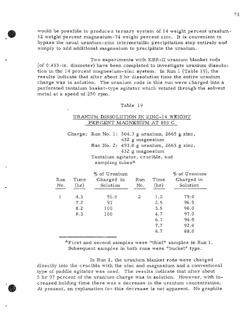
would be possible to produce a t e r n a r y sys tem of 14 weight percent uranium-12 weight percent naagnesium-74 weight percent zinc. It is convenient to bypass the usual u ran ium-z inc in te rmeta l l ic precipi ta t ion step entirely and sinaply to add additional naagnesium to precipi ta te the uranium.
Two exper iments with EBR-II uranium blanket rods (of 0.433-in. d iameter ) have been completed to investigate uraniuna dissolution in the 14 percent magnes ium-z inc sys tem. In Run 1 (Table 19), the resu l t s indicate that after about 8 hr dissolution t ime the entire uranium charge was in solution. The uraniuna rods in this run were charged into a perfora ted tantalum basket - type agi ta tor which rotated through the solvent naetal at a speed of 250 rpm.
Table 19
URANIUM DISSOLUTION IN ZINC-14 WEIGHT PERCENT MAGNESIUM AT 800 C
Charge* Run No. 1: 504.3 g uranium, 2665 g zinc, 432 g magnesium
Run No. 2: 493.0 g uranium, 2665 g zinc, 432 g magnesiuna
Tantalum agi ta tor , c rucib le , and sampling tubes^
Run No.
1
Time (hr)
4.3 7.2 8.2 8.3
% of Uranium Charged in
Solution
96.5 97
100 100
Run No.
2
Time (hr)
1.0 2.5 3.5 4.7 6.7 7.7 8.7
% of Uranium Charged in
Solution
79.0 96.5 96.0 97.0 94.0 92.0 88.0
^ F i r s t and second samples were "thief" samples in Run 1. Subsequent samples in both runs were "bucket" type.
In Run 2, the uran ium blanket rods were charged direct ly into the crucible with the zinc and magnes ium and a conventional type of paddle agi ta tor was used. The resu l t s indicate that after about 5 hr 97 percent of the uran ium charge was in solution. However, with inc r ea sed holding t ime there was a dec rea se in the uranium concentration. At p resen t , an explanation for this dec rea se is not apparent . No graphite
was p resen t in the equipment; graphite f i l ter f r i ts were not employed in sampling; instead dip-type samples were obtained. The amount of carbon introduced with charge m a t e r i a l s is not significant in compar ison to the concentrat ion dec rea se that occur red . It is believed that improvements in sampling and sample-handl ing techniques may resolve this problem.
i. P r epa ra t i on of Compounds by Prec ip i ta t ion f rom Liquid Metal Solutions (A. Schneider, G. L. Rogers)
The formation of var ious compounds in liquid me ta l s has been observed in the past in the course of studies d i rec ted toward the development of recovery and decontamination p r o c e s s e s for f issionable and fer t i le m a t e r i a l s . F o r example , compounds such as uranium carbide or uran ium si l icide were prec ip i ta ted from u ran ium-cadmium solutions by react ion with carbon or si l icon p re sen t as impur i t ies in the solution. In te res t has now developed in exploiting such react ions for p repara t ive purposes , e i ther to synthesize nuclear feed ma te r i a l s or to recover decontaminated nuclear fuel m a t e r i a l s in a form suitable for recycling to a r eac to r . Evidence is now available which shows that this method of p repara t ion is applicable to the synthesis of uranium carbide , uranium si l ic ide, and plutonium carb ide .
This method of p repa ra t ion of compounds such as uranium carbide can also be integrated with p r e sen t liquid me ta l p r o c e s s e s for convers ion of an oxide to a carbide or for purification of i r r ad ia ted m a t e r i a l . The following react ion is an example of the f i r s t possibi l i ty:
UO2 (or UaOg) + 2 Mg (in Zn or Cd) - -^U (in Zn or Cd) + 2 MgO
U (in Zn or Cd) + C (s)—*-UC (s)
The P repa ra t i on of Uranium Monocarbide
Several methods a r e available for the prepara t ion of u r a nium carbides .2 C a r r i e d out at high t e m p e r a t u r e s (above 1000 C), these methods general ly involve: (1) the d i rec t react ion of uranium and carbon, (2) the reduction of uran ium oxides with carbon, resul t ing in the formation of e i ther the monocarbide or dicarbide and carbon monoxide, and (3) the react ion of hot uran ium with an organic compound such as methane . Fo r use as a r eac to r fuel, the uran ium inonocarbide is des i red . The genera l difficulty encountered in the p repa ra t ion of the monocarbide is in the achievement of high puri ty. Even with careful p recau t ions , free uran ium or uranium dicarbide is usually p resen t in the product .
^Bownaan, F . E . , The Carbides of Uranium - An Annotated Bibliog-raphy, NYO-2686 (March I960).

It has been found possible to p repa re uranium monocarbide at t e m p e r a t u r e s below 700 C by precipi ta t ing uranium dissolved in an appropr ia te meta l solvent with carbon. In exper iments conducted to date" in alumina c ruc ib les , u ran ium, which was dissolved in cadmium to a concent ra t ion of near ly 2 percen t , was prec ip i ta ted from the cadmium solution by addition of finely divided activated carbon (-230 mesh) . In the f i r s t exper i ment , at 550 C, 64 pe rcen t of the uran ium precipi ta ted with s t i r r ing in 8 hr. In a second exper iment , near ly complete precipi ta t ion was real ized within Y hr at 700 C. After dist i l l ing away the cadmium, the product of the second exper iment was identified as uran ium monocarbide by X-ray diffraction. However, free carbon is not detectable by X-ray diffraction. Chemical analyses a r e in p r o g r e s s to obtain ca rbon- to -u ran ium ra t ios . In both experinaents an excess of carbon was employed, but the product did not contain any dicarbide . Segregation of the uranium carbide and unreacted carbon was observed in a c r o s s section of the solidified ingot. The uranium carbide set t led to the bottom while the unreac ted carbon concentrated near the surface of the mel t .
In a s imi la r exper iment uranium was precipi ta ted from a 5 pe rcen t magnes ium-95 percent zinc solution at 800 C. Again the product was identified as u ran ium monocarbide . The react ion ra te in this sys tem was found to be lower than in cadmium, but over 85 percent of the ura,nium had reac ted after 3 hr of s t i r r ing .
The P repa ra t i on of Cer ium Carbide
In iTiany pyrometa l lu rg ica l exper iments it has been found that ce r ium behaves quite s imi la r ly to plutonium. The prepara t ion of ce r ium carbide was invest igated to gain famil iar i ty with p rocedures be fore at tempting the synthesis of plutonium carbide .
Ce r ium carbide (Ce2C3) was precipi ta ted from magnes ium solutions in which it was p re sen t initially at a concentrat ion of 21.5 percent . At 695 C, 58 pe rcen t of the ceriuiTi was prec ip i ta ted in 3 ^ hr . The product was identified by X- ray diffraction as Ce2C3 with an indication that t r a c e s of CeC2 and a -Ce may have been p re sen t . This resu l t also supports the findings of Spedding and coworkers^ that Ce2C3 is the lowest stable carbide .
j . Mate r ia l s and Equipment Evaluation
Mater ia ls evaluation studies a r e in p rog res s to evaluate the compatibil i ty of var ious m a t e r i a l s wth liquid meta l sys tems of the types contemplated for r ep rocess ing r eac to r fuels. Much of the effort is being concentra ted on determining which construct ion ma te r i a l s will be most suitable for EBR-II p rocess ing equipment. However, the conditions chosen for some of the t e s t s extend beyond the conditions for p r o c e s s e s of immedia te i n t e r e s t in o rde r to obtain data from which predic t ions of the effects of p r o c e s s changes can be made .
^Spedding, F . H.,_et a l . , J. Am. Chem. Soc. _80_, 4499-4503 (1958),
Three main types of t e s t s a r e being used to evaluate m a t e r i a l s : 1) co r ros ion test ing of meta l coupons with solvent meta l s and molten sa l t s , 2) solut ion-stabi l i ty t e s t s in which solutions of uranium in solvent meta l s a r e contained in agitated ves se l s made of the tes t m a t e r ia l and sampled at in tervals for u ran ium concentrat ion, and 3) m a t e r i a l s demonstra t ion runs in which operat ions such as skull oxide reduction a r e c a r r i e d out repeatedly or for long per iods of t ime after which the effects on the container m a t e r i a l s a r e de termined.
(1) Cor ros ion Studies (P. Nelson, M. Kyle, A. Sanders)
A p r o g r a m is underway to de termine the cor ros ion r e s i s t ance of the re f rac to ry m e t a l s , graphi te , and c e r a m i c s to molten m e t a l s , pa r t i cu la r ly to zinc and z inc-magnes ium solutions. It is also of in te res t to t es t the cor ros ion r e s i s t ance of the same m a t e r i a l s to flux sys t ems , especial ly to those containing alkali and alkali e a r th chlorides and f luorides .
Several means of determining at tack by liquid me ta l s a r e avai lable. Some of the methods a r e enumera ted below:
1) weight and size change of meta l coupons exposed to liquid meta l s for a de termined t ime ;
2) meta l lographic examination of the m a t e r i a l before and after exposure ;
3) compar i son of physical p rope r t i e s before and after exposure to the liquid meta l environment .
None of these methods has been found to be ent i re ly sat isfactory by itself, thus indicating that a combination of these miethods is probably des i rab le .
P r e l i m i n a r y t e s t s have been completed to de termine the cor ros ion ra t e s of th ree flux sys tems on tantalum, tungsten, molybdenum, and tanta lum-10 percen t tungsten alloy. The t e s t s were conducted in tantalum capsules for 100 hr in the rocking furnace descr ibed in ANLr-6287, page 74. An attenapt was made to use weight and size changes to de te rmine liquid me ta l at tack.
The resu l t s indicated that changes in weight and size a r e not p r ec i s e m e a s u r e s of the extent of cor ros ion , since the changes noted in near ly all cases were too smal l to be significant. However, ha rdness tes t ing, in conjunction with ductility t e s t s and metal lographic examinat ions , does look promis ing as one means of evaluation.
Metallographic examination of cor ros ion specimens is the mos t impor tant means of determining the extent of cor ros ion on tantalum, tanta lum-tungsten , and tungsten by molten sal ts and z inc-magnes ium solut ions. This is t rue because the attack is in te rgranular and cannot be detected by weight or thickness change. Physical testing of the samples will indicate the effect of in te rgranula r co r ros ion on the me ta l p r o p e r t i e s , but the depth of co r ros ion can only be determined meta l lographica l ly . Metal lographic investigation of ma te r i a l adhering to the surface of the specimen is a separa te technique that may indicate the mechanics of co r ros ion , but will not be useful in determining the depth of co r ros ion .
The following technique has been found to be the 3xiost sa t is factory to date for examining tanta lum:
1) Mount sample in Bakeli te .
2) Abrade on 180, 240, 320, and 600-gr i t abras ive paper .
3) Pol i sh with 15-micron diamond paste followed by one-mic ron diamond pas te charged on a silk cloth wheel backed with lens cloth (Hyprez oil lubr ica ted) .
4) F ina l pol ish on a mic roc lo th -cove red wheel charged with 0 .1 -mic ron pa r t i c l e size alumina in dist i l led water .
5) E lec t roe tch in a solution containing 60 ml of 85 percent lact ic acid, 20 ml of 70 pe rcen t n i t r ic acid, and 20 ml of 49 percen t hydrofluoric acid at 0,02 amp per sq cm for 2 to 15 sec .
This p rocedure has been used successfully to examine tantalum c o r r o s i o n spec imens . F igure 13 is a photomicrograph of a 0.030-in. tantalum agi ta tor blade which failed due to embr i t t l ement after an 8-hr exposure at 800 C to a mixti i re of skull oxide, 5 weight percen t magnes ium-zinc alloy, and halide flux (47.5 mole pe rcen t magnes ium chlor ide , 47.5 mole percent ca lc ium chlor ide , and 5 mole pe rcen t magnes ium fluoride). Studies to c o r r e l a t e changes in mic roscop ic s t ruc tu re with the degree of cor ros ion evidenced by physica l tes t ing a re in p r o g r e s s .
Cor ros ion of Mild Steels in the Z inc-Cadmium-Magnesium Systems
Resul ts of additional t es t s to de te rmine the cor ros ion r e s i s t ance of naild s tee ls to z inc -cadmium-magnes ium sys tems a re p r e sented in Table 20. Resul ts previous ly repor ted in ANL-6243 indicated l i t t le or no co r ro s ion of mi ld s teel at t e m p e r a t u r e s up to 550 C and zinc concentra t ions of 0 to 10 pe rcen t . The new re su l t s extend the range of
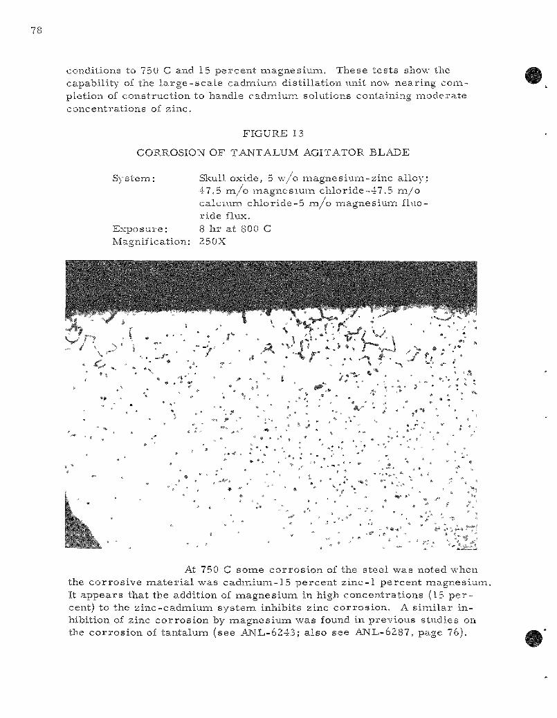
conditions to 75U C and 15 percent magnesium. These tes t s show the capability of the l a r g e - s c a l e cadmium disti l lat ion unit now- nearing completion of construct ion to handle cadmium solutions containing modera te concentrat ions of zinc.
FIGURE 13
CORROSION OF TANTALUM AGITATOR BLADE
System: Skull oxide, 5 w /o magnes ium-zinc alloy; 47.5 m / o magnes ium chloride-47.5 m / o calcium chlor ide-5 m / o magnesium fluoride flux.
Exposure : 8 hr at 800 C Magnification: 250X
/
«. ^ . ' / ^ ,.*« •.
# »
• »
] , . . . • ' . % ^ » # • ^
At 750 C some cor ros ion of the s teel was noted when the cor ros ive naaterial was cadmium-15 percent zinc-1 percent magnesium It appears that the addition of magnes ium in high concentrat ions (15 p e r cent) to the zinc-cadmiuna sys tem inhibits zinc cor ros ion . A s imi la r inhibition of zinc cor ros ion by magncsiuixi was found in previous studies on the cor ros ion of tantalum (see ANL-6243; also see ANL-6287, page 76).

Tab le 20
CORROSION O F 1020 S T E E L BY CADMIUM SOLUTIONS CONTAINING ZINC AND MAGNESIUM
C o n d i t i o n s : 500 h r , 1-in. x 2 - i n . x 0 .120 - in . coupons in t a n t a l u m c a p s u l e s w i th 20 to 40 g m of s o l v e n t m e t a l of i n d i c a t e d c o m p o s i t i o n . C a p s u l e s w e r e r o t a t e d 180° a t 2 c y c l e s p e r m i n u t e .
O b s e r v e d C o r r o s i o n E f f e c t s ^ ' " Z inc Cone (w/o)
T e m p M a g n e s i u m (C) Cone (w/o ) 0 2 5 10 15
500 1 - NC - NC -500 15 - - - NC -750 1 NC NC NC - SC 750 15 NC NC - NC NC
^NC i n d i c a t e s c o r r o s i o n l e s s t han 0.001 in.
"SC i n d i c a t e s s l i gh t c o r r o s i o n , l e s s than 0.002 in.
It shou ld be n o t e d t h a t in T a b l e 20 the c o n c e n t r a t i o n s a r e g iven in we igh t p e r c e n t . B e c a u s e of the low a t o m i c w e i g h t of m a g n e s i u m , a s c o m p a r e d wi th c a d m i u m , r e l a t i v e l y s m a l l w e i g h t p e r c e n t a g e s u b s t i t u t i o n s of m a g n e s i u m f o r cadna ium would be e x p e c t e d to r e d u c e c o n s i d e r a b l y the c h e m i c a l a c t i v i t y of the z i n c .
(2) Solu t ion S tab i l i ty and M a t e r i a l s D e m o n s t r a t i o n T e s t s ( P . N e l s o n , J . Wolkoff, and J . Pav l ik )
E x p e r i m e n t s to d e t e r m i n e the s t a b i l i t y of u r a n i u m in v a r i o u s m e t a l s o l v e n t s and c o n t a i n e r s y s t e m s , and t e s t s to d e m o n s t r a t e the s u i t a b i l i t y of c o n t a i n e r and a c c e s s o r y c o m b i n a t i o n s u n d e r p r o c e s s c o n d i t i ons a r e in p r o g r e s s . The m a i n d i f f e r e n c e s in the two t y p e s of t e s t s a r e tha t in the f o r n a e r the ef fect of the c o n t a i n e r , m e t a l s o l v e n t s , and i m p u r i t i e s on s o l u t i o n s t a b i l i t y i s s t u d i e d and in the l a t t e r the a t t a c k by the so lu t ion on the c o n t a i n e r i s s t u d i e d . Both t y p e s of e x p e r i m e n t s a r e conduc t ed in c r u c i b l e s of abou t o n e - l i t e r c a p a c i t y f a b r i c a t e d of the t e s t m a t e r i a l . Agi ta t ion and m e a n s of s a m p l i n g a r e p r o v i d e d in o r d e r t ha t the u r a n i u m c o n c e n t r a t ion m a y be fo l lowed o v e r the c o u r s e of the r u n (25 to 300 h r ) .
The m a t e r i a l s demonst ra t ion runs have been conducted in a t i l t -pour ing furnace which p e r m i t s pouring off the charge at the end of the run. Subsequently, the crucible and acce s so ry pa r t s a r e examined metal lographical ly and by physical tes t ing. The t empe ra tu r e and solvent composit ion a r e held as near ly constant as possible during m a t e r i a l s demonst ra t ion runs so that the degree of at tack on the m a t e r i a l s may be assoc ia ted with pa r t i cu la r p rocess ing conditions.
Solution-stabil i ty runs a r e conducted in a deep furnace to provide p rec i s e t e m p e r a t u r e control and even t empera tu re distr ibut ion. The control t empe ra tu r e and the solvent concentrat ion may be changed during the run to study the effect of these var iab les on the stability of d i s solved uraniura.
Equipment designed for both types of exper iments has only recent ly been completed. However, a few explora tory exper iments have been completed with available equipinent.
In one explora tory exper iment conducted under conditions siraulating those p r e sen t in the reduction step of the skuU-reclanaation p r o c e s s , flux and a meta l solution were contained in a Grade CS graphite crucible for about 100 hr . The conditions under which the run was made and the r e su l t s obtained a r e shown in Table 21 . Seventeen samples of the meta l phase were taken at in tervals throughout the run. The uran ium content var ied f rom 92.7 percen t to 106.8 percen t of the concentra t ion calculated from the amounts of naater ia ls added. The average uranium analysis was 98.6 percen t of the calculated value, with a s tandard deviation of 3.5 percent . However, approximate ly 3 to 5 percen t of the zinc was evaporated during the course of the exper iment , which would indicate a like percentage of uraniuna los t even if the uran ium concentrat ion r e mained at the calculated init ial concentrat ion. Deposits of u ran ium which were removed from the tanta lum baffles above the flux level contained 22.4 percen t u ran ium. The deposit ion and redissolut ion of this m a t e r i a l during the run could account for the l a rge s tandard deviation in the u r a nium content.
Microscopic examinat ion of the crucible after the run indicated a flux penet ra t ion depth of about -j in. The tantalum baffles were somewhat embr i t t l ed during the run but not to the point of fa i lure .
In another s imi l a r exper iment , the top of the crucible was kept at the t e m p e r a t u r e of the mel t , 800 C, thus prevent ing deposition of the uraniuna above the sur face , but the loss of zinc by evaporat ion was inc reased because condensation did not take place on the inside of the cover .
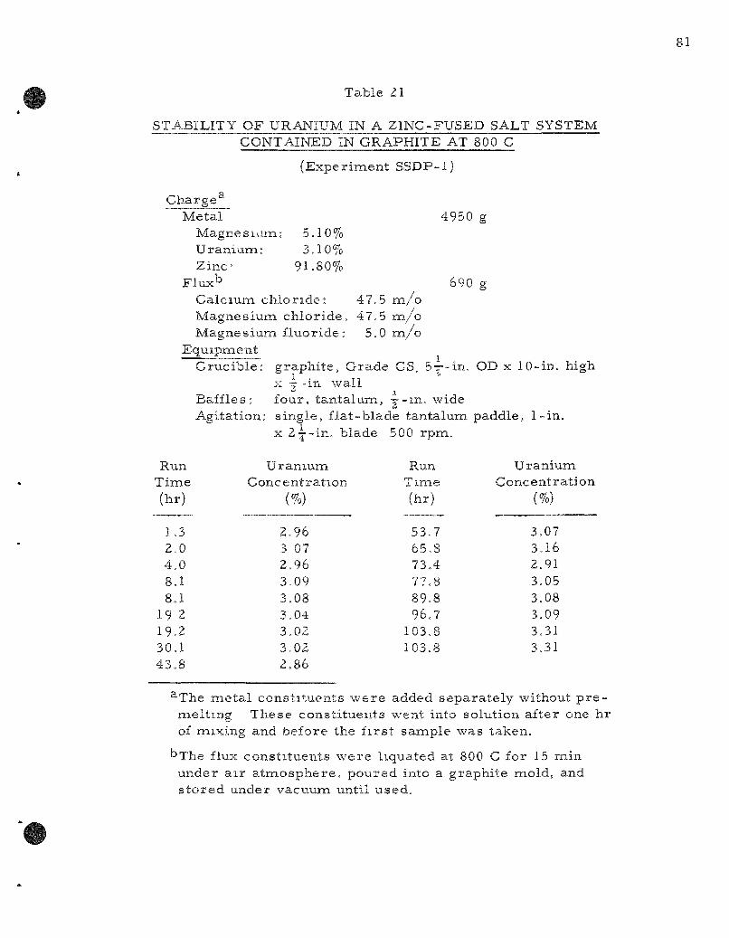
Table 21
STABILITY OF URANIUM IN A ZINC-FUSED SALT SYSTEM CONTAINED IN GRAPHITE AT 800 C
(Experiment SSDP-1)
4950 g
690 g
Charge^ Metal
Magnesiaiia: 5.10% Uranium: 3.10% Z i n c 91.80%
Flux''^ Calcium chlor ide : 47,5 m / o Magnesium chlor ide . 47.5 m / o Magnesium fluoride: 5.0 m / o
Equipment Cruc ib le : graphi te , Grade CS, 5-r--in. OD x 10-in. high
X g' "in wall Baffles: four, tantalum, —-m. wide Agitation: s ingle, f la t -blade tantalum paddle, 1-in.
X Zj-in. blade 500 rpm.
Run Time (hr)
1.3 2.0 4.0 8.1 8.1
19 2 19.2 30,1 43.8
Uranium Concentration
(%)
2,96 3 07 2,96 3,09 3.08 3.04 3.02 3,02 2.86
Run T i m e (hr)
53.7 65.8 73,4 7'^.8 89.8 96.7
103.8 103.8
Uraniuna Concentration
(%)
3.07 3.16 2.91 3.05 3.08 3.09 3.31 3.31
^The me ta l const i tuents were added separa te ly without p r e -mel tmg These const i tuents went into solution after one hr of mixing and before the f i r s t sample was taken.
t>The flux const i tuents were liquated at 800 C for 15 nain under a i r a tmosphere , poured into a graphite mold, and s to red under vacuum until used.
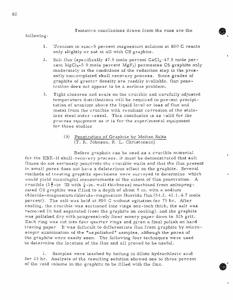
Tentative conclusions drawn from the runs a re the following:
1. Uranium in z inc-5 percent magnesium solution at 800 C reac t s only slightly or not at all with CS graphi te .
2. Salt flux (specifically 47,5 mole percent CaCl2-47,5 mole p e r cent MgClj-S 0 mole percent MgFj) pe rmea t e s CS graphite only modera te ly at the conditions of the reduction step in the p r e s ently contemplated skull r ecovery p r o c e s s . Since grades of graphite of g rea t e r density a r e readi ly available, flux penet ra t ion does not appear to be a se r ious problem.
3. Tight c losures and sea ls on the crucible and carefully adjusted tenaperature d is t r ibut ions will be required to prevent p rec ip i tation of uranium above the liquid level or loss of flux and metal from the crucible with resul tant co r ros ion of the s ta inless s tee l outer vesse l . This conclusion is as valid for the p rocess equipment as it is for the exper imenta l equipment for these studies
(3) Pene t ra t ion of Graphite by Molten Salts (T. R. Johnson, R. L. Chris tensen)
Before graphite can be used as a crucible m a t e r i a l for the EBR-II sku l l - r ecovery p r o c e s s , it must be demons t ra ted that sa l t fluxes do not ser ious ly pene t ra te the crucible walls and that the flux presen t in smal l po res does not have a de le te r ious effect on the graphi te . Several methods of t rea t ing graphite speciiaiens were surveyed to deteriaiine which would yield meaningful m e a s u r e m e n t s of the extent of flux penetra t ion. A crucible (1 j - i n ID with ^ - i n , wall th ickness) machined from un impreg-naied CS graphite was filled to a depth of about 5 in, with a sodium ch lor ide -magnes ium ch lo r ide -magnes ium fluoride flux (54.2, 41,1 ,4 .7 mole percen t ) . The salt was held at 800 C without agitation for 75 h r . After cooling, the crucible was sectioned into r ings one- inch thick, the salt was removed (it had separa ted from the graphi te on cooling), and the graphi te was polished dry with p rogres s ive ly finer e m e r y paper down to 325 gr i t . Each ring was cut into four quar t e r r ings and given a final polish on hard t rac ing paper It was difficult to differentiate flux from graphi te by m i c r o scopic examination of the "as pol ished" sanaples, although the p o r e s of the graphite were easi ly seen. The following four techniques were used to de te rmine the location of the flux and all proved to be useful.
1. Sainples were leached by boiling in dilute hydrochlor ic acid for 24 h r . Analysis of the resul t ing solution showed one to th ree percent of the void volume in the graphi te to be filled with the flux.
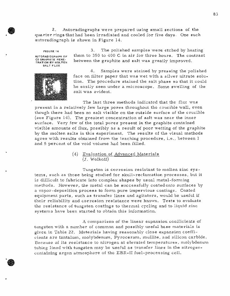
2. Auto radiographs were p repa red using snaall sections of the quar t e r r ings that had been i r r ad ia ted and cooled for five days. One such autoradiograph is shown in Figure 14.
3. The polished samples were etched by heating them to 350 to 400 C in air for three hours . The contras t between the graphite and salt was greatly improved.
4. Samples were stained by press ing the polished face on fil ter paper that was wet with a s i lver ni t ra te solution. The procedure stained the salt phase so that it could be easi ly seen under a mic roscope . Sonae swelling of the salt was evident.
The las t th ree methods indicated that the flux was p resen t in a relat ively few large pores throughout the crucible wall, even though there had been no salt vis ible on the outside surface of the crucible (see Figure 14). The g rea te s t concentrat ion of salt was near the inner surface. Very few of the total pores p resen t in the graphite contained visible amounts of flux, possibly as a resu l t of poor wetting of the graphite by the molten sa l ts in this experinaent. The resul ts of the visual naethods agree with resu l t s obtained from the leaxhing procedure , i .e. , between 1 and 5 percen t of the void volume had been filled.
(4) Evaluation of Advanced Mater ia ls (J. Wolkoff)
Tungsten is co r ros ion res i s tan t to molten zinc s y s t e m s , such as those being studied for skul l - rec lamat ion p r o c e s s e s , but it is difficult to fabricate into complex shapes by usual metal-forming methods . However, the meta l can be successfully coated onto surfaces by a vapor-deposi t ion p roces s to form pure impervious coatings. Coated equipiaient p a r t s , such as t ransfe r lines and agi ta tors , would be useful if the i r rel iabi l i ty and cor ros ion r e s i s t ance were known. Tests to evaluate the res i s t ance of tungsten coatings to the rmal cycling and to liquid zinc sys tems have been s ta r ted to obtain this information.
A compar i son of the l inear expansion coefficients of tungsten with a number of comnaon and possibly useful base naaterials is given in Table 22. Mater ia l s having reasonably close expansion coefficients a r e tantaluna, molybdenum, P y r o c e r a m , mull i te , and silicon carbide. Because of its r e s i s t ance to ni trogen at elevated t empera tu re s , molybdenum tubing lined with tungsten naay be useful as t ransfer lines in the ni trogen-containing argon atnaosphere of the EBR-II fuel-processing cell .
FIGURE 14
AUTORADIOGRAPH OF CS GRAPHITE PENETRATION BY MOLTEN
SALT FLUX
Table 22
LINEAR EXPANSION COEFFICIENTS OF SELECTED MATERIALS
Metals
Tungsten Molybdenum Tantalum Stainless Stee Stainless Stee Inconel
!l 446 ;1 304
Low carbon steel
10" Vc
4.5 5.4 6.6 9.9
17.3 11.5 11.7
Nonmetals
Silica glass Vycor P y r o c e r a m 9608 Graphite Silicon carbide Mullite P y r o c e r a m 9606
io"yc
0.5 0.7
0.7-2.0 1.5-2.5 4.0-5.3
5.5 5.7
The adherence of a tungsten coating was f i r s t t es ted under re la t ively adverse condit ions, i .e . , on type 446 s ta in less s teel which has a considerably higher expansion coefficient than tungsten. At the r e quest of Argonne, tungsten was vapor deposited by the Genera l E lec t r i c Company to a depth of about 6 mi l s on the inside of a y - i n . s ta in less s teel pipe. After t h e r m a l cycling eight t imes between 800 and 100 C, weakening of the bond between the coating and the base meta l occur red . Although the coating did not b reak away, it could be pulled away from the base meta l when the pipe was cut apar t for meta l lographic s amples .
The surface texture of the tungsten coating was nodular and some c racks in the tungsten could be detected meta l lographica l ly . F i g u r e s 15 and 16 show an "as polished" and an etched sect ion of the coated s ta in less s teel before t h e r m a l cycling at inaperfections in the coating. F igure 17 shows the coating after the cycling tes t . Separat ion at the copper layer and the lack of en la rgement of the m i c r o - c r a c k s in the tungsten coating a re evident in the f igure.
(5) Liquid Metal Dist i l la t ion Unit (J. DeKany, L. Dorsey , J . Hepperly)
A pilot p l an t - sca le liquid meta l dis t i l la t ion unit (100 kg of cadmium per hour dis t i l la t ion r a t e , 800-kg feed-tank capacity) to handle cadmium-uran ium solutions has been cons t ruc ted and is being tes ted p r io r to operat ion. This unit will be opera ted to provide design information p e r tinent to liquid me ta l fuel r e p r o c e s s i n g . It will demons t ra te the following operat ions on an engineering sca l e :
(a) Dist i l lat ion of c admium-u ran ium alloy r ep roces s ing solutions.
(b) T rans fe r of liquid me ta l solutions from one vesse l to another , involving the use of p r e s s u r e differences and freeze va lves .

(c) The protect ion of instruiaaents and service lines from liquid naetal va.pors through the use of vapor t raps and f i l te rs .
(d) The autonaatic control of liquid levels , p r e s s u r e s , and temper-a,tures in the unit.
Operation of this unit is expected to begin in the next
qua r t e r .
FIGURE 15
VAPOR-DEPOSITED TUNGSTEN ON TYPE 446 STAINLESS STEEL BEFORE THERMAL CYCLING
(200X, as polished)
-TUNGSTEN
-- ^1 ,uKrtp*n,-| 'j?="*»s 'f%:- ")f" - f •• ,^
o-
^OPPER LAYER
A
TYPE 446 -STAINLESS
STEEL

FIGURE 16
VAPOR-DEPOSITED TUNGSTEN ON TYPE 446 STAINLESS STEEL BEFORE THERMAL CYCLING
(200X, etched)
\ -TUNGSTEN
TYPE 446 -STAINLESS STEEL
FIGURE 17
VAPOR-DEPOSITED TUNGSTEN ON TYPE 446 STAINLESS STEEL AFTER THERMAL CYCLING
BETWEEN SOO AND 100 C (300X, etched)
-TUNGSTEN
\
I COPPER LAYER
TYPE 446 -STAINLESS STEEL
B. Fue l -p roces s ing Fac i l i t i es for EBR-II
1. Design and Construct ion (J. H. Schraidt , M. Levenson)
a. Status of Fuel Cycle Faci l i ty Building Design and Construct ion (E. J . Pe tkus , H. L. Stethers)
The construct ion of the Fuel Cycle Faci l i ty has continued throughout the winter . The Faci l i ty was over 80 percent complete on March 7, 1961, as compared to 70 percen t complete three naonths ea r l i e r . Metallizing of the Argon Cell l iner plate with zinc was completed in January . Shot peening* of the zinc coating was completed during the second week in Feb rua ry . After shot peening, the cell was cleaned and the e r e c tion of major cel l equipment, such as manipula tors and c r anes , was begun.
After install ing the c rane and manipulator br idges , the cont rac tor has been grinding and cleaning the c rane and manipulator r a i l s . Installation of the two argon-cool ing boxes in the subcell has be gun. The argon-cool ing boxes house re f r igeran t coils and a re a port ion of the rec i rcu la t ing sys tem provided to remove the heat generated in the Argon Cell . Work has begun on the instal lat ion of the enaergency p r e s s u r e -relief sys tem for the Argon Cell .
Archi tec tura l work is continuing throughout the building. Painting on both the se rv ice floor and operating floor is proceeding.
The cont rac tor has begun install ing heating and ventilating control ins t ruments and piping. All types of e l ec t r i ca l and piping work is continuing throughout the building. In addition, special equipment such as MI (minera l insulated) cable and manipulator panels a r e being instal led.
b. Fuel Cycle Faci l i ty Equipment (G. J . Berns te in , A. A. Chi lenskas , L. F . Coleman, J . Graae , D. C. Hampson, R. H. Jahnke, M. A. Slawecki, T. W. Eckels)
All the m a t e r i a l s that a r e to be p rocured by ANL at Argonne, 111., for the Fuel Cycle Faci l i ty mel t - re f in ing furnace off-gas sys tem have been o rdered . A work plan, job descr ip t ion , bill of i na t e r i a l s , and drawings for the instal lat ion have been p r epa red .
*Shot peening is the impacting of s teel ba l l s , by means of a i r p r e s s u r e , against a surface , in this case to inc rease the coating density and thus reduce porosi ty .

Two mel t - ref in ing furnaces will be instal led in the Argon Cell. A purchase order has been placed with Trojan Manufacturing Company (a Division of Lindberg Engineering Company) for major components of the furnace. These furnaces will be control led from panelboards in the operating a r e a . A purchase o rde r for two panelboards has been issued to Machinery Electr i f icat ion Inc. of Northboro, Mass ,
A sys tem of space- rad ia t ion moni tors will be instal led in potentially hazardous a r e a s of the Fuel Cycle Faci l i ty . Installation drawing a re completed.
Drawings of the se rv ice feed-through plugs have been completed and sent out for bids . Services (gas, vacuum, and e lec t r i ca l lines) requ i red for equipnaent inside the cel l will penet ra te the shielding floor in these feed- through plugs. The plugs have been descr ibed previously (see ANL-6231, page 35-37 and ANL-6287, page 132).
Solid radioact ive was tes f rom radioact ive a r e a s will be shipped to bur ia l grounds in sealed me ta l conta iners , 6 ft long and of 11-j-in. ID. The container l ids will be s imi l a r to l6- lug lids used on s tandard 5-gal pa i l s . The conta iners will have no ba i l s , but will be lifted magnet ical ly by thei r l ids . The lids will be modified by the a t tachment of a Y7--in, s tee l plate to the unders ide to provide adequate meta l thickness for ca r ry ing the magnet ic flux. A s tandard capping machine was modified so as to be act ivated by the operat ing manipula tor . The capper per formed successfully. A tes t with a 5-gal pail showed that the lid lugs will support a load g r e a t e r than 500 lb. Maximum s c r a p loads a r e expected to be about 200 lb. A design for a pe rmanen t magnet - type lifting device, which is mechanical ly actuated, is being p r e p a r e d by a manufac turer of such m a g netic l i f te rs .
Bids for the interbuilding and scrap-handl ing coffins were rece ived and evaluated, and purchase o r d e r s were placed. O. G. Kelley of Boston, M a s s . , was awarded a cont rac t for the design and fabricat ion of one interbuilding coffin. The coffin will t r a n s p o r t highly radioactive m a t e r ia l between the Reactor Building and the Fuel Cycle Faci l i ty . Knapp Mills of Wilmington, Del. , was awarded a cont rac t for the design and fabricat ion of one scrap-handl ing coffin.
The design of window shut te r s and dr ives has been coin-pleted. Drawings and specifications a r e being pr inted. One d r ive -moto r mount a s sembly and one wall b racke t have been o rde red for mockup and test ing of the design.
An integrat ing gamma dos ime te r capable of recording exposures f rom 10° to 10^° rad would be very useful for record ing the gamma exposure to equipment within the Argon and Air Cells of the Fue l Cycle
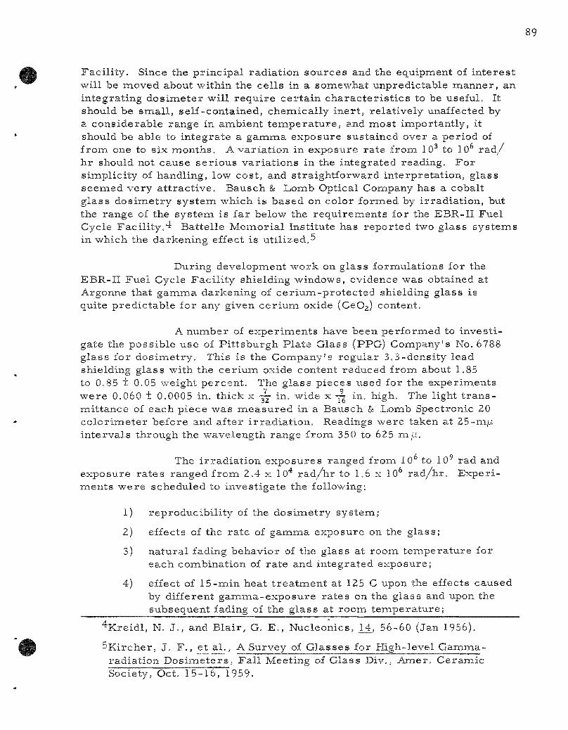
Faci l i ty . Since the pr incipal radiat ion sources and the equipment of in te res t will be moved about within the cel ls in a somewhat unpredictable manner , an integrat ing dos imete r will r equ i re ce r ta in cha rac t e r i s t i c s to be useful. It should be smal l , self-contained, chemical ly iner t , relat ively unaffected by a considerable range in ambient t e m p e r a t u r e , and most inaportantly, it should be able to in tegrate a gamma exposure sustained over a period of f rom one to six months . A var ia t ion in exposure ra te from 10 to 10 r a d / h r should not cause se r ious var ia t ions in the integrated reading. For s implici ty of handling, low cost , and s t ra ightforward interpreta t ion, glass seemed very a t t rac t ive , Bausch 8a Lomb Optical Company has a cobalt g lass dos imet ry sys tem which is based on color formed by i r radia t ion, but the range of the systeiai is far below the requ i rements for the EBR-II Fuel Cycle Facility."i Battelle Memor ia l Institute has repor ted two glass sys tems in which the darkening effect is uti l ized.^
During development work on glass formulations for the EBR-II Fuel Cycle Faci l i ty shielding windows, evidence was obtained at Argonne that gamma darkening of cer iuna-protected shielding glass is quite predic table for any given ce r i um oxide (Ce02) content.
A number of exper iments have been per formed to invest i gate the possible use of P i t t sburgh Plate Glass (PPG) Company's No. 6788 g lass for dos imet ry . This is the Company 's regular 3.3-density lead shielding glass with the ce r ium oxide content reduced from about 1.85 to 0.85 "t 0,05 weight percen t . The g lass p ieces used for the exper iments were 0.060 + 0.0005 in. thick x - y in, wide x -jl in- high. The light t r a n s -mit tance of each piece was m e a s u r e d in a Bausch &, Lomb Spectronic 20 co lo r ime te r before and after i r rad ia t ion . Readings were taken at 25-m/i in terva ls through the wavelength range f rom 350 to 625 m/ i .
The i r rad ia t ion exposures ranged from 10 to 10^ rad and exposure r a t e s ranged from 2.4 x 10"* r a d / h r to 1.6 x 10^ r a d / h r . Exper i ments were scheduled to invest igate the following:
1) reproducibi l i ty of the dos imet ry sys tem;
2) effects of the ra te of gamma exposure on the g lass ;
3) na tura l fading behavior of the glass at room teiaiperature for each combination of ra te and integrated exposure ;
4) effect of 15-nain heat t reatnaent at 125 C upon the effects caused by different gamma-exposu re ra tes on the glass and upon the subsequent fading of the g lass at room t empera tu r e ;
^Kreidl , N. J . , and Bla i r , G. E. , Nucleonics, 14, 56-60 (Jan 1956).
^Kircher , J . F . , et a]_., A Survey of Glasses for High-level Gamma -radiat ion D o s i m e t e r s , Fa l l Meeting of Glass Div., Anaer. Ceramic Society, Oct. 15- l6 ,~l959.

5) the effect of conducting the heat t r ea tment at t imes froiai 30 laiin to 5 hr after i r rad ia t ion;
6) the effect of exi30sure t empera tu re in the 25 to 75 C range;
7) the best p rac t i ca l t ime schedule for heat t r ea tment and reading.
All i r rad ia t ions were perforiaied in the Argonne Ganama I r radia t ion Faci l i ty by means of spent r eac to r fuel.
Figure 18 shows the t r ansmi t t ances of i r rad ia ted and uni r rad ia ted g lass at different wavelengths. The readings were obtained 24 hr after the i r rad ia t ions were completed. Each samxDle was heat t rea ted at 125 C for 15 min. The heat t r ea tmen t was adminis te red one to five hours after removal of the glass from the gamma field.
FIGURE 8
EFFECT CF iRRADlATiOf CJ TRANSMITTAMCE OF
PPG*M0.6788 GLASS
350 400 450 500 550 600 WAVELENGTH, miilimicron
*(PITTSBURGH PLATE GLASS)
Figure 19 shows the naanner in which the internal abso rp tion coefficient (in. "• ) changes with increas ing gananaa-ray exposure . These curves were calculated from the exper imenta l data obtained with the 0.060-in.-thick samples .
F igure 20 shows the change of optical density with tinae at roona teiaiperature of glass samples i r rad ia ted to a total integrated dose of 1 X lO'' rad. The dose ra tes were 6 x 1 0 ^ and 1.6 x 10^ r a d / h r . (Similar resu l t s were obtained at dose ra tes as low as 2.5 x 10* r a d / h r . )
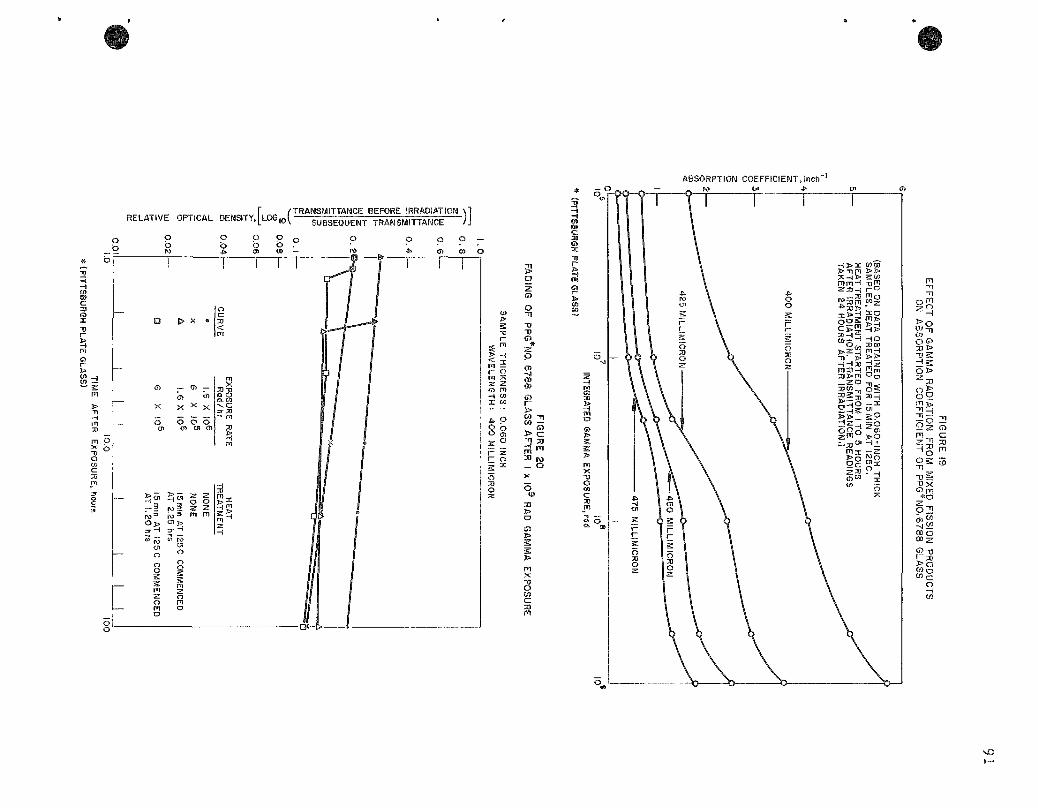
ABSORPTION COEFFICIENT, inch"
RELATIVE OPTICAL DENSITY, [LOG,O( TRANSMITTANCE BEFORE IRRADIATION
SUBSEQUENT TRANSMITTANCE -)] o b
5 Sr
o b
o
2
^ X o
0) _. m
X
5
55. M-^
s? ^ m
55 N 1
«-• ^5
^ o ^ m
o ^
^ "s Hs;' M ^
^
1 ° ^
2
o -D TJ
s
> c
8
3
s s
sO

The optical densi t ies of the samples were m e a s u r e d at 400 m/ i . The effect of heat treatnaent on the g lass samples is a lso shown in the f igure. Samples receiving identical exposures were found to have the same optical densi t ies which dec rea sed at the same ra te with t ime . When some of the samples were heated at 125 C for 15 min, it was found that the optical densi t ies dec r e a s e d marked ly and the subsequent rate of change with t ime became lower. Although the curves shown a r e for samples i r r ad ia t ed to 1 x 10^ rad, it was found that the optical dens i t ies of samples after any given gamma exposure were very near ly equal following the heat t r ea tmen t , r e g a r d l e s s of the ra te of exposure in the range f rom 2.5 x lO'* r a d / h r to 1.6 x 10 r a d / h r . Thus the pos t - i r r ad i a t i on heat t r e a t m e n t removed effects caused by differences in exposure ra te and reduced the ra te of fading at roona t e m p e r a t u r e .
The dos imet ry sys tem appears to have considerable p r o m ise . Calculat ions indicate, however, that, in the exposure range of p a r t i c u la r i n t e r e s t in the Fuel Cycle Faci l i ty , samples 0.120 in. thick should give resu l t s which could be m o r e accura te ly in te rpre ted . Conceptual design of a container for protect ing the samples f rom contanaination while they a r e in s torage within the cel l and of a complete p rocedure for ga ther ing, handling, and reading the samples is well advanced.
c. Cranes and Manipulators (J. Graae , G. J . Bernste in)
The c r anes have been instal led in the Air and Argon Cells at Idaho. All manipula tor br idges have been instal led. Instal lat ion of the c a r r i a g e s has been removed from the construct ion contract .
Manipulator br idge power inlets have been o rde red from A. Dalkin Company. The prototype power inlet plug was wired. Some modi fications were made and incorpora ted in the o rde r to the A. Dalkin Company
Bracke ts and recep tac les for the genera l purpose manipulator arna have been o r d e r e d f rom Ideal Tool and Manufacturing Company. They will be mounted on the manipula tor c a r r i a g e s to provide power and control for the a r t i cu la ted Model 300 Arm when this is used with the ope r ating man ipu la to r s . This arna will be used when an operat ion r equ i r e s g r e a t e r dexter i ty than is poss ible with the operat ing manipula tor .
Toggle switch control boxes for the control of the c r a n e s , man ipu la to r s , and specia l removal hois t w e r e rece ived from the manufac tu re r . They w e r e t es ted in the mockup. Because s eve ra l e r r o r s w e r e found, they were r e tu rned to the manufac tu re r for co r r ec t i ons . They a r e now back and will be r e t e s t ed before shipping to Idaho.
A collapsible manipula tor ca r r i age stand is being designed to occupy a min imum of s torage space and to provide support for the crane t ro l ley when it is lowered to the floor.
The combination lifting beam and lifting tools for bridge dr ives have been c r a t ed in p repa ra t ion for shipnaent to Idaho.
d. Mate r ia l Testing (G. J . Berns te in , L. F . Coleman, J . Graae , M. Slawecki)
The i r r ad ia t ion of MI (minera l insulated) cable end sea ls and a sbes tos - insu la t ed wi re has been summar i zed in ANL-6287, page 87.
Asbes tos - insu la ted wi re samples have received an a c cumulated dose of 1.69 X 10^^ rad to date. Insulation res i s t ance of these samples was low, between 0,2 and 0.5 megohm. However, one sample of the w i r e , which had rece ived a dose of 1.35 x 10^" rad, was heated to dr ive off absorbed mo i s tu r e and then sealed in a vial containing a d e s -sicant. It has since rece ived an additional dose of 3.4 x 1 0^ rad and i ts insulation r e s i s t ance is s t i l l g r e a t e r than 200 megohms. Therefore , the low insulation r e s i s t ance of the unsealed samples can be at t r ibuted to mo i s tu r e absorpt ion and not to radiat ion effects.
F r o m the t ime the Argon Cell is built to the t ime it is filled with argon, the re may be a t ime in terval of six months to one yea r . During this t ime the s teel l iner and other meta l surfaces in the cel l would be subject to co r ro s ion if left unprotected. Therefore , the naetal surfaces should be covered with an application of some protect ive coating or finish. Some of the p rope r t i e s of the coating that would be requi red a r e :
1. surface protect ion;
2. high ref lectance without g l a r e ;
3. min imum of outgassing under radiat ion; and
4. radia t ion r e s i s t a n c e ,
A surface without g la re and with a high reflectance is de s i rab le in the cel l in o rde r to provide i nc reased i l lumination efficiency. These surface fea tures a r e of pa r t i cu l a r impor tance for objects with la rge a r e a s , such as the cel l wa l l s . High levels of i l lumination a r e neces sa ry because of the re la t ively poor t r ansmi t t ance of the 5-ft shielding windows.
Outgassing of the coating or finish would be of p r i m a r y concern only where l a rge surface a r e a s a r e to be covered. Under rad ia tion, paints tend to outgas the organic addit ives and their decomposi t ion
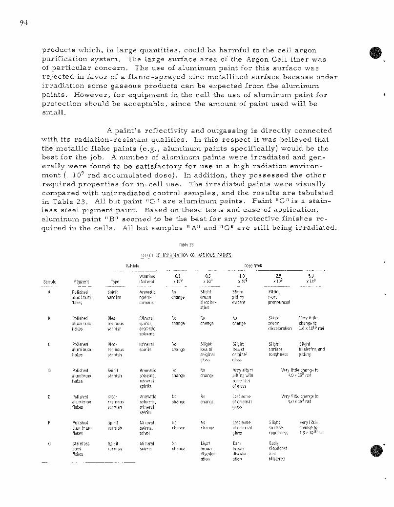
products which, in large quant i t ies , could be harnaful to the cell argon purification systeiai. The large surface a r ea of the Argon Cell l iner was of pa r t i cu la r concern. The use of aluiaiinuna paint for this surface was rejected in favor of a f l ame-sprayed zinc metal l ized surface because under i r rad ia t ion some gaseous products can be expected from the aluminum paints . However, for equipment in the cell the use of aluminuna paint for protect ion should be acceptable , since the amount of paint used will be snaall.
A paint ' s reflectivity and outgassing is direct ly connected with its r ad ia t ion - res i s t an t qual i t ies . In this respec t it was believed that the inetall ic flake paints (e.g., aluminum paints specifically) would be the best for the job. A number of aluminum paints were i r rad ia ted and genera l ly were found to be sat isfactory for use in a high radiation environ-naent (. lO' rad accumulated dose). In addition, they possessed the other requi red p roper t i e s for in-cel l use. The i r rad ia ted jsaints were visually coiaipared with uni r rad ia ted control samples , and the resu l t s a r e tabulated in Table 23. All but paint "G" a r e alunainuna paints . Paint "G" is a s tainless steel pigment paint. Based on these tes ts and ease of application, aluiaiinuna paint "B" seemed to be the best for any protect ive finishes r e quired in the ce l l s . All but samples "A" and "G" a r e sti l l being i r rad ia ted .
Table 23
EFFFCT OF IRRADIATION Oh VARIOUS PAINTS
Vehicle Dose iradi
Pigment
Polished aiuKiinuni flakes
Polished aluminum flalses
Polished aluninum flakes
Polished aluminuiii flakes
Polished aluminum flakes
Polished aluminum flakes
Stainless steel flakes
Type
Spirit varnish
Oleo-resinous varnish
Olco-resinous v'arnish
Soirit varnish
Oleo-resinous varnish
Spirit varnish
Spirit varnisn
Volatiles 'Solvent)
Aromatic hydro-carwns
Mineral spirits, aron^atic solvents
Mineral sisirits
AroiTdtic solvents, mineral spirits
Aromatic solvents, irineral spirits
.Mineral spirits. tolvol
Mineral SDifitS
0.1 xlO?
to change
Change
No change
;o change
change
change
Ho change
0.5 xlO»
Slight liroa-n discoloration
change
Slight loss of original gloss
Jo change
Mo
change
^o change
Light Sjrovvn discoloration
1.0 Xl09
Slight pitting evident
change
Slight loss of original gloss
Very slight pitting lUth some loss of gloss
lost some of original gloss
Lost some of original gloss
Dark hrown discoloration
2.5 x l09
Pitting more pronounced
Slight Dro'.vn discoloration
Slight surface roughness
5.0 xlO'S
Very little change to 1.6x"l0l0rad
Slight blistering and pitting
Very little change to 4.0 y lO'' rad
Very little change to 9.0 X 10^ rad
Slight surface roughness
Badly discolored and hiisterec
Very litile change to 1.3 y lO'-O rad

In addition to the alunainum paints , severa l samples of z inc-base coatings were i r rad ia ted . These form a complex i ron-z inc- lead si l icate on a s tee l surface during curing of the coating. The coating is composed of a liquid port ion containing a water solution of sodium sil icate and a solid port ion containing zinc dust with a smal l amount of lead. Curing is ordinar i ly done by chemical means using a curing solution containing a phosphate dissolved in a volatile organic solvent. However, the coating may also be cured by baking. Two coatings were tested. Samples were p repa red from one formulation by chenaical curing and frona both formulations by baking. The i r r ad ia t ed coatings were compared with uni r radia ted cont ro ls . All samples were discolored after receiving a dose of 1 x 1 0 rad After a dose of 4 x 10^ rad, the discolorat ion had beconae more pronounced and samples had become sticky. Up to 2 x lO' rad, when i r radia t ion of thes samples was discontinued, they had become so discolored and sticky that the coatings were considered unfit for use .
One phase of the ro l l e r -bea r ing tes ts using i r rad ia ted r ad ia t ion- res i s t an t g r e a s e s (see ANL-6287, page 85) has been completed. Of the th ree types of g r ea se tes ted, NRRG-159 and NRRG-335 performed about equally well after i r rad ia t ion to 5 x lO' rad. Data from these tes t s a r e summar ized in Table 24.
Table 24
ROLLER-BEARING TESTS WITH IRRADIATED GREASES
Timken Bearing (No. 432 cup - No. 438 cone) 800 lb axial load at 40 rpm
Grease Type a
NRRG-159
NRRG-159
NRRG-159
NRRG-235
NRRG-335
Irradiation (rad X 10"')
Running Time (hr)
300^
300
300
52
300
Remarks
Ran well. Run terminated voluntarily.
Slight squeak after Z57 hr. Very slight darkening of bearing surface.
Squeak after 180 hr. Cup and cone stuck together when load was re moved after test. Some areas of heat darkening on rollers and cup.
Failed due to breakdown of jell and plating out of solid residual lubricants.
Squeak after 176 hr. Cup and cone stuck together when load was re moved after test. Some areas of heat staining on rollers and cup. Some solid deposit from grease on cup and rollers.
^Products of Standard Oil of California.
^Manufacturer's rated limit.
'^Estimated to be equivalent to four years of actual operating time in the Fuel Cycle Facility.

Tests were c a r r i e d out to explore the likelihood of the g r ea se s becoming sufficiently fluid during i r rad ia t ion to run away from the bear ings . Samples of the th ree g r e a s e s were placed in vials which were provided with dr ip holes , — in. in d iameter and about 20 mi l s in length. Loss of g r e a s e through the holes was checked after radiat ion to 5 x 1 0 ^ , 1 x lO' , 1.5 X lO', 2 X 10^ and 3 x l o ' rad. The samples were confined in bott les so that g rease drippage during each per iod of i r rad ia t ion could be collected and m e a s u r e d .
All t h ree g r e a s e s showed some loss through the dr ip hole, but there was no consis tent re la t ionship between i r rad ia t ion and l o s s . None showed loss after 2 x 1 0 ^ rad. On a cumulative bas i s , NRRG-335 lost the g r ea t e s t anaount and NRRG-159 lost the leas t . These resu l t s were in genera l agreement with the r e su l t s from e a r l i e r t e s t s in which bulk samples were examined at regular in te rva l s . The e a r l i e r t e s t s showed that NRRG-159 underwent the l eas t loss of consistency during i r radiat ion. On the bas i s of these and other r e s u l t s , NRRG-159 has been selected for lubricat ing the operating manipula tors now being built by General Mil ls , Inc.
Additional t e s t s with these g r e a s e s and Timken ro l l e r bear ings a r e being made . Three bear ings which have been a l ternate ly i r r ad ia t ed and then run for 8-hr per iods have been tes ted at 1 x 10^, 2 X lO', and 3 x 1 0 ^ rad. The bear ing lubr icated with NRRG-235 g r e a s e began to squeak after 7 hr following i r r ad ia t ion to 2 x lO' rad and after •£ hr following i r rad ia t ion to 3 x lO'' rad. The bear ings with NRRG-159 and NRRG-335 ran successfully in al l t e s t s . The re su l t s of these t e s t s , which were c a r r i e d out in a i r , should indicate per formance of the bear ings and g r e a s e s in the Air Cell, Since g r e a t e r damage occurs when these g r e a s e s a r e i r r ad i a t ed in an a i r a tmosphere than when they a re i r r ad ia t ed in an iner t a tmosphe re , the resu l t s of the tes t s may be used to es t imate the per formance of the bear ings and g r e a s e s in the Argon Cell.
2. EBR-II Fue l -p roces s ing Mockup (J. H. Schraidt)
a. Manipulator and Manipulator Removal Bl is ter (D. C, Hanapson, J . Graae)
The following redes igned components have been fabr icated and instal led on the manipula tor : (l) br idge drive motor unit, (2) gr ip drive motor and clutch assembly , (3) pick-up brush assembly , (4) hoist clutch, and (5) additional mechan i sm for attaching the a r t icu la ted Model 300 Arm.
As a resu l t of exper ience with this new equipment, sonae changes have been made in the manipula tors being built by General Mills .
The crane and man ipu la to r - r emova l device a re being instal led in the roof of the Fuel Cycle Faci l i ty at Idaho.
Conceptual design of racks permit t ing storing of the Model 300 Genera l Purpose Art iculated Arm in the 24- in . -d iamete r s torage pits in the Argon Cell has been developed.
b. Melt-ref ining Fu rnaces
(D. C. Hampson, W. E. Mil ler , and R. F rye r )
(1) Equipiaient Pe r fo rmance
(a) Crucib les
Crucible behavior has been repor ted previously (see ANL-6183, pages 29 to 32, ANL-6231, pages 50 and 51 and ANL-6287, pages 89 and 90). The c ruc ib les used w e r e not degassed pr io r to use , as previous work had shown that when the crucible charge was bulk uranium, no measu rab l e inc rease in yields resu l ted from the use of degassed c r u c ib les . Therefore , there was no incentive to use degassed c ruc ib les . Some recent work with charges in the form of fuel pins , however, gave evidence that yields could be inc reased by about 1.5 percent when degassed crucibles were subst i tuted for nondegassed c ruc ib les .
Stabilized z i rconia crucib les have been used r e cently as a container for melt ing s c r ap fuel pins (as cast , not sodium coated). Thi r ty-e ight p i n - s c r a p me l t s were made in crucibles which were not degassed. The average yield for these pours was 92.2 ± 1 . 3 percent . Seven naelts were made in c ruc ib les which were degassed. The average yield was 93.9 i 0.9 pe rcen t . The high yield for runs made with degassed cruc ib les was 95.4 pe rcen t and the low was 92.5 percent . Six of the c r u cibles were degassed at 1000 C. One was degassed at 800 C, the yield in this case being 94.2 percen t . Of the seven c ruc ib les , six showed fine d i ame t r i ca l c r acks a c r o s s the bottom after degassing. These c racks did not open up sufficiently in the mel t - re f in ing operat ion to allow escape of uranium.
One additional pin s c r ap naelt was made in a c r u cible which had been degassed at 1000 C. In this case a, c rack in the c r u cible bottoin allowed a smal l anaount of u ran ium to seep out into the furnace susceptor . This dec rea sed the pouring yield to 86,9 percent .
Degassing crucibles for melting fuel pins seems to be worthwhile from the standpoint of nainimizing pin shells and i n c r e a s ing yield. However, there is a r i sk that slight c racks developed during degassing will propagate and allow uranium leakage during melt ing. The type of cracking encountered recent ly and descr ibed above is new. Some of the crucib les recent ly rece ived from Norton have bottoms which a r e about ~ in. thicker than usual . (The nominal thickness of the bottom of s tandard crucibles is one inch.) To study the effect of var ia t ions of bottom thickness on cracking crucibles which have walls and bottoms of the same th ickness , g- in., a r e being obtained frona Norton. Lower degassing t empe ra tu re and shor t e r degassing per iods a r e a lso being invest igated as a means of eliminating cracking during crucible degassing.
(b) Skull Oxidation
Work has s t a r t ed on equipment to be used in the Argon Cell for oxidizing mel t - re f in ing crucible skul ls . One approach is to build sepa ra t e equipment with which to c a r r y out the oxidation step; the other approach is to c a r r y out the oxidation step in the mel t - ref in ing furnace.
To invest igate the feasibil i ty of oxidizing skulls in mel t - ref in ing equipment, a c e r i um- f i s s i um skull from a mel t - ref in ing run was oxidized in the M-V furnace. The skull oxidation was c a r r i e d out as if it were sequential to the mel t - ref in ing operat ion. The crucible containing the skull was heated to 1400 C under one a tmosphere argon in the be l l - j a r furnace. The power to the furnace was shut off and the furnace was allowed to cool under one a tmosphere argon until the skull t empe ra tu r e had dropped to 600 C. The furnace was then evacuated to 10 m m of m e r cury and vented to a i r . The furnace was evacuated and vented to a i r twice more within the next half hour to rep len i sh the oxygen. After the last venting, the furnace stood overnight and was opened the next morning. The skull had powdered completely, except for a few scabs . The furnace susceptor had lost less than one g r a m . The coil did not appear to be adve r se ly affected. In genera l , the oxidizing s tep did not injur the furnace components .
This approach to skull oxidation appeared to have s eve ra l advantages . The number of crucible t r ans f e r s would be cut down, and the mel t refining and skull oxidation could be done in the same equipment . However, p rac t i ca l difficulties have been encountered. The crucible bottom c racks away from the side wall during oxidation and wedges in the furnace susceptor when the furnace is t i l ted to d i scharge the crucible . In addition, problenas of possibly g r e a t e r magnitude a r e introduced when oxygen is allowed to enter the mel t - re f in ing furnace. Since it would not be p rac t i ca l to degas the furnace between runs , a d e c r e a s e would be expected in pouring yield of a subsequent mel t - re f in ing run. This approach, the re fore , has been t e m p o r a r i l y abandoned in favor of use of sepa ra t e equipment.
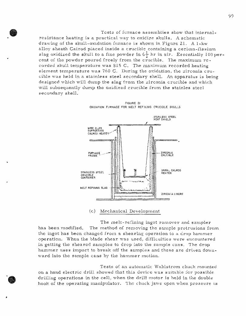
Tests of furnace assembl ies show that in ternal -res i s tance heating is a p rac t ica l way to oxidize skulls . A schematic drawing of the skull-oxidation furnace is shown in Figure 21. A 1-kw alloy sheath Calrod placed inside a crucible containing a ceriuna-fissium slag oxidized the skull to a fine powder in 6— hr in a i r . Essent ial ly 100 pe r cent of the powder poured freely from the crucible. The maxiixium r e corded skull t empera tu re was 815 C. The maximum recorded heating element t empera tu re was 760 C. During the oxidation, the zirconia c ru cible was held in a s ta inless s tee l secondary shell. An apparatus is being designed which will duinp the slag from the zirconia crucible and which will subsequently dump the oxidized crucible from the stainles steel secondary shell .
FIGURE 21
OXIDATION FURNACE FOR MELT REFINING CRUCIBLE SKULLS
WIRE CLIPS SUPPORTING CALROD HEATER''
FURNACE ^ - * -FRAME '- '
STAINLESS STEEL CRUCIBLE CONTAINER
MELT REFINING SLAG
(c) Mechanical Development
The mel t - ref ining ingot remover and sampler has been modified. The inethod of removing the sainple protrus ions from the ingot has been changed from a shearing operation to a drop hammer operat ion. When the blade shear was used, difficulties were encountered in getting the sheared samples to drop into the sample cans. The drop h a m m e r uses impact to break off the samples and these a re driven downward into the sample cans by the h a m m e r naotion.
Tes ts of an automatic Wahlstrom cliLick mounted on a hand e lec t r ic dr i l l showed that this device was suitable for possible dril l ing operat ions in the cell , when the dr i l l motor is held in the double hook of the operating manipulator . The chuck jaws open when p r e s s u r e is
-STAINLESS STEEL HEAT SHIELD
SPIRAL CALROD HEATER
ZIRCONIA LINERS
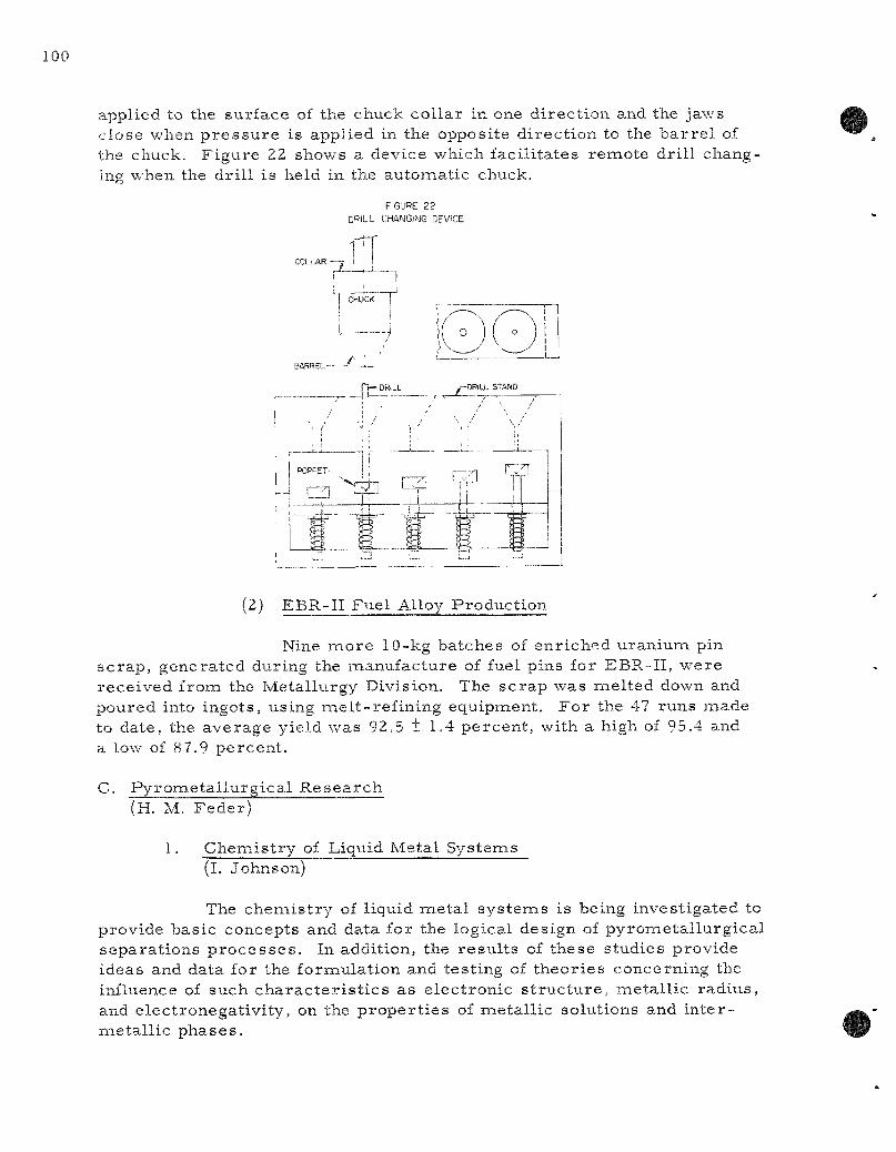
applied to the surface of the chuck col lar in one direct ion and the jaws close when p r e s s u r e is applied in the opposite direct ion to the b a r r e l of the chuck. Figure 22 shows a device which facil i tates remote dri l l changing when the dr i l l is held in the automatic chuck.
F'GURE 22 miL CHA JGING DEVICE
(2) EBR-II Fuel Alloy Production
Nine more 10-kg batches of enriched uranium pin sc rap , generated during the manufacture of fuel pins for EBR-II, were received from the Metallurgy Division. The sc rap was melted down and poured into ingots, using mel t - ref in ing equipment. For the 47 runs made to date, the average yield was 92.5 t 1.4 percent , with a high of 95.4 and a low of 87.9 percent .
C. Pyrometa l lu rg ica l Resea rch (H. M. Feder)
1. Chenaistry of Liquid Metal Systems (l. Johnson)
The chenaistry of liquid meta l sys tems is being investigated to provide basic concepts and data for the logical design of pyrometa l lurg ica l separat ions p r o c e s s e s . In addition, the resu l t s of these studies provide ideas and data for the formulation and testing of theor ies concerning the influence of such cha rac t e r i s t i c s as e lectronic s t ruc tu re , metal l ic radius , and electronegativi ty, on the p roper t i e s of metal l ic solutions and in te r -metal l ic phases .
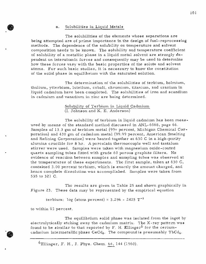
a. Solubilities in Liquid Metals
The solubil i t ies of the e lements whose separat ions a r e being at tempted a r e of p r i m e impor tance in the design of fue l - reprocess ing methods . The dependence of the solubility on t empera tu re and solvent composit ion needs to be known. The solubility and t empera tu re coefficient of solubility of a meta l l ic phase in a liquid meta l solvent a re strongly de pendent on in tera tomic forces and consequently may be used to determine how these forces va ry with the basic p rope r t i e s of the solute and solvent a toms . F o r such basic studieS; it is n e c e s s a r y to know the constitution of the solid phase in equi l ibr ium with the sa tura ted solution.
The de termina t ion of the solubili t ies of t e rb ium, holmium, thulium, y t te rb ium, lutet ium, cobalt, chromium, t i tanium, and uranium in liquid cadmium have been completed. The solubili t ies of i ron and scandium in cadmium and vanadium in zinc a r e being determined.
Solubility of Terb ium in Liquid Cadmiumi (l. Johnson and K. E. Anderson)
The solubility of t e rb ium in liquid cadmium has been m e a s u red by means of the s tandard method d iscussed in ANL-6O68, page 66. Samples of 13.3 gm of t e rb ium me ta l (99+ percent , Michigan Chemical Cor poration) and 430 gm of cadmium meta l (99.99 percen t , Amer ican Smelting and Refining Corporat ion) w e r e heated together at 630 C in a high-pur i ty alumina crucible for 8 h r . A porce la in thermocouple well and tantalum s t i r r e r were used. Samples were taken with magnes ium oxide-coated quar tz sampling tubes fitted with grade 60 porous graphite f i l t e r s . No evidence of react ion between sanaples and sampling tubes was observed at the t e m p e r a t u r e s of these expe r imen t s . The f i r s t sample , taken at 630 C, contained 3.00 percent t e rb ium, which is exactly the amount charged, and hence complete dissolut ion was accomplished. Samples were taken from 535 to 321 C.
The re su l t s a r e given in Table 25 and shown graphical ly in F igure 23. These data may be r e p r e s e n t e d by the empi r i ca l equation
t e rb ium: log (atom percent) = 3.296 - 2425 T"^
to within l 3 pe rcen t .
The equi l ibr ium solid phase was isolated from the ingot by e lect rolyt ica l ly etching away the cadmium ma t r ix . The X- ray pa t te rn was found to be s imi l a r to that r epor ted by F , H, EUinger" for the c e r i u m -cadmium in te rmeta l l i c phase CeCd^. The compoundis p resumably TbCd^.
El l inger , F . H., J . Phys . Chem. 64, 144 (I960).
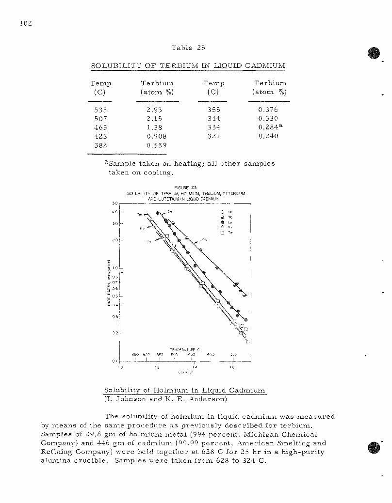
Table 25
SOLUBILITY OF TERBIUM IN LIQUID CADMIUM
Tem,p
(c)
535 507 465 423 382
Terbium (atom %)
2.93 2.15 1.38 0.908 0.559
Temp
(c)
355 344 334 321
Terbium (atom %)
0.376 0.330 0.284^ 0.240
^Sample taken on heating; all other samples taken on cooling.
FIGURE 23 SOLUBILITY OF TERB'UM, HOLMIUM, THULIUM, YTTERBIUM
AND LUTETIUM IN LIQUID CADMIUM
Solubility of Holmium in Liquid Cadmium (I. Johnson and K. E. Anderson)
The solubility of holmium in liquid cadmium was m e a s u r e by nieans of the same procedure as previously descr ibed for terbium. Samples of 29.6 gm of holmiuuTi me ta l (99+ percent , Michigan Chemical Company) and 446 gna of cadmium (QQ.99 percent , American Smelting and Refining Conipany) were held together at 628 C for 25 hr in a high-puri ty alumina crucible . Samples were taken from 628 to 324 C.

The resu l t s a r e given in Table 26 and shown graphically in F igure 23. These data may be r ep re sen t ed by the empi r i ca l equation
holmium: log (atom percent) = 3.409 - 2494 T"-
to within +4.8 percen t .
Table 26
SOLUBILITY OF HOLMIUM IN LIQUID CADMIUM
Temp (c)
628 580 545 501 461
Holmium (atom %)
4.39 3.36 2.23 1.52 0.979
Temp (c)
424 387 351 334 324
Holmium (atom %)
0.646 0.415 0.259 0.205^ 0.179
^Sample taken on heat ing; all other samples taken on cooling.
The equi l ibr ium solid phase was isolated from the ingot by e lec t ro ly t ica l ly etching away the cadmium mat r ix . The X- ray pa t te rn was s imi la r to that found for the t e rb ium-cadmium in termeta l l ic phase and hence the compound is probably HoCd^.
Solubility of Thulium in Liquid Cadmium (I. Johnson and K. E. Anderson)
The solubility of thulium in liquid cadmium has been m e a s ured by means of the same p rocedure as descr ibed previously for terbium. Samples of 13.2 gm of thulium m.etal (99.7 percent , Lindsey Chemical Division) and 370 gm of cadmium meta l (99.99 percent , Amer ican Smelting and Refining Company) were held together at 634 C for 16 hr in a high-puri ty alumina cruc ib le . Samples of the equi l ibr ium liquid phase were taken from 524 to 324 C.
The r e su l t s a r e given in Table 27 and shown graphical ly in F igure 23. These data may be r e p r e s e n t e d by the empi r i ca l equation
thulium: log (atom percent) = 3.488 - 2514 T~^
to within +3 percen t .
Table 27
SOLUBILITY O F THULIUM IN LIQUID CADMIUM
T e m p
(c)
524 501 460 418 382
T h u l i u m ( a tom %)
2.21 1.77 1.11 0.690 0.442
T e m p (C)
347 339 332 324
T h u l i u m ( a t o m %)
0 .275^ 0.245 0 . 2 4 1 ^ 0.224
^Samiples t a k e n on h e a t i n g ; a l l o t h e r s a m p l e s t a k e n on coo l ing .
The e q u i l i b r i u m so l id p h a s e w a s i s o l a t e d f r o m the ingot by e l e c t r o l y t i c a l l y e t ch ing away the c a d m i u m m a t r i x . The X - r a y p a t t e r n w a s s i m i l a r to t h a t found for the t e r b i u m - c a d i x i i u m i n t e r m e t a l l i c p h a s e . The i n t e r m e t a l l i c p h a s e is p r o b a b l y TmCdg.
Solubi l i ty of Y t t e r b i u m in Liquid C a d m i u m (I. J o h n s o n and K. E . A n d e r s o n )
The so lub i l i ty of y t t e r b i u m in l iqu id c a d m i u m w a s m e a s u r e d by m e a n s of the s a m e p r o c e d u r e a s p r e v i o t i s l y d e s c r i b e d for t e r b i u m . S a m p les of 27.2 g m of y t t e r b i u m m e t a l (99+ p e r c e n t , Mich igan C h e m i c a l C o m pany) a n d 4 5 5 g m of c a d m i u m m e t a l (99.99 p e r c e n t , A m e r i c a n Smel t ing and Refining Company) w e r e he ld t o g e t h e r a t 630 C for 2 1 h r in a h i g h - p u r i t y a l u m i n a c r u c i b l e . S a m p l e s of the e q u i l i b r i u m l iquid p h a s e w e r e t aken f rom 504 to 326 C.
F i g u r e 23 . The r e s u l t s a r e given in Tab le 28 and shown g r a p h i c a l l y in
Table 28
SOLUBILITY OF Y T T E R B I U M IN LIQUID CADMIUM
T e m p
(c)
504 463 425 384
Ytterbiuixi ( a t o m %)
3.09 2.12 1.59 1.01
T e m p
(c)
346 343 334 326
Y t t e r b i u m (a tom %)
0.654 0 .688^ 0 .576^ 0.516
^ S a n i p l e s t a k e n on h e a t i n g ; a l l o t h e r s a m p l e s t a k e n on coo l ing .
These data may be r ep re sen t ed by the empi r i ca l equation
y t te rb ium: log (atom percent) = 2.992 - 1957 T"^
to within t 3 .4 percen t .
The equi l ibr ium solid phase was isolated from the ingot by e lect rolyt ical ly etching away the cadmium mat r ix . The X- ray pat tern was s imi la r to that found for the t e rb ium-cadmium compound and hence is probably YbCd^.
Solubility of Lutet ium in Liquid Cadmium (l. Johnson and K. E. Anderson)
The solubility of lutet ium in liquid cadmium has been m e a s u r e d by means of the same p rocedure descr ibed previously for te rb ium and the other r a r e e a r t h s . The exper iment was done in two s teps . In the f i r s t s tep , a charge consist ing of 20,0 gm of lutet ium meta l (99+ p e r cent, Michigan Chemical Company) and 292 gm of cadmium meta l (99.9+percent, e lec t rolyt ic g rade , or ig inal source unknown) was held at 632 C for seventeen hours in a h igh-pur i ty a lumina crucible . Samples of the liquid phase were taken from 528 to 340 C. Below 340 C it was im.possible to sample the liquid phase because of the excess ively large amount of i n t e r meta l l ic phase p re sen t . Accordingly, in the second step, a 200-gm port ion of the ingot from the f i r s t p a r t of the experinaent was mel ted together with 100 gm of cadmium meta l and held for 1 7 hr at 625 C. Samples of the sa tu ra ted liquid phase w e r e taken f rom 557 to 324 C.
The r e su l t s of both p a r t s of the exper iment a re given in Table 29 and shown graphical ly in F igure 23. These data may be r e p r e sented by the empi r i ca l equation
lu te t ium: log (atom percent ) = 7,328 - 7630 T"^ + 1,745 x 10^ T"^
to within 13.8 percen t .
The equi l ibr ium solid phase was isolated f rom a port ion of the ingot f rom the f i r s t p a r t of the exper iment by e lectrolyt ical ly e tching away the cadmium m a t r i x . The X- ray pa t te rn was found to be s imi la r to that for the other heavy r a r e e a r t h - c a d m i u m in termeta l l ic compounds. The in te rmeta l l i c phase is probably LuCd^.
Solubility of Cobalt in Liquid Cadmium (M. G. Chasanov and P . DT Hunt)
In ANL-6145, page 71, p re l imina ry resu l t s for the solubility of cobalt in liquid cadmium w e r e repor ted . The r e su l t s of a m o r e c o m p r e hensive solubility de te rmina t ion a r e shown in F igure 24 and Table 30.

106
Table 29
SOLUBILITY OF LUTLTIUM IN LIQUID CADMIUM
Temp 'C!
557 5283 526 515 499a
LutefiuRi •aton fcl
i ^ c 3.28b 3.18C 2.84'' 2.32b
Temp !CI
486 472 459a
440
Lutetium fatom '7oi
1.99c 1.71 5 I.47I' I.I2C
Temp •CI
4163 394 377a
359
Lutetium (atom * !
0.897b 0.638«: 0.560b 0.422b
Temp 'Ci
352 340a 340 324
lutetium (atom %)
0.373= 0.347b o.sosc 0.288b
^Cafa obtaineij in the first step of the experiment: other data were obtained in the second siep.
bsamples taken on cooling.
<^Samples taken on heating.
FIGURE 2 4 SOLUBILITY OF COBALT IN LIQUID CADMIUM
A HEATING
V COOLING
TEMPERATURE , G
6S0 SCO 5 5 0 5 0 0 4 5 0 4 0 0 3 5 0
1 1 1 . 1 1, 1 ) 1 1 ,1
12 14 1 6 IOOO/T ,K
Table 30
SOLUBILITY OF COBALT IN LIQUID CADMIUM
Temp !C!
653.4 617.4 579.4 548.4
Cobalt (atom ?•)
0.0338 0.0259 0.0208 0.0161
Temp (C)
523.4 501.5 483.4 454.5
Cobalt (atom %)
0.0118 O.OUl 0.00964 0.00821
Temp (C)
426.4 405.4 404.3
Cobalt (atom %)
0.00617 0.00414 0.00413
Temp (C)
353.5 334.6 333.5
Cobalt (atom %)
0.00386 0.00308 0.00313
These data were obtained by taking f i l tered samples of mel t s p r epa red from 99.95 percen t cadmium rod and 99.95 percent cobalt powder. The data over the range from 334 to 653 C may be r e p r e s e n t e d b y the empir ica l equation
cobalt: log (atom percent) = 3.594 - 6515 T~H 1.705x10^ T"^
to within i l l percent .
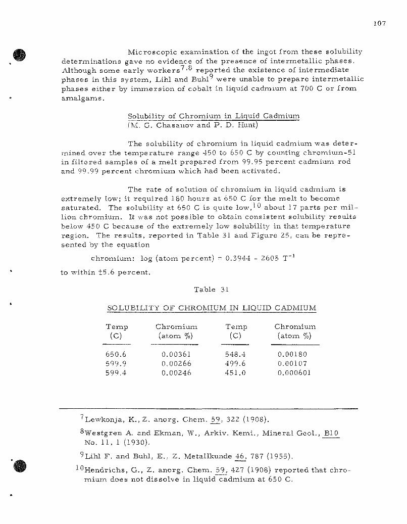
Microscopic examination of the ingot from these solubility determinat ions gave no evidence of the presence of intermetal l ic phases . Although some ear ly worke r s '° repor ted the existence of intermediate phases in this sys tem, Lihl and Buhl" were unable to prepare intermetal l ic phases ei ther by immers ion of cobalt in liquid cadmium at 700 C or from amalgams .
Solubility of Chromium in Liquid Cadmium (M. G. Chasanov and P . D. Hunt)
The solubility of chromium in liquid cadmium was de ter mined over the t empera tu re range 450 to 650 C by counting chromium-51 in fi l tered sanaples of a mel t p repa red from 99.95 percent cadmium rod and 99.99 percent chromium which had been activated.
The rate of solution of chromium in liquid cadmium is ex t remely low; it required 180 hours at 650 C for the melt to become sa tura ted . The solubility at 650 C is quite low,^*^ about 17 par ts per m i l lion chromium. It was not possible to obtain consistent solubility resul ts below 450 C because of the ext remely low solubility in that t empera ture region. The resu l t s , repor ted in Table 31 and Figure 25, can be r e p r e sented by the equation
chromiuiTi: log (atom percent) = 0.3944 - 2605 T~^
to within +5.6 percent .
Table 31
SOLUBILITY OF CHROMIUM IN LIQUID CADMIUM
Temp
(c) 650.6 599.9 599.4
Chromium (atom %)
0.00361 0.00266 0.00246
Temp
(c) 548.4 499.6 451.0
Chromium (atom %)
0.00180 0.00107 0.000601
'Lewkonja, K., Z. anorg. Chem. 5_9, 322 (1908).
^Westgren A. and Ekman, W., Arkiv. Kemi. , Mineral GeoL, BIQ No. 1 1 , 1 (1930).
9Lihl F . and Buhl, E., Z. Metallkunde 46, 787 (1955).
^Hendrichs, G., Z. anorg. Chem. 59, 427 (1908) repor ted that ch ro mium does not dissolve in liquid cadmiuna at 650 C.
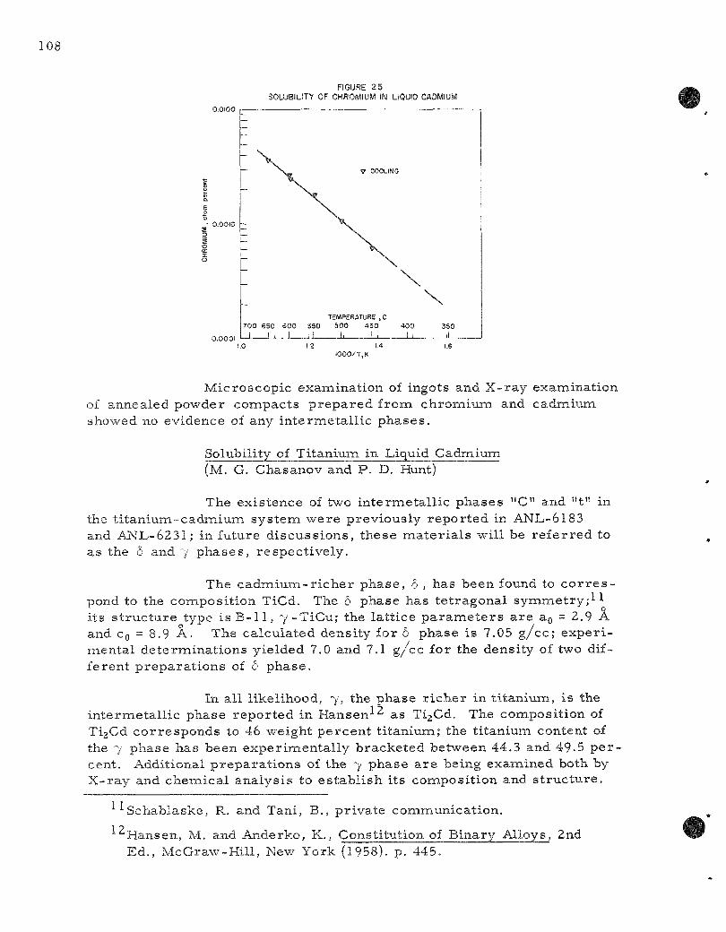
FIGURE 25 SOLUBILITY OF CHROMIUM IN LIQUID CADMIUM
V COOLING
TEMPERATURE , C 700 S50 600 S50 SOO 450 400 _1 I 1 - 1 iJ L LJ L L .
350
1.4 1000/T,K
Microscopic examination of ingots and X-ray examination of annealed powder compacts p repa red from chromium and cadmium showed no evidence of any in termetal l ic phases .
Solubility of Titanium in Liquid Cadmium (M. G. Chasanov and P . D. Hunt)
The existence of two in termeta l l ic phases "C" and "t" in the t i tan ium-cadmium sys tem were previously repor ted in ANL-6183 and AIs[L-6231| in future d iscuss ions , these ma te r i a l s will be r e fe r red to as the 6 and 7 phases , respect ively .
The cadmium- r i che r phase , 6 , has been found to c o r r e s pond to the composit ion TiCd. The 6 phase has te t ragonal symmet ry ; ! 1 its s t ruc ture type i s B - 1 1 , 7 '-TiCu; the lat t ice p a r a m e t e r s a re ao = 2.9 A and Cg = 8.9 A. The calculated density for 6 phase is 7.05 g / cc ; exper i mental determinat ions yielded 7.0 and 7.1 g/cc for the density of two different p repara t ions of 6 phase .
In all likelihood, 7, the phase r i che r in t i tanium, is the internietal l ic phase repor ted in Hansen-'-^ as TigCd. The composition of Ti2Cd cor responds to 46 weight percen t t i tanium; the t i tanium content of the 7 phase has been exper imental ly bracketed between 44.3 and 49.5 percent. Additional p repara t ions of the 7 phase a r e being examined both by X-ray and chem.ical analysis to es tabl i sh its composition and s t ruc tu re .
Schablaske, R. and Tani, B., pr ivate communication.
12 Hansen, M. and Anderko, K., Constitution of Binary Alloys, 2nd Ed., McGraw-Hil l , New York (1958). p. 445.
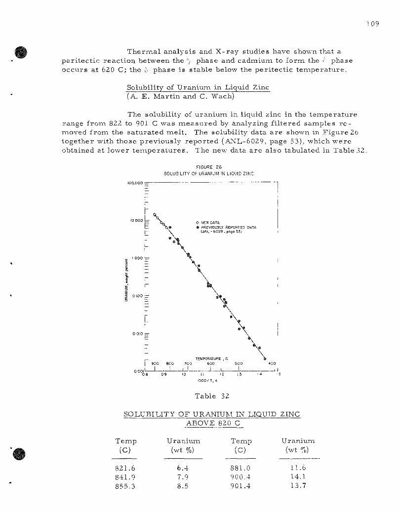
109
Thermal analysis and X-ray studies have shown that a per i tec t ic react ion between the "^ phase and cadmium to form the f phase occurs at 620 C; the 5 phase is stable below the per i tec t ic t empera tu re .
Solubility of Uranium in Liquid Zinc (A. E. Mart in and C. Wach)
The solubility of uranium in liquid zinc in the tempera ture range from 822 to 901 C was m e a s u r e d by analyzing fi l tered samples r e moved from the sa tura ted mel t . The solubility data a re shown in Figure 26 together with those previously repor ted (ANL-6029, page 53), which were obtained at lower t e m p e r a t u r e s . The new data a re also tabulated in Table 32.
FIGURE 26
SOLUBILITY OF URANIUM IN LIQUID ZINC
100.000 1
O NEW DATA ® PREVIOUSLY REPORTED DATA
(ANL-6029,poge 53)
14 ! 5
Table 32
SOLUBILITY OF URANIUM IN LIQUID ZINC ABOVE 820 C
Temp (C)
821.6 841.9 855.3
Uranium (wt %)
6.4 7.9 8.5
Temp
(c) 881.0 900.4 901.4
Uranium (wt %)
11.6 14.1 13.7

The finding of a p e r i t e c t i c in th i s s y s t e m a t about 840 C ( see A N L - 6 2 8 7 , page 102) w-as c o n s i d e r e d to be j u s t i f i c a t i o n for t r e a t i n g the so lub i l i ty da ta be low and above th i s t e m p e r a t u r e s e p a r a t e l y . The so lub i l i ty e q u a t i o n s w h i c h r e s u l t e d a r e
u r a n i u m : log (weight p e r c e n t ) = 6.946 - 6711 T"^ (420 to about 840 C)
u r a n i u m : log (weight p e r c e n t ) = 5.87 - 5550 T"^ (about 840 to 901 C)
The so l id p h a s e in e q u i l i b r i u m wi th the m e l t below the p e r i t e c t i c t e m p e r a t u r e a p p a r e n t l y is the e p s i l o n p h a s e and tha t in e q u i l i b r i u m wi th the m e l t above the p e r i t e c t i c is the de l t a p h a s e .
b . C o p r e c i p i t a t i o n S tud ies
The d e g r e e of s e p a r a t i o n which m a y be a c h i e v e d by r e -c r y s t a l l i z a t i o n f r o m m e t a l l i c s o l v e n t s is often l i m i t e d , not by the l a c k of a suff ic ient d i f f e r ence in so lub i l i t y , but r a t h e r by the ex t en t of c o p r e c i p i t a t ion. T h u s , even though the so lub i l i ty of an i m p u r i t y i s not e x c e e d e d when the t e m p e r a t u r e is l o w e r e d , a l a r g e f r a c t i o n of the i m p u r i t y p r e s e n t m a y c r y s t a l l i z e wi th the f i s s i o n a b l e m e t a l .
C o p r e c i p i t a t i o n by C e C d n f r o m CadmiuiTi Solut ions ( j . M o r i a r t y )
A s y s t e m a t i c s tudy of the inf luence of a t o m i c r a d i u s , m e t a l l ic v a l e n c e , and e l e c t r o n e g a t i v i t y on the c o p r e c i p i t a t i o n phenon:ienon is con -tiiiLiing. The c o p r e c i p i t a t i o n coef f i c ien t s of a n u m b e r of e l e m e n t s c a r r i e d by the c e r i u m - c a d m i u m i n t e r m e t a l l i c compound C e C d n f r o m l iquid c a d m i u m so lu t ions have been m e a s u r e d . The da ta thus fa r o b t a i n e d a r e p r e s e n t e d in Table 33 . D o e r n e r - H o s k i n s d i s t r i b u t i o n c u r v e s a r e shov/n in F i g u r e 27 for a l l da ta ob ta ined d u r i n g th i s r e p o r t p e r i o d .
Table 33
COPRECIPITATION COEFFICIENT IN LIQUID CADMIUM
( C a r r i e r : CeCdn)
T r a c e r Elenaent Coprecipitat ion Coefficient, X T r a c e r Element
Coprecipitation Coefficient, X
Sodium Lithium Potass ium Yttrium Bar ium^ Lanthanum Thorium^ Praseodymium^
1 1
.49
.08 0.631
0 0 0 0 0 + + +
0. 0, 0,
,11 ,09 ,007
Gadolinium^ Samar ium^ Uranium Strontium Europium Scandium^ Zirconium
0.23 0.17 0.13 0.10 0.099 0.05 0.04
1 0.06 I 0.04 + 0.04 ± 0.02 1 0.009 + 0.02 t 0.01
3-New data.
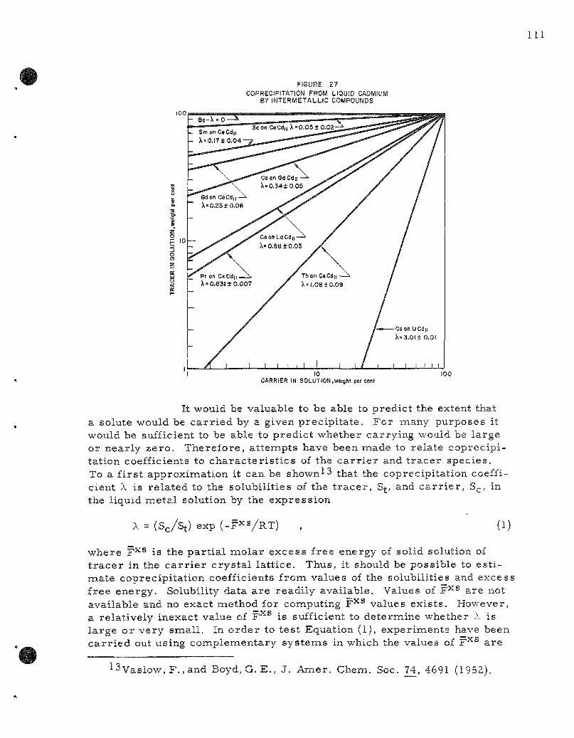
FIGURE 27 COPRECIPITATION FROM LIQUID CADMIUM
BY INTERMETALLIC COMPOUNDS
10 100 CARRIER IN SOLUTION,wtight percent
It would be valuable to be able to predict the extent that a solute would be c a r r i e d by a given precipi ta te . For many purposes it would be sufficient to be able to predic t whether carrying would be large or nearly ze ro . Therefore , a t tempts have been made to relate coprecipi tation coefficients to cha rac t e r i s t i c s of the c a r r i e r and t r a c e r species . To a f i r s t approximation it can be shown-^3 that the coprecipitation coefficient X is re la ted to the solubili t ies of the t r a c e r , S , and c a r r i e r , S ,, in the liquid m.etal solution by the express ion
X=(Sc /S t ) exp ( -F> 'VRT) , (1)
where F^^ is the par t ia l mo la r excess free energy of solid solution of t r a c e r in the c a r r i e r c rys t a l la t t ice . Thus, it should be possible to e s t i mate coprecipitat ion coefficients from values of the solubilities and excess free energy. Solubility data a r e readily available. Values of F-^^ are not available and no exact method for computing F^^ values exis ts . However, a relat ively inexact value of F'^'^ is sufficient to determine whether X is la rge or very smal l . In o rde r to tes t Equation (1), experiments have been c a r r i e d out using complementary sys tems in which the values of F^® a re
13vas low ,F . , and Boyd,G. E. , J . Amer . Chem. Soc. 74, 4691 (1952).
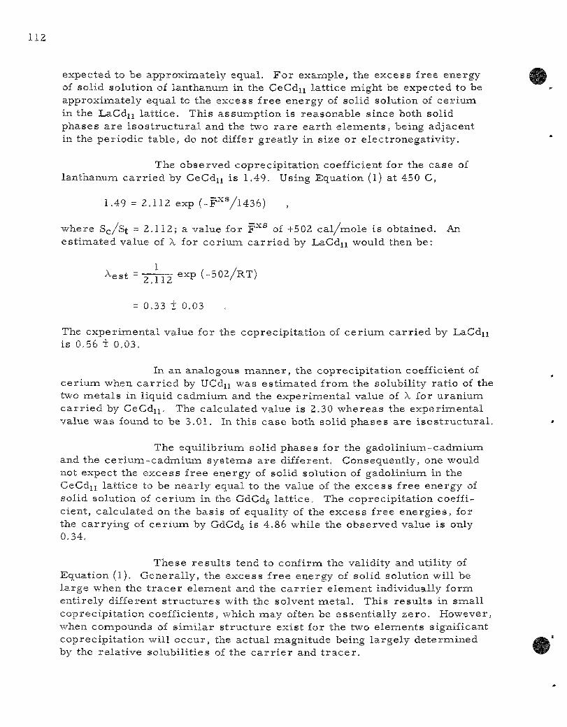
expected to be approximately equal . F o r example , the excess free energy of solid solution of lanthanum in the CeCdn lat t ice might be expected to be approximately equal to the excess free energy of solid solution of ce r ium in the LaCdn la t t ice . This assumpt ion is reasonable since both solid phases a r e i s o s t r u c t u r a l and the two r a r e ea r th e l ements , being adjacent in the per iodic table , do not differ great ly in size or e lectronegat ivi ty .
The observed coprecipi ta t ion coefficient for the case of lanthanum c a r r i e d by CeCdu is 1.49. Using Equation (1) at 450 C,
1.49 = 2.112 exp ( - F ^ y i 4 3 6 )
where S^/St = 2.112; a value for F^® of +502 ca l /mo le is obtained. An es t imated value of X for c e r i um c a r r i e d by LaCd^ would then be:
^est = zTTz ""P ( - 5 0 2 / R T )
= 0.33 + 0.03
The exper imenta l value for the coprecipi ta t ion of c e r i u m c a r r i e d by LaCdn is 0.56 + 0.03.
In an analogous manne r , the coprecipi ta t ion coefficient of ce r ium when c a r r i e d by UCdu was es t imated f rom the solubility ra t io of the two me ta l s in liquid cadmium and the exper imenta l value of X for uran ium c a r r i e d by CeCdn. The calculated value is 2.30 whereas the exper imenta l value was found to be 3.01. In this case both solid phases a r e i sos t ruc tu ra l .
The equi l ibr ium solid phases for the gadol in ium-cadmium and the c e r i u m - c a d m i u m sys t ems a r e different. Consequently, one would not expect the excess f ree energy of solid solution of gadolinium in the CeCdii la t t ice to be near ly equal to the value of the excess free energy of solid solution of c e r i um in the GdCd^ la t t ice . The coprecipi ta t ion coefficient, calculated on the bas i s of equality of the excess f ree ene rg ie s , for the ca r ry ing of ce r ium by GdCd^ is 4.86 while the observed value is only 0.34.
These r e su l t s tend to confirm the validity and utili ty of Equation (1). Genera l ly , the excess f ree energy of solid solution will be la rge when the t r a c e r e lement and the c a r r i e r e lement individually form ent i re ly different s t r u c t u r e s with the solvent me t a l . This resu l t s in smal l coprecipi ta t ion coefficients, which may often be essent ia l ly ze ro . However, when compounds of s imi l a r s t ruc tu re exist for the two e lements significant coprecipi ta t ion will occur , the actual magnitude being la rge ly de te rmined by the re la t ive solubi l i t ies of the c a r r i e r and t r a c e r .
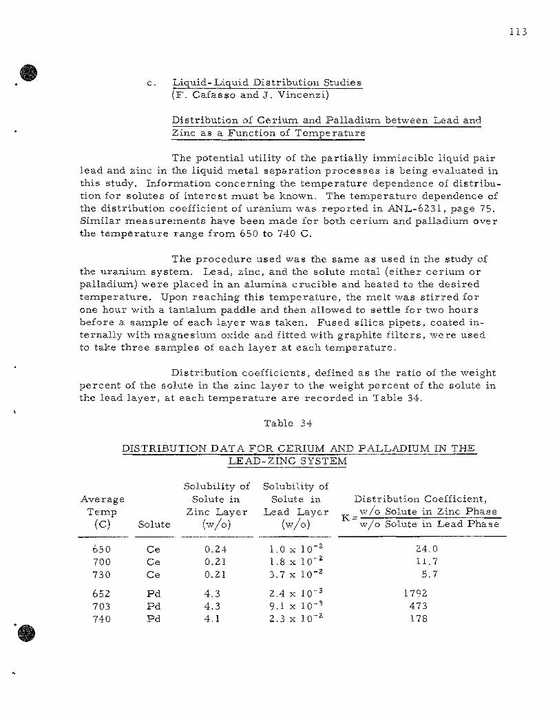
c. Liquid-Liquid Distr ibution Studies ( F . Cafasso and J. Vincenzi)
Distr ibut ion of Cer ium and Pal ladium between Lead and Zinc as a Function of Tempera tu re
The potential utility of the par t ia l ly immiscib le liquid pair lead and zinc in the liquid me ta l separa t ion p r o c e s s e s is being evaluated in this study. Information concerning the t empera tu re dependence of d is t r ibution for solutes of i n t e re s t mus t be known. The t empera tu re dependence of the dis tr ibut ion coefficient of uranium, was repor ted in AN'L-6231, page 75. Similar m e a s u r e m e n t s have been made for both cer ium and palladium over the t empe ra tu r e range fromi 650 to 740 C.
The p rocedure used was the same as used in the study of the uraniura sys tem. Lead, zinc, and the solute metal (either ce r ium or palladium) were placed in an alumina crucible and heated to the des i red t e m p e r a t u r e . Upon reaching this t e m p e r a t u r e , the mel t was s t i r r e d for one hour with a tantalum paddle and then allowed to sett le for two hours before a sample of each layer was taken. Fused si l ica pipets , coated internal ly with ma,gnesium oxide and fitted with graphite f i l t e r s , were used to take th ree samples of each layer at each t empera tu r e .
Distr ibution coefficients, defined as the ratio of the weight percent of the solute in the zinc layer to the weight percent of the solute in the lead l ayer , at each t e m p e r a t u r e a r e recorded in Table 34.
Ave rag' Temp
(c)
650 700 730
652 703 740
Table 34
DISTRIBUTION DATA FOR CERIUM .
e
Solute
Ce Ce Ce
P d P d P d
LEAD
Solubility of Solute in
Zinc Layer (w/o)
0.24 0.21 0.21
4.3 4 .3 4 .1
AND PALLADIUM IN THE i-ZINC SYSTEM
Solubility of Solute in
Lead Layer (w/o)
1.0 X 10"2 1.8 X 10"^ 3.7 X 10"2
2.4 X 10°2 9.1 X 10"^ 2.3 X 10"2
K
Distr w /o w/o
ibution Coefficient, Solute in Zinc Phase Solute in Lead Phase
24.0 11.7
5.7
1792 473 178

These data a r e shown in Figure 28 along with those previously repor ted for uranium (see ANL-6231, page 75). When these data a re compared with the uranium sys tem (see F igure 28), it is noted that the palladium shows the mos t pronounced effect of t e m p e r a t u r e . Over the same t emper ature interval (650 to 740 C), the pal ladium coefficient changed by a factor of about 10, the u ran ium coefficient by a factor of about 8.5, and the ce r ium coefficient by a factor of about 6. Studies a re underway to determine the dependence of the uran ium distr ibution coefficient on uranium in the z inc-lead sys tem. The effect of magnes ium on the uranium distr ibution coefficient in the z inc- lead sys tem is also being determined.
FIGURE 28 DISTRIBUTION OF PALLADIUM, URANIUM, AND CERIUM BETWEEN
LEAD AND ZIMC AS A FUNCTION OF TEMPERATURE 20001
1000 800 600
4 0 0
600 TEMPERATURE, C 650 700
_J i ^
lOOO/T, K
Thermodynamic Studies
Thermodynamic functions for key e lements in liquid meta l solvents and for the more important solid in termeta l l ic phases a r e being measu red . Two methods a r e being used. Galvanic cells have proved to be especial ly useful for the m e a s u r e m e n t of act ivi t ies in liquid meta l solutions as well as for the determinat ion of the free energy of formation of the equil ibrium solid phase in solid-l iquid two-phase regions . On the other hand, for sys tems containing severa l well-defined in termetal l ic phases , measu remen t of the decomposit ion p r e s s u r e by the effusion method is proving to be mos t useful. The two methods supplement each other.
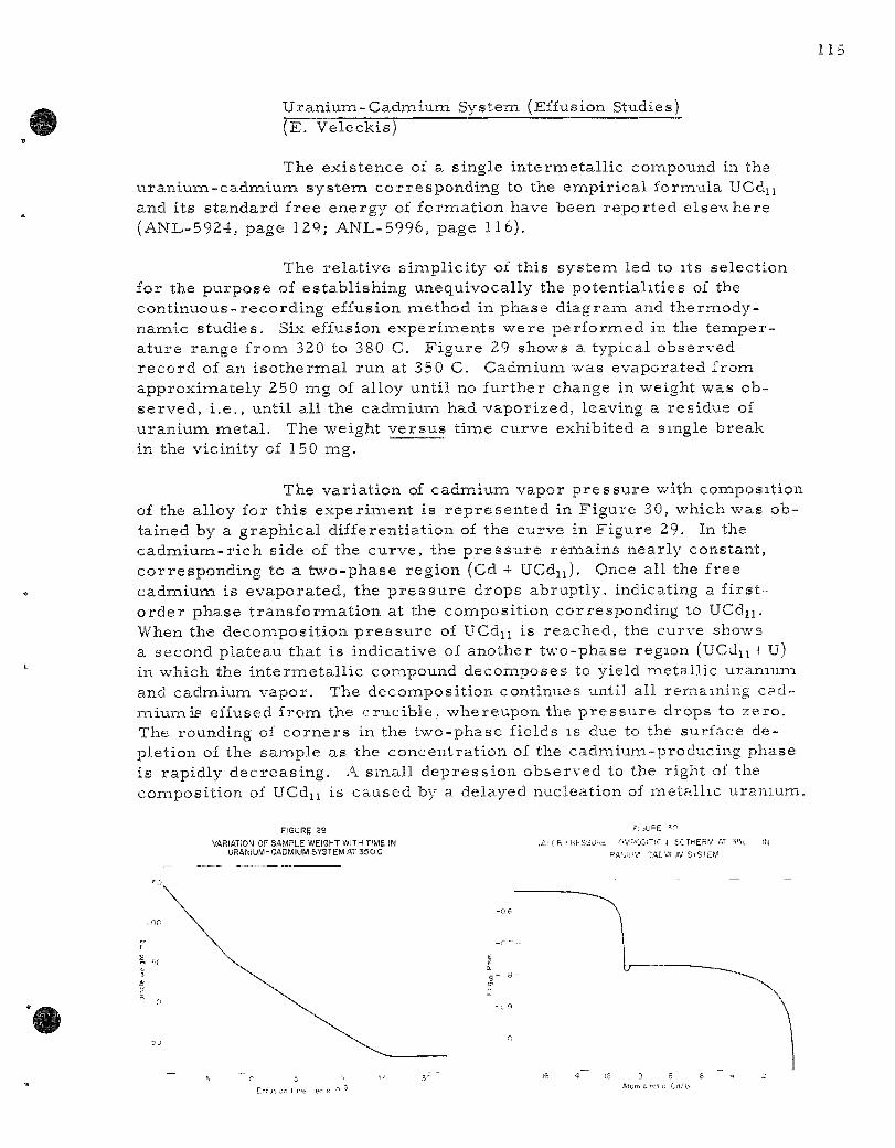
Uranium-Cadmium System (Effusion Studies) ( E 7 Veleckis)
The existence of a single intermetal l ic compound in the u ran ium-cadmium sys tem corresponding to the empir ica l formula UCdu and its s tandard free energy of formation have been reported elsewhere (ANL-5924, page 129; ANL-5996, page 116).
The relat ive simplici ty of this system led to its selection for the purpose of establishing unequivocally the potentiali t ies of the contint ious-recording effusion method in phase diagram and thermodynamic s tudies . Six effusion exper iments were performed in the t emper ature range from 320 to 380 C. Figure 29 shows a typical observed record of an i so thermal run at 350 C. Cadmium was evaporated from approximately 250 mg of alloy until no further change in weight was observed, i .e. , until all the cadmium had vaporized, leaving a residue of uranium meta l . The weight ve r sus t ime curve exhibited a single break in the vicinity of 150 mg.
The var ia t ion of cadmium vapor p r e s s u r e with composition of the alloy for this exper iment is represen ted in Figure 30, which was obtained by a graphical differentiation of the curve in Figure 29. In the cadmium-r i ch side of the curve, the p r e s s u r e remains nearly constant, corresponding to a two-phase region (Cd + UCdu). Once all the free cadmium is evaporated, the p r e s s u r e drops abruptly, indicating a f i r s t -o rder phase t ransformat ion at the composition corresponding to UCdij. When the decomposition p r e s s u r e of UCdu is reached, the curve shows a second plateau that is indicative of another two-phase region (UCdu + U) in which the internaetallic compound decomposes to yield metall ic uranium and cadmium vapor. The decomposit ion continues until all remaining cadmium is effused from the crucible , whereupon the p r e s s u r e drops to zero . The rounding of co rne r s in the two-phase fields is due to the surface depletion of the sample as the concentrat ion of the cadmium-producing phase is rapidly decreas ing . A smal l depress ion observed to the right of the composition of UCdu is caused by a delayed nucleation of metal l ic uranium.
FIGURE S9 VARIATION OF SAMPLE WEIGHT WITH TIME IN
URANIUM-CADMIUM SYSTEM AT 350 C
F] ,UPE V.
lArCR i RFSSURt OWPOSni" J ISCTHERW AT =i<5i. IN
RAMUV CACMl IM SrSrEW
Etf j ^ on f ne er X ' ^
3 8 Atom c rot 0 Cd/U

The cont inuous-recording effusion balance thus provides a powerful tool for a quick survey of the phase d iagram of a binary sys tem. Only a single exper iment i s , in pr inc ip le , n e c e s s a r y to provide information as to the number and composit ion of in te rmedia te phases .
Ce r ium-Zinc System (Effusion Studies) ( E . Veleckis and N. Goetzinger)
The exis tence of stable in te rmedia te phases corresponding to CeZnu and CeZn^ (both with an uncer ta in homogeneity range) , and to CeZn, Ce2Zn, and Ce4Zn have been reported.-^'* In addition, for concent ra tions above 11 atona percent c e r i um, five t h ree -phase equil ibr ia exist , three of which have la rge t he rma l effects and a r e probably due to the per i tec t ic format ion of in te rmedia te phase s . A considerable uncer ta inty exis ts as to the exact phase re la t ionships in this region of the phase d iagram.
The ce r ium-z inc sys tem was invest igated by the cont inuous-recording effusion method. A number of i so the rms were obtained in the t e m p e r a t u r e range f rom 480 to 570 C. F igure 31 i l l u s t r a t e s a typical vapor p r e s s u r e v e r s u s concentra t ion plot for 512 C obtained in an exper iment employing effusion crucible B (effective orifice size of 1.718 X 10"'' sq cm). The inset in F igure 31 shows a port ion of an i s o the rm for a higher c e r i um content at 570 C, m e a s u r e d with crucible C (effective orifice s ize of 5.173 x 10"^ sq cm). It is evident from the graph that eight in te rmedia te phases succeed one another : CeZnu.CegZnjy, CeZn^y, CeZn3^8_6.2> CeZn2, CeZn, Ce2Zn, and Ce4Zn.
The cont inuous- recording effusion method thus se rved to clarify the c e r i u m - z i n c phase d iag ram considerably. Exis tence of the in t e r meta l l ic compounds CeZn^i, CeZn, Ce2Zn, and Ce4Zn is confirmed. Analogous to the u ran ium-z inc sys tem, the phase previous ly identified as CeZng is shown to be Ce2Zni7. The exis tence of CeZn2 is quite probable ; a s imi la r phase has been s t ruc tu ra l ly identified as Laves phase for the sys tem lan thanum-zinc . The previously unknown region between the l imi ts CeZn2 and CejZnj^ exhibits two new phase s : a r a the r unstable phase corresponding to CeZn^y, and a wide solid solution region extending from CeZn^3_Y to CeZn.^^_4.
Hansen, M. and Anderko, K., Constitution of Binary Alloys, McGraw-Hil l Book Co., Inc. , New York (1958).
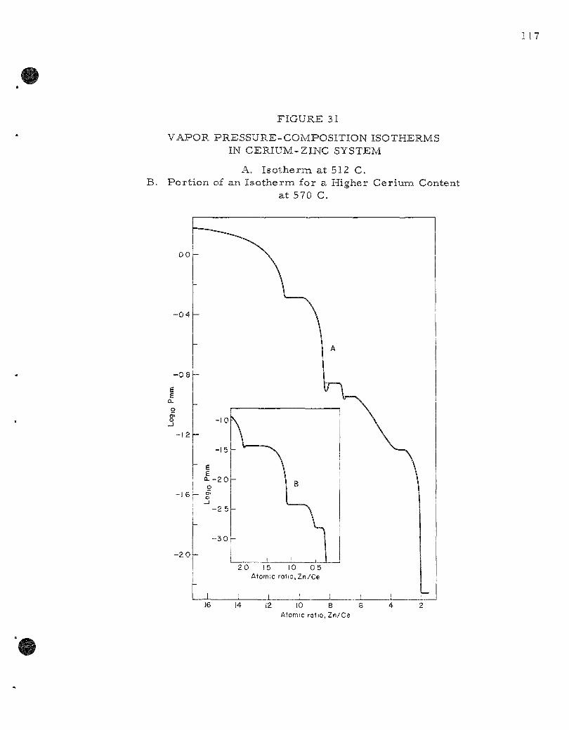
117
FIGURE 31
VAPOR PRESSURE-COMPOSITION ISOTHERMS IN CERIUM-ZINC SYSTEM
A. I so therm at 512 C. B. Por t ion of an Iso therm for a Higher Cerium Content
at 570 C.
- 0 4
- 0 8
e E a.
I -12
-16
- 2 0L-
E E Q - - 2 0 o
- 2 5 -
-3 0 -
2 0 15 10 0 5 Atomic ro}io,Zn/Ce
J \ I I J L 16 14 12 10 8 6
Atomic ratio, Zn/Ce

M a g n e t i c S tud ie s ( F . C a f a s s o and D. G r u e n * )
N e o d y m i u m - C a d m i u m S y s t e m (NdCdu)
The m a g n e t i c s u s c e p t i b i l i t i e s of a s e r i e s of A B u i n t e r m e t a l l i c c o m p o u n d s , w h e r e A i s e i t h e r a r a r e e a r t h o r a c t i n i d e e l e m e n t and B i s c a d m i u m , a r e be ing m e a s u r e d in a jo in t e f for t of the C h e m i c a l E n g i n e e r i n g and the C h e m i s t r y D i v i s i o n s .
An ingot of N d C d u w a s p r e p a r e d by m e l t i n g the p u r e m e t a l s t o g e t h e r . The s p e c i m e n w a s shown to be i s o n a o r p h o u s w i th C e C d u by X - r a y p o w d e r ixiethods. A c h e m i c a l a n a l y s i s s e r v e d to e s t a b l i s h the a t o m r a t i o .
M a g n e t i c s u s c e p t i b i l i t y m e a s u r e m e n t s w i t h a p o w d e r e d s p e c i m e n wer^e m a d e by the F a r a d a y m e t h o d . The s u s c e p t i b i l i t y a p p a r a t u s h a s b e e n d e s c r i b e d in A N L - 6 1 4 5 , p a g e 8 1 . M e a s u r e m e n t s w e r e m a d e a t t en f ixed t e m p e r a t u r e s b e t w e e n the l a m b d a po in t of h e l i u m and r o o m t e m p e r a t u r e . M o l a r s u s c e p t i b i l i t y v a l u e s of the c o m p o u n d NdCdu [M-'^NdCdij] at e a c h t e m p e r a t u r e a r e r e c o r d e d in Tab le 35 . Th i s t a b l e a l s o i n c l u d e s v a l u e s of the m o l a r s u s c e p t i b i l i t i e s of n e o d y i n i u m [ M ^ N ^ ] in the a l loy , wh ich w e r e o b t a i n e d by c o r r e c t i n g f o r the d i a m a g n e t i s m of c a d m i u m . F i g u r e 32 s h o w s t h e r e c i p r o c a l of the m o l a r s u s c e p t i b i l i t y of n e o d y m i u m p l o t t e d a g a i n s t a b s o l u t e t e m p e r a t u r e . The s u c e p t i b i l i t y a p p e a r s to obey a C u r i e - W e i s s Law [X = C / ( T - A ) ] , w i t h a A v a l u e o f - 8 K. L e a s t - s q u a r e s t r e a t m e n t of the d a t a y i e l d s a v a l u e of I .667 for the C u r i e c o n s t a n t C. The ef fec t ive m o m e n t of the a l l oy d e r i v e d f r o m the c a l c u l a t e d C u r i e c o n s t a n t i s 3.67 / i g ( B o h r m a g n e t o n s ) p e r a t o m .
T a b l e 35
M O L A R M A G N E T I C S U S C E P T I B I L I T Y O F NdCdu
M ^ N d C d u ^ l O ^ M ^ N d ^ l O ^ M ^ N d x l O " ^
5.28 8.48 9.84
19.29 21 .03 22 .15 23 .39 57 .87
152.81 246.Oi
5.50 8.70
10.06 19.51 21 .26 22 .37 23.61 58.10
153.03 246.23
1.82 1.15 0.99 0.51 0.47 0.45 0.42 0.17 O.O65 0.046
T e m p (K)
294 .9 184.6 160.2
77.1 70.7 67.1 63.2 20 .4
4.2 2 .0
• C o o p e r a t i n g C h e m i s t , C h e m i s t r y D i v i s i o n .
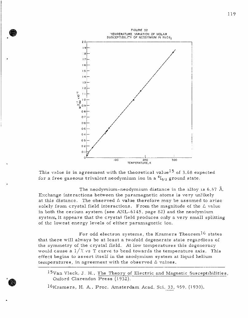
119
FIGURE 32 TEMPERATURE VARIATION OF MOLAR
2 0
1 9
1 8
17
1 6
1 S
1 4
13
1 2
1 z X ^ 0 9
0 8
0 7
0 6
0 5
0 4
0 3
0 2
0 1
-
/
/
/
/ /
/ /
-_ /
/
/ /
/ /
- / - /
' i l l 100 2 0 0
TEMPERATURE, K 3 0 0
This value is in agreement with the theoret ica l v a l u e ^ of 3.68 expected for a free gaseous t r iva lent neodymium ion in a I9/2 ground state.
The neodymium-neodymium distance in the alloy is 6.57 A. Exchange interact ions between the paramagnet ic atoms is very unlikely at this dis tance. The observed A value therefore may be assumed to a r i se solely from c rys t a l field in terac t ions . F r o m the magnitude of the A value in both the ce r ium sys tem (see ANL-6145, page 82) and the neodymium system, it appears that the c rys ta l field produces only a very small splitting of the lowest energy levels of ei ther paramagnet ic ion.
For odd electron sys t ems , the K r a m e r s Theorem-^ ° s tates that there will always be at leas t a twofold degenerate state r egard less of the symmetry of the c rys ta l field. At low tempera tu res this degeneracy would cause a l / X vs T curve to bend towards the t empera tu re axis. This effect begins to a s s e r t itself in the neodymiuna sys tem at liquid heliuna t e m p e r a t u r e s , in agreement with the observed A values.
•^^Van Vleck, J. H., The Theory of Elec t r ic and Magnetic Susceptibili t ies, Oxford Clarendon P r e s s (1932).
l ^ K r a m e r s , H. A., P r o c . Amste rdam Acad. Sci. 33, c)59, (1930).
2. Ca lo r lmet ry (W. N. Hubbard)
Thermodynamic data a r e lacking for many compounds of in te res t in h igh - t empera tu re chemis t ry because of the exper imenta l difficulties involved in making the n e c e s s a r y m e a s u r e m e n t s . A program, has been under taken to help fill this gap.
P a r t of the p r o g r a m consis ts of determ.inations of heats of formation at 25 C by oxygen bonab ca lo r ime t ry . Because some of the com.pounds of in t e re s t a r e difficult to burn in oxygen and, consequently, cannot be studied by oxygen bonab ca lo r ime t ry , the new technique of fluorine bomb ca lo r ime t ry has been developed for the i r study. The accumula-tionof bas ic heat of format ion data for f luorides is a n e c e s s a r y p r e l i m i n a r y adjunct to fluorine bomb ca lo r ime t ry and is a valuable p r o g r a m on its own mer i t .
The heats of format ion at 25 C from oxygen or fluorine combustion ca lo r ime t ry will be combined with the changes in enthalpy m e a s u r e d by a h igh - t empera tu re enthalpy c a l o r i m e t e r to de te rmine thermodynamic p r o p e r t i e s at high t e m p e r a t u r e s . A c a lo r ime t r i c sys tem for m e a s u r e m e n t s up to 1500 C has been designed and is now being fab r i cated. Design concepts for an e lec t ron beam furnace to operate up to 2500 C a r e being tes ted in the l abora to ry .
Some of the compounds of in t e re s t a r e bo r i de s , a luminides , ca rb ides , s i l ic ides , n i t r ides , sulfides, and selenides of me ta l s such as uranium, z i rconium, molybdenum, and tungsten. One major p rob lem in the de terminat ion of the thermodynamic p rope r t i e s of compounds such as these is the p rocu remen t of sufficiently pure samples . It is sometim.es the case , even with "high-pur i ty" s amples , that the total uncer ta inty a s signed to the final exper imenta l r e su l t is due m o r e to the uncer ta inty in defining the sample studied than to al l the other uncer ta in t i es of the m e a s u remen t combined. A p r o g r a m for the p repa ra t ion of u ran ium compounds to be used in the c a l o r i m e t r i c s tudies at Argonne is being c a r r i e d out by Stanford R e s e a r c h Inst i tute. Other compounds will be obtained from v a r i ous l a b o r a t o r i e s . Boron n i t r ide , obtained from P r o f e s s o r John Margrave of the Univers i ty of Wisconsin, z i rconium diboride, obtained from E l m e r J. Ruber , J r . , of Los Alamos Scientific Labora tory , and z i rconium di -hydride and dideuter ide , to be obtained fromi Howard Flotow of the Chemis t ry Division of this Labora tory , a r e examples . Some of the compounds will be synthesized h e r e . The disulfides of naolybdenum and tungsten a r e examples of such compounds a l ready studied.

a. Combustions of Uranium Mononitride in Oxygen (D. R. F r ed r i ckson , R. L. Nuttall, and E. Rudzitis)
The f i r s t of the samples p repa red by Stanford Resea rch Institute to be studied was Sample N-19 of uraniuna mononitr ide. The p r i m a r y problem encountered in the development of techniques for the m e a s u r e m e n t s was that of direct ing the course of the react ion to UsOg. At f i rs t , an oxygen-deficient product UsO/g.^) was usually obtained. The evidence for this was ga thered from careful observat ion of the r e spective weight changes caused by the bomb react ion and by subsequent ignition of the react ion product in a i r at 900 C, as well as from X-ray diffraction studies of the oxygen-deficient product.
It was found that the formation of oxygen-deficient product was re la ted to the reac t ion t e m p e r a t u r e . By spreading the sa3aiple over a re la t ively l a rge a r e a (~1 sq in.) on a platinum support plate and using only 5 a tm oxygen p r e s s u r e , a lowering of the t empera tu re and a smooth quanti tative react ion to the des i r ed end product , UsOg, was obtained.
To verify that the ni t rogen product of the react ion was gaseous ni t rogen r a the r than oxides of ni trogen, the product gases of the react ion were subjected to infra.red ana lys is . No oxides of ni trogen were detected.
A s e r i e s of six c a lo r ime t r i c combustions of Sample N-19 have been completed. A value of -843.71 t 0.10 ca lor ies per g ram of sample burned has been obtained as the s tandard energy of combustion for this s e r i e s . The p rec i s ion of the r e su l t s obtained is excellent. However, insufficient proof of the exact composit ion of the sample leaves a large uncertainty in any value of the heat of formation calculated from the resul t The analysis submit ted for the sample showed 0.20 percent oxygen, 0.05 pe cent carbon, and 0.05 pe rcen t i ron. It is a s sumed that the carbon is all p resen t as uran ium monocarbide , UC, and the iron as the i ron ni t r ide , Fe4N. The state of the oxygen p re sen t is uncer ta in . The assumption that all the oxygen is p r e sen t in solid solution ra ther than as uranium dioxide leads to values of the heat of format ion of uranium mononi t r ide, calculated from the r e s u l t s , that differ by 5.4 c a l / g . This is many t imes the unce r tainty in the value for the heat of conabustion of the sample .
It appears that both oxygen in solid solution and uranium dioxide a r e p resen t . The re la t ive amounts of oxygen in the two phases is as yet unknown. After a d i scuss ion with Stanford Resea rch Insti tute, it was decided (1) that an a t tempt would be laiade to de te rmine the UO/UOg ra t io in the sample by X- ray analys is after cal ibrat ion with uranium dioxide, and (2) that an at tempt would be made to p r epa re a new sample of uran ium mononitr ide with a much lower oxygen content.

122
b. High-puri ty Fluorine for Fluorine Bomb Calor imet ry "(J. Settle)
One of the f i r s t p rob lems in the fluorine bomb ca lo r ime t ry p rog ram was to de te rmine the magnitude of the t h e r m a l effects that might be encountered f rom impur i t ies in the fluorine used in ca lo r ime t r i c combust ions. Ear ly in the p r o g r a m a s e r i e s of molybdenum combustions was conducted with commerc i a l fluorine that contained 1.14 percent impur i t i es . Major impur i t i es were O2, N2, CF4, and CgF^. Very smal l amounts of CjFg, HF, NF3, SiF4, and possibly SF^ and S2F10 were also contained. Another s e r i e s of molybdenum combustions was conducted with fluorine purified by L. Stein* by means of low- tempera tu re fract ional dist i l lat ion. The purified fluorine contained 0.08 percent total oxygen and nitrogen as the only impur i t i e s . The observed heat of conabustion of molybdenum in the c o m m e r c i a l fluorine was about 1 kca l /mo le m o r e negative than the observed heat of combustion of molybdenum in the purified fluorine. This d iscrepancy was cer ta in ly significant and because no fluorine of high puri ty was available commerc ia l ly it was n e c e s s a r y for this labora tory to purify commerc i a l f luorine. An improved low- tempera tu re st i l l was designed and constructed.-l-'7 It has now been used to produce 6 batches of fluorine that contained from 0.02 to 0.08 pe rcen t impur i t i e s . A typ i ca l product of 99.94 percent pure fluorine contained about 0.04 percen t oxygen and 0.02 percen t ni t rogen as the only impur i t i e s .
The Genera l Chemical Division of Allied Chemical Company became in te res ted enough in the problem to build a st i l l s imi la r to the one used h e r e , and has recent ly sent to this l abora tory for evaluation a 1-lb batch of dis t i l led f luorine. This fluorine is 99.75 percen t pure . The impur i t ies a re Ng, 0.14 percen t ; O2, 0.08 percent ; CO2, 0.02 percent ; and CF4, NF3, and SiF4 totaling 0.1 percent . It will be n e c e s s a r y to use this fluorine in comparat ive ca lo r ime t r i c combustions in o rde r to de termine whether there will be significant ther raa l effects from the oxygen, ni t rogen, and carbon dioxide inapuri t ies.
c. Combustions of Boron Nitride in Fluor ine (S. Wise)
Boron ni t r ide was the f i r s t compound to be burned in fluorine bomb ca lo r ime t ry ; previous combustion studies were made with e l e ments . Boron ni t r ide was also the f i r s t substance to be studied that reac ted spontaneously with f luorine. Fo r this study, the combustion bomb react ion vesse l for spontaneously combustible naater ia ls desc r ibed in ANL-6287,
•Cooperat ing chemis t . Chemis t ry Division, Argonne National Labora tory .
"7 Stein, L,, Rudzi t is , E. and Settle, J . L., ANL-6264 (June 1961)

page 125, was ca l ibra ted and used. Seven ca l ibra t ions , in which heat was supplied by the combustions of benzoic acid in oxygen, yielded a 3348.4 i 0.4 ca l / deg ree C for the energy equivalent of the sys tem ANL-Ri-Ni2-Ti. This value is approxinaately 230 ca l / deg ree C less than for the same sys tem without the surrounding fluorine tank. The prec is ion of the r e su l t s , approximately 0.01 percen t , is about the same as for the sys tem without the tank.
When fluorine is expanded from the tank to the evacuated bomb during the ca lo r ime t r i c exper iment , a slight cooling effect is expected. Several blank expansions without sanaples were c a r r i e d out in the ca lo r ime te r to see if this effect could be measu red . Calculations from v i r ia l coefficients showed that 0.7 cal should be absorbed when 6.6 atmos p r e s s u r e of fluorine in the tank is expanded to 2.6 a tmos in the combined bomb and tank sys tem. In p rac t i ce , however, a slight heating effect was observed, caused by a slight fluorination of the nickel surfaces as the fluorine rushed into the evacuated bomb. This problem was elinainated by prefluorinat ing the bomb and tank sys tem for 8 hr at 11 0 C with 3 atmos p r e s s u r e of fluorine before expansion. Under these conditions the calculated energy change of A E = +0.7 cal was observed. In o rder to p r e s e r v e the pref luor inated nickel sur faces , the bomb is opened only in a dry box containing a hel ium a tmosphe re . All manipulation of the bomb contents including weighing a r e done in this enc losure .
A calor inaetr ic s e r i e s of combustions of boron nitr ide in fluorine is now in p r o g r e s s . F o r this study a high-puri ty hexagonal boron nitr ide sanaple, obtained f rom the National Carbon Company through the cour tesy of P r o f e s s o r John Marg rave , Universi ty of Wisconsin, was used. Chemical analys is for impur i t i e s in the sample showed, by weight, 0,40 p e r cent oxygen, 0.12 percen t carbon, 0.02 percent silicon, 0.01 percent hydrogen, and spec t rographic analys is showed 0.008 percent t i tanium.
P r e l i m i n a r y exper iments with boron ni tr ide showed that the mos t sa t is factory conabustion c ha ra c t e r i s t i c s were obtained with
3
0.4 gin of boron ni t r ide c o m p r e s s e d to form a - r - in . -d iamete r pellet which was supported on a disc of optically polished sapphire , 1 in. in d iameter by -•/ in. thick. The sapphire disc is iner t to react ion with fluorine under the conabustion conditions employed and, in addition, has a relat ively high r e s i s t ance to t h e r m a l shock. The slight amount of unburned boron nitr ide in any one combustion can be deternained by weighing, wiping, and reweigh-ing the sapphire disc after combustion. The sapphire disc is supported in the bomb on a mass ive nickel disc held in a ginabel. The determinat ion of unburned boron ni t r ide is based on the assumption that only gaseous bromine tr if luoride is formed in the combustion react ion.
d. Combustions of Zirconium and Molybdenum in Fluorine (E. Greenberg and J . Settle)
Exper imenta l work has been completed for the studies of the heats of format ion of z i rconium tet raf luor ide and molybdenum hexa-fluoride. Revised values of -356.78 ± 0.25 and -372.Sg + 0.22 kca l /mole have been obtained for the s tandard heats of formation [A 1^(25 C)] of z i rconium tet raf luor ide c rys t a l and molybdenum hexafluoride gas , r e spectively. Manuscr ip t s , enti t led "Fluorine Bomb Ca lo r ime t ry : 1. The Heat of Format ion of Zirconium Tetraf luor ide ," and ^'Fluorine Bomb Ca lo r ime t ry : 2. The Heat of Format ion of Molybdenum Hexafluoride," have been accepted for publication in the Journa l of Phys ica l Chemis t ry .
e. Combustions of Uranium in Fluor ine (J. Settle)
Determinat ions of the heats of formation of such compounds as the bor ides and s i l ic ides of uran ium would be a very difficult task by oxygen bomb or solution ca lo r ime t ry because of the difficulty of obtaining well-defined react ion products . To obtain the heats of format ion of these compounds by fluorine combustion ca lo r ime t ry , it is n e c e s s a r y to know the heats of format ion of u ran ium hexafluoride (UF^), boron t r i f luoride (BF3), and si l icon te t raf luor ide (SiF4). The heat of formation of borop. t r i f luoride has recent ly been de te rmined in this labora tory (see ANL-6287, page 125). The heat of format ion of si l icon fluoride has also recent ly been accura te ly m e a s u r e d . 1^ in. cont ras t , the es t imated uncer ta inty inte rva l of the heat of formation of uran ium hexafluoride-I-9)20 ig g r e a t e r than 1 percent . It is evident that a m o r e p r e c i s e determinat ion of the heat of formation of u ran ium hexafluoride is a des i rab le step in the p r o posed study of these uran ium compounds.
In exper iments c a r r i e d out in the labora tory , the main 1 3
sample was uran ium rod about -rr i i- in. d iamete r a n d — i n . long. The rods were ignited at the top by means of a uranium fuse wire and a smal l piece of uran ium foil which acted as a kindler . With this sample a r rangenien t , it was n e c e s s a r y to dilute the fluorine with an iner t gas to reduce the t e m pe ra tu re in the react ion zone and thereby to prevent the melt ing of the uranium. When the gaseous mix ture consis ted of one a tmosphere fluorine and sufficient argon to make the total p r e s s u r e 12 a tmos , no melting
^°Vorobiev, A. F . , Kolesov, V. P . , and Skuratov, S. M., the Bulletin of Chemical Thermodynamics , 3, 23 (I960).
^°The Chemis t ry of Uranium, eds . Katz, J . J . and Rabinowitch, E., McGraw-Hil l Co., New York, N. Y., (1951), p . 412.
20weinstock, B. and Chr is t , R. H., J . Chem. Phys . 16, 436 (1948).
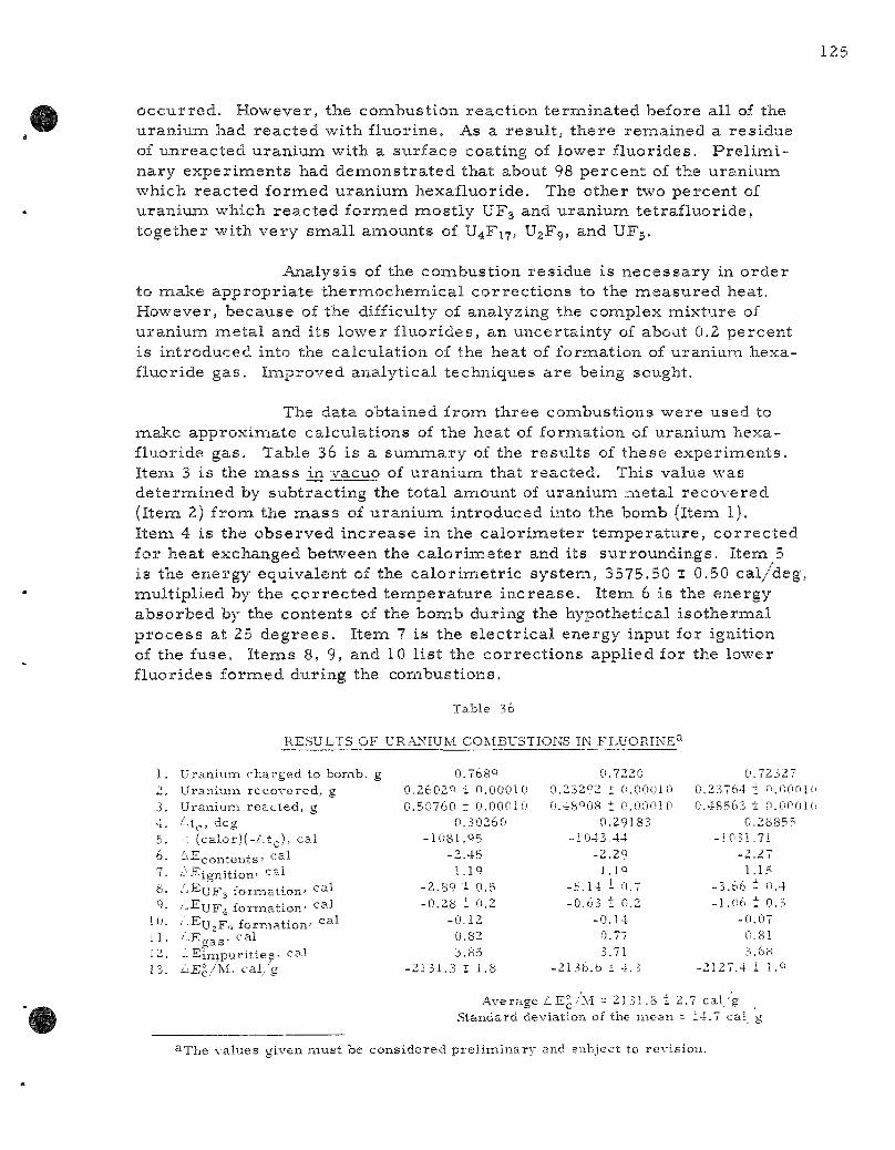
occur red . However, the combustion react ion te rminated before all of the uranium had reac ted with fluorine. As a resul t , there remained a residue of unreacted uranium with a surface coating of lower f luorides. P r e l i m i nary exper iments had demonst ra ted that about 98 percent of the uranium which reacted formed uran ium hexafluoride. The other two percent of uranium which reac ted formed most ly UF3 and uranium tetraf luoride, together with very smal l amounts of U4F17, U2F9, and UF5.
Analysis of the combustion residue is necessa ry in order to make appropr ia te the rmochemica l cor rec t ions to the measu red heat. However, because of the difficulty of analyzing the complex mixture of uranium meta l and its lower f luorides, an uncertainty of about 0.2 percent is introduced into the calculation of the heat of formation of uranium hexafluoride gas . Improved analytical techniques a re being sought.
The data obtained from three combustions were used to make approximate calculations of the heat of formation of uranium hexafluoride gas . Table 36 is a summary of the resul ts of these exper iments . Item 3 is the m a s s m vacuo of uranium that reacted. This value was determined by subtract ing the total amount of uranium meta l recovered (Item 2) from the m a s s of uranium introduced into the bomb (Item 1). Item 4 is the observed inc rease in the ca lo r imete r t empera tu re , cor rec ted for heat exchanged between the ca lo r imete r and its surroundings. Item 5 is the energy equivalent of the ca lo r ime t r i c system,, 3575.50 ± 0.50 cal /deg, multiplied by the co r rec t ed t empera tu re inc rease . Item 6 is the energy absorbed by the contents of the bomb during the hypothetical i so thermal p rocess at 25 degrees . Item 7 is the e lec t r ica l energy input for ignition of the fuse. I tems 8, 9, and 10 l is t the correc t ions applied for the lower fluorides fornaed during the combustions.
Table 36
RESULTS OF URANIUiM COMBUSTIONS IN FLUORINE^"*
1. 2
3 . 4 . 5 . 6.
7 .
8 .
9 . 10 . 1 ! . 12. 1 3 .
UraniuiTi c h a r g e d to b o m b , g Uraniusn r e c o v e r e d , g U r a n i u m r e a c t e d , g Lt^, deg •: (calor)(-Z.t( ;) , c a l
'-^Egontents ' ' " •'• ' - ^ i g n i t i o n ' ca l '"'EUF3 f o r m a t i o n ' < 2il ••'••^UF4 f o r m a t i o n ' '^^^ • ' -Eu,F^ f o r m a t i o n ' °^1
- E i m p u r i t i e s . ca l i:>.E^/'M. cal / 'g
0.768Q 0.2602Q i 0.00010 0.50760 t 0.00010
0.30260 -1081.05
-2 .45 I.IQ
-2 .89 - 0.3 -0 .28 : 0.2
-0 .12 0.82 3.85
-2131.3 1 1.8
0.7220 0.23292 I 0.00010 0.48O08 t 0.00010
0.29183 -1043.44
-2 .29 1.19
-5.14 i 0.7 -0 .63 t 0.2
-0 .14 0.77 3.71
-2136.b 1 4.3
0.72327 0.23764 + O.nonii 0.48563 ± O.OnOK
0.28855 -1051.71
-2.27 1.15
-3.66 t 0.4 -1.06 1 0.3
-0 .07 0.81 3.68
-2127.4 1 l.Q
Average £.E°/M = 2131.8 1 2.7 cal/g Standard deviatioai of the mean - 14.7 cal_ g
"••The values given must be considered prel iminary and subject to revision.
Itena 11 is the net co r r ec t ion due to the hypothetical compress ion and decompress ion of the bomb gases . Item 12 is the net cor rec t ion for i m pur i t ies contained in the uran ium sample . The impur i t i e s , in ppm, were hydrogen, 3; ni t rogen, 80j oxygen, 220,* si l icon, 40,- and carbon, 615. On the assumpt ions that these impur i t i es were p re sen t as UH3, UN, UOg, UjSi, and UC, respec t ive ly , and that the respec t ive fluorination products were UF^, HF, N2, O^, SiF4, and CF4, the cor rec t ion for the impur i t ies was 7.58 i 1.12 c a l / g of sample reac ted . I tem 13 is the energy change per g r am of uran ium for the react ion U(c,a) + 3 F2(g)—*-UF6(g), with the reac tan ts and product in thei r respec t ive s tandard s ta tes at 25 C.
The data in Table 36 pe rmi t the calculat ion of an approximate value of -509 t 3 k c a l / m o l e as the s tandard heat of formation of uran ium hexafluoride gas . Improvements in analyt ical p rocedure should reduce by about an o rde r of magnitude the uncer ta inty in the value of the heat of format ion of u ran ium hexafluoride der ived f rom future ca lo r ime t r i c combust ions .
f. Combustions of Cadmium in Fluor ine (E. Rudzit is and T. Kinsella)
Combustions in fluorine of four m e t a l s , cadmium, zinc, magnes ium, and aluminum, have been studied over the past half year or so. These combust ions differ from o thers that have been studied in that all four me ta l s have re la t ively low melt ing points , which resu l t s in me l t ing of the sample in the ea r ly s tages of combustion. Containment of the molten me ta l during the r e s t of the combustion p r o c e s s p r e s e n t s a p rob lem of sample support . The support m a t e r i a l mus t be chemical ly r e s i s t an t to the molten me ta l as well as to fluorine at elevated t e m p e r a t u r e s and, in addition, mus t be able to withstand the t h e r m a l shock that it r ece ives dur ing the combustion. The solution to the support p roblem was the use of co ld -p ressed , slightly concave d iscs of the fluoride of the me ta l to be burned.
The f i r s t of these me ta l s to be studied calorinae t r ie ally was cadmium. In many r e spec t s the initial combustions were sa t i s fac tory . Slightly l e s s than 2 gm of cadmium res t ing on the top one of two ~ - i n . -thick by 2-in. d i ame te r cadmium fluoride d iscs was ignited e lec t r ica l ly with a cadmium fuse wi re and evolved approximately 3000 cal . Although t e m p e r a t u r e s higher than 1100 C were obtained, as indicated by the melt ing of port ions of the d i s c s , m o r e than 99.99 percen t of the me ta l r eac ted to foriTi the f luoride.
In two r e s p e c t s , the init ial coinbustions w e r e somewhat unsat isfactory. F i r s t , it was found that a significant amount of sample reac ted with fluorine before the sample was ignited. F u r t h e r study, however , showed that co r r ec t ions for this pre- ign i t ion reac t ion could be made . Second, the

t ime requ i red for t h e r m a l equi l ibr ium to be attained in the ca lo r imete r was impra-cticably long. To overcome this problem, the base of the bomb was redesigned and rebuil t in such a way that the nickel support for the ce r amic discs was made a port ion of the base , thus providing good the rmal contact between the bomb and the ca lo r ime te r fluid. Exper iments have shown that the p rob lem of excess ively long t imes to the at tainment of equil ibrium has been el iminated by the new bomb base . Recalibrat ion of the bomb is now n e c e s s a r y before additional ca lo r imet r i c measu remen t s will be made .
g. Combustion of Titanium, Hafnium, and Thorium in F luor ine (E. Greenberg)
P r e l i m i n a r y nonca lor imet r ic combustion exper iments for t i tanium and hafnium were completed and descr ibed in the las t q u a r ter ly repor t (ANL-6287, page 129). Samples for ca lo r ime t r i c exper iments a r e being fabr icated by the Metal lurgy Division. Some additional combustion exper iments were c a r r i e d out with thor ium, but a sat isfactory technique for ca lo r ime t r i c studies has not yet been developed.
h. Coinbustion of Vanadium, Niobium, and Tantalum in F luor ine (E. Greenberg)
Explora tory exper iments were initiated to develop techniques for c a lo r ime t r i c combust ion studies of vanadium, tantalum, and niobium in f luorine. Using a g lass bomb, in o rder to observe the combustion cha rac t e r i s t i c s of these m e t a l s , sa t isfactory conditions have been worked out for tanta lum and niobium. Additional experimentat ion is r e quired for vanadium.
Fo r tantalum and niobium, the sample , in the form of a rod approximately 0.125 in. in d iameter by 1 to l-j ™' long, was ma^chined down to a thin pin at one end and inse r t ed in a smal l hole in a relat ively mass ive nickel stand. The ver t ica l ly supported sample was ignited in the usual raanner with an e l ec t r i ca l fuse wi re threaded through a smal l piece of 0.005-in. foil inse r t ed in a slot at the top of the sample rod. In the ea r ly exper iments with tantalum, the d iameter of the pin which served to support the sample was about 0,035 in. and, because of preferent ia l at tack during the combustion, the rod burned away just above the pin. It was found that i nc rease of the pin d iamete r to about 0.055 in. was sufficient to prevent burning through at the base despite the preferent ia l attack, if the quantity of fluorine in the bomb was proper ly l imited. Grea te r amounts of sample could be burned, without burning through the support pin, by
correspondingly increas ing both the fluorine p r e s s u r e and the length of tantalum sample rod. It i s des i rab le to keep the suppor t -p in d iameter smal l in o rde r to reduce the contact a r ea between the sample and the nickel stand. In the case of niobiura, p referen t ia l a t tack at the base of the sample was not as s e v e r e , and a suppor t -p in d iameter of 0.035 in. was adequate provided that the length of sample and quantity of fluorine were proper ly adjusted. Because of the high melt ing points of tantalum and niobium, the use of pure fluorine was not only feasible but des i rab le in o rde r to shor ten the combustion per iod. In a typical exper iment with tantalum, a fluorine p r e s s u r e of 2000 m m Hg and a 1-j-in.-long tantalum rod weighing 5.3 gm were employed. Approximately 3.9 gm of sample were burned and evolved about 7.7 kcal of heat. In a typical niobium exper iment , fluorine at 1500 nam Hg p r e s s u r e and a 1—-in.-long sample rod weighing 2.8 gm were employed. About 1.6 gm of niobium were burned and evolved about 5,9 kcal of heat . In both the tantalum and nio-biuin exper iments the combust ion product was a uniform white solid which had sublimed away f rom the hot combustion zone and condensed on the cooler wal ls of the bomb. The combustion per iod was about 4 min.
P r e l i m i n a r y vanadium combustions were conducted with 1-in.-long sample rods weighing about 1.7 gm and having a pin base of about 0.035 in. in d i ame te r . Approximately one g r a m of sample was burned and evolved about 6,6 kcal of heat . There was no evidence of preferen t ia l a t tack at the base of the rod. However, the combustions las ted longer than 10 min, which is somewhat undesi rable for a ca lo r ime t r i c exper iment . It appears that p rob lems may be encountered in handling and identifying the combust ion product , which is considerably m o r e volati le and react ive with the a tmosphere than the f luorides of tanta lum and niobium.
High- te rapera ture Enthalpy Ca lo r ime te r (R. L. Nuttall and D. A. F redr i ckson)
The 1500 C furnace component of the drop ca lo r ime te r has been assembled . A high-vacuum sys tem, with n e c e s s a r y e l ec t r i ca l controls to be used with the furnace has been built and instal led. The furnace shell was found to contain leaks and, the re fo re , was d i sa s sembled to be rewelded. Leak testing of the c a l o r i m e t e r shell is now underway.
11. FUEL CYCLE APPLICATIONS OF VOLATILITY AND FLUIDIZATION TECHNIQUES
A d i rec t fluorination volati l i ty p rocess has been proposed for the r ecove ry of uran ium and plutonium from i r rad ia ted nuclear reac to r fuels. In this p r o c e s s advantage is taken of the volati l i t ies of uranium and plutonium hexafluoride and of fluidization techniques. Attempts a re being made to apply this p r o c e s s to uran ium oxide and zirconium ma t r i x fuels.
The proposed p r o c e s s for r ecove ry of uranium and plutonium from spent uranium oxide involves decladding by an appropr ia te react ion in a fluidized bed. Plutonium and uran ium hexafluorides, which resu l t from the reac t ion of the declad oxide fuel with fluorine, may be separa ted using a combination of the var iabi l i ty of the r a t e s of fluorination of the plutonium and uranium compounds and chemical reac t iv i t ies of the hexafluorides.
The decladding s tep of the p r o c e s s for uranium dioxide fuels involves g a s - m e t a l reac t ions in the case of elenaents clad ei ther with s ta in less s teel or Z i rca loy . The g a s - m e t a l react ions a re c a r r i e d out with the fuel e lements submerged in an iner t fluidized bed (calcium fluoride or alundum) which s e r v e s as a heat t r ans fe r mediuin. Dilute mix tures of hydrogen chloride in hydrogen fluoride or the separa te gases have been successful ly employed when zirconium decladding is neces sa ry . In recent work, chlorine has replaced the hydrogen chlor ide. In the case of s ta in less s tee l cladding, chlorine appears to be a possible decladding reagent , based on r e su l t s from pilot plant s tudies .
The decladding reac t ions ( r e fe r red to as p r imary) a re being c a r r i e d out in a two-zone fluid-bed r e a c t o r . Volatilization of the clad or alloying m a t e r i a l occurs in the lower zone during the chlorination react ion. The volatile m a t e r i a l s pass upward into the upper zone, where hydrogen fluoride is admit ted, thereby effecting conversion to solid f luorides . Where solid chlor ides a r e formedj these will also be converted to solid f luorides, s ince the re is solids mixing between zones . The two zones a re separa ted by an inverted conical baffle (other types may also be suitable) which r e duces back-mixing of the gases and prevents the formation of gas mix tures that have been shown to affect these react ions adverse ly .
In pi lot-plant s tudies the react ion of 304 s ta in less s teel tube sect ions with chlorine has been investigated in a l-2--inch d iameter two-zone fluid-bed r eac to r . The ra te of chlorination has been found to dec rease rapidly with t ime because of the formation of an adherent film compr ised pr inaar i ly of nickel and chromium chloride on the surface of the cladding. An average penetra t ion r a t e of 4.6 m i l s / h r was obtained in a 4.7-hour run at 575 C using 87 percen t chlorine (in ni t rogen) . At a higher t empera tu re of 625 C, using the same chlorine concentrat ion, a 35-mil tube completely reac ted in 3,8 hou r s . The effect of chlorine dilution at 625 C was not iceable at concentrat ions below 48 volume percent .

After decladding has been achieved, a subsequent fluorination step is expected to provide the n e c e s s a r y separa t ion of the f issi le e l ements . The d i rec t fluorination of dense uranium dioxide pel le ts is being examined in fluid-bed pilot plant s tudies .
Substantial improvement in t e m p e r a t u r e control at higher react ion r a t e s has been achieved by regulat ion of fluorine inlet flow in place of coolant regulat ion previous ly employed. Four runs have been made in which pellet ba tches of approximate ly 4.5 kg have been completely reac ted at about 500 C; average uran ium hexafluoride production r a t e s of about 20 kg/ (hr ) ( sq ft r eac to r c r o s s section) were obtained with ine r t - f i red pe l lets and approximate ly one-half this ra te for hydrogen-f i red pe l l e t s . The hydrogen-f i red pel le ts (-rin. x-|-in.) a r e cons idered more represen ta t ive of reac to r fuel m a t e r i a l , and in these exper iments 10 to 12 h r was requi red for p rocess ing a complete batch.
Fluor inat ion runs have been made with iner t fluid beds of calcium fluoride or magnes ium fluoride to aid in remova l of heat . Additional runs were made to demons t r a t e the feasibi l i ty of operat ing with a pure zirconium te t raf luor ide fluid bed and without an iner t bed.
Since heat t r an s f e r l imi ts the maximum prac t i ca l reac t ion ra te in the d i rec t f luorination p r o c e s s , a heat t r ans fe r study is being made in a mockup sys t em. In these t e s t s , m e a s u r e m e n t s a r e made of heat t r ans fe r coefficients .for the sur faces of the inner hea te r and of the outer cooling wall, and for effective bed t h e r m a l conductivit ies for sys t ems consis t ing of pellet beds with a fluidized medium in the pellet voids. In s eve ra l exper imenta l t e s t s , effective t h e r m a l conductivit ies along the rad ius of the bed of about 0.8 Btu / (hr ) ( sq ft)(F/ft) were found for the nonfluidized case and of 5 to 10 for fluidization. Fo r the fluidized ca se , surface coefficients of about 80 Btu / (hr ) ( sq ft)(F) were found for the in terna l heating surface and 20 to 60 for the ex terna l cooling sur face .
A new fil ter sys tem with automatic blowback was demons t ra ted , in which the f i l t e rs a r e located in c h a m b e r s separa ted from the r eac to r by a length of one- inch pipe. This design p r o m i s e s to make fi l ter r e p l a c e ment m o r e convenient in radioact ive s y s t e m s .
The r a t e of t h e r m a l decomposi t ion of plutonium hexafluoride has been studied at t e m p e r a t u r e s from 140 to 173 C by a s ta t ic method and from 150 to 250 C by a flow method. A study of the kinet ics of decomposi t ion has es tabl i shed the mechan i sm of the reac t ion . The ra te of the react ion has been formulated as concur ren t f i r s t - and z e r o - o r d e r reac t ions with r e spec t to plutonium hexafluoride p r e s s u r e in the range between 50 and 1100 m m and, of t e m p e r a t u r e from 140 to 170 C. It has been infer red that , within the aforementioned t e m p e r a t u r e and p r e s s u r e r a n g e s , the decomposit ion p roceeds by both a homogeneous and heterogeneous
unimolecular decomposit ion and that the heterogeneous decomposit ion occurs on the surface of the deposited plutonium te t raf luor ide . Rates of decomposit ion of plutonium hexafluoride obtained in the flow sys tem approximate conditions which miay be found in the fluorination reac to r of the Direct F luor ide Volatil i ty p roces s for uranium oxide power reac tor fuels. This information will be useful for plant design and future exper i menta l work.
The physical appearance of plutonium tetraf luoride resul t ing from both t h e r m a l decomposit ion and a lpha-radia t ion decomposit ion has been observed and bulk dens i t ies have been de termined. The bulk density of the product of t h e r m a l decomposi t ion was 15 to 18 t i tnes g rea te r than the bulk densi ty of the product of radiat ion decomposit ion.
It has been demons t ra ted that a la rge quantity (32 gm) of plutonium te t ra f luor ide , which had been deposited in equipment by t he rma l decomposition of plutonium hexafluoride, could be refluorinated to plutonium hexafluoride at about 450 C with a r ecove ry of 98 percent of the plutonium.
The reac t ion of e lementa l broixiine with plutonium hexafluoride has been invest igated. The s to ich iometry of the react ion has been establ ished. P r i m a r y products of the reac t ion a r e plutonium tetraf luoride and bromine pentafluoride. The util i ty of the react ion for the separat ion of uranium and plutonium hexafluorides has been demonst ra ted .
In studies of fission product behavior mix tu res of uran ium dioxide-ruthenium-106 were reac ted with fluorine at 400 and 500 C. It was found that at both of these t e m p e r a t u r e s ruthenium was volatil ized at a ra te equal to or fas te r than that of uran ium volatil ization as uranium hexafluoride. However, it was found that ruthenium pentafluoride decomposed and was deposited on a colder port ion of the walls of the fluorination vesse l . No a l te ra t ion of the r e su l t s occu r r ed when calcium fluoride and zirconium fluoride were added to the or ig inal mix tu re to be fluorinated. The fluorination of uran ium dioxide-niobium-95 mix tu res indicated that niobium is readi ly fluorinated out of uranium dioxide and that the re is no react ion between niobium and calcium f luor ide-z i rconium fluoride bed m a t e r i a l s . Niobium differed from the ruthenium in that ve ry l i t t le (less than one p e r cent) deposited on the reac t ion boat or furnace tube, indicating that niobium can be volati l ized with l i t t le or no difficulty.
In s tudies of reac t ions which might be used to separa te uranium and plutonium, the reac t ions of gaseous sulfur te t raf luor ide with uranium tr ioxide and uranyl fluoride to produce uranium hexafluoride were studied. Sulfur te t raf luor ide has the advantage that it will not reac t with plutonium dioxide or plutonium te t raf luor ide to produce plutonium hexafluoride. It thus can se rve as a select ive fluorinating reagent in fluoride volatil i ty p r o c e s s e s . Kinetics of the reac t ions of sulfur te t raf luor ide with uranium

dioxide and uranyl fluoride have been explored. This work s e rves as a c l a s s i ca l example of the use of a thermobalance in the study of gas-sol id kinetics in a reac t ion in which the final product is volat i le .
A combined chlorinat ion-f luorinat ion (Direct Chlorination P roces s ) p roces s is being examined as an a l te rna te to the fluorination step of the Direct Fluor inat ion Volatili ty P r o c e s s . The two-zone fluidized-bed concept has been employed successful ly in the d i rec t chlorination of s in tered uran ium dioxide pe l l e t s . The volati le uran ium chlor ides produced in the lower zone of the r eac to r a r e converted to solid f luorides by reac t ion with hydrogen fluoride in the upper zone. A charge of 20 pellets (121 g total) was 92 percen t r eac ted at 550 C in only 2.5 hr by a gas s t r e a m containing 69 mole percent chlorine in carbon t e t r ach lo r ide . An equimolar mix ture of carbon t e t r ach lo r ide and chlorine at 550 C has produced higher react ion r a t e s than s eve ra l other gas mix tu re s studied.
The reac t ion of sulfur te t raf luor ide with uran ium tr ioxide to form volatile uran ium hexafluoride has been suggested as a bas i s for a possible fuel r ecove ry scheme (ANL-6145, page 93). This reac t ion might also be cons idered an a l te rna t ive for feed m a t e r i a l s production. The overa l l r e a c tion is cons idered to be : UO3 + 3SF4 —••UFj + 3SOF2. One explora tory two-par t run was made in a 2 - in . -d i ame te r fluid-bed r eac to r to supplement the r e su l t s gained in the l abora to ry (ANL-6231, page 99).
The convers ion of uran ium hexafluoride to uran ium dioxide by a two-s tep fluid-bed p r o c e s s is being studied in o rde r to develop a s imple r method for p repa ra t ion of c e r a m i c r eac to r fuel. The major problem in the f i r s t step., r eac t ion of the hexafluoride with s team to form uranyl f luoride, continues to be fines format ion. P r o p e r sizing of s tar t ing beds a s s u r e s par t i c le growth (average par t i c le d i ame te r of 250/i or c o a r s e r ) ; however , continuous operat ion r e q u i r e s a seed par t ic le feed s t r e a m to mainta in bed fluidity. Regulation of the r a t e of seed par t i c le addition to offset growth without enter ing the region of fines formation (average bed d iamete r l e s s than 250 /i) has not been successful due apparent ly to the continuous format ion of sma l l amounts of fines pa r t i a l ly offsetting seed par t i c le r e q u i r e m e n t s . Runs made at hexafluoride feed r a t e s of lOOg/min [174 lb u ran ium/ (h r ) ( sq ft)] have been extended to seven hours before in ter rupt ion by fines format ion. The effect of s ta r t ing bed par t ic le s ize on fines format ion was invest igated in a number of short r u n s .
The reduct ion of uranyl fluoride to u ran ium dioxide is being studied in a s e r i e s of batch fluidization runs in a 3 - in . -d iamete r fluid-bed r e a c t o r , A naixed gas of s t eam and hydrogen gave much fas ter convers ion than hydrogen alone. A typical product from a run was 3 kg of powder containing 210 ppm res idua l fluoride (specification g rade) . This was p r epa red in 5 hr at 650 C using a gas s t r e a m of th ree p a r t s hydrogen to one pa r t s t eam.

Fluid-bed calcination studies have been initiated in sma l l -d iamete r colunans in an at tempt to reduce the overa l l gas requ i rements for these units and thus reduce the off-gas handling p rob lems . This technique employs the atomizing and feed decomposit ion gases as the p r i m a r y fluidizing medium by instal l ing the s p r a y nozzles in the apex of the cone-bottom r e a c t o r s . The s m a l l - d i a m e t e r aspect has application to the calcination of plutonium solut ions, for which nuclear cr i t ica l i ty considerat ions a re n e c e s s a r y .
A m a s s t r ans fe r study using the s i l ica gel -water system has been completed in the 6 - in . -d iamete r mul t i s tage fluidization coluinn designed to achieve controlled downward t r an spo r t of solids without the use of int e rna l downcomers . Murphree efficiencies of nea r ly 100 percent were obtained.
A. Labora to ry Investigations of F luor ide Volatility P r o c e s s e s (J. F i s che r )
1. The Kinetics and Mechanism of the Thermal Decomposition of Plutonium Hexafluoride* ( L . T revo r row, W. Shinn)
Plutonium hexafluoride undergoes t he rma l decomposit ion to plutonium te t raf luor ide and f luorine. Knowledge of the equil ibrium constants and r a t e s for the theriaial decomposit ion react ion of plutonium hexafluoride is impor tant in the development of p r o c e s s e s for r ecovery of plutonium from spent nuclear fuels by fluoride volatil i ty techniques . Both the s to ich iomet ry and the equi l ibr ia involved in the decomposit ion of plutonium hexafluoride have been investigated previously.'^•'• In the present work, the r a t e of thernaal decomposi t ion of plutoniuin hexafluoride vapor has been studied by a s tat ic method at ini t ial p r e s s u r e s of 14 to 110 cm Hg and at t e m p e r a t u r e s of 140, l 6 l , and 173 C.
The plutonium hexafluoride used in the decomposit ion rate studies was p r e p a r e d by react ing f luorine, at 400 to 550 C, with plutonium dioxide or plutonium te t raf luor ide obtained from AEC sources . F igure 33 is a schemat ic d iagram of the fluorination sys t em. Fluor ine at about one a tmosphere p r e s s u r e was preheated and ci rculated by means of a magnetic piston pump over the plutonium compound, in a nickel boat, within a tubular nickel reac t ion furnace . The volatile plutonium hexafluoride was collected in nickel t r a p s , cooled with dry ice ,
21 T revo r row, L., Shinn, W, A., and Steunenberg, R, K., J . Phys . Chem., in p r e s s ,
*The exper imenta l p rocedures and some p re l imina ry data have been repor ted previous ly . F o r the sake of c la r i ty and unity some of this information is included in this r epor t . The data and conclusions of this r epo r t supersede any previous ly repor ted .
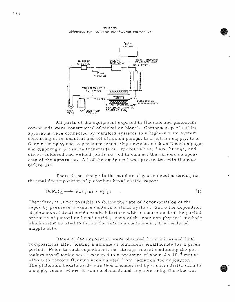
F!GURE33
APPARATUS FOR PLUTONIUM HEXAFLUORIDE PREPARATION
MAGNETIC PISTON PUMP
COLD TRAP
•o FLOW METER
VACUUM MANIFOLD NOT SHOWN
_L - PUF2-1-F2
Fg.Hs VACUUM
BALLAST TANKOOOml)
PREHEATERiSOOC) I l/2mNICKEL PIPE 24 in LENGTH
mmmttmrnttim
BOAT 1 JJ
\y COLD TRAP ( 3 0 0 ml)
FLUORINATION FURNACE, 550 C;BOAT CAPACiTX 50 GRAMS Pu02
• 1-1/2 in NICKEL PlPEISinLENGTH
All p a r t s of the e q u i p m e n t e x p o s e d to f luor ine and p lu ton ium compounds w e r e c o n s t r u c t e d of n i c k e l o r Mone l . C o m p o n e n t p a r t s of the a p p a r a t u s w e r e c o n n e c t e d by mani fo ld s y s t e m s to a h i g h - \ a c u u m s y s t e m c o n s i s t i n g oi m e c h a n i c a l and oil diffusion p u m p s , to a h e l i u m supp ly , to a f luor ine supply , and to p r e s s u r e m e a s u r i n g d e v i c e s , such as B o u r d o n gages and d i a p h r a g m p r e s s u r e t r a n s m i t t e r s . N icke l v a l v e s , f l a r e f i t t i ngs , and s i l v e r - s o l d e r e d and welded jo in t s s e r v e d to connec t the v a r i o u s c o m p o n en ts of the a p p a r a t u s . All of the e q u i p m e n t was p r e t r e a t e d with f luor ine be fo re u s e .
T h e r e i s no change in the n u m b e r of gas m o l e c u l e s d u r i n g the t h e r m a l d e c o i n p o s i t i o n of p lu ton ium h e x a f l u o r i d e v a p o r :
P u F j g ) - P u F i t s ) - F , (g) 1]
r i i e r e f o r e , it is not p o s s i b l e to follow the r a t e of d e c o m p o s i t i o n of the vapor by p r e s s u r e m e a s u r e m e n t s in a s t a t i c s y s t e m . Since the d e p o s i t i o n of p lu ton ium t e t r a f l u o r i d e would i n t e r f e r e with m e ^ l s u r e m e n t of the p a r t i a l p r e s s u r e of p lu ton ium h e x a f l u o r i d e , m a n y of the c o m m o n p h y s i c a l m e t h o d s which migh t be u s e d to follow the r e a c t i o n con t i nuous ly a r e r e n d e r e d i n a p p l i c a b l e .
R a t e s of d e c o m p o s i t i o n w e r e ob ta ined f rom in i t i a l and final c o m p o s i t i o n s a f t e r hea t ing a s a m p l e of p lu ton ium hexa f luo r ide for a g iven p e r i o d . P r i o r to e a c h e x p e r i m e n t , the s t o r a g e v e s s e l con ta in ing the p lu
t o n i u m h e x a f l u o r i d e was e v a c u a t e d to a p r e s s u r e of about 2 x 10" m m at -19o C to r e m o v e f luor ine a c c u m u l a t e d f rom r a d i a t i o n d e c o m p o s i t i o n . The p lu ton ium h e x a f l u o r i d e w a s then t r a n s f e r r e d by v a c u u m d i s t i l l a t i o n to a supp ly v e s s e l w h e r e it was c o n d e n s e d , and any r e m a i n i n g f luor ine was
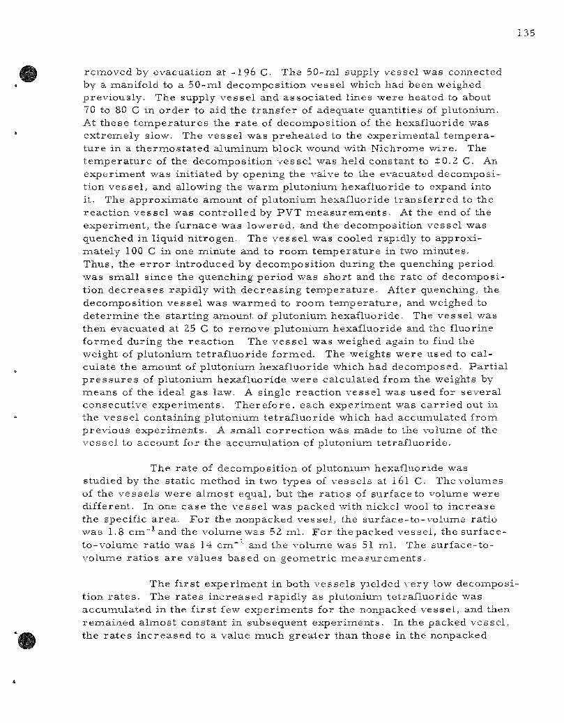
removed by evacuation at -196 C- The 50-ml supply vesse l was connected by a manifold to a 50-ml deconaposition vessel which had been weighed previously. The supply vesse l and assoc ia ted lines were heated to about 70 to 80 C in order to aid the t r ans fe r of adequate quantities of plutonium. At these tenapera tures the r a t e of decomposit ion of the hexafluoride was ex t remely slow. The vesse l was p rehea ted to the exper imental t e m p e r a tu re in a the rmos ta ted alunainum block wound with Nichrome wire . The t empe ra tu r e of the decomposit ion vesse l was held constant to ±0.2 C. An experiment was init iated by opening the valve to the evacuated decomposition vesse l , and allowing the w a r m plutonium hexafluoride to expand into it. The approximate anaount of plutonium hexafluoride t r ans fe r r ed to the reac t ion vesse l was control led by PVT m e a s u r e m e n t s . At the end of the exper iment , the furnace was lowered, and the decomposition vesse l was quenched in liquid ni trogen. The vesse l was cooled rapidly to approxi-naately 100 C in one minute and to room t empera tu re in two minutes . Thus, the e r r o r introduced by decomposit ion during the quenching period was smal l since the quenching per iod was short and the ra te of decomposition dec r ea se s rapidly with decreas ing t e m p e r a t u r e . After quenching, the decomposit ion vesse l was warmed to roona t e m p e r a t u r e , and weighed to de te rmine the s tar t ing amount of plutonium hexafluoride. The vesse l was then evacuated at 25 C to remove plutonium hexafluoride and the fluorine formed during the react ion. The ves se l was weighed again to find the weight of plutonium te t raf luor ide formed. The weights were used to ca l culate the amount of plutonium hexafluoride which had decomposed. Pa r t i a l p r e s s u r e s of plutonium hexafluoride -were calculated from the weights by means of the ideal gas law. A single react ion vesse l was used for severa l consecutive exper iments . There fore , each experiment was c a r r i e d out in the vesse l containing plutonium te t raf luor ide which had accumulated froiai previous exper iments . A smal l cor rec t ion was made to the volume of the vesse l to account for the accumulat ion of plutonium te t raf luor ide.
The ra te of decomposit ion of plutonium hexafluoride was studied by the static method in two types of vesse l s at l 6 l C The volumes of the ve s se l s were a lmost equal, but the ra t ios of surface to volume were different. In one case the vesse l was packed with rdckel wool to inc rease the specific a rea . F o r the nonpacked vesse l , the surface- to-volume ra t io was 1.8 cm~^and the volume was 52 ml . Fo r the packed vesse l , the surface-to-volume ra t io was 14 cm~" and the volume was 51 ml. The su r face - to -volume ra t ios a r e values based on geometr ic m e a s u r e m e n t s .
The f i r s t exper iment in both vesse l s yielded very low decomposition r a t e s . The r a t e s i nc reased rapidly as plutonium tet raf luor ide was accumulated in the f i r s t few exper iments for the nonpacked vesse l , and then remained a lmost constant in subsequent exper iments . In the packed vesse l , the r a t e s inc reased to a value much g r e a t e r than those in the nonpacked

vesse l containing about the s ame amount of plutonium te t ra f luor ide . In the packed vesse l , the plutonium tet raf luor ide probably was deposited over a g r ea t e r a r e a on the surface and in the in t e r s t i ces of the nickel wool. It was concluded that the r a t e of decomposi t ion of plutonium hexafluoride is dependent upon the surface a r e a of plutonium te t ra f luor ide .
One of the reac t ion vesse l s was cut open and the plutonium te t raf luor ide was found as a coating on the walls of the vesse l and as pieces on the bottom of the ve s se l . The dis t r ibut ion of the plutonium t e t r a fluoride was not uniform.
After the deposit ion of a smal l quantity of plutonium te t raf luoride in the nonpacked ves se l , the r a t e s appeared to be independent of the quantity of plutonium te t raf luor ide in the v e s s e l . This was t rue when the the quantity of plutonium te t raf luor ide in the vesse l var ied from about 3 to 6 gin. Because of the manner in which plutonium te t raf luor ide accumulated in the ve s se l , the active surface a r e a of plutonium te t raf luor ide did not i nc r ea se l inear ly with the weight of plutonium te t ra f luor ide . It is assunaed that for th is r eason the active solid surface a r e a did not i nc rease significantly throughout the set of exper iments in the nonpacked vesse l r epor ted h e r e . Thus it was possible to obtain a set of r e su l t s even though the weight of plutoniuna te t raf luor ide in the reac t ion ves se l was different for each exper iment in the set . The r e su l t s of the r a t e exper iments at 140.1, 160.6, and 173.1 C in the nonpacked v e s s e l a r e shown in Table 37, The ra t e was found to be dependent on the p r e s s u r e of plutonium hexafluoride in the nonpacked v e s s e l .
The exper imenta l r e su l t s can be expres sed by a r a t e equation which is of concurren t f i r s t and zero o r d e r s with r e spec t to plutonium hexafluoride p r e s s u r e :
-dp /d t = ko + kip , (2)
The exper imenta l p rocedure used, yielded in tegrated r a t e s of decomposit ion; there fore the in tegrated form of the r a t e equation,
p = po e"kit + (k^/k^) e"kit . (k^/k^) , (3)
where po is the ini t ial p r e s s u r e and p the pa r t i a l p r e s s u r e after react ion t ime t, was used to co r r e l a t e the data obtained. Each exper iment yielded values of p and po. If the reac t ion t i m e s a r e held constant for a set of exper iments , then Equation 3 shows that p is a l inear function of po-Therefore mos t of the exper iments at a given t e m p e r a t u r e were c a r r i e d out for the same reac t ion t ime but at var ious init ial p r e s s u r e s . The use of constant reac t ion t imes pe rmi t t ed the values of ko and ki to be ca lculated conveniently. The values of kx and ko for Equation 3 were calculated frona the data of Table 37 by using the method of leas t s q u a r e s . The ra t e constants obtained in this manner a r e l is ted in Table 38,

Table 37
RATE OF DECOMPOSITION OF PLUTONIUM HEXAFLUORIDE VAPORa
Static Technique
Temp
(c) 140.1 140.1 140.1 140.1 140.1 140.1 140.1 140.1 140.1 140.1
160.6 160.6 160.6 160.6 160.6
173.1 173.1 173.1 173.1 173.1 173.1 173.1 173.1 173.1 173.1 173.1
React ion Time (min)
120 120 120 120 120 120 120 120 120 120
90 90 90 90 90
60 60 60 60 60 60 60 60 60 60 60
Initial Volume of Reaet ion Vesse l : 52, Nonpacked
Initial P r e s s u r e
PuF6 (cm)
101.8 99.5 86.7 76.3 70.0 64.0 56.4 48.5 41.1 14.0
98.1 59.6 51.2 32.6 16.8
108.7 92.8 75.5 75.4 68.9 63.7 53.0 44.9 31.2 25.7 22.2
React ion Vesse
Observed F ina l
P r e s s u r e PuFe (cm)
86.8 85.6 73.6 62.2 56.1 52.2 45.7 37.4 30,9
7.1
70.4 37.9 31.5 16.5
5.9
74.2 59.9 43.8 46.3 39.8 35.4 27.0 20.0 13.1
8.3 6.0
1
Observed Integral
Rate ( c m / h r )
7.5 7.0 6.6 7.1 7.0 5.9 5,4 5.6 5.1 3.4
18.5 14.5 13.1 10.7
7.3
34.5 32.9 31.7 29.1 29.1 28.3 26.0 24.9 18.1 17.4 16.2
.0 ml
Calculated F ina l
P r e s s u r e P u F j (cm)
86.9 84.8 73.1 63.6 55.9 52.3 45.3 38.1 31.3
6.4
Avg Dev
69.2 38.6 31.9 17.1
4.5 Avg Dev
71.7 59.3 45.9 45.8 40.7 36.7 28.4 22.1 11.4
7.2 4.5
Avg Dev
Deviation (cm)
+0.1 -0.8 -0.5 + 1.4 -0.2 +0.1 -0 .4 +0.7 +0.4 -0 .7
+0.4
-1.2 +0.7 +0.4 +0.6 -1.4 ±0.9
-2 .5 -0.6 +2.1 -0.5 +0.9 + 1.3 + 1.4 +2.1 -1.7 -1.1 -1.5 + 1.4
^The quanti ty of plutonium te t ra f luor ide in the ve s se l during these exper imen t s var ied from 3 to 6 gm; however , the in tegra l r a t e s did not change as the weight of solid i nc r ea sed in this r a n g e .
^Calcula ted f rom ra t e constants obtained by fitting the data to the equation -dp /d t = ko + kip, us ing the in tegra ted form
p = poe-^i^ + (ko/ki) e-ki t - ko/kj .
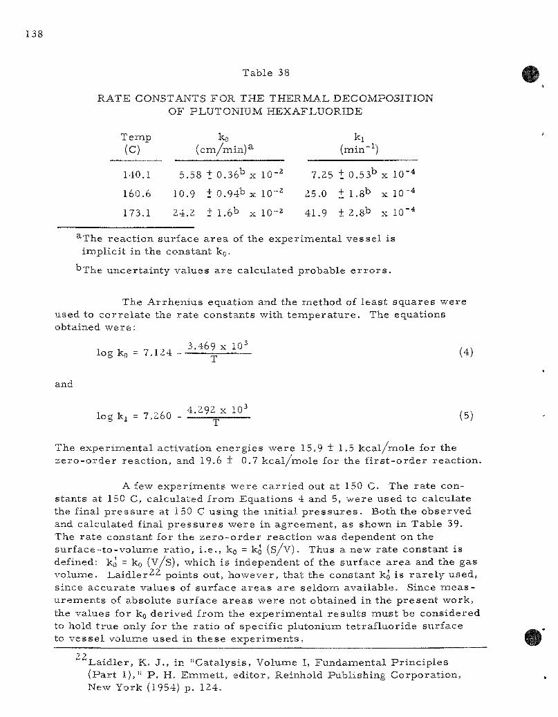
Table 38
RATE CONSTANTS FOR THE THERMAL DECOMPOSITION OF PLUTONIUM HEXAFLUORIDE
Temp
(c) 140.1
160.6
173.1
ko ( cm/min )^
5.58 + 0.36^ X 10-^
10.9 + 0.94b X 10-2
24.2 + 1.6^ X 10-2
ki (min-^)
7,25 + 0.53b X 10-4
25.0 + 1.8^ X 10-4
41.9 + 2,8^ X 10"4
^The reac t ion surface a r e a of the exper imenta l ves se l is implici t in the constant ko-
"The uncer ta in ty values a re calculated probable e r r o r s .
The Arrhen ius equation and the method of leas t squa res were used to co r r e l a t e the ra te constants with t e m p e r a t u r e . The equations obtained we re :
, . „ , , . 3.469 X 10^ log ko = 7.124 ~ (4)
and
^ . „ . , ,^ 4.292 X 10^ ,^. log ki = 7,260 - — ~ (5)
The exper imenta l activation energ ies were 15.9 ± 1 . 5 kc a l /mo le for the z e r o - o r d e r reac t ion , and 19.6 ± 0.7 kc a l /mo le for the f i r s t - o r d e r reac t ion .
A few exper iments were c a r r i e d out at 150 C. The ra te constants at 150 C, calculated from Equations 4 and 5, were used to calculate the final p r e s s u r e at 150 C using the init ial p r e s s u r e s . Both the observed and calculated final p r e s s u r e s were in ag reement , as shown in Table 39. The ra te constant for the z e r o - o r d e r reac t ion was dependent on the sur face- to -vo lume ra t io , i .e . , ko = ko ( s / v ) . Thus a new ra te constant is defined: ko = ko ( v / s ) , which is independent of the surface a r e a and the gas volume. Laid ler^^ points out, however , that the constant ko is r a r e l y used, since accura te values of surface a r e a s a r e seldom avai lable . Since m e a s u r e m e n t s of absolute surface a r e a s were not obtained in the p resen t work, the values for ko der ived from the exper imenta l r e s u l t s mus t be cons idered to hold t rue only for the ra t io of specific plutonium te t raf luor ide surface to ves se l volunae used in these expe r imen t s .
22 La id le r , K. J. , in "Cata lys is , Volume I, Fundamenta l P r inc ip les (Pa r t 1)," P . H. Emmet t , edi tor , Reinhold Publishing Corporat ion, New York (1954) p. 124.
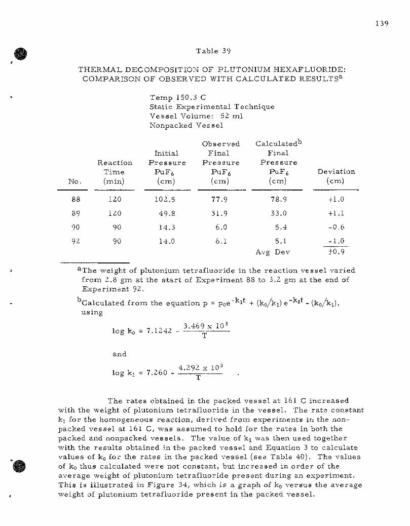
Table 39
THERMAL DECOMPOSITION OF PLUTONIUM HEXAFLUORIDE: COMPARISON OF OBSERVED WITH CALCULATED RESULTS^
Temp 150,3 C Static Exper imenta l Technique Vesse l Volume: 52 ml Nonpacked Vesse l
No.
88
89
90
92
Reaction Time (min)
120
120
90
90
Initial P r e s s u r e
PuFe (cm)
102,5
49.8
14,3
14.0
Observed F ina l
P r e s s u r e PuFfe (cm)
77.9
31.9
6.0
6,1
Calculated^ Final
P r e s s u r e PuFfe (cm)
78.9
33.0
5,4
5.1 Avg Dev
Deviation (cm)
+1,0
+ 1.1
-0.6
-1.0
+0,9
^The weight of plutonium te t raf luor ide in the react ion vesse l var ied from 2,8 gm at the s t a r t of Exper iment 88 to 3.2 gm at the end of Exper iment 92.
Calculated from the equation p = poe" i + (ko/ki) e" ^ - (ko/k^), using
log ko ^ 7.1242 3.469 X 10^
and
log ki = 7.260 4.292 X 10-
The r a t e s obtained in the packed vesse l at l 6 l C inc reased with the weight of plutonium te t raf luor ide in the ve s se l . The ra te constant kj for the homogeneous reac t ion , der ived from experinaents in the non-packed vesse l at l 6 l C, was assunaed to hold for the r a t e s in both the packed and nonpacked v e s s e l s . The value of kj was then used together with the r e su l t s obtained in the packed vesse l and Equation 3 to calculate values of ko for the r a t e s in the packed vesse l (see Table 40), The values of ko thus calculated were not constant , but inc reased in o rde r of the average weight of plutonium te t raf luor ide p resen t during an exper iment . This i s i l lus t ra ted in F igure 34, which is a graph of ko ve r sus the average weight of plutonium te t raf luor ide p re sen t in the packed vesse l .

Table 40
RATE OF DECOMPOSITION OF PLUTONIUM HEXAFLUORIDE VAPOR AT l 6 l C
Static Technique Initial Volume of Vesse l : 51.1 ml Vessel Packed with Nickel Wool
R e a c t i o n T i m e (nain)
360 90 90
120 30
180 30 90 30 30
In i t ia l P r e s s u r e
PuF6 (cm)
84.8 22.8 89.6 74.3 22.9
103.0 ZZ.3
89.5 69.3 32.9
F i n a l P r e s s u r e
PuF6 (cm)
0 . 8 0.02
43.0 4 . 6 6.0 0 . 7 2 . 8 3 .8
31.9 6 .7
Avg Wt PUF4 in V e s s e l
(g)
0.26 0.58 0,79 1.13 1,39 1.74 2.10 2.41 2.78 2.96
Calcu ( c m / i
l a t e d ^ ko aiinxlO^)
14 7 7 ^ Li
35
49 53 45 62 83
H I 83
^Calculated by substituting the value of k^ at 161 C from Table 3{ in Equation 3.
FIGURE 34
VARIATION OF ZERO ORDER RATE CONSTANT WITH WEIGHT OF PLUTONIUM TETRAFLUORIDE
IN PACKED REACTION VESSEL
150
1.0 2.0
AVERAGE WEIGHT Pu F4 IN VESSEL, grams

141
Since the surface a r e a of plutonium te t raf luor ide inc reases as more solid is deposited in the packed vesse l , it s e rves to demons t ra te that the ra te of decomposit ion i n c r e a s e s with i nc rease in surface a r ea . If the sanae amount of plutonium te t raf luor ide were deposited in an unpacked vesse l , the inc r e a s e in ko would be much l e s s .
The concurren t z e r o - and f i r s t - o r d e r dependence of the ra te of reactant p r e s s u r e is s imi l a r to that repor ted for the decoinposition of germanium te t rahydr ide .^^ The f i r s t - o r d e r dependence can be at tr ibuted to the unimolecular , homogeneous decomposit ion of plutonium hexafluoride in the gas phase , and the z e r o - o r d e r dependence can be at tr ibuted to the s imul taneous , heterogeneous decomposit ion of plutonium hexafluoride on the surface of plutoniuiaa te t raf luor ide sa tura ted by the chenaically adsorbed gas .
2. P r o c e s s Development: Plutonium Fluorinat ion and Transpor t Studies ( L . T revo r row, G. J, Vogel, L. Anastas ia , R, Kess ie , H, Griffin, J, Riha, G. Redding, T. Gerding, and T, D. Baker)
An init ial f luorination of oxide fuel will remove a la rge fraction of the uranium as the volatile hexafluoride in the Direct Fluorinat ion Volatility P r o c e s s . In a second fluorination s tep, the remaining uranium and plutonium will be completely converted to the hexafluorides and t r a n s fe r red in the gas effluent from the fluorination reac tor to a condenser . It has been shown that the fluorination of plutonium dioxide proceeds with an init ial rapid convers ion to plutonium te t raf luor ide .^^ Therefore , the max i mum ra t io of plutonium hexafluoride to fluorine in the effluent from the fluorination r eac to r can be es t imated from the equil ibrium constant for the react ion
PUF4(s) + F2 (g) —» PuFe (g)
The plutonium hexafluoride- to-f luor ine rat io in the effluent s t r e a m will be equal to or l e s s than the equi l ibr ium constant at the fluorination t e m p e r a t u r e . Since the equi l ibr ium constant d e c r e a s e s with t empera tu re , the plutonium hexafluoride- to-f luor ine ra t io in the effluent s t r eam will be g rea t e r than the equi l ibr ium constant somewhere in the p rocess line b e tween the fluorination r eac to r and condenser . This will favor decomposi tion somewhere along the l ine . A knowledge of the ra te of t he rma l decomposit ion of plutonium hexafluoride is important in this s tep of the p r o c e s s . Since the ra te of decoinposit ion also d e c r e a s e s with t empera tu re , the amount of decomposi t ion can be reduced by cooling the effluent gas s t r e a m rapidly to a t e m p e r a t u r e at which the ra te of decomposit ion is slow,
23. Tamaru , K., Boudart , M., Taylor , H., J, Phys , Chem, 59, 801 (1955).
•^Steindler, M. J., f Eng 6, 333 (1959). Steindler , M. J., Steidl, D. V., Steunenberg, R. K,, Nuclear Sci. and
142
Labora tory p repara t ion of plutonium hexafluoride with high yields (ANL-6287, page 134) is proof in itself that the compound can be recovered efficiently from a fluorination r e a c t o r . Plant conditions, however , naust be chosen which will pe rmi t the inaximum recovery of plutonium hexafluoride from the fluorination r eac to r effluent. Most of the decomposit ion in the p r o c e s s f luorinator will probably occur in a d i sengaging section above the fluidized bed. The t e m p e r a t u r e of this section is expected to range frona 550 C at one end to about 150 C at the other end. A considerable port ion of the p r o c e s s development p r o g r a m on the labora tory scale has been devoted to a study of the fac tors affecting the r ecovery of plutonium from a fluorination r e a c t o r .
Severa l exper iments designed to invest igate this problem have been repor ted previously (ANL-6287, page 142 to 144). These expe r imen t s consis ted of pass ing plutonium hexafluoride-f luorine mix tures through a heated (550 C) pipe and a length of tubing to a condenser in s imulat ion of p r o c e s s condit ions. The quantity of plutoniuna hexafluoride decomposed in this systein was de termined by the difference in the weight of plutonium hexafluoride enter ing the sys tem and that r ecovered from the sys t em. The r e su l t s of these exper iments showed that 98 to 100 percent of the plutonium hexafluoride which passed through the sys tem could be recovered in the condenser . In the following pa rag raphs further exper i ments a r e desc r ibed which a r e per t inent to the problem of decomposi t ion of plutonium hexafluoride under var ious p r o c e s s condit ions.
Decomposi t ion of Plutonium Hexafluoride in the Effluent from Fluor inat ion of Plutonium Tetraf luor ide
In fur ther exper imen t s , the quantity of plutoniuna hexafluoride decomposed was de termined by d i rec t weight r a the r than by differences in the weight of plutonium hexafluoride enter ing and leaving the s y s t e m . The plutonium hexafluoride-f luorine mix tu res used in these exper iments were components of the effluent gas s t r e a m from a l a b o r a t o r y - s c a l e fluorination of plutonium te t ra f luor ide .
The exper imenta l p rocedure was as follows: F luor ine gas was passed over a sainple of plutonium te t raf luor ide at 550 C. The r e s u l t ing gas mix tu re of plutonium hexafluoride and fluorine was passed through a nickel decomposi t ion ves se l , s imulat ing the line which will exis t between the fluorination r eac to r and the condenser in p r o c e s s equipment. The v e s sel was detached from the sys tem and weighed before and after an expe r i ment to de te rmine the quantity of plutonium te t ra f luor ide deposited in i t . The ves se l had been precondit ioned with fluorine gas at 350 C for s eve ra l hours until the weight change for an eight-hour fluorination per iod was coinparable to the weighing e r r o r . The plutonium hexafluoride-f luorine mix ture was passed from the decomposi t ion vesse l through two t r a p s , cooled to -78 C, where the plutonium hexafluoride was condensed. The fluorine was r ec i r cu la t ed over the plutonium te t raf luor ide in the f luorination boat at 550 C. F igu re 35 is a scheaxiatic d iagram of the sys tem used in these expe r imen t s .

FIGURE 35 APPARATUS USED IN FLUORINATION AND RECOVERY OF
PLUTONIUM HEXAFLUORIDE FROM EFFLUENT STREAM
MAGNETIC PISTON
PUMP
Fg AND He INTRODUCTION
AND VACUUM
MANIFOLD
fp-DECOMPOSITION
VESSEL
mr
.PREHEATER
FLOW METER
pww ft vw/www ]
JJQATL -Jj
U TRAP
COLD TRAP
FLUORINATION FURNACE
R e s u l t s of e x p e r i m e n t s on d e c o m p o s i t i o n of plutoniuna h e x a f luor ide in the effluent s t r e a m a r e l i s t e d in Tab le 4 1 . The to t a l nu inbe r of m o l e s of p lu ton ium h e x a f l u o r i d e in the effluent s t r e a m leav ing the f l u o r i n a t o r w a s c a l c u l a t e d by t ak ing the s u m of the m o l e s of p lu ton ium h e x a f l u o r i d e in the cold t r a p and the m o l e s of p lu ton ium t e t r a f l u o r i d e in the d e c o m p o s i t i o n v e s s e l . The n u m b e r of m o l e s of f luor ine in the effluent s t r e a m was c a l c u l a t e d f rom the i d e a l gas law, with the a id of the a \ ' e r age vo lume flow r a t e , the t o t a l flow t i m e , the a v e r a g e p r e s s u r e , and the t e m p e r a t u r e at the flow m e t e r . T h e s e c a l c u l a t e d v a l u e s of to t a l naoles of plutoniuna h e x a f l u o r i d e and f luo r ine w e r e u s e d to c a l c u l a t e the a v e r a g e r a t i o s of m o l e s plutoniuna h e x a f l u o r i d e to m o l e s f luor ine in the effluent s t r e a m . Data in T a b l e 41 show tha t in a l l e x p e r i m e n t s , the p lu ton ium h e x a f l u o r i d e - f l u o r i n e r a t i o s of the gas m i x t u r e s e n t e r i n g the d e c o m p o s i t ion v e s s e l w e r e m u c h h i g h e r than the e q u i l i b r i u m r a t i o at the t e m p e r a t u r e of the d e c o m p o s i t i o n v e s s e l . Th i s i n s u r e d tha t s o m e d e c o m p o s i t i o n would o c c u r in the d e c o m p o s i t i o n v e s s e l .
It is r a t h e r diff icult to c o n t r o l the v a r i a b l e s in t h e s e e x p e r i m e n t s . H o w e v e r , the w o r k h a s y i e lded s e v e r a l useful r e s u l t s . Data f rom E x p e r i m e n t s 17, 19, and 20 a r e p lo t t ed a s a function of t e m p e r a t u r e in F i g u r e 36.
In a c o m p a r i s o n of the r e s u l t s of E x p e r i m e n t s 28 and 19, the d i f f e r e n c e in d e c o m p o s i t i o n r a t e s w e r e a s s u m e d to be m a i n l y the r e s u l t of the d i f f e r ence in s u r f a c e - t o - v o l u m e r a t i o . In a c o m p a r i s o n of the r e s u l t s of E x p e r i m e n t 17 with the r e s u l t s of E x p e r i m e n t s 32A and 32B, the d i f f e r ence in d e c o m p o s i t i o n r a t e s w e r e m a i n l y the r e s u l t of the diff e r e n c e in s u r f a c e - t o - v o l u m e r a t i o and a r e p a r t l y the r e s u l t of the diff e r e n c e s in p lu ton ium h e x a f l u o r i d e - t o - f l u o r i n e r a t i o .

Table 41
DECOMPOSITION OF PLUTONIUM HEXAFLUORIDE IN THE EFFLUENT STREAM FROM FLUORINATION OF PLUTONIUM TETRAFLUORIDE
Decomposition vessel dimensions: Experiments No. 17,19, 20, 28, inside diameter 4.76 cm, length 25.1 cm. Vessel packed with nickel wool in Experiment No. 28.
Experiments No. 32A and 32B, inside diameter 4.76 cm, length 6.7. Vessel packed with nickel vrool in both Experiments 32A and 32B.
Exp No.
19
28
20
17
32A
32B
Decomp Vessel Temp
(C)
144125
152+1
2061-2
244133
25113
25212
aANL-6101, page 82.
Decomp^ Vessel
Surface-to-volume
Ratio (CRl-1)
1
16
1
1
15
15
Avg Mole Ratio
PuFg/Fz Entering Decomp Vessel
0.008
0.010
0.008
0,008
0.012
0.015
Equilibrium Constanta
PUFJ;F2
at Temp of Decomp Vessel
0.00033
0.00039
0.00087
0.0014
0.0015
0.0015
Total Reaction
Time (hr)
25.2
23.0
22.3
24.2
2.0
2.0
PuFft Recovered Cold Trap
(gl
23.83
a).66
19.91
16.19
1.89
0.97
PuFg Decomp
(g)
0.093
4.70
2.32
5.98
1.26
3.3)
PuFft Decomp
(percent)
0.4
13
10
27
40
77
PuFg Decomp Rate
(g/iir)
0.004
0.20
0.10
0.25
0.63
16
FIGURE 36 RATE OF DECOMPOSITION OF PLUTONIUM HEXAFLUORIDE
VAPOR AS A FUNCTION OF TEMPERATURE
F L O W T E C H N I Q U E kOMPACKED
DECOMPOSITION VESSEL
h I 5
O DECOMPOSITION AT 18 mm PARTIAL PRESSURE OF PuFj
• DECOMPOSITION IN EFFLUENT STREAM FROM FLUOP.NATiON OF PuF4
TEMPERA^'URE, C 250 2 0 0 150
2 0
E x p e r i m e n t s 32A and 32B w e r e c a r r i e d out u n d e r s i m i l a r cond i t ions excep t t ha t the a v e r a g e m a s s of p l u t o n i u m t e t r a f l u o r i d e p r e s e n t in the v e s s e l w a s 0.56 gm in E x p e r i m e n t 32A and 2.55 gna in E x p e r i m e n t 32B. T h i s f u r t h e r d e m o n s t r a t e s tha t the d e c o m p o s i t i o n r a t e is dependen t on the s u r face a r e a of p lu ton ium t e t r a f l u o r i d e and s u p p o r t s the f u n d a m e n t a l w o r k r e p o r t e d in Sec t ion 1, page 133.
In s u m m a r y , r e s u l t s l i s t e d in T a b l e 41 have y i e lded sonae i n f o r m a t ion on the change of d e c o m p o s i t i o n r a t e wi th t e m p e r a t u r e . It h a s b e e n conc luded tha t the r a t e i n c r e a s e s wi th the s u r f a c e - t o - v o l u m e r a t i o of the v e s s e l , and tha t the r a t e i s dependen t on the s u r f a c e a r e a of the so l id p r o d uc t , p lu ton ium t e t r a f l u o r i d e .
D e c o m p o s i t i o n of F lowing P l u t o n i u m Hexa f luo r ide Vapor at a P a r t i a l P r e s s u r e of 18 m m
The r a t e of d e c o m p o s i t i o n of flowing p lu ton ium h e x a f l u o r i d e vapo r w a s s tud ied by a n o t h e r t e c h n i q u e in wh ich the v a r i a b l e s w e r e laiore e a s i l y c o n t r o l l e d . In t h e s e e x p e r i m e n t s a v e s s e l con ta in ing s e v e r a l g r a m s
of plutonium hexafluoride was cooled in an ice bath. The vapor p r e s s u r e of plutonium hexafluoride at the ice point is 18 m m . Plutonium hexafluoride vapor was c i rcula ted through a decomposit ion vesse l positioned ver t ical ly in a furnace, and then back through the vesse l containing the solid plutonium hexafluoride at 0 C. The sys tem was thus filled with plutonium hexafluoride vapor at a constant pa r t i a l p r e s s u r e of 18 mm throughout the exper iments , even though the total p r e s s u r e of the sys tem increased as a resu l t of the s e r i e s of r eac t ions : PuF6(s) —»» PuF6(g) —»• PuF4{s) -r FzCg). Both the ra te of p r e s s u r e r i s e and the weight of plutonium tet raf luor ide deposited in the decomposi t ion ves se l could be used to calculate a ra te of decomposit ion. The dimensions of the decomposi t ion vesse l were 4.76 cm for the inside d iameter and 25.1 cm for the length. The volume of the vesse l was about 446 ml . A set of exper iments was also c a r r i e d out in which the vesse l was packed with nickel wool to i nc r ea se the sur face- to-volume ra t io . In the nonpacked vesse l the sur face- to -vo lume rat io was 1.2 cm" . In the packed ves se l the su r face- to -vo lume ra t io was 16 cm" .
Decomposit ion in Packed and Nonpacked Vesse ls
Data on the ra te of decomposi t ion of plutonium hexafluoride m e a s u r e d by the flow technique in the nonpacked vesse l at a par t i a l p r e s sure of 18 nam a re l is ted in Table 42. The changes of total p r e s s u r e with t ime a re compared in F igure 37 for t h r ee different decomposit ion t e m p e r a t u r e s . The total p r e s s u r e s a r e a lmos t a l inear function of t ime; thus the ra te of decomposi t ion (tangent to the curve) does not change much dur ing each exper iment .* Considering this observat ion together with the fact that the mole fraction of fluorine in the gas increased from alinost 0 to about 0.96 in the exper iment at 256 C, it was concluded that the fluorine r e p r e s s e s the ra te of decomposi t ion to a very smal l degree . The ra t e s of decomposi t ion at a pa r t i a l p r e s s u r e of 1 8 mm are plotted as a function of t e m p e r a t u r e in F igure 36.
Data on the r a t e of decomposit ion in the packed vesse l of plutonium hexafluoride vapor at 18 nana p r e s s u r e obtained by the gas flow technique a r e l is ted in Table 43, The packed vessel had been prefluorinated with fluorine gas at t e m p e r a t u r e s ranging from 25 to 400 C, but at the s t a r t of Exper iment 25 the ves se l contained no plutonium te t ra f luor ide . The r i s e of total p r e s s u r e s with tinae for decomposi t ions at 150 C a r e shown for the packed ves se l in F igure 38. In Exper iment 25 the ra te of p r e s s u r e r i s e (and there fore the r a t e of decomposit ion) was slow at f i rs t and gradually inc reased . This i n c r e a s e of p r e s s u r e r i s e in Exper iment 25 is in te rpre ted to mean that the r a t e of decomposi t ion of plutonium hexafluoride vapor is acce le ra ted by the inc reas ing surface a r e a of solid plutonium te t raf luor ide on the inner surface of the v e s s e l .
'This is s imi l a r to the r e su l t s obtained with the nonpacked vesse l of the s ta t ic exper iments r epor ted in Section 1.

Table 42
RATE OF THERMAL DECOMPOSITION OF PLUTONIUM HEXAFLUORIDE IN A NONPACKED VESSEL
Gas F low Techn ique , Nonpacked 4 4 6 - m l Decompos i t ion Vesse l PuFg pa r t i a l p r e s s u r e : 18 iTiin
Avg Wt
Decompos i t ion T e m p
(C)
150
200
256
PUF4 in Decomp V e s s e l
(g)
15.4
17.2
23.3
D PuFft
ecompo (g)
0.60
3.41
10.3
3ed Reac t ion
Time (hr)
24
23.5
24
In tegra l Decompos i t ion
Rate (g PuFfc/hour)
0.025a 0 .001^
0.145 0.142
0.429 0.430
^'-Calculated f rom the weight of PUF4 co l lec ted in the decompos i t i on v e s s e l .
bCa lcu la ted f rom the to ta l p r e s s u r e i n c r e a s e , with c o r r e c t i o n for rad ia t ion decompos i t i on .
FIGURE 37 PRESSURE CHANGE DURING DECOMPOSITION
OF PLUTONIUM HEXAFLUORIDE
FLOW METHOD PARTIAL PRESSURE PuFg.iSmm DECOMPOSITION VESSEL : 4 4 6 ml
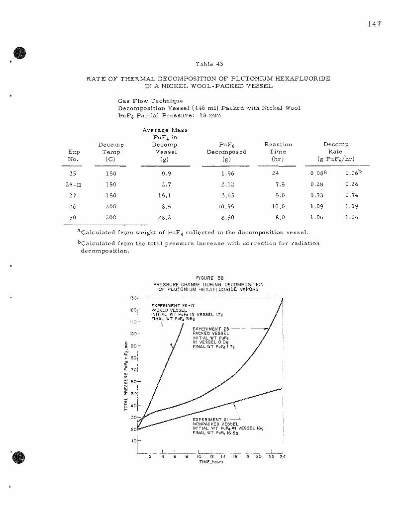
T a b l e 43
R A T E O F T H E R M A L DECOMPOSITION O F PLUTONIUM HEXAFLUORIDE IN A N I C K E L W O O L - P A C K E D VESSEL
Gas F l o w T e c h n i q u e D e c o m p o s i t i o n V e s s e l (446 ml ) P a c k e d wi th Nicke l Wool P u F j P a r t i a l P r e s s u r e : 18 mm
Exp No.
25
25-11
27
26
30
D e c o m p T e m p
(c)
150
150
150
200
200
A v e r a g e M a s s PuF4 in D e c o m p
V e s s e l
(g)
0.9
2.7
15.1
8.5
28.2
PuFfi D e c o m p o s e d
(g)
1.96
2.12
3.65
10.95
8.50
R e a c t i o n T i m e (h r ;
24
7.5
5.0
10.0
8.0
E
(g
O.OSa
0.28
0.73
1.09
1.06
e c o m p Rate P u F e / h r )
0.06^
0.26
0.74
1.09
1.06
^ C a l c u l a t e d f r o m we igh t of PUF4 c o l l e c t e d in the d e c o m p o s i t i o n v e s s e l .
" C a l c u l a t e d f r o m the t o t a l p r e s s u r e i n c r e a s e with c o r r e c t i o n for r a d i a t i o n d e c o m p o s i t i on .
FIGURE 38 PRESSURE CHANGE DURING DECOMPOSITION
OF PLUTONIUM HEXAFLUORIDE VAPORS
10 12 14 TIME,hours
The inc rease of total p r e s s u r e with t ime in the nonpacked vesse l is also shown in F igure 38 for compar i son . There was about 16 g of plutonium te t raf luor ide in the nonpacked vesse l at the s t a r t of the exper iment . The experinient with the packed vesse l s ta r ted with no plutonium tet raf luor ide and ended with about 1.7 g plutonium te t raf luor ide in the v e s sel . The ra te in the packed vesse l was much higher probably because the plutonium te t raf luor ide was dis t r ibuted over a much l a rge r surface .
In Exper iment 25-11 the i nc r ea se of p r e s s u r e with t ime appeared to be l inear (Figure 38). Also, the ra te was about the same as that of the las t par t of Exper iment 25. Other exper iments which s ta r ted with an appreciable quantity of plutonium te t raf luor ide in the decomposi tion vesse l do not show an i nc r ea se of ra te during the course of an exper i ment . This was in te rpre ted to mean that after the deposition of a quantity of plutonium te t raf luor ide the i nc r ea se in surface a r e a of the plutonium te t raf luor ide was smal l even though m o r e plutonium te t raf luor ide was formed. Thus the r a t e of decomposit ion of plutonium hexafluoride per g ram of plutonium te t raf luor ide was even s m a l l e r .
The ra t e of decomposit ion was m e a s u r e d again at 150 C (Experiment No. 27, Table 43) after l a r g e r quantit ies of plutonium t e t r a fluoride had been added to the ve s se l . The ra te inc reased with each suc ceeding exper iment .
The r a t e s of decomposi t ion of plutonium hexafluoride at 200 C in two exper iments (26 and 30, Table 43) with widely different init ial quant i t ies of plutonium te t raf luor ide in the ves se l were about the s a m e . Both exper iments were c a r r i e d out after a la rge quantity of plutonium te t raf luoride had been deposited in the ve s se l . P r e sumab ly the point had been reached where further i n c r e a s e s of plutonium te t raf luor ide surface a r e a were smal l even though m o r e plutonium te t raf luor ide was accumulating in the ve s se l . There fore , a la rge change in the quantity of plutonium t e t r a fluoride in the ves se l would i n c r e a s e the ra te of decomposit ion of plutonium hexafluoride only slightly.
Compar ison of Phys ica l Appearance and Bulk Density of Plutonium Tetraf luor ide Samples
T-wo la rge ves se l s containing plutonium te t raf luor ide were cut open. In one vesse l , 25 g of plutonium te t raf luor ide had deposited on the walls from the t h e r m a l decomposi t ion of plutonium hexafluoride at t e m p e r a t u r e s of 150 to 250 C. In the other vesse l , 34 g of plutonium t e t r a fluoride had accumulated as a loose powder from the low- tempera tu re a lpha- rad ia t ion decomposit ion of plutonium hexafluoride. The object of the exper iment was to examine any differences between the physical p rop e r t i e s of plutonium te t raf luor ide produced by radiat ion decomposi t ion and that imade by t h e r m a l decomposi t ion. The physical form, co lo rs , and bulk

densi t ies for the two samples a r e compared in Table 44. The bulk density of the product of t he rma l decomposition was 1 5 to 18 t imes grea te r than the bulk density of the product of radiat ion decomposition. It is c lear that there is a grea t difference in the physical p roper t i es of the plutonium tetraf luoride produced by the two methods .
Table 44
COMPARISON OF PHYSICAL PROPERTIES OF PLUTONIUM TETRAFLUORIDE PRODUCED BY THERMAL AND
RADIATION DECOMPOSITION OF PLUTONIUM HEXAFLUORIDE
PUF4 Source
T h e r m a l decoinposit ion of PuFe at 150 to 250 C
Radiation decomposi t ion of PuF j mos t ly at low t e m p e r a t u r e s (~Z5 C) sized chunks
Phys ica l F o r m
mos t ly smal l , pointed. c rys ta l l ine p a r t i c l e s ; some powder; some chunks-one chunk was about 1 x |-x- |- in.
mos t ly smal l , feathery p a r t i c l e s ; a few pea -
Color
dark reddish-brown
gray or light green
Bulk Density (g/cc)
4.2^
0.23
T a p Bulk
Density (g/cc)
4 .3^
0.28
^The c rys t a l density of plutonium te t ra f luor ide is 7.0 g / cc ; Zachar iasen , W. H., Paper 20.5 of The T ransu ran ium Ele tnents , National Nuclear Se r i e s , Di\'ision IV, Volume 14B, McGraw-Hil l Book Company, Inc. , New York (1949).
Also of in te res t was the observat ion that the plutonium tet raf luor ide produced by the rma l decomposit ion of plutonium hexafluoride could be removed to a large extent from the walls of the vesse l by mechanical vibrat ion. This suggests that plutonium tetrafluoride deposited on the walls of the disengaging section above a fluidized bed could be periodical ly dislodged by mechanical means and returned to the bed for re-f luor inat ion.
Recovery of Plutonium Tetrafluoride Previously Deposited on Nickel Wool by Thermal Decomposition of Plutonium Hexafluoride
Exper iments on the t he rma l decomposition of plutonium hexafluoride left a total of 3Z.1 g of plutonium tetrafluoride in a vesse l packed with nickel wool. It was neces sa ry to recover this plutonium for future use . The plutonium tetraf luoride could not be mechanically recovered without cutting the vesse l open. If the vesse l were opened, the recovery of smal l par t ic les of the solid from the nickel wool would be extremely difficult. It is possible that an analogous situation may be encountered in the operat ion of a fluoride volatility separat ions plant, i .e . , a quantity

150
of plutonium te t raf luor ide may deposit at a site in p roces s equipment from which simple mechanica l r ecovery of the solid is imposs ib le . Therefore , it was of in te res t to demons t ra te that the plutonium could be recovered by fluorination.
F luor ine gas was c i rcula ted through the vesse l , which was heated to var ious t e m p e r a t u r e s . The gas was passed through a s e r i e s of two cold t r aps cooled to -78 C for condensation of the plutonium hexafluor ide produced. The t r a p s were weighed before and after the fluorinations to de te rmine the degree of r ecovery of plutonium as the hexafluoride. The fluorination was c a r r i e d out in th ree s t eps : P a r t A at 430 C, P a r t B at 220 C, and P a r t C at 450 C. These a r e average t e m p e r a t u r e s . The t e m pe ra tu r e of the ves se l was nonuniform in each exper iment . The init ial volume of the ves se l was about 446 ml (-^1.9 in. in d iameter and ~9.9 in. in length), and it was packed with 123 g of nickel wool. The calculated total nickel surface a r e a in the v e s s e l was 6100 sq cm.
The conditions and r e su l t s of the fluorinations a r e l is ted in Table 45. Since the plutonium te t raf luor ide was probably not d is t r ibuted uniformly on the surface , the geomet r ic a r e a should not be used to expres s the fluorination ra t e as a value per unit of surface a r ea .
Table 45
FLUORINATION AND RECOVERY OF PLUTONIUM PREVIOUSLY DEPOSITED ON NICKEL WOOL BY THERMAL DECOMPOSITION
OF PLUTONIUM HEXAFLUORIDE
Percen tage Recovery Weight of PuF4 initially p resen t on nickel wool = 32.1 g Complete convers ion of 32.1 g PUF4 would yield 36.0 g PuF^ Percen t r ecove ry = 35.2/36.0 x 100 = 98%
No.
31A 31B 31C
Fluor inat ion Time
(hr)
5 10 16b
Avg Temp (c)
^430 -220 -450
Fz Flow Rate (cc /min)
^283 -456 -500
PuFfe Recovered
(g)
14.2(0.1)^ 3.4(0.1)
17.6(0.3) 35.2 total
Fluor inat ion
(g Rate
PuF4/hr )^
2.5 0.3 2.2b
^Correc t ion , g r a m s , to account for radiat ion decomposit ion of PuF^.
"A sharp b reak in the graph of fluorine consumption ve r sus t ime indicated that mos t of the ina t e r i a l was completely fluorinated after 7.1 h r . This t ime was used for calculat ion of the fluorination r a t e .
'^Rate calculated from weight of PuF^ r ecove red .

After conapletion of the fluorination, the vesse l was cut open for an examination of the in te r io r . The nickel wool was intact . The su r face of the walls and the nickel wool were covered with a dull, thin^ gray-green filin.
The fluorination ra te at 450 C appears to be lower than that at 430 C. This was probably caused by the nonuniformity of the t empe ra tu r e of the ves se l and the nonuniformity of distr ibution of plutonium te t raf luoride in the ve s se l . Thus it is possible that a major fraction of the plutonium te t raf luor ide in P a r t C of the fluorination was at a much lower t e m p e r a t u r e than the nominal average vesse l t empera tu re of 450 C. The m o r e impor tant resu l t of these exper iments is the demonstra t ion that a large quantity of plutonium te t raf luor ide which has deposited in equipment can be fluorinated to plutonium hexafluoride at a p rac t ica l ra te with high percentage r e c o v e r i e s . In this case 98 percent of the plutonium was recovered .
Summary of Resul ts on Recovery of Plutonium from the Fluor inat ion Reactor
The following resu l t s have been obtained from exper iments on the labora tory scale rela.ting to the problem of recovery of plutonium from the fluorination r e a c t o r :
(a) The ra te of decomposit ion of plutonium hexafluoride in flowing gas s t r e a m s has been de te rmined at t e m p e r a t u r e s ranging from 150 to 250 C. The r a t e of decomposit ion depends on the surface a r ea of plutonium te t raf luor ide in the equipment. Since the surface a r e a of the plutonium te t raf luor ide was not measu red , it is not possible to ixiake an exact extrapolat ion to the conditions of l a r g e - s c a l e p rocess conditions. It should be poss ib le , however , to extrapolate the r a t e s obtained in the labora tory by scaling up both the quantit ies of plutonium tetraf luoride p resen t in equipment and the wall a r e a s to give an es t imate of the ra te of decomposit ion in p r o c e s s equipment. The surface a r ea of plutonium t e t r a fluoride will not be a l inear function of the quantity of plutonium tet raf luoride in a piece of equipment but will vary with the par t icu la r distr ibution of the solid on the walls of equipment. The distr ibution of the solid can be expected to be nonuniform.
(b) The t h e r m a l decomposit ion of plutonium hexafluoride at t e m p e r a t u r e s from 150 to 250 C produced crys ta l l ine deposits of plutonium te t raf luor ide which could be removed by mechanical" vibration. It is p robable that deposits of plutonium te t raf luor ide in the disengaging section of a fluidized bed could be dislodged by mechanical vibration to fall back into the bed for re - f luor ina t ion .
(c) Deposits of plutonium te t raf luor ide which cannot be removed by mechanica l means can be removed by re-f luor inat ion and this can be done efficiently at t e m p e r a t u r e s between 430 and 450 C.
3. The Reaction of Plutonium Hexafluoride and Bromine (M. J. Steindler , D. V. Steidl, T. Gerding)
A thorough knowledge of the chemical p rope r t i e s of plutonium hexafluoride is requ i red for the development of fluoride volatili ty p r o c e s s e s . Differences in the chemica l behavior of plutonium and uranium hexafluorides may be uti l ized in the separa t ions p r o c e s s e s .
The oxidizing power of plutonium hexafluoride is one of the p rope r t i e s of this substance which i l l u s t r a t e s a usable difference between the hexafluorides of uran ium and plutonium^ A study of the reac t ion be tween sulfur te t raf luor ide and plutonium hexafluoride, repor ted previously (ANL-6231, page 96), indicated that , although the react ion p roceeds quant i tat ively at slightly elevated t e m p e r a t u r e s , the corresponding react ion with uran ium hexafluoride does not p roceed . It i s , the re fore , possible to uti l ize this reac t ion for separa t ing plutonium hexafluoride from uranium hexafluoride.
The reac t ion of e lementa l bromine and plutonium hexafluoride has been invest igated with the s ame genera l a i m s . It has been poss ib le to es tabl i sh the s to ich iometry of the react ion, make some observa t ions on the ra te of the react ion, and to demons t ra t e the uti l i ty of the react ion for the separa t ion of uran ium and plutonium hexafluorides from each o ther .
The exper imenta l p rocedure was as follows. Plutonium hexafluoride, p r epa red by the fluorination of the te t raf luor ide was checked for puri ty by measur ing the vapor p r e s s u r e at the ice point (Pcalc - 18 mm Pobs ~ 19mm) . •'• Reagent grade b romine was purified by t r a p - t o - t r a p d i s t i l lat ion and the puri ty checked by m e a s u r e m e n t of i ts vapor p r e s s u r e at the ice point (Pcalc "= ^^-^ m m , Pobs - ^5 mm) .^^ The reagen t s were dist i l led at low p r e s s u r e s into a t a r ed nickel reac t ion ves se l which had been p r e viously p r e t r e a t e d with e lementa l fluorine and also with plutonium hexafluor ide . At the end of the reac t ion t ime , the unreac ted reagen t s were hydrolyzed in water and plutonium de te rmined .
In those exper iments in which the gaseous products were identified by infrared spec t roscopy , a 10-cm nickel ce l l equipped with s i lver chloride windows was used to contain the ga se s . The infrared spect rophotometer (Beckman IR-4) was ca l ibra ted p r io r to use by the air spec t rum (H2O, CO2).
Wemstock, B . , Weaver, E. E. , and Malm J. B . , J . Inorg. and Nucl. Chem. 11, 104 (1959). ' '
F i s c h e r , J. , and Bingle, J. , J. Am. Chem. S o c , 77, 6511 (1955).
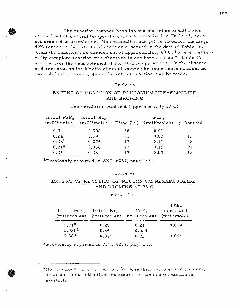
The reac t ion between bromine and plutonium hexafluoride ca r r i ed out at ambient t e m p e r a t u r e s , as summar ized in Table 46, does not proceed to completion. No explanation can yet be given for the large differences in the extents of react ion observed in the data of Table 46. When the reac t ion was c a r r i e d out at approximately 80 C, however, essential ly complete react ion was observed in one hour or l e s s . * Table 47 s u m m a r i z e s the data obtained at elevated t e m p e r a t u r e s . In the absence of d i rec t data on the kinetic effect of varying bromine concentrat ions no m o r e definitive comments on the r a t e of react ion may be made .
Table 46
EXTENT OF REACTION OF PLUTONIUM HEXAFLUORIDE AND BROMINE
T e m p e r a t u r e : Amibient (approximately 30 C)
Initial PuF^ (mil l imoles)
0.24 0.24 0.23^ O.Zia 0.25
Initial Brg (mil l imoles)
0.088 0.59 0.075 0.066 0.26
T ime (hr)
18 21 17 17 17
PuF4 (miillimoles)
0.01 0.03 0.11 0.15 0.03
% Reacted
4 12 48 71 13
' 'Previously repor ted in ANL-6287, page 143.
Table 47
EXTENT OF REACTION OF PLUTONIUM HEXAFLUORIDE AND BROMINE AT 78 C
Time: 1 hr
PuFfe Initial PuF^ Initial Br2 PUF4 unreacted (mil l imoles) (mil l imoles) (mil l imoles) (mill imoles)
0.21a 0.088^ 0.28^
0.29 0.65 0.079
0.21 0.084 0.25
0.009 -
0.004
^-Previously repor ted in ANL-6287, page 143.
*No reac t ions were c a r r i e d out for l e s s than one hour and thus only an upper l imit to the t ime n e c e s s a r y for complete react ion is avai lable .

Although the data on the weight change of the react ion v e s s e l s trongly indicated that the plutonium product of the react ion was plutonium te t raf luor ide , m o r e posit ive identification was des i r ab l e . Attempts to obtain X- r ay diffraction pa t te rns of the solid product failed. This work, as well as previous exper ience , indicated that solids produced by the r educ tion of plutonium hexafluoride at low (less than 150 C) t e m p e r a t u r e s a r e mic roc rys t a l l i ne or amorphous and do not yield identifiable diffraction pa t t e rn s .
As previously repor ted in ANL-6287, page 143, an exper iment in which approximate ly equal mo la r quanti t ies of b romine and plutonium hexafluoride were reac ted at 78 C for two hours produced a light buff-colored solid. Chemical analys is of this solid gave a fluorine to plutonium rat io of 4 .11, indicating that the solid product of the reac t ion is indeed plutonium te t ra f luor ide .
In o rde r to es tabl i sh the identity of the gaseous products of the react ion, samples of the gas phase were analyzed by infrared spec t roscopy . Data from the l i te ra ture^3 ,24 ,25 ^g well as s tandards p repa red in the appara tus used for the exper iments were compared with the gaseous products of the reac t ion . Samples of bromine used in the exper iments were scanned to de te rmine the absence of in f ra red-absorb ing impur i t i e s . None was found. The r e s u l t s of the exper imen t s , summar i zed in Table 48, indicate that the reac t ion of plutonium hexafluoride and bromine produces bromine pentafluoride. The p re sence of bromine t r i f luor ide in the gaseous products from reac t ions c a r r i e d out at slightly elevated t e m p e r a t u r e s miay be explained as being formed by the secondary reac t ion of bromine and bromine pentafluoride.^^ It appears unlikely, however, that the mechan i sm of the react ion between bromine and plutonium hexafluoride involves the d i rec t formation of b romine pentaf luoride. Thus it may be suggested that the reac t ion p roceeds as follows:
PuFs + Br2 - ^ » PuF4 + 2BrF (fast) (l)
2PuF6 + 2 B r F — • 2 P u F 4 + 2BrF3 (fast) (2)
2PuF6 + 2BrF3—•2PUF4 + 2BrF5 (fast) (3)
Brz + SBrFg—•5BrF3 (4)
Although all but React ion 1 have been demons t ra ted , the possibi l i ty of as yet unidentified in t e rmed ia t e s cannot be completely e l iminated. More light may be shed on the mechan i sm by a careful study of the kinet ics of the reac t ion . The use of a heated inf ra red cell r e p r e s e n t s a poss ib le approach to the detection and m e a s u r e m e n t of the r a t e s of format ion of the s e v e r a l b romine f luor ides .
23stein, L., J . Am. Chem. Soc. 8J_, 1273 (1959). 2 4 c i a a s s e n , H . H., Weinstock, B. , and Malm, J . G , , J. Chem. Phys . 28, 285(1958). 25Malm, J. G., Weinstock, B , , and Claassen.H.H., J. Chem. P h y s . 23, 2192(1955).

Table 48
ANALYSIS OF THE GAS PHASE AFTER REACTION OF
In i t i a l P u F ^ ( m i l l i m o l e s )
0.64
0.41
0.73
0.60
0.78
P L U T O N I U M H E X A F L U O R I D E AND BROMINE
In i t i a l B r j ( m i l l i m o l e s )
0.29
0.42
0.70
0.29
0.66 B r F s
T ( C )
84
30 50
27 5 3
27 8 3 27
180
T i m e (hr)
2
19 1
1 1
22 1
17
20
PuF4 ( m i l l i m o l e s )
0.64
0.38
0.76
-
0.65
Gas P h a s e IR A n a l y s i s
B r F g , B r F a
BrFg only
BrFg B r F g , t r a c e B r F s
B r F g , PuF6 B r F g , B r F s B r F g , B r F a ^
BrFg, t r a c e B r F a
^The quantity of B r F j increa.sed after exposure at 27 C and 17 hours .
The application of the react ion of bronnine and plutonium hexafluoride to the separa t ion of uranium from plutonium was briefly investigated. Mixtures of uranium hexafluoride and plutonium hexafluoride were t rea ted with bromine and the gaseous products analyzed to deterinine their uranium and plutoniumi content. Although the data summar ized in Table 49 (previously repor ted in ANL-6287, page 144) reflect experimental difficulties attending the manipulation of mixtures of uranium hexafluoride, plutonium hexafluoride and bromine , it miay be concluded that the s e pa ra tion of uraniuiTi hexafluoride from plutonium hexafluoride by the reduction of the la t te r is applicable to p rocess conditions.
Table 4^
REACTION OF MIXTURES OF PLUTONIUM HEXAFLUORIDE AND
Ini t ial P u F j ( m i l l i m o l e s j
0. b 1 s
URANIUM HEXAFLUORIDE WITH E L E M E N T A L BROMINE
Ini t ia l UF^ ( m i l l i m o l e s )
7.7
^.8
Init ial B r , ( m i l l i m o l e s
0.b7
0.40
T i m e : 2
Temp ) (C)
80
94
h r
PuF4 (mi l l imo les )
0 .7 i
0.35
Volat i le
U (mi l l imo le s j
8.0
Z.8
P r o d u c t s
Pu (mi l l imo les )
0.00b
0.00 8
a-Pre\iously reported in ANL-b2s7. page 144.

In summary , the react ion of plutonium hexafluoride and bromine has been studied from seve ra l viewpoints. It has been shown that the p r i m a r y products of the react ion a re plutonium te t raf luor ide and b r o mine pentafluoride. At ambient t e m p e r a t u r e s excess b romine r ema ins most ly unreacted, whe reas at higher t e m p e r a t u r e s a secondary react ion between bronnine and bromine pentafluoride produces bromine t r i f luor ide . Final ly, the reduction of plutonium hexafluoride has been shown to be applicable to p r o c e s s conditions for the separat ion of uran ium hexafluoride from plutonium hexafluoride. The re is at p resen t a very low specification for bromine in ca scade -g rade uranium hexafluoride (1 ppm). This factor would tend to d iscourage the use of bromine in separa t ion of uranium hexafluoride and plutoniumi hexafluoride if the m a t e r i a l is to be p roces sed in the diffusion plant.
4. F luor inat ion of Uranium Dioxide-Ruthenium-106 and Uranium Dioxide-Niobium-95 Mixtures (H. A. Po r t e and M. J. Steindler)
The f i r s t step in the Direc t Fluor inat ion Volatility P r o c e s s is the remioval of the fuel cladding. Next, the oxides a re fluorinated to the i r respec t ive f luorides . Since uran ium dioxide is converted to uranium hexafluoride at a fas ter ra te (ANL-5924, page 28) than plutonium dioxide is converted to plutonium hexaf luor ide ,^" the major i ty of uraniumi will be volatil ized before significant amounts of plutoniumi a re removed from the fuel, thus affording a pa r t i a l separa t ion of uranium and plutonium. The re la t ive r a t e s of fluorination of ruthenium and niobium were not known with r e spec t to uraniumi. Ruthenium and niobium a re f ission products of pa r t i cu la r in te res t because they contribute a significant amount of the total fission product activity and they have volatile f luor ides .*
It was the purpose of this investigation to de te rmine whether these fission products would be volati l ized and c a r r i e d over with the bulk of the uranium or r ema in with the plutonium. To study this problemi, a s e r i e s of uranium dioxide-ruthenium and uran ium dioxide-niobium miix-tu re s were p r epa red , and the re la t ive r a t e s of remova l of f ission product and uranium from the mix ture were de te rmined .
The mix tu re s were p repa red by an adaptation of the method of Wilson.*^ ' Approximately 20 g of uranyl n i t ra te hexahydrate was d i s solved in 100 ml of water producing a solution 0,6 M in uranyl ion. One to two mi l l i cu r i e s of c a r r i e r - f r e e niobium-95 or ruthenium-106 were then
*RuF5, b . p . 313 C; NbFg, b . p . 233 C.
^^s te indler , M. J. , Steidl, D. V., and Steunenberg, R. K., Nuclear Sci. and Eng,_6^ 333 (Oct 1959),
^"7Wilson, A. S., HW-55319 (March 1958).
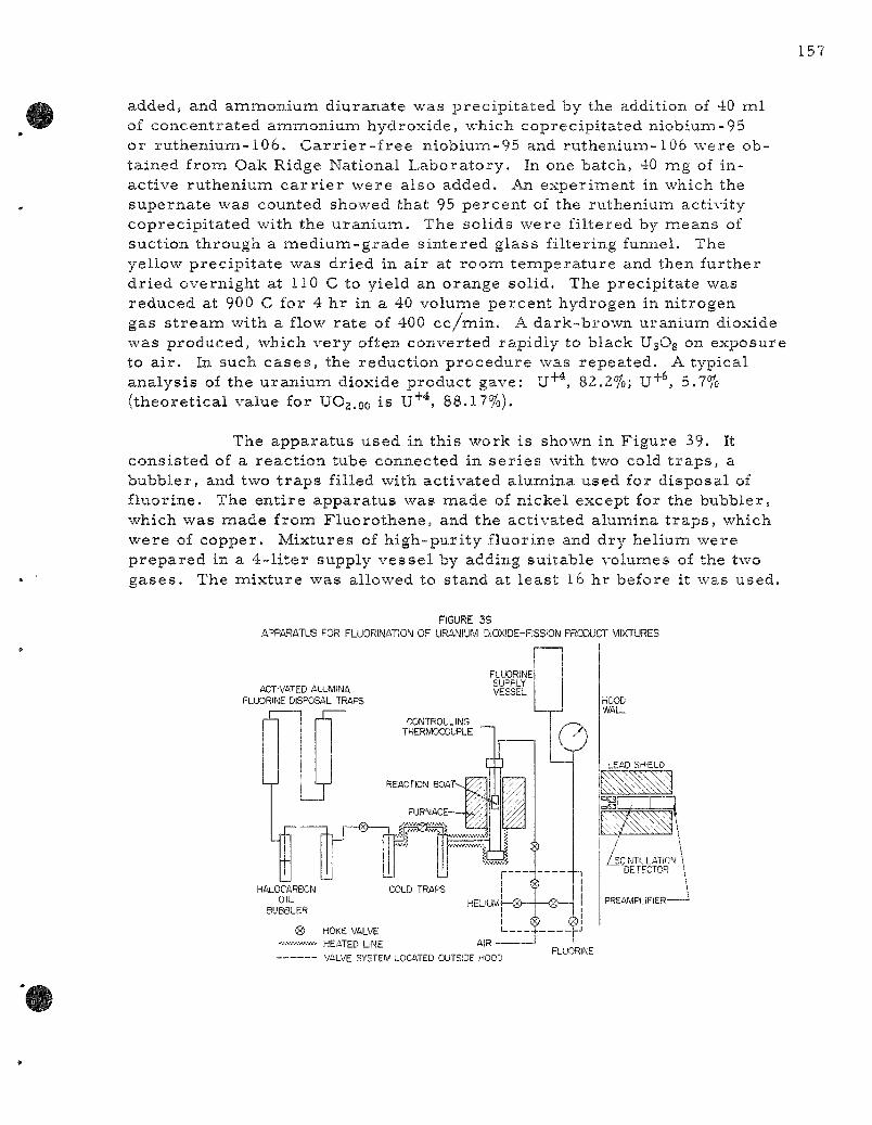
added, and ammonium diuranate was precipi ta ted by the addition of 40 ml of concentrated ammonium hydroxide, which coprecipitated niobium-95 or ruthenium-106. C a r r i e r - f r e e niobium-95 and ruthenium-106 were obtained from Oak Ridge National Laboratory , In one batch, 40 mg of inactive ruthenium c a r r i e r were also added. An experiment in which the supernate was counted showed that 95 percent of the ruthenium activity coprecipi tated with the uran ium. The solids were filtered by means of suction through a med ium-grade s in tered glass filtering funnel. The yellow precipi ta te was dried in air at room tempera tu re and then further dried overnight at 110 C to yield an orange solid. The precipi tate was reduced at 900 C for 4 hr in a 40 volume percent hydrogen in nitrogen gas s t r eam with a flow rate of 400 cc /min . A dark-brown uranium dioxide was produced, which very often converted rapidly to black UsOg on exposure to a i r . In such c a s e s , the reduction procedure was repeated, A typical analysis of the uranium dioxide product gave: U" , 82,2%; U"*" , 5,7% (theoret ical value for UOj.oo is U"*" , 88.17%).
The apparatus used in this work is shown in Figure 39. It consisted of a react ion tube connected in se r i e s with two cold t r aps , a bubbler, and two t r aps filled with activated alumina used for disposal of fluorine. The ent i re apparatus was made of nickel except for the bubbler, which was made from Fluorothene, and the activated alumina t r aps , which were of copper. Mixtures of high-puri ty fluorine and dry helium were p repared in a 4- l i te r supply vesse l by adding suitable volumes of the two gases . The mixture was allowed to stand at least 16 hr before it was used.
FIGURE 39
APPARATUS FOR FLUORINATION OF URANIUM DIOXIDE-FISSIOI PRODUCT MIXTURES
ACTIVATED ALUMINA FLUORINE DISPOSAL TRAPS
FLUORINE SUPPLY VESSEL
VALVE SYSTEM LOCATED OUTSiDE HOOD FLUORINE
The gas flow ra te was adjusted to approximately 50 c c / m i n by observing the bubbler , but the total amount used was computed from the p r e s s u r e drop in the supply tank. The excess fluorine in the off-gas was consumed by the activated alumina t r a p s .
Approximately one g ram of the uranium dioxide-ruthenium-106 or uranium dioxide-niobium-95 mixture was weighed in a nickel react ion boat for each exper iment . The sample was heated to the des i red t e m p e r a tu re in a flowing helium a tmosphere . The react ion boat and contents were weighed again after the exper iment . The amount of uranium remaining in the res idue was computed on the bas i s that the res idue was uranyl fluoride, as had been shown by X- r ay diffraction ana lys i s .
The amount of ruthenium or niobium volati l ized was determined by counting the gamma rays from the mixture in the react ion boat before and after each exper iment . A Harshaw Chemical Company Type 8S8/2 Integral Line scinti l lat ion detector consist ing of a tha l l ium-act ivated sodium iodide c ry s t a l (2-in. d iameter and 2 in. thick) direct ly attached to a photomultiplier tube was employed. The r e s t of the ins t rumentat ion consisted of a preampl i f ie r , a l inear amplif ier , a s ingle-channel pu lse -height analyzer , and a count - ra te m e t e r . The detector was shielded from background in the labora tory by a 2-2--in.-thick lead shield (Figure 39). The beam fromi the react ion boat was collimiated by two lead plugs with l-y-in. and 1-in. openings.
The usual p rocedure was to count the furnace tube, the empty boat, and finally the boat plus sample before each exper iment . After the experiiTient, the p rocedure was to count the boat plus res idue , the empty boat, and finally the furnace tube. It was n e c e s s a r y to follow this procedure to determine the quantity of activity left in the res idue , since ruthenium had the tendency to deposit on the react ion boat and on the furnace tube in the vicinity of the boat.
The exper imenta l r e su l t s a re summar ized in Table 50, Fluor inat ions of uranium dioxide-ruthenium-106 mix tures were c a r r i e d out at 400 and 500 C. It was original ly intended to follow the remova l of ruthenium activity from the mix ture as a function of t ime . However, after the f irs t experimient it became apparent that an appreciable amount of ruthenium activity which was fluorinated out of the mix ture remained on the boat or on the furnace tube in the vicinity of the boat . This may be due to t he rma l decomposit ion of ruthenium pentafluoride to nonvolatile products or to react ion of ruthenium pentafluoride with the nickel boat or furnace tube. After each ruthenium exper iment , the res idual activity was remioved by pass ing fluorine over the boat at 575 C for two h o u r s .

Table 50
FLUORINATION OF URANIUM DIOXIDE-RUTHENIUM-lOo AND URANIUM DIOXIDE-NIOBIUM-95 MIXTURES
Total P r e s s u r e : 1 a tm
Gas Mixture : F luor ine and helium as indicated
Activity Remaining
E x p e r i m e n t
1
7
3
4
5
68
, h
12
13
8
9
10^
U^^
Sample^
U-Rul
U-Ru2
U-Ru2
U-Ru2
U-Ru2
U-Ru2
U-Ru2
U-Ru3
U-Ru3
U-Nbl
U-Nbl
U-Nbl
U-Nbl
Sample Weight
(mg)
1076
852
1000
1255
1020
959
1001
961
1050
1012
1075
1038
980
Temp
(c)
400
400
400
500
500
500
500
500
500
300
400
500
500
Time (min)
30
30
30
20
30
30
30
20
22
75
20
30
30
Gas'=.d Flow Rate
(cc /min j
42
61
37
72
26
85
54
34
53
54
43
32
52
U Left in
Residue'-(%)
iZ
f
46
f
32
0
5
51
f
86
59
8
0
in Residue
(%)
e
f
15
f
19
0
1
58
t
5t>
8
4
1
on Boat (%)
e
27
16
1
23
6
30
7
17
on Furnace
Tube (%)
e
44
2b
0
35
1
15
4
11
U-Rul contains 1 mg inact ive Ru c a r r i e r / g UOj, U-Ru2 contains 65 //c R u ^ V g UO2, U-Ru3 contains 119 ac Ru*"^ and 2.5 mg inact ive Ru c a r r i e r / g UO,, U-Nbl contains 95 uc Nb 'Vg UO2
For convers ion to l inear flow: 1.96 c c / m m = 1 c m / m i n
""Calculated on the bas i s that res idue is UOjF^. Residue from Exper iment 1 analyzed by X - r a y diffraction and found to contain only UO^Fj (no UO2 detec ted) . Residue from Exper imen t 0 analyzed by X - r a y f luorescence and found to contain 0.2% U.
Gas composi t ion was 25 v / o F2 in all runs except 2 and 4 where it was 75 \ / o F2.
Not appl icable .
No res idue left. g
360 mg CaF2 and 230 mg ZrF4 added to s a m p l e .
600 mg CaFj and 460 mg ZrF4 added to s a m p l e .
With pure fluorine or 75 v/o fluorine-25 v/o helium, uranium dioxide fluorinated rapidly at 400 C, and therefore it was neces sa ry to dilute the gas to a 25 v /o fluorine-75 v/o heliumi mixture in order to c a r r y out exper iments of at least 20-min duration.
At both 400 and 500 C, the percent ruthenium fluorinated out of the uran ium dioxide-ruthenium mixture was equal to or g rea te r than the percent uranium volati l ized. The addition of inactive ruthenium c a r r i e r (Exper iments 12 and 13) did not i nc rease the rate of ruthenium removal from the sample .
A mixture of calcium fluoride and zirconium fluoride has been considered as a heat t r ans fe r medium in the fluidized-bed fluorination r e a c tor to be used for the Direct Fluor inat ion Volatility P r o c e s s . In severa l exper iments , some calcium fluoride and zirconium fluoride was added to the uranium dioxide-ruthenium mixture to see whether ruthenium activity would r emain in the iner t bed m a t e r i a l . No activity appeared to r emain in the bed and it was concluded that the re was no react ion between ruthenium and the calciumi f luor ide-z i rconium fluoride mix tu re .
The fluorination of uranium dioxide-niobium-95 mix tu res was studied in the t e inpera tu re range from 300 to 500 C. The same conclusions were reached as in the ruthenium study: F i r s t , niobium is readi ly f luor i nated out of uran ium dioxide and, second, the re is no react ion between niobium and the calciumi f luor ide-z i rconium fluoride bed m a t e r i a l . Niobium differed fromi ruthenium m that very little (<1%) of the niobium activity r e mained on the react ion boat or on the furnace tube in the vicinity of the boat.
5. Kinetics of the Reaction of Uranium Trioxide and Uranyl F luor ide with Sulfur Tetraf luor ide (C. Johnson, J. Stockbar)
The investigation of the s to ichiometry of the react ions of sulfur te t raf luor ide with uran ium tr ioxide and uranyl fluoride was summar i zed in ANL-6231, page 99. In the cu r ren t work, studies were made of the kinet ics and mechanism of the react ion between sulfur te t raf luor ide and uranium tr ioxide or uranyl f luoride.
A Sar tor ius Selecta thermobalance was used for the kinetic s tudies , A continuous r e c o r d of weight change v e r s u s timie was obtained on a Br i s to l Dynamaster recording potent iometer , A sample pan was suspended, by a nickel chain in the react ion chamber , from the s t i r r up of the ba lance . The react ion chamber was fabricated from a 2-in. nickel pipe and was heated by a res is tance-wound furnace. Hot convection cu r ren ts from the furnace were kept out of the balance by a baffle and g a s -blanket a r r angemen t . The Sar tor ius balance was protected from attack by cor ros ive gases by keeping a smal l posit ive p r e s s u r e of argon in the balance at all t i m e s ,
A gas-d is t r ibut ion manifold attached to the react ion chamber allowed choice of react ion gas , whose flow ra te was measu red with a ca l i bra ted t h e r m a l flow m e t e r . The gases passed through a prehea t furnace pr ior to entering the react ion furnace. The sample t e m p e r a t u r e was
m e a s u r e d by a ca l ibra ted thermocouple positioned di rect ly beneath the sample pan. A r eco rd of the sample t empera tu re ve r sus t ime was obtained on a miult ipoint-recording potent iometer . In addition, the t e m p e r a t u r e s of the p rehea t furnace and react ion furnace, and the output of the t h e r m a l flow me te r were monitored continuously.
In a typical exper iment , 400.0 mg of a -200 + 230 mesh f raction of e i ther uran ium tr ioxide or uranyl fluoride was placed on a ta red platinum pan and then lowered into the preheated react ion chamber . The weight of sample plus pan was checked on the Sar tor ius balance while t e m p e r a t u r e equilibriumi between gas and solid was being attained. During this per iod, argon was purged through the react ion chamber . When t e m p e r a t u r e equi l ibr ium had been achieved, the purge gas was shut off and sulfur te t raf luor ide was allowed to flow through the react ion chamber at a flow ra te of 150-200 c c / m i n .
Each exper iment was per formed under conditions of constant t e m p e r a t u r e and constant total flow of react ing gas . The gas manifold, connected to the reac t ion chamber , was equipped with a 14-li ter bal last tank which was charged with var ious mix tu res of ni t rogen and sulfur t e t r a fluoride. The gas miixture was then passed over the sample at atmiospheric p r e s s u r e at a constant flow r a t e .
If the reac t ion between a solid and a gas is one in which the active s i tes of the surface of a solid is sa tura ted with gas molecules , the r a t e of react ion should be zero o rde r with respec t to the p r e s s u r e of the reac tan t g a s . If this is not the case , the ra te will be fractional or higher o r d e r . At constant p r e s s u r e , the ra te of such a p roces s will be propor t ional to the a r e a of the interface at any t ime during the react ion, A sys tem of solid and gas may be idealized by assumiing the solid to cons is t of spher ica l pa r t i c l e s of uniform s ize with react ion s tar t ing at t = 0 on all p a r t i c l e s . In such a react ion the following rela t ionship can be deduced.^^
If the ini t ial m a s s of a solid pa r t i c l e . MQ ~ {JJT^TQP, where TQ is the init ial radius and p the bulk densi ty, the ra te of reduction in m a s s at a given t e m p e r a t u r e maybe assumed to be proport ional to the surface a r ea of the pa r t i c l e :
d M , ^ 2 /r-\ -jp- - k47rr'- , (5)
where r is the radius of the pa r t i c l e at t ime t and k is the constant for a given t e m p e r a t u r e and pa r t i a l p r e s s u r e of reactant gas .
'Anderson, J. S-, Bull . Soc. Chem,, 20, 781 (1953).
The fraction of react ion F that has taken place in t ime t is given by
M„ - M , r v'
^ = - 1 ^ =' -(rv) •
When this is subst i tuted in Equation (5) the lat ter becomes
- ^ = = -k47TroMl-F)^^^ . (6)
Integration of express ion (6) yields
(l-F)^/3 - 1 - k ' t , (7)
where k' = k/rQ.
When the quantity (l-F)^' '^ is plotted against t ime for a typical exper iment , as shown in F igure 40, the points lie on a s t ra ight l ine, in agreement with the equation, except that the re is somie deviation at the beginning and the end of the reac t ion . Exper imenta l conditions govern the deviations at the beginning of each exper iment . The react ion chamber is full of argon at the s t a r t of each exper iment ; the re fo re , it is believed that at least five minutes a re needed for d isp lacement of argon by sulfur te t raf luor ide to take p lace . Consequently, the r a t e s will be abnormal ly low at the beginning of each run.
Deviation fromi the expected kinet ics at the end of the reac t ion may be caused by a number of va r iab les , not the leas t of which is the smal l amount of sample remain ing . Chemisorpt ion of sulfur te t raf luor ide on the surface of the remiaining solid may contr ibute significantly to the final weight of the sample , thereby biasing the r e s u l t s .
The resu l t s of a typical reac t ion of sulfur te t raf luor ide with uran ium tr ioxide is shown in F igure 41 , The init ial i nc r ea se in weight at the s t a r t of the reac t ion is a t t r ibuted to the formation of uranyl f luoride. In s eve ra l exper iments in which the reac t ion was stopped before comple tion, it was noted that the m a t e r i a l remain ing in the pan was of two dist inct phase s : the top 60 percen t was pale yellow in color , the lower m a t e r i a l o range . Chemical analys is confirmed an uptake of f luorine. X - r a y diffraction analys is indicated the yellow m a t e r i a l to be anhydrous uranyl fluoride and the orange m a t e r i a l to be unreac ted uranium t r iox ide .
Thermobalance data on the react ion of sulfur te t raf luor ide with uranyl f luoride, also shown in F igure 41 , gave no indication of inc rease in weight p r i o r to formation of volatile uran ium hexafluoride. If an i n t e r media te such as UOF4 does form, it evidently r e a c t s too fast for the anticipated weight i n c r e a s e to be observed .
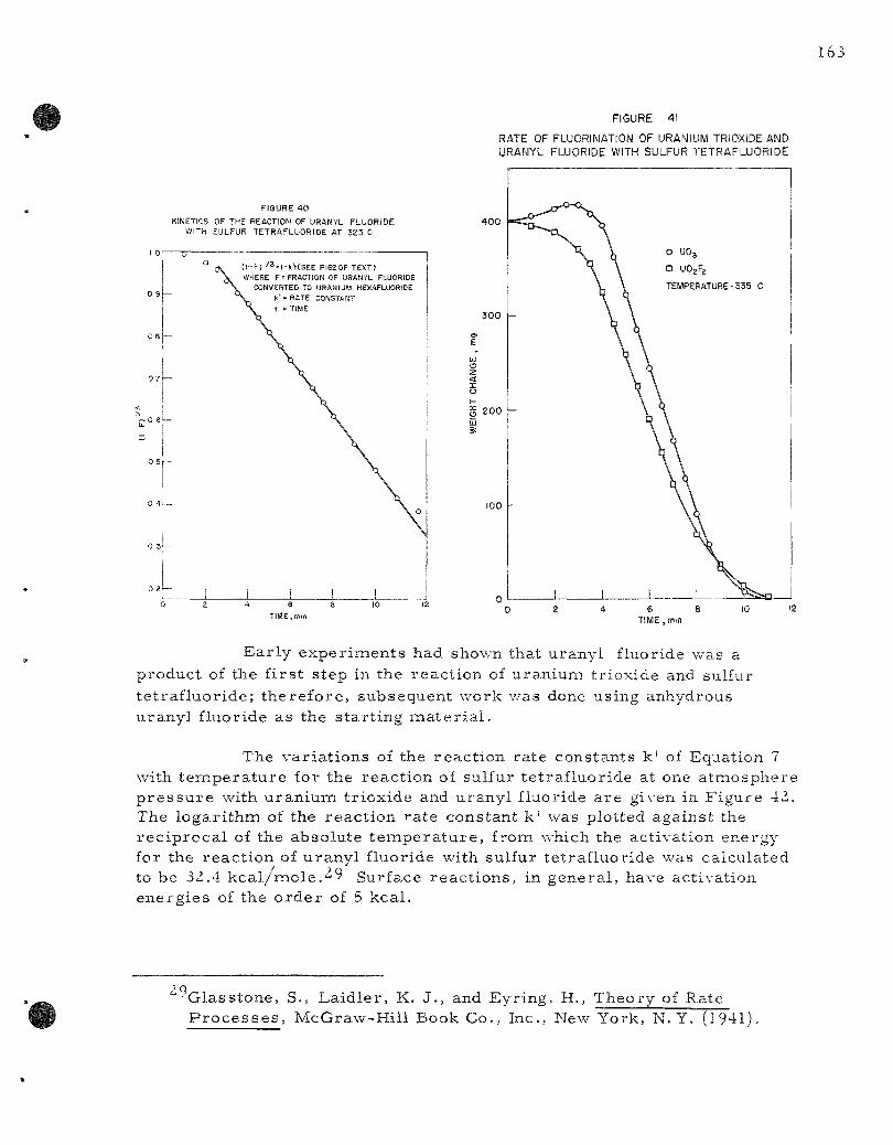
FIGURE 4i
RATE OF FLUORINATION OF URANIUM TRIOXIDE AND URANYL FLUORIDE WITH SULFUR TETRAFLUORIDE
FIGURE 40 KINETICS OF THE REACTION OF URANYL FLUORIDE
WITH SULFUR TETRAFLUORIDE AT 325 C
Ear ly exper iments had shown that uranyl fluoride was a product of the f irs t step in the react ion of uranium trioxide and sulfur te t raf luor ide; therefore , subsequent work was done using anhydrous uranyl fluoride as the s tar t ing m a t e r i a l .
The variat ions of the react ion rate constants k' of Equation 7 with t empera tu re for the react ion of sulfur tetraf luoride at one atmosphere p r e s s u r e with uraniumi trioxide and uranyl fluoride a re given in Figure 42. The logari thm of the react ion ra te constant k ' was plotted against the rec iproca l of the absolute t e m p e r a t u r e , from which the activation energy for the react ion of uranyl fluoride with sulfur tetrafluoride was calculated to be 32.4 k c a l / m o l c ^ ^ Surface react ions , in general , have activation energies of the o rde r of 5 kcal .
29 Glasstone, S., Laidler , K. J., and Eyring, H., Theory of Rate P r o c e s s e s , McGraw-Hill Book Co., Inc., New York, N. Y. (1941).
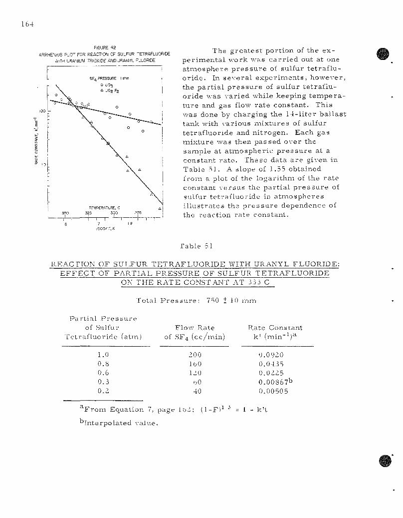
164
FIGURE 4 2
ARRHE^JsUS PLO"^ FOR REACTION OF SULFUR "ETRAFLUORIDE
AITH URANIUM TRIOXiDE AND URANYL FLUORIDE
lOOO/T,K
The g r e a t e s t p o r t i o n of t h e e x -pe r i imen ta l w o r k w a s c a r r i e d out at one a t m o s p h e r e p r e s s u r e of sulfur t e t r a f l u o r i d e . In s e v e r a l e x p e r i m e n t s , h o w e v e r , the p a r t i a l p r e s s u r e of su l fur t e t r a f l u o r i d e was v a r i e d whi le k e e p i n g t e m p e r a t u r e and gas flow r a t e c o n s t a n t . T h i s was done by c h a r g i n g the 1 4 - l i t e r b a l l a s t t ank with v a r i o u s m i x t u r e s of su l fur t e t r a f l u o r i d e and n i t r o g e n . E a c h gas m i x t u r e w a s then p a s s e d o v e r the sannple at a t m o s p h e r i c p r e s s u r e at a c o n s t a n t r a t e . T h e s e d a t a a r e g iven in T a b l e 5 1 . A s lope of 1.55 ob ta ined f rom a plot of the l o g a r i t h m of the r a t e c o n s t a n t v e r s u s the p a r t i a l p r e s s u r e of su l fur t e t r a f l u o r i d e in a t m o s p h e r e s i l l u s t r a t e s the p r e s s u r e d e p e n d e n c e of the r e a c t i o n r a t e c o n s t a n t .
Table 51
REACnON OF SULFUR TETRAFLUORIDE WITH URANYL FLUORIDE: EFFECT OF PARTIAL PRESSURE OF SULFUR TETRAFLUORIDE
ON THE RATE CONSTANT AT i33 C
Tota l P r e s s L i r e : 750 + 1 0 m m
P a r t i a l P r e s s u r e of .Sulfur
T e t r a f l u o r i d e
1.0
0 . 8 0 .6 0 . 3 0 .2
(a tm) F low Rate
of SF 4 ( c c / m i n )
200 IbO 120
oO 40
Rate Cons t an t k ' (min -^ )^
0.0920 0.0435 0.0225 0.00867b 0.0050 5
^ F r o m Equa t i on 7, page IbZ: (1 -F l^ ^
" I n t e r p o l a t e d v a l u e .
1 - k ' t
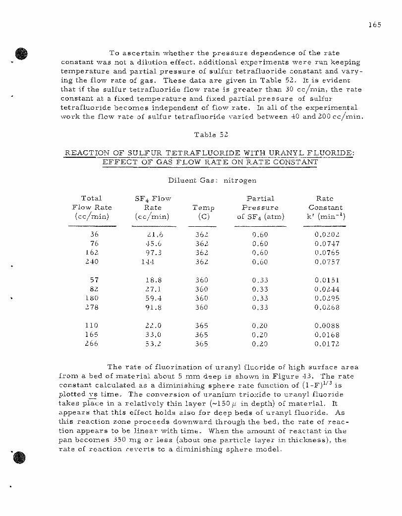
To a sce r t a in whether the p r e s s u r e dependence of the ra te constant was not a dilution effect, additional exper iments were run keeping t empe ra tu r e and par t i a l p r e s s u r e of sulfur te t raf luor ide constant and varying the flow ra te of gas . These data are given in Table 52. It is evident that if the sulfur te t raf luor ide flow rate is g rea te r than 30 cc /min , the ra te constant at a fixed t e m p e r a t u r e and fixed par t ia l p r e s s u r e of sulfur te t raf luor ide becomies independent of flow ra t e . In all of the exper imenta l work the flow ra te of sulfur te t raf luor ide var ied between 40 and 200 cc/iTiin.
Table 52
REACTION OF SULFUR TETRAFLUORIDE WITH URANYL FLUORIDE: EFFECT OF GAS FLOW RATE ON RATE CONSTANT
Diluent Gas : ni t rogen
Total Flow Rate (cc/min)
36 76
162 240
57 82
180 278
no 165 266
SF4 Flow-Rate
(cc /min)
21.6 45.6 97.3
144
18.8 27.1 59.4 91.8
22.0 33.0 53.2
Temp (c)
362 362 362 362
360 360 360 360
365 365 365
Par t i a l P r e s s u r e
of SF4 (atm)
0,60 0.60 0.60 0.60
0.33 0.33 0.33 0.33
0,20 0,20 0.20
Rate Constant k ' (min-^)
0,0202 0.0747 0.0765 0.0757
0,0151 0,0244 0,0295 0,0268
0.0088 0.0168 0.0172
The ra t e of f luorination of uranyl fluoride of high surface a r ea from a bed of m a t e r i a l about 5 mm deep is shown in F igure 43. The ra t e constant calculated as a diminishing sphere r a t e function of ( l -F)^ ' ' ' is plotted vs t i m e . The convers ion of uran ium tr ioxide to uranyl fluoride takes place in a re la t ive ly thin layer (~150/i in depth) of m a t e r i a l . It appears that this effect holds also for deep beds of uranyl f luoride. As this reac t ion zone p roceeds downward through the bed, the ra te of r e a c tion appears to be l inear with tiiTie. When the amount of reac tan t in the pan becomes 350 mg or l e s s (about one par t i c le layer in th ickness) , the ra te of reac t ion r e v e r t s to a diminishing sphere model .
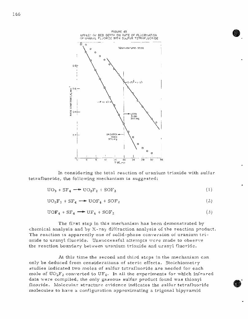
FIGURE 43 EFFECT OF BED DEPTH ON RATE OF FLUORirjATION OF URANYL FLUORIDE WITH SULFUR TETRAFLUORIDE
In c o n s i d e r i n g the t o t a l r e a c t i o n of u r a n i u m t r i o x i d e wi th sul fur t e t r a f l u o r i d e , the fol lowing m e c h a n i s m is s u g g e s t e d ;
UO3 + SF4 — • UO2F2 + SOF2
UO2F2 + SF4 — • UOF4 + SOF2
UOF4 + SF4 — • UFe + SOF2
(1)
(3)
The f i r s t s t e p in t h i s m e c h a n i s m h a s b e e n d e m o n s t r a t e d by c h e m i c a l a n a l y s i s and by X - r a y d i f f r ac t ion a n a l y s i s of the r e a c t i o n p r o d u c t . The r e a c t i o n i s a p p a r e n t l y one of s o l i d - p h a s e c o n v e r s i o n of u r a n i u m t r i oxide to u r a n y l f l u o r i d e . U n s u c c e s s f u l a t t e m p t s w e r e m a d e to o b s e r v e the r e a c t i o n b o u n d a r y be tween u r a n i u m t r i o x i d e and u r a n y l f l u o r i d e .
At t h i s t i m e the s e c o n d and t h i r d s t e p s in the m e c h a n i s m can only be d e d u c e d f r o m c o n s i d e r a t i o n s of s t e r i c e f f ec t s . S t o i c h i o m e t r y s t u d i e s i n d i c a t e d two m o l e s of su l fur t e t r a f l u o r i d e a r e n e e d e d for e a c h m o l e of UO2F2 c o n v e r t e d to UF^. In a l l the e x p e r i m e n t s for which i n f r a r e d da ta w e r e c o m p i l e d , the only g a s e o u s sulfur p r o d u c t found w a s th iony l f l uo r ide . M o l e c u l a r s t r u c t u r e e v i d e n c e i n d i c a t e s the su l fur t e t r a f l u o r i d e m o l e c u l e s to have a con f igu ra t i on a p p r o x i m a t i n g a t r i g o n a l b i p y r a m i d
with one of the th ree equator ia l posit ions unoccupied (point group CZ-Y)- The molecular configuration of thionyl fluoride is thought to be ei ther pyramii-dal (Cs) or t r igonal by pyrainid (C2v) in na tu re . Assumiing that the Czv s t ruc tu re predomina tes in both reac tan t and product, it is eas i ly seen that each sulfur tetrafluioride molecule contr ibutes only two of its fluorines to the solid. This further suggests that in o rde r for Steps (2j and (3) of the react ion miechanismi to take place in a single s tep, two molecules of sulfur te t raf luor ide mus t s imultaneously res ide on an active site on the surface of the uranyl fluoride for fluorine oxygen exchange to take place. Because b imolecular gas - so l id react ions of this type a re ext remely r a r e , some credence is given to the exis tence of UOF4 as a react ion in te rmedia te . Attempts at the p repara t ion and isolat ion of UOF4 have up to now been unsuccessful . However, the formation of UOF4 as a react ion in termedia te can not be completely ruled out.
B. Engineer ing-sca le Investigations of Fluor ide Volatility P r o c e s s e s (A. A. Jonke)
1. Direct Fluor inat ion of Uranium Dioxide Fuels
a. Fluor inat ion of Uranium Dioxide Pel le ts ( j . Gabor, J. Gates , R. Kinzler , A. Rashinskas , J, Wehrle, and W. J, Mechami)
Pilot p l an t - sca le work has been d i rec ted toward the cont r o l of the highly exothermic react ion between fluorine and uranium dioxide. Prev ious work, summar i zed in ANL-6287 (pages 147 to 152), showed the effects of p r o c e s s var iab les ( t empera tu re , fluorine concentrat ion, bed height) on fluorination r a t e s and fluorine efficiency. It was evident from the data obtained that the fluorination proceeded as a two-s tep miechanismi, with uranyl fluoride fines as an in te rmedia te product, and that pel le ts with different h i s to r i e s showed different chemical react iv i ty . Subsequent work has been l imited to pel le ts of the hydrogen-f i red type (sintered for 4 hr at ~1700 C in a hydrogen a tmosphere ) , which have shown lower react ivi ty than pel le ts fired in an iner t a tmosphere and a r e believed to be r e p r e s e n tat ive of r eac to r fuel m a t e r i a l .
Complete Fluorinat ion of Iner t - f i red Pel le ts
A run was made (UOF-25) to invest igate the production capacity of the a i r -coo led r eac to r while fluorinating uraniumi dioxide pe l le ts at 500 C and while using as high a fluorine concentrat ion as poss ib le . This was the las t run made with pel le ts of the ine r t - f i r ed type. In o rde r to use available pellet m a t e r i a l , broken pieces of about 4- in . s ize were uti l ized. The pellet bed was 6 in, deep. Magnesium fluoride was used as an iner t fluid bed.
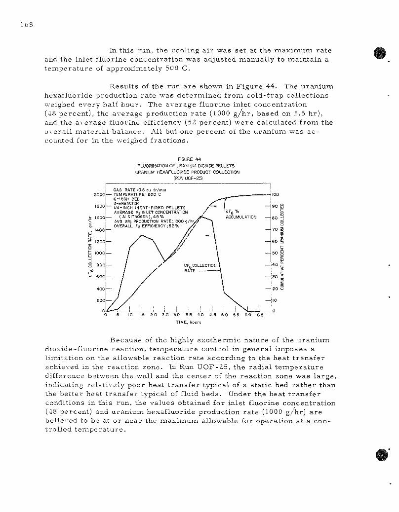
In t h i s r u n , the coo l ing a i r w a s s e t a t the m a x i m u m r a t e and the in le t f luor ine c o n c e n t r a t i o n w a s ad jus t ed m a n u a l l y to m a i n t a i n a t e m p e r a t u r e of a p p r o x i m a t e l y 500 C.
R e s u l t s of the run a r e shown in F i g u r e 44 . The u r a n i u m hexa f luo r ide p r o d u c t i o n r a t e w a s d e t e r m i n e d f r o m c o l d - t r a p c o l l e c t i o n s weighed e v e r y half h o u r . The a v e r a g e f luor ine in le t c o n c e n t r a t i o n (48 p e r c e n t ) , the a v e r a g e p r o d u c t i o n r a t e (1000 g / h r , b a s e d on 5.5 h r ) , and the a v e r a g e f luo r ine ef f ic iency (52 p e r c e n t ) w e r e c a l c u l a t e d f r o m the o v e r a l l nna t e r i a l b a l a n c e . All but one p e r c e n t of the u r a n i u m w a s a c counted for in the we ighed f r a c t i o n s .
FIGURE 44 FLUORINATION OF URANIUM DIOXIDE PELLETS
URANIUM HEXAFLUORIDE PRODUCT COLLECTION (RUN UOF-25)
2 0 2.5 3.0 3 5 4.0 4.5 5 0 5 5 6 0
TIME, hours
85
B e c a u s e of the h igh ly e x o t h e r m i c n a t u r e of the u r a n i u m d i o x i d e - f l u o r i n e r e a c t i o n , t e m p e r a t u r e c o n t r o l in g e n e r a l i m p o s e s a l i m i t a t i o n on the a l lov/able r e a c t i o n r a t e a c c o r d i n g to the h e a t t r a n s f e r a c h i e v e d in the r e a c t i o n z o n e . In Run U O F - 2 5 , t h e r a d i a l t e m p e r a t u r e d i f f e r ence b e t w e e n the wal l and the c e n t e r of the r e a c t i o n zone w a s l a r g e , i nd i ca t ing r e l a t i v e l y poor hea t t r a n s f e r t y p i c a l of a s t a t i c bed r a t h e r t han the b e t t e r hea t t r a n s f e r t y p i c a l of fluid b e d s . Under the hea t t r a n s f e r cond i t ions in th i s run , the v a l u e s ob ta ined for in le t f luor ine c o n c e n t r a t i o n (48 p e r c e n t ) and u r a n i u m h e x a f l u o r i d e p r o d u c t i o n r a t e (1000 g / h r ) a r e b e l i e v e d to be at o r n e a r the m a x i m u m a l lowab le for o p e r a t i o n a t a c o n t r o l l e d t e m p e r a t u r e .

Modification of the Control System to Maximize the Production Rate
Ea r l i e r means of autoinatic t empera ture control utilized variat ion of the flow rate of coolant a i r passing over the external fins on the r eac to r . Although this sys tem operated usefully under most conditions, it was evident in these tes t s that the t empera tu re response of the react ion system under coolant regulation was much slower than under fluorine regulat ion. Also, to achieve maximum react ion ra te , the coolant flow would have to be kept at or near its maximum value. Therefore , the cont ro l system was modified so that fluorine regulation could be used to provide t empera tu re control while operating at miaximum prac t ica l fluorination r a t e s .
Two tes t runs (UOF-26 and 28) were made in the course of setting up this new control sys tem. The final control system is shown in F igure 45. Fluorine from an 18-cu ft s torage tank is thrott led to provide a constant p r e s s u r e in a 1.5-cu ft surge tank. Another control valve regula tes the fluorine flow froin the surge tank to the reac tor ac cording to the reac tor t empera tu re control ler setting.
FIGURE 45
FLUO" NE FLOW CO'-jTROL SYSTEM FOR -^EyPERATuRC C O N T P O L .M
URANUM DIOXIDE PELLET F_UORINATIO\S
H, CO^!S'A^,•T PRESSURE SJ=PLY
SURGE TANK
PRESSURE
' CONTROLLER TEMPERAT„RE
CONTROL ER
F^U DIZAT C\ CCLLSV'tg
.J
In one of these tes t runs (UOF-28j, the pellet charge consisted of par t ia l ly reac ted pellets (of the iner t - f i red type) together with a substantial amount of in termediate uranium fluoride fines in the magnesium fluoride bed. This bed caked at 500 C shortly after fluorine was f irs t introduced, and the run was terminated because of high p r e s sure drop. It is believed that some of the uranium fines in the fluid bed below the pe l le t -suppor t plate reacted to produce uranium hexafluoride, which in turn reacted with the uranium dioxide pellets higher in the bed. Examination of the caked bed showed pel lets cemented together with black, green, and yel low-green ma te r i a l . The black and dark green m a t e r i a l s were identified as UF4 or U4FX7, and the yellow and green
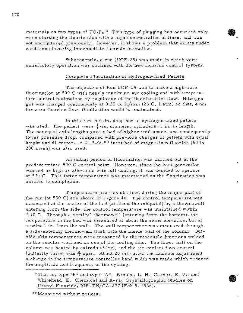
mate r i a l s as two types of UO2F2.* This type of plugging has occur red only when s tar t ing the fluorination with a high concentrat ion of fines, and was not encountered previously . However, it shows a problem that exists under conditions favoring in te rmedia te fluoride formation.
Subsequently, a run (UOF-29) was made in which very sat isfactory operat ion was obtained with the new fluorine control sys tem.
Complete Fluor inat ion of Hydrogen-fired Pe l le t s
The objective of Run UOF-29 was to make a h igh- ra te fluorination at 500 C with near ly maximum air cooling and with t e m p e r a ture control maintained by regulation of the fluorine inlet flow. Nitrogen gas was charged continuously at 0.25 cu ft/min (25 C, 1 atm) so that, even for zero fluorine flow, fluidization would be maintained.
In this run, a 6-in, deep bed of hydrogen-f i red pel lets was used. The pel le ts were •-|--in. d iameter cyl inders , 1 in. in length. The nonequal axis lengths gave a bed of higher void space, and consequently lower p r e s s u r e drop, compared with previous charges of pel le ts with equal height and d i ame te r . A 24.5-in.** iner t bed of magnesiumi fluoride (60 to 200 mesh) was also used.
An initial per iod of fluorination was c a r r i e d out at the p rede te rmined 500 C control point. However, since the heat generat ion was not as high as allowable with full cooling, it was decided to operate at 530 C. This la t te r t e m p e r a t u r e was maintained as the fluorination was ca r r i ed to completion.
Tempera tu re profiles obtained during the major par t of the run (at 530 C) a re shown in F igure 46. The control t e m p e r a t u r e was m e a s u r e d at the center of the bed (at about the midpoint) by a thermowel l entering from the side; the control t empe ra tu r e was maintained within t 10 C. Through a ve r t i ca l thermowel l (entering fromi the bottom), the t e m p e r a t u r e in the bed was measu red at about the same elevation, but at a point 1 in, from the wall . The wall t e m p e r a t u r e was m e a s u r e d through a s ide-en ter ing thermowel l flush with the inside wall of the column. Outside skin t e m p e r a t u r e s were measu red by thermocouple junctions welded on the reac tor wall and on one of the cooling fins. The lower half on the column was heated by ca l rods (3 kw), and the air coolant flow control (butterfly valve) was -|- open. About 20 min after the fluorine adjustment a change in the t e m p e r a t u r e control ler band width was made which reduced the amplitude and frequency of the cycling,
*That i s , type "h" and type "A". Brooks , L. H., Garner , E. V., and Whitehead, E., Chemical and X- ray Crys ta l lographic Studies on Uranyl F luor ide , IGR-TN/CA-277 (Feb 9, 1956).
**Measured without pe l le t s .
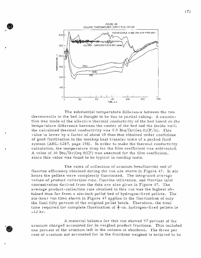
FIGURE 46
COLUMN TEMPERATURES DURING RUN UOF-29
600
500
4 0 0
300
- h
i : \
-
A A A ^ THERMOCOUPLE IN BED ONE INCH FROM WALL
CONTROL THERVOCOUPLE IN BFO (center) \ / \ . , ^ ^ ^ '-'
V. WALL ^,,^ / / V
^—-—^^^rz^^^^^^Z^^ 7
1 1 , 1 1 1 1 1 1 1 ! I l l
60 180 TIME, mm
240 360
The s u b s t a n t i a l t e m p e r a t u r e d i f f e rence be tween the two t h e r m o w e l l s in the bed i s thought to be due to p a r t i a l cak ing . A c a l c u l a t i on was m a d e of the effect ive t h e r m a l conduc t iv i ty of the bed b a s e d on the t e m p e r a t u r e d i f f e r ence b e t w e e n the c e n t e r of the bed and the ins ide wal l ; the c a l c u l a t e d t h e r m a l conduc t iv i ty was 0.5 B t u / ( h r j ( s q ft)(F/ 'f t) . Th i s va lue is l ower by a f ac to r of about 10 than that ob ta ined unde r condi t ions of good f lu id iza t ion in the m o c k u p h e a t t r a n s f e r t e s t s of a packed fluid s y s t e m (ANL-6287 , page 158). In o r d e r to m a k e the t h e r m a l conduc t iv i ty c a l c u l a t i o n , the t e m p e r a t u r e d r o p for the f i lm coeff ic ient was s u b t r a c t e d . A va lue of 30 B t u / ( h r ) ( s q ft)(F) w a s a s s u m e d for the film coeff ic ient , s i n c e t h i s va lue w a s found to be t y p i c a l in m o c k u p t e s t s .
The r a t e s of c o l l e c t i o n of u r a n i u m hexa f luo r ide and of f luo r ine ef f ic iency ob t a ined d u r i n g the r u n a r e shown in F i g u r e 47 . In s ix h o u r s t he p e l l e t s w e r e c o m p l e t e l y f l uo r ina t ed . The i n t e g r a t e d a v e r a g e v a l u e s of p r o d u c t c o l l e c t i o n r a t e , f l uo r ine u t i l i z a t i on , and f luor ine in le t c o n c e n t r a t i o n d e r i v e d f r o m the da t a a r e a l so given in F i g u r e 47. The a v e r a g e p r o d u c t - c o l l e c t i o n r a t e ob ta ined in th i s run was the h ighes t o b t a i n e d thus f a r f r o m a s i x - i n c h pe l l e t bed of h y d r o g e n - f i r e d p e l l e t s . The s i x - h o u r run t i m e shown in F i g u r e 47 a p p l i e s to the f luor ina t ion of only the f inal fifty p e r c e n t of the o r i g i n a l p e l l e t b a t c h . T h e r e f o r e , the t o t a l t i m e r e q u i r e d for c o m p l e t e f l uo r ina t ion of y - i n . h y d r o g e n - f i r e d p e l l e t s i s - 1 2 h r .
A m a t e r i a l b a l a n c e for t h i s run showed 97 p e r c e n t of the u r a n i u m c h a r g e d a c c o u n t e d for in we ighed p r o d u c t f r a c t i o n s . Th i s inc luded one p e r c e n t of the uraniuirs left in the c o l u m n at shu tdown. The t h r e e pe r cen t of u r a n i u m not accoun ted for in the f r a c t i o n s weighed i s be l i eved to be
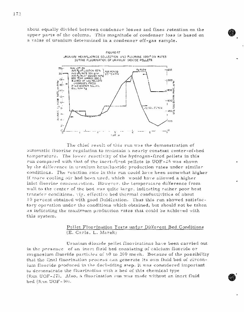
about equa l ly d iv ided b e t w e e n c o n d e n s e r l o s s e s and f ines r e t e n t i o n on the u p p e r p a r t s of the c o l u m n . T h i s m a g n i t u d e of c o n d e n s e r l o s s i s b a s e d on a va lue of u r a n i u m d e t e r m i n e d in a c o n d e n s e r of f -gas s a m p l e .
FiGURE47
URANIUM HEXAFLUORIDE COLLECTION AND FLUORINE ADOnON RATES DURING FLUORINATION OF URANIUM DIOXIDE PELLETS
RUN bO=-29 AVG F2 UT UZATION 55% ] ,g^ pg^.g^ AVG UFg RATE 550 g/P.r f 0 3 "0 4 7hr AVG Fg INLET CO^CEN a2%J BED TE^4P APPROX. 530 C S-irs BED OF 1,02 PELLETS
(HYDROGEIi PIRED) 3-n.DlAM£TER COLUM\ 15 Ou ft/hr Ng
The chief r e s u l t of t h i s run was the d e m o n s t r a t i o n of a u t o m a t i c f luo r ine r e g u l a t i o n to m a i n t a i n a n e a r l y c o n s t a n t c e n t e r - o f - b e d t e m p e r a t u r e . The lower r e a c t i v i t y of the h y d r o g e n - f i r e d p e l l e t s in t h i s run c o m p a r e d with tha t of the i n e r t - f i r e d p e l l e t s in U O F - 2 5 was shown by i-he d i f f e r e n c e in u remium h e x a f l u o r i d e p r o d u c t i o n r a t e s u n d e r s i m i l a r c o n d i t i o n s . The r e a c t i o n rjite in th i s run could have b e e n s o m e w h a t h i g h e r if m o r e cool ing a i r had b e e n u s e d , which would h a v e a l lowed a h i g h e r in le t f luor ine c o n c e n t r a t i o n . H o w e v e r , the t e m p e r a , t u r e d i f f e r e n c e f r o m wal l to the c e n t e r of the bed was qui te l a r g e , i nd i ca t ing r a t h e r poo r h e a t t r a n s f e r c o n d i t i o n s , v iz , ef fec t ive bed t h e r m a l c o n d u c t i v i t i e s of about 10 p e r c e n t ob ta ined with good f lu id iza t ion . Thus t h i s run showed s a t i s f a c t o r y o p e r a t i o n u n d e r the cond i t i ons which ob t a ined , but should not be t a k e n as i nd ica t ing the m a x i m u m p r o d u c t i o n r a t e s tha t could be a c h i e v e d wi th t h i s systeiTi.
P e l l e t F l u o r i n a t i o n T e s t s u n d e r Di f fe ren t Bed Condi t ions (E. C a r l s , L. M a r e k ;
U r a n i u m d iox ide p e l l e t f l u o r i n a t i o n s have been c a r r i e d out in the p r e s e n c e of an i n e r t fluid bed c o n s i s t i n g of c a l c i u m f luo r ide o r m a g n e s i u m f luo r ide p a r t i c l e s of bO to 20 0 m e s h . B e c a u s e of the p o s s i b i l i t y tliat t he final f l uo r ina t i on p r o c e s s can g e n e r a t e i t s own fluid bed of z i r c o n ium f luor ide p r o d u c e d in the dec l add ing s t e p , it was c o n s i d e r e d i m p o r t a n t to d e m o n s t r a t e the f luo r ina t ion with a bed of t h i s c h e m i c a l type (Run U O F - 2 7 ) . A l s o , a f luo r ina t ion run w a s m a d e wi thou t an i n e r t fluid bed (Run U O F - 3 0 ) .

The o b j e c t i v e of Run U O F - 2 7 w a s to d e t e r m i n e w h e t h e r any s p e c i a l d i f f i cu l t i e s a p p e a r e d in the c a s e in which p u r e z i r c o n i u m t e t r a f l uo r ide w a s u s e d a s the i n e r t f luid bed . A t w o - i n c h - d i a m e t e r c o l u m n w a s c h a r g e d wi th 834 gm of u r a n i u m d iox ide p e l l e t s of the i n e r t - f i r e d type (in a t h r e e - i n c h bed depth) and 1467 g m of z i r c o n i u m t e t r a f l u o r i d e . The s c r e e n a n a l y s i s and o t h e r p e r t i n e n t d a t a for t h i s m a t e r i a l a r e g iven in T a b l e 53 .
T a b l e 53
S C R E E N ANALYSIS O F ZIRCONIUM F L U O R I D E F L U I D B E D M A T E R I A L IN RUN U O F - 2 7
S o u r c e : A D F P r o c e s s Run U Z r - 1 0 4 (See A N L - 6 1 8 3 , page 113) d r i e r p r o d u c t Z C P - 7 4 H F (See A N L - 6 1 4 5 , page 115) (3 h r at 600 C)
S c r e e n A n a l y s i s S c r e e n A n a l y s i s b e f o r e F l u o r i n a t i o n a f t e r F l u o r i n a t i o n
S c r e e n S ize
+ 40
+ 60
+100
+200
+325
+ 20
- 20
- 40
- 60
-100
-200
- 3 2 5
Wt %
0.2
3.0
13.1
41.1
42,6
0
0
100.0
S c r e e n S ize
+ 40
+ 60
+100
+200
+325
+ 20
- 20
- 40
- 60
-100
-200
-325
Wt %
-
3.2.
15,1
41.9
37.1
2.7
0.1
100.1
F l u o r i n e w a s a d d e d c a u t i o u s l y at 315 C to p r e v e n t any t e m p e r a t u r e e x c u r s i o n s w h i c h m i g h t h a r m the b e d and which m i g h t c o n fuse the r e s u l t s c o n c e r n i n g the f e a s i b i l i t y of z i r c o n i u m t e t r a f l u o r i d e a s an i n e r t bed m i a t e r i a l . F o r t h e f i r s t 40 m i n the f l u o r i n e c o n c e n t r a t i o n w a s g r a d u a l l y i n c r e a s e d to 20 p e r c e n t and t h e bed t e m p e r a t u r e to 500 C. T h e c o l u m n w a s t h e n o p e r a t e d for abou t one h o u r at 500 C with 20 p e r c e n t f l u o r i n e . Af te r s a t i s f a c t o r y o p e r a t i o n u n d e r t h e s e c o n d i t i o n s , the f l u o r i n e c o n c e n t r a t i o n w a s i n c r e a s e d to 40 p e r c e n t . The c o l u m n w a s t h e n o p e r a t e d wi th the i n c r e a s e d f l u o r i n e for abou t an h o u r . T a b l e 54 d e s c r i b e s the c o n d i t i o n s of the r u n and g i v e s u r a n i u m h e x a f l u o r i d e c o l l e c t i o n r a t e s .

Table 54
URANIUM HEXAFLUORIDE COLLECTION RATES DURING URANIUM DIOXIDE FLUORINATION RUN UOF-Z7
Two- inch-d iamete r Reactor Total Gas Rate 0.5 f t / sec Three - inch Bed of l / 2 - i n . hydrogen-f i red pellets (834 g) Thi r teen- inch Bed of ZrF4 (1467 g)
Average UFg Total Fj Cumulative Collection
Inlet F2 F^ Efficiency UF5 Rate Ji Time Temp Cone Utilization^ to F o r m UFj Collected in Perioi (hr) (C) (To) (%) {%) (g) (g/hr)
0 - 0 . 7 3 1 5 - 5 0 0 0 -20 - - 35 -
0 . 7 - 1 . 8 500 22 .4 21 23 125 82'^
1 .8-2 .8 500 40 .0 12 16 260 135^^
a F2 in - F2 out F , u t i l i z a t i o n = =; a s d e t e r m i n e d by g a s a n a l y s i s .
b ... F2 in UF5 p r o d u c t F j e f f i c i ency to f o r m UF5 = --;—: a s d e t e r m i n e d by w e i g h t of
1 •> i n
product col lected.
It done in a 3-in. column the ra te in this period would be about 180 g / h r .
If done in a 3-in. column the rate in this period would be about 300 g / h r .
The z i r c o n i u m t e t r a f l u o r i d e w a s s c r e e n e d a f te r the run . Tab le 5 3 shows the s c r e e n i i n a l y s i s . Ev iden t ly no s ign i f i can t d e g r a d a t i o n o r s i n t e r i n g o c c u r r e d . Only 13 gm of f ines was c o l l e c t e d in the f i l t e r s . F r o m the s t andpo in t of c h e m i c a l and m e c h a n i c a l s t ab i l i t y it a p p e a r s t ha t the z i r c o n i u m te t ra . f Iuor ide would be a s a t i s f a c t o r y i n e r t bed m a t e r i a l . The f luo r ina t ion r a t e s in Run UOF-Z7 a r e c l o s e to t h o s e ob t a ined p r e v i ous ly u n d e r s i m i l a r cond i t i ons (UOF-247\ , B , s e e ANL-6Z87 , page 148).
The ob jec t ive of Run U O F - 3 0 w a s to d e t e r m i n e the ex ten t and m a g n i t u d e of c o n t r o l p r o b l e m s tha t migh t deve lop for the c a s e in which no i n e r t fluid bed i s u s e d in the p e l l e t f l u o r i n a t i o n s . T h i s i n f o r m a t ion is of i n t e r e s t (1) for c o m p a r i s o n wi th the fluid bed c a s e and (Z) as p r e l i m i n a r y f e a s i b i l i t y e v a l u a t i o n for p r o c e s s i n g cond i t i ons in wh ich t h e i n e r t fluid bed a p p r o a c h h a s c e r t a i n d i s a d v a n t a g e s ; na rne ly , cak ing p r o b -l e ins o r e x c e s s i v e r e t e n t i o n of f i s s i o n a b l e m a t e r i a l .
In t h i s run , the t h r e e - i n c h - d i a m e t e r a i r - c o o l e d ref ic tor was u s e d t o g e t h e r wi th the f luo r ine r e g u l a t o r s y s t e m d e s c r i b e d above for Run U O F - Z 9 . A c o n s t a n t n i t r o g e n flow w a s a l s o u s e d a s b e f o r e .
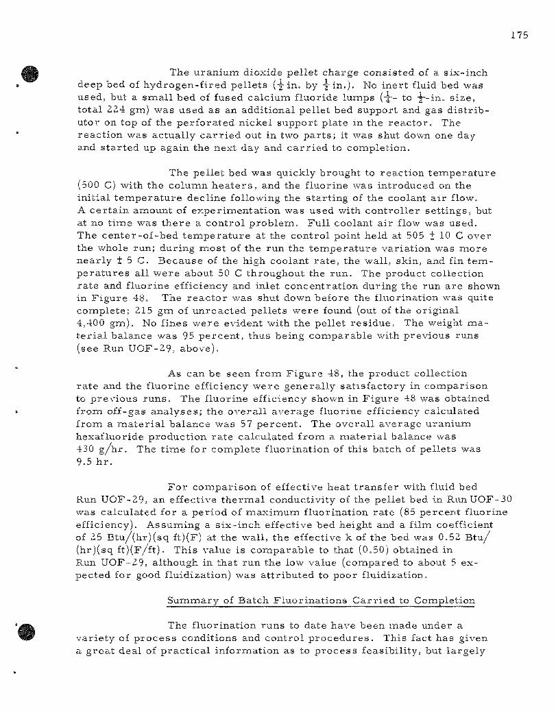
175
The uran ium dioxide pel let charge consis ted of a s ix-inch deep bed of hydrogen-f i red pel le ts (-|-in. by y i n . ) . No iner t fluid bed was used, but a sma l l bed of fused calcium fluoride lumps (-j-- to •|--in. s ize, total 224 gm) was used as an additional pellet bed support and gas d i s t r i b utor on top of the per fora ted nickel support plate in the r eac to r . The react ion was actually c a r r i e d out in two p a r t s ; it was shut down one day and s ta r ted up again the next day and c a r r i e d to completion.
The pel le t bed was quickly brought to react ion t empe ra tu r e (500 C) with the column h e a t e r s , and the fluorine was introduced on the init ial t e m p e r a t u r e decline following the s tar t ing of the coolant a i r flow. A ce r ta in amiount of exper imenta t ion was used with control ler se t t ings , but at no t ime was t he re a control p rob lem. Ful l coolant air flow was used. The cen te r -of -bed t e m p e r a t u r e at the control point held at 505 + 10 C over the whole run; during mos t of the run the temiperature var iat ion was more near ly + 5 C. Because of the high coolant r a t e , the wall, skin, and fin t e m p e r a t u r e s all were about 50 C throughout the run. The product collection ra te and fluorine efficiency and inlet concentrat ion during the run are shown in F igure 48. The r eac to r was shut down before the fluorination was quite complete ; 215 gm of unreac ted pel le ts were found (out of the original 4,400 gm). No fines were evident with the pellet res idue . The weight m a teria.! balance was 95 percen t , thus being comparable with previous runs (see Run UOF-29, above).
As can be seen from F igure 48, the product collection ra te and the fluorine efficiency were general ly sa t is factory in compar ison to previous r u n s . The fluorine efficiency shown in F igure 48 was obtained from off-gas ana lyses ; the overa l l average fluorine efficiency calculated from a m a t e r i a l balance was 57 percen t . The overa l l average uranium hexafluoride production ra te calculated from a m a t e r i a l balance was 430 g / h r . The t ime for complete fluorination of this batch of pel lets was 9.5 h r .
Fo r comiparison of effective heat t r ans fe r with fluid bed Run UOF-29, an effective t h e r m a l conductivity of the pellet bed in Run UOF-30 was calculated for a per iod of maximium fluorination ra te (85 percent fluorine efficiency). Assuming a s ix- inch effective bed height and a film coefficient of 25 Btu / (hr ) (sq ft)(F) at the wall, the effective k of the bed was 0.52 B t u / (hr)(sq ft)(F/ft) . This value is comparable to that (0.50) obtained in Run UOF-29, although in that run the low value (compared to about 5 expected for good fluidization) was at t r ibuted to poor fluidization.
Summary of Batch Fluor inat ions Car r i ed to Completion
The fluorination runs to date have been made under a var ie ty of p r o c e s s conditions and control p r o c e d u r e s . This fact has given a grea t deal of p rac t i ca l information as to p roces s feasibili ty, but largely

Table 55
OVERALL PROCESS CONDITIONS IN BATCH FLUORINATION OF URANIUM DIOXIDE PELLETS
Pel le ts Completely Fliiorinated Three - inch-d iamete r Air-Cooled Reactor 0.25-cu ft /min N2 Flow (Approx) Constant Fj Inlet Concentration Run 20; Variable in Others Initial Pel let Bed Approx b in. Deep
Run
20
H)
T e m p C o n t r o l
au to coo lan t c o n t r o l
m a n u a l
F2 c o n t r o l
avito Fz
cont rol
au to
F2 anil ro!
UO2
P e l l e t
C h a r g e
l / 2 ~ i n . i n e r t -f i r e d
4 . 1 9 k g
1 / 4 - i n . i j i e r t -f i r e d
4 . 2 5 k g
i / 8 - i n . F L -f i r e d , t y p e M,
4 . 8 9 k g
1 / 2 - i n . H 2 -
f i r e d , t y p e N - 2 , 4 . 4 0 k g
Ine r t
B e d
M g F 2 - 3 4 i n .
M S F 2 - 2 4 m .
M g F 2 - 2 4 i n .
n o i n e r t
b e d
B e d
T e m p
(C)
5 0 0
5 0 0
5^0
50 5
Fz I n l e t
C o n e
(%)
20
( c o n s t )
4 8
( a v g )
4 2
( a v g )
30
(a- .g)
F r a c t i o n
of C h a r g e
R e a c t e d
t o U F e
(%)
7 8
9 9
5 0 . ^ * '
95
B a t c h
Rv.-act jon
T i m e
( h r )
b . 2
•^.o
b .o ' ^
9 . 5
O v e r a l l
UFf, R a t e
( g / h r )
b=;o
100 0
soc;*-
4 1 0
0
U t i
v e r a
F2
l i z a t (%)
72
5 3
• 7
11
i o n
0 \ e r a l l B a t c h R e a c t i o n
T i m e
( h r )
8 . 2 ^
5 . 0
1 2 ^
10
Calculated from total charge, and experimental o \e ra l l UF^ production ra te .
Fract ion of total UF5 collected in this final six-hcnir period of the batch t luormation. The o'. erall UF^ collected was 96 percent of the charge.
Data obtained in final six hourb of fluorination.
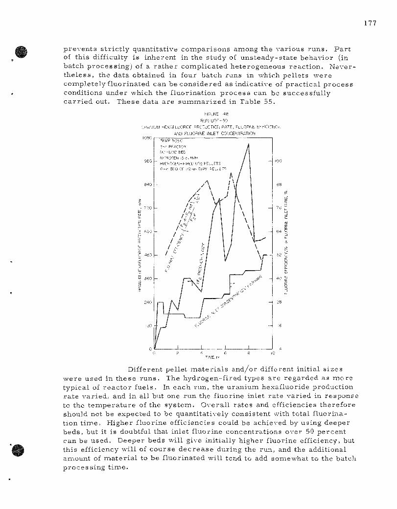
prevents s t r ic t ly quantitative compar isons among the various runs . Pa r t of this difficulty is inherent in the study of uns teady-s ta te behavior (in batch process ing) of a ra ther complicated heterogeneous react ion. Neverthe less , the data obtained in four batch runs in which pellets were comipletely fluorinated can be considered as indicative of prac t ica l p rocess conditions under which the fluorination p rocess can be successfully ca r r i ed out. These data are suminar ized in Table 55.
FIGURE 4 8
RU"*! UOF-50
•JPM'J IUM M E X A F L U O R C ' F F R C C U C T I O I J R A T E , FLUOPI'JE EFFiCiE^Cr,
AND FLUORINE INLET COrjCENTRATION 1080
9 6 0
840
7 20
1
240
120
TFVP 505 C
?-ir REACTOR PJO'LUlD BED MiTROGEN l5Ci.H/tir
HYEROGEM-FIRED UOg PELi-ETS 6-^r BED OF 1/2-rn DlAM -ELI tT=i
" A /!' / /fU /
Ay / / /~"' /
/ / , /
/ / 1 / ,f 1 /
/'"• o /
s
/ \ / 1
n f\ 1 1 1 / ^ / C 1 1 -\ / «, 11 ^^
1 1 1
A
Y \
\ y
—
t
y
I _
4 /
/ /
/
/
1 1
\ \ \ \ \
1 -
i^~ \
\ r -r J "" .X ^ V
1
-
52
3
5
-- 16
4 6 TIME, r>'
Different pellet ma te r i a l s and/or different initial s izes were used in these runs . The hydrogen-fired types a re regarded as more typical of reac tor fuels. In each run, the uraniunn hexafluoride production ra te var ied, and in all but one run the fluorine inlet rate varied in response to the t empera tu re of the sys tem. Overal l ra tes and efficiencies therefore should not be expected to be quantitatively consistent with total fluorination t ime . Higher fluorine efficiencies could be achieved by using deeper beds, but it is doubtful that inlet fluorine concentrations over 50 percent can be used. Deeper beds will give initially higher fluorine efficiency, but this efficiency will of course dec rea se during the run, and the additional amount of miaterial to be fluorinated will tend to add somewhat to the batch process ing t ime .

b . Heat T r a n s f e r Study in P a c k e d F l u i d B e d s (C. B a y e n s , * W. Murphy)
R e a c t i o n s of h a l o g e n g a s e s wi th so l id m a t e r i a l s a r e e x o t h e r m i c p r o c e s s e s in which p r a c t i c a l l y a c h i e v a b l e r a t e s a r e often l i m i t e d by hea t t r a n s f e r . Heat t r a n s f e r t e s t s in a m o c k u p s y s t e m a r e be ing m a d e to a s s i s t in the a n a l y s i s of t e m p e r a t u r e - c o n t r o l p r o b l e m s in the f l uo r ina t i on s t e p of the D i r e c t F l u o r i n a t i o n P r o c e s s app l i ed to u r a n i u m dioxide pe l l e t fuel . In t h i s p r o c e s s i n e r t m a t e r i a l f lu id ized in the vo ids of the p e l l e t bed i s u s e d to a id in hea t r e m o v a l and t e m p e r a t u r e c o n t r o l .
P r e v i o u s r e p o r t s (ANL-6Z31 , page 114 and ANL-6Z87 , page 158) d e s c r i b e d f i lm coef f i c ien t s for i n t e r n a l hea t i ng s u r f a c e s in packed fluid b e d s and p r e l i m i n a r y v a l u e s for the ef fect ive t h e r m a l c o n d u c t iv i ty of the bed in the r a d i a l d i r e c t i o n . In the p r e s e n t p e r i o d add i t i ona l w o r k was p e r f o r m e d to c h e c k the a c c u r a c y and r e p r o d u c i b i l i t y of the va lues of bed t h e r m a l conduc t iv i ty , and to ex tend the da t a o v e r a r a n g e of gas \ e l o c i t i e s .
The r e p r o d u c i b i l i t y s tudy w a s c a r r i e d out in the Z.BB-in. c o l u m n d e s c r i b e d p r e v i o u s l y in A N L - b 2 8 7 , pages 154 and 155. A 10- in . -high pe l l e t pack , in which the bed t h e r m o c o u p l e s w e r e c e n t e r e d , was c o n t a i n e d in a I Z - i n . - h i g h w i r e b a s k e t . The b a s k e t , which fit c l o s e l y i n s i d e the c o l u m n , w a s so s u s p e n d e d tha t t h e r e w e r e 9 in . of u n h i n d e r e d fluid bed be low the pe l l e t p a c k and 10 in . of fluid bed a b o v e . The p e l l e t s w e r e of b r a s s , — i n . x-g-in. The bed m a t e r i a l w a s 80 p e r c e n t 60 m e s h and 20 p e r cent 80 m e s h g l a s s b e a d s ( m i n i m u m f lu id iza t ion ve loc i ty , 1.0 f t / s e c ) . The s u p e r f i c i a l gas \ e l o c i t y for Eill r u n s w a s 1.5 f t / s e c . An ou t l ine of t h e c a l c u l a t i o n s u s e d in t h e s e t e s t s i s g iven in Tab le 56.
Table 5o
CALCULATION O F E F F E C T I V E THERMAL CONDUCTIVITY
k = E f f e c t i \ e t h e r m a l conduct iv i ty a long rad ius of packed fluid bed, B tu / ! l i r ) ( sq f t)(F/ft)
q = Heat t r a n s f e r r a t e , B tu / !h r )
r, r ' = Radia l d i s t a n c e of t h e r m o c o u p l e j u n c t i o n s , ft
L - Length of heat t r a n s f e r zone, ft
_ q log ( r / r ' )
A v e r a g e k - (kj •^•k,)/^ = k
Deviat ion of ki = k, - k , - de \ k
A \ e r a g e Devia t ion of k - fdev kj + dev k2)/2
C o - o p e r a t i v e s tuden t f rom the U n i v e r s i t y of D e t r o i t .

In o rder to m e a s u r e the radia l t empera ture gradient, thermocouple junctions were positioned by axial holes in the pellets (six in a line on one d iamete r ) . This a r rangement is shown as Type I, Figure 49. Three a r r angement s of thermocouples imounted on pellets were used: (1) all six pel lets with axes ver t ica l ; (2) al ternate pellets with axes horizontal ; (3) four pel lets only, each only half s ize . The variat ions in effective t h e r m a l conductivity for different configurations a re shown in Table 57. In genera l , these var ia t ions are believed to have allowed success ively l ess in ter ference with the "normal" void pat terns in the pellet bed. The objective of these various a r rangements was to obtain c loser checks between values of k obtained for the two different radii measu red in each run. The half-s ized pellets appeared to give the best resu l t s in this respec t , as shown by smal le r average deviations from the mean.
FIGURE 49 VARIOUS THERMOCOUPLE ARRANGEMENTS USED
IN THERMAL CONDUCTIVITY MEASUREMENTS
I. SIX PELLETS, AXES VERTICAL H SIX PELLETS, AXES ALTERNATED
m FOUR WHOLE PELLETS JZ FOUR HALVED - PELLETS
In Table 58 are shown the resul ts for a 10-in. pellet pack suspended in the middle of the fluid bed and for a 29-in. pellet pack. In this la t te r case the pellet pack and the fluid bed were the same height and heat t ransfer proceeded radial ly only, without longitudinal heat t ransfer due to "open" fluidization on the top and bottonn. A lower value of thermal conductivity in this second case , ~5 Btu/(hr)(sq ft)(F/ft), indicates that fluidization above and below the pellets is beneficial.

Table "^l
VARIATIONS OF E F F E C I I V E THERMAL CONDUCTIVITY OF A PACKED FLUID BED FOR DIFFERENT
THERMOCOUPLE ARRANGEMENIS
Conditions: 2 .9- in . - ID column 3 ' 8 - i n . X 3 /8 - in . b r a s s pe l le t s ; 10-in. pel le t pack 29- in . fluid bed; g lass beads , avg d i ame te r 0.011 in. Minimmn fluidization velocity: 1.0 f t / sec Cor r ec t ed gas ra te : 3.0 x inin. fluidization ra te (Cor rec ted for pel le t \ oid voluine!
Pe l l e t Or ienta t ion A r r a n g e m e n t of Pe l l e t Axes
Six whole All ve r t i ca l pel le ts
R u n
K - l - A K - l - B K - 2 K-5 K - i K - 4
Gas Temp
fC)
50 50 48 51 97 97
Avg k^ [Btu/ (hr ) (sq
ft)(F/ft)]
10.8 17.2 4 .2 0.8 8.6 8.0
Avg Dev k
(%)
3 5 13 20 26 26 15
Al te rna t e , V e r t i c a l - K-b 10b 10.3 20 Horizontal
Four whole pel le ts A L ' e r t i . a l K-7 94 5.8 lb
Four halved All \ e r t i c a l K-8-A 97 10.0 b pel le ts K - l - A 102 9.7 0
11 3
K-8-A K - l - A K-8 -B K-'J-B
97 102
50 5 !
10.0 9.7 5.b 0.5
A', e ragc <jt two the rma l I'unducti', i t ics obtained on opposite radii at the iiarr..e e l f a t ion.
Table 5h
EKD E F F E C T IN HEAT TRANSFER TESTS
Four halved pe l l e t s ; Az-iea ^-ertical 2<-»-in. fluid bed; Glass bead, Avg d i ame te r 0.001 in. Minimam fluidization \e Ioc i ty , 1.0 ft^-'bec C o r r e c t e d Gas Rate : J.b x min . fluidization ra le
^Correc ted for pel let ^ oid volume 1
Height Pe l le t P
Un.j
10'-
lod
of 'ac k
Run
K-8-A K-<J~A
K-IU-A K - l l b K-IO-B
G a s T e m p
(C)
q ? 102
104 102
54
Avgk^ [Btu, (hrj(sqft)
(F/ft)J
10.0 q.7
4.9 T.4b
3.b
A\ -g Dev k (%)
D
0
19 3
IQ
•^Average of two t h e r m a l conducl ivi t ies obtained on opposite radii at the sanie el e-. a t ion.
"Without wire s c r e e n baske t .
'"Fluid bed abo \e and belov, pellet pack.
Xo fluid bed abo e or belov. pellet pack.
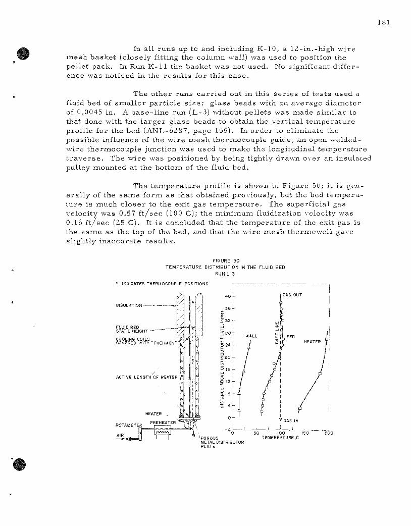
In all runs up to and including K-10, a IZ-in.-high wire mesh basket (closely fitting the column wall) was used to position the pellet pack. In Run K-11 the basket was not used. No significant difference was noticed in the resu l t s for this ca se .
The other runs ca r r i ed out in this se r i e s of tes ts used a fluid bed of sma l l e r par t ic le s i ze : g lass beads with an average diameter of 0.0045 in. A base - l ine run (L-3) without pellets was made s imi la r to that done with the l a rge r glass beads to obtain the ver t ica l t empera tu re profile for the bed (ANL-6Z87, page 155). In order to eliminate the possible influence of the wire mesh thermocouple guide, an open welded-wire thermocouple junction was used to make the longitudinal temiperature t r a v e r s e . The wire was positioned by being tightly drawn over an insulated pulley mounted at the bottom of the fluid bed.
The t empera tu re profile is shown in Figure 50; it is genera l ly of the same form as that obtained previously, but the bed t e m p e r a ture is miuch c loser to the exit gas t e m p e r a t u r e . The superficial gas velocity was 0.57 f t / sec (100 C); the minimum fluidization velocity was 0.16 f t / sec (25 C). It is concluded that the t empera tu re of the exit gas is the same as the top of the bed, and that the wire mesh thermowell gave slightly inaccura te r e s u l t s .
FIGURE 5 0
TEMPERATURE DISTRIBUTION IN THE FLUID BED
RUN L 3
X INDICATES THERMOCOUPLE POSITIONS
INSULATION
FLUID BED STATIC HEIGHT
COOLING COILS „ COVERED WITH "THERhflON"^
^POROUS METAL DISTRIBUTOR PLATE
50 100 150 TEMPERATURE,C
200
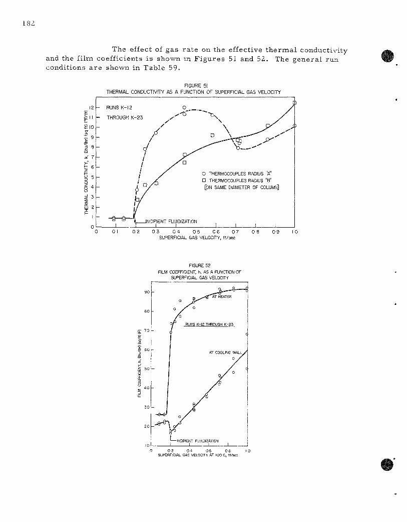
The effect of gas ra te on the effective the rma l conductivity and the film coefficients is shown in F igures 51 and 52, The genera l run conditions a re shown in Table 59.
FIGURE 51 THERMAL CONDUCTIVITY AS A FUNCTION OF SUPERFICIAL GAS VELOCITY
0 01 0 2 0 3 0 4 0 5 0 6 0 7 0 8 0 9 10 SUPERFICIAL GAS VELOCITY, ft/sec
FIGURE 52 FILM COEFFICIENT, h, AS A FUNCTION OF
SUPERFICIAL GAS VELOCITY
0 0 2 0 4 06 0 8 10 SUPERFICIAL GAS VELOCITY AT 100 C, ft/sec
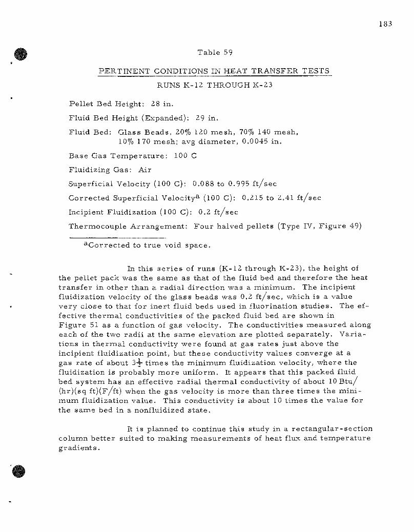
Table 59
PERTINENT CONDITIONS IN HEAT TRANSFER TESTS
RUNS K-12 THROUGH K-23
Pel le t Bed Height: 28 in.
Fluid Bed Height (Expanded): 29 in.
Fluid Bed: Glass Beads , 20% 120 mesh , 70% 140 mesh , 10% 170 mesh ; avg d iamete r , 0.0045 in.
Base Gas T e m p e r a t u r e : 100 C
Fluidizing Gas: Air
Superficial Velocity (100 C): 0,088 to 0.995 f t / sec
Cor rec ted Superficial Velocity^- (100 C): 0,215 to 2,41 f t / sec
Incipient Fluidizat ion (100 C): 0.2 f t / sec
Thermocouple Ar rangement : Four halved pel lets (Type IV, F igure 49)
^Cor rec ted to t rue void space .
In this s e r i e s of runs (K-12 through K-23), the height of the pellet pack was the same as that of the fluid bed and therefore the heat t r ans fe r in other than a rad ia l d i rect ion was a minimum. The incipient fluidization velocity of the glass beads was 0.2 f t / s e c , which is a value very close to that for iner t fluid beds used in fluorination s tudies . The effective t h e r m a l conductivit ies of the packed fluid bed are shown in F igure 51 as a function of gas velocity. The conductivities m e a s u r e d along each of the two rad i i at the same elevation are plotted separa te ly . Var ia t ions in t h e r m a l conductivity were found at gas r a t e s just above the incipient fluidization point, but these conductivity values converge at a gas ra te of about S-x t i m e s the minimumi fluidization velocity, where the fluidization is probably m o r e uniformi. It appears that this packed fluid bed sys tem has an effective rad ia l t h e r m a l conductivity of about 10 Btu / (hr)(sq ft)(F/ft) when the gas velocity is m o r e than th ree timies the min i mum fluidization value. This conductivity is about 10 t imes the value for the same bed in a nonfluidized s t a t e .
It is planned to continue this study in a r ec tangu la r - sec t ion columin be t te r suited to making m e a s u r e m e n t s of heat flux and t empera tu re g rad ien t s .

c. F i l t e r Chamber Tes t s (E. Ca r l s , L, Marek)
P re l imina ry design of a pilot plant for process ing of uranium oxide-plutonium oxide fuels by the Direct Fluorination P r o c e s s is underway. The proposed filter system consis ts of s intered nickel f i l ters (bayonet type) mounted in chambers external to the reac tor and provided with automatic blowback for powder re tu rn to the reac to r . Such an a r rangement has the advantage of allowing ready replacement of the filter as a unit.
A glass and plexiglass mockup of a filter unit of this type was made as shown in Figure 53. A th ree - inch -d iame te r fluid bed column was used and operated with the usual gas veloci t ies .
FIGURE 53
MOCKUP OF EXTERNAL FILTER CHAMBER ASSEMBLY
100 psig BLOWBACK AIR
SOLENOID VALVE
100 pSig BLOWBACK AIR
^SOLENOID VALVE
VE^TURI
©—1 1—©
3-IN. DIAMETER PLEXIGLASS CHAMBER-- —
I—1_^ PNEUMATIC VIBRATOR — ^ MOUNTED ON FLANGE
DISEI^GAGING SECTION
3-IN. DIAMETER GLASS COLUMN
The column was charged with zirconium te t raf luor ide with a high percentage of fines (13.5 percent ^200 mesh) to insure adequate loading of the f i l t e r s . The blowback air p r e s s u r e supply was 100 psig. P r e s s u r e gages were mounted on the inlet to the filter, the filter chamber , and the column itself. A smal l pneumatic vibrator was used to aid in solids t r anspor t from the angled filter chaiiiber lines to the column.
The maximum inc rease in p r e s s u r e in the filter chambers was 3 to 4 psi with a blowback durat ion of 2 sec . As far as could be de t e r mined, at the instant of blowback this same p r e s s u r e inc rease occur red both inside the f i l ter itself and also in the opposite filter chamber not under going blowback. The r e v e r s e p r e s s u r e drop ac ros s the filter during blowback was only about 2 ps i . The p r e s s u r e s were measu red with Bourdon gages , as shown in F igure 53, The inc rease in column p r e s s u r e caused a momen ta ry 10 percent d e c r e a s e in fluidizing gas flow but no visual effect on fluidization quality.
The sys tem operated sat isfactor i ly with a blowback dura tion of 0.5 sec and with a 2-min durat ion between b las t s for each f i l ter . This operat ion was conducted for approxirnately eight hours with no noticeable i nc rease in p r e s s u r e drop a c r o s s the f i l ters and no apparent holdup of la rge amounts of m a t e r i a l in e i ther the fil ter chambers or r e tu rn l ines . The solids r e t u r n line on a 60* angle held up less powder than the 45° r e tu rn l ine. An angle g r e a t e r than 60° would be des i rab le for minimum solids holdup.
The sys tem was opera ted with and without a iO-in.-d iamete r disengaging sect ion between the column and the f i l t e r s . The el imination of such a section had no noticeable effects on p r e s s u r e s repor ted h e r e . More powder seemed to be ca r r i ed up into the filter chamber s when the disengaging sect ion was not used. However, no quant i tat ive information as to the m e r i t of the disengaging section in keeping fines in the bed was obtained,
2, Di rec t Halogenation P r o c e s s for Stainless Steel-clad or Matr ix Fue l s (N. Levitz)
Work has continued in a l-2-in.-diamieter, two-zone fluid-bed r eac to r on the decladding s tep of a p r o c e s s for the recovery of f iss i le m a t e r i a l s from s ta in less s t ee l -c lad fuels of s in tered uranium dioxide. The decladding step involves the reac t ion of chlorine and s ta in less s tee l to produce a volati le i ron chloride which is converted to the solid fluoride by react ion with hydrogen fluoride in the upper zone of the fluid-bed r e a c t o r . The complete reac t ion of chlor ine with the cladding was found to be inhibited by the format ion of adherent films on the surface . Higher chlo-r inat ion t e m p e r a t u r e s than repor ted previously (ANL-6287, page l60) may be n e c e s s a r y to provide sufficiently high penetrat ion r a t e s .
The two-zone fluidized bed has been employed in the d i rec t chlorination of s in te red uranium dioxide pe l le t s . The volatile uranium chlor ides a r e converted to solid f luorides by react ion with anhydrous hydrogen fluoride in the upper zone of the r eac to r . An equivolume mixtu r e of carbon t e t r ach lo r ide and chlorine at 550 C has produced higher react ion r a t e s than s e v e r a l other gas mix tu re s studied.
a. Decladding Stainless Steel-clad Fuels ( j , T. Holmes, J, J, Barghusen, D, J. Raue, and J. E. Kincinas)
The chlorination of s imulated s ta in less s tee l -c lad reac tor fuel e lements is being studied in the lower zone of a I x - i n . - d i a m e t e r , two-zone, f luidized-bed r e a c t o r . The zones a re separa ted by an inverted conical baffle which prevents gas backmixing from the upper zone, where anhydrous hydrogen fluoride is used to convert the volatile and solid chlor ides , formed in the lower zone, to solid f luoride. Abras ive grain alundum, -40 -f200 mesh , is used as the iner t fluidized bed.
Reaction ra te data were obtained at 575 and 625 C (see Table 60). At the higher t e m p e r a t u r e , the effect of chlorine concentrat ion (13 to 87 miole percent in nitrogen) on the reac t ion ra te was studied. Reaction t ime var ied from 1.0 to 4.7 h r . The tes t e lements were Type 304 s ta in less s tee l welded tube sec t ions , -fin, in d iamete r , 4g-in. long, of 35-mil wall th ickness , with one end welded shut and the other end c r imped closed.
Exper iments 01 and 12 show that the overa l l penetra t ion ra te (4,6 to 4.9 m i l s / h r ) was low for c losed-end coupons in chlorine at 575 C for run t imes over four hou r s . The higher r a t e s (9.0 to 10.2 m i l s / h r ) repor ted in ANL-6287, page 160, were for shor t , open-end coupons and react ion timies of l e s s than one hour . The overa l l penetra t ion ra te , ca lculated from weight- loss data, is unrea l i s t i ca l ly la rge for the open-end coupons because of the abras ive action of the fluid bed, which removes the nonvolatile nickel and chromium chlor ides from the ends of the samples . When these effects a re sma l l (long, c losed-end coupons), the dependence of the fluid-bed reac t ion ra t e on t ime can be predic ted fromi the tube r eac to r exper iments summar i zed in ANL-6231, page 124. Complete r e action of 35-miil cladding would take about ten hours at 575 C.
Exper iments 14, 17, 18, 19, 20, 21, and 23 were conducted to obtain react ion ra te data at 625 C. Runs 14 and 17 showed that e s s e n tially complete decladding can be achieved in l e s s than four hours with ei ther 87 or 48 mole percent chlorine in ni t rogen at 625 C. Runs 18 and 19 show that the penet ra t ion ra t e is t i ine dependent, as were the exper iments below 600 C, but is init ial ly higher and has an apparent ly lower coefficient of t ime dependence. Runs 19, 20, and 21 show that decreas ing the chlorine concentrat ion below 48 mole percen t d e c r e a s e s the reac t ion r a t e . No excess heat effects ( t empera tu re excurs ions) were observed in any of the runs .
Separate exper iments were made to de te rmine the ignition t empe ra tu r e of s t a in less s tee l with 87 and 27 mole percen t chlorine in n i t rogen. The p rocedure followed was to introduce the chlor ine with the bed t e m p e r a t u r e at about 565 C and gradually i nc r ea se the t e m p e r a t u r e .
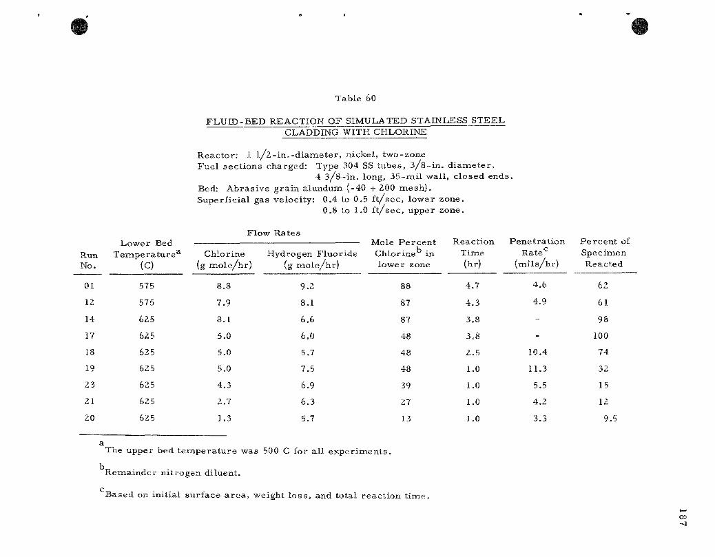
Table 60
F L U I D - B E D REACTION OF SIMULATED STAINLESS S T E E L CLADDING WITH CHLORINE
R e a c t o r : 1 l / z - i n . - d i a m e t e r , n icke l , two-zone F u e l s ec t i ons cha rged : Type 304 SS tubes , 3 / 8 - i n , d i a m e t e r ,
4 3 / 8 - i n , long, 3 5 - m i l wal l , c lo sed e n d s . Bed: A b r a s i v e g r a i n a lundum (-40 -|- 200 m e s h ) . Super f ic ia l gas ve loc i ty : 0.4 to 0.5 f t / s e c , lower zone .
0.8 to 1.0 f t / s e c , upper zone .
Run No.
01
12
14
17
18
19
23
21
20
L o w e r Bed T e m p e r a t u r e ^
(c) 575
575
625
6 2 5
625
625
625
625
6 2 5
Chlor ine (g m o l e / h ]
8.8
7.9
8 .1
5 .0
5 .0
5.0
4 . 3
2 .7
1,3
Flow Rate
r) Hydro
(g
s
igen F l u o r i d e m o l e / h r )
9.2
8.1
6.6
6 .0
5.7
7 ,5
6.9
6 .3
5.7
Mole P e r c e n t Chlor ine in lower zone
88
87
87
4 8
4 8
48
39
27
13
Time (hr)
4 . 7
4 . 3
3 .8
3 .8
2 . 5
1.0
1.0
1.0
1.0
Rate^ ( m i l s / h r )
4 .6
4 .9
-
-
10,4
11.3
5,5
4 ,2
3 .3
a The uppe r bed t e m p e r a t u r e was 500 C for a l l e x p e r i m e n t s ,
b R e m a i n d e r n i t rogen d i luent .
c Based on in i t ia l su r f ace a r e a , weight l o s s , and to ta l r eac t i on t i m e .

Ignition was achieved only with the higher concentrat ion of chlorine gas in the s t r e a m . This occu r r ed at 645 C| the t e m p e r a t u r e ro se rapidly to 680 C and was sustained by the heat of react ion between 670 and 680 C for an additional 40 min . At this t ime , s inter ing of nonvolatile chlor ides and bed ina te r i a l around the two tubular spec imens caused a p r e s s u r e buildup, and the run was t e rmina ted . Sintering of bed m a t e r i a l also occu r r ed in the run with 27 mole percent chlorine at about 670 C, With the higher chlorine concentrat ion, the tubes were about 95 percen t reac ted , but the "meat" was not exposed because of the s inter ing of solids on the specimen. T e m p e r a t u r e s above 650 C should there fore be avoided to prec lude s in t e r ing and ignition p r o b l e m s .
The h igh - t empera tu re (~625 C) chemical decladding of s ta in less s tee l fuel e lements p r e sen t s two major p r o c e s s cons idera t ions : f i rs t , the react ion of the uran ium dioxide "meat" is expected to be rapid in chlorine at the high decladding t e m p e r a t u r e s . It was shown (ANL-6287, page 162) that volati le react ion products a r e formed when uranium dioxide is reac ted with chlorine at 600 C. A higher react ion ra t e would be expected above 600 C, which may complement a p r o c e s s involving complete chlor ination of the fuel e l ements . Second, the cor ros ion of nickel and Inconel becomes appreciable above 550 C, about 10 m i l s / m o at 575 C and 35 m i l s / m o at 625 C (ANL-6287, page 162). Since the t e m p e r a t u r e coefficient for cor rosion is about the same as that for the s ta in less s teel chlorinat ion, the total r eac to r co r ros ion would be independent of decladding t e m p e r a t u r e and new m a t e r i a l s of construct ion must be considered.
Calculations indicated that an alumina s leeve, | - - in . thick, would be sufficient to provide a 100-degree t e m p e r a t u r e gradient from the reac to r wall to the fluidized bed for a typical loading of fuel e lements and a 10 -mi l /h r penet ra t ion r a t e . If the me ta l wall t e m p e r a t u r e were ma in tained below 550 C, the extent of co r ros ion would be acceptable for p roces s appl icat ions. Use of an insulat ing l iner would requ i re the react ion to be self sustaining.
b . Chlorination of Uranium Dioxide
The chlorinat ion of uran ium dioxide is being investigated as an a l te rna te to the Direc t Fluor inat ion P r o c e s s (page 51), Since chlorine r eac t s appreciably with uranium dioxide at the decladding t e m p e r a t u r e s , a dual react ion scheme was proposed for convers ion of the dioxide to the te t ra f luor ide . A ch lor ine-carbon t e t r ach lo r ide mix ture would be used to convert the dioxide pel le ts remain ing in the r eac to r after decladding to volati le uraniuna ch lor ides . The volatile ch lor ides a r e converted to solid fluorides in the upper zone of the two-zone r e a c t o r by the react ion with hydrogen f luoride. An additional t r ea tmen t with fluorine would r e cover the uran ium and plutonium as the volatile hexafluorides , which could be purified by s tandard volat i l i ty techniques . A miajor advantage of the
chlorinat ion p r o c e s s over the Direct Fluor inat ion P r o c e s s is that the reagent cost for convers ion to the hexafluoride is considerably reduced, since hydrogen fluoride, r a the r than fluorine, is used for converting to the te t raf luor ide . Also, the heat produced by the chlorination react ion is l e s s than half that obtained in the Direc t Fluorinat ion P r o c e s s .
It was previous ly shown (ANL-6287, page 162) that a mixture of chlorine and carbon te t rach lor ide gave higher production ra tes of volatile uranium chlor ides than chlorine or carbon te t rach lor ide alone. An investigation of the effect of re la t ive amounts of chlorine and carbon t e t r ach lo r ide gave a maximum react ion ra te [about 800 m g / ( s q cm)(hr)] for a 50 mole percent mix ture at 550 C.
The react ion of phosgene and a phosgene-chlor ine mixture with uranium dioxide pel le ts was also studied by means of the tube furnace r eac to r . The react ion of the pel le ts with 30 mole percent phosgene in chlorine proceeded at a r a t e of 350 to 500 mg / ( sq cm)(hr) at 500 to 600 C, comipared with 380 to 800 m g / ( s q cm)(hr) for a chlor ine-carbon t e t r ach lo r ide mix ture (ANL-6287, page 162). A chlorination rate for phosgene alone was lower by about a factor of two than with the phosgene-chlor ine mix tu re . Since the phosgene reac t ions a re s lower , and the cost is about 1.4 t imes the cost of carbon t e t r ach lo r ide per mole of chlorine, phosgene does not appear to offer any advantage for the chlorination react ion.
In l a r g e r - s c a l e s tudies , twenty uranium dioxide pel le ts (121 g), submerged in an alundum bed (800 g, -40 +200 mesh) in the lower zone of a 1.5-in,, two-zone, fluid-bed r eac to r , were reacted with 69 mole percent chlor ine in carbon t e t r ach lo r ide . The pellets occupied a space about 1 in. in d iameter by 1.5 in. high, and were supported in a wire basket about 2 in. above the cone bottom of the r eac to r , A thermocouple located in the pellet basket gave t e m p e r a t u r e s which var ied between 550 and 555 C and indicated no t e m p e r a t u r e excurs ions . Hydrogen fluoride was introduced to the upper stage (maintained at 440 to 450 C) to convert the uranium chlor ides to f luor ides . This react ion occurs p r imar i ly on the surface of the bed miaterial . The superf ic ia l velocity in the lower and upper zones was 0,4 and 0.8 f t / s e c , respec t ive ly . Reaction for 2,5 hr achieved 92 percent volat i l izat ion of the pel le ts and introduced about 8.7 weight percent uran ium into the total bed. Analysis of the final bed m a t e r i a l indicated that the alundum reac ted with the chlorinating agents to a slight extent. The extent of this react ion is being determined. Analysis of the ammonia off-gas scrub solution showed a negligible uranium c a r r y over (0.007 percent total loss ) .
Two conclusions were reached from the work performed to date . The chlorinat ion ra te is high enough for dissolution of uranium dioxide pel le ts in a reasonable t ime and the heat of react ion is easi ly diss ipated by the fluidized bed. Proposed future work includes the following:
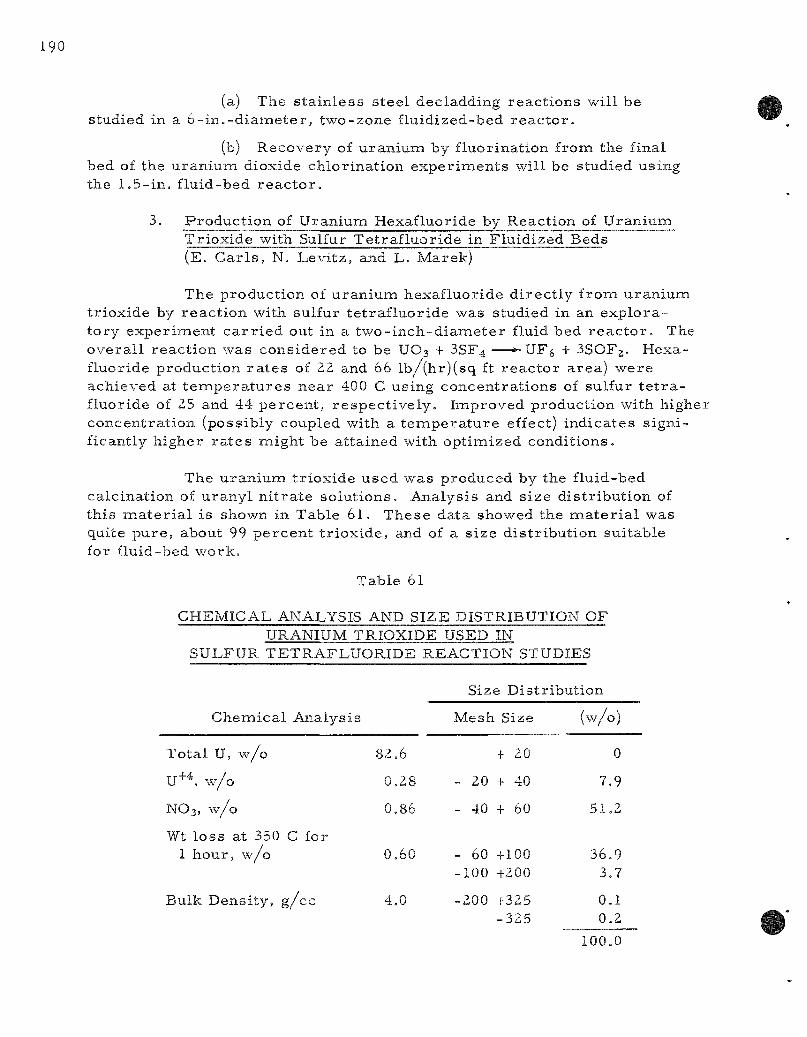
(a) The s ta in less s teel decladding react ions will be studied in a 6 - in , -d i ame te r , two-zone fluidized-bed r eac to r .
(b) Recovery of uranium by fluorination from the final bed of the uranium dioxide chlorination exper iments will be studied using the 1.5-in. fluid-bed r eac to r .
3. Product ion of Uranium Hexafluoride by Reaction of Uranium Trioxide with Sulfur Tetraf luor ide in Fluidized Beds ( E . C a r l s , N. Levitz, and L. Marek)
The production of uranium hexafluoride d i rec t ly from uranium tr ioxide by reac t ion with sulfur te t raf luor ide was studied in an exploratory exper iment c a r r i e d out in a two- inch-d iamete r fluid bed r e a c t o r . The overa l l react ion was considered to be UO3 + 3SF4 •—» UF^ + 3SOF2. Hexafluoride production r a t e s of 22 and 66 lb / (hr ) (sq ft r eac to r area) were achieved at t e m p e r a t u r e s near 400 C using concentrat ions of sulfur t e t r a fluoride of 25 and 44 percent , respec t ive ly . Imiproved production with highe concentrat ion (possibly coupled with a t e m p e r a t u r e effect) indicates s ignificantly higher r a t e s might be attained with optimized condit ions.
The uraniumi t r ioxide used was produced by the fluid-bed calcination of uranyl n i t ra te solut ions. Analysis and size dis tr ibut ion of this m a t e r i a l is shown in Table 61, These data showed the m a t e r i a l was quite pure , about 99 percent t r ioxide , and of a size dis t r ibut ion suitable for fluid-bed work.
Table 61
CHEMICAL ANALYSIS AND SIZE DISTRIBUTION OF URANIUM TRIOXIDE USED IN
SULFUR TETRAFLUORIDE REACTION STUDIES
Size Distr ibut ion
Chemiical Analysis
Total U, w/o
U+*, w/o
NO 3, w/o
Wt loss at 350 C for 1 hour , w/o
Bulk Density, g /cc
82,6
0,28
0.86
0.60
4.0
Mesh Size
- 20
- 40
- 60 -100
-200
+ 20
+ 40
+ 60
+100 +200
+325 -325
(w/o)
0
7,9
51,2
36,9 3.7
0.1 0.2
100.0
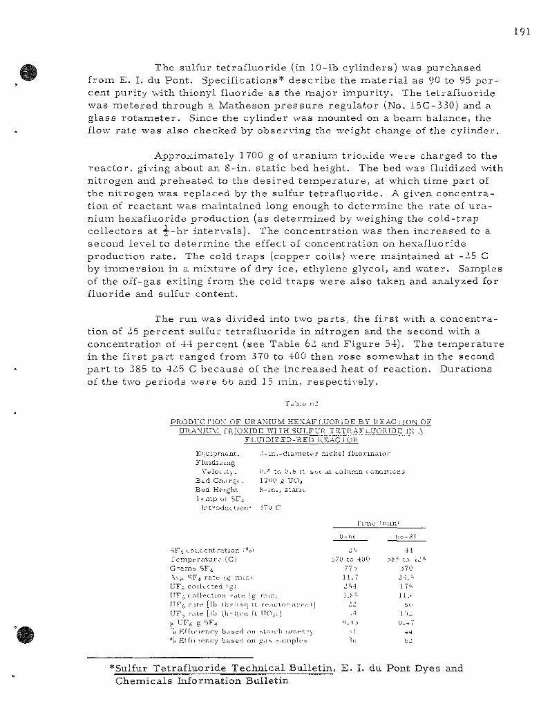
The sul fur t e t r a f l u o r i d e (in 10- lb c y l i n d e r s ) was p u r c h a s e d f r o m E. I. du P o n t . S p e c i f i c a t i o n s * d e s c r i b e the m a t e r i a l a s 90 to 95 p e r cen t p u r i t y wi th th iony l f luor ide a s the m a j o r i m p u r i t y . The t e t r a f l u o r i d e w a s m e t e r e d t h r o u g h a M a t h e s o n p r e s s u r e r e g u l a t o r (No. 15C-330) and a g l a s s r o t a m e t e r . S ince the c y l i n d e r w a s moun ted on a b e a m b a l a n c e , the flow r a t e w a s a l s o c h e c k e d by o b s e r v i n g the weight change of the c y l i n d e r .
A p p r o x i m a t e l y 1700 g of u r a n i u m t r i o x i d e w e r e c h a r g e d to the r e a c t o r , g iving about an 8 - in . s t a t i c bed he igh t . The bed was f luidized with n i t r o g e n and p r e h e a t e d to the d e s i r e d t e m p e r a t u r e , at which t i m e p a r t of the n i t r o g e n w a s r e p l a c e d by the su l fur t e t r a f l u o r i d e . A given c o n c e n t r a t ion of r e a c t a n t w a s m a i n t a i n e d long enough to d e t e r m i n e the r a t e of u r a n i u m h e x a f l u o r i d e p r o d u c t i o n (as d e t e r m i n e d by weigh ing the c o l d - t r a p c o l l e c t o r s at -^--hr i n t e r v a l s ) . The c o n c e n t r a t i o n w a s then i n c r e a s e d to a s e c o n d l e v e l to d e t e r m i n e the effect of c o n c e n t r a t i o n on hexa f luo r ide p r o d u c t i o n r a t e . The cold t r a p s (copper co i l s ) w e r e m a i n t a i n e d at -25 C by i m m e r s i o n in a m i x t u r e of d r y i c e , e thy lene g lycol , and w a t e r . S a m p l e s of the o f f -gas ex i t ing f rom the cold t r a p s w e r e a l so t aken and a n a l y z e d for f luo r ide and sulfur con ten t .
The run w a s d iv ided into two p a r t s , the f i r s t with a c o n c e n t r a t ion of 25 p e r c e n t su l fur t e t r a f l u o r i d e in n i t r o g e n and the second with a c o n c e n t r a t i o n of 44 p e r c e n t ( see T a b l e 62 and F i g u r e 54). The t e i n p e r a t u r e in the f i r s t p a r t r a n g e d f r o m 370 to 400 then r o s e s o m e w h a t in the second p a r t to 385 to 425 C b e c a u s e of the i n c r e a s e d h e a t of r e a c t i o n . D u r a t i o n s of the two p e r i o d s w e r e fab and 15 m i n , r e s p e c t i v e l y .
Table nl
P R O D U C r i O N OF URANIUM HEXAFLUORIDE BY R E A C I I O H OF URA\ ' IUM rRIOXIDE WITH SULFUR TETRAFj- .UORroC IX A
F L U I D I Z E D - B E D REACTOR
Equ ipmen t . Z - m . - d i a m e t e r n ickel f luomna io r F lu id iz ing
Veloc i ty . f'.T to U.b It set at co lumn t on&itions B t d C h a r g t . 17nu g UO^ Bed Height 8- in . , s t a t i c I t m p ot SF4
J r f o d u c t i o n ' i7U C
SF i c o n c e n t r a t i o n fo! r c m p e r a t u r e (Cj G' -ams SF4 \\ g '!F4 r a t e (g m i n i U F j coilfcC ted fg; UF(, co l l ec t ion r a t e !g niiii; U F j r a t e [lb ( h r i i s q it r e a c t o r a r e a ! | UF^ r a t e [lb (h-ncu ft UO3) [ ^ UFs g SF4 "0 Eff iciency bai>ed on btoich o m e t r \ "0 Elfic lency b a s e d on gas s a m p l e r
Time imin>
0-ht bt)-81
J70 to 400 77 •>
11.7
iS4 3.h=.
11
A 0.3J
-.1 3o
3b5 to 1-^
370 >4 ^
17s
11.!
bo 10.i
U.47
•i-i
bl
*Sulfur T e t r a f l u o r i d e T e c h n i c a l B u l l e t i n , E . I. du Pont Dyes and C h e m i c a l s I n f o r m a t i o n B u l l e t i n
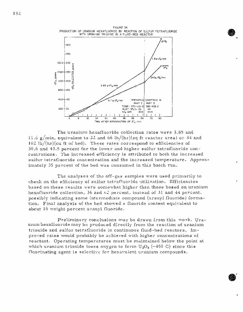
FIGURE 54 PRODUCTION OF URANIUM HEXAFLUORIDE BY REACTION OF SULFUR TETRAFLUORIDE
WITH URANIUM TRIOXIDE IN A FLUID-BED REACTOR
0 8 16 2^ 32 40 48 56 64 72 TIME AFTER INTRODUCTION OF SF^.min
The u r a n i u m h e x a f l u o r i d e c o l l e c t i o n r a t e s w e r e 3.85 and 11.6 g / m i n , equ iva l en t to Zl and 66 l b / ( h r ) ( s q ft r e a c t o r a r e a ) o r 34 and 102 l b / ( h r ) ( c u ft of bed ) . T h e s e r a t e s c o r r e s p o n d to e f f i c i enc ies of 30.6 and 43.5 p e r c e n t for the l o w e r and h i g h e r su l fur t e t r a f l u o r i d e conc e n t r a t i o n s . The i n c r e a s e d e f f ic iency i s a t t r i b u t e d to both the i n c r e a s e d su l fur t e t r a f l u o r i d e c o n c e n t r a t i o n and the i n c r e a s e d t e m p e r a t u r e . A p p r o x i m a t e l y 35 p e r c e n t of the bed w a s c o n s u m e d in t h i s b a t c h r u n .
The a n a l y s e s of the o f f -gas s a m p l e s w e r e u s e d p r i m i a r i l y to c h e c k on the ef f ic iency of su l fur t e t r a f l u o r i d e u t i l i z a t i o n . E f f i c i enc i e s b a s e d on t h e s e r e s u l t s w e r e s o m e w h a t h i g h e r t h a n t h o s e b a s e d on u r a n i u m h e x a f l u o r i d e c o l l e c t i o n , 36 and bZ p e r c e n t , i n s t e a d of 31 and 44 p e r c e n t , p o s s i b l y i nd i ca t i ng sonae i n t e r m e d i a t e compound (u rany l f l uo r ide ) f o r m a t ion . F i n a l a n a l y s i s of the b e d showed a f luo r ide con ten t e q u i v a l e n t to about 10 weigh t p e r c e n t u r a n y l f l uo r ide .
P r e l i m i n a r y c o n c l u s i o n s m a y be d r a w n f rom t h i s w o r k . U r a n i u m h e x a f l u o r i d e m a y be p r o d u c e d d i r e c t l y f rom the r e a c t i o n of u r a n i u m t r i o x i d e and su l fur t e t r a f l u o r i d e in con t inuous f lu id -bed r e a c t o r s . I m p r o v e d r a t e s would p r o b a b l y be a c h i e v e d wi th h i g h e r c o n c e n t r a t i o n s of r e a c t a n t . O p e r a t i n g t e m p e r a t u r e s m u s t be m a i n t a i n e d be low the point at which u r a n i u m t r i o x i d e l o s e s oxygen to f o r m UsOg (~450 C) s i n c e t h i s f l uo r ina t i ng agen t i s s e l e c t i v e for h e x a v a l e n t u r a n i u m c o m p o u n d s .
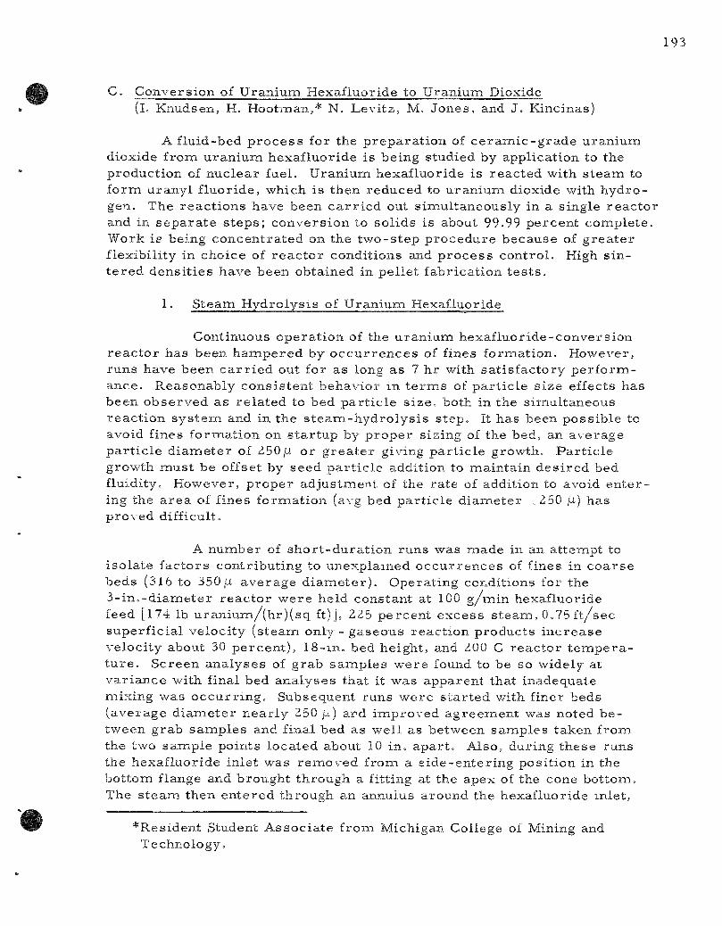
C. C o n v e r s i o n of U r a n i u m H e x a f l u o r i d e to U r a n i u m Dioxide (l. K n u d s e n , H, H o o t m a n , * N, L e v i t z , M. J o n e s , and J . K inc inas )
A f l u i d - b e d p r o c e s s for the p r e p a r a t i o n of c e r a m i c - g r a d e u r a n i u m d iox ide f r o m u r a n i u m h e x a f l u o r i d e i s b e i n g s t u d i e d by app l i ca t i on to the p r o d u c t i o n of n u c l e a r fue l . Uraniuna h e x a f l u o r i d e i s r e a c t e d wi th s t e a m to formi u r a n y l f l u o r i d e , wh ich i s t h e n r e d u c e d to u r a n i u m d ioxide with h y d r o gen . The r e a c t i o n s h a v e been c a r r i e d out s i m u l t a n e o u s l y in a s i ng l e r e a c t o r and in s e p a r a t e s t e p s ; c o n v e r s i o n to s o l i d s i s about 99.99 p e r c e n t c o m p l e t e . Work i s be ing c o n c e n t r a t e d on t h e t w o - s t e p p r o c e d u r e b e c a u s e of g r e a t e r f l ex ib i l i t y in c h o i c e of r e a c t o r c o n d i t i o n s and p r o c e s s c o n t r o l . High s i n t e r e d d e n s i t i e s h a v e b e e n o b t a i n e d in p e l l e t f a b r i c a t i o n t e s t s .
1. S t e a m H y d r o l y s i s of U r a n i u m Hexa f luo r ide
Con t inuous o p e r a t i o n of the u r a n i u m h e x a f l u o r i d e - c o n v e r s i o n r e a c t o r h a s b e e n h a m p e r e d by o c c u r r e n c e s of f ines f o r m a t i o n . H o w e v e r , r u n s h a v e b e e n c a r r i e d out for a s long a s 7 h r with s a t i s f a c t o r y p e r f o r m a n c e . R e a s o n a b l y c o n s i s t e n t b e h a v i o r in t e r m s of p a r t i c l e s i z e effects h a s b e e n o b s e r v e d a s r e l a t e d to b e d p a r t i c l e s i z e , both in the s i m u l t a n e o u s r e a c t i o n s y s t e m and in t h e s t e a m - h y d r o l y s i s s t e p . It h a s b e e n p o s s i b l e to avoid f ines f o r m a t i o n on s t a r t u p by p r o p e r s i z i ng of the bed , an a v e r a g e p a r t i c l e d i a m e t e r of 250jLi o r g r e a t e r g iv ing p a r t i c l e g r o w t h . P a r t i c l e g r o w t h m u s t be offset by s e e d p a r t i c l e add i t ion to m a i n t a i n d e s i r e d bed f lu id i ty . H o w e v e r , p r o p e r a d j u s t m e n t of the r a t e of add i t ion to avoid e n t e r ing the a r e a of f ines f o r m a t i o n (avg bed p a r t i c l e d i a i n e t e r x250 /i) h a s p r o v e d di f f icul t .
A n u m b e r of s h o r t - d u r a t i o n r u n s w a s m a d e in an a t t e m p t to i s o l a t e f a c t o r s c o n t r i b u t i n g to u n e x p l a i n e d o c c u r r e n c e s of f ines in c o a r s e b e d s (316 to 350 [i a v e r a g e d i a m e t e r ) . O p e r a t i n g cond i t i ons for the 3 - i n , - d i a m e t e r r e a c t o r w e r e h e l d c o n s t a n t at 100 g / m i n h e x a f l u o r i d e feed [174 lb u r a n i u m / ( h r ) ( s q ft) J, 225 p e r c e n t e x c e s s s t e a m , 0.75 f t / s e c s u p e r f i c i a l v e l o c i t y ( s t e a m only - g a s e o u s r e a c t i o n p r o d u c t s i n c r e a s e v e l o c i t y about 30 p e r c e n t ) , 1 8 - i n . bed h e i g h t , and 200 C r e a c t o r t e m p e r a t u r e . S c r e e n a n a l y s e s of g r a b s a m p l e s w e r e found to be so w ide ly at v a r i a n c e wi th f ina l bed a n a l y s e s tha t it w a s a p p a r e n t t ha t i n a d e q u a t e m i x i n g w a s o c c u r r i n g . S u b s e q u e n t r u n s w e r e s t a r t e d with f iner b e d s ( a v e r a g e d i a m e t e r n e a r l y 250 /j.) and i m p r o v e d a g r e e m e n t was no t ed b e t w e e n g r a b s a m p l e s and f ina l bed a s w e l l a s b e t w e e n s a m p l e s t a k e n f r o m the two s a m p l e p o i n t s l o c a t e d about 10 i n . a p a r t . A l s o , d u r i n g t h e s e r u n s the h e x a f l u o r i d e i n l e t w a s remioved f r o m a s i d e - e n t e r i n g p o s i t i o n in t h e b o t t o m f lange and b r o u g h t t h r o u g h a f i t t ing at t h e a p e x of the cone b o t t o m . The s t e a m t h e n e n t e r e d t h r o u g h an annu lus a r o u n d the h e x a f l u o r i d e in le t ,
* R e s i d e n t S tudent A s s o c i a t e fromi M i c h i g a n Col l ege of Mining and T e c h n o l o g y ,

an open-end -^-in. tube, •which projected about 1 2 in, up into the cone. This position of the inlet was expected to e l iminate any unusual wall effects in the proximi ty of the reac t ion zone. Seed par t ic le feed r a t e s of 7 to 16 percent of the hexafluoride ra te were tes ted with the higher ra tes apparent ly counteract ing the growth r a t e .
Two approaches were taken in controll ing the ra te of seed par t i c le addition in a t tempts to maintain runs of longer durat ion: one, maintaining a constant r a t e based on previous run data; or , two, adjusting the ra te based on par t i c le size analyses and column indications (column t e m p e r a t u r e s , bed weight indication, e tc . ) . In spite of good control of all feed s t r e a m s , the longer runs up to 7-hr durat ion were also in ter rupted by fines format ion. It appears fromi the changes in bed pa r t i c l e size after per iods of steady s ta te that t he re is a var iab le ra te of fines formiation which affects the seed par t ic le r e q u i r e m e n t s . These fines also affect seed par t ic le r equ i r emen t s which a re lower by about a factor of two than that calculated from the equation developed by Griffin-^O et a l . , for fluid coking, a s imi l a r sol ids-deposi t ion p r o c e s s .
In view of these r e s u l t s , a brief study is being made of the occu r rence of f ines. Four r uns , 61 through 6IC (see Table 63), made with no seed pa r t i c l e feed s t r e a m and no product take-off showed normal par t ic le behavior (growth) with s tar t ing bed par t ic le s i zes ranging from 194 to 225 [I. Runs 6IB and 6IC showed no effect of par t ic le s ize d i s t r i bution (differences in calculated final bed par t i c le size a r e par t ia l ly due to init ial bed weight differences) .
Runs 6ID through 61H with finer s tar t ing beds showed ei ther reduced par t i c le growth or fines format ion. Run 6IE was an additional 45-miin run with the final bed of Run 6 ID, The change from a reduced growth ra te to fines formation appears to be a t ime effect, apparent also in Run 6IG, in which the bed pa r t i c l e d iamete r i nc reased from 128 to 133 /i in 45 miin and then dec reased to 92/i after an additional 45 min . Apparently par t i c le gro'wth init ial ly overcomes fines formation but is then overcome by i t . This may also explain the accumulation of fines in c o a r s e r beds when seed pa r t i c l e addition is being used.
Run 61F was made with the final bed from a previous run (Run 59) which was in te r rupted by fines formiation after 6 hrj fines continued to be formed.
Fu tu re plans call for study of the effect of var iab les such as fluidizing velocity and top bed take-off vs-bottom bed take-off. Cons idera tion is being given to operat ion with a separa te fil ter section in which case fine pa r t i c l e s would not be re tu rned to the bed but r a the r collected separa te ly ,
30Griffin, L. I,, J r , , Moser , J. F . , J r . , Dunlap, D. D. Chem. Eng. P rog . 54, 39 (1958).
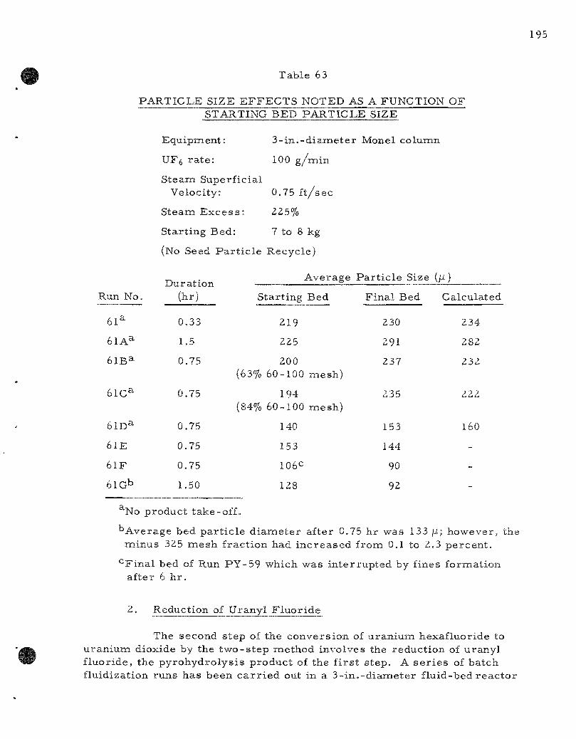
T a b l e 63
P A R T I C L E S I Z E E F F E C T S N O T E D AS A F U N C T I O N O F STARTING B E D P A R T I C L E SIZE
E q u i p m e n t : 3 - i n . - d i a m e t e r Mone l c o l u m n
UFfe r a t e : 100 g / m i n
S t e a m S u p e r f i c i a l
V e l o c i t y : 0.75 f t / s e c
S t e a m E x c e s s : 225%
S t a r t i n g B e d : 7 to 8 kg
(No Seed P a r t i c l e R e c y c l e )
Run No .
6 1 ^
61A^
61B=^
6 1 C ^
61D^
61E
6 1 F
61Gb
D u r a t i o n (hr )
0 .33
1.5
0.75
0.75
0.75
0.75
0.75
1.50
S t a r t i n g
(63%
(84%
219
225
200 60 -100
194 60 -100
140
153
106C
128
Bed
m e s h )
miesh)
F i n a l Bed
230
291
237
235
153
144
90
92
C a l c u l a t e d
234
282
232
222
160
-
-
-
^No p r o d u c t t ake -o f f .
" A v e r a g e b e d p a r t i c l e d iamie te r a f t e r 0.75 h r w a s 133 / i ; h o w e v e r , the m i n u s 325 m e s h f r a c t i o n had i n c r e a s e d f rom 0.1 to 2.3 p e r c e n t .
•^Final bed of Run P Y - 5 9 which w a s i n t e r r u p t e d by f ines f o r m a t i o n a f t e r 6 h r .
2, R e d u c t i o n of U r a n y l F l u o r i d e
The s e c o n d s t e p of t h e c o n v e r s i o n of u r a n i u m h e x a f l u o r i d e to u r a n i u m d iox ide by the t w o - s t e p m e t h o d i n v o l v e s the r e d u c t i o n of u r a n y l f l u o r i d e , t he p y r o h y d r o l y s i s p r o d u c t of the f i r s t s t e p . A s e r i e s of b a t c h f l u id i za t i on r u n s h a s b e e n c a r r i e d out in a 3 - i n , - d i a m e t e r f l u i d - b e d r e a c t o r
to study the reduction reac t ion . In genera l , a mixed gas of s team and hydrogen gave much fas ter convers ion than hydrogen alone, although a thermobalance study using hydrogen at 600 C achieved about 97 percent conversion on a 2-gm sample in 85 min . At p resen t , the re is no s a t i s factory explanation for th is difference in behavior .
The uranyl fluoride feed m a t e r i a l was produced at 200 C by s team hydrolys is of uraniumi hexafluoride. Analysis showed that the feed m a t e r i a l contained the nea r ly theore t ica l content of the fluoride (12,3 pe rcen t ) .
With a 20- in . -deep bed and 100 percent hydrogen as the react ing gas , the convers ion of the feed m a t e r i a l was only eight percent after 6 hr at 650 C. Shallow (8-in. and 4-in.) beds gave a slightly higher conversion, 21 percent at 650 C after 4 h r .
The use of s t eam in the hydrogen s t r e a m gave a lmost comiplete reduction in 2 h r . The gas s t r e a m contained th ree volumies of hydrogen to one volume of s t eam. The effect of t empe ra tu r e with the mixed gas is pronounced; only 32 percent reduction was achieved at 550 C in one hour as compared to 83 percent at 650 C in an equivalent per iod. Specification grade m a t e r i a l (210 ppmi fluoride) was obtained in 5 hr at 650 C with a 3 - k g bed and a gas composit ion of th ree p a r t s hydrogen to one par t s t eam.
The reduction of uranyl fluoride has been found to be the r a t e -controlling reac t ion of the two-s tep p r o c e s s . Fu tu re work will include the optimization of the batch fluidizing p r o c e s s option, and a survey of a moving bed p r o c e s s option.
D. F lu id-bed Calcination Studies in Smal l -d iamete r Columns ( j . Loeding, C. SchoffstoU)
Studies have recent ly been ini t iated to invest igate a schemse which would reduce the quantity of off-gas which would be handled by no rma l fluid-bed calcination techniques . The p rac t i ce from which this scheme will deviate employs a fluidizing medium entering through the bottom of the ca lc iner and a two-fluid (i .e. , liquid feed and a i r or s t eam-a tomiz ing medium) nozzle enter ing through the side or top of the unit. The p resen t studies entai l positioning the atomizing nozzle in the bottom of the unit, d i rec ted upward, thus util izing the atomizing medium as the fluidizing medium. The t e s t s a r e being conducted in s m a l l - d i a m e t e r columns (of 2^ - in , d iameter ) and some success has been rea l ized in the p re l imina ry work. If th is schemie is found feasible , the work is applicable to ca lc ination of plutonium solutions where nuc lear c r i t i ca l i ty cons idera t ions a r e n e c e s s a r y .

E . M u l t i s t a g e F l u i d i z a t i o n S t u d i e s (K. W i l l i a m s o n , J r , )
A m a s s - t r a n s f e r s tudy u s i n g t h e s i l i c a g e l - w a t e r s y s t e m h a s b e e n c o m p l e t e d in the 6 - i n . - d i a m e t e r i n u l t i s t a g e f lu id iza t ion c o l u m n d e s i g n e d to a c h i e v e c o n t r o l l e d d o w n w a r d t r a n s p o r t of s o l i d s wi thout t h e u s e of i n t e r n a l d o w n c o m e r s . T h i s is t he f ina l p h a s e of the e x p e r i m e n t a l w o r k c a r r i e d out a s a d o c t o r a l r e s e a r c h t h e s i s s t u d y . P r e v i o u s s t u d i e s on c o l u m n d e s i g n v a r i a b l e s w e r e r e p o r t e d in A N L - 6 1 8 3 , page 124, The w o r k h a s b e e n c o m p l e t e l y s u m i m a r i z e d a s a t o p i c a l r e p o r t , A N L - 6 2 6 7 ,
F o r the m a s s - t r a n s f e r s t u d y the a d s o r p t i o n of w a t e r v a p o r in a i r by s i l i c a ge l w a s s t u d i e d . T h i s s y s t e m w a s c h o s e n b e c a u s e it l en t i t se l f r e a d i l y to the f l u id i za t ion t e c h n i q u e and p r e s e n t e d no diff icult a n a l y t i c a l p r o b l e m s . The e q u i l i b r i u m r e l a t i o n s h i p b e t w e e n s i l i c a ge l and w a t e r v a p o r w a s d e t e r m i n e d for t e m p e r a t u r e s f r o m 20 to 40 C and p r e s s u r e s f r o m a t m o s p h e r i c to 20 p s i a . T h e s e d a t a w e r e then u s e d to e v a l u a t e t h e M u r p h r e e v a p o r e f f i c i ency (a m e a s u r e of the d e g r e e of a p p r o a c h to t h e o r e t i c a l l y p e r f e c t con t ac t i ng ) for the a d s o r p t i o n of w a t e r v a p o r f r o m a i r by s i l i c a ge l in t h e 6 - i n . - d i a m e t e r m u l t i s t a g e f lu id iza t ion c o l u m n . F r o m the e f f i c i ency , a m o d i f i e d m a s s - t r a n s f e r coef f ic ien t was c a l c u l a t e d . Runs w e r e m a d e at bed d e p t h s f r o m —in, to 8 in , and at s u p e r f i c i a l a i r v e l o c i t i e s f r o m 0,20 to 0,98 f t / s e c .
The s i l i c a g e l u s e d for t h i s w o r k w a s a m i x t u r e c o n s i s t i n g of p a r t i c l e s f r o m 28 to 200 m e s h wi th an a v e r a g e we igh t -miean d i a m e t e r of 277 fi. T h r e e - m m - d i a m e t e r i n e r t g l a s s b e a d s w e r e i n c o r p o r a t e d into e a c h of the t h r e e s t a g e s u p p o r t s .
The M u r p h r e e e f f i c i ency* w a s found to be a p p r o x i m a t e l y 100 p e r c e n t for a l l bed d e p t h s i n v e s t i g a t e d and for a l l bu t the h i g h e s t s u p e r f i c i a l a i r v e l o c i t y . At an a i r v e l o c i t y of 0,98 f t / s e c t h e e f f ic iency d r o p p e d to 96.5 p e r c e n t , c o r r e s p o n d i n g to a m o d i f i e d m s a s s - t r a n s f e r coef f ic ien t of 35 .4 l b / ( s ec ) ( cu ft) ( i b / c u f t ) . As a po in t of r e f e r e n c e , Cox-^^ r e p o r t e d m i a s s -t r a n s f e r coe f f i c i en t s for the s i l i c a g e l - w a t e r s y s t e m , wh ich , when t r a n s l a t e d to M u r p h r e e e f f i c i e n c i e s , gave v a l u e s of 40 p e r c e n t for 4 - i n . b e d s to 80 p e r c e n t for 2 - i n . b e d s . In t h e r e f e r e n c e w o r k r e l a t i v e l y l a r g e ( 1 , 8 - i n , d i a m e t e r ) ge l p a r t i c l e s wi th a i r v e l o c i t i e s f r om 6.25 to 7,90 f t / s e c in a m u l t i s t a g e c o l u m n equ ipped with d o w n c o m e r s w e r e u s e d a s c o m p a r e d to o u r s m a l l p a r t i c l e s ( ~ 0 . 0 1 - i n . - d i a m e t e r ) and low v e l o c i t i e s ( l e s s t han 1 f t / s e c which o f fe red m o r e c o n t a c t a r e a and g r e a t e r c o n t a c t t i m e ,
^The Murphree vapoi efficiency is defined as follows;
Emv "" r'n+l - Yo)/(Y,,,.i •• Y5) . in whicli YQ.. I is the moisture content of the air entering stage B, YQ ihe moisture content of the air leaving stage n, and Yg the moisture content of the air in equilibrium vith the solids on plate 11. The efficieacy iS related to the mass-jansfer coefficient Kga, as follows;
IP "which H' IS the bed depth and Gg ihe mass flo»j rate of air.
-- ICoz, M,, Trans. Insfi, Chem, Eagrs„, 36, 29, (1958),
III. REACTOR SAFETY
The oxidation, ignition, and combustion p r o c e s s e s of uraniumi, z i rconium, and plutonium a re being studied to provide information to aid in minimizing the haza rds assoc ia ted with handling these me ta l s .
Studies of the effect of pre-oxida t ion on the burning curve ignition t e m p e r a t u r e s of u ran ium powders were continued. Ignition t e m p e r a t u r e , at f i rs t , dec reased with extent of pre-oxida t ion for both a fine and a coarse powder fraction. Ignition t e m p e r a t u r e s began to r i s e after m.ore than 50 percen t pre-oxidat ion . Weight gain v e r s u s t ime mieasurements at 150 C with both powder f ract ions showed a two-s tage react ion identical with that found in previous studies of the i so the rmal oxidation of uran ium cubes. The dec reased ignition t e m p e r a t u r e of p re -ox id ized powder may have been due to the fas ter reac t ion ra t e s that occur in the second-s tage react ion.
Ignition studies of u ran ium monocarbide powders a r e repor ted for powders from two sou rces . The powders were composed of i r r e g u l a r p a r t i c l e s . An es t imate of the roughness factor was obtained by the Armour Resea rch Foundation using a F i s c h e r Sub-Sieve Sizer . F r o m this information, it was poss ib le to compute the specific a r e a of a s e r i e s of powder f ract ions . Ignition t e m p e r a t u r e s in oxygen var ied f rom 255 to 320 C for specific a r e a s from 314 to 20 sq c m / g . Ignition t e m p e r a t u r e s of u ran ium monocarbide were 40 to 60 degrees higher than values previous ly repor ted with spher ica l u ran ium powders of corresponding specific a r ea .
A s e r i e s of m e a s u r e m e n t s of burn ing-curve ignition t e m p e r a t u r e s in a i r were made with u ran ium foil squares of two th icknesses (one-half and five mills). Studies were made with s tacks of one, two, four, and eight foil squa res . Ignition t e m p e r a t u r e s dec reased 45 degrees in going from one to two 5-mil foils. Only a smtall additional d e c r e a s e occu r r ed with four or eight foils. Studies a r e a imed at developing means to calculate ignition t e m p e r a t u r e d e c r e a s e s which a r e due to dec reased heat loss by aggregation.
A brief study was made of u ran ium plates of the type used in ZPR-III blanket a s sembl i e s . Eighteen p la tes out of a total of 20,000 were found to be crumbling. Unaffected p la tes had a burning curve ignition t e m p e r a t u r e of 480 C while de te r io ra ted pla tes ignited at 115 C in ei ther a i r or oxygen. The affected pla tes were made by powder mietallurgical techniques. It appears that these p la tes a r e rever t ing to powder.
Studies of the r a t e of burning propagation along uran ium and z i r conium foil s t r ips is continuing. A new ins t rument has been devised to m e a s u r e s imultaneously the propagat ion ra te and the burning t e m p e r a t u r e . A new p r o g r a m was under taken to de te rmine the effects of halogenated hydrocarbons on propagat ion r a t e s and burning t e m p e r a t u r e s . It is propose
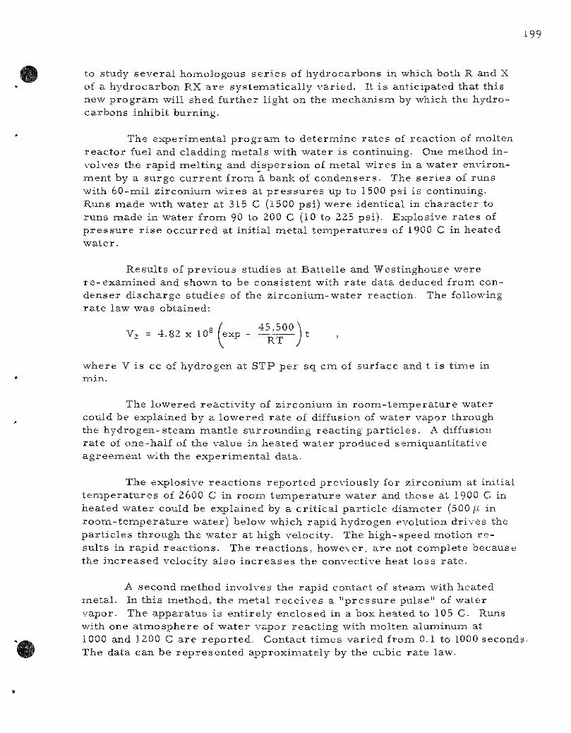
199
to study seve ra l homologous s e r i e s of hydrocarbons in which both R and X of a hydrocarbon RX a r e sys temat ica l ly var ied. It i s anticipated that this new p r o g r a m will shed fur ther light on the mechanism by which the hydrocarbons inhibit burning.
The exper imenta l p r o g r a m to de te rmine ra tes of react ion of molten r eac to r fuel and cladding meta l s with water is continuing. One method involves the rapid mel t ing and d i spers ion of naetal wi res in a water environment by a surge cu r ren t f rom a bank of condensers . The s e r i e s of runs with 60-mil z i rconium w i r e s at p r e s s u r e s up to 1500 ps i is continuing. Runs made with water at 315 C (1500 psi) were identical in cha rac t e r to runs made in water f rom 90 to 200 C (10 to 225 psi) . Explosive r a t e s of p r e s s u r e r i s e occu r r ed at initial meta l t e m p e r a t u r e s of 1900 C in heated water .
Resul ts of p rev ious studies at Battel le and Westinghouse were r e - e x a m i n e d and shown to be consis tent with ra te data deduced from condenser d ischarge studies of the z i rcon ium-wate r reaction. The following r a t e law was obtained:
V, = 4 . 8 2 x 1 0 ' ( e x p - i | S £ ^ ) t ,
where V is cc of hydrogen at STP per sq cm of surface and t is t ime in min.
The lowered reac t iv i ty of z i rconium in r o o m - t e m p e r a t u r e water could be explained by a lowered ra t e of diffusion of water vapor through the hydrogen-s t eam mant le surrounding react ing pa r t i c l e s . A diffusion ra t e of one-half of the value in heated water produced semiquanti tat ive ag reement with the exper imenta l data.
The explosive reac t ions r epor t ed previously for z i rconium at initial t e m p e r a t u r e s of 2600 C in roona t e m p e r a t u r e water and those at 1900 C in heated water could be explained by a c r i t i ca l pa r t i c l e d iameter (500 fi in r o o m - t e m p e r a t u r e water) below which rapid hydrogen evolution dr ives the pa r t i c l e s through the water at high velocity. The high-speed motion r e sul ts in rapid reac t ions . The r eac t ions , however, a r e not complete because the i nc reased velocity also i n c r e a s e s the convective heat loss r a t e .
A second method involves the rapid contact of s team with heated meta l . In this method, the meta l r ece ives a " p r e s s u r e pulse" of water vapor. The appara tus is ent i re ly enclosed in a box heated to 105 C. Runs with one a tmosphere of water vapor reac t ing with molten aluminum at 1000 and 1200 C a r e repor ted . Contact t imes var ied from 0.1 to 1000 seconds. The data can be r ep re sen t ed approximate ly by the cubic ra te law.
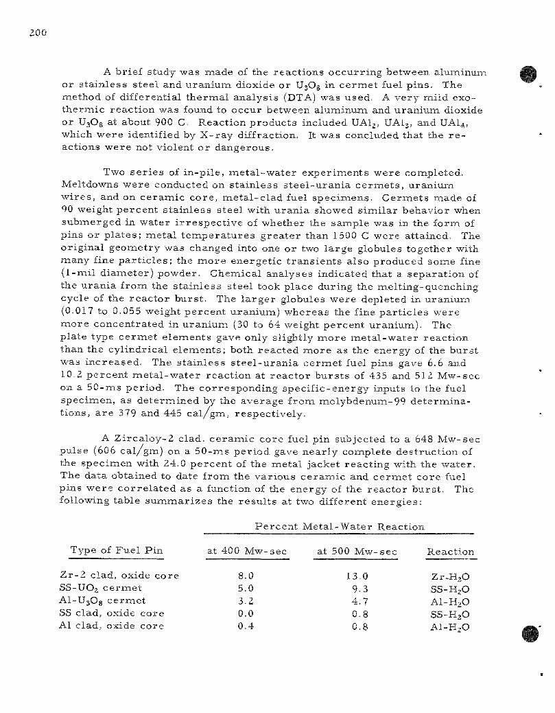
A brief study was made of the reac t ions occur r ing between aluminum or s ta in less s teel and uran ium dioxide or UsOg in c e r m e t fuel p ins . The method of differential thernaal analys is (DTA) was used. A very mild exothe rmic react ion was found to occur between aluminum and uran ium dioxide or UsOg at about 900 C. Reaction products included UAlg, UAI3, and UAI4, which were identified by X - r a y diffraction. It was concluded that the r e actions were not violent o r dangerous.
Two s e r i e s of in-p i le , me ta l -wa te r exper iments were completed. Meltdowns were conducted on s ta in less s t ee l -u ran ia c e r m e t s , u ran ium wi re s , and on ce ramic co re , me ta l - c l ad fuel spec imens . C e r m e t s made of 90 weight percen t s ta in less s teel with u ran ia showed s imi la r behavior when submerged in water i r r e spec t ive of whether the sample was in the form of pins or p la tes ; meta l t e m p e r a t u r e s g rea t e r than 1500 C were attained. The original geometry was changed into one or two la rge globules together with many fine p a r t i c l e s ; the m o r e energet ic t r ans i en t s also produced some fine (1-mil d iameter ) powder. Chemical analyses indicated that a separa t ion of the u ran ia f rom the s ta in less steel took place during the melt ing-quenching cycle of the r eac to r burs t . The l a r g e r globules were depleted in uraniumi (0.017 to 0.055 weight percent uranium) whereas the fine pa r t i c l e s were more concentra ted in u ran ium (30 to 64 weight percent uranium). The plate type c e r m e t e lements gave only slightly m o r e me ta l -wa te r react ion than the cyl indrical e lements ; both reac ted more as the energy of the burs t was inc reased . The s ta in less s t e e l -u r an i a c e r m e t fuel pins gave 6.6 and 10.2 pe rcen t m e t a l - w a t e r reac t ion at r eac to r bu r s t s of 435 and 512 Mw-sec on a 50 -ms per iod. The corresponding speci f ic -energy inputs to the fuel specimen, as de te rmined by the average from molybdenum-99 de te rminat ions, a r e 379 and 445 ca l / gm, respect ive ly .
A Z i rca loy-2 clad, c e r amic core fuel pin subjected to a 648 Mw-sec pulse (606 ca l /gm) on a 50 -ms per iod gave nea r ly complete des t ruct ion of the specimen with 24.0 pe rcen t of the metal jacket react ing with the water . The data obtained to date from the var ious ce r amic and c e r m e t core fuel pins were c o r r e l a t e d as a function of the energy of the reac tor burs t . The following table s u m m a r i z e s the r e su l t s at two different energ ies :
P e r c e n t Meta l -Water Reaction
Type of Fue l Pin
Z r - 2 clad, oxide core SS-UO2 c e r m e t Al-UjOg c e r m e t SS clad, oxide core Al clad, oxide core
at 400 Mw-
8.0 5 .0 3 .2 0 .0 0 . 4
•sec a t 500 Mw-
13.0 9 . 3 4 . 7
0 . 8 0 . 8
•sec R e a c t i o n
Z r -HjO SS-H2O AI-H2O SS-H2O AI-H2O

The conversion from reac to r to absorbed energy for the oxide core pins is 0.935 ( ca l /gm) /Mw-sec and 0.87 (ca l /gm) /Mw-sec for the s ta in less s t ee l -u ran ia c e r m e t s .
Trans ien t s conducted on 64-mil d iameter uranium (93 percent enriched) wi res gave 33.2 and 50.2 percent molten u ran ium-wate r react ion at r eac to r per iods of 440 and 152 m s , respect ively. The average energy input to the wire was 554 c a l / g m from molybdenum-99 analyses . The wi res were converted into fine pa r t i c l e s and powder. It is planned to cor re la te these exper iments with condenser discharge exper iments , which were also c a r r i e d out with w i r e s .
A. Metal Oxidation and Ignition Kinetics (L. Baker)
1. Ignition Studies of Uranium Powder by the Burning-curve Method
The burn ing-curve p rocedure has been used extensively to provide reproducible data on the ignition cha rac t e r i s t i c s of uranium. The sample , mounted on a thermocouple , is heated at a uniform ra te of t emp e r a t u r e inc rease (usually 10 deg/min) in a flowing oxidizing a tmosphere . As the r a t e of react ion i n c r e a s e s , the sample self-heats and finally ignites. A graphical in te rsec t ion method is used to determine ignition t empera tu re . The difference between furnace and sample t empe ra tu r e s gives an indication of the r a t e of reac t ion over a wide tem.perature range. The burning-curve method has been used to define the effects of var ied specific a rea , alloy addit ives, and gas composi t ions on ignition and maximum burning t e m p e r a t u r e (see ANLi-5974, pages 10 to 39)-
a. Effect of P re -ox ida t ion on the Ignition of Uranium Powder (M. Tetenbaumi and R. Wagner)
It was r epor t ed in the previous quar te r ly (ANL-6287, page 172) that ignition t e m p e r a t u r e d e c r e a s e s , levels off, and finally inc r e a s e s with extent of pre-oxida t ion of a fine fraction of spher ical uranium powder (-140 +170 mesh , d = 88/i) . Studies were extended to a coarse fraction (-20 +25 mesh , d = 710/i) to see if a lower specific a r ea powder would show a s imi la r effect. The r e su l t s a r e summar ized in F igure 55. It is apparent that the t rends a r e about the same for the coarse and fine uran ium fract ions . With c o a r s e powder, however, the changes of ignition t e m p e r a t u r e a r e l e s s than the changes obtained with the higher specific a r e a fraction.

FGUPE 55 PC FECT OF PRE-0/IDATlOIii ON IGNITIO"!! TEMPERA-'URES
0= L.RANIUM POWDER iN OXYGEN
20 30 40 50 60 % REACTION DwE " 0 BRE-OXIDATION
P r e - o x i d a t i o n was a c c o m p l i s h e d by h e a t i n g a th in l a y e r of the p o w d e r s in a i r at a p p r o x i m a t e l y 150 C for v a r y i n g l e n g t h s of t i m e . Af ter coo l ing and we igh ing , m i c r o s c o p i c e x a m i n a t i o n of both p o w d e r s a f te r p r e - o x i d a t i o n r e v e a l e d tha t t he s u r f a c e s had b e c o m e c o a t e d with b l a c k oxide n o d u l e s , the t h i c k n e s s i n c r e a s i n g wi th hea t i ng t i m e . F i g u r e 56 shows p h o t o m i c r o g r a p h s of -140 +170 m e s h p o w d e r a s r e c e i v e d and a f t e r 20 h r at 150 C. The oxygen up take (weight gain) of the p o w d e r s i s p l o t t e d in F i g u r e 57 a s a funct ion of t i m e . R e s u l t s r e p o r t e d p r e v i o u s l y (ANL-5974 , page 51) for the oxygen up t ake of p o l i s h e d 1 -cm u r a n i u m cubes i s p l o t t e d for c o m p a r i s o n . It i s a p p a r e n t t ha t both p o w d e r f r a c t i o n s show a f i r s t - s t a g e r e a c t i o n , fo l lowed by a c c e l e r a t i o n to a m o r e r a p i d , l i n e a r s e c o n d - s t a g e p r o c e s s p r e v i o u s l y r e p o r t e d for u r a n i u m c u b e s . The a c c u r a c y and s t ab i l i t y of the t e m p e r a t u r e d u r i n g the p o w d e r s t u d i e s , h o w e v e r , w e r e of a l o w e r o r d e r t han t h o s e o b t a i n e d in the i s o t h e r m a l s t u d i e s wi th c u b e s . Quan t i t a t i ve c o m p a r i s o n s of the r a t e s a r e , t h e r e f o r e , not m a d e .
The m i n i n i u i n ign i t ion t e m p e r a t u r e s in F i g u r e 55 a r e r e a c h e d a f t e r 5 to 1 0 p e r c e n t of the p o w d e r h a s b e e n r e a c t e d at 150 C. Ign i t ions i n i t i a t e d in the b u r n i n g - c u r v e a p p a r a t u s p r o b a b l y beg in in the m o r e r a p i d s e c o n d s t a g e . T h i s m a y accoun t for the d e c r e a s e d ign i t ion t e m p e r a t u r e .
b. Ign i t ion of U r a n i u m M o n o c a r b i d e P o w d e r s (M. T e t e n b a u m , R. Wagne r )
M e a s u r e m e n t s of the ign i t ion b e h a v i o r of u r a n i u m m o n o -c a r b i d e powde r ( h e r e b y d e s i g n a t e d a s S o u r c e A) w e r e r e p o r t e d in the p r e v i o u s q u a r t e r l y (ANL.-6Z87, page 173). S ince t hen , b u r n i n g - c u r v e s t u d i e s have been m a d e with p o w d e r f rom a d i f fe ren t s o u r c e fdes igna ted as S o u r c e B).
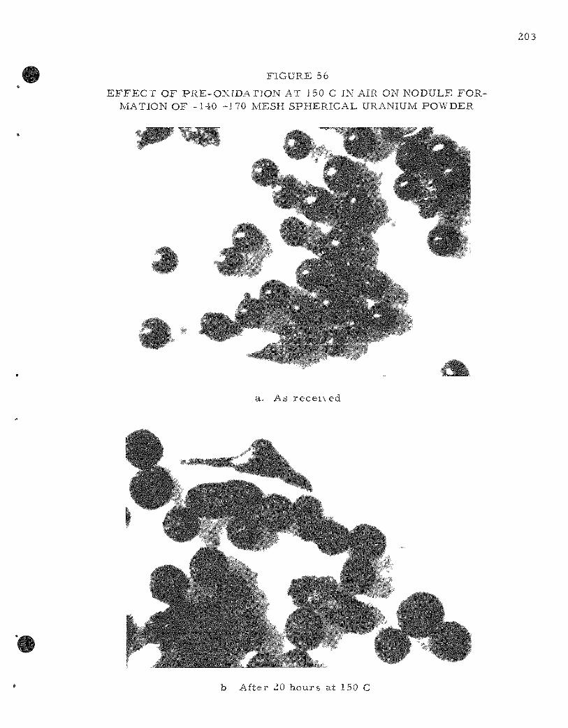
203
FIGURE 5 6
E F F E C T OF PRE-OXIDATION AT 150 C IN AIR ON NODULE FORMATION OF -140 -170 MESH SPHERICAL URANIUM POWDER
a. As r ece i \ ed
» b After 20 hours at 150 C
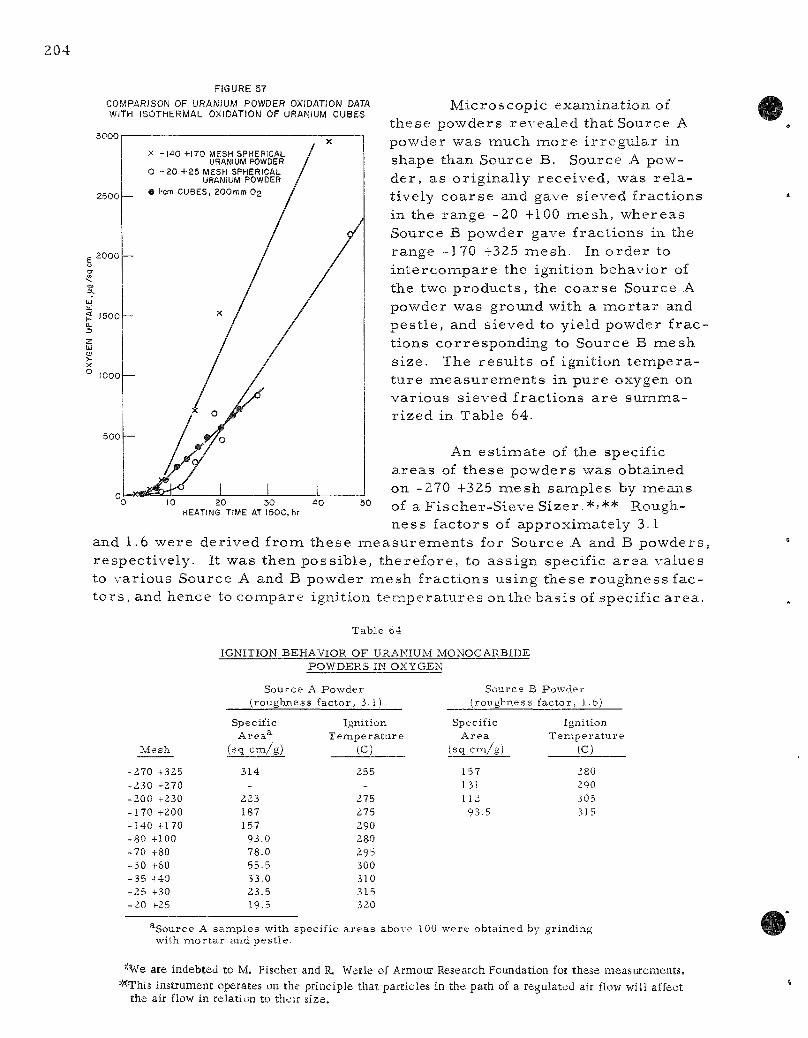
FIGURE 57
COMPARISON OF URANIUM POWDER OXIDATION DATA WITH ISOTHERMAL OXIDATION OF URANIUM CUBES
3000
2500
2000
1500
X o 1000
500
Microscopic examination of these powders revealed that Source A powder was much more i r r egu la r in shape than Source B. Source A powder , as originally received, was r e l a tively coarse and gave sieved fractions in the range -20 +100 mesh , whereas Source B powder gave fractions in the range -170 +325 mesh. In o rde r to in te rcompare the ignition behavior of the two produc ts , the coarse Source A powder was ground with a raor ta r and pes t le , and sieved to yield powder f ractions corresponding to Source B mesh size. The resu l t s of ignition t empera ture measu remen t s in pure oxygen on various sieved fractions a r e summar ized in Table 64.
iO 20 30 HEATING TIME AT I50C, hr
4 0 50
An es t imate of the specific a r eas of these powders was obtained on -270 +325 mesh samples by means of a Fischer-Sieve Sizer .* '** Roughness factors of approximately 3.1
and 1.6 were derived from these measu remen t s for Source A and B powders , respect ively. It was then poss ible , therefore , to assign specific a r e a values to various Source A and B powder mesh fractions using these roughness fact o r s , and hence to compare ignition t empe ra tu r e s on the basis of specific a rea .
T a b l e 64
IGNITION BEHAVIOR O F URANIUM MONOCARBIDE
M e s h
-Z70 -1-325 .230 -270 -200 -^230 -170 -f200 -140 -1-170 -80 -HOG -70 +80 -50 -1-60 -35 •f40 -25 +3,0 -20 F25
Source
POWDERS IN OXYGEN
A Powder (roughness factor, 3.1)
Specific Area^
(sq cm/g)
314
-223 187 157
93.0 78.0 55.5 33.0 23.5 19.5
Ignition Temperature
(C)
255 -
275 275 290 280 295 300 310 315 320
Source B Powder (roughness factor, 1.6)
Specific Area
(sq cm/g)
157 131 112 93.5
Ignition Tempera ture
(C)
280 290 305 315
^Source A samples with specific a reas above 100 were obtained by grinding with mor ta r and pestle.
^\'e are Indebted to M. Fischer and R. Werle of Armour Research Foundation for these measurements. '"This instrument operates on the principle that particles in the path of a regulated air flow will affect
the air flow in relation to their size.
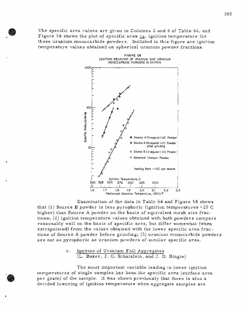
205
The specific a rea values a re given in Columns 2 and 4 of Table 64, and F igure 58 shows the plot of specific a r ea vs. ignition t empera tu re for these uranium monocarbide powders . Included in this figure a re ignition t empera tu re values obtained on spher ical uranium powder fract ions.
FIGURE 58 IGNITION BEHAVIOR OF URANIUM AND URANIUM
MONOCARBIDE POWDERS IN OXYGEN
1000
100
10
• Source A(Irregular) UC Powder
9 Source A (Irregular )UC Powder after grinding
A Source B (Irregular) UC Powder
O Spherical Uranium Powder
Heating Rate ~ I5C per minute
I Ignition Temperature, C 350 325 300 275 250 225
J^_J d \ L. 200
1.6 1.7 !,8 1.9 2.0 2.1 2.2 Reciprocal Absolute Temperoture, lOOO/T
2,3
Examination of the data in Table 64 and Figure 58 shows that (1) Source B powder is l e s s pyrophoric (ignition t empera tu res ~ 25 C higher) than Source A powder on the bas i s of equivalent mesh size f ract ions; (2) ignition tennperature values obtained with both powders compare reasonably well on the bas is of specific a rea , but differ somewhat (when extrapolated) from the values obtained with the lower specific a rea f ractions of Source A powder before grinding; (3) uranium monocarbide powders a r e not as pyrophoric as uran ium powders of s imi la r specific a rea .
c. Ignition of Uranium Foil Aggregates (L. Baker , J. G. Schnizlein, and J. D. Bingle)
The most important var iable leading to lower ignition t empe ra tu r e s of single samples has been the specific a r e a (surface a r e a per gram) of the sample. It was shown previously that there is also a decided lowering of ignition t empera tu re when aggregate samples a re
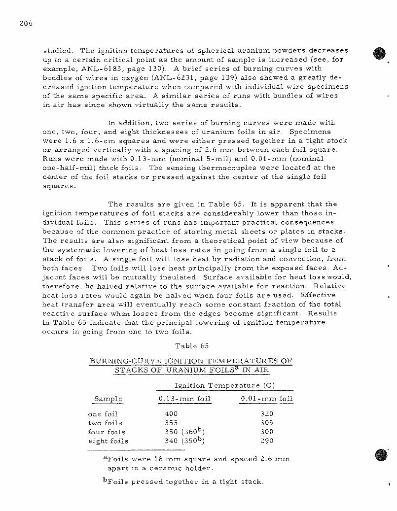
206
studied. The ignition t e m p e r a t u r e s of spher ical u ran ium powders dec reases up to a ce r ta in cr i t ica l point as the amount of sample is i nc reased (see, for example, A N I J - 6 1 8 3 , page 130). A brief s e r i e s of burning curves with bundles of wi res in oxygen (ANL-6231, page 139) also showed a great ly dec r e a s e d ignition t e m p e r a t u r e when compared with individual wire specinnens of the same specific a rea . A s imi la r s e r i e s of runs with bundles of wi res in a i r has since shown vir tual ly the same r e su l t s .
In addition, two s e r i e s of burning curves were made with one, two, four, and eight th icknesses of u ran ium foils in a i r . Specimens were 1.6 x 1.6-cm squares and were ei ther p r e s s e d together in a tight stock or a r ranged ver t ica l ly with a spacing of 2.6 mm between each foil square . Runs were made with 0 .13-mm (nominal 5-mil) and 0 .01-mm (nominal one-half-mil) thick foils. The sensing thermocouples were located at the center of the foil s tacks or p r e s s e d against the center of the single foil squa res .
The r e su l t s a re given in Table 65. It is apparent that the ignition t e m p e r a t u r e s of foil s tacks a r e considerably lower than those individual foils. This s e r i e s of runs has important p rac t i ca l consequences because of the common p r a c t i c e of s tor ing metal sheets or p la tes in s tacks . The r e su l t s a r e also significant from a theore t ica l point of view because of the sys temat ic lowering of heat loss r a t e s in going from a single foil to a stack of foils. A single foil will lose heat by radiat ion and convection, from both faces . Two foils will lose heat pr incipal ly from the exposed faces . Adjacent faces will be mutually insulated. Surface available for heat loss would, therefore , be halved re la t ive to the surface available for react ion. Relative heat loss r a t e s would again be halved when four foils a r e used. Effective heat t r ans fe r a rea will eventually reach some constant fraction of the total reac t ive surface when lo s ses f rom the edges become significant. Resul ts in Table 65 indicate that the pr incipal lowering of ignition t e m p e r a t u r e occurs in going from one to two foils.
Table 65
BURNING-CURVE IGNITION TEMPERATURES OF STACKS OF URANIUM FOILS^
Ignition Temper
Sample 0 .13 -mmfo i l
one foil 400 two foils 355 four foils 350 (360^) eight foils 340 (350^)
IN AIR
a ture (C)
0 .01-mm foil
320 305 300 290
^Foi ls were 16 m m square and spaced 2.6 m m apar t in a c e r a m i c holder .
"Foi l s p r e s s e d together in a tight stack.

Attempts to compute burning curves from i so thermal ra te data and heat t r ans fe r coefficients a r e underway. It may be possible to show quantitatively how inc reased specific a r ea and inc reased aggregation (lowered heat losses ) will lower m e a s u r e d ignition t e m p e r a t u r e s .
d. Ignition of Cer ta in ZPR-II I Blanket P la tes (J. G. Schnizlein, J. D. Bingle)
Because approximate ly 18 out of a total of 20,000 of the -~- in . - th ick uran ium pla tes in use in ZPR-II I to make up blankets in c r i t i ca l a s sembl i e s were observed to be de ter iora t ing and crumbling, the possibi l i ty of an i nc reased pyrophor ic i ty h a z a r d was investigated.
Both de t e r io ra t ed and apparent ly solid ma te r i a l from the same batch were obtained, and samples were p r e p a r e d in the form of approximate ly 3 -mm cubes. Spect rographic , oxygen, and hydrogen analyses were obtained and burn ing-curve ignition exper iments were per formed. The only impur i t i es out of the o rd ina ry , except oxygen, may have been p re sen t as surface contamination acquired during handling in the assembly. An ext remely high oxygen content (24,000 ppm) of the de te r io ra ted sample and a high content (530 ppm) in the unaffected sample suggested poros i ty of the samples .
The ignition t e m p e r a t u r e in oxygen of the unaffected m a t e r i a l (480 C) was approximate ly 60 degrees lower than that obtained for r e a c t o r - g r a d e uran ium in prev ious exper iments with samples of s imi la r s ize . The de te r io ra t ed samples ignited at 115 C in ei ther oxygen or a i r . This t e m p e r a t u r e is slightly lower than the lowest ignition t e m p e r a tu r e previous ly obtained, i .e . , 120 C, for a compacted sample of i r r e g u l a r uranium powder which had a m e a s u r e d specific a r e a of 6,500 sq c m / g m .
It would appear that the de ter iora t ion p r o c e s s is result ing in a r eve r s ion to powder. It is unders tood that these pla tes were p r epa red by powder meta l lu rg ica l methods using hydr ided-dehydr ided inetal powder and that a l a r g e r f ract ion of such p la tes a r e showing signs of de ter iora t ion than a r e the p la tes fo rmed by rol l ing or casting and stamping. Metai lo-graphic examination also indicated poros i ty .
The de te r io ra t ion of u ran ium formed by a powder me ta l lurgica l p r o c e s s due to slow oxidation within the po re s can cause a pyrophor ic i ty haza rd . If poros i ty is an inherent p roper ty of powder meta l lu rg ica l ly formed u ran ium, then it inust be pro tec ted from the air to avoid such hazard .
Pe r sonne l at ZPR have iiiinimized the hazard by recoating the meta l with a f luorocarbon p las t ic per iodical ly . Careful frequent inspect ions a r e also made to remove affected p ieces . The de te r io ra ted p la tes have been s tored in an iner t a tmosphere in sealed paint cans which were placed approximate ly 6 in. apar t in a sand bath.
2. Burning-propagat ion Studies (L. Leibowitz, L. W. Mishler)
The burning-propagat ion r a t e , i .e . , the ra te of advance of a combustion zone along a foil or wi re , has proven to be a useful, r e p r o ducible quantity for studying the na ture of meta l combustion, as well as for judging the influence of var ious fac tors on the burning p r o c e s s .
The meta l is ignited at one end by an e lec t r ica l ly heated plat inum wire and, here tofore , a motion p ic tu re r e c o r d made of the p r o c e s s . Linear propagat ion r a t e s were obtained from these motion p i c tu re s . A new ins t rument has been developed, however, which p e r m i t s the s imultaneous and rapid de terminat ion of burning velocity and t e m p e r a t u r e . This device will be used to study sys temat ica l ly the effect of var ious halogenated hydrocarbons on the burning me ta l .
a. P roposed Studies of the Effect of Halogenated Hydrocarbons on Burning Propagat ion
The effectiveness of halogenated hydrocarbons in combatting f i res has been recognized for some t ime . The ear ly l i t e r a tu r e has been s u m m a r i z e d by F rybu rg . ^^ As pa r t of a search for p rac t i ca l methods of controll ing and prevent ing meta l f i r e s , a l a rge number of substances have been examined for the i r effect on burning-propagat ion ra t e and burning t e m p e r a t u r e . The presen.ce of a few percent in a i r of var ious halogenated hydrocarbons caused a m a r k e d reduct ion in burning propagat ion ra te (ANL-6231, pages 142, 152). Although some study has been made of the mechan ism by which halogenated hydrocarbons inhibit hydrocarbon combust ion,3- it is not at all c lea r how these compounds influence meta l combustion. Because of the low vapor p r e s s u r e of uranium34 at the burning t e m p e r a t u r e , a gas -phase combust ion in a i r is unlikely. The halogenated hydrocarbon thus could not opera te in the s ame manner with me ta l s as with hydrocarbon fuels.
Exainination of the effect of the halogenated agents on the the rma l conductivity and heat capaci ty of a i r e l iminate these p rope r t i e s as the source of the effect. Two pr inc ipa l m e c h a n i s m s may be suggested; (a) the halogenated agents decompose on the burning meta l surface and
37 F r y b u r g , G., Review of L i t e r a t u r e Pe r t inen t to F i re -ex t ingu ish ing Agents and to Basic Mechanisms Involved in Thei r Action, NACA-TN-2102 (May 1950).
3 3 •^-^Belles, F . E . , Chemical Action of Halogenated Agents in F i r e
Extinguishing, NACA-TN-3565 (Sept. 1955).
^ ^ a u h , E . G., and Thorn, R. J. , J. Chem. Phys . , 22, 1414 (1954).
r e m o v e h e a t by the r e a c t i o n
RX ^ R - + X , (1)
w h e r e X is a h a l o g e n a t o m and R- an o r g a n i c r a d i c a l ; o r (b) R e a c t i o n (1) i s follo'wed by
R. + O2 —ROz- , (2)
and the r a t e of the d i f f u s i o n - c o n t r o l l e d c o m b u s t i o n i s l o w e r e d b e c a u s e of a ne t r e d u c t i o n in oxygen a v a i l a b i l i t y . B o n d - d i s s o c i a t i o n e n e r g i e s for a s e r i e s of h a l o m e t h a n e s a r e l i s t e d be low . ^^
D ( R - X ) , k c a l
C H 3 - F CH3-C1 C H a - B r CH3-I
107 80.7 67.5 54
C o n s i d e r a b l e h e a t cou ld b e r e m o v e d f r o m t h e b u r n i n g r e g i o n by such a d i s s o c i a t i o n . R e a c t i o n s s u c h a s (2) h a v e b e e n p r o p o s e d by s e v e r a l w o r k e r s . B l a e d e l , Ogg, and L e i g h t o n , ^ " for e x a m p l e , in s tudying the p h o t o - o x i d a t i o n of m e t h y l i o d i d e p r o p o s e d
CH3I + hv mm-CUs- + I (3)
CHs- + O2 — ^ C H 3 0 2 - (4)
CHjOz- + CH3 —CH3OH + CH2O (5)
a s p a r t of the r e a c t i o n s c h e m e .
A n u m b e r of e x p e r i m e n t s w e r e p e r f o r m e d to d e t e r m i n e the e f f e c t i v e n e s s of the h a l o g e n a t e d c o m p o u n d s in coo l ing an e l e c t r i c a l l y h e a t e d p l a t i n u m foi l . T h e s e r e s u l t s h a v e b e e n r e p o r t e d ( A N L - 6 2 8 7 , p a g e 179) and i n d i c a t e t h a t r e a c t i o n (1) i s not the s o u r c e of the c o m b u s t i o n inh ib i t i on if r e s u l t s wi th the p l a t i n u m c a n be a p p l i e d to b u r n i n g u r a n i u m o r z i r c o n i u m .
S e v e r a l s e r i e s of comipounds have b e e n s e l e c t e d to e x p l o r e s y s t e m a t i c a l l y the r e l a t i v e i m p o r t a n c e of r e a c t i o n s (1) and (2) in the c a s e of m e t a l c o m b u s t i o n in a i r c o n t a m i n a t e d wi th h a l o g e n a t e d h y d r o c a r b o n s . T h e s e c o m p o u n d s a r e l i s t e d be low .
3 5 s z w a r c , M. , C h e m . R e v . , 47 , 75 (1950).
' B l a e d e l , W. J . , 64, 2500 (1942).
^ ^ B l a e d e l , W. J . , Ogg , R. A . , and L e i g h t o n , P . A . , J. A m . C h e m . S o c ,
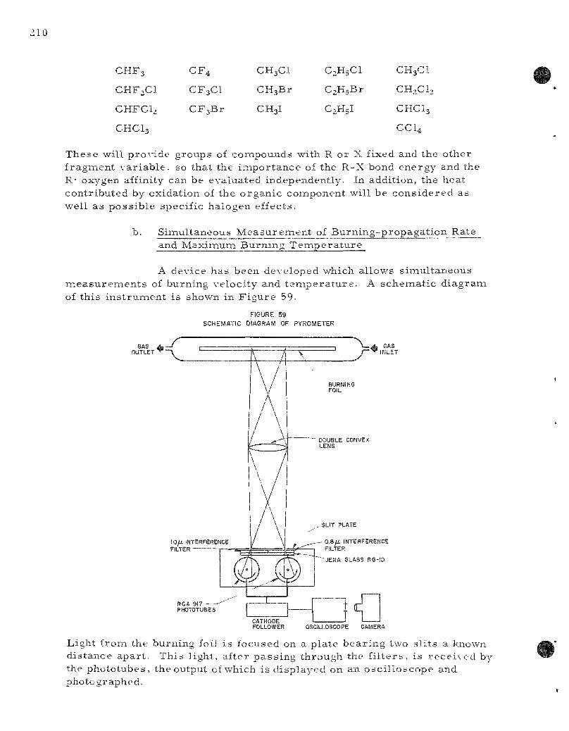
CHFg
CHF2C1
CHFC12
CHC13
C F 4
CF3C1
C F s B r
CH3CI
CHsBr
CH3I
C2H5CI
CaHgBr
C2H5I
CH3CI
CH2CI
CHCI3
CCI4
T h e s e wil l p r o v i d e g r o u p s of c o m p o u n d s with R o r X f ixed and the o t h e r f r a g m e n t v a r i a b l e , so tha t the i m p o r t a n c e of the R - X bond e n e r g y and the R- oxygen affinity can be e v a l u a t e d i ndependen t ly . In add i t ion , t he hea t c o n t r i b u t e d by ox ida t ion of the o r g a n i c c o m p o n e n t wi l l be c o n s i d e r e d as wel l a s p o s s i b l e spec i f i c h a l o g e n e f fec t s .
S i m u l t a n e o u s M e a s u r e m e n t of B u r n i n g - p r o p a g a t i o n Ra te and Maximui-n B u r n i n g T e m p e r a t u r e
A dev ice h a s b e e n d e v e l o p e d which a l lows s i m u l t a n e o u s IT ieasure inen ts of b u r n i n g ve loc i t y and t e m p e r a t u r e . A s c h e m a t i c d i a g r a m of t h i s i n s t r u m e n t is shown in F i g u r e 59.
FIGURE 59
SCHEMATIC DIAGRAM OF PYROMETER
^ GAS ~ INLET
lOfJ. INTERFERENCE FILTER
RCA 917 PHOTOTUBES
_ 0 .8 / i . INTERFERENCE FILTER
OSCILLOSCOPE
Ligh t f r o m the b u r n i n g foil i s focused on a p l a t e b e a r i n g two s l i t s a known d i s t a n c e a p a r t . T h i s l igh t , a f t e r p a s s i n g t h r o u g h the f i l t e r s , i s r e c e i v e d by the p h o t o t u b e s , t he out]3ut of which i s d i s p l a y e d on an o s c i l l o s c o p e and p h o t o g r a p h e d .

The burning velocity is easi ly calculated from the t ime requ i red for the burning front to t r ave l the distance between the s l i t s . The burning t empe ra tu r e may be found in two ways. The radiation intensity in the normal direct ion, ibn} , at wave length X for a black body at absolute t e m p e r a t u r e T is given by the Planck equation
. ^ 2hc^ ^ ^^1 /^s '^'''^~ X' (exp [hc/X kT ] - 1) X5 (exp [C2A T ] - 1)
where h is P lanck ' s constant , k Bol tzmann 's constant, c the velocity of light, and Cj and C2 a r e constants defined by these equations. Neglecting unity in the denominator ,
2Ci
'^"^^ ~~ X^ exp(C2AT) ' ^'^
and for a non-black body
2£Ci 2Ci
nx X5 exp(C2/XT) X^ exp(C2ATB) (8)
where £ is the emiss iv i ty and T g the br igh tness t empe ra tu r e .
In ter ference f i l te rs and the Jena glass f i l ter , RG-10, t ransnait sharply defined wave lengths to the phototubes. Wave lengths of 805 and 976 m/i a r e rece ived by the left- and r ight-hand phototubes, respect ive ly . With the availabil i ty of emiss iv i ty values for tungsten,-^ ' it was poss ib le to ca l ib ra te the ins t rument using a tungsten ribbon lamp, the t e m p e r a t u r e of which was m e a s u r e d using a Leeds and Northrup optical py rome te r . Good ag reemen t was found with the theore t ica l equation.
It is also poss ib le to use the ins t rument as a two-color p y r o m e t e r . The ra t io of in tens i t ies (r) at the two wave lengths Xj and Xj is given by
iX^ ^ z ^ X j
ix, He. exp _2_
X2 (9)
and a s imi la r ca l ibra t ion may be c a r r i e d out. In measur ing the t e m p e r a tu re of objects of unknown emiss iv i ty , the ra t io method offers the advantage that it is general ly a be t te r approximation to a s sume the rat io of emis s iv -i t ies to be unity than to a s sume that the emiss iv i ty itself is unity. It was
^'^De Vos, J. C , Phys ica , 20, 698 (1954)

212
F I G J R E 60
OoCli-LOSCOPE RECORD OF TYPICAL BURWING °R0P4GATI0N OF URANIUM FOIL BURHI^G IN AIR
lOr
found, h o w e v e r , t ha t the m a x i m u m t e m p e r a t u r e of the b u r n i n g f ron t i s not p r e c i s e l y c o n s t a n t a long the e n t i r e l ength of the foil . S ince the r a t i o m e t h o d i s far i n o r e s e n s i t i v e to v a r i a t i o n s in i n t e n s i t y , the b r i g h t n e s s t e m p e r a t u r e wil l be m e a s u r e d u s i n g the i n s t r u m e n t a s two s i n g l e -c o l o r p y r o m e t e r s .
A t y p i c a l o s c i l l o s c o p e r e c o r d of the b u r n i n g is shown in F i g u r e 60. A 3 - m m wide , 0 . 1 3 - m m (5-iTiil) t h i c k u r a n i u m foil was b u r n e d in a i r . Since 6.3 s e c w e r e r e q u i r e d for t h e b u r n i n g f ront to c o v e r the 3 225 cim b e t w e e n the s l i t s , a b u r n i n g ve loc i t y of 0.51 c m / s e c r e s u l t s . F r o m the p e a k h e i g h t s , b r i g h t n e s s t e m p e r a t u r e s of 1325 and 1320 C
•* a r e found at 0.8/-*-(at 4 sec ) and 1.0,a (at 10 s e c ) , r e s p e c t i v e l y . T h i s b u r n i n g
v e l o c i t y a g r e e s we l l wi th the va lue 0.56 c m / s e c found by the p r e v i o u s m e t h o d (ANL-6068 , p a g e 130).
M e a s u r e m e n t s of b u r n i n g v e l o c i t y and t e m p e r a t u r e wil l be c a r r i e d out in a i r c o n t a m i n a t e d with s m a l l q u a n t i t i e s of the o r g a n i c c o m pounds l i s t e d in the p r e c e d i n g s e c t i o n . Both u r a n i u m and z i r c o n i u m wil l be s tud i ed in th i s way.
B. M e t a l - W a t e r R e a c t i o n s (L. B a k e r )
1. C o n d e n s e r - d i s c h a r g e Method (L. B a k e r , R. W a r c h a l )
The c o n d e n s e r - d i s c h a r g e e x p e r i m e n t i s an a t t e m p t to ob ta in fundamen ta l r a t e da t a u n d e r e x p e r i m e n t a l cond i t ions s i m i l a r to t h o s e enc o u n t e r e d d u r i n g a s e r i o u s a c c i d e n t in a n u c l e a r r e a c t o r . E i t h e r a n u c l e a r runav^ay o r a sudden l o s s of coo lan t d u r i n g o p e r a t i o n of a w a t e r - c o o l e d r e a c t o r cou ld r e s u l t in c o n t a c t b e t w e e n v e r y hot fuel and c l add ing m e t a l s wi th w a t e r o r s t e a m , and migh t invol \ e fine p a r t i c l e s . The c o n d e n s e r -d i s c h a r g e e x p e r i m e n t s i m u l a t e s the l i m i t i n g c a s e of a n u c l e a r inc iden t in tha t the h e a t i n g t i m e is v e r y s h o r t and v e r y fine m e t a l p a r t i c l e s a r e p r o d u c e d .
In the c o n d e n s e r - d i s c h a r g e e x p e r i m e n t , m e t a l w i r e s a r e r ap id ly m e l t e d and d i s p e r s e d in a w a t e r - f i l l e d ce l l by a s u r g e c u r r e n t f r om a bank of c o n d e n s e r s . The e n e r g y input to the w i r e is u s e d to c a l c u l a t e the in i t ia l
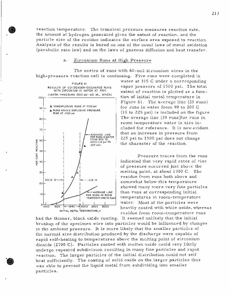
2 1 3
r e a c t i o n t e m p e r a t u r e . The t r a n s i e n t p r e s s u r e m e a s u r e s r e a c t i o n r a t e , the a m o u n t of h y d r o g e n g e n e r a t e d g ives the extent of r e a c t i o n , and the p a r t i c l e s i z e of the r e s i d u e i n d i c a t e s the s u r f a c e a r e a exposed to r e a c t i o n . A n a l y s i s of t h e r e s u l t s i s b a s e d on one of the u s u a l l aws of m e t a l ox ida t ion ( p a r a b o l i c r a t e law) and on the l a w s of g a s e o u s diffusion and h e a t t r a n s f e r .
a. Z i r c o n i u m R u n s a t High P r e s s u r e
The s e r i e s of r u n s wi th 6 0 - m i l z i r c o n i u m w i r e s in the h i g h - p r e s s u r e r e a c t i o n c e l l is con t inu ing . F i v e r u n s w e r e c o m p l e t e d in
w a t e r at 315 C u n d e r a c o r r e s p o n d i n g
100
90
80
70
I 60 p
o: 50 —
. 4 0
30 -
FIGURE 61
RESULTS OF CONDENSER-DISCHARGE RUNS WITH ZIRCONIUM IN WATER AT 3I5C
(VAPOR PRESSURE 1500 psi - 60 MIL WIRES)
20
10 -
A NONEXPLOSIVE RUNS AT 1500 psi
• RUNS HAVING EXPLOSIVE PRESSURE RISE AT 1500 psi
AVERAGE LINE FOR RUNS IN WATER FROM 9 0 0 TO 2 0 0 C (10 psi TO
A 225 psi)
SOLID Zr
1000 — 1 8 4 0 - — » f
AVERAGE LINE FOR RUNS IN ROOM TEMPERATURE (O.Spsi)
I I 1500 — 1 8 4 0 - — » 2 0 0 0 2 5 0 0 3 0 0 0
INITIAL METAL TEMPERATURE,C
v a p o r p r e s s u r e of 1500 p s i . The to ta l ex ten t of r e a c t i o n is p l o t t e d as a funct ion of in i t i a l m e t a l t e m p e r a t u r e in F i g u r e 6 1 . The a v e r a g e l ine (25 r u n s ) for r u n s in w a t e r f r o m 90 to 200 C (10 to 225 ps i ) i s inc luded on the f i gu re . The a v e r a g e l ine (30 runs ) fo r r u n s in r o o m t e m p e r a t u r e w a t e r is a l s o in c luded for r e f e r e n c e . It i s now evident t h a t an i n c r e a s e in p r e s s u r e f r o m 225 p s i to 1500 p s i does not change the c h a r a c t e r of the r e a c t i o n .
P r e s s u r e t r a c e s f r o m the r u n s i n d i c a t e d that v e r y r a p i d r a t e s of r i s e of p r e s s u r e o c c u r r e d jus t above the m e l t i n g poin t , at about 1900 C. The r e s i d u e f r o m r u n s both above and s o m e w h a t be low t h i s t e m p e r a t u r e showed m a n y m o r e v e r y fine p a r t i c l e s than r u n s at c o r r e s p o n d i n g in i t i a l t e m p e r a t u r e s in r o o m - t e m . p e r a t u r e w a t e r . Mos t of the p a r t i c l e s w e r e h e a v i l y coa t ed with whi te ox ide , w h e r e a s r e s i d u e f r o m r o o m - t e m p e r a t u r e r u n s It s e e m e d un l ike ly tha t the in i t i a l had the t h i n n e r , b l a c k oxide coa t ing
b r e a k u p of the s p e c i m e n w i r e into p a r t i c l e s would be inf luenced by changes in the a m b i e n t p r e s s u r e . It i s m o r e l i ke ly tha t the s m a l l e r p a r t i c l e s of the n o r m a l s i z e d i s t r i b u t i o n p r o d u c e d by the d i s c h a r g e w e r e c a p a b l e of r a p i d s e l f - h e a t i n g to t e m p e r a t u r e s above the m e l t i n g po in t of z i r c o n i u m dioxide (2700 C). P a r t i c l e s coa t ed wi th m o l t e n oxide could v e r y l i ke ly u n d e r g o r e p e a t e d s u b d i v i s i o n r e s u l t i n g in m a n y fine p a r t i c l e s and r a p i d r e a c t i o n . The l a r g e r p a r t i c l e s of the in i t i a l d i s t r i b u t i o n could no t self h e a t suf f ic ient ly . The coa t ing of so l id oxide on the l a r g e r p a r t i c l e s thus w a s ab le to p r e v e n t the l iqu id m e t a l f r o m subdiv id ing into s m a l l e r p a r t i c l e s .
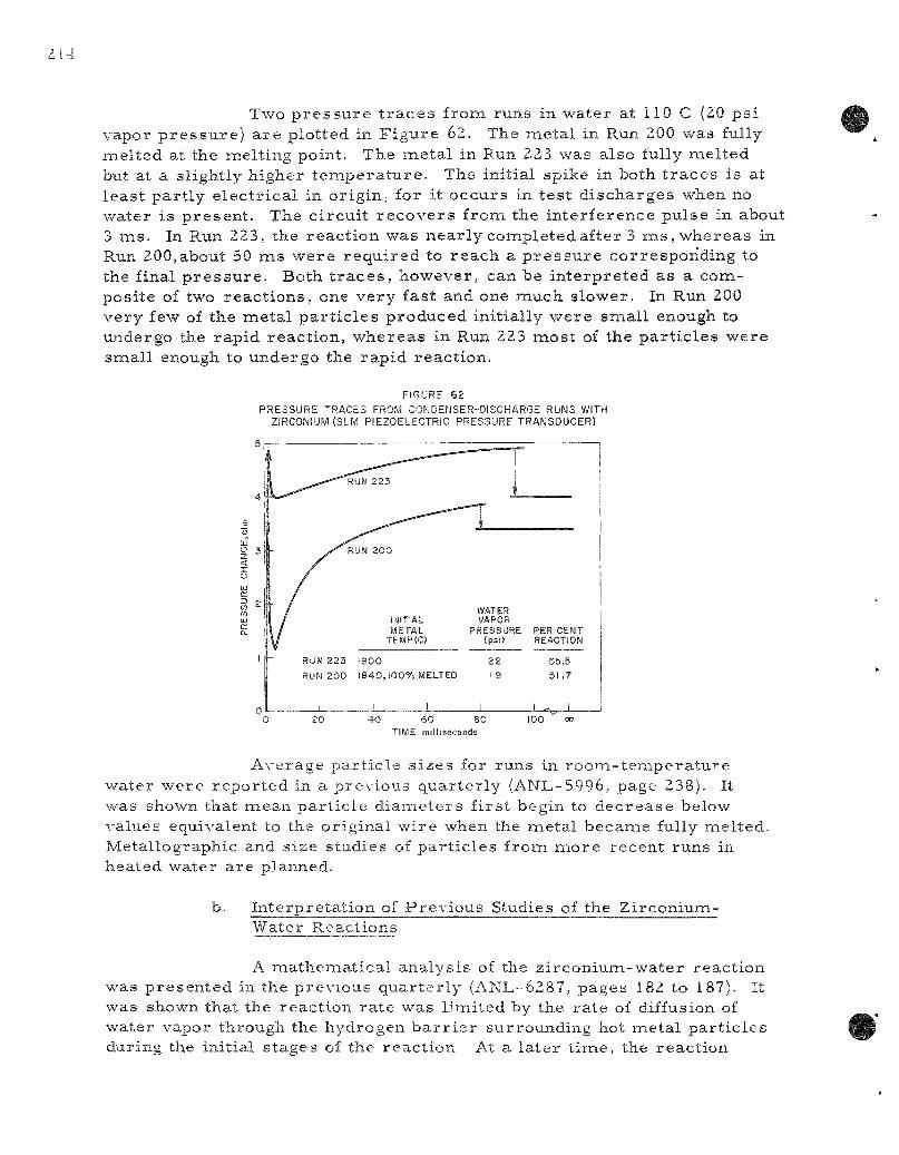
214
Two p r e s s u r e t r a c e s from runs in water at 110 C (20 ps i vapor p r e s s u r e ) a r e plotted in F igu re 62. The meta l in Run 200 was fully melted at the melting point. The meta l in Run 223 was also fully melted but at a slightly higher t e m p e r a t u r e . The initial spike in both t r a c e s is at least par t ly e lec t r ica l in origin, for it occurs in tes t d ischarges when no water is p resen t . The c i rcui t r e c o v e r s from the interference pulse in about 3 ms . In Run 223, the react ion was near ly completed after 3 m s , whereas in Run 200,about 50 ms were requ i red to reach a p r e s s u r e corresponding to the final p r e s s u r e . Both t r a c e s , however, can be in terpre ted as a composite of two reac t ions , one very fast and one much slower. In Run 200 very few of the metal pa r t i c l e s produced initially were small enough to undergo the rapid react ion, whereas in Run 223 most of the par t i c les were small enough to undergo the rapid reaction.
FIGURE 6 2
PRESSURE TRACES FROM CONDENSER-DISCHARGE RUNS WITH ZIRCONIUM ( S I M PIEZOELECTRIC PRESSURE TRANSDUCER)
IMITiAL METAL
TEMP{C)
WATER VAPOR
PRESSURE PER CENT (psi) REACTION
RUN 223 1900
RUN 2 0 0 1 8 4 0 , 1 0 0 % MELTED
22 19
55.5 51.7
4 0 SO 8 0 TIME, milisseconds
100
Average par t ic le s izes for runs in room- t empera tu r e water were repor ted in a previous quar te r ly (ANL-5996, page 238). It was shown that mean par t i c le d iamete rs f i rs t begin to dec rease below values equivalent to the original wire when the metal became fully melted. Metallographic and size studies of pa r t i c les from m o r e recent runs in heated water a re planned.
b. In terpre ta t ion of Prev ious Studies of the Zirconium-Water Reactions
A matheiTiatical analysis of the z i rconium-water react ion was p resen ted in the previous quar te r ly (ANL-6287, pages 182 to 187). It was shown that the react ion ra te was l imited by the ra te of diffusion of water vapor through the hydrogen b a r r i e r surrounding hot metal par t ic les during the initial s tages of the react ion At a la ter tiiTie, the react ion

2
becomes linaited by the parabol ic ra te law. The parabol ic ra te law is general ly cons idered to apply when reac t ion is l imited by the r a t e of diffusion of e i ther meta l ions or oxygen ions through the oxide la t t ice . The ra t e of the f i rs t p r o c e s s , gaseous diffusion, was considered to depend only on the mean t e inpe ra tu re between the meta l and the water and on the vapor p r e s s u r e of water at the w a t e r - w a t e r vapor interface. The ra te of the second p r o c e s s , so l id-s ta te diffusion, was cons idered to depend only on the t emp e r a t u r e of the oxide and the th ickness of the oxide film. The ra te of the so l id-s ta te p r o c e s s d e c r e a s e s very rapidly as the oxide film thickens. The r a t e of the so l id -s ta te p r o c e s s is theore t ica l ly infinite at zero t ime; however , it rapidly d e c r e a s e s and eventually becomes l e s s than the gaseous diffusion r a t e . At this point, the reac t ion becomes controlled by solid-state p r o c e s s e s .
Some of the r e su l t s of previous invest igators were examined in the light of the above concepts . One i so thermal study of the Z i r ca loy -2 -wa te r reac t ion and one of the Z i r c a l o y - 2 - s t e a m react ion were examined in pa r t i cu la r . The studies with water were c a r r i e d out by B o s t r o m a t Westinghouse 38 by induction heating u n d e r w a t e r . Reaction was followed by collecting success ive fract ions of hydrogen generated by react ion. Studies with s team were c a r r i e d out by Lemmon e t aL at Battelle.-^9 in th is study, s team at 20 or 50 ps i was p a s s e d over inductively heated meta l and the extent of r e action de te rmined by m e a s u r e m e n t s of the hydrogen collected. The re su l t s of both studies were summar i zed in the Battel le Report.-^9
Neither inves t iga tor cons idered the possibi l i ty that the reac t ion might have been l imi ted by gaseous diffusion during the ear ly pa r t of a run. Resul t s r epo r t ed by B o s t r o m at 1750 C deviated ser ious ly f rom the parabol ic slope on a plot of the log of hydrogen gas evolved vs . the log of t ime . " The reac t ion appeared to be somewhere between parabol ic and l inear . B o s t r o m ' s data at 1750 C is replot ted in F igure 63. The square of the quantity of hydrogen evolved is plot ted as a function of t i ine. A straight line on this type of plot indicates a parabol ic r a t e . It is apparent that the f i r s t t h r ee points indicated a lower slope than the r emainder , which followed a sa t is factory s t ra ight l ine. This change in slope could be accounted for by t rans i t ion f rom a reac t ion l imi ted by gaseous diffusion to one l imi ted by the parabol ic r a t e law. The lowered initial r a t e could also be due to fai lure to heat the spec imen to reac t ion t e m p e r a t u r e rapidly enough. In ei ther case the log-log plot does not show the t rans i t ion. The t rue parabol ic r a t e constant can be obtained from the slope of the line in F igure 63.
"Bos t rom, W. A., The High T e m p e r a t u r e Oxidation of Zircaloy in Water , WAPD-104 (March 1954).
"Lemmon, A. W., J r . Studies Relating to the Reaction between Zi rconium and Water at High T e m p e r a t u r e s , BMI-1154 (Jan. 1957).

FIGURE 63
REACTION BETWEEN ZIRCALOY-2 AND
WATER AT 1750 C
(DATA FROM BOSTROM, WAPD-104)
25,000
' 20,000
15.000
10,000
5,000
Lfd^ 0.5 1.0 1.5
TIME.mmutss
2.0 2.3
FIGURE 6 4 EFFECT OF TEMPERATURE ON
THE ZiRCONIUM-WATER REACTION 100,000
% 10,000 -
£, CONDENSER DiSCriARGE WETHOD o-BOSTROM. WAPO l04lttCJlCUI.WM! •-LEMMON, BMM154{REt»lClll»IED)
x - 4 8 2 « i 0 8 e x p - 5 ^ 2 2
Bos t rom ' s data at other t empera tu re s indicate an i n c r e a s ing ra te when oxide films become about 25 mils thick. Oxidation to this degree is normal ly not encountered in the condenser -d i scharge studies. Battel le data also showed some tendency toward a decreased initial ra te .
The re su l t s of replotting both sets of data a r e indicated in F igure 64, where the log of the parabol ic ra te constants a r e plotted as a function of rec iproca l absolute t empera tu re . The falling off of the Battel le data above 1300 C is not understood. The react ion ra te at 1840 C (melting point of zirconium) used in the computer studies of the condenser -discharge exper iment is also included on F igure 64.
The value obtained from the condenser studies is more in line with B o s t r o m ' s data. The line drawn in Figure 64 cor responds to an activation
energy of 45.5 kca l /mole and fits condenser data, B o s t r o m ' s data, and the low- tempera tu re Battel le data. The activation energy obtained in this way is believed to be m o r e sat isfactory than one obtained solely from condenser d ischarge studies.
J L 10''/{T,K!
2000 1800 1600 1400 1200 TEMPERATURE,C
1000
The following ra t e law was then calculated:
V^ = 4 . 8 2 x 1 0 ^ ( e x p - i | | ^ ) t , (10)
where V is cc hydrogen at STP pe r sq cm of surface and t is t ime in min.
c. Compar i son of Computed Resul ts with Exper imenta l Resul t s
Computed r e su l t s p resen ted in the previous quar te r ly r e f e r r ed to runs with heated water . It was shown that extensive react ion occu r r ed with a pa r t i c l e , 1.05 m m in diamieter, which was only par t ia l ly mel ted. This r esu l t was consis tent with the exper imental r e su l t s which indicated that react ion rapidly i nc r ea sed with initial metal t empera tu re for meta l in the melt ing point region (see F igure 61).
It was suggested that the much l e s s extensive react ion occur r ing in r o o m - t e m p e r a t u r e water was the resu l t of a dec reased ra te of gaseous diffusion. The very low vapor p r e s s u r e of water at room t emp e r a t u r e (0.5 psi) caused a lowering of the ra te of diffusion of water vapor through the hydrogen b a r r i e r surrounding the meta l pa r t i c l e s . Several methods of descr ibing the d e c r e a s e were investigated theoret ical ly . A ve ry s imple assumpt ion provided reasonable agreement with the data.
Runs with water at room t empe ra tu r e were done both with and without ine r t gas . Runs without added iner t gas generated enough hydrogen and s team a lmost immedia te ly so that the bulk water t e m p e r a t u r e (room t empera tu re ) was below the boiling point of the water deternained by the total p r e s s u r e . This condition is general ly r e f e r r e d to as subcooling. In o r d e r to r ea l i ze the full diffusion r a t e , water at the surface facing heated meta l naust be uniformly at the boiling point. If turbulence or heat t r ans fe r into the water causes a d e c r e a s e in the average t empe ra tu r e of the water surface , then a dec reased diffusion r a t e would resu l t . It was assumed that the average vapor p r e s s u r e driving diffusion was one-half of the total p r e s s u r e . Diffusion r a t e s would then be one-half of those calculated for runs in heated water .
Resul t s of computed reac t ions using one-half of the theore t i ca l diffusion r a t e a r e compared to exper imenta l r e su l t s in F igu re 65. Average pa r t i c l e s izes for runs in which the meta l was not fully mel ted were approximately 1050 jJ. for 30-mil w i r e s , and 2100/i for 60-mil w i r e s . The exper imenta l mean pa r t i c l e d i ame te r s for runs with molten meta l a r e included on the figure. It is apparent that the calculated r e su l t s agree quali tat ively with the exper imenta l r e su l t s for the total extent of react ion.
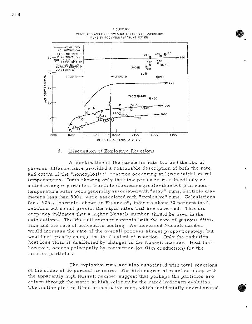
FIGURE 65
COMPUTED AND EXPERIMENTAL RESULTS OF ZIRCONIUM RUNS IN ROOM-TEMPERATURE WATER
•=,0
4 0
30
20
10
EXPERIMENTAL!
O 60-MIL WIRES a 30 -M lLWIRES
• • EXPLOSIVE PRESSURE RISE
(NUMBERS INDICATE AVERAGE PARTICLE DIAMETER,/J.)
SOLID Zr " - »
—
1000 1500
u ° ^
73
240^ ' ^ ° - « ' ^ °
340 ^ 2 ° ^ _ • " 3 3 0
340 • "oQ
IS0# .^-LIQUID Zr # 2 4 0
780 D # 4 4 0 BSSO
? D Q 6 ? ° W - . — — — — » 1050
92^Ql500__Q___ ^ 2 1 0 0
i 1 1 1 2000 2500 3000 3500
INITIAL METAL TEMPERATURE,C
d. D i s c u s s i o n of E x p l o s i v e R e a c t i o n s
A c o m b i n a t i o n of the p a r a b o l i c r a t e law and the law of g a s e o u s diffusion h a v e p r o v i d e d a r e a s o n a b l e d e s c r i p t i o n of both the r a t e and ex ten t of the " n o n e x p l o s i v e " r e a c t i o n o c c u r r i n g at l o w e r in i t i a l m e t a l t e m p e r a t u r e s . Runs showing only the s low p r e s s u r e r i s e i nev i t ab ly r e su l t ed in l a r g e r p a r t i c l e s . P a r t i c l e d i a m e t e r s g r e a t e r t h a n 500 \x in r o o m -t e n a p e r a t u r e w a t e r w e r e g e n e r a l l y a s s o c i a t e d with " s l o w " r u n s . P a r t i c l e d i a m e t e r s l e s s t h a n 500 ,u w e r e a s s o c i a t e d wi th " e x p l o s i v e " r u n s . C a l c u l a t i o n s for a 525-/ i p a r t i c l e , shown in F i g u r e 65, i n d i c a t e about 30 p e r c e n t t o t a l r e a c t i o n but do not p r e d i c t the r a p i d r a t e s t h a t a r e o b s e r v e d . T h i s d i s c r e p a n c y i n d i c a t e s tha t a h i g h e r N u s s e l t n u m b e r should be u s e d in the c a l c u l a t i o n s . The N u s s e l t nunaber c o n t r o l s both the r a t e of g a s e o u s diffus ion and the r a t e of c o n v e c t i v e cool ing . An i n c r e a s e d N u s s e l t n u m b e r would i n c r e a s e the r a t e of the o v e r a l l p r o c e s s a l m o s t p r o p o r t i o n a t e l y , but would not g r e a t l y c h a n g e the to t a l ex ten t of r e a c t i o n . Only the r a d i a t i o n h e a t l o s s t e r m is unaf fec ted by c h a n g e s in the N u s s e l t n u m b e r . Hea t l o s s , h o w e v e r , o c c u r s p r i n c i p a l l y by convec t i on (or f i lm conduc t ion) for t h e s m a l l e r p a r t i c l e s .
The e x p l o s i v e r u n s a r e a l s o a s s o c i a t e d wi th to t a l r e a c t i o n s of the o r d e r of 30 p e r c e n t o r nao re . The h igh d e g r e e of r e a c t i o n a long wi th the a p p a r e n t l y high N u s s e l t n u m b e r s u g g e s t t ha t p e r h a p s the p a r t i c l e s a r e d r i v e n t h r o u g h the w a t e r a t h igh ve loc i t y by the r a p i d h y d r o g e n evolu t ion . The m o t i o n p i c t u r e f i l m s of e x p l o s i v e r u n s , which i n c i d e n t a l l y c o r r o b o r a t e d
the p r e s s u r e t r a c e s in indicating a ve ry rapid react ion, were examined. Motion p ic tu res of explosive runs do show evidence of high speed " s t r e a k s " indicative of rapid pa r t i c l e naotion.
Computed data shown in F igure 65 suggest that the t e r m ignition tenaperature is not of fundamental significance. Rather , "ignition pa r t i c l e s ize" would be m o r e co r r ec t . The cr i t ica l par t ic le d iameter in roona- tempera tu re water i s , accordingly, about 500/i. Calculations indicate that 1050- and 2100-/i pa r t i c l e s will not give more than 20 percent react ion at any t e m p e r a t u r e . Runs with 30- or 60-mil w i re s , however, show an apparen t ignition at 2600 C. This seenas to resu l t from spontaneous subdivision of the l a r g e r pa r t i c l e s •when the oxide can no longer encase l a rge pa r t i c l e s .
The c r i t i ca l pa r t i c l e size is somewhat l a rge r in heated water , probably c lose r to lOOOjU, because of the increased diffusion ra te . This r e su l t s in a loAvering of the apparent ignition t empe ra tu r e to 1900 C
e. Discuss ion of Resul t s with Zirconium
A combination of exper imenta l and theore t ica l studies has provided an accura t e p ic tu re of the reac t ion of z irconium pa r t i c l e s formed a lmost instantaneously under a water surface. The following ra t e law was obtained from an analys is of the condense r -d i scha rge studies and previous studies at lower t e m p e r a t u r e s :
V - 4 . 8 2 x l 0 « ( e . . p - l | ^ ) t ,
where V is cc hydrogen at STP per sq cm of surface and t is t ime in min. Battel le r e su l t s indicate that the equation applies at 1000 C. Condenser studies a r e sa t i s fac tor i ly explained by the r a t e law up to initial meta l t e m p e r a t u r e s of the o rde r of 3000 C when p rope r account is taken of role of gaseous diffusion in the overa l l p r o c e s s .
The r a t e law at the mel t ing point of z irconium (1840 C) is accura te ly de te rmined from condense r -d i scha rge exper iments as follows:
V^ = 10,060t at 1840 C
The ra t e constant at the mel t ing point is de termined by the data to within 10 percen t . Rate constants at higher tenapera tures were considerably l e s s accura te because of the dominance of the melt ing t empe ra tu r e in the t i m e -t e m p e r a t u r e h i s to ry of the p a r t i c l e s . Resul t s obtained by other invest igators at lower t e m p e r a t u r e s w e r e , the re fo re , used to evaluate the activation energy of the react ion.
Computed r e su l t s of the type shown in F igure 65 for runs in room- tenapera tu re water can be used to es t imate the extent of reac t ion to be expected during an accident in a water -cooled r eac to r . The par t ic le s izes produced in the incident and the t e m p e r a t u r e at which they a r e fornaed must be es t imated from considera t ions of reac to r k inet ics . Pa r t i c l e size dis tr ibut ions and breakup pa t t e rns a r e de te rmined direct ly in the TREAT studies to be d iscussed in a l a t e r section.
Resul ts of the type shown in F igure 65 for runs in heated water will be compared to exper imenta l data in a succeeding publication. P a r t i c l e size laieasurements for runs in heated water have not been completed
2. P r e s s u r e - p u l s e Method (D. Mason, P . Martin)
The p r e s s u r e - p u l s e technique has been developed to study the kinet ics of reac t ions of mol ten me ta l s with water vapor under i so the rmal conditions. Resul ts obtained from this method a r e to be used as an aid in analyzing the data obtained from other me ta l -wa te r s tudies . The p r e s s u r e -pulse method should give the best deternaination of the forna of the r a t e law.
The p r e s s u r e in the react ion cell which contains the molten meta l is about 3 laim, due to the p r e s e n c e of argon to reduce the vapor ization of the molten meta l . An induction hea te r is used for heating the sample. When the sample is at the des i red t e m p e r a t u r e , e lec t ronical ly control led valves a r e opera ted in p rope r sequence to contact water vapor at kno^A/n p r e s s u r e with the molten meta l for a specified per iod of t ime. A m o r e complete descr ip t ion of the appara tus and operat ing p rocedure appears in a previous r epor t (ANL-6287, page 190).
Aluminum Runs
F igu re 66 shows the r e su l t s of the reac t ion of water vapor (500 m m p r e s s u r e ) with aluminuna. Reasonably complete data a r e shown for 1000 and 1200 C, although it is planned to check a few additional points.
In five decades of reac t ion tinae, the reac t ion between aluminum and s t eam appears to follow the cubic law. There is some doubt about the ra te at 0.1 sec , but l a rge deviations a r e to be expected at the shor t react ion t imes . A thin layer of a lumina a l ready p re sen t on the aluminum would give a low resu l t at 0.1 s e c A smal l amount of vapor ized aluminuna deposited on the cel l walls would cause a high resu l t . As reac t ion t ime is increased , both effects become l e s s important compared to total react ion.
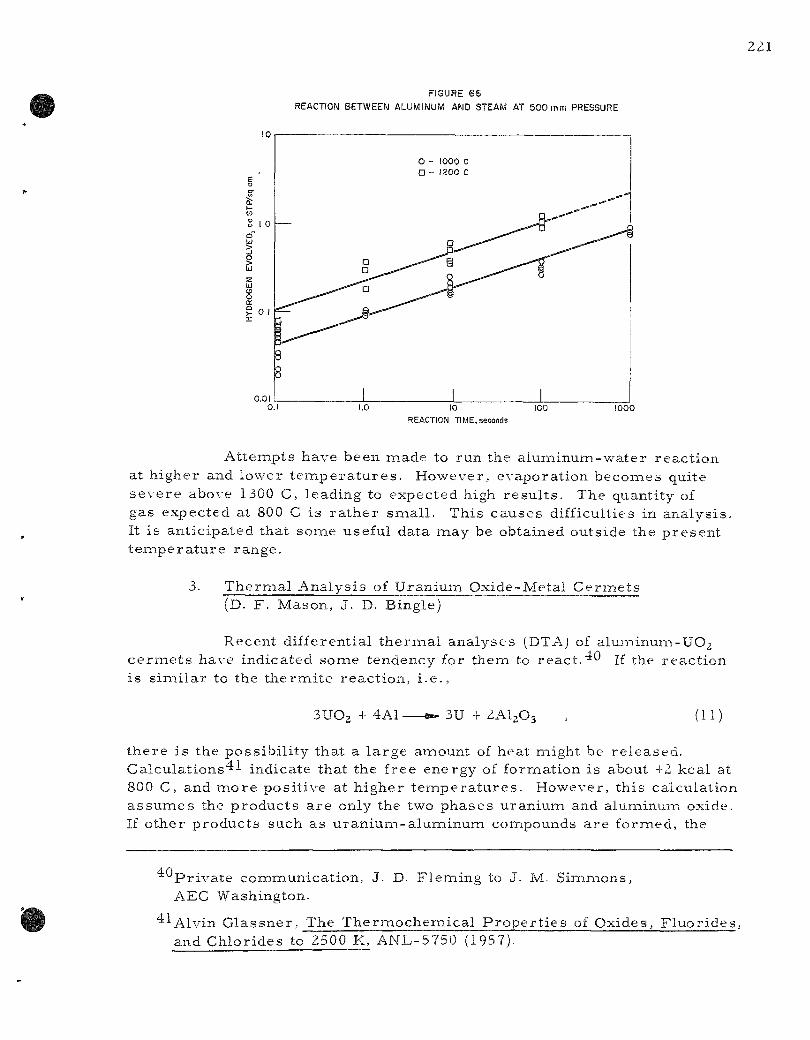
221
FIGURE 66
REACTION BETWEEN ALUMINUM AND STEAM AT 500 mm PRESSURE
10
0.01 0.1 1.0 100 1000
REACTION TIME,
Attenapts have b e e n m a d e to r u n the a l u m i n u m - w a t e r r e a c t i o n at h i g h e r and l o w e r t e i a i p e r a t u r e s . H o w e v e r , e v a p o r a t i o n becoiaies qui te s e v e r e above 1300 C, l e ad ing to e x p e c t e d high r e s u l t s . The quant i ty of gas e x p e c t e d at 800 C i s r a t h e r s m a l l . T h i s c a u s e s d i f f icul t ies in a n a l y s i s . It i s a n t i c i p a t e d tha t s o m e usefu l da ta naay be ob ta ined ou t s ide the p r e s e n t t e m p e r a t u r e r a n g e .
3. T h e r n a a l A n a l y s i s of U r a n i u m O x i d e - M e t a l Cer ia ie ts (D. F . M a s o n , J. D. Bing le )
R e c e n t d i f f e ren t i a l t he rnaa l a n a l y s e s (DTAj of a l uminum-UO2 c e r m e t s have i n d i c a t e d s o m e t e n d e n c y for t h e m to react."^0 jf the r e a c t i o n i s s i m i l a r to the t h e r m i t e r e a c t i o n , i . e . .
3UO, + 4A1- 3U + 2AI2O3 (11)
t h e r e i s the p o s s i b i l i t y t h a t a l a r g e amoun t of hea t m i g h t be r e l e a s e d . Calculations'*•'• i nd i ca t e tha t the f r ee e n e r g y of f o r m a t i o n i s about +2 k c a l at 800 C, and m o r e p o s i t i v e at h i g h e r t e m p e r a t u r e s . Howeve r , t h i s c a l c u l a t i o n a s s u m e s the p r o d u c t s a r e only the two p h a s e s u r a n i u m and alunainum oxide . If o t h e r p r o d u c t s such a s u r a n i u m - a l u m i n u i a i compounds a r e f o r m e d , the
40 P r i v a t e c o m m u n i c a t i o n , J. D. F l e m i n g to J. M. S i m m o n s , AEC Wash ing ton .
'^•'•Alvin G l a s s n e r , The T h e r m o c h e m i c a l P r o p e r t i e s of O x i d e s , F l u o r i d e s , and C h l o r i d e s to 2500 K, A N L - 5 7 5 0 (1957).
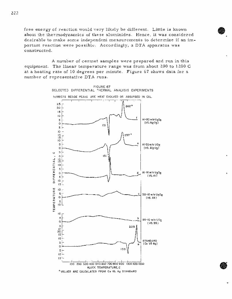
free energy of react ion would very likely be different. Lit t le is known about the thermodynanaics of these aluminides. Hence, it was considered des i rable to make some independent measu remen t s to determine if an ina-portant react ion were possible . Accordingly, a DTA apparatus was constructed.
A number of ce rme t samples were p repa red and run in this equipment. The l inear t empera tu re range was from about 200 to 1200 C at a heating ra te of 10 degrees per minute. F igure 67 shows data for a number of represen ta t ive DTA runs .
FIGURE 67 SELECTED DIFFERENTIAL THERMAL ANALYSIS EXPERIMENTS
MBERS BESIDE PEAKS ARE HEAT EVOLVED OR ABSORBED IN CAL.
Al-SOw/oUjOg (VS,Al203)
AI-5OW/0UO2 (VS. AI2O3)
Al-IOw/oUjOg tVS.AI)
ss - iOw/oUjOe (VS. SS)
SS-IO w/0 UO2
(vs. SS)
V STANDARD ^ (Cu VSAg)
100 200 300 400 500 SOO 700 800 900 1000 1100 1200 BLOCK TEMPER ATURE. C
* VALUES ARE CALCULATED FROM Cu VS. Ag STANDARD
The uran ium oxide-meta l c e r m e t s were also studied by X- ray diffraction. This enabled a determinat ion of the naajor react ion products .
a. DTA Apparatus and P rocedu re
The c e r m e t pin and the reference substance a r e contained in smal l alumina c ruc ib les . The cruc ib les a r e located symnaetrically in a nickel boat which is inse r t ed into a h igh- t empera tu re porce la in furnace tube. The differential thermocouples (Pt; Pt , 10% Rh) a re connected inside the furnace, and a re p ro tec ted by alumina tubes before inser t ion into p r e -dr i l led holes in the sample and the re fe rence substance.
The boat t e m p e r a t u r e is measu red by a chromel -a lumel therm.ocouple located in a hole dr i l led close to the center of the block. A grounded plat inum shield is located around the center of the furnace to r e duce e lec t r i ca l pickup which d is turbs the differential thermocouple r eco rde r . The nickel boat is itself grounded also. The furnace c o n t r o l l e r - p r o g r a m m e r thermocouple is located inside the p l a t inum-res i s t ance furnace but outside of the porce la in furnace tube. The p r o g r a m m e r - c o n t r o l l e r is a Minneapolis-Honeywell Brown Elec t ron ic . The r e c o r d e r is a 2-peri Br is to l with scales of 0 to 1200 C and -0.5 to +0.5 mv.
All samples were run in a slowly flowing purified argon atnaosphere at one atiaiosphere p r e s s u r e . It was felt that an air or oxygen atnaospliere might complicate analysis of the r e s u l t s .
All samples were run frona rooiaa t empera tu re to 1200 C and then back again to about 500 or 550 C. The t empera tu re was again inc r e a s e d to de te rmine which of the reac t ions observed on the DTA cbar t were r e v e r s i b l e .
b. Differential The rma l Analysis Runs
In F igure 67 a r e shown the resu l t s of a number of DTA runs . The heats of reac t ion of most major peaks a r e indicated on the figure. F igure 67a is the resu l t of a sample of copper run against s i lver . This was used to check the t e m p e r a t u r e scale and also to determine the magnitude of the hea ts of reac t ion involved in the c e r m e t runs. F igures 67b and 67c give r e su l t s for s t a in less s teel , 10 weight percen t uranium dioxide and s ta in less s teel , 10 weight percen t UsOg, respect ively , run against s ta in less s teel . If a reac t ion has occu r r ed h e r e , it is too smal l to be d i s tinguished for cer ta in . It is poss ib le that a higher percentage of uranium oxide would give a m e a s u r a b l e react ion. F igure 67d gives the resu l t s for a run of alum.inuna, 10 weight percent UjOg vs . aluminum. The deflections observed a re due to the heat of fusion of the aluminum in the two saiaiples.

F i g u r e s 67e and 67f a r e d a t a f o r a l u m i n u m p l u s 50 weigh t p e r cen t U3O8 and u r a n i u m d iox ide , r e s p e c t i v e l y , vs_. a l u m i n a . Al though t h e r e a r e s o m e m i n o r d i f f e r e n c e s in the two r u n s , they a r e e s s e n t i a l l y s i m i l a r . A def in i te e x o t h e r i n i c r e a c t i o n o c c u r s b e t w e e n 900 and 950 C in b o t h u r a n i u m d i o x i d e - and U,0«-aluiTi inum c e r m i e t s . T h i s r e a c t i o n w a s not r e v e r s i b l e .
4.0 It i s p r o b a b l y the s a m e r e a c t i o n o b s e r v e d by J. D. F l e m i n g , ' * " s i n c e it o c c u r s in the s a m e t e m p e r a t u r e r a n g e (840 to 950 C).
The h e a t of r e a c t i o n w a s e s t i m a t e d f r o m the c a l i b r a t i o n r u n of c o p p e r v s . s i l v e r , and a l s o f r o m the hea t of fus ion of alumiinum. in the r u n i tself . Us ing the c o p p e r v s . s i l v e r c a l i b r a t i o n , the e n e r g i e s of the aluiTiinum-50 we igh t p e r c e n t u r a n i u m dioxide and a lumi inum-50 weight p e r cen t U3O3 s a m p l e s c o m e s out to 90 - 10 c a l / g m s a m p l e . S u b t r a c t i n g the h e a t of fus ion of a l u m i n u m , the e n e r g y b e c o m e s 60 ± 15 c a l / g m s a m p l e .
S a m p l e s of the u r a n i u m dioxide + a l u m i n u m , U3O3 +alumiin u m , u r a n i u m dioxide + s t a i n l e s s s t e e l , and U3O8 + s t a i n l e s s s t e e l c e r m e t s w e r e a n a l y z e d by X - r a y d i f f rac t ion . The DTA s a m p l e s wi th 10 weigh t p e r cen t u r a n i u m oxide in t h e m w e r e , for the m o s t p a r t , i n d i s t i n g u i s h a b l e f r o m s a m p l e s of the o r i g i n a l c e r m e t t ha t h a d not been run . In s o m e c a s e s , the m a t e r i a l w a s found to be s l igh t ly changed , but the c o n c e n t r a t i o n of u r a n i u m dioxide o r UjOg w a s too low to a s s u r e iden t i f i ca t ion of p r o d u c t s p e c i e s . Th i s t e n d e d to con f i rm the n e g a t i v e r e s u l t s of t h o s e DTA r u n s .
The 50 weigh t p e r c e n t u r a n i u m dioxide and U3O8 a l u m i n u m c e r m e t s gave i n o r e p o s i t i v e r e s u l t s wi th X - r a y d i f f rac t ion a n a l y s i s . The r e s u l t s a r e s u m m a r i z e d in T a b l e 66 a long with the 10 we igh t p e r c e n t u r a n ium dioxide a l u m i n u m c e r m e t da t a for c o m p a r i s o n .
Table 66
RESULTS O F X-RAY DIFFRACTION ANALYSIS O F URANIUM OXIDE-ALUMINUM C E R M E T S
X - R a y A n a l y s i s - Before DTA X - R a y A n a l y s i s - After DTA
O r i g i n a l Major Minor Major Minor Compos i t i on Componen t s Componen t s Cons t i t uen t s Cons t i t uen t s
10 w / o UjOg + Al Al UO, Al UO2 (fired to 1200 C) p e r h a p s UjOg
50 w / o UO2 + Al Al , UO2 - UAI4 UAI3, UAl, , ( p r e s s e d , unfired) and Al( ?)
50 w / o UjOg i Al Al , .t-UaOg UAI4, UAls^ UAla,^ UAl, ( p r e s s e d , unfired) l^-UjOg
^In one s a m p l e a m a j o r cons t i tuen t , in ano the r a m i n o r cons t i tuen t .

Some samples were mixed by hand while some were machine mixed and cold p r e s sed . There was no effect of the method of prepara t ion . Segregation occu r r ed in all c a s e s .
Although it s eems apparent that the formation of uran ium-aluminum in te rmeta l l i c compounds is responsible for the observed DTA pa t t e rns , it is not c lear what happens to the oxygen. No uranium dioxide, U3O8, or alumina were detected, even as a minor constituent, in any of the X- r ay pa t te rns of samples after DTA runs . It is probable that aluinina is formed. Even if all the oxygen in u ran ium dioxide were converted to alunaina, the alumina would only consti tute a li t t le over 10 percent of the sample weight. This might be difficult to detect by X- ray diffraction. A la rge excess of aluminum would still be left to form intermetal l ic compounds with uranium.
The the rmi te react ion
3UO2 + 4A1 ^ 3 U + 2AI2O3 , (11)
postulated e a r l i e r , is apparent ly not the react ion taking place. The uranium undergoes fur ther reac t ion with the excess aluminum forming in te rmeta l l ics with it. The net resu l t is a r a the r different overal l thermi te react ion of the following form:
UO2 + Excess Al - — ^ w UAl + x UAI2 + y UAI3 + z UAI4 + AI2O3 , (12)
and s imi la r ly for U3O8.
It is l ikely that the course of the react ion is as follows; Assuming a considerable molar excess of aluminum over oxygen, the u r a nium oxide r e a c t s to form AI2O3 and UAl. Depending on the excess of aluminum available, the degree of mixing, and the re la t ive stabili ty of the var ious in te rmeta l l ic coinpounds, UAI2, UAI3, and UAI4 will also be formed. The heat of react ion involved is about 70 ca l /gm of 50 w/o aluminuna + u r a nium oxide.
It is concluded, there fore , that no violent " the rmi te" r e a c tion is likely to occur which would ser ious ly disrupt ce rme t fuel elements in a r eac to r . This is especia l ly t rue since these react ions a re largely brought about during the p repa ra t ion of the ce rme t s p r io r to incorporat ion into a reac to r fuel.
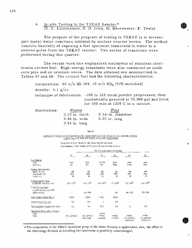
4. I n - p i l e T e s t i n g in the T R E A T R e a c t o r * (R. C. L i i m a t a i n e n , R. O- I v i n s , M. D e e r w e s t e r , F . T e s t a )
T h e p u r p o s e of the p r o g r a m of t e s t i n g in T R E A T is to i n v e s t i gate m e t a l - w a t e r r e a c t i o n s i n i t i a t e d by n u c l e a r r e a c t o r b u r s t s . The m e t h o d c o n s i s t s b a s i c a l l y of e x p o s i n g a fuel s p e c i m e n i m i n e r s e d in w a t e r to a n e u t r o n p u l s e f r o m the T R E A T r e a c t o r . Two s e r i e s of t r a n s i e n t s w e r e p e r f o r m e d d u r i n g t h i s q u a r t e r .
The r e c e n t w o r k h a s e m p h a s i z e d m e l t d o w n s of s t a i n l e s s s t e e l -u r a n i a c e r m e t fuel . H i g h - e n e r g y t r a n s i e n t s w e r e a l so conduc t ed on oxide c o r e p i n s and on u r a n i u m w i r e s . The da t a ob t a ined a r e s u m m a r i z e d in T a b l e s 67 and 68. The c e r m e t fuel h a d the fol lowing c h a r a c t e r i s t i c s :
c o m p o s i t i o n : 90 w / o SS-304 , 10 w / o UOj (93% e n r i c h e d )
d e n s i t y : 6.1 g / c c
t e c h n i q u e of f a b r i c a t i o n : -200 to 325 m e s h p o w d e r p r e p r e s s e d , t h e n i s o s t a t i c a l l y p r e s s e d at 55,000 p s i and f i r e d for 100 m i n at 1205 C in a v a c u u m .
d i m e n s i o n s : P l a t e s 0.10 in. t h i ck 0.46 in. wide 0.93 in. long
P i n s 0 .34- in . d i a m e t e r 0.55 in. long
Tabic 67
SUWMARY OF If-i-PILC DATA ON STAINLESS STEEl-WATER REACTjOKS FOR STAIMESS STEEL-URANIUIV1 DIOXIDI CERMET CORE FUEL PIMS' AMD PLATES IN A WATER E^VIROKMEM
Composition of Core: 90 w/o S S - M , 10 w/o UO2 (93"<. enriched/.
Test Conditions: Water initially at 25 C under 20 psia of tielium pressure,
CEi< Trarsien; Expenmeni Number
FueLMaterM! Clad: Geonefry:
ReactorCharacteristics Burst. i'."ffl-sec: Peak povver, .Vis: Period, r s :
inaMjMtLon^tose: bygold foil activation, nvt;
Fission Energy Input !)y f,'-o59 Analysis tor Z r ^ i . cal/gm of core:
Peak Surface Temp of Pin. C:
Peak Pressure Rise, psi:
Percent of .Metal Reacted with V/ater:
Appearance of Fuei after Transient Clad: Core:
Mcne Pin
435 2770
50
6,0 X IQM
>1550
%0
6.6
fine particles
6,8 X lOU
0I8 i7%l
>!550
100
fine particles and po.vder
52 54
\one Pin
510 2850
50
SS-304 Pin
512 2380
49
Mone Plate
368 2550
51
None Plate
490 2800
52
tone Plate
495 2810
51
6,9 X loM 3.7 X lOM
-500
0
10,2
itielted relted.
particles
298
>1030
190
5.2
melted. Darticles
8,8 X 10l4
446 i822)
Fi'elted, fine particles and poA'der
(loW
279 '3201
11,0
relted. fine particles and po.'/der
*The cooperation of the TREAT operations group of the Idaho Division is appreciated; also, the effort of the Metallurgy Division in furnishing fuel specimens is gratefully acknowledged.

Table 68
SUMMARY OF IN-PILE DATA OK METAL-WATER REACTIONS, OXIDE CORE FUEL PINS AND URANIUM WIRE FUEL SPECIMEMS IN A WATER ENVIROW.E.MT
Composition of Oxide Core: 81,5 w/o ZrOj, 9,1 w/o CaO, 0,7 w/o AI2O3, 8,7 w/o Upg (937o enriched!.
Uranium Wire: M-mil diameter; 93?!! enriched.
Test Conditions; Water initially at 25 C under 20 psia of helium pressure,
CEN Transient Experiment Number
Fuel Material Clad: Core: Geometry:
Reactor Characteristics Burst, Mft-sec; Peak power. Mw: Period, ms:
Thermal Neutron Dose by gold foil activation, nvt:
Fission Energy Input by Mo99 Analysis lor Zr>^>. cal/gm of core;
Peak Surface Temp of Pin. C:
Peak Pressure Rise, psi_:
Percent of Metal Reacted with V.-ater:
Appearance of Fuel after Transient Clad:
Core:
47
Al oxide pin
290 1220
72
«
SS-304 oxide pin
490 1405
72
56
Zr-2 oxide pin
270 630 105
49
Zr-2 oxide pin
648 2700
50
5?
None U
wire
«i 293 152
5S
None U
wire
!00 47
440
4.9 X I Q M
1342/
0.3
end plug pushed out
broken into large fragments
5.7 X 1 0 ^
!530i
4.2
ruptured, hole melted
fine particles
2,8 X MI'S
>100
0,3
not melted
cracked
9 , l x l 0 W
(671)
>220
24.0
ruptured. melted
fine particles
0.8 X 1 0 "
648 15O8!
1500
0
50.2
melted
fine particles and powder
1.1 X I0l'5
460 12851
33.2
melted
fine particles
The da ta f r o m the s t a i n l e s s s t e e l - u r a n i a c e r m e t s (Tab le 67) showed an i n c r e a s e in the ex ten t of m e t a l - w a t e r r e a c t i o n ( f rom 6.6 p e r c e n t in Run C E N - 5 1 to 10.2 p e r c e n t in C E N - 5 2 for p in s ) as the r e a c t o r b u r s t b e c o m e s naore e n e r g e t i c ( f rom 435 to 512 M w - s e c , r e s p e c t i v e l y ) . A l s o , the d a t a i n d i c a t e d tha t t he i n c r e a s e in s u r f a c e a r e a which r e s u l t s in changing f r o m p in to p l a t e - t y p e e l e m e n t s c a u s e s only a s l ight i n c r e a s e in the amount of s t a i n l e s s - s t e e l w a t e r r e a c t i o n for a g iven e n e r g y input . F o r e x a m p l e , comipar ing t r a n s i e n t s C E N - 5 3 and 55 (p la t e s ) wi th C E N - 5 0 and 52 (pins) , i t i s evident t ha t b u r s t s of c o m p a r a b l e e n e r g y (~500 M w - s e c ) and p e r i o d (~50 M w - s e c ) give s u b s t a n t i a l l y the s a m e amoun t of m e t a l - w a t e r r e a c t i o n (9-6 and 10.2 p e r c e n t for p i n s , and 9.1 and 11.0 p e r c e n t for p l a t e s ) . The p l a t e s p e c i m e n s had an in i t i a l t o t a l s u r f a c e a r e a of 7.3 sq c m and the c y l i n d r i c a l s p e c i i n e n s had an in i t i a l s u r f a c e a r e a of 4.6 sq c m ; the vo lu ines w e r e c o m p a r a b l e (0.72 and 0.75 c c , r e s p e c t i v e l y ) .
F i g u r e 68 i s a re jproduct ion of an o s c i l l o g r a p h r e c o r d f r o m one of the t r a n s i e n t s , C E N - 5 4 , wh ich i n d i c a t e s the t i m e s c a l e of the e x p e r i m e n t and shows the shape of the n e u t r o n p u l s e . F r o m the p a r a m e t e r s r e c o r d e d d u r i n g the r e a c t o r t r a n s i e n t and f r o m t h e m e a s u r e d t h e r m a l n e u t r o n dose to the fuel p l a t e , the p e a k f lux m a y be o b t a i n e d s i m p l y f r o m the r a t i o
M w - s e c n v t 3 6 8 o r
3.7 X 10 Mw p e a k nv p e a k 2550 *
Thus the t h e r m a l flux to the m a x
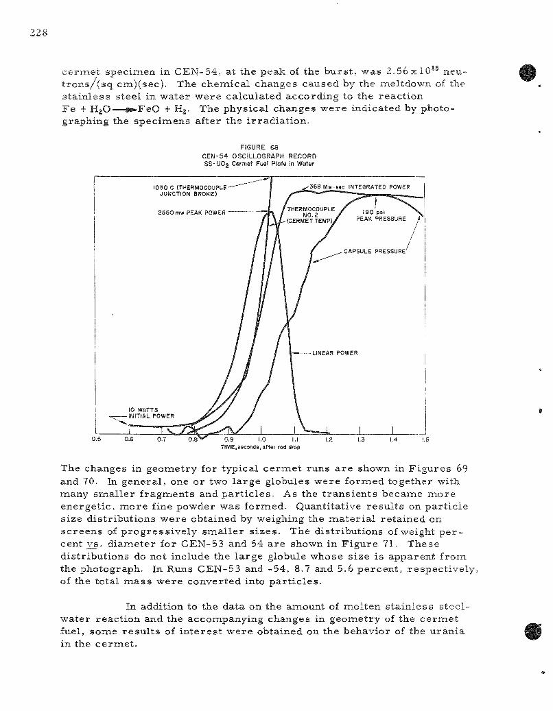
ce rme t specimen in CEN-54, at the peak of the burs t , was 2 .56x10 ^ neu-t r o n s / ( s q cm)(sec) . The chemical changes caused by the meltdown of the s ta in less steel in water were calculated according to the react ion Fe + H 2 O — ^ F e O + Hj- The physical changes were indicated by photographing the specimens after the i r radia t ion .
FIGURE 68 CEN-54 OSCILLOGRAPH RECORD SS-UO2 Cermet Fuel Plate in Water
1030 C (THERMOCOUPLE JUMCTION BROKE)
2 5 5 0 mw PEAK POWER
368 Mw-sec INTEGRATED POWER
10 WATTS -INITIAL POWER
190 psi PEAK PRESSURE
CAPSULE PRESSURE
0,5 0.6 0.7 0.8 0.9 1.0 I.I TIME,seconds, after rod drop
1.2 1.3
The changes in geometry for typical c e r m e t runs a r e shown in F igu re s 69 and 70. In general , one or two large globules were formed together with many smal le r f ragments and pa r t i c l e s . As the t r ans ien t s became more energet ic , more fine powder was formed. Quantitative resu l t s on par t ic le size distr ibutions were obtained by weighing the ma te r i a l re ta ined on sc reens of p rogress ive ly smal le r s izes . The distributions of weight pe r cent vs . d iameter for CEN-53 and 54 are shown in F igure 71. These distr ibutions do not include the large globule whose size is apparent from the photograph. In Runs CEN-53 and -54, 8.7 and 5.6 percen t , respect ive ly , of the total m a s s were converted into pa r t i c l e s .
In addition to the data on the amount of molten s ta in less steel-water react ion and the accompanying changes in geometry of the c e r m e t fuel, some resu l t s of in te res t were obtained on the behavior of the uran ia in the ce rme t .
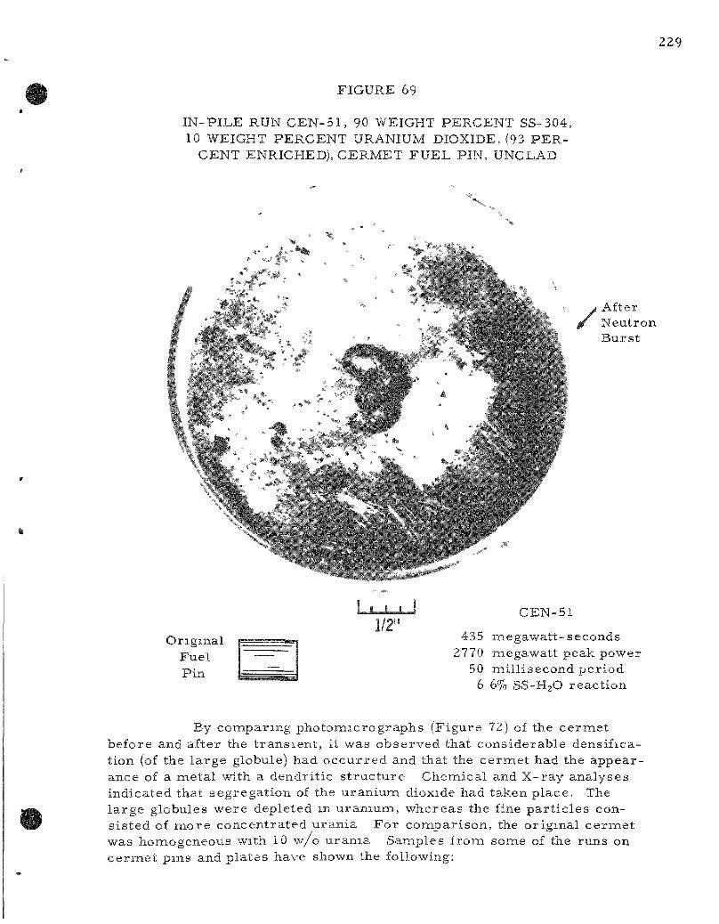
FIGURE 69
IN-PILE RUN CEN-51 , 90 WEIGHT PERCENT SS-304, 10 WEIGHT PERCENT URANIUM DIOXIDE, (93 PER
CENT ENRICHED), CERMET FUEL PIN, UNCLAD
\ J After ^ Neutron
Burst
X J _ L 1/2"
Original Fuel Pin
CEN-51
435 megawatt-seconds 2770 miegawatt peak power
50 mil l isecond period 6 6% SS-H2O react ion
By comparing photomicrographs (Figure 72) of the ce rme t before and after the t rans ien t , it was observed that considerable densifica-tion (of the large globule) had occur red and that the ce rmet had the appearance of a metal with a dendrit ic s t ruc ture Chemical and X-ray analyses indicated that segregat ion of the uranium dioxide had taken place. The la rge globules were depleted m uranium, whereas the fine par t ic les consis ted of more concentrated uran ia For comparison, the original cermiet was homogeneous with 10 w/o urania Samples from some of the runs on ce rme t pms and plates have shown the following:
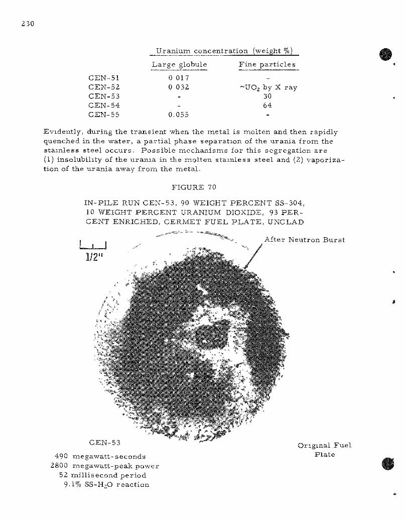
Uranium concentrat ion (weight %)
CEN-51 CEN-52 CEN-53 CEN-54 CEN-55
Large globule
0 017 0 032
--
0.055
Fine pa r t i c l e s
_
~U02 by X ray 30 64 -
Evidently, during the t rans ient when the metal is molten and then rapidly quenched in the water , a pa r t i a l phase separat ion of the uran ia from the s ta inless s teel occurs . Poss ib le mechan isms for this segregat ion a re (1) insolubility of the u ran ia in the molten s ta in less steel and (2) vapor ization of the uran ia away from the meta l .
FIGURE 70
IN-PILE RUN CEN-53, 90 WEIGHT PERCENT SS-304, 10 WEIGHT PERCENT URANIUM DIOXIDE, 93 PERCENT ENRICHED, CERMET FUEL PLATE, UNCLAD
I , After Neutron Burs t ' ' ' ^'^ - ^^. ^^^ /
1/2'
^ ^ N - 5 3 '• ' ' - " Original Fuel
490 megawat t -seconds Plate 2800 megawatt-peak power
52 mil l isecond per iod 9.1% SS-H2O reac t ion

231
FIGURE 71
PARTICLE SlZt DISTRIBUTIONS DETERMINED BY SIEVE
SCREEN ANALYSES 0 ' MELTDOWN PRODUCTS
i ROM SS-UO2 CERMET FUEL PLATES
CEN- '54 5 2 % S S - H g O REACTION
, - 2 0
I i i o
T 3 6 12 28
PASTiCLE SIZE RANGE, m Is
C E N - 5 3
9 1 % S S - H j O REACTIOf,
J 132
To general ize the data on s ta inless s tee l -water react ions from TREAT to other r e a c t o r s , it is n e c e s s a r y to convert from the total energy of the reac tor burs t (Mw-sec) to the fission energy actually absorbed by
the ce rme t specimen (cal /gm). To accomplish this , d i rect fission product analyses were made on samples of the meltdown products from the t rans ien t s . For the s tainless s tee l -uran ia c e r m e t s . four determinat ions of molybdenum-99 gave values of 1 20, 0.81, 0 91 . and 0.57 (ca l /gm) /Mw-sec , for an average of 0.87. The reason for the variat ions is probably connected more with the sampling problem ra ther than with the actual analysis . One method of e l iminating this would be to dissolve all of the meltdown products (fragments, par t ic les ) completely and to leach the walls of the autoclave (this total dissolution technique has been used in some previous runs with uranium core pins). However, this method, while improving the burnup determinat ion, has the disadvantage that
none of the specimen is left for such useful observations as par t ic le size analys is , X- ray analys is , and metal lographic examination. Three determinations of z i rconium-95 gave values of 1.56, 1.68, and 0.64 ( ca l / gm) / Mw-sec , for an average of 1.29. It is recommended that the value 0.87 ca l /gm = 1 Mw-sec be used, since the validity of the miolybdenum-99 analyses has been previously establ ished with uranium pins. The zi rconium-95 analysis is being t r i ed because its longer half-life (relative to molybdenum-99) makes it potentially an at t ract ive isotope to lessen the decay problem, thus permit t ing more t ime for analysis . To obtain a bet ter evaluation, a ' ' s tandard" t rans ien t was run where the fuel pin did not melt . This should give a m o r e accura te compar ison between the zirconium and molybdenum analyses . However, these data are not yet available.
oL 3 6 12 28
PARTICLE SIZE RANGE, mils
The work on meltdowns of ox ide-core , meta l -c lad fuel pins was continued. The appear since of the oxide-core fuel specimens after the t rans ien ts is shown in F igures 73, 74, and 75. Run CEN-49 resul ted in extensive damage to the fuel pin with 24.0 percent of the Zirca loy-2 jacket react ing with the water for the energet ic burs t of 648 Mw-sec on a 50-ms reac tor period. The specific energy input was 609 ca l /gm for Run CEN-49, as calculated from the previously obtained cor re la t ion of 0.94 ( c a l / g m ) / Mw-sec for the samie ox ide-core pel le ts jacketed in aluminum; that i s , 0.94 X 648 = 609. This value of 609 is to be compared to the value of 671 ca l /gm determined for CEN-49 by a zirconium-95 fission product analys is .
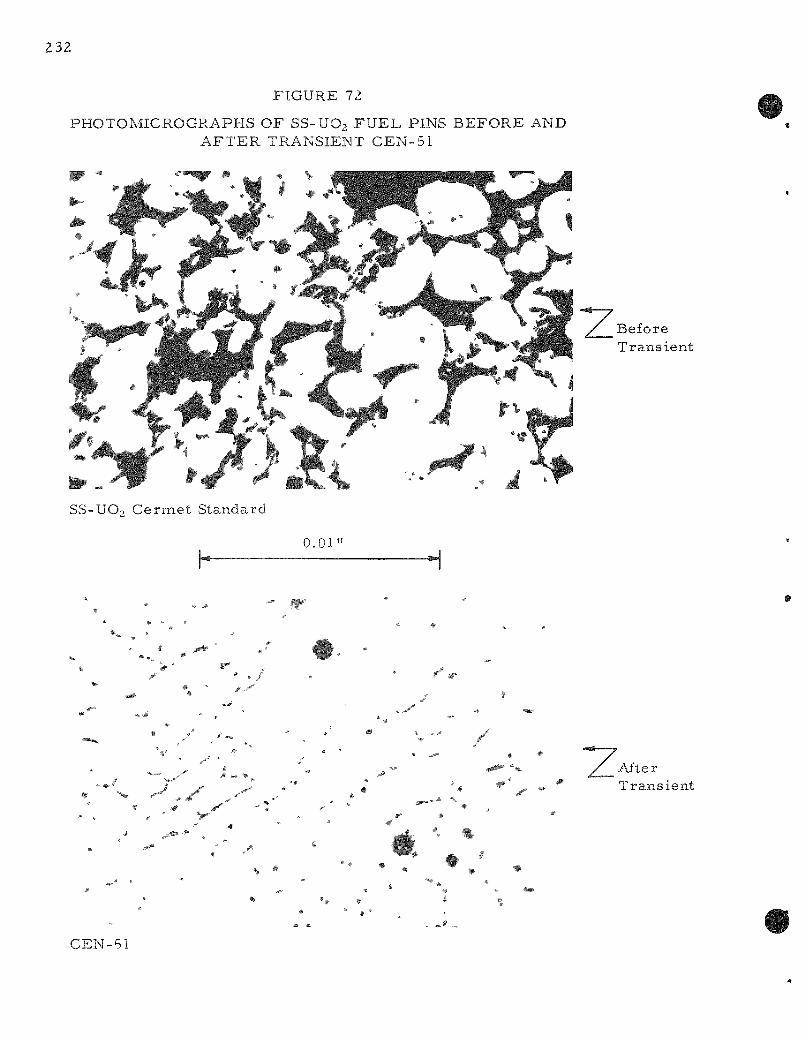
32
FIGURE 72
PHOTOMICROGRAPHS OF SS-UO2 FUEL PINS BEFORE AND AFTER TRANSIENT CEN-51
Before Trans ient
:^':/yi. SS-UO2 Cermet Standard
0.01"
" W • • • » • ' » ,
% ^ S -F
• • ^ X
-
• / /_ ' * • * - ' ; —
^ - >- . ^ - #
- * . # 4 » * *
» " ^- » » *, % • , • 1
#
% #
r ^
^ V / After • • ' ^ ^ '^ Trans ie
• * *
%
, •
%. ^ #
CEN-51
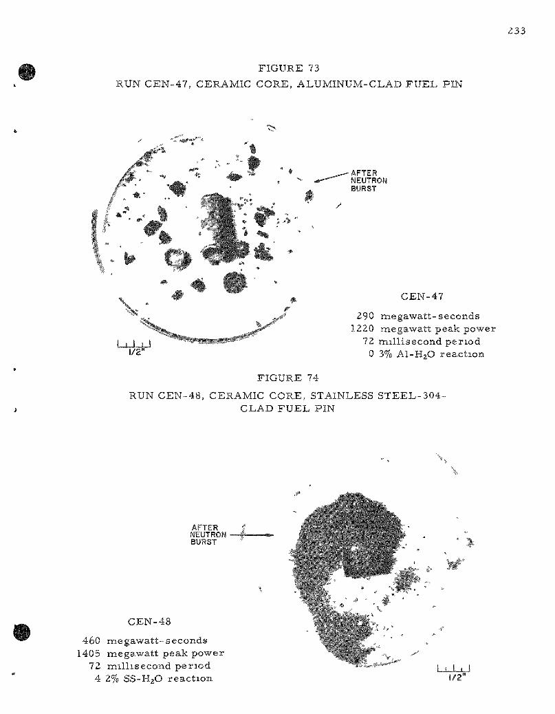
FIGURE 73
RUN CEN-47, CERAMIC CORE, ALUMINUM-CLAD FUEL PIN
:,%
/
•AFTER NEUTRON BURST
\ -
LJLJ_JJ 1/2"
CEN-47
290 megawatt-seconds 1220 megawatt peak power
72 mil l isecond per iod 0 3% AI-H2O react ion
FIGURE 74
RUN CEN-48, CERAMIC CORE, STAINLESS STEEL-304-CLAD FUEL PIN
\ ,
\
AFTER NEUTRON BURST
CEN-48
460 megawat t -seconds 1405 megawatt peak power
72 mil l isecond per iod 4 2% SS-H2O react ion -i t y
1/2"
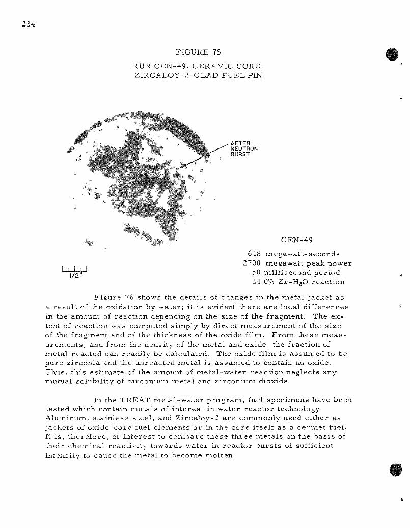
FIGURE 75
RUN CEN-49, CERAMIC CORE, ZIRCALOY-2-CLAD FUEL PIN
AFTER NEUTRON BURST
LxX+J 1/2
CEN-49
648 megawat t -seconds 2700 megawatt peak power
50 mil l isecond per iod 24.0% Zr-HgO react ion
Figure 76 shows the details of changes in the metal jacket as a resu l t of the oxidation by water ; it is evident there a r e local differences in the amount of react ion depending on the size of the fragment. The extent of react ion was computed simply by d i rec t m e a s u r e m e n t of the size of the fragment and of the thickness of the oxide film. F r o m these m e a s u remen t s , and from the density of the metal and oxide, the fraction of metal reac ted can readi ly be calculated. The oxide film is assumed to be pure z i rconia and the unreac ted metal is assumed to contain no oxide. Thus, this es t imate of the amount of me ta l -wa te r react ion neglects any mutual solubility of z irconium meta l and zirconium dioxide.
In the TREAT meta l -wa te r p rog ra m, fuel specimens have been tes ted which contain meta l s of in te res t in water reac to r technology Aluminum, s ta in less s teel , and Zi rca loy-2 a re commonly used either as jackets of oxide-core fuel e lements or in the core itself as a ce rme t fuel. It i s , the re fore , of in te res t to compare these th ree meta l s on the bas i s of their chemical react ivi ty towards water in r eac to r bu r s t s of sufficient intensity to cause the metal to become molten.
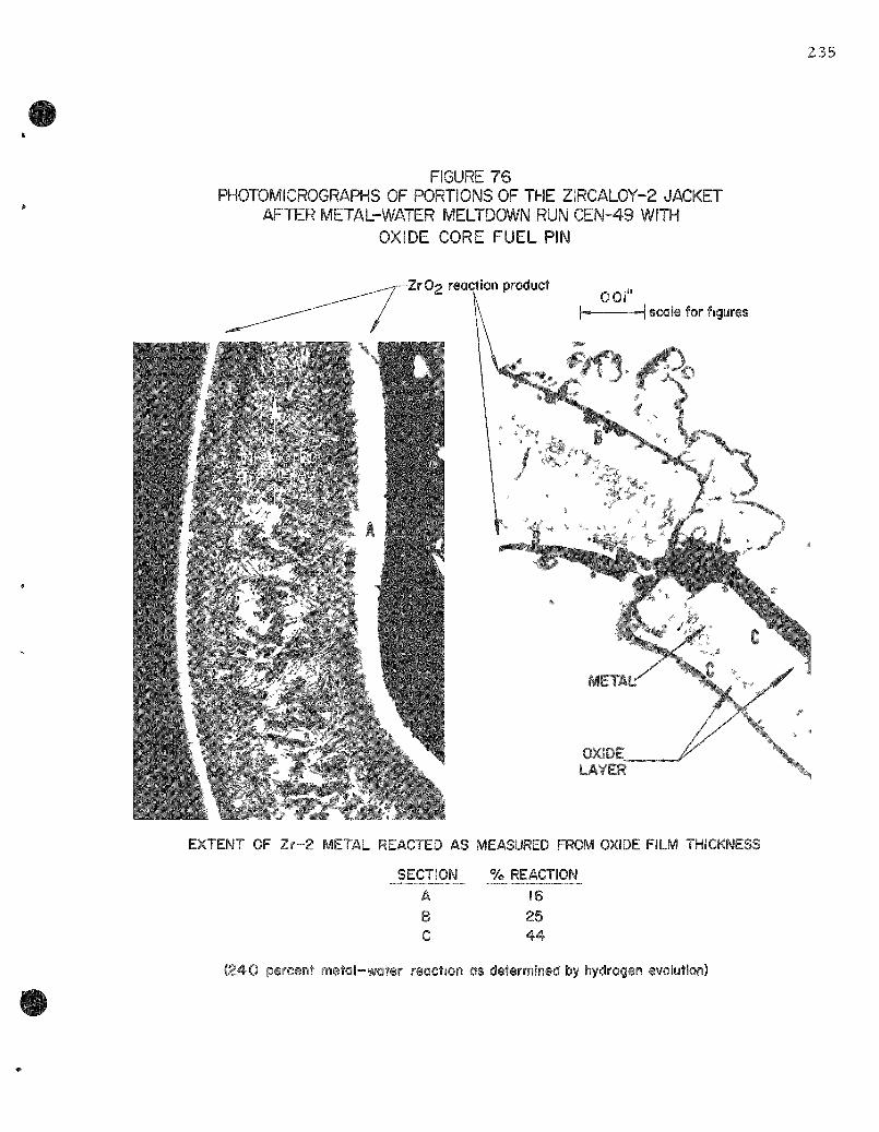
FIGURE 76 PHOTOMICROGRAPHS OF PORTIONS OF THE ZIRCALOY-2 JACKET
AFTER METAL-WATER MELTDOWN RUN CEN-49 WITH
OXIDE CORE FUEL PIN
235
Zr O2 reaction product 001"
scale for figures
4.,.. 'r^l /<>.
OXIOE LAYER
EXTENT OF Zr -2 METAL REACTED AS MEASURED FROM OXIDE FILM THICKNESS
SECTION % REACTION A B C
16 25 44
(240 percent metol-water reaction as determined by hydrogen evolution)
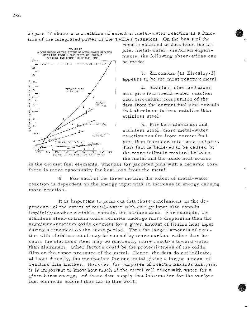
FIGURE 77 A COMPARiSON OF THE EXTENT OF METAL-WATER REACTION
RESULTING FROM IN PILE TESTS OF VARIOUS CERAMIC AND CERMET CORE FUEL PINS
F i g u r e 77 shows a c o r r e l a t i o n of ex t en t of m e t a l - w a t e r r e a c t i o n a s a funct ion of the i n t e g r a t e d p o w e r of the T R E A T t r a n s i e n t . On the b a s i s of the
r e s u l t s o b t a i n e d to da te f r o m the in -p i l e , m e t a l - w a t e r , m e l t d o w n e x p e r i -mients , the fol lowing o b s e r v a t i o n s can be m a d e :
1. Z i r c o n i u m (as Z i r c a l o y - 2 ) a p p e a r s to be the m o s t r e a c t i v e m e t a l .
2. S t a i n l e s s s t e e l and a l u m i n u m give l e s s m e t a l - w a t e r r e a c t i o n t h a n z i r c o n i u m ; c o m p a r i s o n of the da t a f r o m the c e r m e t fuel p ins r e v e a l s t ha t a lumiinum is l e s s r e a c t i v e than s t a i n l e s s s t e e l .
3. F o r both a l u m i n u m and s t a i n l e s s s t e e l , m o r e m e t a l - w a t e r r e a c t i o n r e s u l t s f r o m c e r m e t fuel p i n s than f r o m c e r a m i c - c o r e fuel p i n s . T h i s fact i s b e l i e v e d to be c a u s e d by the m o r e i n t i m a t e m i x t u r e b e t w e e n the m e t a l and the oxide h e a t s o u r c e
in the c e r m e t fuel e l e m e n t s , w h e r e a s for j a c k e t e d p i n s wi th a c e r a m i c c o r e t h e r e i s m o r e o p p o r t u n i t y for h e a t l o s s f r o m t h e m e t a l .
4. F o r e a c h of the t h r e e iTietals, t he ex ten t of m e t a l - w a t e r r e a c t i o n i s dependen t on the e n e r g y input wi th an i n c r e a s e in e n e r g y c a u s i n g m o r e r e a c t i o n .
350 400 ..50 SCO "50 E\EP3^ or T^EAT F<EA""'0>- dJPS^ V« Sp
i t i s i m p o r t a n t to po in t out t ha t t h e s e c o n c l u s i o n s on the d e p e n d e n c e of the ex ten t of m e t a l - w a t e r with e n e r g y input a l s o c o n t a i n i m p l i c i t l y a n o t h e r v a r i a b l e , namiely, t he s u r f a c e a r e a . F o r e x a m p l e , the s t a i n l e s s s t e e l - u r a n i u m oxide c e r m e t s u n d e r g o m o r e d i s p e r s i o n than the a l u m i n u m - u r a n i u m oxide c e r m e t s for a given a m o u n t of f i s s i o n h e a t input du r ing a t r a n s i e n t on t h e s a m e p e r i o d . T h u s the l a r g e r a m o u n t s of r e a c t ion wi th s t a i n l e s s s t e e l m a y be c a u s e d by m o r e s u r f a c e r a t h e r t h a n b e c a u s e the s t a i n l e s s s t ee l inay be i n h e r e n t l y m o r e r e a c t i v e t o w a r d w a t e r than a l u m i n u m . O t h e r f a c t o r s cou ld be the p r o t e c t i v e n e s s of the ox ide f i lm or the v a p o r p r e s s u r e of the m e t a l . H e n c e , the da t a do not i n d i c a t e , at l e a s t d i r e c t l y , the m e c h a n i s m for one m e t a l giving a l a r g e r a inount of r e a c t i o n than a n o t h e r . H o w e \ e r , for p u r p o s e s of r e a c t o r h a z a r d s a n a l y s i s , it is inapor tan t to know how m u c h of the mietal wi l l r e a c t wi th w a t e r for a given b u r s t e n e r g y , and t h e s e da t a supp ly tha t i n f o r m a t i o n for the v a r i o u s fuel e l e m e n t s s t ud i ed thus fa r in t h i s work .

237
In-pile meltdowns of uran ium wires a re being conducted to give coimparisons with the labora tory data on wires which a r e heated e lec t r ica l ly by a condenser d ischarge (data of L. Baker and R. Warchal). Two runs (CEN-57 and 58) were made with 64-mi l -d iameter wi res of uraniuin, 93 percent enriched. In CEN-57, a t rans ient on a 152-ms period with a 648-ca l /gm analytically de termined energy input, 50.2 percent of the uranium reac ted with the water (see Figure 78). This is the la rges t extent of react ion that has been found to date for any metal in the in-pile t e s t s .
FIGURE 78
URANIUM WIRE FUEL SPECIMEN AFTER MELTDOWN CEN-27
/
L J - J - J - J 0.5"
PARTICLES AND FINE POWDER PRODUCED BY TRANSIENT MELTDOWN IN WATER
CEN-57
90 megawatt-seconds 293 nnegawatt peak power 152 mil l isecond per iod
50.2% U-H2O react ion
Figure 79 shows these r e s u l t s , together with previously repor ted runs . The impor tance of the reac to r per iod is i l lustrated. The energy inputs a r e the ones from molybdenumi-99 ana lyses . The energy of 554 ca l / gm is simply an ar i thmet ic average of the two molybdenum-99 determinat ions (648 and 460 ca l /gm) . Final ly, F igure 80 shows the data for all the uran ium-wate r t r ans ien t s plotted as the extent of react ion vs . the energy input. Since only four data points a r e available with uranium wi res at high-energy t rans ien t s (and per iods of about 100 ms) , the location of the curve beyond about 300 c a l / g m is to be considered tentative. Additional runs will be made to indicate the slope m o r e p rec i se ly .
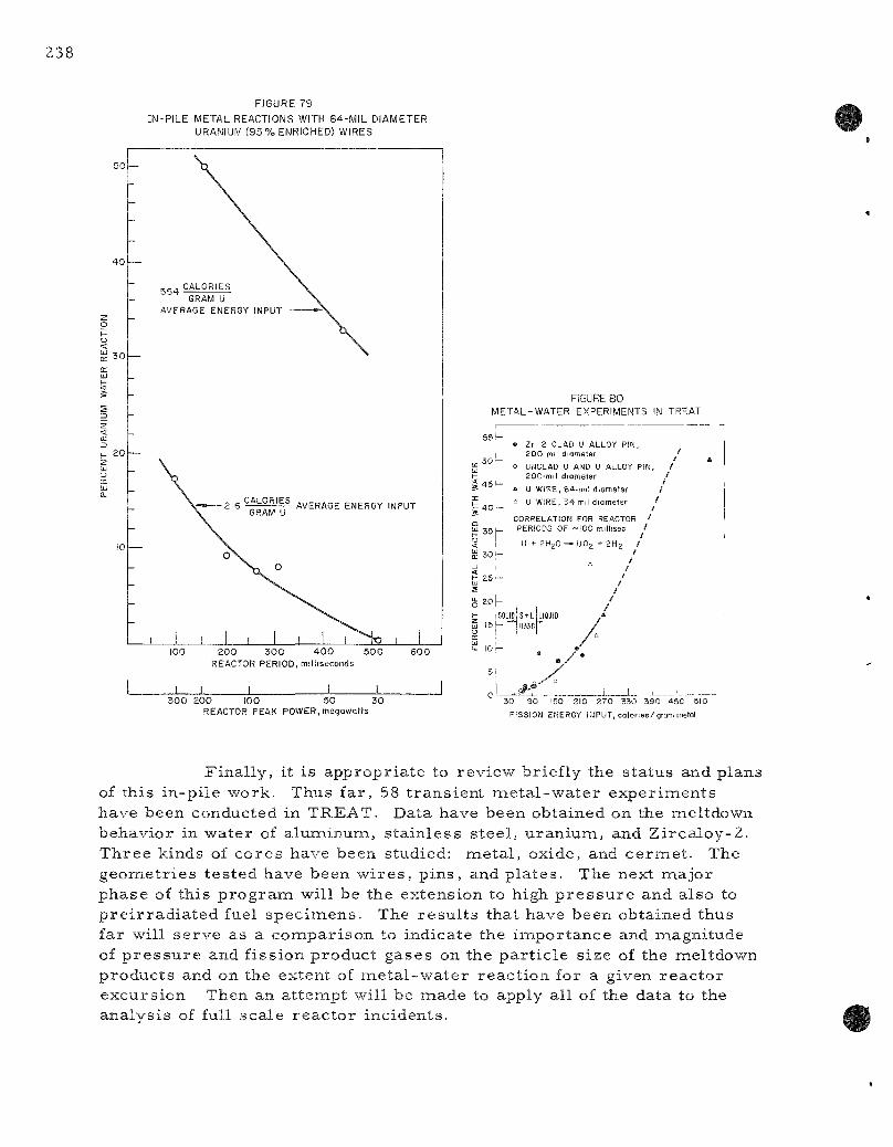
238
FIGURE 79
IN-PILE METAL REACTIONS WITH 64-MiL DIAMETER URANIUM (93 7<> ENRICHED) WIRES
SO-
SO
20
GRAM U
AVERAGE ENERGY INPUT
GRAM U
100 2 0 0 3 0 0 4 0 0 5 0 0 6 0 0 REACTOR PERIOD, milliseconds
3 0 0 200 100 50 30 REACTOR PEAK POWER, megawatts
FIGURE 80 METAL-WATER EXPERIMENTS IN TREAT
55 k
soL-
45 ^-
40 —
2 5 -
20 | -
SOUO IS - *
• Zr 2 CLAD U ALLOY PIN, 200 mil diameter
o UNCLAD U AND U ALLOY PIN, 200-mil diameter
" U WIRE, 64-mil diameter £. U WIRE, 34 mil diameter '
/ CORRELATION FOR REACTOR ^ PERIODS OF ~I00 millisec /
/ U + 2 H 2 0 ~ U 0 2 +2H2 /
/
30 90 150 210 270 330 390 450 510
FISSION ENERGY INPUT, calories/gram metai
Final ly, it is appropria te to review briefly the status and plans of this in-pi le work. Thus far , 58 t ransient me ta l -wa te r exper iments have been conducted in TREAT. Data have been obtained on the meltdown behavior in water of aluminum, s ta in less s teel , u ranium, and Zi rca loy-2 . Three kinds of cores have been studied: meta l , oxide, and ce rmet . The geometr ies tes ted have been w i r e s , p ins , and pla tes . The next major phase of this p r o g r a m will be the extension to high p r e s s u r e and also to p re i r r ad i a t ed fuel spec imens . The resu l t s that have been obtained thus far will serve as a compar ison to indicate the importance and magnitude of p r e s s u r e and fission product gases on the par t i c le size of the meltdown products and on the extent of me ta l -wa te r react ion for a given reac tor excursion Then an at tempt will be made to apply all of the data to the analysis of full scale reac to r incidents.

IV. REACTOR CHEMISTRY
The neu t ron-cap tu re c ro s s sect ions of neptuniumi-237 a r e being de te rmined in the fast neutron energy range . Work has a lso begun on the determinat ion of the total neutron c r o s s section of uranium-233. The cap ture - to - f i s s ion ra t ios in the EBR-Ij Mark III a r e being determined for uranium isotopes 233, 235, 238 and for plutonium isotopes 239 and 240.
The Reactor Decontamination P r o g r a m is d i rec ted at determining the s e r i ousnes s of fuel e lement rup tu res in boiling water r e a c t o r s and the determinat ion of methods of decontamination of contaminated surfaces . Several runs have been made in a s ta in less s teel loop which s imulates the action of a boiling water r e a c t o r . Cur ren t labora tory exper iments on the decontamination of s ta in less s tee l 304 have been conducted with oxalic acid and c i t r ic acid base solutions containing hydrogen peroxide.
A'. Determinat ion of Nuclear Constants (C. E. Crouthamel)
1. Fas t Neutron Cross Sections (D. C. Stupegia, E. Dewell)
Neptunium-237
The neutron c r o s s sect ions of neptunium-237 for inono-energet ic neutrons a r e being de te rmined in the neutron energy range between about 0.4 and 1.7 Mev. Neptunium-237 is a buildup product produced in r e a c t o r s by neutron capture of uran ium-236 and the (n, 2n) react ion of uranium-238. Four samples of neptunium-237 dioxide* wj.th weights varying between 10 and 24 mg have been exposed to mono-energe t i c neutrons from the ANL Physics Division Van de Graaff a c c e l e r a t o r .
Neptunium-238, formied by neutron capture in neptunium-23 7, is a 2.1-day beta emi t te r ; a l i t t le over half of its d is integrat ions give r i s e to gamma of about 1-Mev energy. A l i t e ra tu re review indicated that this peak could be counted with l i t t le in te r ference from either the activity a s soc ia t ed with the neptunium-237 t a rge t or other isotopes likely to be excited under the expected conditions. A tes t exposure to t he rma l neutrons in the C P - 5 rabbi t channel supported this conclusion. As few as 60 dis integra t ions per second were eas i ly observed against a background of 10 mg neptunium dioxide on a 4 x 4-in. Nal(Tl) gamma spec t romete r using a 256-channel pulse ana lyzer . A m e r c u r y abso rbe r was used to reduce the intensi ty of the low-energy components .
*The dioxide was r e c o v e r e d from a stock solution of neptunium (Vl) in pe rch lo r ic acid by reduct ion to neptunium (V) with sodium ni t r ide and precipi ta t ion of neptunium (V) hydrated oxide with aqueous ammonia . The hydrated oxide was calcined at 600 C to give neptunium dioxide.

Proton beam energ ies of 2.275, 2.43, 2.52, and 2.60 Mev were a r b i t r a r i l y chosen for the f irs t four samples . These gave neutron energies from a l i thium ta rge t [Li '(p,n) Be''] of 0.544, 0.716, 0.806, and 0.890 Mev in the d i rec t beam path {0° sca t ter ing angle). The exposure t imes var ied between 6 and 9 hr each at proton beam intensi t ies near 28 /ia. The neutron flux was moni tored constantly with a conventional gas-flow fission chamber d i rec t ly behind the sample . Collection of counting data is in p r o g r e s s .
Uranium-233
Work has recen t ly s t a r t ed on the determinat ion of the total neutron c r o s s sections of uranium-233 in the neutron energy range extending from s e v e r a l kev to about 1.2 Mev. These m e a s u r e m e n t s a r e being made in the Phys ics Division, using the Van de Graaff acce l e ra to r and assoc ia ted equipment. The bas ic m e a s u r e m e n t in this work is the de t e r mination of the at tenuation of a col l imated neutron beam by a known thickness of sample , which in this case is inetal l ic uranium. Severa l m e a s u r e m e n t s have been made and the data a r e being analyzed.
2. Determinat ion of Capture- to- f i ss ion Ratios in EBR-I , Mark III (G. E. Crouthamel , R. R. Heinr ich, , G. McCloud)
Capture- to- f i s s ion ra t ios in EBR-I , Mark III a r e being de te r mined for uranium isotopes 233, 235 and 238 and for plutonium isotopes 239 and 240. Samples have been removed from the blanket b r i ck and the core and blanket rods of EBR-I , Mark III, and a r e to be analyzed.
The saraples have been cleaned by means of an ul t rasonic genera tor to r emove the fission product contamination from the surface of the a luminum capsules containing the samples . Analyses of the wash solutions have indicated the decontamination to be complete and the samples a r e ready for dissolution.
A control sample of uraniumL-233 has been dissolved. A dissolver solution sample has been submitted for m a s s spec t rome t r i c ana lys is . The resu l t of this ana lys is will de te rmine whether the a luminum jacket and r e a gents used in sample p repara t ion have caused any change in the p rede te rmined u ran ium-234 /u ran ium-233 ra t io ,
B. Reactor Decontamination (W. B. Seefeldt)
The r e a c t o r decontamination p r o g r a m has two main objectives: (l) to de te rmine the s e r i o u s n e s s of fuel rup tu re s in boiling water r e a c t o r s as m e a s ured by the quanti t ies of radioact ive m a t e r i a l which deposit in the s team systemi, and (2) to de te rmine what methods of decontaminat ion can be used to remove these deposi ted ac t iv i t i es . The f i rs t study is being made with a

s ta in less s tee l Type 304 loop that s imula tes the action of a boiling water r eac to r ; mixed fission products a r e introduced into the loop to simulate a fuel rup tu re . Quantities and types of fission products deposited on in te r nal ly mounted me ta l sample s t r ips a r e de termined principally with the aid of a 256-channel gamma-sc in t i l l a t ion spec t romete r . In a para l le l effort, s tudies a r e being made in the l abora to ry to find a suitable means of removing the deposited ac t iv i t i es .
Reproducibi l i ty runs were made with the s ta inless s teel Type 304 pi lot-plant loop. Marked var ia t ions with t ime were observed in the fission product content of liquid and vapor samples , and differences were s imi la r ly observed in the deposition c h a r a c t e r i s t i c s of seve ra l fission products as a function of elevation on both s ta in less s tee l and mild s teel sample s t r i p s .
Cur ren t l abora to ry exper iments a r e being conducted on oxalic acid and c i t r ic acid based solutions containing hydrogen peroxide. A g ros s decontamination factor of 30 was obtained on s ta inless s teel Type 304 s u r faces when a solution of 0.16 M sodium oxalate and 1 M hydrogen peroxide, pH adjusted to 4 (with oxalic acid), was used. The effects of seve ra l p a r a m e t e r s , such as solution composit ion, pH, t empera tu re , and t ime, on decontamination were studied with a solution of th ree molar hydrogen peroxide adjusted to a pH of 3 and containing 0.5 to 0.05 molar potass ium oxalate.
The compatabil i ty of hydrogen peroxide with both c i t ra te and oxalic acid based solutions was de te rmined on two low alloy s tee l s . The addition of hydrogen peroxide was found to resu l t in a marked dec rease in the cor ros ion while decreas ing pH inc reased the at tack.
1. Labora to ry Invest igat ions (S. Vogler, H. Tyler)
The pr inc ipa l objective of the labora tory investigations is to study and modify existing decontamination or film removal procedures that have been developed by ei ther indust ry or other AEC con t rac to r s . In gene ra l , developed p rocedures a r e applicable to the p r i m a r y c i rcui ts of p r e s s u r i z e d water r e a c t o r s . Modifications a r e d i rec ted toward use in the vapor spaces of boiling water r e a c t o r s .
One such procedure , which is under study at Oak Ridge National Labora to ry for potential application in the Gas Cooled Reactor , r equ i re s the use of a solution of hydrogen peroxide and sodium oxalate. P r e l i m i n a r y r e su l t s r epo r t ed las t qua r t e r (ANL-6287, page 203) indicated that a solution of hydrogen peroxide and oxalic acid gave ve ry good decontamination. Cur ren t exper iments indicate that a solution of 0.16 M sodium oxalate and 1 M hydrogen peroxide with pH adjusted to 4 with oxalic acid, yields a g ros s decontamination of 30 on s ta in less s tee l when used at 95 C for one-half hour.
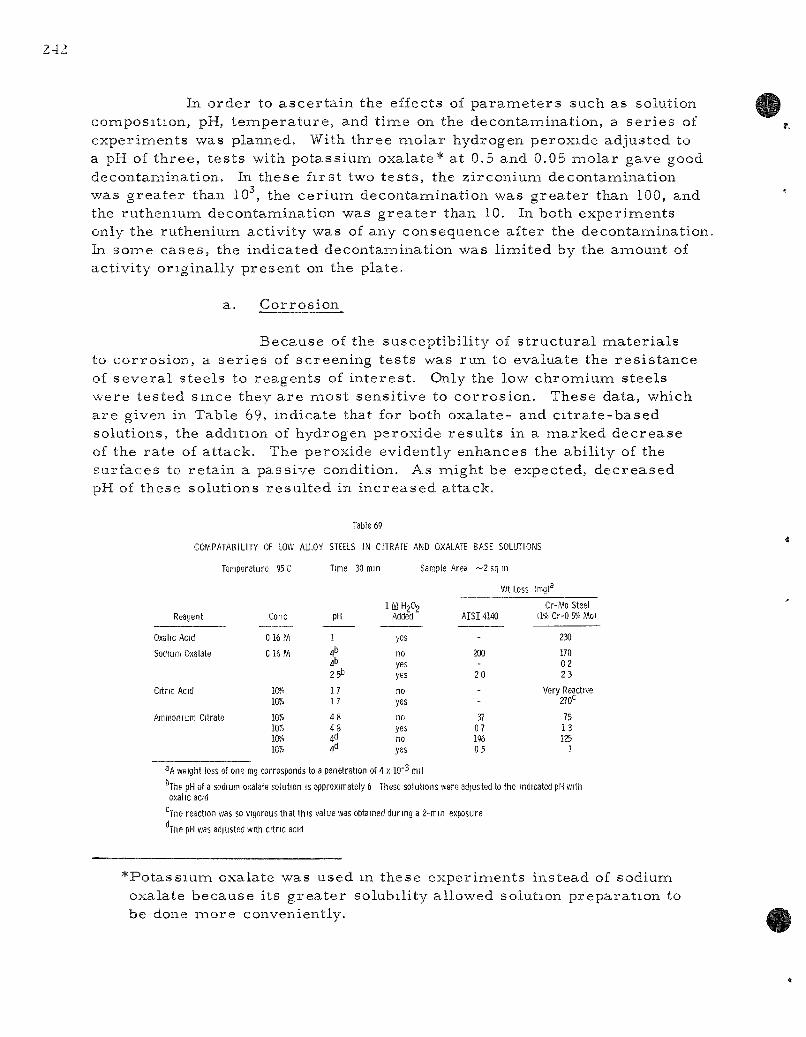
In o r d e r to a s c e r t a i n the ef fec ts of p a r a m e t e r s such a s so lu t ion c o m p o s i t i o n , pH, t e m p e r a t u r e , and t i m e on the d e c o n t a m i n a t i o n , a s e r i e s of e x p e r i m e n t s was p lanned . With t h r e e m o l a r h y d r o g e n p e r o x i d e a d j u s t e d to a pH of t h r e e , t e s t s wi th p o t a s s i u m o x a l a t e * a t 0.5 and 0.05 m o l a r gave good d e c o n t a m i n a t i o n . In t h e s e f i r s t two t e s t s , the z i r c o n i u m d e c o n t a m i n a t i o n was g r e a t e r than 10 , the c e r i u m d e c o n t a m i n a t i o n w a s g r e a t e r than 100, and the r u t h e n i u m d e c o n t a m i n a t i o n was g r e a t e r than 10. In bo th e x p e r i m e n t s only the r u t h e n i u m a c t i v i t y w a s of any c o n s e q u e n c e a f t e r the d e c o n t a m i n a t i o n In s o m e c a s e s , the i n d i c a t e d d e c o n t a m i n a t i o n was l i m i t e d by the a m o u n t of a c t i v i t y o r i g i n a l l y p r e s e n t on the p l a t e .
a. C o r r o s i o n
B e c a u s e of the s u s c e p t i b i l i t y of s t r u c t u r a l m a t e r i a l s to c o r r o s i o n , a s e r i e s of s c r e e n i n g t e s t s was r u n to e v a l u a t e the r e s i s t a n c e of s e v e r a l s t e e l s to r e a g e n t s of i n t e r e s t . Only the low c h r o m i u m s t e e l s w e r e t e s t e d s i n c e they a r e i n o s t s e n s i t i v e to c o r r o s i o n . T h e s e da ta , wh ich a r e g iven in Tab le 69, i n d i c a t e tha t for bo th o x a l a t e - and c i t r a t e - b a s e d so lu t i ons , the add i t ion of h y d r o g e n p e r o x i d e r e s u l t s in a m a r k e d d e c r e a s e of the r a t e of a t t a c k . The p e r o x i d e e v i d e n t l y e n h a n c e s the a b i l i t y of the s u r f a c e s to r e t a i n a p a s s i v e condi t ion . A s m i g h t be expec t ed , d e c r e a s e d pH of t h e s e s o l u t i o n s r e s u l t e d in i n c r e a s e d a t t a c k .
Table 69
COMPATABILITY OF LOW ALLOY STEELS IN CITRATE AND OXALATE BASE SOLUTIONS
Reagent
Oxalic Acid
Sodium Oxalate
Citric Acid
Temperature 95 C
Ammonium Citrate
Cone
0 16M
0 16M
10% 1W»
10% 10?. Iff?. 10%
Time
pH
1
4^
2 5''
17 17
48 4 8
4tl
30 mm Sample
1 M H2O2 Added
yes
no yes yes
no yes
no yes no yes
Area ~ 2 sq
AISI 4140
-200
20
-
37 07 196 05
m
Wt Loss
-
(mg)^
Cr-Mo Steel 11% Cr-0 5% Mo)
230
170 02 23
Very Reactive 270*
75 13 125
1
^A weight loss of one mg corresponds to a penetration of 4 x 10" ' mil
The pH of a sodium oxalate solution is approximately 6 These solutions were adjusted to the indicated pH with oxalic acid
""The reaction was so vigorous that this value was obtained during a 2-min exposure
The pH was adjusted with citric acid
* P o t a s s i u m oxa l a t e w a s u s e d m t h e s e e x p e r i m e n t s i n s t e a d of s o d i u m oxa la t e b e c a u s e i t s g r e a t e r so lub i l i t y a l l o w e d so lu t ion p r e p a r a t i o n to be done m o r e conven ien t ly .
b . S tab i l i t y of O x a l a t e - P e r o x i d e Solu t ions
Informiat ion f r o m Oak R idge N a t i o n a l Labora to ry ' *^ ]^a,s i n d i c a t e d tha t pH c o n t r o l of o x a l a t e - p e r o x i d e so lu t ions w a s i m p o r t a n t in o r d e r to m a i n t a i n so lu t ion s t a b i l i t y . At low p H ' s (~l ) , r e a c t i o n b e t w e e n o x a l a t e and p e r o x i d e w a s found to i n c r e a s e , w h e r e a s a t h igh p H ' s (~4), h y d r o g e n p e r o x i d e d e c o m p o s e d .
S e v e r a l t e s t s to e x p l o r e t h e s e f a c t o r s r e v e a l e d the following r e s u l t s :
1. When a so lu t ion of 0.5 m o l a r oxa l i c a c i d and 3.0 m o l a r h y d r o g e n p e r o x i d e (pH 0.4) w a s p r e p a r e d , g a s s i n g w a s i m i m e d i a t e l y ev iden t . Unde r t h e s e cond i t ions the following reaction'*-^ t a k e s p l a c e :
H2C2O4 + H2O2 — • 2H2O + 2CO2
2. A s o l u t i o n of 0.5 m o l a r p o t a s s i u m o x a l a t e and 3.0 m o l a r h y d r o g e n p e r o x i d e a d j u s t e d to a pH of 4, by the add i t i on of o x a l i c ac id , s h o w e d a s l ow d e c r e a s e in t h e p e r o x i d e con c e n t r a t i o n when k e p t a t 90 C. Howeve r , a f t e r a p e r i o d of f r o m — to 2 h r , t h e r e w a s a r a p i d evolu t ion of g a s wi th the a l m o s t c o m p l e t e d i s a p p e a r a n c e of the h y d r o g e n p e r o x i d e . S u b s e q u e n t e x a m i n a t i o n of the so lu t ion r e v e a l e d tha t the pH of the s o l u t i o n had r i s e n to a p p r o x i m a t e l y 9 to 10. T e s t s a l s o i n d i c a t e t ha t t he bu lk of the o x a l a t e (about 80 p e r c e n t ) r e m a i n e d in so lu t ion , t hus i nd i ca t i ng d e c o m p o s i t i o n of the p e r o x i d e .
3. Such a so lu t i on c a n be s t a b i l i z e d by the con t inuous add i t ion of oxa l i c a c i d to m a i n t a i n the pH a t a p p r o x i m a t e l y 4. The r e s u l t s of s u c h an e x p e r i m e n t in the p r e s e n c e of a s m a l l p i e c e of s t a i n l e s s s t e e l a r e g iven in Tab le 70. T h e s e r e s u l t s i n d i c a t e t h a t w i th pH c o n t r o l t he so lu t ion w a s qu i te s t a b l e to p e r o x i d e l o s s .
42 M e s e r v e y , A. B . , 2nd M e e t i n g , C o m m i t t e e on R e a c t o r D e c o n t a m i n a t i o n , A r g o n n e N a t i o n a l L a b o r a t o r y , D e c e m b e r 1, I960; M e s e r v e y , A. B . , Chi l ton , A. M. , F e r g u s o n , D. E . , D e c o n t a m i n a t i o n of E G C R C h a r g e and S e r v i c e M a c h i n e , O R N L - 6 0 - 1 0 - 4 6 (Oct . 13, I960)
43 H a t c h e r , W. H., T r a n s a c t i o n s of the R o y a l Soc ie ty of Canada , 17, Sec t ion III, 119, (1923). "~~~

4. A solution of 3 M hydrogen peroxide showed a gradual dec rease in the peroxide concentrat ion when heated at 90 C. In the p r e s ence of a piece of s ta in less s teel , the half- t ime was about 280 min.
5. Similar tes ts with c i t r ic acid and hydrogen peroxide indicated that the solution was reasonably stable. In both the p resence and absence of s ta in less s teel , there was a rapid 20 percent d e c r e a s e in the hydrogen peroxide concentrat ion followed by a per iod of from th ree to four hours with essent ia l ly constant peroxide concentrat ion.
Table 70
STABILITY OF POTASSIUM OXALATE-HYDROGEN PEROXIDE SOLUTION IN THE PRESENCE OF
STAINLESS STEEL TYPE 304
Solution: 0.5 M K2C2O4 3 M H2O2 pH 4.6 (by addition of H2C2O4)
Temp: 90 C
Time (hr) pH^ H202(m/l)
0 0.75 1.5 2.25 3 3.75 4.5 5.25 6
4.6 5.2 5.1 4.9 5.0 4.8 4.8 5.0 4.9
2.78 2.70 2.63 2.56 2.45 2.41 2.32 2.27 2.20
a After each pH determinat ion , the pH was was brought back to 4.5 by the addition of oxalic acid.
2. Loop Studies (D. Grosvenor , C. Bally)
A s ta in less s tee l Type 304 loop which s imula tes the action of a boiling water r e a c t o r has been insta l led in a shielded cell in o rde r to study the effects of s imula ted fuel r u p t u r e s . It is of i n t e r e s t to know how much
and what kind of fission products will d is t r ibute through the sys tem in order to a sce r t a in the degree to which maintenance might be impai red in a p rac t i cal sys tem should fuel cladding failure occur .
Fuel rup tu res a r e s imulated in the loop by introducing i r rad ia ted meta l l ic uranium. F i ss ion products a r e r e l e a s e d as the uranium cor rodes in the circulat ing water . Deposition of activi ty in the s team disengaging space is moni tored by inser t ing a meta l l i c sample s t r ip . This is removed following a run, cut into convenient lengths, and counted in a 256-channel gamma-sc in t i l l a t ion spec t rome te r . This is co r re la ted with s imi la r information obtained frona liquid and condensed s team samples .
Two s e r i e s of runs were made in the loop to determine the degree of reproducibi l i ty of the data obtained. All runs were made 3,t a p r e s s u r e of 200 psi, a s team velocity of 0.8 f t / sec , and t ime period of 68 hr. F iss ion products were introduced as long-cooled i r r ad ia t ed metal l ic uranium. In the f i rs t th ree of these runs , a s ta in less s tee l Type 304 sample s t r ip was inse r ted into the s t eam disengaging section while in the la t ter two runs a mild s teel (SAE Type 1018) sample s t r ip was used. Liquid and condensed s team samples were obtained daily. The pr incipal i n t e r e s t s in the exper iment were twofold: ( l) was the composit ion of the circulat ing liquid phase constant with t ime, and (2) if so, was the deposition of fission products on the metal l ic sample s t r ips reproducib le from run to run ?
To de te rmine the fission product content of the liquid and condensed s team samples , g a m m a - e n e r g y spec t ra were obtained with the use of the 256-channel gamma-sc in t i l l a t ion spec t rome te r . The gamma-ene rgy peaks a s soc ia t ed with individual fission product isotopes were identified and the a r e a s under these peaks de te rmined and converted to counts per minute per ml . Due to the differences in activi ty levels between the two types of s amples , sample p repara t ion did differ in detail . As a resul t , numbers obtained for liquid and condensed s team samples a r e not d i rect ly comparab le . The r e su l t s obtained for the ces ium-137 and z i rconium-niobium-95 act iv i t ies a r e shown in Table 71. Data for ce r ium-141 and ru thenium-103 were f ragmentary in na ture because peaks as de termined visual ly were obscured. Within any one given run, the ces ium-137 content of the liquid appeared to be reasonably consistent , with the exception of the one-day sample of liquid from Run USD, in which a value nea r ly twice those of the second- and th i rd -day samples was observed. The average value for each run showed a consis tent i nc rease up to Run U3D followed by a d e c r e a s e to Run U3F. The effect is probably r ea l . The ces ium-137 content of the condensed s t eam samples was reasonably consis tent except for the second- and th i rd -day samples of Run U3F, in which values inc r e a s e d by a factor of 3 to 8. A possible cause for this effect is c r o s s -contamination occurr ing during the sampling procedure . However, such an effect should a lso have been observable in condensed s team samples from the preceding four r u n s .

Table 71
CESIUM-137 CONTENT OF LIQUID AND VAPOR DURING LOOP REPRODUCIBILITY RUNS
P r e s s u r e : 200 psi Steam Velocity: 0.8 f t / sec Source of Activity: I r r ad ia ted na tu ra l uranium,^
105-day cooled
Run No.
U3B
U3C
U3D
USE
U3F
Time after Run Star t
(days)
1 2 3
1 2 3
1 2 3
1 2 3
1 2 3
Cesium Content ( c p m / m l ) ^
Liquid
1317 1548 1940
1702 1694 2217
5120 2664 2872
c 2703 2090
2162 1873 2210
— Vapor
2.7 5.9 3.3
3.1 2.1
c
2 .4 1.1 2.2
5.3 2.5 2.0
2.7 9.5
23
Zirconium-Content (c
Liquid
d d d
798 d c
15,600 190 116
c 101
61
468 213
28.3
-Niobium :pm/ml)
Vapor
2.8 0.63 0.43
1.1 0.18
c
0.92 0.18 0.51
0.55 d d
d 0.52 1.0
^I r r ad ia t ed 64 days in C P - 5 (41 MWO/ton).
The exact re la t ionship between these values and dis integrat ion r a t e has not been de termined, nor has the re la t ionship between liquid and vapor counts been es tabl i shed as the sample p repara t ion methods were not identical .
Sample was not r ep resen ta t ive (gamma-scan r e su l t s inconsis tent with other data) .
d Not detected.

2
The z i rconium-niobium-95 content of the liquid samples showed a consis tent decreas ing pat tern for each individual run. The effect was l ikewise observable in the condensed s team samples . In Run USB, the f irs t one of the group made, no z i rconium peaks were observable on any of the gamma scans obtained of l iquids. One operating difference occur red in this run as compared to the four o the rs , which may explain the discrepancy. Run USB was begun after a 48-hr per iod of operat ion of the loop in which the intent was to cor rode the uranium. During this period, the s team velocity in the s team disengaging section was kept as close to zero feet per second as possible in o rder to prevent p r e m a t u r e fission product deposition. There was no cool-down of the loop following this cor ros ion period and immediate ly preceding Run USB. All of the other runs were begun following a shut-down per iod (which included a cool-down) in which new metal l ic sample s t r ips were inser ted . It appears that when one begins with a cold loop initial z i r conium contents a r e high. This gradual ly dec rease s with exposure t ime until some equil ibriura value is achieved. The t ime requ i red to achieve this equi l ibr ium is something in excess of three days. Additional runs a r e indicated to clarify the t ime r equ i r ed to r each equil ibrium.
Several observat ions have been made regarding the ruthenium-103 and ce r ium-141 contents during the reproducibi l i ty runs . A smal l ruthenium peak was consis tent ly observed in g a m m a - r a y spec t ra of condensed s team samples , but this peak was not detectable visual ly in spect ra of liquid s a m ples . The opposite was t rue for ce r ium. The reasons a r e not c lear , but the data thus indicate that, while some smal l enr ichment of ruthenium is occurr ing in the vapor, a depletion is occurr ing for cer ium. There likewise appeared to be a downward t rend in the ruthenium content in condensed s team samples as a run p r o g r e s s e d through the thi rd day.
Activity deposition data on the meta l l ic saimple s t r ips in the disengaging section of the loop were obtained. The re la t ionship of the fission product deposition data to the fission product content of liquid and s team cannot be defined because of the la rge var ia t ion of the la t ter . The deposition pa t te rns of the five runs l ikewise did not show s imi l a r i t i e s . The resu l t s for Run u s e , shown in F igure 81, i l lus t r a t e the wide var ia t ions of deposition obtained as a function of elevation. The s e r i e s of gamma spec t ra on which Figure 81 is based is shown in F igure 82.
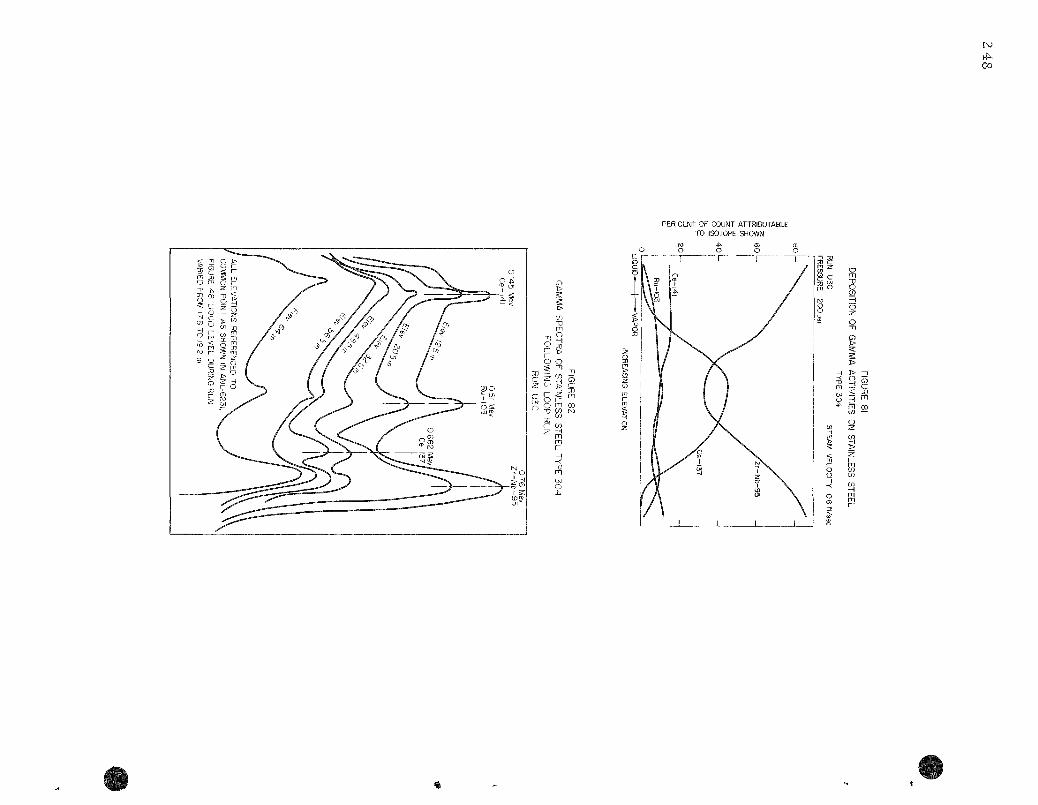
PER CENT OF COUNT ATTRIBUTABLE TO ISOTOPE SHOWN
<- "n
§ 8 m J}
^ * ^ CO
CD 5
o
c
o o ^
i i 2:
> X 0
.z
> 2f rp
/ (
\
X y" .
^
J> n n n
m
% 9 CO
s T1 m
s / H \ 0
^ y^
/^
- > ^ ^ " ^ ^ a ^ .
y /
-^ ^ X
/ j "
/ / /C c ^ s
^ ^ ^ ^ \ ^ ^ / ) \ _
/A /A / / /'if 1 " / / A / *
/ / / /
3^^-£ ^ ^ x>...
^ g ° - ^ .^...rf-"*^
I X \JV j ^ — - X ^— /•—
/ s
\ - ^
.-—-- — 0
- g
^ — -
. ^ '
3JO "1^
> O S w ^
0 0 j i ,
— <
7°
Hi CD9
35 f -X
c C»J 0
0
I )
fe
R r^
( ••
zr
H
r-(••> •Ti
CO
3
m fn H
Tl 0 S
m
' U h i

V. ROUTINE OPERATIONS
( H . G . Swope)
A. Was te P r o c e s s i n g ( H . G . Swope, J . H a r a s t , K. B r e m e r , B. KuUen and N. Ondracek)
T h e r e w e r e 3Z,Z05 g a l of l iqu id r a d i o a c t i v e w a s t e s p r o c e s s e d f rom J a n u a r y t h r o u g h M a r c h , 1961. M e t h o d s of p r o c e s s i n g and v o l u m e s w e r e a s fo l lows:
P r o c e s s Ga l
E v a p o r a t i o n and C o n c e n t r a t i o n 23,258 F i l t r a t i o n 3,670 I o n - E x c h a n g e (Cat ion, only) 3,670 N e u t r a l i z a t i o n of H F W a s t e s 126 A b s o r p t i o n on V e r n i i c u l i t e 381 D e c a y 1,100
T o t a l 32,205
B. H i g h - l e v e l G a m m a - i r r a d i a t i o n F a c i l i t y ( H . G . Swope, J . H a r a s t , R. J u v i n a l , R. J a r r e t t , G. T e a t s , and V. L e m k e )
A s u m m a r y of i r r a d i a t i o n s p e r f o r m e d in R a c k s M - i and M 2 for J a n u a r y t h r o u g h M a r c h , 1961 is g iven in Tab le 72.
Tablt i2
\'.m\\\ i IbH l f \ : L bA"V/* irSAUIATluN FAf I1IT1
bU'.'ViAP if IPFAPIATIONS ' ' E P r ' i r k D If, VM i ^ ". 1 AND'.1 1 . ! I\G \\\W\ rHC UlGn VA"') H l^hi
[ ark V 1 F i f k " ! ^
' lonth
Janiisr, tnbruarv M^irh
Totdi';
.alp
Ky f Sai pleb''
>lu IP"
liiW
- t t. „ \i
Ki A
Ci i r i f S<ir pks
IS kl7 11
Tntdi 111 n Bo e l r
Da,
75-;
b b 'iH
UniK " d ' ! "
Kv 11
2g^g
•? >i
111 if_
. . 1 In n
'•iontn
Januai h i l l ud>, " iH l 1
I -a
1 !
l\ if Urrs
1 1
Oo^ii ^ "^ San (ile^
1
Ih 11
fi
1 itai l lrt i Units base.) p S- jt l ' .
Da, NKiit
.1 2 S 1 4
s 2f
Uin Uni»
I
^
A m o c k u p r a c k (M-3)was f a b r i c a t e d so that e x p e r i m e n t s could be p e r f o r m e d on the v e r t i c a l p l a c e m e n t of fuel r o d s for un i fo rm d o s i m e t r y t h roughou t an i r r a d i a t i o n c y l i n d e r . The new r a c k wi l l a c c o m m o d a t e No. 10 s i z e d c a n s ( 6 - ^ - i n . d i a m e t e r x 7 m . high) .
16
Copyright © 2022 FDOKUMEN