ANL/RERTR/TM-13 CONF-8809221- Proceedings of the 1988 ...
473
\/ ANL/RERTR/TM-13 CONF-8809221-- ANL/RERTR/TM-13 CONF-8809221- Proceedings of the 1988 International Meeting on REDUCED ENRICHMENT FOR RESEARCH AND TEST REACTORS San Diego, California September 19-22,1988 Reduced Enrichment Research and Test Reactor Program ARGONNE NATIONAL LABORATORY, ARGONNE, ILL. Operated by THE UNIVERSITY OF CHICAGO Prepared for the U. S. DEPARTMENT OF ENERGY Office of Intelligence and National Security, ,, c Office of Arms Control and Nonproliferation under Contract W-31-IO9-Eng-38
-
Upload
khangminh22 -
Category
Documents
-
view
16 -
download
0
Transcript of ANL/RERTR/TM-13 CONF-8809221- Proceedings of the 1988 ...

\/ ANL/RERTR/TM-13CONF-8809221--
ANL/RERTR/TM-13CONF-8809221-
Proceedings of the1988 International Meeting onREDUCED ENRICHMENT FOR
RESEARCH AND TEST REACTORS
San Diego, California
September 19-22,1988
Reduced EnrichmentResearch and Test Reactor
Program
ARGONNE NATIONAL LABORATORY, ARGONNE, ILL.Operated by THE UNIVERSITY OF CHICAGO
Prepared for the U. S. DEPARTMENT OF ENERGYOffice of Intelligence and National Security, ,,cOffice of Arms Control and Nonproliferationunder Contract W-31-IO9-Eng-38

Argonne National Laboratory, with facilities in the states of Illinois and Idaho, isowned by the United States government, and operated by The University of Chicagounder the provisions of a contract with the Department of Energy.
DISCLAIMER-This report was prepared as an account of work sponsored by an agency of(he United States Government. Neither the United States Government norany agency thereof, nor any of their employees, makes any warranty, expressor implied, or assumes any legal liability or responsibility for the accuracy,completeness, or usefulness of any information, apparatus, product, or pro-cess disclosed, or represents that its use would not infringe privately ownedrights. Reference herein to any specific commercial product, process, orservice by trade name, trademark, manufacturer, or otherwise, does notnecessarily constitute or imply its endorsement, recommendation, orfavoring by the United States Government or any agency thereof. The viewsand opinions of authors expressed herein do not necessarily state or reflectthose of the United States Government or any agency thereof.
Reproduced from the best available copy.
Available to DOE and DOE contractors from theOffice of Scientific and Technical Information
P.O. Box 62Oak Ridge, TN 37831
Prices available from (615) 576-8401
Available to the public from theNational Technical Information Service
U.S. Department of Commerce5285 Port Royal RoadSpringfield, VA 22161

Distribution CategoryNuclear Energy (UC-940)
ANL/RERTR/TM-13CONF-8809221
ARGONNE NATIONAL LABORATORY9700 South Cass AvenueArgonne, Illinois 60439
Proceedings of the1988 International Meeting on
REDUCED ENRICHMENT FORRESEARCH AND TEST REACTORS
San Diego, CaliforniaSeptember 19-22, 1988
Armando TravelliProgram Chairman
Administrative Arrangements
Carole SimpsonEileen Johnson
July 1993
OF THM DOCUMENT I

The previous Reduced Enrichment for Research and Test Reactor meetingswere held at:
Argonne National Laboratory - November 1978
Saclay, France - December 1979
Argonne National Laboratory - November 1980
Juelich, FRG - September 1981
Argonne National Laboratory - November 1982
Tokai, Japan - October 1983
Argonne National Laboratory - October 1984
Petten, The Netherlands - October 1985
Gatlinburg, Tennessee - November 1986
Buenos Aires, Argentina - September 1987
San Diego, California - September 1988
Berlin, Germany - September 1989
Newport, Rhode Island - September 1990
Jakarta, Indonesia - November, 1991
Roskilde, Denmark - September, 1992

PREFACE
The international effort to develop and implement newresearch reactor fuels utilizing low-enriched uranium, insteadof highly-enriched uranium, continues to make solid progress.This effort is the cornerstone of a widely shared policy aimedat reducing, and possibly eliminating, international traffic inhighly-enriched uranium and the nuclear weapon proliferationconcerns associated with this traffic.
The effort involves scientists, reactor operators,commercial fuel suppliers, research centers, and governmentorganizations from at least 35 different countries, each sharingour common goal and each unique in its contributions.
To foster direct communication and exchange of ideas amongthe specialists in this area, the Reduced Enrichment Researchand Test Reactor (RERTR) Program, at Argonne NationalLaboratory, sponsored this meeting as the eleventh of a serieswhich began in 1978. All previous meetings of this series arelisted on the facing page.
The focus of this meeting was the General Atomics Company,which championed utilization of LEU fuels in its greatlysuccessful TRIGA reactors, and whose new high-density LEU fuelswere licensed by the NRC in 1987. On behalf of all attendees,I would like to thank the General Atomics Company for many yearsof successful and continuing cooperation, and for theinteresting tour of their facilities which they provided on thisoccasion.
It was with much sadness that we learned, on the second dayof the meeting, of the untimely death of Dr. Richard A. Lewis inan airplane crash. Dick pioneered the concept of the RERTRprogram and for many years supported our efforts with his adviceand indomitable energy. With a great feeling of loss, Idedicate these proceedings to his memory.
Armando TravelliProgram Manager
111

1 .2 .3 .4 .5 .6 .7 .8 .9 .
1 0 .1 1 .1 2 .1 3 .1 4 .1 5 .1 6 .1 7 .1 8 .1 9 .2 0 .2 1 .2 2 .2 3 .2 4 .2 5 .2 6 .
J .J .K.J .G.A.S.J .F.S.M,I ,C,E!H-D.A,PDJ-H,M.BKKR
Kwok, ANL, U.S.Colton, SCDA, U.S.Kanda, KURRI, japanRest, ANL, U.S.Thamm, KFA-JQllch, FRGT r a v e l l i , ANL, U.S.ceja , DOE, U.S.J a s p e r t , Euratom, BelgiumDiMeglio, RINSC, U.S.MO, ANL, U.S.Madariaga, INVAP S.E., ArgentinaConcha, IAN, ColombiaSimpson, ANL, U.S.Johnson, ANL, U.S.
t . Kung, IN£R, TaiwanThorn, UKAEA-Dounreay, ScotlandT i s s i e r , CERCA, FrancePor te , CERCA, FranceC i o r s e t t i , CNEA, Argentina
C. Marguin, CERCA, FranceHassel , CERCA/NUKEM, FRGCundy, JRC-Petten, The Nether landsHorn, NRC, U.S.Sa l t ved t , Studsvik Nuc., SwedenHaack, Risa Nat l . Lab . , DenmarkDomagala, ANL, U.S.
2 7 .2 8 .2 9 .3 0 .3 1 .3 2 .3 3 .3 4 .3 5 .3 6 .3 7 .3 8 .3 9 .4 0 .4 1 .4 2 .4 3 .4 4 .4 5 .4 6 .4 7 .4 8 .4 9 .5 0 .5 1 .5 2 .
J .J .M.I .P .J .A.J .A.J .W.J ,Y,J-O,E,G,R.G,F.Y,WI,
. PW
w
Matos, ANL, U.S.Deen, ANL, U.S.Bre t scher , ANL, U.S.Borns te in , ANL, U.S.Blum, Transnuc lea i r e , FranceSchreader , AECL, CRNL, CanadaWares, UKAEA-Dounreay, ScotlandDeVries, IRI, The NetherlandsStromich, Interar.oin GmbH, FRGAhlf, JRC-Petten, The NetherlandsKrul l , GKSS, FRGSnelgrove, ANL, U.S.Fanjas, CERCA, France
F. Poupard, CERCA, FranceGai lar , Purdue Univers i ty , U.S.Bauer, I n s t . Laue-Langevin, FranceGruber, NUKEM GmbH, FRGMuranaka, IAEA, Aust r iaWest, GA, U.S.Merchie, CEA-Grenoble, FranceFutamura, JAERI, JapanKrug, KFA-JUlich, FRGKennedy, AECL, CRNL, CanadaErns t , McMaster Univ . , CanadaRuzicka, cintichem U.S.Byszewskl, IAEA, Aus t r ia
5 3 .5 4 .5 5 .5 6 .5 7 .5 8 .5 9 .6 0 .6 1 .6 2 .6 3 .6 4 .6 5 .6 6 .6 7 .6 8 .6 9 .7 0 .7 1 .7 2 .7 3 .7 4 .7 5 .7 6 .7 7 .
R.H.G.G.A.W.R.E.A.G.J .F .H.J -K.A.T.B.H.K.J .R.S,J ,A.
Rydin, Univ. of V i rg in i a , U.S.FuchS, CERCA/NUKEM, FRGHofman, ANL, U.S.Vandegrif t , ANL, U.S.Sameh, KFK-Karlsruhe, FRGWoodruff, ANL, U.S.DeLaBarre, DOS, U.S.Adolph, Risa Nat. l .ab. , DenmarkBeeckmans, CEN/SCK, BelgiumCopeland, ORNL, U.S.Borring, Ris0, DenmarkSakural , JAERI, JapanTschiesche, Nuc.Cargo ( Serv. , FRG
H. Guiheux, COGEMA, FranceParker, UKAEA-Rlsley, U.K.Rohrmoser, Tech. Univ. Munich, FRGWiencek, ANL, U.S.Horn, NRC, U.S.Preble , BsW, U.S.Brown, DOE, U.S.DeFelice, Precis ion Componts., U.S.Knight, ORNL, U.S.Fukushima, Nissho Iwai Corp., JapanMarks, BiW, U.S.BaJlagny, CEA-CEN-Saclay, France

1988 1NTERWA7IONAL MEETING OM REDUCED EMRICHMEMT FORRESEARCH AMD TEST REACTORS SEPT. 19-22, 1988
H AMD TENNIS RESORT, SAM DIEGO, CALIFORNIA USAKOMA KAI BE/-

Table of Contents
SESSION I
September 19, 1988
NATIONAL PROGRAMSChairman: A. Travelli (ANL, USA)
PageSTATUS OF THE RERTR PROGRAM
A. Travelli, ANL 3
THE STATUS OF THE GERMAN AF PROGRAM, PROSPECTS WITHRESPECT TO PROGRAM TERMINATION, FURTHER INTERNATIONALRERTR COOPERATION, AND -HEU -LEU RESEARCH REACTORCONVERSIONS
G. Tharnm, KFA-Julich 14
PRESENT STATUS AND OBJECTIVES OF THE REDUCED ENRICHMENTPROGRAM FOR RESEARCH REACTORS IN FRANCE
F. Merchie, CEA-CEN-Grenoble 24
STATUS OF REDUCED ENRICHMENT PROGRAM FOR RESEARCHREACTORS IN JAPAN
K. Kanda* and H. Nishihara, KURRIY. Futamura, H. Sakurai, and Y. Iso, JAERI 31
NATIONAL PROGRAMS (Continued)Chairman: K.Haack, (Ris0 National Laboratory, Denmark)
STATUS OF CANADIAN LOW-ENRICHED URANIUM CONVERSIONPROGRAM
J.W. Schreader*, I.C. Kennedy, and D.F. Sears, AECL . . . 39
IAEA ACTIVITIES IN RESEARCH REACTOR SAFETY
W. Byszewski, IAEA 48
SESSION II
September 19, 1988
CHANGES IN THE FUEL FABRICATION INDUSTRYChairman: G. Thamm (KFA-Julich, FRG)
WHY NUKEM STEPS OUT OF THE MTR-FUEL ELEMENT MARKETAND HOW TO SOLVE THE PROBLEMS RESULTING FROM THAT
H. Hassel, CERCA/NUKEM, FRG 69
RECENT EVOLUTION IN THE MTR FUEL INDUSTRYY. Fanjas* and J.C. Marguin, CERCA '73
"Denotes speakervii

SESSION III
September 19, 1988
FUEL DEVELOPMENTChairman: G. Thamm (KFA-Jiilich, FRG)
FABRICATION OF HIGH-DENSITY FUEL PLATES BY HOTISOSTATIC PRESSING
T.C. Wiencek*, R.F. Domagala, and H. R. Thresh, ANL . . . 85
SOME RECENT OBSERVATIONS ON THE RADIATIONBEHAVIOR OF URANIUM SILICIDE DISPERSION FUEL
G. L. Hofman, ANL 92
FUEL DEVELOPMENT (Continued)Chairman: K. Saltvedt (Energiteknik AB, Sweden)
THE EFFECT OF CRYSTAL STRUCTURE STABILITY ON SWELLINGIN INTERMETALLIC URANIUM COMPOUNDS
J. Rest., G.L. Hofman, and R.C. Birtcher, ANL Ill
FINAL RESULTS OF TEST-IRRADIATIONS WITH LEU-PLATESAT KFA 'JiiLICH
W. Krug", E. Groos, J. Seferiadis, and G. Thamm,KFA-Julich 155
IRRADIATION BEHAVIOR OF THE CNEA'S EXPERIMENTALURANIUM SILICIDE DISPERSION FUEL PLATES
G. L. Hofman*, ANLA. Mara j of sky and C. Kohut, CNEA 182
SESSION IV
September 20, 1988
FUEL FABRICATIONChairman: W. Krull (GKSS, FRG)
ADAPTION OF INSPECTION METHODS TO LEU FUELJ. F. Poupard, CERCA 209
MANUFACTURE OF RESEARCH REACTOR FUELSR. W. Knight, ORNL 225
LEU FUEL ELEMENT PRODUCTION PLANT AT RIS<J> NATIONALLABORATORY
E. Adolph*, P. Toft, and J. Borring, Ris0 228
PREPARATION OF REDUCED ENRICHMENT FUELS FOR KOREAMULTIPURPOSE RESEARCH REACTOR AND THE EFFORTS TO REDUCETHE DIFFICULTIES IN COMMINUTION OF U3SI-AL DISPERSEDFUEL
I. H. Kuk, C.K. Kim, and J. T. Lee, KAERI 239
Vlll

SESSION V
September 20, 1988
CONVERSION EXPERIENCESChairman: F. Merchie (CEA-CEN-Grenoble, France)
FUEL ELEMENT POWERS, 235U MASSES, AND BURNUPS FROMGAMMA-SCANNING DATA (PRELIMINARY ANALYSIS OF IRRADIATEDORR LEU FUEL ELEMENTS)
M. M. Bretscher" and J. L. Snelgrove, ANLR. W. Hobbs, ORNL 257
ENRICHMENT REDUCTION ACTIVITIES FOR THE FRG-1 ANDFRG-2 RESEARCH REACTORS
W. Krull, GKSS 273
LICENSE APPROVAL ON THE CONVERSION OF DR-3 TO LEUK. Haack, Ris0 282
SESSION VI
September 20, 1988
CONVERSION PLANS AND STUDIESChairman: K. Kanda (KURRI, Japan)
FULL CORE MEU FUEL DEMONSTRATION IN THE JRR-2Y. Futamura", J. Tsunoda, and T. Koganezawa, JAERI . . . . 293
REDUCED ENRICHMENT FUEL CONVERSION EFFORTS AT THESWEDISH R2 RESEARCH AND TEST REACTOR
E. Kaffehr and K. Saltvedt, Studsvik AB 304
LEU FUEL CYCLE ANALYSESFOR THE BELGIAN BR2 RESEARCH REACTOR
J. R. Deen* and J. L. Snelgrove, ANL 313
CONVERSION AIMS ON THEIR WAY FROM PHYSICSTO ECONOMY
A. Stromich and H-J. Rogler, Interatom GmbH 324
CONVERSION PLANS AND STUDIES (Continued)Chairman: F. DiMeglio (RINSC, USA)
ANALYTICAL, ENGINEERING AND LICENSING ASPECTS OFTHE OSURR LEU CONVERSION/UPGRADE
J. Talnagi", T. Aldemir, and D. W. Miller,Ohio State University 335
STATUS OF THE UNIVERSITY OF VIRGINIA REACTORCONVERSION TO LEU FUEL
R. A. Rydin', S. Wasserman, M. Fehr, D. Freeman,and B. Hosticka, University of Virginia 346
NEUTRONIC CALCULATIONS FOR THE IAN-R1 RESEARCHREACTOR CORE CONVERSION
I. A. Concha, IAN 358ix

SESSION VIX
September 21, 1988
CONVERSION PLANS AND STUDIES (Continued)Chairman: A. Beeckmans (CEN-SCK, Belgium)
PRELIMINARY SAFETY ANALYSIS FOR JMTR CORECONVERSION TO LEU FUEL
F. Sakurai*, E. Ishituka, H. Ando, M. Saito,and R. Oyamada, JAERI 37 =
PHYSICS OF THE MUNICH COMPACT CORE DESIGNA. Rohrmoser, K. Boning, and W. Glaser, TUM 392
SOME OBSERVATIONS REGARDING RESEARCH REACTORCOMPARISONS TO THE SPERT TRANSIENT EXPERIMENTS
W. L. Woodruff, ANL 404
SESSION VIII
September 21, 1988
TARGETSChairman: J. E. Matos (ANL, USA)
PRODUCTION CYCLE OF FISSION MOLYBDENUM-99A. A. Sameh* and H. J. Ache, KFK 417
PROCESSING OF LOW-BURNUP LEU SILICIDE TARGETSJ. Kwok', G. F. Vandegrift, and J. E. Matos, ANL 434
CONTINUING INVESTIGATIONS ON ELECTROCHEMICALPREPARATION OF LEU TARGETS FOR "MO PRODUCTION
S. L. Marshall, L. Redey, D. R. Vissers',G. F. Vandegrift, and J. E. Matos, ANL 443
TRANSNUCLEAIRE INTRODUCTION TO THETRANSPORTATION PANEL 459
FINAL LIST OF ATTENDEES 461

SESSION I
S*pt«mb*r 19, 1988
NATIONAL PROGRAMS
Chairman:
K. Travall i(AHL, USA)
K. Haack(KES0, Denmark)

STATUS OP THE RERTR PROGRAM
A. TravelliArgonne National Laboratory
Argonne, Illinois 60439 U.S.A.
ABSTRACT
The progress of the Reduced Enrichment Research and TestReactor (RERTR) Program is described. After a briefsummary of the results which the RERTR Program, incollaboration with its many international partners, hadachieved by the end of 1987, the major events, findings,and activities of 1988 are reviewed.
The U.S. Nuclear Regulatory Commission issued a formaland generic approval of the use of U3Si2~Al dispersionfuel in research and test reactors, with densities up to4.8 g U/cm3.
New significant findings from postirrad.iatior. exami-nations, from ion-beam irradiations, and from analyticalmodeling, have raised serious doubts about the potentialof LEU U3Si-Al dispersion fuel for applications requiringvery high uranium densities and high burnups (>6 g U/cm^,>50% burnup) .
As a result of these findings, the fuel developmentefforts have been redirected towards three newinitiatives: 1) a systematic application of ion-beamirradiations to screen new materials; 2) application ofHot Isostatic Pressing (HIP) procedures to produce U3Si2~Al plates with high uranium densities and thin uniformcladding; and 3) application of HIP procedures to produceplates with U3Si wires imbedded in an aluminum matrix,achieving stability, high uranium density, and thinuniform cladding. The new iuel concepts hold the promiseof extraordinary performance potential and requireapproximately five years to develop. The first resultsare encouraging but not conclusive. More concrete resultsare needed before a decision can be reached about thedesirability of bringing these efforts to conclusion.
As the RERTR Program embarks in a period of renewed fueldevelopment, with exciting new tools, techniques, andconcepts, the importance of international cooperationcontinues to be essential.

INTRODUCTION
The Reduced Enrichment Research and Test Reactor (RERTR) Program was
established in 1978 by the Department of Energy (DOE). It was managed and
funded by DOE through 1986. Beginning in 1987, funding responsibility for the
program was assumed by the Arms Control and Disarmament Agency (ACDA) with
management responsibility shared between ACDA and DOE. The primary objective
of the program is to develop the technology needed to use Low-Enrichment
Uranium (LEU) instead of High-Enrichment Uranium in research and test
reactors, and to do so without significant penalties in experiment
performance, economics, or safety aspects.
Excellent progress has been made toward the achievement of this objective
through the close cooperation which has existed since the beginning between
the program and the many organizations represented at this meeting. In
particular, cooperation with General Atomics has been active since 1978. As
part of this cooperation, rods of several advanced LEU TRIGA fuel types were
developed and fabricated by General Atomics and demonstrated by the RERTR
Program through an extensive series of irradiations in the Oak Ridge Research
Reactor (ORR). It is a pleasure to report here, in close proximity to General
Atomics and to their Mark-F reactor which will be refueled next month with one
of the new LEU fuels, on the status of the RERTR Program, on last year's
progress, and on our plans.
OVERVIEW OP THE SEPTEMBER 1987 PROGRAM STATUS
By September 1987, when the last International RERTR Meeting was held,1
the main results achieved in the fuel development area were:
(a) The qualified uranium densities of the three main fuels which were
in operation with HEU in research reactors when the program began
(UA1X-A1 with up to 1.7 g U/cm3; U3O8-AI with up to 1.3 g U/cm3; and
UZrHx with 0.5 g U/cm3) had been significantly increased. The new
uranium densities extended up to 2.3 g U/cm3 for UA1 X-A1, 3.2 g
U/cm3 for U3O8-AI, and 3.7 g U/cm3 for UZrHx. Each fuel had been
tested extensively for up to these densities and, in some cases,
beyond them. All the data needed to qualify these fuel types with
LEU and with the higher uranium densities had been collected.
(b) For U3Si2~Ai, all the data needed to qualify this fuel type with LEU
and with densities up to 4.8 g U/cm3 had been collected and
submitted to the U.S. Nuclear Regulatory Commission (NRC) for
review. In addition, a whole-core demonstration using this fuel had
been successfully completed in the ORR using a mixed-core approach.
(c) For U3Si-Al, miniplates with up to 6.1 g U/cm3 had been fabricated
by ANL and the CNEA, and irradiated to 84-96% in the ORR. PIE of
these miniplatea had given good results, but had shown that some
burnup limits might need to be imposed for the higher densities.

A large number of miniplates (54) had been irradiated in the ORR aspart of the second miniplate series. These miniplates had densitiesup to 7.2 g U/cm3, enrichments up to 93%, greater than stochiometricSi contents, and other variations. Only partial postirradiationexaminations had been completed, with inconclusive results.
Four full-size plates, fabricated by CERCA with up to 6.0 g U/cm3
had been successfully irradiated to 53-54% burnup in SILOE.
Irradiation testing of a full-size t^Si-Al (6.0 g U/cm^) element,fabricated by CERCA, had been successfully completed in SILOE with55% burnup.
In other important program areas, reprocessing studies at the SavannahRiver Laboratory had concluded that the RERTR fuels could be successfullyreprocessed at the Savannah River Plant and DOE had defined the terms andconditions under which these fuels will be accepted for reprocessing.
Extensive studies had been conducted, with favorable results, on theperformance, safety, and economic characteristics of LEU conversions. Thesestudies included many joint study programs, which were in progress for 28reactors from 17 different countries.
A new analytical/experimental program had begun to determine thefeasibility of using LEU, instead of HEU, in fission targets dedicated to theproduction of 99Mo for medical applications.
Coordination of the safety calculations and evaluations had begun for theU.S. university reactors planning to convert to LEU as required by the recentNRC rule. Calculations for seven reactors were in progress.
PROGRESS OF THE RERTR PROGRAM IN 1988
1. Fuel Development
The past year was marked by several significant events, findings andinitiatives in the fuel development area. These factors have stronglyaffected the entire program's activities, objectives, schedule, and plans forthe future.
1) In July 1988 the U. S. Nuclear Regulatory Commission issued a formaland generic approval^ of the use of U3Si2-Al fuel in research andtest reactors, with uranium densities up to 4.8 g/cm3.
This approval is the coronation of many years of work on U3Si2~Al fuel bythe entire RERTR effort, both in the United States and abroad. It paves theway for several research reactor core conversions that are already in progressin the U.S. It also provides foreign licensors with convincing evidence thatthe methods, procedures, and results used to qualify this fuel are valid,because they have passed with flying colors one of the most demanding reviewsto which they could be subjected.

With the addition of U3Si2-Al fuel to the list of the LEU fuels which
were successfully qualified since the RERTR Program began, it can be safely
concluded that at least 90% of the research reactors which were using HEU fuel
in 1978 can now use LEU fuels without significant penalties. Most of the
program's efforts are now to be devoted to the higher uranium densities needed
to convert the remaining reactors, which use approximately 30% of the HEU
dedicated to research reactor fuels. It is in this area that three important
findings were made at the beginning of 1988.
2) As the postirradiation examinations of the second miniplate series
progressed3 (including ^ S i , 03811,5, U3SiCu, and other plates
containing ^ S i as their primary component), the results failed to
indicate that the tendency of ^ S i to swell under irradiation could
be suppressed by any of the modifications which had been tried.
3) A technique based on ion bombardment and in-situ transmission
electron ndcroscopy (TEM) of ^ S i samples4, revealed that this
material undergoes a crystalline-to-amorphous transformation when
irradiated under conditions very .similar to those encountered by
fuel operating in a research reactor. After the transformation,
U3Si loses nearly all of its structural stability and flows
plastically as observed in the past in several miniplates subjected
to high burnups during in-pile irradiations.
4) An analytical model was developed5 to predict the behavior of
amorphous U^Si under irradiation. The model predicts correctly the
swelling and bubble distribution of ^ S i under in-pile irradiation,
and the very different behavior observed for
These findings forced a thorough reeva]uation of the potential of
fuel, as developed so far, for achieving the long-term goals of the program.
It was concluded that the evidence available to date indicates that U3Si can
be used safely with densities of up to 6 g U/cm3 and intermediate burnups
(<50%), as indicated by miniplate results and by full-size element irradia-
tions in SILOE. However, there are strong indications that the material as
currently developed cannot be used safely outside these limits. Furthermore,
the problems associated with ^Si-Al appear to stem from a fundamental
property of the material (its amorphous structure, after the irradiation-
induced transformation) which does not appear to be sensitive to the type of
adjustments considered so far.
As a result, many of the program's activities, which up to that time had
been directed at the demonstration of U^Sx fuels in the high-burnup, high-
uranium-density range, had to be redirected. Since the traditional processes
had already been extensively pursued and applied* to the very limits of fabric-
ability, new and fresh approaches were required t p achieve the higher uranium
loadings which are the goal of the program. The Experiences and ideas of many
years were brought to bear on this exercise, and tne result was a new set of
initiatives and activities which have now been in progress for almost six
months.
5) Continue ion-beam irradiations of ^ S i specimens and of other
specimens, to observe the behavior of their crystalline structure
and physical properties under irradiation.
\

A general objective of this task is to gain a fundamental understanding
of how, when, and why the crystalline-to-amorphous transformation occurs in
U 3 S L A specific objective is to identify treatments or alloying additions
which might prevent the transformation from occurring. It has already been
noticed during ion-beam irradiations that the onset of the transformation is
strongly dependent on temperature and prior irradiations. It may be possible
to identify procedures or additions which prevent the transformation, or new
promising fuel materials. The potential usefulness of this tool for the
evaluation of nuclear fuels is enormous and largely untapped. The results are
obtained nearly one hundred times faster, and nearly one hundred times less
expensively, than those obtained through in-pile testing. Of course, in-pile
testing will still be required to confirm the good behavior of promising
candidate fuels.
6) Pursue development of a U3Si2~Al fuel with greater fuel volumefraction than achieved in the past, and a greatly improved fuelhomogeneity, allowing use of thinner nominal cladding.
The goal of this activity is to develop plates with a uranium density ofup to 6.8 g/cm3 in the fuel meat, and with a uniform clad thickness of0.25 mm.
7) Pursue development of a rodded-plate U3S1 fuel concept compatible
with the amorphous structure of this material.
In this concept, the t^Si is shaped into wires imbedded in the aluminum
matrix. The structural strength of the matrix prevents the swelling of the
wires, as evidenced by the AECL experience with t^Si-Al rods^ and by the small
forces observed at work on the amorphous material. The goal of this activity
is to develop plates with a uranium density of up to 8.6 g/cm3 in the fuel
meat, and with a uniform clad thickness of 0.25 mm.
A key element of the last two activities is the replacement of plate
rolling with Hot isostatic Pressing (HIP), in which the entire plate is
subjected simultaneously to very high, uniform, and controlled temperatures
and pressures. HIPping promises to make it possible to achieve reliably the
very thin uniform cladding thicknesses which are pursued in both activities.
Thin cladding, combined with high uranium density in the fuel meat, holds the
promise for research reactor fuels of extraordinary performance. For
instance, a typical MTR plate with 0.38 mm clad and 0.51 mm meat would require
10.2 g U/cm^ and 12.9 g U/crn- , respectively, to achieve the same uranium
loading as the fuels which are the goal of the activities described in items 6
and 7 for a plate of the same thickness.
It is too soon to predict with confidence the outcome of these efforts,
but the preliminary results are encouraging^.
2. Fuel Demonstration
Detailed analyses of the experiments which were performed during the
whole-core demonstration of U3S12-AI fuel in the Oak Ridge Research Reactor
(ORR) have made good progress.
The importance of these experiments transcends the particular fuel whichwas used in the demonstration. The ORR demonstration was accomplished onpurpose through the mixed-core approach which is likely to be followed by themajority of research reactors undergoing conversion to reduced enrichmentfuels. This process is more cost-effective and less disruptive of reactoroperations than a simultaneous enrichment change of the whole core, but isalso more difficult to calculate. The results of the ORR demonstrationanalyses8 provide convincing evidence that the physics and analytical toolsneeded to predict accurately the behavior of a research reactor undergoing amixed-core conversion are well at hand.
Postirradiation examinations of representative elements used in the ORRdemonstration have been initiated, and are planned for conclusion in 1989.The channel gap measurements are consistent with the excellent behaviorobserved in past U3Si2~Al miniplate and full-size element postirradiationexaminations.
Demonstration activities for fuels with densities in excess of 4.8 gU/cm3 have been postponed to match the pace of the new activities of the fueldevelopment area. Demonstration activities of U3Si2~Al fuel with intermediateenrichments have been deferred because of a determination by the ExecutiveBranch that such enrichments would not meet current nuclear non-proliferationgoals.
3. Generic Analysis and Specific Support
Analyses of the feasibility to convert the many foreign reactors withwhich the RERTR Program has joint study agreements have continued. As inprevious years, some of these studies concern high-power, high-performancereactors like the HFR-Petten (The Netherlands), the BR-2 (Belgium), and theRHF (France), which require special considerations and methods. The resultsobtained to date are generally positive, and prototype elements with reducedenrichment will soon begin to be tested in at least one of these reactors.
A significant fraction of the analytical effort was dedicated to thecoordination of the safety calculations and evaluations for U.S. universityreactors planning to convert to LEU as required by the NRC. Of thesereactors, one (the Rensselaer Polytechnic Institute Reactor Critical Facility,RPI-RCF) has already been successfully converted to LEU SPERT fuel.* Thesafety analyses for four other reactors (at Worcester Polytechnic Institute,Ohio State University, Manhattan College, and University of Missouri at Rolla)have been completed. Conversion of the first .two of these reactors isexpected to occur before the end of the year. Calculations for five morereactors (at Iowa State University, University of Virginia, Rhode IslandNuclear Science Center, University of Lowell, and University of Florida) arein progress.
The RERTR Program support for the RPI-CRF conversion was limited to thequalification of its fuel.

4. LEU Targets
Experimental studies related to the separation of 99Mo from irradiatedLEU targets with very low burnup have been performed9. The targets containeduranium in both silicide and metal form, and the results were favorable.
Application of electrolytic deposition of uranium metal on a stainlesssteel base, for the production of targets with enhanced uranium content, hasmade good progress10. However, several problems remain to be solved beforethis method can be applied to an industrial process. During the forthcomingyear, we plan to pursue the same goal by applying Hot Isostatic Pressingprocedures to the bonding of LEU metal foils to a Zircaloy base.
PLANNED ACTIVITIES
The new developments which have occurred in the fuel area have had astrong impact on our plans for future program activities. The intense, short-duration activities which were planned last year to demonstrate and qualify analready developed fuel (U3Si-Al) have been replaced by less intense, long-duration efforts aiming at the development of the new fuel concepts.
The U.S. Government agencies responsible for managing the RERTR Programhave approved and support the current fuel development activities of theprogram. The major activities which are already in progress, and which areplanned for continuation in the near term are:
1. Complete postirradiation examinations of the ORR demonstrationelements.
2. Continue ion bombardment and TEM examinations to identify possibletreatments or modifications of U3Si-Al fuel that would prevent itfrom losing its crystalline structure under irradiation.
3. Use HIP procedures to prepare U3Si2~Al miniplates with high fuelvolume fractions in the fuel meat and thin uniform cladding.
4. Use HIP procedures to prepare miniplates with wires of ^ S i (orsimilar materials) imbedded in the fuel meat and thin uniformcladding.
5. Make preparations for subsequent in-pile irradiations of theminiplates.
6. In parallel with these activities, complete documentation of thefuels which have already been qualified, and support theirimplementation.
7. Perform calculations and evaluations for reactors preparing toundergo conversion, to assist in improving performance and inresolving safety issues.
8. Develop a viable process, based on LEU, for the production offission 99Mo in research reactors.

It is estimated that qualification of the new fuels will requireapproximately five years. More concrete results from the ongoing fueldevelopment activities must be obtained before a long-term fuel developmentplan can be finalized and approved.
Figure 1 illustrates a conceptual unapproved schedule for the long-termactivities that would be required to bring to fruition the ongoing fueldevelopment efforts.
SUMMARY AMD CONCLUSION
1988 has been an intense and stimulating year for the RERTR Program. Newfindings/ difficult decisions, and bold new initiatives have altered much ofthe program's activities and plans, and may revolutionize future fuelfabrication processes for research reactors.
A very important event occurred when the NRC issued a formal genericapproval of the LEU tJ3Si2~Al dispersion fuel with meat densities up to 4.8 gU/cm3, for use in research and test reactors. The NRC approval was thecoronation of many years of effort, and paves the way for the extensiveapplication of this new fuel in research reactors worldwide.
Three significant findings raised serious doubts about the potential ofLEU U3Si-Al dispersion fuel for application in reactors requiring more than4.8 g U/cm^ to convert. Postirradiation examinations of the second miniplateseries continued to show excessive swelling at high burnups for all the^Si-Al variants which had been tried; a technique based on ion bombardmentdisclosed that the swelling is due to a fundamental property of l^Si, namely,the disintegration of its crystalline structure under irradiation; and,finally, an analytical model confirmed that the assumption of an irradiation-induced disintegration of the crystalline structure is consistent with theobserved morphology of irradiated UgSi-Al miniplates. It was concluded thatU3S1-AI dispersion fuel appears to be usable with densities no greater than 6g U/cm^ and burnups no greater than 50%, but that different fuels are neededfor reactors with requirements beyond this range.
A meaningful effort was initiated to develop viable LEU research reactorfuels that could operate in the very-high-uranium-density, very-high-burnuprange. The ideas and experiences of many years were brought to bear on thisexercise, and the result was a diversified approach based on several newtechniques and concepts, each with different strengths and weaknesses, andeach holding extraordinary performance potential. The main techniques andconcepts of this approach are:
1) A systematic application of ion-beam irradiations and in-situ TEMobservations to gain fundamental understanding of the amorphizationprocess, to learn how to control it, and to screen new fuelmaterials. The potential usefulness of this tool for testing andscreening new reactor fuels is enormous because of its simplicity,speed, and low cost.
10

2) Application of Hot Isostatic Pressing (HIP) procedures to U3Si2~Al
dispersion fuel. This concept holds the promise of overcoming the
loading limitations of U3Si2~Al due to the rolling process, while
retaining the advantage of its excellent irradiation behavior. Fuel
meat densities up to 6.8 g U/cm3 appear feasible, with uniform
cladding thickness of 0.25 mm. This combination could be used to
achieve fuel plate loadings in excess of those required for the
conversion of any HEU research reactor currently in operation.
3) Application of Hot Isostatic Pressing procedures to a fuel plate
containing ^ S i wires imbedded in an aluminum matrix. Fuel meat
densities up to 8.6 g U/cm-* appear feasible, with uniform cladding
thickness of 0.25 mm. The fuel plate loadings which can be achieved
with this combination are even higher than those achievable with theu 3 s i 2 ~ A 1 H I P concept.
The first results obtained in each of these activities are encouraging,
bu'; not conclusive. A set of miniplates, reflecting the best that can be
achieved in each concept, will be assembled during the next year and
preparations for their irradiation will be made. At that time, it will be
possible to define the desirability, requirements, and schedule for a long-
term fuel development activity which would bring these concepts to fruition
A conceptual schedule indicates that five years would be required to achieve
this goal.
The other major program activities have made solid progress during the
past year, without startling developments comparable to those which have
marked the fuel area. Analyses of the ORR demonstration have shown that the
neutronics properties of mixed-core conversions can be predicted with the
required reliability and precision. Several safety analyses for U.S.
university research reactors planning to convert to LEU have been completed.
One of these reactors has already converted, and two more are planning to
convert within the next three months. Finally, in the LEU target area, tests
on irradiated, low-burnup samples have been successfully conducted and
application of HIPping procedures to the fabrication of targets with very high
uranium content is planned.
Active cooperation among international fuel developers, commercial
vendors, and reactor operators has been instrumental to the success which the
overall RERTR effort has already achieved. As we embark in a period of
renewed fuel development, with exciting new tools, techniques, and concepts,
the importance of continued international cooperation continues to be
essential.

REFERENCES
1. A. Travelli,"The RERTR Program: Progress and Plans", Proc. X Int'l Mtg.on RERTR, Buenos Aires, Argentina, Sep. 28-Oct. 1, 1987 (to bepublished).
2. U.S. Nuclear Regulatory Commission, "Safety Evaluation Report Related tothe Evaluation of Low-Enriched Uranium Silicide-Aluminum dispersion Fuelfor Use in Non-Power Reactors", NUREG-1313, July 1988.
3. G. L. Hofman, "Some Recent Observations on the Irradiation Behavior ofUranium Silicide Dispersion Fuel", These Proceesings.
4. R. C. Birtcher, C. W. Allen, L. E. Rehn, and G. L. Hofman, "Simulationof the Swelling of Intermetallic Reactor Fuels", J. Nuci. Mat. 152., 1988.
5. J. Rest, G. L. Hofman and R. C. Birtcher, "The Effect of CrystalStructure Stability on the Mobility of Gas Bubbles in IntermetallicUranium Compounds", Proc. Symp. on Effects of Radiation on Materials,June 27-29, 1988, Andover, MA.
6 D. F. Sears, "Fabrication and Irradiation Testing of LEU at CNRL - Statusas of September 1987", Proc. X Int'l Mtg. on RERTR, Buenos Aires,Argentina, Sep.28-Oct.1, 1987 (to be published).
7. T. C. Wiencek, R. C. Domagala, and H. R. Thresh, "High Density FuelPlates by Hot Isostatic Pressing", These Proceedings.
8. M. M. Bretscher, "Fuel Element Powers, ^SU Masses, and Burnups fromGamma-Scanning Data Preliminary Analysis of Irradiated ORR LEU FuelElements", These Proceedings.
9. J. Kwok and G. F. Vandegrift, "Processing of Low-Burnup LEU SilicideTargets", These Proceedings.
10. S. Marshall, L. Redey, D. Vissers, G. Vandegrift, and J. Matos,"Electrochemical Formation of LEU Targets for the Production of ^ % o "These Proceedings.
12

Fig. 1. Conceptual Fuel Development Schedule
ACTIVITY 1988 1989 1990 1991 1992 1993
Mp FabMp IrrMp CoolMp PIEEl FabEl IrrEl CoolEl PIE
13

The Status of the German AF ProgramProspects with Respect to
— Program Termination
- Further Int. RERTR Cooperation and
- HEU—LEU Research Reactor Conversions
G. Thamm
Kernforschungsanlage Julich GmbH,
Federal Republic of Germany
Abstract
In the past year work on the topics of LEU fuel and fuel element
fabrication technology as well as LEU fuel and fuel element
qualification within the German AF Program has been concluded so
that the corresponding individual projects can be formally
terminated at the end of 1988. The difficulties experienced at
Nukem finally leading to the decision to discontinue fuel element
fabrication for research reactors consequently means that the
essential goal of the AF Program, namely of constructing an LEU
fabrication line operating under industrial/commercial conditions,
cannot be realized in Germany. However, the know—how for the
required methods and procedures, and also for the equipment, has
been developed and in part the preparation of this equipment has
reached such an advanced stage that it would be possible to realize
the LEU fabricatk n line at a different fuel element manufacturer.
The studies on tne HEU-LEU conversion concepts have largely
been completed for the German research reactors.
14

1. Introduction
In spite of considerable difficulties with the program partner Nukem, mainly caused by
the suspension for almost three months of the operating license for fuel element
fabrication, it was largely possible to conclude work within the AF program according to
plan and on schedule. As already reported last year / I / , it will therefore be possible to
formally terminate the program at the end of 1989.
In the following sections, a report will be given on the status of work and then the
outlook with respect to completion of the program, possible further international
RERTR cooperation after terminating the program, and the possibilities emerging for
the short— and medium—term HEU—LEU conversion of research reactors.
2. Status
One year ago, work was still continuing on 7 major tasks within the AF program
(see / I / ) . This was distributed between the existing main fields of activity as follows:
— 3 LEU fuel and fuel element technology
— 3 LEU fuel and fuel element qualification
— 1 HEU—LEU conversion studies.
One of these projects was already completed at the end of 1987. Five further projects
will be terminated in 1988 so that only one single project remains for 1989. The following
sub-sections present information on the status of work for the three different fields.
2.1 LEU fuel development and fuel element fabrication
As is well known, work in this field is concentrated on discovering technically optimized,
low—cost solutions for the 6 essential process steps in the manufacture of LEU—MTR fuel
elements using uranium silicide fuel, and after completing this work on installing an
LEU fuel element fabrication line operating under commercial/industrial conditions (see
and
The work has been successfully completed for fuel conversion. The procedures or
15

technical devices have been developed and constructed to reduce dust release with an
• increased throughput of uranium material in the LEU case to such an extent that
increased radiation exposure for the pfcrso&nel can be avoided during later operation. On
the basis of previous good operating experience with the prototype devices, the
corresponding systems have already been ordered for later incorporation into the LEU
fabrication line. The associated major task was completed by Nukem at the end of 1987.
In a further individual task, Nukem was able to employ the procedures and technical
systems developed for the overall process of LEU fuel element fabrication by the seriesproduction of 78 LEU fuel dements for the HEU-LEU conversion of the Geesthacht
research reactors. The technical know—how and also to a very great extent the technical
devices are therefore already available for incorporation into the LEU fuel element
fabrication line to be installed. The goal of this major task — to be concluded at t .c end
of 1988 — has thus been achieved. It was not possible to continue any further work
within the framework of the third Nukem major task in 1988 — namely the finalassembly of the LEU fuel element fabrication line. This project will have to be
prematurely terminated in 1988. The results gathered so far will be presented in a final
report.
2.2 LEU fuel qualificationLEU fuel plates and elements have been tested in Germany within the framework of the
AF program, primarily in Geesthacht and Jiilich.
After concluding the irradiation of 25 plates of reduced size in previous years, the
post-examinations were completed this year both at Geesthacht and also Jiilich. The
results will be presented at this RERTR Meeting (see /4 / and /5/) . Oidy a few brief
details will therefore be presented in the following.
At Geesthacht, 5 U3Si2 plates with increased (approx. 40 %) and normal (< 25 %) fine
grain fraction (40 fan) were irradiated up to a burn-up of about 1.5 x 10²¹ f/cm3. The
post-examinations revealed excellent irradiation behavior. Due to the greater initial
porosity, the swelling behavior of the plates with an increased fine grain fraction is lower
than for the reference plates. Furthermore, the low swelling rates determined are in good
agreement with the data obtained in corresponding studies in America (see / 6 / and /7/) .
According to the results of these studies, it therefore seems admissible to permit a higher
(than 25 %) fine grain fraction in the LEU fuel element fabrication specifications.

As is well known, plates of reduced size were irradiated in the FRJ-2 (DIDO) at Jtilich
in two irradiation campaigns of 10 plates each. The post—examinations of the plates had
already progressed well last year (examinations were actually completed for the first
campaign) so that it was possible to communicate the essential results in Buenos Aires
(see /8/) . After finishing the post-irradiation examinations, the complete results are
now available. It became apparent that the plates from the second campaign (5 x U3Sij.5with 6 gU/cm3, and 5 with U3S11.3 with 6.5 gU/cm3) already display microstructure
behavior characterized by the irradiation behavior of the UsSi fraction even with
moderate burn-ups (approx. 1.2 x 10²¹ f/cm3). The interlinkage of fission gas bubbles
typical of UsSi occurred - naturally only weakly characterized in accordance with the
burn—up rate. The B4C poisoning present in some plates did not exert any perceptible
influence. One plate became leaky due to mechanical defects (around the groove
designed to accommodate a thermocouple with a very great reduction in cladding
thickness) and as is known led to the premature termination of irradiation due to
increased releases of fission products into the coolant water of the irradiation device.
Reactions between the water, or the decomposition products of the water, with the fuel
only took place in the immediate area around the leak and led to considerable pillowing
of the fuel plate there. Even in the immediate vicinity of this area, the microstructure of
the fuel still displayed completely normal behavior. Studies on the release of fission
products were carried out on selected plates from both irradiation campaigns by cutting
open the plates. The measured relative release rates for Kr 85 were about 1 x 10 for
the plates with U3S12 or U3Sij.3 and U3S11.5 fuel. In the case of U3S1 plates with incipient
breakaway swelling and strong interlinkage of fission gas bubbles in the fuel meat, on the
other hand, release rates higher *>y about three orders of magnitude were determined.
The releases of solid fission products (Cs-137 and Ce—144) were significantly lower and
only amounted to a few 10~ . Release behavior very similar to the UA1X fuel thus results
for U3Si2fuel.s
2.3 HEU—LEU conversions, studies and preparatory work
In the meantime basic Sadies, by means of which all data essential for the HEU—LEU
conversion were to be determined, have also been completed for the BER-II (see
also /9/)- Calculations were undertaken for two fuel elements with different loads (323 g
of U-235; 3.7 gU/cm3 and 402 g of U-235; 4.6 gU/cm3). The higher fuel element load
would have been expected to lead to a significant increase in the mean burn-up, but on
the other hand would have reduced the thermal neutron flux in the reflector or
irradiation positions by up to 20 %. The operator has meanwhile decided in favor of the
17

323 g element. This element requires an HEU—LEU transition phase of approx. 250
full—power days, in which case temporary power reductions will be required with the
first "mixed cores" in the transitional phase due to very high power density form factors.
It will not be possible to begin conversion of the reactor before 1992.
The GKSS obtained the license for the HEU-LEU conversion of their reactors FRG-1
and FRG-2 in May 1988. Conversion will only be able to take place in early 1989 since a
cold neutron source still has to be installed (see also /4/).
The operating— and licensing-specific studies have been started for the FRJ—2 in Julich,
primarily providing the data required for the licensing procedure. It will not be possible
to effect conversion before 1992 since due to the withdrawal of Nukem a different fuel
element manufacturer will have to be qualified by corresponding test irradiations with
fuel elements in HEU and LEU of the design type required for later LEU operation.
The FRM in Garching is currently being mainly operated with an MEU element. Final
LEU conversion is only envisaged here if the project of a new modern beam tube reactor
with a compact cylindrical core cannot be realized — the plant design and safety analysis
report are being drawn up for this project at present (see /10/).
3. Prospects
In the following sections a survey will be given of the termination of the AF program,
discussing in detail the achievable goals after the Nukem decision to discontinue
production of fuel elements for research reactors. The possible form of further
international RERTR cooperation after the formai completion of the AF program will be
outlined and also the possibilities at present (or in the medium term) of the HEU—LEU
conversion of research reactors.
3.1 Termination of the AF program
It was reported at the international RERTR meeting at Buenos Aires, Argentina / I / ,
last year that the German AF program will be terminated according to plan at the end
of 1989.The major reasons for this decision were also presented. This is naturally still
the case today and has been reinforced by work in the past year.
A year ago, 7 of the total of 15 individual projects within the AF program were still
under way (3 fuel and fuel element technology, 3 fuel and fuel element qualification, and
18

1 HEU-LEU conversion studies). Even if from a formal point of view 6 projects are still
operative, nevertheless only one project will remain at the end of 1988. This involves
work with Interatom on the HEU—LEU conversion studies. As already mentioned in 2.3,
this work will be completed according to plan and on schedule next year.
The remaining 5 major tasks will be completed at the end of 1988. The 3 tasks on LEU
fuel and fuel element qualification by irradiations and post-examinations will be
completed according to plan and on schedule since, as reported in 2.2, the
post-irradiation examinations of all plates of reduced size have been completed in
Geesthacht and Julich, and also the irradiation tests with LEU fuel elements (mainly at
Geesthacht). All further irradiations with LEU fuel elements, primarily in Julich and
later also in Berlin, will be carried out with LEU fuel elements of a prototype character
for the respective reactor so that their application is only of signficance for the
subsequent HEU—LEU conversion and no longer "formally" serves for fuel or fuel
element qualification as defined in the AF program.
The 2 individual tasks still existing on LEU fuel and fuel element technology were
affected to varying extents by the situation at Nukem in Hanau (see /7/) . As is well
known, at the height of a campaign in the German media culminating in the accusation
based on rumor that Nukem had infringed the non-proliferation treaty by supplying
weapons grade uranium material to Libya and Pakistan, the competent atomic
regulatory commission suspended Nukem's license for the processing of nuclear fuel in
mid—January 1988 on the grounds of alleged violations in handling radioactive waste. In
spite of subsequent intensive efforts by Nukem, which also very rapidly revealed that the
accusations of passing on "bomb material" proved to be without foundation, it was
nevertheless not possible to recover the operating license in such good time that all
deadlines for existing fuel element supply contracts could be fulfilled. Nukem therefore
announced on March 10, 1988 after time-consuming internal discussions, their decision
to discontinue altogether the fabrication of fuel elements for research reactors. Even
though the German research reactor operators and the AF program greatly regretted
this decision due to the resulting consequences nevertheless they appreciated the reasons
for it. After all, Nukem would also have to reckon in future with similar interventions in
the operation of their facilities, which would no longer permit contractual obligations to
be fulfilled on time. In the final analysis, this would also have led to the loss of
international competitiveness. Only after this decision in early April 1988 was the license
restored to Nukem with the proviso that radioactive material should be removed from
19

the facility by the end of 1988. In spite of the major obstacles and restrictions thus
caused, Nukem was still able to successfully complete one of its two individual tasks,
namely "testing the fabrication technology for LEU-MTR fuel elements by producing a
fairly large series of fuel elements". As reported in 2.1, 78 LEU fuel elements have
already been fabricated and delivered for the HEU-LEU conversion of the GKSS
research reactors. The task will therefore be completed according to plan and onschedule at the end of 1988.
In contrast, it was not possible to work on the final Nukem task - "Installation of an
LEU fuel element fabrication line on the basis of uranium silicide fuel" — in the current
year. Although a great deal of essential knowledge on fabricating elements for the GKSS
has been obtained for the installation of a final LEU fuel element fabrication line,
nevertheless the corresponding work on the actual hardware construction of this line
could understandably no longer be carried out. In principle, the know—how for the
method to be used and in part also for the technical devices to be incorporated into the
fabrication process has been acquired. The results will of course be compiled in a final
report after the premature termination of the project. A total of only about 30 % of the
funds of almost DM 10 million envisaged for this uncompleted task have been spent. The
overall cost of the AF program will thus be reduced to a little over DM 50 million in
comparison to the figure represented at the last RERTR meeting in Buenos Aires (see
/ I / ) . The precise figures will only be available in early 1989.
3.2 Further international RERTR cooperation
On the assumption that all national programs currently under way would be formally
terminated at the latest at the end of 1990, the RERTR activities which would be
necessary after this period and possible measures for their implementation were
discussed at the final round-table discussion at the last international RERTR meeting
in Buenos Aires. Three major fields were determined for these activities:
1. The continuation of an exchange of information by further RERTR meetings from
1991 onwards.
2. Assistance in HEU-LEU conversions for those countries unable to convert their
reactors by the early nineties and not having at their disposal the necessary
technical or scientific capacities.
20

3. The qualification of LEU fuels by irradiation and post-irradiation examinations
by manufacturers in countries only now or in future building up their LEU
fabrication lines.
Representatives from America, France, Japan and Germany (with two further observers
from Belgium and Indonesia) met at the IAEA in Vienna at the end of May 1988 in
order, as agreed, to compile proposals for further action to be submitted at this meeting.
It became apparent at Vienna that primarily for budgetary reasons America would most
probably continue the RERTR program beyond the end of 1990 for a further two to
three years. During this phase, work should be intensified on the development and
qualification of uranium fuels with particularly high densities (above 7 gU/cm3) to be
undertaken on the basis of current design or by modifying the construction of MTR fuel
plates using U3S1. Test plates are to be subsequently manufactured and tested under
irradiation. Germany will not be participating in such work, not least due to the decision
by Nukem described in 3.1. Test irradiations will also not be possible in Germany due to
the termination of these projects (irradiation facilities are no longer available for these
tests at Geesthacht and Julich). However, these tests are to be carried out in
high—performance reactors anyway, as for example the HFIR at Oak Ridge.
It is assumed in Germany that if the US RERTR program should continue in existence
then the "leading role" in further international cooperation will be taken over by the
Americans. Even if a number of staff from the German AF program have already
undertaken or will in the foreseeable future take over other tasks, at least representatives
of the German research reactors will continue to participate in the international RERTR
meetings and report on preparations for implementing or the implementation itself and
the operating experience subsequently obtained in HEU—LEU conversions. This is
possible in any case even without the formal existence of the German AF program.
However, the extent to which, if at all, RERTR work can be undertaken by the German
partners in accordance with international coordination will be extremely limited.
3.3 HEU—LEU conversion of research reactors
At the beginning of the AF program 7 research reactors with a total power of 63 MW
and annual requirements of 50 to 60 kg of HEU were in operation in Germany. Of these,
the FRJ-1 in Julich (10 MW) has in the meantime been shut down and the long-term
further operation of the FRG-2 (15 MW) in Geesthacht is uncertain at present. All
German reactors - including the two mentioned above - could be converted to
21

operation with LEU by using U3Si2-Al dispersion fuel. The license has already been
granted for the reactors at Geesthacht. The conversion at Geesthacht will probably only
take place in early 1989 primarily due to the installation of a cold neutron source in the
FRG-1 which still has to be undertaken (see also /4/) . The respective conversion
concept has already been decided for the reactors in Berlin (BER—II, 10 MW) and in
Julich (FRJ-2, 23 MW) and preparations are already under way so that it will be
possible to convert the reactors in the early nineties. The Munich reactor (FRM, 4 MW)
can also be converted to LEU in its present form. It is currently being operated with
MEU. A complete conversion to LEU will probably only be undertaken if vhe concept of
a modern beam tube reactor (see also /10/) with a cylindrical compact core (20 MW),
presently being studied, cannot be implemented. The reactor in Braunschweig (FMRB,
1 MW) is similarly convertible but due to its low fuel consumption will probably
continue to be operated with HEU until its final shutdown at the end of the nineties.
Due to the work of the AF program, fuel requirements in Germany will thus be
completely covered by LEU material from about the mid-nineties1. Only if the Munich
plans are realized will annual requirements of approx. 15 kg of HEU be maintained for
the Federal Republic of Germany.
About 450 kg of HEU are required outside the USA at present for use in research
reactors (see / l l / ) - Of this, a quantity of between 300 and 350 kg can be replaced by
LEU material. This means a reduction in the total HEU material requirements to about
30 %. This quantity is distributed between a few facilities (in Europe for example
between the HFR, Grenoble, the ORPHEE, Saclay, and the BR-II in Mol) and should
thus represent a low proliferation risk on the basis of specific monitoring for a few
facilities. The HEU material for the operation of these facilities should therefore be
guaranteed in any case until the new development work starting in America for
particularly high uranium densities has been concluded. Such a guarantee is therefore
considered appropriate since in America a number of high-performance research reactors
(including HFIR, HFBR, ATR..."« with a total power of more than 400 MW and annual
requirements of more than 300 kg of HEU are not going to be converted to operation
with LEU either. After all, this is about three times the HEU material requirements
compared with that outside the USA.
1 The shutdown of research reactors previously operated with HEU is naturally also to
be regarded as a constructive contribution towards reducing the proliferation risk.
22

References
/ I / G. Thamm, "The Status of the German AF Program and Thoughts Toward a
Nationally and Internationally Coordinated Termination of the Programs", Int.
RERTR Meeting, Buenos Aires, Argentina, Sept. 28 - Oct. 01, 1987
/ 2 / H.W. Hassel, E. Wehner, "Series Production in a Standardized Fabrication Line
for Silicide Fuels and Commercial Aspects", Int. RERTR Meeting, Buenos Aires,
Argentina, Sept. 28 - Oct. 01, 1987
/ 3 / H.W. Hassel, "Why Nukem Steps out of the HTR-Fuel-Element Market and
how to Solve Problems Resulting from that", this Conference
/4 / W. Krull, "Enrichment Reduction Activities for the FRG-1 and FRG-2 Research
Reactors — Status and Future Plans", this Conference
/ 5 / W. Krug, E. Groos, J. Seferiadis, G. Thamm, "Final Results of the Test
Irradiations with LEU Plates at KFA Jiilich", this Conference
/6 / J.L. Snelgrove, "Qualification Status of LEU Fuels", Int. RERTR Meeting,
Buenos Aires, Argentina, Sept. 28 - Oct. 01, 1987
/ 7 / G.L. Hofmann, L.A. Neimark, "Prospects for Stable High-Density Dispersion
Fuels", Int. RERTR Meeting, Buenos Aires, Argentina, Sept. 28 - Oct 01,1987
/ 8 / E. Groos, W. Krug, G. Thamm, "LEU Fuel Testing at KFA Jiilich under the
German AF Program, Plate Irradiation and PIE". Int. RERTR Meeting, Buenos
Aires, Argentina, Sept. 28 - Oct. 01, 1987
/9 / A. Stromich, H.J. Roegler, "Conversions on their Way from Physics to
Economy", this Conference
/10/ K. Boning, W. Glaser, A. Rohrmoser, "Neutron Physics of the New Munich
Compact Core Design", this Conference
/ l l / Nuclear Fuel -June 27, 1988 - 11
23

PRESENT STATUS AND OBJECTIVES OF THE REDUCEDENRICHMENT PROGRAM FOR RESEARCH REACTORS IN FRANCE
F. MERCHIECEA. France
ABSTRACT
After a brief presentation of the policy followed by the CEA in the field of its multipurpose researchreactors, the paper describes the present status of the RERTR program in France and the results of theLEU conversion studies performed for OSIRIS and SILOE.
1. GENERAL
Before describing the present state of progress of the CEA's program for reduction of enrichment, it isno doubt valuable to briefly recall the major principles of the policy adopted over the past few years bythe CEA on the subject of research reactors.
The desire to have a range of research reactors at its disposal which comply with the most recent andthe most stringent safety criteria, and which are perfectly adapted in both number and quality to thecurrent and future requirements of the different research programs indeed emerges very clearty fromthe latest decisions and directions set by the CEA. namely:
m modification of the pool lining and of the internal structures of SILOE in order to withstand theBORAX accident
• standardization of the fuel elements for SILOE and OSIRIS with the adoption of a 20 % enrichedU3Si2 fuel, while ORPHEE for its part has to retain its 93 % enriched compact core in order tocontinue to provide the highest possible thermal fluxes required by the fundamental physicsexperiments set up on its beams.
• definitive shut down of MELUSINE on June 30th. 1988 after 30 years of operation, with extremelysatisfactory results in all respects, in particular in the experimental field.
The CEA thus currently has at its disposal a coherent set of 3 modern and complementary highperformance reactors:
• OSIRIS (70 MW) for testing materials and production of radio-isotopes
• SILOE (35 MW) for testing materials, production of radio-isotopes and fundamental research, as anew tangential beam tube in addition to the two existing radial tubes has been installed tocompensate for the shut down of MELUSINE
• ORPHEE (14 MW) designed and built to be totally devoted to fundamental research on beams tubesand equipped with very high performance experimental facilities (cold sources, hot source, neutronguides etc.).
0/L

A system of pluriannual management of the irradiation programs enables coordination of theexperimental loading schedules and the annual operating programs of the three reactors. Incollaboration with the MOL Centre (Belgium), harmonization of the operating programs has since 1988been extended to the BR2 reactor, so as to guarantee good consistency of Mo~99 production inEurope.
2. THE CEA CONTRIBUTION TO THE RERTR PROGRAM
From the very beginning, the CEA has participated in the RERTR international program, signingcollaboration agreements with the DOE/ANL and the CERCA. These agreements have given rise tonumerous qualification tests for high density LEU fuel elements, carried out principally in SILOE.
It was in fact in about 1975 that the CEA launched a study program on the reduction of the enrichmentof its research reactor fuel elements, based on the utilization of a 7 % enriched UO2 fuel in the form ofvery thin rectangular pellets called CARAMEL This resulted in the conversion in 1979 of the OSIRISreactor (70 MW) located at Saclay. which since then uses the CARAMEL fuel exclusively. Ten yearslater. OSIRIS still remains the most powerful research reactor in the world to have carried out the HEUto LEU conversion.
Table 1 hereafter summarizes the principal qualification tests carried out in SILOE and OSIRIS onsilicon-based fuel elements, the first tests in the program having been earned out on UAtx und U3O8
fuels, then subsequently abandoned in view of the highly promising prospects offered by silicides. ftshould be noted that immersed metrology benches were developed on this occasion to measure underwater the variations in plate thickness and width of the cooling channels, so as to guarantee closemonitoring of any possible swelling under irradiation. These dimensional readings, together with fluxmeasurements, cladding failure detection and bum-up measurements by gamma scanning also carriedout between cycles, enable relativery detailed monitoring to be obtained virtually on line for the differentqualification tests.
The prospects opened up by silicides fairly rapidly gave rise to preliminary neutron studies to evaluatethe consequences for each reactor of a possible change in fuel.
Once the qualification of the U3S12 fuel element at 4.8 g/cm3 was considered to be established in 1987.detailed technical and economic studies were undertaken for the introduction of this new fuel in SILOEand OSIRIS. In view of the results, the conversion of SILOE and OSIRIS has been decided, and all theappropriate measures have been taken to prepare supplies of the fuel materials and the first fuelelement fabrications.
While the conversion of OSIRIS and SILOE appears globally to be acceptable both technically andeconomically, as will be shown hereafter, the special situation of ORPHEE does not allow the sameconclusions to be drawn.
Indeed, in order to satisfy the requirements of fundamental research to which it is entirely devoted, theORPHEE reactor is designed to produce the highest possible fluxes in the heavy water reflector whereall the beam tubes are set up. Consequently, the configuration of the core is extremely compact andincludes only 8 elements loaded with a UAlx fuel enriched to 93 % with a density of 1.2 g/cm3. that is tosay identical to that of the RHF. which is hardly surprising given that the two reactors were designedwith the same objectives. The invariable geometry of the core of ORPHEE is fixed by the reduceddimensions (25 x 25 cm) of the zincalloy caisson separating the core from the heavy water vessel.Hence, any modification of the core which may be made necessary by the adoption of the U3Si2 fuel at4.8 g/cm3 would inevitably impose a change in the principal internal structures of the reactor (caisson.
25

heavy water vessel, set-up of the beam tubes and various cold and hot sources etc.). all of whichrepresent large-scale, difficult and highly costly alterations. This choice of course cannot beconvincing, knowing that the only benefit of such an operation will be a strong decrease in all thereactor's current performances, with its consequences for the research programs.
Even with a fuel with a density greater than 4.8 g/cm3. such as a 1)38*12 with a density equal to a tg/cm3 for example, the deterioration of fluxes would still be significant, while the reduction in theefficiency of the control rods would diminish the reactivity shutdown margin to an unacceptable degreeat the beginning of the core life-time.
In comparison with SILOE and OSIRIS, whose situations are less restrictive in this respect, the HEUremains an essential condition for ORPHEE to reach the objective for which it was designed and built.
3. LEU CONVERSION STUDIES APPLIED TO OSIRIS AND SILOE
3.1 Technical aspects
Given that detailed neutron studies of new cores are always very long and thus extremely costly, thefirst objective set was to obtain with a maximum degree of confidence all the results needed toestablish reliable technical and economic comparisons between reference cores made of CARAMELand U3Si2 for OSIRIS. UAI at 93 % and U3Si2 for SILOE.
Preliminary calculations carried out with U3Si2 at different densities up to 5.3 g/crrr3 have confirmed thata density of 4.8 g/cm3 may be definitively accepted both for OSIRIS and for SILOE. This offers theadvantage of having the same basic fuel for both reactors and being able to use the results of themajority of the qualification tests performed to date on U3Sl2 in support of the safety documents to besubmitted to the safety authorities before any change.
With this same concern for standardization, identical thicknesses of meat, cladding and plate werechosen on the two reactors. At one point, an increase from 23 to 25 had been considered in thenumber of plates of the standard elements of SILOE. Finally for both technical, economic and safetyreasons, the present geometry of the plates and the elements has been maintained. On OSIRIS, thesituation is different in that the CARAMEL plates are thicker (e = 2.25 mm). Thermohydraulicoptimization leads to the acceptance of 22 plates for the standard U3Si2 elements as against 17 for theCARAMEL elements. It should also be remembered that the pitch of the OSIRIS lattice is square, thecross-section of the elements being 82 x 82 mm. whereas the section of the standard MTR latticeelements is 76 x 80 mm. The height determined for the UgSig core of OSIRIS is also slighjly different:630 mm as against 600 mm for SILOE.
Although SILOE uses UAI elements containing boron and OSIRIS also used boron before its conversionto CARAMEL all the reference calculations are made without burnable poison, for reasons ofsimplification of implementation and interpretation. The codes used are those developed by the CEAand known by the name of APOLLO and ICARE.
Table 2 summarizes the principal characteristics of the U3S'i2 cores and elements of SILOE and OSIRIS.
In comparison with the performances of the UAI and CARAMEL reference cores of SILOE and OSIRIS,the conversion to U3S12 fuel elements will have the following consequences:
26
• for SILOE. the thermal fluxes available in the reflector will be on average 5 % less, while the fastfluxes in the special irradiation sites of the core will be preserved, with however a harder neutronspectrum in particular in the core (the ratio <pep-t f cp^ will increase by 35 %).
• for OSIRIS the thermal fluxes in the reflector will be about 8 % greater on average, while the fastfluxes in the core sites will be about 12 % less, with gamma heating in the core which is about 50 %greater, which is not without causing problems for certain experiments.
Tne detailed studies are continuing so as to determine the optimal concentrations of burnable poison tobe introduced in the elements and to fix the final configurations.
As far as the strategy for building the LEU cores is concerned: progressive transfer by regularintroduction of new U3S(2 elements in the present HEU core of SILOE and CARAMEL core of OSIRIS, ordirect passage from the present configurations to the new LEU configurations, a preference isbeginning to emerge in favour of a direct passage, so as to perturb the experiments and irradiationprograms in progress for the sho r t s possible period.
3.2 Safety Aspects
As far as safety is concerned, the authorities in question wished to obtain an "industrial" confirmation ofthe qualification of U3Si2. by requesting the fabrication and the irradiation of a few first series elements,produced with technical specifications and procedures which are absolutely identical to those to beapplied for series commercial manufacturing.
In addition, the authorities verified that the consequences of a BORAX type reactivity accident on aU3SL2 core would remain within the limits of those arising on a UAl core, and that the dimensioning ofthe reactor main structures was therefore not brought into question. (The explosive BORAX typeaccident is taken as the design basis accident in research reactors in France).
Lastly, the consequences of a classic cladding failure or of a localised fuel melting (bum out or flowblockage) must be subjected to a comparative evaluation with UAl (release of fission products,contamination of pools and circuits).
3.3 Economic Aspects
From the economic point of view, the neutron studies have provided all the data necessary for settingup comparative calculations for the cost of HEU and LEU cycles at the equilibrium (spent fuel bum-up,annual consumption etc.).
Taking the enrichment and reprocessing prices currently applied by the DOE. i.e.
Enrichment: UTS < 10 %. 157 DollarsUTS > 10%. 492 Dollars
Reprocessing: UAl at 93 %. 1000 Dollars/kgU3Si2 at 20 %. 835 Dollars/kg
as well as the COGEMA's ruling prices for its different services (transport and conversion of UF6 to Umetal, recovery and processing of production waste, dispatch and transport of irradiated fuel elementsetc.). and the prices published by CERCA for the industrial manufacture of U3Si2 elements (that is 1.3
27

times the price of UAI elements), the following conclusions may be reached, taking into accountvalorization of the uranium credit after reprocessing : the cost of the 20 % enriched U3S12 cycle, atOSIRIS and at SILOE. is identical to that of the 93 % enriched UAI cycle, to within less than 4 % on thebasis of an annual operation of about 200 days.
The recent increase of the price of UTS > 10 % from 492 to 922 dollars which will be enforced by theDOE as from 1.1.1989. leads to an increase in the cost of cycles of 3.S % for UAI 93 % and 1 % for
4. CONCLUSIONS
After evaluation of the technical and economic consequences of the use of a 20 % enriched U3S12 fuelwith 4.8 g/cm3. in OSIRIS and SILOE. the CEA has decided not to place any new order of 93 %enriched UAI fuel elements for SILOE and of CARAMEL fuel elements for OSIRIS.
Once the supplies and production under way have been consumed, the two reactors will then use thesame 20 % enriched U3SI2 fuel. The safety documents are in preparation with a view to approval within18 months. In parallel, the operations of an industrial nature associated with the supply of material andseries production have been defined and are progressively being established.
A few important points however remain to be elucidated. The first question concerns the conditions forthe reprocessing after 1988 of the 93 % enriched irradiated fuel elements from ORPHEE and SILOEuntil its conversion to l^Si j . Before defining a final position on what is to become of these irradiatedelements, we are waiting for the announcement of the new DOE provisions to be made for the 10 yearsto come on the one hand, and on the other hand to know under what conditions the HEU credits thusgenerated could be valorized and utilized.
The next question concerns the SRP reprocessing conditions for irradiated UgS^ fuel elementsdispatched after 1992. at which date the conditions currently applied by the DOE expire.
Independently of the considerable economic aspects associated with these questions, our safetyauthorities are indeed concerned about what becomes of the irradiated LEU elements, and their finalagreement remains in any case subject to the establishment of a satisfactory solution for the end of thecycle.
28

TABLE 1. U3Si and U3Si2 FUEL TESTINGS IN SILOE AND OSIRIS
REACTOR
SILOE
SILOE
SILOE
SILOE
OSIRIS
FUEL
U3Si4 plates
U3Si2
4 plates
U3Si1 elt with 2
removable plates
U3Si21 elt with 2
removable plates
U3Six1 elt
DENSITY AVERAGE BURN-UP MAX. SWELLING MAX. FISSIONS% mm
ro
5.55.56.06.0
2.03.75.25.4
6.0
5.2
46535443
78767575
5259
5454
0.050.060.1050.095
0.0350.0450.0450.055
0.0700.095
0.0150.025
2.212.072.192.19
0.881.542.152.27
1.762.06
1.41.4
4.66 83 2.25

TABLE 2 - SILOE AND OSIRIS LEU CORES
FUEL
ENRICHMENT, %
DENSITY, g/cm3
THICKNESS, mm
MEAT
CLADDING
PLATE
PLATE SIZES, mm
WATER CHANNEL.mm
NUMBER OF PLATES
U5 per STD. ELT., g
UT per STD. ELT., g
CORE configuration
U5 IN THE CORE, g
BOL
EOL
CYCLE DURATION, d
SILOE (35 MW)
U3SI2
20
4.8
0.5
0.38
1.27
600 X 65.5
2.10
23
416
2106
32 (28S+ 4 C)
9.300
8.200
2 x 14
OSIRIS (70 MW)
U3SI2
20
4.8
0.5
0.38
1.27
630 X 68.4
2.48
22
458
2320
44 (38 S+ 6 C)
12.500
10.800
21
30

STATUS OF REDUCED ENRICHMENT PROGRAM FOR RESEARCH REACTORS IN JAPAN
Keiji Kanda, Hideaki Nishihara
Research Reactor Institute, Kyoto UniversityKumatori-cho, Sennan-gun, Osaka 590-04, Japan
and
Yoshiaki Futamura, Hiroshi Sakurai and Yasuhiko Iso
Japan Atomic Energy Research InstituteUchisaiwai-cho, Chiyoda-ku, Tokyo 100, Japan
ABSTRACT
The reduced enrichment programs for the JRR-2, JRR-3,JRR-4 and JMTR of Japan Atomic Energy Research Institute(JAERI), and the KUR and KUHFR of Kyoto UniversityResearch Reactor Institute (KURRI) are in progress underthe Joint Study Programs with Argonne National Laboratory(ANL)•
The post irradiation examination on the MEU/LEUalumnide full-size fuel elements has been completed or isin progress in JAERI. The full core demonstration usingMEU aluminide fuel was achieved in the JRR-2 in November1987. The feasibility studies for use of LEU silicidefuel in the JMTR and KUR are in progress.
INTRODUCTION
Among eighteen research reactors and critical assemblies in Japan (Tables1 and 2), those v/hich are relevant to the RERTR program are the JRR-2, JRR-3,JRR-4 and JMTR of JAERI and the KUR and KUHFR of KURRI (Table 5). The RERTRprogram in Japan has been pursued extensively under the direction of the FiveAgency Committee on Highly Enriched Uranium, which consists cf the Science andTechnology Agency, the Ministry of Education, Science and Culture, theMinistry of Foreign Affairs, JAERI and KURRI. It has played a remarkable rolein deciding policies related to the program and in close cooperation with AK1.
31

through Joint Studies.
The program in JAERI for the first step, in which the JRR-2 and JMTR arecc L'c converted to the use of 45% enriched uranium aluminide fuels and the. F.'-3 and JFR-4 to the use of 20% enriched uranium aluminide fuels, has beenconvlezed or in progress. Further core conversion of the JMTR for use of 20%enriched uranium silicide fuel with burnable poison has been studied sinceI9S- in accordance with the Joint Study with ANL. Along with this direction,silicide nuniplates were irradiated in the JMTR. Hydraulic tests using dumiu/fuel elements and release/born measurements of fission products or silicidefuel are under way in cooperation with KURRI.
On the other hand, in KURRI the same efforts as in JAERI to reducethe enrichment of the KUR fuel are in progress. In order that the safetyreview application for full core fuel demcnstration is accepted, the presentdata OP LEU silicide fuel are regarded to be insufficient. Therefore, JAERIis planning to perform a thermal-hydraulic experiment of miniplates incc-operation with KURRI, and KURRI also planning to demonstrate to use two fullsize LEU sjJicide fuel elements among the current HEU elements, prior to ther.afety review application for full core conversion with LEU silicide fuel.
JAERI
JRR-2
According to the RERTR program, the core conversion from HEU(93%) fuel toMEU (45%) fuel was carried out in the JRR-2. The safety review for theconvarsion was over in December 1986. The following items were required to beinstalled additionally considering the latest LWR-based safety criteria.
1. An additional emergency heavy water supply equipment.2. Safety circuits of high flux at low power mode and fuel failure.
Operation of the JRR-2 had been carried out with HEU fuel until April 24,1987. The installation works were performed from May to October 1987. Thefirst criticality with MEU fuel was achieved en November 25, 1987. After thecritical examination, several kinds of experiments concerning with reactorcharacteristics were performed.
Now the JRR-2, converted to use MEU fuel, has been smoothly operated withthe rated power (10 MW) under the annual schedule from February 8, 1988.Detailed descriptions of the test results are presented at this meeting.
JRR-3
The applications of the upgraded JRR-3 for design and construction permitcompleted and the construction works have been started in May 1987. The
32

installation works for the reactor components are in progress and will bsfinished in 1990. The design of the upgraded JRR-3 fuel (LEU, 2.2 gU/cc) wascompleted, and the fuel fabrication will be started in 1988. The firstcriticality of the upgraded JRR-3 will be scheduled in 1990.
JRR-4
The post irradiation experiments of the full-sized UA1 -Al fuel elementloaded with 20% enriched uranium (2.2 gU/cc) irradiated in th'e JRR-2 have beencompleted with good results. The results of scanning electron microscopy(SEM) and X-ray micronalysis (XMA) of the fuel plates are being compiled.Another LEU full-sized UA1 -Al fuel element in the JRR-4 has been irradiatedwith a good in-core behavior and will be finished at the end of November 198S.
The core conversion from HEU fuel to LEU fuel is under considerationincluding the upgrade of utilization capability.
JMTR
The full core demonstration with MEU fuel (UA1 r-Al, 1.6 gU/cc) elementsin the JMTR was successfully carried out August 198%. The JMTR has been insteady operation with '*!'.',' fuel. The application of safety review for furthercore conversion from Mt£U fuel to LEU fuel is in preparation.
1. The miniplate irradiation tests (U-Si-, 5.0 and 5.3 gU/cc) werecompleted in 1986 with satisfactory results.
2. The safety analysis of LEU core is in progress, and the results so farare presented in this meeting.
3. The hydraulic tests for confirming mechanical integrity will becarried out in 1988 using two dummy fuel elements.
4. The measurements of temperature-dependent LEU silicide fuel propertieswill be carried out in Fiscal 1988.
5. The irradiation of LEU silicide fuel specimens measuring re]ease/born(R/B) of fission products at high temperature will be started inNovember 1988. Experiments for fuel behavior in a reactor accidentcondition and basic studies on compatibility of U Si particle andaluminum matrix, fission product release mechanism, etc. arescheduled.
KURRI
KURRI has had the Joint Study Program with ANL since May 1977. The KURhas been successful in operation with HEU (93%) alloy fuel since 1964, and
33

will be converted to use LEU silicide fuel. Neutronics calculations andthermal hydraulic analysis for use of LEU fuel in the KUR have been almostcompleted, and it has been confirmed that the KUR core can be converted to useLEU silicide fuel without major design change. Before the full coreconversion with LEU silicide fuel, two elements will be irradiated and testedin the current HEU core in Fiscal 1990, for which safety analysis is inpreparation. The full core conversion will be anticipated in 1993. As to theKUHFR, no significant progress has been made in the past year.
REFERENCES
1. K. Kanda, "Reducing Enrichment Program for Research Reactors in Japan",in Proceedings of the International Meeting of Research and Test ReactorCore Conversion from HEU to LEU Fuels, Argonne, USA, November 8-10,ANL/RERTR/TM-4 CONF-821155, pp.24-32 (September 1983).
2. K. Sato, "Opening Statement to the Internation Meeting on ReducedEnrichment for Research and Test Reactors", in Proceedings of theInternation Meeting on Pveduced Enrichment for Research and Test Reactors,Tokai, Japan, October 24-27, 1983, JAERI-M 84-073, pp.8-10 (May 1984).
3. K. Kanda, T. Shibata, I. Miyanaga, H. Sakurai and M. Kanbara, "Status ofReduced Enrichment Program for Research Reactor Fuels in Japan", inProceedings of International Meeting on Reduced Enrichment of ResearchReactor and Test Reactors, Argonne, USA, October 15-18, 1984,ANL/RERTR/TM-6 CONF-8410173, pp.11-20 (July 1985).
4. I. Miyanaga, K. Kamei, K. Kar.da and T. Shibata, "Present Status ofReduced Enrichment Program for Research and Test Reactor Fuels in Japan",in Reduced Enrichment for Research and Test Reactors, Proceedings of anInternational Meeting, Petten, The Netherlands, October 14-16, 1985, D.Reidel Publishing Company, Dordrecht/Boston/Lancaster/Tokyo, pp.21-32,(March, 1986).
5. K. Kanda, T. Shibata, Y. Iso, H. Sakurai and Y. Okamoto, "Status ofReduced Enrichment Program for Research and Test Reactor Fuels in Japan",in Proceedings of the 1986 International Meeting on Reduced Enrichmentfor Research and Test Reactors, Gatlinburg, USA, November 3-6, 1986,ANL/RERTR/TM-9 CONF-861185, pp.14-22.
6. Y. Futamura, H. Sakurai, Y, Iso, K. Kanda and I, Kimura, "Status ofReduced Enrichment Program for Research and Test Reactor Fuels in Japan",in Proceedings of the 10th RERTR Meeting, Buenos Aires, Argentina,September 28 - October 1, 1987, in press.
34

Table 1. Japanese Research Reactors in Operation
CO
Name
JRR-2
UTR-KINKI
Owner
JAERI
Kinki Univ.
Site
Tokai
Higashiosaka
Type and
D20 (CP-5)
H O (UTR)
enrichment
U-AlUAI
X
U-Al
93 %45 %
90%
Max.
1010
1
power
MWMW
W
Start-up
1960.1987.
1961.
data
1111
11
TRIGA'- I I Rikkyo Univ. Yokosuka H20 (TRIGA) U-ZrH 20%
TTR
JRR-3
TRIGA-IIMUSASHI
100 kW
Toshiba Yokosuka HO (pool ) U-Al 20% 100 kW
JAERI TokaiDO ( t ank ) NU 10 MW
1 UO 1 .5%HO (pool ) UAI -Al 20% 20 MW
MusashiInst. Tech.
Kawasaki(TRIGA) U-ZrH 20% 100 kW
1961.12
1962.3
1962.9
1990
1963.3
KUR
JRR-4
JMTR
YAYOI
NSRR
KURRI
JAERI
JAERI
Univ. ofTokyo
JAERI
Kumatori
Tokai
Oarai
Tokai
Tokai
H?0 (tank)
H20 (pool)
H20 (MTR)
U-Al
U-Al
U-AlUAlx
fast U(horizontally movable)
H20 (TRIGA) U-ZrH
93%
93%
93%45%
93%
20%
5 MW
3.5 MW
50 MW50 MW
2 kW
300 kW
1964.6
1965.1
1968.31986.8
1971.4
1975.6

Table 2. Japanese Critical Assemblies in Operation
Name
VHTRC
TCA
NCA
JMTRC
Owner
JAERI
JAER1
NAIG
JAERI
Site
Tokai
Tokai
Kawasaki
Oa rai
Type and enrichment
Graphite U 20%horizontally split
H O(tank) UO 2.6%UO^-PuO.^ 2.6%
H2O(tank) UO 2 1-4.9%
H90(pool) U-A1 93%UAl 45%
X
Max. power
10 W
200 W
200 W
100 W
Start-up
1961.
1962.
1963.
1965.1983.
date
1
8
12
108
FCA JAERI Tokai fastU 93%U 20%Pu
horizontally split
2 kW 1967.4
DCA PNC Oarai D-O(tank) UO 0.22%U O P u O 1.5%
1 kW 1969.12
various U-Al 93%KUCA KURRI Kuraatori multi-core UAl 45%
x
1001
(short
WkWtime)
19741981
.8
.5

Table 3. Research Reactors Relevant to RERTR in Japan
Name
KUR
KUHFR
JRR-2
JRR-3
JRR-4
JMTR
KUCA
JMTRC
(KURRI)
(KURRI)
(JAERI)
(JAERI)
(JAERI)
(JAERI)
(KURRI)
(JAERI)
Power(MW)
5
30
10
20
3.5
50
Related
0.0001
0.0001
FirstCritical
1964
9
1960
1962
1965
1968
FuelEnrichment
HEU -
HEU •
HEU -
LEU -
HEU -
MEU -
* LEU
* MEU
» MEU
* LEU
> LEU
> LEU
Critical Assemblies
1974
1965
HEU •> MEU
H E U •>•• MEU
Conversion
1993
1
1987
1990
9
1993
1981
1983
37

Table 4.
1977.1977.
1978.1978.1978.
1979.1979.1979.1980.1980.1980.1981.1983.1983.1983.1984.1984.1984.1984.
1984.
1984.
1985.
1985.
1985.
1985.
1986.
1986.
1986.1987.1988.
11.11.
5.6.10.
2.5.7.1.8.9.5.3.8.11.3.4.4.9.
10.
11.
1.
3.
6.
10.
1.
5.
8.11.7.
History of Reduced Enrichment Program for Research andTest Reactors in Japan
Japanese Committee on INFCE WG-8 was started.Joint Study Program was proposed at the time of theapplication of export license of HEU for the KUHFR.
ANL-KURRI Joint Study Phase A was started.Five Agency Committee on Highly Enriched Uranium was organized.Five Agency Committee tentatively agreed to reduce the KUHFR
fuel enrichment from 93% to 45% as recommended by INFCE WG-8in Japan.
ANL-KURRI Joint Study Phase A was completed.Project team for RERTR was formed in JAERI.ANL-KURRI Joint Study Phase B was started.ANL-JAERI Joint Study Phase A was started.ANL-JAERI Phase A was completed.ANL-JAERI Phase B was started.MEU UA1 -Al full core experiment was started in the KUCA.ANL-KUR^I Phase B was completed.MEU UA1 -Al full core experiment in the JMTRC was started.ANL-KURSI Phase C was started.ANL-JAERI Phase B was completed.ANL-JAERI Phase C was started.MEU-HEU mixed core experiment in the KUCA was started.Irradiation of 2 MEU and 1 LEU UA1 .-Al full size elements in
the JRR-2 was started. X
Irradiation of LEU UA1 -Al full size element in the JRR-4 wasstarted.
Thermal-hydraulic calculations for the KUR core conversion fromHEU to LEU was performed.
Irradiation of MEU UAlx-Al full size elements in the JMTR wasstarted.
Irradiation of MEU UA1 -Al full size elements in the JMTR wascompleted.
Irradiation of LEU U Si -Al miniplates in the JMTR was started.Irradiation of LEU UXSiy-Al miniplates in the JMTR was
completed. ^Keutronics calculations for the KUR core conversion from HEU to
LEU was performed.Irradiation of MEU UA1 -Al full size elements in the JRR-2 wascompleted.
Irradiation of MEU UA1 .-Al full size elements in the JRR-2 wascompleted.
The JMTR was fully converted from HEU to ME1/ fuels.MEU UA1 -Al full core in the JRR-2 was started.PIE of feu, LEU UA1 -Al full size element in the JRR-2 was
completed.
38

STATUS OF CANADIAN LOW-ENRICHED URANIUMCONVERSION PROGRAM
J.W. Schreader, I.C. Kennedy, and D.F. SearsAtomic Energy of Canada LimitedChalk River Nuclear LaboratoriesChalk River, Ontario, Canada
KOJ 1J0
Presented at
The International Meeting onReduced Enrichment for
Research and Test Reactors (RERTR)September 19-22, 1988
San Diego, California, USA
ABSTRACT
Despite a dramatic increase in the cost of our newLEU fuel fabrication shop and setbacks in itsconstruction schedule, AECL's program to convert theNRU Reactor to LEU fuel has moved aheadsignificantly. Thirty-one prototype LEU fuel rodsare nearly ready for installation in the reactor, andconstruction work on the new fuel shop has begun.According to the current schedule, full-scaleproduction of LEU fuel for NRU will begin during1990. In our continuing fuel development program, amini-element test irradiation is in progress toassess the behaviour of U3Si2 fuel with variousparticle size distributions, as an alternative to theU3Si dispersion fuel already developed for the NRUand MAPLE-X10 reactors.
39

INTRODUCTION
This status report is an update on the program to convert Atomic Energy ofCanada Limited's NRU reactor, situated at Chalk River Nuclear Laboratories(CRNL), from a highly-enriched uranium (93.15 wt% U-235, HEU) fueledreactor to a low-enriched uranium (19.75 wt% U-235, LEU) fueled reactor.NRU is a powerful and versatile heavy-water moderated and cooled reactorused for research and radioisotope production. It features on-powerrefueling, and typically contains about 95 fuel rods (assemblies) eachhaving an initial fuel content of 0.5 kg U-235. The reactor operates onthe average 80% of the time at approximately 130 MW (Th).
We regret to inform this meeting that delays in the construction of our newLEU fuel fabrication building and a re-evaluation of the time needed forequipment installation and commissioning have caused a slippage ofapproximately eight months in our conversion program. However, we are nowinstalling the foundations for the building, and full-scale fuelfabrication is expected to begin in 1990.
FABRICATION OF U,Si FUEL
Prototype Fuel Rods
Using industrial-scale manufacturing equipment housed in several CRNLbuildings, we have completed the extrusion of uranium silicide cores for 31additional NRU prototype rods. Cladding of the aluminum sheaths onto theextruded cores has been completed, most of the end plugs have been welded,and 25 of 31 complete fuel bundle assemblies have been produced. Inaddition, extruded cores for four prototype fuel bundles have been producedfor our new MAPLE-X10 reactor, construction of which begins in 1989.
LEU Fuel Fabrication Facility
At the same time, work has proceeded toward the construction of a newbuilding dedicated to the production of LEU fuel.
Increased demands by the regulatory agencies on criticality and safety, arda need for additional in-process storage capacity, required a re-design ofcertain areas of the original building plan. Also, equipment used in thetemporary facilities for the production of the 31 prototype LEU fuel rodshad to be optimized for larger-scale production. The latter forcedre-design and, in some cases, procurement of additional equipment. All ofthis increased the estimated cost of the building and equipment from $3.8M(CDN) to $6.5M (CDN). Management, of course, then requested a completereview of all estimates and further presentations to our Board of Directors
40

who just recently approved our proceeding, even at the increased costs.All of this has taken valuable time.
The estimate of the time required for the moving and installation ofequipment and commissioning of the new fabrication processes has beenincreased to approximately seven months. The ...EU process, particularly the"front end" (from casting to extrusion) involves many more operations thanthe HEU process (see Figure 1). Our experience thus far has been workingin a "batch" production mode with tho various operations located in severalbuildings and, as noted earlier, using methods and equipment that must bechanged somewhat for full-scale production. Our experience makes usoptimistic about our final success but we need the additional time toensure that our staff is fully familiar and competent with the newequipment and processes.
LEU
CASTINGi
HEAT TREATMENT
CHIPPING
GRINDING
WASHING
DRYING
PULVERIZING
BLENDING
EXTRUSION
VACUUM DRYINGiii
HEU
CASTING
EXTRUSION
DRAWING
Fig. 1. Major Steps in Fuel Fabrication Processes.
41

We are pleased to report that the final pour of concrete for the foundationof the new fabrication building is being readied as we meet here today andthe first of the prototype LEU rods is ready for insertion in NRU thisweek. Programming for the computerized nuclear materials accounting andcontrol system for the new LEU facility has also been completed. This willprovide real-time data for the various accounting zones in the LEUfabrication process and building storage areas. Our Nuclear MaterialsControl Branch, responsible for all nuclear material accounting on site,will also have a computer terminal giving direct access toinventory/accounting within the new building, the first CRNL facility withthat capability.
PLANS FOR NRU REACTOR CONVERSION TO LEU FUEL
Philosophy of Conversion
Early in the LEU conversion program, it was decided that an essentialintermediate step would be the on-site manufacture of a large-enough numberof fuel assemblies (about 30) to give us confidence that our fuelproduction rate could exceed our fuel usage rate. When all of the 31assemblies which were subsequently fabricated are installed in NRU, this"partial core" of LEU fuel rods will allow us to evaluate effects on theD20 and its helium cover gas. Heavy water is the coolant as well as themoderator of NRU, and a purification system continuously cleans the D20 asit picks up corrosion products from aluminum and steel reactor components.
The 31 prototype LEU fuel rods will be inserted at the usual fueling rateof about two per week beginning in 1988 September, until by 1989 January wewill have approximately one-third of the reactor fueled with LEU. Normalfuel management practice will be followed, whereby the fuel is initiallyinstalled in a relatively low-flux location and subsequently moved severaltimes to other higher-flux locations until it reaches full burnup afterabout a year.
In deciding on the fuel rod movements needed to satisfy the variousexperimental and isotope production rods in NRU, the reactor physicistswill treat the HEU and LEU fuel rods as completely interchangeable. Basedon our good experience with the first seven prototype LEU rods irradiatedin 1984 to 1986, we expect to see no differences in individual fuel rodbehavior or handling, but we will be looking for any magnified effect onbulk parameters such as coolant/moderator chemistry or overall reactivity.Barring the occurrence of any adverse bulk effects, we will proceed towardconverting the whole NRU core as LEU fuel rods become available.
42

Revised Schedule for Converting NRU to LEU Fuel
After construction and commissioning of the new fuel fabrication facility,we expect to manufacture NRU LEU rods in 1990 and to begin the full coreconversion when a stable production rate is achieved by 1990 September.
The current schedule is:
Begin construction of LEU Fuel Fabrication buildingInstall first of 31 LEU prototype rods in reactorComplete LEU Fuel Fabrication buildingCommence equipment installation and commissioningCommence production of NRU LEU fuelIntroduce first LEU production fuel rods into NRU
1988 Summer1988 September1989 June1989 July1990 February1990 September
Fuel Supply
By 1988 October, CRNL will issue requests for quotations for the supply ofthe approximately 400 kg LEU required for the first NRU LEU core.Recognizing the slippage of approximately eight months in the conversionprogram, we are monitoring our HEU supply very closely and will beconsidering various contingencies to ensure the continued operation of NRUReactor through the conversion process.
TEST IRRADIATION PROGRAM
General
As reported at the previous RERTR conference1, we have successfullycompleted the test irradiation program to qualify U3Si dispersion fuel foruse in the NRU Reactor. In the extruded rod form, U3Si performs wellin-reactor up to very high burnup (6-8 vol% swelling at 93 atomic %burnup). It appears that U3Si dispersions are mainly being consideredelsewhere for similar, large, high-power research reactors; by contrast,most low- to medium-power reactors are being converted to a U3Si2
dispersion instead, because the plate-type fuel design providesinsufficient restraint to maintain acceptable swelling with U3Sidispersions. Considering the number of smaller reactors scheduled forconversion to U3Si2, the potential database which could be generated onU3Si2 fuel performance as a result, the generic approval for use of thisfuel in USNRC licenced research reactors, and the implications of safetyand licencing precedents based on U3Si2 , CRNL has decided to evaluateU3Si2 as a backup dispersion fuel. Also, since U3Si2 is friable and moreeasily reduced into powders than U3Si , it is economically attractive froma fuel manufacturing viewpoint and could serve as a good candidate fuel forsmaller Canadian reactors.
43

During the last year the U3Si2 fuel fabrication effort has beenconcentrated on developing gentle powder manufacturing methods to minimizethe amount of fines produced, and on optimizing the core fabricationprocess for the higher loading of U3Si2 required. The challenge is toextrude cores with the higher volume fraction of dispersant required, whilemaintaining the U-235 homogeneity and uniformity, and minimizing theporosity and segregation in the long NRU fuel elements.
Experiment Exp-FZZ-921
In order to evaluate the behavior of the U3Si2 dispersion fuel and qualifyit for use in Canadian reactors, a new test irradiation, experimentExp-FZZ-921, was initiated. As reported previously1, the test vehicle forirradiating LEU silicide dispersion fuels in NRU has been the mini-element(except for the full-scale demonstration irradiation of seven prototype12-element NRU rods, Exp-FZZ-913). The mini-element fuel core diameter(5.5 mm) and clad wall thickness (0.76 mm) are the same as full-size NRUelements. The mini-elements are, however, only 184 mm long compared with2.9 m for NRU elements. The mini-elements also resemble NRU elements inthat they have six cooling fins at 60° intervals around the cladding.
Twelve mini-elements containing approximately 64 wt% U3Si2 dispersed in Al(3.15 gU/cm3, the loading required for NRU) were fabricated for the testirradiation in NRU. The U3Si2 was cast using a high-frequency vacuuminduction furnace. Since we know from previous test irradiations that theparticle size is an important variable which can affect dispersion fuelswelling, we were also interested in determining its effect on U3Si2 fuelperformance. For example, a previous experiment Exp-FZZ-918 confirmed thatswelling was proportional to the percentage of fine (< 44 \im) particlescontained (see Figure 2).
The mini-elements for Exp-FZZ-921 were divided into 3 groups of 4 elements,each containing a range of particle size distributions. Group 1 containedthe size distribution which resulted from U3Si2 pulverization trials with alaboratory-scale hammer mill. The U3Si2 is brittle and easily reduced intopowders, but hammer-milled powders contain a high percentage of fines ascan be seen in Figure 3. Normally the amount of fines in a dispersion fuelwould be kept to a minimum, to minimize the damage to the matrix materialfrom fission product recoil, and to reduce the fuel surface area and thusthe amount of solid-state reaction with the matrix material. However, itwas reported that tests at the Oak Ridge Reactor show as much as 50% finescould be accommodated in U3Si2 fuel elements with no detrimental effects
2,so the hammer-milled powders were included. If this were found to besuitable, then little further development would be required to manufactureCRNL's annual powder requirements.
Group 3 contained a size distribution close to that currently used withU3Si. It is felt that with the development of gentler size-reductionmethods such as jaw- or roll-crushing, the percentage of fines could bereduced to the Group 3 fraction.
44

o> 6
l/J
o
EXP-FZZ-918
/
20 40 60 80
U-235 BURNUP (ATOMIC %)
Fig. 2. Swelling dependence on particle size distribution and burnup formini-elements containing Al-61.4 wt% uranium silicide(EXP-FZZ-918). Group 1 contained the highest fraction of fines,Groups 2 and 3 had progressively lower fractions and Group 4contained the fraction used at CRNL.
45

Fig. 3. SEM micrograph of typical powders produced by the hammer-mill.
The mini-elements in Group 2 contained an intermediate size distributionbetween Group 1 and Group 3.
The mini-elements were installed in NRU in 1988 June, and were irradiatedunder typical NRU driver fuel operating conditions at linear power ratingsbetween 86-92 kW/m. The assembly was removed after reaching approximately60% burnup of the original U-235. After cooling, three of themini-elements, one from each group, will be removed from the assembly forj" rradiation examinations in the reactor bays and the hot-cells. Ther.. fining elements will be returned to the reactor for further irradiation,and will be removed for interim and final examinations after 80 and 93%burnup respectively.

CONCLUSIONS
1) Despite the slippage in the overall conversion program we areconfident that most major hurdles have been overcome. We havecommitted ourselves to dealing with any others that come along, withthe ultimate goal still being the conversion of NRU to LEU fuel.
2) Barring any unforeseen complications, the complete conversion of theNRU Reactor to LEU fuel should be achieved by 1991.
3) In our continuing fuel development program, twelve Al-64 wt% U3Si2
mini-elements containing a variety of particle size distributions wereirradiated up to 60 atZ burnup in NRU, without incident. Three of theelements will be removed for PIE and the remaining elements will beirradiated up to 80 and 93 at% burnup, after which they will beexamined similarly.
REFERENCES
1. D.F. Sears, L.C. Berthiaume, L.N. Herbert, "Fabrication andIrradiation Testing of LEU Fuels at CRNL - Status as of 1987September", Proceedings of the International RERTR Meeting, BuenosAires, Argentina, September 28 - October 2, 1987 (to be published).
2. G.L. Copeland, et al., "Performance of LEU U3Si2-Al Dispersion FuelElements in the Oak Ridge Research Reactor", ANL/RERTR/TM-10, October1987.

IAEA ACTIVITIES IN RESEARCH REACTOR SAFETY
W. ByszewskiInternational Atomic Energy Agency
Vienna, Austria
ABSTRACT
The paper presents activities of the IAEA in two areas ofresearch reactor safety; safety inspections to research reactors anddevelopment of safety standards.
Safety inspections are preformed mainly to countries underAgency sponsored projects, but also on request to other MemberStates.
The paper first presents the scope and objectives of theinspection.
Secondly, the Agency programme of Safety Standards developmentis described.
1. INTRODUCTION
There are presently about 326 research reactors operating in55 countries (see Table 1). The total number of research reactoryears of operating experience is 9474, 6555 of these with unitsstill operating.
The range of the research reactors is large, varying fromvery small ones including those used for teaching, to development orprototype plant of many hundreds of megawatts capacity.
Four more research reactors were shut down in 1987, making atotal of 204 shut down. These reactors offer the potential forexperience to be gained on decommissioning.
In 1987 seventeen were under construction and 18 wereplanned.
Developing countries are operating 76 research reactors,constructing 12 and planning 16. More than 63% of the operatingresearch reactors have an operating history of over 20 years. Itmeans that a large number of the research reactors were constructed20-25 years ago and many of them are nearing or have reached the endof their useful life. The age distribution of current reactors isshown in Fig.l.
The Agency has given an appropriate consideration to nuclearsafety of research reactors.
In 1972 the Agency started safety advisory missions toresearch reactors which are under the Agency sponsored projects (seeTable 2), whereby the Agency is entitled to examine the operationaland radiological safety aspects of Agency assisted projects.
The IAEA's statute authorizes it to establish and adoptsafety standards and the Agency countinues to play an important rolein this area. However, for research reactors many safety standardsare still lacking.
The main document, Code of Practice "Safe operation ofResearch Reactors and Critical Assemblies", Safety Series No 35 hasbeen revised and published in 1984 as a new edition. A few otherdocuments have been initiated recently.
This paper sets out some of the activities at the Agency inthe field of Research Reactor Safety.
49

2. SAFETY INSPECTIONS TO RESEARCH REACTORS
Operational safety advisory programme was created to provideuseful assistance and advice from an international perspective toresearch reactor operators and regulators on how to enhanceoperational safety and radiation protection on their reactors.
In the most comprehensive form of safety mission, a team ofexperts assesses all areas affecting the ultimate safety of aparticular research reactor. These missions are conducted regularly,about once each four years. Each mission comprises IAEA staff and ifnecessary external consultants.
Safety missions cover not only the operational safety ofreactors themselves, but also the safety of associated experimentalloops, isotope laboratories and other experimental facilities.
Safety missions are also performed on request in otherMember States which are interested in receiving impartial advice andassistance in order to enhance the safety of research reactors.
2.1. Objectives of the Mission
The objectives of a safety mission are to conduct acomprehensive integrated safety assessment of the research reactorfacility and to compare the safety of the reactor with the Agency'ssafety standards.
The evaluation is also aimed at facilitating an exchange ofknowledge and experience between the experts and reactor personnel.
Safety missions are Intended not to be a regulatory-typeinspection that checks compliance with national requirements, but toachieve enhanced operational safety through application of effectivepractices used at other facilities around the world.
50

2.2. Areas of the Inspection
2.2.1 General
The mission checks whether the safety at the reactor issubject to review by a regulatory organisation independent of theoperating organisation and noting the frequency of regularinspections and any non-compliance observed by the inspectors. Doesa reactor safety committee, or equivalent advisory group exist toreview safety problems arising in reactor operations and in planningof experiments.
The mission also checks whether the Safety Analysis Report(SAR) is up to date including accident analysis and whether the SARaddresses current deterministic and probabilistic methodologies forsafety assessment.
2.2.2. Nuclear Safety
The nuclear safety review is mainly based on therequirements of the "Safe operation Research Reactor and CriticalAssemblies" as it appears in the Agency's Safety Series No.35, 1984edition.
The review examines the following areas:
2.2.2.1. Safety Specifications —The mission checks whether thereare approved safety specifications, including limits and conditionsfor the conduct of operations and experiments, and correctiveactions in case of violation of the safety limits.
2.2.2.2. Periodic Testing and Inspection —The mission checks thesurveillance test intervals established for the different reactorsystems, the availability of written procedures for testing andinspection and the compliance of test results with safetyspecifications.
2.2.2.3. Management —The mission verifies the organisationalstructure of the Research Centre and Reactor Department for clearlydefined duties and responsibilities in implementing and controllingfacility activities. Particular attention is paid to training andretraining programmes, staff size, qualification and licencing ofthe operators, programmes for reactor utilization, quality assurancefor operation, physical security and housekeeping.
51

2.2.2.4. Operating instructions —During the inspection the missionchecks whether all normal and emergency operating proceduresrequired for guiding the operating personnel are in place, that thepersonnel are trained and retrained in these procedures, and asystem has been astablished for regular review of all procedures andfor the communication of any revisions to the operating personneland other holders of the document.
2.2.2.5. Records and Reports —The mission checks whether allessential records on design and operation related to safety arebeing maintained.
2.2.2.6. Maintenance —The mission checks primarily the preventivemaintenance programme for the reactor, the organisation ofmaintenance, the equipment available, and the procedures anddocumentation for maintenance. It also checks whether a system ofwork permits and approval after the maintenance is completed exists.
2.2.2.7. Experiments and modification —The mission checks theassurance of safety in routine experiments and irradiations and thesafety review process for new experiments or modifications in thereactor systems.
2.2.2.8. Physical security —The mission checks whether a physicalsecurity plan exists for the facility and whether it has beenapproved by the regulatory body.
2.2.2.9. Quality Assurance Programme for Operation —The missionchecks whether the operating organisation has a quality assuranceprogramme duly reviewed and approved by the regulatory body thatwill govern the quality at all safety related items during theoperations. Does the quality assurance programme cover periodictesting and inspection of components and equipment at a determinedfrequency.
2.2.2.10. Conduct of Operations —The mission conducts awalk-through of the facility and asks questions of reactor personnelon matters relating to the reactor systems and the safety of reactoroperation.
52

The mission checks :a) Housekeeping in the facilityb) Operational status of components and equipment
important to safetyc) Leak tightness of containment/confinementd) Proper demarcation of high radiation areas, e.g.
experimental facilities, spent fuel storage, etc.e) Following up the approved procedures by they operators and accomplishment of the required
checklists and forms.f) Function and calibration of instruments and systems.g) Knowledge of operating limits of the reactor and,
of its operational characteristics by theoperators
h) Reactor incidents and abnormal occurences with safetysignificances which may have occurred.
i) Number of unplanned scrams per year (for the lastthree years)
j) Future plans for the reactor facility (conversion,increase in power level)
2.2.3.Radiation Protection
The mission examines the following areas
2.2.3.1. Roles and responsibilities of management, the lineorganisation and the authority of the radiation protection staffwith regard to the operating personnel.
2.2.3.2. Staff selection, training and qualification.
2.2.3.3. Occupational radiation control including equipment,facilities and procedures for external and internal dose control,and surveillance activities including dosimetry and monitoringactivities.
2.2.3.4. Public radiation control including equipment, facilitiesand procedures for control and monitoring of liquid gaseous andsolid waste discharged into environment and environmental monitoring.
53

2.2.3.5. Emergency planning and preparedness at on-site and off-siteorganizations responsible for responding to nuclear accidents andradiological emergencies.
2.3. Performance of the Mission
The members of a mission study information provided inadvance by the research reactor organisation to familiarizethemselves with the reactor, its main design features, operatingcharacteristics, and the organisation of the reactor operation. Thisinformation is contained in a questionnaire which is filled out bythe reactor operator.
At the reactor site members of the mission :- examine the safety documentation of the facility,- review the oprational status of the reactor,andobserve, if possible, a reactor start-up and shutdown,
- discuss technical details with the responsiblepersonnel.
At the conclusion the mission's principal findings andrecommendations are discussed with the senior management of theoperating organisation and representatives of the regulatoryauthority.
2.4. Reporting Policy
After examining in depth the operational safety and theradiation protection aspects of the reactor operation the missionorally convey their findings and recommendations to the relevantauthorities (operating organisation and regulatory body) during thefinal meeting. Shortly afterwards, a final mission report withconclusions is submitted through official channels to the MemberState concerned. Further distribution of the report is at thediscretion of the requesting Member State.
2.5. Some Conclusions from Inspections
The results of the inspections have shown that in somecountries there are problems with radiation protection practices andnuclear safety.
54

Very often the Safety Analysis Report is not updated,regulatory supervision needs clarification and improvement,maintenance procedures should be more formalised and records andreports are not maintained properly. In many cases populationdensity around the facility has increased affecting the validity ofthe original safety analysis.
3. SAFETY STANDARDS AND REGULATIONS
Until now little safety guidance was available to facilitatenational efforts to update safety at reserach reactor facilities. Tomeet that need the IAEA has initiated a safety standards programmefor reseach reactors. For the past 4 years the IAEA has collectedinformation and experience on this subject.
3.1. Published Documents
The first document, the Safety Guide on "Safety inDecommissioning of Research Reactors", Safety Series No 74 has beenpublished in 1986. With the increasing age of many research reactorsmuch more attention has been given to decommissioning. This SafetyGuide was issued in response to this need as part of the Agency'sprogramme for establishing Codes of Practice and Safety Guides forresearch reactors. It supplements the existing Code of Practice onthe Safe Operation of Research Reactors and Critical Assemblies,Safety Series No 35 (1984 Edition).
Additionally some TECDOS's have been published in the areaswhere the needs were recognized (see Table 3).
3.2. New Documents
According to the Research Reactor Safety Publicationsprogramme the Agency had started to develop such Safety Guides as
- Research Reactor Safety Criteria- Research Reactor Safety Assessment- Safety Aspects of Research Reactor Modification,
and the following documents are planned for the future:
55

- Siting of Research Reactors (revision of TECDOC-403)- Regulatory Aspects of Research Reactors
An Advisory Group Meeting on Research Reactor Publications(AGM) was held in Vienna in June 1988 to review the Agency'sproposed Research Reactor Safety Publications programme and theexisting documents for Research Reactor Safety.
The AGM has categorized all documents according to the newproposed structure for safety-related publications at the Agency. Anumber of technical areas are identified to group together thosedocuments which are mainly devoted to one topic, e.g. to wastemanagement, radiation protection or research reactor safety. Withineach of these groups, called an Application Area, a hierarchicalstructure of the following four levels is established :
- Safety Fundamentals- Safety Standards- Safety Guides- Safety Practices
Publications which are not part of the Safety Series as theyaddress subjects additional to those of safety are:
- Technical Reports- TECDOC's
According to the proposed structure the AGM has developed alist of Safety Standards, Safety Guides and Safety Practices givingfor each the objectives, topics to be covered, priority, relateddocumentation and status/follow-up/recommendations where appropriate.
A general survey of all the above documents is shown inTable 4. Some changes and additions, taking into account the newapproved structure for safety-related documents have been introducedin the programme. For example, the Safety Guide on Research ReactorSafety Principles and Criteria has been split into two guides -design and operation. Commissioning, Emergency Planning andUtilization are now new guides. The old guide on Modification hasbeen "downgraded" to a safety practice under the safety guide onOperation.
The remaining Safety Practices are new documents. However,the majority of them will be based on existing documents (TECDOCsand contributions by experts participating in activities of theprevious progrmme).
56

In Table 5 is shown a schedule of the steps to produce thementioned documents and the recommendations on how to proceed fortheir development.
The mentioned recommendations take into account the fact thatalmost all the proposed documents can be prepared from existingdocuments. For this reason, small working groups of experts at onlyone meeting will be able to prepare drafts to be presented directlyto Technical Committee Meeting. The AGM also recommended that theChairman of the Working Group also chair the corresponding TechnicalCommittee for consistency. This would streamline the process byeliminating one or two Advisory Group Meetings which otherwise wouldbe required to prepare the first draft.
A particular recommendation was that a specific QualityAssurance Guide for Research Reactors not be produced. The adoptedapproach has been to incorporate QA requirements into each specificsafety standard, guide or practice. The NUSS QA documents could beutilized for Research Reactors up to a certain extent.
After finalizing all safety guides the Advisory Group Meetingon Research Reactor Publications should be reconvened to initiatethe overall safety standard for research reactor (old Safety SeriesNo 35).
The entire process is expected to take about 3 years withcurrent Agency resources. In some cases it may be necessary to sendthe working group drafts to specific advisory groups for review.
57

Table 1. Research Reactors in Operation (22 April 1988)
Number Number
ArgentinaAustraliaAustriaBelgiumBrazil
BangladeshBulgariaCanadaChileChina
ColombiaCzechoslovakiaDem. People's Rep. of KoreaDenmarkEgypt
FinlandFranceGerman Democratic RepublicGermany, Federal Republic ofGreece
HungaryIndiaIndonesiaIran, Islamic Republic ofIraq
IsraelItalyJamaicaJapanKorea, Republic of
52363
11
1419
1
h21
1215212
35312
$1
183
Libyan Arab JamahiriyaMalaysiaMexicoNetherlandsNorway
PakistanPeruPhilippinesPolandPortugal
RomaniaSouth AfricaSpainSwedenSwitzerland
Taiwan, ChinaThailandTurkeyUnited KingdomUSA
USSRVenezuelaViet NamYugoslaviaZaire
TOTAL
11322
11131
2 a
1124
5121599
24a
1131
326
a Information incomplete,b Includes a CEC reactor.Source: IAEA Research Reactor Database.
58

Table 2. RECORDS OF IAEA RESEARCH REACTOR SAFETY HISSIOMS
FACILITYDESCRIPTION
FACILITYLOCATION DATES OF SAFETY MISSION VISIT
72 73 7« 75 76 77 78 79 80 81 82 83 Bt 85 86 87
5HW RAEPreactor
ArgentinaSiemens SUR-100 Zero powerreactor
Ezeiza AtomicCentreBuenos Aires
Univ. ofBosario
Drazil
1OHW pool typereactor
Instituto deEner&iaAtomi t ?Sao Paolo
Chile5.MW Heraldtype reactor
La KeinaHuclear CentreSantiago
Columbia20KW pool typereactor
Instituto deAsuntos Hucl.Bogota
Egypt2 MWUWR-C
IKSHAS
Finland100KU TRIGA Finland Inst.
of TechnologyOtaniemi
5 HUGRR-1
Democritosnuclear Res.Centre Athens
Indonesia
1 MWTRIGA MX II
250 KMTRIGA MX II
BandungSes. Centre
YogyakartaRes. Centre
IranSHW Pool typereactor
Teheran Vucl.Centre, Univ. >tof Teheran
20 KW Slowpoke Universityres. reactor of West
Indies,Kingston
>.A. : Hot Applicable, x - has taken place,

RECORDS OF IAEA RESEARCH REACTOR SAFETY HISSIOMS
FACILITYCOUSTRY DESCRIPTIOH
FACILITYLOCATION DATES OF SAFETY MISSIOH VISIT
72 73 74 75 76 77 78 79 BO 81 82 83 8* 85 86 87 88
Japan10HW JRR-3 JAERI
Tokai - Mura
1O0KU TKIGAKorea, Rep MX IIof 2MU TRIGA
UK III
Korea AtomicEnergy Res.Inst. Seoul
1 HWMalaysia TRIGA MK II
Tun IsmailAtomic Res.Centre
Haroco TRIGA MK I Rabat
1MU TRIGAMK III.MX-ASUR -100,KX-B
Mexican Katio.Hucl.Ener.com. xNatio. Autonomoust U.of xMexico
Duel.ChicagoSCA.KX-C
Hucl.ChicagoSCA.HX-C
Katio. Poly-technic Inst. *
School of Eng.Zacatecss x
Norway 20 KW,MORA ReactorHBWR
Institute ofAtomicEnergy,Kjeller
5KW Pooltype
Pakistan reactorPIHSTECHRawal Phindi
Zero powerPeru Res. reactor
Nuclear Res.Centre, Lima
60

FACILITYDESCRIPTION
FACILITYLOCATION DATES OF SAFETY MISSIOM VISIT
72 73 74 75 76 77 78 79 80 81 82 83 8* 85 86 87 SB
Philippines
1HW Fool type Phil. AtomicEnergy COIRD.
Quezon City
14 HW Dual. Core Romanian Inst.Romania TRIGA for Hucl. Tech.
nolosy, Pitesti
SpainZero energyfast reactorCOBAL-I
Spanish NuclearEnergy Comtn.Madrid
2HW TRIGAThailand HK III
Off. of AtomicEnergy for Peace,
Bangkok
Turkey
Uruguay
Vietnam
Venezuela
2HW Pooltype reactor
100KW RV-1res. reactor
0,5 MW
res. reactor
3 MW KV-1res. reactor
Cekmece HuclearRes. & TrainingCentre, latar.bul
Nuclear ResearchCentre, Montevideo X
Duel. ResearchInst., Da Lat
VenezuelanScientific Res. >Institute
X
X X
X
X
Decommission ing
X
100 KU TBIGAYugoslavia KK II
Duel. Inst.Josef StefanLjubljana
10 MW, HUR Boris KidricVinca, Belgrade
Zaire1 MW TRIGAWC I
Lovaniuin Univ.of KinshasaLeopoldville
61

Table 3. IAEA TECDOCS on Research Reactor Safety
1. IAEA TECDOC-348
Earthquake resistant design of nuclear facilities with limitedradioactive inventory (1985 Edition)
2. IAEA TECDOC-400
Probabilistic safety assessment for research reactors (1987 Edition)
3. IAEA TECDOC-403
Siting of research reactors (1987 Edition)
4. IAEA TECDOC-233
Research reactor core conversion from the use of highly enricheduranium to the use of low enriched uranium fuelsGuidebook (1980 Edition)
5. IAEA TECDOC-448
Analysis and upgrade of instrumentation and control systems for themodernization of research reactors (1988 Edition)
62

Table 4 Research Reactor Safety Documents - Survey Sheet
SAFETYSTANDARD
SAFETYGUIDES
SG 1 Regulatory Aspects
SG 2 Safety Analysis Report
SG 3 Emergency Planning
— - SG 4 Siting
SG 5 Design for Safety
•SG 6 Commissioning
SG 7 Safe Operation
SAFETYPRACTICES
i—SP 2.1 Methods and Tools forNuclear and Thermal SafetyAnalysis
—SP 2.2 Source Term Derivation andRadiological ConsequenceAnalysis
— S P 2.3 Accident Analysis
SP 5.1 Earthquake Resistant DesignSP 5.2 Design InformationSP 5.3 Instrumentation and Control
Systems
SP 7.1. Personnel Qualificationsand Training
SP 7.2 Operational SafetyDocumentation
—SP 7.3 Safety Aspects ofModifications
SG 8 Safety Aspects of Utilization
SG 9 Decommissioning
63

Table 5 Recommended Schedule for Research Reactor Publications
1988
AG on Publications No. I/June 1988/1 weekTC on Design (Safety Guide)/October 1988/1 weekCS on Design (Safety Guide and Practices)/December 1988/1 week
1989
AG on Safety Analysis Report (Safety Guide)/February 1989/2 weeksAG on Operational Safety (Safety Guide and Practices)/April 1989/
2 weeksAG on Publications No. 2/September 1989/1 weekTC on Safety Analysis Report (Safety Guide)/December 1989/1 week
1990
AG on Safe Utilization (Safety Guide and Practices)/Spring 1990/2 weeksAG on Commissioning, Decommissioning and Emergency Planning (Safety
Guides)Summer 1990/2 weeksAG on Regulatory Aspects and Siting (Safety Guides)/Fall 1990/2 weeksTC on Operational Safety (Safety Guide)/Winter 1990/1 week
1991
AG on Publications No. 3/early 1991/2 weeksTC on Safe Utilization (Safety Guide)/Spring 1991/1 weekMail review of the Safety Guides on Commissioning, Decommissioning,
Emergency Planning, Siting and Regulatory Aspects/Spring 1991TC on the Safety Standard/Summer 1991/1 week
64

Fig. 1 The Age Distribution of Research Reactors (Source: IAEA RRDBMay 1988) '
q
Q.O
CNoCM
65

66

SESSION I I
September 19, 1988
CHANGES IN THE FUEL FABRICATION INDUSTRY
Chairman:
G. Thamra(KFA, Federal Republic of Germany)
67

WHY NUKEM STEPS OUT OF THE MTR-FUEL ELEMENT MARKET AND
HOW TO SOLVE THE PROBLEMS RESULTING FROM THAT
Horst W. Hassel
NUKEM GmbH
and
C.E.C.C.N.
D-6450 Hanau/Main, Hessen, Federal Republic of Germany
ABSTRACT
Since NUKEM has been forced by political circumstances
to stop any kind of handling and converting radioactive
materials, mainly enriched and depleted uranium, the most
important question arising from that decision, had to be
answered: How to avoid major difficulties which NUKEM1s
customers within this field of business may run into by
such an unexpected event? There was just one reasonable
answer: A quick and smooth transfer of current contracts,
know-how, materials, tools, equipments and documents to a
close-by European company, experienced enough to step into
NUKEM's MTR- and depleted uranium business.
After many years of strong and permanent attacks, the West German anti-
nuclear movement has won an important battle: NUKEM1s operation licence for
fabricating nuclear fuel was withdrawn by the German authorities on January
15, 1989. After Tshernobyl and the Hanau bribery scandal it was just a
question of time to feed the pro and contra discussion with more and more
hysteric argumentation and extremely unfair rumors against that company which
almost everybody saw as the center of the nuclear fuel cycle in Germany.
End of February, after a permanent discussion with the authorities, it
was for sure not to reobtain the operation licence within a period which could
have allowed to continue all work contracted. Also the risk of further
production stops due to unpredictable actions of various authorities under the
permanent pressure of the media forming the so called public opinion could no
longer be accepted, neither by NUKEM nor by its customers!
Therefore it was decided not to continue in the long run but only to
fight for a limited operation licence which allows at least two important
steps:
1) To finish the most important fabrication under current contracts inHanau, and in parallel to that,
2) To transfer the business to CERCA by the help of CECCN and to train
CERCA personnel at NUKEM's Hanau facilities (fabrication + QA) up to the
end of 198 8 using the restricted operation licence.
69

1) For finalizing the most important fabrication under current contracts
NUKEM was allowed by the restricted licence, obtained in April, only to
perform the work for which the uranium was available already at Hanau at
least in the form of purified metal. All scraps had to be collected,
identified and packed for the transfer to a European facility for
chemical recovery. For several reasons NUKEM chose COGEMA in France.
2) The work for which there was no purified uranium metal available at
Hanau at the time of obtaining the restricted licence had to be
transferred to CERCA after entering into a corresponding agreement
between the two companies.
Why did NUKEM choose CERCA?
CERCA is a very well experienced company in tnis field, which has
fabricated around 250000 fuel plates within the past 30 years,
always being up to date concerning the needs and requirements of
the market, and already having performed all necessary r + d for
LEU/silicide fuel.
CERCA can make available the necessary capacity without major
problems (see the presentation of M. Yves Fanjas/CERCA).
It is a company within the EC and close-by.
Both companies already have cooperated in the field of supplying
advanced fuel to European High Flux Research Reactors such as for
the research centers in Ispra, Grenoble, Petten and Studsvik.
All this has given the best guarantee for an immediate and effective
transfer of current contracts, i.e. avoiding major delays in the supply of
fuel elements. Any delay until now only was caused by the very restricted way
of granting export- and transport-licences by various German authorities which
felt very much irritated by the rumors and accusations coming from the anti-
nuclear movement and the major part of the West German press and mass media.
Anyway, export licences were necessary not only for uranium but also for
aluminum materials, tools, equipments, know-how, drawings and specs.
Aluminum, for example, had become some kind of strategic material for which an
export licence was not easy to get.
In order to handle all these transfer questions in front of the
customers, CERCA and NUKEM have founded a common marketing company called
CECCN (Compagnie Europeenne de Combustibles CERCA NUKEM) for a limited period
of time. All in all the transfer period has been calculated with approx. two
and a half years, starting mid of 1988, ending around December 1990.
More details will be given by the Appendix and within the CERCA-presentation.
The "surviving" parts of NUKEM, which already have had 75 % of the totalturn over within the past 3 years, are divisions such as process engineering,electronic non-destructive testing equipments, nuclear fuel service.
70

alternative energy products, environmental protection systems, otherequipments and toolings.
For the High Temperature fuel element fabrication NUKEM is still tryinghard to find a solution together with other companies interested in this fieldin order to form a new HTR-fuel company which then allows NUKEM to continuewithout having the need of any licence for the handling of radioactivematerial.
71

A p p e n d i x
Article 9 of the CERCA-NUKEM Agreement:Marketing Company
9.1 The Parties agree to establish a Marketing Company to be calledCompagnie Europeene de Combustible CERCA NUKEM (CECCN), SARL(hereinafter referred to as "the Company").
This Company shall be organized under the laws of France and theform of such Company shall be a Societe a responsabilite limitee(SARL). The by-laws of this Company are attached as Appendix F.
Sixty percent (60 %) of the shares of the Company shall be held byCERCA and forty percent (40 %) of the shares by NUKEM. The totalshare capital of the Company shall be 50.000 FF. The Company shallhave its registered place of business in Creteil, France, and therepresentatives of the Company shall have the use of office space atHanau made available by NUKEM.
9.2 The business purpose of the Company is restricted to the rights andobligations stipulated under the exclusive Sales RepresentativeContract to be signed with CERCA, the translation thereof isattached hereto as Appendix G. As provided in the Sales Repre-sentative Contract the Company shall have the responsibility for thecommercialization of CERCA's activities in the areas of fuelproduction for MTR and the manufacturing of depleted uranium. Inconsequence CERCA shall not address and contact any customerswithout the involvement of the Company except in cases where CERCAcan demonstrate that the customer wishes expressively to dealdirectly with CERCA. The Sales Representative Contract covers allcountries except France, provided, however that Institut Max vonLaue - Paul-Langevin -, Grenoble, shall be covered by the Contract.
9.3 CERCA and NUKEM shall put at the disposal of the Company thenecessary staff to ensure smooth operations according to the needsof the market; in the beginning two professionals and one secretaryfrom NUKEM and one professional plus secretary from CERCA shall beput at the disposal of the Company for full time services. Thepersonnel will remain employees of NUKEM and CERCA respectively.
The Managing Director shall be Mr. Paul Quinton of CEfiCA, whoseservices for the Company shall without any charges to the >_c ny.
Mr. Hassel shall be the representative of the office jf the Companyat Hanau and at the same time the deputy of Mr. Quinton.
72

RECENT EVOLUTION IN THE MTR FUEL INDUSTRY
Y.FANJASC.E.R.C.A.
ROMANS - FRANCE
J.C.MARGUINC.E.C.C.N.
CRETEIL - FRANCE
ABSTRACT
The take over of NUKEM MTR fuel activities byCERCA requires the adaptation of the commercial orga-nization and the industrial equipment to the newsituation. The creation of a marketing company andthe evolution of CERCA MTR workshop are reported.
The paper also gives the latest results of CERCAsilicide irradiation program.
INTRODUCTION
The recent events in Germany have significantly modified the landscapeof the MTR fuel industry. NUKEM's withdrawal from this field has left severalcustomers with a problem of short term supply.
In order to minimize the inconvenience of such a situation for thecustomers, we had to manage a quick and efficient transfer of NUKEM'sactivities. "A quick and efficient transfer" : this was meaning two things :
- To help the customers in making a smooth transition from onesupplier to the other.
- To adapt our workshop to take over NUKEM's fabrications withina short period of time.
In view of meeting the above two goals, CERCA and NUKEM have set up anagreement by which :
- A new marketing company was created to help meeting the firstgoal.
- Complementary equipments, toolings, materials and documentswould be transfered from NUKEM to CERCA to help meeting thesecond goal.
73

The main purpose of this pap?r is to keep everybody informed of theagreement signed between the two companies and to explain how CERCA isadapting its production capacity to the new situation.
The second purpose is to give the latest results about the CERCA
silicide irradiation program-
After a few words about the agreement itself, we will present :
- The new marketing company,
- The evolution of CERCA MTR workshop.
Finally, we will say a few words about the irradiation of a mixedU3Si/U3Si2 prototype fuel element in the OSIRIS reactor core.
THE CERCA-NUKEM AGREEMENT
Following NUKEM's decision to step out of the MTR fuel business, thetwo companies NUKEM and CERCA started negotiations which were concludedby the signature of an agreement on the 27th of April.
By this agreement, CERCA takes over NUKEM's basis of business in thefields of MTR fuels and depleted uranium products. As a result, NUKEM willmove some equipments and toolings to CERCA. It will also transfer thecontracts entered into with customers, provided customers agree with sucha transfer. In such cases, uranium, materials, structural parts and documents(specifications,drawings, procedures...) will be delivered to CERCA- Thisapplies to any contract NUKEM cannot achieve within the restricted timeavailable for NUKEM to perform the remaining work under the restrictedgovernmental operating license.
Such a transmission of contracts and the negotiation of future contractswill be greatly facilitated by the creation of the marketing company CECCNwhich employs the salesmen from NUKEi-1 and CERCA.
NEW MARKETING COMPANY (Slide 1)
NUKEM and CERCA agreed to establish a marketing company to be calledCOMPAGNIE EUROPEENNE DE COMBUSTIBLES CERCA-NUKEM, in short CECCN. Sixtypercent of the shares of the company are held by CERCA and forty percentby NUKEM. The company has its registered place of business in Creteil,France and another place of business in Hanau, Germany. The managingdirector is Mr QUINTON, president of CERCA.
The company is set up for a period of time of twc and a half years,until December 1990.

Scope of activity of the Company
CERCA appoints CECCN as a world wide representative for the MTR fuelelements and civil applications of depleted uranium.
Obligations of the Company
The Company has the responsibility for commercial relations withcustomers. All inquiries should be addressed to this company which hasto prepare and submit the offers. After the negotiations with the customer,the order has to be submitted,or sent to CECCN but will be confirmed andsigned by CERCA which has to perform the contracted work and to give thenecessary garanties.
ADAPTATION OF CERCA MTR WORKSHOP
The quantity of fuel plates to be produced in 1989 corresponds to twicethe quantity produced in 1988. The doubling of the production output is notworrying in itself. On the one hand, the CERCA workshop has a large extracapacity and we have already fabricated in the past more than twice thepresent annual quantity. On the other hand, the flexibility of our peopleand our equipments is so that the management of great variations in pro-duction level can be well kept under control.
However, the simultaneous arrival of many new orders coming from newcustomers requires to improve further the flexibility. The difficulty arisesfrom the great variety of products resulting from the various enrichments(HEU, MEL), LEU), various compounds (uranium aluminium alloy, aluminide,silicide), various compositions and various plate and components dimensionsof products, to be manufactured simultaneously.
We are overcoming such a difficulty by improving the flexibility of ourproduction facility in three fields : the workshop building, the personneland the equipments.
The MTR workshop building
We are now finishing the modifications of the workshop which areresulting in a 25 % increase in ground area (slide 2).
The extra space is mainly used for increasing our semi-finished andfinished products storage capacity and setting up new equipments. Theworkshop extension work will be completed in October of this year.
75

Increase in personnel
The doubling of the production output: involves a significant increasein personnel, both in offices and on the production line. Such an increaseis greatly facilitated by the presence of the FBFC company (PWR fuelmanufacturer) on the same site. This related company employs in Romansfive time as many people as CERCA. It is thus possible to obtain its helpby transfer of qualified personnel accustomed to work in the nuclear fuelindustry.
We have already moved most of the necessary additional people fromFBFC to CERCA in order to give them the necessary specific training.Several new workers are already operational.
Work in two shifts is already in practice for some operations. It isgoing to be generalized.
In parallel, we have reinforced our development team by a new R&Dengineer.
Equipments
In order to fulfill our task, we need two kinds of additional fabrica-tion and inspection equipments :
- Machines which will increase the flexibility of our workshopby allowing simultaneous production or inspection of differentproducts and avoiding long interruptions due to equipmentcleaning or adjusting.
- Machines, and mainly toolings, which are specific to a giventype of fuel element or to a given customer.
NUKEM equipments : Most of above two kinds of equipments are existing inNUKEM. The list of those which will be transfered to CERCA is given in Slide3. The transfer will take place as soon as the necessary permits are obtainedfrom the German authorities.
CERCA equipments : Other equipments which are CERCA designed have alreadybeen or will soon be installed in our facility. Among them, we particularlymention two new powder lines : one so-called mini-line and one full sizeline. The mini-line is already operational. The full size line was designedtwo years ago by CERCA. The corresponding glove boxes and machines have beenordered. Taking into account the time necessary for delivery, the new linewill be fully operational at the beginning of next year. Thus, we will havefour powder production units able to produce simultaneously HEU, MEL) and LEUaluminides and LEU silicides.
76

STATUS OF CERCA SUICIDE IRRADIATION PROGRAM (Slide 4)
Since the last RERTR meeting, the main evolution in our silicide programhas been the irradiation of mixtures of U3Si2 and U3Si :
- In the OSIRIS reactor one test element loaded to 4.8 g U/cm3
has been successfully burned to an average 83 % burn-up. Theproportion of L)3Si in the fuel powder was 30 u/.?o.This result clearly shows that the presence of U3Si even inlarge amounts is not detrimental to the fuel behaviour evenat a very high burn-up level.
- In the HFR reactor another fuel element loaded to 5.5 g U/cm3
will start irradiation in October of this year. In this elementthe proportion of U3Si phase is even higher than in the OSIRISelement since it reaches 47 \u.% (calculated value).
CONCLUSION
The new situation in the MTR fuel industry was requiring a very quickreaction in order to minimize the consequences for the customer. The actionswe have undertaken both from the marketing and from the production pointsof view show that CERCA is ready to assume its new obligations.
As always in the past, our main concern is to fully satisfy ourcustomers'needs. This new challenge will give CERCA the opportunity toprove its reliability once more.
The recent reinforcement of our research and development team alsodemonstrates our firm intention to improve further our products and toalways be in a position to propose the best adapted fuel to our customers.
77

CERCASLIDE 1
CECCNA NEW MARKETING COMPANY
CERCA
60%Co
NUKEM
CECCN
COMPAGNIE EUROPEENNE DE COMBUSTIBLES CERCA-NUKEM
Head-Office : CRETEIL, FRANCEGerman-Office : HANAU, GERMANY
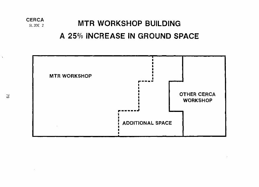
CERCASLIDE 2 MTR WORKSHOP BUILDING
A 25% INCREASE IN GROUND SPACE
MTR WORKSHOP
OTHER CERCAWORKSHOP
ADDITIONAL SPACE

MAIN EQUIPMENTS TO BE TRANSFEREDFROM NUKEM TO CERCA
MACHINES :
MELTING FURNACEFUEL CORES PRESSING MACHINEROLLING MILLELECTRON BEAM WELDING MACHINES
GAMMA COUNTING MACHINEULTRASONIC TESTING MACHINEX-RAY HOMOGENEITY SCANNING MACHINEWATER CHANNELS INSPECTION MACHINESEMI AUTOMATIC CLADDING MEASURING DEVICE
TOOLINGS :
TOOLINGS ADAPTED TO TRANSFERED EQUIPMENTSTOOLINGS SPECIFIC TO PARTICULAR FUEL ELEMENTS
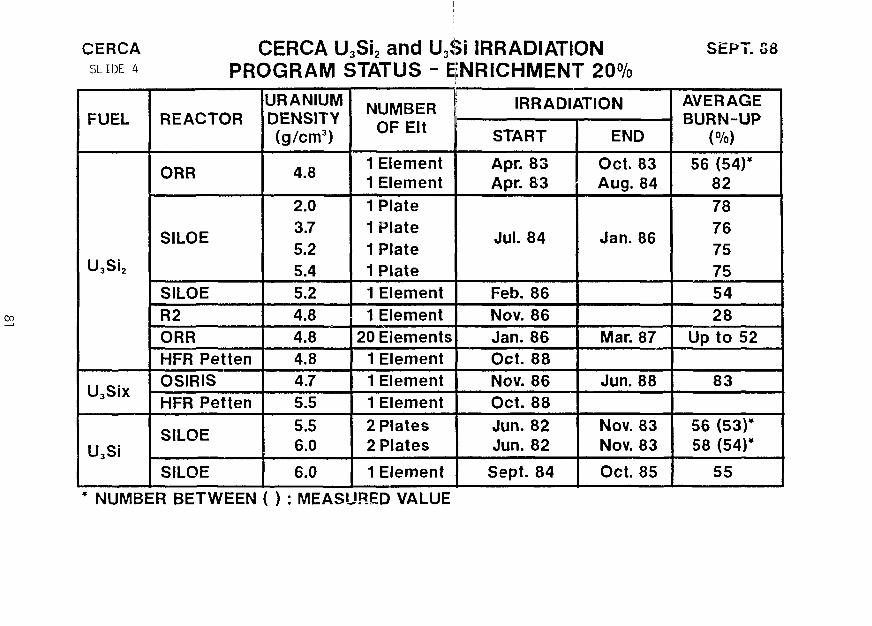
CERCASLIDE k
00
CERCA U3Si2 and U3Si IRRADIATIONPROGRAM STATUS - ENRICHMENT 20%
SEPT. G8
FUEL
U3Si2
U3Six
U3Si
REACTOR
ORR
SHOE
SILOER2ORRHFR PettenOSIRISHFR Petten
SILOE
SILOE
URANIUMDENSITY(g/cm3)
4.8
2.03.75.25.45.24.84.84.84.75.5
5.56.0
6.0
NUMBEROF Elt
1 Element1 Element1 Plate1 Plate1 Plate1 Plate1 Element1 Element
20 Elements1 Element1 Element1 Element2 Plates2 Plates
1 Element
IRRADIATION
START
Apr. 83Apr. 83
Jul. 84
Feb. 86Nov. 86Jan. 86Oct. 88Nov. 86Oct. 88Jun. 82Jun. 82
Sept. 84
END
Oct. 83Aug. 84
Jan. 86
Mar. 87
Jun. 88
Nov. 83Nov. 83
Oct. 85
AVERAGEBURN-UP
(%)
56 (54)*82787675755428
Up to 52
83
56 (53)*58 (54)*
55
NUMBER BETWEEN ( ) : MEASURED VALUE

82

SESSION I I I
September 19, 1988
FUEL DEVELOPMEMT
Chairmen:
G. Thamm(KFA, Federal Republic of Germany)
K. Saltvedt(Studsvik Nuclear, Sweden)
83

FABRICATION OF HIGH-DENSITY FUEL PLATES BY HOT ISOSTATIC PRESSING
T. C. Wiencek, R. F. Domagala and H. R. ThreshFabrication Technology Section
Materials and Components Technology DivisionArgonne National LaboratoryArgonne, Illinois U.S.A.
ABSTRACT
The loading limits of U^Si AND UjSi2 dispersion fuelplates fabricated by conventional techniques have beenreached. Fuel densities of up to 7.0 gU/cm have beensuccessfully produced. These loadings are sufficient for theneeds of most research reactors, but a few reactors requirehigher fuel densities. Two concepts are presented which maylead to loadings beyond 7.0 gU/cm : a wire concept in which0.030 in. (0.76 mm) uranium silicide wire is bonded within analuminum plate and a dispersion concept in which a highlyloaded (>50 volume percent fuel), uniformly clad fuel plate isproduced. In both concepts hot isostatic pressing is a keyprocessing technique.
INTRODUCTION
The loading limits of conventional fabrication techniques have beenreached for U-jSi and U^Si2 powder metallurgy fuel plates. On a laboratoryscale, fuel densities of up to 7.0 gU/cm have been successfully produced.However, a few reactors require higher fuel densities. As a point ofreference, for reactors loaded with HEU (93% enriched) UA1X with a fueldensity of 1.7 gU/cm and a fuel zone thickness of 0.020 in. (0.51 mm), theequivalent loading for LEU (20% enriched) fuel would be as follows:
Ratio of Enrichment x Original Loading x Reactivity Factor
(93/20) x 1.7 x 1.15 = 9.1 gU/cm3
In terms of quality and fabricability, this is well beyond the loadingrange possible for conventionally produced powder metallurgy core fuelplates, irrespective of the fuel alloy chosen.
Other innovative techniques were examined to meet the low-enrichmentneeds of these high-performance reactors. Two concepts have been proposedto address this issue. The first effort involves the generation of wires ofU- Si and/or Uy^Ga^gSi-^j. These wires would be used as filaments bonded intoAl in such a geometry as to generate plates with loadings approaching 9.0gU/cm in the fuel zone. The second effort involves a dispersion concept inwhich a highly loaded (>50 volume percent U2Si2), uniformlv clad fuel plateis produced with areal loadings equivalent to 9.0 gU/cm .
85

The most common problem with highly loaded fuel plates is the limitedability of the material system to respond uniformly to the rolling proc-ess. The major cause of this is the difference in the hardness of the fueland the matrix. The fuel particles are very hard and resist deformation;the matrix is soft and flows very easily. When the volume fraction of theharder fuel phase reaches about 40-50%, the classic "dog-bone" effect isseen. This is a thickening of the ends of the fuel zone such that whenviewed in longitudinal cross section, the fuel zone resembles a dog-bone.The ends of the fuel zone are where the greatest discontinuities occur. Inthese regions the aluminum clad is forced over the fuel zone withoutreducing the fuel zone thickness. In the center of the fuel zone during therolling process, the constraint, and therefore the deformation, is uni-form. Dog-boning is minimal in shaped (tapered) compacts containing up toabout 55 volume percent fuel. At higher fuel percentages, the differencesin hardness between fuel zone and cladding are so great that the fuelappears as a series of dog-bones, with alternating thick and thin areasthroughout the whole zone. Because of minimum clad thickness requirementsand limits on the uniformity of uranium loading, plates with a fuel zone ofthis shape are not acceptable.
The root of this problem is the rolling process, which is a linecontact deformation system. Dog-boning occurs because the fuel zone isconstrained from lateral motion but can move in the rolling direction, whichis the least restrained direction. This flow is probably greatest duringthe early rolling passes when the fuel zone is the least constrained by thethickness and geometry. At later passes there is more resistance andprobably less dog-boning. If a uniform pressure could be applied to thefuel plate to deform it, this problem would be minimized and perhapseliminated.
PROCESS
The process we chose to apply to this problem is hot isostatic pressing(HIPping). Over the last fifteen years, this process equipment has becomemore readily available and HIPping has gone from being a specializedlaboratory technique to a commercially used process. In this fabricationmethod, the workpiece is hermetically sealed in a deformation container,placed in a high-pressure environment [approximately 30 ksi (207 MPa)] andheated to an appropriate temperature in the range of 200-1500°C. Thecombination of heat and pressure densifies, sinters and bonds the work-piece. A schematic representation of a HIP unit is shown in Figure 1.
All of the HIP experiments to date have been conducted on a Conawayunit manufactured in -1980. The HIP chamber is approximately 4.5 in. (11.4cm) in diameter and 6 in. (15.2 cm) high. A molybdenum heater permitsheating to as high as 1500°C. Since all our work has been and will be withAl and Al alloy clad, we plan never to exceed ~500°C.
The potential advantages of a HIPped fuel plate are uniform clad andfuel zone thickness as well as control of the fabrication atmosphere,temperature and pressure. With the appropriate HIP, plates can be batchprocessed. However, a complete installation capable of batch processingfull-size plates could easily cost over a half million dollars (U.S.A.).

Cooling jacket
Load
Pressure vessel
' Upper cover
Heal shield
Heating element
Thermocouple
Power connection
Power Thermocouple
Fig. 1. Schematic Representation of HIP Unit.
CONCEPTS
Wire Concept
Figure 2 shows a schematic cross section of a "wire-concept" fuelplate. This design can be fabricated with a solid cover plate and a baseplate in which cavities are machined to accept the fuel wires. Alter-natively, top and bottom cover plates can be machined with grooves to acceptone-half the wire diameter and the cover plates placed together to totallysurround the wire. If such a configuration with UoSi or UycGai gSi-i c wiresof 0.030 in. (0.76 mm) diameter, can be successfully bonded, the uraniumdensity in the fuel zone will be 8.6 g/cm .
The wire concept provides a system (plate) with the followingadvantages:
• The mechanical constraint on the fuel will be much greater than in aconventional dispersed-phase plate configuration.
87

Fuel: U3Si or U 7 5Ga 1 0Si 1 5; 0.030 in. (0.76 mm) Diameter
U Loading: 8.6 £/cm
A.-0.050 in. (1.27 mm) B:0.010 in. (0.25 mm) C:0.010 in. (0.25 mm)
Fig. 2. Cross Section of "Wire Concept" Fuel Plate
tA
I
B
•B
Fuel: U3Si2, 55 vol.%, <1% Porosity
U Loading: 6.2 g/cm
A:0.050 in. (1.27 mm) B:0.010 in. (0.25 mm)
Fig. 3. Cross Section of "Dispersion Concept" Fuel Plate
88

• The fuel phase has relatively little surface area, compared with adispersed phase, to react with the Al matrix.
• Precise positioning of fuel is possible.
• Shaped fuel distributions may be achieved.
The two major challenges in producing such fuel plates are to produce U-jSiand UTcGa-jflSi-jr wires of the indicated diameter and to HIP-bond them to asuitable aluminum alloy such as 6061. (HIP bonding of aluminum alloys isnot a trivial task.)
The fuels chosen for experimental work were U^Si with a density of 15.2g/cm and a composition of 96 wt.% U and V-j^Ga^gSi^ with a density of 15.6g/cm and a composition of 94.1 wt.% U. U^Si has been chosen as onecandidate for the wire concept because so much is known about its irradia-tion behavior as well as the chemical, physical, and mechanical propertiesof this phase. U^Si in an Al matrix is known to be relatively stable underirradiation up to at least 50% burnup. No irradiation data for Uy^Ga-LoSi-^are available; it was chosen because it represents a simple modification ofU^Si and, most important, can be cold rolled at least 40% at room tempera-ture. With successive rolling and 800°C annealing steps, it is presumedthat wire of the required dimensions can be fabricated. Both compositionsrequire a prolonged heat treatment (72 h, 800°C) to form the intermetalliccompounds by a peritectoid reaction.
Dispersion Concept
A cross section of the HIPped "dispersion-concept" fuel plate is shownschematically in Figure 3. For this concept, the fuel of choice is ^812-The strategy underlying the dispersion concept is simply to increase thethickness of the fuel zone to 0.030 in. (0.76 mm); with 55 vol.% U3Si2,this thickness would provide an equivalent areal loading of 9.3 gU/cm .Since the total plate thickness cannot exceed 0.050 in. (1.27 mm), a cladthickness of 0.010 ± 0.002 in. (0.25 ± 0.051 mm) will be required. By itsnature, the HIP process may be expected to produce a plate with finaldimensions that are very nearly those of the assembled components beforeHIPping, so a uniform clad thickness can reasonably be expected. Incontrast, such a uniformity is never guaranteed in a rolled plate. The twomajor challenges in the dispersion concept are, then, to produce thin powdermetallurgy compacts of U-jSi2 + Al with uniform thickness and acceptablehomogeneity and to HIP bond them within a suitable Al alloy clad.
RESULTS AND DISCUSSION
Work on the concepts described above is in its early stages. Trialruns .were made with an argon atmosphere and pieces of solid 6061 Al alloy todemonstrate that the newly installed HIP unit was functioning properly.After this, several archive Argonne miniplates and compatibility studyplates, originally fabricated by standard rolling procedures, were HIPped.The object was to determine whether the porosity in the fuel zone could bereduced by the process. Several plates were treated and porosity values of
89

much less than 2% were calculated from immersion density measurements.
Several attempts to HIP-bond 6061 to itself were only moderatelysuccessful; bonding was inadequate. However, instead of devoting time andeffort to developing the proper surface preparation parameters and operatingtemperatures and pressures, we chose at this time to use 1100 Al (99.00 min.Al) for further HIP experiments. Pieces of 1.5 in. (38.1 mm) diameter 1100Al rod were HIPped end-to-end and tensile bars were machined from the prod-uct. Three such bars were produced, machined, and tested to failure.Values for ultimate tensile strength and percent elongation measured for theHIP-bonded specimens were within the normal scatter band for solid wroughtpieces of 1100 Al in the 0-temper (soft) condition. Metallographic exam-inations of the zone of the original interface showed some recrystallizationacross the interface and what appeared to be a sound metallurgical bond.
Wire Concept
Generating 0.030 in. (0.76 mm) wire of the aforementioned U-base alloysfor the wire-concept plates is currently being addressed. "Bare"UyrGai nSii 5 round/oval rods -0.4 in. (—10 mm) in diameter have been rolledat several temperatures. As stated earlier, we have already demonstratedthat stock of this alloy can be reduced in thickness by up to -40% by flatrolling at room temperature. With intermediate anneals of 1 h at 800°C, wehave successfully produced sheet of this alloy as thin as 0.016 in.(0.4 mm). This thickness is obviously less than the 0.76-mm target dia-meter. Flat rolling produces sheet from which wires with a square crosssection can, of course, be cut. However, wire with a circular cross-sectionwould presumably be better constrained from swelling during irradiationbecause of the hoop stresses in the surrounding clad. Square cross sectionwire could be reshaped into a round with appropriate additional processingsteps.
To obviate the necessity for intermediate anneals, hot-rolling experi-ments at 400° and 800°C were conducted with the U-Ga-Si alloy. For the400°C experiments, an oil bath served to both heat the alloy and partiallyprotect the surface from contact with air (oxygen). However, the amount ofreduction in thickness before cracking occurred was the same as for rollingat room temperature. Therefore, use of an oil bath appears to provide noadvantage.
For rolling at 800°C, a salt bath was used. The salt, a mixture of 65wt.% KCOj, 10 wt.% NaCOj and 25 wt.% LiCO-j, is used commercially for hotrolling of U metal. No improvement in the rolling characteristics wasobserved and severe corrosive attack of the alloy by the carbonate saltoccurred. It has been concluded that cold rolling at room temperature withintermediate anneals is the most expeditious procedure for fabricatingU75Ga10S^15 w*-reJ n o further hot rolling experiments with this alloy arecontemplated.
The currently planned procedure is rod rolling followed by swaging toconvert the round/oval ingot bars into wire of the desired diameter. Alloperations will be conducted at room temperature, with intermediate 800°Canneals at approximately every 30 to 35% reduction in cross-sectional area.
90

Efforts to produce U-jSi wire have just been initiated. Our previousexperience has shown that it is not possible to accommodate more than one ortwo percent reduction of U^Si at room temperature, so all working processesare planned for temperatures above room temperature. No increase in work-ability of U^Si has been observed up to ~600°C. At 600°C and above, wherethe carbonate salt bath was used, severe corrosive attack of U-jSi by thesalt outweighed any improvement in ductility.
The plan for further deformation experiments with U^Si involves"canning" cast and heat-treated rods in an appropriate material (304stainless steel, for example); working the canned assembly at, say, 800°C,and then stripping away the protective layer.
Dispersion Concept
The dispersion concept requires a thin compact. To test the feasi-bility of this approach, a compact of 55 vol.% W and balance Al and void wasinserted into a cavity machined into a piece of 0.080 in. (2.03 mm) thick1100 Al plate. A flat 1100 Al plate of the same dimensions was used as acover and the assembly was TIG-welded peripherally; Cu chills and clampswere used to minimize heating of the internal mating surfaces of the compactand clad. The 1100 Al pieces were chemically cleaned in an Oakite-160solution, following practices identical to those employed for cleaning Alhardware for conventional rolling of fuel plates. This assembly was HIP-bonded at 500°C and -11,000 psi (-76 MPa) for two hours. The chamber wasnot pressurized until the internal thermocouple indicated 500°C. Theproduct appeared to be well bonded. Immersion density measurements wereconducted, and calculations based on the data indicated 7.6% voids in thefuel zone. A full transverse section of this plate was cut and the samplemounted and polished for metallographic study. The clad thicknesses oneither side of the fuel zone were remarkably uniform. The bond at the 1100Al interface appeared to be sound.
Additional experiments with W+Al compacts HIP bonded into Al alloyframe and cover assemblies are planned. When procedural parameters areestablished, depleted-uranium UoSio + Al powder compacts will be preparedand HIPped.
SUMMARY AND CONCLUSIONS
New concepts and fabrication procedures are being addressed forfabricating plate-type fuel elements with U densities approaching 9.0 g/cm ,or increasing the fuel zone thickness of a 0.050 in. (1.27 mm) thick plateto a point where the equivalent loading can be achieved. Hot isostaticpressing is the procedure of choice at present. Concepts involving theutilization of U-jSi or U75GaioSi15 w^ r e anct t n e direct Hipping of high-U-density compacts in a near-net-shape geometry are being investigated.
91
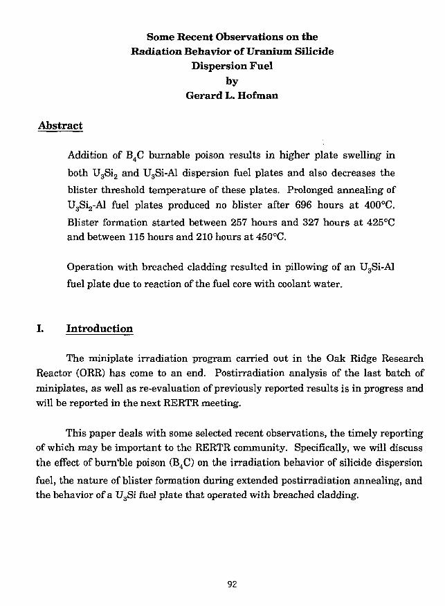
Some Recent Observations on theRadiation Behavior of Uranium Silicide
Dispersion Fuelby
Gerard L. Hofman
Abstract
Addition of B4C burnable poison results in higher plate swelling in
both U3Si2 and U3Si-Al dispersion fuel plates and also decreases the
blister threshold temperature of these plates. Prolonged annealing of
U3Si2-Al fuel plates produced no blister after 696 hours at 400°C.
Blister formation started between 257 hours and 327 hours at 425°Cand between 115 hours and 210 hours at 450°C.
Operation with breached cladding resulted in pillowing of an U3Si-Al
fuel plate due to reaction of the fuel core with coolant water.
I. Introduction
The miniplate irradiation program carried out in the Oak Ridge ResearchReactor (ORR) has come to an end. Postirradiation analysis of the last batch ofminiplates, as well as re-evaluation of previously reported results is in progress andwill be reported in the next RERTR meeting.
This paper deals with some selected recent observations, the timely reportingof which may be important to the RERTR community. Specifically, we will discussthe effect of burn'ble poison (B4C) on the irradiation behavior of silicide dispersion
fuel, the nature of blister formation during extended postirradiation annealing, andthe behavior of a U3Si fuel plate that operated with breached cladding.
92

II. Effect of BdC
Some reactor core designs require the addition of burnable poison in their
fuel elements. The most convenient way of incorporating a burnable poison such as10B is by mixing an appropriate amount of powdered B4C with the fuel powder. In
order to assess the possible effects of such a mixture on the irradiation behavior of
silicide dispersion fuel, several U3Si2 and U3Si miniplates containing typical
amount of B4C were fabricated. After irradiation in the ORR to approximately 80%235U bumup, postirradiation analysis was performed. The results were compared topostirradition data from previously irradiated sibling miniplates that contained noB4C.
The difference in irradiation behavior between fuel plates with and without
B4C is appreciable. As shown in Table I, the B4C-containing plates had an average
thickness increase of 0.15 mm vs. 0.05 mm for plates without B4C at approximately
the same 235U burnup. Likewise the average meat swelling was 8.6 vs. 2.4%.
Metallographic examination reveals the reason for the larger swelling of the
B4C-containing plates. Comparison of polished cross section, (Figs. 1 and 2) clearly
show a much larger fraction of retained as-fabricated porosity in the B4C-containing
plates, as well as many clusters of large pores in the fuel particles. The retainedas-fabricated porosity was measured with an image analyzer and found to havedecreased during irradiation from 10% to 4.5% for the B4C-containing plates and
from 10% to less than 1% for the sibling plates without B4C (see Table I). Calculat-
ing the amount of fuel particle swelling AVP, with the following formula:
one obtains, respectively, 31% and 25%. The difference in fuel swelling is presum-
ably due to the presence of pore clusters in the fuel particles of B4C-containing
plates.
93

In order to further investigate this apparent effect of B4C on swelling, se-
lected samples were examined with a scanning electron microscope (SEM) including"
energy dispersive x-ray analysis, and with a scanning Auger electron microprobe
(SAM).
Figure 3 shows the distribution of B4C particles (dark angular features) in an
unirradiated fuel plate. The B4C particles are clearly identified by the boron
Auger-electron dot-map shown in Fig. 3.
The meat microstructure after irradiation is also shown in Fig. 3. Againclearly identified by SAM are the B4C particles, which now appear less angular in
shape presumably as a result of irradiation damage. Bigger B4C particles are found
at residual as-fabricated porosity suggesting that the presence of B4C prevents
closure of the pores. Detailed SAM analysis did not detect boron, carbon, or the
reaction product lithium in the residual pores. The only other element involved is
helium produced through a generation by the reaction:
10B(n,o07Li
The amount of helium generated in a particle of the size shown in Fig. 3 at complete
burnup of the 10B isotope is approximately 7 x 10"10 moles. If all this helium is
released into the pore shown in Fig. 1, a pressure of approximately 800 psi could be
generated at 100°C. Such a high pressure would certainly prevent closure of the
pore, but a lower pressure due to only fractional helium release from the B4C parti-
cle might well be sufficient to prevent pore closure. Without further analyses it
seems nevertheless plausible at this point to conclude that helium release is respon-
sible for the observed retention of as-fabricated porosity.
Next we examined the clusters of large pores in the fuel particles that ac-count for the larger fuel particle swelling in the B4C-containing plates. Optical
metallography of etched meat microstructure and a SAM micrograph shown inFig. 4 reveal a different fuel microstructure around the clusters. The appearance ofthis etched fuel microstructure is similar to that of fuel that has reacted withaluminum; however, SEM analysis found no difference in composition between the
94

phase around the pores and the bulk of the fuel. SAM analysis again showed noevidence of boron or carbon but a faint indication of lithium was detected.
High magnification SEM examination of the fuel, also shown in Fig. 4 showsthe typical small.-regular-spaced fission gas bubbles in the bulk U3Si2, but absence
of these small bubbles in the different structure around the large pore clusters.Apparently fission gas diffusivity in the cluster area was much higher leading to thegrowth of large bubbles. We can only speculate that a small amount of lithium andpossibly also helium diffused from B4C particles into adjacent fuel causing a in-crease to fission gas difFusivity. We believe that there is enough circumstantialevidence to state that activation products from the B4C particles are the root-cause
of the higher swelling of B4C-containing fuel plates. The effect of B4C on U3Si plates
was similar to that in U3Si2 plates.
III. Blister Formation During Postirradiation Annealing
Blister annealing tests are routinely performed on experimental fuel platesas part of the postirradiation analysis. These tests consist of 1/2 hour annealingsteps of 50°C starting at 350°C until blisters are observed. The temperature atwhich blisters are first formed is called the blister threshold temperature and is afigure of merit to assess the high temperature stability of fuel plates.
To better characterize blister formation long time anneals are performed tostudy the time-temperature relation of blister formation as well as the behavior ofblisters after continued annealing.
The test results are shown in Table II for LEU U3Si2 plates with high loading
(5.2-5.6 g cm'3) after approximately 85% 23oU burnup. The normal blister thresholdtemperature for this type of plate is 525°C for the standard 1/2 hour anneal. Thedata in Table II shows that the plates are very stable at 400°C, for no blistersformed after a total time of 696 hours at temperature. The time to form blistersdecreases to 327 hours at 425°C and 210 hours at 450°C. No measurable change inplate thickness occurred prior to blister formation at any temperature.
95
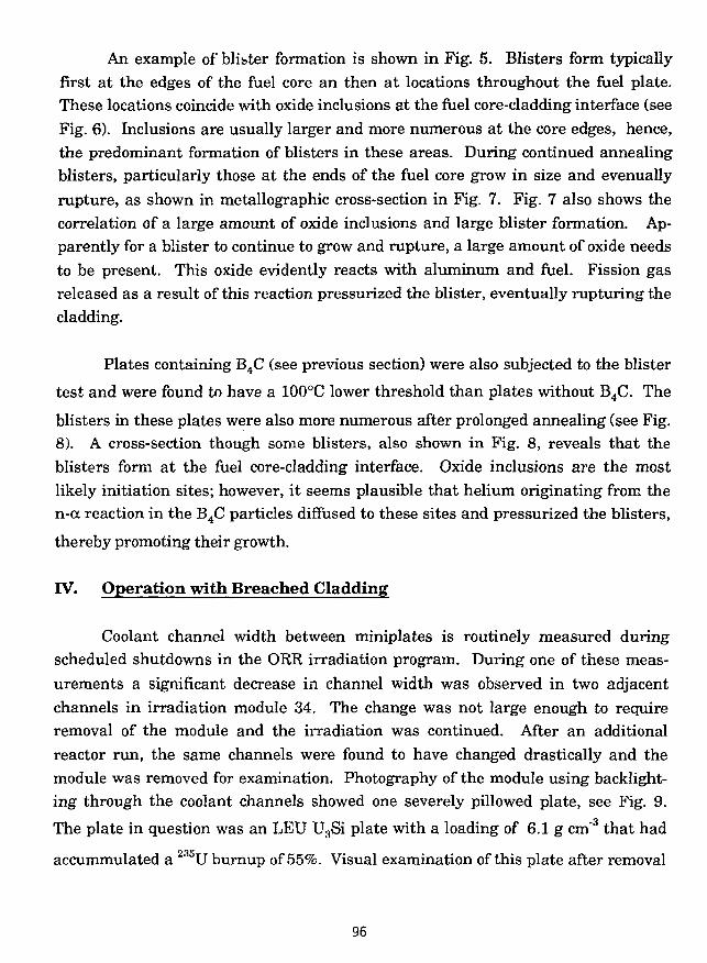
An example of blibter formation is shown in Fig. 5. Blisters form typicallyfirst at the edges of the fuel core an then at locations throughout the fuel plate.These locations coincide with oxide inclusions at the fuel core-cladding interface (seeFig. 6). Inclusions are usually larger and more numerous at the core edges, hence,the predominant formation of blisters in these areas. During continued annealingblisters, particularly those at the ends of the fuel core grow in size and evenuallyrupture, as shown in metallographic cross-section in Fig. 7. Fig. 7 also shows thecorrelation of a large amount of oxide inclusions and large blister formation. Ap-parently for a blister to continue to grow and rupture, a large amount of oxide needsto be present. This oxide evidently reacts with aluminum and fuel. Fission gasreleased as a result of this reaction pressurized the blister, eventually rupturing thecladding.
Plates containing B4C (see previous section) were also subjected to the blister
test and were found to have a 100°C lower threshold than plates without B4C. The
blisters in these plates were also more numerous after prolonged annealing (see Fig.8). A cross-section though some blisters, also shown in Fig. 8, reveals that theblisters form at the fuel core-cladding interface. Oxide inclusions are the mostlikely initiation sites; however, it seems plausible that helium originating from then-cc reaction in the B4C particles diffused to these sites and pressurized the blisters,
thereby promoting their growth.
IV. Operation with Breached Cladding
Coolant channel width between miniplates is routinely measured duringscheduled shutdowns in the ORR irradiation program. During one of these meas-urements a significant decrease in channel width was observed in two adjacentchannels in irradiation module 34. The change was not large enough to requireremoval of the module and the irradiation was continued. After an additionalreactor run, the same channels were found to have changed drastically and themodule was removed for examination. Photography of the module using backlight-ing through the coolant channels showed one severely pillowed plate, see Fig. 9.
The plate in question was an LEU U3Si plate with a loading of 6.1 g cm"3 that had
accummulated a 23oU burnup of 55%. Visual examination of this plate after removal
96

from the module revealed a transverse crack at one end of the pillow near the end ofthe fuel core. Also, the channel width probe had gouged the cladding on the pillow,as shown in Fig. 9.
A metallographic section was taken at the end of the pillow transecting thecrack as shown in Fig. 10. The crack is located at the "dog bone" end of the fuel corewhere the cladding is rather thin. There is a large amount of two phase reactionproduct in the area and this reaction product contains large fission gas bubbles. Thecladding breached probably early on during the irradiation in a very thin spot overthe dog bone end. Ingress of water during continued irradiation resulted in thereaction (most likely oxidation) of the silicide - Al dispersion. Fission gas bubblesevidently grow easily in the reaction product, although hydrogen originating fromthe decomposition of H2O may also have contributed to bubble growth. The reac-tion product, including its gas bubbles, appears similar to the fuel core phases foundin high burnup - highly loaded U3O8-A1 fuel plates where the U3O8 has completely
reacted with the aluminum matrix.[l] It is of interest to note that predefected fuelplates when soaked in hot water for prolonged periods [2] do not show the formationof interaction product and do not swell; evidenty radiation is necessary for thereaction to occur. No unusual fission gas activity was detected during the irrada-tion and release of fission gas through the crack, which must have occurred to someextent, was evidently of such a low rate that the ORR instrumentation could notmeasure it.
German investigators have reported on operation with a failed U3Si2 mini-
plate [3]. The cladding of this plate had cracked at a thermocouple attachment point
and also had also developed a pillow at the crack site.
It is interesting to note that experimental UA^-Al dispersion miniplates
irradiated in the Advanced Fast Reactor, ATR, with cladding corrosion defects alsodeveloped pillows [4].
97
References
1. G. L. Hofman et al., Nucl. Technol. Vol. 72, Mar. 1986, pp. 330-344.2. R. F. Domagala, Argonne National Laboratory, Private Communication.3. C. Thamm, KFA, Jiilich personal communication, and W. Krug etc., this
meeting.4. J. M. Beeston et al., Idaho National Engineering Laboratory, EGG-SE-6696,
Oct. 1984.
98

TABLE I. Comparison of LEU, U3Si2 MJniplates
With and Without B4C
235U Loading, g cm"3
At, in. (mm)
AVm, %
AVF, %
WithB4C
5.1
0.005 (0.15)
8.6
31
46
10
4.5
1.9
Without B,C
5.1
0.0021 (0.05)
2.4
25
46
10
1.0
2.2
v p %FDm , 1021
Bu, % 79 84
Blister
Temp, °C 425 525
where:
At is plate thickness increase, including oxide layer.ym _ ym
AVm is meat volume change — °
AVF is fuel particle volume change.
VF is the original fuel volume fraction in meat.
Vo is the original as-fabricated porosity in meat.
Vp is the fraction of as-fabricated porosity remaining after irradiation.
FD is the accumulated fission density.
99

TABLE II. Postirradition Annealing Data ofU3Si2 Miniplates
Plate A-99, 5.2 gcm 3 , 79%Bu, 400°C
time, hours
06
47117313531696
Thickness,Grid Point* 5
62.062.062.062.062.561.8
mils6
61.561.561.361.361.361.361.2
7
61.461.461.361.361.361.361.4
Comments
No Blisters
Plate A-91, 5.6 gcm3, 84%Bu, 425°C
50.050.650.058.0
50.350.261.061.0
50.250.050.250.2
37
One BlisterBlisters WarpingBlisters Warping
0257327423517
Plate A-85, 5.0 g cm"3, 84% Bu, 450cC
0 51.0 51.0 51.420 51.0 51.0 51.4115 51.8 51.2 51.5210 53.0 53.1 53.0 Blister in Center278 54.1 55.0 54.8 U +Warping490 73.0 68.0 60.7 Many Small Blisters
and Warping
*These points are spaced on the longitudinal center line of the plates.
100

• v • . * . .- ]'~*::':". ?•»»;':,.','-
Fig. 1. Microstructure of Plate A-199P, U3Si2 & B4C,Showing Retained As-Fabricated Porosity andBubble Clusters in Fuel After Irradiation
107

• * s •
•• I 4
/ : • •
• > • #
' « • • • • • • - ; . . .
X • . • • "
Fig. 2. Microstructure of Plate A, U3Si2 Without B4C,
Showing Nearly Complete Closure of As-Fabricaied
Porosity and Absence of Bubble Clusters
102

<, .
(210716) SAM, Specimen Current(210717) SAM, Boron
SEM(210739) SAM, Boron, Detail
Fig. 3. Fuel Core Microstructure Showing B4C Particles,
Upper: Unirradiated; Lower: Irradiated103

Optical Eteched
SAM SEM
Fig. 4. Fuel Microstructure Showing Structural DifferenceAround Bubble Clusters in Fuel Particles
104

Fig. 5. Location of Blisters in Irradiated U3Si2 PlatesAfter 1/2 Hour at 525°C
105

• 4l • •»
feSI r
Fig. 6. Fuel Core Microstructure of Irradiated U3Si PlateShowing Location of Oxide Particles at Core Edgeand Dog Bone End
106

Fig. 7. Crossection of Ruptured Blister at Dog Bone Endof Irradiated U3Si2 Plate After Prolonged Annealingat 450°C
107

oCX5
Fig. 8. Blisters and Crossection Through Blisters of B4CContaining U3Si2 Plate after Prolonged Annealingat 450°C

ii. •ct
IHHM
Back lightening through moduleEdge on view of pillowed plate
Fig. 9. Views of Pillowed U3Si Plate A211, Showing Crackof Edge of Pillow
109

Detail
Fig. 10. Crossection of Pillowed Region of Plate 211,Including Crack Showing Remnants ReactionProduct

THE EFFECT OF CRYSTAL STRUCTURE STABILITYON SWELLING IN INTERMETALLIC
URANIUM COMPUNDS
by
J. Rest, G. L. Hoftnan, and R. C. Birtcher
ABSTRACT
Irradiation experiments with certain low-enrichment, high-density, uranium-base
intermetallic alloys that are candidate reactor fuel materials, such as U3Si and U6Fe, have
revealed extraordinarily large voids at low and medium fuel burnup. This phenomenon of
breakaway swelling does not occur in other fuel types, such as U3Si2 and UA13, where a
distribution of relatively small and stable fission gas bubbles forms. In situ transmission
electron microscope observations of ion radiation-induced rapid swelling of intermetallic
materials are consistent with growth by plastic flow. Large radiation enhancement of
plastic flow in amorphous materials has been observed in several independent experiments
and is thought to be a general materials phenomenon.
The basis for a microscopic theory of fission gas bubble behavior in irradiated
amorphous compounds has been formulated. The assumption underlying the overall theory
is that the evolution of the porosity from that observed in the crystalline material to that
observed in irradiated amorphous U3Si as a function of fluence is due to a softening of the
irradiated amorhpus material. Bubble growth in the low-viscosity material has been
approximated by an effective enhanced diffusivity. Mechanisms are included for the
radiation-induced softening of the amorphous material, and for a relation between gas atom
mobilities and radiation-induced (defect-generated) changes in the material. Results of the
analysis indicate that the observed rapid swelling in U3Si arises directly from enhanced
m

bubble migration and coalescence due to plastic flow.
I. Introduction
Fission gas bubbles have recently been shown to exhibit extremely high growth
rates at relatively low temperatures in certain uranium compounds [1]. It was proposed
that this accelerated swelling phenomenon occurs only in compounds that undergo a
crystalline-to-amorphous transformation, and that it is a manifestation of radiation en-
hancement of diffusion and plastic flow in amorphous solids.
The classical model of radiation-enhanced diffusion and creep in crystals, based on
the generation of vacancies in excess of their thermal equilibrium concentration, does not
apply in a noncrystalline solid where, strictly speaking, the vacant lattice site or vacancy
does not exist. In amorphous solids, a model of a radiation-enhanced free volume can be
used to interpret the very large flow rates observed. We will draw together here the results
of several seemingly unrelated experimental studies in an attempt to generalize this large
radiation effect in amorphous solids, and explore a model that describes the effect in
partirular as it relates to nuclear fuel.
Mineralogists have long recognized the presence of radiation-induced crystalline-to-
amorphous transformations in natural radioacative compounds. The extent of this so-
called metamict condition is used to determine the age of minerals and was first described
by Pellas [2], who showed that partially eovalent crystals can undergo this transformation.
This bond-type criterion for amorphization has more recently been confirmed in an exten-
sive ion bombardment study of compounds by Naguib and Kelly [3], who fouond that
amorphization is quite common and should occur whenever the ionicity is <0.47.
112
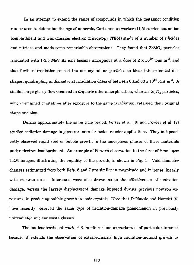
In an attempt to extend the range of compounds in which the metamict condition
can be used to determine the age of minerals, Cartz and co-workers [4,5] carried out an ion
bombardment and transmission electron microscopy (TEM) study of a number of silicides
and nitrides and made some remarkable observations. They found that ZrSiO4 particles
irradiated with 1-3.5 MeV Kr ions became amorphous at a dose of 2 x 10¹⁹ ions m'2, and
that further irradiation caused the non-crystalline particles to bloat into extended disc
shapes, quadrupling in diameter at irradiation doses of between 6 and 60 x 10 9 ions m' . A
similar large glassy flow occurred in a-quartz after amorphization, whereas Si3N4 particles,
which remained crystalline after exposure to the same irradiation, retained their original
shape and size.
During approximately the same time period, Porter et al. [6] and Fowler et al. [7]
studied radiation damage in glass ceramics for fusion reactor applications. They independ-
ently observed rapid void or bubble growth in the amorphous phases of these materials
under electron bombardment. An example of Porter's observation in the form of time-lapse
TEM images, illustrating the rapidity of the growth, is shown in Fig. 1. Void diameter
changes estimatged from both Refs. 6 and 7 are similar in magnitude and increase linearly
with electron dose. Inferences were also drawn as to the effectiveness of ionization
damage, versus the largely displacement damage imposed during previous neutron ex-
posures, in producing bubble growth in ionic crystals. Note that DeNatale and Horwitt [8]
have recently observed the same type of radiation-damage phenomenon in previously
unirradiated nuclear waste glasses.
The ion bombardment work of Klaumunzer and co-workers is of particular interest
because it extends the observation of extraordinarily high radiation-induced growth to
113

metallic glasses. From a series of papers published from 1982 [3-11], it appears likely that
all amorphous alloys (metallic glassed fire susceptible to large plastic flow under heavy ion
bombardment. Recently, Kla'.miinzer et al. performed an ion bombardment experiment
with borosilicate glass [12] and again found a very large plastic flow, comparable to that
seen in the metallic glasses.
In reactor irradiation experiments with intermetallic uranium compounds, Hofman
[1] showed that an enormous increase in gas bubble growth occurs when a compound
becomes amorphous during irradiation. An example of this rapid bubble growth in U3Si is
illustrated in Pig. 2. Evidence of very large plastic flow in neutron-irradiated materials has
also been reported in U6Fe by Bloch [13], in PUe Fe by Coffinberry and Waldron [14] and in
BeO by Yeniscavich and Bleiberg [15]. In every one of these experiments, the material
exhibiting excessive flow was found to be amorphous after irradiation.
Finally, the ion bombardment and in situ TEM experiments of Birtcher et al. on
U3Si [16] underscore the general nature of the effect. During irradiation of the amorphous
phase, the initial specimen perforation increased rapidly in size. This did not occur in the
crystalline phase. Figure 3 shows the behavior of a strip of material between two holes in
amorphous U3Si during 1-MeV Kr irradiation. This material is under tension during the
irradiation and undergoes plastic flow. Small holes within the strip grow and coalesce.
This growth stops when the irradiation is interrupted. The overall behavior is identical to
that displayed by reactor-irradiated U3Si (Fig. 2). These observations suggest that plastic
flow induced by a large radiation dose is not restricted to partially covalent materials but
can occur in any amorphous solid.
114

The deformation measurements obtained in the ion bombardment experiments of
Cartz, Klaumunzer, and Birtcher are combined in the plot shown in Fig. 4. The close
grouping of the data should be considered coincidental and not indicative of a functional
relationship, since no corrections for experimental differences have been made. However,
Fig. 4 does illustrate the magnitude of observed deformations as well as the apparent linear
relationship between deformation and irradiation dose. This linear dose dependence, which
was also found during the electron irradiations of Porter and Fowler, indicates that atomic
displacements control the deformation rate.
This summary of results of widely different experiments strongly suggests a unique
radiation effect in glassy materials. The very large plastic flows suggest low viscosities
characteristic of glass near its softening point. However, all experiments were performed
below 0.3 Tm, temperatures where the materials in question are hard and have high vis-
cosities. Indeed, after irradiation these amorphous materials are found to be hard and
brittle. For example, the microhardness of U3Si v measured after irradiation), increased
slightly after prolonged neutron irradition, during which the compound became amorphous
and experienced excessive swelling. The drastic difference between elastic properties
during and after irradiation is graphically shown in Fig. 5, which is a scanning electron
microscope (SEM) image of the surface of a large fission gas bubble in U3Si. The smooth
flow patterns on the bubble surface indicate viscous behavior, whereas the fractured
"ligaments" which had connected two sides of the bubble, and which were broken during
SEM sample preparation after irradiation, indicate brittle behavior. It may be concluded
that viscous flow occurs under ion, electron, and neutron irradiation and fissioning in the
glassy (amorphous) state only, whether this state is pre-existing or is formed during the
irradiation.
115

As suggested in the preceding discussions, the underlying mechanisms affecting
swelling behavior in intermetallic compounds involve mechanical instability under irradia-
tion. As we shall show, radiation-enhanced diffusion and plastic flow are key determinants
of swelling behavior. Figure 6 is a plot of the fuel swelling, obtained from immersion
density measurements, for U6Fe, U3Si, U3Si2, and UA13 dispersion fuels. The UA13 and
U3Si2 show little swelling after very high U burnup, but the higher density U6Fe and U3Si
experience rapid swelling at medium and low burnup.
The differences in fission gas bubble behavior are illustrated in Fig. 7 for the four
fuels shown in Fig. 6. Typically, UA13 does not develop resolvable fission gas bubbles, but
U3Si2 contains bubbles which have an extremely narrow size distribution and uniform
spacing, and which appears to be arranged in rows. The U3Si develops large bubbles which
interconnect and result in rapid swelling. At low burnup, U6Fe likewise develops large
irregular bubbles which interconnect, causing a sharp increase in the swelling curve.
As will be shown in Section II, the swelling behavior of the stable compounds UAI3, U3Si2,
and USi can be explained with current models of fission gas behavior in nuclear fuels,
models that include such effects as radiation-enhanced diffusion and nucleation and growth
of fission gas bubbles on grain boundaries, subgrain boundaries and dislocations in a
crystalline solid.
In Section III, it will be shown that the gas bubble growth observed in U6Fe, U3Si,
and U6Mn at low temperature can be explained by assuming that under irradiation, prop-
erties of the fuel approach those of the liquid state. Results will be presented which sug-
gest that extraordinarily low viscosity occurs in amorphous solids under irradiation. An
116

analytical model will be presented which relates the migration energy for diffusion within a
defect cascade to the level of damage sustained in the material. Measurements by
Okamota et al. [17] of the change in sound velocity in irradiated intermetallic compounds
have shown that substantial elastic softening of the intermetallic compounds occurs ir the
crystalline state and is associated with the progressive destruction of the chemical long-
range order which precedes the onset of amorphization in these materials. The shear
constant decreases linearly by as much as 50% with increasing volume dilation, and ex-
trapolates to zero at a volume dilatation of about 4.7%.
II. Fission Gas Bubble Behavior in Crystalline Intermetallic Compounds
A. Models
Estimates of the quantity of gas that can be accounted for in the observed
U3Si2 bubble population (Fig. 7) fall far short of the total amount generated. As the limit of
resolution in the SEM is about 50 nm, it is likely that a high density of small bubbles
and/or a high concentration of gas in solution is present within the U3Si2 matrix. A
mechanistic fission gas release and swelling mode, GRASS-SST [18,19], has been utilized to
interpret the observations.
For the purpose of calculation (i.e., reasonable code running times), the
bubbles are represented by a set of size classes defined in terms of the number of gas atoms
per bubble. This method of grouping significantly reduces the number of equations needed
to describe the bubble size distributions. The bubble classes are ordered so that the first
class refers to bubbles that contain only one gas atom. If S; denotes the average number of
atoms per bubbie for bubbles in the ith class (henceforth, called i bubbles), then the bubble
117

size classes are defined by
(1)
where m > 1.6, i > 2, and Sj = 1. The S2 class is assumed to consist of a single gas atom
associated with one or more vacancies or vacancy clusters. Py is the probability of an i
bubble coalescing with a j bubble when the bubbles move by random motion, and is given
by
Pjj = 4jt(rj + rpCDj + Dp (2)
where r; is the average i-bubble radius and D; is the average i-bubble diffusion coefficient in
the lattice.
The rate of coalescence, Cy, of bubbles with j bubbles is given by
Cij=PijFiFj (3)
where F{ is the number of i bubbles per unit volume. Details of the bubble growth calcula-
tion are given in the Appendix.
Dislocations can act as trapping sites for fission gas and bubbles. The fission
gas atoms diffuse by random motion to dislocations at a rate
. _ 2nD\ pc
where p is the dislocation density, c is the concentration of fission gas in the lattice, rx is
the radius of a single gas atom, and rc is the radius of the cylindrical capture volume
around the dislocation, i.e.,
rbp = l. (5)
118

Once the fission gas is pinned to dislocations, the gas can coalesce with both lattice and
dislocation bubbles (re-solution causes gas atoms to be knocked back into the lattice).
Coalescence probabilities for bubbles on dislocations can be derived from a solution of the
one-dimensional, time-dependent diffusion equation, and are given by
Pij=(Df +DjdWp, (6)
where Df is the average i-bubble diffusion coefficient on dislocations.
Bubble growth in crystalline U3Si2 during low-temperature (<200°C) irradia-
tion occurs primarily by the diffusion of gas atoms to existing bubbles, i.e., the bubbles are
basically immobile. Gas atom diffusion in U3Si2 at 100°C is primarily athermal, i.e.,
irradiation enhanced. The gas atom diffusivities used in GRASS-SST are taken from those
reported by Hoh and Matzke [20], and are given by
Da = 3.5 • lO^m 5 • f (7)a
where f is the fission rate.
Bubble growth is limited not only by the gas atom and gas bubble densities
and diffusivities, but by radiation-induced gas atom re-solution, i.e., the rate, b, at which
gas atoms are ejected from a bubble owing either to direct or to indirect collisions by fission
fragments.
The re-solution rate is calculated with the assumption that gas atom re-
solution from a spherical bubble is isotropic and proceeds by the knocking out of single gas
atoms. Thus, from geometrical considerations
,=¥ j (T[- k
R* dR (8,
119

where cos 0 = (rf - X2 - R2 )/2RX, X is the distance an average ejected atom travels, and b0 is
an experimentally determined constant [19].
For bubbles on dislocations, equilibrium is reached when the diffusion flux of
gas atoms from the local concentration gradients is balanced by the flux owing to re-
solution. If instantaneously there are N; bubbles per unit length of dislocation, the re-
Xsolution flux is N4b/2. If the gas atom concentration is zero at the dislocation and C a
distance X from it, the diffusion flux is approximately given by D C fX from Fick's law.
Thus, at equilibrium, when the two fluxes are equal.
(1 - CVC°) = 1 - S Nf b,- A/2DC° (9)i
where C° is the gas atom concentration far from the dislocation.
Within the rate theory approach used in GRASS-SST, the rate of gas atom
re-solution from dislocation bubbles, bNj/2, is multiplied by the factor C^ = Cx/C° to obtain
the backward flux of gas atoms. Good agreement between theory and experiment is ob-
tained only for small values of C* (C* « 1 ) . Physically, these results are interpreted as due
to a small value of the penetration depth, X. The value of X used in GRASS-SST (X = 5 nm)
and by Dowling et al. [21 ] is consistent with this conclusion and is on the order of a defect
cascade size.
A system of coupled equations for the evolution of the size distribution of
fission gas bubbles in the lattice and on dislocations can be derived [19] on the basis of the
models discussed above. The equations have the form
Ff = - A?F?F? - BfFf + C,a(i = 1,.... N; a = 1,2) (10a)
120

where Fi is the number of a-type bubbles in the ith size class per unit volume; a = 1,2
represents the lattice and dislocation distributions, respectively; and the coefficients Bi and
Cf obey functional relationships of the form
C? = C?(Ff,.... Ffj, F?, Ff+1 ..., Ff,) (10b)
B«=B1a(FP,...,Ff+1)F?,Ff+1 ...,Fg,)
where a = 1; (3 = 1,2; a = 2
a = 2;3 = l,2;a = l.
In Eq. 10, A[* represents the rate at which a-type bubbles grow out of the ith
size class due to coalescence with other bubbles in the ith class; Bs represents the rate at
which a-type bubbles are lost from the ith size class owing to coalescence with bubbles in
other size classes, change in bubble type owing to bubble migration processes, and re-
solution; and Cj represents the rate at which bubbles are being added to the ith size class
owing to fission gas absorption, bubble nucleation, bubble growth resulting from bubble
coalescence, and bubble shrinkage from the i+1 class due to gas atom re-solution.
Figure 8 is a GRASS-SST flow chart. Given the operating conditions, such as
the time step, temperature, stress, grain size and dislocation densities, GRASS-SST calcu-
lates the equilibrium bubble radii for the size classes of bubbles under consideration (the
initial number of size classes is an input) by using a modified hard-sphere equation of state
for xenon as well as the generalized capillary relation
(11)
121

where Pj(T) is the gas pressure in a bubble with radius r;, y is the surface energy, and OH is
the local hydrostatic stress.
After the bubble radii have been determined, the bubble diffusivities and
coalescence probabilities are calculated. The code then solves for the bubble size distribu-
tions (Eqs. 10) incrementally by using a modified midpoint rule to generate a sequence of
approximations; every sequence is interpolated by rational functions to obtain a "trial"
solution until specified convergence criteria are satisfied. (If required, the code will incre-
ment the number of size classes involved in the calculation.) Finally, the fission gas re-
leased and the swelling due to retained gas are calculated. The intragranular swelling due
to retained fission gas is calculated from the bubble size distributions, Ff, using
AV=^Xr?F? (12)3 U
B. Results of GRASS-SST Calculations
The observed bubble distribution in crystalline U3Si2 contains bubbles having
a relativey uniform separation, with many of the bubbles lying along straight lines (Fig 7).
Electron microscope observations of intragranular bubble distributions in uranium dioxide
irradiated at temperatures in excess of about 700°C have also shown bubbles lying in
straight lines [22], Calculations of homogeneous bubble nucleation suggest that
heterogeneous nucleation is most likely to occur when nuclei are present with a spacing of
less than a micron [23]. This led Speight [24] to the supposition that dislocations or, more
likely, dislocation networks that form low-angle subgrain boundaries act as favorable nuclei
for bubble growth under these conditions, since they are present on this scale and their
effective binding energy with fission gas atoms is large. Studies of helium precipitation in
122

metals have shown directly that He precipitates at dislocations [25]. In fissile materials, it
would appear that as the bubbles nucleate and grow, their associated dislocations will
climb by adsorption of excess interstitials remaining after vacancies are absorbed by
bubbles and other sinks (equal numbers of vacancies and interstitials are produced). The
climb is such that a bubble transfers from the tensile to the compressive side of the disloca-
tion and away from the region of high gas density. The only locations that remain as good
nucleation and growth centers throughout the irradiation are the dislocation nodes, and it
is to be expected that the largest bubbles will be located at these sites, with small ones on
or near dislocation lines.
Figure 9 shows the GRASS-SST-calculated bubble size distribution in U3Si2
at 16 U at.% burnup. Also shown is the average observed bubble diameter. The calculation
shown in Fig. 9 was made with the assumption that gas atom re-solution from bubbles on
dislocations is a factor of 10 smaller than re-solution of bubbles in the lattice. This differ-
ence is due to a larger knock-out distance required to separate a gas atom from a bubble
located on a dislocation. For gas-atom knock-out distances, X, less than the gas-capture
radius for a dislocation, rc> the gas associated with bubbles on dislocations is effectively
trapped. Thus bubbles on dislocations grow at a faster rate. As can be seen from Fig. 9,
the GRASS-SST-calculated distribution of bubbles on dislocations is in good alignment with
the average bubble diameter. The majority of the generated fission gas is predicted to be in
very small bubbles not on dislocations (radii less than about 5 nm). However, the small
bubbles are responsible for only 50% of the total swelling.
Figure 10 compares the measured and GRASS-SST-calculated gas bubble
swelling as a function of fluence for U3Si2. The calculation closely matches the linear
dependence of the observed swelling on fluence. The constant difference between the
123

straight-line approximation to the data and the GRASS-SST-calculated values can be
associated with solid fission products (i.e., fission products other than the noble gases) not
included in the GRASS-SST calculations. Sensitivity studies performed with GRASS-SST
indicate that the calculated results shown in Fig. 9 are relatively insensitive to the value of
the athermal diffusivity, Da, and the assumed value for the dislocation density, p. However,
the size distribution of bubbles on dislocations is very sensitive to the assumed value for
the dislocation gas atom re-solution rate, i.e., b0 in Eq. 8. The reason for the relative
insensitivity to Da of the calculated distribution of bubbles on dislocations and in the lattice
is related to the dominance of re-solution of gas atoms originally contained within highly
concentrated bubbles in the lattice. The motion of gas in the lattice is dominated by a high
number of trapping (by bubbles) and detrapping (via re-solution) events. Increasing Da
increases the gas atom mobility while at the same time increasing the trapping rate at
small bubbles in the lattice. These two interrelated and competitive processes result in a
relatively weak Da dependence of the gas atom flux to dislocations.
On the other hand, the gas atom re-solution rate from dislocation bubbles
directly affects the growth rate of the bubbles on dislocations. A decreased value for the
dislocation gas atom re-solution rate allows the dislocation bubbles to effectively retain
their gas. Reasonable agreement is obtained for re-solution from dislocation bubbles at a
rate that is a factor 10 lower than that used for bulk gas atom re-solution. This observation
is consistent with the gas atom capture properties of dislocations.
124

III. FISSION GAS BUBBLE BEHAVIOR IN IRRADIATED AMORPHOUS
INTER-METALLIC COMPOUNDS
As discussed in Section I, observations of certain low-enrichment, high-density,
uranium-base intermetallic alloys, such as U3Si and U6Fe, have revealed extraordinarily
large voids at low and medium fuel burnup. This phenomenon of breakaway swelling does
not occur in other fuel types, such as U3Si2 and UA13, where instead a distribution of
relatively small, stable fission gas bubbles forms. The in situ observations of ion-
radiation-induced rapid swelling of intermetallic materials (ses Fig. 3) are consistent with
growth by plastic flow.
A microscopic theory of fission gas bubble behavior in irradiated amorphous com-
pounds is proposed in this section. The assumption underlying the overall theory is that
the difference in evolution of the porosity between crystalline and amorphous U3Si is due to
a softening of the irradiated amorphous material with a concurrent orders-of-magnitude
increase in the effective gas bubble diffusivity due to plastic flow. The coupling of changes
in shear modulus with radiation-induced softening of amorphous material and gas atom
mobility within defect cascades is discussed.
A, Model for Irradiation-induced Softening of Amorphous Materials
The major differences between the crystalline and amorphous phases are due
to changes in the elastic properties. In a number of recent studies discussed in Section I,
elastic softening of irradiated glasses was reported. P. R. Okamoto et al. [26] show that
substantial elastic softening of intermetallic compounds occurs in the crystalline phase and
is associated with the progressive destruction of the chemical long-range order. Brillouin
scattering experiments and transmission electron diffraction studies f27] have shown that
125

single-crystal silicon and polycrystalline intermemtallic compounds undergo dramatic
elastic softening after irradiation with charged-particle beams. Measurements of the
change in sound velocity show that the average shear constant decreases by as much as
30% in silicon and by as much as 50% in intermetallics. These results point to a strong
coupling between strain and order parameter as a possible origin of the elastic softening
and to strain accumulation as an important prerequisite for the amorphization of these
intermetallics.
The degree of long-range atomic order, S, has an exponential dependence on
the total dose <])t,
S/So = exp (-K<[>t). (12)
Measurements by Okamoto et al. [17] of the Zr3Al lattice dilation, Aa/a, determined from
the change in spacings of the (400) fundamental reflection, showed that Aa/a increases with
increasing dose, reaches a maximum value of about 0.8% at the dose where amorphization
starts, then drops abruptly to -0.7% (S~0) and thereafter remains approximately constant.
For doses up to 0.2 dpa, the percentage lattice dilatation is a quadratic function of S:
Aa/a = (Aa/a)m [1 - (S/So)2] (13)
where S/So = exp [-11.6 <j)t] is the observed dose dependence of S and (Aa/a)m = 0.775% is the
maximum lattice dilatation due to disordering. The results of Brillouin scattering meas-
urements (post-inadiation) on the same material showed that a large (~50%) decrease in
the shear constant occurs after chemical disordering. The decrease occurs prior to the
onset of amorphization, and hence the elastic softening is a precursor effect rather than a
consequence of amorphization. This result is significant since it strongly suggests that an
elastic instability triggers the onset of amorphization. For doses up to 0.15 dpa, the shear
126

constant is a quadratic function of S:
C/Co = 0.5 [1 + (S/So)2]. (14)
The S dependence of both the elastic softening and lattice dilatation can be understood-
qualitatively in terms of phenomenological theories of order-disorder based on central
pair-wise interactions, as described in Refs. 12 and 13 of the paper by Okamato et al. [26].
The S2 dependence described by Eqs. 13 and 14 implies that the shear con-
stant is a linear function of volume dilation, 3Aa/a. Eliminating (S/So) in Eqs. 13 and 14
yields
C/Co = [1 - (3Aa/a)/4.65]. (15)
As described by Eq. 15, the shear constant decreases linearly with volume dilatation and
extrapolates through the glass gap (i.e., the change in the density between the partially
disordered crystalline phase and the amorphous phase is -2.5% to zero at 3Aa/a (~4.7%),
which is very close the value of 4 + 1 % measured by Schulson for total volume expansion of
amorphous Zr3Al [28]. The loss of resistance to shearing at a dilatation of 4.7% indicates
that the partially disordered material (S ~ 0.2) is mechanically unstable with respect to
density fluctuations comparable in magnitude to the glass expansion gap. Since density
fluctuations of comparable magnitude may occur in the cores of energetic cascades, the
irradiation itself can provide the additional density fluctuation required to trigger an
elastic instability in the partially disordered material. An estimate of these density fluc-
tuations in U3Si is presented inSection IIIC.
Okamoto et al. [26] emphasize that the elastic instability which occurs during
irradiation is not one in which the entire crystal transforms catastrophically to an amor-
127

phous phase at some critical disorder. The glass expansion gap represents a nucleation
barrier against glass formation in the highly-strained, metastable, disordered crystalline
material. Although the dilatational strain will have a well-defined average value, local
dilatation fluctuations result in regions of mechanical instability, i.e., amorphization, and
not everywhere simultaneously. In the context of the theory being developed in this paper,
the important point is that disorder results in a volume-dependent shear coefficient during
irradiation similar to that associated with the heating and melting of metals.
B. Calculation of Gas-Atom Diffusivities Within Defect Cascades
Measurements of ion beam mixing of tracer impurities in metallic glasses
and in the pure crystalline elements comprising the glasses performed by Hahn et al. [29]
at 80 K demonstrated that the ion mixing efficiency of the tracer impurities was greater in
the metallic glasses than in either of the constituent elements for the NiZr and CuEr
systems. The athermal diffusivities of the tracer impurities in the metallic glasses was
within a factor of 10 of those measured in the crystalline materials. Although in the right
direction, a factor of 10 increase in the gas-atom diffusivities is not sufficient to explain the
breakaway swelling observed in the irradiated U3Si material (Fig. 2). However, the Hahn
et al. results are consistent with the picture of cascade dynamics provided by recent mo-
lecular dynamics computer simulations [30]. The simulations show that the cascade region
has a "liquid-like" structure during the thermal spike phase of the cascade evolution.
C. P. Flynn [31 ] has developed a simple picture for the relationship between
the migration energy for diffusion and the elastic constants of the material. A diffusion
jump introduces a lattice strain. One may expect the strain caused by the jump to be
mainly a shear. An estimate of the energy in this shear strain can be obtained by treating
128

the material as a Hookeian solid. For Hookeian shear, the work done per unit volume of
strain energy in the body is given by
W = | e 2 C (16)
where C is the shear modulus and e is the strain caused by the jump. The energy in the
shear strain is obtained by multiplying W by the strained volume. Choosing a volume
given by ^ Jta3, where a is the atomic spacing, results in
E m = ~ jca3C'e2 (17)
In Flynn's more rigorous elastic theory, large atomic displacements causing
diffusion jumps in monatomic crystals are treated as a summation of phonon amplitudes.
Using the harmonic approximation, Flynn derived an expression for a Gibbs function for
the migration energy given by
Em=CQ52 (18)
where C is an average elastic constant for migration, Q is the atomic volume, 82 = q2/s2,
where q measures the energy fluctuation needed for a jump to continue to completion and s
is a measure of the jump path. Equations 17 and 18 have the same functional dependence
on the shear modulus. A decrease in the shear modulus will result in a proportional
decrease in the migration energy for diffusion.
The thermally activated gas atom diffusivities in the amorphous phase can
be described by an exponential dependence on tempreature, i.e.,
D = DQexp (-E/RT). (19)
129

Gas atom mobility in irradiated crystalline material at relatively low temperatures is
dominated by athermal diffusion. However, a decrease in Em may result in thermal activa-
tion dominating the diffusion process. From Eqs. 18 and 15, the migration energy in the
damaged material is reduced to
Ed = Em [1 - (3Aa/a)/4.65] (20)
where Em is on the order of the migration energy in the undamaged material. The dif-
fusivity in the damaged material is thus increased to
Dd = Da exp [(Em/RT) • (3Aa/a)/4.65]. (21)
For a 37c dilatation, the diffusivity at 150°C would be enhanced by about ten orders of
magnitude over thermal diffusion.
It is important to note that the gas atom diffusivity as given by Eq. 21 is
appropriate only for local regions of the amorphous (or crystalline) material which are
sustaining damage. The dilatation, Aa/a in Eq. 21, applies to this damaged region (e.g., the
volume of the damage cascade), and is estimated to have a lifetime on the order of the
defect cascade, 1CT10 s. From the analysis presented in section III A on the irradiation-
induced softening of amorphous materials, it follows that Eq. 21 applies as well to damaged
regions in partially disordered crystalline materials. The key difference in bubble behavior
between irradiated crystalline and amorphous materials suggested by the experimental
results presented in section I is that the amorphous materials can undergo substantial
plastic flow. In irradiated amorphous materials containing fission gas (e.g., U3Si), over-
pressurized bubbles can provide the driving force for flow. In addition, density fluctuations
produced by the damage cascade can provide a driving force for microscopic deformation.
Plastic flow, in turn, results in enhanced bubble coalescence and bubble sweeping of gas
130

atoms out of solution.
The calculation of bubble growth in irradiated amorphous materials is
complicated by the interplay between bubble growth (driven by plastic flow) and plastic
flow (e.g., driven by bubble overpressure). In order to provide for a computationally
tractable description of this phenomenon, the assumption is made that bubble motion in a
material undergoes plastic flow can be described by an effective bubble diffusivity on the
basis of random motion in a liquid where the bubbles move by volume diffusion. The
diffusivity of a bubble of radius r; migrating by volume diffusion is given by
D; = - ^ - Du (22)4
where Q is a molecular volume and Du is the diffusivity of the diffusing atoms. This
diffusion is qualitatively described by the Stokes-Einstein equation:
Du = kT/(67irur|) (23)
where ru is the radius of the diffusing species and f\ is the viscosity. A softening of the
material produces a decrease in r\ and a corresponding increase in Du. The assumption is
made here that in irradiated amorphous materials, the effect of plastic flow can be de-
scribed by using an effective atomic diffusivity Du equal to Dd (Eq. 21).
C. Results of GRASS-SST Calculation
The reader should keep in mind that several key physical processes are
occurring simultaneously as damage is sustained in the material. The first process is
radiation-induced crystalline to amorphous transitions, which occur in certain materials
when long-range order in the crystal is destroyed. The loss of long-range order> directly
131

observed by Okamoto et al. [26], has been qualitatively correlated with compound stability,
as expressed by the free energy of formation [1 ]. The amortization process occurs on a
microscopic scale when the local dilatation due to a damage cascade exceeds the glass
expansion gap. Subsequently, the number density of these microscopic amorphous regions
increases with time until they begin to overlap. The dose dependence of the amorphous
volume fraction can be estimated by using a statistical overlap model [32] which assumes
that each fission event produces many cascades that are amorphous.
The second process is the softening of the amorphous regions. This
irradiation-induced softening process was noted by Klaumunzer [9-11] and others [4,5], and
can be understood in terms of local density fluctuations which increase the free volume.
Bethune [33] has observed an anomalous volume increase of 2.4% in U3Si irradiated at
temperatures below 100°C. Although he has interpreted his observations in terms of small
vacancy clusters of diameter < 2 nm, they could be interpreted as an overall increase in free
volume.
The third process is the increase in the motion of gas bubbles in material
undergoing plastic flow. This motion has been qualitatively described by the use of effec-
tive atomic mobilities in the irradiated amorphous regions as described by Eq. 22. (Note
that these atomic mobilities are directly applicable to the damage cascade region.) The
increased atomic mobilities result in an enhanced growth rate of small gas bubbles and a
reduction in the effectiveness of gas atom re-solution. The resultant overpressurized
bubbles provide a driving force for plastic flow. Subsequently, the growing bubbles inter-
connect and the result is substantial porosity and deformation.
132

Approximately 5 MeV of damage energy is liberated by each fission event,
and each event consists of about 200 cascades having individual energies of 5 to 30 keV.
The increase of the amorphous volume fraction, VA, is given by
^ = V C [ 1 - V A ] (24)
where Vc is the average cascade volume and n is the number of cascades produced. In-
tegrating Eq. 24 yield
VA = 1 - exp [-Vcn] (25)
For a fission rate of 1 x 10 m" s" and cascades with diameters of 10 nm, the material will
be 99 percent amorphous after a dose of 4.4 x 10²² fissions'm"3 or a time of 45 sec. Within a
relatively short time the crystalline U3Si is rendered amorphous. Subsequently, the fission
gas atoms and bubbles undergo motion in the flowing material. This motion has been
qualitatively characterized by enhanced diffusivities given by Eqs. 21 and 22, respectively.
If we assume an average dilatation, 3Aa/a, of 3%, Eq. 21 predicts a diffusivity of about 6 x
10"14 m2s"1. This value for the gas atom diffusivity is equivalent to a viscosity of about 350
poises. The reader should note that the effective diffusivities (Eq. 21 and 22) used to
characterize bubble motion in plastically flowing material are not related to the viscosity
through the Stokes-Einstein equation (eq. 23). Although these diffusivities are characteris-
tic of those within the "liquid-like" damage cascade regions, as discussed in Ref. 29, they
are not observed in the bulk irradiated amorphous material. This apparent anomaly has
been addressed by van den Beuhel [34], where violations of the Stokes-Einstein relation
(from linear to parabolic behavior) has been measured. The violation of the Stones-Einstein
relation is attributed to high concentrations of flow defects in irradiated amorphous materi-
133

als in response to applied stress.
Following the above discussion, GRASS-SST has been used to simulate
fission gas behavior in U3Si. The amorphous U3Si was treated as if it were a low-melting-
point (150°C) material. A gas atom diffusivity of 6 x 10~14 mV 1 was used, and bubbles were
assumed to move by volume diffusion as given by Eq. 22. Figure 11 shows the GRASS-
SST-calculated evolution of the gas-bubble size distribuiton in amorphous U3Si. The
calculations show that the bubble size distribution evolves to larger sizes as the irradiation
proceeds. This results in an unrestrained fractional volume swelling of about 135% at 6 x
1027 fissions "m"3.
Although the bubble sizes calculated for amorphous U3Si are substantially
larger than those calculated for crystalline U3Si2, the model does not describe the extreme
porosity and frothing observed in Fig. 2. This discrepancy is due to the absence of a realis-
tic model to describe swelling in a material that exhibits plastic flow characteristic of a low
viscosity. Small bubbles, formed from the precipitation of gas atoms, act as sinks for the
continusously generated fission gas. The persistent radiation damage provides a sustained
softening of the amorphous material. Upon bubble coalescence, the number of gas atoms
and the bubble volume are conserved. Thus, these newly formed bubbles are in an over-
pressurized state. Subsequently, the bubbles grow toward their equilibrium configuration
by deforming the relatively soft surrounding material. Upon reaching equilibrium, the
total surface area of the bubbles is conserved and a significant volume increase results.
134

IV. CONCLUSIONS
We have reviewed the irradiation behavior of intermetallic uranium alloys and have
found similarities with the irradiation behavior of other intermetallics. Several of these
systems undergo a crystalline-to-amorphous transformation during irradiation at low
temperatures. The amorphous phases soften and are mechanically unstable during irradia-
tion, even though they are brittle after irradiation. The mechanical instability arises from
an elastic softening which increases the ductility by many orders of magnitude. In reactor
fuels, this mechanical instability results in the rapid nucleation and growth of fission gas
bubbles. Because of the decreased viscosity of the amorphous material under irradiation,
fission-gas bubbles coalesce to form extremely large cavities, and the material swells at an
uncontrollable rate (frothing). This swelling can be as much as three orders of magnitude
greater than that observed in crystalline material.
Insight into the mechanisms involved has been gained through computer modeling
with the GRASS-SST computer code. The kinetics of swelling in crystalline U3Si2 have
been studied. The majority of fission gas is found to be in small bubbles (diameters <5 nm)
which are dispersed throughout the crystal lattice. However, the swelling arises equally
from the high density of small bubbles and a low density of large bubbles which are pinned
to dislocations. Calculations show that the growth of the bubbles on dislocations is very
sensitive to irradiation-induced re-solution of gas atoms from the bubble back into the
crystal lattice. Re-solution from bubbles on dislocations is predicted to occur at a rate that
is ten times lower than that from bubbles dispersed in the crystal lattice. This difference is
due to a larger knock-out distance required to separate a gas atom from a bubble located on
a dislocation. For gas atom knock-out distances less than the gas-capture radius for a
dislocation, the gas associated with bubbles on dislocations is effectively trapped. Thus,
135

bubbles on dislocations are more effective at retaining their gas and grow at a higher rate
than bubbles dispersed in the crystal lattice. The peaks in the bubble distribution at small
and large sizes (Pig. 11) result from a balance between bubble nucleation, growth driven by
diffusion, and shrinkage driven by re-solution (the latter two are linearly dependent on
fission rate). Thus, the bubble size distribution is independent of fission gas generation
rate but dependent on the total number of fission events or on the amount of gas generated.
Changes in dislocation density or fuel chemistry during irradiation will strongly affect the
distribution of large bubbles.
Analysis of fission gas behavior in irradiated amorphous U3Si suggests that ir-
raditaion softening combined with bubble overpressurization results in very large plastic
flow. The effect of plastic flow has been modeled by an effective diffusivity. Enhanced
diffusion leads to very rapid nucleation of gas bubbles, a rapid coarsening of the bubble-size
distribution, and an enhanced fuel swelling rate. This model does not fully describe the
observed extent of bubble growth and frothing, which arise from very rapid bubble migra-
tion and coalescence due to plastic flow.
136

APPENDIX
Coalescence between bubbles causes bubbles to change from one size class to
another. The probability that a coalescence between an i bubble and a j bubble will result
in a k bubble is given by the array Tyk. Assume that i > j in all cases. The number of gas
atoms involved in one such coalescence is S; + S-. The array T i k is defined by the following
three conditions:
1. The total probability of producing a bubble is unity; i.e., LT». =1.k 1JK
2. TKe number of gas atoms, on the average, is conserved; i.e. ST--.S. = S- + S-.
3. For a given pair, i and j , only two of the T-i array elements (corresponding to k and
k + 1, where S j < S- + S. < Su+-.; i-e, m > 1.6) can be nonzero.
From these three conditions, it follows that k = i, and
Thus, the probability that a coalescence between an i bubble and a j bubble results in a k
bubble is given by
llJk~ s k + 1 - s k -1 s k + 1 - s k - (A2)
The array T--^ may be considered as the probability that an i bubble becomes a k
bubble as a result of its coalescence with a j bubble. The rate N-i at which i bubles become
k bubbles is given by
137

N i k = z c i j T i j k - ( A 3 )
The j bubble is assumed to disappear; gas atoms are absorbed into the i bubble. The rate x
of disappearance is given by
x. = E C{-, (A4)
The rate N ^ at which i bubbles become k bubbles, with k = i+1, is reduced by
re-solution of gas atoms. Re-solution is the rsult of a direct (or possibly indirect) collision
between a fission fragment and a gas bubble. From Eqs. A2 and A3
N- = £ C«» T-•i t 11 11KXIV II \ i ^
(A5)ifiSk-Si
Fj y p p c
STTsT^i^J'
The expression
gives the rate at which gas atoms are added to an i bubble. Re-solution causes an i bubble
to lose gas atoms at a rate given by b-S-, where b- is the probability that a gas atom in an i
bubble is redisolved. The reduced N-- becomes
138

(Py Fj Sj) - bi Si .] . (A6)
If the expression within parentheses is negative, then N-i is 2ero, and N., ., the rate at
which i bubbles become i -1 bubbles, with k ' = i - 1 , is
N*- = s p t (bi Si "S Pij Fj Sj X (A7)
Equations A6 and A7 are proportional to the probabilities that any particular i
bubble becomes a n i + l o r a n i - 1 bubble, respectively; the ratio of the probabilities is
equal to the ratio of the rates. Clearly, the above definitions of N-i converve the total
number of gas atoms.
139

REFERENCES
1. Hofman, G. L., Journal of Nuclear Materials, Vol. 140,1986, pp. 256-263.
2. Pellas, P., Comptes Rendus Hebdomadaires des Seances de I'Academie des Sciences,
Vol. 233,1969, pp. 1369-1371.
3. Niguib, H. M. and Kelly, R., Radiation Effects, Vol. 25,1975, pp. 1-12.
4. Cartz, L. and Fournelle, R., Radiation Effects, Vol. 41,1979, pp. 211-217.
5. Cartz, L., Karkoris, F. C , and Fournelle, R. A., Radiation Effects, Vol. 54,1981, pp.
57-64.
6. Porter, D. L., Pascussi, M. R., and Olbert, B. H., Journal of Nuclear Materials, Vol.
103-104,1981, pp. 767-772.
7. Fowler, J. D., Jr., Hurley, C. F., Kennedy, J. C, and Clinard F. W., Jr., Journal of
Nuclear Materialc, Vol. 103-104,1981, pp. 755-760.
8. DeNatale, J. F. and Howitt, D. G., American Ceramic Society, Bulletin, Vol. 66, No.
9,1987, pp. 1393-1396.
9. Klaumunzer, S., Schumacher, C , Rentzsch, S., and Vogel, G., Ada Metallurgica,
Vol. 30,1982, pp. 1493-1502.
10. Klaumunzer, S., and Schumacher, C, Physical Review Letters, Vol. 51, No. 21,1983,
pp. 1987-1990.
11. Klaumunzer, S., Schumacher, C , Hou, Ming-dong, and Vogel, C , Rapidly Quenched
Metals, Vol. 1, S. Steeb and H. Warlimont, Eds., North Holland, New York, 1985.
12. Klaumunzer, S., Liu, Li Chang, and Schmacher, C , Applied Physics Letters (in
press).
13. Bloch, J., Journal of Nuclear Materials, Vol. 6,1962, pp. 203-212.
140

14. Coffinberry, A. S. and Waldron, M. B., Progress in Nuclear Energy, Vol. 1,1956, p.
399.
15. Yeniscavich W. and Bleiberg, M. L., WAPD-BT-20.
16. Birtcher, R. C , Allen, C. W., Rehn, L. E., and Hofman, G. L., Journal of Nuclear
Materials, Vol. 152,1988, pp. 73-76.
17. Okomoto, P. R., Rehn, L.E., Pearson, J., Bhadra, R., and Grimsditch, M., In Proc.
Int. Symposium on Solid-State Amorphizing Transformations, Los Alamos National
Laboratory, August 1987, (in press).
18. Rest, J., GRASS-SST: A Comprehensive, Mechanistic Model for the Prediction of
Fission-Gas Behavior in UO2-Base Fuels during Steady-State and Transient Conditi
ons, NUREG/CR-0202, ANL-78-53, Argonne National Laboratory, 1978.
19. Rest, J. and Cronenberg, A.W., Journal of Nuclear Materials, Vol. 150, 1987, pp.
203-225.
20. Hoh, A. and Matzke, Mj., Journal of Nuclear Materials, Vol. 48,1973, pp. 157-164.
21. Dowling, D. M., White, R. J., and Tucker, M. O., Journal of Nuclear Materials, Vol.
110, No. 1,1982, pp. 37-47.
22. Turnbull, J. A., Journal of Nuclear Materials, Vol. 38,1971, pp. 203-212.
23. Greenwood, C. W., Foreman, A. J. E., and Rimmer, D. E., Journal of Nuclear
Materials, Vol. 4, 1959, pp. 305-324.
24. Speight, M. V. and Greenwood, C. W., Journal of Nuclear Materials, Vol. 16, 1965,
pp. 327-332.
25. Krishan, K, Radiation Effects, Vol. 66,1987, pp. 122-155.
141

26. Okamoto, P. R, Rehn, L. E., Pearson, J., Bhadra, R, and Grimsditch, M., Proce-
dures of Materials Research Society Meeting, Boston, Mass., Nov. 1987, (in press).
27. Grimsditch, M., Coray, K. E., Bhadra, R, Kampwirth, R. T., and Rehn, L. E., Physi-
cal Review, Vol. B35,1987, p. 883.
28. Schulson, E. M., Journal of Nuclear Materials, Vol. 83,1979, pp. 239-264.
29. Hahn, H., Averback, R. S., and Rothman, S. J., Physical Review Letters, Vol. 59,
1982, pp. 1930-1933.
30. Diaz de la Ruban, T., Averback, R. S., Benedek, R., and Kins, W.E., Physical Reveiw
Letters, Vol. 59,1987, pp. 1930-1933.
31. Flynn, C. P., Physical Review, Vol. 171, No. 3,1960, pp. 682-698.
32. Brimhall, J. L., Kissinger, H. E., and Pelton, A. R, Radiation Effects, Vol. 90,1985,
pp. 241-258.
33. Bethune, B., Journal of Nuclear Materials, Vol. 40,1971, pp. 205-212.
34. Van den Beuhel, A., Scripta Metallurgica, Vol. 22,1988, pp. 877-880.
142

LIST OF FIGURES
1. Void and Bubble Growth in Preirradiated Borosilicate Glass During Electron
Irradiation.
2. Formation of Large Gas Bubbles in Irradiated U3Si Dispersed in Aluminum.
3. Deformation of U3Si (Black) as a Function of Kr Dose.
4. Deformation in Several Amorphous Materials After Ion Bombardment.
5. Scanning Microscope Image of the Surface of a Large Bubble Shown in Pig. 2.
6. Swelling of Various Intermetallic Low-Enriched Uranium Compounds Verses
Fission Density in the Compound.
7. Characteristic Fission Gas Bubble Morphology in Various Intermetallic Uranium
Compounds after Reaching the Indicated Fission Density (FD).
8. GRASS-SST Flow Chart.
9. Bubble Size Distribution in Crystalline U3Si2 at 16 at.% Burnup.
10. Comparison of Measured (Symbols) and Calculated Swelling in Crystalline U3Si2.
11. Calculated Bubble Size Distribution in Amorphous U3Si as a Function of Fission
Density.
143

Fig. 1
144

ooCM
CM
145

Fig. 3

in
CHANGE IN SAMPLE WIDTH (%)
Q_°GO
o(/)m5*
UJ/
SU
ro5
roO
T i r
I I I I I 111 i i i 11in
O01
1 FT TINT
• • •
LAU
M
e2Mm33
CD
HO
ldl
m33
oARTZ
I I M i l l !
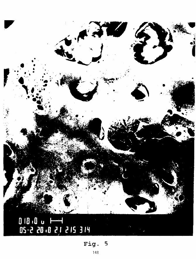
r
Fig. 5148

2 4 6
FISSION DENSITY,I027 FISSION,m"3
Fig. 6149

UA1X, FD = 6«1027 m"3 U,SiP, FD = 15*10
27 m"3
FD = 5«1027 m~ UrFe, FD = 2' TO' TO27 m"
Fig. 7150

OPERATING CONDITIONS
CALCULATE BUBBLERADII
CALCULATE BUBBLEDIFFUSIVITIES
SOLVE f /STEM OF EQUATIONS FORBUBBLE-SIZE DISTRIBUTIONS
Fj = -QjFj - b.F.2 + c. , ( i = I ,N )
C; =
CHECK FOR CONVERGENCE
CALCULATE GASRELEASE AND
SWELLINGREDUCE TIME STEP
Fig. 8151

1026
BUBBLE SIZE DISTRIBUTION INCRYSTALLINE U3Si2
AT 16 U at. % BURNUP
1024
fO
UJQ
LLJ_ Icom
10'
© IN BULK CRYSTALLINE U 3 S i 2
(D ON DISLOCATIONS WITHINCRYSTALLINE U 3 Si 2
OBSERVED AVERAGE BUBBLEDIAMETER IN CRYSTALLINE U 3 Si 2
I O I 8 h -
0.01 O.I 1.0 10.0BUBBLE DIAMETER
100.0
Fig. 9152

100 I—
UJ
CO
1
•O
—
1 1
U3Si2
20%40%93%
I 1 I 1 I 1 1 I I 1 1 1 1 1
ENRICHED URANIUM . / _ -So
I I !• > i ^ —
i 1 i i i i 1 i i i i 1 i i0 5 10
FISSION DENSITY (IO27m"3)15
Fig. 10

BUBBLE SIZE DISTRIBUTION INAMORPHOUS U3Si
1.2 x lO 2 7 FISSION * m " 3
AVV = 20.3
6 x IO27 FISSION • m~3
.6 x I 0 2 4 FISSION • m
10°-
0.01 O.I 1.0 10.0BUBBLE DIAMETER (/im)
100.0
Fig. 11154

Final Results of Test-Irradiations with LEU-Platesat KFA Jiilich
W. Krug, E. Groos, J. Seferiadis, and G. ThammKernforschungsanlage JiilichFederal Republic of Germany
1. Introduction
The irradiation program of the German AF-Program has
been terminated recently.
Two irradiation campaigns have been accomplished at the
DIDO-reactor at KFA-JiHich.
In total 20 test plates have been irradiated and inves-
tigated in the hot cells at KFA-JCuich. Some results
have been reported in earlier meetings.
The final results and a summary of all results will be
presented.
2. Irradiati ons
The irradiations have been performed with the so called
AF-Loop-Julich.
Ten test-plates can be inserted in each inpile-section.
They are arranged in two groups of give plates each, one
above the other with coolant flow upwards.
The first irradiation experiment AF1 was in operation
from July 19P3 to October 19R4.
After 321 full power days (fpd) an average burn-up
(U—23^ consumption) of more than 80 % had been achieved.
155

The second irradiation experiment AF2 has been operated
from march 1986 to January 1987. It had to be stopped
unscheduled after 130 full power days because of a plate
failure, which caused a significant increase of the
cooling water activity by fission products. An average
burn-up (U-235 consumption) of 42 % has been reached.
Test-plate and irradiation data are summarized in fig. 1
and fig. 2.
3. Post Irradiation Examinations (PIE)
The post irradiation examinations have been performed in
the hot cells of KFA-Julich corresponding to the PIE-
program shown in fig. 3. The numbers behind the titles
of the different chapters indicate the number of inves-
tigated plates, representing AFl, AF2.
3.1 Visual Inspections
AFl:
All plates were covered with a brittle reddish layer of
1 tenth of a mm ore more, which partly started to peel
off. Along the border of the meat small blisters could
be seen, also at the thermocouple attachments. Analysis
showed, that this layer consisted of AI2O3 coloured by
1 % iron. At the start-up of this experiment the cooling
water quality came out of control for about 24 hours.
Because of a wrong filling of the deionisation filter, a
pH-value of 9,1 was reached, which caused the formation
of this A
At the end of the meat zone of one U-jOg-plate a swelling
of about 25 mm in diameter with about the double of the
normal plate thickness could be identified. Other defor-
mations could not be seen.
156

AF2:
All plates were monotonous grey coloured with a thin
oxide layer as it is normal for Aluminium-surfaces after
irradiation.
At one U3Si]_ r 3-plate a small crack was found at a
thermocouple attachment combined with local bulging of
lenticular size on both sides of the plate. This crack
was identified, also lateron by micrographs as the
source of the fission product release.
3.2 Analysis of the plate layer (AF1)
The reddish brown layer of the AFl-plates has been
analyzed by three different methods:
- Gamma spectroscopy:
The main components were Zn65 (3,6 • 106 Bq/g) and C06
(2,0 • lf)6 Bq/g. Minor components were Mn54, Sc46, Fe59
Sbl24 and Cr51. These are all activated products, no
fission products were found.
- Quantitative optic-emission spectroscopic analysis:
Aluminium was found as the main component (32 % ) , Nickel
and Iron as minor components.
- Micro-probe-scanning:
The same results than before, but in addition oxygen
was found.
The layer was identified as consisting of AI2O3,
coloured by about 1 % of Fe.
157

3.3 Gamma Scanning
The distribution of the fission products along the area
of all test plates of AF1 were measured by gamma-scan-
ning. Based on these results the gamma-scanning for AF2
could be abandoned.
Gamma scans have been performed along the length and
transvers for the total Gamma-emission (130 to 1470 keV)
and for the Nuclides Nb95, RhlO6, Csl34, Csl37, Cel44.
The p]ots are showing the relative activity distribution
at the date of measurement.
The course of curves of the total Gamma-emission as well
of the single Nuklids are egual in the tendency of the
respective test plate. This is valid for the highly
mobile isotopes (Csl34 and 137) as well as for the
isotopes of low mobility (Nb95, RhlO6, Cel44), and it
means, that local differences of activity are caused by
inhomogeneities from the fabrication. There are for
instance higher activities at one or both ends of the
plates (dog boning), rather clear at the L^Si-plates,
with differences up to 25 % (fig. 4).
The transvers scans for the same plates are showing more
or less a clear depression of activity via the middle of
the plate (fig. 5).
3.4 Dimensional Measurements
Dimensional measurements have been performed by
- mechanical measurements of plate thicknes (AF1),
- optical measurements of plate thickness (micrographs,
AF1),
- volume change determination (AF1, AF2).
158

The mechanical measurements of the plate thicknes has
been performed by two movable feelers. The distance
between them (plate thickness) has been recorded via an
inductive displacement pick-up. The accuracy of these
measurements was + 0,001 mm.
The measurements for each plate have been made along
three lines, on which also the five measuring points of
the pre-irradiation measurements were lying.
The five U3Si2~plates alltogether showed a reduction of
thickness, caused by a chemical attack of the cooling
water at the start of the irradiation. The average value
is -(4,3^1,7)%. Also the two UjOg-plates still showed a
small decrease of thickness, except the distinct local
swelling at one plate with 53 % in maximum.
The average value was -(1,15^2,87)%. Against them all
U"3Si-plates showed a significant swelling with an
average value of + (7, 9+_10, 0)%. The large scattering is
regarded by the great standard deviation.
The optical measurements of plate thickness have been
performed at micrographs by an ocularmicrometer. In
addition to the measurements of the total plate thick-
ness also the thickness of the meat could be measured.
The results of the mechanical and optical measurements
are in a good agreement.
The optical measurements indicate, that for the U3Si2~
plate there is a small but significant swelling of the
meat of about 6 % concealed by the decrease of the total
thickness of this plate.
The swelling of the meat of the U^si-plate was much more
stronger, in minimum 13 %, in maximum 110%.
159

Regarding these values for the particular pure fuel the
following values of relative swelling are determined:
U3Si2 (45 Vol.%) : 14 %,
U3Si (42 Vol.%) : 31 % min,
260 % max.
The swelling of the fuel zone has been also determined
by the volume change of the plates during irradiation.
The volume of the plates as well as their weight have
been determined before and after irradiation. The volume
change provides a mean value for the whole plate which
can be corrected by the cladding loss out of the weight
difference. Oxide layer removal (Aloca Bright Dip) and
volume change determination (immersion) were performed
according to procedures used for PIE of LEU plates at
ANL.
The followinq results were found:
AF1:
Weight and volume of all plates had decreased. The
weight losses are refered to the loss of cladding by
corrosion.
The average weight decrease of (5,4 + 0,8)% corresponds
to a reduction of cladding betweeen 0,04 to 0,05 mm on
each side. This is in good agreement with the optical
measurements (0,045 mm). The average weight decrease for
the U3Si2- and U3Og-plates was (5,1 ±0,8)%, for the
U3Si-plates only 1,4 %.
As a result of the swelling of the fuel zone the netto
volume increase of the test plates was for u^Og- and
U3Si2-plates (1,9+0,8)% and for U3Si-plates 7,0 %.
160

AF2:
As expected the volume and weight changes are remarkably
lower than for AF1. The volume decrease was measured
between 1,7 and 3,2 %, which was correlated with a
weight decrease between 1,3 and 2,3 %. Particularly low
are the values for the swelling of the fuel zone, which
are between -0,2 and +0,3 %.
In fig. 6 the main results of the dimensional measure-
ments are listed up.
The volume increase of t.ie different fuel-types are
shown in fig. 7 as a function of the fuel fission
density. The solid lines represent the results of the
US-RERTR-program. The consistency of the results of both
programs looks very good.
and u^Sij 3, u^Si^ 5 are lying in the range of
linear swelling, where a good irradiation behavior can
be expected. The l^Si-plates are highly in the range of
break away swelling, so that a bad irradiation behavior
must be expected.
3.5 Metalloqraphic Examinations
Four plates of AF1 and AF2 respectively have been used
for metallographic examinations. The microstructures
of the fuel we;/e investigated by optical microscopy up
to magnifications of 500x.
A transvers section through the swelled area of the
defect plate (AF2) showed, that a crack has developed in
the edge of the thermocouple groove. The rest of the
cladding was to thin to withstand all stresses during
irradiation. About 15 mm around the leak the
161

microstructure of the meat is totally destroyed. The
lenticular swelling to both sides of the plate seems to
be caused by steam generated from penetrating water.
Beyond this reaction zone the fuel remained completely
uninfluenced. This makes clear that the defect has a
mechanical reason caused by the cutting of the croove.
Typical pictures of transvers sections of all four types
of fuel (AF1) are shown in fig. 8, 9, 10 and 11 (mag-
nification 50 and 500). The U3Si2-plates (4,75 resp.
5,04 gU/cm3) behaved very well (fig. 8, 9). Only small
fission gas bubbles have been formed, which are
uniformly distributed within the fuel particles. The
bonding between fuel particles and the metallic phase
(Al) or the cladding is completely intact.
u*3Si (6,05 gU/cm3, fig. 10), however, is in the range of
break away swelling. Fuel particles have linked up to a
high extent loosing their identity. Large gas bubbles
(up to 0,5 mm) have accumulated, opening extended cavi-
ties in the central region of the fuel meat. The occu-
rance of pillowing without further irradiation due the
thermal cycling effects only seems highly probable.
Also these results are in an excellent agreement with
the ANL-PIE results.
The U3O8 plate (fig. 11) which pillowed during irra-
diation shows large gas bubble formation only in the
region of the pillowed blister and here only betweeen
meat and cladding, not in the centre region. At one side
cladding and meat are separated by a large gap. The
remaining parts of the meat (non-pillowed) show a quite
normal microstructure similar to that of U3Si2 resp.
unirraoiated t^Og.
162

The micrographs of the u^si]^f^/ir5-plates with and
without B4C show a rather undisturbed microstructure of
the meat, which indicates a low burn-up ( 40 % U235).
Only a low amount of small gas bubbles can be reco-
gnized, which don't influence the microstructure anyway.
Remarkable however ist the presence of singular larger
gas bubbles, which cannot be accumulated by diffusion
due to the achieved burn-up. This must explained by
the influence of the contained u^Si. An influence on the
integrity of the meat with this burn-up can be neglec-
ted. But these bubbles can be the origin of damages at
higher burn-ups.
An influence of the B4c has not been found.
3.6 Blister Tests
One plate of each fuel type has been selected for the
blister test, i.e. four plates of AF1 and AF2 respec-
tively. Four plates have been heated up together in each
case in air to the desired temperature, starting with
350°C, increasing in 50° and above 500° in 25° steps,
and held there for 30 minutes. After cooling down to
room temperature, the plates were inspected visually.
Plates with blisters were removed and testing was con-
tinued .
The results are listed up in fig. 12. The order of the
listing indicates the behaviour of the plates starting
with the worst plate and ending with the best.
Beside the dimensional measurements also the blister
tests indicate clearly, that U3S12 as fuel is superior
to the other alternatives, particularly if it is con-
sidered, that the U3S11 3-, U^Si 115-plates had only
achieved half the burn-up.
163

3.7 Fission Product Release Tests
The aim of these tests was to investigate the release of
gaseous (Kr85) and solid (Csl37) fission products from
defect plates during transport or storage. Therefore 4
plates have been cut through (simulation of a mechanical
damage) and the halfs were heated up to 300°C in steps
of 100°C. The pieces were standing in a small oven with
the cutting areas two cm deep in a loose charcoal bed
for removing solid fission products.
The results of Kr85 release are shown in fig. 13, those
of Csl37 and Cel44 in fig. 14.
In general the results for the u"3Si2-plates show a lower
release as well for Kr85 (l#10~4 of the inventory) as
for Csl37 and Cel44 (1 to 2'10"7 of the inventory). It
is of importance/ that the very low release of the solid
fission products for both isotopes has nearly the same
fraction. This means/ that there is no temperature de-
pendant diffusion. Both fission products probably came
into the charcoal by mechanical abrasion of fuel from
the cut areas. In principle it is a dust contamination.
The O^Si-plate released nearly the same Kr85-activity
as the U3Si2-plat.es, although a higher release could
be expected caused by the changed micro structure.
The reason is, that Kr has diffused into the large and
combined gas bubbles even during irradiation. When the
plate has been cut through, this gas released immediately.
It has been registrated in the vent system of the hot
cells. A recalculation resulted in a Kr85-release of
about 10 % at that time, which is about a factor of 1000
more than during the annealing test.
The results of these annealing tests can be summarized
as follows:
164

Fission gases: At normal temperature (<30 °C), no re-
lease can be measured, at higher temperatures (up
to 300 °C) for an undisturbed microstructure the
available reservoir is quickly discharged so that
the release is reduced to zero soon. J131 could not
be measured. With the presence of water it is ex-
pected that it will behave like fission gases.
Solid fission products: At temperatures up to 300 °C
no release by diffusion must be expected, even for
the high mobile Cs. But at all temperatures a dust
contamination by abrasion must be taken ir account.
4. Conclusion
This irradiation program was mainly concentrated on the
investigation of uranium silicides. 4 uranium silicides
(U3Si, U3Siif3, U3Silf5, (J3Si) an U3Og (as a reference
fuel) have been irradiated and examined in hot cells at
KFA-Jiilich.
Significantly different irradiation behavior have been
found between U3Si2 and U3Si.
All results of the German AF-program are in a good
agreement with the respective results of the ANL-PIE
results (G.L. Hofman, L.A. Neimark).
2 showed
lower swelling (well below 10 % ) , far away from
break away swelling,
moderate microstructure changes,
higher blister thresholds (>500 °C),
lower release rates of fission products for defect
fuel elements.
165

Based on these results, no burn-up limits have to be
considered, as also stated by J.L. Snelgrove.
Also t^Sij 2/1 5 has shown a good irradiation behavior,
but only the half of burn-up has been reached. Never-
theless the microstructure contains agglomerations of
fission gas bubbles, which are typical for U3S1. There-
fore it must be expected, that the further irradiation
behavior will be dominated by the U^Si component. That
means, that also for this fuel the same limits of burn-
up will be valid (1,8 • 1021 cm"3), as stated by J.L.
Snelgrove for
As the essential result of this irradiation program
has been proven as a pontential fuel for the conversion
to low enriched fuel elements for test reactors. There-
fore no further activities to investigate alternative
fuels are necessary for us and therefor the irradiation
programs have been terminated.
166

5. References
/I/ E. Groos, H.J. Bucker, H. Derz, R. Schroder
Nachbestrahlungsuntersuchungen an Testplatten fur
niedrig angereicherte Brennelemente fur Forschungs-
reaktoren
KFA-HZ, Mai 1988
/2/ G. Thamm
The Status of the German AF-Program
This Conference
/3/ G. Thamm
The Status of the German AF-Program and Thoughts
Toward a Nationally and Internationally Coordinated
Termination of the Programs
Int. RERTR-Meeting, Buenos Aires, Argentina,
Sept. 28 - Oct. 01, 1987
/4/ J.L. Snelgrove
Qualification Status of LEU Fuels
Int. RERTR-Meeting, Buenos Aires, Argentina,
Sept. 28 - Oct. 01, 1987
/5/ G.L. Hofmann, L.A. Neimark
Prospects for Stable High-Density Dispersion Fuels
Int. RERTR-Meeting, Buenos Aires, Argentina,
Sept. 28 - Oct. 01, 1987
/6/ E. Groos, W. Krug, G. Thamm
LEU Fuel Testing at KFA-Jii.Uch under the German AF-
Program, Plate Irradiation and PIE
Int. RERTR-Meeting, Buenos Aires, Argentina,
Sept. 28 - Oct. 01, 1987
167

Final Results of Test-Irradiations with LEU-PlatesatKFAJulich '9
Test-Plate Data
S
-acHve core helgfh [mm] -
10 -TZ1 ?{direction o
8 ' i • • i 3
7 _ _ _ _ — — — — — — — m . ! coolant flow
J T21-T2&: thermocouplescore laieasurment of plate surface fanperature)
Test Plates:Meat:Cladding:
200 x190 xAIMg2
6050
x 1,27 mmmm
U-235 - Content:- A F 1 : 4,38g/plate-AF2: 6,00g/plate
168

Final Results of Test-IrradiationsatKFAJulich
with LEU-PlatesFig. 2
Test-Plate and Irradation Data
Fuel
U3Si2
U3Si2
U3Si
U3O3
U3Si1 i5*
U 3Si i ! 3*
Nr.
3
2
3
2
4
6
* 2 resp. 3 plate:
AF1: July
AF2: March
Meatthickness
mm
0,51
0,48
0,40
0,51
0,56
0,52
U-Density
g/cm3
4,75
5,04
6,05
2,34
6,0
6,5
; with B4C
1983 to Oct. 1984,321
1986 to Jan. 198?, 130
U-235Enrichm.
%
19,75
19,75
19,75
40,00
19,70
19,78
fpd
fpd
Burn-up
fiss./cm3
1.9 x 10²¹
2,0 x 10²¹
2,4 x 10²¹
1,9 x 10²¹
1,1 x 10²¹
1,2 x 10²¹
Exp.
A F 1
Mi £.
169

Final Results of Test-Irradiations with LEU-PlatesatKFAJiilich '9
PIE-Program
- Visual inspections (10,10),
- analysis of the plate layer (AF1),
- gamma scanning (10,0),
- dimensional measurements (10,4),
- metallographic examinations (4,4),
- blister tests (4,4),
- fission product annealing tests (3,1).
170

Final Results of Test-Irradiations with LEU-Platesat KFA Julich
Fig. 4
Gamma Scans U3Si-plate (along the length)
Total
100 200 mm
Cs-137
100 200mm
Cs-134
oo 200 mm
3 SCOOi
ISSOOI
1 OOG. .
0
Ce 144
i I I I I I i I '-•!.•
100 200mm
Nb-95
100 200mm
Rh-106
100 200mm
171

Final Results of Test-Irradiations with LEU-Platesat KFA Jiilich
Fig. 5
Gamma Scans U3Si-plate (transvers)
s GQCO,.
35
Total
70 mm
Cs-137
35
Ce 144
70 mm
Nb-95
70mm 70mm
aol
Cs-134 Rh-106
7Qmm 70mm
172

Final Results of Test-IrradiationsatKFAJUIich
with LEU-PlatesPin firig. o
Results of Dimensional Measurements
Exp.
AF1
AF2
Fuel(U-density)
U3Si2(4.75)
U3Si2(5.04)
U3Si(6.05)
U3O8
(2.34)
UsSlw(6.5)
U3Si15
(6.0)
Claddingreduction(one side)
mm
0.04
0.04
0.05
0.05
0.02
0.01
Rel. swellingof fuel zone
%
7.3
4.3
32.4
5.7(13.1)
1.45
0.55
Rel. swellingof fuel
%
29.6
28.0
85.5
26.9(49.0)
16.2
13.2
173

Final Results of Test-Irradiations with LEU-PlatesatKFAJiilich
Fig. 7
Volume Change of Fuel as Function ofFuel Fission Density
(Curves according to G.L. Hofman and LA. Neimark, ANL)
u.
0
• U3SIO U3S!1-
O U3SI2
• u3o8
8 0
7 0
6 0
5 0
4 0
3 0
2 0
10
1
I I
—
— J
U 6 F S //
- A
i i i
i —
UgSf /
(U.Mn) /
i i i
5 6 7
(flss./cm3x1021)
174

Final Results of Test-Irradiations with LEU-Platesat KFA Jiilich
—ien
^f5^50:1
\ . :
5 0 : 1
Fig. 8 Microstructure of a U3Si2 fuel plate (No. 10) withfission densities of 1.9 x 10² 1 f/cm3 (4.75 gU/cm3,U-35:19,75%)

Finai Results of Test-Irradiations with LEU-PlatesatKFAJulich
50 : 500:1 50:1
Fig. 9 Microstructure of a U3S12 fuel plate (No. 3) withfission densities of 2.0 x 10²¹ f/cm3 (5.04 gU/cm3,U-35:19,75%)

Final Results of Test-Irradiations with LEU-PlatesatKFAJulich
50:1 50:1
Fig. 10 Microstructure of a U3SI fuel plate (No. 4) withfission densities of 2.4 x 10²¹ f/cm3 (6.05 gU/cm3,U-35:19,75%)

Final Results of Test-Irradiations with LEU-P!atesat KFA Jiiiich
5 0 : 15 0 : 1
Fig. 11 Microstructure of a U3O8 fuel plate (No. 1) withfission densities of 1.9 x 10 2 1 f/cm3 (2.30 gU/cm3,U-35: 40.00 %)

Final Results of Test-Irradiat ions w i th LEU-Platesat KFA Ji i l ich
Fig. 12
Results of Blister Tests
Temp.
°C
400
500
525
Fi
type
U3O8
UsSI™
U3Si
UaSiu(B4C)
U3SI1l3
U3Si2
U3Si15
(B«C)
U3Si2
jel
densityg/cm3
2.34
6.0
6.05
6.5
6.5
5.04
6.0
4.75
Results
Irradiation blister enlarged (leak)
Plate strongly bended,large blisterwith two holes
Very large blister covering half ofplate. Plate bended like a S.
(At 400° C start of bending, strongbending at 450°C).Strongly bended, large blister.
(Bending like before). Stronglybended.
Many small blisters mainly alongthe meat border and a small hole.Slightly bended.
1 large blister, strongly bendedlike a S.
Many small blisters mainly alongthe meat border, slightly bended.
179

Final Results of Test-IrradiationsatKFAJulich
with LEU-Plates Pin n
Kr-85-Release from Defect Plates
Fuel
(density]
U3Si2
(4.75)
U 3 Si 2
(5.04)
U3Si(6.05)
U3Si13
(6.5)
Temp.
°C
200
300
208
257
307
200
300
200
300
Duration
heating
h
2.5
2.0
4.0
19.0
5.0
4.5
4.5
22.0
4.0
release
h
0.5
2.0
1.0
1.7
0.8
1.5
4.5
4.7
1.1
Act.
Amplit.
Bq x 104
0.4
5.9
7.3
13.6
3.4
0.4
4.6
20
16
peak
Area
Bq x 104
0.4
39.0
7.0
25.0
3.1
3.2
43.0
104
27
total
release
Bq x 105
39
35
46
121
Kr-85
inventory
Bq x 101
3.8
3.7
3.8
2.9
Relat.
release
10-4
1.0
0.95
1.2(1200)
4.2
180

Final
Fuel(density)
U3Si2(4.75)
U3Si2(5.04)
U3Si
(6.05)
U3SI13
(6.50)
Results of Test-Irradiations with LEU-Platesat KFA Julich
Ei/i 1Arig. IH
Cs-137- and Ce-144-Release
Temp.
°C
200
300
200
250
300
200
300
200
300
from Defect Plates
Release(104Bq)
Cs-137
4.1
3.7
3.3
11.6
51.8
5.2
Ce-144
11.5
13.7
2.6
42.9
146
13.7
Inventory(1012Bq)
Cs-137
0.40
0.40
0.40
0.26
Ce-144
0.60
0.40
0.60
2.3
Relat. Release(10-7)
Cs-137
1.0
0.9
0.8
2.9
13.1
2.0
Ce-144
1.9
2.3
0.6
7.2
24.4
0.6
181

Irradiation Behavior of the CNE A's Experimental
Uranium Silicide Dispersion Fuel Plates
byAdolfo Marajofsky, Carlos Kohut (CNEA)
and Gerard L. Hofman (ANL)
1. INTRODUCTION
Since 1978 the CNEA ECBE project has been involved in the development of dispersion
fuel plates with four types of fuel materials-UAl^ U3O8, U3Si, and U3Si2-to be used in low
enriched (LEU < 20% 235U) fuel elements for research reactors. Miniplates with these fuel
materials were manufactured at CNEA and were irradiated in the ORR in three series of irradi-
tions as part of the RERTR miniplate irradiation program. The first irradiation contained U3Og
and UA1X fuel, the second U3O8, UAL and U3Si, while the third irradiation test consisted of six
U3Si2 miniplates and one U3Si miniplate. This third test is the subject of this paper. The present
results compare favorably with other irradiations performed in the RERTR program1-2 showing in
particular the excellent behavior of the UjSij. The overall data accumulated support the
qualification of the CNEA fabrication techniques.
2. EXPERIMENTAL
The ORR irradiation module No. 30 contained seven CNEA miniplates-six with U3Si2
and one with U3Si, as well as three ANL miniplates. The standard dimensions of these mini-
plates are 4.5 in. (114 mm) long, 2.0 in. (51 mm) wide and either 0.06 (1.52 mm) or 0.05 in.
(1.27 mm) thick. More detailed characteristics are given in Table 1.
Module 30 was irradiated in the ORR between November 27, 1985 and November 8,
1986, for a total irradiation time of 272.32 full-power days. The peak plate burnup achieved was
81% of the original 23SU.
The fuel alloys consisted of metallic U enriched to 45%, purchased from the USDOE and
alloyed with natural U metal to achieve an enrichment of 19.70 wt.% 235U, and pure Si. The fuel
ingots were produced by induction melting in alumina (A 1203) crucibles under inert gas atmos-
182

phere (Ar or He) at low pressure (530 mba) followed by casting in graphite molds. The fuel
alloy ingots were annealed for 72 h at 800°C in fused-quartz tubes, prior to comminution to fuel
alloy powder. The fuel powder particle size ranged from 44 to 90 |im, plus 25 w/o fines (particle
size <44 jam). The Al powder used was a commercially available atomized powder (Arquimex).
The average particle size was 8 |im, with 100% less than 45 ^m and 99.5% less than 38 Jim. The
minimum Al content was 99.5% wt.%. The cladding and frame material was 6061 Al alloy,
produced by KICSA Co. Arg. conforming to ASTM B209-67 (aluminum alloy sheet).
The fuel plate specifications conformed to the fuel plate specification for RERTR irradia-
tion tests in the ORR Reactor and were in accordance with the inspection and QA documentation
stated by the ORR Engineering Technology Division,[3].
The fabrication sequence of the miniplates was as follows:
(1) Weighing and blending fuel and aluminum powder for each compact.
(2) Cold pressing at 450 MPa for all the blends. The surface of the die was lubricated
with stearic acid.
(3) Cleaning the frames and cover plates by caustic etching followed by neutralizing
with nitric acid.
(4) Placing the compacts in the frames and welding the cover plates (TIG welding) to
the frames.
(5) Hot roll bonding after preheating for one hour in air at 490°C or 510°C. Inter-
mediate heating between successive passes was 15-30 minutes.
(6) Annealing the plates for one hour at 490°C or 510°C at the conclusion of hot
rolling to soften the plates and test for blister formation (unbonded areas).
(7) Cold rolling to final dimensions (85% total reduction in hot plus cold rolling).
(8) Finishing operations - radiographing for core locations, shearing to size, cleaning,
and inspecting for dimensional requirements.
A description of the postirradiation examination methods employed can be found in [5]
and the purpose of each one of the steps in [2]. Briefly, the examination included:
• Visual examination and photography of the as-received module.
• Visual examination and photography of individual plates after dismanteling of the
module.
183

• Longitudinal and transverse y-scanning.
• Plate thickness measurements.
• Plate immersion volume measurement after oxide scale removed.
• Blister annealing of selected plate.
Sectioning of selected plates for optical metallography, scanning electron micros-
copy and burnup analysis.
3.0 DISCUSSION OF RESULTS
Visual inspection of the irradiation module in the as-received condition using back-
lighting through the coolant channels revealed no unusual features. No bowing, warping or
pillowing or the plates and no coolant channel obstructions were observed.
As is usually the case for high burnup modules, the plates could not be removed from the
intact module and required cutting off of one of the side plates of the module. Visual examina-
tion showed each plate to be in excellent condition.
The longitudinal and transverse y scans of each plate yielded very regular y intensity
traces indicating uniform fuel distribution and absence of dog boning. Representative lon-
gitudinal gross y scan traces are shown in Fig. 1.
Plate thickness measurements were made with a micrometer having a 1/4 inch anvil.
Nine measurements were taken on each plate spaced on a square grid on the plate. The maxi-
mum, minimum, and average values measured on each plate are given in Table 2. The thickness
increase of the U3Si2 plates was very uniform ranging from 3 to 4 mils (0.08 to 0.10 (im). The
sole U3Si plate also had a uniform thickness increase of 4 to 5 mils (0.10 to 0.13 mm). These
data indicate that the fuel swelling is very uniform along the plates.
Prior to measuring the plate volume increase, AV , by the Archemedian method, a layer
of oxidation product that has a much lower density than aluminum must be removed. This layer
consists primarily of Beomite and can be removed with a hot acid treatment, called bright
dipping. With the assumption that no significant swelling of the aluminum has occurred, the
volume increase of the core or meat, AVm, may be calculated using the as-built core volume
fraction of the plate. If it is further assumed that the as-built core porosity has been consumed by
the swollen fuel, an assumption that must be confirmed by metallography, the actual fuel swell-
184

ing, AVf, may be computed as follows:
(AVm +A\O
V?
where: AV? is the as-built porosity fraction in the core and AV° the as-built fuel volume fraction
in the core. The swelling data, together with average 235U burnup and accumulated fission
density, for each plate are given in Table 4. The swelling behavior of the CNEA fuel can be
accessed by comparison to swelling data of previously irradiated miniplates of similar fissile
loading. This is done graphically for U3Si2 in Fig. 2 and for U3Si in Fig. 3. It may be concluded
that the CNEA-produced fuel compares very favorably in this respect.
Metallographic examination was performed on two U3Si2 plates, one 0.05 in. (1.27 mm)
and 0.06 in. (1.52-mm)-thick plate, and on the sole U3Si plate. Figure 4 shows a transverse
section taken from the midpoint of the plate. The fuel core is very uniform in thickness, and the
as-built porosity has, except for some very small remnant, been consumed by fuel swelling.
Oxidized fuel particles are present at the core-cladding interface toward the fuel edge (see details
in Fig. 4), and to a minor degree throughout the fuel core (see Fig. 5). Oxide particles like these
are introduced during plate fabrication and occur to various degrees in silicide fuel made by all
manufacturers. They do not appear to affect the irradiation behavior of the fuel but are the
nucleation sites for blisters that occur during high temperature blister testing. Figure 6 shows a
longitudinal section starting at the center of the trailing end (with respect to the rolling direction)
of the plate. Again the fuel core is very uniform without significant dog boning, which is consis-
tent with the y-scanning results. A relatively large amount of oxidized fuel is present (see detail),
which is not uncommon at the end of fuel cores. This oxidization as mentioned before, has never
been found to affect the irradiation behavior of the fuel plate. The majority of the fuel
microstructure is represented by the sections shown in Figs. 7, 8, and 9 taken from a 1.52-mm-
thick (7,8) and 1.27-mm-thick (9) plate, respectively. The fuel contains a few oxide particles and
a very small fraction of retained as-fabricated porosity. The vast majority of the fuel particles
exhibited typical U3Si2 behavior, i.e., they contain a dense population of very small fission gas
bubbles and patches of larger bubbles. These larger bubbles form in the minor U3Si phase
distributed throughout the major U3Si2 phase. The formation of some U3Si is unavoidable in
practice and does not negatively affect irradiation behavior when kept to a reasonably low
185

volume fraction. The high magnification scanning electron images of the fuel microstructure in
Figs. 10 and 11 show, respectively, an oxide particle and the fission gas bubble morphology.
Figure 12 shows a longitudinal section through the trailing end of the U3Si plate. This
plate also exhibits a uniform fuel distribution, absence of dog boning, and the presence of some
oxide particles. A representative microstructure of the U3Si fuel is shown in Fig. 13. The gas
bubble morphology is typical of U3Si that is well below the breakaway swelling stage, as
evidenced by the absence of large interconnected bubbles. The U3Si bubble morphology is
consistent with the swelling values shown in Fig. 3.
A small section from the center of U3Si2 plate RA-321 was spectrographically analyzed
for U and Pu isotopic composition. The results of this analysis was used to calculate the burnup
and fission density at the center of this plate. The average burnup of each plate was determined
by integration of the longitudinal y scans and normalization of these values to that of the
spectrographically analyzed plate RA-321.
Finally, one U3Si2 plate was subjected to a blister annealing test. This test consists of
annealing steps of 1/2 hour each beginning at 425°C and increasing by 25° intervals. Blistering
at the edges of the fuel core was first detected after the 525°C annealing step. This is consistent
with blister temperature measured for other U3Si2 plates.
4. SUMMARY AND CONCLUSIONS
CNEA miniplates loaded with 43 (33) vol.% of 19.75%-enriched U3Si2 (U3Si), giving a
uranium loading of 4.8 g/cm3, were irradiated up to 81 at.% bumup of the 235U. The behavior of
all plates was excellent and consistent with that of plates irradiated previously in the RERTR
program. In particular:
the blister test showed few blisters beginning at 525°C.
• fuel swelling as a function of fission density compares well with previously
irradiated mini plates.
• the microstructure shows a relatively uniform distribution of fission gas bubbles
in the fuel grains.
186

The single U3Si plate shows larger fission gas bubbles as expected but the bubbles
did not exhibit significant coalescence. As such the fuel did not enter the stage of
break-away swelling and the plate did not approach pillowing.
The U3Si2 fuel grain contains a fine distributed second phase, probably U3Si,
which appears as a consequence of the fabrication process. Given the fact that the
fuel composition was on the U side of stochiometric U3Si2, some metallic U was
likely present after casting. During the 72 hour anneal given the fuel, this U was
transformed to the observed U3Si phase. The gas bubbles in this second phase are
much larger than in the U3Si2 phase, which is consistent with U3Si behavior.
Some oxidized particles were seen, primarily at the interface of meat and frame
Such oxidized fuel particles have been previously identified as the nuclei of
blisters during high temperature post irradiation blister tests. The quantity of
oxidized particles is not considered excessive, and there is no reason for concern.
The excellent behavior of the plates may be considered as a qualification of the
CNEA plate fabrication process.
ACKNOWLEDGMENTS
The author's should like to thank Mssrs. G. L. Copeland, J. L. Snelgrove, and
D. R. Giorsetti for their support and personnel of the ANL - A. G. Hotcell facility for carrying
out the postirradiaton examiantion.
187

REFERENCES
1. J. L. Snelgrove, R. F. Domagala, G. L. Hofman, T. C. Wiencek, G. L. Copeland,
R. W. Hobbs, and R. L. Senn, The Use ofU£i2 Dispersed in Al Plate Type Fuel Elements
for Research on Test Reactors, Argonne National Laboratory Report, ANL/RERTR/TM-
11 (October 1987).
2. G. L. Copeland, R. W. Hobbs, G. L. Hofman, and J. L. Snelgrove, Performance of Low
Enriched U3Si2 Al Dispersion Fuel Elements in the ORR Reactor, Argonne National
Laboratory Report, ANL/RERTR/TM-10 (October 1987).
3. ORNL Document No. Q-11821-ET-002-5-0, "Fuel Plate Specification for RERTR
Irradiation Test," Appendix A of R. L. Senn and M. M. Martin, Irradiation Testing of
Miniature Fuel Plates for the RERTR Program, Oak Ridge National Laboratory Report,
ORNL/TM-T161 (July 1981).
4. E. Perez, C. Kohut, D. Giorsetti, G. L. Copeland, and J. Snelgrove, Irradiation Perform-
ance of CNEA UAlx and U3O8 Miniplates, Int. Meeting on Reduced Enrichment for
Research and Test Reactors, Tokai-mura, Japan, October 17,91983.
5. J. Gomez, R. Morando, E. E. Perez, D. R. Giorsetti, G. L. Copeland, G. L. Hofman and
J. L. Snelgrove, Postirradiation Examination of High-U-Loaded Low-Enriched U3OS,
UAl2 and U3Si Test Fuel Plates, Int. Meeting on Reduced Enrichment for Research and
Test Reactors, Argonne, USA, Oct. 1984.
188

Number
TABLE 1
CHARACTERISTICS OF CNEA MINIPLATES
RA311 RA313 RA 316 RA 315 RA321 RA319 RA320
Plate Weigh (g)
Plate Thick, (mm)(in)
Fissile Bearing
Compound
Meat Weight (g)
U Weight (g)
Enrich. (235) wt.%
Average MeatThick.
Plate Vol. (cm3)
Meat Vol. (cm3)
U Density (cm3)
Maximal (mg/cm2)
U Surface Density
36.43
1.5240.060
U3Si
21.54
15.71
19.70
0.775
8.7745
3.2637
4.812
43.18
36.34
1.5240.060
U3Si2
21.50
15.91
19.70
0.776
8.7565
3.2637
4.876
44.32
36.33
1.5240.060
U3Si2
21.45
15.88
19.70
0.776
8.7785
3.2715
4.856
44.05
36.36
1.5240.060
U3Si2
21.51
15.93
19.70
0.776
8.7784
3.2825
4.853
44.03
28.13
1.2700.050
U3Si2
14.36
10.65
19.70
0.558
7.3117
2.2154
4.809
27.95
28.09
1.2700.050
U3Si2
14.38
10.74
19.70
0.558
7.2929
2.2188
4.838 '
28.06
28.24
1.2700.050
U3Si2
14.38
10.62
19.70
0.558
7.3361
2.2066
4.838
28.09
189

TABLE 2
Plate, Thickness Before and After IrradiationIn in. and mm
Plate
RA311
RA313
RA315
RA316
RA319
RA320
RA321
Average
0.06471.643
0.06351.613
0.06351.613
0.06351.613
0.05311.349
0.05351.359
0.05331.354
Postirradiation
Maximum
0.06501.651
0.06411.621
0.06401.626
0.06391.623
0.05371.364
0.05401.372
0.05371.364
Minimum
0.06421.631
0.06301.600
0.06311.603
0.06321.605
0.05261.336
0.05321.351
0.05291.344
Pre. Irrad.
Average
0.061.524
0.061.524
0.061.524
0.061.524
0.051.270
0.051.270
0.051.270
190

TABLE 2
Irradiation History of Module 30
Modulein
Position
2
2
2
2
4
4
BeginIrrad.
11/27/85
1/06/86
3/26/86
6/27/86
8/11/86
9/26/86
EndIrrad.
1/06/85
3/26/86
5/31/86
8/10/86
9/26/86
11/18/86
Full-PowerDays
32.2
57.4
54.9
41.3
34.2
52.3
AverageModule
Power, kW
90
76
57
45
54
36
Estimated U235
Burnup atEnd of Cycle, %
14
35
50
59
68
77
191

TABLE 3
Immersion Volume Measurements
Comp Mod No. V" % Vf° % AVm% AVf% 235UBu FDF(1021) FDm(1021)
U3Si 30 RA311 7.75
U3Si2 30 RA313 7.56
U3Si2 30 RA315 8.01
U3Si2 30 RA316 7.96
U3Si2 30 RA319 8.76
U3Si2 30 RA320 8.66
U3Si2 30 RA321 9.11
33
43
43
43
34
34
34
5.20
2.80
1.81
1.81
1.49
1.68
1.52
39.2
24.1
22.8
22.7
23.8
24.0
24.7
77
77
77
77
78
81
80
5.2
4.1
4.1
4.1
4.1
4.3
4.2
1.7
1.7
1.7
1.7
1.8
1.8
1.8
192

it
i i :
i': -r—I,'
p
; r.ri
i:
.-
-••-+• r
• f ;
: - ( •
VT'T.
• • : I
i;H
.:- —'
i! '
:il
§?I?'C' ~
.1
•
: : !
' ! [• i
'!1
! ! - •
• • ! ( •
_f. ! : •
—T"T"h
p
Ti';.i
.rjyl
iZ.—
••-.-"••
j . • RA313
IT*"'"
u:i'i ,• i
• ' -£-•
M
. . . „
iJf::] ; '
'Ii'
i ' •'•
t
j !.,.t
: • ; [ •
-'.. i
j : :
•
ii-i
RA319 f
'jitEE
H i ;
'-I! p
jr:
* '' • r
-til
(Ij
• } ; •
InWi
' ' ' • I
: ! ;
f I
• 1 J J : ' '
1 !;:T> ...-- -—
1 I •
' , - 1 ' •
- ' i f i j
f ' • t-
-' .rtx
1
1 ;
:ff|
k1*1 :"
; -
" i i i
• ;: |
.ii.
•1;t~
• • • :
' " f
;frU"Hi
• 1T •
-it.
i
! • ? ;
}:•
1 ' •
f •
" - f" ' 1
' ." i ;
j>
,M
i J i
: . . : )
—
I's-t
- f-Hr •
'Hi*
•ff:1i' ;ii"
rl i4-.J i ] . .
r.
! RA315.• • !
; . ' ) ;
• •• i"l
T
: . i , ;
' : ; . ; ;
: Iij-; i i f-T !'r" *1 ! • ! i-rr t | | .
' ; I i i
;:jij_
:ip." i iL
j . ' :
fu
'"•'
1 :#f
i[
f ' i fRA321 |f.
' i : : Hi
iiiTj
- ' ! •!-•
R A ^ l
iJ-fi
lit!
! !L1 :
- nr t ! i
•ll
If!:»'
• H M' ' ' '-;•
—r
• i • j
. '
i: • "
i ; • ' •
. . ' :
- —T
r. i
- ' - ;
r ; r t -
• -, • i j
T T L ;
- J ! ,
i • i •
j ; - •
i •.
t ; . . •
I.
•iiil
•
it:.
— -
ii;
; i;
—
" -1 • M
. : . , . • .
"!: JT
f l
• i j •
:• j
• • ! ! : •
• ! ! ! '
;•! r - -:
I . , ' : ' • . :
!
i i . :
' • .
; ; .
—
—
L
I' i r
! ; '
; : ;
• f
Jin
' • i
.",
-r—
- i • ^*
• • . ,
: . : .
••[;'-
1
- • ; " '
l l Pf
.::; il••ill !i
:• RA3
.-' '• h;. • ' ! i
;r: l!
ill; ir • : " !"
liiii
III:i 1!
i ;!
16 j |
i '
{ , j j
• '• • i
;;;
' i • '
iii.
"i
i.JiERi.321 \ i .
• + ; i
' " , i ' •' t ' ' -
iiip
1 — 1 " t
i 7-Tjfls
j . ; -
! - i
' r '
I '• '•
—~1
i
;
!: r
i::
: .
f ' •
I,
! i
;
j
n_ i l_
Fig. 1. Longitudinal Gross y Scans of CNEA Sllicide Miniplates
193

35-i
30H
25 A
20 A
15 A
io A
a aaa
0 0.5i
1.51 1.5 2 2.5 3 3.5 4 4.5
FISSION DENSITY IN FUEL, 1021 cm'3
Legend• ANL
• CNEA
5 5.5 6
Fig. 2. Swelling of U3SI2 In ANLand CNEA Miniplates
with LEU Loadings of up to 5.6 g cm*3

120-1 A
100-A
A
8 0 -
4 0 -
2 0 -
0-0.5 1.5 2 2.5 3 3.5 4 4.5 5 5.5 6
FISSION DENSITY IN FUEL, l t f ' cm ' 3
Fig. 3. Swelling of U3Si in ANL and CNEA Miniplates with LEU
Loadings from 4.8 to 6.3 g cm'3 (C indicates CNEA data)
i6.5
Legend• 4.8, g cm• 5.2• 5.6O 6.1A 6.3
- 3

• . ; . # • • •
, v . - . ' ~ • * • ' ' • • ; •
rFig. 4. Transverse Section of U3Si2 Plate RA 321, and
Detail Showing Oxidation of Core Edge

. . .,•».. - V „ ,
• • • • • • ; ' . * ' «
• •
Fig. 5. Detail from Transverse Section of Plate RA 321, showingFuel Microstructure and Oxidized Particles

»*\
O00
\
Fig. 6. Longitudinal Section of Plate RA 321, Showing Minimal"Dogboning," Detail Showing Oxidized Fuel Particles

' .*>•»•••. \ .v
• •
* • • : - • / , .> ' • • '
• J - ^ . - > - . - 4 V.
Fig. 7. Transverse Section of U3Si2 Plate RA 315, Showing Fuel Microstructure,Oxidized Fuel Particle, and Remnants of as-fabricated Porosity

• . . I /
• < > • • • • • : , . i
, '«f?
* »
• ' '&V
r
Fig. 8. Typical Fuel MIcrostructure of U3SI Plate RA 315

O
•*$•- „-
• ; > • - •
Fig. 9. Typical Fuel Microstructure of U.SL Plate RA 321o Z
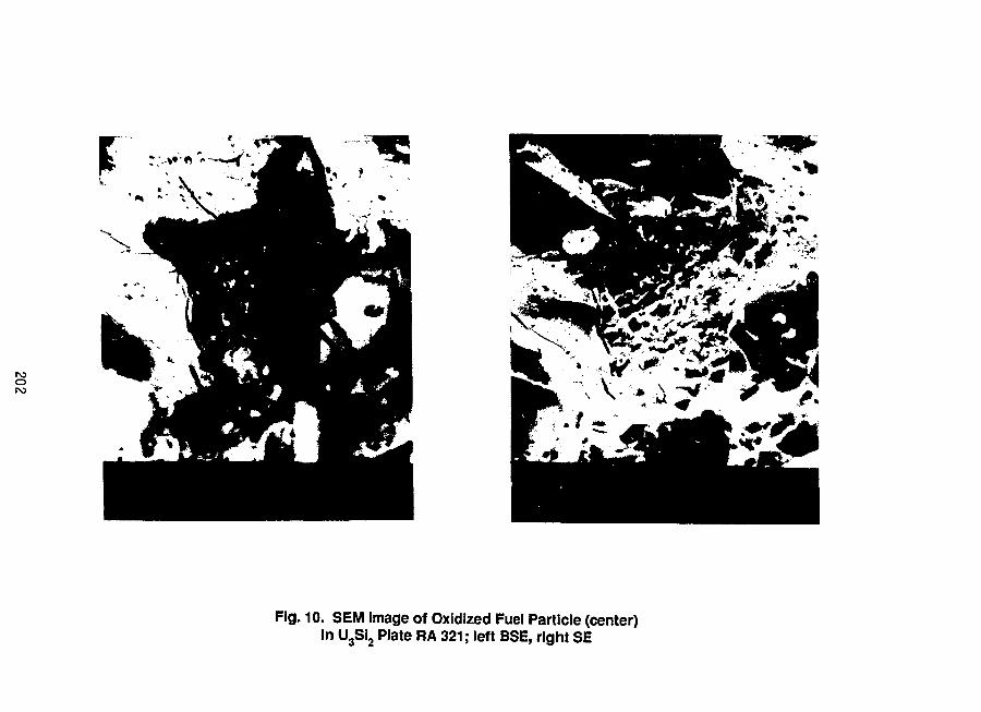
rooro
Fig. 10. SEM Image of Oxidized Fuel Particle (center)in U3Si2 Plate RA 321; left BSE, right SE

Fig. 11. SEM Images Showing Representative Fuel Microstructureand Bubble Morphology in U3Si2 Plate RA 321
203

o4
• ^ * * « •
* • „ • > _
Fig. 12. Longitudinal Section of U3Si Plate RA 311,
Detail Showing Oxidized Fuel at Core Edge

,'J. ^'f' % * • • : ' • - - . . " • - . . . • > • • . - • % .
r\5Oin
V- . * • -.iCT" . „ - •• ••••••
• • : • • •
7 " «'. X\;
' A , '
Fig. 13. Typical Fuel Microstructure Of U3Si
Fuel in Plate RA 311

206

SESSION IV
September 20, 1988
FUEL FABRICATION
Chairman:
W. Krull(GKSS, Federal Republic of Germany)
207

ADAPTATION OF INSPECTION METHODS
TO LOW ENRICHED URANIUM FUEL
J.F. POUPARDC.E.R.C.A.
ROMANS - FRANCE
ABSTRACT
Within the scope of RERTR Program, fuel plates up to 6 g/cm5 have beenmanufactured by CERCA.
These changes in fuel density imply many changes in manufacturing andinspection procedures and equipments.
Some inspection methods have to be adapted, and new methods and/ornew equipments have been designed to solve the problems met with the densityincrease.
We present here the problems met and the solutions found for threeimportant inspection methods :
- U 235 content determination in fuel cores.
- Enrichment determination of fuel plates.
- Ultrasonic testing of fuel plates.
For each method, we will present the methods and the equipments inuse at CERCA for Low Enriched Uranium fuel cores and fuel plates.
INTRODUCTION
The fuel plates production involve., many inspection steps. When theproduction line has to be adapted from HEU fuel to LEU fuel, inspectionmethods and equipments have been reviewed.
As stated in Table 1, three major points of interest arised and wewill present hereafter the adoption of inspection methods, new equipmentsdeveloped.
209

Table 1. Inspection Methods for MTR Fuel
Methods used for HEU Fuel Adaptation to LEU
Uranium Analysis
UA1 Analysis
Grain Size Measurement
U235 Content of Fuel Coresby Gamma Counting
Dimensional Inspection of Fuel Cores
Ultrasonic Inspection of Fuel Plates
X-Ray Inspection of Fuel Plates
Visual Inspection of Fuel Plates
Cladding Thickness Inspection
Dimensional Inspection of Fuel Plates
Surface Contamination of Fuel Plates
Fuel Elements Inspection
Unchanged
Adaptation to silicides
Unchanged
U235 Content of Fuel Coresby Weighing Method
Unchanged
Enrichment Control of Fuel Plates
New Equipment for Core Edge Effect
Unchanged
Unchanged
Unchanged
Unchanged
Unchanged
Unchanged
The Table 1 shows clearly that the efforts on inspection methods havebeen concentrated on U235 content determination (by gamma counting and byweighing method), enrichment control of fuel plates and ultrasonic inspectionof fuel plates. In each case, new equipments have been designed by CERCA.
U235 CONTENT DETERMINATION
Basis of measurements
Gamma Counting Method
The measurement of U235 content in fuel cores is based on the measure-ment of gamma ray emissicn characteristic of U235 in the energy range of
210

185 keV. For this measurement, we useva Nal detector put in a lead shieldingin order to prevent it from the background radiation. An electronic equip-ment allows counting of gamma rays in terms of number of pulses. Thismeasurement is compared with countings obtained with standard corescontaining a known content of U235. To reduce the effect of statisticaldispersion of countings on standard, it is of common use to perform severalmeasurements on standards and to take into account the main value of theseseveral countings.
Weighing Method
Another method is based on recording the weights of powders addedtogether in the manufacture of one fuel core and the weight of the fuelcore. As the uranium content and the enrichment ratio in U235 is determinedon the powder by chemical and isotopic analysis, we can calculate for everyfuel core the U.total content and the U235 content.In order to prevent anymistake when reporting the results, the scales have been connected to com-puters and a special software developed by CERCA can give directly theinspection report.
Parameters of errors and dispersion
General Parameters of dispersion for gamma counting method
We present here a very brief summary of errors and dispersion ofmeasurements made by gamma counting method. In fact, the gamma flux measuredon a given equipment is a function of the following parameters :
- Gamma ray emission of U235.
- Self attenuation of gamma ray in the fuel core.
- Geometrical factors related to the location of fuel core anddetector.
- Amplification factor of the electronic equipment.
The major parameters of errors are :
- Randomly statistical dispersion of the radiation emission(following a Poisson distribution). The variability of themethod is still relatively high compared to the range of tole-rances (.2 % compared to the range of tolerances t. 2 %).
- Interference radiation due to the fuel core itself (reflexion,diffusion, etc..) or due to external factors (background,cosmic radiation, etc...). As the measurement is performed bycomparison, this does not affect the value measured just addinga very slight variability.
211

- Measurement errors due to dimensional and homogeneity disper-sion. For dimension differences, these differences are measuredand correction for thickness differences are calculated.Homogeneity differences could locally change significantly thecontribution to gamma ray flux of the fuel core and thereforecould affect the measurement and add a significant variability.
- Measurement errors due to calibration (accuracy of standardcores values, dispersion of calibration results, etc...). Theseerrors are related to isotopic and chemical analysis variabilityfor establishing the value of U235 content of the standards andto variability of countings on standards for periodical cali-bration.
General parameters of dispersion for weighing method
The errors and dispersion are due mainly to the following factors :
- Weighing variability that could be considered as fairly low,compared to the range of tolerances and decreasing in relativevalue when the weight is increasing.
- Powder homogeneity in order to take a representative sample andto give analytical values valid for each fuel core. For UAlxand U3Si2 powders, the variability due to inhomogeneity isguite low and could be negligible.
- U. total content and U-235 isotopic analysis are the majorfactor of variability for this method.
Comparison of weighing and gamma counting for Low Enriched Uranium Fuel
When we have reviewed the causes of errors as stated hereabove, wehave faced important factors when changing from High Enriched Uranium toLow Enriched Uranium Fuel. We have compared these causes of errors to thosedue to weighing method (weight of powder x U total content x enrichmentratio = U-235 content). As far as the weights of powders and fuel cores areincreasing, the accuracy of weight measurement is better and if some otherfactors show that the accuracy of gamma counting is decreasing, we havethought that weighing method would be a good solution for Low EnrichedUranium Fuel.
These factors were :
Statistical variability of gamma ray emission : this variability would bethe same as far as the number of countings measured would be the same. Thisincreased the time of inspection or involved doubling the detector (one oneach face of the fuel core).
212

Dimensional and homogeneity dispersion : the effect of dimensional variabilityis not changed, but the effect of homogeneity variability is different. Wecan say that local variability in homogeneity has a self attenuation effectdouble for U3Si2 fuel than for UAlx fuel. As far as this cannot be correctedby calculation, it is a cause of variability from one core to another.
Equipment developed by CERCA
Principle
CERCA took the decision to develop an equipment based on weighingpowders and cores and on isotopic and chemical analysis. The equipment isdesigned to give also support for the manufacturing operators preparing themixing of powders and pressing the fuel cores.
We consider it as a "Computer Aided Weighing".
The scales are directly connected to computers linked in a localnetwork. In this local network of computers a data base gives to the operatorall the necessary informations to keep the manufacturing process undercontrol and prevents any mistake from the operator.
Powder weighing station
At the powder weighing station, the operator puts together the UA1X or U35i2powders with different grain sizes and the aluminium powder. All the powdersweights are measured on scales directly connected to a computer. This allowsto record directly on the working station all the powders weights and toreject directly mixing with incorrect proportion of powders.
Core Pressing Station
The press operator measures directly after pressing the weight and thedimensions of the fuel cores. Scales and dimensional equipments are connecteddirectly to computer. So, for each fuel core, we have recorded the componentsweights and the fuel core weight.
Data Processing
Knowing,by isotopic and chemical analysis,the U.content and the U-235ratio of the powder used, we can calculate the U-235 content and the U.totalcontent of each core. The system allows to get directly the data printed forverification.
Development for the future
Some developments have been planned to put in this system otherworking stations and to give directly the data to uranium inventory systemby data processing.
213

ENRICHMENT CONTROL DF FUEL PLATES
Purpose
In developing the Low Enriched Fuel manufacturing in the same facilitythat this used for High Enriched Fuel, CERCA has taken into accountthe risk of a mistake between fuel cores of different enrichments, even ifa full Identification and hraceability program was applied. To avoid anyconsequences of this type of mistake, CERCA decides to inspect all the fuelplates for a recognition of enrichment. The main goal of this inspection isto discriminate between enrichments in the range of 93 % and enrichmentsclose to 45 % and close to 20 %.
Basis of the measurement
Gamma Spectroscopy
The measurement is based on the gamma ray spectrography. For this, thegamma ray emitted by the fuel plates is measured and analyzed with a germaniumdetector. The data generated in the detector are computer processed for :
- automatic search of peaks,
- substracting of background,
- deconvolution of multiple peaks.
This computer process gives a spectrum, Number of pulses as a functionof gamma ray energy in keV as measured during a given period of time.
Relationship with enrichment
From the gamma ray spectrum, we choose two peaks characteristicsshowing the effect of U-235 and U.total. The area of the gamma ray peakat 185.7 keV is representative of the U-235 amount.
The area of the X-ray peak at 98.4 keV is representative of theUranium total content. This peak is due to self attenuation of gamma ray185.7 keV for the total uranium present in the core. More uranium totalimplies more attenuation for the Yray at 185.7 keV and more emission ofX ray at 98.4 keV.
From this two areas, the computer software could calculate estimationsfor total amount of uranium, content of U-235 and therefore the enrichmentratio is estimated as a function of the ratio between the areas of the twopeaks.
214

Calibration
The calibration is performed by use of real fuel plates with knownU. content and isotopic analysis. From this known values, the relationshipbetween enrichment ratio and the ratio of the areas of the two peaks willbe determine'' and used for inspection.
Equipment designed by CCRCA
The equipment designed by CERCA is based on a classical gammaspectrometer with a special software to allow the calculation of isotopicratio.
This equipment is used to check the enrichment of all fuel platesproduced in the workshop since five years, when CERCA has begun to work onmass production of different enrichments.
ULTRASONIC INSPECTION OF FUEL PLATES
Basis of the inspection
Principle of the inspection
The fuel plates are inspected by an ultrasonic testing method inimmersion with focalized transducers. The inspection is based on the ampli-tude of the ultrasonic pulse after transmission through the fuel plate(double transmission with reflexion on a steel mirror). The transducersused are emitter/receiver type.
Defect Detection
After the double transmission through the plate, the ultrasonic pulseis electronically checked for amplitude. If there was no signal in theelectronic gate used to follow the echo or if the signal was tooattenuated, we consider that the ultrasonic beam has met a defect and hasbeen reflected partly or totally.
Problem met with LEU Fuel
When the density in the fuel meat has been increased for UAlx from1.2 g/cm3 to 2.2 g/cm3 .'ind up to 6.0 g/cm3 for UxSiy3, the ultrasonicinspection of fuel plates has been limited by the core edge effect.
Core edge effect
The core edge effect is due to the presence of two areas with differentultrasonic speed.
215

At the limit of these two areas, there is a possibility of combinationof two waves with different phases. This gives a combination/attenuationeffect with amplitude maxima and minima (typical diffraction effect).
As the inspection equipment is based on the amplitude of the ultrasonicpulse, this is seen as a defect.
This core edqe effect has been seen very clearly when the density offuel has been increased. The core edqe was detected as a "false reject" onthe ultrasonic equipment.
New Equipment designed by CERCA
In order to solve the problem presented here above, CERCA has workedin relationship with a french specialized company to design a new machine.
Mechanical Equipment
The mechanical part of the new equipment is based on the same principleas the previous one :
- a stainless steel pool,
- a rotatinq disk supporting six transducers,
- a steel mirror at the bottom part of the pool,
- a driving mechanism for the translation of fuel plates betweenthe transducers and the mirror.
This equipment allows settings of rotatinq speed and translation speedin order to adjust the step of inspection pattern. This is established tokeep the sensitivity in accordance with specification.
Ultrasonic Equipment
The ultrasonic equipment is based on 6 transducers emitter/receivertype with a fully diqital electronic. The electronic eguipment couldbe programmed with more than 30 sets of parameters in memory. The frequencycould be adjusted in a wide ranqe between 1 and 20 MHz.
Data Processing and Monitoring Equipment
The monitoring and data processing functions are performed with a harddisk mass memory. The computer monitors all the inspection parameters forone type of plates : motor speeds, ultrasonic parameters, criteria. The datagiven by the ultrasonic equipment are processed by the computer. Defectinformation, if any, is analyzed for size and location to be compared to
216

the criteria. After data processing, this allows to have a quality certificatedirectly qiven by the printer connected to the computer.
Core edge information
As far as all informations coming from the ultrasonic unit are fullydigital and related to a given location on the plate, it is possible tohave a data processing in the core edge area. The core edge effect could bediscriminated from the defect effect. This allows a full inspection of fuelplates with very high density fuel.
CONCLUSION
CERCA has made many efforts in research and development for inspectionmethods in the ten past years. These efforts have given new methods to ins-pect LEU Fuel and to improve the equipments in use at CERCA.
For the future, our intent is to continue those efforts in order toapply new techniques, to improve the reliability of the methods in use andto satisfy the customers' needs.
217

CERCAINSPECTION METHODS FOR MTR FUEL
METHODS USED FOR HEU
URANIUM ANALYSIS
UAlx ANALYSIS
GRAIN SIZE MEASUREMENT
U235 CONTENT OF FUEL CORESBY GAMMA COUNTING
DIMENSIONAL INSPECTION OF FUEL CORES
No inspection performed when onlyone enrichment
ULTRASONIC INSPECTION OF FUEL PLATES
X-RAY INSPECTION OF FUEL PLATES
VISUAL INSPECTION OF FUEL PLATES
CLADDING THICKNESS INSPECTION
DIMENSIONAL INSPECTION OF FUEL PLATES
SURFACE CONTAMINATION OF FUEL PLATES
FUEL ELEMENTS INSPECTION
ADAPTATION TO LEUUNCHANGED
ADAPTATION TO SILSCIDES
UNCHANGED
U235 CONTENT OF FUEL CORESBY WEIGHING METHOD .
UNCHANGED |
ENRICHMENT CONTROL OF FUEL PLATES
NEW EQUIPMENT FOR CORE EDGE EFFECT
UNCHANGED
UNCHANGED
UNCHANGED
UNCHANGED
UNCHANGED
UNCHANGED

CERCA MEASUREMENT OF U-235 CONTENTBY GAMMA COUNTING
GAMMA COUNTING
Standard
value
U-235 content Standard
on actual core valueU-235 CONTENT

CERCA GAMMA EMISSION SPECTRUMOF FUEL PLATES
RHF
roroo
ENRICHMENT 9 3 %
LAENERGY KeV
84 105 126 147 168 185 210

CERCA GAMMA EMISSION SPECTRUMOF FUEL PLATES
ORR
ro
ENRICHMENT 2 0 %
84 105 126 147 168 185 210ENERGY KeV

CERCA F ( J E L p L A T E S ULTRASONIC INSPECTIONNORMAL INSPECTION
SEPT. 88
rorsjro
111 / / / i i i f i n I I I J I
TRANSDUCER
WATER
A!. CLADDING
UAIx/AI OR U3Si2/AI
Al. CLADDING
WATER
STEEL MIRROR

CERCA F U E L P L A T E S ULTRASONIC INSPECTIONDEFECT EFFECT
SEPT. 88
tn m
TRANSDUCER
WATER
Al. CLADDING
UAIx/AI OR U3SI2/AI
Al. CLADDING
WATER
STEEL MIRROR
NO ECHO = ALARM

CERCA F U E L p L A T E S ULTRASONIC INSPECTIONCORE EDGE EFFECT
SEPT. 88
1
\1
1.\
V1•1
!r1
.
/
!
\
1 11
III III I l l f I I I II
ri
in
TRANSDUCER
WATER
Al. CLADDING
UAIx/AI OR U3Si2/AI
Al. CLADDING
WATER
STEEL MIRROR
NO ECHO
! \ ! \

Manufacture of Research Reactor Fuels
R. W. KnightOak Ridge National LaboratoryOak Ridge, Tennessee 37831
USA
Editor's Note
This paper summarized the information being published as OakRidge National Laboratory Report ORNL/TM-11809, "Observations in theManufacture of Aluminum Based Research Reactor Fuel Elements." Theabstract and table of contents of ORNL/TM-11809 are included in theseproceedings in lieu of a summary paper. I encourage those with aninterest in the subject to obtain the full report from the author.
Abstract
A large number of research reactor fuel elements are manufacturedusing aluminum. Configurations may vary, but the manufacturing sequence,problems, and philosophy are the same. Today, fuel forms are UALX, U3O8,or U3Si2. They are clad in aluminum and roll swaged into side plates,combs and end fittings are attached, and the unit is final machined.This report carries the reader through the manufacturing sequence andpoints out possible problems and solutions to problems in varying stepsof the manufacture.
225

Contents
Abstract
Introduction
Material
Uranium
Aluminum Powder . . . .
Boron
Silicon
Powder Preparation . .
Weighing and Blending .
Frames and Covers . . .
Billet Assembly . . . .
Roll Bonding
Cold Rolling
Inspection
Homogeneity
Ultrasonics
Alpha Counting . . . .
Dimensional Inspection
Gamma Scanning . . . .
Boron Homogeneity . . .
Destructive Examination
Fuel Elements
Conclusions
References
226

227

LEU FUEL ELEMENT PRODUCTION PLANT AT RISC NATIONAL LABORATORY
P. Toft, J. Borring, E. AdolphMetallurgy Department, Rise National Laboratory
DK-4000 Roskilde, Denmark
ABSTRACT
A production plant for fabricating LEU silicide fuelelements has been established at Riso NationalLaboratory. The first eight elements for the Danishreactor DR3 have been produced, based on 19.74 %-enriched U3Si2 powder. The production plant and thefabrication process has been set up without encoun-tering major problems.
INTRODUCTION
Since the RERTR meeting in Gatlinburg November 3-6 1986, our maineffort has been concentrated on finishing our HEU fuel elementproduction. The three LEU fuel elements produced in our pilotplant (1) has been irradiated without incident (2).The currentstatus is that we have stopped our HEU fuel element productionand started our routine production of LEU fuel elements to theDR3 reactor.
FUEL ELEMENT DESIGN
The LEU fuel element is made with the same outer design as ourHEU fuel element (Fig.l). The fuel content is increased from 150g to 180 g u 2 3 5 in order to compensate for the lower enrichment.The DR3 fuel element consists of 4 fuel tubes arranged concen-trically. Each tube is made of 3 fuel plates welded together.All relevant fuel element data are shown in Table 1.
228

Fig 1. LEU fuel element
LEU FUEL ELEMENT PRODUCTION PLANT
The flow sheet in Fig. 2 and photos 1-13 give a general view ofour LEU fuel element production plant. The plant has beenestablished based on experience gained from our pilot plant pro-duction (1) . During the spring 1988 we have fabricated eightelements without any major problems. Our annual production forthe DR3 reactor is estimated to be fifty fuel elements.
CONCLUSION
Our LEU fuel element production plant has been established and isrunning satisfactorily. Process variables used in our pilot plantproduction (1) has shown a good reproducibility when implementedin our production plant.
229

Fig. 2
LEU Fuel Element Fabrication Line At Riso National Laboratory
Powder Handling
U3Si2powder
DegassedAl-powder
Glovebox
Powder sievingWeighing andmixing
Photo 1
Compact Fabrication Fuel Plate Fabrication
BlendingU3Si2/AI-powderPhoto 2
PressingCompacts
Photo 3
Frames andcovers, de -greased andacid cleaned
Mounting com• pacts in frames
and covers
Photo 5
SandwichWelding
Photo 6
Fuel Plate Fabrication
roCOo
Sandwichstoring
j Photo 4
Vacuum an -nealing sand -wich. Degas-sing
Photo 7
Hot rollingsandwich
Photo 8
Vacuum an -nealing fuelplates. Hydro-gen extraction
+- plates
Photo 7
Hot rolling fuelplates, con-tinuing
Photo 8
Blister AnnealCold rollingfuel plates
Cutting fuelplates intosize
Fuel Plate Fabrication Fuel Tube Fabrication
Soft annealingDecreasingand acidcleaning
Fuel Tube Fabrication
DimensioncheckStraightness
Degreasingfuel tubes
X-Ray for in -horn, and strayparticles
Samples fordetermination,ofmeatandcladding thick.
Visual inspec-tionandconta-minatiofi check
Bending andwelding fuelplates 3 t o -gether to forma tube
Photo 9
Tube calibrati-on
Photo 10
Cutting tubesinlo size
Combs andouter tube
Assembly fuelsection with4 tubes
Photon
Cooling chan-nelcheck
Structuralelement parts
Fuel Element Assembly

ACKNOWLEDGEMENT
The authors thank John Jespersen, Ole Olsen, Kjeld Sandsted andErling Sorensen for their participation in our LEU silicide fuelwork. We are indebted to The Argonne National Laboratory, TheBabcox and Wilcox Company and The RERTR Project for theirvaluable contributions in connection with our conversion from HEUfuel element fabrication to LEU fuel element fabrication.
REFERENCES
1. P.Toft, J.Borring and E.Adolph, Metallurgy Department, RisoNational Laboratory, DK-4000 Roskilde, Denmark. "Pilot plantproduction at Riso of LEU silicide fuel elements for theDanish reactor DR3" presented at the RERTR meeting inGatlinburg, USA, November 3-6, 1986.
2. K. Haack, DR3, Riso National Laboratory, DK-4000 Roskilde,Denmark. "License approval of DR3's conversion to LEU" pre-sented at the RERTR meeting in San Diego, USA, September 19-22, 1988.
231

Table 1: Fuel Element Data
Powder and Cladding Data
UgSip PowderEnrichmentAl PowderCladding Material
-100+325 mesh;-325 mesh < =20%19.74% U 2 3 5
AlcanMD101, -100 meshAIMgi (98% Al, 1 % Mg, 1 % Other)
Compact Data
Compact LengthCompact WidthCompact ThicknessCompositionCompacting PressureUranium Density
82.45 mm57.70 mm4.40/6.60 mmw/o AI/U^Si2=33.6/66.4Approx. 80 tons3.3g/cm3
Fuel Tube Data
Tube LengthCore Length (nom.)Tube Thickness (nom.)Core Thickness (nom.)Cladd. Thickness (nom.)Diam. Fuel Tube 1Diam. Fuel Tube 2Diam. Fuel Tube 3Diam. Fuel Tube 4
660.4 mm600.0 mm
1.50 mm0.56 mm0.47 mm
63.85 mm73.65 mm83.45 mm93.25 mm
232

Powder Handling
Photo 1: All powder handling is carried out in a glovebox containing an argon atmosphere withless then one percent oxygen.
Compact Fabrication
Photo 2: Blending of U3Si2/AI mixtures is carried out in a special blender.
233

Compact Fabrication
Photo 3: The pressing of U3Si2/AI compacts is carried out in a 2501 hydraulic press. All pressingoperations are performed in a built in glovebox with a small negative pressure.
Photo 4: Compacts and sandwiches are stored in exicatores with a vacuum better than 10 £ torr.
234

Fuel Plate Fabrication
Photo 5: Sandwiches are mounted in a fume cupboard. The frames are preheated to about 50 °Cin order to ease the mounting, and to fit the frame/compact configuration, more closely.
Photo 6: Sandwiches are welded in a fume cupboard with a controlled airflow. The sandwiches aremounted in a water cooled fixture which reduces the heat to the compacts during welding.
235
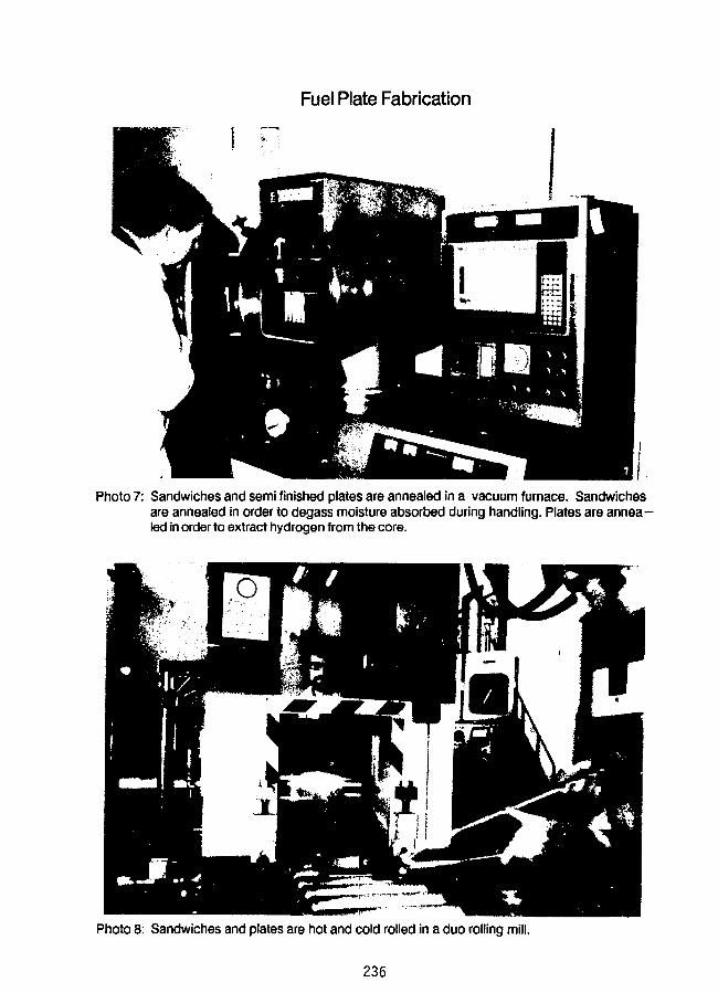
Fuel Plate Fabrication
Photo 7: Sandwiches and semi finished plates are annealed in a vacuum furnace. Sandwichesare annealed in order to degass moisture absorbed during handling. Plates are annea-led in order to extract hydrogen from the core.
Photo 8: Sandwiches and plates are hot and cold rolled in a duo rolling mill.
236

Photo 9: Fuel plates are welded 3 together ina special fixture and bended to form a tube.
Photo 10: Calibration of fuel tubes to final shape
Fuel Element Assembly
Photo 11: Assembly of tubes into fuel sections. Photo 12: Fuel element assembly.
237

Fuel Element Assembly
Photo 13: Four DR3 fuel elements with LEU
238

PREPARATION OP REDUCED ENRICHMENT FUELS FOR THE KOREA MULTI-PURPOSE RESEARCHREACTOR AND THE EFFORTS TO REDUCE THE DIFFICULTIES IN COMMINUTION OF UaSi-AlDISPERSED FUEL
I.H.KUK, C.K.KIM, J.T.LEEKorea Advanced Energy Research Institute
Daejeon, Korea
ABSTRACT
Fuels to be loaded in KMRR (Korea Multipurpose Research Reactor) willbe similar to the pin type of the Canadian MAPLE-X. The fuel meat willconsist of U3Sii+x dispersed in an Al matrix with enrichment of less than20 %. Test fabrication of these fuel meats was made with depleted uraniumin accordance with the conventional methods developed so far in the RERTRinternational program.<1>
It was experienced that the heat-treated blank with UaSi]+x was so tough,especially when x is close to 0, that particular equipment and labour had tobe introduced in the following comminution. Better comminution was attemptedby comminuting the as-cast ingot, composed of brittle UaSia and free uranium,prior to the heat-treatment. The concentration of uranium and siliconfluctuates in the cast ingot due to the formation of the primary U3S12. Thecomminution below a certain size gives rise to inhomogeneities betweenparticles. The size limit is decreased by reducing the size of the primaryihSiz dendrites. For 10^m of the primary UaSi;; dendrites, the particlesover 350ym contain sufficient numbers of primary phases for the homogeneity,resulting in a satisfactory heat-treatment which leaves no appreciable uraniumor silicon-rich phase untransformed behind.
INTRODUCTION
KAERI made a plan to build a multi-purpose research reactor of 30 MWe.Design and construction are under way, and are scheduled to be completed by1992. The reactor will be used in testing nuclear fuels and reactorcomponents, production of radio-isotopes and neutron transmutation dopedsilicon, neutron activaton analyses of various materials, research employingneutron beams, neutron radiography, etc. The general layout of the reactoris as shown in Fig.l.<2>
239

Fig.l The plane view of the reactor and the experimental facilities(from proceedings of the 2nd appl. physics symp. on the physin nucl. industry, Korean Physical Soceity, p 161)
240

The inner core has 31 honeycomb channels: 20 channels to accommodatethe hexagonal driver fuel assemblies of 30 elements each ; 8 channels toaccept the circular shim fuel assemblies of 18 elements each ; 3 sites,including the central flux trap, provided for testing rigs of fuels andmaterials. Both fuel assemblies, hexagonal with 30 elements and circularwith 18 elements, have the same pin-type element design. Each element hasan extruded fuel meat cladded with Al having 8 fins for better heat transfer.The fuel meat contains uranium silicide particles dispersed in an aluminummatrix.
Uranium silicide particles are fabricated in a composition of UaSii+x,following the techniques developed so far in the RERTR program. X in theifeSii+x will be minimized for higher loading, but the lower limit will bedetermined studying the performance at high burn-up. Extruded pins weremade by casting the ingot with depleted uranium in arc or induction furnaces,heat-treating in vacuum, comminuting to the final size, blending with Alpowders and extruding into the designed dimension.
It was pointed out that comminuting becomes more time-consuming, nucessitating heavier equipment and several extra processes to be added, as xapproaches 0 in UsSii+x. This is due to the difference in toughness betweenU3S1 and U.iSia. KfoSiz As brittle enough to be comminuted easily even by hand,in mortar and pestle; on the other hand, IfaSi is so tough that hoavy-dutyequipment and a complicated pulverizer must be added in the process. Moreoverpowders and chips are left even after the end of the batch operation ; theproducts are mixed with impurities and some more undesirable labour isrequired. The difficulties in comminuting foSi can be reduced if the ingotis comminuted before the heat-treatment leading to the peritectoid reactionfrom UaSi?. to ifeSi. The cast ingot with ibSiz + Uss is brittle and iscomminuted easily. Thus, an attempt was made to exchange the order of heattreatment and comminution processes. The process flows are compared in Fig.2.
However, the as-cast ingot always has micro-segregation due to theformation of the primary UbSia dentrite particles. Moreover, there occursmacro-segregation in the ingot obtained in induction melting and casting,and a small amount of segregation is produced in arc melting and casting aswell. These segregations limit the size of the particles to be heat-treated.The particle which contains a relatively greater amount of ifeSis is richerin Si, so that it may remain as it is even after the long heat-treatment.On the other hand, the particle which contains a relatively smaller amountof LbSi?., is rich in U, so that it. leaves free uranium untransformed evenafter the long heat-treatment. These cause inhomogeneity between fuelparticles, and may result in inhomogeneity in loading density and failurearound the area of the free uranium.
241

Conventional process(Process I)
Alternate process(Process II)
Melting & Casting
IUs Si.? + Uss ingot
IHeat treatment
U3Si
lathe
Ichip
Irinse
Idry
i
*] press
Icoarse particles
Melting & Casting
Iingot ifeSia + Uss
IComminution
Iparticles
IHeat treatment
PulverizingI
fine particles
IBlending
IExtrusion
IFuel Meat - Pin
, *2pulverize
Ifine particles
U3Si +
BlendingI
Extrusion
IFuel Meat - Pin
Fig.2 Comparison sheet of the process flows*1 The ingot melted and cast in induction furnace is processed by lathe.
The ingot melted and cast in arc furnace is processed by press and milling.*2 If the heat-treated particles are fine enough, they can be used directly
in blending.
The smaller the comminuted particles, the greater the inhomogeitybetween particles. Comminuting down to the size comparable with the primaryU3S12 dendrii.es, one particle may contain nothing but UaSis and another maycontain all but free uranium. This type of inhomogeneity due to miero-segregation decreases as the average particle size increases. Above a certainsize, the Lnhomogeneity due to the micro-segregation exists no longer. Thiswill be called "the critical size". With an infinite size of material to beheat treated as is used in the conventional process, the micro-segregation canbe reduced within a period of time. The critical size depends on the primary\hr">i?. size. Fortunately, we can control the size of the primary UaSi.a'iendrites by the cooling rate in solidification of the ingot.
Studies wore made following process II in Fig.2; first, to find thedependence of the primary ifeSiz particle, siy.r- on the cooling rate insolidification of the ingot; second, to find the critical size of thecomminuted particle for a certain size of the primary i
242

Experiments
The conventional process shows difficulties, as described above. Sinceprocess is well known, the detailed descriptions of process I in fig.2 isexcluded here. Rather, process II is mainly described here.
Casting Alloys and the Measurement of Cooling Rate
Various cooling rates were obtained using both an arc melting furnaceand an induction melting furnace. In induction melting, three ways ofcooling were used; molten alloys were held at 960 °C to form eutectic UsSiaand cooled; molten alloys were cooled controlling the cooling rate of thezirconia mold and graphite mold; molten alloys were cooled in a Cu moldcooled by running water. In arc melting, two ways of cooling were used;conventional cooling by introducing He/Ar to the molten ingot on the Cuhearth and rapid cooling by passing He/Ar through liquid nitrogen trap.
Depleted uranium (99.9 wt%) and silicon lump (99.9999 wt%) were chargedin a weight ratio of, 96.1 / 3.9 in arc melting, 95.8 / 4.2 in inductionmelting. Alloy compositions were analyzed showing the results of siliconbalance, 3.90 ± 0.05 wt % in arc melting, 4.12 ±. 0.27 w\:% in inductionmelting. The statistical deviation in silicon weight in induction meltingis introduced by the negative segregation from top to bottom in the cast.
Cooling rates were measured in two ways; thermocouples were dipped in th«--molten cast ingot; and an optical pyrometer was pointed on the molten ingotand the reading was recorded automatically through the pyrometer system.
The sizes of the primary UaSia were measured metallographically by theimage analyzer. Micro-variations of uranium and silicon were traced by KDXanalysis.
Communition
The ingot cast in the induction furnace was in 25 mm <j> x 180 mm L.One group of ingots were? crushed into a small segments by a 100 tonhydraulic press and were comminuted into various sizes by mortar and pestleof tool steel. The other group of ingots were machined into chips by lathi?and were comminuted by mortar and pestle. Chips were rinsed and dried beforecomminution. The ingot cast in the arc furnace was made into ft button shapeof 70 mm wide and 8 mm thick. The ingot was crushed in the press and wascomminuted by mortar and pestle.
Ingots were comminuted to 6 different size groups: +10, -10 / +20, -20/ +40, -40 / +100 meshes; 150 - 40 JJm and below 40 >'m.
fhe comminuted particles were mounted in an epoxy resin and were observedunder the optical microscope and scanning electron microscope, to compare thesize of the primary UaSia with the size of the comminuted particle and to findif there were any preferential sites propagating cracks between phases. Thespecimen observed in SBM was coated with gold. The fracture surface of theparticles were also examined to find if crack propagating surface morphologymay have any influence on the inhomogeneity between comminuted particles.
In a conventional process, the ingot from induction melting was heattreated in vacuum and the billet was machined to chips and pulverized to therequired size. The ingot from arc melting was crushed by a press and a rolJmill, and was pulverized in an impact mill.
243

Heat treatment
The comminuted particles were loaded on a steel boat and were heat-treated in a resistance furnace at 800 "C in vacuum 10E-6 torr for the varioustimes, 1, 5, 24, 48 and 72 hrs. The heat-treated particles were mounted inan epoxy resin and the phase changes were examined under the optical micro-scope. The phase change, was also analyzed by x-ray diffractometry. Uraniumand silicon content were measured by line scanning of BDX on the SEM of thepolished surfaces to identify the phases. The degree of inhomogeneity (I)is given by the ratio of the number of particles with free uranium remaininguntransformed (Nu) to the total number of particles (Nt).
NuI = (1)
Nt
Results and Discussion
The Size of the Primary lfeSi2 Particles
Fig.3 shows the variation of the primary ifeSia size with the coolingrate. Large dendritic particles are those obtained in an induction furnaceand small particles below 10 .Mm in arc furnace. As is well known, theparticle size decreases with the cooling rate.<3> It is noted that we canobtain dendritic particles close to 5 ^m with a cooling rate over 50 "C/sec.The particle size approaches and levels out to 5 ym when the cooling rateis increased over 50 °C/sec. This indicates that we can reduce the dendriticparticle size but no smaller than 5JJm.
800 1600 2400 3200
COOLING RATES CC/min)
«000
(Fig. 3 Primary ibSia particle size vs. the coo.1 ing rate of the molteningot.)
244

X--ray Analysis
n.m n.m M.M ».M **.m n.m M.M n.m u.m n.m
i : i >i
llil l i
, ll
ii
i i
itU M
mm
I ! iy
1 1.M9I
ll •
-n.it nn
MM *ftt• > t
M-U NU1 1 1
i i
As-cast ingots and the comminutedparticles show all the similar results,as is in Fig. 4. They consisting oc~uranium, T-uranium, Us Sis primarydendrites, UsSi eutectoid in freeuranium matrix.
As a convenience, the results areintroduced first for the primary tfeSiaparticle size 5- 30 .Mm, obtained inan arc melting furnace. The billetheat-treated at 800 °C for 72 hrs (inprocess I in Fig.l) shows no freeuranium left untransformed and Fig.4. The result of x-ray diffrac-and negligible UaSia, as shown in tometry of as-cast ingot and of theFig.5a. All the remarkable peaks comminuted particles,in this result stand for Us Si. This indicate that the peritectoid reactionis completed leaving no free uranium. This result is compared with theparticles over 40 mesh,i.e. , +10, -10/+20, -20/40 mesh, heat-treated at800 °C for 24 hrs (Fig.5b) and for 72 hrs (Fig.5c). There is littledifference between the three, Fig. 5a, 5b and 5c. This means that theparticles over 40 mesh can be completely heat-treated within 24 hrs. Theparticles of size between 150 ^m and 44 ^m show evidently, in Fig. 6a, thatsome untransformed free uranium was left. This indicates that some of thecomminuted particles are smaller than 'the critical size'. It causesinhomogeneity so that one particle is poor in silicon and rich in uraniumwhile the reverse is true in another particle. This phenomenon is foundmore obviously in Fig.6b where the result of the comminuted particles smallerthan 44JJm is shown.
With a primary UaSis size greater than 30 J-'m, untransformed freeuranium was always Left even after 72 hours at 800 °C, whatever the size ofthe primary UsSic may be. The x-ray results are quite similar to those ofFig.6b and are not shown here for simplicity.
Fig. 5. The result of x-ray diffrac-tometry (a) of the billet heat- ;treated at 800 °C for 72 hrs.(b) of the communited particlesgreater than +40 mesh(+10, -10/+20,-20/+40), heat-treated at 800 °C for24 hrs. (c) of the same size ofparticle with (b) but heat-treatedfor 72 hrs.
t
1
I
1 , ,11
1 „ c
iiW H UJ11,
" " " "
M "«». till
II
I |
1t in tin
-IH.« till
U.KI til
245

1 l _ . •
1 1
1
. Ill 1II 1 _
' . Ill 1
mnt' i
Ii
1
hUSii
Ih1 i ii i
i i i .k.ii •
i
i—
la;
Fig. 6. The result of x-ray diffrac-tometry (a) of the comminutedparticles with sizes between 150 and44JJm heat-treated at 800 °C for72hrs. (b) of the comminutedparticles with sizes smaller than44.Mm heat-treated at 800 °C for72hrs.
. ilt i
i i
1ii
1
•i
«na
! Ii IIllOt
1M m
• A l l
IIWin
i
1ia»
Ii
1
I i
i li
1
I
ff
| |
f
1 1
t
i t
I7M
1?»
•»
l i t
• I I
(b)
Fracture surfaces of the comminuted particles
The ground and polished surface of the comminuted particle before heat-treatment were examined under SEM and analyzed by EDX. The polished surfaceshows that crack propagate randomly both through the primary ibSi;? particlesand the free uranium matrix, in Fig.7a. Note the area in the circles of thismicrograph. Cracks propagate transgranularly, not altering directions at theinterface between phases. This is identified by the fracture surface observa-tion in SEM. In Fig.7b, fracture surfaces are found to be dominantly trans-granular. Therefore, the inhomogeneity between particles cannot be attributedto the crack propagating morphology on the surface of the comminuted particles.Consequently, it is proposed that the inhomogeneity between particles arisesnot from the fracture surface morphology but from the statistical relationof the population and size of the primary UsSiz particles within thecomminuted particle size.
246

Fig. 7a SEM shows the polished surface of communited particle. Note thatcracks propagating in the circled area. Matrix is the uranium solidsolution and the dark second phases are primary U3Si2 paritcles. (x200)
Fig. 7b Fracture surfaces of the communited particles.(xlOOO) The size ofthe particle is -10/+20 mesh.
247

Phase Identification by EDX
The ground and polished surfaceof the particle comminuted beforeheat-treatment was line scanned byEDX in SEM to analyze the content ofuranium in different phases. Fig.8ais the result of EDX in the arcmelted specimen. This result showsthat uranium is in high concentrationin the matrix where free uranium ismainly contained. In the middle ofthe micrograph, there, are two holeswhere particles are missing. Thecontent of uranium drops abruptly inthis area, which implies that therewere second phases, i.e., the. primaryUsSia.
The specimen taken from theparticle, comminuted after the castingin induction furnace, has a relativelygreater size of the primary tfeSia,(see Fig.3). The polished surface ofthis specimen shows a microstructureas shown in Fig.8b. Si content isanalyzed by line scanning of EDX onthis surface. The dark phase is U3Si2,and the bright grey phase in the middleis the free uranium matrix in whichsmall eutectic third particles spreadall over. The result shows that Si isrich in the dark U3S12 phase, butdrops drastically in the free uraniummatrix. Si content in the freeuranium matrix shows three differentlevels. The uppermost levels areassumed to be tbSia, the level ofwhich seems to be lowered by theeffect of using large a size beam inline-scanning. The middle level isassumed to be UsSi and the lowest levelseems to stand for free uranium.
Fig. 8b EDX line scanning on thepolished surface of as-cast ingot from induction furnace. Dark area shows theprimary U3Si2 phase and the bright grey area shows uranium solid solution.Dark spots in the middle of the uranium solid solution are those of the thirdphase. Note that the silicon content drops to the lowest level in the matrixof uranium solid solution and to two levels in the places where the thirdphases located.
Fig. 8a EDX line scanning ofuranium content on the polishedsurface of as-cast ingot fromarc furnace. Matrix is theuranium solid solution and theholes in the middle are theplaces where the UaSi2 phasesare missed. Note that theuranium content drops in theholes (marked A).
248

The comminuted particles smaller than 150*Hm with about lO'm primaryia, have a distribution of phases as in Fig.10a; and the heat-treated
particles show an inhomogeneity due to the fact that one has a great amountof untransformed free uranium and another has a relatively large amount ofU3S12 left, as is shown in Fig.10b. This inhomogeneity effect is reduced asthe particle size increases. The particle -40/+100 mesh is in the middle ofthis trend showing some retained free uranium in Fig.11. The particlesgreater than +40 mesh complete the transformation within 24 hrs, as shownin Fig.12a. The particles greater than +20 mesh show no difference, asshown in Fig.12b.
These results of the metal1ographical analysis agree well with the x-rayanalysis.
(a) (b)
Fig. 10 (a) The comminuted particle smaller than 44>'m with primaryphases of about 10iJm. The particle size is compared with the size ofUnSia. (x400) (b) The heat-treated particles of the size smaller than 150±>mwith primary UrtS'j;; of lOJ'm. Note the evidence of inhomogeneity caused byfree uranium left untransforuied in some particles. The matrix is uraniumsolid solution and the small phases are UaSip;. Heat, treated at 800 "C for72 hrs.(x400)
249

Peritectoid Reaction of the Comminuted Particles
Heat-treatment was performed with six different comminuted particles and for6 different primary tbSia sizes. The point is to find the formation of LbSiand the amount of U3Si2 and free uranium retained after the heat-treatment.The amount of UaSii; and free uranium left in the heat-treated particle showsthe inhomogeneity of the chemical composition of a particle. The criticalsi2e of a particle is determined by the inhomogeneity factor (I in Equ.l),with respect to the primary U3S12 size. In practice, the results areintroduced here just for two extremely different sizes of primary U3S12: onegreater than 30 J'm obtained in an induction furnace; and another about 10.Mm obtained in an arc furnace. Other results are not important to thepresent purpose bo find the smallest critical particle size for comminution.
The particle with the primary LfoSia greater than SO^m does not completethe tranformation leaving a great amount of untransformed free uranium andU3Si2 even after the long time of heat-treatment. The micro structures areshown in Fig.9a (for a particle machined into chips and comminuted beforeheat-treatment) and in Fig.9b (for a particle after heat-treatment).
(a) (b)
Fig.9 (a) The machined and comminuted particles from the ingot cast in aninduction furnace showing tht? microstructure of large UaSiz. (x400)(b) The heat-treated particle from induction melting. Note that theperitectoid reaction is not completed even after the long time of heat-treatment and that free uranium is left. (x400) The dark grey area is thematrix of uranium solid solution and the bright area is tbSia. Heat-treated at 800 °C for 72 hrs.
250

Fig. 11 The heat-treated particles of the size -40/-I100 mesh show lessinhomogeneity than the particles of 150 J'm. Heat-treated at 800 °C for72hrs.(x75)
(a) (b)
Fig. 12 (a) The particles of the size +40 mesh heat-treated at 800 °C for24hrs show completion of the phase transformation. (x400) (b) The particlesgreater than +20 mesh heat treated at 800 °C for 24hrs. (x400)
251

The above results are shown quantitatively in Fig.13 in terms of I inEqu.l. It is found that the inhomogeneity decreases with the size of thecomminuted particle. The crititcal size for 10 .Mm primary lfeSi2 is about35O.Min. However, the critical size varies with the size of the primary tbTherefore, it is proposed that the critical can be reduced by reducing thesize of primary UsSi2 but no smaller than 5 P
Fig. 13 The degree of inhomogeneity vs.the comminuted particle size, counting thenumber of particles containg free uranium/ total number of particles.
100
RWTICLE SIZE
1000
CONCLUSION
Test fabrication of KMRR fuel was made with depleted uranium inaccordance with the fuel development procedure of RERTR program.
Communition of the heat-treated UaSii+x, especially when x is close to0, is difficult, necessitating particular equipment and labour. Communitionis performed before the heat-treatment.(1) The primary IJaSia dendritic particle is decreased in order to reduce thecritical size in order to achieve homogeneity of the comminuted particles.The particle size of primary UsSia decreases with the cooling rate, but cannotbe made smaller than 5 -Mm.
(2) The fracture surface of the comminuted particle shows trans-granularfractures. The inhomogeneity in chemical composition of the comminutedparticles is not attributed to the fracture morphology but to the statisticalrelation of the size and population of the primary U3S12 particles within thesize of the comminuted particles.
(3) Particles with the primary lfaSi2 greater than 30 JJm do not completethe peritectoid reaction, leaving free uranium untransformed.(4) The smaller the particles comminuted, the greater the inhomogeneity inchemical composition between particles.(5) For particles with primary U3Si2 of 10 J^m, the critical size for thehomogeneity is found to be about 350 J'm.
252

(6) The critical size can be reduced if the primary TJsSi?. particle size isreduced by increasing the cooling rate in solidification of the molten ingot.(7) With a particle size greater than the critical size for homogeneity, theperitectoid reaction can be completed within 24 hrs at 800 "C, even fasterthan the conventional process.
REFERENCES
1. 'Fuel development and Fabrication' in proceedings of the 1980, 1982, 1984and 1986 Intl. Meeting on Reduced Enrichment for Research and Test Reactors.ANL/RERTR/TM-3,4,6 and 9 CONF801144, 821155, 8410173 and 861185.
2. S.K. Oh, S.Y. Kim and D.H. Kim "Design Characteristics of KMRR and itsutilization" in Proceedings of the 2nd Appl. Phys. Symp. on the physics inNuclear Industry, KPS, 2, 147 (1987)
3. L.C. Berthiaume and B.S. Wyatt "Effect of Primary U3S12 particle size anddistribution on the peritectoid reaction in uranium / silicon alloys."CHNL, AECL-3222, Dec. 1968)
253

254

SESSION V
September 20, 1988
CONVERSION EXPERIENCES
Chairman:
F. Mexchi*(CEA-CEN, rranc*)
255

FUEL ELEMENT POWERS, 2 3 5U MASSES, AMD BURNUPS FROMGAMMA-SCANNING DATA
(PRELIMINARY ANALYSIS OF IRRADIATED ORR LEU FUEL ELEMENTS)
M. M. Bretscher and J. L. SnelgroveArgonne National Laboratory
Argonne, Illinois 60^39 USA
and
R. W. HobbsOak Ridge National Laboratory
Oak Ridge, Tennessee 37831 USA
ABSTRACT
Fuel elements used in the ORR whole-core LEU fueldemonstration have been gamma-scanned to determine axialdistributions of 11(9La and 137Cs fission productactivities. This data has been analyzed to determine cycle-averaged fuel element powers, residual 235U masses, andburnups of discharged fuel elements. Methods used toanalyze the data are discussed and results are presented forthe LEU fuel elements. Measured and calculated fuel elementpowers agree to within 5%, residual 2 3 5U masses to within2%, and burnups to within 3/5. These results are somewhatpreliminary and await improved burnup calculations andindependent calibration data to be based on the destructiveanalyses of a number of irradiated fuel elements.
INTRODUCTION
After each cycle of operation during the whole-core LEU demonstration,fuel elements from the 30 MW Oak Ridge Research Reactor (ORR) were removedfrom the core to allow for xenon decay. During these intercycle periods thefuel elements were scanned along their centerlines to measure the Ilt0Lafission product activity. Because of the relatively short half livesinvolved, this information was used to determine fuel element powers andburnups which occurred during the previous operating cycle. In addition,discharged fuel elements were gamma-scanned using the 137Cs activity. Becauseof the 30-year half life of 137Cs, this measurement integrates the activityover all previous cycles of operation and so gives information regarding the235U mass and burnup in the discharged fuel.
Figure 1 shows a schematic drawing of the fuel element gamma scanningapparatus which is anchored at the edge of the reactor pool. The fuel elementis placed horizontally in a tray located at the bottom of the pool. Undercomputer control, the element is moved beneath a 1/2-diamete» voided verticaltube to each of 16 predetermined counting locations along the element axis.The tube extends upward through about 16 feet of water to a lead collimatorone foot long with a 1/16-inch diameter hole. Gamma rays are detected in a
257

lithium-drifted germanium crystal (58 cm3) and the results of a gamma-peakfitting routine for each axial location scanned are stored on floppy disks.Figure 2 shows a measured gamma spectrum of irradiated LEU fuel.
This paper describes methods used to analyze the gamma scanning data.Results are presented for LEU fuel elements used during the ORR whole-coredemonstration. However, these results are still somewhat preliminary. Thefinal calibration of the gamma-scanning system awaits burnup data to be basedon destructive analyses of several ORR fuel elements. With the exception ofcore 179A, the last core to operate in the ORR, new burnup calculations areneeded to:
1) use improved cross section sets
2) use improved estimates of 235U masses in the HEU fuel elements
3) account for voided beam tube effects
4) correct an error which occurred in some of the initial burnupcalculations when a few beryllium reflector elements wereunintentionally overlayed with a water/aluminum mixture.
Some earlier evaluations of the gamma scanning data are given in the firstthree references.
DATA ANALYSIS METHODS
The fission product chains which lead to the production of 11(0La and137Cs are
1lt0I(0.86s)-*1i|OXe(13.6s)-1/|OCs(63.7s)-i40Ba(12.79d)-12tOLa(i<0.26h)->1'4OCe(stable)
137Te(4s) - 137I(24.5s) * 137Xe(3.84m) •* 137Cs(3O.17y) * 137Ba(stable)
with cumulative fission yields of 6.28/& and 6.22?, respectively. For ll<0La, thegamma ray yield is 95.6/6 for the 1596 kev line. In the case of 137Ca, the 662kev gamma ray has a yield of 84.6?. These are the gamma rays used in the gamma-scanning analysis system. Because of interfering gamma rays, the 137Cs scanscannot be recorded until most of the short-lived fission product activities havedecayed away.
The equations which govern the population densities of ll<0Ba, 1M0La, and137Cs during the irradiation cycle are given below.
dT NB - V " hh ~ °B • NB
dt NL = XBNB " XLNL " \ • NB
df NC = V " XCNC " °C • MC
258

Here the subscripts B, L, and C refer to llt0Ba, llt0La, and 1 3 7Cs, respectively.F is the cycle-averaged fission rate per unit volume and Y the fission yield. Inall cases neutron capture losses (0$) are negligibly small relative to the Xdecay constants. These equations determine the specific activity of 11|0La and137Cs at a given point r in the fuel. Thus, the 1Il0La specific activity, AL(r),may be written as
\ / £ i L s L . (1)
BDFL(r) is the buildup-decay factor for ^°La and is given by
* X I(i-e"X B t e i)e" X B t w i-x R(i-e"
X L t e i)e" X L t w i
BDF = I -t r—T-M (2)
Here, m is the number of reactor startups for a given irradiation cycle, t g i isthe exposure time (in equivalent full-power days) for the ith startup, and twj isthe wait interval (days) from the ith reactor shutdown until the llf0La activityis counted. The values for te^ and tw^ are obtained from the count times anddetailed power histories for each irradiation cycle. In Eq. (1) CRr(r) is theobserved count rate associated with the decay of 11(0La and corrected for anyresidual activity from earlier irradiation cycles. E, is the probability that allt0La decay occurring in the volume Vg "seen" by the detector will result in acount. It follows from Eq. (1) that the residual llt0La count rate at time t cafter n irradiation cycles is
n-1 BDF (t ) RE(t .)RCRL(tc) = CRL(tc.) B D F ^ T RETrr {3)
where RE(tQ) is the relative efficiency of the detector system at time tc. Theserelative efficiency factors account for possible long term changes in detectorefficiency and were measured by periodically counting the 137Cs activity of fuelelement C021. Note that the net count rate in Eq. (1) has been normalized(divided) by the appropriate relative efficiency factor.
The fuel element power and burnup depend on the total fission rate in thefuel element, which is the volume integral of the fission density. Thus,
= VM<F> = <CRL/BDFL>/YBGL (4)
where the overall geometric efficiency G^ = (Vg/Vu)Er. V^ is the volume of thefuel in the element and <F> is the volume-averaged fission density. Iftransverse gradients are neglected, <CR,/BDF^> may be evaluated by numericallyintegrating (trapezoidal rule) the axial count rates divided by the correspondingvalues of BDFL.
259

Because of the 30.17 yr half life of 137Cs, the specific cesium activity isdirectly related to the total fission density, TF.
Ac(r) = YCXC TF(r) BDFc(r) = CRc(r)/VsEc (5)
where the subscript C is used to denote 137Cs quantities and where the buildup-decay factor is given by
BDFc(r) =
(6)n -X_t . / nY t e C w j / Y t
J=l J ' j=1 J
In Eq. (6) n is the number of irradiation cycles during which the fuel elementwas activated. As for the case of 1 M 0La ) CR^ in Eq. (5) is the measured
137Cscount rate divided by the appropriate relative efficiency factor. The totalfissions which occurred in the discharged fuel element are given by the volumeintegral of TF(r).
/fuel TF(^ d^ = V T F > = <CV B D FC > / XC YC GC (7)
VSGr = (TJ—) E_ is the overall geometric efficiency factor for the detection of
137Cs gamma rays. Assuming the effects of transverse gradients are negligible,<CRQ/DBF C> may be evaluated by numerically integrating the axial distribution of137Cs count rates divided by the appropriate value of BDFQ.
The fuel element cycle-averaged power (P) is directly proportional to thetotal fission rate.
P(MW) = VM<
F > ER = ER < C RL / B D FL > / YB GL (8)
Ep, is the recoverable energy per fission and has a value of 3.152 x 10~17 MW-sec/fiss for the thermal fission of 2 3 5U.
The 235U burnup depends on the total number of fissions, Np, which occurredin the fuel element. Thus,
235) NF(235F/F) 235AW/Nfl (9)
where 235a is the spectrum-averaged 235U capture-to-fission ratio, 2 35p/p thefraction of fissions due to 2 3 5U, 235AW the atomic weight of "su, and NA isAvogadro's number. Because 23sa and 235F/F vary somewhat as a function ofburnup, A23SM was obtained from a least squares polynomial fit of the form
260

If the geometric efficiencies G, and Gn are known, Np can be evaluated from boththe 140La and 137Cs count rate data using the equations already developed.
EVALUATION OF GL(!*°La) AND Gc(»3
7Cs)
During the ORR whole-core LEU fuel demonstration seven cores operated at fullpower (30 MW) using only LEU 19-plate fuel elements. For each of these cores itis possible to derive a value for G^ by requiring that the measured power summedover all the fuel elements be equal to 30(1-PFFF)MW where PFpF is the calculatedpower fraction developed in the fuel follower portions of the shim rods. FromEq. (8) it follows that
= x^ J <CRL/BDFL>./30(1-PFFF) (11)
where n is the number of standard fuel elements in the core. Table I lists thevalues of GL obtained for each of the seven cores. The average value is
G. (1i|0La) = (3.9^4 ± 0.030) 10"13
where the error is the standard deviation of the mean. Note that the calculatedpower fractions PFFF are in the range of 0.13 to 0.16.
For a given fuel element the accumulated total fissions obtained from the'"•"La counting data must equal that obtained from the 137Cs data. This factallows a determination of the ratio Gc(
137Cs)/GL(llt0La) for each fuel element.
From Eqs. (4) and (7) it follows that
Gc(137Cs)/GL(^
0La) ,•- S £ £-£ (12)
^ <CRL/BDFL>itei/YB
where the summation extends over the n cycles of irradiation. For all theirradiated LEU fuel elements (68) the average value of this ratio is
<Gc(137Cs)/GL(
11<0La)> = 7.448 ± 0,015
where again the error is the standard deviation of the mean. Combining theseresults gives
— 137 -12Gc(
J'Cs) r (2.937 ± 0.023)10 .
261

RESULTS
Using the methods just described, powers, end-of-cyele (EOC) 235U masses,and burnups have been evaluated from the gamma-scanning data for each of the LEUfuel elements used in the demonstration. Approximate correction factors havebeen applied to the calculations for the voided beam tube effects and berylliumoverlay errors mentioned in the Introduction. These correction factors wereobtained by re-calculating a few representative cores in which the beam tubeswere explicitly modeled and the beryllium overlay errors corrected. Thus far,however, the volume integrations of the gamma-scanning data have been performedassuming transverse gradient effects are negligibly small.
Table II summarizes the irradiation history of a typical LEU fuel element(BO44). For this element calculated and measured powers agree to within 4? orless for each of the seven irradiation cycles. The calculated and measured end-of-cycle 2 3 5U masses agree to better than 1? for each cycle. Discharge burnupsbased on REBUS-3 calculations, llt0La counting, and 137Cs counting are 50.4551,50.40?, and 50.04?, respectively.
Figure 3 shows the C/E (calculated-to-experiment) ratios for the cycle-averaged powers in ORR core 179A. For all but three elements these ratios differfrom unity by 5? or less. Similar results are shown in Fig. 4 where all the C/Eratios at each grid position are averaged over the seven LEU cores. Again, allbut three of the ratios fall within the 5? range.
Measured end-of-cycle (EOC) 23$U masses, burnups, and corresponding C/Eratios for the 179A core are shown in Figs. 5 and 6. In all cases the calculatedand measured masses are equal to within 2?. For a fresh LEU fuel element the235U mass is either 339 or 340 grams. Discharge fuel masses obtained from 140Lacounting data are very consistent with those gotten from '37Cs counting. This isillustrated in Fig. 7 where the EOC '''OLa-to-1 37Cs 2 3 5U mass ratio is shown forthe fuel elements in core 179A.
The calculated and measured axial distributions of 23^U masses and burnupswere obtained by dividing the fuel column into six segments of equal height (10.0cm). Table III shows llt0La and 137Cs C/E mass ratios for each segment averagedover the fuel elements in core 179A. Generally speaking, the measured andcalculated axial mass distributions are in good agreement. The maximum burnupoccurs in fuel segment C (20.0-30.0 cm from the bottom of the core). For fuelelement B044 (see Table II) the average discharge burnup is 50.04? (137Cs data)whereas the measured value for segment C is 63.21? with a corresponding C/E ratioof 1.02.
CONCLUSIONS
For reasons given in the Introduction, these results are still somewhatpreliminary. New REBUS-3 burnup calculations are needed
a) to take advantage of more accurate cross sections recently generated,
b) to explicitly model the voided beam tubes and to use an improved corebox treatment,
262

c) to remove beryllium-overlay errors, and
d) to use more accurate 23SU mass data for the partially burned HEU fuelelements used in the HEU/LEU transition cores. This information willsoon be obtained from an analysis of the gamma scanning data for theseHEU elements using procedures described in this paper.
A quasi-experimental method, described earlier, was used to determinenumerical values for the geometric efficiencies GL(
ll)0La) and Gp(137Cs) for LEUfuel. In principle, these same techniques can be used to find the correspondingefficiencies for HEU fuel. Alternatively, the HEU/LEU ratio of gamma attenuationin the fuel may be calculated from appropriate gamma interaction crosssections. However, a direct determination of the efficiency factors must awaitthe PIE results from the destructive analyses of several ORR fuel elements.
The results presented earlier neglect corrections for possible transversegradients in the measured fuel element fission rates. By counting fuel elementsat ±1/2 inch displacements from the center line and by taking data with both theconvex and concave sides of the fuel plates facing the detector, R. W. Hobbs hasobtained experimental data from which it may be possible to determine position-dependent gradient correction factors for four of the LEU cores. These results,together with supporting calculations, need to be carefully studied beforegradient correction factors are applied to the gamma-scan data.
Because of the above limitations, the results given in this paper must beregarded as preliminary. Nevertheless, they are very encouraging. Theseanalyses suggest that gamma scanning of irradiated fuel elements for 1M0La and137Cs activities provides a method for measuring cycle-averaged fuel elementpowers, end-of-cycle 235U masses and corresponding burnups. Measured andcalculated fuel element powers agree to within 5% or less, 235U masses to within±2%, and burnups to ±355- In addition, z35(j masses in discharged fuel elementsobtained from the llt0La data are very consistent with results based on i37Cscounting.
REFERENCES
1. R. W. Hobbs, M. M. Bretscher, R. J. Cornelia, and J. L. Snelgrove, "TheTransition Phase of the Whole-Core Demonstration at the Oak Ridge ResearchReactor," Proceedings of the 1986 International Meeting on Reduced Enrichmentfor Research and Test Reactors, pp. 269-286, Gatlinburg, Tennessee, Nov. 3-6,1986, ANL/RERTR/TM-9, CONF-861185.
2. R. W. Hobbs, "Fuel Element Gamma Scanning at the Oak Ridge ResearchReactor," Trans. ANS 55, 195 (Nov. 1987).
3. L. Robinson, R. W. Hobbs, F. F. Dyer, L. P. Pugh, J. L. Snelgrove, andN. A. Teasley, Jr., "An Automated Fuel Element Scanning System,"J. Radioanal. Nucl. Chem., Articles, in press.
4. B. J. Toppel, "A User's Guide for the REBUS-3 Fuel Cycle AnalysisCapability," Argonne National Laboratory Report ANL-83-2 (March 1983).
263

Table I. Evaluation of GL(140La)
Core GL(i"°La)
177D 4.047 » 10~13
178A 4.047 x 10"13
178C 3.867 x 10"13
178D 3.944 x 1O~13
178H 3.848 x 10~13
178J 3.903 x 10~13
179A 3.949 * 10"13
GL(i40La) = (3.944 ± O.O3O)1O"13
Note: The error in G. is the standard deviation of the mean.
Table II. Irradiation History of Fuel Element BO44
Cycle
176B
176D
177B
177D
178C
178H
179A
Grid
E8
E4
F3
B7
E6
C6
E5
FPD's
21.864
19.446
18.516
15.334
11.782
20.277
20.169
Calc.
1.080
1.356
1.081
0.969
1.243
1.029
1.088
Power - MWExp.
1.054
1.303
1.114
0.962
1.283
1.050
1.056
C/E
1.025
1.041
0.970
1.007
0.968
0.980
1.030
EOC :Calc.
309.9
277.1
252.7
234.8
217.5
193.5
168.5
.: 168.5
2 3 5u MassExp.
310.8
279.2
253.8
236.0
218.1
193.1
168.6
169.9
- gC/E
0.997
0.993
0.996
0.995
0.997
1.002
0.999
0.992
Cycle length in full-power (30-MW) days.
264

Table III. ORR Core 179A
Axial Distribution of EOC C/E U-235 Mass Ratios
Fuel sSegment
A
B
C
D
E
F
All
ElementsBurnup
La-140
0.98
0.99
1.00
1.01
1.01
1.00
1.00
Having<352Cs-137
0.99
1.00
1.01
1.01
1.00
0.99
1.00
ElementsBurnup
La-140
0.96
0.99
1.02
1.05
1.04
1.01
1.01
Having>35%Cs-137
0.98
1.01
1.02
1.02
1.01
0.98
1.00
All Elements in CoreLa-140 Cs-137
0.97
0.99
1.01
1.02
1.02
1.00
1.00
0.99
1.00
1.01
1.01
1.01
0.99
1.00
Fuel segments of equal height (10.0 cm) with Segment A at bottom of core.
265
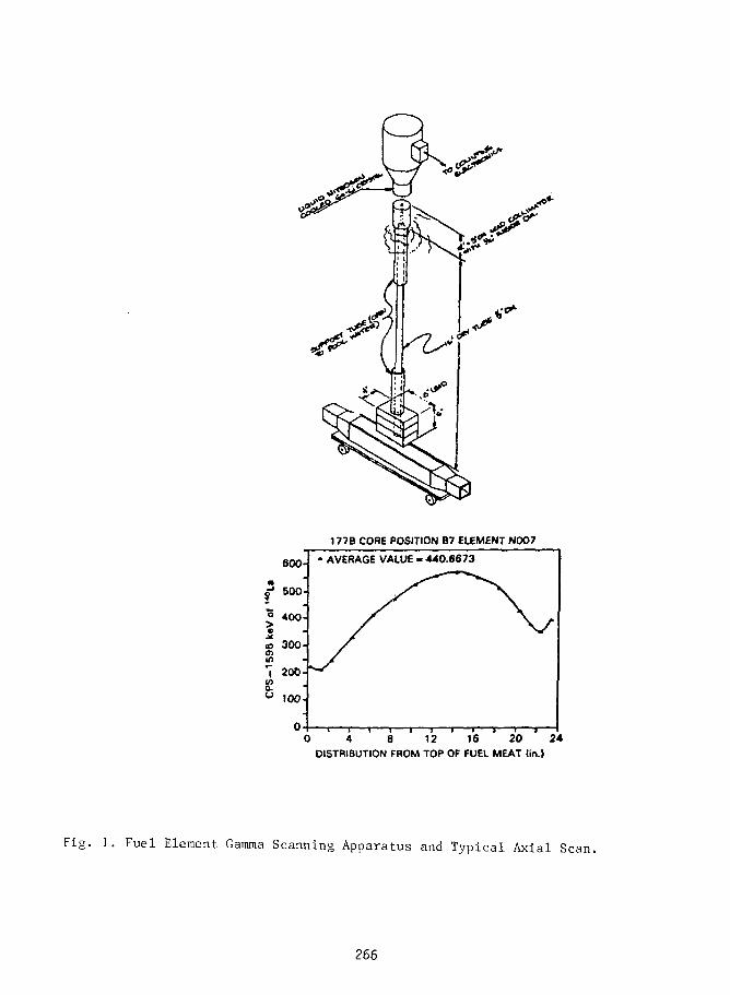
177B CORE POSITION B7 ELEMENT NOO7
AVERAGE VALUE « 440.6673
0 4 8 12 16 20 24DISTRIBUTION FROM TOP OF FUEL MEAT tin.)
Fig. 1. Fuel Element Gamma Scanning Apparatus and Typical Axial Scan.
266

GAMMA SPECTRUM OP LEU FUEL
Middle of Element B084 2-3-87
4 "
3 -
2 -
1 -
0 500 1000 1500 2000 2500 3000 3500
CHANNEL NUMBER
Fig. 2
267

ORR CORE 179A
Cycle-Average Power C/E Ratios
e 9
IA • DFE 1.00 0.96 1 0 0 0.94 1.02 DFE
1.07 SR 0.98 SR 0.99
1.01 1.03 0.98 0.95 0.93
1.00 1.06 SR 1.00 SR 0.95 1.03 N
0.97 0.99 1.03 1.02 1.01
1.02 SR 1.05 SR 1.05
SR = Shim Rod Assemblies
MFE = Magnetic Fusion Experiment
Al = Aluminum Block
Ir, Eu = Irradiation facility for activating iridiumor europium samples
DFE s Dummy Fuel Element
Fig. 3
268

C/E Power Ratios Averaged Over the
Seven LEU Cores
8 9
DFE 1.01 0.93 0.96 0.96 1.05 DFE
1.06 SR 1.01 SR 1.02
1.00 1.04 1.03 0.98 0.96
1.01 1.04 SR 1.05 SR 0.96 1.01
0.96 0.99 1.04 1.00 0.99
1.01 SR 1.07 SR 1.02
G B DFE
SR s Shim Rod Assemblies
MFE = Magnetic Fusion Experiment
Al = Aluminum Block
Ir, Eu = Irradiation facility for activating iridiumor europium samples
DFE = Dummy Fuel Element
Fig.
269

ORR Core 179A
Measured EOC U-235 Masses and Corresponding C/E Ratios
1 8
DFE2 8 5 ^ 295 186 292 283
314
1.00
273
1.00
291
1.00
1.00
249
0.99
272
1.00
256
1.00
1.01
SR
194
1.01
SR
193
1.01
SR
1.00
171
1.02
166
1.02
166
1.00
169
1.00
225
1.00
1.00
SR
188
1.01
SR
224
0.99
SR
1.00
256
1.00
218
1.01
280
1.00
314
1.00
276
1.00
288
1.00
DFE
U-235 Mass, g
C/E Ratio
N
SR = Shim Rod Assemblies
MFE s Magnetic Fusion Experiment
Al = Aluminum Block
Ir, Eu = Irradiation facility for activating iridiumor europium samples
DFE = Dummy Fuel Element
Fig. 5
270

ORR Core 179A
Measured EOC U-235 Bumups and Corresponding C/E Ratios
1 8 9
A
B
C
D
E
F
DFE
7.441.01
19.7
1.01
14.3
0.97
15.6
0.97
26.7
1.04
34.5
0.99
24.5
1.00
13.2
0.95
SR
42.8
0.99
SR
43.3
0.98
SR
45.0
1.00
49.5
0.98
51.0
0.99
51.1
1.00
SO.4
1.00
33.6
1.01
14.0
0.97
SR
44.6
0.98
SR
33.8
1.01
SR
16.8
0.99
24.6
1.00
35.8
0.9B
17.5
1.00
7.40
0.93
18.7
1.01
15.3
1.01
DFE
% U-235 Burnup
C/E Ratio
N
SR as Shim Rod Assemblies
MFE = Magnetic Fusion Experiment
Al s Aluminum Block
Ir, Eu = Irradiation facility for activating iridiumor europium samples
DFE = Dummy Fuel Element
Fig. 6
271

ORR Core 179A
EOC La-140/Cs-137 U-235 Mass Ratio
A DFE 1.00 1.00 1.00 1.00 1.00
N
SR = Shim Rod Assemblies
MFE = Magnetic Fusion Experiment
Al = Aluminum Block
Ir, Eu = Irradiation facility for activating iridiumor europium samples
DFE = Dummy Fuel Element
Fig. 7
272

ENRICHMENT REDUCTION ACTIVITIES FOR THE FRG-1 AND FRG-2RESEARCH REACTORS
W. Krull
GKSS Forschungszentrum Geesthacht GmbH
Geesthacht, Federal Rupublic of Germany
ABSTRACT
The GKSS research centre is participating since 1980 in the national andinternational efforts on enrichment reduction to clarify the needs on safetyand licensing issues, to decide on fuel tests, to perform fuel tests and con-version calculations. These efforts are being made within the IAEA workinggroups, the German AF-program and the GKSS R & D program.
There are successfully tested fuel elements with 45 % and 20 % enrich-ment; UA1X, U3O8 and l^Sig fuel meat; U-densities up to 3.7 g U/cc and fis-sion densities up to 1.25 x 10^1 fissions/cc (ex. Pu) and five L)3Si'2 fuelplates (P(U) = 4.75 g/cc).
A safety report for the conversion of the FRG-1 to LEU fuel (U3S12,p = 3.7 g U/cc) has been submitted to the licensing authority. After examin-ing the safety report by independent experts (TliV) and the licensing autho-rity the license for the conversion has been granted in May 1988.
78 fuel elements have been fabricated and delivered to GKSS with diffi-culties. The FRG-1 is ready for conversion to LEU fuel.
Two fuel elements are instrumented with 8 thermocouples to perform lossof flow and fuel plate temperature measurements. GKSS has performed alreadyreactivity, microflux, flux distribution, fuel plate temperature and loss offlow measurements.
1. Present situation and future needs
The GKSS reseerch centre Geesthacht GmbH operates the two MTR-typeswimming pool research reactors FRG-1 (5 MW) and FRG-2 (15 MW). These reac-tors in operation since 30 resp. 25 years are used for fundamental andapplied research, mainly in materials testing and development. Main effortsare made (e.g. installation of a cold neutron source /I/, backfitting /2/) tohave today and in future a high utilization, availability and safety stan-dard. Both reactors are operated in one reactor hall in a connecting pool sy-
273

stem with at present ca. 800 MWd/a resp. 3200 MWd/a. The fuel elements usedare identical: 23 plates, UA1X, standard geometry, 93 % enriched and 180 gU-235/element, meat dimensions 0.51 x 62.8 x 600 mm3, c ining thickness 0.38+_ 0.08 mm, canning material AlMgl.
The 5 toW FRG-1 will be used in future with higher availability and to agreater percentage for beam tube experiments. Therefore the installation of acold neutron source in one of the beam tubes will be supported by reducingthe core size. Reducing the core size, enlarging the burnup and the fuelcycle length can be made only if the fuel loading is increased and the con-trol rod design is changed from the old oval type to fork type absorbers.
The 15 MW-FRG-2 is and will be used mainly for materials testing. Thepresent program (testing of large specimens of pressure vessel steel) requirea core size with 7 x 7 positions and last til the the end of 1991.
Increase in fuel loading can and will reduce fuel cycle cost signifi-cantly and (or) enables to reduce the core size due to changing experimentalneeds. Therefore the tendency is to increase fuel loading and to change con-trol rod design. As our two reactors are operated in one pool system with thesame fresh and spent fuel storage we intend to have the same fuel elementsfor both reactors in the future, too. This makes design and decisions alittle more complicate.
2. Fuel testing
After discussions with the independent experts (TUV* = consultants ofthe licensing authority) and the licensing authority it was agreed to have aprocedure for fuel development and fuel testing showing five steps and start-ing from no knowledge and finishing with the conversion of the reactor. Thetests of prototype fuel elements should be done in the reactor under conside-ration /3/. If these prototype fuel element tests are not performed in thereactor under consideration, the conversion procedure will be extremelystretched as operation has to be interrupted by fuel element inspection.
Fuel tests in the FRG-2 reactor were made within the German AF-program(RERTR) and for our own conversion needs: investigation of fabricationallimits and qualification of fuel elements.
a. Investigation of fabricational limits
Swelling may depend on the amount of fine grain (grain size ^ 40 u). 5plates containing l)3Si2 fuel with fine grain content up to 40 % and anU-density of 4.75 g U/cc were irradiated to a burnup of ca. 63 % whichcorresponds to 1.27 x 10²¹ fissions/cc (ex. Pu). Fission product releasewas measured on line. No defects were observed.
*) TUV = Technischer Uberwachungsverein
274

b. Qualification of fuel elements (details see table 1)
- 10 fuel elements, 45 % enrichment, UA1X, P = 1.41 g U/cm3, 280 g U-235were burned up to 64 %, test reason: backup variant;
- 7 fuel elements, 20 % enrichment, ^Og, p = 3.1 g U/cm3, 270 g U-235 areburned up to 66 %, test reason: fabricational limits and backup variant;
- 4 fuel elements, 20 % enrichment U3Si*2, P = 3.7 g U/cm3, 323 g U-235 areburned up to 68.5 %, test reason: prototype for the conversion of ourresearch reactors.
3. Experimental program
a. Qualification of fuel elements
During the qualification tests of fuel elements especially the followingexperiments were performed: reactivity measurements (comparison with pre-sent fuel), "micro"thermal neutron flux distribution, fuel plate tempera-ture at normal operation and during loss of flow experiments, flux mappingand fission product release /3/.
b. Investigation of fabricational limits
The five fuel plates were investigated in our hot cells /4/. The followinginvestigations were made: visuell inspection, dimension and volume change,-scan (total and nuclide specific), blister test and metallography. Theseresults were obtained
- no peculiarities were observed during visuell inspection- overall swelling was below 1 % AV/V per plate (the porosity was between6 % and 8.4 %), meat swelling is below 5.4 %
- the total T and Cs-137 -y-scans are showing identical profiles with cha-racteristic peaks at the top and buttom of the fuel plate due to fuelinhomogeneities and neutron flux peaking
- two blister temperatures were measured between 520 °C and 540 °C- Al-fuel interactions were found in a narrow zone around the fuel par-
ticles. The size of this zone is comparable to the fission product re-coil thickness in Al (a few urn)
- nearly no remaining porosity was observed- very small fission gas bubbles could be seen (—0.1 urn)- an increase in bubble size up to a few urn and in some cases an agglome-
ration of bubbles were found- no differences were found between fuel plates with low (17 %) and in-creased (40 %) fine grain content.
All these results are an excellent confirmation of results presented byHofman and Snelgrove 76/.
275

4. Conversion of the FRG-reactors
The conditions for the conversion of our research reactors are as f o l -lows: same fuel elements for FRG-1 and FRG-2, unchanged geometry (23 plates),reduction of fuel cycle cost and increase of excess reactivity (higher U-235loading, Be-reflector, fork type absorbers), increase of neutron flux in theexperimental positions of the FRG-1 (reduction of core size).
A safety report for the conversion of the FRG-1 and FRG-2 research reac-tors was submitted to the licensing authority. Especially the followingpoints were discussed:
a. applied changes
- fuel elementsenrichment 90 %, 93 % to 19.75 %fuel meat UA1X to U3Si-2U-density 0.44 g U/cc to 3.7 g U/cccanning material AlMgi to AlMg2fuel loading 180 g U-235 to 323'g U-235
- control rodsHf fork type absorbers shall be used instead of oval Cd-B/).C absorbers
- conversion of the FRG-1fuel elements and 5 (instead of 4) control rods as described.The conversion procedure is discussed in detail.
- conversion of the FRG-2No detailed procedure was discussed. As one of the conditions of theexisting operation license is that a new reactor core configuration hasto be approved by a safety commitee it was believed to get a more gene-ral license for the conversion of the FRG-2.
b. qualification of the fuel and the fuel elements
I t was decided to use U3Si2 fuel with ca. 3.7 g U/cc. For 100 % U-235burnup the fission density is 1.57 x 10^1 fission/cc (ex. Pu). Due to in-vestigations made by G. Hofman and J . Snelgrove /6 / i t was very easy toshow that the swelling is below 6 %. The porosity was limited in the spe-cif ications to 4 % - 11 % as swelling is depending on i t / 5 / . As the fa-bricator was not able to reach the specified value a porosity of 2 % wasaccepted. A major step for the qualif ication was the successful test ofthe 4 prototype fuel elements. Therefore i t could be demonstrated thatU3Si-2 is qualified for the conversion of the FRG-1 and the FRG-2 researchreactors.
For the qualification of U3Si'2 fuel and fuel elements a detailed reporthas to be written describing the test program and procedure, corrosion ex-periments, swelling behaviour, bl ister temperature, metallographic inve-stigations, exothermic reaction etc. Within this qualifying discussionfuel specs and fuel fabrication was of main interest, too. The IAEA-TEC-DOC-467 /5/ w i l l be helpful.
276

c. fork type absorbers
The present FRG control rods are central absorbers of the oval type withCd and B4C as absorbing material. For some reasons we want to switch overto uncanned Hf fork type absorbers
- fork type absorbersmore reactivity per control rodqualified type
- Hfno canning necessaryno Ag contamination possibleapproximately the same reactivity worth as Ag-In-Cd.
d. FRG-1 conversion
First the general conversion aspects have to be discussed. These aspectsare described in the IAEA-Guidebook on safety and licensing aspects due toresearch reactor core conversion, which is under preparation since 1980.Within the five volumes of this guidebooks there is enough information,which shall not be repeated at this place.
In addition calculations were made by GKSS and Interatom HI for the con-version procedure and the reactor core under consideration: startup acci-dent, reactivity balance, conversion procedure, max. permissible power ormax. form factor, flow instability. Fig. 1 shows the present and the fu-ture reactor core configuration. Some details of the calculations are gi-ven in the IA- paper presented by Strbmich at this meeting 111.
e. FRG-2 conversion
No detailed calculations are presented at this time as the idea was tofollow one of the conditions of the existing operation license.
f. licensing procedure
In following § 7 of the German Atomic Energy Act an Ordinance gives exact-ly conditions when a license application needs a public hearing procedure.These conditions are: increase of activity release above given values,change of safety features of material structures, changes of the reactorprotection systems, increase of thermal power or fission product inventoryor storage capacity by more than 10 %. Only the increase of fission pro-duct inventory (if actinides are included) is of interest. This increaseis between 3 % and 5 %. Therefore there exist no demands having a publichearing procedure getting a license for the conversion of the FRG researchreactors.
Beside this it is of course at all time within the decision of the licens-ing authority to have a public hearing if there may be concerns that inconnection with the applied changes negative conditions for the publicexist. Comparing the pros and cons it is believed that the negative influ-ence
277

- increase of fission product inventory,is by far over compensated by
- increasing the shut down reactivity,(fork type absorbers and (for FRG-1) the number of control rods)
- prompt (Doppler) negative temperature coefficient*,- greater negative void coefficient*,- proliferation risk reduced.*
Therefore the licensing authority decided that there is no need having a pub-lic hearing.
5. License
After a detailed expertise of the presented safety report by the inde-pendent consultants (TUV) of the licensing authority and by the authority it-self, the license for the conversion of the FRG-1 has been granted in May 88with the following demands
- an experimental program for the conversion procedure has to be presentedone month in advance. Main points are: shut down reactivity, reactivityspeed and fuel plate temperature.
- experimental results have to be presented to the licensing authority andthe TUV before startup of the following fuel cycle
- the fluence dependence of the reactivity worth of the Hf fork type ab-sorbers has to be presented to the authority in due time.
As mentioned GKSS is installing a cold neutron source in a new Be blockreflector at the FRG-1 research reactor. The cold neutron source and the re-actor (first with old fuel) are ready for startup but the reconstruction ofthe beam tube experiments will take til early 1989. Therefore the conversionof the FRG-1 will start not before 1989.
Today the future utilization of the FRG-2 research reactor is under dis-cussion. Therefore the decision for the future operation, utilization, coreconfiguration and conversion of the FRG-2 is pending.
*) LEU instead of HEU fuel
278

Literature:
/I/ W. Krull, K. Hansen, J. Stein: The cold neutron source for the FRG-1 re-search reactor at the GKSS research centre, IAEA-SR-119/27, Kopenhagen9.-13. September 1985
W. Krull: Die Kalte Neutronenquelle am Forschungsreaktor FRG-1, Atom-wirtschaft 33 (1988) 43-47
HI W. Krull: Backfitting- und Upgrading-MaBnahmen fur Forschungsreaktoren,Reaktortagung Aachen 9.-11. April 1986
W. Hajek, H.-J. Kriks, W. Krull: Backfitting-MaBnahmen bei den For-schungsreaktoren in Braunschweig (FMRB) und Geesthacht (FRG-1 undFRG-2), Atomwirtschaft, to be published
/3/ W. Krull: Reduced enrichment activities at GKSS, RERTR-meeting, Petten14.-16. October 1985
/4/ J. Miillauer: private communication 1988
15/ W. Krull: Standardization of specifications and inspection proceduresfor LEU pi ate-type research reactor fuel, RERTR-meeting, Gatiinburg3.-6. November 1986IAEA-TECDOC-467 (1988)
/6/ G. Hofmann, L. Neimark, F. Olquin: The effect of fabrication variableson the irradiation performance of uranium silicide dispersion fuelplates, RERTR-meeting, Gatlinburg 3.-6. November 1986
J. Snelgrove et a!.: The use of U3Si"2 dispersed in Aluminium in plate-type elements for research and test reactors, ANL/RERTR/TM-11, 1987
HI A. Stromich: paper presented at this meeting
279

Table 1: Fuel Elements Qualification
II III IV
Weight U-235 (g)
Weight U (g)
Enrichment (%)
Meat material
Density (g U/cc)
Canning material
Number
Goal averageburnup {%)
Burnup MWd
Test s tatus
Test finished
Max peak burnup10^1 fissions/cc(ex Pu)
180
193, 200
93
UA1X
0.44
AlMgl
1000
45
64.8
present fuel
open
0.66
280
622
45
UA1X
1.41
AlMgl
10
60
134.4
finished
Apr i l 84
1.01
270
1357
20
"308
3.1
AlMg2
7
65
140.4
finished
Autumn 86
1.00
323
1635
20
U3ST2
3.7
A1Mg2
4
65
168.0
finished
Spring 87
1.25
Average U-235 burnup45 58.9-64.0 58.3-66.0 66.3-68.5
280
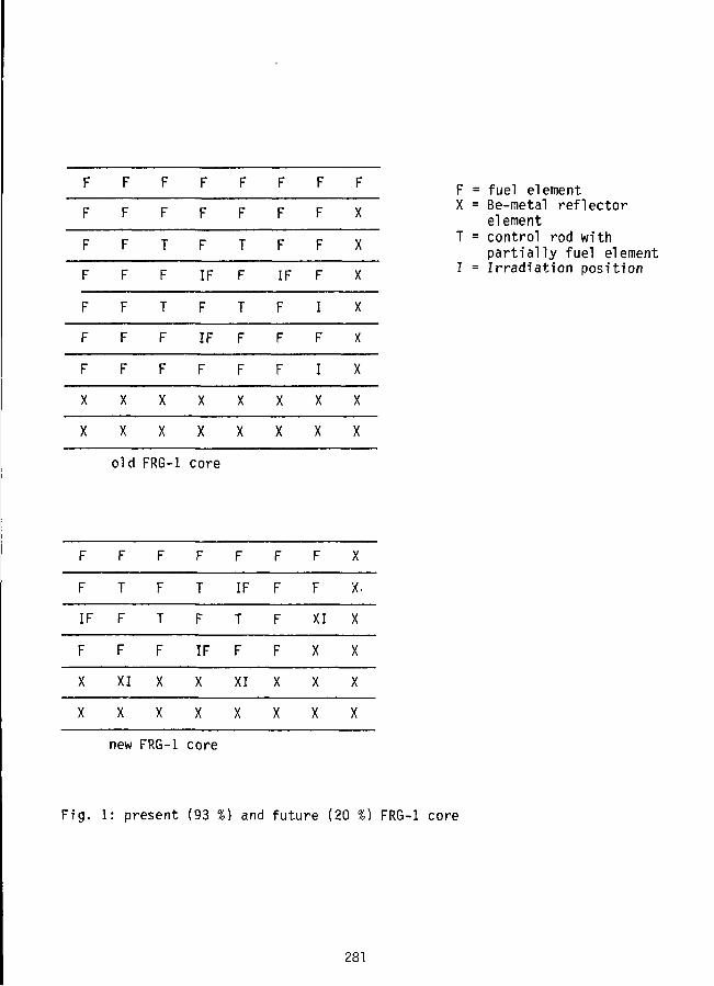
F
F
LL.
F
F
F
F
X
X
F
F
F
LL.LL.
F
LL.
X
X
F
T
F
T
F
F
X
X
LL.
F
IF
F
IF
F
X
X
F
T
LL.
T
F
F
X
XLL.
F
IF
F
F
F
X
X
LL.LL.
F
I
F
I
X
X
LL.
X
X
X
X
X
X
X
X
old FRG-1 core
F
F
IF
F
X
X
F
TiL
.LL.
XI
X
LL.
F
T
F
X
X
F
T
F
IF
X
X
F
IF
T
F
XI
X
F
F
F
F
X
X
F
F
XI
X
X
X
X
x.
X
X
X
X
F = fuel elementX = Be-metal reflector
elementT = control rod with
partially fuel elementI = Irradiation position
new FRG-1 core
Fig. 1: present (93 %) and future (20 %) FRG-1 core
28!

17/N 221
LICENSE APPROVAL ON THE CONVERSIONOF DR 3 TO LEU
Karsten HaackRisa National LaboratoryDK-4000 Roskilde, Denmark
ABSTRACT
The license application for co:,version of the danish DR 3 reactor from theuse of highly enriched uranium (HEU) to low enriched uranium (LEU) and fora power increase from 10 to 12 MW, was forwarded September 1986 to . theauthorities: The Danish Nuclear Inspectorate, the National Institute ofRadiation Hygiene and the Danish Labour Inspection Service. The applicationwas based on 155 pages of amendments to the safety documentation.
The amendments were discussed and explained on a series of meetings betweenreactor and authority representatives during 1987.
A framework approval was issued by the authorities in June 1988. Thereactor management expects to have fullfilled the frames for the start ofthe conversion by supplementary reports and investigations before thescheduled date for start of conversion: October, 14th, 1988.
The mixed core operation schedule is presented. Full-core LEU operation isexpected around May 1990.
THE APPLICATION
On September 18th, 1986, Riso applied to the Danish authorities for 12 MWLEU operation of reactor DR 3.
The accompanying documentation was based on 15 MW operation because itturned out during the revision of the safety documentation, that 15 MWoperation would be feasible within the authorized conditions of operation.This would facilitate an eventual later power increase above 12 MW as well.
The application was based on amendments to the DR 3 safety documentation,concerning following subjects:
- Flow stability evaluation- Initial events safety analysis
282

- Analysis of cold coolant accidents initiated by the primarycooling system
- Analysis of cold coolant accidents initiated by the secondarycooling system
- Evaluation of emergency cooling system capability at aloss-of-coolant accident
- Analysis of loss of all primary cooling after reactorshut-down
- Coarse control arm failure analysis- Evaluation of the tertiary cooling system (fjord coolingwater) capability at 15 MW power
- Re-evaluation of the shut-down margin- Analysis of reactivity accidents at low power- Calculation of individual and population doses from core
melt-down accidents at DR 3- Reference data ammendments collection.
Evaluation of the mixed core operation phase and proposals for revisions on7 items of the "authorized conditions for operation of DR 3" were enclosed.
CLEARING-UP AND SUPPLEMENTARY DOCUMENTATION
During 1987 the Nuclear Inspectorate raised a series of supplementaryquestions in meetings and in letters. The main topics were"
1) Maximum fuel element power and power peaking
We had proposed to vouch for the flow stability of the fuelelements by setting a limitation on the fu-3l element power,because the fuel element power distribution can be measuredon-line by means of the built-in thermocouples at the fuelelement exit ports when the flow through each fuel element isknown. We had measured the flow distribution of the core foreach of the three combinations of two main circulators in June1986. The inspectorate demanded an evaluation of theprobability that a 1000 kW limit on the 180g fuel element couldbe infringed, and they required a calculation of the powerpeaking factor in a 1000 kW fuel element.
2) Flow instability factorThe 1000 kW limit was based on a flow instability factor of1.3. Earlier we had applied a factor of 1.5 because the coreflow distribution was not known for certain after the changefrom a box type to an annular type of fuel element. The flowdistribution measurements in 1986 provided the base fordecreasing the factor to 1.3.
The Nuclear Inspectorate required information on flowinstability factors of other DIDO/PLUTO-type reactors.
283

Re 2) We asked Harwell (UK), Julich (FRG) and Lucas Height (NSW,Australia), for which instability factors they apply, and their kindreplies confirmed that our choice (1.30) was reasonable and safe.
3) Void coefficients in a LEU coreCalculation of void coefficients of DR 3 was a part of thebenchmark calculations on heavy water research reactors in theguidebook IAEA-TECDOC-324. The authorities required a separatereport.
4) Reactivity transients in a LEU coreThe authorities required recalculations of all transientscalculations in the DR 3 safety documentation. We had arguedthat because of the higher temperature coefficients in a LEUcore, reactivity transients would be smaller than in a HEUcore.
5) Wigner energy deposition in the graphite reflectorThe authorities required an updating of the previous report onthis subject, because of the power increase applied for in theapplication for the conversion to LEU.
6) Lifetime of the coarse control arm (CCA) systemThe burn-up of the CCA's is faster at a higher power. Theauthorities wanted to know the estimated lifetimes of the 7CCA's and they required a schedule for the exchange of the CCAconnecting rods, which are exposed to the damage flux in thereactor.
Re 6) We made an inquiry on demand of the authorities, to oursister-reactors on the lifetime of their CCA connecting rods. Unfortunatelytheir operation conditions and maintenance schedules were very differentfrom ours, so our programme for exchange of the rods had to be made ratherconservatively.
7) LOCA design basis accidentThe loss-of-coolant-accident (LOCA) upon which the emergencycooling system design was originally based, was a longitudinalrupture of one of the main tubes in the heavy water plant room.This accident has for many years been considered incredibleowing to the thick stainless steel walls of the tubes and thelow pressure in the system. The revised report evaluating theemergency cooling system at increased power in connection withthe conversion to LEU was based on a more probable rupturecaused by fatigne stresses in a welding seam of one of thestainless steel tubes. This would cause a smaller leak rate, ofcourse, which made the authorities suspicious. They asked foran evaluation by an independant body on credible ruptures ofthe primary system pipework, and required measurement of theemergency cooling water flow to each fuel element.
284

Re 7) We asked the danish institute for welding research and development"Svejsecentralen" to evaluate the D_0 pipework. They made a thoroughexamination and concluded that a risk Tor small leakages would exist afterso many years of operation, but the probability for large ruptures in themain pipes was very small and insignificant. This conclusion confirmed ourproposal for an amended design basis for the emergency cooling system.
The emergency cooling water flow to each individual fuel element wasmeasured during the extended shut-down prior to the conversion.
8) Cooling system temperatures at increased power levelsThe authorities required a set of diagrams showing thetemperatures in all cooling systems at steady conditions atpower levels of 10, 12 and 15 MW.
9) PIEs of the three danish LEU test fuel elementsThe authorities required post-irradiation examinations (PIE) ofthe three danish manufactured test elements. We had argued thatvery thorough PIEs had been carried out on mini plates and fullscale test elements at ORNL and the authorities had copies ofthe reports from the RERTR-meetings. We had pointed out thatPIEs on our test elements would undoubtedly not add newinformation to the existing documentation.
Re 9) We arranged a meeting between dr. Jim Matos from the RERTR-programme,ANL and our Nuclear Inspectorate (NI). Jim Matos reported on theexperiences obtained by PIEs under the RERTR programme. NI was satisfied bythe information, but stuck to the demand for a series of fuel tube wallthickness measurement on the 3 test elements, combined with a visualinspection for blisters. The thickness measurements and the visualinspections have been carried out in our shearing pond. Mo swelling withinan accuracy range of ± 0.02 mm was detected, and no blisters were seenneither in the visual inspection nor in the photographical documentation.
10) Guarantee for reprocessingThe authorities demanded a written obligation from the USDOEthat they would recieve the used LEU fuel elements forreprocessing and final store of the high-active waste. We hadgiven them a copy of the US Federal Register/Vol 51 No-32/Tuesday, February 18, 1986/Notice, but they wanted a moreobligatory statement.
Re 10) This subject was also discussed between Jim Matos and NI. It wasfinally decided to ask the EURATOM supply agency for assistance onobtaining a written obligation from USDOE for reprocessing and final storeof the fuel. Until now we have not got such an obligation.
11) Conversion approval for other reactorsThe authorities required statements from such reactors whichhave got the permission to convert to LEU or were expecting thepermission in a near future.
285

Re 11) We asked mr. Winkler (SAPHIR reactor, Switzerland), dr. Burtscher(ASTRA reactor, Austria) and dr. Krull (FRG-1, FRG-2, DFR) to inform us onthe state of their conversions. Our authorities were happy to learn (Nov.1987) that the swiss and the austrian reactor allready had obtained theirlicense for LEU-operation and that the Geesthacht reactors would have theirlicense in a couple of months.
12) Argumentation for non-amended "Authorized Conditions ofOperation" (ACO)We had given written proposals for amendments to 7 ACO's whichwe found to be the only which had to be amended owing to theLEU-conversion and the power increase. The authority required awritten argumentation for each of the remaining 80 ACO's, onthe reason why they should not be amended.
13) Safety at low-power operationThe DR 3 safety documentation contains a chapter aboutreactivity transients starting from low power (< 50 kW) wherethe temperature coefficients have no effect.
The authorities required a revision with the changedtemperature coefficients of LEU taken in consideration.
14) Earliest time of withdrawal of used fuel elements from the coreBy increasing the reactor power the maximum fuel element poweris also increased. This extend the time after shut down neededto ensure that the residual heat of the fuel element can beremoved by convection in free air if the cooling fails. We hadproposed to replace the time limit (37 hours after shut-down)by a limit of 1.9 kW residual power. This is the residual power37 hours after shut-down in a fuel element which had beenoperating at 700 kW just before shut-down.
The authorities required a device for measurement of theindividual fuel element powers, so that we just beforeshut-down could measure the powers of those fuel elements whichhave to be changed during the shut-down.
Re 14) We provided a delta-T-times-flow measurement channel for the powerof each fuel element. The individual flows were allready known for all 3main circulator combinations, and the outlet temperatures were accessiblethrough the built-in outlet thermocouples in the fuel elements. The inlettemperatures were obtained by statistical treatment of data collectionsfrom previous operation. The control room computer was coded to supply thefuel element powers on demand.
We have supplied most of the additional information required by theauthorities. Only a few items were lacking when the authorities decided toisue a preliminary approval:
286

THE FRAMEWORK APPROVAL
Early 1988 the authorities issued an "evaluation report" with a "frameworkapproval", e.g. an approval under conditions that some demands werefullfilled before the conversion starts and other demands were fullfilledbefore a full LEU core were established.
Required by the authorities before the conversion starts:- Thickness measurements of test elements- Emergency cooling flow measurements- Recomputation of reactivity transients- Schedule for exchange of the CCA connecting rods
Required march 1989, before full LEU-core is established:- Instruction for measures against LOCAs- Analysis c 1 loss-of-lead-shield-cooling-accident- Reanalysis on max. energy release by transients- Calculation of reactivity increase by D_O-fillingof the He-volume in the top of the reactor tank
- Recalculations of transients and safety absorberreactivity worths with a series of different coreconfigurations
- Revised proposals for "authorized conditions ofoperation"
- Reevaluation of LEU-operation based on experienceobtained during the mixed-core operation.
During the mixed-core operation period we are obliged to precalculatethermal and fast neutron flux densities and power distributions in the corebefore the start of each reactor cycle, and to verify these calculations bymeasurements during each cycle. The results shall be presented in a reportto the authorities after establishment of the full LEU-core. This reportshall also contain results from calibrations of the safety absorbers(safety rods and coarse control arms), measurements of temperaturecoefficients and an evaluation of operation conditions in the pure LEU-coreafter the conversion.
MIXED-CORE OPERATION SCHEDULE
At start-up on October 14. 1988 eight 180g LEU fuel elements will bepresent in the core in the positions shown below (figure 1).
When these LEU fuel elements burn-up (at about 50% of the initialU235-content) they will be replaced by new LEU fuel elements in the samepositions.
The remaining 18 core positions will contain HEU fuel elements until thestock is empty, which is expected about November 1989("Kl"-period in the figure).
287

No. of fuel elements
26
HEU
-L - K2 ^
LEU
Tin
14.Oct.! Nov.89 May90
Al
LEU
LEU
LEU
LEU
LEU
LEU
LEU
LEU
E4
The core during the Kl-period
Figure 1
The last core positions will be converted from HEU to LEU around May 1990.
There are two reasons for this conversion schedule:
1)
2)
The experimenters will have steady and foreseeableirradiation conditions during the Kl-period.
If failures in the first production series of LEU fuel elementsshow up during the Kl-period, we will still have thepossibility to replace the 8 LEU fuel elements by 8 HEU fuelelements and continue the operation while new LEU fuel elementsare produced.
REFERENCES
1. K. Haack, Irradiation of MEU and LEU Test Fuel Elements in DR 3Page 203, Proceedings of the International Meeting on ReducedEnrichment for Research and Test Reactors, 24-27. Oct- 1983,Tokai, Japan.
288

2. K. Haack, Study on Al-alloy or Silicide LEU for DR 3 inDenmark. Page 337, Proceedings of the 1984 InternationalMeeting on Reduced Enrichment for Research and Test Reactors,Argonne, Illinois, Oct. 15-18, 1984.
3. K. Haack, Selection of Fuel Type and Core Pattern andApplication for LEU-Licensing of the Danish Reactor DR 3. Page359, Proceedings of the 1986 International Meeting on ReducedEnrichment for Research and Test Reactors, Gatlinburg,Tennessee, Nov. 3-6, 1986.
289Trvk (irafnk Scrvi

290

SESSION VI
September 20, 1988
CONVERSION PLANS AND STUDIES
Chairmen:
K. Kanda(KURRI, Japan)
F. DiMeglio(RINSC, USA)
291

FULL CORE MEU FUEL DEMONSTRATION IN THE JRR-2
Yoshiaki Futamura, Junsaku Tsunoda and Takashi KoganezawaJapan Atomic Energy Research InstituteTokai-mura, Ibaraki-ken 319-11, Japan
ABSTRACT
In 1980, when JRR-2 was planned to convert from HEU toLEU, the LEU fuel being adopted in JRR-2 had net been quali-fied yet. So the MEU fuel was selected for JRR-2 conversion.
The integrity of MEU fuel element was confirmed withthe irradiation test in JRR-2 and PIEs of irradiated fuel.
From the safety review on the base of LWR criteria,some modifictions and installations of additional equipmentwere required.
In November 1987, JRR-2 was converted to MEU and inJanuary 1988, the full core MEU fuel demonstration test hasbeen successfully completed and the JRR-2 has been satis-factorily operated with MEU fuel since that time.
INTRODUCTION
The Japan Research Reactor No.2 (JRR02) is a heavy water moderated andcooled 10 MW tank type reactor using both ETR type and cylindrical type fuelelements, and has been utilized for wide purpose such as irradiation forreactor fuels and materials, radioisotope production, neutron beam experi-ments and so on since October 1960. The characteristics of JRR-2 in shownin Table 1.
For converting from HEU to medium enriched uranium (MEU) fuel, thefollowing guidelines were set up for the fuel element design.
(1) The reactor characteristic is equivalent to that of the previous core.(2) The dimensions and the configuration of the fuel elements should be
unchanged.(3) The number of the fuel elements loaded in the core and the core confi-
guration should be unchanged.(4) The U-235 content per fuel element should be sufficient to allow
operation with the fuel life-time and the reactivity of the corebeing less than those of previous one respectively.
293

Under the above mentioned guideline, MEU aluminum dispersed fuel with uraniumdensity 1.6 gU/cm3 in the fuel meat was adopted.
The MEU and EEU reactor core characteristics of JRR-2 are shown in Table2, and the specifications of the MEU and HEU fuel elements are shown in Table3. The structure of the MEU fuel element is shown in Fig. 1, and the JER-2core configuration is shown in Fig. 2.
For converting to MEU fuel, the following tests and equipment instal-lation had been carried out.
(1) Irradiation test of full sized MEU fuel elements.(2) Installation of required equipment on considering the safety review.
The full core conversion to MEU fuel was permitted by Japanese Govern-ment on November 5th 1986.
The criticality examinations and reactor characteristic examinationsincluding rated power demonstration test with full core MEU fuel weresuccessfully performed from November 1987 to January 1988. Since the time,JRR-2 has been satisfactorily operated with MEU fuel.
Installation of Additional Equipment on Considering"the Safety Review Evaluation
By the results of required safety review evaluation analysis for thereactor systems on the base of LWR safety criteria, some reactor systemswere found not to satisfy with the single failure criteria. Therefore, thefollowing systems were additionally installed.
JRR-2 cooling system and emergency cooling system in shown in Fig. 3.
(1) An emergency heavy water supply system.(2) Scram circuits "Flux High at low power mode" and "Fuel Failure".(3) Re-establishment of two vital electical power supply systems (if one
system not available, another one can be put into in use).
The emergency heavy water supply system consists of a heavy water re-server tank (ET-1) with 6 m3 of heavy water, two supply pumps (Ep-2, Ep-2A)with redundancy and pipings. It functions to recover the coolant leveldecrease in the reactor at the postulated loss of coolant accident. Thereactor coolant level being decreased to the preset level due to any cause,one of two supply pumps is automatically started. Then the pump supplies theheavy water from the reserver tank to the reactor core to keep it in the water(refer to Fig. 3). The additional sump pit recirculation pump is installedto reinforce the current recirculation system in consideration of redundancy.The two scram circuits has been installed with redundancy respectively.As a prevent measure of the start-up accidents, the "Flux High at low powermode" initiates trip circuits for reactor shut down when the flux level isexceeded the preset point equivalent to 0.44 % rated power (440 KW) at thelow power operation mode. The "Fuel Failure" initiates the trip circuits
294

when the count rate of the fuel failure detectors (FFD) is exceeded the presetpoint corresponding to the value of ten times higher than the back ground.
There must be redundancy in the power supply for the engineering safetyfeatures, so the electric power must be separately supplied to the two pumpsin those systems.
Irradiation Tests
Two MEU fuel elements fabricated by CERCA were irradiated, and theyhad the same specifications as those of the driver fuel element to be loadedin JRR-2. Concerning with the irradiation test, the following items wereexpected to be confirmed.
(1) Reactivity of fuel element.(2) Integrity during operation.(3) Bumup warranty.
The MEU fuel element (cylindrical type fuel element) had a comparablereactivity with that of HEU fuel. For example, the reactivity of the MEUfuel is 2.02 % AK/K and that of HEU is 1.96 % AK/K when each fuel was sepa-rately loaded at the same position (B ring) of the reactor core. Bothreactivity are found to be almost same.
These two MEU fuel elements were loaded in the core for irradiation fromSeptember 1984 to December 1985. They had been irradiated with good behavior,such as no fission gas detected.
After the irradiation, post irradiation examinations (PIEs) for one MEUfuel element were carried out, such as (a) visual inspection (b) dimensionmeasurement (c) X-ray radiography (d) ganma scanning (e) dlister test(f) mechanical properties (g) metallography (h) absolute burnup (i) SEM andXMA.
The results of PIEs showed satisfactory with no indication of irradiationbehavior for using as reactor fuel element.
Full Core MEU Fuel Demonstration
The full core demonstration with MEU fuel was carried out November 25,1987 through January 30, 1988 with satisfactory results. The followingexaminations and measurements were performed.
(1) Excess reactivity.(2) One rod stuck margin.(3) Shut down margin.(4) Temperature coefficient.(5) Neutron flux.
295

(6) Control rod worth.(7) Moderator dump effect.(8) Xenon poisoning effect.
The main results are shown in Table 4 and 5, and xenon poisoning effectsis shown in Fig. 4.
Conclusion
The full core demonstration with MEU fuel in JRR-2 had been successfullycompleted with results sufficient to operate JRk-2 safely. Some neutronicsdata and reactor core characteristics data such as excess reactivity, shutdown margin, temperature coefficient, etc. were measured and compared withcalculation values. Those measurement results show almost consistency withits respective calculation value. The results were satisfactory.
During the reactor operation, fission products leakage was carefullychecked by the monitoring of the primary coolant and the cover gas He.No fission products were observed.
REFERENCES
1. T. Sato, M. Sato, Y. Asahi. T. Koganezawa, S. Yamaguch and J. Tsunoda,LOSS-OF-COOLANT ACCIDENT OF JRR-2 IN A SAFETY ANALYSIS FOR CORECONVERSION, JAERI-memo 63-220, 1986.
2. M. Kurosawa and Y. Torii, NEUTOONICS DESIGN OF MEDIUM-ENRICHEDURANIUM CORE OF THE RESEARCH REACTOR, JRR-2, JAERI-M 86-052, 1988.
3. CHARACTERISTIC MEASUREMENTS OF JRR-2 AFTER MODIFICATION JRR-2OPERATION SECTION, JAERI-M 6943, 1977.
4. Y. Futamura et. al., "Post-Irradiation Examination of Low EnrichedUAlx-Al Fuel Element in JAERI" in 10th RERTR Meeting, Buenos Aires,Argentina, Sep. 28 Oct. 2, 1987.
296

Table 1. Characteristics of JRR-2
Type
Power
Moderator/coolantmaterialPressuretemperature
coolant velocity
Reflector
Fuelmaterialenrichmentioadingtype
Control rod
Neutron flux(In-core irradiation holeof cylindrical type:6B)
Power density
Tank type
10 MW thermal
D20Atmosphere44°C (Inlet).50°C (Outlet)3 ~ 4 m/s (water ch.)
D20
UA£X
93 %24 elementCylindrical typeand MTR
6 rods (Cd)
5.5 x 10¹³ (}>f (max.)7.0 x 10¹³ <J>th (max.)
30 kw/£ (ave.)
297

Table 2. Reactor core characteristics of the MEU and HEU fuel
Excess reactivity %Ak/k
Total control rod worth %Ak/k
Highest control rod worth %Ak/k
Shut down margin %Ak/k
One rod stuck shut down margin%Ak/k
Temperature coefficient(27°C-52°C) Ak/k/°C
Prompt neutron life time s
MEU core
18
31
10
14
4
-(0.23-1.2) x 10"3
(17- 127°C)
2.6x 10" u
HEU core
16
37
12
22
10
-0.37* lo"3
(27- 52°C)
(2.8-3.l)xlO""
Table 3. Specifications of MEU and HEU fuel
Meat
1
Clad
Fuelplate
Fuelelement
Material
Enrichment (%)
Thickness (mm)
U-Density (g/cm3)
Thickness (mm)
Thickness (mm)
Number of fuel plate
U-235 Content (g)
Dimension(cylindrical type) (mm)
MEU fuel
UA£X-A1dispersien
45
0.51
1.6
0.38
1.27
15
220
108* * 950
HEU fuel
U-Alalloy
93
0.51
0.7
0.38
1.27
15
195
108* * 950
298

Tbale 4. Measurement values of demonstration testcomparing with calculated ones
Excess reactivity %Ak/k
Total control rod worth %Ak/k
Highest control rod worth %Ak/k
Shut down margin %Ak/k
One rod stuckshut down margin
Moderator dump effect %Ak/k
Temperature coefficient »/A1/, ,or(27°C-52°C) 4flK/fc/ o
Measured
17
33
6.4(C1)
16
10
-0.71
-0.017--0.045(16 -56°C)
Calculated
18
31
10(Cl)
14
4
-0.59
-0.023--0.12(17 ~127°C)
Table 5. Measured neutron fluxes in MEU and HEUfuel core
——___^^ CoresTypical ^~^~—-__irradiation facilities""—--—-__ _
Neutronflux
1013/cm2s
In—coreirradiationholes
Verticalexperimentalthimble
Pneumatictube
6B
6C
VT-1
Pn-2
MEU core
5.8/5.2
4.7/3.6
13/2.8
8.1/0.3
1
HEU core
7.0/5.5
5.4/4.0
20/2.5
8.0/0.25
* The neutron flux are given asThermal Neutron Flux / Fast Neutron Flux.
299

eou
o
(UT3•H3to0)
i-H3CO
aCJ
c•Ha4 J
oa.p .3
CO
oo
a>•a• H3GO
OJrH301p .CO
ul-l0)
D.
Oi4 J
a
01
cM
ai4Jni
i—io.
01
£i n
J J)-.oa.c3co01
4-J
rtO.
i -HW3
(V-Q3J-I
! J014-1
O
n
V4(1)4 J
am•ato
u01
aa
CN
014J
a«T3n)1401
o
f—i
aCU
S
too
X!c
Cd
bo
300

VT-2 „ ,. VT-9-v Dump line
O F u e l e l e m e n t ( 1 A ~ 6 D )
O V e r t i c a l e x p e r i m e n t a l t h i m b l e (VT)
C o n t r o l rod
Fig. 2. JRR-2 core configuration
301

LI
oIX)
L2 Voter level in a core vessel
Location Vatcr level loss
LI 0 c i
L2 About -12 c«
L3 About -65 co
L4 About -67 c»
L5 About -68 c»
L6 About -77 c»
Introductiory
svibol
Bel loves
Cnrck valvePneumatic opera LeddiaphraM valve
Hotcr drive valve
Manual drive valve
Functional status
Closed valve
Puip in operation
Level
noraa) level
Scraa level
llacvy vatcr outlet ill level
Itavey water outlet "2 level
Fuel clement cooling vatcr outlet level
Fuel core upper top level
llcliua gas supply systci
Corrosion res i s t i ng Al-a l toy pipe
Stainless steel pipe
Fig. 3. J R R - 2 cooling system and emergency core cooling system

QWOS
wo
o
oCO
o
O
"3"
tub
F % ) A I I A I
303

3TUDSVIK NUCLEAR
Reduced Enrichment Fuel Conversion Efforts at theSwedish R2 Research and Test Reactor
E. Kaffehr and K. SaltvedtStudsvik AB, Sweden
Abstract
Studies on the feasibility of operating the R2reactor with LEU fuel have been in progress since1982.
STUDSVIK is at present irradiating LEU silicidedemonstration fuel elements with two differentfuel densities. Two of the high density elements
235initially containing 490 g U and with a meat235 2density of 4.8 kg U /cm are manufactured by
B & W. CERCA and NUKEM have each manufactured oneelement with the same fissile loading.
Three elements with an initial fissile loading of
320 g u are manufactured by B & W. The highdensity elements have reached burnup in the rangefrom 11.6 to 22.6%. One of the elements with alower fuel density has reached 50% burnup.
304

Introduction
Comprehensive studies on the feasibility ofoperating the R2-reactor with LEU fuel werecarried out from 1982 to 1985. A large part ofthis work was done by the RERTR-project staff inArgonne and part of the work has been reported atprevious RERTR-meetings (1).
The conclusion of these preliminary calculationswas that the fuel cycle costs would be about thesame with LEU elements as with HEU elements, ifthe LEU elements were loaded with approximately
23550% more U than the HEU elements. The manu-facturing cost for LEU elements was then assumedto be about 1.4 times that of the HEU elements.The performance reduction was calculated to be5 - 15% for experiments requiring thermal neutronsand was almost unchanged for irradiation damageexperiments. T^e calculations also indicated that
235fissile loading as high as 490 g U could beused and that this would give a substantialreduction in the fuel cycle costs.
Irradiation of LEU demonstration elements in theR2 reactor
In 1984 STUDSVIK made an agreement with ANL toirradiate four LEU demonstration fuel elements,
235each of them with a fissile loading of 490 g UTwo of the elements were manufactured by B & W andthe two other by CERCA and NUKEM. In additionSTUDSVIK also ordered three elements from B & Wwith a lower fuel loading. The elements were manu-factured according to essentially the same speci-fications.
Design data for the elements are given in Table 1.
Table 1 Design data for the LEU demonstrationirradiated in R2
Manufacturer U 2 3 5 Fuelcontent compositiong
CERCA
NUKEM
B & W
B & W
490
490490
320
u3si2
u3si2
U3 S i2u3si2
Meatthicknessmm
0.76
0.76
0.76
0.76
. elements
Claddingthicknessmm
0.38/0.57
0.38/0.57
0.38/0.57
0.38/0.57
pu -g/cm
4.8
4.8
4.83.1
305

Four of the B & W elements were already deliveredin June 1984. The CERCA and NUKEM elements weredelivered to Studsvik during the spring of 1986.The irradiation testing of these elements hashowever been much delayed compared with theinitial planning. There are several reasons forthe delay. Some of them are due to the replacementof the reactor vessel which was performed duringthe second half of 1984 and the first quarter of1985.
The reason for the replacement was that ductilitymeasurements on irradiated samples of the reactorvessel material showed unexpectedly low values.Lacking documentation on the manufacturing qualityof the vessel STUDSVIK was not able to show thatrupture of the reactor vessel and consequentsticking of the control rods could not occur.
To fulfil present design requirements and safetycriteria the new vessel had to be modified inseveral respects compared to the old one. One ofthe major modifications was that the core latticewas changed from a 10 x 10 configuration to a8 x 10 configuration. The Be-reflector was omittedon two sides of the core. Because of this the twofixed test loops for LWR fuel, each occupying twolattice positions, had to be moved to core positionswith higher neutron fluxes.
The change of the core geometry and reflectorcomposition had a large effect on the conditionsfor core loading and fuel shuffling.
After restart of the reactor with the new vesselwe had difficulties in loading the heavy B & Welement in the core without either exceeding thestated peak power limits or impairing the condi-tions for the experiments in the core. Thisproblem was mostly related to the long termexperiments designed for the old core.
After receiving the CERCA and NUKEM elements weperformed a series of low power measurementsaiming at verification and validation of the corephysics calculation methods and establishingloading criteria for these heavy elements.
The license to operate the elements at high powerwas obtained after reporting the results of themeasurements to the safety authority.
306

The most important limitation stated in theoperating license is that if the core calculationprevious to the loading shows a peak power in theelement exceeding 70% of the maximum permissiblelevel the calculation must be verified by adequatemeasurements. This requirement implies a greatproblem for the reactor operation.
It has generally not been possible to find morethan one or occasionally two core positions wherethose heavy elements could be accepted withoutprevious neutron flux measurements, either withconsideration to the peak power criteria or to theeffects on the experiments in the core. Neutronflux measurements including evaluation of theresults do however reduce the fuel power avail-ability of the reactor by 30 - 40 hours.
To reduce the operating costs the reactor has forapproximately two years been operated by a reducednumber of staff and with reduced availability.
Because of this the operating schedule has beenvery busy and it has not been considered acceptableto carry out flux measurements more frequentlythan every third or fourth period.
Lower power activation measurements have inaddition to the initial campaign been performed ontwo later occasions.
Detailed neutronic calculations of possibleconfigurations for irradiation testing of LEUprototype elements in the R2 HEU core have beenperformed both at ANL and in Studsvik.
It was not possible however to reproduce the coreloadings which were assumed for the ANL calcula-tions with sufficient accuracy to allow a detailedcomparison between the ANL calculations and themeasurements to be made. We attempted a comparisonby calculating the effects of the differencesbetween actual and assumed core loadings
The preliminary conclusions from the comparisonsbetween the measurements and the calculations madeby Argonne and STUDSVIK are:
We generally found good agreement betweenthe Argonne calculations of the powerdistribution in the core and the measure-ments after corrections of the differencesin the core loading. We did not however
307

find the element power peaking factors,i.e. maximum power density in an elementto the average power density in theelement, to be as high as was predictedby Argonne.
When we compared the measurements and thecalculations made in Studsvik the agree-ment was mostly acceptable. It seemshowever as if the predictions overesti-mate the neutron flux in the periphery ofthe core and especially in the cornerpositions where we found calculated tomeasured ratios up to 1.33. We alsonoticed a tendency to underestimate theneutron fluxes in HEU elements adjacentto the LEU elements.
Also the STUDSVIK calculations predictedhigher element power peaking factors thanwere measured. We believe that this isthe same effect which has been observedby comparisons between calculations andmeasurements made in ORR reported byCornelia, Bretcher and Hobbs at the 1986RERTR-meeting (2). They found that theneutron flux in the center of an elementwas overpredicted and underpredicted nearthe sideplates of the element.
Figure 1 shows average ratios betweencalculated and measured neutron flux inthe LEU elements which have been irra-diated up to now, and also some typicalvalues in some HEU elements. The figurealso shows the ratios between calculatedand measured power peaking factors in theLEU elements. Unfortunately we do nothave a sufficient number of qualifiedwires from the measurements in the HEUelements to evaluate the power peakingfactors in those elements.
The irradiation data of the LEU demonstrationelements up to the beginning of September 1988 areshown in Table 2.
308

Table 2 Irradiation data^for £,EU demonstration elements inthe R2 reactor ('±98£-0*-01)
Manufacturer
CERCA
B & V?
B & W
NUKEM
Initial
U 2 3 5 g
490
490
320
490
Firr
days
110
62
194
62
Pelement
kW
800
770
660
730
Burnup
u 2 3 5 %22.6
12.2
50.6
11.6
235The U content in the elements has dropped to alevel where it will be easier to load the elementsin to the core, and we expect the burnup to besubstantially quicker in the future.
All three high density elements above will reach50% burnup before the end of 1989, and the targetfluence which is twice the fluence necessary toachieve 50% burnup can be reached during thespring of 1990. The second high density B & Welement will reach approximately 35% burnup at theend of 1989.
One of the elements will be brought to the HotCell Laboratory for destructive examination afterthe 50% burnup.
Visual inspection and measurements of meat volumechanges
The elements have been visually inspected in thereactor pool after each operating period. The onlynoticeable observation so far is a very lightred-brown coating mainly on the sideplates on theNUKEM element.
In order to detect volume changes of the fuelplates the elements are weighed after every thirdoperation period. The weight can be determinedwith an accuracy of 0.1 g which corresponds to avolume change in the meat of all the fuel platesof 0.1%
No significant volume changes have been observedso far in the high density LEU elements.
309

We nave however observed a volume decrease ofapproximately 1% in the B & W element which hasreached 50% burnup.
The core conversion plan for the R2 reactor
The conversion of the R2 core will be achieved bygradually replacing the fully burned HEU elementsby LEU elements. The start of the conversionprocess will be determined with consideration tothe inventory of HEU elements.
During the first phase of the transition it willbe necessary to replace the burned HEU elements bya mixture of unirradiated HEU and LEU elements inorder to obtain an acceptable uranium distributionin the core.
The past transition equilibrium state is reachedwhen the inventory of partially burned elementscorresponds to two core loadings.The number of HEU elements needed for the wholetransition process corresponds to approximatelyone core loading.
STUDSVIK plans to start with the transition inSeptember 1988, and the equilibrium state will bereached two years later.
The studies which were based on the previous modeof operation, which means 6300 operating hours peryear and a cycle length of 24 days, indicated that
235an element loading of 400 g U would be a goodcompromise between considerations to fuel economyand performance.
with the present mode of operation, which means4400 operating hours per year and a cycle lengthof 17 days, we might have to reduce the loading inthe elements. Calculations are in progress and thefinal decision will be made within the next fewmonths.
310

Figure 1 Average calculated to measured neutronflux and power peaking ratios in mixedLEU/HEU cores
ALH
LEU1.131.04
S11A
HEU0.820
LEU1. 161.17
HEU0.90
SI 2:1
LEU1.131 .10
ALH
Be
HEU1.10
311:1
HEU0.95
HEU1.10
SI 2:2
Be
Be
C
3
C
2
C
•| 1
Be
Be
HEU1.01
Be
Be
HEU0.99
HEU1.00
Be
Be
C
5
C
6
C
U
Be
Be
HEU1.05
Be
ALH
LEU1.051 .04
HEU1 .04
HEU1. 10
LEU1.231.27
ALH
311

References
1. R. B. Pond, K. E. Freese and J. E. Matos"Performance and Fuel Cycle Costs Studyof the R2 reactor with HEU and LEU fuels"in Proceeding of the InternationalMeeting on the RERTR Program, Argonne,October 15 - 18 1984.
2. R. J. Cornelia, M. M. Bretcher andR. W. Hobbs"Comparison of calculated and measuredirradiated wiredata for HEU and mixedHEU/LEU cores in the ORR.
312

LEU FUEL CYCLE ANALYSES FOR THE BELGIAN BR2 RESEARCH REACTOR
Jamss R. Deen and James L. SnelgroveArgonne National Laboratory
Argonne, Illinois
ABSTRACT
Equilibrium fuel cycle characteristics were calculated forreference HEU and two proposed LEU fuel cycles using an 11-groupdiffusion-theory neutron flux solution in hexagonal-Z geometry.The diffusion theory model was benchmarked with a detailed MonteCarlo core model. The two proposed LEU fuel designs increased the2 3 5U loading 20% and the fuel meat volume 51%. The first LEUdesign used -^B as a burnable absorber and the second used Cdwires as an alternative burnable absorber. Either proposed LEUfuel element would provide equilibrium fuel cycle characteristicssimilar to those of the HEU fuel cycle. irradiation rates of Cocontrol followers and Ir disks in the center of the core werereduced 6 ± II in the LEU equilibrium core compared to referenceHEU core.
INTRODUCTION
The Reduced Enrichment Research and Test Reactor (RERTR) Program and theCentre d'Etude de 1'Energy Nucleaire (CEN/SCK) have been engaged in a jointstudy to determine the most suitable LEU fuel element design for the BR2 reactorin Mol, Belgium.1"3 The previous fuel cycle analyses were performed using afive-group diffusion theory model. Comparisons of the diffusion and Monte Carlomodels in hexagonal-Z geometry of fresh and equilibrium cores indicated the needfor improvements to the diffusion model. Presented in this paper are theequilibrium fuel cycle characteristics calculated using the improved diffusiontheory model for two proposed LEU fuel designs.
REACTOR DESCRIPTION
The BR2 core is cooled and moderated with pressurized light water with anaverage pressure of 12 bar. The reference steady state power level is 56 MW,but the reactor has the cooling capacity to permit operation at 125 MW. Theberyllium matrix has 79 cylindrical holes in a hexagonal lattice of 9.644 cmpitch at the midplane of the core. The holes are filled with fuel elements,control rods, various experiments or Be plugs. There are 64 standard channelsof 84 mm diameter, 10 small channels of 50 mm diameter, and five large channelsof 200 mm diameter. All core elements are placed at a slight angle from a per-fectly vertical position relative to the core midplane in order to permit easier
313

access to core elements. The cosine of this non-vertical placement of elementvaries from 0.9981 to 0.9844 and does not significantly affect smeared materialdensities except in the upper and lower reflectors.
Core configuration 10D, which has 31 fuel elements with six shim and tworegulating control rods as shown in Figure 1, has been chosen for theseanlayses. No actual experiments have been modeled in these fuel cycle analyses.All core positions have been modeled using Be central plugs.
Fuel Element Description
The standard HEU fuel element has six concentric fuel rings with an activefuel length of 762 mm placed in an 84 mm diameter channel in a Be hexagonalmatrix. Each fuel ring is formed by three fuel plates secured in position by amechanical connection along their edges to three equally spaced radial Al webs(corresponding to the side plates of box-type elements) as shown in Figure 2.The water gap between the fuel plates is 3 mm and the fuel plate thickness is1.27 mm with a fuel meat thickness of 0.51 :nm. Each HEU fuel element contains400g 235y w£th 3.8g B from B4C and 1.4g Sm from Sm2C>3 as burnable absorbershomogeneously mixed into the UA1X fuel meat.
Control Rod Description
The six shim control rods are divided into three axial zones: a cadmiumcontrol zone; a ^Co zone, 12.15 cm in length; and a Be follower zone. Theannular Cd section has an outer diameter of 60 mm and an inner diameter of50 mm as shown in Figure 3. The two regulating control rods are similar to theshim rods but have a thinner annular cadmium control zone with outtr diameter of39 mm and inner diameter of 34 mm and no cobalt annular zone.
GENERATION OF CROSS SECTIONS FOR FUEL AND CONTROL RODS
TABLE I T h e E P R T - C E L L 4 c o d e w a s u s e d t o
generate all neutron cross sectionsBroad-Group Neutron Energy Structure f o r u s e i n t h e f u e l c y c l e c a l c u l a_
for Neutronic Analyses t i o n s_ E P R I _ C E L L u s e s one-dimensional
integral transport theory with 35neutron groups below 1.8 eV (similarto THERMOS) and 68 neutron groupsabove 1.85 eV in a homogeneous mixture(similar to GAM). The fine groupcross sections were collapsed into 11broad groups with three groups above1.85 eV and eight below for use inbroad-group diffusion-theory fuelcycle calculations as shown inTable I. A cylindrical representationof the fuel element was developedassuming that no web material waspresent and that the outer Be fillerblock could be represented as an
314
NeutronGroup
123456789
1011
upper
05
6.1.8.4.3.2.6.
EnergyBoundary
(eV)
1.0.821.531
1..249.427197276061049325
x 107
x 106
x 103
.855x 10-'x 10-1x 10-2x 10-2x 10~2
x 10-2x 10-3

Fig. 1. BR2 Core Configuration 10DFig. 2. BR2 HEU Fuel Element Cross
Section at Core Midplane
LUGE IKRACIATIW Positions
CONTROL ROD
Fig. 3. BR2 Control and FollowerSections of Shim Control Rod
ALL DIMENSIONS IN mm
E22 ALUMINUM S FUEL PLATE • HjO E£3 BERYLLIUM
Fig. 4. EPRI-CELL Model for CdWire Depletion
ALL DIMENSIONS IN m m
0 ALUMINUM 0 BERYLLIUM Q CADMIUM
CADMIUM CONTROL SECTION
OUTER RACK OF EACH ANNULAR ZONE
r, - CU mm - Cd WIRE
I-, - 4.3 mm - AI/H,0
r4 • 19.3 mm - FUEL
r, - 2*.% mm - 8*
315

annulus. Each fuel meat, clad, and moderator zone was modeled separately withone mesh point used in each zone. A total of 44 mesh points was required forthis model to calculate burnup-dependent cross sections for each isotope in eachfuel plate of the fuel element. Each axial zone of the control rod wasrepresented by a cylindrical model surrounded by an outer zone of homogenizedfresh fuel.
Generation of Cross Sections for Cd Wires
The EPRI-CELL model for depletion of Cd wires consisted of four differentzones surrounding a single Cd wire as shown in Figure 4. The first of thesezones consisted of Al, representing any wire cladding and those parts of the weband fuel plate edge cladding closest to the wire, and had a radius equal to thedistance from the center of the wire to the closest moderator. The secondannular zone consisted of Al and H2O, representing a volume-averaged mixture ofweb, fuel plate edge cladding, and moderator within a radius equal to thedistance from the center of the wire to the closest fuel meat. The third zonewas a homogeneous mixture of fuel, cladding, and moderator materials. The lastzone was Be to represent the presence of Be filler block and inner plugmaterial.
The key variables in the development of this model for accurately follow-ing the changes in composition of Cd from beginning to end of life were thevolumes of the outer two zones (fuel and Be). Increasing the volume of fuelwould harden the neutron spectrum while Be volume increases would soften thethermal spectrum without much effect on the higher energy groups. The maincriterion for achieving a good EPRI-CELL model for Cd depletion was to create aneutron spectrum over the entire volume of the wire that would be as close aspossible to the spectrum calculated by an exact VIM^ model of the fuel elementwith each Cd wire explicitly represented. Once this spectrum was achieved, theEPRI-CELL calculated Ea of the unirradiated wire was within ±1% of the VIMresult averaged over all wire locations in the element.
FUEL ELEMENT BENCHMARK COMPARISONS USING VIM AND DIF3D
In order to determine the adequacy of the cross section data generated byEPRI-CELL for use in whole-core diffusion calculations, it was necessary tobenchmark the data using VIM. This benchmarking activity was needed because ofthe unusual geometry of the standard fuel element as well as the departure frominfinite lattice boundary conditions caused by numerous fuel-non-fuel interfacesin the core. Initial VIM-DIF3D comparisons were made with infinite latticeboundary conditions before whole-core comparisons were begun.
The VIM model of the fuel element was an exact geometrical representationof the location of each fuel plate. Be plug and matrix block, and water channelusing the standard combinatorial geometry option. The fuel element was modeledassuming no axial leakage and perfect reflector boundary conditions for allneutron energies at all radial surfaces.
The initial comparisons of fuel cross section data were made in aninfinite lattice environment with a single homogeneous-composition, 11-broad-group diffusion calculation using a nodal method6 DIF3D7 flux solution. The keyitems for comparison of the two models were kj,,, and isotopic absorption rates
316

normalized to unity, as shown in Table II. Also included in Table II with theHEU fuel element are the comparisons for the two proposed LEU fuel elementdesigns. LEU design #1 was loaded with 480 g 235U/element and 2.85 g B and 1.4g Sm mixed into the fuel meat. LEU design #2 has the same 235U and Sm loadingbut with the boron burnable absorber replaced by 36 Al-clad Cd wires (0.4 mm indiameter) placed in the Al support webs of the element. Each of the VIM caseshad accumulated 100,000 neutron histories, resulting in standard deviations forthe most significant isotopic absorption rates presented in Table III of lessthan ±2%. The standard deviation for the VIM k , was ±0.003 Akoo.
The results of the VIM and DIF3D models were in good agreement for thecase of fresh HEU or LEU fuel in an infinite array of like elements. The onlyadjustment that was necessary for achieving this agreement for the elementsusing boron as a burnable absorber was to replace the EPRI-CELL cr^<n,2n) for Bewith the VIM Giln,2n) in the DIF3D model. With 32% of the fuel element volumeoccupied by the Be matrix and central plug, the n,2n scattering in Be was asignificant contribution to the element reactivity with approximately four n,2nscattering events occurring for every 100 absorption events. Since the stronglyabsorbing Cd wires in LEU design #2 occupy a very small volume relative to thefuel element, the EPRI-CELL microscopic thermal cross sections for 113Cdrequired adjustment until the 113Cd absorption rate in DIF3D was equivalent tothe VIM model prediction. Once the 113Cd absorption rate was forced to be equalto the VIM rate and the VIM <Ji(n,2n) for Be utilized, all other isotopicabsorption rates in the element were brought into good agreement usingunadjusted EPRI-CELL cross section data. Four additional infinite lattice VIM-DIF3D comparisons were necessary for LEU elements using Cd wires so that thethermal absorption cross sections for -^3Cd could be properly adjustedthroughout the lifetime of the wires.
WHOLE CORE MODEL COMPARISONS USING VIM AND DIF3D
In order to benchmark the DIF3D core model, six comparisons were made witha detailed VIM core model, three each with HEU fuel and with LEU fuel. Four ofthe six comparisons were for all-fresh fuel with no axial leakage both with andwithout control rods inserted and two were hexagonal-Z core models withbeginning-of-equilibrium-cycle loadings and partially inserted control rods.
The VIM BR2 core model was an exact representation of each fuel plate,water region, web, Cd wire, Be plug in planar or hexagonal-Z geometry. The onlyapproximation to the actual core geometry was the assumption that all elementswere perfectly orthogonal to the horizontal mid-plane of the core. A total of1876 zones were required for the HEU equilibrium cycle core and 2186 zones forthe LEU equilibrium cycle core. Each VIM case required 300,000 neutronhistories to obtain absorption rate standard deviations <±2% for each signifi-cant isotope in each fuel element. Lumped fission products were simulated usingconcentrations of 135Xe and 95Mo. One axially averaged fuel meat concentrationwas used per element to reduce the volume of input that several axiallydependent compositions would require. The shim rods were all positioned withthe end of the 12.15 cm-long cobalt follower section at 2.5 cm above the coremid-plane. The regulating rods were pulled such that their Cd section tips were
317

TABLE II
Benchmark Comparisons of VIM and Single-Composition Infinite Lattice DIF3DModels of Fresh 400 g 2 3 5U HEU Reference Fuel and Fresh 480 g 2 3 5U LEU Fuel
Isotopic Absorption Rates Normalized to Unity
Isotope
10E
Si
16 0
9 Be
0000
0000
HEUVIM
.6686
.0044
.0225
.1634-.0525.0689.0013.0184_
ElementDIF3D
000,0,
0.0.0.0.
.6662
.0047
.0214
.1655-.0530.068800110192_
LEU ElementVIM
00.0,0,0.0.0.0.0.
.6529
.0774
.0180
.1344
.0006
.0428054300110185_
No. 1DIF3D
0.0.0.0.0.0.0.0.0.
655107800172135400060419053700100180_
000
000000
LEUVIM
.6878
.0785
.0185-
.0006
.0450
.0531
.0C12
.0180
.0974
Element
000
000000
No. 2DIF3D
.6865
.0780
.0188-
.0005
.0446
.0531
.0011
.0202
.0972
1.3918 1.3914 1.3682 1.3710 1.4396 1.4411
TABLE III
Comparison of Isotopic Absorption Rates Calculated Using VIMand Several DIF3D Nodal Models for the BR2 BOL HEU Core
Isotopic Absorption Rates Normalized to Unity
Isotope
23Sy
23809Be10B
lH27A11<39Sm
VIM
0.58210.00330.05700.14510.13130.03220.0476
DIF3D20 gr
0.58260.00340.05940.14650.12800.03150.0476
DIF3D11 gr
0.58330.00340.05900.14660.12750.03150.0476
0000000
DIF3D5 gr
.5867
.0034
.0578
.1477
.1250
.0312
.0472
DIF3D*20 gr
0.58600.00340.05830.14740.12510.03100.0479
DIF3D*5 gr
0.58930.00340.05700.14850.12260.03080.0475
1.1581 1.1590 1.1601 1.1636 1.1663
*Finite difference with 64 triangles per hexagon mesh.
1.1691
318

also 2.5 cm above the core mid-plane, which corresponds to a rod position of 505mm of withdrawal. A no-return current boundary condition was placed at axialplanes 30 cm above and below the active core zone and at the outer radialboundary of seven hexagonal rings.
The DIF3D core model required 127 hexagonal unit cells for the sevenhexagonal rings in each of the 21 axial mesh planes for the 31-fuel-elementcore. The microscopic cross sections were burnup dependent for all heavy metaland burnable absorber materials. The nodal method of flux solution to thediffusion equations using 11 broad groups was used for this model. Therationale for this selection can be deduced by a comparison of the isotopicabsorption rates and k^ data using finite difference and nodal methods withdifferent group structures as shown in Table III. The comparison presented inTable III was for an all-fresh HEU core with all control rods fully withdrawn.Although the finite difference and nodal methods yielded identical flux solu-tions in infinite lattice single fuel element DIF3D cases, the nodal methodyielded better predictions of absorption rate and k^ for every group structuretested in whole core calculations. Increasing the number of groups below0.625 eV using the nodal method yielded closer agreement with VIM. A finergroup structure above 0.625 eV was also compared with VIM fine group neutronspectra but found to be unnecessary to improve any reaction rates or neutronspectral comparisons.
The whole-core reactivity comparisons using the VIM and DIF3D models arepresented in Table IV. In each case the keff's agree to within ±0.003 Akeff.The isotopic absorption rate comparisons for the entire core followed the sametrends presented in Table III for the fresh core comparisons. The hydrogenabsorption was underpredicted consistently in HEU and LEU cores but the bias isreduced upon insertion of all control rods. Most other isotopic absorptionrates were predicted well except for Be, whose absorption rate is consistentlylarger than for VIM. The only adjustment to the microscopic cross section datawas a further adjustment to the Gi{n,2n) of Be compared to infinite latticecomparisons. Although the keff comparisons for the equilibrium HEU and LEUcores were as good as the fresh core comparisons, the agreement in the isotopicabsorption rates was not as favorable. Although all heavy metal and burnableabsorber absorption rates were predicted to within <±2%, the hydrogen absorptionwas overpredicted by 3.9% in the HEU core and 6.5% in the LEU core. Thesedifferences did not affect the core reactivity because the absorption in thesteel axial reflector material was underpredicted by a similar amount.
The average fission rate per element predicted by DIF3D was within +3.3%of the VIM result for all elements in the HEU core. The average bias wasreduced to ±2.5% for the DIF3D prediction of element fission rates in the LEUcore relative to VIM. The peak element fission rate has been lowered in the LEUcore relative to the HEU core by 5.4% because of the small shift in power out ofthe central ring.
FUEL CYCLE ANALYSES
The fuel management strategy used for these equilibrium fuel cyclecalculations was based upon the burnup distribution and fuel cycle length of19.8 days observed for configuration 10D. Six of the eight fresh elementsloaded into the core at the beginning of each cycle were located in the fourthhexagonal ring, along with all six shim control rods. The other two fresh
319

elements were loaded into the fifth ring. The third ring consisted of second-and third-cycie-residence fuel in which nearly half of the total core power isproduced, providing a large source of neutrons for the central irradiationposition. The core power peak usually occurred in this third ring. The nominalcore thermal power was 56 MW but calculations were also performed at 20% abovethis average power because significant portions of the BR2 operating historyhave been at higher-than-average power levels.
One of the primary fuel cycle objectives, in addition to minimizing LEUfuel density and power peaking, was to preserve or reduce the movement ofcontrol rods during the fuel cycle. Reduced control rod motion providesconstant irradiation conditions for the in-core experiments. This was achievedthrough the careful selection of burnable absorber materials, concentrations andlocations. The use of the rapidly depleting 149Sm in the fuel meat reduced thestartup control rod motion until 135Xe and 149Sm had reached equilibriumconcentrations. The use of 10B reduced the total control rod travel during acycle by placing more absorber control material at the beginning of the cycleand depleting a significant portion of it before the end of cycle was reached.Cd wires performed much the same as 10B except the difference in absorber worthfrom beginning to end of cycle was greater owing to the faster 113Cd depletionrate.8-9
Equilibrium fuel cycle characteristxcs were obtained using the REBUS310
code with 11 group, burnup-dependent cross sections. The EPRI-CELL burnup-dependent cross sections were fit to different order polynomials using theleast-squares method. The DIF3D model developed by benchmark comparisons withVIM was used in REBUS3 to perform all nodal diffusion theory solutions. Asummary of the equilibrium fuel cycle characteristics using HEU and LEU fuels ispresented in Table V. The BOEC ke££ was a simulated startup reactivity withsaturated Sm in previously burned fuel and no 135Xe. The EOEC keff assumedequilibrium concentrations of 135Xe and 149Sm. All control rods were fixed attheir mid-cycle positions, 505 mm. By comparing the EOEC keff for the referenceHEU cycle and the LEU cycle using 2.85 g B/element, the use of LEU meat with4.9 Mg/m3 meat density would provide -0.7% Akeff more reactivity. Similarlywhen 10B was replaced by Cd wires in the LEU fuel cycle, the increase in Akeffwas 2.0% Akeff. This reactivity increase was caused by less burnable absorbermaterial present at EOEC in the Cd case compared to the boron case. Therequired LEU fuel density was slightly higher when using the Cd wires clad withAl, but the minimum LEU density could be reduced to ~4.8 Mg/m3 by reducing the235U loading by 6%. This would bring the reactivity performance of the LEU andHEU cycles closer together while using the ORR U3Si2~Al demonstrated LEU fueldensity.11 The comparison of the HEU and LEU fuel cycles operating at 67.2 MWdemonstrated an increasingly favorable reactivity bonus for LEU fuel cycleoperating at higher burnups. Pu fission replaces more of the reactivity lost by235U burnup in LEU fuels with higher burnups compared to the HEU fuel cycle.
The reactivity change from BOEC to EOEC increased 42% in the LEU cycleusing 10B absorbers and 21% using the Cd wires for operation at 56 MW relativeto the reference HEU cycle. This reactivity change is an indication of thedistance control rods must travel to preserve criticality during the cycle.When the power was increased to 67.2 MW, the control rod travel was reduced by-6% in the LEU cycle relative to the HEU cycle. A further reduction inreactivity change from BOEC to EOEC could be achieved through the addition ofmore burnable absorber material or by operation at higher power levels.
320

TABLE IV
BR2 Whole Core Reactivity Comparisons for Freshand Equilibrium HEU and LEU Cores
Enrichment
LEULEULEU
HEUHEUHEU
CoreBurnup
BOLBOLBOEC
BOLBOLBOEC
AllControl
Rods
withdrawninserted505 mm*
withdrawninserted505 mm*
111
111
whole Corekeff
VIM
.2160
.0801
.1405
.1581
.0340
.1245
DIF3D
1.21571.07711.1390
1.16011.03481.1268
Near core midplane position of 480 mm.
TABLE V
Summary of BR2 HEU and LEU EquilibriumFuel Cycle Characteristics
Enrichment
Core Power (MW)235U/element (g)Burnable AbsorberMeat U Density (Mg/m3)keff (BOEC) 1keff (EOEC) 1
Discharge Burnup (%)AveragePeak
HEU
5640010B
1.3.1242.1061
4465
HEU
67.240010B
1.31.11081.0779
5275
LEU
5648010B
4.91.13881.1125
3553
LEU
56480
"3cd5.1
1.15561.1331
3553
LEU
67.2480
H3Cd5.1
1.14841.1153
4260
321

The peak nodal power for the LEU cores relative to the HEU cores hasincreased ~2 to 3% according to DIF3D predictions. Referring back to the VIM-DIF3D equilibrium core benchmark, VIM predicted an average fission ratereduction in the peak element of 5% while DIF3D predicted no change in the samepeak element. Therefore the LEU peak power is probably slightly lower relativeto HEU equivalent-fuel-management cores if credit is taken for the slightredistribution in the radial power from the central core to the periphery in theLEU cores.
Changes in Co and Ir Irradiation Rates
The irradiation rates of 59Co and natural Ir in an LEU core were comparedto an HEU equilibrium core using VIM. For the core provided by the BR2 staff,Co and Ir were the primary materials used for isotope production. Most of theCo was located in the six shim control followers and the Ir disks were locatedin the central large irradiation hole, HI. The capsule used for irradiation ofthe Ir disks was 75 mm in height located near the axial flux peak of the core.Each disk contained 35 mg of Ir and was attached to the exterior of an Alannulus 21 mm in diameter with a central water hole. There were 228 disksplaced around each of three Al annuli located 10 6.4 mm from the center of the HIirradiation hole. Each of these disks was modeled in exact detail in the VIMequilibrium core model. It was necessary to model Ir as a combination of 197Auand 6Li owing to the absence of Ir from the VIM library, assuming a resonanceintegral of 2000 barns and thermal absorption cross section of 426 barns for Ir.
The relative absorption rates for Co and Ir were found to be reduced by6 ± 1% in LEU relative to an HEU core. The correction for fission sourcedifferences in adjacent power-producing elements was less than 2%. Thereductions in the Ir and Co irradiation rates followed the thermal fluxreduction computed for LEU relative to HEU cores without any experimentspresent.
CONCLUSIONS
The equilibrium HEU-LEU fuel cycle comparisons have indicated that LEUfuels with meat densities of ~4.8 Mg/m3, comparable to the LEU density used inthe LEU-ORR demonstration core, would provide fuel cycle characteristics similarto current operational characteristics. A change from the use of 10B in thefuel meat to Cd wires placed in the webs would provide ~2% Akeff more excessreactivity at EOEC. Fast neutron fluxes are slightly higher in LEU cores whilethermal flux reductions are less than 10% in irradiation positions adjacent to afuel element or in the reflector. Power peaking changes would require moredetailed study, but indications from these analyses were that power shiftscaused by a harder neutron spectrum near the core center reduced the LEU peakpower. The change in the location of the burnable absorbers from the fuel meatto the web also served to reduce local power peaking within the element.Control rod worth changes were minimal. Reductions in Ir and Co irradiationrates were less than 10%.
Detailed benchmark comparisons of the DIF3D model were required using VIMbecause of the unusual core and fuel element geometry and the large volume ofin-core Be. The Be a-^tn^n) was found to be location dependent and a neu-tronically important parameter for determination of core reactivity requiring
322

careful benchmarking with VIM. Most research reactor core analyses have beenpossible using one thermal group below 0.625 eV. With the presence of more Be,the BR2 core model needed a few more thermal groups to accurately determinereaction rates and reactivity. With the completion of extensive benchmarkcomparisons for the BR2 core diffusion model, one can have greater confidence inthe fuel cycle predictions of reactivity and reaction rates.
REFERENCES
1. J. M. Baugnet, et al., "The BR2 Materials Testing Reactor and the RERTRProgram, Present Status and Future Trends," Proc. of 1984 InternationalMeeting on Reduced Enrichment for Research and Test Reactors, ANL/RERTR/TM-6, CONF-8410173, 423-445 (1985).
2. J. R. Deen and J. L. Snelgrove, "Preliminary LEU Fuel Cycle Analyses forthe Belgian BR2 Reactor," Proc. of the 1986 International Meeting onReduced Enrichment for Research and Test Reactors, ANL/RERTR/TM-9, CONF-861185, 345-358 (1986).
3. J. R. Deen and J. L. Snelgrove, "LEU Fuel Cycle Analyses for the BelgianBR2 Reactor," Trans. Am. Nucl. Soc. , .5_6, 581 (1988).
4. B. A. Zolotar et al., "EPRI-CELL Description," Advanced Recycle MethodologyProgram System Documentation, Part II, Chap. 5, Electric Power ResearchInstitute (Sept. 1977); EPRI-CELL code supplied to Argonne NationalLab. by Electric Power Research Institute, Palo Alto, California (1977) .
5. "VIM - A Continuous Energy Monte Carlo Code at ANL," A Review of the Theoryand Application of Monte Carlo Methods, Proc. Seminar-Workshop, April 21-23, 1980, ORNL/RISC-44, Oak Ridge National Lab.
6. R. D. Lawrence, "The DIF3D Nodal Neutronics Option for Two- and Three-Dimensional Diffusion Theory Calculations in Hexagonal Geometry," ANL-83-1,Argonne National Lab. (Mar. 1983).
7. K. L. Derstine, "DIF3D: A Code to Solve One, Two, and Three-DimensionalFinite Difference Diffusion Theory Problems," ANL-82-64, Argonne NationalLab. (Apr. 1984).
8. J. R. Deen and J. L. Snelgrove, "Comparison of Boron and Cadmium BurnableAbsorbers in Research Reactors," Trans. Am. Nucl. Soc, .35, 570 (1980).
9. J. R. Deen and J. L. Snelgrove, "Advantages of Cadmium Burnable Absorbersin Research Reactors," Trans. Am. Nucl. Soc, 38> 287 (1981).
10. B. J. Toppel, "A User's Guide for the REBUS-3 Fuel Cycle AnalysisCapability," ANL-83-2, Argonne National Lab. (Mar-. 1983).
11. M. M. Bretscher, J. L. Snelgrove, and R.W. Hobbs, "The ORR Whole-Core LEUFuel Demonstration," Trans. Am. Nucl. Soc., 56., 579 (1988).
323

CONVERSION AIMS OH THEIR WAY FROM PHYSICS TO ECOMOMY
A. Stromich, H.-J. RoeglerInteratom GmbH
Bergisch Gladbach, Germany
ABSTRACT
Within the German AF-Program all the calculationalefforts related to the planned core conversion of researchreactors in Germany were overtaken by Interatom. Ten reactorHEU-cores had to be analysed and treated for conversion toLEU-fuel daring the course of this program up to now. Astime went on aspects of economics generated complicationsarising from the extreme increase of U 235 loading togetherwith the change of enrichment to compensate for the highfabrication costs of the new fuel. Dependent on the develop-ment since 1979 with respect to operation and use of re-search reactors in Germany in the program up to now fivecores remained for conversion including licensing and therelated calculational tasks. For one core the conversionlicense is already achieved, the residual four are indifferent stages of licensing procedure. Another LEU-corecalculated by Interatom in detail is the core of the MPR 30in Indonesia, erected by Interatom 1984 - 1987.
INTRODUCTION
Ir. the framework of the German AF-Program from its start in 1979 allcalcuiational work related to the planned conversions of German researchreactors has been performed by Interatom. This includes the pure nuclearcalculations for defining suitable fuel and fuel elements with lowenriched uranium as well as performance and safety-related aspects as theyare essential for scientists, for operations and for licensing bodies.Subsequently more complications were generated by economical aspects dueto the extreme increase of U 235 loading per fuel element in the planningof the operators together with the change of enrichment. Target of thisU 235 loading increase was to compensate for the high fabrication costs ofthe new fuel. Moreover, the operators influenced the work at Interatom byadditional demands towards upgrading, reflector improvements, powerdensity increase etc.
A parallel task for Interatom since 1980 has been the design,licensing and supply of a modern multipurpose research reactor forIndonesia foreseen to use LEU-fuel from the beginning of its operation(August 1987).
324

TASKS FOR CONVERSION CALCULATIONS
The members of the AF-Program have agreed upon a catalogue of tasksfor conversion calculations which are classified into
basic studieslicensing-specific studiesoperating specific studies
Standard tasks which are nearly equal for each reactor are:
basic studiesrecalculation of core status with HEU.. reactivity levels.. burnupscomplete fixation o£ the REU-fiuel and control elements. . geometry. . U loading. . target burnupfixation of related absorbers (old/new)• • type.. absorbing material. . geometryanalysis and definition of the LEU-core. . configuration.. burnup and cycle length.. power density distribution. . shut down margin.. neutron fluxes (core/reflector/irradiation positions)transition phase analysis.. optimum mixed cores. . LEU first core plus subsequent LEU transition cores.. respective safety related characteristics
licensing-specific studiesreactivity coefficientsselected kinetics parametersfission product inventoryaccident analysis.. new calculations or plausibility evaluations based on new feed
back coefficients.. assessment with references to guide books
Non-standard Tasks arise from special demands of the licensingauthorities or demands of the operator with respect to reactor operationafter conversion:
licensing-specific studiescalculational prove of all variations of LEU-core for futureflexibility of operation for the actual license (most plants)calculations for experimental test of fuel elements with smallchanges in fabrication procedure with HEU before converting (FRJ-2)comparison of burn-up behaviour of different absorbers (FRG-1)determination of inventory of actinides
325

(separately to fission inventory; FRG-1, BER-II)fission product release on basis of new source terms (BER-II)analysis of the hypothetical accident of fuel melting bypropagation (BER-II)
operating-specific studiesoperator demands on input data for station codes. . fluxes. . cross sections. . other parameters
ANALYSED CORES
In the course of the AF-Program ten different HEU-cores of sevenresearch reactors were the starting point for conversion investigations.These cores are shown in Fig. 1.
tK
r
t
~
sz
.}
2 r
itW-
JJ
) ::
rCn
»
J
§
r
IFRJ-1 10 MWJiil ich
z ill
1 1
i|
' 1 1 11
11
_ it
—fh
* *
s xr
FRG-1 5 MW FRG-2 15 MWGeesthacht Geesthacht
M
1<ii
11
|
•
t J
Standard- Compact- Standard- Compact-FMRB 1 MW FRH 1 HM FRM 'I MW BER1I 5 MW BERII 10 MW BER11 10 MWBrunswick Munich Munich Berlin Berlin Berlin
FIG.1 COMPILATION OF CORESCALCULATED FOR CONVERSION TO LOWER ENRICHMENT
The calculations had to comprise different moderators H2O, D2O, alltypes ot reflectors C, Be, D2O, H2O and different types of absorbers suchas oval central absorber, fork type absorber and a three-rod typeabsorber. Moreover, a lot of irradiation inserts had to be treated. Beforestarting the conversion investigations each of these HEU-cores wererecalculated in order to assure that the used methods and models treat thespecial core and the core related components correctly. The calculateddata had to be compared with a data set of good measurements of excessreactivity, shut down reactivity, neutron fluxes, power distribution etc.An example for the recalculation of a FRG-2 core is given in Fig. 2.
326

Sph
Bufnup
FueIBBle»entPower Pewinq I actorControl BlenentBeryUiua - HetalElement
Graphite Element
Fission Chaiiber
Irradiation Inserts
Irradiation Position
Excess Reactivity
Shutdown Margin
rfeaiurnMTvt
8.S %
- 14 .9 %
Calculation
8 .8 %
- 13.4 %
F I G . 2 STATUS OF THE HEU-REFERENCE CORE BY RECALCULATION (EXAMPLE FRG-2)
CHOICE OF LEU-FUEL ELEMENT
Excess Looding per FE with u u U I i S i» * u f %fu „ t>100
FMRBFRMFBO- IWBER-IiFRJ-2
ftidASfRA
DS
•ffloi nI!)
Tiine Scale of AF-P rog ram
1979 19B0 1981 19B2 1903 1961. 1935 1986 1987
same cycle length IMWdl
U235-EXCESS LOADING DEVELOPMENT VS. TIMEF'G.3 |N THE AF-PROGRAM
327

During the AF-Program for most of the reactors there was a develop-ment towards high or even extrsmely high I) 235 loadings per LEU-fuelelement in order to compensate for the high fabrication costs. This waspossible as a consequence of the success in development and fabricationand the favourable irradiation results of u*3Si2-fuel. The development ofthe U 235 loading with time for the German research reactors isdemonstrated in Fig. 3.
A clear trend is displayed away from the two lower loading levelsresulting from reactor physics. The trend leads to a zone with distinctlyincreased loading determined by economical considerations regardingfabrication and fuel cycle costs. Each of the three stations GKSS-Geesthacht (FRG-1, FRG-2), HMI-Berlin (BER-II), KFA-Jiilich (FRJ-2) showsits own path of U 235 excess loading gradient. From the beginning GKSS hasbeen on the highly economical path. HMI followed with a delay of time, inan intermediate stage even going to an extremely high U 235 loading butsoon stepping back to the same U 235 loading as GKSS. The path of KFA israther smooth and ends with a relatively moderate excess loading. For theresidual German reactors no more conversion calculations had to beperformed since 1981. Table 1 compiles characteristics of HEU- and MEU-elements used for calculations of HEU- or MEU-target cores.
Table 1: Compilation of LEU- and MEU-elements
FRJ-2
FRG-1/2
BER-II
FRM
FRMB
FRM
200180225
270323
206204402323
262
165.
280
LEU-Element
g/FEg/FEg/FE
g/FEg/FE
g/FEg/FEg/FEg/FE
g/FE
5 g/FE
MEU
g/FE
3. 12.83.5
3.13.7
2.362.344.63.7
3.0
1.85
ggg
gg
gggg
g
g
-Element
1.41 g
U/cm3U/cm3U/cm3
U/cm3U/cm3
U/cm3U/cm3U/cm3U/cm3
U/cm3
U/cm3
U/cm3
meatmeatmeat
meatmeat
meatmeatmeatmeat
meat
meat
meat
U3Si2
U3Si2
U3Si2
u3o8U3Si2
U3O8
U3O8
U3Si2
U3Si2
U3O8
U Alx
U Alx
LEU TARGET CORES AND THEIR DEVELOPMENT
From the starting point of HEU-cores which had to be converted at thebeginning of the AF-Program 1979 (upgrading of BER-II was not yet decided)there remained 5 cores for the complete calculational task of conversion:
- GKSS-Geesthacht FRG-1, FRG-2- KFA-Julich FRJ-2
HMI-Berlin BER-II Standard Core, BER-II Compact Core
328

FRG-1 Conversion
The conversion of the FRG-1 is licensed. The LEU-Elements of 323 gU 235 have been fabricated and are ready for insertion. Fig. 4 shows atypical HEU-core and the LEU-Target core1. The number of fuel elements ofthe LEU-core is reduced to about 50 % of the HEU-core. The oval centralabsorbers will be replaced by fork type absorbers. A beryllium blockreflector is designed for better neutron physics adjustment to the core ofbeam tubes and the new cold neutron source. All conversion calculationshave been performed; the only exception is the investigation of the burnupof the absorbers.
21
1
5
5
5
2
1
A
A
A
30
8
13
31
20
4
2
A
A
A
9
26
•2a30
X15
34
A
A
A
24
32
38
33
luL
32
r,VA
>
21
26
•>•32
Ja31
9
VA
14
11
25
&2
25
10
2
A
A
A
8
7
33
33
O37
OA
•
•
30
A
A
- • : • %
A
A
A
•
O
beryllium
10
10
250
A
A
29
0
38
19
A
A
38
1.8
"To"19
A
A
38
3B
46
A
A
29
"29™
19
A
A
29
19
48
10
OA
0
0
A
A
A
A
A
A
A
A
A
A
HEU
1B0 g
1983
LEU
323 g
FIG. FRG-1 - CONVERSION
329

FRG-2 Conversion
The fuel elements, control elements and absorbers for the FRG-2 (HEU)are the same as for the FRG-1 (HEU) and so it will be for the respectiveLEU cores. Thus the high flexibility of fuel management for bothFRG-reactors will be maintained. The number of fuel elements of the FRG-2LEU-core will be a little smaller and the reflector region contains three^--screens and three irradiation inserts compensating the reactivity excessfrom the higher U 235 loading (cf. Fig. 5).
The LEU-license still depends on supplementary contributions byanalysis.
•i
p
•
.
p
1
1
f
1
I
0
0
2
33
32
L
0
o1
18
t l
IS
l l
^)
4
21
31
21
Ji
* 0
23
iim
39
39
34
U i
22
O
2<.
(.1
•im39
15
10
o1
o28
20
31
20
16
9
i
9
g
10
18
13
6
0
o1
1
r
A
i
i
i
CK
i!
» |
i
H Eli
160 g
CK
k
k
k1
A
" . ; • :
k
o3
16
IT8
O• oA k
—1
0
16
21
1721
21
0
15
• M16^ M56
13
(.0
(.6
0
56
56
55
CK
H413
13
12mtm56
32
Tfo1& 1 632 | 16
32 ! ? t
! '. ' ifi
i
1
k
k
A
FIG.5 FRG-2- CONVERSION
330

FRJ-2 Conversion
30
7
0
0
0
0
0
•r»rw35
0
r0
0
0
15
15
30
V
19
33
17
35 31
0 ^23 jr21
0
16
15
30
| 15 30 | 30
0
0
r15
30
0
30
15
40
17
30r0
35 30
29
0
30 0
30 15
30
15
15 0
0
16
19
[ 3 5 [ 1 9 [ C
V24
F33
40
ry
.1
0
33 29
r»16 34
14
HEU
150 g170 g
1984
LEU
• 200 g
1985
LEU
B 180 g225 g
198S
FIG. 6 FRJ-2: TWO ATTEMPTS TO CONVERT
KFA-Julich did not intend to obtain major changes of the core andreflector configuration. Therefore the decision for a LEU-element could bestraight forward. The HEU-core is set up oE fuel elements with twodifferent U 235 loadings. The attempt to convert the core to LEU-elementswith only one U 235 loading failed*- under the boundary condition that fuelelement snuffling should not be necessary (equal to HEU). Consequently,LEU fuel elements with cwo different loadings (180 g, 225 g) were chosenfor the conversion of FRJ-2 (Fig. 6). Concerning the status of theconversion calculations: Basic investigations are finished, investigationsspecific for licensing and for operation after conversion have beenstarted.
331

BER-II Conversion
For BER-II three HEU-cores had to be investigated for conversion. InFig. 7 the complicated conversion planning (including dead ends) forBER-II is demonstrated. Complication arose from the upgrading of theBER-IT from 5 MW to 10 MW and from its reconstruction. 1980 the conversionof the 5 MW-core was investigated. After the decision of HMI for theupgrading to 10 MW and after the fixation of the corresponding HEU-corewith a newly designed beryllium block reflector was established a LEU-corewas determined using the conversion criterion of the same cycle length inpercent U 235 burnup. This criterion led to a low U 235 loading of 204 gfor the LEU-element. In the course of development of LEU-fuel it turnedout that such a low 0 235 loading will lead to a significant increase ofthe fuel cycle costs.
X
A
A
1
i
19
12
20
130
0
15
31
<(35
•110
0
20I t
43
to
31
220
X
A1
At
X
19
12
20
13
0
0
15
31
•A35
*\10
0
20
43
40
34
22
0
19
1.3
43(.1
200
44
25
ho15
9
0
0
12
2611
0
X
A
A
A
A
DX
191,3
43
41
8
200
4 4
25
toOie9
0
0
12
asn0
x
A
4
AA
ox
5MW
HEU
180 g
1980
5MWL EU206 g
1980
L1134Q
:c1
0It25
131
0
a33Uy.V,0
US<-5
Oit..3
v.I.U
Ousi.535It.
0M3636U0D
A13V.
75IS0A
110HW!HEU|i80g
J19B1
]10MW| L E UJ
A
22
3344
33
22
A
0
11
5544
44
B
0
11
O
o11
I t
o
Qi i
02ltd
55
0
0
A7733U.
33
22
k
;c60 O 48 36,
X 0
] 1981
|10MWLEUA02g
1987
"I10MWI L E US 323g
! +
Ji98B
A011
2111
0
A
11
521
21O
0
011
021
21
0
11
1
0
11
2121
2111
0
J110MW!HEU180 g
J1982
Q u a
~]10MW
LEU
402 g
±i
, |1987
n io MW:LEU| 3 2 3 g
JOOSO i?.
11988
FIG.7 BERII-CONVERSION PLANNING INCL. DEAD ENDS
Additionally, 1982 an alternative HEU-core, the compact core, wasdesigned with a reduced number of fuel elements to about 65 % of thereference (standard core). Both cores - standard core and compact core -shall be operated alternatively. Consequently both cores shall beconverted to LEU-fuel. To compensate for the significant increase of fuel
332

fabrication costs HMI 1985 selected the fuel element with the same U 235loading of 323 g as GKSS, but switched lateron 1987 even to a LEU-elementwith 402 g U 235 loading. The choice of the 402 g U 235 per fuel elementled for the standard core to a ring core with 6 graphite reflectorelements and four irradiation positions in the core centre in order tocompensate for the high reactivity resulting from the high U 235 content.The choice of the 402 g fuel element was a pure economical solution. Butit was really unfavourable from the physics point of view. There will beno use for four irradiation positions in the core centre in the futureoperation. On the other hand the graphite elements do not contribute to anincrease of neutron flux in the reflector. They will be heated up to hightemperatures. Consequently HMI stepped back to the 323 g-element. Newreferences for standard core and compact core were designed.
For these reference cores with the 323 g-element the basicinvestigations, most of the licensing-specific and a part of operating-specific work are performed. An intermediate report dealing with allsafety-related aspects of the conversion is transferred to the licensingauthorities. This report proves that with the conversion of BER-II thereare no major problems to be expected and no considerable backfittingmeasures necessary. The work at Interatom for the preparation of a finalsafety analysis report for the conversion is going on.
Concerning the work for the conversion of BER-II two facts were verytime consuming:
the upgrading and reconstruction of the reactor with the relatedlicensing procedure for HEU-fuel.the significant increase of fuel cycle costs with respect to LEU-fuelwhich can only be compensated by a U 235 loading per element as high aspossible.
CONCLUSIONS
Within the AF-Program five cores remained up to now for the conversionto LEU-fuel. For all cores the basic studies have been finished. For theGKSS (FRG-l/FRG-2) the licensing- and operating-specific studies have beenworked out finally. For HMI (BER-II) the licensing-specific studies havebeen mostly performed, the operating-specific are still under way.Operating- and licensing-speciEic studies for KFA (FRJ-2) have beenstarted recently since the FRJ-2 has still to run through the phase ofdemonstrating the qualification of the way of the LEU-fuel elementmanufacturing. The conversions will be performed with LEU-elements ofrelatively high uranium densities and U3Si2-Al fuel. The Conversioninvestigations for the German research reactors interacted with the workfor the development, licensing and construction of a new reactor with LEU-fuel from its start-up (August 1987), the HPR 30 in Indonesia. A report onthis subject we are pleased to leave to the experts of BATAN at a comingconference on research reactors.
333

REFERENCES
H.-J. RoeglerConversion Planning for the Two FRGs of the GKSS-Research CentreProceedings of the International Meeting on Reduced Enrichment fromResearch and Test Reactors24 - 27 October 1983, Tokai, Japan, JAERI-M 84-073 (May 1984)
A. Stromich, Ch. Siebertz, M. WickertThe Conversion of the DIDO-Type Reactor FRJ-2 - Studies and ConclusionsReduced Enrichment for Research and Test ReactorsProceedings of an International Meeting, Petten 1985D. Reidel Publishing Dordrecht
334

ANALYTICAL, ENGINEERING AND LICENSING ASPECTS OF THEOSURR LEU CONVERSION/UPGRADE
T. Aldemir. J. W. Talnagi, D. W. MillerThe Ohio State UniversityColumbus. Ohio, U.S.A.
ABSTRACT
The efforts for the I.EU conversion of the 10 kW Ohio StateUniversity Research Reactor (OSURR) with a simultaneous powerupgrade to 500 kW have been underway since August 1985. Thedetails of the analytical/experimental design studies have beenreported at the previous RERTR meetings and elsewhere. Thesestudies are summarized and put into perspective with regard to theconversion/upgrade objectives. The physical system changes andlicensing process for the conversion/ upgrade are described.
INTRODUCTION
The Ohio State University Research Reactor (OS(JRR) is a 10 kW. natural-convection-cooled reactor using 14.0 g 235JJ p e r 2.74 mm thick, flat-plate,HEI7 UAl-alloy MTR-type fuel elements. In August 1985. funding was obtainedfrom the U.S. Department of Energy, with matching funds from The Ohio StateUniversity (OSIJ), for the LEU conversion of OSURR with a simultaneous powerupgrade to 500 kW. The conversion/upgrade will take place with 1.27 mmthick U3Si2-Al "standardized"1 plates which have n nominal loading of 12.5 g2 U. Natural convection core cooling mode will be maintained in the powerupgrade and a pool heat removal system (PHRS) will be installed.
The details of the analytical/experimental design studies for theconversion/upgrade of OSURR have been reported at previous RERTR meetingsand elsewhere . The objectives of this paper arc: a) to summarize thepreviously reported studies and to put them into perspective with regard tothe conversion/upgrade objectives, and b) to describe the physical systemchanges and licensing process for the conversion/upgrade.
ANALYTICAL/EXPERIMENTAL STUDIES
Tho change in fuel plato characteristics requires the determination nfa new fuel geometry and core configuration for the conversion/upgrade ofOSURR. Also, measures have to be taken to limit the pool top ^6N activity(PTNA) to allowable levels. The analytical/experimental studies consistedof bo1 h noutronic and thermal-hydraulit: work towards the following designobjectives :
335

1. Allow sufficient excess reactivity to compensate for experiment worth(0.7% Ak/k), temperature and xenon feedback and other burnup effectswhile maintaining a minimum 1% Ak/k cold, clean shutdown margin withthe highest worth rod stuck out.
2. Allow a minimum 20% margin to onset of nucleate boiling (ONB) in thehot channel under steady-state operation.
3. Maximize the thermal neutron flux at the central irradiation facility(CTF) and the beam tube positions.
4. Minimize the PTNA.
5. Maximize the water temperature at. the inlet to the primary side of thePHRS to enhance heat exchanger efficiency.
The LEU fuel element geometry was fixed as 16 and 10 standardizedplates per standard and control element, respectively. Each standard andcontrol element, also contains two unfueled plates. The function of theunfueled plates in the standard fuel elements is to reduce core loadingwithout a substantial reduction in core size and increase in coolant channelthickness (which reduces the ONB margin under natural convection). Theunfuelled plates in the control elements serve as guides for the controlrods.
Neutronic Studies
The first phase of the neutronic studies involved benchmarking thecomputational core model for tho existing HEU fueled core by comparing thepredicted results for excess reactivity, control rod worths, and fluxdistribution against: measured values. The; core was modeled as having 13 and16 material zones for the 2- and 3-D diffusion calculations, respectively,using 2DB11 with a 67 X 72 mesh, and UMDIF (University of Michigan 3-Dversion of 2DB) with a 67 X 72 X 39 mesh. The 4-group diffusion parametersfor each material zone (except the control rods) were determined by theLEOPARD code. Effective absorption cross sections for the control rodswere found by matching the absorption rates predicted by Monte-Carlo anddiffusion calculations on a supercel1 containing the control rod13. TheMonte-Carlo calculations were performed by the Argonne National Laboratory(AND RERTR Program using VIM . Comparison of the computed andexperimentally determined data showed excellent agreement3, with 0.18% Ak/kdifference in excess reactivity and a maximum difference of 0.253; Ak/k inindividual safety rod worth.
Next, 15 LEU con; configurations were analyzed to determine theconfiguration which satisfies the design objectives #1 #3. Orm 17 and two18 standard fuel element cores, with excess readivities. radial peakingfactors and thermal neutron flux levels at the CIF/beam tube positions inthe ranges 1.57-1.91% A k/k, 1.30-1.41, and 1.40-1.44 X 10I3/7.2-8.0 X 10 1 2
neutrons/cm /second, respectively, were identified as possible options .Comparison of the diffusion calculation results for excess reactivities androd worths for the 17 element and one of the 18 element LEU cores to theresults of full core Monte-Carlo simulations (performed by AN'L RERTR
336

Program) again showed excellent agreement. Transient analyses using PARET "indicate that these possible LEU cores can accomodate step reactivityinsertions of up to $1.00 with a minimum burnout ratio of 4.02 (burnout heatflux/maximum heat flux the during transient), assuming: no scram occurs. Dueto the similarity of the predicted core characteristics and in view of fuelfabrication tolerances, it was not found to bo physically meaningful tochoose one of these options as the optimal configuration with regard todesign objective #3.
Thermal-Hydraulic Studies
The thermal-hydraulic studies involved both computational amiexperimental work. The 3-D steady-state velocity and temperaturedistributions in the OSURR pool were simulated using the C0MMIX-1A code16,considering various arrangements to meet the design objectives #4 and #5.The flow domain was modeled partly as continuum and partly as porous medium,using 10496 computational cells and 3360 surface elements4"7. All the majorpool components were explicitly described in the simulations and threedifferent flow models were used to assess the effects of local turbulence onglobal pool dynamics. The simulations showed that a sufficiently deepstagnant water layer could be created below the pool surface by theconventional measure for limiting PTNA in natural -convection-cooled researchreactors (i.e. plume dispersion by a flat water jet directed across the topof the core, with the PHRS inlet away from the core) to yield an estimated6N dose rate of <1 mrem/hr at the pool surface8. However, the simulationsalso showed that this conventional measure is infeasible in view ofobjective #5. A better option was found to be to contain the core outflowin a shroud (an 75 cm tall open box) and to place the PHRS inlot within theshroud at the core outlet. There is no appreciable change in the PTNAcompared to the conventional measure, but the coolant temperature at thePHRS inlet increases from 25°C to 38°C.
Experimental studies were undertaken to investigate the validity of thecurrently used correlations for predicting the ONB heat flux in pi ate-typefuel element channels under low velocity, upward-flow conditions, andthereby to reduce the uncertainty in the determination of the ONB margintowards objective #2. Channel surface roughness, height (~65 cm), width (~7cm), and heat source distribute <n along the channel (truncated cosine) forthe experiments simulated expected operating conditions'* • . The results for2 to 4 mm thick channels and upward flow velocities in the range of 2 to 15cm/second showed that the currently used correlations can over- orunderestimate the ONR heat flux by as much as a factor of 10. A newcorrelation was obtained which predicts the experimental results within 13%and which is valid in the local pressure range of 1.40 to 1.46 atmospheres .The ONB margins for the possible OSURR I.EII core configurations were found tobe in the range of 50 to 60 percent.
PHYSICAL SYSTEM MODIFICATIONS
Changes to the reactor system are required for both the fuel conversionand power upgrade. The LEU elements were specified to be identical to the
337

existing HEU elements in regard to their outer dimensions and structuralmaterial makeup (6061 Al) to minimize variation in physical characterist ics.The LEU elements will also have end boxes and side plates idrnl ir<il tci tlioseof the current HEtJ elements. Flat-plate fuel geometry will be ma inta inertand tin; fuel plates will be swaged to the side; plates as it is done wild (lieexisting HEU elements. Other mechanical join ing will be done wilh welds.The control elements w N l be fabricated to accommodate tin: existing OSHKRcontrol rods, with a nearly identical gap for the control rod movementcompared to that of the HEU elements (for similar control rod stroke ariddrop time characteristics).
Since the possible LEU core configurations all require a reduction incore size (resulting from the higher fuel loading of the LEU elements),several grid plate positions will be vacant. In addition, all of tin;current graphite isotope irradiation elements will have he removed '.y meetthe design objective #1. Thus, up to 8 grid plate positions may beunoccupied. The vacant grid plate positions will be plugged with aluminumboxes having outer dimensions identical to fuel elements. These plugs willprevent excessive bypass coolant flow and improve the thermal -hydraulic coreperformance.
Several options were examined for the PIIRS and the PURS was designedusing the following criteria:
1. The PHRS must not significantly perturb the natural convection flowthrough in the core (i.e. lead to upward forced convection).
2. The PHRS must be capable of removing the full core heat load under avariety of environmental conditions.
3. The PHRS design should be kept as simple as possible for reliableoperation.
4. The instrumentation for the PHRS operation and monitoring mustinterface with the reactor safety system.
5. The PHRS cost should be minimized while satisfying criteria #2 #4.
Criterion #1 is motivated by procedural considerations rather thantechnical. Although upward forced convection cooling (such r-.s used inCanadian MAPLE systems) improves the ONR margin, its implementationnecessitaties a new construction license for the upgrade of OSURR. However,the power upgrade is regarded as a license amendment if the current corecooling mode is maintained.
Consideration of criterion #5 above resulted in early elimination ofthe somewhat traditional research reactor cooling system components of a wetcooling tower and a tube-arid-shell heat exchanger. Instead, a dry cooJingsystem with a forced-draft 8-fan unit (drycooler) and two plate-and-frameheat exchangers (one using a mixture of ethylene-glycol as the working fluidand the other water) was designed. These heat exchangers provide relativelylarge heat transfer surface in a compact package, enhance simplicity andreduce total system cost. The ethylene-glycol mixture allows operation ofthe system under low outdoor temperatures.
338

Figure 1 shows a simplified schematic diagram of the PHRS. Thedrycoolor is sizeri so that the entire 500 kW heat 'load can be rejected tothe atmosphere if the air temperature is 23°C and the entire availablevolume of secondary fluid flows through the drycooler. If the airtemperature is lower than 23°C, the bypass leg in the secondary loop can beused for reducing the excess heat removal capacity while still maintaining aconstant total volumetric flow rate. The heat removal capacity can be alsoadjusted by varying the number of fans operated at a time (4 or 8). Inaddition, the secondary loop pump has adjustable capacity to allow a rangeof flow rates during initial setup and shakedown of the system. When theoutdoor air temperature exceeds 23°C. the auxiliary heat exchanger providesadditional cooling capacity to remove 500 kW. The auxiliary heat exchangeruses city watt;r as its heat sink. The primary loop pump has constantcapacity, but the flow rate through the loop can be adjusted by a modulatingvalve for different power levels in view of criterion #1.
Tin; primary coolant is drawn from the top of the core through a plenumcontaining a manifold whi'ch has numerous suction points to allow relativelyuniform withdrawal of heated water at the core outlet. Above the suctionmanifold is the shroud, which contains the heated water rising from the topof the core and limits bypass flow of cooler pool water into the PHRS. Theprimary coolant is first directed through a decay tank located within thereactor pooi. The decay tank provides a delay time of about 70 to 80seconds for the primary coolant and removes almost all N via radioactivedecay. The decay tank is insulated to reduce heat loss from the primarycoolant to the? cooler reactor pool and thus decrease in heat exchangerefficiency. The system configuration avoids expensive and cumbersomeshielding of the primary system piping, heat exchanger and the decay tankitself. The cooled primary water is returned to the reactor pool at a pointabove the core, through a disperse!- nozzle. The disperser creates adownward-directed jet of water to prevent the core outlet water which mayleak outside the shroud from reaching the pool top. The nozzle is locatedand directed so that outward flow from the nozzle does not affect thenatural convertive coolan I flow through the core.
Criterion #4 above requires the addition of several reactor tripfunctions and alarm readouts related to operation of the PHRS. The reactorwill trip on: a) low pool water (<610 cm from the bottom of the pool), b)high core inlel temperature (>35°C) and c) loss of flow in the primary orsecondary coolant loops if the reactor power is above 120 kW. The last tripfunction assures that the I'TNA is limited to operationally tolerable levelsand cooling capacity is available for heat removal from the pool. Warninga] arms are activated on changes in: a) flow rates in the primary andsecondary loops, b) temperatures at various locations around the PHRS, c)pressure drops across certain system components (e.g., heat, exchangers), d)outdoor air temperature, and i>) the status of pumps and fans (i.e. on/off).
Other instrumentation modifications required for the power upgradeinclude: a) extending the range of startup power range monitoring(SPRMO) chaiine., , b) installing a more s ...itive, digital electrometer in thelinear power monitoring channel (F.PMC), c) installing of a second gaseouseffluent monitor to measure Ar- concentration in the exhaust stream of thepneumatic transfer system (rabbit) and d) adding one or more area radiationmonitor (ARM) channels to the existing ARM system. The range of the SPRMC
339

O
Signal to Control Rm.
RERCTOR CORE
Suction Manifold
L Position IndicatorM Motor Iriven ValveQ Flow RateT TemperatureP PressureV Valve
Fxg.l Simplified Schematic Diagram of the OSURR Pool Heat Removal System

can be extended by simply providing for a longer stroke; in the movement ofthe neutron sensor (fission ion chamber) away from the core during powerascension. The LPMC neutron sensor (compensated ion chamber) has adequateresponse characteristics to provide meaningful information on reactor powerover the anticipated range, but the existing tube-based electrometer hasinsufficient resolution to display the sensor signal over this range. Asolid-state digital electrometer has been installed to improve the displayresolution. The rabbit exhaust effluent monitor consists of: a) a shieldedsample volume, b) a high-sensitivity beta sointillator, c) an air pump orblower to pass exhaust stream effluent through the sample volume at a knownvolumetric flow rate, d) a programmable digital ratemeter with variouswarning and alarm setpoints (located in the control room), and e) astripchart recorder. Each added ARM channel will utilize a G-M radiationdetector of appropriate sensitivity, a digital ratemeter similar to thatused in the rabbit exhaust effluent monitor and an analog ratemeter displayat the sensor location with various warning and alarm annunciators andindicators.
Uncertainties in delivery of the LEU fuel, as well as possible delaysin the U.S. Nuclear Regulatory Commission (NRC) approval to use the LEUfuel, make shipment of HEU fuel prior to receipt of I,EU fuel an unattractiveoption. Severe economic penalty can result from an extended facilityshutdown. The current conversion/upgrade schedule calls for: a) receipt andinterim storage of the LEU fuel, b) unloading and interim storage of the HRUfuel from the reactor core, c) installation of the LEU core, and, d) startupand testing of the LEU fueled OSURR. This approach also allows the HEU fuelelements to undergo their required decay prior to shipment while the LEUcore is being loaded and tested, further reducing facility outage. Althoughthe OSURR has a fuel storage pit recessed into the floor of the pool, it wasdecided to keep this pit available for the LEU fuel prior to loading intothe core and an additional storage rack was designed. FSuilt from aluminum,the storage rack will hold 16 fuel elements in a 2 X 8 array, with a nominalelement pitch of 15 cm, and will be placed in the bulk shielding facility(BSF) pool adjacent to the OSURR pool. A critical ity analysis of thestorage rack indicates that it will have an infinite multiplication factorof less than 1.0 when fully loaded with standard OSURR HEU fuel elements. Afuel transfer cask has been built from carbon steel and lead to allowshielded transfer of the HEU fuel elements one at a lime from the reactorpool to the BSF pool.
LICENSING PROCESS
Operation of the OSURR with LEtJ fuel at an increased power levelrequires the approval of the revised technical specifications (TS) and thesafety analysis report (SAR) which describe the modified reactor system andchanges in operational characteristics. Early in the conversion/upgradeeffort, the NRC decided that the order for conversion would include thereactor modifications related only to the fuel change, while any otherchanges would be dealt with through Uie usual license amendment process.The OSU has prepared a unified SAR which addresses the modifications broughtabout both by the fuel change and the pownr upgrade. A preface to the SARidentifies the sections dealing with the following items:
341

o Changes related only to fuel conversion (e.g. kej>^, rod worth).
o Changes related only to power upgrade (e.g. effluent production rate,dose rates).
o Changes related to both fuel conversion and upgrade (e.g. changes inchannel thermal-hydraulics, plate temperature distributions, transientcore performance).
o Updates and changes which are not related to either fuel conversion orpower upgrade (e.g. demographics, instrumentation upgrades completedsince the last license renewal and reformatting of TS to meet theguidelines of ANSr/ANS 15.1-1982).
The TS were also revised to reflect operation of the OSURR at an increasedpower level, but the sections related to power upgrade were prefaced withthe notation "This section not applicable for 10 kW operation". Thisapproach to the licensing process allows the NRC the flexibility to issue afuel conversion order based on those sections of the SAR which deal onlywith changes related to the fuel conversion while addressing the otheraspects through the normal license amendment process. It. also allows theOSU to perform the analytical efforts as a single task and to generate andsubmit a single set of documents describing all changes, avoidingduplication of effort.
CONCLUSION, STATUS AND FUTURE PLANS
The analytical/experimental studies performed to date have identifiedthree LEU cores and a system configuration which allow operating the OSURRat a steady-state power level of up to 500 kW. These studies have alsoprovided:
o a quantitative understanding of natural-conveotion-cooled researchreactor pool dynamics with plume dispersion, resolving the differencein opinion regarding the feasibility of power upgrades whilemaintaining the core cooling mode,
o a new technique for simultaneously minimizing the PTNA and maximizingthe coolant temperature: at the primary cooling loop suction point,thereby maximizing heat exchanger efficiency and reducing coolingsystem costs, and
o an improved correlation for predicting the ONB heat f]ux in plate-typenatural-convection-cool(id research reactors.
Based on results of the analytical/experimental studies and systemdesign efforts, the revised TS, together with the supporting SAR, weresubmitted to the NRC for approval in October 1987. The SAR also includesthe results of calculations performed to assess the possible radiologicalconsequences of controlled and uncontrolled releases. An initial set ofquestions concerning those aspects of the license modifications related onlyto fuel conversion has been received and answered. Action by NRC on the OSU
342

response is expected shortly. Additional questions and comments concerningissues related to the power change have been also received. These questionsand comments are being studied at the present time. Formal responses areplanned to be submitted to NRC in the next few months. Procurement ofequipment and materials needed for the fuel change and power upgrade isproceeding. Some equipment has been installed, with utilization pendinglicensing action. Until definite action is taken on the pending licensechanges, operation of the OSURR will continue with the existing systems.
Initially, it was expected that LEU fuel could be loaded into the OSURRduring the Summer of 1988. This schedule would have minimized the impact ofa facility outage on reactor users, since courses utilizing the reactor wen;rescheduled for the Spring quarter. However, delays resulting from theextended negotiation of the fuel fabrication contract have? led topostponment of the plans. Optimistically, fuel loading could begin sometimein late Fall 1988. Otherwise, the next available time is Summer of 1989.Because of heavy facility utilization Winter and Spring, a facility outageduring these times is undesirable. Once again, courses normally scheduledto use the reactor during the Summer of 1989 will have to be shifted toSpring. Upon the receipt of the NRC approval for fuel and/or power change,a startup plan will be developed to outline those steps to be taken toaccomplish the specified change. The conversion/upgrade of OSURR isexpected to be completed in December of 1989.
ACKNOWLEDGEMENT
The authors would like to acknowledge Dr. J. E. Matos (ANL) and theRERTR Program staff for their cooperation since the inception of the OSURRconversion/upgrade project and for their contribution to neutronic studies.The contribution of the OSU Nuclear Engineering Program students (M.Belhadj, J.-J. Ha, M. D. Seshadri, H. S. Aybar) and faculty (Drs. R. N.Christensen and D. Richards) is recognised through the cited references. Inaddition, the authors would like to thank Dr. M. Caner (SOREQ, Israel) forinstalling LEOPARD, 2DB and UMDIF on the OSU computer system, A. P. Clark(Assurance Technical Services) for his assistance in cooling systemspecification and design, and R. D. Myser (OSURR) for his assistance indrafting the revised technical specifications. The study was partlysupported by the U.S. Department of Energy Grant No. DE-FG02--85ER75201.A000.
REFERENCES
1. H. H. Young, K. R. Brown, J. E. Matos, "Conversion and Standardizationof University Reactor Fuels Using Low-Enriched Uranium - Plans andSchedules", ANL/RERTR/TM-9, 31-43. Argonne National Laboratory (1988).
2. M. Caner, T. Aldemir, "Preliminary Neutronics Calculations For theOSURR LEU Conversion/Upgrade Program", Reduced Enrichment For Researchand Test Reactors, D. Reidel Publishing Co., 273-285 (1986)
3. M. D. Seshadri, H. S. Aybar, T. Aldemir, "Neutronic Design of An LEU
343

Core for The Ohio State University Research Reactor", to appear in theProceedings of the 1987 International RERTR Meeting, Buenos Aires,Argentina (Sept. 28-0ot. 2, 1987).
4. J.J. Ha, M. Belhadj, T. Aldemir, R.N. Christensen,"Feasibility ofMaintaining Natural Convection Mode Core Cooling in Research ReactorPower Upgrades", to appear in the Proceedings of the 1987 InternationalRERTR Meeting, Buenos Aires, Argentina (Sept. 28-0ct. 2. 1987)
5. M. D. Seshadri, T. Aldemir, "Neutronic Scoping Calculations for O3URRCore Design With Standardized UgSi2 Fuel Plates", ANL/RERTR/TM-9, 410-421, Argonne National Laboratory (1988).
6. M. Belhadj, R.N. Christensen, T. Aldemir, " Experimental Investigationof Onset of Nuclear Boiling in Thin, Rectangular Channels", Proceedingsof the 1986 International RERTR Meeting, ANL/RERTR/TM-9, 461-472,Argonne National Laboratory (1988)
7. J.J. Ha, T. Aldemir, "Thermal-Hydraulic Analysis of the OSURR Pool forPower Upgrade With Natural Convection Core Cooling", Proceedings of the19'86 International RERTR Meeting, ANL/RERTR/TM-9. 473-487, ArgonneNational Laboratory (1988)
8. J.-J. Ha, T. Aldemir, "Pool Dynamics of Natural Convection-CooledResearch Reactors", Nuc]. Techno.!., 79, 297-310 (1987).
9. M. Belhadj, T. Aldemir, R. N. Christensen, "Onset of Nucleate Boilingin Thin, Rectangular Channels Under Low-Velocity, Upward-FlowConditions", NucJ. Technol. 82, 330-340 (1988).
10. T, Aldemir, "Neutronic/Therma]-Hydraulic Studies for the LEUConversion/Upgrade of OSURR", Trans. Am. Nucl. Soc. 56, 572-573 (1988).
11. W. W. Little, Jr., R. W. Hardie,""2DB User's Manual - Revision 1",BNWL-831, REV1 (.1969).
12. R. F. Barry, "LEOPARD •- A Spectrum-Dependent Non-Spatia] Depletion Codefor the IBM-7094". WCAP-3269-26 (1963).
13. M. M. Bretscher, "Blackness Coefficients, Effective DiffusionParameters, and Control Rod Worths for Thermal Reactors", ANL/RERTR/TM-5, Argonne National Laboratory (1984).
14. E. M. Gelbard, R. E. Prael, "Monte Carlo Work at the Argonne NationalLaboratory", ANL-75-2, p. 201, Argonne National Laboratory (3975).
15. W. L. Woodruff, "A Kinetics and Thermal-Hydraulics Capability for theAnalysis of Research Reactors", Nucl. Techno], 64, 196-206 (1984).
16. H. M. Domanus, R. C. Schmitt, W. T. Sha, V. L. Shah, "C0MMIX-1A: AThree--Dimensjonal Transient Single-Phase Computer Program For Thermal-Hydraulic Analysis of Single and Multicomponent Systems, Volume I:User's Manual", NUREG/CR-2896 Vol. I (1983).
344

17 "Research Reactor Core Conversion from the Use of Highly EnrichedUranium to the Use of Low Enriched Uranium Fuels - Guidebook", IAEA-TECDOC-233, 96. 368, Internationa] Atomic Energy Agency, Vienna,Austria (1980).
18. F. Merohie (CEN/Grenoble-France), H. Winkler (EIR-Switzerland), A. F.DiMeglio (RINSC-USA), Private Communication (Nov. 5. 1986).
345

STATUS OF THE UNIVERSITY OF VIRGINIAREACTOR CONVERSION TO LEU FUEL
R.A. Rydin, M. Fehr, S. Wasserman, D. Freeman and B. HostickaDept. of Nuclear Engineering and Engineering Physics
University of VirginiaCharlottesville, Virginia, USA
ABSTRACT
The University of Virginia is preparing to convert the 2MWT UVAR reactorfrom 18-curved plates/element high-enriched fuel to comparable flat platelow-enriched fuel. Scoping studies have taken into account the uniquefeatures of the UVAR: its flexibility to use various size core arrangements,different reflectors, and a variety of external experiments. Benchmarkingstudies against a previously measured core confirmed our ability to calculatecriticality, control rod worths, and temperature coefficients. Depletionstudies of low enriched cores suggest that the use of 22 plates/element in a4-by-5 array will give a considerably longer core life and a generally higherthermal flux than direct replacement with 18 plates/element. Thermalhydraulic calculations indicate that these cores are acceptable with onlysmall changes in safety system settings.
DESCRIPTION OF THE UVAR FACILITY
The UVAR is a 2 MWT swimming pool-type research reactor. It is made upof plate-type MTR fuel elements mounted on an 8-by-8 grid plate that issuspended from a movable bridge above a large open pool of water. Thereactor can be moved to either end of the pool while the other pool half isdrained for maintenance purposes. But only when the core is mounted on theSouth end, directly above a coolant funnel that provides forced down-flowcirculation, can it be operated at full power. This position is shown inFigure 1, which also shows the location of the experimental beam ports.
The original UVAR design was done by J.L. Meem [1], circa 1960, usinganalytical two-group theory. The Technical Specifications (TS) requiremaintenance of a minimum shut-down margin of 0.4% Ak/k with the largest worthshim rod fully withdrawn. Any core arrangement that will fit on the gridplate, and that meets this TS, can be used, providing that the control rodsare experimentally recelebrated each time a new core arrangement, which wasnot previously tried, is assembled. The UVAR has been operated for more thantwenty years using experimental techniques, essentially without benefit ofcomputational modeling. During this time, both 12-flat-plate fuel elementsand 18-curved-plate fuel elements have been used in separate cores, andarrangements having anywhere from 16 to 27 fuel elements have been operated.Some cores have been entirely water reflected, others graphite reflected,while cores in the EPRI sponsored studies of radiation damage to pressurevessel steels have had water on some sides and graphite on the others. Somesuch arrangements are shown in Figures 2-4.
346

It is not really to our advantage to allow the UVAR core size to becomeas large as 27 elements, because the thermal flux available for experimentsis correspondingly reduced. We believe that a more practical future strategywould be to try to operate with a core arrangement that is essentially fixedin a 4-by-5 array, with the shim rods placed close to the core center, asillustrated in Figure 5, to provide a high shutdown margin. We also believethat a planned fuel shuffling pattern should be used in place of our currentad hoc procedure of trying to obtain equal burnup for each element ininventory.
GPCk '0= ~-CE -RE
NEUTRONBEAMPORTS
SOUTHEASTACCESS
FACILITY
SOITH ACCESSFACILITY
Figure 1. Sketch of UVAR Pool Showing8-by-8 Grid Plate
347

111113 5 3 S K 3 § £JKmxKtttt111$1111 iSssSask
liiitevTVTvlSaVTVTvTv
m1
s
ft
^PWm
^ S^ ^^VTYTVTYTVTVTY'r1
^ WATER
Figure 2. Long Core Experiment
mmwSwss
23332
I EXPERIMENT
i
1
|w
1m•TO
1s
LllR ^
••RB I
w
SI
SGRAPHITE l_sj SOURCE
RADIATIONWATER R. RB
FACILITY
Figure 4. Sample Corefrom EPRI Experiments
giiiiiiiiiiii
mBMgiiiiiiiiii SSiiiiijiiiiiiiiii:::piiiiiiiH!!hi!ii!!iffli iiiiiiiiiiiii:;
ffi::||::::::::::::::^
N M M M ; M M | : : 1 M M ^: : : | i : E : : : E : ; : : : : : : : ^:;;;:=;;;;::; wwwwM
GRAPH ITE
WATER
s SOURCE
Figure 3. 1975 Texas A&M Core
GRAPHITE WATER
Figure 5. Ideal LEUUVAR Core Configuration
348

BENCHMARK CALCULATIONS
The most recently measured UVAR-core configuration that met theconditions of being clean, unburned, and fully documented, was an initial1975 loading of 18-plate Texas A&M fuel elements. This arrangement, shown inFigure 3, was a 4-by-4 element array, asymmetrically surrounded by graphite.Almost all other recent UVAR core arrangements have contained fuel elementshaving only an approximately known individual burnup history, making themunsuitable for benchmark purposes.
Available data for the Texas A&M core included measured individualcontrol rod worth curves, an implied measured excess reactivity worth withall control rods withdrawn from the critical position, an approximatetemperature defect worth obtained from single warm-up and cool-down swings,and an implied measured equilibrium xenuu worth. Since the control rod worthcurves are measured by repositioning any three control rods at equal depth toincrementally measure the fourth, some control rod interaction effects areb\iilt into the measurements. Integral rod worths may still be accuratelydetermined in this manner, but the differential rod worth curves are probablysomewhat tilted to the bottom of the core causing measurements, based uponsubtraction from the critical position, to be somewhat in error.
Effective Control Rod Cross Sections
Control rods are strongly absorbing bodies having relatively smallplanar dimensions. They must be treated using transport theory, which mustalso take into account thermal spectrum hardening. We have developedeffective diffusion theory cross sections in two groups, for both the boronsteel shim rods and the stainless steel regulating rod, by applying thefollowing procedure.
A transport theory model of a control rod surrounded by fuel materialwas made in slab geometry using the THERMOS thermalization code. Thermalgroup absorption fractions in both the fuel and absorber regions wereobtained from this model. Fast group absorption fractions for the sameregions were then obtained using the GAMTEC slowing down and thermalizationcode in cylindrical geometry; the GAMTEC thermal group result was crosschecked against THERMOS. A cell model was then made using the 2D diffusiontheory code EXTERMINATOR, and the fast group and thermal group absorptioncross sections were iteratively varied until both the thermal and fast groupabsorption fractions matched those from THERMOS and GAMTEC. Finally, theseeffective cross sections were used with the same mesh spacings in the 2DBUMdiffusion theory code for our reactor design studies.
Control Rod Worths
The procedure for obtaining effective control rod cross sections wasapplied separately to both HEU and LEU models. Within the uncertainties ofthe iterative process, the results were essentially the same for both. Whenthese values were used in 2DBUM models of the 4-by-4 Texas A&M core (calledHEU-18) the results shown in Table 1 were obtained.
349

Table 1. Control Rod Worths for the 4-by-4 Texas A&M Core andReplacements
Case
HEU-18 Expt.
(gm235U/elemHEU-18(192gm)LEU-18(225gm)LEU-22(275gm)
Rod 1*$
4.7.5
4.75
4.73
4.79
Rod 2*$
5.00
4.89
4.87
4.92
Rod 3*$
3.06
2.79
2.84
2.96
Rod 4*
$
0.57
0.71
0.75
0.83
-"Experimental and Computational Uncertainties are ±5%
The integral rod worths for all three shim rods were predicted withinthe experimental accuracy of the measurements, while the regulating rod waspredicted slightly high. Experimental uncertainties of ±5% are attributed toinaccuracies in period measurements and to uncertainties in the precise valueof beta-effective, which was taken to be £eff = 0.008.
Calculations were also made for LEU replacement cores having 18plates/element (LEU-18) and 22 plates/element (LEU-22). The predictedcontrol rod worths are also given in Table 1, where it is seen that they donot differ markedly from the HEU-18 results.
When the critical control rod positions for a core are entered into theexperimentally measured integral control rod worth curves, the excessreactivity available for removing the rods entirely is determined. The sumof these values for the Texas A&M core experiment is reported in Table 2.The value of ke£f that is obtained from the corresponding 2DBUM model of thesame core, using axial ?> values obtained from an ANL 3D model, isapproximately 0.02 higher. The ANL B2 value is consistent with the B 2
determined by Meem [1], and with that determined from an RZ model of thecore.
Table 2. Beginning-of-Life Unrodded keff for TexasA&M UVAR Core
CONDITION
EXPERIMENTAL,* HEU-18
2DB CALC, 5 = 7.8 CM, B2 = .0017
KEFF
1.036 ± 0.005
1.062
Implied From Control Rod Worth Curves
350

The difference between the calculated and experimental values isprobably caused by the use of a 2D model to represent a 3D situation. Theexperimentally determined total control rod worths agree well with thecalculated values, but the experimental sigmoid-shaped integral worth curvesare probably tilted towards the bottom of the core due to the method used todetermine them. The effect of such a tilt is an implied low experimentalresult for an unrodded core, in agreement with observation. We plan toanalyze the experiment using a partially-rodded 3D model to try to resolvethis discrepancy.
Feedback Effects
Experimental values are also available for the Texas A&M core for theworth of equilibrium xenon-samarium and for the moderator temperaturecoefficient. The xenon-samarium worth was obtained from the differences inthe critical control rod positions for the no-xenon case as implied from themeasured integral control rod worth curves. This value probably suffers fromthe same difficulties mentioned previously. The temperature coefficient wasimplied from a single heat-up experiment and a corresponding cool-downexperiment whose worths differed by about 50%. Xenon buildup was alsoignored. Hence, this value cannot be considered to be anything but an orderof magnitude estimate.
The experimental Texas A&M core feedback results are given in Table 3,where they are compared with calculated results for both HEU and LEU models.The calculations of temperature coefficients were made both directly fromLEOPARD cell models and from 2DBUM models of the full core, with comparableresults.
The experimentally derived xenon-samarium worth is about .004 lower thanthe calculated worth, which again implies that the experimental control rodworth curves are tilted toward the bottom of the core. The calculatedtemperature coefficients are lower than the measured value by more than afactor of two, but this is not considered bad agreement due to the inaccuracyof the measurements. The LEU cores have very slightly lower moderatorcoefficients than the HEU core, but they pick up a Doppler coefficient due tothe increased 238y ioacjing.
Table 3. Feedback Effects for the 4-by-4 Texas A&M UVAR Cores andReplacements.
Case
HEU-18Expt*
HEU-18
LEU-18LEU-22
Xenon-SamariumWorthAp
-1.9%
-2.3%
-2.3%-2.4%
Temperature*Defect
(x 104)
-19.
-7.6
-7.3-6.8
Moderator*CoefficientAp/AT(°C)(x 104)
-5.2
-1.9
-1.8-1.7
DopplerCoefficientAp/AT(°C)(x 105)
-0.09
-1.0-1.2
"Experimental Measurements are ±50%
351

SCOPING STUDIES
Part of the conceptional difficulty in studying future UVAR performanceis caused by its almost random past history. Not only has the UVAR core sizevaried from 16 to 27 fuel elements, but also the philosophy that has beenused to move fuel has involved constituting new cores from elements havingroughly equal burnup. We refer to this scheme as flat burnup.
In order to make the problem tractable, we picked three fixed arrays (4-by-4, 4-by-5 and 5-by-5) as the bases of comparison, and did calculationswith HEU-18 plate fuel and LEU-18 and LEU-22 plate replacement fuel. Weinitially tried to simulate the flat burnup shuffling pattern, but found thatthis scheme was counterproductive compared to an unshuffled core burnup thatachieves a certain amount of natural power flattening.
The 2-dimensional burnup calculations were each initially done with afixed average axial B^ in all planar regions. The calculations were laterrerun with spatially dependent B^ values obtained from ANL, but the resultswere qualitatively similar. The comparisons are shown in Figures 6-8, whereseveral comments of a general nature can be made.
First, all LEU cores start out with a somewhat lower keff than thecorresponding HEU cores because they have a harder neutron spectrum and aconsequently greater leakage. The burnup curves for LEU are less steep thanfor HEU, and therefore the excess reactivity curves eventually cross asdepletion increases. However, for the 4-by-4 core, the lower initial ke££ ofLEU-18 fuel cannot be made up by the decreased burnup slope before the excessreactivity crosses zero, and therefore LEU-18 fuel will not last as long asHEU-18 fuel. On the other hand, LEU-22 fuel will have comparable performanceto HEU-18 fuel.
For a 4-by-5 array, one finds that both the LEU-18 and HEU-18 fuel reachan asymptotic behavior, and these cores attain essentially equal burnup atthe same point in life where the excess reactivity crosses zero. On the samebasis, LEU-22 fuel lasts about 50% longer than LEU-18 fuel, even though theuranium loading is only 20% greater.
A similar behavior is seen for thf 5-by-5 core models. Again, the HEU-18 and LEU-18 cores have essentially the same endpoint, while the LEU-22 corelasts about 50% longer. But the mosu interesting result is that the LEU-22core in a 4-by-5 array lasts almost as long as an LEU-18 core in a 5-by-5array. This means that an LEU-22 core can be kept in a 4-by-5 configuration,with attendant higher average thermal flux for experimental purposes, andstill operate almost as long as our previous larger cores.
ANL[2] has independently calculated all of the 4-by-5 cases using a 3-dimensional model, and has verified that a 2-dimensional model gives similarresults when the correct spatially-dependent axial B^ values are used. Theirresults are shown in Figure 9. We find that our HEU results are in almostexact agreement with theirs, while our LEU results are offset low by about 1%in keff.
352

s •
• •
3 -
2 -
1 -
1 -
%Ak/k
rx
N
vs. DEPLETION4 x 4 CORES
% a k / k vs. DEPLETION
40
• HEUBURNUP (M*d)LBJ 18
BURNUP (U*d)+ ISJ11
Figure 6. Unshuffled 4-by-4Depletion of HEU and LEU CoresUsing 2DBUM
Figure 7. Unshuffled 4-by-5Depletion of HEU and LEU CoresUsing 2DBUM
% Ak /k vs. DEPLETION5 s 5 CORES
/ k vs. DEPLETION4 I 5 CORES. ANL (3-D)
Figure 8. Unshuffled 5-by-5Depletion of HEU and LEU CoresUsing 2DBUM
Figure 9. Unshuffled 4-by-5Depletion of HEU and LEU Coresby ANL in 3D
353

Only minor differences exist between the UVA and ANL 4-by-5 LEU models.UVA included a small amount of 2 3 4U and 2 3 6U in the LEU fuel specification,whereas ANL used only "°U. This change essentially accounts for thedifference in results. The qualitative conclusions are still the same: LEU-22 fuel is a superior replacement, relative to LEU-18 fuel, for use in theUVAR.
ANL has also suggested that we consider using an equilibrium-cycleshuffling pattern, based upon the adoption of a fixed 4-by-5 core array.Thir. cycle appears to be very attractive for the UVAR, if LEU-22 fuel isindeed used to replace our present HEU-18 fuel. This option is under seriousconsideration, although we would like to retain the right to use biggercores, if needed.
THERMAL HYDRAULIC ANALYSISThe UVA thermal hydraulic analysis makes use of two basic computer code
packages, PARET and THERHYD. The PARET code from ANL is used to calculate anenvelope of maximum achievable power transients, based upon pump coastdownand period trips, all accompanied by Scram. The net result of all of thePARET analyses is the fact that the control rod release and insertion timesare the limiting factors for the UVAR, and that temperature feedback playsonly a minor role. The responses for both HEU and LEU cores are quitesimilar. Transients not accompanied by Scram are argued to fall within theSPERT Experiment envelope.
The main tool for our analysis is the THERHYD code[3], developed at UVAin 1967. This code is used to calculate limiting-power versus system-flowenvelopes for the UVAR, below which all PARET transients must lie. The codehandles forced convection down-flow, using an axial power distribution fitand planar peaking factors from 2DBUM. The limiting condition is given usinga burnout ratio of 1.49 (99% confidence that burnout will not occur) andtaking into account channel and loading tolerances and bypass flow.
The peaking factors obtained from 2DBUM are shown in Table 4 for all ofthe cores that have been analyzed. Also shown is an older experimentalmeasurement[4,5], scaled up to an 18-plate HEU fuel element. In general, thecalculated peaking factors are a bit larger than the measured value, but liewithin the experimental uncertainty.
Table 4. Planar Power Peaking Factors
CORE CONFIGURATION
HEU-18 4-BY-4
LEU-18 4-BY-4
LEU-22 4-BY-4
LEU-18 4-BY-5
LEU-22 4-BY-5
CALCULATED
1.58
1.62
1.67
1.66
1.71
EXPERIMENTAL*
1.45 ± 0.15
*Scaled From 12-Plate Measurement
354

Some of the more important data used in the THERHYD analysis aretabulated in Table 5. When these data are employed, we obtain limiting-powerversus system-flow curves, such as shown in Figure 10. In general, theinclusion of reasonable tolerances in fuel element manufacture causes thelimiting envelope to approach the actual transient results from PARET. Weconclude that reasonable control must be exercised on the process of makingLEU fuel, especially for the LEU-22 assemblies.
Table 5. Data And Parameters For Thermal Hydraulic Analysis
LEU-18 LEU-22
Core sizeNumber of PlatesNumber of ChannelsRadial Peaking Factor
(For Comparison)Core SizeNumber of PlatesNumber of ChannelsRadial Peaking Factor
4x42522381.62
4x42522381.45
4x53243061.67
HEU-184x5324306
Not Determined
4x43082941.66
HEU-124x41681541.37
4x53963781.71
4x52161981.57
Axial Power Distribution:
Inlet Temperature:Pool Depth to Core Center:Flow Distribution Factor:
Exit Peak as defined by 5th orderpolynomial in Dahlheimer's Thesis.
20.36 Ft.16.5%
Reference Non Element Flow Parameters:Core:System Flow:Element Flow:Dynamic D.P.:
Element Dimensions:
hannel GapChannel WidthFuel WidthFuel Loading U235Plate Thickness
4x4 12 Plate HEU940 GPM48 GPM0.0776 psi
18 plate 22 plate Tolerances
0.1244"2.621"2.395"12.5 g0.05"
0.0927" (both +/- -007&.002")2.621" (+/" 0.013")2.395" (+/- 0.075")12.5 g (+/- 0.35 g)0.05"
355

POWtK
11 -
10 -
9 -
8 -
7 -
6 -
3 -
2 -
1 -
(MWT)
PUM. COA:
-100
22 PLATE 4x5 LEU
MD TCII FPAMfTPI\U 1 ULLKMlvUtoGAP + . 002"
5TD0WNS V - ^ K S X
I 1 I 1 1300 500 700
SYSTEM FLOW
wwwww"®"LSS"S
| i
900
(GPM)
/ IKANMtNlliW\\\\\\\\ '
©NORMAL OPS.(2 MW @ 1020
I I I |1100 1300
MW
GPM)
I |1500
Figure 10. Limiting Power vs. Flow, 4-by-5 LEU-22 Plates/Element
The overall conclusion is that the LEU fuel is only slightly worse thanHEU fuel from a thermal hydraulic standpoint. This result will require asmall upward revision in the minimum safety system settings for the UVAR whenit is converted. Otherwise, the small 4-by-4 core is more limiting than thelarger 4-by-5 core (due to a higher average heat flux), and the 22-plate fuelelement is more limiting than the 13-plate fuel element (due to manufacturingtolerances).
CONCLUSIONSWe conclude that the LEOPARD-LINX-2DBUM package of computer codes is in
good working order at UVA and provides a reasonable basis of predicting thefuture performance of LEU replacement cores in the UVAR. However, thepresent 2D analysis does not appear to be sufficient for predicting the exactcritical configuration of a partially-rodded core, due to an inability toinclude the axial flux-tilt effect on the control rod curves. For thispurpose, we plan to use the DIF3D code on our new IBM-3090 computer. Webelieve that our present method of computing effective cross sections forcontrol rods works well, but we plan to check these results against ANL.
The best replacement option for the UVAR appears to be the use of 22-plate LEU fuel assemblies in a fixed 4-by-5 core array. We will seriouslyconsider the adoption of the shuffle pattern recommended by ANL. On theother hand, it is to our advantage to retain the flexibility of loading UVARcores to meet experimental needs.
Finally, all of the postulated LEU UVAR replacement cores meet therequired thermal-hydraulic conditions for safe operation. However, we willhave to make slight changes in current UVAR limiting safety system settingsand pay close attention to the manufacturing tolerances placed on the newfuel.
356

REFERENCES
1. J.L. Meem, Two Group Reactor Theory. Appendix A, Gordon and Breach
Science Publishers, New York, N.Y., 1964.
2. J.E. Matos, Private Communication from Argonne National Laboratory,August 1988.
3. J.A. Dahlheimer, "Thermal-Hydraulic Safety Analysis of Pool Reactors",M.S. Thesis, University of Virginia, 1967.
4. U.K. Brunot, "An Analysis of Fuel Element Surface Temperature andCoolant Flow Rate in the University of Virginia Reactor," M.S. Thesis,University of Virginia, 1961.
5. R.L.J. McGuinness, "Thermal-Hydraulic Safety Analysis of 18-PlateReactor Fuel Elements", B.S. Thesis, University of Virginia, 1973.
357

NEUTRON1C CALCULATIONS FOR THE IAN-R1 RESEARCH REACTOR CORECONVERSION
I. A. ConchaInstitute* de Asuntos Nucleares
Bogo+ Colombia
ABSTRACT
This paper presents the neuvronic analysis for theconversion of the 10 Kw IAN-R1 research reactorfrom HEU C90%) to LEU C20%D. By changing thenumber of LEU plates per standard element, fivedifferent LEU protoipe cores are found acceptablein excess reactivity, and deeper studies with thelowest and higest AK/K% a r e carried out.
INTRODUCTION
The Instituto de Asuntcs Nucleares CIAN) has proposed the projectof changing the core of the IAN-R1 research reactor to performthe core conversion from HEU to LEU and to rice the power fromlOKw to lMw. To reduce the costs of the core conversion, a rninimunof geometrical and structural changes must be done, and the newfuel could be any usual density and uranium content LEU fuel.
This calculations were done at Argonne National Laboratory indeveloping an IAEA fellowship, with the EPRI-CELL and DIF3D codeswhich has been deeply prooved by the RERTR-Program staff. Thethermal-hydraulics calculations and safety analysis will be donein the inmediate future, just based on this neutronicscalculations. I want to thank the tolaboration I received fromall RERTR program staff, and specially Dr. Jim Matos, whom droveme during the time I spent at Argonne doing this calculations.
REACTOR AND FUEL ASSEMBLIES DESCRIPTION
The IAN-R1 research reactor is a swirning pool type facility,light water moderated, natural convection cooled and graphitereflected (Figure 1). Standard fuel elements consist of a 10 MTRflat plate array as shown in Figure 2.
The core is a 4x4 array of fuel assemblies surrounded by 20graphite reflector elements; 3 of the 16 fuel assemblies arecontrol elements C€> fuel plates/control element) and one row ofsix of the graphites contain circular irradiation spaces. Tables1 and 2 shows the main caracteristics of the core and the fuele1ement s.
358

Fisur-e
Fl SSIONCHAMBER LOCATION
SHIMSAFETY ROD -
REFLECTOR ELEMENT
o
?0
- • = -
o
r-
o
[.J
—o
—
--
oooooo
, REGULATING ROO
j FUEL ELEMENT
.—J_— ^-SOURCE
— ISOTOPE PRODUCTIONELEMENT
75
-I
CORE ARRANGEMENT
Alt dimensions in mm.
FUEL PLATES ...
-BEAM PORT
FUEL ST0RA6ERACK
FUEL ELEMENT
HORIZONTAL SECTION REACTOR IAN-R 1
359

Fi gur e No ,,2IAN-RI STANDARD FUEL ELEMENT H.E.U.00%)
(All dim in cm.)
! T T
10 Pious/ S.F.E
ISOfl 9 Ua"/9 f F U-Af 1(00
Representation: I r1
TZONE (: Mod: 77 5%
Clodd:l57.Miat: 7.3%
ZONE 2: H,0 6 5 %At :35 V.
Table 1. IAN-RI Core Description.
Reactor typeNominal PowerPlates per standard elementPlates pe~ control elementCritical U235 mass (Kg)Core loading U235 mass (Kg)Safety absorbing materialRegulating absorbing materialGrid perforationsGrid pitchCooloing-moderating materialAverage water temperatureMaximum water temperatureReflector material
Swiming pool, MTR10 Kw1062. 1672.1819Boron-SS C2 rods)SS-holow water filled6x67. 71 cmLight water30 deg-C38 deg-CGraphite
360

Table 2. Fuel Element Description.
Enrichment %Plate typeFuel element dimensions (cm)Plate dimensions (cm)Fuel meat dimensions Ccm)Water channel thickness Ccm)Cladding thickness Ccm)Plates/Standard elementPlates/Control elementFuel typeU-densityU-fractionU-235/plate
90Flat MTR7. 62x7. 62x71.450. 1524x7.023x63. 820. 0508x6. 23x59. 370.5260. 0508106U-A11100 alloy0.8916 grs/cc0.267715.06 grs
NEUTRONIC CALCULATIONS
The macroscopic problem-dependent cross sections for each of thedifferent regions of the reactor were generated using EPRI-CELLcode with normal group structure used at Argonne NationalLaboratory colapsed to 5 or 7 energy groups, modeling differentunit cells for each of the regions of the reactor. The generatedcross sections sets were used in 2 and 3-dimensional difusioncalculations with the DIF3D difusion code. Zone dependent energypromediated extrapolation lengths were used while XY difusioncalculations by using the EXTRAP code. In Table 3 main featuresof HEU core elements are shown.Figure 3 shows the geometricalrepresentation of the core used for the input of the difusioncode. Because of in XYZ geometry the code does not acceptcircular regions, the irradiation spaces were transformed intosquares preserving the area. Figures 4 and 5 are control elementsand graphite reflector/irradiation elements.
Figure No 3
CfOZ
CF02
361

Figure No. 4-
IAN-RI GRAPHITE IRRADIATION /REFLECTORS
T
4
GRAPHITE SIDE PLATE AREA: 12 846787 cm
VAl 1 77309 H20: 0.62846(2
A1606I: 0 3715388
Figure No.5
IAN-RJ LEU CONTROL ELEMENT
r=24Scm; A=I8 5B2
| somi of
1—1
L
m
1
1
—J
— — — —1
1
J.Tii-I
i
1
1
t I1MTI
I io>»')«n*iT t"
V""""'* t IF ; i
1 i i
I : f• i ' •
362

GR01 to GR14 are normal graphite reflector elements, GI01 to GI06are graphite irradiation-reflector elements where irradiationspaces are water filled and represented as GIRO1 to GIR06. F01 toF13 are standard fuel elements, CF01 to CFO3 are control elementswhere control rod spaces are represented by CRO1 to CRO3. FS3 andFS1O are special fuel elements where the first and the last fuelplates were replaced by dummy plates when starting the reactor in1964 in order to fix the KEFEc to the value of 1.00603. The sideplates are presented as square frames of the fuel elementsbecause the fuel plates are located into aluminum boxes, attachedat the top and bottom by screws across the array. This kind of"side plates" are not very usual in research reactor thecnology.
The fresh core (20 deg-c) XYZ five groups calculated value forthe K E F E C w a s 1.0147021 Cl. 449 Ajc/K%). Even the calculated valueis about 0.8% AK/K higher than the experimental value theconclusions to be drawn from the following calculations will notbe afected by this "bias", because of the diferences in excessreactivity will hold, and this diferences are the quantities tobe considerated in the analisys.
Recently, as a magister tesis work, thermal fluxes were measuredinside irradiation spaces CGIR1 to GIR6) at Z coordinatescoincident with those of the XYZ DIF3D code input. Figures 6 and7 shows experimental and calculated values, where a very goodagreement can be seen. The reactor was calculated at 10 Kw, andthe measurements were done at the same power.
Table 3.
Zones
Standard Fuel:- Total- Meat- Cladding- Moderator
Standard Side Plate:- Total- Aluminum- Moderator
Control Region--- Total- Aluminum- Moderator
Control Side Plate:- Total- Aluminum- Moderator
HEU Zone Volumes
AreaCnfr
42.2548183.1651496. 330309832.75936
17.15445.980779811.173627
16.9019271.994047614.90778
17.15445.8032511.35115
and Compositions
Vo1umeCm3
2508. 7741187. 9228375.851551945. 0051
1018.4996355.09384663.4061
1003.5096118. 39159885.11216
1018. 4996344.55346673.94615
Fraction
0. 07490820.14981480. 775281
0.3486440.6513562
0.11797750.8820116
0.33829510.6617048
363

THERMAL. NEUTRON FLUX THERMAL. NEUTRON FL.UM
CO
9
r |- ' '
-1 I I I I, I I I I L. . I I

LOW ENRICHED URANIUM CALCULATIONS
In order to reduce core conversion costs, a typical low-enrichedfuel plate was chosen with the following main caracteristics:
-Fuel plate dimensions Ccm)-Fuel meat dimensions Ccm)-Fuel type
-Enrichment %-U235 grs/plate-Cladding aluminum type
0. 127x7.0231x63. 8170. 0508x6. 065x59. 05
19.7512.50A1-6061
The external LEU fuel plate dimensions are compatible with theIAN-R1 fuel boxes, so the present core geometry and equipment donot need to be changed for the core conversion.
To perform the LEU calculations the dimensions of the fueledregion in the plate-to-plate direction was fixed at the samevalue of the HEU core Cwater chanels were adjusted), but thewidth was transformated to the new value. Because of the platethickness is fixed, the water channel between plates decreasedwhen the number of plates per standard fuel element wasincrerased- Also a total of 8 plates per control element wasfixed for all the 5 cases analyzed; in this way, the guide tubesfor the control absorbers has the same dimensions in HEU as inLEU control elements so that the present control rods can also beused in the future core.
The main features of the elements that were studied are shown intables 4, 5, 6, and 7.
Table
No.plates/sfe1314151617
Table 5.
No. Plates1?14151617
4. Standard LEU
U235 grs162.5175. 0187.5200.0212. 5
Element Designs
Standard LEU Element
Meat0.09737820.10486890.11235950.11985010.1273408 o
o o
o
o
Water channel0. 394680. 357410.325120.296860.27193
cm
Volume Fractions
Clad14606741573033168539317977521910112
Moderator0.75655440.73782780. 71910120. 70037470. 681648
365

Table 6. Control Reflector Zones
No. Plates14151617
C.R.Thick.2.906523.164843.390923.59036
VF Aluminum0. 11010740. 10111080.09436960. 0849338
VF Moderator0.88989260.89888920.90563040. 9150662
Table 7. Standard Side Plates
No. Plates1314151617
VF Aluminum0.34734520.35399590.36064660.36729740.3739481
VF Moderator0.65265480.64600410.63935340.63270260.6260519
hlxt0.0.0.0.
o.
.Reg.Tk.23204542154676201104818853471774457
The respectives EPRI-CELL and DIF3D inputs were prepared for eachof the cases mentioned above and run to obtain the excessreactivity curve shown in Fig.8.
1.1.0 1J.(I
N u m b e r of [>l:ilc.s
366

This results were done for 5 energy groups. It can be seen thatto obtain a LEU core with at least the same excess reactivity asthe actual HEU core, a minimum of 14 plates per standard fuelelement must be included. If it is desired to increase thereactor power, then to compensate the burnup reactivity loss, astandard element with 15-17 plates is desirable. All thepossibilities in figure 3 are reasonable choices for the IAN-R1LEU core.
SOME COMPARATIVE STUDIES FOR THE HEU CORE AND TWO LEU CORES
In the following, all the LEU studies are for the 14 and 17plates per standard fuel element prototype cores.
Borom Impurity Content in the Cladding
The boron impurity content of the aluminum cladding must be takeninto account in selecting an apropiated fuel element design forcore conversion. It was found a linear excess reactivity losswith increasing of the BIO content in the cladding. Also, all thealuminum impurities can be represented as an equivalent naturalboron amount. For both LEU cases the loss is about 0.15^K/K% perlOppm boron:
ppm BIO added 14-LEU A_K/K% 17-LEU A_KYK%0 2. 604 3. 96710 2.455 3.81420 2.307 3. 662
Control Rod Worth
The IAN-R1 core has two shim safety rods and one regulating rod.The regulating rod is a SS tube with an eliptical shape and across section of 5.715x1.27 cm. The experimental regulating rodvalue is -0. 4% J\K/K. Generating macroscopic cross sections forthe SS in cilindrical geometry preserving areas to make it tocorrespond to the real geometry of the control rod position, the2d-difusion calculation was run whith the rods into the core:
CORE
HEU
14-LEU
17-LEU
ROD POSITION
OUTIN
OUTIN
OUTIN
(JL/K
1.6501.056
2. 4551. 916
3. 8143. 267
ROD
-0.
-0.
-0.
WORTH
594
539
547
367

Prompt Neutron Life Time and Effective Delayed Neutron Fraction
These two core physical parameters were evaluated for the HEU andthe two LEU prototype cores using the DIF2D computer code andalso using the 1/v absorber insertion method which essentiallyconsist in a serie of different calculations adding a smallamount of suitable neutron 1/v isotope absorber in the wholereactor to apply the perturbation theory formula:
I = limP N 0
via graphical extrapolation,in micro seconds):
CORE 3 _
(6k/k)/N.C
The resuslts folows ( time is given
"DIF2D
HEU14-LEU17-LEU
0. 007740.007710.00773
87.0679.5977. 16
75. 1663.5860.21
Isothermal Feedback Reactivity Coefficients
These coefficients were determinated by comparing the excessreactivity changes as a function of the temperature, consideringthe following effects: (a) The hardness of the neutron spectrumdue to the rice of the water temperature only. Cb) The increasingof the fast neutron leakage due to the diminution of the waterdensity while increasing its temperature. Cc) The Increasing ofthe resonant absorption of the U238 due to the rice of the meattemperature CDoppler effect).
The calculations for the water temperature coefficient were doneusing 7 energy groups, while the others whith only 5 energygroups. The results are shown in Figures 9 to 13.
CONCLUSIONS
The work presented in this paper is just the begining of thecomplete package of the core conversion study for the IAN-R1research reactor. Most of the results are still on the codeoutputs or being analyzed at the present, eg. neutron fluxesamong others, wich are the basis for next calculations.
The experimental work recently done by P. Reyes CMagister Studentof the National University of Colombia, Bogota) and E. Ramirez,CPhysics Section-IAN) shows a nice agreement between calculatedvalues and measurements, increasing the worth of thiscalculations. This work is going to be presented in the nextfurure at the University. I want to thank them for theirpermision to put some results here.
368

IAN-R1 COREIsothermal Reactivity Feedback Coefficients
20.0 40.0 60.0 80.0
TEMPERATURE deg-c100.0
IAN-R1 COREDoppler Effect
ooo
5 <5
(Ak/
k)-0
.10
-0,0
5
r C
HA
NG
E 5
-0.2
0 -0
.15
^CTI
VIT'
-0.2
5
o
-0.3
5).4
0
20.0 60.0
\ *•
- -
100.0
HEU.... 14-LSU. . 17-LEU
1400
v ' • - .
\
180.0
\
220 0
VV
• * . " • • ,
-go
•0.1
0 -0
.05
•0.2
0 -0
.15
-0.2
50.
30•0
.35
-0.4
0
20.0 60.0 100.0 140.0 180.0 220.0
FUEL TEMPERATURE deg-c
369

IAN-R1 HEUIsothermal Reactivity Coefficients
20.0 40.0 60.0 60.0
TEMPERATURE deg-c
IAN-R1 14-LEUIsothermal Reactivity Coefficients
Ld
z
o
>
TOTALDENS, onlyTEMP, only
40.0 60.0 60.0TEMPERATURE deg-c
100.0
370

IAN-R1 17-LEUIsothermal Reactivity Coefficients
0.0(A
k/k)
-0.2
UJ '
o
CH
Ah-0
.6IV
ITY
.ACT -0
.8
vco j
eg ;
200 40.0 60.0
> ^ " "
TOTALTEMP, onlyDENS, only
00 0
\
\
\ \
\\
1W
\\ \
\ N
\
.0
.oo
-0.2
-0.4
-0.6
-0.8
q
20.0 40.0 60.0 80.0
TEMPERATURE deg-c100.0
377

372

SESSION VII
September 21, 1988
CONVERSION PLANS AND STUDIES
Chairman:
A. Beeckmans(CEN-SCK, Belgium)
373

PRELIMINARY SAFETY ANALYSIS FOR JMTR CORE CONVERSION
TO LEU FUEL
Fumio SAKURAI, Etsuo ISHITSUKA, Hiroei ANDO, Hinoru SAITOand Rokuro OYAMADA
Japan Atomic Energy Research InstituteOarai Research Establishment
Oarai-machi,Ibaraki-ken,Japan
ABSTRACT
Japan Materials Testing reactor(JMTR,50MWt) hasbeen successfully operated with the MEU(45% enricheduranium)fuel since July 1986. The effort is stillcontinued to convert the core from MEU to LEU fuel.The safety assessment in the application for theJMTR core conversion to LEU fuel is being alloverrevised based on light water power reactor(LWR)-basecriteria. This paper provides the analyses carriedout for the three of the design basis events ; lossof A-C power, primary and secondary coolant pumpshaft seizures. The analyses predicted that thosedesign basis events can meet the design basiscriteria defined based on the criteria of the LWRand the characteristics of research reactor.
INTRODUCTION
In recent safety review for research reactor installation includingreactor modification like the core conversion with reduced enriched fuel,LWR-base criteria are translated in most cases. For this reason, the safetyassessment in the application of safety review for the JMTR core conversionto LEU fuel is required to be allover revised based on LWR-base criteria.
375

In the present application, the anticipated operational transients(AOT) areincluded in the postulated accidents(PA), and no judgment criteria for PAare set up.
In the revised application, the judgments shown in Table 1 will be setup. Items of AOT and PA being discussed are listed in Table 2.
The safety analyses for the design basis events shown in Table 2 arebeing carried out in order to estimate whether each event can meet thedesign basis criteria shown in Table 1 without changing the safety systemsetting currently adopted in the JMTR. The analyses are being carried outusing the thermo-hydraulic transient analysis code THYDE-W developed atJAERI. A full plant simulation is used in the analyses for the transientbehavior of the JMTR.
This paper describes analytical results of (1) loss of A-C power, (2)primary coolant pump shaft seizure and (3) secondary coolant pump shaftseizure and some of matters for the safety review for the JMTR coreconversion to LEU fuel presented in this meeting.
MAJOR FEATURES OF JMTR THERMOHYDRAULICS
The JMTR is a light water moderated and cooled 50MW tank type reactor.Figure 1 shows the core configuration of the JMTR. The core consists of 22standard fuel elements, 5 control rods with fuel followers, and Be and Alreflectors with irradiation holes. Table 3 shows the characteristics of theJMTR.
Figure 2 shows the schematic diagram of the standard fuel element withburnable absobers of Cd wires to be used in the JMTR . JAERI decided to usethe LEU silicide fuel element with burnable absobers of Cd wires in the
JMTR in order to (1) extend the core life from 11 days in the present MEDfuel core to 24 days in the LEU core, and (2) reduce the reactivity swingduring the cycle.
Figure 3 shows the schematic diagram of the primary cooling system. Inthe primary cooling system, four main circulation pumps are installedparallel with one another, and the three pump of them are operated duringthe reactor operation. Two emergency cooling pumps are installed parallelwith the main circulation pumps, and the power to the pumps is suppliedfrom the diesel generator. The one of emergency cooling pumps is alwaysoperated during the reactor operation. In order to prevent the core frombeing not covered with water in case of loss-of-coolant accidents(LOCA) dueto a pipe break, syphon break valves, connecting valves and recyclingsystem are installed.
376

ANALYTICAL RESULT AND DISCUSSION
Loss of A-C Power
Analysis Condition
The loss of A-C power is assumed to be occurred when the reactor is inthe full power normal operation. Three main circulating pumps installed inthe primary cooling system and three circulating pumps installed in thesecondary cooling system stop immediately, and their coastdown is started.On the other hand, an emergency cooling pump installed in the primarycooling system keeps operation with the rated rotation, and an auxiliarycooling pump installed in the secondary cooling system starts to operate.
Following the loss of reactor coolant flow caused by the loss of A-Cpower a reactor trip is actuated on a trip signal shown in Table 4. Thereactor trip settings used in the analyses are the same as the onecurrently adopted in the JHTR. The time from the initiation of a tripsignal to initiation of control rod motion is conservatively assumed to be0.4 second. For conservatism, the reactivity feedback effects are not takeninto account.
Results and Discussions
Figure 4 shows the transients of the primary and secondary coolantflows,the core inlet and outlet pressures. The core inlet pressuredecreases due to the loss of the main circulating pump at power,and thecore outlet pressure increases due to a decrease in the differentialpressure between the core inlet and outlet caused by a decrease in theprimary coolant flow.
Figure 5 shows the reactor power, the coolant flows in the hot andaverage channels and the differential pressure between the core inlet andoutlet. It can be seen that a reactor trip is actuated on a signal of thelow differential pressure between the core inlet and outlet at about 0.8second after initiation of the transient,and the reactor power is rapidlyreduced by the control rod insertion.
Figure 6 shows the transients of the coolant,fuel centerline and fuelsurface temperatures at the hot spot. The maximum coolant,fuel centerlineand fuel surface temperatures of 118 V, 224 t and 205 V,, respectively, arereached at about 1.2 seconds after initiation of the transient. At the same
377

time, a minimum DNB ratio of about 2.4 is reached,too. This value iscalculated by using Bernath correlation.
It became clear from the analyses that the loss of A-C power transientcan meet the criteria for AOT without changing the reactor trip settingscurrently adopted in the JMTR.
Primary coolant Pump Shaft Seizure
Analysis Condition
The shaft of the one of the main circulating pumps is assumed to beinstantaneously seized when the reactor is in the full power normaloperation. The coolant flow through the seizured pump is rapidlyreduced,leading to a reactor trip on a signal shown in table 4.
In the analyses,a seizure of No.1 main circulating pump shaft isassumed to occur, NO.2 and No. 3 circulating pumps and NO.1 emergencycooling pump are assumed to keep operation with the rated rotation duringthe accident.
Results and Discussions
Figure 7 shows the transients of pump flows. The coolant flow throughNo. 1 pump is rapidly reduced and kept at zero by the effect of a checkvalve installed at the discharged side of the pump since about 0.5 secondafter initiation of the accident. The coolant flows through No. 2 and No. 3pumps that keep operation with the rated rotation increase due to adecrease in the pressure loss in the primary coolant system following adecrease in primary coolant flow caused by the seizure of Nol. pump shaft.
Figure 8 shows the primary coolant flow, the core inlet and outletpressure. The primary coolant flow decreases to 4,800 rnVhr at about 0.4second after initiation of the accident, and is after then maintained. Thecore inlet and outlet pressures reach 13.7 Kg/cmzG and 11.1 Kg/cmzG,respectively, at about 0.4 second after initiation of the accident, and areafter then maintained.
Figure 9 shows the reactor power,the primary coolant flows in the hotand average channels,the differential pressure between the core inlet andoutlet. A reactor trip is actuated on a signal of the low differentialpressure between the core inlet and outlet at about 0.7 second afterinitiation of the accidents.
378

Figure 10 shows the transients of the coolant,fuel centerline andsurface temperatures at the hot spot. The highest fuel temperature of 198 £, the highest fuel surface temperature of 178 t and the highest coolanttemperature of 99 t are reached at about 0.7 second after initiation of theaccident, i. e. at the initiation of control rod insertion. At this time, theminimum DNB ratio of about 3.5 is reached, too.
It became clear from the analyses that the primary coolant pump shaftseizure accident can meet the criteria for AOT without changing the reactortrip settings currently adopted in the JMTR, even in the accidentcondition.
Secondary Coolant Pump Seizure
Analysis Condition
The shaft of the one of the circulating pumps is assumed to beinstantaneously seized when the reactor is in the full power normaloperation.
In the analyses, a seizure of No.,1 circulating pump shaft is assumed tooccur, and NO.2 and No.3 circulating pumps are assume to keep operationwith the rated rotation.
Results and Discussions
Figure 11 shows the transients of pump flows. The coolant flow throughNo. 1 pump is rapidly reduced and kept at zero by the effect of a checkvalve installed at the discharged side of the pump since about 0.3 secondafter initiation of the accident. The coolant flows through No. 2 and No. 3pumps that keep operation with the rated rotation increase due to adecrease in a pressure loss in the secondary coolant system.
Figure 12 shows the heat removal from the primary cooling system, thesecondary coolant flow and the reactor power. It can be seen that in caseof this accident a reactor trip is not actuated. The heat removal from theprimary cooling system decreases with decrease in the secondary coolantflow at the early stage of the accident, but it recovers to the initiallevel.
Figure 13 shows the coolant and fuel temperatures at the hot spot.These temperatures reach another steady values at about 1,000 seconds afterinitiation of the accidents. In this steady state, the fuel centerline
379

temperature and the DNB ratio are calculated to be about 180 E and 3.6,
respectively.It became clear from the analyses that in case of the secondary coolant
pump shaft seizure accident the reactor safety can be kept without areactor trip.
MATTERS TO BE SOLVED FOR SAFETY ANALYSES
Establishment of Neutronics Calculation Methodfor Fuel Element with Cd Wires
The accurate evaluation of the neutronic effect of Cd wire upon thecore is very important in order to estimate the nuclear characteristics ofthe JMTR LEU fuel core. Therefore, the following modeling of the fuelelement with Cd wires is under examination now.
The fuel element is modeled with separated fuel and nonfuel regions forthe core burnup calculation. The nonfuel region contains Cd wires. In orderto generate proper cross sections for the nonfuel region, it is necessaryto develop an adequate model for Cd depletion due to burnup. The maincriterion for an adequate model for Cd depletion is to create a neutronspectrum over the entire volume of the wire that v/ould be as close aspossible to the practical spectrum. The spectrum calculated by Monte Carlocalculation code VIM is used as a reference spectrum. This modeling will bevalidated experimentally using the critical facility JMTRC.
Experimental Validation of DNB Heat Flux Correlation
Most DNB heat flux correlations for the thermal-hydraulic design ofresearch reactors have been produced under the normal operationalconditions with high coolant velocities. Therefore, before thosecorrelations are used in the analyses of AOT or PA with loss of coolantvelocity, it is necessary to evaluate the applicabilities of them under lowcoolant velocity conditions.
JAERI developed a DNB heat flux correlation that is applicable to thelow coolant velocity and low pressure condition in order to design theupgraded JRR-3. Therefore, this correration cannot be used in the analysesof AOT and PA in the JMTR whose coolant is pressurized to 14 Kg/cm2Gwithout any corrections.
380

It is necessary to investigate the DNB heat fluxes under the JMTR AOTand PA conditions in the experiments. The experiments will be carried outin 1989.
Measurements of LEU Silicide Properties
Integrity of the fuel must be kept even in case of AOT as mentionedabove. Therefore, temperature-dependent property data up to 400 "C arenecessary for the fuel meat, because the maximum temperature allowed fromview point of the blister-threshold temperature is 400 'C in case of AOT.The measurements will be carried out in 1988.
CONCLUDING REMARKS
This paper presents the preliminary analyses carried out for the threeof the design basis events of the JMTR and some of matters for the safetyreview for the JMTR core conversion to LEU fuel.
The analyses show the following results.(1) The loss of A-C power transient can meet the design basis criteria for
AOT without changing the reactor trip settings currently adopted inthe JMTR.
(2) The primary and secondary coolant pump seizure accidents can meet thedesign basis criteria for AOT without changing the reactor tripsettings currently adopted in the JMTR, even in the PA condition. Incase of the secondary coolant pump shaft seizure accident, the reactorsafety can be kept without a reactor trip.
The following matters must be solved for the safety analysis of the JMTRLEU fuel core.(1) Establishment of neutronics calculation method for the fuel element
with Cd wires.(2) Experimental validation of DNB heat flux correlation.(3) Measurement of LEU silicide fuel properties.
381
REFERENCES
1. R. Oyamada, M. Saito, A .Yamaraoto and H .Sakurai, "Licensing Aspect ofReduced Enrichment Program for JMTR Fuel," in Proceedings of theInternational Meeting on Reduced Enrichment for Research and TestReactor, Buenos Aires, Argentina, 28 Sep - 2 Oct, 1987.
2. K. Kanda, et al., "Status of Reduced Enrichment Program for Research andTest Reactor Fuels in Japan," these proceedings.
3. Y. Nagaoka, R .Oyamada, J.E. Matos and W. L. Woodruff, "NeutronicAnalysisof The JMTR with LEU and Burnable Poison," in Proceedings of thInternat ional Meeting on Reduced Enrichment for Research and TestReactor,Argonne, Illinois, U.S.A., October 18, 1984, ANL/RERTR/TM-6,CONF-8410173.
4. Y. Sudo, K. Miyata, H. Ikawa, et al., "Core Heat Transfer Experiment forJRR-3 to Be Upgraged at 20 HW • Part I," JAERI-M85-126,(in Japanese),1985.
5. J. R. Deen and J.L.Snelgrove, "Preliminary LEU Fuel Cycle Analyses for theBelgian BR2 Reactor," in Proceedings of the International Meeting onReduced Enrichment for Research and Test Reactor, Argonne.Illinois.U.S.A., November 3-6,1986.
382

Table 1 Design Basis Criteria in the JMTR
Judgement criteria for APTThe core must be kept so as to be able to revert to the
normal operational conditions without damage when AOT occurs.* Minimum DNB ratio ^ 1 . 5 .* Fuel core maximum temperature I Blister threshold
temperature(400£).* NO significant deformation of fuel plate.* Pressure loaded to the primary coolant system i 1. 1 X Maximumoperational pressured. 8 MPa).
Judgement criteria for PA* The reactor core must be covered with water in any cases.* The reactor core must not be led to significant damage, andcan be cooled enough.
* Pressure loaded to the primary coolant system § 1.2 X Maximumoperational pressured. 8 MPa).
* NO significant risk of radiation, dose to the public.
Table 2 Items of Design Basis Events to be revised
AOT* Uncontrolled positive reactivity insertion by reactivitycontrol system from low power start up condition.
* Uncontrolled positive reactivity insertion by reactivitycontrol system at the rated power.
* Positive reactivity insertion by sudden temperature drop ofthe primary coolant.
* Single and multiple reactor coolant pump trips.* Pressure drop of the primary coolant.* Loss of A-C power.
PA* Core channel flow blockage.* Reactor coolant pump shaft seizure.* Loss-of-coolant accident resulting from the postulated primary
coolant pipe breaks.
383

Table 3 Characteristics of the JMTR
Type Tank TypePower 50 MW thermalHeat Flux (ave. ) 115 W/cmz
Neutron Flux (X1014 n/cm2 ), (max.)fast(>l Me) thermal
fuel region 4 4reflector region 1 4
Fuel Elementstandard 22follower 5
Moderator/Coolantmaterial H2Oinlet pressure 14 Kg/cm2Ginlet temperature ^ 49 t
coolant velocity 10 m/sReflectormaterial Be, Al
Table 4 Tripping Functions Considered in the Analysis
Tripping Function Limiting Trip PointHigh Core Inlet Pressure 17. 1 Kg/cm2GLow Core Inlet Pressure 12.0 Kg/cmzGLow Primary Coolant Flow 4, 000 m3/hrLow Differential Pressure between 2.2 Kg/cm2G
Core Inlet and OutletHigh Coolant Temperature Difference 10.5 E
between Core Inlet and Outlet
384

V
•lt-3,
ooo
QD.OQ
oOOO
OGL.-I OWL-2
OOOOOOIII_ l l l
II1!
Ill,?H!Ill
III
II!
II!
IffIII?•/?Ill
Ill
III
III
III
in
in
inininin
oQOOoQOO
°oooo°
Fuel element
Be reflector with Irradiation hole
Al reflector with irradiation hole
\
JTTT] Control rod with fuel follower O Irradiation holes
Fig. 1 JMTR Core Configuration
385

Fuel Plate
Fuel Meat
p— II
3.3
¥m ||
\
-1.27
' 00.4 Cd with Al Sheath
Fig. 2 Schematic Diagram of the Standard Fuel Element
386

00-vl
From Pure Water Supply System
ReactorPool
ConnectingValves
ReactorPressureVessel
r-D Syphon Break Valves
to Secondary^Cooling System
LI
0900
MainPumps
EmergencyPumps
HeatExchangers
0900
Leaked Water Recycling System777;
-*•- To Waste Water Storage Tank Yard
777777777
No.l Storage Tank No. 2 Storage Tank
Fig. 3 Schematic Diagram of Primary Cooling System

7000.0
6000.Q<
i i I r T i
5000.0 -
4000.0
a
si
I3000.0 -
2000.0 -
1000.0 -
0.0,
17.0
16.0
15.0 _O
14.0 J>
•X- 13.0
12.0
11.0
10.0
12K
§
0.0 1.0 2.0 3.0 4.0 5.0 6.0 7.0 8.0 9.0 10.0
Time (s)
Fig. 4 Core Inlet and Outlet pressures, Primary and Secondary Coolant Flov/s( Loss of A - C Power)
3.6
3.0
Normalized Reactor Power
Normalized Coolant Flow in Hot Channel
Differential Pressure between Core
Inlet and Outlet
0.0 1.0 2.0 3.0 4.0 5.0 6.0 7.0 8.0 9.0
Fig. 5 Normalized Reactor Power and Coolant Flow in Hot Channel,Differential Pressure between Core Inlet and Outlet
(Loss of A —C Power)
388

Fuel Centerline Temperature
i I i I I I60.00.0 1.0 2.0 3.0 4.0 5 0 6.0
Time (s)8.0 9.0 10.0
Fig. 6 Coolant, Fuel Centerline and Surface Temperatures at Hot Spot(Loss of A-C Power)
No.2 and No.3 Main Circulating Pumps
Emergency Cooling Pump
-0.2 -No.l Main Circulating Pump
-0.4 1 1 10.0 0.5 1.0 1.5 2.0 2.5 3.0
Time (s)3.5 4.0 4.5 5.0
Fig. 7 Pump Flow in Primary Cooling System(Primary Coolant Pump Shaft Seizure)
389

(A
7000.0
6000.
5000.0
4000.C
3000.0
2000-0
1000.0
I I I I I I I I
0.0 I I I
/Primary Coolant Flow
Core Inlet Pressure
Core Outlet Pressure
I I I I I I
17.0
16.0
15.0 ~o"I
14.0 "I
13.0 gen
a12.0 E
11.0
0.0 0.5 1.0 1.5 2.0 2.5 3.0 3-5 4.0 4.5 5.0Time (s)
Fig. 8 Primary Coolant Flow, Core Inlet and Outlet Pressures(Primary Coolant Pump Shaft Seizure )
0.0
I I I I I I
Coolant Flows in Hot and Average Channcels
Differential Pressure between CoreInlet and Outlet
Normalized Reactor Power
I I I I I J |_ I
3.6
3.0
2.4
I1-8
D
1.2 |Q_
0.6
0.00.0 0.5 1.0 1.5 2.0 2.5 3.0 3.5 4.0 4.5 5.0
Time (s)
Fig. 9 Differential Pressure between Core Inlet and Outlet, Normalized Reactor Powerand Coolant Flows in Hot and Average Channels
(Primary Coolant Pump Shaft Seizure)
3Q0
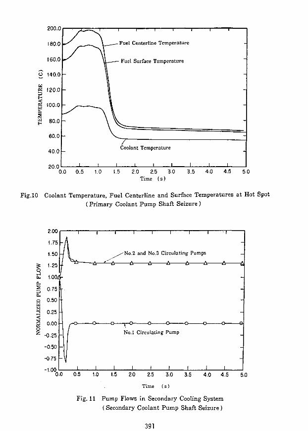
Fuel Centerline Temperature
Fuel Surface Temperature
Coolant Temperature
0.0 0.5 t.5 2.0 2.5 3.0Time (s)
3.5 4.0 4.5 5.0
Fig.10 Coolant Temperature, Fuel Centerline and Surface Temperatures at Hot Spot(Primary Coolant Pump Shaft Seizure)
T I I 1 I 1 I I
-No.2 and No.3 Circulating Pumps
No.l Circulating Pump
I I1.5 2.0 2.5 3.0
Time (s)
3.5 4.0 4.5 5.0
Fig. 11 Pump Flows in Secondary Cooling System(Secondary Coolant Pump Shaft Seizure)
391

6000.0
5000.0
40C0-0 -
3000.0 -
o£ 2000.0
1000.0 -
0.0
? Q
| |
1Coolant
1
1 1 1
Normalnzed Reactor Powers
JJ * "
^Normalized Heat
Flow in Secondary
I 1
Removal
Cooling
1 I
1 1 1
System
1 1
1.2<o
- 1.0
s0.6 Q
z
- 0.6
ciO
0.4 o•<
c0.2 N
0.0 O0.0 150.0 300.0 450.0 600.0 750.0 900.0 1050.0 1200.0 1350.0 1500.0
Time ( s )
Fig. 12 Coolant Flow in Secondary Cooling System, Normalized Reactor Powerand Heat Removal
(Secondary Coolant Pump Shaft Seizure)
200.0
180.0£=
160.0Q=
o140.0
120.0
I 100.0
80.0
60,0
40.0 I I
i i i i i r
Fuel Centerline Temperature at Hot Spot
Fuel Surface Temperature at Hot Spot
Coolant Temperature at Hot SpotX x
I I J_ I I I I
-A-
0.0 160.0 300.0 450.0 600.0 750.0 900.0 1050.0 1200-0 1350.0 1500.0
Time (s}
Fig. 13 Coolant, Fuel Centerline and Surface Temperatures at Hot Spot( Secondary Coolant Pump Shaft Seizure )
392
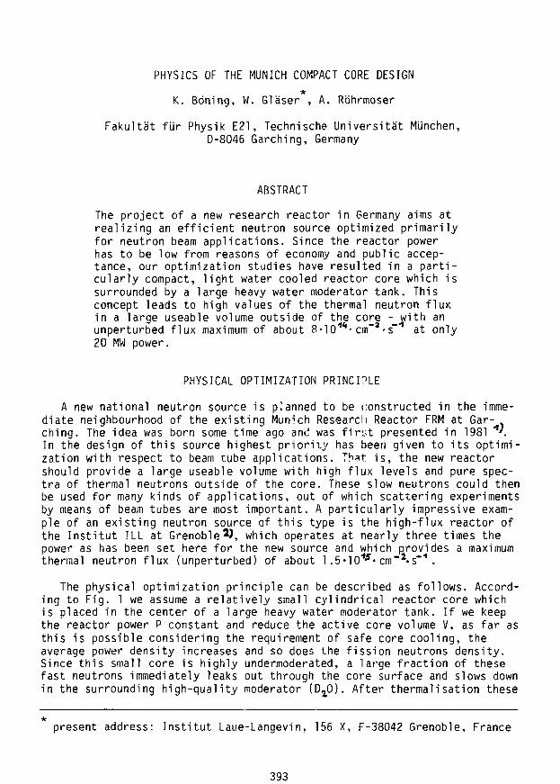
PHYSICS OF THE MUNICH COMPACT CORE DESIGN*
K. Boning, W. Glaser , A. Rbhrmoser
Fakultat fur Physik E21, Technische Universitat MUnchen,D-8046 Garching, Germany
ABSTRACT
The project of a new research reactor in Germany aims atrealizing an efficient neutron source optimized primarilyfor neutron beam applications. Since the reactor powerhas to be low from reasons of economy and public accep-tance, our optimization studies have resulted in a parti-cularly compact, light water cooled reactor core which issurrounded by a large heavy water moderator tank. Thisconcept leads to high values of the thermal neutron fluxin a large useable volume outside of the core - with anunperturbed flux maximum of about 8-10""1- cnf^s""1 at only20 MW power.
PHYSICAL OPTIMIZATION PRINCIPLE
A new national neutron source is planned to be constructed in the imme-diate neighbourhood of the existing Munich Research Reactor FRM at Gar-ching. The idea was born some time ago and was first presented in 1981 *'.In the design of this source highest priority has been given to its optimi-zation with respect to beam tube applications. That is, the new reactorshould provide a large useable volume with high flux levels and pure spec-tra of thermal neutrons outside of the core. These slow neutrons could thenbe used for many kinds of applications, out of which scattering experimentsby means of beam tubes are most important. A particularly impressive exam-ple of an existing neutron source of this type is the high-flux reactor ofthe Institut ILL at Grenoble 2J, which operates at nearly three times thepower as has been set here for the new source and which provides a maximumthermal neutron flux (unperturbed) of about 1.5-10"*J- cm"2-s~'1 .
The physical optimization principle can be described as follows. Accord-ing to Fig. 1 we assume a relatively small cylindrical reactor core whichis placed in the center of a large heavy water moderator tank. If we keepthe reactor power P constant and reduce the active core volume V, as far asthis is possible considering the requirement of safe core cooling, theaverage power density increases and so does the fission neutrons density.Since this small core is highly undermoderated, a large fraction of thesefast neutrons immediately leaks out through the core surface and slows downin the surrounding high-quality moderator (Dz0). After thermalisation these
*present address: Institut Laue-Langevin, 156 X, F-38042 Grenoble, France
393

Fig. 1 Schematic view of a typical "inverse flux trap" research reac-tor (vertical cut at left, horizontal cut at right). The cylin-drical core is shown in full black. In the heavy water (D^O)moderator tank the position of the thermal flux maximum ty^f* isindicated but the beam tubes and other experimental or reaclorinstallations were left out.
neutrons lead to the high thermal flux ($.„, and a very pure thermal spectrumin a large useable moderator volume as is required for their experimentalutilization ("inverse flux trap", see Fig. 1). In this way the ratio ofthermal flux in the region of the beam tube noses to reactor power assumesa high value, which means that a high flux level can be realized at lowpower.
Important contributions to this behaviour arise from the fact, that theeffective neutron slowing-down volume in the Dz0 moderator decreases and- additionally - the probability of neutrons diffusing back into the coredecreases also when the core dimensions are reduced. This follows just fromsimple geometrical reasons- On the other hand, the choice of a smaller re-actor core leads to problems such as a low multiplication factor or shortreactor cycle, a high power density, the requirement of fuel with high U235density, etc.. These and other aspects will be further discussed in thenext section.
The physical arguments just given can easily be checked and confirmed bynumerical calculations. In the unperturbed case of Fig. 1, i.e. withoutconsideration of the experimental installations in the moderator tank, thewhole arrangement has cylindrical symmetry (R,Z) whence 2-dimensional cal-culations allow a very realistic study of the core behaviour. As an exampleFig. 2 shows in a comparison of those calculations that heavy water D^O isthe best material for our purpose since it provides both a large volume ofhigh thermal flux and a large multiplication factor - as compared to theother moderator materials beryllium, graphite and light water Ha0.
394

o D20 (k = 1.224}
o Graphite (k = 1.178)
Beryllium (k = 1.283)
40 60 80
RAD I US fcml100 120
Fig. 2 Radial cut in the core mid-plane (Z = 0) through the whole core-moderator-arrangement for different materials of the moderatoroutside of the core as indicated. The thermal neutron flux §+tl at20 MW power is plotted and the values of the effective multipli-cation factor k are given for all the 4 cases considered. The coreis always the same as discussed later in this paper (KKE7, butwith constant uranium density and without boron absorber ring),compare Fig. 4, with the central control rod in its out-of-coreposition and the beryllium reflector inside of the core.
395

In another series of calculations the inner and outer radii of cores withotherwise identical geometry were varied in a way as to keep the activecore volume constant. These calculations again clearly yielded the highestthermal flux maximum ^iT* f° r the smallest core. On the other hand somecycle-days are being lost in this case, because the reactivity at begin oflife is somewhat smaller for the smaller core than for a core with a largerinner diameter. To compensate for this effect one could abandon the crite-rion of identical core volume; that means that the outer diameter of thesmaller cores could be expanded until the same cycle length would be ob-tained for the different cores. The results then are without strongly sig-nificant differences. If the inner core diameter is increased in this wayfrom 6.5 cm to 9.0 cm the neutron flux maximum would be obtained to belower by about 4 %. The integral heating of the water in the hot flux lineresulted to be identical at the begin of the cycle for the two cases consi-dered here, which both guarantee the same cycle lenght as just discussed 3i
COMPACT CORE
The new high-flux research reactor which shall be optimized primarilyfor beam-tube experiments is being designed in Germany by a group at theTechnical University of Munich. Since the reactor power has to be low fromreasons of economy and public acceptance, its value has been fixed to P =20 MW only. So the goal was to develop a particularly "efficient" neutronsource. As a result, our studies have led to a particularly compact, lightwater cooled reactor core in a large heavy water moderator tank. The con-cept also has to provide a relatively long reactor cycle length of about 50full power days, which was mostly an economical but also an experimentalrequirement. Fig. 3 shows the latest design of the compact core (version"KKE7"). The high enriched fuel (93 %) is contained in 113 involute-shapedplates with 0.60 mm meat thickness and 0.38 mm Al cladding on both sides.The active core volume of V = 17.6 liter is defined by inner and outerradii of 67.5 and 112.0 mm, respectively, and by 700 mm of height; it con-tains a total of 7.54 kg U235. Allowing for additional fuel-free zones witha radial span of 5 mm on both sides of the plates and for a thickness ofthe inner and outer Al core tubes of 6 and 7 mm, respectively, the radialdimensions of the complete core are 59.0 and 121.5 mm as indicated in Fig.3. In the axial direction the fuel-free plate extensions are 15 mm wideon either end. As a consequence of the involutes the H^O cooling channelsbetween the plates have constant thickness, in this case 2.2 mm.
If we assume for simplicity that the reactor power P will be fully de-posited in the active core volume V the average power density comes out tobe P/V = 1.15 MW/liter; this value is of the same order as that of the HFRGrenoble or of the HFIR Oak Ridge. Flattening of the power density profileover the volume of the compact core will be achieved by two means. First,the density of the uranium in the new tlgS^/Al dispersion fuel will be ra-dially graded into two zones: 3.0 g/cm3 up to a radius of 105.6 mm and 1.5g/cm3 otherwise. That means that the U density will be significantly re-duced in the outer core region where the thermal flux is particularly highbecause of the neutrons diffusing back from the Da0 tank. This discontinu-ous method to flatten the radial power density profile is considered to bebetter reproducible and more economical than grading the fuel continuouslywhich would otherwise be superior.
396

control'rod
tuel plate
cooling channel
KKE 7
Fig. 3 Horizontal cut through the compact core (version KKE7) placedwithin the core channel tube which separates the Hz0 region(inside) from the Da0 region (outside). The central control rodis in its out-of-core position, i.e. shown in this figure isthe beryllium follower with its Al cladding.
The second means to flatten the power and fission density profiles re-fers to the axial direction. Here it is a ring of burnable poison, i.e. ofan Al-cladded B/Al cermet with preliminary dimensions of 3 mm thickness andabout 50 mm height, which is inserted into the outer core tube immediatelybelow the lower end of the fuel plates. Initially this ring contains about10 g of boron in its natural isotope composition. This solution is a verysimple way to reduce the power density, especially at the axial core end,where a narrow peak is generated by the light water in the core channeltube. The alternative way of putting the poison into all the fuel plateswould be more expensive 4'.
Fig. 4 gives a schematic vertical cut through the central region of thereactor5'. Shown are the plates (not the tubes) of the compact core and theboron ring B. The core channel tube CCT separates the Ha0 primary coolantfrom the DjO moderator regions (the full,dimensions of the Da0 tank areboth 2.5 m diameter and height). The reactor will be controlled by acentral control rod CR, which according to the present design status is acylinder of natural hafnium with 56 mm outer radius, 2.5 mm thickness and820 mm height. Additionally there will be 5 or 6 safety absorber rods which
397

can be shot into the Da0 tank in case of emergency but which are fullywithdrawn during regular reactor operation. The Hf cylinder of the centralcontrol rod is filled with aluminium (Al) and followed by a central reflec-tor of beryllium (Be), the height of which is 900 mm.
CRl\\\\v| H2°
CCT
Eo
M
t
0
Fig. 4 Vertical cut through the whole arrangement. One can see the compactcore KKE7 (only the fuel plates of which are shown here) with theboron ring B. The core channel tube CCT separates the HjO coolantfrom the Dj.0 moderator. The control rod CR is shown in its positionat the begin of the cycle (begin of life BOD, with its Al fillerand Be follower. The contour lines represent the thermal neutronflux in units of lO*"1- cm"3- s"1 at 20 MW power.
398

n-FLUX HOEHE= .00 cm
D Be + 2 mm A1 (k = 1.200)
o D~0 + 5 mm AT (k = 1.190)
H20 1.0 g/cmJ (k = 1.123)
H-0 0.5 g/cnT (k = 1.169)
0.1 g/cnT (K = 1.128)
15 20
RADIUS
Fig. 5 Radial cut in the core midplane (Z = 0) through the whole core-moderator-arrangement for different materials of the reflector in-side of the core as indicated. The thermal neutron flux $+k at 2nMW power is plotted and the values of the effective multiplicationfactor k are given for all the cases considered. The core is thecompact core KKE7 as in Fig. 3 with the moderator outside of thecore being always D^O. The inner reflectors beryllium and heavy wa-ter are discussed inside an alu-bottle of 2 mm respectively 5 mm,and the case of light water is shown for 3 different densities.
399

As already mentioned in the first section, a particular problem of such acompact reactor core lies in achieving a value of the multiplication factorbeing large enough to allow a sufficiently long reactor cycle. So it isessential that the new high-density uranium-silizide fuel will be used withhigh enrichment in order to provide a sufficient U235-loading of the core.Further, core cooling by light water H20 - instead of Da0 - is not only ve-ry attractive from operational and economical reasons, but is also necess-ary from physical arguments: the enhanced slowing-down strength of Ha0 in-creases the in-core part of neutron moderation and so the multiplicationfactor (nevertheless the compact core is still highly undermoderated). Inthe central core channel below the control rod light water would not repre-sent a good choice of a reflector material, since both beryllium and Da0give rise to a longer reactor cycle. This is illustrated in Fig. 5. One canalso see that the multiplication factor k shows a complicated behaviour ifthe Hx0 density decreases in the central core channel, which comes from thevariation in the balance of the neutron slowing down and absorption ratesin H20. So the void coefficient of the light water inner reflector would beinitially (down to a water density of about 0.4 g/cm3) positive incontrast to the void coefficient of the (undermoderated) core itself whichis always strongly negative. From these reasons the light water in the cen-tral core channel has been replaced by the beryllium reflector which is de-signed as a follower of the control rod.
Numerical neutron diffusion and transport calculations have been per-formed for the compact core reactor 3\ In the unperturbed case, i.e. with-out consideration of the experimental and reactor installations in the Da0tank, and once the homogenized results of the fuel lattice cell calcula-tions have been obtained, this is a problem of purely 2-dimensional geo-metry (R,Z). For the hypothetical case of the control rod being fully with-drawn from the core (i.e. if its lower end would be at Z = 45 cm in Fig. 4)the calculations yield a value of the multiplication factor of k = 1.192for the fresh core at operating temperatures; this value would have beenlarger by 1.0 % without the boron ring. The position Z = - 9.8 cm of thecontrol rod as shown in Fig. 4 corresponds to the situation at the beginn-ing of the cycle, however with k kept at a fixed value about 4 % higherthan the critical value of 1.0 . This is to compensate the reactivityreducing effect of the D,,0 tank installations and also of some otherdetails which have not been considered in these calculations. Contour linesof the thermal flux 0+<% at 20 MW have been obtained for this situation;they are also plotted in Fig. 5 and show how the neutrons concentrate inthat part of the core which is not directly affected by the control rodabsorber and that a maximum thermal flux of about $"** = 8-10""1- arT^-s"1
piles up in the Dx0 moderator. At the end of the reactor cycle - whichcomes out to be about 50 full power days - the control rod will be with-drawn from the core and the position of ^H."*"^^ De more or ^ess exactlyon the core midplane (Z = 0).
Fig. 6 shows the local power density in the compact core at 20 MW as afunction of the axial coordinate Z. The various curves refer to differentradii as specified. The distinct power density maxima at both axial ends (Z= +_ 35 cm) are a consequence of the strong reflector peak of the thermalflUx in the Hjp (compare Fig. 4). Due to the high thermalisation strengthof Ha0 this reflector peak is steeper and closer to the fuel zone as in thecase of Dj_O. This effect would be particularly distinct at the beginning ofthe cycle (BOL) as shown in Fig. 6 when the thermal flux is highly asymmet-
400

ric in Z because of the control rod. However, it is exactly for this situa-tion that the boron ring has its strongest effect and - indeed - the powerdensity maximum at the lower core edge (which would otherwise be of theorder of 3.5 MW/liter) has been reduced to about 2.5 MW/liter. At the endof the reactor cycle the BIO absorber in the boron ring has practicallydisappeared ('burnt', remaining concentration about 7 %) and the controlrod is withdrawn from the core; the power density curves are nearly symme-tric in Z, then, their maximum being reduced to about 2.3 MW/liter and si-tuated on the upper core edge, now. Finally, the two uppermost power den-sity curves in Fig. 6 belong to the hot channels of the two core regions
position of:B-ring control
11,045 cm10.394 cm
at radius R8,9 cm7,9 cm
0-40 -30 -20 -10 0
Fig.Z ( c m )
6 Axial dependence of the local power density in the compact core KKE7at 20 MW power. The various curves refer to different radii as spe-cified. The position of the control rod is again that at the beginof the cycle (BOD; it is indicated on the top of the figure to-gether with the axial position of the boron ring B (compare Fig. 4).
401

with different U density in the meat - apparently these two curves are vir-tually identical which demonstrates that the radial fuel grading is veryeffective and has been properly adjusted. During the reactor cycle thecurve belonging to the largest radius decreases faster than the other onesince the fuel burnup is stronger in the outer core region. At the end ofthe cycle the local maximum of the fission density in the meat amounts to1.85 • 10 1 1 fissions/cm3.
The primary cooling water will be flowing downwards through the corefrom technical reasons (core support and handling, etc.). There are inprinciple two possible directions to move the control rod during the reac-tor cycle. The first one would be to move it downwards, i.e. in the direc-tion of the flow of the cooling water. This would be a good choice with re-spect to the begin of the cycle where most of the reactor power is producedin the upper half of the core where the cooling water has both a lower tem-perature and a higher pressure to improve the cooling conditions. However,the axial asymmetry of the power-density distribution is not very distinctat the begin of the cycle as a consequence of the flattening effect of theboron ring (Fig. 6). Further, at the end of the cycle the power densityprofile becomes rather symmetric, as has already been mentioned. So it isalso possible - as far as core cooling is concerned - to move the controlrod upwards, i.e. opposite to the directions of both the flow of the coo-ling water and the force of gravitiy. It is this latter solution which hasbeen adopted now since it is considered to be strongly superior with re-spect to reactor safety. That means, even in the hypothetical case of a me-chanical break of the control rod drive the absorber will be quickly forceddown in its shut-down position by the combined action of the flowing waterand of gravity.
The large dimensions of the Da0 moderator tank of both 2.5 m diameterand height (as at the HFR Grenoble) are essentially a consequence of therequirement to provide sufficient volume for the installation of the ex-perimental (and some reactor) facilities. Of main interest in this contextis, of course, a large useable volume with high thermal flux values as de-fined in the first section of this paper. Additionally, however, there aremany applications where high thermal flux levels do not represent the es-sential requirement as compared to, e.g., the details of the neutron spec-trum or the possibility to irradiate large or strongly absorbing samples.Applications of this kind can be performed in the outer regions of the Da0tank - with only negligible influence on the neutronics of the core.
Final remark: the planned compact core reactor will be characterized byan unperturbed maximum thermal flux of about 8-10'1* cm"x-s"1 outside of thecore at only 20 MW power - and by a flux to power ratio which is higherthan at any existing reactor.
ACKNOWLEDGEMENTS
This work was supported by the German Bundesministerium fur Forschungund Technologie BMFT.
402

REFERENCES
1. K. BONING, W. GLASER, J. MEIER, "Vorschlag einer Modernisierung desForschungsreaktors Munchen FRM", Internal Report of the Physik-Depart-ment der Technischen Universitat Mlinchen, Munich (1981)
2. K. SCHARMER, H.G. ECKERT, "FOEHN - Das kritische Experiment fur denDeutsch-Franzosischen HochfluBreaktor", Report of the Kernforschungs-zentrum Karlsruhe, KFK 1064 (1971)
3. A. RO'HRMOSER, Ph. D. Thesis at the Technical University of Munich (inpreparation)
4. L.BUTH, M. KUCHLE, "Das Brennelement des HFR-Grenobie mit Festbor inden Rohren statt in den Platten", Internal Report of the Kernfor-schungszentrum Karlsruhe (1978)
5. K. BONING, W. GLASER, J. MEIER, G. RAU, A. ROHRMOSER und L. ZHANG,"Status of the Design of the Munich Compact Core with Involute-ShapedFuel Plates, in Proc. Int. Meeting on Reduced Enrichment for Researchand Test Reactors (RERTR), Gatiinburg, Tenn., USA, Nov.1986, publishedas an ANL-Report
403

SOME OBSERVATIONS REGARDING RESEARCH REACTOR COMPARISONSTO THE SPERT TRANSIENT EXPERIMENTS
W. L. WoodruffArgonne National Laboratory
Argonne, Illinois 60439 USA
ABSTRACT
The SPERT I experiments have been used in the SafetyAnalysis Reports of many research reactors to define safetylimits on the maximum reactivity insertion. Comparisons forselected reactor cores show that transient parameters arequite sensitive to flow channel thickness, reactor size, andthe pressure or coolant depth over the core. For example,higher operating pressures can in fact contribute to higherpeak clad temperatures. Comparison of current HEU reactordesigns with low power and large flow channels and proposedLEU designs show that the LEU designs will provide largersafety margins for reactivity insertions because of a highervoid/density feedback and the addition of Doppler feedback.
INTRODUCTION
In the late 1950s and early 1960s, a wide range of reactivity insertiontransients were carried out in the SPERT I series of cores-'- includingdestructive tests in the D-12/25 core.2 Since these cores were similar indesign to many of the light water cooled and moderated, MTR type, researchreactors, the results of these experiments have been used in the Safety AnalysisReports (SARs) of many research reactors to define safety limits for reactivityinsertion or maximum excess reactivity. These experimental data have also beenused to evaluate various analytical^ and computational^ methods for the analysesof reactor transients.
The PARET code^ is capable of computing results that givr good agreementwith the SPERT I tests. The code provides a me'ans of comparing some types ofresearch reactors with "similar" SPERT cores.
The International Atomic Energy Agency (IAEA) 10MW benchmark core4 isrepresentative of a large class of research reactors, and the clad meltingthreshold predicted by the PARET code has been found to compare favorably withthat predicted by the D-12/25 tests.3 The benchmark, core is also compared withthe B-24/32 SPERT core, which has a similar geometry.
A number of low power research reactor designs have fuel elements withonly ten plates and rather large channel spacing. These reactors are most
404

similar to the D-12/25 core with twelve plates per element, but there aresignificant differences. Comparisons are provided which show the impact of someof these differences.
RESULTS AND DISCUSSION
The current version of the PAKET code has been used to generate all ofthe results shown here. A $1.50 step insertion has been used as a convenienttransient for comparison.
Two examples of research reactors are compared with the SPERT I D-12/25and B-24/32 cores: 1) A small research reactor with 10 fuel plates in eachstandard element, referred to as RR10, and 2) The IAEA benchmark reactor with 23plate standard elements. All of the reactors have Highly Enriched Uranium (HEU)fuel. RR10 represents an extreme case with a small core and a large channelthickness, while the IAEA benchmark reactor is more typical. Some of thegeometric and kinetics characteristics are shown in Table I.
Table I. A Comparison of SPERT I, RR10, and Benchmark Properties
Reactor
SPERT D-12/25SPERT B-24/32RR10, HEUBenchmark
NeutronReactor Gen. Time, us
SPERT D-12/25 60.0SPERT B-24/32 50.0RR10, HEU 60.9Benchmark 56.0
TotalNo. ofPlates
270768169551
Beta Eff.
0.00700.00700.00780.0076
CoolantChannel,
0.4550.1650.6580.223
Density/voidCoef., $/% void
0.42140.35710.27100.2992
cm
Coolant Temp.Coef.,
2.2.0.1.
$/K*100
801527732646
The D-12/25 core has larger coolant channels and fewer plates than theB-24/32 core, but the D-12/25 core also has larger feedback coefficients. TheRR10 core has an even larger channel spacing and even fewer plates than theD-12/25, while the feedback coefficients for both voiding and coolant tempera-ture are considerably smaller. The void/density coefficient is about 2/3 ofthe D-12/25 value, and the temperature coefficient is only about 1/4 of thatof the D-12/25 core. The other kinetics parameters for the prompt neutrongeneration time and beta effective are also somewhat larger and result in alarger inverse period, alpha, for the same reactivity insertion (see Table II).
405

Table II. Results withife*.50 Step Insertion of Reactivity
Reactor P, MW E t m, MWs Alpha, s"1 Ttm, °C Peak T, °C
D-12/25RR10D-12/25*D-12/25**
225219258286
4.943.875.145.16
65.874.265.875.6
238267247248
325496366356
*Using feedback coefficients from RR10 in SPERT D-12/25 core.**Using feedback coefficients, beta effective and neutron generationtime from RR10.
The RR10 with the HEU fuel does not behave like the _D-12/25 SPERT coreunder similar transient conditions, as shown for a $1.50 step reactivityinsertion in Table II. While the peak power (P) and the energy deposited to thetime of peak power (Et ) a,re similar, the clad temperature at the time of
peak power (Tj-m) and the peak clad temperature (Peak T) are substantially
higher for the RR10.
Kinetics Parameter Differences
Table II also shows the use of RR10 kinetics parameters with the SPERT ID-12/25 core. The smaller feedback coefficients in D-12/25* increases the peaktemperature from 325°C to 366°C, but power and energy have also increased withthese changes. The D-12/25 case with matching alpha shows a slight decreasein the peak clad temperature. The modified D-12/25 cases still have no filmboiling and thus good heat transfer from the clad, while the RR10 hassignificant film boiling over the course of the transient and poor heattransfer. The feedback for the RR10 and the D-12/25 cores is substantiallydifferent even with the same parameters imposed.
The feedback for the RR10 and the D-12/25 reactors is compared atapproximately the same energy deposition in Table III. Both the voiding andtemperature feedback are substantially lower in the RR10. The voiding feedbackis still high in the last case even with the lower coefficient from the RR10.Clearly other differences are contributing to these results.
Core and Channel Size Differences
While the differences are not independent and difficult to evaluate, anattempt has been made to isolate the sources of the differences noted. Thepower in the RR10 HEU case is distributed over far fewer plates, and withlarger channel spacing the same voiding is a smaller percentage of the volume.These differences would contribute to a higher clad temperature, and if thetemperature is high enough to initiate film boiling, the poor heat transfer canproduce even higher clad temperatures.
406

Table III. Feedback and Energy Deposition Comparison
Reactor E, MWs
D-12/25 3.82RR10 3.78
D-12/25 5.49RR10 5.61
D-12/25 6.12RR10 6.15
D-12/25* 6.13 304 / 168 2.185 / 0.039
PeakCh. 1 /
184261
268396
312449
T, °C' Ch. 2
/ 123/ 168
/ 152/ 238
/ 158/ 259
FeedbackVoidincr /
0.099 i0.337 j
1.762 /1.004 /
2.454 /0.921 /
' Temo.. S
1 0.072' 0.026
' 0.134' 0.038
' 0.210' 0.064
*Using feedback coefficients, beta effective and neutron generation time(kinetics parameters) from RR10.
The SPERT I D-12/25 core with the RR10 kinetics parameters is used here asa reference case. The total number of plates in D-12/25 can be reduced from theoriginal 270 toward the 169 in the RR10 as shown in Table IV with the channelspacing held constant. This could be taken as a reduction in the number of fuelelements in the core, but no effort has been made to make the numbersnecessarily correspond to any physically realizable cases. Also the loading inthe cases ; ith fewer plates would have to increase to preserve reactivity, andthis in turn would result in changes in the conductivity and volumetric heatcapacity of the fuel meat. These changes have not been included but should beof only minor importance. The kinetics parameters would also change with coresize but have been held constant. In the last two cases in Table IV, thechannel spacing is increased to match the RR10 value.
The cases with fewer and fewer plates result in the clad and coolantheating up faster, more feedback, and a lower peak power and energy depositionto time of peak power. The power and energy deposition in the fuel, however,are just proportional to the number of plates in the core (172/270 * 286 MW =182 MW vs 181 MW shown in table). Thus, the clad temperatures are about thesame for all cases. The film boiling finally reached in the 172 plate case israther modest and the energy stored in the fuel is still low. The threshold forfilm boiling has been reached. The RR10 results exhibit a significant degree offilm boiling as noted earlier.
Increasing the channel spacing has more influence on the clad temperatureas shown in Table IV. This Increase in coolant volume reduces the feedback andallows the power following the peak to remain higher, and a higher cladtemperature is reached. Table V compares the 172 plate model with and withoutthe increased channel spacing over the course of the transient. The peak cladtemperatures reached still do not compare with the RR10 case shown in Table II,and other differences must be found.
407

Table IV. Performance Variation with Number of Elements (Plates)
D-12/25 Case
270 Plates235200180175172
175*172*
P(P/Plate), MW
286 (1.06)249 (1.06)211 (1.06)191 (1.06)185 (1.06)181 (1.06)
196 (1.12)192 (1.12)
Peak T,
360360360360360360
400400
°C Boiling
TransitionTransitionTransitionTransitionTransition
Film
FilmFilm
*Channel spacing increased from 0.455 cm to 0.658 cm matching RR10.
Table V. Effects of Increasing the Channel Spacing in D-12/25
172 Plate Data: With Channel Increase / Without Increase
t, s
0.2850.2900.2950.3000.3010.3020.3040.3060.3080.3100.3150.3200.3250.330
P,
76.8 /105 /143 /184 /191 /192 /171 /133 /99.6 /74.4 /38.9 /22. 3 /14.3 /9.8 /
MW
75.910314017718117914498.963.941.616.48.04.83.8
E,
1.201.652.263.083.273.463.834.144.374.544.814.965.055.11
MWs
11111111111111
1.191.632.243.043.223.403.723.974.124.234.364.424.454.47
Tc,
113142173231245260291319342360388401400398
T
1111I111111I11
°c
112141172230244259288313331343358358350348
Void/Dens.Feedback
0.0043 ,0.0066 ,0.0177 j0.1785 y0.2540 >0.5393 j1.2536 i1.5527 ;1.6075 /1.5462 /1.4156 /1.2244 )1.2172 /1.2206 /
1 01 0' 0' 0' 0' 0' 1' 2' 2' 2' 1' 1' 1• o
, $
.0054
.0084
.0228
.2320
.3570
.7848
.6925
.1169
.1094
.1255
.8420
.5803
.4027
.8818
408

Operating Pressure Differences
Other differences such as the direct heating source to the coolant, platewidth, inlet coolant flow rate, and fuel conductivity were considered but werenot found to be significant contributors. The difference noted in the operatingpressure of 113.3 kPa for SPERT and 169.6 kPa for RR10 (deeper pool) was foundto be significant. Table VI shows the effect of changing only the operatingpressure in the initial D-12/25 core to that of the RR10 core. The peak cladtemperature increases by 62°C. The peak power and energy deposition alsoincrease.
Table VI. Effects of Increasing Operating Pressure in D-12/25
Press, kPa P, MW Et_, MWs Ttrn, °C Peak T, °C
110.0
120.0
130.0
140.0
150.0
160.0
170.0
224
229
234
239
243
247
248
4.90
5.04
5.19
5.29
5.43
5.55
5.59
236
243
250
254
261
266
268
321
337
347
354
363
373
383
While a higher operating pressure gives a larger margin to the onset anddeparture from nucleate boiling, the dynamics of the reactivity insertiontransient and the benefits of surface boiling to heat transfer and feedback mustalso be considered. By increasing the pressure in the SPERT model, boiling(voiding) is suppressed and the lower feedback results in an increase in theclad temperature. Also, heat transfer in single phase is generally lower thantwo phase (until film boiling is reached), and this contributes to a higher cladtemperature.
The cumulative effects of changing the SPERT I D-12/25 core parameters tothe values for the RR10 HEU core are summarized in Table VII. The third throughfifth cases all have 172 plates rather than the 169 in the RR10. A peak cladtemperature was not reached in the case with increased operating pressure. Witha reduction to 169 plates this case would more nearly agree with the RR10results. The two cases still have differences in the axial distributions andpeaking factors that contribute to some of the differences observed. Thepeaking factor for the SPERT core is 1.83 compared to a value of 1.65 for theRR10 core. The importance of operating pressure on the void/density feedback tothe transient behavior of the reactor has been clearly demonstrated.
409

Table VII. Cumulative Effects of RR10 Values in SPERT D-12/25
Case P, MW E t . MWs Ttrn, °C Peak T, °C
Ref. (270 Plates)Kinetics Parms.& 172 Plates& Ch. Increase& Press. IncreaseRR10, HEU
225
286
181192
225
219
4.94
5.163.27
3.41
3.99
3.87
238
248
248255
297
267
325
356
3604 02
547+*
496
Peak temperature not reached in this case.
Differences with LEU Fuel
The proposed LEU conversion fuel for the RR10 class of reactors has an 18plate standard element and a much smaller channel spacing than the HEU case.The characteristics of the two cores are shown in Table VIII. The density/voidcoefficient is larger for the LEU case, but the coolant temperature coefficientis lower. The most important difference is the significant Doppler coefficientin the LEU fuel. The results of a $1.50 step insertion are also compared inTable VIII. The peak clad temperature is much lower for the LEU core and morecomparable to the SPERT values at a similar pressure. The HEU SPERT cores,however, should not be used for comparison in the LEU cases.
Table VIII. RR10 with Proposed LEU Fuel
Fuel
LEU
HEU
Plates/
Standard
Element
18
10
Total
No. of
Plates
301
169
Coolant
Channel, cm
0.316
0.658
NeutronGen. Time.
50.5
60.9
0
0
BetaEff.
.00787
.00785
Feedback Coefficients
LEUHEU
LEU
HEU
Density/VoidCoef.. $/%
0.2991
0.2710
P, MW
234219
Coolant Temp. Coef.$/K*100
0.245
0.732
Transient Results
Etm' m s Ttm< °C
4.52 2573.87 267
Doppler Coef.$/K*100
0.186
0.0
Peak T, °C
358496
410

Benchmark Comparison
As shown in Table I, the channel spacing for the benchmark core is some-what larger than the B-24/32 SPERT core, while the core size (number of plates)is smaller. The feedback coefficients for the benchmark are smaller than eitherof the SPERT cores considered here. The operating pressure for the benchmarkcore is 170 kPa as in the RR10 case and higher than that in the SPERT cores.The benchmark core has forced flow.
Again a $1.50 step insertion is used with the benchmark core, and theresults are compared with both SPERT cores in Table IX. Although the benchmarkcore would appear to be more similar to the B-24/32 core, the result areconsiderably different. The agreement is more favorable for the D-12/25 core,and as noted earlier the threshold for clad melting in the benchmark agrees verywell with the results from the D-12/25 tests.
Both SPERT cores predict a higher clad temperature than that computed forthe benchmark core, and the case where the pressure is reduced to match that ofthe SPERT cores gives even lower values. At least in these cases a SPERTcomparison would be conservative.
The benchmark core with LEU fuel has been shown-^ to give a peak cladtemperature that is 45°C lower than the HEU case. The threshold for cladmelting was predicted to be $2.35 for HEU and $2.80 for LEU in the benchmarkcore and $2.30 for the D-12/25 SPERT core (in excellent agreement with theexperimental results). Another study-* has predicted a step of $3.7 as thethreshold for clad melting in the B-24/32 core and values in excess of $3 formost of the other cores in the SPERT I series. These values, however, disagreewith the D-12/25 and benchmark results. The other cores in the SPERT series,did not include destructive tests. Thus, experimental data in this range is notavailable for direct comparisons.
Table IX. Benchmark Core Comparison with SPERT Cores
Reactor
D-12/25B-24/32BenchmarkBenchmark*
P, MW
225576342308
Et , MWs
4.9411.86.615.82
Ttm' C
238215204179
Peak T, UC
325301271242
Clad Melting Threshold, $
D-12/25 2.30Benchmark, HEU 2.35Benchmark, LEU 2.80
Operating pressure reduced from 170 kPa to 113.3 kPa.
411
CONCLUSIONS
Based on these results, a somewhat atypical 10 plate/element RR10 HEU coreshows significant differences when compared to the SPERT I D-12/25 core; thedifferences observed appear to be the result of an accumulation of differencesin feedback, reactor size, channel spacing, and operating pressure. In the HEUcores the void/density feedback is the most important component. Thevoid/density coefficient is less important in the LEU case because Dopplerfeedback plays a significant role. The proposed LEU fuel also has a moretypical channel spacing and number of plates per element. Thus, the LEU fuelhas a much lower peak clad temperature than the HEU case.
With the IAEA benchmark core, though more typical, the transient resultsstill do not compare well with the SPERT I cores. The peak clad temperature forboth SPERT cores is higher than that for the benchmark core. In earlier workthe PARET code was found to give good agreement with the SPERT I tests includingthe prediction for clad melting in the D-12/25 core for a $2.30 step insertion.A slightly higher clad melting threshold of $2.35 for the benchmark core isconsistent with the peak clad temperature estimates. Estimates by others of inexcess of $3 for the B-24/32 and other SPERT I cores would seem to be out ofline with these findings. Again the LEU fueled core requires a largerreactivity insertion to initiate melting than the HEU case.
Some differences between research reactors and the SPERT I cores that atfirst may seem unimportant can contribute to some substantial differences in thetransient behavior. The strong influence of the operating pressure on thetransient response is one such example. These differences do not alwayscontribute to a conservative safety margin when comparison are made to the SPERTcores. Most research reactors have set very conservative reactivity insertionlimits that are well below limits reported for any of the SPERT I tests. Sincethe SPERT I series did not include LEU cores, the results cannot be used fordirect comparison to the LEU conversion cores. The conversion to LEU fuel inmost cases leads to larger safety margins, but some additional analysis may beuseful.
ACKNOWLEDGEMENTS
This author is very grateful to Mr. K. E. Freese of ANL for hiscontributions to the computation of kinetics parameters for this work and toDr. J. E. Matos for his many helpful discussions.
412

REFERENCES
1. S. G. Forbes, et al., "Analysis of Self-shutdown Behavior in theSPERT I Reactor," IDO-16528, Idaho National Engineering Laboratory(1959).
2. A. H. Spano and R. W. Miller, "SPERT I Destructive Test Program SafetyAnalysis Report," IDO-16790, Idaho National Engineering Laboratory(1962).
3. W. L. Woodruff, "A Kinetics and Thermal-hydraulics Capability for theAnalysis of Research Reactors," Nucl. Tech., 6±, 196-206 (1983).
4. "Research Reactor Core Conversion from the Use of Highly EnrichedUranium to the Use of Low Enrichment Uranium Fuels Guidebook,"IAEA-TECDOC-233, International Atomic Energy Agency (1980).
5. Reactor Physics Constants, ANL-5800 (Second Edition), ArgonneNational Laboratory (1963).
413

414

SESSION VIII
September 21, 1988
TARGETS
Chairman:
J . Matos(ANL, USA)
415
PRODUCTION CYCLE OF FISSION MOLYBDENUM-99
Sameh A. Ali and H. J. AcheNuclear Research Center Karlsruhe
Institute of Radiochemistry7500 Karlsruhe, P. O. Box 36 40, D - 7500 Karlsruhe, FRG
ABSTRACT
Technetium-99m for human organ function tests has to fulfill high qualitystandards such as nuclear purity, maximal specific activity and radionuclidconcentration. This can be only realized by using technetium, generated fromfission molybdenum-99 separated from irradiated shortly cooled nuclear fueltargets. The actual world-wide used uranium targets with U-235-enrichments ofabout 90 - 93 % has to be reduced under 20 % due to nonproliferation aspects.Expected handicaps such as higher irradiation and waste treatment costs,resulting from the enrichment depth can be overcome by replacing the actualused UAIx-targets by U3Si2-silicides keeping the same target dimensions by usinglow enriched uranium. Due to the alkaline digestion behavior of uran-silicideremarkable modifications in the existing production processes are needed.Basing on first experiences with unirradiated U3Si2-targets of MTR-type expectedchanges in the Kf K-production cycle presented will be discussed.
INTRODUCTION
The most frequently used radioisotope in medical organ function tests istechnetium-99-m. The chemical versatility of the pertechnetate anion, the y-decay energy and the half-life of Tc-99m allow optimum conditions for itsapplication in clinical diagnostics. Due to its short half-life the delivery of thisisotop all over the country is not possible at a reasonable price. This shortcomingwas effectively eliminated by introduction of the generator technique, aprocedure long practiced in radiochemistry, according to which the longer-livedparent nuclide is absorbed on a chemically and radiation resistant matrix. Thecontinuously produced daughter nuclide is eluted with a suitable solution. Theparent nuclide of Tc-99 is molybdenum-99. Because of its half-life of 66 hours,the mentioned concept can be realized [1]. The advantages offered by Tc-99mcan be fully utilized only if highest chemical purity, specific activity andconcentration can be ensured. This requirement can be met only if it is fulfilledby the parent nuclide, molybdenum-99, too. Solely fission molybdenum attainsthe by far highest specific activities. It is obtained by processing of irradiated andshortly cooled U-235 containing targets. Many process variants published [2 - 9]reflect the growing interest in its practical application.
417

The most commonly used targets are rather small fuel elements of the typeused in material testing reactors. They are processed after irradiation withthermal neutrons and short periods of cooling down. In order to achieve thehighest possible product yields, targets enriched to approximately 90 - 93 %U-235 are used. The steadily growing demands for fission nuclides in nuclearmedical applications is accompanied by a corresponding increase in the amountsof highly enriched uranium which must be handled. The wider dissemination ofthis sensitive material inevitably resulting from the growing demands constitutesan ever increasing serious problem. The substitution of highly enriched uraniumby fuels of less than 20 % enrichment is steadily aimed and has been successful inmodifying reactor core loads. It was possible to compensate the lowerenrichment levels by using silicide containing fuel elements of high fuel densityand to avoid in this way losses in neutron flows. Considerations to the effect thatthese positive experiences could be transferred to the similar irradiation targetsemployed in Mo-99 production meet with the refusal by the producers ofradioisotopes. Their arguments are being backed by experience accumulated sofar in the chemical treatment of the irradiated elements. Uranium silicide targetshave shown to react at much slower rates compared to the presently usedaluminides, both in the process of digestion with alkali hydroxide solutions andin the course of direct dissolution in nitric acid. Abandoning the silicides andretaining the aluminides despite their low levels of enrichment - on account ofthe greater amounts of targets then needed - would imply major drawbacks interms of the costs of irradiation, transport and waste treatment. Consideringthese aspects, the KfK Radiochemistry Institute (IRCH) adapted under aTechnology Transfer Program the process of fission product molybdenumseparation developed at the Institute to the application of silicide targets. Thisprocess will be described together with the integrated nuclear fuel recycling andthe target fabrication. Modifications of the flowsheet expected from the use ofsilicide targets will be explained.
Molybdenum separation
The targets consist of an aluminium cladded uranium/aluminium alloy of theapproximate composition UAI3; since the aluminium content in the compound isvariable, the term UAIX is mostly used. To achieve the highest possible fissionproduct yields uranium enriched to 90 - 93 % is used. The individual plates areirradiated jointly in one rig exposed to thermal neutron fluxes of approximately5 x 1013 -1 x 10"14 n/scm2 for five to ten days with forced cooling. Figure 1 showsa picture of the fuel element plates in the irradiation holder.
418

Fig. 1. Fuel element targets in the aluminium irradiation holder. Thedimensions of the plates are: 220 mm in length, 40 mm in width and 1.3 mm inthickness. The dimension of the fuel meat inside is 200 mm in length, 300 mm inwidth and 0.5 mm in thickness.
Fig. 2. a-tight transportation-and connection system
419

To minimize decay losses of the desired nuclide the targets are transportedto the processing plant after a minimum decay period of about twelve hours.Figure 2 shows the a-tight transportation- and connection system. The firstchemical step normally consists in the alkaline digestion of the target using 3 -6M NaOH respectively KOH. After a minimum decay period of about twelve hours,a simplified scheme of the complete Mo-99 production process including thesubsequent recycling of nuclear fuel, developed at KfK, is snowed in Figure 3.
Fig. 3. Scheme of the complete Mo-99-production including fuel recyclingand target fabrication. I
During the alkaline digestion the main constituents of the plate aredissolved namely aluminium and the fission products soluble in this medium suchas alkaline and alkaline earth cations as well as antimony, iodine, tellurium, tin,and molybdenum. The volatile fission products with Xenon-133 as the maincarrier of activity leave the dissolver at its upper end passing through a refluxcondenser together with the hydrogen generated in the digestion process anddriven by a nitrogen stream. The hydrogen is oxidized to H2O via CuO at 350 -400°C and the resulting water condensed. Xenon is collected together withnitrogen in preevacuated stainless steel tanks and later on carried to the xenondelay section (D. S.) passing deep bed carbon filters. To guarantee a safe,leakage-free process all equipment used in this extremely hot part of the processare made of stainless steel. Figure 4 shows a picture of the digestion equipment[10] and the first Mo-purification column.
420

Fig. 4. Stainless steel digestion equipment in operation in the hot cell.
The aikaline solution containing molybdenum passes through a column ofthe strong basic exchanger AG 1 x 8, 50 - 100 mesh. Molybdenum is quantita-tively adsorbed on the exchanger together with a significant part of fissionproducts. Cationic impurities as caesium, strontium, and barium pass through thecolumn together with hydroxaluminate, tellurit and iodine anions. Afterwashing the column with fodium hydroxide molybdenum and the main part ofthe accompanying fission products are eluted with 1 - 1.5 M sulfuric acid andsubsequently with a solution of 0.5 M ammonium hydroxide and 1 M sodiumsulfate. This solution is transferred to the Mo-purification cell. Figure 5 shows apicture of this installation part.
421

Fig. 5. Fission molybdenum purification cell used in Karlsruhe.
The process solution is subsequently treated with solutions of ammoniumthiocyanide, potassium iodide, sodium sulphite and finally acidified withsulphuric acid up to 1 1.5- 2.0 M H2SO4. Underthese conditions the molybdenumwill be reduced and forms an extremely stable anionic [Mo(SCN)6]3-complexwith the thiocyanide ions. From this medium molybdenum can be retainedquantitatively on ion exchangers with functional nitrilodiacetate groups such aschelex-100 [11]. In Figure 6 the distribution coefficients of molybdenum onchelex-100 in thiocyanate, sulphite and HCI respectively H2SO4 containingsolutions are shown.
422

C7>O
Fig. 6. Distribution coefficients of molybdenum thiocyanate complex as afunction of the acid concentration on Chelex-100 50-100 mesh.
It should be mentioned that under these conditions all fission productswhich accompany the molybdenum have distribution coefficients of approxima-tely 1 on chelex-100 that means, in one column a decontamination factor ofabout 105 can be practically gained.
In the following step the column is subsequently washed with thiocyanidecontaining sulphuric acid, sulphuric acid and water. The molybdenum elutionfrom the column is carried out with 1 M NaOH. To guarantee a product ofhighest purity the procedure is repeated on a second smaller chelex-100 column.The described process is schematically presented in Figure 7. The eluate of thesecond column will be acidified with the calculated amount of nitric acid toadjust a pH-value of the solution between 1.8 - 3.5.
423

Alkoline Dissolver Solulion f6M No OH 1Mo. (Ru.Zr( . I",!O3', It, SoAlkali. Alkaline Earth. At
AG-I Anlon Exchanger
Retained; Mo. Ru. Zr. I *
Alkaline WasteTe.Al.Alkali,IO3'Akaline Earth,So
Repeat
Acidic Wasle
Ru.Zr, ! '
Eluatt:M o , R u . Zr, I "
IT
Chelex-100 Icn ExchangerRetained: M o " [SCN) 6
3 .
Eluent:1)1.5M H2SOc2I0.SM H2SOt
I.5M NajSOi
Add:
NH4(SCN)Na2 SO3K I
Etuenl:
IM NaOH
XEluate:
Fig. 7. Flowsheet of the fission molybdenum separation process.
To avoid retention of corrosion products from the metal equipment on theAI2O3 column the solution has to pass first a cation exchange AG 50 x 8 100 - 200mesh column before it enters a chromatographic column filled with aluminiumoxide. The Al2O3-column is useful to purify molybdenum from nonvolatilesodium salts and from possible traces of contamination. After washing thecolumn with 0.01 M HNO3 and finally with water, the molybdenum is eluted with1 M ammonium hydroxide and transferred to the sublimation cell. The molybde-num solution is evaporated in a stainless steel apparatus and afterwards placedinto a platinum crucible. The residue is evaporated on an electric hot plate andthe crucible with the completely dried residue slowly heated up to about 700°Cin a quartz glass apparatus inside a resistance furnace. At this temperature allorganic impurities possibly introduced from the ion exchangers into the productare removed. The last process is the sublimation of the molybdenum oxide. Thesublimation is started after a quartz glass condensation device is placed over thequartz vessel in the furnace and the temperature increased to about 1150°C. Themolybdenum volatilization is finished in about 30 minutes. In the upper parts ofthe quartz device the moiybdenum trioxide is deposited. After removal of thecrucible the oxide is dissolved with ammonia vapour. The molybdenum solutionis mixed with sodium hydroxide and ammonia is removed by boiling. Thesolution obtained in that way represents the final product. The flowsheet of thisprocess part is shown in Figure 8.
424

Eluate:
Ha,MoOv
Eluent:
H,0
r MNOj
pH2
t
Cation Eichanger
Retained: Corrosion products
BreaMhrouah:
MoO,1'
( T tAI}0^ Column
Retained Traces TeO,!". Mo O,1'
Eluent.
1 M NH, OH
W a s t e - 1 " • • ;
i- r— i1 Eluaff.
Evaporation
Sublimation at 1000"C
1T
MoOj
| .NHUOH
INH^MoO.
11
Product
!M NaOH
Fig. 8. Flowsheet of the purification procedure on cation exchanger/aluminium oxide system and the MoO3-sublimation.
The sublimation step is an integral part of most Mo-separation processesbecause it guarantees that the product is not contaminated by organicimpurities. The disadvantage of this procedure: It is labor intensive in operationand time consuming since the evaporation of the Mo-containing solution has tobe carried out very carefully to prevent overboiling. These aspects initiated aresearch program to simplify the volatilization process. The basic idea was to finda suitable adsorber-matrix, which is able to retain the molybdenum quantita-tively from aqueous solutions and which permits a thermal desorption of themolybdenum(VI) oxide by applying hightemperatures[12].
425

The mentioned aim succeeded and an efficient system basing on the Mo-adsorption on SnO2 and the subsequent thermal desorption of molybdenumoxide in a H2O-stream containing oxygen, was developed [13]. The total yieldwas found to be better than 97 % and the process time was reduced to one hour.
Recycling of the nuclear fuel
The insoluble residue contains about 99 % of the initially irradiated uraniumin the form of uranium dioxide and alkaline diuranate together with theinsoluble fission product species, above all ruthenium, zirconium and thelanthanides. Under aspects of economy and safety the nuclear fuel must berecycled, targeted and reirradiated. To minimize the investment costs for fueland installation protection the amount of enriched U-235 has to be as low aspossible with the consequence tnat the fuel cooling times will not be longer thanfew weeks. In this case the digestion residues still contaminated in Ci-scale with1-131 and Xe-133 kept in some undissolved uranium/aluminium alloy particles,under these conditions the other wise proven dissolution in nitric acid followedby the Purex Process [14 - 16] cannot be recommended. The drawback of usingHNO3 in hot installations filtered by activated carbon is fire risk caused by Noxgenerated during the dissolution. Charcoal is by far the most effective materialfor Xenon delay at room temperature and it shows an excellent iodine retentionbehavior in combination with practical advantages such as adequate resistanceto wear and economic efficiency. The described difficulties were successfullyavoided by dissolving the uranium dioxide and diuranate residues in HCO3-/CO3--medium and chromatographic decontamination of the fuel solution by passingthrough exchanger columns.
The presented process is based on the formation of soluble negativ chargeduranyltricarbonato-complexes. Figure 9 shows the uranium solubility as afunction of the carbonate molarity.
426

gU/1
Fig. 9. Solubility of uranium in carbonat media as a function of the CO3-concentration.
The decontamination of the fuel solution is carried out on radiation resistentinorganic adsorbers. Several commercial available exchangers, mainlymetaloxides, were found out to realize efficient purification of the uraniumsolutions [17]. Figure 10 shows the highest distribution coefficients of cesium,cerium, strontium and zirconium on their individual best adsorbers as a functionof the HCO3-/CO3-- ratio in batch experiments.
427

a
o
3-
Sr/MnO2
Cs/AHCCF
Ce/MnO2
Zr/MnO2
Sr/Al2O3 s.
955
9010
7030
6040
4060
1090
595
NQ2CO3
N Q H C O 3
Fig. 10. Distribution coefficients of Cs on AHCCF = (NH4)2 [CoFe(CN)6], Ce, Sr,Zr on MnO2 and Sr on AI2O3 in different HCO3/CO3- ratios total carbonatemolarity.
The adsorption behavior of the mentioned exchangers for fission productspermits suitable separation possibilities from solutions containing highcarbonate concentrations. Following dynamic experiments with differentstationary phases demonstrated their efficiency. The table includes thedetermined breakthrough in percent of Ce, Cs, Ru, Sb, Sr and Zr on columns ofAHCCF = (NH4)2 [CoFe(CN)6], acidic AI2O3, MnO2 and SnC>2 by passing fissionproduct tracers dissolved in 1 M HCO3-/CO3- solutions. The loaded columns werewashed subsequently with hydrogencarbonate/carbonateof thesame molarity.
428

Table
Fiss.Prod.
AI2O3AHCCFMnO2SnO2
loading sol.washing sol.total carbonatcone.HCO3-/CO3--
Ce
10098
10095
= 10 ml= 15 ml
= 1.0 M= 2 :1
Cs
60100
70
Ru
9431826
column:diameterbed volume
Cond. rate
Sb
380
1000
II II
n
Sr
—1
—>
1
00
0o
oo
o
9,7 mm5,5 ml
0,84 m • n-1
Zr
010010063
• cm-2
The percentage data underline the efficiency of inorganic exchangers forfission product separation in carbonat systems. Only ruthenium is not completelyretained on the named adsorbers. The best Ru-decontamination was carried outon AI2O3 columns. The detailed breakthrough behavior of Ru on AI2O3, ( N H ^CoFe(CN)6, MnC>2 and SnO2 columns during the loading and washing steps isplotted in Figure 11.
BI X )
4 5 6 7 8 9 1 0 1 2 3 4 5 6 7 8 9 » n 12 13 J4 15 mlLoading -\ Washing - ^
Fig. 11. Breakthrough curves of Ru-carbonat species on columns of[CoFe(CN)6], acidic AI2O3, MnO2 and SnO2.
Experimental conditions similar to the Table
429

Further experiments were carried out to study the influence of higheruranium concentrations on the retention behavior of the mentioned exchangers.They showed significant increases of the adsorption behavior for the relevantfission products. Particularly remarkable was the increase of cerium andzirconium retention on MnO2- The dynamic breakthrough of cerium on MnC>2-columns in uranium free and 35 g uranium per liter containing HCO3-/CO3—solutions are plotted in Figure 12. The comparable data for zirconium areshowed in Figure 13.
20 40 60 80 100 20-Loading
40 60 80 100 ml
—Washing
Fig. 12. Breakthrough in % of Ce by loading on MnC>2-columns fromuranium containing and uranium free HCO3-/CO3--solutions.
Total HCO3-/CO3--molarity:Adsorber:Adsorber amount:Column dimensions:
Loading solution:Washing solution:
g9,7 mm 075 mm length100 ml50 ml
430

100
80-
60-
40-
60 80 100 20
20 i
Zr + U-A C
T 1 1 1 1 r
60 80 100 ml
Washing
Fig. 13. Breakthrough in % of Zr by loading on MnO2-columnsfrom uraniumcontaining and uranium free HCO3-/CO3--solutions.
Total HCO3VCO3- molarity:Adsorber:Adsorber amount:Column dimensions:
Loading solution:Washing solution:
1MnO25g9,7 mm 075 mm length100 ml50 ml
The plotted data in both figures demonstrate the high efficiency of MnO2-columns for the fuel decontamination in carbonate media. The presence ofuranium leads to significant increase of the retention capacity for the mentionednuclides. The most probable explanation of this effect is that by the formation ofuranyltricarbonatocomplexesthe excess of free HCO3/CO3 --ions is reduced. Thisminimizes the formation of negativ charged fission product spezies of highcarbonate coordination which are not retained properly. The decontaminatedfuel solution is passed through a column of the intermediate basic exchangerBio-Rex 5 [18, 19]. Uranium is retained quantitative by loading degrees below250 g / kg exchanger.
431

After subsequently washing of the stationary phase with ~ 0.1 Mhydrogencarbonate/carbonate solution and water, uranium is eluted with 4 Mnitric acid. The final fuel purification is carried out on tributyl phosphate loadedorganic stationary phases [20, 21]. The eluted uranium is precipitated asdiuranate in ammonia. The dried ammoniumdiuranate is converted to U3O8,subsequently to UF4 and finally to U3Si2- The powdered alloy is used for theproduction of target material by MTR-technique.
l ' targets and expected process modifications
Alkaline digestion experiments in 3 -10 M sodium- and potassium hydroxidesolutions with unirradiated uranium silicide targets showed extremely lowsolubility of the alloy. Corresponding to this behavior low molybdenum yieldshave to be expected. Sufficientincrease of the fission Mo-yields can only beobtained by a following dissolution step. Two processes appear practical:
The oxidation with hydrogen peroxide in basic mediaDissolution of the alloy in 3 M HNO3 and precipitation of the uranium andfission products with NaOH.
Actually the acid dissolution is favoured. The molybden containing streamwill be combined with the other part separated from the alkaline digestion andretained on a cationic adsorber. The adjusted eluate will be loaded on the Chelexcolumn and the process can be continued as presented in the flow sheet.
REFERENCES
1. W. D. Tucker, M. W. Greene, A. P. Murrenhoff, Atompraxis8(i962) 163.
2. L.G.Stang (Coordinator): BNL 864 (T-347) (1964).
3. P. Richards: USAEC, 323(1966).
4. C. L Ottinger: ORNL, 34 (1970).
5. Y. Kawakami: Isotope News 6 (1977).
6. W. Heyne:lsotopenpraxis 10(13)0977)343.
7. C. K. Sivaramakrishnan, A. V. Jadhav, K. Raghuraman, S. Raman, P. S. Nair,M. U. Ramanish: BARC-847(1976).
8. H. Arino, H. H. Kramer: Int. J. Appl. Radiat. Isot. 29 (1978) 97.
9. O. Hladik, G. Bernhardt, W. Boessert, R. Munze, Tech. Comm. Meetingorganized by IAEA, Karlsruhe (1987).
432

10. Sameh A. Ali, K. Sauermann: German Patent PS 2306 592 (1981)
11. Sameh A. Ali, J. Knapp, J. Reinhardt: German Patents: PS 2610 948 (1979),PS 2758 783 (1980), US Patent: PS 4044953 (1978).
12. J. Biirck, Sameh A. Ali, H. J. Ache: KfK-3754 (1984).
13. J. Burck: KfK-4095 (1986).
14. R. G.Wymer, B. L. Vondra,CRC Press (1981).
15. T. V. Healy, H. A. C. McKay, Trans. Faraday Soc, 52,633, (1959).
16. K. Alcock, G. F. Best, E. Hesford, H. A. C. McKay, J. Inorg. Nucl. Chem., 6,(1958), 328.
17. Sameh A. Ali, U. Berndt, W. Rottmann, W. Leifeld, U. Kaminski, Int. Conf."RECOD '87", Paris, Vol. 1, 451 -458.
18. J. Haag: KfK-3460 (1983).
19. Sameh A. Ali, J. Haag: German Patent: PS 3144974.
20. R. Kroebel, A. Maier, Int. Solv. Extr. Conf. Lyon 3JL (1974) 2095.
21. H. Eschrich, W. Ochsenfeld, Sep. Science and Technology 15, (1980). 697
433

PROCESSING OF LOW-BURNUP LEU SUICIDE TARGETS
Jane D. Kwok, George F. Vandegrift, and James E. MatosArgonne National Laboratory
9700 South Cass AvenueArgonne, Illinois 60439
ABSTRACT
Currently much of the world's supply of 99mTc formedical purposes is produced from "Mo derived from thefissioning of high enriched uranium (HEU). Substitution oflow enriched uranium (LEU) silicide fuel for the HEU alloyand aluminide fuels used in current target designs willallow equivalent " M o yields with no change in targetgeometries. In these studies, targets were irradiated tolow burnup (10"^%) to produce fission products and 239j|p a tconcentrations conveniently measured by gamma spectroscopy.
Processing was done by dissolution of LEU targets inacid or base followed by alumina column recovery of °°Mo.Acid dissolution is more rapid, but precipitation of silicaresults in loss of ^^Mo. Dissolution of U3Si2~Al targets inbase requires more processing steps than the current processfor UA1X-A1 fuel. A two-step process of first dissolvingthe 6061A1 cladding and fuel meat aluminum, and thendissolving the U3S12 fuel particles, has the advantage ofeliminating the aluminum from further processing. Loss of9^Mo during the aluminum dissolution is attributed to recoilof 9^Mo o ut of th e silicide particles during irradiation. Alarger particle size would decrease this 9^Mo i o s s.
INTRODUCTION
Technetium-99m for medical purposes is a decay product of 9%o, whichis produced in nuclear reactors from the fissioning of 235u o r frOm neutroncapture in 98Mo. This continuing effort is related only to fission-product99
The purpose of this study is to assess the feasibility of substitutingLEU for HEU in targets for production of fission-product 9%o. Switchingfrom HEU (93% 2 3 5U) to LEU (<20% 2 3 5U) while maintaining 99Mo yields andtarget geometries requires a denser fuel. Uranium silicide dispersedin aluminum (U3Si2-Al) with a uranium density of 4.8 g/cm3 is currently thefuel of choice. Its approval by the NRC for use as a reactor fuel alsomakes it attractive as a 99Mo target fuel.*
*Work supported by the U.S. Department of Energy, SST Program underContract W-31-109-Eng-38.
434

In this study, targets of U3Si2 and U metal were irradiated andchemically processed by either an acidic or basic dissolution. Nuclidebehaviors could then be monitored throughout the processing. Aluminacolumn separation of molybdenum was done after dissolution of theirradiated targets. Alumina column runs were also preformed with tracer99Mo only.
The current process for basic dissolution involves dissolving theentire target in Na0H/N03 solution.2 During the dissolution, uranium andvarious fission products precipitate as hydrated hydroxide salts. Thismixture is diluted and filtered, and the solution is acidified forpurification of the molybdenum on an alumina column. The dissolution ofU3Si2 is extremely slow with NaOH/N03 solution alone, so the currentprocess must be modified. As suggested in an earlier progress report, thedissolution can be done in two steps.3 The first step dissolves the 6061A1cladding and the aluminum matrix in a 3M NaOH solution, leaving behind theU3Si2 particles. The high density of the U3Si2 (12 g/cm
3) allows the basicaluminum-containing solution and the precipitated hydroxide/salt componentsof the aluminum alloy cladding to be decanted easily from the silicideparticles. The u"3Si2 can then be dissolved separately in Na0H/H202-Uranium stays in solution as a peroxo complex until the peroxide isdestroyed. Once the uranium has precipitated, the process is the same asthat currently in use.
The acidic dissolution of UA1X is done with nitric acid in thepresence of Hg^+ as a catalyst.^ Once the target is dissolved, the pH isadjusted for the alumina column procedure. The biggest difference inswitching to U3S12 is the precipitation of the silicates during acidicdissolution. Researchers at the Atomic Energy of Canada, Ltd., report thatthis finely divided precipitate tends to plug the alumina column, as wellas adsorb ^^Mo. Irradiation of the silicide tended to make the particleseven finer and the problem worse.^
EXPERIMENTAL
Irraoiation
Targets were irradiated in the 180 kW JANUS reactor at ANL for80 minutes at 1/4 power. This low burnup, which produc ,d approximately0.9 mCi of 99Mo an<i 3 mci of 239Np, was chosen so that the nuclideactivities would be high enough to be measured by gamma spectroscopy butlow enough for processing in an unshielded hood. Targets were eitherone-quarter of a U3Si2 miniplate or uranium metal foil (0.2-mm thick,4.5 g) wrapped in aluminum foil. They were electron-beam welded undervacuum into an 1100A1 capsule, which was then placed in a secondary 1100A1container for introduction into the reactor.
Basic Dissolution
The sample was digested in 3M NaOH to dissolve the 6061A1 cladding andthe aluminum of the fuel matrix (henceforth referred to as the aluminumfraction). The aluminum fraction, including its hydroxide precipitates,
435

was removed, leaving the dense fuel particles. The fuel was dissolved byadding 20 mL aliquots of 1.5M Na0H/15%H202 and heating, pouring offsolution before each addition. After destruction of the peroxide throughheating, the hydroxides (including uranium) were separated from thesolution by centrifugation.
The supernate from the uranium hydroxide precipitation was acidifiedwith HNO3 to a pH of 0.32 for loading onto the alumina column. The aluminacolumn procedure for the irradiated samples was the same as that for the"Mo-only samples, except that the columns were not thermostated.Molybdenum was eluted with concentrated NH4OH.
Acidic Dissolution
The acidic dissolution began with the sample being placed into asolution of 3M HNO3 plus Hg(NO3>2 as a catalyst. This resulted in a fairlyviolent reaction that soon subsided. Concentrated HNO3 was added tosustain the reaction rate. The dissolution solution was gravity filteredto remove the precipitate (mostly silicates). The solution pH was adjustedupward with NaOH solution for loading onto the alumina column. Molybdenumwas eluted with 1M NH4OH instead of concentrated NH4OH.
Dissolution of U Metal
The uranium metal foil, wrapped in aluminum, was cut in two. Onepiece was treated by the acidic dissolution procedure. This dissolutionwas fast, and the resulting solution was taken through the alumina columnprocedure.
The second piece of uranium metal was combined with all of thealuminum foil and heated with 3M NaOH. This solution was decanted, and theuranium metal was dissolved in 1.5M NaOH/15% H2O2. This dissolution wasvery slow. At its completion, the remaining peroxide was destroyed byheating. The hydroxides were centrifuged, and the solution pH adjusted forloading onto the alumina column.
Alumina Column Procedure
For the 59iy]o_oniy experiments, a 2.7 Curie 99mTc generator from DuPont
NEN was used as a source of "Mo.
A circulating bath was connected to a water jacket enclosing a 0.9 cmdiameter column for temperature control at 25 or 50°C. The column had twoadjustable syringes: one on top to avoid solvent mixing above the alumina,and one on the bottom to support the alumina. The column bottom wasconnected to a peristaltic pump and finally to a sample collector.
Alumina (3.0 g) was washed three times with water. The column wasprepared and preconditioned with the appropriate molarity of nitric acid,depending on the loading solution. Either a 99M O spiked HNO3 solution or a
436

dissolved target solution of pH 0.32 was then loaded onto the alumina.Flow rates were 1.2 mL/min unless specified otherwise. After loading, thecolumn was washed ^Ith 25 mL of the appropriate nitric acid solutionfollowed by 50 mL of water. Then the column was washed with 25 mL of 0.01MNH4OH and eluted with either 1M or concentrated NH4OH. For the run at50°C, the eluting temperature had to be lowered to 25°C to avoid boiling ofthe concentrated NH4OH.
Gamma Counting
Samples were counted on either a Packard Biogamma automatic gammacounting system using a Nal detector or on a germanium detector equippedwith an automatic sample changer and a Nuclear Data 66 multichannelanalyzer. For counting on the Nal detector, the Mo double peak at 739 and778 keV was used to avoid overlap with the Tc peak at 141 keV.
RESULTS AND DISCUSSION
Basic Dissolution
The foremost benefit for using basic digestion of irradiated uraniumtargets for "Mo production is the high degree of separation achieved.During target digestion, as ^ M o £S dissolved, it is purified from U, Np,Pu, and many of the fission products that have insoluble hydroxide salts.A second benefit is that radioxenon can be collected separately fromradioiodine (recovered during acidification). These benefits appear toremain when HEU aluminide is substituted by LEU silicide.
Chemical Partitioning
As expected from their chemistries, many radionuclides precipitateduring the basic dissolution as hydroxides (Fig. 1). Nuclides remaining insolution include Mo, Ru, Rh, Te, I, Cs, and (inexplicably) Ce. With theexception of Cs, some of each of these nuclides is associated with theprecipitate. This is probably due to their complex chemistry (Ru) oradsorption by the hydroxides (Mo).
Activation products of minor metals in the 6061A1 cladding (Zn, Ti,Mn, Mg, Fe, Cu, and Cr) were not observed in the target solutions. Theiractivities were calculated to be under background levels except for °^Cu,which was borderline. Activity from these nuclides should not be importantto the purity of the final " M o product.
Mo-99 Loss
From Fig. 2, we see that about 15% of the fission products (includingis lost during the first basic dissolution step to the aluminum
fraction. Four possible mechanisms for this loss are the following:
437

100
o•o"53
U(S
80-
8014 0 -
2 0 -
111II
I
ii J
Zr Nb Mo Ru Rh Te I Cs Ba La Ce Nd Eu Np
Nuclides
D Supernates0 Precipitates
Fig. 1. Distributionthe Two-Step
of Nuclides duringBasic Dissolution.
100
u3
Om
UJ
80-
60
40-
20-
• Fuel^3 Al fraction
Zr Nb Mo Ru Rh Te I Cs Ba Ce Nd Eu
Nuclides
Np
Fig,. 1,s Loss of Nuclides to Aluminum Fractionduring First Step of Basic Dissolution.
(1) recoil due to fission energy from the uranium silicide particles intothe aluminum matrix, (2) loss of U3Si2 fine particles due to carryoverduring transfer of the aluminum fraction away from the fuel, (3)dissolution of U3Si2 in NaOH-only solutions, and (4) dissolution of a"shall" of UA1X around the U3Si2 particles that is formed duringirradiation. Because these shells have only been seen at very highburnups (>30%), the fourth mechanism should not be important.
438

The 9S>Mo i o s s <jue to recoil can be calculated based on the particlesize distribution of the fuel, which relates to the total fuel surfacearea.5 The fission fragment range, or the distance a fission product willtravel, was estimated at 9.4 fim, the value for U 0 2 ^ This value isprobably an overestimate, since the value for U metal is 6.8 Jim.Calculated and experimental losses for 99M O and
239jjp a r e preSented inTable 1.
Table 1. Loss of 9 9 M O and 239Np to the
Aluminum Fraction during Dissolutionwith Sodium Hydroxide
% " M o LOSS % 239 Np Loss
Exp. Calc.a Exp. Calc.a
U3Si2 20 19 3 0
U metal 3.3 2.7-6.2b 0 0aUsing 9.A /im (value for UO2) for fission fragment range.°Range is an artifact of experimental procedure, not thecalculation itself.
Neptunium-239 is an activation product rather than a fission product;therefore, its calculated recoil loss is 0%. The experimental value forthe aluminum fraction but could also be due to dissolution of U3Si2-Because 239j$p does not recoil, its loss should also be a measure of theloss of U, 239pUj an<j other activation products. For the processing ofU metal, the experimental 239jjp i o s s w a s 0%, as expected. Because themetal was present as a foil, °9Mo loss due to carryover of fines would notoccur. The calculated 99Mo loss for the metal foil is smaller than thatfor the L'3Si2 particles because of its smaller surface area. Agreementwith experimental values in both cases is good.
With larger particles sizes, the loss of ^Mo during the two-stepbasic dissolution would decrease; less "Mo Would escape due to recoil,fewer fines would carry over to the aluminum fraction, and less U3Si2 woulddissolve.
Loss of "Mo during acidic dissolution is a result of silicateprecipitation. At our low target burnups, we saw 6% loss of the " M o ,likely due to its association with the silicates.
Alumina Columns
In column runs using "Mo tracer only, excellent recoveries wereobtained with the alumina columns (Table 2). There was no significanttemperature effect with loading at 50°C rather than 25°C. Loadingsolutions were either 0.5 or 1M HNO3, with the lower concentration beingpossibly better.3>4
439

Results for the alumina column separation of Mo after dissolution ofthe irradiated targets are shown in Figs. 3 and 4. These clearly show theadvantage of the initial basic hydroxide separation prior to the columnprocedure. The acidic dissolution final eluant had several nuclideseluting with 9 9Mo, including Rh, I, Te, Nd, and Eu. The basic dissolutioneluant contained only 131j ancj 99
Table 2. Experimental Conditions and Results fromAlumina-Column Experiments Using 99Mo Only.
Run
123A56
Temp.
(°C)
252525252550
Loading[HN03]
(M)
0.50.50.50.511
Flow RatemL/min
1.20.6711.21.21.2
FWHMb
(mL)
2.34.52.454
% 99Moin Effluent
0.120.0250.031_
0.89-
% Yield99Mo
144a
10410296108104
aHigh yield probably due to counting interference with 99mxc peak.^ width at half maximum.
CONCLUSIONS
There are several factors important to a decision on the best way toprocess U3S12. An acidic dissolution in HNO3 is amenable to a batchdissolver because concentrated HNO3 can be added to sustain the reactionrate. The acidic dissolution is faster, but silicates will precipitate andcause problems during the alumina column procedure.
Due to the rapid decline of the reaction rate of U3Si2 in NaOH/R^C^,this dissolution would be more appropriate to a continuous flow dissolver.Basic dissolution allows the separation of I and Xe radionuclides, avoidssilicate precipitation, and allows the initial separation from otherfission products, U, Np, and Pu. This would also reduce uranium losses. Atwo-step dissolution process, where the cladding and fuel matrix aluminumare dissolved first in NaOH and separated from the fuel dissolutionprocess, removes the bulk of the Al from further processing. This, inturn, reduces processing volumes and transuranic waste. This advantage issomewhat offset by the " M o i o s s during the first step of the dissolutionbut may be countered by increasing U3S12 particle size. No problems withthe alumina column procedure are anticipated with the basic dissolution.
Future work will be performed to test our finding of 9%o loss duringthe basic dissolution process and to set conditions for processing a full-burnup target under plant conditions.
440

o8?
80 •
60 •
40 •
20 •
0 -
,, • Rhx B I
B Te^ 0 Ndx H e .\ B
* C:
" E •
B Mo
IPi p^ra E
1^CJH
z
- r- ^
Loading Wash 1 Wash 2 Wash 3
Stages in Column Procedure
Elution
Fig. 3. Distribution of Nuclides from Alumina Column afterAcidic Dissolution. Loading onto column in0.5M HNO3. Wash 1 is 0.5M HNO3, Wash 2 is H20.Wash 3 is 0.01M NH4OH, Elution by 1M NH4OH.
Io3
U10111
100
80
60
40
20
m TC• HuE Im TaB Mo
0Fig. 4.
Loading Wash 1 Wash 2 Wash 3 Elution
Stages in Column Procedure
Distribution of Nuclides from Alumina Column afterBasic Dissolution. Loading onto column in 0.5M HNO3.Wash 1 is 0.5M HNO3, Wash 2 is H 20, Wash 3 is0.01M NH4OH, Elution by concentrated NH4OH.
441

REFERENCES
1. U.S. Nuclear Regulatory Conunision, "Safety Evaluation Report Relatedto the Evaluation of Low-enriched Uranium Silicide-Aluminum DispersionFuel for Use in Non-power Reactors," NUREG-1313 (July 1988).
2. J. Salac2, "Reprocessing of Irradiated Uranium 235 for the Productionof Mo-99, 1-131, Xe-133 Radioisotopes," Revue IRE Tijdschrift 9(3)(1985).
3. G. F. Vandegrift, J. D. Kwok, S. L. Marshall, D. R. Vissers, andJ. E. Matos, "Continuing Investigations for Technology Assessment of9 % o Production from LEU Targets," Proc. 1987 International Meeting onReduced Enrichment for Research and Test Reactors, in press.
4. K. A. Burrill and R. J. Harrison, "Report on Technical CommitteeMeeting on Fission Molybdenum for Medical Use," October 13-16, 1987,Nuclear Research Centre Karlsruhe, Federal Republic of Germany, to bepublished.
5. J. C. Wood, J. T. Foo, L. C. Berthiaume, L. N. Herbert, J. D. Schaeferand D. Hawley, "Reduced Enrichment Fuels for Canadian ResearchReactors—Fabrication and Performance," Proc. 1986 InternationalMeeting on Reduced Enrichment for Research and Test Reactors,ANL/RERTR/TM-9 CONF-861185 (1986).
6. C. E. Weber and H. H. Hirsch, "Dispersion-Type Fuel Elements," Proc.1955 Geneva Conf. on Peaceful Uses of Atomic Energy, Vol. 9, #P561.
442

CONTINUING INVESTIGATIONS ON ELECTROCHEMICAL PREPARATION OFLEU TARGETS FOR "Mo PRODUCTION
S. L. Marshall, L. Redey, D. R. Vissers, G. F. Vandegriftand J. E. Matos
Chemical Technology Division, Argonne National LaboratoryArgonne, IL 60439-4387, U.S.A.
ABSTRACT
Continuing investigations of uranium electrodeposition frommolten salts, as a possible method for the preparation of low-enriched uranium targets for "Mo production, are described.Potential-pulse plating has been applied with two electrolytes: (1)a UClj-LiCl-KCl mixture close to the eutectic composition and (2) 4w/o UF4 in LiCl-KCl-LiF ternary eutectic. The widest range ofoperating conditions is provided by the second electrolyte at 504°C.This electrolyte is economically attractive owing to its low uraniumcontent. Dendrite-free, well-bonded uranium films have also beenproduced with bipolar current-pulse plating on substrates. Currentdensities sufficient to plate 6-mil coatings in 8 hours have beenachieved without loss of coating uniformity or adhesion. Thisprocess was demonstrated on a cylindrical mock target that wasapproximately 1/3 the size of a commercial target.
INTRODUCTION
The substitution of low-enriched uranium (LEU) for the high-enricheduranium (HEU) presently used in cylindrical targets (design patented byArino et al.1-2) for "Mo production will probably require replacement of theuranium oxide film by uranium metal.
Electrodeposition of uranium from molten-salt mixtures consisting of 20w/o UC13 in LiCl-KCl eutectic, onto nickel and tantalum substrates, has beendescribed elsewhere.3-4 The reversible deposition kinetics of uranium resultsin a strong tendency towards formation of dendritic (irregular, tree-like)deposits. Dendrite formation must be avoided to generate coatings satisfyingthe surface uniformity standards required of targets for "Mo production.
Dendrites are usually formed under constant-potential or constant-currentplating conditions.3'4 A pulsed potential method involving application of apotential V7 for time T and a second potential, Vj = 0, for time rx was
443

examined. Faster deposition was achieved by increasing V2 and decreasing r,but only to the point where dendrite formation was avoided. Conditions foravoidance of dendrites were determined previously by a two-level factorialexperiment.4 For each value of T, these conditions imply a linear relationbetween r and V,'2*
The subject of this paper is the determination of "dendrite-free" platingconditions in electrolytes other than 20 w/o UCl3 in LiCl-KCl. Current-pulseplating is also discussed, and a successful plating demonstration of acommercial-type tubular uranium target for "Mo production is described.
EXPERIMENTAL
Electrolytes and Electrodes
To avoid the well-known deleterious effects of oxygen and moisture inmolten-salt electroplating,5-6 work was carried out in a glove box (VacuumAtmospheres Corp.) under helium, with oxygen and moisture content below 1 ppm.Depleted uranium was used throughout this work. Electrolytes were prepared asfollows:
(1) Reaction of 221.75 g KC1 (Alpha), 227.76 g LiCl-KCl eutectic, 182.80 gFeCl2, and 6.40 g LiCl (Anderson Physics Laboratory) with 228.78 g U metalproduced UC13:
2U + 3FeCl2 = 2UC13 + 3Fe (1)
The final composition of the electrolyte was UC13 11.8 m/o (42.1 w/o), LiCl30.8 m/o (13.5 w/o), KC1 (57.4 m/o). This is close to the ternary eutecticwith composition UC13 12.0 m/o (42.4 v/o), LiCl 29.5 m/o (12.8 m/o), KC158.5 m/o (44.8 w/o), and melting point 335°C.7
(2) Reaction of excess U metal with a 4.5 w/o solution of UF4 (supplied by theY-12 Plant of Oak Ridge National Laboratory) in a ternary eutectic withcomposition LiCl 56.0 m/o (43.3 w/o), KC1 40.5 m/o (55.1 w/o), and LiF 3.5 m/o(1.6 w/o) formed U3+ according to the reaction:
3U4+ + U = 4U3+ (2)
Uranium anodes in the form of rods or discs were used, with a stainlesssteel rod serving as a current collector. Potential-pulse plating experiments
444

were carried out on a nickel disc (area 0.178 cm2) cathode, described in Refs.3 and 4. Bipolar current-pulse plating experiments used cylindrical nickelcoupons with a total area of 7.74 cm2. A uranium rod served as the referenceelectrode. Electrical control of the cell in experiments with these small discand coupon electrodes was provided by a potentiostat and function generator(Princeton Applied Research, models 173 and 175).
Tubular Cathode Plating Assembly
For uranium electrodeposition experiments on a cathode resembling acommercial target, a two-electrode plating cell was developed. Electrolyte(1) was contained in a 1.5-in. i.d. alumina crucible, surrounded by astainless steel secondary crucible. The cathode (101 cm2 area) was made from5 in. length of nickel tubing, 1-in. i.d. and 1.25-in. o.d., with opposingexternal grooves cut in the walls to facilitate separation of the tube intotwo halves after the experiment, and examination of the electrodeposit.Nickel tubing, 1/8-in. i.d. and 1/4-in. o.d., welded to the upper rim of thecathode, served as the current collector and thermocouple gland.
A 5/16-in. dia uranium anode was positioned coaxially with the cathode(using a boron nitride insulator with center hole, lying on the bottom of thealumina crucible). The entire assembly, with the heat reflectors for thefurnace well, is shown in Fig. 1.
Iff
(a) (b)
Fig. 1. Photograph showing cell components (a) and assembledcell (b). The cell components in Fig. la are from left to light:cell hanger, steel crucible, A12O3 crucible, BN insulator, Ni tubecathode, heat shield unit, BN insulator sleeves, and a 5/16-in. diarod in front of the other components.
445

RESULTS AND DISCUSSION
Potential-Pulse Plating Experiments
To decrease plating times under pulsed-potential conditions, one canincrease the voltage pulse (V2) or decrease the time, rx, that the system isresting. However, those variables can be optimized only in a region wheredendrite formation is avoided.
Dendrite formation under pulsed potential control was assessed by visualestimation of the length, d (in mm), of the largest dendrite present afterapplication of the potential signal for 20 minutes. In Refs. 3 and 4, theconditions for which d = 0 were expressed by a linear relation between r andV2 for each T. In the present study, linearity was not assumed, and thedesired relation between r and V2 was determined for T = 1 ms. If theconditions of each experiment are represented as points with coordinates r andV2, the values of d define a surface above the r-V2 plane (Fig. 2). It isthen possible to determine the region in this plane where d = 0.
250
225
200
175
150
- 125
100
75
50 .
25
A = (1) Electrolyte 1, 509°CV = (2) Electrolyte 2, 455°CO = (3) Electrolyte 2, 5O4°C• = (4) Electrolyte 2, 558°C
Fig. 2. Boundaries of dendrite-free V2,R regions for (1) e lec-trolyte 1 at 509°C, (2) electrolyte 2 at 455°C, (3) electrolyte 2 at504°C, and (4) electrolyte 2 at 550°C. Regions above the curve aredendrite free; below the curves dendrites form.
446

Results are shown in Fig. 2 for electrolytes (1) and (2) at severaltemperatures. Dendrites are formed for (r. V2) values lying above t-he curveappropriate to the given conditions. For instance, at the point (10, 200),dendrites were formed in electrolyte (1) at 509°C (curve 1) but not inelectrolyte (2) at 504°C (curve 3). The largest dendrite-free region wasobserved with electrolyte (2) at 504°C (curve 3), and the smallest withelectrolyte (1) at 509°C (curve 1). Comparison of curves 2 and 3 shows thatelevation of the temperature from 455°C to 504°C in electrolyte (2) results inan enlargement of the range of accessible values of r and V2. Furtherimprovement does not, however, result from increasing the temperature to558°C, as shown by comparison of curves 3 and 4.
It may be concluded that the mixed chloride-fluoride electrolyte (2)provides a wider range of operating conditions than the all-chlorideelectrolyte (1). This result is also significant in demonstrating thesuccessful use of an electrolyte of lower uranium concentration and,consequently, lover cost.
Current-Pulse Plating Experiments
The potential-pulse technique mentioned in the preceding section was themost convenient method for screening pulse parameters for dendrite formation.Industrial electroplating is, however, commonly carried out under controlled-current conditions, since the extent of electrodeposition is more convenientlydetermined. Although the simple application of a constant cathodic current maybe used in most cases, periodically interrupted currents can produce platedcoatings of finer grain size and superior coherence.8
The technique used here involved alternate application of cathodiccurrent density ic for time tc and anodic current density ia for time ta. Thistechnique results in the removal of a fraction of the material depositedduring each cathodic pulse; the reciprocal of this fraction is given by
In terms of q, the ratio of pulse lengths R = tc/ta, and the average currentdensity <i>, values of ia and ic are given by
ia = <i> (1 + R)/(l + q) (4)
ic = <i> q(l + R)/R(l + q)
447

Uniformity of coverage was found to be favored by q values close to -1.For R = 2 and <i> = -7 mA-cm"2, the optimal ranges are -20 to -40 mA*cm"2 for
thus, q is between -1.3 and -1.5.ic and 30 to 40 mA* cm"2 for i
Experiments of this type in electrolyte (1) were preceded by a nucleationpulse of -1.0 A-cm"2 for 2 s, which was intended to ensure uniform coverage ofthe substrate with crystal nuclei. The coupon shown in Fig. 3 was plated with
= -74.9 mA*cm" 4.17 ms, ia = 107.0 mAconditions result in R = 2, <i> = -14.3 mA cm"2,
cm"2, and ta = 2.08 ms. Theseand q = -1.400. The values
of ic and tc correspond to the deposition of about a monolayer of uranium perplating pulse, of which 1/1.4 = 71.4% is removed in the following dissolutionpulse. Plating time in this case was 8 hours, so that the average thicknessis 6.9 mil. Relatively high deposition rates can, therefore, be achievedwithout adverse effects on the morphology or adhesion of the deposit.
Fig. 3. Uranium Plated Nickel Coupon.
Tubular Cathode Plating Experiment
Since uranium electrodepostion requires one ampere-minute per squarecentimeter per mil, 10 Ah is required for a 6-mil coating of the cathode. Theplating conditions of the coupon in Fig. 3 were used in electrolyte (1). Anucleation pulse was not used in this study because of the high currents(100 A) involved. After plating, the cathode was halved longitudinally,rinsed with deionized water, dried with methanol, and photographed (Fig. 4).
With small coupons, nucleation pulses generally improve the uniformity ofthe deposit, but their omission in this study did not seem to affect thequality of the deposit. Differences in the anode-cathode separation(respectively, 1/8 and 11/32 in.) and the current distribution probablyexerted more effect. With the exception of some dendrites, the quality of thedeposit in the tubular cathode configuration was as good or slightly betterthan that observed on the small coupons (see Fig. 4).
448

The dendrites are seen to be concentrated on the side opposite thecurrent collector. Heat conduction along this heavy-walled tub*3 cnnH hnvpcaused a temperature gradient, which, in turn, would have resulted inelectrolyte convection and uranium concentration gradients. Such an effectwould have been compounded by the radiative, rather than conductive, heatingof the crucible in the furnace well.
This experiment has demonstrated the simplicity and feasibility ofuranium electrodeposition as a method for LEU target production. Stillrequired are more detailed consideration of temperature- and current-distribution effects and optimization of current-pulse platingconditions. Further work, with the tubular cathodes will be carried out tooptimize the cell design and plating regime.
Fig. 4. Uranium Plated Tubular Cathode.
ACKNOWLEDGMENTS
This work was supported by the U.S. Department of Energy under contractNos. W-31-109-Eng-38 and DE-AC05-840R21400.
REFERENCES
1. H. Arino, H. H. Kramer, J. J. McGovern, A. K. Thornton, "Production ofHigh Purity Fission Product Molybdenum-00," U.S. Patent 3,799,883, March28, 1974.
449

2. H. Arino, F. J. Cosolito, K. D. George, A. K. Thornton, "Preparation of aPrimary Target for the Production of Fission Produrts in a NuclearReactor," U.S. Patent 3,940,318, February 24, 1976.
3. G. F. Vandegrift, J. D. Kwok, S. L. Marshall, D. R. Vissers and J. E.Matos, Proceedings of the International Meeting on Reduced Enrichment forResearch and Test Reactors, Buenos Aires, Argentina, September 1987.
4. S. L. Marshall and D. R. Vissers, Electrochemical Society 173rd Meeting,Atlanta, GA, May 1988, Extended Abstract No. 280.
5. M. Kolodney, J. Electrochem. Soc, 129: 2438 (1982)
6. M. Broc, "Etude de Revetements Metalliques Prepares par ElectrolyseIgnee", French Atomic Energy Commission Report CEA-R4291 (1978).
7. V. N. Desyatnik and B.V. Dubinin, J. Appl. Chem. USSR, 48: 885 (1975)
8. The Canning Handbook of Surface Finishing Technology, 23rd ed., publishedby W. Canning pic in association with E. and F. N. Spon Ltd, Birmingham(1982).
450

P.JL. Woodruff, W. Woodruff (ANL), and P. Ernst(McMaster University)
K. Parker (UKAEA, UK), D. Thorn (UKAEA, UK),A. Wares (UKAEA, UK), and G. Gruber (NUKEM,FRG)
I. Kuk (KAERI, Korea), 0. Gailar (Purdue University),and J. Talnagi (Ohio State University)
Y. Futamura (JAERI, Japan), F. Sakurai(JAERI, Japan), and S. Fukushima (NisshoIwai, Japan)

A. Sameh {KFK, FRG), H. Tschiesche (Transnuklear, FRG),and D. Sears (AECL, Canada)
T. Michaels (NRC), F. DiMeglio (RINSC),and K. Brown (EG&G)
4
(S3
A. Travelli (ANL) and L. Woodruff S. Ceja (DOE) and D. Giorsetti (CNEA,Argentina)

?"\„-*_ ' /• A'" TRAVELLI I F. KRCHK
A. Travelli (ANL), F. Merchie (CEA/CEN, France),R. Muranaka (IAEA, Austria), and J. Jaspert (EURATOH, Belgium)
D. Giorsetti (CNEA, Argentina), S. Ceja (DOE).J. Col ton (ACDA), A. Travelli (ANL),F. Merchie (CEA/CEN, France), andR. Muranaka (IAEA, Austria)
R. Muranaka (IAEA, Austria), J. Jaspert (EURATOM, Belgium),K. Kanda (KURRI, Japan), and R. DeLaBarre (OES/NEC)
A. Travelli (ANL), F. Merchie (CEA/CEN,France), R. Muranaka (IAEA, Austria).J. Jaspert (EURATOM, Belgium), K. Kanda(KURRI, Japan), and R. DeLaBarre (OES/NEC)

Giorsetti (CNEA, Argentina), S. Ceja (DOE),Thorn (UKAEA, UK), and J. Colton (ACDA) D. Thorn (UKAEA, UK), J. Colton (ACDA)
and G. Thamm (KFA, FRG)
.toin
A. Travelli (ANL), F. Merchie (CEA/CEN, France), andR- Muranaka (IAEA, Austria) R. Muranaka (IAEA, Austria), R. DiMeglio,
and F. DiMeglio (RINSC)

R. Muranaka (IAEA, A u s t r i a ) , "Gabi,1
and L. WoodruffE. Adolph (Riso, Denmark), H. Preble (B&W),J . Marks (B&W), J . Borring (Riso, Denmark),and K. Borring
A. Snelgrove, K. Kanda (KURRI, Japan), C. Simpson (ANL),S. Mo (ANL), and L. Woodruff
R. Muranaka (IAEA, Austria) sings"Tiny Bubbles"

P. Ernst (McMaster University), H. Tschiesche(Transnuklear, FRG), J. Marguin (CERCA, France),P. Porte (CERCA, France), and H. Fuchs (CERCA/NUKEM, FRG)
O1
1. Kennedy (AECL/CRNL, Canada) andJ. Schreader (AECL, Canada)
\J
G. Copeland (ORNL) and K. Brown (EG&G)C. Simpson (ANL) and E. Johnson (ANL)

P. Porte (CERCA, France), E. Bauer (Institut Laue-Langevin, France), and J. Poupard (CERCA, France)
h
J. Marks (B4W) and E. Adolph (Riso, Denmark)
I. Kuk (KAERI, Korea), R. Domagala (ANL),and D. Domagala
A. Travelli (ANL), D. Giorsetti (CNEA,Argentina), R- Rydin (University ofVirginia), and K. Saltvedt (StudsvikEnergiteknik, Sweden)

I . Kennedy (AECL/CRNL, Canada), I . Bornstein (ANL),J . Col ton (ACDA), and I . Kuk (KAERI, Korea)
CO
D. Giorsetti (CNEA, Argentina), S. Ceja (DOE),D. Thorn (UKAEA, UK), J. Col ton (ACDA), G. Thairni(KFA, FRG), and A. Travelli (ANL)
A. Tissier (CERCA, France), W. Byszewski(IAEA, Austria), J. Poupard (CERCA, France)|and P. Porte (CERCA, France)
B. Horn (NRC) and J. Matos (ANL)

TRANSNUCLEAIRE INTRODUCTION TO THE TRANSPORTATION PANEL
I have the pleasure to represent at this meeting TRANSNUCLEAIRE, aFrench Transport and Engineering Company as well as its affiliated companiesestablished in 8 countries with major nuclear programs.
TRANSNUCLEAIRE was founded 25 years ago and followed the growth of theworld's nuclear industry. Its expertise is specifically related to :
the Transport of radioactive material
- the Design and procurement of the appropriate packagings and equipments
Through a permanent network of affiliated companies, TRANSNUCLEAIREoperates on a worldwide basis, providing each customer with a full "door todoor" transport arrangement. This is important as all transport operationshave distinctive features and the following steps must be performedaccurately:
Obtaining Regulatory authorizations, package licenses and licensevalidations in different countries concerned with the transport.
Selecting the best routes and the most reliable transport companies.
As necessary, drawing up customs declarations, providing import/exportlicenses and delivery verification certificates, complying with physicalprotection requirements, supplying nuclear liability coverage, providingloss and damage insurance, representing consignor for transportsperformed under exclusive use, establishing emergency plans andproviding technical assistance in case of accident, etc...
In addition TRANSNUCLEAIRE can rent standard equipments (in particularshielded casks) for transport or storage, develop ne<v ones and provideassistance to reactors for operating the equipment or train their staff,maintaining quick connection with reprocessors within the framework of areprocessing contract or provide the reactor operators with a completetransport/reprocessing package.
One of the first casks developed by TRANSNUCLEAIRE was the Pegase caskwhich contains up to 4 0 standard MTR elements with a cooling time of 4 months.This development was made at the request of the French Atomic EnergyCommission who ordered 6 units. Now, the casks are the property of COGEMA whoperforms the maintenance in specialized shops, but they remain availablethrough TRAN3NUCI.EAIRE, in particular for the transport of MTR spent fuel toUS reprocessing plants.
As a matter of fact, just during the past decade, TRANSNUCLEAIRE usedthe casks for more than 110 shipments to Savannah River and Idaho. Thetransports originated mainly from France, Belgium and Denmark butTRANSNUCLEAIRE has also transported spent MTR fuel from Sweden, Holland,Spain, Italy, Switzerland, Turkey and South Africa, to various reprocessingplants, using different types of shielded casks, in particular, the TNI am'TN7 models.
459

TRANSNUCLEAIRE has also developed various shielded casks which arecurrentlyu owned by themselves or customers to serve different test reactorsthroughout the world and especially to transport fuel or material specimensfor postirradiation examinations (PIE). Of course, TRANSNUCLEAIRE has newcasks currently under development: oen of the,m is an extra large capacitycask for the transport of MTR fuel with one year cooling time. As concernsthe unirradiated MTR fuel, TRANSNUCLEAIRE currently transports some enrichedUF6 but mainly delivers enriched metallicuranium to CERCA Plant in France andtransports the completed elements to the various customers of CERCA throughoutthe world, using different packaging generally supplied by the customers orCERCA.
Let me quickly give TRANSNUCLEAIRE positions concerning the recentchanges and trends affecting MTR transport business.
First, I want to mention the impact of the 1985 revision of the IAEAregulations for the transport of radioactive materials. One feared inparticular that the reduction by a factor 5 of the A2 value for Uraniumabove 5% enrichment would affect the licensability of some existingpackaging for fresh MTR assemblies {such as CERCA FS13 model). In factthis is not the case, as even for the new reduced A2 value, the activityof the fuel matrix does not exceed the allowable limit for LSA IIImaterials, whichever is the enrichment of the fuel elements.Nevertheless, the margin for highly enriched fuel is now so slim thatany foreseeable change in the regulation to take into account theactivity of uranium impurities may reverse the above conclusion. Moregenerally, one may consider that the implementation of 1985 IAEAregulations which is foreseen in 1990 will not significantly affect MTRtransports, even if some very old casks risk to become obsolete due to alack, of Q.A. records or poor maintenance.
One also may question the impact on transport business of the reductionof fuel enrichment from about 93% to less than 20%, together with theforeseeable increase of uranium in the fuel elements.
From a criticality point of view, there should be no problem, except insome instances the need to perform new criticality calculations tosupport package license extensions.
We can also mention that even for expected extended burnups the neutrondose rate at the surface of spent fuel casks will remain negligible.
A positive consequence of the enrichment reduction is linked to thephysical protection of unirradiated fuel as the armed escorts and airforce planes required above 20% enrichment will not be necessary anymore: this will greatly simplify transport coordination and speed updeliveries, especially with international transports.
- To complete this quick survey of trends concerning MTR fuel management,I should mention that to deal with difficulties for renewal ofreprocessing contracts, TRANSNUCLEAIRE can offer economical storagecasks or storage/transport casks allowing reactors to wait for asatisfactory solution to the problems linked to reprocessing of MTRfuel.
460

Final List of Attendees
1988 International Meeting on Reduced Enrichment forResearch and Test Reactors
Argonne National LaboratorySeptember 19-22, 1988
Adolph, Eivind (Mr.)Metallurgy DepartmentRis0 National LaboratoryPost Box 49DK-4000 RoskildeDenmark
Phone: 45-2-37-1212Telex: 43 116Facsimile: 45-2-35-1173
Ballagny, Alain (Mr.)Services des PilesCEA-Centre d'Etudes Nucleaires de Saclay91191 gif sur YvetteCedexFrance
Phone: 33-1-69-08-41-95Telex: ENERG 604641FFacsimile: 33-1-69-08-65-11
Ahlf, Jiirgen (Dr.)Commission of the European CommunitiesJoint Research CentreP.O. Box 21755 2G PettenThe Netherlands
Phone: 31-22-46-5101Telex: 57211 REACPFacsimile: 31-22-46-1002
Bauer, Ekkehardt (Dr.)Institut Laue-LangevinAvenue des MartyrsBP 156XF38042 GrenobleFrance
Phone: 33-76-487000Telex: 320621FFacsimile: 33-76-483906
Aldemir, Tune (Dr.)Department of Nuclear EngineeringThe Ohio State University206 West 18th AvenueColumbus, Ohio 43210USA
Phone: 614-422-4627Telex: NoneFacsimile: 614-292-3163
Beeckmans de West-Meerbeeck, Andre, (Dr.)Belgian Nuclear Research CentreCentre d'Etude de l'Energie NucleaireCEN/SCK200 BoeretangB-2400 MolBelgium
Phone: 32-14-311801Telex: 31922 ATOMOL BFacsimile: 32-14-315021
Axmann, Anton (Dr.)Hahn-Meitner-InstitutGlienicker Str. 100D-1000 Berlin 3$Federal Republic of Germany
Phone: 49-30-8009-2740Telex: 185 763Facsimile: 49-30-8009 2999
Blum, Paul (Mr.)Transnucleaire11, rue Christophe Colomb75008 ParisFrance
Phone: 33-1-47.23.78.50tsTelex: 280992Facsimile: 33-1-47.20.26.08
461

Bornstein, Ira (Mr.)RAS-208Argonne National Laboratory9700 So. Cass AvenueArgonne, Illinois 60439USA
Phone: 312-972-4673 (Comm. S FTS)TWX: 910-258-3285 US DOE-CH ARGNFacsimile: 312-972-5318
Borring, Jan (Mr.)Atlas Advanced Engineering DivisionAtlas-Danmark/Ris0 National LaboratoryP.O. Box 4 9DK-4000 RoskildeDenmark
Phone: 45-2-37-12-12, Ext. 5738Telex: 43116A RISOE DKFacsimile: 45-2-35-11-73
Bretscher, Manuel M. (Dr.)RERTR/AP-207Argonne National Laboratory9700 S. Cass AvenueArgonne, Illinois 60439USA
Phone: 312-972-8616 (Comm. & FTS)TWX: 910-258-3285 US DOE-CH ARGNFacsimile: 312-972-5161 or 4007
Brown, Keith R. (Mr.)EG&G Idaho, Inc.P.O. Box 1625Idaho Falls, Idaho 83415USA
Phone: 208-526-1181583-1181 (FTS)
TWX: NoneFacsimile: Unknown
Byszewski, Witold (Mr.)International Atomic Energy AgencyWagramerstrasse 5A-1400 ViennaAustria
Phone: 43-222-2360, X-2655Telex: 112645 ATOM AFacsimile: Unknown
Ceja, Salvador (Mr.)Office of International Affairsand Energy EmergenciesU.S. Department of EnergyM/S 7-G-046, Forrestal Bldg.Washington, D.C. 20585USA
Phone: 202-586-1883896-1883 (FTS)
TWX: 710-822-0176 DOEFRSTAL WSHFacsimile: 202-586-2707
Colton, J. Phillip (Mr.)Nuclear Safeguards and Technology Div.Arms Control and Disarmament Agency320 21st Street, N.W.Main State Room 4664Washington, D.C. 20541USA
Phone: 202-647-1140 (Comrn. & FTS)Telex: ITT-44080, WI-WUI-64144Facsimile: 202-647-6721
Copeland, George L. (Dr.)Oak Ridge National LaboratoryBldg. 4508, MS-6089P.O. Box XOak Ridge, Tennessee 37831-6089USA
Phone: 615-574-3909624-3909 (FTS)
TWX: 810-572-1076 US DOE OKREFacsimile: 615-574-7721
Cundy, Michael R. (Mr.)Commission of the European CommunitiesJoint Research Centre - PettenP.O. Box 21755 ZG PettenThe Netherlands
Phone: 31-22-46-5332Telex: 57211 REACP NLFacsimile: 31-22-46-1002

Deen, James R. (Dr.)RERTR/AP-207Argonne National Laboratory9700 S. Cass AvenueArgonne, Illinois 604239USA
Phone: 312-972-4853 (Comm. & FTS)TWX: 910-258-3285 US DOE-CH ARGNFacsimile: 312-972-5161 or 4007
Domagala, Robert F. (Mr.)RERTR/MCT-212Argonne National Laboratory9700 S. Cass AvenueArgonne, Illinois 60439USA
Phone: 312-972-5197 (Comm. & FTS)TWX: 910-258-3285 US DOE-CH ARGNFacsimile: 312-972-4798
DeFelice, John D.Precision Components CorporationBox M-101, 500 Lincoln StreetYork, Pennsylvania 17405USA
Phone: 717-848-1126Telex: NoneFacsimile: Unknown
Ernst, Peter C. (Mr.)Nuclear ReactorNcMaster University1280 Main Street WestHamilton, Ontario L8S 4K1Canada
Phone: 416-525-9140, Ext. 4279Telex: 061-8347Facsimile: 416-528-5030
DeLaBarre, R. Robin (Mr.)Department of StateOES/NEC, Rm. 78202201 C Street, N.W.Washington, D.C. 20520USA
Phone: 202-647-2245 (Comm.Telex: 440511 IBGC UIFacsimile: 202-647-6510
& FTS)
Fanjas, Yves (Mr.)CERCABP-1114Les Berauds26104 Romans, CedexFrance
Phone: 33-75-05-6061Telex: FCOMB A 345155FFacsimile: 33-75-05-6078
DeVries, Jacob W. (Mr.)HOR/IRIInteruniversitair Reactor InstitutMekelweg 15NL 2629 JB DelftThe Netherlands
Phone: 31-15-781402Telex: 38214 IRI NLFacsimile: 31-15-786422
L. leglio, Francis A. (Mr.)Rhode Island Nuclear Science CenterRhode Island Atomic Energy CommissionSouth Ferry RoadNarragansett, Rhode Island 02882-1197USA
Phone: 401-789-9391Texex: NoneFacsimile: Unknown
Fuchs, Heinrich (Mr.)Compagnie Europeenne de CombustibleCERCA-NUKEMc/o NUKEM GmbHPostfach 110080645 Hanau 11Federal Republic of Germany
Phone: 49-6181-58-2350Telex: 4184780 NUKM DFacsimile: Unknown
Fukushima, Shounosuke (Mr.)Nuclear Industry Section 2Nuclear Energy DepartmentNissho Iwai Corporation4-5, Akasaka 2-chomeMinato-ku, Tokyo 107Japan
Phone: 81-3-588-2794Telex: 22233Facsimile: 81-3-588-4216/4924
463

Futamura, Yoshiaki (Dr.)Japan Atomic Energy Research InstituteTokai-mura, Ibaraki-kenJapan 319-11
Phone: 81-292-82-5318Telex: J24596Facsimile: Unknown
Haack, Karsten (Mr.)Ris0 National LaboratoryPostbox 49DK-4000 RoskildeDenmark
Phone: 45-2-37-1212Telex: 43116A RISOE DKFacsimile: 45-2-75-5052
Gailar, Owen (Dr.)School of Nuclear EngineeringPurdue UniversityWest Lafayette, Indiana 47907USA
Phone: 317-494-5754Telex: UnknownFacsimile: Unknown
Hassel, Horst W. (Mr.)NUKEM GmbHPostfach 110080D-6450 Hanau 11Federal Republic of Germany
Phone: 49-6181-58 x2336Telex: 4184780 NUKM DFacsimile: Unknown
Giorsetti, Domingo (Mr.)Comisi6n Nacional de Energia AtomicaDepartamento Combustibles NuclearesAvenida del Libertador 82501429 Buenos AiresArgentina
Phone: 541-707-713Telex: 26110 CAC ARFacsimile: 541-752-4722
Hejian, Mao (Mr.)Southwest Center for ReactorEngineering Research & DesignP.O. Box 291-106Chengdu, SichuanPeoples Republic of China
Phone: 825 Special Line 4416Telex: 222315 FACNC CN881020/ICDFacsimile: Unknown
Gruber, Gerhard (Mr.)MTR Fuel ServicesNUKEM GmbH, Alzenau BranchP.O. Box 1313, Industriestr. 13D-8755 AlzenauFederal Republic of Germany
Phone: 49-6023-500-609Telex: 4188233 NUKA DFacsimile: 49--6023-500-600
Hofman, Gerard L. (Dr.)RERTR/MCT-EBR-II-310Argonne National Laboratory97 0 0 S. Cass AvenueArgonne, Illinois 60439USA
Phone: 312-972-6683 (Comm. & FTS)TWX: 910-258-3285 US DOE-CH ARGNFacsimile: 312-972-6788
Guiheux, Jean-Michel (Mr.)COGEMA2, rue Paul DautierB.P. 4 - 78141 Velizy-VillacoublayCedexFrance
Phone: 33-1-39-46-96-41Telex: 697 833 FFacsimile: 33-1-34-65-1377
Horn, Brian G. (Mr.)U.S. Nuclear Regulatory CommissionMail Stop 881-SSWashington, D.C. 20555USA
Phone: (301) 427-4271 (Comn. & FTS)Telex: 908142 NRC-BHD-WSHFacsimile: Unknown
464

Jaspert, Jiirgen F. W. (Mr.)Euratom Supply AgencyRue de la Loi, 200B-1049 BrusselsBelgium
Phone: 32-2-235-1248Telex: 21877 COMEUR BRUFacsimile: 32-2-235-0527
Krull, Wilfried (Dr.)Forschungszentrum GeesthachtGKSS Reaktorstrasse 7-9Postfach 1160D-2054 GeesthachtFederal Republic of Germany
Phone: 49-4152-87-1200Telex: 218712 GKSS GFacsimile: 49-4152-87-1618
Kanda, Keiji (Dr.)Kyoto UniversityResearch Reactor InstituteKumatori-chO/ Sennan-gunOsaka 590-04Japan
Phone: 81-724-52-0901Telex: 5397073 KURRIA JFacsimile: 81-724-53-0360
Kennedy, Ian C. (Mr.)Atomic Energy of Canada Ltd.Chalk River Nuclear LaboratoriesChalk River, Ontario KOJ U OCanada
Phone: 613-584-3311, X-3028Telex: 053-34555 AECL B CKRFacsimile: 613-589-2039
Knight, Rodney W. (Mr.)Operations DivisionOak Ridge National LaboratoryBldg. 7910P.O. Box XOak Ridge, Tennessee 37831-6387USA
Phone: 615-574-5713 (Comm.)FTS: 624-5713 or 624-6916
Telex: 810-572-1076 US DOE OKREFacsimile: Unknown
Kuk, I. H.(Dr.)Radiation Shielding MaterialFabrication Research DivisionKorea Advanced Energy Research InstituteP.O. Box 7, Daeduk-DanjiChoong-namKorea 300-31
Phone: 42-820-2334Telex: KAERI K-45553Facsimile: Unknown
Rung, Hsien-tzu (Mr.)Institute of Nuclear Energy ResearchP.O. Box 3-14Lung-tan, 32500Taiwan, R.O.C.
Phone: 886-2-3145384, X-4148Telex: 34154 CAECFacsimile: 886-3-471-1064
Kwok, Jane (Ms.)RERTR/CMT-205Argonne National Laboratory9700 South Cass AvenueArgonne, IL 60439USA
Phone: 312-972-7699 (Comm. & FTS)TWX: 910-258-3285 US DOE-CH ARGNFacsimile: 312-972-5287
Krug, Wolfgang (Dr.)Zentralableitung ForschungsreaktorenKernsforschungsanlage Jiilich GmbHPostfach 1913 D-5170Julich 1Federal Republic of Germany
Phone: 49-2461-613197Telex: 833556 KFA DFacsimile: 49-2461-615327
Madariaga, Marcelo (Mr.)Comision Nacional de Energia AtomicaCentro Atomico BarilocheBarilocheArgentina
Phone: UnknownTelex: 80739 INVAP ARFacsimile: Unknown
465

Marguin, Jean-Claude (Mr.)CERCA9-11 Rue Georges Enesco94000 Creteil, CedexFrance
Phone: 33-14-377-1263Telex: 213051 F CERCAFacsimile: Unknown
Mo, Sai Chi (Dr.)RERTR-207Argonne National Laboratory9700 S. Cass AvenueArgonne, Illinois 60439USA
Phone: 312-972-6054 (Comm. & FTS)TWX: 910-258-3285 US DOE-CH ARGNFacsimile: 312-972-5161 or 4007
Marks, John A. (Mr.)Babcock & WilcoxNaval Nuclear Fuel DivisionP.O. Box 785, Mail Code 61Lynchburn, Virginia 24505USA
Phone: 804-522-5340Telex: 90164 0 B&W NNFD LYFacsimile: 804-522-5922
Matos, James E. (Dr.)RERTR/AP-207Argonne National Laboratory9700 S. Cass AvenueArgonne, Illinois 60439USA
Phone: 312-972-6758 (Comm. & FTS)TWX: 910-258-3285 US DOE-CH ARGNFacsimile: 312-972-5161 or 4007
Merchie, Francis (Mr.)Research Reactors DivisionCEA/CEN-GrenobleP.O. Box 8538041 Grenoble, Cedex, France
Phone: 33-76-88-44-00Telex: 320323 F ENERG AFacsimile: Unknown
Michaels, Theodore S. (Mr.)U.S. Nuclear Regulatory CommissionMail Stop 11H3Washington, D.C. 20555USA
Phone: 301-492-1102 (Comm.Telex: 908142 NRC-BHD WSHFacsimile: 301-492-7142
& FTS)
Muranaka, Richard G. (Mr.)Department of Research and IsotopesDivision of Research & LaboratoriesIAEA - Rm. 2372Wagramerstrasse 5P.O. Box 100A-1400 Vienna, Austria
Phone: 43-222-2360, X-1751Telex: 112645Z ATOM AFacsimile: 43-123-4564
Parker, Keith A. (Mr.)United Kingdom Atomic Energy AuthorityCommercial Directorate, Rm. E443Risley, Warrington,Cheshire, WA3 6ATUnited Kingdom
Phone: 44-925-31244 x-2631Telex: 629301 ATOMRY GFacsimile: 44-925-31244, X-2563
Perdomo, Ismael Antonio Concha (Mr.)Area de Fi^icaInstituto de Asuntos NuclearesAvenida Eldorado Carrera 50Apartado Aereo 8595Bogota, D.E.Colombia
Phone: UnknownTelex: 42416 IANBG COFacsimile: Unknown
Porte, Philippe (Mr.)CERCA9-11, Rue Georges Enesco94 008 Creteil, CedexFrance
Phone: 33-43-77-12-63Telex: 264276Facsimile: 33-43-99-96-59
466

Poupard, Jean. F. (Mr.)CERCALes Berauds, B P 111426104 Romans, CedexFrance
Phone: 33-75-75-05-60-00Telex: FCOMB A 345155FFacsimile: Unknown
Rydin, Roger A. (Dr.)Reactor FacilityUniversity of VirginiaCharlottesville, VirginiaUSA
Phone: 804-924-7136Telex: UnknownFacsimile: Unknown
22901
Preble, Harry E. (Mr.)Naval Nuclear Fuel DivisionBabcock & WilcoxP.O. Box 785Mt. Athos RoadLynchburg, Virginia' 24505-0785USA
Phone: 804-522-5660Telex: 901640 B&W NNFD LYFacsimile: 804-522-5922
Rest, Jeffrey (Dr.)MCT-212Argonne National Laboratory9700 South Cass AvenueArgonne, Illinois 60439USA
Phone: 312-972-5026 (Comm. & FTS)TWX: 910-258-3285 US DOE-CH ARGNFacsimile: 312-972-4798
Rohrmoser, Anton (Dr.)Physik-Department, E21Technische Universitaet Miinchen8046 GarchingFederal Republic of Germany
Phone: 49-89-32092151Telex: UnknownFacsimile: 49-89-32092112
Ruzicka, William G. (Mr.)Cintichem, Inc.P.O. Box 816Tuxedo, New York 10987USA
Phone: 914-351-2131, X-234TWX: 710-577-2881Facsimile: Unknown
Sakurai, Fumio (Dr.)Japan Atomic Energy Research InstituteTokai-mura, Ibaraki-kenJapan 319-11
Phone: 81-292-67-4111Telex: J24596Facsimile: Unknown
Saltvedt, Kristian (Mr.)Fuel Technology DepartmentStudsvik Energiteknik ABS-611 82 NykopingSweden
Phone: 46-155-21000Telex: 64 013 STUDS SFacsimile: 46-155-63070
Sameh, A. Ali (Dr.)Kernforschungszentrum KarlsruheInstitut fur RadiochemiePostfach 3640Weberstrasse 5D-7500 Karlsruhe 1Federal Republic of Germany
Phone: 49-7247-82-2664Telex: 17724716-KFKFacsimile: Unknown
Schreader, Jack W. (Mr.)Atomic Energy of Canada Ltd.Chalk River Nuclear LaboratoriesChalk River, Ontario K0J U OCanada
Phone: 613-584-3311, X-4350Telex: 053-34555 AECL B CKRFacsimile: 613-589-2039
467

Seymour, L. Kenneth (Mr.)EGSG Idaho, Inc.P.O. Box 1625 - MS 7114Idaho Falls, Idaho 83415USA
Phone: 208-526-0203FTS: 583-0203TWX: 910-977-5915 US DOE IDAHFacsimile: 208-526-4715
Snelgrove, James L. (Dr.)RERTR/AP-207Argonne National Laboratory9700 S. Cass AvenueArgonne, Illinois 60439USA
Phone: 312-972-6369 (Comm. & FTS)TWX: 910-258-3285 US DOE-CH ARGNFacsimile: 312-972-5161 or 4007
Thom, David (Mr.)Dounreay Nuclear Power DevelopmentEstablishmentNorthern DivisionUnited Kingdom Atomic Energy AuthorityThursoCaithness KW147TZScotland
Phone: 44-847-62121, X-677Telex: 75297Facsimile: 44-847-63167, X-648
Tissier, Antoine (Mr.)CERCALes Berauds26104 Romans-sur-IsereFrance
Phone: 33-75-70 02 22Telex: FCOMB A 345155FFacsimile: Unknown
Stromich, Alfred (Dr.)Interatom GmbHFriedrich-Ebert-Strasse5060 Bergisch Gladbach 1Federal Republic of Germany
Phone: 49-2204-842677Telex: 8878457 IAGL DFacsimile: Unknown
Talnagi, Joseph W. (Mr.)The Ohio State UniversityNuclear Reactor Laboratory1298 Kinnedr RoadColumbus, Ohio 43212USA
Phone: 614-422-6755Telex: UnknownFacsimile: 614-730-4271
Thamm, Gerd H. (Dr.)Zentralableitung ForschungsreaktorenKernsforschungsanlage Jiilich GmbHPostfach 1913 D-5170Jiilich 1Federal Republic of Germany
Phone: 49-2461-61-5055Telex: 833556-20 KF DFacsimile: 49-2461-61-3841
Travelli, Armando (Dr.)RERTR/AP-207Argonne National Laboratory9700 S. Cass AvenueArgonne, Illinois 60439USA
Phone: 312-972-6363 (Comm. & FTS)TWX: 910-258-3285 US DOE-CH ARGNFacsimile: 312-972-5161 or 4007
Tschiesche, Horst (Mr.)Nuclear Cargo & Service GmbHRodenbacher Chaussee 6Postfach 11 00 30D-6450 Hanau 11Federal Republic of Germany
Phone: 49-6181-58-2427Telex: 4184123 TNH DFacsimile: 49-6181-58-2081
Vandegrift, George F. (Dr.)RERTR/CMT-205Argonne National Laboratory9700 S. Cass AvenueArgonne, Illinois 60439USA
Phone: 312-972-4513 (Comm. & FTS)TWX: 910-258-3285 US DOE-CH ARGNFacsimile: 312-972-5237
468

Visser, Donald R. (Dr.)CMT-205Argonne National Laboratory9700 S. Cass AvenueArgonne, Illinois 60439USA
Phone: 312-972-4331 (Comm. & FTS)TWX: 910-258-3285 US DOE-CH ARGNFacsimile: 312-972-5287
Wares, Alexander (Mr.)Dourneay Nuclear Power DevelopmentEstablishmentNorthern DivisionUnited Kingdom Atomic Energy AuthorityThurso, Caithness KW14 7TSScotland
Phone: 44-847-62121, X-677Telex: 75297Facsimile: Unknown
West, Gordon B. (Mr.)General AtomicsTRIGA Reactor DivisionP.O. Box 85608San Diego, California 92138USA
Phone: 619-455-2292Telex: 695065 GA TECH SDGFacsimile: 619-455-4169
Wiencek, Thomas C. (Mr.)RERTR/MCT-212Argonne National Laboratory9700 S. Cass AvenueArgonne, Illinois 60439USA
Phone: 312-972-5020 (Comm. & FTS)TWX: 910-258-3285 US DOE-CH ARGNFacsimile: 312-972-4798
Woodruff, William L. (Dr.)RERTR/AP-207Argonne National Laboratory9700 S. Cass AvenueArgonne, IL 60439USA
Phone: 312-972-8634 (Comm. & FTS)TWX: 910-258-3285 US DOE-CH ARGNFacsimile: 312-972-5161 or 4007
469

DISTRIBUTION FOR ANL/RERTR/TM-13 (CONF-8809221)
Internal:
A.C.P.D.W.M.L.
SchriesheimE.I.W.L.H.G.
TillAmundsonCisselDeitrichDerbidgeLeSage
R. B. PoeppelR. J. TeunisA, Travelli (75)D. C. WadeAll ANL Attendees (15)TIS Files (1)
External:
ANL East Library
ANL West Library
DOE-OSTI, for distribution per UC-940 (99)
Manager, Chicago Operations Office, DOE
Director, Technology Management Div., DOE-CH
Engineering Physics Division Review Committee:
Robert J. Budnitz, Future Resources AssociatedMichael J. Driscoll, Massachusetts Institute of TechnologyGeorge H. Gillespie, G.H. Gillespie AssociatesW. Reed Johnson, University of VirginiaJames E. Leiss, ConsultantWarren F. Miller, Jr., University of CaliforniaGerold Yonas, Sandia National Laboratories
All Non-ANL Attendees and Participants (67)
470