Yarn Processing
37
A Report on Spinning Process Prepared By Engr. Saad Ahmed Salman
-
Upload
independent -
Category
Documents
-
view
4 -
download
0
Transcript of Yarn Processing

A Report on Spinning Process
Prepared By
Engr. Saad Ahmed Salman

2
Table of ContentsIntroduction:...............................................................................................................................4
Objectives: .................................................................................................................................4
Terminology Used in Textile Industry:......................................................................................4
Count:.....................................................................................................................................4
Tex: ........................................................................................................................................5
Denier:....................................................................................................................................5
Pounds/ spindle: .....................................................................................................................5
English Count: .......................................................................................................................5
Metric system:........................................................................................................................5
Coefficient of Variation CV%: ..............................................................................................5
The Irregularity U%:..............................................................................................................5
Twist per inch (TPI):..............................................................................................................5
Thin Place: .............................................................................................................................5
Thick Place: ...........................................................................................................................5
Neps: ......................................................................................................................................6
Micronaire (Mic.) – fineness: ................................................................................................6
Process Work Flow Diagram of Spinning: ................................................................................7
Production Machineries and Their Functions: ...........................................................................8
Blow Room: ...........................................................................................................................8
1. Control unit ....................................................................................................................9
2. Channel for cable chain .................................................................................................9
3. Fly duct ..........................................................................................................................9
4. Swiveling tower .............................................................................................................9
5. Control box ....................................................................................................................9
6. Take off unit...................................................................................................................97. Suction duct ...................................................................................................................9
8. Traversing rails ..............................................................................................................9
9. Bale lay down area.........................................................................................................9
10. Chassis .........................................................................................................................9
In figure (B), the main part of a uniclean machine has been shown, where; .....................91. Double pin beater ...........................................................................................................9
2. Grid bar ..........................................................................................................................9
3. Waste chamber...............................................................................................................9
Carding:................................................................................................................................14
Breaker & Finisher Drawing:...............................................................................................15
Lap Former: .........................................................................................................................16

3
Comber:................................................................................................................................17
Simplex Frame/Roving Frame:............................................................................................18
Ring Frame: .........................................................................................................................18
Winding: ..............................................................................................................................19
Rotor Machines:...................................................................................................................21
Heat Set Machine:................................................................................................................23
Utility Machineries and Their Functions: ................................................................................24
Compressor& Dryer:............................................................................................................24
Power Generator: .................................................................................................................26
Boiler: ..................................................................................................................................27
Chiller: .................................................................................................................................28
Figure: A schematic diagram of a vapor absorption chiller.................................................28
Air-conditioning Plant: ........................................................................................................29
Different Types of Attachment: ...............................................................................................30
Slub: .....................................................................................................................................30
Inject: ...................................................................................................................................30
Siro:......................................................................................................................................30
Lycra: ...................................................................................................................................30
Sample Production Calculation: ..............................................................................................31
Required Winding Machine:................................................................................................31
Required Ring Machine: ......................................................................................................31
Required Simplex Machine: ................................................................................................32
Required Finisher Drawing:.................................................................................................32
Required Comber Machine: .................................................................................................33
Required Unilap Machine: ...................................................................................................33
Required Breaker Drawing: .................................................................................................33
Required Carding Machine: .................................................................................................34
Consumable Spare Parts of Machineries & their life: .............................................................35
Conclusion: ..............................................................................................................................37

4
Introduction:Spinning is the process where yarn is Produced from raw cotton. Severel process andmachineries are involved with this industry. Spinning is the initial process for fabric or readymade garments production. Yarn that has been produced in spinning mill will be sent to theKnitting or Weaving factory. Here, fabric will be produced and send to the garments factoryfor garment production.
Objectives:A spinning mill is space consuming industry. From raw cotton to yarn processing, lot ofmachineries are involved. Numbers of machineries has been used in each step for yarnprocessing. Objectives of this report has given below:
Get technical knowledge of spinning mills. Understanding yarn manufacturing process from cotton. Enhancing knowledge about spinning machineries and function. Learn about maintanance and planning. Get knowledge about consumable spares and how frequently the are needed.
Terminology Used in Textile Industry:Every industry has their own terminology that has been widly used in same industry. Textileindustry is not an exception. Terminology that is widely used in Textile industry has beendescribed below:
Count:The count of Yarn is a numerical expression which defines its fineness. It is a numbersindicating the mass per unit length or the length per unit mass of yarn. Count is denoted byNe. There are two systems for denoting count:
Direct System:Count is mass per unit length. Thus, higher the count coarser the yarn.
W x lNe = -----------
w x L
Where, W = Wt of the samplew = Unit of wt of the systemL = Length of the samplel = Unit of the length of yarn.
Indirect System:Count is length per unit mass.In this system higher the count finer the yarn.
L x wNe = -----------
l x W
Where, Ne= Count.

5
L= The length of the sample.W=The wt. of the sample at the official regainw = Unit of the wt of the system.l= The Unit of length of the system.
Tex:Count is the Tex system is the wt. in gm of 01 km of yarn. i.e. wt/1000m.
Denier:It is the wt in gm of 9000m of yarn. i.e. lycra, PET.
Pounds/ spindle:It is the wt in pound of 14400 yd of yarn (for Jute count)
English Count:It is defined as no. of hank (840yds) per lb. For example, If 1 pound of yarn contains 20hanks of 840 yards, then English cotton count will be 20Ne .1 hank=840yds.
Metric system:It is defined as no of hank (1000m) per kg. Example If 01 kg of yarn contains 40 hanks of1000m, Then Metric system Yarn count will be 40Nm
Coefficient of Variation CV%:The coefficient of variation CV is a well known value for the determination of the evennessof slivers, roving’s and yarns. The Coefficient of Variation (CV) is the standard deviation(SD) expressed as a percentage of the mean. Each process in a spinning mill contributes apart to the evenness.
CV % = (SD ÷ mean) x 100
The Irregularity U%:It is the percentage mass deviations of unit length of material and caused by uneven fibredistribution along length of strand. The irregularity U% is proportional to the intensity of themass variations around the mean value. The U% is independent of the evaluating time ortested material length with homogeneously distributed mass variation.
Twist per inch (TPI):This value is only measured over one inch (1inch=2.45cm). This term is used commonly toexpress twist level of the yarn.
Thin Place:Thin places are places in the yarn that are thinner than 50% or more than the averagediameter of the yarn. There is no limitation in the length of the thin place. Better yarn has lessthin place.
Thick Place:Thick places are determined where the yarn diameter is in excess of 50% of the average yarndiameter and the length is 8-12mm.

6
Neps:It has to be made a differentiation in the two faults - thick places and neps.Frequently-occurring thick places exhibit a length that corresponds with the mean staplelength of the fibre. A nep is a very short thick place in the yarn, a small fault having a lengthof 2mm diameter of 3 times or more at a standard setting of 200%. It can either be a fibernep, a seed coat nep or a trash particle. It can be thicker than 200% of the average yarndiameter. The increase for neps is calculated to a reference length of 1mm. They can be abunch of entangled fibres commonly not bigger than pin ball head.
Micronaire (Mic.) – fineness:A measure of mass per unit length expressed in micrograms per inch for cotton. A fibersample of constant weight is measured by passing air through the fibers and measuring thedrop in pressure. The micronaire scale has been established empirically with a standard set ofcottons and is not linear. Other factors such as fineness and maturity have an influence onmicronaire results.

7
Process Work Flow Diagram of Spinning:Spinning is conversion of fibers into yarn. These fibers can be natural fibers (cotton) orartificial fibers (polyester). Final product of spinning is yarn. Spinning is the foundationprocess and all the subsequent value added processes such as Weaving, Knitting, Garmentsand Denims are depend upon it. Any variation in quality of spinning product directly affectsthe entire value chain.
Figure: Work flow chart of spinning process
UNIfloc MBO
Carding
Breaker
PackagingPackaging
Breaker
Unilap
Simplex
Finisher
Finisher
Heat Set
Comber
Ring
Winding Heat Set
Rotor
NormalProcess
CombProcess
Open EndProcess
Ring process

8
Production Machineries and Their Functions:Different types of machineries have been used for the conversion of fibers into yarn and theirfunctions are different. A brief discussion of function of the major machineries used inSquare textile Complex has been described below:
Blow Room:Blow room is the starting of the spinning operation. It is the section where suppliedcompressed bale is turn into a uniform lap of particular length. The basic functions of blowroom are opening, cleaning, dust removal, blending and evenly feeding the material on thecard. The machineries required to carry out these functions are:
Figure: Work flow diagram of Blow room
Bale Opener:Bale Opener Machine is the first major machine in the Blow Room. It could be automatic ormanual. The functions of a bale opener machine are open the tuft of cotton, mix & blend thefiber, remove a considerable amount of trash from fiber which is taken out by fan to FDP andact as a reservoir for the next machine. Unifloc is an automatic bale opener machine thatplucks raw cotton in lump form and sends these to clean through air transportation for coarsecleaning.
(A) (B)
1. Cotton Bale2. Unicleane or
Cleaning Machine3. Unimix or Mixing
Machine4. Fine Cleaner5. Condenser6. Carding7. Coiler

9
Figure: Unifloc machine plucking cotton from Lay-down (A) and identification of majorparts of automatic bale opener (B).
From Figure (B), the major parts of automatic bale opener are:
1. Control unit2. Channel for cable chain3. Fly duct4. Swiveling tower5. Control box6. Take off unit7. Suction duct8. Traversing rails9. Bale lay down area10. Chassis
Cleaning Machine:Cleaner machine is an important machine in spinning for opening and cleaning impuritiesfrom cotton. This machine is set normally after Bale Opener machine. It main functions are toopen & clean the cotton by combinations of opposite spike & the beating action. It alsoremoves the impurities such as leaves, stalk, motes & sand without damaging the fiber.
1 2 3
(A) (B)
Figure: Uniclean machine of blow room (A) & (B)
In figure (B), the main part of a uniclean machine has been shown, where;
1. Double pin beater2. Grid bar3. Waste chamber

10
Mixing Machine:This is a process of mixing the same or different category of fibers to get desired propertiesand cost effectiveness. Mixing is done after the study of the essential properties of fiber likestaple length, tensile strength, fineness, uniformity etc. Fibers actually stored in six chambersand mixed up by beating.
Figure: Unimix machine of blow room
In figure above, major parts of unimix machine has been indicated and they are:
1. Storage Section 9. Material exit2. Separating Vanes 10. Stripper roller3. Conveyor Belt 11. Take-off roller4. Top exhaust air exit 12. Spiked feed lattice5. Partitions 13. Opening and cleaning unit6. Downwards exhaust air 14. Waste chamber7. Intermediate section 15. Conveyor belt drive8. Delivery section
6 Chambers

11
Fine Cleaner:Traditional methods use more number of machines to open and clean natural fibers. In thissection fine cleaning is done through beating and waste products are separated. Mechanicalaction on fibers causes some deterioration on yarn quality, particularly in terms of neaps.
Figure: Fine cleaning or uniflex machine and identification of their major parts
From figure above the major part of fine cleaner machine:
1. Inlet duct 7. Feed roll2. Ventilator 8. Trough3. Dust cage 9. Grid bar4. Plain drum 10. Waste box5. Cleaned cotton outlet duct 11. Laminar chute6. Laminar chute

12
Contamination Separator:In every steps of blow room, the main function is cleaning. The most effective protectionhere consists of two stages: One for the separation of metals, heavy parts and burningmaterial at the start of the cleaner line and one for the specific separation of foreign parts(foreign fibers) at the end of the cleaning line. The wide range of special contaminationseparator machines makes it possible here to find the ideal configuration for each line:
Figure: JOSSI Contamination Sorter in blow room

13
Condenser:The condenser are de-dusting duct remove from chute material by suction air. This chutematerial sends to the carding machine for further processing via chute line.
Figure: Rieter condenser unit in blow room
From figure above, the major parts of a condenser are:
1. Material feed 7. Fan2. Feed funnel 8. Guide plate over take-off roller3. Perforated drum 9. Take-off roller4. Protected cover 10. Switch5. Exhaust air outlet 11. Material delivery6. Inspection glass

14
Carding:The carding machine mainly removes the naps, short fibers and remaining impurities in thecotton fiber and forms carded sliver. Mainly impurities are removed at the intake and thenaps and short fibers are removed by action between the cylinder and flat. It is called theheart of cotton spinning because the quality of a yarn is greatly dependent upon the cardingmachine. In carding machine, cotton converted into sliver, which is deposited in sliver can.
Figure: Carding machine and its major parts.
From the figure above, the major parts of a carding machine are:
1. Aero feed 8. Carding profile 15. Waste removal2. Material distribution device 9. Detaching device3. Carding profile 10. Fleece pick-up by cross apron4. Flat cleaner 11. Stepped rollers5. Flat 12. Doffer6. Cylinder 13.Bottom part of the machine7. Complete covering 14. Licker-in

15
Breaker & Finisher Drawing:Carded Slivers are fed into the Breaker draw-Frame. Here, slivers are stretched/Straightenedand made in to a single sliver. Also fiber blending can be done at this stage. Some other tasksof this draw frame are drafting, parallelizing, blending, dust removal etc. Usually, it takes 12sliver can as input and give one sliver can as output.
Breaker Drawing and Finisher Drawing looks similer but the main difference between thesetwo is Finisher Drawing has Auloleveller. Auloleveller is a online monitering system inspinning process and an integral part of the process for better yarn production. Sliverscollected from carding have high degree of uneveness and contains infamous piecings.Autoleveller adjust the draft continuously and maintain consistent hank of sliver. It willprovide hiher efficiency in further process. So, for obtaining good quality yarn autoleveller ismust.
Figure: Draw frame and its sectional view.
From the figures above, the major parts of a draw frame are:
1. Input sliver can2. Feed roller3. Drafting zone4. Tube5. Calendar discs6. Sliver passage7. Tube gear in to a can8. Creel
8

16
Lap Former:Its a precombing operation. In this machine, laps are prepared for combing process. Afterfirst drawing when the fibers are partially parallelized and more regularized, they arecombined together, up to 48 ends on sliver lap machine and a small lap is produce with apredetermine weight/yd & length. This is the preparatory machine for the comber. Usually, ittakes 24 sliver can from breaker drawing and makes a lap.
Figure: Sectional view of a Unilap E32
From figure above: the parts of Inilap machines are,
1. Lap roller 6. Lap2. Lap head 7. Lap roller flanges3. Calendar roller 8. Fleeces4. Sliver Feed units 9. Drafting System A5. Drawing Sliver 10. Drafting System B

17
Comber:The process of straightening and parallelizing of fibers and the removal of short fibers byusing combs and this combs assisted by brushes. This processes carried out in order toimprove the quality of the sliver coming out of the card. It also removes naps and residueimpurities. It takes 8 laps from lap former and make a single sliver can.
Figure: Comber of a blow room
Major parts of a comber machine has been listed below,
1. Lap2. Head Stock3. Combing Zone (circuler comb, top comb, detaching roller, delivery roller,
calender roller etc)4. Drafting Zone (Top Roller, bottom roller etc)5. Coiler Zone6. Deposited Sliver Can
1
2
3
4
5
6

18
Simplex Frame/Roving Frame:In yarn manufacturing system, simplex frame is situated after the drawing frame. The sliverwhich is produced from the draw frame that is thicker and it is not suitable to feed into thering frame directly to produce yarn. For this reason, drawn sliver is treated before enteringinto the ring frame. There are three basic steps in the operation of the roving frame – drafting,twisting and winding. In this process drawn sliver is input and fine Roving is output. Theroving is feed into ring frame for yarn production. It is noted that, simplex is essential for theproduction of cotton yarn in case of ring spinning system.
Figure: Symmetric view of a Roving Frame
Ring Frame:Roving produced in roving frame used in ring frame to obtain the desired yarn. Main functionof ring frame is to draft the roving until the required fineness is achieved, then twist thedrafted yarn to form yarn of required count and strength. Finally, wind the twisted yarn onthe bobbin for further processing. In ring frame, any type of fiber can be spun and wide rangeof count can be processed. Higher yarn strength can also be achieved through ring frame.
Figure: Symmetric view of a Ring Frame

19
Winding:Winding is one of the most important operation, which is mainly occurred in spinningsection. The ring-spinning operation produces a ring bobbin containing just a few grams ofyarn, which is unsuitable for the further processing. This necessitates the preparation of adense and uniform yarn package of sufficiently large size. The packages prepared in windingare normally cross-wound, containing several kilograms of yarns. Clearer device is alsoinstalled in each spindle of winding machine. The clearer for winding machines is asophisticated sensor which is able to eliminate disturbing thick places, thin places, foreignfibers and separate bobbins which do not fulfill the conditions with respect to evenness,imperfections, hairiness, count deviations, etc.
1. Headstock2. Bobbin Transport system3. Machine Body4. Winding Head5. Control station6. Cleaning Unit
Figure: Symmetric view of a Savio Winding Machine
1. Box housing of the mechanical,electrical and pneumatic driving components.
2. Tensor and antiwrap device3. Clearer4. Package yarn suction5. Economiser6. Yarn Splicer7. Yarn accompanying Leaver8. Bobbin Yarn Suction9. Yarn Tensioner10. Waxing Unit11. Yarn Detection Feeler12. Pre-clearer13. Scissors Unit14. Yarn Guide15. Unit Control Panel
Figure: Winding Heads Middle Unit

20
1. Rotating Package2. Yarn Guide3. Drum & Package chute pallet4. Package Cradle5. Cradle support & package chute6. Cradle support & adjustment screw7. Mobile Nozzle8. Chutters9. Clearer10. Bobbin Slide11. Bobbin Slide Drive12. Bobbin Ejector13. Bobbin Magazine
Fifure: Symmetrical View of a winding head
13

21
Rotor Machines:The rotor spinning machine is unlike any other machine in the short staple spinning mill inthe range of tasks it has to perform, namely all the basic operations:
Sliver feed: A card or draw frame sliver is fed through a sliver guide via a feed rollerand feed table to a rapidly rotating opening roller.
Sliver opening: The rotating teeth of the opening roller comb out the individual fibersfrom the sliver clamped between feed table and feed roller. After leaving the rotatingopening roller, the fibers are fed to the fiber channel.
Fiber transport to the rotor: Centrifugal forces and a vacuum in the rotor housingcause the fibers to disengage at a certain point from the opening roller and to movevia the fiber channel to the inside wall of the rotor.
Fiber collection in the rotor groove: The centrifugal forces in the rapidly rotatingrotor cause the fibers to move from the conical rotor wall toward the rotor groove andbe collected there to form a fiber ring.
Yarn formation: When a spun yarn end emerges from the draw-off nozzle into therotor groove, it receives twist from the rotation of the rotor outside the nozzle, whichthen continues in the yarn into the interior of the rotor. The yarn end rotates around itsaxis and continuously twists-in the fibers deposited in the rotor groove, assisted by thenozzle, which acts as a twist-retaining element.
Yarn take-off, winding: The delivery shaft and the pressure roller through the nozzleand the draw-off tube and wound onto a cross-wound package continuously take offthe yarn formed in the rotor. Between takeoff and package, several sensors controlyarn movement as well as the quality of the yarn and initiate yarn clearing if any pre-selected values are exceeded.
Figure: Symmetrical view of a Rotor machine
A- Drive Unit B- Machine SectionC- End Unit E- Starter WinderF- Automatic Piecer Carriage G- Package DofferK- Spin Box L- Spinning Position

22
Figure: Different parts of rotor head
1. Cover 6. Opening Roller Housing 17. Clamping Leaver2. Adapter 7. Feed Tray 18. Rotor Housing3. Navel 8. Condenser 19. Rotor4. Opening Roller Brake 9. Opening Roller 22. Pre-condenser5. Feed Clutch 10. Pressure ventilation

23
Heat Set Machine:After winding process, the yarn cones are sent to heat setting section. In this chamber, yarnpackages are heated by steam generated from boiler for several hours. This process reducesthe hairiness of the yarn, will give the yarn better shape and will increase the strength of theyarn. During heat setting, yarn packages can gain weight up to 2%. After heat settings yarnpackages are sent for packaging.
Figure: Xorella Heat setting Machine

24
Utility Machineries and Their Functions:Apart from the production machineries, the machineries which are used to support theproduction process are utility machineries such as boiler, compressor, generator, airconditioning plant etc. Utility machineries and production machineries are subsidiary to eachother. List of utility machineries and their functions has been described below:
Compressor& Dryer:Air compressors are one of the indispensible equipment in industries. Most of the productionmachineries of spinning mills need compressed air to run accordingly. The compressed airproduced by the compressors are not suitable to use in any machineries directly. This aircontains water vapour which is harmfull for any machineries. Dryers are used to remove thiswater vapor. So, compressed air produced by the compressor has to be transfered to themachineries via Dryer.
Figure: Rotary screw compressor
The rotary screw compressor uses two rotors (helical screws) to compress the air. There’s a‘female’ rotor and a ‘male’ rotor. The rotors are of different shape, but fit each other exactly.When the rotors start turning, air will get sucked in on one side and gets ‘trapped’ betweenthe rotors. Since the rotors are continuously turning, the air gets pushed to the other end ofthe rotors (the ‘pressure side’) and new fresh air gets sucked in.
Because this is a continuous process, this kind of compressor doesn’t make a lot of noise; itruns quiet and smoothly. The screw compressor will run 24/7 and 365 days a year withoutany problems. The capacity (liters of air per second) of screw compressors are generallymuch bigger compared to piston-type compressors.
This type of compressor is usually the best choice for industries where lot of compressed airis required.

25
Figure: Dryer connected to the compressors
Dryers are connected at the end of compressors. Compressed air may contain water vaporwhich is not suitable for the production machineries. Compressed air produced by thecompressor passed through the dryer to the machineries. Dryer used refrigeration cycle andcondensed water drain out.

26
Power Generator:Generators are useful appliances that supply electrical power during a power outage andprevent discontinuity of daily activities or disruption of business operations.
An electric generator is a device that converts mechanical energy obtained from an externalsource into electrical energy. Generator uses the mechanical energy supplied to it to force themovement of electric charges present in the wire of its windings through an external electriccircuit. This flow of electric charges constitutes electric current supplied by the generator.Generator works on the principle of electromagnetic induction discovered by MichaelFaraday in 1831-32. Faraday discovered that flow of electric charges could be induced bymoving an electrical conductor, such as a wire that contains electric charges, in a magneticfield. This movement creates a voltage difference between the two ends of the wire orelectrical conductor, which in turn causes the electric charges to flow, thus generating electriccurrent.
Figure: Different parts of an electric generator
Main components of an electric generator can be broadly classified as follows:
1. Engine 2. Alternator3. Fuel System 4. Voltage Regulator5. Cooling and Exhaust Systems 6. Lubrication System7. Battery Charger 8. Control Panel9. Main Assembly / Frame

27
Boiler:The heart of an industrial boiler system is a hot water or steam boiler operated with a certainkind of fuel. The boiler heats up or evaporates the water inside it, which is then transported tothe consumers via pipe systems. In case of steam the transport is based on inherent pressure.The cooled water or the condensed steam returns to the boiler where it can be heated again.Loss of water must be compensated by treated fresh water to avoid corrosion. Flue gasescreated by combustion are discharged into the atmosphere through a chimney.
Figure: Cross-sectional view of a fire tube boiler
The Boilers used in Square Textile Complex are Fire Tube Exhaust Gas Boiler (EGB).Exhausts of the generator are used here to produce steam in the boiler. The hot flue gas(Temperature 480°C-550°C) coming from the generators used to pass through the tubes ofthe boiler and these tubes are surrounded by the water. Water at the outside of tubes is heatedby hot tubes, so there is heat transfer between hot gases inside tubes and water outside tubes.Thus water will gain temperature from the tubes and converted into steam. Produced steam isused in Heat Set machine as well as in vapor absorption chiller.

28
Chiller:Absorption type chiller is simple heat exchanger operating at different pressure. It does nothave any moving parts hence less noise and vibration. Waste heat normally utilized and fullyautomatic driven hence minimal number of human intervention required.
Figure: A schematic diagram of a vapor absorption chiller

29
Air-conditioning Plant:Air conditioning is the process of treating air also as to control simultaneously itstemperature, humidity, cleanliness and distribution to meet the requirements of "conditionedspace". An air conditioning system may use heating, cooling, humidifying, de-humidifyingand filtering units and combination of these depending upon the outside weather.
Air conditioning plant is very important in spinning industry. To get better quality yarn,temperature and relative humidity need to be maintained properly.
Figure: Central Air-conditioning plant
The basic task of the Luwa Central Air Conditionino Plant is :
a) Air conditioningb) Air conveyancec) Purification of the room air
The volume offresh air drawn through the weather proiectlon louvers and outside air intakedepends on the position of the fresh air dampers (2), which are linked with the return airdampers (3) in such a way that the air volume tlowing through the mixing chamber (4) isalways 100%. Depending on the outside atmospheric conditions and the heat accumulation inthe room, an air heater may be requires in front of the return air damper. The air straightener(5) governs the air flow in such a manner that its speed and direction are at any point of thewasher's cross section uniformly distributed. This eveness is necessary to obtain the bestpossible economic etfect from the humidification by means of the spray bank (6), and also toenable the water.eliminator (7) to eliminate large water droplets as uniformly as possible. Theconditioned air is then blown by the supply air fan (8) into the duct system. A return air fan(11) evacuates the heated and dust and fibre charged air from the production room. On iheother hand, the dust and fibres floating in the return air is held back by the rotary air fiiter (9).The accumulated dust and fibres are usually evacuated and dumped automatically (10) ormust be removed by hand. Depending on the requirements, the purified exhaust air is eitherrecycled into the system (12) or blown through the exhaust air dampers to the open air.
1
61. Protection grill / Outside air
intake2. Fresh air damper3. Return air damper4. Mixing chamber5. Air straightner6. Spray bank7. Water eliminator8. Supply air fan9. Automatic rotary air filter10. Suction fan / dust bag11. Return air fan12. Exhaust air damper
2

30
Different Types of Attachment:Different types of attachments are attached to the ring machine such as slub, inject, siero andlycra according to the requirements. But in rotor machine only slub attachment is possible.Combination of inject plus slub and lycra plus slub are attached in some machines. Unit-2 isfree of any type of attachment.
Slub:Slub is a process where external attachment is attached to the ring or rotor machine whichconsists of servo motor and encoder. Since the servo motor gives additional speed to theback roller in reguler interval, the yarn diameter increased than the normal yarn diameter insame interval. So the yarn will get thick places for certain distance in a regular interval.
Inject:Inject is a process where roving sliver is injected to the normal yarn during ring process in aregular interval. So the yarn will get thick places for certain distance in a regular interval aslike slub processs. Different colored roving sliver can be injected to create multi coloredyarn.
Siro:It is a process of combining two yarn twising together and make single yarn in the ringprocess. Differet colored yarn can be achieved from this process.
Lycra:Lycra is a process where some equipment are attached to the ring frame such as lycra roller,roving stopper, sensor, servo motor, PCB etc. During this process, lycra from roller and sliverfrom roving twisted together and make yarn. Lycra is elastic material so the lycra yarn hasthe elastisity.

31
Sample Production Calculation:Calculation for machineries requirement to produce 30,000 Kg of yarn per day has beenshown below:
Let,Yarn Production = 30,000 kg/Day Here,Yarn Count = 30 Ne 1 Yards = 0.9144 mCalculation for Winding Machine, 1 Kg = 2.2046 lbNo of dram = 60Machine speed = 1500 m/ minMachine Efficiency = 65
Required Winding Machine: ∗ . ∗ / ∗Production / Machine/ Day = ∗ ∗ 0.9144 ∗ 2.20461500 ∗ 60 ∗ 60 ∗ 24 ∗ 0.65
= 840 ∗ 30 ∗ 0.9144 ∗ 2.2046= 1658.26 kg30,000
No of required winding machine = = 18.09 ≈ 191658Required Ring Machine: . ∗ . .∗ / ∗Production / Machine/ Day = ∗ ∗ ∗ 2.2046 ∗ 3617000 ∗ 1008 ∗ 60 ∗ 24 ∗ 0.94
= 840 ∗ 30 ∗ 19.7 ∗ 36 ∗ 2.2046= 588 kg
Production loss during winding operation is 1% (Assumption).30000 ∗ 1So, Total Ring production has to be = 30,000 + = 30,300 Kg10030,300No of required Ring machine = = 51.53 ≈ 52588
TPI (Twist Per Inch)= TM√Count
TM (Twist Multiplier)= 3.6
TPI = 3.6 * √ 30 = 19.7
Sp. Speed = 17,000 rpm
No. of Sp. = 1008
Efficiency = 94%

32
Required Simplex Machine: . ∗ . .∗ / ∗Production / Machine/ Day = ∗ ∗ ∗ 2.2046 ∗ 361100 ∗ 120 ∗ 60 ∗ 24 ∗ 0.70
= 840 ∗ 0.75 ∗ 0.87 ∗ 36 ∗ 2.2046= 3058.72 kg
Production loss during Ring operation is 3% (Assumption).30300 ∗ 3So, Total Roving production has to be = 30,300 + = 31,209 Kg10031,209No of required Roving machine = = 10.20 ≈ 11Machine3058.72Required Finisher Drawing:
Production loss during Simplex operation is 2% (Assumption).31209 ∗ 2So, Total Roving production has to be = 31,209 + = 31,833.18 Kg100∗ / ∗Production / Machine/ Day = X KTex1000450 ∗ 60 ∗ 24 ∗ 0.75
= X 4.91000= 2381 Kg31,833.18
No of required Drawing machine = = 13.37 ≈ 14Machine2381
TPI (Twist Per Inch)= TM√HanksTM (Twist Multiplier)= 1Roving Hanks = 0.75TPI = 1 * √ 30 = 0.87Sp. Speed = 1100 rpmNo. of Sp. = 120Efficiency = 70%
Speed = 450 m/minEfficiency = 75%KTex =4.9

33
Required Comber Machine:Production loss during drawing operation = 0.5%
So, Input of Comber Machine = 31,833 + (0.5*31833)/100 = 31,992.17∗ ∗ . .∗ ∗ ∗ KTex ∗Production / Machine/ Day = 1000 ∗ 1000350 ∗ 4.7 ∗ 8 ∗ 24 ∗ 60 ∗ 0.83 ∗ 80 ∗ 0.85
= 1000 ∗ 1000= 1069.56
Number of Comber Machine Required = 31,992 / 1069.56 30 Machine
Required Unilap Machine:Waste of Comber machine = Noil 17 % & Lap waste 1%
So, input of Unilap machine = 31,992 + (31992*18)100 = 37,750.56
∗ KTex .∗ / ∗Production / Machine/ Day = 1000
= 8870 Kg
Number of Comber Machine Required = 37750 / 8870 = 4.26 5 Machine
Required Breaker Drawing:Waste of Unilap Machine = 0.5%
So, Input of Breaker Machine = 37750 + (37750*0.5)100 = 37,938.75 Kg∗ / ∗Production / Machine/ Day = X KTex1000
650 ∗ 60 ∗ 24 ∗ 0.75= X 4.9 = 3439.8 Kg1000
37938.75No of required Drawing machine = = 11.03 ≈ 12Machine3439.8
Nips = 350 m/minFeed/Nips= 4.7mmEfficiency = 85%Number of Head=8Noil=17%Lap KTex =80
Efficiency = 70%Delivery Speed=110 m/minLap KTex =80
Speed = 650 m/minEfficiency = 75%KTex =4.9

34
Required Carding Machine:Waste of Breaker machine = 1%
So, Input of Carding Machine = 37938.75 + (37938.75*1)/100 = 38,318.14 Kg
∗ KTex .∗ / ∗Production / Machine/ Day = 1000165 ∗ 4.9 ∗ 24 ∗ 60 ∗ 0.9
= 1000= 1047.816
38318.14No of required carding machine = = 36.57 ≈ 37Machine1047.816
Speed = 165 m/minEfficiency = 90%KTex =4.9

35
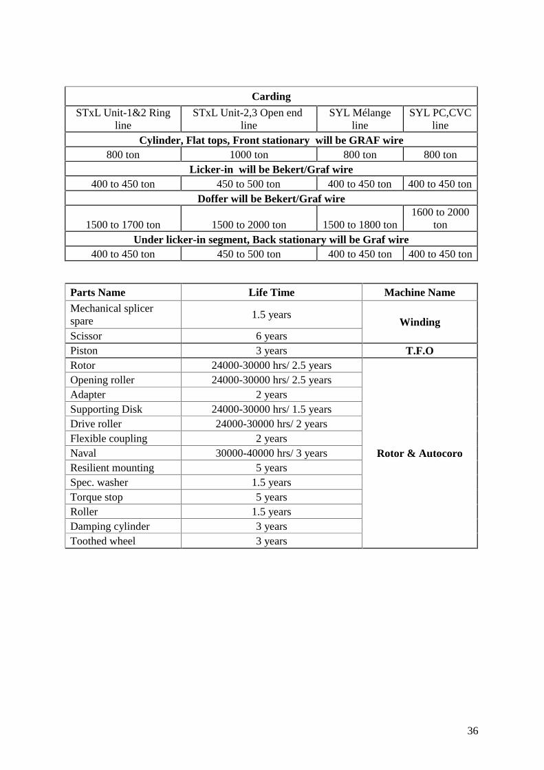
Consumable Spare Parts of Machineries & their life:
Ring and Roving Frame
Parts Name Brand Origin life time Remarks
Top Apron
Hokushin/Kureha Japan 2 to 2.5 yearsGoldtex Taiwan 8 to 10 months
JKS Germany 1 to 1.5 yearsAccotex Germany 1.5 to 2 years
Bottom ApronFor short apron life will be same as top apron same brand.For long apron Life will be 6 month more than top apron same brand.
Ring cupBreaker(Titan) CH 8 years
R & F DE 5 to 6 yearsLaksmi India 3 to 4 years
Snail wire - - 8 Years
Spindle
Novibra Germany 13 to 17 years Auto doffingNovibra Germany 10 to 14 years Manual doffing
SKF Germany 13 to 17 years Auto doffingSKF Germany 10 to 14 years Manual doffing
Rovingholder
KHK Japan 10 to 12 yearsAutotex India 5 to 6 years
Rubber cotGoldtex Taiwan Minimum dia
27mm
Rubber cot bothback & front Shouldbe samemanufacturer.
Accotex Germany
CompactSpare
1 Year
CleaningRoller
4 Year
Spacer 4 Year
Comber/Unilap/Drawing
Circularcomb brush Reiter Germany 02 years
Circularcomb Graf Germany 1100 to 1200 ton
Top comb Graf Germany 900 to 1000 tonDetaching
roller brush Reiter/ Alternative 2 years
Cot Rollerfor Unilap
Max dia 39mm &Min dia 36mm
Cot Rollerfor Drawing
Max dia 38mm &Min dia 36mm
36
Carding
STxL Unit-1&2 Ringline
STxL Unit-2,3 Open endline
SYL Mélangeline
SYL PC,CVCline
Cylinder, Flat tops, Front stationary will be GRAF wire800 ton 1000 ton 800 ton 800 ton
Licker-in will be Bekert/Graf wire400 to 450 ton 450 to 500 ton 400 to 450 ton 400 to 450 ton
Doffer will be Bekert/Graf wire
1500 to 1700 ton 1500 to 2000 ton 1500 to 1800 ton1600 to 2000
tonUnder licker-in segment, Back stationary will be Graf wire
400 to 450 ton 450 to 500 ton 400 to 450 ton 400 to 450 ton
Parts Name Life Time Machine NameMechanical splicerspare
1.5 yearsWinding
Scissor 6 yearsPiston 3 years T.F.ORotor 24000-30000 hrs/ 2.5 years
Rotor & Autocoro
Opening roller 24000-30000 hrs/ 2.5 yearsAdapter 2 yearsSupporting Disk 24000-30000 hrs/ 1.5 yearsDrive roller 24000-30000 hrs/ 2 yearsFlexible coupling 2 yearsNaval 30000-40000 hrs/ 3 yearsResilient mounting 5 yearsSpec. washer 1.5 yearsTorque stop 5 yearsRoller 1.5 yearsDamping cylinder 3 yearsToothed wheel 3 years

37
Conclusion:Square entered into textile business in 1997 with a single unit. Since then it has beenexpanding on a regular interval with modern technologies. Now, Square Spinning Complexconsists of four units equiped with modern machineries. Someother latest machineries are yetto append to enhance its strength in yarn manufacturing.