A micromechanical model of woven structures accounting for yarn–yarn contact based on Hertz theory...
13
A micromechanical model of woven structures accounting for yarn–yarn contact based on Hertz theory and energy minimization F. Chaouachi a , Y. Rahali a , J.F. Ganghoffer b,⇑ a Unité de recherche de mécanique des solides, structures et développements technologiques, ESSTT, Université de Tunis, BP56, Bab Mnara 1008, Tunisia b LEMTA, Université de Lorraine, 2, Avenue de la Forêt de Haye, TSA 60604, BP 160, 54518 Vandoeuvre Cedex, France article info Article history: Received 16 April 2013 Received in revised form 25 April 2014 Accepted 26 May 2014 Available online 12 June 2014 Keywords: A. Fabrics/textiles B. Mechanical properties C. Micro-mechanics Hertzian contact between yarns abstract The equilibrium shape of plain weave fabric, accounting for yarn to yarn contact and incorporating the transverse compressibility, is presently investigated, relying on an energetic analysis of the textile. Each yarn is modeled as an undulated beam at a mesoscopic level, with a shape modeled by a Fourier series. In order to get an accurate description of the contact between yarns, we have considered the contact occur- ring on a surface (distributed contact) of finite extent according to Hertz contact theory. This method allows evaluating the reaction forces between weft and warp from the pressure distribution in the con- tact zone between yarns, and the evolution of the contact area versus the applied tension. The overall response of fabric under uniaxial and biaxial tension is computed as the minimum of the total potential energy of the set of interwoven yarns, including the work of reaction forces on the contact zones. The cal- culated nonlinear response for two important materials (glass, carbon) is due to the change of the geom- etry, namely the crimp variation and the change of contact area during increased loading. The contact area increases with the applied tensile force and is comparable to the yarn diameter. Only the contribu- tion of the displacement due to flexion is shown to be sensitive to the distribution of the forces on the contact surface. A good agreement between the model predictions and tensile measurements of the response of plain weave fabric has been obtained. Ó 2014 Elsevier Ltd. All rights reserved. 1. Introduction Considerable attention from composite manufacturing sector has been devoted to textile composites and especially woven fab- rics. These structures have many advantages over unidirectional fiber reinforced composites, such as enhanced dimensional stabil- ity over a large range of temperatures [1], more balanced proper- ties in the fabric plane, and better impact resistance. The mechanical behavior of fabrics is clearly a multi-scale problem. Woven fabrics are structured, hierarchical materials, having three structural levels [2], called macro-level, meso-level and micro- level, where the first has the largest and the latter has the smallest order of magnitude. The mechanical behavior of woven fabrics is complex due to the intricate interactions of the yarns that consti- tute the fabric ‘‘mesostructure’’. The multi-scale nature of the fabric leads to a complex mechanical behavior. Micro-scale approaches take repartition and contact between thousands of fibers into account. Some studies have been performed at this scale [3], but the analysis of the mechanical behavior of the woven unit cell at this scale is very difficult accounting for the number of fibers (some thousands) in a unit cell. In macro-scale approaches, fabrics are modeled as membranes (or shells if bending is taken into account); these approaches are used in forming simulations. They focus on the characterization of fabric behavior without explicitly modeling the geometric structure of the textile; the fabric is mod- eled as a homogeneous continuum which obeys a specific constitu- tive relation. These continuous models do not include crimp and interlacement effects, which are important features of the fabric reinforcement behavior. The analyses at meso-scale consider the geometry of the woven unit cell but consider the yarns as continuous domains, accounting possibly for single yarn interactions. A lot of mesostructurally based analytical models have been developed for the study of woven fabrics behaviors. Such analytical models use mathematical relations to predict the mechanical response of the fabric and its component yarns in specific modes of deformation. In addition, these models can be used to quantify homogenized material properties for use in continuum models. Hearle et al. [4] described a number of classical analytical fabric models. Kawabata et al. [5–7] presented general theories for uniaxial, biaxial and shear http://dx.doi.org/10.1016/j.compositesb.2014.05.027 1359-8368/Ó 2014 Elsevier Ltd. All rights reserved. ⇑ Corresponding author. Tel.: +33 3 83 59 57 24; fax: +33 3 83 59 55 51. E-mail addresses: [email protected] (F. Chaouachi), [email protected] (Y. Rahali), [email protected] (J.F. Ganghoffer). Composites: Part B 66 (2014) 368–380 Contents lists available at ScienceDirect Composites: Part B journal homepage: www.elsevier.com/locate/compositesb
-
Upload
independent -
Category
Documents
-
view
4 -
download
0
Transcript of A micromechanical model of woven structures accounting for yarn–yarn contact based on Hertz theory...

Composites: Part B 66 (2014) 368–380
Contents lists available at ScienceDirect
Composites: Part B
journal homepage: www.elsevier .com/locate /composi tesb
A micromechanical model of woven structures accounting for yarn–yarncontact based on Hertz theory and energy minimization
http://dx.doi.org/10.1016/j.compositesb.2014.05.0271359-8368/� 2014 Elsevier Ltd. All rights reserved.
⇑ Corresponding author. Tel.: +33 3 83 59 57 24; fax: +33 3 83 59 55 51.E-mail addresses: [email protected] (F. Chaouachi), [email protected]
(Y. Rahali), [email protected] (J.F. Ganghoffer).
F. Chaouachi a, Y. Rahali a, J.F. Ganghoffer b,⇑a Unité de recherche de mécanique des solides, structures et développements technologiques, ESSTT, Université de Tunis, BP56, Bab Mnara 1008, Tunisiab LEMTA, Université de Lorraine, 2, Avenue de la Forêt de Haye, TSA 60604, BP 160, 54518 Vandoeuvre Cedex, France
a r t i c l e i n f o
Article history:Received 16 April 2013Received in revised form 25 April 2014Accepted 26 May 2014Available online 12 June 2014
Keywords:A. Fabrics/textilesB. Mechanical propertiesC. Micro-mechanicsHertzian contact between yarns
a b s t r a c t
The equilibrium shape of plain weave fabric, accounting for yarn to yarn contact and incorporating thetransverse compressibility, is presently investigated, relying on an energetic analysis of the textile. Eachyarn is modeled as an undulated beam at a mesoscopic level, with a shape modeled by a Fourier series. Inorder to get an accurate description of the contact between yarns, we have considered the contact occur-ring on a surface (distributed contact) of finite extent according to Hertz contact theory. This methodallows evaluating the reaction forces between weft and warp from the pressure distribution in the con-tact zone between yarns, and the evolution of the contact area versus the applied tension. The overallresponse of fabric under uniaxial and biaxial tension is computed as the minimum of the total potentialenergy of the set of interwoven yarns, including the work of reaction forces on the contact zones. The cal-culated nonlinear response for two important materials (glass, carbon) is due to the change of the geom-etry, namely the crimp variation and the change of contact area during increased loading. The contactarea increases with the applied tensile force and is comparable to the yarn diameter. Only the contribu-tion of the displacement due to flexion is shown to be sensitive to the distribution of the forces on thecontact surface. A good agreement between the model predictions and tensile measurements of theresponse of plain weave fabric has been obtained.
� 2014 Elsevier Ltd. All rights reserved.
1. Introduction
Considerable attention from composite manufacturing sectorhas been devoted to textile composites and especially woven fab-rics. These structures have many advantages over unidirectionalfiber reinforced composites, such as enhanced dimensional stabil-ity over a large range of temperatures [1], more balanced proper-ties in the fabric plane, and better impact resistance. Themechanical behavior of fabrics is clearly a multi-scale problem.Woven fabrics are structured, hierarchical materials, having threestructural levels [2], called macro-level, meso-level and micro-level, where the first has the largest and the latter has the smallestorder of magnitude. The mechanical behavior of woven fabrics iscomplex due to the intricate interactions of the yarns that consti-tute the fabric ‘‘mesostructure’’. The multi-scale nature of thefabric leads to a complex mechanical behavior. Micro-scaleapproaches take repartition and contact between thousands offibers into account. Some studies have been performed at this scale
[3], but the analysis of the mechanical behavior of the woven unitcell at this scale is very difficult accounting for the number of fibers(some thousands) in a unit cell. In macro-scale approaches, fabricsare modeled as membranes (or shells if bending is taken intoaccount); these approaches are used in forming simulations. Theyfocus on the characterization of fabric behavior without explicitlymodeling the geometric structure of the textile; the fabric is mod-eled as a homogeneous continuum which obeys a specific constitu-tive relation. These continuous models do not include crimp andinterlacement effects, which are important features of the fabricreinforcement behavior.
The analyses at meso-scale consider the geometry of the wovenunit cell but consider the yarns as continuous domains, accountingpossibly for single yarn interactions. A lot of mesostructurallybased analytical models have been developed for the study ofwoven fabrics behaviors. Such analytical models use mathematicalrelations to predict the mechanical response of the fabric and itscomponent yarns in specific modes of deformation. In addition,these models can be used to quantify homogenized materialproperties for use in continuum models. Hearle et al. [4] describeda number of classical analytical fabric models. Kawabata et al.[5–7] presented general theories for uniaxial, biaxial and shear

F. Chaouachi et al. / Composites: Part B 66 (2014) 368–380 369
deformation properties of plain weave fabrics based on a simplifiedmodel representing the structure of the fabric unit cells. The basicgeometry used in this theory is based on one-dimensional stiffnesselements (bars) representing yarns, and the connecting stiffnesselements at the intersection of yarns to model the compressionbetween yarns. Other researchers have developed improved ana-lytical models, including Realff et al. [8], who modify Kawabata’suniaxial model to include more complex behaviors such as yarnflattening and consolidation. Kato et al. [9] proposed an analyticalmodel for predicting the constitutive behavior of a coated fabriccomposite that is based on the pin-joined lattice-type geometry.Recently, Ben Boubaker et al. [10–12] developed a meso-level dis-crete model for plain weave, which was then extended to generalmonolayer textiles in Assidi et al. [13]. For a more detailed descrip-tion of several other analytical models, see [14,15].
Analytical models of the fabric mesostructure can be incorpo-rated into anisotropic continuum formulations to yield models thattrack the fabric mesostructure as the continuum deforms. A num-ber of authors have presented models for woven fabrics with con-tinuum properties calculated from a deforming unit cell. Boisseet al. [16,17] constructed a three-dimensional unit cell like thatof Kawabata for quasi-static and dynamic simulations of compositeforming but did not incorporate the resistance to yarn rotation orthe inertia of uncrimping. Rattensperger et al. [18] follow a similarapproach for modeling fabric-reinforced hydraulic hoses, with thefabric lattice geometry similar to that used by Kato, and adopt aconventional finite element formulation with rebar reinforce-ments. Tanov and Brueggert [19] presented a mesostructurallybased continuum model that includes shear and locking resistancethrough diagonal spar elements within the assumed unit cell net-work. Boisse et al. [20,21] later used a planar unit cell for dynamicsimulations by incorporating shear resistance at the cross-overpoint but did not include cross-locking. Hamila et al. [22] extendedthis approach to a shell finite element which included the resis-tance to bending of the yarns.
Alternative approaches suitable for simulating general fabricdeformations are based on finite elements: either they discretelymodel in three dimensions every yarn in the weave, or theyhomogenize the response of the yarns, typically by treating thefabric as an anisotropic continuum. The discrete approach, usedby Shockey et al. [23–25], Ng et al. [26], Duan et al. [27], Zhanget al. [28], and Talebi et al. [29], among others, has the advantageof capturing all yarn interactions and providing a detailed descrip-tion of all mechanisms of fabric deformation. It is thus valuable forstudying the various modes of deformation of the yarns and theeffects of parameters such as weave style and yarn properties onmacroscopic deformation. However, building these elaborate finiteelement meshes is tedious, and simulating actual structures orevents of significant duration is computationally prohibitive inmost cases. On the other hand, the homogenized, continuumapproach, used by Peng and Cao [30–32], Xue et al. [33,34], andBaseau [35], amongst others, allow greater computational effi-ciency and it can be easily integrated into multi-component sys-tem models. Although this approach can accurately represent themacroscopic response of woven fabrics, it does not explicitly modelthe modes of deformation or interactions between yarns, andtherefore cannot predict all of the necessary yarn-level aspects ofdeformation. Peng and Cao [30,31] applied a dual homogenizationtechnique to predict the mechanical behavior of woven fabricsfrom a sequence of models for fibres. In the first step, a unit cellwas made for the yarn section to estimate the effective elastic con-stants of fibre yarn. Then, another unit cell at the meso-level wasconstructed to represent the periodic structure of the woven fabric.Peng and Cao [32] developed a continuum mechanics-based non-orthogonal constitutive model to characterize the anisotropicmaterial behavior of woven composite fabrics under large
deformation. Moreover, Xue et al. [34] developed an integratedmeso-macro model for the prediction of mechanical properties ofwoven fabrics under large deformations. The same authors previ-ously suggested a non-orthogonal constitutive model for the pre-diction of mechanical properties at the macro scale [33], relyingon experimental measurements to identify the constants of theirmodel. Baseau [35] developed continuum formulations for ‘‘fila-mentary networks’’, appropriate for non-reinforced fabrics. Kinget al. [36] proposed a new approach for the continuum modelingof fabrics by selecting a geometric model for the fabric weave cou-pled with constitutive models for the yarns behavior. The lastauthors used energy minimization method to relate the fabricsstructural configuration to the macroscopic deformation.
A common assumption in the literature is that the contactbetween yarns is punctual [13,37]; this assumption can be consid-ered as valid for structures sufficiently large compared to the areaof contact. In [37], although sliding between yarns is modeled, thecontact is represented using concentrated forces, and not distrib-uted pressures as in a standard contact mechanics approach. How-ever, the contact area becomes comparable to the size of therepresentative unit cell (we can reasonably assume textile to beperiodic, and consisting of the spatial repetition of a certain armor)in the case of textiles (as shown on Fig. 6 in [37]). One accordinglyexpects that the contact between the two sets of yarns will have asignificant effect on the overall mechanical response. It is then theprincipal objective of this contribution to quantitatively assess theeffect of the distribution of contact forces between yarns on themechanical response of plain weave fabric.
The principal goal of this contribution is to extend the previousdiscrete model of textile monolayers based on energy minimiza-tion following Ben Boubaker et al. [10,11] and Assidi et al. [13] tothe consideration of the contact between warp and weft. An ana-lytical approach will be followed in this contribution, and Hertzanalytical contact theory will be employed. The yarns will be mod-eled at an intermediate meso level, so that the fibrous structurewill not be explicitly described. Nevertheless, we shall evaluatethe effective moduli of yarns from the fiber level using some modelof the literature.
This works is organized as follows: in Section 2, the contactmodel between yarns based on Hertz theory is presented, leadingto an expression of the reaction force exerted by the transverseyarn, and the variation of the contact area with load. The potentialenergy of the woven structure is constructed in Section 3, incorpo-rating the work of the reaction forces. An algorithm for the resolu-tion of the set of equations of the model is presented in Section 4.Results of uniaxial simulations evidencing the effect of warp toweft contact interactions are presented (Section 5). Finally, a sum-mary of the main results and perspectives are given (Section 6).
2. Hertzian contact between yarns
We analyze in the sequel the mechanical response of such a tex-tile monolayer; in view the subsequent analysis, it is convenient tosplit the sets of interwoven yarns into two interacting subsystems:the set of warp denoted Xwa and the set of weft denoted Xwe. Eachyarn is modeled as an undulated beam assumed to be flexible andextensible. We further make the assumption that the contactbetween yarns is perfect and does not induce relative sliding.Accordingly, one shall involve energetic principles in combinationwith Hertzian contact mechanics in order to evaluate the equilib-rium shape of the monolayer submitted to a tensile (uniaxial orbiaxial) loading.
We consider plain weave fabric as the assembly of two sets oforthogonal yarns (warp and weft) in an initial configuration. Eachyarn within the woven structure is assimilated to a homogeneous

370 F. Chaouachi et al. / Composites: Part B 66 (2014) 368–380
beam submitted to the contact forces exerted by the transverseyarns (Fig. 2.1).
The main assumptions of the present model are as follows:
– The tensile force remains aligned with the direction of loading.– The yarns are represented as undulated beams endowed with
effective mechanical properties, in line with the previouslymentioned meso-scale analyses. Those effective properties willbe determined from micromechanical models of the literature.
– In order to simplify the calculations, the initial yarn section(before contact occurs) is assumed to be circular (this will how-ever not restrict the generality of the presented methodology).
– The yarns are in perfect contact with no relative sliding.
The vertical deflection of each yarn (modeled as a beam ele-ment) is expressed as a Fourier series with coefficients dependingupon the forces applied to the beam element. Timoshenko beammechanics leads to the following expression of the initial deflec-tion of warp and weft in the absence of external load [11]:
w jo�weðyÞ ¼
XNwa
n¼1
awen; j sin ð j� 1Þpþ n
pyLwe
� �ð1Þ
wko�waðxÞ ¼
XNwe
n¼1
awan;k sin ðk� 1Þpþ n
pxLwa
� �ð2Þ
with wjo�we; wk
o�wa respectively the initial deflections of the warpand weft, Lwa, Lwe respectively the projected length of the yarns inthe x and y directions, n the number of harmonics, Nwa, Nwe respec-
tively the number of warp and weft, awan;k
� �n2½1;Nwe �
; awen; j
� �n2½1;Nwa �
are
the Fourier series coefficients (detailed in Appendix B, see Eqs.(B.4) and (B.5)) and j, k the labeling of warp and weft in the wovenstructure (Fig. 2.1).
Those expressions (Eqs. (B.4) and (B.5)) are valid only for concen-trated (punctual) reaction forces; the goal of this contribution is todevelop more general expressions for the Fourier series expansions
Fig. 2.1. Micromechanical mo
describing the shape of woven monolayers, relying on a more accu-rate and realistic representation of the contact between yarns.
Since the yarns are described as cylindrical beams, one firstanalyses the Hertzian contact between orthogonal cylinders, inwhich case it is known that the contact area is an ellipse [38].The total reaction force is supposed to be known, and one deter-mines its spatial distribution from Hertz theory as well as the con-tact surface. From Hertz theory [38], the pressure distribution onthe elliptic zone of contact (Fig. 2.2) writes:
P0ðx; yÞ ¼ pm
ffiffiffiffiffiffiffiffiffiffiffiffiffiffiffiffiffiffiffiffiffiffiffiffi1� x2
a2 �y2
b2
sð3Þ
with the maximum pressure therein:
pm ¼3N
2pabInvolving the normal effort acting on the contact N, and the majorand minor radii of the contact ellipse, respectively quantities a, b,expressing versus the normal effort as
a ¼ m1
ffiffiffiffiffiffiffiffiffiffiffiffiffiffiffiffiffiffiffiffiffiffiffiffiffiffiffiffiffiffiffiffiffiffiffiffiffiffiffiffiffiffiffiffiffiffi3pNðk1 þ k2Þ
2 C1 þ C 01 þ C2 þ C 02� �3
s; b ¼ m2
m1a ð4Þ
The coefficients m1, m2 therein are expressed in [40] through a fic-tive angle u depending upon the curvature radius C (the scalarsC1; C01; C2; C02) and the angle h between the planes of principal cur-vatures representing the relative orientation of both yarns (exposedin Appendix A), viz.
u¼arccos
ffiffiffiffiffiffiffiffiffiffiffiffiffiffiffiffiffiffiffiffiffiffiffiffiffiffiffiffiffiffiffiffiffiffiffiffiffiffiffiffiffiffiffiffiffiffiffiffiffiffiffiffiffiffiffiffiffiffiffiffiffiffiffiffiffiffiffiffiffiffiffiffiffiffiffiffiffiffiffiffiffiffiffiffiffiffiffiffiffiffiffiffiffiffiffiffiffiffiffiffiffiffiffiffiffiffiffiffiffiC1�C 01� �2þ C2�C 02
� �2þ2 C1�C 01� �
C2�C02� �
cosð2hÞq
C1þC01þC2þC 02
0@
1Að5Þ
The coefficients k1, k2 in (6) are dependent on the Poisson’s ratio ofboth yarns, coefficients m1; m2 and the tensile moduli E1, E2 (exposedin Appendix A), as
del of plain weave fabric.
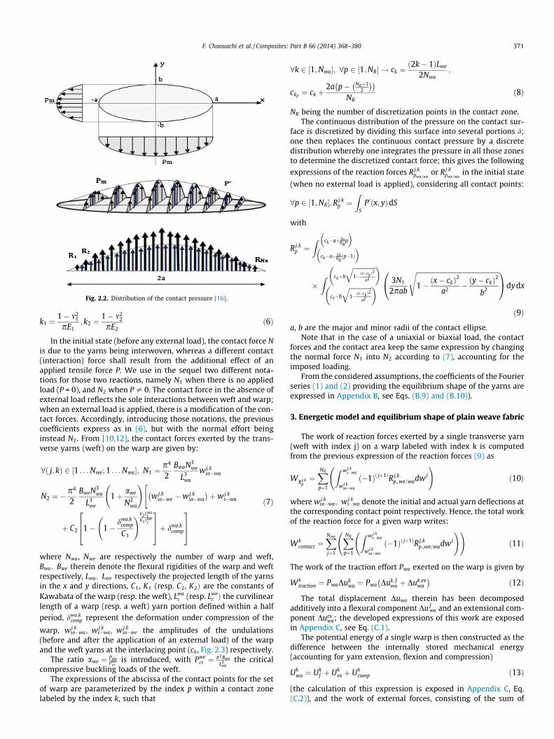
Fig. 2.2. Distribution of the contact pressure [16].
F. Chaouachi et al. / Composites: Part B 66 (2014) 368–380 371
k1 ¼1� m2
1
pE1; k2 ¼
1� m22
pE2ð6Þ
In the initial state (before any external load), the contact force Nis due to the yarns being interwoven, whereas a different contact(interaction) force shall result from the additional effect of anapplied tensile force P. We use in the sequel two different nota-tions for those two reactions, namely N1 when there is no appliedload (P = 0), and N2 when P – 0. The contact force in the absence ofexternal load reflects the sole interactions between weft and warp;when an external load is applied, there is a modification of the con-tact forces. Accordingly, introducing those notations, the previouscoefficients express as in (6), but with the normal effort beinginstead N2. From [10,12], the contact forces exerted by the trans-verse yarns (weft) on the warp are given by:
8ð j; kÞ 2 ½1 . . . Nwe; 1 . . . Nwa�; N1 ¼p4
2BwaN3
we
L3wa
w j;kso�wa
N2 ¼ �p4
2BweN3
wa
L3we
1þ awe
N2wa
!"w j;k
so�we �w j;kso�wa
� �þw j;k
s�wa
þ C2 1� 1�dwa;k
comp
C1
!K2Lwac
K1Lwec
264
375þ dwa;k
comp
375
ð7Þ
where Nwa, Nwe are respectively the number of warp and weft,Bwa; Bwe therein denote the flexural rigidities of the warp and weftrespectively, Lwa; Lwe respectively the projected length of the yarnsin the x and y directions, C1, K1 (resp. C2, K2Þ are the constants ofKawabata of the warp (resp. the weft), Lwa
c (resp. Lwec Þ the curvilinear
length of a warp (resp. a weft) yarn portion defined within a halfperiod, dwa;k
comp represent the deformation under compression of the
warp, w j;kso�wa; w j;k
s�wa; wj;kso�we the amplitudes of the undulations
(before and after the application of an external load) of the warpand the weft yarns at the interlacing point (ck, Fig. 2.3) respectively.
The ratio awe ¼ PwePwe
cris introduced, with Pwe
cr ¼ p2Bwe
L2we
the criticalcompressive buckling loads of the weft.
The expressions of the abscissa of the contact points for the setof warp are parameterized by the index p within a contact zonelabeled by the index k, such that
8k 2 ½1;Nwa�; 8p 2 ½1;NR� ! ck ¼ð2k� 1ÞLwe
2Nwa;
ckp ¼ ck þ2a p� NRþ1
2
� �� �NR
ð8Þ
NR being the number of discretization points in the contact zone.The continuous distribution of the pressure on the contact sur-
face is discretized by dividing this surface into several portions d;one then replaces the continuous contact pressure by a discretedistribution whereby one integrates the pressure in all those zonesto determine the discretized contact force; this gives the following
expressions of the reaction forces Rj;kpwa=we
or Rj;kpwe=wa
in the initial state
(when no external load is applied), considering all contact points:
8p 2 ½1;NR�;R j;kp ¼
ZS
P0ðx; yÞdS
with
R j;kp ¼
Z ck�aþ2aNR
p
� �ck�aþ2a
NRðp�1Þ
� �
�Z ckþb
ffiffiffiffiffiffiffiffiffiffiffiffiffiffi1�ðx�ck Þ
2
a2
q� �
ck�b
ffiffiffiffiffiffiffiffiffiffiffiffiffiffi1�ðx�ck Þ
2
a2
q� � 3N1
2pab
ffiffiffiffiffiffiffiffiffiffiffiffiffiffiffiffiffiffiffiffiffiffiffiffiffiffiffiffiffiffiffiffiffiffiffiffiffiffiffiffiffiffiffiffiffiffiffiffiffiffiffi1� ðx� ckÞ2
a2 � ðy� ckÞ2
b2
s0@
1Adydx
ð9Þ
a, b are the major and minor radii of the contact ellipse.Note that in the case of a uniaxial or biaxial load, the contact
forces and the contact area keep the same expression by changingthe normal force N1 into N2 according to (7), accounting for theimposed loading.
From the considered assumptions, the coefficients of the Fourierseries (1) and (2) providing the equilibrium shape of the yarns areexpressed in Appendix B, see Eqs. (B.9) and (B.10)).
3. Energetic model and equilibrium shape of plain weave fabric
The work of reaction forces exerted by a single transverse yarn(weft with index j) on a warp labeled with index k is computedfrom the previous expression of the reaction forces (9) as
WR j;kp¼XNR
p¼1
Z w j;ks�wa
w j;kso�wa
ð�1Þð jþ1ÞR j;kp we=wadw j
!ð10Þ
where w j;kso�wa; wj;k
s�wa denote the initial and actual yarn deflections atthe corresponding contact point respectively. Hence, the total workof the reaction force for a given warp writes:
Wkcontact ¼
XNwe
j¼1
XNR
p¼1
Z w j;ks�wa
w j;kso�wa
ð�1Þð jþ1ÞR j;kp we=wadw j
! !ð11Þ
The work of the traction effort Pwa exerted on the warp is given by
Wktraction ¼ PwaDuk
wa ¼ Pwa Duk; fwa þ Duk;ex
wa
� �ð12Þ
The total displacement Duwa therein has been decomposedadditively into a flexural component Du f
wa and an extensional com-ponent Duex
wa; the developed expressions of this work are exposedin Appendix C, see Eq. (C.1).
The potential energy of a single warp is then constructed as thedifference between the internally stored mechanical energy(accounting for yarn extension, flexion and compression)
Ukwa ¼ Uk
f þ Ukex þ Uk
comp ð13Þ
(the calculation of this expression is exposed in Appendix C, Eq.(C.2)), and the work of external forces, consisting of the sum of

Fig. 2.3. Distribution of the reaction forces.
372 F. Chaouachi et al. / Composites: Part B 66 (2014) 368–380
the work of the applied load Wktraction and of the reaction forces
Wkcontact , viz.
Vk ¼ Ukwa �Wk
traction �Wkcontact ð14Þ
The total potential energy of the whole plain weave structure isthen the sum over all warp yarns
wko�waðxÞ ¼
2L3wa
p4Bwa
XNR
p¼1
Rj;kpwe=wa
XNwe
n¼1
XNwe2
m¼1
1n4
sin npNwe
2m� 32
� �þ 2 p�ðNRþ1Þ
2
� �anp
NR :Lwa
� �
� sin npNwe
2m� 12
� �þ 2 p�ðNRþ1Þ
2
� �anp
NR :Lwe
� �26664
37775
0BBB@
1CCCA sin ðk� 1Þpþ npx
Lwa
� �
V ¼XNwa
k¼1
Vk ð15Þ
The equilibrium shape of the fabric is then obtained from theset of configuration parameters fak;ukg that achieve a minimumof V. The simulation of tensile test of plain weave fabric relies onthe algorithm described in the next section.
4. Algorithm for the numerical resolution of the set ofequations
The input data are:
– The yarn geometrical parameters for the considered textilemonolayer, here plain weave.
– The mechanical properties of the warp and weft (tensile moduliand transverse compression parameters).
– The tensile load P.
The results include:
– The evolution of the contact surface between yarns versus theapplied tension.
– The total displacement and the components due to extensionand flexion.
– The contact forces along the yarn.
The methodology relies on the following steps:
– Determination of the initial shape of the yarn and of the initialcontact surface.
– Computation of the contact force N1 in the absence of externalforce.
– Computation of the initial yarn shape from the deflectionamplitude.
– Computation of the reaction forces due to contact at initialstate, thus the initial yarn shape.
– Evaluation of the curvilinear length Ls�wa of the warp [39],expression
Ls�wa ¼Z Lwa
0
ffiffiffiffiffiffiffiffiffiffiffiffiffiffiffiffiffiffiffiffiffiffiffiffiffiffiffiffiffiffiffi1þ dyoðxÞ
dx
� �2s
dx:
– Determination of the flexural and extensional rigidities,quantities
Cf ¼ Bwa
D; Cex ¼ EAwa
D
D is the curvilinear distance between two constitutive nodes(Fig. 2.1).– Initialization of the yarn amplitudes:
8p 2 ½1 . . . NR�;8ði; jÞ 2 ½1 . . . Nwe; 1 . . . Nwa�; wp;iso wa
¼ ð�1Þiþ1Apwa; wp; j
so we ¼ ð�1Þ jApwe
with
Apwa¼ Ao�wa cos
4pa NRþ12 � p
� �NR � Lwa
!;
Apwe¼ Ao�we cos
4pa NRþ12 � p
� �NR � Lwe
!
F. Chaouachi et al. / Composites: Part B 66 (2014) 368–380 373
And
Table 1Mechan
Fibre
TypeNumFilamYarnLongBendPoissPoissTran
Ao�wa ¼Dwa
2; Ao�we ¼
Dwe
2
– Increase of the tensile load along the warp by increments dP,such that Pwa½k� ¼ k � dP, k = 1 . . . ,n, with n the number of calcu-lation steps.
– Expression of the tensile load along the weft as a fraction of thewarp tensile load, Pwe ¼ aPwa½k�; the coefficient a therein is var-ied to simulate the transition from a uniaxial to a biaxial loading(it is indicative of the degree of biaxiality).
– Determination of the total potential energy of the plain weavestructure according to (15), assembling therein all contributionsevaluated in Eqs. (10)–(14).
– Minimization of the potential energy and determination of theequilibrium due to an applied uniaxial or biaxial tension, lead-ing to the tensile response of fabric.
– Evaluation of the reaction forces and of the contact surface.
5. Numerical results and discussion
Since we do not focus on a specific type of yarn, but aim atdeveloping a predictive model able to account for different typesof yarns, computations will be done for two yarns, namely glassand carbon.
We adopt the following choice of the geometrical and mechan-ical parameters, chosen as in [41,42], for the purpose of comparingwith a situation of a finite area incorporating an evolution of thecontact based on Hertz theory.
The geometrical parameters of discretization are selected as:
Lwa ¼ Lwe ¼ 0:022 m,Nwa ¼ Nwe ¼ 16,n0=period ¼ 12,NR ¼ 15.
The mechanical properties of the chosen fibers within the mul-tifilament yarns are [41]:
Young’s modulus: Ef glass ¼ 80:109 Pa and Ef carbon ¼ 238:109 Pa.The yarn behavior viewed as a bundle of filaments is related in a
complicated manner to the arrangement of the fibers and to theirindividual mechanical properties. The measurement of multifila-ment properties in relation to the organization and properties ofthe inherent fibers is a very challenging task; especially, the yarncompressive response is quite complex (nonlinear and non-regu-lar) due to the reorganization of the fibers within the yarn [47].For this reason, we rather rely on analytical models, consideringespecially the analysis given by Alagirusamy and Das [48], whostates that in the unstrained state, the modulus of the twisted yarnand constituent fiber are related by Eq. (16), and Curiskis and Car-naby [46] who express the yarn effective mechanical propertiesfrom the geometrical and micromechanical parameters inherentto the fibers within the yarn (by Eqs. (17) and (18)), as follows:
ical properties of the chosen fibers [41].
type E-Glass Carbon
Multifilament Multifilamentber of filaments 1200 6000ent diameter (lm) 16 7diameter (mm) 0.58 0.57
itudinal tensile moduli (GPa) 1.9 5.66ing stiffness (N mm2) 0.31 0.16on’s ratio mTL 0.77on’s ratio mLT 0.8 0.9 0.8 0.9sverse tensile moduli (GPa) 1.82 1.62 5.44 4.84
The longitudinal tensile moduli is given by EL ¼ Eyarn ¼ Ef �cos2ðqÞ ð16Þ
The Poisson’ ratio expresses as mTL ¼8sin2ðqÞ
p2ð2� sin2ðqÞÞð17Þ
The transverse tensile moduli is given by ET ¼mTL
mLTEL ð18Þ
In the present work, the helical angle of the fibers is chosen asq ¼ 30�. The longitudinal moduli of the bundle of fibers buildingthe yarn are evaluated based on the formula (16)–(18) and reportedin Table 1. In order to calculate the transverse modulus based on(18), we consider Poisson’s ratio mLT as a varying parameter, select-ing the values 0.8 and 0.9 (those values satisfy the conditionEL > ET ). From the previous microstructural fiber parameters, weobtain the mechanical effective properties of the two types of yarnsconsidered in this work given in Table 1.
The two sets of Kawabata constants K corresponding to the twovalues of Poisson’s ratio mLT are then determined for each type ofyarn by using Kawabata’s model:
d ¼ C 1� e�KFL
� �ð19Þ
) dddF¼ CK
Le�
KFL
Especially; for F ¼ 0;dddF¼ CK
L: ð20Þ
In the general case; it holds that ET ¼re¼
FSDlL
! DlF¼ L
ET Sð21Þ
Combining previous relations lead to an identification of the Kawa-bata constant K: consideration of relations (20) and (21) leads toCKL ¼ L
ES hence K ¼ L2
ET :S:C, with L the contact length, S the contact area
and C a constant therein. Using this procedure delivers the follow-ing parameters of the Kawabata compressibility model for the dif-ferent yarns:
For the carbon yarn:
Case1: C = 0.3 � 10�6 and K = 0.78 � 10�3.Case2: C = 0.3 � 10�6 and K = 0.876 � 10�3.
For the glass yarn:
Case1: C = 0.3 � 10�6 and K = 2.32 � 10�3.Case2: C = 0.3 � 10�6 and K = 2.61 � 10�3.
The calculated moduli are reported in Table 1. The bendingmoduli for the carbon and glass yarns are given in [41].
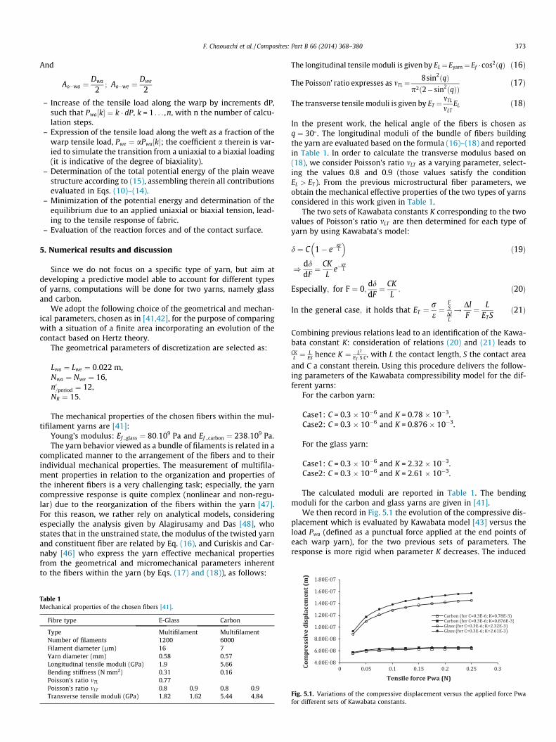
We then record in Fig. 5.1 the evolution of the compressive dis-placement which is evaluated by Kawabata model [43] versus theload Pwa (defined as a punctual force applied at the end points ofeach warp yarn), for the two previous sets of parameters. Theresponse is more rigid when parameter K decreases. The induced
Fig. 5.1. Variations of the compressive displacement versus the applied force Pwafor different sets of Kawabata constants.

Fig. 5.2. Variation of the contact area versus the applied force Pwa for different setsof Kawabata constants: C = 0.3 � 10�6.
Fig. 5.3. Variation of the reaction force versus the applied force Pwa .
374 F. Chaouachi et al. / Composites: Part B 66 (2014) 368–380
evolution of the contact area and reaction forces is shown inFigs. 5.2 and 5.3 respectively: the contact area increases rapidlywith the loading in a first stage, and the slope of this evolution thendecreases with ongoing loading; this evolution will be explained inthe sequel by a deeper analysis of the deformation mechanisms ofthe fabric. It appears that the compression parameters have a weakeffect on both the reaction force and contact area.
From a numerical point of view, we have tested different dis-cretizations of the contact zone (in case of a finite contact area);the 15 discretization points adopted in all subsequent simulations
Fig. 5.4. Variations of the flexural displacements for two kinds of reinforcement:effect of the contact forces distribution (15R).
are sufficient, since we checked that no more variations of theoverall response are observed for a finer discretization.
For the two yarns, the contact area is important in comparisonto the yarn diameter: the major axis of the large diameter of thecontact area for the glass yarn is evaluated to 0.3 mm, a value sim-ilar to the warp diameter, here 0.58 mm. We notice that for thesame load Pwa, the contact area is greater for the glass yarn in com-parison to the carbon yarn (the same thing for the reaction forceevaluated in Eq. (9)), due to the greater value of the tensilestiffness.
We further analyze the deformation mechanisms, in terms ofthe yarn flexion and extension for the two types of yarns; the var-iation of the displacement in flexion is illustrated in Fig. 5.4 for apunctual contact (referred to as 1R) and a distributed contact(referred to as 15R); the flexural component of the displacementevolves according to a J-shape type response in both cases (1Rand 15R), thereby following the general trend observed in the lit-erature [16]. Fig. 5.4 further shows that the flexural componentof the displacement is sensitive to the distribution of contactforces: this is due to the fact that the reaction force increases inthe first stage of the overall response (a consequence of thedecrease of the yarn crimp, which is an easy deformation mecha-nism), before saturating in the later stage of the response.
We illustrate in Fig. 5.5 the variation of the component of thedisplacement in extension for the two yarns and with the two setsof Kawabata constants. We firstly notice that the component of thedisplacement in extension varies linearly versus the applied forcePwa, and it is further completely insensitive to the compression.This means that yarn compression mostly acts on the flexuralbehavior of the tested fabric. The influence of the yarn compress-ibility on the overall response of composite fibrous reinforcementis well-known in the literature [44]; the present analysis gives fur-ther insight into the mechanisms responsible for this effect at theyarn scale.
We observe on Fig. 5.6 an effect of the way the load distributionis modeled in the contact zone on the overall response of the fabric,for several types of reinforcement materials: the response is morerigid for a punctual contact. This behavior can be explained adopt-ing an energetic point of view: the work of the tensile force is thesame in both contact representations; the total work of the reac-tion forces as well as the internal mechanically stored energy arefound to be greater for punctual contact, thus leading to a stiffermechanical response. Whatever the type of yarns, the two familiesof curves converge to a common response independently of theway the contact is described (punctual or distributed); this canbe explained by the fact that the flexural contribution of the totaldisplacement decreases, while the extensional displacement isinsensitive to the contact forces distribution. The same also holdsfor the compression behavior.
Fig. 5.5. Variations of the extensional displacements for two kinds of reinforcementand for different sets of Kawabata constant. Punctual contact model (1R) anddistributed contact (15R).
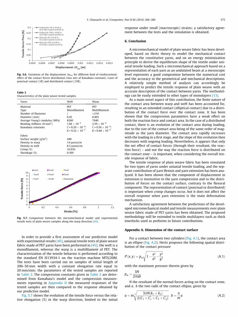
Fig. 5.6. Variations of the displacement Duwa for different kind of reinforcement:effect of the contact forces distribution (two sets of Kawabata constant). Cases ofpunctual contact (1R) and distributed contact (15R).
Table 2Characteristics of the plain weave tested samples.
Yarns Weft Warp
Material PET PETType Monofilament MultifilamentNumber of filaments / �210Diameter (mm) 0.45 0.403Average Young’s modulus (MPa) 8260 7940Bending stiffness (N mm2) 1.66 � 10�5 2.59 � 10�6
Kawabata constants C = 0.29 � 10�4;K = 0.32 � 10�5
C = 0.56 � 10�4;K = 0.44 � 10�4
FabricSurface weight (g/m2) 440Density in warp 14 yarns/cmDensity in weft 8.5 yarns/cmCrimp (%) 16.93%Shrinkage (%) 0.30%
Fig. 5.7. Comparison between the micromechanical model and experimentaltensile tests of plain weave samples along the warp direction [45].
F. Chaouachi et al. / Composites: Part B 66 (2014) 368–380 375
In order to provide a first assessment of our predictive modelwith experimental results [45], uniaxial tensile tests of plain weavefabric made of PET yarns have been performed in [45]; the weft is amonofilament, whereas the warp is a multifilament of PET. Thecharacterization of the tensile behavior is performed according tothe standard EN IS13934-1 on the traction machine MTS/20M.The tests have been carried out on samples of initial length of200–50 mm width with a constant elongation rate equal to20 mm/min; the parameters of the tested samples are reportedin Table 2. The compression constants given in Table 2 are deter-mined from Kawabata’s model and the compression measure-ments reporting in Appendix D the measured responses of thetested samples are then compared to the response obtained byour predictive model.
Fig. 5.7 shows the evolution of the tensile force versus the rela-tive elongation (%) in the warp direction, limited to the initial
response under small (macroscopic) strains; a satisfactory agree-ment between the tests and the simulation is obtained.
6. Conclusion
A micromechanical model of plain weave fabric has been devel-oped, based on Hertz theory to model the mechanical contactbetween the constitutive yarns, and on an energy minimizationprinciple to derive the equilibrium shape of the textile under uni-axial tensile loading. Such a micromechanical approach based on arepresentation of each yarn as an undulated beam at a mesoscopiclevel represents a good compromise between the numerical costand the accuracy in the geometrical and mechanical descriptions.A relatively simple method of analysis can accordingly beemployed to predict the tensile response of plain weave with anaccurate description of the contact between yarns. The methodol-ogy can be easily extended to other types of monolayers [13].
As a main novel aspect of this contribution, the finite nature ofthe contact area between warp and weft has been accounted for,resulting in an extended contact (elliptical contact) due to a distri-bution of the contact force over the contact zone. It has beenshown that the compression parameters have a weak effect onboth the reaction force and contact area. In the case of a distributedcontact, there is an evolution of the contact area during loading,due to the size of the contact area being of the same order of mag-nitude as the yarn diameter. The contact area rapidly increaseswith the loading in a first stage, and the slope of this evolution thendecreases with ongoing loading. Nevertheless, it appears that onlythe net effect of contact forces (through their resultant, the reac-tion force) – and not the way the reaction force is distributed onthe contact zone – is important, when considering the overall ten-sile response of fabric.
The tensile response of plain weave fabric has been simulatedfor two types of yarns under uniaxial tensile loading, and the sep-arate contribution of yarn flexion and yarn extension has been ana-lyzed. It has been shown that the component of displacement inextension is insensitive to the yarn compression and to the distri-bution of forces on the contact surface, contrary to the flexuralcomponent. The representation of contact (punctual or distributed)is important when crimp changes occur, but it does not affect theoverall response when yarn extension is the main deformationmechanism.
A satisfactory agreement between the predictions of the devel-oped micromechanical model and tensile measurements over plainweave fabric made of PET yarns has been obtained. The proposedmethodology will be extended to textile multilayers such as thickitnerlocks used as preforms in future contributions.
Appendix A. Dimension of the contact surface
For a contact between two cylinders (Fig. A.1), the contact areais an ellipse (Fig. A.2); Hertz proposes the following spatial distri-bution of the contact pressure
P0ðx; yÞ ¼ pm
ffiffiffiffiffiffiffiffiffiffiffiffiffiffiffiffiffiffiffiffiffiffiffiffi1� x2
a2 �y2
b2
sðA:1Þ
with the maximum pressure therein given by
pm ¼3N
2pab
N the resultant of the normal forces acting on the contact zone,and a; b the two radii of the contact ellipse, given by
a ¼ m
ffiffiffiffiffiffiffiffiffiffiffiffiffiffiffiffiffiffiffiffiffiffiffiffiffiffiffiffiffiffiffiffiffiffiffiffiffiffiffiffiffiffiffiffiffiffi3pNðk1 þ k2Þ
2 C1 þ C 01 þ C2 þ C 02� �3
s; b ¼ n
ma ðA:2Þ

Fig. A.1. Contact between cylindrical two yarns.
Fig. A.2. Ellipsoidal contact area between two cylindrical yarns.
Fig. B.1. Beam submitted to a punctual vertical force.
376 F. Chaouachi et al. / Composites: Part B 66 (2014) 368–380
This expression involves the following parameters: the coefficientsn, m [40] versus the angle
u¼arccos
ffiffiffiffiffiffiffiffiffiffiffiffiffiffiffiffiffiffiffiffiffiffiffiffiffiffiffiffiffiffiffiffiffiffiffiffiffiffiffiffiffiffiffiffiffiffiffiffiffiffiffiffiffiffiffiffiffiffiffiffiffiffiffiffiffiffiffiffiffiffiffiffiffiffiffiffiffiffiffiffiffiffiffiffiffiffiffiffiffiffiffiffiffiffiffiffiffiffiffiffiffiffiffiffiffiffiffiffiffiffiC1�C 01� �2þðC2�C 02Þ
2þ2 C1�C 01� �
C2�C 02� �
cosð2hÞq
C1þC 01þC2þC 02
0@
1A
ðA:3Þ
C1, C01 are the maximal and minimal curvatures of solid 1 in theplanes P01 and P001 respectively; C2; C02 are the maximal and minimalcurvatures of solid 2 in the planes P02; P002 respectively, h is the angle
between P01 and P02, and k1 ¼1�m2
1pE1
; k2 ¼1�m2
2pE2
depend on the elastic
properties of both cylinders. We denote E1, E2 the tensile moduliof both yarns (Fig. A.1), and m1; m2 their Poisson’s ratio.
Appendix B. Expressions of the Fourier coefficients
The vertical deflection of each yarn (modeled as a beam ele-ment) is expressed as a Fourier series with coefficients dependingupon the forces applied to this beam element.
Fig. B.2. Distribution of the reaction forces exerted by the
We first consider the case of a single concentrated force (F). Theequilibrium shape of an elastic beam of length L (Fig. B.1) is givenby Timoshenko beam theory [40] as:
wðxÞ ¼XN
n¼1
ansinnpx
L
� �ðB:1Þ
with the Fourier coefficients (before any external load) given by
an ¼2FL3
Bp4
1n4 sin
npcL
� �ðB:2Þ
B: the flexural rigidity of the beam.
N: the number of harmonics.
In the case of an external load (axial or biaxial), the Fourier coef-ficients are given by:
an ¼2FL3
Bp4
1
n2 n2 þ PPcr
� � sinnpc
L
� �
with Pcr ¼ p2BL2 the critical compressive buckling loads of the beam.
transverse yarns (weft) on the warp (labeled with k).

Fig. B.3. Spatial distribution of contact forces on a warp yarn.
F. Chaouachi et al. / Composites: Part B 66 (2014) 368–380 377
The plain weave structure is supposed to be periodical along thex direction; the warp and weft are modeled as elastic beams, sub-jected to punctual forces applied to the top of each crimp (Fig. B.2),distributed in a periodical manner. The Fourier coefficients expressin a more detailed manner from Eq. (B.2) as:
awan;k ¼
2Fwe=waL3wa
Bwap4
1n4 sin
npc1
Lwa
� �� 2Fwe=waL3
wa
Bwap4
1n4
� sinnpc2
Lwa
� �þ 2Fwe=waL3
wa
Bwap4
1n4 sin
npc3
Lwa
� �
� 2Fwe=waL3wa
Bwap4
1n4 sin
npc4
Lwa
� �ðB:3Þ
with
c1 ¼Lwa
8; c2 ¼
3Lwa
8; c3 ¼
5Lwa
8; c4 ¼
7Lwa
8
awan;k ¼
2Fwe=waL3wa
Bwap4
1n4 sin
npLwa
Lwa
8
� �� sin
npLwa
3Lwa
8
� �
þ sinnpLwa
5Lwa
8
� �� sin
npLwa
7Lwa
8
� �
awan;k ¼
2Fwe=waL3wa
Bwap4
1n4 sin
np4
12
� �� sin
np4
32
� �
þ sinnp4
52
� �� sin
np4
72
� �
awan;k ¼
2Fwe=waL3wa
Bwap4
1n4 sin
npNwe
12
� �� sin
npNwe
32
� �
þ sinnpNwe
52
� �� sin
npNwe
72
� �
8n 2 ½1::Nwe�; awan;k ¼
2Fwe=waL3wa
Bwap4
XNwe2
m¼1
1n4 sin
npNwe
2m� 32
� �� �
� sinnpNwe
2m� 12
� �� �
ðB:4Þ
For the case of warp on weft interaction, it holds 8n 2 ½1 . . . Nwa�:
awen; j ¼
2Fwa=weL3we
Bwep4
XNwa2
m¼1
1n4 sin
npNwa
2m�32
� �� ��sin
npNwa
2m�12
� �� �
ðB:5Þ
Hence, the equilibrium states associated to the weft and warp yarns(before any external load) are expressed by:
wko�waðxÞ ¼
2Fwe=waL3wa
Bwap4
XNwe
n¼1
XNwe2
m¼1
1n4 sin
npNwe
2m� 32
� �� ��
� sinnpNwe
2m� 12
� �� ��: sin
npxLwa
� �ðB:6Þ
w jo�weðyÞ ¼
2Fwa=weL3we
Bwep4
XNwa
n¼1
XNwa2
m¼1
1n4 sin
npNwa
2m� 32
� �� ��
� sinnpNwa
2m� 12
� �� ��: sin
npyLwe
� �ðB:7Þ
Nwa, Nwe are respectively the number of warp and weft, Bwa; Bwe
respectively the flexural rigidities of the warp and weft, Lwa, Lwe
respectively the projected length of the yarns in the x and y direc-tions, m the number of considered periods and Fwa=we; Fwe=wa thereaction forces.
When the previous contact model is refined to account for a dis-tribution of contact forces on a finite size contact (Fig. B.3), the pre-vious Fourier series coefficients become
awan;k ¼
2F1we=waL3wa
Bwap4
1n4 sin
npc11
Lwa
� �þ 2F2we=waL3
wa
Bwap4
1n4
� sinnpc1
Lwa
� �þ 2F3we=waL3
wa
Bwap4
1n4 sin
npc12
Lwa
� �
� 2F1we=waL3wa
Bwap4
1n4 sin
npc21
Lwa
� �� 2F2we=waL3
wa
Bwap4
1n4
� sinnpc2
Lwa
� �� 2F3we=waL3
wa
Bwap4
1n4 sin
npc22
Lwa
� �ðB:8Þ
with
c1 ¼Lwa
4; c2 ¼
3Lwa
4; c11 ¼ c1 �
2a3; c21 ¼ c2 �
2a3;
c12 ¼ c1 þ2a3; c22 ¼ c2 þ
2a3
the abscissa of the contact points, and a the major radii of the con-tact ellipse.
awan;k ¼
2F1we=waL3wa
Bwap4
1n4 sin
npc11
Lwa
� �� sin
npc21
Lwa
� � þ 2F2we=waL3
wa
Bwap4
� 1n4 sin
npc1
Lwa
� �� sin
npc2
Lwa
� � þ 2F3we=waL3
wa
Bwap4
� 1n4 sin
npc12
Lwa
� �� sin
npc22
Lwa
� �
awan;k ¼
2F1we=waL3wa
Bwap4
1n4 sin
npc11
Lwa
� �� sin
npc21
Lwa
� � þ 2F2we=waL3
wa
Bwap4
� 1n4 sin
npc1
Lwa
� �� sin
npc2
Lwa
� � þ 2F3we=waL3
wa
Bwap4
� 1n4 sin
npc12
Lwa
� �� sin
npc22
Lwa
� �
awan;k¼
2F1we=waL3wa
Bwap4
1n4 sin
npLwa
Lwa
4�2a
3
� �� ��sin
npLwa
3Lwa
4�2a
3
� �� �
þ2F2we=waL3wa
Bwap4
1n4 sin
npLwa
Lwa
4
� ��sin
npLwa
3Lwa
4
� �
þ2F3we=waL3wa
Bwap4
1n4 sin
npLwa
Lwa
4þ2a
3
� �� ��sin
npLwa
3Lwa
4þ2a
3
� �� �
378 F. Chaouachi et al. / Composites: Part B 66 (2014) 368–380
awan;k ¼
2F1we=waL3wa
Bwap4
1n4 sin
np2
12� 2anp
3Lwa
� �� sin
np2
32� 2anp
3Lwa
� �
þ 2F2we=waL3wa
Bwap4
1n4 sin
np2
12
� �� sin
np2
32
� �
þ 2F3we=waL3wa
Bwap4
1n4 sin
np2
12þ 2anp
3Lwa
� �� sin
np2
32þ 2anp
3Lwa
� �
awan;k ¼
2F1we=waL3wa
Bwap4
XNwe2
m¼1
1n4 sin
npNwe
2m� 32
� �� 2anp
3Lwa
� �
� sinnpNwe
2m� 12
� �� 2anp
3Lwa
� �
þ 2F2we=waL3wa
Bwap4
XNwe2
m¼1
1n4 sin
npNwe
2m� 32
� �� �
� sinnpNwe
2m� 12
� �� �
þ 2F3we=waL3wa
Bwap4
XNwe2
m¼1
1n4 sin
npNwe
2m� 32
� �þ 2anp
3Lwa
� �
� sinnpNwe
2m� 12
� �þ 2anp
3Lwa
� �
Wktraction ¼ Pk
wa
Xnp
j¼1
Xð n04�1ð Þþ ðj�1Þ:ndpð ÞÞ
i¼ 1þ ðj�1Þ:ndpð Þð ÞD cos wk
x;i
� �� cos wk
x;o;i
� �� �0@
1Aþ
D� ðNR�1ÞaNR
� �cos wk
x; n04þ ðj�1Þ:ndpð Þð Þ
� �� cos wk
x;o; n04þ ðj�1Þ:ndpð Þð Þ
� �� �� �þ
Xð NR�1þn04ð Þþ ðj�1Þ:ndpð ÞÞ
i¼ n04þ1ð Þþ ðj�1Þ:ndpð Þð Þ
2aNR
cos wkx;i
� �� cos wk
x;o;i
� �� �0B@
1CAþ
D� ðNR�1ÞaNR
� �cos wk
x; NRþn04ð Þþ ðj�1Þ:ndpð Þð Þ
� �� cos wk
x;o; NRþn04ð Þþ ðj�1Þ:ndpð Þð Þ
� �� �� �þ
Xð NR�2þ 34n0ð Þð Þþ ðj�1Þ:ndpð ÞÞ
i¼ NRþ1þn04ð Þþ ðj�1Þ:ndpð Þð Þ
D cos wkx;i
� �� cos wk
x;o;i
� �� �0B@
1CAþ
D� ðNR�1ÞaNR
� �cos wk
x; NR�1þ 34n0ð Þð Þþ ðj�1Þ:ndpð Þð Þ
� �� cos wk
x;o; NR�1þ 34n0ð Þð Þþ ðj�1Þ:ndpð Þð Þ
� �� �� �þ
Xððndp�n04 Þþððj�1Þ:ndpÞÞ
i¼ NRþ 34n0ð Þð Þþ ðj�1Þ:ndpð Þð Þ
2aNR
cos wkx;i
� �� cos wk
x;o;i
� �� �0B@
1CAþ
D� ðNR�1ÞaNR
� �cos wk
x; ndpþ1�n04ð Þþ ðj�1Þ:ndpð Þð Þ
� �� cos wk
x;o; ndpþ1�n04ð Þþ ðj�1Þ:ndpð Þð Þ
� �� �� �þ
Xðndpþððj�1Þ:ndpÞÞ
i¼ððndpþ2�n04 Þþððj�1Þ:ndpÞÞ
D cos wkx;i
� �� cosðwk
x;o;i� �0
@1A
0BBBBBBBBBBBBBBBBBBBBBBBBBBBBBBBBBBBBBBBBBBBBBBBBBB@
1CCCCCCCCCCCCCCCCCCCCCCCCCCCCCCCCCCCCCCCCCCCCCCCCCCA
0BBBBBBBBBBBBBBBBBBBBBBBBBBBBBBBBBBBBBBBBBBBBBBBBBB@
1CCCCCCCCCCCCCCCCCCCCCCCCCCCCCCCCCCCCCCCCCCCCCCCCCCA
þ ukNdþ1
0BBBBBBBBBBBBBBBBBBBBBBBBBBBBBBBBBBBBBBBBBBBBBBBBBB@
1CCCCCCCCCCCCCCCCCCCCCCCCCCCCCCCCCCCCCCCCCCCCCCCCCCA
awan;k ¼
2L3wa
Bwap4
X3
p¼1
Fpwe=wa
XN2
m¼1
1n4
sin npNwe
2m� 32
� �þ 2 p�2ð Þanp
3Lwa
� �
� sin npNwe
2m� 12
� �þ 2 p�2ð Þanp
3Lwa
� �2664
3775
0BB@
1CCA
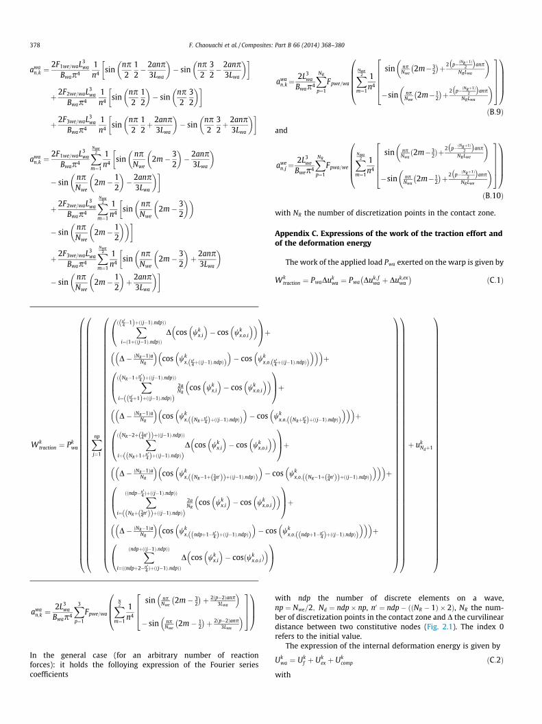
In the general case (for an arbitrary number of reactionforces): it holds the folloying expression of the Fourier seriescoefficients
awan;k¼
2L3wa
Bwap4
XNR
p¼1
Fpwe=wa
XNwe2
m¼1
1n4
sin npNwe
2m�32
� �þ2 p�ðNRþ1Þ
2
� �anp
NRLwa
� �
�sin npNwe
2m�12
� �þ2 p�ðNRþ1Þ
2
� �anp
NRLwa
� �266664
377775
0BBBB@
1CCCCA
ðB:9Þ
and
awen;j ¼
2L3we
Bwep4
XNR
p¼1
Fpwa=we
XNwa2
m¼1
1n4
sin npNwað2m�3
2Þþ2 p�ðNRþ1Þ
2
� �anp
NRLwe
� �
�sin npNwa
2m�12
� �þ2 p�ðNRþ1Þ
2
� �anp
NRLwe
� �266664
377775
0BBBB@
1CCCCA
ðB:10Þ
with NR the number of discretization points in the contact zone.
Appendix C. Expressions of the work of the traction effort andof the deformation energy
The work of the applied load Pwa exerted on the warp is given by
Wktraction ¼ PwaDuk
wa ¼ Pwa Duk; fwa þ Duk;ex
wa
� �ðC:1Þ
with ndp the number of discrete elements on a wave,np ¼ Nwe=2; Nd ¼ ndp� np, n0 ¼ ndp� ððNR � 1Þ � 2Þ, NR the num-ber of discretization points in the contact zone and D the curvilineardistance between two constitutive nodes (Fig. 2.1). The index 0refers to the initial value.
The expression of the internal deformation energy is given by
Ukwa ¼ Uk
f þ Ukex þ Uk
comp ðC:2Þ
with
Ukex ¼
Xnp
j¼1
Xððn04�1Þþððj�1Þ�ndpÞÞ
i¼ð1þððj�1Þ�ndpÞÞ
12 Ck
ei ukiþ1 � uk
i
� �2 þ 12 Ck
e1 i ukðn04þ1Þþ ðj�1Þ�ndpð Þð Þ � uk
n04þððj�1Þ�ndpÞð Þ
� �2
þXððNR�1Þþn04þððj�1Þ�ndpÞÞ
i¼ ðn04þ1Þþððj�1Þ�ndpÞð Þ12 Ck
e2 i ukiþ1 � uk
i
� �2 þ 12 Ck
e1 i ukðNRþ1Þþn0
4þ ðj�1Þ�ndpð Þð Þ � ukNRþn0
4þððj�1Þ�ndpÞð Þ
� �2
þXððNR�2Þþ3�n04 þððj�1Þ�ndpÞÞ
i¼ ðNRþ1Þþn04þððj�1Þ�ndpÞð Þ
12 Ck
ei ukiþ1 � uk
i
� �2 þ 12 Ck
e1 i ukNRþ3�n0
4 þ ðj�1Þ�ndpð Þð Þ � ukðNR�1Þþ3�n0
4 þððj�1Þ�ndpÞð Þ
� �2
þXðndp�n0
4þððj�1Þ�ndpÞÞ
i¼ NRþ3�n04 þ ðj�1Þ�ndpð Þð Þ
12 Ck
e2 i ukiþ1 � uk
i
� �2 þ 12 Ck
e1 i ukndpþ2�n0
4þ ðj�1Þ�ndpð Þð Þ � ukndpþ1�n0
4þððj�1Þ�ndpÞð Þ
� �2
þXðndpþððj�1Þ�ndpÞÞ
i¼ ndpþ2�n04þððj�1Þ�ndpÞð Þ
12 Ck
ei ukiþ1 � uk
i
� �2
266666666666666666666666666664
377777777777777777777777777775
ðC:3Þ
UkF ¼
Xnp
j¼1
Xððn04�1Þþððj�1Þ�ndpÞÞ
i¼ 1þ ðj�1Þ�ndpð Þð Þ
12 Ck
fi wkx;iþ1 � wk
x;i
� �2þ 1
2 Ckf1 i wk
x; ðn04þ1Þþððj�1Þ�ndpÞð Þ � wkx; n0
4þ ðj�1Þ�ndpð Þð Þ� �2
þXððNR�1Þþn04þððj�1Þ�ndpÞÞ
i¼ ðn04þ1Þþððj�1Þ�ndpÞð Þ12 Ck
f2 i wkx;iþ1 � wk
x;i
� �2þ 1
2 Ckf1 i wk
x; ðNRþ1Þþn04þ ðj�1Þ�ndpð Þð Þ � wk
x; NRþn04þ ðj�1Þ�ndpð Þð Þ
� �2
þXððNR�2Þþ3�n04 þððj�1Þ�ndpÞÞ
i¼ ðNRþ1Þþn04þððj�1Þ�ndpÞð Þ
12 Ck
fi wkx;iþ1 � wk
x;i
� �2þ 1
2 Ckf1 i wk
x; NRþ3�n04 þ ðj�1Þ�ndpð Þð Þ � wk
x; ðNR�1Þþ3�n04 þððj�1Þ�ndpÞð Þ
� �2
þXðndp�n0
4þððj�1Þ�ndpÞÞ
i¼ NRþ3�n04 þððj�1Þ�ndpÞð Þ
12 Ck
f2 i wkx;iþ1 � wk
x;i
� �2þ 1
2 Ckf1 i wk
x; ndpþ2�n04þððj�1Þ�ndpÞð Þ � wk
x; ndpþ1�n04þ ðj�1Þ�ndpð Þð Þ
� �2
þXðndp�1þððj�1Þ�ndpÞÞ
i¼ ndpþ2�n04þððj�1Þ�ndpÞð Þ
12 Ck
fi wkx;iþ1 � wk
x;i
� �2þXnp�1
i¼1
12 Ck
fi wkx; ðndp:iÞþ1ð Þ � wk
x; ndp:ið Þ
� �2
266666666666666666666666666664
377777777777777777777777777775
ðC:4Þ
Fig. D.1. Sectional view of the transverse compression device.
F. Chaouachi et al. / Composites: Part B 66 (2014) 368–380 379
The coefficients Ce, Ce1, Ce2, Cf , Cf 1, Cf 2 therein are respectively theyarn rigidities in extension and flexion, expressed versus the yarntensile and flexural rigidities by
Ce ¼EAwa
D; Ce1 ¼
EAwa
D� ðNR�1Þ�aNR
; Ce2 ¼EAwa
2�aNR
; Cf ¼EIwa
D; Cf1
¼ Bwa
D� ðNR�1Þ�aNR
; Cf2¼ Bwa
2�aNR
and
Ukcomp ¼
Lwas
K1C1 � dwa;k
comp
� �ln 1�
dwa;kcomp
C1
!þ dwa;k
comp
" #ðC:5Þ
Lwas is the curvilinear length of a warp yarn; C1, K1 are the Kawabata
constants of the warp, and dwa;kcomp represent the deformation under
compression of the warp.
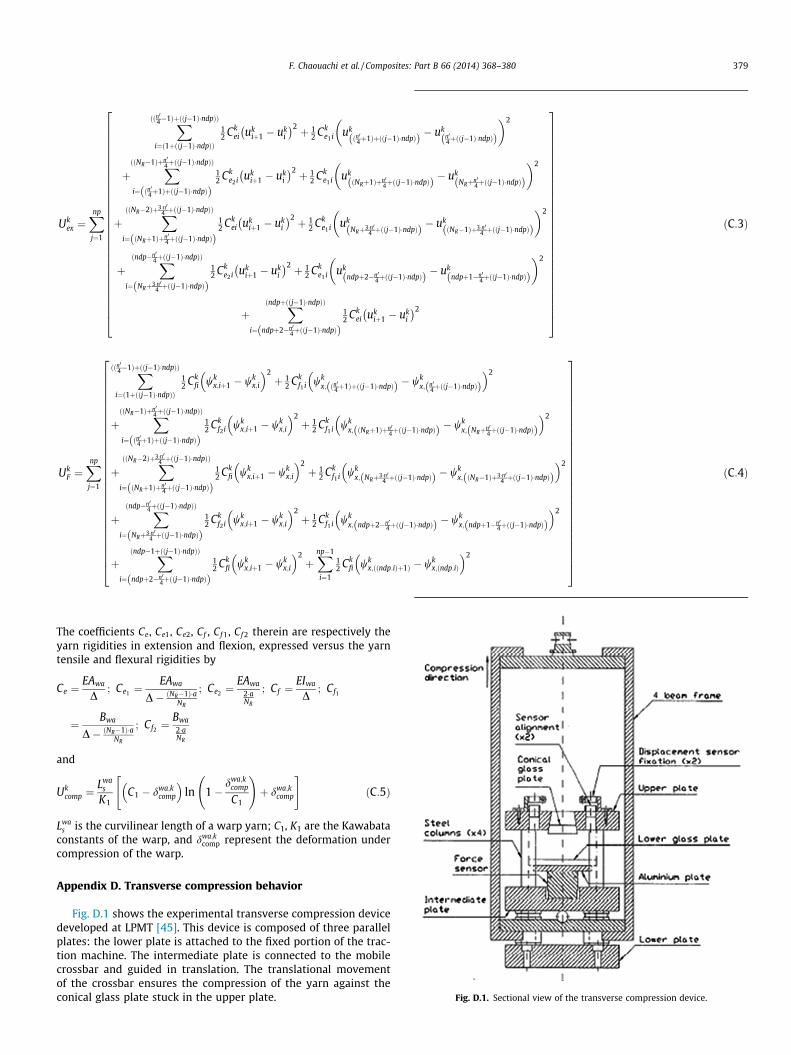
Appendix D. Transverse compression behavior
Fig. D.1 shows the experimental transverse compression devicedeveloped at LPMT [45]. This device is composed of three parallelplates: the lower plate is attached to the fixed portion of the trac-tion machine. The intermediate plate is connected to the mobilecrossbar and guided in translation. The translational movementof the crossbar ensures the compression of the yarn against theconical glass plate stuck in the upper plate.

Fig. D.2. Transverse compression response of the weft yarns [45].
Fig. D.3. Transverse compression response of the warp yarns [45].
380 F. Chaouachi et al. / Composites: Part B 66 (2014) 368–380
Furthermore, two displacement sensors, with measurementrange �1 mm, directly in contact with the glass plate, used to mea-sure the relative movement between the two compression plates.A force sensor, placed under the tested yarn, measures the com-pressive force exerted on the sample. The adopted compressionspeed is 1 mm/min. The experimental results of the compressionmeasurements are exposed in Figs. D.2 and D.3. The compressionconstants given in Table 2 are determined from Kawabata model(see Eq. (19)), the non-linear least squares method and the com-pression measurements.
References
[1] Tabiei A, Yi WT. Comparative study of predictive methods for woven fabriccomposite elastic properties. Compos Struct 2002;58:149–64.
[2] Lomov SV, Ivanov DS, Verpoest I, Zako M, Kurashiki T, Nakai H, et al. Meso-FEmodelling of textile composites: road map, data flow and algorithms. ComposSci Technol 2007;67:1870–91.
[3] Durville D. Modélisation par éléments finis des propriétés mécaniques destructures textiles: de la fibre au tissu. Euro J Comput Mech 2002;11:463–77.
[4] Hearle JWS, Grosberg P, Baker S. Structural mechanics of fibers. Yarns andfabrics, vol. 1. New York (USA): John Wiley and Sons; 1969.
[5] Kawabata S, Niwa M, Kawai H. Finite-deformation theory of plain-weavefabrics – 1. The biaxial-deformation theory. J Text Inst 1973;64:21–46.
[6] Kawabata S, Niwa M, Kawai H. Finite-deformation theory of plain-weavefabrics – 2. The uniaxial-deformation theory. J Text Inst 1973;64:47–61.
[7] Kawabata S, Niwa M, Kawai H. Finite-deformation theory of plain-weavefabrics – 3. The shear-deformation theory. J Text Inst 1973;64:62–85.
[8] Realff ML, Boyce MC, Backer S. A micromechanical model of the tensilebehavior of woven fabric. Text Res J 1997;67:445–59.
[9] Kato S, Yoshiro T, Minami H. Formulation of constitutive equations for fabricmembranes based on the concept of fabric lattice model. Eng Struct1999;21:691–708.
[10] Ben Boubaker B, Haussy H, Ganghoffer JF. Consideration of the yarn–yarninteractions in meso/macro discrete model of fabric. Part I: Single yarnbehaviour. Mech Res Commun 2007;34:359–70.
[11] Ben Boubaker B, Haussy H, Ganghoffer JF. Consideration of the yarn–yarninteractions in meso/macro discrete model of fabric. Part II: Woven fabricunder uniaxial and biaxial extension. Mech Res Commun 2007;34:371–9.
[12] Ben Boubaker B, Haussy H, Ganghoffer JF. Discrete woven structure model:yarn-on-yarn friction. Compt Rend Méc 2007;335:150–8.
[13] Assidi M, Ben Boubaker B, Ganghoffer JF. Equivalent properties of monolayerfabric from mesoscopic modelling strategies. Int J Solids Struct 2011;48:2920–30.
[14] Realff ML. Mechanical properties of fabrics woven from yarns produced bydifferent spinning technologies. Ph.D. Thesis. Massachusetts Institute ofTechnology; 1992.
[15] Komeili M, Milani AS. On the effect of uncertainly factors on mechanicalbehavior of woven fabric composites at meso-level. ASME Int Mech Eng CongExpos Proc 2010;11:253–7.
[16] Boisse P, Borr M, Buet K, Cherouat A. Finite element simulations of textilecomposite forming including the biaxial fabric behavior. Composites Part B1997;28B:453–64.
[17] Boisse P, Gasser A, Hivet G. Analyses of fabric tensile behaviour: determinationof the biaxial tension-strain surfaces and their use in forming simulations.Composites Part A 2001;32:1395–414.
[18] Rattensperger H, Eberhardsteiner J, Mang HA. Numerical investigation of highpressure hydraulic hoses with steel wire braid. In: IUTAM symposium oncomputational mechanics of solid materials at large strains; 2003. p. 407–16.
[19] Tanov RR, Brueggert M. Finite element modelling of non-orthogonal looselywoven fabrics in advanced occupant restraint systems. Finite Elem Anal Des2003;39:357–67.
[20] Boisse P, Zouari B, Gasser A. A mesoscopic approach for the simulation ofwoven fibre composite forming. Compos Sci Technol 2005;65:429–36.
[21] Boisse P, Zouari B, Daniel J. Importance of in-plane shear rigidity in finiteelement analyses of woven fabric composite performing. Composites Part A2006;37:2201–12.
[22] Hamila N, Boisse P, Sabourin F, Brunet M. A semi-discrete shell finite elementfor textile composite reinforcement forming simulation. Int J Numer MethodsEng 2009;79:1443–66.
[23] Shockey DA, Elrich DC, Simons JW. Improved barriers to turbine enginefragments: interim report I; 1999a. DOT/FAA AR-99/8, I.
[24] Shockey DA, Elrich DC, Simons JW. Improved barriers to turbine enginefragments: interim report II; 1999b. DOT/FAA AR-99/8, II.
[25] Shockey DA, Elrich DC, Simons JW. Improved barriers to turbine enginefragments: interim report III; 2001. DOT/FAA AR-99/8, III.
[26] Ng S, Tse P, Lau K. Numerical and experimental determination of the in-planeelastic properties of 2/2 Twill weave fabric composites. Composites Part B1998;29B:735–44.
[27] Duan Y, Keefe M, Bogetti TA, Powers B. Finite element modeling of transverseimpact on a ballistic fabric. Int J Mech Sci 2006;48:33–43.
[28] Zhang GM, Batra RC, Zheng J. Effect of frame size, frame type, and clampingpressure on the ballistic performance of soft body armor. Composites Part B2008;39:476–89.
[29] Talebi H, Wong SV, Hamouda AMS. Finite element evaluation of projectile noseangle effects in ballistic perforation of high strength fabric. Compos Struct2009;87:314–20.
[30] Peng X, Cao J. Numerical determination of mechanical elastic constants oftextile composites. Proc – Am Soc Compos 2000:677–88.
[31] Peng X, Cao J. A dual homogenization and finite element approach for materialcharacterization of textile composites. Composites Part B 2002;33:45–56.
[32] Peng X, Cao J. A continuum mechanics-based non-orthogonal constitutivemodel for woven composite fabrics. Composites Part A 2005;36:859–74.
[33] Xue P, Peng X, Cao J. A non-orthogonal constitutive model for characterizingwoven composites. Composites Part A 2003;34:183–93.
[34] Xue P, Cao J, Chen J. Integrated micro/macro-mechanical model of wovenfabric composites under large deformation. Compos Struct 2005;70:69–80.
[35] Baseau E. Finite deformation of elastic–plastic filamentary networks. Int JNonlinear Mech 2003;38:1473–9.
[36] King MJ, Jearanaisilawong P, Socrate S. A continuum constitutive model for themechanical behavior of woven fabrics. Int J Solids Struct 2005;42:3867–96.
[37] Parsons EM, King M, Socrate S. Modeling yarn slip in woven fabric at thecontinuum level: simulations of ballistic impact. J Mech Phys Solids2013;61:265–92.
[38] Landau L, Lifchitz E. Théorie de l’élasticité. Mir, Moscou; 1967.[39] Timoshenko S. Théorie de la Stabilité Élastique. Beranger, Paris and Liège;
1947.[40] Aublin M, Boncompain R, Boulaton M, Caron D, Jeay E, Lacage B, et al. Systèmes
mécaniques. Théorie et dimensionnement. Paris: Dunod; 1998.[41] Laura B, Gilles D, Gérard B. Mechanical behaviour of plain-knit reinforced
injected composites: effect of inlay yarns and fibre type. Composite Part B2013:20–9.
[42] Djaja RG, Moss PJ, Carr AJ. Finite element modeling for an oriented assembly ofcontinuous fibers. Text Res J 1992:445–57.
[43] Kawabata S. Nonlinear mechanics of woven and knitted materials. In: ChouTW, Ko FK, editors. Textile structural composites, vol. 3. Amsterdam: Elsevier;1989. p. 67–116.
[44] Charmetant A, Vidal-Salle E, Boisse P. Hyperelastic modelling for mesoscopicanalyses of composite reinforcements. Compos Sci Technol 2011;71:1623–31.
[45] Jeguirim S, Fontaine S. Internal report, LPMT. Université de Haute-Alsace,Mulhouse, France; 2008.
[46] Curiskis JI, Carnaby GA. Continuum mechanics of the fiber bundle. Text Res J1985:334–44.
[47] Chen X. Modelling and predicting textile behaviour. Woodhead publishingseries in textiles. University of Manchester; 2010.
[48] Alagirusamy R, Das A. Technical textile yarns: industrial and medicalapplications. Woodhead publishing series in textiles. CRC Press; 2010.