1.0 GENERAL 1.1 REQUIREMENTS A. Furnish and install a new ...
54
(Adhered) Page 1 of 17 1.0 GENERAL 1.1 REQUIREMENTS A. Furnish and install a new weather and watertight --- Adhered High Performance KEE Fleeceback Thermoplastic Roofing System that complies with ASTM D6754 Standard Specification for Ketone Ethylene Ester Based Sheet Roofing. B. Basis of design is FiberTite KEE 50 mil XT Fleeceback membrane. C. Alternate KEE membrane substitution must have certification, by letter from the Membrane Roof System Manufacturer (MRSM), stating that the submitted project specific membrane formulation has a minimum of 20 years of successful performance history in the state of Florida. Roof system manufacturer must provide locations to be visited for performance inspection by the Architect Engineer and/or Owner. D. Alternate KEE membrane substitution must provide testing report from an approved third party testing agency, verifying the percentage of KEE content to be compliance with ASTM D 6754. 1.2 SUBSTITION PROCEDURES A. Owner will consider requests for Substitutions by the Bidder only (not materials suppliers, etc.) Submit list of proposed substitutions as part of project startup documents. B. Document each request with complete data substantiating compliance of proposed Substitution with Contract Documents. C. A request constitutes a representation that the Bidder: 1. Has investigated proposed product and determined that it meets or exceeds ASTM 6754 and does not require extensive revisions. 2. Will coordinate installation and make changes to other work which may be required for the Work to be complete with no additional cost to Owner. 3. Waives claims for additional costs or time extension which may subsequently become apparent. D. Substitution Procedure. 1. Submit copy of request for Substitution for consideration to Owner no later than 10 days before bid opening date. 2. Submit shop drawings, product data, and applicable certified test results attesting to proposed product equivalence. Burden on proof is on proposer. 3. Owner will issue a written addendum of decision to accept or reject request of substitutions. E. Substitution will not be considered when they are indicated or implied on Submittals, without written request or when acceptance will require revision to the Contract Documents. 1.3 PROJECT SCOPE A. Roofing Contractor shall furnish all labor, materials, tools, equipment and supervision
-
Upload
khangminh22 -
Category
Documents
-
view
0 -
download
0
Transcript of 1.0 GENERAL 1.1 REQUIREMENTS A. Furnish and install a new ...

(Adhered) Page 1 of 17
1.0 GENERAL
1.1 REQUIREMENTS
A. Furnish and install a new weather and watertight --- Adhered High Performance KEE Fleeceback Thermoplastic Roofing System that complies with ASTM D6754 Standard Specification for Ketone Ethylene Ester Based Sheet Roofing.
B. Basis of design is FiberTite KEE 50 mil XT Fleeceback membrane.
C. Alternate KEE membrane substitution must have certification, by letter from the Membrane Roof System Manufacturer (MRSM), stating that the submitted project specific membrane formulation has a minimum of 20 years of successful performance history in the state of Florida. Roof system manufacturer must provide locations to be visited for performance inspection by the Architect Engineer and/or Owner.
D. Alternate KEE membrane substitution must provide testing report from an approved third party testing agency, verifying the percentage of KEE content to be compliance with ASTM D 6754.
1.2 SUBSTITION PROCEDURES
A. Owner will consider requests for Substitutions by the Bidder only (not materials suppliers, etc.) Submit list of proposed substitutions as part of project startup documents.
B. Document each request with complete data substantiating compliance of proposed Substitution with Contract Documents.
C. A request constitutes a representation that the Bidder:
1. Has investigated proposed product and determined that it meets or exceeds ASTM 6754 and does not require extensive revisions.
2. Will coordinate installation and make changes to other work which may be required for the Work to be complete with no additional cost to Owner.
3. Waives claims for additional costs or time extension which may subsequently become apparent.
D. Substitution Procedure. 1. Submit copy of request for Substitution for consideration to Owner no later than
10 days before bid opening date. 2. Submit shop drawings, product data, and applicable certified test results attesting
to proposed product equivalence. Burden on proof is on proposer. 3. Owner will issue a written addendum of decision to accept or reject request of
substitutions. E. Substitution will not be considered when they are indicated or implied on Submittals,
without written request or when acceptance will require revision to the Contract Documents.
1.3 PROJECT SCOPE
A. Roofing Contractor shall furnish all labor, materials, tools, equipment and supervision
(Adhered) Page 2 of 17
necessary to complete the installation of a new High Performance Mechanically Attached KEE Roofing Membrane including roof related insulation and/or cover-boards, flashings, accessories and related metalwork in strict accordance with the contract, drawings and High Performance Membrane Roof System Manufacturer's (MRSM) most current specifications and details.
B. The roofing contractor shall be an "Authorized Roofing Contractor" of the MRSM in good standing and be fully knowledgeable of all the requirements within the contract documents as well as all job site conditions that could affect their work.
C. The roofing contractor shall confirm all given information and notify the building owner / owner's representative, prior to bid, of any conflicts that will affect the quality or cost of the proposal.
D. Failure to submit a timely pre-qualification proposal will be grounds for total rejection of the contractor's proposal.
1.4 QUALITY ASSURANCE
A. Manufacturer's Qualifications: The High Performance Membrane Manufacturer shall be an American owned company with no less than 25 years performance track record in the state of Florida.
B. Installer Qualifications: A licensed roofing contractor, authorized by the MRSM to install the type of roof system specified for this project.
C. Source Limitations: Obtain all components including roof insulation and/or cover-board, fasteners adhesives and other accessories as required, from the approved MRSM.
D. The specified membrane roofing system must consist of the materials required and be installed under the following criteria.
1. UL Listing; provide materials bearing Underwriters Laboratories (UL) marking / label on the packaging or containers indicating materials have been produced under UL classification and follow-up services.
2. FM Listing; provide membrane roofing system and materials that have been evaluated by FM Global (FM) for spread of flame, seam leakage, hail resistance and wind uplift. Identify materials with FM Approved marking / label.
i Fire/Windstorm Classification: FM 1-90 ii Hail Resistance: SH
E. The roofing contractor shall maintain an adequate number of skilled workers who are thoroughly trained and experienced in the necessary crafts, and who are completely familiar with the specified requirements and methods necessary for the proper performance of the work. No allowance will be made for lack of skill on the part of the workers.
F. Any deviations from contract, drawings and/or specifications must be submitted in writing for approval prior to implementation to the design professional representing the owner and the MRSM for acceptance / approval by both parties.
G. Upon completion of the roof installation the roofing contractor shall arrange for a quality assurance / warranty inspection by the Technical Service Department of the
(Adhered) Page 3 of 17
approved MRSM. Notice of the inspection date and time will be given to the owner / owner's representative at least 72 hours prior to the inspection taking place.
1.5 REFERENCES
A. ASTM D6754 Standard Specification for Ketone Ethylene Ester Based Sheet Roofing
B. ASTM D 751 Test Methods for Coated Fabrics
C. UL 790 Underwriters Laboratories (UL) - Fire Hazard Classifications
D. FM 4470 GM Global (FM) - Roof Assembly Classifications
E. National Roofing Contractors Association (NRCA) - Roofing and Waterproofing Manual
1.6 PERFORMANCE REQUIREMENTS
A. General Performance: completed high performance membrane roof system and base flashing shall withstand specified uplift pressures, thermally induced movement, and exposure to weather without failure due to defective manufacture, fabrication, installation or other defects in construction.
B. Material Compatibility: provide roofing materials that are compatible with one another under conditions of service and application required, as demonstrated by the MRSM based upon insitu field evidence of the roofing membrane/systems service life cycle greater than 20-years.
C. Roofing System Design: provide high performance membrane roofing system that is identical to systems that have been successfully tested by a qualified testing and inspecting agency to resist wind uplift pressure calculated according to ASCE-7.
1.7 SUBMITTAL REQUIREMENTS
A. General Performance: completed high performance membrane roof system and base flashing shall withstand specified uplift pressures, thermally induced movement, and exposure to weather without failure due to defective manufacture, fabrication, installation or other defects in construction.
B. Material Compatibility: provide roofing materials that are compatible with one another under conditions of service and application required, as demonstrated by the MRSM based upon insitu field evidence of the roofing membrane/systems service life cycle greater than 20-years.
C. Roofing System Design: provide high performance membrane roofing system that is identical to systems that have been successfully tested by a qualified testing and inspecting agency to resist wind uplift pressure calculated according to ASCE-7.
1.8 PRODUCTS AND/OR WORK NOT INCLUDED IN THIS SPECIFICATION
A. Rough Carpentry; wood nailers and wood blocking
B. Masonry; waterproofing, through wall flashing, scupper openings
C. Plumbing; installation of any roof drains
D. Electrical; rooftop electrical penetrations

(Adhered) Page 4 of 17
E. Mechanical; rooftop HVAC equipment installation
1.9 PRODUCT DELIVERY, STORAGE AND HANDLING
A. Deliver all materials to the job site in manufacturer's original, unopened containers, with legible labels and in sufficient quantity to allow for continuity of work.
B. Select and operate material handling equipment in a safe manner, guarding against damage to existing construction or newly applied roofing and conforming to manufacturer's recommendations of handling and storage.
C. All rolls of membrane shall be stored, lying down, elevated above the roof deck and completely protected from moisture with tarpaulins. (Manufacturer's packaging is not considered adequate for outdoor storage.)
D. Insulation and cover board materials shall be elevated on pallets and fully protected from moisture with tarpaulins. (Manufacturer's packaging is not considered adequate protection from moisture.)
E. Adhesives and sealants shall be safely stored between 50° F and 80°F prior to use.
F. Flammable materials shall be stored in a cool, dry area away from sparks and open flames. Follow all precautions as outlined in manufacturer's Material Safety Data Sheets.
G. Materials, having been determined by the owner/owner's representative to be damaged, shall be immediately removed from the construction site and replaced at no cost to the owner.
1.10 COORDINATION
A. Prior to installation of materials, a pre-roofing conference shall be held with the roofing contractor, general contractor, owner/owner's representative(s) and representatives of all trades that may be working on the roof / completed membrane to discuss the specified roofing system, coordinate its proper application and the expectations of all parties involved. The authorized roofing contractor and the owner/owner's representative shall notify all parties a minimum of fourteen days prior to the meeting.
B. Plan and coordinate the installation of the roofing system with other trades in such a manner to avoid membrane damage, keeping the complete installation weather tight and in accordance with all approved details and warranty requirements.
C. A Technical Representative of the MRSM shall be available to make recommendations necessary to ensure compliance with project specifications and specification alternatives due to unforeseen job conditions.
D. Topics of discussion at the pre-construction meeting may include the following:
1. Utility Usage
2. Sanitary Facilities
3. Material Storage Areas
4. Roof loading areas
5. Site Access

(Adhered) Page 5 of 17
6. Roof Access
7. Project security
8. Rooftop Penetrations
9. Completed Roof Protection
10. Employee parking
1.11 JOB CONDITIONS
A. Safety
1. Take all necessary precautions regarding worker health and safety when using solvents, adhesives and hot asphalt.
2. Store flammable liquid and materials away from open sparks, flames and extreme heat.
3. Take necessary precautions when using solvents and adhesives near fresh air intakes.
4. Comply with all OSHA requirements for construction. It is the roofing contractor's responsibility to comply with all state, federal and local codes, guidelines and safety requirements.
5. Daily site cleanup shall be performed to minimize debris and hazardous congestion.
6. Roof work involves handling combustible and heavy materials at height, on some occasions directly over other trades working below the roof deck or in cases of occupied buildings, over building occupants. Extreme caution will be utilized when installing the roof to prevent injury to roofing personnel, other trades, building occupants and to property. Listed below is a partial list of safety requirements, additional requirements exist in order to comply with OSHA and jobsite regulations.
7. Material Safety Data Sheets (MSDS) shall be maintained on the jobsite for any and all roofing materials being stored or installed on the project.
8. Fire suppression equipment will be readily available on the roof top whenever combustible roofing material is being handled. Protect against fire and flame spread at all times.
9. Roofing contractor will establish a safety plan and rooftop evacuation procedures and brief his personnel on appropriate emergency actions.
B. Protection
1. Schedule installation sequence to limit access and utilization of the newly installed membrane for material storage, construction staging, mechanical and/or excessive foot traffic.
2. Provide proper protection on all newly completed roofing to avoid damage to the new roofing system.
3. Traffic should be minimized on a freshly laid roof.
(Adhered) Page 6 of 17
4. Protect building walls, rooftop units, windows and other components during installation.
C. Additional Precautions
1. Adverse weather conditions e.g. extreme temperature, high winds, high humidity and moisture, could have a detrimental effect on adhesives, general production efforts and/or the quality of the finished installation. Contact Manufacturers Technical Rep for recommendations and acceptable tolerances.
2. Daily production schedules of new roofing shall be limited to only that which can be made 100% watertight at the end of the day, including all flashing and night seals.
3. All surfaces to receive new roof system, including insulation and flashing, shall be free from all dirt, debris and be thoroughly dry.
4. Comply with local EPA requirements as published by Local, State and Federal authorities.
5. All construction debris shall be removed from the construction site and legally dispose of off site.
6. If a condition is discovered that is not covered by the project drawings and specifications notify the general contractor and owner's representative immediately and resolve the conflict. Take appropriate steps to prevent water intrusion into the roof system until such conflict is resolved and roofing operations are continued.
1.12 WARRANTY
A. Provide manufacturer's 20 Year No Dollar Limit Warranty. All materials to be supplied by membrane manufacturer to be covered under warranty.
B. Provide contractor's warranty covering leaks caused by material defects and or installation workmanship for a period of two years.
2.0 PRODUCTS
2.1 GENERAL
A. All roofing system components shall be manufactured or supplied by approved MRSM.
B. Unless approved otherwise prior to project bid, all roofing components are to be manufactured or supplied through approved MRSM and be included in the warranty coverage.
2.2 MEMBRANE
A. A nominal 50-mil ketone ethylene ester (KEE) FEECEBACK membrane, reinforced with a 6.5-oz yd² knitted polyester fabric with a 4-oz yd² non-woven polyester fabric heat bonded to the backside. KEE membrane must meet or exceed all requirements outlined ASTM D 6754 - 02 Standard Specification for Ketone Ethylene Ester (KEE) Sheet Roofing. Membrane color shall be DC196 Off-White

(Adhered) Page 7 of 17
2.3 FLASHING MEMBRANE
A. The KEE membrane shall be used for all flashing requirements to match the field membrane milage and warranty expectations selected for the roofing system.
2.4 COVERBOARD
A. Cover-board (insulation overlayment) shall be a water resistant gypsum core substrate conforming to the following:
1. FM approved meeting Class A 1-90, for fire and wind.
2. UL Classification: Class A Assembly.
3. Meet requirements of ASTM C 473
B. Approved Cover Board supplied by MRSM.
1. 1/2 in. Securock Gypsum Fiber
2. 1/2 in. Dexcell FA
2.5 ROOF ACCESSORIES
A. Furnish accessories manufactured, marketed or approved by MRSM required to complete the roof installation to manufacturer's specification including (as applicable) but not limited to the items listed below.
1. ADHESIVES; application technique and coverage rates will vary according to substrate and environmental conditions.
i KEE Bonding Adhesive; A VOC compliant solvent borne, contact (two sided) bonding adhesive, designed for bonding non-fleece back KEE membrane / flashing to properly prepared and pre-authorized vertical substrates and smoothback membrane applications.
ii. Foam Adhesive - Dual component, single bead (ribbon applied) urethane insulation adhesive. Adhesive is a non-solvent, elastomeric, urethane adhesive, specifically designed for bonding single or multiple layers of roof insulation and insulation composites and/or cover boards to structural roof decks and base sheets.
iii. Fleeceback Adhesive; a polymeric water borne, VOC compliant bonding adhesive, one side application (substrate only), designed for bonding KEE-FB (fleece back) membranes to properly prepared and pre-authorized horizontal substrates.
2. Flashing Sealant; a one-component gun-grade polyurethane sealant to seal flashing termination.
3. Pourable Sealant; a one-component pourable, self leveling, polyurethane sealant to fill "pitch pans". Pitch pans are to be avoided whenever possible.
(Adhered) Page 8 of 17
4. Liquid Flashing; polymethyl methacrylate (PMMA) liquid resin for use in aberrant penetrations and low flashing terminations. Liquid flashing areas must be pre-qualified by membrane manufacturer.
5. Clad Metal; to fabricate metal flashing, 4' x 10' sheets of 0.040 thick 3003H14 aluminum, laminated with a 0.020 mil polymeric coating.
6. Pre-Molded Flashing(s); injection molded vent stack and inside/outside corner flashing using KEE 741 compound.
7. Non-Reinforced Membrane; field fabrication membrane, 0.060 mil non-reinforced KEE membrane.
8. KEE Tuff Walk Way & Protection Pads; high grade walk way/protection material with "slip resistant" design.
9. Fasteners
i Membrane fasteners; to secure KEE membrane to steel, wood and structural concrete decks. A #15-13, buttress threaded, #3 Phillips head fastener constructed of case hardened carbon steel with a reduced diameter drill point and corrosion resistant coating.
ii Insulation fasteners; to secure insulation to steel, wood and structural concrete decks. A #14-13, heavy duty threaded steel #3 Phillips truss, self tapping corrosion resistant fastener.
10. ISOweld Plates; A 3” (75 mm) round, high-tensile, 22-gauge corrosion resistant steel plate with a KEE compatible polymeric coating used with approved fasteners to attach insulation boards to the structural deck and as a subsequent platform to induction weld the KEE Roofing Membrane.
11. Barbed Stress Plates; used to anchor membrane, is 19-ga., AZ50 galvalume steel; 1.5 by 2.75 in. (38 by 70 mm) oval stress distribution plate with barbs and has a 0.25 in. (6 mm) diameter center hole.
12. Insulation Stress Plates; used to secure insulation and/or cover-board to steel, wood and structural concrete decking. Manufactured from high density polyethylene, 3 inch in diameter, designed with a self locking mechanism to secure the head of the fasteners into the plate.
13. Termination Bar; membrane flashing(s) restraint/termination seals, nominal 1/8 inch x 1 inch x 10' 6060-T5 extruded aluminum bar with pre-punched slots, 8 inch on center.
14. Metal Fascia System; two piece "snap-on" pre-formed, architectural metal edge system. Must be supplied by membrane manufacturer and included in warranty.
2.6 WOOD NAILERS
A. Wood shall be No. 2 or better construction grade lumber.
B. Creosote or asphaltic type preservatives are not acceptable.
C. Minimum top nailer thickness shall be 1 ½ inches nominal.

(Adhered) Page 9 of 17
3.0 EXECUTION
3.1 GENERAL
A. The latest manufacturer specifications and installation techniques are to be followed along with the following additional requirements. These specific minimum requirements must be accounted for in the contractors bid / proposal and shall not be altered.
B. The roofing contractor is responsible for providing a suitable substrate surface for the proper installation of the Membrane Roofing System, roof insulation and specified components.
C. The roofing contractor shall examine all areas and conditions where by work in this section is to be installed.
D. Notify the Building Owner / Owner Representative of any and all conditions detrimental to the proper and timely execution of the work. Do not proceed until such conditions have been corrected to the satisfaction of the owner / owner's representative.
E. Commencement of roofing operations indicates the roofing contractor's acceptance of the roofing substrate for roof application.
3.2 SUBSTRATE PREPARATION
A. Surfaces scheduled to receive new membrane roofing shall be free of any standing water, dew, ice, loose debris or any other contaminate that could impair the quality of the installation.
B. Substrate shall be smooth, clean and free of sharp edges and or projections and obvious depressions that would interfere with the installation of a high quality high performance
C. Examine all the areas and conditions where by work in this section is to be installed. Correct any and all conditions detrimental to the proper and timely execution of the work. Do not proceed until such conditions have been corrected to the satisfaction of the owner / owner's representative.
D. Prepared substrate shall be smooth, dry, and free of debris and/or any other irregularities which would interfere with the proper installation of the roofing system.
E. Do not proceed with any part of the application until all defects and preparation work have been corrected and complete.
F. Adhesives will not bond to wet, damp or inadequately cured lightweight insulating concrete or poured structural concrete.
G. Reroofing applications that require modification to the deck and/or insulation system should be installed to provide positive slope and subsequent positive drainage of the new KEE Roofing System.
H. All terminations of the KEE Roofing System must be constructed to prevent water from penetrating behind or beneath the new KEE Roofing System. This includes water from above, beside, below and beneath the new system.
3.3 REMOVE OF EXISTING COATED MOD-BIT.
A. Remove all existing mod-bit roofing down to the existing lightweight concrete

(Adhered) Page 10 of 17
B. Remove only enough roofing to accommodate the day’s work and ensure the exposed area can be made 100% watertight at the end of the day or prior to inclement weather.
3.4 RECOVER EXISTING LIGHTWEIGHT CONCRETE.
A. Remove all loose debris and/or vacuum and legally dispose of off site.
B. Remove and replace all wet or deteriorated lightweight concrete with like kind.
C. Clean all exposed metal surfaces such as pipes, pipe sleeves, drains, duct work, etc., by removing loose paint, rust and any asphalt or coal tar pitch of any kind. Remove and properly discard lead sleeves at soil stacks.
D. Existing Lightweight Concrete
1. Deteriorated decking shall be repaired and/or replaced with appropriate materials according to standard industry regulations and practices.
2. Repair any depressions and/or areas where reinforcing has become exposed.
3. Before installing new coverboard using the approved adhesive:
i. Cracks and or camber differentials greater than 0.1875 of an inch shall be repaired using an appropriate cementitious grout or fill, and feathered to promote a smooth transition.
ii. All surface irregularities shall be leveled to ensure complete contact with the decking for insulation bonded in hot asphalt or approved adhesives.
3.5 WOOD NAILERS.
A. Install treated lumber at the same heights as insulation layer or adjacent construction ± 0.25 inch. Continuous treated wood nailers are to be installed at all perimeters, around roof projections and penetrations as shown in approved details.
B. Where wood nailers are installed directly on the substrate, the substrate shall be carefully examined to confirm that the entire area provides a suitable fastening surface. All defects shall be repaired by the appropriate trade prior to installation.
C. Nailers shall be at least 3.5 inches wide and 1.5 inches high and installed and anchored in such a manner to resist a force of 250 lbs. per linear foot of wood blocking in any direction.
D. Nailers along parapets, curbs and expansion joints are recommended for insulated decking. Consult KEE Construction Details or Technical Customer Services for optional/alternate membrane termination/securement methods.
3.6 INSTALLATION - GENERAL
A. Perform all related work specified in other sections of the contract documents necessary for the proper installation of the high performance high performance.
B. Ensure mechanical fasteners do not penetrate items located within or secured to the bottom of the deck: i.e. electrical conduit, post tension cables or other miscellaneous items.
C. Outside ambient air temperatures must be 40°F and rising during the use of any and all adhesives.
(Adhered) Page 11 of 17
3.7 ROOF INSULATION /COVERBOARD - GENERAL
A. Roof insulation and/or coverboard shall be installed where by the long dimension of the board(s) run in parallel alignment and the short dimensions are staggered.
B. Insulation and/or coverboard shall be installed with minimum joint dimensions and shall be tightly butted where possible. Maximum joint widths shall be 3/8". Damaged corners shall be cut out and replaced with an insulation piece a minimum of 12" x 12" pieces that are cut from larger panels and are smaller than one square foot are not acceptable.
C. Install no more than can be covered during the same working day.
D. Taper roof insulation to drain sumps using tapered edge strips. If an insulation layer is 1½" or less, taper 12" from the drain bowl. If insulation thickness exceeds 1½", taper 18" from the drain bowl. All taper boards or pieces must be adhered or mechanically fastened with a minimum of two fasteners per board.
E. When a cover board and/or multiple layers are installed each layer shall be offset from the previous layer a minimum of 12" on center.
F. At the end of each working day, provide a watertight cover on all unused insulation as to avoid moisture penetration.
3.8 COVERBOARD ATTACHMENT – ADHERED SYSTEMS
A. Coverboard shall be applied to and installed over properly prepared and pre-approved
substrates, free of any debris, dirt, grease, oil or moisture.
B. Foam Adhesive
1. Approved adhesive shall be applied only to properly prepared and pre-approved substrates, free of any debris, dirt, grease, oil or moisture.
2. The minimum product temperature at time of application shall be 70°F.
3. Approved adhesive shall not be applied when surface or ambient temperatures are below 40° or above 110° F.
4. Coverboard shall be fully bonded to the substrate with a maximum board size of 4 feet x 8 feet.
5. Coverboard shall be set into a continuous 1/2 inch bead of adhesive at a minimum rate of one linear foot of adhesive for every one square foot of coverboard.
6. Approved adhesive rates are to be increased in roof perimeter and corner zones according to specific project requirements and manufacturer's design recommendations.
7. Place the coverboards onto the adhesive beads and walk on the boards, spreading the adhesive for maximum contact.
8. A second walking will be required after ten (10) minutes to ensure maximum contact and bond strength.

(Adhered) Page 12 of 17
3.9 MEMBRANE INSTALLATION – GENERAL
A. Quality Control
1. It will be the responsibility of the roofing contractor to initiate and maintain a QC program to govern all aspects of the installation of the Membrane Roofing System.
2. The project foreman and or supervisor will be responsible for the daily execution of the QC program which will include but is not limited to the supervision, inspection and probing of all heat welding incorporated within the Membrane Roofing System.
3. If inconsistencies in the quality of the application of the composite, membrane and/or welds are found, all work shall cease until corrective actions are taken to ensure the continuity the installation.
B. General
1. Work shall be coordinated to ensure that sequencing of the installation promotes a 100% watertight installation at the end of each day.
2. All KEE Roofing Systems with Induction Weld shall be designed utilizing and determined to be in compliance with the procedures outlined within the current publication of ASCE Standard 7. Alternative designs may be determined using the criteria within Factory Mutual Research Loss Prevention Data.
3. A KEE Roofing Systems with Induction Weld may utilize either conventional roll goods or custom pre-welded panel rolls.
4. Restrictions regarding outside ambient air temperature are relative only to the exposure limits of the workers and/or adhesives when necessary.
5. When using adhesives outside ambient air temperature shall be above 40˚F. Curing or drying time of the adhesive will be affected by ambient temperatures and must be taken into consideration when determining flashing lengths.
6. Humidity can affect the drying time of solvent borne adhesives and/or cause condensation to form on the newly applied adhesive.
7. No moisture may be present on the adhesive(s) prior to mating or application of KEE membranes.
8. KEE Roofing Systems with Induction Weld shall only be installed over properly prepared and sound substrates, free from excessive surface roughness, dirt, debris and moisture.
3.10 MEMBRANE SECUREMENT – ADHERED
A. The authorized roofing contractor shall assume full responsibility for any and all irregularities, defects or quality issues that arise due to failure to following published installation guidelines for the proper installation of adhered KEE membrane roofing systems.
B. Membrane (without fleece backing) Adhered with KEE membrane Bonding Adhesive.

(Adhered) Page 13 of 17
a. Position the membrane and fold the sheet to allow a workable exposure of the underside of the sheet.
b. Apply a 100% continuous coat of bonding adhesive to the exposed bottom side of the membrane and a mirrored area of the substrate.
c. The amount of membrane and substrate that can be coated with adhesive will be determined by application method, ambient temperature, humidity and available manpower.
d. Adhesive may be applied by spraying and back rolling or just rolling. Do not dump adhesive or pour from the cans.
e. Roller applied adhesive shall utilize a solvent resistant ⅜”nap roller, spreading the adhesive to ensure a smooth, even 100% coverage of the substrate and membrane.
f. Spray applied adhesive must be spread out by roller to ensure a smooth, even 100% coverage of the substrate and membrane with no voids, skips, globs, puddles or similar irregularities. Note: a squeegee can be used to “flatten” or spread globs and puddles of adhesive.
g. Adhesive coverage should average 100 square feet per gallon of applied adhesive with a 50 square feet per gallon net coverage (± 10%) for the membrane and substrate combined.
h. Allow the adhesive to dry or cure to a point of being tacky, but not stringy to the touch on both surfaces. Do not allow adhesive to completely dry out on either surface.
i. When sufficiently cured, carefully maneuver the glued portion of the membrane onto the glued substrate surface, avoiding any wrinkles or air pockets.
j. Broom the adhered portion of the membrane to ensure full contact and complete the bonding process by firmly pressing the bonded membrane into place with a weighted, foam-covered, lawn roller.
k. Repeat the process for the remaining unbonded portion of the membrane, lapping subsequent, adjacent rolls of membrane a minimum of 3”, ensuring proper shingling of the membrane to shed water along the laps.
l. No adhesive shall be applied to the lap seam areas of the membrane. Contaminated areas will inhibit proper welding of the seams requiring a membrane patch or strip.
m. Do not use bad or marginal adhesives. Contact technical services if the quality of the adhesive is suspect.
3.11 HOT AIR WELDING
A. General
1. All field seams exceeding 10' in length shall be welded with an approved automatic welder.
2. All field seams must be clean and dry prior to initiating any field welding.
3. Remove foreign materials from the seams (dirt, oils, etc.) with MEK or authorized alternative.
4. Do not allow cleaning solvents to come in contact with the Kynar top finish when using Kynar membrane. Aggressive solvents will either mar or completely remove
(Adhered) Page 14 of 17
the top finish.
5. Use clean white cotton cloths and allow approximately five minutes for solvents to dissipate before initiating the automatic welder. Do not use denim or synthetic rags for cleaning.
6. Contaminated areas within a membrane seam will inhibit proper welding and will require a membrane patch.
7. All welding shall be performed only by qualified personnel to ensure the quality and continuity of the weld.
8. Keep the bottom of the Induction Weld tool and cooling magnets clean.
9. Continuous operation of the induction welding process can promote overheating of the cooling magnets. Periodically cool the magnets using clean water to prevent melting and/or scarring of the KEE membrane.
10. Follow the Induction Welder Tool manufacturer’s recommendations for periodic cleaning and maintenance for the equipment.
B. Hand Welding
1. The lap or seam area of the membrane may be intermittently tack welded to hold the membrane in place.
2. The back interior edge of the membrane shall be welded first, with a thin, continuous weld to concentrate heat along the exterior edge of the lap during the final welding pass.
3. The nozzle of the hand held hot air welder shall be inserted into the lap at a 45˚ angle to the lap. Once the polymer on the material begins to flow, a hand roller shall be use to apply pressure at a right angle to the tip of the hand welder. Properly welded seams shall utilize a 1½" wide nozzle, to create a homogeneous weld, a minimum of 1½" in width.
4. Smaller nozzles may be used for corners, and other field detailing, maintaining a minimum 1" weld.
C. Automatic Machine Welding
1. Proper welding of the KEE Membrane can be achieved with a variety of automatic welding equipment. Contact Technical Services for specific recommendations.
2. Follow all manufacturer instructions for the safe operation of the automatic welder.
3. Follow local code requirements for electric supply, grounding and surge protection.
4. The use of a dedicated, portable generator is highly recommended to ensure a consistent electrical supply, without fluctuations that can interfere with weld consistency.
5. Properly welded seams shall utilize a 1½" wide nozzle, to create a homogeneous weld, a minimum of 1½" width.
(Adhered) Page 15 of 17
3.12 INSPECTION
A. The job foreman and/or supervisor shall initiate daily inspections of all completed work which shall include, but is not limited to the probing of all field welding with a dull pointed instrument to assure the quality of the application and ensure that any equipment or operator deficiencies are immediately resolved.
B. Ensure that all aspects of the installation (sheet layout, attachment, welding, flashing details, etc.) are in strict accordance with the most current MRSM Specifications and Details.
C. Excessive patching of field seams because of inexperienced or poor workmanship will not be accepted at time of FINAL INSPECTION FOR WARRANTY ACCEPTANCE.
D. Any deviation from pre-approved specifications and/or details requires written authorization from MRSM Technical Services prior to application to avoid any warranty disqualification.
E. It is the contractor, job foreman, and supervisor and/or quality control personnel to perform a final self-inspection on all seams prior to requesting the inspection for warranty issuance by MRSM Technical Services.
3.13 FLASHING
A. Clean all vents, pipes, conduits, tubes, walls and stacks to bare metal. All protrusions must be properly secured to the roof deck with approved fasteners. Remove and discard all lead, pipes and drain flashing. Flash all penetrations according to approved details.
B. Remove all loose and/or deteriorated cant strips and flashing.
C. Flash all curbs, parapets and interior walls in strict accordance with approved MRSM details.
D. All flashing shall be adhered to properly prepared, approved substrate(s) with bonding adhesive applied in sufficient quantity to ensure total adhesion.
E. The base flashing of all membrane flashing shall extend out on to the plane of the deck, beyond the wood nailers to a maximum width of 8".
F. Vertical flashing shall be terminated no less than 8" above the plane of the deck with approved termination bar and counter-flashing or metal cap flashing.
G. When using trowel grade polymeric sealant (mastic) as the adhesive, vertical wall flashing termination shall not exceed 40" without supplemental mechanical attachment of the flashing between the deck and the termination point of the flashing.
H. Complete all inside and outside corner flashing details with KEE preformed corners or an approved field fabrication detail.
I. Probe all seams with a dull, pointed probe to ensure the weld has created a homogeneous bond.
J. Install penetration accessories in strict accordance with approved details. Ensure penetration accessories have not impeded in any way the working specification. (Refer to the related trade for the technical specification).
3.14 METAL FLASHING

(Adhered) Page 16 of 17
A. All perimeter edge details are to be fabricated from Polymeric-Clad Metal or utilize a prefabricated Fascia System.
B. Fasten all metal flashing to wood nailers or approved substrate with approved fasteners 8 inches on center.
C. Install metal flashing in accordance with MRSM Published Specifications and Construction Details.
3.15 ROOF DRAINS
A. Flash all roof drains in accordance with manufacturer roof drain details.
B. Minimum 60-mil non-reinforced membrane shall be used for flashing the drain assembly.
C. The drain target sheet should be sized and installed to provide for a minimum of 12 inch of exposed 60-mil on all sides of the drain
3.16 PITCH PANS
A. Every reasonable effort shall be made to eliminate the need for pitch pans including the removal of all existing pans. Contact MRSM Technical Services for specific design alternatives and recommendations.
B. In the event of no alternative, fabricate pitch pans from KEE Clad metal, installed in accordance with manufacturer details, ensuring proper attachment, maintaining a minimum of 2" clearance around the penetration.
C. Pitch pans shall be filled with non-shrinking grout to within 1" of the top of the pan. Allow the grout to dry and fill remainder of the pan with membrane manufacturers pourable sealant.
D. Pitch pans and the sealant will require periodic maintenance by the building owner’s maintenance personnel.
E. Pitch pans are maintenance items and shall not be considered as part of the warranty.
3.17 EXPANSION JOINTS
A. Flash all expansion joints in accordance with authorized/approved details. Fasten all expansion joint material according to MRSM specifications. Ensure the expansion material has sufficient material to expand to the widest point in expansion without causing undue stress on the expansion joint material.
B. If the expansion joint is a "pre-formed" system, the manufacturer, description and a drawing illustrating the method of installation must be included in the contractor's submittals.
3.18 SEALANTS
A. Apply authorized sealant(s) to all surface mounted reglets and per project requirements. Sealant(s) are to shed water. Follow all manufacturer's instructions and installation guides.
B. Use primer when recommended by the manufacturer.

(Adhered) Page 17 of 17
C. Sealants will require periodic maintenance by the building owner's maintenance personnel.
3.19 TEMPORARY SEALS
A. At the end of each working day or at the sign of rain, install temporary, 100% watertight seal(s) where the completed new roofing adjoins the uncovered deck.
B. If water is allowed to enter beneath the newly completed roofing, the affected area(s) shall be removed and replaced at no additional expense to the building owner.
C. Prior to the commencement of work, cut out and remove all contaminated membrane, insulation, roof cement or sealant and properly dispose off site.
3.20 WALKWAYS
A. Walkways and protection pads shall be installed at staging areas for roof top equipment maintenance or areas subject to regular foot traffic as designated by contract and/or drawings.
3.21 LIGHTNING PROTECTION
A. The installation of lightning protection must be coordinated with the authorized roofing contractor, UL certified lightning contractor and the building owner.
B. The lightning protection must be installed in such a manner that base plates, air terminals and cables do not penetrate the roofing membrane without the use of pre-approved flashing details.
3.22 COMPLETION
A. Remove any and all debris, excess materials and scrap of any kind from the roof and surrounding premises prior to demobilization.
B. Inspect all field welds, detailing and terminations to ensure a 100% the watertight installation.
3.23 WARRANTY INSPECTION
A. Upon completion of the project, the authorized roofing contractor shall complete and submit the MRSM Project Completion Notice.
B. Upon receipt of the notice of completion, a Technical Representative of the MRSM shall schedule an inspection with a representative of the authorized roofing contractor to thoroughly review the installation and verify compliance with MRSM specifications.
C. Any corrections or modifications necessary for compliance with the specifications and acceptance for warranty (punch list) will be noted on the Final Inspection for Warranty Form.
D. Upon completion of all punch list items and final acceptance of the installation, a warranty as authorized by the MRSM will be issued.

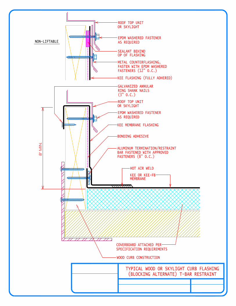
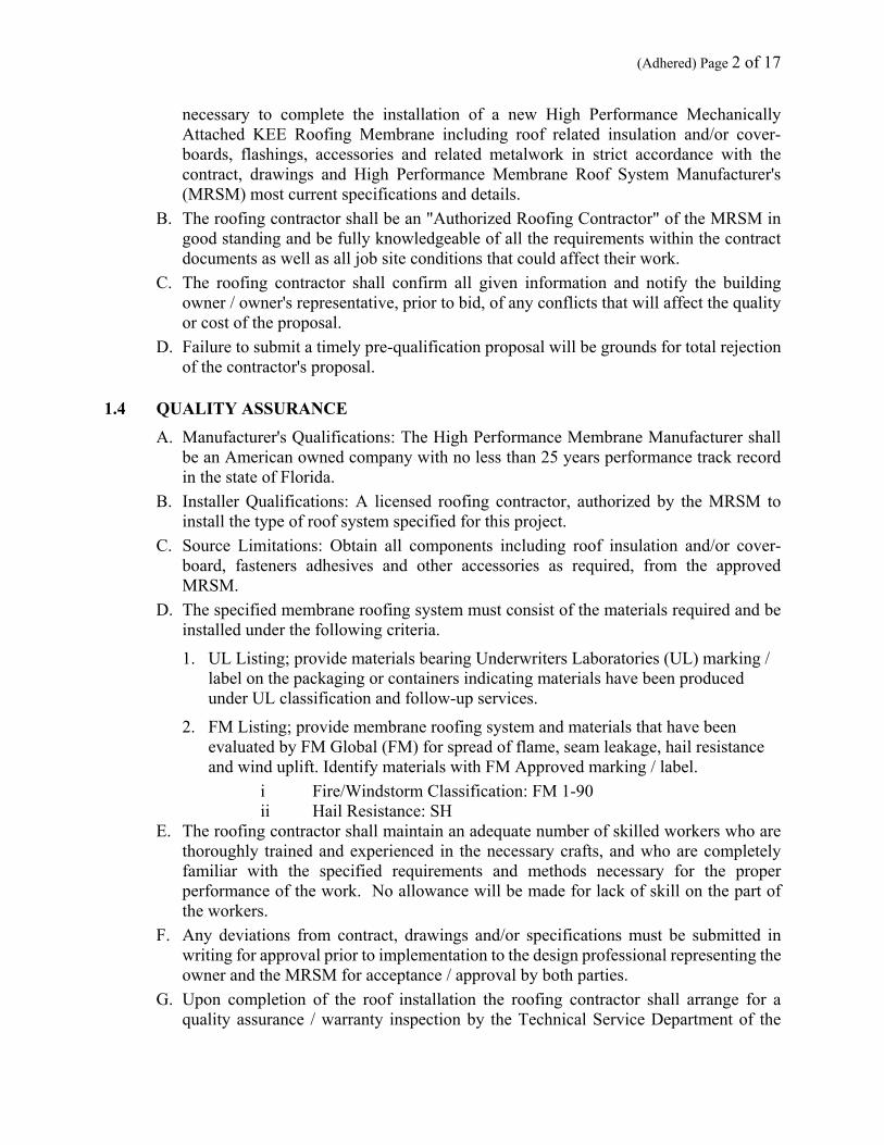
TYPICAL WOOD OR SKYLIGHT CURB FLASHING(BLOCKING ALTERNATE) T-BAR RESTRAINT
8" M
IN.
KEE OR KEE-FB MEMBRANE
HOT AIR WELD
COVERBOARD ATTACHED PER SPECIFICATION REQUIREMENTS
WOOD CURB CONSTRUCTION
NON-LIFTABLE
ROOF TOP UNITOR SKYLIGHT
EPDM WASHERED FASTENERAS REQUIRED
SEALANT BEHIND OP OF FLASHING
METAL COUNTERFLASHING,FASTEN WITH EPDM WASHERED FASTENERS (12" O.C.)
KEE FLASHING (FULLY ADHERED)
GALVANIZED ANNULARRING SHANK NAILS(3" O.C.)
ROOF TOP UNITOR SKYLIGHT
EPDM WASHERED FASTENERAS REQUIRED
KEE MEMBRANE FLASHING
BONDING ADHESIVE
ALUMINUM TERMINATION/RESTRAINT BAR FASTENED WITH APPROVEDFASTENERS (8" O.C.)
ROOFING SOLUTIONSINTELLIGENT

COVERBOARD ATTACHED PER SPECIFICATION REQUIREMENTS
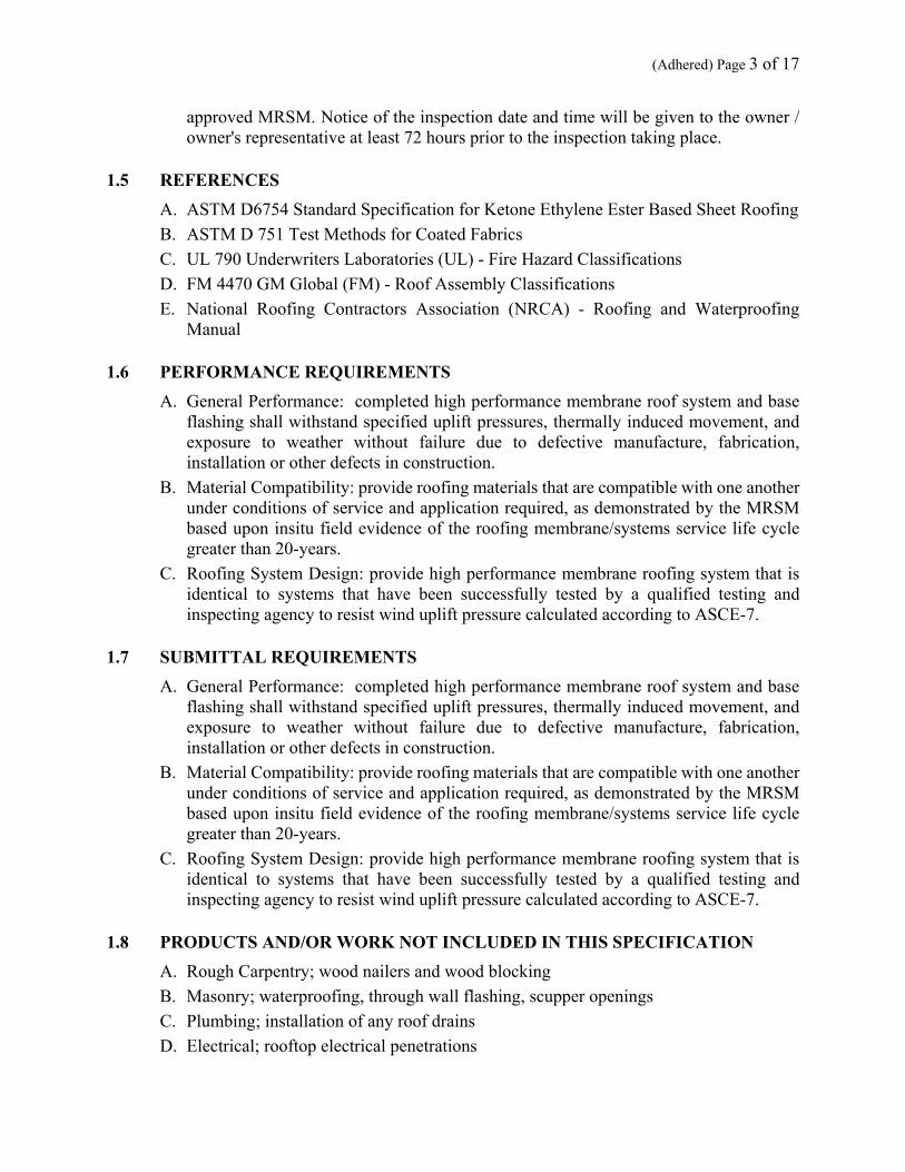
PIPE PENETRATION
SEALANT
STAINLESS STEEL WORM GEAR CLAMP
8" MIN.
FIELD FABRICATED PIPE FLASHING
ROOFING SOLUTIONSINTELLIGENT
BONDING ADHESIVE
NON-REINFORCED FIELD FORMED FLASHING MEMBRANE
HOT AIR WELD
FASTENER& STRESS PLATE(MIN. 4 FASTENERS)
NON-REINFORCED FIELD FORMED FLASHING MEMBRANE
HOT AIR WELD
KEE OR KEE-FB MEMBRANE
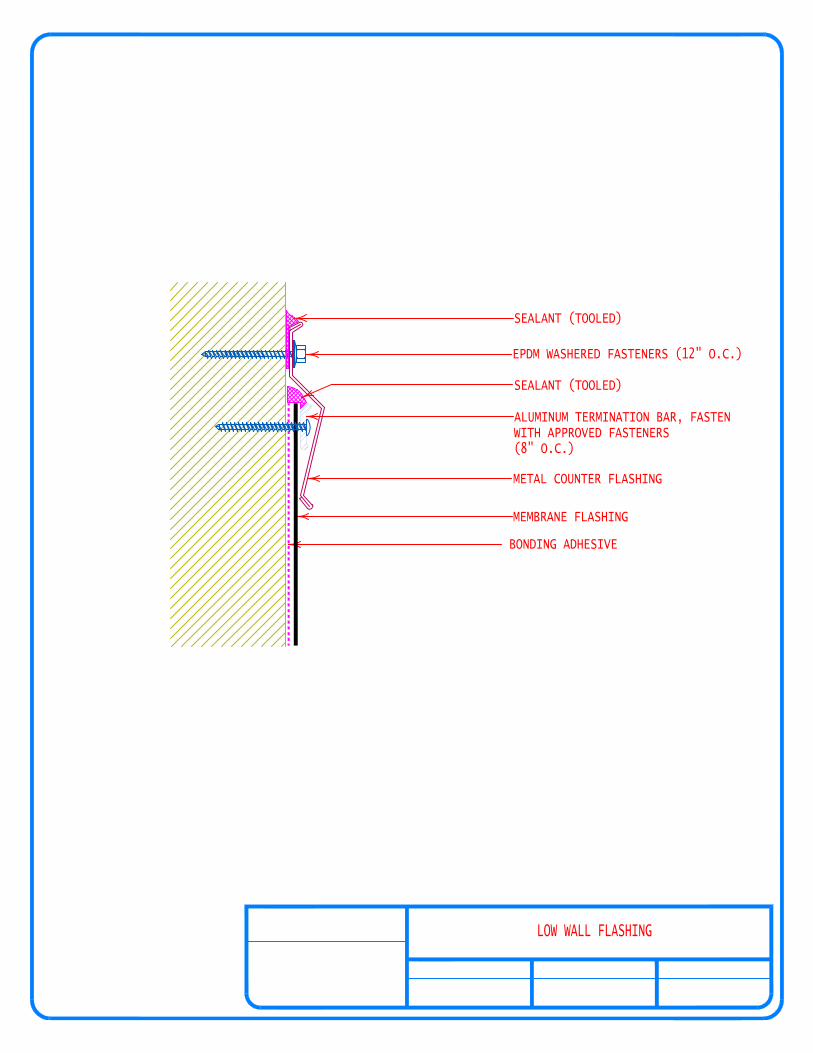
LOW WALL FLASHING
MEMBRANE FLASHING
BONDING ADHESIVE
SEALANT (TOOLED)
EPDM WASHERED FASTENERS (12" O.C.)
SEALANT (TOOLED)
ALUMINUM TERMINATION BAR, FASTEN WITH APPROVED FASTENERS(8" O.C.)
METAL COUNTER FLASHING
ROOFING SOLUTIONSINTELLIGENT

WALL FLASHINGWITH METAL CAP FLASHING
HOT AIR WELD
KEE SMOOTH OR FB MEMBRANE
ISO OR COVERBOARD ATTACHED PER SPECIFICATION REQUIREMENTS
CONTINUOUS GALVANIZED METAL CLEAT
RING SHANK NAILS (3" O.C.)FASTEN WITH GALVANIZED ANNULAR
ROOFING SOLUTIONSINTELLIGENT
FTR ALUMINUM TERM. / RESTRAINT BARATTACHED W/ APPROVED FASTENERS(8" O.C.)
METAL COPING CAP
EPDM WASHERED FASTENERS(12" O.C.)
WOOD BLOCKINGATTACHED @ 250 LBF/FT
BUTYL SEALING TAPE (BY OTHERS)
KEE MEMBRANE FLASHING
APPROVED BONDING ADHESIVE

PRE-MOLDED PIPE FLASHING
KEE "PRE-MOLDED" FLASHING
FASTENER& STRESS PLATE(MIN. 4 FASTENERS)
HOT AIR WELD
KEE OR KEE-FB MEMBRANE
COVERBOARD ATTACHED PER SPECIFICATION REQUIREMENTS
PIPE PENETRATION
SEALANT
STAINLESS STEEL WORM GEAR CLAMP
ROOFING SOLUTIONSINTELLIGENT
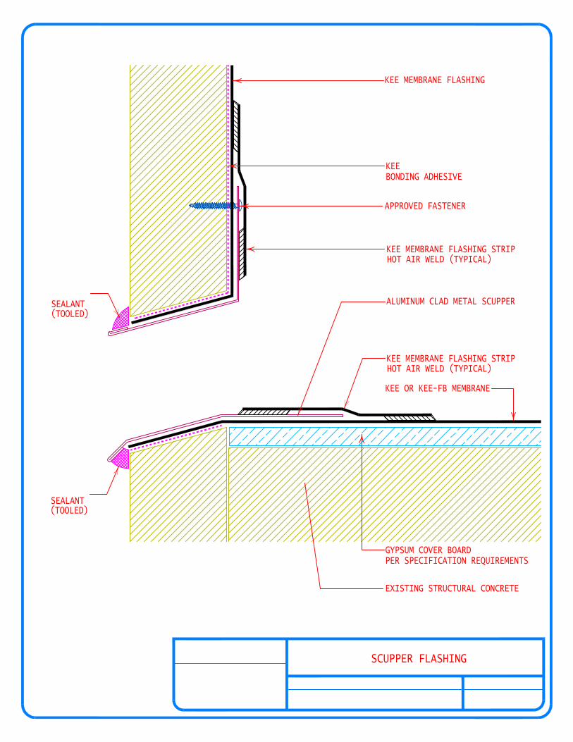
SEALANT
SEALANT
EXISTING STRUCTURAL CONCRETE
GYPSUM COVER BOARDPER SPECIFICATION REQUIREMENTS
SCUPPER FLASHING
(TOOLED)
(TOOLED)
ROOFING SOLUTIONSINTELLIGENT
KEE MEMBRANE FLASHING
KEE BONDING ADHESIVE
APPROVED FASTENER
KEE MEMBRANE FLASHING STRIP HOT AIR WELD (TYPICAL)
ALUMINUM CLAD METAL SCUPPER
KEE MEMBRANE FLASHING STRIP HOT AIR WELD (TYPICAL)
KEE OR KEE-FB MEMBRANE

TYPICAL DRAIN FLASHING
A SMOOTH TRANSITION AS REQ.
FASTENER(S) & STRESS PLATE(S) 12" O.C. AROUND SUMP AREA
EXTEND KEE NON-REINFORCED MINIMUM OF 1/2" BEYOND INSIDE OF CLAMPING RING
DRAIN ASSEMBLYWITH CLAMPING RING(BY OTHERS)
SEALANT
KEE NON-REINFORCED MEMBRANE FLASHING
IF REQUIRED: TAPERED ISO ATTACHED @ MIN OF 2 FASTENERS PER BOARD
KEE MEMBRANE
HOT AIR WELD
FIELD TAPER SUMP TO PROVIDE
ROOFING SOLUTIONSINTELLIGENT
NEMO|etc.
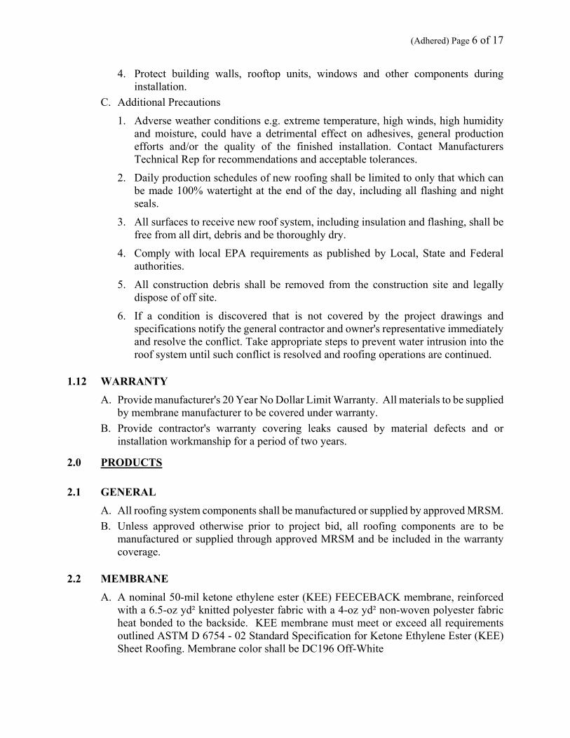
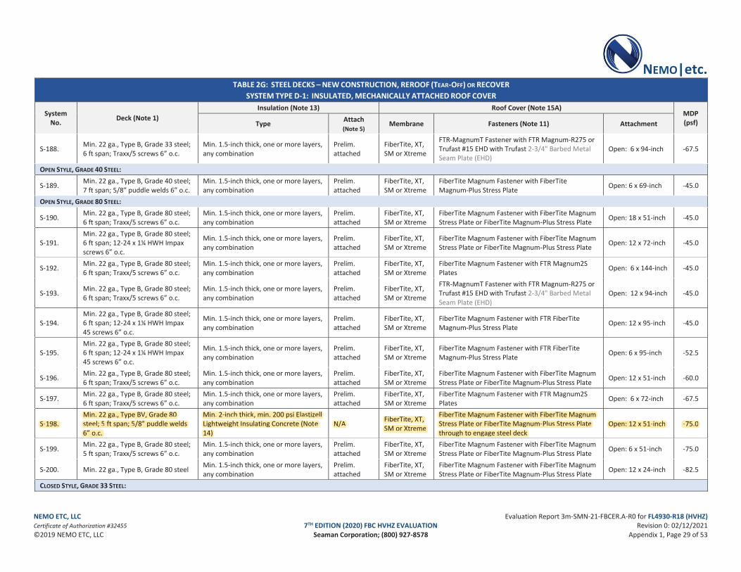
NEMO ETC, LLC Evaluation Report 3m-SMN-21-FBCER.A-R0 for FL4930-R18 (HVHZ) Certificate of Authorization #32455 7TH EDITION (2020) FBC HVHZ EVALUATION Revision 0: 02/12/2021 ©2019 NEMO ETC, LLC Seaman Corporation; (800) 927-8578 Appendix 1, Page 29 of 53
TABLE 2G: STEEL DECKS – NEW CONSTRUCTION, REROOF (TEAR-OFF) OR RECOVER SYSTEM TYPE D-1: INSULATED, MECHANICALLY ATTACHED ROOF COVER
System No. Deck (Note 1)
Insulation (Note 13) Roof Cover (Note 15A) MDP (psf) Type Attach
(Note 5) Membrane Fasteners (Note 11) Attachment
S-188. Min. 22 ga., Type B, Grade 33 steel; 6 ft span; Traxx/5 screws 6” o.c.
Min. 1.5-inch thick, one or more layers, any combination
Prelim. attached
FiberTite, XT, SM or Xtreme
FTR-MagnumT Fastener with FTR Magnum-R275 or Trufast #15 EHD with Trufast 2-3/4" Barbed Metal Seam Plate (EHD)
Open: 6 x 94-inch -67.5
OPEN STYLE, GRADE 40 STEEL:
S-189. Min. 22 ga., Type B, Grade 40 steel; 7 ft span; 5/8” puddle welds 6” o.c.
Min. 1.5-inch thick, one or more layers, any combination
Prelim. attached
FiberTite, XT, SM or Xtreme
FiberTite Magnum Fastener with FiberTite Magnum-Plus Stress Plate Open: 6 x 69-inch -45.0
OPEN STYLE, GRADE 80 STEEL:
S-190. Min. 22 ga., Type B, Grade 80 steel; 6 ft span; Traxx/5 screws 6” o.c.
Min. 1.5-inch thick, one or more layers, any combination
Prelim. attached
FiberTite, XT, SM or Xtreme
FiberTite Magnum Fastener with FiberTite Magnum Stress Plate or FiberTite Magnum-Plus Stress Plate Open: 18 x 51-inch -45.0
S-191. Min. 22 ga., Type B, Grade 80 steel; 6 ft span; 12-24 x 1¼ HWH Impax screws 6” o.c.
Min. 1.5-inch thick, one or more layers, any combination
Prelim. attached
FiberTite, XT, SM or Xtreme
FiberTite Magnum Fastener with FiberTite Magnum Stress Plate or FiberTite Magnum-Plus Stress Plate Open: 12 x 72-inch -45.0
S-192. Min. 22 ga., Type B, Grade 80 steel; 6 ft span; Traxx/5 screws 6” o.c.
Min. 1.5-inch thick, one or more layers, any combination
Prelim. attached
FiberTite, XT, SM or Xtreme
FiberTite Magnum Fastener with FTR Magnum2S Plates Open: 6 x 144-inch -45.0
S-193. Min. 22 ga., Type B, Grade 80 steel; 6 ft span; Traxx/5 screws 6” o.c.
Min. 1.5-inch thick, one or more layers, any combination
Prelim. attached
FiberTite, XT, SM or Xtreme
FTR-MagnumT Fastener with FTR Magnum-R275 or Trufast #15 EHD with Trufast 2-3/4" Barbed Metal Seam Plate (EHD)
Open: 12 x 94-inch -45.0
S-194. Min. 22 ga., Type B, Grade 80 steel; 6 ft span; 12-24 x 1¼ HWH Impax 45 screws 6” o.c.
Min. 1.5-inch thick, one or more layers, any combination
Prelim. attached
FiberTite, XT, SM or Xtreme
FiberTite Magnum Fastener with FTR FiberTite Magnum-Plus Stress Plate Open: 12 x 95-inch -45.0
S-195. Min. 22 ga., Type B, Grade 80 steel; 6 ft span; 12-24 x 1¼ HWH Impax 45 screws 6” o.c.
Min. 1.5-inch thick, one or more layers, any combination
Prelim. attached
FiberTite, XT, SM or Xtreme
FiberTite Magnum Fastener with FTR FiberTite Magnum-Plus Stress Plate Open: 6 x 95-inch -52.5
S-196. Min. 22 ga., Type B, Grade 80 steel; 6 ft span; Traxx/5 screws 6” o.c.
Min. 1.5-inch thick, one or more layers, any combination
Prelim. attached
FiberTite, XT, SM or Xtreme
FiberTite Magnum Fastener with FiberTite Magnum Stress Plate or FiberTite Magnum-Plus Stress Plate Open: 12 x 51-inch -60.0
S-197. Min. 22 ga., Type B, Grade 80 steel; 6 ft span; Traxx/5 screws 6” o.c.
Min. 1.5-inch thick, one or more layers, any combination
Prelim. attached
FiberTite, XT, SM or Xtreme
FiberTite Magnum Fastener with FTR Magnum2S Plates Open: 6 x 72-inch -67.5
S-198. Min. 22 ga., Type BV, Grade 80 steel; 5 ft span; 5/8” puddle welds 6” o.c.
Min. 2-inch thick, min. 200 psi Elastizell Lightweight Insulating Concrete (Note 14)
N/A FiberTite, XT, SM or Xtreme
FiberTite Magnum Fastener with FiberTite Magnum Stress Plate or FiberTite Magnum-Plus Stress Plate through to engage steel deck
Open: 12 x 51-inch -75.0
S-199. Min. 22 ga., Type B, Grade 80 steel; 5 ft span; Traxx/5 screws 6” o.c.
Min. 1.5-inch thick, one or more layers, any combination
Prelim. attached
FiberTite, XT, SM or Xtreme
FiberTite Magnum Fastener with FiberTite Magnum Stress Plate or FiberTite Magnum-Plus Stress Plate Open: 6 x 51-inch -75.0
S-200. Min. 22 ga., Type B, Grade 80 steel Min. 1.5-inch thick, one or more layers, any combination
Prelim. attached
FiberTite, XT, SM or Xtreme
FiberTite Magnum Fastener with FiberTite Magnum Stress Plate or FiberTite Magnum-Plus Stress Plate Open: 12 x 24-inch -82.5
CLOSED STYLE, GRADE 33 STEEL:
Min. 22 ga., Type BV, Grade 80 Min. 2-inch thick, min. 200 psi Elastizell FiberTite Magnum Fastener with FiberTite Magnum FiberTite, XT, S-198. steel; 5 ft span; 5/8” puddle welds Lightweight Insulating Concrete (Note N/A Stress Plate or FiberTite Magnum-Plus Stress Plate Open: 12 x 51-inch -75.0SM or Xtreme6” o.c. 14) through to engage steel deck

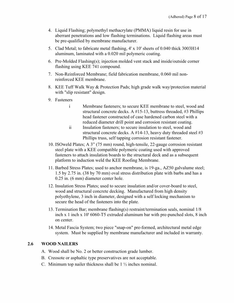
HOT AIR WELD
PER SPECIFICATION REQUIREMENTSEXISTING LIGHTWEIGHT CONCRETE
EXISTING CONCRETE DECK
KEE OR KEE-FB MEMBRANE(ADHERED PER SPECIFICATION)
GYPSUM COVER BOARD(ADHERED PER SPECIFICATIONS)
ROOFING SOLUTIONSINTELLIGENT
LIGHTWEIGHT INSULATING CONCRETEOVER CONCRETE DECK W/ ADHERED COVERBOARD

4'
8'
12" 12"
6" 24" 6"
6"
6"
4'
4'

69" (1.8 m)
74" (1.9 m)
5" (13 cm)
5" (13 cm)
"A"
PE
RIM
ETE
RZ
ON
E
6" O.C.(15 cm)
CenteredIn FullSheet
"A"PERIMETER
ZONE
6" (15 cm)
QuarterOf FullSheet
CenteredIn FullSheet
50"
Mechanically Attached KEE 50" wide sheets

Page 1 of 2
Scope of Work Tuesday, June 24, 2021
PROJECT: Lee County Public Works BUILDING CONTACT: Scott Musheff 1500 Monroe Street [email protected]
Fort Myers, FL 33901 Aerial View:
General Scope of Work:
1. Contractor to coordinate staging, mobilization and permitting with owner at pre‐construction meeting. 2. If required for permitting, contractor to provide stamped engineering. 3. Contractor to provide owner a 20 Year NDL Warranty at completion of project. All components to be
purchased from membrane manufacturer are to be included in the warranty.
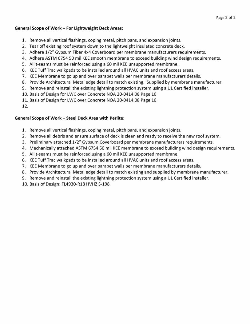
Page 2 of 2
General Scope of Work – For Lightweight Deck Areas:
1. Remove all vertical flashings, coping metal, pitch pans, and expansion joints. 2. Tear off existing roof system down to the lightweight insulated concrete deck. 3. Adhere 1/2” Gypsum Fiber 4x4 Coverboard per membrane manufacturers requirements. 4. Adhere ASTM 6754 50 mil KEE smooth membrane to exceed building wind design requirements. 5. All t‐seams must be reinforced using a 60 mil KEE unsupported membrane. 6. KEE Tuff Trac walkpads to be installed around all HVAC units and roof access areas. 7. KEE Membrane to go up and over parapet walls per membrane manufacturers details. 8. Provide Architectural Metal edge detail to match existing. Supplied by membrane manufacturer. 9. Remove and reinstall the existing lightning protection system using a UL Certified installer. 10. Basis of Design for LWC over Concrete NOA 20‐0414.08 Page 10 11. Basis of Design for LWC over Concrete NOA 20‐0414.08 Page 10 12.
General Scope of Work – Steel Deck Area with Perlite:
1. Remove all vertical flashings, coping metal, pitch pans, and expansion joints. 2. Remove all debris and ensure surface of deck is clean and ready to receive the new roof system. 3. Preliminary attached 1/2” Gypsum Coverboard per membrane manufacturers requirements. 4. Mechanically attached ASTM 6754 50 mil KEE membrane to exceed building wind design requirements. 5. All t‐seams must be reinforced using a 60 mil KEE unsupported membrane. 6. KEE Tuff Trac walkpads to be installed around all HVAC units and roof access areas. 7. KEE Membrane to go up and over parapet walls per membrane manufacturers details. 8. Provide Architectural Metal edge detail to match existing and supplied by membrane manufacturer. 9. Remove and reinstall the existing lightning protection system using a UL Certified installer. 10. Basis of Design: FL4930‐R18 HVHZ S‐198
�
�������������� ��������������������������������������������� ���
����������� ��
!�"#�����$%���� &'()*+�,*-.�/00��
��12�$%����3�� 4')567+')56�89(:;+6+.�<(=>*?6+@��
��12���A1��������� B'(C�DED�F='�B+?;*:;+6+.�9;�G'(�DHI�F='�0*?=6'J+**�4K<8�:?=6�9L+;�G'(�DMII�F='�=6;>:6>;?*�:9(:;+6+��
N%A��"�$%����O�P��� Q(+�9;�G9;+�*?-+;=�9R�'(=>*?6'9(�?@5+;+@�7'65�?FF;9L+@�?@5+='L+.�G+GS;?(+�?@5+;+@C��
����T���������U�N%A��"�V�"�������A�����%��W�����11�AA����A�������A��U����$�#���������X�A��������������������U���U�AX��������#����A�����U�Y���AA�A��U��11�AA����A�U�"��A������1�"�����1��Z��X����A1��������[����U��\Y��U����]�U����̂Y���"���A���U���������U���#��1���U�Y����_�����X���������U�"�"#����A���A��U����$�#�������Q(+�9;�G9;+�*?-+;=�9R�65+�R9**97'()�'(=>*?6'9(=̀���\�A��3�AY�������V�%���O��������P� 3�AY�������[�A�����A�
O$�#��� P��
[�A���������A��%�����
[$Wa��Y�b�[$Wa��Y���b�[$Wa��Y��cb��][��"33b�!Y���!���[� b�cNX���Ub���WTd� �����3�AY����"���N�!���"Y"�����e��X�12� ���� �����$���3�AY�������V�%���� 3�AY�������[�A�����A�
O$�#��� P��
[�A���������A��%�����
���A��12����"�b�N�]fW�]g�T%�AY"[�#���W����\���U�!���"Y"��h�e��X�12� ���� �����������������AY�������AX����#���UX���U�����X��U�12����3]���UX�A���A�]W��������U����1�����Y�YA� ��1X���##��A�A��1�U���e���1���W��������W������������1������N���U��U�W�N���i�������AY�����������1X"������3�AY���������A��U��A�#�A����%������%�AX����#��YA�U����%��A�#�A����%��A�Z��X���A�1��U���%�������������U�������%�����AY���������A�����U��A��X��������"�"#�����AY#A��������!�"#������ j'S+;k'6+.�j'S+;k'6+l&B.�j'S+;k'6+lmk.�j'S+;k'6+lmk;+G+.�&6-*+�nI�9;�&6-*+�nIlB�;99R�:9L+;�
?@5+;+@�7'65�jkolpqI+�r9(@'()�s@5+='L+�?FF*'+@�?6�?�;?6+�9R�p�)?*t=uC�69�65+�S?:v�='@+�9R�65+�G+GS;?(+�?(@�69�65+�=>S=6;?6+C�4?F=�?;+�=+?*+@�7'65�pCMl'(:5�5+?6�7+*@C�
Q;�
j'S+;k'6+ljr.�j'S+;k'6+lmk�jr.�j'S+;k'6+l&B�jr.�&6-*+�nI�jr�9;�&6-*+�nIlB�jr�;99R�:9L+;�?@5+;+@�7'65�596�?=F5?*6�?6�DM�*S=t=uC�9;�jkolHqI�7?6+;�S?=+@�?@5+='L+�?6�pII�R6Dt)?*C�4?F=�?;+�=+?*+@�7'65�pCMl'(:5�5+?6�7+*@C�w
!���"Y"���A��������AAY����
lpnICI�F=R��R9;�0*?=6'J+**�������x&++�y+(+;?*�4'G'6?6'9(�zq{�lDHICI�F=R��R9;�B+?;*:;+6+����x&++�y+(+;?*�4'G'6?6'9(�zq{�
� �
�
�������������� ��������������������������������������������� ���
������������ ��
!�"#�����$%���� &'()*+�,*-.�/00��
��12�$%����3�� 4')567+')56�89(:;+6+.�<(=>*?6+@��
��12���A1��������� B'(C�DEF�G='�0*?=6'H+**�4I<8�:?=6�9J+;�K'(�LMNDD)?.�OO�P='�=6++*�@+:P��
Q%A��"�$%����R�S���� T(+�9;�K9;+�*?-+;=�9U�'(=>*?6'9(�?@5+;+@�7'65�?GG;9J+@�?@5+='J+.�K+KV;?(+�?@5+;+@C��
����W���������X�Q%A��"�Y�"�������A�����%��Z�����11�AA����A�������A��X����$�#���������[�A��������������������X���X�A[��������#����A�����X�\���AA�A��X��11�AA����A�X�"��A������1�"�����1��]��[����A1��������̂����X��_\��X�����̀X����a\���"���A���X���������X���#��1���X�\����b�����[���������X�"�"#����A���A��X����$�#�������T(+�9;�K9;+�*?-+;=�9U�65+�U9**97'()�'(=>*?6'9(=c���_�A��3�A\�������Y�%���R��������S� 3�A\�������̂�A�����A�
R$�#��� S��
�̂A���������A��%�����
$̂Zd��\�e�̂$Zd��\���e�̂$Zd��\��fe��̀ �̂�"33e�!\���!���̂� e�fQ[���Xe���ZWg� e�3�A\����"���Q�!���"\"�����h��[�12� ���� �����$���3�A\�������Y�%��� 3�A\�������̂�A�����A�
R$�#��� S��
�̂A���������A��%�����
���A��12����"�e�Q�̀ iZ�̀ j�W%�A\"̂�#���Z����_���X�!���"\"��kh��[�12� ���� �����������������A\�������A[����#���X[���X�����[��X�12����3̀���X[�A���A�̀Z��������X����1�����\�\A� ��1[���##��A�A��1�X���h���1���Z��������Z������������1������Q���X��X�Z�Q���l�������A\�����������1["������3�A\���������A��X��A�#�A����%������%�A[����#��\A�X����%��A�#�A����%��A�]��[���A�1��X���%�������������X�������%�����A\���������A�����X��A��[��������"�"#�����A\#A��������!�"#������ m'V+;n'6+.�m'V+;n'6+N&B.�m'V+;n'6+Non.�m'V+;n'6+Non;+K+.�&6-*+�MF�9;�&6-*+�MFNB�;99U�:9J+;�
?@5+;+@�7'65�mnpNLqF+�r9(@'()�s@5+='J+�?GG*'+@�?6�?�;?6+�9U�L�)?*t=uC�69�65+�V?:P�='@+�9U�65+�K+KV;?(+�?(@�69�65+�=>V=6;?6+C�4?G=�?;+�=+?*+@�7'65�LCvN'(:5�5+?6�7+*@C�
T;�
m'V+;n'6+Nmr.�m'V+;n'6+Non�mr.�m'V+;n'6+N&B�mr.�&6-*+�MF�mr�9;�&6-*+�MFNB�mr;99U�:9J+;�?@5+;+@�7'65�596�?=G5?*6�?6�Dv�*V=t=uC�9;�mnpNEqF�7?6+;�V?=+@�?@5+='J+�?6�LFF�U6Dt)?*C�4?G=�?;+�=+?*+@�7'65�LCvN'(:5�5+?6�7+*@C�w
!���"\"���A��������AA\����
p99U�89J+;t<(=>*?6'9(�B?x'K>K�,;+==>;+��NLMFCF�G=U�U9;�0*?=6'H+**�����y&++�z+(+;?*�4'K'6?6'9(�{q|��
p+U+;�69�4I<8�}+:P�K?(>U?:6>;+;~=�:>;;+(6��Ts�U9;�K?x'K>K�@+=')(�G;+==>;+�'(�=6++*�@+:P�?GG*':?6'9(=C�
�� �

Investigative Roof Report
Monday, June 28, 2021
PROJECT: Lee County Public Works BUILDING CONTACT: Scott Musheff 1500 Monroe Street [email protected]
Fort Myers, FL 33901 [email protected]
Aerial View:
ROOF INVESTIGATION REPORT Page 2
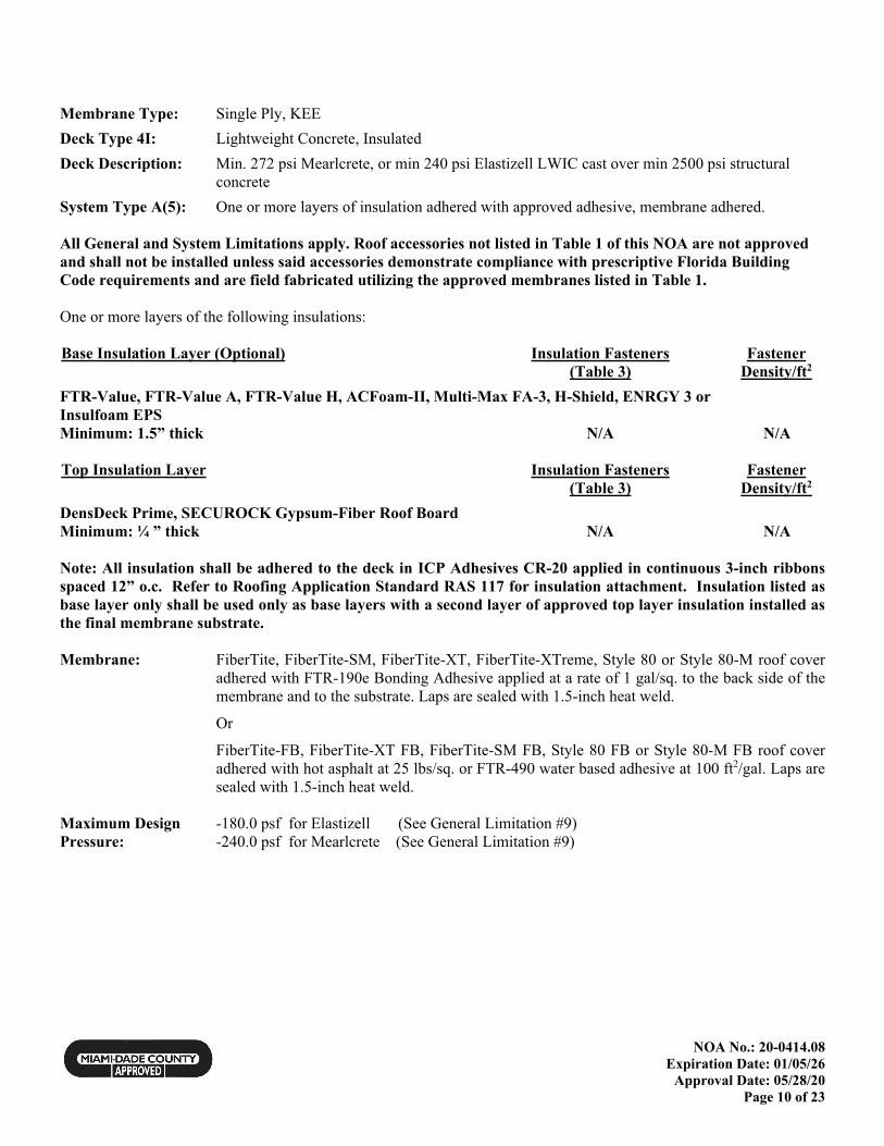
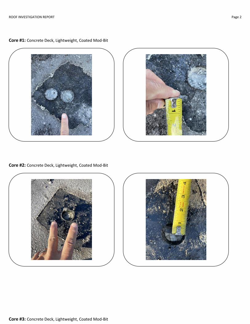
Core #1: Concrete Deck, Lightweight, Coated Mod-Bit
Core #2: Concrete Deck, Lightweight, Coated Mod-Bit
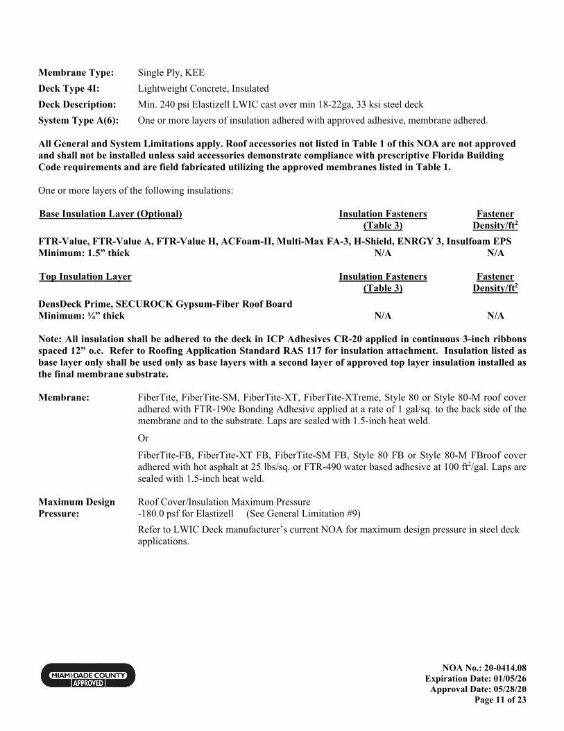
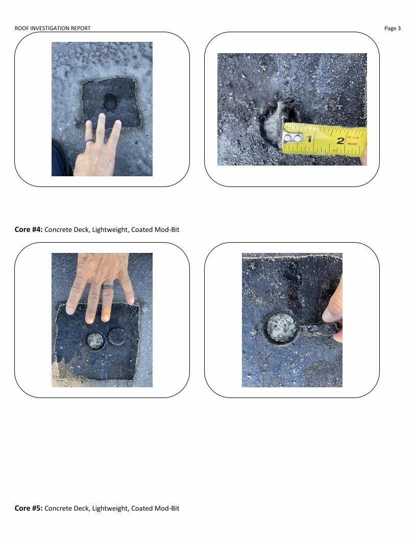
Core #3: Concrete Deck, Lightweight, Coated Mod-Bit
ROOF INVESTIGATION REPORT Page 3
Core #4: Concrete Deck, Lightweight, Coated Mod-Bit
Core #5: Concrete Deck, Lightweight, Coated Mod-Bit
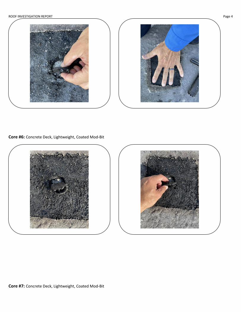
ROOF INVESTIGATION REPORT Page 4
Core #6: Concrete Deck, Lightweight, Coated Mod-Bit
Core #7: Concrete Deck, Lightweight, Coated Mod-Bit
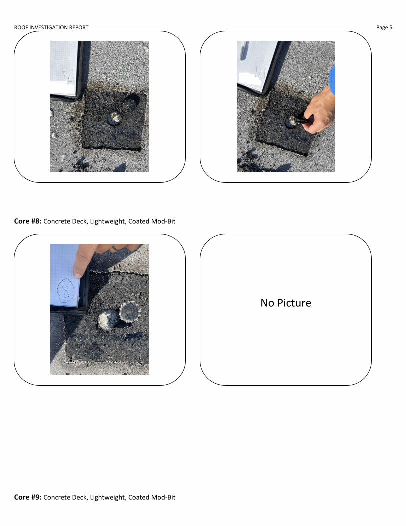
ROOF INVESTIGATION REPORT Page 5
Core #8: Concrete Deck, Lightweight, Coated Mod-Bit
Core #9: Concrete Deck, Lightweight, Coated Mod-Bit
No Picture

ROOF INVESTIGATION REPORT Page 6
Core #10: Concrete Deck, Lightweight, Coated Mod-Bit
Core #11: Metal Deck, 1” Perlite, Coated BUR
No Picture

ROOF INVESTIGATION REPORT Page 7
Core #12: Concrete Deck, Lightweight, Coated Mod-Bit
No Picture

ROOF INVESTIGATION REPORT Page 8
Core #13: Concrete Deck, Lightweight, Coated Mod-Bit
Miscellaneous Pictures:
Section 2
Section 3

ROOF INVESTIGATION REPORT Page 9
Section 4 Wall
Section 4 Wall/Scupper/Coping
Section 4 Coping
Section 5
Section 6
Section 6 Inside Wall

ROOF INVESTIGATION REPORT Page 10
Section 6 Wall Flashing
Section 7 Outside View Parapet
Section 8 Low Access Area
Section 8 Bottom of Door
Section 9 Coping View
Section 9 Copin9
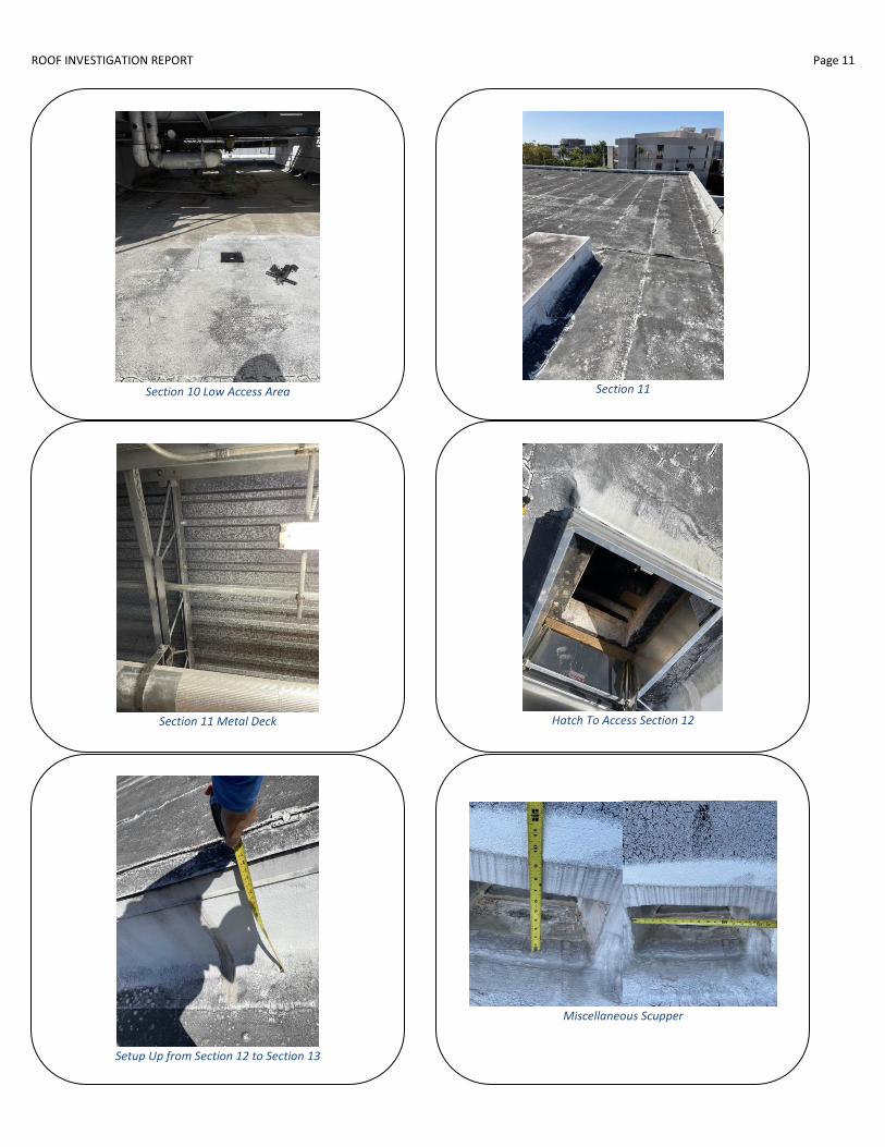
ROOF INVESTIGATION REPORT Page 11
Section 10 Low Access Area
Section 11
Section 11 Metal Deck
Hatch To Access Section 12
Setup Up from Section 12 to Section 13
Miscellaneous Scupper

ROOF INVESTIGATION REPORT Page 12
Investigation Area continued:

ROOF INVESTIGATION REPORT Page 13
Investigation Area continued:
Sample #11: Wall Flashing Sample Sample taken for asbestos test
Sample #11: Wall Flashing Sample Sample taken for asbestos test
MANUFACTURER CONTACT: Shawn Sulzener West Florida Territory Manager 941-321-2747 (cell)
INVESTIGATION REPORT

25,587 sqftRoof Report6 facets
Predominant Pitch 0/121500 Monroe St, Fort Myers, FL 33901, USALee County Facilities Management
1
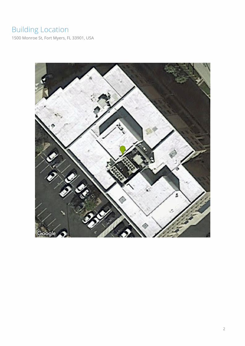
Building Location1500 Monroe St, Fort Myers, FL 33901, USA
2

Diagram1500 Monroe St, Fort Myers, FL 33901, USA
3

Length Measurement Report1500 Monroe St, Fort Myers, FL 33901, USA
Eaves 1126ft 2in Valleys 0ft Hips 0ftRidges 0ft Rakes 0ft Wall Flashing 663ft 6inStep Flashing 0ft Transitions 0ft Unspecified 0ft
99
49
24
149
24
17
2425
2427
229
39
40
39
40
49
50
25
19
24
31
47
22
19
24
28
46
37
36
37
36
23 23 23
23 13 13
12 12
14
24
14
24
11
21
1121
Note: The above diagram contains measurements that have been rounded up. 6 and 9 are written •6 and •9 to avoid confusion.Some edge length totals have been hidden from the diagram to avoid overcrowding. Flashings are depicted as dotted lines.
4

Area Measurement Report1500 Monroe St, Fort Myers, FL 33901, USA
Total Low Pitch: 0 sqft Predominant Pitch: (0/12)Total Two Story: 0 sqft Predominant Pitch Area: 25,587 sqftTotal Two Layer: 0 sqft Total Area: 25,587 sqft
21,641
172 185
1,313
1,961
317
Note: The above diagram contains measurements rounded to the nearest whole number. The total at the top of the page is the sum of all the unrounded (exact) measurements, which is then rounded. Flashings are depicted as dotted lines. Deleted facets, which are not labeled with area, (Skylights, Chimneys, AC units) are omitted from area sums. 5

Pitch & Direction Measurement Report1500 Monroe St, Fort Myers, FL 33901, USA
0
0 0
0
0
0
Note: Flashings are depicted as dotted lines. Deleted facets do not have a pitch and therefore are not labeled.
6

All Structures Summary1500 Monroe St, Fort Myers, FL 33901, USA
Measurements
Total Roof Area 25,587 sqft
Total Roof Facets 6 facets
Predominant Pitch 0/12
Total Eaves 1126ft 3in
Total Valleys 0ft
Total Hips 0ft
Total Ridges 0ft
Total Rakes 0ft
Total Wall Flashing 663ft 7in
Total Step Flashing 0ft
Total Transition 0ft
Total Unspecified 0ft
Hips + Ridges 0ft
Eaves + Rakes 1126ft 3in
Pitch 0/12
Area (sqft) 25,587
Squares 255.9
Waste % 0% 10% 12% 15% 17% 20% 22%
Area (sqft) 25,587 28,146 28,658 29,426 29,937 30,705 31,217
Squares 255.9 281.5 286.6 294.3 299.4 307.1 312.2
7