AF-5000 Install Manual - Advanced Flight Systems
245
AF-5000 Install Manual Experimental instrument limited to use in experimental aircraft. Not approved for use in aircraft with FAA type certificates. Patents 6,271,769 B1 and 6,940,425
-
Upload
khangminh22 -
Category
Documents
-
view
0 -
download
0
Transcript of AF-5000 Install Manual - Advanced Flight Systems

AF-5000 Install Manual
Experimental instrument limited to use in experimental aircraft.
Not approved for use in aircraft with FAA type certificates.
Patents 6,271,769 B1 and 6,940,425

Version 15.1 AF-5000 Series Install Manual 2
Installation Manual
Experimental instrument limited to use in experimental aircraft. Not approved for use in aircraft with FAA type certificates.
Patents 6,271,769 B1 and 6,940,425

Version 15.1 AF-5000 Series Install Manual 3
AF-5000 Series Post Installation Check
CAUTION: Do not fly the aircraft until the following check list has been completed.
Never Power the system with an automotive battery charger and the aircraft battery disconnected.
Before Power is applied for the First Time
□ Screen mounted following the installation manual
□ Magnetometer mounted (Label up, connector forward, same angle as EFIS[Mag Only])
□ Screen case has been properly grounded using case screw
□ Wiring harness is properly connected to screen
□ Verify relay protection diodes are installed on all large aircraft relays (Master, Starter, Avionics...etc)
□ Pitot/Static and AOA plumbing is secured to the correct ports
□ Trim Servo indication wires are connected per the installation manual wiring diagram Applying Power for the First Time
□ Turn on aircraft battery power and power on the screens.
□ Verify the unit powers on; read the warning message where the I AGREE button is displayed. This page contains the software version installed along with any mapping effective/expiration dates.
□ Set the clock time-zone offset
□ Set the AHRS Pitch Adjust for your aircraft's panel tilt (0 to 7 degrees typically)
□ Following the installation manual, calibrate the Fuel Tanks
□ Following the installation manual, calibrate all trim and flap position sensors
□ Set the airspeed V speeds based on your aircraft manufacturers recommendations.
□ Set all engine temperatures/limits based on your engine manufacturers recommendations
□ Set fuel tank, fuel pressure, fuel pressure, oil temperature, and oil pressure warning parameters
□ Configure your Serial Ports based on devices connected
□ Configure your GPS/NAV Settings based on Serial Port selection
□ Verify all GPS and NAV sources are properly communicating with the EFIS. See Appendix J: 430W - EFIS - Autpilot - ARINC Troubleshooting guide if you have an autopilot and/or a Garmin GNS-430W/530W.
□ AOA Post-Installation Pre-Flight Checklist Completed

Version 15.1 AF-5000 Series Install Manual 4
First Engine Start
□ With relay protection diodes installed, your AFS screen(s) can be turned on before the engine is started.
□ After the engine has started, verify oil pressure and temperature. If none is indicated SHUT DOWN the engine. Verify all wiring and consult your local A&P, the engine manufacturer, and/or AFS technical support.
□ Verify all engine indications are correct per your engine manufacturers manual
Before First Flight
□ Verify you have the latest system software and mapping data (if applicable) - Visit the AFS Website for latest software and map data.
□ Weight & Balance page updated with your aircrafts data
□ Checklist pages updated with information from your aircraft manufacturer
□ Magnetometer Alignment completed on all screens with an AHRS installed (See video on AFS website Support Forum)
□ EFIS AOA Calibration Checklist completed
□ Pitot/Static check completed from an authorized FAA Repair Station.
□ EFIS and autopilot gains are set per the installation manual
In-Flight Configuration
□ Verify airspeed and altitude indicate correctly
□ Verify heading indicates correctly using a backup whiskey compass for reference
□ Test navigation sources and verify they function properly
□ If an autopilot is installed and coupled to the EFIS, check its functions
After First Flight
□ Calibrate Fuel Flow K-Factor (See Installation Manual)
AOA FLIGHT WARNING:
The EFIS may be shipped with AOA aircraft calibration data pre-installed. If you choose to use this
data, you must verify the validity of the data or calibrate the AOA to meet your specifications before
using. You must also read and understand the separate AOA manual before using the AOA
instrument in flight

Version 15.1 AF-5000 Series Install Manual 5
LIMITED WARRANTY / AGREEMENT
Advanced Flight Systems Inc. (“AFS”) warrants its aircraft monitoring system instrument and system components to be free
from defects in materials and workmanship for a period of one year commencing on the date of the first flight of the
instrument or one year after the invoice date, whichever comes first. AFS will repair or replace any instrument or system
components under the terms of this Warranty provided the item is returned to AFS prepaid.
This Warranty shall not apply to any unit or component that has been repaired or altered by any person other than AFS, or that has been subjected to misuse, abuse, accident, incorrect wiring, or improper or unprofessional installation by any person. THIS WARRANTY DOES NOT COVER ANY REIMBURSEMENT FOR ANYONE'S TIME FOR INSTALLATION, REMOVAL, ASSEMBLY OR REPAIR. AFS reserves the right to determine the reason or cause for warranty repair.
1. This Warranty does not extend to any engine, machine, aircraft, boat, vehicle or any other device to which the AFS monitoring system may be connected, attached, or used with in any way.
2. THE REMEDIES AVAILABLE TO THE PURCHASER ARE LIMITED TO REPAIR, REPLACEMENT, OR REFUND OF THE
PURCHASE PRICE OF THE PRODUCT, AT THE SOLE DISCRETION OF AFS. CONSEQUENTIAL DAMAGES, SUCH AS DAMAGE TO THE ENGINE OR AIRCRAFT, ARE NOT COVERED, AND ARE EXCLUDED. DAMAGES FOR PHYSICAL INJURY TO PERSON OR PROPERTY ARE NOT COVERED, AND ARE EXCLUDED.
3. AFS is not liable for expenses incurred by the customer or installer due to AFS updates, modifications, improvements,
upgrades, changes, notices or alterations to the product. 4. The pilot must understand the operation of this product before flying the aircraft. Do not allow anyone to operate the
aircraft that does not understand the operation of the monitoring system. Keep the operating manual in the aircraft at all times.
5. AFS is not responsible for shipping charges or damages incurred during shipment. 6. No one is authorized to assume any other or additional liability for AFS in connection with the sale of AFS products. 7. IF YOU DO NOT AGREE TO ACCEPT THE TERMS OF THIS WARRANTY, YOU MAY RETURN THE PRODUCT
FOR A FULL REFUND. IF YOU DO NOT AGREE TO ACCEPT THE TERMS OF THIS WARRANTY, DO NOT INSTALL THE PRODUCT.
8. This warranty is made only to the original purchaser and is not transferable. THIS WARRANTY IS IN LIEU OF ALL
OTHER WARRANTIES OR OBLIGATIONS, EXPRESS OR IMPLIED, ORAL OR WRITTEN. AFS EXPRESSLY DISCLAIMS ALL IMPLIED WARRANTIES OF MERCHANTABILITY OR FITNESS FOR A PARTICULAR PURPOSE. THE PURCHASER AGREES THAT IN NO EVENT SHALL AFS BE LIABLE FOR SPECIAL, INCIDENTAL OR CONSEQUENTIAL DAMAGES, INCLUDING DAMAGES TO THE ENGINE OR AIRCRAFT, LOST PROFITS, LOSS OF USE, OR OTHER ECONOMIC LOSS. EXCEPT AS EXPRESSLY PROVIDED HEREIN, AFS DISCLAIMS ALL OTHER LIABILITY TO THE PURCHASER OR ANY OTHER PERSON IN CONNECTION WITH THE USE OR PERFORMANCE OF AFS' PRODUCTS, INCLUDING BUT NOT LIMITED TO STRICT PRODUCTS LIABILITY IN TORT.
IMPORTANT PRE-INSTALLATION NOTICE
Before installing the monitoring system, READ THE LIMITED WARRANTY / AGREEMENT. There is information in the Limited Warranty / Agreement that may alter your decision to install this product. IF YOU DO NOT ACCEPT THE TERMS OF THE LIMITED WARRANTY / AGREEMENT DO NOT INSTALL THE PRODUCT. The product may be returned for a refund if you do not accept the terms of the Limited Warranty / Agreement.
Before starting the installation, make sure that your planned installation will not interfere with the operation of any controls. The installer should use current aircraft standards and practices to install this product. Refer to AC 43.13-2A, Acceptable Methods, Techniques, and Practices - Aircraft Alterations and AC 43.13-1B, Acceptable Methods, Techniques, and Practices--Aircraft Inspection and Repair.

Table of Contents
AF-5000 Series Post Installation Check ________________________________________________ 3
LIMITED WARRANTY / AGREEMENT __________________________________________________ 5
INTRODUCTION _________________________________________________________________ 11
AF-5000 Installation Manual _______________________________________________________ 12
System Overview and Planning ............................................................................................................ 12
EFIS Screen Rear Connections .............................................................................................................. 16
Mechanical Mounting .......................................................................................................................... 18 AF-5800 ..................................................................................................................................................................... 18 AF-5700 ..................................................................................................................................................................... 19 AF-5600 ..................................................................................................................................................................... 20 AF-5500 ..................................................................................................................................................................... 21
72200 Advanced-SV ADAHRS-200/201 ................................................................................................. 22 72236 Advanced-SV MAG-236 .................................................................................................................................. 26 ADAHRS-200/201 MAG-236 Magnetic Heading Calibration ..................................................................................... 28
72010 Remote AHRS / Magnetometer ................................................................................................. 29 Magnetometer Installation P/N: 8350-0480 ............................................................................................................ 29 AHRS/Magnetometer Installation P/N: 72010 ......................................................................................................... 29 P/N: 72010 Magnetometer Alignment ..................................................................................................................... 31
Alarm Output ...................................................................................................................................... 32
Electrical Connections .......................................................................................................................... 33 EFIS Backup Battery Wiring ...................................................................................................................................... 35
Audio Connections .............................................................................................................................. 39 Volume Adjustment .................................................................................................................................................. 39
Screen Communication Settings (AHRS, AirData, EMS) ........................................................................ 40
EFIS Serial Port Connections ................................................................................................................ 42 Serial Port Planning ................................................................................................................................................... 42 Serial Port # Function Hardware Setup .................................................................................................................... 43 GPS/NAV # Data Source Software Setup .................................................................................................................. 44
EFIS Serial Port Configuration Examples ............................................................................................... 45
External Device Configuration ............................................................................................................. 48 71410 SV-ARINC 429 ADAPTOR ................................................................................................................................ 48 71400 AF-ARINC 429 ADAPTOR ................................................................................................................................ 52 Advanced-SV Autopilot ............................................................................................................................................. 55 74152 SV-Autopilot Panel ........................................................................................................................................ 60 AF-Pilot Autopilot ..................................................................................................................................................... 65 CO Guardian Display ................................................................................................................................................. 67 74125 AF-Intercom ................................................................................................................................................... 68 74122 AF-Com Radio ................................................................................................................................................ 77 P/N: 71426 AF-AUDIO Panel PAC-15 ........................................................................................................................ 90 P/N: 73102 AF-GPS Antenna Module ....................................................................................................................... 91 Avidyne IFD-540 / IFD-440 to AF-ARINC ................................................................................................................... 94 Avidyne IFD-540 / IFD-440 to SV-ARINC ................................................................................................................... 95 Garmin 430W/530W ................................................................................................................................................ 96 Garmin GTN650/750 ................................................................................................................................................. 97 Garmin SL-30 ............................................................................................................................................................ 99 Garmin SL-40 ............................................................................................................................................................ 99 Garmin GNC-255 ..................................................................................................................................................... 102

Version 15.1 AF-5000 Series Install Manual 7
Garmin GTR-225 ..................................................................................................................................................... 102 Garmin 396/496 ...................................................................................................................................................... 103 P/N: 74109 Dynon/AFS SV-261 Transponder ......................................................................................................... 104 Garmin GTX 327 / GTX 330 Transponder ................................................................................................................ 115 Sandia STX 165R Transponder ................................................................................................................................ 115 P/N: 73140 Wi-Fi Module ....................................................................................................................................... 116 P/N: 74113 SV-ADSB-472 Dual Band Receiver ........................................................................................................ 119 P/N: 74112 SV-ADSB-470 Single Band Receiver ..................................................................................................... 120 FreeFlight XPLORER ADS-B Receiver ....................................................................................................................... 128 NavWorx ADS-B ...................................................................................................................................................... 130 WX-500 Stormscope ............................................................................................................................................... 133
71320 SV-EMS Engine Module _____________________________________________________ 134 Physical Mounting .................................................................................................................................................. 134 SV-EMS 220 Sensor and Transducer Wiring Map ................................................................................................... 135 SV-EMS 221 Sensor and Transducer Wiring Map ................................................................................................... 139
Engine Sensor Installation ________________________________________________________ 141
Lycoming/Continental ....................................................................................................................... 141 EGT Clamp Installation ............................................................................................................................................ 141 RPM Sensor Installation .......................................................................................................................................... 142 P/N: 71420L RPM Interface Board .......................................................................................................................... 143 Oil Temperature Sensor Installation ....................................................................................................................... 144 TIT Probes ............................................................................................................................................................... 145
Rotax Engines .................................................................................................................................... 146 CHT Probes ............................................................................................................................................................. 146 EGT Probes .............................................................................................................................................................. 147 RPM ........................................................................................................................................................................ 147 Rotax Oil Pressure ................................................................................................................................................... 148 Fuel Flow ................................................................................................................................................................. 150 Rotax Fuel Pressure ................................................................................................................................................ 151
JABIRU .............................................................................................................................................. 154 CHT Sensor .............................................................................................................................................................. 154
Diemech Turbine ............................................................................................................................... 155
Amp Transducer Installation .............................................................................................................. 156
Pressure Transducer Installation ........................................................................................................ 157 Oil Pressure Transducer Installation ....................................................................................................................... 157 Fuel Pressure Transducer Installation .................................................................................................................... 157 VDO Pressure Sensors ............................................................................................................................................ 159
Fuel Flow Transducer Installation ...................................................................................................... 160 Fuel Flow Calibration .............................................................................................................................................. 161
Manifold Pressure Transducer Installation ......................................................................................... 162
Manifold Sensor Connections: ........................................................................................................... 162
SV-EMS Manifold Sensor Configuration: ............................................................................................ 163
Fuel Tank Level Sensor....................................................................................................................... 164 Float Type ............................................................................................................................................................... 164 Capacitance Type .................................................................................................................................................... 164 P/N: 51105 Van’s Capacitance Tank Adaptor ........................................................................................................ 164
Trim & Flap Position Installation ........................................................................................................ 165
Coolant Temp .................................................................................................................................... 166

Version 15.1 AF-5000 Series Install Manual 8
Airplane Map Icon Image _________________________________________________________ 167
Vendor Logo Splash Screen _______________________________________________________ 168
Landing Gear Warning System ____________________________________________________ 169 Landing Advisory Mode .......................................................................................................................................... 169
Instrument Calibration ___________________________________________________________ 173
Advanced-SV Network Configuration ................................................................................................. 174 Scanning for Network Devices ................................................................................................................................ 174 Updating Network Devices ..................................................................................................................................... 175 Configuring ADAHRS 200 and 201 .......................................................................................................................... 175 Configure Aircraft Info ............................................................................................................................................ 176
Engine Gauge Color Bands ................................................................................................................. 177
Airspeed Color Range Settings ........................................................................................................... 178
Altimeter Check ................................................................................................................................. 178
RPM Calibration ................................................................................................................................ 179
Fuel Tank Calibration ......................................................................................................................... 180
Trim/Flap Calibration ........................................................................................................................ 184
Test Audio ......................................................................................................................................... 184
Horsepower....................................................................................................................................... 185
Switch Inputs ..................................................................................................................................... 186
Administrative Settings __________________________________________________________ 187 System Files ............................................................................................................................................................ 187 Multiple Screen Setup ............................................................................................................................................ 188 Dual AHRS Configuration ........................................................................................................................................ 188
APPENDIX A: Specifications _______________________________________________________ 190 Screen Part Numbers .............................................................................................................................................. 190 Physical ................................................................................................................................................................... 190 Power Requirements .............................................................................................................................................. 190
Temperature Specifications ............................................................................................................... 191
ARINC Adapter .................................................................................................................................. 192
APPENDIX C: Electrical Connections ________________________________________________ 193
Advanced SV Network Wiring ............................................................................................................ 195
P/N: 53625 EFIS Expansion Network Harness ..................................................................................... 197
APPENDIX D: Metric Units ________________________________________________________ 198
APPENDIX E: AF-5000 Software Updates ____________________________________________ 199
APPENDIX F: Database Updates ___________________________________________________ 201
Seattle Avionics Dynon Skyview Data ................................................................................................ 201
Map Nav Data ................................................................................................................................... 202 AFS Nav Data .......................................................................................................................................................... 202 Worldwide Jeppesen Data Files .............................................................................................................................. 203 Pocket FMS Map Data Files .................................................................................................................................... 206

Version 15.1 AF-5000 Series Install Manual 9
Approach Plates, VFR Sectional, IFR Low Maps, Flight Guide Airport Diagrams .................................. 209
APPENDIX G: EFIS Activation Keys __________________________________________________ 211
APPENDIX H: Eagle EMS Interface __________________________________________________ 213
APPENDIX I: AOA Pressure Port Location ____________________________________________ 214
APPENDIX J: Troubleshooting _____________________________________________________ 215 GTN650 to EFIS Interface Troubleshooting ........................................................................................................... 216 GNS-430W/530W - EFIS - Autopilot - ARINC Interface Troubleshooting ............................................................... 222
APPENDIX K: Vertical Power VP-X Interface _________________________________________ 227
Electrical System Status Page ............................................................................................................. 227
VPX Interface Configuration .............................................................................................................. 228
APPENDIX L: Flight Director/AF-Pilot Procedures flying an Approach ______________________ 230 Flying an LPV Approach .......................................................................................................................................... 230 Flying an ILS Approach ............................................................................................................................................ 234
APPENDIX M: Upgrading a AF-3000/4000 to a AF-5000 ________________________________ 235
Example Wiring Diagrams ________________________________________________________ 236
P/N: 73101 AF-GPS Garmin 18 (**old unit, replaced with 73102) ....................................................... 236
P/N: 53600 EFIS Main Harness ........................................................................................................... 237
P/N:538XX CHT/EGT Harnesss ........................................................................................................... 238
P/N:53900 Engine Sensor Harness (Internal EMS) .............................................................................. 239
AF-5000, GTN-650, 74109 Trans, AF-Pilot ........................................................................................... 240
AF-5000v7, 74112 ADSB, 74109 Trans, AF-Pilot, AF-GPS ..................................................................... 241
AF-5000, Navworx ADSB, GTX-330, 430W, AF-Pilot ............................................................................ 242
AF-5000, VPX Pro, GTX-430W, AF-Pilot .............................................................................................. 243
AF-Pilot Mechanical ........................................................................................................................... 244
Connector Filters ............................................................................................................................... 244
Registration Information _________________________________________________________ 245

Version 15.1 AF-5000 Series Install Manual 10
MANUAL REVISION HISTORY
REVISION DATE DESCRIPTION
2.0 1/6/2012 Updates
2.1 2/1/2012 Updated Schematics, Software Updates, Map data
2.2 2/2/2012 Audio, GTN650
2.3 2/7/2012 Landing Gear, ARINC Schematics, Rotax Wiring
2.4 4/1/2012 New VFR & IFR Low Chart Format, Serial Schematics
2.5 6/20/2012 Landing Gear Warning, Remote AHRS, GTN650
2.6 8/7/2012 VFR Sectionals, IFR Low, Radio, Transponder, Airplane Icon Vendor Logo
2.7 12/12/2012 Kavlico Pressure Sensors
2.8 3/15/2012 Trig Transponder, Free Flight ADSB, AF-5800
2.9 3/20/13 Radio and Transponder controls, PocketFMS
2.10 7/11/2013 Added P/N: 72102 GPS Module
2.11 8/23/13 CHT/EGT Wiring, Coolant Temp
2.12 8/28/13 GTN650 Interface Trouble Shooting
2.14 9/7/13 Added AFS ADS-B Install , New GTN650 Configuration
2.15 9/20/13 Updated fuel tank calibration procedure, Added Install Info
2.16 10/1/13 Advanced Skyview Network Connections
2.17 11/20/13 Fixed SD card name in data files, Advanced-SV ADAHRS
2.20 1/9/2014 Support for Advanced-SV Network Components
2.21 2/1/2014 Fixed ADAHRS P/N Typo, Updated Example Schematics, MAG
2.22 2/4/2014 Updated Rotax Sensor Connections
3.0 9/12/2014 AF-5400T, Logbook, Touch Interface
3.1 9/30/2014 Formatting Changes, Serial #0 in Electrical Connections
3.2 3/2/2015 New TCW Backup Battery, WiFi
5.0 10/20/2015 Dynon Autopilot,
5.2 4/2/2016 AF-5700
5.3 4/12/2016 SV-EMS Schematic
15.0 11/1/2017 ADS-B 472

Version 15.1 AF-5000 Series Install Manual 11
INTRODUCTION
Advanced Flight Systems Inc. manufactures different size AF-5000 Series Displays. The AF-5400 and AF-5500 use an 8.4” display. The AF-5600 uses a 10.4" display and the AF-5800 a 12.1" display. The AF-5400 fits in the same mounting cut-out as the AF-3500/4500 EFIS making it extremely easy for those wanting to upgrade. All models are high resolution LED backlit screens that provide the high intensity brightness during the day and very low intensity brightness at night. All AF-5000 Series Displays can be optionally equipped with a Touch Screen option that adds flexibility, capability, and a more intuitive user experience. Synthetic Vision is a standard feature on the AF-5000 Series.
Options include: Mapping, AOA, Autopilot, backup GPS, ARINC adapter, ADS-B Traffic & Weather receiver, XM Weather receiver, Remote transponder, Remote audio panel, WIFI wireless tablet communications…
Several configurations are available for each display. Each display has four (4) serial ports used for interfacing to external devices, SD Card Slot, two (2) USB ports, Ethernet port, and SV Network Connectivity. With no other "boards" a display is considered a Multi-Function Display (MFD).
An Air Data/Attitude & Heading Reference System (ADAHRS) can be added to any display and includes a Pitot/Static input, and Magnetometer for compass information. The ADAHRS provides all six-pack gauges in electronic form on the EFIS display. The primary name for such a configuration is an EFIS (Electronic Flight Information System).
An Engine Board or Remote Engine Sensor Module can be added to a display which provides the interface to all engine sensors and EGT/CHT probes. The primary name for this configuration is an Engine Monitor.
All Displays share information, and can access any information when connected through an Ethernet Cable. More Screens are often used to reduce the amount of information in a single area, increase screen area, add functionality
through increased serial ports/ USB connections, and allow buttons and knobs to have more dedicated tasks.
Multiple systems can be easily connected to share all data between screens. For instance, install an ADAHRS and an Engine Monitor and both screens will have the ability to display flight and engine instruments.
WARNING It is possible for any instrument to fail and display inaccurate readings. Therefore, the pilot must be able to recognize an instrument failure and must be proficient in operating the aircraft safely in spite of an instrument failure. Contact the FAA or a local flight instructor if training is desired to be proficient. The ability for this product to detect a problem is directly related to the pilot’s ability to program proper limits and the pilot’s interpretation and observation skills. The pilot must understand the operation of this product before flying the aircraft. Do not allow anyone to operate the aircraft that does not know the operation of this product. A copy of the User manual must be kept in the aircraft at all times.
Visual and Aural Warnings
NOTE: The system is designed to remove a gauge needle from the screen if a transducer is disconnected.
Each gauge can have an upper and lower caution and warning limit. If a gauge is in the caution area the needle will turn yellow. If a gauge is in the warning area the needle will turn red.
If the engine RPM is greater than 500rpm and a gauge is in the warning area the gauge name will be displayed in the info strip on the screen in red and an audible warning will generated. For example if the oil pressure is low, the “Check Oil Pressure” warning should sound, this will repeat every 5 seconds until the gauge is no longer in the warning area or [ACK] (button 12) is pressed to acknowledge the error and stop the audible warning for that gauge.
The system will give the audible warning “Check Fuel Computer” on startup if the fuel computer’s gallons remaining value does not match the fuel tanks level. This feature (if turned on in Instrument Calibration) should warn if fuel is added and the fuel computer is not adjusted. The number of gallons that will generate an error is adjusted in Instrument Calibrate. Since the fuel levels are NOT accurate when the tanks are near full this value is doubled when the tanks show full.

Version 15.1 AF-5000 Series Install Manual 12
AF-5000 Installation Manual
System Overview and Planning

Version 15.1 AF-5000 Series Install Manual 13
The following tasks/steps should be followed in order to successfully install an AF-5000 based system in the aircraft. Detailed information of installation, calibration, component wiring… is found in sections of this manual.
1. System Overview and Planning The first thing you should do is make a block diagram of all the components that will be connected in the aircraft. The block diagram should include all the EFIS screens, Radios, GPS units, Transponder, AP, and ADS-B Receiver. You need to decide which screen will be the PFD in front of the pilot and which screen will have the engine monitor board (EMS). The block diagram should clearly indicate where each EFIS screen serial port will be connected to each piece of equipment. See “Aircraft Avionics Block Diagram” that immediately follows this list for an example system block diagram.
The following requirements should be followed:
a. The PFD screen should have an ADAHRS connected to it.
b. The SV Devices should be wired to the SV-Network
c. A GPS Navigator’s (430W, GTN650, GTN750) RS-232 serial port must be wired to the same EFIS screen as the AF-ARINC module that is also connected.
d. The Transponder should be wired to the PFD
e. If the aircraft has two Nav radios each one should be wired to a different screen for backup reliability.
f. If the aircraft has two GPS units each one should be wired to a different screen for backup reliability.
g. You can’t have XM and ADS-B weather with a single screen system.
2. Mechanical Mounting Find convenient mounting locations for all the components: Screens, ADAHRS, Transponder, ADS-B… keeping in mind that they might need to be removed for service after the aircraft is finished. The EFIS screens should be mounted from the front of the panel using the supplied 6-32 screws. It is highly recommend that you use 6-32 PEM or Nut Plates for screen mounting to the instrument panel.
3. Component Power and Ground Wiring Connect each EFIS screen and component to a separate properly sized fuse or circuit breaker. Each EFIS screen MUST have the backup power wired to a backup battery or fused direct aircraft battery connection. All EFIS screens and components should be wired to a good ground connection.
4. Screen RS-232 Serial Port Wiring Using your block diagram wire the EFIS Screen(s) serial ports to the external equipment.
5. Screen Digital Inputs and Output wiring a. Digital inputs are not shared between screens, if you are using the inputs for door or canopy warning they should be wired to the PFD screen. b. Inputs used for Landing Gear should be wired to the PFD c. Inputs should be wired to a switch that connects to ground to activate.
d. The Digital Output is designed to be used with a warning light and will connect to ground anytime an EFIS warning is activated.
6. Pitot-Static- AOA Plumbing
ADAHRS Pitot and Static connections are standard 1/8” NPT. Double check that you don’t have them reversed!

Version 15.1 AF-5000 Series Install Manual 14
7. Ethernet Wiring The Ethernet connection is a Standard CAT 5 cable between screens. If you are connecting to an AF-5000 EFIS screen you will need to use a crossover cable. If you are using more than one screen and/or Ethernet XM weather you will need to use a separate Ethernet Switch.
8. Engine Sensor Installation and Wiring Wire each engine sensor to the Engine Module using the sensor wiring schematic.
9. Configure Screen communication settings for ADAHRS, Airdata, Engine on each screen Configure the IP Address for each screen in the aircraft. The PFD EFIS Screen must have IP Address 175. Two EFIS Screens in the same aircraft must not have the same IP Adress. Only the EFIS screen with the EMS board should be configured with Engine Module TXD, the other screens should be configured as RXD.
EFIS Screen with EMS Board Other Screens in Aircraft
10. Scan for SV-Network Devices
Scan for SV-Network devices on each screen in the aircraft through instrument calibration mode, once all devices are found, navigate to their respective sections and be sure to set the serial numbers and “Save”.
11. Configure Serial Ports and GPS/NAV data sources on each screen Configure each serial port on each EFIS screen for the type of data it will be sending and receiving. The three GPS/NAV data sources on all EFIS screens in the aircraft must be pointed to the same device. You should never point a GPS/NAV data source to the RS-232 Aviation serial port connected to a GPS Navigator (430W, GTN650, GTN750) it should only be used with the AF-ARINC serial port connect to it.
12. Select correct engine sensor part number for each engine sensor on the PFD. The correct part number for each engine sensor should be selected on the PFD EFIS Screen. You cannot select the sensor part number on an EFIS screen that is not the SV-Network “Master”.
13. Calibrate the Fuel Tanks sensors on the PFD. You must calibrate the fuel tanks on the PFD EFIS Screen. You cannot calibrate the fuel tanks on an EFIS screen that is not the SV-Network “Master”.
14. Calibrate the Trim and Flap sensors on the Screen with the EMS board installed. You must calibrate the Trim and Flaps on the PFD EFIS Screen. You cannot calibrate the Trim and Flaps on an EFIS screen that is not the SV-Network “Master”.
15. Configure the Aircraft V Speeds on each screen This will need to be configured on each EFIS Screen in the Aircraft.
16. Configure each Engine Gauges Red-Yellow-Green ranges on each Screen. This will need to be configured on each EFIS Screen in the Aircraft.
17. Configure the Fuel Tank size and Red-Yellow-Green ranges on each Screen. This will need to be configured on each EFIS Screen in the Aircraft.
18. Configure Weight and Balance data on each screen. This will need to be configured on each EFIS Screen in the Aircraft.

Version 15.1 AF-5000 Series Install Manual 15
19. Configure Check List data on each screen. This will need to be configured on each EFIS Screen in the Aircraft.
20. Configure the Inputs on each Screen. Each EFIS Screen has three unique inputs that will need to be configured.
21. Configure Radio Settings on each screen The Radio type will need to be configured on each EFIS Screen in the Aircraft that you want to be able to tune the Radio on.
22. Configure Transponder Settings on each screen The Transponder type will need to be configured on each EFIS Screen in the Aircraft that you want to be able to tune the Transponder on.
23. Verify Correct Airdata settings and plumbing with a Pitot/Static test before the first flight. You should have a Pitot-Static and Transponder test performed on the aircraft to verify that everything is working correctly before the aircraft is flown for the first time.

Version 15.1 AF-5000 Series Install Manual 16
EFIS Screen Rear Connections
AF-5600/5800 Rear View
`
AF-5500 Rear View

Version 15.1 AF-5000 Series Install Manual 17

Version 15.1 AF-5000 Series Install Manual 18
Mechanical Mounting
The Display should be mounted from the front of the instrument panel with four 6-32 screws in the bezel corners. For ease of service the panel should have 6-32 plate nuts installed for mounting the screens.
AF-5800

Version 15.1 AF-5000 Series Install Manual 19
AF-5700

Version 15.1 AF-5000 Series Install Manual 20
AF-5600
AF-5600 Screen Cut Out

Version 15.1 AF-5000 Series Install Manual 21
AF-5500
AF-5500 Screen Cut Out
The rear connectors are 3.75” from the front panel and the plugs require another 3” for clearance. The case ground screw in the middle of the heat sink should be connected to the main aircraft ground buss with a #18 AGW wire.

Version 15.1 AF-5000 Series Install Manual 22
72200 Advanced-SV ADAHRS-200/201
P/N: 72200 and 72201
All AF-5000 EFIS systems that support the Advanced-SV network (Rev 7 hardware) can use the P/N: 72200 Primary and 72201 Backup Advanced-SV ADAHRS units connected to the network.
Proper installation of the Advanced-SV ADAHRS module(s) is critical. PFD performance is significantly linked to a proper ADAHRS installation. The installation location must meet all of the mechanical, magnetic, orientation, and environmental requirements detailed below.
ADAHRS with Respect to Center-of-Gravity The location should also be magnetically benign. Given that it may be difficult or impossible to avoid all sources of magnetic interference, it is possible to characterize and compensate for small, static magnetic fields with calibration. Calibration cannot, however, compensate for dynamic magnetic fields (e.g., AC currents, non-constant DC currents, and non-stationary ferrous material such as electric turn coordinators and control surfaces). Thus, you must avoid mounting the module close to sources of dynamic magnetic fields, avoid wires that carry large amounts of current, and use non-magnetic fasteners for installation. AFS’s general rule of thumb is that 1 to 2 feet between the module and sources of magnetic fields is generally good enough, but 2 or more feet is better.
Use of stainless steel mounting hardware is not recommended as it is not always non-magnetic.
If you use a magnet to test whether possible interfering materials are non-magnetic, do not actually touch the magnet to the material you are testing, as this contact can cause the material you are testing to become magnetized.

Version 15.1 AF-5000 Series Install Manual 23
Move a handheld compass throughout the space surrounding your intended location to get a rough idea of the suitability of the area. Note that this test should be done with major aircraft systems operating (e.g., strobe lights and radios on) because some systems can cause magnetic interference. If the compass needle deviates significantly from magnetic North or cycles back and forth, the location is not ideal for ADAHRS installation.
Advanced-SV Network
ADAHRS Installation Orientation
An ADAHRS module should be mounted within one degree of parallel to all three aircraft axes, with the pneumatic fittings facing toward the front of the aircraft. The module’s mounting tabs must be on the bottom. The label must be on the top. Figure 2 shows the correct orientation of the ADAHRS as it would appear if you were above the aircraft, looking down at it. The module will not operate properly if it is rotated or inverted in any other orientation.
There are no module-to-module proximity requirements when installing multiple ADAHRS modules in an aircraft. For example, one ADAHRS may be installed on top of another ADAHRS module. Other installation location requirements still apply.
Version 15.1 AF-5000 Series Install Manual 24
The ADAHRS installation location should also adhere to the following requirements:
• Avoid locations that are lower than the lowest point in the pitot/static system to reduce the chance of allowing moisture to enter the module.
• Avoid locations that are subject to severe vibration.
• Avoid locations that are subject to rapid changes in temperature.
• Avoid locations that are subject to extreme humidity.
• Leave ample working room for electrical and pneumatic connections.
Advanced-SV Network Wiring
The Advanced-SV ADAHRS is connected to the EFIS using the Advanced-SV network cables, hubs and splitters. See Appendix C for the pin outs of the AF-5000 to Advanced SV Network.
OAT Sensor Installation
The SV-OAT-340 is an outside air temperature sensor. In order for it work properly, it must be able to
measure air temperature accurately. Avoid exposing the sensor to sources of heat that would
interfere with outside air temperature readings such as:
• Direct sunlight
• Engine heat and exhaust
• Aircraft interior (back side of sensor)
• Heated air from the cabin exiting from an open window or cabin air exhaust port
The installation area should have space for a nut and wires on the back side of the sensor. It is
acceptable to extend or reduce the wire length if necessary. Reduce the wire length by cutting
out the desired length from the middle of the wires and splicing together the remaining ends.
If there is a backup ADAHRS in the SkyView system, it is acceptable to install a backup OAT sensor a
few inches away from the primary sensor. When running primary and backup OAT sensor wiring
together tape sensor wire pairs together to avoid confusion later.
Route and secure the sensor wires to the location of the ADAHRS module. Keep wires away from
radios, ignition, and other noisy electronics.
1. Carefully insert the pins on the wires into the connector housing. Pins are not polarized and
lock into place when inserted correctly.
2. Connect the sensor to the ADAHRS module.

Version 15.1 AF-5000 Series Install Manual 25

Version 15.1 AF-5000 Series Install Manual 26
72236 Advanced-SV MAG-236
The SV-MAG-236 Remote Magnetometer was developed for situations where the SV-ADAHRS-
200/201’s integrated magnetometer cannot be located in an area free of magnetic disturbances
while satisfying the other installation constraints (such as proximity to center of gravity) of the SV-
ADAHRS-200/201. The SV-MAG-236 is particularly recommended for steel-frame aircraft.
P/N: 72,236
All AF-5000 EFIS systems that support the Advanced-SV network (Rev 7 hardware) can use the P/N: 72236 Remote Magnetometer unit connected to the network.
Proper installation of the Advanced-SV Magnetometer is critical. Performance is significantly linked to a proper magnetometer installation. The installation location must meet all of the mechanical, magnetic, orientation, and environmental requirements detailed below.
The location should be magnetically benign. Given that it may be difficult or impossible to avoid all sources of magnetic interference, it is possible to characterize and compensate for small, static magnetic fields with calibration. Calibration cannot, however, compensate for dynamic magnetic fields (e.g., AC currents, non-constant DC currents, and non-stationary ferrous material such as electric turn coordinators and control surfaces). Thus, you must avoid mounting the module close to sources of dynamic magnetic fields, avoid wires that carry large amounts of current, and use non-magnetic fasteners for installation. AFS’s general rule of thumb is that 1 to 2 feet between the module and sources of magnetic fields is generally good enough, but 2 or more feet is better.
Use of stainless steel mounting hardware is not recommended as it is not always non-magnetic.
If you use a magnet to test whether possible interfering materials are non-magnetic, do not actually touch the magnet to the material you are testing, as this contact can cause the material you are testing to become magnetized.

Version 15.1 AF-5000 Series Install Manual 27
Move a handheld compass throughout the space surrounding your intended location to get a rough idea of the suitability of the area. Note that this test should be done with major aircraft systems operating (e.g., strobe lights and radios on) because some systems can cause magnetic interference. If the compass needle deviates significantly from magnetic North or cycles back and forth, the location is not ideal for ADAHRS installation.
As with the SV-ADAHRS-200/201, an SV-MAG-236 should be mounted within one degree of parallel
to all three aircraft axes. The SV-MAG-236 should be oriented such that:
• The SV-MAG-236’s mounting tabs must be oriented towards the bottom of the aircraft.
• The label on the SV-MAG-236’s must be oriented towards the top of the aircraft.
• SV-MAG-236 Installation and Configuration
• 20-4 SkyView System Installation Guide - Revision V
• The side of the SV-MAG-236 where the cable exists must be oriented towards the nose of
the aircraft (as noted on the label of the unit – CABLE END FORWARD).
• The side of the SV-MAG-236 with the LED indicator must be oriented towards the rear of the
aircraft.
If the SV-ADAHRS-200/201 is installed with a pitch other than 0°, the SV-MAG-236 must be installed
with the same pitch.
The Advanced-SV Magnetometer is connected to the EFIS using the Advanced-SV network cables, hubs and splitters. See Appendix C for the pin outs of the AF-5000 to Advanced SV Network.

Version 15.1 AF-5000 Series Install Manual 28
ADAHRS-200/201 MAG-236 Magnetic Heading Calibration
AFS calibrates every ADAHRS during manufacture, however a separate calibration is required to accurately measure magnetic heading in an aircraft installation. The calibration procedure in this section simultaneously calibrates every SV-ADAHRS-20X in the Advanced-SV network.
Magnetic heading calibration requires pointing the aircraft in four directions and acquiring data at each direction. The aircraft’s configuration and major systems should be in a state that resembles flight conditions during calibration (i.e., the canopy should be closed, the aircraft’s pitch attitude matches AF-5000’s attitude depiction, the engine should be running, and all electronic devices should be on). An accurate method of aligning the aircraft with magnetic North, East, South, and West, such as an airport’s compass rose, is required.
Tail wheel equipped aircraft can be calibrated in their normal nose up ground attitude as long as the AF-5000 attitude display shows the correct corresponding nose up attitude. A working GPS receiver must be connected to the AF-5000 system in order to calibrate magnetic heading. The AF-5000 uses GPS-derived position information to calculate magnetic intensity, declination, and variation. It is important to calibrate magnetic heading in an area that has been verified to be magnetically neutral. The presence of steel reinforcement (rebar), electrical power lines under the tarmac, or other natural deposits of ferrous metals can result in an inaccurate compass calibration. Airport compass roses are usually verified to be magnetically neutral. For more information on this issue see FAA Notice Number: NOTC4031: https://www.faasafety.gov/files/notices/2012/Aug/CAUTION_TLP_031612_Rev10.pdf
Procedure
1. Move the Aircraft to open area on Asphalt
2. Turn on the EFIS and wait for the Attitude Indeterminate Red X to go away.
3. Select MAG cal on the EFIS from the following menu: [SET] -> [AHRS] -> [MAG CAL]
HOLD Button for 2 seconds
4. After accessing the MAG Align menu press the [START] button and follow the on-screen directions.

Version 15.1 AF-5000 Series Install Manual 29
72010 Remote AHRS / Magnetometer
If the EFIS has been factory configured to use either an internal Crossbow AHRS with a remote magnetometer or the remote P/N:72010 AHRS/Magnetometer it will have Pitot and Static connections. Only the very early AF-5000 screens were shipped with the internal Crossbow AHRS. All AF-5000 screens manufactured since May 2012 with Pitot-Static ports should be configured for a RS-232 remote AHRS and will have a –R part number.
Example: AF-5600EE-R
AF-5000EF or EE EFIS units without a –R part number
Must use the Remote Magnetometer P/N: 8350-0480 (Gold color)
AF-5000EF or EE EFIS units with the –R part number
Must use the remote AHRS/Magnetometer P/N: 72010 (Red color)
Magnetometer Installation P/N: 8350-0480
The Remote Magnetometer P/N: 8350-0480 must be mounted so that its orientation is as closely aligned with the EFIS screen as possible. It should be mounted with the electrical connector facing toward the front of the plane, and the mounting tabs on the bottom. The bracket used to hold the remote magnetometer must account for all differences in angles between the EFIS and the remote Magnetometer. This includes pitch, roll, and yaw. Using an electronic level that reads to 1/10th of a degree to make sure it is aligned with the EFIS in pitch and roll to better than 2/10ths of a degree is recommended. Dual Magnetometers should be mounted about 10” apart.
AHRS/Magnetometer Installation P/N: 72010
The Remote AHRS/Magnetometer P/N: 72010 should be mounted so that its orientation is closely aligned with the Aircraft. It should be mounted with the electrical connector facing toward the front of the aircraft with the mounting tabs on the bottom. Dual AHRS/Magnetometers should be mounted about 10” apart.
Mounting Location (P/N: 72010 or P/N:8350-0480)
The remote magnetometer must not be located within 24 inches of any large, moving, ferrous metal objects such as landing gear components, motors, steel control cables or linkage. Avoid any metallic objects that may change position between ground operations and flight operations, such as landing gear, flap actuators, and control linkages.
The remote magnetometer should not be located close to high current DC power cables or 400 cycle AC power cables and their associated magnetic fields. Wires carrying high currents, alternate currents, or intermittent currents can cause magnetic variations that will affect the unit. Keep wires with these characteristics at least 24 inches away from the remote magnetometer. These wires can include:
Battery wires
Strobe wires
Autopilot control wires
Position light wires
Version 15.1 AF-5000 Series Install Manual 30
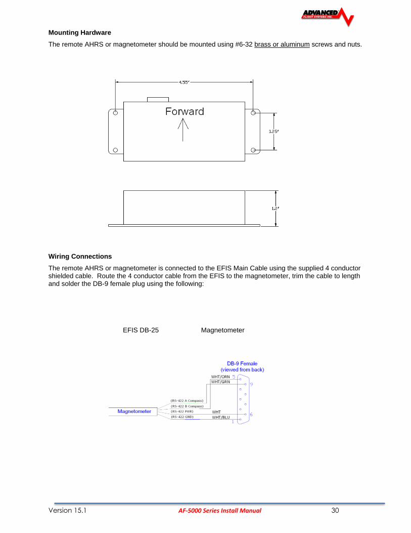
Mounting Hardware
The remote AHRS or magnetometer should be mounted using #6-32 brass or aluminum screws and nuts.
Wiring Connections
The remote AHRS or magnetometer is connected to the EFIS Main Cable using the supplied 4 conductor shielded cable. Route the 4 conductor cable from the EFIS to the magnetometer, trim the cable to length and solder the DB-9 female plug using the following:
EFIS DB-25 Magnetometer

Version 15.1 AF-5000 Series Install Manual 31
P/N: 72010 Magnetometer Alignment
A Magnetometer alignment will need to be performed after the system has been installed or any time the aircraft has had any major changes that could affect the magnetometer. The Magnetometer alignment will need to be performed in an area where the aircraft can easily be rotated. The alignment should be done with the engine stopped and the aircraft electronics on.
• The Magnetometer Alignment must be done with no vibration, the engine must be off!
• The aircraft needs to be in the same configuration as if in flight! If you have a sliding canopy it must be closed as many are magnetized.
• Aircraft should be at least 50 feet from any metal structure!
• Do not align the Magnetometer with the aircraft located on a concrete ramp with rebar!
• The AHRS must remain in the same attitude during the Mag alignment! Do not push down on the aircraft tail to get the plane to turn!
• Do not try to do a Mag align while the AHRS is initializing with the Red X!
• Aircraft should be rotated at approximately 360 degrees in 45 seconds and should require 1 to 1 ½ turns.
Magnetometer Alignment Procedure
1. Move the Aircraft to open area on Asphalt
2. Turn on the EFIS and wait for the Attitude Indeterminate Red X to go away.
3. Select MAG cal on the EFIS from the following menu: [SET] -> [AHRS] -> [MAG CAL] HOLD Button for 2 seconds
4. After accessing the MAG Align menu press the [START] button and follow the on-screen directions. Once instructed to start tuning the aircraft you must start rotating in less than 5 seconds.
5. Rotate the aircraft at a rate of approximately 360 degrees in 45 seconds and continue to rotate until instructed to stop. You should have to turn the aircraft between 1 and 1 ½ turns. It should take 250-300 data points during the 1 to 1 ½ turns. If the data points are counting at a slower rate the AHRS is detecting too much vibration or Magnetic interference.
6. If the AHRS displays an Elliptical Error you should try the procedure again only after the Attitude Indeterminate Red X to goes away.
7. If you continue to experience Elliptical Errors you will need to relocate the AHRS to a better location.

Version 15.1 AF-5000 Series Install Manual 32
EFIS Outside Air Temperature Transducer Installation
The OAT transducer P/N: 40305 is mounted on the airframe with a 3/8" hole where the exhaust will not affect it. Testing has shown the bottom of the wing is an excellent location. The OAT sensor wires should be connected from the EFIS Main Harness to the sensor with Fast On Terminals, Butt Connectors or with solder and heat shrink. If you are using the Advanced-SV ADAHRS unit this OAT sensor is not required, you will use the ADAHRS connected OAT sensor.
CAUTION Static Sensitive Part: Always ground yourself before wiring.
OAT Calibration
1. Place the EFIS into Instrument Calibration mode. Use the [NEXT] button to scroll down to OAT and press [SELECT].
2. Adjust the Shift Adjust value until the OAT is reading correctly.
3. Press [SAVE]
Alarm Output
The system has an output that will be connected to ground if one of the gauges is in the RED warning band or an input is configured to trigger the alarm. The Alarm Output can be used to drive a master warning light on the panel.
If multiple screens are used, only ONE screens alarm output is needs to be utilized. All EFIS and Engine alarms will be transferred to the main screen.

Version 15.1 AF-5000 Series Install Manual 33
For wiring information see APPENDIX M:
Electrical Connections
For wiring information see APPENDIX M: EFIS Main Power Connections The AF-5000 Series power requirement is 12 volts at 2.8 Amps, a 5 amp circuit breaker or fuse should be used for the system. All wire should meet Mil Standard MIL-W-22759/16 (Tefzel insulation)
20 AWG wire is normally sufficient for the power supply and ground wires.
EFIS Main Cable (DB-25)
Pin 1, 15 Red Master Power
Pin 2, 3 Black Master Ground
The master power pins are internally connected.

Version 15.1 AF-5000 Series Install Manual 34
EFIS Backup Power Connections The AF-5000 Series backup power input must be connect to the aircraft battery or a TCW backup battery module. The backup power input keeps the clock time when shut down and prevents an EFIS reboot when starting the aircraft engine.
EFIS Expansion Cable (DB-15)
Pin 6 Red Backup/KeepAlive Power Input
Pin 15 Black Backup Power Ground
CAUTION: The screen case and sensors must have a good ground to the aircraft battery. The case grounding screw should be connected with at least a 20 awg wire to the main aircraft ground buss.

Version 15.1 AF-5000 Series Install Manual 35
EFIS Backup Battery Wiring
P/N: 71713 3 AMP hours for a single screen
P/N: 71714 6 AMP hours for two screens

Version 15.1 AF-5000 Series Install Manual 36

Version 15.1 AF-5000 Series Install Manual 37

Version 15.1 AF-5000 Series Install Manual 38
P/N: 71703 2 AMP hours for a single screen **Old Model
P/N: 71704 4 AMP hours for two screens **Old Model

Version 15.1 AF-5000 Series Install Manual 39
Audio Connections
If two EFIS units are being installed, the audio from only 1 screen should be connected. All alerts are passed through the Ethernet network. The harness is wired for a 560-ohm audio output that allows you to match the output impedance of the system to standard aircraft audio panel and intercom audio devices. If your radio or audio panel does not have an unswitched audio input you will need to purchase a audio mixer. Do not attempt to connect the EFIS audio to a music input on an intercom, they are not the same impedance and it will not be loud enough. Do not attempt to connect the EFIS audio along with a com radio to the same intercom input.
We recommend the following audio mixer if you do not have an audio panel:
http://www.fdatasystems.com/AP_60.htm
For wiring information see APPENDIX M:
Volume Adjustment
The volume can be adjusted from the Instrument Calibration Audio Test menu.
The range is (0%-100%) and is adjusted using the knob followed by pressing the [SAVE] button.
The Test Audio menu will play all the sounds in the system.

Version 15.1 AF-5000 Series Install Manual 40
Screen Communication Settings (AHRS, AirData, EMS)
Each EFIS screen in the aircraft needs to be configured to talk to an AHRS, EMS , Airdata, and any remote EFIS screens.
Primary and Remote Screen IP Addresses
• Set the IP Address: This Display for each screen in the airplane using the following table:
Pilot Screen Co Pilot Screen #2 Screen #3
PFD EM MFD
175 176 177
• Set the IP Address Other Display setting in each screen in the airplane. This is the IP Address of the remote screen that will supply the AHRS and Airdata to the screen. This should NEVER be set to the screens own IP Address. If you have a single EFIS screen you should set it to 176.
Example Configuration for a three EFIS screen system
Pilot PFD EFIS Screen Center EM EFIS Screen Co Pilot MFD Screen
Engine Module Config
Hardware Network Description
OFF RXD Get Engine Data from Remote Screen
INT TXD EMS Board installed send Data to Remote Screen
INT OFF EMS Board installed no Remote Screen
EXT * TXD Turbine/FADEC send data to Remote Screen
EXT * OFF Turbine/FADEC no Remote Screen
CAN TXD CAN BUSS Engine send data to Remote Screen
CAN OFF CAN BUSS Engine no Remote Screen
OFFLINE No Engine Module Connected
* EFIS Screen Serial Port must be wired to Engine Module
Example Configuration for a three EFIS screen system
Pilot PFD EFIS Screen Center EFIS Screen with Engine Board Co Pilot EFIS Screen

Version 15.1 AF-5000 Series Install Manual 41
Air Module Config
Hardware Network Description
OFF RXD Get Air Data from Remote Screen
INT TXD Air Data installed send Data to Remote Screen
INT OFF Air Data installed no Remote Screen
OFFLINE No Air Data connected
* EFIS Screen Serial Port must be wired to Engine Module
Example Configuration for a three EFIS screen system
Pilot PFD EFIS Screen with Air Data Center EFIS Screen with Air Data Co Pilot EFIS Screen no Air Data
AHRS Module Config
Hardware Network Description
OFF RXD Get AHRS Data from Remote Screen
INT TXD AFS AHRS Connected send Data to Remote Screen
INT OFF AFS AHRS Connected no Remote Screen
EXT * TXD Remote AHRS send data to Remote Screen
EXT * OFF Remote AHRS no Remote Screen
OFFLINE
No Engine Module Connected
* Remote AHRS wired to Serial Port 1 – 4 ; Dynon D10, Levil, SBG
Example Configuration for a three EFIS screen system
Pilot PFD EFIS Screen with AHRS Center EFIS Screen with AHRS Co Pilot EFIS Screen no AHRS

Version 15.1 AF-5000 Series Install Manual 42
EFIS Serial Port Connections
Each EFIS screen has four serial ports that can be used for external equipment (GPS, NAV, Traffic, FADEC Engine, ect..) communication. If you have more than one screen installed in your aircraft and they are connected with Ethernet you can share the serial ports between screens. For the serial ports and navigation sources (GPS, NAV) to work properly you will need to configure the actual serial port number hardware settings as well as assign an EFIS navigation source to a serial port number. The following steps should be followed:
Serial Port Planning
The EFIS screen that is directly in front of the pilot shall be the Primary Flight Display (PFD). The PFD should have the following:
• IP Address 175
• AF-ARINC Module should be wired to the PFD serial port (#1, #2, #3, or #4)
• The ARINC and RS-232 serial ports from a GPS Navigator (430W, GTN650,…) must be wired to the same screen.
• The GPS/NAV 1,2,3 data source for a GPS Navigator (430W, GTN650,…) must never point to the AVTN Serial port.
• The AF-Pilot RS-232 Serial port should be wired to the PFD serial port (#1, #2, #3, or #4)
• In a two screen installation two GPS units should not be wired to the same screen.
• In a two screen installation two NAV (VOR/ILS) radios should not be wired to the same screen.
• The Transponder must be wired to the PFD EFIS screen
• In a two screen installation the ADS-B unit should be wired to the MFD screen.

Version 15.1 AF-5000 Series Install Manual 43
STEP 1
Serial Port # Function Hardware Setup
This is where you configure each serial port for the external device that is physically wired to the port. You will need to know which serial port each device is wired to on the screen and what the external devices communication settings are. From [Instrument Calibration] mode you should select the following menu to configure each Serial Port:
[1. Admin Settings] ->
Serial Port # Options Notes
Serial Port #1-4 Functions DISABLED Nothing wired to port Ext. AHRS External AHRS input NMEA @ 4800 External GPS with NMEA @ 4800 baud TRFC/ICARUS Garmin Traffic In / ICARUS Out SL-30 Garmin SL-30 radio connected ARINC AF-ARINC module connected to port AVTN/CHELTON Chelton Engine Data Out AVTN/ARNAV 430W/530W or GPS with Aviation format FADEC SBC-100 FADEC Data In FADEC SBC-250 Do Not Use OP TECH OP Engine Data Out NMEA/AVTN NMEA 9600 In / AVIATION Out TRFC/SHADIN ALT Garmin Traffic In/ SHADIN Out GARMIN AT Garmin AT format, Dynon gray code converter MAGELLAN Transponders set to MAGELLAN format NORTHSTAR Transponders set to NORTHSTAR format AFS GPS AFS GPS TRAFFIC Garmin Traffic format (GTX 330, Zaon, ADS-B) AVTN/AVTN Aviation In / Aviation Out
VPX Vertical Power VP-X Interface COGUARD CO Guardian Interface ADSB NavWorx ADS-B Interface
NOTES: STEP 1 should be done for all screens in the aircraft and only configured for the equipment that is physically connected to that screens serial ports.

Version 15.1 AF-5000 Series Install Manual 44
STEP 2
GPS/NAV # Data Source Software Setup
This is where you configure the three available EFIS CDI and Moving Map data sources (GPS/NAV 1,2,3) to their assigned serial ports. The data sources for multiple screens must be configured to the same navigation source. If you configure GPS/NAV1 as Serial Port 4 (ARINC Module connect to Port #4) on the left screen the right screen must be set GPS/NAV1 as Remote ARINC. This configures the EFIS to read the data from the ARINC port anytime GNAV 1 is selected from either screen.
From [Instrument Calibration] mode you should select the following menu to configure each GPS/NAV Data Source
[1. Admin Settings] ->
GPS/NAV # Options Notes
10. GPS/NAV 1-3 Data Source* NONE No connected Nav or GPS Serial Port #1 GPS or Nav Radio Connect to Serial Port #1 Serial Port #2 GPS or Nav Radio Connect to Serial Port #2 Serial Port #3 GPS or Nav Radio Connect to Serial Port #3 Serial Port #4 GPS or Nav Radio Connect to Serial Port #4 Remote GPS GPS connected to remote screen Remote ARINC GPS/NAV connected to remote screen ARINC Remove NAV SL-30 connected to remote screen. NOTES: *If you have an ARINC module it must be configured as the GPS/NAV1 Data Source. **If you have a second ARINC module it must be configured as the GPS/NAV2 Data Source.
Depending on the type of Nav Radio connected to the GPS/NAV data source it will be displayed on the screen as one of the following:
GNAVx GPS Navigator 430W/530W/480 GPSx GPS Only Unit NAVx SL30 Nav Radio
Where x is the order number of the GPS or Nav radio, a GPS Navigator has a GPS and a Nav radio and will be displayed as GNAV1 for the first unit and GNAV2 for the second.

Version 15.1 AF-5000 Series Install Manual 45
EFIS Serial Port Configuration Examples
AF-5000 EFIS, Vertical Power VPX-Pro, (430W or GTN650), AF-Pilot, GTX 327
Serial Port #1 430W + GTX 327
Serial Port #2 AF-Pilot
Serial Port #3 VPX-PRO
Serial Port #4 AF-ARINC Module

Version 15.1 AF-5000 Series Install Manual 46
The following examples should help you configure your system: <Example #1> Single Screen, Garmin 496, GTX 327 and SL30
5. Serial Port #1 Function NMEA/AVTN Garmin 496 GPS 6. Serial Port #2 Function TRFC/ICARUS Garmin GTX 327 Transponder 7. Serial Port #3 Function SL-30 SL30 Nav/Com 8. Serial Port #4 Function DISABLED 9. Serial Port Network Sharing DISABLED 10. GPS/NAV 1 Data Source Serial Port #1 GPS 1 11. GPS/NAV 2 Data Source Serial Port #3 NAV 1 12. GPS/NAV 3 Data Source NONE <Example #2> Single Screen with AF-ARINC, Garmin 430W, GTX 327 and SL30
5. Serial Port #1 Function AVTN/ARNAV Garmin 430W GPS RS-232 Port 6. Serial Port #2 Function TRFC/ICARUS Garmin GTX 327 Transponder 7. Serial Port #3 Function SL-30 SL30 Nav/Com 8. Serial Port #4 Function ARINC AF-ARINC Module -> 430W 9. Serial Port Network Sharing DISABLED 10. GPS/NAV 1 Data Source Serial Port #4 GNAV 1 11. GPS/NAV 2 Data Source Serial Port #3 NAV 2 12. GPS/NAV 3 Data Source NONE <Example #3> Single Screen with AF-ARINC, Garmin 430W, GTX327, FADEC Engine
5. Serial Port #1 Function AVTN/ARNAV Garmin 430W GPS RS-232 Port 6. Serial Port #2 Function TRFC/ICARUS Garmin GTX 327 Transponder 7. Serial Port #3 Function FADEC SBC-100 FADEC Engine Controller 8. Serial Port #4 Function ARINC AF-ARINC Module -> 430W 9. Serial Port Network Sharing DISABLED 10. GPS/NAV 1 Data Source Serial Port #4 GNAV 1 11. GPS/NAV 2 Data Source NONE 12. GPS/NAV 3 Data Source NONE <Example #4> Dual Screen with AF-ARINC, Garmin 430W, GTX 330, SL30, 496 SCREEN 1 (430W, GTX330, SL30)
5. Serial Port #1 Function AVTN/ARNAV Garmin 430W GPS RS-232 Port 6. Serial Port #2 Function TRFC/ICARUS Garmin GTX 330 Transponder 7. Serial Port #3 Function SL-30 SL30 Nav/Com 8. Serial Port #4 Function ARINC AF-ARINC Module -> 430W 9. Serial Port Network Sharing ENABLED 10. GPS/NAV 1 Data Source Serial Port #4 GNAV 1 -> 430W 11. GPS/NAV 2 Data Source Serial Port #3 NAV 2 -> SL30 12. GPS/NAV 3 Data Source REMOTE GPS GPS 2 -> 496 from other screen
SCREEN 2 (496)
5. Serial Port #1 Function NMEA/AVTN Garmin 496 6. Serial Port #2 Function DISABLED 7. Serial Port #3 Function DISABLED 8. Serial Port #4 Function DISABLED 9. Serial Port Network Sharing ENABLED 10. GPS/NAV 1 Data Source REMOTE ARINC GNAV 1 -> 430W from other screen 11. GPS/NAV 2 Data Source REMOTE NAV NAV 2 -> SL30 from other screen 12. GPS/NAV 3 Data Source Serial Port #1 GPS 2 -> 496 this screen

Version 15.1 AF-5000 Series Install Manual 47
AFS EFIS Serial Port Work Sheet N_ _ _ _ _
Screen 1
Serial Port # Preferred Use Device Data Format NAV Data Source Label
(GNAVx GPSx NAVx)
Serial Port #1 GPS RS-232
Serial Port #2 Encoder/Traffic
Serial Port #3 SL30, ARINC
Serial Port #4 ARINC, AF-GPS
Screen 2
Serial Port # Preferred Use Device Data Format NAV Data Source Label
(GNAVx GPSx NAVx)
Serial Port #1 GPS RS-232
Serial Port #2
Serial Port #3 SL30, ARINC
Serial Port #4 AF-GPS
Screen 3
Serial Port # Preferred Use Device Data Format NAV Data Source Label
(GNAVx GPSx NAVx)
Serial Port #1 GPS RS-232
Serial Port #2
Serial Port #3
Serial Port #4

Version 15.1 AF-5000 Series Install Manual 48
External Device Configuration
71410 SV-ARINC 429 ADAPTOR
The SV-ARINC adaptor lets an AF-5000 EFIS connect to a GPS Navigator (Avidyne IFD540, Garmin GTN-650/750) using the Advanced-SV network. This eliminates the need to use an EFIS serial port for GPS navigator communication.
AFS does not provide mounting hardware with SV-ARINC-429 module. The mounting tabs on each side of the module have holes sized for #10 fasteners, but it is up to the installer to decide how the SV-ARINC-429 will be secured to the aircraft. Follow recommended torque practices when tightening the mounting hardware. Do not rivet the SV-ARINC-429 to the aircraft as this will hinder future removal if necessary. Advanced-SV Network Connection
Connect the SV-ARINC-429 module to the Advanced-SV network using the hardware mentioned in the Advanced-SV System Construction Section or using equivalent hardware.
If you have to install a connector on the end of a network cable, insert all pins into the D9 connector. Refer to Appendix C: Electrical Connections for details on connector pin-outs and wire colors. Remember to configure the Advanced-SV network after connecting all modules to a display.
ARINC-429 Device Connection
Harness Construction
Because the SV-ARINC-429 can be connected to a variety of devices, the harness requirements will vary from airplane to airplane. Therefore, AFS does not supply pre-manufactured harnesses for the SV-ARINC-429 module. Instead, your SV-ARINC-429 shipped with enough connectors and pins to generate a wide variety of harness configurations. Refer to the sections below for detailed wiring information.
If you do not own a D-sub machined-pin crimping tool, they can be obtained for under $50 from many retailers. See http://wiki.dynonavionics.com for known sources of these products. You may also find it helpful to own a pin insertion/extraction tool as well.
Additional harness construction and wiring information can be found in Appendix C: Electrical Connections.
The SV-ARINC-429 has a single 25 pin female D-Sub socket which is used for all data connections to your compatible ARINC-429 device. The pin out depicted in Figure 82 below depicts the view from the rear of your male D25 connector
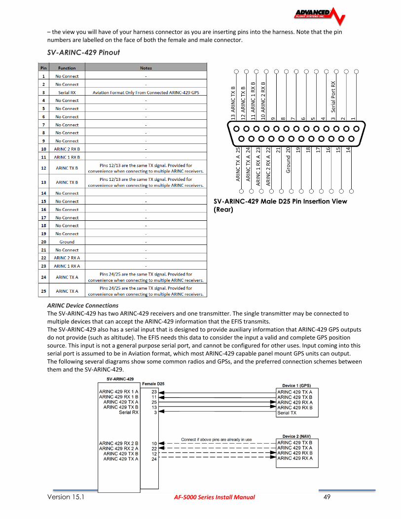
Version 15.1 AF-5000 Series Install Manual 49
– the view you will have of your harness connector as you are inserting pins into the harness. Note that the pin numbers are labelled on the face of both the female and male connector.
SV-ARINC-429 Pinout
SV-ARINC-429 Male D25 Pin Insertion View
(Rear)
ARINC Device Connections The SV-ARINC-429 has two ARINC-429 receivers and one transmitter. The single transmitter may be connected to multiple devices that can accept the ARINC-429 information that the EFIS transmits. The SV-ARINC-429 also has a serial input that is designed to provide auxiliary information that ARINC-429 GPS outputs do not provide (such as altitude). The EFIS needs this data to consider the input a valid and complete GPS position source. This input is not a general purpose serial port, and cannot be configured for other uses. Input coming into this serial port is assumed to be in Aviation format, which most ARINC-429 capable panel mount GPS units can output. The following several diagrams show some common radios and GPSs, and the preferred connection schemes between them and the SV-ARINC-429.

Version 15.1 AF-5000 Series Install Manual 50
Garmin GTN-650/750 Series Configuration Information The following are the typical Garmin and AF-5000 configuration settings when this combination of products is used:
Garmin Settings
"ARINC 429 Configuration" page
In 1: Low | EFIS Format 3 In 2: Unused by SkyView, configure as needed for other equipment Out: Low | GAMA Format 1 SDI: Common "VOR/LOC/GS Configuration Page
Nav Radio: Enabled ARINC 429 Configuration: Tx Speed: Low SDI: Common Other Settings: Unused by AF-5000 “RS-232 Configuration” Page
RS232 1 Output: Aviation Output 1 Optional (ADS-B)
If Dynon/AFS SV-XPNDR-261 is being used for ADS-B Out capability: Another GTN serial output should be set to “Garmin ADS-B” format. That serial port should be connected to the SV-XPNDR-261’s pin 3 through a 1.21k resistor as described in the transponder installation section of this manual.

Version 15.1 AF-5000 Series Install Manual 51
71410 SV-ARINC EFIS Configuration Settings

Version 15.1 AF-5000 Series Install Manual 52
71400 AF-ARINC 429 ADAPTOR
The AF-ARINC adaptor provides 2 serial ARINC 429 inputs for display of navigation data (VOR, ILS, GPS, LPV ) from a Garmin 430W/530W/480/650/750 and 1 ARINC 429 serial output. The ARINC 429 output can be connected to multiple ARINC 429 receivers; 430W, 530W, 480, and Autopilots that support GPS steering commands.
For ARINC module wiring information see APPENDIX M, drawing number: 53620WD
ARINC Module Software Updating
The ARINC adaptor software is upgraded from the EFIS Calibration menu under System
Maintenance.

Version 15.1 AF-5000 Series Install Manual 53
Procedure
1. Download the latest ARINC software from the AFS support page.
http://www.advanced-flight-systems.com
2. Unzip the ARINC.zip file, and place the ARINC.HEX file onto a SD card.
3. Insert the card into the unit and navigate to the Upgrade ARINC page.

Version 15.1 AF-5000 Series Install Manual 54
4. Cycle power to the ARINC adaptor. If the ARINC module is powered on the same source as the EFIS the internal EFIS battery should keep the EFIS running during the power cycle.
5. Press the SEL button to begin loading the new code. The screen will say, “Loading….xxx”. Where xxx is the number of bytes transferred.
6. When the screen prints “Done.”, you can remove the card and reboot the ARINC module.
7. Verify that the ARINC software version was updated from the following menu after the EFIS is running in normal mode: [CHECK] -> [ABOUT] The ARINC software version should be displayed in the list.
Now the ARINC module is ready for use.

Version 15.1 AF-5000 Series Install Manual 55
Advanced-SV Autopilot
Dynon Autopilot Servo Installation, Configuration, and Calibration
This chapter contains generic mechanical and electrical installation guidelines for the Dynon servos mentioned in Table 50. Plane-specific kits purchased from Dynon contain detailed drawings and diagrams which are intended to be used in conjunction with this guide as a complete set of installation instructions. A complete list of aircraft mounting kits is available on the current Price List/Order Form at http://store.dynonavionics.com. Drawings and diagrams are also available at http://docs.dynonavionics.com.
This Figure is a high-level overview of a suggested servo installation, configuration, and calibration procedure.
Dynon Avionics offers the following servo models:

Version 15.1 AF-5000 Series Install Manual 56
Compass Calibration Requirement
The Advanced-SV autopilot requires an accurate compass to operate efficiently and comfortably in heading mode and the radio-based VOR/NAV mode. Therefore it is critical that the ADAHRS be installed correctly, calibrated, and operating well in all attitudes.
Servo Mechanical Installation Dynon Avionics has researched suitable mounting points for a number of popular aircraft and offers mounting kits and instructions for them. If you have purchased one of these kits, use the instructions included with it as your primary guide; the following mechanical installation information is more general in nature. If you have purchased cable-drive capstan servos (SV32C or SV42C), refer to the documentation that came with the included Capstan Accessory Kit (101116-000).
For installing Dynon Avionics servos in aircraft for which Dynon does not offer kits, we offer a Generic Servo Installation Kit (101020-000) of basic parts and basic installation instructions. The generic servo push-pull mounting kit includes some of the hardware to mount a servo and connect to the aircraft controls, but requires the installer to fabricate mounting brackets. This kit can be used in either pitch or roll applications that use a servo with an output arm (not suitable for use with pulley/cable servos). Some additional fasteners (not supplied by Dynon) and brackets will be required depending on the installation method chosen.
Neglecting to properly install and/or use Dynon Avionics AP hardware can result in failures which could cause loss of aircraft control resulting in aircraft damage, personal injury, or death. If there are any questions on the part of the installer it is mandatory to resolve these questions prior to flight.
When installing the servo, you must first determine a mount location for proper
interaction with the existing control system. The mounting point that is chosen must
allow the servo arm and associated linkage to move freely through the entire range of
travel. To prevent the possibility of the servo arm going OVER CENTER, the servo arm
must not travel more than a total of +/-60° from neutral position. When the aircraft
controls are centered, the arm of the servo should be perpendicular to the attaching
push rod. If this is not the case, we recommend adjusting the length of the push rod or
consider a different mounting point. For maximum efficiency and the lightest drag on
the flight controls, you should choose the smallest servo that provides sufficient torque
to move and hold the flight controls with a minimum of slippage.
The servo arm must not rotate even near to the point called OVER CENTER, the point at which the primary aircraft control would “lock up”. Over center happens when the angle between the servo arm and the attached push rod becomes so great that the control system cannot drive against the servo arm. To protect against this possibility, a Range of Motion Limiting Bracket is supplied with each Dynon Avionics servo. These brackets are drilled so that they can be mounted at different angles as required (18° intervals). The brackets are supplied for the protection of the pilot, and we recommend that the Range of Motion Limiting Bracket be installed to ensure that an OVER CENTER condition cannot occur. During normal servo operation, the Range of Motion Limiting Bracket should never be used. It is only intended for use as a safety mechanism in the SkyView Autopilot system. When installing the Range of Motion Limiting Bracket, only use the supplied screws. Using longer screws to install the bracket, you will penetrate and damage the electronics.

Version 15.1 AF-5000 Series Install Manual 57
Once a suitable mounting point for each servo has been determined, the next step is
to fabricate a mount for the servo to attach to the aircraft. Generally this will be a
bracket made of sheet metal or corner stock. Dynon recommends using 6061 T6
aluminum with a minimum thickness of 0.050” for the best balance of strength to
weight. When fabricating a mounting bracket, refer to the servo dimensions below. Be
sure to leave ample room for the arm and attached linkage to move through a
complete range of motion without interference.
In normal operation, autopilot servos can reach temperatures that can be very uncomfortable to, and perhaps cause burns to unprotected skin. Thus, servos should be mounted in an area, or in such a manner to prevent accidental skin contact. If mounting the servo in an exposed area is necessary, a shroud should be installed (that doesn’t restrict ventilation) that protects against accidental skin contact with the servos.
Push-Pull Servo Dimensions Use the following dimensions (in inches) for reference when planning and implementing your installation.

Version 15.1 AF-5000 Series Install Manual 58
Linkage Mount Position Force and Travel The two diagrams below illustrate the maximum travel and force available at each linkage mounting point. As can be seen, the closer you mount the linkage to the shaft, the more force the servo can deliver. However, this also means the travel of the arm is shorter. Again, ensure that the servo arm is nowhere near going over-center throughout the entire range of the
control system.
The maximum linear travel specifications called out above denote the distance traveled by the location on the arm such that it is 60° from center at maximum distance in either direction (e.g., the A hole on the standard servo arm can linearly travel 1.3”(33mm) from center in either direction). During installation, the linkage hardware must be connected to the servo arm such that the servo can actuate the connected control surface while approaching, but not exceeding the called out maximum linear travel specification. If too much slippage occurs during servo flight testing, it may be necessary to use a stronger servo.
Each Dynon Avionics servo includes a precision-machined brass shear screw that pins the servo arm to the servo arm attachment, providing an ultimate manual override. Servo shear screws will break at the application of 100 inch-pounds of torque, at which point the servo arm will travel freely. If the brass shear screw is broken during autopilot installation or usage, do not replace it with a standard screw– contact Dynon Technical Support (contact information at the beginning of this manual) for a replacement shear screw. Instruction for replacing the shear screw can be found at http://docs.dynonavionics.com.

Version 15.1 AF-5000 Series Install Manual 59
Autopilot System Electrical Installation

Version 15.1 AF-5000 Series Install Manual 60
74152 SV-Autopilot Panel
This chapter contains pre-installation considerations, installation instructions, and details to install the SV-AP-PANEL/H (Horizontal orientation) and SV-AP-PANEL/V (Vertical orientation). Physically, electronically, and operationally, the two versions are identical, and hereafter referred to SV-AP-PANEL.
The SV-AP-PANEL is an optional control panel for a AF-5000 system that provides one-button controls for the SV Autopilot that are otherwise operated from the AF-5000 display menu buttons (which are still accessible after the installation of an SV-AP-PANEL).
SV-AP-PANEL NOSE UP and NOSE DN BUTTONS
The NOSE UP button on the SV-AP-PANEL commands the AP System, if engaged, to incrementally pitch the AP “Nose Up” via IAS or VS adjustments depending on what mode the AP is in.
Similarly, the NOSE DN button on the SV-AP-PANEL commands the AP system, if engaged, to incrementally pitch the AP “Nose Down” via IAS or VS adjustments depending on what mode the AP is in.. The SV-AP-PANEL NOSE UP and NOSE DN buttons command the AP; these buttons do not command trim controls (via the 15-pin DSUB connector). The only controls for trim are button inputs to the 15-pin DSUB connector – see details below).

Version 15.1 AF-5000 Series Install Manual 61
Electrical Installation SV Network The SV-AP-PANEL has two SV Network connections (D-9 connectors). Both connectors are electrically identical and are internally connected. Thus, the SV-AP-PANEL can be installed in the SV Network as a “pass-through” device, or “daisy chained” from one SV Network device, through the SV-AP-PANEL, to the next SV Network device. The SV-NET-1.5CC is an 18-inch SV Network cable that is ideal for such situations. The SV-AP-PANEL receives power (for operation of the buttons) from SV Network. Dimming of the SV-AP-PANEL is controlled by the AF-5000 display(s).
Trim Motor Control In addition to the AP mode buttons, the SV-AP-PANEL includes an
adjustable, speed-sensitive trim controller, eliminating the need for relay packs or a
separate trim controller. The integrated trim controller is wired to a D15 connector that
can be connected to Aircraft power (12V only), pushbuttons (typically, on the stick),
and power to and control of up to two trim motors - such as those made by Ray Allen.
A set of pushbuttons can optionally be installed for the copilot. The pilot’s pushbuttons
take priority over the copilot’s pushbuttons. Pushbuttons used for Trim Motor Control
must be Push Button Normally Open (PBNO) – a momentary switch with a contact that
is closed only when the button is pushed. One terminal of the pushbutton is connected
to the selected pin, the other terminal of the pushbutton is connected to avionics
ground (can be common with Pin 2).
Note that the SV-AP-PANEL’s trim controller only connects to the trim motors. The SV-
AP-PANEL does not connect to or monitor trim position. Monitoring trim position is done
by connecting the trim motor’s potentiometer (position sensor) that is mechanically
ganged to the trim motor to a Trim Input pin on the AF-5000 EMS connector.
Trim Motor Control Safety Features
• Pilot trim controls override Copilot trim controls.
• If SV Network connection or AF-5000 power is lost, the trim motor functions will continue to function as long as avionics power is available at Pin 9. When a AF-5000 is not powered on (not communicating with the SV-AP-PANEL) the speed scheduling features (QUICKEST TRIM SPEED / SLOWEST TRIM SPEED) are not available. In this failsafe mode, the trim motors will run at their full speed when trim buttons are pushed.
• If a trim control button is detected as pushed when power is first applied to Pin 9, trim control will not activate until the button is first released.

Version 15.1 AF-5000 Series Install Manual 62
• If a trim control button is pushed for more than five seconds (or longer, such as a stuck button), trim control on that axis will be temporarily inactivated until the button is first released.
• Motor outputs are protected against short circuits. If two SV-AP-PANELs are installed, connect only one SV-AP-PANEL to control trim motors. Do not connect the second SV-AP-PANEL’s D15 connector in parallel with the first SV-AP-PANEL’s D15 connector – doing so could cause unexpected behavior and/or damage to the units and the trim motors. On the D15 connector, Power (Pin 9) and Ground (Pin 2) connections are only required to control a Pitch trim motor and/or a Roll trim motor. If the trim motor outputs are not used, Power (Pin 9) and Ground (Pin 2) should not be connected. Ray Allen trim motors are known to work - connect the white wires to Pins 7 and 8 (MOTOR 1) and/or Pins 14 and 15 (MOTOR 2). If using other trim motors, ensure that the trim motor’s maximum current does not exceed 2A. The functions assigned to each pin in Table 69 below reflect Motor 1 being used for TRIM UP/DOWN and Motor 2 being used for TRIM RIGHT/LEFT.

Version 15.1 AF-5000 Series Install Manual 63

Version 15.1 AF-5000 Series Install Manual 64
The Trim motor speeds are adjusted in the Elevator and Aileron Calibration Menu
Post Installation Checks • Verify buttons operate all AP modes.
• Verify dim commands from SkyView display dim the backlighting of the SV-AP-PANEL.
• Verify that trim controls operate as commanded from Pilot and (optional) Copilot controls.
• During a test flight, use the PITCH trim pushbuttons to bring the plane slightly out of PITCH trim. Verify that PITCH auto-trim automatically trims the PITCH as needed. (Assumes that PITCH auto-trim is enabled.)
• During a test flight, use the ROLL trim pushbuttons to bring the plane slightly out of ROLL trim. Verify that ROLL auto-trim automatically trims the ROLL as needed. (Assumes that ROLL auto-trim is enabled.)

Version 15.1 AF-5000 Series Install Manual 65
AF-Pilot Autopilot
The AF-Pilot autopilot requires both RS-232 GPS data and ARINC 429 data. The RS-232 port can be wired directly to a GPS that provides NMEA/Aviation data or to the EFIS PFD. If you wire the Autopilot RS-232 port to an EFIS RS-232 port configured as AF-PILOT you will be able to turn ON and OFF the Autopilot from the EFIS screen and the EFIS will display the current Autopilot mode and trim. The AF-Pilot RS-232 port should be connected to the same screen as the AF-ARINC module.
This example uses EFIS serial port #3, any open serial port can be used.
EFIS AF-Pilot
Pin 5 #3 RXD --------------- Pin 7 TXD
Pin 4 #3 TXD --------------- Pin 17 RXD
AF-ARINC
Pin 13 Out A --------------- Pin 14 ARINC In A
Pin 25 Out B --------------- Pin 15 ARINC In B
Example Autopilot wiring with Garmin GTN 650:

Version 15.1 AF-5000 Series Install Manual 66
Serial Port configured for AF-Pilot Autopilot.

Version 15.1 AF-5000 Series Install Manual 67
CO Guardian Display
Currently, the new “s” mode processor will display data from any of the CO Guardian units that support RS-232 MFD output. The current cabin CO level is displayed on any of the Check List pages. If the CO Guardian device generates a warning, the current CO level will be displayed as a pop up message on the EFIS screen. If you have the new Aero-455 (CO, heart rate, O2 level ) monitor, the data will be displayed as a pop up message after about 20 seconds of monitoring you finger. The CO Guardian should be wired to any open serial port and then the serial port Admin setting set to CO Guardian.

Version 15.1 AF-5000 Series Install Manual 68
74125 AF-Intercom
While the AF-INTERCOM-2S is designed to seamlessly complement a AF-5000 System, its design is flexible enough to be used in any experimental or light sport aircraft panel that does not required a TSO’d intercom.
Physical Installation The AF-INTERCOM-2S package includes #6-32 hex-drive round head fasteners
(to match those furnished with AF-5000 displays). Fasteners are 5/8” in length and require a 5/64” hex drive tool. AFS recommends fastening the included mounting screws to nut plates installed behind the panel. If access behind the panel allows, standard #632 lock nuts or nuts with lock washers can be used. Do not rivet the AF-INTERCOM-2S to the aircraft as this will hinder future removal if necessary.
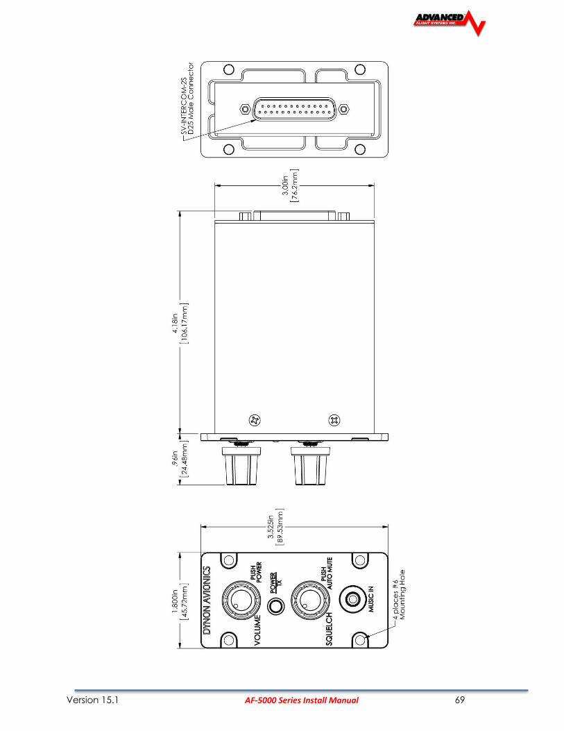
Version 15.1 AF-5000 Series Install Manual 69

Version 15.1 AF-5000 Series Install Manual 70
* == While the audio grounds labeled with a * ultimately come back to the main ground on pin 1, they should NOT be wired directly from the source audio device to any ground (pin 1 or otherwise) directly. Instead, to minimize noise and interference, their ground lines should be routed with their audio signal inside the required shielded cable as far as possible and connected to ground as close to the intercom as possible. Connecting these grounds to the shield (which is also grounded at pin 1) at the intercom end of the harness is a suitable way to accomplish this goal.
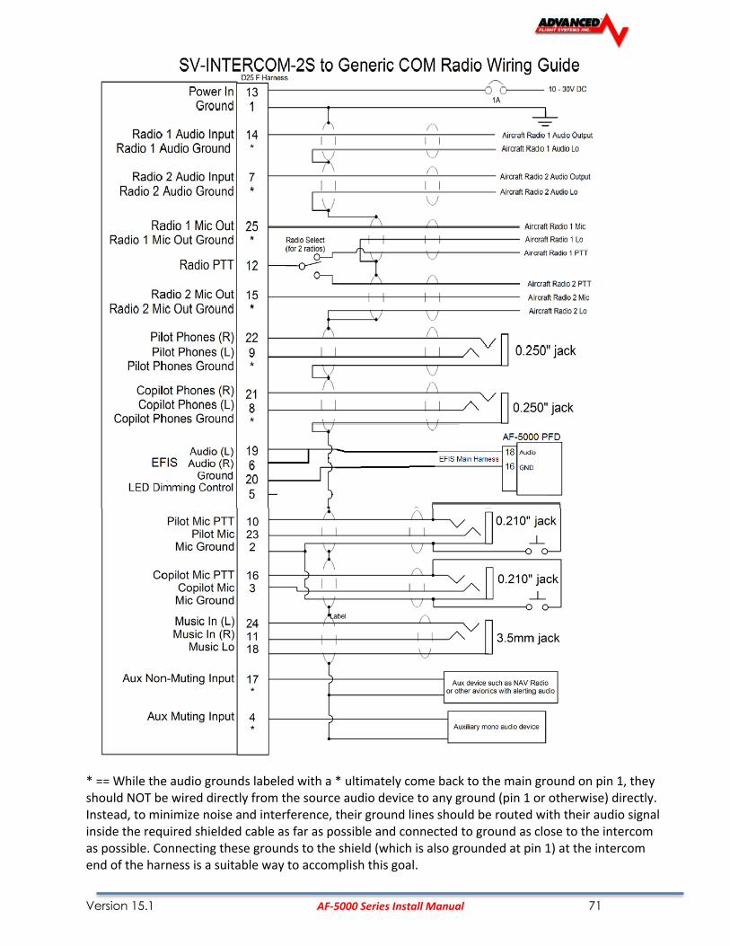
Version 15.1 AF-5000 Series Install Manual 71
* == While the audio grounds labeled with a * ultimately come back to the main ground on pin 1, they should NOT be wired directly from the source audio device to any ground (pin 1 or otherwise) directly. Instead, to minimize noise and interference, their ground lines should be routed with their audio signal inside the required shielded cable as far as possible and connected to ground as close to the intercom as possible. Connecting these grounds to the shield (which is also grounded at pin 1) at the intercom end of the harness is a suitable way to accomplish this goal.

Version 15.1 AF-5000 Series Install Manual 72
AF-INTERCOM -2S Pin
AF-5000 AF-INTERCOM-2S Function
Notes
1 N/A Master Ground In / Master Shield Ground.
The shields of all shielded audio cables should be connected to this pin.
2 N/A Microphone / PTT Ground
Pilot and Copilot
3 N/A Copilot Microphone
4 N/A Auxiliary Mono Muting Input
This audio signal mutes when audio signals are received on other non-muting inputs and radio inputs. Use this input for NON critical audio signals.
5 N/A LED Dimmer Input
6 AF-5000 D25 Pin 18 Stereo Non-Muting (EFIS) Audio Input
This audio signal does not mute, and is typically used to receive audio from AF-5000 or other EFIS system with stereo output.
7 AF-COM 425 #2 Pin 10 Radio 2 or Other Aux Non-Muting Audio Input
This audio signal does not mute. Typically used for a second COM, a NAV radio, or other mono avionics alerts.
8 N/A Copilot Headphones Left
9 N/A Pilot Headphones Left
10 N/A Pilot Push-To-Talk Switch Input
11 N/A Stereo Music In Right This input is over-ridden by the Music In jack on the AF-INTERCOM-2S
12 AF-COM-425 #1 Pin 5 AF-COM-425#2 Pin 5
Push-To-Talk Output If two radios are used, this signal must be switched between the two radios so that only ONE radio transmits at a time.
13 N/A Power In

Version 15.1 AF-5000 Series Install Manual 73
AF-INTERCOM-2S Pin AF-500 Unit Pin AF-INTERCOM-2S Function
Notes
14 AF-COM-425 #1 Pin 10 Radio 1 Headphones Input
Connects to AF-COM-425 #1 / Radio #1 Headphones Output
15 AF-COM-425 #2 Pin 1 Radio 2 Microphone Output
16 N/A Copilot Push-To-Talk Switch
17 N/A Non-Muting Mono Aux Input
This audio signal does not mute when audio signals are received on other inputs. Use this input for critical audio signals such as a NAV radio or avionics alerts.
18 N/A Music In Ground Used exclusively for stereo audio ground. Should not be used for other ground connections.
19 AF-5000 D25 Pin 18 Stereo Non-Muting () Audio Input Left
This audio signal does not mute, and is typically used to receive audio from EFIS system with stereo output.
20 AF-5000 DB-25 Pin 16 Stereo Non-muting (EFIS) Audio Ground
Used exclusively for stereo EFIS audio ground. Should not be used for other ground connections.
21 N/A Copilot Headphones Right
22 N/A Pilot Headphones Right
23 N/A Pilot Microphone
24 N/A Stereo Music In Left This input is over-ridden by the Music In jack on the AF-INTERCOM-2S
25 AF-COM-425 #1 Pin 1 Radio 1 Microphone
Using Dim Input (Pin 5) Using Dim Input (Pin 5) you must dim this using a PWM dimmer that
switches the ground side of the lighting circuit. A varying voltage or resistance will not work. Hook pin 5 to the negative terminal of your dimmer and the transmit/power LED will dim with your dim control. This input may be connected in parallel with other loads that are dimmed by the dimmer

Version 15.1 AF-5000 Series Install Manual 74
Shielded audio cable is required In an audio system such as the AF-INTERCOM-2S, it is required to
use separate shielded cables for microphone and other input signals, and headphone and other output signals. If separate shielded cables are not used, squealing, hum, and other undesirable audio will likely be heard. To reduce electrical noise from being induced into audio circuits, separate the audio wiring as much as possible from other electrical wiring.
Audio cable shields must terminate at a common point A ground loop is more than one
electrical path to ground. Ground loops are a common source of noise with audio systems. Because other electrical loads can cause large current flows in a ground path, audio system grounds should be isolated as much as possible from electrical ground. Except where specifically directed in the diagrams above, the shields for all audio cables should terminate at a single point, with that point connected directly to Pin 1 (Master Ground) of the AF-INTERCOM-2S. Additionally, the point should be as close to the AF-INTERCOM-2S side of your harness as possible.
Dual Radio PTT Installation The AF-INTERCOM-2S has two separate radio outputs that can each be connected to an individual COM radio. The PTT output, therefore, needs to be externally switched so that you can control which radio receives the PTT signal (and therefore transmits). An external single pole, double throw (SPTD) switch (not provide) should be installed to select which radio the PTT is connected to. See the wiring schematics above (AF-INTERCOM-2S pin 12) for a depiction of this connection.
Headset jacks must be electrically isolated from the panel If your panel is
electrically conductive (such as aluminum), the headset jacks must be electrically isolated from the panel. Insulating washers are included with the headset jacks. Another method is to mount the jacks on a small plastic plate instead of mounting the jacks directly to the panel.
Version 15.1 AF-5000 Series Install Manual 75
Power To power the AF-INTERCOM-2S on and off manually, press the volume knob. The power switch remembers its on/off state: Once the AF-INTERCOM-2S is powered on, aircraft power can be used to turn the Intercom on and off in normal use. Therefore, the power switch need not be used in routine operation.
LED Power/Transmit Indicator
The LED indicator light in the center of the Intercom is green when the Intercom is powered on. When either the pilot or co-pilot PTT switch is depressed, the LED becomes orange to indicate radio transmission.
Volume
The volume knob adjusts the audio levels of the stereo music input and pilot-to-copilot intercom communication only. It does not adjust the volume level of aircraft radios or other devices that are connected. Adjust the volume levels on your radios and other audio devices to achieve the desired volume balance between all audio devices in the aircraft.
Squelch Adjustment The AF-INTERCOM-2S has voice-activated (VOX) microphone channels to reduce background noise from the aircraft when no one is speaking. When either the pilot or co-pilot speaks into their headset, their microphone channel is activated, allowing them to be heard by the other person. The microphone audio level that is required to activate a microphone channel is adjusted with the squelch knob. Adjust squelch with the engine running: First, while no one is talking, turn the squelch knob until you hear background noise in your headset. Next, adjust the squelch until you no longer hear background noise. Finally, with the microphone very near your lips, talk to confirm that normal speech levels activate the microphone. The VOX feature will automatically close the microphone after you finish speaking. To reduce background noise, the pilot and co-pilot microphones are activated individually.
Front Music In Jack The AF-INTERCOM-2S has wiring provisions for a permanent stereo music source via its rear-mounted wiring connector.
A music device can also be plugged in to the standard 3.5mm Music In jack on the front of the intercom. When a device is plugged in to the Music In jack, it over-rides the permanent music input.
Muting Inputs Whenever a radio or other non-muting input has audio activity, music and muting input volume is immediately decreased to near fully-muted so that you may hear important radio transmissions or audio alerts. When audio from radios/non-muting inputs ceases for a moment (.5 second), volume levels are automatically restored gradually over the next second.

Version 15.1 AF-5000 Series Install Manual 76
Selectable Auto Mute (music only) Press the squelch knob to toggle whether or not music is muted by intercom conversation as well as by non-muting input and radio activity. This allows you to set the music and aux muting input to not mute as you sing along or occasionally chat over the intercom:
• When Auto Mute is DISABLED: Only audio activity from radios and non-muting inputs will mute music.
• When Auto Mute is ENABLED: Audio from radios, non-muting inputs, AND intercom conversation will mute music.
Fail-safe Operation
When power is lost or the AF-INTERCOM-2S is powered off, the primary radio is connected directly to the pilot’s headset. If the pilot headset is a stereo headset, you will only hear radio audio in one ear. Intercom conversation and audio from other radios and inputs (including music) will not be heard when in this unpowered fail-safe mode.
Radio Push-to-Talk (PTT) Behavior and Priority When the pilot or co-pilot presses their PTT switch, only the person pressing their PTT is heard over the radio. If the pilot and co-pilot PTT buttons are both depressed, the pilot PTT takes priority. Only the pilot’s voice is transmitted over the radio. Additionally, the pilot PTT will take priority from the co-pilot even if the co-pilot PTT is already depressed.
Dual Radio Operation If you have two COM radios, you will have installed an external switch that chooses which radio transmits when you press the PTT switch.
Use your radio volume control to control which radio(s) you wish to hear at any given moment.
AF-Intercom Specifications

Version 15.1 AF-5000 Series Install Manual 77
74122 AF-Com Radio
The AF-COM Radio is a complete radio system, consisting of the AF-COM-PANEL control panel installed on the panel, and the AF-COM-425 transceiver installed elsewhere. AF-COM-PANEL Installation instructions for the AF-INTERCOM (referenced in these instructions) have their own separate manual available for download. AF-COM-PANEL

Version 15.1 AF-5000 Series Install Manual 78
The figures on the following pages show recommended panel cutouts, mounting hole patterns, and mechanical dimension for the AF-COM-PANEL/V (vertical) and AF-COM-PANEL/H (horizontal). Use these diagrams to plan for the space required by the display.
To mount an AF-COM-PANEL, cut the opening in your panel, drill out the mounting holes, install nutplates, and use the included mounting screws to fasten the display to the panel. Your AF-COM-C25 is shipped with #6-32 hex-drive round head fasteners. Fasteners are 5/8” long and require a 5/64” hex drive tool. AFS recommends fastening the included mounting screws to nut plates installed behind the panel. If access behind the panel allows, standard #6-32 lock nuts or nuts with lock washers can be used. Do not rivet the AF-COM-PANEL to the panel as this will hinder future removal if necessary. The following installation procedure should be followed to install the AF-COM-425 remote transceiver module, remembering to allow adequate space for installation of cables and connectors.
• If you are installing two COM radios, it is acceptable to co-locate the two AF-COM-425 transceiver modules.
• Select a position in the aircraft for the AF-COM-425 that is not too close to any high external heat source. (The AF-COM-425 is not a significant heat source itself and does not need to be kept away from other devices for this reason).
• Avoid sharp bends and placing the cables too near to the aircraft control cables.
• Secure the AF-COM-425 to the aircraft via the four (4) mounting holes. The unit should be mounted to a flat surface.
Additional items you will require for installation of AF-COM-C25, but which are not in the AF-COM-C25 package, include:
• Nutplates for mounting AF-COM-PANEL to the panel
• Circuit breaker or fuse for power to AF-COM-425
• Power wires to AF-COM-425
• AF-COM-425 to AF-COM-PANEL wiring
• Advanced-SV Network cables to connect the AF-COM-PANEL to Advanced-SV Network
• COM Antenna, coaxial cable, terminated to Male BNC connector. The AF-COM-C25 is compatible with aircraft COM antennas commonly available.

Version 15.1 AF-5000 Series Install Manual 79
Mounting Dimensions The following diagrams are NOT to scale. However, paper templates are included with your AF-COM-C25

Version 15.1 AF-5000 Series Install Manual 80
AF-COM-425
AF-COM-425 Dimensions

Version 15.1 AF-5000 Series Install Manual 81
Electrical Installation
Power Input AF-COM-C25 is compatible with 12 volt and 24 volt systems (10 to 30 volts DC). Power input is connected to the AF-COM-425, which then supplies power to the AF-COM-PANEL via the 5-wire cable between the two units. See wiring diagrams and pinouts for details.
Audio Signal Grounding Ensure that audio input and output grounds terminate at a single point - typically the intercom or audio panel. Do not connect an audio input or output ground to aircraft frame ground or a power or data ground. You should run dedicated wires from audio devices to the single point audio input and output ground.
Audio Shielding Shielded cable must be used for all audio connections. The shield should be connected to ground only at the single point audio ground.
Advanced-SV Network Connectors The two D9 connectors on the back of a AF-COM-PANEL display are Advanced-SV network connectors. They have identical pin-outs and are electrically connected inside the AF-COM-425 (i.e., they are completely interchangeable). Installers may use either connector or both connectors in AF-5000 installations. Using both of these connectors allows installers to “daisy-chain” another Advanced-SV Network module that may be co-located behind the panel.
Electrical Connections Harness Construction Because the AF-COM-C25 (AF-COM-PANEL connected to AF-COM-425) can be mounted in a variety of locations, the harness length requirements will vary from airplane to airplane. Therefore, AFS does not supply pre-manufactured harnesses for the AF-COM-C25. Instead, your AF-COM-C25 includes connectors and pins to generate a wide variety of harness configurations. Refer to the sections below for detailed wiring information. The AF-COM-PANEL has two (electrically identical) D9 male connectors for connection to Advanced-SV Network and one D15 male connector for connection with the AF-COM-425 and an optional Frequency Flip/Flop pushbutton input. The AF-COM-425 has one D15 male connector for connection to the AF-COM-PANEL, power, audio, and Push To Talk (PTT). A single BNC coaxial connector attaches to the antenna.
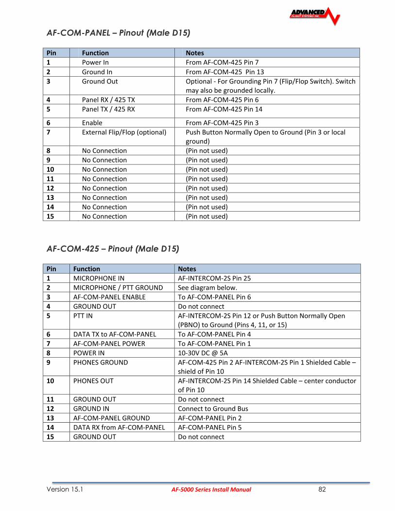
Version 15.1 AF-5000 Series Install Manual 82
AF-COM-PANEL – Pinout (Male D15)
Pin Function Notes
1 Power In From AF-COM-425 Pin 7
2 Ground In From AF-COM-425 Pin 13
3 Ground Out Optional - For Grounding Pin 7 (Flip/Flop Switch). Switch may also be grounded locally.
4 Panel RX / 425 TX From AF-COM-425 Pin 6
5 Panel TX / 425 RX From AF-COM-425 Pin 14
6 Enable From AF-COM-425 Pin 3
7 External Flip/Flop (optional) Push Button Normally Open to Ground (Pin 3 or local ground)
8 No Connection (Pin not used)
9 No Connection (Pin not used)
10 No Connection (Pin not used)
11 No Connection (Pin not used)
12 No Connection (Pin not used)
13 No Connection (Pin not used)
14 No Connection (Pin not used)
15 No Connection (Pin not used)
AF-COM-425 – Pinout (Male D15)
Pin Function Notes
1 MICROPHONE IN AF-INTERCOM-2S Pin 25
2 MICROPHONE / PTT GROUND See diagram below.
3 AF-COM-PANEL ENABLE To AF-COM-PANEL Pin 6
4 GROUND OUT Do not connect
5 PTT IN AF-INTERCOM-2S Pin 12 or Push Button Normally Open (PBNO) to Ground (Pins 4, 11, or 15)
6 DATA TX to AF-COM-PANEL To AF-COM-PANEL Pin 4
7 AF-COM-PANEL POWER To AF-COM-PANEL Pin 1
8 POWER IN 10-30V DC @ 5A
9 PHONES GROUND AF-COM-425 Pin 2 AF-INTERCOM-2S Pin 1 Shielded Cable – shield of Pin 10
10 PHONES OUT AF-INTERCOM-2S Pin 14 Shielded Cable – center conductor of Pin 10
11 GROUND OUT Do not connect
12 GROUND IN Connect to Ground Bus
13 AF-COM-PANEL GROUND AF-COM-PANEL Pin 2
14 DATA RX from AF-COM-PANEL AF-COM-PANEL Pin 5
15 GROUND OUT Do not connect

Version 15.1 AF-5000 Series Install Manual 83
The following figure depicts how a single AF-COM-C25 is connected to an AF-INTERCOM-2S.
Note that Advanced-SV Network connection(s) on AF-COM-PANEL are not shown, nor are additional connections between the AF-INTERCOM-2S and other devices that it connects to.
Single AF-COM-425 to AF-Intercom-2S Wiring Diagram
The following figure depicts how a dual AF-COM-C25 is connected to an AF-INTERCOM-2S. Note that the additional connections between the AF-INTERCOM-2S and other devices that it connects to are not shown. Note that the associated AF-COM-PANELs are also not shown; there are no changes in the AF-COM-PANEL to AF-COM-425 wiring from the single AF-COM-425 to AF-INTERCOM-2S previously shown.

Version 15.1 AF-5000 Series Install Manual 84
Dual AF-COM-425 to AF-Intercom-2S Wiring Diagram
The following figure depicts connecting a AF-COM-425 directly to a single headset (headphone + microphone) and a Push-To-Talk Switch when no intercom is used in a single-place aircraft.

Version 15.1 AF-5000 Series Install Manual 85
Headset Jack Schematic
Power/Ground Input The AF-COM-C25 requires 10-30V DC. For wire runs from power distribution to the AF-COM-425 up to 6’, 22 AWG wire is sufficient for power and ground wires. For wire runs from power distribution to the AF-COM-425 longer than 6’, 20 AWG wire is recommended for power and ground wires. For the cable between the AF-COM-425 and the AF-COM-PANEL, 22 AWG power and ground wire is sufficient. Use a 5 Amp fuse or circuit breaker for power supply protection to each AF-COM-C25.
Power Specifications Approximate current consumption at 12 volts DC
Approximate current consumption at 24 volts DC
AF-COM-C25 – Transmit 3.0 amps average 1.5 amps average
AF-COM-C25 – Receive 0.2 amps average 0.1 amps
AF-COM-PANEL TO AF-COM-425 Interconnections
AF-COM-425 Pin AF-COM-PANEL Pin Notes
3 6 ENABLE AF-COM-425 -> AF-COM-PANEL
7 1 POWER AF-COM-425 -> AF-COM-PANEL
13 2 GROUND AF-COM-425 -> AF-COM-PANEL
14 5 DATA OUT AF-COM-PANEL -> AF-COM-425)
6 4 DATA IN AF-COM-425 -> AF-COM-PANEL
Optional Flip / Flop Button Pin 7 of the AF-COM-PANEL can be connected to a Push Button Normally Open (PBNO) and GROUND. Pushing this button “flip flops” the ACTIVE and STANDBY frequency selection - the same function as pressing in the TUNE knob on the AF-COM-PANEL. Typically this signal is used with a button on the stick.

Version 15.1 AF-5000 Series Install Manual 86
Phones / Headset Connections for SV-INTERCOM-2S
AF-COM-425 Pin
AF-INTERCOM-2S Pin
Notes
10 14 PHONES OUT Audio signal from radio to headset phones
9 1 PHONES GROUND Shield connection for PHONES OUT
5 12 PUSH TO TALK IN When connected to GROUND, SV-COM-C25 switches from Receive to Transmit
1 25 MICROPHONE IN Audio signal from headset microphone to radio
2 1 MICROPHONE / PTT GROUND Shield connection for MICROPHONE IN
To avoid noise, hum, and other undesirable signals, always use shielded cable for any low-level audio signals such as microphone inputs, and connect the shield of the cable as directed.
Antenna Installation AFS does not supply COM antennas, radio coaxial cable, or antenna BNC connectors. The antenna (including coaxial cable and connector) should be installed according to the manufacturer’s instructions. The following considerations should be taken into account when siting the antenna:
• The antenna should be well removed from any projections, the engine(s) and propeller(s). It should also be well removed from landing gear doors, access doors or others openings which will break the ground plane for the antenna.
• Separation of COM antenna(s) from transponder(s) and GPS receivers / antennas: 1 foot (12 inches).
• Separation of COM antenna(s) from Automatic Direction Finder (ADF) or 121.5 MHz Emergency Locator Transmitter (ELT): 4 feet (48 inches)
• Separation of COM antenna from another COM or NAV antenna: Recommended separation between COM antenna(s), NAV antenna(s), and ELT antennas is 6 feet (72 inches). Minimum required separation between antennas is 4 feet (48 inches). Ideally, install the primary COM antenna on the lower fuselage, and install the secondary / standby COM antenna on the upper fuselage.
• The COM antenna(s) should not be installed in close proximity to AF-5000 displays, modules, or servos to avoid RF interference.
• Where practical, plan the antenna location to keep the cable lengths as short as possible and avoid sharp bends in the cable to minimize the VSWR (voltage standing wave ratio).
• Double-shielded coaxial cable is superior to single shield coax – more of the transmit power will be coupled to the antenna, and less received signal will be lost.

Version 15.1 AF-5000 Series Install Manual 87
• Electrical connection to the antenna should be protected to avoid loss of efficiency as a result of the presence of liquids or moisture. All antenna feeders shall be installed in such a way that a minimum of RF energy is radiated inside the aircraft.
Antenna Ground Plane When a conventional aircraft monopole antenna is used it relies on a ground plane for correct behavior. For ideal performance the ground plane should be very large compared to the wavelength of the transmission, which is approx. 7.5 feet. In a metal skinned aircraft this is usually easy to accomplish, but is more difficult in a composite or fabric skinned aircraft. In these cases a metallic ground plane should be fabricated and fitted under the antenna.
As the ground plane is made smaller, the actual dimensions of the ground plane become more critical, and small multiples of the wavelength should be avoided, as should circles. Rectangles or squares are much less likely to create a critical dimension that resonates with the transmissions. The thickness of the material used to construct the ground plane is not critical, providing it is sufficiently conductive. A variety of proprietary mesh and grid solutions are available. Heavyweight cooking foil meets the technical requirements, but obviously needs to be properly supported.
Antenna Cable When routing the cable, ensure that you:
• Route the cable away from sources of heat.
• Avoid routing antenna cables together.
• Route the cable away from potential interference sources such as ignition wiring, 400Hz generators, fluorescent lighting and electric motors.
• Allow a minimum separation of 300 mm (12 inches) from an ADF antenna cable.
• Keep the cable run as short as possible.
• Avoid routing the cable around tight bends.
• Avoid kinking the cable even temporarily during installation.
• Secure the cable so that it cannot interfere with other systems.
Network Setup As with all other Advanced-SV Network devices, the AF-COM-C25 must be configured into the Advanced-SV Network. Go to CAL MENU Advanced-SV NETWORK [SCAN]. The AF-COM-C25 will be listed as SV-COM-PANEL. Then set the Serial Number by navigating to CAL MENU COM RADIO (Always “Save” after changing any parameter)

Version 15.1 AF-5000 Series Install Manual 88
COM RADIO Setup Set the Primary Serial Number, then adjust Squelch, Sidetone, and Microphone Gain. Be sure to always hit “Save” after making adjustments Go to CAL MENU COM RADIO
• SQUELCH LEVEL – Adjust squelch level so that the audio is heard during transmissions, and muted when transmissions are not present.
• SIDETONE VOLUME – Adjust for your personal preference of how much microphone audio is heard in the headset when transmitting.
• MIC GAIN – The default setting of 50 should work for most installations. If other people report that your transmissions fade off at the end or can't be heard at all, you may need more mic gain. If your transmissions are reported to sound "hollow", "robotic" or if they have a lot of background noise, less mic gain is likely needed. Follow the instructions in this menu to find a value that works for your installation. Also note these issues can only be heard on real transmissions by third parties. The sidetone you hear in your own headset is completely unaffected by Mic Gain.
• PRIMARY SN – The primary radio serial number needs to be set in the Com Radio Setup Page. The serial number can be found by doing a scan in CAL ADVANCED SV-NETWORK

Version 15.1 AF-5000 Series Install Manual 89
Post Installation Checks Ground Tests 1. Do all AF-COM-C25 buttons and knobs function normally? 2. Does the (optional) FLIP/FLOP pushbutton swap the STBY and COM frequencies?
3. Does pushing the PTT switch cause the AF-COM-C25 to transmit (only) when pushed? DO NOT TRANSMIT WITHOUT AN ANTENNA CONNECTED. DOING SO WILL DAMAGE YOUR AF-COM-C25 RADIO. 4. (Optional, if two AF-COM-C25s installed) Does the PTT Select Switch cause only the selected radio to transmit when PTT switch is pushed?
5. Temporarily install a VSWR meter between the AF-COM-425 and the antenna. Using brief test transmissions, is the VSWR 3:1 or below? The maximum acceptable VSWR for AF-COM-C25 is 3:1.
6. When transmitting on AF-COM-C25, is there any interference to other aircraft systems?
7. Power off the AF-5000 display(s). The SV-COM-C25 should continue to operate normally, with the exception that auto-population of frequencies will not occur, and a NO SV error message will appear approx. 3 seconds after SV is not operating. In Flight Tests 1. Does the AF-COM-C25 receive other aircraft and ground transmissions at reasonable ranges?
2. Is received audio clear at most volume levels on the AF-COM-C25? (Distortion at high volume levels is normal.)
3. Are transmissions from the AF-COM-C25 heard by others at reasonable ranges? (Keep in mind that the power output of the AF-COM-C25 is 6 watts.)
4. Are transmissions from the AF-COM-C25 clear (when received by others)?

Version 15.1 AF-5000 Series Install Manual 90
P/N: 71426 AF-AUDIO Panel PAC-15

Version 15.1 AF-5000 Series Install Manual 91
P/N: 73102 AF-GPS Antenna Module
Physical Installation The diagram below shows the mounting dimensions of the GPS module. Note that it utilizes a common bolt pattern found in much of general aviation.
Mounting hardware is not included. The 73102 AF-GPS Antenna Module is designed to work with #8 fasteners with 100 degree countersunk heads. The use of nut plates is recommended for convenience, but other hardware can be used if space allows. Specific hardware selection is determined by the installer. We recommend you use weather sealant around the fastener heads to keep moisture from entering the aircraft through the mounting holes. The module itself is sealed and includes a rubber gasket that seals the inner wire hole. It also allows the module to be mounted on slightly curved surfaces. For extra protection, you may use weather sealant around the outside of the AF-GPS Antenna Module where it meets the skin of the aircraft.

Version 15.1 AF-5000 Series Install Manual 92
73102 GPS Wiring for AF-5000 non V7 Hardware
The GPS Module includes 18 feet of wire for connection to the EFIS display. The GPS Module can be connected to any available EFIS serial port.
The GPS module uses the same power pin as the OAT probe on AF-5000 for non V7 Hardware versions.
73102 GPS GPS Description EFIS Connection PIN EFIS Description
ORANGE Power EFIS MAIN 6 OAT Power
BLACK Ground EFIS Expansion 9 GPS Ground
PURPLE/GRAY GPS TXD RS-232 RXD
ORANGE/GRAY GPS RXD RS-232 TXD
Example Using Serial Port #4 on non V7 hardware versions.

Version 15.1 AF-5000 Series Install Manual 93
73102 AF-GPS Wiring for AF-5000 V7 Hardware
The GPS Module includes 18 feet of wire for connection to the EFIS display. The GPS Module can be connected to any available EFIS serial port.
The GPS module uses a dedicated power pin on AF-5000 V7 Hardware versions.
73102 GPS GPS Description EFIS Connection PIN EFIS Description
ORANGE Power EFIS Expansion 1 8V Power
BLACK Ground EFIS Expansion 9 GPS Ground
PURPLE/GRAY GPS TXD RS-232 RXD
ORANGE/GRAY GPS RXD RS-232 TXD
Example Using Serial Port #4 for V7 Hardware version.

Version 15.1 AF-5000 Series Install Manual 94
Avidyne IFD-540 / IFD-440 to AF-ARINC

Version 15.1 AF-5000 Series Install Manual 95
Avidyne IFD-540 / IFD-440 to SV-ARINC

Version 15.1 AF-5000 Series Install Manual 96
Garmin 430W/530W
See Appendix M: EFIS/ARINC/AP Troubleshooting Guide
The 430W/530W should be wired for RS-232 Aviation format to serial port #1 along with their ARINC lines connected to the AF-ARINC module. See APPENDIX M, drawing number: 53620WD
EFIS Main Cable 430W RS-232 Connection
Pin 10 TXD --------------- 4001-57 RX
Pin 22 RXD --------------- 4001-56 TX
The 430W/530W needs the following software configuration settings:
1. MAIN ARINC 429 CONFIG Power up the 430W while holding the ENTER button and press [ENT] -> [ENT] to get to the Main ARINC 429 Config page. Configure the 430W using these settings. OUT must be set to GAMA 429.
2. VOR / LOC / GS ARINC 429 CONFIG Turn the inside right knob around 14 clicks to configure the VOR/LOC/GS ARINC 429 to the following settings.
3. Serial Ports
Select ARNAV/ei-fuel for the input and Aviation as the output.

Version 15.1 AF-5000 Series Install Manual 97
Garmin GTN650/750

Version 15.1 AF-5000 Series Install Manual 98
Configure EFIS Serial port to AVTN/FADC1

Version 15.1 AF-5000 Series Install Manual 99
Garmin SL-30
The AF-5000 will send/receive data from a SL30 on any configured EFIS Serial Port. The EFIS can get VOR/LOC/GS data from the SL30 and can set the OBS setting on the SL30. The EFIS can remote tune the radio frequencies on a SL30. If the EFIS is also connected to a Garmin 396/496 it will pass through any radio frequency tuning commands to the SL30. EFIS Serial Port #3 Example
EFIS Main Cable SL30 37 Pin Connector
Pin 4 TXD --------------- Pin 4 RX
Pin 5 RXD --------------- Pin 5 TX
Pin 21 GND --------------- Pin 3 GND The Indicator Head Type setting should be set to SERIAL in the SL30. This will enable the OBS to be set from the SL30 buttons and from the EFIS.
Garmin SL-40
The AF-5000 will send/receive data from a SL40 on any configured EFIS Serial Port. The EFIS can remote tune the radio frequencies on a SL40. EFIS Serial Port #3 Example
EFIS Main Cable SL40 15 Pin Connector
Pin 4 TXD --------------- Pin 10 RX
Pin 5 RXD --------------- Pin 3 TX
Pin 21 GND --------------- Pin 11 GND No setup is required in the SL40 Radio, The EFIS serial port should be configured as SL30 / SL40. You should not select a NAV/GPS source for the SL40.

Version 15.1 AF-5000 Series Install Manual 100
EFIS Radio Frequency Configuration. If you want to be able to set and display the frequencies from a remote radio you will need select the correct radio from the EFIS Communications setup menu and ENABLE the feature.

Version 15.1 AF-5000 Series Install Manual 101

Version 15.1 AF-5000 Series Install Manual 102
Garmin GNC-255
The AF-5000 will send/receive data from a GNC255 on any configured EFIS Serial Port. The EFIS can get VOR/LOC/GS data from the GNC255 and can set the OBS setting on the GNC255. The EFIS can remote tune the radio frequencies on a GNC255. EFIS Serial Port #3 Example
EFIS Main Cable GNC-255 P2001 44 Pin Connector
Pin 4 TXD --------------- Pin 16 RX
Pin 5 RXD --------------- Pin 1 TX
Pin 21 GND --------------- Pin 31 GND The Indicator Head Type setting should be set to SERIAL, IO mode: NMEA in the GNC255. This will enable the OBS to be set from the GNC255 buttons and from the EFIS. Enter Calibration mode by cycling power while holding the ENT key
Garmin GTR-225
The AF-5000 will send/receive data from a SL40 on any configured EFIS Serial Port. The EFIS can remote tune the radio frequencies on a SL40. EFIS Serial Port #3 Example
EFIS Main Cable SL40 15 Pin Connector
Pin 4 TXD --------------- Pin 10 RX
Pin 5 RXD --------------- Pin 3 TX
Pin 21 GND --------------- Pin 11 GND No setup is required in the SL40 Radio, The EFIS serial port should be configured as GTR/GTN-2XX. You should not select a NAV/G

Version 15.1 AF-5000 Series Install Manual 103
Garmin 396/496
1. The 396/496 can send RS-232 data in NMEA 4800 Baud format or NMEA & VHF 9600 Baud. If you also have a SL30/SL40 connected you should use the NMEA & VHF 9600 Baud setting in the GPS. This will enable you to set the standby radio frequency on the SL30 from the GPS. Make sure that you use the same baud rate setting in the GPS and EFIS Admin setup.
2. The NMEA output rate on the 396/496 must be set to normal. To access the Advanced NMEA Output Setup: a. Press MENU twice to open the Main Menu. b. Use the ROCKER to select Setup from the vertical tab list. c. Select Interface from the row of tabs along the top. d. Highlight the field below Serial Data Format. Press ENTER e. Select NMEA In/NMEA Out. Press ENTER f. Press MENU to open the options menu. Select Advanced NMEA
Setup and press ENTER.

Version 15.1 AF-5000 Series Install Manual 104
P/N: 74109 Dynon/AFS SV-261 Transponder
The SV-261 Mode S transponder is a DO-181D compliant Mode S level 2els datalink transponders, with support for ADS-B extended squitter, which also meets the relevant environmental requirements of DO-160F/ED-14F. The SV-XPNDR-261 has a nominal power output of 250 watts, and meets the power output requirements for Class 1. The ADS-B function meets DO-260B class B1S. The SV-261 is certified to ETSO 2C112b and ETSO C166a, and to FAA TSO C112c and C166b.
The SV- 261 transponder is controlled using the AF-5000 on-screen menu system. This allows the transponder to be mounted separately from the instrument panel and reduces the amount of panel space taken by the transponder. The AF-5000 also provides pressure altitude directly to the transponder, eliminating the need for a separate altitude encoder. The SV-261 transponder runs from either 14 volt nominal or 28 volt nominal DC power supply with no configuration changes required. The SV-261 transponder responds to both legacy Mode A/C interrogations and to Mode S interrogations from both ground radar and airborne collision avoidance systems. In all cases, the interrogations are received by the transponder on 1030MHz, and replies are transmitted on 1090MHz
The SV-261 has a single D25 female connector which provides the data and power inputs to the transponder. A single TNC coaxial connector attaches to the antenna.
SV-261 Interface – Pinout (Female D25)
Pin Function Notes
1 Loopback 1 Connect to Pin 2
2 Loopback 1 Connect to Pin 1
3
GPS Serial Input Certified GPS Only for ADS-B Out (see
explanation below)
4 No Connect -
5 Transponder Serial RX Data Input from AF-5000
6 No Connect -
7 Transponder Serial TX Data Output to AF-5000
8 No Connect -
9 No Connect -
10 No Connect -
11 No Connect -
12 Loopback 2 Connect to Pin 13
13 Loopback 2 Connect to Pin 12
14 Ground Connect to Aircraft Ground

Version 15.1 AF-5000 Series Install Manual 105
Pin Function Notes
15 11-33V DC Connect to Aircraft Power
16 No Connect -
17 External Standby In Optional: Not Commonly Connected
18 Mutual Suppression Optional: Not Commonly Connected
19 Squat Switch In Optional: Not Commonly Connected
20 Ident Switch In Optional: Not Commonly Connected
21 No Connect -
22 No Connect -
23 No Connect -
24 No Connect -
25 No Connect -

Version 15.1 AF-5000 Series Install Manual 106
Note that pins 1 <> 2, and pins 12 <> 13 must be connected to each other as depicted above via your wiring harness. They are not shorted internally.
Power/Ground Input
The power supply can be 11-33 Volts DC; no voltage adjustment is required. 20 AWG wire is sufficient for wire runs up to 50’ for this application. Use a 3 or 5 Amp fuse or circuit breaker for power supply protection to the SV-261.
The transponder power input is not protected against reversed power connections. Reversing the power and ground inputs to the transponder will destroy it. Check wiring before applying power.
Mutual Suppression (optional) Mutual Suppression allows two or more transmitters on adjacent frequencies to inhibit the other transmitters when one is active to limit the interference effects. It is commonly used between transponders and DME systems, and between transponders and collision avoidance systems. Most installations will not make use of this feature, since most AF-5000 equipped aircraft have only one transponder and often do not have DME equipment or other active traffic system that interrogate other aircraft.
The Mutual Suppression pin (18) is an ARINC compatible suppression bus interface, which acts as both an input and an output. The SV- 261 will assert this signal when it is transmitting, and can be suppressed by other equipment that asserts the signal. The SV -261 will drive approximately 24 Volts on the output (independently of supply voltage), and will treat the input as active whenever the bus has greater than 10 Volts. If you are using the Mutual Suppression feature, simply connect all of the Mutual Suppression wires from devices that use them together.

Version 15.1 AF-5000 Series Install Manual 107
Ident Switch Input (optional) AF-5000 has an IDENT button in its transponder menu that is normally used to ident when requested by ATC. However, the ident switch input allows the IDENT function to be selected using a remote switch. The input is active low, and will be asserted when the voltage to ground is pulled below approximately 4 Volts. Therefore, a momentary switch to ground should be installed on this output if a remote ident switch is desired.
Squat Switch Input (optional) The Squat switch input allows the transponder to automatically switch between Airborne and Ground modes, and affects both the Mode S reply behavior and the ADS-B reporting behavior. The input will be asserted when the voltage to ground is pulled below approximately 4 Volts. The logical sense of the input can be programmed to be either active low or active high in the AF-5000 Setup Menu. This must be a mechanical switch that accurately reflects the aircraft’s on-ground status. Mode-S certification requirements state that this cannot be a simple airspeed switch.
On an aircraft with no appropriate squat switch circuit this input should be left unconnected, and the transponder programmed to either ignore the input or use its “automatic” airborne/ground capability. See the AUTO ALT/GND SWITCH setting in the Transponder Settings section of this chapter for further information about this capability.
External Standby Input (optional)
This input, when held low, places the transponder in Standby mode. It should be used to switch between transponders in an installation with two transponders. The input is active low, and will be asserted when the voltage to ground is pulled below approximately 4 Volts.
Direct Serial GPS Position Input Although the AF-5000 can send its GPS information to the SV- 261 for use with its ADS-B position-reporting capability, The AF-5000 GPS does not meet any certification standard, and is not TSO’d. Additionally, appropriately certified GPS units that can provide position for regulatory-compliant ADS-B installations may need to be connected directly to the ADS-B Out device (in this case, the SV- 261) for compliance credit. For these purposes, a dedicated direct serial input is provided on the SV- 261 module that allows an appropriate GPS receiver serial output to be connected directly to the SV- 261. If you connect a GPS to this direct input, you must install a 1.21k resistor (included with the SV -261) between the GPS and the SV-261 as shown. The SV- 261 GPS input can recognize the following protocols:
• Industry standard “Aviation” protocol
• Freeflight GPS proprietary protocol
• Garmin proprietary ADS-B protocol (compatibility not verified) Some of the protocols listed above may not contain all the required data for a compliant ADS-B message, depending on the intended airspace regulations. Further information can be found in the GPS Data section under the Transponder Settings of this chapter.
(US-Only) Direct Serial GPS Position Input for FAA 2020 ADS-B Out Mandate Compliance To comply with the 2020 ADS-B Out Mandate in the US, the GPS position used for ADS-B Out position reports must be directly connected to a suitable ADS-B Out device (in this case, the SV- 261), and, that GPS must meet TSO C166b. DO NOT connect any GPS (including AF-5000 own GPS outputs) that does not meet TSO C166b directly to the transponder.
It is important to note that in the US, the ADS-B Out “mandate” and its associated GPS requirements do not go into effect until 2020. If you do not already have an appropriately TSO’d WAAS IFR GPS in the aircraft, you may continue to leave this Direct Serial unconnected for the time being. Instead the AF-5000 has the capability to send its GPS position to the SV- 261 . Although The AF-5000’s GPS output does not meet the 2020 requirements, it can be used until then to “wake up” the ADS-B ground stations so that they report back traffic targets around your aircraft’s position.

Version 15.1 AF-5000 Series Install Manual 108
Antenna Installation The antenna should be installed according to the manufacturer’s instructions. In our RV-10 Aircraft we used a Comant CI 105 DME/Transponder Antenna. The following considerations should be taken into account when siting the antenna:
• The antenna should be well removed from any projections, the engine(s) and propeller(s). It should also be well removed from landing gear doors, access doors or others openings which will break the ground plane for the antenna.
• The antenna should be mounted on the bottom surface of the aircraft and in a vertical position when the aircraft is in level flight.
• Avoid mounting the antenna within 3 feet of the ADF sense antenna or any COMM antenna and 6 feet from the transponder to the DME antenna.
• Where practical, plan the antenna location to keep the cable lengths as short as possible and avoid sharp bends in the cable to minimize the VSWR (voltage standing wave ratio).
Electrical connection to the antenna should be protected to avoid loss of efficiency as a result of the presence of liquids or moisture. All antenna feeders shall be installed in such a way that a minimum of RF energy is radiated inside the aircraft.
Antenna Ground Plane When a conventional aircraft monopole antenna is used it relies on a ground plane for correct behavior. For ideal performance the ground plane should be very large compared to the wavelength of the transmission, which is 275 mm. In a metal skinned aircraft this is usually easy to accomplish, but is more difficult in a composite or fabric skinned aircraft. In these cases a metallic ground plane should be fabricated and fitted under the antenna. As the ground plane is made smaller, the actual dimensions of the ground plane become more critical, and small multiples of the wavelength should be avoided, as should circles. Rectangles or squares are much less likely to create a critical dimension that resonates with the transmissions. The smallest practical ground plane is a square around 120 mm per side; as the size increases the performance may actually get worse, but will be better by the time the ground plane is 700 mm on each side. Anything much larger than that size is unlikely to show significant further improvement.
The thickness of the material used to construct the ground plane is not critical, providing it is sufficiently conductive. A variety of proprietary mesh and grid solutions are available. Heavyweight cooking foil meets the technical requirements, but obviously needs to be properly supported.
Antenna Cable The SV-261 is designed to meet Class 1 requirements with the same 2 dB allowance. Excessive loss will degrade both transmitter output power and receiver sensitivity. Allowing 0.25dB loss for the connector at each end of the antenna cable assembly leaves an allowance of 1.5dB maximum loss for the cable itself. An acceptable cable:
• Has less than 1.5 dB loss for the run length needed
• Has a characteristic impedance of 50 Ohms
• Has double braid screens or has a foil and braid screen Once the cable run length is known, a cable type with low enough loss per meter that meets the above requirements can be chosen. Longer runs require lower loss cable. Consider moving the SV -261 closer to the antenna to minimize the losses in the antenna cable – subject to the limits identified above, the SV- 261 can be at any distance from the AF-5000 display without affecting performance in any way.
Note: Low loss cable typically uses foamed or cellular dielectrics and foil screens. These make such cables especially prone to damage from too-tight bends or from momentary kinking during installation. Once kinked, these cables do not return to full performance when straightened.

Version 15.1 AF-5000 Series Install Manual 109
The following table is a guide to the maximum usable lengths of some common cable types. Actual cable loss varies between manufacturers, there are many variants, and the table is therefore based on typical data. Use it as a guide only and refer to the manufacturer’s data sheet for your specific chosen cable for accurate values.
Antenna TNC Connector This section describes the technique for attaching the antenna cable to a TNC connector. A TNC connector is not supplied with the SV- 261. The SV-261 has a female TNC connection. Therefore, you will need to source a male TNC connector that is compatible with the antenna cable type that meets your aircraft’s needs. A dual crimp style TNC connector can be completed using a wide range of commercial crimp tools (for example the Tyco 5-1814800-3). The die apertures for the inner pin and the outer shield should be approximately 1.72 mm and 5.41 mm respectively.
• Strip back the coax cable to the dimensions in the table, as shown in the diagram below. Slide 25 mm (1 inch) of heat shrink tubing over the cable.
• Slide the outer crimp sleeve over the cable – it must go on before securing the center contact.

Version 15.1 AF-5000 Series Install Manual 110
• Crimp the center contact to the cable.
• Insert the cable into the connector – the center contact should click into place in the body, the inner shield should be inside the body of the connector and the outer shield should be outside the body.
• Crimp the outer sleeve over the shield.
• Slide heat shrink tubing forward (flush to connector) and heat to shrink the tubing.
AF-5000 Configuration for SV-261 Transponder
The configuration of the Transponder is done from the AF-5000 Instrument Calibration menu.
Serial Port Setup
The AF-5000 serial port that is wired to the Transponder should be set to 7410 AFS XPDR in the Configure Admin Settings menu.

Version 15.1 AF-5000 Series Install Manual 111
Transponder Settings
Settings when connected to a Garmin GTN650 or 430W configured to ADS-B
The following settings need to be configured before testing and using the transponder. They are all accessed from the Transponder menu.
• AIRCRAFT Mode S CODE: The Mode S Code is a 24 bit number issued to the aircraft by the registration authority for the aircraft. The website http://www.airframes.org provides hex codes for most countries’ aircraft that can be directly inputted into AF-5000. The hex code is the value shown in the ICA024 result field. Alternatively, Mode S codes for US-registered aircraft can be found at the FAA aircraft registry at http://registry.faa.gov/aircraftinquiry/. The FAA aircraft register shows both the octal number and the hexadecimal. Setting up the SV- 261 requires the hexadecimal number. If you only have the octal number, you must convert it to hexadecimal. There is an Octal to Hexadecimal converter tool available in the support section of http://www.trig-avionics.com/.
The hex code needs to be set to the aircraft’s assigned code for the transponder to function properly. The default code of 000000 is not a valid code. If the code is left at 000000, the transponder will only work in SBY mode.
• VFR CODE: When the pilot presses the VFR button, a pre-programmed code will replace the current squawk code. The pre-programmed code is set up here; the choice of code will depend on the normal location of the aircraft. In the USA, the VFR squawk code is 1200. In most parts of Europe, the VFR squawk code should be set to 7000.

Version 15.1 AF-5000 Series Install Manual 112
• AUTO ALT/GND SWITCH: Allows the transponder to automatically switch between Airborne and Ground modes. Available options include:
NONE : Automatic switching disabled
SQUAT SWITCH LOW ON GND: Utilizes a physical squat switch connected the SV- 261 per the above instructions. When this option is selected, the transponder will consider the aircraft to be on the ground when this switch is low (electrically grounded).
SQUAT SWITCH LOW IN AIR: Utilizes a physical squat switch connected the SV- 261 per the above instructions. When this option is selected, the transponder will consider the aircraft to in flight when this switch is low (electrically grounded).
AUTOMATIC (AIR DATA): The transponder automatically determines whether the aircraft is in flight or not by using a combination of GPS and air data changes from AF-5000.
• AIRCRAFT CATEGORY: To assist ATC tracking of aircraft, an aircraft category can be transmitted by Mode S transponders. Set as appropriate for your aircraft.
• AIRCRAFT LENGTH and AIRCRAFT WIDTH: On the ground, ADS-B transmits encoded aircraft size information which is used by ATC to identify taxiing routes and potential conflicts. Using the aircraft length and width (wingspan), in your current distance/speed units (meters or feet), the SV- 261 will calculate the appropriate size code for transmission.
• MAXIMUM CRUISE SPEED: Mode S transponders can transmit their maximum airspeed characteristics to aircraft equipped with TCAS. This information is used to help identify threats and to plan avoiding action by the TCAS equipped aircraft. The airspeeds are grouped in ranges. Set as appropriate for your aircraft.
• TIS TRAFFIC: Enables the display of TIS traffic on the AF-5000 Map page when in an area served by a TIS-enabled radar. Note that TIS is a Mode S uplink service that is provided by some US approach radars. TIS coverage is limited to the coverage areas of those radars; there is no TIS provision outside the USA. If another traffic device is connected to AF-5000 and is set up correctly, its traffic information will trump the TIS traffic from the SV- 261, regardless of this setting.
• GPS DATA: Determines the source of GPS position updates for ADS-B Out:
Use of any of the DIRECT GPS-to-transponder position reporting methods below require that the GPS that is connected to the transponder be TSO’d when used in the US. Additionally, only specific models are supported via these connections. Other counties may have different regulatory requirements for GPS position indicators that are connected directly to the SV- 261’s direct serial input.
• DIRECT (AVIATION): Generic GPS outputting Aviation format data, connected directly to SV- 261 pin 3,
transmitting at 9600 baud. As this data format does not contain all of the information that ADS-B position inputs require, Trig does not recommend using this connection for any purposes. Using this setting causes the transponder to transmit the following ADS-B performance parameters:
SIL: 0 (Unknown integrity) NACp: 0 (Unknown position accuracy) NIC: 0 (Unknown containment) NACv: 1 (10m/s accuracy)
• DIRECT (FREEFLIGHT): Freeflight 1201 or 1204 GPS, connected directly to SV- 261 pin 3, transmitting at 19200 baud. Using this setting causes the transponder to transmit the following ADS-B performance parameters:
SIL: 2 (Level C integrity) NACp: Sent from GPS to transponder. Refer to GPS documentation. NIC: Sent from GPS to transponder. Refer to GPS documentation. NACv: 1 (10m/s accuracy)

Version 15.1 AF-5000 Series Install Manual 113
• DIRECT (GARMIN ADS-B): Garmin GNS 400W/500W series (WAAS) or Garmin GTN series, both with appropriate software updates as designated by Garmin, connected directly to SV -261 pin 3, transmitting at 9600 baud. Note that this option only works with transponder software 2.02 or above. See the Transponder Software Updates section below for more information about transponder software. Using this setting causes the transponder to transmit the following ADS-B performance parameters:
SIL: 3 (Level B integrity) NACp: Sent from GPS to transponder. Refer to GPS documentation. NIC: Sent from GPS to transponder. Refer to GPS documentation. NACv: 1 (10m/s accuracy)
• AFS Direct: AF-5000 reports its GPS position to the transponder via its nominal AF-5000<>SV-
261 serial connection. Using this setting causes the transponder to transmit the following ADS-B performance parameters:
SIL: 0 (Unknown integrity) NACp: 8, 9 or 10. Dynamic, as reported by GPS. NIC: 8 (Containment radius <0.1 NM) NACv: 1 (10m/s accuracy)
• GPS STATUS: Displays whether the SV-XPNDR-26X is receiving valid GPS data.
• ADS-B IN FREQUENCY: Tells the ADS-B system which frequency (US-only) the aircraft can receive traffic/weather information on.
NONE: The aircraft does not have ADS-B In capability
978 MHz UAT: The aircraft can receive ADS-B traffic and/or weather information via a UAT band (978 Mhz)
1090 MHz ES: The aircraft can receive ADS-B traffic information via a 1090 Mhz ES (extended squitter) device.

Version 15.1 AF-5000 Series Install Manual 114
Transponder Post Installation Checks Post installation checks should be carried out in accordance with your certification requirements. These checks should include:
• Mode S interrogations to verify correct address programming.
• Verification of the reported altitude using a static tester.
• Where installed, verification of correct squat switch ground/airborne indications. In an aircraft with a squat switch, setting the Mode switch to ALT when the aircraft is on the ground should leave the transponder in GND mode; when the aircraft becomes airborne, the mode should switch automatically to ALT.
• Interrogations to verify the receiver sensitivity. A Mode S transponder should have a minimum triggering level (MTL) of between -77 dBm and -71 dBm. Failure to meet this requirement usually indicates antenna or coaxial cable problems.
• Interrogations to verify the transmitted power. A Class 1 installation should have no less than 125 Watts at the antenna (and no more than 500 Watts). A Class 2 installation should have no less than 71 Watts at the antenna (and no more than 500 Watts). Failure to meet this requirement is also generally due to antenna or wiring issues.
• Where installed, verification of the GPS position source and ADS-B outputs. Whenever a valid position is received by the transponder and the transponder is in any mode other than Standby, ADS-B Extended Squitters should be observed on the transponder test set.
• Ensure all regulatory requirements are met. In the United States, the transponder must be tested and inspected per FAR 91.413.

Version 15.1 AF-5000 Series Install Manual 115
Garmin GTX 327 / GTX 330 Transponder
The AF-5000 can act as the altitude encoder and send the current pressure altitude on EFIS Serial Port #2. The GTX 327 / GTX 330 should be configured for ICARUS altitude format. The EFIS can also be configured to receive traffic data from the GTX 330 for the moving map. The GTX 330 should be set for Serial 1 ICARUS Input and REMOTE/TIS output. EFIS Serial Port EFIS Main Cable GTX 327 GTX 330
Serial Port #2 TXD Pin 13 Pin 19 Pin 22 Serial Port #2 RXD Pin 25 none Pin 23
NOTE: The only time an altimeter and your transponder altitude will agree is when you have the baro set at 29.92. All transponders
require pressure altitude referenced to standard pressure (29.92 in. Hg). The computers at the air traffic control center automatically adjust your altitude for the pressure offset. Why is this done? If it was not done this way the altitude that all the planes were reporting would be based on whatever setting a pilot had set and you would have a possibility for human error.
Sandia STX 165R Transponder
The EFIS will send altitude and commands to the remote transponder through a single serial port.
EFIS Serial Port EFIS Main Cable STX 165R STX 165R Function
Serial Port #2 TXD Pin 13 2 RS-232 RXD Serial Port #2 RXD Pin 25 7 RS-232 TXD
1 Power (11-33V) 5 Ground
Sandia STX 165R Connector Pins

Version 15.1 AF-5000 Series Install Manual 116
P/N: 73140 Wi-Fi Module
The Wi-Fi Adapter for AF-5000 allows communication with selected Wi-Fi devices and selected application software on those devices. When equipped for Wi-Fi only one Wi-Fi Adapter needs to be installed in the plane. The Wi-Fi Adapter for AF-5000 is the only Wi-Fi adapter that AFS supports for use with the AF-5000 EFIS. The Wi-Fi Adapter for AF-5000 functions as a Wi-Fi Access Point (AP) – compatible devices connect to the EFIS display as you would connect to a Wi-Fi AP for Internet Access.
While selected devices can connect to a Wi-Fi Adapter for AF-5000 in a manner similar to connecting to a Wi-Fi AP, an AF-5000 system does not provide Internet Access.
The Wi-Fi Adapter for AF-5000 is compatible with all EFIS Touch screen displays, AF-5000 Rev 7 hardware and any EFIS with the updated CPU (CHECK > ABOUT > SYS OS: 5 ). Physical installation of the Wi-Fi Adapter for AF-5000 is simple. With the AF-5000 display powered off, plug it into an available USB port on the back of the EFIS display. Each Wi-Fi Adapter is shipped with a short USB extension cable which may increase performance and/or range in certain installations. Configuration of the AF-5000 Wi-Fi system only needs to be done on one EFIS display that has the Wi-Fi module connected. To configure the Wi-Fi Adapter access the [SET] -> [CAL] MENU The AF-5000 system supports both HOST and CLIENT Modes.

Version 15.1 AF-5000 Series Install Manual 117
HOST Mode Use Host mode if you want the EFIS to connect to an iPad or iPhone running a flight planning App (ForeFlight, FlyQ, FltPlanGo) NETWORK ESSID: Displays the Wi-Fi Network name that will be displayed on a connected device; this name can be changed by the installer. PASSWORD: User changeable password. WI-FI PASSWORD (WPA2):
• Minimum of 8 characters
• Maximum of 12 characters
• Valid characters are A-Z, 0-9
• Uppercase and lowercase is significant – the password typed in on the device must match the uppercase.
• After entering the password, push the ENTER button. When in the WI-FI SETUP menu the password will be displayed.
• Write down the password for future reference and easy recall, such as in the plane’s logbook. WI-FI ICON ON APPLE DEVICES: This setting should only be set to NO for Apple devices that have both Wi-Fi and Cellular data capabilities. When set to YES, Apple devices will show the Wi-Fi icon. However, Cellular data will not be usable. When set to NO, Apple devices will not show the Wi-Fi icon (even if connected to AF-5000 EFIS), but Cellular data will still be usable.
• YES – Choose YES if you are using an Apple iPad that does not have cellular capability (Wi-Fi only), or an Apple iPod Touch.
• NO – Choose NO if you have an Apple iPhone or Apple iPad with cellular capability AND you wish to use the cellular data
Client Mode Use Client Mode if you want the EFIS to connect to a Wifi ADS-B Module that supports GDL90 data or a Wi-Fi Hotspot. Wi-Fi Hotspot EFIS data updates will be added in a future software update. After changing the Wi-Fi mode you will need to power down and power up the EFIS for the changes to take effect. The Wi-Fi receiver should not be used in Client Mode connected to a Wi-Fi ADS-B module on the same EFIS screen that is configured for a wired ADS-B receiver. You must disable any EFIS serial port that is configured for ADS-B data on the same EFIS as the Wi-Fi module.

Version 15.1 AF-5000 Series Install Manual 118
Selecting a Wi-Fi ADS-B receiver or Wi-Fi Hotspot You can select the Wi-Fi network to connect to from the SET > WiFi button. Once you select the network the EFIS will ask for the password. You will need to get the password from the network administrator or device manual. Testing Wi-Fi ADS-B data You can verify that the Wi-Fi ADS-B unit is working from the: CHECK > ABOUT > WX button The ADS-B WX Message Count will count if the ADS-B receiver is getting weather data from a ground station, in most areas you will need to be airborne to get data. The Last Message count is reset every time the EFIS gets data from the Wi-Fi network and should be a small number if it is working.

Version 15.1 AF-5000 Series Install Manual 119
P/N: 74113 SV-ADSB-472 Dual Band Receiver
AF-5000 can receive traffic and weather via the AF-ADSB Traffic and Weather Receiver. The AF-ADSB is a remote mounted module that connects to the AF-5000 via a serial port on one of your EFIS display(s). It also requires the installation of a dedicated antenna for ADS-B signal reception.
snip

Version 15.1 AF-5000 Series Install Manual 120
P/N: 74112 SV-ADSB-470 Single Band Receiver

Version 15.1 AF-5000 Series Install Manual 121
P/N: 32021 AFS ADS-B Optional Install Kit
The optional AFS ADS-B install kit includes the following compontents:
Item QTY Part Number Description
1 1 50,109F DB-9 Connector
2 1 50,109S DB-9 Connector Shell
3 9 50,100M Male DSUB Pins
4 1 73,125 Ball and Stick UAT Antenna
5 2 50,011 BNC Male Crimp Connector RG-142 (Antenna end)
The AF-ADSB is designed to be mounted in any convenient location in the cockpit, the cabin, or an avionics bay. The following installation procedure should be followed, remembering to allow adequate space for installation of cables and connectors.
• Select a position in the aircraft that is not too close to any high external heat source. (The AF-ADSB is not a significant heat source itself and does not need to be kept away from other devices for this reason).
• Avoid sharp bends and placing the cables too near to the aircraft control cables.
• Secure the AF-ADSB to the aircraft using its four (4) mounting holes. The device should be mounted to a flat surface. The mounting tabs on each side of the module have holes sized for #8-32 fasteners, but it is up to the installer to decide how the module will be secured to the aircraft.
Additional items you will require, but which are not in the AF-ADSB package, include:
• Antenna and fixing hardware. Antenna selection suggestions are available in the following section.
• Cables and female BNC connector. You need to supply and fabricate all required cables. Guidance on cable types is given below.
• Mounting hardware: To secure the AF-ADSB to the aircraft.
Electrical Installation Because the AF-ADSB can be mounted in a variety of locations, the harness length requirements will vary from airplane to airplane. Therefore, Advanced Flight does not supply pre-manufactured harnesses for the AF-ADSB. Instead, your AF-ADSB shipped with the required D9 connector and pins to generate a suitable harness. Refer to the sections below for detailed wiring information.

Version 15.1 AF-5000 Series Install Manual 122
AF-ADS Pin-out Pin
Function Notes
1 10-30V DC Connect to Aircraft Power 2 AF-ADSB Serial RX Data Input from AF-5000 TXD Pin 3 AF-ADSB Serial TX Data Output to AF-5000 RXD Pin 4 Ground Connect to Aircraft Ground 5 No Connect - 6 No Connect - 7 No Connect - 8 No Connect -
9 No Connect -
The pin out depicted below depicts the view from the rear of your male D9 connector – the view you will have of your harness connector as you are inserting pins into the harness. Note that the pin numbers are labeled on the face of both the female and male connector.
(from back side of male D9 connector on the wiring harness)
The following shows the connections for the AF-5000’s nominally available serial ports. Only ONE of the following serial ports will be used on one screen.

Version 15.1 AF-5000 Series Install Manual 123
Power/Ground Input The AF-ADSB can be powered by 10-30 Volts DC. 22 AWG wire is sufficient for wire runs up to 50’ for this application. Use an appropriate size fuse or circuit breaker for power supply protection to the AF-ADSB. If 22 AWG wire is used, a 1 or 3 amp fuse/circuit breaker is acceptable. The AF-ADSB must be connected to aircraft power, and not to any of the AF-5000 power outputs.
Serial RX/TX All communication between the AF-ADSB module and the AF-5000 is accomplished via a single bidirectional serial connection. To accomplish this:
• Choose an unused serial port on a EFIS display to connect the AF-ADSB. Note that both the TX and RX sides of the serial port are needed, and both the RX and TX lines must be connected.
• Connect the AF-ADSB TX wire (pin 3) to the AF-5000 serial RX of your choosing.
• Connect the AF-ADSB RX wire (pin 2) to the AF-5000 serial TX of your choosing.
Antenna Selection and Installation The AF-ADSB requires its own antenna; it cannot share the transponder’s antenna. The selected antenna should be installed according to the manufacturer’s instructions. A UAT-specific antenna or a transponder antenna may be used with the AF-ADSB. Antennas available include (but are not limited to):
UAT Antennas AFS P/N: 73,125 Ball and Stick UAT Antenna Delta Pop (non-TSO): http://www.deltapopaviation.com/UAT_Antenna.html
Rami AV-74 (TSO’d): http://www.rami.com/product-view.php?pid=24 Transponder Antennas: Any antenna suitable for use with an aircraft transponder will work with the AF-ADSB.
The following considerations should be taken into account when siting the antenna:
• The antenna should be well removed from any projections, the engine(s) and propeller(s). It should also be well removed from landing gear doors, access doors or others openings which will break the ground plane for the antenna.
• The antenna should be mounted on the bottom surface of the aircraft and in a vertical position when the aircraft is in level flight.
• Where practical, plan the antenna location to keep the cable lengths as short as possible and avoid sharp bends in the cable to minimize the VSWR (voltage standing wave ratio).
• The AF-ADSB antenna should not be installed within 2 feet (24 inches) of the transponder antenna.

Version 15.1 AF-5000 Series Install Manual 124
Antenna Ground Plane When a conventional aircraft monopole antenna is used it relies on a ground plane for correct behavior. For ideal performance the ground plane should be very large compared to the wavelength of reception, which is 305 mm. In a metal skinned aircraft this is usually easy to accomplish, but is more difficult in a composite or fabric skinned aircraft. In these cases a metallic ground plane should be fabricated and fitted under the antenna. As the ground plane is made smaller, the actual dimensions of the ground plane become more critical, and small multiples of the wavelength should be avoided, as should circles. Rectangles or squares are much less likely to create a critical dimension that resonates with the transmissions. The smallest practical ground plane is a square around 130 mm per side; as the size increases the performance may actually get worse, but will be better by the time the ground plane is 780 mm on each side. Anything much larger than that size is unlikely to show significant further improvement.
The thickness of the material used to construct the ground plane is not critical, providing it is sufficiently conductive. A variety of proprietary mesh and grid solutions are available. Heavyweight cooking foil meets the technical requirements, but obviously needs to be properly supported.
Antenna Cable An acceptable cable:
• Has less than 3.0 dB loss for the run length needed. For runs less than 17 feet, RG58 is acceptable.
• Has a characteristic impedance of 50 Ohms
• If running the antenna cable in a bundle with or in close proximity to the transponder antenna cable: Has double braid screens or has a foil and braid screen. For runs less than 17 feet, RG400 is acceptable.
When routing the cable, ensure that you:
• Route the cable away from sources of heat.
• Route the cable away from potential interference sources such as ignition wiring, 400Hz generators, fluorescent lighting and electric motors.
• Keep the cable run as short as possible.
• Avoid routing the cable round tight bends.
• Avoid kinking the cable even temporarily during installation.
• Secure the cable so that it cannot interfere with other systems.

Version 15.1 AF-5000 Series Install Manual 125
Antenna BNC Connector This section describes the technique for attaching the antenna cable to a BNC connector. A BNC connector is not supplied with the AF-ADSB. The AF-ADSB has a female BNC connection. Therefore, you will need to source a male BNC connector that is compatible with the antenna cable type that meets your aircraft’s needs.
A dual crimp style BNC connector can be completed using a wide range of commercial crimp tools (for example the Tyco 5-1814800-3). The die apertures for the inner pin and the outer shield should be approximately 1.72 mm and 5.41 mm respectively.
• Strip back the coax cable to the dimensions in the table, as shown in the diagram below. Slide 25 mm (1 inch) of heat shrink tubing over the cable.
• Slide the outer crimp sleeve over the cable – it must go on before securing the center contact.
Crimp the center contact to the cable.
• Insert the cable into the connector – the center contact should click into place in the body, the inner shield should be inside the body of the connector and the outer shield should be outside the body.
• Crimp the outer sleeve over the shield. Slide heat shrink tubing forward (flush to connector) and heat to shrink the tubing.
AF-ADSB -Related AF-5000 Display Settings Serial Port Setup Before the ADS-B STATUS menu can be accessed, the AF-ADSB needs to be set up as a serial device on the AF-5000 display. To accomplish this: Go to CALIBRATION MENU > SET > CAL > ADMIN Settings
• Navigate to the serial port that you physically connected the AF-ADSB module to in the previous steps.
• Select 71412 AF-ADSB. Press SAVE. • Exit SETUP.
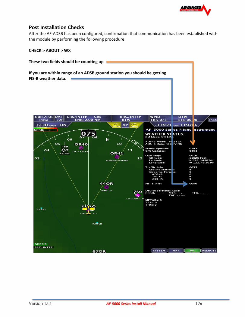
Version 15.1 AF-5000 Series Install Manual 126
Post Installation Checks After the AF-ADSB has been configured, confirmation that communication has been established with the module by performing the following procedure: CHECK > ABOUT > WX These two fields should be counting up If you are within range of an ADSB ground station you should be getting FIS-B weather data.

Version 15.1 AF-5000 Series Install Manual 127

Version 15.1 AF-5000 Series Install Manual 128
FreeFlight XPLORER ADS-B Receiver
P/N: 74110
P/N: 32020 Freeflight ADS-B Optional Install Kit
The optional Freeflight ADS-B install kit includes the following compontents:
Item QTY Part Number Description
1 1 50,115F DB-15 Connector
2 1 50,115S DB-15 Connector Shell
3 15 50,100F Female DSUB Pins
4 1 73,125 Ball and Stick UAT Antenna
5 1 50,010 SMA Male Crimp Connector RG-142 (ADS-B end)
6 1 50,011 BNC Male Crimp Connector RG-142 (Antenna end)

Version 15.1 AF-5000 Series Install Manual 129

Version 15.1 AF-5000 Series Install Manual 130
NavWorx ADS-B
The NavWorx ADS600 series ADS-B equipment can be directly interfaced to your AF-5000 EFIS. The ADS600 UAT receiver displays ADS-B information including TIS-B traffic and FIS-B weather. The ADS600-B UAT Transceiver displays the same information but also transmits your position to the ADS-B system. ADS-B is a free service provided by the FAA that transmits weather and traffic information to aircraft with compatible receivers. With a transceiver, aircraft can participate in the system by transmitting their position to the ADS-B system for the benefit of other aircraft and ATC. ADS600 (-B) Setup Connect the NAVWORX device to your EFIS in accordance with the NavWorx installation manual. The ADS600-B Display Port can connect to any available AFS serial port. The ADS600-B Altitude Encoder Port should connect to AFS serial port #2. It is important to have the NavWorx maintenance port connected to a DB9 connector. This will allow for future software updates and to setup/configure the ADS-B box. Configure Serial Port #3 for ADSB57K and Serial Port #2 for TFC/ICARUS EFIS Main Harness ADS600(-B) P1 EFIS Configuration 13 Serial #2 TX 7 ICARUS/TRFC 5 Serial #3 RX 5 ADS-B 4 Serial #3 TX 24 ADS-B 21 Serial #3 GND 23 ADS-B
Configure the wired EFIS serial port for ADSB 57k. This example shows the configuration for connection to serial port #3.

Version 15.1 AF-5000 Series Install Manual 131
Use the NavWorx ADS600 Console PC software to configure the ADSB unit.
Altitude should be set to Icarus 9,600
Display Port set to Traffic Alerts (Advanced Flight Systems) and 57,600 Baud Rate
Verify that you have the Transmitter ENABLED

Version 15.1 AF-5000 Series Install Manual 132
Verify that the ADSB unit is talking to the EFIS. The CHECK -> ABOUT EFIS page will display the ADSB OSHIP messages (scroll down). The OSHIP message counter should be counting up.
The TRFC: and FIS-B: message counters will count up when the unit is getting data from the ground station.

Version 15.1 AF-5000 Series Install Manual 133
WX-500 Stormscope
The AF-5000 can receive and display lightning from a L3 WX-500 Stormscope. The WX-500 is a remote mounted module that connects to the AF-5000 via a serial port on one of your EFIS display(s).
EFIS Serial Port Setting: WX500

Version 15.1 AF-5000 Series Install Manual 134
71320 SV-EMS Engine Module
Physical Mounting
Advanced Flight Systems does not include mounting hardware for use with the SV-EMS-220. The mounting tabs on each side of the module have holes sized for #10 fasteners, but it is up to the installer to decide how the EMS will be secured to the aircraft. Use of ferrous fasteners in this location is acceptable as the EMS is not adversely affected by small magnetic fields. Dynon recommends button head style AN hardware as spacing between the holes in the tabs and the body of the enclosure will limit what style tool can be used to tighten certain fasteners.
SkyView Network Connection Connect the EMS module to the SkyView network. If you have to install a connector on the end of a network cable, insert all pins into the D9 connector. Remember to configure the network after connecting all modules to a display.

Version 15.1 AF-5000 Series Install Manual 135
SV-EMS 220 Sensor and Transducer Wiring Map

Version 15.1 AF-5000 Series Install Manual 136
DB-37 Connector
Pin EMS 37-pin Harness Wire Color Sensor
1 Red Not Used (Skyview Voltmeter 1)
2 Yellow or Unwired Not Used (Skyview Voltmeter 2)
3 Black Ground
4 Violet/Blue Carb Temperature
5 Black Ground
6 White/Yellow Oil pressure
7 White/Brown Oil temperature
8 Brown Fuel pressure
9 Brown/Blue Flap Position
10 Brown/Yellow Elevator Trim
11 Orange Aileron Trim
12 Yellow Coolant Temperature
13 Black Ground
14 Yellow Fuel flow
15 Red +8V Fuel Flow & Amps Hall Transducer Power
16 Black Ground
17 Black Ground
18 White/Red +5V Aux Out 300ma
19 White/Black Fuel Flow Input 2
20 Orange/Brown Tank 1
21 Orange/Blue Tank 2
22 Violet/Yellow Tank 3
23 Violet/Green Tank 4
24 Orange/Green Ammeter shunt +
25 Orange/Violet Ammeter shunt -
26 Green/Red Manifold Pressure
27 Open Turbo Inlet 1 Temp +
28 Open Turbo Inlet 1 Temp -
29 Yellow/Green Not Used (Skyview Alarm )
30 Black Signal Ground
31 White/Orange Ammeter Hall Effect
32 White/Green Standard RPM LEFT
33 White/Blue Standard RPM Right
34 Blue Low Voltage RPM Left (<12 Volts)
35 Green Low Voltage RPM Right (<12Volts)
36 Blue or Unwired Turbo Inlet Temp 2 +
37 Green or Unwired Turbo Inlet Temp 2 -

Version 15.1 AF-5000 Series Install Manual 137
Converting AFS EM to SV-EMS 220

Version 15.1 AF-5000 Series Install Manual 138
DB-25 Connector
Pin EMS 25-pin Thermocouple Harness Wire Color Sensor
1 Open N/A
2 Red CHT 6
3 Red EGT 6
4 Red CHT 5
5 Red EGT 5
6 Red CHT 4
7 Red EGT 4
8 Red CHT 3
9 Red EGT 3
10 Red CHT 2
11 Red EGT 2
12 Red CHT 1
13 Red EGT 1
14
15
16
17
18
19
20
21
22
23
24
25

Version 15.1 AF-5000 Series Install Manual 139
SV-EMS 221 Sensor and Transducer Wiring Map
DB-37 Connector
Pin EMS 37-pin Harness Wire Color Sensor
1 Not connected
2 Not connected
3 Black Ground
4 Violet/Blue Elevator Trim
5 Black Ground
6 White/Yellow Oil pressure
7 White/Brown Oil temperature
8 Brown Fuel pressure
9 Brown/Blue Carburetor Temp
10 Brown/Yellow Coolant Temp
11 Orange Rotax CHT 1
12 Yellow Rotax CHT 2
13 Black Ground
14 Yellow Fuel flow
15 Not connected
16 Black Ground
17 Black Ground
18 Not connected
19 Not connected
20 Orange/Brown Tank 1
21 Orange/Blue Tank 2
22 Violet/Yellow Flaps
23 Violet/Green Aileron Trim
24 Orange/Green Ammeter shunt +
25 Orange/Violet Ammeter shunt -
26 Green/Red Manifold Pressure
27 Open RPM Signal to Rotax 912 iS Prop Controller
28 Grounded to common ground with Prop Controller
29 Not connected
30 Not connected
31 White/Orange Ammeter Hall Effect
32 White/Green RPM (10+ Volts)
33 Not connected
34 Blue Low Voltage RPM (<12 Volts)
35 Not connected
36 Blue or Unwired CAN High from 912 iS ECU
37 Green or Unwired CAN Low from 912 iS ECU

Version 15.1 AF-5000 Series Install Manual 140
DB-25 Connector
Pin EMS 25-pin Thermocouple Harness Wire Color Sensor
1 Open N/A
2 Red CHT 6
3 Red EGT 6
4 Red CHT 5
5 Red EGT 5
6 Red CHT 4
7 Red EGT 4
8 Red CHT 3
9 Red EGT 3
10 Red CHT 2
11 Red EGT 2
12 Red CHT 1
13 Red EGT 1
14
15
16
17
18
19
20
21
22
23
24
25

Version 15.1 AF-5000 Series Install Manual 141
Engine Sensor Installation
Lycoming/Continental
Lycoming CHT Probe Location EGT Probe Location
EGT Clamp Installation
1. Locate the EGT probes, P/N 40200, not less than 1 1/2” or more than 3” below the exhaust stack attachment flange. 2” to 3” is optimum, and try to mount all probes equal distance from the exhaust flanges. On curved stacks, assume probe tip is on stack centerline for determining distance to exhaust flange. Carefully center punch the probe hole locations such that the portions of the probes external to the exhaust pipes will not interfere with any parts of the engine or cowling. Drill holes with a #30 drill.
2. Carefully insert probe and clamp snugly with screwdriver. 3. Install CHT probes, P/N 40100, in threaded wells on cylinders. Torque probe bodies to 25-30 inch pounds. 4. Install terminals on #20 type J & K thermocouple wire 5. WIRES MUST HAVE A 1/4" DRIP LOOP TO PREVENT OIL OR SOLVENT FROM RUNNING INTO THE
PROBE.
This wire is very hard and will loosen inside a crimped brass or copper terminal, as there is no “cold welding” action like there is with crimped copper wire.
To prevent loosening of the crimp in service proceed as follows:
1. Strip wire exposing 3/8” of core conductor. Take care not to nick or cut the conductor. 2. Double end of wire back in hairpin bend so crimp is on doubled wire. 3. Crimp on a non-insulated barrel terminal using a crimping tool designed for non-insulated terminals. Be sure
that the barrel seam is facing the rounded side of the crimping tool and not the crimping post as this will result in a poor crimp.
4. Place a drop of Alpha Metals 51022 liquid soldering flux (Ace Hardware) in open end of crimp and then heat and sweat in rosin core solder to fill the joint.
2. Fasten the extensions to the engine by means of clamps held by valve cover screws or by tying the extensions to intake tubes. If the extension goes up to a valve cover, provide some slack for a “drip loop” so that oil and engine cleaning solvents will drip off probe lead and not run into the end of the probe. It is important that the probe lead or extension wire be first clamped or tied to the engine before being tied to the engine mount or airframe, to keep “working” of the probe lead as it comes out of the body to a minimum. AVOID CONTACT OF LEADS WITH CYLINDER HEADS OR EXHAUST PIPES. USE SLEEVING OVER LEADS IF TYING TO IGNITION HARNESS. If leads cannot pass through firewall with other wiring, drill a 3/8” hole in firewall and use a neoprene grommet for each 4 to 6 leads, seal with a sealing compound.

Version 15.1 AF-5000 Series Install Manual 142
RPM Sensor Installation
The RPM sensor should be installed in the non-impulse coupled magneto if possible (Engines with one electronic ignition should install the sensor in the impulse mag). The correct magneto can be found in the engine manual. The sensor is screwed into the magnet vent port nearest the magneto-mounting flange where the magneto attaches to the engine. Replace the existing vent plug with the sensor. The RPM sensor wires should be connected to the Engine Harness with Fast On Terminals, Butt Connectors or with solder and heat shrink. If using one mag and one electronic ignition, use the mag sensor for RPM input, as long as the mag is turning, RPM will be displayed even with the mag turned off.
The RED sensor is for Slick Mags and the BLUE sensor is for Bendix mags.
CAUTION: Do not route RPM sensor wires with Magneto P leads or electron ignition wiring. Most Magnetos have two ports on opposite sides, one near the plug wires and one near the drive shaft. The sensor needs to be mounted in the port closest to the drive shaft.
HARNESS SENSOR WIRE
Pin 31 White/Orange +5V RED Pin 32 White/Green Signal WHT Pin 16 Black Ground BLK
ELECTRONIC IGNITION The electronic ignition input is on connector pin 33. It may be necessary to remove the RPM wire from Pin 32 to Pin 33. This should only be used if dual electronic ignitions are installed! Engine Harness Pin 33 Electronic Ignition input. P-Mags If using P-Mags, verify they are in 12V RPM signal mode with the manufacturer and connect it to Pin 33 (Electronic RPM Input). If one P-Mag and one Mag are installed, either the PMAG or the MAG sensor can be used for RPM input, DO NOT CONNECT BOTH.

Version 15.1 AF-5000 Series Install Manual 143
P/N: 71420L RPM Interface Board
The 71420L board can be used to read two electronic ignition modules.

Version 15.1 AF-5000 Series Install Manual 144
Oil Temperature Sensor Installation
P/N: 40405
The standard P/N: 40405 oil temperature sensor is mounted on the engine. The engine manual should show the proper location for the sensor. The bushing is supplied with a crush type gasket that can only be used once. The location is usually near the filter and should be safety wired to the engine case. Replace the existing vent plug with the supplied bushing and sensor. The Oil Temperature Pressure sensor wire should be connected from the harness to the transducer by crimping a standard #8 ring terminal to the wire. Pin 7 White/Brown Optional 2 Wire Oil Temperature Sensors If you oil temperature changes when you turn on and off electrical loads you have a bad engine case ground. If you are unable to fix your engine ground you can install one of the optional two wire oil temp sensors. AFS Part Number Vendor Vendor Part Number P/N: 40412 UMA 1B3 P/N: 40415 Westach 399S9 Connect one sensor wire to the White/Brown wire and one to an EMS ground connection. Do NOT connect to a ground on the engine. Select the correct sensor part number in EFIS Calibration > Oil Temperature

Version 15.1 AF-5000 Series Install Manual 145
TIT Probes
If your aircraft has turbo inlet temperature probes they are wired to the Engine Sensor Main Harness cable

Version 15.1 AF-5000 Series Install Manual 146
Rotax Engines
CHT Probes
The Rotax engine has two CHT sensors preinstalled on the engine. One sensor is installed in the left side cylinder head water jacket and one is on the right side.
Rotax recommends bare ¼” female Faston terminals (6.3x0.8 DIN 46247) to connect to the CHT probes. You will need to add wires to the unpopulated connector pins.
The Rotax CHT probes are resistive sensors and should be connected to the DB-37 engine monitor plug pins 22 (Tank 3) and 23 (Tank 4). When using the Rotax CHT probes you will not be able to have four fuel tanks.
Once you have the sensors installed you will need to configure the CHT sensor type to “ROTAX CHT”
and configure the Temperature Ranges for your engine.

Version 15.1 AF-5000 Series Install Manual 147
EGT Probes
For Rotax engines two of the four cylinders are usually monitored for EGT, you can select to monitor all four EGT’s of desired. If only two EGT probes are used they should be mounted on the two rear cylinder’s exhaust manifolds for proper temperature comparison.
See EGT Clamp Style Probe Installation for instructions.
Boss Mount EGT Probes Some Rotax engine exhaust manifolds are drilled for boss mount EGT probes. If your engine has boss mount EGT locations use our optional P/N: 40,202 Boss Mount EGT Probe.
Once you have the EGT sensors installed you will need to configure the Engine Type to “ROTAX 2 EGT” or “ROTAX 4 EGT”
RPM
The Rotax engines have a 5th trigger coil for RPM monitoring. The trigger coil outputs on a two-wire harness. Connect one of the two wires to ground and the other to the supplied 33K resistor, the other end of the resistor than connects to the P/N: 71420 R Rotax RPM interface board yellow wire. The Rotax RPM interface board is a small heat shrinked module and should be secured on the inside of the aircraft. If you are using the P/N:71420RX you do not need to install the 33K resistor.
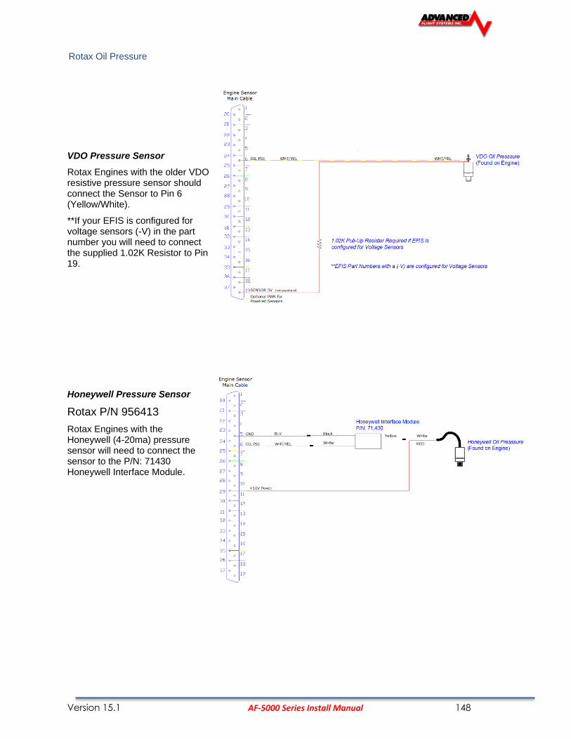
Version 15.1 AF-5000 Series Install Manual 148
Rotax Oil Pressure
VDO Pressure Sensor
Rotax Engines with the older VDO resistive pressure sensor should connect the Sensor to Pin 6 (Yellow/White).
**If your EFIS is configured for voltage sensors (-V) in the part number you will need to connect the supplied 1.02K Resistor to Pin 19.
Honeywell Pressure Sensor
Rotax P/N 956413
Rotax Engines with the Honeywell (4-20ma) pressure sensor will need to connect the sensor to the P/N: 71430 Honeywell Interface Module.

Version 15.1 AF-5000 Series Install Manual 149
Rotax P/N 956413 Oil Pressure Sensor (new 2012) The new Rotax oil pressure sensor is functionally identical to the previous Honeywell (Rotax P/N 956413) sensor, and connects in the same. However, the connector and wiring for the sensor that Rotax includes with the engine may require some assembly. See the diagram below for the pin out of the connector, Sensor pin A is not connected.
Select 41,102 HON RTX as the sensor type.

Version 15.1 AF-5000 Series Install Manual 150
Fuel Flow
The Rotax 914 has fuel return and requires a second fuel flow transducer and the P/N 71,440 Fuel Flow Differential Module. Make sure that the main fuel line transducer is connected to FEED and the return line transducer is connected to RETURN. The P/N: 71,440 FFDM-1 Module will also need to be connected to +12V Power buss. The +12V Power will power the module and both transducers.

Version 15.1 AF-5000 Series Install Manual 151
Rotax Fuel Pressure
ROTAX 912
P/N: 41201 Kavlico Fuel Pressure Sensor
EFIS must be configured for voltage sensors (-V) in the part number
Select 41,215 VDO (0-30) Sensor in calibration, use shift adjust to make fuel pressure display 0 PSI

Version 15.1 AF-5000 Series Install Manual 152
ROTAX 914
The Rotax 914 uses a special UMA differential pressure sensor P/N: 41,220.

Version 15.1 AF-5000 Series Install Manual 153
VDO Fuel Pressure Sensor
**If your EFIS is configured for voltage sensors (-V) in the part number you will need to connect the supplied 1.02K Resistor to Pin 19.
Select 41,215 VDO (0-30) Sensor in calibration, use shift adjust to make fuel pressure display 0 PSI

Version 15.1 AF-5000 Series Install Manual 154
JABIRU
CHT Sensor
Jabiru engines require a 12mm ring-terminal CHT probe for each cylinder. First, slide the compression washer off the spark plug. Slide the 12mm ring-terminal probe onto the plug. Now, slide the spark plug compression washer back onto the spark plug. Reinstall the spark plug into the spark plug hole. Refer to the documentation that came with the engine for more information.

Version 15.1 AF-5000 Series Install Manual 155
Diemech Turbine
The Diemech Turbine uses both CAN Aerospace and individual sensors to monitor the engine. The following sensors should be connected to the engine:
Gearbox Oil Pressure
AF-5000 EMS Connector Sensor Pin
Customer Power (9-36V) 1
Aircraft Ground 2
DB-37 Pin 6 Oil Pressure 3
Oil Temperature
AF-5000 EMS Connector Sensor Pin
DB-37 Pin 7 Oil Temp 1
DB-37 Pin 5 Ground 5
Fuel Pressure
Uses standard AFS Kavlico (0-50PSI) sensor and wiring
EGT
QTY 1 Type K EGT probe wired to EGT #1 EMS input.

Version 15.1 AF-5000 Series Install Manual 156
Amp Transducer Installation
Shunt Transducer
Mount the Shunt amp transducer to a stationary location in the main power wire from the Alternator.
The Shunt Amp transducer wires should be connected from the harness to the transducer by crimping two standard #8 ring terminal to the wires. Pin 24 Orange/Green + Alternator Side Pin 25 Orange/Purple - Battery Side
Optional Hall Effect Transducer (Used for dual Alternator Systems)
Mount the amp transducer in the cabin area to a stationary location. The amp transducer board should be mounted so that the bottom of the circuit board does not touch any metal. The amp transducer is designed to measure the current in the wire from the alternator. The wire from the alternator must pass through the transducer in the proper direction; the board is marked alternator on one side and battery on the other. Male D-sub pins will need to be crimped onto the transducer wires.
CAUTION: Always ground yourself before wiring.
Pin 29 +10V White/Orange Pin 11 Signal White Pin 30 Ground White/Blue

Version 15.1 AF-5000 Series Install Manual 157
Pressure Transducer Installation
Firewall Installation using Van’s P/N: VA-168, 3-port manifold mounting block.
Oil Pressure Transducer Installation
Mount the oil pressure transducer in a stationary location. Connect the transducer with aircraft grade hose and fittings. The proper oil pressure port can be found in the engine manual. The engine must have a pressure fitting with a restrictor hole in it. The transducer is supplied with 1/8” NPT pipe thread connections. The case of the sender has to be connected to ground. The Oil Pressure transducer wire should be connected from the harness to the transducer by crimping a standard #8 ring terminal to the wire or connecting to the supplied connector. Pin 6 White/Yellow
NOTE: The pressure rating (100psi or 10bar 150psi) can be found stamped on the bottom hex fitting of the transducer
P/N Pressure Manufacturer Color Termination
41,101 0-150 PSI (10 bar) Kavlico Gold/Black Plug
41,105 0-100 PSI Stewart Warner Gold #8 Ring
41,115 0-150 PSI (10 bar) VDO Silver #8 Ring
CAUTION: NEVER CONNECT THE PRESSURE TRANSDUCER DIRECTLY TO THE ENGINE.
Fuel Pressure Transducer Installation
Mount the fuel pressure transducer to a stationary location. Connect the transducer with aircraft grade hose and fittings. The proper fuel pressure connection port can be found in the engine manual. The engine must have a pressure fitting with a .040” or smaller restrictor hole in it, this prevents fuel pump pulsations from damaging the transducer and will slow the flow of fuel if a hose were to fail. The transducer is supplied with 1/8” NPT pipe thread connections. The case of the sender has to be connected to ground. The Fuel Pressure transducer wire should be connected from the harness to the transducer by crimping a standard #8 ring terminal to the wire. If using the P/N: 41,215 (0-30 PSI) transducer, a ¼” Fast-On terminal is used for the transducer wire and a separate ground wire connected to the second terminal. It does not matter which terminal is used for the sensor wire or ground wire. Pin 8 Brown
NOTE: The pressure rating can be found stamped on the bottom hex fitting of the transducer
Carbureted Engines
P/N Pressure Manufacturer Color Terminal
41,201 0-15 PSI Kavlico Gold/Black Plug
41205 0-16 PSI Stewart Warner Gold #8 Ring
41215 0-30 PSI (2 bar) VDO Silver ¼” Fast-On (Signal & GND)

Version 15.1 AF-5000 Series Install Manual 158

Version 15.1 AF-5000 Series Install Manual 159
Fuel Injected Engines
P/N Pressure Manufacturer Color Terminal
41,301 0- 50 PSI Kavlico Gold/Black Plug
41305 0-60 PSI Stewart Warner Gold #8 Ring
41315 0-80 PSI (5 bar) VDO Silver #8 Ring
VDO Pressure Sensors
**If your EFIS is configured for voltage sensors (-V) in the part number you will need to connect the supplied
1.02K Resistors to Pin 19 for each VDO Pressure Sensor.

Version 15.1 AF-5000 Series Install Manual 160
Fuel Flow Transducer Installation
The inlet and outlet ports in the fuel flow transducer have ¼” NPT threads. Use only ¼” NPT hose or pipe fittings to match. When assembling fittings into the inlet and outlet ports DO NOT EXCEED a torque of 180 inch lbs, or screw the fittings in more than 2 full turns past hand tight WHICHEVER HAPPENS FIRST. AFS will not be responsible for cracked castings caused by failure to use ¼” NPT fittings, over-torqueing the fittings, or assembling them beyond the specified depth. Use only aircraft FUEL LUBE on the NPT fittings; NEVER USE TEFLON TAPE or SILICON SEALER IN AN AIRCRAFT FUEL SYSTEM.
A screen or filter should be installed upstream of the flow transducer to screen out debris which could affect rotor movement or settle in the V-bearings.
Mount the fuel flow transducer in a position so the three wire leads are pointed straight up. Use only smooth radius curves in the fuel line and place the transducer with 5” of straight line before and after. The transducer wires should be connected directly to the 37-pin D-SUB using the cable provided. The transducer should be mounted according to the fuel metering device manufacturer’s recommendations.
AFS has seen good results with the following mounting:
1. The transducer in a stationary location in-line between the electric boost pump and the engine driven pump.
2. The transducer in a stationary location in-line between the fuel injection servo and the distribution block.
3. The transducer in a stationary location in-line between the Engine driven pump and the Carburetor.
NOTE: The Electronics International FT-60 (Red Cube) transducer is rated for .6 – 70+ GPH. AFS recommends that the Electronics International FT-90 (Gold Cube) transducer be used for applications requiring more than 35 GPH (350HP) or for gravity flow fuel systems without a fuel pump (Contact AFS to exchange transducers).
CAUTION: NEVER CONNECT THE FUEL FLOW TRANSDUCER DIRECTLY TO THE ENGINE WITHOUT
COVERING WITH FIRE SLEEVE.
The Fuel Flow transducer wires should be connected from the harness to the transducer using the supplied fast on connectors.
Pin 15 Red +5V Pin 14 White Signal Pin 13 Black Ground

Version 15.1 AF-5000 Series Install Manual 161
Fuel Flow Calibration
The accuracy of the fuel computer is affected by the value of Counts per .01 gals (K Factor). The Counts per .01 gals (K Factor) sets the calibration of the instrument to match the flow transducer and the variations in the installation. After running a tank of fuel use the following formula to adjust the accuracy.
The Counts per .01 gals (K Factor) is adjusted from the Fuel Flow/Computer page in Instrument Calibration.
New Counts per .01 gals = (Old Counts per .01 gals) x (Disp GAL USED/PUMP GALS)

Version 15.1 AF-5000 Series Install Manual 162
Manifold Pressure Transducer Installation
The manifold pressure transducer should be mounted on the firewall or in the cabin area. The transducer port is connected to the engine manifold pressure port with a ¼” ID hose and hose clamp. The manifold pressure port location can be found in the engine manual.
P/N Pressure Application
41400 30 In-Hg Old AFS Sensor for Normally Aspirated Engine
41401 59 In-Hg Current Sensor (Normal and Turbo Engine)
We used the following fittings to connect the transducer in our aircraft:
AN823-4 45 deg pipe to 37 deg flare fitting
471-4D 37 deg flare fitting for hose
306-4 ¼” ID Black Hose
The transducer wires should be connected from the harness to the transducer using the supplied Weatherpack connector.
For information on crimping the Weatherpack pins: http://www.weatherpack.com The Weatherpack connector comes with three pins, three rubber seals, and a connector housing. Slide the three rubber seals onto the three wires and the pins onto the ends of the wires. Crimp the 3 pins onto the ends of the wires, ensuring that the long tabs that cradle the rubber seal wrap around the seal.
Manifold Sensor Connections:
Pin 18 WHT/RED +5V C Pin 26 GRN/RED Signal (4.5V - .5V) B Pin 17 Black Ground A

Version 15.1 AF-5000 Series Install Manual 163
SV-EMS Manifold Sensor Configuration:
These settings are for the current Dynon SV-EMS sensor kit.
1. Select the Sensor Type:
2. Configure Engine Limits:
3. Press SAVE
4. Use the Shift Adjust to remove any small errors in the manifold pressure display. The Manifold Pressure should match the Altimeter Baro setting when you have the altitude set to zero feet.

Version 15.1 AF-5000 Series Install Manual 164
Fuel Tank Level Sensor
Float Type
Any standard 40-240 Ohm float style probe should work without any problem. The single wire from the Engine Harness should be connected to the float sensor terminal. Verify that the float mounting base is attached to the airframe ground. For the tank gauges to work properly, the floats should freely move from the top to the bottom of the tank.
Capacitance Type
If the engine monitoring system was setup at the factory for Capacitance fuel tanks input any probe or adaptor that puts out a 0-5 Volt DC signal can be used. A 1.5K OHM resistor Must be placed in series with the fuel tank input wire to limit the voltage to 4 Volts if using the Internal EMS board. You don’t need the resistor if you are using the remote Dynon EMS module.
P/N: 51105 Dynon Van’s Capacitance Tank Adaptor
Sensor Connections: Adaptor Wire Function Connection Red +12V EFIS Power Source White Signal (4V - .5V) Tank 1 EMS Pin 20 ORN/BRN Tank 2 EMS Pin 21 ORN/BLU Black Ground Avionics Ground

Version 15.1 AF-5000 Series Install Manual 165
Trim & Flap Position Installation
The system is designed to read the position transducer that is in the MAC trim servo. The MAC servo has 5 wires. The two white wires are for motor operation and the color-striped wires are for the position transducer.
The flap position can be measured by using the MAC linear position sensor P/N: POS-12 http://www.rayallencompany.com/products/indsens.html
CAUTION: DO NOT connect the MAC indicators and the AF-5500/5600 the MAC trim servos. The MAC trim indicators are +12V and the EFIS screens are +10V. The power and ground wires connect to all the servo’s.
CAUTION: Verify before turning the system on the trim servo wiring is correct. If the +10V or Ground connection is wired to the WHT/GRN wire on a servo, it could damage the servo.
Pin 2 Yellow +10V Trim and/or Flap WHT/BLU Pin 3 Black Ground Trim and/or Flap WHT/ORN Pin 34 Blue Flap Posn Flap WHT/GRN Pin 35 Brown/Yellow Elevator Posn Trim WHT/GRN Pin 36 Brown/Blue Aileron Posn Trim WHT/GRN Pin 12 Not Pinned Rudder Posn Trim WHT/GRN Note: Trim & Flap Positions MUST be calibrated. See the Instrument Calibration section.

Version 15.1 AF-5000 Series Install Manual 166
Coolant Temp
The Coolant temp input is designed to use the AFS standard Oil Temp sensor P/N:40406 AFS has optional calibration data for the VDO P/N: 323-057 (300F) Sensor

Version 15.1 AF-5000 Series Install Manual 167
Airplane Map Icon Image The AF-5000 Map can be configured to use a custom airplane Icon. From the Calibration -> Transfer Files menu select Aircraft Image to transfer the new airplane Icon from the SD card to the EFIS screen.
The Airplane Icon must be a 128 x 128 pixel png file with a transparent background with the name airplane.png Procedure to load new airplane Icon:
5. Using a graphics program save your new 128 x 128 Icon to a SD card using the name airplane.png
6. Place the SD card into the EFIS screen
7. Select the Aircraft Image menu from the Transfer Files menu.
8. Press the REST button to transfer the Icon to the EFIS screen.

Version 15.1 AF-5000 Series Install Manual 168
Vendor Logo Splash Screen
The AF-5000 can be configured to use a custom startup splash screen. From the Calibration Transfer Files menu select Vendor Logo Image to transfer the new splash screen from the SD card to the EFIS screen. The Vendor Logo must be a 1024 x 225 pixel png file with the name VLOGO_1024x225.png ** VLOGO_1024x225.png file must be smaller than 200K Procedure to load new splash screen: 1. Using a graphics program save your new 1024 x 225 pixel file to a SD card using the name
VLOGO_1024x225.png.
2. Place the SD card into the EFIS screen
3. Select the Vendor Logo File menu from the Transfer Files menu.
4. Press the REST button to transfer the new file.
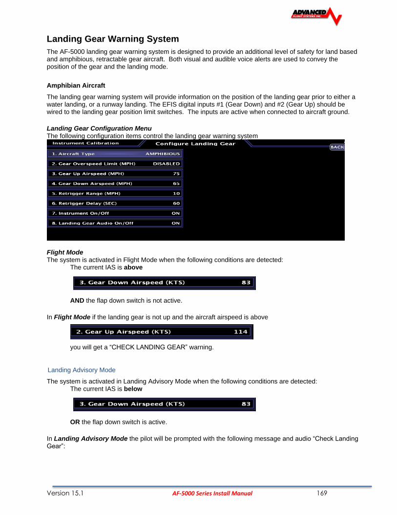
Version 15.1 AF-5000 Series Install Manual 169
Landing Gear Warning System
The AF-5000 landing gear warning system is designed to provide an additional level of safety for land based and amphibious, retractable gear aircraft. Both visual and audible voice alerts are used to convey the position of the gear and the landing mode.
Amphibian Aircraft
The landing gear warning system will provide information on the position of the landing gear prior to either a water landing, or a runway landing. The EFIS digital inputs #1 (Gear Down) and #2 (Gear Up) should be wired to the landing gear position limit switches. The inputs are active when connected to aircraft ground.
Landing Gear Configuration Menu The following configuration items control the landing gear warning system
Flight Mode The system is activated in Flight Mode when the following conditions are detected:
The current IAS is above
AND the flap down switch is not active.
In Flight Mode if the landing gear is not up and the aircraft airspeed is above
you will get a “CHECK LANDING GEAR” warning.
Landing Advisory Mode
The system is activated in Landing Advisory Mode when the following conditions are detected: The current IAS is below
OR the flap down switch is active.
In Landing Advisory Mode the pilot will be prompted with the following message and audio “Check Landing Gear”:

Version 15.1 AF-5000 Series Install Manual 170
Pressing WATER plays the sound “Water Landing” and starts checking for the gear up input.
Pressing RUNWAY plays the sound “Runway Landing” and starts checking for the gear down input.
After 15 seconds if the gear is not in the correct position for the selected landing mode will trigger a new message and audio alert.
Gear Down Indication during climb-out. A Single 'Check Landing Gear' audio is issued as a reminder when passing through the Gear Down Speed.
Gear Down Overspeed Indication. Will be accompanied with audio alert “Check Landing Gear”.

Version 15.1 AF-5000 Series Install Manual 171
Gear Transition indication shown when lifting or lowering the landing gear.
Gear Up Indication
Gear Up Landing Mode Selection Initiated by Flaps Deployment.
Gear Up Water Landing Mode Selected, Green Box indicated good and Blue for water.

Version 15.1 AF-5000 Series Install Manual 172
Gear Down Runway Landing Mode Selected, Green Box indicated good and gray for runway.
WARNING: THE AF-5000 LANDING GEAR WARNING SYSTEM SHOULD NOT BE
UTILIZED AS THE PRIMARY MEANS OF DETERMINING GEAR POSITION. THE USER SHOULD UTILIZE THE NORMAL OPERATING PROCEDURES AS DEFINED IN THE AIRCRAFT FLIGHT MANUAL AS THE PRIMARY INDICATION OF GEAR POSITION.
Landing Gear configuration menu.
1. Aircraft Type Selects Land or Amphibian mode. 2. Gear Up Airspeed (KTS) If the landing gear is not up and the aircraft is above this speed you will get the alert “CHECK LANDING GEAR” 3. Gear Down Airspeed (KTS) The airspeed that will trigger the select landing mode message. 4. Instrument On/Off Enables the gear warning system. 5. Landing Gear Audio On/Off Should be ON for audible warnings.

Version 15.1 AF-5000 Series Install Manual 173
Instrument Calibration
Instrument calibration will allow you to calibrate the various instruments and set the desired warning levels.
Calibration mode can be entered from the run screen as long as you do not have any airspeed from the following menu:
[SET] -> [CAL] Hold for 2 seconds
A list of instruments will appear. Scroll through the list by rotating the joystick. There are multiple pages of instruments.
To calibrate an instrument press the joystick in, While the cursor is on the desired instrument. On the Right side of the screen, a calibration list will appear.
On the top right a number will appear. This is the digital value read by the selected sensor. This value will change if the condition the sensor is reading changes (Example, AD_VALUE 453).
Below this number there will be a list of calibration data. Rotate the joystick to select the desired line and press the joystick in to enable the cursor.
To adjust any of the warning values make sure the cursor is on the desired one and twist the knob until the value desired is displayed.
When an instrument has been calibrated/setup, press [BACK] to return to the previous page.

Version 15.1 AF-5000 Series Install Manual 174
Advanced-SV Network Configuration
From the Instrument Calibration menu you should select: 2. Advanced-SV Network
Scanning for Network Devices
Press the SCAN button to detect all the devices on the Network

Version 15.1 AF-5000 Series Install Manual 175
Updating Network Devices
If any of the Network devices have old software you can press the LOAD button to update the software on all network devices. Once the new software is loaded on the network devices the system will reboot.
Configuring ADAHRS 200 and 201
Once the system as detected the ADAHRS 200 or 201 you will need to configure the EFIS to use them.
Select HW:AF-SV, NET:OFF for both the Air Module Config and AHRS Module Config

Version 15.1 AF-5000 Series Install Manual 176
Configure Aircraft Info
The aircraft registration tail number needs to be set in the Aircraft Info page. The software will
calculate the Mode S Code after you enter the N Number. The N Number and ICAO address is
used for the transponder and to filter out the aircraft in ADS-B traffic data.

Version 15.1 AF-5000 Series Install Manual 177
Engine Gauge Color Bands
Max
The instrument displayed value at the top of the gauge
Red High At The instrument displayed value when the needle turns red at the top of the gauge. If a red range is not desired, set this parameter to the max value. Yellow High At The instrument displayed value when the needle turns yellow at the top of the gauge. If a yellow range is not desired, set this parameter to the max value.
Yellow Low At The instrument displayed value when the needle turns yellow at the bottom of the gauge. If a red range is not desired, set this parameter to the min value.
Red Low At The instrument displayed value when the needle turns red at the bottom of the gauge. You can set this parameter to the Min value if you do not want a bottom yellow band.
Minimum The instrument displayed value at the bottom of the gauge Audio On/Off Turns on or off the audio warning feature.
Instrument On/Off Turns on or off the entire instrument.
Calibration Tips:
• AF-5500/5600 systems are shipped with all sensors except Fuel Tanks and Trim / Flap sensors fully calibrated. Individual sensors should not need to be adjusted unless a new sensor is installed.
• The Amps transducer (Hall or Shunt) will need to have the zero amp point set.
• Anytime an Instrument is calibrated and new data is entered, make sure to write that data down. Keep a good record of this data in a safe place in the event. If something happens and data is lost, the data written down can easily be re-entered.
• When calibrating any temperature sensor wait until the calibration number stops changing (2-3 minutes) before recording it. This will help make the calibration more accurate.
To exit the calibration page press the [BACK] button twice. This will return the EFIS to main flight information display. The calibration data entered/changed will be saved and used. Make sure to use caution while calibrating instruments. Saving bad calibration data causes the instrument readings to be off.

Version 15.1 AF-5000 Series Install Manual 178
Airspeed Color Range Settings
The Airspeed tape color range settings should be adjusted for your aircraft. All the speeds are in Knots. You must configure these settings on each EFIS Screen in the aircraft.
Max: Top of the gauge Should be set to 240 KTS unless you have the special order high speed sensors.
Vne: Never Exceed Speed This is where the Red arc starts.
Vno: Normal Operation, This is the top of the green arc, bottom of the yellow.
Vfe: Flap Extend Speed, Top of the white arc.
Vs0: Stall Speed with the Flaps up.
Vs1: Stall Speed with the Flaps Down.
Airspeed Adjust: This should normally be 0, it can be used to offset the airspeed readings.
Airspeed Enable: This should normally be On, it can be used to turn off the airspeed gauge.
Units: Knots or MPH
Altimeter Check
Item 2 in Instrument Calibration The altimeter check should be performed on an as-needed basis. If the altimeter is found to be out of specification, the following adjustment can be performed from the EFIS Calibration menu:
2. Altitude
3. Altitude Adjust (FT)
After making an adjustment, ensure that the altimeter meets the tolerances allowed between 0 and 30,000 feet. If this adjustment does not correct the unit, contact Advanced Flight Systems for service.

Version 15.1 AF-5000 Series Install Manual 179
RPM Calibration
The RPM Gauge has three unique features that are slightly different than the standard gauge options. These features include:
Yellow Mid Band Top: Used to depict prop operating mid range restrictions. This should be set to 0 if the propeller manual doesn't specify a mid caution range.
Yellow Mid Band Bottom: Used to depict prop operating mid range restrictions. This should be set to 0 if the propeller manual doesn't specify a mid caution range.
Pulses Per 2 Revolutions: The systems needs to know how many pulses the RPM input will see in two propeller rotations. The following data should help select the correct number to use.
1. Standard RPM sensor with Slick Mag 4 Cylinders: Pulses = 2
2. Standard RPM sensor with Slick Mag 6 Cylinders: Pulses = 3
3. Standard RPM sensor with Lasar Mag 4 Cylinders: Pulses = 4
4. Standard RPM sensor with Lasar Mag 6 Cylinders: Pulses = 6
5. Electronic Ignition 4 Cylinders: Pulses = 4
6. Electronic Ignition 6 Cylinders: Pulses = 6

Version 15.1 AF-5000 Series Install Manual 180
Fuel Tank Calibration
The AF-5000 screen with the engine board stores two sets of calibration numbers for each tank. It uses the ground calibration numbers when the Airspeed is less than 30kts (1700 RPM for Engine Monitor only). The flight calibration numbers are used when the airspeed is greater than 30kts (1700 RPM for Engine Monitor only). This feature enables the fuel gauges to read correct on the ground for a tail-wheel equipped airplane. If the aircraft does not have a tail-wheel set the ground and flight data to the same calibration number.
It is important to understand that fuel level measurements are subject to the physical limitations of the sensor. Depending on your fuel tank and sensor geometry, there may be some immeasurable fuel at one or both ends of the fuel
level sensors’ range. The end result is that you may experience fuel readings at “full” that are numerically less than the physical capacity of the tanks, and in this case you may also see no apparent change in fuel level readings when the sensor is maxed out on the full side. Similarly, on the empty side, you may see a zero quantity indication before the tank is truly empty if the sensor has reached the bottom of its travel or measuring capability when the tank still in fact has fuel in it. Most fuel tank sensors are mounted in the root of the wing. If your wing has dihedral it is common for the fuel tank sensor to stop reading the fuel level at around 2/3 of a tank.

Version 15.1 AF-5000 Series Install Manual 181
Steps To Calibrate a Tank:
1. Place the EFIS screen with the Engine Board into Instrument Calibration mode. Use the joystick knob to scroll to Tank 1 (Left Main), Tank 2 (Right Main), Tank 3 Left Aux, or Tank 4 Right Aux.
2. Verify the Tank is Empty.
3. Enter the max size of the Tank in the Tank Size field.
4. Set the Audio On/Off Setting. If this is set to ON, an Audio warning will sound if the fuel level is below the Red Low At setting.
5. Set the Instrument On/Off Setting. If this set this to ON the tank will be displayed.
6. Enter the number of calibration points; it must have at least two points. Four points could be used (zero, ¼, ½, ¾, Full) or one point for every 2 gallons. Every calibration point must be different from the previous value until the tank sensor cannot detect a change in the fuel level. Tank sensor values must never reverse direction.
7. Use the joystick knob to Scroll down to the tank calibration data. The calibration data is displayed in columns, one for ground and one for flight. Use the knob joystick to switch between ground and flight data columns. The current AD_VALUE reading for the tank is displayed at the top of the table.

Version 15.1 AF-5000 Series Install Manual 182
8. Starting at 0 Gallons press the [COPY] button or use the knob to record the current AD_Value to the correct fuel amount and attitude (ground or flight).
9. Add fuel (at increments decided on) and then record the new AD_Value by pressing [COPY]
10. Fill and record a reading for each attitude (ground and flight). If it is a tail wheel aircraft, the best way to do this is to record the ground data then lift the tail and record the flight data after the fuel reading has settled. Repeat this for each increment until the tank is full.
11. Press the [SAVE] button to save the data to permanent memory and [BACK] to exit Tank Calibration.
12. After completing Tank 1, move on to Tank 2 and follow the same procedure. If Aux Tanks are present, follow this procedure for Tank 3 & 4.
13. IF THE AIRCRAFT DOES NOT HAVE AUX TANKS, TURN TANKS 3 & 4 OFF!
CAUTION: Do not turn off power before pressing the save button and exiting the calibration menu.
Calibration Tips:
When lifting the tail you should set it on something, so the level you lift it to will be consistent. You should also wait until the reading stops changing before setting it.
Fuel tank sensors are not accurate when the tank is near full. Once you notice the reading not changing much or not corresponding with the rest of the readings during calibration the last few entries in the fuel calibration data should be set to the same value.
If the tanks do not consistently show full, lower the digital value for the tank full data.
The fuel gauge will only show the digital fuel amount for the highest reading that the float changed with a plus sign indicating that the correct fuel amount is not known but is over the last reading. The analog gauge will show full for the last changing reading. It is normal for an 18-gallon tank to show 16+ when it is full. This indicates that the float stopped changing at 16 gallons and this is the highest fuel reading that can be detected by the float in the tank.
Valid Tank calibration values.
Values do not reverse direction and the sensor stopped detecting fuel changes at 25 gallons.
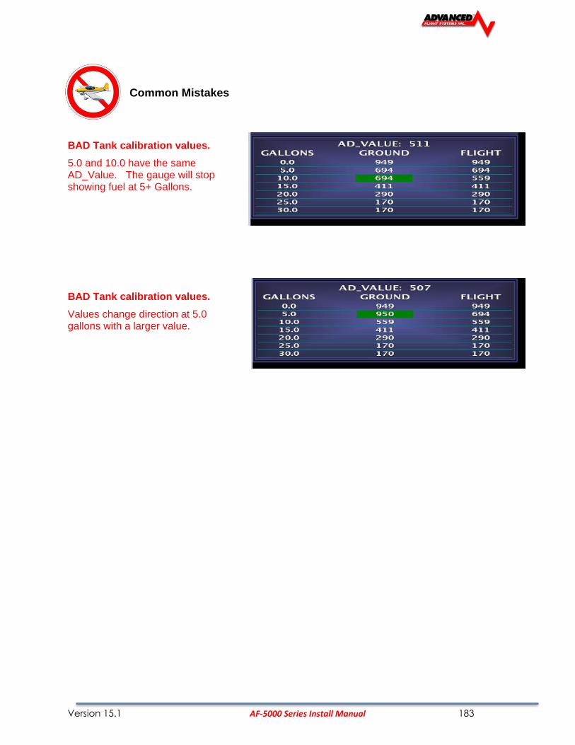
Version 15.1 AF-5000 Series Install Manual 183
Common Mistakes
BAD Tank calibration values.
5.0 and 10.0 have the same AD_Value. The gauge will stop showing fuel at 5+ Gallons.
BAD Tank calibration values.
Values change direction at 5.0 gallons with a larger value.

Version 15.1 AF-5000 Series Install Manual 184
Trim/Flap Calibration
Item 28-30 in Instrument Calibration
From the Calibration menu select:
Item 26 Elevator
Item 27 Aileron
Item 28 Flap Position
The calibration menu lets the user set the up, down, and center position. If these sensors are no connected, they can be turned off.
To calibrate Elevator Trim (for example):
1. Run the trim servo all the way up. With UP highlighted, press [COPY]. 2. Move the trim servo to the center streamline position. With CENTER highlighted, press [COPY]. 3. Move the trim servo all the way down. With DOWN highlighted, press [COPY]. 4. Press [SAVE].
Repeat this procedure for Aileron Trim and Flap Position
CAUTION: Do not turn off power before pressing the save button and exiting the calibration menu.
Test Audio
Item 33 in Instrument Calibration
The range is (0%-100%) and is adjusted using the knob followed by pressing the [SAVE] button. The Test Audio menu will play all the sounds in the system.

Version 15.1 AF-5000 Series Install Manual 185
Horsepower
You configure the Engine Horsepower from the Calibration > Horsepower Menu. You need to set
the engine type and rated HP. If you have an engine type that is in the list, please choose the appropriate engine. This will allow the system to perform some calculations that are specific to that engine, such as % power (Lycoming / Continental only) and special operating limitations (Rotax only). If your engine is not listed, choose "Other." Horsepower is used to do some of the % power calculations (Lycoming/Continental engines only) and the auto Rich-of-Peak and Lean-of-Peak detection. Set it to the engine manufacturer's rated HP for initial usage. You may need to adjust this number in order to get all calculations working correctly. If you are getting an auto Lean-of-Peak indication that is coming on too early, before the engine actually peaks while leaning, lower this number. It is not meant to be a measure of actual horsepower produced, as engines that are more efficient will act as if they are lower horsepower in the calculation. This will be particularly true if you are running a higher compression ratio than the stock charts are based upon.
Version 15.1 AF-5000 Series Install Manual 186
Switch Inputs
Item 34 in Instrument Calibration
The system has 3 hardware inputs that can be used to monitor an external switch. The inputs are labeled #1, #2, #3
Input #3 is normally used for an AOA Flap Switch.
For wiring information see APPENDIX M:
The Inputs will display the text on the Screen from the SYSTEM.AFD file when an Input is either grounded or open. A normally open or normally closed switch is selectable in the Inputs menu, see example below. There is also a timer feature that will alarm after a set time is reached. If any input other than FUEL TANK XFR is selected, the timer will zero after the input is disabled. In the case of a FUEL TANK XFR input, the timer will only clear after a power cycle. This allows the pilot to have the total duration of the fuel tank transfer for the entire flight (to allow for multiple tank transfers).
Note: FUEL TANK XFR can only be used on INPUT #1 or #2
EXAMPLE Input #1 should Alarm with “Door” From the EFIS Calibration menu select: 34. Inputs
1. Input 1 Label - Press the joystick in to activate the cursor. Use the bottom row of buttons to enter a label
Press [ENTER] remaining characters [SAVE]
EXAMPLE Input #1 is a Normally Closed switch, meaning EFIS will alarm when switch is not grounded 34. Inputs
3. Input 1 Logic [Turn KNOB] to select between normally open and normally closed
EXAMPLE Input #1 should alarm if tip tank transfer pump is left on for 25 minutes 34. Inputs
2. Input 1 Usage [Turn KNOB] until TANK TRANSFER appears press
4. Input 1 Timeout (mm:ss) [Turn KNOB] until 25:00 appears
CAUTION: Do not turn off power before pressing the save button and exiting the calibration menu.
NOTE: If no input label is desired on the screen, delete the label.
Reboot the system for the input settings to take effect.

Version 15.1 AF-5000 Series Install Manual 187
Administrative Settings
System Files
The system has the following files in flash memory.
Calibration data files for the sensors:
AIRDATA.AFC Airspeed, Altimeter, AOA, System Voltages
ENGINE.AFC Engine Sensors EGTCHT.AFC EGT and CHT Sensors HORSEPWER.AFC Engine Horse Power Parameters
TANKS.AFC Calibration data for all fuel tanks
AOA.AFC Calibration data for AOA
Instrument range settings data files:
(max, min, red, yellow, green arcs)
AIRDATA.AFD Airspeed, Altimeter, System Voltages
ENGINE.AFD Engine gauges
Checklists & Maintenance data files:
CHKLST.AFD Check Lists MAINT.AFD Maintenance items
System settings data files:
NVRAM.AFD Backup of NV Ram SYSTEM.AFD System Network, Hardware Installed
EFIS.AFD EFIS screen system settings
Data Logging files:
ymmddhhm.ALD Flight and Engine data logs
ymmddhhm.ALS System debug logs ymmddhhm.ALR Ram memory logs y year mm month dd date hh hour m minute

Version 15.1 AF-5000 Series Install Manual 188
Multiple Screen Setup
Multiple screens (EFIS and Engine Monitor) can be connected together to enable data sharing by using a standard Ethernet cross over cable or Ethernet hub plugged into the back of the units. Once the screens are connected with the cable, each screen needs to be configured properly.
Every screen on the Network must have a unique IP Number, the following format is used for multiple screens:
EFIS Screen in front of Pilot 15. Network IP Number this screen 175
Screen on CoPilot side 15. Network IP Number this screen 176
Screen #3 - MFD 15. Network IP Number this screen 177
The 17. Network IP Number Other screen setting controls which other screen the EFIS data will be displayed from. Any screen that does not have an AHRS should have this set to the address of the remote screen with the AHRS that it will display EFIS data from or compare AHRS data with.
Dual AHRS Configuration
CAUTION
For Dual AHRS cross checking to work set the AHRS Module Config to TXD and the Network IP Number Other screen to the address of the remote AHRS.
Multiple Screen Configuration Examples
The following examples should help when configuring the system: <Example #1> AF-5000EF EFIS and AF-5000EM Engine Monitor
EFIS Screen #1
1. Admin Settings 12. Engine Module Config HW:OFF, NET:RXD 13. Air Module Config HW:INT, NET:TXD 14. AHRS Module Config HW:INT, NET:TXD 15. Network IP Number this screen 175 16. Network IP Number Other screen 176
Engine Monitor Screen #2
1. Admin Settings 12. Engine Module Config HW:INT, NET:TXD 13. Air Module Config HW:OFF, NET:RXD 14. AHRS Module Config HW:OFF, NET:RXD 15. Network IP Number this screen 176 16. Network IP Number Other screen 175
<Example #2> AF-5500EF EFIS and AF-5600EE EFIS-Engine Monitor (AHRS Cross Checking)
EFIS Screen #1
1. Admin Settings 12. Engine Module Config HW:OFF, NET:RXD 13. Air Module Config HW:INT, NET:TXD 14. AHRS Module Config HW:INT, NET:TXD 15. Network IP Number this screen 175 16. Network IP Number Other screen 176
EFIS-Engine Monitor Screen #2
1. Admin Settings 12. Engine Module Config HW:INT, NET:TXD 13. Air Module Config HW:INT, NET:OFF

Version 15.1 AF-5000 Series Install Manual 189
14. AHRS Module Config HW:INT, NET:TXD 15. Network IP Number this screen 176 16. Network IP Number Other screen 175
<Example #3> AF-5500EF EFIS and AF-5600EE EFIS-Engine Monitor and AF-5500MFD
EFIS Screen #1
1. Admin Settings 12. Engine Module Config HW:OFF, NET:RXD 13. Air Module Config HW:INT, NET:TXD 14. AHRS Module Config HW:INT, NET:TXD 15. Network IP Number this screen 175 16. Network IP Number Other screen 176
EFIS-Engine Monitor Screen #2
1. Admin Settings 12. Engine Module Config HW:INT, NET:TXD 13. Air Module Config HW:INT, NET:OFF 14. AHRS Module Config HW:INT, NET:TXD 15. Network IP Number this screen 176 16. Network IP Number Other screen 175
MFD Screen #3
1. Admin Settings 12. Engine Module Config HW:OFF, NET:RXD 13. Air Module Config HW:OFF, NET:RXD 14. AHRS Module Config HW:OFF, NET:RXD 15. Network IP Number this screen 177 16. Network IP Number Other screen 176
Dual Screen Data Configuration
Any time engine or EFIS settings are changed, the configuration files should be transferred from one screen to the other.
On the screen where a cal point was changed (Vfe speed, RPM color band ranges...etc) follow the steps below with an SD card installed. In Instrument Calibration -> Admin Settings, highlight 1. All User Level Files and press [SAVE]
On the screen to receive the files, insert the SD card and follow the same procedure but press [REST]
This will force the screen to get the configuration data files from the remote screen for those items that this screen is setup. Reboot both screens.
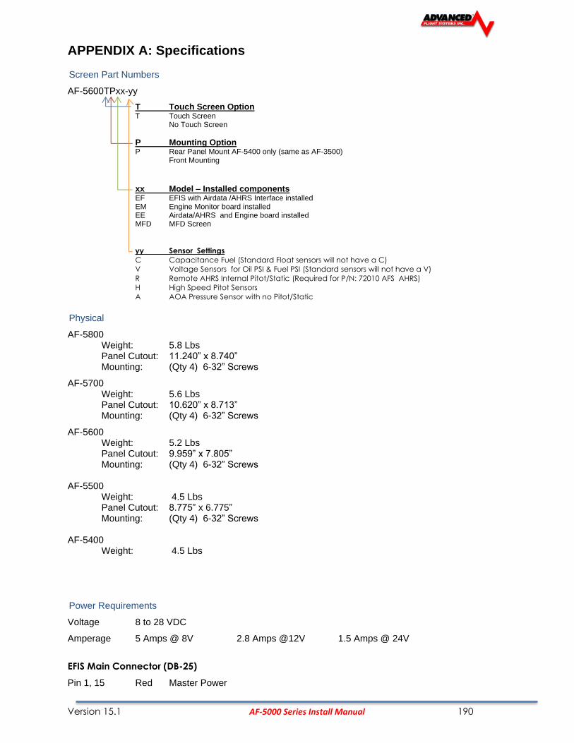
Version 15.1 AF-5000 Series Install Manual 190
APPENDIX A: Specifications
Screen Part Numbers
AF-5600TPxx-yy
T Touch Screen Option T Touch Screen No Touch Screen
P Mounting Option P Rear Panel Mount AF-5400 only (same as AF-3500) Front Mounting
xx Model – Installed components EF EFIS with Airdata /AHRS Interface installed EM Engine Monitor board installed EE Airdata/AHRS and Engine board installed MFD MFD Screen
yy Sensor Settings
C Capacitance Fuel (Standard Float sensors will not have a C)
V Voltage Sensors for Oil PSI & Fuel PSI (Standard sensors will not have a V)
R Remote AHRS Internal Pitot/Static (Required for P/N: 72010 AFS AHRS)
H High Speed Pitot Sensors
A AOA Pressure Sensor with no Pitot/Static
Physical
AF-5800 Weight: 5.8 Lbs Panel Cutout: 11.240” x 8.740” Mounting: (Qty 4) 6-32” Screws
AF-5700 Weight: 5.6 Lbs Panel Cutout: 10.620” x 8.713” Mounting: (Qty 4) 6-32” Screws
AF-5600 Weight: 5.2 Lbs Panel Cutout: 9.959” x 7.805” Mounting: (Qty 4) 6-32” Screws
AF-5500 Weight: 4.5 Lbs
Panel Cutout: 8.775” x 6.775” Mounting: (Qty 4) 6-32” Screws AF-5400 Weight: 4.5 Lbs
Power Requirements
Voltage 8 to 28 VDC
Amperage 5 Amps @ 8V 2.8 Amps @12V 1.5 Amps @ 24V
EFIS Main Connector (DB-25)
Pin 1, 15 Red Master Power

Version 15.1 AF-5000 Series Install Manual 191
Pin 2, 3 Black Master Ground
The master power pins are internally connected
EFIS AUX/ Expansion Connector (DB-15)
Pin 6 Red Backup/KeepAlive Power Input
Pin 15 Black Backup Power Ground
SD Card
The AF-5000 Series displays have a standard size Secure Digital (SD) memory card slot in the upper right hand corner for : Software Loading, Data Transfer.
Backup Battery
There are two primary options for backup battery power input.
• TCW backup battery module
P/N: 71704 3 AMP hours for a single screen
P/N: 71714 6 AMP hours for two screens
• Direct Aircraft Battery connection
Temperature Specifications
Environmental Specifications Storage Temperature Operating Temperature
Autopilot Servos SV32/42/52 -30 °C to +75 °C -30 °C to +60 °C
72200/201 ADAHRS -40 °C to +70 °C -30 °C to +60 °C
74112 ADS-B Receiver -40 °C to +70 °C -30 °C to +60 °C
74152 AP-Panel -40 °C to +70 °C -30 °C to +60 °C
71410 ARINC-429 -40 °C to +70 °C -30 °C to +60 °C
74122 COM RADIO -40 °C to +70 °C -30 °C to +60 °C
SV-COM-X83 -55 °C to +85 °C -20 °C to +70 °C
AF-5500/5600/5800 -40 °C to +70 °C -30 °C to +60 °C
SV-EMS-220/221 -40 °C to +70 °C -30 °C to +60 °C
73102/73120 AF-GPS -40 °C to +70 °C -40 °C to +60 °C
72236 Remote MAG -40 °C to +70 °C -30 °C to +60 °C
74109 Transponder -55 °C to +85 °C -20 °C to +70 °C

Version 15.1 AF-5000 Series Install Manual 192
AF-ARINC Module
6-32 Mounting Screws
Both Sides
ARINC Adapter
CATION do not use mounting screws longer than 3/8”

Version 15.1 AF-5000 Series Install Manual 193
APPENDIX C: Electrical Connections
EFIS MAIN CONNECTOR
Pin Pin Name I/O
1 MASTER POWER IN
2 MASTER GROUND IN
3 MASTER GROUND IN
4 SERIAL #3 – TX OUT
5 SERIAL #3 – RX IN
6 OAT + *non ADAHRS sys. OUT
7 OAT SIGNAL IN
8 INPUT #3 IN
9 SERIAL #1 - GROUND IN
10 SERIAL #1 – TX OUT
11 Serial #0 TXD OUT
12 POWER to AHRS OUT
13 SERIAL #2 – TX OUT
14 WARNING LIGHT OUT
15 MASTER POWER IN
16 AUDIO GROUND OUT
17 INPUT #1 IN
18 EFIS AUDIO OUT
19 OAT GROUND OUT
20 INPUT #2 IN
21 SERIAL #2/#3 - GROUND OUT
22 SERIAL #1 - RX IN
23 Serial #0 – RXD IN
24 Serial #0 - GROUND OUT
25 SERIAL #2 - RX IN

Version 15.1 AF-5000 Series Install Manual 194
EFIS EXPANSION CONNECTOR
Only for pre AF-5000 rev 7 hardware without the Advanced-SV network
Pin Pin Name I/O
1 +5V DC (350mA max) OUT
2 SERIAL #4 - TX OUT
3 RESERVED --
4 RESERVED --
5 RESERVED --
6 BACKUP/KEEPALIVE IN
7 RESERVED --
8 RESERVED --
9 GROUND IN
10 SERIAL #4 - RX IN
11 CAN BUSS LOW IN/OUT
12 CAN BUSS HIGH IN/OUT
13 VOLTS #2 MONITOR IN
14 RESERVED --
15 BACKUP GROUND IN

Version 15.1 AF-5000 Series Install Manual 195
EFIS EXPANSION CONNECTOR
Advanced SV Network AF-5000 R7 and Later
Pin Pin Name I/O
Color Advanced Network
DB-9 Male Pin
1 +8V DC (350mA max) OUT ORN
2 SERIAL #4 - TX OUT
3 Network Ground 1 OUT BLK 2
4 Network Data 2A IN/OUT GRN/WHT 8
5 Network Ground 2 OUT WHT/BLK 3
6 BACKUP/KEEPALIVE IN
7 Network Data 1A OUT GRN 1
8 Network Power #1 OUT RED 7
9 Ground OUT
10 SERIAL #4 - RX IN
11 Network Data 2B IN/OUT BLU/WHT 4
12 Network Power #2 OUT RED/WHT 9
13 VOLTS #2 MONITOR IN
14 Network Data 1B IN/OUT BLU 6
15 BACKUP GROUND IN
Advanced SV Network Wiring
Advanced-SV Network Female D9 Pin
Advanced-SV Network Cable Wire Color
Description
1 Green Network Data 1 A
2 Black Network Ground 1
3 White with Black Stripe Network Ground 2
4 White with Blue Stripe Network Data 2 B
5 Orange EMS Auxiliary Voltage
6 Blue Network Data 1 B
7 Red Network Power 1
8 White with Green stripe
Network Data 2 A
9 White with Red stripe Network Power 2
Network Female D9 Pin Insertion View (Rear)

ENGINE SENSOR CONNECTOR
Pin Pin Name I/O
1 RESERVED --
2 TRIM POWER OUT
3 TRIM GROUND OUT
4 CARB TEMP IN
5 CARB GROUND OUT
6 OIL PSI IN
7 OIL TEMP IN
8 FUEL PSI IN
9 TIT #2 - OUT
10 TIT #2 + IN
11 AMPS #2 - SENSOR IN
12 RESERVED --
13 FUEL FLOW - GROUND OUT
14 FUEL FLOW - SENSOR IN
15 FUEL FLOW - POWER OUT
16 RPM - GROUND OUT
17 MANIFOLD - GROUND OUT
18 MANIFOLD - VOLTAGE OUT
19 SENSOR 5V OUT
20 TANK #1 IN
21 TANK #2 IN
22 TANK #3 IN
23 TANK #4 IN
24 AMPS #1 - VOLTAGE OUT
25 AMPS #1 - GROUND OUT
26 MANIFOLD - SENSOR IN
27 TIT #1 - OUT
28 TIT #1 + IN
29 AMPS #2 - POWER OUT
30 AMPS - GROUND OUT
31 RPM - VOLTAGE OUT
32 RPM - SENSOR IN
33 ELECTRONIC RPM - SENSOR IN
34 FLAP POSITION IN
35 ELEVATOR TRIM IN
36 AILERON TRIM IN
37 Sensor Ground OUT
EGT/CHT PROBE CONNECTOR
Pin Pin Name I/O
1 RESERVED --
2 CHT 6 - Red IN
3 EGT 6 - Red IN
4 CHT 5 - Red IN
5 EGT 5 - Red IN
6 CHT 4 - Red IN
7 EGT 4 - Red IN
8 CHT 3 - Red IN
9 EGT 3 - Red IN
10 CHT 2 - Red IN
11 EGT 2 - Red IN
12 CHT 1 - Red IN
13 EGT 1 - Red IN
14 CHT 6 + WHT IN
15 EGT 6 + YEL IN
16 CHT 5 + WHT IN
17 EGT 5 + YEL IN
18 CHT 4 + WHT IN
19 EGT 4 + YEL IN
20 CHT 3 + WHT IN
21 EGT 3 + YEL IN
22 CHT 2 + WHT IN
23 EGT 2 + YEL IN
24 CHT 1 + WHT IN
25 EGT 1 + YEL IN

P/N: 53625 EFIS Expansion Network Harness

Version 15.1 AF-5000 Series Install Manual 198
APPENDIX D: Metric Units
Each gauge has Display Units or Units in Calibration that can be changed to display alternate units. EXAMPLE Oil Temperature Boot the EFIS in Calibration mode and select: 18. Oil Temperature
9. Display Units [TURN JOYSTICK] [SAVE]
CAUTION: Do not turn off power before pressing the save button and exiting the calibration menu.
OAT units can be changed on the main screen by pressing [EFIS] -> [OAT C/F] or [ENGINE] -> [OAT C/F] button. Available Units
Altitude FEET/INHG METER/INHG FEET/MBAR METER/MBAR
Airspeed KTS
MPH
Temperatures ( EGT, CHT, TIT, Carb, Coolant, Oil, OAT) Fahrenheit
Celsius
Manifold InHg MBAR Fuel Flow, Fuel Computer, Fuel Tanks Liters Gallons Fuel Pressure, Oil Pressure PSI
MBAR

Version 15.1 AF-5000 Series Install Manual 199
APPENDIX E: AF-5000 Software Updates
The AF-5000 series EFIS software can be updated from a SD card or from a USB memory stick plugged into the back of the screen. The SD card or USB Memory stick must have a volume name or the EFIS will not install the software.
PROCEDURE
1. Download the zip file with the latest version of software from: http://www.advanced-flight-systems.com
2. Plug the SD card or USB memory stick into your Computer and verify that the SD card or USB memory stick has a volume name. In this example the volume name is “SANDISK 2G”, the name does not matter it just must have one.
3. Extract the zip file onto the SD card or USB memory stick and verify that it looks like the following picture. The SD card or USB memory stick must have an “afs_installx86” directory on it.
4. Power the EFIS screen using Master Power.
5. Select Instrument Calibration mode by pressing the SET button and then holding the CAL button for 3 seconds.

Version 15.1 AF-5000 Series Install Manual 200
6. SELect Admin Settings
7. Use the bottom Joystick knob to move the cursor to Upgrade System and then press SEL
NOTE: You can turn the knob to move through the list or you can use the joystick to quickly move the cursor.
8. After the SD card or USB memory stick is displayed press SEL to install the software.
9. After the software installs you will get a message to press any key and you can then remove the SD card.

Version 15.1 AF-5000 Series Install Manual 201
APPENDIX F: Database Updates
The AF-5000 series stores the Map data on the internal EFIS memory, the Approach Plates, VFR Sectionals, IFR Low Maps and Airport diagrams are stored on a USB memory stick plugged into the back of the EFIS.
Seattle Avionics Dynon Skyview Data
Starting with AF-5000 EFIS version 12.0 software you must be using Chart data provided by Seattle Avionics. The new Chart data is updated on the EFIS 16 GB USB memory stick using Seattle Avionics Chart Data Manager PC software. Each EFIS display in the aircraft must have a separate USB stick with the data plugged into the rear USB connector.
Seattle Avionics Data (select Dynon Skyview Data) is available from the following link:
http://seattleavionics.com/ChartData/default.aspx?TargetDevice=Dynon
The High Resolution Synthetic Vision data is also stored on the USB memory stick in a directory names HRTERRAIN. You can download the terrain data for your region from the following directory:
http://www.advanced-flight-systems.com/MapData/terraindata.html
Seattle Avionics ChartData Manager Software A Properly Configured USB Memory Stick

Version 15.1 AF-5000 Series Install Manual 202
Map Nav Data
The AF-5000 series can use three different sources of Map NAV data:
1. AFS NAV data for USA Customers (Free from AFS web site)
2. Jeppesen NAV Data for different regions in the world (Purchased from Jeppesen web site)
3. Pocket FMS NAV Data for different regions in the world (Purchased from Pocket FMS web site)
Getting Updated NAV data to your SD Card so the EFIS can load it.
AFS Nav Data
1. Download the zip file with the current map data from: www.advanced-flight-systems.com/MapData/mapdata.html
2. Plug the SD card or USB memory stick into your Computer and verify that the SD card or USB memory stick has a volume name. In this example the volume name is “SANDISK 2G”, the name does not matter it just must have one.
3. Extract the zip file onto the SD card or USB memory stick and verify that it looks like the following picture. The SD card or USB memory stick must have the following three files on it.
4. See Loading Map Nav Data from the SD card into the EFIS in the next few pages.

Version 15.1 AF-5000 Series Install Manual 203
Worldwide Jeppesen Data Files
The Terrain and Vector files are provided by Advanced Flight Systems and are rarely updated. The MAP files are provided by Jeppesen and install on the SD card using their JSUM program.
NOTE: If your EFIS is currently working with Jeppesen data in the region you are flying in you do not need to update any files from the AFS web store. You only need to use the Jeppesen JSUM program to update the NAV data.
File Name Description Source
Only updated when changing regions or switching to Jeppesen data AF2TERxx.AFM Terrain height information for the US AFS Web Store AF2VECxx.AFM Vector data for US roads/rivers/lakes/cities AFS Web Store Updated every 28 days AF2MAPxx.AFM Navigational data (airports, obstacles, navaids, …) Jeppesen JSUM
xx Region Code for your area.
AF Africa AS Asia EU Europe ME Middle East NA North America SA South America PA Pacific Instructions: If your EFIS is currently working with Jeppesen data in the region you are flying skip to step 2
1. Using the AFS WEB Site select and download the World Wide (Terrain and Vector) support files onto your SD card.

Version 15.1 AF-5000 Series Install Manual 204
2. Using the Jeppesen JSUM program on your PC get the current AFSMAPxx.AFM map data from Jeppesen.
2a. Start the JSUM program on your PC and login using YOUR Username and Password
2b. Select your data region and press Start. If you do not have any Services you will need to contact Jeppesen to purchase the Map Data
2c. Select your Map SD card location

Version 15.1 AF-5000 Series Install Manual 205
2d. Press Continue 2e. OK to Finish
3. See Loading Map Nav Data from the SD card into the EFIS in the next few pages.

Version 15.1 AF-5000 Series Install Manual 206
Pocket FMS Map Data Files
The PocketFMS Foundation provides worldwide aeronautical data and is professionally maintained and updated every 28 days. Pocket FMS Coverage covers Europe, North America (including Canada), Australia, and New Zealand.
For more information on PocketFMS visit their website at www.pocketfms.com
The Terrain and Vector files are provided by Advanced Flight Systems and are rarely updated. The MAP NAV data file is exported from the Pocket FMS program on your PC and moved to the SD card.
NOTE: If your EFIS is currently working with PocketFMS data in the region you are flying in you do not need to update any files from the AFS web store. You only need to use the Pocket FMS program to update the NAV data.
File Name Description Source
Only updated when changing regions or switching to PocketFMS data AF2TERxx.AFM Terrain height information for the US AFS Web Store AF2VECxx.AFM Vector data for US roads/rivers/lakes/cities AFS Web Store Updated every 28 days AF2MAPFM.AFM Navigational data (airports, obstacles, navaids, …) Pocket FMS program
xx Region Code for your area.
AF Africa AS Asia EU Europe ME Middle East NA North America SA South America PA Pacific Instructions: If your EFIS is currently working with data in the region you are flying skip to step 2
1. Using the AFS WEB site select and download the World Wide (Terrain and Vector) support files onto your SD card.
2. Using the PocketFMS software select: FILE > EFIS AeroData Export > Advanced Flight Systems
3. See Loading Map Nav Data from the SD card into the EFIS in the next few pages.

Version 15.1 AF-5000 Series Install Manual 207
Loading Map Nav Data from the SD card into the EFIS
1. Insert the SD card into the EFIS screen and Power the EFIS screen using Master Power.
2. Select Instrument Calibration mode by pressing the SET button and then holding the CAL button for 3 seconds.
3. SELect Admin Settings
4. Use the bottom Joystick knob to SELect Transfer Files

Version 15.1 AF-5000 Series Install Manual 208
5. After the SD card or USB memory stick is displayed select Upgrade Maps with the Joystick and then press STRT to install the Map data.
6. After the Map data is installed you can then remove the SD card.

Version 15.1 AF-5000 Series Install Manual 209
Approach Plates, VFR Sectional, IFR Low Maps, Flight Guide Airport Diagrams
The Approach plates, VFR Sectionals, IFR Low altitude Charts and Flight Guide Airport diagrams are all stored on a USB Memory stick plugged into the back of the EFIS screen.
1. Purchase and download the zip files with the current Approach Plates, VFR Sectional, IFR Map data and Airport Diagrams for your desired region from: http://www.advanced-flight-
systems.com/webstore/
The VFR Sectional and IFR Low data is divided into 4 regions (NW, SW, NE, SE)
2. Plug an 8 Gig or larger USB memory stick into your Computer and verify that the USB memory stick has the volume name AFS_DATA. We have been using a 8 Gig PNY USB Memory stick that is only ½” long. The Memory stick should be formatted as FAT32.
3. Extract the zip files into the USB memory stick and verify that it looks like the following picture.
Approach Plates
Flight Guide Airport Diagrams
Diagrams
Database
IFR Low Data Files
VFR Sectional Data Files

Version 15.1 AF-5000 Series Install Manual 210
Approach Plates Note:
Extract the zip file into a directory named CHARTS on the USB memory stick and verify that it looks like the following picture.
The CHARTS directory should have a .ACH file for every airport.
4. Insert the USB Memory Stick into the back of the EFIS screen

Version 15.1 AF-5000 Series Install Manual 211
APPENDIX G: EFIS Activation Keys
The optional Mapping, AOA, and Synthetic Vision are all activated by entering a unique Key. The Valid key should have been provided when you purchased the system.
PROCEDURE
The activation keys can be entered from the following Calibration Menu:
1. SELect Admin Settings
2. SELect System Maintenance
3. Then SELect Manage Keys

Version 15.1 AF-5000 Series Install Manual 212
4. SELect the key to enter using the Joystick knob
5. Enter the provided key using the keypad and then press ENTER. The Key status should then change to VALID.
Each EFIS screen will have a unique activation key for each feature purchased. If you have multiple screens verify that you are entering the correct key for the correct Serial Number EFIS screen.

Version 15.1 AF-5000 Series Install Manual 213
APPENDIX H: Eagle EMS Interface
The engine monitor can be configured to display engine data from an
Eagle EMS Electronic Ignition. The Eagle EMS and AFS Engine Monitor
share CHT, RPM, Fuel Flow, Fuel Pressure, and Manifold Pressure.
Below is the method of getting the data from the EagleEMS to your AFS Engine Monitor.
CHT - EagleEMS recommends a splitter made by JPI
RPM - Install a 1K ohm resistor between the RPM output of the EagleEMS (wired to Pin 32 of the
AFS Engine Monitor) and Pin 31 of the AFS Engine Monitor
Fuel Flow - Install a 1K ohm resistor between the Fuel Flow output of the EagleEMS (wired to Pin 14
of the AFS Engine Monitor) and Pin 15 of the AFS Engine Monitor. Set K-Factor to 330
Fuel Pressure - Install the fuel transducer for the AFS Engine Monitor in the standard location (on
the 3-port manifold provided by Van's). EagleEMS gets fuel pressure from a different location on
the engine.
Manifold Pressure - 'T' into the manifold pressure hose coming out of the engine fitting going to
the EagleEMS.

Version 15.1 AF-5000 Series Install Manual 214
APPENDIX I: AOA Pressure Port Location
AIRCRAFT WING SPAN LOCATION WING CHORD LOCATION FLAP SWITCH
AirTractor 802A on Wipline 1000 floats
Left wing bay just outboard of the tie down
20" aft of the leading edge at 25% chord
Contacts closed at all but flaps up
Glasair II Upper port 25 1/4" and lower port
27 1/4" inboard of the outboard wing rib
Just aft of the main spar 13 1/4" aft of the leading edge
During flap extension closed prior to 1/3 flaps
Glastar Just inboard of the most outboard
wing rib Just aft of the main spar 11 inches aft
of the leading edge During flap extension closed
prior to 1/3 flaps
Lake LA4-200 Upper port 7" and lower port 5"
inboard of the outboard wing skin 8" aft of the leading edge. See drawing
S-LA4. Closed when flaps down
Lancair Legacy Ports are pre-installed ports are pre-installed During flap extension closed
prior to 1/3 flaps
Lancair 250/320/360 Upper port 2" inboard of the most outboard wing rib. Lower port just inboard of the most outboard rib.
"D" section just forward of the electrical conduit. 3 1/4" aft of the
leading edge (12% chord)
During flap extension closed prior to 1/3 flaps
Lancair ES Upper port 3" inboard of BL202.5 rib inboard face. Lower port 1.5" inboard of BL202.5 inboard face
9" aft of the leading edge along the cord line right wing
During flap extension closed prior to 1/3 flaps
Lancair IV with winglets
Inboard winglet right wing 7.5" aft of the leading edge During flap extension closed
prior to 1/3 flaps
Lancair IV w/o winglets
Pitot tube dry bay opposite wing 15 to 40% chord During flap extension closed
prior to 1/3 flaps
Murphy Moose Middle of the outboard wing bay. Upper port 6" and lower port 4"
inboard of the wing skin outer end
2 1/2" forward of the wing skin break at the spar
During flap extension closed prior to 1/3 flaps
RV-4, 6, 7, 8
Middle of the outboard wing bay. Upper port 4 3/4" and lower port 7 1/2" inboard of the wing skin outer
end
6" forward of the wing skin break at the spar about 12" aft of the leading
edge
During flap extension closed prior to 1/3 flaps
RV-9
Middle of the outboard wing bay. Upper port 4 3/4" and lower port 7 1/2" inboard of the wing skin outer
end
11" aft of the leading edge measured along the chord line
During flap extension closed prior to 1/3 flaps
RV-10
Middle of the outboard wing bay. Upper port 9 `/4" and lower port 7 1/4" inboard of the wing skin outer
end
9" forward of the wing skin break at the spar
During flap extension closed prior to 1/3 flaps

Version 15.1 AF-5000 Series Install Manual 215
APPENDIX J: Troubleshooting
Problem Cause Solution
The EFIS does not power on The EFIS is not getting power Check circuit breakers, wire connections, and that the connector is seated properly.
The EFIS does not power off The EFIS remains on Verify engine RPM < 1500, verify main and backup power has been removed. Press and hold button 2 for > 5 seconds
Fuel Tank/Trim Indications are wrong
Fuel/Trim sensors have not been calibrated
Calibrate fuel tanks and trim per installation manual.
Engine/GPS information is not showing up on second unit
Ethernet cable not installed or incorrect settings
Ensure Ethernet cable is connected to both screens and IP Addresses are set correctly.
Dashes shown in CRS or BRG information on CDI
No CRS/BRG source is selected Change NAV source settings EFIS -> NAVIGATION -> SRC
NO GPS shown on MAP Unit cannot detect a GPS connected
Serial port function, of GPS/NAV Source not set correctly or GPS powered off
GPS INT shown on MAP GPS has not acquired a position lock
Ensure GPS antenna has an unobstructed view of the sky
MAP FILE TO OLD shown on MAP SD Card contains older map file Download the newest map data files from the AFS website
Charts are not displaying Charts haven't been downloaded or aren't located on the card correctly
Charts should all be located on the SD Card in a folder named CHARTS. Airport selected is not in downloaded region
Garmin GNS-430W/530W not communicating with EFIS
EFIS or GNS-430/530 not configured properly
See 430W/530W - EFIS - Autopilot - ARINC Interface Troubleshooting Document
AFS PILOT does not stay in EXT mode
Autopilot is not receiving adequate ARINC data
See 430W/530W - EFIS - Autopilot - ARINC Interface Troubleshooting Document
AFS PILOT oscillates laterally EFIS or AP gains set incorrectly -Ensure current software installed -Set the GPSS gain in the AP to 16 -Adjust the AP LAT Activity while the AP is flying the aircraft (not in EFIS mode). The aircraft should be responsive to changes in track using the AP knob. -Adjust the EFIS Roll gain so the aircraft will make a 90+ degree turn and overshoot the final heading by 1 degree or less
Software update doesn't work Improperly formatted SD card or wrong brand SD Card
Ensure a SanDisk brand SD Card is used and it is formatted with a FAT32 file system.
Fuel Computer Warning continues to flash yellow
Improperly set fuel computer setting
Due to wing dihedral, different aircraft require a different Cross Check Error Limit for the fuel computer to compare fuel qty and fuel flow. Change the setting to approx 15.0 in the Fuel Computer item in Instrument Calibration

Version 15.1 AF-5000 Series Install Manual 216
GTN650 to EFIS Interface Troubleshooting
These tests must be done on the screen that is directly wired to the AF-ARINC module and GTN650 RS-232 Aviation format serial port.
The AF-5000 EFIS gets data from both the ARINC and RS-232 signals from the GTN650. The CDI, VDI, and GPS LAT/LON data is received from the GTN650 ARINC signals. The Flight Plan and Waypoint data is received from the GTN650 RS-232 Aviation Serial Data. The GTN650 outputs test CDI and WP data on the Instrument Panel Self Test page every time on power up (second Continue button press). On the GTN startup Self Test page you should get a Half left CDI and a WP ID of GARMN
Test Procedure
1. Power up the GTN650 and press Continue to display the Panel Self Test Page.
2. Verify that the AF-5000 EFIS CRS is set to CDI:AUTO and GNAV1
If you don’t have a GNAV1 option you have the EFIS serial port or GPS/NAV settings configured wrong.

Version 15.1 AF-5000 Series Install Manual 217
3. Verify that you getting the Half Left LCDI, Half UP VCDI, and WPID GARMN
If you are not getting the CDI needles you have a problem with the ARINC data.
If you are not getting the WP ID: GARMN you have a problem with the RS-232 Aviation data.
4. EFIS Serial Port Settings.
Verify that you have the serial port wired to the GTN configured as AVTN/FADC1
Verify that you have the Serial port wired to the AF-ARINC module configured as ARINC.
Verify that you have GPS/NAV1 Data Source set to the ARINC serial port.
Verify that you DO NOT HAVE a GPS/NAV Data source set to the AVTN/ARNAV serial port!!

Version 15.1 AF-5000 Series Install Manual 218
5. GTN RS-232 Serial Port Settings
Verify that you have the GTN Serial port wired to the EFIS configured as Aviation Output 1 and FADC Format 1
6. GTN ARINC Settings.
Verify that you have the GTN ARINC port wired to the AF-ARINC module configured as Low and EFIS Format 3
Verify that you have the GTN ARINC Out port wired to the AF-ARINC module configured as Low and GAMA Format 1

Version 15.1 AF-5000 Series Install Manual 219
7. EFIS ARINC Test Page
Verify that the EFIS is getting ARINC GPS data in the ARINC GPS Test Page Menu.
1. ADMIN Settings
20. Diagnostics
1. ARINC GPS Test
If the EFIS is not getting ARINC GPS data verify that the AF-ARINC module has power and is wired correctly.
8. EFIS RS-232 Test Page
Verify that the EFIS is getting RS-232 Aviation data in the Serial Port Loop Back Test Page Menu. You should see data flashing by and the receive counter counting.
1. ADMIN Settings
20. Diagnostics 5. Serial Port Loop Back Test (Select the serial port that is wired to the GTN)
If the EFIS is not getting RS-232 Aviation data verify that the Serial Port is wired correctly and not shorted.

Version 15.1 AF-5000 Series Install Manual 220
EFIS Main Cable GTN-650 Aviation Data
Pin 10 TXD ------------- P1001 - 27 RXD
Pin 22 RXD ----<---------- P1001 - 8 TXD
Pin 9 GND --------------- NC
AF-ARINC Cable GTN-650 ARINC Data
Pin 23 IN 1 B ILS ----------- P1004 - 23 ILS VOR OUT
Pin 11 IN 1A ILS ----------- P1004 - 24
Pin 24 IN 2B GPS ----------- P1001 - 29 GPS OUT
Pin 12 IN 2A GPS ----------- P1001 - 10
Pin 25 OUTB OBS ----------- P1001 - 67 OBS IN
Pin 13 OUTA OBS ----------- P1001 - 48
EFIS AUX DB-15 Cable AF-ARINC EFIS to AF-ARINC RS-232
Pin 10 RXD --------------- 10 TXD
Pin 2 TXD --------------- 22 RXD
Pin 9 GND --------------- 9 GND

Version 15.1 AF-5000 Series Install Manual 221
9. AF-ARINC Power Test
Remove the top AF-ARINC cover by removing the four top cover screws. If the Green LED is lighted then the module has power. If the LED is not lighted use a volt meter to verify that the AF-ARINC DB-25 connector has power.
Pin 1 (12-28) Volts
Pin 3 Ground
Verify that the plug in Fuse is not
blown with an Ohm Meter.
If you use mounting screws longer than 3/8” it will blow the internal fuse

Version 15.1 AF-5000 Series Install Manual 222
GNS-430W/530W - EFIS - Autopilot - ARINC Interface Troubleshooting
These tests must be done on the screen that is directly wired to the AF-ARINC module and 430W RS-232 Aviation format serial port.
1. Verify that the EFIS is communicating with the AF-ARINC module
a. Verify the ARINC software version from the following EFIS menu: [CHECK] -> [MAINT.] -> (ABOUT)
If the EFIS is displaying an ARINC Version number, the EFIS is communicating with the ARINC module and you can move to Step 2.
b. Verify the EFIS serial port settings from the calibration menu: [CHECK] -> [MAINT.] -> [ADMIN] -> [CALIB.] 1. Admin Settings
Verify that you have the same serial port number configured to ARINC that you physically wired the module to. This is normally Serial Port #4, although it does not have to be.
c. Verify that the AF-ARINC module does not have old software. From the Calibration menu select:
1. Admin Settings
21. System Maintenance
3. Upgrade ARINC Software
Cycle the power to the ARINC module (Turn OFF and ON Master Switch) to see if the EFIS can detect the module at the slower speed. If the EFIS detects the AF-ARINC module you will need to insert an SD card with the updated ARINC software to program it.
d. Verify that you have power to the AF-ARINC module.
Remove the top AF-ARINC cover by removing the four top cover screws. If the Green LED is lighted then the module has power. If the LED is not lighted use a volt meter to verify that the AF-ARINC DB-25 connector has power.
Pin 1 (12-28) Volts
Pin 3 Ground
If the connector has power and you have not wired the connector backwards! Call AFS for a replacement AF-ARINC module.
e. Verify that you have wired the serial port TXD and RXD to the correct pins on both the EFIS and ARINC connectors.
EFIS AUX DB-9 Color ARINC DB-25
1 WHT/ORN 22
6 WHT 10

Version 15.1 AF-5000 Series Install Manual 223
2. Verify that the 430W Configuration is correct
a. Main ARINC 429 CONFIG Power up the 430W while holding the ENTER button and press [ENT] -> [ENT] to get to the Main ARINC 429 Config page. Verify that the screen looks correct.
b. Serial Ports
Turn the inside right knob to configure the MAIN RS232 CONFIG to the following settings
Note: Serial port selections shown are specific to the AFS schematic found in the rear of this manual.
c. VOR/LOC/GS ARINC 429 CONFIG
Turn the inside right knob around 14 clicks to configure the VOR/LOC/GS ARINC 429 to the following settings.
3. Verify that the 430W GPS ARINC to EFIS interface is working The 430W must be running software version 3.30 or later or you will not get a CDI needle displayed!
a. Verify that the 430W is selected as the EFIS NAV source from the following menu: EFIS -> NAVIGATION -> CRS/GNAV1
The course needle should be set to CRS/GNAV1
b. Turn on the 430W and select the Instrument Test Page, second startup page (press ENTER once after power up).
Verify that the 430W is not in VLOC mode for this test. The 430W will power up in the last mode selected. Verify that the EFIS CDI, VDI, and WPID all look like this screen: WPID: GARMN
CDI Half Left
VDI Half Up
If the CDI, VDI, and WP ID are correct move to Step 4.

Version 15.1 AF-5000 Series Install Manual 224
If the WP ID is missing check the following:
1. Verify that you have configured the Serial Ports and GPS/NAV data sources correctly. You should not have a GPS/NAV data source connected to Serial Port #1, it should only connect to the ARINC module!
If you have the following it will not work !!
12. GPS/NAV 3 Data Source Serial Port #1
2. Verify the EFIS Serial Port #1 connections, Check the following connections:
EFIS DB-25 Function Wire 430W
10 Serial #1 TXD WHT 4001-57
22 Serial #1 RXD WHT/ORN 4001-56
If the CDI and VDI are missing the AF-ARINC module is not receiving ARINC data from the 430W. Check the following connections: ARINC DB-25 Function 430W
12 ARINC GPS In 2-A 4001-46
24 ARINC GPS In 2-B 4001-47
4. Verify that the EFIS can send CRS/OBS data to 430W CRS
a. Select <-CRS-> on the EFIS knob.
As you turn the EFIS knob the OBS number on the 430W Test Page should change. Once you stop turning the knob the OBS setting will return to 150.
If the OBS did not change on the 430W the 430W is not receiving ARINC data from the AF-ARINC module. Check the following connections: ARINC DB-25 Function 430W
25 ARINC Out B 4001-49
13 ARINC Out A 4001-48

Version 15.1 AF-5000 Series Install Manual 225
5. Verify that the 430W NAV ARINC to EFIS interface is working
a. Press the ENTER button on the 430W to bypass the Instrument Panel Self Test.
b. Press the CDI button on the 430W to switch to NAV mode.
c. Verify that the EFIS CRS needle turned green and is displaying the nav frequency from the 430W.
If the CDI did not turn green the AF-ARINC module is not receiving ARINC NAV data from the 430W. Check the following connections:
ARINC DB-25 Function 430W
23 ARINC ILS/VOR 1-B 4006-23
11 ARINC ILS/VOR 1-A 4006-24
The ILS/VOR ARINC signals are not on the same 430W connector as the GPS signals! They are wired to the 430W 4006 connector.
6. Verify that the EFIS can send commands to the Autopilot
a. Select the following Menu on the EFIS screen:
EFIS -> AP/FD
b. Select the Heading Bug for the Lateral mode: LAT HDG
c. Select the Altitude Bug for the Vertical mode: VER ALT
d. If the Flight Director is turned on it should have yellow wings and tips.
e. Select <-HDG-> from the knob list, center the heading bug .
f. Press the EFIS button on the Autopilot and verify that the AP display changes to "EFIS" or "EXT.".
If the AP display did not change to EFIS it is not getting ARINC steering signals from the AF-ARINC module. Check the following:

Version 15.1 AF-5000 Series Install Manual 226
i. Verify that the AP/FD LAT and VER sources are set correct; LAT HDG VER ALT
ii. If you have installed an AUTOPILOT Source Select switch is it in EFIS mode?
iii. Check the following connections: AF-ARINC DB-25 Function Autopilot DB-25
25 ARINC Out B 15
13 ARINC Out A 14
g. Verify that the AP will follow the heading Bug, as you turn the heading bug left and right on the EFIS screen the control stick should follow it.
If the control stick did not follow the heading bug check steps i. and ii. from above.
7. EFIS and Autopilot Gain Settings The following settings are what we use in our RV-10 & RV-4 and should be used as a good starting point for your aircraft.
EFIS -> AP/FD -> SETTINGS EFIS Settings RV-10 RV-4 Sportsman Roll Gain 0 .05 0.05 0.04 Loc Gain 0.50 0.50 0.50 Alt Gain 5.00 5.00 3.00 GS Gain 3.00 3.00 3.00 FD Gain 1.50 1.50 1.20
To change autopilot settings, press the following buttons. LAT: Press AP button for a few seconds VERT: Press EFIS button for a few seconds
AP Settings RV-10 RV-4 Sportsman LAT Activity 9 5 3 LAT Torque 12 12 12 Bank Angle High High Med Micro Activity 0 0 0 GPSS Gain 16 16 16 VRT Activity 6 3 11 VRT Torque 12 12 12 MIN Speed 80 65 70 MAX Speed 170 170 145 Static Lag 2 2 1 Micro Activity 0 0 2 Half Step N N N

APPENDIX K: Vertical Power VP-X Interface
The AF-5000 series systems are capable of interfacing to an electronic circuit breaker power system. When enabled, the Electrical Status page can be accessed by pressing the CHECK -> ELECT Buttons.
Electrical System Status Page
The current VPX Status, System Current, Voltage, and Landing Light WigWag mode are displayed on the top of the page.
Use the SELect knob to display more detailed information for each circuit. Once a circuit is highlighted it will display the circuit NAME, Current draw, Breaker size, Operating Switch and Status.
Circuits are color coded based on their current status: Green Circuit ON and OK White Circuit OFF Red Tripped
You can control each circuit using the lower screen buttons:
ON Turn Circuit ON
OFF Turn Circuit OFF
RESET Reset tripped Circuit Breaker
STEADY Stop WigWag flashing lights and make steady

Version 15.1 AF-5000 Series Install Manual 228
VPX Interface Configuration
Serial Port Connection
The VPX System can be wired to any available EFIS RS-232 Serial Port. Once you have connected the VPX serial port to an EFIS serial port you need to set the EFIS serial port function to VPX from the EFIS Admin Settings Menu.
In this example we have configured serial port #1 for the VPX device.
VPX Configuration
You then need to set the VPX type in the VP-X Configuration menu.

Version 15.1 AF-5000 Series Install Manual 229
Use the SELect knob to select the type of VP-X system you have. The following VP-X systems are supported:
VP-X
VP-X Sport
VP-X Pro
After selecting the correct VP-X system be sure to press the SAVE button.
After completing the setup you should be able to access the Electrical Status page from the EFIS CHECK menu by pressing the ELECT button.

Version 15.1 AF-5000 Series Install Manual 230
APPENDIX L: Flight Director/AF-Pilot Procedures flying an Approach
Flying an LPV Approach
The following example shows how to use the EFIS, Garmin 430W and ADVANCED Pilot to fly the KUAO GPS 35 approach.
In this picture we have selected the RNAV GPS 35 approach on the 430W, selected DUBMY as our Initial Approach Fix, and activated the approach in the 430W. The AF/FD mode is NAV for Lateral and ARM for Vertical. This means the AP/FD is following the 430W's lateral GPS course and is holding altitude at the altitude bug until vertical guidance is provided from the 430W (usually just outside the FAF).
We are currently 2:01 Minutes and 4.6 miles from DUBMY (IAF). From the map screen we have selected CHART, selected the RNAV 35 approach plate, and then used the knob to scroll the approach plate. The map screen will remember the current plate and scroll position making it very easy to switch back and forth from the map screen to the approach plate. From the approach plate we see that we need to be at 3600Ft at DUBMY and we have set the altitude bug to 3600 ft. Again, the AP/FD mode is NAV for lateral and ARM for vertical, the AP/FD is following the 430W flight plan for lateral and using the altitude bug for vertical.

Version 15.1 AF-5000 Series Install Manual 231
From the approach plate we see that we now need to be at 2500Ft at HITAK and we have set the altitude bug to 2500 ft. The AP/FD vertical is still in ARM waiting for vertical guidance from the 430W.
After passing HITAK we start getting vertical guidance from the 430W and it switches from Vertical ARM to Vertical NAV. At this point the AP/FD will hold altitude until the vertical deviation indicator is centered. Once the VDI is centered, the AP/FD will capture the glide-slope and hold it centered while descending.

Version 15.1 AF-5000 Series Install Manual 232
At CIGRU (the FAF) the VDI changes from a pointer to a diamond indicating that we are getting the Glide Path Indicator (GPI) and are on the “LPV Glide-slope”. I have also set the Minimums Bug to the 500Ft Decision Height from the approach plate.
At 200ft above the decision height, the flight director tips will turn orange indicating the AP/FD is about to level off and hold altitude at the Minimums Bug. Notice in this picture that the green flight path marker is on the runway indicating the path of the aircraft.

Version 15.1 AF-5000 Series Install Manual 233
Before reaching the decision height I have set the Altitude bug to the 4000ft missed procedure altitude from the approach plate. After pressing the SUSP button on the 430W the AP/FD will follow the 430W missed procedure for lateral guidance and switch from following the Minimums bug to the Altitude bug.

Version 15.1 AF-5000 Series Install Manual 234
Flying an ILS Approach
For the AP to capture and follow the ILS, the following procedure should be used.
1. ILS frequency active and verified in your Nav radio (110.90 in this example) 2. ILS inbound Approach Course (OBS) set using the CRS knob selection (218 in this example).
If you are using a GPS Navigator (430W, 530W, GTN650, GTN 750) and have an approach loaded that terminates with an ILS the EFIS will set the inbound CRS to the GPS course when the Navigator switches from GPS to NAV ILS. This will only be the correct CRS when the GPS approach has waypoints in line with the final ILS inbound CRS.
3. AP LAT mode in ARM 4. AP VER mode in ARM 5. Heading bug must be within +/- 40 deg of the Inbound Approach Course 6. Altitude bug must be below the glide-slope intercept altitude. 7. LOC CDI must be within 80% and you must be below the GS for the VER mode to change to NAV.

Version 15.1 AF-5000 Series Install Manual 235
APPENDIX M: Upgrading a AF-3000/4000 to a AF-5000
If you are upgrading an existing AF-3000 or AF-4000 to the AF-5000 system you will need to do the following:
1. Install the new Part Number 72200 Advanced-SV ADAHRS using the instructions in this manual. You will need to run Pitot and Static lines to the new ADAHRS. You will also need to install and wire the new OAT sensor to the new ADAHRS. The new ADAHRS will wire to the AF-5000 EFIS using the SV-Network.
2. Install the new part number 71714 external EFIS backup battery using the instructions in this manual.
3. Replace any old Garmin GPS-18 GPS with a new AF-GPS
4. Remove the serial port #4 wires from the old AF-3000/4000 DSUB-9 connector and install them into the new DSUB-15 Auxiliary connector using the following pins.
Pin Pin Name I/O
Color AF-3000/4000
DSUB-9 Pin
1 +8V DC (350mA max) OUT ORN
2 SERIAL #4 - TX OUT 1
3 Network Ground 1 OUT BLK
4 Network Data 2A IN/OUT GRN/WHT
5 Network Ground 2 OUT WHT/BLK
6 BACKUP/KEEPALIVE IN
7 Network Data 1A OUT GRN
8 Network Power #1 OUT RED
9 Ground OUT
10 SERIAL #4 - RX IN 6
11 Network Data 2B IN/OUT BLU/WHT
12 Network Power #2 OUT RED/WHT
13 VOLTS #2 MONITOR IN
14 Network Data 1B IN/OUT BLU
15 BACKUP GROUND IN

Version 15.1 AF-5000 Series Install Manual 236
Example Wiring Diagrams
P/N: 73101 AF-GPS Garmin 18 (**old unit, replaced with 73102)
Will not work with R7 hardware

Version 15.1 AF-5000 Series Install Manual 237
P/N: 53600 EFIS Main Harness

Version 15.1 AF-5000 Series Install Manual 238
P/N:538XX CHT/EGT Harnesss

Version 15.1 AF-5000 Series Install Manual 239
P/N:53900 Engine Sensor Harness (Internal EMS)

Version 15.1 AF-5000 Series Install Manual 240
AF-5000, GTN-650, 74109 Trans, AF-Pilot

Version 15.1 AF-5000 Series Install Manual 241
AF-5000v7, 74112 ADSB, 74109 Trans, AF-Pilot, AF-GPS

Version 15.1 AF-5000 Series Install Manual 242
AF-5000, Navworx ADSB, GTX-330, 430W, AF-Pilot

Version 15.1 AF-5000 Series Install Manual 243
AF-5000, VPX Pro, GTX-430W, AF-Pilot

Version 15.1 AF-5000 Series Install Manual 244
AF-Pilot Mechanical
Flat Pack mounting
Connector Filters
In some installations will require optional noise filters on the connector. If you are experiencing radio
squelch problems order the following filters from AFS:
EFIS Main Harness Filter P/N: 57,025
Engine Sensor Harness Filter P/N: 57,037

Version 15.1 AF-5000 Series Install Manual 245
Registration Information
To receive important notification of Service Bulletins, and service difficulty reports, please EMAIL the following information to:
Or Mail to:
Advanced Flight Systems Inc. 320 S. Redwood St. Canby OR 97013 USA
Owner's Name: _________________________________________
Address: _______________________________________________
_______________________________________________________
City: ___________________________________________________
State:_____________________Postal Code ZIP: _____________
Country: _______________________________________________
Home telephone: ______________________________________
Business Telephone: ____________________________________
E-mail: _________________________________________________
Aircraft Model and N#: _________________________________
Engine Model :_________________________________________
System Model #:_____________Serial Number: _____________
Installer: ________________________________________________