1 s2 0 S0263876213003389 main
10
Please cite this article in press as: Kim, W.S., et al., The process design and simulation for the methanol production on the FPSO (floating production, storage and off-loading) system. Chem. Eng. Res. Des. (2013), http://dx.doi.org/10.1016/j.cherd.2013.08.009 ARTICLE IN PRESS CHERD-1342; No. of Pages 10 chemical engineering research and design x x x ( 2 0 1 3 ) xxx–xxx Contents lists available at ScienceDirect Chemical Engineering Research and Design j ourna l h omepage: www.elsevier.com/locate/cherd The process design and simulation for the methanol production on the FPSO (floating production, storage and off-loading) system Won Seok Kim a,b , Dae Ryook Yang b , Dong Ju Moon a , Byoung Sung Ahn a,∗ a Clean Energy Research Center, Korea Institute of Science and Technology, Seoul, Republic of Korea b Department of Chemical and Biological Engineering, Korea University, Seoul, Republic of Korea a b s t r a c t A process for methanol production from 100 MM scfd of stranded gas and CO 2 is proposed and simulated using a commercial process simulator, PRO/II v.9.1, for a FPSO (floating production, storage, off-loading) system. The process consists of Steam-CO 2 Reforming (SCR), methanol synthesis, a Reverse Water-Gas Shift (RWGS) reaction and ancillar- ies with recycle streams to SCR and RWGS. All reactors were simulated using the Gibbs reactor model. Also, the Plug Flow Reactor (PFR) model with reaction rate equations was used for the methanol reactor and the result was com- pared to the Gibbs reactor model. To maximize the use of the carbon source in stranded gas and CO 2 while avoiding an undesirable increase in process size, the optimum recycle ratios were calculated with a satisfying constraint, a steam-to-carbon ratio ≥ 1 in the SCR. In the proposed Methanol-FPSO process the RWGS reactor can maximize CO 2 utilization and case studies were performed to analyze the influence of RWGS. © 2013 Published by Elsevier B.V. on behalf of The Institution of Chemical Engineers. Keywords: Methanol production; Process simulation; FPSO; Optimization; Stranded gas; CO 2 utilization 1. Introduction Due to the depletion of easily accessible oil, untapped resources that are unused for technical or economic reasons, for example deep sea oil and gas or shale gas, are becoming more important. One of the biggest problems of exploiting deep sea resources is the transportation problem. Due to its difficulty of transportation, most of off-shore associated gas is burning out. For short distances from the on-shore, transportation through pipelines is feasible. However, for long distance, a FPSO (floating production, storage and off-loading) type facility can be a breakthrough technology. Gas can be transported more easily in liquid phase, and there are a number of technologies to make gas to liquid phase by physically or chemically. There are a couple of can- didate technologies that we can apply to FPSO which have already been proven on-shore, such as LNG (liquefied nat- ural gas), GTL (gas-to-liquid), methanol and DME (dimethyl ether) production technology. The gas processing process ∗ Corresponding author. Tel.: +82 29585854. E-mail address: [email protected] (B.S. Ahn). Received 21 February 2013; Received in revised form 12 July 2013; Accepted 10 August 2013 varies depending on the gas reservoir conditions. For instance, Northeast Australia, Vietnam and Indonesia have mostly CO 2 -rich gas reservoirs. CO 2 should be separated before lique- faction process in LNG production process to prevent blockage caused by solidification of CO 2 . However, without separating CO 2 , gas can be converted to liquid phase during methanol production process. For instance, CO 2 to methanol technol- ogy is regarded as one of the leading CCU (carbon capture and utilization) technologies. Methanol has been produced conventionally from natu- ral gas through steam reforming or Auto Thermal Reforming (ATR), or through direct CO 2 hydrogenation using CO 2 and H 2 as raw material. Joo et al. (1999) developed the CAMERE process which produces syngas through a RWGS reaction from CO 2 and H 2 , then the syngas can be converted to methanol. Olah et al. (2009) suggested a methanol production process using bi-reforming or Steam-CO 2 Combined Reforming (SCR) of nat- ural gas. As SCR consumes CO 2 as a raw material, CO 2 -rich gas can be utilized without a CO 2 separation unit. However, the 0263-8762/$ – see front matter © 2013 Published by Elsevier B.V. on behalf of The Institution of Chemical Engineers. http://dx.doi.org/10.1016/j.cherd.2013.08.009
-
Upload
independent -
Category
Documents
-
view
0 -
download
0
Transcript of 1 s2 0 S0263876213003389 main
ARTICLE IN PRESSCHERD-1342; No. of Pages 10
Tpo
Wa
b
1
Drfmdigtdt
tpdaue
0h
chemical engineering research and design x x x ( 2 0 1 3 ) xxx–xxx
Contents lists available at ScienceDirect
Chemical Engineering Research and Design
j ourna l h omepage: www.elsev ier .com/ locate /cherd
he process design and simulation for the methanolroduction on the FPSO (floating production, storage andff-loading) system
on Seok Kima,b, Dae Ryook Yangb, Dong Ju Moona, Byoung Sung Ahna,∗
Clean Energy Research Center, Korea Institute of Science and Technology, Seoul, Republic of KoreaDepartment of Chemical and Biological Engineering, Korea University, Seoul, Republic of Korea
a b s t r a c t
A process for methanol production from 100 MM scfd of stranded gas and CO2 is proposed and simulated using a
commercial process simulator, PRO/II v.9.1, for a FPSO (floating production, storage, off-loading) system. The process
consists of Steam-CO2 Reforming (SCR), methanol synthesis, a Reverse Water-Gas Shift (RWGS) reaction and ancillar-
ies with recycle streams to SCR and RWGS. All reactors were simulated using the Gibbs reactor model. Also, the Plug
Flow Reactor (PFR) model with reaction rate equations was used for the methanol reactor and the result was com-
pared to the Gibbs reactor model. To maximize the use of the carbon source in stranded gas and CO2 while avoiding
an undesirable increase in process size, the optimum recycle ratios were calculated with a satisfying constraint, a
steam-to-carbon ratio ≥ 1 in the SCR. In the proposed Methanol-FPSO process the RWGS reactor can maximize CO2
utilization and case studies were performed to analyze the influence of RWGS.
© 2013 Published by Elsevier B.V. on behalf of The Institution of Chemical Engineers.
Keywords: Methanol production; Process simulation; FPSO; Optimization; Stranded gas; CO2 utilization
ural gas. As SCR consumes CO2 as a raw material, CO2-rich gas
. Introduction
ue to the depletion of easily accessible oil, untappedesources that are unused for technical or economic reasons,or example deep sea oil and gas or shale gas, are becoming
ore important. One of the biggest problems of exploitingeep sea resources is the transportation problem. Due to
ts difficulty of transportation, most of off-shore associatedas is burning out. For short distances from the on-shore,ransportation through pipelines is feasible. However, for longistance, a FPSO (floating production, storage and off-loading)ype facility can be a breakthrough technology.
Gas can be transported more easily in liquid phase, andhere are a number of technologies to make gas to liquidhase by physically or chemically. There are a couple of can-idate technologies that we can apply to FPSO which havelready been proven on-shore, such as LNG (liquefied nat-ral gas), GTL (gas-to-liquid), methanol and DME (dimethyl
Please cite this article in press as: Kim, W.S., et al., The process designproduction, storage and off-loading) system. Chem. Eng. Res. Des. (2013), h
ther) production technology. The gas processing process
∗ Corresponding author. Tel.: +82 29585854.E-mail address: [email protected] (B.S. Ahn).Received 21 February 2013; Received in revised form 12 July 2013; Acce
263-8762/$ – see front matter © 2013 Published by Elsevier B.V. on behttp://dx.doi.org/10.1016/j.cherd.2013.08.009
varies depending on the gas reservoir conditions. For instance,Northeast Australia, Vietnam and Indonesia have mostlyCO2-rich gas reservoirs. CO2 should be separated before lique-faction process in LNG production process to prevent blockagecaused by solidification of CO2. However, without separatingCO2, gas can be converted to liquid phase during methanolproduction process. For instance, CO2 to methanol technol-ogy is regarded as one of the leading CCU (carbon capture andutilization) technologies.
Methanol has been produced conventionally from natu-ral gas through steam reforming or Auto Thermal Reforming(ATR), or through direct CO2 hydrogenation using CO2 and H2
as raw material. Joo et al. (1999) developed the CAMERE processwhich produces syngas through a RWGS reaction from CO2
and H2, then the syngas can be converted to methanol. Olahet al. (2009) suggested a methanol production process usingbi-reforming or Steam-CO2 Combined Reforming (SCR) of nat-
and simulation for the methanol production on the FPSO (floatingttp://dx.doi.org/10.1016/j.cherd.2013.08.009
pted 10 August 2013
can be utilized without a CO2 separation unit. However, the
alf of The Institution of Chemical Engineers.

ARTICLE IN PRESSCHERD-1342; No. of Pages 10
2 chemical engineering research and design x x x ( 2 0 1 3 ) xxx–xxx
dia
Fig. 1 – The process blockmethanol synthesis reaction, especially from syngas, rarelyconsumes or sometimes produces CO2; therefore, CO2 con-sumption rely solely on the Reformer.
In this study, a novel Methanol-FPSO process is proposed.The proposed methanol production process uses off-shoreCO2-rich stranded gas. To maximize CO2 consumption, an SCRprocess was adopted as a Reformer and RWGS was added forrecycling the effluent of the methanol reactor. Also, in order toapply in spatially constrained off-shore condition, the overallprocess was set in a high pressure environment. For this newlyproposed process configuration, the optimum operating con-ditions, such as the recycle rates of the unreacted materialswere obtained to maximize stranded gas and CO2 consump-tion, at the same time we wished to avoid undesirable processsize increases at the conceptual design stage.
2. Process simulation
The process block diagram of the Methanol-FPSO is shownin Fig. 1. The Methanol-FPSO process consists of 6 sections:Pre-reforming, Reforming, Methanol synthesis, Separation &Purification, Recycle & Vent, and RWGS reaction.
After separation of water and gas condensate (C5+) con-tained in the stranded gas, only light hydrocarbons (C1–C4) arefed into the Pre-reformer, then higher hydrocarbons (C2+) are
Please cite this article in press as: Kim, W.S., et al., The process designproduction, storage and off-loading) system. Chem. Eng. Res. Des. (2013),
converted into C1-components (mostly methane) in the Pre-reformer. The methane is fed to the Reformer with CO2, and
Fig. 2 – The process flow diagram of M
gram of Methanol-FPSO.
then a synthesis gas is produced through ‘Steam-CO2 Com-bined Reforming of methane (SCR)’. And after the removal ofwater, the syngas are fed into the Methanol reactor. Througha methanol synthesis reaction, some of the syngas are con-verted to methanol. Through G-L (gas-liquid) separation, theunreacted gas and liquid crude methanol are separated, andcrude methanol is purified to 99.9 mol% by the removal ofwater. Some unreacted gas (CH4, H2, CO, CO2,) is recycled tothe RWGS and some of the rest is fed to the Reformer. r1 repre-sents the fraction of total unreacted gas going into the RWGS,and r2 is the fraction of the rest going into the Reformer.
Simulation was carried out using a process simulator, SIM-SCI PRO/II v.9.1. As shown in Fig. 2, residual heat was recoveredby a heat exchanger network. All component properties wereprovided by PRO/II. The Peng–Robinson Equation of State (EOS)was selected as the thermodynamic model to calculate prop-erties of hydrocarbon mixtures at high pressure. Breman andBeenackers (1996) showed that the Peng–Robinson EOS givesgood predictions for gas-liquid solubility in the methanol pro-duction process with a relative deviation 4.0%. The processcapacity was specified to be 100 MM scfd (million standardcubic feet per day) of stranded gas. To simulate the methanolreactor, both Gibbs reactor and Plug Flow Reactor (PFR) mod-els were used. The other reactors (Pre-reformer, Reformer,and RWGS reactor) were simulated using the Gibbs reactor
and simulation for the methanol production on the FPSO (floatinghttp://dx.doi.org/10.1016/j.cherd.2013.08.009
model and simulation results were compared to data previ-ously reported in literatures.
ethanol-FPSO by SIMSCI PRO/II.
ARTICLE IN PRESSCHERD-1342; No. of Pages 10
chemical engineering research and design x x x ( 2 0 1 3 ) xxx–xxx 3
Table 1 – The composition of stranded gas, condensateand feed gas.
Stranded gas(stream: STR-G)
Condensate(stream: P-10)
Feed gas(stream: S-17)
Temperature(◦C)
25.0 143.3 11.4
Pressure (bar) 80.0 4.9 27.0Mole flow
(MM scfda)100 1.713 98.287
Mole flow(kg mol/h)
5264.0 68.7 5195.3
Mole fractionN2 0.0201 1.88E−11 0.0203CO2 0.0250 3.33E−08 0.0253CH4 0.7900 5.36E−08 0.8004C2H6 0.0650 3.17E−06 0.0659C3H8 0.0550 0.0002 0.0557N-C4 0.0075 0.0018 0.0076I-C4 0.0151 0.0160 0.0151N-C5 0.0049 0.1374 0.0031I-C5 0.0068 0.2327 0.0038N-C6 0.0108 0.6118 0.0028
a MM scfd: million standard cubic feet per day.
2
Sbst8owficcouMsRP
ATR or tri-reforming in spatially constrained off-shore condi-
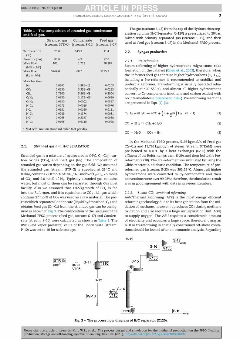
.1. Stranded gas and H/C SEPARATOR
tranded gas is a mixture of hydrocarbons (H/C, C1–C10), car-on oxides (CO2), and inert gas (N2). The composition oftranded gas varies depending on the gas field. We assumedhe stranded gas (stream: STR-G) is supplied at 25 ◦C and0 bar, contains 79.0 mol% of CH4, 16.5 mol% of C2–C6, 2.5 mol%f CO2 and 2.0 mol% of N2. Typically stranded gas containsater, but most of them can be separated through Gas inlet
acility. Also we assumed that 1765 kg mol/h of CO2 is fednto the Reformer, and it is equivalent to CO2-rich gas whichontains 27 mol% of CO2 was used as a raw material. The pro-ess which separates Condensate (liquid hydrocarbon, C5) andbtains Feed gas (C1–C4) from the stranded gas can be config-red as shown in Fig. 3. The composition of the Feed gas to theethanol-FPSO process (feed gas, stream: S-17) and Conden-
ate (stream: P-10) were calculated as shown in Table 1. TheVP (Reid vapor pressure) value of the Condensate (stream:
Please cite this article in press as: Kim, W.S., et al., The process designproduction, storage and off-loading) system. Chem. Eng. Res. Des. (2013), h
-10) was set to 10 for safe storage.
Fig. 3 – The process flow diagra
The gas (stream: S-15) from the top of the Hydrocarbon sep-aration column (H/C Separator, C-120) is pressurized to 28 bar,mixed with primary separated gas (stream: S-12), and thenused as feed gas (stream: S-17) in the Methanol-FPSO process.
2.2. Syngas production
2.2.1. Pre-reformingSteam reforming of higher hydrocarbons might cause cokeformation on the catalyst (Chen et al., 2003); therefore, whenthe Reformer feed gas contains higher hydrocarbons (C2–C6+),installing a Pre-reformer is recommended to stabilize andprotect a Reformer. Pre-reforming is usually operated adia-batically at 400–550 ◦C, and almost all higher hydrocarbonsconvert to C1-components (methane and carbon oxides) withno intermediates (Christensen, 1996). Pre-reforming reactionsare presented in Eqs. (1)–(3).
CnHm + nH2O → nCO +(
n + 12
m
)H2 (n > 1) (1)
CO + 3H2 � CH4 + H2O (2)
CO + H2O � CO2 + H2 (3)
In the Methanol-FPSO process, 5195 kg mol/h of Feed gas(C1–C4) and 11,765 kg mol/h of steam (stream: STEAM) werepre-heated to 400 ◦C by a heat exchanger (E260) with theeffluent of the Reformer (stream: S-29), and then fed to the Pre-reformer (R210). The Pre-reformer was simulated by using theGibbs reactor in adiabatic condition. The temperature of pre-reformed gas (stream: S-23) was 393.25 ◦C. Almost all higherhydrocarbons were converted to C1-components and theirconversions were over 99.98%; therefore, the simulation resultwas in good agreement with data in previous literature.
2.2.2. Steam-CO2 combined reformingAutoThermal Reforming (ATR) is the most energy efficientreforming technology due to its heat generation from the oxi-dation of methane, however, it produces CO2 during methaneoxidation and also requires a huge Air Separation Unit (ASU)to supply oxygen. The ASU requires a considerable amountof electricity and occupies a large space; therefore, using an
and simulation for the methanol production on the FPSO (floatingttp://dx.doi.org/10.1016/j.cherd.2013.08.009
tions should be looked after an economic analysis. Regarding
m of H/C separator (C120).
ARTICLE IN PRESSCHERD-1342; No. of Pages 10
4 chemical engineering research and design x x x ( 2 0 1 3 ) xxx–xxx
syngas composition, H2/CO = 2 syngas is known as the bestfor methanol production. Steam reforming or dry reformingproduces too high or too low a H2/CO ratio; therefore, addi-tional gas conditioning units are required. In this work, wechose Steam-CO2 combined reforming to utilize CO2. Withthis reforming technology, we can produce H2/CO = 2 syngaswithout additional gas conditioning units. Basini and Piovesan(1998) proved that the most economical process to produceH2/CO = 2 syngas is SCR. Consequently we chose SCR for theMethanol-FPSO.
The main reactions of steam-CO2 combined reforming areknown as Eqs. (4)–(6).
CH4 + H2O � CO + 3H2 (4)
CH4 + CO2 � 2H2 + 2CO (5)
CO + H2O � CO2 + H2 (6)
In Lee’s (2012) SCR experiment (CH4/H2O/CO2 = 1/1.63/0.6,900 ◦C, 21 bar), CH4 conversion was 83.24% and CO2 conversionwas 60.16%. In this work, to simulate the Reformer, the Gibbsreactor model was used and reaction conditions were set to900 ◦C and 21 bar. The simulation result for methane conver-sion (83%) agreed well with experimental data, but there wasa significant difference in the CO2 conversion result (34%).
Coke formation on the catalyst is the most significant prob-lem in the Reformer (Eqs. (7) and (8)), and this problem canbe prevented by keeping an appropriate steam-to-carbon ratio(S/C ratio).
CH4 � C + 2H2 (7)
2CO � CO2 + C (8)
Annesini et al. (2007) reported how CO2 affects the cokinglimit in steam-CO2 combined reforming. In high tempera-tures (>1000 K), the presence of CO2 lowers the possibilityof coke formation, and its coking limit is approximatelyyH2O/yCH4 + yCO2 = 1. This value is far less than the S/C ratio = 3that has been frequently used in steam reforming. Lee (2012)also reported that no coke formation was seen at an S/Cratio = 1.019 in a 24 h catalyst test. Consequently, we assumedan S/C ratio = 1 as the coking limit and this value will be usedas a constraint in optimization.
Hot Reformer effluent (900 ◦C) is to be cooled down to50 ◦C to remove water at T290. To recover residual heat, theReformer feed (stream: S-26, 287 ◦C) are pre-heated at the heatexchangers (E250) with hot Reformer effluent (stream: S-28,900 ◦C).
2.3. Methanol production
2.3.1. Methanol synthesis reactionKlier et al. (1982) and Liu et al. (1984) reported that smallamounts of water prevent the reduction of the Cu based cat-alyst and keeps the catalyst highly active in the methanolsynthesis reaction; whereas, as the composition of waterincreases, the water is strongly and competitively adsorbed onthe active site of the catalyst. In this work, produced syngas
Please cite this article in press as: Kim, W.S., et al., The process designproduction, storage and off-loading) system. Chem. Eng. Res. Des. (2013),
was cooled down to 50 ◦C in E280 and then the water (stream:W-30) was removed to less than 0.6 mol% at T290.
Methanol synthesis reactions are known to follow Eqs.(9)–(11)
CO + 2H2 � CH3OH (9)
CO2 + 3H2 � CH3OH + H2O (10)
CO + H2O � CO2 + H2 (11)
The methanol synthesis reaction is very sensitive to CO2
concentration in feed. Klier et al. (1982) reported that in lowCO2 concentrations, carbon conversion to methanol increasesalong with increases of CO2 concentration until the thresh-old point. After that threshold point, carbon conversionto methanol decreases along with CO2 the concentrationincrease. With regard to the reaction mechanism, smallamounts of CO2 makes the catalyst active due to the oxidiz-ing catalyst, whereas large amounts of CO2 strongly adsorbson the catalyst active sites so the reaction rate is retarded.Paradoxically, even though CO2 is the main carbon source inmethanol synthesis, CO2 is rarely consumed or is even some-times produced during methanol synthesis from syngas (Limet al., 2009).
Thanks to the development of catalysts, methanol produc-tion has been able to operate at low pressures (50–70 bar) andlow temperatures (230–270 ◦C). In this work, we set the oper-ating conditions to 250 ◦C and 51 bar. Syngas is compressed to51 bar in a compressor (K310) and heated up to 210 ◦C duringcompressing.
2.3.2. Methanol reactor simulationThe Gibbs reactor model, which calculates the reaction equi-librium, was used first to simulate methanol synthesis. Themethanol synthesis reaction has a low per pass conversionrate (25–40%); therefore, Gibbs reactor results were not in goodagreement with experimental data. In this study, a Plug FlowReactor (PFR) model was used to simulate the methanol syn-thesis reaction more accurately.
Although a number of kinetic rate equations have beenproposed in literature, we chose the kinetic equation pro-posed by VandenBussche and Froment (1996). They developedthe Langmuir–Hinshelwood–Hougen–Watson (LHHW) typesteady-state kinetic equation with experimental work usinga commercial Cu/ZnO/Al2O3 catalyst at pressures of 15–51 barand temperatures of 180–250 ◦C. They also compared the sim-ulation result with Klier et al.’s (1982) experimental data andproved that the model was in good agreement with experi-mental data. In addition, the rate equations and parametershad already been adopted from several authors (Arthur, 2010;Chen et al., 2011; Luyben, 2010; Panahi et al., 2012; Shahrokhiand Baghmisheh, 2005; Yusup et al., 2010), some of themproved that this kinetic model was in good agreement withindustrial methanol plant data. Accordingly, in this work, weadopted the rate equation without model validation.
The rate equations are presented in Eqs. (12) and (13) andkinetic parameters are shown in Table 2.
rMeOH =k′
5aK′2K3K4KH2 pCO2 pH2 [1 − (1/K
eq1 )(pH2OpCH3OH/p3
H2PCO2 )]
(1 + (KH2O/K8K9KH2 )(pH2O/pH2 ) +√
KH2 pH2 + KH2OPH2O)3
(12)
rRWGS = k′1pCO2 [1 − K
eq2 (pH2OpCO/pCO2 PH2 )]
(1 + (KH2O/K8K9KH2 )(pH2O/pH2 ) +√
KH2 pH2 + KH2OPH2O)(13)
and simulation for the methanol production on the FPSO (floatinghttp://dx.doi.org/10.1016/j.cherd.2013.08.009
For simple calculation, we assumed a one-dimensionalmodel, no axial/radial dispersion, isothermal conditions and a
ARTICLE IN PRESSCHERD-1342; No. of Pages 10
chemical engineering research and design x x x ( 2 0 1 3 ) xxx–xxx 5
Table 2 – Kinetic parameters and equilibrium constants.a
�,b Kieq,c A(i) B(i) Unit Note
√KH2 0.499 17,197 bar−1/2 Kinetic parameters
KH2O 6.62 × 10⁻¹¹ 124,119 bar−1
KH2OK8K9KH2
3453.38 – –
k′5aK′
2K3K4KH2 1.07 36,696 mol/kg·s·bar2 Kinetic factork’1 1.22 × 10⁻¹◦ −94,765 mol/kg·s·barK
eq1 3066 10.592 bar−2 Equilibrium constantd
Keq2 2073 2.029
a VandenBussche and Froment (1996).b � = A(i) exp(B(i)/RT), R = 8.314 J/mol·K.c A K
eq
i= 10(A/T−B).
d From Graaf et al. (1986).
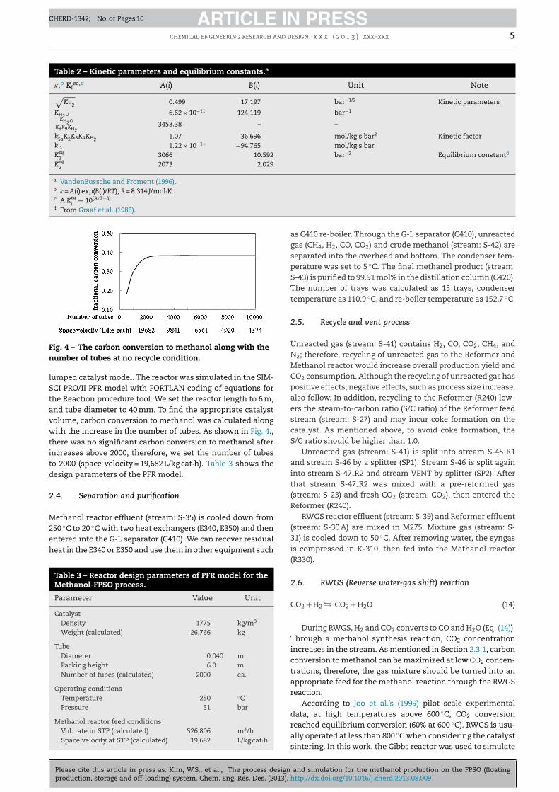
Fig. 4 – The carbon conversion to methanol along with then
lStavwtitd
2
M2eh
umber of tubes at no recycle condition.
umped catalyst model. The reactor was simulated in the SIM-CI PRO/II PFR model with FORTLAN coding of equations forhe Reaction procedure tool. We set the reactor length to 6 m,nd tube diameter to 40 mm. To find the appropriate catalystolume, carbon conversion to methanol was calculated alongith the increase in the number of tubes. As shown in Fig. 4.,
here was no significant carbon conversion to methanol afterncreases above 2000; therefore, we set the number of tubeso 2000 (space velocity = 19,682 L/kg cat·h). Table 3 shows theesign parameters of the PFR model.
.4. Separation and purification
ethanol reactor effluent (stream: S-35) is cooled down from50 ◦C to 20 ◦C with two heat exchangers (E340, E350) and then
Please cite this article in press as: Kim, W.S., et al., The process designproduction, storage and off-loading) system. Chem. Eng. Res. Des. (2013), h
ntered into the G-L separator (C410). We can recover residualeat in the E340 or E350 and use them in other equipment such
Table 3 – Reactor design parameters of PFR model for theMethanol-FPSO process.
Parameter Value Unit
CatalystDensity 1775 kg/m3
Weight (calculated) 26,766 kg
TubeDiameter 0.040 mPacking height 6.0 mNumber of tubes (calculated) 2000 ea.
Operating conditionsTemperature 250 ◦CPressure 51 bar
Methanol reactor feed conditionsVol. rate in STP (calculated) 526,806 m3/hSpace velocity at STP (calculated) 19,682 L/kg cat·h
as C410 re-boiler. Through the G-L separator (C410), unreactedgas (CH4, H2, CO, CO2) and crude methanol (stream: S-42) areseparated into the overhead and bottom. The condenser tem-perature was set to 5 ◦C. The final methanol product (stream:S-43) is purified to 99.91 mol% in the distillation column (C420).The number of trays was calculated as 15 trays, condensertemperature as 110.9 ◦C, and re-boiler temperature as 152.7 ◦C.
2.5. Recycle and vent process
Unreacted gas (stream: S-41) contains H2, CO, CO2, CH4, andN2; therefore, recycling of unreacted gas to the Reformer andMethanol reactor would increase overall production yield andCO2 consumption. Although the recycling of unreacted gas haspositive effects, negative effects, such as process size increase,also follow. In addition, recycling to the Reformer (R240) low-ers the steam-to-carbon ratio (S/C ratio) of the Reformer feedstream (stream: S-27) and may incur coke formation on thecatalyst. As mentioned above, to avoid coke formation, theS/C ratio should be higher than 1.0.
Unreacted gas (stream: S-41) is split into stream S-45 R1and stream S-46 by a splitter (SP1). Stream S-46 is split againinto stream S-47 R2 and stream VENT by splitter (SP2). Afterthat stream S-47 R2 was mixed with a pre-reformed gas(stream: S-23) and fresh CO2 (stream: CO2), then entered theReformer (R240).
RWGS reactor effluent (stream: S-39) and Reformer effluent(stream: S-30 A) are mixed in M275. Mixture gas (stream: S-31) is cooled down to 50 ◦C. After removing water, the syngasis compressed in K-310, then fed into the Methanol reactor(R330).
2.6. RWGS (Reverse water-gas shift) reaction
CO2 + H2 � CO2 + H2O (14)
During RWGS, H2 and CO2 converts to CO and H2O (Eq. (14)).Through a methanol synthesis reaction, CO2 concentrationincreases in the stream. As mentioned in Section 2.3.1, carbonconversion to methanol can be maximized at low CO2 concen-trations; therefore, the gas mixture should be turned into anappropriate feed for the methanol reaction through the RWGSreaction.
According to Joo et al.’s (1999) pilot scale experimentaldata, at high temperatures above 600 ◦C, CO2 conversionreached equilibrium conversion (60% at 600 ◦C). RWGS is usu-
and simulation for the methanol production on the FPSO (floatingttp://dx.doi.org/10.1016/j.cherd.2013.08.009
ally operated at less than 800 ◦C when considering the catalystsintering. In this work, the Gibbs reactor was used to simulate
ARTICLE IN PRESSCHERD-1342; No. of Pages 10
6 chemical engineering research and design x x x ( 2 0 1 3 ) xxx–xxx
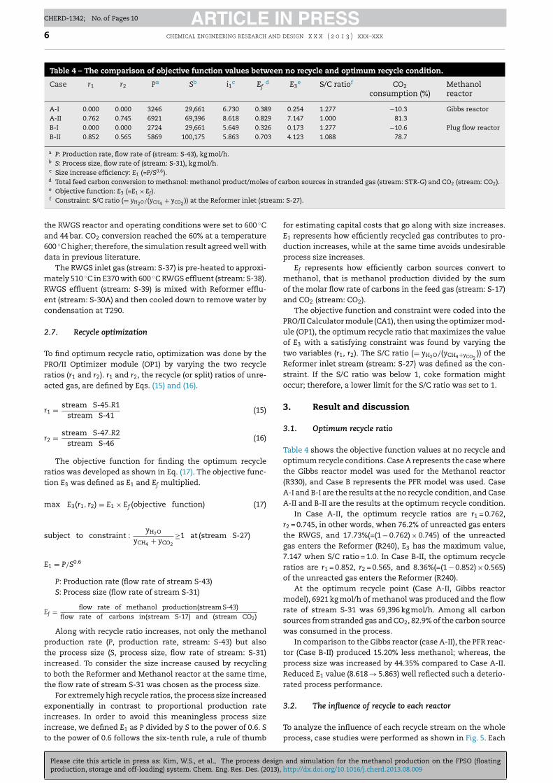
Table 4 – The comparison of objective function values between no recycle and optimum recycle condition.
Case r1 r2 Pa Sb i1c Efd E3
e S/C ratiof CO2consumption (%)
Methanolreactor
A-I 0.000 0.000 3246 29,661 6.730 0.389 0.254 1.277 −10.3 Gibbs reactorA-II 0.762 0.745 6921 69,396 8.618 0.829 7.147 1.000 81.3B-I 0.000 0.000 2724 29,661 5.649 0.326 0.173 1.277 −10.6 Plug flow reactorB-II 0.852 0.565 5869 100,175 5.863 0.703 4.123 1.088 78.7
a P: Production rate, flow rate of (stream: S-43), kg mol/h.b S: Process size, flow rate of (stream: S-31), kg mol/h.c Size increase efficiency: E1 (=P/S0.6).d Total feed carbon conversion to methanol: methanol product/moles of carbon sources in stranded gas (stream: STR-G) and CO2 (stream: CO2).e Objective function: E3 (=E1 × Ef).f Constraint: S/C ratio (= yH O/(yCH + yCO )) at the Reformer inlet (stream: S-27).
2 4 2the RWGS reactor and operating conditions were set to 600 ◦Cand 44 bar. CO2 conversion reached the 60% at a temperature600 ◦C higher; therefore, the simulation result agreed well withdata in previous literature.
The RWGS inlet gas (stream: S-37) is pre-heated to approxi-mately 510 ◦C in E370 with 600 ◦C RWGS effluent (stream: S-38).RWGS effluent (stream: S-39) is mixed with Reformer efflu-ent (stream: S-30A) and then cooled down to remove water bycondensation at T290.
2.7. Recycle optimization
To find optimum recycle ratio, optimization was done by thePRO/II Optimizer module (OP1) by varying the two recycleratios (r1 and r2). r1 and r2, the recycle (or split) ratios of unre-acted gas, are defined by Eqs. (15) and (16).
r1 = stream S-45 R1stream S-41
(15)
r2 = stream S-47 R2stream S-46
(16)
The objective function for finding the optimum recycleratios was developed as shown in Eq. (17). The objective func-tion E3 was defined as E1 and Ef multiplied.
max E3(r1, r2) = E1 × Ef (objective function) (17)
subject to constraint :yH2O
yCH4 + yCO2
≥1 at (stream S-27)
E1 = P/S0.6
P: Production rate (flow rate of stream S-43)S: Process size (flow rate of stream S-31)
Ef = flow rate of methanol production(stream S-43)flow rate of carbons in(stream S-17) and (stream CO2)
Along with recycle ratio increases, not only the methanolproduction rate (P, production rate, stream: S-43) but alsothe process size (S, process size, flow rate of stream: S-31)increased. To consider the size increase caused by recyclingto both the Reformer and Methanol reactor at the same time,the flow rate of stream S-31 was chosen as the process size.
For extremely high recycle ratios, the process size increasedexponentially in contrast to proportional production rateincreases. In order to avoid this meaningless process size
Please cite this article in press as: Kim, W.S., et al., The process designproduction, storage and off-loading) system. Chem. Eng. Res. Des. (2013),
increase, we defined E1 as P divided by S to the power of 0.6. Sto the power of 0.6 follows the six-tenth rule, a rule of thumb
for estimating capital costs that go along with size increases.E1 represents how efficiently recycled gas contributes to pro-duction increases, while at the same time avoids undesirableprocess size increases.
Ef represents how efficiently carbon sources convert tomethanol, that is methanol production divided by the sumof the molar flow rate of carbons in the feed gas (stream: S-17)and CO2 (stream: CO2).
The objective function and constraint were coded into thePRO/II Calculator module (CA1), then using the optimizer mod-ule (OP1), the optimum recycle ratio that maximizes the valueof E3 with a satisfying constraint was found by varying thetwo variables (r1, r2). The S/C ratio (= yH2O/(yCH4+yCO2
)) of theReformer inlet stream (stream: S-27) was defined as the con-straint. If the S/C ratio was below 1, coke formation mightoccur; therefore, a lower limit for the S/C ratio was set to 1.
3. Result and discussion
3.1. Optimum recycle ratio
Table 4 shows the objective function values at no recycle andoptimum recycle conditions. Case A represents the case wherethe Gibbs reactor model was used for the Methanol reactor(R330), and Case B represents the PFR model was used. CaseA-I and B-I are the results at the no recycle condition, and CaseA-II and B-II are the results at the optimum recycle condition.
In Case A-II, the optimum recycle ratios are r1 = 0.762,r2 = 0.745, in other words, when 76.2% of unreacted gas entersthe RWGS, and 17.73%(=(1 − 0.762) × 0.745) of the unreactedgas enters the Reformer (R240), E3 has the maximum value,7.147 when S/C ratio = 1.0. In Case B-II, the optimum recycleratios are r1 = 0.852, r2 = 0.565, and 8.36%(=(1 − 0.852) × 0.565)of the unreacted gas enters the Reformer (R240).
At the optimum recycle point (Case A-II, Gibbs reactormodel), 6921 kg mol/h of methanol was produced and the flowrate of stream S-31 was 69,396 kg mol/h. Among all carbonsources from stranded gas and CO2, 82.9% of the carbon sourcewas consumed in the process.
In comparison to the Gibbs reactor (case A-II), the PFR reac-tor (Case B-II) produced 15.20% less methanol; whereas, theprocess size was increased by 44.35% compared to Case A-II.Reduced E1 value (8.618 → 5.863) well reflected such a deterio-rated process performance.
3.2. The influence of recycle to each reactor
and simulation for the methanol production on the FPSO (floatinghttp://dx.doi.org/10.1016/j.cherd.2013.08.009
To analyze the influence of each recycle stream on the wholeprocess, case studies were performed as shown in Fig. 5. Each
ARTICLE IN PRESSCHERD-1342; No. of Pages 10
chemical engineering research and design x x x ( 2 0 1 3 ) xxx–xxx 7
eform
c(r(a
cwEArtt
bd
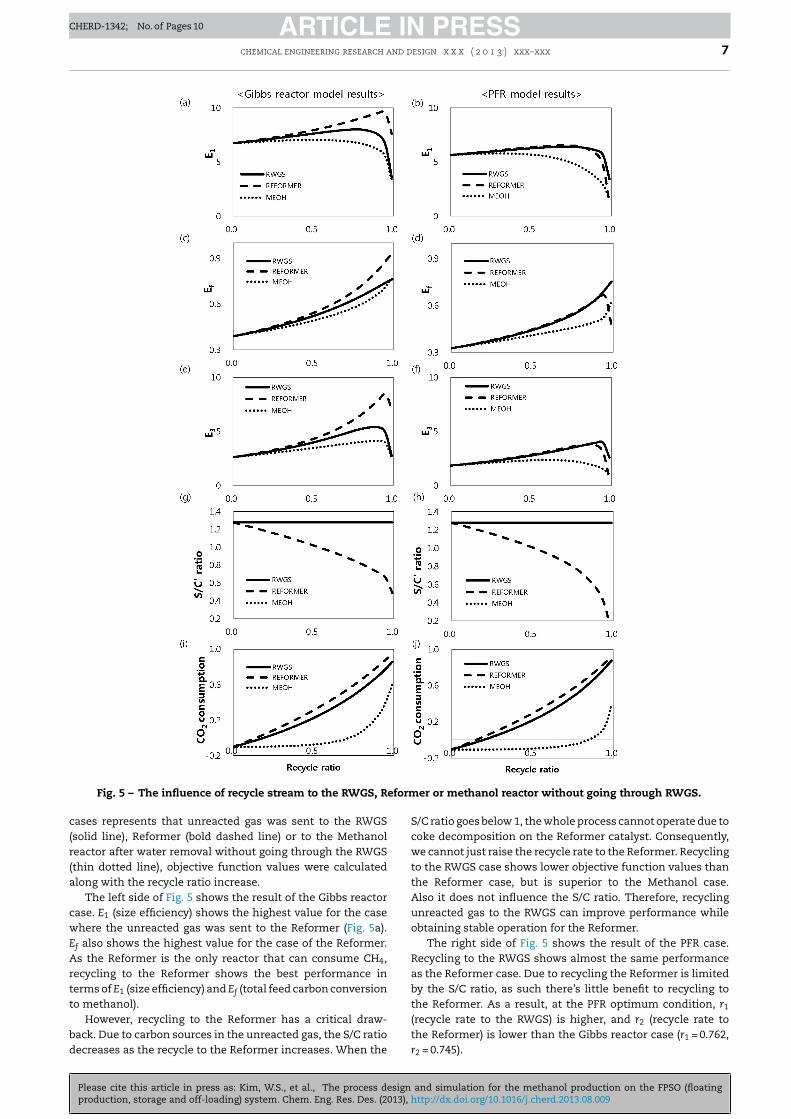
Fig. 5 – The influence of recycle stream to the RWGS, R
ases represents that unreacted gas was sent to the RWGSsolid line), Reformer (bold dashed line) or to the Methanoleactor after water removal without going through the RWGSthin dotted line), objective function values were calculatedlong with the recycle ratio increase.
The left side of Fig. 5 shows the result of the Gibbs reactorase. E1 (size efficiency) shows the highest value for the casehere the unreacted gas was sent to the Reformer (Fig. 5a).
f also shows the highest value for the case of the Reformer.s the Reformer is the only reactor that can consume CH4,
ecycling to the Reformer shows the best performance inerms of E1 (size efficiency) and Ef (total feed carbon conversiono methanol).
However, recycling to the Reformer has a critical draw-
Please cite this article in press as: Kim, W.S., et al., The process designproduction, storage and off-loading) system. Chem. Eng. Res. Des. (2013), h
ack. Due to carbon sources in the unreacted gas, the S/C ratioecreases as the recycle to the Reformer increases. When the
er or methanol reactor without going through RWGS.
S/C ratio goes below 1, the whole process cannot operate due tocoke decomposition on the Reformer catalyst. Consequently,we cannot just raise the recycle rate to the Reformer. Recyclingto the RWGS case shows lower objective function values thanthe Reformer case, but is superior to the Methanol case.Also it does not influence the S/C ratio. Therefore, recyclingunreacted gas to the RWGS can improve performance whileobtaining stable operation for the Reformer.
The right side of Fig. 5 shows the result of the PFR case.Recycling to the RWGS shows almost the same performanceas the Reformer case. Due to recycling the Reformer is limitedby the S/C ratio, as such there’s little benefit to recycling tothe Reformer. As a result, at the PFR optimum condition, r1
(recycle rate to the RWGS) is higher, and r2 (recycle rate to
and simulation for the methanol production on the FPSO (floatingttp://dx.doi.org/10.1016/j.cherd.2013.08.009
the Reformer) is lower than the Gibbs reactor case (r1 = 0.762,r2 = 0.745).
ARTICLE IN PRESSCHERD-1342; No. of Pages 10
8 chemical engineering research and design x x x ( 2 0 1 3 ) xxx–xxx
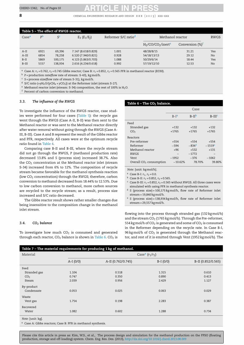
Table 5 – The effect of RWGS reactor.
Casea Pb Sc E3 (E1/Ef) Reformer S/C ratiod Methanol reactor RWGS
H2/CO/CO2/inerte Conversion (%)f
A-II 6921 69,396 7.147 (8.618/0.829) 1.001 48/28/8/15 31.21 YesA-III 6854 78,258 6.520 (7.940/0.821) 0.928 54/18/13/13 29.12 NoB-II 5869 100,175 4.123 (5.863/0.703) 1.088 50/29/6/14 18.44 YesB-III 5157 138,934 2.616 (4.234/0.618) 0.992 57/19/12/10 12.53 No
a Case A: r1 = 0.762, r2 = 0.745 Gibbs reactor; Case B: r1 = 0.852, r2 = 0.565 PFR in methanol reactor (R330).b P = production rate(flow rate of stream: S-43), kg mol/h.c S = process size(flow rate of steam S-31), kg mol/h.d S/C ratio (=yH2O/(yCH4 + yCO2)) at the Reformer inlet (stream S-27).e Methanol reactor inlet (stream: S-34) composition, the rest of 100% is H2O.f
Table 6 – The CO2 balance.
Case
B-Ia B-IIb B-IIIc
FeedStranded gas +132 +132 +132CO2 +1765 +1765 +1765
ReactorsPre-reformer +554 +554 +554Reformer −594 −834d −1519e
Methanol reactor +96 +532 +131RWGS – −1772 –Vent −1952 −376 −1062Overall CO2 consumption −10.62% 78.70% 39.80%
Note: [unit: kg mol/h].a Case B-I: r1, r2 = 0.0.b Case B-II: r1 = 0.852, r2 = 0.565.c Case B-III: r1 = 0.852, r2 = 0.565 without RWGS. All three cases were
simulated with using PFR in methanol synthesis reactor.d S (process size) = 100,175 kg mol/h, flow rate of Reformer inlet
stream = 19,840 kg mol/h.e S (process size) = 138,934 kg mol/h, flow rate of Reformer inlet
stream = 29,557 kg mol/h.
Percent of carbon conversion to methanol.
3.3. The influence of the RWGS
To investigate the influence of the RWGS reactor, case stud-ies were performed for four cases (Table 5): the recycle gaswent through the RWGS (Case A-II, B-II) was then sent to theMethanol reactor or was sent to the Methanol reactor directlyafter water removal without going through the RWGS (Case A-III, B-III). Case A and B represent the result of the Gibbs reactorand PFR, respectively. All cases were at the optimum recycleratio found in Table 4.
Comparing case B-II and B-III, where the recycle streamdid not go through the RWGS, P (methanol production rate)decreased 13.8% and S (process size) increased 38.7%. Alsothe CO2 concentration at the Methanol reactor inlet (streamS-34) increased from 6% to 12%. The composition of recyclestream became favorable for the methanol synthesis reaction(low CO2 concentration) through the RWGS; therefore, carbonconversion to methanol decreased from 18.44% to 12.53%. Dueto low carbon conversion to methanol, more carbon sourcesare recycled to the recycle stream; as a result, process sizeincreased and S/C ratio decreased.
The Gibbs reactor result shows rather smaller changes duebeing insensitive to the composition change in the methanolinlet stream.
3.4. CO2 balance
Please cite this article in press as: Kim, W.S., et al., The process designproduction, storage and off-loading) system. Chem. Eng. Res. Des. (2013),
To investigate how much CO2 is consumed and generatedthrough each reactor, CO2 balance is shown in Table 6. CO2 is
Table 7 – The material requirements for producing 1 kg of meth
Material
A-I (0/0) A-II (0.762/0.
FeedStranded gas 1.104 0.518
CO2 0.747 0.350
Steam 2.039 0.956
By-productCondensate 0.053 0.025
WasteVent gas 1.754 0.198
RecoveredWater 1.082 0.602
Note: [unit: kg].a Case A: Gibbs reactors; Case B: PFR in methanol synthesis.
flowing into the process through stranded gas (132 kg mol/h)and the stream CO2 (1765 kg mol/h). Through the Pre-reformer,554 kg mol/h of CO2 is generated and some of CO2 is consumedin the Reformer depending on the recycle rate. In Case B-I,
and simulation for the methanol production on the FPSO (floatinghttp://dx.doi.org/10.1016/j.cherd.2013.08.009
96 kg mol/h of CO2 is generated through the Methanol reac-tor, and rest of it is emitted through Vent (1952 kg mol/h). The
anol.
Casea (r1/r2)
745) B-I (0/0) B-II (0.852/0.565)
1.315 0.6100.890 0.4132.429 1.127
0.063 0.029
2.283 0.387
1.288 0.734
ARTICLE IN PRESSCHERD-1342; No. of Pages 10
chemical engineering research and design x x x ( 2 0 1 3 ) xxx–xxx 9
ow
8Cbo
ec1i
cdr
3m
Ts
goes
4
AoF((tarcvoatrepawcorwmtcpdaaC
d1t
verall CO2 consumption was −10.62% and this means thehole process produced CO2.
In Case B-II (no RWGS), the Reformer consumed34 kg mol/h and Methanol reactor produced 532 kg mol/h ofO2. Due to presence of the RWGS, 1772 kg mol/h of CO2 cane consumed, and only 376 kg mol/h of CO2 is emitted. Theverall CO2 consumption was 78.70%.
However, in Case B-III, there is no reactor to consume CO2
xcept for Reformer. Due to accumulating CO2 in the recy-le stream, S (process size) increased 38.69%. To consume519 kg mol/h of CO2 in the Reformer, the size of the Reformernlet (stream: S-27) increased 48.98%.
Consequently, due to presence of the RWGS, the processan consume up to 78.70% CO2 in the optimum recycle con-itions. In addition, the process size can be minimized byeducing excess CO2.
.5. Material requirement for producing 1 kg ofethanol
he material requirement for producing 1 kg of methanol ishown in Table 7.
At the optimum recycle ratio, case A-II, 0.518 kg of strandedas, 0.350 kg of CO2, 0.956 kg of steam are required. 0.025 kgf condensate is produced and 0.198 kg of vent gas should bemitted. Recovered water can be reused as a feed steam by theteam generation process.
. Conclusion
novel Methanol-FPSO production process was proposed inrder to utilize off-shore stranded gas and CO2. The Methanol-PSO process consists of a Steam-CO2 Combined ReformerSCR), a methanol synthesis reactor, a Reverse Water-Gas ShiftRWGS) reactor and other ancillaries with recycle streams tohe SCR and RWGS. The whole process was simulated using
commercial process simulator (SIMSCI PRO/II). The Gibbseactor model, which represents the equilibrium conversion,onfirmed that the proposed process configuration can con-ert a considerable amount of CO2 into methanol. Also, thebtained results are comparable to the data in previous liter-ture in terms of the carbon conversion to methanol. In ordero incorporate the actual situation, the methanol synthesiseactor was simulated by the PFR model with reaction ratequations that describe the influence of CO2 well when com-ared to previous literature. The optimal operating conditionsre obtained using the constrained optimization techniqueith the objective function, which maximizes the feed carbon
onversion to methanol while avoiding an inefficient increasef the process size. The lower limit of the steam-to-carbonatio was set to 1 to avoid coke deposition in the SCR reactor. Itas found that the configuration with the RWGS and recyclingost of the methanol reactor effluent to the RWGS provided
he best result. Due to the presence of the RWGS in the recy-le stream, methanol production rate increased by 13.8% androcess size decreased by 38.7% compared to the case withirect recycling to the methanol reactor without the RWGSs seen in the conventional methanol production process. Inddition, total feed carbon conversion increased by 8.5% andO2 consumption was increased by 38.9%.
It was found that 5869 kg mol/h of methanol could be pro-uced from 100 MM scfd (5264 kg mol/h) of stranded gas and
Please cite this article in press as: Kim, W.S., et al., The process designproduction, storage and off-loading) system. Chem. Eng. Res. Des. (2013), h
765 kg mol/h of CO2, and the total feed carbon conversiono methanol was 70.3% where CO2 consumption was 78.7%
using the PFR model in optimum recycle conditions (r1 = 0.852,r2 = 0.565). 0.518 kg of stranded gas, 0.350 kg of CO2 and 0.956 kgof steam were required to produce 1 kg of methanol. In addi-tion, 0.602 kg of water could be recovered as a feed after thesteam generation process. The proposed Methanol-FPSO pro-cess in this study seems to have great potential in terms of theefficient utilization of CO2-rich off-shore stranded gas.
Acknowledgements
This work was supported by the research program of KoreaInstitute of Science and Technology and by the HumanResources Development program (No. 20114010203050) of theKorea Institute of Energy Technology Evaluation and Planning(KETEP) grant funded by the Korea government Ministry ofTrade, Industry and Energy.
References
Annesini, M.C., Piemonte, V., Turchetti, L., 2007. Carbonformation in the steam reforming process: a thermodynamicanalysis based on the elemental composition, conferencepaper, ICheaP-8.
Arthur, T., 2010. Control Structure Design for Methanol Process.Department of Chemical Engineering, Norwegian Universityof Science and Technology, Trondheim, pp. 1–91.
Basini, L., Piovesan, L., 1998. Reduction on synthesis gas costs bydecrease of steam/carbon and oxygen/carbon ratios in thefeedstock. Ind. Eng. Chem. Res. 37, 258–266.
Breman, B.B., Beenackers, A.A., 1996. Thermodynamic models topredict gas-liquid solubilities in the methanol synthesis, themethanol-higher alcohol synthesis, and the Fischer–Tropschsynthesis via gas-slurry processes. Ind. Eng. Chem. Res. 35,3763–3775.
Chen, Z., Yan, Y., Elnashaie, S.S.E.H., 2003. Modeling andoptimization of a novel membrane reformer for higherhydrocarbons. AIChE J. 49, 1250–1265.
Chen, L., Jiang, Q.Z., Song, Z.Z., Posarac, D., 2011. Optimization ofmethanol yield from a Lurgi reactor. Chem. Eng. Technol. 34,817–822.
Christensen, T.S., 1996. Adiabatic prereforming of hydrocarbons –an important step in syngas production. Appl. Catal. A: Gen.138, 285–309.
Graaf, G.H., Sijtsema, P.J.J.M., Stamhuis, E.J., Joosten, G.E.H., 1986.Chemical-equilibria in methanol synthesis. Chem. Eng. Sci.41, 2883–2890.
Joo, O.-S., Jung, K.-D., Moon, I., Rozovskii, A.Y., Lin, G.I., Han, S.-H.,Uhm, S.-J., 1999. Carbon dioxide hydrogenation to formmethanol via a reverse-water-gas-shift reaction (the CAMEREprocess). Ind. Eng. Chem. Res. 38, 1808–1812.
Klier, K., Chatikavanu, V., Herman, R.H., Simmons, G.W., 1982.Catalytic synthesis of methanol from CO/H(2). J. Catal. 74,343–360.
Lee, Y.J., 2012. The Steam CO2 Reforming of Methane For Gas toLiquid(GTL) – Floating Production Storage Offloading(FPSO)System. Department of Chemical & Biological Engineering,Korea University, Seoul.
Lim, H.W., Park, M.J., Kang, S.H., Chae, H.J., Bae, J.W., Jun, K.W.,2009. Modeling of the kinetics for methanol synthesis usingCu/ZnO/Al(2)O(3)/ZrO(2) catalyst: influence of carbon dioxideduring hydrogenation. Ind. Eng. Chem. Res. 48, 10448–10455.
Liu, G., Willcox, D., Garland, M., Kung, H.H., 1984. The rate ofmethanol production on a copper-zinc oxide catalyst: thedependence on the feed composition. J. Catal. 90, 139–146.
Luyben, W.L., 2010. Design and control of a methanolreactor/column process. Ind. Eng. Chem. Res. 49, 6150–6163.
Olah, G.A., Goeppert, A., Prakash, G.K.S., 2009. Chemical recyclingof carbon dioxide to methanol and dimethyl ether: from
and simulation for the methanol production on the FPSO (floatingttp://dx.doi.org/10.1016/j.cherd.2013.08.009
greenhouse gas to renewable, environmentally carbon neutralfuels and synthetic hydrocarbons. J. Org. Chem. 74, 487–498.

ARTICLE IN PRESSCHERD-1342; No. of Pages 10
10 chemical engineering research and design x x x ( 2 0 1 3 ) xxx–xxx
industrial methanol reactor based on simplified steady-state
Panahi, P.N., Mousavi, S.M., Niaei, A., Farzi, A., Salari, D., 2012.Simulation of methanol synthesis from synthesis gas in fixedbed catalytic reactor using mathematical modeling andneural networks. Int. J. Sci. Eng. Res. 3, 1–7.
Shahrokhi, M., Baghmisheh, G.R., 2005. Modeling, simulation and
Please cite this article in press as: Kim, W.S., et al., The process designproduction, storage and off-loading) system. Chem. Eng. Res. Des. (2013),
control of a methanol synthesis fixed-bed reactor. Chem. Eng.Sci. 60, 4275–4286.
VandenBussche, K.M., Froment, G.F., 1996. A steady-state kineticmodel for methanol synthesis and the water gas shift reactionon a commercial Cu/ZnO/Al2O3 catalyst. J. Catal. 161, 1–10.
Yusup, S., Anh, N.P., Zabiri, H., 2010. A simulation study of an
and simulation for the methanol production on the FPSO (floatinghttp://dx.doi.org/10.1016/j.cherd.2013.08.009
model. IJRRAS 5, 213–222.