1-s2 0-S0038109812002529-main
8
Spin-filtered edge states in graphene D. Gosa ´ lbez-Martı ´nez a,n , D. Soriano a,b , J.J. Palacios c , J. Ferna ´ ndez-Rossier a,d a Departamento de Fı ´sica Aplicada, Universidad de Alicante, San Vicente del Raspeig, 03690 Alicante, Spain b CIN2 (ICN-CSIC) and Universitat Aut onoma de Barcelona, Catalan Institute of Nanotechnology, Campus UAB, 08193 Bellaterra (Barcelona), Spain c Departamento de Fı ´sica de la Materia Condensada, Universidad Auto ´noma de Madrid, Cantoblanco, 28049 Madrid, Spain d Iberian International Nanotechnology Laboratory, Avenida Mestre Jose´ Veiga, 4715-330 Braga, Portugal article info Article history: Accepted 12 April 2012 Accepted by L. Brey Available online 26 April 2012 Keywords: A. Graphene D. Quantum spin Hall phase D. Spin–orbit coupling D. Electronic transport abstract Spin–orbit coupling changes graphene, in principle, into a two-dimensional topological insulator, also known as quantum spin Hall insulator. One of the expected consequences is the existence of spin- filtered edge states that carry dissipationless spin currents and undergo no backscattering in the presence of non-magnetic disorder, leading to quantization of conductance. Whereas, due to the small size of spin–orbit coupling in graphene, the experimental observation of these remarkable predictions is unlikely, the theoretical understanding of these spin-filtered states is shedding light on the electronic properties of edge states in other two-dimensional quantum spin Hall insulators. Here we review the effect of a variety of perturbations, like curvature, disorder, edge reconstruction, edge crystallographic orientation, and Coulomb interactions on the electronic properties of these spin filtered states. & 2012 Elsevier Ltd. All rights reserved. 1. Introduction Since the fabrication of high mobility graphene based transis- tors, back in 2004 [1], the exploration of graphene has led to a number of striking experimental findings [2] such as the quantum Hall effect [3,4], even at room temperature, the Klein tunneling, the universal optical absorption, and also to an even larger amount of theory work predicting exotic electronic phases in graphene. Whereas most of the new electronic phases in Con- densed Matter Physics are driven by the Coulomb interactions, in 2005 Kane and Mele (KM) predicted that spin–orbit coupling (SOC) alone would turn graphene into a completely new electro- nic state, the so-called quantum spin Hall insulator (QSHI) [5,6]. Inspection of the energy bands of graphene, as described within the Kane–Mele model, look deceptively like an ordinary narrow gap semiconductor. However, a careful study of the wave function topology in reciprocal space reveals that the gap opened at the Dirac points by the SOC has different signs at the two valleys. The twisting in the reciprocal state makes graphene topologically different from vacuum or graphene without SOC. The most conspicuous consequence of the topologically non-trivial band structure of the QSHI is the existence of spin-filtered edge states at the boundaries of graphene with other topologically trivial systems. The quantum spin Hall phase proposed by Kane and Mele can be portrayed as two copies of a quantum Hall phase [6], one for each spin orientation and with opposite spin-dependent field orientations. Like in the conventional quantum Hall phase, the bulk states are gapped, but the edges hold states at the Fermi energy that carry current. In the quantum spin Hall phase, at a given edge, spin up electrons flow in the opposite direction to that of spin down electrons, resulting in a pure spin current flow. Since backscattering in a given edge requires reversal of the spin, the conductance of the edge states is expected to be quantized even in the presence of time-reversal preserving disorder. In their original work, KM studied the competition between the intrinsic SOC, which drives the QSHI phase, and inversion symmetry breaking perturbations, such as a Rashba spin–orbit term and a staggered perturbation, which make graphene an ordinary insulator. The interplay of these couplings with non- magnetic disorder was later addressed by Sheng et al. [7,8]. They found that, as expected, the QSHI phase, and thereby the spin- filtered edge states, were robust with respect to the addition of time-reversal symmetric disorder. Here we address four different topics: first, the relation of the KM model with the microscopic description of SOC in graphene. In Section 2, we show that the KM Hamiltonian, originally derived from heuristic symmetry considerations, is a good effective one orbital description of the low energy bands of flat graphene, as described with a 4-orbital Slater–Koster (SK) Hamiltonian includ- ing SOC [9–12]. Our second topic refers to the influence of the geometry of the sample on the electronic properties of the spin-filtered edge Contents lists available at SciVerse ScienceDirect journal homepage: www.elsevier.com/locate/ssc Solid State Communications 0038-1098/$ - see front matter & 2012 Elsevier Ltd. All rights reserved. http://dx.doi.org/10.1016/j.ssc.2012.04.046 n Corresponding author. Tel.: þ34 965903400. E-mail address: [email protected] (D. Gosa ´ lbez-Martı ´nez). Solid State Communications 152 (2012) 1469–1476
Transcript of 1-s2 0-S0038109812002529-main
Solid State Communications 152 (2012) 1469–1476
Contents lists available at SciVerse ScienceDirect
Solid State Communications
0038-10
http://d
n Corr
E-m
journal homepage: www.elsevier.com/locate/ssc
Spin-filtered edge states in graphene
D. Gosalbez-Martınez a,n, D. Soriano a,b, J.J. Palacios c, J. Fernandez-Rossier a,d
a Departamento de Fısica Aplicada, Universidad de Alicante, San Vicente del Raspeig, 03690 Alicante, Spainb CIN2 (ICN-CSIC) and Universitat Aut �onoma de Barcelona, Catalan Institute of Nanotechnology, Campus UAB, 08193 Bellaterra (Barcelona), Spainc Departamento de Fısica de la Materia Condensada, Universidad Autonoma de Madrid, Cantoblanco, 28049 Madrid, Spaind Iberian International Nanotechnology Laboratory, Avenida Mestre Jose Veiga, 4715-330 Braga, Portugal
a r t i c l e i n f o
Article history:
Accepted 12 April 2012
Accepted by L. Brey
Spin–orbit coupling changes graphene, in principle, into a two-dimensional topological insulator, also
known as quantum spin Hall insulator. One of the expected consequences is the existence of spin-
filtered edge states that carry dissipationless spin currents and undergo no backscattering in the
Available online 26 April 2012Keywords:
A. Graphene
D. Quantum spin Hall phase
D. Spin–orbit coupling
D. Electronic transport
98/$ - see front matter & 2012 Elsevier Ltd. A
x.doi.org/10.1016/j.ssc.2012.04.046
esponding author. Tel.: þ34 965903400.
ail address: [email protected] (D. Gosalbe
a b s t r a c t
presence of non-magnetic disorder, leading to quantization of conductance. Whereas, due to the small
size of spin–orbit coupling in graphene, the experimental observation of these remarkable predictions
is unlikely, the theoretical understanding of these spin-filtered states is shedding light on the electronic
properties of edge states in other two-dimensional quantum spin Hall insulators. Here we review the
effect of a variety of perturbations, like curvature, disorder, edge reconstruction, edge crystallographic
orientation, and Coulomb interactions on the electronic properties of these spin filtered states.
& 2012 Elsevier Ltd. All rights reserved.
1. Introduction
Since the fabrication of high mobility graphene based transis-tors, back in 2004 [1], the exploration of graphene has led to anumber of striking experimental findings [2] such as the quantumHall effect [3,4], even at room temperature, the Klein tunneling,the universal optical absorption, and also to an even largeramount of theory work predicting exotic electronic phases ingraphene. Whereas most of the new electronic phases in Con-densed Matter Physics are driven by the Coulomb interactions, in2005 Kane and Mele (KM) predicted that spin–orbit coupling(SOC) alone would turn graphene into a completely new electro-nic state, the so-called quantum spin Hall insulator (QSHI) [5,6].Inspection of the energy bands of graphene, as described withinthe Kane–Mele model, look deceptively like an ordinary narrowgap semiconductor. However, a careful study of the wave functiontopology in reciprocal space reveals that the gap opened at theDirac points by the SOC has different signs at the two valleys. Thetwisting in the reciprocal state makes graphene topologicallydifferent from vacuum or graphene without SOC. The mostconspicuous consequence of the topologically non-trivial bandstructure of the QSHI is the existence of spin-filtered edge statesat the boundaries of graphene with other topologically trivialsystems.
ll rights reserved.
z-Martınez).
The quantum spin Hall phase proposed by Kane and Mele canbe portrayed as two copies of a quantum Hall phase [6], one foreach spin orientation and with opposite spin-dependent fieldorientations. Like in the conventional quantum Hall phase, thebulk states are gapped, but the edges hold states at the Fermienergy that carry current. In the quantum spin Hall phase, at agiven edge, spin up electrons flow in the opposite direction to thatof spin down electrons, resulting in a pure spin current flow. Sincebackscattering in a given edge requires reversal of the spin, theconductance of the edge states is expected to be quantized evenin the presence of time-reversal preserving disorder.
In their original work, KM studied the competition betweenthe intrinsic SOC, which drives the QSHI phase, and inversionsymmetry breaking perturbations, such as a Rashba spin–orbitterm and a staggered perturbation, which make graphene anordinary insulator. The interplay of these couplings with non-magnetic disorder was later addressed by Sheng et al. [7,8]. Theyfound that, as expected, the QSHI phase, and thereby the spin-filtered edge states, were robust with respect to the addition oftime-reversal symmetric disorder.
Here we address four different topics: first, the relation of theKM model with the microscopic description of SOC in graphene.In Section 2, we show that the KM Hamiltonian, originally derivedfrom heuristic symmetry considerations, is a good effective oneorbital description of the low energy bands of flat graphene, asdescribed with a 4-orbital Slater–Koster (SK) Hamiltonian includ-ing SOC [9–12].
Our second topic refers to the influence of the geometry of thesample on the electronic properties of the spin-filtered edge
M Γ K M
-30
-20
-10
0
10
20
E(eV)
K-1
0
1
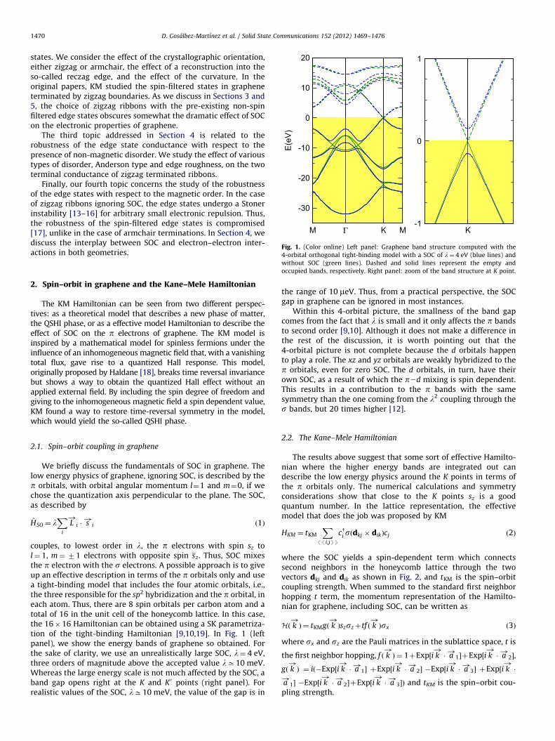
Fig. 1. (Color online) Left panel: Graphene band structure computed with the
4-orbital orthogonal tight-binding model with a SOC of l¼ 4 eV (blue lines) and
D. Gosalbez-Martınez et al. / Solid State Communications 152 (2012) 1469–14761470
states. We consider the effect of the crystallographic orientation,either zigzag or armchair, the effect of a reconstruction into theso-called reczag edge, and the effect of the curvature. In theoriginal papers, KM studied the spin-filtered states in grapheneterminated by zigzag boundaries. As we discuss in Sections 3 and5, the choice of zigzag ribbons with the pre-existing non-spinfiltered edge states obscures somewhat the dramatic effect of SOCon the electronic properties of graphene.
The third topic addressed in Section 4 is related to therobustness of the edge state conductance with respect to thepresence of non-magnetic disorder. We study the effect of varioustypes of disorder, Anderson type and edge roughness, on the twoterminal conductance of zigzag terminated ribbons.
Finally, our fourth topic concerns the study of the robustnessof the edge states with respect to the magnetic order. In the caseof zigzag ribbons ignoring SOC, the edge states undergo a Stonerinstability [13–16] for arbitrary small electronic repulsion. Thus,the robustness of the spin-filtered edge states is compromised[17], unlike in the case of armchair terminations. In Section 4, wediscuss the interplay between SOC and electron–electron inter-actions in both geometries.
without SOC (green lines). Dashed and solid lines represent the empty and
occupied bands, respectively. Right panel: zoom of the band structure at K point.
2. Spin–orbit in graphene and the Kane–Mele Hamiltonian
The KM Hamiltonian can be seen from two different perspec-tives: as a theoretical model that describes a new phase of matter,the QSHI phase, or as a effective model Hamiltonian to describe theeffect of SOC on the p electrons of graphene. The KM model isinspired by a mathematical model for spinless fermions under theinfluence of an inhomogeneous magnetic field that, with a vanishingtotal flux, gave rise to a quantized Hall response. This model,originally proposed by Haldane [18], breaks time reversal invariancebut shows a way to obtain the quantized Hall effect without anapplied external field. By including the spin degree of freedom andgiving to the inhomogeneous magnetic field a spin dependent value,KM found a way to restore time-reversal symmetry in the model,which would yield the so-called QSHI phase.
2.1. Spin–orbit coupling in graphene
We briefly discuss the fundamentals of SOC in graphene. Thelow energy physics of graphene, ignoring SOC, is described by thep orbitals, with orbital angular momentum l¼1 and m¼0, if wechose the quantization axis perpendicular to the plane. The SOC,as described by
HSO ¼ lX
i
L!
i � s!
i ð1Þ
couples, to lowest order in l, the p electrons with spin sz tol¼ 1, m¼ 71 electrons with opposite spin sz. Thus, SOC mixesthe p electron with the s electrons. A possible approach is to giveup an effective description in terms of the p orbitals only and usea tight-binding model that includes the four atomic orbitals, i.e.,the three responsible for the sp2 hybridization and the p orbital, ineach atom. Thus, there are 8 spin orbitals per carbon atom and atotal of 16 in the unit cell of the honeycomb lattice. In this case,the 16�16 Hamiltonian can be obtained using a SK parametriza-tion of the tight-binding Hamiltonian [9,10,19]. In Fig. 1 (leftpanel), we show the energy bands of graphene so obtained. Forthe sake of clarity, we use an unrealistically large SOC, l¼ 4 eV,three orders of magnitude above the accepted value lC10 meV.Whereas the large energy scale is not much affected by the SOC, aband gap opens right at the K and K 0 points (right panel). Forrealistic values of the SOC, lC10 meV, the value of the gap is in
the range of 10 meV. Thus, from a practical perspective, the SOCgap in graphene can be ignored in most instances.
Within this 4-orbital picture, the smallness of the band gapcomes from the fact that l is small and it only affects the p bandsto second order [9,10]. Although it does not make a difference inthe rest of the discussion, it is worth pointing out that the4-orbital picture is not complete because the d orbitals happento play a role. The xz and yz orbitals are weakly hybridized to thep orbitals, even for zero SOC. The d orbitals, in turn, have theirown SOC, as a result of which the p2d mixing is spin dependent.This results in a contribution to the p bands with the samesymmetry than the one coming from the l2 coupling through thes bands, but 20 times higher [12].
2.2. The Kane–Mele Hamiltonian
The results above suggest that some sort of effective Hamilto-nian where the higher energy bands are integrated out candescribe the low energy physics around the K points in terms ofthe p orbitals only. The numerical calculations and symmetryconsiderations show that close to the K points sz is a goodquantum number. In the lattice representation, the effectivemodel that does the job was proposed by KM
HKM ¼ tKM
X
//i,jSS
cyi sðdkj � dikÞcj ð2Þ
where the SOC yields a spin-dependent term which connectssecond neighbors in the honeycomb lattice through the twovectors dkj and dik as shown in Fig. 2, and tKM is the spin–orbitcoupling strength. When summed to the standard first neighborhopping t term, the momentum representation of the Hamilto-nian for graphene, including SOC, can be written as
Hð k!Þ¼ tKMgð k
!Þszszþtf ð k
!Þsx ð3Þ
where sx and sz are the Pauli matrices in the sublattice space, t is
the first neighbor hopping, f ð k!Þ¼ 1þExp½i k
!� a!
1�þExp½i k!� a!
2�,
gð k!Þ ¼ ið�Exp½i k
!� a!
1� þExp½i k!� a!
2� �Exp½i k!� a!
3� þExp½i k!�
a!
1� �Exp½i k!� a!
2�þExp½i k!� a!
3�Þ and tKM is the spin–orbit cou-pling strength.
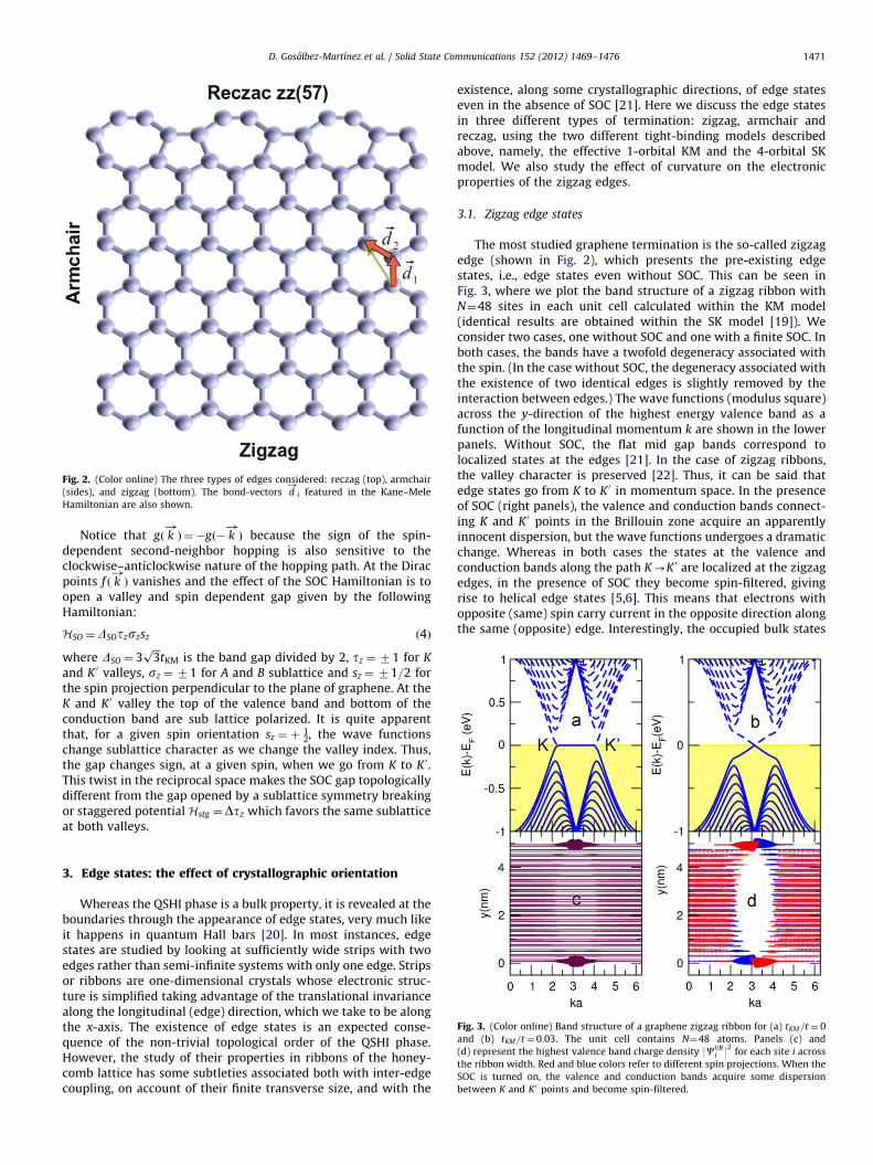
Fig. 2. (Color online) The three types of edges considered: reczag (top), armchair
(sides), and zigzag (bottom). The bond-vectors d!
i featured in the Kane–Mele
Hamiltonian are also shown.
D. Gosalbez-Martınez et al. / Solid State Communications 152 (2012) 1469–1476 1471
Notice that gð k!Þ¼�gð� k
!Þ because the sign of the spin-
dependent second-neighbor hopping is also sensitive to theclockwise–anticlockwise nature of the hopping path. At the Diracpoints f ð k
!Þ vanishes and the effect of the SOC Hamiltonian is to
open a valley and spin dependent gap given by the followingHamiltonian:
HSO ¼DSOtzszsz ð4Þ
where DSO ¼ 3ffiffiffi3p
tKM is the band gap divided by 2, tz ¼ 71 for K
and K 0 valleys, sz ¼ 71 for A and B sublattice and sz ¼ 71=2 forthe spin projection perpendicular to the plane of graphene. At theK and K 0 valley the top of the valence band and bottom of theconduction band are sub lattice polarized. It is quite apparentthat, for a given spin orientation sz ¼ þ
12, the wave functions
change sublattice character as we change the valley index. Thus,the gap changes sign, at a given spin, when we go from K to K 0.This twist in the reciprocal space makes the SOC gap topologicallydifferent from the gap opened by a sublattice symmetry breakingor staggered potentialHstg ¼Dtz which favors the same sublatticeat both valleys.
Fig. 3. (Color online) Band structure of a graphene zigzag ribbon for (a) tKM=t¼ 0
and (b) tKM=t¼ 0:03. The unit cell contains N¼48 atoms. Panels (c) and
(d) represent the highest valence band charge density 9CVBi 92
for each site i across
the ribbon width. Red and blue colors refer to different spin projections. When the
SOC is turned on, the valence and conduction bands acquire some dispersion
between K and K 0 points and become spin-filtered.
3. Edge states: the effect of crystallographic orientation
Whereas the QSHI phase is a bulk property, it is revealed at theboundaries through the appearance of edge states, very much likeit happens in quantum Hall bars [20]. In most instances, edgestates are studied by looking at sufficiently wide strips with twoedges rather than semi-infinite systems with only one edge. Stripsor ribbons are one-dimensional crystals whose electronic struc-ture is simplified taking advantage of the translational invariancealong the longitudinal (edge) direction, which we take to be alongthe x-axis. The existence of edge states is an expected conse-quence of the non-trivial topological order of the QSHI phase.However, the study of their properties in ribbons of the honey-comb lattice has some subtleties associated both with inter-edgecoupling, on account of their finite transverse size, and with the
existence, along some crystallographic directions, of edge stateseven in the absence of SOC [21]. Here we discuss the edge statesin three different types of termination: zigzag, armchair andreczag, using the two different tight-binding models describedabove, namely, the effective 1-orbital KM and the 4-orbital SKmodel. We also study the effect of curvature on the electronicproperties of the zigzag edges.
3.1. Zigzag edge states
The most studied graphene termination is the so-called zigzagedge (shown in Fig. 2), which presents the pre-existing edgestates, i.e., edge states even without SOC. This can be seen inFig. 3, where we plot the band structure of a zigzag ribbon withN¼48 sites in each unit cell calculated within the KM model(identical results are obtained within the SK model [19]). Weconsider two cases, one without SOC and one with a finite SOC. Inboth cases, the bands have a twofold degeneracy associated withthe spin. (In the case without SOC, the degeneracy associated withthe existence of two identical edges is slightly removed by theinteraction between edges.) The wave functions (modulus square)across the y-direction of the highest energy valence band as afunction of the longitudinal momentum k are shown in the lowerpanels. Without SOC, the flat mid gap bands correspond tolocalized states at the edges [21]. In the case of zigzag ribbons,the valley character is preserved [22]. Thus, it can be said thatedge states go from K to K 0 in momentum space. In the presenceof SOC (right panels), the valence and conduction bands connect-ing K and K 0 points in the Brillouin zone acquire an apparentlyinnocent dispersion, but the wave functions undergoes a dramaticchange. Whereas in both cases the states at the valence andconduction bands along the path K-K 0 are localized at the zigzagedges, in the presence of SOC they become spin-filtered, givingrise to helical edge states [5,6]. This means that electrons withopposite (same) spin carry current in the opposite direction alongthe same (opposite) edge. Interestingly, the occupied bulk states
D. Gosalbez-Martınez et al. / Solid State Communications 152 (2012) 1469–14761472
also carry a spin current in the opposite direction so that the netspin current at the edge is zero [23].
3.2. Armchair edge states
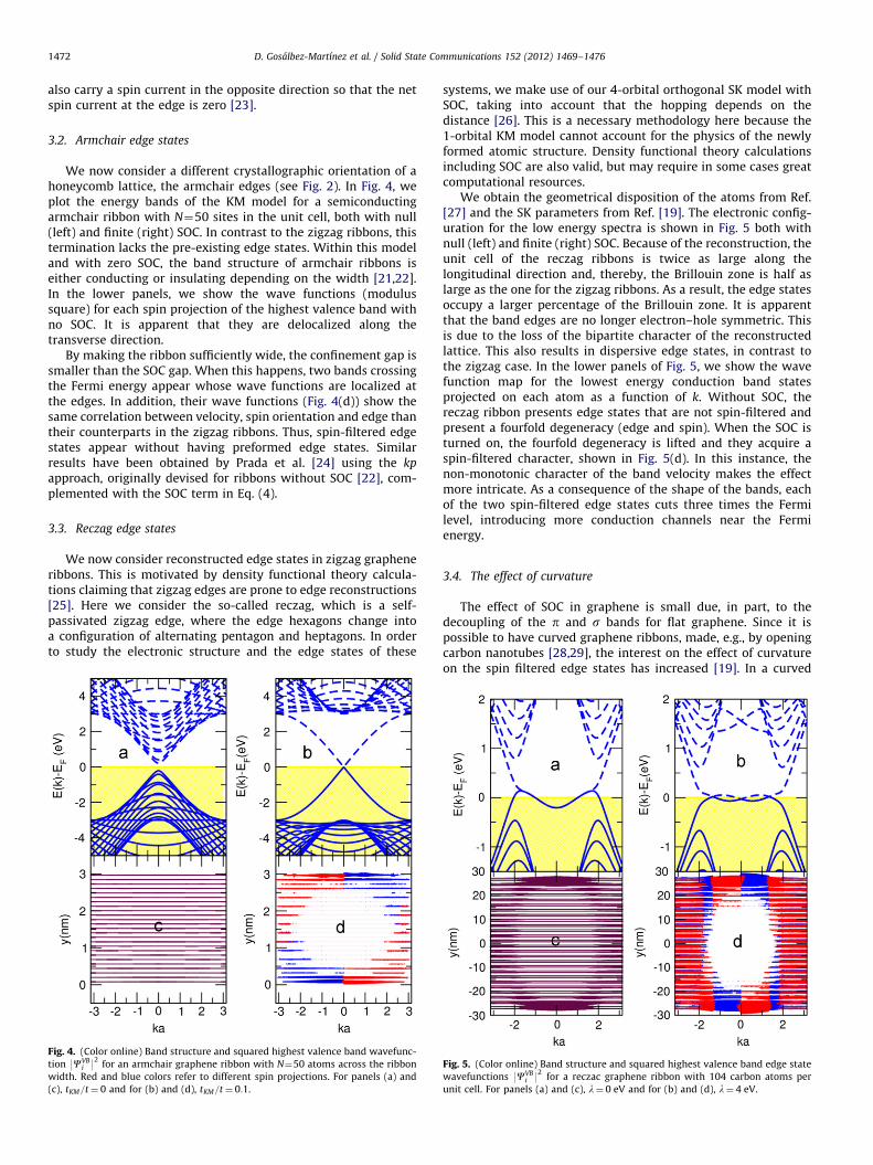
We now consider a different crystallographic orientation of ahoneycomb lattice, the armchair edges (see Fig. 2). In Fig. 4, weplot the energy bands of the KM model for a semiconductingarmchair ribbon with N¼50 sites in the unit cell, both with null(left) and finite (right) SOC. In contrast to the zigzag ribbons, thistermination lacks the pre-existing edge states. Within this modeland with zero SOC, the band structure of armchair ribbons iseither conducting or insulating depending on the width [21,22].In the lower panels, we show the wave functions (modulussquare) for each spin projection of the highest valence band withno SOC. It is apparent that they are delocalized along thetransverse direction.
By making the ribbon sufficiently wide, the confinement gap issmaller than the SOC gap. When this happens, two bands crossingthe Fermi energy appear whose wave functions are localized atthe edges. In addition, their wave functions (Fig. 4(d)) show thesame correlation between velocity, spin orientation and edge thantheir counterparts in the zigzag ribbons. Thus, spin-filtered edgestates appear without having preformed edge states. Similarresults have been obtained by Prada et al. [24] using the kp
approach, originally devised for ribbons without SOC [22], com-plemented with the SOC term in Eq. (4).
3.3. Reczag edge states
We now consider reconstructed edge states in zigzag grapheneribbons. This is motivated by density functional theory calcula-tions claiming that zigzag edges are prone to edge reconstructions[25]. Here we consider the so-called reczag, which is a self-passivated zigzag edge, where the edge hexagons change intoa configuration of alternating pentagon and heptagons. In orderto study the electronic structure and the edge states of these
Fig. 4. (Color online) Band structure and squared highest valence band wavefunc-
tion 9CVBi 92
for an armchair graphene ribbon with N¼50 atoms across the ribbon
width. Red and blue colors refer to different spin projections. For panels (a) and
(c), tKM=t¼ 0 and for (b) and (d), tKM=t¼ 0:1.
systems, we make use of our 4-orbital orthogonal SK model withSOC, taking into account that the hopping depends on thedistance [26]. This is a necessary methodology here because the1-orbital KM model cannot account for the physics of the newlyformed atomic structure. Density functional theory calculationsincluding SOC are also valid, but may require in some cases greatcomputational resources.
We obtain the geometrical disposition of the atoms from Ref.[27] and the SK parameters from Ref. [19]. The electronic config-uration for the low energy spectra is shown in Fig. 5 both withnull (left) and finite (right) SOC. Because of the reconstruction, theunit cell of the reczag ribbons is twice as large along thelongitudinal direction and, thereby, the Brillouin zone is half aslarge as the one for the zigzag ribbons. As a result, the edge statesoccupy a larger percentage of the Brillouin zone. It is apparentthat the band edges are no longer electron–hole symmetric. Thisis due to the loss of the bipartite character of the reconstructedlattice. This also results in dispersive edge states, in contrast tothe zigzag case. In the lower panels of Fig. 5, we show the wavefunction map for the lowest energy conduction band statesprojected on each atom as a function of k. Without SOC, thereczag ribbon presents edge states that are not spin-filtered andpresent a fourfold degeneracy (edge and spin). When the SOC isturned on, the fourfold degeneracy is lifted and they acquire aspin-filtered character, shown in Fig. 5(d). In this instance, thenon-monotonic character of the band velocity makes the effectmore intricate. As a consequence of the shape of the bands, eachof the two spin-filtered edge states cuts three times the Fermilevel, introducing more conduction channels near the Fermienergy.
3.4. The effect of curvature
The effect of SOC in graphene is small due, in part, to thedecoupling of the p and s bands for flat graphene. Since it ispossible to have curved graphene ribbons, made, e.g., by openingcarbon nanotubes [28,29], the interest on the effect of curvatureon the spin filtered edge states has increased [19]. In a curved
Fig. 5. (Color online) Band structure and squared highest valence band edge state
wavefunctions 9CVBi 92
for a reczac graphene ribbon with 104 carbon atoms per
unit cell. For panels (a) and (c), l¼ 0 eV and for (b) and (d), l¼ 4 eV.

Fig. 6. (Color online) (a) Spin polarization of edge states at k¼ 0:99p=a (top) and
k¼�0:99p=a (bottom). (b) Angle between the normal direction of the edge and
the spin polarization as a function of the curvature for l¼ 5 meV (red dots) and
l¼ 2 eV (blue squares).
D. Gosalbez-Martınez et al. / Solid State Communications 152 (2012) 1469–1476 1473
ribbon, the p orbitals are not longer decoupled from the sorbitals. This is similar to the case of flat graphene under theaction of a perpendicular electric field [9]. As a consequence, wecan expect a new term in the effective Hamiltonian for the plinear in the atomic SOC constant l, as a result of which sz is not agood quantum number anymore. In the case of flat grapheneunder an external electric field, the new term is the so-calledextrinsic SOC or Rashba interaction, which acts as a spin-flippingnearest-neighbor hopping.
The electronic structure of curved graphene ribbons withzigzag terminations is shown in Fig. 6 and has been obtainedwithin the 4-orbital SK model including SOC [19]. The low energyband structure (not shown) remains similar to the case of flatribbons, except for the appearance of a small dispersion in theoriginally flat bands. For finite SOC, the edge bands are spinfiltered as well, but with an important difference with respect tothe flat case. Since sz is not a good quantum number, the spinpolarization of these states acquire an angle, y, with respect to thenormal direction at each atom of the edge. In Fig. 6(a), werepresent the wavefunction of the edge states at k¼ 70:99p=a.The fact that the spin polarization points in the opposite directionfor these two k states reveals that they form a time reversalKramers pairs. In Fig. 6(b), we also show how y evolves withrespect to the curvature for two different values of the SOC. Weobserve that the effect of curvature is dramatic for a realisticvalue of the spin–orbit coupling, where almost negligible curva-tures make the spin point in the tangential direction.
As a conclusion for this section, we have seen how SOC givesrise to the appearance of spin filtered edge states, regardless ofthe crystallographic direction of the edge. Interestingly, the bandsof the edge states do depend on the direction. Unfortunately, theenergy scale for the edge states dispersion is below 1 meV whencomputed with realistic values of the SOC for graphene. However,understanding spin filtered edge states in this chemically simplesituation could shed some light on the edge states in morecomplicated systems.
4. Disorder and electronic transport
The topological character of the QSHI phase manifests itself inthe robustness of the spin-filtered edge states. In the presence ofnon-magnetic disorder, they behave like a pair of robust quantumchannels, presenting a conductance quantization, G0 ¼ 2e2=h,even when sz is not a good quantum number [5,6]. Shortly after
KM proposed the existence of a QSHI phase in graphene, theconductance quantization was numerically verified by Shenget al. for the Anderson disorder model [7,8]. Also it has beenstudied the robustness of the quantum channel in QSHI/Metaljunctions and under the effect of edge roughness [30]. Here wecarry out a similar study through an analysis of the transportproperties of zigzag ribbons in a variety of situations. We aremostly intrigued by the case of curved ribbons as the onesintroduced in the previous section. First, for illustration purposes,we revisit the problem in flat ribbons. As shown in Section 2,zigzag graphene ribbons with SOC constitute the most simplemodel of QSHI since they present a single branch of helical statesfor any width of the ribbon and only inter-edge backscatteringcould affect the quantization of conductance. Finally, we askourselves if the spin non-conserving effect of the curvature canplay any role in the inter-edge backscattering.
We study two types of disorder: Anderson type, where we sumrandom on-site values Ei distributed uniformly in a range ½�W ,W � tothe Kane–Mele Hamiltonian, and structural defects, such as con-strictions across the ribbon width. We are interested in coherenttransport so we make use of the standard Landauer formalism as inRef. [31]: The disordered region contains N¼ Lx � Ly ¼ 300 latticesites, where Ly¼10 is the number of horizontal lines along theribbon width and Lx¼30 is the number of atoms along each chain.
In Fig. 7(a), we show the density of states at the Fermi level inreal space for increasing disorder strength W and for a SOC strengthtKM ¼ 0:1t. All results with Wa0 have been averaged over 10random realizations of disorder. In the trivial insulator case fortKM ¼ 0, where a bulk gap arises due to lateral confinement, disorderinduces intra-edge backscattering, localizing the edge states andstrongly reducing the conductance at the Fermi level (see Fig. 7(b)).The effect of SOC on the conductance (close to the Fermi energy) isdramatic: even for large values of W, backscattering is almostentirely suppressed, as expected from their spin-filtered character.
In finite width systems, when spin-filtered states of differentedges having the same spin polarization are able to interact onewith each other, a finite inter-edge backscattering will be presentand an exact quantization is no longer expected. We study thiseffect by introducing constrictions in the ribbon (see Fig. 8, rightpanels). We model them by removing atoms in an area near theedge delimited by gaussian functions be�ax2
(x runs along theedge) for random b and a. Here we take tKM ¼ 0:01t or l¼ 4 eV. InFig. 8, we show the conductance for three different constrictionsas a function of energy. We can observe that, while in the absenceof SOC (dashed–dotted lines), the conductance is negligible at theFermi energy because the edge states are able to interact with thestates in the opposite edge and backscatter, for finite SOC theconductance increases appreciably (solid lines). These resultshave been obtained within the KM model.
Sheng et al. [7] numerically showed that the QSHI phasesurvive in the presence of non-conserving spin terms. Here westudy this by introducing a transversal bending over the constric-tions previously analyzed. The curvature introduces a non-trivialangle for the spin polarization of the spin-filtered edge states ofgraphene nanoribbons as mentioned in Section 3. These anglesare different for each edge. This behavior raises the questionwhether the relative phase between the spin orientation of thetwo channels could affect the process of backscattering. In orderto answer this question, we need to use our 4-orbital SKHamiltonian instead of the single orbital KM model. First, weanalyze the transport for flat constrictions and compare theresults with the KM ones. To be meaningful, we need to saturatethe s dangling bonds of the carbon atoms with hydrogen atoms.We compute the two terminal conductance with the ANT1D code,which is part of the ALACANT package [32]. In Fig. 8(a)–(c), thedotted lines show the conductance for the three constrictions
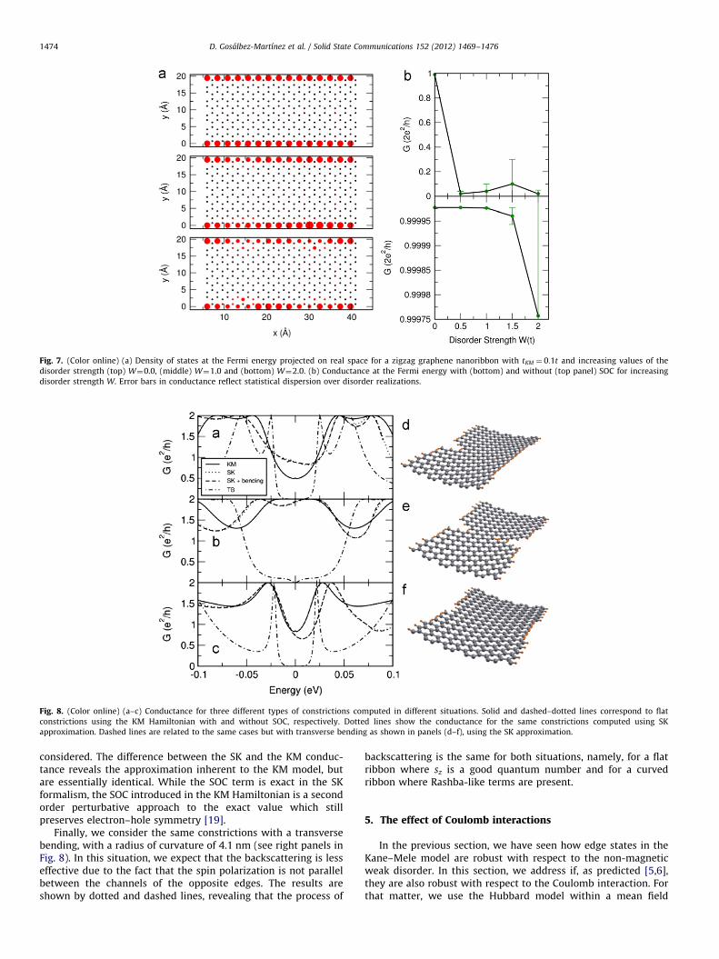
Fig. 8. (Color online) (a–c) Conductance for three different types of constrictions computed in different situations. Solid and dashed–dotted lines correspond to flat
constrictions using the KM Hamiltonian with and without SOC, respectively. Dotted lines show the conductance for the same constrictions computed using SK
approximation. Dashed lines are related to the same cases but with transverse bending as shown in panels (d–f), using the SK approximation.
Fig. 7. (Color online) (a) Density of states at the Fermi energy projected on real space for a zigzag graphene nanoribbon with tKM ¼ 0:1t and increasing values of the
disorder strength (top) W¼0.0, (middle) W¼1.0 and (bottom) W¼2.0. (b) Conductance at the Fermi energy with (bottom) and without (top panel) SOC for increasing
disorder strength W. Error bars in conductance reflect statistical dispersion over disorder realizations.
D. Gosalbez-Martınez et al. / Solid State Communications 152 (2012) 1469–14761474
considered. The difference between the SK and the KM conduc-tance reveals the approximation inherent to the KM model, butare essentially identical. While the SOC term is exact in the SKformalism, the SOC introduced in the KM Hamiltonian is a secondorder perturbative approach to the exact value which stillpreserves electron–hole symmetry [19].
Finally, we consider the same constrictions with a transversebending, with a radius of curvature of 4.1 nm (see right panels inFig. 8). In this situation, we expect that the backscattering is lesseffective due to the fact that the spin polarization is not parallelbetween the channels of the opposite edges. The results areshown by dotted and dashed lines, revealing that the process of
backscattering is the same for both situations, namely, for a flatribbon where sz is a good quantum number and for a curvedribbon where Rashba-like terms are present.
5. The effect of Coulomb interactions
In the previous section, we have seen how edge states in theKane–Mele model are robust with respect to the non-magneticweak disorder. In this section, we address if, as predicted [5,6],they are also robust with respect to the Coulomb interaction. Forthat matter, we use the Hubbard model within a mean field

D. Gosalbez-Martınez et al. / Solid State Communications 152 (2012) 1469–1476 1475
approximation (MFA), where the interaction term is approximatedby U
Piðni,m/nikSþni,k/ni,mÞ. More sophisticated approaches have
also implemented recently [33,34].At half-filling, the Hubbard model in the honeycomb lattice
has magnetic order at sufficiently large U. In the MFA Uc ¼ 2:2t,using Quantum Monte Carlo Uc 45t [35]. This magnetic orderingis always accompanied by a gap opening transforming grapheneinto a Mott insulator. On the contrary, the zigzag edge states havea very large density of states at the Fermi energy so that, at zeroSOC, undergo the ferromagnetic transition at arbitrary small U. Inthe case of finite width ribbons, the inter-edge correlations areantiferromagnetic and a band-gap opens in the otherwise con-ducting band structure [13–16].
Thus, under the separate influence of SOC and Coulombrepulsion, the preformed zigzag edge states undergo a radicalchange in their electronic structure. In the first case, they carryspin-currents and acquire a linear dispersion, in the second case
Fig. 9. (Color online) On the left panel we show the phase diagram of an AC ribbon
with Ny¼50 in the presence of Coulomb (U=t) and spin–orbit (tKM=t) interactions.
The labeled regions are related to the following phases: (I) Insulating or
semiconducting phase, (II) antiferromagnetic insulating phase, (III) Quantum spin
Hall insulating phase with gapless edge states and (IV) antiferromagnetic phase
where metallic edge states are still preserved. On the right panel we show the
phase diagram for the AF insulating (AF), the AF valley half-metal (HM) and the
non-magnetic (NM) phases for the ZZ ribbon with Ny¼24.
Fig. 10. (Color online) Band structure and projected spin density along the valence ban
the phase diagram (a) (U ¼ 1:0t, tKM ¼ 0:1t), (b) (U ¼ 3:0t, tKM ¼ 0:1t) and (c) (U ¼ 3:5t,
they are ferromagnetic and, for finite width ribbons, open a gap.Thus, it was not clear a priori what would be the combined effectof SOC and Coulomb repulsions. This problem was addressed bytwo of us [17]. When the SOC is turned on, the effect on theinsulting band structure of the magnetic phase is to decrease theband-gap in one valley and increase it in the other. This valleysymmetry breaking goes together with a reduction in the edgemagnetic moment. As the SOC is increased, the gap closes in thevalleys, the edges being still magnetic. This phase is a valley half-metal. As the SOC increases further, the magnetic moment goes tozero and the non-magnetic phase is recovered. These findings aresummarized in the phase diagram of Fig. 9(b), for a ZZ grapheneribbon containing Ny¼24, that shows that, because of the SOC, afinite U is needed to make the edges magnetic.
We now consider the armchair termination, for which nopreformed edge states exist, within the MFA for the Hubbard–Kane–Mele model. This system has also been addressed using thebosonization techniques [36]. In Fig. 10, we show our results forthe band structure and edge-state wave function of an ACterminated ribbon, for three values of U, and tKM ¼ 0:1t. At theleft, with U¼t, the system is non-magnetic, and very similar tothe U¼0 case. When the Coulomb interaction is increased above acritical value, the bulk atoms undergo an antiferromagnetictransition but the edge atoms stay non-magnetic and the spin-filtered edge states are preserved. Only when the interaction isincreased above a Uc significantly larger than the one that makesthe bulk magnetic, the edge atoms go magnetic as well and thespin-filtered edge states disappear. Thus, for AC edges it is fair tostay that spin-filter edge states are robust with respect toCoulomb repulsion, since they survive even when the bulk goesantiferromagnetic.
In Fig. 9(a), we show the phase diagram of a semiconductingAC ribbon in the presence of both Coulomb and spin–orbitinteraction. For tKM o0:05t and UoUc (region I) the ribbonremains semiconducting and for U4Uc the gap increases andthe ribbon becomes an antiferromagnet (region II). For tKM 40:05t
the ribbon transform into a QSHI holding spin filtered edge statesas those shown in the case of the ZZ ribbons (region III) and, asthe Coulomb interaction increases, we find a new phase (regionIV) which is antiferromagnetic with a magnetic moment per atom
d of an AC ribbon with Ny¼50 for three different states along the line tKM ¼ 0:1t in
tKM ¼ 0:1t).
D. Gosalbez-Martınez et al. / Solid State Communications 152 (2012) 1469–14761476
in the edge of 9m9� 0:2 but where the gap is still closed and thestates remain spin-filtered.
6. Summary
We have studied the electronic properties of the spin-filterededge states that appear in graphene because of spin–orbit coupling.Whereas they are a generic feature of the quantum spin Hallinsulator phase, their properties are very different depending onthe existence of preformed edge states, i.e., edge states that occureven with no SOC. For instance, reczag edges have three conduc-tance channels, and zigzag edges are not robust with respect to theCoulomb interactions. Whereas graphene is not a good material tostudy spin-filtered edge states experimentally, because of the lowspin–orbit coupling, it provides an ideal platform to study genericfeatures of such an interesting object which can be found in othertwo-dimensional topological insulators.
Acknowledgments
This work has been financially supported by MEC-Spain(MAT07-67845,FIS2010-21883) and CONSOLIDER CSD2007-0010). We acknowledge fruitful conversations with L. Brey andT. Stauber and to the Centro de Computacion Cientıfica of UAM forcomputational resources.
References
[1] K.S. Novoselov, et al., Science 306 (2004) 666.[2] A.H. Castro Neto, F. Guinea, N.M.R. Peres, K.S. Novoselov, A.K. Geim, Rev. Mod.
Phys. 81 (2009) 109.[3] K.S. Novoselov, et al., Nature 438 (2005) 197–200.
[4] Y. Zhang, et al., Nature 438 (2005) 201–204.[5] C.L. Kane, E.J. Mele, Phys. Rev. Lett. 95 (2005) 226801.[6] C.L. Kane, E.J. Mele, Phys. Rev. Lett. 95 (2005) 146802.[7] L. Sheng, D.N. Sheng, C.S. Ting, F.D.M. Haldane, Phys. Rev. Lett. 95 (2005)
136602.[8] D.N. Sheng, Z.Y. Weng, L. Sheng, F.D.M. Haldane, Phys. Rev. Lett. 97 (2006)
036808.[9] H. Min, et al., Phys. Rev. B 74 (2006) 165310.
[10] D. Huertas-Hernando, F. Guinea, A. Brataas, Phys. Rev. B 74 (2006) 155426.[11] Y. Yao, F. Ye, X.L. Qi, S.C. Zhang, Z. Fang, Phys. Rev. B 75 (2007) 041401(R).[12] S. Konschuh, M. Gmitra, J. Fabian Phys. Rev. B 82 (2010) 245412.[13] M. Fujita, K. Wakabayashi, K. Nakada, K. Kusakabe, J. Phys. Soc. Jpn. 65 (1996)
1920.[14] Y.-W. Son, M.L. Cohen, S.G. Louie, Phys. Rev. Lett. 97 (2006) 216803.[15] Y.-W. Son, M.L. Cohen, S.G. Louie, Nature 444 (2006) 347.[16] J. Fernandez-Rossier, Phys. Rev. B. 77 (2008) 075430.[17] D. Soriano, J. Fernandez-Rossier, Phys. Rev. B 82 (2010) 161302(R).[18] F.D.M. Haldane, Phys. Rev. Lett. 61 (1988) 2015.[19] D. Gosalbez-Martınez, J.J. Palacios, J. Fernandez-Rossier, Phys. Rev. B 83
(2011) 115436.[20] B.I. Halperin, Phys. Rev. B 25 (1982) 2185.[21] K. Nakada, M. Fujita, G. Dresselhaus, M.S. Dresselhaus, Phys. Rev. B 54 (1996)
17954.[22] L. Brey, H. Fertig, Phys. Rev. B 73 (2006) 235411.[23] D. Zheng, G.M. Zhang, C. Wu, Phys. Rev. B 84 (2011) 205121.[24] E. Prada, P. San-Jose, L. Brey, H.A. Fertig, Solid State Commun. 151 (2011)
10751083.[25] P. Koskinen, S. Malola, H. Hakkinen, Phys. Rev. Lett. 101 (2008) 115502.[26] W.A. Harrison, Elementary Electronic Structure, World Scientific, Singapore,
2004.[27] J.N.B. Rodrigues, et al., Phys. Rev. B 84 (2011) 155435.[28] L. Jiao, L. Zhang, X. Wang, G. Diankov, H. Dai, Nature 458 (2009) 877.[29] Dmitry V. Kosynkin, et al., Nature 458 (2009) 872.[30] Georgo Metalidis, Elsa Prada, arXiv:1012.4345.[31] F. Munoz-Rojas, D. Jacob, J. Fernandez-Rossier, J.J. Palacios, Phys. Rev. B 74
(2006) 195417.[32] D. Jacob, J.J. Palacios, J. Chem. Phys. 134 (2011) 044118.[33] D.-H. Lee, Phys. Rev. Lett. 107 (2011) 166806.[34] Wei Wu, Stephan Rachel, Wu-Ming Liu, Karyn Le Hur, arXiv:1106.0943.[35] S. Sorella, E. Tosatti, Europhys. Lett. 19 (1992) 699.[36] M. Zarea, N. Sandler, Phys. Rev. Lett. 99 (2007) 256804.