
1-s2 0-S0926337313003834-main
9
Applied Catalysis B: Environmental 142–143 (2013) 752–760 Contents lists available at SciVerse ScienceDirect Applied Catalysis B: Environmental jo ur nal home p ag e: www.elsevier.com/locate/apcatb The “cascade effect” of nano/micro hierarchical structure: A new concept for designing the high photoactivity materials – An example for TiO 2 Po-Chin Chen a,b , Min-Chiao Tsai a,c , Min-Han Yang a , Ting-Ting Chen a , Huang-Chin Chen c , I.-Chun Chang a , Yi-Chun Chang b , Yu-Liang Chen b , I.-Nan Lin c , Hsin-Tien Chiu b , Chi-Young Lee a,∗ a Department of Materials Science and Engineering, National Tsing Hua University, Hsinchu 30013, Taiwan b Department of Applied Chemistry, National Chiao Tung University, Hsinchu 30010, Taiwan c Department of Physics, Tamkang University, New Taipei City 25137, Taiwan a r t i c l e i n f o Article history: Received 27 March 2013 Received in revised form 30 May 2013 Accepted 31 May 2013 Available online 19 June 2013 Keywords: Titanium dioxide Hierarchical structure Photocatalyst Charge separation Hetero-junction a b s t r a c t The chrysanthemum-like TiO 2 (CT800) was synthesized. It exhibited excellent photoactivity, which greatly exceeded that of conventional P25. To discover the key factors that governed the photocatalytic properties, the specific reduction of Ag + ions was carried out and EPR spectra of CT800 were obtained. Both an HADDF image and EDX mapping indicated that the Ag + ions tended to be reduced close to the center of the micro matrix of CT800. Moreover, the EPR spectra strongly suggest that the excited elec- trons tended to migrate toward the center of the micro matrix, resulting from a multiple junction, cascade effect, which efficiently reduces the recombination of excited electrons and holes and greatly increases the photoactivity. Additionally, the special morphology of CT800 was responsible for the hot spots at the surface of nano sheets and then contributing to its outstanding photocatalytic activity. Furthermore, the unidirectional electron transfer, because of the cascade effect, by materials of different sizes provides a new avenue for the design of electronic and photoelectrochemical devices. © 2013 Elsevier B.V. All rights reserved. 1. Introduction Recently, nano/micro hierarchically structured materials have attracted considerable attention since their architectures combine the features of micro- and nano-scaled materials and exhibit unique properties that differ from those of the corresponding mono- morphological structures [1–3]. Their favorable performance in various applications, such as lithium-ion batteries [4], gas sensors [5], dye-sensitized solar cells (DSSCs) [6] and photocatalysts, have been reported upon [7]. To enhance the efficiency of photocata- lysis, the key factors that govern photocatalysis attract the most attention by scientists. Numerous investigations have revealed that the high efficiency of a photocatalyst has several characters. (1) A high surface area can provide more active sites for the forma- tion of photo-generated free radicals [8–10]. (2) A wide spectral absorption of light enables the use of considerable solar energy, yielding a higher photo-reaction rate. One means of using more ∗ Corresponding author at: Department of Materials Science and Engineering, National Tsing Hua University, 101, Section 2, Kuang-Fu Road, Hsinchu 30013, Taiwan. Tel.: +886 3 5728692; fax: +886 3 5722366. E-mail address: [email protected] (C.-Y. Lee). solar energy is to reduce the band gap. Both doping with a small amount of impurity [11] and creating surface defects to form the sub-bands, can reduce the band gap of a material [12]. (3) Efficient charge separation by a hetero-junction can reduce the recombina- tion rate of excited electrons and holes. Generally, a hetero-junction effect occurs between two materials [13,14] or polymorphs [15,16] that have different band gaps or energy states. The electrons tend to migrate to the lower energy states, and the holes migrate in the opposite direction, which strongly reduces the recombination of excited electrons and holes. Moreover, in our earlier study, a similar phenomenon was observed in a anatase TiO 2 single phase [17]. When the anatase titanium dioxides of different sizes were mixed, great photocatalytic performance was observed, resulting from the efficient charge separation, which was due to the hetero- junction between the different sized particles. As we know, the most effective charge separation system is the photosynthesis in nature. In plant cell, chloroplast is one of the major pigments performs photosynthesis efficiently. When light is absorbed, the excited electrons are formed and passed down to an electron trans- port chain, which consists of a series of electron acceptors with different energy states. This multiple electron transport process significantly reduces the electron-hole recombination making the photosynthesis efficient. (4) Hot spots on the surface of a material 0926-3373/$ – see front matter © 2013 Elsevier B.V. All rights reserved. http://dx.doi.org/10.1016/j.apcatb.2013.05.076
Transcript of 1-s2 0-S0926337313003834-main

Tcf
PIHa
b
c
ARRAA
KTHPCH
1
atpmv[blatAtay
NT
0h
Applied Catalysis B: Environmental 142– 143 (2013) 752– 760
Contents lists available at SciVerse ScienceDirect
Applied Catalysis B: Environmental
jo ur nal home p ag e: www.elsev ier .com/ locate /apcatb
he “cascade effect” of nano/micro hierarchical structure: A newoncept for designing the high photoactivity materials – An exampleor TiO2
o-Chin Chena,b, Min-Chiao Tsaia,c, Min-Han Yanga, Ting-Ting Chena, Huang-Chin Chenc,.-Chun Changa, Yi-Chun Changb, Yu-Liang Chenb, I.-Nan Linc,sin-Tien Chiub, Chi-Young Leea,∗
Department of Materials Science and Engineering, National Tsing Hua University, Hsinchu 30013, TaiwanDepartment of Applied Chemistry, National Chiao Tung University, Hsinchu 30010, TaiwanDepartment of Physics, Tamkang University, New Taipei City 25137, Taiwan
a r t i c l e i n f o
rticle history:eceived 27 March 2013eceived in revised form 30 May 2013ccepted 31 May 2013vailable online 19 June 2013
a b s t r a c t
The chrysanthemum-like TiO2 (CT800) was synthesized. It exhibited excellent photoactivity, whichgreatly exceeded that of conventional P25. To discover the key factors that governed the photocatalyticproperties, the specific reduction of Ag+ ions was carried out and EPR spectra of CT800 were obtained.Both an HADDF image and EDX mapping indicated that the Ag+ ions tended to be reduced close to thecenter of the micro matrix of CT800. Moreover, the EPR spectra strongly suggest that the excited elec-
eywords:itanium dioxideierarchical structurehotocatalystharge separation
trons tended to migrate toward the center of the micro matrix, resulting from a multiple junction, cascadeeffect, which efficiently reduces the recombination of excited electrons and holes and greatly increasesthe photoactivity. Additionally, the special morphology of CT800 was responsible for the hot spots at thesurface of nano sheets and then contributing to its outstanding photocatalytic activity. Furthermore, theunidirectional electron transfer, because of the cascade effect, by materials of different sizes provides a
n of e
etero-junction new avenue for the desig. Introduction
Recently, nano/micro hierarchically structured materials havettracted considerable attention since their architectures combinehe features of micro- and nano-scaled materials and exhibit uniqueroperties that differ from those of the corresponding mono-orphological structures [1–3]. Their favorable performance in
arious applications, such as lithium-ion batteries [4], gas sensors5], dye-sensitized solar cells (DSSCs) [6] and photocatalysts, haveeen reported upon [7]. To enhance the efficiency of photocata-
ysis, the key factors that govern photocatalysis attract the mostttention by scientists. Numerous investigations have revealed thathe high efficiency of a photocatalyst has several characters. (1)
high surface area can provide more active sites for the forma-
ion of photo-generated free radicals [8–10]. (2) A wide spectralbsorption of light enables the use of considerable solar energy,ielding a higher photo-reaction rate. One means of using more∗ Corresponding author at: Department of Materials Science and Engineering,ational Tsing Hua University, 101, Section 2, Kuang-Fu Road, Hsinchu 30013,aiwan. Tel.: +886 3 5728692; fax: +886 3 5722366.
E-mail address: [email protected] (C.-Y. Lee).
926-3373/$ – see front matter © 2013 Elsevier B.V. All rights reserved.ttp://dx.doi.org/10.1016/j.apcatb.2013.05.076
lectronic and photoelectrochemical devices.© 2013 Elsevier B.V. All rights reserved.
solar energy is to reduce the band gap. Both doping with a smallamount of impurity [11] and creating surface defects to form thesub-bands, can reduce the band gap of a material [12]. (3) Efficientcharge separation by a hetero-junction can reduce the recombina-tion rate of excited electrons and holes. Generally, a hetero-junctioneffect occurs between two materials [13,14] or polymorphs [15,16]that have different band gaps or energy states. The electrons tendto migrate to the lower energy states, and the holes migrate inthe opposite direction, which strongly reduces the recombinationof excited electrons and holes. Moreover, in our earlier study, asimilar phenomenon was observed in a anatase TiO2 single phase[17]. When the anatase titanium dioxides of different sizes weremixed, great photocatalytic performance was observed, resultingfrom the efficient charge separation, which was due to the hetero-junction between the different sized particles. As we know, themost effective charge separation system is the photosynthesis innature. In plant cell, chloroplast is one of the major pigmentsperforms photosynthesis efficiently. When light is absorbed, theexcited electrons are formed and passed down to an electron trans-
port chain, which consists of a series of electron acceptors withdifferent energy states. This multiple electron transport processsignificantly reduces the electron-hole recombination making thephotosynthesis efficient. (4) Hot spots on the surface of a material
viron
hdtpbaonbtpttacsst
2
2
CCiApwaofchm
2
tXpitbTd
2
ti0pwab
2
uTc
P.-C. Chen et al. / Applied Catalysis B: En
ave been suggested to be photoactive sites [18–20]. Chen et al.emonstrated experimentally and numerically that highly pho-oactive sites were located at the interfaces among particles, andromoted efficient photocatalysis [18]. These key phenomena cane considered in the development of highly photoactive materi-ls. TiO2 is one of the most important functional materials becausef its wide range of applications [21–31]. Recently, some forms ofano/micro hierarchically structured TiO2 have been synthesizedy various methods and have performed well in various applica-ions [32–37], and especially as in photocatalysts [38,39]. This gooderformance must be accurately explained. Hence, this investiga-ion seeks to elucidate the key causes of the good photoactivity ofhe nano/micro hierarchically structured TiO2. In this investigation,
special “cascade effect” was observed in the nano/micro hierarchi-ally structured TiO2. The photo-excited electrons and holes wereeparated by a series of electron transfer between various energytates, reducing the recombination, which result in excellent pho-oactivity.
. Experimental
.1. Preparation of TiO2
In this work, all chemicals were purchased from Aldrichompany and used directly without further purification.hrysanthemum-like TiO2 were synthesized from titanium
sopropoxide (TTIP, 97%, Aldrich) and acetic acid (98–100%,ldrich) by a simple solvothermal method. The details of therocedure can be found in our earlier work [4]. Once the reactionas complete, the solvent was removed by placing the products in
vacuum. The white powder, chrysanthemum-like titanate, wasbtained (hereafter CT). The products were heated in air at 800 ◦Cor 1 h at a temperature ramping rate of 1 ◦C per minute, and thenooled to room temperature (yielding a product that is referred toereafter as CT800). CT800g was prepared by grinding CT800 in aortar using a pestle by hand for 10 min.
.2. Experiments on photocatalyst
The performances of TiO2 (CT800, CT800g and P25) as a pho-ocatalyst were studied. The samples were illuminated under ane lamp at an intensity of about 1 W cm−2. Each powdered sam-le was placed in 25 mg L−1 methylene blue (MB) solution, stirred
n the dark for 1 h, and then illuminated. During illumination, arace amount of solution was removed every 5 min and centrifuged,efore being filtered through a Millipore filter to separate out theiO2 particles. UV–vis spectra of the filtrates were obtained toetermine the concentration of methylene blue.
.3. Preparation of Ag@CT800
To determine the kinetics of photo-excited electrons in CT800,he powdered sample was suspended in AgNO3(aq) solution andlluminated under an Xe lamp. The concentration of AgNO3(aq) was.6 mM; the illumination period was 5 min. After illumination, therecipitate was collected using a centrifuge, washed several timesith DI-water to remove the residual solvent AgNO3(aq) solution
nd then dried in vacuo. The product was subsequently examinedy STEM (scanning transmission electron microscopy).
.4. Characterization of materials
Scanning electron microscope (SEM) images were obtainedsing a JOEL-6500 field emission scanning electron microscope.ransmission electron microscopy (TEM) and STEM images wereaptured with a JOEL-2010 transmission electron microscope at
mental 142– 143 (2013) 752– 760 753
an accelerating voltage of 200 kV, high-angle annular dark field(HADDF) images were acquired using an HAADF detector with anacceptance angle from 150 to 400 mrad. The structure of the pow-der was using a Brucker D8-advanced diffractometer (XRD) with CuK� radiation. Electron paramagnetic resonance (EPR) spectra wereobtained using a Brucker E-580 Electron paramagnetic resonancespectrometer. The samples were placed in a Suprasil quartz glasstube with a diameter of 5 mm and then cooled to 10 K in 20 min,before being illuminated by an Xe lamp (120 W) for 20 min. Datawere collected every 5 min at 10 K.
3. Results and discussion
3.1. Characterization of As-synthesized TiO2
Fig. 1(a) and (b) presents the SEM image and XRD pattern of thechrysanthemum-like TiO2 (CT800), respectively. The diameter ofeach particle is about 2 �m (Fig. 1(a)) and the XRD pattern of CT800can be indexed to anatase (JCPDS, No. 21-1272). Fig. 1 (c) displaysthe TEM image of CT800, revealing a morphology that is consis-tent with the SEM image. Each particle is constructed from nanosubulate sheets that grew radially from the center of the matrix.Additionally, the thickness of each nano subulate sheet graduallydecreases. The thicknesses and grain sizes of zones 1, 2 and 3 fromthe tip of the sheet to the center of matrix follows the order zone1 < zone 2 < zone 3. HRTEM was used to analyze the CT800 fur-ther. According to Fig. 1(d)–(f), the thicknesses in zones 1, 2 and3 are approximately 5 nm, 15 nm and 30 nm, respectively. Numer-ous small grains formed in zone 1. In zones 2 and 3, the crystalgrains are larger with better crystallinity. Additionally, it is worthmentioning that traces of immature particles were found in CT andCT800 (hereafter designated as immature CT and immature CT800,respectively), as shown in Fig. S1(a) and (b). Similar to mature par-ticles, CT and CT800, the immature particles are also constructedby nano subulate sheets but the amounts of nano subulate sheetare much less than the mature particles. Therefore, the center ofthe chrysanthemum is exposed, and may be observed by SEM.
3.2. Photocatalytic test
The photoactivity of CT800 was investigated by studying thedegradation of methylene blue (MB), using commercial TiO2(Degussa P25) as the reference. Fig. 2 depicts the photodegrada-tion of MB by CT800 and P25. Obviously, CT800 exhibited higherphotoactivity than P25: the k values of CT800 and P25 were 0.117and 0.083, respectively. Recently, some reports have attributedthe favorable photoactivity of P25 to its hetero-junction, which isformed as a synergistic effect of anatase and rutile [40–43]. Rutilecan utilize not only UV light but also visible light, and can injectelectrons into anatase while the holes remain in the rutile, resultingin charge separation. Hence, the recombination of excited electronsand holes is reduced, resulting in favorable performance of the pho-tocatalyst. However, CT800 is composed of a single phase, anatase.The two-phase hetero-junction, comprising anatase and rutile, inP25 is not present in CT800. Therefore, the excellent photoactivityof CT800 must be attributed to other factors. In previous research,the high photoactivity of materials has usually been attributed toseveral factors, such as (1) a large surface area [8], (2) a wide spec-tral range of absorbed light [11,12], (3) efficient charge separationby the hetero-junction [13–16] and (4) hot spots on the surfaceof the material [18–20]. Comparing CT800 with P25 demonstrates
that P25 has a higher specific surface area (52 cm3 g−1) than doesCT800 (22 cm3 g−1) (Fig. S2). However, the spectral range of lightabsorbed by P25, which consists of mixed anatase and rutile phases,is wider than that absorbed by the single-phase CT800, because the
754 P.-C. Chen et al. / Applied Catalysis B: Environmental 142– 143 (2013) 752– 760
Fig. 1. (a) SEM image, (b) XRD pattern and (c) TEM image of CT800. (d), (e), and (f) HRTEM images that correspond to zones 1, 2 and 3 in (c).
Fig. 2. (a) C/C0 versus time for degradation of methylene blue (MB) and (b) ln(C0/C) as a function time for CT800 and P25. The slopes of black and red lines are 0.11713and 0.08339, respectively. C0 and C denote initial concentrations at adsorption equilibrium and concentration of MB at various photodegradation times, respectively. (Forinterpretation of the references to color in this figure legend, the reader is referred to the web version of the article.)

P.-C. Chen et al. / Applied Catalysis B: Environmental 142– 143 (2013) 752– 760 755
Table 1Small-particle size effects upon the BET surface area, wavelength at the band gap position, magnitude of blue shift of the band gap compared with bulk TiO2, and quantumyields of the photocatalytic reactions of CH3CCH with H2O over anatase-type TiO2, at 300 K [44].
Particle size (Å) BET surface area (m2 g−1) Wavelength at band gap position (nm) Magnitude of blue shift of band gap (eV) Quantum yieldsa (%)
38 1068 371.5 0.156 7.18 × 10⁻²
50 941 375 0.126 7.02 × 10⁻²
65 609 380.5 0.079 8.80 × 10⁻²
85 430 385 0.041 2.42 × 10⁻²
110 312 387 0.024 2.26 × 10⁻²
220 137 388 0.016 1.13 × 10⁻²
ormed
blf
3
mipotbTTqpfigpmvsgtbhpst
Festt
530 26 389.9
a Quantum yields were measured at 300 nm. Quantum yield = (number of photof
and gap of rutile is smaller than that of anatase, expending theight absorption. Therefore, neither the first nor the second factoravors photocatalysis by CT800.
.3. Cascade effect
The third factor, the hetero-junction, is associated with twoaterials or polymorphs, such as P25. Moreover, in our earlier
nvestigation, a hetero-junction was found to be formed betweenarticles of different sizes, even if they comprise only single phasef TiO2 [17], because the band gaps in nano materials exceedhose of bulk materials [44,45]. Anpo et al. also reported thatoth the band gap and photocatalysis quantum yields of anataseiO2 are increase with decreasing particle size of TiO2 (Table 1).he large blue shift in the absorption spectra results from size-uantization effect [44–48]. These reports are consistent with ourrevious observations, the hetero-junction occurring between dif-erent sized particles of the same material. In the case of CT800,n the form of subulate sheets comprised chrysanthemums, therains of the tips of subulate sheets are nano-sized, but the centralarts of the chrysanthemums which consist of many large grains areicro-scaled. This variation in sizes of the grain in a particle causes
ariation in its band structure; the tips of sheets have higher energytate due to the larger band gap which is caused by the nano-sizedrain. However, the grain sizes increased gradually along the direc-ion toward the center of CT800, accompany with the decreasing inand gaps and quantum yield. Therefore, the central micro matrix
as lower energy state. Hence, resulting in a series of electron trans-ort from the tips of sheets to the central micro matrix, lead to theeparation of electrons and holes, which greatly improves the pho-ocatalytic properties. The electron transfer between grains in theig. 3. “Cascade effect” of nano/micro hierarchically structured TiO2. The bar showed in thnergy states, respectively. The colored chrysanthemum constructed by sheets which is iheets is higher than that of central micro matrix, owing to size effect, and the excited elhe enlargement was extracted from TEM image. The excited electron at the tip (encloseo the lower excited energy state (black bar). (For interpretation of the references to colo
0.000 0.264 × 10⁻²
products)/(number of incident photons).
sheet may be designated as a multiple junction, because of the grainsize increased gradually from the tips of nano sheets to the centralmicro matrix, accompany with the gradationally decrease of energystate. The electrons migrate as a series of cascade toward the cen-tral micro matrix (Fig. 3). This phenomenon is analog to the electrontransport chain in the photosynthesis. In additional, a gradient ofelectric potential resulting from the different amounts of excitedelectrons at the tip and the center of chrysanthemum also driveelectrons from tip to center to generate “cascade effect”. As previ-ously reported [44], the quantum yield of the smaller nano grain ishigher than that of the larger grain. Thus, during the illuminationof CT800, the excited electrons at the tips of sheets are more thanthat at the central parts of the chrysanthemums. Accordingly, a gra-dient of electric potential was formed in between the tip and thecentral part. Subsequently, the excited electrons tend to migratetoward the central parts of the chrysanthemums, and the excitedholes were move toward the different directions.
3.3.1. Examine the cascade effect by the specific reduction of Ag+
ionsTo examine the excited electrons move to the center part of CT
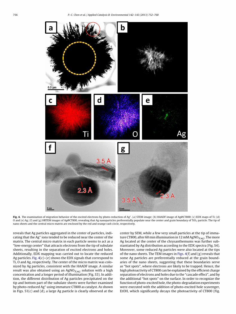
800 resulting in the great photocatalysis, the photo-reduction ofAgNO3 was studied using CT800 as the catalyst. CT800 was sus-pended in AgNO3(aq) solution and illuminated under an Xe lamp.Following illumination for 5 min, the precipitate was rinsed by DIwater, yielding the brown product (Ag@CT800). Figs. 4(a) and (b)displays the STEM and HAADF images of Ag@CT800, respectively.
The morphology of Ag@CT800 was similar to that of CT800, despitethe presence of some small particles on it. Generally, in a large parti-cle, the tip, edge and corner with high surface energy, usually leadto the nucleation on there [49–52]. However, the HAADF imagee left side represents the energy state, red and black colors represent high and lowllustrated at the center of the figure represents the energy state of the tips of nanoectrons tend to migrate toward the central micro matrix. The image of the sheet ind by red square) which has higher exciting energy state (red bar) tends to migrater in this figure legend, the reader is referred to the web version of the article.)
756 P.-C. Chen et al. / Applied Catalysis B: Environmental 142– 143 (2013) 752– 760
F ductioO es pren ircle,
rcm“sAATnrcttbi
ig. 4. The examination of migration behavior of the excited electrons by photo-re and (e) Ag; (f) and (g) HRTEM images of Ag@CT800, revealing that Ag nanoparticlano sheets and the central micro matrix are enclosed by the red and orange rash c
eveals that Ag particles aggregated in the center of particles, indi-ating that the Ag+ ions tended to be reduced near the center of theatrix. The central micro matrix in each particle seems to act as a
low-energy center” that attracts electrons from the tip of subulateheets, resulting in the separation of excited electrons and holes.dditionally, EDX mapping was carried out to locate the reducedg particles. Fig. 4(c)–(e) shows the EDX signals that correspond toi, O and Ag, respectively. The center of the micro matrix was colo-ized by Ag particles, consistent with the HAADF image. A similaresult was also obtained using an AgNO3(aq) solution with a highoncentration and a longer period of illumination (Fig. S3). In addi-
ion, the different distribution of Ag particles precipitated on theip and bottom part of the subulate sheets were further examinedy photo-reduced Ag+ using immature CT800 as catalyst. As shownn Figs. S1(c) and (d), a large Ag particle is clearly observed at the
n of Ag+. (a) STEM image; (b) HAADF image of Ag@CT800; (c) EDX maps of Ti; (d)ferentially populate near the center and grain boundary of TiO2 particle. The tip ofrespectively.
center by SEM, while a few very small particles at the tip of imma-ture CT800, after 60 min illumination in 12 mM AgNO3(aq). The moreAg located at the center of the chrysanthemums was further sub-stantiated by Ag distribution according to the EDX spectra (Fig. S4).Moreover, some reduced Ag particles were also located at the tipsof the nano sheets. The TEM images in Figs. 4(f) and (g) reveals thatsome Ag particles are preferentially reduced at the grain bound-aries of the nano sheets, suggesting that these boundaries serveas “hot spots”, where electrons are likely to be trapped. Hence, thehigh photoactivity of CT800 can be explained by the efficient chargeseparation of electrons and holes due to the “cascade effect”, and by
the additional “hot spots” on the surface. In order to recognize thefunction of photo-excited hole, the photo-degradation experimentswere executed with the addition of photo-excited hole scavenger,EtOH, which significantly decays the photoactivity of CT800 (Fig.
P.-C. Chen et al. / Applied Catalysis B: Environmental 142– 143 (2013) 752– 760 757
) TEM
Si
3o
pFCt
F0
Fig. 5. (a) SEM image; (b) XRD pattern; (c
5). Thus, imply that the active excitons of the photo-degradations hole.
.3.2. Examine the cascade effect by destroying the morphologyf material
To confirm further the “cascade effect”, the morphology and
hotoactivity of ground CT800 (CT800g) were studied in detail.ig. 5(a) and (c) presents the SEM and TEM images of groundT800 (CT800g), respectively. The nano/micro hierarchical struc-ure of CT800 was completely destroyed after grinding. Theig. 6. (a) C/C0 versus time for the degradation of methylene blue (MB) and (b) ln(C0/C)
.11713 and 0.04554, respectively. (For interpretation of the references to color in this fig
image and (d) HRTEM image of CT800g.
chrysanthemum-like morphology collapsed and became smallfragments, causing the specific surface area of CT800g to be largerthan that of CT800 (Fig. S2). The XRD pattern and HRTEM imagereveal that the crystalline structure of CT800g is that of anatase(Fig. 5(c) and (d)). According to the XRD examinations and grainsize estimation of CT800 and CT800g by Scherrer equation, both
the grain sizes and crystallinity of CT800g are the same as those ofCT800 (Fig. S6). Fig. 6 shows the photodegradation of MB by CT800and CT800g. The CT800g had poorer photoactivity than CT800; thek value of CT800g was only 0.041, even though CT800g had largeras a function of time for CT800 and CT800g. The slopes of black and blue lines areure legend, the reader is referred to the web version of the article.)

7 vironmental 142– 143 (2013) 752– 760
sn“swS
bnofCorooetnio
3
a
F(
58 P.-C. Chen et al. / Applied Catalysis B: En
pecific surface area. This result is not surprising, since CT800g didot have the nano/micro hierarchical structure, and so lacked thecascade effect” and “hot spots” that promote photoactivity. Theimilar result was also observed when the fibrillar anatase TiO2as used as the active material of the photodegradation of MB (Fig.
7).The light harvest of CT800 and CT800g were further studied
y UV–vis spectra, as shown in Fig. 7. The additional absorptionear the visible region of CT800g results from the small band gapf CT800g, reveals that some defects were generated on the sur-ace by grinding [53]. The estimated band gaps of CT800g andT800 are 3.19 and 3.25 eV, respectively. Increasing surface defectsn CT800g slightly decrease its bandgap, resulting in the wideregion of light absorption, which improve the light harvest. More-ver, after grinding, the surface area of CT800g is larger than thatf CT800. According to these observations, CT800g is expected toxhibit better photocatalytic activity than that of CT800. However,he results revealed the reverse. Therefore, we proposed that theano/micro hierarchical structure with “cascade effect” is one of the
mportant factors that resulted in the great photocatalytic activityf CT800.
.3.3. Examine the cascade effect by EPRThe electron paramagnetic resonance (EPR) technique was
dopted to investigate the electronic state of the photocatalysts
ig. 8. EPR spectra of (a) CT800 and (b) CT800g; (c) and (d) EPR signal intensity that corref) integrated area under EPR signals that correspond to surface electron-trapping sites in
Fig. 7. UV-abs spectra of CT800 and CT800g powders.
under illumination. Fig. 8(a) and (b) presents the EPR spectrum ofCT800 and CT800g, respectively. Under illumination, the intensesignal at g = 1.991 can be identified as being associated with thetrapped electrons in the lattice of anatase [54,55], and the broad
sponds to lattice electron trapping sites in CT800 and CT800g, respectively; (e) and CT800 and CT800g, respectively.
viron
stivaocftlnooisoromdtottsfb
4
pfsoclanolAitpFcf
A
or
A
f2
R
[
[[
[
[
[
[
[[
[
[
[
[
[
[
[
[
[
[
[
[
[
[
[[
[
[[
[
[
[
[
[
[[
[
P.-C. Chen et al. / Applied Catalysis B: En
ignal in the range g = 1.86–1.95 was attributable to the electronshat were trapped at the surface sites [56]. Such a broad signalndicates that electrons were trapped at various surface sites witharious energy states [57]. Since the CT800 has a nano/micro hier-rchical structure, we propose that the nano sheets contribute mostf the surface electron trapping sites and the central micro matrixontribute most of the lattice electron trapping sites. To analyzeurther the kinetics of the excited electrons, Fig. 8(c) and (e) plotshe variation of the intensity of the signals associated with theattice and surface electrons, respectively, with time. Under illumi-ation, the intensity of the signal from the lattice-trapped electronsf CT800 increased with the illumination time. However, the ratef increase decreased slowly for 15 min, after which the rate ofncrease increased slightly. The number of trapped electrons at theurface reached its maximum at 15 min, before declining. Thesebservations strongly suggest that the flow of electrons was unidi-ectional, and the excited electrons that were generated at the tipf the nano sheets tended to move toward the center of the microatrix from the tip of the nano sheets. In contrast, CT800g exhibited
ifferent features. The intensity of the trapped lattice electrons ini-ially increased, saturating after 15 min (Fig. 8(d)), and the numberf electrons trapped at the surface sites increased in proportion tohe illumination time (Fig. 8(f)) because of the absence of the mul-iple junction. Moreover, in the EPR spectrum of CT800g, a broadignal that is related to the electrons that are trapped on the sur-ace sites is also observed, it showed stronger intensity than CT800ecause of the specific surface area of CT800g is larger than CT800.
. Conclusion
In summary, TiO2 (CT800) with a chrysanthemum-like mor-hology, constructed from nano subulate sheets that grew radiallyrom the center of the matrix, was synthesized and exhibited out-tanding photocatalytic performance. The excellent photoactivityf CT800 is attributed to (1) effective charge separation that isaused by the hopping of electrons from the tips of the nano subu-ate sheets to the central matrix of the particle by “cascade effect”,nd (2) the “hot spots” on the surface. The cascade effect of theano/micro hierarchical structure was verified by the observationf the aggregation of electrons in the center of the chrysanthemum-ike TiO2 particle, as revealed by EPR and the specific reduction ofg+ ions. The photocatalytic reaction of TiO2-related materials was
nvestigated in detail. The results thus obtained provide in sight intohe design of photoactive materials and help to explain the highhotoactivity of nano/micro hierarchically structured materials.urthermore, the unidirectional electron transfer, because of theascade effect, by materials of different sizes provides a new avenueor the design of electronic and photoelectrochemical devices.
cknowledgement
The authors would like to thank the National Science Councilf the Republic of China, Taiwan, for financially supporting thisesearch under contract no. NSC 100-2113-M-007-006-.
ppendix A. Supplementary data
Supplementary data associated with this article can beound, in the online version, at http://dx.doi.org/10.1016/j.apcatb.013.05.076.
eferences
[1] J.S. Chen, Y.L. Tan, C.M. Li, Y.L. Cheah, D.Y. Luan, S. Madhavi, F.Y.C. Boey,L.A. Archer, X.W. Lou, Journal of the American Chemical Society 132 (2010)6124–6130.
[[[[
mental 142– 143 (2013) 752– 760 759
[2] D. Deng, M.G. Kim, J.Y. Lee, J. Cho, Energy & Environmental Science 2 (2009)818–837.
[3] X.F. Gao, L. Jiang, Nature 432 (2004), 36-36.[4] P.C. Chen, M.C. Tsai, H.C. Chen, I.N. Lin, H.S. Sheu, Y.S. Lin, J.G. Duh, H.T. Chiu,
C.Y. Lee, Journal of Materials Chemistry 22 (2012) 5349–5355.[5] H.G. Zhang, Q.S. Zhu, Y. Zhang, Y. Wang, L. Zhao, B. Yu, Advanced Functional
Materials 17 (2007) 2766–2771.[6] J.-Y. Liao, J.-W. He, H. Xu, D.-B. Kuang, C.-Y. Su, Journal of Materials Chemistry
22 (2012) 7910–7918.[7] Y.F. Zhao, M. Wei, J. Lu, Z.L. Wang, X. Duan, Acs Nano 3 (2009) 4009–4016.[8] F. Lu, W.P. Cai, Y.G. Zhang, Advanced Functional Materials 18 (2008) 1047–1056.[9] T.J. Zhu, J. Li, Q.S. Wu, ACS Applied Materials & Interfaces 3 (2011) 3448–3453.10] W. Li, Y.H. Deng, Z.X. Wu, X.F. Qian, J.P. Yang, Y. Wang, D. Gu, F. Zhang, B. Tu,
D.Y. Zhao, Journal of the American Chemical Society 133 (2011) 15830–15833.11] T. Ohno, T. Tsubota, M. Toyofuku, R. Inaba, Catalysis Letters 98 (2004) 255–258.12] M.Y. Xing, J.L. Zhang, F. Chen, B.Z. Tian, Chemical Communications 47 (2011)
4947–4949.13] V. Etacheri, M.K. Seery, S.J. Hinder, S.C. Pillai, Chemistry of Materials 22 (2010)
3843–3853.14] H.J. Huang, D.Z. Li, Q. Lin, W.J. Zhang, Y. Shao, Y.B. Chen, M. Sun, X.Z. Fu, Envi-
ronmental Science & Technology 43 (2009) 4164–4168.15] Z. Ding, G.Q. Lu, P.F. Greenfield, Journal of Physical Chemistry B 104 (2000)
4815–4820.16] G.H. Tian, H.G. Fu, L.Q. Jing, B.F. Xin, K. Pan, Journal of Physical Chemistry C 112
(2008) 3083–3089.17] T.Y. Ke, C.Y. Lee, H.T. Chiu, Applied Catalysis A-General 381 (2010) 109–113.18] J.J. Chen, J.C.S. Wu, P.C. Wu, D.P. Tsai, Journal of Physical Chemistry C 115 (2011)
210–216.19] G.H. Li, S. Ciston, Z.V. Saponjic, L. Chen, N.M. Dimitrijevic, T. Rajh, K.A. Gray,
Journal of Catalysis 253 (2008) 105–110.20] J.J. McDowell, J.I. McKelvey, L.A. Richard, J.T. Banks, Canadian Journal of
Chemistry-Revue Canadienne De Chimie 86 (2008) 703–708.21] M.C. Tsai, J.C. Chang, H.S. Sheu, H.T. Chiu, C.Y. Lee, Chemistry of Materials 21
(2009) 499–505.22] D.V. Bavykin, J.M. Friedrich, F.C. Walsh, Advanced Materials 18 (2006)
2807–2824.23] T.Y. Ke, P.C. Chen, M.H. Yang, H.T. Chiu, C.Y. Lee, CrystEngComm 13 (2011)
5292–5295.24] M.C. Tsai, T.L. Tsai, C.T. Lin, R.J. Chung, H.S. Sheu, H.T. Chiu, C.Y. Lee, Journal of
Physical Chemistry C 112 (2008) 2697–2702.25] J.M. Macak, H. Tsuchiya, A. Ghicov, K. Yasuda, R. Hahn, S. Bauer, P. Schmuki,
Current Opinion in Solid State & Materials Science 11 (2007) 3–18.26] C.-T. Wang, C.-F. Yen, Journal of Sol-Gel Science and Technology 61 (2012)
83–89.27] M.C. Tsai, T.L. Tsai, D.B. Shieh, H.T. Chiu, C.Y. Lee, Analytical Chemistry 81 (2009)
7590–7596.28] M.-H. Yang, T.-T. Chen, Y.-S. Wang, H.-T. Chiu, C.-Y. Lee, Journal of Materials
Chemistry 21 (2011) 18738–18743.29] G. Cernuto, N. Masciocchi, A. Cervellino, G.M. Colonna, A. Guagliardi, Journal of
the American Chemical Society 133 (2011) 3114–3119.30] T.Y. Ke, C.W. Peng, C.Y. Lee, H.T. Chiu, H.S. Sheu, CrystEngComm 11 (2009)
1691–1695.31] M.C. Wu, J. Hiltunen, A. Sapi, A. Avila, W. Larsson, H.C. Liao, M. Huuhtanen, G.
Toth, A. Shchukarev, N. Laufer, A. Kukovecz, Z. Konya, J.P. Mikkola, R. Keiski,W.F. Su, Y.F. Chen, H. Jantunen, P.M. Ajayan, R. Vajtai, K. Kordas, Acs Nano 5(2011) 5025–5030.
32] S. Ahmed, A. Du Pasquier, D.P. Birnie, T. Asefa III, ACS Applied Materials &Interfaces 3 (2011) 3002–3010.
33] H. Bai, Z. Liu, D.D. Sun, Chemical Communications 46 (2010) 6542–6544.34] W. Hu, L. Li, W. Tong, G. Li, T. Yan, Journal of Materials Chemistry 20 (2010)
8659–8667.35] J.-Y. Liao, H.-P. Lin, H.-Y. Chen, D.-B. Kuang, C.-Y. Su, Journal of Materials Chem-
istry 22 (2012) 1627–1633.36] W.-P. Liao, J.-J. Wu, Journal of Materials Chemistry 21 (2011) 9255–9262.37] F. Sauvage, F. Di Fonzo, A.L. Bassi, C.S. Casari, V. Russo, G. Divitini, C. Ducati, C.E.
Bottani, P. Comte, M. Graetzel, Nano Letters 10 (2010) 2562–2567.38] F. Di Fonzo, C.S. Casari, V. Russo, M.F. Brunella, A.L. Bassi, C.E. Bottani, Nano-
technology 20 (2009).39] L. Xiang, X. Zhao, J. Yin, B. Fan, Journal of Materials Science 47 (2012)
1436–1445.40] T. Ohno, K. Sarukawa, K. Tokieda, M. Matsumura, Journal of Catalysis 203 (2001)
82–86.41] T. Hirakawa, K. Yawata, Y. Nosaka, Applied Catalysis A-General 325 (2007)
105–111.42] Y.K. Kho, A. Iwase, W.Y. Teoh, L. Maedler, A. Kudo, R. Amal, Journal of Physical
Chemistry C 114 (2010) 2821–2829.43] B. Sun, P.G. Smirniotis, Catalysis Today 88 (2003) 49–59.44] M. Anpo, T. Shima, S. Kodama, Y. Kubokawa, Journal of Physical Chemistry 91
(1987) 4305–4310.45] A.J. Nozik, F. Williams, M.T. Nenadovic, T. Rajh, O.I. Micic, Journal of Physical
Chemistry 89 (1985) 397–399.
46] L. Brus, Journal of Physical Chemistry 90 (1986) 2555–2560.47] L.E. Brus, Journal of Chemical Physics 79 (1983) 5566–5571.48] C.B. Almquist, P. Biswas, Journal of Catalysis 212 (2002) 145–156.49] M.T. Clavaguera-Mora, N. Clavaguera, D. Crespo, T. Pradell, Progress in MaterialsScience 47 (2002) 559–619.

7 viron
[
[
[
[
[
[
60 P.-C. Chen et al. / Applied Catalysis B: En
50] H. Cuppen, H. Meekes, W. Van Enckevort, E. Vlieg, Journal of Crystal Growth286 (2006) 188–196.
51] M.E. Glicksman, Principles of solidification: an introduction to modern casting
and crystal growth concepts, Springer, 2010.52] P. Hartman, in: P. Hartman (Ed.), Crystal Growth: an Introduction, North-Holland, Amsterdam, 1973.
53] S. Indris, R. Amade, P. Heitjans, M. Finger, A. Haeger, D. Hesse, W. Grunert, A.Borger, K.D. Becker, Journal of Physical Chemistry B 109 (2005) 23274–23278.
[
[
mental 142– 143 (2013) 752– 760
54] I.R. Macdonald, S. Rhydderch, E. Holt, N. Grant, J.M.D. Storey, R.F. Howe, Catal-ysis Today 182 (2012) 39–45.
55] O.I. Micic, Y.N. Zhang, K.R. Cromack, A.D. Trifunac, M.C. Thurnauer, Journal of
Physical Chemistry 97 (1993) 7277–7283.56] D.C. Hurum, A.G. Agrios, K.A. Gray, T. Rajh, M.C. Thurnauer, Journal of PhysicalChemistry B 107 (2003) 4545–4549.
57] D.C. Hurum, K.A. Gray, T. Rajh, M.C. Thurnauer, Journal of Physical Chemistry B109 (2005) 977–980.