1-s2 0-S0017931014000283-main
15
Analysis and optimization of fan-shaped pin–fin in a rectangular cooling channel Mi-Ae Moon, Kwang-Yong Kim ⇑ Department of Mechanical Engineering, Inha University, 253 Yonghyun-Dong, Nam-Gu, Incheon 402-751, Republic of Korea article info Article history: Received 1 May 2013 Received in revised form 20 December 2013 Accepted 31 December 2013 Keywords: Fan-shaped pin–fin Heat transfer Reynolds-averaged Navier–Stokes (RANS) analysis Multi-objective optimization Radial basis neural network method abstract The heat transfer performance of a new fan-shaped pin–fin in a rectangular cooling channel is evaluated using three-dimensional Reynolds-averaged Navier–Stokes equations in comparison with a circular pin– fin. A multi-objective optimization of the fan-shaped pin–fin was performed using a hybrid evolutionary algorithm with surrogate modeling to maximize the heat transfer and to minimize the friction loss simul- taneously. The fluid flow and heat transfer were analyzed using the shear stress transport turbulence model in the Reynolds number range of 5000–100,000. The results of our analysis indicate that the aver- aged Nusselt number with the fan-shaped pin–fin was improved considerably in comparison with that of the circular pin–fin over the whole range of Reynolds numbers. For the optimization of the fan-shaped pin–fin, the ratio of the radius of front part of the pin–fin to that of the rear part, and the lateral reduction angle of the pin–fin, were selected as the design variables. Fifteen design points were generated using Latin hypercube sampling, and the values of the objective function were evaluated at these points. The surrogate models for the objective functions were constructed using the radial basis neural network method. The Pareto-optimal solutions of the fan-shaped pin–fin show that the designs were improved with respect to heat transfer and pressure drop in comparison with the circular and reference pin–fins. Ó 2014 Elsevier Ltd. All rights reserved. 1. Introduction Extended surfaces with turbulators such as pin–fins, ribs, and dimples are commonly used to enhance heat transfer in cooling channels by increasing the total area of the heat transfer surface, regeneration of boundary layer, and producing secondary flow. Among the various types of turbulators, pin–fin arrays have been widely used as an effective tool to enhance convective heat trans- fer in many engineering applications including the internal cooling channels of gas turbine blades. Heat transfer and pressure drop characteristics are important in most applications of pin–fins. To improve heat transfer and reduce pressure loss due to the pin–fin arrays, it is essential to understand the physical mechanisms that govern the heat transfer and pres- sure drop. Initial stage studies for pin–fin arrays were performed by Sparrow et al. [1] and Van Fossen [2]. They experimentally studied staggered and in-line pin–fin arrays installed in an internal cooling channel. Metzger et al. [3] investigated the effects of streamwise and spanwise distances between pin–fins. They discovered that the area-averaged heat transfer coefficient on the heated surface depends on the streamwise and spanwise distances between pin–fins for both staggered and in-line arrays. Chyu et al. [4] conducted an experiment to evaluate the heat transfer perfor- mance of staggered and in-line pin–fin arrays in a cooling channel. The heat transfer rate was enhanced by at least a factor of two by introducing one of the pin–fin arrays in the smooth channel, and the staggered pin–fin arrays showed higher heat transfer perfor- mance than the in-line arrays. Ames et al. [5] experimentally mea- sured the pressure, temperature, velocity, and turbulence intensity in a channel with pin–fins. Their results showed a peak in the heat transfer rate at the third row. And, they reported that the pressure coefficient had its maximum value at the first row, and decreased downstream toward the channel exit. Experimental investigations of heat transfer and pressure drop in a rectangular channel with and without pin–fins were performed by Chang et al. [6] at Rey- nolds numbers of 10,000 to 30,000. This study revealed that the area-averaged Nusselt numbers on the heated surface increased as the gap between the pins and the endwall decreased. Extensive studies of the heat transfer and friction loss charac- teristics for various cross-sectional shapes of pin–fins have been performed in the past few decades. Mass transfer characteristics of stepped circular pin–fin arrays were studied by Goldstein and Chen [7]. They found that stepped circular pin–fins produce higher heat transfer than uniform diameter circular pin–fins. Uzol and Camci [8] compared various heat transfer promoters such as circu- lar and elliptical pin–fins installed in internal cooling passages. 0017-9310/$ - see front matter Ó 2014 Elsevier Ltd. All rights reserved. http://dx.doi.org/10.1016/j.ijheatmasstransfer.2013.12.085 ⇑ Corresponding author. Tel.: +82 32 872 3096; fax: +82 32 868 1716. E-mail address: [email protected] (K.-Y. Kim). International Journal of Heat and Mass Transfer 72 (2014) 148–162 Contents lists available at ScienceDirect International Journal of Heat and Mass Transfer journal homepage: www.elsevier.com/locate/ijhmt
-
Upload
shivajiuniversity -
Category
Documents
-
view
0 -
download
0
Transcript of 1-s2 0-S0017931014000283-main

International Journal of Heat and Mass Transfer 72 (2014) 148–162
Contents lists available at ScienceDirect
International Journal of Heat and Mass Transfer
journal homepage: www.elsevier .com/locate / i jhmt
Analysis and optimization of fan-shaped pin–fin in a rectangularcooling channel
0017-9310/$ - see front matter � 2014 Elsevier Ltd. All rights reserved.http://dx.doi.org/10.1016/j.ijheatmasstransfer.2013.12.085
⇑ Corresponding author. Tel.: +82 32 872 3096; fax: +82 32 868 1716.E-mail address: [email protected] (K.-Y. Kim).
Mi-Ae Moon, Kwang-Yong Kim ⇑Department of Mechanical Engineering, Inha University, 253 Yonghyun-Dong, Nam-Gu, Incheon 402-751, Republic of Korea
a r t i c l e i n f o a b s t r a c t
Article history:Received 1 May 2013Received in revised form 20 December 2013Accepted 31 December 2013
Keywords:Fan-shaped pin–finHeat transferReynolds-averaged Navier–Stokes (RANS)analysisMulti-objective optimizationRadial basis neural network method
The heat transfer performance of a new fan-shaped pin–fin in a rectangular cooling channel is evaluatedusing three-dimensional Reynolds-averaged Navier–Stokes equations in comparison with a circular pin–fin. A multi-objective optimization of the fan-shaped pin–fin was performed using a hybrid evolutionaryalgorithm with surrogate modeling to maximize the heat transfer and to minimize the friction loss simul-taneously. The fluid flow and heat transfer were analyzed using the shear stress transport turbulencemodel in the Reynolds number range of 5000–100,000. The results of our analysis indicate that the aver-aged Nusselt number with the fan-shaped pin–fin was improved considerably in comparison with that ofthe circular pin–fin over the whole range of Reynolds numbers. For the optimization of the fan-shapedpin–fin, the ratio of the radius of front part of the pin–fin to that of the rear part, and the lateral reductionangle of the pin–fin, were selected as the design variables. Fifteen design points were generated usingLatin hypercube sampling, and the values of the objective function were evaluated at these points. Thesurrogate models for the objective functions were constructed using the radial basis neural networkmethod. The Pareto-optimal solutions of the fan-shaped pin–fin show that the designs were improvedwith respect to heat transfer and pressure drop in comparison with the circular and reference pin–fins.
� 2014 Elsevier Ltd. All rights reserved.
1. Introduction
Extended surfaces with turbulators such as pin–fins, ribs, anddimples are commonly used to enhance heat transfer in coolingchannels by increasing the total area of the heat transfer surface,regeneration of boundary layer, and producing secondary flow.Among the various types of turbulators, pin–fin arrays have beenwidely used as an effective tool to enhance convective heat trans-fer in many engineering applications including the internal coolingchannels of gas turbine blades.
Heat transfer and pressure drop characteristics are important inmost applications of pin–fins. To improve heat transfer and reducepressure loss due to the pin–fin arrays, it is essential to understandthe physical mechanisms that govern the heat transfer and pres-sure drop. Initial stage studies for pin–fin arrays were performedby Sparrow et al. [1] and Van Fossen [2]. They experimentallystudied staggered and in-line pin–fin arrays installed in an internalcooling channel. Metzger et al. [3] investigated the effects ofstreamwise and spanwise distances between pin–fins. Theydiscovered that the area-averaged heat transfer coefficient on theheated surface depends on the streamwise and spanwise distances
between pin–fins for both staggered and in-line arrays. Chyu et al.[4] conducted an experiment to evaluate the heat transfer perfor-mance of staggered and in-line pin–fin arrays in a cooling channel.The heat transfer rate was enhanced by at least a factor of two byintroducing one of the pin–fin arrays in the smooth channel, andthe staggered pin–fin arrays showed higher heat transfer perfor-mance than the in-line arrays. Ames et al. [5] experimentally mea-sured the pressure, temperature, velocity, and turbulence intensityin a channel with pin–fins. Their results showed a peak in the heattransfer rate at the third row. And, they reported that the pressurecoefficient had its maximum value at the first row, and decreaseddownstream toward the channel exit. Experimental investigationsof heat transfer and pressure drop in a rectangular channel withand without pin–fins were performed by Chang et al. [6] at Rey-nolds numbers of 10,000 to 30,000. This study revealed that thearea-averaged Nusselt numbers on the heated surface increasedas the gap between the pins and the endwall decreased.
Extensive studies of the heat transfer and friction loss charac-teristics for various cross-sectional shapes of pin–fins have beenperformed in the past few decades. Mass transfer characteristicsof stepped circular pin–fin arrays were studied by Goldstein andChen [7]. They found that stepped circular pin–fins produce higherheat transfer than uniform diameter circular pin–fins. Uzol andCamci [8] compared various heat transfer promoters such as circu-lar and elliptical pin–fins installed in internal cooling passages.
Nomenclature
A area of heat transfer surface (m2)AR aspect ratio, W/HCf skin friction coefficientDh hydraulic diameter of the channel (m)F objective functionf friction factor of the channelf0 reference friction factorH height of channel (m)h height of rib (m)kf fluid thermal conductivity (W/m K)Lp streamwise distance from the inlet to the center of the
pin–fin (m)Nu Nusselt numberNu0 reference Nusselt number in Eq. (1)Nu area-averaged Nusselt numberPr Prandtl numberDp pressure drop (Pa)
q0 wall heat flux (W/m2)Rf radius of front part of fan-shaped pin–fin (m)Rp radius of circular pin–fin (m)Re Reynolds number, UinDh/mT local temperature (K)Tb bulk temperature (K)Tw wall temperature (K)Uin average temperature at the inlet (m/s)W width of channel (m)x, y, z orthogonal coordinate system
Greek symbolsm kinetic viscosity (kg/ms)h lateral reduction angle of fan-shaped pin–fin (�)sx wall shear stress (N/m2)
M.-A. Moon, K.-Y. Kim / International Journal of Heat and Mass Transfer 72 (2014) 148–162 149
Their results show that the heat transfer coefficient for circularpin–fins was about 27% higher than that of elliptical pin–fins. Sahi-ti et al. [9] carried out experiments regarding heat transfer and fric-tion loss in a rectangular channel with various shapes of pin–fincross-sections; e.g., a NACA airfoil, dropform, lancet, ellipse, circle,and square. They reported that the elliptical pin–fin arrays showedthe highest heat transfer rate with a similar pressure drop amongthe tested pin–fin shapes. Chyu et al. [10] examined the heattransfer performance of circular, cubic, and diamond shaped pin–fin arrays in a channel. Their results revealed that diamond-shapedpin–fins showed the best heat transfer performance, but the cubicand diamond shaped pin–fins resulted in higher pressure lossesthan circular pin–fins. Weilin and Abel [11] experimentally studiedin-line and staggered square pin–fins, and showed that staggeredarrays have higher heat transfer performance than in-line arrays.
Since the horseshoe vortex induced by a pin–fin is associatedwith secondary flow generation and heat transfer enhancement,a considerable amount of research on horseshoe vortices has beenconducted. Ireland and Jones [12] observed a horseshoe vortexnear a pin–endwall junction in fully-developed duct flow, whichresulted in heat transfer augmentation. They showed that thehorseshoe vortex generated at the pin–endwall junction playedan important role in heat transfer enhancement on both the pin–fin and endwall. Chyu and Goldstein [13] investigated mass trans-fer in a channel with seven rows of circular pin–fins. They sug-gested that the maximum local heat transfer coefficient locatedaround the pin–fin is due to the presence of the horseshoe vortex.Wang et al. [14] visualized the horseshoe vortex at the pin–end-wall junction using smoke-wire visualization. They showed thatthe obstacle attached to the pin–fin significantly enhanced the pro-duction of the horseshoe vortex, which led to augmentation of theheat transfer on the pin–endwall junction. Won et al. [15] mea-sured the distribution of the heat transfer coefficient in a coolingchannel with eight rows of pin–fins. Their results indicated thatheat transfer on the heated surface is affected by the strength ofthe horseshoe vortex. Furthermore, they reported that the horse-shoe vortex structure becomes complex and strong as the Reynoldsnumber increases.
Optimization techniques combined with computational fluiddynamics have developed rapidly in recent decades. Numericaloptimization methods are regarded as a general design tool andoffer a number of advantages, including automated designcapabilities, a variety of constraints, and multidisciplinaryapplications. However, because of long computing times, thecoupling of numerical optimization with three-dimensional (3-
D) Navier–Stokes analysis has only recently become practical.Among various optimization algorithms, the surrogate modelingtechnique has been widely used in engineering applications dueto its intrinsic advantages [16–21]. Different kinds of surrogatemodels have been used to find the optimum geometries ofvarious turbulators to enhance heat transfer performance[17,18,21]. Moon and Kim [18–20] performed numerical optimi-zations of a two-pass channel with circular pin–fin arrays andvarious guide vanes installed in the turning region using the re-sponse surface approximation (RSA) [22] and Kriging methods[23] to enhance heat transfer performance. Kim et al. [24] opti-mized the geometry of inclined elliptic dimples in a cooling chan-nel using a radial basis network (RBNN) [25].
The present work proposes a novel cross-sectional pin–finshape to improve heat transfer and reduce the pressure drop in acooling channel with a pin–fin. The heat transfer performance ofthe proposed pin–fin was evaluated in comparison with a circularpin–fin using 3-D Reynolds-averaged Navier–Stokes (RANS) analy-sis. Optimization of a fan-shaped pin–fin was performed to en-hance heat transfer and reduce the pressure drop in a channelwith a fan-shaped pin–fin. A hybrid evolutionary multi-objectivealgorithm (hybrid MOEA) using an elitist non-dominated sortinggenetic algorithm (NSGA-II) [26] combined with a local searchstrategy [27] was employed for the optimization. Two geometricvariables of the fan-shaped pin–fin were selected as the designvariables. To find a set of optimal designs, Pareto optimal solutionswere obtained in the specified design space.
2. Geometry of fan-shaped pin fin
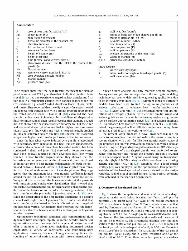
Fig. 1 shows the computational domain and the pin–fin shapeproposed in this work (which is called the ‘‘fan-shaped’’ pin–finhereafter). The aspect ratio (AR = W/H) of the cooling channel is2.05 with a channel height (H) of 28.7 mm, which is same as thatused by Simoneau and Van Fossen [28]. The hydraulic diameterof the rectangular channel Dh is 38.55 mm and the length of cool-ing channel is 203.2 mm. A single pin–fin was installed in the cool-ing channel. The distance between the side walls and the center ofthe pin–fin is 0.50 �W. The streamwise distance from the inletsection to the center of the pin–fin (Lp) is 3.61 � Dh. The radius ofthe front part of the fan-shaped pin–fin, Rp, is 9.53 mm. The refer-ence shape of the fan-shaped pin–fin has a radius of the rear part ofthe pin–fin (Rf) of 1.20Rp and a lateral reduction angle of thepin–fin (h) of 60.0�. From these variables, geometric variables
(a) Computational domain.
(b) Configuration of fan-shaped pin-fin.
Fig. 1. Schematic computational domain and pin–fin shape [30].
150 M.-A. Moon, K.-Y. Kim / International Journal of Heat and Mass Transfer 72 (2014) 148–162
Rf/Rp and h were selected as the design variables for the optimiza-tion based on previous parametric studies [29,30].
3. Solution methodology
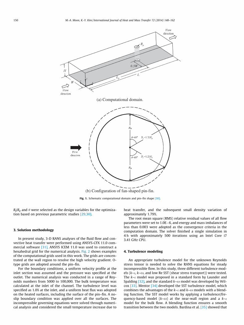
In present study, 3-D RANS analyses of the fluid flow and con-vective heat transfer were performed using ANSYS-CFX 11.0 com-mercial software [31]. ANSYS ICEM 11.0 was used to construct ahexahedral grid for the numerical analysis. Fig. 2 shows examplesof the computational grids used in this work. The grids are concen-trated at the wall region to resolve the high velocity gradient. O-type grids are adopted around the pin–fin.
For the boundary conditions, a uniform velocity profile at theinlet section was assumed and the pressure was specified at theoutlet. The numerical analysis was conducted in a range of Rey-nolds numbers from 5000 to 100,000. The bulk temperature wascalculated at the inlet of the channel. The turbulence level wasspecified as 1.0% at the inlet, and a uniform heat flux was adoptedon the heated surfaces, including the surface of the pin–fin. A no-slip boundary condition was applied over all the surfaces. Theincompressible governing equations were solved through numeri-cal analysis and considered the small temperature increase due to
heat transfer, and the subsequent small density variation ofapproximately 1.79%.
The root mean square (RMS) relative residual values of all flowparameters were set to 1.0E�6, and energy and mass imbalances ofless than 0.003 were adopted as the convergence criteria in thecomputation domain. The solver finished a single simulation in4 h with approximately 500 iterations using an Intel Core i73.41 GHz CPU.
4. Turbulence modeling
An appropriate turbulence model for the unknown Reynoldsstress tensor is needed to solve the RANS equations for steadyincompressible flow. In this study, three different turbulence mod-els (k–e, k–x, and low Re SST (shear stress transport)) were tested.The k–e model was proposed in a standard form by Launder andSpalding [32], and the standard k–x model was developed by Wil-cox [33]. Mentor [34] developed the SST turbulence model, whichcombines the advantages of the k–e and k–x models with a blend-ing function. The SST model works by applying a turbulence/fre-quency-based model (k–x) at the near-wall region and a k–emodel for the bulk flow. A blending function ensures a smoothtransition between the two models. Bardina et al. [35] showed that
(a) Computational grids in whole domain
(b) Grids near the pin-fin for k-ε model.
(c) Grids near the pin-fin for k-ω and low Re SST models.
Fig. 2. Grid system examples for different turbulence models [30].
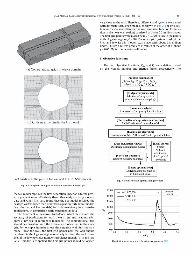
Fig. 3. Multi-objective optimization procedure.
Fig. 4. Grid dependency test for reference geometry [30].
M.-A. Moon, K.-Y. Kim / International Journal of Heat and Mass Transfer 72 (2014) 148–162 151
the SST model captures the flow separation under an adverse pres-sure gradient more effectively than other eddy viscosity models.Garg and Ameri [36] also found that the SST model resolved thepassage vortex better than other two-equation turbulence models(e.g., the k–e and k–x models) for turbomachinery heat transferapplications, in comparison with experimental data.
The treatment of near-wall turbulence, which determines theaccuracy of predictions for wall shear stress and heat transfer,plays a key role in turbulence modeling. The computational gridshould be consistent with the turbulence modes used in the anal-ysis. For example, in order to use the empirical wall function (k–emodel) near the wall, the first grid points near the wall shouldbe placed in the log-law region, relatively far from the wall. How-ever, if the low Reynolds number turbulence models (k–x and lowRe SST models) are applied, the first grid points should be located
very close to the wall. Therefore, different grid systems were usedwith different turbulence models, as shown in Fig. 2. The grid sys-tem for the k–e model (to use the wall empirical function formula-tion in the near-wall region) consisted of about 2.5 million nodes.The first grid points were placed near y = 0.05H to locate the pointsin the log-law region (y+ > 30). The other grid system to adopt thek–x and low Re SST models was made with about 3.8 millionnodes. This grid system produced y+ values of the order of 1 (abouty = 0.001H) for the next-to-wall nodes.
5. Objective functions
The two objective functions, FNu and Ff, were defined basedon the Nusselt number and friction factor, respectively. The
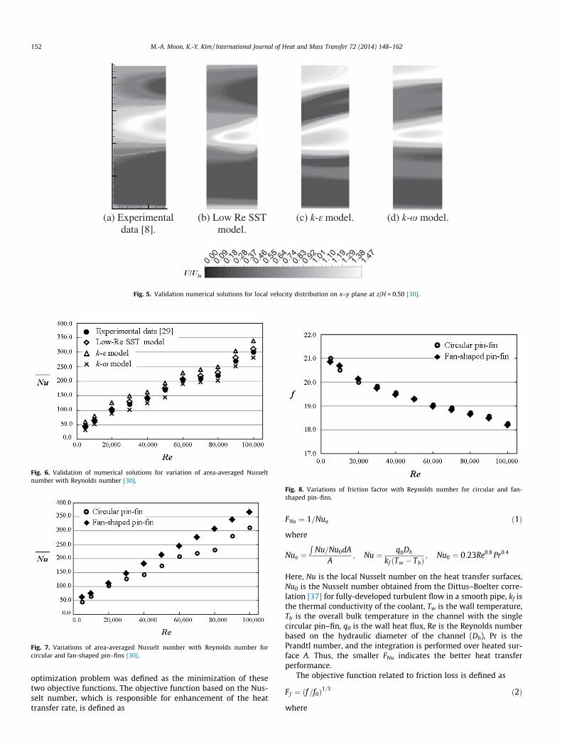
(a) Experimental data [8].
(b) Low Re SST model.
(c) k-ε model. (d) k-ω model.
Fig. 5. Validation numerical solutions for local velocity distribution on x–y plane at z/H = 0.50 [30].
Fig. 6. Validation of numerical solutions for variation of area-averaged Nusseltnumber with Reynolds number [30].
Fig. 7. Variations of area-averaged Nusselt number with Reynolds number forcircular and fan-shaped pin–fins [30].
Fig. 8. Variations of friction factor with Reynolds number for circular and fan-shaped pin–fins.
152 M.-A. Moon, K.-Y. Kim / International Journal of Heat and Mass Transfer 72 (2014) 148–162
optimization problem was defined as the minimization of thesetwo objective functions. The objective function based on the Nus-selt number, which is responsible for enhancement of the heattransfer rate, is defined as
FNu ¼ 1=Nua ð1Þ
where
Nua ¼R
Nu=Nu0dAA
; Nu ¼ q0Dh
kf ðTw � TbÞ; Nu0 ¼ 0:23Re0:8 Pr0:4
Here, Nu is the local Nusselt number on the heat transfer surfaces,Nu0 is the Nusselt number obtained from the Dittus–Boelter corre-lation [37] for fully-developed turbulent flow in a smooth pipe, kf isthe thermal conductivity of the coolant, Tw is the wall temperature,Tb is the overall bulk temperature in the channel with the singlecircular pin–fin, q0 is the wall heat flux, Re is the Reynolds numberbased on the hydraulic diameter of the channel (Dh), Pr is thePrandtl number, and the integration is performed over heated sur-face A. Thus, the smaller FNu indicates the better heat transferperformance.
The objective function related to friction loss is defined as
Ff ¼ ðf=f0Þ1=3 ð2Þ
where
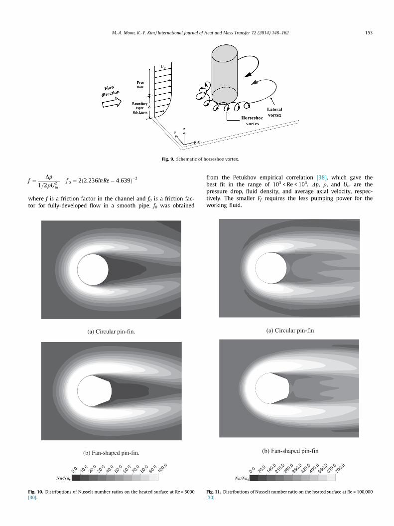
Fig. 9. Schematic of horseshoe vortex.
M.-A. Moon, K.-Y. Kim / International Journal of Heat and Mass Transfer 72 (2014) 148–162 153
f ¼ Dp
1=2qU2in;
f 0 ¼ 2ð2:236lnRe� 4:639Þ�2
where f is a friction factor in the channel and f0 is a friction fac-tor for fully-developed flow in a smooth pipe. f0 was obtained
(a) Circular pin-fin.
(b) Fan-shaped pin-fin.
Fig. 10. Distributions of Nusselt number ratios on the heated surface at Re = 5000[30].
from the Petukhov empirical correlation [38], which gave thebest fit in the range of 103 < Re < 106. Dp, q, and Uin are thepressure drop, fluid density, and average axial velocity, respec-tively. The smaller Ff requires the less pumping power for theworking fluid.
(a) Circular pin-fin
(b) Fan-shaped pin-fin
Fig. 11. Distributions of Nusselt number ratio on the heated surface at Re = 100,000[30].

(a) Re = 5,000.
(b) Re = 100,000.
Fig. 12. Cross-streamwise-averaged Nusselt number for circular and fan-shapedpin–fins [30].
(a) x/Dh = 3.68.
(c) x/Dh = 3.83.
Fig. 13. Spanwise distributions of Nusselt num
154 M.-A. Moon, K.-Y. Kim / International Journal of Heat and Mass Transfer 72 (2014) 148–162
6. Latin hypercube sampling
In order to construct a surrogate model for an objectivefunction, objective function values evaluated at some design pointsin the design space are required. As previously mentioned, threedesign variables related to the geometry of the fan-shapedpin–fin were selected for the optimization. The design pointswithin the design space were selected with the help of Latin hyper-cube sampling (LHS) as the design of experiment [39]. LHS is one ofthe effective sampling methods in the Design and Analysis ofComputer Experiments (DACE) [39]. Latin hypercube sampling isused to select n different values from each of k variables X = [x1,x2,. . . ,xk]T with probability density function f(x) in the following man-ner. The range of each variable is portioned into n non-overlappingintervals of equal probability 1/n. From each internal, one value isselected randomly according to the probability density of the inter-val. One value from each interval is selected at random with re-spect to the probability density in the interval. The n values thusobtained for X1 are paired in a random manner (equally likely com-binations) with the n values of X2. These n pairs are combined in arandom manner with n values of X3 to form n triples, and so on, un-til n k-tuplets are formed. The process generates random samplepoints, thereby ensuring that all portions of the design space arerepresented.
7. Radial basis neural network model
In the present work, the RBNN model [25] was employed as asurrogate model for the objective functions of the optimization.The two main advantages of using this model are keeping themathematics simple and reducing the computational cost. Asdescribed by Orr [25], the RBNN is constructed of two-layered
(b) x/Dh = 3.73.
(d) x/Dh = 3.93.
ber for circular and fan-shaped pin–fins.
M.-A. Moon, K.-Y. Kim / International Journal of Heat and Mass Transfer 72 (2014) 148–162 155
networks with a hidden layer of radial basis transfer functions withlinear output. The hidden layer consists of a set of radial basis func-tions that act as activation functions. The linear model can be ex-pressed as a linear combination of a set of N basis functions,
a ¼ radbasðjjw� pjjbÞ ð3Þ
Here, the net input to the radbas transfer function is the vectordistance between its weight vector w and the input vector p, and ismultiplied by the bias b. The transfer function for a radial basisneuron is
radbasðnÞ ¼ e�n2 ð4Þ
The radial basis function has a maximum of 1 when its input is0. As the distance between w and p decreases, the output increases.Thus, a radial basis neuron acts as a detector that produces a valueof 1 wherever the input p is identical to its weight vector p. Thebias b allows the sensitivity of the radbas neuron to be adjusted.If the radial basis function and other parameters are fixed throughthe training process, the model is linear. However, if the basis func-tion changes during the training/learning process, the model isnonlinear. The learning process is equivalent to finding a surfacein multi-dimensional space that provides a best fit to the trainingdata, which is further used to interpolate the test data. The param-eters for fitting this surrogate model are a spread constant (SC) anda user-defined error goal (EG). The SC value determines the widthof an area in the input space to which each neuron responds. It isimportant that the RBNN of the hidden layer overlaps to allowgood generalization. Since a small value of EG will produce over-training of the network while a large error goal will affect the
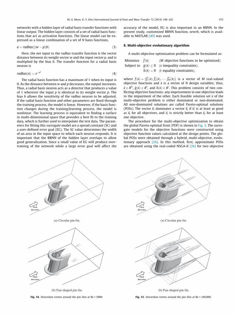
(a) Circular pin-fin.
(b) Fan-shaped pin-fin.
Fig. 14. Horseshoe vortex around the pin–fins at Re = 5000.
accuracy of the model, EG is also important in an RBNN. In thepresent study, customized RBNN function, newrb, which is avail-able in MATLAB [40] was used.
8. Multi-objective evolutionary algorithm
A multi-objective optimization problem can be formulated as:
Minimize �f ð�xÞ ðM objective functions to be optimizedÞ:Subject to �gð�xÞ � 0 ðs inequality constraintsÞ;
�hð�xÞ ¼ 0 ðt equality constraintsÞ;
where �f ð�xÞ ¼ ff1ð�xÞ; f2ð�xÞ; � � � ; fMð�xÞg is a vector of M real-valuedobjective functions and �x is a vector of N design variables; thus,�x 2 RN , �gð�xÞ 2 RS, and �hð�xÞ 2 Rt . This problem consists of two con-flicting objective functions; any improvement in one objective leadsto the impairment of the other. Each feasible solution set �x of themulti-objective problem is either dominated or non-dominated.All non-dominated solutions are called Pareto-optimal solutions(POSs). The vector xi dominates a vector xj if xi is at least as goodas xj for all objectives, and xi is strictly better than xj for at leastone objective.
The procedure for the multi-objective optimization to obtainthe global Pareto-optimal front (POF) is shown in Fig. 3. The surro-gate models for the objective functions were constructed usingobjective function values calculated at the design points. The glo-bal POSs were obtained through a hybrid, multi-objective, evolu-tionary approach [26]. In this method, first, approximate POSsare obtained using the real-coded NSGA-II [26] for two objective
(a) Circular pin-fin.
(b) Fan-shaped pin-fin.
Fig. 15. Horseshoe vortex around the pin–fins at Re = 100,000.

156 M.-A. Moon, K.-Y. Kim / International Journal of Heat and Mass Transfer 72 (2014) 148–162
functions. Here, ‘‘real-coded’’ means that the crossover and muta-tions are conducted in real space for obtaining a response of theNSGA-II. These solutions are then rectified by searching the locallyoptimal solution for each objective function over the whole (NSGA-II-derived) optimal solution using sequential quadratic program-ming (SQP) with NSGA-II-derived solutions as initial guesses. SQPis a gradient-based optimization technique that is a generalizationof Newton’s method. In a local search, the first objective is opti-mized and the second objective is treated as an equality constraint.The local search is repeated for the second objective function whiletreating the first objective as an equality constraint. Two new setsof optimal solutions were obtained using this process. These solu-tions and the solutions obtained through NSGA-II were thenmerged. From these aggregated solutions, the first dominated solu-tions were discarded, and then duplicate solutions were eliminatedto obtain global POSs. The process of local search was executed toimprove the quality of the POSs.
In order to select the representative solutions from the severalPOSs, K-means clustering [39] was performed. This is an iterativeprocess for forming the clusters. K-means clustering of the POS setsserves two purposes: (1) to identify the subsets that can be used toidentify the boundary of the Pareto optimal response surface, and(2) to reduce the large number of POSs to obtain a manageablenumber of trade-off designs that can be evaluated by the designer.
(a) x/Dh =
(b) x/Dh =
(c) x/Dh =
(d) x/Dh =
Fig. 16. Streamlines near the surface downstr
These representative solutions were distributed along the POF. Thenumerical solutions were derived in relation to the designs at theselected representative solutions.
9. Results and discussion
To find the optimal number of grids, a grid dependency test wasperformed for the Nusselt number distribution on the heated sur-face with a reference fan-shaped pin–fin using the low Re SST tur-bulence model in previous work [30], as shown in Fig. 4. Fromthese results, the optimal number of grids for the reference geom-etry was determined to be about 3.8 million nodes. The grid sys-tems for the various geometries at the design points wereconstructed with approximately the same grid spacing with thisoptimum grid system for the reference shape. Therefore, a numberof grids in the range from 3.5 million to 4.2 million were used,depending on the geometry.
Present numerical solutions were validated through compari-son with the experimental data of Uzol and Camci [8] and Simo-neau and Van Fossen [28] for the cooling channel with a circularpin–fin described in previous work [30]. Fig. 5 shows the totalvelocity distributions on a specified x–y plane, z/H = 0.50. Fig. 6presents area-averaged Nusselt number variations with the
3.93.
3.95.
3.97.
3.99.
eam of circular pin–fin on the y–z plane.
M.-A. Moon, K.-Y. Kim / International Journal of Heat and Mass Transfer 72 (2014) 148–162 157
Reynolds number in the range from 5000 to 100,000. These figuresshow comparisons of results calculated using three different turbu-lence models (k–e, k–x, and low Re SST) with experimental data.As shown in Figs. 5 and 6, the low Re SST model results show thebest agreement with experimental data among the tested turbu-lence models for predictions of the total velocity and area-aver-aged Nusselt number in the channel.
9.1. Comparative analysis between fan shape and circular pin–fins
Figs. 7 and 8 present variations of the computational area-aver-aged Nusselt number and friction factor with the Reynolds numberfor the fan-shaped pin–fin, respectively, in comparison with thosefor the circular pin–fin with radius Rp. The value of the area-aver-aged Nusselt number for the fan-shaped pin–fin is greater than thecircular pin–fin over the whole range of Reynolds numbers. As theReynolds number increases, the heat transfer with the fan-shapedpin–fin relatively improves, and the Nusselt number for the fan-shaped pin–fin is larger than that for the circular pin–fin by22.8% at Re = 80,000. On the other hand, the friction loss decreasesas the Reynolds number increases for both pin–fins, as shown inFig. 8. This is consistent with previous results [6,10]. The pressure
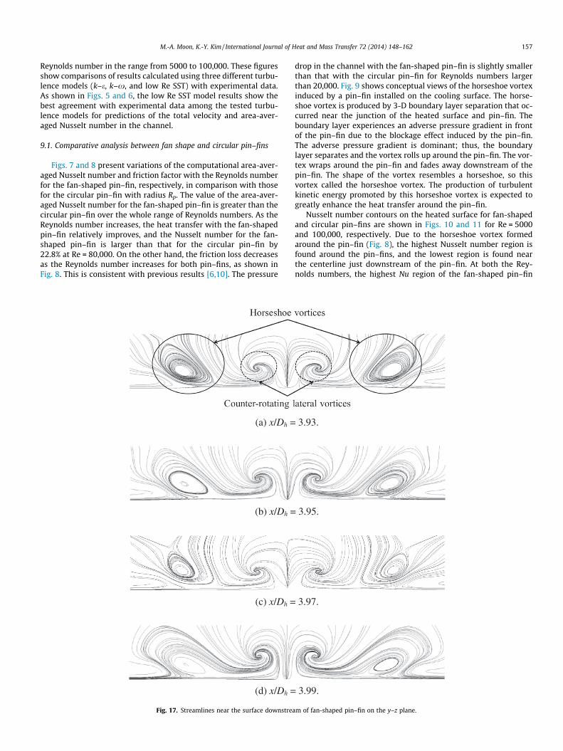
(a) x/Dh =
(b) x/Dh =
(c) x/Dh =
(d) x/Dh =
Fig. 17. Streamlines near the surface downstrea
drop in the channel with the fan-shaped pin–fin is slightly smallerthan that with the circular pin–fin for Reynolds numbers largerthan 20,000. Fig. 9 shows conceptual views of the horseshoe vortexinduced by a pin–fin installed on the cooling surface. The horse-shoe vortex is produced by 3-D boundary layer separation that oc-curred near the junction of the heated surface and pin–fin. Theboundary layer experiences an adverse pressure gradient in frontof the pin–fin due to the blockage effect induced by the pin–fin.The adverse pressure gradient is dominant; thus, the boundarylayer separates and the vortex rolls up around the pin–fin. The vor-tex wraps around the pin–fin and fades away downstream of thepin–fin. The shape of the vortex resembles a horseshoe, so thisvortex called the horseshoe vortex. The production of turbulentkinetic energy promoted by this horseshoe vortex is expected togreatly enhance the heat transfer around the pin–fin.
Nusselt number contours on the heated surface for fan-shapedand circular pin–fins are shown in Figs. 10 and 11 for Re = 5000and 100,000, respectively. Due to the horseshoe vortex formedaround the pin–fin (Fig. 8), the highest Nusselt number region isfound around the pin–fins, and the lowest region is found nearthe centerline just downstream of the pin–fin. At both the Rey-nolds numbers, the highest Nu region of the fan-shaped pin–fin
3.93.
3.95.
3.97.
3.99.
m of fan-shaped pin–fin on the y–z plane.
158 M.-A. Moon, K.-Y. Kim / International Journal of Heat and Mass Transfer 72 (2014) 148–162
is thicker in front of the pin–fin, and persists longer in the wake re-gion. The heat transfer enhancement in front of the fan-shapedpin–fin attributes to the increase in the strength of the horseshoevortex around the pin–fin, which will be discussed later, compared
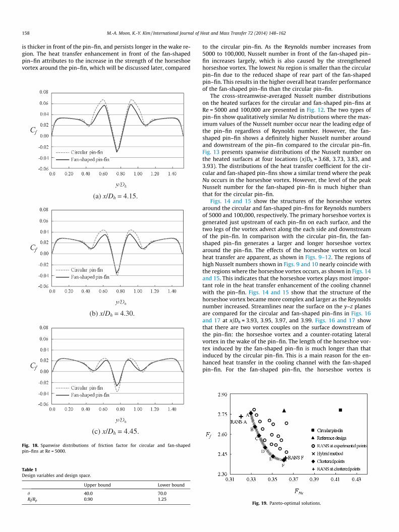
(a) x/Dh = 4.15.
(b) x/Dh = 4.30.
(c) x/Dh = 4.45.
Fig. 18. Spanwise distributions of friction factor for circular and fan-shapedpin–fins at Re = 5000.
Table 1Design variables and design space.
Upper bound Lower bound
h 40.0 70.0Rf/Rp 0.90 1.25
to the circular pin–fin. As the Reynolds number increases from5000 to 100,000, Nusselt number in front of the fan-shaped pin–fin increases largely, which is also caused by the strengthenedhorseshoe vortex. The lowest Nu region is smaller than the circularpin–fin due to the reduced shape of rear part of the fan-shapedpin–fin. This results in the higher overall heat transfer performanceof the fan-shaped pin–fin than the circular pin–fin.
The cross-streamwise-averaged Nusselt number distributionson the heated surfaces for the circular and fan-shaped pin–fins atRe = 5000 and 100,000 are presented in Fig. 12. The two types ofpin–fin show qualitatively similar Nu distributions where the max-imum values of the Nusselt number occur near the leading edge ofthe pin–fin regardless of Reynolds number. However, the fan-shaped pin–fin shows a definitely higher Nusselt number aroundand downstream of the pin–fin compared to the circular pin–fin.Fig. 13 presents spanwise distributions of the Nusselt number onthe heated surfaces at four locations (x/Dh = 3.68, 3.73, 3.83, and3.93). The distributions of the heat transfer coefficient for the cir-cular and fan-shaped pin–fins show a similar trend where the peakNu occurs in the horseshoe vortex. However, the level of the peakNusselt number for the fan-shaped pin–fin is much higher thanthat for the circular pin–fin.
Figs. 14 and 15 show the structures of the horseshoe vortexaround the circular and fan-shaped pin–fins for Reynolds numbersof 5000 and 100,000, respectively. The primary horseshoe vortex isgenerated just upstream of each pin–fin on each surface, and thetwo legs of the vortex advect along the each side and downstreamof the pin–fin. In comparison with the circular pin–fin, the fan-shaped pin–fin generates a larger and longer horseshoe vortexaround the pin–fin. The effects of the horseshoe vortex on localheat transfer are apparent, as shown in Figs. 9–12. The regions ofhigh Nusselt numbers shown in Figs. 9 and 10 nearly coincide withthe regions where the horseshoe vortex occurs, as shown in Figs. 14and 15. This indicates that the horseshoe vortex plays most impor-tant role in the heat transfer enhancement of the cooling channelwith the pin–fin. Figs. 14 and 15 show that the structure of thehorseshoe vortex became more complex and larger as the Reynoldsnumber increased. Streamlines near the surface on the y–z planesare compared for the circular and fan-shaped pin–fins in Figs. 16and 17 at x/Dh = 3.93, 3.95, 3.97, and 3.99. Figs. 16 and 17 showthat there are two vortex couples on the surface downstream ofthe pin–fin: the horseshoe vortex and a counter-rotating lateralvortex in the wake of the pin–fin. The length of the horseshoe vor-tex induced by the fan-shaped pin–fin is much longer than thatinduced by the circular pin–fin. This is a main reason for the en-hanced heat transfer in the cooling channel with the fan-shapedpin–fin. For the fan-shaped pin–fin, the horseshoe vortex is
Fig. 19. Pareto-optimal solutions.

Table 2Results of multi-objective optimization (Re = 5000).
Design Design variable Objective function value
Predicted value by hybrid MOEA RANS calculated value
h Rf/Rp FNu Ff FNu Ff
Circular pin–fin 0.0 1.00 – – 0.4149 2.7589Reference 60.0 1.20 – – 0.3614 2.7520POS A 62.3 0.97 0.3296 2.7589 0.3202 2.7468POS F 43.8 1.11 0.3610 2.4049 0.3624 2.4443
(a) Reference design (θ = 60.0° and Rf/Rp = 1.20).
(b) Optimal design, POS A (θ = 62.3° and Rf/Rp = 0.97).
Fig. 20. Nusselt number ratio distributions on the heated surface at Re = 5000.
Fig. 21. Cross-streamwise-averaged Nusselt number at Re = 5000.
M.-A. Moon, K.-Y. Kim / International Journal of Heat and Mass Transfer 72 (2014) 148–162 159
stronger than the counter-rotating lateral vortex on the surfacedownstream near the pin–fin, but the opposite trend is found inthe case of the circular pin–fin. The weaker counter-rotating lateralvortex behind the fan-shaped pin–fin arises from the unique shapeof the rear part of the pin–fin. The cross-streamwise distributionsof the skin friction coefficient downstream of the pin–fins areshown in Fig. 18. The skin friction coefficient [41] is defined asfollows:
Cf ¼sw
1=2qU2in
ð5Þ
where sx is the local wall shear stress averaged on the top and bot-tom surfaces of the channel at specified y location. The skin frictioncoefficients in the cooling channel with the circular and fan-shapedpin–fins show qualitatively similar distributions. The high level ofthe skin friction coefficient is found in the heat transfer enhance-ment region around each pin–fin as presented in Fig. 18(a). The neg-ative values of the skin friction coefficient shown in Fig. 18 reflectreverse flow due to the flow separation induced by the pin–fin.The overall magnitude of the skin friction factor for the fan-shapedpin–fin is slightly smaller than that for the circular pin–fin. This isconsistent with the fact that the fan-shaped pin–fin yields slightlysmaller values of the friction factor than the circular pin–fin, asshown in Fig. 8.
9.2. Multi-objective optimization of fan-shaped pin–fin
The present multi-objective optimization was performed forRe = 5000. The design space shown in Table 1 was first determinedusing preliminary calculations under geometric constraints. POSsand objective function values calculated at the experimental pointsselected by LHS are shown in Fig. 19, where the POSs were gener-ated by a hybrid MOEA through the RBNN method. A real-codedNSGA-II was invoked to obtain well-spread approximate Pareto-optimal solutions with 120 generations and 105 populations. Thecrossover and mutation probabilities were set to 0.85 and 0.15,respectively. The crossover and mutation parameters were decidedto be 15 and 150, respectively. Since the purpose of this optimiza-tion is to minimize both objective functions simultaneously, theshape of the obtained POF resembles a concave front. In this work,no solution out of 270 POSs is superior to any other with respect toboth objectives because each solution is a global POS. Tradeoffanalysis shows that a higher Nusselt number can be obtained atthe cost of a higher friction factor: this shows the competing
160 M.-A. Moon, K.-Y. Kim / International Journal of Heat and Mass Transfer 72 (2014) 148–162
nature of the two objective functions. The POSs were groupedthrough K-means clustering [39] to determine the representativesolution for a group of solutions. Six representative clusters (POSsA, B, C, D, E, and F) were found, as shown in Fig. 19.
Table 2 shows results of the optimization for the two represen-tative POSs (A and F) located at the ends of the POF in comparisonwith the reference design (h = 60.0� and Rf/Rp = 1.20) and the circu-lar pin–fin. POS A is the heat transfer-oriented design and POS F isthe friction loss-oriented design. The objective function valuespredicted by hybrid MOEA are in agreement with the valuesobtained by RANS analysis, with relative errors in the range of0.9 to 3.1%. The values of the objective function related to the heat
(a) x/Dh = 4.15.
(b) x/Dh = 4.30.
(c) x/Dh = 4.45.
Fig. 22. Spanwise distributions of friction factor at Re = 5000.
transfer (FNu) for POSs A and F decrease by 22.82% and 12.65%,respectively, compared with the circular pin–fin. And, the valuesof the objective function related to friction factor (Ff) for POSs Aand F decrease by 0.44% and 11.40%, respectively, compared withthe circular pin–fin. This confirms that the heat transfer-orienteddesign, POS A, gives the lowest Fnu value, and the friction loss-ori-ented design, POS F, gives the lowest Ff value. Table 2 shows thatthe heat transfer is more sensitive to the design variable Rf/Rp thanto h, whereas the friction loss is more sensitive to h. Thus, in theheat transfer-oriented design, POS A, the change in Rf/Rp is muchlarger than the change in h relative to the reference design, whilein the friction loss-oriented design, POS F, the change in h is largerthan the change in Rf/Rp.
In Fig. 20, the local Nusselt number contours on the heatedsurfaces are presented for the reference design and the heat trans-fer-oriented design (POS A). The distributions are qualitativelysimilar, but the POS A distribution shows a larger high heat trans-fer region, and a smaller low heat transfer region than thereference design. Fig. 21 shows the cross-streamwise averagedNusselt number distribution in the flow direction for the referencedesign and POS A. POS A shows the distribution level that is higherthan the reference design at x/Dh > 3.43; i.e., around anddownstream of the pin–fin.
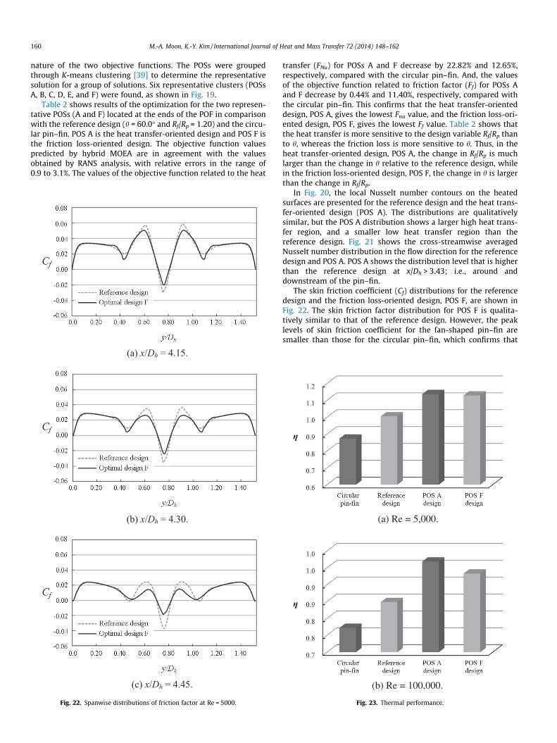
The skin friction coefficient (Cf) distributions for the referencedesign and the friction loss-oriented design, POS F, are shown inFig. 22. The skin friction factor distribution for POS F is qualita-tively similar to that of the reference design. However, the peaklevels of skin friction coefficient for the fan-shaped pin–fin aresmaller than those for the circular pin–fin, which confirms that
(a) Re = 5,000.
(b) Re = 100,000.
Fig. 23. Thermal performance.
M.-A. Moon, K.-Y. Kim / International Journal of Heat and Mass Transfer 72 (2014) 148–162 161
POS F has a much smaller pressure drop than the reference design,as shown in Fig. 19 and Table 2.
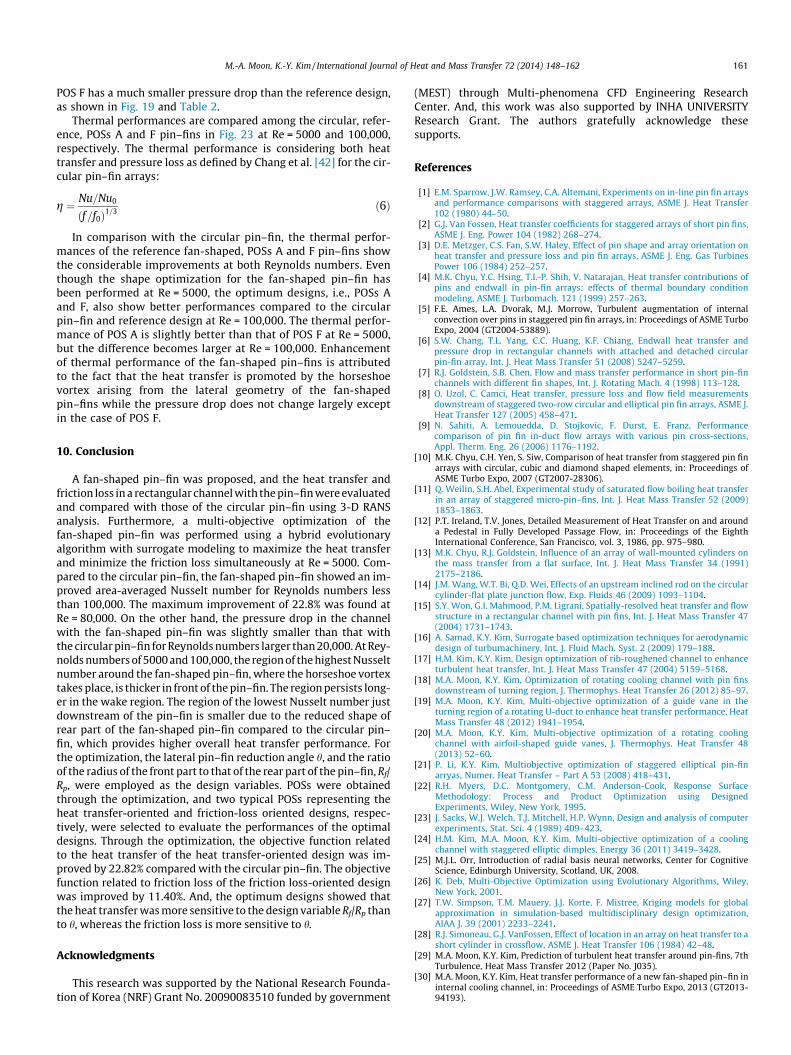
Thermal performances are compared among the circular, refer-ence, POSs A and F pin–fins in Fig. 23 at Re = 5000 and 100,000,respectively. The thermal performance is considering both heattransfer and pressure loss as defined by Chang et al. [42] for the cir-cular pin–fin arrays:
g ¼ Nu=Nu0
ðf=f0Þ1=3 ð6Þ
In comparison with the circular pin–fin, the thermal perfor-mances of the reference fan-shaped, POSs A and F pin–fins showthe considerable improvements at both Reynolds numbers. Eventhough the shape optimization for the fan-shaped pin–fin hasbeen performed at Re = 5000, the optimum designs, i.e., POSs Aand F, also show better performances compared to the circularpin–fin and reference design at Re = 100,000. The thermal perfor-mance of POS A is slightly better than that of POS F at Re = 5000,but the difference becomes larger at Re = 100,000. Enhancementof thermal performance of the fan-shaped pin–fins is attributedto the fact that the heat transfer is promoted by the horseshoevortex arising from the lateral geometry of the fan-shapedpin–fins while the pressure drop does not change largely exceptin the case of POS F.
10. Conclusion
A fan-shaped pin–fin was proposed, and the heat transfer andfriction loss in a rectangular channel with the pin–fin were evaluatedand compared with those of the circular pin–fin using 3-D RANSanalysis. Furthermore, a multi-objective optimization of thefan-shaped pin–fin was performed using a hybrid evolutionaryalgorithm with surrogate modeling to maximize the heat transferand minimize the friction loss simultaneously at Re = 5000. Com-pared to the circular pin–fin, the fan-shaped pin–fin showed an im-proved area-averaged Nusselt number for Reynolds numbers lessthan 100,000. The maximum improvement of 22.8% was found atRe = 80,000. On the other hand, the pressure drop in the channelwith the fan-shaped pin–fin was slightly smaller than that withthe circular pin–fin for Reynolds numbers larger than 20,000. At Rey-nolds numbers of 5000 and 100,000, the region of the highest Nusseltnumber around the fan-shaped pin–fin, where the horseshoe vortextakes place, is thicker in front of the pin–fin. The region persists long-er in the wake region. The region of the lowest Nusselt number justdownstream of the pin–fin is smaller due to the reduced shape ofrear part of the fan-shaped pin–fin compared to the circular pin–fin, which provides higher overall heat transfer performance. Forthe optimization, the lateral pin–fin reduction angle h, and the ratioof the radius of the front part to that of the rear part of the pin–fin, Rf/Rp, were employed as the design variables. POSs were obtainedthrough the optimization, and two typical POSs representing theheat transfer-oriented and friction-loss oriented designs, respec-tively, were selected to evaluate the performances of the optimaldesigns. Through the optimization, the objective function relatedto the heat transfer of the heat transfer-oriented design was im-proved by 22.82% compared with the circular pin–fin. The objectivefunction related to friction loss of the friction loss-oriented designwas improved by 11.40%. And, the optimum designs showed thatthe heat transfer was more sensitive to the design variable Rf/Rp thanto h, whereas the friction loss is more sensitive to h.
Acknowledgments
This research was supported by the National Research Founda-tion of Korea (NRF) Grant No. 20090083510 funded by government
(MEST) through Multi-phenomena CFD Engineering ResearchCenter. And, this work was also supported by INHA UNIVERSITYResearch Grant. The authors gratefully acknowledge thesesupports.
References
[1] E.M. Sparrow, J.W. Ramsey, C.A. Altemani, Experiments on in-line pin fin arraysand performance comparisons with staggered arrays, ASME J. Heat Transfer102 (1980) 44–50.
[2] G.J. Van Fossen, Heat transfer coefficients for staggered arrays of short pin fins,ASME J. Eng. Power 104 (1982) 268–274.
[3] D.E. Metzger, C.S. Fan, S.W. Haley, Effect of pin shape and array orientation onheat transfer and pressure loss and pin fin arrays, ASME J. Eng. Gas TurbinesPower 106 (1984) 252–257.
[4] M.K. Chyu, Y.C. Hsing, T.I.-P. Shih, V. Natarajan, Heat transfer contributions ofpins and endwall in pin-fin arrays: effects of thermal boundary conditionmodeling, ASME J. Turbomach. 121 (1999) 257–263.
[5] F.E. Ames, L.A. Dvorak, M.J. Morrow, Turbulent augmentation of internalconvection over pins in staggered pin fin arrays, in: Proceedings of ASME TurboExpo, 2004 (GT2004-53889).
[6] S.W. Chang, T.L. Yang, C.C. Huang, K.F. Chiang, Endwall heat transfer andpressure drop in rectangular channels with attached and detached circularpin-fin array, Int. J. Heat Mass Transfer 51 (2008) 5247–5259.
[7] R.J. Goldstein, S.B. Chen, Flow and mass transfer performance in short pin-finchannels with different fin shapes, Int. J. Rotating Mach. 4 (1998) 113–128.
[8] O. Uzol, C. Camci, Heat transfer, pressure loss and flow field measurementsdownstream of staggered two-row circular and elliptical pin fin arrays, ASME J.Heat Transfer 127 (2005) 458–471.
[9] N. Sahiti, A. Lemouedda, D. Stojkovic, F. Durst, E. Franz, Performancecomparison of pin fin in-duct flow arrays with various pin cross-sections,Appl. Therm. Eng. 26 (2006) 1176–1192.
[10] M.K. Chyu, C.H. Yen, S. Siw, Comparison of heat transfer from staggered pin finarrays with circular, cubic and diamond shaped elements, in: Proceedings ofASME Turbo Expo, 2007 (GT2007-28306).
[11] Q. Weilin, S.H. Abel, Experimental study of saturated flow boiling heat transferin an array of staggered micro-pin–fins, Int. J. Heat Mass Transfer 52 (2009)1853–1863.
[12] P.T. Ireland, T.V. Jones, Detailed Measurement of Heat Transfer on and arounda Pedestal in Fully Developed Passage Flow, in: Proceedings of the EighthInternational Conference, San Francisco, vol. 3, 1986, pp. 975–980.
[13] M.K. Chyu, R.J. Goldstein, Influence of an array of wall-mounted cylinders onthe mass transfer from a flat surface, Int. J. Heat Mass Transfer 34 (1991)2175–2186.
[14] J.M. Wang, W.T. Bi, Q.D. Wei, Effects of an upstream inclined rod on the circularcylinder-flat plate junction flow, Exp. Fluids 46 (2009) 1093–1104.
[15] S.Y. Won, G.I. Mahmood, P.M. Ligrani, Spatially-resolved heat transfer and flowstructure in a rectangular channel with pin fins, Int. J. Heat Mass Transfer 47(2004) 1731–1743.
[16] A. Samad, K.Y. Kim, Surrogate based optimization techniques for aerodynamicdesign of turbumachinery, Int. J. Fluid Mach. Syst. 2 (2009) 179–188.
[17] H.M. Kim, K.Y. Kim, Design optimization of rib-roughened channel to enhanceturbulent heat transfer, Int. J. Heat Mass Transfer 47 (2004) 5159–5168.
[18] M.A. Moon, K.Y. Kim, Optimization of rotating cooling channel with pin finsdownstream of turning region, J. Thermophys. Heat Transfer 26 (2012) 85–97.
[19] M.A. Moon, K.Y. Kim, Multi-objective optimization of a guide vane in theturning region of a rotating U-duct to enhance heat transfer performance, HeatMass Transfer 48 (2012) 1941–1954.
[20] M.A. Moon, K.Y. Kim, Multi-objective optimization of a rotating coolingchannel with airfoil-shaped guide vanes, J. Thermophys. Heat Transfer 48(2013) 52–60.
[21] P. Li, K.Y. Kim, Multiobjective optimization of staggered elliptical pin-finarryas, Numer. Heat Transfer – Part A 53 (2008) 418–431.
[22] R.H. Myers, D.C. Montgomery, C.M. Anderson-Cook, Response SurfaceMethodology: Process and Product Optimization using DesignedExperiments, Wiley, New York, 1995.
[23] J. Sacks, W.J. Welch, T.J. Mitchell, H.P. Wynn, Design and analysis of computerexperiments, Stat. Sci. 4 (1989) 409–423.
[24] H.M. Kim, M.A. Moon, K.Y. Kim, Multi-objective optimization of a coolingchannel with staggered elliptic dimples, Energy 36 (2011) 3419–3428.
[25] M.J.L. Orr, Introduction of radial basis neural networks, Center for CognitiveScience, Edinburgh University, Scotland, UK, 2008.
[26] K. Deb, Multi-Objective Optimization using Evolutionary Algorithms, Wiley,New York, 2001.
[27] T.W. Simpson, T.M. Mauery, J.J. Korte, F. Mistree, Kriging models for globalapproximation in simulation-based multidisciplinary design optimization,AIAA J. 39 (2001) 2233–2241.
[28] R.J. Simoneau, G.J. VanFossen, Effect of location in an array on heat transfer to ashort cylinder in crossflow, ASME J. Heat Transfer 106 (1984) 42–48.
[29] M.A. Moon, K.Y. Kim, Prediction of turbulent heat transfer around pin-fins, 7thTurbulence, Heat Mass Transfer 2012 (Paper No. J035).
[30] M.A. Moon, K.Y. Kim, Heat transfer performance of a new fan-shaped pin–fin ininternal cooling channel, in: Proceedings of ASME Turbo Expo, 2013 (GT2013-94193).

162 M.-A. Moon, K.-Y. Kim / International Journal of Heat and Mass Transfer 72 (2014) 148–162
[31] CFX-11.0 Solver Theory, Ansys Inc., 2008.[32] B.E. Launder, D.B. Spalding, The numerical computation of turbulent flow,
Comput. Methods Appl. Mech. Eng. 3 (1974) 269–289.[33] D.C. Wilcox, Reassessment of the scale-determining equation for advanced
turbulence models, AIAA J. 26 (1988) 1299–1310.[34] F.R. Menter, Two-equation eddy-viscosity turbulence models for engineering
application, AIAA J. 32 (1994) 1598–1605.[35] J.E. Bardina, P.G. Huang, T.J. Coakley, Turbulence modeling validation, AIAA J.
35 (1997) 1997–2121.[36] V.K. Garg, A.A. Ameri, Two-equation turbulence model for prediction of heat
transfer on a transonic turbine blade, Int. J. Heat Fluid Flow 225 (2001) 593–602.
[37] F.W. Dittus, L.M. Boelter, Heat Transfer in Automobile Radiators of the TurbulatorType, vol. 2, University of California, Berkeley Publication, 1930. pp. 443–461.
[38] B.S. Petukhov, Advances in Heat Transfer, vol. 6, Academic Press, New York,1970. pp. 503–504.
[39] JMP� 5.1., SAS Institute Inc., 2004.[40] MATLAB. The Language of Technical Computing, Release 14, The Math Works
Inc., 2001.[41] T. von Karman, Turbulence and skin friction, J. Aeronaut. Sci. 1 (1934) 1–20.[42] S.W. Chang, T.L. Yang, C.C. Huang, K.F. Ching, Endwall heat transfer and
pressure drop in rectangular channels with attached and detached circularpin-fin array, Int. J. Heat Mass Transfer 51 (2008) 5247–5259.