1 PROJECT DESCRIPTION - Environmental Clearance
35
1 1 PROJECT DESCRIPTION 1.0 INTRODUCTION MSPL Limited (MSPL) has been established a 1.2 MTPA Iron Ore Pellet Plant over 41 Acres, at Survey no. 2, 8, 9, 12 to 15, 132, 136 & part of 5, 6, 7, 16, 17 at Village: Halavarthi, Tahsil: Koppal, District: Koppal, Karnataka. Government of Karnataka has issued Environmental Clearance for establishment of pellet plant vide letter no. FEE 28 ECO 2010 dated: 1/12/2010. Karnataka State Pollution Control Board has granted consent for operation, combined consent order no. KSPCB/SEO/MINES/2010-11/673, Dated: 08.12.2010. As per Environmental Impact Notification S.O.1533 (E), dt.14th September 2006, as amended 2009, issued under Environment (Protection) Act 1986, has made it mandatory to obtain environmental clearance for scheduled development projects from MOEF&CC. With above Notification, Karnataka State Pollution Control Board had issued a letter vide PCB/MINI/LIMESTONE/2014-15/3579 Dated 16 Oct 2014 to MSPL Ltd, to obtain EC from MOEF&CC to the ‘stand-alone’ Pellet Plant within one year. The TOR was prescribed for undertaking detailed EIA-EMP study in addition to generic TOR vide Letter No. F.N. J-11011/383/2014-IA.II (I) Dated: 8 th April 2015. The EC was accorded to the project by MOEF&CC vide their Letter no No. F.N. J- 11011/383/2014-IA.II (I) Dated: 23 rd September 2016 1.1 Purpose of this environmental Appraisal Report The purpose of this Environmental Appraisal Report is to help the regulatory authority to review the proposed modification in the existing pellet plant and its impact on environment due to the addition of beneficiation circuit as high-quality iron ore is not available in the region of Karnataka. The quality of ore available to the process is in the range of 53-54% of Fe while the existing process is meant to be operated at 63% plus Fe. This Environmental Appraisals Report (EAR) accordingly addresses the change in environmental concerns for Pellet plant (Stand-Alone) of 1.2 MTPA capacity of M/s MSPL Limited, located at Village: Halavarthi, Tahsil: Koppal, District: Koppal.
-
Upload
khangminh22 -
Category
Documents
-
view
1 -
download
0
Transcript of 1 PROJECT DESCRIPTION - Environmental Clearance

1
1 PROJECT DESCRIPTION
1.0 INTRODUCTION
MSPL Limited (MSPL) has been established a 1.2 MTPA Iron Ore Pellet Plant over
41 Acres, at Survey no. 2, 8, 9, 12 to 15, 132, 136 & part of 5, 6, 7, 16, 17 at
Village: Halavarthi, Tahsil: Koppal, District: Koppal, Karnataka. Government of
Karnataka has issued Environmental Clearance for establishment of pellet plant
vide letter no. FEE 28 ECO 2010 dated: 1/12/2010.
Karnataka State Pollution Control Board has granted consent for operation,
combined consent order no. KSPCB/SEO/MINES/2010-11/673, Dated: 08.12.2010.
As per Environmental Impact Notification S.O.1533 (E), dt.14th September 2006,
as amended 2009, issued under Environment (Protection) Act 1986, has made it
mandatory to obtain environmental clearance for scheduled development projects
from MOEF&CC.
With above Notification, Karnataka State Pollution Control Board had issued a
letter vide PCB/MINI/LIMESTONE/2014-15/3579 Dated 16 Oct 2014 to MSPL Ltd,
to obtain EC from MOEF&CC to the ‘stand-alone’ Pellet Plant within one year.
The TOR was prescribed for undertaking detailed EIA-EMP study in addition to generic
TOR vide Letter No. F.N. J-11011/383/2014-IA.II (I) Dated: 8th April 2015.
The EC was accorded to the project by MOEF&CC vide their Letter no No. F.N. J-
11011/383/2014-IA.II (I) Dated: 23rd September 2016
1.1 Purpose of this environmental Appraisal Report
The purpose of this Environmental Appraisal Report is to help the regulatory authority to
review the proposed modification in the existing pellet plant and its impact on
environment due to the addition of beneficiation circuit as high-quality iron ore is not
available in the region of Karnataka. The quality of ore available to the process is in the
range of 53-54% of Fe while the existing process is meant to be operated at 63% plus
Fe. This Environmental Appraisals Report (EAR) accordingly addresses the change in
environmental concerns for Pellet plant (Stand-Alone) of 1.2 MTPA capacity of M/s
MSPL Limited, located at Village: Halavarthi, Tahsil: Koppal, District: Koppal.
2
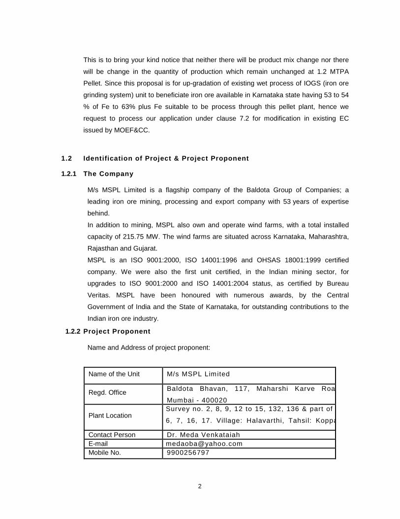
This is to bring your kind notice that neither there will be product mix change nor there
will be change in the quantity of production which remain unchanged at 1.2 MTPA
Pellet. Since this proposal is for up-gradation of existing wet process of IOGS (iron ore
grinding system) unit to beneficiate iron ore available in Karnataka state having 53 to 54
% of Fe to 63% plus Fe suitable to be process through this pellet plant, hence we
request to process our application under clause 7.2 for modification in existing EC
issued by MOEF&CC.
1.2 Identification of Project & Project Proponent
1.2.1 The Company
M/s MSPL Limited is a flagship company of the Baldota Group of Companies; a
leading iron ore mining, processing and export company with 53 years of expertise
behind.
In addition to mining, MSPL also own and operate wind farms, with a total installed
capacity of 215.75 MW. The wind farms are situated across Karnataka, Maharashtra,
Rajasthan and Gujarat.
MSPL is an ISO 9001:2000, ISO 14001:1996 and OHSAS 18001:1999 certified
company. We were also the first unit certified, in the Indian mining sector, for
upgrades to ISO 9001:2000 and ISO 14001:2004 status, as certified by Bureau
Veritas. MSPL have been honoured with numerous awards, by the Central
Government of India and the State of Karnataka, for outstanding contributions to the
Indian iron ore industry.
1.2.2 Project Proponent
Name and Address of project proponent:
Name of the Unit M/s MSPL Limited
Regd. OfficeBaldota Bhavan, 117, Maharshi Karve Road,
Mumbai - 400020
Plant LocationSurvey no. 2, 8, 9, 12 to 15, 132, 136 & part of 5,
6, 7, 16, 17. Vil lage: Halavarthi, Tahsil: Koppal,
District: Koppal.Contact Person Dr. Meda Venkataiah
E-mail [email protected]
Mobile No. 9900256797
3
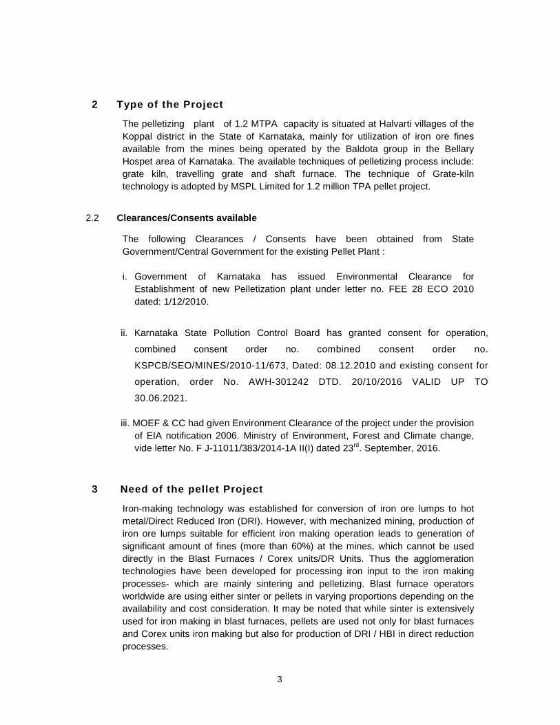
2 Type of the Project
The pelletizing plant of 1.2 MTPA capacity is situated at Halvarti villages of the
Koppal district in the State of Karnataka, mainly for utilization of iron ore fines
available from the mines being operated by the Baldota group in the Bellary
Hospet area of Karnataka. The available techniques of pelletizing process include:
grate kiln, travelling grate and shaft furnace. The technique of Grate-kiln
technology is adopted by MSPL Limited for 1.2 million TPA pellet project.
2.2 Clearances/Consents available
The following Clearances / Consents have been obtained from State
Government/Central Government for the existing Pellet Plant :
i. Government of Karnataka has issued Environmental Clearance for
Establishment of new Pelletization plant under letter no. FEE 28 ECO 2010
dated: 1/12/2010.
ii. Karnataka State Pollution Control Board has granted consent for operation,
combined consent order no. combined consent order no.
KSPCB/SEO/MINES/2010-11/673, Dated: 08.12.2010 and existing consent for
operation, order No. AWH-301242 DTD. 20/10/2016 VALID UP TO
30.06.2021.
iii. MOEF & CC had given Environment Clearance of the project under the provision
of EIA notification 2006. Ministry of Environment, Forest and Climate change,
vide letter No. F J-11011/383/2014-1A II(I) dated 23rd. September, 2016.
3 Need of the pellet Project
Iron-making technology was established for conversion of iron ore lumps to hot
metal/Direct Reduced Iron (DRI). However, with mechanized mining, production of
iron ore lumps suitable for efficient iron making operation leads to generation of
significant amount of fines (more than 60%) at the mines, which cannot be used
directly in the Blast Furnaces / Corex units/DR Units. Thus the agglomeration
technologies have been developed for processing iron input to the iron making
processes- which are mainly sintering and pelletizing. Blast furnace operators
worldwide are using either sinter or pellets in varying proportions depending on the
availability and cost consideration. It may be noted that while sinter is extensively
used for iron making in blast furnaces, pellets are used not only for blast furnaces
and Corex units iron making but also for production of DRI / HBI in direct reduction
processes.

4
Utilization of low grade ore and fines has to play an important role In India. Partly
due to the sponge iron sector; the overall percentage of lumps usage in steel
making (47%) is higher than most other countries. As hard ore reserves is
depleting day by day, lump generation suitable for blast furnace operation is
coming down resulting in production of large amount of surplus fines.
Alternative iron making processes for production of steel may lead to changing
pattern of use material inputs and feed stock causing significant shift in
respective share of lumps and agglomerated iron ore (pellets) and will also
enable the use of ores which could not be utilized earlier. As fines form
considerable part of iron ore resources, value addition to the iron ore fines, through
various activities such as Beneficiation, Pelletization is the need of the hour.
Presently, most of the coal based sponge iron plants in India, use iron ore lumps.
The requirement is generally 1.6 to 1.8 t/ t of sponge iron. These high
requirements are mainly due to the fines generated in handling the purchased ore
from the sources to the plant. This reduces the kiln campaign length and
increases the loss of ore fines.
Use of pellets with better physical and metallurgical properties for
sponge iron production reduces the accretion formation in the kiln and the
pellets consumption is about 1.6 t/t. Further, the production from the kiln is
expected to increase by 35% to 40%. It is noteworthy that the operations of the
iron ore mines of M/s MSPL Limited at Viom (high grade) and Lyll (Low grade)
are in process. Thus, the iron ore fines so generated, are utilized through
pelletizing route for making mainly coal based sponge iron and sometimes at blast
furnaces also..
The use of pellets is however, restricted in the Indian Blast Furnaces mainly due to
high cost of pellets compared to lump ore and captive sinter. But In the face of
shrinking reserves of high-grade ores, low grade ores must now be concentrated
before further processing and used. Pellets form one of the best options, due to
their excellent physical and metallurgical properties. Concentrating iron values in
ore needs grinding to liberate the gangue. Pelletizing is the only
agglomeration process of these beneficiated concentrates. Moreover, due to
their high strength and suitability for storage, pellets can be easily transported over
long distances, with repeated transhipments if necessary.
In view of the encouraging economic growth in the country, which is likely to
continue in the future, M/s MSPL Ltd had taken the decision and set up a pellet
plant.
Secondly, the Hospet-Bellary region in the state of Karnataka is a high potential
zone in terms of Iron and steel and allied industries because of natural resources
like water and raw materials like iron ore, Dolomite etc. The easy availability of iron
ore from nearby mines and water from Tungabhadra reservoir makes it an
attractive area for iron steel industry.

5
4 Need for modification in the process
The running 1.2 million ton per year pellet plant for which Environment
consents/clearances is already available from both the state Government and Union
Government as stated in para – 1.2 operates by using as mined iron ore fines (-10
mm ). After blending, the average Fe content of the fines are maintained
commensurate to an average Fe of minimum 63% in the pellet which is acceptable
by blast furnaces and coal based sponge iron plants. As mentioned before, the
Group has two operating mines – one high grade (+65%) and the other low grade
(56-60%). The compulsion of maintaining the minimum Fe% in the pellet at 63%
severely limits the proportion of the poorer grade captive iron ore in the pellet plant.
Further, In general, the average grade of iron ore available in Karnataka is lower
than those of Jharkhand, Orissa and Chhattisgarh. The present process available at
the pellet plant would severely limit use of iron ore fines of Fe % lower than 58%
which are abundant in Karnataka with economic price. So it is intended to
introduce a fine iron ore beneficiation circuit in the process to upgrade fine
ore with 53.5% Fe (average) to a fine ore concentrate (325 mesh – P80) with
63.3% Fe. Even though the concentration process will generate tailings and these
are planned to be stored in an eco friendly way, at an adjacent site for future
profitable use. The fine beneficiated concentrate would go to the hoppers of the
green balling plant in the main circuit of the pellet plant. The present equipment
used for dry grinding of the (-) 10 mm iron fines to 325 mesh would not be used
unless fines not needing beneficiation are used at any time. For such fines the wet
grinding can be used bypassing the beneficiation circuit.
5. The proposed modification in the process therefore would bring the following
benefits to the company as well as to the country as a whole.
• Poorer grade local iron ore fine (with Fe 54-56%) which have a veryrestricted use in the Indian/local steel industry will find an outlet leading tothe conservation of iron ore resources in line with our national mineral policy.
• This would lead to clearing of accumulated low grade fine ore dumps innearby mines.
• The company would be able to increase the output of the mine with poorgrade ore and would be able to lengthen the life of the better ore grade mineby reducing output. This would improve the viability of the pellet production.The present margin in pellet production from better grade ores is very thin.
• Even when the company is to buy fine ore from the market in Karnataka,going for poorer grade fines would give price advantages. Now that demandof poor grade fine ores from China had dwindled and import of low grade fineore is restricted in China.
6
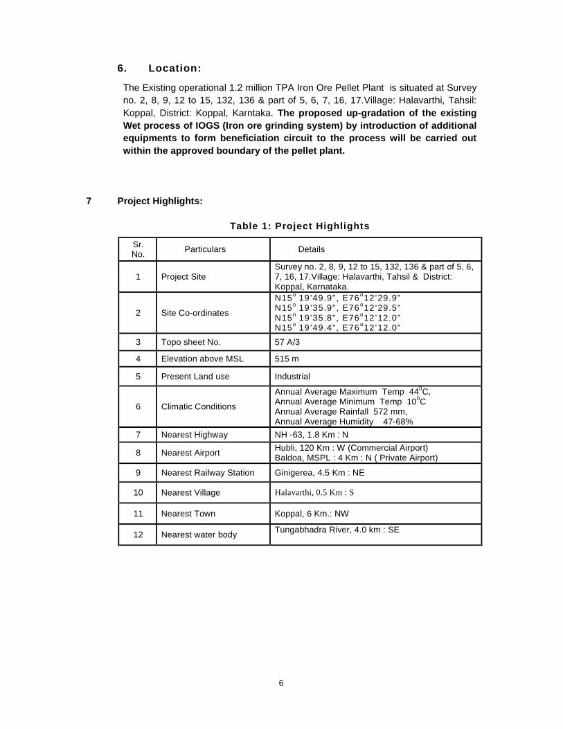
6. Location:
The Existing operational 1.2 million TPA Iron Ore Pellet Plant is situated at Survey
no. 2, 8, 9, 12 to 15, 132, 136 & part of 5, 6, 7, 16, 17.Village: Halavarthi, Tahsil:
Koppal, District: Koppal, Karntaka. The proposed up-gradation of the existing
Wet process of IOGS (Iron ore grinding system) by introduction of additional
equipments to form beneficiation circuit to the process will be carried out
within the approved boundary of the pellet plant.
7 Project Highlights:
Table 1: Project Highlights
Sr.No.
Particulars Details
1 Project SiteSurvey no. 2, 8, 9, 12 to 15, 132, 136 & part of 5, 6,7, 16, 17.Village: Halavarthi, Tahsil & District:Koppal, Karnataka.
2 Site Co-ordinates
N15o
19’49.9” , E76o12’29.9”
N15o
19’35.9” , E76o12’29.5”
N15o
19’35.8” , E76o12’12.0”
N15o
19’49.4” , E76o12’12.0”
3 Topo sheet No. 57 A/3
4 Elevation above MSL 515 m
5 Present Land use Industrial
6 Climatic Conditions
Annual Average Maximum Temp 440C,
Annual Average Minimum Temp 100C
Annual Average Rainfall 572 mm,Annual Average Humidity 47-68%
7 Nearest Highway NH -63, 1.8 Km : N
8 Nearest AirportHubli, 120 Km : W (Commercial Airport)Baldoa, MSPL : 4 Km : N ( Private Airport)
9 Nearest Railway Station Ginigerea, 4.5 Km : NE
10 Nearest Village Halavarthi, 0.5 Km : S
11 Nearest Town Koppal, 6 Km.: NW
12 Nearest water bodyTungabhadra River, 4.0 km : SE

7
Figure 1: General Location of the Project
Site

8
Figure 2: Specific Location of the Project Site

9
Figure 3: The Google Image of the Project Site
8 Size / Magnitude of Operation
The existing operational pelletizing plant of 1.2 MTPA capacity is situated at
Vil lage: Halavarthi, Tahsil & District: Koppal, Karnataka. The area of the
project is 41 Acres (Total area in possession is 113 Acres).
The Indian steel industry which predominantly uses expensive lump ore is
gradually moving towards usage of sintered ore and pellets. We have forayed into
pellets; with a modest start of 1.2 million tonnes per annum pellet plant. We cater
to the requirements of sponge Iron manufacturers in South India, by providing
customers premium quality pellets which will yield higher metallised Sponge Iron
with reduced production costs.
9 Iron Ore Pellet Plant
The Main Plant faci li t ies of the Pellet Plant after modificat ion would be as
under:
1. Raw Material Yard Existing
2. Dry Grinding units for Bentonite and Coal Existing
3 Fine ore beneficiation circuit comprising of:

10
The layout of the plant after introduction of f ine ore beneficiation is given in
the Drawing No. ENVIRO/MSPL/PELLET/EC/GL/001. The original layout of
the pellet plant is with provision for wet grinding of ore with space earmarked
and provision of the equipment. The proposed modif ications have been mostly
adjusted within those space provisions.
10. Plant description
10.1 Raw Material Yard
Iron ore fines for the pellet plant are received from MSPL’s mines by self-
discharging trucks / dumpers. A stockyard of about 60,000t capacity is available to
store about 10 day’s requirement of iron ore fines. Coal from port of unloading is
received at site in trucks and an overall stacking capacity of about 8,000t is
available which meet 60 days requirement of coal. Bentonite is received by trucks
in loose form and is stored in a covered building with a storage capacity of about
1100t, which meets 20 days requirement. Iron ore fines, coal and bentonite are
reclaimed from the respective storages by front end loaders.
10.2 Raw Material Preparation
Iron ore fines are currently wet ground in a ball mill and coal & bentonite is ground
in a vertical roller mill. Both the mills and bins of respective feed materials Iron ore;
Bentonite and Coal are provided in the same building. Ground product is stored in
separate silos of iron ore / bentonite and coat bin. After modification, fine ore will
be beneficiated from 53-54% Fe to over 63% Fe through scrubbing-de-sliming-
3AScrubber, primary grinding and spiral
concentrator buildingModification/Addition
3BSecondary, tertiary grinding and magnetic
separation building.
Modification/Addition
3C Filtration building for concentrate & pellets Modification/Addition
3D Filter cake storage Modification/Addition
3E Thickeners for concentrate & tails Modification/Addition
4. Disc Pelletizer Building Existing
5. Travel Grate, Rotary Kiln, Annular Cooler Existing
6. Product Screening Room Existing
7. De-dusting System Existing
8. Utilities / Services Existing
11
primary grinding-spiral concentration-secondary/tertiary grinding and magnetic
separation.
10.2.1 Description of the beneficiation process of fine ore.
The iron ore input is iron ore f ines (-) 10 mm. The iron ore material is
received in underground feed hopper. Iron ore is conveyed to 2 nos day
bins. There is needle feeder below the day bins, which discharges the
material onto another belt conveyor. This belt conveyor feed the
material to one scrubber. Water is mixed with iron ore and loose clay
particles are dislodged and come into slurry. Output of scrubber goes
to a vibrat ing screen having 1 mm aperture. Screen coarse size particle
are carried to the primary ball mill through a belt conveyor. Undersize
particles from the screen are sent to de-sliming cyclones at 25µm. De-
sliming cyclone underf low is mixed with primary ball mill output and
overf low is sent to tailing thickener. Output from primary ball mill is fed
to sizing hydro-cyclone targeted at 300µm size. The underf low
(+300µm) from this cyclone will route back to ball mill for further
grinding and overf low (-3-00µm) wil l proceed for further beneficiation
steps.
Sizing hydro-cyclone overf low will pass through de-sliming cyclone to
prepare material (30% solids) for spiral circuit. Material with about 30%
solids will pass to spiral circuit, where two products namely
concentrate and tails will be generated. Spiral concentrate wil l have
superior Fe grade of +63% Fe and will go to f inal grinding step. Spirals
tails will go to a regrinding mill. The product of regrinding mill wil l be
fed to magnetic separator circuit. Magnetic circuit concentrate wil l have
+63% Fe grade and will go to f inal grinding step. Output of f inal
grinding mill wi ll be sent to the concentrate thickener. Tails generated
from magnetic circuit wi ll be sent to the tail ing thickener.
Material from concentrate thickener will be f iltered using pressure f ilter
to product cake with about 8-10% moisture and will be stacked in the
designated area for pellet manufacturing. Tails from tailing thickener
wil l be sent to tailing f ilter to produce cake of about 15-17% moisture.
These cakes will be stacked in demarcated open area inside the plant
for a short time before shif t ing to an environmentally controlled
adjoining area for storage for further use. The tentative location of this
storage is shown a drawing ENVIRO/MSPL/PELLET/GL-002. Since the
need to store tails will arise only after commissioning of the
beneficiation circuit, EC for this site for temporary storage of tails will
be sought after words. The land is already in possession of MSPL and
proper environment protection for water and air pollution will be taken
by providing light vegetation cover on the dumps and providing a green
belt around it.

12
Quantity of waste generated will be about 0.65 mill ion tonnes per
annum.
The summary of the features of the f ine ore beneficiation process is
given in the Table below:
Sl.No.
Item Value
1 Annual production of concentrate envisaged 1,400,000 t
2 Feed grade % Fe 53-54
3 Feed size(-) 10 mmF80 6 mm
4 Product size P 80: 325 mesh
5 Product grade63.5% Fe in pellet
commensurate.
6 Annual working hours envisaged 7920 (330 days)
7 Annual feed input of fine ore 2,200,000 t
8 Average Fe in input f ines envisaged 53.5%
9 Specif ic gravity 3.88
10 Yield 64%
The flow chart of the iron ore beneficiation process to be adopted by
the company is given in Annexure-1 and also in the next page.

13
The Beneficiation of f ine ore circuit

14
10.2.2 Coal Grinding:
Imported coal is received in plant by trucks and is stock piled in coal shed. The
same is transferred to Day bin inside the Grinding unit for Ore / Bentonite and Coal
by a set of conveyors.
The main facilities in this system are raw coal bin, Belt weigh feeder, Hot gas
generator, vertical roller mill, Cyclone & bag filter with ac ID fan.
The day bin for coal fines is located inside the Ball mill building along the side of
dried ore bin and Bentonite bin. This bin is load cell mounted for level control in the
bin. Effective volume of the bin is approx. 200 cum with its storing capacity of 100
tons and a storage time of 10 hours. Bin is lined with wear resistant material.
The belt weigh feeder located below the bin, feeds regulated quantity of coal to the
vertical roller mill having a capacity of 20 TPH.
Hot air generator is attached to the mill, along with a combustion air fan and sealed
air fan. LSHS is used as fuel for the burners of HAG at present and has a provision
to change over to gas coming from the proposed iron making plant as and when
available.
After pulverizing, pulverized coal is pneumatically transported to the burner(s)
mounted at the head of rotary kiln (from discharge side of the kiln).
The compressors required to supply compressed air for pneumatic transport of
pulverized coal are also accommodated in the same building at Ground level.
Provision for nitrogen purging of the system is also given.
10.2.3 Bentonite Grinding:
The Bentonite is procured in lumps from of about <25 mm size and is ground in a
vertical Raymond roller mill of capacity 4 t/h to a size of 90% -200 mesh and will be
pneumatically transported to the bentonite bin of proportioning building.
10.3 Disc Pelletiser Building
The mixed material is conveyed and distributed to 6 mixed material bins with a
storage capacity of approx. 50 m3 each, installed directly above the 6 pelletizing
discs (5W + 1S). A horizontal conveyor, equipped with pneumatically operated
ploughs distributes the mixed material and green ball returns into the mix, material
bins. Any spillage passing under these ploughs is discharged at the head end of
the conveyor in to the last bin. Belt weigh feeders are provided below the outlet of
each bin to draw out required quantity of mixed material onto the pelletizing discs.
The mixed material is continuously discharged from the bins and fed to balling
discs. Controlled quantity of water shall be added to the balling discs to adjust the
final moisture content of the green balls. Green pellets are formed on the disc. The

15
discs are fixed at suitable inclination and variable speed drive and controlled water
spray to aid proper green ball formation.
The green pellets produced will be screened by roller screen to screen out (9)mm
to (+16) mm grain size and then will be distributed onto wide belt conveyor and
swing belt conveyor. It will be uniformly distributed onto Traveling grate bed and
specified thickness of the bed is 200 mm
For distributing the narrow stream of green pellets smoothly and evenly onto the 4
m wide, 48 m Length grate machine, an oscillating conveyor is installed which
feeds the green pellets uniformly onto a 4.6 m wide belt conveyor. This wide belt
conveyor discharges the green pellets onto a double deck roller feeder which
consists of an upper and a lower roller deck. The upper part screens out oversize
green pellets (Le. + 16 mm) and the lower deck will screen out undersize green
pellets (Le. – 8 mm). Undersize and over size green pellets are recycled by the belt
conveyors back to the balling area.
10.4 Induration System
Induration system consists of three facilit ies:
Travell ing Grate
Rotary kiln
Circular cooler
Green pellet are dried and pre-heated on the Travell ing grate,
indurated in the rotary kiln and cooled in the circular cooler.
Travelling Grate
The green balls are dried in the travell ing grate machine, which
consists of hood and moving mechanism, driving unit, scraping unit,
wind boxes, dust boxes, and lubrication system etc.
This machine is 4m wide and 45 m long. It is be driven by frequency
variable and speed adjustable double drive. The thickness of the
distributed material on the grate is 160 - 180mm. The machine on an
average runs at a speed of 1.65 m/min.
The travelling grate machine is divided into 4 zones, which are
• Air suction drying zone I
• Air suction drying zone II
• Preheating zone I
• Preheating-zone II.
Air Suction Drying Zone I (Updraft drying section)
The green pellets will be dried with 150oC drying air f low and the
adhesive water of green pellet is removed to prevent too much moisture
in the green pellet.

16
Air Suction Drying Zone II (Downdraft drying zone)
This zone uses recovered hot waste gas of nearly 400oC coming from
Preheat zone II making the pellet to withstand over 650 oC temperature
of Preheating zone I.
Preheating zone I
The hot air stream over 600oC will continue to dry and temperature rise
green pellet through material bed to ensure that the pellet can
withstand high temperature of 1050oC in preheating Zone II.
Preheating zone II
The pellet wil l be oxidized, heated and some will be sol idif ied and
hardened so that the pellet has certain strength which is necessary for
withstanding the impact while dropping from travelling grate to rotary
kiln. The heating source is the hot air stream of about 105 o0oC from
rotary kiln discharge end. Here the auxil iary burner is provided and fuel
oil is used as a fuel for the burner.
Rotary Kiln
The pellet dried through the travell ing grate machine are indurated and
hardened in the rotary kiln, which consists of barrel, supporting device,
stop wheel device, driving device, seal device, head seal kit, head seal
cover, end seal cover, position control system etc.
The rotary kiln is of 4.85m dia X 35m long, slope 4.25%. Soft and
frequency converter drive will be adopted. Rotary speed is -1 rpm. The
rotary kiln is provided with internal refractory lining with two gears
supporting system Resident time of pellet in kiln is about 30 min.
Rotary kiln fi ll ing rate is 8-10%. Baking temperature is about 1250 to
1300 deg. C.
The preheated pellet are fed into the kiln at end of the rotary kiln
through the scraper and chute. Head of the kiln is provided with long
flame burners of dedicated design. The pellet are heated / indurated by
radial heat uniformly inside the rotary kiln.
From coal injection vessels / hoppers located near the coal pulverizing
system, coal is pneumatically transported and injection is carried out to
the burners of rotary kiln. Electric valves controls the injection. Two
no's combustion air blowers are provided for supply of additional
combustion air.
The temperature of the rotary kiln is tested and controlled by infrared
and double temperature measurement instrument - f ixed thermo
couples.

17
Indurated pellets are discharged into the circular cooling machine
through the rotary kiln.
Main technical parameters of Rotary Kiln are:
1. Internal dia of the rotary kiln: 4.85m;
2. Length of the rotary kiln: 35m,
3. Slope of the rotary kiln: 4. 25%.
4. Rotary Speed of the rotary kiln:
5. Normal: 1.0 r/min;
6. Speed regulating range: 0.5 - 1.5 r/min;
7. Rotary speed at the emergency: 0.07r/min;
8. Fill ing rate: 8-10%
9. Material handling capacity 200 t/h,
10. Material to be handled- Hot dried Pellets Feeding sizes: 8-16mm;
11. Duration of the material kept in the kiln: 30min
10.6 Circular Cooler
Circular cooling machine consists of driving device, rotary device,
supporting roll, side stop gear, pressing roll, framework, feeding
hopper, cover, safety facil ity at the discharging point, wind box,
“material discharging hopper, covers for discharging area, discharging
device, double layer dust discharging valve and chimney etc.
The diameter of circular cooler is12.5 m, effective area is 69 m2.
Material distribution height is about 760 mm. Cooling time is 45-50 min.
The pellet wil l be cooled to less than 150 deg. C.
Over size pellets of +20mm and other particles will be sorted out
through the fixed sieve before the pellet is sent to the circular cooling
machine for cooling to ensure the cooling quality of the pellet.
The gas cover of the circular cooling machine is divided into three
zones:
• Zone I: Hot gas enters the rotary kiln through its head cover as
combustion air,
• Zone II: Hot gas enters directly in to the air suction drying zone II
of the 17ravell ing grate bar machine;
• Zone III: The gas discharged into the air through the chimney. The
circular cooling machine is provided with 3 air blowers.
Under the discharging hopper of the circular cooling machine is buffer
with capacity of 1620 m3, through which the material will be discharged
uniformly under the control of the gate valve.

18
The circular cooling machine is applied for cooling 1250 deg.
Centigrade pellet discharged from the rotary kiln. The sizes of the
discharged pellet ore are 8-16mm.
Main Technical Parameters are:
1. Effective cooling area: 69 sqm;
2. Material handling capacity: 200 TPH;
3. Material to be handled: Hot pellet;
Feeding temperature: about 1250 centigrade;
4. Feeding sizes: 8-16mm
5. Discharging temperature: less than 150 centigrade.
6. Intermediate dia of the circular cooling machine: 12.5m;
7. Width of the pallet: 2200mm;
8. Thickness of the material: 760mm
9. Normal cooling time: 45 min;
10. Driving device: type: pinion and girth gear driving.
10.7 Product Screening System
Pellet product (cooled pellets) are discharged into the belt conveyor
through the buffer bunker under the circular machine and then
transferred through the belt conveyor into the product screen house. A
vibrating double deck screen is provided to screen out all the undersize
pellets. The undersize pellets are sent back to the grinding section by
set of conveyors. The correct size pellets are sent to stock yard by
conveyor system.
10.8 Product Storage
Pellets from Pellet screening station are conveyed to the pellet
stockyard by means of conveyor C-16. An electronic belt weigh is
provided on conveyor C-16 to measure the outgoing pellets. At the
stockyard, the pellet are, stacked in 2 piles of 22.5 (w) x 150 m (I) x
6.0m (h) by means of a twin –boom stacker of 200 TPH capacity. The
pellet stockyard has a capacity of about 40000 t, which takes care of
10 days pellet production. The pellets are reclaimed by means of 2 no.
Front end loaders to load trucks for dispatch.
10.9 Utilities
Fuel Oil Facility
Fuel Oil storage system is designed as standalone facil ity to cater to
the requirement of furnace oil for Pellet plant. Storage capacity is
designed to meet the oil requirement for a maximum period of 15 days.
The storage system consists of 2 numbers of main storage tanks,
heaters, dykes around the storage tanks, unloading pumps, transfer
pumps and piping network along with heat tracing and insulation,

19
valves and fitt ings for unloading oil into tank and distribution of furnace
oil to consumers.
10.10 Repair Shop Facility
A repair shop is established to meet the day to day repairs and
maintenance requirements of various units of the plant. The shop is
equipped with machine tools like, Lathe, Mill ing machine, Dril ling
machine, Grinding machines etc. Other accessories like Workbench,
tool cabinet, and surface plate and tool trolley table are also
envisaged. Operations like Turning, Milling, Dril ling, Grinding, Jig
boring etc. can be performed on these machines.
10.11 Air Conditioning and Ventilation Facility
Air-cooled packaged type air conditioning plant is provided for the
control room for the switchyard. Split A/C units are envisaged in the
Executives rooms, Conference room & Laboratory. Appropriate
ventilation facilit ies are provided for Main Substation for the switchyard
& L T Sub-Stat ions in the pellet plant area to supply fresh air inside the
premises and lett ing out the hot air.
10.12 Compressed Air Facility
The total estimated requirement of Compressed Air for the pellet plant
is 2500 Nm3/hr at 7.0 Kg/cm2 g. To meet the above requirement it is
proposed to install 3 air compressors of 1250 Nm3/hr out of which 2
are working and 1 is on standby. Necessary cooling towers, cooling
water pumps, interconnecting air and water lines are installed in the
compressed air facilit ies. To meet the air qual ity requirement of
instrument and pneumatic conveying system 3 air dryers each of 1250
Nm3/hr are also installed. Inter plant air pipe lines are laid from the
Compressed Air Station to various production units to supply
compressed air.
10.13 Ventilation Facility
These facilit ies are provided for Main Substation for the switchyard & L
T Sub-Stations in the pellet plant area to supply fresh air inside the
premises and letting out the hot air.
10.14 Instrumentation and Process Control
All process and equipment controls for Pellet plant wil l be carried out
through PLC (Programmable Logic Controller). The total plant
consisting of pellet plant shall be controlled and operated from a
central control room (CCR). The control and instrumentation provided
for the proposed pellet plant shall be considered based on the latest
state of art technology in the field of control and instrumentation.

20
11 Process Description
Raw material iron ore f ines will be fed to Iron ore beneficiation system
(beneficiated cake 184t/h) 80% -325 mesh. The beneficiation process is
described above. For pelletization, we require f i lter cake of 8.5% to 9%
moisture, therefore we are adopting Pressure Filter supplied by M/s
Outotec (Larox) from Finland.
Filter Press system is then used to remove the excess water from the
slurry to produce filter cakes of approximately 8.5% to 9% moisture.
The produced Filter cakes are then transported to the proport ioning
building by belt conveyor. The raw material, Bentonite and the dust
collected in the plant is subjected to automatic weight proport ioning
with set proportioning ratio according to production requirements.
The proportioned mix is then mixed in vertical mixer supplied by M/s
EIRICH from Germany and the mixed proportioned is fed to Balling Disc
building (Pelletizing). The Balling building is provided with 6 sets of 6
m dia. ball ing disc with 5 in operation and 1 standby. 0.5% to 1.0%
water will be added in pelletizing process so as to realise optimum
value of water content in the mix for palletizing and green pellets are
produced.
The green pellets produced are screened by rol ler screen to screen out
(-8 mm) mm and (+16) mm grain size and is then distributed onto wide
belt conveyor and swing belt conveyor. It is uniformly distributed onto
the travelling grate bed which has a specif ied thickness of 200 mm.
The green pellets are dried and preheated on travell ing grate machine
(4m width, 48 m Length). The drying process consists of Updraft drying
section, Downdraft drying section, Preheating section I and Section II.
The Roasting and solidif ication process of pellet is done in the rotary
kiln (5m dia, 35 m Length) and rolled along the circumference of rotary
kiln. Specially designed Powder coal burner is installed at kiln
discharge end and the flame length, high temperature position and, air-
powdered coal ratio.With heat radiation action inside the kiln, the pellet
is roasted at the same time of roll ing so as to ensure uniform roasting.
The roasting temperature of pellet is 1250 – 13500C.
The temperature of the pellets discharged from rotary kiln is about
12500C and is uniformly distributed on the pellet cart of annular cooler
through receiving hopper of annular cooler. The pellet is then cooled to
below 100oC and is further oxidised in the annular cooler so that the
FeO content is reduced to below 1%.
The discharging hopper of annular cooler discharges the < 100oC
finished pellet to f inished product belt conveyor and then to product
Stock yard through Tripper conveyor.

21
For De-dusting purpose, Plant De-dusting ESP has been installed. The
dust collected is fed pneumatically to a collecting Bin in proport ioning
building and the same is reused as raw material.
The process flow of the pellet plant is given in Annexure-2 and also
reproduced below:

22
12 Raw material Requirement
The raw materials required for the proposed pellet plant are iron ore
f ines, pulverized coal (non Coking) that has a calorif ic value of 6800
Kcal/kg and 14% of ash content and Bentonite, which is used as binder.
A brief description of potential sources of raw materials and quality are
presented below.
The gross annual requirement of various raw materials (including
Moisture) of the plant and their indicative sizes with probable source
are given in table below.
Table 2: Annual requirement of major raw materials after
introduction of fine ore beneficiation
Sl.No.
Raw material
Annual
Requirement,
TonsProbableSource
1 Iron Ore Fines 2,200,000 MSPL Mines
2 Coal 53,900 Imported
3 Bentonite 15,300 Gujarat
4 Fuel Oil 15,600Local Oi l
Companies
The average chemical composition of raw materials used for production
of acid Pellets are shown in Table below –
Table 3: Chemical Composition of Raw Materials
A. Iron Ore Fines
Chemical Composition %
Total Fe SiO2 Al2O3 CaO MgO S P
53-54 12.58 2.78 -- -- 0.006 0.044
Physical Properties
Grain Size (mm) Moisture % Density (t /m3) LOI %
< 10 < 10 2.2 --
B. Coal
Calorif ic ValueKcal/Kg
GrainSize
Volat i leMatter
Ash S
6800 – 72000 – 25
mm10 – 20 % < 14 % <= 5 %

23
C. Bentonite
Chemical Composit ion % Physical property
SidroO2 Al2O3 CaO MgO LOI Grain Size
38 38 6.70 0.80 <= 8 -50 mm
The Iron Ore fines for the pellet plant will be supplied from the captive
mines of MSPL, situated near Hospet, which is about 21 km away from
the proposed plant site. These fines shall be transported from mine by
trucks.
High calorif ic value coal will be used as fuel for induration of the
pellets. Coal will be imported and from the port of import wil l be
transported to the plant site by trucks.
Bentonite shall be transported by road from Gujarat.
The specif ic requirements of raw materials (Dry & Net) Kg / t of Pellets
is as under –
Table 4: Raw Material (dry & net). Kg/t of pellets
Sr.No. MaterialSpecific Consumption
Kg/ t
1 Beneficiated Iron Ore Fines 1023.55
2 Bentonite 12
3 Pulverised Coal 40
Table 5: Material Balance for Pellet plant
Input Output
Mater ial % t/h t /yr Mater ial % t/h
Benef ic iated Iron
Ore Fines89.19 155.07 1228154.4 Pellets
87.14
151.5
Bentoni te 1.05 1.82 14414.00ProcessLosses
3.10 5.39
Water 9.76 16.97 134402.40 Evaporat ion 9.75 16.97
Total 100 173.86 1376970.8 Total 100173.8
6
13 Quality of Pellets
The average chemical composition of the acidic pellets is given in table
below:

24
Table 6: Chemical Composition of Pellets
Parameter %
I ron Total (Fe) >63.5
Sil ica (SiO2) <2.5
Alumina (Al2O3) <2.5
Sulphur (S) 0.001
The mechanical and metallurgical properties of the f inished pellets will
depend upon the physical and chemical characteristics of input raw
materials.
The average mechanical and metallurgical properties of f inished acid
pellets of 8-15 mm size are given in Table below.
Table 7: Mechanical and metallurgical properties of finished acid
pellets
Sr. No. Parameter Value
1
Size, 8 to 15 mm 95 %
+ 15 mm 2.5 % max.
-5 mm 2.5 % max.
2 Porosity 24 to 28 %
3 Cold Crushing Strength 250 Kg/p min.
4 ASTM tumble Index (+ 5,35 mm) 92 % min.
5 Abrasion Index (-0.5 mm) < 2 %
6 JIS swel ling Index < 14 %
Typical indicative quality specification of BF grade pellets is furnished
below:
Table 8: Typical Quality specifications of BF Grade pellets.
Chemical Quality
Parameter Specification Typical
Fe 63% min 65.5%
SiO2+Al2O3 5% max 4.5%
Al2O3 0.60% max 0.55%
Na2O 0.05% max 0.025%
K2O 0.05% max 0.025%
TiO2 0.10% max 0.10%
Mn 0.10% max 0.08%
P 0.04% max 0.03%
S 0.02% max 0.01%
V 0.05% max 0.02%
Basicity (CaO+Mgo)/ (Si02+Al203) – 0.4
Moisture ( free moisture loss at 105 degree centigrade) : 4% max (fair season),6% max monsoon
Physical Quality
Screen Analysis Specification Typical
-16mm, +9mm 85% min 88%

25
-9mm, +6.35mm 7% max 4%
-5mm 5% max 4%
Tumbler test (ASTM)
Tumble Index (+6.35mm) 94% min 95%
Tumble index (+0.6mm) 5% max 4%
Metallurgical Properties
Specification Typical
Swel ling (JIS) 20% max 18%
Compression strength 250 Kg/pellet min 260
Porosity 25% min 26%
Reducibi l ity (JIS) 60% min 62
Typical indicative quality specification of DR grade pellets is furnished
below:
Table 9: Typical Quality specifications of DR Grade pellets.
Chemical Quality
Parameter Specification Typical
Fe 66.50% min 66.80 %
SiO2+Al2O3 3.10% max 3.00%
Al2O3 0.60% max 0.55%
Na2O 0.05% max 0.025%
K2O 0.05% max 0.025%
TiO2 0.10% max 0.10%
Mn 0.10% max 0.08%
P 0 04 % max 0.03%
S 0.02% max 0.01%
Basicity (CaO+Mgo) / (Si02+Al203) – 0.5
Moisture ( free moisture loss at 105 degree centigrade) : 4% max (fair season),6% max monsoon
Physical Quality
Screen Analysis Specification Typical
-16mm, +9mm 85%min 88%
-9mm, +6.35mm 7%max 4%
-5mm 5%max 4%
Tumbler test (ASTM)
Tumble Index (+6.35mm) 94%min 95%
Metallurgical Properties
Specification Typical
Swel ling (JIS) 20% max 18%
Compression strength 250 Kg/pellet min 260
Porosity 25% min 26%
Reducibi l ity (JIS) 60% min 32
14 Water Requirement
In the pellet plant, for pellet making process water is required for
process, cooling of equipment, dust suppression, f ire f ighting and
drinking and sanitary needs the estimated water requirement is brief ly
465.21m3/day.

26
However the fine ore beneficiation process will require water to the
extent of difference between the water content of the outgoing filter
concentrate cake (about 10%) and tailing cakes (15-18%) and the water
intake with the fine ore from the mine (about 4-6%). To this quantity,
the process loss, blow down loss and evaporation loss of the
circulating water need to be added. For the beneficiation process, the
gross make up water requirement wil l be 0.455X10 6m3/Year or
1380m3/day.
The total estimated make up requirement of water for the pellet plant
with f ine ore beneficiation at rated capacity therefore come to 1845.9
m3 /day.(76.9 m3/Hr) The water is proposed to be made available from
the bore wells/rain water storage at the site and water from TB dam as
per present allocation from Karnataka Government.
Table 10: Water requirement
Sr.No.
PurposeQty
(m3/day)
1 Beneficiation process 1380
1 Pellet izing Process 276.75
2 Cooling of pellets 174.01
3 Domestic 14.45
Total
1845.21Or76.9m3/Hr
In beneficiation most of input water is in the form of retained water with
the filter cakes of the concentrate and tails. This water is totally
evaporated finally and no eff luent loss is expected. In the cooling
towers, the blow down is about 2-3%. This water is used for plantation
and spraying in the raw material yard to contain dust. .
The water requirement met from surface water resources. The water
from Tungabhadra Dam is pumped to the RCC Filtered water storage
tank. The Tungabhadra Dam Board had sanctioned a total of 2.5 MGD.
15 Power Requirement
The power requirement for the Beneficiation and Pellet Plant is 6.6kV
and will be met by the Karnataka State Electricity Board sanctioned
quota. Power will be received at 220 kV from Utility (GESCOM) and
stepped down to 33 KV and again to 6.6kV for further distribution. The
maximum demand of the total plant covered under this report is about

27
15 MW at 0.95 p. f. with an annual energy consumption of 80 mil lion
units.
210kV supply will be stepped down to 33 KV through 1 No. Of 63 MVA
power transformer. This is installed in the 220 KV switchyard at MRSS.
The control and Relay panels for the 220 kV bays are installed in the
control/switchgear building adjacent to the switchyard. A 6.6kV
switchboard is installed in the switchgear Room to feed the loads of
Ball Mill and stockyard area. The 6.6kV switchboard will also feed a
separate 6.6kV substation to feed the Mixing, Balling, induration and
screening areas. 6.6/0.433kV substations are located at different load
centres to cater to LT loads of the plant Reactive power compensating
equipment has been provided in the 6.6kV buses at MRSS to maintain
a power factor of 0.95. Illumination of the plant for the required level of
illumination will be as per industry standards .
16 Manpower Requirement
The present project is providing direct employment to nearly 168
workers. The local persons have been given preference in
employment as per the qualif ication and technical competencies.
Necessary training has been given to train the unemployed youths of
the nearby vil lages. Indirect employment opportunities have been
created in the periphery of the project automatically as the project
started operation in the region.
In order to operate and maintain the plant facilit ies, including its
technical general administration needs, the manpower in the Iron
Ore Pelletization Plant is estimated as 314. The above manpower
covers the top management, middle and junior level executives and
other supporting staff including workforce. The category wise
break-up of manpower is indicated in the following table.
Table 11: Category-wise break-up of Manpower
Sr. No Category Man Power
1 Managerial 30
2 Technical 68
4 Skilled 129
5 Semi-skilled 57
6 Un-skil led 23
7 Clerical 7
Total 314

28
17 Environment Management
The pollutants in the form of solids, liquids and gases generated
from various technological units of Iron Ore Pelletization Plant have no
hazardous effects on the environment. Pollution of the environment
not only adversely affects all li fe forms, but also shortens the life of
plant and equipment. This vital aspect, therefore, has been taken into
account while planning the plant and equipment and adequate
measures are being taken to limit the emission of pollutants within the
stipulations of statutory norms. Adoption of technology like recovery of
dust/ash for re-use as raw material fulf ils the twin objectives of material
conservation and pollution control.
17.1 Air pollution
Pollutants of concern from the proposed pellet are Particulate Matter,
Sulphur Dioxide, fugitive emission etc.
A stack of 75 m Height have been provided in Plant.
The MSPL is getting screened raw material and is stock piled in the
premises. Spraying of water on the stockyard stockpiles controls any
fugitive emissions from this area.
An ESP located near the travell ing grate does the process de-dusting
of the drying & induration area.
Plant de-dusting system for all the material transfer points and screens
is carried out by a bag filter system. Dust collected from the bag filters
is re-circulated
Pulverised coal is used as fuel for induration of pellets in rotary kiln of
Induration area. Coal is pulverized in vertical roller mill. This mill is
located in the same building of Ball mill for grinding iron ore and
bentonite. The mill is connected to the cyclone, bag filter and an ID
fan. Ground coal is collected in a bin below the bag filter. Product from
cyclone is also fed to the ground coal bin. 2 nos of ground coal
bins/hoppers are provided below the ground coal bin.
The dried waste gas will be discharged into the air through the
chimney.

29
17.2 Water pollution
17.2.1 Pellet making facilities
Waste water generation is only due to domestic and washing or cooling
water from pellet plant. The wastewater generated will be treated in the
STP and reused for plantat ion purposes. The makeup water
requirement for proposed pellet plant is only 12 m3/hr, This is mainly
used for cooling, make-up water dust suppression, process and
domestic use. The proposed water demand will be met from
Tungabhadra dam reservoir.
There is no eff luent generated in the Iron Ore Pelletization Plant. The
plant has been designed and equipment has been selected accordingly.
Thus, the plant is designed as “ZERO DISCHARGE”.
17.2.2 Fine ore beneficiation
The fine ore beneficiation needs process water for making iron ore
slurry to be passed through the various equipments as needed for wet
concentration of Fe in the ore. However most of this water comes back
to the circuit from the thickeners and filters used for making the final
concentrate and tailing cake. The major use of the water is to account
for the dif ference in the water contents of the concentrate (8-10%) and
the tail (15-18%) and the water input with the fine ore (-) 10 mm (4-
6%). Water losses are due to evaporation and other process losses and
blow down of the tanks (about 2-3%). The major used water therefore
goes with the product and the tails which eventually gets evaporated in
the drier or naturally. The process water lost is accumulated in a tank
and used for irr igat ion and spraying in the yard. Thus the Fine ore
beneficiation plant would also maintain a zero discharge of water
from the units.
17.3 Noise pollution
The physical description of sound concerns its loudness as a function
of frequency. Noise in general is sound which is composed of many
frequency components of various loudness distributed over the audible
frequency range. Various noise scales have been introduced to
describe, in a single number, the response of an average human to a
complex sound made up of various frequencies at different loudness
levels. The most common and universally accepted scale is the 'A'
weighted network dB (A). The scale has been designed to weigh
various components of noise according to the response of a human ear.
The major sources of noise generation in the pellet plant are from fixed
plant installations and external transport movements.

30
The common noise generating sources from the fixed installations are
screens, vibrators, conveyors and rotary kiln and the ball mills. Apart
from these, another noise generating source is DG set which will be
operated occasionally i.e. used as a standby source of electricity.
However, ID Fans are the major noise-generating source.
Trucks carrying the raw material into the plant premises and the
finished product from the industry are the main sources of noise
pollution.
Various measures to reduce noise pollution include reduction
of noise at source, provision of acoustic lagging for the equipment
and suction side silencers, selection of low noise equipment. In
some areas where due to technological process, it is not feasible to
bring down the noise level within acceptable limits, personnel
working in these areas are provided with noise reduction aid such
as ear muff ler and also the duration of exposure of the personnel
are limited as per the norms.
17.4 Solid Waste Management.
For the overall pellet plant, the pelletizing process practically
generates no solid waste. A very small quantity of coal f ines and iron
ore f ines will be generated and also dry dust from air pollution control
equipment, which will be reused, in the industrial process. Hence there
is no solid waste generation.
The fine ore beneficiation process however will generate tailing to the
extent of about 35% of the input iron ore which would have Fe content
33.4% on an average in compliance with the latest IBM norm. At rated
output of the plant, the annual generation of such tailing would be
650,000 t. The generated tailings from the tail slurry f ilter would be
transported to a designated site inside the plant boundary for a few
days ti ll i t is moved to a designated dumping yard outside the plant
boundary within MSPL land to the east of the existing plant fencing to
be stored for a few years ti ll these tail ings are reused. The proposed
dumping site will be environmentally protected by providing green belt
around and individual dumping stacks will be provided with a light
green over growth. The actual dumping requirement would take some
more time and a separate EC for the dumping site would be sought
soon. The temporary stocking of the tails inside the plant boundary is
shown in the revised plant layout drawing and the proposed dump site
in the adjoining land is shown in the overall site drawing.
The dried domestic sludge generated from sewage treatment plant will
be used as manure for green belt development.

31
18. Green Belt.Adequate green belt is provided all around the pellet plant and inside
the plant premises. Locally available types of trees which are resistant
to pollutants are planted. The detailed layout of the plant has been
prepared with indicative area of plantation for the whole plant.
The plantation has been done in a phased manner before
commencement of operation of the Pelletizing Plant. The green belt is
shown in the plant layout.
19. A Summary of this report is presented in a tabular form in the
next few pages.

32
Summary
A Comparison between the present operating process and
conditions and those proposed after introduction of fine ore
beneficiation.
Sl.No
Parameter Now After modification
1 ProcessPellet making with highgrade(av. 63.5%) f ineore input
Pellet making with lowgrade fine ore (53-54%)input
2 Product
1.2 mil l ion tons Pelletsfor use in sponge ironkilns and blast furnacesmostly.
1.2 mi ll ion tons Pelletsfor use in sponge ironkilns and blast furnacesmostly.
3 Input iron oreOre fine (-) 10 mm1.3486 mil l ion tons; Fe63-65%
Ore fine (-) 10 mm 2.2mill ion tons; Fe 53-54%
4Other process rawmaterials
Unchanged
5 Process steps
• Wet grinding ofore f ines andother rawmaterials
• Proportioning• Ball ing to green
pellets• Heat indurat ion to
hardened pellets• Cooling• Despatch
• Wet grinding ofore f ines andbeneficiation ofiron content.
• Dry gr inding ofother rawmaterials
• Proportioning• Ball ing to green
pel lets• Heat indurat ion to
hardened pellets• Cooling• Despatch
6 Area of the plant41 acres out of avai lable113 acres
41 acres out of available113 acres. Themodif icat ion would belimited to the exist ingplant s ite. However,some of the adjoiningavai lable land to beuti l ized to store tai l ingfor a few years t il l theirreuse. Separate EC forthe temporary dump wil lbe sought.

33
Sl.
No.
Parameter Now After Modification
6 Make up water requirement 19.4 m3/Hr 76.9 m3/Hr
7 Environment impact
7.1 Air pollut ion
The pellet plant usesESP and bag fil ter tocollect dust from theeff luent gases as wellas from the ambientair inside the plant.The process dust iscollected andrecycled in theprocess.
Spray is used toreduce dust in theyards and junctionhouses.
The same steps wil lcontinue. No airpollution from thebeneficiation circuitsince it is a wetprocess.
7.2 Water pol lution
The exist ing processuses very l i tt le water.Zero discharge ofwater is pract iced.
Introduct ion ofbeneficiation wil lrequire more make upwater as explainedabove. Most of thesewater wil l beult imately beevaporated either inthe atmosphere or atthe raw mix driers.Water spi lled from theprocesses and tankblow downs wil l becollected and used forspraying in the yardsas well as forirr igat ion. Zerodischarge of waterfrom the plant site wil lbe maintained.

34
Sl.
No.
Parameter Now After Modification
7.3 Solid waste generation
In the presentprocess the entiresolid waste iscollected and re-usedin the process. Sothere is pract ically nosolid wastegenerat ion.
With beneficiat ion off ine low grade ores, arejected portion calledtai ling wi ll ar ise whichis approximately 35%of the overall iron orethrough put. This wil lbe very low in Feabout 28.2% andmostly of sil ica andalumina. The tai lingswill be temporari lystored within the plantboundary for dryingand then shifted to anadjoining site (landowned by MSPL) forstorage for a few yearst il l it is used at thef il l ing work of theupcoming steel plant inthe site or used byemploying some of theupcoming technologiesfor recovery of si l icaand alumina.

35
Sl.
No.
Parameter Now After Modification
8
Overall advantages of
this proposed
modification
(1) Poorer grade local ironore fine including thoseowned by MSPL (with Fe54-56%) which have a veryrestricted use in theIndian/local steel industrywill find an outlet leading tothe conservation of iron oreresources in line with ournational mineral policy.
(2) This would lead toclearing of accumulated lowgrade fine ore dumps innearby mines.
(3) The company would beable to increase the outputof the mine with poor gradeore and would be able tolengthen the life of thebetter ore grade mine byreducing output. This wouldimprove the viability of thepellet production. Thepresent margin in pelletproduction from bettergrade ores is very thin.
(4) Even when the companyis to buy fine ore from themarket in Karnataka, goingfor poorer grade fines wouldgive price advantages. Nowthat demand of poor gradefine ores from China haddwindled and import of lowgrade fine ore is restrictedin China.
(5) In the present highlydepressed price situation ofiron ore and pellets themodification would bringcost reduction of themanufactured pelletsthereby providing bettermargin for the company.