
; i FLEXIBLE RADIATOR THERMAL VACUUM i_ _,, TEST ...
102
:_ ", 29 October 1982 /, ; i FLEXIBLE RADIATOR THERMAL VACUUM i_ _,, TEST REPORT i:_i t ' r e_; I _i Prepared For i i i : NATIONAL AERONAUTICS AND SPACE ADMINISTRATION Ji*i ]_ JOHNSON SPACE CENTER L:,' i t Under Contract NAS9-14776 i1 ¢'a" _" or en _. L. cox I
-
Upload
khangminh22 -
Category
Documents
-
view
0 -
download
0
Transcript of ; i FLEXIBLE RADIATOR THERMAL VACUUM i_ _,, TEST ...
:_ ", 29 October 1982 /,
; i FLEXIBLE RADIATOR THERMAL VACUUMi_ _,, TEST REPORT
i:_it '
re_;I
_i Prepared For ii i :
NATIONAL AERONAUTICS AND SPACE ADMINISTRATION
Ji*i ]_ JOHNSON SPACE CENTER
L:,'i
t Under Contract NAS9-14776
i1 ¢'a" _" oren _. L. cox
I
00000001
TABLE OF CONTENTS _i
PAGE
i.O SUMMARY/INTRODUCTION . • • • .................. 161
2.0 TEST OBJECTIVES .................... • • • • 4
3.1 TEST ARTICLE DESCRIPTION .................... 5
! 3•1 Soft Tube Flexible Radiator ............. i
3.2 Hard Tube Flexible Radiator .... . ........... ii
4.0 TEST CONFIGURATION ....................... 17
4.1 Test Support Hardware ................... 17
4.2 Radiator Panel Instrumentation .............. 23.=i
4.3 Freon 21 Safety Considerations ..............25
5•O TEST RESULTS .......................... 26--5
i 5.1 Soft Tube Radiator Panel ................. 26
5.1.1 Soft Tube Heat Rejection Evaluation ........ 26
-- 5.1.2 Soft Tube Fin Effectiveness ............ 35
_ 5.1.3 Soft Tube Radiator Flow/Pressure Drop Evaluation • . 38
7o 5.1.4 SINDA Thermal and Flow Analysis of Soft TubeI
Radiator Test ................... 52
5.1.5 Deployment/Retraction System ............ 59 _
5.2 Hard Tube Radiator Panel ................. 63
5.2.1 Performance .................... 63
5.2.2 Deployment/Retraction System ............ 7460 CONCLUSIONS........................... 77 II
7.0 REFERENC_ ........................... 77
APPENDICES
A Fl_ble Radiator Test Instrumentation List .......... 78
_ C Flexible Radiator Teat Timeline Notes ............. 87
00000001'TSA04

f
1I LIST OF FIGURES
i PAGE
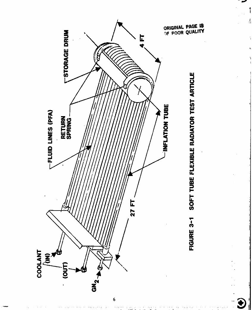
3-1 Soft Tube Flexible Radiator Test Article ........... 6
3-2 Soft Tube Flexible Radiator Fin Material ........... 7
3-3 Soft Tube Flexible Radiator Panel (Partial Deployment) .... 9
3-4 Hard Tube Flexible Radiator Test Article ........... 12
:_'i 3-5 Radiator Panel Details - Hard Tube Radiator ......... 13
• I 3-6 Flexible Fin Layup- Hard Tube Radiator ........... 14
I 3-7 Hard Tube Radiator Erection Linkage ............. 15[ 4-1 General Test Arrangement .................. 18
: _- 4-2 Soft Tube Radiator Deployment Table ............. 19
: l: 4-3 Hard Tube Radiator Deployment Table ............. 20
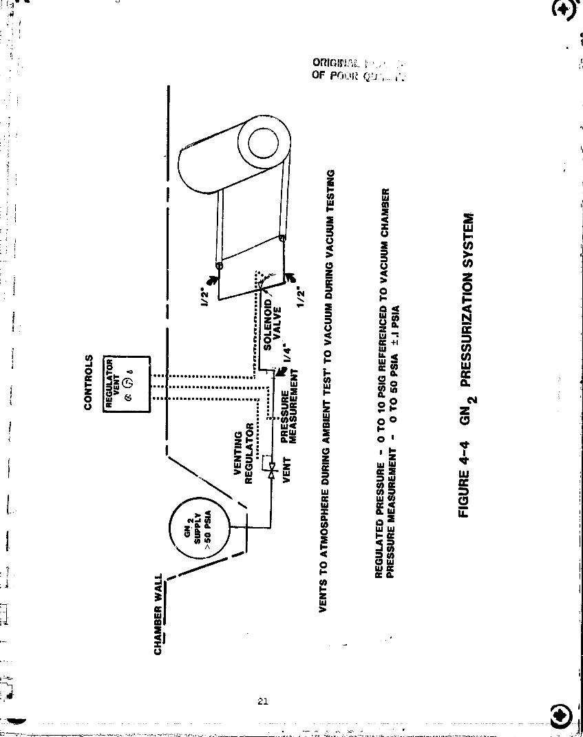
4-4 GN2 Pressurization System .................. 21
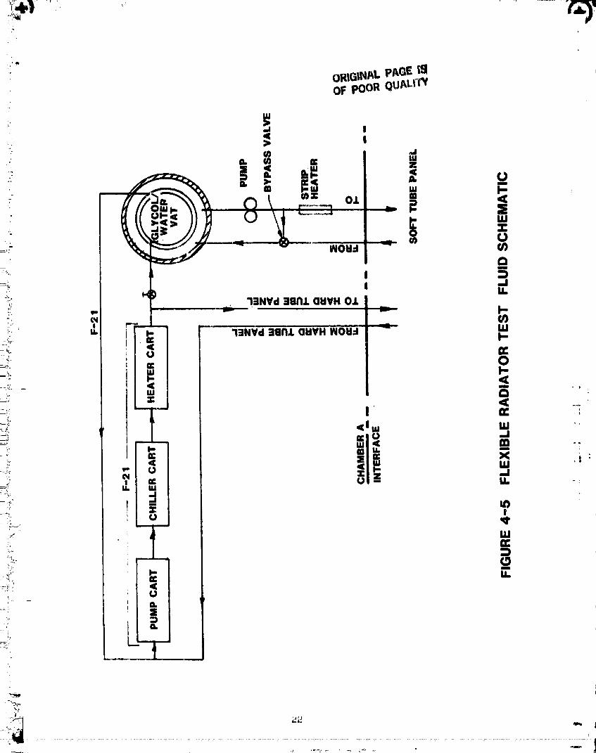
i F 4-5 Flexible Radiator Test Fluid Schematic 220_
4-6 Instrumentation Layout ................... 2_
: F 5-i Soft Tube Flexible Radiator Performance With Designi
Environment and TIN = iOO°Y.................. 32
|- 5-2 Soft Tube Flexible Radiator Performance With Design
Environment and TIN = 141°F................... 33 _
5-3 Soft Tube Flexible Radiator Performance With Coldwall
i" Environment (TS 180°F) 3_l D • • • • • • • • • • • • • • • • • •
5-4 Soft Tube Radiator Fin Temperatures At 4 Feet ........ 37
_I" 5-5 Soft Tube Radiator Pressure Drop Test Summary 39|
5-6 Soft Tube Radiator Pressure Drop (W/H20) ........... _2
I 5-7 Test Setup for System Flow Tost and Dye Injection Test .... _3
• I 5-8 Test Setup for Radiator Tube Flow Tests ........... 49
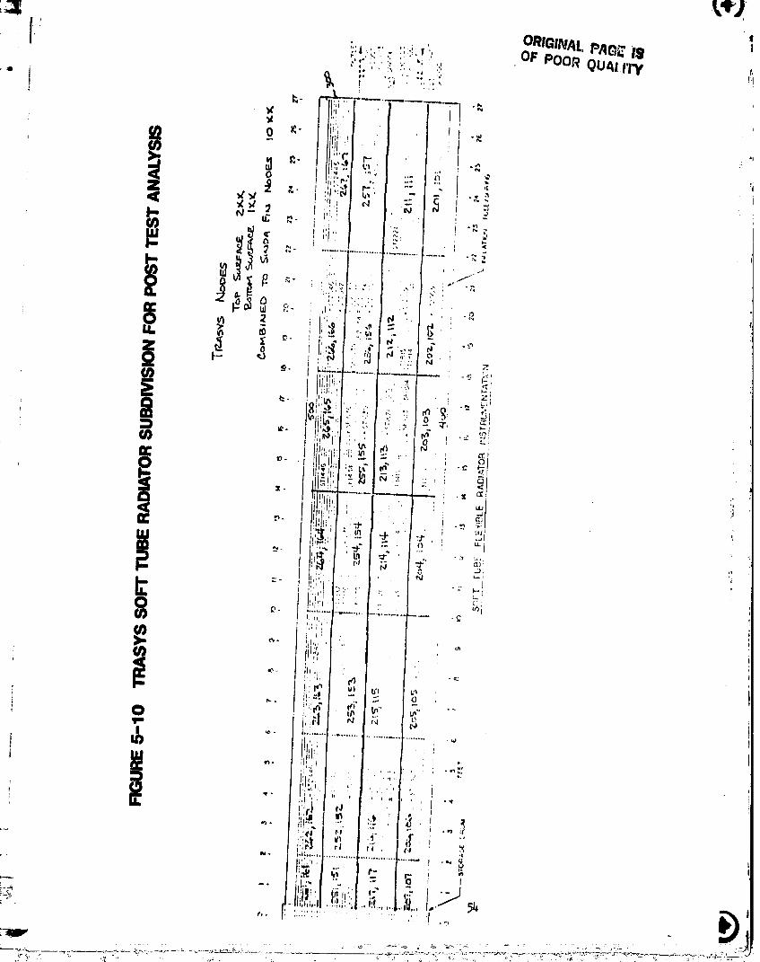
'[ 5-9 Corrosion Inside Flexible Radiator Manifold ......... 53[ 5-10 TRASYS Soft Tube Radiator Subdivision for Post Test Analysis • 54
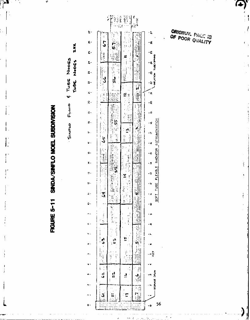
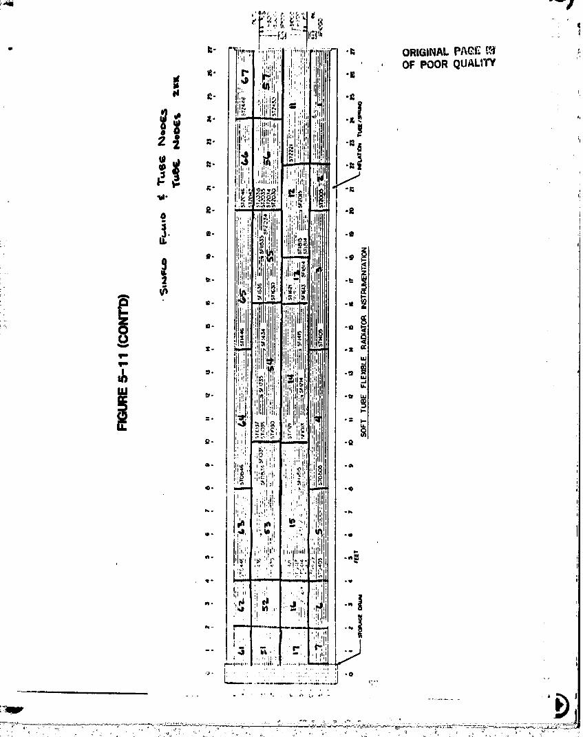
5-11 SINDA/SINFLO Model Subdivision ................ 56
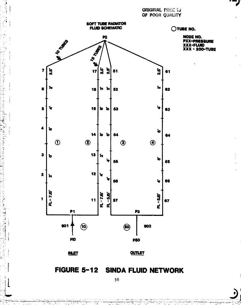
I i5-12 SINDA Fluid Network • • • .......... • ....... 58!
5-13 Hard Tube Flexible Radiator Post Test Damage Sketch ..... 68 0
[ " 5-14 Hard Tube Flexible Radiator Temperatures, T.P. 974 70!
5-15 Hard Tube Flexible Radiator Temperatures, T.P. 971 ...... Yl
5-16 Hard Tube Flexible Radiator Temperatures, T.P. 964-2 #3 • • • 72
5-17 Hard Tube Flexible Radiator T_mperatures, T.P. 964-2 #4 . • • 73
5-18 Hard Tube Flexible Radiator Test Support Hardware . .... . 75•_ ii
i
00000001-TSA05
i ¸¸ |
• i
, ' I LIST OF TABLESPAGE
j
i
:: I 3-1 Soft Tube Flexible Radiator Parameters ...... . . ..... 103-2 Hard Tube Flexible Radiator Parameters.. .... • ...... 16
• _ 5-1 Soft Tube Performance Test Summary for First Week . ...... 28|
! 5-2 Soft Tube Performance Test Summery for Secoxld Week • ...... 29
' _ 5-5 Comparison of TI59 Model with SINDA/SINFLO Model ........ 30I
:; i 5-4 Radiation Form Factors for Soft Tube Radiator Test • 31
i -,- 5-5 Radiatin$ Fin Effectiveness Estimates ............. 36// f_: I 5-6 Glycol/Water Thermal Properties Used in Analyses ........ 38
-_: 5-7 Flow Tube Temperatures Soft Tube Radiator (OF) ......... _i
t 5-8a System Pressure Drop Test Conducted 4-23-82 • • • • ...... kk
5-8b Preliminary Pressure Drop Test Conducted 4-21-82 ........ _
.... 5 9 L_ftSialDY j _6_ :_ - • e In ection Tests ............... • •
_;_,_," _ 5-iO Right Side Dye Injectlon Tests ................. _7
_- 5-11 Right Side Flow Tube Pressure/Flow Evaluation ......... 50
_! _, _-12 Leftsiae FlowTubePressure/FlowEvalu_tion ......... 5Z_' 5 13 Effective Sink Determination 60
_; " 5 14 Effective Sink Determination 60i e • • e • O • O • • • _ • • • • e •
5-15 Effective Sink Temperature Determination ............ 60
_ _ 5-16 Correlation of Soft Tube Model ................. 61
r_" .... 5-17 Soft Tube Radiator Test Point Correlation Fully Deployed .... 61
_°_: i 5-18 Hard Tube Performance Test Summary First Week .......... 6k_ 5-19 Hard '[ube Performance Test Summary Second Week ......... 65
:; ,- 5-20 Hard Tube Radiator Test Data Test Point 924 .......... 66
"J'.' 'I
,1 , t
;1
-- r
2-I
,:_? ili
"_"--_ _°"° '__:°0""°'"" _"" _::_' '_............... '......... 00000001-TSA06

!4[ i
!i I.0 SUMMARY/INTRODUCTION _
, The Flexible Radiator Test was conducted in the NASA/JSC Space '
i Environment Simulation Laboratory, Chamber A, on dates 17 September 1980 thru ,,i 19 September 1980 and 29 September 1980 thru 3 October 1980. The purpose of
the test was to evaluate the deployment, retraction and thermal/hydraullc
i performance of the soft tube and hard tube flexible radiator panels.
The soft tube panel test article was a 3.3' by 27' flexible panel
i designed and fabricated in 1978• It was designed to reject 1.33 MW of heat toa O°F sink temperature with lO0°F glycol/water or Coolanol 15 fluid inlet
_- temperature. The panel is stowed by rolling up on a i0 inch diameter by 4
i foot long drum and is deployed by inflating two four inch diameter inflation
. tubes which straighten two coiled flat springs. Retraction is by deflation of
i the tubes• The flow tube routing is ler4thwise in the panel. Fluid flows thee
27 feet length through half the tubes and returns the 27 feet through the
!: are Teflon material, 1/8" O.D., 1/16" I.D.other half. The tubes flexible PFA
and are spaced 0.75" apart. The soft tube panel is designed for a 90 percent
! probability of withstanding the micrometeoroid environment of low earth orbit
for 30 days.
_ The hard tube panel test article was a 25 foot long panel which
o tapers from 48 inches at one end to 32 inches at the other end, for 167 ft2
Of radiating area. It was designed and fabricated in the 1979/1980 time
; _ period to reject i•I kW to a O°F sink temperature The tubes are 1/8" O.D.,@ •
.027" I.D. 316 stainless steel tubes which are routed across the width of the
I panel so they do not flex on retraction. The tube thicknesses are sized to !
provide a 5 year micrometeoroid life. Freon 21 is the design fluid for this
:_ j panel. The fluid manifolds which are routed down each lor_ edge of the panel i_ _ |
are flexible, fabricated with 1/4 inch metal bellows, and roll up on i!
_ _ retraction• Stowage of the hard tube panel is on a 12 inch diameter by 4-I/2
feet storage drum.
_ ,. The soft tube radiator test article used in this test was subjectedI
j to limited prior testing. This testing consisted of a room ambient
deployment/retraction test and a thermal vacuum solar exposure test. The
:I deployment test was performed at Vought in May 1978 and the solar exposure
test was performed at NASA-JSC in November 1978. Successful deployment and
I" retraction of the panel was witnessed by the NASA contract technical monitor-g-
and recorded on 16 mm movie film. The purpose of the solar exposure test was
00000001-TSA07
/.m
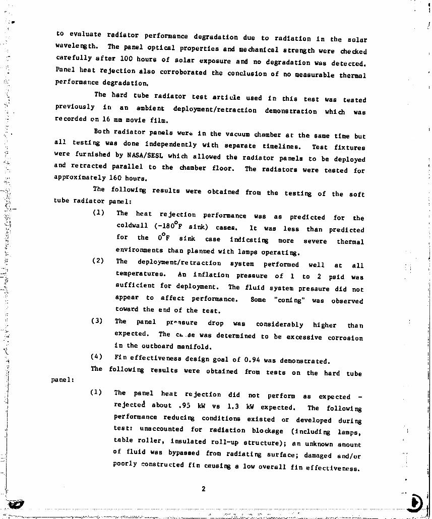
to evaluate radiator performance degradation due to radiation In the solar.
-" wavelength. The panel optical properties and mechanical strength were checked
- carefully after I00 hours of solar exposure and no degradation was detected.
! Panel heat rejection also corroborated the conclusion of no measurable thermal
-,i::.' performance degrada tlon.
ii_ The hard tube radiator test article used in this test was tested
_:_+_; previously in an ambient deployment/retraction demonstration which was
!! recorded on 16 mm movie film. t
!:' Both radiator panels were in the vacuum chamber at the same time but
: all testing was done independently with separate ttmelines. Test fixtures
_::i were furnished by NASA/SESL which allowed the radiator panels to be deployed
'_++ and retracted parallel to the chamber floor. The radiators were tested for° i
approximately 160 hours.
_ii The following results were obtained from the testing of the softiJo_'+ tube radiator panel:
o::- (1) The heat rejection performance was as predicted for the
_+_ coldwall (-180°F sink) cases. It was leas than predicted
=.- for the 0°F sink case indicating more severe thermal
_+" environments than planned with lamps operati_.
_. (2) The deployme nt/re tract Ion system performed well at all
o_: temperature9. An inflation pressure of 1 to 2 paid was
_ sufficient for deployment. The fluid system pressure did not
i! appear to affect performance. Some "coning*' was observed
_:. toward the end of the test.!7
_: (3) The panel pressure drop was considerably higher than
_;_. expected. The c_..se was determined to be excessive corrosion
-" in the outboard manifold.
_ (4) Fin effectiveness design goal of 0.94 was demonstrated.
_i The following results were obtained from tests on the hard tube
_'_i pane I :
(1) The panel heat rejection did not perform as expected -.ii! reJecte_ about .95 kN vs 1.3 kN expected. The following
+ performance reduci_ conditions existed or developed during
test" unaccounted for radiation blockage (including lamps,
ol table roller, insulated roll-up structure); an unknown amount
of fluid was bypassed from radiating surface; damaged and/or
_j poorly constructed fin causlog a low overall fln effectiveness. .
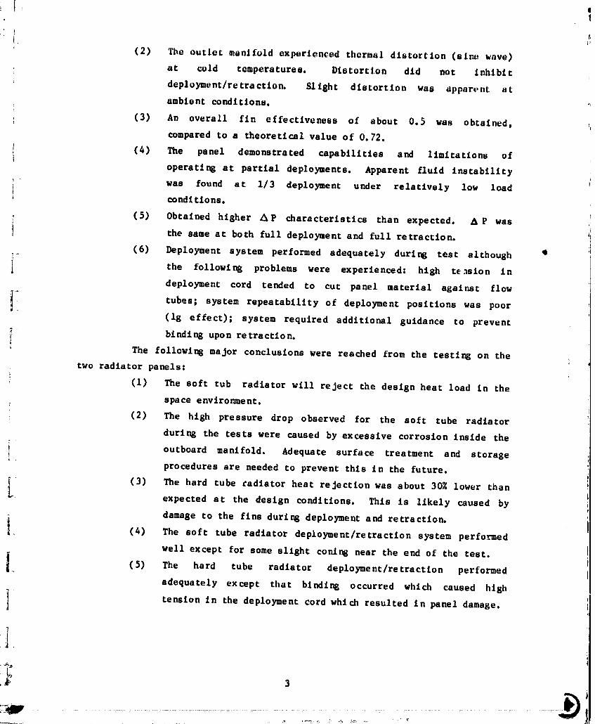
(2) The outlet manifold experienced thermal distortion (sine wave)
at cold temperatures. Distortion did not inhibit
deployment/retractlon. Sllght distortion was apparent at
ambient conditions. "
; (3) An overall fin effectiveness of about 0.5 was obtained,
compared to a theoretical value of O. 72.
{ (4) The panel demonstrated capabilities and limitations of
: operating at partial deployments. Apparent fluid instability
was found a t I/3 deployment under relatively low load
condl tions.
, (5) Obtained higher Ap characteristics than expected. A P was
1 the same at both full deployment and full retraction.
(6) Deployment system performed adequately during test although q
I the following problems were experienced- high te._slon in
deployment cord tended to cut panel material against flow
_- tubes; system repeatability of deployment positions was poor
(lg effect); system required additional guidance to prevent
binding upon retraction.
The following major conclusions were reached from the testing on the
two radiator panels"
: (1) The soft tub radiator will reject the design heat load in the
space environment.
(2) The high pressure drop observed for the soft tube radiator
during the tests were caused by excessive corrosion inside the
outboard manifold. Adequate surface treatment and storage
procedures are needed to prevent this in the future.
(3) The hard tube cadiator heat rejection was about 30_ lower than• expected at the design conditions. This is likely caused by
damage to the fins during deployment and retraction.
i, (4) The soft tube radiator deployment/retraction system performed
well except for some slight coning near the end of the test.
(5) The hard tube radiator deployment/re traction performed
adequately except that binding occurred which caused high
i tension in the deployment cord which resulted in panel damage.
t
.... 00000001-TSA09
2.0 TEST OBJECTIVES_ J ..... ii
Two flexible, deployable/retractlon, radlators were desi_,nnd nnd
. f,lbrte_ted by the Vought Corporation. The two radi.tor panels .redi.tin_uishable by their mission life design. One panel is designed with a qO
,- percent probability of withstanding the micrometeoroid environment of a low
_arth orbit for 30 days. This panel is designated the "soft tube" radiator
after the PFA Teflon tubes which distribute the transport fluid over the
panel. The second panel is designed with armored flow tubes to withstand the
.... same micrometeoroid environment but for 5 years. It is designated the "hard
tube" radiator after its stainless steel flow tubes.
: The primary objectives of testing these radiators fell in two
i-_ _ categories. The first was to determine the thermal performance of the
i radiators under anticipated environmental conditions. The second objective
_ _. was to demonstrate and evaluate the two deployment systems of the radiators in
:i_; a thermal vacuum environment. As part of the first objective of mapping the
_::!'_" thermal performance of the radiator, data was collected to determine the
_::i follo_:ing:
i_!_i_. (I) Radiator heat rejection capability in simulated thermal
'' envi ronme nts.....i
:-" _= (2) Pressure drop characteristic_ of the panels in deployed and
_,;i: _ retracted positions. :/
_:_ _ (3) Transport fluid flow stability in parallel tubes.
::_ _ (4) Flexible fin material fin effectiveness.
(5) Radiator thermal performance at partial deploylnent.
i/_'.._" The objective to evaluate the two deployment systems in a one-g test
: :_ had to be principally of a qualitative nature. Deploying and retracting the
'_ i ° radiator panels allowed the following to be observed.
(i) Deployment system operating characteristics in a thermal vacuum._
' _-° (2) Deployment system operat',onal variations and inconsistencies.
_! :I (3) Deployment system forces other than those attributable tot _ gravity and the test support equipment.
- i/
.i' !
O0000001-TSAIO

,__ _ 3.0 TEST ARTICLE DESCRIPTIONt i ...... i
• 3.1 SOFT TUBE FLEXIBLE RADIATOR
: The _oft tube flexibl_ r_diator, illu_trnted in Figure _-1, ts
..._i_ designed to reject 1.33 kW to a O°F sink uoln_ Coolanol 15 or glycol/water
" as the transport fluid with a 100°F radiator inlet temperaZure.
_,,! _i _,]ycol/water was used as the transport fluid in this test. The overall
! , radiator dimensions in the fully deployed configuration are 3.3 feet wade by
27 feet long to give a total radiator area (from both sides) of 178 square.
_ I feet. In the stowed configuration, the radiator rolls up on a drum 10 inches
_ii i in diameter by 4 feet long to a final diameter of approximately 17 inches.
_i _ The soft tube panel was constructed from six basic components: (1)
_ _"; I the flexible fin, (2) panel flow tubes, (3) fluid manifolds, (4) deployment
_ . inflation tubes, (5) retraction springs, and (6) the stowage drum. Principal
I to the capability of the panel to reject heat is the fin material. It
_ consists of two layers of 40 x 67 mesh silver wire screen and two layers of
:io/i 3-rail Teflonfilm.Allfour layersare beat fusedinto a flexibleoo_ composite conducting film. Figure 3-2 illustrates the resulting film cross
.... °i_ t" section. Solar absorptance of the fusion bonded laminate is about 0.16 and_, : • emittance is 0.71.
_': To distribute the heat from the transport fluid over the panel area, '
50 flow tubes of PFA Teflon (1/8" O.D. x 1/16" I.D.) spaced .75" apart are
_ used. Fusion bonding was used to form the laminate of the two fin layers
i i°! I sandwiching the flow tubes. These flow tubes run parallel to the long :i
_ii dimension of the radiator panel and connect to aluminum manifolds. The
t
....i] tube-to=manifold connections are made with standard Swagelock fittings, 3M
EC2216 adhesive, and tube inserts which allowed the fittings to capture the
soft tubing without collasping the tube wall. Samples of these connectionsi
were tested for extended periods in a 200°F water bath at 100 psi internal
pressure without leakage.
The fluid manifolds distribute the flow to the panel such that 25
flow tubes receive inlet flow. At the drum end of the radiator, a second
I manifold collects the flow and directs it into the other 25 flow tubes on the
return leg back along the panel into the outlet manifold (see Figure 3-1).
I The outlet manifold collects the transport fluid from the radiator and directsit back into the environmental control system.
-- ....................................... O0000001-TSA11

:., !
Q
The flexlb!_ radlat_r panel i_ _towed in, _ppro_!matel,V _igh$ wrap_
_n a i0 inch drum (she Figurn 3-3). Pour inch dlamot,or inflate.on tube_-_m_de
by Sholdahl af Kevlar/mylar or_ attachnd alol_ each _ldo of th_ radiator
" panel. 2poelally prepared flat oprlngo ore incorporated in each inflation
, tube in a pocket alone the drum slde of the inflatlon tube. The retraction
i sprin_s must be closely matched as to the magnitude of force each exerts. A
• mismatch in retraction sprin_ force, will not allow the radiator panel to
.... wind-up in the original stowage volume. A sprin_ adjustment capability _s
,; d_.si_ned into the spring hold down to fine tune the pnnel
deployment/retraction path. Panel deployment is achieved by pressurizing (_ I
psi_) the inflation tubes which work against the retraction sprin_ force to
roll the stowage drum outward exposing increasing amounts of panel area.
_,,. Table 3-1 summarizes some of the important design parameters for the:
' ,_ prototype soft tube radiator panel. These parameters represent the optimum
7 :;. design for the conditions imposed.
?,
.!
5,
: %-
'i
, i)
i)I
I
00000001-TSA14


¢
TABLE 3-1'j(
SOFT TUBE FLEXIBLE RADIATOR PARAMETERS
Coolant Fluid Coolanol 15
Radiator Panel Length 27'
Radiator Panel Area 89.1 Ft 2
Radiator Panel Width 3.3'
Number of Tubes 50
Tube Spacing 0.75"
Tube Outside Diameter 0.125"
Tube Inside Diameter 0.0625"
Relative Weight 58.5 lb.
Pressure Drop 25.5 psi
Bending Moment for 10" Dia Drum 14 in-lb
Minimum Outlet Temp (100°F Inlet) -70°F
Radiator Fin Emissivity 0.71
Effective Panel Absorptivity (Solar) 0.16
Radiator Fin Efficiency 0.943
Spring Dimensions (5" Dia Mandrel) 0.167" x 3" x 31'
* The relative weight includes manifolds, the deployment drum,
retraction springs, transport tubing and fittings, transport D
fluid, radiator fins, and the weight penalty for fluid pres-
sure drop.
),el
" _'- _ -:= " '........" _ .... _'° _° '......... ............. ' O0000:-"-_:O01--TSB02_:--
,l& V Jt
I, IJ
I
Q
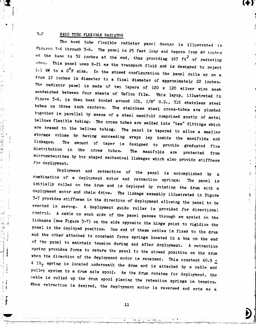
"_.2 HARD TUBE FLEXIBLE RADIATORi i i, , __ • iJ
Th_ hard tube flexible radiator pan,l design is illustratpd _n
1_i_,,r_.n5-4 through 3-6. The panel is 25 feet lon_ and tapers from 48 _nch,._
st the base to 32 inches at the end, thus providing 167 ft 2 of radiating
area. This panel uses R-21 as the transport fluid and is designed to reject
I.I kW to a O°F sink. In the stowed configuration the panel rolls up on a
drum 12 inches in diameter to a final diameter of approximately 22 inches.
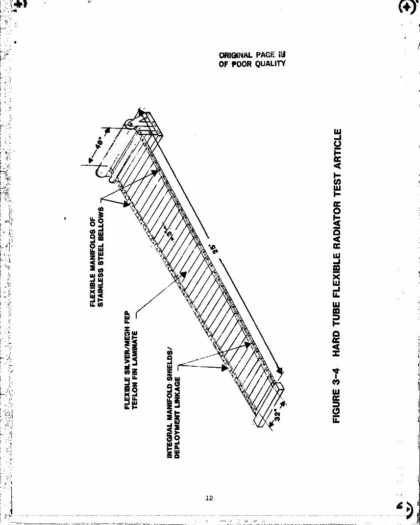
The radiator panel is made of two layers of 120 x 120 silver wire mesh
• sandwiched between four sheets of Teflon film. This layup, illustrated _n
Figure 3-6, is then heat bonded around i01, 1/8" O.D., 316 stainless steel
tubes on three inch centers. The stainless steel cross-tubes are plumbed
together in parallel by means of a steel manifold comprised mostly of metal
bellows flexible tubing. The cross tubes are welded into "tee" fittings which
_-_" are brazed to the bellows tubing. The panel is tapered to allow a smaller
_ _ storage volume by having succeeding wraps lay inside the manifolds and
-_ linkages. The amount of taper is designed to provide graduated flow
distribution in the cross tubes. The manifolds are protected fromI-/
micrometeorites by box shaped mechanical linkages which also provide stiffness
for deployment.
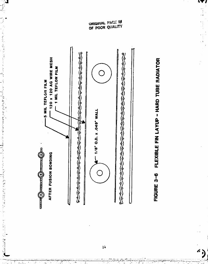
Deployment and retraction of the panel is accomplished by a
combination of a deployment motor and retraction springs. The panel is
initially rolled on the drum and is deployed by rotating the drum with a
deployment motor and chain drive. The linkage assembly illustrated in Figure
3-7 provides stiffness in the direction of deployment allowing the panel to be!
i erected in zero-g. A deployment guide roller is provided for directional
_ control. A cable on each side of the panel passes through an eyelet on the
-i' : linkages (see Figure 3-7) on the side opposite the hinge point to rigidize the
panel in the deployed position. One end of these cables is fixed to the drum
__ _: and the other attached to constant force sprigs located in a box on the end
....i ' of %he panel to maintain tension during and after deployment. A retraction
_i i sprin_ provides force to return the panel to the stowed position on the drumwhen the direction of the deployment motor is reversed. This constant 40.9 +i! , 4 Ibf spring is located underneath the drum and is attached by a cable and
_ i pulley system to a drum axle spool. As the drum rotates for deployment, the
cable is rolled up the drum spool placing the retention springs in tension.|
_ _ Wh,;n retraction is desired, the deDloyment motor is reversed and acts as ai I
Im
-z ,,-,. ............. ..... .......... .... .................................. 00000001-TSBO

_ z4
00000001-TSB06
_, ,,T/_ _ .,_ , •
00000001-TSB07
brake to insure a smooth retraction.
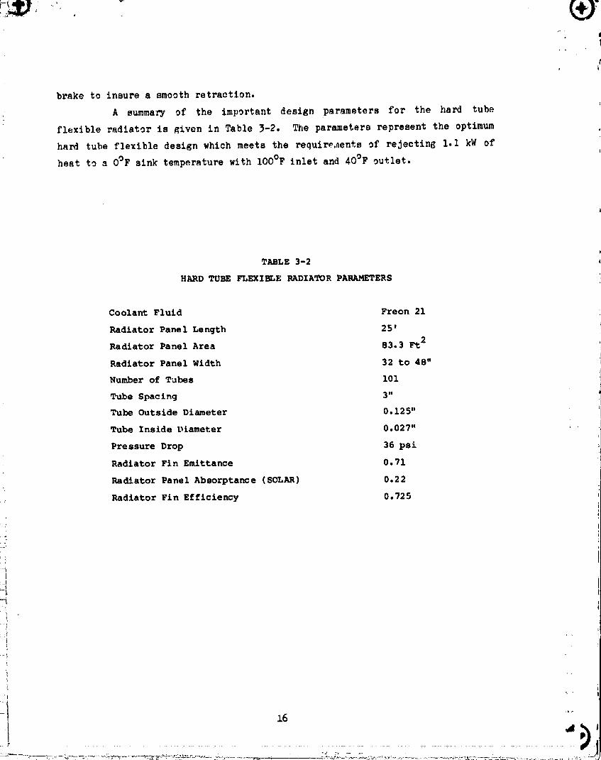
A summary of the important design parameters for the hard tube
flexible radiator is _iven in Table 3-2. The parameters represent the optimum
hard tube flexible design which meets the requirP,aente of rejecting I.I kW of
heat to a O°F sink temperature with iOO°F inlet and 40°F outlet.
TABLE 3-2
HARD TUBE FLEXImLE RADIATOR PARAMETERS
Coolant Fluid Freon 21
Radiator Panel Length 25'
Radiator Panel Area 83.3 Ft2
Radiator Panel Width 32 to 48"
Number of Tubes I01
Tube Spacing 3"
Tube Outside Diameter 0.125"
Tube Inside Diameter 0.027"
Pressure Drop 36 psi i
Radiator Fin Emittance 0.71
Radiator Panel Absorptance (SOLAR) 0.22
Radiator Fin Efficiency 0.725
i!
|
16
O000000q-TSBO8
I: z
. ?'
4.0 TEST CONFIGURATION
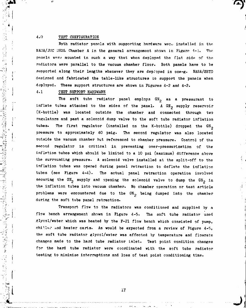
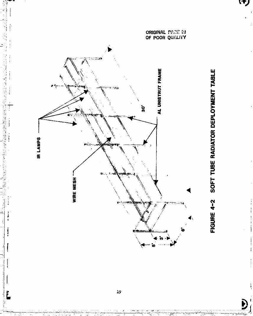
Both radiator panels with supporting hardware worL_ installed in thn i
_:i NASA/JSC SESL Chamber A in the general arrangement shown in Figure 4-I The
'_ _ p,_nel._w_r,_ mounted in such a way that when deployed the flat side of the
,: _ radiators were parallel to the vacuum chamber floor. Both panels have to be
!. supported along their lengths whenever they are depJoyed in one-g. NASA/SETD_ desi_,ned and fabricated the table-like structures go support the panels when
_:: deployed. These support structures are shown in Figures 4-2 and 4-2..i
! 4.1 TEST SUPPORT HARDWARE
_, The soft tube radiator panel employs GN2 as a pressurant to
,_ inflate tubes attached to the sides of the panel. A GN2 supply reservoir
-_ J (K-bottle) was located outside the chamber and connected through two
=_' " regulators and past a solenoid dump valve to the soft tube radiator inflation
....., ] tubes. The first regulator (installed on the K-bottle) dropped the GN 2
_:!i pressure to approximately 40 psig. The second regulator was also located/T_ outside the vacuum chamber but referenced to chamber pressure. Control of the
=_°_ second regulator is critical in preventing over-pressurization of the
_:_ infl_tion tubes which should be limited to a i0 psi (maximum) difference above
_°'_' the surrounding pressure. A solenoid valve installed at the split-off to the _.,
_i'>_'_, inflation tubes was opened during panel retraction to deflate the inflation
__: tubes (see Figure 4-4). The actual panel retraction operation involved
_ securing the GN2 supply and opening the solenoid valve to dump the GN2 in
the inflation tubes into vacuum chamber. No chamber operation or test article
problems were encountered due to the GN 2 being dumped into the chamber
_ii_; I during the soft tube panel retraction._t
:_ Transport flow to the radiators was conditioned and supplied by a
,_:_-:I flow bench arrangement shown in Figure 4-5. The soft tube radiator used
_,:_. glycol/water which was heated by the F-21 flow bench which consisted of pump,
...._iii'_ i chi_l_,: and heater carts. As would be expected from a review of Figure 4-5,
-'_ the soft tube radiator glycol/water was affected by temperature and flowrate
"_ i_::" chan_es made to the hard tube radiator inlet. Test point condition changes7_ _ for the hard tube radiator were coordinated with the soft tube radiator
ii_! i testing to minimize interruptions and loss of test point conditioning time.
• ..)
0000000]-TS809

ORIGINAL PAGiZ_.:_OF POOR QUALIT"g
"'4
O0000001-TSBIO
!"11'J, lr_;j:II!
ORIGINAL P_I,,_!_|111 +!iOF POOR QUALli+Y
.-1 m
i_ 2o t
O0000001-TSB12
!;wI. 21
O0000001-TSBI3
+r
ORIGINAl..PAGE tglOF pOOR QUAI..t'TV
, W
- " _,_, UJ
, o g, a
J
,s, I- I ltNVd tSn.L OEIVH NOU=I I_J
+_. < i n.(3 I_ 0_+ ,,=,1 _-_ ,, .. ...... I o,,,_;' LLI r, ,
=_+ eclw -I
;1+-- w "< _O +_,_',, Jim I_ iLL llillllm X i;
+_,: i ° m_ -,:-:_ .j
--?_. _ l
u. + + ILl
;, )
O000000]-TSB]4
@
:" i ORIGINAL PA_. L;-,:
_ 4.2 RADIATOR PANEL INSTRUMENTATION OF POOR QUALI_y• i
i The radiator panels were instrumented to obtain thermal performancei"
: _ data consistent with achieving the stated test objectives. Each radiator
*, pane] had fifty (36 gauge) thermocouples integrated with the particular panel
• I d,,ployment system to allow free and unrestricted panel deployment and
r_traction. The soft tube radiator was also equipped with redundant immersion
_ i thermocouples at the tr,_nsport fluid inlet and outlet manifold ports. Theii'"
i panel thermocouples (50 per panel) and the four immersion thermocouples were
i delivered with the radiator panels (Figure 4-6). NASA provided and installed(4
_- all additional instrumentation and connecting cables. This additional
7 instrumentation consisted of:
_- ! i) Inlet Pressure Transducer - one at each panel inlet port
_ 2) Delta Pressure Transducer - one across each pane'l's inlet
_i: and outlet port
...._ 3) Platinum Probe _Lermistors - one at inlet and outlet ports
,_: (two per radiator panel)
i; 4_ Flow Meters - one per transport fluid loop,
_; outside the vacuum chamber
5) Immersion Thermocouples - on flow bench for monitoring
F-21 flow conditioning
!_ 6) Thermocouples - on chamber walls, floor, test
support structure, deployment
-.- motor, and screwjack motor
• 7) IR Radiometers - twelve per panel
_ All the test data was processed through the NASA/SETD FLEX data
system. The data was processed real-time and displayed on CRT's throughout
the testing. Hard copies (called SCOOPS) of all processed data items were
r_ obtained at regular intervals and at various other specified times as
_ conditions warranted. In addition, all the test data was recorded on magnetlc
( tape for post-test plotting and analysis.
To record the data/information to make the various qualitative
assessments concerning the radiators, NASA installed three, in-chamber movie
cameras. Each camera had 'pan' and 'zoom' capabilities. Approximately one
hour of video information was recorded for permanent retention.
"- 00000001-TSC01

I IJ
i r!i
i 4.3 FREON 21 SAFETY CONSIDERATIONS
The toxic nature of Freo_ 21 is widely reported and since the hard
tube radiator used Freon 21 as the heat transport fluid, appropriate ',
p_'_c_d,,reswere established to safe guard personnel. The Freon 21 flow bench
,nd test article were estimated to contain 500 pounds of Freon 21. Since the
flow bAnch was pressure and leak checked at approximately 2.5 times the
operating pressure, the test article was assumed to offer the greatest
potential for a Freon 2] leak. If such a leak had occurred, sensors
positioned at the inlet to the diffusion pumps would have alerted test
personnel. Test article pressures were strictly controlled from exceeding
! verifiable safe limits.
i Before test personnel were allowed in the vacuum chamber after ai repress, an assigned safety monitor entered the chamber to test the Freon 21
concentration level. After the first two chamber repressurizations,
" oncentration levels of 6-7 parts per million (ppm) were detected in the
chamber. After the latter repressurizations concentration levels were lower,
i approximately 2 ppm. This apparent improvement is believed to be due tof
instrumentation accuracy because no fluid system repairs were made after the
:I- initiation of testing. The area around the Freon 21 flow bench (outside the
_ chamber) was monitored throughout the test for F-21 concentration level.
%_
00000001-TSC03
I omomAt,p .GE;Sor:eooe QUAL V¢°
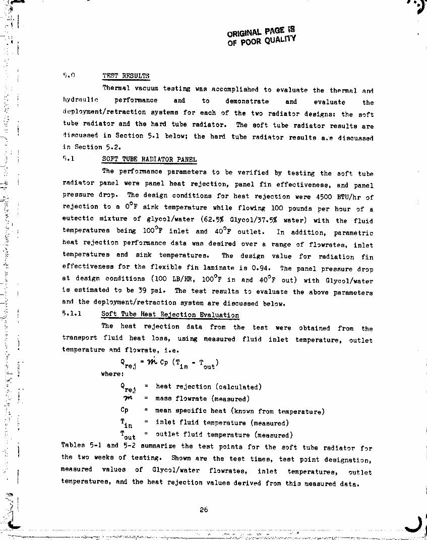
5.O T_ST RESULTS
Thermal vacuum testing was accomplished to evaluate the thermal and
_" I hyd ra,£lic performance and to demonstrate and evaluate the
_:" deployment/retraction systems for each of the two radiator designs: the soft
tube radiator and the hard tube radiator. The soft tube radiator results are
+ discussed in Section 5.1 below; the hard tube radiator results a.e discussed
.... in Section 5.2.
i; i 5.1 SOFT TUBE RADIATOR PANEL
_'+ The performance parameters to be verified by testing the soft tube
_ radiator panel were panel heat rejection, panel fin effectiveness, and panel
_: pressure drop. The design conditions for heat rejection were 4500 BTU/hr of
ii_ rejection to a O°F sink temperature while flowing iOO pounds per hour of a
_ eutectic mixture of glycol/water (62.5% Glycol/37.5% water) with the fluid
_[ temperatures being IOO°F inlet and 40°F outlet. In addition, parametric
_i heat rejection performance data was desired over a range of flowrstes, inlet
_ temperatures and sink temperatures. The design value for radiation fin
°_ effectiveness for the flexible fin laminate is 0.94. The panel pressure drop
at design conditions (I00 LB/HR, IOO°F in and 40°F out) with Glycol/water
is estimated to be 39 psi. The test results to evaluate the above parameters
and the deployment/retraction system are discussed below.
_i; _ 5.1.1 Soft Tube Heat Re_ection Evaluation
_ _ The heat rejection data from the test were obtained from the
:i transport fluid heat loss, using measured fluid inlet temperature, outlet: J
, temperature qnd flowrate, i.e.i?
i _" Qrej = _ Cp (Tin - Tou t)
whe re:
' QreJ_: = heat rejection (calculated)
'_" i _ = mass flowrate (measured)
, Cp = mean specific heat (known from temperature)
o +_,_ Tin_ = inlet fluid temperature (measured)
'_+ Tou t = outlet fluid temperature (measured)
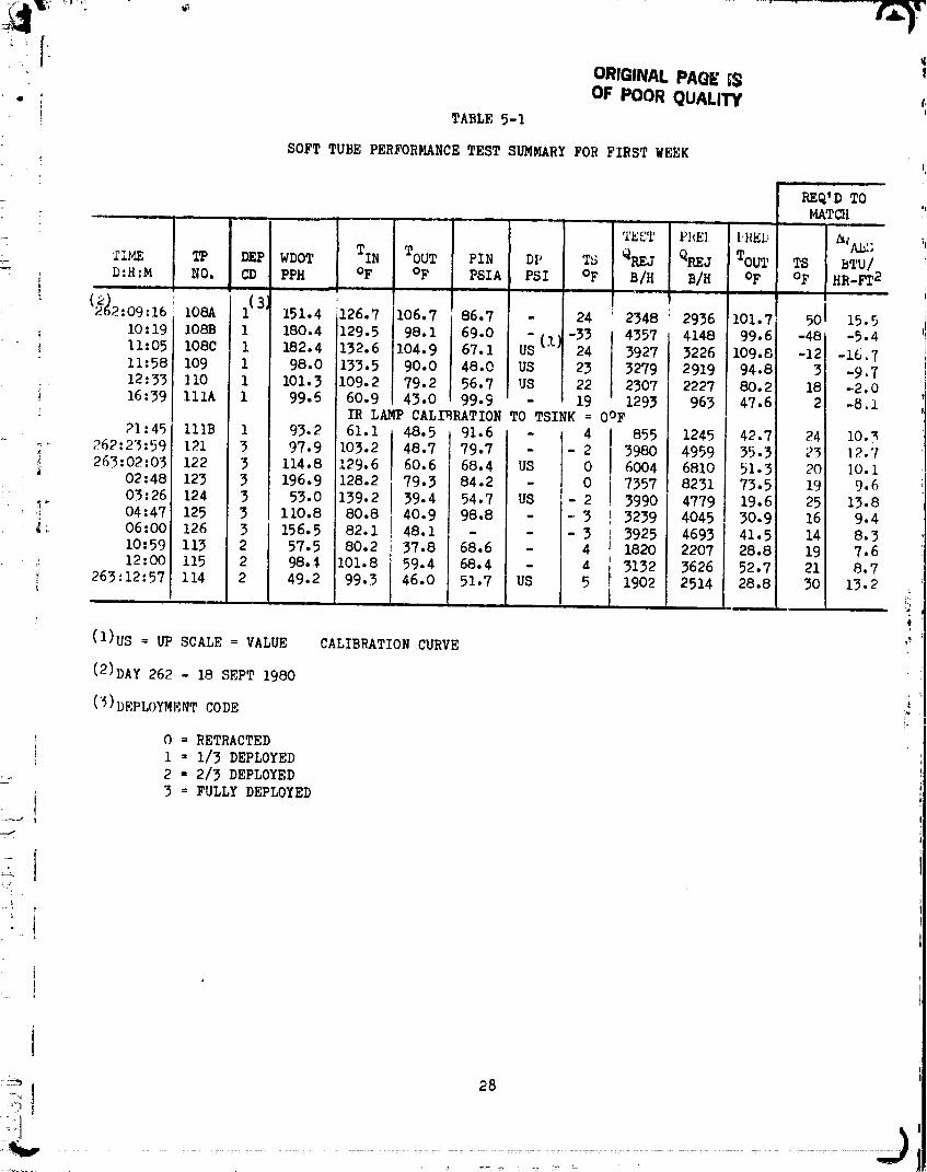
Tables 5-I and 5-2 summarize the test points for the soft tube radiator for
,+ _ the two weeks of testing. Shown are the test times, test point designation,
i measured values of Glycol/water flowrates, inlet temperatures, outlet
+ temperatures, and the heat rejection values derived from this measured data.
iL 26 J
00000001-T$C04

t!
ORIGINAL PAGE _. _ _!iOF POOR QUALITY
Predictions were made for comparison purposes for each of the test
points shown in Table 5-1 and 5-2 using a radiator analysis program written
for use on the TI 59 programmable calculator. The analysis program : '_
progressively solves for the temperatures for a number of panel elements by an
iterative process using the followir_ equations.
+ hrWl (_--p)
Ti = Ts + (Ti_1 - Ts) e
- + )
hP hrW A_)hP(_i_z-T s) "hP+_rWWbi + ....... e= Ts hP + hrW
whe re:
T i = the fluid temperature leaving element i
T s -- radiation sink temperature
h = fluid-to-tube heat transfer coefficient i •
p = area of heat transfer for h per unit length (wetted
perimeter) "_''
hr = radiation heat transfer coefficient between panel " "
and sink temperature
W = panel width
= mass flowrate of fluid
Cp = specific heat of fluid
AX = flow length for each element
¢ = panel emissivity
= panel fin effectiveness
Tbi = the mean radiation temperature for element i
The set of equations is solved iteratively for each of the elements of the
panel, starting at the fluid inlet end and progressing to the outlet. (The
numbor nf elements for the panel is input and must be between ] and 20,
inclusive. Ten elements were used for the test analysis.)
Values input into the analysis were as follows:
h = 51.39 BTU/hr-ft2-°F
WP = .409 Ft
2T
...........................uuuuuuu,'...... TSC05
ORIGINALPAGEG$ !, OF POORQUALITY t,
• ; ,Im TABLE 5-1
SOFT TUBE PERFORMANCE TEST SUMMARY FOR FIRST WEEK
ii
REQ'D TOMATCH '
e t ,c,II
• 21ME TF DEP WDOT TIN TOUT PIN DP TS _REJ Q_J TOUT TS BTU/D:H:M NO. CD PPH OF OF PSIA PSI OF B/H B/H OF OF HR-FT 2
22_--2:09:16108A i{'31 151.4 126.7 1106.7 86.7 - 24 I;2348 2936 101.7 501 15.5
I0:19 I08B l 180.4 129.5 98.1 69.0 - (I) -33 4357 4148 99.6 -48J -5.4ii:05 1080 1 182.4 i132.6 I04.9 67.1 US 24 3927 3226 109.8 -12 -16._ii:58 109 i 98.0 1133.5 90.0 48.0 US 23 3279 2919 94.8i 3 -9.7
_ 12:33 II0 1 101.3 109.2 79.2 56.7 US I 22 2307 2227 80.21 18 -2.0! 16:39 Ilia I 99.5 60.9 43.0 99.9 - 19 1293 963 47.6 2 -8.1i_ IR LAMP CALIBRATION TO TSINK = OOF
21:45 llIB I 93.2 61.1 48.5 91.6 - 4 855 1245 42.7 241 I0.3
_ 262:25:59 121 3 97.9 103.2 48.7 79.7 - - 2 3980 4959 55.3 251 12.7263:02:03 122 3 114.8 129.6 60.6 68.4 US 0 6004 6810 51.3 20 ]0.i
_ 02:48 123 3 196.9 128.2179.3 84.2 - 0 I 7357 8231 73.5 19 9.6
03:26 124 3 53.0 139.2 I 39.4 54.7 US - 2 ! 3990 4779 19.6 25 13.8, ,; 04:47 125 3 110.8 80.8 40.9 98.8 - --3 } 3239 4045 30.9 16 9.4
_ 06:00 126 3 156.5 82.1 48.1 - - - 3 ! 3925 4693 41.5 14 8.3i0:59 113 2 57.5 80.2 i 37.8 68.6 - 4 ! 1820 2207 28.8 19 7.6
12:00 115 2 98.¢ 101.8 159.4 68.4 - 4 I 3132 3626 52.7 21 8.7
! 263:12:57 114 2 49.2 99.3 i 46.0 51.7 US 5 I1902 2514 28.8 30 13.2
(1)US = UP SCALE = VALUE CALIBRATION CURVE
(2)DAY 262 - 18 SEPT 1980
('_) I)_PLOYMENTCODE :_
0 = RETRACTED
1 = 1/3 DEPLOYED
2 = 2/3 DEPLOYEDL:"3 = FULLY DEPLOYED
00000001-TSC06

_ _Imk I'
!, t: t
OI IGBNALPAGE19OF POOR QUALITY f_'
TABLE 5-2
SOFT TUBE PERFORMANCE TEST SUMMARY FOR SECOND WEEK
• iii
K_Q'D TOMATCH
n • _ i u i | L ii ,m_ ii,i
WDOT TIN TOUT [ TS " Q_J TOUT TS BTU/TIME T9 DEP PIN DP _REJ
D:H:M NO. CD i PPH OF OF PSIA PSI I OF B/H B/H OF OF HR-FT 2I ! j nl , ,n,
( 3:07:22"101-2'0(41218.0!100.492.5 99.6 82.8 1313 1382 92.1-138 5.6
11:28 102-2 1 162.4 99.5 58.7 97.9 ii80.8 C/W! 4953 4358 63.6 -460 -7.5
15:50 i05-2 0 150o9 101.5 89.5 75.2 58.0 C/W 1377 1376 89.5 -180 0.0
17:00 106-2 0 49.9 100.2 74.8 44.4 27.2 C/W 953 1251 66.9 - 50 26.9
20:09 i03-2 0 306.4 141.8 133.6 98.2 81.1 C/W i 1993 1793 34.4 -400 -7.5
273121:45 112-2 0 244.6 140.2 80.2 U_ 'I) 85.0 C/W 11293 10084 86.6 -460 -7.5 i274:07:48 IR LAMP CALIBRATION TO TSINK = O°F ;_
13:10 116-2 3 102.7 141.6 57.3 67.7 49.0 4 6594 6953 52.6 14 5.02 i15:06 117-2 3 203.5 157.9 84.8 87.6 69.1 4 8294 8801 81.5 15 5.54 'i
17:15 120-2 3 257.4 139.8 94.1 98.7 80.3 1 9109 9706 91.1 13 5.95 _20:I0 136-2 2 202.3 141.3 99.8 79.6 61.8 -3 6525 6775 97.8 5 3.82
22:03 137-2 2 104.1 140.7 78.4 57.8 39.9 -2 4982 5579 71.1 19 10.52274:23:50 138-2 1 99.5 143.3 102.7 48,2 30.2 -2 3145 3634 96.2 26 14.3
275:00:52 139-2 1 201.5 138.3 115.3 75.0 56.9 0 3628 5920 ]13.5 15 7.507:03 129-2 3 100.5 119.8 66.8 70.3 51.7 25 40_2 4•841 56.1 44 11.2O8:17 130-2 3 203.5 120.4 85.3 94.7 76.1 25 5485 6446 79,1 43 10.6II:i0 131-2 3 243.5 129.8 93.2 US 81.0 25 6854 7540 89.5 37 6.9
12:33 132-2 2 204.5 1133.3 100.6 82.9 64.7 25 5174 5408 99.1 32 4.0 ,_
14:10 133-2 2 99.1 129.8i 79.2 58.5 40.3 25 3846 4215 74.3 37 6.9 !_17:_5 134-2 1 99.6 !130.2i 98.0 51.3 33.1 25 2474 2670 94.5 39 8.1 --18:25 135-2 1 197.9 !130.0 110.6 78.4 60.4 25 2990 3104 109.9 30 2.8
20:40 140-2 1 203.2 i129.1 89.4 89.8 71.8 C/W 6199 5421 94.4 -460 -7.5 ";
21:47 141-2 I 151.0 130.1 79.5 75.1 57.2 C/W 5833 5442 84.5 -460 -7.5 ,, it;'75:23:09 142-2 1 186.0 100.4 79.0 99.9 81.4 0 3015 2592 82.0 - 25 -10.9_!73:13:35 150-2 0 i196.4 102.5 92.5 98.0 79.8 C/W 1458 1396 92.9 -250 -5.1
276:15:01 151-2 0 151.4 128.6 113.6 64.7 46.8 C/W 1752 1651 114.5 -460 -7.5
(1)US = UP SCALE
(2)C/W = COLD WALL ENVIRONMENT (ASSUMED -180OF)
(5)DAY 27_ - 29 SEPT 1980
(4)I_I,:I'IDYMMNT CODI_
O = RETRACTED
1 = 1/3 DEPLOYED? = 2/_ DEPLOYED"_ _ FULLY DEPLOYED
[] 29 °.
00000001-TSC07
f
ORIGINAL P/_C_ t_ ,_;, OF POOR QUALIW t
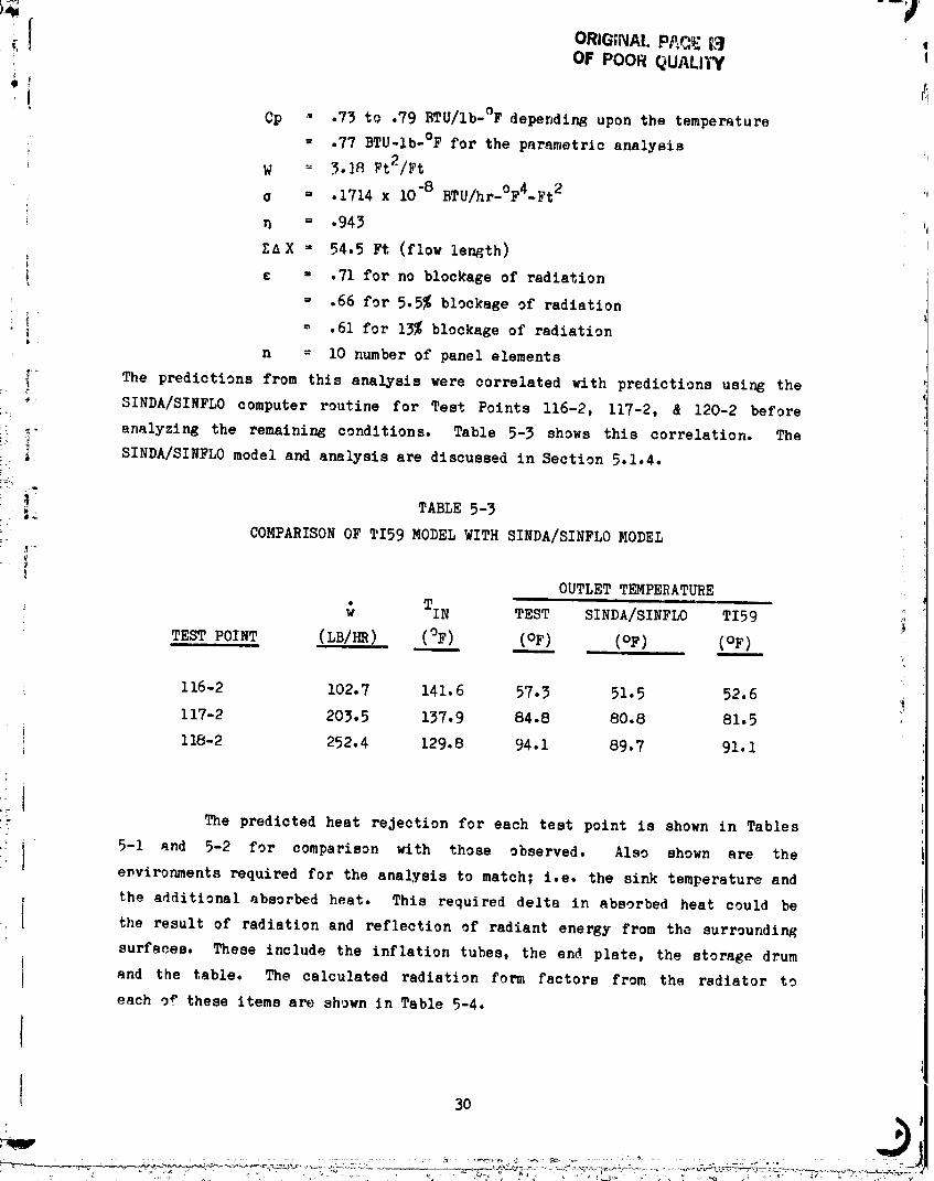
_ Cp .- .73 to .79 BTU/Ib-°F depending upon the temperature
= .77 BTU-lb-°F for the parametric analysis _,
W = 3.18 pt2/Ft
o = .1714 x 10"8 BTU/hr-°F4-Ft 2
= .943
T.AX = 54.5 Ft (flow length)
! ¢ = .71 for no blockage of radiation
= .66 for 5.5% blockage of radiation
i = .61 for 13% blockage of radiation
n = I0 number of panel elements
__ The predictions from this analysis were correlated with predictions using the
SINDA/SINFLO computer routine for Test Points 116-2, 117-2, & 120-2 before
: .,, analyzing the remaining conditions. Table 5-3 shows this correlation. The
!_ _ SINDA/SINFLO model and analysis are discussed in Section 5.1.4.; :
! TABLE 5-3J_
! COMPARISON OF TI59 MODEL WITH SINDA/SINFLO MODEL
OUTLET TEMPERATURE
TIN TEST SINDA/SINFLO TI59 i
TEST POINT (LB/HR) (OF) (OF) (OF) (OF)
I16-2 102.7 141.6 57.3 51.5 52.6117-2 203.5 137.9 84.8 80.8 81.5 '
118-2 252.4 129.8 94.1 89.7 91.1
,r_ The predicted heat rejection for each test point is shown in Tables
• i 5-1 and 5-2 for comparison with those observed. Also shown are the
I environments required for the analysis to match; i.e. the sink temperature and
the additional absorbed heat. This required delta in absorbed heat could bef• I the result of radiation and reflection of radiant energy from tha surrounding
surfaces. These include the inflation tubes, the end plate, the storage drum
and the table. The calculated radiation form factors from the radiator to
each of these items are shown in Table 5-4.
I! 3o
3
00000001-TSC08

TABLE 5-4
RADIATION FORM FACTORS FOR SOFT TUBE RADIATOR TEST
" FORM FACTOR FROM RADIATOR
...._ ITEM TO ITS4, FI2m
:"_ Inflation Tube .046
End Plate .002
.... Storage Drum .007
__i:_ Table , •076
--'i, Total •131
_iii' These form factors were used to estimate the blockage of radiation from the
_?,_.:_ radiator to the chamber wall (simulated space).
_! The results shown in Tables 5-1 and 5-2 indicate that correlationa
=_ between predictions and test results can be obtained if the sink temperatures
!i:! are increased for high thermal environment conditions. The additional heat
flux required is approximately 5 to IO BTU/hr-ft2" with an average of
-_ BTU/hr_ft 2 - __, approximately 7 required. This results in a equivalent sink }_
': temperature of 15°F for the O°F sink test cases. "'
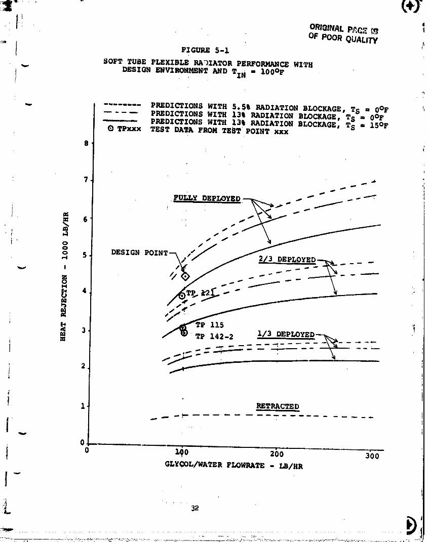
Figures 5-i thru 5-3 show the predicted performance maps for the -:
_, sof_ tube flexible radiator along with data points from the test for i
_ comparison purposes. Figure 5-1 shows the comparison for a fluid inlet
_'i,. temperature of IOO°F and sink temperature of O°F (design conditions).
," Predictions are shown for a range of flowrates, a range of deployment
_ fractions, and for different environment conditions. The predicted
_ p_rformance for the fully deployed panel at O°F sink and iO0 Ib/hr f!owrate
_!"_ is about 5000 BTU/hr for assumed blockage of 5.5% (inflation tubes, drum and
°_ end plate). Assuming blockage from the support table also (blockage of 13%)
_i the performance is predicted to be 4800 BTU/hr, which is 300 BTU/hr hiRher
i} thqn tho de'_ign heat rejection of 4500 BTU/hr. However, for test poir_ 121,
::i which was very. close to the design conditions, the performance was only:i
_I m_-,n,_r.d to be 4000 BTU/hr. This lower-than-expected perfonna_,ce wa.__,i! _,',,_':,l,.ut£-)r all the high environment testing (i.e., O°F, and 25°F r_ink
.'_ t_-,_l,_r:.t_r_,).There are a number of candidate explanations possible fgr th_
i"!
O0000001-TSCO9
. L"e'JI- ._ ORIGINAL P/,(_E L.q t
OF POOR QUALITY ,,' !-q
1 FIGURE 5-i.SOFT TUBE FLEXIBLE RADIATOR PERFORMANCEWITH
"_ DESIGN ENVIRO_NT AND TIN - 100OF ',I
61
........ PREDICTIONS WITH 5,511 RADIATION BLOCKAGE, TS _ 0OFPREDICTIONS WITH 1311RADIATION BLOCKAGE, TS a 0OF
- PREDICTIONS WITH 13% RADIATION BLOCKAGE, TS = 15OFIDTPilxx TEST DATA FROM TEST POINT Xxx
8
FUr.LyDEPm,YED_ ...... "" _t -.-"
: o 5 DESIGN POINT-'_,,./ EPLOYED_ .--_ -.
_, I • _ _ .-. ....
/ _ lz5 "i3 Z/3_ --_ ,TPZ41-_ EPLOYED._\._ --i _ _ _ .... ....... \-_-- ---- ,
! z _T_c_ED
I . .
i o" GLYCOL/WATER FLOWRATE - LB/HR
1-i
i=_i,. ' " " 32 " '
...... "" '+---:_:-+':+_--'_'_"-"'-':_'_"........_......'_ 00000001-TSC 10
: /
11.. °
FIGUR_ 5-2 ............... OF POOR 'QUALITySO_TTUDEFLBXISZ,EI_ADIATOaP_0_CE WI_.DmaZr_SNVIRONmmT_D TZN_-.-_41oF
...... PREDICTIONS ;WITH 5o51 RADIAT£0N BLOCKAGE, TS " _0°_'-PREDICTION8 ;NZTH 13% RADZATX0N BLOCKAGE, TS _0WF
---------PREDICTIONS:WITH 13% RADIATION BLOCKAGE. T_ _s 15°F
10. OTPxXX, TEST DATA FROM TEST POINT xxx p .,''_ • s
i P _ ' "
: 9" /s P 120-2
FULLY DEPLOYED .//!/. i , _ ,
-. .//_/ --a/3 oSPLOYBO_ -. -- " "
i-::: _ I 16_'_.
6. I
zi -- 5" _ TP ?
-, - 2,4 _"
T- "24 _ I:../P I I °"
i. P 139-2i, /
_ P 138-2
i
i:!
411
I I I I II I I II _ I [ II " ql : " III_I :: _ I II
, 0 i00 200 300
! GLYCOL/WATER FLOWRATE - LB/hr
33
6600000:1:TSCi1
=
':7
i_ em_lNACP._GSJU '"" OF POOR QUALITY
FZGURI$ 5-3
-_._ SOW T_E P_XIB_ _ZATOR PE_OR_ WITH
COLOW_8_z_.'_' (Ts - ._.soop)
p
P_DICTIONS WI_ 13% BLO_GE OF VZ_ TO SPACE.u Q TPxxx TEST _TA PROM TEST POINT xxx
t1
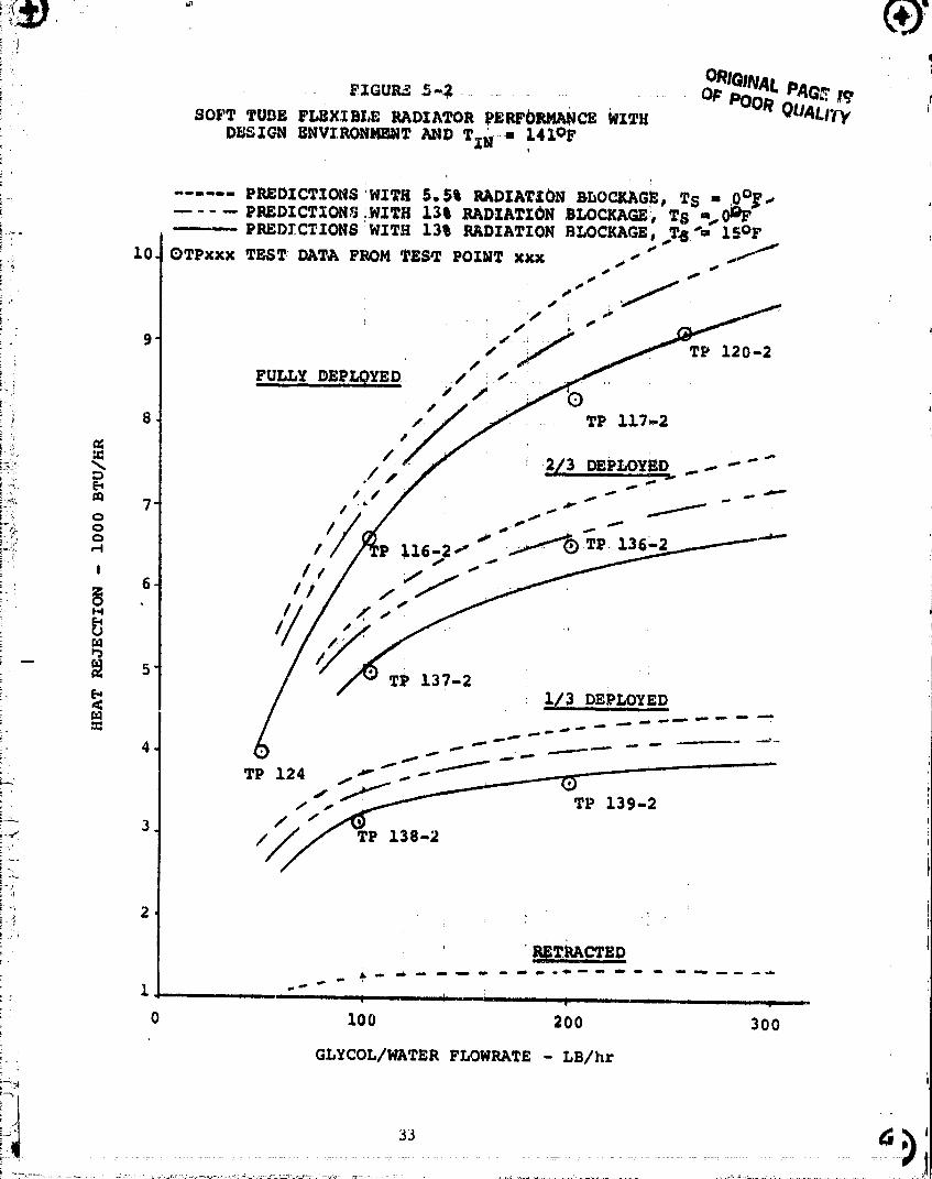
low performance, ?hess lrclude higher radiation environment than indicated,
p_or radiator panel fin ef.'octiveneoo, poor flow di_trihution, instrumentat!.on
errors and heat gain or loss by the fluid manifolds and fluid lines. The .,
environmental effects appear the most likely and was assumed for correlation
purpoees. There is some evidence of poor flow distribution in the tubes as
discussed in Section 5.1._. However, it is assumed the effect is small
because of the good cold wall environment performance.
It was found that approximately 7 BTU/hr-ft 2 absorbed heat was
required over and above the basic sink temperature to achieve a reasonable
match of the test data. This represents a sink temper-_ure increase of 15°F
for the O°F sink temperature cases and ]3°F for the 25°F sink cases.
The correlation is shown in Figures 5-I and 5-2 for the high environment
cases. The 15°F sink temperature seems to correlate reasonably well.
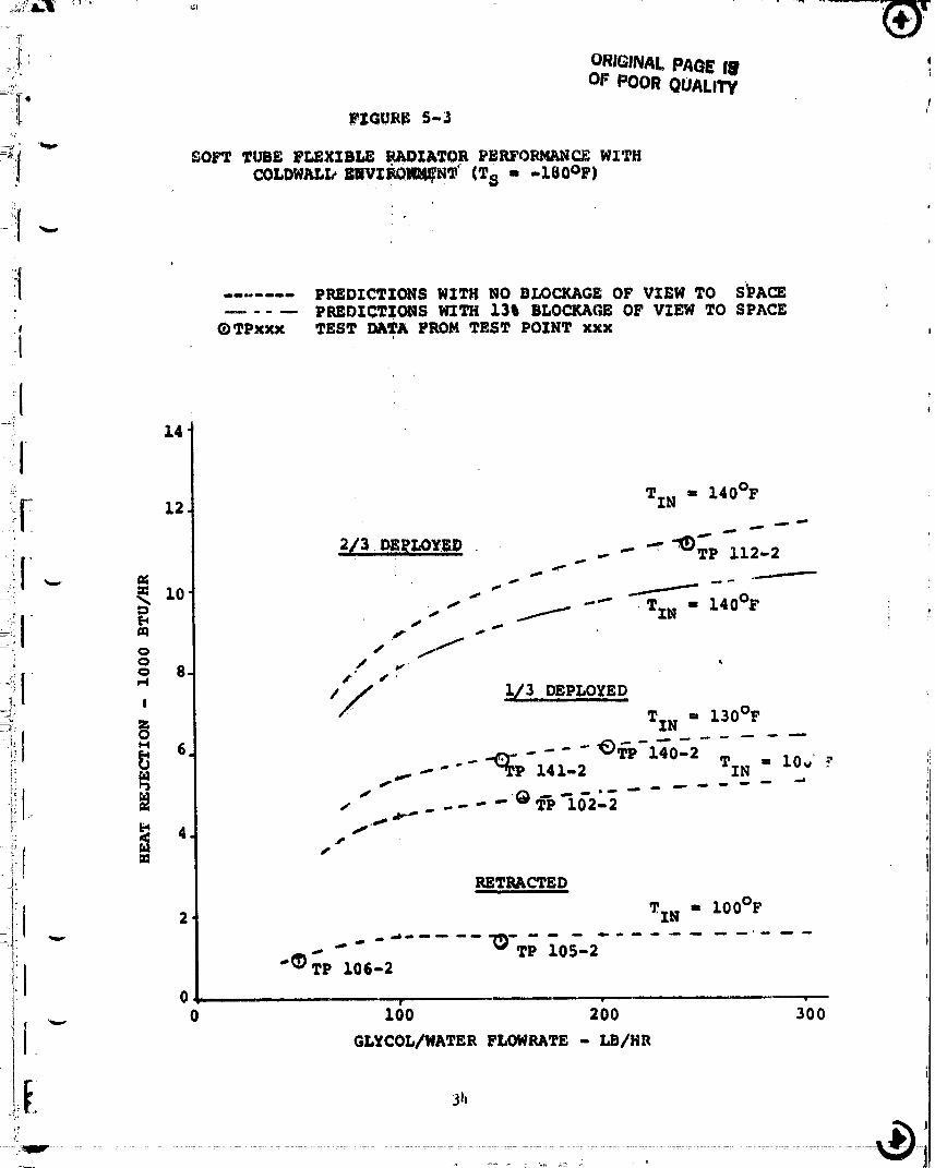
Figure 5-3 shows the performance predictions for the coldwall
conditions and the test data points for comparison. It was found for this
environment that the panel heat rejection was very high. The test data
matches the analytical predictions when no blockage was assumed. This result
tends to support the theory that the reduced perforaance at the hi_her
environment conditions is due to higher-than-anticipated radiation
environment. The results indicate that the panel performs well with the
expected fin effectiveness and emittance.
Another test point that supports the hot environment theory is No.
142-2 shown on Figure 5-1. This test point indicated a much higher than
predicted heat rejection for the 1/3 deployed condition. This is believed to
be caused by testin_ at coldwall conditions which immediately preceeded this
_:_t point, lowering the support structure temperatures.
The results from analysis of the test data points to a radiator
p_nel capable of rejecting heat in the quantities for which it was designed.
The eoldwall tests support this conclusion. The test data :_nslysis also
indicates that the environmental flux absorbed by the radiato_r pa.el exceeded
the desired flux by an average of about 7 BTU/hr-ft 2.
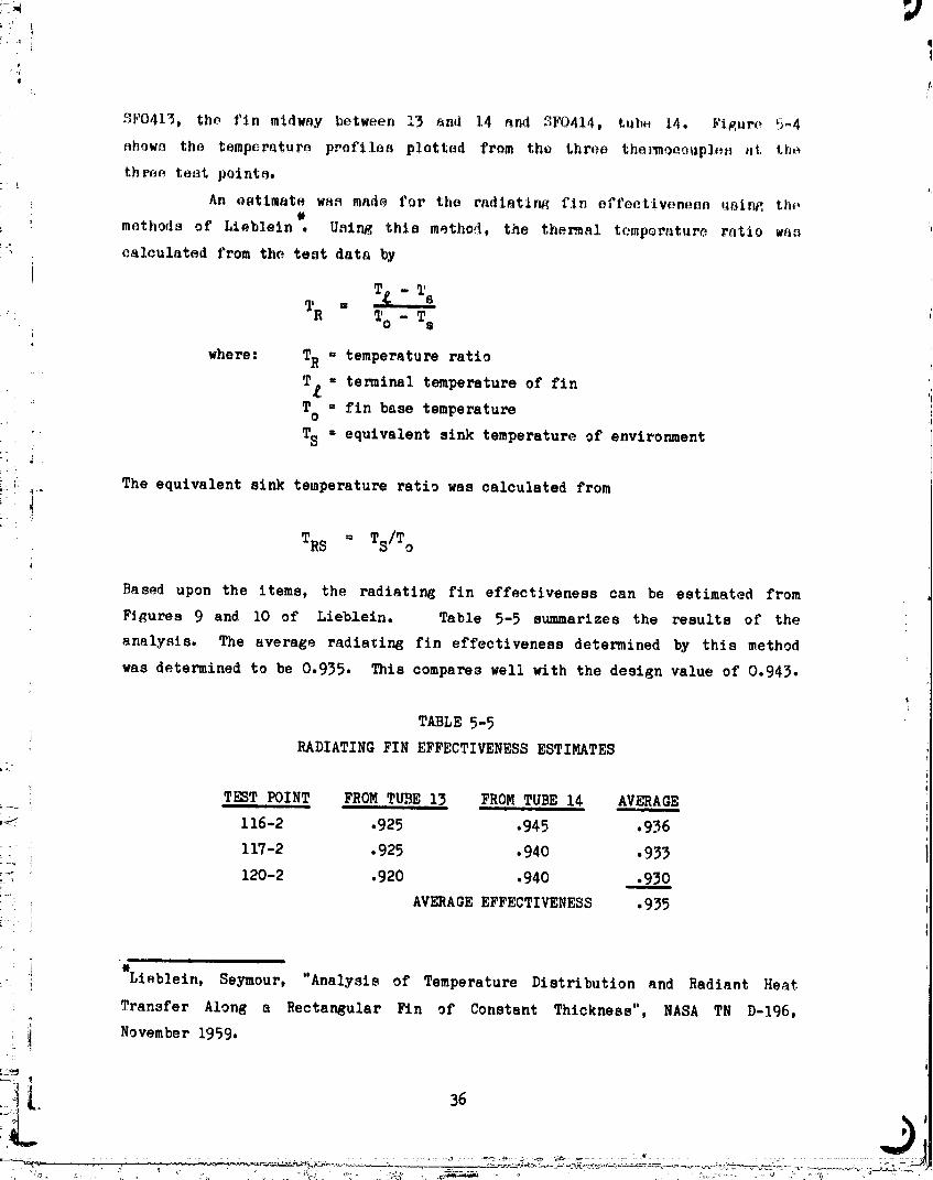
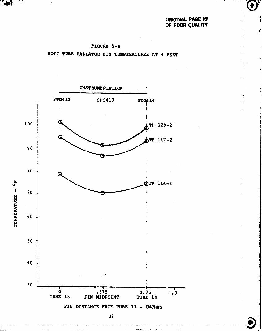
_,.1.2 Soft Tube Fin Effectivenessi ....
The thermocouple instrumentation on the panel fin wn_- used to
estim, te its fin effectiveness during the testings. Test points i16-2, I17-2,
and ]_O-P were evaluated at the four foot location (from the storage dru.t).
The th-r_ocouples evaluated at the four foot location were ST0413, tube ]3,
00000001-TSC13
_ i t
SF0413, the fin mldwa,v between 13 and 14 and 2F0414, tub. 14. l,'i_,ure 5-4
nhown the temperature profile_ plotted from the three themQeo_pl_n hi, the
throe to_t point_.
, An ootlmato web made for the radlatln_ fin effectivenonfl uolng, the
methods of Liebleln _. U_iI_ this method, the thermal temperature ratio wa,_
'_ , calculated from the te_t data by
}
_ ,,, 8
TR To, - T_
where: TR = temperature ratio
i T e = terminal temperature of finT = fin base temperatureo
" i' TS = equivalent sink temperature of environment
_i, The equivalent sink temperature ratio was calculated from
!' !
TRS = Ts/T °
Based upon the items, the radiating fin effectiveness can be estimated from
Figures 9 and iO of Lieblein. Table 5-5 summarizes the results 0£ the
analysis. The average radiating fin effectiveness determined by this method
was determined to be 0.935. This compares well with the design value of 0.943.
TABLE 5-5
RADIATING FIN EFFECTIVENESS ESTIMATES
' TEST POINT FROM TU3E 13 FROM TUBE 14 AVERAGE
i_ 116-2 .925 .945 .936
117-2 •925 .940 •933
,-.'_ 120-2 •920 .940 .930
;'-'. AVERAGE EFFECTIVENESS 935}
i_I i
el
.i _ieblein, Seymour, "Analysis of Temperature Distribution and Radiant Heatt
Transfer Along a Rectangular Fin of Constant Thickness", NASA TN D-196,
i November 1959.
""°.......... 00000001-TSC14
ORIGINAL PAGE II q!OF POOR QUALITY f,
tl
FIGURE 5-4 ',
SOFT TUBE RADZATOR F_N TEMPERATURES AT 4 FEET '"Jl
ZNSTRUMENTATZON.... .ii
STO413 SFO413 STO_141
1oo 12o-2
90 _TP 117-2
80
_TP 116-2
o
J 70
_ 60Ul
5O
40
30 , , _ , , -- - r • ....
0 .375 0.75 1.0TUBE 13 FIN MZDPOZNT TUBE 14
FIN DISTANCE FROM TUBE 13 - INCHES
A
00000001-TSD01
.
_ili
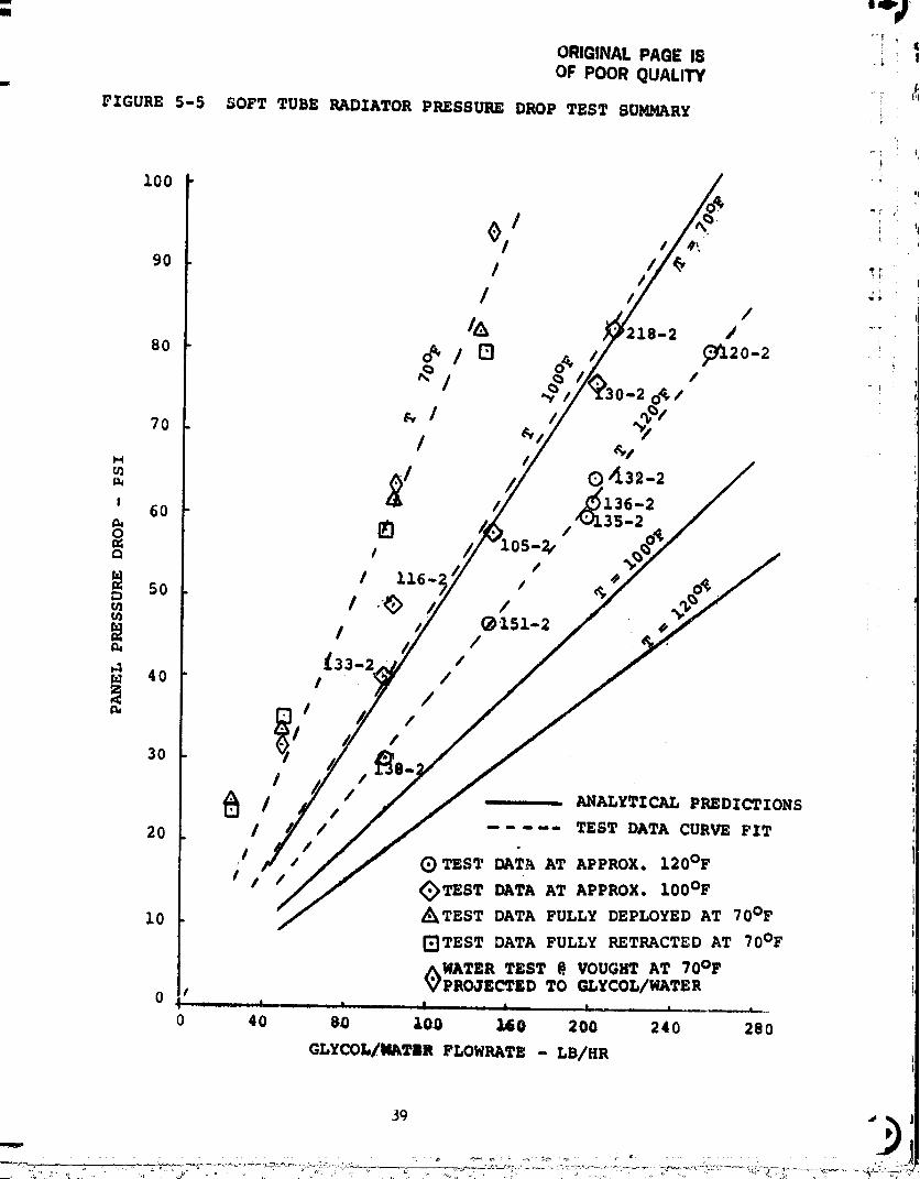
i 5.1.3 Soft Tube Radiator Flow/Pressure Drop Evaluation
The flowrate and pressure drop values measured in the soft tube
radiator test are tabulated in Table 5..2. The pressure drop instrumentation
was not worklr_ for the test of the first day, summarized in Table 5-1.
Analytical predictions were made for the radiator panel pressure
' _ drop vs flowrate at different fluid temperatures to help in test data
evaluation. The equation for pressure drop in a tube was written; including
' entrance and exit losses in the .046 I.D., .44 inch long inserts. Thei
equation reduces to the following when geometric terms are included:
_P - 2.19 _-& + .0o_26m--
i " °where:
!_: i- _P = pressure drop, psi
_ _ = viscosity, ib/ft-hr
= panel flowrate, Ib/hr
:_ This equation was used to predict the panel pres_ure drop. Table 5-6 gives
the property values used in the analysis.iI
I,_ TABLE 5-6
! i GLYCOL/WATER THERMAL PROPERTIES USED IN ANALYSES
TEMPERATURE VELOC ITY D_NSI TYi ,.
_" OF LB/FT-HR LB/FT 3
!_", 70 12 67.2!._-._ i00 7.25 66.5
_ 120 5•81 66 •I
The analysis results are summarized in Figure 5-5, along with test
data for similar conditions. Comparison of the analysis and test data shows
the test pressure drops higher than the predictions by about 55 to 65%. At
the design conditions of iOO Ib/hr, and an average temperature of 70°F
(IO0°F inlet, 40°F outlet), the predicted pressure drop was 39.1 psi while
;_ 38
.... = =
0000000J-TSD02
l
I
ORIGINAL PAGE IS .OF POOR QUALITY
FIGURE 5-5 SOFT TUBE RADIATOR PRESSURE DROP TEST SUMMARY
100
/ _'0l i
90 t "'"
/ /cg .; z8-2
80 o_ / 13 o*' , o-2 ,_,
70 _' I ,_,_I/ ,_l
M
,_ ,_'136-2I 60 ",:.,,135-2
I 116-, /so
_151-2
_33-2 //r.u 40 !
3O
I J'
/ .... ANALYTICAL PREDICTIONSI t20 I / ..... TEST DATA CURVE FIT
I (_)TEST DAT_ AT APPROX. 120°F
I I I _TEST DATA AT APPROX. 100°F
10 _TEST DATA FULLY DEPLOYED AT 70°F
_TEST DATA FULLY RETRACTED AT 70°F
WATER TEST @ VOUGHT AT 70°FPROJECTED TO GLYCOL/WATER
0 40 8.0 100 ,L60 200 240 280
GLYCOI,/MATIR FLOWRATE - LB/HR
the measured pressure drop is 60 to 62 psi, or about 53 to 60% higher than th_
,n_lysis.
The cause of the high pressure drop was not known at the time of the
tests. Some of the suspected causes were:I
(i) Physical blockage due to particulate contamination.
(2) Corrosion in test article manifold. !
(3) Shrinkage of PFA Teflon tubing during fusion bonding.
(4) Possible losses in fittin_ or hardware not accounted for in
analysis.
The physical blockage theory, either by contamination or by
corrosion was supported by examination of temperature instrumentation on the
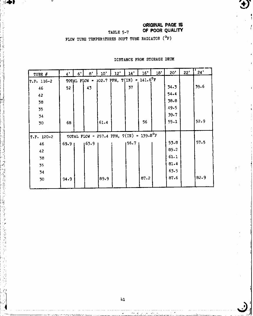
panel that gave a indication of the panel flow distribution. Table 5-7 shows
the panel temperatures for the return half of the panel f " two tests. It is
obvious from these temperatures that the flow is less in tubes 34, 38, and 46
i than it is in 30, 35 and 42. Also, in water tests, the panel pressure dropi_
was observed to be reduced by about 30% following back flush test as indicated
by Figure 5-6.
Because of the unanswered questions concerning the panel pressure
drop, the flexible radiator panel was transported to Vought and tests were
conducted in the SES laboratory. The tests conducted included (i) an overall
system pressure drop test, (2) a dye injection test to observe the flow
movement in the individual tubes, and (3) pressure/flow measurement for the
individual tubes. Distilled water was used as the test fluid for all the
tests.
Figure 5-7 shows a schematic of the test setup for the system
; pressure drop test and the dye injection test. The results for the system
pressure drop test are shown in Table 5-8. Five flowrates were tested ranging
:J from 50 Ib/hr to 250 ib/hr. The test was conducted twice: (i) a preliminary
' test shown in Table 5-8(b) and (2) a retest shown in Table 5-8(a). The water
i- pressure drop values were projected to Glycol/water values by multiplying by
_" the quantity (_//_)*(_/_,_ which is a value of 4.83 at 70°F. The
_ prujected Glycol/water pressure drops for the retest are plotted in Figure 5-5
to show the correlation with data taken earlier at NASA-JSC. A goodi
correlation is shown.
It was i,_teresting to note the variation in the pressure drop
between the preliminary test on 4-21-82 and the later test on 4-23-82, shown
iill ,o
' ..... ' 00000001-TSD04
i, ORIGINALPAQ£Ill' TABLE5-7 OF POORqUALITY
i-i.i-_' FLOW TUBE TEMFERITURES SOFT TUBE RADIATOR (OF)
i .ti'
i_ DISTANCE FROM STORAGE DRUM
T.P. i16-2 FLOW = 102.7 PPH = 141.60F
i- 46 39.6
_I[ 4238
i t}i 34
! 30 52.9
i,!_)i T.P. 120-2 TOTAL FLOW = 257.4 PPH, T(IN) = 139.8°F,I 46 57.5
-I 42
38
__ 35
i ._ 34
i._.,_i 30 82.9
i<i
L_
':?Ii.i
! •
00000001-TSD05

_' FIGURE5-6 SOFT TUBE RADIATORPRESSUREDROP (W/H 20) _'i
I so
ORIGINAL PAOE iSOF POOR QUALITY _/_ "
i 70 //
/i /i 60 /_
_ /" 9
a 50 /
• 0
am,_ 40
Ill,
-, /IllZ
., /II.
//
20 /
/_ / (_ PRIOR TO BACK FLUSH
:' ,/_ AFTER BACK FLUSH
I (_ DURING FM RECAL
._ 10 Q
i
_J
O _r_--l-----i " t , ,;
O 80 160 240 820 400
PANEL FLOW RATE LBM/HR
..................... " 00000001 TSD(

!!
i, !
? +l M-,.J _ ,,_++ + I II++!+,,+i ..... <'+,++,++] ++ '++++++ '' +© +
: + , ml
++++i
0000000]-TSD07

I̧f,
TABLE _-8 _
ia) SYST_4 PRESSURE DROP TEST
CONDUCTED 4-23-82,j
i HO0)_TEMPERATURE - V2°F*_
1 PROJECTED 'i GLYCOL/WATER
FLOW SUMP _P
! TEST RATE _ WATER TEMP (WATER x 4.83)PoIN_..._(LBIH_) (PSID) (o__..!_ (_D_........
I
I 50 6.58 68 31.782 I00 13.i0 68,4 6_,27
_ 3 150 19.4 69 93.71 4 200 25•i 69.5 121•2° ' 5 250 31.7 69,8 15_.I
V
1
b) PRELIMINARYPRBSSUR_DROP TEST
: CONDUCTED4-21-82
1 50 5-9 71 28.50 i_2 I00 ii.85 70.4 57•2_3 150 18.i 70 87•44 200 24• 2 71 116 • 9
_,
00000001-TSD08
W_
in Table 5-8. A change of about 7% is observed. This was well beyond the
expected variation due to inaccuracies in the data. It was suspected that
this variation is due to trash in the outboard manifold as evidenced by other
tests discussed below. As the trash is moved around inside the manifold, the
flow system configuration changes causing pressure drops to be different.
_ This was also felt to be an explanation for the scatter in the NASA data.
Dye injection tests were conducted to observe the movement of the
fluid in the panel. The schematic shown in Figure 5-7 was again the test
• setup. The dye injected into the elastomer tube was a concentrated solution
of Gentian Violet dye. Flow was stopped for observation three times following
the first observation of dye at the inlet manifold: i) at iO seconds, 2)25
seconds, and 3) 48 seconds. The distances which the fluid in each tube had
progressed was observed for each time. Table 5-9 shows the results for the
first two observations. The dye front was still in the left bank for these
:_ times. By taking the difference between the iO second and the 25 second
observations, a flow velocity in each tube was estimated as shown in Table
5-9. The flow appeared uniform and the velocities correspond very well with
the measured flowrate and the tube ID's of 0.0625 inches. This portion of the
test indicated that: i) there were no restrictions in the tubes on the left
half of the panel, and 2) the tube diameters are nominal, i.e. they have not
been collapsed in manufacturing.
The dye was also observed at 48 seconds into the test when the dye
had progressed to the right tube bank. At that time no dye was observed in
the first 4 tubes from the right edge. The dye in tubes 5, 8 and 9 was about
3 to 4 feet down from the outboard manifold. The dye in tubes 6 and 7 was
< al,out 2/3 of the way down. The dye in tubes iO thru 25 had traveled the
entire length of the right side. This result indicated clogging of the tubes
on the extreme right side, although quantitive data was not available because
of the unknown mixing effects of the outboard manifold.
! A second dye injection test was conducted with the flow direction
! reversed from the nozTaal (flow entering the right side first). The results of
thi_ te_t, shown in Table 5-iO, indicate that the flow in the right side of
the panel w_s fairly uniform when flowed in reverse, contrary to the
indi,'ati',n_of the first dye test. This indicated possib]e foreign material
in the outboard manifold, clogging the manifold.
.... 0000000 -TSO09


[
ORIGINAL PAGE I.'_r)F POOf_QUALITY a
_AB_ 5-Z0 l'__IGHT SIDE DYE INJECTION TESTS
TOTAL FLOW - 50 LB/HR
FLUID TEMP _ 69°F ,
TUBE NO.(FROM LEFT OUT DYE LOCATION DISTANCE FLOWEDIN VELOCITYBOARD,EI_E), i0 SEC 25 SEC 15 SEC FT/SEC
i 0 1'2" 14" --*2 0 5'3" 6Y' --*3 0 7'5" 89" --*4 1'1" 10'11" 118" 0.9835 1'6" 9'4" 94" 0.7836 2'9" 12'2" 113" O.9427 2'11" 12'7" 116" O.9668 4'0" 12'1i" 107" 0.8929 4'8" 13'7" 107" O.892i0 4'9" 13'ii" 1i0" O.917Ii 5'6" 13'II" i01" 0.84212 6'9" 16'O" iii" 0.92513 6'3" 13'i0" 104" O.86614 7'4" 15'0" 92" 0.76715 6'O" 15'2" ii0" O.91716 5'11" 14'6" i03" O.85817 5'0" 13'11" 107" O.89218 4'0" 12'9" 105" 0.87519 3'9" 12'8" 107" O.89220 2'Ii" 12'2" Iii" 0-92521 2'2" 12'2" 120" i.00022 i'6" ii'8" 122" 1.01723 O'i0" i0'i0" 120" I.00024 0 7'6" 90"* --*25 0 2'0" 24"* --*
: 0.908"* i
Velocitynot mea_tingfulEquivalent to 54 ib/hr for 25 tubes with 0.0625 in. I.D.
............................................... " O0000001-TSD11
:
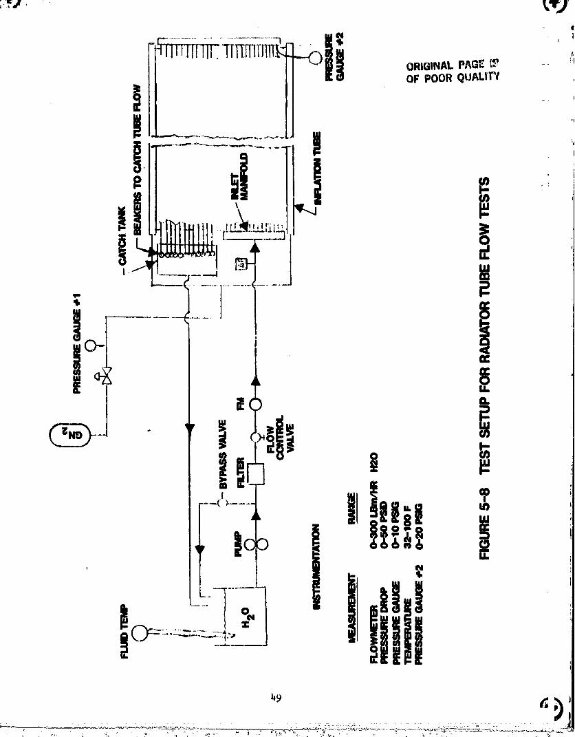
_ I Figure 5-8 shown a schematic of the tort a¢_tup for radiator t,,het
i i pros._ure flow tests. The primary ehan_os wQre the addition of n t,,_eond
press,_re P,auge at the outboard manlfold, th@ d_sconnectin_ of the radiator
tubes from the outlet manifold and the addition of a catch tank an_ beakers
i for measurln_, indivldual flowrates. With the total radiator flow at i00
ib/hr, the flow from each tube was caught in a beaker for 2 minutes and an
accurate weight was determined. Two tests were run. First measuring the flow
i distribution in the right tubes and second measuring the flow distribution in
the left half of the panel. The results of the first test are shown in Table
5-11. The results indicate significant restrictions in tubes i thru 5 and
tube 7. This is similar but slightly different than observed in the dye
tests. (In that test tubes I thru 5, 8 and 9 were restricted.) The pressure
drop in the apparently unrestricted tubes was close to the calculated value,
with the mean difference being 0.II psi and the standard deviation being 0.29
psi. The mean error is only 2% and the standard deviation only 5%.
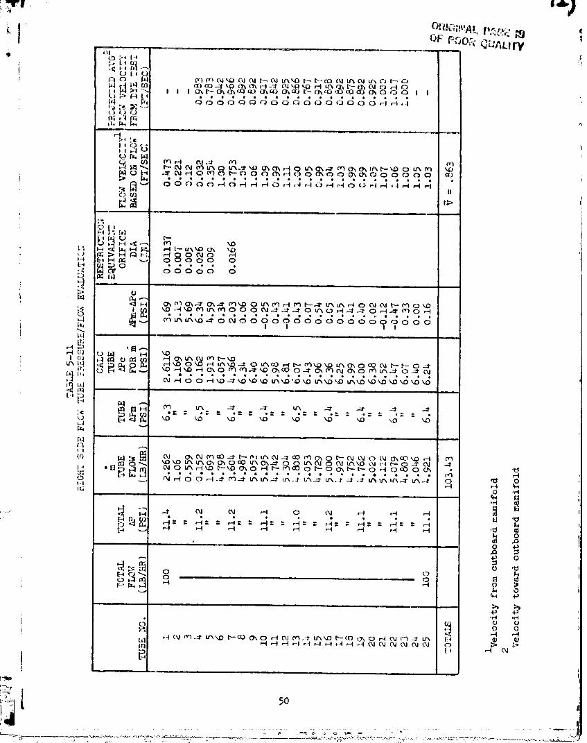
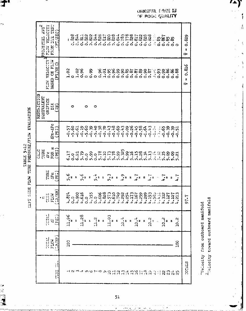
The flow direction was reversed and the flow distribution was
determined in the left half of the panel was determined. Table 5-12 shows the
results of this test. It was observed that flow was totally restricted in
three tubes (No. 2, 5, and 7 from the left edge). This is at variance with i
the dye tests which indicated no blockage in the left side. The flow in the
remaining tubes indicated no apparent restriction. An anomaly was observed in
this test in the pressure measurement. The measured pressure was less _han
the calculated pressure in all cases and appeared to be worse as the test
i progressed to higher number tubes. The mean of the error in the non-cloggedtubes was -0.51 psi (calculated pressure drop higher than measured). The
standard deviation of the error was about .21 psi.
The primary conclusions from the tests to date are:
(I) The higher-than expected panel pressure drop is due to clogginga! of the tubes in the downstream half of the panel at the
° outboard manifold.
i (2) The pressure drops observed in the test are consistent withthose observed in the NASA-JSC test and the tube pressure drops
agree well with predictions.
I Since the evidence of the flow/pressure drop tests pointed to
foreign material in the outboard manifold, the end cap of the manifold was
I removed for observation. It was found that excessive corrosion had occurred
t _8
00000001-TSD12
qF POOir_QUP,LITY' l
- ,, , , ,
00000001-TSE01
• |!
W
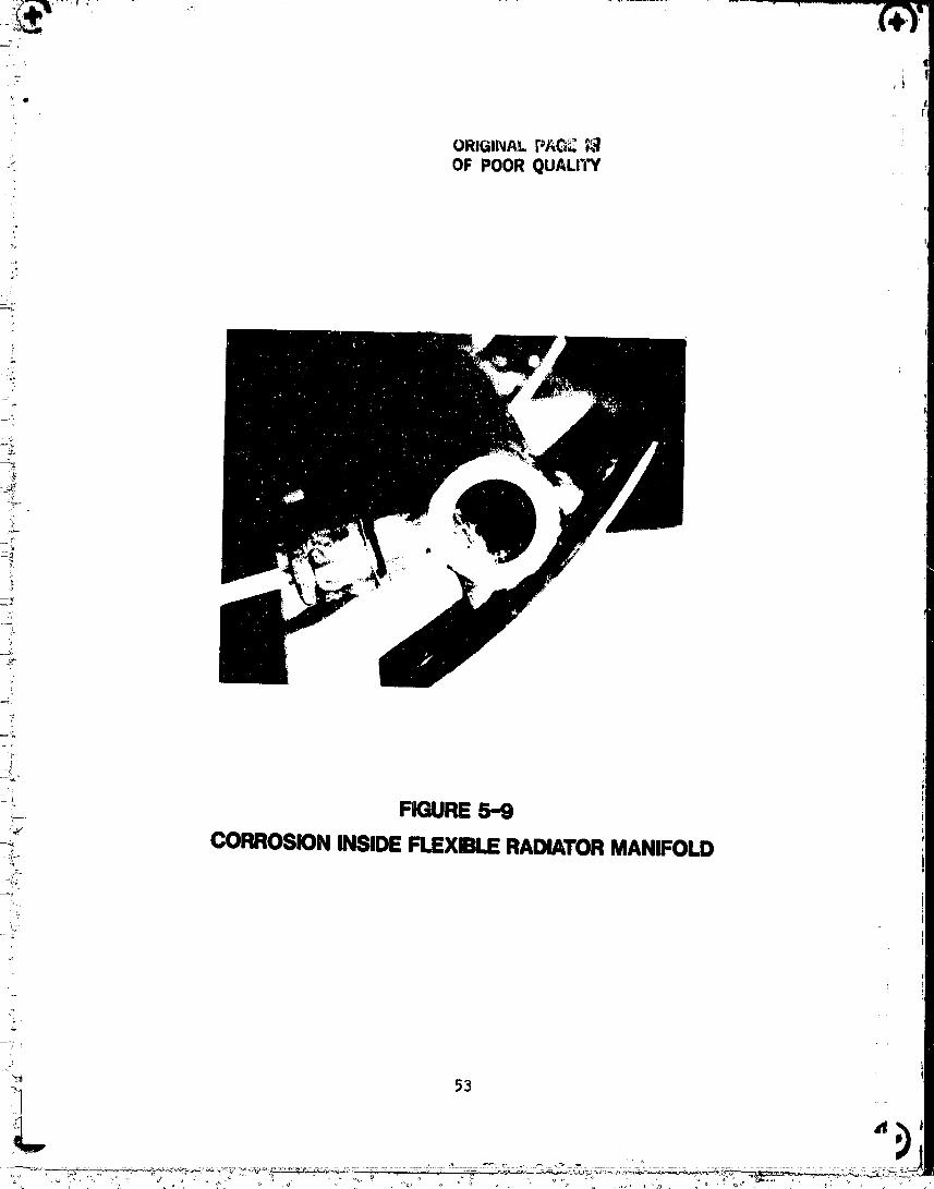
inside the manifold, covering the entire surface with lumps of a white _
substance. The corrosion was particularly heavy on the inside face of the
fittings welded to the aluminum manifold (around the flow opening). A photo _i
of the open manifold end showing the corrosion is presented in Figure 5-9.a_
The corrosion was identified as aluminum oxide, most likely caused by water or
Glycol/water trapped in the manifold followir_ the Solar Exposure test in
November 1978. The manifold was thoroughly cleaned and was aladine treated to
protect against corrosion. The manifold end cap was welded closed and the
manifold replaced. It was observed that the Swagelock fittings were corroded
on the exterior. These were replaced for both manifolds and the radiator
panel was leak tested. It should be noted that the inlet and outlet manifolds
were not refurbished - only the outboard manifold.
In conclusion, flow/pressure drop data for the soft tube radiator
measured approximately 60_ higher than the predictions would indicate. This
was determined to be caused by foreign material in the outboard manifold
!- caused by corrosion.
5.1.4 SINDA Thermal and Flow Analysis of Soft Tube Radiator Test
In order to assess the results of the thermal vacuum test of thei
! soft tube flexible radiator, a thermal _ath model of the radiator was
constructed. The model was constructed in a two step process. The first step
was to use the TRASYS program to compute the radiation conductances in the
vacuum chamber/test setup. This was done by designing a three-dimensional
i geometric model of the radiator, its support table and the chamber floor.
Figure 5-10 shows the radiator subdivision for the TRASYS model. Then the
i model was completed by adding the fluid flow paths and thermal capacitances of
tube nodes. Conductance paths through the fin material were also added. The
model is designed for the SINDA/SINFL0 program and is comprised of nearly 100
nodes with over 400 conductance paths. The model was constructed in as simple
a manner as it could be without eliminating the capability to study in detail
! the test results. Figure 5-11 depicts the fin nodes and Figure 5-12 describes
the fluid network of the model. The model could very easily be integrated
with other models of the vehicle to which the radiator would be attached.
Since the model was designed for the full deployment configuration,
only those test points could be analyzed. Six test points in this fully
deployed configuration were run in each of the two weeks of testing. The sink
temperature during the test was simulated by using infrared lamps to heat the
00000001-TSE02
J
ORIGINAL P/_G_ ;'._
i OF POOR QUALII"Y
4'=,_..
L
4
1
__. FIGURE 5-9
_ CORROSIONINSIDEFLEXIBLERADIATORMANIFOLD
,_ ".)
00000001-TSEO3

, ORIGINALPAGEil_
_ ',;'_:,'i::ii "i_ "_ OFpoorQuA._Q
I _. _ 6' I ! i
I i ,, ; I
L _J m
!T ;T ",t- . ," i "_
2. !_t!:!,+,_,.._ !_ii.,:;
#q_!:,_,,Io H
,il!il!,,r,r,i, .,,, _
"" ii :'_ :..,:i:titi ' J ": £ _IU " q "=
9 ......
> ' '! ,ii!
12: :_t
'II!I
l-
I_- °III_ ,;
...... . , , , ._ 5 I)G. •...... ._
. ......... ,
O000000]-TSE05
i'i +
. i ORIGINAL P,_,_'_._• ; OF POOR QUALITY ,
._/t 80F'r 11JSERABATORFLUID8OIEMATIC OTUBE NO.
+ _ P2 NODENO.
; / XXX-FLUlD_++I XXX + 200"TUBE+-+,.: _o
'+o
+ +_.-
+++:-++'•'++:_'+"i+_ 6 _ 16, i _ 52 _1 6+)+++ 5 _ 15 _0 b 53 _ 63
!!+i " 14 i0 _0 54 64
__++ ® ® i ® ®+:;
+ _SS b 65++
2 _i 12 qt
,,o, I ,,o.+ I' I
)'
?
....! FIGURE 5-12 SINDA FLUID NETWORK
+++__.++-+ + J+'_--_°_ °°+°++.° ++++°+_+++++ _'+'++,+<,+ n°++ + +
O000000_-TSBO8

tI
I
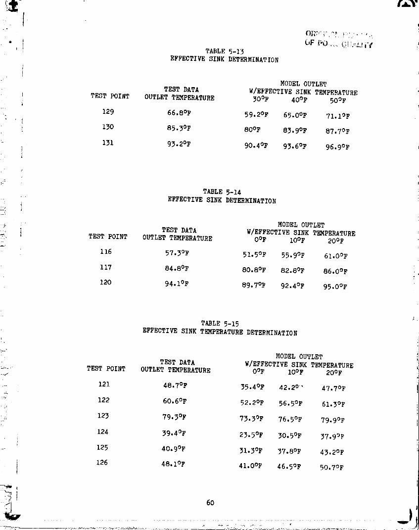
top surface of the radiator only. The test setup attempted to _rovide uniform
heating. The model predicted greater net heat rejection (lower outlet
temperatures) at the sink temperatures which were believed to have been .,
simulated. 0nly by raising the effective sink temperature does the modelIi
predict the measured performance. Test points 129, 130 and 131 appear to have
an effective sink temperature of 40°F (see Table 5-13). All of the other
fully deployed test points appear to have effective sink temperatures of
between iO°F and 20°F. Any attempts at lower sink temperatures only
resulted in freezing the radiator fluid. Tables 5-14 and 5-15 show the
results of determining the effective sink temperature for the remaining test
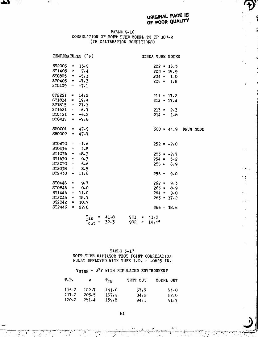
points with a fully deployed radiator. A closer look at the radiator
temperatures during the sink temperature calibration (see Table 5-16) indicate
that the environment simulation was very non-uniform under no flow
conditions. The panel temperatures ranged from 22.8°F to -7.3°F when the
environment was believed to have been oOF. There are a number of sources
for this non-uniform heating. The heated surface of the radiator was
surrounded by highly reflective aluminized Mylar insulation blankets which
wrapped the inflation tubes and also the inlet manifold. In addition, the
stowage drum sat above the heated surface and the top portion remained very
close to the IR lamps. This would lead to abnormally high heatin_ of the drum
and its integral fluid manifold.
The results shown in Tables 5-14 and 5-15 were compared with the
results of the T159 predictions shown in Tables 5-1 and 5-2 to obtain a
correlated simplified model. The results compare very well.
In order to more accurately predict the radiator performance, panel
_nvlronments were estimated based upon the steady state panel temperatures
observed in the test during the IR calibration of test point 107-2 (see Table
5-16). The SINDA model predicted outlet temperatures are compared with the
te,_;tdata for test points 116-2, 117-2 and 120-2 in Table 5-17. The predicted
rem_]ts are closer to the test data, but still hip,her.
5.l.b Deployment/Retraction System
The soft tube radiator inflation-tube deployment system performed
well particularly following improvements in the test support equipment
incorDorated after the first week of testing. Pane] retraction w_s _ztr_,m_].v
,';[cwuntil the line size into the inflation tube was increased fr,_m ._/4 in_-_h
to |i_/ inch diameter and a solenoid dump valve was added (refer to Fi_;ur,,_
4-d). Pnn_l deployment required 3 psi or less pressure differential to
...... .............. 0000000q-TSK09
|.A.|
• !, I TABLE 5-13
EFFECTIVE SINK DETERMINATION
i MODEL OUTLET
TEST DATA W/EFFECTIVE SINK TEMPERATURE
I TEST POINT OUTLET TEMPERATURE 3OOF 4OOF 5OOFi
129 66.8°F 59.2OF 65.0OF 71.1OF
i 130 85.3°F 80oF 83.9OF 87.7OF
•- 131 93.2°F 90.4OF 93.6OF 96.9OF
J
TABLE 5-14
EFFECTIVE SINK DETERMINATION,!
MODEL OUTLETo
TEST DATA W/EFFECTIVE SINK TEMPERATURE_ i TEST POINT OUTLET TEMPERATURE OOF lOOF 20OF
116 57.3°F 51.5OF 55.9OF 61.OOF
I17 84.8°F 80.8°F 82.8OF 86.OOF
120 94.1°F 89.7oF 92.4OF 95.OOF
TABLE 5-15
EFFECTIVE SINK TEMPERATURE DETERMINATION
_ MODEL OUTLET
TEST DATA W/EFFECTIVE SINK TEMPERATURETEST POINT OUTLET TEMPERATURE OOF IOOF 2OOF
121 48.7°F 35.4OF 42.20.` 47.7OF
_ 122 60.6°F 52.2OF 56.5OF 61.3OF
! 123 79.3°F 73.3OF 76.5OF 79.9OF
124 39.4°F 23.5OF 30.5OF 37.9OF
.... 125 40.9°F 31.3OF 37.8OF 43.2OF
i 126 48.1OF 41.OOF 46.5OF 50.7OF
..... .......................... 00000001-TSE10
ORIGINALPAGEIS _ ,OF POORQUALITV
TABLE5-16CORRELATION OF SOFT TUBE MODEL TO TP 107-2 i
(IR CALIBRATION CONDITIONS) j
!T_PERATURES (OF) SINDA TUBE NODES ,i
ST2005 = 15.9 202 = 16.3
ST1405 = 7.4 203 = 15.9
ST0805 = -5.1 204 = 1,0
ST0405 = -7.3 205= 1.8ST0409 = -7.1
ST222] = 14.2 211 = 17.2
ST1814 = 19.4 212 = 17.4ST1815 = 21.1
ST1621 = -6.7 213 = 2.3ST0421 = -6.2 214 = 1.8ST0417 = -7.8
SMO001 = 47.9 600 = 44.9 DRUM NODESMO002 = 47.7
ST0430 = -1.6 252 = -2.0ST0436 = 2.8
STI036 = -8.3 253 = -2.7
ST1630 = 0.3 254 = 5.2
ST2030 = 6.6 255 = 6.9ST2038 = 8.5 ....
ST2430 = 11.6 256 = 9.0
ST0446 = 9.7 262 = 9-3
ST0846 = 0.0 263 = 8.9
ST1446 = ii.0 264 = 9.0
ST2046 = 18.7 265 = 17.2ST2042 = 10.7
ST2446 = 22.8 266 = 18.6
Tin = 41.8 901 = 41.8
Tout = 32.3 902 = 14.4"
TABLE 5-17SOFT TUBE RADIATOR TEST POINT CORRELATION
FULLY DEPLOYED WITH TUBE I.D. = .0625 IN.
TSINK = O°F WITH SIMULATED ENVIRONMENT
T.P. w TIN TEST OUT MODEL OUT
116-2 102.7 141.6 57.3 54.8
117-2 203.5 157.9 84.8 82.0
120-2 251.4 139.8 94.1 91.7
61
00000001-TSE11
: |
t,fl
inflate the tubes. Total area deployment was F,enerally accomplished in less'q
than 5 minutes from the initiation of pressurization. In the test, deployment
and r_traction was controlled manually with close attention Riven to avoidinR
inflatation tube over-pressurization. No attempt was made to establish a
i rapid deployment time. Dumpin_ the gas from the Inflatation tubes for
r_traction was accomplished by remotely opening the solenoid dump valve. This
vnlve's orifice and connecting lines determine gas bleed off time and
therefore panel retraction time (approximately 8 minutes). The soft tube
radiator and inflation tube deployment system is force-sensitive and a small
, imbalance of forces will cause the panel to track out-of-line (i.e. not travel
straight). An imbalance of forces and out-of-line tracting shows up most[
dramatically during retraction. If an imbalance exists the storage drum does
not roll back on top of the panel but "cones" to the side of least resistance.
i This was the first thermal vacuum test which deployed and retractedi
the panal although roughly I00 ambient cycles on the system had been
accomplished. Prior to thermal vacuum testing the deployment system wasl
adjusted to track a straight line. The final adjustment prior to chamber pump
: down had the panel "biased" or "coning" to the inlet manifold side
. approximately 1 inch which was considered acceptable. However, durin_ the
test the panel was observed to "cone" to the outlet manifold side
approximately 6 inches during retractions. These retractions were made with
the transport fluid flowing. The cause of the c.nlng reversal is not known
but an investigation into the problem should include:
i. The difference in flow tube stiffness between inlet end outlet
tube, banks (25 tubes each).
2. Thermal distortion of the retraction springs.
- "-- .... ° ' " .... '........".... 00000001-TSE 1',

5.2 HARD TUBE RADIATOR PANEL
_: The_ items to be verified by testing_ . the hard tube_ flexibla radiator
p_nel included the heat rejection performance, pro_sure drop, panel fin
i effectiveness and evaluation of the deployment system. The hard tube radiator
is designed to reject i.i kW of heat to a O°F sink while flowir_ 300 ib/br
'_' of Freon 21 entering the panel at lOO°F (and exitin_ at approximately
...._ 40°F). The panel has a 3 inch tubs apacir_ designed to provide a fin
effectiveness of 0.725. A design value was not specified for the panel
: pressure drop. These items are evaluated below.
:i 5•2.i Pe rforaanc e• - . i
The test data that was obtained to evaluate the hard tube radiator
panel performance is summarized in Tables 5-18 and 5-19 for the two days of
testing. Shown are the flowrate, inlet and outlet temperatures, inlet
pressure, pressure drop, sink temperature and heat removed from the fluid.
_; The fluid heat rejection is calculated by:
....._ Qrej = 7_ Cp (Tin- Tou t )""_" whe re:
__" Qrej = heat rejected_" _ = Freon 21 t'lowrate
x Cp = Freon 21 specific heat (Function of temperature)
_. Tin = fluid inlet temperature
-==:' Tout = fluid outlet temperature
__ Test point 924 (summarized in Table 5-20) is the only hard tube
-_; radiator test point which had the fluid inlet conditions (_ = 305.5 pph,
-'__. T = 99.6°F) and sink temperature (4°F) close to the design values.
:'k_?]panel deplosn_ent is actually 23.3 ft which IS approximately 10% greater
-_; than the actual panel deployed length of 20.9 ft, shown in Table 5-18.
"-- Therefore the penal heat rejection would be expected to be reduced
-!: propr_tionally from i.I kW to i kW or 3413 B/hr. The heat rejection was
._;_ measured to be 3243 B/hr or 5% low. Fin damage and poor tube-to-fin bondin_
-'_ coul:t account for the additional loss of panel heat rejection capacity.
; Panel fin effectiveness for the 3 inch tube spacing design wasU% c
,: calculated as .725, however, a value of 0.5 correlates panel heat rejection!
_ for th_ cold wall environment test points to instrumentation accuracy. But
i tF_: _;,me fin effectiveness (0.5) does not correlate the zero OF test point
h_,,_tt _e.}ection well resulting in deviations from the assumed correct value of"l
i. 03 _.
00000001-TS E12

TABLE 5-18
' 'i HARD TUBE PERFORMANCE TEST SUMMARY FIRST WEEK
:t
'PTME TP DEP WDOT IN TOUT PIN DP TB O_M,I
::i D:H:M NO. CD PPH F F PSIA PSI F B/H4:
i: 261;23:45 901 0 151.7 71.4 60.4 79.6 6.6 C/W 418262:01:46 902A 0 230.9 73.9 68.4 94.0 16.0 C/W 320
"_ 03"I0 904 0 302.1 72.0 68.3 104.8 28.8 C/W 281
" 05"23 904A 0 416.6 78.5 75.5 130.9 53.4 C/W 305
i!!_ 07: 20 906 0 604.6 69.7 68.9 193.9 - C/W 107
' _ i0:18 903 0 284.4 141.5 132.7 116.6 31.0 C/W 687
12:01 905 0 507.2 139.8 135.5 176.6 93.2 C/W 591:i 16:08 917 3 301.7 144.3 57.7 113.8 29.8 C/W 6795
,,_ 18:18 920 3 503.5 140.7 82.7 175.0 89.0 C/W 770819:55 919 3 504.0 69.6 27.5 154.7 72.3 C/W 5228
_-!'>'. ?62:22:09 918 3 298.3 70.9 57.6 105.9 26.3 C/W 4623L. IR LAMP CALIBRATION TO TSINK = 0 F% 263: 03:38 924 3 305.5 99.6,,)._ 57.8 112.5 30.0 4 3243_, 04:56 923 3 301.7 70.9 40.1 108.7 26.8 3 2306
_:;, 05: 43 927 3 507.0 70.5 49.1 158.6 73 •5 3 2702:_: 07:08 926 3 494.4 139.4 99.3 172.2 84.1 3 5286
_'._ 07:55 925 3 300.5 139.4 84.2 121.0 30.5 2 436a
_, 263:09:02 970 3 150.6 136.4 58.0 97.8 6.7 I 3075
= °_:
-oi_'
-,ill
_ (I) Deplgyment Code: 0 --Stowed (Deployed Length = 0.58 Ft.)
3 = Fully Deployed (Deployed Length = 20.9 Ft. )
" (2) C/W = Cold Wall Environment (180OF)
_' (3) Day 261 17 September 1980_2
:i!}.:ii
.!
%.i
0000000] -T$£ ]4
"+_3I:I
If ORIGINAL PAGE IgOF POOR QUALr_
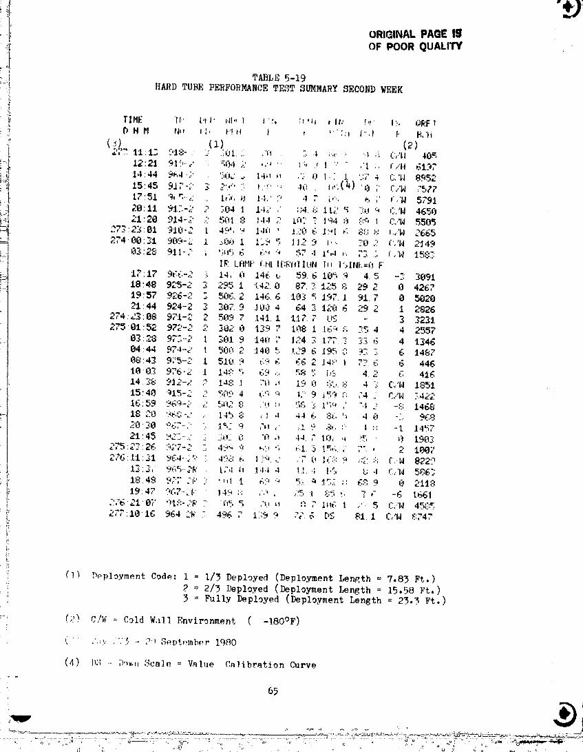
i TABLE 5-19
:i HARD TUBE PERFORMANCE TEST SUMMARY SECOND WEEK
i: TIME IP [,t I' _,Jl,,I _',', :,'_, , It,' hi' I_. J)_,Fvf I_ H M rd,_ I:, t-!H t , *":;t l",l k _,'td
(3) (1) (2)
i!il 27_ t11.:; 91;"3°' " :: .[.Ot." ,"_'i :.: .1 ;,,:. :" "l ',:: L':/II 40_
12"2t 91'!,*..2 : '_¢._,12 ,,', " __ _ ! v ,'I:. _T/'l,I ___1"4714:44 '3_.t...' _ 50,: ... IqH _, ,'2 0 I,- 1. '3,:' 4 r:,'|,,I 8952
:_i" 15'45 917-2 ._ 2'v.' " ,.r.., ,,(., . ,,,.,(1_)._, ;, C,.$1 7577I,':51 9,._..,-.: .. 1,;,, kt 1.1,.' '." ,1 7 (,'., _. ;' r..'W 5791
::I 2811 9.17.-2 2 _:04 I l'l_'l' :::4.8 1L2 '_ "):Uq C,"H 4650_i 21:2.8 914-2 ...'501:9 14-I2 kh::_'l'a4::_::'.:':_I C."H ,5505
.._-'22:01 910-2 t 49', '._ l,lh ' 120 6 ]:"I g 8:[: ,:, L,."N 2665274'G0:_1 9_0-:" 1 ._:0_ I 129 5 112 9 i". -'0 2 t..'N 2_149
02:28 911-'/' ; ";n':,. 6 6"' '_ 57 .1 1',,1 ,-, "-,_ ". ,,'W 1='"..,,:..;..II¢ LflHP fill |[:E'I(IIUN |l_ ]":,INI.=O F'
17 17 966-2 k 1.4,'6, 146 _. 59. 6 105 9 4 5 -2 .2091
18:48 9;'5-2 2 "_ " _--...... I ,.4_.O 87..-.':125 8 29 2 0 4267
19:57 _...... ......-'_-,:[. 506.2 146.6 Ik_ =,I'_71 91.7 0 5_20
21'44 924-2 2 287. 9 .1CIO4 64 .3 128 6 29 2 t 2826274 "'_' " ...._ 88 971-2 _ _89 7' 141. I i&7. 7 Ll$ - _: 223127581'52 972-2 2 282 0 :t_9 7 D)8 I .16_ :-, .-:5 4 4 2557
8_28 97:,-.2 t ._019 14__;" 124 _ 17. _: 3:.E6 4 1_46
0444 97,1--2 t 5OCi2 148 .5 129 6 195 ::: 93:- 6 148708:43 975-2 1 518 9 69 6 66 2 :I4PI ?:-"6 6 446
58 5 t.'S 4 -" 6 41618:03 976"Z 1 14:".5 69 ... ""14. _8 '_...'1..'..-,: ," /48 .I :'_t i_. 19 __.... :::'; 8 4 -: C,."N 1851
_ . _'74 ':t5:40 :)15-2 2 _;C,'-,4 6'- '_ 1.-9 j ,- :-: ,"4 C.."N ".,.42216'59 969-2 2 51v2 E: ,_._ '., ",:-'__ .t'__' ,' ".1 .i' -t-: 146818:20 '3gC:-,:' ,.. 145 E: , I 4 4.1 6 8,:, ': 4 (_ -:.. 96828:_8 c'KT-'." " .1%- 9 ,'*_, ;I. 9 8(, " I :-' -i 1.,I",721 : 45 '__2:.-..-.' :_. :;_:_::_: .'_ ,_ ,14. ,." 10, *_ :'5 _ t90k
275:2_:26 927-2 " 4':_q 9 _,'i, "; ,i.1. 5 1=,,:,. ; 7t , 2 1I)87_,.61t:31 .u6,1..,F.; 49,-: 6 1?'-_ _.' ,, 0 16;: 9 .:2 :', .¢.-W 8229
-_J: 13:2, 965--2[< t,-',l il 1,1,1 4 I I..I 1,5 U ,1 (:,'|4 586:;I, t8:48 92:' J'_,' - -,,1 I _,:i, '_ % _ .15,:. :: g:_ 9 0 21!8
i 19:47 ")67-:'1:" 1,17 ::; ;"." :_ 85 "_,., .I :, :. ,- -6 t66t
, ,:,b'218;" '"t:::-2_' -iff, 5 ,"_,._ ,, , DW. I ,:"- 5 C,"I4 45,;.....I
1: Z,7:18"16 964 2k 496 , 139 9 ,,'. 6 [)5 8t. I C.."W ¢""
!
/: (I_ _eployment Code: I = i/5 Deployed (Deployment Length : 7.8_ Ft.)2 = 2/3 Deployed (Deployment Length = 15.58 Ft. )
: ! 3 Fully Deployed (Deployment Length = 23-3 Ft.)
(;?) C/W = Cold Wall Environment ( -180°F)
(: ,'._.v .".'_ *- 2:t S_ptember 1980
(4) IK-__ ;)-)_,,'__cale= Value Calibration Curve
00000001-TSF01
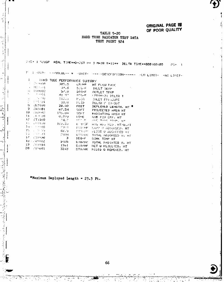
{!.1
ORIGiNAl.. PAGE II 11OF POOR QUALITY
TABI,E 5-20HARD TUBE RADIATOR TEST DATA ',
TEST POINT 924°,
-7 "
ORIGINAL PAGE IS ,: '1OF POOR QUALITY
11
20 to 40 percent. One possible source of error appears to be the IR lamp
aimuletion of the zero OF sink temperature. The lamps were off during the
cold w.ll test point runs and therefore were not a factor. The "correct"
value of panel heat rejection was taken as that parameter titled and printed
out as "Fluid Q Removed" (ZQ9001) by the FLEX data system. This "correct"
value was compared to a calculated heat rejection using the follo_ing equation.
- QRAD -- ¢P'6_ A (TRAD -TSINK)where:
= 0.5 (value assumed for correlation)
6 = 0.71
= Stefan-Boltzmann constant . ,i• I
A = ZA9OO2, Radiating area 'I
TRAD = ZT9000, Avg. tube temperature
TSINK = Fin sample temperature
The cold wall environment heat rejection being correlatable to a low
fin effectiveness has credence when the panel fabrication and panel fin damage
is reviewed. The hard tube panel flexible fin was damaged during the thermal
vacuum testing (see Figure 5-13). This damage is believed to have been caused
by the 1/8" diameter nylon cords which are used to rotate the storage drum for
panel deployment. Pre-test ambient deployment/retraction cycles did not cause
th_ fin damage (i.e. the fin was not damaged prior to the thermal vacuum
test). The fin damage appears to have been caused when the storage drum
"froze" (i.e. would not rotate for panel deployment). Repeated deployment
attempts in the "frozen" condition probably resulted in the fin being
:]:_,n_ged. Hard tube panel deployment problems were recorded in the test
%i;_eline notes (Appendix B) as early as day 263 (Ist week).
" Resolution of the deployment system "freezing" will require
disassembling the panel storage drum and coiled flex-hose fluid transfer__I
_" "]_wi_,_a (located on the ends of the storage drum axle). DurinF the
disassembly process close attention should be given to the alignment and
_allin_ of bushing, bearings and bearing retainers on the storage drum axle.
Inspection of the fluid transfer device can not be made until the flex hose
r,,tainin_,sleeve is removed. The hose shuttle which reverses the Flex h_se
w}n,_in:;direction is a potential source of storage drum binding. The braided
!'l,-_v h_," moves past several Teflon "slider blocks" on the ]lose :'..hutt]_ .,n,]
the ':'_,fl'_ntoryhave cold-flowed into the hose braid causinR the bindLn,,_.
.... , ..,.,..___,_,.,c.__._.,.. " ,,, _ .._:_j. _,,..... _:.;_: , _ . , -o_j- - . .... , .... _ .... _.
" "°' ' "'.....° °° ....................... O0000001-TSFO3
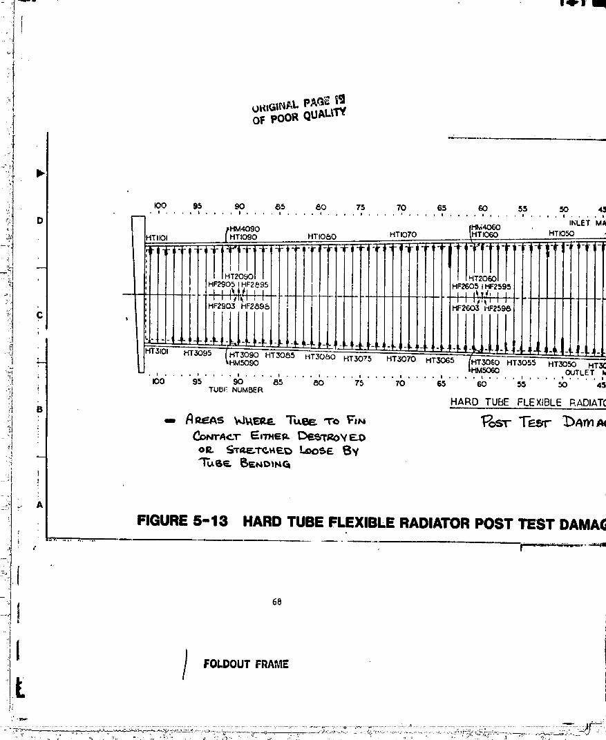
i!1
' OFpOORQUAL_I'Y
--:1
•_,o. . .'P.... 9,0.... 87.... 8,o.... ? .... _P.... _?.... ,_.... s,s.... ,_.... :,D fHlvi4060 . INLET MA
_HM4090 HTIO_O HTI070 _HTI(ToO HTI050
.,., ,.oTTFTTIrTTTI.TTT,T;Tr1 I]TTTI.I! TI" '-'.....: r-i'-,i'- 7- -,,- - " '",
7'1 ;f1"_'-9-5 HT3090 HT'308-'-_" H'_C)'-_ HT3"O-'_,_
. . , .... , .... i .... , .... , .... , .... , , _ , .... OUTLET:_I ' ° ° ° ° ° ° * * ° ' ' ' ° ' 'Ioo 9s 90 8s 80 75 70 _s _0 ss 50 4sil ! TUB_: NUMBER;_i HARD TUBE FLEXIBLE RADIAT[';_ B
i
A
FIGURE5-13 HARDTUBE FLEXIBLE RADIATORPOST TEST DAMA(_
.1-t
!:
00000001-TSF04

14,1'-
I!
•Jc Poor QUALi_.
47 4o = p 27 _ ,,5 ,? ., ee_._s• ' .... * • I . . . 0 a , o . . 0 • . •
INLET MANIFOLD IHM4030 ............... , . . . = HPI000
"'1050 HTI040 _HTIO30 HT 1020 HTIOIO INLE T _,
HIOOOI
HPIOO= IHF229& ',I
i¢
.-_-3050 HT,.3045 HT3040 HT3035 J HOOOC2OUTLET MANIFOLD HT3025 HT3OZO HT_]O,,,5
.......... ' .... _ _b b _ .T3o,o _LCT,• . , , l I * . t I , l I . I . * , I I , i 4 I * I l I
45 40 3 25 _ 2 ' 5 t
RADIATOI_,INSTRUMENTATICN I
FOLDGUT FRAME
00000001-TSF05
I The hard tube radiator was designed and sized to reject i.i kW to a
O°F sink while flowing 300 pph of Freon 21 (entering the panel at lOO°F
,nd exitin4_, at 40°F), The fluld-to-tube temperature difference for the
Fully deployed panel is 2 to lO°F. Larger differences of 20 to 30°F were
measured For the i/3 and 2/3 deployed panel configurations. The causes of
these large fluid-to-tube temperature differences need to be investigated
I further. When the panel is partially deployed, the stowed flow tubes are in abenign environment and tend to act as bypass lines to the deployed panel
area. The short flow tubes (toward the panel tip) are designed to carry less
£1ow but could be _etting much less flow than expected due to the flow
bypassing effect. Fluid-to-tube heat transfer resistance increases as the
tube flowrates decrease (for turbulent flow) which would contribute to the
high fluid-to-tube temperature differences in partially deployed
configurations.
:- The hard tube panel was instrumented with 50 thermocouples.
: Thirty-two thermocouples were installed on the flow tubes of which 19 were at
the outlet manifold side of the panel. These nineteen flow tube thermocouples
i can be used to infer a panel flow distribution. Figures 5-14 and 5-15 showthe typical flow tube temperature profiles out along the panel. The higher
outlet temperature tubes have the larger flowrates. For example tubes 55 and
I 75 thermocouples indicate more fluid flowing in these tubes than in adjacpnt
instrumented tubes. If these tubes are actually getting a larger flow, then
I other tubes must be receiving less than their design flow. The hard tubepanel flows are designed to be different for each flow tube with the longest
I tube receiving the greatest flowrate. Off-design flow distribution would tendto reduce panel heat rejection.
L Another effect which was considered in the testing was that of themanifold links on panel heat rejection. Test point 964-2 flow conditions were
run with the manifold links (bare aluminum) exposed to the thermal environment[
and then repeated with the manifold links and wing-tip spring box insulated ,:
with 6 layers of aluminized mylar. Figures 5-26 and 5-17 show the manifold
i" link temperatures for the insulated and un-insulated test runs. When theL
links are insulated the inlet manifold fluid keeps the link temperatures
I almost constant along the panel and above the inlet side tube temperatureswhich are exposed to the environment. For the case of the un-insulated inlet
_i manifold links, the link temperatures radiating to the cold wall environment
• '. •
°'...... '........... 00000001-TSF06
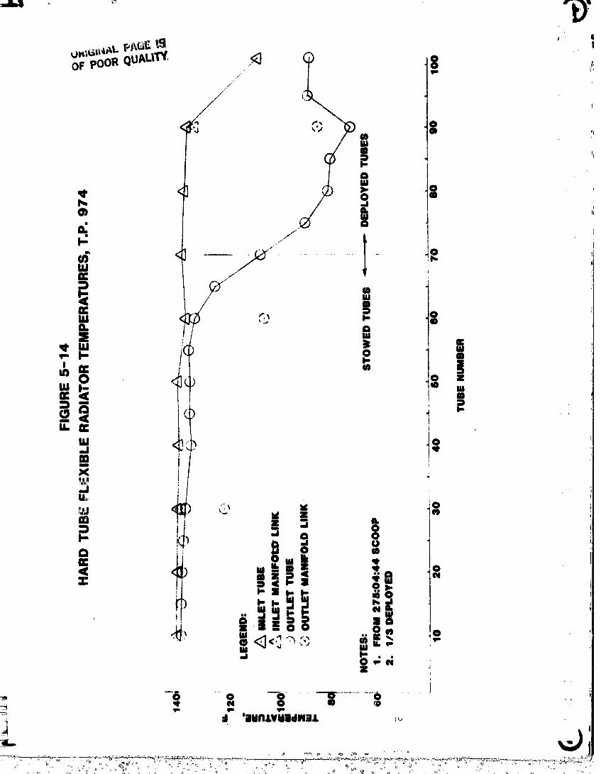
4
!
|
_ j j
/
BIm
w I _9 +. o8- o
z / | .
/ t,"vw ( os,,- I- mI,-I scU) E , m :)
0 d ._ I-14. E
w_. <,.,. iom
X
__.i
,.,+ + .; .," i 1
° + -! ,< < m " ;
• + "+++++.,"_ ,+Z :i
I
+, -6 +o l I o_0
i _I 'illdNJ,Vll|dlNt,L ++
_.. ,
• + ,,+ , ,,+ o + ' +.,.-_+..... + +o }' °_,+o_ ++ o- +,oo % _ +++ . ,, ..+ .+ . :+.+ ,,.,+ + + <,+'.v, .......... _, 7 + " +,.+ "+ *'"o "L._+> ',+ "++. +_i+ o+ .] % u ..... + " +' '+ o " ,+ v+ ,++ ' + , + ,,. "" + ",+ ,
00000001-TSF07

, --,j
" I
I ' i 8 ,,_. | -
. 0 ) io J
__1 ; /
W _ // ii _ ! /"
W < ' iZ
i! ox 2_ •
liW_VlIWdWi4,
O0000001-TSF08

F_)_,_ _l'rl
-_; ORIGINAL PAC% _,,,,';* ;;i ,- OF POOR QUALITY
-/ • //
,, t D
/ :
i _ _ . --._r • f'_, '"._
[ ,
i _. ?
i m (
[ _!:)t
_g: _ m6 1 r i i.,
_i j;,•_ _,._ .
°;* ¢_
p,:.: L°.
"} :-.ti ¢ /
)\. _ /,/
_; • <_ _0/ '! _oq._ _ Ii //
• i
i-_iot i,,!
,!._ d 'DMN,LV!d|_I_iLL ,. #
00000001-TSF09

e'
4
. I
I I
/'
( "i'Y ' "? 0* _ '"
i "
° !
¢.
! t"
_= d q" 'ilIiKI.LVliHIdlU.L
OOOOOO0"I--I-$F'I0
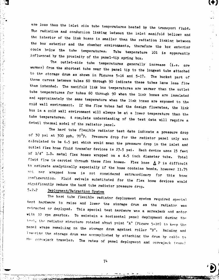
i e
!.,i are less than the inlet side tube temperatures heated by the transport fluid.
• ': The radiation and conduction linking between the inlet manifold bellows and '
_, _ the interior of the link boxes is smaller than the radiation linkin_ between
the box exterior and the chamber environments, therefore the box exterior
::. cool.q below the tube temperatures. Tube temperature iO1 is apparently
:: influenced by the proximity of the panel-tip spring box.
_ __ The outlet-side tube temperatures generally increase (i.e. are
i_!: warmer) from the shortest tube near the panel tip to the longest tube attached
i :" to thp storage drum as shown in Figures 5-16 and 5-17. The bucket part of
these curves between tubes 60 through 90 indicate these tubes have less flow
i . than intended. The manifold link box temperatures are warmer than the outlet
; tube temperatures for tubes 60 through 90 when the link boxes are insulated
;and approximately the same temperature when the link boxes are exposed to thei °
! cold wall environment. If the flow tubes had the design flowrates, the link
;_: box in a cold wall environment will always be at a lower temperature than the
..... tube temperatures. A complete understanding of the test data will require ai:
% detail thermal model of the radiator panel.
!_ The hard tube flexible radiator test data indicate a pressure drop
!_. of 30 psi at 300 pph, 70°F. Pressure drop For the radiator panel only was
i:!_' c41culated to be 6.5 psi which would mean the pressure drop in the inlet and
i_ outlet flex hose fluid transfer devices is 23.5 psi. Each device uses 15 feet
i_ of 1/4" I.D. metal flex hoses wrapped on a 4,5 inch diameter tube. Total
',_: fluid flow is carried through these flex hoses. Flex hose _ P is difficult!
_ : to estimate analytically especially if the hose contains bends, however 11.75
_: _i Der wrapped hose is not considered extraordinary for this hose
J'. _onfi_uration. Fluid swivels substituted for the flex hose devices would
_ :_i_nificantly reduce the hard tube radiator pressure drop.
5•2.2 Deplo_ment/Retraction System
The hard tube flexible radiator deployment system required speei.1
' tent hardware to raise and lower the storage drum as the radiator was'i
!i!I r_tracted or deployed. This special test hardware w_s a screw.lack and motnrwith IO rpm gearbox. To maintain a horizontal panel deployment durin_ th_
i.... t...._,,th,, r_diator structure rotated about point "A'° (Figure 5-18) to ke(_p th_
panel wraps remai_.ing on the storage drum against roller "B°'. Raising and
l_wr.rin_:the storage drum was accomplished by attaching the drum by cnblp to
fb,, _:cr_:wjack traveler. The rates of panel deployment and ,_crewjsck i-,"4v(:7
," ..................... 00000001-TSF 11
_,,, 14.1 +II
.'_+:3+
ORIGINAL ' +_'......,+
OF POORQU_LIW*1
O0000001-TSF12
qt
• ! _!
wore fairly wall synchronized initially but beoame increasingly unsynehronizod
during the progress o_ the teat. Mention has boon made previously of the fin
damage by the nylon d_ployment rope. The d_ploymont rope also bent (believe
to have occurred when the storage drum froze) the flow tubes which reduced the
drum diameter the rope and succeeding panel wraps rolled up on. A smaller ',_
wind-up diameter _iters the deployment speed end thus the synchronization. An
_perations procedure was _stablished which involves temporarily negatlnP, the
screwjack limit switches to allow full panel deployment and the test continued.
A phenomenon occurred concerning the outlet manifold links which
remains unexplained. The manifold links developed a slnusoidal wave (maximum
amplitude - 1 foot) shape along the manifold. This "kinking" of trle outlet
manifold occurred on the first day of testing and reoccurred in approximately
80% of all full panel deployments. The inlet manifold was unaffected and
remained straight during all the deployments. During retraction the panel
"kinked" outlet manifold straighten out each time and was rolled up on the
storage drum. Several videotape records of the manifold "kinking" phenomenon
were _ade. These may be useful in further investigations.
Inspection of the manifold links after the test revealed no binding
or apparent cause of binding. It was originally speculated that a binding
problem existed. The source of the _utlet manifold kinking, it is related to
the thermal vacuum environment. The link boxes rotate on a close tolerance
stainless steel fluid tee which was lubricated with Molykote-Z. Molykote-Z is
a vacuum compatible lubricant with very low outgassing characteristics.
p
2" ¢
.... .... " 00000001-TSF13
6.0 CONCLUSIONS
l The followir_ main conclusionn w_ro reached from the testin_ on th_two radiator p.nels:
I (i) The soft tube radiator will _ejoct the des$gn ho_t l_ad in thoJ' space environment.
(2) The high pressure drop observed for the soft tube radiator
during, the tests were caused by excessive corrosion inside the
outboard manifold. Adequate aurface treatment and storage
I procedures are needed to pervent this in the future.
(3) The hard tube radiator he_t rejection was about 30% lower than
I expected at the design conditions. This is likely caused by
damage to the fin during deployment and retraction.
[_ (4) The soft tube radiator deployment/retraction system performed
well except for some slight coning near the end of the test.
(5) The hard tube radiator deployment/retraction performed
adequately except that binding occurred which caused high
tension in the deployment cord which resulted in panel damage.
7.0 ZFER C SI. Hixon, C. W., Development of a Prototype Flexible Radia%or System -
Final Report, Vought Corporation Report No. 2-50320/9R-52078.- 2. Hixon, C. W., Design and Development of a Hard Tube Flexible
_i Radiator System - Final Report, Vought Corporation Report No.d2-30320/0R-52416, dated 25 April 1980.
_ 3. Rankin, J. G., et.al., Flexible Radiator Thermal Vacuum Test
i Requirements, NASA/JSC 16554, CSD-SH-168, dated 6 August 1980.
4. Rankin, J. G., et.al., Flexible Radiator Thermal Vacuum Test Plan,
;.... NASA/JSC 16555, CSD-SS-032, dated 9 September 1980.
5. Rankin, J. G. and Marshall, P., Flexible Radiator Thermal Vacuum
Quick Look Summary, NASA/JSC dated October 1980.
--T
° 77
O0000001-TSF14

)
!/'
1
_i APPENDIX A!-i
FLEXIBLE RADIATOR TEST INSTRUMENTATION LIST
i
!
!1'!I
L 7_.)
. o 'li ,, . _, ..... ... _ _, "o, ,_ ,, _, . , , .... , _ _ ".) , . o _ _ , !,
00000001-TSG01

iI INSTRUMENTATION LIST KEY
e
HARD TUBE THER/4OCOUPLE- MID
-'- 1st letter H - HARD TUBE RADIATOR
: 2nd letter F - FIN
M - MANIFOLD
l T - TUBE
._ 1st number I - Flow Tube Inlet
' i 2 - Flow Tube and Fin Cencerline5
_ _ 3 - Flow Tube Outlet
.._. i 4 - Inlet Manifold Link Box
. 5 - Outlet Manifold Link Box
2nd number 0 - NOT A FIN T/C
1 - INDICATES TUBE 101
V!_ .. 2,3,5,6,8 or 9 - Part of T/C Fin Location
_- i 3rd & 4th TUBE NUMBER (If 2nd number = O)
I _ __ number
i_ _, "_ Examplgs :
_, Hard Tube Radiator, Inlet Man'.fold Thermocouple Near Inlet of Flow
i_{ ",__ Tube 30
: _: _ HM4030
:_ _o, Hard Tube Radiator, Centerline Fin Thermocouple, ,3 inches From
', .i:'- _ Tube 60, Between Tube 60 and Tube 61t
_!. HF2603
_i SOFT TUBE THERMOCOUPLES- MID :_
i_ 1st letter S - Soft Tube Radiator
2rid letter F - Fin
" : M - Manifold (trailing numbers not dimensionally
_'_. significant)%
...._ T - Tube
',-. tat & 2rid Designates the Linear Position (in feet) from Drume
!_:_ numbers End of the Deployed Radiator Panel
: 3rd & 4th Designates Tube Number of Tube Thermocouple or Next
...... numbers Lowest Tube Num!_.r of Fin Thermocouplet
e
" i
-IL 79 ,,
00000001-TSG02
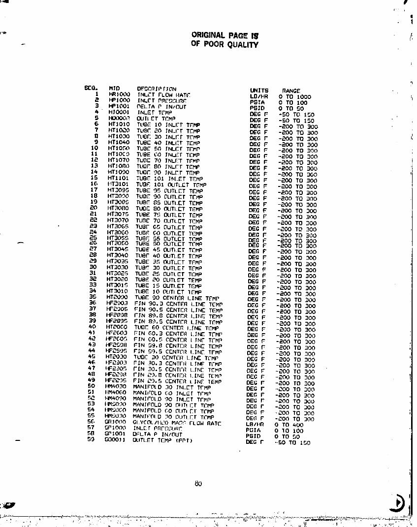
iv
r i I
I
ORIGINAL PAO_ IS ,_IiOF POOR QUALITY
;I
6[:0. MID DFGCRIP rfON UNITS RANG_1 HRIOL'_ INLL"T FLOW t_ATL".. LDIHR 0 TO 1000,'_ HP]O00 INL['T PRCC,L'AJRf PSIA 0 TO 1003 HPIO01 _EL.TA P IN/OUT PSID 0 TO 504 HIOOOt IrNLET TD"mP BEG F -50 TO t_O5 HI.,]t)OOJ_ OUTI _T TI.'.MP BEG F -$0 TO 1506 HT|OIO TUBE 10 INLet TFMP DE(;, F -200 TO 3007 ttT10,.7.O TUBt- 20 INI.I'T T.FMP DEIG F -200 TO =300II HTIO_O TLIO.F.30 INL.F.TT£'.l_P BEG F -200 TO -3009 HT1040 TUBE 40 INLIST TCMP DEE F -200 TO ._0010 HTIO_.O TUBE 50 INL.F.TTEMP BEG F -200 TO 30011 HTIOEO TUBE CO INLET TEMP BEG F -20(3 TO 30012 HTI070 TUDC 70 INLI';TTFMP BEG F -200 TO 30013 HT]OIIO TUI3F 80 fNLFT TCMP BEG F -200 TO ._0014 HT_090 TUBI- 90 INLET TEMP BEG F -2043 TO 3001S HTlI01 TUBE '..01INt.ET TF_MP BEG F -200 TO 3001£,, HT310] TUBF. 101 OUTLET T_MP DEG F -200 TO ,30017 HT3095 TUBE '3_, OUTLET TEMP BEG F -200 TO 30018 HT_O'_"K)TUOE 90 OUTLET TITMP BEG F -200 TO 30019 ).IT30B5 TUBE ZIS OUTLE;T TEblP BEG F -200 TO 300
I-IT.":;O_30 TUOE 80 OUTLET TEMP BEG F -200 TO _0021 HT3075 TUBE 7'.;OUTLET TEMP BEG F -200 TO 30022 HT3070 TUllE 70 OLJTLET TCMP BEG F -200 TO 30023 HT_OG_r, TUBF Gr_ OUTLET TEMP DEG F -200 TO .30024 HT3OGO TUBF GO OUTLET Tf'NP BEG F -200 TO 30025 ttT30S5 TUBE SS OUTLET TI.'MP BEG F -200 TO 300_G HT.-'tO£,O TUBE 50 OUTLET TOMP DEG F -200 TO 300_7 HT3045 TUBE 45 OUTLET TCMP DEC, F -200 TO DO0a8 HT3040 TUBF 40 OUTLET T_MP BEG F -200 TO 300
HT3035 TUBE 35 OUTLET TEMP DEE F -2('X)TO 300-_0 HT3030 TUB_ 30 OUTLET TEMP BEG F -200 TO 30031 HT30,_ TUBE _..c,OUTI.CT Tl'_MP DEE F -200 TO 300_k3 HT3020 TUBE 20 OUTLET TEMP DEG F -200 TO 30033 HT3015 TUBE 15 OUTLET TEMP BEG F -200 TO 30034 HT3010 TLIBE lO OLJTIET 1E'MP DEG F -200 TO 3003S HTE_O'-'_OTUBE _30 CENTER LINE TEMP BEG F -200 TO 3003(; I.I=2'.303FiN 90. D CENTE'.RLINE TCMP DEG F -204} TO 30037 HF_';)05 FIN 90.5 CENTER I.I'NETEMP BEG F -200 TO 300
HF_EI'._8 F_N 89.8 CENTER I_IN_ TEMP BEG F -200 TO 300-_ HF289_ FIN 8_._.5 CENTER LINE TtTMP DEE F -200 TO 30040 HT_'OGO TUBF. EO CL-NTEIR I_JNE TI'MP DEE F -200 TO 300_] HF2G03 FIN GO,3 CENTER L.INE TFMP BEG F -200 TO _0042 t_(,O_ FIN E,O.5 CCNTC:R t IN_"T['MP BEG F -200 TO :30043 HF'2598 FIN 59.1_ CENT FR LINE TEMP DEG F -200 TO 30044 HF_5,)_ FIN 5'-3.5 CENT_TR I IN.F. Tt'MP DEC F -_00 TO 30045 HT2030 TUBE 30 CENTER LINE TL'MP OEG F -_00 TO 3004G I-F230ii FIN 30.3 CCNTFR LINT TI-MP BEG F -_00 TO 30047 llCr2:iO_FIN 30.5 CENTFA LIN_ T.F.M? BEG F -_00 TO 3004B HF_._'_t'_f'IN 29.0 Cr-NTF.RI..LNET_/M__ DE(I,F --_00 TO .30049 I-F_.'35 FI'N _O. 5 CENTIT'I'IL|NE TEMP DEE F -200 TO _00.SO HM4030 MANIFOLD 30 I>NL.ETTFMP DEG F -200 TO _I0051 IIM_IOCO MANIFOLD C.O INLET TI'_IP OF-G F -200 TO 30052 HM40'='K3MANIFOLO 90 ]'NLET TFMP DEE F -r_O0 TO .-300S3 IIM'30'_OMANI'FOLO 90 OilTlCT TtZMP D£G F -_00 TO .300S4 HMSOC.O MANIFOI.D CO OLJTI.ET TL-MP OEG F _,_00 TO 300S_ Hl,150:-lOMANI'FOLD .'10OUTI|-T TITMP IDE_'_F -P_.O0TO 300SG GR]O00 GIYCOL/HdO MA3'7 FLOW RATE LB/IIR 0 TO 400$7 5P1000 INLr_,FPrlF_',.';liiTF_ PGIA 0 10 100511 FGPIO01 DFLTA P IN/OUT PSID 0 TO 50r_) r._oo_ 1 OUTL.F.T TCMP (PPT) BEG F --SO TO 150
8O

ORIGINAL PAGE IS"- OF POOR qUALITY.
_,0 _£)001_ OUTLET TCMP (TM T/C) BEG F -SO TO lraOGI 000013 OUTLF,.T TI:MP (]M TiC) DE(] F -SO TO 1_0¢-,,2_ _I004.'_J INLET TCMP (PPT) O_G F -r._O TO 1_063 GIO002 INLET TEMP (IM T/C) OEG F -50 TO 150G4 SIO00.] INLET T_MP (IM T/C) DEC,,F -SO TO 1S0
: 6S _#lO00J Of; MAN(FOLD TEMP DEG F -SO TO 1SO66 SMO00_ 08 MANWOLO TEMP DEG F -SO TO ISOG7 GTO_4G TUBE 46 AT 4 FEET T_'MP DEG F -200 TO ,DO0
SF04.3C, FXN .3G. rj A1 4 FI_ET TEMP DEG F -,_00 TO .30069 STO,'t_) TUBE :30 AT 4 FEET TEMP _.G F -200 TO 30070 ST0421 TUBE _1 AT 4 FEET TEMP DEG F -200 TO 30071 ST0417 TLIBE 17 AT 4 FEET T£MP DEG F -200 TO 3007E BTOZ*14 TUBE 14 AT 4 FL'F-T TFMP OEG F -BOO TO 30079 SF0413 FIN 1.3,5 AT 4 FEET TE.MP OEG F -200 TO 300
I 74 ST041.3 TUBE 13 AT 4 FEET TEMP DEC, F -200 TO 300
75 ST0409 TUBE 9 AT 4 FEET TEMP D_G F -200 TO 30076 ST0405 TUBE 5 AT 4 FEET TEMP BEG F -200 TO 30077 SFO63S FIN 3S. S AT G FEET TEMP OEG F -200 TO 300
l 7B GFOC.14 FIN 14.. r, AT £, FEET TEMP OEG F -200 TO 300"/9 STOB4¢., TUBE 4G AT _ FEET TEMP BEG F -200 TO 30080 SFOB3_ F_N 34.S AT Et FEET TEMP BEG F -200 TO 30081 SFOBIS FIN 15.5 AT i3FEET TEMP DEG F -200 TO 30082 STOB05 TUBE S AT B FEET TEMP DEG F -200 TO 300
83 ST1037 TUBE 37 AT 10 FEET TCJ,IP DEG F -200 TO 30084 BFIO_G FIN .3G.S AT 10 FEET TEMP DEC, F -200 TO 300BS STIO3G TUBE _G AT 10 FiTET TEMP DEC, F -200 TO _008_ ST10.30 TUBE .30 AT 10 FE_T TEMP DEC, F -L_BO TO 30087 BT1021 TUBE 21 AT 10 FEET TEMP DEG F -200 TO .300
I 88 SF101.3 FTN 1-3.5 AT 10 FEE]" TEMP DEG F -200 TO 300"- 89 SFI_3S FIN 3S.S AT 12 FEET TEMP DEE F -200 TO 30090 _Flr_14 FIN 14. S AT 12 FEET TEMP DEG F -PO0 TO 300
91 6T1446 TUBE 4G AT 14 FEET T_MP DEG F -200 TO 90092 SF14.34 FIN 34.5 AT 14 FF.ET TEMP DEG F -_-K)OTO 30093 SF1415 FIN 15.5 AT 14 FEET TFI_ DEE F -200 TO 30094 BT140S TUBE S AT 14 FEET TEMP DEE F -200 TO 3009S SF163G FIN 3G.5 AT lr_ FEET TEMP DEC, F -200 TO 300_ STIG30 TUBE 30 AT 1¢, FEET TEMP BEG F -200 TO 300
I 97 STI(;21 TUaE P-1 AT IG FFCT TEMPDEC, F -200 TO 300
9B 8FI(313 FIN 13.5 AT 1G FFET TEMP DEC, F -200 TO 30099 _F1/].35 FIN 3S.S AT 10 FEET TEMP DEC, F -200 TO 300
100 BT1i]15 TUBE 1_ AT 1B FEF.T TEMP DEE F -200 TO 300101 SFIB14 FIN 14._ AT 1B FEET TEMP DEC, F -200 TO ]00102 _T1814 TUBE 14 AT 18 FEET TFMP DEC, F -;:00 TO 300103 STL-'_O4G TUBE 4_, AT ,_0 FEET TEMP DEC, F -200 TO .300104 _T_-%14,_TUB_ 4_ AT DO FEET TEMP DEC, F -200 TO 300
I 10S OT_0.3)] TUBE 31]AT L_O FEET TEMP DEG F -200 TO 30010£, GT203_ TLGE .3S AT _0 FEET TEMP BEG F -_.00 TO 300107 GF,'_03_ FIN _4.5 AT 20 FEET TCMP DEG F -200 TO 90010B _T_0.34 TUBE 34 AT ,?0 F.FCT Tt'.MP DEG F m_ TO 300
i 109 STY030 TUBE .30 AT _0 FEET TEMP DEG F --_00 TO 30_)110 SFL_015 FIN IS.5 AT _0 FEET TEMP DE(; F --200 TO .300111 GT_.O05 TUBE 5 AT '_0 FEET TCMF DEG F --200 TO 300112 ST_P2_ TUBE 21 AT _P. FEET TEMP DEG F "P.O0 TO 300113 GT2_4_, TUOC _6 AT _4 FEET TCMP DEG F -200 TO _00
I 114 GT_._30 TUeC 30 AT _4 F_ET rCMP DE(; F -P.O0 TO 300115 ZAIO0; PROJL-CTi'OARFA ST S(_ FT 0 TO 10011£, ZAIO0_ flADIATINC, AI_'A _T _ FT 0 TO _00117 ZA_J01 PROJI.'.CT_L')AI'_L-A14T _l FT 0 TO 100
111] ZABO0_ RADIATIN(; AREA HT _ FT 0 TO _.00119 ZCIOOI CP OF GL¥C_L/ItL'O B/#-F 0.4 TO O.B
81
; "'" "' ° " " ' " 00000001-TSG04
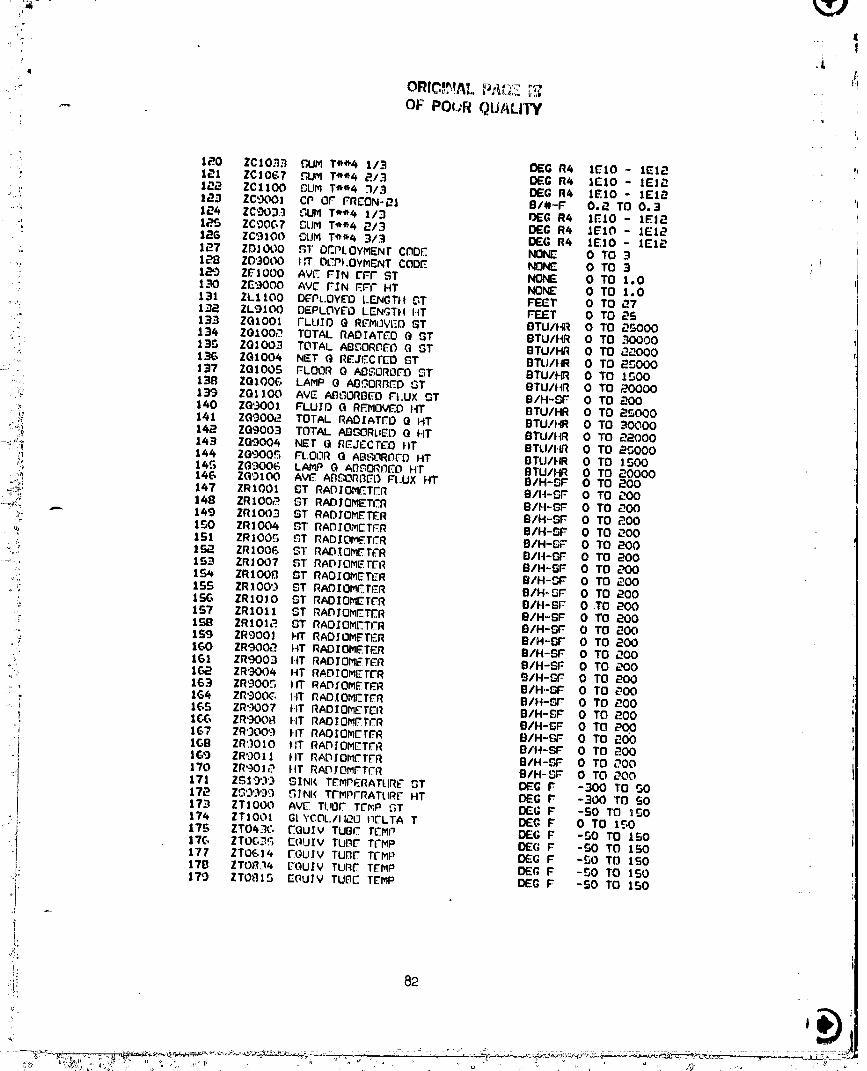
;: |
"_ OF POUR QU/_LI'W
1_0 ZC1033 _UM T'_'_'4 113 DEG R4 IE10 - IE12 ":i_ 1_1 ZC|067 _UM T_"_4 _./3 D£G R4 IE10 - IEJ_
1_ ZClIO0 OUM T¢"_4 1113 DEG R4 IE10 - 1E12 _d..i: 123 ZCgOO] CP OF FRCON-,'_I B/#.-F 0.2 TO 0.3.,_ 124 ZC'D03.3 :_UM Te_4 113 13EG R4 IE10 - IE12
., IP._ ZC'._OG7 P,_LIMTee4 _/3 O£G R4 IE10 - 1E12" 1_6 ZC9100 L3UMTe_4 3t3 DEG R4 1E10 - IE1P.
127 ZOJO00 _T OEPI..OYMENr CI3D.F. _ 0 TO 3:" 1_,8 ZD'3000 I:T DCPt.OYMENT CODE NONE 0 TO 3 '
1,_3 Z_|O00 AV[_ FIN L"FF ST NONE 0 TO 1.0_"! 130 ZE9000 AVE' FIN _FF HT NONE 0 TO 1.0: 131 ZL.1100 D_PL.OY£O L-ENGTH _T FEET 0 TO _7
o(': 1._. ZL9100 DEPLOYL"O LENGTH HT FF,JE.T 0 TO 2S133 ZGIO01 FLUID Q REMdVEO ST BTLI/HR 0 TO 55000134 ZOlOOf_ TOTAL RAD]ATL'-.D(} GT BTU/HR 0 TO 30000
':':': 135 Z0]003 TOTAL AB_ORP,Et') 0 5T BTU/HR 0 TO _000-': 136 ZG1004 Nr:T (_ RF..Jtt.crco _T BTUtIR 0 TO 2_000
s:!' 137 ZOlOOS FLOOR 0 AI_'Z,ORDFO _T BTU/_R 0 TO 1500:..! 1_¢_ ZGIOOE, LAMP 0 AD_OR_D GT BTLI/HR O TO 20000-,:: 139 Z01100 AVE ABGORtlEO FLUX OT B/H-P,_F 0 TO _00
• y140 Z09001 FLUIO G R_.MOV:F.OItT DTU/HR 0 TO _SO00
-._ 141 Z0900_2 TOTAL RAOIAT['O 0 HT BTU/HR 0 TO 30000,_:_ 142 Z09003 TOTAL ,_ORU_L') G HT BTU/IIR 0 TO _2000143 Z09004 NET (} REJECTL-O HT BTU/I.R 0 TO 25000
144 ZO'300_ FLOOR G ABS,0RL'IFDHT OTUIHR 0 TO 1500_I 14.G ZG'_O06 LAMP G A[_GQRt_EOHT BTU/HR 0 TO _0000_ 146 Z0'-3100 AVG AB_OR_Gt3 FI.UX HT B/H-SF 0 TO _00
_', 147 ZRIO01 _T RA[3IOMETER B/It-OF 0 TO _00._;; 148 ZRlOOf_ _T RADIOMETER 8/I-I-_F 0 TO _00
=<m. ,... 149 ZRIO03 ST RADIO_.T£R B/H-_F 0 TO _00," 150 ZRIO04 _T RADIOMCTFR BIH-_F 0 TO _00_ ISI ZRIO0_ L3T RADIOMETCR BIH-SF 0 TO 200•" 1._2 ZRIO06 5T RAD._OME..Tk_R B/H-OF 0 TO _00
'%":: 153 ZR_O07 ST RADfOMETFR B/H-SF 0 TO ¢-_00• 15_ ZRIO0[t GT RAOIOMETER B/H-°,_ 0 TO 200
_' lSS ZRIO09 ST RADIOMETER BIH-_F 0 TO _00_'; 1SG ZRIO]O _T RADIOMETI_R B/H-SF 0 .TO _00
'-' 157 ZR1011 ST RADIOMETER 8tH-SF 0 TO 200'; 1_ ZRI01_ _T RADIOMETER B/H-_ _- 0 TO _00_.. 159 ZRgO0_ FIT RADIOMETER B/H-OF 0 TO _00o' 160 ZRgO0_ HT RADIOMETER B/H-SF 0 TO _00" 161 ZRgO03 HT RADIOMEt'ER B/H-CA: 0 TO 200
162 ZRgO04 HT RAD.TOM_FITR r31H-_F 0 TO _00"_'. 163 ZRgO0_ tit RADfOME=.TER B/H-_ 0 TO _00:' 1G4 ZRgOOG FIT RADIOMETER B/H-_._ 0 TO P-O0_, ; IGS ZR'-3007 fit RADIOMETER B/H-_F 0 TO 200
1 1(.(:, ZRgOOR HT RAOIOM_T_:R 8/i4-GF 0 TO _Op"t 167 ZR'_O0':_ FIT RAOIOMCr_R B/H-OF 0 TO _00
i IGB ZR'._010 t:T RA[3IOMCTER B/tt--SF 0 TO _00I09 ZR9011 lit RADIOM/'.TER B/H-OF 0 TO _00"_ 170 ZRgO_ lit RADTOMFTCR B/H--b*F 0 TO DO0
'"l 171 Z_19'_') SINK TErqPERATURF _T DEG F" -300 TO 50
17_ ZG'_'_'_'_ G_NK T{'MPFRATLIR_ HT DEG F -300 TO SO173 ZTlO00 AV_ TUOF TCP_P C,T OEG F -SO TO I_0174 ZTIO01 GtYCOL./II_OI]_LTA T DEC, F 0 TO 1E,O
1"t_ ZTO_.:',_C(_uIvTUneTrMP OEGF -SO TO tSO177 ZTO614 I":OO]V TUllE T[MP DEG F -50 TO 150
: t'tt] ZTO_,'_.:'__ou_v TUtOr.T_MP OEC,F -so To ISO
.:I! 170 ZTO_31_ EOLJ_V TUI3E TEMP OEG F -._0 TO 150
il:
:t"
_: 82
) '
'_ _......... .. .... : : - " 2'2 =L-_.'_, _.... _ _ _._,._. _;_,..___.-;-___--._. ; .. _ -,-: .... :, ," - ___.._._.__,._.:_Sa_iO.;),_e-;o.a._.:=;..k_._;-_._.__ r..... ..__ai___- _.
_j _,,/,,_ ,,,./,_,,/.../,_,_ i i _.,_v v v

t!
OF POOR_i!_,__V'.
IBO ZTIO%3 EGUIV TL,O_ TCMP OEG F -._0 TO IS0
101 ZTI_3S EQUIV TUllE TCMP DEE F -SO TO IS0 ,,18_ ZTI_.|4 EQUIV TUt_ TFMP DE.G F -SO TO 1501t33 ZT1434 EQUIV TUOE TCMP DEE F -50 TO ISO184 ZT1_15 EQUIV TUOC TCMP BEG F -50 TO 150105 ZTIE.3G EOUIV TUBE TEMP DEE F -50 TO ISO18G ZT_GI3 E(3U,IV TURC TCMP BEG F -SO TO IS0187 ZT]t13_ rQUIV TU[31_TEMP DEE F -50 TO IS0188 ZTP015 EOUIV TUDI7 tEMP OfiG F -SO TO 1S01_'-) ZT8100 AVI_..CIIAHL")I_RWALL. TOvP OEG F -300 TO 100190 Zl'L:t,'_O0 AVE CHAMi3_R FL.OOR T_..MP OEG F -300 TO 100191 ZT_.X_O0 AVE-.TUBe TEMP HT DEE F -SO TO lSO103 ZTgO0) FRF:ON-_I OCLTA T OE;G F 0 TO 150193 ZX11/+I TEMP RATIO _T TUllE 14 NONE 0 TO 1.0194 ZXllr,1 TEMP RATIO _T TUBE 1S NONE 0 TO 1.0195 ZX1131 TEMP RATIO ST TUllE 13 NONE 0 TO 1.0196 ZXlI_P. TEMP RATIO _T TUB.F 2/+ NONE O TO 1.0197 ZX13G1 TEMP RATIO GT TUBE 36 NONE 0 TO 1.019g ZX1371 Tr'MP RATIO ST TURE 37 NONE 0 TO 1.0199 ZX1341 TEMP RATIO fiT TUBE 34 NONE 0 TO 1.0
ZX13S! TEMP RATIO _T TUllE 3S NONE 0 TO 1.0L"K)I ZXIO00 AVE TEMP RATIO _T NONE 0 TO 1.0L::O.'_ 2XIO33 Ave TEMP RAT.(O J/3 ST NONE O TO 1.OL_O3 ZXIOG7 AVE TEMP RATIO 2/3 ST NONE O TO 1.0_-_0_ ZXl_O0 AVE TCMP RATIO 3/3 ST NONE 0 TO 1.020S lXgO00 AVE TEMP RATIO HT NONE 0 TO 1.0_OCa ZX9033 AVE TEMP RATIO I/3 HT NONE 0 TO 1.0207 ZXgO_7 AVE TCMP RATIO 3/3 HT NONE 0 TO 1.0E_OB ZXglO0 AVE TEMP RATIO 3/3 HT NONE 0 TO 1.0209 ZX9301 TEMP RATIO HT TUPF 30 NONE 0 TO 1.0210 ZX930_ TFMP RATIO lit TUBE 30 NONE. 0 TO 1.0
_.11 ZXgE,01 TEMP RATIO HT TUBE 60 NONE 0 TO 1.0 i212 ZX960_ TCMP RATIO HT TUBE GO NON__ 0 TO 1.0_13 ZX9901 TEMP Ratio FIT TUBE '.30 NONE 0 TO I.0`214 ZX990P. I"EMP RATIO 14T TUBE 90 NONE 0 TO 1.0`21S ZE9_01 FIN EFFICIENCY TUBE 30 NONE_ 0 TO 1.0_16 ZE930_ FIN EFFICIENCY TUllE 30 NONE 0 TO 1.0_.17 ZEgE,01 FIN EFFICIENCY TUBE C,O NONE. 0 TO 1.021B ZEgGO_ FIN EFFICIENCY TUBE 60 NONE 0 TO I,O_19 ZE9_901 FIN EFFICIENCY TUBE 90 NONE 0 TO 1.0
ZE990P. FIN EFFICIENCY TUBE 90 NONE 0 TO 1.0P..I Z_11/+1 FIN EFFICIENCY TUBE 1/+ NONE 0 TO 1.0
22`2 ZEII_:I FIN EFFICIENCY TUB_ 1S NONE 0 TO 1.02_3 ZE1131 FIN EFFICIENCY TUBE 13 NONE 0 TO 1.02,24 ZEtl/+_ FIN EFFICIFNCY TUBE 1_ NONE 0 TO 1.0225 ZE13C,I FIN EFFICIENCY TUBE 3G NONE 0 TO 1.0`2=-'% ZE1371 FIN EFFICIENCY TUBIT 37 NONE 0 TO 1..0_._.7 ZE1341 FIN EFFICIENCY TUBE 3_ NONE 0 TO 1.0"_,_P._ ZE13'3_ FIN EI--FIC_FNCY TLIO_ 35 NONE 0 TO 1.0_3 _ir_T70 _ TI'_OLL£YPO'3ITION1/_ NONE OOR 1_30 Z'E_TQ_4 TROU..EY POC,TION 1/_ NONE 0 OR 1
;_31 ZT_71!_ TROLLEY PO'3ITION 1/3 NONE 0 OR 1;=3_. TROLLEY PO'T,'ION 1/,_ NONt'_ 0 OR ]_33 OO _T INFLATION PRE_LJRE PSIA 0 TO GO_34 ST3001 HIRE TtTMRFRAT_IRC'- BEG F -200 TO 300P,-3S BT:-')O0_ N|RC T_MF_-I1ATI.IR_ DE(; F -PO0 TO 300`23G OT._O03 NIRC_ TEMPEI'_ATIJR_. BEG F -200 TO 300_37 7F1000 ST FLOW RATE Ln/IIR 0 TO /+00P.3B ZF'._300 HT FLOW RATE LO/HR 0 TO 1000
N_.XT PARAMETER =" ,23'3
e
00000001-TSG06
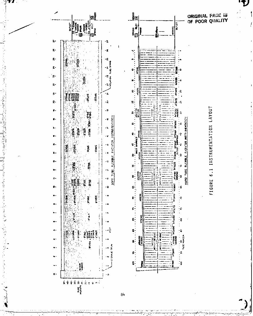

, !
t_
RADIOME.TRRS
Twenty-four radiometers (twelve for each radiator) were installed to t;
,,_.a_re the radiant flux of the IR _amp arrays° Twenty of these radiometersep
]_at_d around the panel periphery measured the flux directly while the other
i faur located beneath the panel measured the flux transmitted through the _iI
radlators plus that emitted by the bottom radiator surfaces. The radlometer's
i calibration range extended between 0 and 200 BTU's per hour per square foot.!
q'h_:,_pp_'oximate location of the radiometers is shown in the Figure.
! .
.... ° 0000000i-TSG08

o o_ o o_-_ N N
r
!
t,!:l
APPENDIX B
FLEXIBLE RADIATORTEST TIMELINE NOTES
O000000]-TSG] 0
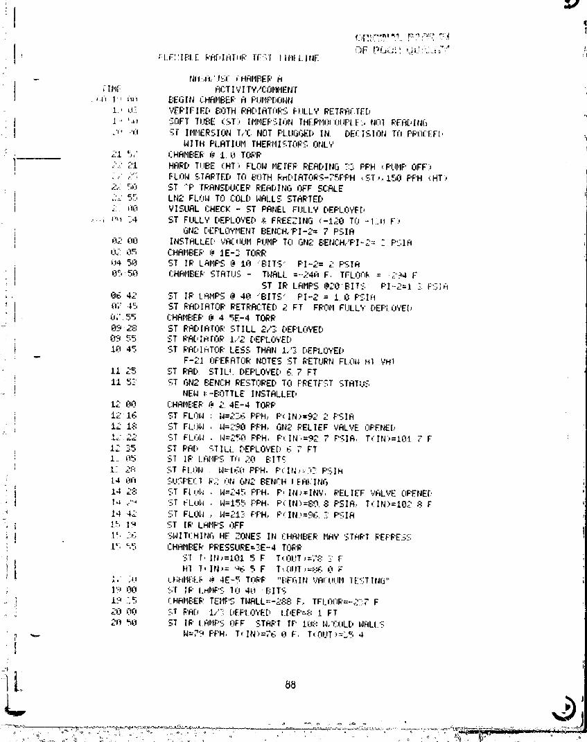
iI
FLE:',IF:I [ f,'fl[Jlt:lDU_' IF'ST I IMt LINE " :!
NHSh..'ISI_iHRI@:E_'fl
I I t,l_ flr:T I VI T'v'/CI3HHEN1_, . ,.n 1-:_hr_ E:EGIN CHGHBEE'Q PIJNPI.,I]HN1., u._ VERIFIED BOTH RR[.:,IRTOI_SFLILLY I_!ETRFllTTED
I "" _;_t _0FT TUBE (ST) II'IHEI;'SIONIHEI_'HI]_:].F'IF-.l'a]lIREFI[.,ING
i -'_;'O Sl"IIIHERSION T,.'r:NOT F'LLIGL_EI_IN. DEE ISIOI'ITI3PF'I3E:EFI," IN 1111 PLAT I LII4THERHI_TOI;'SUNL v
21 5,' CHRHBEIkL_ 1. 0 TOI;'P
i ;'.-) 2:[ HARD TUBE (HT) FLON PIE[EF RER[:,ING _:2:F'F'H ,:F'LIHPOFF:).-' ,.i'_ FL,L'INS'IAPTEDTn B]TH 6:rtC,IFITOR'..-;-7_PPH,.ST ,, .I.50 PPH (HT'
2,.i gO ST "F' TRANSDLCERREADING I]FF St:ALE: t L'.-: 55 LN_ FLON TO r:OLD " "• NHLL:, STARTED
i ,;:. i.'vO VISUAL CHECk"- ST PRNEL FI.ILLY DEF'LrPr'E[,._.; r,l_ ::4 ':,T FULLY DEF'Lr_YED& FREEZING ,:-12e Tfl .-l::u F.,
[ GN2 [,EPLOVNENT BENCH,,'F'I-2=7 PSIR='l.::'OO INSTRLLE[:, ',/BE_11III F'I.IIIF'Try r " "] .... ._N,_E:ENI::H/F'I- Z:: F'SIR_-IL:05 CHAHBEII'@ ".IE--.':TORR
0,_ 5_'I ST IR L;d4F'S@ 11".I"E:ITS" F'I-2=Z'PSIR
855h CHRRBE[,'STATUS - TNRLL =--24_1 F, TI--LOF=I,.= -234 F
! ST IR LRMPS @20"BITS PI.-2=1-:F'Lc;Q. 06 42 ST IP LFIHPS @ 40 "BITS" F'I-2= I.0 F'Slfl
. _174.5 ST PRDIRTOR RETRRr:TED 2 FT FI;,Ot'IF.ILLt[:,EF'I"YE{,0;' 55 CHAME:EI;'@ 4 5E-4 TORR0'32::'.' ST RRC,IATOR STILL 2/'3DEF'LrIYED09 55 ST I_R[:,I_rOP 1/2 DEPLnYEDIF_ 45 ST I;'R[.,IF_TORLESS THAN 1,.'S [.El:LUtE[
-- F-21 OF'E_.FITORNOTES ST PETURN FL.O_,_HI VHI
11 _._,"_ ST RAD STIL!.DEPLOYED 6.7 FT.
II 53 ST GN2 BENCH RESThRED TO PRETEST STATUS
-_ NEN r.-E:OTTLEINSTRLLE[:,
12 O0 r:HAME:E_'@ 2. 4E-4 TOF,'F't21G ST FLhN ..N=2].,:,PF'H,F'(IN;,=9;.'" F'SIR
i i.:' 1:-: ST FI.OH . l,J=£'90F'PH,GN2 PELIEF VALVE OPENEDI_ 2.-'-" ST FLOIJ , l.,J=25_iF'F'H,F'(IN,=92.7 P'.;IA,T(IN':,=I01,"F
I'-I i "! i 'I! 11'3.5 ST PAl:, '-,rILL.,.EFLU,E[.6 , FT! I.._;t':.; SI IF.' I.RHF'S TO 20 E:ITS' 1: 2,"-.' ST FIAII,J I,J=t_OPF'H,F'(IN....)" F'SIR
-: [4 ,'_fl ':,U:.F'Erl I_';: NN f " ......... ._tl_ BENrH I_ERI,ING. . l"-"-'%• i 14 Z'_: ST Fli,l,_ .,-_.-,.F'F'H,F',IN:,"INV,PELIEF VFtLVE ClF'ENE[.'
_..w,, I. ,:":" 'bTfLub_ , N-I-¢':......F'PH,F'(IN)=80.:3F'SIR..T(IN)=I02 :_"F
-_ 14 42 ST FLOI._ I,I=2CZ'."F'F'H,F',;IN;,=96.3:F:.IH=-
, ; 1':; 1'_ ST I_'LANF'SOFF
.1,._':__; SI_IT(:HINGHE ZONES IN CHAHBER I'IHY STRPT REF'I;'E_:S
.t'_",5 =:HR_E:E&'F'RESSLIRE=SE-4 TOPK'S1 T,lN_:101 5 F T_rI!,T_=',":._.:F
i HI I,IN.'=% 5 F T,.FIIJT.,=E:K F0
• I,' LU L.HI@IE:LI._._4E-5 Trll_'F' "E:EGINVRL_LII.IH"IE':::TIN_3"19 O0 _;T IF" I.HIIF: 10 4E1 E:II":_,
:i 17 .r FHRIIEE_; TEl,IF:, T " - "'"""" NHLL--c,-,¢, F, TFLOnP=-.:.'].7 F_i 20 ;tL'_ '_=,TI;'RD 1,."'_:DEF'II'I'T'EDL[EF-,:, .1.F T
21"t'51-_ $I lP LAHP';3OFF STRI;'TTP IU8 lq,'r:l:lL[:, lqHLI.S•,,=,. N-r 4 PPH, T,:IN.=,b O F', T( I.'ILIT:,=".=';4
,_- _ _- ..... o- ......... o- -_ - , _ ,._V._._I__.E_......... _,
OOOOOOOI-TSGII

ORIGINAL PAGE IgOF POOR QUALITY
TI fiE flCT IV I T',',,'COHHENT
,:'K1 ,:_: 43. '-.i IT'!L-IE; H,.'COL[:'N- '-NLL-:, RBOI_'TED=UNF_E:LFT;] I'IAINTFtlN•" _.._'°:45 HI TF'qFtl. ILI-II4F'LETE N=-1513F'F'H, T,.'|N>_.?fj F
... e_._,+.: ST [(,.' LRHF'$ T£1 4_t BT'r$
.._ _,-.,.: 01 1_.'Ii:_ $1 H=ISL' F'F'H, I(IN)_=91 F, T(OLIT>=_:.I F-: ,_,1 2'3 Sr FLOWSHUT OFF - RTTEI'IF'1ING I_ETPRCTION
'1. (tl __.o, S'IkEFPRCT ION SI"RRT
Ol 4k:, H{ TP '.Bk:t',._flCOI'IPLETE N=2.':(l F'F'H., To:lli.;=74 F
. _:,.',' '.:,T t?HI.olHD:=I,'REII_'FtL'TFD@} (K( -,e '" FT IN ¢;I.IDDENHI?,/E; li13 10 HT rr"_=:14(:OHF'I.EIE N=:uCt F'F'H, T, I N .,-,,..-: F: U5 ,:C: HT TP?R4R EOHF'LETE |,J=450 F'F'H, u[L.IN"=?8 F1
_}':, _..T SI" k_I,IRTOI;' SIlLI. [,EPIJ:IYED @ 5 FI,i: 05 46 ST "'5 .,:78' N=I,:,.. PPH, r,: IN 8 F, T(OUT',=11_ '-' F! 05 48 Hr H=601 F'PH.,T(IN.,=?86 F',F'(IN_,=192F'SIR'_ h_ 42 ST F'R[,I RTOP _'E1RRCFI ON SCRUE:E:ED,i 06.43 ST PA[.,IRTOR Cao."I FT.:1 =:1_57 ST N=I4i* F'F'H, T,: 1N._=109. 6 F, T(l:lliT.,=jE_). _ F
v7 L.,O Hr 5. 306 (OI'IF'LETE N=60_3F'PH, 'r, IN..,:70 F
_iI U? .-:El ST RR[;,IRI01_ RER[:,.TI.ISI'E[:,TO 8. t FTt O? 16 S,i TPIU;-:HC(sI'IF'LETEI,I:150F'F'H,T,:lN):12e.F-?t ki-, -:.g HI H=2'"% F'F'H, I,. IN,=t4t F
-1,_ ;=_1::; HT IF":'F!:'rnHF'LETE I,I=:.:UEIF'PH, T(IN.)-'14ktF
_1 -- iVt I_, SI FFiOSB r:OHF'LETE bl:IE:OF'F'H., T(IN:,=I,?T F• 1.o "-, _.'EOUESTE[.,ZEklLIT'.-,INIFff_lST (UNCRLIBPRTED:
: ! I1 10 ST 'IF'L_JSCrCI'IF'I F.TE bl:-lSO F'F'H, "1,:IN ,:i_-;2 F4 Zl 44 ST lF'Jkr3fe=/iF'LEI'EN=lCtEt F'PH. T,:IN.._=I3-:F:' 1i' ,J_ HT 1F':-_:t5L.Or,IF'I.ETE N=5_TIEtF'PH, 1_I N :,-140 F' 1.;' 7." ':,lTF'110COHF'LETE N::IOo F'PH, T, IN.,=_O F
1" i0 HT N=15'3 F'PH., l(' IN ,=:t2_. 5 Ft:- 54 HT _4=150 FF'H, T_IN)=I48 FJ:: 56 H1 I_'nL:,IA!O_'[:,EF'L.OY/4ENTBEGINS
.... .I._5? HT HR>-:DEPLOY LIGHT ON @ 2El'?FT
•': 14 55 ST N:-'.::4 I.'PH, T, IN:,=-6,C'F
,: iK,O_, 1,-I[ 1F"-+I," COHF'I.ErE l.l=:(tEt F'F'H, T_ 1N.'=144 F,. I,-,-9 '-.llr'l]lH _t'IF'I,1LETElq=.lO_._F'F'H.I,:]N,;E,JF:: , '::l T':',INt: UNI:RL.1E,BRTE(,.,
I::: 1:-: HT TF":_20 (OHF'LETE H=500 F'F'H, T, IN.,=14] F11, ',' HI 1F"-'1':_ I.=¢IFLET[- N:;B(tO PF'H, i, [N,-:-,'_I F_'*t :3: ':T I ittfljI. HIE[., Ts1ra, = C_F, E:EIDIN"f;:'tllE:21 45 ",T IF'tllE: tOI'IPI.ETF: 14=95 PPH., T<Iti.,-_,l F
t Z':_"(l_ HI TF'_]_::.(OHPLEIL H=]._30 F'F'H. T_IN.,=7J F--: 2.-.' =,_I qT I_'R[.,IRTI3E'[:,EFifMHENT l,l=I_tH F'F'H. T,.IN:,=,_i."t F__ U4 $1 E'R[.,IH!'LII; FI.II.I 'd I,FPLrtYED =_ ,.:'T ;:..'FFI-'- '_, Y'IDEOFRF'E[,HT I'IRNIF[q l, I..INI.S,_ :fJ HI TI-'_O. ,IP LflI,IP _:HLIE$'GIION:_ E:EGIi.,r::.
, CHHHE,EE' I I_)HI"S,OFF.,_,:, "* 1_F'1,:'1rnHPI TE N:--LCIOF'F'H, T,: IN:"IO_ F
_9
•L' _ ..........
%
UUUUUUUI IOL_IL
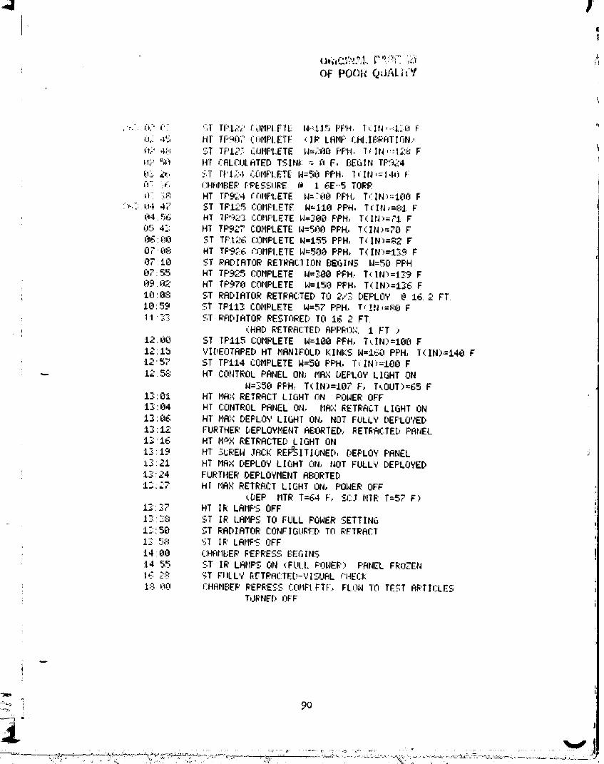
1
OF PO0_ QdALI(Y
,_. (t-' (': '_T TF'_2,_' rdMF'LlflE N_lJ5 F'F'H. T(IN,=I_F_I f "_LL 4,; HT TP_07 COItFi-ETE (II;'. I-RMF' CI_I.IF:i_'FITIJ3NJ,(t,> ,l_; ST TF'I2_ COMF'LETE l,l_.,:-'fl_F'F'H, 1(IN, _':t_;;_F _d02 5$;t HI CRLCUIoHTEDTSINtz _ its F, BEGIN TF'9_'4 I03. ;Z_' _.T rl'l,:_,l COHF'I.ETE1,1=50F'PH. l(IN,=14i) Fn. ;_ CHRI,IEIE_'F'_'[_S;I.IR£ fl I _E'-5 TORR
19,, ' = i,t- "'..;_ HT rr._o4 rnMPIoETE W=T_tOPPH, T,:TIN:,=IOi3 F:_',;,-;:u.l 47 =,T TPI,_.. CL3MF'I=ETEW=ltO PPH, T(IN_--8t F'
_14.5b H1 IF'9_ COMPLETE lq=;:O0 F'PH, T(IN)=71 F05 4"; HT TF'927 COMPLETE N=500 PPH, T(IN_=70 FCt6:00 ST TPI2e. COMPLETE W=tfi5 F'PH, T_IN')=_;: F0," 0¢": HT TF'9;:E; r:nMF'I.ETE W=5F_OF'PH, T(IN:,=I_9 F07 IR ST _'RDIRTOR RETRRC:IIhN BEGINS W=SFtPPH0755 HT TF'925 L':OMPLETE W=_O0 F'F'H. T( lf'i;_=_,9 F09 _'3_ HT TF'97h COMF'LETE W=15_'_PF'H. T(IN)=I_6 F10'08 ST RADIATOR RETRACTED TO 2/Z:.DEF'LOY @ 16.2 FT
10: 5_.. ST TPll_ COMPLETE W=57 PPH. Trl .._t,,=_:0 F11 _-..; '_=,TRADIATOR RE_TrjI;'E[, TO IG 2 FT.
(HAD RETRRC'rEDRF'PB'O;_. 1 FT )12-00 ST TF'II5 COMPLETE W=lO0 PF'H, T_IN)=IO0 F1215 VIDEOTAPED HT MANIFOLD KINKS W=lGh PF'H, T(IN)=140 F1257 ST TF'II4 COMPLETEW=50 F'F'H, T_IN)=IO0 F
•-- L258 HT CONTROLPRNEL ON_ MAX DEPLOY LIGHT ON_4=350 F'F'H, T(IN)=I07 F, T_OUT)=65 F
13'01 HT MAX RETRACT LIGHT nN POWEROFF13'04 HT CONTROL PANEL ON.. MAX RETRF_C:TLIGHT ON
1306 HT HRX DEPLOY LIGHT ON, NOT FULL','DEF'LOYED
13'12 FURTHER DEF'LOYHENT ABORTED, RETRRCTE[:,PANEL13"16 HT I'I_XRETRACTED LIGHT ON
1_'<:t9 HT SL:REW.IFICKREFR31TIONED, DEF'LOYF'ANEL13:21 HT MAX DEF'LOY LIGHT ON, NOT FULLY DEPLOYED13:24 FURTHER DEPLOYMENTABORTED13:_7 HI MAX RETRACT LIGHT ON, POWER OFF
(DEP MTR T=64 F., SC.I HIM T=57 F)13:._7 HT IR LAMPS OFFI-_'_:':: '_",TIR LRMPS TO FULL POWER SETTING1_::50 ST RADIATOR C:ONFIGLIR'EC,TO RFTR'RCT13: _'-'-,,', ST IE'LAHF'C.,OFF14:00 CHRIIE:ERPEF'RESS BEGINS
14 55 SI' IR LAMPS ON ,:FI.II.I. F'OWEE.') F'RNEL FR:OZENI ,_: 2:_: '_T FI ILL't' &ET_RL.TE[.- v I:. HL CHECK1:': _0 r:HAHE:EPREF'RES.SCLff'IF'I.FTF., FLnW I0 TEST RRTIr:LES
TLIRNEDOFF
,!
i v. ":°°';"° _ _, _'_.. }i:, ._." ,":,C..... '_ '_ ".,:;4_' , ..... N.o .... _ '
00000001-TSG13
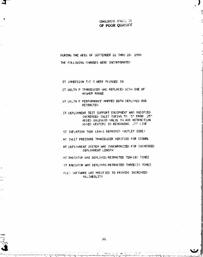
i|
OF POOR QUALI('Y
'1
[_UI_',INGl'HlCNEEIr_OF__EF'TEi"IBEI;',22 THRU2__r, _ _r_ _'_'_
THE FOLLCIL,JINf-_r_:HANGE_-REI?,EINC:fI_'PrJ_'RTEI':,
ST II',INERSIONT,..'r.;."_WEPE F'I.UGGE[,IN
ST C,EL.TAF'TI_ANSDUCERHAS REF'LAC.EC,RI'{HONE OF'HI_HER I_'ANGE
ST [:,ELTFIP F'ERFOP.I'IRI',Ir:IFI'4FIPPEDBOTH DEPLOVED F(IqDl_'.ElRACTE[:,
ST DEPLO'¢I'IENTTEST '_--UF'POF.'.TEtXIIPMENT|,IRSI'IODIFIE[:,:INCREQSEC,INLET TUI::I_JGTO 5" FROM. 25"Q[,[,E[:,SOLEN61D VALVE TO FIll,PETI_'.RCTIONFI[,[.,EDHEATEf;'.5TO REI,IFIININGj_:S"LINE
ST INFLFITIONTUBE L.EF_kSI;eEF'AII;'Er_(OUTLET SIDE)
H1 INLET PRESSUI;'ETRANSDUCER VERIFIED FOP.SIGNAL
HT C,EF'LrIYI',IENTSYSTEr4I,JFISSVNCHI;'ONIZE[.,FOR INC_.'EASEDC,EPLOVI"IENTLENGTH
HT I;'FIDIF_TOI;'L,IFISDEPLO','ED,..'_:ETRFICTEDTEN('IS)TINES
ST RFIDIFITOI;,I,IFISDEPLOYE{.v"PETRRCTEDTH_'EE(_OTINES
Fl_li::5OFTI_AREL_'QSMODIFIED TO PI;'OVIDEINCPEFISE[,F_:ELIBBILITY
O0000001-TSG14
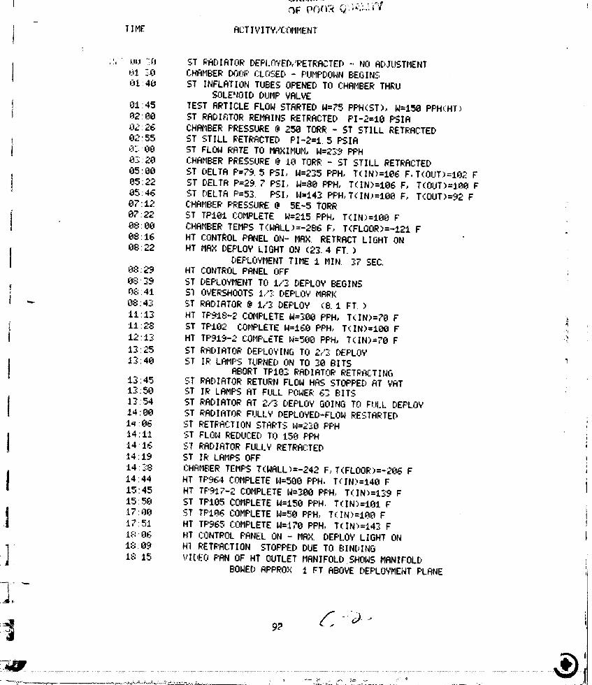
,_F pr)+Y+;< _+ +`;.L+i+_+l
T]ME ACT IVITY...'COIIMEHT
:_," Uu ]:h ST RADIATOR DEF'I.O;'ED,.'RETRRCTED- NO ADJUSTMENTi
j _ ]A CHAMBER DOOP CLOSED - F'UMPDOWN BEGINSC+1:40 ST INFLATION TUBES OPENED TO CHAMBERTHRUSOLENOID DUMP VALVE
i ;JI'45 IEST ARTICLE FLOW STARTED W=?5 PPH(ST), W=ISB PPH(HT)i A2:_O ST RADIATOR REMAINS RETRACTED PI-2=IO PSIR!
02'26 CHAI_BER PRESSURE @ 250 TORR - ST STILL RETRACTED
i 02'55 ST STILL RETRACTED PI-2=t. 5 F'SIR] CC.'_te ST FLOW RATE TO MAXIMUM, W=2_'.'_PPH
03:2C+ CHAMBER PRESSURE @ t0 TORR - 5T STII.LRETRACTED
05:B8 ST DELTA P=79. 5 PSI, W=2_5 PPH, T(IN)=t06 F.T(OUT>=I02 F
i i)5:22 ST DELTA P=29. 7 PSI.. W=80 PPH, T(IN)=106 F, T(OUT)=I_O FeS:4G ST DELTA P=53. PSI, W=t4_ PPH, T(IN_=Iee F, T(OUT)=92 F87:12 CHAMBER PRESSURE @ 5E-5 TORR
i 07"22 5T TPtO1 r:OMPLETE W=215 PPH, T(IN)=I80 F
08:_0 CHAMBER TEMPS TKWRLL>=-286 F, T(FLOOR)=-121 FC48'.16 HT CONTROLPANEL ON- MAX. RETRACT LIGHT ON08:22 HT MRX DEPLOY LIGHT ON (23. 4 FT. )
I DEPLOYMENT TIME t MIN. _7 $EC.08:29 HT CONTROL PANEL OFF
08:39 ST DEPLOYMENTTO 1/3: DEPLOY BEGINS
08:41 S% OVERSHOOTS1,".".:DEF'LOYMARK! -.-- 08:43 ST RADIATOR @ I/._DEPLOY (8. I FT. )
1t't3 HT TF'918-2 COMPLETEW=3_ PPH, T(IN)=70 F
i 11"28 ST TF'I02 COMPLETEW=168 PPH, T(IN)=100 F +._i 12 13 HT TP919-2 COMF'LETE|4=5'e0PPH, T(IN)=?O F
13 25 ST RADIATOR DEPLOYING TO "-_+=,'_ DEF'LOY13 40 ST IF.'.LAMPS TURNED ON TO 30 BITS
I ABORT TF'IO_ RADIATOR RETPAC:TING13 45 bT RADIATOR RETURN FLOW HAS STOPPED AT VAT13 50 ST IR LRMF'SAT FULL F'FtWER.G3 BITS
I IZ.54 ST RRDIRTOR AT 2/+_DEPLOY GOING TO FUI.I.DEPLOY .14 80 ST RADIATOR FULLY DEPLOYED-FLOW RESTARTED
I++:e6 ST RETRACTION _,5TARTSW=2_0 PPH14"11 ST FLOW REDUCED TO 150 PPH
t t416 ST RADIATOR FULLY RETRACTED14:19 ST IR LAMPS OFFt4'-"'=.,:., L':HAMBERTEMPS T(NRLL)---'4e=-" _ F, T(FLOOR)=-20G F
I t4:44 HT TP964 CAMPLETE W=5EIOPPH. T(IN)=t41B F15:45 HT TF'917-2 COMPLETEW=3Oe PPH, T(IN)=t39 F
1558 ST TPI05 COMPLETE W=I5_)PPH, T(IN_=IOI F i
17'+._Et ST TPtO_ COMF'LETEW=50 PF'H, T(IN)=I_30 F Ii1 '°• 17:51 HT TPL:/6.,COMPLETEW=tTla PPH. TCIN)=t4:< F
it-:Q_, HT r.:ONTROLF'RNEL ON - MAX. DEPLOY LIGHT ON 1I,"::89 HI RETRACTION STOPPED DUE TO BINDINGI
| 18 15 VI[;,EOPAN OF HT OUTLET MANIFOLD SHOWS MANIFOLDJl BOWEDRPPROX t FT ABOVE DEPLOYMENTF'LANE
..... 00000002

TIME RCTIVITY/COllMENT
273 L8 4_, HT OUTLET MRNIFOLD NO[;,RL MRP OF TEI4F'APPROXIMATED BY VISUAL CUES
: i8 46 HT RETRACTION STOPPEDAT 2/3 DEPLOY MRPK1847" HT RETRACTION RESUMED
_ 18'50 HT MAX RETRACT LIGHT ON
....." 1855 HT REDEPLOYED TO 2/3 DEPLOY -15.6 FT.
, IB5B HT CONTROL PANEL OFF T(DEP MTR)-34 F,T(SCJ NTR)=40 F
.. 1900 CHAMBER TEMPS T(WALL)=-242 F,T<FLOORI)=-IT"5F, IE-5 TORR
20:09 ST TPt03-2 COMPLETEW=300 PPH, T(IN)=I42 F_,: 20:tt HT TP91"< COHPLETE W=30e PPH, T(IN)=I4"< F
;0:15 ST DEPLOYMENT TO 2/:< DEPLOY STARTSi_'_. 20:30 ST RADIATOR AT 2/3 DEPLOY - 16.2 FT.
,<:. 20:48 ST RERDJUSTED TO 2/3 DEF'LOY (RETRRCTED 8 INCHES)
:_ .. 21:20 HT TPYt4 COMPLETE W=580 PPH, T(IN)=144 F.'-'.._:: 21:24 ST RADIATOR PANEL AT 13 FT.
...... 2t:37" ST DEPLOYED TO 17" FT.i:: 21"45 ST TPII2 COMPLETE W=245 PPH, T(IN)=I40 F
_i! 21"48 ST RETRRCTED 2 FT IN SUDDEN MOVE
_._ 2155 ST DEPLOYED TO 2,/_RDEPLOY HRR_C(16.2 FT.)
,_". 22 18 HT OUTLET MANIFOLD PANNED-APPEARS STRAIGHT NOW
i! L.7220 HT RETRRCTED TO i,"3DEPLOY W/HIGH FLUID PRESSURE!:r_;_.: W=500 PPH, P(IN)=IY8 P.C.IR,DEPLOYED (7.B FT. ):_; - _Z_O ST DEPLOYMENT TO _7 __FT. BEGINS: o_•:_. 22_9 ST FIILLYDEPLOYED AT 27".3 FT.
_ ST FLOW DECAYING (TEMPS FRLLING),%-5;;. =-,'00 ABORT ST TPIIG W/COLD WALLS
_" _3"8i HT TF'910COMPLETE N=508 F'PH,T(IN)=I40 F
_ _._,""C.12 ST IR LAMPS ON TO 30'BITS'o'i'
%_'. 23'39 ST FLriW TURNED OFF
=,;: 27400"<1 HT TP989 COMPLETEW=300 PPH., T(IN>=140 F_:" 01'05 ST TP107 (IR LRMF'S TO TSINK=O F) E:EGINS
;-'_ CL-"_'28 HT TP91t COMPLETE W=580 PPH, T(IN)=?e F :
i.:. 06 _:G ST PANEL AVERAGETEHF'ERATURE- 4 F __° 06 ._6 HT AF'F'EARSTO BE "E:'¢PRSSING"EXPOSED TUBES ;
L 0655 HT TF'Ye8ABORTED DUE TO BYPASSING FLOW ;_..4 O? 0_.3 ST RETRRCTIr_N INITIATED'°_- h7 20 ST RADIATOR FULL','RETRACTED (18MIN. FROM FIRST MOVE. :, ;
:- _ ;I,".,:$3 HT C:ONTRhL PANEL ON - 7 8 FT. ii;i _,']7 HT CONT_;OLF'ANELOFF - RADIATOR AT MAX RETRACT ": I
:_ C_ 07-48 ST TF'I_)7 COMPLETE TSINK=4 F ._,--- _.
-,_i U8 14 ST DEPLOYMENT STA_ W=O PPH _i08.22 ST RA[)IRTORFULLY DEPLOYED - 27 _ FT -,.
J.l;" C_F:.4Q ST FLOW STRRTED W/TSINK-4 FL,,. HT IF.'LAMPS TO TSINK=O F.,14:_i_iJOF'F'H ""
:;i I
,w
- :_
00000002-TSA03
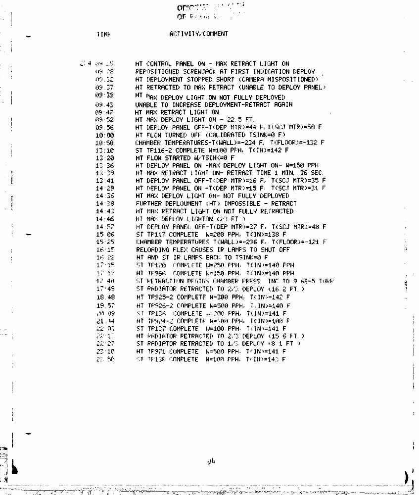
L
.. III'IF Ai'.:'IIV11Y/COMMENT
II
2; 4 u:-, :.5 HT CONTROLPANEL ON - HRX RETRACTLIGHT ONi! ,t'? ;:':_: REF'":GI TI OWEDSCE'EW..IACk:RT F I RST I NDI CATI ON DEPLOYi h'_t.._._."" HT DEPLOYMENT STOPPED SHORT (CAMERA MISPOSITIONED')
_:.t9:":7 HT RETRACTEDTO MAX RETRACT (UNABLE TO DEPLOY PANEL,
I! E19:._9 HT IIRX DEPLOY LIGHT ON NOT FULLY DEPLOYED= 0_.4_ UNABLE TO INCREASE DEPLOYMENT-RETRACTAGAIN
0947 HT MAX RETRACTLIGHT ONR952 HT flAXDEPLOY LIGHT ON - 22.5 FT.0956 HT DEPLOY F'RNELOFF-T<DEP HTR)=44 F,T(SCJ MTR)=58 F
IO:_e HT FLOW TURNED OFF <CALIBRATED T$1NK=O F)
18:50 CHRr'IBERTEMPERRTURES-T(HRLL)=-234 F, T(FLOOR.)=-IS2FJ.S:IO ST TPII6-2 COMPLETE W=180 PPH, T(IN)=I42 F
I__:20 HT FLOW STARTED W/TSINI<=8 FI_:.R6 HT DEPLOY PANEL ON -MAX DEPLOY LIGHT ON- W=150 PPH13"$9 HT HAX RETRACT LIGHT ON- RETRRr:T TIME i MIN. 36 SEE:.
13:41 HT DEPLOY PANEL OFF-T(DEP MTR>=I6 F, T(SCJ MTR)=S5 F
1429 HT [:,EF'LOYPANEL ON -T(DEP MTR)=I5 F, T(SC..IHTR)=_R:tF14_6 HT MAX DEPLOY LIGHT ON- NOT FULLY DEPLOYED
14-_<8 FURTHER DEF'LOIJHENT(FIT)IMPOSSIBLE - RETRACT
14:43 HT MR>,'RETRACTLIGHT ON NOT FULLY RETRACTED14:46 HT HA::.,'DEF'LOYL IGHTON (2-: FT >14"57 HT DEPLOY PANEL OFF-T(DEP MTR)=S7 F, T(SCJ MTR)=48 F ,
-- 15 06 ST TF'iI? COMPLETE W=ZOOPPH, T(IN)=I38 F• I¢_.1. 25 CHAMBERTEHF'ERRTLIREST(WRLL)=-236 F., T(FLOOR)=-12t F1615 RELOADING FLEX CRUSES IR LRMF'STO SHUT OFF !;
1_ 22 HT AND ST IR LAMP_ BACK TO TSINK=B F171=; 'ST TF'120 rr¢IF'LFTE W=25_'i F'PH, T(IN:=.I40 F'PH
t7 t7 HT TF'96_ r:OMPLETEI,I='lSOPPH., T(IIN)=I4.RF'PH1, 4_! ST i,'ETRAF.:TII'IN_:FriIN,:; F:HRHBER '' r-c _. FEE_-..,INr:TEl 9 _E-_ I,:IK'_'17'49 ST ;'RDIRTORRETRACTED Trl2/: DEPLOY (.16.2 FT.)
18:48 HT TF'925-2COMPLETF W=SOB PF'H.,I(IN:,=I42 F
19 =;7 HT TF"T_26-2 L':rlItF'LETEW=5e(lF'F'H, T,..IN)=t40 F_:=_09 '._.1rF'l-.;. rOHPLEIE ,:-'r,_J PPH, T(IN.)=t41 F21 14 HT TF'_24-:."COMPLETEI,V-_'..00PPH, T(IN:,=I00 F,::2 0-: ST TF'I:;7 COHPLETE W=tOO PPH. T,. IN,=I41 F-'' 1:. HT WRDIATI:I_'RETRACTED"fh 2..'-: DEPLhY (15. _ F'r. )¢_=% o
22 ""=,. '_:.TRADIATOR RETRACTEDTO 1.,'S DEPLrY,' (8 t FT .)_:_,-10 HI lF'3;"l EOMPLETE W=St?tOPPH. /,:IN,=141 F"- _ri 5T TF'I;:': rOMPLETE W=tOft F'F'H. T"IN._=t4:.: F
r_J_
. :.,, ' ,,° °:_: ° ' _" :° o' _'.,lf._, _ :,_,- T_!,: "_ ,.... "t..... . ,:._;_ ::o'_"--'<':'_""_: ..... ........,_- o,...... - °-_-:_'c,-_:_:.......... _.->,--,...-.... - _::!
00000002-TSA04
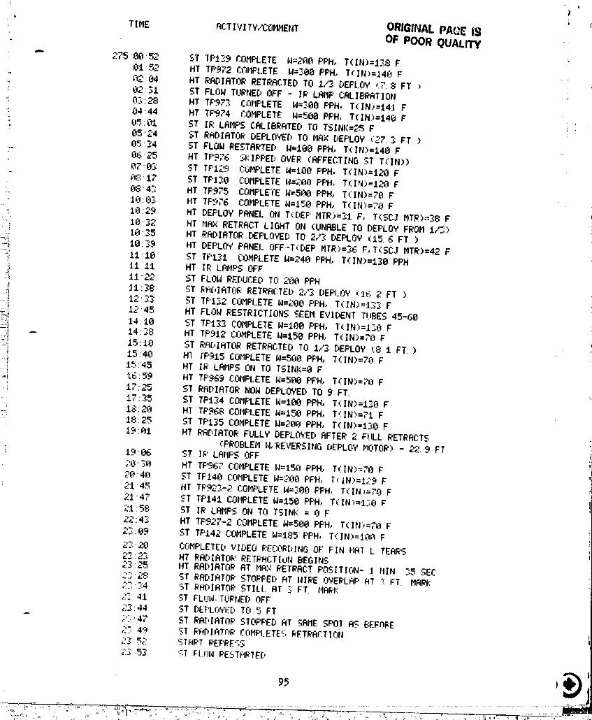
' TI ME ACTI V[ TY/COMIIENT ORIGINAl..PAQE I_OF POOR QUALITY -
r
"_ 275;00:52 ST TP139 COMPLETE W=2R('IF'PM, T(IN)=138 FElt ='_'....,,- HT TF'972 CF-eMF'LETEW=_:e8PPH, T(IN)=14_) F_'_.J)4 HT RADIATOR RETRACTED TO I/-_DEPLOY r:7.:.:_FT )
: 02;I ST FLOW TUI_'NEDOFF - IR LAMP CALIBRATION "
c_ 8:<:28 HT TF'9?'_< CFIMPLETE W=_O0 PPH, T(IN)=14J F.; 04 '44 HT TP974 F=:OMF'LETEW=580 PF'H, T( IN)=140 F :" _J=.,:C11 ST IR.LAMPS CALIBRATED TO TSINK=25 F I
• 05''_4 ST RADIRTO_' DEPLOYEDTO MAX DEPLOY """ "__,:r..., FT )85:34 ST FLOW RESTRRTED W=188 PPH, T(IN)=I48 F -'
:" 86 25 HT TP9;'6 SI:IF'PEDOVER (RFFECTING ST T(TIN))
878"_< ST TF'129 I::OMF'LETEW=iO0 PPH, T(.IN)=I2FJF
;_:3t7 ST TF'I_8 COMPLETEW=2F_FJPF'H, T(IN)=128 F084.'; HT TF'975 COMPLETEW=5_._8PPH, T(IN)=?O F
_" 10:_.)._ HT TF'976 COMPLETEW=158 PPH, T(INI:,=,"Ct F
IR-"9"_ ,_. HT DEPLOY PANEL ON T(DEF' MTR)=.?,I F, TKSCJ MTR)_-S8 F:-_' lr_'J'._2 HT MR× RETRACT LIGHT ON (UNABLE TO DEPLOY FROM 1/.3)..., :t8_5 HT RADIATOR DEPLOYEDTO 2/'< DEPLOY (t5. G FT. )_'.i I_:_9 HT DEPLOY PANEl.OFF--T(DEP MTR)=_6 F.,T<SCJ HTR)=42 F
_ 11'10 ST TF'I.'<I COMPLETEW=248 PPH, T(IN)=t_8 PPH?!
__ 11 11 HT IF,; LAMPS OFF_ II'"'_=-" ST FLOW REDUCED TO 208 PPH
!1"38 ST RF@IRTOG'RETRRC:TED 2/3 ' F'DEFI.JS (16 2 FT )
-_ 12_3 ST TF't2,2 COMPLETEW=208 PPH, T(IN)=I33 F=: 12;45 HT FLOW RESTRICTIONS SEEM EVIDENT TUBES 45-60
14:18 ST TPI-_<3COMPLETE W=108 PF'H,T(IN)=i2.sz_F
_._ ,_. 14:._8 HT TPYI2 COMPLETE W=15(BPPH, T(IN)=78 F
_;I 15:18 ST RADIATOR RETRRC:TED TO 1/3 DEPLOY (8 i FT.)-'J 15:48 HI iF'915COMPLETE H=508 PF'H,T(IN>=7_IF
15:45 HT IR LAMPS ON TO TSINK=8 Fi
-'-i 16:5_ HT TF'9_9COMPLETE W=580 PPH, T(IN)=?_JFi 17:25 ST RADIATOR NOW DEPLOYED TO 9 FT.
t7:35 ST TP134 COMPLETEH=t00 PPH, T(IN)=I38 F1_:28 HT TP968 COMPLETEW=t58 PPH, T(IN)=?i F
_ 18:25 ST TPI_5 COMPLETE W=208 PPH, T(IN)=I3_)F
t9:_"_t HT RRDIRTOR FULLY DEPLOYEDAFTER 2 FULL RETRRCTS('PROBLEMW,'REVERSING DEPLOY HOTOR) "'_- _..9 FT
i 19:86 ST IF' LAMPS OFF2C_:_C1 HT TP967 COIIPLETE N=158 PPH, T(IN)=70 F294_'_ ST TFI40 COMPLETEW=20EtPF'H.. T(IN)=I_'9 F
: 2t :4..=; HT TF'92".;-2 F:OHPLETEW=-:88 PF'H. T(IN:,=;'8 F2.1.47 ST TF't41 COHPLETEW=150 PF'H, T(IN)=IT;O F;-:I:58 ST IR LRIIPS ON TO TSINK = E_F-_,,,_ , .-;.=.=.4._ HT TP927-2 COMPLETEW=5='18PF'H., TKIN)=78 F2,_:09 ST TF'I4_COMPLETE W-I_:,..,-_'=F'PH.,T(IN)=I_._ F
2.'<:20 COHPLETED VIDEO P.ECORDING OF FIN l'IRlL TERMS2'.'::2-', HT RADIATOR RETRRCTIdN BEGINS;;:<:25 HT RADIATOR AT MA:._RETRACT F'OSITION- J IIIN .-,5SEE:.
'""¢' ST RADIATOR STOPPED RT WIRE OVERLRF'RT T::FT. MARl(c.._. eL,=,
""_'<4 ST G'.RDIRT_E'STILt.RT _:FT. t'IR_ICe'_!.
2": 4t ST FLUN. TURNED OFF;_:._44 ST DEF'L;IYED TO 5 FT
-- ;':;:47 ST RI_[:,IRTORSTOPPED RT SAME SPOT "_H.. BEFORE" 4q. ST RRDIRTFIG'CFIMF'L.ETE'_G'ETRA.F:TION¢',:.:. ."'5_:'_ 5;._ '_TI:IG'I" G'FF'G'Fc_-...:,.,.=, 53 '_T FI..OI,JPESTFIRTED
95 t
........-; ,,, 00000002 TSA05
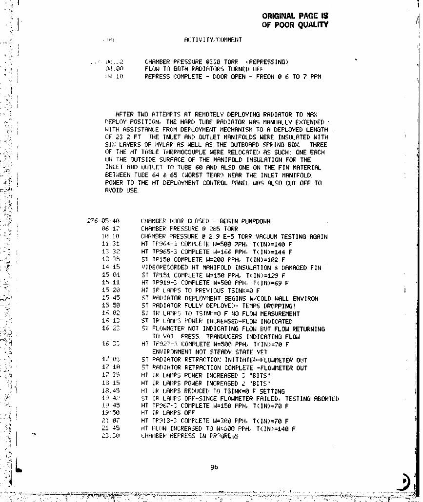
,'if. P Q=,,_.,, OF POOR QUALITY ,
,j:
!? ,},
., !'.i _,..:.. 00.,..2 CHAMBERPE?ESSURE@2.:'<GTORF.' ,/PEPRESSING) "L. _;_,1OA FLOW TA BOTH RRDIRTOR.STIJRNEDAFF
"' 10 REPRESSCOMPLETE DOOROPEN FREON @ 6 TO ? PPM
l
!;!i I
:r:' AFTER TWO RTTEMF'TSAT REMOTELY DEPLOYING RRDIRTOR TO MRX
°;.°:_.,,i r.,EPLOYPOSITI(IN, THE HARD TUBE RADIATOR WAS MANUALLY EXTENDED"i WITH ASSISTANCE FROM DEPLOYMENT MECHANISM TO R DEPLOYED LENGTH
•;-,_' nF 2E_2 FT THE INLET AND OUTL.ETMANIFOLDS WERE INSULATED WITH.. SIX LR_EE:,OF MYLAR AS WELL AS THE OUTBOARD SPRING BOX. THREE
._,.', OF THE HT TAP:LE THERMOCOUPLEI_ERE RELOCATEDAS SUCH ONE EACH_": ON THE OUTSIDE SURFACE OF THE MANIFOLD INSULATION FOR THE
:;°;'_'. INLET AND OLITLETTn TUBE 60 AN[)ALSO ONE ON THE FIN MATERIAL:"__ BETWEEN TUBE G4 & 65 (WORST TEAR) NEAR THE INLET MANIFOLD.
_'_ POWER TO THE HT DEPLOYMENT CONTROL PANEL.I/ASALSO CUT OFF TO_:°_,!_ AVOID USE.
i_k 27605:40 CHAMBEF.;Dr,sF.:CLOSED - BEGIN PUMPDOHN. _ A;__ 17 CHRr,IBERPF.'ESSLIRE@ (._o_,.,._TnF.'R_;_o._: I._}.I0 CHANGER PRESSURE @ 2.._E-5 TORR VACUUM TESTING AGAIN.,._. :1.1.]1 HT TF"SG4-.Sr" -_.oMFLETEW=500 ?PH.,T(IN)=148 F
"_°.LCI._. : 1]': '>__,_: HT TP965-._ COMPLETEW:I_6 PPH, T(IN)=144 F
?,
._':; IZ.:-.-_ ST TF':I58COMPLETE W=2eO PPH, T(IN)=IG2 F
:i_riot,, 14:15 VI[:,En_'ECCRDEDHT MRNIFOLD INSULATION & DAMAGED FIN
_: 15'8t ST TPISI COMF'I.ETEW=150 PPH., T(IN)=129 Fi:_;:i:: 15:11 HT TP919--.__ r:OMPLETEW=500 PPH, T(IN)=E;9F
_.. 15:20 HT I;T'LAr.IPSTO _'_'_"rF.cv_,._:,"0'r"TSINK=O F i
_w,i.' 1545 ST EIA[:,IRTORDEPLOYMENT BEGINS W/COLD WALL ENVIRON.i,L .
....:. i..,:58 ST F.'RDIATORFULLY DEPLOYEI')-TEMPS DROPPING!_>.
" :;;:,;: 1_:82 ST IP LAMPS TO TSINK=O F NO FLOW MERSUREMENT_' 1_1_ ST IR LRr,IF'SPOWER INr:RERSED-FLEW INDICATED
<_i IG:2]: SI FLOWMETEF.'.rIOTINC,ICBTING FLOW BLITFLOW RETURNING
: _<_ TO VAT PRESS. TRANDUCERS INDICATING FLOW
:_,i_ [G"C. HT TF'927-.-', COMF'LETEW=500 PF'H, T(IN)=70 F__i':_ ENVIF.'r_NMENTNOT STEADY STATE YET
., ',_ t7:0-'.': ST _'ADIATORRETRACTIOt: INITIRTED-FLOWMETER OUT!:o_'_ 17-10 ST I;IR[:,IRTORRETRACTION COMPLETE -FLOWIIETEROUT
il 17:5:5 Hl IF.:LRMPS POWER INCRERSED S "BITS"i ! 18:15 HT IF.'LAMF'SF'OWERINCREFISED£ "BITS"=,
i.I__ "1 ];_:.45 141 1_: LHtlF., REDUCE[:,TO TSINK=O F SETTING
_.? 4,? '_-%]IP LAMPS AFF-SINCE FLOHMETERFAILED, TESTING RBOR.TED1'_:._.45 HT TF'?GT-;:r:OMPLETEW=150 F'F'H, T(IN)=70 F
: / _-',; 1--_5)-t. HI IP LRr'IPS OFF2tO_' H-r TP918-S r:011F'LETEW=3eO PPI4, T(IN>=?0 F
,._:t_ _1.45 HT FLI."IWINCREASED TO W.'-C,00F'PH,T(IN)=148 F
._!; -"3:50 CHAItE:E_.'F.EFI:I.E.=IN F'R%SRESSN
£/'_ " b
00000002-TSA06
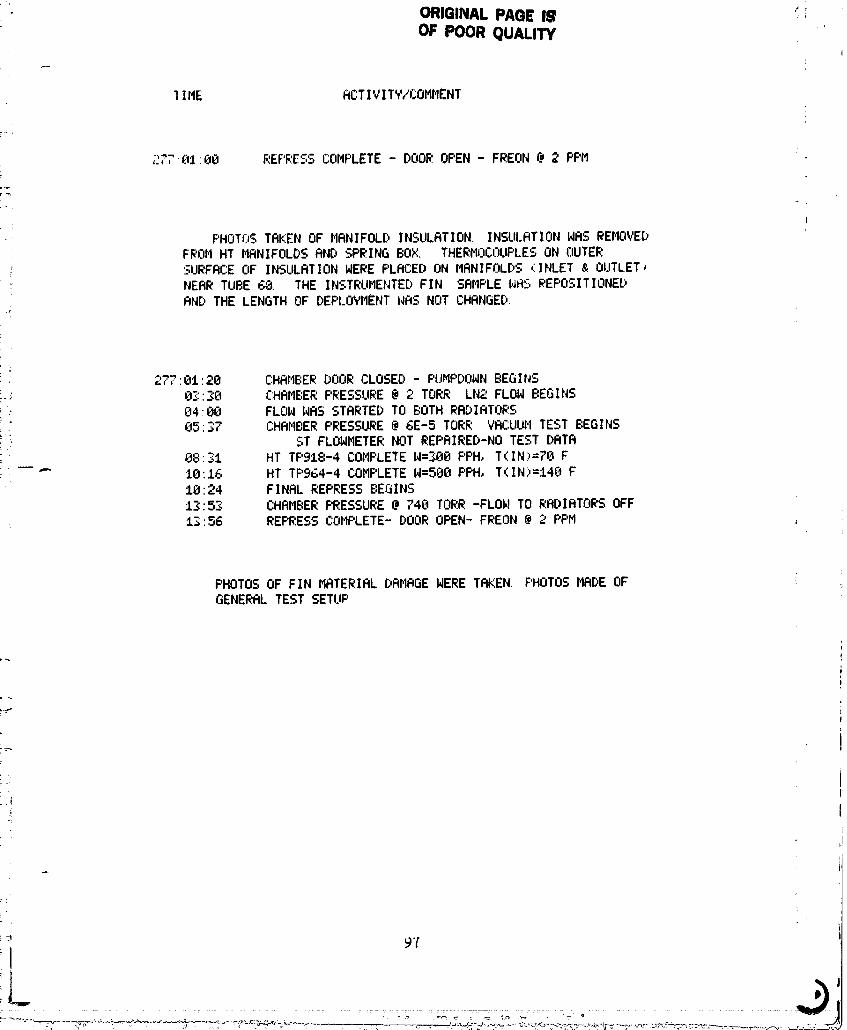
ORIGINAL PAGE IgOF POOR QUALITY "
] IME ACTIVITY/COIII_ENT
2 _ " REF_.E:,_COMPLETE DOOR OPEN - FREON @ 2 PF'M7,._ L30 '"'' '-_" -
F'HOTLGTAKEN OF MANIFOLD INSULATION.INSULATIONWAS REMOVED! FROI4HT MANIFOLDSAND SPRING BOX. THERMOCOUPLESON OUTER; SURFACE OF INSULATIONWERE PLACED ON MANIFOLDS (;INLET& OUTLET_
NEAR TUBE 60. THE INSTRUMENTEDFIN SAMPLE WAS PEF'OSITIONE[)AND THE LENGTH OF DEPLOYMENTWAS NOT CHANGED.
277'0t:20 CHAMBER DOOR CLOSED - PUMPDOWN BEGINS.-_: 0"..:'30 CHAMBER PRESSURE @ 2 TORR LN;.'FLOW BEGINS
0400 FLOW WAS STARTED TO BOTH RADIATORS
:. 85:37 CHAMBER PRESSURE @ 6E-5 TORR VRCUUIITEST BEGINS: ST FLOWMETERNOT REPAIRED-NOTEST DATA
88:31 HT TF'918-4 COMPLETEW=300F'PH, T(IN>=78 F--" 10:].6 HT TF'964-4COMPLETE N=500 PPH, T(IN)=148F
10:24 FINAL REPRESS BEGINS13:53 CHAMBER PRESSURE @ 748 TORR -FLOW TO RADIATORS OFF13:56 REPRESS COMPLETE-DOOR OPEN- FREON @ 2 PPM
PHOTOSOF FIN MATERIALDRMBGEWERETAKEN• PHOTOSMADEOFGENERALTEST SETUP
"_ 9"(
'1_ I
00000002-TSA07