
Zeroth-order phase-contrast technique
10
Zeroth-order phase-contrast technique José Carlos Pizolato, Jr., 1,2 Giuseppe Antonio Cirino, 1 Cristhiane Gonçalves, 2 and Luiz Gonçalves Neto 2, * 1 Department of Research and Development, Holophotonics Equipamentos Ópticos e Eletrônicos Ltda—ME, Avenida Araraquara 863, 13566-770 São Carlos—SP, Brazil 2 Department of Electrical Engineering, University of São Paulo, Avenida Dr. Carlos Botelho 1465, 13560-970 São Carlos—SP, Brazil *Corresponding author: [email protected] Received 15 March 2007; revised 16 August 2007; accepted 10 September 2007; posted 14 September 2007 (Doc. ID 80987); published 22 October 2007 What we believe to be a new phase-contrast technique is proposed to recover intensity distributions from phase distributions modulated by spatial light modulators (SLMs) and binary diffractive optical elements (DOEs). The phase distribution is directly transformed into intensity distributions using a 4f optical correlator and an iris centered in the frequency plane as a spatial filter. No phase-changing plates or phase dielectric dots are used as a filter. This method allows the use of twisted nematic liquid-crystal televisions (LCTVs) operating in the real-time phase-mostly regime mode between 0 and p to generate high-intensity multiple beams for optical trap applications. It is also possible to use these LCTVs as input SLMs for optical correlators to obtain high-intensity Fourier transform distributions of input amplitude objects. © 2007 Optical Society of America OCIS codes: 070.0070, 070.2580, 070.6020, 070.6110. 1. Introduction Since the 1960s digital holography has been used ex- tensively to generate and control spatial complex dis- tributions or intensity distributions of light. Lohmann, Brown, and Paris proposed the binary amplitude mod- ulation detour-phase hologram to partially implement the full complex-amplitude modulation using photog- raphy film [1,2]. As alternative methods, Goodman [3] mentioned the works of Lee [4] and Burckhardt [5]. Lee utilized four fixed subcells per cell with a gray- level transmittance, the first representing the real and positive part of the Fourier coefficient, the second the imaginary and positive part, the third the real and negative part, and the fourth the imaginary and neg- ative part. Since the real or negative parts are either positive or negative but not both, two of the subcells in every cell are normally opaque. Burckhardt recognized that any point in the complex plane can be reached with only three gray-level phasors, one at 0 deg, one at 120 deg, and the third at 240 deg. All prior techniques mentioned here allow only off-axis reconstructions. Chu et al. [6] proposed directed modulation of com- plex modulation using the twin-layer technique, which permits on-axis reconstructions. This ap- proach is known as the referenceless on-axis complex hologram (ROACH). The limitation of the ROACH is the low accuracy in the fabrication of thin layers with both phase modulation and absorption. Noponen and Turunen [7] presented a mathematical scheme to ob- tain the complex-amplitude modulation synthesizing a high-carrier frequency diffractive optical element (DOE) that performs phase and amplitude modula- tion of the first carrier-grating order. Kettunnen et al. [8] introduced the encoding of complex amplitude varying the diffraction efficiency and the phase of the zeroth order of a carrier grating by modulating the shape depth of the structure of each rectangular pixel. Mendlovic et al. [9] proposed an encoding tech- nique to design zeroth-order (on-axis) Fraunhofer computer-generated holograms. The encoding method assumes fixed spatial partitioning of the cell and a phase-only value allocated to each subelement. Davis et al. [10] proposed the encoding of amplitude infor- mation onto phase-only filters modulated by liquid- crystal televisions (LCTVs). In their approach they modulate the phase that is encoded onto the filter, 0003-6935/07/317604-10$15.00/0 © 2007 Optical Society of America 7604 APPLIED OPTICS Vol. 46, No. 31 1 November 2007
-
Upload
independent -
Category
Documents
-
view
4 -
download
0
Transcript of Zeroth-order phase-contrast technique
Zeroth-order phase-contrast technique
José Carlos Pizolato, Jr.,1,2 Giuseppe Antonio Cirino,1 Cristhiane Gonçalves,2
and Luiz Gonçalves Neto2,*1Department of Research and Development, Holophotonics Equipamentos Ópticos e Eletrônicos Ltda—ME,
Avenida Araraquara 863, 13566-770 São Carlos—SP, Brazil2Department of Electrical Engineering, University of São Paulo, Avenida Dr. Carlos Botelho 1465,
13560-970 São Carlos—SP, Brazil
*Corresponding author: [email protected]
Received 15 March 2007; revised 16 August 2007; accepted 10 September 2007;posted 14 September 2007 (Doc. ID 80987); published 22 October 2007
What we believe to be a new phase-contrast technique is proposed to recover intensity distributions fromphase distributions modulated by spatial light modulators (SLMs) and binary diffractive optical elements(DOEs). The phase distribution is directly transformed into intensity distributions using a 4f opticalcorrelator and an iris centered in the frequency plane as a spatial filter. No phase-changing plates orphase dielectric dots are used as a filter. This method allows the use of twisted nematic liquid-crystaltelevisions (LCTVs) operating in the real-time phase-mostly regime mode between 0 and p to generatehigh-intensity multiple beams for optical trap applications. It is also possible to use these LCTVs as inputSLMs for optical correlators to obtain high-intensity Fourier transform distributions of input amplitudeobjects. © 2007 Optical Society of America
OCIS codes: 070.0070, 070.2580, 070.6020, 070.6110.
1. Introduction
Since the 1960s digital holography has been used ex-tensively to generate and control spatial complex dis-tributions or intensity distributions of light. Lohmann,Brown, and Paris proposed the binary amplitude mod-ulation detour-phase hologram to partially implementthe full complex-amplitude modulation using photog-raphy film [1,2]. As alternative methods, Goodman [3]mentioned the works of Lee [4] and Burckhardt [5].Lee utilized four fixed subcells per cell with a gray-level transmittance, the first representing the real andpositive part of the Fourier coefficient, the second theimaginary and positive part, the third the real andnegative part, and the fourth the imaginary and neg-ative part. Since the real or negative parts are eitherpositive or negative but not both, two of the subcells inevery cell are normally opaque. Burckhardt recognizedthat any point in the complex plane can be reachedwith only three gray-level phasors, one at 0 deg, one at120 deg, and the third at 240 deg. All prior techniquesmentioned here allow only off-axis reconstructions.
Chu et al. [6] proposed directed modulation of com-plex modulation using the twin-layer technique,which permits on-axis reconstructions. This ap-proach is known as the referenceless on-axis complexhologram (ROACH). The limitation of the ROACH isthe low accuracy in the fabrication of thin layers withboth phase modulation and absorption. Noponen andTurunen [7] presented a mathematical scheme to ob-tain the complex-amplitude modulation synthesizinga high-carrier frequency diffractive optical element(DOE) that performs phase and amplitude modula-tion of the first carrier-grating order. Kettunnen et al.[8] introduced the encoding of complex amplitudevarying the diffraction efficiency and the phase of thezeroth order of a carrier grating by modulating theshape depth of the structure of each rectangularpixel. Mendlovic et al. [9] proposed an encoding tech-nique to design zeroth-order (on-axis) Fraunhofercomputer-generated holograms. The encoding methodassumes fixed spatial partitioning of the cell and aphase-only value allocated to each subelement. Daviset al. [10] proposed the encoding of amplitude infor-mation onto phase-only filters modulated by liquid-crystal televisions (LCTVs). In their approach theymodulate the phase that is encoded onto the filter,
0003-6935/07/317604-10$15.00/0© 2007 Optical Society of America
7604 APPLIED OPTICS � Vol. 46, No. 31 � 1 November 2007
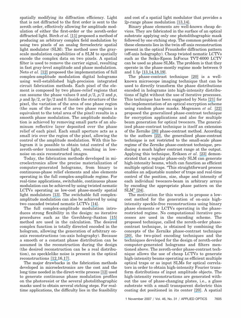
spatially modifying its diffraction efficiency. Lightthat is not diffracted to the first order is sent to thezeroth order, effectively allowing for amplitude mod-ulation of either the first-order or the zeroth-orderdiffracted light. Birch et al. [11] proposed a method ofproducing an arbitrary complex field modulation byusing two pixels of an analog ferroelectric spatiallight modulator (SLM). The method uses the gray-scale modulation capabilities of a SLM to spatiallyencode the complex data on two pixels. A spatialfilter is used to remove the carrier signal, resultingin fast gray-level amplitude and phase modulation.Neto et al. [12] proposed the implementation of fullcomplex-amplitude modulation digital hologramsusing well-established high-precision integratedcircuit fabrication methods. Each pixel of the ele-ment is composed by two phase-relief regions thatcan assume the phase values 0 and p�2, p�2 and p,p and 3p�2, or 3p�2 and 0. Inside the structure of thepixel, the variation of the area of one phase region(the sum of the area of the two phase regions isequivalent to the total area of the pixel) results in asmooth phase modulation. The amplitude modula-tion is achieved by removing small parts of an alu-minum reflective layer deposited over the phaserelief of each pixel. Each small aperture acts as asmall iris over the region of the pixel, allowing thecontrol of the amplitude modulation. With this ho-logram it is possible to obtain total control of thezeroth-order transmitted light, resulting in low-noise on-axis reconstructed images.
Today, the fabrication methods developed in mi-croelectronics allow the precise materialization ofcomputer-generated holograms, from binary tocontinuous-phase relief elements and also elementsoperating in the full complex-amplitude regime. Forreal-time applications, switchable, continuous phasemodulation can be achieved by using twisted nematicLCTVs operating as low-cost phase-mostly spatiallight modulators [13]. The switchable full complex-amplitude modulation can also be achieved by usingtwo cascaded twisted nematic LCTVs [14].
The full complex-amplitude modulation intro-duces strong flexibility in the design: no iterativeprocedures such as the Gerchberg–Saxton [15]method are used in the calculation. The desiredcomplex function is totally directed encoded in thehologram, allowing the generation of arbitrary on-axis reconstructions (on-axis holography). Becausea smooth or a constant phase distribution can beassumed in the reconstruction during the design(the desired reconstruction can be a real distribu-tion), no specklelike noise is present in the opticalreconstructions [12,16,17].
The major drawbacks in the fabrication methodsdeveloped in microelectronics are the cost and thelong time needed in the direct-write process [12] usedto generate continuous phase modulation profileson the photoresist or the several photolithographicmasks used to obtain several etching steps. For real-time applications, the difficulty lies in the feasibility
and cost of a spatial light modulator that provides a2p-range phase modulation [13,14].
Binary phase elements are well-known cheap de-vices. They are fabricated in the surface of an opticalsubstrate applying only one photolithographic maskfollowed by one etching step. The common problem ofthese elements lies in the twin off-axis reconstructionpresent in the optical Fraunhofer diffraction pattern(off-axis holography). Cheap twisted nematic LCTVssuch as the Seiko-Epson InFocus TVT-6000 LCTVcan be used as phase SLMs. The problem is that theyoperate in the phase-mostly regime mode between 0and 1.5p [13,14,18,19].
The phase-contrast technique [20] is a well-known microscope imaging technique that can beused to directly transform the phase distributionsencoded in holograms into high-intensity distribu-tions of light without the use of iterative processes.This technique has been suggested by Neto [21] forthe implementation of an optical encryption schemeusing random phase masks. Mogensen et al. [22]proposed the generalized phase-contrast techniquefor encryption applications and also for multiplebeam generation for optical tweezers. The general-ized phase-contrast technique is itself an extensionof the Zernike [20] phase-contrast method. Accordingto the authors [22], the generalized phase-contrasttechnique is not restricted to the small-scale phaseregime of the Zernike phase-contrast technique, pro-ducing a much higher contrast range at the output.Applying this technique, Eriksen et al. [23] demon-strated that a regular phase-only SLM can generatehigh-intensity beams, which can function as efficientmultiple optical traps. “This straightforward processenables an adjustable number of traps and real-timecontrol of the position, size, shape and intensity ofeach individual tweezers-beam in arbitrary arraysby encoding the appropriate phase pattern on theSLM” [24].
The motivation for this work is to propose a low-cost method for the generation of on-axis high-intensity speckle-free reconstructions using binaryphase elements or LCTVs operating in the phase-restricted regime. No computational iterative pro-cesses are used in the encoding scheme. Theproposed technique, called the zeroth-order phase-contrast technique, is obtained by combining theconcepts of the Zernike phase-contrast technique[20], the two-pixel encoding techniques and thetechniques developed for the design of zeroth-ordercomputer-generated holograms and filters men-tioned above. The zeroth-order phase-contrast tech-nique allows the use of cheap LCTVs to generatehigh-intensity beams operating as efficient multipleoptical traps or as input SLMs for optical correla-tors in order to obtain high-intensity Fourier trans-form distributions of input amplitude objects. Thehigh-intensity reconstructions are generated with-out the use of phase-changing plates, i.e., a glasssubstrate with a small transparent dielectric thincoating dot positioned in its center [20]. A spatial
1 November 2007 � Vol. 46, No. 31 � APPLIED OPTICS 7605
filter is used to remove the unwanted signal. Onlythe zeroth-order is transmitted.
The proposed phase-contrast technique is exam-ined in detail in the following sections. The phaseencoding is first demonstrated using a LCTV as aphase SLM [13,14,18,19]. The technique is also ap-plied to the design of binary phase DOEs, with specialattention to the error analysis of the encoding pro-cess. Two kinds of phase modulation devices are man-ufactured by employing well-established, low-costintegrated circuit fabrication steps [25]: the first ele-ment operates in transmittance mode and the secondin reflective mode. Optical verifications of the inten-sity distribution retrieved from the phase informa-tion encoded in both the LCTV and DOEs are shown.
2. Zeroth-Order Phase-Contrast Technique
The Zernike phase-contrast technique [20] can beexplained by considering a transparent object t�x, y�� exp�ja�x, y�� illuminated by a coherent and uniformwavefront of amplitude equal to 1 in the input of animage-forming system such as a 4f optical correlator.A magnification of unity is assumed, and the finiteextent of the entrance and exit pupil is not consid-ered. The phase shift a�x, y� is assumed to be lessthan 1 rad as a necessary condition to achieve linear-ity [20]. Expanding the term t�x, y� � exp�ja�x, y�� asa Taylor expansion and neglecting the terms of ordera�x, y�2 and higher, the amplitude transmittance canbe approximated by
t�x, y� � 1 � ja�x, y�. (1)
The first term of Eq. (1) represents the light thatpasses through t�x, y� without change, called thebackground, and the second term represents the dif-fracted light. The image produced by the system is
written as
I�x, y� � �1 � ja�x, y��2 � 1. (2)
The diffracted light is not observed because it is inphase quadrature with the background. If this phasequadrature is modified using a phase-changing plate,intensity variations occur and the transparent objectcan be observed. The phase-changing plate consists ofa glass substrate with a small transparent dielectricthin coating dot positioned in its center. The dot isplaced in the optical axis of the back focal plane of thefirst lens where one has the optical Fourier transformof the transparent object. The dot has a thickness andindex of refraction such that the phase of the zero-frequency component of the Fourier transform of thebackground is retarded by ��2 rad relative to thephase of the Fourier transform of the diffracted light.The Fourier transform performed by the second lensgives the intensity of the resulting image:
I�x, y� � �exp�j����2�� � ja�x, y��2 � 1 � 2a�x, y�.(3)
In Eq. (3) the image intensity has become linearlyrelated to the phase shift a�x, y�.
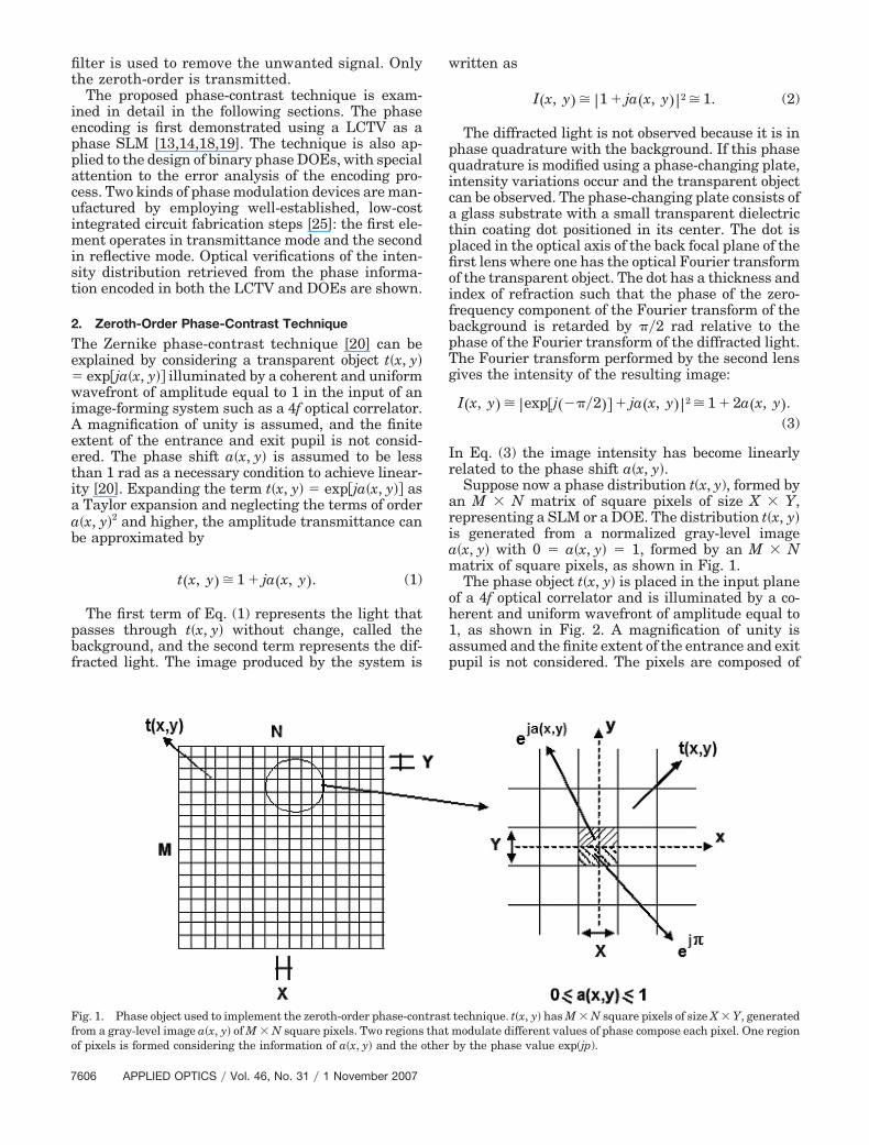
Suppose now a phase distribution t(x, y), formed byan M � N matrix of square pixels of size X � Y,representing a SLM or a DOE. The distribution t�x, y�is generated from a normalized gray-level imagea�x, y� with 0 � a�x, y� � 1, formed by an M � Nmatrix of square pixels, as shown in Fig. 1.
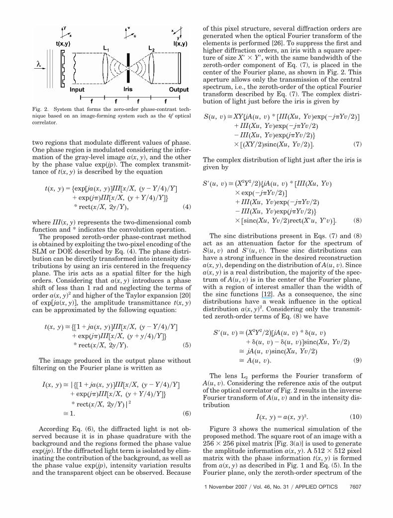
The phase object t�x, y� is placed in the input planeof a 4f optical correlator and is illuminated by a co-herent and uniform wavefront of amplitude equal to1, as shown in Fig. 2. A magnification of unity isassumed and the finite extent of the entrance and exitpupil is not considered. The pixels are composed of
Fig. 1. Phase object used to implement the zeroth-order phase-contrast technique. t�x, y� has M � N square pixels of size X � Y, generatedfrom a gray-level image a�x, y� of M � N square pixels. Two regions that modulate different values of phase compose each pixel. One regionof pixels is formed considering the information of a�x, y� and the other by the phase value exp(jp).
7606 APPLIED OPTICS � Vol. 46, No. 31 � 1 November 2007
two regions that modulate different values of phase.One phase region is modulated considering the infor-mation of the gray-level image a�x, y�, and the otherby the phase value exp�jp�. The complex transmit-tance of t�x, y� is described by the equation
t�x, y� � �exp�ja�x, y��III�x�X, �y � Y�4��Y�� exp�j��III�x�X, �y � Y�4��Y��* rect�x�X, 2y�Y�, (4)
where III�x, y� represents the two-dimensional combfunction and * indicates the convolution operation.
The proposed zeroth-order phase-contrast methodis obtained by exploiting the two-pixel encoding of theSLM or DOE described by Eq. (4). The phase distri-bution can be directly transformed into intensity dis-tributions by using an iris centered in the frequencyplane. The iris acts as a spatial filter for the highorders. Considering that a�x, y� introduces a phaseshift of less than 1 rad and neglecting the terms oforder a�x, y�2 and higher of the Taylor expansion [20]of exp�ja�x, y��, the amplitude transmittance t�x, y�can be approximated by the following equation:
t�x, y� � ��1 � ja�x, y��III�x�X, �y � Y�4��Y�� exp�j��III�x�X, �y � y�4��Y��* rect�x�X, 2y�Y�. (5)
The image produced in the output plane withoutfiltering on the Fourier plane is written as
I�x, y� � |��1 � ja�x, y��III�x�X, �y � Y�4��Y�� exp�j��III�x�X, �y � Y�4��Y��* rect�x�X, 2y�Y�|2
� 1. (6)
According Eq. (6), the diffracted light is not ob-served because it is in phase quadrature with thebackground and the regions formed the phase valueexp�jp�. If the diffracted light term is isolated by elim-inating the contribution of the background, as well asthe phase value exp�jp�, intensity variation resultsand the transparent object can be observed. Because
of this pixel structure, several diffraction orders aregenerated when the optical Fourier transform of theelements is performed [26]. To suppress the first andhigher diffraction orders, an iris with a square aper-ture of size X� � Y�, with the same bandwidth of thezeroth-order component of Eq. (7), is placed in thecenter of the Fourier plane, as shown in Fig. 2. Thisaperture allows only the transmission of the centralspectrum, i.e., the zeroth-order of the optical Fouriertransform described by Eq. (7). The complex distri-bution of light just before the iris is given by
S�u, v� � XY�jA�u, v� * �III�Xu, Yv�exp��j�Yv�2��� III�Xu, Yv�exp��j�Yv�2�� III�Xu, Yv�exp�j�Yv�2��� ��XY�2�sinc�Xu, Yv�2��. (7)
The complex distribution of light just after the iris isgiven by
S��u, v� � �X2Y2�2��jA�u, v� * �III�Xu, Yv�� exp��j�Yv�2��� III�Xu, Yv�exp��j�Yv�2�� III�Xu, Yv�exp�j�Yv�2��� �sinc�Xu, Yv�2�rect�X�u, Y�v��. (8)
The sinc distributions present in Eqs. (7) and (8)act as an attenuation factor for the spectrum ofS�u, v� and S��u, v�. These sinc distributions canhave a strong influence in the desired reconstructiona�x, y�, depending on the distribution of A�u, v�. Sincea�x, y� is a real distribution, the majority of the spec-trum of A�u, v� is in the center of the Fourier plane,with a region of interest smaller than the width ofthe sinc functions [12]. As a consequence, the sincdistributions have a weak influence in the opticaldistribution a�x, y�2. Considering only the transmit-ted zeroth-order terms of Eq. (8) we have
S��u, v� � �X2Y2�2��jA�u, v� * ��u, v�� ��u, v� � ��u, v��sinc�Xu, Yv�2�
� jA�u, v�sinc�Xu, Yv�2�� A�u, v�. (9)
The lens L2 performs the Fourier transform ofA�u, v�. Considering the reference axis of the outputof the optical correlator of Fig. 2 results in the inverseFourier transform of A�u, v� and in the intensity dis-tribution
I�x, y� � a�x, y�2. (10)
Figure 3 shows the numerical simulation of theproposed method. The square root of an image with a256 � 256 pixel matrix [Fig. 3(a)] is used to generatethe amplitude information a�x, y�. A 512 � 512 pixelmatrix with the phase information t�x, y� is formedfrom a�x, y� as described in Fig. 1 and Eq. (5). In theFourier plane, only the zeroth-order spectrum of the
Fig. 2. System that forms the zero-order phase-contrast tech-nique based on an image-forming system such as the 4f opticalcorrelator.
1 November 2007 � Vol. 46, No. 31 � APPLIED OPTICS 7607
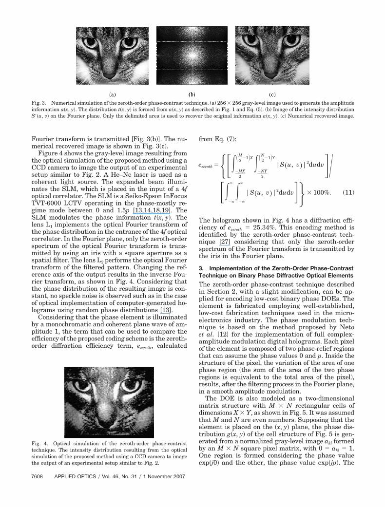
Fourier transform is transmitted [Fig. 3(b)]. The nu-merical recovered image is shown in Fig. 3(c).
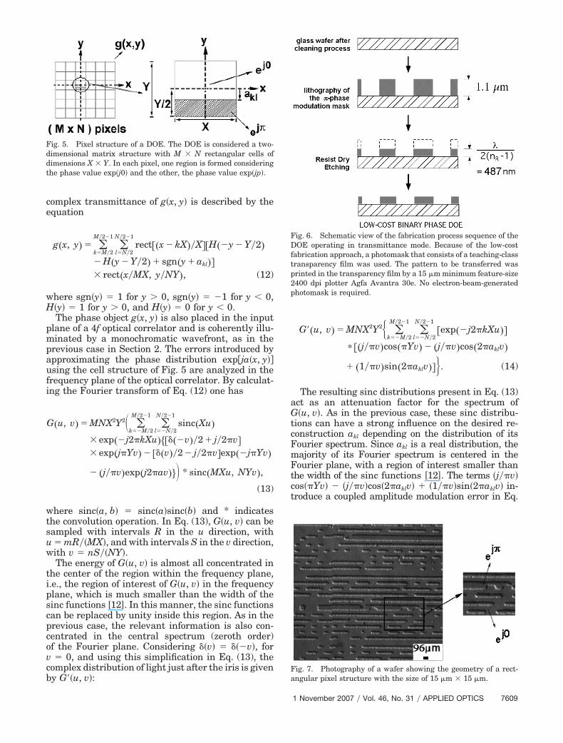
Figure 4 shows the gray-level image resulting fromthe optical simulation of the proposed method using aCCD camera to image the output of an experimentalsetup similar to Fig. 2. A He–Ne laser is used as acoherent light source. The expanded beam illumi-nates the SLM, which is placed in the input of a 4foptical correlator. The SLM is a Seiko-Epson InFocusTVT-6000 LCTV operating in the phase-mostly re-gime mode between 0 and 1.5p [13,14,18,19]. TheSLM modulates the phase information t�x, y�. Thelens L1 implements the optical Fourier transform ofthe phase distribution in the entrance of the 4f opticalcorrelator. In the Fourier plane, only the zeroth-orderspectrum of the optical Fourier transform is trans-mitted by using an iris with a square aperture as aspatial filter. The lens L2 performs the optical Fouriertransform of the filtered pattern. Changing the ref-erence axis of the output results in the inverse Fou-rier transform, as shown in Fig. 4. Considering thatthe phase distribution of the resulting image is con-stant, no speckle noise is observed such as in the caseof optical implementation of computer-generated ho-lograms using random phase distributions [13].
Considering that the phase element is illuminatedby a monochromatic and coherent plane wave of am-plitude 1, the term that can be used to compare theefficiency of the proposed coding scheme is the zeroth-order diffraction efficiency term, ezeroth, calculated
from Eq. (7):
ezeroth ���MX2
�M2
�1 X��NY
2
�N2
�1 Y|S�u, v�|2dudv� ⁄
���
� ���
�
|S�u, v�|2dudv�� � 100%. (11)
The hologram shown in Fig. 4 has a diffraction effi-ciency of ezeroth � 25.34%. This encoding method isidentified by the zeroth-order phase-contrast tech-nique [27] considering that only the zeroth-orderspectrum of the Fourier transform is transmitted bythe iris in the Fourier plane.
3. Implementation of the Zeroth-Order Phase-ContrastTechnique on Binary Phase Diffractive Optical Elements
The zeroth-order phase-contrast technique describedin Section 2, with a slight modification, can be ap-plied for encoding low-cost binary phase DOEs. Theelement is fabricated employing well-established,low-cost fabrication techniques used in the micro-electronics industry. The phase modulation tech-nique is based on the method proposed by Netoet al. [12] for the implementation of full complex-amplitude modulation digital holograms. Each pixelof the element is composed of two phase-relief regionsthat can assume the phase values 0 and p. Inside thestructure of the pixel, the variation of the area of onephase region (the sum of the area of the two phaseregions is equivalent to the total area of the pixel),results, after the filtering process in the Fourier plane,in a smooth amplitude modulation.
The DOE is also modeled as a two-dimensionalmatrix structure with M � N rectangular cells ofdimensions X � Y, as shown in Fig. 5. It was assumedthat M and N are even numbers. Supposing that theelement is placed on the �x, y� plane, the phase dis-tribution g�x, y� of the cell structure of Fig. 5 is gen-erated from a normalized gray-level image akl formedby an M � N square pixel matrix, with 0 � akl � 1.One region is formed considering the phase valueexp�j0� and the other, the phase value exp�jp�. The
Fig. 3. Numerical simulation of the zeroth-order phase-contrast technique. (a) 256 � 256 gray-level image used to generate the amplitudeinformation a�x, y�. The distribution t�x, y� is formed from a�x, y� as described in Fig. 1 and Eq. (5). (b) Image of the intensity distributionS��u, v� on the Fourier plane. Only the delimited area is used to recover the original information a�x, y�. (c) Numerical recovered image.
Fig. 4. Optical simulation of the zeroth-order phase-contrasttechnique. The intensity distribution resulting from the opticalsimulation of the proposed method using a CCD camera to imagethe output of an experimental setup similar to Fig. 2.
7608 APPLIED OPTICS � Vol. 46, No. 31 � 1 November 2007
complex transmittance of g�x, y� is described by theequation
g�x, y� � �k�M�2
M�2�1
�l�N�2
N�2�1
rect��x � kX��X��H��y � Y�2�� H�y � Y�2� � sgn�y � akl��� rect�x�MX, y�NY�, (12)
where sgn�y� � 1 for y 0, sgn�y� � �1 for y 0,H�y� � 1 for y 0, and H�y� � 0 for y 0.
The phase object g�x, y� is also placed in the inputplane of a 4f optical correlator and is coherently illu-minated by a monochromatic wavefront, as in theprevious case in Section 2. The errors introduced byapproximating the phase distribution exp�ja�x, y��using the cell structure of Fig. 5 are analyzed in thefrequency plane of the optical correlator. By calculat-ing the Fourier transform of Eq. (12) one has
G�u, v� � MNX2Y2� �k��M�2
M�2�1
�l��N�2
N�2�1
sinc�Xu�� exp��j2�kXu������v��2 � j�2�v�� exp�j�Yv� � ���v��2 � j�2�v�exp��j�Yv�
� �j��v�exp�j2�av�� * sinc�MXu, NYv�,
(13)
where sinc�a, b� � sinc�a�sinc�b� and * indicatesthe convolution operation. In Eq. (13), G�u, v� can besampled with intervals R in the u direction, withu � mR��MX�, and with intervals S in the v direction,with v � nS��NY�.
The energy of G�u, v� is almost all concentrated inthe center of the region within the frequency plane,i.e., the region of interest of G�u, v� in the frequencyplane, which is much smaller than the width of thesinc functions [12]. In this manner, the sinc functionscan be replaced by unity inside this region. As in theprevious case, the relevant information is also con-centrated in the central spectrum (zeroth order)of the Fourier plane. Considering ��v� � ���v�, forv � 0, and using this simplification in Eq. (13), thecomplex distribution of light just after the iris is givenby G��u, v�:
G��u, v� � MNX2Y2 �k��M�2
M�2�1
�l��N�2
N�2�1
�exp��j2�kXu��� ��j��v�cos��Yv� � �j��v�cos�2�aklv�
� �1��v�sin�2�aklv���. (14)
The resulting sinc distributions present in Eq. (13)act as an attenuation factor for the spectrum ofG�u, v�. As in the previous case, these sinc distribu-tions can have a strong influence on the desired re-construction akl depending on the distribution of itsFourier spectrum. Since akl is a real distribution, themajority of its Fourier spectrum is centered in theFourier plane, with a region of interest smaller thanthe width of the sinc functions [12]. The terms �j��v�cos��Yv� � �j��v�cos�2�aklv� � �1��v�sin�2�aklv� in-troduce a coupled amplitude modulation error in Eq.
Fig. 6. Schematic view of the fabrication process sequence of theDOE operating in transmittance mode. Because of the low-costfabrication approach, a photomask that consists of a teaching-classtransparency film was used. The pattern to be transferred wasprinted in the transparency film by a 15 �m minimum feature-size2400 dpi plotter Agfa Avantra 30e. No electron-beam-generatedphotomask is required.
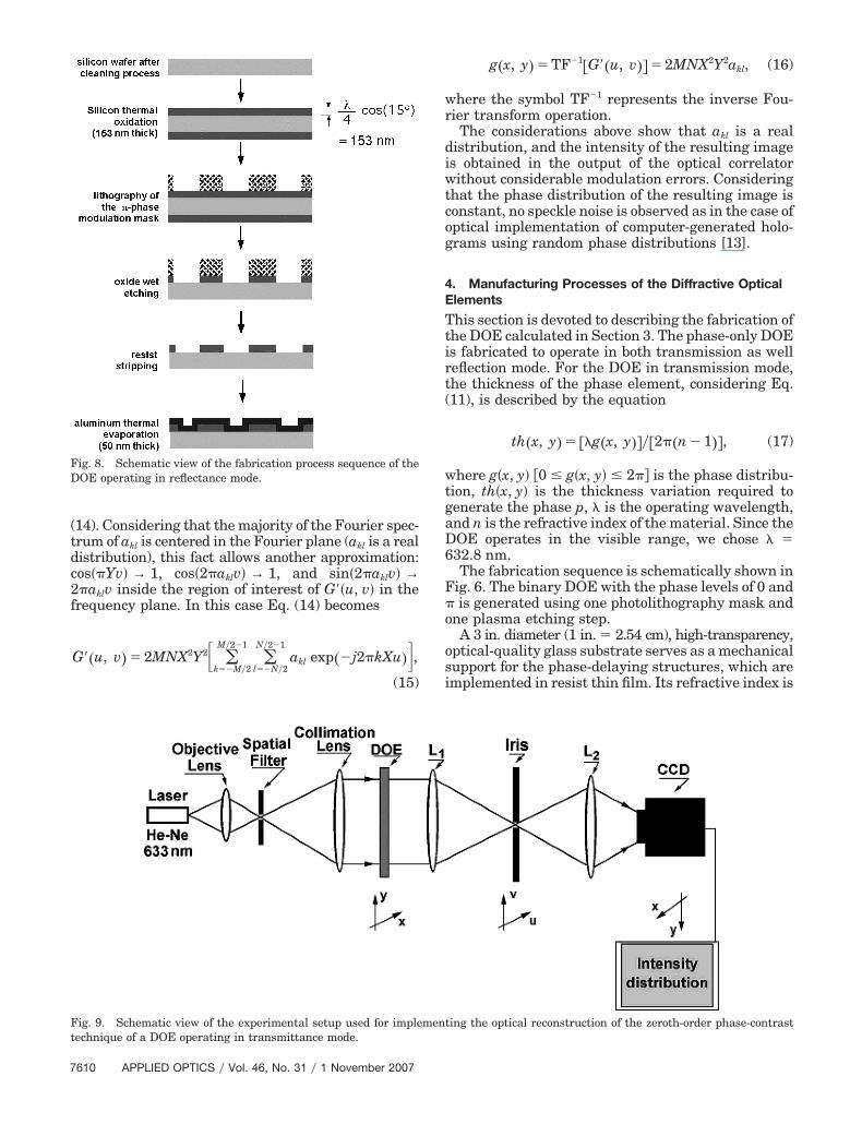
Fig. 7. Photography of a wafer showing the geometry of a rect-angular pixel structure with the size of 15 �m � 15 �m.
Fig. 5. Pixel structure of a DOE. The DOE is considered a two-dimensional matrix structure with M � N rectangular cells ofdimensions X � Y. In each pixel, one region is formed consideringthe phase value exp�j0� and the other, the phase value exp�jp�.
1 November 2007 � Vol. 46, No. 31 � APPLIED OPTICS 7609
(14). Considering that the majority of the Fourier spec-trum of akl is centered in the Fourier plane (akl is a realdistribution), this fact allows another approximation:cos��Yv� → 1, cos�2�aklv� → 1, and sin�2�aklv� →2�aklv inside the region of interest of G��u, v� in thefrequency plane. In this case Eq. (14) becomes
G��u, v� � 2MNX2Y2 �k��M�2
M�2�1
�l��N�2
N�2�1
akl exp��j2�kXu��,(15)
g�x, y� � TF�1�G��u, v�� � 2MNX2Y2akl, (16)
where the symbol TF�1 represents the inverse Fou-rier transform operation.
The considerations above show that akl is a realdistribution, and the intensity of the resulting imageis obtained in the output of the optical correlatorwithout considerable modulation errors. Consideringthat the phase distribution of the resulting image isconstant, no speckle noise is observed as in the case ofoptical implementation of computer-generated holo-grams using random phase distributions [13].
4. Manufacturing Processes of the Diffractive OpticalElements
This section is devoted to describing the fabrication ofthe DOE calculated in Section 3. The phase-only DOEis fabricated to operate in both transmission as wellreflection mode. For the DOE in transmission mode,the thickness of the phase element, considering Eq.(11), is described by the equation
th�x, y� � ��g�x, y����2��n � 1��, (17)
where g�x, y� �0 g�x, y� 2�� is the phase distribu-tion, th�x, y� is the thickness variation required togenerate the phase p, � is the operating wavelength,and n is the refractive index of the material. Since theDOE operates in the visible range, we chose � �632.8 nm.
The fabrication sequence is schematically shown inFig. 6. The binary DOE with the phase levels of 0 and� is generated using one photolithography mask andone plasma etching step.
A 3 in. diameter (1 in. � 2.54 cm), high-transparency,optical-quality glass substrate serves as a mechanicalsupport for the phase-delaying structures, which areimplemented in resist thin film. Its refractive index is
Fig. 8. Schematic view of the fabrication process sequence of theDOE operating in reflectance mode.
Fig. 9. Schematic view of the experimental setup used for implementing the optical reconstruction of the zeroth-order phase-contrasttechnique of a DOE operating in transmittance mode.
7610 APPLIED OPTICS � Vol. 46, No. 31 � 1 November 2007

nR � 1.65. Since g�x, y� � �, the required gratingthickness is th�x, y� � 633��2�1.65 � 1�� � 487 nm.
The adhesion characteristics of the resist dependvery much on the cleanness of the glass substrate. Inthis work, a six-step process was used, which is oftenpart of a standard silicon substrate cleaning sequence[28–30].
After the cleaning process, the substrate was sub-mitted to optical lithography. Because of the low-cost fabrication approach, we used a photomaskthat consisted of a teaching-class transparency film.The pattern to be transferred was printed in thetransparency film by a 15 �m minimum feature-sizeplotter, 2400 dpi Agfa-Geavert Group Avantra 30e.No electron-beam-generated photomask is required.All the process steps used are well controlled and wellknown for micro-optics and microelectronic applica-tions.
On top of the glass substrate, a positive photoresistwas spun (3500 rpm, for 20 s), prebaked (90 s dura-
tion at 105 °C), exposed to UV light (11 s duration, at25 mW�cm2 and 436 nm wavelength g-line mercurylamp source), developed, and postbaked (120 s dura-tion at 115 °C), resulting in a film thickness of1.1 �m. Scanning electron microscope analysis showsthat the sidewalls of the resist are nearly vertical.
Resist films can easily be etched by oxygen plas-mas. Several of these plasmas were investigated,in a single wafer reactive ion etching system, de-scribed in detail in [28–30]. With the photomaskused, four different DOEs were fabricated on a 3 in.diameter glass substrate. Each element has a 1 cm� 1 cm area. A top view photograph, using an opticalmicroscope, of a wafer with the fabricated elements isshown in Fig. 7.
For the DOE operating in reflection mode, thethickness variation required to generate an opticalpath difference of � rad is given by
th�x, y� � �� cos�����4, (18)
where � is the illumination angle with respect to thenormal of the DOE plane. Considering an illumi-nating angle of 15 deg we have th�x, y� � �633 �0.966��4 � 152.9 nm.
The DOE was fabricated using the same mask asbefore. In this case we used a silicon wafer where athermal oxidation was first carried out. From thestandard process in the laboratory, a 152.9 nm thicksilicon dioxide film was obtained, with uniformitybetter than 95%, obtained from an ellipsometric tech-nique [28]. Figure 8 shows the fabrication processsequence used. The substrate was first cleaned by astandard silicon substrate cleaning sequence [28–30]and submitted to the thermal oxidation: 1150 °C for
Fig. 10. Optical reconstruction of an intensity distribution imageencoded in DOE transmittance mode fabricated using the stepsdescribed in Section 4. The recovered information was imaged ontoa CCD camera.
Fig. 11. Schematic view of the experimental setup used for implementing the optical reconstruction of the zeroth-order phase-contrasttechnique of a DOE operating in reflection mode.
1 November 2007 � Vol. 46, No. 31 � APPLIED OPTICS 7611
10 h in oxygen atmosphere. The sample was submit-ted to optical lithography over the oxide thin film, aswas the previous transmittance DOE. The exposedoxide was chemically etched on a 6 NH4F � 1 HFsolution, at room temperature, for 4 min. Underthese conditions the backside of the wafer emergesdry from the etching solution, indicating that all theoxide was removed. The remaining resist wasstripped away by an acetone bath at 50 °C, for 10min. The phase relief was made reflective throughthe deposition of an aluminium thin film by stan-dard thermal evaporation.
5. Optical Results
The experimental setup shown in Fig. 9 is used toobtain the optical reconstruction from the DOE oper-ating in transmittance mode. An expanded beam of aHe–Ne laser illuminates the DOE, which is placed inthe input of the 4f optical correlator. The lens L1implements the optical Fourier transform of the in-put distribution. In the Fourier plane, only the zerothorder generated by the DOE is transmitted. The lensL2 implements the Fourier transform of the filteredcomponent and the recovered information is then im-aged onto a CCD camera as shown in Fig. 10. Chang-ing the reference axis of the output results in theinverse Fourier transform.
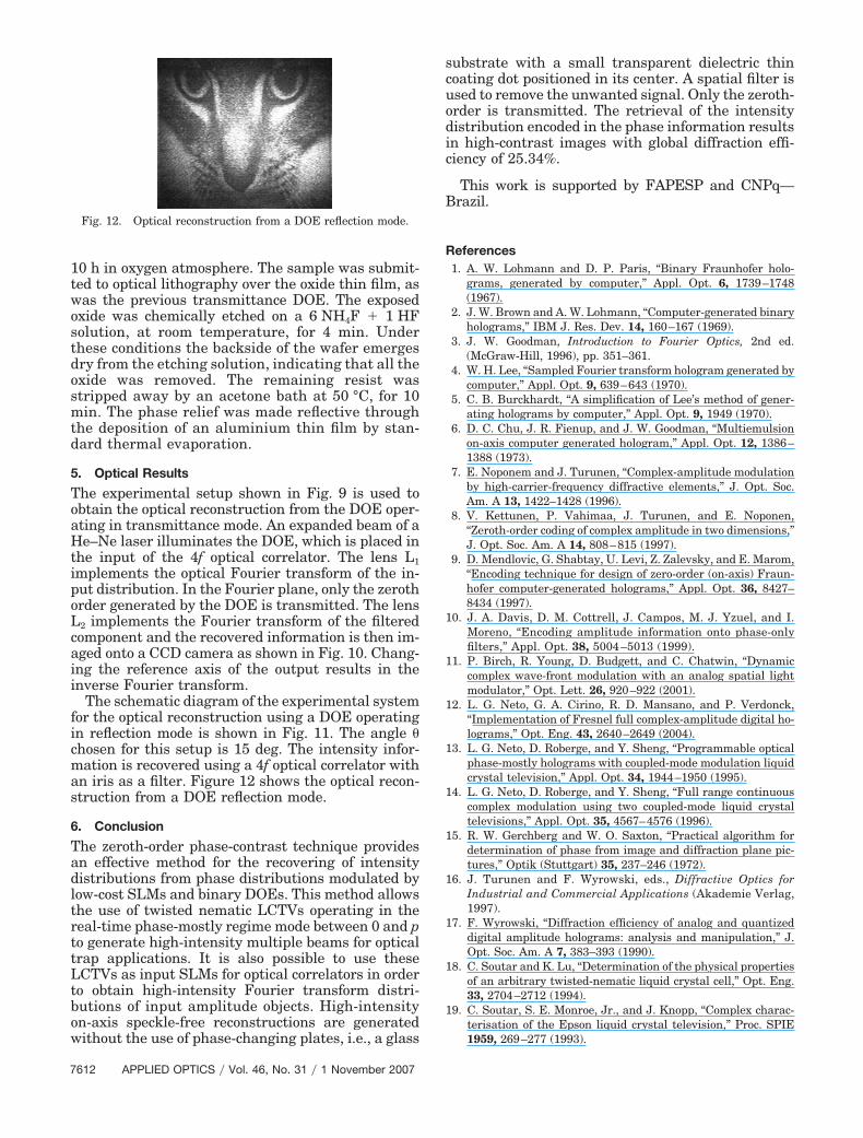
The schematic diagram of the experimental systemfor the optical reconstruction using a DOE operatingin reflection mode is shown in Fig. 11. The angle �chosen for this setup is 15 deg. The intensity infor-mation is recovered using a 4f optical correlator withan iris as a filter. Figure 12 shows the optical recon-struction from a DOE reflection mode.
6. Conclusion
The zeroth-order phase-contrast technique providesan effective method for the recovering of intensitydistributions from phase distributions modulated bylow-cost SLMs and binary DOEs. This method allowsthe use of twisted nematic LCTVs operating in thereal-time phase-mostly regime mode between 0 and pto generate high-intensity multiple beams for opticaltrap applications. It is also possible to use theseLCTVs as input SLMs for optical correlators in orderto obtain high-intensity Fourier transform distri-butions of input amplitude objects. High-intensityon-axis speckle-free reconstructions are generatedwithout the use of phase-changing plates, i.e., a glass
substrate with a small transparent dielectric thincoating dot positioned in its center. A spatial filter isused to remove the unwanted signal. Only the zeroth-order is transmitted. The retrieval of the intensitydistribution encoded in the phase information resultsin high-contrast images with global diffraction effi-ciency of 25.34%.
This work is supported by FAPESP and CNPq—Brazil.
References1. A. W. Lohmann and D. P. Paris, “Binary Fraunhofer holo-
grams, generated by computer,” Appl. Opt. 6, 1739–1748(1967).
2. J. W. Brown and A. W. Lohmann, “Computer-generated binaryholograms,” IBM J. Res. Dev. 14, 160–167 (1969).
3. J. W. Goodman, Introduction to Fourier Optics, 2nd ed.(McGraw-Hill, 1996), pp. 351–361.
4. W. H. Lee, “Sampled Fourier transform hologram generated bycomputer,” Appl. Opt. 9, 639–643 (1970).
5. C. B. Burckhardt, “A simplification of Lee’s method of gener-ating holograms by computer,” Appl. Opt. 9, 1949 (1970).
6. D. C. Chu, J. R. Fienup, and J. W. Goodman, “Multiemulsionon-axis computer generated hologram,” Appl. Opt. 12, 1386–1388 (1973).
7. E. Noponem and J. Turunen, “Complex-amplitude modulationby high-carrier-frequency diffractive elements,” J. Opt. Soc.Am. A 13, 1422–1428 (1996).
8. V. Kettunen, P. Vahimaa, J. Turunen, and E. Noponen,“Zeroth-order coding of complex amplitude in two dimensions,”J. Opt. Soc. Am. A 14, 808–815 (1997).
9. D. Mendlovic, G. Shabtay, U. Levi, Z. Zalevsky, and E. Marom,“Encoding technique for design of zero-order (on-axis) Fraun-hofer computer-generated holograms,” Appl. Opt. 36, 8427–8434 (1997).
10. J. A. Davis, D. M. Cottrell, J. Campos, M. J. Yzuel, and I.Moreno, “Encoding amplitude information onto phase-onlyfilters,” Appl. Opt. 38, 5004–5013 (1999).
11. P. Birch, R. Young, D. Budgett, and C. Chatwin, “Dynamiccomplex wave-front modulation with an analog spatial lightmodulator,” Opt. Lett. 26, 920–922 (2001).
12. L. G. Neto, G. A. Cirino, R. D. Mansano, and P. Verdonck,“Implementation of Fresnel full complex-amplitude digital ho-lograms,” Opt. Eng. 43, 2640–2649 (2004).
13. L. G. Neto, D. Roberge, and Y. Sheng, “Programmable opticalphase-mostly holograms with coupled-mode modulation liquidcrystal television,” Appl. Opt. 34, 1944–1950 (1995).
14. L. G. Neto, D. Roberge, and Y. Sheng, “Full range continuouscomplex modulation using two coupled-mode liquid crystaltelevisions,” Appl. Opt. 35, 4567–4576 (1996).
15. R. W. Gerchberg and W. O. Saxton, “Practical algorithm fordetermination of phase from image and diffraction plane pic-tures,” Optik (Stuttgart) 35, 237–246 (1972).
16. J. Turunen and F. Wyrowski, eds., Diffractive Optics forIndustrial and Commercial Applications (Akademie Verlag,1997).
17. F. Wyrowski, “Diffraction efficiency of analog and quantizeddigital amplitude holograms: analysis and manipulation,” J.Opt. Soc. Am. A 7, 383–393 (1990).
18. C. Soutar and K. Lu, “Determination of the physical propertiesof an arbitrary twisted-nematic liquid crystal cell,” Opt. Eng.33, 2704–2712 (1994).
19. C. Soutar, S. E. Monroe, Jr., and J. Knopp, “Complex charac-terisation of the Epson liquid crystal television,” Proc. SPIE1959, 269–277 (1993).
Fig. 12. Optical reconstruction from a DOE reflection mode.
7612 APPLIED OPTICS � Vol. 46, No. 31 � 1 November 2007
20. J. W. Goodman, Introduction to Fourier Optics (McGraw-Hill,1968), pp. 220–222.
21. L. G. Neto, “Implementation of image encryption using phasecontrast techniques,” Proc. SPIE 3386, 284–289 (1998).
22. P. C. Mogensen and J. Glückstad, “Phase-only optical decryp-tion of a fixed mask,” Appl. Opt. 40, 1226–1235 (2001).
23. R. L. Eriksen, P. C. Mongensen, and J. Glückstad, “Multiplebeam optical tweezers generated by the generalized phasecontrast method,” Opt. Lett. 27, 267–269 (2002).
24. R. L. Eriksen, V. R. Daric, and J. Glückstad, “Fully dynamicmultiple-beam optical tweezers,” Opt. Express 10, 597–602(2002).
25. R. D. Mansano, P. Verdonk, and H. S. Maciel, “Anisotropicreactive ion etching in silicon, using a graphite electrode,”Sens. Actuators A 65, 180–186 (1998).
26. L. G. Neto, L. B. Roberto, P. Verdonck, R. D. Mansano, G. A.
Cirino, and M. A. Stefani, “Multiple line generation over highangle using a hybrid difractive-refractive phase element,”Appl. Opt. 40, 211–218 (2001).
27. J. C. Pizolato, Jr. and L. G. Neto, “The zero-order phase-contrasttechnique,” in Diffractive Optics and Micro-Optics Topical Meet-ing (Optical Society of America, 2004), paper DMA4.
28. L. G. Neto, P. S. P. Cardona, G. A. Cirino, R. D. Mansano, andP. Verdonck, “Design, fabrication and characterization of a fullcomplex-amplitude modulation difractive optical element,” J.Microlithogr., Microfabr., Microsyst. 2, 96–104 (2003).
29. W. Kern and D. A. Puotinen, “Cleaning solution based onhydrogen peroxide for use in semiconductor technology,” RCARev. 31, 187–206 (1970).
30. W. Kern, ed., Handbook of Semiconductor Wafer CleaningTechnology: Science, Technology and Application (Noyes,1993), p. 443.
1 November 2007 � Vol. 46, No. 31 � APPLIED OPTICS 7613