Contrast enhancement technique based on local detection of edges
13
COMPUTER VISION, GRAPHICS, AND IMAGE PROCESSING 46, 162-174 (1989) Contrast Enhancement Technique Based on Local Detection of Edges AZEDDINE BEGHDADI* AND ALAIN LE NEGRATE Groupe dilnalyse d’lrnages Biomc+dicales, Unioersitk Ret@ Drscurtes-C‘NA M. 3, Bld Pasteur 75015, Par& France Received January 21,1988; accepted October 28,1988 A digital processing technique is proposed in order to enhance image contrast without significant noise enhancement. The technique, derived from Gordon’s algorithm, accounts for visual perception criteria, namely for contour detection. The efficiency of our algorithm is compared to Gordon’s and to the classical ones. c 1989 Academic press. hc. 1. INTRODUCTION Many digital contrast enhancement techniques have been used in order to optimize the visual quality of the image for human or machine vision through gray-scale or histogram modifications [l-4]. All these methods try to enhance the contrast of the input image without measuring the contrast itself. Moreover there is no universal criterion or unifying theory specifying the validity of a given enhance- ment technique [2]. Contrast measures the relative decrease of the luminance in an image. It is highly correlated to the intensity gradient. Furthermore, the contrast can be deftned locally or globally. When an image is composed of textured regions it seems more adequate to perform a local analysis and thus to define a local contrast. In the present paper we only consider the local contrast associated to each pixel in a given neighborhood. It is well known that local contrast can be enhanced by computing the differences between the signal in each picture element and those in surrounding pixels and by amplifying these differences [5]. The original idea of Gordon et al. is based on these considerations. They directly define a contrast function and contrast enhancement functions without taking into account either the gray-scale or the gray level histogram of the input image. This is the reason why their method is more efficient and powerful than the classical ones. However, they tested their method only on mammographies [6,7]. The main deficiency of this method lies in the noise and the size of the details to be shown. The principal concern of this communication is to propose another definition of the contrast, associated to a pixel in a given neighborhood, according to some physical criteria in order to improve Gordon’s algorithm for application to problem- atical images. This can be achieved by taking into account the theory of edge detection operators [8] and visual perception criteria [9]. *Present address: Laboratoire des PropriCtes Mtcaniques et Thermodynamiques des Mattriaux, Universite Paris Nord, Avenue J. B. Clement, 93430 Villetaneuse, France. 162 0734-189X/89 $3.00 Copyright 0 1989 by Academic Press, Inc. All rights of reproduction in any form resewed.
-
Upload
independent -
Category
Documents
-
view
1 -
download
0
Transcript of Contrast enhancement technique based on local detection of edges

COMPUTER VISION, GRAPHICS, AND IMAGE PROCESSING 46, 162-174 (1989)
Contrast Enhancement Technique Based on Local Detection of Edges
AZEDDINE BEGHDADI* AND ALAIN LE NEGRATE
Groupe dilnalyse d’lrnages Biomc+dicales, Unioersitk Ret@ Drscurtes-C‘NA M.
3, Bld Pasteur 75015, Par& France
Received January 21,1988; accepted October 28,1988
A digital processing technique is proposed in order to enhance image contrast without significant noise enhancement. The technique, derived from Gordon’s algorithm, accounts for visual perception criteria, namely for contour detection. The efficiency of our algorithm is compared to Gordon’s and to the classical ones. c 1989 Academic press. hc.
1. INTRODUCTION
Many digital contrast enhancement techniques have been used in order to optimize the visual quality of the image for human or machine vision through gray-scale or histogram modifications [l-4]. All these methods try to enhance the contrast of the input image without measuring the contrast itself. Moreover there is no universal criterion or unifying theory specifying the validity of a given enhance- ment technique [2].
Contrast measures the relative decrease of the luminance in an image. It is highly correlated to the intensity gradient. Furthermore, the contrast can be deftned locally or globally. When an image is composed of textured regions it seems more adequate to perform a local analysis and thus to define a local contrast.
In the present paper we only consider the local contrast associated to each pixel in a given neighborhood. It is well known that local contrast can be enhanced by computing the differences between the signal in each picture element and those in surrounding pixels and by amplifying these differences [5]. The original idea of Gordon et al. is based on these considerations. They directly define a contrast function and contrast enhancement functions without taking into account either the gray-scale or the gray level histogram of the input image. This is the reason why their method is more efficient and powerful than the classical ones. However, they tested their method only on mammographies [6,7]. The main deficiency of this method lies in the noise and the size of the details to be shown.
The principal concern of this communication is to propose another definition of the contrast, associated to a pixel in a given neighborhood, according to some physical criteria in order to improve Gordon’s algorithm for application to problem- atical images. This can be achieved by taking into account the theory of edge detection operators [8] and visual perception criteria [9].
*Present address: Laboratoire des PropriCtes Mtcaniques et Thermodynamiques des Mattriaux, Universite Paris Nord, Avenue J. B. Clement, 93430 Villetaneuse, France.
162 0734-189X/89 $3.00 Copyright 0 1989 by Academic Press, Inc. All rights of reproduction in any form resewed.

CONTRAST ENHANCEMENT TECHNIQUE 163
m
Rl 3m
m (l&l; [II
FIG. 1. Window configuration of Gordon’s contrast definition.
2. METHOD
Our method is derived from the original algorithm of Gordon et al. [6,7]. We first refer below to Gordon’s algorithm and, second, we propose an improvement by taking into account some perception criteria [l, 91.
2.1. Gordon’s Method
The method of Gordon et al. is based on the local analysis of the decrease of the luminance in an image. For a given pixel (k, I) they consider a window of odd number size centered on this pixel (k, I). In the window W,, (Fig. 1) they consider two regions: R, (the inner window W,) and the surrounding region R,.
For m = 1, for example, they consider the central pixel (k, I) and its eight nearest neighbors. For a given value of m they define the contrast associated to the pixel (k,l) of gray level X,, by:
where XI= C Xij/(mXm) (2)
(i>;)ERl
and x2 = c Xij/(8m X m). (3)
(i. j)cRZ
Notice that for m = 1, xi is replaced by the gray level X,, of the current pixel (k, r), and thus the contrast C,, is directly related to Xk,, in contrast- to m > 1, where the contrast C,, is related to xi, and thus measures the relative decrease Ix, - x,] of two averaged luminances of large regions. We will discuss the effects of this procedure later.
The contrast C,, being defined, its enhancement is then performed using special functions tr$sforming the gray level X,, into XL, according to the sign of the difference (Xi - x,).

164 BEGHDADI AND LE NEGRATE
2.2. Contrast Enhancement Method Based on Local Edge Detection Our method is similar to the one described above. But we propose another
definition of the contrast C,, based on the detection of object edges. It is well known that the perception mechanisms are very sensitive to contours [l, 91. We account for this peculiar factor by applying contour detection operators to windows of adequate size. More precisely, we choose the size as an odd number in order to be centered on the current pixel (k, I), sufficiently large to filter out the noise and small enough to take into account the size of small details to be shown. We then compute, in each window Wk,, the edge value A,, of each pixel (i, j) belonging to W,,. The edge value Alj is computed using either the Laplacian, the Sobel, or the operators defined by Weszka and Rosenfeld [lo]. These operators are less noise sensitive than others [l, lo]. For instance, with the Laplacian operator, A;, is defined by
A,, = IX,, - xl, (41
where X is the mean gray level of the eight nearest neighbor pixels of (i, j), and X,,, is the pixel gray level. In each window W,, we compute the mean edge gray level E,, (i.e., the mean gray level of points located at the object boundaries [ll, 121. To compute Ek, one can refer to the expression given by Kittler et al. in their thresholding method [13]. It was shown by these authors that the gray level corresponding to object frontiers can be obtained by computing the average value of the pixel gray levels weighted by their edge values.
In our approach a similar expression of the mean edge gray level Ek, is defined by
To compute the edge value Aij, Kittler et al. use only the vertical or horizontal masks ] - 10 11. In contrast, we refer to the theory of edge detection operators [g] to compute Ai, and we use a large window to make these operators less noise sensitive. This is the only difference with the definition of Sk, given by Kittler er al. After computing Ek, we define the contrast C,, associated to the pixel (k, I), center Of wk[, by
c
k’
= ix,, - Ekli
Ix,, + Ek,i ’ (6)
Note that, in contrast to definition (1) C,, is directly related to the gray level of the current pixel (k, 1). The expression (6) leads to
* - Ck, x,, = Ek,--- 1 + Ck,
if X,, I Ek,
and (7)
xk, 1 + Ck,
= Ekl------
’ - ck, if X,, > E,,
Finally, C,, is transformed into CL, = F(C,,), using a function F satisfying the conditions: C,, E [0, l] : F(Ck,) 2 C,, and F(C,,) E [0, 11.
The simplest way to get an enhanced contrast C,l, is to use the square root function: CL, = (Ck,)‘/*; as 0 I C,, I 1, it becomes CL, 2 C,, and 0 I CL, 5 1.

CONTRAST ENHANCEMENT TECHNIQUE 165
For the contrast enhancement, A. P. Dhawan et al. [7] use other elaborate functions like
F(C,,) = 1 - exp( -nC,,), F(C,,) = ln(1 + &,,) or F( C,,) = tanh( K,,).
These authors have shown that the optimum choice of n is 2 or 3. We can also use the function F( C,,) = ( Ck,)“lb, with b = 2P, p an integer and u < b. After enhancement of the contrast, we refer to expressions (7) to get a modified gray level XLL as follows:
1 - CL, x,l, = &-----
1 + c,,, if X,, 5 Ek,
and (7bis) 1 + c,l,
XL, = Ekl- 1 - c,l,
if X,, > Ek,.
Before enhancing the contrast, the image can be filtered using the median filter which does not perceptibly blur the contours [l]. It would be more efficient to use the new image smoothing techniques described by Sher et al. [14] for the image filtering. But our purpose is to point out that the contrast can be enhanced without significant noise amplification by applying our method to a nonfiltered image.
In short, the different steps of our method are thus the following:
Step 1. Choose an odd number m for the window size. Step 2. Compute the mean edge gray level Ek, in the window W,, centered on
the current pixel (k, I). Step 3. Compute the local contrast C,, associated to the current pixel (k, I)
center of W,,. Step 4. Transform C,, into CL, by using one of the functions previously
mentioned. Step 5. Transform X,, into XL1 following expressions (7bis). Step 6. Repeat the treatment for each pixel.
2.2.1. Theoretical Study of the Validity of the Method
To study the contrast enhancement transformations, we define the ratio R,, = X;,/E,,. Figure 2 shows the plot of R,, versus the original contrast C,, for some contrast enhancement functions. The curves clearly point out the sharp transition between the two regions: X,, < Ek, and X,, > Ekl. The curve behaviour depends on the contrast enhancement functions.
Notice that for C,, close to zero, R,, tends towards unity, and the slope of the curves is high. It means that the gray level X,, of a point close to the object boundaries is abruptly shifted towards XL, according to the difference (E,, - X,,). The discontinuity at the value R,, = 1 allows the separation between the two classes of gray levels.
First, in the lower domain, X,, < Ek,, when C,, tends towards 1, the gray level X,, is shifted towards zero. This effect concerns the points located far from and at

166 BEGHDADI AND LE NEGRATE
FIG. 2. Plots of the ratio R,, versus C,, for some contrast enhancement functions: (a) 1: Cl, = (C,,)“4; 2: C,l, = (Ck,)1’2; 3: C,(, = (Ck,)3’4. (b) 1: C,l, = ln(1 + 3C,,); 2: CL, = 1 - exp(-3C,,): 3: CL, = ln(1 + 2C,,); 4: CL, = 1 - exp( - 2C,,).
the left the object boundaries. In fact this first class of points corresponds to the first part of expression (7bis), which can be written as:
1 - c;, R,,= ___
1 + CL,'
As CL1 tends towards 1, R,, tends towards zero. Second, in the upper domain, X,, 2 zk,, when C,, tends towards the value 1, the
gray level X,, is shifted towards infinite values. This concerns the points located far from and on the right side of the object boundaries. This behavior can be easily deduced from expression (7bis), second part:
1 + CL, R,,=--- 1 - c;; (8bis)
As, CL, tends towards 1, the ratio R,, tends towards infinity. It is also clear that the choice of the contrast enhancement function modifies the
slope of the curves. The highest slope of the curves shown on Fig. 2 corresponds to the function (C,,) 1’4. The choice of the contrast enhancement function depends on the kind of detail and luminance gradient to be enhanced.
Another theoretical proof of the efficiency and correctness of this treatment can be achieved by examinin g how the edge value Ak, of a given pixel (k, I) is amplined by our procedure.
For a given pixel (k, I), let us write the relationships between its gray level and its edge value before and after contrast enhancement. The original gray level X,, is related to A,, by
X,, = E,, + A,,. (9)

CONTRAST ENHANCEMENT TECHNIQUE 167
Similarly, after contrast enhancement, we can write
since Ek, does not change after the treatment (see expressions (7bis)). From Eqs. (7bis), (9), and (9bis) we get
2Ck, Akl = &,- 1 * c,,
( + if X,, I Ek, and - if X,, > Ekl). (10)
Equation (10) clearly shows that the edge value is related to the contrast. One can also relate the initial edge value to the new one obtained after contrast enhance- ment. Indeed we have an expression similar to (10) which relates Ak, to CL,. These two relations yield the ratio:
4d 1 * c,, -=- A kl 1 r C’ . kl
(lobis)
This last equation clearly shows that the edge value Ak, is amplified up to Ai, with respect to the contrast C,, associated to the current pixel (k, I).
2.2.2. Theoretical Comparison with Gordon’s Method We will first point out some limitations of Gordon’s contrast definition (see
expression (1)). Different neighborhoods of the pixel (k, /) have to be considered, leading obviously to different C,, values. We applied this method to some of our images and observed that, for a small neighborhood, the noise and digitization effects are enhanced, and that, for a large neighborhood, the method is inefficient, leading to a loss of details [15,16]. Dhawan et al. have noticed these limitations and have suggested some improvements [7]. Unfortunately their revised method does not seem to be more efficient. Computationally, their method is very involved, as it requires an optimization of the neighborhood choice and the contrast enhancement function. Furthermore, they suppose that the contrast corresponding to noise and digitization effects lies in the interval [0, 0.11. And then they select the neighborhood and the function which does not induce any increase of C,, in this range. Such conditions are not always satisfied. Our approach is different. We define the contrast associated to each pixel with respect to its gray level position from the mean gray level of object boundaries. We then transform the gray level Xk[ according to its relative position from the object edges. The noise is not considerably enhanced due to the averaging of all the gray levels weighted by the edge values of the pixels in the current window W,,. Furthermore, our method sharpens the contours, by shifting the gray levels apart from the contour gray level into two opposite directions.
Our procedure improves the contrast without modifying the location of the contour gray levels. Indeed X,, = zk, implies that the considered picture element lies on a boundary object, and then (expression (6)) the associated local contrast C,, is zero. It is thus clear, following equations (7bis), that X,, is not modified by the treatment.
Considering now expression (5) it can be noticed that well inside the objects, or the background, the edge values are weak and hence the sum of gray levels weighted

168 BEGHDADI AND LE NEGRATE
by these values is also weak, in contrast to the vicinity of object boundaries where the edge values are large and hence the sum of gray levels being weighted by their edge values is also large. It is thus clear that definition (5) gives a good estimate of the mean edge gray level.
Another physical parameter, about which Gordon’s algorithm and our treatment must be compared, is the noise effect. It is well known that high edge value may correspond to noise. Kittler et al. have investigated this problem and shown that, for a sufficiently large sample of points, the effect of noise is negligible when applying any expression similar to (5) [13].
In our formulation this can be achieved by choosing large windows. Furthermore, the window size does not perceptibly a&& the contrast enhancement compared to Gordon’s algorithm. Indeed in a given window, (size (3m x 3m), for instance), Gordon et al. define a central region R,: (m X m) and the surrounding zone R, of this central window. To the current pixel (k, I) located at the center they associate the contrast C,, defined by expression (1). Note that this procedure applied to a large window, induces a loss of details, the gray level of the current pixel (k, I) being replaced by an average value x1 over a large number of pixels within the central region, in contrast to our contrast definition where C,, is directly related to the pixel gray level X,,. All these differences will be illustrated and discussed below.
3. RESULTS AND DISCUSSION
Two kinds of images are used to test our contrast enhancement method with a good evaluation of the contour detection quality: computer simulated images and real geographic images.
3.1. Simulated Images
Let us first consider simulated images with different spatial frequencies and contour thicknesses. Figure 3a displays the synthetic image before treatment, Fig. 3b after using Gordon’s technique with a window size (99 X 99), and Fig. 3c after using our method with the same window size. In the two cases we have used the square root function as a contrast enhancement function. The derivative operator used in our method is the Sobel operator.
It is obvious, using only visual perception criteria, that the image of Fig. 3b is quite different from the original, while the image of Fig. 3c treated with our method looks closer to it. This first result confirms the validity of the perception criteria involved in the basic formulations of our method. The effects on the contours of the bands emphasize the inefficiency of Gordon’s method as applied to a narrow band (see Fig. 3b). The deformations observed in the frontiers are due first to the too large size of the window, exceeding the width of the bands; second, to its contrast definition (1) where the gray level X,, is replaced by an average value x1. The weakness of this definition is due to the fact that x1 does not correctly represent X,, in this example.
The plots of the 34imensional function representing the spatial distribution of gray levels in the image before treatment (Fig. 3a’), after using Gordon’s method (Fig. 3b’) and after applying our procedure (Fig. 3c’), clearly emphasize the differences between the two approaches. The curves obtained using our treatment

CONTRAST ENHANCEMENT TECHNIQUE 169
(a)
(b’) (a’)
FIG. 3. Contrast enhancement of a simulated image: (a) original simulated image; (b) image (a) treated by Gordon’s method; (c) image (a) treated by our method; (d) the extracted contour of the image (a); (a’), (b’), and (c’) perspective views of gray level distribution in the framed zone of (resp., (a), (b), and (cl).
are much smoother and the peaks and valleys corresponding to the different classes of bands are more pronounced than those obtained using Gordon’s method.
In order to extract the contours of the different bands we used a special local analysis of the gray levels as follows:
For a given pixel (k, r) we compute the mean edge gray level Ek, in the window W,, according to expression (5). Then we consider the left and the upper pixel neighbors of (k, I), say (k, I - 1) and (k - 1,l - 1). If a transition through Ek, is crossed we force the gray level X,, to the highest value; in the opposite case we put it to the lowest value zero. The transition is detected according to the sign of the product P defined by P = (X,, ,- i - E,,)( X,-i, ,- i - E,,). The transition between the two classes of gray level is encountered when sgn( P) = - 1 (i.e., when P is negative).

170 BEGHDADI AND LE NEGRATE
FIG. 4. Photograph of a map of an area in the south of France. Large and dark zones are mountains, dot points are houses, and lines are roads and geographic levels.
Figure 3d displays the result obtained when applying this procedure to the original image (Fig. 3a). It allows an evaluation of the quality of our contour detection method expressed by relation (5).
These results confirm the efficiency of our method in discriminating the classes according to their frontiers without significant noise enhancement.
3.2. Real Images
Let us now examine a second kind of image: a real image of a geographic map of an area in the south of France (Fig. 4). Our aim with this image is to test the validity of our method when the scene is very busy and composed of different structures: large details like mountains, small details like houses, contours and lines of different widths like roads, or geographic area names written with different types.
Several contrast enhancement techniques have been applied to this image, such as local equalization [17], hyperbolization [2,3], Gordon’s method, our method, as well as other classical ones.
In all the classical algorithms a gray-scale transformation is used to give the picture a specified distribution of gray levels, or the gray level of the pixel is modified according to a transformation of the gray level histogram [l-3,17].
3.2.1. Classical Methods and Results
Let us first examine the results obtained when using the classical methods. Each technique has been applied to the treatment of the same image using a window of size (35 x 35). To make it easier the visual comparison between all these methods, a zone composed of different kinds of details was chosen and zoomed before and after each enhancement process.
Figure 5a shows the result after applying local uniform equalization. An enhance- ment of the contrast can be noticed, but a loss of detail occurs because the transformation distributes equally the gray levels of the picture elements. This transformation also stretches or compresses some gray level ranges [l], thus induc- ing a loss or a stretching of some details in the image. This effect is illustrated by Fig. 5a where large dark or light regions are stretched while small regions like houses or thin roads disappear. The comparison of zoomed zones of Fig. 4 and Fig.

FIG. 5. Classical contrast enhancements of the original image (Fig. 4): (a) Local equalization; (b) Local Rayleigh transformation; (c) Local logarithm hyperbolization; (d) Local exponential transforma- tion.
5a shows the thickening of the word “FENOUILLET” and of the letter “H,” for example, on the last image. The letters near or inside the large dark regions are less visible in Fig. 5a than in the original image. This loss of detail is due to the uniform equalization transformation modifying the gray level histogram so that all gray levels occur equally.
The second histogram modification for contrast enhancement, using a gray scale transformation to give the image a Rayleigh gray level distribution, is illustrated in Fig. 5b which is comparable to Fig. 5a.
The third kind of transformation presented here is the histogram hyperbolization. The output probability density is a logarithmic hyperbolic function [2]. Figure 5c clearly shows that this transformation abruptly modifies the gray level scale. Indeed the image is separated out into very dark and very light regions. But correlatively small light objects located near or inside large light regions are smoothed out. The comparison of zoomed zones of Fig. 4 and Fig. 5c shows the vanishing of the word “FENOUILLET” and of some houses on the last image. One can also remark that dark objects are more stretched than light ones due the properties of the hyperbolic function. This kind of contrast enhancement technique can thus be useful for classifying dark and light objects, but is inefficient in the detection of different classes of gray levels or contours. Other functions can be used with the hyper-

172 BEGHDADI AND LE NEGRATE
bolization histogram like the cube root function [2], for example. The results are comparable.
Another severe histogram transformation for contrast enhancement consists in using the output image gray level distribution as an exponential transfer function. This procedure is illustrated in Fig. 5d. It is well known that the exponential function is an abrupt transformation. The transformed image thus exhibits very abrupt gray level variations. The transitions between dark and light regions are very sharp. Many details are lost, like small roads and houses. In the zoomed zone the word “FENOUILLET” is nearly smoothed out in the dark region (mountains), but it is still more visible than in Fig. 5c. Furthermore, this transformation does not take into account small gradient densities. In the output image dark regions are more stretched than light ones due to the strong decrease of the exponential function used in this treatment.
3.2.2. Comparison with Gordon’s Method and Ours
Let us now compare the results obtained using Gordon’s algorithm and our method. For testing both methods we used the same window size and the same contrast enhancement function, the square root function. The Sobel operator was used to compute &, in our method.
For a small window of size (3 X 3) the results obtained using both algorithms are comparable. The contrast is enhanced without any significant loss of details (see Fig. 6). On the other hand, the comparison of the visual quality of the zoomed zone
(a) (b)
(a’) (b’)
FIG. 6. Contrast enhancement of original image (Fig. 4): (a) Gordon’s method (window size 3 x 3): (a’) our method (window size 3 X 3). (b) Gordon’s method (window size 9 X 9); (b’) our method (window size 9 X 9). (c) Gordon’s method (window size 15 x 15); (c’) our method (window size 15 x 15).
CONTRAST ENHANCEMENT TECHNIQUE 173
to the corresponding one in Fig. 5 shows that the classical methods are rather poor. In the original image (Fig. 4) the geographic levels cannot be distinguished while in Figs. 6a and a’ they are visible. However, if the visual quality is enhanced in Figs. 6a and a’, the noise effects are enhanced too, due to the use of too small a window size. Differences between our method and Gordon’s show up at a window of size (9 X 9) (see Figs. 6b and b’): many details are lost or blurred in the “Gordon image” (Fig. 6b). For example, the geographic levels are more visible in the zoomed zone of our image (Fig. 6b’) and the area name “FENOUILLET” is conserved while it vanishes with Gordon’s treatment.
Gordon’s method becomes less powerful than ours when the window size is increased, as illustrated by Figs. 6c and c’ with a window of size (15 X 15).
All these comparisons confirm that our method can enhance the contrast without any significant enhancement of the noise and digitization effects, in contrast to the classical and Gordon’s methods.
3.3. Noise Efect
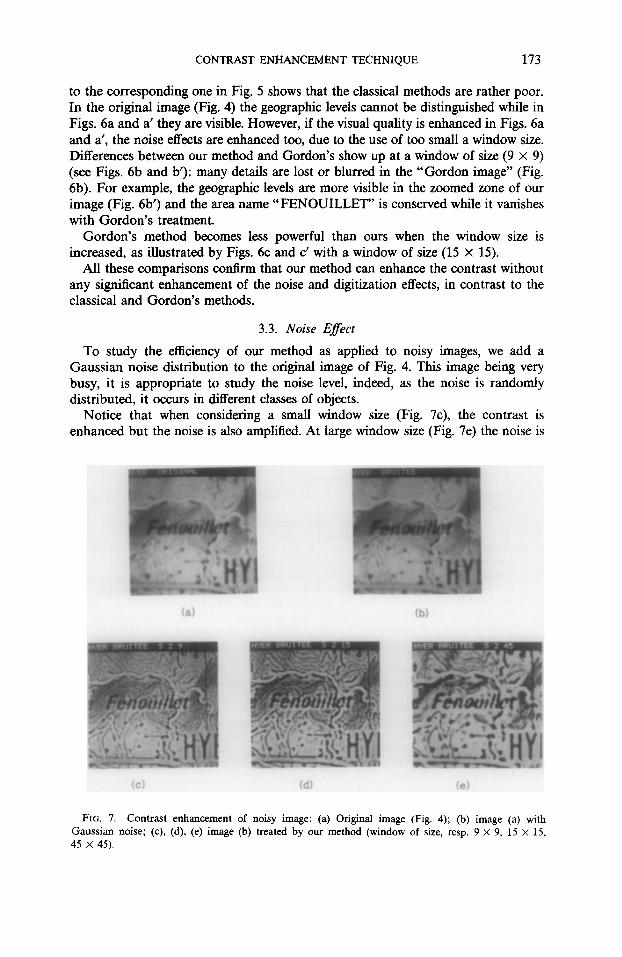
To study the efficiency of our method as applied to noisy images, we add a Gaussian noise distribution to the original image of Fig. 4. This image being very busy, it is appropriate to study the noise level, indeed, as the noise is randomly distributed, it occurs in different classes of objects.
Notice that when considering a small window size (Fig. 7c), the contrast is enhanced but the noise is also amplified. At large window size (Fig. 7e) the noise is
(a) (b)
Cd) (e)
FIG. 7. Contrast enhancement of noisy image: (a) Original image (Fig. 4); (b) image (a) with Gaussian noise; (c), (d), (e) image (b) treated by our method (window of size, resp. 9 x 9, 15 x 15, 45 x 45).

174 BEGHDADI AND LE NEGRATE
filtered out but some details are smoothed out. A compromise consists in using an intermediate window size (Fig. 7d).
Recall that the noise level comes into play in the computation of Ek, through the expression (5). As we average over all the pixels of the current window it is possible to reduce the noise effect when we consider large window sizes.
4. CONCLUSION
We have proposed another formulation of the contrast definition based on a local analysis of the edge gray levels in the image. The principal idea of our approach is to combine Gordon’s method [6,7] and the theory of contour detection operators [8]. We have compared our method to the classical and Gordon’s ones.
Our method is less sensitive to digitization effects and noise. It improves the gray level distribution and facilitates the extraction of the relevant information. It is thus useful in discriminating the objects according to their boundaries. Furthermore our method sharpens the edges and the micro-edges [18] when considering small windows, without significant noise enhancement. This method could be of great help in object contour extraction in low contrast images, thus making the segmentation of the image into meaningful regions easier.
It can also be used as a post-treatment to multithresholding and thus facilitating data compression without significant distortion.
ACKNOWLEDGMENTS
The authors are grateful to Dr. M. L. Theye and Dr. J. Lafait for critical reading of the manuscript.
REFERENCES 1. A. Rosenfeld and A. Kak, (Eds.), Digital Picture Processing, Academic Press, New York/London,
1982. 2. W. Pratt, (Ed.), Digital Image Processing, Wiley Interscience, New York, 1978. 3. W. Frei, Comput. Graphics Image Process. 6, 1977, 286. 4. R. Hummel, Comput. Graphics Image Process. 6, 1977, 184. 5. V. Kim and L. Yaroslavskii, Computer Vision Graphics Image Process. 35, 1986, 234-258. 6. R. Gordon and R. M. Rangayan, Appl. Opt. 23, No. 4 (1984). 7. A. P. Dhawan, G. Buelloni, and R. Gordon, IEEE. Trans. Med. Imaging MI-5, No. 1 (1986). 8. D. Marr and E. Hildreth, Proc. Roy. Sot. London B 2@7,1980, 187-217. 9. T. N. Comsweet, Visual Perception, Academic Press, New York, 1970.
10. J. W. Weszka and A. Rosenfeld, IEEE. Trans. Systems Man Cybern. SMC-9, No. 1 1979, 38. 11. D. P. Panda and A. Rosenfeld, IEEE. Trans. Comput. C-27, No. 9, 1978. 12. J. S. We&a, R. N. Nagel, and A. Rosenfeld, IEEE. Trans. Comput. 5, 1974, 1322. 13. J. Kittler, J. IIIingworth, and J. Fi$Iein, Comput. Vision Graphics Image Process. 30, 1985, 125-147. 14. A. Scher, F. R. Dias Velasco, and A. Rosenfeld, IEEE. Trans. Systems Man Cybern. SMC-le, No. 3.
1980, 153. 15. A. Beghdadi, Thesis, University of Paris-6, June 1986. 16. A. Beghdadi, A. Le Negrate, H. Dupoisot, A. Constans, J. Lafait, P. Gadenne, and P. Albarede, in
MARI 87, Intelligent Networks and Machines, Paris, La Villette, 18-22 May 1987. 17. D. J. Ketcham, R. W. Lowe, and J. W. Weber, Real-time image enhancement techniques, in Seminar
on Image Processing, Huges Aircraft, Pacijc Groue, CA 1976, pp. l-6. 18. A. Rosenfeld and M. Thurston, IEEE. Trans. Comput. C-20, No. 5, 1971, 562.