Robust FDI in Induction Motors via Second Order Sliding Mode Technique
6
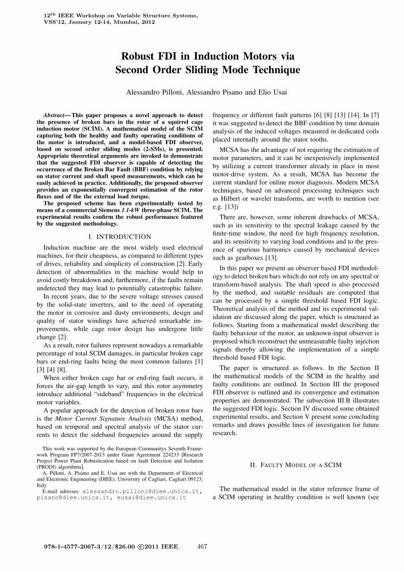
Robust FDI in Induction Motors via Second Order Sliding Mode Technique Alessandro Pilloni, Alessandro Pisano and Elio Usai Abstract— This paper proposes a novel approach to detect the presence of broken bars in the rotor of a squirrel cage induction motor (SCIM). A mathematical model of the SCIM capturing both the healthy and faulty operating conditions of the motor is introduced, and a model-based FDI observer, based on second order sliding modes (2-SMs), is presented. Appropriate theoretical arguments are invoked to demonstrate that the suggested FDI observer is capable of detecting the occurrence of the Broken Bar Fault (BBF) condition by relying on stator current and shaft speed measurements, which can be easily achieved in practice. Additionally, the proposed observer provides an exponentially convergent estimation of the rotor fluxes and of the the external load torque. The proposed scheme has been experimentally tested by means of a commercial Siemens 1.1-kW three-phase SCIM. The experimental results confirm the robust performance featured by the suggested methodology. I. INTRODUCTION Induction machine are the most widely used electrical machines, for their cheapness, as compared to different types of drives, reliability and simplicity of construction [2]. Early detection of abnormalities in the machine would help to avoid costly breakdown and, furthermore, if the faults remain undetected they may lead to potentially catastrophic failure. In recent years, due to the severe voltage stresses caused by the solid-state inverters, and to the need of operating the motor in corrosive and dusty environments, design and quality of stator windings have achieved remarkable im- provements, while cage rotor design has undergone little change [2]. As a result, rotor failures represent nowadays a remarkable percentage of total SCIM damages, in particular broken cage bars or end-ring faults being the most common failures [1] [3] [4] [8]. When either broken cage bar or end-ring fault occurs, it forces the air-gap length to vary, and this rotor asymmetry introduce additional “sideband” frequencies in the electrical motor variables. A popular approach for the detection of broken rotor bars is the Motor Current Signature Analysis (MCSA) method, based on temporal and spectral analysis of the stator cur- rents to detect the sideband frequencies around the supply This work was supported by the European Communitys Seventh Frame- work Program FP7/2007-2013 under Grant Agreement 224233 [Research Project ¨ Power Plant Robustication based on fault Detection and Isolation (PRODI) algorithms ¨ ]. A. Pilloni, A. Pisano and E. Usai are with the Department of Electrical and Electronic Engineering (DIEE), University of Cagliari, Cagliari 09123, Italy E-mail adresses: [email protected], [email protected], [email protected] frequency or different fault patterns [6] [8] [13] [14]. In [7] it was suggested to detect the BBF condition by time domain analysis of the induced voltages measured in dedicated coils placed internally around the stator tooths. MCSA has the advantage of not requiring the estimation of motor parameters, and it can be inexpensively implemented by utilizing a current transformer already in place in most motor-drive system. As a result, MCSA has become the current standard for online motor diagnosis. Modern MCSA techniques, based on advanced processing techniques such as Hilbert or wavelet transforms, are worth to mention (see e.g. [13]) There are, however, some inherent drawbacks of MCSA, such as its sensitivity to the spectral leakage caused by the finite-time window, the need for high frequency resolution, and its sensitivity to varying load conditions and to the pres- ence of spurious harmonics caused by mechanical devices such as gearboxes [13]. In this paper we present an observer based FDI methodol- ogy to detect broken bars which do not rely on any spectral or transform-based analysis. The shaft speed is also processed by the method, and suitable residuals are computed that can be processed by a simple threshold based FDI logic. Theoretical analysis of the method and its experimental val- idation are discussed along the paper, which is structured as follows. Starting from a mathematical model describing the faulty behaviour of the motor, an unknown-input observer is proposed which reconstruct the unmeasurable faulty injection signals thereby allowing the implementation of a simple threshold based FDI logic. The paper is structured as follows. In the Section II the mathematical models of the SCIM in the healthy and faulty conditions are outlined. In Section III the proposed FDI observer is outlined and its convergence and estimation properties are demonstrated. The subsection III.B illustrates the suggested FDI logic. Section IV discussed some obtained experimental results, and Section V present some concluding remarks and draws possible lines of investigation for future research. II. FAULTY MODEL OF A SCIM The mathematical model in the stator reference frame of a SCIM operating in healthy condition is well known (see 12 th IEEE Workshop on Variable Structure Systems, VSS’12, January 12-14, Mumbai, 2012 978-1-4577-2067-3/12/$26.00 c 2011 IEEE 467
Transcript of Robust FDI in Induction Motors via Second Order Sliding Mode Technique
Robust FDI in Induction Motors viaSecond Order Sliding Mode Technique
Alessandro Pilloni, Alessandro Pisano and Elio Usai
Abstract— This paper proposes a novel approach to detectthe presence of broken bars in the rotor of a squirrel cageinduction motor (SCIM). A mathematical model of the SCIMcapturing both the healthy and faulty operating conditions ofthe motor is introduced, and a model-based FDI observer,based on second order sliding modes (2-SMs), is presented.Appropriate theoretical arguments are invoked to demonstratethat the suggested FDI observer is capable of detecting theoccurrence of the Broken Bar Fault (BBF) condition by relyingon stator current and shaft speed measurements, which can beeasily achieved in practice. Additionally, the proposed observerprovides an exponentially convergent estimation of the rotorfluxes and of the the external load torque.
The proposed scheme has been experimentally tested bymeans of a commercial Siemens 1.1-kW three-phase SCIM. Theexperimental results confirm the robust performance featuredby the suggested methodology.
I. INTRODUCTION
Induction machine are the most widely used electricalmachines, for their cheapness, as compared to different typesof drives, reliability and simplicity of construction [2]. Earlydetection of abnormalities in the machine would help toavoid costly breakdown and, furthermore, if the faults remainundetected they may lead to potentially catastrophic failure.
In recent years, due to the severe voltage stresses causedby the solid-state inverters, and to the need of operatingthe motor in corrosive and dusty environments, design andquality of stator windings have achieved remarkable im-provements, while cage rotor design has undergone littlechange [2].
As a result, rotor failures represent nowadays a remarkablepercentage of total SCIM damages, in particular broken cagebars or end-ring faults being the most common failures [1][3] [4] [8].
When either broken cage bar or end-ring fault occurs, itforces the air-gap length to vary, and this rotor asymmetryintroduce additional “sideband” frequencies in the electricalmotor variables.
A popular approach for the detection of broken rotor barsis the Motor Current Signature Analysis (MCSA) method,based on temporal and spectral analysis of the stator cur-rents to detect the sideband frequencies around the supply
This work was supported by the European Communitys Seventh Frame-work Program FP7/2007-2013 under Grant Agreement 224233 [ResearchProject Power Plant Robustication based on fault Detection and Isolation(PRODI) algorithms].
A. Pilloni, A. Pisano and E. Usai are with the Department of Electricaland Electronic Engineering (DIEE), University of Cagliari, Cagliari 09123,Italy
E-mail adresses: [email protected],[email protected], [email protected]
frequency or different fault patterns [6] [8] [13] [14]. In [7]it was suggested to detect the BBF condition by time domainanalysis of the induced voltages measured in dedicated coilsplaced internally around the stator tooths.
MCSA has the advantage of not requiring the estimation ofmotor parameters, and it can be inexpensively implementedby utilizing a current transformer already in place in mostmotor-drive system. As a result, MCSA has become thecurrent standard for online motor diagnosis. Modern MCSAtechniques, based on advanced processing techniques suchas Hilbert or wavelet transforms, are worth to mention (seee.g. [13])
There are, however, some inherent drawbacks of MCSA,such as its sensitivity to the spectral leakage caused by thefinite-time window, the need for high frequency resolution,and its sensitivity to varying load conditions and to the pres-ence of spurious harmonics caused by mechanical devicessuch as gearboxes [13].
In this paper we present an observer based FDI methodol-ogy to detect broken bars which do not rely on any spectral ortransform-based analysis. The shaft speed is also processedby the method, and suitable residuals are computed thatcan be processed by a simple threshold based FDI logic.Theoretical analysis of the method and its experimental val-idation are discussed along the paper, which is structured asfollows. Starting from a mathematical model describing thefaulty behaviour of the motor, an unknown-input observer isproposed which reconstruct the unmeasurable faulty injectionsignals thereby allowing the implementation of a simplethreshold based FDI logic.
The paper is structured as follows. In the Section IIthe mathematical models of the SCIM in the healthy andfaulty conditions are outlined. In Section III the proposedFDI observer is outlined and its convergence and estimationproperties are demonstrated. The subsection III.B illustratesthe suggested FDI logic. Section IV discussed some obtainedexperimental results, and Section V present some concludingremarks and draws possible lines of investigation for futureresearch.
II. FAULTY MODEL OF A SCIM
The mathematical model in the stator reference frame ofa SCIM operating in healthy condition is well known (see
12th IEEE Workshop on Variable Structure Systems,VSS’12, January 12-14, Mumbai, 2012
978-1-4577-2067-3/12/$26.00 c©2011 IEEE 467

TABLE INOMENCLATURE OF SCIM MODEL
State Variables:
Shaft speed x1
α β Stator Currents x2,3
α β Rotor Fluxes x4,5
Input variables:
Load Torque TL
α β Stator Voltage Supply uα,β
Model Parameters:
Pole pairs number np
Viscous friction coefficient fv
Rotor inertia J
Rotor and stator resistance Rr,s
Rotor, stator and mutual inductance Lr,s,m
e.g. [9] [12]):x1 = a1 (x3x4 � x2x5)�a2x1 +a3TLx2 = b1x4 �b2x2 +b3x1x3 +b4usα
x3 = b1x5 �b2x3 �b3x1x2 +b4usβ
x4 = c1x2 � c2x4 �npx1x5x5 = c1x3 � c2x5 +npx1x4
(1)
where the meaning of the variables, and the underlyingelectromechanical parameters, are reported in the Table I andthe ai’s, bi’s and ci’s parameters take the form
a1 =npLmJLr
a3 = � 1J
b1 = LmRrσLsL2
r
b3 =npLmσLsLr
c1 = RrLr
Lm
a2 = fvJ
σ = 1� L2m
LrLs
b2 = L2mRr+L2
r RsσLsL2
r
b4 = 1σLs
c2 = RrLr
(2)
The load torque TL is generally not available for measure-ments in applications, and it is considered as an “unknowninput” entering the above motor dynamics.
As it is well known, breaking of (one or more) rotor barsis a damage frequently occurring in induction machines afterlong periods of operation. It causes the air-gap diameter tovary, thereby perturbing the rotating field and introducing
additional harmonics in the electrical variables of the ma-chine (current and fluxes), and, as a consequence, in theelectromagnetic torque and speed variables as well [1]. Thefrequencies of these additional harmonics (called sidebandfrequencies) depend on the motor slip variable s= 1�ω/ωe,where ω is the shaft speed and ωe is the synchronous speedof the magnetic field, according to
fbbs = (1±2ks) fs, k = 1,2,3, . . . (3)
where fs is the frequency of the sinusoidal stator supplyvoltage. The main sideband frequencies (obtained setting k =1 in (3)) represent the dominant contributions, and the higherharmonic can be neglected without any significant loss inaccuracy.
An accurate estimate of the operating slip s is, thus, aprerequisite to reliable frequency-based diagnosis of the socalled “motor current signature analysis” (MCSA) methods.
As shown in [7], BBF can be detected by time domainanalysis of induced voltages in the stator voltages; for thesereason an appropriate approach to model the machine be-haviour in the BBF condition is to include, in the “nominal”machine model (1) additional exogenous voltages fBBα , fBBβ
added to the corresponding stator supply voltages.The “faulty” SCIM mathematical model takes then the
form: x1 = a1 (x3x4 � x2x5)�a2x1 +a3TLx2 = b1x4 �b2x2 +b3x1x3 +b4(usα + fBBα )x3 = b1x5 �b2x3 �b3x1x2 +b4(usβ
+ fBBβ)
x4 = c1x2 � c2x4 �npx1x5x5 = c1x3 � c2x5 +npx1x4
(4)
In absence of the BBF condition the additional entries fBBα
and fBBβare identically zero, whereas when the fault occur
they became nonzero and inject in the system the sidebandfrequencies to reproduce the effect of the machine behaviourin the BBF condition.
III. SECOND ORDER SLIDING MODE FDI OBSERVER
An observer-based approach to robust FDI in SCIM ispresented in the following. Due to the presence of unknowninputs in the faulty motor dynamics (4), unknown-inputobservation techniques are mandatory.
Residual signals are wanted to be identified such that theyare identically (or, more realistically, close to) zero whenthe motor behaves in healthy mode, and promptly becomenonzero when the associated fault occurs. The exogenousinputs fBBα and fBBβ
would be ideal residual signal, but theyare obviously not available for measurements. However, byappropriate sliding mode based methodologies such signalscan be reconstructed with an estimation error exponentiallydecaying to zero. The reconstructed fault inputs fBBα andfBBβ
will be then subject to an appropriate, non conventional,threshold based residual evaluation procedure for fault detec-tion.
12th IEEE Workshop on Variable Structure Systems,VSS’12, January 12-14, Mumbai, 2012
978-1-4577-2067-3/12/$26.00 c©2011 IEEE 468
A. Residual Generation
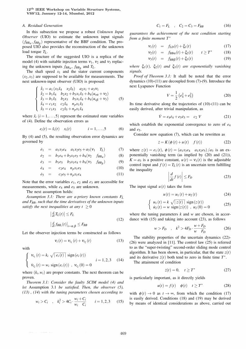
In this subsection we propose a robust Unknown InputObserver (UIO) to estimate the unknown input signals( fBBα , fBBβ
) representative of the BBF condition. The pro-posed UIO also provides the reconstruction of the unknownload torque TL.
The structure of the suggested UIO is a replica of themodel (4) with suitable injection terms ν1, ν2 and ν3 replac-ing the unknown inputs fBBα , fBBβ
and TL.The shaft speed x1 and the stator current components
(x2,x3) are supposed to be available for measurements. Thenext unknown-input observer (UIO) is proposed:
˙x1 = a1 (x3x4 � x2x5)�a2x1 +a3ν1˙x2 = b1x4 �b2x2 +b3x1x5 +b4(usα +ν2)˙x3 = b1x5 �b2x3 �b3x1x4 +b4(usβ +ν3)˙x4 = c1x2 � c2x4 �npx1x5˙x5 = c1x3 � c2x5 +npx1x4
(5)
where xi (i = 1, . . . ,5) represent the estimated state variablesof (4). Define the observation errors as
ei(t) = xi(t)� xi(t) i = 1, . . . ,5 (6)
By (4) and (5), the resulting observation error dynamics aregoverned by
e1 = a1x3e4 �a1x2e5 +a3(ν1 �TL) (7)e2 = b1e4 +b3x1e5 +b4(ν2 � fBBα ) (8)e3 = b1e5 �b3x1e4 +b4(ν3 � fBBβ
) (9)e4 = �c2e4 �npx1e5 (10)e5 = �c2e5 +npx1e4 (11)
Note that the error variables e1, e2 and e3 are accessible formeasurements, while e4 and e5 are unknown.
The next assumption holds:Assumption 3.1: There are a-priory known constants FL
and FBB, such that the time derivatives of the unknown inputssatisfy the next inequalities at any t ≥ 0∣∣ d
dt TL(t)∣∣≤ FL∣∣ d
dt fBBi(t)∣∣i=α,β
≤ FBB
(12)
Let the observer injection terms be constructed as follows
νi (t) = νi1 (t)+νi2 (t) (13)
with νi1 (t) = ki√∣ ei (t) ∣ sign(ei (t))
i = 1,2,3νi2 (t) = wi sign(ei (t)) , νi2 (0) = 0
(14)
where (ki,wi) are proper constants. The next theorem can beproven.
Theorem 3.1: Consider the faulty SCIM model (4) andlet Assumption 3.1 be satisfied. Then, the observer (5),(13) , (14) with the tuning parameters chosen according to
wi >Ci , k2i > 4Ci · wi +Ci
wi �Cii = 1,2,3 (15)
C1 = FL , C2 =C3 = FBB (16)
guarantees the achievement of the next condition startingfrom a finite moment T ∗
ν1(t) = fLD(t)+ξ1(t) (17)ν2(t) = fBBα(t)+ξ2(t) t ≥ T ∗ (18)ν3(t) = fBBβ (t)+ξ3(t) (19)
where ξ1(t), ξ2(t) and ξ3(t) are exponentially vanishingsignals.
Proof of Theorem 3.1: It shall be noted that the errordynamics (10)-(11) are decoupled from (7)-(9). Introduce thenext Lyapunov Function
V =12(e2
4 + e25)
(20)
Its time derivative along the trajectories of (10)-(11) can beeasily derived, after trivial manipulation, as
V = e4e4 + e5e5 =�c2 V (21)
which establish the exponential convergence to zero of e4and e5.
Consider now equation (7), which can be rewritten as
z = K (φ (t)+u(t)� f (t)) (22)
where z(t) = e1 (t), φ (t) = (a1x3e4 �a1x2e5)/a3 is an ex-ponentially vanishing term (as implied by (20) and (21)),K = a3 is a positive constant, u(t) = ν1(t) is the adjustablecontrol input and f (t) = TL (t) is an uncertain term fulfillingthe inequality ∣∣∣∣ d
dtf (t)
∣∣∣∣≤ FD (23)
The input signal u(t) takes the form
u(t) = u1 (t)+u2 (t) (24){u1 (t) = k
√∣ z(t) ∣ sign(z(t))u2 (t) = w sign(z(t)) , u2 (0) = 0
(25)
where the tuning parameters k and w are chosen, in accor-dance with (15) and taking into account (23), as follows
w> FD , k2 > 4FD · w+FD
w�FD(26)
The stability properties of the uncertain dynamics (22)-(26) were analyzed in [11]. The control law (25) is referredto as the “super-twisting” second-order sliding mode controlalgorithm. It has been shown, in particular, that the state z(t)and its derivative z(t) both tend to zero in finite time T ∗.
The attainment of condition
z(t) = 0, t ≥ T ∗ (27)
is particularly important, as it directly yields
u(t) = f (t)�φ(t) t ≥ T ∗ (28)
with φ(t) → 0 as t → ∞, from which the condition (17)is easily derived. Conditions (18) and (19) may be derivedby means of identical considerations as above, carried out
12th IEEE Workshop on Variable Structure Systems,VSS’12, January 12-14, Mumbai, 2012
978-1-4577-2067-3/12/$26.00 c©2011 IEEE 469
on the remaining error dynamics (8) and (9), that can berewritten in the form (22), too, and analyzed in the sameway. Theorem 3.1 is proven. �
The injection signals ν2 and ν3 will be used as residuals inthe next analysis, as they provide asymptotically convergingestimates of the fault signals fBBα and fBBβ
. Signal ν1represent an asymptotically exact estimation of the unknownload torque TL, which is useful, e.g., in Direct Torque Control(DTC) applications (see [10], [15]). The suggested FDIobserver provides an exponentially converging estimate ofthe rotor flux components as well.
B. Residual Evaluation
Residual evaluation exploits the relations (18) and (19).The two residuals are aggregated in a single one
r(t) = ν22 (t)+ν2
3 (t) (29)
The simplest fault detection strategy could be sought asfollows [5]:{
i f r(t)≤ ε then BBF is inactivei f r(t)> ε then BBF is active (30)
where ε is a suitably chosen constant threshold. The aboveFDI logic turns out to be rather sensitive against the mea-surement noise. Furthermore, in the case of study the residualr(t), due to the well-known oscillatory behaviour with zeromean (see (3) does not allow a threshold based identification.For this reason we propose to consider an indicator of theaverage power of the signal in a receding horizon temporalwindow of analysis. Then the next signal is constructed
E(t) =
√∫ t
t�∆Tr(τ)dτ (31)
where ∆T is the width of the receding horizon time window,and the FDI logic correspondingly becoming{
i f E(t)≤ ε then BBF is inactivei f E(t)> ε then BBF is active (32)
IV. EXPERIMENTAL RESULTS
The proposed method has been experimentally tested byusing signals acquired during tests with a commercial 1.5 kWSCIM whose main ratings are reported in the Table II.
Breaking of a single motor bar was intentionally causedby drilling the squirrel cage (see Figure 1). Acquisition ofspeed and current measurements was made (at the samplingrate of 5 kHz) during different tests, in healthy conditions(i.e., before drilling the bar) and after causing the fault. Themeasurement campaign has been conducted at the laborato-ries of the Department of Electrical Engineering, UniversidadPolitecnica de Valencia, by the electrical machines and drivesresearch group, that kindly provided us with the data.
The measurements have been processed online, the sug-gested FDI observer has been implemented and used to detect
TABLE IIRATINGS OF THE USED MOTOR (SIEMENS 1LA7090-2AA10)
Rated Power : 1.5 kW cosφ = 0.85
Rated frequency/full-load speed: 50 Hz 2860 rpm
Rated terminal supply voltage: 230 V�∆ 400 V�Y
Rated supply current with full load: 5.65 A�∆ 3.25 A�Y
whether the current measurements are taken from an healthyor faulty motor.
The electromechanical motor parameters needed for theobserver implementation are derived from the motor datasheet, whenever possible, or set to reasonable values sug-gested by engineering intuition and identification experi-ments and are reported in Table III.
After few trial and error tests, devoted to guarantee afast and accurate convergence to zero of the measurableestimation errors e1,e2 and e3, the observer parameters havebeen set as follows
w1 = 14 w2 = 22 w3 = 22k1 = 80 k2 = 200 k3 = 200 (33)
and the time window size ∆T was selected as
∆T = 0.3 (34)
We have found that the choice of this parameter is notcritical, i.e. the suggested algorithm has featured satisfactoryperformance with the parameter ∆T chosen differently, too.
The observer and the associated FDI logic are activatedafter 9 seconds, to let the machine reach the sinusoidal steadystate under the applied three-phase 230V/50Hz input voltage.
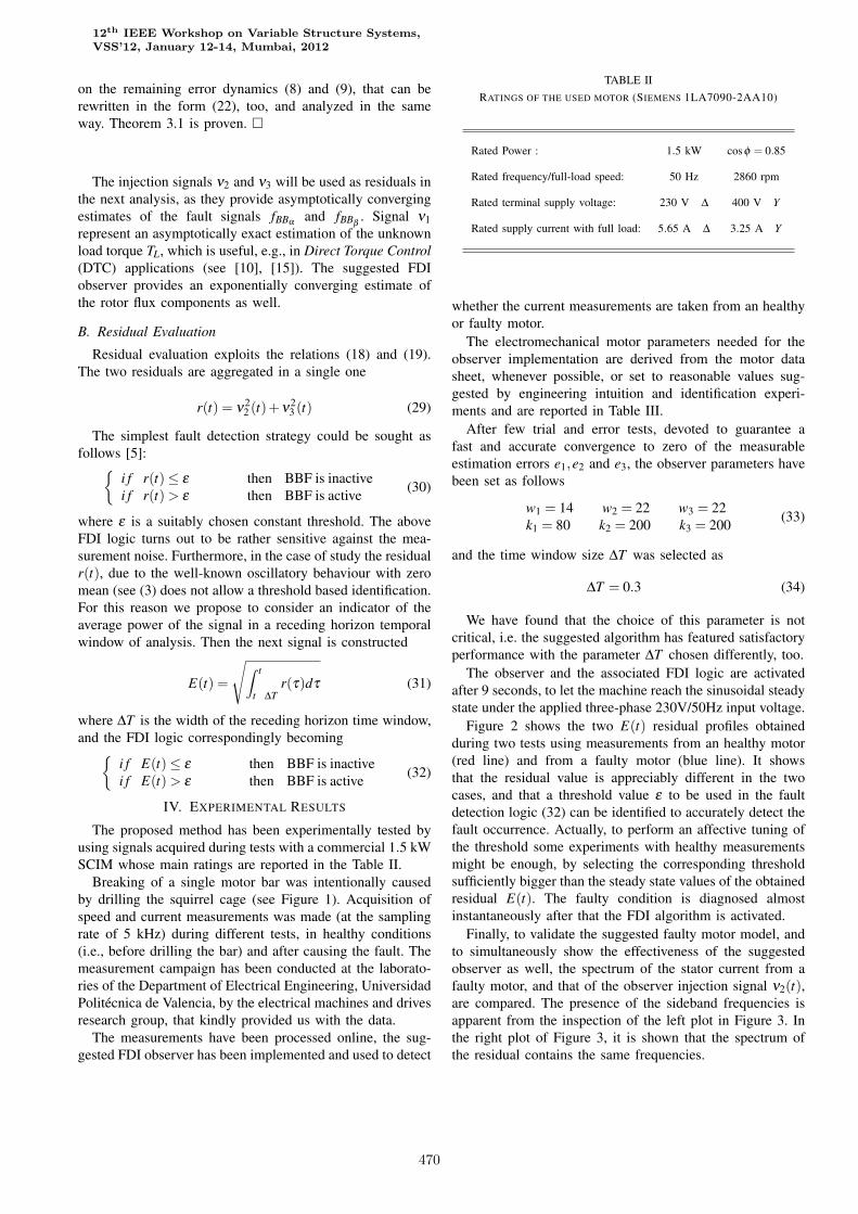
Figure 2 shows the two E(t) residual profiles obtainedduring two tests using measurements from an healthy motor(red line) and from a faulty motor (blue line). It showsthat the residual value is appreciably different in the twocases, and that a threshold value ε to be used in the faultdetection logic (32) can be identified to accurately detect thefault occurrence. Actually, to perform an affective tuning ofthe threshold some experiments with healthy measurementsmight be enough, by selecting the corresponding thresholdsufficiently bigger than the steady state values of the obtainedresidual E(t). The faulty condition is diagnosed almostinstantaneously after that the FDI algorithm is activated.
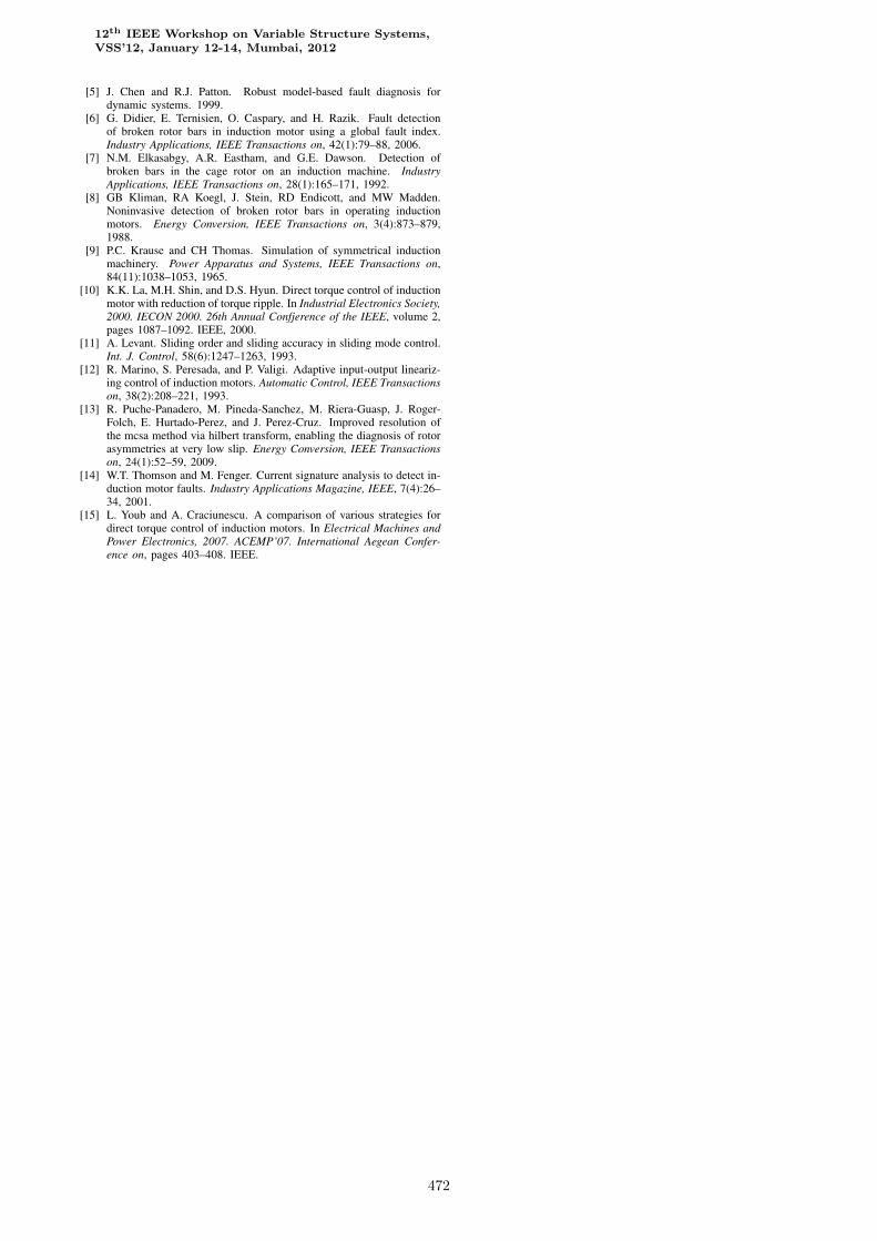
Finally, to validate the suggested faulty motor model, andto simultaneously show the effectiveness of the suggestedobserver as well, the spectrum of the stator current from afaulty motor, and that of the observer injection signal ν2(t),are compared. The presence of the sideband frequencies isapparent from the inspection of the left plot in Figure 3. Inthe right plot of Figure 3, it is shown that the spectrum ofthe residual contains the same frequencies.
12th IEEE Workshop on Variable Structure Systems,VSS’12, January 12-14, Mumbai, 2012
978-1-4577-2067-3/12/$26.00 c©2011 IEEE 470
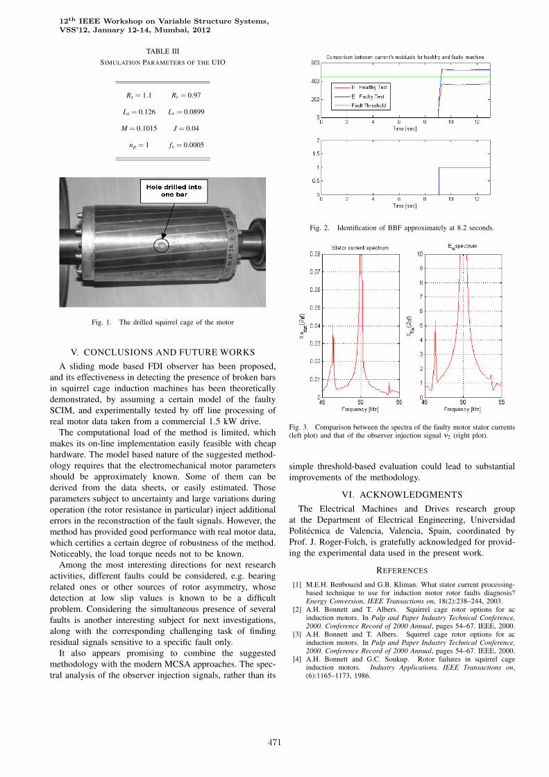
TABLE IIISIMULATION PARAMETERS OF THE UIO
Rs = 1.1 Rr = 0.97
Ls = 0.126 Lr = 0.0899
M = 0.1015 J = 0.04
np = 1 fv = 0.0005
Fig. 1. The drilled squirrel cage of the motor
V. CONCLUSIONS AND FUTURE WORKS
A sliding mode based FDI observer has been proposed,and its effectiveness in detecting the presence of broken barsin squirrel cage induction machines has been theoreticallydemonstrated, by assuming a certain model of the faultySCIM, and experimentally tested by off line processing ofreal motor data taken from a commercial 1.5 kW drive.
The computational load of the method is limited, whichmakes its on-line implementation easily feasible with cheaphardware. The model based nature of the suggested method-ology requires that the electromechanical motor parametersshould be approximately known. Some of them can bederived from the data sheets, or easily estimated. Thoseparameters subject to uncertainty and large variations duringoperation (the rotor resistance in particular) inject additionalerrors in the reconstruction of the fault signals. However, themethod has provided good performance with real motor data,which certifies a certain degree of robustness of the method.Noticeably, the load torque needs not to be known.
Among the most interesting directions for next researchactivities, different faults could be considered, e.g. bearingrelated ones or other sources of rotor asymmetry, whosedetection at low slip values is known to be a difficultproblem. Considering the simultaneous presence of severalfaults is another interesting subject for next investigations,along with the corresponding challenging task of findingresidual signals sensitive to a specific fault only.
It also appears promising to combine the suggestedmethodology with the modern MCSA approaches. The spec-tral analysis of the observer injection signals, rather than its
Fig. 2. Identification of BBF approximately at 8.2 seconds.
Fig. 3. Comparison between the spectra of the faulty motor stator currents(left plot) and that of the observer injection signal ν2 (right plot).
simple threshold-based evaluation could lead to substantialimprovements of the methodology.
VI. ACKNOWLEDGMENTS
The Electrical Machines and Drives research groupat the Department of Electrical Engineering, UniversidadPolitecnica de Valencia, Valencia, Spain, coordinated byProf. J. Roger-Folch, is gratefully acknowledged for provid-ing the experimental data used in the present work.
REFERENCES
[1] M.E.H. Benbouzid and G.B. Kliman. What stator current processing-based technique to use for induction motor rotor faults diagnosis?Energy Conversion, IEEE Transactions on, 18(2):238–244, 2003.
[2] A.H. Bonnett and T. Albers. Squirrel cage rotor options for acinduction motors. In Pulp and Paper Industry Technical Conference,2000. Conference Record of 2000 Annual, pages 54–67. IEEE, 2000.
[3] A.H. Bonnett and T. Albers. Squirrel cage rotor options for acinduction motors. In Pulp and Paper Industry Technical Conference,2000. Conference Record of 2000 Annual, pages 54–67. IEEE, 2000.
[4] A.H. Bonnett and G.C. Soukup. Rotor failures in squirrel cageinduction motors. Industry Applications, IEEE Transactions on,(6):1165–1173, 1986.
12th IEEE Workshop on Variable Structure Systems,VSS’12, January 12-14, Mumbai, 2012
978-1-4577-2067-3/12/$26.00 c©2011 IEEE 471
[5] J. Chen and R.J. Patton. Robust model-based fault diagnosis fordynamic systems. 1999.
[6] G. Didier, E. Ternisien, O. Caspary, and H. Razik. Fault detectionof broken rotor bars in induction motor using a global fault index.Industry Applications, IEEE Transactions on, 42(1):79–88, 2006.
[7] N.M. Elkasabgy, A.R. Eastham, and G.E. Dawson. Detection ofbroken bars in the cage rotor on an induction machine. IndustryApplications, IEEE Transactions on, 28(1):165–171, 1992.
[8] GB Kliman, RA Koegl, J. Stein, RD Endicott, and MW Madden.Noninvasive detection of broken rotor bars in operating inductionmotors. Energy Conversion, IEEE Transactions on, 3(4):873–879,1988.
[9] P.C. Krause and CH Thomas. Simulation of symmetrical inductionmachinery. Power Apparatus and Systems, IEEE Transactions on,84(11):1038–1053, 1965.
[10] K.K. La, M.H. Shin, and D.S. Hyun. Direct torque control of inductionmotor with reduction of torque ripple. In Industrial Electronics Society,2000. IECON 2000. 26th Annual Confjerence of the IEEE, volume 2,pages 1087–1092. IEEE, 2000.
[11] A. Levant. Sliding order and sliding accuracy in sliding mode control.Int. J. Control, 58(6):1247–1263, 1993.
[12] R. Marino, S. Peresada, and P. Valigi. Adaptive input-output lineariz-ing control of induction motors. Automatic Control, IEEE Transactionson, 38(2):208–221, 1993.
[13] R. Puche-Panadero, M. Pineda-Sanchez, M. Riera-Guasp, J. Roger-Folch, E. Hurtado-Perez, and J. Perez-Cruz. Improved resolution ofthe mcsa method via hilbert transform, enabling the diagnosis of rotorasymmetries at very low slip. Energy Conversion, IEEE Transactionson, 24(1):52–59, 2009.
[14] W.T. Thomson and M. Fenger. Current signature analysis to detect in-duction motor faults. Industry Applications Magazine, IEEE, 7(4):26–34, 2001.
[15] L. Youb and A. Craciunescu. A comparison of various strategies fordirect torque control of induction motors. In Electrical Machines andPower Electronics, 2007. ACEMP’07. International Aegean Confer-ence on, pages 403–408. IEEE.
12th IEEE Workshop on Variable Structure Systems,VSS’12, January 12-14, Mumbai, 2012
978-1-4577-2067-3/12/$26.00 c©2011 IEEE 472